Enterprise Deployment Guide for Oracle ... - Oracle Help Center
598
Oracle® Fusion Middleware Enterprise Deployment Guide for Oracle SOA Suite 12c (12.2.1.4) F29876-04 July 2021
-
Upload
khangminh22 -
Category
Documents
-
view
6 -
download
0
Transcript of Enterprise Deployment Guide for Oracle ... - Oracle Help Center

Oracle® Fusion MiddlewareEnterprise Deployment Guide for Oracle SOASuite
12c (12.2.1.4)F29876-04July 2021

Oracle Fusion Middleware Enterprise Deployment Guide for Oracle SOA Suite, 12c (12.2.1.4)
F29876-04
Copyright © 2014, 2021, Oracle and/or its affiliates.
Primary Author: Oracle Corporation
This software and related documentation are provided under a license agreement containing restrictions onuse and disclosure and are protected by intellectual property laws. Except as expressly permitted in yourlicense agreement or allowed by law, you may not use, copy, reproduce, translate, broadcast, modify, license,transmit, distribute, exhibit, perform, publish, or display any part, in any form, or by any means. Reverseengineering, disassembly, or decompilation of this software, unless required by law for interoperability, isprohibited.
The information contained herein is subject to change without notice and is not warranted to be error-free. Ifyou find any errors, please report them to us in writing.
If this is software or related documentation that is delivered to the U.S. Government or anyone licensing it onbehalf of the U.S. Government, then the following notice is applicable:
U.S. GOVERNMENT END USERS: Oracle programs (including any operating system, integrated software,any programs embedded, installed or activated on delivered hardware, and modifications of such programs)and Oracle computer documentation or other Oracle data delivered to or accessed by U.S. Government endusers are "commercial computer software" or "commercial computer software documentation" pursuant to theapplicable Federal Acquisition Regulation and agency-specific supplemental regulations. As such, the use,reproduction, duplication, release, display, disclosure, modification, preparation of derivative works, and/oradaptation of i) Oracle programs (including any operating system, integrated software, any programsembedded, installed or activated on delivered hardware, and modifications of such programs), ii) Oraclecomputer documentation and/or iii) other Oracle data, is subject to the rights and limitations specified in thelicense contained in the applicable contract. The terms governing the U.S. Government’s use of Oracle cloudservices are defined by the applicable contract for such services. No other rights are granted to the U.S.Government.
This software or hardware is developed for general use in a variety of information management applications.It is not developed or intended for use in any inherently dangerous applications, including applications thatmay create a risk of personal injury. If you use this software or hardware in dangerous applications, then youshall be responsible to take all appropriate fail-safe, backup, redundancy, and other measures to ensure itssafe use. Oracle Corporation and its affiliates disclaim any liability for any damages caused by use of thissoftware or hardware in dangerous applications.
Oracle and Java are registered trademarks of Oracle and/or its affiliates. Other names may be trademarks oftheir respective owners.
Intel and Intel Inside are trademarks or registered trademarks of Intel Corporation. All SPARC trademarks areused under license and are trademarks or registered trademarks of SPARC International, Inc. AMD, Epyc,and the AMD logo are trademarks or registered trademarks of Advanced Micro Devices. UNIX is a registeredtrademark of The Open Group.
This software or hardware and documentation may provide access to or information about content, products,and services from third parties. Oracle Corporation and its affiliates are not responsible for and expresslydisclaim all warranties of any kind with respect to third-party content, products, and services unless otherwiseset forth in an applicable agreement between you and Oracle. Oracle Corporation and its affiliates will not beresponsible for any loss, costs, or damages incurred due to your access to or use of third-party content,products, or services, except as set forth in an applicable agreement between you and Oracle.

Contents
Preface
Audience xxi
Documentation Accessibility xxi
Conventions xxi
Diversity and Inclusion xxii
Part I Understanding an Enterprise Deployment
1 Enterprise Deployment Overview
About the Enterprise Deployment Guide 1-1
When to Use the Enterprise Deployment Guide 1-1
2 About a Typical Enterprise Deployment
Diagram of a Typical Enterprise Deployment 2-1
About the Typical Enterprise Deployment Topology Diagram 2-2
Understanding the Firewalls and Zones of a Typical Enterprise Deployment 2-3
Understanding the Elements of a Typical Enterprise Deployment Topology 2-3
Receiving Requests Through Hardware Load Balancer 2-4
Purpose of the Hardware Load Balancer (LBR) 2-4
Summary of the Typical Load Balancer Virtual Server Names 2-6
HTTPS Versus HTTP Requests to the External Virtual Server Name 2-7
Understanding the Web Tier 2-7
Benefits of Using a Web Tier to Route Requests 2-7
Alternatives to Using a Web Tier 2-8
Configuration of Oracle HTTP Server in the Web Tier 2-9
About Mod_WL_OHS 2-9
Understanding the Application Tier 2-9
Configuration of the Administration Server and Managed Servers DomainDirectories 2-10
Using Oracle Web Services Manager in the Application Tier 2-11
iii

Best Practices and Variations on the Configuration of the Clusters and Hosts onthe Application Tier 2-11
About the Node Manager Configuration in a Typical Enterprise Deployment 2-12
About Using Unicast for Communications within the Application Tier 2-13
Understanding OPSS and Requests to the Authentication and Authorization Stores 2-14
About Coherence Clusters In a Typical Enterprise Deployment 2-14
About the Data Tier 2-16
3 About the Oracle SOA Suite Enterprise Deployment Topology
About the Primary and Build-Your-Own Enterprise Deployment Topologies 3-2
Diagrams of the Primary Oracle SOA Suite Enterprise Topologies 3-2
Diagram of the Oracle SOA Suite and Oracle Service Bus Topology 3-2
Diagram of the Oracle SOA Suite and Oracle Business Activity Monitoring Topology 3-3
About the Primary Oracle SOA Suite Topology Diagrams 3-4
About the Topology Options for Oracle Service Bus 3-5
Summary of Oracle SOA Suite Load Balancer Virtual Server Names 3-5
About the Routing of SOA Composite Requests 3-6
More About the soainternal Virtual Server Name 3-6
About Web Services Optimizations for SOA Composite Applications 3-7
About Accessing SOA Composite Applications through Oracle HTTP Server 3-8
About Accessing Oracle SOA Suite Composite Applications Through the LoadBalancer 3-8
Summary of the Managed Servers and Clusters on SOA Application Tier 3-9
Flow Charts and Road Maps for Implementing the Primary Oracle SOA Suite EnterpriseTopologies 3-9
Flow Chart of the Steps to Install and Configure the Primary Oracle SOA SuiteEnterprise Topologies 3-10
Roadmap Table for Planning and Preparing for an Enterprise Deployment 3-12
Roadmap Table for Configuring the Oracle SOA Suite and Oracle Service BusEnterprise Topology 3-12
Roadmap Table for Configuring the Oracle SOA Suite and Oracle Business ActivityMonitoring Enterprise Topology 3-13
Building Your Own Oracle SOA Suite Enterprise Topology 3-14
Flow Chart of the Build Your Own Enterprise Topologies 3-14
Description of the Supported Build Your Own Topologies 3-15
About Installing and Configuring a Custom Enterprise Topology 3-17
About Using Automatic Service Migration for the Oracle SOA Suite Enterprise Topology 3-17
About Reference Configuration for SOA and OSB 3-18
Part II Preparing for an Enterprise Deployment
iv

4 Using the Enterprise Deployment Workbook
Introduction to the Enterprise Deployment Workbook 4-1
Typical Use Case for Using the Workbook 4-1
Using the Oracle SOA Suite Enterprise Deployment Workbook 4-2
Locating the Oracle SOA Suite Enterprise Deployment Workbook 4-2
Understanding the Contents of the Oracle SOA Suite Enterprise Deployment Workbook 4-2
Using the Start Tab 4-3
Using the Hardware - Host Computers Tab 4-3
Using the Network - Virtual Hosts & Ports Tab 4-4
Using the Storage - Directory Variables Tab 4-4
Using the Database - Connection Details Tab 4-5
Who Should Use the Enterprise Deployment Workbook? 4-5
5 Procuring Resources for an Enterprise Deployment
Hardware and Software Requirements for the Enterprise Deployment Topology 5-1
Hardware Load Balancer Requirements 5-1
Host Computer Hardware Requirements 5-2
General Considerations for Enterprise Deployment Host Computers 5-3
Reviewing the Oracle Fusion Middleware System Requirements 5-3
Typical Memory, File Descriptors, and Processes Required for an EnterpriseDeployment 5-4
Typical Disk Space Requirements for an Enterprise Deployment 5-5
Operating System Requirements for an Enterprise Deployment Topology 5-6
Reserving the Required IP Addresses for an Enterprise Deployment 5-6
What is a Virtual IP (VIP) Address? 5-7
Why Use Virtual Host Names and Virtual IP Addresses? 5-7
Physical and Virtual IP Addresses Required by the Enterprise Topology 5-8
Identifying and Obtaining Software Distributions for an Enterprise Deployment 5-8
6 Preparing the Load Balancer and Firewalls for an Enterprise Deployment
Configuring Virtual Hosts on the Hardware Load Balancer 6-1
Overview of the Hardware Load Balancer Configuration 6-1
Typical Procedure for Configuring the Hardware Load Balancer 6-2
Summary of the Virtual Servers Required for an Enterprise Deployment 6-2
Additional Instructions for admin.example.com 6-3
Additional Instructions for soa.example.com 6-3
Additional Instructions for soainternal.example.com 6-4
Additional Instructions for osb.example.com 6-4
Additional Instructions for mft.example.com 6-4
v

Configuring the Firewalls and Ports for an Enterprise Deployment 6-5
7 Preparing the File System for an Enterprise Deployment
Overview of Preparing the File System for an Enterprise Deployment 7-1
Shared Storage Recommendations When Installing and Configuring an EnterpriseDeployment 7-2
About the Recommended Directory Structure for an Enterprise Deployment 7-3
File System and Directory Variables Used in This Guide 7-5
About Creating and Mounting the Directories for an Enterprise Deployment 7-11
Summary of the Shared Storage Volumes in an Enterprise Deployment 7-12
8 Preparing the Host Computers for an Enterprise Deployment
Verifying the Minimum Hardware Requirements for Each Host 8-1
Verifying Linux Operating System Requirements 8-2
Setting Linux Kernel Parameters 8-2
Setting the Open File Limit and Number of Processes Settings on UNIX Systems 8-3
Viewing the Number of Currently Open Files 8-3
Setting the Operating System Open File and Processes Limits 8-3
Verifying IP Addresses and Host Names in DNS or Hosts File 8-4
Configuring Operating System Users and Groups 8-5
Enabling Unicode Support 8-5
Setting the DNS Settings 8-6
Configuring Users and Groups 8-6
Configuring a Host to Use an NTP (time) Server 8-7
Configuring a Host to Use an NIS/YP Host 8-7
Mounting the Required Shared File Systems on Each Host 8-9
Enabling the Required Virtual IP Addresses on Each Host 8-10
9 Preparing the Database for an Enterprise Deployment
Overview of Preparing the Database for an Enterprise Deployment 9-1
About Database Requirements 9-2
Supported Database Versions 9-2
Additional Database Software Requirements 9-2
Setting the PROCESSES Database Initialization Parameter for an EnterpriseDeployment 9-3
Creating Database Services 9-4
Using SecureFiles for Large Objects (LOBs) in an Oracle Database 9-6
About Database Backup Strategies 9-7
vi

Implementing a Database Growth Management Strategy for Oracle SOA Suite 9-7
Part III Configuring the Enterprise Deployment
10
Creating the Initial Infrastructure Domain for an Enterprise Deployment
About the Initial Infrastructure Domain 10-2
About the Infrastructure Distribution 10-2
Characteristics of the Domain 10-2
Variables Used When Creating the Infrastructure Domain 10-3
Support for Dynamic Clusters in Infrastructure Domains 10-3
Installing the Oracle Fusion Middleware Infrastructure on SOAHOST1 10-4
Installing a Supported JDK 10-4
Locating and Downloading the JDK Software 10-5
Installing the JDK Software 10-5
Starting the Infrastructure Installer on SOAHOST1 10-6
Navigating the Infrastructure Installation Screens 10-6
Installing Oracle Fusion Middleware Infrastructure on the Other Host Computers 10-8
Checking the Directory Structure 10-8
Disabling the Derby Database 10-9
Creating the Database Schemas 10-9
Installing and Configuring a Certified Database 10-10
Starting the Repository Creation Utility (RCU) 10-10
Navigating the RCU Screens to Create the Schemas 10-10
Verifying Schema Access 10-13
Configuring the Infrastructure Domain 10-14
Starting the Configuration Wizard 10-14
Navigating the Configuration Wizard Screens to Configure the Infrastructure Domain 10-14
Creating the Domain with Static Clusters 10-14
Creating the Domain with Dynamic Clusters 10-25
Configuring a Per Host Node Manager for an Enterprise Deployment 10-34
Creating a Per Host Node Manager Configuration 10-35
Creating the boot.properties File 10-37
Starting the Node Manager on SOAHOST1 10-38
Configuring the Node Manager Credentials and Type 10-38
Configuring the Domain Directories and Starting the Servers on SOAHOST1 10-40
Starting the Administration Server Using the Node Manager 10-40
Validating the Administration Server 10-41
Creating a Separate Domain Directory for Managed Servers on SOAHOST1 10-42
Starting and Validating the WLS_WSM1 Managed Server on SOAHOST1 10-44
Propagating the Domain and Starting the Servers on SOAHOST2 10-45
vii

Unpacking the Domain on SOAHOST2 10-45
Starting the Node Manager on SOAHOST2 10-47
Starting and Validating the WLS_WSM2 Managed Server on SOAHOST2 10-47
Modifying the Upload and Stage Directories to an Absolute Path 10-47
Configuring Listen Addresses When Using Dynamic Clusters 10-47
Creating a New LDAP Authenticator and Provisioning Enterprise Deployment Users andGroup 10-47
About the Supported Authentication Providers 10-48
About the Enterprise Deployment Users and Groups 10-48
About Using Unique Administration Users for Each Domain 10-49
About the Domain Connector User 10-49
About Adding Users to the Central LDAP Directory 10-49
About Product-Specific Roles and Groups for Oracle SOA Suite 10-50
Example Users and Groups Used in This Guide 10-50
Prerequisites for Creating a New Authentication Provider and Provisioning Users andGroups 10-51
Provisioning a Domain Connector User in the LDAP Directory 10-51
Creating the New Authentication Provider 10-53
Provisioning an Enterprise Deployment Administration User and Group 10-56
Adding the Administration Role to the New Administration Group 10-58
Updating the boot.properties File and Restarting the System 10-58
Adding the wsm-pm Role to the Administrators Group 10-59
Backing Up the Configuration 10-59
Verification of Manual Failover of the Administration Server 10-60
11
Configuring Oracle HTTP Server for an Enterprise Deployment
About the Oracle HTTP Server Domains 11-2
Variables Used When Configuring the Oracle HTTP Server 11-2
Installing Oracle HTTP Server on WEBHOST1 11-2
Installing a Supported JDK 11-3
Locating and Downloading the JDK Software 11-3
Installing the JDK Software 11-3
Starting the Installer on WEBHOST1 11-4
Navigating the Oracle HTTP Server Installation Screens 11-4
Verifying the Oracle HTTP Server Installation 11-6
Creating an Oracle HTTP Server Domain on WEBHOST1 11-7
Starting the Configuration Wizard on WEBHOST1 11-7
Navigating the Configuration Wizard Screens for an Oracle HTTP Server Domain 11-7
Installing and Configuring an Oracle HTTP Server Domain on WEBHOST2 11-10
Starting the Node Manager and Oracle HTTP Server Instances on WEBHOST1 andWEBHOST2 11-10
viii

Starting the Node Manager on WEBHOST1 and WEBHOST2 11-10
Starting the Oracle HTTP Server Instances 11-10
Configuring Oracle HTTP Server to Route Requests to the Application Tier 11-11
About the Oracle HTTP Server Configuration for an Enterprise Deployment 11-11
Purpose of the Oracle HTTP Server Virtual Hosts 11-12
About the WebLogicCluster Parameter of the <VirtualHost> Directive 11-12
Recommended Structure of the Oracle HTTP Server Configuration Files 11-12
Modifying the httpd.conf File to Include Virtual Host Configuration Files 11-13
Creating the Virtual Host Configuration Files 11-13
Validating the Virtual Server Configuration on the Load Balancer 11-15
Configuring Routing to the Administration Server and Oracle Web Services Manager 11-15
Validating Access to the Management Consoles and Administration Server 11-17
12
Configuring Oracle Traffic Director for an Enterprise Deployment
About Oracle Traffic Director 12-2
About Oracle Traffic Director in an Enterprise Deployment 12-2
Variables Used When Configuring Oracle Traffic Director 12-3
Installing Oracle Traffic Director in Collocated Mode on the Application Tier Hosts 12-4
Starting the Oracle Traffic Director Installer 12-4
Navigating the Oracle Traffic Director Installation Screens (Collocated) 12-4
Verifying the Installation on the Application Tier Hosts 12-7
Installing Oracle Traffic Director in Standalone Mode on the Web Tier Hosts 12-7
Installing a Supported JDK 12-7
Locating and Downloading the JDK Software 12-7
Installing the JDK Software 12-7
Starting the Oracle Traffic Director Installer 12-8
Navigating the Oracle Traffic Director Installation Screens (Standalone) 12-9
Verifying the installation on the Web Tier Hosts 12-11
Extending the Domain with Oracle Traffic Director System Components 12-12
Starting the Configuration Wizard 12-12
Navigating the Configuration Wizard Screens to Extend the Domain 12-12
Propagating the Domain and Starting the Node Manager on the Web Tier Hosts 12-15
Packing Up the Domain on the Application Tier 12-15
Unpacking the Domain Configuration on the Web Tier Hosts 12-16
Configuring and Starting Node Manager on the Web Tier Hosts 12-17
Creating an Oracle Traffic Director Configuration 12-17
Starting the Oracle Traffic Director Default Instance 12-18
Defining Oracle Traffic Director Virtual Servers for an Enterprise Deployment 12-18
Creating the Required Origin Server Pools 12-19
Creating the Required Virtual Servers 12-21
ix

Creating the Required Virtual Server Routes 12-22
Enabling SSL Passthrough 12-25
Creating a TCP Proxy for an Enterprise Deployment 12-26
Creating a Failover Group for Virtual Hosts 12-27
Creating Failover Groups 12-27
13
Extending the Domain with Oracle SOA Suite
Variables Used When Configuring Oracle SOA Suite 13-2
Support for Dynamic Clusters in Oracle SOA Suite 13-2
Synchronizing the System Clocks 13-3
Installing the Software for an Enterprise Deployment 13-3
Starting the Oracle SOA Suite Installer on SOAHOST1 13-4
Navigating the Installation Screens 13-4
Installing Oracle SOA Suite on the Other Host Computers 13-5
Verifying the Installation 13-5
Reviewing the Installation Log Files 13-5
Checking the Directory Structure 13-5
Viewing the Contents of Your Oracle Home 13-6
Creating the Oracle SOA Suite Database Schemas 13-6
Starting the Repository Creation Utility (RCU) 13-6
Navigating the RCU Screens to Create the Schemas 13-6
Verifying Schema Access 13-9
Configuring SOA Schemas for Transactional Recovery 13-9
Extending the Enterprise Deployment Domain with Oracle SOA Suite 13-10
Starting the Configuration Wizard 13-11
Navigating the Configuration Wizard Screens to Extend the Domain with Oracle SOASuite 13-11
Extending the Domain with Static Clusters 13-11
Extending the Domain with Dynamic Clusters 13-19
Targeting Adapters Manually 13-28
Propagating the Extended Domain to the Domain Directories and Machines 13-29
Packing Up the Extended Domain on SOAHOST1 13-30
Unpacking the Domain in the Managed Servers Domain Directory on SOAHOST1 13-31
Unpacking the Domain on SOAHOST2 13-32
Starting and Validating the WLS_SOA1 Managed Server 13-33
Starting the WLS_SOA1 Managed Server 13-34
Adding the SOAAdmin Role to the Administrators Group 13-34
Validating the Managed Server by Logging in to the SOA Infrastructure 13-34
Starting and Validating the WLS_SOA2 Managed Server 13-35
Modifying the Upload and Stage Directories to an Absolute Path 13-35
Configuring Listen Addresses When Using Dynamic Clusters 13-35
x

Configuring the Web Tier for the Extended Domain 13-35
Configuring Oracle HTTP Server for the WLS_SOA Managed Servers 13-36
Configuring the WebLogic Proxy Plug-In 13-39
Validating the Oracle SOA Suite URLs Through the Load Balancer 13-39
Post-Configuration Steps for Oracle SOA Suite 13-40
Configuring Oracle Adapters for Oracle SOA Suite 13-40
Enabling High Availability for Oracle File and FTP Adapters 13-40
Enabling High Availability for Oracle JMS Adapters 13-44
Enabling High Availability for the Oracle Database Adapter 13-46
Enabling SSL Communication Between the SOA Servers and the Hardware LoadBalancer 13-46
Considerations for Sync-Async Interactions in a SOA Cluster 13-46
Updating FusionAppsFrontendHostUrl 13-47
Enabling JDBC Persistent Stores for Oracle SOA Suite 13-47
Enabling Automatic Service Migration for Oracle SOA Suite 13-48
Backing Up the Configuration 13-48
14
Extending the Domain with Oracle Service Bus
About Configuring Oracle Service Bus in Its Own Domain 14-2
Variables Used When Configuring Oracle Service Bus 14-3
Support for Dynamic Clusters in Oracle Service Bus 14-3
Overview of Adding OSB to the Topology 14-4
Prerequisites for Extending the Domain to Include Oracle Service Bus 14-5
Installing Oracle Service Bus Software 14-5
Starting the Oracle Service Bus Installer 14-6
Navigating the OSB Installation Screens 14-6
Installing the Software on Other Host Computers 14-7
Validating the OSB Installation 14-7
Reviewing the Installation Log Files 14-7
Checking the Directory Structure 14-8
Viewing the Contents of Your Oracle Home 14-8
Extending the SOA or Infrastructure Domain to Include Oracle Service Bus 14-8
Starting the Configuration Wizard 14-9
Navigating the Configuration Wizard Screens to Extend the Domain with OracleService Bus 14-9
Extending the Domain with Static Clusters 14-9
Extending the Domain with Dynamic Clusters 14-17
Propagating the Extended Domain to the Domain Directories and Machines 14-26
Summary of the Tasks Required to Propagate the Changes to the Other DomainDirectories and Machines 14-26
Starting and Validating the WLS_OSB1 Managed Server 14-27
xi

Starting the WLS_OSB1 Managed Server 14-27
Adding the MiddlewareAdministrators Role to the Enterprise DeploymentAdministration Group 14-28
Validating the Managed Server 14-28
Starting and Validating the WLS_OSB2 Managed Server 14-28
Verifying the Appropriate Targeting and Configuration for OSB Singleton Services 14-29
Modifying the Upload and Stage Directories to an Absolute Path 14-30
Configuring Listen Addresses When Using Dynamic Clusters 14-31
Configuring the Web Tier for the Extended Domain 14-31
Configuring Oracle HTTP Server for the Oracle Service Bus 14-32
Configuring the WebLogic Proxy Plug-In 14-35
Validating the Oracle Service Bus URLs Through the Load Balancer 14-35
Post-Configuration Tasks for Oracle Service Bus 14-36
Enabling High Availability for Oracle DB, File and FTP Adapters 14-36
Considerations for Poller Transports 14-37
Configuring Specific Oracle Service Bus Services for an Enterprise Deployment 14-38
Enabling SSL Communication Between the Oracle Service Bus Servers and theHardware Load Balancer 14-38
Enabling JDBC Persistent Stores for Oracle Service Bus 14-38
Enabling Automatic Service Migration for Oracle Service Bus 14-39
Backing Up the Configuration 14-39
15
Extending the Domain with Business Process Management
Variables Used When Configuring Business Process Management 15-2
Support for Dynamic Clusters in Business Process Management 15-3
Support for Reference Configuration in Business Process Management 15-3
Prerequisites for Extending the SOA Domain to Include Oracle BPM 15-4
Installing Oracle Business Process Management for an Enterprise Deployment 15-4
Starting the Installation Program 15-4
Navigating the Oracle BPM Installation Screens 15-5
Installing the Software on Other Host Computers 15-6
Verifying the Installation 15-7
Reviewing the Installation Log Files 15-7
Checking the Directory Structure 15-7
Viewing the Contents of Your Oracle Home 15-7
Running the Configuration Wizard on SOAHOST1 to Extend a SOA Domain to IncludeBPM 15-7
Starting the Configuration Wizard 15-8
Navigating the Configuration Wizard Screens to Extend the Domain with BPM 15-8
Propagating the Extended Domain to the Domain Directories and Machines 15-11
Updating SOA BPM Servers for Web Forms 15-12
xii

Starting the WLS_SOA Managed Servers with Business Process Management 15-13
Adding the Enterprise Deployment Administration User to the Oracle BPM AdministratorsGroup 15-14
Configuring the Web Tier for the Extended Domain 15-14
Configuring Oracle HTTP Server for Oracle Business Process Management 15-14
Enabling SSL Communication Between Business Process Management Servers and theHardware Load Balancer 15-16
Validating Access to Business Process Management Through the Hardware Load Balancer 15-16
Configuring BPMJMSModule for the Oracle BPM Cluster 15-17
Enabling JDBC Persistent Stores for Business Process Management 15-19
Enabling Automatic Service Migration for Business Process Management 15-20
Backing Up the Configuration 15-20
16
Extending the Domain with Oracle Enterprise Scheduler
About Adding Oracle Enterprise Scheduler 16-2
Variables Used When Configuring Oracle Enterprise Scheduler 16-3
Support for Dynamic Clusters in Oracle Enterprise Scheduler 16-3
Support for Reference Configuration in Oracle Enterprise Scheduler 16-4
Creating the Database Schemas for ESS 16-4
Starting the Repository Creation Utility (RCU) 16-4
Navigating the RCU Screens to Create the Enterprise Scheduler Schemas 16-5
Verifying Schema Access 16-7
Extending the SOA Domain to Include Oracle Enterprise Scheduler 16-8
Starting the Configuration Wizard 16-8
Navigating the Configuration Wizard Screens to Extend the Domain with OracleEnterprise Scheduler 16-8
Extending the Domain with Static Clusters 16-9
Extending the Domain with Dynamic Clusters 16-14
Propagating the Extended Domain to the Domain Directories and Machines 16-21
Adding the ESSAdmin Role to the SOA Administrators Group 16-21
Starting and Validating the WLS_ESS1 Managed Server 16-21
Starting and Validating the WLS_ESS2 Managed Server 16-23
Modifying the Upload and Stage Directories to an Absolute Path 16-23
Configuring Listen Addresses When Using Dynamic Clusters 16-23
Configuring the Web Tier for the Extended Domain 16-23
Configuring Oracle HTTP Server for the WLS_ESS Managed Servers 16-24
Configuring the WebLogic Proxy Plug-In 16-25
Validating Access to Oracle Enterprise Scheduler Through the Hardware Load Balancer 16-25
Backing Up the Configuration 16-26
xiii

17
Extending the Domain with Business Activity Monitoring
Variables Used When Configuring Business Activity Monitor 17-2
Support for Dynamic Clusters in BAM 17-3
Support for Reference Configuration in BAM 17-3
About Configuring BAM in Its Own Domain 17-3
Prerequisites When Adding Oracle BAM to the Domain 17-4
Understanding the Installation Requirements for Adding Oracle BAM to the Domain 17-4
Understanding the Database Schema Requirements for Oracle BAM 17-4
Backing Up the Existing Installation 17-4
Special Instructions When Configuring Oracle BAM on Separate Hosts 17-5
Procuring Additional Host Computers for Oracle BAM 17-5
Installation Requirements When Configuring Oracle BAM on Separate Hosts 17-5
Installation Requirements When Using a Separate Volume or Partition 17-6
Installation Requirements When Using a Shared Oracle Home 17-6
Configuration Wizard Instructions When Configuring Oracle BAM on Separate Hosts 17-7
Propagating the Domain Configuration When Configuring Oracle BAM on SeparateHosts 17-7
Roadmap for Adding Oracle BAM to the Domain 17-7
Extending the SOA Domain to Include Oracle Business Activity Monitoring 17-8
Starting the Configuration Wizard 17-9
Navigating the Configuration Wizard Screens for Oracle BAM 17-9
Propagating the Extended Domain to the Domain Directories and Machines 17-14
Adding the Enterprise Deployment Administration User to the Oracle BAM AdministrationGroup 17-15
Starting and Validating the WLS_BAM1 Managed Server 17-15
Starting and Validating the WLS_BAM2 Managed Server 17-16
Modifying the Upload and Stage Directories to an Absolute Path 17-17
Configuring the Web Tier for the Extended Domain 17-17
Configuring Oracle HTTP Server for the WLS_BAM Managed Servers 17-18
Configuring the WebLogic Proxy Plug-In 17-18
Validating Access to Oracle BAM Through the Hardware Load Balancer 17-19
Enabling JDBC Persistent Stores for BAM 17-19
Enabling Automatic Service Migration for BAM 17-20
Backing Up the Configuration 17-20
18
Extending the Domain with Oracle B2B
Variables Used When Configuring Oracle B2B 18-2
Support for Dynamic Clusters in Oracle B2B 18-3
Support for Reference Configuration in Oracle B2B 18-3
Prerequisites for Extending the SOA Domain to Include Oracle B2B 18-3
xiv

Installing Oracle B2B for an Enterprise Deployment 18-4
Starting the Oracle B2B and Healthcare Installer on SOAHOST1 18-4
Navigating the Oracle B2B Installation Screens 18-5
Installing the Software on Other Host Computers 18-6
Verifying the B2B or Healthcare Installation 18-6
Reviewing the Installation Log Files 18-7
Checking the Directory Structure 18-7
Viewing the Contents of Your Oracle Home 18-7
Running the Configuration Wizard to Extend for Oracle B2B 18-7
Starting the Configuration Wizard 18-8
Navigating the Configuration Wizard Screens for Oracle B2B 18-8
Propagating the Extended Domain to the Domain Directories and Machines 18-11
Starting the B2B Suite Components 18-11
Updating the B2B Instance Identifier for Transports 18-12
Configuring the Web Tier for the Extended Domain 18-13
Configuring Oracle HTTP Server for Oracle B2B 18-13
Adding the B2BAdmin Role to the SOA Administrators Group 18-15
Validating Access to Oracle B2B Through the Load Balancer 18-15
Enabling JDBC Persistent Stores for Oracle B2B 18-15
Enabling Automatic Service Migration for Oracle B2B 18-16
Backing Up the Configuration 18-16
19
Configuring Oracle Managed File Transfer in an Enterprise Deployment
About Oracle Managed File Transfer 19-2
About Managed File Transfer in an Enterprise Deployment 19-3
Characteristics of the Managed File Transfer Domain 19-4
Variables Used When Configuring Managed File Transfer 19-5
Support for Dynamic Clusters in Managed File Transfer 19-6
Synchronizing the System Clocks 19-7
Prerequisites for Creating the Managed File Transfer Domain 19-7
Installing the Software for an Enterprise Deployment 19-7
Starting the Managed File Transfer Installer on MFTHOST1 19-8
Navigating the Installation Screens When Installing Managed File Transfer 19-8
Installing the Software on Other Host Computers 19-9
Verifying the Installation 19-9
Reviewing the Installation Log Files 19-9
Checking the Directory Structure for Managed File Transfer 19-9
Creating the Managed File Transfer Database Schemas 19-10
Starting the Repository Creation Utility (RCU) 19-10
Navigating the RCU Screens to Create the Managed File Transfer Schemas 19-10
xv

Verifying Schema Access 19-13
Creating the Managed File Transfer Domain for an Enterprise Deployment 19-13
Starting the Configuration Wizard 19-14
Navigating the Configuration Wizard Screens for MFT 19-14
Configuring the Domain with Static Clusters 19-14
Configuring the Domain with Dynamic Clusters 19-24
Configuring Node Manager for the Managed File Transfer Domain 19-34
Creating the boot.properties File 19-35
Starting the Node Manager on MFTHOST1 19-35
Configuring the Node Manager Credentials and Type 19-36
Configuring the Domain Directories and Starting the Servers on MFTHOST1 19-38
Disabling the Derby Database 19-38
Starting the Administration Server Using the Node Manager 19-39
Validating the Administration Server 19-40
Creating a Separate Domain Directory for Managed Servers on MFTHOST1 19-40
Starting and Validating the WLS_MFT1 Managed Server on MFTHOST1 19-42
Propagating the Domain and Starting the Servers on MFTHOST2 19-43
Unpacking the Domain Configuration on MFTHOST2 19-43
Starting the Node Manager on MFTHOST2 19-44
Starting and Validating the WLS_MFT2 Managed Server on MFTHOST2 19-45
Modifying the Upload and Stage Directories to an Absolute Path 19-45
Configuring Listen Addresses When Using Dynamic Clusters 19-45
Configuring the Web Tier for the Extended Domain 19-45
Configuring Oracle Traffic Director for Managed File Transfer 19-45
Configuring the WebLogic Proxy Plug-In 19-46
Validating the Managed File Transfer URLs Through the Load Balancer 19-46
Configuring and Enabling the SSH-FTP Service for Managed File Transfer 19-46
Generating the Required SSH Keys 19-47
Configuring the SFTP Ports 19-48
Additional SFTP Configuration Steps for Managed File Transfer 19-48
Creating a New LDAP Authenticator and Provisioning Users for Managed File Transfer 19-50
Enabling JDBC Persistent Stores for Oracle Managed File Transfer 19-51
Enabling Automatic Service Migration for Oracle Managed File Transfer 19-51
Backing Up the Configuration 19-52
Part IV Common Configuration and Management Procedures for anEnterprise Deployment
xvi

20
Common Configuration and Management Tasks for an EnterpriseDeployment
Configuration and Management Tasks for All Enterprise Deployments 20-1
Verifying Appropriate Sizing and Configuration for the WLSSchemaDataSource 20-2
Verifying Manual Failover of the Administration Server 20-3
Failing Over the Administration Server When Using a Per Host Node Manager 20-4
Validating Access to the Administration Server on SOAHOST2 Through OracleHTTP Server 20-5
Failing the Administration Server Back to SOAHOST1 When Using a Per HostNode Manager 20-6
Configuring Listen Addresses in Dynamic Cluster Server Templates 20-7
Configuring Server Template Listen Addresses Using the Machine Name 20-8
Modifying the Upload and Stage Directories to an Absolute Path in an EnterpriseDeployment 20-9
Setting the Front End Host and Port for a WebLogic Cluster 20-10
Enabling SSL Communication Between the Middle Tier and the Hardware LoadBalancer 20-11
When is SSL Communication Between the Middle Tier and Load BalancerNecessary? 20-11
Generating Self-Signed Certificates Using the utils.CertGen Utility 20-12
Creating an Identity Keystore Using the utils.ImportPrivateKey Utility 20-13
Creating a Trust Keystore Using the Keytool Utility 20-15
Importing the Load Balancer Certificate into the Truststore 20-16
Adding the Updated Trust Store to the Oracle WebLogic Server Start Scripts 20-16
Configuring OTD Node Manager to Use the Custom Keystores 20-17
Configuring WebLogic Servers to Use the Custom Keystores 20-18
Testing Composites Using SSL Endpoints 20-20
Configuring Roles for Administration of an Enterprise Deployment 20-20
Summary of Products with Specific Administration Roles 20-21
Summary of Oracle SOA Suite Products with Specific Administration Groups 20-22
Adding a Product-Specific Administration Role to the Enterprise DeploymentAdministration Group 20-22
Adding the Enterprise Deployment Administration User to a Product-SpecificAdministration Group 20-23
Using Persistent Stores for TLOGs and JMS in an Enterprise Deployment 20-24
Products and Components that use JMS Persistence Stores and TLOGs 20-24
JDBC Persistent Stores vs. File Persistent Stores 20-25
Using JDBC Persistent Stores for TLOGs and JMS in an Enterprise Deployment 20-27
Using File Persistent Stores for TLOGs and JMS in an Enterprise Deployment 20-35
About JDBC Persistent Stores for Web Services 20-39
Best Configuration Practices When Using RAC and Gridlink Datasources 20-39
Performing Backups and Recoveries for an Enterprise Deployment 20-40
xvii

Online Domain Run-Time Artifacts Backup/Recovery Example 20-41
Configuration and Management Tasks for an Oracle SOA Suite Enterprise Deployment 20-48
Deploying Oracle SOA Suite Composite Applications to an Enterprise Deployment 20-48
Using Shared Storage for Deployment Plans and SOA Infrastructure ApplicationsUpdates 20-49
Managing Database Growth in an Oracle SOA Suite Enterprise Deployment 20-49
Managing the JMS Messages in a SOA Server 20-49
Draining the JMS Messages from a SOA Server 20-50
Importing the JMS Messages into a SOA Server 20-53
Considerations for Cross-Component Wiring 20-53
Cross-Component Wiring for WSMPM and ESS 20-54
Using the cluster_name Syntax with WSMPM 20-55
21
Using Whole Server Migration and Service Migration in an EnterpriseDeployment
About Whole Server Migration and Automatic Service Migration in an EnterpriseDeployment 21-1
Understanding the Difference between Whole Server and Service Migration 21-1
Implications of Using Whole Server Migration or Service Migration in an EnterpriseDeployment 21-2
Understanding Which Products and Components Require Whole Server Migration andService Migration 21-3
Creating a GridLink Data Source for Leasing 21-4
Configuring Whole Server Migration for an Enterprise Deployment 21-6
Editing the Node Manager's Properties File to Enable Whole Server Migration 21-7
Setting Environment and Superuser Privileges for the wlsifconfig.sh Script 21-8
Setting the PATH Environment Variable for the wlsifconfig.sh Script 21-8
Granting Privileges to the wlsifconfig.sh Script 21-8
Configuring Server Migration Targets 21-9
Testing Whole Server Migration 21-10
Configuring Automatic Service Migration in an Enterprise Deployment 21-11
Setting the Leasing Mechanism and Data Source for an Enterprise Deployment Cluster 21-11
Configuring Automatic Service Migration for Static Clusters 21-12
Changing the Migration Settings for the Managed Servers in the Cluster 21-13
About Selecting a Service Migration Policy 21-13
Setting the Service Migration Policy for Each Managed Server in the Cluster 21-14
Validating Automatic Service Migration in Static Clusters 21-14
Failing Back Services After Automatic Service Migration 21-16
Configuring Automatic Service Migration for Dynamic Clusters 21-17
About Selecting a Service Migration Policy for Dynamic Clusters 21-17
Changing the Migration Settings for the Persistent Stores 21-18
xviii

Changing the Migration Settings for the JTA Service 21-18
Validating Automatic Service Migration in Dynamic Clusters 21-19
Failing Back Services After Automatic Service Migration 21-21
22
Scaling Procedures for an Enterprise Deployment
Scaling Out the Topology 22-1
Scaling Out the Topology for Static Clusters 22-1
Prerequisites for Scaling Out 22-2
Scaling Out a Static Cluster 22-2
Verifying the Scale Out of Static Clusters 22-13
Scaling Out the Topology for Dynamic Clusters 22-14
Prerequisites for Scaling Out 22-14
Scaling Out a Dynamic Cluster 22-15
Verifying the Scale Out of Dynamic Clusters 22-18
Scaling in the Topology 22-19
Scaling in the Topology for Static Clusters 22-19
Scaling in the Topology for Dynamic Clusters 22-22
Scaling Up the Topology 22-23
Scaling Up the Topology for Static Clusters 22-23
Prerequisites for Scaling Up 22-23
Scaling Up a Static Cluster 22-24
Verifying the Scale Up of Static Clusters 22-33
Scaling Up the Topology for Dynamic Clusters 22-34
Prerequisites for Scaling Up 22-34
Scaling Up a Dynamic Cluster 22-34
Verifying the Scale Up of Dynamic Clusters 22-37
Scaling Down the Topology 22-38
Scaling Down the Topology for Static Clusters 22-38
Scaling Down the Topology in a Dynamic Cluster 22-41
23
Configuring Single Sign-On for an Enterprise Deployment
About Oracle HTTP Server Webgate 23-1
General Prerequisites for Configuring Oracle HTTP Server WebGate 23-2
Enterprise Deployment Prerequisites for Configuring OHS 12c Webgate 23-2
Configuring Oracle HTTP Server 12c WebGate for an Enterprise Deployment 23-3
Registering the Oracle HTTP Server WebGate with Oracle Access Manager 23-4
About RREG In-Band and Out-of-Band Mode 23-4
Updating the Standard Properties in the OAM11gRequest.xml File 23-5
Updating the Protected, Public, and Excluded Resources for an Enterprise Deployment 23-8
xix

Running the RREG Tool 23-10
Running the RREG Tool in In-Band Mode 23-11
Running the RREG Tool in Out-Of-Band Mode 23-12
Files and Artifacts Generated by RREG 23-12
Copying Generated Artifacts to the Oracle HTTP Server WebGate Instance Location 23-13
Insert OHS SimpleCA Certificate into the Wallet Artifact 23-15
Enable MD5 Certificate Signatures for the Oracle HTTP Server Instances 23-16
Restarting the Oracle HTTP Server Instance 23-16
Setting Up the WebLogic Server Authentication Providers 23-17
Backing Up Configuration Files 23-17
Setting Up the Oracle Access Manager Identity Assertion Provider 23-17
Updating the Default Authenticator and Setting the Order of Providers 23-18
Configuring Oracle ADF and OPSS Security with Oracle Access Manager 23-19
A Using Multi Data Sources with Oracle RAC
About Multi Data Sources and Oracle RAC A-1
Typical Procedure for Configuring Multi Data Sources for an Enterprise Deployment A-1
B Targeting Applications and Resources to Servers
Oracle SOA Enterprise Application Targets B-1
Oracle SOA Enterprise Deployment Library Targets B-3
Oracle SOA Enterprise Deployment Startup Class Targets B-8
Oracle SOA Enterprise Deployment Shutdown Class Targets B-9
Oracle SOA Enterprise Deployment JMS System Resource Targets B-9
Oracle SOA Enterprise Deployment JDBC System Resource Targets B-9
xx

Preface
This guide explains how to install, configure, and manage a highly available Oracle FusionMiddleware enterprise deployment..
• Audience
• Documentation Accessibility
• Conventions
• Diversity and Inclusion
AudienceIn general, this document is intended for administrators of Oracle Fusion Middleware, whoare assigned the task of installing and configuring Oracle Fusion Middleware software forproduction deployments.
Specific tasks can also be assigned to specialized administrators, such as databaseadministrators (DBAs) and network administrators, where applicable.
Documentation AccessibilityFor information about Oracle's commitment to accessibility, visit the Oracle AccessibilityProgram website at http://www.oracle.com/pls/topic/lookup?ctx=acc&id=docacc.
Access to Oracle Support
Oracle customers that have purchased support have access to electronic support through MyOracle Support. For information, visit http://www.oracle.com/pls/topic/lookup?ctx=acc&id=infoor visit http://www.oracle.com/pls/topic/lookup?ctx=acc&id=trs if you are hearing impaired.
ConventionsThe following text conventions are used in this document:
Convention Meaning
boldface Boldface type indicates graphical user interface elements associated with anaction, or terms defined in text or the glossary.
italic Italic type indicates book titles, emphasis, or placeholder variables for whichyou supply particular values.
monospace Monospace type indicates commands within a paragraph, URLs, code inexamples, text that appears on the screen, or text that you enter.
xxi
Note:
This guide focuses on the implementation of the enterprise deploymentreference topology on Oracle Linux systems.
The topology can be implemented on any certified, supported operatingsystem, but the examples in this guide typically show the commands andconfiguration steps as they should be performed using the bash shell onOracle Linux.
Diversity and InclusionOracle is fully committed to diversity and inclusion. Oracle respects and values havinga diverse workforce that increases thought leadership and innovation. As part of ourinitiative to build a more inclusive culture that positively impacts our employees,customers, and partners, we are working to remove insensitive terms from ourproducts and documentation. We are also mindful of the necessity to maintaincompatibility with our customers' existing technologies and the need to ensurecontinuity of service as Oracle's offerings and industry standards evolve. Because ofthese technical constraints, our effort to remove insensitive terms is ongoing and willtake time and external cooperation.
Preface
xxii

Part IUnderstanding an Enterprise Deployment
It is important to understand the concept and general characteristics of a typical enterprisedeployment, before you configure the Oracle SOA Suite enterprise deployment topology.
This part of the Enterprise Deployment Guide contains the following topics.
• Enterprise Deployment OverviewThe Enterprise Deployment Guide provides detailed, validated instructions that help youplan, prepare, install, and configure a multi-host, secure, highly available, productiontopology for selected Oracle Fusion Middleware products.
• About a Typical Enterprise DeploymentIt is essential to understand the components of a typical enterprise deployment topology.
• About the Oracle SOA Suite Enterprise Deployment Topology

1Enterprise Deployment Overview
The Enterprise Deployment Guide provides detailed, validated instructions that help you plan,prepare, install, and configure a multi-host, secure, highly available, production topology forselected Oracle Fusion Middleware products.
This chapter introduces the concept of an Oracle Fusion Middleware enterprise deployment.It also provides information on when to use the Enterprise Deployment guide.
• About the Enterprise Deployment GuideAn Enterprise Deployment Guide provides a comprehensive, scalable example forinstalling, configuring, and maintaining a secure, highly available, production-qualitydeployment of selected Oracle Fusion Middleware products. The resulting environment isknown as an enterprise deployment topology.
• When to Use the Enterprise Deployment GuideThis guide describes one of the three primary installation and configuration options forOracle Fusion Middleware. Use this guide to help you plan, prepare, install, and configurea multi-host, secure, highly available, production topology for selected Oracle FusionMiddleware products.
About the Enterprise Deployment GuideAn Enterprise Deployment Guide provides a comprehensive, scalable example for installing,configuring, and maintaining a secure, highly available, production-quality deployment ofselected Oracle Fusion Middleware products. The resulting environment is known as anenterprise deployment topology.
For example, the enterprise deployment topology introduces key concepts and best practicesthat you can use to implement a similar Oracle Fusion Middleware environment for yourorganization.
Each Enterprise Deployment Guide provides detailed, validated instructions for implementingthe reference topology. Along the way, the guide also offers links to supporting documentationthat explains concepts, reference material, and additional options for an Oracle FusionMiddleware enterprise deployment.
Note that the enterprise deployment topologies described in the enterprise deploymentguides cannot meet the exact requirements of all Oracle customers. In some cases, you canconsider alternatives to specific procedures in this guide, depending on whether thevariations to the topology are documented and supported by Oracle.
Oracle recommends customers use the Enterprise Deployment Guides as a first option fordeployment. If variations are required, then those variations should be verified by reviewingthe related Oracle documentation or by working with Oracle Support.
When to Use the Enterprise Deployment GuideThis guide describes one of the three primary installation and configuration options for OracleFusion Middleware. Use this guide to help you plan, prepare, install, and configure a multi-
1-1

host, secure, highly available, production topology for selected Oracle FusionMiddleware products.
Alternatively, you can use the other primary installation and configuration options:
• To install a development environment, use the instructions in Installing OracleSOA Suite Quick Start for Developers in Installing SOA Suite and BusinessProcess Management Suite Quick Start for Developers.
A development environment provides the software and tools that you can use todevelop Java, Oracle Application Development Framework, and other applicationsthat depend on Oracle technologies. Development environments are typicallyinstalled on a single host and do not require many of the features of a productionenvironment.
• Review Planning an Installation of Oracle Fusion Middleware, which providesadditional information to help you prepare for any Oracle Fusion Middlewareinstallation.
Chapter 1When to Use the Enterprise Deployment Guide
1-2

2About a Typical Enterprise Deployment
It is essential to understand the components of a typical enterprise deployment topology.
This chapter provides information on the Enterprise Deployment Topology diagram.
• Diagram of a Typical Enterprise DeploymentThis diagram shows all the components of a typical enterprise deployment, including theWeb tier, Application tier, and Data tier. All enterprise deployments are based on thesebasic principles.
• About the Typical Enterprise Deployment Topology DiagramA typical enterprise deployment topology consists of a Hardware Load Balancer (LBR),web tier, an application tier, and data tier. This section provides detailed information onthese components.
Diagram of a Typical Enterprise DeploymentThis diagram shows all the components of a typical enterprise deployment, including the Webtier, Application tier, and Data tier. All enterprise deployments are based on these basicprinciples.
All Oracle Fusion Middleware enterprise deployments are designed to demonstrate the bestpractices for installing and configuring an Oracle Fusion Middleware production environment.
A best practices approach starts with the basic concept of a multi-tiered deployment andstandard communications between the different software tiers.
Figure 2-1 shows a typical enterprise deployment, including the Web tier, Application tier, andData tier. All enterprise deployments are based on these basic principles.
For a description of each tier and the standard protocols used for communications within atypical Oracle Fusion Middleware enterprise deployment, see About the typical EnterpriseDeployment Topology Diagram.
2-1

Figure 2-1 Typical Enterprise Deployment Topology Diagram
389/636 (OPSS Authentication)
RAC DBProduct Schemas;OPSS Authorization Store
Database
1521
1521Firewall FW2 DMZIntranet Zone(Database Tier)
Ports Open:389,636,
1521, 6200
DBHOST2DBHOST1
RAC
389/636 (OPSS Authentication)
HTTP
NAT’d Intranet URLs
HOST1
Admin Server
JRF/OPSS
Admin Console
Enterprise Manager
ProductConsole
WLS_WSM1 WLS_PROD1
JRF/OPSS JRF/OPSS
WSM-PM Product
HOST2
WLS_WSM2 WLS_PROD2
JRF/OPSS JRF/OPSS
WSM-PM Product
edginternal.example.com admin.example.com
Firewall FM1 DMZSecure Zone(Application Tier)
Ports Open:HTTP, Mbean
Proxy
Firewall FW0 DMZPublic Zone(Web Tier)
Ports Open:443, 80
HTTPS: 443
Internet
Workstation Workstation
WEBHOST1
OHS
Mod_WL_OHS
WEBHOST2
OHS
Mod_WL_OHS
VIP1: product.example.com xxx.yyy.zzz.220LBR:
OHS with all Virtual URLs,FTP site, and
Proxy
db-scan.example.com
77777777
HTTP HTTP
About the Typical Enterprise Deployment Topology DiagramA typical enterprise deployment topology consists of a Hardware Load Balancer (LBR),web tier, an application tier, and data tier. This section provides detailed information onthese components.
• Understanding the Firewalls and Zones of a Typical Enterprise Deployment
• Understanding the Elements of a Typical Enterprise Deployment Topology
• Receiving Requests Through Hardware Load Balancer
• Understanding the Web Tier
• Understanding the Application Tier
Chapter 2About the Typical Enterprise Deployment Topology Diagram
2-2

• About the Data Tier
Understanding the Firewalls and Zones of a Typical Enterprise DeploymentThe topology is divided into several security zones, which are separated by firewalls:
• The web tier (or DMZ), which is used for the hardware load balancer and Web servers (inthis case, Oracle HTTP Server instances) that receive the initial requests from users.This zone is accessible only through a single virtual server name that is defined on theload balancer.
• The application tier, which is where the business and application logic resides.
• The data tier, which is not accessible from the Internet and reserved in this topology forthe highly available database instances.
The firewalls are configured to allow data to be transferred only through specificcommunication ports. Those ports (or in some cases, the protocols that need open ports inthe firewall) are shown on each firewall line in the diagram.
For example:
• On the firewall protecting the web tier, only the HTTP ports are open: 443 for HTTPS and80 for HTTP.
• On the firewall protecting an application tier, HTTP ports, and MBean proxy port areopen.
Applications that require external HTTP access can use the Oracle HTTP Serverinstances as a proxy. Note that this port for outbound communications only and the proxycapabilities on the Oracle HTTP Server must be enabled.
• On the firewall protecting the data tier, the database listener port (typically, 1521) must beopen.
The LDAP ports (typically, 389 and 636) are also required to be open for communicationbetween the authorization provider and the LDAP-based identity store.
The ONS port (typically, 6200) is also required so that the application tier can receivenotifications about workload and events in the Oracle RAC Database. These events areused by the Oracle WebLogic Server connection pools to adjust quickly (creating ordestroying connections), depending on the availability and workload on the Oracle RACdatabase instances.
For a complete list of the ports that you must open for a specific Oracle Fusion Middlewareenterprise deployment topology, see the chapter that describes the topology that you want toimplement, or refer to the Enterprise Deployment Workbook for the topology that you want toimplement. See Using the Enterprise Deployment Workbook.
Understanding the Elements of a Typical Enterprise Deployment TopologyThe enterprise deployment topology consists of the following high-level elements:
• A hardware load balancer that routes requests from the Internet to the web servers in theweb tier. It also routes requests from internal clients or other components that performinternal invocations within the corporate network.
• A web tier, consisting of a hardware load balancer and two or more physical computersthat host the web server instances (for high availability).
Chapter 2About the Typical Enterprise Deployment Topology Diagram
2-3

The web server instances are configured to authenticate users (through anexternal identity store and a single sign-on server) and then route the HTTPrequests to the Oracle Fusion Middleware products and components that arerunning in the Application tier.
The web server instances also host static web content that does not require theapplication logic to be delivered. Placing such content in the web tier reduces theoverhead on the application servers and eliminates unnecessary network activity.
• An application tier, consisting of two or more physical computers that are hosting acluster of Oracle WebLogic Managed Servers, and the Administration Server forthe domain. The Managed Servers are configured to run the various Oracle FusionMiddleware products, such as Oracle SOA Suite, Oracle Service Bus, OracleWebCenter Content, and Oracle WebCenter Portal, depending on your choice ofproducts in the enterprise deployment.
• A data tier, consisting of two or more physical hosts that are hosting an OracleRAC Database.
Receiving Requests Through Hardware Load BalancerThe following topics describe the hardware load balancer and its role in an enterprisedeployment.
• Purpose of the Hardware Load Balancer (LBR)
• Summary of the Typical Load Balancer Virtual Server Names
• HTTPS Versus HTTP Requests to the External Virtual Server Name
Purpose of the Hardware Load Balancer (LBR)There are two types of load balancers, Local Load Balancers and Global LoadBalancers. Load balancers can either be hardware devices such as Big IP, Cisco,Brocade, and so on—or they can be software applications such as Oracle TrafficDirector. Most load balancer appliances can be configured for both local and globalload balancers.
Load balancers should always be deployed in pairs to ensure that no single loadbalancer is a single point of failure. Most load balancers do this in an active-passiveway. You should consult your load balancer documentation on how best to achievethis.
Note:
Oracle does not certify against specific load balancers. The configurationinformation of load balancers given in the Enterprise Deployment guide arefor guidance only and you should consult with your load balancer vendorabout the best practices that are associated with the configuration of thedevice that you are using.
A local load balancer is used to distribute traffic within a site. It can distribute bothHTTP and TCP traffic and the requirements of your deployment dictates which optionsyou should use. Local load balancers often provide acceleration for SSL encryptionand decryption as well as the ability to terminate or off-load SSL requests. SSL
Chapter 2About the Typical Enterprise Deployment Topology Diagram
2-4

termination at the load balancer provides a significant performance gain to applications,ensuring that traffic to and from a site remains encrypted without the overhead of on the flysoftware encryption inside the deployment itself. Enterprise Deployment guide environmentsalways utilize a local load balancer.
A global load balancer is used when you have multiple sites that need to function as thesame logical environment. Its purpose is to distribute requests between the sites based on apre-determined set of rules. Global load balancers are typically used in Disaster Recovery(DR) deployments or Active/Active Multi-Data Center (MDC) deployments.
The following topics describe the types of requests that are handled by the hardware loadbalancer in an Enterprise Deployment:
• HTTP Requests From the Internet to the Web Server Instances in the Web Tier
• Load Balancer Considerations for Disaster Recovery and Multi-Data Center Topologies
• SFTP Requests for Oracle MFT Integration
• Specific Internal-Only Communications Between the Components of the Application Tier
HTTP Requests From the Internet to the Web Server Instances in the Web TierThe hardware load balancer balances the load on the web tier by receiving requests to asingle virtual host name and then routing each request to one of the web server instances,based on a load balancing algorithm. In this way, the load balancer ensures that no one webserver is overloaded with HTTP requests.
For more information about the purpose of specific virtual host names on the hardware loadbalancer, see Summary of the Typical Load Balancer Virtual Server Names.
Note that in the reference topology, only HTTP requests are routed from the hardware loadbalancer to the web tier. Secure Socket Layer (SSL) requests are terminated at the loadbalancer and only HTTP requests are forwarded to the Oracle HTTP Server instances. Thisguide does not provide instructions for SSL configuration between the load balancer and theOracle HTTP Server instances or between the web tier and the application tier.
The load balancer provides high availability by ensuring that if one web server goes down,requests are routed to the remaining web servers that are up and running.
Further, in a typical highly available configuration, the hardware load balancers areconfigured such that a hot standby device is ready to resume service in case a failure occursin the main load balancing appliance. This is important because for many types of servicesand systems, the hardware load balancer becomes the unique point of access to makeinvocations and, as a result, becomes a single point of failure (SPOF) for the whole system ifit is not protected.
Load Balancer Considerations for Disaster Recovery and Multi-Data Center TopologiesIn addition to the load-balancing features for local site traffic as described in the previoustopics, many LBR also include features for configuring global load-balancing across multiplesites in DR or active/active MDC topologies.
A global load balancer configuration uses conditional DNS to direct traffic to local loadbalancers at different sites. A global load balancer for Oracle Fusion Middleware is typicallyconfigured for DR or MDC topologies:
• Active/Passive DR: Always send requests to site 1 unless site 1 in unavailable in whichcase send traffic to site 2.
Chapter 2About the Typical Enterprise Deployment Topology Diagram
2-5

• Active/Active MDC: Always send requests to both site 1 and site 2, often based onthe geographic location of the source request in relation to the physicalgeographical location of the sites. Active/Active deployments are available only tothose applications which support it.
For example:
Application entry point: app.example.com
Site 1 - Local Load Balancer Virtual Host: site1app.example.comSite 2 - Local Load Balancer Virtual Host: site2app.example.com
When a request for app.example.com is received, the global load balancer would:
• If the topology is active/passive DR:
Change the IP address of app.example.com in DNS to resolve as the IP address ofthe local load balancer Virtual Host for the active site. For example:site1app.example.com (assuming that is the active site).
• If the topology is active/active MDC:
Change the IP address of app.example.com in DNS to resolve as either the IPaddress of site1app.example.com or site2app.example.com depending on whichsite is nearest to the client making the request.
For information on Disaster Recovery, see Disaster Recovery Guide.
For more information on Multi-Data Center topologies for various Fusion Middlewareproducts, see the MAA Best Practices for Fusion Middleware page on the OracleTechnology Network website.
SFTP Requests for Oracle MFT IntegrationWhen MFT is deployed, the load balancer also needs to configure a TCP VirtualServer that will load balance the sFTP requests across different OTD instances in theDMZ. The sFTP protocol is the secure protocol that is used to provide file transfers forMFT in the Enterprise Deployment Guides. See Embedded FTP and sFTP Servers inUsing Oracle Managed File Transfer.
Specific Internal-Only Communications Between the Components of the Application TierIn addition, the hardware load balancer routes specific communications between theOracle Fusion Middleware components and applications on the application tier. Theinternal-only requests are also routed through the load balancer by using a uniquevirtual host name.
Summary of the Typical Load Balancer Virtual Server NamesIn order to balance the load on servers and to provide high availability, the hardwareload balancer is configured to recognize a set of virtual server names. By using thenaming convention in Figure 2-1, the following virtual server names are recognized bythe hardware load balancer in this topology:
• product.example.com: This virtual server name is used for all incoming traffic.
Users enter this URL to access the Oracle Fusion Middleware product that youhave deployed and the custom applications that are available on this server. The
Chapter 2About the Typical Enterprise Deployment Topology Diagram
2-6

load balancer then routes these requests (by using a load balancing algorithm) to one ofthe servers in the web tier. In this way, the single virtual server name can be used toroute traffic to multiple servers for load balancing and high availability of the web serversinstances.
• productinternal.example.com: This virtual server name is for internal communicationsonly.
The load balancer uses its Network Address Translation (NAT) capabilities to route anyinternal communication from the application tier components that are directed to thisURL. This URL is not exposed to external customers or users on the Internet. Eachproduct has specific uses for the internal URL, so in the deployment instructions, thevirtual server name is prefixed with the product name.
• admin.example.com: This virtual server name is for administrators who need to accessthe Oracle Enterprise Manager Fusion Middleware Control and Oracle WebLogic ServerAdministration Console interfaces.
This URL is known only to internal administrators. It also uses the NAT capabilities of theload balancer to route administrators to the active Administration Server in the domain.
For a complete set of virtual server names that you must define for your topology, see thechapter that describes the product-specific topology.
HTTPS Versus HTTP Requests to the External Virtual Server NameNote that when you configure the hardware load balancer, a best practice is to assign themain external URL (for example, http://myapplication.example.com) to port 80 and port443.
Any request on port 80 (non-SSL protocol) should be redirected to port 443 (SSL protocol).Exceptions to this rule include requests from public WSDLs. See Configuring Virtual Hosts onthe Hardware Load Balancer.
Understanding the Web TierThe web tier of the reference topology consists of web servers that receive requests from theload balancer. In a typical enterprise deployment, at least two Oracle HTTP Server instancesor two Oracle Traffic Director instances are configured in the web tier. The following topicsprovide more detail.
• Benefits of Using a Web Tier to Route Requests
• Alternatives to Using a Web Tier
• Configuration of Oracle HTTP Server in the Web Tier
• About Mod_WL_OHS
Benefits of Using a Web Tier to Route RequestsA web tier with Oracle HTTP Server or Oracle Traffic Director is not a requirement for manyof the Oracle Fusion Middleware products. You can route traffic directly from the hardwareload balancer to the WLS servers in the Application Tier. However, a web tier providesseveral advantages, which is why it is recommended as part of the reference topology.
• The web tier provides faster fail-over in the event of a WebLogic Server instance failure.The plug-in actively learns about the failed WebLogic Server instance by using theinformation supplied by its peers. It avoids the failed server until the peers notify the plug-
Chapter 2About the Typical Enterprise Deployment Topology Diagram
2-7

in that it is available. Load balancers are typically more limited and their monitorscause higher overhead.
• The web tier provides DMZ public zone, which is a common requirement insecurity audits. If a load balancer routes directly to the WebLogic Server, requestsmove from the load balancer to the application tier in one single HTTP jump, whichcan cause security concerns.
• The web tier allows the WebLogic Server cluster membership to be reconfigured(new servers added, others removed) without having to change the web serverconfiguration (as long as at least some of the servers in the configured list remainalive).
• Oracle HTTP Server delivers static content more efficiently and faster thanWebLogic Server; it also provides the ability to create virtual hosts and proxies viathe Oracle HTTP Server configuration files. You can configure Oracle TrafficDirector to cache the static content, which reduces the load on servers in the backend and helps improve performance for clients.
• The web tier provides HTTP redirection over and above what the WebLogic Serverprovides. You can use Oracle HTTP Server or Oracle Traffic Director as a frontend against many different WebLogic Server clusters, and in some cases, controlthe routing by using content-based routing.
• Oracle HTTP Server provides the ability to integrate single sign-on capabilities intoyour enterprise deployment. For example, you can later implement single sign-onfor the enterprise deployment by using Oracle Access Manager, which is part ofthe Oracle Identity and Access Management family of products.
• A web tier with Oracle HTTP Server or Oracle Traffic Director provides support forWebSocket connections deployed within the WebLogic Server.
• Oracle Traffic Director can act as a TCP proxy to provide FTP/SFTP services,which are required for some enterprise deployments.
Note:
As of release 12.2.1.4.0, Oracle Traffic Director is deprecated. Oraclestrongly recommends to use Oracle HTTP Server for the SOA EnterpriseDeployment architecture. Oracle Traffic Director should be used only invery specific use cases that requires TCP routing such as FTP andSFTP services in Oracle Managed File Transfer. See Configuring OracleManaged File Transfer in an Enterprise Deployment.
For more information about Oracle HTTP Server, see Introduction to Oracle HTTPServer in Administering Oracle HTTP Server.
For more information about Oracle Traffic Director, see Overview of Oracle TrafficDirector in Administering Oracle Traffic Director.
Alternatives to Using a Web TierAlthough a Web tier provides a variety of benefits in an enterprise topology, Oraclealso supports routing requests directly from the hardware load balancer to theManaged Servers in the middle tier.
This approach provide the following advantages:
Chapter 2About the Typical Enterprise Deployment Topology Diagram
2-8

• Lower configuration and processing overhead than using a front-end Oracle HTTP ServerWeb tier front-end.
• Monitoring at the application level since the LBR can be configured to monitor specificURLs for each Managed Server (something that is not possible with Oracle HTTPServer).
You can potentially use this load balancer feature to monitor SOA composite applicationURLs. Note that this enables routing to the Managed Servers only when all compositesare deployed, and you must use the appropriate monitoring software.
Configuration of Oracle HTTP Server in the Web TierStarting with Oracle Fusion Middleware 12c, the Oracle HTTP Server software can beconfigured in one of two ways: as part of an existing Oracle WebLogic Server domain or in itsown standalone domain. Each configuration offers specific benefits.
When you configure Oracle HTTP Server instances as part of an existing WebLogic Serverdomain, you can manage the Oracle HTTP Server instances, including the wiring ofcommunications between the web servers and the Oracle WebLogic Server ManagedServers by using Oracle Enterprise Manager Fusion Middleware Control. When you configureOracle HTTP Server in a standalone configuration, you can configure and manage the OracleHTTP Server instances independently of the application tier domains.
For this enterprise deployment guide, the Oracle HTTP Server instances are configured asseparate standalone domains, one on each Web tier host. You can choose to configure theOracle HTTP Server instances as part of the application tier domain, but this enterprisedeployment guide does not provide specific steps to configure the Oracle HTTP Serverinstances in that manner.
See About Oracle HTTP Server in Installing and Configuring Oracle HTTP Server.
About Mod_WL_OHSAs shown in the diagram, the Oracle HTTP Server instances use the WebLogic Proxy Plug-In(mod_wl_ohs) for proxying HTTP requests from Oracle HTTP Server to the Oracle WebLogicServer Managed Servers in the Application tier.
See What are Oracle WebLogic Server Proxy Plug-Ins? in Using Oracle WebLogic ServerProxy Plug-Ins.
Understanding the Application TierThe application tier consists of two physical host computers, where Oracle WebLogic Serverand the Oracle Fusion Middleware products are installed and configured. The application tiercomputers reside in the secured zone between firewall 1 and firewall 2.
The following topics provide more information:
• Configuration of the Administration Server and Managed Servers Domain Directories
• Using Oracle Web Services Manager in the Application Tier
• Best Practices and Variations on the Configuration of the Clusters and Hosts on theApplication Tier
• About the Node Manager Configuration in a Typical Enterprise Deployment
• About Using Unicast for Communications within the Application Tier
Chapter 2About the Typical Enterprise Deployment Topology Diagram
2-9

• Understanding OPSS and Requests to the Authentication and AuthorizationStores
• About Coherence Clusters In a Typical Enterprise Deployment
Configuration of the Administration Server and Managed Servers DomainDirectories
Unlike the Managed Servers in the domain, the Administration Server uses an active-passive high availability configuration. This is because only one Administration Servercan be running within an Oracle WebLogic Server domain.
In the topology diagrams, the Administration Server on HOST1 is in the active stateand the Administration Server on HOST2 is in the passive (inactive) state.
To support the manual fail over of the Administration Server in the event of a systemfailure, the typical enterprise deployment topology includes:
• A Virtual IP Address (VIP) for the routing of Administration Server requests.
• The configuration of the Administration Server domain directory on a sharedstorage device.
In the event of a system failure (for example a failure of HOST1), you can manuallyreassign the Administration Server VIP address to another host in the domain, mountthe Administration Server domain directory on the new host, and then start theAdministration Server on the new host.
However, unlike the Administration Server, there is no benefit to storing the ManagedServers on shared storage. In fact, there is a potential performance impact whenManaged Server configuration data is not stored on the local disk of the hostcomputer.
As a result, in the typical enterprise deployment, after you configure the AdministrationServer domain on shared storage, a copy of the domain configuration is placed on thelocal storage device of each host computer, and the Managed Servers are started fromthis copy of the domain configuration. You create this copy by using the OracleWebLogic Server pack and unpack utilities.
The resulting configuration consists of separate domain directories on each host: onefor the Administration Server (on shared storage) and one for the Managed Servers(on local storage). Depending upon the action required, you must performconfiguration tasks from one domain directory or the other.
For more information about structure of the Administration Server domain directoryand the Managed Server domain directory, as well as the variables used to referencethese directories, see Understanding the Recommended Directory Structure for anEnterprise Deployment.
There is an additional benefit to the multiple domain directory model. It allows you toisolate the Administration Server from the Managed Servers. By default, the primaryenterprise deployment topology assumes the Administration Server domain directoryis on one of the application tier hosts, but if necessary, you could isolate theAdministration Server further by running it from its own host, for example in caseswhere the Administration Server is consuming high CPU or RAM. Some administratorsprefer to configure the Administration Server on a separate, dedicated host, and themultiple domain directory model makes that possible.
Chapter 2About the Typical Enterprise Deployment Topology Diagram
2-10

Using Oracle Web Services Manager in the Application TierOracle Web Services Manager (Oracle WSM) provides a policy framework to manage andsecure web services in the Enterprise Deployment topology.
In most enterprise deployment topologies, the Oracle Web Services Manager Policy Managerruns on Managed Servers in a separate cluster, where it can be deployed in an active-activehighly available configuration.
You can choose to target Oracle Web Services Manager and Fusion Middleware products orapplications to the same cluster, as long as you are aware of the implications.
The main reasons for deploying Oracle Web Services Manager on its own managed serversis to improve performance and availability isolation. Oracle Web Services Manager oftenprovides policies to custom web services or to other products and components in the domain.In such a case, you do not want the additional Oracle Web Services Manager activity to affectthe performance of any applications that are sharing the same managed server or cluster asOracle Web Services Manager.
The eventual process of scaling out or scaling up is also better addressed when thecomponents are isolated. You can scale out or scale up only the Fusion Middlewareapplication Managed Servers where your products are deployed or only the ManagedServers where Oracle Web Services Manager is deployed, without affecting the otherproduct.
Best Practices and Variations on the Configuration of the Clusters and Hosts on theApplication Tier
In a typical enterprise deployment, you configure the Managed Servers in a cluster on two ormore hosts in the application tier. For specific Oracle Fusion Middleware products, theenterprise deployment reference topologies demonstrate best practices for the number ofManaged Servers, the number of clusters, and the services that are targeted for each cluster.
These best practices consider typical performance, maintenance, and scale-out requirementsfor each product. The result is the grouping of Managed Servers into an appropriate set ofclusters within the domain.
Variations of the enterprise deployment topology allow the targeting of specific products orcomponents to additional clusters or hosts for improved performance and isolation.
For example, you can consider hosting the Administration Server on a separate and smallerhost computer, which allows the FMW components and products to be isolated from theAdministration Server.
For another example, in an Oracle SOA Suite deployment, you might deploy Oracle SOASuite and Oracle Service Bus on different hosts. Similarly, you might target Oracle BusinessActivity Monitoring and Enterprise Scheduler to a separate cluster on separate hostcomputers.
These variations in the topology are supported, but the enterprise deployment referencetopology uses the minimum hardware resources while keeping high availability, scalability,and security in mind. Perform the appropriate resource planning and sizing, based on thesystem requirements for each type of server and the load that the system must sustain.Based on these decisions, you must adapt the steps to install and configure these variationsaccordingly from the instructions presented in this guide.
Chapter 2About the Typical Enterprise Deployment Topology Diagram
2-11

SOA enterprise deployment supports two different topologies: static clusters-basedtopology and dynamic clusters-based topology. Static clusters, also called configuredclusters, are conventional clusters where you manually configure and add each serverinstance. Dynamic clusters consist of server instances that can be dynamically scaledup to meet the resource needs of your application. A dynamic cluster uses a single-server template to define configuration for a specified number of generated (dynamic)server instances. When you create a dynamic cluster, the dynamic servers arepreconfigured and automatically generated for you. This enables you to scale up thenumber of server instances in the dynamic cluster when you need additional servercapacity. You can start the dynamic servers without having to first manually configureand add them to the cluster.
Mixed clusters (clusters that contains both dynamic and configured server instances)are not supported in a SOA enterprise deployment.
About the Node Manager Configuration in a Typical Enterprise DeploymentStarting with Oracle Fusion Middleware 12c, you can use either a per domain NodeManager or a per host Node Manager. The following sections of this topic providemore information on the impact of the Node Manager configuration on a typicalenterprise deployment.
Note:
For general information about these two types of Node Managers, see Overview in Administering Node Manager for Oracle WebLogic Server.
About Using a Per Domain Node Manager Configuration
In a per domain Node Manager configuration—as opposed to a per host NodeManager configuration—you actually start two Node Manager instances on theAdministration Server host: one from the Administration Server domain directory andone from the Managed Servers domain directory. In addition, a separate NodeManager instance runs on each of the other hosts in the topology.
The Node Manager that controls the Administration Server uses the listen address ofthe virtual host name created for the Administration Server. The Node Manager thatcontrols the Managed Servers uses the listen address of the physical host. When theAdministration Server fails over to another host, an additional instance of NodeManager is started to control the Administration Server on the failover host.
The key advantages of the per domain configuration are an easier and simpler initialsetup of the Node Manager and the ability to set Node Manager properties that areunique to the Administration Server. This last feature was important in previousreleases because some features, such as Crash Recovery, applied only to theAdministration Server and not to the Managed servers. In the current release, theOracle SOA Suite products can be configured for Automated Service Migration, ratherthan Whole Server Migration. This means the Managed Servers, as well as theAdministration Server, can take advantage of Crash Recovery, so there is no need toapply different properties to the Administration Server and Managed Server domaindirectories.
Chapter 2About the Typical Enterprise Deployment Topology Diagram
2-12

Another advantage is that the per domain Node Manager provides a default SSLconfiguration for Node Manager-to-Server communication, based on the Demo Identity storecreated for each domain.
About Using a Per Host Node Manager Configuration
In a per host Node Manager configuration, you start a single Node Manager instance tocontrol the Administration Server and all Managed Servers on a host, even those that residein different domains. This reduces the footprint and resource utilization on the AdministrationServer host, especially in those cases where multiple domains coexist on the same computer.
A per host Node Manager configuration allows all Node Managers to use a listen address ofANY, so they listen on all addresses available on the host. This means that when theAdministration Server fails over to a new host, no additional configuration is necessary. Theper host configuration allows for simpler maintenance, because you can update and maintaina single Node Manager properties file on each host, rather than multiple node managerproperty files.
The per host Node Manager configuration requires additional configuration steps. If you wantSSL for Node Manager-to-Server communication, then you must configure an additionalIdentity and Trust store, and it also requires using Subject Alternate Names (SAN), becausethe Node Manager listens on multiple addresses. Note that SSL communications are typicallynot required for the application tier, because it is protected by two firewalls.
About Using Unicast for Communications within the Application TierOracle recommends the unicast communication protocol for communication between theManaged Servers and hosts within the Oracle WebLogic Server clusters in an enterprisedeployment. Unlike multicast communication, unicast does not require cross-networkconfiguration and it reduces potential network errors that can occur from multicast addressconflicts as well.
When you consider using the multicast or unicast protocol for your own deployment, considerthe type of network, the number of members in the cluster, and the reliability requirements forcluster membership. Also consider the following features of each protocol.
Features of unicast in an enterprise deployment:
• Uses a group leader that every server sends messages directly to. This leader isresponsible for retransmitting the message to every other group member and other groupleaders, if applicable.
• Works out of the box in most network topologies
• Requires no additional configuration, regardless of the network topology.
• Uses a single missed heartbeat to remove a server from the cluster membership list.
Features of multicast in an enterprise deployment:
• Multicast uses a more scalable peer-to-peer model, where a server sends each messagedirectly to the network once and the network makes sure that each cluster memberreceives the message directly from the network.
• Works out of the box in most modern environments, where the cluster members are in asingle subnet.
• Requires additional configuration in the routers and WebLogic Server (that is, MulticastTTL) if the cluster members span more than one subnet.
Chapter 2About the Typical Enterprise Deployment Topology Diagram
2-13

• Uses three consecutive missed heartbeats to remove a server from the clustermembership list.
Depending on the number of servers in your cluster and on whether the clustermembership is critical for the underlying application (for example, in session-replication intensive applications or clusters with intensive RMI invocations across thecluster), each model may act better.
Consider whether your topology is going to be part of an active-active disasterrecovery system or if the cluster is going to traverse multiple subnets. In general,unicast acts better in those cases.
For more information about multicast and unicast communication types, see thefollowing resources:
• Configuring Multicast Messaging for WebLogic Server Clusters in High AvailabilityGuide
• One-to-Many Communication Using Unicast in Administering Clusters for OracleWebLogic Server
Understanding OPSS and Requests to the Authentication and AuthorizationStores
Many of the Oracle Fusion Middleware products and components require an OraclePlatform Security Services (OPSS) security store for authentication providers (anidentity store), policies, credentials, keystores, and for audit data. As a result,communications must be enabled so the application tier can send requests to andfrom the security providers.
For authentication, this communication is to an LDAP directory, such as OracleInternet Directory (OID) or Oracle Unified Directory (OUD), which typicallycommunicates over port 389 or 636. When you configure an Oracle FusionMiddleware domain, the domain is configured by default to use the WebLogic ServerAuthentication provider. However, for an enterprise deployment, you must use adedicated, centralized LDAP-compliant authentication provider.
For authorization (and the policy store), the location of the security store varies,depending upon the tier:
• For the application tier, the authorization store is database-based, so frequentconnections from the Oracle WebLogic Server Managed Servers to the databaseare required for the purpose of retrieving the required OPSS data.
• For the web tier, the authorization store is file-based, so connections to thedatabase are not required.
For more information about OPSS security stores, see the following sections ofSecuring Applications with Oracle Platform Security Services:
• Authentication Basics
• The Security Model
About Coherence Clusters In a Typical Enterprise DeploymentThe standard Oracle Fusion Middleware enterprise deployment includes a Coherencecluster that contains storage-enabled Managed Coherence Servers. Oracle FMW
Chapter 2About the Typical Enterprise Deployment Topology Diagram
2-14

products add their clusters as members to this default coherence cluster during domaincreation or extension.
This configuration is a good starting point for using Coherence. Depending upon your specificrequirements, you can consider tuning and reconfiguring Coherence to improve performancein a production environment
Note:
Most Oracle Fusion Middleware products include Coherence GAR deployments.These deployments may have specific requirements pertaining to the defaultCoherence Cluster configuration (for example, local caches versus distributed).Consult the appropriate product installation and administration guides for specificlimitations or processes regarding Coherence cluster configuration changes.
When reviewing port assignments, note that the Oracle Fusion Middleware products andcomponents default to a Well Known Address (WKA) list that uses the port specified on theCoherence Clusters screen of the Configuration Wizard. The WKA list also uses the listenaddress of all servers that participate in the coherence cluster as the listen address for theWKA list. These settings can be customized by using the WLS Administration Console.
With respect to listen addresses, a Coherence cluster uses different services and protocolsfor network communications. The following are the out of the box services and their bindpoints:
• Discovery Service - Responsible for discovering other services including the cluster,defaults to a wildcard address, that is, listens on all addresses. It is configurable viaoperational configuration coherence/cluster-config/unicast-listener/discovery-address(generally left unset).
• Clustering/TCMP - Responsible for intra-cluster communication, defaults to whateverlocal address is routable to the WKA list, which are SOAHOST1 and SOAHOST2 ips inan enterprise deployment topology. It is configurable via operational configurationcoherence/cluster-config/unicast-listener/address (generally left unset).
• Extend Proxy - Responsible for communication with non-clustered clients, defaults to thediscovery address. It is configurable via cache cache-config/caching-schemes/proxy-scheme/acceptor-config/tcp-acceptor/local-address (generally left unset).
For more information, refer to the following resources:
• For information about Coherence clusters, see Configuring and Managing CoherenceClusters in Administering Clusters for Oracle WebLogic Server.
• For information about tuning Coherence, see Performance Tuning in AdministeringOracle Coherence.
• For information about storing HTTP session data in Coherence, see UsingCoherence*Web with WebLogic Server in Administering HTTP Session Management withOracle Coherence*Web.
• For more information about creating and deploying Coherence applications, see CreatingCoherence Applications for WebLogic Server and Deploying Coherence Applications forWebLogic Server in Developing Oracle Coherence Applications for Oracle WebLogicServer.
Chapter 2About the Typical Enterprise Deployment Topology Diagram
2-15

• For information about the coherence listen addresses, see Element Reference and Configuring Caches in Developing Applications with Oracle Coherence.
About the Data TierIn the data tier, an Oracle RAC database runs on the two hosts (DBHOST1 andDBHOST2). The database contains the schemas required by the Oracle SOA Suitecomponents and the Oracle Platform Security Services (OPSS) policy store.
You can define multiple services for the different products and components in anenterprise deployment to isolate and prioritize throughput and performanceaccordingly. In this guide, one database service is used as an example. Furthermore,you can use other high availability database solutions to protect the database:
• Oracle Data Guard: See Introduction to Oracle Data Guard in Oracle Data GuardConcepts and Administration.
• Oracle RAC One Node: See Overview of Oracle RAC One Node in Oracle RealApplication Clusters Administration and Deployment Guide.
These solutions above provide protection for the database beyond the informationprovided in this guide, which focuses on using an Oracle RAC Database, given thescalability and availability requirements that typically apply to an enterprisedeployment.
For more information about using Oracle Databases in a high availability environment,see Database Considerations in High Availability Guide.
Chapter 2About the Typical Enterprise Deployment Topology Diagram
2-16

3About the Oracle SOA Suite EnterpriseDeployment Topology
The Oracle SOA Suite enterprise deployment topologies represent specific referenceimplementations of the concepts that are described in About a Typical EnterpriseDeployment.
• About the Primary and Build-Your-Own Enterprise Deployment TopologiesThis guide focuses on one or more primary reference topologies for a selected product.In addition, this guide provides high-level information about how to design and build yourown enterprise deployment topology.
• Diagrams of the Primary Oracle SOA Suite Enterprise TopologiesThe two primary Oracle SOA Suite enterprise deployment topologies are: Oracle SOASuite and Oracle Service Bus Topology and Oracle SOA Suite and Oracle BusinessActivity Monitoring Topology.
• About the Primary Oracle SOA Suite Topology DiagramsMost of the elements of Oracle SOA Suite topologies represent standard features of anyenterprise topology that follows the Oracle-recommended best practices. These elementsare unique to the primary topology.
• Flow Charts and Road Maps for Implementing the Primary Oracle SOA Suite EnterpriseTopologiesInstructions in the form of flow charts and road maps help you to install and configure theenterprise deployment topology with ease.
• Building Your Own Oracle SOA Suite Enterprise TopologyYou can implement alternative topologies depending on the requirements of yourorganization, by using some variations of the instructions provided in this guide.
• About Installing and Configuring a Custom Enterprise TopologyIf you choose to implement a topology that is not described in this guide, be sure toreview the certification information, system requirements, and interoperabilityrequirements for the products that you want to include in the topology.
• About Using Automatic Service Migration for the Oracle SOA Suite Enterprise TopologyTo ensure high availability of the Oracle SOA Suite products and components, this guiderecommends that you enable Oracle WebLogic Server Automatic Service Migration forthe clusters that you create as part of the reference topology.
• About Reference Configuration for SOA and OSBBeginning with SOA Release 12c (12.2.1.4), during the installation process, you cancreate either a Reference Configuration domain or a Classic domain using the Templatesscreen of the Configuration Wizard. A Reference Configuration domain guards serversfrom running into out-of-memory, stuck threads, endpoint connectivity, and databaseissues.
3-1

About the Primary and Build-Your-Own EnterpriseDeployment Topologies
This guide focuses on one or more primary reference topologies for a selectedproduct. In addition, this guide provides high-level information about how to design andbuild your own enterprise deployment topology.
The exact topology you install and configure for your organization might vary, but forthe primary topologies, this guide provides step-by-step instructions for installing andconfiguring those topologies.
For the build-your-own topologies, the guide also provides information about how toadd specific components or products required for your specific environment.
Diagrams of the Primary Oracle SOA Suite EnterpriseTopologies
The two primary Oracle SOA Suite enterprise deployment topologies are: Oracle SOASuite and Oracle Service Bus Topology and Oracle SOA Suite and Oracle BusinessActivity Monitoring Topology.
• Diagram of the Oracle SOA Suite and Oracle Service Bus Topology
• Diagram of the Oracle SOA Suite and Oracle Business Activity MonitoringTopology
Diagram of the Oracle SOA Suite and Oracle Service Bus TopologyFigure 3-1 shows a diagram of the Oracle SOA and Oracle Service Bus enterprisedeployment topology.
Note:
You can configure Oracle Service Bus in the same domain as Oracle SOASuite or in its own domain. See About the Topology Options for OracleService Bus.
For a description of the standard elements shown in the diagram, see Understandingthe Typical Enterprise Deployment Topology Diagram.
For a description of the elements shown in the diagram, see Understanding thePrimary Oracle SOA Suite Topology Diagrams.
Chapter 3About the Primary and Build-Your-Own Enterprise Deployment Topologies
3-2

Figure 3-1 Oracle SOA Suite and Oracle Service Bus Enterprise DeploymentReference Topology Diagram
SOAHOST1
AdminServer
JRF/OPSS
AdminConsole
OSBConsole
EM
WLS_WSM1
JRF/OPSS
WSM-PM
WLS_SOA1
JRF/OPSS
SOA
B2B
Composer
Rules
WLS_ESS1
JRF/OPSS
ESS
Hosting App
WLS_OSB1
JRF/OPSS
OSB
Aggre-gationServer
SOAHOST2
AdminServer
JRF/OPSS
AdminConsole
OSBConsole
EM
WLS_WSM2
JRF/OPSS
WSM-PM
WLS_SOA2
JRF/OPSS
SOA
B2B
Composer
Rules
WLS_ESS2
JRF/OPSS
ESS
Hosting App
WLS_OSB2
JRF/OPSS
OSB
Aggre-gationServer
389/636 (OPSS Authn/ID Store)
1521 (and AuthZ)
RAC DBMDS, ESS, SOA Suite Schemas andSecurity Store (Policy, Credential, Audit)
SOA DatabaseSecurity Store
1521
Firewall FW2 DMZIntranet Zone(Database Tier)
Ports Open:389,636,
1521, 4624, 6200
DBHOST2DBHOST1
RAC
389/636 (OPSS Authn)
HTTP
HTTP
NAT’d Intranet URLs NAT’d Intranet URLs
OHS with all Virtual URLs, FTP site, and
Proxy
soainternal.example.com admin.example.com
Firewall FW1 DMZSecure Zone(Application Tier)
Ports Open:HTTP
Firewall FW0 DMZPublic Zone(Web Tier)
Ports Open:443,
80
HTTPS: 443
Internet
Workstation Workstation
WEBHOST2
OHS
Mod_WL_OHS
WEBHOST1
OHS
Mod_WL_OHS
7777 7777
7777 7777
VIP1: soa.example.com | VIP2: osb.example.com xxx.yyy.zzz.220LBR:
HTTP
Diagram of the Oracle SOA Suite and Oracle Business Activity MonitoringTopology
Figure 3-2 shows a diagram of the Oracle SOA Suite and Oracle Business Activity Monitoringenterprise topology.
For a description of the standard elements shown in the diagram, see Understanding theTypical Enterprise Deployment Topology Diagram.
For a description of the elements that are specific to the Oracle SOA Suite topologies, see Understanding the Primary Oracle SOA Suite Topology Diagrams.
Chapter 3Diagrams of the Primary Oracle SOA Suite Enterprise Topologies
3-3

Figure 3-2 Oracle SOA Suite and Oracle Business Activity MonitoringEnterprise Topology Diagram
389/636 (OPSS Authn/ID Store)
1521 (and AuthZ)
RAC DBMDS, SOA Suite Schemas andSecurity Store (Policy, Credential, Audit)
SOA DatabaseSecurity Store
1521
Firewall FW2 DMZIntranet Zone(Database Tier)
Ports Open:389,636,
1521
DBHOST2DBHOST1
RAC
389/636 (OPSS Authn)
HTTP
HTTP
HTTP
NAT’d Intranet URLs NAT’d Intranet URLs
OHS with all Virtual URLs, FTP site, and
Proxy
SOAHOST2
Admin Server
JRF/JPS
Admin Console
Enterprise Manager
WLS_WSM2 WLS_SOA2 WLS_BAM2
JRF/JPS JRF/JPS JRF/JPS
WSM-PM BAM ServerSOA/BPM
B2B WebApp
Composer
Rules
SOAHOST1
Admin Server
JRF/JPS
Admin Console
Enterprise Manager
WLS_WSM1 WLS_SOA1 WLS_BAM1
JRF/JPS JRF/JPS JRF/JPS
WSM-PM BAM ServerSOA/BPM
B2B WebApp
Composer
Rules
soainternal.example.com admin.example.com
Firewall FW1 DMZSecure Zone(Application Tier)
Ports Open:HTTP
Firewall FW0 DMZPublic Zone(Web Tier)
Ports Open:443,
80
HTTPS: 443
Internet
Workstation Workstation
WEBHOST2
OHS
Mod_WL_OHS
WEBHOST1
OHS
Mod_WL_OHS
7777 7777
7777 7777
VIP1: soa.example.com xxx.yyy.zzz.220LBR:
About the Primary Oracle SOA Suite Topology DiagramsMost of the elements of Oracle SOA Suite topologies represent standard features ofany enterprise topology that follows the Oracle-recommended best practices. Theseelements are unique to the primary topology.
These elements are described in detail in Understanding a Typical EnterpriseDeployment.
Before you review the information here, it is assumed that you have reviewed theinformation in Understanding a Typical Enterprise Deployment and that you arefamiliar with the general concepts of an enterprise deployment topology.
See the following sections for information about the elements that are unique to thetopology described in this chapter:
• About the Topology Options for Oracle Service Bus
• Summary of Oracle SOA Suite Load Balancer Virtual Server Names
Chapter 3About the Primary Oracle SOA Suite Topology Diagrams
3-4

• About the Routing of SOA Composite Requests
• Summary of the Managed Servers and Clusters on SOA Application Tier
About the Topology Options for Oracle Service BusThe Oracle SOA Suite and Oracle Service Bus topology diagram in this guide assumes asingle domain that contains both SOA Suite and Oracle Service Bus. However, it is oftenadvantageous to configure Oracle Service Bus in its own domain.
For example, consider separate domains when you are using Oracle Service Bus on anenterprise scale. In this scenario, you can then use Oracle Service Bus to route to multipleSOA domains and other services.
On the other hand, if you are using Oracle Service Bus primarily for mediating and providingrouting for SOA Suite composite applications, configure Oracle Service Bus in the samedomain, but in separate clusters for optimum performance and scalability.
When considering these options, take into account patching and other life cycle maintenanceoperations. For example, Oracle SOA Suite and Oracle Service Bus sometimes have differingpatching requirements. If the two products are in separate domains, it can be easier to patchone without affecting the other.
Summary of Oracle SOA Suite Load Balancer Virtual Server NamesIn order to balance the load on servers and to provide high availability, the hardware loadbalancer is configured to recognize a set of virtual server names.
For information about the purpose of each of these server names, see Summary of theTypical Load Balancer Virtual Server Names.
The following virtual server names are recognized by the hardware load balancer in OracleSOA Suite topologies:
• soa.example.com : This virtual server name is used for all incoming traffic. It acts as theaccess point for all HTTP traffic to the runtime SOA components. The load balancerroutes all requests to this virtual server name over SSL. As a result, clients access thisservice by using the following secure address:
soa.example.com:443
• osb.example.com : This virtual server name that acts as the access point for all HTTPtraffic to the runtime Oracle Service Bus resources and proxy services. The load balancerroutes all requests to this virtual server name over SSL. As a result, clients access thisservice by using the following secure address:
osb.example.com:443
• soainternal.example.com : This virtual server name is for internal communicationsbetween the application tier components only and is not exposed to the Internet.
Specifically, for the Oracle SOA Suite enterprise topology, this URL is used for bothOracle SOA Suite and Oracle Service Bus internal communications.
The traffic from clients to this URL is not SSL-enabled. Clients access this service byusing the following address and the requests are forwarded to port 7777 on WEBHOST1and WEBHOST2:
soainternal.example.com:80
Chapter 3About the Primary Oracle SOA Suite Topology Diagrams
3-5

Note that this URL can also be set as the URL to be used for internal serviceinvocations while modeling composites or at runtime with the appropriateEnterprise Manager MBeans. See More About the soainternal Virtual ServerName.
• admin.example.com :This virtual server name is for administrators who need toaccess the Oracle Enterprise Manager Fusion Middleware Control and OracleWebLogic Server Administration Console interfaces.
Note:
There are some components that use specific TCP Virtual Servers in thefront end LBR for non- HTTP access to the system. This is the case ofMLLP for Oracle SOA HC Integration and Oracle MFT. These virtualservers may use the same host name and different port or may use adifferent host name. Using a different host name may be a likely optionwhen network tools are used for controlling traffic (for example,prioritizing the type of traffic based on the destination addresses).However, you will require an additional host name address in therequired DNS systems.
Instructions later in this guide explain how to:
• Configure the hardware load balancer to recognize and route requests to thevirtual host names.
• Configure the Oracle HTTP Server instances on the web tier to recognize andproperly route requests to the virtual host names and the correct host computers.
About the Routing of SOA Composite RequestsThe following topics provide additional information on configuring the enterprisedeployment for Oracle SOA Suite composite applications.
• More About the soainternal Virtual Server Name
• About Web Services Optimizations for SOA Composite Applications
• About Accessing SOA Composite Applications through Oracle HTTP Server
• About Accessing Oracle SOA Suite Composite Applications Through the LoadBalancer
More About the soainternal Virtual Server NameThe sointernal.example.com virtual server name functions exactly the same as thesoa.example.com, except that it invoked by intranet clients and callbacks only. Thistopic provides additional details.
The soainternal.example.com virtual server name is not used explicitly during theinstallation and configuration of the enterprise deployment, but custom systems oftenexpose services that should be consumed by internal-only clients. In those cases, forefficiency and security reasons, you should avoid using an external URL such assoa.example.com. Instead, you should use an address that cannot be invoked byInternet clients. SOA composite applications, in particular, can use this internal URL intheir end points, either directly or through deployment plans.
Chapter 3About the Primary Oracle SOA Suite Topology Diagrams
3-6

When you use the soainternal.example.com address, there are implications for the frontend address specified for the system. Web services optimizations (for example, direct RMIinvocation instead of invocations that involve a full loopback to the load balancer endpoint)are triggered when the front end address for the cluster matches the invocation endpoint. Forthis reason, depending on the number and relevance of the expected internal invocations,consider setting the front end URL for the cluster and the ServerURL and HTTPServerURLproperties to either the external or internal.
You can set the front end URL for a cluster when you create the cluster in the ConfigurationWizard. You can also modify it later, by using the WebLogic Server Administration Console.See Configure HTTP Protocol in Oracle WebLogic Server Administration Console OnlineHelp.
For more information about setting the ServerURL and HTTPServerURL properties, see Configuring SOA Infrastructure Properties.
About Web Services Optimizations for SOA Composite ApplicationsWhen you configure internal callbacks so that SOA composite applications can communicateefficiently within the enterprise deployment, you should be aware of how the system checksfor the proper end-point address for each request.
For webservice local optimization, the basic requirement is to make sure that the two SOAcomposites are colocated on the same Managed Server or process. To determine if thecomposites are colocated on the same server, Oracle SOA Suite compares the server onwhich the target service composite is deployed (host and port configuration) with thosespecified in the reference service endpoint URI.
• For target service host value, here is the sequence of checks in order of precedence:
– Checks the Server URL configuration property value on SOA Infrastructure CommonProperties page.
– If not specified, checks the FrontendHost and FrontendHTTPPort (orFrontendHTTPSPort if SSL is enabled) configuration property values from the clusterMBeans.
– If not specified, checks the FrontendHost and FrontendHTTPPort (orFrontendHTTPSPort if SSL is enabled) configuration property values from the OracleWebLogic Server MBeans.
– If not specified, uses the DNS-resolved Inet address of localhost.
• For target service port value, here is the sequence of checks in order of precedence:
– Checks the port configured in HttpServerURL on SOA Infrastructure CommonProperties page.
– If not specified, checks the port configured in Server URL on SOA InfrastructureCommon Properties page.
– If not specified, checks the FrontendHost and FrontendHTTPPort (orFrontendHTTPSPort if SSL is enabled) configuration property values from the clusterMBeans.
– If not specified, checks the FrontendHost and FrontendHTTPPort (orFrontendHTTPSPort if SSL is enabled) configuration property values from the OracleWebLogic Server MBean.
– If not specified, SOA Suite assumes 80 for HTTP URLs and 443 for HTTPS URLs.
Chapter 3About the Primary Oracle SOA Suite Topology Diagrams
3-7

About Accessing SOA Composite Applications through Oracle HTTP ServerWhen you route requests from the Oracle HTTP Server instances on the web tier tospecific Oracle SOA Suite composite application URLs on the application, consider thefollowing:
• In previous releases of Oracle Fusion Middleware, if a request to Oracle SOASuite composite application was received by the Managed Server and thecomposite application was not yet loaded, Oracle HTTP Server generated anHTTP 503 (Service Unavailable) message.
• In Oracle Fusion Middleware 12c, this behavior has changed. If requests for acomposite arrives before the composite is active, then the HTTP requests are puton hold until the required artifacts are available and the composite reaches theactive state.
Note:
Composites that include JCA bindings, EJB, and ADF binding cannot belazy loaded and act similar to composites that are yet loaded.
This change in behavior allows you to route requests to composite applications thatare not yet loaded during the startup of an Oracle SOA Suite Managed Server.However, the communication channel between the Oracle HTTP Server and OracleWebLogic Server needs to account for the possibility of long delays in getting replies.
To address this issue, while you configure firewalls between Oracle HTTP Server andOracle WebLogic Server, set the appropriate timeout to avoid shutting down ofconnections that are waiting for a composite to be loaded. See Configuring theFirewalls and Ports for an Enterprise Deployment.
Note that the Oracle HTTP Server instances route requests based on the availability ofthe Oracle WebLogic Server servers and not on the availability of any specificapplication. The instances continue to route the requests as long as the OracleWebLogic Server is up and running.
About Accessing Oracle SOA Suite Composite Applications Through the LoadBalancer
In the default configuration, the hardware load balancer routes all requests to the webtier, which then routes the requests to the appropriate resource in the application tier.
However, you can configure the hardware load balancer to route directly to ManagedServers on the application tier. This configuration has some benefits, especially in anOracle SOA Suite enterprise deployment:
• Configuration and processing overhead is lower than when you use Oracle HTTPServer.
• It enables monitoring at the application level, because the load balancer can beconfigured to monitor specific URLs in each WLS Server (something that is notpossible with Oracle HTTP Server).
Chapter 3About the Primary Oracle SOA Suite Topology Diagrams
3-8

If Oracle HTTP server directs an HTTP request for a composite to a Oracle SOA SuiteManaged Server and the soa-infra application is not yet active, then the request fails.Therefore, you should always verify that the soa-infra application is active after you start,restart, or migrate a server.
There is at least one disadvantage to this approach. If requests are routed directly from theload balancer to the Managed Servers, then each request crosses two firewalls without anyproxy or interception. This might a security issue, depending on the network security policiesin your organization.
Summary of the Managed Servers and Clusters on SOA Application TierThe application tier hosts the Administration Server and Managed Servers in the OracleWebLogic Server domain.
Depending upon the topology you select, the Oracle WebLogic Server domain for the OracleSOA Suite domain consists of the clusters shown in Table 3-1. These clusters function asactive-active high availability configurations.
Table 3-1 Summary of the Clusters in the Oracle SOA Suite Enterprise Deployment Topology
Cluster Managed Servers Dynamic Cluster Support
Oracle SOA Suite, Oracle BusinessProcess Management, and OracleB2B Cluster
WLS_SOA1, WLS_SOA2 Yes
Oracle Web Services ManagerCluster
WLS_WSM1, WLS_WSM2 Yes
Oracle Service Bus Cluster WLS_OSB1, WLS_OSB2 Yes
Oracle Enterprise Scheduler WLS_ESS1, WLS_ESS2 Yes
Oracle Business Activity MonitoringCluster
WLS_BAM1, WLS_BAM2 No
There are some clusters that run in their own domains, such as MFT. The cluster for MFT isshown in Table 3-2
Table 3-2 Summary of the Cluster in the Oracle SOA Suite Enterprise Deployment Topologywith Their Own Domains
Cluster Managed Servers Dynamic Cluster Support
Oracle Managed File Transfer WLS_MFT1, WLS_MFT2 Yes
Flow Charts and Road Maps for Implementing the PrimaryOracle SOA Suite Enterprise Topologies
Instructions in the form of flow charts and road maps help you to install and configure theenterprise deployment topology with ease.
The following sections summarize the high-level steps that you must perform to install andconfigure the enterprise topology that is described in this chapter.
Chapter 3Flow Charts and Road Maps for Implementing the Primary Oracle SOA Suite Enterprise Topologies
3-9

• Flow Chart of the Steps to Install and Configure the Primary Oracle SOA SuiteEnterprise Topologies
• Roadmap Table for Planning and Preparing for an Enterprise Deployment
• Roadmap Table for Configuring the Oracle SOA Suite and Oracle Service BusEnterprise Topology
• Roadmap Table for Configuring the Oracle SOA Suite and Oracle BusinessActivity Monitoring Enterprise Topology
Flow Chart of the Steps to Install and Configure the Primary OracleSOA Suite Enterprise Topologies
Figure 3-3 shows a flow chart of the steps required to install and configure the primaryenterprise deployment topologies that is described in this chapter. The sectionsfollowing the flow chart explain each step in the flow chart.
This guide is designed so you can start with a working Oracle SOA Suite domain andthen later extend the domain to add additional capabilities.
This modular approach to building the topology allows you to make strategic decisions,based on your hardware and software resources, as well as the Oracle SOA Suitefeatures that are most important to your organization.
It also allows you to validate and troubleshoot each individual product or componentas they are configured.
This does not imply that configuring multiple products in one Configuration Wizardsession is not supported; it is possible to group various extensions similar to the onespresented in this guide in one Configuration Wizard execution. However, theinstructions in this guide focus primarily on the modular approach to building anenterprise deployment.
Chapter 3Flow Charts and Road Maps for Implementing the Primary Oracle SOA Suite Enterprise Topologies
3-10

Figure 3-3 Flow Chart of the Enterprise Topology Configuration Steps
Post-Configuration Tasks
Planning an Enterprise Deployment
Add Oracle HTTP Server to the Web Tier
Select a topology
Extend the domain with Oracle SOA Suite
Extend the domain with Oracle SOA Suite
Extend the domain Oracle Service Bus
See the “Build Your Own” Flow Chart
Understand the basics of a Typical Enterprise Deployment
Understand the Oracle SOA Suite Reference Topology
Review the Oracle SOA Suite EDG Workbook
Procure the hardware, IP addresses and software downloads
Preparing for an Enterprise Deployment
Prepare the hardware load balancer and firewalls
Prepare the file system
Verify system requirements, mount shared storage, and enable virtual IPs
Identify or install a supported Oracle RAC Database
Yes Yes
No
JDBCStores forJMS andTLOGs
?
WholeServer
Migration orAutomated
ServerMigration
?
No
Review Chapter on WSM and ASM
Review Common Configuration Chapter
Yes
Configure Single
Sign-On?
No
Review SingleSign-On Chapter
Extend the domain with Enterprise Scheduler
Extend the domain withOracle Business Activity Monitoring
Extend the domain withOracle B2B
Extend the domain withOracle B2B
Oracle SOA Suite and
Oracle Service Bus
Oracle SOA Suite, Business Process
Managementand Business
Activity Monitoring
Oracle Service Bus Build Your Own
Extend the domain with OracleService Bus
Extend the domain with BusinessProcess Management
Start
Finish
Create the initial Infrastructure domain
Chapter 3Flow Charts and Road Maps for Implementing the Primary Oracle SOA Suite Enterprise Topologies
3-11
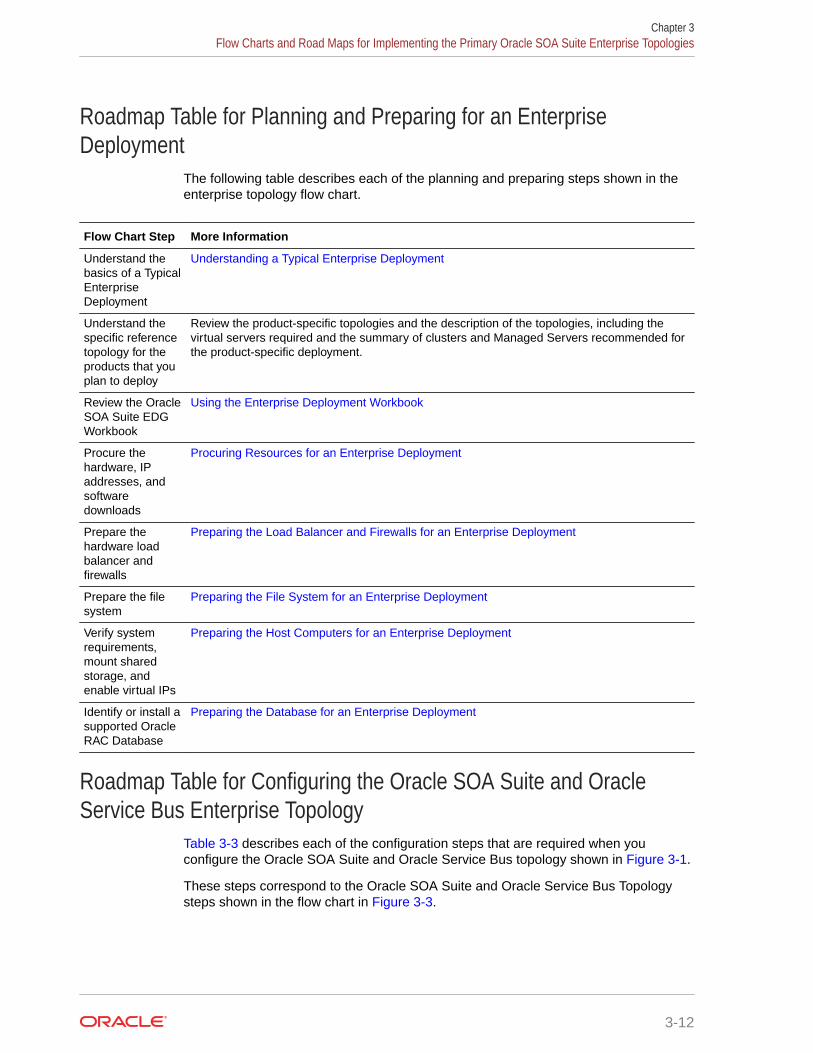
Roadmap Table for Planning and Preparing for an EnterpriseDeployment
The following table describes each of the planning and preparing steps shown in theenterprise topology flow chart.
Flow Chart Step More Information
Understand thebasics of a TypicalEnterpriseDeployment
Understanding a Typical Enterprise Deployment
Understand thespecific referencetopology for theproducts that youplan to deploy
Review the product-specific topologies and the description of the topologies, including thevirtual servers required and the summary of clusters and Managed Servers recommended forthe product-specific deployment.
Review the OracleSOA Suite EDGWorkbook
Using the Enterprise Deployment Workbook
Procure thehardware, IPaddresses, andsoftwaredownloads
Procuring Resources for an Enterprise Deployment
Prepare thehardware loadbalancer andfirewalls
Preparing the Load Balancer and Firewalls for an Enterprise Deployment
Prepare the filesystem
Preparing the File System for an Enterprise Deployment
Verify systemrequirements,mount sharedstorage, andenable virtual IPs
Preparing the Host Computers for an Enterprise Deployment
Identify or install asupported OracleRAC Database
Preparing the Database for an Enterprise Deployment
Roadmap Table for Configuring the Oracle SOA Suite and OracleService Bus Enterprise Topology
Table 3-3 describes each of the configuration steps that are required when youconfigure the Oracle SOA Suite and Oracle Service Bus topology shown in Figure 3-1.
These steps correspond to the Oracle SOA Suite and Oracle Service Bus Topologysteps shown in the flow chart in Figure 3-3.
Chapter 3Flow Charts and Road Maps for Implementing the Primary Oracle SOA Suite Enterprise Topologies
3-12

Note:
You can configure Oracle Service Bus in the same domain as Oracle SOA Suite orin its own domain. See About the Topology Options for Oracle Service Bus.
Table 3-3 Roadmap Table for Configuring the Oracle SOA Suite and Oracle Service BusEnterprise Topology
Flow Chart Step More Information
Create the initial infrastructure domain Creating the Initial Infrastructure Domain for anEnterprise Deployment
Extend the domain to include the web tier Configuring the Web Tier for an Enterprise Deployment
Extend the domain with Oracle SOA Suite Extending the Domain with Oracle SOA Suite
Extend the domain with Oracle Service Bus Extending the Domain with Oracle Service Bus
Extend the domain with Enterprise Scheduler Extending the Domain with Oracle Enterprise Scheduler
Note that extending the domain with EnterpriseScheduler is optional; perform the procedure in thischapter only if you want to configure EnterpriseScheduler.
Extend the domain with Oracle B2B Extending the Domain with Oracle B2B
Note that extending the domain with Oracle B2B isoptional; perform the procedures in this chapter only ifyou want to configure Oracle B2B.
Create a domain for Oracle Managed File Transfer Configuring Oracle Managed File Transfer in anEnterprise DeploymentNote that extending the domain with Oracle ManagedFile Transfer is optional; perform the procedures in thischapter only if you want to configure Oracle ManagedFile Transfer.
Roadmap Table for Configuring the Oracle SOA Suite and Oracle BusinessActivity Monitoring Enterprise Topology
Table 3-4 describes each of the configuration steps that are required to configure the OracleSOA Suite and Oracle Business Activity Monitoring topology shown in Figure 3-2.
These steps correspond to the configuration steps shown for the Oracle SOA Suite OracleBusiness Activity Monitoring topology in the flow chart in Figure 3-3.
Table 3-4 Roadmap Table for Configuring the Oracle SOA Suite and Oracle Business ActivityMonitoring Enterprise Topology
Flow Chart Step More Information
Create the initial infrastructure domain Creating the Initial Infrastructure Domain for anEnterprise Deployment
Extend the domain to include the web tier Configuring the Web Tier for an Enterprise Deployment
Extend the domain with Oracle SOA Suite Extending the Domain with Oracle SOA Suite
Chapter 3Flow Charts and Road Maps for Implementing the Primary Oracle SOA Suite Enterprise Topologies
3-13

Table 3-4 (Cont.) Roadmap Table for Configuring the Oracle SOA Suite and Oracle BusinessActivity Monitoring Enterprise Topology
Flow Chart Step More Information
Extend the domain with Business Process Management Extending the Domain with Business ProcessManagement
Extend the domain with Oracle Business ActivityMonitoring
Extending the Domain with Business Activity Monitoring
Extend the domain with Oracle B2B Extending the Domain with Oracle B2B
Note that extending the domain with Oracle B2B isoptional; perform the procedures in this chapter only ifyou want to configure Oracle B2B.
Building Your Own Oracle SOA Suite Enterprise TopologyYou can implement alternative topologies depending on the requirements of yourorganization, by using some variations of the instructions provided in this guide.
This document provides step-by-step instructions to configure the two primaryenterprise topologies for Oracle SOA Suite, which are described in Diagrams of thePrimary Oracle SOA Suite Enterprise Topologies.
However, Oracle recognizes that the requirements of your organization may vary,depending on the specific set of Oracle Fusion Middleware products that you purchaseand the specific types of applications that you deploy.
In many cases, you can install and configure an alternative topology — one thatincludes additional components, or one that does not include all the Oracle SOA Suiteproducts that is shown in the primary topology diagrams.
Note:
All managed servers of a component type in the domain must belong to thatcluster. For example, Oracle Service Bus domains support only a singleService Bus cluster inside each domain.
• Flow Chart of the Build Your Own Enterprise Topologies
• Description of the Supported Build Your Own Topologies
Flow Chart of the Build Your Own Enterprise TopologiesBuilding your own enterprise topology involves picking and choosing which OracleFusion Middleware products and which configuration steps you want to use to buildyour topology.
Figure 3-4 shows the high-level configuration steps that are required to build sometypical alternative Oracle SOA Suite enterprise topologies. Each of the configurationsteps corresponds to a chapter in this guide.
Chapter 3Building Your Own Oracle SOA Suite Enterprise Topology
3-14

Note that modifications of the steps in this guide are necessary in order to implement theBuild Your Own topologies. Refer to Description of the Supported "Build Your Own"Topologies for more information.
Figure 3-4 Flow Chart of the Oracle SOA Suite Build-Your-Own Topologies
“Build Your Own” Configuration Steps
Planning anEnterpriseDeployment
Preparing for anEnterpriseDeployment
Create the initialInfrastructure domain
Extend the domainto include the Web Tier
Select a topology
SOA Suite and EnterpriseScheduler only
Extend the domain withOracle SOA Suite
Oracle SOA Suite andOracle B2B only
Extend the domain withOracle SOA Suite
SOA Suite and Business Process Management only
Extend the domain withOracle SOA Suite
Extend the domain withEnterprise Scheduler
Extend the domain withOracle B2B
Extend the domain withBusiness Process Management
Oracle SOA Suite for healthcare integration
Extend the domain withOracle SOA Suite
Oracle Business ActivityMonitoring only
Extend the domain withOracle Business Activity Monitoring
Post-Configuration Tasks
Oracle Service Bus andEnterprise Scheduler Service only
Extend the domain withOracle Service Bus
Extend the domain withOracle SOA Suitefor healthcare integration
Extend the domain withEnterprise Scheduler Service
Start
Finish
Oracle SOA Suite for MFT Integration
Extend the domain withOracle SOA Suite
Configuring OracleManaged File Transfer in an Enterprise Deployment
Description of the Supported Build Your Own TopologiesTable 3-5 describes the configuration steps to follow if you want to use the instructions in thisguide to build the enterprise topologies listed in Figure 3-4.
It also identifies some differences you need to consider when you use the existinginstructions in this guide to build each topology.
Chapter 3Building Your Own Oracle SOA Suite Enterprise Topology
3-15

Table 3-5 Roadmap Table for Building Your Own Enterprise Topology
Topology After You Configure the Web Tier,Refer to the Following Chapters
Considerations and Dependencies
SOA Suite and BusinessProcess Management only
• Extending the Domain withOracle SOA Suite
• Extending the Domain withBusiness Process Management
These instructions assume you will run theOracle SOA Suite and Business ProcessManagement installer twice--once to installOracle SOA Suite and once to install OracleBusiness Process Management.
Alternatively, you can install both OracleSOA Suite and Oracle Business ProcessManagement at the same time by selectingthe BPM install type during the installation.
Similarly, you can configure this topology byrunning the Configuration Wizard only onceby selecting both the SOA and OracleBusiness Process Management templatesduring the Configuration Wizard session.
Oracle SOA Suite and OracleB2B only
• Extending the Domain withOracle SOA Suite
• Extending the Domain withOracle B2B
No special instructions required.
SOA Suite and EnterpriseScheduler only
• Extending the Domain withOracle SOA Suite
• Extending the Domain withOracle Enterprise Scheduler
No special instructions required.
Oracle Service Bus andEnterprise Scheduler only
See
• Extending the Domain withOracle Service Bus
• Extending the Domain withOracle Enterprise Scheduler
This topology does not require Oracle SOASuite. However, the instructions in Extendingthe Domain with Oracle Service Bus assumeyou have already created a cluster of twoSOA Managed Servers.
As a result, when you create this topology,ignore any references to the SOA ManagedServers or the SOA Cluster.
In addition, you must run the RepositoryCreation Utility (RCU) to create theSOAINFRA schema, which is also requiredby Oracle Service Bus.
Oracle Business ActivityMonitoring only
Extending the Domain with BusinessActivity Monitoring
The instructions in Extending the Domainwith Business Activity Monitoring assumethat you are extending an existing OracleSOA Suite domain and that the Oracle SOASuite software (which includes Oracle BAM)has already been installed in an Oraclehome on shared storage.
For this Oracle BAM-only topology, you needto install Oracle SOA Suite into the OracleFusion Middleware Infrastructure Oraclehome before you can configure the domainto include an Oracle BAM cluster.
In addition, you must run the RepositoryCreation Utility (RCU) to create the requiredSOA schemas.
Chapter 3Building Your Own Oracle SOA Suite Enterprise Topology
3-16

Table 3-5 (Cont.) Roadmap Table for Building Your Own Enterprise Topology
Topology After You Configure the Web Tier,Refer to the Following Chapters
Considerations and Dependencies
Oracle SOA Suite forhealthcare integration
Note:
Healthcare in a WebLogic Domain option isdeprecated in Fusion Middleware 12.2.1.4.0 and willbe removed in the next release. Therefore, thechapter titled Extending the Domain with Oracle SOASuite for Healthcare Integration is no longer includedin this guide.
Oracle SOA Suite for MFTIntegration
• Extending the Domain withOracle SOA Suite
• Configuring Oracle ManagedFile Transfer in an EnterpriseDeployment
Oracle Managed File Transfer requiresOracle Traffic Director as the web server inthe web tier.
About Installing and Configuring a Custom Enterprise TopologyIf you choose to implement a topology that is not described in this guide, be sure to reviewthe certification information, system requirements, and interoperability requirements for theproducts that you want to include in the topology.
After you verify that the topology is supported, then you can either use the instructions in thisguide as a guide to install and configure the components that you need, or you can install andconfigure a standard installation topology by using the Oracle Fusion Middleware 12cinstallation guides and use the Start Small and Scale Out approach to configure yourenvironment.
For more information about planning your installation, see Planning for a ProductionEnvironment in Planning an Installation of Oracle Fusion Middleware.
About Using Automatic Service Migration for the Oracle SOASuite Enterprise Topology
To ensure high availability of the Oracle SOA Suite products and components, this guiderecommends that you enable Oracle WebLogic Server Automatic Service Migration for theclusters that you create as part of the reference topology.
Starting SOA 12.2.1.4, Service Migration can be configured using the Configuration WizardHA Options screen for both static and dynamic clusters. For static clusters, when you selectthe Enable Automatic Service Migration option in the Configuration Wizard HA Optionsscreen, it configures migratable target definitions that are required for automatic servicemigration.
For dynamic clusters, the Enable Automatic Service Migration option in the ConfigurationWizard HA Options screen configures the required service migration policies in the dynamicclusters (migratable targets are not used in dynamic clusters because the functionalities of
Chapter 3About Installing and Configuring a Custom Enterprise Topology
3-17

the automatic service migration are provided inherently by the dynamic cluster whenthe proper migration policies are set in the persistent stores).
In the same screen, you can use JTA Transaction Log Persistence and JMS ServerPersistence options to configure them with JDBC stores automatically. Oraclerecommends that you enable these options when you configure static clusters in theSOA enterprise deployment.
For more information about service migration, see Using Whole Server Migration andService Migration in an Enterprise Deployment.
About Reference Configuration for SOA and OSBBeginning with SOA Release 12c (12.2.1.4), during the installation process, you cancreate either a Reference Configuration domain or a Classic domain using theTemplates screen of the Configuration Wizard. A Reference Configuration domainguards servers from running into out-of-memory, stuck threads, endpoint connectivity,and database issues.
A Reference Configuration domain supports SOA, OSB, ESS, and B2B topologies.The templates in these products include Reference Configuration in their names, andare the default templates listed in the Configuration Wizard for these products.
Note:
• A SOA Reference Configuration domain does not support BPM and BAMcomponents. The Reference Configuration feature does not apply toMFT domains.
• There is no specific Reference Configuration template for ESS. However,ESS can be added to both a Reference Configuration domain and to aClassic domain.
A Reference Configuration domain provides tuned parameters out-of-the-box for newlycreated SOA projects. Tuned parameters include but are not limited to:
• Java Virtual Machine: heap size, HTTP timeouts
• WebLogic Server: JTA timeout, HTTP extended logging
• Database: distributed_lock_timeout, db_securefiles
• Product-Specific: SOA, Service Bus, Adapters - Work Manager configuration,payload size restriction, and so on
This guide uses the Reference Configuration templates for SOA, OSB, and B2Bcomponents to take advantage of the tuned configuration.
For information about Reference Configuration, see:
• Selecting the Configuration Template for Oracle SOA Suite in Installing andConfiguring Oracle SOA Suite and Business Process Management.
• Configuring a Reference Configuration Domain in Administering Oracle SOA Suiteand Oracle Business Process Management Suite.
Chapter 3About Reference Configuration for SOA and OSB
3-18

• Developing SOA Projects in Reference Configuration Mode in Developing SOAApplications with Oracle SOA Suite.
Note:
If you plan to extend the SOA domain to add BPM or BAM, the SOA domain mustbe created using the Classic templates.
The previous SOA templates, which do not implement the Reference Configurationoptimizations, are named Classic templates. Classic templates are not shown in theConfiguration Wizard, but they are still available and located at:
• $ORACLE_HOME/soa/common/templates/wls (SOA and B2B Classictemplates)
– oracle.soa.classic.domain_template.jar - SOA Classic templateused to create new SOA Classic domains.
Note:
This is a domain template and not an extension template. Thistemplate has dependencies on the basic WebLogic Serverdomain template (wls.jar) and the Oracle SOA Suite template(oracle.soa_template.jar). This template should be usedonly to create a new domain, not to extend any domain.
– oracle.soa_template.jar - SOA Classic template used to extend anexisting Infra domain with SOA Classic. This template is used in this guideto extend the Infra domain for scenarios where BPM or BAM will be addedto the domain.
– oracle.soa.b2b.classic.domain_template.jar - B2B Classictemplate used to create a new B2B Classic domains.
– oracle.soa.b2b_template.jar - B2B Classic template used to extendan existing Classic domain with B2B Classic. This template is used in thisguide to extend the SOA domain with B2B when it is a Classic domain (forscenarios where BPM or BAM will be added to the domain).
• $ORACLE_HOME/osb/common/templates/wls (OSB Classic template)
– oracle.osb.classic.domain_template.jar - OSB Classic templateused to create a new OSB Classic domain.
– oracle.osb_template.jar - OSB Classic template used to extend anexisting domain with OSB Classic. This is used in this guide to extend theInfra or SOA Classic domain for scenarios where BPM or BAM will beadded to the domain.
Subsequent extensions on a Classic SOA domain (for B2B or OSB) must be donewith Classic templates and not with Reference Configuration templates. Other SOAcomponents (BPM, BAM, ESS, and MFT) do not have Reference Configurationtemplates, so the default templates shown in the Configuration Wizard for theseproducts can be used to extend the SOA Classic domain.
Chapter 3About Reference Configuration for SOA and OSB
3-19

Each chapter in this guide will indicate the template to use in each case.
Chapter 3About Reference Configuration for SOA and OSB
3-20

Part IIPreparing for an Enterprise Deployment
It is important to understand the tasks that need to be performed to prepare for an enterprisedeployment.
This part of the enterprise deployment guide contains the following topics.
• Using the Enterprise Deployment WorkbookThe Enterprise Deployment workbook enables you to plan an enterprise deployment foryour organization.
• Procuring Resources for an Enterprise DeploymentIt is essential to procure the required hardware, software, and network settings beforeyou configure the Oracle SOA Suite reference topology.
• Preparing the Load Balancer and Firewalls for an Enterprise DeploymentIt is important to understand how to configure the hardware load balancer and ports thatmust be opened on the firewalls for an enterprise deployment.
• Preparing the File System for an Enterprise DeploymentPreparing the file system for an enterprise deployment involves understanding therequirements for local and shared storage, as well as the terminology that is used toreference important directories and file locations during the installation and configurationof the enterprise topology.
• Preparing the Host Computers for an Enterprise DeploymentIt is important to perform a set of tasks on each computer or server before you configurethe enterprise deployment topology. This involves verifying the minimum hardware andoperating system requirements for each host, configuring operating system users andgroups, enabling Unicode support, mounting the required shared storage systems to thehost and enabling the required virtual IP addresses on each host.
• Preparing the Database for an Enterprise DeploymentPreparing the database for an enterprise deployment involves ensuring that the databasemeets specific requirements, creating database services, using SecureFiles for largeobjects in the database, and creating database backup strategies.

4Using the Enterprise Deployment Workbook
The Enterprise Deployment workbook enables you to plan an enterprise deployment for yourorganization.
This chapter provides an introduction to the Enterprise Deployment workbook, use cases,and information on who should use the Enterprise Deployment workbook.
• Introduction to the Enterprise Deployment WorkbookThe Enterprise Deployment workbook is a spreadsheet that is used by architects, systemengineers, database administrators, and others to plan and record all the details for anenvironment installation (such as server names, URLs, port numbers, installation paths,and other resources).
• Typical Use Case for Using the WorkbookIt is important to understand the roles and tasks involved in a typical use case of theEnterprise Deployment workbook.
• Using the Oracle SOA Suite Enterprise Deployment WorkbookLocating and understanding the Oracle SOA Suite Enterprise Deployment workbookenables you to use it efficiently.
• Who Should Use the Enterprise Deployment Workbook?The details of the Enterprise Deployment workbook are filled in by the individual or ateam that is responsible for planning, procuring, or setting up each category of resources.
Introduction to the Enterprise Deployment WorkbookThe Enterprise Deployment workbook is a spreadsheet that is used by architects, systemengineers, database administrators, and others to plan and record all the details for anenvironment installation (such as server names, URLs, port numbers, installation paths, andother resources).
The Enterprise Deployment workbook serves as a single document that you can use to trackinput variables for the entire process, allowing for:
• Separation of tasks between architects, system engineers, database administrators, andother key organizational roles.
• Comprehensive planning before the implementation.
• Validation of planned decisions before the actual implementation.
• Consistency during implementation.
• A record of the environment for future use.
Typical Use Case for Using the WorkbookIt is important to understand the roles and tasks involved in a typical use case of theEnterprise Deployment workbook.
4-1

A typical use case for the Enterprise Deployment workbook involves the following rolesand tasks, in preparation for an Oracle Fusion Middleware Enterprise Deployment:
• Architects read through the first five chapters of this guide, and fill in thecorresponding sections of the workbook.
• The workbook is validated by other architects and system engineers.
• The architect uses the validated workbook to initiate network and system changerequests with the system engineering departments.
• The Administrators and System Integrators who install and configure the softwarerefer to the workbook and the subsequent chapters of this guide to perform theinstallation and configuration tasks.
Using the Oracle SOA Suite Enterprise DeploymentWorkbook
Locating and understanding the Oracle SOA Suite Enterprise Deployment workbookenables you to use it efficiently.
The following sections provide an introduction to the location and contents of theOracle SOA Suite Enterprise Deployment workbook:
• Locating the Oracle SOA Suite Enterprise Deployment Workbook
• Understanding the Contents of the Oracle SOA Suite Enterprise DeploymentWorkbook
Locating the Oracle SOA Suite Enterprise Deployment WorkbookThe Oracle SOA Suite Enterprise Deployment workbook is available as a MicrosoftExcel spreadsheet in the Oracle Fusion Middleware documentation library. It isavailable as a link on the Install, Patch, and Upgrade page of the library.
Understanding the Contents of the Oracle SOA Suite EnterpriseDeployment Workbook
The following sections describe the contents of the Oracle SOA Suite EnterpriseDeployment workbook. The workbook is divided into tabs, each containing a set ofrelated variables and values that you need to install and configure the EnterpriseDeployment topologies.
• Using the Start Tab
• Using the Hardware - Host Computers Tab
• Using the Network - Virtual Hosts & Ports Tab
• Using the Storage - Directory Variables Tab
• Using the Database - Connection Details Tab
Chapter 4Using the Oracle SOA Suite Enterprise Deployment Workbook
4-2

Using the Start TabThe Start tab of the Enterprise Deployment workbook serves as a table of contents for therest of the workbook. You can also use it to identify the people who will be completing thespreadsheet.
The Start tab also provides a key to identify the colors used to identify workbook fields thatneed values, as well as those that are provided for informational purposes.
The following image shows the Start tab of the Enterprise Deployment workbook.
Figure 4-1 Start Tab of the Enterprise Deployment workbook
Using the Hardware - Host Computers TabThe Hardware - Host Computers tab lists the host computers that are required to install andconfigure the Oracle SOA Suite Enterprise Deployment topology.
The reference topologies typically require a minimum of six host computers: two for the webtier, two for the application tier, and two for the Oracle RAC database on the data tier. If youdecide to expand the environment to include more systems, add a row for each additionalhost computer.
Chapter 4Using the Oracle SOA Suite Enterprise Deployment Workbook
4-3
The Abstract Host Name is the name used throughout this guide to reference thehost. For each row, procure a host computer, and enter the Actual Host Name. Youcan then use the actual host name when any of the abstract names is referenced inthis guide.
For example, if a procedure in this guide references SOAHOST1, you can thenreplace the SOAHOST1 variable with the actual name provided on the Hardware -Host Computers tab of the workbook.
Note:
If two domains share the same node, for example, if you set up the OracleSOA suite, and then create MFT with its own domain, you have two domainson the same node. In this case, you use SOAHOST1 and MFTHOST1 at thesame time, one for each domain.
For easy reference, Oracle also recommends that you include the IP address,Operating System (including the version), number of CPUs, and the amount of RAMfor each host. This information can be useful during the installation, configuration, andmaintenance of the enterprise deployment. See Preparing the Host Computers for anEnterprise Deployment.
Using the Network - Virtual Hosts & Ports TabThe Network - Virtual Hosts & Ports tab lists the virtual hosts that must be defined byyour network administrator before you can install and configure the enterprisedeployment topology.
The port numbers are important for several reasons. You must have quick reference tothe port numbers so that you can access the management consoles; the firewalls mustalso be configured to allow network traffic through specific ports.
Each virtual host, virtual IP address, and each network port serves a distinct purposein the deployment. See Preparing the Load Balancer and Firewalls for an EnterpriseDeployment.
In the Network - Virtual Hosts table, review the items in the Abstract Virtual Host orVirtual IP Name column. These are the virtual host and virtual IP names that are usedin the procedures in this guide. For each abstract name, enter the actual virtual hostname that is defined by your network administrator. Whenever this guide referencesone of the abstract virtual host or virtual IP names, replace that value with the actualcorresponding value in this table.
Similarly, in many cases, this guide assumes that you are using default port numbersfor the components or products you install and configure. However, in reality, you arelikely to use different port numbers. Use the Network - Port Numbers table to map thedefault port values to the actual values that are used in your specific installation.
Using the Storage - Directory Variables TabAs part of preparing for an enterprise deployment, it is assumed you are using astandard directory structure, which is recommended for Oracle enterprisedeployments.
Chapter 4Using the Oracle SOA Suite Enterprise Deployment Workbook
4-4

In addition, procedures in this book reference specific directory locations. Within theprocedures, each directory is assigned a consistent variable, which you should replace withthe actual location of the directory in your installation.
For each of the directory locations listed on this tab, provide the actual directory path in yourinstallation.
In addition, for the application tier, it is recommended that many of these standard directoriesbe created on a shared storage device. For those directories, the table also provides fields soyou can enter the name of the shared storage location and the mount point that is used whenyou mounted the shared location. See Preparing the File System for an EnterpriseDeployment.
Using the Database - Connection Details TabWhen you install and configure the enterprise deployment topology, you often have to makeconnections to a highly available Oracle Real Application Clusters (RAC) database. In thisguide, the procedures reference a set of variables that identify the information you need toprovide to connect to the database from tools, such as the Configuration Wizard and theRepository Creation Utility.
To be sure that you have these values handy, use this tab to enter the actual values for thesevariables in your database installation. See Preparing the Database for an EnterpriseDeployment.
Who Should Use the Enterprise Deployment Workbook?The details of the Enterprise Deployment workbook are filled in by the individual or a teamthat is responsible for planning, procuring, or setting up each category of resources.
The information in the Enterprise Deployment workbook is divided into categories. Dependingon the structure of your organization and roles that are defined for your team, you can assignspecific individuals in your organization to fill in the details of the workbook. Similarly, theinformation in each category can be assigned to the individual or team that is responsible forplanning, procuring, or setting up each category of resources.
For example, the workbook can be filled in, reviewed, and used by people in yourorganization that fill the following roles:
• Information Technology (IT) Director
• Architect
• System Administrator
• Network Engineer
• Database Administrator
Chapter 4Who Should Use the Enterprise Deployment Workbook?
4-5

5Procuring Resources for an EnterpriseDeployment
It is essential to procure the required hardware, software, and network settings before youconfigure the Oracle SOA Suite reference topology.
This chapter provides information on how to reserve the required IP addresses and identifyand obtain software downloads for an enterprise deployment.
• Hardware and Software Requirements for the Enterprise Deployment TopologyIt is important to understand the hardware load balancer requirements, host computerhardware requirements, and operating system requirements for the enterprisedeployment topology.
• Reserving the Required IP Addresses for an Enterprise DeploymentYou have to obtain and reserve a set of IP addresses before you install and configure theenterprise topology. The set of IP addresses that need to be reserved are listed in thissection.
• Identifying and Obtaining Software Distributions for an Enterprise DeploymentBefore you begin to install and configure the enterprise topology, you must obtain thesoftware distributions that you need to implement the topology.
Hardware and Software Requirements for the EnterpriseDeployment Topology
It is important to understand the hardware load balancer requirements, host computerhardware requirements, and operating system requirements for the enterprise deploymenttopology.
This section includes the following sections.
• Hardware Load Balancer RequirementsThe section lists the wanted features of the external load balancer.
• Host Computer Hardware RequirementsThis section provides information to help you procure host computers that are configuredto support the enterprise deployment topologies.
• Operating System Requirements for an Enterprise Deployment TopologyThis section provides details about the operating system requirements.
Hardware Load Balancer RequirementsThe section lists the wanted features of the external load balancer.
The enterprise topology uses an external load balancer. The features of the external loadbalancer are:
5-1
• Ability to load-balance traffic to a pool of real servers through a virtual host name:Clients access services by using the virtual host name (instead of using actualhost names). The load balancer can then load balance requests to the servers inthe pool.
• Port translation configuration should be possible so that incoming requests on thevirtual host name and port are directed to a different port on the backend servers.
• Monitoring of ports on the servers in the pool to determine availability of a service.
• Ability to configure names and ports on your external load balancer. The virtualserver names and ports must meet the following requirements:
– The load balancer should allow configuration of multiple virtual servers. Foreach virtual server, the load balancer should allow configuration of trafficmanagement on more than one port. For example, for Oracle HTTP Server inthe web tier, the load balancer needs to be configured with a virtual server andports for HTTP and HTTPS traffic.
– The virtual server names must be associated with IP addresses and be part ofyour DNS. Clients must be able to access the external load balancer throughthe virtual server names.
• Ability to detect node failures and immediately stop routing traffic to the failednode.
• It is highly recommended that you configure the load balancer to be in fault-tolerant mode.
• It is highly recommended that you configure the load balancer virtual server toreturn immediately to the calling client when the backend services to which itforwards traffic are unavailable. This is preferred over the client disconnecting onits own after a timeout based on the TCP/IP settings on the client machine.
• Ability to maintain sticky connections to components. Examples of this includecookie-based persistence, IP-based persistence, and so on.
• The load balancer should be able to terminate SSL requests at the load balancerand forward traffic to the backend real servers by using the equivalent non-SSLprotocol (for example, HTTPS to HTTP).
• SSL acceleration (this feature is recommended, but not required for the enterprisetopology).
• The ability to route TCP/IP requests; this is a requirement for Managed FileTransfer, which can use sFTP/FTP protocol.
Host Computer Hardware RequirementsThis section provides information to help you procure host computers that areconfigured to support the enterprise deployment topologies.
It includes the following topics.
• General Considerations for Enterprise Deployment Host ComputersThis section specifies the general considerations that are required for theenterprise deployment host computers.
• Reviewing the Oracle Fusion Middleware System RequirementsThis section provides reference to the system requirements information to helpyou ensure that the environment meets the necessary minimum requirements.
Chapter 5Hardware and Software Requirements for the Enterprise Deployment Topology
5-2

• Typical Memory, File Descriptors, and Processes Required for an Enterprise DeploymentThis section specifies the typical memory, number of file descriptors, and operatingsystem processes and tasks details required for an enterprise deployment.
• Typical Disk Space Requirements for an Enterprise DeploymentThis section specifies the disk space that is typically required for this enterprisedeployment.
General Considerations for Enterprise Deployment Host ComputersThis section specifies the general considerations that are required for the enterprisedeployment host computers.
Before you start the process of configuring an Oracle Fusion Middleware enterprisedeployment, you must perform the appropriate capacity planning to determine the number ofnodes, CPUs, and memory requirements for each node depending on the specific system'sload as well as the throughput and response requirements. These requirements vary for eachapplication or custom Oracle SOA Suite system being used.
The information in this chapter provides general guidelines and information that helps youdetermine the host computer requirements. It does not replace the need to perform capacityplanning for your specific production environment.
Note:
As you obtain and reserve the host computers in this section, note the host namesand system characteristics in the Enterprise Deployment workbook. You will usethese addresses later when you enable the IP addresses on each host computer.See Using the Enterprise Deployment Workbook.
Reviewing the Oracle Fusion Middleware System RequirementsThis section provides reference to the system requirements information to help you ensurethat the environment meets the necessary minimum requirements.
Review the Oracle Fusion Middleware System Requirements and Specifications to ensurethat your environment meets the minimum installation requirements for the products that youare installing.
The Requirements and Specifications document contains information about general OracleFusion Middleware hardware and software requirements, minimum disk space and memoryrequirements, database schema requirements, and the required operating system librariesand packages.
It also provides some general guidelines for estimating the memory requirements for yourOracle Fusion Middleware deployment.
Chapter 5Hardware and Software Requirements for the Enterprise Deployment Topology
5-3

Typical Memory, File Descriptors, and Processes Required for an EnterpriseDeployment
This section specifies the typical memory, number of file descriptors, and operatingsystem processes and tasks details required for an enterprise deployment.
The following table summarizes the memory, file descriptors, and processes requiredfor the Administration Server and each of the Managed Servers computers in a typicalOracle SOA Suite enterprise deployment. These values are provided as an exampleonly, but they can be used to estimate the minimum amount of memory required for aninitial enterprise deployment.
The example in this topic reflects the minimum requirements for configuring theManaged Servers and other services required on SOAHOST1, as depicted in thereference topologies.
When you are procuring machines, use the information in the Approximate TopMemory column as a guide when determining the minimum physical memory eachhost computer should have available.
After you procure the host computer hardware and verify the operating systemrequirements, review the software configuration to be sure the operating systemsettings are configured to accommodate the number of open files listed in the FileDescriptors column and the number processes listed in the Operating SystemProcesses and Tasks column. See Setting the Open File Limit and Number ofProcesses Settings on UNIX Systems.
Managed Server,Utility, or Service
Approximate TopMemory (SOAClassic Domain)
Approximate TopMemory (SOAReferenceConfigurationDomain)
Number of FileDescriptors
Operating SystemProcesses andTasks
Administration Server 3.5 GB 4 GB 3500 165
WLS_WSM 3.0 GB 8 GB 2000 130
WLS_SOA 4.0 GB 8 GB 3100 240
WLS_OSB 4.0 GB 8 GB 2200 180
WLS_ESS 3.5 GB 8 GB 1300 35
WLS_BAM 3.5 GB N/A** 2300 210
WLST (connection tothe Node Manager)
1.5 GB 1.5 GB 910 20
Configuration Wizard 1.5 GB 1.5 GB 700 20
Node Manager 1.0 GB 1.0 GB 720 15
TOTAL 27.0 GB* 40 GB* 17000 1200
* Approximate total, with consideration for Operating System and other additionalmemory requirements.
** BAM is not supported in Reference Configuration Domains.
Beginning with Release 12c (12.2.1.4), you can create either a ReferenceConfiguration domain or a Classic domain by using the Templates screen of the
Chapter 5Hardware and Software Requirements for the Enterprise Deployment Topology
5-4

Configuration Wizard, during installation. A Reference Configuration domain guards serversfrom running into out-of-memory, stuck threads, endpoint connectivity, and database issues.
The Reference Configuration domain supports SOA, OSB, SOA + OSB, and B2B topologiesand Oracle recommends it in the SOA Enterprise Deployment Guide for the components thatsupport it.
In a Reference Configuration domain, the min and max heap memory (-Xms -Xmx)configured for each server are greater than in Classic Domains: they are set to 4 GB for theAdmin Server and 8 GB for the managed servers.
In case you need to tune these parameters, they are specified in thefile $ORACLE_HOME/soa/common/bin/setSOARefConfigEnv.sh
# JVM Memory Arguments if [ "${STARTUP_GROUP}" = "AdminServerStartupGroup" ] ; then MEM_ARGS_NEW_MIN="-Xms4g" export MEM_ARGS_NEW_MIN
MEM_ARGS_NEW_MAX="-Xmx4g" export MEM_ARGS_NEW_MAX else MEM_ARGS_NEW_MIN="-Xms8g" export MEM_ARGS_NEW_MIN
MEM_ARGS_NEW_MAX="-Xmx8g" export MEM_ARGS_NEW_MAX fi
See Configuring a Reference Configuration Domain in Administering Oracle SOA Suite andOracle Business Process Management Suite.
Typical Disk Space Requirements for an Enterprise DeploymentThis section specifies the disk space that is typically required for this enterprise deployment.
For the latest disk space requirements for the Oracle Fusion Middleware 12c (12.2.1.4.0)products, including the Oracle SOA Suite products, review the Oracle Fusion MiddlewareSystem Requirements and Specifications.
In addition, the following table summarizes the disk space that is typically required for anOracle SOA Suite enterprise deployment.
Use the this information and the information in Preparing the File System for an EnterpriseDeployment to determine the disk space requirements required for your deployment.
Server Disk
Database nXm
n = number of disks, at least 4 (striped as one disk)
m = size of the disk (minimum of 30 GB)
WEBHOSTn 10 GB
SOAHOSTn (SOA only) 10 GB*
SOAHOSTn (SOA and OSB) 11 GB*
Chapter 5Hardware and Software Requirements for the Enterprise Deployment Topology
5-5

* For a shared storage Oracle home configuration, two installations suffice by making atotal of 20 GB.
Operating System Requirements for an Enterprise DeploymentTopology
This section provides details about the operating system requirements.
The Oracle Fusion Middleware software products and components that are describedin this guide are certified on various operating systems and platforms, which are listedin Oracle Fusion Middleware System Requirements and Specifications.
Note:
This guide focuses on the implementation of the enterprise deploymentreference topology on Oracle Linux systems.
The topology can be implemented on any certified, supported operatingsystem, but the examples in this guide typically show the commands andconfiguration steps as they should be performed by using the bash shell onOracle Linux.
Reserving the Required IP Addresses for an EnterpriseDeployment
You have to obtain and reserve a set of IP addresses before you install and configurethe enterprise topology. The set of IP addresses that need to be reserved are listed inthis section.
Before you begin installing and configuring the enterprise topology, you must obtainand reserve a set of IP addresses:
• Physical IP (IP) addresses for each of the host computers that you have procuredfor the topology
• A virtual IP (VIP) address for the Administration Server
• Additional VIP addresses for each Managed Server that is configured for WholeServer Migration
For Fusion Middleware 12c products, such as Oracle SOA Suite, that supportAutomatic Service Migration, VIPs for the Managed Servers are typically notnecessary.
• A unique virtual host name to be mapped to each VIP.
You can then work with your network administrator to be sure that these required VIPsare defined in your DNS server. Alternatively, for non-production environments, youcan use the /etc/hosts file to define these virtual hosts.
For more information, see the following topics.
• What is a Virtual IP (VIP) Address?This section defines the virtual IP address and specifies its purpose.
Chapter 5Reserving the Required IP Addresses for an Enterprise Deployment
5-6

• Why Use Virtual Host Names and Virtual IP Addresses?For an enterprise deployment, in particular, it is important that a set of VIPs--and thevirtual host names to which they are mapped--are reserved and enabled on the corporatenetwork.
• Physical and Virtual IP Addresses Required by the Enterprise TopologyThis section describes the physical IP (IP) and virtual IP (VIP) addresses that arerequired for the Administration Server and each of the Managed Servers in a typicalOracle SOA Suite enterprise deployment topology.
What is a Virtual IP (VIP) Address?This section defines the virtual IP address and specifies its purpose.
A virtual IP address is an unused IP Address that belongs to the same subnet as the host'sprimary IP address. It is assigned to a host manually. If a host computer fails, the virtualaddress can be assigned to a new host in the topology. For the purposes of this guide, virtualIP addresses are referenced, which can be reassigned from one host to another, andphysical IP addresses are referenced, which are assigned permanently to hardware hostcomputer.
Why Use Virtual Host Names and Virtual IP Addresses?For an enterprise deployment, in particular, it is important that a set of VIPs--and the virtualhost names to which they are mapped--are reserved and enabled on the corporate network.
Alternatively, host names can be resolved through appropriate /etc/hosts file propagatedthrough the different nodes.
In the event of the failure of the host computer where the IP address is assigned, the IPaddress can be assigned to another host in the same subnet, so that the new host can takeresponsibility for running the Managed Servers that are assigned to it.
The reassignment of virtual IP address for the Administration Server must be performedmanually, but the reassignment of virtual IP addresses for Managed Servers can beperformed automatically by using the Whole Server Migration feature of Oracle WebLogicServer.
Whether you should use Whole Server Migration or not depends upon the products that youare deploying and whether they support Automatic Service Migration.
For example, starting with Oracle SOA Suite 12c, the SOA Suite products support automaticservice migration. As a result, it is no longer necessary to reserve VIPs for each of theManaged Servers in the domain. Instead, a VIP is required for the Administration Server only.
Note:
Regardless the use of virtual or physical IPs, Oracle also recommends that you usealiases to map to different IPs in different data centers in preparation for disasterrecovery. It is recommended to use these aliases to configure the listen address forthe components. This approach will be used in this guide.
Chapter 5Reserving the Required IP Addresses for an Enterprise Deployment
5-7

Physical and Virtual IP Addresses Required by the EnterpriseTopology
This section describes the physical IP (IP) and virtual IP (VIP) addresses that arerequired for the Administration Server and each of the Managed Servers in a typicalOracle SOA Suite enterprise deployment topology.
Before you begin to install and configure the enterprise deployment, reserve a set ofhost names and IP addresses that correspond to the VIPs in Table 5-1.
You can assign any unique host name to the VIPs, but in this guide, each VIP isreferenced by using the suggested host names in the table.
Note:
As you obtain and reserve the IP addresses and their corresponding virtualhost names in this section, note the values of the IP addresses and hostnames in the Enterprise Deployment workbook. You will use theseaddresses later when you enable the IP addresses on each host computer.See Using the Enterprise Deployment Workbook .
Table 5-1 Summary of the Virtual IP Addresses Required for the Enterprise Deployment
Virtual IP VIP Maps to... Description
VIP1 ADMINVHN ADMINVHN is the virtual host nameused as the listen address for theAdministration Server and fails overwith manual failover of theAdministration Server. It is enabledon the node where the AdministrationServer process is running.
Identifying and Obtaining Software Distributions for anEnterprise Deployment
Before you begin to install and configure the enterprise topology, you must obtain thesoftware distributions that you need to implement the topology.
The following table lists the distributions used in this guide.
For general information about how to obtain Oracle Fusion Middleware software, see Obtaining Product Distributions in Planning an Installation of Oracle FusionMiddleware.
For more specific information about locating and downloading specific Oracle FusionMiddleware products, see the Oracle Fusion Middleware Download, Installation, andConfiguration Readme Files on OTN.
Chapter 5Identifying and Obtaining Software Distributions for an Enterprise Deployment
5-8

Note:
The information in this guide is meant to complement the information contained inthe Oracle Fusion Middleware certification matrixes. If there is a conflict ofinformation between this guide and the certification matrixes, then the information inthe certification matrixes must be considered the correct version, as they arefrequently updated.
Distribution Description Installer File Name
Oracle Fusion Middleware 12c(12.2.1.4.0) Infrastructure
Download this distribution to installthe Oracle Fusion MiddlewareInfrastructure, which includes OracleWebLogic Server and Java RequiredFiles software required for OracleFusion Middleware products.
This distribution also installs theRepository Creation Utility (RCU),which in previous Oracle FusionMiddleware releases was packagedin its own distribution.
fmw_12.2.1.4.0_infrastructure.jar
Oracle HTTP Server 12c (12.2.1.4.0) Download this distribution to installOracle HTTP Server on the Web tierhosts.
fmw_12.2.1.4.0_ohs_linux64.bin
Oracle Traffic Director 12c(12.2.1.4.0)
Download this distribution to installOracle Traffic Director on the Webtier hosts.
fmw_12.2.1.4.0_otd_linux64.bin
Oracle Fusion Middleware 12c(12.2.1.4.0) SOA Suite and BusinessProcess Management
Download this distribution to installthe SOA Foundation and BPMsoftware, which includes OracleBusiness Activity Monitoring (BAM)and Oracle Enterprise Scheduler(ESS).
fmw_12.2.1.4.0_soa.jar
Oracle Fusion Middleware 12c(12.2.1.4.0) Service Bus
Download this distribution if you planto install and configure OracleService Bus as part of the OracleSOA Suite enterprise topology.
fmw_12.2.1.4.0_osb.jar
Oracle Fusion Middleware 12c(12.2.1.4.0) B2B and Healthcare
Download this distribution if you planto install and configure Oracle B2B orOracle B2B Healthcare as part of theOracle SOA Suite enterprisetopology.
fmw_12.2.1.4.0_b2bhealthcare.jar
Oracle Fusion Middleware 12c(12.2.1.4.0) Managed File Transfer
Download this distribution if you planto install and configure OracleManaged File Transfer as part of theOracle SOA Suite enterprisetopology.
fmw_12.2.1.4.0_mft.jar
Chapter 5Identifying and Obtaining Software Distributions for an Enterprise Deployment
5-9

6Preparing the Load Balancer and Firewalls foran Enterprise Deployment
It is important to understand how to configure the hardware load balancer and ports that mustbe opened on the firewalls for an enterprise deployment.
• Configuring Virtual Hosts on the Hardware Load BalancerThe hardware load balancer configuration facilitates to recognize and route requests toseveral virtual servers and associated ports for different types of network traffic andmonitoring.
• Configuring the Firewalls and Ports for an Enterprise DeploymentAs an administrator, it is important that you become familiar with the port numbers thatare used by various Oracle Fusion Middleware products and services. This ensures thatthe same port number is not used by two services on the same host, and that the properports are open on the firewalls in the enterprise topology.
Configuring Virtual Hosts on the Hardware Load BalancerThe hardware load balancer configuration facilitates to recognize and route requests toseveral virtual servers and associated ports for different types of network traffic andmonitoring.
The following topics explain how to configure the hardware load balancer, provide a summaryof the virtual servers that are required, and provide additional instructions for these virtualservers:
• Overview of the Hardware Load Balancer Configuration
• Typical Procedure for Configuring the Hardware Load Balancer
• Summary of the Virtual Servers Required for an Enterprise Deployment
• Additional Instructions for admin.example.com
• Additional Instructions for soa.example.com
• Additional Instructions for soainternal.example.com
• Additional Instructions for osb.example.com
• Additional Instructions for mft.example.com
Overview of the Hardware Load Balancer ConfigurationAs shown in the topology diagrams, you must configure the hardware load balancer torecognize and route requests to several virtual servers and associated ports for differenttypes of network traffic and monitoring.
In the context of a load-balancing device, a virtual server is a construct that allows multiplephysical servers to appear as one for load-balancing purposes. It is typically represented byan IP address and a service, and it is used to distribute incoming client requests to theservers in the server pool.
6-1

The virtual servers should be configured to direct traffic to the appropriate hostcomputers and ports for the various services that are available in the enterprisedeployment.
In addition, you should configure the load balancer to monitor the host computers andports for availability so that the traffic to a particular server is stopped as soon aspossible when a service is down. This ensures that incoming traffic on a given virtualhost is not directed to an unavailable service in the other tiers.
Note that after you configure the load balancer, you can later configure the web serverinstances in the web tier to recognize a set of virtual hosts that use the same namesas the virtual servers that you defined for the load balancer. For each request comingfrom the hardware load balancer, the web server can then route the requestappropriately, based on the server name included in the header of the request. See Configuring Oracle HTTP Server for Administration and Oracle Web ServicesManager.
Typical Procedure for Configuring the Hardware Load BalancerThe following procedure outlines the typical steps for configuring a hardware loadbalancer for an enterprise deployment.
Note that the actual procedures for configuring a specific load balancer will differ,depending on the specific type of load balancer. There may also be some differencesdepending on the type of protocol that is being load balanced. For example, TCPvirtual servers and HTTP virtual servers use different types of monitors for their pools.Refer to the vendor-supplied documentation for actual steps.
1. Create a pool of servers. This pool contains a list of servers and the ports that areincluded in the load-balancing definition.
For example, for load balancing between the web hosts, create a pool of serversthat would direct requests to hosts WEBHOST1 and WEBHOST2 on port 7777.
2. Create rules to determine whether a given host and service is available and assignit to the pool of servers that are described in Step 1.
3. Create the required virtual servers on the load balancer for the addresses andports that receive requests for the applications.
For a complete list of the virtual servers required for the enterprise deployment,see Summary of the Virtual Servers Required for an Enterprise Deployment.
When you define each virtual server on the load balancer, consider the following:
a. If your load balancer supports it, specify whether the virtual server is availableinternally, externally, or both. Ensure that internal addresses are onlyresolvable from inside the network.
b. Configure SSL Termination, if applicable, for the virtual server.
c. Assign the pool of servers created in Step 1 to the virtual server.
Summary of the Virtual Servers Required for an EnterpriseDeployment
This topic provides details of the virtual servers that are required for an enterprisedeployment.
Chapter 6Configuring Virtual Hosts on the Hardware Load Balancer
6-2

The following table provides a list of the virtual servers that you must define on the hardwareload balancer for the Oracle SOA Suite enterprise topology:
Virtual Host Server Pool Protocol SSLTermination?
External?
admin.example.com:80 WEBHOST1.example.com:7777WEBHOST2.example.com:7777
HTTP No No
soa.example.com:443 WEBHOST1.example.com:7777WEBHOST2.example.com:7777
HTTPS Yes Yes
soainternal.example.com:80
WEBHOST1.example.com:7777WEBHOST2.example.com:7777
HTTP No No
osb.example.com:443 WEBHOST1.example.com:7777WEBHOST2.example.com:7777
HTTPS Yes Yes
mft.example.com:7022 WEBHOST1.example.com:7022WEBHOST1.example.com:7022
SFTP No Yes
mft.example.com:443 WEBHOST1.example.com:7500WEBHOST1.example.com:7500
HTTP Yes Yes
mft.example.com:80 WEBHOST1.example.com:7500WEBHOST1.example.com:7500
HTTP No Yes
Note:
If SOA Suite and Oracle Managed File Transfer are deployed on the same host,then Managed File Transfer can share the HTTP and HTTPS virtual servers thatare used by SOA to access the Managed File Transfer console. However, aseparate Managed File Transfer virtual server is required for TCP protocol (used toload balance SFTP requests).
Additional Instructions for admin.example.comThis section provides additional instructions that are required for the virtual server-admin.example.com.
When you configure this virtual server on the hardware load balancer:
• Enable address and port translation.
• Enable reset of connections when services or hosts are down.
Additional Instructions for soa.example.comWhen you configure this virtual server on the hardware load balancer:
• Use port 80 and port 443. Any request that is directed to port 80 (non-SSL protocol)should be redirected to port 443 (SSL protocol).
• Specify ANY as the protocol (non-HTTP protocols are required for B2B).
• Enable address and port translation.
• Enable reset of connections when services and nodes are down.
Chapter 6Configuring Virtual Hosts on the Hardware Load Balancer
6-3

• Create rules to filter out access to /console and /em on this virtual server.
These context strings direct requests to the Oracle WebLogic ServerAdministration Console and to the Oracle Enterprise Manager Fusion MiddlewareControl and must be used only when you access the system fromadmin.example.com.
Note:
Oracle recommends that you configure LBR for cookie-based persistencebecause session persistence is required for some web applications of SOA,such as BPM Worklist (/integration/worklistapp), SOA Composer (/soa/composer), BPM Composer (/bpm/composer), BPM Workspace (/bpm/workspace), and so on.
Additional Instructions for soainternal.example.comWhen you configure this virtual server on the hardware load balancer:
• Enable address and port translation.
• Enable reset of connections when services or nodes are down.
• As with the soa.example.com, create rules to filter out access to /console and /emon this virtual server.
Additional Instructions for osb.example.comWhen you configure this virtual server on the hardware load balancer:
• Use port 80 and port 443. Any request that is directed to port 80 (non-SSLprotocol) should be redirected to port 443 (SSL protocol).
• Specify any as the protocol (non-HTTP protocols are required for B2B).
• Enable address and port translation.
• Enable reset of connections when services and nodes are down.
• Create rules to filter out access to /console and /em on this virtual server.
These context strings direct requests to the Oracle WebLogic ServerAdministration Console and to the Oracle Enterprise Manager Fusion MiddlewareControl and should be used only when you access the system fromadmin.example.com.
Additional Instructions for mft.example.comManaged File Transfer requires a single Oracle Traffic Director virtual server for theSecure File Transfer Protocol (SFTP). See Configuring Oracle Managed File Transferin an Enterprise Deployment.
In the Managed File Transfer scenario, the load balancer routes SFTP requests acrosstwo Oracle Traffic Director instances. The Oracle Traffic Direct instances routes therequests to the SFTP embedded servers, which are running on the Managed File
Chapter 6Configuring Virtual Hosts on the Hardware Load Balancer
6-4

Transfer Managed Servers. For consistency, the port used in the hardware load balancer, inOracle Traffic Director and in the SFTP servers, is 7022.
Note:
As of release 12.2.1.4.0, Oracle Traffic Director is deprecated. Oracle stronglyrecommends to use Oracle HTTP Server for the SOA Enterprise Deploymentarchitecture. Oracle Traffic Director should be used only in very specific use casesthat requires TCP routing such as FTP and SFTP services in Oracle Managed FileTransfer. See Configuring Oracle Managed File Transfer in an EnterpriseDeployment.
Configuring the Firewalls and Ports for an EnterpriseDeployment
As an administrator, it is important that you become familiar with the port numbers that areused by various Oracle Fusion Middleware products and services. This ensures that thesame port number is not used by two services on the same host, and that the proper portsare open on the firewalls in the enterprise topology.
The following tables lists the ports that you must open on the firewalls in the topology:
Note:
The TCP/IP port for B2B is a user-configured port and is not predefined. Similarly,the firewall ports depend on the definition of TCP/IP ports.
Firewall notation:
• FW0 refers to the outermost firewall.
• FW1 refers to the firewall between the web tier and the application tier.
• FW2 refers to the firewall between the application tier and the data tier.
Table 6-1 Firewall Ports Common to All Fusion Middleware Enterprise Deployments
Type Firewall Port and PortRange
Protocol /Application
Inbound /Outbound
OtherConsiderationsand TimeoutGuidelines
Browser request FW0 80 HTTP / LoadBalancer
Inbound Timeout dependson the size andtype of HTMLcontent.
Browser request FW0 443 HTTPS / LoadBalancer
Inbound Timeout dependson the size andtype of HTMLcontent.
Chapter 6Configuring the Firewalls and Ports for an Enterprise Deployment
6-5

Table 6-1 (Cont.) Firewall Ports Common to All Fusion Middleware Enterprise Deployments
Type Firewall Port and PortRange
Protocol /Application
Inbound /Outbound
OtherConsiderationsand TimeoutGuidelines
Browser request FW1 80 HTTP / LoadBalancer
Outbound (forintranet clients)
Timeout dependson the size andtype of HTMLcontent.
Browser request FW1 443 HTTPS / LoadBalancer
Outbound (forintranet clients)
Timeout dependson the size andtype of HTMLcontent.
Callbacks andOutboundinvocations
FW1 80 HTTP / LoadBalancer
Outbound Timeout dependson the size andtype of HTMLcontent.
Callbacks andOutboundinvocations
FW1 443 HTTPS / LoadBalancer
Outbound Timeout dependson the size andtype of HTMLcontent.
Load balancer toOracle HTTPServer
n/a 7777 HTTP n/a n/a
Oracle TrafficDirectorregistration withAdministrationServer
FW1 7001 HTTP / t3 Inbound Set the timeout toa short period(5-10 seconds).
AdministrationServer to OracleTraffic DirectorNode Manager
FW1 5556 SSL / NodeManager
Outbound Set the timeout toa short period(5-10 seconds).
Sessionreplication withina WebLogicServer cluster
n/a n/a n/a n/a By default, thiscommunicationuses the sameport as theserver's listenaddress.
AdministrationConsole access
FW1 7001 HTTP /AdministrationServer andEnterpriseManager
t3
Both You should tunethis timeoutbased on the typeof access to theadmin console(whether you planto use the OracleWebLogic ServerAdministrationConsole from theapplication tierclients or clientsexternal to theapplication tier).
Chapter 6Configuring the Firewalls and Ports for an Enterprise Deployment
6-6

Table 6-1 (Cont.) Firewall Ports Common to All Fusion Middleware Enterprise Deployments
Type Firewall Port and PortRange
Protocol /Application
Inbound /Outbound
OtherConsiderationsand TimeoutGuidelines
Database access FW2 1521 SQL*Net Both Timeout dependson databasecontent and onthe type ofprocess modelused for SOA.
Coherence fordeployment
n/a 9991 n/a n/a n/a
Oracle UnifiedDirectory access
FW2 389
636 (SSL)
LDAP orLDAP/ssl
Inbound You should tunethe directoryserver'sparametersbased on loadbalancer, and notthe other wayaround.
OracleNotificationServer (ONS)
FW2 6200 ONS Both Required forGridlink. An ONSserver runs oneach databaseserver.
Load balancer toOTD
n/a 7022, 7500 SFTP HTTP n/a n/a
MFT SFTPRequests
FW0, FW1 7022 SFTP/ OTD andWLS_MFTn
Inbound Timeout dependson the size of thetransferred files.
MFT HTTPRequests
FW1 7500 HTTP/WLS_MFTn
Inbound Timeout dependson the size andtype of the HTMLcontent.
*External clients can access SOA servers directly on RMI or JMS (for example, forJDeveloper deployments and for JMX monitoring), in which case FW0 might need to be openor not depending on the security model that you implement.
Table 6-2 Firewall Ports for Product-specific Components in Oracle Fusion MiddlewareEnterprise Deployments
Type Firewall Port and PortRange
Protocol /Application
Inbound /Outbound
OtherConsiderationsand TimeoutGuidelines
WSM-PM access FW1 7010
Range: 7010 -7999
HTTP /WLS_WSM-PMn
Inbound Set the timeout to60 seconds.
Chapter 6Configuring the Firewalls and Ports for an Enterprise Deployment
6-7

Table 6-2 (Cont.) Firewall Ports for Product-specific Components in Oracle Fusion MiddlewareEnterprise Deployments
Type Firewall Port and PortRange
Protocol /Application
Inbound /Outbound
OtherConsiderationsand TimeoutGuidelines
SOA Serveraccess
FW1* 8001
Range: 8000 -8010
HTTP /WLS_SOAn
Inbound Timeout variesbased on the typeof process modelused for SOA.
Oracle ServiceBus Access
FW1 8011
Range:8011-8021
HTTP /WLS_OSBn
Inbound/Outbound
Set the timeout toa short period(5-10 seconds).
BAM access FW1 9001
Range: 9000 -9080
HTTP /WLS_BAMn
Inbound Connections toBAM WebAppsare kept openuntil the report/browser is closed,so set the timeoutas high as thelongest expecteduser session.
Oracle EnterpriseScheduler access
FW1 8021 HTTP/WLS_ESSn
Inbound -
MLLP Requests FW0, FW1 9500 — 95nn Application:MLLP/HC
Inbound Timeout dependson the expectedMLLP transfersizes.
Chapter 6Configuring the Firewalls and Ports for an Enterprise Deployment
6-8

7Preparing the File System for an EnterpriseDeployment
Preparing the file system for an enterprise deployment involves understanding therequirements for local and shared storage, as well as the terminology that is used toreference important directories and file locations during the installation and configuration ofthe enterprise topology.
This chapter describes how to prepare the file system for an Oracle Fusion Middlewareenterprise deployment.
• Overview of Preparing the File System for an Enterprise DeploymentIt is important to set up your storage in a way that makes the enterprise deployment easyto understand, configure, and manage.
• Shared Storage Recommendations When Installing and Configuring an EnterpriseDeploymentOracle recommends that you implement certain guidelines regarding shared storagewhen you install and configure an enterprise deployment.
• About the Recommended Directory Structure for an Enterprise DeploymentThe diagrams in this section show the recommended directory structure for a typicalOracle Fusion Middleware enterprise deployment.
• File System and Directory Variables Used in This GuideUnderstanding the file system directories and the directory variables used to referencethese directories is essential for installing and configuring the enterprise deploymenttopology.
• About Creating and Mounting the Directories for an Enterprise DeploymentOracle recommends that you implement certain best practices when you create or mountthe top-level directories in an enterprise deployment.
• Summary of the Shared Storage Volumes in an Enterprise DeploymentIt is important to understand the shared volumes and their purpose in a typical OracleFusion Middleware enterprise deployment.
Overview of Preparing the File System for an EnterpriseDeployment
It is important to set up your storage in a way that makes the enterprise deployment easy tounderstand, configure, and manage.
This chapter provides an overview of the process of preparing the file system for anenterprise deployment. Oracle recommends setting up your storage according to informationin this chapter. The terminology defined in this chapter is used in the diagrams andprocedures throughout the guide.
Use this chapter as a reference to understand the directory variables that are used in theinstallation and configuration procedures.
7-1

Other directory layouts are possible and supported, but the model adopted in thisguide was designed for maximum availability, providing both the best isolation ofcomponents and symmetry in the configuration and facilitating backup and disasterrecovery. The rest of the document uses this directory structure and directoryterminology.
Shared Storage Recommendations When Installing andConfiguring an Enterprise Deployment
Oracle recommends that you implement certain guidelines regarding shared storagewhen you install and configure an enterprise deployment.
Before you implement the detailed recommendations in this chapter, be sure to reviewthe recommendations and general information about using shared storage in the HighAvailability Guide.
The recommendations in this chapter are based on the concepts and guidelinesdescribed in the High Availability Guide.
Table 7-1 lists the key sections that you should review and how those concepts applyto an enterprise deployment.
Table 7-1 Shared Storage Resources in the High Availability Guide
Section in High AvailabilityGuide
Importance to an Enterprise Deployment
Shared Storage Prerequisites Describes guidelines for disk format and the requirements for hardwaredevices that are optimized for shared storage.
Using Shared Storage for Binary(Oracle Home) Directories
Describes your options for storing the Oracle home on a shared storagedevice that is available to multiple hosts.
For an enterprise deployment, Oracle recommends that you use redundantOracle homes on separate storage volumes.
If a separate volume is not available, a separate partition on the shared diskshould be used to provide redundant Oracle homes to application tier hosts.
Using Shared Storage for DomainConfiguration Files
Describes the concept of creating separate domain homes for theAdministration Server and the Managed Servers in the domain.
For an enterprise deployment, the Administration Server domain homelocation is referenced by the ASERVER_HOME variable.
Shared Storage Requirements forJMS Stores and JTA Logs
Provides instructions for setting the location of the transaction logs and JMSstores for an enterprise deployment.
Introduction to Zero DowntimePatching
Describes the Zero Downtime feature and the procedure to configure andmonitor workflows.
Chapter 7Shared Storage Recommendations When Installing and Configuring an Enterprise Deployment
7-2

Note:
Zero Downtime Patching (ZDT Patching) provides an automated mechanism toorchestrate the rollout of patches while avoiding downtime or loss of sessions. ZDTreduces risks and downtime of mission-critical applications that require availabilityand predictability while applying patches.
By using the workflows that you define, you can patch or update any number ofnodes in a domain with little or no manual intervention. Changes are rolled out toone node at a time. This preemptively allows for session data to be migrated tocompatible servers in the cluster and allows service migration of singleton services,such as JTA and JMS.
When you patch the Oracle home, the current Oracle home must be installed locallyon each node that is included in the workflow. Although it is not required, Oraclealso recommends that the Oracle home be in the same location on each node.
About the Recommended Directory Structure for an EnterpriseDeployment
The diagrams in this section show the recommended directory structure for a typical OracleFusion Middleware enterprise deployment.
The directories shown in the diagrams contain binary files that are installed on the disk by theOracle Fusion Middleware installers, domain-specific files generated through the domainconfiguration process, as well as domain configuration files that are propagated to the varioushost computers through the Oracle WebLogic Server pack and unpack commands.
The diagrams are used to indicate:
• Figure 7-1 shows the resulting directory structure on the shared storage device after youhave installed and configured a typical Oracle Fusion Middleware enterprise deployment.The shared storage directories are accessible by the application tier host computers.
• Figure 7-2 shows the resulting directory structure on the local storage device for a typicalapplication tier host after you have installed and configured an Oracle Fusion Middlewareenterprise deployment. The Managed Servers in particular are stored on the local storagedevice for the application tier host computers.
• Figure 7-3 shows the resulting directory structure on the local storage device for a typicalweb tier host after you have installed and configured an Oracle Fusion Middlewareenterprise deployment. Note that the software binaries (in the Oracle home) are installedon the local storage device for each web tier host.
Note:
Figure 7-3 assumes that you are using Oracle HTTP Server in the web tier.However, you can also use Oracle Traffic Director to route HTTP and otherrequests to the application tier.
Where applicable, the diagrams also include the standard variables used to reference thedirectory locations in the installation and configuration procedures in this guide.
Chapter 7About the Recommended Directory Structure for an Enterprise Deployment
7-3

Figure 7-1 Recommended Shared Storage Directory Structure for an EnterpriseDeployment
R
/domains
ORACLE_BASE_SHARED/u01/oracle
Domain Configuration Files/config
NFS Volume 3
DEPLOY_PLAN_HOME/dp
/applications KEYSTORE_HOME/keystores
* Used for per-domain
Node Manager
ASERVER_HOME/domain_name
/bin
/config
/nodemanager . . .
/fmwconfig
/components
/servers
/AdminServer
APPLICATION_HOME/domain_name
NFS Volume 4
ORACLE_RUNTIME/runtime
/cluster_name
/domain_name
ORACLE_HOME/fmw
JAVA_HOME/jdk
. . .
WL_HOME/wlserver
EM_DIR/em
Product Binary Files/products
HOST1: NFS Volume 1HOST2: NFS Volume 2
PROD_DIR/prod1
PROD_DIR/prod2
ORACLE_COMMON_HOME/oracle_common
*See About the Node Manager Configuration in a Typical Enterprise Deployment.
Figure 7-2 Recommended Local Storage Directory Structure for an ApplicationTier Host Computer in an Enterprise Deployment
HOST1: NFS Volume 5HOST2: NFS Volume 6
PRIVATE_CONFIG_DIR/config
NM_HOME/nodemanager
/domains
MSERVER_HOME/domain_home
/bin /servers /nodemanager
. . ./WLS_PROD1 /WLS_PROD2
. . .
ORACLE_BASE_PRIVATE
* Used for per-domain Node Manager
/u02/oracle
* Used for per-domain Node Manager
* See About the Node Manager Configuration in a Typical Enterprise Deployment.
Chapter 7About the Recommended Directory Structure for an Enterprise Deployment
7-4

Figure 7-3 Recommended Local Storage Directory Structure for a Web Tier HostComputer in an Enterprise Deployment
R
/domains
/bin /servers . . .
ORACLE_BASE/u02/oracle
Web Tier directories can be on shared (/u01) or local (/u02) storage
Domain Configuration Files/config
WEB_DOMAIN_HOME/domain_home
/nodemanager
/fmwconfig
/components
/OHS
/config
/instance_name(OHS Runtime Directory)
/instances OHS_CONFIG_DIR/instance_name
ORACLE_HOME/fmw
JAVA_HOME/jdk
. . .WL_HOME/wlserver
EM_DIR/em
OHS_DIR/ohs
ORACLE_COMMON_HOME/oracle_common
Product Binary Files/products
File System and Directory Variables Used in This GuideUnderstanding the file system directories and the directory variables used to reference thesedirectories is essential for installing and configuring the enterprise deployment topology.
Table 7-2 lists the file system directories and the directory variables that are used toreference the directories on the application tier. Table 7-3 lists the file system directories andvariables that are used to reference the directories on the web tier.
For additional information about mounting these directories when you use shared storage,see About Creating and Mounting the Directories for an Enterprise Deployment.
Throughout this guide, the instructions for installing and configuring the topology refer to thedirectory locations that use the variables shown here.
You can also define operating system variables for each of the directories listed in thissection. If you define system variables for the particular UNIX shell that you are using, youcan then use the variables as they are used in this document, without having to map thevariables to the actual values for your environment.
Chapter 7File System and Directory Variables Used in This Guide
7-5

Note:
As you configure your storage devices to accommodate the recommendeddirectory structure, note the actual directory paths in the EnterpriseDeployment workbook. You will use these addresses later when you enablethe IP addresses on each host computer.
See Using the Enterprise Deployment Workbook.
Table 7-2 Sample Values for Key Directory Variables on the Application Tier
DirectoryVariable
Description Relative Path Sample Value on theApplication Tier
ORACLE_BASE The base directory, under whichOracle products are installed.
N/A /u01/oracle
ORACLE_HOME The read-only location for theproduct binaries. For theapplication tier host computers,it is stored on shared disk.
The Oracle home is createdwhen you install the OracleFusion MiddlewareInfrastructure software.
You can then install additionalOracle Fusion Middlewareproducts into the same Oraclehome.
ORACLE_BASE/products/fmw /u01/oracle/products/fmw
ORACLE_COMMON_HOME
The directory within the OracleFusion Middleware Oracle homewhere common utilities, libraries,and other common OracleFusion Middleware products arestored.
ORACLE_HOME/oracle_common /u01/oracle/products/fmw/oracle_common
WL_HOME The directory within the Oraclehome where the OracleWebLogic Server softwarebinaries are stored.
ORACLE_HOME/wlserver /u01/oracle/products/fmw/wlserver
PROD_DIR Individual product directories foreach Oracle Fusion Middlewareproduct that you install.
ORACLE_HOME/prod_dir /u01/oracle/products/fmw/prod_dirThe product can be soa,wcc, idm, bi, or anothervalue, depending on yourenterprise deployment.
EM_DIR The product directory used tostore the Oracle EnterpriseManager Fusion MiddlewareControl software binaries.
ORACLE_HOME/em /u01/oracle/products/fmw/em
JAVA_HOME The location where you installthe supported JavaDevelopment Kit (JDK).
ORACLE_BASE/products/jdk /u01/oracle/products/jdk
Chapter 7File System and Directory Variables Used in This Guide
7-6

Table 7-2 (Cont.) Sample Values for Key Directory Variables on the Application Tier
DirectoryVariable
Description Relative Path Sample Value on theApplication Tier
SHARED_CONFIG_DIR
The shared parent directory forshared environmentconfiguration files, includingdomain configuration, keystores,runtime artifacts, and applicationdeployments
ORACLE_BASE/config /u01/oracle/config
PRIVATE_CONFIG_DIR
The local or nfs-mounted privateconfiguration directory unique toa given host containing themachine-specific domaindirectory (MSERVER_HOME).Directory variable:
PRIVATE_CONFIG_DIR
/u02/oracle/config /u02/oracle/config
ASERVER_HOME
The Administration Serverdomain home, which is installedon a shared disk.
SHARED_CONFIG_DIR/domains/domain_name
/u01/oracle/config/domains/domain_nameIn this example, replacedomain_name with thename of the WebLogicServer domain.
MSERVER_HOME
The Managed Server domainhome, which is created by usingthe unpack command on thelocal disk of each application tierhost.
PRIVATE_CONFIG_DIR/domains/domain_name
/u02/oracle/config/domains/domain_nameIn this example, replacedomain_name with thename of the WebLogicServer domain.
APPLICATION_HOME
The Application home directory,which is installed on shareddisk, so the directory isaccessible by all the applicationtier host computers.
SHARED_CONFIG_DIR/applications/domain_name
/u01/oracle/config/applications/domain_nameIn this example, replacedomain_name with thename of the WebLogicServer domain.
Chapter 7File System and Directory Variables Used in This Guide
7-7

Table 7-2 (Cont.) Sample Values for Key Directory Variables on the Application Tier
DirectoryVariable
Description Relative Path Sample Value on theApplication Tier
ORACLE_RUNTIME
This directory contains theOracle runtime artifacts, such asthe JMS logs and TLogs.
Typically, you mount thisdirectory as a separate sharedfile system, which is accessibleby all hosts in the domain.
When you run the ConfigurationWizard or perform post-configuration tasks, and youidentify the location of JMSstores or TLOGS persistentstores, you can use thisdirectory, qualified with thename of the domain, the nameof the cluster, and the purposeof the directory.
For example:
ORACLE_RUNTIME/cluster_name/jms
N
ot
e:
ThisisnotrequiredforTLOGSandJMSstoreswhenJDBCsto
ORACLE_BASE/runtime /u01/oracle/runtime/
Chapter 7File System and Directory Variables Used in This Guide
7-8

Table 7-2 (Cont.) Sample Values for Key Directory Variables on the Application Tier
DirectoryVariable
Description Relative Path Sample Value on theApplication Tier
resareused,whichistherecommendationinthisguide.However, itmaystillbeusedforotherruntimesharedartifacts,ifneeded.
Chapter 7File System and Directory Variables Used in This Guide
7-9

Table 7-2 (Cont.) Sample Values for Key Directory Variables on the Application Tier
DirectoryVariable
Description Relative Path Sample Value on theApplication Tier
NM_HOME The directory used by the PerMachine Node Manager startscript and configuration files.
Note: This directory isnecessary only if you are usinga Per Machine Node Managerconfiguration.
See About the Node ManagerConfiguration in a TypicalEnterprise Deployment.
PRIVATE_CONFIG_DIR/node_manager
/u02/oracle/config/node_manager
DEPLOY_PLAN_HOME
The deployment plan directory,which is used as the defaultlocation for applicationdeployment plans.
Note: This directory is requiredonly when you are deployingcustom applications to theapplication tier.
SHARED_CONFIG_DIR/dp /u01/oracle/config/dp
KEYSTORE_HOME
The shared location for customcertificates and keystores.
SHARED_CONFIG_DIR/keystores
/u01/oracle/config/keystores
Table 7-3 Sample Values for Key Directory Variables on the Web Tier
Directory Variable Description Sample Value on the WebTier
WEB_ORACLE_HOME The read-only location for the Oracle HTTP Serverproduct binaries. For the web tier host computers, thisdirectory is stored on the local disk.
The Oracle home is created when you install the OracleHTTP Server software or Oracle Traffic Directorsoftware.
/u02/oracle/products/fmw
ORACLE_COMMON_HOME
The directory within the Oracle HTTP Server Oraclehome where common utilities, libraries, and othercommon Oracle Fusion Middleware products are stored.
/u02/oracle/products/fmw/oracle_common
WL_HOME The directory within the Oracle home where the OracleWebLogic Server software binaries are stored.
/u02/oracle/products/fmw/wlserver
PROD_DIR Individual product directories for each Oracle FusionMiddleware product that you install.
/u02/oracle/products/fmw/ohs
JAVA_HOME The location where you install the supported JavaDevelopment Kit (JDK).
/u02/oracle/products/jdk
WEB_DOMAIN_HOME The Domain home for the standalone Oracle HTTPServer domain, which is created when you install OracleHTTP Server on the local disk of each web tier host.
/u02/oracle/config/domains/domain_nameIn this example, replacedomain_name with thename of the WebLogicServer domain.
Chapter 7File System and Directory Variables Used in This Guide
7-10

Table 7-3 (Cont.) Sample Values for Key Directory Variables on the Web Tier
Directory Variable Description Sample Value on the WebTier
WEB_CONFIG_DIR This is the location where you edit the Oracle HTTPServer configuration files (for example, httpd.conf andmoduleconf/*.conf) on each web host.
Note this directory is also referred to as the OHSStaging Directory. Changes made here are laterpropagated to the OHS Runtime Directory.
See Staging and Run-time Configuration Directories inthe Administering Oracle HTTP Server.
/u02/oracle/config/domains /domain_name/config/fmwconfig /components/OHS/instance/ /instance_name
WEB_APPLICATION_HOME
If you are using Oracle Traffic Director as your Webserver, this is the location of the domain applications inlocal storage in the Web tier hosts.
/u02/oracle/config/applications/domain_name
WEB_KEYSTORE_HOME If you use Oracle Traffic Director as your web server, thisis the location for custom certificates and keystores.
/u02/oracle/config/keystores
About Creating and Mounting the Directories for an EnterpriseDeployment
Oracle recommends that you implement certain best practices when you create or mount thetop-level directories in an enterprise deployment.
• For the application tier, install the Oracle home, which contains the software binaries, ona second shared storage volume or second partition that is mounted to SOAHOST2. Besure the directory path to the binaries on SOAHOST2 is identical to the directory path onSOAHOST1.
For example:
/u01/oracle/products/fmw/
See Shared Storage Recommendations When Installing and Configuring an EnterpriseDeployment.
• This enterprise deployment guide assumes that the Oracle Web tier software is installedon a local disk.
The Web tier installation is typically performed on local storage to the WEBHOST nodes.When you use shared storage, you can install the Oracle Web tier binaries (and createthe Oracle HTTP Server instances) on a shared disk. However, if you do so, then theshared disk must be separate from the shared disk used for the application tier, and youmust consider the appropriate security restrictions for access to the storage deviceacross tiers.
As with the application tier servers (SOAHOST1 and SOAHOST2), use the samedirectory path on both computers.
For example:
Chapter 7About Creating and Mounting the Directories for an Enterprise Deployment
7-11

/u02/oracle/products/fmw/
• If you configure Oracle Service Bus (OSB) in its own domain, but on the samehost as Oracle SOA Suite, then you must create an additional Oracle home(ORACLE_HOME) for the OSB binaries, and you should mount that Oracle homeseparately from the SOA Oracle home.
For example, the OSB_ORACLE_HOME might be mounted as follows:
/u03/oracle/products/fmw/osb
• Similarly, if you configure OSB in its own domain, but on the same host as OracleSOA Suite, then you should mount the domain directories separately from theOracle SOA Suite domain directories.
For example, the OSB Administration Server domain directory might be mountedas follows:
/u03/oracle/config/domains/osb_domain_name
And the OSB Managed Servers domain directory might be mounted as follows:
u04/oracle/config/domains/osb_domain_name
• If you configure Oracle Managed File Transfer(MFT) in its own domain, but on thesame host as Oracle SOA Suite, then you must create an additional Oracle home(ORACLE_HOME) for the MFT binaries, and you should mount that Oracle homeseparately from the SOA Oracle home. You cannot install MFT in the samedomain as Oracle SOA Suite.
For example, the MFT_ORACLE_HOME might be mounted as follows:
/u03/oracle/products/fmw/mft
• Similarly, if you configure MFT on the same host as Oracle SOA Suite, then youshould mount the domain directories separately from the Oracle SOA Suitedomain directories.
For example, the MFT Administration Server domain directory might be mountedas follows:
/u03/oracle/config/domains/mft_domain_name
And the MFT Managed Servers domain directory might be mounted as follows:
u04/oracle/config/domains/mft_domain_name
Summary of the Shared Storage Volumes in an EnterpriseDeployment
It is important to understand the shared volumes and their purpose in a typical OracleFusion Middleware enterprise deployment.
You can use shared storage to host the Web tier binaries and config to make backupseasier so that files are stored on a more fault-tolerant hardware, but each node needsto use a private directory that is not shared with the other nodes.
The following table summarizes the shared volumes and their purpose in a typicalOracle Fusion Middleware enterprise deployment.
Chapter 7Summary of the Shared Storage Volumes in an Enterprise Deployment
7-12

See Shared Storage Recommendations When Installing and Configuring an EnterpriseDeployment.
Table 7-4 Shared Storage Volumes in an Enterprise Deployment
Volume in SharedStorage
Mounted to Host Mount Directories Description and Purpose
NFS Volume 1 SOAHOST1 /u01/oracle/products/ Storage for the productbinaries to be used bySOAHOST1; this is wherethe Oracle home directoryand product directories areinstalled. Used initially bySOAHOST1, but can beshared with other hostswhen scaling-out thetopology.
NFS Volume 2 SOAHOST2 /u01/oracle/products/ Storage for the productbinaries to be used bySOAHOST2; this is wherethe Oracle home directoryand product directories areinstalled. Used initially bySOAHOST2, but can beshared with other hostswhen scaling-out thetopology.
NFS Volume 3 SOAHOST1 SOAHOST2 /u01/oracle/config/ Administration Serverdomain configuration,mounted to all hosts; usedinitially by SOAHOST1, butcan be failed over to anyhost.
NFS Volume 4 SOAHOST1 SOAHOST2 /u01/oracle/runtime/ The runtime artifactsdirectory, mounted to allhosts, contains runtimeartifacts such as JMS logs,blogs, and any cluster-dependent shared filesneeded.
NFS Volume 5 SOAHOST1 /u02/oracle/config/ Local storage for theManaged Server domaindirectory to be used bySOAHOST1, if the privateManaged Server domaindirectory resides on sharedstorage.
NFS Volume 6 SOAHOST2 /u02/oracle/config/ Local storage for theManaged Server domaindirectory to be used bySOAHOST2, if the privateManaged Server domaindirectory resides on sharedstorage.
Chapter 7Summary of the Shared Storage Volumes in an Enterprise Deployment
7-13

Table 7-4 (Cont.) Shared Storage Volumes in an Enterprise Deployment
Volume in SharedStorage
Mounted to Host Mount Directories Description and Purpose
NFS Volume 7 WEBHOST1 /u02/oracle/ Local storage for theOracle HTTP Server or theOracle Traffic Directorsoftware binaries (Oraclehome) and domainconfiguration files that areused by WEBHOST1, if theweb tier private binary andconfig directories reside onshared storage.
NFS Volume 8 WEBHOST2 /u02/oracle/ Local storage for theOracle HTTP Server or theOracle Traffic Directorsoftware binaries (Oraclehome) and domainconfiguration files that areused by WEBHOST2, if theWeb Tier private binary andconfig directories reside onshared storage.
Chapter 7Summary of the Shared Storage Volumes in an Enterprise Deployment
7-14

8Preparing the Host Computers for anEnterprise Deployment
It is important to perform a set of tasks on each computer or server before you configure theenterprise deployment topology. This involves verifying the minimum hardware and operatingsystem requirements for each host, configuring operating system users and groups, enablingUnicode support, mounting the required shared storage systems to the host and enabling therequired virtual IP addresses on each host.
This chapter describes the tasks that you must perform from each computer or server that ishosting the enterprise deployment.
• Verifying the Minimum Hardware Requirements for Each HostAfter you procure the required hardware for the enterprise deployment, it is important toensure that each host computer meets the minimum system requirements.
• Verifying Linux Operating System RequirementsYou can review the typical Linux operating system settings for an enterprise deploymentin this section.
• Configuring Operating System Users and GroupsThe users and groups to be defined on each of the computers that host the enterprisedeployment are listed in this section.
• Enabling Unicode SupportIt is recommended to enable Unicode support in your operating system so as to allowprocessing of characters in Unicode.
• Setting the DNS Settings
• Configuring Users and Groups
• Configuring a Host to Use an NTP (time) Server
• Configuring a Host to Use an NIS/YP Host
• Mounting the Required Shared File Systems on Each HostIt is important to understand how to mount the shared storage to all the servers thatrequire access.
• Enabling the Required Virtual IP Addresses on Each HostTo prepare each host for the enterprise deployment, you must enable the virtual IP (VIP)addresses.
Verifying the Minimum Hardware Requirements for Each HostAfter you procure the required hardware for the enterprise deployment, it is important toensure that each host computer meets the minimum system requirements.
After you have procured the required hardware for the enterprise deployment, log in to eachhost computer and verify the system requirements listed in Hardware and SoftwareRequirements for the Enterprise Deployment Topology.
8-1

If you deploy to a virtual server environment, such as Oracle Exalogic, ensure thateach of the virtual servers meets the minimum requirements.
Ensure that you have sufficient local disk storage and shared storage configured asdescribed in Preparing the File System for an Enterprise Deployment.
Allow sufficient swap and temporary space; specifically:
• Swap Space–The system must have at least 500 MB.
• Temporary Space–There must be a minimum of 500 MB of free space in the /tmpdirectory.
Verifying Linux Operating System RequirementsYou can review the typical Linux operating system settings for an enterprisedeployment in this section.
To ensure the host computers meet the minimum operating system requirements,ensure that you have installed a certified operating system and that you have appliedall the necessary patches for the operating system.
In addition, review the following sections for typical Linux operating system settings foran enterprise deployment.
• Setting Linux Kernel Parameters
• Setting the Open File Limit and Number of Processes Settings on UNIX Systems
• Verifying IP Addresses and Host Names in DNS or Hosts File
Setting Linux Kernel ParametersThe kernel-parameter and shell-limit values shown in Table 8-1 are recommendedvalues only. Oracle recommends that you tune these values to optimize theperformance of the system. See your operating system documentation for moreinformation about tuning kernel parameters.
Kernel parameters must be set to a minimum of those in Table 8-1 on all nodes in thetopology.
The values in the following table are the current Linux recommendations. For the latestrecommendations for Linux and other operating systems, see Oracle FusionMiddleware System Requirements and Specifications.
If you deploy a database onto the host, you might need to modify additional kernelparameters. See the documentation for your version of the database. For example, Configuring Kernel Parameters for Linux in Grid Infrastructure Installation and UpgradeGuide for Linux. .
Table 8-1 UNIX Kernel Parameters
Parameter Value
kernel.sem 256 32000 100 142
kernel.shmmax 4294967295
To set these parameters:
Chapter 8Verifying Linux Operating System Requirements
8-2

1. Sign in as root and add or amend the entries in the /etc/sysctl.conf file.
2. Save the file.
3. Activate the changes by entering the following command:
/sbin/sysctl -p
Setting the Open File Limit and Number of Processes Settings on UNIXSystems
On UNIX operating systems, the Open File Limit is an important system setting, which canaffect the overall performance of the software running on the host computer.
For guidance on setting the Open File Limit for an Oracle Fusion Middleware enterprisedeployment, see Host Computer Hardware Requirements.
Note:
The following examples are for Linux operating systems. Consult your operatingsystem documentation to determine the commands to be used on your system.
For more information, see the following sections.
• Viewing the Number of Currently Open Files
• Setting the Operating System Open File and Processes Limits
Viewing the Number of Currently Open FilesYou can see how many files are open with the following command:
/usr/sbin/lsof | wc -l
To check your open file limits, use the following commands.
C shell:
limit descriptors
Bash:
ulimit -n
Setting the Operating System Open File and Processes LimitsTo change the Open File Limit values:
1. Sign in as root user and edit the following file:
/etc/security/limits.conf
2. Add the following lines to thelimits.conf file (these values are the minimumrecommended values, shown here for example only):
* soft nofile 4096* hard nofile 65536
Chapter 8Verifying Linux Operating System Requirements
8-3

* soft nproc 2047* hard nproc 16384
The nofiles values represent the open file limit; the nproc values represent thenumber of processes limit.
3. Save the changes, and close thelimits.conf file.
Note:
If you are running Oracle Enterprise Linux 6 or Red Hat Linux 6 or ahigher version, ensure that these values are not overridden byany .conf file located in /etc/security/limits.d/ folder. Forexample, in Oracle Enterprise Linux 6 or Red Hat Linux 6, the valuesdefined in the 90-nproc.conf file can override the values defined inlimits.conf.
In Oracle Enterprise Linux 7 or Red Hat Linux 7, the file 20-nproc.conf can also override these values. In addition, otherexisting .conf files located in that folder can also override the valuesdefined in /etc/security/limits.conf.
4. Re-login into the host computer.
5. Use the following commands to check the current values:
echo "soft nofile = $(ulimit -S -n)"echo "hard nofile = $(ulimit -H -n)"echo "soft nproc = $(ulimit -S -u)"echo "hard nproc = $(ulimit -H -u)"
Execute these commands with user 'root' and user 'oracle' to check the effectivevalues for each user.
Verifying IP Addresses and Host Names in DNS or Hosts FileBefore you begin the installation of the Oracle software, ensure that the IP address,fully qualified host name, and the short name of the host are all registered with yourDNS server. Alternatively, you can use the local hosts file and add an entry similar tothe following:
IP_Address Fully_Qualified_Name Short_Name
For example:
10.229.188.205 host1.example.com host1
Oracle also recommends that you use aliases to map to different IPs in different datacenters in preparation for disaster recovery. For more information about disasterrecovery, see Disaster Recovery Guide. You can also use these aliases to configurethe listen address for some of the components.
In this guide, the abstract hostnames that are provided on the Hardware - HostComputers tab of the workbook (SOAHOSTn and ADMINVHN) are used for thesealiases, so the /etc/hosts can be similar to this example:
Chapter 8Verifying Linux Operating System Requirements
8-4

10.229.188.204 host1-vip.example.com host1-vip ADMINVHN 10.229.188.205 host1.example.com host1 SOAHOST1 10.229.188.206 host2.example.com host2 SOAHOST2 10.229.188.207 host3.example.com host3 WEBHOST1 10.229.188.208 host4.example.com host4 WEBHOST2
Configuring Operating System Users and GroupsThe users and groups to be defined on each of the computers that host the enterprisedeployment are listed in this section.
Groups
You must create the following groups on each node.
• oinstall
• dba
Users
You must create the following user on each node.
• nobody–An unprivileged user.
• oracle–The owner of the Oracle software. You may use a different name. The primarygroup for this account must be oinstall. The account must also be in the dba group.
Note:
• The group oinstall must have write privileges to all the file systems on sharedand local storage that are used by the Oracle software.
• Each group must have the same Group ID on every node.
• Each user must have the same User ID on every node.
Enabling Unicode SupportIt is recommended to enable Unicode support in your operating system so as to allowprocessing of characters in Unicode.
Your operating system configuration can influence the behavior of characters supported byOracle Fusion Middleware products.
On UNIX operating systems, Oracle highly recommends that you enable Unicode support bysetting the LANG and LC_ALL environment variables to a locale with the UTF-8 character set.This enables the operating system to process any character in Unicode. Oracle SOA Suitetechnologies, for example, are based on Unicode.
If the operating system is configured to use a non-UTF-8 encoding, Oracle SOA Suitecomponents may function in an unexpected way. For example, a non-ASCII file name mightmake the file inaccessible and cause an error. Oracle does not support problems caused byoperating system constraints.
Chapter 8Configuring Operating System Users and Groups
8-5

Setting the DNS SettingsConfigure the host to access your corporate DNS hosts. To do this, update DNSsettings by updating the file /etc/resolv.conf.
Configuring Users and GroupsCreate the following groups and user either locally or in your NIS or LDAP server. Thisuser is the Oracle Software Owner.
The instructions below are for creating the user locally. Refer to your NISdocumentation for information about creating these groups and user in your NISserver.
Groups
You must create the following groups on each node.
• oinstall
• dba
To create the groups, use the following command as root:
groupadd groupname
For example
groupadd -g 500 oinstallgroupadd -g 501 dba
User
You must create the following user on each node.
• oracle–The owner of the Oracle software. You may use a different name. Theprimary group for this account must be oinstall. The account must also be in thedba group.
Note:
• The group oinstall must have write privileges to all the file systems onshared and local storage that are used by the Oracle software.
• Each group must have the same Group ID on every node.
• Each user must have the same User ID on every node.
• The user and group should exists at the NIS server due to the NFSv4mount requirement.
To create a local user, use the following command as root:
useradd -g primary group -G optional groups -u userid username
Chapter 8Setting the DNS Settings
8-6

For example:
useradd -g oinstall -G dba -u 500 oracle
Note:
To create this user in NIS, refer to your NIS documentation.
Configuring a Host to Use an NTP (time) ServerAll servers in the deployment must have the same time. The best way to achieve this is touse an NTP server. To configure a host to use an NTP server:
1. Determine the name of the NTP server(s) you wish to use. For security reasons, ensurethat these are inside your organization.
2. Log in to the host as the root user.
3. Edit the file /etc/ntp.conf to include a list of the time servers. After editing, the fileappears as follows:
server ntphost1.example.comserver ntphost2.example.com
4. Run the following command to synchronize the system clock to the NTP server:
/usr/sbin/ntpdate ntpserver1.example.com/usr/sbin/ntpdate ntpserver2.example.com
5. Start the NTP client using the following command:
service ntpd start
6. Validate that the time is set correctly using the date command.
7. To make sure that the server always uses the NTP server to synchronize the time. Setthe client to start on reboot by using the following command:
Command in OEL 7:
systemctl enable ntpd
Command in OEL 6:
chkconfig ntpd on
Configuring a Host to Use an NIS/YP HostIf you are using NFS Version 4, configure a directory service or an NIS (Network InformationServer). If your organization does not have one already, use the built-in one on the ZFSstorage appliance. See Configuring NFS Version 4 (NFSv4) on Exalogic in the Oracle FusionMiddleware Exalogic Machine Owner's Guide for more information.
Once you have configured your NIS host, configure each compute node to use it. Beforebeginning, determine the host names of the NIS servers you are going to use.
1. Login to the host as root.
2. Edit the /etc/idmapd.conf configuration file:
Chapter 8Configuring a Host to Use an NTP (time) Server
8-7

vi /etc/idmapd.conf
Set the domain value, as in the following example:
Domain = example.com
3. Restart the rpcidmapd service:
service rpcidmapd restart
4. Update the /etc/yp.conf configuration file, and set the correct domain value, asin the following example:
vi /etc/yp.conf
Add the following line:
domain example.com server NIS_Server_hostname_or_IP
Where example.com is the example domain and NIS_Server_hostname_or_IP isthe host name or IP address of the NIS host. You must replace these samplevalues with values appropriate for your environment.
5. Set NIS domain name on the command line:
domainname NIS_DOMAIN_NAME
For example:
domainname nisdomain.example.com
6. Edit the /etc/nsswitch.conf configuration file:
vi /etc/nsswitch.conf
Add nis to each of the following entries:
Note:
The first value may be compat or files depending on your OS andenterprise requirements.
passwd: files nis shadow: files nis group: files nis automount: files nis nisplus aliases: files nis nisplus
7. Restart the rpcidmapd service:
service rpcidmapd restart
8. Restart the ypbind service by running the following command:
service ypbind restart
9. Check the yp service by running this command:
ypwhich
10. Verify if you can access Oracle user accounts:
Chapter 8Configuring a Host to Use an NIS/YP Host
8-8

ypcat passwd
11. Add ypbind to your boot sequence, so that it starts automatically after rebooting.
chkconfig ypbind on
Mounting the Required Shared File Systems on Each HostIt is important to understand how to mount the shared storage to all the servers that requireaccess.
The shared storage configured, as described in Shared Storage Recommendations WhenInstalling and Configuring an Enterprise Deployment, must be available on the hosts that useit.
In an enterprise deployment, it is assumed that you have a hardware storage filer, which isavailable and connected to each of the host computers that you have procured for thedeployment.
You must mount the shared storage to all servers that require access.
Each host must have appropriate privileges set within the Network Attached Storage (NAS)or Storage Area Network (SAN) so that it can write to the shared storage.
Follow the best practices of your organization for mounting shared storage. This sectionprovides an example of how to do this on Linux by using NFS storage.
You must create and mount shared storage locations so that SOAHOST1 and SOAHOST2can see the same location if it is a binary installation in two separate volumes.
See Shared Storage Recommendations When Installing and Configuring an EnterpriseDeployment.
You use the following command to mount shared storage from a NAS storage device to aLinux host. If you are using a different type of storage device or operating system, refer toyour manufacturer documentation for information about how to do this.
Note:
The user account used to create a shared storage file system owns and has read,write, and execute privileges for those files. Other users in the operating systemgroup can read and execute the files, but they do not have write privileges.
See Selecting an Installation User in the Oracle Fusion Middleware InstallationPlanning Guide.
In the following example, nasfiler represents the shared storage filer. Also note that theseare examples only. Typically, the mounting of these shared storage locations should be doneby using the /etc/fstabs file on UNIX systems, so that the mounting of these devicessurvives a reboot. Refer to your operating system documentation for more information.
To mount the shared storage on Linux:
1. Create the mount directories on SOAHOST1, as described in Summary of the SharedStorage Volumes in an Enterprise Deployment, and then mount the shared storage. Forexample:
Chapter 8Mounting the Required Shared File Systems on Each Host
8-9

mount -t nfs nasfiler:VOL1/oracle/products/ /u01/oracle/products/
2. Repeat the procedure on SOAHOST2 using VOL2.
Validating the Shared Storage Configuration
Ensure that you can read and write files to the newly mounted directories by creating atest file in the shared storage location that you just configured.
For example:
$ cd newly mounted directory$ touch testfile
Verify that the owner and permissions are correct:
$ ls -l testfile
Then remove the file:
$ rm testfile
Note:
The shared storage can be a NAS or SAN device. The following exampleillustrates creating storage for a NAS device from SOAHOST1. The optionsmay differ depending on the specific storage device.
mount -t nfs -o rw,bg,hard,nointr,tcp,vers=3,timeo=300,rsize=32768,wsize=32768 nasfiler:VOL1/Oracle/u01/oracle
Contact your storage vendor and machine administrator to learn about theappropriate options for your environment.
Enabling the Required Virtual IP Addresses on Each HostTo prepare each host for the enterprise deployment, you must enable the virtual IP(VIP) addresses.
See Reserving the Required IP Addresses for an Enterprise Deployment.
It is assumed that you have already reserved the VIP addresses and host names andthat they have been enabled by your network administrator. You can then enable theVIPs on the appropriate host.
Note that the virtual IP addresses used for the enterprise topology are not persistedbecause they are managed by Whole Server Migration for selected Managed Serversand clusters (although in this guide, Oracle recommends Service Migration rather thatServer Migration for SOA enterprise deployment, and this does not require virtual IPs)or by manual failover (for the Administration Server).
Starting with Oracle Enterprise Linux 6, the "ifconfig" command is deprecated andis replaced with the "ip" command.
To enable the VIP addresses on each host, run the following commands as root:
Chapter 8Enabling the Required Virtual IP Addresses on Each Host
8-10

1. Determine the CIDR notation of the netmask. Each Netmask has a CIDR notation. Forexample, 255.255.240.0 has a CIDR of 20.
If the netmask you are adding is the same as the interface, the fastest way to determinethis is to examine the existing IP address that are assigned to the network card. You cando this by using the following command:
ip addr show dev eth0
Sample output:
2: eth0: <BROADCAST,MULTICAST,UP,LOWER_UP> mtu 1500 qdisc pfifo_fast qlen 1000link/ether 00:21:f6:03:85:9f brd ff:ff:ff:ff:ff:ffint 192.168.20.1/20 brd 10.248.11.255 scope global eth0
In this example, the CIDR value is the value after the forward slash (/), which is, 20. If youare unsure of the CIDR value, contact your network administrator.
2. Configure the additional IP address on the appropriate network interface card with anappropriately suffixed label using the following command:
ip addr add VIP/CIDR dev nic# label nic#:n
Note:
For each VIP that you need to add, increment the :n suffix starting with :1
Example: For VIP IP of 192.168.20.3, netmask: 255.255.240.0 (CIDR: 20), and the eth0NIC:
ip addr add 192.168.20.3/20 dev eth0 label eth0:1
3. For each of the virtual IP addresses that you define, update the ARP caches by using thefollowing command:
arping -b -A -c 3 -I eth0 192.168.20.3
Chapter 8Enabling the Required Virtual IP Addresses on Each Host
8-11

9Preparing the Database for an EnterpriseDeployment
Preparing the database for an enterprise deployment involves ensuring that the databasemeets specific requirements, creating database services, using SecureFiles for large objectsin the database, and creating database backup strategies.
This chapter provides information about the database requirements, creating databaseservices, and about the database backup strategies.
• Overview of Preparing the Database for an Enterprise DeploymentIt is important to understand how to configure a supported database as part of an OracleFusion Middleware enterprise deployment.
• About Database RequirementsBefore you configure the enterprise deployment topology, you have to verify that thedatabase meets the requirements described in the following sections.
• Creating Database ServicesWhen multiple Oracle Fusion Middleware products are sharing the same database, eachproduct should be configured to connect to a separate, dedicated database service. Thisservice should be different from the default database service. Having a different servicename from the default, allows you to create role based database services for DisasterRecovery and Multi-Datacenter topologies.
• Using SecureFiles for Large Objects (LOBs) in an Oracle DatabaseSecureFiles is a new LOB storage architecture introduced in Oracle Database 11gRelease 1. It is recommended to use SecureFiles for the Oracle Fusion Middlewareschemas, in particular for the Oracle SOA Suite schemas.
• About Database Backup StrategiesPerforming a database backup at key points in the installation and configuration of anenterprise deployment enables you to recover quickly from any issue that might occur inthe later configuration steps.
• Implementing a Database Growth Management Strategy for Oracle SOA SuiteAn Oracle enterprise deployment, including Oracle SOA Suite, presents severalchallenges for database administrators, including managing the growth of the OracleSOA Suite database. Underestimating the importance of managing the database canlead to issues when the database is moved to a production environment.
Overview of Preparing the Database for an EnterpriseDeployment
It is important to understand how to configure a supported database as part of an OracleFusion Middleware enterprise deployment.
Most Oracle Fusion Middleware products require a specific set of schemas that must beinstalled in a supported database. The schemas are installed by using the Oracle FusionMiddleware Repository Creation Utility (RCU).
9-1
In an enterprise deployment, Oracle recommends a highly available Real ApplicationClusters (Oracle RAC) database for the Oracle Fusion Middleware product schemas.
About Database RequirementsBefore you configure the enterprise deployment topology, you have to verify that thedatabase meets the requirements described in the following sections.
• Supported Database Versions
• Additional Database Software Requirements
• Setting the PROCESSES Database Initialization Parameter for an EnterpriseDeployment
Supported Database VersionsUse the following information to verify what databases are supported by each OracleFusion Middleware release and which version of the Oracle database you are currentlyrunning:
• For a list of all certified databases, refer to Oracle Fusion Middleware SupportedSystem Configurations.
• To check the release of your database, query the PRODUCT_COMPONENT_VERSIONview:
SQL> SELECT VERSION FROM SYS.PRODUCT_COMPONENT_VERSION WHERE PRODUCT LIKE 'Oracle%';
Oracle Fusion Middleware requires that the database supports the AL32UTF8character set. Check the database documentation for information on choosing acharacter set for the database.
Since FMW 12.1.3 pluggable databases (PDBs) are also supported for Oracle FusionMiddleware schemas, see Interoperability with Supported Databases in UnderstandingInteroperability and Compatibility.
For enterprise deployments, Oracle recommends that you use GridLink data sourcesto connect to Oracle RAC databases.
Note:
For more information about using GridLink data sources and SCAN, see Using Active GridLink Data Sources in Administering JDBC Data Sources forOracle WebLogic Server.
Use of Active GridLink has specific licensing requirements, including a validWebLogic Suite license. See Oracle Oracle WebLogic Server data sheet.
Additional Database Software RequirementsIn the enterprise topology, there are two database host computers in the data tier thathost the two instances of the RAC database. These hosts are referred to asDBHOST1 and DBHOST2.
Chapter 9About Database Requirements
9-2

Before you install or configure the enterprise topology, you must ensure that the followingsoftware is installed and available on DBHOST1 and DBHOST2:
• Oracle Clusterware
See Installing Oracle Grid Infrastructure in Oracle Grid Infrastructure Installation Guidefor Linux.
• Oracle Real Application Clusters
See Installing Oracle RAC and Oracle RAC One Node in Oracle Real ApplicationClusters Installation Guide for Linux and UNIX.
• Time synchronization between Oracle RAC database instances
The clocks of the database instances must be in sync if they are used by servers in aFusion Middleware cluster configured with server migration.
• Automatic Storage Management (optional)
See Introducing Oracle Automatic Storage Management in Oracle Automatic StorageManagement Administrator's Guide.
Setting the PROCESSES Database Initialization Parameter for anEnterprise Deployment
Table 9-1 lists some of the typical Oracle SOA Suite enterprise topologies and the value thatyou should use when you set the PROCESSES initialization parameter for each topology.
Use this information as a guide when you configure the Oracle RAC database for anenterprise deployment.
Table 9-1 Required Initialization Parameters
Configuration Parameter Required Value(Classic Value)
Required Value(ReferenceConfigurationDomain)
Parameter Class
SOA PROCESSES 300 or greater 600 or greater Static
BAM PROCESSES 200 or greater * Static
SOA and BAM PROCESSES 500 or greater - Static
SOA and OSB PROCESSES 800 or greater 1200 or greater Static
* BAM does not support Reference Configuration topology.
To check the value of the initialization parameter using SQL*Plus, you can use the SHOWPARAMETER command.
1. As the SYS user, issue the SHOW PARAMETER command as follows:
SQL> SHOW PARAMETER processes;
2. Set the initialization parameter by using the following command:
SQL> ALTER SYSTEM SET processes=300 SCOPE=SPFILE;
3. Restart the database.
Chapter 9About Database Requirements
9-3

The method that you use to change a parameter's value depends on whether theparameter is static or dynamic, and on whether your database uses a parameter file ora server parameter file.
Note:
For more information on changing parameter values, see ChangingInitialization Parameter Values in Oracle Database Administrator's Guide. Formore information on database parameters for Reference ConfigurationTopology, see Database Settings under Configured Reference ConfigurationDomain Settings in Administering Oracle SOA Suite and Oracle BusinessProcess Management Suite.
Creating Database ServicesWhen multiple Oracle Fusion Middleware products are sharing the same database,each product should be configured to connect to a separate, dedicated databaseservice. This service should be different from the default database service. Having adifferent service name from the default, allows you to create role based databaseservices for Disaster Recovery and Multi-Datacenter topologies.
Note:
The instructions in this section are for the Oracle Database 19c release. Ifyou are using another supported database, refer to the appropriatedocumentation library for more up-to-date and release-specific information.
For more information about connecting to Oracle databases using services, see Overview of Using Dynamic Database Services to Connect to Oracle Databases inReal Application Clusters Administration and Deployment Guide.
In addition, the database service should be different from the default database service.For complete instructions on creating and managing database services for an OracleDatabase 19c database, see Overview of Automatic Workload Management withDynamic Database Services in Real Application Clusters Administration andDeployment Guide.
Runtime connection load balancing requires configuring Oracle RAC Load BalancingAdvisory with service-level goals for each service for which load balancing is enabled.
You can configure the Oracle RAC Load Balancing Advisory for SERVICE_TIME orTHROUGHPUT. Set the connection load-balancing goal to SHORT.
You create and modify Oracle Database services by using the srvctl utility.
To create and modify a database service:
1. Add the service to the database and assign it to the instances by using srvctl:
srvctl add service -db soadb -service soaedg.example.com -preferred soadb1,soadb2
Chapter 9Creating Database Services
9-4

Note:
For the Service Name of the Oracle RAC database, use lowercase letters,followed by the domain name. For example: soaedg.example.com
If the database is a multitenant database, provide the pluggable database (PDB) namewhen creating the service so that the service is associated with the specified PDB. Forexample:
srvctl add service -db soadb -service soaedg.example.com -preferred soadb1,soadb2 -pdb PDB1
2. Start the service:
srvctl start service –db soadb –service soaedg.example.com
Note:
For complete instructions on creating and managing database services withSRVCTL, see Creating Services with SRVCTL in the Real Application ClustersAdministration and Deployment Guide.
3. Modify the service so that it uses the Load Balancing Advisory and the appropriateservice-level goals for runtime connection load balancing.
Use the following resources in the Oracle Database 19c Real Application ClustersAdministration and Deployment Guide to set the SERVICE_TIME and THROUGHPUTservice-level goals:
• Overview of the Load Balancing Advisory
• Configuring Your Environment to Use the Load Balancing Advisory
For example:
Check the default configuration of the service by using this command:
srvctl config service -db soadb -service soaedg.example.com
Several parameters are shown. Check the following parameters:
• Connection Load Balancing Goal: Long
• Runtime Load Balancing Goal: NONE
You can modify these parameters by using the following command:
srvctl modify service -db soadb -service soaedg.example.com -rlbgoal SERVICE_TIME -clbgoal SHORT
4. Restart the service:
srvctl stop service -db soadb -service soaedg.example.comsrvctl start service -db soadb -service soaedg.example.com
Chapter 9Creating Database Services
9-5
5. Verify the change in the configuration:
srvctl config service -db soadb -service soaedg.example.comRuntime Load Balancing Goal: SERVICE_TIME Service name: soaedg.example.com Service is enabled Server pool: soadb_soaedg.example.com ... Connection Load Balancing Goal: SHORT Runtime Load Balancing Goal: SERVICE_TIME ...
Using SecureFiles for Large Objects (LOBs) in an OracleDatabase
SecureFiles is a new LOB storage architecture introduced in Oracle Database 11gRelease 1. It is recommended to use SecureFiles for the Oracle Fusion Middlewareschemas, in particular for the Oracle SOA Suite schemas.
Beginning with Oracle Database 11g Release 1, Oracle introduced SecureFiles, a newLOB storage architecture. Oracle recommends that you use SecureFiles for the OracleFusion Middleware schemas, in particular for the Oracle SOA Suite schemas. See Using Oracle SecureFiles LOBs in the Oracle Database SecureFiles and LargeObjects Developer's Guide.
The db_securefile system parameter controls the SecureFiles usage policy. Thisparameter can be modified dynamically. The following options can be used for usingSecureFiles:
• PERMITTED: The default setting prior to 12c. Allows SecureFile LOB storage whenthe SECUREFILE keyword is used. The default storage method is BasicFile.
• PREFERRED: The default setting from 12c onward, which uses SecureFile LOBstorage in all cases where LOB storage would otherwise default to BasicFile.
• FORCE: Creates all (new) LOBs as SecureFiles.
• ALWAYS: Tries to create LOBs as SecureFiles, but falls back to BasicFiles if notpossible (if ASSM is disabled).
• IGNORE: Ignore attempts to create SecureFiles.
• NEVER: Disallow new SecureFiles creations.
The default setting for using SecureFiles from Oracle 12c Databases onward, isPREFERRED . This means that the database attempts to create a SecureFiles LOBunless a BasicFiles LOB is explicitly specified for the LOB or the parent LOB (if theLOB is in a partition or sub-partition). The Oracle Fusion Middleware schemas do notexplicitly specify BasicFiles, which means that Oracle Fusion Middleware LOBsdefaults to SecureFiles when installed in an Oracle 12c database or higher version.
Beginning with the Fusion Middleware 12.2.1.4 release, when SOA is configured usingthe Reference Configuration feature (which is the configuration used for Enterprise
Chapter 9Using SecureFiles for Large Objects (LOBs) in an Oracle Database
9-6

Deployment Guide), Oracle recommends to set the db_securefile system parameter to"ALWAYS" on Oracle 12c databases and higher. For example:
sql> alter system set db_securefile=ALWAYS scope=both;
For more information about database settings on a Reference Configuration domain, see Database Settings in Administering Oracle SOA Suite and Oracle Business ProcessManagement Suite.
For Oracle 11g Databases, Oracle recommends that you set the db_securefile parameterto FORCE before you create the Oracle Fusion Middleware schemas with the RepositoryCreation Utility (RCU).
Note that the SecureFiles segments require tablespaces managed with automatic segmentspace management (ASSM). This means that LOB creation on SecureFiles will fail if ASSMis not enabled. However, the Oracle Fusion Middleware tablespaces are created by defaultwith ASSM enabled. As a result, with the default configuration, nothing needs to be changedto enable SecureFiles for the Oracle Fusion Middleware schemas.
About Database Backup StrategiesPerforming a database backup at key points in the installation and configuration of anenterprise deployment enables you to recover quickly from any issue that might occur in thelater configuration steps.
At key points in the installation and configuration of an enterprise deployment, this guiderecommends that you back up your current environment. For example, after you install theproduct software and create the schemas for a particular Oracle Fusion Middleware product,you should perform a database backup. Performing a backup allows you to perform a quickrecovery from any issue that might occur in the later configuration steps.
You can choose to use your own backup strategy for the database, or you can simply make abackup by using operating system tools or RMAN for this purpose.
Oracle recommends that you use Oracle Recovery Manager for the database, particularly ifthe database was created using Oracle Automatic Storage Management. If possible, you canalso perform a cold backup by using operating system tools such as tar.
Implementing a Database Growth Management Strategy forOracle SOA Suite
An Oracle enterprise deployment, including Oracle SOA Suite, presents several challengesfor database administrators, including managing the growth of the Oracle SOA Suitedatabase. Underestimating the importance of managing the database can lead to issueswhen the database is moved to a production environment.
For information about determining an appropriate strategy and planning for capacity, testing,and monitoring, see Managing Database Growth in Administering Oracle SOA Suite andOracle Business Process Management Suite.
Chapter 9About Database Backup Strategies
9-7
Part IIIConfiguring the Enterprise Deployment
This part of the Enterprise Deployment guide contains the following topics:
• Creating the Initial Infrastructure Domain for an Enterprise Deployment
• Configuring Oracle HTTP Server for an Enterprise DeploymentFor an enterprise deployment, Oracle HTTP Server must be installed on each of the webtier hosts and configured as Oracle HTTP standalone domains on each host.
• Configuring Oracle Traffic Director for an Enterprise Deployment
• Extending the Domain with Oracle SOA Suite
• Extending the Domain with Oracle Service BusThe procedures described in this chapter guide you through the process of extending theenterprise deployment topology with Oracle Service Bus (OSB).
• Extending the Domain with Business Process Management
• Extending the Domain with Oracle Enterprise Scheduler
• Extending the Domain with Business Activity Monitoring
• Extending the Domain with Oracle B2B
• Configuring Oracle Managed File Transfer in an Enterprise DeploymentThe procedures explained in this chapter guide you through the process of adding OracleManaged File Transfer to your enterprise deployment.

10Creating the Initial Infrastructure Domain foran Enterprise Deployment
The following topics describe how to install and configure an initial domain, which can beused as the starting point for an enterprise deployment. Later chapters in this guide describehow to extend this initial domain with the various products and components that comprise theenterprise topology that you are deploying.
• About the Initial Infrastructure DomainBefore you create the initial Infrastructure domain, be sure to review the following keyconcepts.
• Variables Used When Creating the Infrastructure DomainAs you perform the tasks in this chapter, you reference the directory variables that arelisted in this section.
• Support for Dynamic Clusters in Infrastructure DomainsInfrastructure domains support two different topologies: static clusters-based topologyand dynamic clusters-based topology. When choosing the dynamic cluster topology, thereare some differences with respect to the conventional static clusters configuration.
• Installing the Oracle Fusion Middleware Infrastructure on SOAHOST1Use the following sections to install the Oracle Fusion Middleware Infrastructure softwarein preparation for configuring a new domain for an enterprise deployment.
• Creating the Database SchemasOracle Fusion Middleware components require the existence of schemas in a databasebefore you configure a Fusion Middleware Infrastructure domain. Install the schemaslisted in this topic in a certified database for use with this release of Oracle FusionMiddleware.
• Configuring the Infrastructure DomainThe following topics provide instructions for creating a WebLogic Server domain usingthe Fusion Middleware Configuration wizard.
• Configuring a Per Host Node Manager for an Enterprise DeploymentFor specific enterprise deployments, Oracle recommends that you configure a per-hostNode Manager, as opposed to the default per-domain Node Manager.
• Configuring the Domain Directories and Starting the Servers on SOAHOST1After the domain is created and the node manager is configured, you can then configurethe additional domain directories and start the Administration Server and the ManagedServers on SOAHOST1.
• Propagating the Domain and Starting the Servers on SOAHOST2After you start and validate the Administration Server and WLS_WSM1 Managed Serveron SOAHOST1, you can then perform the following tasks on SOAHOST2.
• Modifying the Upload and Stage Directories to an Absolute Path
• Configuring Listen Addresses When Using Dynamic Clusters
10-1

• Creating a New LDAP Authenticator and Provisioning Enterprise DeploymentUsers and GroupWhen you configure an Oracle Fusion Middleware domain, the domain isconfigured by default to use the WebLogic Server authentication provider(DefaultAuthenticator). However, for an enterprise deployment, Oraclerecommends that you use a dedicated, centralized LDAP-compliant authenticationprovider.
• Adding the wsm-pm Role to the Administrators GroupAfter you configure a new LDAP-based Authorization Provider and restart theAdministration Server, add the enterprise deployment administration LDAP group(SOA Administrators) as a member to the policy.Updater role in the wsm-pmapplication stripe.
• Backing Up the ConfigurationIt is an Oracle best practices recommendation to create a backup after yousuccessfully extended a domain or at another logical point. Create a backup afteryou verify that the installation so far is successful. This is a quick backup for theexpress purpose of immediate restoration in case of problems in later steps.
• Verification of Manual Failover of the Administration Server
About the Initial Infrastructure DomainBefore you create the initial Infrastructure domain, be sure to review the following keyconcepts.
• About the Infrastructure Distribution
• Characteristics of the Domain
About the Infrastructure DistributionYou create the initial Infrastructure domain for an enterprise deployment by using theOracle Fusion Middleware Infrastructure distribution. This distribution contains both theOracle WebLogic Server software and the Oracle JRF software.
The Oracle JRF software consists of Oracle Web Services Manager, OracleApplication Development Framework (Oracle ADF), Oracle Enterprise Manager FusionMiddleware Control, the Repository Creation Utility (RCU), and other libraries andtechnologies that are required to support the Oracle Fusion Middleware products.
Later in this guide, you can then extend the domain to support the Oracle FusionMiddleware products that are required for your enterprise deployment.
See Understanding Oracle Fusion Middleware Infrastructure in Understanding OracleFusion Middleware.
Characteristics of the DomainThe following table lists some of the key characteristics of the domain that you areabout to create. Reviewing these characteristics helps you to understand the purposeand context of the procedures that are used to configure the domain.
Many of these characteristics are described in more detail in Understanding a TypicalEnterprise Deployment.
Chapter 10About the Initial Infrastructure Domain
10-2

Characteristic of the Domain More Information
Uses a separate virtual IP (VIP) address for theAdministration Server.
Configuration of the Administration Server and ManagedServers Domain Directories
Uses separate domain directories for the AdministrationServer and the Managed Servers in the domain.
Configuration of the Administration Server and ManagedServers Domain Directories
Includes a dedicated cluster for Oracle Web ServicesManager
Using Oracle Web Services Manager in the ApplicationTier
Uses a per host Node Manager configuration. About the Node Manager Configuration in a TypicalEnterprise Deployment
Requires a separately installed LDAP-basedauthentication provider.
Understanding OPSS and Requests to theAuthentication and Authorization Stores
Variables Used When Creating the Infrastructure DomainAs you perform the tasks in this chapter, you reference the directory variables that are listedin this section.
These directory variables are defined in File System and Directory Variables Used in ThisGuide.
• ORACLE_HOME
• ASERVER_HOME
• MSERVER_HOME
• APPLICATION_HOME
• JAVA_HOME
• NM_HOME
In addition, you reference the following virtual IP (VIP) addresses and host names that aredefined in Physical and Virtual IP Addresses Required by the Enterprise Topology:
• ADMINVHN
• SOAHOST1
• SOAHOST2
• DBHOST1
• DBHOST2
• SCAN Address for the Oracle RAC Database (DB-SCAN.example.com)
Support for Dynamic Clusters in Infrastructure DomainsInfrastructure domains support two different topologies: static clusters-based topology anddynamic clusters-based topology. When choosing the dynamic cluster topology, there aresome differences with respect to the conventional static clusters configuration.
Static clusters, also called configured clusters, are conventional clusters where you manuallyconfigure and add each server instance. A dynamic cluster includes a new "server-template"object that is used to define a centralized configuration for all generated (dynamic) serverinstances. When you create a dynamic cluster, the dynamic servers are preconfigured and
Chapter 10Variables Used When Creating the Infrastructure Domain
10-3

automatically generated for you. This feature enables you to scale up the number ofserver instances in the dynamic cluster when you need additional server capacity. Youcan simply start the dynamic servers without having to first manually configure andadd them to the cluster.
The steps in this section include instructions to configure the domain for both static ordynamic topologies. The differences between the two types of configurations are listedbelow:
• The Configuration Wizard process may differ for each case. For example, youshould define server templates for dynamic clusters instead of servers.
• For dynamic clusters, you should perform the server-specific configurations suchas setting the listen address, configuring the upload and staging directories, orconfiguring the keystores in the server template instead of in the server.
• Service migration is configured in a different way for dynamic clusters. Dynamicclusters do not use migratable targets, instead, the JMS resources are targeted tothe cluster, and use migration policies. For dynamic and static cluster, all theconfiguration related with Service Migration can be automatically performed by theConfiguration Wizard and this is the approach used in this guide.
Mixed clusters (clusters that contains both dynamic and configured server instances)are not supported in the Oracle SOA Suite enterprise deployment.
Installing the Oracle Fusion Middleware Infrastructure onSOAHOST1
Use the following sections to install the Oracle Fusion Middleware Infrastructuresoftware in preparation for configuring a new domain for an enterprise deployment.
• Installing a Supported JDK
• Starting the Infrastructure Installer on SOAHOST1
• Navigating the Infrastructure Installation Screens
• Installing Oracle Fusion Middleware Infrastructure on the Other Host Computers
• Checking the Directory StructureAfter you install the Oracle Fusion Middleware Infrastructure and create the Oraclehome, you should see the directory and sub-directories listed in this topic. Thecontents of your installation vary based on the options that you selected during theinstallation.
• Disabling the Derby Database
Installing a Supported JDKOracle Fusion Middleware requires that a certified Java Development Kit (JDK) isinstalled on your system.
• Locating and Downloading the JDK Software
• Installing the JDK Software
Chapter 10Installing the Oracle Fusion Middleware Infrastructure on SOAHOST1
10-4

Locating and Downloading the JDK SoftwareTo find a certified JDK, see the certification document for your release on the Oracle FusionMiddleware Supported System Configurations page.
After you identify the Oracle JDK for the current Oracle Fusion Middleware release, you candownload an Oracle JDK from the following location on Oracle Technology Network:
http://www.oracle.com/technetwork/java/index.html
Be sure to navigate to the download for the Java SE JDK.
Installing the JDK SoftwareInstall the JDK onto the VOL1 and VOL2 shared storage volumes mounted to /u01/oracle/products on the application tier hosts. Name the folder for the JDK without version numbersto avoid re-configuration challenges during JDK upgrades. Example: /u01/oracle/products/jdk.
Note:
Multiple installations may be needed as recommended mount points use multipleproduct shared volumes.
For more information about the recommended location for the JDK software, see the Understanding the Recommended Directory Structure for an Enterprise Deployment.
The following example describes how to install a recent version of JDK 1.8.0_241.
1. Change directory to the location where you downloaded the JDK archive file.
cd download_dir
2. Unpack the archive into the JDK home directory, and then run the following commands:
tar -xzvf jdk-8u241-linux-x64.tar.gz
Note that the JDK version listed here was accurate at the time this document waspublished. For the latest supported JDK, see the Oracle Fusion Middleware SystemRequirements and Specifications for the current Oracle Fusion Middleware release.
3. Move the JDK directory to the recommended location in the directory structure.
For example:
mv ./jdk1.8.0_241 /u01/oracle/products/jdk
See File System and Directory Variables Used in This Guide.
4. Define the JAVA_HOME and PATH environment variables for running Java on the hostcomputer.
For example:
export JAVA_HOME=/u01/oracle/products/jdkexport PATH=$JAVA_HOME/bin:$PATH
Chapter 10Installing the Oracle Fusion Middleware Infrastructure on SOAHOST1
10-5

5. Run the following command to verify that the appropriate java executable is in thepath and your environment variables are set correctly:
java -version
The Java version in the output should be displayed as 1.8.0_241.
6. Repeat steps 1 through 5 for each unique products shared volume on anappropriate host. For example: SOAHOST1 and SOAHOST2.
Starting the Infrastructure Installer on SOAHOST1To start the installation program, perform the following steps.
1. Log in to SOAHOST1.
2. Go to the directory where you downloaded the installation program.
3. Launch the installation program by invoking the java executable from the JDKdirectory on your system, as shown in the following example:
$JAVA_HOME/bin/java -d64 -jar distribution_file_name.jar
In this example:
• Replace JAVA_HOME with the environment variable or actual JDK location onyour system.
• Replace distribution_file_name with the actual name of the distributionJAR file.
If you download the distribution from the Oracle Technology Network (OTN),then the JAR file is typically packaged inside a downloadable compressed file.
To install the software required for the initial Infrastructure domain, thedistribution you want to install is fmw_12.2.1.4.0_infrastructure.jar.
For more information about the actual file names of each distribution, see Identifying and Obtaining Software Downloads for an Enterprise Deployment.
When the installation program appears, you are ready to begin the installation. See Navigating the Installation Screens for a description of each installation programscreen.
Navigating the Infrastructure Installation ScreensThe installation program displays a series of screens, in the order listed in thefollowing table.
If you need additional help with any of the installation screens, click the screen nameor click the Help button on the screen.
Chapter 10Installing the Oracle Fusion Middleware Infrastructure on SOAHOST1
10-6

Table 10-1 Navigating the Infrastructure Installation Screens
Screen Description
Installation Inventory Setup On UNIX operating systems, this screen appears if you are installing anyOracle product on this host for the first time. Specify the location where youwant to create your central inventory. Ensure that the operating system groupname selected on this screen has write permissions to the central inventorylocation.
See Understanding the Oracle Central Inventory in Installing Software with theOracle Universal Installer.
Note:
Oracle recommends that you configure thecentral inventory directory on the productsshared volume. Example: /u01/oracle/products/oraInventory
You may also need to execute thecreateCentralinventory.sh script as rootfrom the oraInventory folder after the installercompletes.
Welcome This screen introduces you to the product installer.
Auto Updates Use this screen to search My Oracle Support automatically for availablepatches or automatically search a local directory for patches that you havealready downloaded for your organization.
Installation Location Use this screen to specify the location of your Oracle home directory.
For the purposes of an enterprise deployment, enter the value of theORACLE_HOME variable listed in Table 7-2.
Installation Type Use this screen to select the type of installation and as a consequence, theproducts and feature sets that you want to install.
For this topology, select Fusion Middleware Infrastructure.
Note:
The topology in this document does not includeserver examples. Oracle strongly recommendsthat you do not install the examples into aproduction environment.
Prerequisite Checks This screen verifies that your system meets the minimum requirements.
If there are any warning or error messages, refer to the Oracle FusionMiddleware System Requirements and Specifications document on the OracleTechnology Network (OTN).
Security Updates If you already have an Oracle Support account, use this screen to indicatehow you would like to receive security updates.
If you do not have one and are sure that you want to skip this step, clear thecheck box and verify your selection in the follow-up dialog box.
Chapter 10Installing the Oracle Fusion Middleware Infrastructure on SOAHOST1
10-7

Table 10-1 (Cont.) Navigating the Infrastructure Installation Screens
Screen Description
Installation Summary Use this screen to verify the installation options that you have selected. If youwant to save these options to a response file, click Save Response File andprovide the location and name of the response file. Response files can beused later in a silent installation situation.
For more information about silent or command-line installation, see Using theOracle Universal Installer in Silent Mode in Installing Software with the OracleUniversal Installer.
Installation Progress This screen allows you to see the progress of the installation.
Installation Complete This screen appears when the installation is complete. Review the informationon this screen, then click Finish to dismiss the installer.
Installing Oracle Fusion Middleware Infrastructure on the Other HostComputers
If you have configured a separate shared storage volume or partition for secondaryhosts, then you must install the Infrastructure on one of those hosts.
See Shared Storage Recommendations When Installing and Configuring an EnterpriseDeployment.
To install the software on the other host computers in the topology, log in to each host,and use the instructions in Starting the Infrastructure Installer on SOAHOST1 and Navigating the Infrastructure Installation Screens to create the Oracle home on theappropriate storage device.
Note:
In previous releases, the recommended enterprise topology included acolocated set of Oracle HTTP Server instances. In those releases, there wasa requirement to install the Infrastructure on the web tier hosts (WEBHOST1and WEBHOST2). However, for this release, the Enterprise Deploymenttopology assumes that the web servers are installed and configured instandalone mode, so they are not considered part of the application tierdomain. See Configuring Oracle HTTP Server for an Enterprise Deployment
Checking the Directory StructureAfter you install the Oracle Fusion Middleware Infrastructure and create the Oraclehome, you should see the directory and sub-directories listed in this topic. Thecontents of your installation vary based on the options that you selected during theinstallation.
To check the directory structure:
1. Change to the ORACLE_HOME directory where you installed the Infrastructure.
Chapter 10Installing the Oracle Fusion Middleware Infrastructure on SOAHOST1
10-8

2. Enter the following command:
ls --format=single-column
The directory structure on your system must match the structure shown in the followingexample:
cfgtoollogscoherence em inventory OPatch oracle_common oraInst.loc ouiwlserver
See What are the Key Oracle Fusion Middleware Directories? in Understanding OracleFusion Middleware.
Disabling the Derby DatabaseDisable the embedded Derby database, which is a file-based database, packaged withOracle WebLogic Server. The Derby database is used primarily for developmentenvironments. As a result, you must disable it when you are configuring a production-readyenterprise deployment environment; otherwise, the Derby database process startsautomatically when you start the Managed Servers.
To disable the Derby database:
1. Navigate to the following directory in the Oracle home:
cd WL_HOME/common/derby/lib
2. Rename the Derby library jar file:
mv derby.jar disable_derby.jar
3. If each host uses a separate file system, repeat steps 1 and 2 on each host.
Creating the Database SchemasOracle Fusion Middleware components require the existence of schemas in a databasebefore you configure a Fusion Middleware Infrastructure domain. Install the schemas listed inthis topic in a certified database for use with this release of Oracle Fusion Middleware.
• Metadata Services (MDS)
• Audit Services (IAU)
• Audit Services Append (IAU_APPEND)
• Audit Services Viewer (IAU_VIEWER)
• Oracle Platform Security Services (OPSS)
• User Messaging Service (UMS)
• WebLogic Services (WLS)
• Common Infrastructure Services (STB)
Chapter 10Creating the Database Schemas
10-9

Use the Repository Creation Utility (RCU) to create the schemas. This utility isinstalled in the Oracle home for each Oracle Fusion Middleware product. For moreinformation about RCU and how the schemas are created and stored in the database,see Preparing for Schema Creation in Creating Schemas with the Repository CreationUtility.
Complete the following steps to install the required schemas:
• Installing and Configuring a Certified Database
• Starting the Repository Creation Utility (RCU)
• Navigating the RCU Screens to Create the Schemas
• Verifying Schema Access
Installing and Configuring a Certified DatabaseMake sure that you have installed and configured a certified database, and that thedatabase is up and running.
See the Preparing the Database for an Enterprise Deployment.
Starting the Repository Creation Utility (RCU)To start the Repository Creation Utility (RCU):
1. Navigate to the ORACLE_HOME/oracle_common/bin directory on your system.
2. Make sure that the JAVA_HOME environment variable is set to the location of acertified JDK on your system. The location should be up to but not including thebin directory. For example, if your JDK is located in /u01/oracle/products/jdk:
On UNIX operating systems:
export JAVA_HOME=/u01/oracle/products/jdk
3. Start RCU:
On UNIX operating systems:
./rcu
Note:
If your database has Transparent Data Encryption (TDE) enabled, andyou want to encrypt your tablespaces that are created by the RCU,provide the -encryptTablespace true option when you start RCU.
This defaults the appropriate RCU GUI Encrypt Tablespace checkboxselection on the Map Tablespaces screen without further effort during theRCU execution. See Encrypting Tablespaces in Creating Schemas withthe Repository Creation Utility.
Navigating the RCU Screens to Create the SchemasFollow the instructions in this section to create the schemas for the Fusion MiddlewareInfrastructure domain:
Chapter 10Creating the Database Schemas
10-10

• Task 1, Introducing RCU
• Task 2, Selecting a Method of Schema Creation
• Task 3, Providing Database Connection Details
• Task 4, Specifying a Custom Prefix and Selecting Schemas
• Task 5, Specifying Schema Passwords
• Task 6, Verifying the Tablespaces for the Required Schemas
• Task 7, Creating Schemas
• Task 8, Reviewing Completion Summary and Completing RCU Execution
Task 1 Introducing RCUReview the Welcome screen and verify the version number for RCU. Click Next to begin.
Task 2 Selecting a Method of Schema CreationIf you have the necessary permission and privileges to perform DBA activities on yourdatabase, select System Load and Product Load on the Create Repository screen. Theprocedure in this document assumes that you have the necessary privileges.If you do not have the necessary permission or privileges to perform DBA activities in thedatabase, you must select Prepare Scripts for System Load on this screen. This optiongenerates a SQL script, which can be provided to your database administrator. See Understanding System Load and Product Load in Creating Schemas with the RepositoryCreation Utility.Click Next.
Tip:
For more information about the options on this screen, see Create repository inCreating Schemas with the Repository Creation Utility.
Task 3 Providing Database Connection DetailsProvide the database connection details for RCU to connect to your database.
1. In the Host Name field, enter the SCAN address of the Oracle RAC Database.
2. Enter the Port number of the RAC database scan listener, for example 1521.
3. Enter the RAC Service Name of the database.
4. Enter the User Name of a user that has permissions to create schemas and schemaobjects, for example SYS.
5. Enter the Password of the user name that you provided in step 4.
6. If you have selected the SYS user, ensure that you set the role to SYSDBA.
7. Click Next to proceed, and then click OK on the dialog window confirming thatconnection to the database was successful.
Chapter 10Creating the Database Schemas
10-11

Tip:
For more information about the options on this screen, see DatabaseConnection Details in Creating Schemas with the Repository Creation Utility.
Task 4 Specifying a Custom Prefix and Selecting Schemas
1. Specify the custom prefix that you want to use to identify the Oracle FusionMiddleware schemas.
The custom prefix is used to logically group these schemas together for use inthis domain. For the purposes of this guide, use the prefix FMW1221_
Tip:
Make a note of the custom prefix that you choose to enter here; you lneed this later, during the domain creation process.
For more information about custom prefixes, see Understanding CustomPrefixes in Creating Schemas with the Repository Creation Utility.
2. Select AS Common Schemas.
When you select AS Common Schemas, all the schemas in this section areautomatically selected.
If the schemas in this section are not automatically selected, then select therequired schemas.
There are two mandatory schemas that are selected by default. You cannot deselectthem: Common Infrastructure Services (the STB schema) and WebLogic Services(the WLS schema). The Common Infrastructure Services schema enables you toretrieve information from RCU during domain configuration. See Understanding theService Table Schema in Creating Schemas with the Repository Creation Utility.
Tip:
For more information about how to organize your schemas in a multi-domainenvironment, see Planning Your Schema Creation in Creating Schemas withthe Repository Creation Utility.
Click Next to proceed, and then click OK on the dialog window confirming thatprerequisite checking for schema creation was successful.
Task 5 Specifying Schema PasswordsSpecify how you want to set the schema passwords on your database, then specifyand confirm your passwords. Ensure that the complexity of the passwords meet thedatabase security requirements before you continue. RCU proceeds at this point evenif you do not meet the password polices. Hence, perform this check outside RCUitself.Click Next.
Chapter 10Creating the Database Schemas
10-12

Tip:
You must make a note of the passwords you set on this screen; you need themlater on during the domain creation process.
Task 6 Verifying the Tablespaces for the Required SchemasYou can accept the default settings on the remaining screens, or you can customize howRCU creates and uses the required tablespaces for the Oracle Fusion Middleware schemas.
Note:
You can configure a Fusion Middleware component to use JDBC stores for JMSservers and Transaction Logs, by using the Configuration Wizard. These JDBCstores are placed in the Weblogic Services component tablespace. If yourenvironment expects to have a high level of transactions and JMS activity, you canincrease the default size of the <PREFIX>_WLS tablespace to better suit theenvironment load.
Click Next to continue, and then click OK on the dialog window to confirm the tablespacecreation.For more information about RCU and its features and concepts, see About the RepositoryCreation Utility in Creating Schemas with the Repository Creation Utility.
Task 7 Creating SchemasReview the summary of the schemas to be loaded and click Create to complete schemacreation.
Note:
If failures occurred, review the listed log files to identify the root cause, resolve thedefects, and then use RCU to drop and recreate the schemas before you continue.
Task 8 Reviewing Completion Summary and Completing RCU ExecutionWhen you reach the Completion Summary screen, verify that all schema creations havebeen completed successfully, and then click Close to dismiss RCU.
Verifying Schema AccessVerify schema access by connecting to the database as the new schema users are createdby the RCU. Use SQL*Plus or another utility to connect, and provide the appropriate schemanames and passwords entered in the RCU.
For example:
Note:
If the database is a plugable database (PDB), the apropriate tns alias that points tothe PDB must be used in the sqlplus command.
Chapter 10Creating the Database Schemas
10-13

./sqlplus FMW12214_WLS/<WLS_schema_password>
SQL*Plus: Release 19.0.0.0.0 - Production on Tue May 26 06:04:29 2020 Version 19.6.0.0.0
Copyright (c) 1982, 2019, Oracle. All rights reserved.
Last Successful login time: Tue Apr 07 2020 01:04:10 -07:00
Connected to:Oracle Database 19c Enterprise Edition Release 19.0.0.0.0 - 64bit ProductionVersion 19.6.0.0.0
SQL>
Configuring the Infrastructure DomainThe following topics provide instructions for creating a WebLogic Server domain usingthe Fusion Middleware Configuration wizard.
For more information on the other methods that are available for creating a domain,see Additional Tools for Creating, Extending, and Managing WebLogic Domains inCreating WebLogic Domains Using the Configuration Wizard.
• Starting the Configuration Wizard
• Navigating the Configuration Wizard Screens to Configure the InfrastructureDomain
Starting the Configuration WizardTo begin domain configuration, run the following command in the Oracle FusionMiddleware Oracle home on SOAHOST1.
ORACLE_HOME/oracle_common/common/bin/config.sh
Navigating the Configuration Wizard Screens to Configure theInfrastructure Domain
Follow the instructions in the following sections to create and configure the domain forthe topology, with static or dynamic clusters.
• Creating the Domain with Static Clusters
• Creating the Domain with Dynamic Clusters
Creating the Domain with Static ClustersFollow the instructions in this section to create and configure the domain for thetopology.
Domain creation and configuration includes the following tasks.
• Task 1, Selecting the Domain Type and Domain Home Location
• Task 2, Selecting the Configuration Templates
• Task 3, Selecting the Application Home Location
Chapter 10Configuring the Infrastructure Domain
10-14

• Task 4, Configuring the Administrator Account
• Task 5, Specifying the Domain Mode and JDK
• Task 6, Specifying the Database Configuration Type
• Task 7, Specifying JDBC Component Schema Information
• Task 8, Providing the GridLink Oracle RAC Database Connection Details
• Task 9, Testing the JDBC Connections
• Task 10, Selecting Advanced Configuration
• Task 11, Configuring the Administration Server Listen Address
• Task 12, Configuring Node Manager
• Task 13, Configuring Managed Servers
• Task 14, Configuring a Cluster
• Task 15, Assigning Server Templates
• Task 16, Configuring Dynamic Servers
• Task 17, Assigning Managed Servers to the Cluster
• Task 18, Configuring Coherence Clusters
• Task 19, Creating Machines
• Task 20, Assigning Servers to Machines
• Task 21, Creating Virtual Targets
• Task 23, Reviewing Your Configuration Specifications and Configuring the Domain
• Task 24, Writing Down Your Domain Home and Administration Server URL
Task 1 Selecting the Domain Type and Domain Home LocationOn the Configuration Type screen, select Create a new domain.In the Domain Location field, specify the value of the ASERVER_HOME variable, as definedin File System and Directory Variables Used in This Guide.
Tip:
For more information about the other options on this screen of the ConfigurationWizard, see Configuration Type in Creating WebLogic Domains Using theConfiguration Wizard.
Task 2 Selecting the Configuration TemplatesOn the Templates screen, make sure Create Domain Using Product Templates isselected, then select the following templates:
• Oracle Enterprise Manager [em]
Selecting this template automatically selects the following dependencies:
– Oracle JRF [oracle_common]
– WebLogic Coherence Cluster Extension [wlserver]
• Oracle WSM Policy Manager [oracle_common]
Chapter 10Configuring the Infrastructure Domain
10-15

Tip:
More information about the options on this screen can be found in Templates in Creating WebLogic Domains Using the Configuration Wizard.
Task 3 Selecting the Application Home LocationOn the Application Location screen, specify the value of the APPLICATION_HOMEvariable, as defined in File System and Directory Variables Used in This Guide.
Tip:
More information about the options on this screen can be found in Application Location in Creating WebLogic Domains Using the ConfigurationWizard.
Task 4 Configuring the Administrator AccountOn the Administrator Account screen, specify the user name and password for thedefault WebLogic Administrator account for the domain.Make a note of the user name and password specified on this screen; you need thesecredentials later to boot and connect to the domain's Administration Server.
Task 5 Specifying the Domain Mode and JDKOn the Domain Mode and JDK screen:
• Select Production in the Domain Mode field.
• Select Oracle Hotspot JDK in the JDK field.
Note:
Be sure that it points to the folder where you have installed the JDK.See Installing the JDK Software.
Select Production Mode on this screen to give your environment a higher degree ofsecurity. This mode requires a user name and password to deploy applications and tostart the Administration Server.
Tip:
More information about the options on this screen, including the differencesbetween development mode and production mode, can be found in DomainMode and JDK in Creating WebLogic Domains Using the ConfigurationWizard.When you start the Administration Server, a boot identity file can be createdto bypass the need to provide a user name and password, in productionmode. See Creating the boot.properties File.
Task 6 Specifying the Database Configuration TypeOn the Database Configuration Type screen:
Chapter 10Configuring the Infrastructure Domain
10-16

• Select RCU Data to activate the fields on this screen.
The RCU Data option instructs the Configuration Wizard to connect to the database andService Table (STB) schema to automatically retrieve schema information for theschemas needed to configure the domain.
• Verify that Vendor is Oracle and Driver is *Oracle's Driver (Thin) forService Connections; Versions: Any.
• Verify that Connection Parameters is selected.
Note:
If you choose to select Manual Configuration on this screen, you have tomanually fill in the parameters for your schema on the JDBC Component Schemascreen.
After you select RCU Data, fill in the fields as shown in the following table:
Field Description
Host Name Enter the Single Client Access Name (SCAN) Addressfor the Oracle RAC database, which you entered in theEnterprise Deployment Workbook.For information about the Enterprise DeploymentWorkbook, see Using the Enterprise DeploymentWorkbook.
DBMS/Service Enter the service name for the Oracle RAC databaseappropriate for this domain where you will install theproduct schemas. For example:
soaedg.example.com
Specify the service name based on the value configuredearlier in the Preparing the Database for an EnterpriseDeployment section.
Port Enter the port number on which the database listens.For example, 1521.
Schema OwnerSchema Password
Enter the user name and password to connect to thedatabase's Service Table schema.This is the schema user name and password that wasspecified for the Service Table component on theSchema Passwords screen in RCU (see Creating theDatabase Schemas).The default user name is prefix_STB, where prefix isthe custom prefix that you defined in RCU.
Click Get RCU Configuration when you finish specifying the database connectioninformation. The following output in the Connection Result Log indicates that the operation issuccessful.
Connecting to the database server...OKRetrieving schema data from database server...OKBinding local schema components with retrieved data...OK
Chapter 10Configuring the Infrastructure Domain
10-17

Successfully Done.
Click Next if the connection to the database is successful.
Tip:
More information about the RCU Data option can be found in Understandingthe Service Table Schema in Creating Schemas with the RepositoryCreation Utility.More information about the other options on this screen can be found in Datasource Defaults in Creating WebLogic Domains Using the ConfigurationWizard.
Task 7 Specifying JDBC Component Schema InformationVerify that the values on the JDBC Component Schema screen are correct for allschemas.The schema table should be populated, because you selected Get RCU Data on theprevious screen. As a result, the Configuration Wizard locates the databaseconnection values for all the schemas required for this domain.At this point, the values are configured to connect to a single-instance database.However, for an enterprise deployment, you should use a highly available RealApplication Clusters (RAC) database, as described in Preparing the Database for anEnterprise Deployment.In addition, Oracle recommends that you use an Active GridLink datasource for eachof the component schemas. For more information about the advantages of usingGridLink data sources to connect to a RAC database, see Database Considerations inthe High Availability Guide.To convert the data sources to GridLink:
1. Select all the schemas by selecting the checkbox in the first header row of theschema table.
2. Click Convert to GridLink and click Next.
Task 8 Providing the GridLink Oracle RAC Database Connection DetailsOn the GridLink Oracle RAC Component Schema screen, provide the informationrequired to connect to the RAC database and component schemas, as shown infollowing table.
Element Description and Recommended Value
SCAN, Host Name, and Port Select the SCAN check box.In the Host Name field, enter the Single Client AccessName (SCAN) Address for the Oracle RAC database.In the Port field, enter the SCAN listening port for thedatabase (for example, 1521).
Chapter 10Configuring the Infrastructure Domain
10-18

Element Description and Recommended Value
ONS Host and Port These values are not required when you are using anOracle 12c database or higher versions because theONS list is automatically provided from the database tothe driver.Complete these values only if you are using Oracle 11gdatabase:• In the ONS Host field, enter the SCAN address for
the Oracle RAC database.
• In the Port field, enter the ONS Remote port(typically, 6200).
Enable Fan Verify that the Enable Fan check box is selected, so thedatabase can receive and process FAN events.
For more information about specifying the information on this screen, as well as informationabout how to identify the correct SCAN address, see Configuring Active GridLink DataSources with Oracle RAC in the High Availability Guide.You can also click Help to display a brief description of each field on the screen.
Task 9 Testing the JDBC ConnectionsUse the JDBC Component Schema Test screen to test the data source connections that youhave just configured.A green check mark in the Status column indicates a successful test. If you encounter anyissues, see the error message in the Connection Result Log section of the screen, fix theproblem, and then try to test the connection again.
Tip:
More information about the other options on this screen can be found in TestComponent Schema in Creating WebLogic Domains Using the ConfigurationWizard.
Task 10 Selecting Advanced ConfigurationTo complete domain configuration for the topology, select the following options on theAdvanced Configuration screen:
• Administration Server
This is required to configure the listen address of the Administration Server.
• Node Manager
This is required to configure Node Manager.
• Topology
This is required to add, delete, or modify the Settings for Server Templates, ManagedServers, Clusters, Virtual Targets, and Coherence.
Chapter 10Configuring the Infrastructure Domain
10-19

Note:
When you use the Advanced Configuration screen in the ConfigurationWizard:
• If any of the above options are not available on the screen, then returnto the Templates screen, and be sure that you selected the requiredtemplates for this topology.
• Do not select the Domain Frontend Host Capture advancedconfiguration option. You later configure the frontend host property forspecific clusters, rather than for the domain.
Task 11 Configuring the Administration Server Listen AddressOn the Administration Server screen:
1. In the Server Name field, retain the default value-AdminServer.
2. In the Listen Address field, enter the virtual host name that corresponds to theVIP of the ADMINVHN that you procured in Procuring Resources for anEnterprise Deployment and enabled in Preparing the Host Computers for anEnterprise Deployment.
For more information on the reasons for using the ADMINVHN virtual host, see Reserving the Required IP Addresses for an Enterprise Deployment.
3. In the Listen Port field, enter the port number to access the administration server.This guide recommends that you use the default port 7001.
Leave the other fields at their default values. In particular, be sure that no servergroups are assigned to the Administration Server.
Task 12 Configuring Node ManagerSelect Manual Node Manager Setup as the Node Manager type.
Tip:
For more information about the options on this screen, see Node Managerin Creating WebLogic Domains Using the Configuration Wizard.For more information about per domain and per host Node Managerimplementations, see About the Node Manager Configuration in a TypicalEnterprise Deployment.For information about Node Manager configurations, see Configuring NodeManager on Multiple Machines in Administering Node Manager for OracleWebLogic Server.
Task 13 Configuring Managed ServersUse the Managed Servers screen to create two new Managed Servers:
1. Click the Add button to create a new Managed Server.
2. Specify WLS_WSM1 in the Server name column.
3. In the Listen Address column, enter SOAHOST1.
Chapter 10Configuring the Infrastructure Domain
10-20

Be sure to enter the host name that corresponds to SOAHOST1; do not use the IPaddress.
4. In the Listen Port column, enter 7010.
5. In the Server Groups drop-down list, select JRF-MAN-SVR and WSMPM-MAN-SVR.
These server groups ensure that the Oracle JRF and Oracle Web Services Manager(OWSM) services are targeted to the Managed Servers that you are creating.
Server groups target Fusion Middleware applications and services to one or moreservers by mapping defined groups of application services to each defined server group.Any application services that are mapped to a given server group are automaticallytargeted to all servers that are assigned to that group. See Application Service Groups,Server Groups, and Application Service Mappings in Domain Template Reference.
Note:
Nonce caching for Oracle Web Services is initialized automatically by theWSM-CACHE-SVR server group and is suitable for most custom applications.This initialization is automatically performed in SOA, OSB, and other FMWservers that run JRF and create a coherence cluster. Nonce is a uniquenumber that can be used only once in a SOAP request and is used to preventreplay attacks. Nonce caching naturally scales with the number of addedManaged Servers that run Web service applications.
For information about advanced caching configurations, see Caching theNonce with Oracle Coherence in Securing Web Services and ManagingPolicies with Oracle Web Services Manager, which provides additionalguidance for the use of nonce caching and the WSM-CACHE-SVR server-group in custom WLS servers.
6. Repeat this process to create a second Managed Server named WLS_WSM2.
For the Listen Address, enter SOAHOST2. For the Listen Port, enter 7010. Apply thesame server groups that you applied to the first managed server to the WLS_WSM2.
The Managed Server names suggested in this procedure (WLS_WSM1 and WLS_WSM2)are referenced throughout this document; if you choose different names then be sure toreplace them as needed.
Tip:
More information about the options on this screen can be found in ManagedServers in Creating WebLogic Domains Using the Configuration Wizard.
Task 14 Configuring a ClusterUse the Clusters screen to create a new cluster:
1. Click the Add button.
2. Specify WSM-PM_Cluster in the Cluster Name field.
3. Click Next.
Chapter 10Configuring the Infrastructure Domain
10-21

Note:
If you specify a front-end host and a front-end port, the URL validation failsafter domain configuration because the web tier is not setup at this point.Hence, any redirections in the hosted application returns to the front-endaddress. You must configure the web tier to allow accessing the URLsthrough LBR.You can configure the front-end port and address at a later point. Forinstructions, see Setting the Front End Host and Port for a WebLogicCluster.
Tips:
For more information about the options on this screen, see Clusters inCreating WebLogic Domains Using the Configuration Wizard.
Task 15 Assigning Server TemplatesClick Next.
Task 16 Configuring Dynamic ServersVerify that all dynamic server options are disabled for clusters that are to remain asstatic clusters.
1. Confirm that the Calculated Listen Port and Calculated Machine Namescheckboxes on this screen are unchecked.
2. Confirm that the Server Template selection and Dynamic Server Groups areUnspecified.
3. Click Next.
Task 17 Assigning Managed Servers to the ClusterUse the Assign Servers to Clusters screen to assign WLS_WSM1 and WLS_WSM2 to thenew cluster WSM-PM_Cluster:
1. In the Clusters pane, select the cluster to which you want to assign the servers;in this case, WSM-PM_Cluster.
2. In the Servers pane, assign WLS_WSM1 to WSM-PM_Cluster by doing one of thefollowing:
• Click once on WLS_WSM1 to select it, and then click on the right arrow to moveit beneath the selected cluster (WSM-PM_Cluster) in the Clusters pane.
or
• Double-click on WLS_WSM1 to move it beneath the selected cluster (WSM-PM_Cluster) in the clusters pane.
3. Repeat these steps to assign the WLS_WSM2 Managed Server to the WSM-PM_Cluster.
Chapter 10Configuring the Infrastructure Domain
10-22

Tip:
More information about the options on this screen can be found in Assign Serversto Clusters in Creating WebLogic Domains Using the Configuration Wizard.
Task 18 Configuring Coherence ClustersUse the Coherence Clusters screen to configure the Coherence cluster that is automaticallyadded to the domain.In the Cluster Listen Port, enter 9991.
Note:
For Coherence licensing information, see Oracle Coherence Products in OracleFusion Middleware Licensing Information User Manual.
Task 19 Creating MachinesUse the Machines screen to create new machines in the domain. A machine is required inorder for the Node Manager to be able to start and stop the servers.
1. Select the Unix Machine tab.
2. Click the Add button to create new UNIX machines.
Use the values in Table 10-2 to define the Name and Node Manager Listen Address ofeach machine.
3. Verify the port in the Node Manager Listen Port field.
The port number 5556, shown in this example, may be referenced by other examples inthe documentation. Replace this port number with your own port number, as needed.
Name Node Manager Listen Address Node Manager ListenPort
ADMINHOST Enter the value of the ADMINVHN variable. 5556
SOAHOST1 The value of the SOAHOST1 host name variable or SOAHOST1alias. For example, SOAHOST1.example.com.
5556
SOAHOST2 The value of the SOAHOST2 host name variable or SOAHOST2alias. For example, SOAHOST2.example.com.
5556
Tip:
More information about the options on this screen can be found in Machines inCreating WebLogic Domains Using the Configuration Wizard.
Task 20 Assigning Servers to MachinesUse the Assign Servers to Machines screen to assign any statically defined managedservers to the appropriate machines. Servers that are part of a dynamic cluster are assignedto the calculated machine names automatically.
Chapter 10Configuring the Infrastructure Domain
10-23
The Assign Servers to Machines screen is similar to the Assign Managed Servers toClusters screen. Select the target machine in the Machines column, select the servername in the left column, and click the right arrow to assign the server to theappropriate machine.Assign the servers as follows:
• Assign the AdminServer to the ADMINHOST machine.
• Assign the WLS-WSM1 Managed Server to the SOAHOST1 machine.
• Assign the WLS-WSM2 Managed Server to the SOAHOST2 machine.
Tip:
More information about the options on this screen can be found in AssignServers to Machines in Creating WebLogic Domains Using theConfiguration Wizard.
Task 21 Creating Virtual TargetsClick Next.
Task 22 Creating PartitionsClick Next.
Task 23 Reviewing Your Configuration Specifications and Configuring theDomainThe Configuration Summary screen contains the detailed configuration information forthe domain that you are about to create. Review the details of each item on thescreen and verify that the information is correct.If you need to make any changes, you can go back to any previous screen either byusing the Back button or by selecting the screen in the navigation pane.Domain creation does not begin until you click Create.In the Configuration Progress screen, click Next when it finishes.
Tip:
More information about the options on this screen can be found in Configuration Summary in Creating WebLogic Domains Using theConfiguration Wizard.
Task 24 Writing Down Your Domain Home and Administration Server URLThe Configuration Success screen shows the following items about the domain youjust configured:
• Domain Location
• Administration Server URL
You must make a note of both items as you need them later; the domain location isneeded to access the scripts that are used to start the Administration Server.Click Finish to dismiss the Configuration Wizard.
After you have completed creating the domain with static clusters, go to Configuring aPer Host Node Manager for an Enterprise Deployment.
Chapter 10Configuring the Infrastructure Domain
10-24

Creating the Domain with Dynamic ClustersFollow the instructions in this section to create and configure the domain for the topology.
• Task 1, Selecting the Domain Type and Domain Home Location
• Task 2, Selecting the Configuration Templates
• Task 3, Selecting the Application Home Location
• Task 4, Configuring the Administrator Account
• Task 5, Specifying the Domain Mode and JDK
• Task 6, Specifying the Database Configuration Type
• Task 7, Specifying JDBC Component Schema Information
• Task 8, Providing the GridLink Oracle RAC Database Connection Details
• Task 9, Testing the JDBC Connections
• Task 10, Selecting Advanced Configuration
• Task 11, Configuring the Administration Server Listen Address
• Task 12, Configuring Node Manager
• Task 13, Configuring Managed Servers
• Task 14, Configuring a Cluster
• Task 15, Assigning Server Templates
• Task 16, Configuring Dynamic Servers
• Task 17, Configuring Coherence Clusters
• Task 18, Creating Machines
• Task 19, Assigning Servers to Machines
• Task 20, Creating Virtual Targets
• Task 21, Creating Partitions
• Task 22, Reviewing Your Configuration Specifications and Configuring the Domain
• Task 23, Writing Down Your Domain Home and Administration Server URL
Task 1 Selecting the Domain Type and Domain Home LocationOn the Configuration Type screen, select Create a new domain.In the Domain Location field, specify the value of the ASERVER_HOME variable, as definedin File System and Directory Variables Used in This Guide.
Tip:
For more information about the other options on this screen of the ConfigurationWizard, see Configuration Type in Creating WebLogic Domains Using theConfiguration Wizard.
Chapter 10Configuring the Infrastructure Domain
10-25

Task 2 Selecting the Configuration TemplatesOn the Templates screen, make sure that Create Domain Using Product Templatesis selected, then select the following templates:
• Oracle Enterprise Manager [em]
Selecting this template automatically selects the following dependencies:
– Oracle JRF [oracle_common]
– WebLogic Coherence Cluster Extension [wlserver]
• Oracle WSM Policy Manager [oracle_common]
Tip:
More information about the options on this screen can be found in Templates in Creating WebLogic Domains Using the Configuration Wizard.
Task 3 Selecting the Application Home LocationOn the Application Location screen, specify the value of the APPLICATION_HOMEvariable, as defined in File System and Directory Variables Used in This Guide.
Tip:
More information about the options on this screen can be found in Application Location in Creating WebLogic Domains Using the ConfigurationWizard.
Task 4 Configuring the Administrator AccountOn the Administrator Account screen, specify the user name and password for thedefault WebLogic Administrator account for the domain.Make a note of the user name and password specified on this screen; you need touse these credentials later to boot and connect to the Administration Server domain.
Task 5 Specifying the Domain Mode and JDKOn the Domain Mode and JDK screen:
• Select only Production in the Domain Mode field.
• Select the Oracle Hotspot JDK in the JDK field.
Select the Production Mode on this screen to give your environment a higher degreeof security. This requires a user name and password to deploy applications and tostart the Administration Server.
Chapter 10Configuring the Infrastructure Domain
10-26

Tip:
More information about the options on this screen, including the differencesbetween development mode and production mode, can be found in Domain Modeand JDK in Creating WebLogic Domains Using the Configuration Wizard.When you start the Administration Server, a boot identity file can be created tobypass the need to provide a user name and password in production mode. See Creating the boot.properties File.
Task 6 Specifying the Database Configuration TypeOn the Database Configuration Type screen:
• Select RCU Data to activate the fields on this screen.
The RCU Data option instructs the Configuration Wizard to connect to the database andService Table (STB) schema. This connection automatically retrieves schemainformation for the schemas to configure the domain.
• Verify that Vendor is Oracle and Driver is *Oracle's Driver (Thin) forService Connections; Versions: Any.
• Verify that Connection Parameters is selected.
Note:
If you select Manual Configuration on this screen, you have to manually fill in theparameters for the schema on the JDBC Component Schema screen.
After you select RCU Data, fill in the fields as shown in the following table:
Field Description
Host Name Enter the Single Client Access Name (SCAN) Addressfor the Oracle RAC database, which you entered in theEnterprise Deployment Workbook.
DBMS/Service Enter the service name for the Oracle RAC databasewhere you will install the product schemas. For example:
orcl.example.com
Be sure to specify the common service name that isused to identify all the instances in the Oracle RACdatabase; do not use the host-specific service name.
Port Enter the port number on which the database listens.For example, 1521.
Chapter 10Configuring the Infrastructure Domain
10-27

Field Description
Schema OwnerSchema Password
Enter the user name and password to connect to thedatabase's Service Table schema.The schema user name and password that wasspecified for the Service Table component on theSchema Passwords screen in RCU (see Creating theDatabase Schemas) is used here.The default user name is prefix_STB, where prefix isthe custom prefix that you defined in RCU.
Click Get RCU Configuration when you finished specifying the database connectioninformation. The following output in the Connection Result Log indicates that theoperation is successful.
Connecting to the database server...OKRetrieving schema data from database server...OKBinding local schema components with retrieved data...OK
Successfully Done.
Click Next if the connection to the database is successful.
Tip:
More information about the RCU Data option can be found in Understandingthe Service Table Schema in Creating Schemas with the RepositoryCreation Utility.More information about the other options on this screen can be found in Datasource Defaults in Creating WebLogic Domains Using the ConfigurationWizard.
Task 7 Specifying JDBC Component Schema InformationVerify that the values on the JDBC Component Schema screen are correct for allschemas.The schema table is populated because you selected Get RCU Data on the previousscreen. As a result, the Configuration Wizard locates the database connection valuesfor all the schemas that are required for this domain.At this point, the values are configured to connect to a single-instance database.However, for an enterprise deployment, you must use a highly available RealApplication Clusters (RAC) database, as described in Preparing the Database for anEnterprise Deployment.In addition, Oracle recommends that you use an Active GridLink datasource for eachof the component schemas. For more information about the advantages of usingGridLink data sources to connect to a RAC database, see Database Considerations intheHigh Availability Guide.To convert the data sources to GridLink:
1. Select all the schemas by selecting the checkbox in the first header row of theschema table.
2. Click Convert to GridLink and click Next.
Chapter 10Configuring the Infrastructure Domain
10-28

Task 8 Providing the GridLink Oracle RAC Database Connection DetailsOn the GridLink Oracle RAC Component Schema screen, provide the information that isrequired to connect to the RAC database and component schemas, as shown in followingtable.
Element Description and Recommended Value
SCAN, Host Name, and Port Select the SCAN check box.In the Host Name field, enter the Single Client AccessName (SCAN) Address for the Oracle RAC database.In the Port field, enter the SCAN listening port for thedatabase (for example, 1521).
ONS Host and Port These values are not required when you are using anOracle 12c database or higher versions because theONS list is automatically provided from the database tothe driver.Complete these values only if you are using Oracle 11gdatabase:• In the ONS Host field, enter the SCAN address for
the Oracle RAC database.
• In the Port field, enter the ONS Remote port(typically, 6200).
Enable Fan Verify that the Enable Fan check box is selected, so thedatabase can receive and process FAN events.
For more information about specifying the information on this screen, as well as informationabout how to identify the correct SCAN address, see Configuring Active GridLink DataSources with Oracle RAC in the High Availability Guide.You can also click Help to display a brief description of each field on the screen.
Task 9 Testing the JDBC ConnectionsUse the JDBC Component Schema Test screen to test the data source connections that youhave configured.A green check mark in the Status column indicates a successful test. If you encounter anyissues, see the error message in the Connection Result Log section of the screen, fix theproblem, and then try to test the connection again.
Tip:
More information about the other options on this screen can be found in TestComponent Schema in Creating WebLogic Domains Using the ConfigurationWizard.
Task 10 Selecting Advanced ConfigurationTo complete domain configuration for the topology, select the following options on theAdvanced Configuration screen:
• Administration Server
This is required to configure the listen address of the Administration Server.
• Node Manager
This is required to configure Node Manager.
Chapter 10Configuring the Infrastructure Domain
10-29

• Topology
This is required to add, delete, or modify the Settings for Server Templates,Managed Servers, Clusters, Virtual Targets, and Coherence.
Note:
When you use the Advanced Configuration screen in the ConfigurationWizard:
• If any of the options are not available on the screen, then return to theTemplates screen, and ensure that you have selected the requiredtemplates for this topology.
• Do not select the Domain Frontend Host Capture advancedconfiguration option. Later, you have to configure the frontend hostproperty for specific clusters, rather than for the domain.
Task 11 Configuring the Administration Server Listen AddressOn the Administration Server screen:
1. In the Server Name field, retain the default value: AdminServer.
2. In the Listen Address field, enter the virtual host name that corresponds to theVIP of the ADMINVHN that you procured in Procuring Resources for anEnterprise Deployment and enabled in Preparing the Host Computers for anEnterprise Deployment.
For more information on the reasons for using the ADMINVHN virtual host, see Reserving the Required IP Addresses for an Enterprise Deployment.
3. In the Listen Port field, enter the port number to access the administration server.This guide recommends that you use the default port 7001.
Leave the other fields at their default values. In particular, be sure that no servergroups are assigned to the Administration Server.
Task 12 Configuring Node ManagerSelect Manual Node Manager Setup as the Node Manager type.
Tip:
For more information about the options on this screen, see Node Managerin Creating WebLogic Domains Using the Configuration Wizard.For more information about per domain and per host Node Managerimplementations, see About the Node Manager Configuration in a TypicalEnterprise Deployment.For additional information, see Configuring Node Manager on MultipleMachines in Administering Node Manager for Oracle WebLogic Server.
Task 13 Configuring Managed ServersDo not configure any static managed servers. All servers are assigned dynamically.Click Next.
Chapter 10Configuring the Infrastructure Domain
10-30

Task 14 Configuring a ClusterUse the Clusters screen to create a new cluster:
1. Click the Add button.
2. Specify WSM-PM_Cluster in the Cluster Name field.
3. Click Next.
Note:
If you specify a front-end host and a front-end port, the URL validation fails afterdomain configuration because the web tier is not setup at this point. Hence, anyredirections in the hosted application returns to the front-end address. You mustconfigure the web tier to allow accessing the URLs through LBR.You can configure the front-end port and address at a later point. For instructions,see Setting the Front End Host and Port for a WebLogic Cluster.
Tips:
For more information about the options on this screen, see Clusters in CreatingWebLogic Domains Using the Configuration Wizard.
Task 15 Assigning Server TemplatesUse the Server Templates screen to configure the template:
1. Verify that wsmpm-server-template is selected in the Name field.
2. Specify 7009 in the Listen Port field.
3. Leave the Enable SSL option unchecked.
4. Click Next.
Task 16 Configuring Dynamic ServersUse the Dynamic Clusters screen to configure the required clusters:
1. Verify that WSM-PM_Cluster is listed in the Cluster Name field.
2. From the Server Template drop-down list, select wsmpm-server-template.
3. Specify WLS_WSM in the Server Name Prefix field.
4. Specify 2 in the Dynamic Cluster Size field.
5. Specify SOAHOST* in the Machine Name Match Expression field, and select CalculatedMachine Names.
Chapter 10Configuring the Infrastructure Domain
10-31

Note:
The dynamic cluster Calculated Machine Names and Machine NameMatch Expression attributes control how server instances in a dynamiccluster are assigned to a machine. If the Calculated Machine Namesattribute is set to False, the dynamic servers are not assigned to amachine. If the Calculated Machine Names attribute is set to True, theMachine Name Match Expression attribute is used to select the set ofmachines that is used for the dynamic servers. If the Machine NameMatch Expression attribute is not set, all the machines in the domainare selected. Assignments are made by using a round robin algorithm.
To make things easier regardless of your actual physical hostname,Oracle recommends that you use SOAHOSTn as your WebLogic machinenames, as explained in Task 18, Creating Machines, where n is asequential number. This convention makes it easy for dynamic clustersto determine where to start each cluster member. If you want to followthis convention, in the Machine Match Expression field, enterSOAHOST*.
If you do not adopt this convention, the cluster members are started oneach machine that you define in Task 18, Creating Machines, includingthat of ADMINHOST. This situation is undesirable as you would end youwith two cluster members that run on the same physical server but areattached to two different domain homes.
6. Select the Calculated Listen Ports field.
Note:
Dynamic clusters with the Calculated Listen Port option selected haveincremental port numbers for each dynamic managed server that iscreated automatically: dynamic server 1 will use Listen Port+1, dynamicserver 2 will use Listen Port+2.
Since the Listen Port that is configured is 7009 and calculated ports ischecked, WSMPM dynamic servers use the following ports:
• WLS_WSM1 server listens in 7010 port
• WLS_WSM2 server listens in 7011 port
7. In Dynamic Server Groups, select WSMPM-DYN-CLUSTER.
8. Click Next.
Chapter 10Configuring the Infrastructure Domain
10-32

Note:
The Configuration Wizard does not allow you to specify a specific listen address fordynamic servers. For information about setting a specific listen address forWebLogic servers that are members of a dynamic cluster, see Configuring ListenAddresses in Dynamic Cluster Server Templates.
Task 17 Configuring Coherence ClustersUse the Coherence Clusters screen to configure the Coherence cluster that is automaticallyadded to the domain.In the Cluster Listen Port, enter 9991.
Note:
For Coherence licensing information, see Oracle Coherence Products in OracleFusion Middleware Licensing Information User Manual.
Task 18 Creating MachinesUse the Machines screen to create new machines in the domain. A machine is required inorder for the Node Manager to be able to start and stop the servers.
1. Select the Unix Machine tab.
2. Click the Add button to create the new UNIX machines.
Use the values in Table 10-2 to define the Name and Node Manager Listen Address ofeach machine.
3. Verify the port in the Node Manager Listen Port field.
The port number 5556, shown in this example, may be referenced by other examples inthe documentation. Replace this port number with your own port number, as needed.
Name Node Manager Listen Address Node Manager ListenPort
ADMINHOST Enter the value of the ADMINVHN variable. 5556
SOAHOST1 The value of the SOAHOST1 host name variable or SOAHOST1alias. For example, SOAHOST1.example.com.
5556
SOAHOST2 The value of the SOAHOST2 host name variable or SOAHOST2alias. For example, SOAHOST2.example.com.
5556
Note:
The name of the machine should reflect the value that you have specified in theMachine Match Expression field with the addition of a sequential number. That is,if you have specified SOAHOST* in the Machine Match Expression field, then thenames of your machines should be SOAHOST1, SOAHOST2, and so on.
Chapter 10Configuring the Infrastructure Domain
10-33

Tip:
More information about the options on this screen can be found in Machinesin Creating WebLogic Domains Using the Configuration Wizard.
Task 19 Assigning Servers to MachinesUse the Assign Servers to Machines screen to assign any statically defined managedservers to the appropriate machines. Servers that are part of a dynamic cluster areassigned to the calculated machine names automatically.Assign AdminServer to the ADMINHOST machine.
Task 20 Creating Virtual TargetsClick Next.
Task 21 Creating PartitionsClick Next.
Task 22 Reviewing Your Configuration Specifications and Configuring theDomainThe Configuration Summary screen contains the detailed configuration information forthe domain that you are about to create. Review the details of each item on thescreen and verify that the information is correct.If you need to make any changes, you can go back to any previous screen either byusing the Back button or by selecting the screen in the navigation pane.Domain creation begins when you click Create.In the Configuration Progress screen, click Next when it finishes.
Tip:
More information about the options on this screen can be found in Configuration Summary in Creating WebLogic Domains Using theConfiguration Wizard.
Task 23 Writing Down Your Domain Home and Administration Server URLThe Configuration Success screen shows the following items about the domain thatyou have configured:
• Domain Location
• Administration Server URL
You must make a note of both items because you need them later; the domainlocation is required to access the scripts that are used to start the AdministrationServer.Click Finish to dismiss the Configuration Wizard.
Configuring a Per Host Node Manager for an EnterpriseDeployment
For specific enterprise deployments, Oracle recommends that you configure a per-hostNode Manager, as opposed to the default per-domain Node Manager.
Chapter 10Configuring a Per Host Node Manager for an Enterprise Deployment
10-34

For more information about the advantages of a per host Node Manager, see About the NodeManager Configuration in a Typical Enterprise Deployment
• Creating a Per Host Node Manager ConfigurationThe step in configuring a per-host Node Manager is to create a configuration directoryand two new node manager configuration files. You must also edit the defaultstartNodeManager.sh file.
• Creating the boot.properties FileYou must create a boot.properties if you want to start the Administrator Serverwithout being prompted for the Administrator Server credentials. This step is required inan enterprise deployment. When you start the Administration Server, the credentials thatyou enter in this file are encrypted.
• Starting the Node Manager on SOAHOST1After you manually set up the Node Manager to use a per-host Node Managerconfiguration, you can start the Node Manager on SOAHOST1, by using thestartNodeManager.sh script.
• Configuring the Node Manager Credentials and TypeBy default, a per-host Node Manager configuration does not use Secure Socket Layer(SSL) for Node Manager-to-server communications. As a result, you must configure eachsystem in the domain to use a communication type: plain, rather than SSL. In addition,you have to set the Node Manager credentials so that you can connect to theAdministration Server and Managed Servers in the domain.
Creating a Per Host Node Manager ConfigurationThe step in configuring a per-host Node Manager is to create a configuration directory andtwo new node manager configuration files. You must also edit the defaultstartNodeManager.sh file.
To create a per-host Node Manager configuration, perform the following tasks, first onSOAHOST1, and then on SOAHOST2:
1. Log in to SOAHOST1 and create a directory for the Node Manager configuration files :
For example:
mkdir -p /u02/oracle/config/nodemanager
Note that this directory should be on a local disk, because it is specific to the host. Thisdirectory location is known as the Node Manager home, and it is identified by theNM_HOME directory variable in examples in this guide.
2. Change directory to the Node Manager home directory:
cd NM_HOME
3. Create a new text file called nodemanager.properties and add the values shown in Example 10-1 to this new file.
For more information about the properties that you can add to thenodemanager.properties file, see Node Manager Properties in Administering NodeManager for Oracle WebLogic Server.
In the nodemanager.properties file, you enable crash recovery for servers as a part ofthis configuration. See Node Manager and System Crash Recovery in AdministeringNode Manager for Oracle WebLogic Server.
4. Locate the startNodeManager.sh file in the following directory:
Chapter 10Configuring a Per Host Node Manager for an Enterprise Deployment
10-35

WL_HOME/server/bin
5. Copy the startNodeManager.sh file to the Node Manager home directory.
6. Edit the new startNodeManager.sh file and add the NODEMGR_HOME property asfollows:
NODEMGR_HOME="NM_HOME"
In this example, replace NM_HOME with the actual path to the Node Managerhome.
7. Locate the stopNodeManager.sh script in the WL_HOME/server/bin directory.Copy it to the Node Manager home directory. Edit the copied file and edit theNODEMGR_HOME property pointing to the node manager home (as it has beendone for the startNodemanager.sh file):
NODEMGR_HOME="NM_HOME"
In this example, replace NM_HOME with the actual path to the Node Managerhome.
8. Create another new file in the Node Manager home directory, callednodemanager.domains.
The nodemanager.domains file provides additional security by restricting NodeManager client access to the domains listed in this file.
9. Perform steps 1 through 8 on SOAHOST2.
10. Add the following entries to the new nodemanager.domains files:
On SOAHOST1, add values for both the Administration Server domain home andthe Managed Servers domain home:
soaedg_domain=MSERVER_HOME;ASERVER_HOME
Note:
The path that is mentioned first (MSERVER_HOME) is considered as theprimaryDomainPath and Managed Servers are run from this location.
On SOAHOST2, add the value for the Managed Servers domain home only:
soaedg_domain=MSERVER_HOME
In these examples, replace ASERVER_HOME and MSERVER_HOME with thevalues of the respective variables, as described in File System and DirectoryVariables Used in This Guide.
Example 10-1 Contents of the nodemanager.properties File
DomainsFile=/u02/oracle/config/nodemanager/nodemanager.domainsLogLimit=0PropertiesVersion=12.2.1.4.0AuthenticationEnabled=trueNodeManagerHome=/u02/oracle/config/nodemanager
Chapter 10Configuring a Per Host Node Manager for an Enterprise Deployment
10-36

#Include the specific JDK homeJavaHome=/u01/oracle/products/jdkLogLevel=INFODomainsFileEnabled=trueStartScriptName=startWebLogic.sh#Leave blank for listening on ANYListenAddress=NativeVersionEnabled=trueListenPort=5556LogToStderr=trueSecureListener=falseLogCount=1StopScriptEnabled=falseQuitEnabled=falseLogAppend=trueStateCheckInterval=500CrashRecoveryEnabled=trueStartScriptEnabled=trueLogFile=/u02/oracle/config/nodemanager/nodemanager.logLogFormatter=weblogic.nodemanager.server.LogFormatterListenBacklog=50
Creating the boot.properties FileYou must create a boot.properties if you want to start the Administrator Server withoutbeing prompted for the Administrator Server credentials. This step is required in an enterprisedeployment. When you start the Administration Server, the credentials that you enter in thisfile are encrypted.
To create a boot.properties file for the Administration Server:
1. Create the following directory structure:
mkdir -p ASERVER_HOME/servers/AdminServer/security
2. In a text editor, create a file called boot.properties in the security directory that youcreated in the previous step, and enter the Administration Server credentials that youdefined when you ran the Configuration Wizard to create the domain:
username=adminuserpassword=password
Note:
When you start the Administration Server, the username and password entries inthe file are encrypted.
For security reasons, minimize the amount of time the entries in the file are leftunencrypted; after you edit the file, you should start the server as soon aspossible so that the entries are encrypted.
3. Save the file and close the editor.
Chapter 10Configuring a Per Host Node Manager for an Enterprise Deployment
10-37
Starting the Node Manager on SOAHOST1After you manually set up the Node Manager to use a per-host Node Managerconfiguration, you can start the Node Manager on SOAHOST1, by using thestartNodeManager.sh script.
To start the Node Manager on SOAHOST1:
1. Change directory to the Node Manager home directory:
cd NM_HOME
2. Run the following command to start the Node Manager and send the output of thecommand to an output file, rather than to the current terminal shell:
nohup ./startNodeManager.sh > ./nodemanager.out 2>&1 &
3. Monitor the the nodemanager.out file; make sure the NodeManager startssuccessfully. The output should eventually contain a string similar to the following:
<INFO><Plain socket listener started on port 5556>
Configuring the Node Manager Credentials and TypeBy default, a per-host Node Manager configuration does not use Secure Socket Layer(SSL) for Node Manager-to-server communications. As a result, you must configureeach system in the domain to use a communication type: plain, rather than SSL. Inaddition, you have to set the Node Manager credentials so that you can connect to theAdministration Server and Managed Servers in the domain.
The following procedure temporarily starts the Administration Server with the defaultstart script, so that you can perform these tasks. After you perform these tasks, youcan stop this temporary session and use the Node Manager to start the AdministrationServer.
1. To start the Administration Server by using the default start script:
a. Change directory to the following directory:
cd ASERVER_HOME/bin
b. Run the start script:
./startWebLogic.sh
Watch the output to the terminal, until you see the following:
<Server state changed to RUNNING>
2. Log in to the WebLogic Server Administration Console by using the WebLogicadministrator user and password.
3. Configure the Node Manager type:
Note:
Be sure to perform this task for each WebLogic Server system in thedomain.
Chapter 10Configuring a Per Host Node Manager for an Enterprise Deployment
10-38

a. Click Lock & Edit.
b. In the Domain Structure navigation tree, expand the name of the domain that youhad created through the Configuration Wizard, and then expand Environment.
c. Click Machines.
d. Click the link for the ADMINHOST machine.
e. Click the Node Manager tab.
f. Change the Type property from SSL to Plain.
g. Click Save.
h. Repeat this task for each machine in the domain.
i. Click Activate Changes.
4. Set the Node Manager credentials:
a. Click Lock & Edit.
b. In the Domain Structure navigation pane, click the name of the domain.
c. Select the Security tab.
The Security > General tab must be selected.
d. Scroll down and expand the Advanced security options.
e. Make a note of the user name in the NodeManager Username field.
Optionally, you can edit the value to create a new Node Manager user name.
f. Enter a new password in the NodeManager Password and confirm the values in theNodeManager Password fields.
g. Click Save, and then click Activate Changes.
h. Restart AdminServer.
5. In a new terminal window, use the following steps to refresh theSystemSerialized.dat file. Without this step, you cannot connect to the NodeManager and use it to start the servers in the domain:
a. Change directory to the following directory:
cd ORACLE_COMMON_HOME/common/bin
b. Start the WebLogic Server Scripting Tool (WLST):
./wlst.sh
c. Connect to the Administration Server by using the following WLST command:
connect('admin_user','admin_password','admin_url')
For example:
connect('weblogic','<password>','t3://ADMINVHN:7001')
d. Use the nmEnroll command to enable the Node Manager to manage servers in aspecified WebLogic domain.
nmEnroll('ASERVER_HOME')For example:
nmEnroll('/u01/oracle/config/domains/soaedg_domain')
Chapter 10Configuring a Per Host Node Manager for an Enterprise Deployment
10-39

6. Optionally, if you want to customize any startup properties for the AdministrationServer, you can use the following WLST command to create astartup.properties file for the Administration Server:
nmGenBootStartupProps('AdminServer')The startup.properties file is created in the following directory:
ASERVER_HOME/servers/AdminServer/data/nodemanager/
7. Return to the terminal window where you started the Administration Server withthe start script.
8. Press Ctrl+C to stop the Administration Server process.
Wait for the Administration Server process to end and for the terminal commandprompt to appear.
Configuring the Domain Directories and Starting the Serverson SOAHOST1
After the domain is created and the node manager is configured, you can thenconfigure the additional domain directories and start the Administration Server and theManaged Servers on SOAHOST1.
• Starting the Administration Server Using the Node ManagerAfter you have configured the domain and configured the Node Manager, you canstart the Administration Server by using the Node Manager. In an enterprisedeployment, the Node Manager is used to start and stop the Administration Serverand all the Managed Servers in the domain.
• Validating the Administration ServerBefore you proceed with the configuration steps, validate that the AdministrationServer has started successfully by making sure that you have access to the OracleWebLogic Server Administration Console and Oracle Enterprise Manager FusionMiddleware Control; both of these are installed and configured on theAdministration Servers.
• Creating a Separate Domain Directory for Managed Servers on SOAHOST1When you initially create the domain for enterprise deployment, the domaindirectory resides on a shared disk. This default domain directory is used to run theAdministration Server. You can now create a copy of the domain on the localstorage for both SOAHOST1 and SOAHOST2. The domain directory on the local(or private) storage is used to run the Managed Servers.
• Starting and Validating the WLS_WSM1 Managed Server on SOAHOST1After you have configured Node Manager and created the Managed Serverdomain directory, you can use Oracle Enterprise Manager Fusion MiddlewareControl to start the WLS_WSM1 Managed Server on SOAHOST1.
Starting the Administration Server Using the Node ManagerAfter you have configured the domain and configured the Node Manager, you can startthe Administration Server by using the Node Manager. In an enterprise deployment,the Node Manager is used to start and stop the Administration Server and all theManaged Servers in the domain.
To start the Administration Server by using the Node Manager:
Chapter 10Configuring the Domain Directories and Starting the Servers on SOAHOST1
10-40

1. Start the WebLogic Scripting Tool (WLST):
cd ORACLE_COMMON_HOME/common/bin./wlst.sh
2. Connect to Node Manager by using the Node Manager credentials:
wls:/offline>nmConnect('nodemanager_username','nodemanager_password', 'ADMINVHN','5556','domain_name', 'ASERVER_HOME','PLAIN')
Note:
This user name and password are used only to authenticate connectionsbetween Node Manager and clients. They are independent of the serveradministrator ID and password and are stored in the nm_password.propertiesfile located in the following directory:
ASERVER_HOME/config/nodemanager
3. Start the Administration Server:
nmStart('AdminServer')
Note:
When you start the Administration Server, it attempts to connect to Oracle WebServices Manager for WebServices policies. It is expected that the WSM-PMManaged Servers are not yet started, and so, the following message appears inthe Administration Server log:
<Warning><oracle.wsm.resources.policymanager><WSM-02141><Unable to connect to the policy access service due to Oracle WSM policy manager host server being down.>
4. Exit WLST:
exit()
Validating the Administration ServerBefore you proceed with the configuration steps, validate that the Administration Server hasstarted successfully by making sure that you have access to the Oracle WebLogic ServerAdministration Console and Oracle Enterprise Manager Fusion Middleware Control; both ofthese are installed and configured on the Administration Servers.
To navigate to Fusion Middleware Control, enter the following URL, and log in with the OracleWebLogic Server administrator credentials:
ADMINVHN:7001/em
Chapter 10Configuring the Domain Directories and Starting the Servers on SOAHOST1
10-41

To navigate to the Oracle WebLogic Server Administration Console, enter the followingURL, and log in with the same administration credentials:
ADMINVHN:7001/console
Creating a Separate Domain Directory for Managed Servers onSOAHOST1
When you initially create the domain for enterprise deployment, the domain directoryresides on a shared disk. This default domain directory is used to run theAdministration Server. You can now create a copy of the domain on the local storagefor both SOAHOST1 and SOAHOST2. The domain directory on the local (or private)storage is used to run the Managed Servers.
Placing the MSERVER_HOME on local storage is recommended to eliminate thepotential contention and overhead caused by servers writing logs to shared storage. Itis also faster to load classes and jars need from the domain directory, so anytemporary or cache data that the Managed Servers use from the domain directory isprocessed quicker.
As described in Preparing the File System for an Enterprise Deployment, the path tothe Administration Server domain home is represented by the ASERVER_HOMEvariable, and the path to the Managed Server domain home is represented by theMSERVER_HOME variable.
To create the Managed Server domain directory:
1. Sign in to SOAHOST1 and run the pack command to create a template as follows:
cd ORACLE_COMMON_HOME/common/bin ./pack.sh -managed=true \ -domain=ASERVER_HOME \ -template=/full_path/create_domain.jar \ -template_name=create_domain_template \ -log_priority=DEBUG \ -log=/tmp/pack.log
In this example:
• Replace ASERVER_HOME with the actual path to the domain directory youcreated on the shared storage device.
• Replace full_path with the complete path to the location where you want tocreate the domain template jar file. You need to reference this location whenyou copy or unpack the domain template jar file. It is recommended to choosea shared volume other than ORACLE_HOME, or write to /tmp/ and copy thefiles manually between servers.
You must specify a full path for the template jar file as part of the -templateargument to the pack command:
SHARED_CONFIG_DIR/domains/template_filename.jar
• The create_domain.jar file is a sample name for the jar file that you create,which contains the domain configuration files.
• The create_domain_template label is the label is assigned to the templatedata stored in the template file.
Chapter 10Configuring the Domain Directories and Starting the Servers on SOAHOST1
10-42

2. Make a note of the location of the create_domain.jar file that you just created with thepack command.
Tip:
For more information about the pack and unpack commands, see Overview ofthe Pack and Unpack Commands in Creating Templates and Domains Usingthe Pack and Unpack Commands.
3. If you have not already, create the recommended directory structure for the ManagedServer domain on the SOAHOST1 local storage device.
Use the examples in File System and Directory Variables Used in This Guide as a guide.
4. Run the unpack command to unpack the template in the domain directory onto the localstorage, as follows:
cd ORACLE_COMMON_HOME/common/bin
./unpack.sh -domain=MSERVER_HOME \ -overwrite_domain=true \ -template=/full_path/create_domain.jar \ -log_priority=DEBUG \ -log=/tmp/unpack.log \ -app_dir=APPLICATION_HOME
Note:
The -overwrite_domain option in the unpack command allows you to unpacka managed server template into an existing domain and existing applicationsdirectories. For any file that is overwritten, a backup copy of the original iscreated. If any modifications had been applied to the start scripts and ear filesin the managed server domain directory, they must be restored after thisunpack operation.
Additionally, to customize server startup parameters that apply to all servers ina domain, you can create a file called setUserOverridesLate.sh andconfigure it to, for example, add custom libraries to the WebLogic Serverclasspath, specify additional JAVA command-line options for running theservers, or specify additional environment variables. Any customizations thatyou add to this file are preserved during domain upgrade operations, and arecarried over to remote servers when you use the pack and unpackcommands.
In this example:
• Replace MSERVER_HOME with the complete path to the domain home to becreated on the local storage disk. This is the location where the copy of the domain isunpacked.
• Replace /full_path/create_domain.jar with the complete path and file name of thedomain template jar file that you created when you ran the pack command to packthe domain on the shared storage device.
Chapter 10Configuring the Domain Directories and Starting the Servers on SOAHOST1
10-43

• Replace APPLICATION_HOME with the complete path to the Applicationdirectory for the domain on shared storage. See File System and DirectoryVariables Used in This Guide.
Tip:
For more information about the pack and unpack commands, see Overview of the Pack and Unpack Commands in Creating Templatesand Domains Using the Pack and Unpack Commands.
5. Change directory to the newly created Managed Server directory and verify thatthe domain configuration files were copied to the correct location on theSOAHOST1 local storage device.
Starting and Validating the WLS_WSM1 Managed Server onSOAHOST1
After you have configured Node Manager and created the Managed Server domaindirectory, you can use Oracle Enterprise Manager Fusion Middleware Control to startthe WLS_WSM1 Managed Server on SOAHOST1.
1. Enter the following URL into a browser to display the Fusion Middleware Controllogin screen:
http://ADMINVHN:7001/em
In this example:
• Replace ADMINVHN with the host name assigned to the ADMINVHN VirtualIP address in Identifying and Obtaining Software Downloads for an EnterpriseDeployment.
• Port 7001 is the typical port used for the Administration Server console andFusion Middleware Control. However, you should use the actual URL that wasdisplayed at the end of the Configuration Wizard session when you createdthe domain.
Tip:
For more information about managing Oracle Fusion Middleware byusing Oracle Enterprise Manager Fusion Middleware, see GettingStarted Using Oracle Enterprise Manager Fusion Middleware Controlin Administering Oracle Fusion Middleware.
2. Sign-in to the Fusion Middleware Control by using the administrator's account. Forexample: weblogic.
3. Select the Servers pane to view the Managed Servers in the domain.
4. Select only the WLS_WSM1 Managed Server, and note the assigned port number.
5. Click Control > Start on the tool bar to start the selected WLS_WSM1 ManagedServer.
Chapter 10Configuring the Domain Directories and Starting the Servers on SOAHOST1
10-44

6. To verify that the Managed Server is working correctly, open your browser and enter thefollowing URL:
SOAHOST1:7010/wsm-pm/
Enter the domain admin user name and password when prompted.
Note:
Use the port number appropriately, as assigned for your static or dynamiccluster. If you select the Calculate Listen Port option for dynamic clusters, theport number for each dynamic managed server that is automatically created isincremented by one: dynamic server 1 will use Listen Port+1, dynamic server 2will use Listen Port+2.
Since the Listen Port configured for Dynamic Cluster is 7009 and calculatedports is checked, WSMPM dynamic servers use the following ports:
• http://SOAHOST1:7010/wsm-pm/
• http://SOAHOST2:7011/wsm-pm/
Propagating the Domain and Starting the Servers onSOAHOST2
After you start and validate the Administration Server and WLS_WSM1 Managed Server onSOAHOST1, you can then perform the following tasks on SOAHOST2.
• Unpacking the Domain on SOAHOST2
• Starting the Node Manager on SOAHOST2
• Starting and Validating the WLS_WSM2 Managed Server on SOAHOST2
Unpacking the Domain on SOAHOST2This procedure assumes you have copied the file that you created earlier in a location that isaccessible from both SOAHOST1 and SOAHOST2; such as the ASERVER_HOME directory,which is located on the shared storage filer:
1. Log in to SOAHOST2.
2. If you haven't already, create the recommended directory structure for the ManagedServer domain on the SOAHOST2 storage device.
Use the examples in File System and Directory Variables Used in This Guide as a guide.
3. Make sure the create_domain.jar accessible to SOAHOST2.
For example, if you are using a separate shared storage volume or partition forSOAHOST2, then copy the template to the volume or partition mounted to SOAHOST2.
4. Run the unpack command to unpack the template in the domain directory onto the localstorage, as follows:
Chapter 10Propagating the Domain and Starting the Servers on SOAHOST2
10-45

cd ORACLE_COMMON_HOME/common/bin
./unpack.sh -domain=MSERVER_HOME \ -overwrite_domain=true \ -template=/full_path/create_domain.jar \ -log_priority=DEBUG \ -log=/tmp/unpack.log \ -app_dir=APPLICATION_HOME
Note:
The -overwrite_domain option in the unpack command allowsunpacking a managed server template into an existing domain andexisting applications directories. For any file that is overwritten, a backupcopy of the original is created. If any modifications had been applied tothe start scripts and ear files in the managed server domain directory,they must be restored after this unpack operation.
Additionally, to customize server startup parameters that apply to allservers in a domain, you can create a file calledsetUserOverridesLate.sh and configure it to, for example, add customlibraries to the WebLogic Server classpath, specify additional javacommand line options for running the servers, or specify additionalenvironment variables. Any customizations you add to this file arepreserved during domain upgrade operations, and are carried over toremote servers when using the pack and unpack commands.
In this example:
• Replace MSERVER_HOME with the complete path to the domain home to becreated on the local storage disk. This is the location where the copy of thedomain will be unpacked.
• Replace /full_path/create_domain.jar with the complete path and filename of the domain template jar file that you created when you ran the packcommand to pack up the domain on the shared storage device.
• Replace APPLICATION_HOME with the complete path to the Applicationdirectory for the domain on shared storage. See File System and DirectoryVariables Used in This Guide.
Tip:
For more information about the pack and unpack commands, see Overview of the Pack and Unpack Commands in Creating Templatesand Domains Using the Pack and Unpack Commands.
5. Change directory to the newly created MSERVER_HOME directory and verify thatthe domain configuration files were copied to the correct location on theSOAHOST2 local storage device.
Chapter 10Propagating the Domain and Starting the Servers on SOAHOST2
10-46

Starting the Node Manager on SOAHOST2After you manually set up the Node Manager to use a per host Node Manager configuration,you can start the Node Manager by using the following commands on SOAHOST2:
1. Change directory to the Node Manager home directory:
cd NM_HOME
2. Run the following command to start the Node Manager and send the output of thecommand to an output file, rather than to the current terminal shell:
nohup ./startNodeManager.sh > nodemanager.out 2>&1 &
Starting and Validating the WLS_WSM2 Managed Server on SOAHOST2Use the procedure in Starting and Validating the WLS_WSM1 Managed Server onSOAHOST1 to start and validate the WLS_WSM2 Managed Server on SOAHOST2.
Modifying the Upload and Stage Directories to an Absolute PathAfter you configure the domain and unpack it to the Managed Server domain directories onall the hosts, verify and update the upload and stage directories for Managed Servers in thenew clusters. See Modifying the Upload and Stage Directories to an Absolute Path in anEnterprise Deployment.
Configuring Listen Addresses When Using Dynamic ClustersThe default configuration for dynamic managed servers in dynamic clusters is to listen on allavailable network interfaces. In most cases, the default configuration may be undesirable. Tolimit the listen address to a specific address when you use dynamic clusters, see ConfiguringListen Addresses in Dynamic Cluster Server Templates. Reverify the test URLs that areprovided in the previous sections after you change the listen address and restart theclustered managed servers.
Creating a New LDAP Authenticator and Provisioning EnterpriseDeployment Users and Group
When you configure an Oracle Fusion Middleware domain, the domain is configured bydefault to use the WebLogic Server authentication provider (DefaultAuthenticator).However, for an enterprise deployment, Oracle recommends that you use a dedicated,centralized LDAP-compliant authentication provider.
The following topics describe how to use the Oracle WebLogic Server Administration Consoleto create a new authentication provider for the enterprise deployment domain. This procedureassumes that you have already installed and configured a supported LDAP directory, such asOracle Unified Directory or Oracle Internet Directory.
• About the Supported Authentication Providers
• About the Enterprise Deployment Users and Groups
Chapter 10Modifying the Upload and Stage Directories to an Absolute Path
10-47

• Prerequisites for Creating a New Authentication Provider and Provisioning Usersand Groups
• Provisioning a Domain Connector User in the LDAP Directory
• Creating the New Authentication Provider
• Provisioning an Enterprise Deployment Administration User and Group
• Adding the Administration Role to the New Administration Group
• Updating the boot.properties File and Restarting the System
About the Supported Authentication ProvidersOracle Fusion Middleware supports a variety of LDAP authentication providers. See Identity Store Types and WebLogic Authenticators in Securing Applications with OraclePlatform Security Services.
The instructions in this guide assume that you are using one of the following providers:
• Oracle Unified Directory
• Oracle Internet Directory
• Microsoft Active Directory
Note:
By default, the instructions here describe how to configure the identityservice instance to support querying against a single LDAP identity store withan unencrypted connection.
If the connection to your identity provider has to be secured through SSL,then additional keystone configuration is required for role management in theEnterprise Manager Fusion Middleware Control to function correctly. Foradditional configuration information, see Doc ID 1670789.1 atsupport.oracle.com.
Also, you can configure the service to support a virtualized identity store,which queries multiple LDAP identity stores, by using LibOVD.
For more information about configuring a Multi-LDAP lookup, refer to Configuring the Identity Store Service in Securing Applications with OraclePlatform Security Services.
About the Enterprise Deployment Users and GroupsThe following topics provide important information on the purpose and characteristicsof the enterprise deployment administration users and groups.
• About Using Unique Administration Users for Each Domain
• About the Domain Connector User
• About Adding Users to the Central LDAP Directory
• About Product-Specific Roles and Groups for Oracle SOA Suite
Chapter 10Creating a New LDAP Authenticator and Provisioning Enterprise Deployment Users and Group
10-48

• Example Users and Groups Used in This Guide
About Using Unique Administration Users for Each DomainWhen you use a central LDAP user store, you can provision users and groups for use withmultiple Oracle WebLogic Server domains. As a result, there is a possibility that oneWebLogic administration user can have access to all the domains within an enterprise.
It is a best practice to create and assign a unique distinguished name (DN) within thedirectory tree for the users and groups that you provision for the administration of your OracleFusion Middleware domains.
For example, if you plan to install and configure an Oracle SOA Suite enterprise deploymentdomain, then create a user called weblogic_soa and an administration group called SOAAdministrators.
About the Domain Connector UserOracle recommends that you create a separate domain connector user (for example,soaLDAP) in your LDAP directory. This user allows the domain to connect to the LDAPdirectory for the purposes of user authentication. It is recommended that this user be a non-administrative user.
In a typical Oracle Identity and Access Management deployment, you create this user in thesystemids container. This container is used for system users that are not normally visible tousers. Placing the user into the systemids container ensures that customers who haveOracle Identity Governance do not reconcile this user.
About Adding Users to the Central LDAP DirectoryAfter you configure a central LDAP directory to be the authenticator for the enterprisedomain, then you should add all new users to the new authenticator and not to the defaultWebLogic Server authenticator.
To add new users to the central LDAP directory, you cannot use the WebLogic AdministrationConsole. Instead, you must use the appropriate LDAP modification tools, such asldapbrowser or JXplorer.
When you are using multiple authenticators (a requirement for an enterprise deployment),login and authentication will work, but role retrieval will not. The role is retrieved from the firstauthenticator only. If you want to retrieve roles using any other authenticator, then you mustenable virtualization for the domain.
To enable virtualization:
1. Browse to the Fusion Middleware Control, and log in with the administrative credentials.
http://adminvhn:7001/em
2. Navigate to WebLogic Domain > Security > Security Provider Configuration.
3. Expand Security Store Provider.
4. Expand Identity Store Provider.
5. Click Configure.
6. Add a custom property.
7. Set the following properties:
Chapter 10Creating a New LDAP Authenticator and Provisioning Enterprise Deployment Users and Group
10-49

• virtualize with value true
• optimize_search with value true
Click OK.
8. Click OK again to persist the change.
9. Restart the Administration Server and all managed servers.
For more information about the virtualize property, see OPSS System andConfiguration Properties in Securing Applications with Oracle Platform SecurityServices.
Note:
When you set virtualize to true, applications that create users or groups inthe LDAP require two additional custom properties in the Identity StoreProvider:
• Property user.create.bases, to specify the DN under which the userswill be created. Example: cn=users,dc=example,dc=com.
• Property group.create.bases, to specify the DN under which the groupswill be created. Example: cn=groups,dc=example,dc=com.
You can configure these properties by following the steps that are describedabove for adding the virtualize property.
SOA products do not have any application that creates users or groups in theLDAP, so this is required only if you are planning to deploy any additionalapplication that does it. See Configuring the Identity Store in SecuringApplications with Oracle Platform Security Services
About Product-Specific Roles and Groups for Oracle SOA SuiteEach Oracle Fusion Middleware product implements its own predefined roles andgroups for administration and monitoring.
As a result, as you extend the domain to add additional products, you can add theseproduct-specific roles to the SOA Administrators group. After they are added to theSOA Administrators group, each product administrator user can administer thedomain with the same set of privileges for performing administration tasks.
For instructions on adding additional roles to the SOA Administrators group, see Common Configuration and Management Tasks for an Enterprise Deployment.
Example Users and Groups Used in This GuideIn this guide, the examples assume that you provision the following administration userand group with the following DNs:
• Admin User DN:
cn=weblogic_soa,cn=users,dc=example,dc=com
• Admin Group DN:
Chapter 10Creating a New LDAP Authenticator and Provisioning Enterprise Deployment Users and Group
10-50

cn=SOA Administrators,cn=groups,dc=example,dc=com
• Product-specific LDAP Connector User:
cn=soaLDAP,cn=systemids,dc=example,dc=com
This is the user that you use to connect WebLogic Managed Servers to the LDAPauthentication provider. This user must have permissions to read and write to theDirectory Trees:
cn=users,dc=example,dc=comcn=groups,dc=example,dc=com
Note:
This user needs to be granted membership in the following groups to provide readand write access:
cn=orclFAUserReadPrivilegeGroup,cn=groups,dc=example,dc=comcn=orclFAUserWritePrivilegeGroup,cn=groups,dc=example,dc=comcn=orclFAGroupReadPrivilegeGroup,cn=groups,dc=example,dc=comcn=orclFAGroupWritePrivilegeGroup,cn=groups,dc=example,dc=com
Prerequisites for Creating a New Authentication Provider and ProvisioningUsers and Groups
Before you create a new LDAP authentication provider, back up the relevant configurationfiles:
ASERVER_HOME/config/config.xmlASERVER_HOME/config/fmwconfig/jps-config.xmlASERVER_HOME/config/fmwconfig/system-jazn-data.xml
In addition, back up the boot.properties file for the Administration Server in the followingdirectory:
ASERVER_HOME/servers/AdminServer/security
Provisioning a Domain Connector User in the LDAP DirectoryThis example shows how to create a user called soaLDAP in the central LDAP directory.
To provision the user in the LDAP provider:
1. Create an LDIF file named domain_user.ldif with the following contents and then savethe file:
dn: cn=soaLDAP,cn=systemids,dc=example,dc=comchangetype: addorclsamaccountname: soaLDAPuserpassword: passwordobjectclass: topobjectclass: person
Chapter 10Creating a New LDAP Authenticator and Provisioning Enterprise Deployment Users and Group
10-51

objectclass: organizationalPersonobjectclass: inetorgpersonobjectclass: orcluserobjectclass: orcluserV2mail: [email protected]: soaLDAPsn: soaLDAPcn: soaLDAPuid: soaLDAP
Note:
If you use Oracle Unified Directory, then add the following four groupmemberships to the end of the LDIF file to grant the appropriate read/write privileges:
dn:cn=orclFAUserReadPrivilegeGroup,cn=groups,dc=example,dc=comchangetype: modifyadd: uniquememberuniquemember: cn=soaLDAP,cn=systemids,dc=example,dc=com
dn: cn=orclFAGroupReadPrivilegeGroup,cn=groups,dc=example,dc=comchangetype: modifyadd: uniquememberuniquemember: cn=soaLDAP,cn=systemids,dc=example,dc=com
dn: cn=orclFAUserWritePrivilegeGroup,cn=groups,dc=example,dc=comchangetype: modifyadd: uniquememberuniquemember: cn=soaLDAP,cn=systemids,dc=example,dc=com
dn: cn=orclFAGroupWritePrivilegeGroup,cn=groups,dc=example,dc=comchangetype: modifyadd: uniquememberuniquemember: cn=soaLDAP,cn=systemids,dc=example,dc=com
2. Provision the user in the LDAP directory.
For example, for an Oracle Unified Directory LDAP provider:
OUD_INSTANCE_HOME/bin/ldapmodify -a \ -h idstore.example.com -D "cn=oudadmin" \ -w password \ -p 1389 \ -f domain_user.ldif
For Oracle Internet Directory:
Chapter 10Creating a New LDAP Authenticator and Provisioning Enterprise Deployment Users and Group
10-52

OID_ORACLE_HOME/bin/ldapadd -h idstore.example.com \ -p 3060 \ -D cn="orcladmin" \ -w password \ -c \ -v \ -f domain_user.ldif
Creating the New Authentication ProviderTo configure a new LDAP-based authentication provider:
1. Log in to the WebLogic Server Administration Console.
2. Click Security Realms in the left navigational bar.
3. Click the myrealm default realm entry.
4. Click the Providers tab.
Note:
The DefaultAuthenticator provider is configured for the realm. This is thedefault WebLogic Server authentication provider.
5. Click Lock & Edit in the Change Center.
6. Click the New button below the Authentication Providers table.
7. Enter a name for the provider.
Use one of the following names, based on the LDAP directory service that you plan touse as your credential store:
• OUDAuthenticator for Oracle Unified Directory
• OIDAuthenticator for Oracle Internet Directory
• OVDAuthenticator for Oracle Virtual Directory
8. Select the authenticator type from the Type drop-down list.
Select one of the following types, based on the LDAP directory service that you plan touse as your credential store:
• OracleUnifiedDirectoryAuthenticator for Oracle Unified Directory
• OracleInternetDirectoryAuthenticator for Oracle Internet Directory
• OracleVirtualDirectoryAuthenticator for Oracle Virtual Directory
9. Click OK to return to the Providers screen.
10. On the Providers screen, click the newly created authenticator in the table.
11. Select SUFFICIENT from the Control Flag drop-down menu.
Setting the control flag to SUFFICIENT indicates that if the authenticator can successfullyauthenticate a user, then the authenticator should accept that authentication and shouldnot continue to invoke any additional authenticators.
If the authentication fails, it falls through to the next authenticator in the chain. Make sureall subsequent authenticators also have their control flags set to SUFFICIENT; in
Chapter 10Creating a New LDAP Authenticator and Provisioning Enterprise Deployment Users and Group
10-53

particular, check the DefaultAuthenticator option and make sure that its controlflag is set to SUFFICIENT.
12. Click Save to save the control flag settings.
13. Click the Provider Specific tab and enter the details specific to your LDAP server,as shown in the following table.
Note that only the required fields are discussed in this procedure. For informationabout all the fields on this page, consider the following resources:
• To display a description of each field, click Help on the Provider Specific tab.
• For more information on setting the User Base DN, User From Name Filter,and User Attribute fields, see Configuring Users and Groups in the OracleInternet Directory and Oracle Virtual Directory Authentication Providers inAdministering Security for Oracle WebLogic Server.
Parameter Sample Value Value Description
Host For example: idstore.example.com The LDAP server's server ID.
Port For example: 1389 The LDAP server's port number.
Principal For example: cn=soaLDAP,cn=systemids,dc=example,dc=com
The LDAP user DN used to connect to theLDAP server.
Credential Enter LDAP password. The password used to connect to theLDAP server.
SSL Enabled Unchecked (clear) Specifies whether SSL protocol is usedwhen connecting to the LDAP server.
User Base DN For example:cn=users,dc=example,dc=com
Specify the DN under which your usersstart.
All Users Filter (&(uid=*)(objectclass=person)) Instead of a default search criteria for AllUsers Filter, search all users based onthe uid value.
If the User Name Attribute for the userobject class in the LDAP directorystructure is a type other than uid, thenchange that type in the User From NameFilter field.
For example, if the User Name Attributetype is cn, then this field should be set to:
(&(cn=*)(objectclass=person)))
User From Name Filter For example:
(&(uid=%u)(objectclass=person))
If the User Name Attribute for the userobject class in the LDAP directorystructure is a type other than uid, thenchange that type in the settings for theUser From Name Filter.
For example, if the User Name Attributetype is cn, then this field should be set to:
(&(cn=%u)(objectclass=person))).
User Name Attribute For example: uid The attribute of an LDAP user object thatspecifies the name of the user.
Group Base DN For example:cn=groups,dc=example,dc=com
Specify the DN that points to your Groupsnode.
Chapter 10Creating a New LDAP Authenticator and Provisioning Enterprise Deployment Users and Group
10-54

Parameter Sample Value Value Description
Use Retrieved UserName as Principal
Checked Must be turned on.
GUID Attribute entryuuid This value is prepopulated withentryuuid whenOracleUnifiedDirectoryAuthenticator is used for OUD. Check this value ifyou use Oracle Unified Directory as yourauthentication provider.
14. Click Save to save the changes.
15. Click Security Realms in the right navigation pane, and then click the default realmname (myrealm), and then Providers to return to the Providers page.
16. Click Reorder, and then use the resulting page to make the Provider you just created firstin the list of authentication providers.
17. Click OK.
18. On the Providers Page, click DefaultAuthenticator.
19. From the Control Flag drop-down, select SUFFICIENT.
20. Click Save to update the DefaultAuthenticator settings.
21. In the Change Center, click Activate Changes.
22. Restart the Administration Server and all managed servers.
To stop the Managed Servers, log in to Fusion Middleware Control, select the ManagedServers in the Target Navigator and click Shut Down in the toolbar.
To stop and start the Administration Server using the Node Manager:
a. Start WLST:
cd ORACLE_COMMON_HOME/common/bin./wlst.sh
b. Connect to Node Manager using the Node Manager credentials you defined in whenyou created the domain in the Configuration Wizard:
wls:/offline>nmConnect('nodemanager_username','nodemanager_password', 'ADMINVHN','5556','domain_name', 'ASERVER_HOME','PLAIN')
c. Stop the Administration Server:
nmKill('AdminServer')
d. Start the Administration Server:
nmStart('AdminServer')
e. Exit WLST:
exit()
To start the Managed Servers, log in to Fusion Middleware Control, select the ManagedServers, and click Start Up in the toolbar.
Chapter 10Creating a New LDAP Authenticator and Provisioning Enterprise Deployment Users and Group
10-55

Note:
If you plan to log in to the system immediately by using the central LDAPuser role, you can skip the restart until you have assigned theAdministration role to the new enterprise deployment administrationgroup. For more information, see Adding the New Administration User tothe Administration Group.
23. After the restart, review the contents of the following log file:
ASERVER_HOME/servers/AdminServer/logs/AdminServer.log
Verify that no LDAP connection errors occurred. For example, look for errors suchas the following:
The LDAP authentication provider named "OUDAuthenticator" failed to make connection to ldap server at ...
If you see such errors in the log file, then check the authorization providerconnection details to verify that they are correct and try saving and restarting theAdministration Server again.
24. After you restart and verify that no LDAP connection errors are in the log file, trybrowsing the users and groups that exist in the LDAP provider:
In the Administration Console, navigate to the Security Realms > myrealm >Users and Groups page. You should be able to see all users and groups thatexist in the LDAP provider structure.
Provisioning an Enterprise Deployment Administration User and GroupThis example shows how to create a user called weblogic_soa and a group called SOAAdministrators.
To provision the administration user and group in LDAP provider:
1. Create an LDIF file named admin_user.ldif with the following contents and thensave the file:
dn: cn=weblogic_soa,cn=users,dc=example,dc=comchangetype: addorclsamaccountname: weblogic_soauserpassword: passwordobjectclass: topobjectclass: personobjectclass: organizationalPersonobjectclass: inetorgpersonobjectclass: orcluserobjectclass: orcluserV2mail: [email protected]: weblogic_soasn: weblogic_soacn: weblogic_soauid: weblogic_soa
2. Provision the user in the LDAP directory.
Chapter 10Creating a New LDAP Authenticator and Provisioning Enterprise Deployment Users and Group
10-56

For example, for an Oracle Unified Directory LDAP provider:
OUD_INSTANCE_HOME/bin/ldapmodify -a \ -h idstore.example.com -D "cn=oudadmin" \ -w password \ -p 1389 \ -f admin_user.ldif
For Oracle Internet Directory:
OID_ORACLE_HOME/bin/ldapadd -h idstore.example.com \ -p 3060 \ -D cn="orcladmin" \ -w password \ -c \ -v \ -f admin_user.ldif
3. Create an LDIF file named admin_group.ldif with the following contents and then savethe file:
dn: cn=SOA Administrators,cn=Groups,dc=example,dc=comdisplayname: SOA Administratorsobjectclass: topobjectclass: GroupOfUniqueNamesobjectclass: orclGroupuniquemember: cn=weblogic_soa,cn=users,dc=example,dc=comcn:SOA Administratorsdescription: Administrators Group for the Oracle SOA Suite Domain
4. Provision the group in the LDAP Directory.
For Oracle Unified Directory:
OUD_INSTANCE_HOME/bin/ldapmodify -a \ -D "cn=oudadmin" \ -h oudhost.example.com \ -w password \ -p 1380 \ -f admin_group.ldif
For Oracle Internet Directory:
OID_ORACLE_HOME/bin/ldapadd -h oidhost.example.com \ -p 3060 \ -D cn="orcladmin" \ -w password \ -c \ -v \ -f admin_group.ldif
5. Verify that the changes were made successfully:
a. Log in to the Oracle WebLogic Server Administration Console.
b. In the left pane of the console, click Security Realms.
c. Click the default security realm (myrealm).
d. Click the Users and Groups tab.
Chapter 10Creating a New LDAP Authenticator and Provisioning Enterprise Deployment Users and Group
10-57

e. Verify that the administrator user and group that you provisioned are listed onthe page.
Adding the Administration Role to the New Administration GroupAfter you add the users and groups to Oracle Internet Directory, the group must beassigned the Administration role within the WebLogic domain security realm. Thisenables all users that belong to the group to be administrators for the domain.
To assign the Administration role to the new enterprise deployment administrationgroup:
1. Log in to the WebLogic Administration Server Console by using the administrationcredentials that you provided in the Configuration Wizard.
Do not use the credentials for the administration user that you created andprovided for the new authentication provider.
2. In the left pane of the Administration Console, click Security Realms.
3. Click the default security realm (myrealm).
4. Click the Roles and Policies tab.
5. Expand the Global Roles entry in the table and click Roles.
6. Click the Admin role.
7. Click Add conditions.
8. Select Group from the Predicate List drop-down menu, and then click Next.
9. Enter SOA Administrators in the Group Argument Name field, and then clickAdd.
SOA Administrators is added to the list box of arguments.
10. Click Finish to return to the Edit Global Role page.
The SOA Administrators group is now listed.
11. Click Save to finish adding the Admin Role to the SOA Administrators group.
12. Validate that the changes were made by logging in to the WebLogic AdministrationServer Console by using the new weblogic_soa user credentials.
If you can log in to the Oracle WebLogic Server Administration Console andFusion Middleware Control with the credentials of the new administration user thatyou just provisioned in the new authentication provider, then you have configuredthe provider successfully.
Updating the boot.properties File and Restarting the SystemAfter you create the new administration user and group, you must update theAdministration Server boot.properties file with the administration user credentialsthat you created in the LDAP directory:
1. On SOAHOST1, go the following directory:
ASERVER_HOME/servers/AdminServer/security
2. Rename the existing boot.properties file:
Chapter 10Creating a New LDAP Authenticator and Provisioning Enterprise Deployment Users and Group
10-58

mv boot.properties boot.properties.backup
3. Use a text editor to create a file called boot.properties under the security directory.
4. Enter the following lines in the file:
username=weblogic_soapassword=password
5. Save the file.
6. Restart the Administration Server.
Adding the wsm-pm Role to the Administrators GroupAfter you configure a new LDAP-based Authorization Provider and restart the AdministrationServer, add the enterprise deployment administration LDAP group (SOA Administrators) asa member to the policy.Updater role in the wsm-pm application stripe.
1. Sign in to the Fusion Middleware Control by using the administrator's account. Forexample: weblogic_soa.
2. From the WebLogic Domain menu, select Security, and then Application Roles.
3. Select the wsm-pm application stripe from the Application Stripe drop-down menu.
4. Click the triangular icon next to the role name text box to search for all role names in thewsm-pm application stripe.
5. Select the row for the policy.Updater role to be edited.
6. Click the Application Role Edit icon to edit the role.
7. Click the Application Role Add icon on the Edit Application Role page.
8. In the Add Principal dialog box, select Group from the Type drop-down menu.
9. To search for the enterprise deployment administrators group, enter the group name SOAAdministrators in the Principal Name Starts With field and click the right arrow to startthe search.
10. Select the appropriate administrators group in the search results and click OK.
11. Click OK on the Edit Application Role page.
For additional steps in preparation for possible scale out scenarios, see Considerations forCross-Component Wiring.
Backing Up the ConfigurationIt is an Oracle best practices recommendation to create a backup after you successfullyextended a domain or at another logical point. Create a backup after you verify that theinstallation so far is successful. This is a quick backup for the express purpose of immediaterestoration in case of problems in later steps.
The backup destination is the local disk. You can discard this backup when the enterprisedeployment setup is complete. After the enterprise deployment setup is complete, you caninitiate the regular deployment-specific Backup and Recovery process.
Chapter 10Adding the wsm-pm Role to the Administrators Group
10-59

For information about backing up your configuration, see Performing Backups andRecoveries for an Enterprise Deployment.
Verification of Manual Failover of the Administration ServerAfter you configure the domain, test failover by following the steps that are describedin Verifying Manual Failover of the Administration Server.
Chapter 10Verification of Manual Failover of the Administration Server
10-60

11Configuring Oracle HTTP Server for anEnterprise Deployment
For an enterprise deployment, Oracle HTTP Server must be installed on each of the web tierhosts and configured as Oracle HTTP standalone domains on each host.
The Oracle HTTP Server instances on the web tier direct HTTP requests from the hardwareload balancer to specific Managed Servers in the application tier.
Before you configure Oracle HTTP Server, be sure to review Understanding the Web Tier.
Note:
As of Fusion Middleware 12.2.1.4.0, Oracle Traffic Director has been deprecated.For an enterprise deployment, use Oracle HTTP Server. Oracle Traffic Directorshould be used only in very specific use cases that require TCP routing such asFTP and SFTP services in Oracle Managed File Transfer. See Configuring OracleManaged File Transfer in an Enterprise Deployment.
• About the Oracle HTTP Server DomainsIn an enterprise deployment, each Oracle HTTP Server instance is configured on aseparate host and in its own standalone domain. This allows for a simple configurationthat requires a minimum amount of configuration and a minimum amount of resources torun and maintain.
• Variables Used When Configuring the Oracle HTTP ServerAs you perform the tasks in this chapter, you reference the directory variables that arelisted in this topic.
• Installing Oracle HTTP Server on WEBHOST1It is important to understand the procedure for installing the Oracle HTTP Server softwareon the web tier.
• Creating an Oracle HTTP Server Domain on WEBHOST1The following topics describe how to create a new Oracle HTTP Server standalonedomain on the first web tier host.
• Installing and Configuring an Oracle HTTP Server Domain on WEBHOST2After you install Oracle HTTP Server and configure a domain on WEBHOST1, then youmust also perform the same tasks on WEBHOST2.
• Starting the Node Manager and Oracle HTTP Server Instances on WEBHOST1 andWEBHOST2It is important to understand how to start the Oracle HTTP Server instances onWEBHOST1 and WEBHOST2.
• Configuring Oracle HTTP Server to Route Requests to the Application TierIt is important to understand how to update the Oracle HTTP Server configuration files sothat the web server instances route requests to the servers in the domain.
11-1

About the Oracle HTTP Server DomainsIn an enterprise deployment, each Oracle HTTP Server instance is configured on aseparate host and in its own standalone domain. This allows for a simple configurationthat requires a minimum amount of configuration and a minimum amount of resourcesto run and maintain.
Note:
Oracle Fusion Middleware requires that a certified Java Development Kit(JDK) is installed on your system and JAVA_HOME is set on the web tierhosts.
For more information about the role and configuration of the Oracle HTTP Serverinstances in the web tier, see Understanding the Web Tier.
Variables Used When Configuring the Oracle HTTP ServerAs you perform the tasks in this chapter, you reference the directory variables that arelisted in this topic.
The values for several directory variables are defined in File System and DirectoryVariables Used in This Guide.
• WEB_ORACLE_HOME
• WEB_DOMAIN_HOME
• JAVA _HOME
In addition, you reference the following virtual IP (VIP) address and host names:
• ADMINVHN
• WEBHOST1
• WEBHOST2
Installing Oracle HTTP Server on WEBHOST1It is important to understand the procedure for installing the Oracle HTTP Serversoftware on the web tier.
• Installing a Supported JDK
• Starting the Installer on WEBHOST1
• Navigating the Oracle HTTP Server Installation Screens
• Verifying the Oracle HTTP Server Installation
Chapter 11About the Oracle HTTP Server Domains
11-2

Installing a Supported JDKOracle Fusion Middleware requires that a certified Java Development Kit (JDK) is installed onyour system.
• Locating and Downloading the JDK Software
• Installing the JDK Software
Locating and Downloading the JDK SoftwareTo find a certified JDK, see the certification document for your release on the Oracle FusionMiddleware Supported System Configurations page.
After you identify the Oracle JDK for the current Oracle Fusion Middleware release, you candownload an Oracle JDK from the following location on Oracle Technology Network:
http://www.oracle.com/technetwork/java/index.html
Be sure to navigate to the download for the Java SE JDK.
Installing the JDK SoftwareOracle HTTP Server requires that you install a certified Java Development Kit (JDK) on yoursystem.
You must install the JDK in the local storage device for each of the web tier host computers.The web tier host computers, which reside in the DMZ, do not necessarily have access to theshared storage on the application tier.
For more information about the recommended location for the JDK software, see the Understanding the Recommended Directory Structure for an Enterprise Deployment.
The following example describes how to install a recent version of JDK 1.8.0_241.
1. Change directory to the location where you downloaded the JDK archive file.
cd download_dir
2. Unpack the archive into the JDK home directory, and then run the following commands:
tar -xzvf jdk-8u241-linux-x64.tar.gz
Note that the JDK version listed here was accurate at the time this document waspublished. For the latest supported JDK, see the Oracle Fusion Middleware SystemRequirements and Specifications for the current Oracle Fusion Middleware release.
3. Move the JDK directory to the recommended location in the directory structure.
For example:
mv ./jdk1.8.0_241 /u02/oracle/products/jdk
See File System and Directory Variables Used in This Guide.
4. Define the JAVA_HOME and PATH environment variables for running Java on the hostcomputer.
Chapter 11Installing Oracle HTTP Server on WEBHOST1
11-3

For example:
export JAVA_HOME=/u02/oracle/products/jdkexport PATH=$JAVA_HOME/bin:$PATH
5. Run the following command to verify that the appropriate java executable is in thepath and your environment variables are set correctly:
java -version
The Java version in the output should be displayed as 1.8.0_241.
6. Repeat steps 1 through 5 for each web tier host. For example, WEBHOST1 andWEBHOST2.
Starting the Installer on WEBHOST1To start the installation program, perform the following steps.
1. Log in to WEBHOST1.
2. Go to the directory in which you downloaded the installation program.
3. Enter the following command to launch the installation program:
./fmw_12.2.1.4_ohs_linux64.bin
When the installation program appears, you are ready to begin the installation.
Navigating the Oracle HTTP Server Installation ScreensThe following table lists the screens in the order that the installation program displaysthem.
If you need additional help with any of the installation screens, click the screen name.
Chapter 11Installing Oracle HTTP Server on WEBHOST1
11-4

Table 11-1 Oracle HTTP Server Installation Screens
Screen Description
Installation Inventory Setup On UNIX operating systems, this screen appears if youinstall any Oracle product on this host for the first time.Specify the location where you want to create yourcentral inventory. Ensure that the operating systemgroup name selected on this screen has writepermissions to the central inventory location.
See Understanding the Oracle Central Inventory inInstalling Software with the Oracle Universal Installer.
Note:
Oracle recommends thatyou configure the centralinventory directory withinthe products directory.Example: /u02/oracle/products/oraInventory
You may also need toexecute thecreateCentralinventory.sh script as root fromthe oraInventory folderafter the installercompletes.
Welcome This screen introduces you to the product installer.
Auto Updates Use this screen to automatically search My OracleSupport for available patches or automatically searchthe local directory for patches that you have alreadydownloaded for your organization.
Installation Location Use this screen to specify the location of your Oraclehome directory.
For the purposes of an enterprise deployment, enter thevalue of the WEB_ORACLE_HOME variable listed in Table 7-3.
Installation Type Select Standalone HTTP Server (Managedindependently of WebLogic server).
This installation type allows you to configure the OracleHTTP Server instances independently from any otherexisting Oracle WebLogic Server domains.
JDK Selection For the value of JDK Home, enter the value ofJAVA_HOME that you set when installing the JDKsoftware.
Chapter 11Installing Oracle HTTP Server on WEBHOST1
11-5

Table 11-1 (Cont.) Oracle HTTP Server Installation Screens
Screen Description
Prerequisite Checks This screen verifies that your system meets theminimum necessary requirements.
If there are any warning or error messages, verify thatyour host computers and the required software meet thesystem requirements and certification informationdescribed in Host Computer Hardware Requirementsand Operating System Requirements for the EnterpriseDeployment Topology.
Installation Summary Use this screen to verify the installation options that youselected. If you want to save these options to a responsefile, click Save Response File and provide the locationand name of the response file. Response files can beused later in a silent installation situation.
See Using the Oracle Universal Installer in Silent Modein Installing Software with the Oracle Universal Installer.
Installation Progress This screen allows you to see the progress of theinstallation.
Installation Complete This screen appears when the installation is complete.Review the information on this screen, then click Finishto close the installer.
Verifying the Oracle HTTP Server InstallationVerify that the Oracle HTTP Server installation completed successfully by validatingthe WEB_ORACLE_HOME folder contents.
Run the following command to compare the installed folder structure with the followinglist:
ls --format=single-column WEB_ORACLE_HOME
The following files and directories are listed in theOracle HTTP Server Oracle Home:
bincdatacfgtoollogscrscsscvhasinstallinventoryjlibldaplibnetworknlsohsOPatchoracle_common
Chapter 11Installing Oracle HTTP Server on WEBHOST1
11-6

oracoreoraInst.locouiperlplsqlpluginsprecompQOpatchracgrdbmsslaxsqlplussrvmwebgatewlserverxdk
Creating an Oracle HTTP Server Domain on WEBHOST1The following topics describe how to create a new Oracle HTTP Server standalone domainon the first web tier host.
• Starting the Configuration Wizard on WEBHOST1
• Navigating the Configuration Wizard Screens for an Oracle HTTP Server Domain
Starting the Configuration Wizard on WEBHOST1To start the Configuration Wizard, navigate to the following directory and start the WebLogicServer Configuration Wizard, as follows:
cd WEB_ORACLE_HOME/oracle_common/common/bin./config.sh
Navigating the Configuration Wizard Screens for an Oracle HTTP ServerDomain
Oracle recommends that you create a standalone domain for the Oracle HTTP Serverinstances on each web tier host.
The following topics describe how to create a new standalone Oracle HTTP Server domain:
• Task 1, Selecting the Domain Type and Domain Home Location
• Task 2, Selecting the Configuration Templates
• Task 3, Selecting the JDK for the Web Tier Domain.
• Task 4, Configuring System Components
• Task 5, Configuring OHS Server
• Task 7, Reviewing Your Configuration Specifications and Configuring the Domain
• Task 8, Writing Down Your Domain Home
Chapter 11Creating an Oracle HTTP Server Domain on WEBHOST1
11-7

Task 1 Selecting the Domain Type and Domain Home LocationOn the Configuration Type screen, select Create a new domain.In the Domain Location field, enter the value assigned to the WEB_DOMAIN_HOMEvariable.Note the following:
• The Configuration Wizard creates the new directory that you specify here.
• Create the directory on local storage, so the web servers do not have anydependencies on storage devices outside the DMZ.
Do not use this attribute value:
• More information about the Domain home directory can be found in About the Domain Home Directory in Planning an Installation of OracleFusion Middleware.
• More information about the other options on this screen can be found in Configuration Type in Oracle Fusion Middleware Creating WebLogicDomains Using the Configuration Wizard.
• For more information about the web tier and the DMZ, see Understanding the Firewalls and Zones of a Typical EnterpriseDeployment.
• For more information about the WEB_DOMAIN_HOME directoryvariable, see File System and Directory Variables Used in This Guide.
Task 2 Selecting the Configuration TemplatesOn the Templates screen, select Oracle HTTP Server (Standalone) - [ohs].
Tip:
More information about the options on this screen can be found in Templates in Oracle Fusion Middleware Creating WebLogic Domains Usingthe Configuration Wizard.
Task 3 Selecting the JDK for the Web Tier Domain.Select the Oracle HotSpot JDK installed in the /u02/oracle/products/jdk directoryprior to the Oracle HTTP Server installation.
Task 4 Configuring System ComponentsOn the System Components screen, configure one Oracle HTTP Server instance. Thescreen should, by default, have a single instance defined. This is the only instancethat you need to create.
1. The default instance name in the System Component field is ohs1. Use thisdefault name when you configure WEBHOST1.
2. Make sure that OHS is selected in the Component Type field.
Chapter 11Creating an Oracle HTTP Server Domain on WEBHOST1
11-8

3. If an application is not responding, use the Restart Interval Seconds field to specify thenumber of seconds to wait before you attempt a restart if an application is notresponding.
4. Use the Restart Delay Seconds field to specify the number of seconds to wait betweenrestart attempts.
Task 5 Configuring OHS ServerUse the OHS Server screen to configure the OHS servers in your domain:
1. Select ohs1 from the System Component drop-down menu.
2. In the Listen Address field, enter WEBHOST1.
All the remaining fields are prepopulated, but you can change the values as required foryour organization. See OHS Server in Oracle Fusion Middleware Creating WebLogicDomains Using the Configuration Wizard.
3. In the Server Name field, verify the value of the listen address and listen port.
It should appear as follows:
http://WEBHOST1:7777
Task 6 Configuring Node ManagerSelect Per Domain Default Location as the Node Manager type, and specify the user nameand password for the Node Manager.
Note:
For more information about the options on this screen, see Node Manager inCreating WebLogic Domains Using the Configuration Wizard.For information about Node Manager configuration, see Configuring NodeManager on Multiple Machines in Administering Node Manager for OracleWebLogic Server.
Task 7 Reviewing Your Configuration Specifications and Configuring the DomainThe Configuration Summary screen contains detailed configuration information for thedomain that you are about to create. Review the details of each item on the screen andverify that the information is correct.If you need to make any changes, you can go back to any previous screen either by usingthe Back button or by selecting the screen in the navigation pane.Domain creation does not begin until you click Create.In the Configuration Progress screen, click Next when it finishes.
Tip:
More information about the options on this screen can be found in ConfigurationSummary in Creating WebLogic Domains Using the Configuration Wizard.
Task 8 Writing Down Your Domain HomeThe Configuration Success screen shows the domain home location.
Chapter 11Creating an Oracle HTTP Server Domain on WEBHOST1
11-9

Make a note of the information provided here, as you need it to start the servers andaccess the Administration Server.Click Finish to close the Configuration Wizard.
Installing and Configuring an Oracle HTTP Server Domainon WEBHOST2
After you install Oracle HTTP Server and configure a domain on WEBHOST1, thenyou must also perform the same tasks on WEBHOST2.
1. Log in to WEBHOST2 and install Oracle HTTP Server by using the instructions in Installing Oracle HTTP Server on WEBHOST1.
2. Configure a new standalone domain on WEBHOST2 by using the instructions in Creating a Web Tier Domain on WEBHOST1.
Use the name ohs2 for the instance on WEBHOST2, and be sure to replace alloccurrences of WEBHOST1 with WEBHOST2 and all occurrences of ohs1 withohs2 in each of the examples.
Starting the Node Manager and Oracle HTTP ServerInstances on WEBHOST1 and WEBHOST2
It is important to understand how to start the Oracle HTTP Server instances onWEBHOST1 and WEBHOST2.
• Starting the Node Manager on WEBHOST1 and WEBHOST2
• Starting the Oracle HTTP Server Instances
Starting the Node Manager on WEBHOST1 and WEBHOST2Before you can start the Oracle HTTP Server instances, you must start the NodeManager on WEBHOST1 and WEBHOST2:
1. Log in to WEBHOST1 and navigate to the following directory:
WEB_DOMAIN_HOME/bin
2. Start the Node Manager as shown in the following sections by using nohup andnodemanager.out as an example output file:
nohup WEB_DOMAIN_HOME/bin/startNodeManager.sh > WEB_DOMAIN_HOME/nodemanager/nodemanager.out 2>&1 &
3. Log in to WEBHOST2 and perform steps 1 and 2.
See Advanced Node Manager Configuration in Administering Node Manager forOracle WebLogic Server.
Starting the Oracle HTTP Server InstancesTo start the Oracle HTTP Server instances:
1. Navigate to the following directory on WEBHOST1:
Chapter 11Installing and Configuring an Oracle HTTP Server Domain on WEBHOST2
11-10

WEB_DOMAIN_HOME/bin
For more information about the location of the WEB_DOMAIN_HOME directory, see FileSystem and Directory Variables Used in This Guide.
2. Enter the following command:
./startComponent.sh ohs1
Note:
Every time you start the Oracle HTTP server, you will be asked for the NodeManager password. If you do not wish this behaviour, then use the followingcommand the first time you start the Oracle HTTP server:
./startComponent.sh ohs1 storeUserConfig
This time when you enter the Node Manager password, it will be encrypted andstored. Future start and stop of the Oracle HTTP server will not require you toenter the Node Manager password.
3. When prompted, enter the Node Manager password.
4. Repeat steps 1 through 3 to start the ohs2 instance on WEBHOST2. See Starting OracleHTTP Server Instances in Administering Oracle HTTP Server.
Configuring Oracle HTTP Server to Route Requests to theApplication Tier
It is important to understand how to update the Oracle HTTP Server configuration files so thatthe web server instances route requests to the servers in the domain.
• About the Oracle HTTP Server Configuration for an Enterprise Deployment
• Modifying the httpd.conf File to Include Virtual Host Configuration Files
• Creating the Virtual Host Configuration Files
• Validating the Virtual Server Configuration on the Load Balancer
• Configuring Routing to the Administration Server and Oracle Web Services Manager
• Validating Access to the Management Consoles and Administration Server
About the Oracle HTTP Server Configuration for an Enterprise DeploymentThe following topics provide overview information about the changes that are required to theOracle HTTP Server configuration files in an enterprise deployment.
• Purpose of the Oracle HTTP Server Virtual Hosts
• About the WebLogicCluster Parameter of the <VirtualHost> Directive
• Recommended Structure of the Oracle HTTP Server Configuration Files
Chapter 11Configuring Oracle HTTP Server to Route Requests to the Application Tier
11-11

Purpose of the Oracle HTTP Server Virtual HostsThe reference topologies in this guide require that you define a set of virtual servers onthe hardware load balancer. You can then configure Oracle HTTP Server to recognizerequests to specific virtual hosts (that map to the load balancer virtual servers) byadding <VirtualHost> directives to the Oracle HTTP Server instance configurationfiles.
For each Oracle HTTP Server virtual host, you define a set of specific URLs (orcontext strings) that route requests from the load balancer through the Oracle HTTPServer instances to the appropriate Administration Server or Managed Server in theOracle WebLogic Server domain.
About the WebLogicCluster Parameter of the <VirtualHost> DirectiveA key parameter of the Oracle HTTP Server <VirtualHost> directive is theWebLogicCluster parameter, which is part of the WebLogic Proxy Plug-In for OracleHTTP Server. When you configure Oracle HTTP Server for an enterprise deployment,consider the following information when you add this parameter to the Oracle HTTPServer configuration files.
The servers specified in the WebLogicCluster parameter are important only at startuptime for the plug-in. The list needs to provide at least one running cluster member forthe plug-in to discover other members of the cluster. When you start the Oracke HTTPserver, the listed cluster member must be running.. Oracle WebLogic Server and theplug-in work together to update the server list automatically with new, failed, andrecovered cluster members.
Some example scenarios:
• Example 1: If you have a two-node cluster and then add a third member, you donot need to update the configuration to add the third member. The third member isdiscovered on the fly at runtime.
• Example 2: You have a three-node cluster but only two nodes are listed in theconfiguration. However, if both listed nodes are down when you start Oracle HTTPServer, then the plug-in would fail to route to the cluster. You must ensure that atleast one of the listed nodes is running when you start Oracle HTTP Server.
If you list all members of the cluster, then you guarantee you can route to thecluster, assuming at least one member is running when Oracle HTTP Server isstarted.
Recommended Structure of the Oracle HTTP Server Configuration FilesRather than adding multiple virtual host definitions to the httpd.conf file, Oraclerecommends that you create separate, smaller, and more specific configuration filesfor each of the virtual servers required for the products that you are deploying. Thisavoids populating an already large httpd.conf file with additional content, and it canmake troubleshooting configuration problems easier.
For example, in a typical Oracle Fusion Middleware Infrastructure domain, you canadd a specific configuration file called admin_vh.conf that contains the virtual hostdefinition for the Administration Server virtual host (ADMINVHN).
Chapter 11Configuring Oracle HTTP Server to Route Requests to the Application Tier
11-12

Modifying the httpd.conf File to Include Virtual Host Configuration FilesPerform the following tasks to prepare the httpd.conf file for the additional virtual hostsrequired for an enterprise topology:
1. Log in to WEBHOST1.
2. Locate the httpd.conf file for the first Oracle HTTP Server instance (ohs1) in the domaindirectory:
cd WEB_DOMAIN_HOME/config/fmwconfig/components/OHS/ohs1/
3. Verify if the httpd.conf file has the appropriate configuration as follows:
a. Run the following command to verify the ServerName parameter, be sure that it is setcorrectly, substituting the correct value for the current WEBHOSTn:
grep "ServerName http" httpd.conf ServerName http://WEBHOST1:7777
b. Run the following command to verify there is an include statement that includes all*.conf files from the moduleconf subdirectory:
grep moduleconf httpd.conf IncludeOptional "moduleconf/*.conf"
c. If either validation fails to return results, or returns results that are commented out,open the httpd.conf file in a text editor and make the required changes in theappropriate locations.
# # ServerName gives the name and port that the server uses to identify itself. # This can often be determined automatically, but we recommend you specify # it explicitly to prevent problems during startup. # # If your host doesn't have a registered DNS name, enter its IP address here. # ServerName http://WEBHOST1:7777 # and at the end of the file: # Include the admin virtual host (Proxy Virtual Host) related configuration include "admin.conf" IncludeOptional "moduleconf/*.conf"
d. Save the httpd.conf file.
4. Log in to WEBHOST2 and perform steps 2 and 3 for the httpd.conf file, replacing anyoccurrences of WEBHOST1 or ohs1 with WEBHOST2 or ohs2 in the instructions as necessary.
Creating the Virtual Host Configuration FilesTo create the virtual host configuration files:
Chapter 11Configuring Oracle HTTP Server to Route Requests to the Application Tier
11-13

Note:
Before you create the virtual host configuration files, be sure that you haveconfigured the virtual servers on the load balancer, as described in Purposeof the Oracle HTTP Server Virtual Hosts.
1. Log in to WEBHOST1 and change directory to the configuration directory for thefirst Oracle HTTP Server instance (ohs1):
cd WEB_DOMAIN_HOME/config/fmwconfig/components/OHS/ohs1/moduleconf
2. Create the admin_vh.conf file and add the following directive:
<VirtualHost WEBHOST1:7777> ServerName admin.example.com:80 ServerAdmin [email protected] RewriteEngine On RewriteOptions inherit</VirtualHost>
3. Create the soainternal_vh.conf file and add the following directive:
<VirtualHost WEBHOST1:7777> ServerName soainternal.example.com:80 ServerAdmin [email protected] RewriteEngine On RewriteOptions inherit</VirtualHost>
4. Restart the ohs1 instance:
a. Change directory to the following location:
cd WEB_DOMAIN_HOME/bin
b. Enter the following commands to stop and start the instance; provide the nodemanager password when prompted:
./stopComponent.sh ohs1
./startComponent.sh ohs1
5. Copy the admin_vh.conf file and the soainternal_vh.conf file to the configurationdirectory for the second Oracle HTTP Server instance (ohs2) on WEBHOST2:
WEB_DOMAIN_HOME/config/fmwconfig/components/OHS/ohs2/moduleconf
6. Edit the admin_vh.conf and soainternal_vh.conf files and change anyreferences from WEBHOST1 to WEBHOST2 in the <VirtualHost> directives.
7. Restart the ohs2 instance:
a. Change directory to the following location:
cd WEB_DOMAIN_HOME/bin
b. Enter the following commands to stop and start the instance:
./stopComponent.sh ohs2
./startComponent.sh ohs2
Chapter 11Configuring Oracle HTTP Server to Route Requests to the Application Tier
11-14

Validating the Virtual Server Configuration on the Load BalancerFrom the load balancer, access the following URLs to ensure that your load balancer andOracle HTTP Server are configured properly. These URLs should show the initial OracleHTTP Server 12c web page.
• http://admin.example.com/index.html
• http://soainternal.example.com/index.html
Configuring Routing to the Administration Server and Oracle Web ServicesManager
To enable Oracle HTTP Server to route to the Administration Server and the WSM-PM_Cluster, which contain the WLS_WSM managed servers, you must add a set of<Location> directives and add the WebLogicCluster parameter to the list of nodes in thecluster.
To set the WebLogicCluster parameter:
1. Log in to WEBHOST1, and change directory to the following location:
cd WEB_DOMAIN_HOME/config/fmwconfig/components/OHS/ohs1/moduleconf/
2. Add the following directives to the admin_vh.conf file within the <VirtualHost> tags:
# Admin Server and EM<Location /console> WLSRequest ON WebLogicHost ADMINVHN WeblogicPort 7001</Location>
<Location /consolehelp> WLSRequest ON WebLogicHost ADMINVHN WeblogicPort 7001</Location>
<Location /em> WLSRequest ON WebLogicHost ADMINVHN WeblogicPort 7001</Location>
The admin_vh.conf file should appear as it does in Example 1, admin_vh.conf file.
3. Add the following directives to the soainternal_vh.conf file within the <VirtualHost>tag:
Chapter 11Configuring Oracle HTTP Server to Route Requests to the Application Tier
11-15

Note:
Configure the port numbers appropriately, as assigned for your static ordynamic cluster. Dynamic clusters with the Calculate Listen Port optionselected have incremental port numbers for each dynamic managedserver that is created automatcially.
The WebLogicCluster directive needs only a sufficient number ofredundant server:port combinations to guarantee initial contact in case ofa partial outage. The actual total list of cluster members is retrieveautomatically upon first contact with any given node.
# WSM-PM<Location /wsm-pm> WLSRequest ON WebLogicCluster SOAHOST1:7010,SOAHOST2:7010 WLProxySSL OFF WLProxySSLPassThrough OFF</Location>
The soainternal_vh.conf file should appear as it does in Example 2,soainternal_vh.conf file.
For more information about the WebLogicCluster parameter in this example, see About the WebLogicCluster Parameter of the <VirtualHost> Directive.
4. Restart the ohs1 instance:
a. Change directory to the following location:
cd WEB_DOMAIN_HOME/bin
b. Enter the following commands to stop and start the instance:
./stopComponent.sh ohs1
./startComponent.sh ohs1
5. Copy the admin_vh.conf file and the soainternal_vh.conf file to the configurationdirectory for the second Oracle HTTP Server instance (ohs2) on WEBHOST2:
WEB_DOMAIN_HOME/config/fmwconfig/components/OHS/ohs2/moduleconf/
6. Edit the admin_vh.conf file on WEBHOST2 and change the <VirtualHost>directive references from WEBHOST1:7777 to WEBHOST2:7777.
7. Edit the soainternal_vh.conf file on WEBHOST2 and change the <VirtualHost>directive references from WEBHOST1:7777 to WEBHOST2:7777.
8. Restart the ohs2 instance:
a. Change directory to the following location:
cd WEB_DOMAIN_HOME/bin
b. Enter the following commands to stop and start the instance:
./stopComponent.sh ohs2
./startComponent.sh ohs2
Chapter 11Configuring Oracle HTTP Server to Route Requests to the Application Tier
11-16

Example 1 admin_vh.conf file
<VirtualHost WEBHOST1:7777> ServerName admin.example.com:80 ServerAdmin [email protected] RewriteEngine On RewriteOptions inherit
# Admin Server and EM<Location /console> WLSRequest ON WebLogicHost ADMINVHN WeblogicPort 7001</Location>
<Location /consolehelp> WLSRequest ON WebLogicHost ADMINVHN WeblogicPort 7001</Location>
<Location /em> WLSRequest ON WebLogicHost ADMINVHN WeblogicPort 7001</Location></VirtualHost>
Example 2 soainternal_vh.conf fileContents of this file:
<VirtualHost WEBHOST1:7777> ServerName soainternal.example.com:80 ServerAdmin [email protected] RewriteEngine On RewriteOptions inherit
# WSM-PM<Location /wsm-pm> WLSRequest ON WebLogicCluster SOAHOST1:7010,SOAHOST2:7010 WLProxySSL OFF WLProxySSLPassThrough OFF</Location></VirtualHost>
Validating Access to the Management Consoles and Administration ServerTo verify the changes that you have made in this chapter:
1. Use the following URL to the hardware load balancer to display the Oracle WebLogicServer Administration Console, and log in by using the Oracle WebLogic Serveradministrator credentials:
http://admin.example.com/console
This validates that the admin.example.com virtual host on the load balancer is able toroute requests to the Oracle HTTP Server instances on the web tier, which in turn canroute requests for the Oracle WebLogic Server Administration Console to theAdministration Server in the application tier.
Chapter 11Configuring Oracle HTTP Server to Route Requests to the Application Tier
11-17

2. Similarly, you should be able to access the Fusion Middleware Control by using asimilar URL:
http://admin.example.com/em
Chapter 11Configuring Oracle HTTP Server to Route Requests to the Application Tier
11-18

12Configuring Oracle Traffic Director for anEnterprise Deployment
Note:
As of 12.2.1.4.0, Oracle Traffic Director is deprecated. Oracle strongly recommendsto use Oracle HTTP Server for the SOA Enterprise Deployment architecture. OracleTraffic Director should be used only in very specific use cases that requires TCProuting such as FTP and SFTP services in Oracle Managed File Transfer. See Configuring Oracle Managed File Transfer in an Enterprise Deployment.
When you configure the web tier, you have the option of using Oracle Traffic Director to routerequests to the application tier, rather than Oracle HTTP Server. The procedure to configureOracle Traffic Director is different from that of Oracle HTTP Server. To use Oracle TrafficDirector, install it on both the web tier hosts and the application tier hosts. Then, extend theenterprise deployment domain to include Oracle Traffic Director.
Before you configure Oracle Traffic Director, be sure to review Understanding the Web Tier.
• About Oracle Traffic DirectorOracle Traffic Director (OTD) is a software load balancer for load balancing HTTP/S andTCP traffic to application tier. The application-tier servers that receive the requests fromOracle Traffic Director are referred to as Oracle Traffic Director origin servers. Originservers can be application servers, web servers, Oracle Managed File Transfer, LDAPdirectory servers, MLLP servers, or any type of TCP server.
• About Oracle Traffic Director in an Enterprise DeploymentOracle Traffic Director can be used as an alternative to Oracle HTTP Server on the webtier. Similar to Oracle HTTP Server, it can route HTTP requests from the front-end loadbalancer to the application-tier WebLogic Managed Servers. However, only Oracle TrafficDirector provides TCP load balancing and failover.
• Variables Used When Configuring Oracle Traffic DirectorThe procedures for installing and configuring Oracle Traffic Director reference use aseries of variables that you can replace with the actual values used in your environment.
• Installing Oracle Traffic Director in Collocated Mode on the Application Tier HostsYou can install Oracle Traffic Director by using an interactive graphical wizard provided bythe Oracle Universal Installer. To configure Oracle Traffic Director for high availability,perform the steps on two mount points.
• Installing Oracle Traffic Director in Standalone Mode on the Web Tier HostsYou can install Oracle Traffic Director by using an interactive graphical wizard provided bythe Oracle Universal Installer. This standalone installation is performed on the twoWEBHOST systems that is used in enterprise deployment.
• Extending the Domain with Oracle Traffic Director System ComponentsYou need to perform certain tasks in order to extend the enterprise deployment domainwith the Oracle Traffic Director software.
12-1

• Propagating the Domain and Starting the Node Manager on the Web Tier HostsAfter you have installed Oracle Traffic Director on the application tier hosts andyou have extended the domain with Oracle Traffic Director system components,you can then copy the domain configuration to the hosts on the web tier andconfigure the Node Manager.
• Creating an Oracle Traffic Director ConfigurationAn Oracle Traffic Director configuration is a collection of metadata that you canuse to instantiate Oracle Traffic Director. Oracle Traffic Director reads theconfiguration when a server instance starts on the web tier hosts and whileprocessing client requests.
• Starting the Oracle Traffic Director Default InstanceYou can use the Oracle Traffic Director configuration to create instances of OracleTraffic Director servers on one or more administration nodes.
• Defining Oracle Traffic Director Virtual Servers for an Enterprise DeploymentBy default, when you created the configuration, a default virtual server for HTTPaccess was created, named edg_config. However, each enterprise deploymentuses additional Oracle Traffic Director virtual servers and origin-server pools forspecific purposes. For example, each time you extend the domain with a newFusion Middleware product, there are additional virtual servers that must to bedefined.
• Creating a TCP Proxy for an Enterprise DeploymentOracle MFT uses a TCP proxy to route SFTP requests to the backend MFT WLSservers.
• Creating a Failover Group for Virtual HostsA failover group ensures high availability of Oracle Traffic Director instances bycombining two Oracle Traffic Director instances.
About Oracle Traffic DirectorOracle Traffic Director (OTD) is a software load balancer for load balancing HTTP/Sand TCP traffic to application tier. The application-tier servers that receive the requestsfrom Oracle Traffic Director are referred to as Oracle Traffic Director origin servers.Origin servers can be application servers, web servers, Oracle Managed File Transfer,LDAP directory servers, MLLP servers, or any type of TCP server.
Starting with Oracle Fusion Middleware 12c (12.2.1), in addition to being available foruse with the engineered systems (Oracle Exalogic running either Oracle Linux orOracle Solaris or Oracle SuperCluster running Oracle Solaris), Oracle Traffic Directoris available for customers with the Oracle WebLogic Server Multi-tenancy or OracleWebLogic Server Continuous Availability add-on options.
For more information about OTD, see Overview of Oracle Traffic Director inAdministering Oracle Traffic Director.
About Oracle Traffic Director in an Enterprise DeploymentOracle Traffic Director can be used as an alternative to Oracle HTTP Server on theweb tier. Similar to Oracle HTTP Server, it can route HTTP requests from the front-endload balancer to the application-tier WebLogic Managed Servers. However, onlyOracle Traffic Director provides TCP load balancing and failover.
Chapter 12About Oracle Traffic Director
12-2

If you configure Managed File Transfer, which requires the routing and load balancing of theSFTP requests), then you must use Oracle Traffic Director.
In a enterprise deployment, you install Oracle Traffic Director on both the web tier hosts andthe application Tier hosts, because Oracle Traffic Director is added to the domain in theapplication-tier hosts, for system management purposes.
On each application tier host, you install Oracle Traffic Director in collocated mode, in thesame Oracle home where you installed the application tier software.
On each web tier host, you install Oracle Traffic Director in standalone mode.
You then use the Fusion Middleware Configuration Wizard to extend the application-tierdomain to include the Oracle Traffic Director system components. This allows the OracleTraffic Director components to be managed by the same Administration Server that is used tocontrol the Managed Servers in the domain.
The following topics provide specific instructions for using the Oracle Traffic Directorconfiguration required for Managed File Transfer. However, the procedures in these topicscan be used to configure Oracle Traffic Director as the web tier for other components in theenterprise deployment topology.
Variables Used When Configuring Oracle Traffic DirectorThe procedures for installing and configuring Oracle Traffic Director reference use a series ofvariables that you can replace with the actual values used in your environment.
The following directory location variables are used in these procedures:
• WEB_ORACLE_HOME
• ASERVER_HOME
• MSERVER_HOME
• WEB_DOMAIN_HOME
• JAVA_HOME
• NM_HOME
• WEB_APPLICATION_HOME
For more information about file system directories and the directory variables, see FileSystem and Directory Variables Used in This Guide.
In addition, you reference the virtual IP (VIP) address — ADMINVHN that is defined in Reserving the Required IP Addresses for an Enterprise Deployment.
• ADMINVHN
Actions in this chapter are performed on the following host computers:
• APPHOST1
• APPHOST2
• WEBHOST1
• WEBHOST2
Chapter 12Variables Used When Configuring Oracle Traffic Director
12-3

Note:
Note that for this chapter, APPHOST1 and APPHOST2 provide a moregeneric variable for the application tier hosts. This is because, dependingupon the domain that you create, the host name variable varies.
For example, if you configure Oracle Traffic Director for an Oracle SOA Suitedomain, APPHOST1 is the same as SOAHOST1. However, if you configureOracle Traffic Director for an Oracle Managed File Transfer domain, which istypically configured in its own domain, then APPHOST1 is the same asMFTHOST1.
Installing Oracle Traffic Director in Collocated Mode on theApplication Tier Hosts
You can install Oracle Traffic Director by using an interactive graphical wizard providedby the Oracle Universal Installer. To configure Oracle Traffic Director for highavailability, perform the steps on two mount points.
• Starting the Oracle Traffic Director Installer
• Navigating the Oracle Traffic Director Installation Screens (Collocated)
• Verifying the Installation on the Application Tier Hosts
Starting the Oracle Traffic Director InstallerTo start the installation program:
1. Log in to the application host and go to the directory in which you downloaded theinstaller.
2. Run the following command to launch the installation wizard:
On Linux
fmw_12.2.1.4.0_otd_linux64.bin
When the installation program appears, you are ready to begin the installation.
Navigating the Oracle Traffic Director Installation Screens (Collocated)The following table describes how to use the installer screens to install Oracle TrafficDirector in a colocated mode on the first application tier host.
Chapter 12Installing Oracle Traffic Director in Collocated Mode on the Application Tier Hosts
12-4

Note:
Installing Oracle Traffic Director in the rest of the application tier is also required inthese cases:
• If you have planned any domain extensions, you might encounter errors whenyou unpack the domain in the rest of application hosts, due to missing requiredcomponents.
• In the application hosts where AdminServer can fail over because OTDcomponents are required by the AdminServer.
If you need additional help with any of the installation screens, click the screen name.
Screen Description
Installation Inventory Setup On UNIX operating systems, if this is the first time thatyou are installing any Oracle product on this host, thisscreen appears. Specify the location where you want tocreate your central inventory. Make sure that theoperating system group name selected on this screenhas write permissions to the central inventory location.
For more information about the central inventory, see Oracle Fusion Middleware Installing Software with theOracle Universal Installer in Installing Software with theOracle Universal Installer.
Note:
Oracle recommends thatyou configure the centralinventory directory on theproducts shared volume.Example: /u01/oracle/products/oraInventory
You may also need toexecute thecreateCentralinventory.sh script as root fromthe oraInventory folderafter the installercompletes.
Welcome This screen introduces you to the product installer.
Click Next.
Auto Updates Select whether you want to receive automatic updatesfor this product.
Chapter 12Installing Oracle Traffic Director in Collocated Mode on the Application Tier Hosts
12-5

Screen Description
Installation Location Enter the path to the existing application tier Oraclehome.
Runtime processes cannot write to this directory.
For the purposes of this enterprise deployment, enterthe value of the ORACLE_HOME variable that is listed in Table 7-2.
Installation Type Use this screen to select the type of installation andconsequently, the products and feature sets you want toinstall.
Select Collocated OTD (Managed through WebLogicserver).
JDK Selection For the value of JDK Home, enter the value ofJAVA_HOME that you set when you install the JDKsoftware.
Prerequisite Checks The installer analyzes the host computer to ensure thatthe prerequisites are fulfilled. The results of theprerequisite checks are displayed on this screen.
If a prerequisite check fails, an error or warningmessage is displayed. You can do the following:• Fix the error and click Rerun. For example, if any of
the required packages that are listed in Prerequisites for Installing Oracle Traffic Directorare not available in the system, install them.
• To ignore the error or warning and continue with theinstallation, click Skip.
• To stop the prerequisite checking process, clickStop.
Click Next to continue.
Installation Summary This screen displays the Oracle home directory that youspecified earlier. It also indicates the amount of diskspace that is used for the installation and the free spaceavailable.
Review the information on this screen.
To save the settings specified so far in the installationwizard in a text file (called a response file), click Save. Ifnecessary, you can use the response file to perform thesame installation from the command line.
Click Install to begin the installation.
For more information about silent or command lineinstallation, see "Using the Oracle Universal Installer inSilent Mode" in Installing Software with the OracleUniversal Installer.
Installation Progress This screen shows the progress and status of theinstallation process.
If you want to cancel the installation, click Cancel. Thefiles that were copied to your system before youcanceled the installation remains on the system; youshould remove them manually.
Click Next to continue.
Installation Complete Click Finish.
Chapter 12Installing Oracle Traffic Director in Collocated Mode on the Application Tier Hosts
12-6

Verifying the Installation on the Application Tier HostsAfter you complete the installation and the post-installation steps, verify that the Oracle homedirectory (ORACLE_HOME/otd) contains the following directories:
commonlibplugins
Installing Oracle Traffic Director in Standalone Mode on the WebTier Hosts
You can install Oracle Traffic Director by using an interactive graphical wizard provided by theOracle Universal Installer. This standalone installation is performed on the two WEBHOSTsystems that is used in enterprise deployment.
• Installing a Supported JDK
• Starting the Oracle Traffic Director Installer
• Navigating the Oracle Traffic Director Installation Screens (Standalone)
• Verifying the installation on the Web Tier Hosts
Installing a Supported JDKOracle Fusion Middleware requires that a certified Java Development Kit (JDK) is installed onyour system.
• Locating and Downloading the JDK Software
• Installing the JDK Software
Locating and Downloading the JDK SoftwareTo find a certified JDK, see the certification document for your release on the Oracle FusionMiddleware Supported System Configurations page.
After you identify the Oracle JDK for the current Oracle Fusion Middleware release, you candownload an Oracle JDK from the following location on Oracle Technology Network:
http://www.oracle.com/technetwork/java/index.html
Be sure to navigate to the download for the Java SE JDK.
Installing the JDK SoftwareOracle HTTP Server requires that you install a certified Java Development Kit (JDK) on yoursystem.
You must install the JDK in the local storage device for each of the web tier host computers.The web tier host computers, which reside in the DMZ, do not necessarily have access to theshared storage on the application tier.
Chapter 12Installing Oracle Traffic Director in Standalone Mode on the Web Tier Hosts
12-7

For more information about the recommended location for the JDK software, see the Understanding the Recommended Directory Structure for an Enterprise Deployment.
The following example describes how to install a recent version of JDK 1.8.0_241.
1. Change directory to the location where you downloaded the JDK archive file.
cd download_dir
2. Unpack the archive into the JDK home directory, and then run the followingcommands:
tar -xzvf jdk-8u241-linux-x64.tar.gz
Note that the JDK version listed here was accurate at the time this document waspublished. For the latest supported JDK, see the Oracle Fusion MiddlewareSystem Requirements and Specifications for the current Oracle FusionMiddleware release.
3. Move the JDK directory to the recommended location in the directory structure.
For example:
mv ./jdk1.8.0_241 /u02/oracle/products/jdk
See File System and Directory Variables Used in This Guide.
4. Define the JAVA_HOME and PATH environment variables for running Java on thehost computer.
For example:
export JAVA_HOME=/u02/oracle/products/jdkexport PATH=$JAVA_HOME/bin:$PATH
5. Run the following command to verify that the appropriate java executable is in thepath and your environment variables are set correctly:
java -version
The Java version in the output should be displayed as 1.8.0_241.
6. Repeat steps 1 through 5 for each web tier host. For example, WEBHOST1 andWEBHOST2.
Starting the Oracle Traffic Director InstallerTo start the installation program:
1. Log in to the application host and go to the directory in which you downloaded theinstaller.
2. Run the following command to launch the installation wizard:
On Linux
fmw_12.2.1.4.0_otd_linux64.bin
When the installation program appears, you are ready to begin the installation.
Chapter 12Installing Oracle Traffic Director in Standalone Mode on the Web Tier Hosts
12-8

Navigating the Oracle Traffic Director Installation Screens (Standalone)The installation program displays a series of screens, in the order that is listed in the followingtable.
If you need additional help with any of the installation screens, click the screen name.
Screen Description
Installation Inventory Setup On UNIX operating systems, if this is the first time thatyou are installing any Oracle product on this host, thisscreen appears. Specify the location where you want tocreate your central inventory. Make sure that theoperating system group name selected on this screenhas write permissions to the central inventory location.
For more information about the central inventory, see Using the Oracle Universal Installer in InstallingSoftware with the Oracle Universal Installer
Note:
Oracle recommends thatyou configure the centralinventory directory withinthe products directory.Example: /u02/oracle/products/oraInventory
You may also need toexecute thecreateCentralinventory.sh script as root fromthe oraInventory folderafter the installercompletes.
Welcome Click Next.
Auto Updates Select whether you want to receive automatic updatesfor this product.
Chapter 12Installing Oracle Traffic Director in Standalone Mode on the Web Tier Hosts
12-9

Screen Description
Installation Location Use this screen to specify the location of your Oraclehome directory.
Oracle home is the directory in which software binariesfor Oracle products are stored.
Note:
Runtime processes cannotwrite to this directory.
. For the purposes of an enterprise deployment, enterthe value of the WEB_ORACLE_HOME variable that islisted in Table 7-3.
Installation Type Use this screen to select the type of installation andconsequently, the products and feature sets that youwant to install.
Select Standalone OTD (Managed independently ofWebLogic server).
JDK Selection For the value of JDK Home, enter the value ofJAVA_HOME that you set when you install the JDKsoftware.
Prerequisite Checks The installer analyzes the host computer to ensure thatthe prerequisites are fulfilled. The results of theprerequisite checks are displayed on this screen.
If a prerequisite check fails, an error or warningmessage is displayed. You can do the following:
• Fix the error and click Rerun. For example, if any ofthe required packages listed in Prerequisites forInstalling Oracle Traffic Director are not available inthe system, install them.
• To ignore the error or warning and continue with theinstallation, click Skip.
• To stop the prerequisite checking process, clickStop.
Click Next.
Installation Summary This screen displays the Oracle home directory that youspecified earlier. It also indicates the amount of diskspace that is used for the installation and the free spaceavailable.
Review the information on this screen.
To save the settings specified so far in the installationwizard in a text file (called a response file), click Save. Ifnecessary, you can use the response file to perform thesame installation from the command line.
Click Install to begin the installation.
For more information about silent or command lineinstallation, see "Using the Oracle Universal Installer inSilent Mode" in Installing Software with the OracleUniversal Installer.
Chapter 12Installing Oracle Traffic Director in Standalone Mode on the Web Tier Hosts
12-10

Screen Description
Installation Progress This screen shows the progress and status of theinstallation process.
If you want to cancel the installation, click Cancel. Thefiles that were copied to your system before youcanceled the installation remains on the system; youshould remove them manually.
Click Next.
Installation Complete Click Finish.
Verifying the installation on the Web Tier HostsAfter you complete the installation and the post-installation steps, use the ls --format=single-column command to verify that the Oracle home directory contains thefollowing directories:
bincdatacfgtoollogscrscsscvhasinstallinventoryjlibldaplibnetworknlsOPatchoracle_commonoracoreoraInst.locotdouiperlplsqlpluginsprecompQOpatchracgrdbmsslaxsqlplussrvmwebgatewlserverxdk
Chapter 12Installing Oracle Traffic Director in Standalone Mode on the Web Tier Hosts
12-11

Extending the Domain with Oracle Traffic Director SystemComponents
You need to perform certain tasks in order to extend the enterprise deployment domainwith the Oracle Traffic Director software.
• Starting the Configuration Wizard
• Navigating the Configuration Wizard Screens to Extend the Domain
Starting the Configuration Wizard
Note:
If you have added any customizations directly to the start scripts in thedomain, those customizations are overwritten by the configuration wizard. Tocustomize server startup parameters that apply to all servers in a domain,create a file called setUserOverridesLate.sh and configure it. For example,add custom libraries to the WebLogic Server classpath, specify additionalJAVA command-line options for running the servers, or specify additionalenvironment variables. Any customizations you add to this file are preservedduring domain upgrade operations, and are carried over to the remoteservers when you use the Pack and Unpack commands.
1. Stop the Administration Server.
2. Navigate to the following directory and start the WebLogic Server ConfigurationWizard in the Administration Server node (SOAHOST1):
cd ORACLE_HOME/oracle_common/common/bin./config.sh
Navigating the Configuration Wizard Screens to Extend the Domain
After you start the Configuration Wizard, follow these instructions to extend theexisting domain.
• Task 1, Selecting the Domain Type and Domain Home Location
• Task 2, Selecting the Configuration Templates for Oracle Traffic Director
• Task 3, Providing the GridLink Oracle RAC Database Connection Details
• Task 4, Testing the JDBC Connections
• Task 5, Selecting Advanced Configuration Options
• Task 6, Adding System Components for Oracle Traffic Director
• Task 7, Creating WebLogic Server Machines for Oracle Traffic Director
• Task 8, Reviewing Your Configuration Specifications and Configuring the Domain
• Task 9, Writing Down Your Domain Home and Administration Server URL
Chapter 12Extending the Domain with Oracle Traffic Director System Components
12-12

• Task 10, Start the Administration Server
Task 1 Selecting the Domain Type and Domain Home LocationOn the Configuration Type screen, select Update an existing domain.In the Domain Location field, enter the value assigned to the ASERVER_HOME variable.
Note:
• For more information about the domain home directory, see Choosing aDomain Home in Planning an Installation of Oracle Fusion Middleware.
• For more information about the other options on this screen, see ConfigurationType in Creating WebLogic Domains Using the Configuration Wizard.
• For more information about the web tier and the DMZ, see Understanding theFirewalls and Zones of a Typical Enterprise Deployment.
• For more information about the ASERVER_HOME directory variable, see FileSystem and Directory Variables Used in This Guide.
Click Next.
Task 2 Selecting the Configuration Templates for Oracle Traffic DirectorOn the Templates screen, select Oracle Traffic Director -12.2.1.4.0 [otd]
Tip:
More information about the options on this screen can be found in Templates inCreating WebLogic Domains Using the Configuration Wizard.
Click Next.
Task 3 Providing the GridLink Oracle RAC Database Connection DetailsNo new datasources must be created in the GridLink Oracle RAC Component Schemascreen.Click Next.
Task 4 Testing the JDBC ConnectionsIn the JDBC Component Schema Test screen, test the data source connections that youhave configured.Review that all the tests are successful and click Next.
Task 5 Selecting Advanced Configuration OptionsTo complete the domain configuration for the topology, select the following option on theAdvanced Configuration screen:System ComponentsClick Next.
Task 6 Adding System Components for Oracle Traffic DirectorOn the System Components screen, click Next.
Chapter 12Extending the Domain with Oracle Traffic Director System Components
12-13

It is not necessary to configure the system components in the configuration wizard.For instructions to create the Oracle Traffic Director instances required for theenterprise deployment, see Starting the Oracle Traffic Director Instances.
Task 7 Creating WebLogic Server Machines for Oracle Traffic DirectorUse the Machines screen to create two new machines in the domain. A machine isrequired in order for the Node Manager to be able to start and stop the servers.
1. Select the Unix Machine tab.
2. Click the Add button to create two new Unix machines, one for each OTDinstances.
3. Specify WEBHOSTn in the Node Manger Listen Address field and 5556 in theNode Manager Listen Port field, for each machine.
4. Click Next.
Task 8 Reviewing Your Configuration Specifications and Configuring theDomainThe Configuration Summary screen contains the detailed configuration information forthe domain that you are about to extend. Review the details of each item on thescreen and verify that the information is correct.If you need to make any changes, you can go back to any previous screen either byusing the Back button or by selecting the screen in the navigation pane.Click Update to execute the domain extension.In the Configuration Progress screen, click Next when it finishes.
Tip:
More information about the options on this screen can be found in Configuration Summary in Creating WebLogic Domains Using theConfiguration Wizard.
Task 9 Writing Down Your Domain Home and Administration Server URLThe Configuration Success screen shows the following items about the domain thatyou configured:
• Domain Location
• Administration Server URL
You must make a note of both items as you need them later; the domain location isneeded to access the scripts used to start the Administration Server.Click Finish to dismiss the configuration wizard.
Task 10 Start the Administration ServerIf the Admin Server was running during the domain extension process, restart theserver to ensure the changes that you have made to the domain have been applied.
Chapter 12Extending the Domain with Oracle Traffic Director System Components
12-14

Note:
After the domain is extended to include OTD, all applications tier nodes include theOTD installation even if they do not use OTD. This addition is required for homeconsistency and to maintain the required script references across all nodes.
Propagating the Domain and Starting the Node Manager on theWeb Tier Hosts
After you have installed Oracle Traffic Director on the application tier hosts and you haveextended the domain with Oracle Traffic Director system components, you can then copy thedomain configuration to the hosts on the web tier and configure the Node Manager.
• Packing Up the Domain on the Application Tier
• Unpacking the Domain Configuration on the Web Tier Hosts
• Configuring and Starting Node Manager on the Web Tier HostsOracle Traffic Director runs alone on the web tier hosts, and therefore, it is not necessaryto create a per node Node Manager for each web tier host. Instead, Oracle TrafficDirector nodes use the default per domain Node Manager.
Packing Up the Domain on the Application TierUse the following steps to create a template JAR file that contains the domain configurationinformation:
1. Log in to APPHOST1, and run the pack command to create a template JAR file asfollows:
cd ORACLE_COMMON_HOME/common/bin ./pack.sh -managed=true \ -domain=ASERVER_HOME \ -template=full_path/extend_otd_template.jar\ -template_name=extend_otd_template
In this example:
• Replace ASERVER_HOME with the actual path to the domain directory you createdon the shared storage device.
• Replace full_path with the complete path to the directory where you want thetemplate jar file saved.
• extend_otd_template.jar is a sample name for the JAR file that you are creating,which contains the domain configuration files, including the configuration files for theOracle HTTP Server instances.
• extend_otd_template is the name assigned to the domain template file.
2. Make a note of the location of the template JAR file that you just created with the packcommand.
Chapter 12Propagating the Domain and Starting the Node Manager on the Web Tier Hosts
12-15

Tip:
For more information about the pack and unpack commands, see Overview of the Pack and Unpack Commands in Creating Templatesand Domains Using the Pack and Unpack Commands.
3. Copy the template JAR file to a location available to the web tier hosts.
Unpacking the Domain Configuration on the Web Tier HostsUse the following procedure to copy the Oracle Traffic Directory domain configurationinformation to the web Tier hosts.
1. Log in to WEBHOST1.
2. If you haven't already, create the recommended directory structure for theManaged Server domain on the WEBHOST1 storage device.
Use the examples in File System and Directory Variables Used in This Guide as aguide.
3. Make sure that the template JAR file that you created with the pack command isaccessible to WEBHOST1.
4. Run the unpack command to unpack the template in the domain directory onto thelocal storage, as follows:
cd ORACLE_COMMON_HOME/common/bin
./unpack.sh -domain=WEB_DOMAIN_HOME \ -overwrite_domain=true \ -template=complete_path/extend_otd_template.jar \ -log_priority=DEBUG \ -log=/tmp/unpack.log \ -app_dir=WEB_APPLICATION_HOME
In this example:
• Replace WEB_DOMAIN_HOME with the complete path to the domain hometo be created on the local storage disk. This is the location where the copy ofthe domain is unpacked.
• Replace complete_path with the complete path to the domain template jar filethat you created when you ran the pack command to pack up the domain onthe shared storage device.
• Replace WEB_APPLICATION_HOME with the complete path to theApplication directory for the domain on local storage. See File System andDirectory Variables Used in This Guide.
Tip:
For more information about the pack and unpack commands, see Overview of the Pack and Unpack Commands in Creating Templatesand Domains Using the Pack and Unpack Commands.
Chapter 12Propagating the Domain and Starting the Node Manager on the Web Tier Hosts
12-16

5. Change directory to the newly created WEB_DOMAIN_HOME directory and verify thatthe domain configuration files were copied to the correct location on the WEBHOST1local storage device.
6. Repeat the unpack steps on WEBHOST2.
Configuring and Starting Node Manager on the Web Tier HostsOracle Traffic Director runs alone on the web tier hosts, and therefore, it is not necessary tocreate a per node Node Manager for each web tier host. Instead, Oracle Traffic Directornodes use the default per domain Node Manager.
Oracle also recommends that you use the SSL Node Manager in the DMZ for securityreasons.
To create the required Node Manager configuration and start Node Manager on each web tierhost, follow these steps. Repeat for each web tier host.
1. Navigate to WEB_DOMAIN_HOME/nodemanager.
2. Edit the nodemanager.properties file and check the following properties:
• ListenAddress = WEBHOSTn
• SecureListener = true
3. Change the directory to WEB_DOMAIN_HOME/bin.
4. Run the following command to start Node Manager:
nohup ./startNodeManager.sh > $WEB_DOMAIN_HOME/nodemanager/nodemanager.out 2>&1 &
Creating an Oracle Traffic Director ConfigurationAn Oracle Traffic Director configuration is a collection of metadata that you can use toinstantiate Oracle Traffic Director. Oracle Traffic Director reads the configuration when aserver instance starts on the web tier hosts and while processing client requests.
To create a configuration:
1. Log in to Fusion Middleware Control for the application tier domain.
2. From the WebLogic Domain menu, select Administration > OTD Configurations.
3. From the Change Center menu (the lock icon), select Lock & Edit.
4. Click Create.
The New Configuration Wizard screen is displayed.
5. Specify a name for the configuration, and an origin server type.
For example, specify edgconfig as the configuration name, select HTTP as the OriginServer Type, and then click Next.
6. In the Create Configuration: Listener screen, accept the default values and click Next.
7. In the Create Configuration: Origin Server Pool screen, click Next.
You can later add additional origin servers and origin-server pools for the products thatyou are configuring in the enterprise deployment.
Chapter 12Creating an Oracle Traffic Director Configuration
12-17

8. In the Create Configuration: Deployment screen, select WEBHOST1 and WEBHOST2 asWebLogic Server machines for deployment. Click Next.
9. Review the screen with the configuration definitions and click CreateConfiguration to create the configuration.
10. From the Change Center menu (the lock icon), select Activate Changes to makethe changes effective.
Note:
The following are automatically created after you create the configuration:
• One virtual servers named edgconfig.
• One instance on each of the hosts that are defined for the configuration.
Starting the Oracle Traffic Director Default InstanceYou can use the Oracle Traffic Director configuration to create instances of OracleTraffic Director servers on one or more administration nodes.
To start the Oracle Traffic Director default instance:
1. Log in to Fusion Middleware Control for Traffic Director.
2. From the WebLogic Domain, select Administration > OTD Configurations.
A list of the available configurations is displayed.
3. Select the configuration that you created earlier. For more information, see Creating an Oracle Traffic Director Configuration.
4. From the Traffic Director Configuration menu, select Administration >Instances.
The Instances page is displayed.
5. Select the instance from the list of instances, click Start, and then verify that theoperation completes successfully.
Defining Oracle Traffic Director Virtual Servers for anEnterprise Deployment
By default, when you created the configuration, a default virtual server for HTTPaccess was created, named edg_config. However, each enterprise deployment usesadditional Oracle Traffic Director virtual servers and origin-server pools for specificpurposes. For example, each time you extend the domain with a new FusionMiddleware product, there are additional virtual servers that must to be defined.
For a complete list of the virtual servers required for the enterprise deployment, see Summary of the Virtual Servers Required for an Enterprise Deployment
For general information about creating Oracle Traffic Director virtual servers, see Creating a Virtual Server in the Fusion Middleware Administering Oracle TrafficDirector.
Chapter 12Starting the Oracle Traffic Director Default Instance
12-18

To create and configure virtual servers, you must create the origin server pools and thendefine the virtual servers.
• Creating the Required Origin Server Pools
• Creating the Required Virtual Servers
• Creating the Required Virtual Server Routes
• Enabling SSL Passthrough
Creating the Required Origin Server PoolsTable 12-1 lists the origin server pools required for an enterprise deployment. To create therequired origin server pools by using Fusion Middleware Control:
1. Log in to Fusion Middleware Control.
2. From the WebLogic Domain menu, select Administration > OTD Configurations.
A list of the available configurations is displayed.
3. Select the configuration for which you want to add the Origin-Server Pool.
4. From the Traffic Director Configuration menu, select Administration > Origin ServerPools.
The Server Pools page is displayed. It displays a list of the server pools (HTTP/SandTCP server pools) defined for the configuration.
5. From the Change Center menu (the lock icon), select Lock and Edit.
6. Under HTTP/S Origin Server Pools, click Create to create any required HTTP origin-server pools.
7. Under Origin Server Information, specify the address of the servers that are associatedwith the origin server pool.
8. Click OK on the right-top of the screen.
You are returned to the Origin Pools page.
9. Under TCP Origin Server Pools, click Create to create any TCP origin-server pools.
10. Under Origin Server Information, specify the address of the servers that are associatedwith origin server pool.
11. Click OK on the right-top of the screen.
You are returned to the Origin Pools page.
12. Select Activate Changes in the submenu that shows up when you click the lock icon onthe upper-right corner of the screen.
The details of the origin-server pool that you just created are displayed on the Origin-Server Pools page.
13. Repeat the steps for any additional origin server pools required for the enterprisedeployment.
After the origin-server pool is created, the Results screen of the New Origin-Server Poolwizard displays a message confirming successful creation of the origin-server pool.
14. Select Activate Changes in the submenu that shows up when you click the lock icon onthe upper-right corner of the screen.
Chapter 12Defining Oracle Traffic Director Virtual Servers for an Enterprise Deployment
12-19

Table 12-1 lists the origin server pools required by the Fusion Middleware products.You can use this information as you create the origin server pools by using the OracleTraffic Director management pages in Fusion Middleware Control.
Table 12-1 Origin Server Pools Required for Each Product
Product Origin-Server Pool Type Origin Servers
All products; one for eachdomain
admin-pool HTTP ADMINVHN.example.com:7001
Oracle Web ServicesManager
wsm-pool HTTP soahost1.example.com:7010
soahost2.example.com:7010
Oracle SOA Suite
Business ProcessManagement
Oracle SOA Suite forHealthcare
soa-pool HTTP soahost1.example.com:8001
soahost2.example.com:8001
Oracle EnterpriseScheduler
ess-pool HTTP soahost1.example.com:8021
soahost2.example.com:8021
Business ActivityMonitoring
bam-pool HTTP soahost1.example.com:9001
soahost2.example.com:9001
Oracle Service Bus osb-pool HTTP soahost1.example.com:8011
soahost2.example.com:8011
Oracle Managed FileTransfer
mft-pool HTTP mfthost1.example.com:7500
mfthost2.example.com:7500
Oracle Managed FileTransfer
mft-sftp-pool TCP mfthost1.example.com:7022*
mfthost2.example.com:7022*
Note:
• *7022 is the default port that is used for the SFTP listeners on theManaged File Transfer servers.
• Configure the port numbers appropriately, as assigned for your static ordynamic cluster. Dynamic clusters with the Calculate Listen Port optionselected will have incremental port numbers for each dynamic managedserver that you create.
Chapter 12Defining Oracle Traffic Director Virtual Servers for an Enterprise Deployment
12-20

Creating the Required Virtual ServersTable 12-2 lists the virtual servers that are required for an enterprise deployment. To create avirtual server do the following:
1. Log in to Fusion Middleware Control.
2. From the WebLogic Domain menu, select Administration > OTD Configurations.
A list of the available configurations is displayed.
3. Select the configuration for which you want to create a virtual server.
4. From the Traffic Director Configuration menu, select Administration > virtual server.
5. From the Change Center menu (the lock icon), select Lock and Edit.
6. Under Virtual Servers, click Create.
The New Virtual Server wizard starts.
7. Enter the name of the virtual server.
8. Select Select listeners for this virtual server and click Next.
9. Select the listener that was created with the configuration and accept other defaults. ClickNext.
10. In the Create Virtual Server: Origin Server Pool screen, select Select a pool of originservers.
11. For each of the Virtual Servers, select the pool as indicated in Table 12-2.
When you have finished providing the required information, click Next.
12. Review the data in the Create Virtual Server: Review screen, and click Create VirtualServer.
After the virtual server is created, the Results screen of the New Virtual Server wizarddisplays a message confirming a successful creation of the virtual server.
13. Select Activate Changes in the submenu that shows up when you click the lock icon onthe upper-right corner of the screen.
Table 12-2 lists the virtual servers that are required by the Fusion Middleware products. Youcan use this information as you create the required virtual servers by using the Oracle TrafficDirector management pages in Fusion Middleware Control.
Table 12-2 Virtual Servers Required for Each Product
Product Virtual Server Name Host Served Pool Listener
All products; one foreach domain
admin.example.com admin.example.com admin-pool *
Oracle SOA Suite
Business ProcessManagement
Oracle B2B
soa.example.com soa.example.com soa-pool *
Oracle EnterpriseScheduler
soa.example.com soa.example.com ess-pool *
Chapter 12Defining Oracle Traffic Director Virtual Servers for an Enterprise Deployment
12-21

Table 12-2 (Cont.) Virtual Servers Required for Each Product
Product Virtual Server Name Host Served Pool Listener
Business ActivityMonitoring
soa.example.com soa.example.com bam-pool *
Oracle SOA Suite
Business ProcessManagement
soainternal.example.com
WEBHOST1-V1* soa-pool *
Oracle Web ServicesManager
soainternal.example.com
WEBHOST1-V1* wsm-pool *
Oracle EnterpriseScheduler
soainternal.example.com
WEBHOST1-V1* ess-pool *
Business ActivityMonitoring
soainternal.example.com
WEBHOST1-V1* bam-pool *
Oracle Service Bus osb.example.com osb.example.com osb-pool *
Oracle Service Bus osbinternal.example.com
WEBHOST2-V1* osb-pool *
Oracle Managed FileTransfer
mft-http.example.com mft.example.com mft-pool *
Note:
*WEBHOST1-V1 and WEBHOST2-V1 are the VIPS that are used for thecorresponding Oracle Traffic Director failover groups.
Creating the Required Virtual Server RoutesSome of the Oracle Fusion Middleware products require specific URIs defined, sospecific requests can be routed to the correct Managed Servers and with the correctprotocol. In Oracle Traffic Director, you can define these URIs by creating specificroutes for the selected virtual servers that you have created.
1. Review the information available in Table 12-3.
This topic lists all the routes required for each of the specific Oracle FusionMiddleware products. For the products that you are deploying, note the virtualserver, then name of the route, the list of URIs, and the origin server pool. You canuse that information to create each required route.
2. Log in to Fusion Middleware Control.
3. From the WebLogic Domain menu, select Administration > OTDConfigurations.
A list of the available configurations is displayed.
4. Click the configuration for which you want to create a virtual server.
The Traffic Director Configuration page appears.
5. From the Traffic Director Configuration menu, select Administration > virtualserver.
Chapter 12Defining Oracle Traffic Director Virtual Servers for an Enterprise Deployment
12-22

6. Click the name of the virtual server that you want to edit.
7. Select the Routes tab.
8. From the Change Center menu (the lock icon), select Lock and Edit.
9. Click Create.
The Create Route page appears.
10. In the Name field, enter a name for the Route.
Refer to for the list of routes you need to create for each Fusion Middleware product.
11. In the Condition field, click Edit Expression. The Edit Expression dialogue box isdisplayed.
12. Click Edit Manually.
13. Enter the following syntax to identify a specific URL to which the routing information willbe assigned:
$uri =~ '/context_string'
For example:
$uri =~ '/soa-infra'
If you have to enter multiple URLs, then separate them with or. For example:
$uri =~ '/soa-infra' or $uri=~'/inspection.wsil'
Alternatively, you can click Create, and build the expression up via the wizard. Forexample:
a. Select $uri in the Variables/Functions list.
b. Select =~ in the Operator.
c. Enter /context_string in the Value field.
d. Click OK. Repeat for each of the conditions to be added. For subsequent conditions,you should also change the expression type to or.
14. Click Validate to check the syntax of the expression. If it is correct, click OK to save theroute conditions.
15. From the Origin Server Pool drop-down menu, select the pool that is associated withthis route.
Requests that meet the conditions of this route are directed to the selected pool.
Table 12-3 lists the virtual server routes (or URIs) that are required by the Fusion Middlewareproducts. You can use this information as you create the required routes by using the OracleTraffic Director management pages in Fusion Middleware Control.
Chapter 12Defining Oracle Traffic Director Virtual Servers for an Enterprise Deployment
12-23

Table 12-3 Virtual Server Routes Required for Each Product
Product Virtual Server Name Route Origin-server pool URIs
All products; one foreach domain
admin.example.com admin-route admin-pool /console
/em
/consolehelp
Oracle Service Bus admin.example.com osbadmin-route admin-pool /sbconsole
/servicebus
Oracle Web ServicesManager
soainternal.example.com
wsm-route wsm-pool /wsm-pm
Oracle SOA Suite soa.example.com soa-route soa-pool /soa-infra
/inspection.wsil
/integration
/sdpmessaging/userprefs-ui
/DefaultToDoTaskFlow
/workflow
/ADFAttachmentHelper
/soa/composer
/frevvo
Oracle Service Bus osb.example.com osb-route osb-pool /sbinspection.wsil
/sbresource
/osb
/alsb
Business ProcessManagement
soa.example.com soa-route soa-pool /bpm/composer
/bpm/workspace
/bpm/casemgmt
Oracle EnterpriseScheduler
soa.example.com ess-route ess-pool /ess
/EssHealthCheck
/ess-async
/ess-wsjob
Business ActivityMonitoring
soa.example.com bam-route bam-pool /bam/composer
/OracleBAMWS
/oracle/bam/
Oracle B2B soa.example.com soa-route soa-pool /b2bconsole
/b2b/services
/b2b/httpreceiver
Chapter 12Defining Oracle Traffic Director Virtual Servers for an Enterprise Deployment
12-24

Table 12-3 (Cont.) Virtual Server Routes Required for Each Product
Product Virtual Server Name Route Origin-server pool URIs
Oracle Managed FileTransfer
mft-http-example.com mft-route mft-pool /mftconsole
Enabling SSL PassthroughIn the enterprise deployment, Topology SSL is terminated at the hardware load balancer andpassed through to Oracle Traffic Director by using the HTTP protocol.
Oracle Traffic Director requires extra configuration steps to ensure that any applicationredirects occur correctly.
To ensure that application redirects occur correctly, perform the following steps for each routethat is associated with a virtual server where SSL is used and terminated at LBR, which arethe following virtual servers:
• soa.example.com
• osb.example.com
• mft-http.example.com
1. Log in to Fusion Middleware Control.
2. From the WebLogic Domain menu, select Administration > OTD Configurations.
A list of the available configurations is displayed.
3. Click the configuration you want to change.
The Traffic Director Configuration page appears.
4. From the Traffic Director Configuration menu, select Administration > virtual server.
5. Click the name of the virtual server that you want to edit.
6. Select the Routes tab. From the list of the defined routes, click a route, for example,default-route.
7. In the Route Properties screen, expand Advanced Settings.
8. Remove any content in the box labeled Rewrite Headers.
9. In the Parameters Forwarded to Origin Servers section, deselect the following:
• Cipher
• Key Size
• SSL/TLS Session ID
• Issuer DN
• User DN
• Certificate
• Secret Key Size
• SSL
10. Repeat steps 8 and 9 for each route in the virtual server.
Chapter 12Defining Oracle Traffic Director Virtual Servers for an Enterprise Deployment
12-25

11. After modifying all the routes in the virtual server, click Activate Changes.
Also, you must configure OTD to insert a header that notifies the origin servers that theclient is using SSL. Follow these steps for each virtual server that is using LBR as SSLterminator:
1. Log in to SOAHOST1.
2. Go to ASERVER_HOME/config/fmwconfig/components/OTD/edgconfig/config.
3. Edit the <virtual_server_name>-obj.conf file. For soa.example.com virtualserver, edit soa.example.com-obj.conf.
4. Add the following after <Object name=”default”>:
NameTrans fn="set-variable" insert-headers="wl-proxy-ssl: true"
With this directive, you configure OTD to insert the header wl-proxy-ssl : trueto the origin servers for this virtual server.
5. Repeat the steps with osb.example.com virtual server configuration file and mft-http.example.com virtual server configuration file.
6. Restart the AdminServer.
7. Restart the OTD instances.
Creating a TCP Proxy for an Enterprise DeploymentOracle MFT uses a TCP proxy to route SFTP requests to the backend MFT WLSservers.
To create a TCP Proxy, do the following:
1. Log in to Fusion Middleware Control. Click the WebLogic Domain button at theupper-left corner of the page.
2. Select Administration > OTD Configurations.
A list of the available configurations is displayed.
3. Select the configuration for which you want to create a TCP Proxy.
4. In the Common Tasks pane, click Traffic Director Configuration.
5. Select Administration > TCP proxies.
6. In the TCP Proxies table, click Lock & Edit, and then Create.
The New TCP Proxy wizard starts. Table 12-4 lists the TCP proxies that arerequired for an enterprise deployment.
7. Enter a name for the proxy without selecting FTP, and click Next.
8. In the Create TCP Proxy: Listener screen, specify the name of the listener, thecorresponding port, and * as address. Click Next.
9. In the Create TCP Proxy: Origin Server Pool screen, select the correspondingpool that you created in the previous steps. Click Next.
10. Review the next screen and click Create TCP Proxy.
Chapter 12Creating a TCP Proxy for an Enterprise Deployment
12-26

11. Select Activate Changes in the submenu that shows up when you click the lock icon onthe upper-right corner of the screen.
Table 12-4 Summary of the TCP Proxies
Product TCP Proxy Name Origin Server Pool TCP Listener Name TCP Listener Port
Oracle Managed FileTransfer
mft-sftp.example.com mft-sftp-pool mft-ftp-listener *:7022
Creating a Failover Group for Virtual HostsA failover group ensures high availability of Oracle Traffic Director instances by combiningtwo Oracle Traffic Director instances.
When a request is sent to one of the virtual hosts in the EDG, the front end load balancerredirects the request to the IP address that has been configured to load balance requests.This IP address is enabled on one of the OTD instances but it can be migrated to anotherOTD instance should a failure occur. You can combine two Oracle Traffic Director instancesin a failover group represented by one or two virtual IP (VIP) addresses. You can do this bycreating an active-passive failover group for the IP address. This failover group lists a primaryand a number of secondary instances.
The following instructions explain how to create failover groups for the IP addressesassociated with the different virtual servers in the configuration. The failover groups for theMFT OTD IP addresses are optional since the load balancer fails over requests between thetwo Oracle Traffic Director instances, but they provide faster failure detection and failoverthan the typical load balancer monitors.
For more information about creating failover groups or other high availability configurationsfor Oracle traffic Director, see Configuring Oracle Traffic Director for High Availability in theAdministrator's Guide.
• Creating Failover GroupsYou can implement a highly available pair of Oracle Traffic Director instances by creatingfailover groups.
Creating Failover GroupsYou can implement a highly available pair of Oracle Traffic Director instances by creatingfailover groups.
Before you begin:
• Decide the unique VIP address that you want to assign to the failover group.
– The VIP addresses should belong to the same subnet as that of the nodes in thefailover group.
– The VIP addresses must be accessible to clients.
Chapter 12Creating a Failover Group for Virtual Hosts
12-27

Note:
To configure an active-active pair of Oracle Traffic Director instances,you must create two failover groups with the same instances, but with adistinct VIP address for each failover group, and with the primary andbackup node roles reversed.
• Identify the Oracle Traffic Director nodes that you want to configure as primary andbackup nodes in the failover group. The nodes should be in the same subnet.
Note that the nodes that you select have Oracle Traffic Director instances presenton them for the specified configuration.
• Identify the network interface for each node.
For each network interface that is currently up on the host, the administrationserver compares the network part of the interface's IP address with the networkpart of the specified VIP. The first network interface that results in a match is usedas the network interface for the VIP.
For this comparison, depending on whether the VIP specified for the failover groupis an IPv4 or IPv6 address, the administration server considers only those networkinterfaces on the host that are configured with an IPv4 or IPv6 address,respectively.
• You can bind to a VIP IP address within the HTTP listener by performing a systemconfiguration that allows you to bind to a non-existing address, as a sort of forwardbinding. Perform one of the following system configurations:
echo 1 > /proc/sys/net/ipv4/ip_nonlocal_bind
or
sysctl net.ipv4.ip_nonlocal_bind=1
(change in /etc/sysctl.conf to keep after a reboot)
Make sure that the IP addresses of the listeners in the configuration for which youwant to create a failover group are either an asterisk (*) or the same address asthe VIP. Otherwise, requests sent to the VIP are not routed to the virtual servers.
• Make sure that the router ID for each failover group is unique. For everysubsequent failover group that you create, the default router ID is decremented byone: 254, 253, and so on.
To create a failover group by using the Fusion Middleware Control, do the following:
1. Log in to Fusion Middleware Control.
2. Click the WebLogic Domain button at the upper left corner of the page.
3. Select Administration > OTD Configurations.
A list of the available configurations is displayed.
4. Select the configuration for which you want to create a failover group.
5. Click the Traffic Director Configuration in the Common Tasks pane.
6. Select Administration > Failover Groups.
Chapter 12Creating a Failover Group for Virtual Hosts
12-28

The Failover Groups page is displayed. It shows a list of the Failover Groups defined forthe configuration.
7. Click Lock & Edit, and then click Create in the Active Passive Failover Groups tab.
8. In the Failover Group Creation screen, enter the following
• Virtual IP: Enter the floating hostname that is moved across nodes. This needs tomap top a valid Virtual IP that can be enabled both in WEBHOST1 and WEBHOST2.Make sure this VIP is not yet enabled in the nodes.
• Router ID: Enter a number from 1 to 255. The value must be unique across failovergroups because this value is the identifier for the VRRP process that performs the IPfailover.
• Select the Primary and Backup Instance to host the VIP and enter the requirednetwork interfaces where the VIPs will be enabled.
Note:
Generally it is sufficient to leave Network Interface (NIC) at the default value ofAuto Detect. If you leave the default, Oracle Traffic Director (OTD) determineswhich network interface card to use based on the IP address of the failovergroup. If, however, this is not easily derivable, for example, if you have not useda standard CIDR associated with the IP address, you may have to manually tellOTD the network interface to which the failover group should be attached.
For example, if your internal IP address is 192.168.1.1, and it is associated withbond0, and uses a valid net mask (CIDR), and your IP address of the failovergroup is 192.168.50.1, OTD knows to use network interface bond0. If, however,OTD cannot determine the appropriate interface, you are required to specify itin this field.
Oracle Traffic Director validates the information before creating the failovergroup.
If you receive a validation error similar to the following, the IP Address you aretrying to assign is incompatible with the current configuration of the networkcard. If you see this error you will have to choose a different IP Address/netmask:
OTD-67322 The specified virtual IP 'x.x.x.x' cannot be bound to any of the network interfaces on the node 'hostname'. The IP addresses bound to the node are [......] check if the specified virtual IP is in the proper subnet. This error could also be caused if either the network interfaces on the node are not configured correctly or if the network prefixlength is incorrect.
9. Click Close on the Results screen.
The details of the failover group that you just created are displayed on the FailoverGroups page.
Chapter 12Creating a Failover Group for Virtual Hosts
12-29

Note:
• At this point, the two nodes form an active-passive pair. To convertthem into an active-active pair, create another failover group with thesame two nodes, but with a different VIP and with the primary andbackup roles reversed.
• When you create a failover group you must run otd_startFailoveron those machines as a root user. This is to manually start thefailover. If this command is not executed, failover does not start andthere is no high availability. For more information aboutotd_startFailover, see WebLogic Scripting Tool Command Referencefor Oracle Traffic Director.
To run the otd_startFailover command, follow these steps:
Start WLST as root or as a user with sudo rights.
[root@webhost1]# ./wlst.sh Initializing WebLogic Scripting Tool (WLST) ... Jython scans all the jar files it can find at first startup. Depending on the system, this process may take a few minutes to complete, and WLST may not return a prompt right away.
wls:/offline> wls:/offline> props = {}
wls:/offline> props['domain-home'] = '/u02/oracle/config/domains/mftedg_domain/'
wls:/offline> props['instance'] ='otd_edgconfig_WEBHOST1'
wls:/offline> otd_startFailover(props)
Run the failover command in WEBHOST2 also. Use theWEBHOST2 instance name in this case. For example:props['instance'] ='otd_edgconfig_WEBHOST2’.
• The operating system keepalived package is needed forotd_startFailover. This package is not bundled with all Linuxdistribution and it needs to manually installed on the operatingsystem. Refer to your operating system for details and installation.
Chapter 12Creating a Failover Group for Virtual Hosts
12-30

13Extending the Domain with Oracle SOA Suite
You need to perform certain tasks in order to extend the enterprise deployment domain withthe Oracle SOA Suite software.
• Variables Used When Configuring Oracle SOA SuiteWhile extending the domain with Oracle SOA Suite, you are referencing the directoryvariables listed in this section.
• Support for Dynamic Clusters in Oracle SOA SuiteSOA supports two different topologies: static clusters-based topology and dynamicclusters-based topology. When choosing the dynamic cluster topology, there are somedifferences with respect to the conventional static clusters configuration.
• Synchronizing the System ClocksBefore you extend the domain to include Oracle SOA Suite, verify that the system clockson each host computer are synchronized.
• Installing the Software for an Enterprise DeploymentThe procedure to install the software for an enterprise deployment is explained in thissection.
• Creating the Oracle SOA Suite Database SchemasBefore you can configure an Oracle SOA Suite domain, you must install the requiredschemas in a certified database for use with this release of Oracle Fusion Middleware.
• Extending the Enterprise Deployment Domain with Oracle SOA SuitePerform the following tasks to extend the existing enterprise deployment domain with theOracle SOA Suite software.
• Propagating the Extended Domain to the Domain Directories and MachinesAfter you have extended the domain with the Oracle SOA Suite instances, and you haverestarted the Administration Server on SOAHOST1, you must then propagate the domainchanges to the domain directories and machines.
• Starting and Validating the WLS_SOA1 Managed ServerNow that you have extended the domain, started the Administration Server, andpropagated the domain to the other hosts, you can start the newly configured OracleSOA Suite Managed Servers.
• Starting and Validating the WLS_SOA2 Managed ServerAfter you validate the successful configuration and startup of the WLS_SOA1 ManagedServer, you can start and validate the WLS_SOA2 Managed Server.
• Modifying the Upload and Stage Directories to an Absolute Path
• Configuring Listen Addresses When Using Dynamic Clusters
• Configuring the Web Tier for the Extended DomainConfigure the web server instances on the web tier so that the instances route requestsfor both public and internal URLs to the proper clusters in the extended domain.
• Post-Configuration Steps for Oracle SOA SuiteAfter you install and configure Oracle SOA Suite, consider the following post-configuration tasks.
13-1

• Enabling JDBC Persistent Stores for Oracle SOA SuiteOracle recommends that you use JDBC stores, which leverage the consistency,data protection, and high availability features of an Oracle database and makesresources available for all the servers in the cluster.
• Enabling Automatic Service Migration for Oracle SOA SuiteTo ensure high availability for the product installed in this chapter, you mustconfigure service migration appropriately.
• Backing Up the ConfigurationIt is an Oracle best practices recommendation to create a backup after yousuccessfully extended a domain or at another logical point. Create a backup afteryou verify that the installation so far is successful. This is a quick backup for theexpress purpose of immediate restoration in case of problems in later steps.
Variables Used When Configuring Oracle SOA SuiteWhile extending the domain with Oracle SOA Suite, you are referencing the directoryvariables listed in this section.
The values for several directory variables are defined in File System and DirectoryVariables Used in This Guide.
• ORACLE_HOME
• ASERVER_HOME
• MSERVER_HOME
• APPLICATION_HOME
• DEPLOY_PLAN_HOME
• WEB_DOMAIN_HOME
• JAVA_HOME
• ORACLE_RUNTIME
In addition, you reference the following virtual IP (VIP) address that are defined in Reserving the Required IP Addresses for an Enterprise Deployment:
• ADMINVHN
Actions in this chapter are performed on the following host computers:
• SOAHOST1
• SOAHOST2
• WEBHOST1
• WEBHOST2
Support for Dynamic Clusters in Oracle SOA SuiteSOA supports two different topologies: static clusters-based topology and dynamicclusters-based topology. When choosing the dynamic cluster topology, there are somedifferences with respect to the conventional static clusters configuration.
Static clusters, also called configured clusters, are conventional clusters where youmanually configure and add each server instance. A dynamic cluster includes a new
Chapter 13Variables Used When Configuring Oracle SOA Suite
13-2

"server-template" object that is used to define a centralized configuration for all generated(dynamic) server instances. When you create a dynamic cluster, the dynamic servers arepreconfigured and automatically generated for you. This feature enables you to scale up thenumber of server instances in the dynamic cluster when you need additional server capacity.You can simply start the dynamic servers without having to first manually configure and addthem to the cluster.
The steps in this section include instructions to configure the domain for both static ordynamic topologies. The differences between the two types of configurations are listed below:
• The Configuration Wizard process may differ for each case. For example, you shoulddefine server templates for dynamic clusters instead of servers.
• For dynamic clusters, you should perform the server-specific configurations such assetting the listen address, configuring the upload and staging directories, or configuringthe keystores in the server template instead of in the server.
• Service migration is configured in a different way for dynamic clusters. Dynamic clustersdo not use migratable targets, instead, the JMS resources are targeted to the cluster, anduse migration policies. For dynamic and static cluster, all the configuration related withService Migration can be automatically performed by the Configuration Wizard and this isthe approach used in this guide.
Mixed clusters (clusters that contains both dynamic and configured server instances) are notsupported in the Oracle SOA Suite enterprise deployment.
Synchronizing the System ClocksBefore you extend the domain to include Oracle SOA Suite, verify that the system clocks oneach host computer are synchronized.
Oracle recommends the use of the Network Time Protocol (NTP). See Configuring a Host toUse an NTP (time) Server.
To verify the time synchronization, query the NTP service by running the ntpstat commandon each host.
Sample output:
$ ntpstatsynchronised to NTP server (10.132.0.121) at stratum 3 time correct to within 42 ms polling server every 16 s
Installing the Software for an Enterprise DeploymentThe procedure to install the software for an enterprise deployment is explained in this section.
• Starting the Oracle SOA Suite Installer on SOAHOST1
• Navigating the Installation Screens
• Installing Oracle SOA Suite on the Other Host Computers
• Verifying the Installation
Chapter 13Synchronizing the System Clocks
13-3

Starting the Oracle SOA Suite Installer on SOAHOST1To start the installation program:
1. Log in to SOAHOST1.
2. Go to the directory where you downloaded the installation program.
3. Launch the installation program by invoking the java executable from the JDKdirectory on your system, as shown in the following example:
JAVA_HOME/bin/java -d64 -jar Installer File Name
Be sure to replace the JDK location in these examples with the actual JDK locationon your system.
Replace Installer File Name with the name of the actual installer file for yourproduct listed in Identifying and Obtaining Software Distributions for an EnterpriseDeployment.
When the installation program appears, you are ready to begin the installation.
Navigating the Installation ScreensThe installation program displays a series of screens, in the order listed in thefollowing table.
If you need additional help with any of the installation screens, click the screen name.
Screen Description
Welcome This screen introduces you to the product installer.
Auto Updates Use this screen to automatically search My Oracle Support for availablepatches or automatically search a local directory for patches that you havealready downloaded for your organization.
Installation Location Use this screen to specify the location of your Oracle home directory.
For more information about Oracle Fusion Middleware directory structure,see Selecting Directories for Installation and Configuration in Planning anInstallation of Oracle Fusion Middleware.
Installation Type Use this screen to select the type of installation and consequently, theproducts and feature sets you want to install.
• Select SOA Suite
Prerequisite Checks This screen verifies that your system meets the minimum necessaryrequirements.
If there are any warning or error messages, you can refer to one of thedocuments in the Roadmap for Verifying Your System Environment sectionin Installing and Configuring the Oracle Fusion Middleware Infrastructure.
Installation Summary Use this screen to verify the installation options that you selected.
Click Install to begin the installation.
Installation Progress This screen allows you to see the progress of the installation.
Click Next when the progress bar reaches 100% complete.
Installation Complete Review the information on this screen, then click Finish to dismiss theinstaller.
Chapter 13Installing the Software for an Enterprise Deployment
13-4

Installing Oracle SOA Suite on the Other Host ComputersIf you have configured a separate shared storage volume or partition for the products mountpoint and ORACLE_HOME on SOAHOST2, then you must also perform the productinstallation on SOAHOST2.
See Shared Storage Recommendations When Installing and Configuring an EnterpriseDeployment.
To install the software on the other host computers in the topology, log in to each host, anduse the instructions in Starting the Infrastructure Installer on SOAHOST1 and Navigating theInfrastructure Installation Screens to create the Oracle home on the appropriate storagedevice.
Verifying the InstallationAfter you complete the installation, you can verify it by successfully completing the followingtasks.
• Reviewing the Installation Log Files
• Checking the Directory Structure
• Viewing the Contents of Your Oracle Home
Reviewing the Installation Log FilesReview the contents of the installation log files to make sure that no problems wereencountered. For a description of the log files and where to find them, see UnderstandingInstallation Log Files in Installing Software with the Oracle Universal Installer.
Checking the Directory StructureThe contents of your installation vary based on the options that you select during theinstallation.
The addition of Oracle SOA Suite adds the following directory and sub-directories. Use the ls--format=single-column command to verify the directory structure.
ls --format=single-column /u01/oracle/products/fmw/soa
bambinbpmcommonintegrationjlibmodulespluginsreadme.txtreportssoa
For more information about the directory structure you should see after installation, see Whatare the Key Oracle Fusion Middleware Directories? in Understanding Oracle FusionMiddleware.
Chapter 13Installing the Software for an Enterprise Deployment
13-5

Viewing the Contents of Your Oracle HomeYou can also view the contents of your Oracle home by using the viewInventoryscript. See Viewing the contents of an Oracle home in Installing Software with theOracle Universal Installer.
Creating the Oracle SOA Suite Database SchemasBefore you can configure an Oracle SOA Suite domain, you must install the requiredschemas in a certified database for use with this release of Oracle Fusion Middleware.
• Starting the Repository Creation Utility (RCU)
• Navigating the RCU Screens to Create the Schemas
• Verifying Schema Access
• Configuring SOA Schemas for Transactional Recovery
Starting the Repository Creation Utility (RCU)To start the Repository Creation Utility (RCU):
1. Navigate to the ORACLE_HOME/oracle_common/bin directory on your system.
2. Make sure that the JAVA_HOME environment variable is set to the location of acertified JDK on your system. The location should be up to but not including thebin directory. For example, if your JDK is located in /u01/oracle/products/jdk:
On UNIX operating systems:
export JAVA_HOME=/u01/oracle/products/jdk
3. Start RCU:
On UNIX operating systems:
./rcu
Note:
If your database has Transparent Data Encryption (TDE) enabled, andyou want to encrypt your tablespaces that are created by the RCU,provide the -encryptTablespace true option when you start RCU.
This defaults the appropriate RCU GUI Encrypt Tablespace checkboxselection on the Map Tablespaces screen without further effort during theRCU execution. See Encrypting Tablespaces in Creating Schemas withthe Repository Creation Utility.
Navigating the RCU Screens to Create the SchemasSchema creation involves the following tasks:
• Task 1, Introducing RCU
Chapter 13Creating the Oracle SOA Suite Database Schemas
13-6

• Task 2, Selecting a Method of Schema Creation
• Task 3, Providing Database Connection Details
• Task 4, Specifying a Custom Prefix and Selecting Schemas
• Task 5, Specifying Schema Passwords
• Task 6, Specifying Custom Variables
• Task 7, Verifying the Tablespaces for the Required Schemas
• Task 8, Creating Schemas
• Task 9, Reviewing Completion Summary and Completing RCU Execution
Task 1 Introducing RCUClick Next.
Task 2 Selecting a Method of Schema CreationIf you have the necessary permission and privileges to perform DBA activities on yourdatabase, select System Load and Product Load. This procedure assumes that you havethe necessary privileges.If you do not have the necessary permission or privileges to perform DBA activities in thedatabase, you must select Prepare Scripts for System Load on this screen. This optiongenerates a SQL script, which can be provided to your database administrator to create therequired schema. See Understanding System Load and Product Load in Creating Schemaswith the Repository Creation Utility.Click Next.
Task 3 Providing Database Connection DetailsProvide the database connection details for RCU to connect to your database.
1. In the Host Name field, enter the SCAN address of the Oracle RAC Database.
2. Enter the Port number of the RAC database scan listener, for example 1521.
3. Enter the RAC Service Name of the database.
4. Enter the User Name of a user that has permissions to create schemas and schemaobjects, for example SYS.
5. Enter the Password of the user name that you provided in step 4.
6. If you have selected the SYS user, ensure that you set the role to SYSDBA.
7. Click Next to proceed, then click OK on the dialog window confirming that connection tothe database was successful.
Task 4 Specifying a Custom Prefix and Selecting SchemasChoose Select existing prefix, and then select the prefix you used when you created theinitial domain.From the list of schemas, select the SOA Suite schema. This automatically selects SOAInfrastructure. In addition, the following dependent schemas have already been installedwith the Infrastructure and are grayed out:
• Common infrastructure Services
• Oracle Platform Security Services
• User Messaging Service
• Audit Services
Chapter 13Creating the Oracle SOA Suite Database Schemas
13-7

• Audit Services Append
• Audit Services Viewer
• Metadata Services
• Weblogic Services
The custom prefix is used to logically group these schemas together for use in thisdomain only; you must create a unique set of schemas for each domain as schemasharing across domains is not supported.
Tip:
For more information about custom prefixes, see Understanding CustomPrefixes in Creating Schemas with the Repository Creation Utility.For more information about how to organize your schemas in a multi-domainenvironment, see Planning Your Schema Creation in Creating Schemas withthe Repository Creation Utility.
Click Next to proceed, then click OK on the dialog window to confirm that prerequisitechecking for schema creation was successful.
Task 5 Specifying Schema PasswordsSpecify how you want to set the schema passwords on your database, then specifyand confirm your passwords. Ensure that the complexity of the passwords meet thedatabase security requirements before you continue. RCU proceeds at this point evenif you do not meet the password polices. Hence, perform this check outside RCUitself.
Tip:
You must make a note of the passwords that you set on this screen; youneed them later on during the domain creation process.
Click Next.
Task 6 Specifying Custom VariablesSpecify the custom variables for the SOA Infrastructure schema.For the enterprise deployment topology, enter LARGE for the Database Profile customvariable. See About the Custom Variables Required for the SOA Suite Schemas inInstalling and Configuring Oracle SOA Suite and Business Process Management.Click Next.
Task 7 Verifying the Tablespaces for the Required SchemasOn the Map Tablespaces screen, review the information, and then click Next toaccept the default values.Click OK in the confirmation dialog box.Click Next.
Task 8 Creating SchemasReview the summary of the schemas to be loaded, and click Create to completeschema creation.
Chapter 13Creating the Oracle SOA Suite Database Schemas
13-8

Note:
If failures occurred, review the listed log files to identify the root cause, resolve thedefects, and then use RCU to drop and recreate the schemas before you continue.
Task 9 Reviewing Completion Summary and Completing RCU ExecutionWhen you reach the Completion Summary screen, verify that all schema creations havebeen completed successfully, and then click Close to dismiss RCU.
Verifying Schema AccessVerify schema access by connecting to the database as the new schema users created bythe RCU. Use SQL*Plus or another utility to connect, and provide the appropriate schemanames and passwords entered in the RCU.
For example:
Note:
If the database is a plugable database (PDB), the apropriate tns alias that points tothe PDB must be used in the sqlplus command.
./sqlplus FMW12214_SOAINFRA/<soainfra_password>SQL*Plus: Release 19.0.0.0.0 - Production on Tue May 26 06:04:29 2020 Version 19.6.0.0.0
Copyright (c) 1982, 2019, Oracle. All rights reserved.
Last Successful login time: Tue Apr 07 2020 01:04:10 -07:00
Connected to:Oracle Database 19c Enterprise Edition Release 19.0.0.0.0 - 64bit ProductionVersion 19.6.0.0.0
SQL>
Configuring SOA Schemas for Transactional RecoveryAfter you have installed the Oracle SOA Suite schemas successfully, use the procedure inthis section to configure the schemas for transactional recovery.
This procedure sets the appropriate database privileges so that the Oracle WebLogic Servertransaction manager can query the schemas for transaction state information and issue theappropriate commands, such as commit and rollback, during recovery of in-flight transactionsafter a WebLogic Server is unexpectedly unavailable.
These privileges should be granted to the owner of the SOAINFRA schema, which youdefined when you created the schemas with the RCU.
To configure the SOA schemas for transactional recovery privileges:
1. Log on to SQL*Plus as a user with sysdba privileges. For example:
sqlplus "/ as sysdba"
Chapter 13Creating the Oracle SOA Suite Database Schemas
13-9

2. If the database used by SOA is a plugable database, change the session toconnect to the PDB used. For example:
SQL> alter session set container=PDBNAME;
3. Enter the following commands:
SQL> Grant select on sys.dba_pending_transactions to soa_schema_prefix_soainfra;
Grant succeeded. SQL> Grant force any transaction to soa_schema_prefix_soainfra; Grant succeeded. SQL>
Extending the Enterprise Deployment Domain with OracleSOA Suite
Perform the following tasks to extend the existing enterprise deployment domain withthe Oracle SOA Suite software.
Note:
For an improved footprint and to optimize startup, only core adapters aretargeted to the SOA cluster (MFT Cluster if you are configuring MFT) afterthe Configuration Wizard session. You must target the second-tier adaptersmanually, if required. See Targeting Adapters Manually.
Extending the domain involves the following tasks:
• Starting the Configuration WizardStart the Configuration Wizard as the first step to extend the existing enterprisedeployment domain.
• Navigating the Configuration Wizard Screens to Extend the Domain with OracleSOA SuiteFollow the instructions in these sections to extend the domain for Oracle SOASuite, with static or dynamic clusters.
• Targeting Adapters ManuallyOnly core adapters are targeted to the SOA cluster after you run the ConfigurationWizard. You must target second-tier adapters manually, on a need basis.
Chapter 13Extending the Enterprise Deployment Domain with Oracle SOA Suite
13-10

Starting the Configuration WizardStart the Configuration Wizard as the first step to extend the existing enterprise deploymentdomain.
Note:
If you added any customizations directly to the start scripts in the domain, those areoverwritten by the configuration wizard. To customize server startup parameters thatapply to all servers in a domain, you can create a file calledsetUserOverridesLate.sh and configure it, for example, add custom libraries to theWebLogic Server classpath, specify Additional JAVA command line options forrunning the servers, or specify additional environment variables. Anycustomizations you add to this file are preserved during domain upgradeoperations, and are carried over to remote servers when using the pack and unpackcommands.
To start the Configuration Wizard:
1. From the WebLogic Server Console, stop any managed servers that are modified by thisdomain extension. Managed Servers that are not effected can remain on-line.
2. For any managed servers to be modified, verify that the managed server shutdown hascompleted.
3. Stop the Administration Server once all managed servers are in a steady state.
4. Navigate to the following directory and start the WebLogic Server Configuration Wizard.
cd ORACLE_HOME/oracle_common/common/bin./config.sh
Navigating the Configuration Wizard Screens to Extend the Domain withOracle SOA Suite
Follow the instructions in these sections to extend the domain for Oracle SOA Suite, withstatic or dynamic clusters.
• Extending the Domain with Static Clusters
• Extending the Domain with Dynamic Clusters
Extending the Domain with Static ClustersFollow the instructions in this section to extend the domain for Oracle SOA Suite, with staticclusters.
Chapter 13Extending the Enterprise Deployment Domain with Oracle SOA Suite
13-11

Note:
This procedure assumes that you are extending an existing domain. If yourneeds do not match the instructions given in the procedure, ensure that youmake your selections accordingly, or refer to the supporting documentationfor additional details.
Domain creation and configuration includes the following tasks:
• Task 1, Selecting the Domain Type and Domain Home Location
• Task 2, Selecting the Configuration Template
• Task 3, Configuring High Availability Options
• Task 4, Specifying the Database Configuration Type
• Task 5, Specifying JDBC Component Schema Information
• Task 6, Providing the GridLink Oracle RAC Database Connection Details
• Task 7, Testing the JDBC Connections
• Task 8, Keystore
• Task 9, Selecting Advanced Configuration
• Task 10, Configuring Managed Servers
• Task 11, Configuring a Cluster
• Task 12, Assigning Server Templates
• Task 13, Configuring Dynamic Servers
• Task 14, Assigning Managed Servers to the Cluster
• Task 15, Configuring Coherence Clusters
• Task 16, Verifying the Existing Machines
• Task 17, Assigning Servers to Machines
• Task 18, Configuring Virtual Targets
• Task 19, Configuring Partitions
• Task 20, Reviewing Your Configuration Specifications and Configuring the Domain
• Task 21, Writing Down Your Domain Home and Administration Server URL
• Task 22, Start the Administration Server
Task 1 Selecting the Domain Type and Domain Home LocationOn the Configuration Type screen, select Update an existing domain.In the Domain Location field, select the value of the ASERVER_HOME variable,which represents the complete path to the Administration Server domain home thatyou created in Creating the Initial Infrastructure Domain for an Enterprise Deployment.For more information about the directory location variables, see File System andDirectory Variables Used in This Guide.For more information about the other options on this screen, see Configuration Typein Creating WebLogic Domains Using the Configuration Wizard.
Chapter 13Extending the Enterprise Deployment Domain with Oracle SOA Suite
13-12

Task 2 Selecting the Configuration TemplateOn the Templates screen, make sure Update Domain Using Product Templates isselected, then select the following templates:
• Oracle SOA Suite Reference Configuration [soa]
For more information about the options on this screen, see Templates in Creating WebLogicDomains Using the Configuration Wizard.
Note:
If you plan to extend the domain to add a component that does not supportReference Configuration, such as BPM and BAM (Reference Configuration issupported only in SOA, OSB, B2B, and ESS), the domain must be updated usingthe SOA classic template.The classic SOA templates, which do not implement the optimizations included inReference Configuration are not shown in the Configuration Wizard, but areavailable and located at:
• $ORACLE_HOME/soa/common/templates/wls (the SOA and B2B classictemplates)
• $ORACLE_HOME/osb/common/templates/wls (the OSB classic template)
To select the SOA classic extension template for SOA, in the Configuration WizardTemplates screen:
1. Select Update Domain Using Custom Template.
2. Browse to $ORACLE_HOME/soa/common/templates/wls.
3. Select oracle.soa_template.jar.
Important:
Do not use oracle.soa.classic.domain_template.jar toextend the infra domain. This SOA classic template should be usedto only create domains from zero, not to extend an existing infradomain. To extend an infra domain to add SOA classic, useoracle.soa_template.jar.
Subsequent extensions on a Classic SOA domain for B2B or OSB must be donewith Classic extension templates and not with Reference Configuration templates.If you do not plan to add any component that do not support ReferenceConfiguration, Oracle recommends you to use the Oracle SOA Suite ReferenceConfiguration template.
Task 3 Configuring High Availability OptionsThis screen appears for the first time when you create a cluster that uses Automatic ServiceMigration or JDBC stores or both. After you select HA Options for a cluster, all subsequentclusters that are added to the domain by using the Configuration Wizard, automatically applyHA options (that is, the Configuration Wizard creates the JDBC stores and configures ASMfor them).On the High Availability Options screen:
Chapter 13Extending the Enterprise Deployment Domain with Oracle SOA Suite
13-13

1. Select Enable Automatic Service Migration with Database Basis.
2. Set JTA Transaction Log Persistence to JDBC TLog Store.
3. Set JMS Server Persistence to JMS JDBC Store.
Note:
Oracle recommends that you use JDBC stores, which leverage theconsistency, data protection, and high availability features of an oracledatabase and makes resources available for all the servers in the cluster.So, the Configuration Wizard steps assume that the JDBC persistent storesare used along with Automatic Service Migration.When you choose JDBC persistent stores, additional unused File Stores areautomatically created but are not targeted to your clusters. Ignore these FileStores.If, for any reason, you want to use Files Stores, you can retain the defaultvalues for TLOGs and JMS persistent store options in this screen andconfigure them in a shared location later. See Task 9, Selecting AdvancedConfiguration. Shared location is required to resume JMS and JTA in afailover scenario.You can also configure TLOGs and JMS persistent stores manually in a poststep. For information about the differences between JDBC and Files Stores,and for specific instructions to configure them manually, see UsingPersistent Stores for TLOGs and JMS in an Enterprise Deployment.
Click Next.
Task 4 Specifying the Database Configuration TypeOn the Database Configuration Type screen, select RCU Data.All fields are prepopulated, because you already configured the domain to referencethe Fusion Middleware schemas that are required for the Infrastructure domain. In theRCU Data screen:
• Verify that Vendor is Oracle and Driver is *Oracle's Driver (Thin) forService Connections; Versions: Any.
• Verify that Connection Parameters is selected.
• Verify and ensure that credentials in all the fields are the same as those providedduring the configuration of Oracle Fusion Middleware Infrastructure.
Click Get RCU Configuration after you finish verifying the database connectioninformation. The following output in the Connection Result Log indicates that theoperation is successful.
Connecting to the database server...OKRetrieving schema data from database server...OKBinding local schema components with retrieved data...OK
Successfully Done.
Chapter 13Extending the Enterprise Deployment Domain with Oracle SOA Suite
13-14

Tip:
For more information about the RCU Data option, see Understanding the ServiceTable Schema in Creating Schemas with the Repository Creation Utility.For more information about the other options on this screen, see DatasourceDefaults in Creating WebLogic Domains Using the Configuration Wizard.
Task 5 Specifying JDBC Component Schema InformationOn the JDBC Component Schema screen, select all the SOA schemas in the table.When you select the schemas, the fields on the page are activated and the databaseconnection fields are populated automatically.Click Convert to GridLink , and then click Next.
Task 6 Providing the GridLink Oracle RAC Database Connection DetailsOn the GridLink Oracle RAC Component Schema screen, provide the information that isrequired to connect to the RAC database and component schemas, as shown in thefollowing table.
Element Description and Recommended Value
SCAN, Host Name, and Port Select the SCAN check box.In the Host Name field, enter the Single Client AccessName (SCAN) Address for the Oracle RAC database.In the Port field, enter the SCAN listening port for thedatabase (for example, 1521).
ONS Host and Port These values are not required when you are using anOracle 12c database or higher versions because theONS list is automatically provided from the database tothe driver.Complete these values only if you are using Oracle 11gdatabase:• In the ONS Host field, enter the SCAN address for
the Oracle RAC database.
• In the Port field, enter the ONS Remote port(typically, 6200).
Enable Fan Verify that the Enable Fan check box is selected, so thatthe database can receive and process FAN events.
Task 7 Testing the JDBC ConnectionsUse the JDBC Component Schema Test screen to test the data source connections that youhave just configured.A green check mark in the Status column indicates a successful test. If you encounter anyissues, see the error message in the Connection Result Log section of the screen, fix theproblem, then try to test the connection again.For more information about the other options on this screen, see Test Component Schema inCreating WebLogic Domains Using the Configuration Wizard.
Task 8 KeystoreUse this screen to specify details about the keystore to be used in the domain.For a typical enterprise deployment, you can leave the default values.See Keystore in Creating WebLogic Domains Using the Configuration Wizard.
Chapter 13Extending the Enterprise Deployment Domain with Oracle SOA Suite
13-15

Task 9 Selecting Advanced ConfigurationTo complete domain configuration for the topology, select Topology on the AdvancedConfiguration screen.
Note:
JDBC stores are recommended and selected in Task 3, Configuring HighAvailability Options so there is no need to configure File Stores.If you choose File Stores in Task 3, Configuring High Availability Options,you have to select the File Stores option here to configure them in a sharedlocation in ORACLE_RUNTIME/domain_name/SOA_Cluster/jms. Sharedlocation is required to resume JMS and JTA in a failover scenario.
Task 10 Configuring Managed ServersOn the Managed Servers screen, a new Managed Server for Oracle SOA Suiteappears in the list of servers. This server was created automatically by the OracleSOA Suite configuration template that you selected in Task 2, Selecting theConfiguration Template.Perform the following tasks to modify the default Oracle SOA Suite Managed Serverand create a second Oracle SOA Suite Managed Server:
1. Rename the default Oracle SOA Suite Managed Server to WLS_SOA1.
2. Click Add to create a new Oracle SOA Suite Managed Server, and name itWLS_SOA2.
Tip:
The server names recommended here are used throughout thisdocument; if you choose different names, be sure to replace them asneeded.
3. Use the information in the following table to fill in the rest of the columns for eachOracle SOA Suite Managed Server.
For more information about the options on the Managed Server screen, see ManagedServers in Creating WebLogic Domains Using the Configuration Wizard.
Server Name Listen Address ListenPort
EnableSSL
SSL ListenPort
Server Groups
WLS_WSM1 SOAHOST1 7010 No Disabled WSMPM-MAN-SVR and JRF-MAN-SVR
WLS_WSM2 SOAHOST2 7010 No Disabled WSMPM-MAN-SVR and JRF-MAN-SVR
WLS_SOA1 SOAHOST1 8001 No Disabled SOA-MGD-SVRS-ONLY
WLS_SOA2 SOAHOST2 8001 No Disabled SOA-MGD-SVRS-ONLY
Task 11 Configuring a ClusterIn this task, you create a cluster of Managed Servers to which you can target theOracle SOA Suite software.
Chapter 13Extending the Enterprise Deployment Domain with Oracle SOA Suite
13-16

You also set the Frontend Host property for the cluster, which ensures that, whennecessary, WebLogic Server redirects Web services callbacks and other redirects tosoa.example.com on the load balancer rather than the address in the HOST header of eachrequest.For more information about the soa.example.com virtual server address, see ConfiguringVirtual Hosts on the Hardware Load Balancer.Use the Clusters screen to create a new cluster:
1. Click the Add button.
2. Specify SOA_Cluster in the Cluster Name field.
3. Specify soa.example.com in the Frontend Host field.
4. Specify 80 as the Frontend HTTP Port and 443 as the Frontend HTTPS port.
Note:
By default, server instances in a cluster communicate with one another by usingunicast. If you want to change your cluster communications to use multicast, referto Considerations for Choosing Unicast or Multicast in Administering Clusters forOracle WebLogic Server.
For more information about the options on this screen, see Clusters in Creating WebLogicDomains Using the Configuration Wizard.
Task 12 Assigning Server TemplatesClick Next to continue.
Task 13 Configuring Dynamic ServersVerify that all dynamic server options are disabled for clusters that are to remain as staticclusters.
1. Confirm that Calculated Machine Names and Calculated Listen Port checkboxes onthis screen are unchecked.
2. Confirm the Server Template and Dynamic Server Groups selections areUnspecified.
3. Click Next.
Task 14 Assigning Managed Servers to the ClusterUse the Assign Servers to Clusters screen to assign WLS_SOA1 and WLS_SOA2 to the newcluster SOA_Cluster:
1. In the Clusters pane, select the cluster to which you want to assign the servers; in thiscase, SOA_Cluster.
2. In the Servers pane, assign WLS_SOA1 to SOA_Cluster by doing one of the following:
• Click WLS_SOA1 Managed Server once to select it, and then click on the right arrow tomove it beneath the selected cluster in the Clusters pane.
• Double-click WLS_SOA1 to move it beneath the selected cluster in the clusters pane.
3. Repeat to assign WLS_SOA2 to SOA_Cluster.
For more information about the options on this screen, see Assign Servers to Clusters inCreating WebLogic Domains Using the Configuration Wizard.
Chapter 13Extending the Enterprise Deployment Domain with Oracle SOA Suite
13-17

Task 15 Configuring Coherence ClustersUse the Coherence Clusters screen to configure the Coherence cluster that isautomatically added to the domain. Leave the port number value at 9991, as it wasdefined during the initial Infrastructure domain creation.For Coherence licensing information, see Oracle Coherence Products in OracleFusion Middleware Licensing Information User Manual.
Task 16 Verifying the Existing MachinesClick Next to proceed.
Task 17 Assigning Servers to MachinesUse the Assign Servers to Machines screen to assign the Oracle SOA Suite ManagedServers you just created to the corresponding machines in the domain.Assign WLS_SOA1 to SOAHOST1, and assign WLS_SOA2 to SOAHOST2.For more information about the options on this screen, see Assign Servers toMachines in Creating WebLogic Domains Using the Configuration Wizard.
Task 18 Configuring Virtual TargetsClick Next.
Task 19 Configuring PartitionsClick Next.
Task 20 Reviewing Your Configuration Specifications and Configuring theDomainThe Configuration Summary screen contains detailed configuration information for thedomain that you are about to extend. Review the details of each item on the screenand verify that the information is correct.If you need to make any changes, you can go back to any previous screen if you needto make any changes, either by using the Back button or by selecting the screen inthe navigation pane.Click Update to execute the domain extension.In the Configuration Progress screen, click Next when it finishes.For more information about the options on this screen, see Configuration Summary inCreating WebLogic Domains Using the Configuration Wizard.
Task 21 Writing Down Your Domain Home and Administration Server URLThe Configuration Success screen shows the following items about the domain thatyou just configured, including:
• Domain Location
• Administration Server URL
Make a note of both these items, because you need them later; you need the domainlocation to access the scripts used to start the Administration Server, and you needthe Administration Server URL to access the WebLogic Server AdministrationConsole and Oracle Enterprise Manager Fusion Middleware Control.Click Finish to dismiss the Configuration Wizard.If the Admin Server was running during the domain extension process, restart theserver before you continue.
Task 22 Start the Administration ServerStart the Administration Server to ensure that the changes that you have made to thedomain have been applied.
After you complete extending the domain with static clusters, go to Targeting AdaptersManually.
Chapter 13Extending the Enterprise Deployment Domain with Oracle SOA Suite
13-18

Extending the Domain with Dynamic ClustersFollow the instructions in this section to extend the domain for Oracle SOA Suite, withdynamic clusters.
Note:
This procedure assumes that you are extending an existing domain. If your needsdo not match the instructions given in the procedure, ensure that you make yourselections accordingly, or refer to the supporting documentation for additionaldetails.
Domain creation and configuration includes the following tasks.
• Task 1, Selecting the Domain Type and Domain Home Location
• Task 2, Selecting the Configuration Template
• Task 3, Configuring High Availability Options
• Task 4, Specifying the Database Configuration Type
• Task 5, Specifying JDBC Component Schema Information
• Task 6, Providing the GridLink Oracle RAC Database Connection Details
• Task 7, Testing the JDBC Connections
• Task 8, Keystore
• Task 9, Selecting Advanced Configuration
• Task 10, Configuring Managed Servers
• Task 11, Configuring a Cluster
• Task 12, Assigning Server Templates
• Task 13, Configuring Dynamic Servers
• Task 14, Configuring Coherence Clusters
• Task 15, Verifying the Existing Machines
• Task 16, Assigning Servers to Machines
• Task 17, Virtual Targets
• Task 18, Partitions
• Task 19, Reviewing Your Configuration Specifications and Configuring the Domain
• Task 20, Writing Down Your Domain Home and Administration Server URL
• Task 21, Start the Administration Server
Task 1 Selecting the Domain Type and Domain Home LocationOn the Configuration Type screen, select Update an existing domain.In the Domain Location field, select the value of the ASERVER_HOME variable, whichrepresents the complete path to the Administration Server domain home you created whenyou created the initial domain.
Chapter 13Extending the Enterprise Deployment Domain with Oracle SOA Suite
13-19

Do not enter the value of the MSERVER_HOME variable, which represents thelocation of the Managed Servers domain directory.For more information about the directory location variables, see File System andDirectory Variables Used in This Guide.
Tip:
More information about the other options on this screen can be found in Configuration Type in Creating WebLogic Domains Using the ConfigurationWizard.
Task 2 Selecting the Configuration TemplateOn the Templates screen, make sure Update Domain Using Product Templates isselected, then select the following templates:
• Oracle SOA Suite Reference Configuration [soa]
Tip:
More information about the options on this screen can be found in Templates in Creating WebLogic Domains Using the Configuration Wizard.
Chapter 13Extending the Enterprise Deployment Domain with Oracle SOA Suite
13-20
Note:
If you plan to extend the domain to add a component that does not supportReference Configuration, such as BPM and BAM (Reference Configuration issupported only in SOA, OSB, B2B, and ESS), the domain must be updated usingthe SOA classic template.The classic SOA templates, which do not implement the optimizations included inReference Configuration are not shown in the Configuration Wizard, but areavailable and located at:
• $ORACLE_HOME/soa/common/templates/wls (the SOA and B2B classictemplates)
• $ORACLE_HOME/osb/common/templates/wls (the OSB classic template)
To select the SOA classic extension template for SOA, in the Configuration WizardTemplates screen:
1. Select Update Domain Using Custom Template.
2. Browse to $ORACLE_HOME/soa/common/templates/wls.
3. Select oracle.soa_template.jar.
Important:
Do not use oracle.soa.classic.domain_template.jar toextend the infra domain. This SOA classic template should be usedonly to create domains from zero, not to extend an existing infradomain. To extend an infra domain to add SOA classic, useoracle.soa_template.jar.
Subsequent extensions on a Classic SOA domain for B2B or OSB must be donewith Classic extension templates and not with Reference Configuration templates.If you do not plan to add any component that do not support ReferenceConfiguration, Oracle recommends you to use the Oracle SOA Suite ReferenceConfiguration template.
Task 3 Configuring High Availability OptionsThis screen appears for the first time when you create a cluster that uses Automatic ServiceMigration or JDBC stores or both. After you select HA Options for a cluster, all subsequentclusters that are added to the domain by using the Configuration Wizard, automatically applythese HA options.On the High Availability Options screen:
1. Select Enable Automatic Service Migration with Database Basis.
2. Set JTA Transaction Log Persistence to JDBC TLog Store.
3. Set JMS Server Persistence to JMS JDBC Store.
Chapter 13Extending the Enterprise Deployment Domain with Oracle SOA Suite
13-21
Note:
Oracle recommends that you use JDBC stores, which leverage theconsistency, data protection, and high availability features of an oracledatabase and makes resources available for all the servers in the cluster.So, the Configuration Wizard steps assume that the JDBC persistent storesare used along with Automatic Service Migration.When you choose JDBC persistent stores, additional unused File Stores areautomatically created but are not targeted to your clusters. Ignore these FileStores.If, for any reason, you want to use Files Stores, you can retain the defaultvalues for TLOGs and JMS persistent store options in this screen andconfigure them in a shared location later. See Task 9, Selecting AdvancedConfiguration. Shared location is required to resume JMS and JTA in afailover scenario.You can also configure TLOGs and JMS persistent stores manually in a poststep. For information about the differences between JDBC and Files Stores,and for specific instructions to configure them manually, see UsingPersistent Stores for TLOGs and JMS in an Enterprise Deployment.
Click Next.
Task 4 Specifying the Database Configuration TypeOn the Database Configuration Type screen, select RCU Data.All fields are prepopulated, because you already configured the domain to referencethe Fusion Middleware schemas that are required for the Infrastructure domain. Onthe RCU Data screen:
• Verify that Vendor is Oracle and Driver is *Oracle's Driver (Thin) forService Connections; Versions: Any.
• Verify that Connection Parameters is selected.
• Verify and ensure that credentials in all the fields are the same as those providedduring the configuration of Oracle Fusion Middleware Infrastructure.
Click Get RCU Configuration after you finish verifying the database connectioninformation. The following output in the Connection Result Log indicates that theoperation is successful:
Connecting to the database server...OKRetrieving schema data from database server...OKBinding local schema components with retrieved data...OK
Successfully Done.
Click Next.
Chapter 13Extending the Enterprise Deployment Domain with Oracle SOA Suite
13-22

Tip:
For more information about the RCU Data option, see Understanding the ServiceTable Schema in Creating Schemas with the Repository Creation Utility.For more information about the other options on this screen, see DatasourceDefaults in Creating WebLogic Domains Using the Configuration Wizard.
Task 5 Specifying JDBC Component Schema InformationOn the JDBC Component Schema screen, select all the SOA schemas in the table.When you select the schemas, the fields on the page are activated and the databaseconnection fields are populated automatically.Click Convert to GridLink and click Next.
Task 6 Providing the GridLink Oracle RAC Database Connection DetailsOn the GridLink Oracle RAC Component Schema screen, provide the information that isrequired to connect to the RAC database and component schemas, as shown in thefollowing table.
Element Description and Recommended Value
SCAN, Host Name, and Port Select the SCAN check box.In the Host Name field, enter the Single Client AccessName (SCAN) Address for the Oracle RAC database.In the Port field, enter the SCAN listening port for thedatabase (for example, 1521).
ONS Host and Port These values are not required when you are using anOracle 12c database or higher versions because theONS list is automatically provided from the database tothe driver.Complete these values only if you are using Oracle 11gdatabase:• In the ONS Host field, enter the SCAN address for
the Oracle RAC database.
• In the Port field, enter the ONS Remote port(typically, 6200).
Enable Fan Verify that the Enable Fan check box is selected, so thedatabase can receive and process FAN events.
Task 7 Testing the JDBC ConnectionsUse the JDBC Component Schema Test screen to test the data source connections youhave just configured.A green check mark in the Status column indicates a successful test. If you encounter anyissues, see the error message in the Connection Result Log section of the screen, fix theproblem, then try to test the connection again.
Tip:
For more information about the other options on this screen, see Test ComponentSchema in Creating WebLogic Domains Using the Configuration Wizard.
Chapter 13Extending the Enterprise Deployment Domain with Oracle SOA Suite
13-23

Task 8 KeystoreUse this screen to specify details about the keystore to be used in the domain.For a typical enterprise deployment, you can leave the default values.See Keystore in Creating WebLogic Domains Using the Configuration Wizard.
Task 9 Selecting Advanced ConfigurationTo complete domain configuration for the topology, select Topology on the AdvancedConfiguration screen.
Note:
JMS JDBC stores are recommended and selected in Task 3, ConfiguringHigh Availability Options so there is no need to configure File Stores.If you choose JMS File Stores in Task 3, Configuring High AvailabilityOptions, you have to select the File Stores option to configure them in ashared location in ORACLE_RUNTIME/domain_name/SOA_Cluster/jms. Sharedlocation is required to resume JMS and JTA in a failover scenario.
Task 10 Configuring Managed ServersOn the Managed Servers screen, a new Managed Server for Oracle SOA Suiteappears in the list of servers. This server was created automatically by the OracleSOA Suite configuration template that you selected in Task 2, Selecting theConfiguration Template.SOA Static Managed Server definitions are not needed for dynamic clusterconfiguration. To remove the default Managed Server, complete the following steps:
1. Click the Managed Server and click Delete.
2. Click Next.
Task 11 Configuring a ClusterIn this task, you create a cluster of Managed Servers to which you can target theOracle SOA Suite software.You also set the Frontend Host property for the cluster, which ensures that, whennecessary, WebLogic Server redirects Web services callbacks and other redirects tosoa.example.com on the load balancer rather than the address in the HOST header ofeach request.For more information about the soa.example.com virtual server address, see Configuring Virtual Hosts on the Hardware Load Balancer.Use the Clusters screen to create a new cluster:
1. Click the Add button.
2. Specify SOA_Cluster in the Cluster Name field.
3. Specify soa.example.com in the Frontend Host field.
4. Specify 80 as the Frontend HTTP Port and 443 as the Frontend HTTPS port.
Chapter 13Extending the Enterprise Deployment Domain with Oracle SOA Suite
13-24

Note:
By default, server instances in a cluster communicate with one another usingunicast. If you want to change your cluster communications to use multicast, referto Considerations for Choosing Unicast or Multicast in Administering Clusters forOracle WebLogic Server.
Tip:
More information about the options on this screen can be found in Clusters inCreating WebLogic Domains Using the Configuration Wizard.
Task 12 Assigning Server TemplatesTo configure a template, complete the following steps:
1. Verify that soa-server-template is selected in the Name field.
2. Specify 8000 in the Listen Port field.
3. Leave the Enable SSL option unchecked.
4. Click Next.
Task 13 Configuring Dynamic ServersUse the Dynamic Clusters screen to configure the required clusters:
1. Verify SOA_Cluster is listed in the Cluster Name field.
2. From the Server Template drop-down list, select soa-server-template.
3. Specify WLS_SOA in the Server Name Prefix field.
4. Specify 2 in the Dynamic Cluster Size field.
5. Specify SOAHOST* in the Machine Name Match Expression field and select CalculatedMachine Names.
Chapter 13Extending the Enterprise Deployment Domain with Oracle SOA Suite
13-25

Note:
The dynamic cluster Calculated Machine Names and Machine NameMatch Expression attributes control how server instances in a dynamiccluster are assigned to a machine. If the Calculated Machine Namesattribute is set to False, the dynamic servers are not assigned to amachine. If the Calculated Machine Names attribute is set to True, theMachine Name Match Expression attribute is used to select the set ofmachines that is used for the dynamic servers. If the Machine NameMatch Expression attribute is not set, all the machines in the domainare selected. Assignments are made by using a round robin algorithm.
To make things easier regardless of your actual physical hostname,Oracle recommends that you use SOAHOSTn as your WebLogicmachine names, where n is a sequential number. This is explained in Task 18, Creating Machines of configuring the infrastructure domain.This convention makes it easy for dynamic clusters to determine whereto start each cluster member. If you want to follow this convention, in theMachine Match Expression field, enter SOAHOST*.
If you do not adopt this convention, the cluster members are started oneach machine that you define in Task 18, Creating Machines, includingthat of ADMINHOST. This situation is undesirable as you would end upwith two cluster members that run on the same physical server but areattached to two different domain homes.
6. Select Calculated Listen Ports.
Note:
Dynamic clusters with the Calculated Listen Port option selected haveincremental port numbers for each dynamic managed server that iscreated automatically: dynamic server 1 will use Listen Port+1, dynamicserver 2 will use Listen Port+2.
Since the Listen Port configured is 8000 and calculated ports ischecked, SOA dynamic servers use the following port numbers:
• WLS_SOA1 server listens in 8001 port
• WLS_SOA2 server listens in 8002 port
7. Select the Dynamic Server Groups SOA-DYN-CLUSTER-ONLY.
8. Click Next.
Chapter 13Extending the Enterprise Deployment Domain with Oracle SOA Suite
13-26

Note:
The Configuration Wizard does not allow you to specify a specific listen address fordynamic servers. For information about setting a specific listen address forWebLogic servers that are members of a dynamic cluster, see Configuring ListenAddresses in Dynamic Cluster Server Templates.
Task 14 Configuring Coherence ClustersUse the Coherence Clusters screen to configure the Coherence cluster that is automaticallyadded to the domain. Leave the port number value at 9991, as it was defined during theinitial Infrastructure domain creation.
Note:
For Coherence licensing information, see Oracle Coherence Products in OracleFusion Middleware Licensing Information User Manual.
Task 15 Verifying the Existing MachinesClick Next.
Task 16 Assigning Servers to MachinesClick Next.
Task 17 Virtual TargetsClick Next.
Task 18 PartitionsClick Next.
Task 19 Reviewing Your Configuration Specifications and Configuring the DomainThe Configuration Summary screen contains detailed configuration information for thedomain that you are about to extend. Review the details of each item on the screen andverify that the information is correct.If you need to make any changes, you can go back to any previous screen either by usingthe Back button or by selecting the screen in the navigation pane.Click Update to execute the domain extension.In the Configuration Progress screen, click Next when it finishes.
Tip:
More information about the options on this screen can be found in ConfigurationSummary in Creating WebLogic Domains Using the Configuration Wizard.
Task 20 Writing Down Your Domain Home and Administration Server URLThe Configuration Success screen shows the following items about the domain that you justconfigured, including:
• Domain Location
• Administration Server URL
Chapter 13Extending the Enterprise Deployment Domain with Oracle SOA Suite
13-27

Make a note of both these items, because you need them later; you need the domainlocation to access the scripts used to start the Administration Server, and you needthe Administration Server URL to access the WebLogic Server AdministrationConsole and Oracle Enterprise Manager Fusion Middleware Control.Click Finish to dismiss the configuration wizard.If the Admin Server was running during the domain extension process, restart theserver before you continue.
Task 21 Start the Administration ServerStart the Administration Server to ensure that the changes that you have made to thedomain have been applied.
Targeting Adapters ManuallyOnly core adapters are targeted to the SOA cluster after you run the ConfigurationWizard. You must target second-tier adapters manually, on a need basis.
The following second-tier adapters have to be targeted manually:
Note:
Some of these adapters may not be available with the default installation.See Oracle Technology Network for Adapter availability.
• MSMQAdapter
• SocketAdapter
• OracleBamAdapter
• CoherenceAdapter
• SAPAdapter
• SiebelAdapter
• ERPAdapter
• Oracle SalesCloudAdapter
• RightNowAdapter
• EloquaAdapter
• NetSuiteAdapter
• LdapAdapter
• JDEWorldAdapter
To target a second-tier adapter manually:
1. Navigate to and log into the Oracle WebLogic Server Administration Console. Forexample: http://ADMINVHN:7001/console.
Chapter 13Extending the Enterprise Deployment Domain with Oracle SOA Suite
13-28

Note:
If you have already configured web tier, use http://admin.example.com/console.
2. In the left pane of the console, click Deployments.
3. Locate and click the name of the adapter in the Summary of the Deployments table.
4. Click Lock & Edit.
5. In the Targets tab, select SOA_Cluster.
Note:
If you are deploying MFT, select MFT_Cluster as the target.
6. Click Save.
7. Activate the changes.
8. In the left pane of the console, click Deployments and verify that the adapter is in theActive state.
Propagating the Extended Domain to the Domain Directoriesand Machines
After you have extended the domain with the Oracle SOA Suite instances, and you haverestarted the Administration Server on SOAHOST1, you must then propagate the domainchanges to the domain directories and machines.
Table 13-2 summarizes the steps required to propagate the changes to all the domaindirectories and machines.
Note that there is no need to propagate the updated domain to the WEBHOST1 andWEBHOST2 machines because there are no changes to the Oracle HTTP Server instanceson those host computers.
Table 13-2 Summary of Tasks Required to Propagate the Domain Changes to DomainDirectories and Machines
Task Description More Information
Pack up the Extended Domain onSOAHOST1
Use the pack command to create anew template JAR file that containsthe new Oracle SOA Suite ManagedServers configuration.
When you pack up the domain,create a template JAR file calledsoadomaintemplate.jar.
Packing Up the Extended Domain onSOAHOST1
Unpack the Domain in the ManagedServers directory on SOAHOST1
Unpack the template JAR file in theManaged Servers directory onSOAHOST1 local storage.
Unpacking the Domain in theManaged Servers Domain Directoryon SOAHOST1
Chapter 13Propagating the Extended Domain to the Domain Directories and Machines
13-29

Table 13-2 (Cont.) Summary of Tasks Required to Propagate the Domain Changes to DomainDirectories and Machines
Task Description More Information
Unpack the Domain on SOAHOST2 Unpack the template JAR file in theManaged Servers directory on theSOAHOST2local storage.
Unpacking the Domain onSOAHOST2
• Packing Up the Extended Domain on SOAHOST1
• Unpacking the Domain in the Managed Servers Domain Directory on SOAHOST1
• Unpacking the Domain on SOAHOST2
Packing Up the Extended Domain on SOAHOST1Use the following steps to create a template JAR file that contains the domainconfiguration information:
1. Log in to SOAHOST1 and run the pack command to create a template JAR file asfollows:
cd ORACLE_COMMON_HOME/common/bin ./pack.sh -managed=true \ -domain=ASERVER_HOME \ -template=full_path/soadomaintemplate.jar \ -template_name=soa_domain_template \ -log=/tmp/pack_soa.log \ -log_priority=debug
In this example:
• Replace ASERVER_HOME with the actual path to the domain directory thatyou created on the shared storage device.
• Replace full_path with the complete path to the directory where you want thetemplate jar file saved.
• soadomaintemplate.jar is a sample name for the JAR file that you arecreating, which contains the domain configuration files, including theconfiguration files for the Oracle HTTP Server instances.
• soa_domain_template is the name assigned to the domain template file.
2. Make a note of the location of the template JAR file that you just created with thepack command.
Tip:
For more information about the pack and unpack commands, see Overview of the Pack and Unpack Commands in Creating Templatesand Domains Using the Pack and Unpack Commands.
Chapter 13Propagating the Extended Domain to the Domain Directories and Machines
13-30
Unpacking the Domain in the Managed Servers Domain Directory onSOAHOST1
To copy the updated domain configuration information from the Administration Server domaindirectory to the Managed Servers domain directory:
1. Log in to SOAHOST1 if you haven't already.
2. If you haven't already, create the recommended directory structure for the ManagedServer domain on the SOAHOST1 local storage device.
Use the examples in File System and Directory Variables Used in This Guide as a guide.
3. Run the unpack command to unpack the template in the domain directory onto the localstorage, as follows:
cd ORACLE_COMMON_HOME/common/bin
./unpack.sh -domain=MSERVER_HOME \ -overwrite_domain=true \ -template=/full_path/soadomaintemplate.jar \ -log_priority=DEBUG \ -log=/tmp/unpack.log \ -app_dir=APPLICATION_HOME
Note:
The -overwrite_domain option in the unpack command allows you to unpacka managed server template into an existing domain and existing applicationsdirectories. For any file that is overwritten, a backup copy of the original iscreated. If any modifications had been applied to the start scripts and ear filesin the managed server domain directory, they must be restored after thisunpack operation.
Additionally, to customize server startup parameters that apply to all servers ina domain, you can create a file called setUserOverridesLate.sh and configureit to, for example, add custom libraries to the WebLogic Server classpath,specify additional JAVA command-line options for running the servers, orspecify additional environment variables. Any customizations that you add tothis file are preserved during domain upgrade operations, and are carried overto remote servers when you use the pack and unpack commands.
In this example:
• Replace MSERVER_HOME with the complete path to the domain home to be created onthe local storage disk. This is the location where the copy of the domain is unpacked.
• Replace /full_path/soadomaintemplate.jar with the complete path and file nameof the domain template jar file that you created when you ran the pack command topack up the domain on the shared storage device.
• Replace APPLICATION_HOME with the complete path to the applications directory forthe domain on shared storage. See File System and Directory Variables Used in ThisGuide
Chapter 13Propagating the Extended Domain to the Domain Directories and Machines
13-31

Tip:
For more information about the pack and unpack commands, see Overview of the Pack and Unpack Commands in Creating Templatesand Domains Using the Pack and Unpack Commands.
4. Change directory to the newly created MSERVER_HOME directory and verify that thedomain configuration files were copied to the correct location on the SOAHOST1local storage device.
Unpacking the Domain on SOAHOST2This procedure assumes you have copied the file that you created earlier in a locationthat is accessible from both SOAHOST1 and SOAHOST2; such as theASERVER_HOME directory, which is located on the shared storage filer:
1. Log in to SOAHOST2
2. If you haven't already, create the recommended directory structure for theManaged Server domain on the SOAHOST2 storage device.
Use the examples in File System and Directory Variables Used in This Guide as aguide.
3. Make sure the soadomaintemplate.jar accessible to SOAHOST2.
For example, if you are using a separate shared storage volume or partition forSOAHOST2, then copy the template to the volume or partition mounted toSOAHOST2.
4. Run the unpack command to unpack the template in the domain directory onto thelocal storage, as follows:
cd ORACLE_COMMON_HOME/common/bin
./unpack.sh -domain=MSERVER_HOME \ -overwrite_domain=true \ -template=/full_path/soadomaintemplate.jar \ -log_priority=DEBUG \ -log=/tmp/unpack.log \ -app_dir=APPLICATION_HOME
Chapter 13Propagating the Extended Domain to the Domain Directories and Machines
13-32

Note:
The -overwrite_domain option in the unpack command allows unpacking amanaged server template into an existing domain and existing applicationsdirectories. For any file that is overwritten, a backup copy of the original iscreated. If any modifications had been applied to the start scripts and ear filesin the managed server domain directory, they must be restored after thisunpack operation.
Additionally, to customize server startup parameters that apply to all servers ina domain, you can create a file called setUserOverridesLate.sh and configureit to, for example, add custom libraries to the WebLogic Server classpath,specify additional JAVA command line options for running the servers, orspecify additional environment variables. Any customizations you add to this fileare preserved during domain upgrade operations, and are carried over toremote servers when using the pack and unpack commands.
In this example:
• Replace MSERVER_HOME with the complete path to the domain home to becreated on the local storage disk. This is the location where the copy of the domainwill be unpacked.
• Replace /full_path/soadomaintemplate.jar with the complete path and file nameof the domain template jar file that you created when you ran the pack command topack up the domain on the shared storage device.
• Replace APPLICATION_HOME with the complete path to the Application directoryfor the domain on shared storage. See File System and Directory Variables Used inThis Guide.
Tip:
For more information about the pack and unpack commands, see Overview ofthe Pack and Unpack Commands in Creating Templates and Domains Usingthe Pack and Unpack Commands.
5. Change directory to the newly created MSERVER_HOME directory and verify that thedomain configuration files were copied to the correct location on the SOAHOST2 localstorage device.
Starting and Validating the WLS_SOA1 Managed ServerNow that you have extended the domain, started the Administration Server, and propagatedthe domain to the other hosts, you can start the newly configured Oracle SOA Suite ManagedServers.
This process involves three tasks as described in the following sections.
• Starting the WLS_SOA1 Managed Server
• Adding the SOAAdmin Role to the Administrators Group
• Validating the Managed Server by Logging in to the SOA Infrastructure
Chapter 13Starting and Validating the WLS_SOA1 Managed Server
13-33

Starting the WLS_SOA1 Managed Server
Note:
SOA Servers depend on the policy access service to be functional. Thisimplies that the WSM-PM Managed Servers in the domain need to be up andrunning and reachable before the SOA servers are started.
To start the WLS_SOA1 Managed Server:
1. Enter the following URL into a browser to display the Fusion Middleware Controllogin screen:
http://ADMINVHN:7001/em
Note:
If you have already configured web tier, use http://admin.example.com/console.
2. Sign in to the Fusion Middleware Control by using the administrator's account. Forexample: weblogic_soa.
3. In the Target Navigation pane, expand the domain to view the Managed Serversin the domain.
4. Select only the WLS_SOA1 Managed Server and click Start Up on the OracleWebLogic Server toolbar.
5. When the startup operation is complete, navigate to the Domain home page andverify that the WLS_SOA1 Managed Server is up and running.
Adding the SOAAdmin Role to the Administrators GroupBefore you validate the Oracle SOA Suite configuration on the WLS_SOA1 ManagedServer, add the SOAAdmin administration role to the enterprise deploymentadministration group (SOA Administrators).
To perform this task, refer to Configuring Roles for Administration of an EnterpriseDeployment.
Validating the Managed Server by Logging in to the SOA InfrastructureAfter you add the SOAAdmin role to the SOA Administrators group, you can thenvalidate the configuration of the Oracle SOA Suite software on the WLS_SOA1Managed Server as follows:
1. Use your web browser to navigate to the following URL:
http://SOAHOST1:8001/soa-infra/
Chapter 13Starting and Validating the WLS_SOA1 Managed Server
13-34

2. Log in by using the enterprise deployment administrator user credentials (weblogic_soa).
You should see a web page with the following title:
Welcome to the Oracle SOA Platform on WebLogic
Starting and Validating the WLS_SOA2 Managed ServerAfter you validate the successful configuration and startup of the WLS_SOA1 ManagedServer, you can start and validate the WLS_SOA2 Managed Server.
To start and validate the WLS_SOA2 Managed Server, use the procedure in Starting andValidating the WLS_SOA1 Managed Serverfor WLS_SOA2 Managed Server.
For validation of the URL, enter the following URL in your web browser and log in by usingthe enterprise deployment administrator user (weblogic_soa):
For Static cluster:
http://SOAHOST2:8001/soa-infra/
For Dynamic cluster:
http://SOAHOST2:8002/soa-infra/
Modifying the Upload and Stage Directories to an Absolute PathAfter you configure the domain and unpack it to the Managed Server domain directories onall the hosts, verify and update the upload and stage directories for Managed Servers in thenew clusters. See Modifying the Upload and Stage Directories to an Absolute Path in anEnterprise Deployment.
Configuring Listen Addresses When Using Dynamic ClustersThe default configuration for dynamic managed servers in dynamic clusters is to listen on allavailable network interfaces. In most cases, the default configuration may be undesirable. Tolimit the listen address to a specific address when you use dynamic clusters, see ConfiguringListen Addresses in Dynamic Cluster Server Templates. Reverify the test URLs that areprovided in the previous sections after you change the listen address and restart theclustered managed servers.
Configuring the Web Tier for the Extended DomainConfigure the web server instances on the web tier so that the instances route requests forboth public and internal URLs to the proper clusters in the extended domain.
For additional steps in preparation for possible scale-out scenarios, see Updating CrossComponent Wiring Information.
• Configuring Oracle HTTP Server for the WLS_SOA Managed Servers
• Configuring the WebLogic Proxy Plug-In
• Validating the Oracle SOA Suite URLs Through the Load Balancer
Chapter 13Starting and Validating the WLS_SOA2 Managed Server
13-35

Configuring Oracle HTTP Server for the WLS_SOA Managed ServersTo configure the Oracle HTTP Server instances in the web tier so that they routerequests correctly to the Oracle SOA Suite cluster, use the following procedure tocreate an additional Oracle HTTP Server configuration file that creates and defines theparameters of the soa.example.com virtual server.
This procedure assumes that you performed the Oracle HTTP Server configurationtasks described in Configuring Oracle HTTP Server to Route Requests to theApplication Tier.
To create the virtual host configuration file so that requests are routed properly to theOracle SOA Suite clusters:
1. Log in to WEBHOST1 and change directory to the configuration directory for thefirst Oracle HTTP Server instance (ohs1):
cd WEB_DOMAIN_HOME/config/fmwconfig/components/OHS/ohs1/moduleconf/
2. Create the soa_vh.conf file and add the following directive:
<VirtualHost WEBHOST1:7777> ServerName https://soa.example.com:443 ServerAdmin [email protected] RewriteEngine On RewriteOptions inherit</VirtualHost>
3. Add the following directives inside the <VirtualHost> tags:
Note:
• The URL entry for /workflow is optional. It is for the workflow tasksthat are associated with Oracle ADF task forms. The /workflow URLitself can be a different value, depending on the form.
• Configure the port numbers appropriately, as assigned for your staticor dynamic cluster. Dynamic clusters with the Calculate Listen Portoption selected have incremental port numbers for each dynamicmanaged server that you create.
The WebLogicCluster directive needs only a sufficient number ofredundant server:port combinations to guarantee an initial contact incase of a partial outage. The actual total list of cluster members isretrieved automatically on the first contact with any given node.
<Location /soa-infra> WLSRequest ON WebLogicCluster SOAHOST1:8001,SOAHOST2:8001 WLProxySSL ON WLProxySSLPassThrough ON</Location>
# SOA inspection.wsil
Chapter 13Configuring the Web Tier for the Extended Domain
13-36

<Location /inspection.wsil> WLSRequest ON WebLogicCluster SOAHOST1:8001,SOAHOST2:8001 WLProxySSL ON WLProxySSLPassThrough ON</Location>
# Worklist<Location /integration> WLSRequest ON WebLogicCluster SOAHOST1:8001,SOAHOST2:8001 WLProxySSL ON WLProxySSLPassThrough ON</Location>
# UMS prefs<Location /sdpmessaging/userprefs-ui> WLSRequest ON WebLogicCluster SOAHOST1:8001,SOAHOST2:8001 WLProxySSL ON WLProxySSLPassThrough ON</Location>
# Default to-do taskflow<Location /DefaultToDoTaskFlow> WLSRequest ON WebLogicCluster SOAHOST1:8001,SOAHOST2:8001 WLProxySSL ON WLProxySSLPassThrough ON</Location>
# Workflow<Location /workflow> WLSRequest ON WebLogicCluster SOAHOST1:8001,SOAHOST2:8001 WLProxySSL ON WLProxySSLPassThrough ON</Location>
#Required if attachments are added for workflow tasks<Location /ADFAttachmentHelper> WLSRequest ON WebLogicCluster SOAHOST1:8001,SOAHOST2:8001 WLProxySSL ON WLProxySSLPassThrough ON</Location>
# SOA composer application<Location /soa/composer> WLSRequest ON WebLogicCluster SOAHOST1:8001,SOAHOST2:8001 WLProxySSL ON WLProxySSLPassThrough ON</Location>
The soa_vh.conf file sppears as it does in Example 13-1.
4. Copy the soa_vh.conf file to the configuration directory for the second Oracle HTTPServer instance (ohs2):
WEB_DOMAIN_HOME/config/fmwconfig/components/OHS/ohs2/moduleconf/
Chapter 13Configuring the Web Tier for the Extended Domain
13-37

5. Edit the soa_vh.conf file and change any references to WEBHOST1 toWEBHOST2 in the <VirtualHost> directives.
6. Restart the Oracle HTTP servers on WEBHOST1 and WEBHOST2.
Example 13-1 soa_vh.conf file
<VirtualHost WEBHOST1:7777> ServerName https://soa.example.com:443 ServerAdmin [email protected] RewriteEngine On RewriteOptions inherit
<Location /soa-infra> WLSRequest ON WebLogicCluster SOAHOST1:8001,SOAHOST2:8001 WLProxySSL ON WLProxySSLPassThrough ON</Location>
# SOA inspection.wsil<Location /inspection.wsil> WLSRequest ON WebLogicCluster SOAHOST1:8001,SOAHOST2:8001 WLProxySSL ON WLProxySSLPassThrough ON</Location>
# Worklist<Location /integration> WLSRequest ON WebLogicCluster SOAHOST1:8001,SOAHOST2:8001 WLProxySSL ON WLProxySSLPassThrough ON</Location>
# UMS prefs<Location /sdpmessaging/userprefs-ui> WLSRequest ON WebLogicCluster SOAHOST1:8001,SOAHOST2:8001 WLProxySSL ON WLProxySSLPassThrough ON</Location>
# Default to-do taskflow<Location /DefaultToDoTaskFlow> WLSRequest ON WebLogicCluster SSOAHOST1:8001,SOAHOST2:8001 WLProxySSL ON WLProxySSLPassThrough ON</Location>
# Workflow<Location /workflow> WLSRequest ON WebLogicCluster SOAHOST1:8001,SOAHOST2:8001 WLProxySSL ON WLProxySSLPassThrough ON</Location>
#Required if attachments are added for workflow tasks
Chapter 13Configuring the Web Tier for the Extended Domain
13-38

<Location /ADFAttachmentHelper> WLSRequest ON WebLogicCluster SOAHOST1:8001,SOAHOST2:8001 WLProxySSL ON WLProxySSLPassThrough ON</Location>
# SOA composer application <Location /soa/composer> WLSRequest ON WebLogicCluster SOAHOST1:8001,SOAHOST2:8001 WLProxySSL ON WLProxySSLPassThrough ON</Location></VirtualHost>
Note:
If internal invocations are going to be used in the system, add the appropriatelocations to the soainternal virtual host.
Configuring the WebLogic Proxy Plug-InBefore you can validate that requests that are routed correctly through the Oracle HTTPServer or Oracle Traffic Director instances, you must set the WebLogic Plug-In Enabledparameter for the clusters that you just configured. To configure the WebLogic Proxy Plug-in:
1. Log in to the Oracle WebLogic Server Administration Console.
2. In the Domain Structure pane, expand the Environment node.
3. Click Lock & Edit in the Change Center.
4. Click Clusters.
5. Select the cluster to which you want to proxy requests from Oracle HTTP Server.
The Configuration: General tab is displayed.
6. Scroll down to the Advanced section and expand it.
7. Set WebLogic Plug-In Enabled to yes.
8. Click Save.
9. If more than one cluster was deployed for the latest domain extension, repeat steps 4through 8 until all the clusters are consistently updated.
10. Click Activate Changes in the Change Center.
11. Restart all Managed Servers in all the clusters that you modified in this chapter.
Validating the Oracle SOA Suite URLs Through the Load BalancerTo validate the configuration of the Oracle HTTP Server virtual hosts and to verify that thehardware load balancer can route requests through the Oracle HTTP Server instances to theapplication tier:
1. Verify that the server status is reported as Running in the Administration Console.
Chapter 13Configuring the Web Tier for the Extended Domain
13-39

If the server is shown as Starting or Resuming, wait for the server status tochange to Started. If another status is reported (such as Admin or Failed), checkthe server output log files for errors.
2. Verify that you can access these URLs:
• https://soa.example.com:443/soa-infra
• https://soa.example.com:443/integration/worklistapp
• https://soa.example.com:443/sdpmessaging/userprefs-ui
• https://soa.example.com:443/soa/composer
3. Verify that Identity Service can be invoked successfully on the application tier byaccessing the following load balancer URL:
https://soa.example.com:443/integration/services/IdentityService/identity?WSDL
Post-Configuration Steps for Oracle SOA SuiteAfter you install and configure Oracle SOA Suite, consider the following post-configuration tasks.
• Configuring Oracle Adapters for Oracle SOA Suite
• Enabling SSL Communication Between the SOA Servers and the Hardware LoadBalancer
• Considerations for Sync-Async Interactions in a SOA Cluster
• Updating FusionAppsFrontendHostUrl
Configuring Oracle Adapters for Oracle SOA SuiteIf the Oracle SOA Suite applications that you are developing take advantage of any ofthe Oracle adapters for Oracle SOA Suite, then you should make sure that theadapters are configured to work efficiently and securely in the enterprise topology.
See the following topics for more information.
• Enabling High Availability for Oracle File and FTP Adapters
• Enabling High Availability for Oracle JMS Adapters
• Enabling High Availability for the Oracle Database Adapter
Enabling High Availability for Oracle File and FTP AdaptersIf the Oracle SOA Suite applications that you are developing or deploying require theOracle File and FTP Adapters, you must configure the adapters for high availability inthe enterprise deployment topology.
Use the following sections to complete this task.
• Understanding the Oracle File and FTP Adapter Configuration
• Configuring the Oracle File Adapter in the Administration Console
Chapter 13Post-Configuration Steps for Oracle SOA Suite
13-40

• Editing the JCA File Within the Composite Application
• Configuring the Oracle FTP Adapter
Understanding the Oracle File and FTP Adapter ConfigurationThe Oracle File and FTP adapters enable a BPEL process or an Oracle Mediator to read andwrite files on private file systems and on remote file systems through the File TransferProtocol (FTP).
When configured properly, these adapters support high availability for an active-activetopology with Oracle BPEL Process Manager and Oracle Mediator service engines for bothinbound and outbound operations.
For general information about this task, see Configuring Oracle File and FTP Adapters inUnderstanding Technology Adapters. The instructions provided here are specific to theOracle SOA Suite enterprise deployment.
Note:
The File Adapter picks up a file from the inbound directory, processes it, and thenoutputs a file to the output directory. Because the File Adapter is non-transactional,files can be processed twice. As a result, it is possible to get duplicate files whenthere is failover in the RAC backend or in the SOA managed servers.
Configuring the Oracle File Adapter in the Administration ConsoleTo make the Oracle File Adapter highly available, first modify the Oracle File Adapterdeployment descriptor for the connection-instance that corresponds to eis/HAFileAdapter.
You can perform this task from the Oracle WebLogic Server console:
1. Navigate to and log into the Oracle WebLogic Server Administration Console.
For example:
http://ADMINVHN:7001/console
Note:
If you have already configured web tier, use http://admin.example.com/console.
2. In the left pane of the console, click Deployments.
3. Locate the FileAdapter resource adapter in the Summary of Deployments table.
4. Click FileAdapter to display the Settings for FileAdapter page.
5. Click Configuration.
6. Click Outbound Connection Pools.
7. Expand javax.resource.cci.ConnectionFactory to see the configured connectionfactories.
Chapter 13Post-Configuration Steps for Oracle SOA Suite
13-41
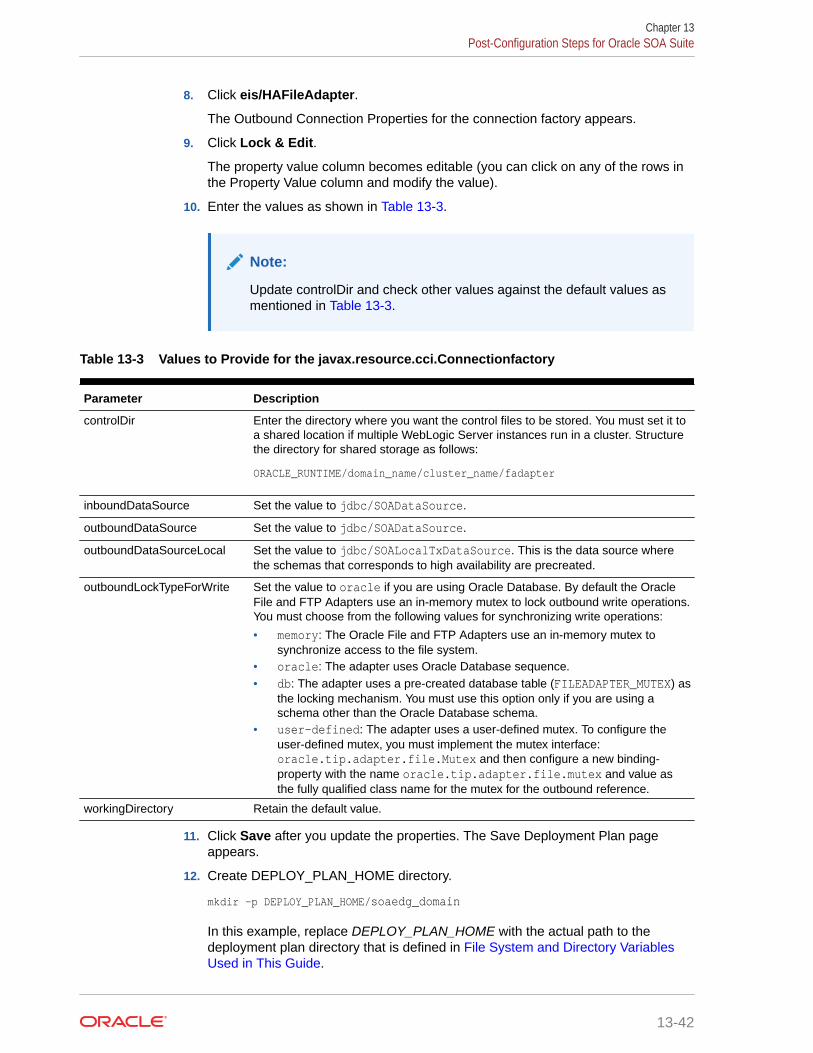
8. Click eis/HAFileAdapter.
The Outbound Connection Properties for the connection factory appears.
9. Click Lock & Edit.
The property value column becomes editable (you can click on any of the rows inthe Property Value column and modify the value).
10. Enter the values as shown in Table 13-3.
Note:
Update controlDir and check other values against the default values asmentioned in Table 13-3.
Table 13-3 Values to Provide for the javax.resource.cci.Connectionfactory
Parameter Description
controlDir Enter the directory where you want the control files to be stored. You must set it toa shared location if multiple WebLogic Server instances run in a cluster. Structurethe directory for shared storage as follows:
ORACLE_RUNTIME/domain_name/cluster_name/fadapter
inboundDataSource Set the value to jdbc/SOADataSource.
outboundDataSource Set the value to jdbc/SOADataSource.
outboundDataSourceLocal Set the value to jdbc/SOALocalTxDataSource. This is the data source wherethe schemas that corresponds to high availability are precreated.
outboundLockTypeForWrite Set the value to oracle if you are using Oracle Database. By default the OracleFile and FTP Adapters use an in-memory mutex to lock outbound write operations.You must choose from the following values for synchronizing write operations:
• memory: The Oracle File and FTP Adapters use an in-memory mutex tosynchronize access to the file system.
• oracle: The adapter uses Oracle Database sequence.• db: The adapter uses a pre-created database table (FILEADAPTER_MUTEX) as
the locking mechanism. You must use this option only if you are using aschema other than the Oracle Database schema.
• user-defined: The adapter uses a user-defined mutex. To configure theuser-defined mutex, you must implement the mutex interface:oracle.tip.adapter.file.Mutex and then configure a new binding-property with the name oracle.tip.adapter.file.mutex and value asthe fully qualified class name for the mutex for the outbound reference.
workingDirectory Retain the default value.
11. Click Save after you update the properties. The Save Deployment Plan pageappears.
12. Create DEPLOY_PLAN_HOME directory.
mkdir -p DEPLOY_PLAN_HOME/soaedg_domain
In this example, replace DEPLOY_PLAN_HOME with the actual path to thedeployment plan directory that is defined in File System and Directory VariablesUsed in This Guide.
Chapter 13Post-Configuration Steps for Oracle SOA Suite
13-42

13. Enter a shared storage location for the deployment plan path value. The directorystructure is as follows:
DEPLOY_PLAN_HOME/soaedg_domain/FileAdapterPlan.xml
14. Click OK to save the storage location.
15. Click Save to save and then click Activate Changes to apply your changes to the FileAdapter.
16. Update the deployment in the console:
a. Click Deployments.
b. Click Lock & Edit.
c. Select the checkbox for the FileAdapter deployment.
d. Click Update.
e. Select the option: Update this application in place with new deployment planchanges (A deployment plan must be specified for this option.)
f. Click the Change Path button and select the FileAdapterPlan.xml file from the pathto the shared storage location.
g. Click Finish.
h. Activate the changes.
17. Verify that the FileAdapter deployment is activated and running:
a. In the Administration Console, click Deployments in the left pane.
b. Locate the FileAdapter deployment in the Deployments table.
c. If it is not in the active state, click the Control tab under Summary of Deployments,and then select FileAdapter under Deployments. Select Start, and then ServicingAll Requests.
d. Click Yes.
Editing the JCA File Within the Composite ApplicationAfter you have configured the FileAdapter deployment in the Administration Console, you canedit the .jca file that is included in the composite applications to be deployed so that they canuse the connection factory that was configured in the previous steps, as shown in Example 13-2.
Note:
The location attribute is set to eis/HAFileAdapter for the connection factory.
Example 13-2 Example of the File Adapter .JCA File Modifications for an Enterprise Deployment
<adapter-config name="FlatStructureOut" adapter="File Adapter" xmlns="http://platform.integration.oracle/blocks/adapter/fw/metadata"> <connection-factory location="eis/HAFileAdapter" adapterRef=""/> <endpoint-interaction portType="Write_ptt" operation="Write"> <interaction-spec className="oracle.tip.adapter.file.outbound.FileInteractionSpec">
Chapter 13Post-Configuration Steps for Oracle SOA Suite
13-43

<property../> <property../> </interaction-spec> </endpoint-interaction></adapter-config>
Configuring the Oracle FTP AdapterIf your application requires an FTP Adapter, then repeat the procedures Configuringthe Oracle File Adapter in the Administration Console and Editing the JCA File Withinthe Composite Application, with the following differences:
• Locate the FtpAdapter deployment in the list of deployments in the AdministrationConsole.
• Click FtpAdapter to display the Settings for the FtpAdapter page.
• Click Configuration.
• Click Outbound Connection Pools.
• Expand javax.resource.cci.ConnectionFactory to see the configured connectionfactories.
• Click eis/Ftp/HAFtpAdapter.
The Outbound Connection Properties for the connection factory appears.
• Click Lock & Edit.
• Modify the adapter properties for high availability. See Table 13-3.
• Update the ControlDir property so it points to the following location:
ORACLE_RUNTIME/domain_name/cluster_name/ftpadapter
• Enter a shared storage location for the deployment plan. The directory structure isas follows:
DEPLOY_PLAN_HOME/soaedg_domain/FtpAdapterPlan.xml
• Update the FTPAdapter deployment in the console. See Configuring the OracleFile Adapter in the Administration Console.
Enabling High Availability for Oracle JMS AdaptersWhen the Oracle JMS adapter communicates with multiple servers in a cluster, theadapter's connection factory property FactoryProperties must list available servers. Ifit does not list servers, the connection is established to only one random server. If thatparticular server goes down, no further messages are processed.
To avoid this issue, you can use the “cluster name” syntax in the FactoryPropertiesof the adapter instead of using the static list of members. The cluster name syntax isas follows:
cluster:t3://cluster_name
When you use cluster:t3://cluster_name, the invocation fetches the complete listof members in the cluster at any given time, thus avoiding any dependencies on theinitial servers and accounting for every member that is alive in the cluster at that pointof time. Note that you can use this cluster syntax only when the cluster is in the samedomain.
Chapter 13Post-Configuration Steps for Oracle SOA Suite
13-44

To modify the adapter's JCA connection factory:
1. Log into your Oracle WebLogic Server Administration Console by using the followingURL:
http://ADMINVHN:7001/console
Note:
If you have already configured web tier, use http://admin.example.com/console.
2. Click Deployments in the left pane for Domain Structure.
3. Click JmsAdapter under Summary of Deployments on the right pane.
4. Click the Configuration tab.
5. Click the Outbound Connection Pools tab and expandoracle.tip.adapter.jms.IJmsConnectionFactory to see the configured connectionfactories.
6. Click Lock & Edit.
7. Click the specific instance that you are using (for example, eis/wls/Queue). TheOutbound Connection Properties for the connection factory opens.
8. In the FactoryProperties field (click the corresponding cell under Property value), enterthe following, all on one line, separated by semicolons:
java.naming.factory.initial=weblogic.jndi.WLInitialContextFactory;java.naming.provider.url=cluster:t3://SOA_Cluster;java.naming.security.principal=weblogic;java.naming.security.credentials=<password>
9. Click Save after you update the properties. The Save Deployment Plan page appears.
10. (First time only) Enter a shared storage location for the deployment plan. The directorystructure is as follows:
DEPLOY_PLAN_HOME/soaedg_domain/JMSAdapterPlan.xml
11. Click OK to commit the updated storage path.
12. Click Save.
13. Repeat steps 7 through 9 for all required connection factories.
14. Click Activate Changes.
15. Update the deployment in the console:
a. Click Deployments.
b. Click Lock & Edit.
c. Select the checkbox for the JMS Adapater.
d. Click Update.
e. Select Update this application in place with new deployment plan changes (Adeployment plan must be specified for this option.) , and select the deployment
Chapter 13Post-Configuration Steps for Oracle SOA Suite
13-45

plan saved in a shared storage location; all servers in the cluster must be ableto access the plan.
f. Click Finish.
g. Activate the changes.
Enabling High Availability for the Oracle Database AdapterTo ensure High Availability while leveraging the Oracle Database Adapter, the LogicalDelete Polling Strategy is used normally as it performs better than a physical delete.However, when you have a clustered environment where multiple nodes are polling forthe same data, a single record might get processed more than once. To avoid thisproblem, Oracle Database Adapter uses a distributed polling technique that uses anOracle Database feature called skip locking.
If you were using the Logical Delete Polling Strategy approach previously, you canremove (in db.jca) or clear (Logical Delete Page of wizard) the MarkReservedValue,and you automatically get skip locking.
The benefits of using skip locking over a reserved value include:
• Skip locking scales better in a cluster and under load.
• All work is in one transaction (as opposed to update/reserve, then commit, thenselect in a new transaction), so the risk of facing a non-recoverable situation in ahigh availability environment is minimized.
• No unique MarkReservedValue must be specified. Previously, for this to work youwould have to configure a complex variable, such as R${weblogic.Name-2}-${IP-2}-${instance}.
If you are using Logical Delete polling, and you set MarkReservedValue, skip locking isnot used.
For more information, see "Scalability" and "Polling Strategies" in the Oracle FusionMiddleware User's Guide for Technology Adapters.
Enabling SSL Communication Between the SOA Servers and theHardware Load Balancer
After you extend the domain with Oracle SOA Suite, you should also ensure that theAdministration Server and Managed Servers can access the front-end SSL URL of thehardware load balancer.
This allows SOA Composite applications and web services to invoke callbacks andother communications with the front-end secure URL. See Enabling SSLCommunication Between the Middle Tier and the Hardware Load Balancer.
Considerations for Sync-Async Interactions in a SOA ClusterIn a SOA cluster, the following scenarios are not supported:
• Synchronous BPEL process with mid-process receive.
• Synchronous BPEL process calling asynchronous services.
• Callback from synchronous processes.
Chapter 13Post-Configuration Steps for Oracle SOA Suite
13-46

Updating FusionAppsFrontendHostUrlYou must configure Oracle Workflow with the appropriate URL so that the default-to-do tasksand custom tasks' details use the front-end load balancer to create task-display URLs.To configure the appropriate URLs:
1. Log in to Oracle Enterprise Manager Fusion Middleware Control with the username andpassword that you specified in the boot.properties file. See Creating theboot.properties File.
2. In the left navigation tree, expand WebLogic Domain, and then click System MBeanBrowser.
3. Navigate to Application Defined Mbean> oracle.as.soainfra.config.
a. If you are configuring a static cluster, navigate to Server:WLS_SOA1>WorkflowConfig.
b. If you are configuring a dynamic cluster, navigate to Domain: soaedg_domain>WorkflowConfig.
4. Click human-workflow.
Note:
In a clustered environment, there are multiple human-workflow Mbeans, one forevery server in the cluster. Modify any one of them to update the propertycentrally in MDS for the entire cluster.
5. On the right panel, look for the FusionAppsFrontendHostUrl attribute.
6. For the FusionAppsFrontendHostUrl attribute, specify the value *=https://soa.example.com:443.
7. Click Apply.
Enabling JDBC Persistent Stores for Oracle SOA SuiteOracle recommends that you use JDBC stores, which leverage the consistency, dataprotection, and high availability features of an Oracle database and makes resourcesavailable for all the servers in the cluster.
If you have made the following selections in the High Availability Options screen, asrecommended in this guide both for static and static clusters, then JDBC persistent stores arealready configured for both JMS and TLOGS:
• Set JTA Transaction Log Persistence to JDBC TLog Store.
• Set JMS Server Persistence to JMS JDBC Store.
In case you did not select JDBC for JMS and TLOGS persistent in the High AvailabilityOptions screen, you can still configure JDBC stores manually in a post step. For specificinstructions to configure them manually, see Using JDBC Persistent Stores for TLOGs andJMS in an Enterprise Deployment.
Chapter 13Enabling JDBC Persistent Stores for Oracle SOA Suite
13-47

Note:
The High Availability Options screen appears during the ConfigurationWizard session for the first time when you create a cluster that usesAutomatic Service Migration or JDBC stores or both. All subsequent clustersthat are added to the domain by using the Configuration Wizard,automatically apply the selected HA options.
Enabling Automatic Service Migration for Oracle SOA SuiteTo ensure high availability for the product installed in this chapter, you must configureservice migration appropriately.
Automatic Service Migration is already configured if you have selected EnableAutomatic Service Migration with Database Leasing in the High Availability Optionsscreen, as recommended in this guide for both static and dynamic clusters. When thatoption is selected, Database Leasing is configured and the migratable targets (whenusing static cluster) or the persistent stores (when using dynamic clusters) are createdwith the appropriate migration policies for the cluster.
If you have implemented this setting, validate the configuration as described in Validating Automatic Service Migration in Static Clusters.
In case you do not select this option during the Configuration Wizard session, you canconfigure automatic migration manually in a post step. For instructions, see Configuring Automatic Service Migration in an Enterprise Deployment.
Note:
The High Availability Options screen appears during the ConfigurationWizard session for the first time when you create a cluster that usesAutomatic Service Migration or JDBC stores or both. All subsequent clustersthat are added to the domain by using the Configuration Wizard,automatically apply the selected HA options.
Backing Up the ConfigurationIt is an Oracle best practices recommendation to create a backup after yousuccessfully extended a domain or at another logical point. Create a backup after youverify that the installation so far is successful. This is a quick backup for the expresspurpose of immediate restoration in case of problems in later steps.
The backup destination is the local disk. You can discard this backup when theenterprise deployment setup is complete. After the enterprise deployment setup iscomplete, you can initiate the regular deployment-specific Backup and Recoveryprocess.
For information about backing up your configuration, see Performing Backups andRecoveries for an Enterprise Deployment.
Chapter 13Enabling Automatic Service Migration for Oracle SOA Suite
13-48

14Extending the Domain with Oracle ServiceBus
The procedures described in this chapter guide you through the process of extending theenterprise deployment topology with Oracle Service Bus (OSB).
• About Configuring Oracle Service Bus in Its Own DomainWhen you add Oracle Service Bus (OSB) to your enterprise topology, you can add it tothe existing SOA domain, or you can create a new domain for OSB, separate from theOracle SOA Suite domain.
• Variables Used When Configuring Oracle Service BusAs you perform the tasks in this chapter, you reference the directory variables that arelisted in this section.
• Support for Dynamic Clusters in Oracle Service BusOracle Service Bus supports two different topologies: static clusters-based topology anddynamic clusters-based topology. When choosing the dynamic cluster topology, there aresome differences with respect to the conventional static clusters configuration.
• Overview of Adding OSB to the TopologyBefore you add OSB to the topology, you must ensure that you have already performedthe steps that are required to create an initial Infrastructure domain and then extendedthe domain to include Oracle SOA suite.
• Prerequisites for Extending the Domain to Include Oracle Service BusBefore you extend the current domain, ensure that your existing deployment meets thenecessary prerequisites.
• Installing Oracle Service Bus SoftwareYou can install Oracle Service Bus in an enterprise deployment by using the OSBInstaller.
• Extending the SOA or Infrastructure Domain to Include Oracle Service BusYou can use the Configuration Wizard to extend the existing enterprise deployment SOAdomain with the Oracle Service Bus. You have to perform a series of additional tasks tocomplete the extension.
• Propagating the Extended Domain to the Domain Directories and MachinesAfter you have extended the domain with the OSB instances, and you have restarted theAdministration Server on SOAHOST1, you must then propagate the domain changes tothe domain directories and systems.
• Modifying the Upload and Stage Directories to an Absolute Path
• Configuring Listen Addresses When Using Dynamic Clusters
• Configuring the Web Tier for the Extended DomainIt is important to understand how to configure the web server instances on the web tier sothat they route requests for both public and internal URLs to the proper clusters in theextended domain.
14-1

• Post-Configuration Tasks for Oracle Service BusAfter you install and configure Oracle Service Bus in the domain, consider thefollowing post-configuration tasks.
• Enabling JDBC Persistent Stores for Oracle Service BusOracle recommends that you use JDBC stores, which leverage the consistency,data protection, and high availability features of an Oracle database and makesresources available for all the servers in the cluster.
• Enabling Automatic Service Migration for Oracle Service BusTo ensure that Oracle Service Bus (OSB) is configured for high availability, youmust configure the OSB Servers for service migration.
• Backing Up the ConfigurationIt is an Oracle best practices recommendation to create a backup after yousuccessfully extended a domain or at another logical point. Create a backup afteryou verify that the installation so far is successful. This is a quick backup for theexpress purpose of immediate restoration in case of problems in later steps.
About Configuring Oracle Service Bus in Its Own DomainWhen you add Oracle Service Bus (OSB) to your enterprise topology, you can add it tothe existing SOA domain, or you can create a new domain for OSB, separate from theOracle SOA Suite domain.
For more information about the OSB topology, see About the Topology Options forOracle Service Bus.
If you decide to configure Oracle Service Bus in a separate domain, then keep in mindthe following when you use the instructions to add Oracle Service Bus to yourtopology:
• Ignore any references to the SOA Managed Servers or the SOA Cluster. Theseelements of the domain only exist if you extend a domain that has already beenextended with Oracle SOA Suite.
• You must run the RCU to create the SOAINFRA schema for the Oracle ServiceBus domain. This schemas is required by Oracle Service Bus. You must use aunique SOAINFRA schema and schema prefix for the Oracle Service Bus domain.
• When you run the Configuration Wizard, the High Availability Options screenappears as described in Navigating the Configuration Wizard Screens to Extendthe Domain with Oracle SOA Suite.
This screen appears for the first time when you create a cluster that usesAutomatic Service Migration or JDBC stores or both. After you select HA Optionsfor a cluster, all subsequent clusters that are added to the domain by using theConfiguration Wizard, automatically apply HA options (that is, the ConfigurationWizard creates the JDBC stores and configures ASM for them).
Oracle recommends that you select the following options:
– Select Enable Automatic Service Migration with Database Leasing.
– Set JTA Transaction Log Persistence to JDBC TLog Store.
– Set JMS Server Persistence to JMS JDBC Store.
Chapter 14About Configuring Oracle Service Bus in Its Own Domain
14-2

Variables Used When Configuring Oracle Service BusAs you perform the tasks in this chapter, you reference the directory variables that are listedin this section.
The values for several directory variables are defined in File System and Directory VariablesUsed in This Guide.
• ORACLE_HOME
• ASERVER_HOME
• MSERVER_HOME
• JAVA_HOME
• WEB_DOMAIN_HOME
In addition, you reference the following virtual IP (VIP) addresses that are defined in Physicaland Virtual IP Addresses Required by the Enterprise Topology:ADMINVHN
Actions in these topics are performed on the following host computers:
• SOAHOST1
• SOAHOST2
• WEBHOST1
• WEBHOST2
Support for Dynamic Clusters in Oracle Service BusOracle Service Bus supports two different topologies: static clusters-based topology anddynamic clusters-based topology. When choosing the dynamic cluster topology, there aresome differences with respect to the conventional static clusters configuration.
Static clusters, also called configured clusters, are conventional clusters where you manuallyconfigure and add each server instance. A dynamic cluster includes a new "server-template"object that is used to define a centralized configuration for all generated (dynamic) serverinstances. When you create a dynamic cluster, the dynamic servers are preconfigured andautomatically generated for you. This feature enables you to scale up the number of serverinstances in the dynamic cluster when you need additional server capacity. You can simplystart the dynamic servers without having to first manually configure and add them to thecluster.
The steps in this section include instructions to configure the domain for both static ordynamic topologies. The differences between the two types of configurations are listed below:
• The Configuration Wizard process may differ for each case. For example, you shoulddefine server templates for dynamic clusters instead of servers.
• For dynamic clusters, you should perform the server-specific configurations such assetting the listen address, configuring the upload and staging directories, or configuringthe keystores in the server template instead of in the server.
• Service migration is configured in a different way for dynamic clusters. Dynamic clustersdo not use migratable targets, instead, the JMS resources are targeted to the cluster, anduse migration policies. For dynamic and static cluster, all the configuration related with
Chapter 14Variables Used When Configuring Oracle Service Bus
14-3

Service Migration can be automatically performed by the Configuration Wizard andthis is the approach used in this guide.
Mixed clusters (clusters that contains both dynamic and configured server instances)are not supported in the Oracle SOA Suite enterprise deployment.
Overview of Adding OSB to the TopologyBefore you add OSB to the topology, you must ensure that you have alreadyperformed the steps that are required to create an initial Infrastructure domain andthen extended the domain to include Oracle SOA suite.
Table 14-1 lists and describes the high-level steps to extend an existing SOA domainor an existing Infrastructure domain for Oracle Service Bus.
Table 14-1 Steps for Extending a SOA Domain to Include Oracle Service Bus
Step Description More Information
Install Oracle Service Bus software. Install OSB software on the targetsystem.
Installing Oracle Service BusSoftware
Optionally, install the SOAINFRAschema in a supported database.
OSB requires the SOAINFRAschema for thewlsbjmsrpDataSource datasource. If you plan to run OSB in itsown domain, then you must be surethat you have installed a separateSOAINFRA schema for OSB in asupported database.
Be sure to use a unique schema forthe SOAINFRA schema that is usedby the OSB domain.
Creating the Oracle SOA SuiteDatabase Schemas
Optionally, create a newInfrastructure domain.
If you plan to run OSB in its owndomain, then you must first create anInfrastructure domain, so you canextend that domain with OSB.
Creating the Initial InfrastructureDomain for an EnterpriseDeployment
Run the Configuration Wizard toExtend the Domain.
Extend the SOA or Infrastructuredomain to contain Oracle ServiceBus components.
Extending the SOA or InfrastructureDomain to Include Oracle ServiceBus
Propagate the Domain Configurationto the Managed Server Directory inSOAHOST1 and to SOAHOST2.
Oracle Service Bus requires someupdates to the WebLogic Server startscripts. Propagate these changes byusing the pack and unpackcommands.
Propagating the Extended Domain tothe Domain Directories andMachines
Start the Oracle Service BusServers.
Oracle Service Bus servers extendan already existing domain. As aresult, the Administration Server andrespective Node Managers arealready running in SOAHOST1 andSOAHOST2.
Starting and Validating theWLS_OSB1 Managed Server
Validate the WLS_OSB ManagedServers.
Verify that the server status isreported as Running in the AdminConsole and access URLs to verifystatus of servers.
Starting and Validating theWLS_OSB2 Managed Server
Chapter 14Overview of Adding OSB to the Topology
14-4

Table 14-1 (Cont.) Steps for Extending a SOA Domain to Include Oracle Service Bus
Step Description More Information
Configuring Oracle HTTP Server forthe WLS_OSBn Managed Servers.
To enable Oracle HTTP Server toroute to Oracle Service Bus consoleand Oracle Service Bus service, setthe WebLogicCluster parameter tothe list of nodes in the cluster.
Configuring Oracle HTTP Server forthe Oracle Service Bus
Validating Access Through OracleHTTP Server.
Verify that the server status isreported as Running.
Validating the Oracle Service BusURLs Through the Load Balancer
Enable High Availability for OracleFile and FTP Adapters.
Make Oracle File and FTP Adaptershighly available for outboundoperations by using the databasemutex locking operation.
Enabling High Availability for OracleDB_ File and FTP Adapters
Backing up the Oracle Service BusConfiguration.
To back up the domain configurationfor immediate restoration in case offailures in future procedures.
Backing Up the Configuration
Prerequisites for Extending the Domain to Include OracleService Bus
Before you extend the current domain, ensure that your existing deployment meets thenecessary prerequisites.
• Back up the installation. If you have not yet backed up the existing Fusion MiddlewareHome and domain, Oracle recommends backing it up now.
To back up the existing Fusion Middleware Home and domain, see Performing Backupsand Recoveries in the SOA Enterprise Deployments.
• Verify that you have installed the Infrastructure and SOA software binaries in an Oraclehome on shared storage and they are available from SOAHOST1 and SOAHOST2.
• If Oracle Service Bus is being configured in the same domain as SOA, then theappropriate SOAINFRA schema (used by the wlsbjmsrpDataSource) is already available.If OSB is being configured in its own domain, then you must run RCU to install theSOAINFRA schema in a supported database by using a different schema prefix than theSOAINFRA schema used by the SOA domain.
• You have already configured Node Manager, Administration Server, (optionally SOAServers) and WSM Servers as described in previous chapters to run a SOA system.Optionally, you may have already configured Server migration, transaction logs,coherence, and all other configuration steps for the SOA System.
• If you haven't done so already, verify that the system clocks on each host computer aresynchronized. You can do this by running the date command simultaneously on the hostsin each cluster.
Alternatively, there are third-party and open-source utilities you can use for this purpose.
Installing Oracle Service Bus SoftwareYou can install Oracle Service Bus in an enterprise deployment by using the OSB Installer.
Chapter 14Prerequisites for Extending the Domain to Include Oracle Service Bus
14-5

• Starting the Oracle Service Bus Installer
• Navigating the OSB Installation Screens
• Installing the Software on Other Host Computers
• Validating the OSB Installation
Starting the Oracle Service Bus InstallerTo start the installation program, perform the following steps.
1. Log in to the target system, SOAHOST1.
2. Go to the directory in which you downloaded the installation program.
3. Set the path for the java executable:
export JAVA_HOME=JAVA_HOMEexport PATH=$JAVA_HOME/bin:$PATH
In this example, replace JAVA_HOME with the value this variable listed in FileSystem and Directory Variables Used in This Guide and entered in the EnterpriseDeployment Workbook.
4. Launch the installation program by entering the following command:
java -d64 -jar fmw_12.2.1.4.0_osb.jar
When the installation program appears, you are ready to begin the installation.
Navigating the OSB Installation ScreensTable 14-2 provides description of each installation program screen.
Table 14-2 OSB Installation Screens
Screen Description
Welcome This screen introduces you to the product installer.
Auto Updates Use this screen to automatically search My OracleSupport for available patches or automatically search alocal directory for patches that you’ve alreadydownloaded for your organization.
Installation Location Use this screen to specify the location of your Oraclehome directory.
If you plan to extend the existing SOA domain, theninstall the OSB software into the existing Oracle home,where the SOA software has already been installed.
If you plan to configure OSB in a separate domain, theninstall the OSB software in the Infrastructure Oraclehome.
Installation Type Use this screen to select the type of installation andconsequently, the products and feature sets that youwant to install.
For this topology, select Service Bus.
Chapter 14Installing Oracle Service Bus Software
14-6

Table 14-2 (Cont.) OSB Installation Screens
Screen Description
Prerequisite Checks This screen verifies that your system meets theminimum necessary requirements.
If there are any warning or error messages, you canrefer to one of the following documents in Roadmap forVerifying Your System Environment in Installing andConfiguring the Oracle Fusion Middleware Infrastructure.
Installation Summary Use this screen to verify the installation options that youselect. If you want to save these options to a responsefile, click Save Response File and provide the locationand name of the response file. Response files can beused later in a silent installation situation.
For more information about silent or command-lineinstallation, see Using the Oracle Universal Installer inSilent Mode in Installing Software with the OracleUniversal Installer.
Click Install to begin the installation.
Installation Progress This screen allows you to see the progress of theinstallation.
Installation Complete This screen appears when the installation is complete.Review the information on this screen, then click Finishto dismiss the installer.
Installing the Software on Other Host ComputersIf you have configured a separate shared storage volume or partition for SOAHOST2, thenyou must also install the software on SOAHOST2. For more information, see Shared StorageRecommendations When Installing and Configuring an Enterprise Deployment.
Note that the location where you install the Oracle home (which contains the softwarebinaries) varies, depending upon the host. To identify the proper location for your Oraclehome directories, refer to the guidelines in File System and Directory Variables Used in ThisGuide.
Validating the OSB InstallationAfter you complete the installation, you can verify it by successfully completing the followingtasks.
• Reviewing the Installation Log Files
• Checking the Directory Structure
• Viewing the Contents of Your Oracle Home
Reviewing the Installation Log FilesReview the contents of the installation log files to make sure that no problems wereencountered. For a description of the log files and where to find them, see UnderstandingInstallation Log Files in Installing Software with the Oracle Universal Installer.
Chapter 14Installing Oracle Service Bus Software
14-7

Checking the Directory StructureThe contents of your installation vary based on the options you selected during theinstallation.
The addition of Oracle Service Bus adds the following directory and sub-directories.Use the ls --format=single-column command to verify the directory structure:
ls --format=single-colum ORACLE_HOME/osb/bincommonconfigdocfinancialL10Nlibmodulesosbpluginstools
For more information about the directory structure post the installation process, see What are the Key Oracle Fusion Middleware Directories? in Understanding OracleFusion Middleware.
Viewing the Contents of Your Oracle HomeYou can also view the contents of your Oracle home by using the viewInventoryscript. See Viewing the contents of an Oracle home in Installing Software with theOracle Universal Installer.
Extending the SOA or Infrastructure Domain to IncludeOracle Service Bus
You can use the Configuration Wizard to extend the existing enterprise deploymentSOA domain with the Oracle Service Bus. You have to perform a series of additionaltasks to complete the extension.
Extending the domain involves the following tasks.
• Starting the Configuration Wizard
• Navigating the Configuration Wizard Screens to Extend the Domain with OracleService Bus
Chapter 14Extending the SOA or Infrastructure Domain to Include Oracle Service Bus
14-8

Starting the Configuration Wizard
Note:
If you added any customizations directly to the start scripts in the domain, those areoverwritten by the configuration wizard. To customize server startup parameters thatapply to all servers in a domain, you can create a file calledsetUserOverridesLate.sh and configure it, for example, add custom libraries to theWebLogic Server classpath, specify additional java command-line options forrunning the servers, or specify additional environment variables. Anycustomizations you add to this file are preserved during domain upgradeoperations, and are carried over to remote servers when you use the pack andunpack commands.
To begin domain configuration:
1. Shut down the Administration Server to prevent any configuration locks, saves, oractivations from occurring during the configuration of the domain.
2. Navigate to the following directory and start the WebLogic Server Configuration Wizard.
ORACLE_HOME/oracle_common/common/bin./config.sh
Navigating the Configuration Wizard Screens to Extend the Domain withOracle Service Bus
In this step, you extend the domain created in Extending the Domain with Oracle SOA Suite ,and add the Oracle Service Bus software components and Managed Servers.
The steps reflected in this section would be very similar if Oracle Service Bus was extendinga domain containing only an Administration Server and a WSM-PM Cluster, but some of theoptions, libraries, and components shown in the screens could vary.
Follow the instructions in these sections to create and configure the domain for the topology,with static or dynamic clusters.
• Extending the Domain with Static Clusters
• Extending the Domain with Dynamic Clusters
Extending the Domain with Static ClustersFollow the instructions in this section to extend the domain for Oracle Service Bus, with staticclusters.
Chapter 14Extending the SOA or Infrastructure Domain to Include Oracle Service Bus
14-9

Note:
This procedure assumes that you are extending an existing domain. If yourneeds do not match the instructions given in the procedure, ensure that youmake your selections accordingly, or refer to the supporting documentationfor additional details.
Domain creation and configuration includes the following tasks.
• Task 1, Selecting the Domain Type and Domain Home Location
• Task 2, Selecting the Configuration Template
• Task 3, Specifying the Database Configuration Type
• Task 4, Specifying JDBC Component Schema Information
• Task 5, Providing the GridLink Oracle RAC Database Connection Details
• Task 6, Testing the JDBC Connections
• Task 7, Selecting Advanced Configuration
• Task 8, Configuring Managed Servers
• Task 9, Configuring a Cluster
• Task 10, Assigning Server Templates
• Task 11, Configuring Dynamic Servers
• Task 12, Assigning Managed Servers to the Cluster
• Task 13, Configuring Coherence Clusters
• Task 14, Verifying the Existing Machines
• Task 15, Assigning Servers to Machines
• Task 16, Configuring Virtual Targets
• Task 17, Configuring Partitions
• Task 18, Reviewing Your Configuration Specifications and Configuring the Domain
• Task 19, Writing Down Your Domain Home and Administration Server URL
• Task 20, Start the Administration Server
Task 1 Selecting the Domain Type and Domain Home LocationOn the Configuration Type screen, select Update an existing domain.In the Domain Location field, select the value of the ASERVER_HOME variable,which represents the complete path to the Administration Server domain home thatyou created when you created in Creating the Initial Infrastructure Domain for anEnterprise Deployment.For more information about the directory location variables, see File System andDirectory Variables Used in This Guide.For more information about the other options on this screen, see Configuration Typein Creating WebLogic Domains Using the Configuration Wizard.
Chapter 14Extending the SOA or Infrastructure Domain to Include Oracle Service Bus
14-10

Task 2 Selecting the Configuration TemplateOn the Templates screen, make sure that Update Domain Using Product Templates isselected, then select the following templates:
• Oracle Service Bus Reference Configuration [osb]
The following additional templates should already be selected, because they were usedto create the initial domain:
– Oracle SOA Suite Reference Configuration [soa] (if you are extending a SOAdomain)
– Oracle Enterprise Manager [em]
– Oracle WSM Policy Manager [oracle_common]
– Oracle JRF [oracle_common]
– WebLogic Coherence Cluster Extension [wlserver]
The ODSI XQuery 2004 Components [oracle_common] template is also automaticallyselected when you select Oracle Service Bus template.
Note:
There is no 12.2.1.4.0 template for ODSI. The 12.1.3.0 template works for your12.2.1.4 configuration.
For more information about the options on this screen, see Templates in Creating WebLogicDomains Using the Configuration Wizard.
Chapter 14Extending the SOA or Infrastructure Domain to Include Oracle Service Bus
14-11

Note:
If you plan to extend the domain to add a component that does not supportReference Configuration, such as BPM and BAM (Reference Configurationis supported only in SOA, OSB, B2B, and ESS), or if you are extending aclassic SOA domain with OSB, the OSB classic domain templates must beused.The classic SOA templates, which do not implement the optimizationsincluded in Reference Configuration are not shown in the ConfigurationWizard, but are available and located at:
• $ORACLE_HOME/soa/common/templates/wls (the SOA and B2Bclassic templates)
• $ORACLE_HOME/osb/common/templates/wls (the OSB classictemplate)
To select the classic OSB extension template for extending a classic domainto add OSB, in the Configuration Wizard Templates screen:
1. Select Update Domain Using Custom Template.
2. Browse to $ORACLE_HOME/osb/common/templates/wls.
3. Select oracle.osb_template.jar.
Important:
Do not useoracle.osb.classic.domain_template.jar to extendinfra or SOA classic domain. The OSB classic template can beused only to create domains from zero, not to extend on anexisting infra or SOA classic domain. To extend an infra orSOA classic domain and add OSB classic, useoracle.osb_template.jar as indicated here.
Subsequent extensions on a Classic SOA domain for B2B or OSB must bedone with Classic templates and not with Reference Configurationtemplates.If you do not plan to add any component that do not support ReferenceConfiguration, Oracle recommends you to use the Oracle OSB ReferenceConfiguration template.
Task 3 Specifying the Database Configuration TypeOn the Database Configuration Type screen, select RCU Data.All fields are pre-populated, because you already configured the domain to referencethe Fusion Middleware schemas that are required for the Infrastructure domain.
• Verify that the Vendor is Oracle and the Driver is *Oracle's Driver(Thin) for Service Connections; Versions: Any.
• Verify that Connection Parameters is selected.
Chapter 14Extending the SOA or Infrastructure Domain to Include Oracle Service Bus
14-12
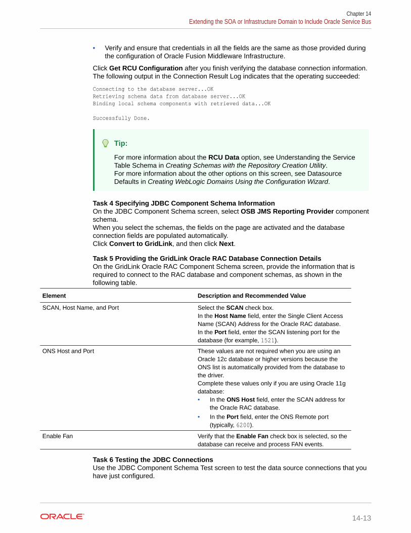
• Verify and ensure that credentials in all the fields are the same as those provided duringthe configuration of Oracle Fusion Middleware Infrastructure.
Click Get RCU Configuration after you finish verifying the database connection information.The following output in the Connection Result Log indicates that the operating succeeded:
Connecting to the database server...OKRetrieving schema data from database server...OKBinding local schema components with retrieved data...OK
Successfully Done.
Tip:
For more information about the RCU Data option, see Understanding the ServiceTable Schema in Creating Schemas with the Repository Creation Utility.For more information about the other options on this screen, see DatasourceDefaults in Creating WebLogic Domains Using the Configuration Wizard.
Task 4 Specifying JDBC Component Schema InformationOn the JDBC Component Schema screen, select OSB JMS Reporting Provider componentschema.When you select the schemas, the fields on the page are activated and the databaseconnection fields are populated automatically.Click Convert to GridLink, and then click Next.
Task 5 Providing the GridLink Oracle RAC Database Connection DetailsOn the GridLink Oracle RAC Component Schema screen, provide the information that isrequired to connect to the RAC database and component schemas, as shown in thefollowing table.
Element Description and Recommended Value
SCAN, Host Name, and Port Select the SCAN check box.In the Host Name field, enter the Single Client AccessName (SCAN) Address for the Oracle RAC database.In the Port field, enter the SCAN listening port for thedatabase (for example, 1521).
ONS Host and Port These values are not required when you are using anOracle 12c database or higher versions because theONS list is automatically provided from the database tothe driver.Complete these values only if you are using Oracle 11gdatabase:• In the ONS Host field, enter the SCAN address for
the Oracle RAC database.
• In the Port field, enter the ONS Remote port(typically, 6200).
Enable Fan Verify that the Enable Fan check box is selected, so thedatabase can receive and process FAN events.
Task 6 Testing the JDBC ConnectionsUse the JDBC Component Schema Test screen to test the data source connections that youhave just configured.
Chapter 14Extending the SOA or Infrastructure Domain to Include Oracle Service Bus
14-13

A green check mark in the Status column indicates a successful test. If you encounterany issues, see the error message in the Connection Result Log section of thescreen, fix the problem, then try to test the connection again.For more information about the other options on this screen, see Test ComponentSchema in Creating WebLogic Domains Using the Configuration Wizard.
Task 7 Selecting Advanced ConfigurationTo complete domain configuration for the topology, select Topology on the AdvancedConfiguration screen.
Note:
JDBC stores are recommended and selected in Task 3, Configuring HighAvailability Options so there is no need to configure File Stores.If you choose File Stores in Task 3, Configuring High Availability Options,you have to select the File Stores option here to configure them in a sharedlocation in ORACLE_RUNTIME/domain_name/OSB_Cluster/jms. Sharedlocation is required to resume JMS and JTA in a failover scenario.
Task 8 Configuring Managed ServersOn the Managed Servers screen, a new Managed Server for Oracle SOA Suiteappears in the list of servers. This server was created automatically by the OracleSOA Suite configuration template that you selected in Task 2, Selecting theConfiguration Template.Perform the following tasks to modify the default Oracle SOA Suite Managed Serverand create a second Oracle SOA Suite Managed Server:
1. Rename the default Oracle SOA Suite Managed Server to WLS_OSB1.
2. Click Add to create a new Managed Server, and name it WLS_OSB2.
Tip:
The server names recommended here are used throughout thisdocument; if you choose different names, be sure to replace them asneeded.
3. Use the information in Table 14-3 to fill in the rest of the columns for eachManaged Server.
4. Select OSB-MGD-SVRS-ONLY as the server group for the OSB Servers.Deselect OSB-MGD-SVRS-COMBINED that is selected by default.
5. Click Next.
For more information about the options on the Managed Server screen, see ManagedServers in Creating WebLogic Domains Using the Configuration Wizard.
Name Listen Address Listen Port SSL ListenPort
SSL Enabled Server Groups
WLS_SOA1 SOAHOST1 8001 n/a No SOA-MGD-SVRS-ONLY
Chapter 14Extending the SOA or Infrastructure Domain to Include Oracle Service Bus
14-14

Name Listen Address Listen Port SSL ListenPort
SSL Enabled Server Groups
WLS_SOA2 SOAHOST2 8001 n/a No SOA-MGD-SVRS-ONLY
WLS_WSM1 SOAHOST1 7010 n/a No JRF-MAN-SVRWSMPM-MAN-SVR
WLS_WSM2 SOAHOST2 7010 n/a No JRF-MAN-SVRWSMPM-MAN-SVR
WLS_OSB1 SOAHOST1 8011 n/a No OSB-MGD-SVRS-ONLY
WLS_OSB2 SOAHOST2 8011 n/a No OSB-MGD-SVRS-ONLY
The WLS_SOA Managed Servers appear if you extend an existing Oracle SOA Suitedomain with Oracle Service Bus.
Task 9 Configuring a ClusterIn this task, you create a cluster of Managed Servers to which you can target the OracleSOA Suite software.You also set the Frontend Host property for the cluster, which ensures that, whennecessary, WebLogic Server redirects web services callbacks and other redirects tosoa.example.com on the load balancer rather than the address in the HOST header of eachrequest.For more information about the soa.example.com virtual server address, see ConfiguringVirtual Hosts on the Hardware Load Balancer.Use the Clusters screen to create a new cluster:
1. Click the Add button.
2. Specify OSB_Cluster in the Cluster Name field.
3. Specify osb.example.com in the Frontend Host field.
4. Specify 80 as the Frontend HTTP Port and 443 as the Frontend HTTPS port.
Note:
By default, server instances in a cluster communicate with one another by usingunicast. If you want to change your cluster communications to use multicast, referto Considerations for Choosing Unicast or Multicast in Administering Clusters forOracle WebLogic Server.
For more information about the options on this screen, see Clusters in Creating WebLogicDomains Using the Configuration Wizard.
Task 10 Assigning Server TemplatesClick Next to continue.
Task 11 Configuring Dynamic ServersClick Next to continue.
Task 12 Assigning Managed Servers to the ClusterOn the Assign Servers to Clusters screen, assign servers to clusters as follows:
Chapter 14Extending the SOA or Infrastructure Domain to Include Oracle Service Bus
14-15

Note that the WLS_SOA Managed Servers appear only if you extend an existingOracle SOA Suite domain with Oracle Service Bus.
• SOA_Cluster (If you are extending a SOA domain):
– WLS_SOA1
– WLS_SOA2
• WSM-PM_Cluster:
– WLS_WSM1
– WLS_WSM2
• OSB_Cluster:
– WLS_OSB1
– WLS_OSB2
Click Next.For more information about the options on this screen, see Assign Servers to Clustersin Creating WebLogic Domains Using the Configuration Wizard.
Task 13 Configuring Coherence ClustersUse the Coherence Clusters screen to configure the Coherence cluster that isautomatically added to the domain. Leave the port number value at 9991, as it wasdefined during the initial Infrastructure domain creation.For Coherence licensing information, see Oracle Coherence Products in OracleFusion Middleware Licensing Information User Manual.
Task 14 Verifying the Existing MachinesConfirm that the following entries appear:
Name Node Manager Listen Address
SOAHOST1 SOAHOST1
SOAHOST2 SOAHOST2
ADMINHOST ADMINVHN
Leave all other fields to their default values.Click Next.
Task 15 Assigning Servers to MachinesOn the Assign Servers to Machines screen, assign servers to machines as follows:
• ADMINHOST:
– AdminServer
• SOAHOST1
– WLS_SOA1 (if extending a SOA domain)
– WLS_WSM1
– WLS_OSB1
• SOAHOST2:
Chapter 14Extending the SOA or Infrastructure Domain to Include Oracle Service Bus
14-16

– WLS_SOA2 (if extending a SOA domain)
– WLS_WSM2
– WLS_OSB2
For more information about the options on this screen, see Assign Servers to Machines inCreating WebLogic Domains Using the Configuration Wizard.
Task 16 Configuring Virtual TargetsClick Next.
Task 17 Configuring PartitionsClick Next.
Task 18 Reviewing Your Configuration Specifications and Configuring the DomainThe Configuration Summary screen contains the detailed configuration information for thedomain that you are about to extend. Review the details of each item on the screen andverify that the information is correct.If you need to make any changes, you can go back to any previous screen, either by usingthe Back button or by selecting the screen in the navigation pane.Click Update to execute the domain extension.In the Configuration Progress screen, click Next when it finishes.For more information about the options on this screen, see Configuration Summary inCreating WebLogic Domains Using the Configuration Wizard.
Task 19 Writing Down Your Domain Home and Administration Server URLThe Configuration Success screen shows the following items about the domain you justconfigured, including:
• Domain Location
• Administration Server URL
Make a note of both these items, because you need them later; you need the domainlocation to access the scripts used to start the Administration Server, and you need theAdministration Server URL to access the WebLogic Server Administration Console andOracle Enterprise Manager Fusion Middleware Control.Click Finish to dismiss the Configuration Wizard.
Task 20 Start the Administration ServerStart the Administration Server to ensure the changes that you have made to the domainhave been applied.
After you have completed extending the domain with static clusters, go to Propagating theExtended Domain to the Domain Directories and Machines.
Extending the Domain with Dynamic ClustersFollow the instructions in this section to extend the domain for Oracle Service Bus, withdynamic clusters.
Chapter 14Extending the SOA or Infrastructure Domain to Include Oracle Service Bus
14-17

Note:
This procedure assumes that you are extending an existing domain. If yourneeds do not match the instructions given in the procedure, ensure that youmake your selections accordingly, or refer to the supporting documentationfor additional details.
Domain creation and configuration includes the following tasks.
• Task 1, Selecting the Domain Type and Domain Home Location
• Task 2, Selecting the Configuration Template
• Task 3, Specifying the Database Configuration Type
• Task 4, Specifying JDBC Component Schema Information
• Task 5, Providing the GridLink Oracle RAC Database Connection Details
• Task 6, Testing the JDBC Connections
• Task 7, Selecting Advanced Configuration
• Task 8, Configuring Managed Servers
• Task 9, Configuring a Cluster
• Task 10, Assigning Server Templates
• Task 11, Configuring Dynamic Servers
• Task 12, Configuring Coherence Clusters
• Task 13, Verifying the Existing Machines
• Task 14, Assigning Servers to Machines
• Task 15, Configuring Virtual Targets
• Task 16, Configuring Partitions
• Task 17, Reviewing Your Configuration Specifications and Configuring the Domain
• Task 18, Writing Down Your Domain Home and Administration Server URL
• Task 19, Start the Administration Server
Task 1 Selecting the Domain Type and Domain Home LocationOn the Configuration Type screen, select Update an existing domain.In the Domain Location field, select the value of the ASERVER_HOME variable,which represents the complete path to the Administration Server domain home thatyou created in Creating the Initial Infrastructure Domain for an Enterprise Deployment.For more information about the directory location variables, see File System andDirectory Variables Used in This Guide.For more information about the other options on this screen, see Configuration Typein Creating WebLogic Domains Using the Configuration Wizard.
Task 2 Selecting the Configuration TemplateOn the Templates screen, make sure Update Domain Using Product Templates isselected, then select the following templates:
Chapter 14Extending the SOA or Infrastructure Domain to Include Oracle Service Bus
14-18

• Oracle Service Bus Reference Configuration [osb]
The following additional templates should already be selected, because they were usedto create the initial domain:
– Oracle SOA Suite Reference Configuration[soa] (if you are extending a SOAdomain)
– Oracle Enterprise Manager [em]
– Oracle JRF [oracle_common]
– Oracle WSM Policy Manager [oracle_common]
– WebLogic Coherence Cluster Extension [wlserver]
The ODSI XQuery 2004 Components [oracle_common] template is also automaticallyselected when you select Oracle Service Bus template.
Note:
There is no 12.2.1.4.0 template for ODSI. The 12.1.3.0 template works for your12.2.1 configuration.
For more information about the options on this screen, see Templates in Creating WebLogicDomains Using the Configuration Wizard.
Chapter 14Extending the SOA or Infrastructure Domain to Include Oracle Service Bus
14-19

Note:
If you plan to extend the domain to add a component that does not supportReference Configuration, such as BPM and BAM (Reference Configurationis supported only in SOA, OSB, B2B, and ESS), or if you are extending aclassic SOA domain with OSB, the OSB classic domain templates must beused.The classic SOA templates, which do not implement the optimizationsincluded in Reference Configuration, are not shown in the ConfigurationWizard, but are available and located at:
• $ORACLE_HOME/soa/common/templates/wls (the SOA and B2Bclassic templates)
• $ORACLE_HOME/osb/common/templates/wls (the OSB classictemplate)
To select the classic OSB extension template for extending a classic domainto add OSB, in the Configuration Wizard Templates screen:
1. Select Update Domain Using Custom Template.
2. Browse to $ORACLE_HOME/osb/common/templates/wls.
3. Select oracle.osb_template.jar.
Important:
Do not useoracle.osb.classic.domain_template.jar to extendinfra or SOA classic domain. The OSB classic template can beused only to create domains from zero, not to extend on anexisting infra or SOA classic domain. To extend an infra orSOA classic domain and add OSB classic, useoracle.osb_template.jar as indicated here.
Subsequent extensions on a Classic SOA domain for B2B or OSB must bedone with Classic templates and not with Reference Configurationtemplates.If you do not plan to add any component that do not support ReferenceConfiguration, Oracle recommends you to use the Oracle OSB ReferenceConfiguration template.
Task 3 Specifying the Database Configuration TypeOn the Database Configuration Type screen, select RCU Data.All fields are pre-populated, because you already configured the domain to referencethe Fusion Middleware schemas that are required for the Infrastructure domain.
• Verify that the Vendor is Oracle and the Driver is *Oracle's Driver(Thin) for Service Connections; Versions: Any.
• Verify that Connection Parameters is selected.
Chapter 14Extending the SOA or Infrastructure Domain to Include Oracle Service Bus
14-20

• Verify and ensure that credentials in all the fields are the same as those provided duringthe configuration of Oracle Fusion Middleware Infrastructure.
Click Get RCU Configuration after you finish verifying the database connection information.The following output in the Connection Result Log indicates that the operation is successful.
Connecting to the database server...OKRetrieving schema data from database server...OKBinding local schema components with retrieved data...OK
Successfully Done.
Tip:
For more information about the RCU Data option, see Understanding the ServiceTable Schema in Creating Schemas with the Repository Creation Utility.For more information about the other options on this screen, see DatasourceDefaults in Creating WebLogic Domains Using the Configuration Wizard.
Task 4 Specifying JDBC Component Schema InformationOn the JDBC Component Schema screen, select OSB JMS Reporting Provider componentschema.When you select the schemas, the fields on the page are activated and the databaseconnection fields are populated automatically.Click Convert to GridLink , and then click Next.
Task 5 Providing the GridLink Oracle RAC Database Connection DetailsOn the GridLink Oracle RAC Component Schema screen, provide the information that isrequired to connect to the RAC database and component schemas, as shown in thefollowing table.
Element Description and Recommended Value
SCAN, Host Name, and Port Select the SCAN check box.In the Host Name field, enter the Single Client AccessName (SCAN) Address for the Oracle RAC database.In the Port field, enter the SCAN listening port for thedatabase (for example, 1521).
ONS Host and Port These values are not required when you are using anOracle 12c database or higher versions because theONS list is automatically provided from the database tothe driver.Complete these values only if you are using Oracle 11gdatabase:• In the ONS Host field, enter the SCAN address for
the Oracle RAC database.
• In the Port field, enter the ONS Remote port(typically, 6200).
Enable Fan Verify that the Enable Fan check box is selected, so thedatabase can receive and process FAN events.
Task 6 Testing the JDBC ConnectionsUse the JDBC Component Schema Test screen to test the data source connections that youhave just configured.
Chapter 14Extending the SOA or Infrastructure Domain to Include Oracle Service Bus
14-21

A green check mark in the Status column indicates a successful test. If you encounterany issues, see the error message in the Connection Result Log section of thescreen, fix the problem, then try to test the connection again.For more information about the other options on this screen, see Test ComponentSchema in Creating WebLogic Domains Using the Configuration Wizard.
Task 7 Selecting Advanced ConfigurationTo complete domain configuration for the topology, select Topology on the AdvancedConfiguration screen.
Note:
JMS JDBC stores are recommended and selected in Task 3, ConfiguringHigh Availability Options so there is no need to configure File Stores. If youchoose JMS File Stores in Task 3, Configuring High Availability Options, youhave to select the File Stores option to configure them in a shared locationin ORACLE_RUNTIME/domain_name/SOA_Cluster/jms. Shared location isrequired to resume JMS and JTA in a failover scenario.
Task 8 Configuring Managed ServersOn the Managed Servers screen, a new Managed Server for Oracle SOA Suiteappears in the list of servers. This server was created automatically by the OracleSOA Suite configuration template that you selected in Task 2, Selecting theConfiguration Template.Static Managed Server definitions are not needed for dynamic cluster configurations.To remove the default Managed Server, complete the following steps:
1. Delete the default Managed Server.
2. Click Next to proceed to the next screen.
Task 9 Configuring a ClusterIn this task, you create a cluster of Managed Servers to which you can target theOracle SOA Suite software.You also set the Frontend Host property for the cluster, which ensures that, whennecessary, WebLogic Server redirects web services callbacks and other redirects tosoa.example.com on the load balancer rather than the address in the HOST header ofeach request.For more information about the soa.example.com virtual server address, see Configuring Virtual Hosts on the Hardware Load Balancer.Use the Clusters screen to create a new cluster:
1. Click the Add button.
2. Specify OSB_Cluster in the Cluster Name field.
3. Specify osb.example.com in the Frontend Host field.
4. Specify 80 as the Frontend HTTP Port and 443 as the Frontend HTTPS port.
Chapter 14Extending the SOA or Infrastructure Domain to Include Oracle Service Bus
14-22

Note:
By default, server instances in a cluster communicate with one another by usingunicast. If you want to change your cluster communications to use multicast, referto Considerations for Choosing Unicast or Multicast in Administering Clusters forOracle WebLogic Server.
For more information about the options on this screen, see Clusters in Creating WebLogicDomains Using the Configuration Wizard.
Task 10 Assigning Server TemplatesUse the Server Templates screen to configure the template:
1. Verify that osb-server-template is selected in the Name field.
2. Specify 8010 in the Listen Port field.
3. Leave the Enable SSL option unchecked.
4. Click Next.
Task 11 Configuring Dynamic ServersUse the Dynamic Clusters screen to configure the required clusters:
1. Specify OSB_Cluster in the Cluster Name field.
2. From the Server Template drop-down list, select osb-server-template.
3. Specify WLS_OSB in the Server Name Prefix field.
4. Specify 2 in the Dynamic Cluster Size field.
5. Specify SOAHOST* in the Machine Name Match Expression field and select CalculatedMachine Names.
Chapter 14Extending the SOA or Infrastructure Domain to Include Oracle Service Bus
14-23

Note:
The dynamic cluster Calculated Machine Names and Machine NameMatch Expression attributes control how server instances in a dynamiccluster are assigned to a machine. If the Calculated Machine Namesattribute is set to False, the dynamic servers are not assigned to amachine. If the Calculated Machine Names attribute is set to True, theMachine Name Match Expression attribute is used to select the set ofmachines that is used for the dynamic servers. If the Machine NameMatch Expression attribute is not set, all the machines in the domainare selected. Assignments are made by using a round robin algorithm.
To make things easier regardless of your actual physical hostname,Oracle recommends that you use SOAHOSTn as your WebLogicmachine names, where n is a sequential number. This is explained in Task 18, Creating Machines of configuring the infrastructure domain.This convention makes it easy for dynamic clusters to determine whereto start each cluster member. If you want to follow this convention, in theMachine Match Expression field, enter SOAHOST*.
If you do not adopt this convention, the cluster members are started oneach machine that you define in Task 18, Creating Machines, includingthat of ADMINHOST. This situation is undesirable as you would end upwith two cluster members that run on the same physical server but areattached to two different domain homes.
6. Select the Calculated Listen Ports.
Note:
Dynamic clusters with the Calculated Listen Port option selected haveincremental port numbers for each dynamic managed server that iscreated automatically: dynamic server 1 will use Listen Port+1, dynamicserver 2 will use Listen Port+2.
Since the Listen Port configured is 8010 and calculated ports ischecked, OSB dynamic servers use the following port numbers:
• WLS_OSB1 server listens in 8011 port
• WLS_OSB2 server listens in 8012 port
7. In Dynamic Server Groups, select OSB-DYN-CLUSTER-ONLY.
8. Click Next.
Task 12 Configuring Coherence ClustersUse the Coherence Clusters screen to configure the Coherence cluster that isautomatically added to the domain. Leave the port number value at 9991, as it wasdefined during the initial Infrastructure domain creation.For Coherence licensing information, see Oracle Coherence Products in OracleFusion Middleware Licensing Information User Manual.
Chapter 14Extending the SOA or Infrastructure Domain to Include Oracle Service Bus
14-24

Task 13 Verifying the Existing MachinesConfirm that the following entries appear:
Name Node Manager Listen Address
SOAHOST1 SOAHOST1
SOAHOST2 SOAHOST2
ADMINHOST ADMINVHN
Leave all other fields to their default values.Click Next.
Task 14 Assigning Servers to MachinesClick Next.
Task 15 Configuring Virtual TargetsClick Next.
Task 16 Configuring PartitionsClick Next.
Task 17 Reviewing Your Configuration Specifications and Configuring the DomainThe Configuration Summary screen contains detailed configuration information for thedomain that you are about to extend. Review the details of each item on the screen andverify that the information is correct.If you need to make any changes, you can go back to any previous screen , either by usingthe Back button or by selecting the screen in the navigation pane.Click Update to execute the domain extension.In the Configuration Progress screen, click Next when it finishes.For more information about the options on this screen, see Configuration Summary inCreating WebLogic Domains Using the Configuration Wizard.
Task 18 Writing Down Your Domain Home and Administration Server URLThe Configuration Success screen shows the following items about the domain you justconfigured, including:
• Domain Location
• Administration Server URL
Make a note of both these items, because you need them later; you need the domainlocation to access the scripts used to start the Administration Server, and you need theAdministration Server URL to access the WebLogic Server Administration Console andOracle Enterprise Manager Fusion Middleware Control.Click Finish to dismiss the Configuration Wizard.
Task 19 Start the Administration ServerIf the Admin Server was running during the domain extension process, restart the serverbefore you continue to ensure that the changes that you have made to the domain havebeen applied.
Chapter 14Extending the SOA or Infrastructure Domain to Include Oracle Service Bus
14-25

Note:
When you configure OSB as a dynamic cluster, you have to activate thecluster leasing that is needed for OSB singleton applications (that isAggregator) correctly. By default, the leasing configuration is not performedby the Configuration Wizard for the dynamic cluster. Therefore, if you startthe OSB managed servers before you configure the leasing to OSB_Cluster,you see messages such as the following in the logs:
<Warning> <oracle.osb.statistics.statistics> <OSB-473015> <As Automatic Service Migration enabled in Domain, selection of Aggregation Server delayed till Aggregator Singleton is activated. This may happen either during start of all managed servers or migration of Aggregator Singleton due to failure of managed server where it is activated. If this message did not stop after sometime, check managed servers are running. If not, contact Oracle Support.>
<Error> <oracle.osb.statistics.statistics> <OSB-473003> <Aggregation Server Not Available. Aggregator stub was null>
<Error> <oracle.osb.statistics.statistics> <OSB-473003> <Aggregation Server Not Available. Failed to get remote aggregator
After you complete the leasing configuration for the cluster, these messagesdisappear. The configuration of the leasing is performed later. See Verifyingthe Appropriate Targeting and Configuration for OSB Singleton Services.
Propagating the Extended Domain to the DomainDirectories and Machines
After you have extended the domain with the OSB instances, and you have restartedthe Administration Server on SOAHOST1, you must then propagate the domainchanges to the domain directories and systems.
Note that there is no need to propagate the updated domain to the WEBHOST1 andWEBHOST2 systems, because there are no changes to the Oracle HTTP Serverinstances on those host computers.
Refer to the following sections for more information.
• Summary of the Tasks Required to Propagate the Changes to the Other DomainDirectories and Machines
• Starting and Validating the WLS_OSB1 Managed Server
• Starting and Validating the WLS_OSB2 Managed Server
• Verifying the Appropriate Targeting and Configuration for OSB Singleton Services
Summary of the Tasks Required to Propagate the Changes to theOther Domain Directories and Machines
Table 14-4 summarizes the steps required to propagate the changes to all the domaindirectories and systems.
Chapter 14Propagating the Extended Domain to the Domain Directories and Machines
14-26

Table 14-4 Summary of Tasks Required to Propagate the Domain Chanegs to DomainDirectories and Machines
Task Description More Information
Pack up the Extended Domain onSOAHOST1
Use the pack command to create anew template jar file that contains thenew OSB Servers configuration.
When you pack up the domain, createa template jar file calledsoadomaintemplateExtOSB.jar.
Packing Up the Extended Domain onSOAHOST1
Unpack the Domain in theManaged Servers Directory onSOAHOST1
Unpack the template jar file in theManaged Servers directory onSOAHOST1 local storage.
Unpacking the Domain in theManaged Servers Domain Directoryon SOAHOST1
Unpack the Domain onSOAHOST2
Unpack the template jar file in theManaged Servers directory on theSOAHOST2 local storage.
Unpacking the Domain onSOAHOST2
Starting and Validating the WLS_OSB1 Managed ServerAfter you extend the domain, restart the Administration Server, and propagate the domain tothe other hosts, use the following procedure to start the WLS_OSB1 server and validate if theserver is configured successfully:
• Starting the WLS_OSB1 Managed Server
• Adding the MiddlewareAdministrators Role to the Enterprise Deployment AdministrationGroup
• Validating the Managed Server
Starting the WLS_OSB1 Managed Server1. Enter the following URL into a browser to display the Fusion Middleware Control login
screen:
http://ADMINVHN:7001/em
Note:
If you have already configured web tier, use http://admin.example.com/console.
2. Log in to Fusion Middleware Control by using the Administration Server credentials.
3. In the Target Navigation pane, expand the domain to view the Managed Servers in thedomain.
4. Select only the WLS_OSB1 Managed Server, and click Start Up on the Oracle WebLogicServer toolbar.
Chapter 14Propagating the Extended Domain to the Domain Directories and Machines
14-27

Note:
OSB Servers depend on the policy access service to be functional. Thisimplies that the WSM-PM Managed Servers in the domain need to be upand running and reachable before the OSB servers are started.
5. When the startup operation is complete, navigate to the Domain home page andverify that the WLS_OSB1 Managed Server is up and running.
Adding the MiddlewareAdministrators Role to the Enterprise DeploymentAdministration Group
Before you validate the Oracle Service Bus configuration on the WLS_OSB1 ManagedServer, add the Oracle Service Bus MiddlewareAdministrators administration role tothe enterprise deployment administration group (SOA Administrators) and add theIntegrationAdministrators group in the external LDAP directory.
To perform this task, refer to Configuring Roles for Administration of Oracle SOA SuiteProducts.
Validating the Managed ServerAfter you add the MiddlewareAdministrator role to the SOA Administrators group,you can validate the configuration of the Oracle Service Bus software on theWLS_OSB1 Managed Server as follows:
1. Use your web browser to navigate to the following URL:
http://SOAHOST1:8011/sbinspection.wsil
Replace SOAHOST1 with the value of this variable in the Enterprise DeploymentWorkbook. For more information about the physical IP (IP) and virtual IP (VIP)addresses required for the Administration server and each of the managedservers, see Physical and Virtual IP Addresses Required by the EnterpriseTopology.
2. Log in by using the enterprise deployment administration user (SOAAdministrators).
With the default installation, this should result in the following HTTP response tothe Web services call:
<ins:inspection xmlns:ins="http://schemas.xmlsoap.org/ws/2001/10/inspection/"/>
Starting and Validating the WLS_OSB2 Managed ServerFollow similar steps as in the previous section for WLS_OSB2:
1. Log in to Fusion Middleware Control by using the Administration Servercredentials.
2. In the Target Navigation pane, expand the domain to view the Managed Servers inthe domain.
Chapter 14Propagating the Extended Domain to the Domain Directories and Machines
14-28

3. Select only the WLS_OSB2 Managed Server, and click Start Up on the Oracle WebLogicServer tool bar.
4. When the startup operation is complete, navigate to the Domain home page and verifythat the WLS_OSB2 Managed Server is up and running. Access the equivalent URLs forthe WLS_OSB2:
For static clusters:
http://SOAHOST2:8011/sbinspection.wsil
For dynamic clusters:
http://SOAHOST2:8012/sbinspection.wsil
5. Verify the correct deployment of the Oracle Service Bus console to the AdministrationServer by accessing the following URL:
http://ADMINVHN:7001/servicebus/
Verifying the Appropriate Targeting and Configuration for OSB SingletonServices
Oracle Service Bus uses some singleton services that should run only in one of the WLSservers in the OSB_Cluster. These singleton services are:
• Aggregator
• SLA Alert Manager
• Poller transports (Email, File, FTP, and SFTP pollers)
This is controlled by the global property OSB Singleton Components Automatic Migration,which exposed in Enterprise Manager, in the Global Settings section of the Service Busconfiguration. When activated, it uses the WebLogic Singleton Framework to guarantee thesingleton behavior and automatic migration of these OSB singleton services.
Similar to server or service migration, a database leasing is a requirement for the OSBSingleton Components Automatic Migration to work properly. The OSB SingletonComponents Automatic Migration checkbox does not automatically define the leasingdatasource, it just marks these applications as singletons.
This OSB global property and the Database Leasing are checked by default for the SOAEnterprise Deployment topologies, both for dynamic and static cluster, as long as EnableAutomatic Service Migration was selected during the configuration wizard asrecommended in this guide.
For cases where Automatic Service Migration was not enabled using the ConfigurationWizard, and you define it manually afterwards, you must also check OSB SingletonComponents Automatic Migration manually.
To guarantee the appropriate Singleton behavior for OSB:
Verify that the OSB Singleton Components Automatic Migration option is checked:
1. Log in to Oracle Fusion Middleware Enterprise Manager. In a browser, go to the followingURL:
http://ADMINVHN:7001/em
2. Navigate to SOA > service-bus (AdminServer) > Global Settings.
Chapter 14Propagating the Extended Domain to the Domain Directories and Machines
14-29

The property OSB Singleton Components Automatic Migration must bechecked by default for the SOA EDG topologies.
Verify that the appropriate targeting exists by following these steps:
1. In a browser, go to the following URL:
http://ADMINVHN:7001/console
2. Log in as the administrator.
3. In the Domain Structure tree on the left, click Deployments.
4. Find the Aggregator Singleton Marker Application. Verify that the value in theTargets column of the table is OSB_Cluster.
Verify that the leasing datasource is defined for the OSB_Cluster:
1. In a browser, go to the following URL:
http://ADMINVHN:7001/console
2. Log in as the administrator.
3. In the Domain Structure, expand Environment, and then click Clusters.
4. Click OSB_Cluster.
5. Click the Migration tab.
6. Verify that Database is selected in the Migration Basis drop-down menu and theleasing datasource Data Source For Automatic Migration is defined.
If database leasing is not defined, see Setting the Leasing Mechanism and DataSource for an Enterprise Deployment Cluster for instructions to configure it.
Note:
It is assumed that at the time of configuring the domain with the ConfigWizard, for static clusters, the Enable Automatic Service Migration optionis checked in the High Availability Options screen. If the option is notchecked, Service Bus Domain Singleton Marker Application is targeteddirectly to the first server of the cluster WLS_OSB1 and this server hosts thesingleton services. Oracle does not recommend this approach because itdoes not provide automatic migration of the OSB singletons services in caseof a failure.
Modifying the Upload and Stage Directories to an AbsolutePath
After you configure the domain and unpack it to the Managed Server domaindirectories on all the hosts, verify and update the upload and stage directories forManaged Servers in the new clusters. See Modifying the Upload and Stage Directoriesto an Absolute Path in an Enterprise Deployment.
Chapter 14Modifying the Upload and Stage Directories to an Absolute Path
14-30

Configuring Listen Addresses When Using Dynamic ClustersThe default configuration for dynamic managed servers in dynamic clusters is to listen on allavailable network interfaces. In most cases, the default configuration may be undesirable. Tolimit the listen address to a specific address when you use dynamic clusters, see ConfiguringListen Addresses in Dynamic Cluster Server Templates. Reverify the test URLs that areprovided in the previous sections after you change the listen address and restart theclustered managed servers.
Configuring the Web Tier for the Extended DomainIt is important to understand how to configure the web server instances on the web tier sothat they route requests for both public and internal URLs to the proper clusters in theextended domain.
Note:
If you add custom endpoints in OSB, make sure that you add the appropriate URLsto the OHS or the OTD configuration. For example, if you add a proxy service suchas RNOWOSB/, you must add the following URL to osb_vh.conf for the services tobe available through OHS/OTD:
<Location /RNOWOSB> WLSRequest ON WebLogicCluster SOAHOST1:8011,SOAHOST2:8011 WLProxySSL ON WLProxySSLPassThrough ON</Location>
Alternatively, Oracle recommends that you create a unique root context in the webtier and use that as the base path for all proxy services. For example, if the rootcontext is /endpoint, the configured endpoint URL is osb.example.com/endpoint/RNOWOSB/. This avoids the need to alter the web tier config file withevery new endpoint and also benefits from a single resource configuration for SSO,if OAM is used.
<Location /endpoint> WLSRequest ON WebLogicCluster SOAHOST1:8011,SOAHOST2:8011 WLProxySSL ON WLProxySSLPassThrough ON</Location>
• Configuring Oracle HTTP Server for the Oracle Service BusTo configure the Oracle HTTP Server instances in the web tier so that they route requestscorrectly to the Oracle Service Bus cluster, use the following procedure to create anadditional Oracle HTTP Server configuration file that creates and defines the parametersof the soa.example.com virtual server.
• Configuring the WebLogic Proxy Plug-InSet the WebLogic Plug-In Enabled parameter for the OSB cluster.
Chapter 14Configuring Listen Addresses When Using Dynamic Clusters
14-31

• Validating the Oracle Service Bus URLs Through the Load BalancerVerify the Oracle Service Bus URLs to ensure that appropriate routing and failoveris working from the hardware load balancer to the HTTP Server instances to theOracle Service Bus components.
Configuring Oracle HTTP Server for the Oracle Service BusTo configure the Oracle HTTP Server instances in the web tier so that they routerequests correctly to the Oracle Service Bus cluster, use the following procedure tocreate an additional Oracle HTTP Server configuration file that creates and defines theparameters of the soa.example.com virtual server.
This procedure assumes that you have performed the Oracle HTTP Serverconfiguration tasks described in Configuring Oracle HTTP Server for Administrationand Oracle Web Services Manager.
To set the parameter:
1. Log in to WEBHOST1 and change directory to the configuration directory for thefirst Oracle HTTP Server instance (ohs1):
cd WEB_DOMAIN_HOME/config/fmwconfig/components/OHS/ohs1/moduleconf
2. Create a new configuration file, called osb_vh.conf file, and add the following<VirtualHost> directive to the file:
<VirtualHost WEBHOST1:7777> ServerName https://osb.example.com:443 ServerAdmin [email protected] RewriteEngine On RewriteOptions inherit</VirtualHost>
3. Add the following directives inside the <VirtualHost> tags:
Note:
Configure the port numbers appropriately, as assigned for your static ordynamic cluster. Dynamic clusters with the Calculate Listen Port optionselected have incremental port numbers for each dynamic managedserver that you create.
The WebLogicCluster directive needs only a sufficient number ofredundant server:port combinations to guarantee an initial contact incase of a partial outage. The actual total list of cluster members isretrieved automatically on the first contact with any given node.
<Location /sbinspection.wsil> WLSRequest ON WebLogicCluster SOAHOST1:8011,SOAHOST2:8011 WLProxySSL ON WLProxySSLPassThrough ON</Location>
<Location /sbresource> WLSRequest ON WebLogicCluster SOAHOST1:8011,SOAHOST2:8011
Chapter 14Configuring the Web Tier for the Extended Domain
14-32

WLProxySSL ON WLProxySSLPassThrough ON</Location>
<Location /osb> WLSRequest ON WebLogicCluster SOAHOST1:8011,SOAHOST2:8011 WLProxySSL ON WLProxySSLPassThrough ON</Location>
<Location /alsb> WLSRequest ON WebLogicCluster SOAHOST1:8011,SOAHOST2:8011 WLProxySSL ON WLProxySSLPassThrough ON</Location>
<Location /default> WLSRequest ON WebLogicCluster SOAHOST1:8011,SOAHOST2:8011 WLProxySSL ON WLProxySSLPassThrough ON</Location>
The osb_vh.conf file appears as it does in Example 14-1.
4. Add the following entry to the admin_vh.conf file within the <VirtualHost> tags:
<Location /sbconsole > WLSRequest ON WebLogicHost ADMINVHN WeblogicPort 7001</Location>
<Location /servicebus> WLSRequest ON WebLogicHost ADMINVHN WeblogicPort 7001</Location>
<Location /lwpfconsole > WLSRequest ON WebLogicHost ADMINVHN WeblogicPort 7001</Location>
The admin_vh.conf file appears as it does in Example 14-2.
5. Log in to WEBHOST2 and copy the osb_vh.conf file and the admin_vh.conf file to theconfiguration directory for the second Oracle HTTP Server instance (ohs2):
WEB_DOMAIN_HOME/config/fmwconfig/components/OHS/ohs2/moduleconf
6. Edit the osb_vh.conf file and change any references to WEBHOST1 to WEBHOST2 inthe <VirtualHost> directives.
7. Restart Oracle HTTP Servers on WEBHOST1 and WEBHOST2.
Chapter 14Configuring the Web Tier for the Extended Domain
14-33

Example 14-1 osb_vh.conf file
<VirtualHost WEBHOST1:7777> ServerName https://osb.example.com:443 ServerAdmin [email protected] RewriteEngine On RewriteOptions inherit
<Location /sbinspection.wsil > WLSRequest ON WebLogicCluster SOAHOST1:8011,SOAHOST2:8011 WLProxySSL ON WLProxySSLPassThrough ON</Location>
<Location /sbresource > WLSRequest ON WebLogicCluster SOAHOST1:8011,SOAHOST2:8011 WLProxySSL ON WLProxySSLPassThrough ON</Location>
<Location /osb > WLSRequest ON WebLogicCluster SOAHOST1:8011,SOAHOST2:8011 WLProxySSL ON WLProxySSLPassThrough ON</Location>
<Location /alsb > WLSRequest ON WebLogicCluster SOAHOST1:8011,SOAHOST2:8011 WLProxySSL ON WLProxySSLPassThrough ON</Location>
<Location /default> WLSRequest ON WebLogicCluster SOAHOST1:8011,SOAHOST2:8011 WLProxySSL ON WLProxySSLPassThrough ON </Location> </VirtualHost>
Example 14-2 admin_vh.conf file
# The admin URLs should only be accessible via the admin virtual host
<VirtualHost WEBHOST1:7777> ServerName admin.example.com:80 ServerAdmin [email protected] RewriteEngine On RewriteOptions inherit
# Admin Server and EM<Location /console> WLSRequest ON WebLogicHost ADMINVHN WeblogicPort 7001</Location>
Chapter 14Configuring the Web Tier for the Extended Domain
14-34

<Location /consolehelp> WLSRequest ON WebLogicHost ADMINVHN WeblogicPort 7001</Location>
<Location /em> WLSRequest ON WebLogicHost ADMINVHN WeblogicPort 7001</Location>
<Location /sbconsole > WLSRequest ON WebLogicHost ADMINVHN WeblogicPort 7001</Location>
<Location /servicebus> WLSRequest ON WebLogicHost ADMINVHN WeblogicPort 7001 </Location>
<Location /lwpfconsole > WLSRequest ON WebLogicHost ADMINVHN WeblogicPort 7001</Location></VirtualHost>
Configuring the WebLogic Proxy Plug-InSet the WebLogic Plug-In Enabled parameter for the OSB cluster.
1. Log in to the Oracle WebLogic Server Administration Console.
2. In the Domain Structure pane, expand the Environment node.
3. Click on Clusters.
4. Select the OSB_Cluster cluster to which you want to proxy requests from Oracle HTTPServer.
The Configuration: General tab is displayed.
5. Scroll down to the Advanced section and expand it.
6. Click Lock and Edit.
7. Set the WebLogic Plug-In Enabled to yes.
8. Click Save, and then click Activate Changes. Restart the OSB servers for the changesto be effective.
Validating the Oracle Service Bus URLs Through the Load BalancerVerify the Oracle Service Bus URLs to ensure that appropriate routing and failover is workingfrom the hardware load balancer to the HTTP Server instances to the Oracle Service Buscomponents.
To verify the URLs:
Chapter 14Configuring the Web Tier for the Extended Domain
14-35

1. While WLS_OSB1 is running, stop WLS_OSB2 by using the Oracle WebLogicServer Administration Console.
2. Access the following URL and verify the HTTP response as indicated in Startingand Validating the WLS_OSB2 Managed Server:
https://osb.example.com/sbinspection.wsil
3. Start WLS_OSB2 from the Oracle WebLogic Server Administration Console.
4. Stop WLS_OSB1 from the Oracle WebLogic Server Administration Console.
5. Access the same URL and verify the HTTP response as indicated in Starting andValidating the WLS_OSB2 Managed Server.
Note:
Since a front end URL has been set for the OSB_Cluster, the requests tothe urls result in a reroute to the LBR, but in all cases it should suffice toverify the appropriate mount points and correct failover in Oracle HTTPServer.
6. Verify this URL by using your load balancer address:
https://osb.example.com:443/sbinspection.wsil
You can also verify http://admin.example.com:80/servicebus.
Post-Configuration Tasks for Oracle Service BusAfter you install and configure Oracle Service Bus in the domain, consider thefollowing post-configuration tasks.
• Enabling High Availability for Oracle DB, File and FTP Adapters
• Considerations for Poller TransportsOSB provides native Poller transports that are not transactional in nature. Thesetransports poll a source directory, FTP server, or email server for new messagesand push the processing payloads to the required JMS destinations. Email, File,FTP, and SFTP fall in this category.
• Configuring Specific Oracle Service Bus Services for an Enterprise Deployment
• Enabling SSL Communication Between the Oracle Service Bus Servers and theHardware Load Balancer
Enabling High Availability for Oracle DB, File and FTP AdaptersOracle SOA Suite and Oracle Service Bus use the same database, file, and FTP JCAadapters.
You create the required database schemas for these adapters when you use theOracle Repository Creation Utility before you configure Oracle SOA Suite. Thedatabase adapter does not require any configuration at the WebLogic Server resourcelevel.
Chapter 14Post-Configuration Tasks for Oracle Service Bus
14-36
The required configuration for the other adapters is described in section Enabling HighAvailability for Oracle File and FTP Adapters.
If you configure Oracle Service Bus as an extension of a SOA domain, you do not need toadd to the configuration already performed for the adapters.
If you deploy Oracle Service Bus as an extension to an Oracle Fusion MiddlewareInfrastructure domain (without Oracle SOA Suite), perform the steps as described in EnablingHigh Availability for Oracle File and FTP Adapters.
Considerations for Poller TransportsOSB provides native Poller transports that are not transactional in nature. These transportspoll a source directory, FTP server, or email server for new messages and push theprocessing payloads to the required JMS destinations. Email, File, FTP, and SFTP fall in thiscategory.
Poll-based transports use a transport poller thread that is pinned to a Managed Server. AllManaged Servers in a cluster can process the pertaining payload, but only one server canpoll for the message. To protect the system from outages, the poller thread must beconfigured as an application-scoped singleton and the involved JMS destinations must behighly available.
The Poller Transport singleton behavior, similar to the other OSB singleton services, iscontrolled by the property OSB Singleton Components Automatic Migration.
When checked, an application-scoped singleton for the poller is deployed to the cluster.Similar to server or service migration, a leasing is a requirement for the OSB SingletonComponents Automatic Migration to work properly.
Note:
This checkbox does not automatically define the leasing datasource, it just marksthe applications as singletons.
The property OSB Singleton Components Automatic Migration and the Database Leasing arechecked by default for the SOA Enterprise Deployment topologies, both for dynamic andstatic cluster, if Enable Automatic Service Migration was selected in the ConfigurationWizard, as recommended in this guide.
If the leasing datasource is not already configured and this checkbox is activated, ensure thatyou configure the leasing datasource. See Verifying the Appropriate Targeting andConfiguration for OSB Singleton Services.
You can verify that your poller transport is configured as an application-scoped singleton forOSB Singleton Components Automatic Migration by following these steps:
1. In a browser, go to the following URL:
http://ADMINVHN:7001/console
2. Log in as the administrator.
3. In the Domain Structure tree on the left, click Deployments..
4. Verify that there is a singleton application deployed for the transport poller. Example:SB_FILE_Proxy_*
Chapter 14Post-Configuration Tasks for Oracle Service Bus
14-37

5. Verify that the value in the Targets column of the table is OSB_Cluster.
For the high availability of this transport services, it is required to protect the pertainingJMS destinations (used for payload processing) from failures. In SOA EnterpriseDeployment topologies, both for dynamic and static clusters, this protection is providedby the Automatic Service Migration.
Configuring Specific Oracle Service Bus Services for an EnterpriseDeployment
To use IBM WebSphere MQ Connection resources and the MQ Transport in OracleService Bus, you must add the MQ client libraries to the classpath.
One option is to copy the required MQ libraries to the following location in the domainhome directory:
DOMAIN_HOME/lib
This is also the case for custom assertions and JBoss integration services:
• When you use JBoss initial context factory classes, make sure to include the classand any dependent classes in the DOMAIN_HOME/lib directory.
• Similarly, for custom assertions, create the required jar file with the assertion andadd the jar to the DOMAIN_HOME/lib directory.
Further, to use these services in an enterprise deployment, you must add the requiredlibraries to the Administration Server domain home (ASERVER_HOME/lib) and theManaged Server domain home (MSERVER_HOME/lib).
For more information about configuring and developing services for Oracle ServiceBus, see Getting Started with the Oracle Service Bus Console in Developing Serviceswith Oracle Service Bus.
Enabling SSL Communication Between the Oracle Service BusServers and the Hardware Load Balancer
After you extend the domain with Oracle Service Bus, you should also ensure that theAdministration Server and Managed Servers can access the front-end, SSL URL ofthe hardware load balancer.
This allows Oracle Service Bus Web services and other services to invoke callbacksand other communications with the front-end, secure URL. See Enabling SSLCommunication Between the Middle Tier and the Hardware Load Balancer.
Enabling JDBC Persistent Stores for Oracle Service BusOracle recommends that you use JDBC stores, which leverage the consistency, dataprotection, and high availability features of an Oracle database and makes resourcesavailable for all the servers in the cluster.
If you have made the following selections in the High Availability Options screen, asrecommended in this guide both for static and static clusters, then JDBC persistentstores are already configured for both JMS and TLOGS:
• Set JTA Transaction Log Persistence to JDBC TLog Store.
Chapter 14Enabling JDBC Persistent Stores for Oracle Service Bus
14-38

• Set JMS Server Persistence to JMS JDBC Store.
In case you did not select JDBC for JMS and TLOGS persistent in the High AvailabilityOptions screen, you can still configure JDBC stores manually in a post step. For specificinstructions to configure them manually, see Using JDBC Persistent Stores for TLOGs andJMS in an Enterprise Deployment.
Note:
The High Availability Options screen appears during the Configuration Wizardsession for the first time when you create a cluster that uses Automatic ServiceMigration or JDBC stores or both. All subsequent clusters that are added to thedomain by using the Configuration Wizard, automatically apply the selected HAoptions.
Enabling Automatic Service Migration for Oracle Service BusTo ensure that Oracle Service Bus (OSB) is configured for high availability, you mustconfigure the OSB Servers for service migration.
Automatic Service Migration is already configured if you have selected Enable AutomaticService Migration with Database Leasing in the High Availability Options screen, asrecommended in this guide for both static and dynamic clusters. When that option is selected,Database Leasing is configured and the migratable targets (when using static cluster) or thepersistent stores (when using dynamic clusters) are created with the appropriate migrationpolicies for the cluster.
If you have implemented this setting, validate the configuration as described in ValidatingAutomatic Service Migration in Static Clusters.
In case you do not select this option during the Configuration Wizard session, you canconfigure automatic migration manually in a post step. For instructions, see ConfiguringAutomatic Service Migration in an Enterprise Deployment.
Note:
The High Availability Options screen appears during the Configuration Wizardsession for the first time when you create a cluster that uses Automatic ServiceMigration or JDBC stores or both. All subsequent clusters that are added to thedomain by using the Configuration Wizard, automatically apply the selected HAoptions.
Backing Up the ConfigurationIt is an Oracle best practices recommendation to create a backup after you successfullyextended a domain or at another logical point. Create a backup after you verify that the
Chapter 14Enabling Automatic Service Migration for Oracle Service Bus
14-39

installation so far is successful. This is a quick backup for the express purpose ofimmediate restoration in case of problems in later steps.
The backup destination is the local disk. You can discard this backup when theenterprise deployment setup is complete. After the enterprise deployment setup iscomplete, you can initiate the regular deployment-specific Backup and Recoveryprocess.
For information about backing up your configuration, see Performing Backups andRecoveries for an Enterprise Deployment.
Chapter 14Backing Up the Configuration
14-40

15Extending the Domain with Business ProcessManagement
The procedures described in this chapter guide you through the process of extending theenterprise deployment topology to include Business Process Management (BPM).
• Variables Used When Configuring Business Process ManagementAs you perform the tasks in this chapter, you reference the directory variables that arelisted in this section.
• Support for Dynamic Clusters in Business Process ManagementBusiness Process Management supports two different topologies: static clusters-basedtopology and dynamic clusters-based topology. When choosing the dynamic clustertopology, there are some differences with respect to the conventional static clustersconfiguration.
• Support for Reference Configuration in Business Process ManagementOracle BPM does not support the Reference Configuration. Hence, you can extend BPMonly with a Classic SOA domain that has been created using the classic SOA domaintemplates.
• Prerequisites for Extending the SOA Domain to Include Oracle BPMBefore you extend the current domain, ensure that your existing deployment meets thenecessary prerequisites.
• Installing Oracle Business Process Management for an Enterprise DeploymentThe installation of Oracle SOA Foundation and Business Process Management softwarefor an enterprise deployment is a three-step process.
• Running the Configuration Wizard on SOAHOST1 to Extend a SOA Domain to IncludeBPMRun the Configuration Wizard from the ORACLE_COMMON_HOME directory to extend adomain that contains an Administration Server, Oracle Web Services Manager and SOAto support BPM components.
• Propagating the Extended Domain to the Domain Directories and MachinesOracle BPM Suite requires some updates to the WebLogic Server start scripts.Propagate these changes by using the pack and unpack commands.
• Updating SOA BPM Servers for Web FormsOracle BPM Web Forms define the interface that enables users to interact with yourapplication. For business applications that are created with Oracle BPM, these forms aredisplayed in Oracle Business Process Management Workspace.
• Starting the WLS_SOA Managed Servers with Business Process ManagementFor configuration changes and start scripts to be effective, you must start the WLS_SOAnserver to which BPM has been added.
• Adding the Enterprise Deployment Administration User to the Oracle BPM AdministratorsGroupBefore you validate the Oracle Business Process Management configuration on theManaged Server, add the enterprise deployment administration user (weblogic_soa) tothe Business Process Management Administrators group in the LDAP directory.
15-1

• Configuring the Web Tier for the Extended DomainConfigure the web server instances on the web tier so that the instances routerequests for both public and internal URLs to the proper clusters in the extendeddomain.
• Enabling SSL Communication Between Business Process Management Serversand the Hardware Load BalancerAfter you extend the domain with Business Process Management, you mustensure that the Administration Server and Managed Servers can access the front-end, SSL URL of the hardware load balancer.
• Validating Access to Business Process Management Through the Hardware LoadBalancerBecause the cluster address for the SOA_Cluster has already been set in theprevious chapter, the Business Process Management system can be verified onlyafter the Oracle HTTP Server configuration files have been modified to route theBusiness Process Management context URLs to the WebLogic Servers.
• Configuring BPMJMSModule for the Oracle BPM ClusterWhen you configure Oracle Business Process Management in a Oracle WebLogicServer domain, the BPMJMSModule JMS module is deployed automatically.
• Enabling JDBC Persistent Stores for Business Process ManagementIn the enterprise topology, BPM is configured on the existing Oracle SOA SuiteManaged Servers and uses the persistent stores of the SOA cluster. Oraclerecommends that you use JDBC stores, which leverage the consistency, dataprotection, and high availability features of an Oracle database and makesresources available for all the servers in the cluster.
• Enabling Automatic Service Migration for Business Process ManagementIn the enterprise topology, BPM is configured on the existing Oracle SOA SuiteManaged Servers. To ensure that BPM is configured for high availability, you mustconfigure the SOA Servers for service migration.
• Backing Up the ConfigurationIt is an Oracle best practices recommendation to create a backup after yousuccessfully extended a domain or at another logical point. Create a backup afteryou verify that the installation so far is successful. This is a quick backup for theexpress purpose of immediate restoration in case of problems in later steps.
Variables Used When Configuring Business ProcessManagement
As you perform the tasks in this chapter, you reference the directory variables that arelisted in this section.
The values for several directory variables are defined in File System and DirectoryVariables Used in This Guide.
• ORACLE_HOME
• ASERVER_HOME
• MSERVER_HOME
• WEB_DOMAIN_HOME
• JAVA_HOME
Chapter 15Variables Used When Configuring Business Process Management
15-2

In addition, you reference the following virtual IP (VIP) addresses that are defined in Physicaland Virtual IP Addresses Required by the Enterprise Topology:
• ADMINVHN
Actions in this chapter are performed on the following host computers:
• SOAHOST1
• SOAHOST2
• WEBHOST1
• WEBHOST2
Support for Dynamic Clusters in Business Process ManagementBusiness Process Management supports two different topologies: static clusters-basedtopology and dynamic clusters-based topology. When choosing the dynamic cluster topology,there are some differences with respect to the conventional static clusters configuration.
Static clusters, also called configured clusters, are conventional clusters where you manuallyconfigure and add each server instance. A dynamic cluster includes a new "server-template"object that is used to define a centralized configuration for all generated (dynamic) serverinstances. When you create a dynamic cluster, the dynamic servers are preconfigured andautomatically generated for you. This feature enables you to scale up the number of serverinstances in the dynamic cluster when you need additional server capacity. You can simplystart the dynamic servers without having to first manually configure and add them to thecluster.
The steps in this section include instructions to configure the domain for both static ordynamic topologies. The differences between the two types of configurations are listed below:
• The Configuration Wizard process may differ for each case. For example, you shoulddefine server templates for dynamic clusters instead of servers.
• For dynamic clusters, you should perform the server-specific configurations such assetting the listen address, configuring the upload and staging directories, or configuringthe keystores in the server template instead of in the server.
• Service migration is configured in a different way for dynamic clusters. Dynamic clustersdo not use migratable targets, instead, the JMS resources are targeted to the cluster, anduse migration policies. For dynamic and static cluster, all the configuration related withService Migration can be automatically performed by the Configuration Wizard and this isthe approach used in this guide.
Mixed clusters (clusters that contains both dynamic and configured server instances) are notsupported in the Oracle SOA Suite enterprise deployment.
Support for Reference Configuration in Business ProcessManagement
Oracle BPM does not support the Reference Configuration. Hence, you can extend BPM onlywith a Classic SOA domain that has been created using the classic SOA domain templates.
Chapter 15Support for Dynamic Clusters in Business Process Management
15-3

Prerequisites for Extending the SOA Domain to IncludeOracle BPM
Before you extend the current domain, ensure that your existing deployment meets thenecessary prerequisites.
• Back up the installation. If you have not yet backed up the existing FusionMiddleware Home and domain, Oracle recommends backing it up now.
To back up the existing Fusion Middleware Home and domain, see PerformingBackups and Recoveries in the SOA Enterprise Deployments.
• Existing WL_HOME and SOA ORACLE_HOME (binaries) are installed in previouschapters on a shared storage and are available from SOAHOST1 andSOAHOST2.
• Node Manager, Admin Server, SOA Servers and WSM Servers exist and havebeen configured as described in previous chapters to run a SOA system.
• You do not need to run RCU to load additional schemas for BPM. These are partof the SOA repository and are loaded into the DB in the SOA chapter
Installing Oracle Business Process Management for anEnterprise Deployment
The installation of Oracle SOA Foundation and Business Process Managementsoftware for an enterprise deployment is a three-step process.
• Starting the Installation Program
• Navigating the Oracle BPM Installation Screens
• Installing the Software on Other Host Computers
• Verifying the Installation
Starting the Installation ProgramTo start the installation program, perform the following steps.
1. Log in to the target system.
2. Make sure that a certified JDK already exists on your system. See Installing aSupported JDK
3. Go to the directory where you downloaded the installation program.
4. Launch the installation program by running the java executable from the JDKdirectory on your system, as shown in the example below.
JAVA_HOME/bin/java -d64 -jar fmw_12.2.1.4.0_soa_generic.jar
See Identifying and Obtaining Software Distributions for an EnterpriseDeployment.
Chapter 15Prerequisites for Extending the SOA Domain to Include Oracle BPM
15-4

Be sure to replace JDK location in these examples with the actual JDK location on yoursystem.
When the installation program appears, you are ready to begin the installation.
Navigating the Oracle BPM Installation ScreensThe installation program displays a series of screens, in the order listed in Table 15-1.
If you need additional help with any of the installation screens, click the screen name.
Table 15-1 Oracle Business Process Management Install Screens
Screen Description
Installation Inventory Setup On UNIX operating systems, if this is the first time thatyou are installing any Oracle product on this host, thisscreen appears. Specify the location where you want tocreate your central inventory. Make sure that theoperating system group name selected on this screenhas write permissions to the central inventory location.
For more information about the central inventory, see Understanding the Oracle Central Inventory in InstallingSoftware with the Oracle Universal Installer.
Note:
Oracle recommends thatyou configure the centralinventory directory on theproducts shared volume.Example: /u01/oracle/products/oraInventory
You may also need toexecute thecreateCentralinventory.sh script as root fromthe oraInventory folderafter the installercompletes.
Auto Updates Use this screen to automatically search My OracleSupport for available patches or automatically search alocal directory for patches that you’ve alreadydownloaded for your organization.
Installation Location Use this screen to specify the location of your Oraclehome directory. For the Oracle Home, specify /u01/oracle/products/fmwnnnn.
For more information about Oracle Fusion Middlewaredirectory structure, see Selecting Directories forInstallation and Configuration in Planning an Installationof Oracle Fusion Middleware.
Chapter 15Installing Oracle Business Process Management for an Enterprise Deployment
15-5

Table 15-1 (Cont.) Oracle Business Process Management Install Screens
Screen Description
Installation Type Use this screen to select the type of installation andconsequently, the products and feature sets that youwant to install.
• Select BPM
Note:
The topology in thisdocument does not includethe examples, Oraclestrongly recommends thatyou do not install theexamples into a productionenvironment.
Prerequisite Checks This screen verifies that your system meets theminimum necessary requirements.
If there are any warning or error messages, you canrefer to one of the following documents in Roadmap forVerifying Your System Environment in Installing andConfiguring the Oracle Fusion Middleware Infrastructure.
Installation Summary Use this screen to verify the installation options that youselected. If you want to save these options to a responsefile, click Save Response File and provide the locationand name of the response file. Response files can beused later in a silent installation situation.
For more information about silent or command-lineinstallation, see Using the Oracle Universal Installer inSilent Mode in Installing Software with the OracleUniversal Installer.
Click Install to begin the installation.
Installation Progress This screen allows you to see the progress of theinstallation.
Click Next when the progress bar reaches 100%complete.
Installation Complete Review the information on this screen, then click Finishto dismiss the installer.
Installing the Software on Other Host ComputersIf you have configured a separate shared storage volume or partition for SOAHOST2,then you must also install the software on SOAHOST2. For more information, see Shared Storage Recommendations When Installing and Configuring an EnterpriseDeployment.
Note that the location where you install the Oracle home (which contains the softwarebinaries) varies, depending upon the host. To identify the proper location for your
Chapter 15Installing Oracle Business Process Management for an Enterprise Deployment
15-6

Oracle home directories, refer to the guidelines in File System and Directory Variables Usedin This Guide.
Verifying the InstallationAfter you complete the installation, you can verify it by successfully completing the followingtasks.
• Reviewing the Installation Log Files
• Checking the Directory Structure
• Viewing the Contents of Your Oracle Home
Reviewing the Installation Log FilesReview the contents of the installation log files to make sure that no problems wereencountered. For a description of the log files and where to find them, see UnderstandingInstallation Log Files in Installing Software with the Oracle Universal Installer.
Checking the Directory StructureThe contents of your installation vary based on the options that you selected during theinstallation.
The addition of BPM adds the following directory and sub-directories to theORACLE_HOME/soa/bpm directory. Use the ls --format=single-column command to verify thelist of directories:
ls --format=single-column ORACLE_HOME/soa/bpmcompositeshelpsetslibmodules
For more information about the directory structure you should see after installation, see Whatare the Key Oracle Fusion Middleware Directories? in Understanding Oracle FusionMiddleware.
Viewing the Contents of Your Oracle HomeYou can also view the contents of your Oracle home by using the viewInventory script. See Viewing the contents of an Oracle home in Installing Software with the Oracle UniversalInstaller.
Running the Configuration Wizard on SOAHOST1 to Extend aSOA Domain to Include BPM
Run the Configuration Wizard from the ORACLE_COMMON_HOME directory to extend a domainthat contains an Administration Server, Oracle Web Services Manager and SOA to supportBPM components.
• Starting the Configuration Wizard
• Navigating the Configuration Wizard Screens to Extend the Domain with BPM
Chapter 15Running the Configuration Wizard on SOAHOST1 to Extend a SOA Domain to Include BPM
15-7

Starting the Configuration Wizard
Note:
If you have added any customizations directly to the start scripts in thedomain, those are overwritten by the configuration wizard. To customizeserver startup parameters that apply to all servers in a domain, you cancreate a file called setUserOverridesLate.sh and configure it to, forexample, add custom libraries to the WebLogic Server classpath, specifyadditional java command-line options for running the servers, or specifyadditional environment variables. Any customizations that you add to this fileare preserved during domain upgrade operations, and are carried over toremote servers when you use the pack and unpack commands.
To start the Configuration Wizard:
1. From the WebLogic Server Console, stop any managed servers that are modifiedby this domain extension. Managed Servers that are not effected can remain on-line.
Note:
This specific domain extension for Oracle Business ProcessManagement component modifies the WLS_SOAn Managed Servers.Be sure to shut down these Managed Servers.
2. Verify the status of the Managed Servers, and then stop the Administration Server.
3. Navigate to the following directory and start the WebLogic Server ConfigurationWizard.
cd ORACLE_HOME/oracle_common/common/bin./config.sh
Navigating the Configuration Wizard Screens to Extend the Domainwith BPM
In this step, you extend the domain created in Extending the Domain with Oracle SOASuite , and add the BPM components and Managed Servers. Follow the instructions inthese sections to extend the domain for BPM, with static or dynamic clusters. Thesteps are the same in both cases.
Chapter 15Running the Configuration Wizard on SOAHOST1 to Extend a SOA Domain to Include BPM
15-8

Note:
This procedure assumes you are extending an existing domain. If your needs donot match the instructions given in the procedure, be sure to make your selectionsaccordingly, or refer to the supporting documentation for additional details.
Domain creation and configuration includes the following tasks:
• Task 1, Selecting the Domain Type and Domain Home Location
• Task 2, Selecting the Configuration Template
• Task 3, Providing the GridLink Oracle RAC Database Connection Details
• Task 4, Testing the JDBC Connections
• Task 5, Selecting Advanced Configuration
• Task 6, Reviewing your Configuration Specifications and Configuring the Domain
• Task 7, Writing Down Your Domain Home and Administration Server URL
• Task 8, Start the Administration Server
Task 1 Selecting the Domain Type and Domain Home LocationOn the Configuration Type screen, select Update an existing domain.In the Domain Location field, select the value of the ASERVER_HOME variable, which representsthe complete path to the Administration Server domain home you created in Creating theInitial Infrastructure Domain for an Enterprise Deployment.For more information about the directory location variables, see File System and DirectoryVariables Used in This Guide
Tip:
More information about the other options on this screen can be found in Configuration Type in Creating WebLogic Domains Using the Configuration Wizard.
Task 2 Selecting the Configuration TemplateOn the Templates screen, make sure Update Domain Using Product Templates is selected,then select the following templates:
• Oracle BPM Suite [soa]
In addition, the following additional templates should already be selected, because they wereused to create the initial domain and extend it to SOA:
• Basic Weblogic Server Domain [wlserver]
• Oracle SOA Suite [soa]
• Oracle Enterprise Manager [em]
• Oracle WSM Policy Manager [oracle_common]
• Oracle JRF [oracle_common]
• WebLogic Coherence Cluster Extension [wlserver]
Chapter 15Running the Configuration Wizard on SOAHOST1 to Extend a SOA Domain to Include BPM
15-9

• Oracle Service Bus [osb] (if the domain was extended with Oracle Service Bus)
• ODSI XQuery 2004 Components [oracle_common] (if the domain was extendedwith Oracle Service Bus)
Note:
There is no 12.2.1.4 template for ODSI. The 12.1.3 template will work foryour 12.2.1.4 configuration.
Tip:
More information about the options on this screen can be found in Templates in Creating WebLogic Domains Using the Configuration Wizard.
Task 3 Providing the GridLink Oracle RAC Database Connection DetailsAll fields are pre-populated, because you already configured the domain to referencethe Fusion Middleware schemas that are required for the Infrastructure domain. BPMuses the existing Datasources for SOA and no new Datasources need to be added tothe domain.
Note:
Any custom datasources that were created before the extension (such asLEASING datasources) will show up before this screen. Check theDatasources row and click Next. The test datasource screen will verify itsvalidity. Click Next.
Task 4 Testing the JDBC ConnectionsUse the JDBC Component Schema Test screen to test the data source connectionsyou have just configured.A green check mark in the Status column indicates a successful test. If you encounterany issues, see the error message in the Connection Result Log section of thescreen, fix the problem, then try to test the connection again.For more information about the other options on this screen, see Test ComponentSchema in Creating WebLogic Domains Using the Configuration Wizard.
Task 5 Selecting Advanced ConfigurationTo complete domain configuration for the topology, do not select any additionaloptions on the Advanced Configuration screen. Click Next. BPM applications andrequired artifacts will be targeted automatically to the existing SOA servers.
Task 6 Reviewing your Configuration Specifications and Configuring theDomainThe Configuration Summary screen contains the detailed configuration information forthe domain you are about to extend. Review the details of each item on the screenand verify that the information is correct.If you need to make any changes, you can go back to any previous screen , either byusing the Back button or by selecting the screen in the navigation pane.
Chapter 15Running the Configuration Wizard on SOAHOST1 to Extend a SOA Domain to Include BPM
15-10

Click Update to execute the domain extension.In the Configuration Progress screen, click Next when it finishes.
Tip:
More information about the options on this screen can be found in ConfigurationSummary in Creating WebLogic Domains Using the Configuration Wizard.
Task 7 Writing Down Your Domain Home and Administration Server URLThe Configuration Success screen will show the following items about the domain you justconfigured:
• Domain Location
• Administration Server URL
You must make a note of both items as you will need them later; the domain location isneeded to access the scripts used to start Administration Server, and the URL is needed toaccess the Administration Server.Click Finish to dismiss the configuration wizard.
Task 8 Start the Administration ServerIf the Admin Server was running during the domain extension process, restart the server toensure the changes you have made to the domain have been applied.
Propagating the Extended Domain to the Domain Directoriesand Machines
Oracle BPM Suite requires some updates to the WebLogic Server start scripts. Propagatethese changes by using the pack and unpack commands.
Table 15-2 summarizes the steps that are required to propagate the changes to all thedomain directories and systems.
Note that there is no need to propagate the updated domain to the WEBHOST1 andWEBHOST2 machines, because there are no changes to the Oracle HTTP Server instanceson those host computers.
Table 15-2 Summary of Tasks Required to Propagate the Domain Changes to DomainDirectories and Machines
Task Description More Information
Pack up the Extended Domain onSOAHOST1
Use the Pack command to create anew template jar file that contains thenew Oracle BPM Suite ManagedServers configuration.
When you pack up the domain,create a template jar file calledsoadomaintemplateExtSOABPM.jar.
Packing Up the Extended Domain onSOAHOST1
Unpack the Domain in the ManagedServers Directory on SOAHOST1
Unpack the template jar file in theManaged Servers directory onSOAHOST1 local storage.
Unpacking the Domain in theManaged Servers Domain Directoryon SOAHOST1
Chapter 15Propagating the Extended Domain to the Domain Directories and Machines
15-11

Table 15-2 (Cont.) Summary of Tasks Required to Propagate the Domain Changes to DomainDirectories and Machines
Task Description More Information
Unpack the Domain on SOAHOST2 Unpack the template jar file in theManaged Servers directory on theSOAHOST2 local storage.
Unpacking the Domain onSOAHOST2
Updating SOA BPM Servers for Web FormsOracle BPM Web Forms define the interface that enables users to interact with yourapplication. For business applications that are created with Oracle BPM, these formsare displayed in Oracle Business Process Management Workspace.
For a Web form to work properly in a highly available environment, perform thefollowing steps:
1. Edit the MSERVER_HOME/bin/startWebLogic.sh file.
Note:
If you perform a domain extension, the script is overwritten by theunpack command. Therefore, you have to apply the changes again inthe startWebLogic.sh file. You can also copy the changes from thebackup file that the unpack command creates before you overwrite thescript. Alternatively, you can add this to thesetUserOverridesLate.sh script instead of adding tostartWebLogic.sh.
2. Insert the following code in the startWebLogic.sh file. Use a different port than theserver listen port:
Note:
Insert this code before "SAVE_JAVA_OPTIONS="${JAVA_OPTIONS}"" in thestartWebLogic.sh file.
if [ "${SERVER_NAME}" = "WLS_SOA1" ]; then export cache_port=7801 export host_bind=SOAHOST1 fi if [ "${SERVER_NAME}" = "WLS_SOA2" ]; then export cache_port=7801 export host_bind=SOAHOST2 fi if [ "${SERVER_NAME}" = "WLS_SOA1" ] || [ "${SERVER_NAME}" = "WLS_SOA2" ] ; then JAVA_OPTIONS="${JAVA_OPTIONS}
Chapter 15Updating SOA BPM Servers for Web Forms
15-12

-Djgroups.tcpping.bind_port=${cache_port} -Djgroups.tcpping.initial_hosts=SOAHOST1[7801],SOAHOST2[7801] -Dfrevvo.metadata.cache-config=/WEB-INF/cache-clustered.xml -Dfrevvo.cache.config.file=cache-tcp.xml -Dfrevvo.cluster=SOA_Cluster -Djgroups.tcpping.num_members=2 -Djgroups.bind_addr=${host_bind} -Djava.net.preferIP4Stack=true" fi
Note:
Servers, hosts, ports, and num_members are updated in scale scenarios. Allthe values for JAVA_OPTIONS must be on one line in the file.
Starting the WLS_SOA Managed Servers with BusinessProcess Management
For configuration changes and start scripts to be effective, you must start the WLS_SOAnserver to which BPM has been added.
Because BPM extends an already existing SOA system, the Administration Server andrespective Node Managers are already running in SOAHOST1 and SOAHOST2.
To start the WLS_SOA1 Managed Server:
1. Enter the following URL into a browser to display the Fusion Middleware Control loginscreen:
http://ADMINVHN:7001/em
2. Log in to Fusion Middleware Control by using the Administration Server credentials.
3. In the Target Navigation pane, expand the domain to view the Managed Servers in thedomain.
4. Ensure that the server is still selected and click Start Up in the toolbar.
5. Repeat steps 3 and 4 for the WLS_SOA2 Managed Server.
6. When the startup operation is complete, navigate to the Domain home page and verifythat the WLS_SOA1 and WLS_SOA2 Managed Servers are up and running.
Chapter 15Starting the WLS_SOA Managed Servers with Business Process Management
15-13

Adding the Enterprise Deployment Administration User tothe Oracle BPM Administrators Group
Before you validate the Oracle Business Process Management configuration on theManaged Server, add the enterprise deployment administration user (weblogic_soa) tothe Business Process Management Administrators group in the LDAP directory.
To perform this task, refer to Configuring Roles for Administration of Oracle SOA SuiteProducts.
Note that the first time you log in to the Business Process Management Composer orBusiness Process Management Worklist applications, you must log in as a user that isa member of the Administrators group. After the initial login, any user can be anadministration user, as long as they are granted the following roles:
OracleBPMComposerRolesApp/BPMComposerAdmin
Also, after the first login, any authenticated user should be able to access theBusiness Process Management applications.
Configuring the Web Tier for the Extended DomainConfigure the web server instances on the web tier so that the instances routerequests for both public and internal URLs to the proper clusters in the extendeddomain.
For additional steps in preparation for possible scale-out scenarios, see UpdatingCross Component Wiring Information.
• Configuring Oracle HTTP Server for Oracle Business Process ManagementMake the following modifications to the Oracle HTTP Server instance configurationfiles to ensure that the Oracle HTTP Server instances in the web tier can routeOracle Business Process Management requests correctly to the Oracle BusinessProcess Management software.
Configuring Oracle HTTP Server for Oracle Business ProcessManagement
Make the following modifications to the Oracle HTTP Server instance configurationfiles to ensure that the Oracle HTTP Server instances in the web tier can route OracleBusiness Process Management requests correctly to the Oracle Business ProcessManagement software.
To enable Oracle HTTP Server to route requests to the BPM Composer and BPMWorkspace console:
1. Log in to WEBHOST1 and change directory to the configuration directory for thefirst Oracle HTTP Server instance (ohs1):
cd WEB_DOMAIN_HOME/config/fmwconfig/components/OHS/ohs1/moduleconf
2. Add the following directives inside the <VirtualHost> tag in the soa_vh.conf file:
Chapter 15Adding the Enterprise Deployment Administration User to the Oracle BPM Administrators Group
15-14

Note:
Configure the port numbers appropriately, as assigned for your static ordynamic cluster. Dynamic clusters with the Calculate Listen Port option selectedhave incremental port numbers for each dynamic managed server that youcreate.
The WebLogicCluster directive needs only a sufficient number of redundantserver:port combinations to guarantee an initial contact in case of a partialoutage. The actual total list of cluster members is retrieved automatically on thefirst contact with any given node.
# BPM<Location /bpm/composer> WLSRequest ON WebLogicCluster SOAHOST1:8001,SOAHOST2:8001 WLProxySSL ON WLProxySSLPassThrough ON</Location>
# BPM<Location /bpm/workspace> WLSRequest ON WebLogicCluster SOAHOST1:8001,SOAHOST2:8001 WLProxySSL ON WLProxySSLPassThrough ON</Location>
# To upload attachments<Location /bpm/casemgmt> WLSRequest ON WebLogicCluster SOAHOST1:8001,SOAHOST2:8001 WLProxySSL ON WLProxySSLPassThrough ON</Location>
<Location /frevvo> WLSRequest ON WebLogicCluster SOAHOST1:8001,SOAHOST2:8001 WLProxySSL ON WLProxySSLPassThrough ON</Location>
3. Log in to WEBHOST2 and change the directory to the following location so that you canupdate the configuration file for the second Oracle HTTP Server instance (ohs2):
cd WEB_DOMAIN_HOME/config/fmwconfig/components/OHS/ohs2/moduleconf
4. Open the soa_vh.conf file and add the Oracle Business Process Management directivesto the <VirtualHost> tag.
5. Restart Oracle HTTP Servers on WEBHOST1 and WEBHOST2.
Chapter 15Configuring the Web Tier for the Extended Domain
15-15

Enabling SSL Communication Between Business ProcessManagement Servers and the Hardware Load Balancer
After you extend the domain with Business Process Management, you must ensurethat the Administration Server and Managed Servers can access the front-end, SSLURL of the hardware load balancer.
This allows Business Process Management to use web services to invoke callbacksand other communications with the front-end secure URL.
If you already configured this communication for the Oracle SOA Suite (WLS_SOA)Managed Servers, then you should be able to validate this configuration by using thevalidation procedures in Validating Access to Business Process Management Throughthe Hardware Load Balancer.
If you have not yet configured SSL communication with the hardware load balancer,then see Enabling SSL Communication Between the Middle Tier and the HardwareLoad Balancer before you proceed to the validation steps.
Validating Access to Business Process ManagementThrough the Hardware Load Balancer
Because the cluster address for the SOA_Cluster has already been set in the previouschapter, the Business Process Management system can be verified only after theOracle HTTP Server configuration files have been modified to route the BusinessProcess Management context URLs to the WebLogic Servers.
Use the following procedure to verify the Business Process Management URLs toensure that appropriate routing and failover is working from the hardware loadbalancer to the Oracle HTTP Server instances to the Business Process ManagementManaged Servers:
1. While the WLS_SOA2 Managed Server is running, stop the WLS_SOA1 ManagedServer by using the Oracle WebLogic Server Administration Console.
2. Use your web browser to access the following URLs:
https://soa.example.com/bpm/composer/https://soa.example.com/bpm/workspace/
3. Log in by using the weblogic_soa administration credentials.
You should see the BPM Composer and BPM Workspace applications(Figure 15-1 and Figure 15-2).
4. Start WLS_SOA1 from the Oracle WebLogic ServerAdministration Console.
5. Stop WLS_SOA2 from the Oracle WebLogic Server Administration Console.
6. Access the same URLs to verify that the load balancer and Oracle HTTP Serverinstances can route the requests to the other Managed Server.
Chapter 15Enabling SSL Communication Between Business Process Management Servers and the Hardware Load Balancer
15-16

Figure 15-1 Oracle BPM Composer
Figure 15-2 Oracle BPM Workspace
Configuring BPMJMSModule for the Oracle BPM ClusterWhen you configure Oracle Business Process Management in a Oracle WebLogic Serverdomain, the BPMJMSModule JMS module is deployed automatically.
When you deploy Oracle Business Process Management Server as part of a OracleWebLogic Server cluster, you must verify that the default values for the quota and redeliverylimits for specific JMS resources within the BPMJMSModule JMS module are correct.
Specifically, you must verify the JMS topic resources listed in the following table.
Chapter 15Configuring BPMJMSModule for the Oracle BPM Cluster
15-17

Table 15-3 List of the JMS Topic Resources Within the BPMJMSModule JMS Module
JMS Resource Property Description Recommended Setting
Measurement distributedtopic in a clusterconfiguration:
dist_MeasurementTopic_auto
Quota If a large number ofmessages are published tothe measurement JMStopic and the messageconsumption is relativelyslow, this setting causesissues.
When the JMS defaultthreshold of maximummessage size is reached,then additional messagescannot be published andany attempt at publishingfails with the followingexception:
ResourceAllocationException
Set Quota toMeasurementQuota
Measurement distributedtopic in a clusterconfiguration:
dist_MeasurementTopic_auto
Redelivery Limit When this property is set to-1, JMS retries sending themessage until the messageis successfullyacknowledged.
If the measurement topicconsumers cannot processmessages due to a systemerror that causes thetransaction to rollback, thenthe system can experienceperformance issues andthe filling up of logs withrepeated exceptions.
Set the redelivery limit tothree (3).
Measurement distributedtopic in a clusterconfiguration:
dist_MeasurementTopic_auto
Forwarding Policy A Forwarding Policy set toReplicated is not the bestperformance option forBPM analytics, verify that itis set to Partitioned.
For more information aboutoptimizing performance,see Tuning OracleBusiness ProcessManagement in TuningPerformance.
For more information onpartitioned and replicatedforwarding policies, see Configuring PartitionedDistributed Topics inAdministering JMSResources for OracleWebLogic Server.
Set the Forwarding Policyto Partitioned.
To modify the BPMJMSModule resource settings:
Chapter 15Configuring BPMJMSModule for the Oracle BPM Cluster
15-18

1. Log in to the Oracle WebLogic Server Administration Console.
2. Select Services > Messaging > JMS Modules in the left navigation pane.
3. Click BPMJMSModule in the list of JMS Modules.
4. Select dist_MeasurementTopic_auto in the Summary of Resources table.
5. Click the Thresholds and Quotas tab.
6. Click Lock and Edit.
7. Verify that Quota is set to MeasurementQuota. If it is not set, selectMeasurementQuota from the Quota drop-down menu and click Save.
8. Click the Delivery Failure tab.
9. Verify that the following fields are set to 3:
• Redelivery Delay Override
• Redelivery Limit
10. Click the General tab.
11. Verify that Forwarding Policy is set to Partitioned. If the default value is notPartitioned, select it and click Save.
12. Restart all SOA BPM cluster nodes for the changes to take effect.
Enabling JDBC Persistent Stores for Business ProcessManagement
In the enterprise topology, BPM is configured on the existing Oracle SOA Suite ManagedServers and uses the persistent stores of the SOA cluster. Oracle recommends that you useJDBC stores, which leverage the consistency, data protection, and high availability features ofan Oracle database and makes resources available for all the servers in the cluster.
If you have made the following selections in the High Availability Options screen, asrecommended in this guide both for static and static clusters, then JDBC persistent stores arealready configured for both JMS and TLOGS:
• Set JTA Transaction Log Persistence to JDBC TLog Store.
• Set JMS Server Persistence to JMS JDBC Store.
In case you did not select JDBC for JMS and TLOGS persistent in the High AvailabilityOptions screen, you can still configure JDBC stores manually in a post step. For specificinstructions to configure them manually, see Using JDBC Persistent Stores for TLOGs andJMS in an Enterprise Deployment.
Note:
The High Availability Options screen appears during the Configuration Wizardsession for the first time when you create a cluster that uses Automatic ServiceMigration or JDBC stores or both. All subsequent clusters that are added to thedomain by using the Configuration Wizard, automatically apply the selected HAoptions.
Chapter 15Enabling JDBC Persistent Stores for Business Process Management
15-19

Enabling Automatic Service Migration for Business ProcessManagement
In the enterprise topology, BPM is configured on the existing Oracle SOA SuiteManaged Servers. To ensure that BPM is configured for high availability, you mustconfigure the SOA Servers for service migration.
Automatic Service Migration is already configured if you have selected EnableAutomatic Service Migration with Database Leasing in the High Availability Optionsscreen, as recommended in this guide for both static and dynamic clusters. When thatoption is selected, Database Leasing is configured and the migratable targets (whenusing static cluster) or the persistent stores (when using dynamic clusters) are createdwith the appropriate migration policies for the cluster.
If you have implemented this setting, validate the configuration as described in Validating Automatic Service Migration in Static Clusters.
In case you do not select this option during the Configuration Wizard session, you canconfigure automatic migration manually in a post step. For instructions, see Configuring Automatic Service Migration in an Enterprise Deployment.
Note:
The High Availability Options screen appears during the ConfigurationWizard session for the first time when you create a cluster that usesAutomatic Service Migration or JDBC stores or both. All subsequent clustersthat are added to the domain by using the Configuration Wizard,automatically apply the selected HA options.
Backing Up the ConfigurationIt is an Oracle best practices recommendation to create a backup after yousuccessfully extended a domain or at another logical point. Create a backup after youverify that the installation so far is successful. This is a quick backup for the expresspurpose of immediate restoration in case of problems in later steps.
The backup destination is the local disk. You can discard this backup when theenterprise deployment setup is complete. After the enterprise deployment setup iscomplete, you can initiate the regular deployment-specific Backup and Recoveryprocess.
For information about backing up your configuration, see Performing Backups andRecoveries for an Enterprise Deployment.
Chapter 15Enabling Automatic Service Migration for Business Process Management
15-20

16Extending the Domain with Oracle EnterpriseScheduler
The procedures explained in this chapter guide you through the process of extending theenterprise deployment domain with the Oracle Enterprise Scheduler software.
• About Adding Oracle Enterprise SchedulerBefore you add Oracle Enterprise Scheduler to a SOA domain, familiarize yourself withthe high-level steps that you have to perform to complete the extension process.
• Variables Used When Configuring Oracle Enterprise SchedulerAs you perform the tasks in this chapter, you reference the directory variables that arelisted in this section.
• Support for Dynamic Clusters in Oracle Enterprise SchedulerOracle Enterprise Scheduler supports two different topologies: static clusters-basedtopology and dynamic clusters-based topology. When choosing the dynamic clustertopology, there are some differences with respect to the conventional static clustersconfiguration.
• Support for Reference Configuration in Oracle Enterprise SchedulerOracle Enterprise Scheduler supports both SOA Classic domains and SOA ReferenceConfiguration domains. ESS can be added to a SOA Classic domain (created with theSOA Classic template) and to a SOA Reference Configuration domain (created with theSOA Reference Configuration template).
• Creating the Database Schemas for ESSBefore you can configure an Oracle ESS server, you must install the required schemason a certified database for use with this release of Oracle Fusion Middleware.
• Extending the SOA Domain to Include Oracle Enterprise SchedulerYou can use the Configuration Wizard to configure and extend the existing enterprisedeployment SOA domain with Oracle Enterprise Scheduler. You also need to performadditional tasks to complete the extension.
• Propagating the Extended Domain to the Domain Directories and MachinesAfter you have extended the domain with the ESS instances, and you have restarted theAdministration Server on SOAHOST1, you must then propagate the domain changes tothe domain directories and machines.
• Adding the ESSAdmin Role to the SOA Administrators GroupBefore you validate the Oracle Enterprise Scheduler configuration on the WLS_ESS1Managed Server, add the ESSAdmin role to the enterprise deployment administrationgroup (SOA Administrators).
• Starting and Validating the WLS_ESS1 Managed ServerNow that you have extended the domain, restarted the Administration Server, andpropagated the domain to the other hosts, you can start the newly configured ESSservers.
16-1

• Starting and Validating the WLS_ESS2 Managed ServerAfter you start the WLS_ESS2 managed server, you must verify that the serverstatus is reported as Running in the Admin Console and access the URLs to verifythe status of servers.
• Modifying the Upload and Stage Directories to an Absolute Path
• Configuring Listen Addresses When Using Dynamic Clusters
• Configuring the Web Tier for the Extended DomainConfigure the web server instances on the web tier so that the instances routerequests for both public and internal URLs to the proper clusters in the extendeddomain.
• Validating Access to Oracle Enterprise Scheduler Through the Hardware LoadBalancerVerify the URLs to ensure that appropriate routing and failover is working from theHTTP Server to the Oracle ESS components.
• Backing Up the ConfigurationIt is an Oracle best practices recommendation to create a backup after yousuccessfully extend a domain or at another logical point. Create a backup afteryou verify that the installation so far is successful. This is a quick backup for theexpress purpose of immediate restoration in case of problems in later steps.
About Adding Oracle Enterprise SchedulerBefore you add Oracle Enterprise Scheduler to a SOA domain, familiarize yourselfwith the high-level steps that you have to perform to complete the extension process.
Table 16-1 lists and describes the high-level steps to extend a SOA domain withOracle Enterprise Scheduler.
Table 16-1 Steps for Extending a SOA Domain to Include Oracle Enterprise Scheduler
Step Description More Information
Create Database Schemas for ESS Navigate the RCU screens to createthe database schemas.
Creating the Database Schemas forESS
Run the Configuration Wizard toExtend the Domain
Extend the SOA/OSB domain tocontain Oracle Enterprise Schedulercomponents.
Extending the SOA Domain toInclude Oracle Enterprise Scheduler
Propagate the Domain Configurationto the Managed Server Directory inSOAHOST1 and to SOAHOST2
Oracle Enterprise Scheduler requiressome updates to the WebLogicServer start scripts. Propagate thesechanges by using the pack andunpack commands.
Propagating the Extended Domain tothe Domain Directories andMachines
Start the Oracle EnterpriseScheduler Servers
Oracle Enterprise Scheduler serversextend an already existing domain.As a result, the Administration Serverand respective Node Managers arealready running in SOAHOST1 andSOAHOST2.
Starting WLS_ESS1 ManagedServer
Validate the WLS_ESS ManagedServers
Verify that the server status isreported as Running in the AdminConsole and access URLs to verifystatus of servers.
Starting and Validating theWLS_ESS2 Managed Server
Chapter 16About Adding Oracle Enterprise Scheduler
16-2

Table 16-1 (Cont.) Steps for Extending a SOA Domain to Include Oracle Enterprise Scheduler
Step Description More Information
Configuring Oracle HTTP Server forthe WLS_ESSn Managed Servers
To enable Oracle HTTP Server toroute to Oracle Enterprise Schedulerconsole and service, set theWebLogicCluster parameter to thelist of nodes in the cluster.
Configuring Oracle HTTP Server forthe WLS_ESS Managed Servers
Validating Access Through OracleHTTP Server
Verify that the server status isreported as Running.
Validating Access to OracleEnterprise Scheduler Through theHardware Load Balancer
Backing up the Oracle EnterpriseScheduler
To back up the domain configurationfor immediate restoration in case offailures in future procedures.
Backing Up the Oracle EnterpriseScheduler Configuration
Variables Used When Configuring Oracle Enterprise SchedulerAs you perform the tasks in this chapter, you reference the directory variables that are listedin this section.
The values for several directory variables are defined in File System and Directory VariablesUsed in This Guide.
• ORACLE_HOME
• ASERVER_HOME
• MSERVER_HOME
• WEB_DOMAIN_HOME
In addition, you reference the following virtual IP (VIP) addresses that are defined in Physicaland Virtual IP Addresses Required by the Enterprise Topology:
• ADMINVHN
Actions in this chapter are performed on the following host computers:
• SOAHOST1
• SOAHOST2
• WEBHOST1
• WEBHOST2
Support for Dynamic Clusters in Oracle Enterprise SchedulerOracle Enterprise Scheduler supports two different topologies: static clusters-based topologyand dynamic clusters-based topology. When choosing the dynamic cluster topology, there aresome differences with respect to the conventional static clusters configuration.
Static clusters, also called configured clusters, are conventional clusters where you manuallyconfigure and add each server instance. A dynamic cluster includes a new "server-template"object that is used to define a centralized configuration for all generated (dynamic) serverinstances. When you create a dynamic cluster, the dynamic servers are preconfigured andautomatically generated for you. This feature enables you to scale up the number of server
Chapter 16Variables Used When Configuring Oracle Enterprise Scheduler
16-3

instances in the dynamic cluster when you need additional server capacity. You cansimply start the dynamic servers without having to first manually configure and addthem to the cluster.
The steps in this section include instructions to configure the domain for both static ordynamic topologies. The differences between the two types of configurations are listedbelow:
• The Configuration Wizard process may differ for each case. For example, youshould define server templates for dynamic clusters instead of servers.
• For dynamic clusters, you should perform the server-specific configurations suchas setting the listen address, configuring the upload and staging directories, orconfiguring the keystores in the server template instead of in the server.
• Service migration is configured in a different way for dynamic clusters. Dynamicclusters do not use migratable targets, instead, the JMS resources are targeted tothe cluster, and use migration policies. For dynamic and static cluster, all theconfiguration related with Service Migration can be automatically performed by theConfiguration Wizard and this is the approach used in this guide.
Mixed clusters (clusters that contains both dynamic and configured server instances)are not supported in the Oracle SOA Suite enterprise deployment.
Support for Reference Configuration in Oracle EnterpriseScheduler
Oracle Enterprise Scheduler supports both SOA Classic domains and SOA ReferenceConfiguration domains. ESS can be added to a SOA Classic domain (created with theSOA Classic template) and to a SOA Reference Configuration domain (created withthe SOA Reference Configuration template).
The process to extend a SOA Classic or a Reference Configuration domain to addESS is the same and is described in this chapter.
Creating the Database Schemas for ESSBefore you can configure an Oracle ESS server, you must install the required schemason a certified database for use with this release of Oracle Fusion Middleware.
Follow the instructions in these sections to install the schemas.
• Starting the Repository Creation Utility (RCU)
• Navigating the RCU Screens to Create the Enterprise Scheduler Schemas
• Verifying Schema Access
Starting the Repository Creation Utility (RCU)To start the Repository Creation Utility (RCU):
1. Navigate to the ORACLE_HOME/oracle_common/bin directory on your system.
2. Make sure that the JAVA_HOME environment variable is set to the location of acertified JDK on your system. The location should be up to but not including thebin directory. For example, if your JDK is located in /u01/oracle/products/jdk:
Chapter 16Support for Reference Configuration in Oracle Enterprise Scheduler
16-4
On UNIX operating systems:
export JAVA_HOME=/u01/oracle/products/jdk
3. Start RCU:
On UNIX operating systems:
./rcu
Note:
If your database has Transparent Data Encryption (TDE) enabled, and youwant to encrypt your tablespaces that are created by the RCU, provide the -encryptTablespace true option when you start RCU.
This defaults the appropriate RCU GUI Encrypt Tablespace checkbox selectionon the Map Tablespaces screen without further effort during the RCU execution.See Encrypting Tablespaces in Creating Schemas with the Repository CreationUtility.
Navigating the RCU Screens to Create the Enterprise Scheduler SchemasSchema creation involves the following tasks:
• Task 1, Introducing RCU
• Task 2, Selecting a Method of Schema Creation
• Task 3, Providing Database Connection Details
• Task 4, Specifying a Custom Prefix and Selecting Schemas
• Task 5, Specifying Schema Passwords
• Task 6, Verifying the Tablespaces for the Required Schemas
• Task 7, Creating Schemas
• Task 8, Reviewing Completion Summary and Completing RCU Execution
Task 1 Introducing RCUClick Next.
Task 2 Selecting a Method of Schema CreationIf you have the necessary permission and privileges to perform DBA activities on yourdatabase, select Create Repository > System Load and Product Load. This procedureassumes that you have the necessary privileges.If you do not have the necessary permission or privileges to perform DBA activities in thedatabase, you must select Prepare Scripts for System Load on this screen. This optiongenerates a SQL script, which can be provided to your database administrator. See Understanding System Load and Product Load in Creating Schemas with the RepositoryCreation Utility.Click Next.
Task 3 Providing Database Connection DetailsProvide the database connection details for RCU to connect to your database.
Chapter 16Creating the Database Schemas for ESS
16-5

1. In the Host Name field, enter the SCAN address of the Oracle RAC Database.
2. Enter the Port number of the RAC database scan listener, for example 1521.
3. Enter the RAC Service Name of the database.
4. Enter the User Name of a user that has permissions to create schemas andschema objects, for example SYS.
5. Enter the Password of the user name that you provided in step 4.
6. If you have selected the SYS user, ensure that you set the role to SYSDBA.
7. Click Next to proceed, then click OK on the dialog window confirming thatconnection to the database was successful.
Task 4 Specifying a Custom Prefix and Selecting SchemasSelect Select existing prefix and specify the prefix you used for the original domaincreation schemas.Expand the Oracle AS Common Schemas and then select the Oracle EnterpriseScheduler in the component list.The custom prefix is used to logically group these schemas together for use in thisdomain only; you must create a unique set of schemas for each domain as schemasharing across domains is not supported.
Tip:
For more information about custom prefixes, see Understanding CustomPrefixes in Creating Schemas with the Repository Creation Utility.For more information about how to organize your schemas in a multi-domainenvironment, see Planning Your Schema Creation in Creating Schemas withthe Repository Creation Utility.
Tip:
You must make a note of the custom prefix you choose to enter here; youneed this later on during the domain creation process.
Click Next to proceed, then click OK on the dialog window confirming that prerequisitechecking for schema creation was successful.
Task 5 Specifying Schema PasswordsSpecify how you want to set the schema passwords on your database, then specifyand confirm your passwords. Ensure that the complexity of the passwords meet thedatabase security requirements before you continue. RCU proceeds at this point evenif you do not meet the password polices. Hence, perform this check outside RCUitself.
Chapter 16Creating the Database Schemas for ESS
16-6

Tip:
You must make a note of the passwords you set on this screen; you need themlater on during the domain creation process.
Click Next.
Task 6 Verifying the Tablespaces for the Required SchemasClick Next in the Default and temporary tablespaces selection (accept defaults), and click inthe confirmation Pop-up window that warns about tablespaces that are being created.
Task 7 Creating SchemasReview the summary of the schemas to be loaded, and click Create to complete schemacreation.
Note:
If failures occurred, review the listed log files to identify the root cause, resolve thedefects, and then use RCU to drop and recreate the schemas before you continue.
Task 8 Reviewing Completion Summary and Completing RCU ExecutionWhen you reach the Completion Summary screen, verify that all schema creations havebeen completed successfully, and then click Close to dismiss RCU.
Verifying Schema AccessVerify schema access by connecting to the database as the new schema users created bythe RCU. Use SQL*Plus or another utility to connect, and provide the appropriate schemanames and passwords entered in the RCU.
For example:
Note:
If the database is a plugable database (PDB), the apropriate tns alias that points tothe PDB must be used in the sqlplus command.
./sqlplus FMW12214_ESS/<ess_password>
SQL*Plus: Release 19.0.0.0.0 - Production on Tue May 26 06:04:29 2020 Version 19.6.0.0.0
Copyright (c) 1982, 2019, Oracle. All rights reserved.
Last Successful login time: Tue Apr 07 2020 01:04:10 -07:00
Connected to:Oracle Database 19c Enterprise Edition Release 19.0.0.0.0 - 64bit ProductionVersion 19.6.0.0.0
SQL>
Chapter 16Creating the Database Schemas for ESS
16-7

Extending the SOA Domain to Include Oracle EnterpriseScheduler
You can use the Configuration Wizard to configure and extend the existing enterprisedeployment SOA domain with Oracle Enterprise Scheduler. You also need to performadditional tasks to complete the extension.
Extending the domain involves the following tasks.
• Starting the Configuration Wizard
• Navigating the Configuration Wizard Screens to Extend the Domain with OracleEnterprise Scheduler
Starting the Configuration Wizard
Note:
If you added any customizations directly to the start scripts in the domain,those are overwritten by the configuration wizard. To customize serverstartup parameters that apply to all servers in a domain, you can create a filecalled setUserOverridesLate.sh and configure it, for example, add customlibraries to the WebLogic Server classpath, specify additional java command-line options for running the servers, or specify additional environmentvariables. Any customizations you add to this file are preserved duringdomain upgrade operations, and are carried over to remote servers whenyou use the pack and unpack commands.
To begin domain configuration:
1. Shut down the Administration Server to prevent any configuration locks, saves, oractivations from occurring during the configuration of the domain.
2. Navigate to the following directory and start the WebLogic Server ConfigurationWizard.
ORACLE_HOME/oracle_common/common/bin./config.sh
Navigating the Configuration Wizard Screens to Extend the Domainwith Oracle Enterprise Scheduler
Follow the instructions in the following sections to extend the domain for OracleEnterprise Scheduler, with static or dynamic clusters.
• Extending the Domain with Static Clusters
• Extending the Domain with Dynamic Clusters
Chapter 16Extending the SOA Domain to Include Oracle Enterprise Scheduler
16-8

Extending the Domain with Static ClustersIn this step, you extend the domain created in Extending the Domain with Oracle SOA Suiteto contain Oracle Enterprise Scheduler components.
The steps reflected in this section are very similar to the steps required to extend an OracleFusion Middleware Infrastructure domain directly, but some of the options, libraries, andcomponents shown in the screens will vary.
Domain creation and configuration includes the following tasks:
• Task 1, Selecting the Domain Type and Domain Home Location
• Task 2, Selecting the Configuration Template
• Task 3, Specifying the Database Configuration Type
• Task 4, Specifying JDBC Component Schema Information
• Task 5, Providing the GridLink Oracle RAC Database Connection Details
• Task 6, Testing the JDBC Connections
• Task 7, Selecting Advanced Configuration
• Task 8, Configuring Managed Servers
• Task 9, Configuring a Cluster
• Task 10, Assigning Server Templates
• Task 11, Configuring Dynamic Servers
• Task 12, Assigning Managed Servers to the Cluster
• Task 13, Configuring Coherence Clusters
• Task 14, Verifying the Existing Machines
• Task 15, Assigning Servers to Machines
• Task 16, Configuring Virtual Targets
• Task 17, Configuring Partitions
• Task 18, Reviewing Your Configuration Specifications and Configuring the Domain
• Task 19, Writing Down Your Domain Home and Administration Server URL
• Task 20, Start the Administration Server
Task 1 Selecting the Domain Type and Domain Home LocationOn the Configuration Type screen, select Update an existing domain.In the Domain Location field, select the value of the ASERVER_HOME variable, whichrepresents the complete path to the Administration Server domain home you created in Creating the Initial Infrastructure Domain for an Enterprise Deployment.For more information about the directory location variables, see File System and DirectoryVariables Used in This Guide
Chapter 16Extending the SOA Domain to Include Oracle Enterprise Scheduler
16-9

Tip:
More information about the other options on this screen can be found in Configuration Type in Creating WebLogic Domains Using the ConfigurationWizard.
Task 2 Selecting the Configuration TemplateOn the Templates screen, make sure Update Domain Using Product Templates isselected, then select the following templates:Oracle Enterprise Scheduler Service Basic [oracle_common]Oracle Enterprise Manager Plugin for ESS [em]Click Next.
Task 3 Specifying the Database Configuration TypeOn the Database Configuration Type screen, select RCU Data.All fields are pre-populated, because you already configured the domain to referencethe Fusion Middleware schemas that are required for the Infrastructure domain.
• Verify that Vendor is Oracle and Driver is *Oracle's Driver (Thin) forService Connections; Versions: Any.
• Verify that Connection Parameters is selected.
• Verify and ensure that credentials in all the fields are the same as those providedduring the configuration of Oracle Fusion Middleware Infrastructure.
Note:
Any custom datasources that were created before the extension (such asLEASING datasources) will show up before this screen. Check theDatasources row and click Next. The test datasource screen will verify itsvalidity. Click Next.
Click Get RCU Configuration after you finish verifying the database connectioninformation. The following output in the Connection Result Log indicates that theoperation succeeded:
Connecting to the database server...OKRetrieving schema data from database server...OKBinding local schema components with retrieved data...OKSuccessfully Done.
Tip:
More information about the RCU Data option can be found in Understandingthe Service Table Schema in Creating Schemas with the RepositoryCreation Utility.More information about the other options on this screen can be found in Datasource Defaults in Creating WebLogic Domains Using the ConfigurationWizard.
Chapter 16Extending the SOA Domain to Include Oracle Enterprise Scheduler
16-10
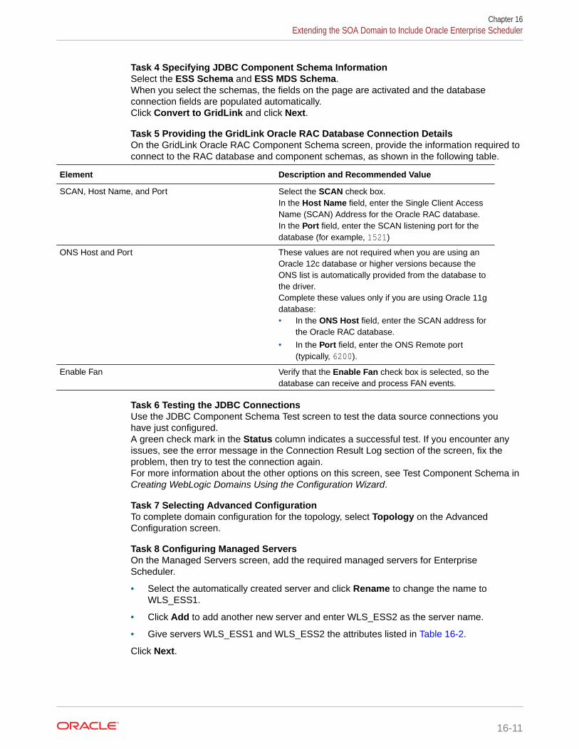
Task 4 Specifying JDBC Component Schema InformationSelect the ESS Schema and ESS MDS Schema.When you select the schemas, the fields on the page are activated and the databaseconnection fields are populated automatically.Click Convert to GridLink and click Next.
Task 5 Providing the GridLink Oracle RAC Database Connection DetailsOn the GridLink Oracle RAC Component Schema screen, provide the information required toconnect to the RAC database and component schemas, as shown in the following table.
Element Description and Recommended Value
SCAN, Host Name, and Port Select the SCAN check box.In the Host Name field, enter the Single Client AccessName (SCAN) Address for the Oracle RAC database.In the Port field, enter the SCAN listening port for thedatabase (for example, 1521)
ONS Host and Port These values are not required when you are using anOracle 12c database or higher versions because theONS list is automatically provided from the database tothe driver.Complete these values only if you are using Oracle 11gdatabase:• In the ONS Host field, enter the SCAN address for
the Oracle RAC database.
• In the Port field, enter the ONS Remote port(typically, 6200).
Enable Fan Verify that the Enable Fan check box is selected, so thedatabase can receive and process FAN events.
Task 6 Testing the JDBC ConnectionsUse the JDBC Component Schema Test screen to test the data source connections youhave just configured.A green check mark in the Status column indicates a successful test. If you encounter anyissues, see the error message in the Connection Result Log section of the screen, fix theproblem, then try to test the connection again.For more information about the other options on this screen, see Test Component Schema inCreating WebLogic Domains Using the Configuration Wizard.
Task 7 Selecting Advanced ConfigurationTo complete domain configuration for the topology, select Topology on the AdvancedConfiguration screen.
Task 8 Configuring Managed ServersOn the Managed Servers screen, add the required managed servers for EnterpriseScheduler.
• Select the automatically created server and click Rename to change the name toWLS_ESS1.
• Click Add to add another new server and enter WLS_ESS2 as the server name.
• Give servers WLS_ESS1 and WLS_ESS2 the attributes listed in Table 16-2.
Click Next.
Chapter 16Extending the SOA Domain to Include Oracle Enterprise Scheduler
16-11

Name Listen Address Listen Port SSL Listen Port SSL Enabled Server Groups
WLS_SOA1 SOAHOST1 8001 n/a No SOA-MGD-SVRS-ONLY
WLS_SOA2 SOAHOST2 8001 n/a No SOA-MGD-SVRS-ONLY
WLS_WSM1 SOAHOST1 7010 n/a No JRF-MAN-SVRWSMPM-MAN-SVR
WLS_WSM2 SOAHOST2 7010 n/a No JRF-MAN-SVRWSMPM-MAN-SVR
WLS_OSB1 SOAHOST1 8011 n/a No OSB-MGD-SVRS-ONLY
WLS_OSB2 SOAHOST2 8011 n/a No OSB-MGD-SVRS-ONLY
WLS_ESS1 SOAHOST1 8021 n/a No ESS-MGD-SVRS
WLS_ESS2 SOAHOST2 8021 n/a No ESS-MGD-SVRS
Note:
• The WLS_SOA Managed Servers appear only if you are extending adomain where Oracle SOA Suite has been configured.
• The WLS_OSB Managed Servers appear only if you are extending adomain where Oracle Service Bus has been configured.
Task 9 Configuring a ClusterOn the Configure Clusters screen, add the ESS_Cluster cluster, by using the valuesfor each cluster as shown in Table 20-1.Click Next.
Task 10 Assigning Server TemplatesClick Next.
Task 11 Configuring Dynamic ServersClick Next.
Task 12 Assigning Managed Servers to the ClusterOn the Assign Servers to Clusters screen, assign servers to clusters as follows:
• SOA_Cluster - If you are extending a SOA domain.
– WLS_SOA1
– WLS_SOA2
• WSM-PM_Cluster:
– WLS_WSM1
Chapter 16Extending the SOA Domain to Include Oracle Enterprise Scheduler
16-12

– WLS_WSM2
• OSB_Cluster - If you are extending an OSB domain:
– WLS_OSB1
– WLS_OSB2
• ESS_Cluster:
– WLS_ESS1
– WLS_ESS2
Click Next.
Task 13 Configuring Coherence ClustersUse the Coherence Clusters screen to configure the Coherence cluster that is automaticallyadded to the domain. Leave the port number value at 9991, as it was defined during theinitial Infrastructure domain creation.
Task 14 Verifying the Existing MachinesOn the Unix Machines tab, confirm that the following entries appear:
Name Node Manager Listen Address
SOAHOST1 SOAHOST1
SOAHOST2 SOAHOST2
ADMINHOST ADMINVHN
Leave all other fields to their default values.Click Next.
Task 15 Assigning Servers to MachinesOn the Assign Servers to Machines screen, assign servers to machines as follows:
• ADMINHOST:
– AdminServer
• SOAHOST1
– WLS_SOA1 (if extending a SOA domain)
– WLS_WSM1
– WLS_OSB1 (if extending an OSB domain)
– WLS_ESS1
• SOAHOST2
– WLS_SOA2 (if extending a SOA domain)
– WLS_WSM2
– WLS_OSB2 (if extending an OSB domain)
– WLS_ESS2
Click Next..
Task 16 Configuring Virtual TargetsClick Next to continue.
Chapter 16Extending the SOA Domain to Include Oracle Enterprise Scheduler
16-13

Task 17 Configuring PartitionsClick Next to continue.
Task 18 Reviewing Your Configuration Specifications and Configuring theDomainThe Configuration Summary screen contains the detailed configuration information forthe domain you are about to extend. Review the details of each item on the screenand verify that the information is correct.If you need to make any changes, you can go back to any previous screen if you needto make any changes, either by using the Back button or by selecting the screen inthe navigation pane.Click Update to execute the domain extension.In the Configuration Progress screen, click Next when it finishes.For more information about the options on this screen, see Configuration Summary inCreating WebLogic Domains Using the Configuration Wizard.
Task 19 Writing Down Your Domain Home and Administration Server URLThe Configuration Success screen will show the following items about the domain youjust configured, including:
• Domain Location
• Administration Server URL
Make a note of both these items, because you will need them later; you will need thedomain location to access the scripts used to start the Administration Server, and youwill need the Administration Server URL to access the WebLogic ServerAdministration Console and Oracle Enterprise Manager Fusion Middleware Control.Click Finish to dismiss the Configuration Wizard.If the Admin Server was running during the domain extension process, restart theserver before you continue.
Task 20 Start the Administration ServerStart the Administration Server to ensure the changes you have made to the domainhave been applied.
After you have completed extending the domain with static clusters, go to Propagatingthe Extended Domain to the Domain Directories and Machines.
Extending the Domain with Dynamic ClustersIn this step, you extend the domain that were created in Extending the Domain withOracle SOA Suite to contain Oracle Enterprise Scheduler components.
The steps reflected in this section are very similar to the steps required to extend anOracle Fusion Middleware Infrastructure domain directly, but some of the options,libraries, and components shown in the screens vary.
Domain creation and configuration includes the following tasks:
• Task 1, Selecting the Domain Type and Domain Home Location
• Task 2, Selecting the Configuration Template
• Task 3, Specifying the Database Configuration Type
• Task 4, Specifying JDBC Component Schema Information
• Task 5, Providing the GridLink Oracle RAC Database Connection Details
• Task 6, Testing the JDBC Connections
Chapter 16Extending the SOA Domain to Include Oracle Enterprise Scheduler
16-14

• Task 7, Selecting Advanced Configuration
• Task 8, Configuring Managed Servers
• Task 9, Configuring a Cluster
• Task 10, Assigning Server Templates
• Task 11, Configuring Dynamic Servers
• Task 12, Configuring Coherence Clusters
• Task 13, Verifying the Existing Machines
• Task 14, Assigning Servers to Machines
• Task 15, Configuring Virtual Targets
• Task 16, Configuring Partitions
• Task 17, Reviewing Your Configuration Specifications and Configuring the Domain
• Task 18, Writing Down Your Domain Home and Administration Server URL
• Task 19, Start the Administration Server
Task 1 Selecting the Domain Type and Domain Home LocationOn the Configuration Type screen, select Update an existing domain.In the Domain Location field, select the value of the ASERVER_HOME variable, whichrepresents the complete path to the Administration Server domain home that you created in Creating the Initial Infrastructure Domain for an Enterprise Deployment.For more information about the directory location variables, see File System and DirectoryVariables Used in This Guide
Tip:
More information about the other options on this screen can be found in Configuration Type in Creating WebLogic Domains Using the Configuration Wizard.
Task 2 Selecting the Configuration TemplateOn the Templates screen, make sure that the Update Domain Using Product Templates isselected, and then select the following templates:
• Oracle Enterprise Scheduler Service Basic [oracle_common]
• Oracle Enterprise Manager Plugin for ESS [em]
Click Next.
Task 3 Specifying the Database Configuration TypeOn the Database Configuration Type screen, select RCU Data.All fields are pre-populated, because you already configured the domain to reference theFusion Middleware schemas that are required for the Infrastructure domain.
• Verify that the Vendor is Oracle and the Driver is *Oracle's Driver (Thin) forService Connections; Versions: Any.
• Verify that Connection Parameters is selected.
• Verify and ensure that credentials in all the fields are the same as those provided duringthe configuration of Oracle Fusion Middleware Infrastructure.
Chapter 16Extending the SOA Domain to Include Oracle Enterprise Scheduler
16-15

Note:
Any custom datasources that were created before the extension (such asLEASING datasources) shows up before this screen. Check theDatasources row and click Next. The test datasource screen verifies itsvalidity. Click Next.
Click Get RCU Configuration after you finish verifying the database connectioninformation. The following output in the Connection Result Log indicates that theoperation succeeded:
Connecting to the database server...OKRetrieving schema data from database server...OKBinding local schema components with retrieved data...OKSuccessfully Done.
Tip:
More information about the RCU Data option can be found in Understandingthe Service Table Schema in Creating Schemas with the RepositoryCreation Utility.More information about the other options on this screen can be found in Datasource Defaults in Creating WebLogic Domains Using the ConfigurationWizard.
Task 4 Specifying JDBC Component Schema InformationSelect the ESS Schema and ESS MDS Schema.When you select the schemas, the fields on the page are activated and the databaseconnection fields are populated automatically.Click Convert to GridLink, and then click Next.
Task 5 Providing the GridLink Oracle RAC Database Connection DetailsOn the GridLink Oracle RAC Component Schema screen, provide the information thatis required to connect to the RAC database and component schemas, as shown in thefollowing table.
Element Description and Recommended Value
SCAN, Host Name, and Port Select the SCAN check box.In the Host Name field, enter the Single Client AccessName (SCAN) Address for the Oracle RAC database.In the Port field, enter the SCAN listening port for thedatabase (for example, 1521).
Chapter 16Extending the SOA Domain to Include Oracle Enterprise Scheduler
16-16

Element Description and Recommended Value
ONS Host and Port These values are not required when you are using anOracle 12c database or higher versions because theONS list is automatically provided from the database tothe driver.Complete these values only if you are using Oracle 11gdatabase:• In the ONS Host field, enter the SCAN address for
the Oracle RAC database.
• In the Port field, enter the ONS Remote port(typically, 6200).
Enable Fan Verify that the Enable Fan check box is selected, so thedatabase can receive and process FAN events.
Task 6 Testing the JDBC ConnectionsUse the JDBC Component Schema Test screen to test the data source connections youhave just configured.A green check mark in the Status column indicates a successful test. If you encounter anyissues, see the error message in the Connection Result Log section of the screen, fix theproblem, then try to test the connection again.
Tip:
For more information about the other options on this screen, see Test ComponentSchema in Creating WebLogic Domains Using the Configuration Wizard.
Task 7 Selecting Advanced ConfigurationTo complete domain configuration for the topology, select the following options on theAdvanced Configuration screen:
• Topology
Add, Delete, or Modify Settings for Server Templates, Managed Servers, Clusters,Virtual Targets, and Coherence.
Task 8 Configuring Managed ServersOn the Managed Servers screen, a new Managed Server for Oracle Enterprise Schedulerappears in the list of servers.Static Managed Server definitions are not needed for dynamic cluster configurations. Toremove the default Managed Server, complete the following steps:
1. Delete the default Managed Server.
2. Click Next to proceed to the next screen.
Task 9 Configuring a ClusterOn the Configure Clusters screen, add the ESS_Cluster cluster by using the values for eachproperty shown in the following table.
Name Cluster Address Frontend Host Frontend HTTP Port Frontend HTTPs
SOA_Cluster Leave it empty soa.example.com 80 443
WSM-PM_Cluster Leave it empty Leave it empty Leave it empty Leave it empty
OSB_Cluster Leave it empty osb.example.com 80 443
Chapter 16Extending the SOA Domain to Include Oracle Enterprise Scheduler
16-17

Name Cluster Address Frontend Host Frontend HTTP Port Frontend HTTPs
ESS_Cluster Leave it empty soa.example.com 80 443
Click Next.
Note:
• The SOA_Cluster cluster appears only if you are extending a domainwhere Oracle SOA Suite has been configured.
• The OSB_Cluster cluster appears only if you are extending a domainwhere Oracle Service Bus has been configured.
Task 10 Assigning Server TemplatesUse the Server Templates screen to configure the template:
1. Verify that ESS-server-template in selected in Name field.
2. Specify 8020 in the Listen Port field.
3. Leave the Enable SSL option unchecked.
4. Click Next.
Task 11 Configuring Dynamic ServersUse the Dynamic Clusters screen to configure the required clusters:
1. Specify ESS_Cluster in the Cluster Name field.
2. From the Server Template drop-down list, select ESS-server-template.
3. Specify WLS_ESS in the Server Name Prefix field.
4. Specify 2 in the Dynamic Cluster Size field.
5. Specify SOAHOST* in the Machine Name Match Expression field and selectCalculated Machine Names.
Chapter 16Extending the SOA Domain to Include Oracle Enterprise Scheduler
16-18

Note:
The dynamic cluster Calculated Machine Names and Machine Name MatchExpression attributes control how server instances in a dynamic cluster areassigned to a machine. If the Calculated Machine Names attribute is set toFalse, the dynamic servers are not assigned to a machine. If the CalculatedMachine Names attribute is set to True, the Machine Name MatchExpression attribute is used to select the set of machines that is used for thedynamic servers. If the Machine Name Match Expression attribute is not set,all the machines in the domain are selected. Assignments are made by using around robin algorithm.
To make things easier regardless of your actual physical hostname, Oraclerecommends that you use SOAHOSTn as your WebLogic machine names,where n is a sequential number. This is explained in Task 18, CreatingMachines of configuring the infrastructure domain. This convention makes iteasy for dynamic clusters to determine where to start each cluster member. Ifyou want to follow this convention, in the Machine Match Expression field,enter SOAHOST*.
If you do not adopt this convention, the cluster members are started on eachmachine that you define in Task 18, Creating Machines, including that ofADMINHOST. This situation is undesirable as you would end you with twocluster members that run on the same physical server but are attached to twodifferent domain homes.
6. Select Calculated Listen Ports.
Note:
Dynamic clusters with the Calculated Listen Port option selected haveincremental port numbers for each dynamic managed server that is createdautomatically: dynamic server 1 will use Listen Port+1, dynamic server 2 willuse Listen Port+2.
Since the Listen Port configured is 8020 and calculated ports is checked, ESSdynamic servers use the following port numbers:
• WLS_ESS1 server listens in 8021 port
• WLS_ESS2 server listens in 8022 port
7. In Dynamic Server Groups, select ESS-DYN-CLUSTER.
8. Click Next.
Chapter 16Extending the SOA Domain to Include Oracle Enterprise Scheduler
16-19

Note:
The Configuration Wizard does not allow you to specify a specific listenaddress for dynamic servers. For information about setting a specific listenaddress for WebLogic servers that are members of a dynamic cluster, see Configuring Listen Addresses in Dynamic Cluster Server Templates.
Task 12 Configuring Coherence ClustersUse the Coherence Clusters screen to configure the Coherence cluster that isautomatically added to the domain. Leave the port number value at 9991, as it wasdefined during the initial Infrastructure domain creation.
Task 13 Verifying the Existing MachinesOn the Unix Machines tab, confirm that the following entries appear:
Name Node Manager Listen Address
SOAHOST1 SOAHOST1
SOAHOST2 SOAHOST2
ADMINHOST ADMINVHN
Leave all other fields with their default values.Click Next.
Task 14 Assigning Servers to MachinesClick Next.
Task 15 Configuring Virtual TargetsClick Next.
Task 16 Configuring PartitionsClick Next.
Task 17 Reviewing Your Configuration Specifications and Configuring theDomainThe Configuration Summary screen contains detailed configuration information for thedomain that you are about to extend. Review the details of each item on the screenand verify that the information is correct.If you need to make any changes, you can go back to any previous screen , either byusing the Back button or by selecting the screen in the navigation pane.Click Update to execute the domain extension.In the Configuration Progress screen, click Next when it finishes.For more information about the options on this screen, see Configuration Summary inCreating WebLogic Domains Using the Configuration Wizard.
Task 18 Writing Down Your Domain Home and Administration Server URLThe Configuration Success screen shows the following items about the domain thatyou just configured, including:
• Domain Location
• Administration Server URL
Make a note of both these items, because you need them later; you need the domainlocation to access the scripts used to start the Administration Server, and you need
Chapter 16Extending the SOA Domain to Include Oracle Enterprise Scheduler
16-20

the Administration Server URL to access the WebLogic Server Administration Console andOracle Enterprise Manager Fusion Middleware Control.Click Finish to dismiss the Configuration Wizard.If the Admin Server was running during the domain extension process, restart the serverbefore you continue.
Task 19 Start the Administration ServerStart the Administration Server to ensure the changes that you have made to the domainhave been applied.
Propagating the Extended Domain to the Domain Directoriesand Machines
After you have extended the domain with the ESS instances, and you have restarted theAdministration Server on SOAHOST1, you must then propagate the domain changes to thedomain directories and machines.
The following table summarizes the steps that are required to propagate the changes to allthe domain directories and machines.
Task Description More Information
Pack up the Extended Domain onSOAHOST1
Use the pack command to create anew template jar file that contains thenew ESS Servers configuration.
When you pack up the domain,create a template jar file calledsoadomaintemplateExtESS.jar.
Packing Up the Extended Domain onSOAHOST1
Unpack the Domain in the ManagedServers Directory on SOAHOST1
Unpack the template jar file in theManaged Servers directory onSOAHOST1 local storage.
Unpacking the Domain in theManaged Servers Domain Directoryon SOAHOST1
Unpack the Domain on SOAHOST2 Unpack the template jar file in theManaged Servers directory on theSOAHOST2 local storage.
Unpacking the Domain onSOAHOST2
Adding the ESSAdmin Role to the SOA Administrators GroupBefore you validate the Oracle Enterprise Scheduler configuration on the WLS_ESS1Managed Server, add the ESSAdmin role to the enterprise deployment administration group(SOA Administrators).
To perform this task, refer to Configuring Roles for Administration of Oracle SOA SuiteProducts.
Starting and Validating the WLS_ESS1 Managed ServerNow that you have extended the domain, restarted the Administration Server, andpropagated the domain to the other hosts, you can start the newly configured ESS servers.
To start the configured ESS servers:
1. Enter the following URL into a browser to display the Fusion Middleware Control loginscreen:
Chapter 16Propagating the Extended Domain to the Domain Directories and Machines
16-21

http://ADMINVHN:7001/em
In this example:
• Replace ADMINVHN with the host name assigned to the ADMINVHN VirtualIP address in Identifying and Obtaining Software Downloads for an EnterpriseDeployment.
• Port 7001 is the typical port used for the Administration Server console andFusion Middleware Control. However, you should use the actual URL that wasdisplayed at the end of the Configuration Wizard session when you createdthe domain.
2. Log in to Fusion Middleware Control by using the Administration Servercredentials.
3. In the Target Navigation pane, expand the domain to view the Managed Servers inthe domain.
4. Select only the WLS_ESS1 Managed Server, and click Start Up on the OracleWebLogic Server tool bar.
Note:
ESS Servers depend on the policy access service to be functional. Thisimplies that the WSM-PM servers in the domain need to be reachablebefore the SOA servers are started.
5. When the startup operation is complete, navigate to the Domain home page andverify that the WLS_ESS1 Managed Server is up and running.
6. To verify the ESS software is configured, enter the following URL in the browser:
http://SOAHOST1:8021/EssHealthCheck/
With the default installation, this should be the HTTP response, as shown in thefollowing image.
Click on the Check Health button, and then log in by using the welogic_soaadministration credentials.
The reply should report that Oracle Enterprise Schedule (ESS) is up and running.
Chapter 16Starting and Validating the WLS_ESS1 Managed Server
16-22

Starting and Validating the WLS_ESS2 Managed ServerAfter you start the WLS_ESS2 managed server, you must verify that the server status isreported as Running in the Admin Console and access the URLs to verify the status ofservers.
Perform the same steps that you used to start WLS_ESS1, to start WLS_ESS2.
1. Log in to Fusion Middleware Control by using the Administration Server credentials.
2. In the Target Navigation pane, expand the domain to view the Managed Servers in thedomain.
3. Select only the WLS_ESS2 Managed Server, and click Start Up on the Oracle WebLogicServer tool bar.
4. When the startup operation is complete, navigate to the Domain home page and verifythat the WLS_ESS2 Managed Server is up and running, access the equivalent URLs forthe WLS_ESS2:
For static clusters:
http://SOAHOST2:8021/EssHealthCheck/
For dynamic clusters:
http://SOAHOST2:8022/EssHealthCheck/
Click the Check Health button, and then log in by using the welogic_soa administrationcredentials.
The reply reports that Oracle Enterprise Scheduler is up and running.
Modifying the Upload and Stage Directories to an Absolute PathAfter you configure the domain and unpack it to the Managed Server domain directories onall the hosts, verify and update the upload and stage directories for Managed Servers in thenew clusters. See Modifying the Upload and Stage Directories to an Absolute Path in anEnterprise Deployment.
Configuring Listen Addresses When Using Dynamic ClustersThe default configuration for dynamic managed servers in dynamic clusters is to listen on allavailable network interfaces. In most cases, the default configuration may be undesirable. Tolimit the listen address to a specific address when you use dynamic clusters, see ConfiguringListen Addresses in Dynamic Cluster Server Templates. Reverify the test URLs that areprovided in the previous sections after you change the listen address and restart theclustered managed servers.
Configuring the Web Tier for the Extended DomainConfigure the web server instances on the web tier so that the instances route requests forboth public and internal URLs to the proper clusters in the extended domain.
For additional steps in preparation for possible scale-out scenarios, see Updating CrossComponent Wiring Information.
Chapter 16Starting and Validating the WLS_ESS2 Managed Server
16-23

• Configuring Oracle HTTP Server for the WLS_ESS Managed ServersMake the following modifications to the Oracle HTTP Server instance configurationfiles to ensure that the Oracle HTTP Server instances in the web tier can routeOracle Enterprise Scheduler requests correctly to the WLS_ESS ManagedServers on SOHOST1 and SOAHOST2.
• Configuring the WebLogic Proxy Plug-InSet the WebLogic Plug-In Enabled parameter for the ESS cluster.
Configuring Oracle HTTP Server for the WLS_ESS Managed ServersMake the following modifications to the Oracle HTTP Server instance configurationfiles to ensure that the Oracle HTTP Server instances in the web tier can route OracleEnterprise Scheduler requests correctly to the WLS_ESS Managed Servers onSOHOST1 and SOAHOST2.
To enable Oracle HTTP Server to route Oracle Enterprise Scheduler requests to theapplication tier:
1. Log in to SOAHOST1 and change directory to the configuration directory for thefirst Oracle HTTP Server instance (ohs1):
cd WEB_DOMAIN_HOME/config/fmwconfig/components/OHS/ohs1/moduleconf
2. Add the following directives inside the <VirtualHost> tag in the soa_vh.conf file:
Note:
Configure the port numbers appropriately as assigned for your static ordynamic cluster. Dynamic clusters with the Calculate Listen Port optionselected have incremental port numbers for each dynamic managedserver that you create.
The WebLogicCluster directive needs only a sufficient number ofredundant server:port combinations to guarantee initial contact in case ofa partial outage. The actual total list of cluster members is retrieveautomatically upon first contact with any given node.
<Location /ess > WLSRequest ON WebLogicCluster SOAHOST1:8021,SOAHOST2:8021 WLProxySSL ON WLProxySSLPassThrough ON</Location>
<Location /EssHealthCheck > WLSRequest ON WebLogicCluster SOAHOST1:8021,SOAHOST2:8021 WLProxySSL ON WLProxySSLPassThrough ON</Location>
<Location /ess-async > WLSRequest ON WebLogicCluster SOAHOST1:8021,SOAHOST2:8021 WLProxySSL ON WLProxySSLPassThrough ON
Chapter 16Configuring the Web Tier for the Extended Domain
16-24

</Location>
<Location /ess-wsjob > WLSRequest ON WebLogicCluster SOAHOST1:8021,SOAHOST2:8021 WLProxySSL ON WLProxySSLPassThrough ON</Location>
3. Log in to SOAHOST2 and change directory to the following location so you can update theconfiguration file for the second Oracle HTTP Server instance (ohs2):
cd WEB_DOMAIN_HOME/config/fmwconfig/components/OHS/ohs2/moduleconf
4. Open the soa_vh.conf file and add the Oracle Business Process Management directivesto the <VirualHost> tag.
5. Restart Oracle HTTP Servers on WEBHOST1 and WEBHOST2.
Configuring the WebLogic Proxy Plug-InSet the WebLogic Plug-In Enabled parameter for the ESS cluster.
1. Log in to the Oracle WebLogic Server Administration console.
2. In the Domain Structure pane, expand the Environment node.
3. Click on Clusters.
4. Select the ESS_Cluster cluster to which you want to proxy requests from Oracle HTTPServer.
The Configuration: General tab is displayed.
5. Scroll down to the Advanced section, expand it.
6. Click Lock and Edit.
7. Set the WebLogic Plug-In Enabled to yes.
8. Click Save, and then click Activate Changes.
9. Restart the ESS servers for the changes to be effective.
Validating Access to Oracle Enterprise Scheduler Through theHardware Load Balancer
Verify the URLs to ensure that appropriate routing and failover is working from the HTTPServer to the Oracle ESS components.
To verify the URLs:
1. While WLS_ESS1 is running, stop WLS_ESS2 by using the Oracle WebLogic ServerAdministration Console.
2. Access the following URL from your web browser, and verify the HTTP response asindicated in Starting and Validating the WLS_ESS2 Managed Server:
https://soa.example.com/EssHealthCheck
Chapter 16Validating Access to Oracle Enterprise Scheduler Through the Hardware Load Balancer
16-25

3. Start WLS_ESS2 from the Oracle WebLogic Server Administration console.
4. Stop WLS_ESS1 from the Oracle WebLogic Server Administration console.
5. Verify these URLs by using your load balancer address:
https://soa.example.com:443/EssHealthCheckhttps://soa.example.com/ess
Backing Up the ConfigurationIt is an Oracle best practices recommendation to create a backup after yousuccessfully extend a domain or at another logical point. Create a backup after youverify that the installation so far is successful. This is a quick backup for the expresspurpose of immediate restoration in case of problems in later steps.
The backup destination is the local disk. You can discard this backup when theenterprise deployment setup is complete. After the enterprise deployment setup iscomplete, you can initiate the regular deployment-specific Backup and Recoveryprocess.
For information about backing up your configuration, see Performing Backups andRecoveries in the SOA Enterprise Deployments.
Chapter 16Backing Up the Configuration
16-26

17Extending the Domain with Business ActivityMonitoring
The procedures explained in this chapter guide you through the process of extending theenterprise deployment domain to include Oracle Business Activity Monitoring.
• Variables Used When Configuring Business Activity MonitorAs you perform the tasks in this chapter, you reference the directory variables that arelisted in this section.
• Support for Dynamic Clusters in BAMBusiness Activity Monitoring does not support dynamic clusters in this release.
• Support for Reference Configuration in BAMOracle BAM does not support Reference Configuration. Hence, you can add BAM only toa Classic SOA domain.
• About Configuring BAM in Its Own DomainFor adding BAM to the enterprise topology, you can add it to the existing SOA domain oryou can create a new domain for BAM, separate from the Oracle SOA suite domain.
• Prerequisites When Adding Oracle BAM to the DomainBefore you add Oracle BAM to your existing Oracle SOA Suite domain, consider thefollowing information and prerequisites.
• Special Instructions When Configuring Oracle BAM on Separate HostsIf you choose to configure Oracle BAM on its own hardware, then you can use theinstructions in this chapter, as long as you also consider the information in the followingsections.
• Roadmap for Adding Oracle BAM to the DomainThe table in this section lists the high-level steps to extend a SOA domain for OracleBusiness Activity Monitoring.
• Extending the SOA Domain to Include Oracle Business Activity MonitoringYou can use the Configuration Wizard to extend the existing enterprise deployment SOAdomain with the Oracle Business Activity Monitoring.
• Propagating the Extended Domain to the Domain Directories and MachinesAfter you have extended the domain with the BAM instances, and you have restarted theAdministration Server on SOAHOST1, you must then propagate the domain changes tothe domain directories and machines.
• Adding the Enterprise Deployment Administration User to the Oracle BAM AdministrationGroupBefore you validate the Oracle BAM configuration on the Managed Server, add theenterprise deployment administration user (weblogic_soa) to the BAMAdministratorgroup.
• Starting and Validating the WLS_BAM1 Managed ServerAfter extending the domain, restarting the Administration Server, and propagating thedomain to the other hosts, start the newly configured BAM servers.
17-1

• Starting and Validating the WLS_BAM2 Managed ServerAfter you start the WLS_BAM2 managed server, you must verify that the serverstatus is reported as Running in the Admin Console and access the URLs to verifythe status of the servers.
• Modifying the Upload and Stage Directories to an Absolute Path
• Configuring the Web Tier for the Extended DomainConfigure the web server instances on the web tier so that the instances routerequests for both public and internal URLs to the proper clusters in the extendeddomain.
• Validating Access to Oracle BAM Through the Hardware Load BalancerVerify that Oracle BAM URLs are successfully routing requests from the hardwareload balancer to the Oracle HTTP Server instances to the Oracle BAM software inthe middle tier.
• Enabling JDBC Persistent Stores for BAMOracle recommends that you use JDBC stores, which leverage the consistency,data protection, and high availability features of an Oracle database and makesresources available for all the servers in the cluster.
• Enabling Automatic Service Migration for BAMBy default, the BAM Managed Servers are always configured with AutomaticService Migration. Specific BAM migratable targets with the appropriate migrationpolicies are created and the cluster database leasing is configured for the BAMcluster during the Configuration Wizard session.
• Backing Up the ConfigurationIt is an Oracle best practices recommendation to create a backup after yousuccessfully extend a domain or at another logical point. Create a backup afteryou verify that the installation so far is successful. This is a quick backup for theexpress purpose of immediate restoration in case of problems in later steps.
Variables Used When Configuring Business Activity MonitorAs you perform the tasks in this chapter, you reference the directory variables that arelisted in this section.
The values for several directory variables are defined in File System and DirectoryVariables Used in This Guide.
• ORACLE_HOME
• ASERVER_HOME
• MSERVER_HOME
• ORACLE_RUNTIME
• WEB_DOMAIN_HOME
In addition, you reference the following virtual IP (VIP) address that are defined in Physical and Virtual IP Addresses Required by the Enterprise Topology:
• ADMINVHN
Actions in this chapter are performed on the following host computers:
• SOAHOST1
• SOAHOST2
Chapter 17Variables Used When Configuring Business Activity Monitor
17-2

• WEBHOST1
• WEBHOST2
• BAMHOST1
• BAMHOST2
Support for Dynamic Clusters in BAMBusiness Activity Monitoring does not support dynamic clusters in this release.
You can configure BAM in its own domain or in an existing SOA domain, including a domainwhere the rest of the clusters are dynamic. However, the BAM cluster is configured as a staticcluster in all cases. The procedures explained in this chapter help you extend the domainwith a static BAM cluster.
Support for Reference Configuration in BAMOracle BAM does not support Reference Configuration. Hence, you can add BAM only to aClassic SOA domain.
About Configuring BAM in Its Own DomainFor adding BAM to the enterprise topology, you can add it to the existing SOA domain or youcan create a new domain for BAM, separate from the Oracle SOA suite domain.
For more information about building the SOA topology, see Building Your Own Oracle SOASuite Enterprise Topology.
If you decide to configure BAM in a separate domain, keep the following points in mind to addBAM to your topology:
• Ignore any references to the SOA Managed Servers or the SOA Cluster. These elementsof the domain exist only if you extend a domain that has already been extended with theOracle SOA suite.
• Run the Repository Creation Utility (RCU) to create the SOAINFRA schema for the BAMdomain. This schema is required by BAM. You must use an unique SOAINFRA schemaand schema prefix for the BAM domain.
• When running the Configuration Wizard, the High Availability Options screen appears asdescribed in Navigating the Configuration Wizard Screens to Extend the Domain withOracle SOA Suite.
This screen appears for the first time when you create a cluster that uses AutomaticService Migration or JDBC stores or both. After you select HA Options for a cluster, allsubsequent clusters that are added to the domain by using the Configuration Wizard,automatically apply HA options (that is, the Configuration Wizard creates the JDBCstores and configures ASM for them).
Oracle recommends that you select the following options to configure Automatic ServiceMigration and JDBC stores automatically:
– Select Enable Automatic Service Migration with Database Basis.
– Set JTA Transaction Log Persistence to JDBC TLog Store.
– Set JMS Server Persistence to JMS JDBC Store.
Chapter 17Support for Dynamic Clusters in BAM
17-3

Prerequisites When Adding Oracle BAM to the DomainBefore you add Oracle BAM to your existing Oracle SOA Suite domain, consider thefollowing information and prerequisites.
Note:
If you choose to install Oracle BAM on a separate set of host computers,then in addition to the prerequisites listed here, see Special InstructionsWhen Configuring Oracle BAM on Separate Hosts.
• Understanding the Installation Requirements for Adding Oracle BAM to theDomain
• Understanding the Database Schema Requirements for Oracle BAM
• Backing Up the Existing Installation
Understanding the Installation Requirements for Adding Oracle BAMto the Domain
This chapter assumes that you are configuring Oracle Business Activity Monitoring onthe same host computers as Oracle SOA Suite, as shown in Figure 3-2.
In the default Oracle SOA Suite and Oracle Business Activity Monitoring topology, youtarget Oracle BAM to its own Managed Servers and its own cluster, but it sharessystem resources with the other Oracle SOA Suite products on SOAHOST1 andSOAHOST2. Those system resources include a shared storage device where theOracle SOA Suite software has been installed in an existing Oracle home directory.
In the default topology, there is no need to install Oracle BAM, because Oracle BAM isincluded in the Oracle SOA Suite and Oracle Business Process Managementdistribution and is installed into the Oracle home directories when you install OracleSOA Suite in Understanding the SOA Enterprise Deployment Topology .
Understanding the Database Schema Requirements for Oracle BAMThe schemas required for Oracle BAM are created in the database when you run theRepository Creation Utility (RCU) to create the required Oracle SOA Suite schemas.
As a result, there is no need to run RCU specifically for Oracle BAM.
Backing Up the Existing InstallationIf you have not yet backed up the existing Fusion Middleware Home and domain, backit up now.
To back up the existing Fusion Middleware Home and domain, see PerformingBackups and Recoveries in the SOA Enterprise Deployments.
Chapter 17Prerequisites When Adding Oracle BAM to the Domain
17-4

Special Instructions When Configuring Oracle BAM on SeparateHosts
If you choose to configure Oracle BAM on its own hardware, then you can use theinstructions in this chapter, as long as you also consider the information in the followingsections.
For some organizations, it might make sense to install and configure Oracle BAM onseparate host computers so the Oracle BAM software can use dedicated hardware resourcesand can be further isolated from the other Oracle SOA Suite products.
• Procuring Additional Host Computers for Oracle BAM
• Installation Requirements When Configuring Oracle BAM on Separate Hosts
• Configuration Wizard Instructions When Configuring Oracle BAM on Separate Hosts
• Propagating the Domain Configuration When Configuring Oracle BAM on Separate Hosts
Procuring Additional Host Computers for Oracle BAMIf you are configuring Oracle BAM on its own set of host computers, you must procure theadditional hardware and be sure that it meets the system requirements described in HostComputer Hardware Requirements and Operating System Requirements for the EnterpriseDeployment Topology.
You should also add the required entries to the Enterprise Deployment Workbook, asdescribed in Using the Enterprise Deployment Workbook . For the purposes of this guide, youcan refer to these host computers as BAMHOST1 and BAMHOST2.
Installation Requirements When Configuring Oracle BAM on SeparateHosts
If you configure Oracle BAM on its own set of host computers, then you should follow thesame shared storage strategy that you are following for the host computers where the otherOracle SOA Suite products are installed.
Note:
The Oracle home used by BAMHOST1 and BAMHOST2 must contain the exact setof software binaries used by the SOAHOST1 and SOAHOST2 hosts in the domain;otherwise, unpredictable behavior in the execution of the binaries may occur.
Depending on your shared storage strategy, one of the following sections apply if you areusing separate host hardware for the Oracle BAM software:
• Installation Requirements When Using a Separate Volume or Partition
• Installation Requirements When Using a Shared Oracle Home
Chapter 17Special Instructions When Configuring Oracle BAM on Separate Hosts
17-5

Installation Requirements When Using a Separate Volume or PartitionIf BAMHOST1 and BAMHOST2 are using separate shared storage volumes orpartitions, then you must install the Infrastructure and optionally Oracle SOA Suite onthose hosts. For more information, see Shared Storage Recommendations WhenInstalling and Configuring an Enterprise Deployment.
Note that the location where you install the Oracle home (which contains the softwarebinaries) varies, depending upon the host. To identify the proper location for youOracle home directories, refer to the guidelines in File System and Directory VariablesUsed in This Guide.
To install the software on BAMHOST1 and BAMHOST2, log in to each host, andperform the following tasks:
• Use the instructions in Installing the Oracle Fusion Middleware Infrastructure inPreparation for an Enterprise Deployment to create the Oracle home on theappropriate storage device and install Oracle Fusion Middleware Infrastructure.
• Optionally, use the instructions in Installing Oracle SOA Suite for an EnterpriseDeployment to install the Oracle SOA Suite software.
Installation Requirements When Using a Shared Oracle HomeIf BAMHOST1 and BAMHOST2 are using an existing volume or partition where theOracle Fusion Middleware Infrastructure or Oracle SOA Suite are already installed,then you must mount the volumes appropriately to BAMHOST1 and BAMHOST2. Formore information, see Mounting the Required Shared File Systems on Each Host.Ensure that BAMHOST1 and BAMHOST2 have access to this Oracle home, similar tothe rest of the hosts in the domain.
This is the preferred method of using shared storage for the enterprise deployment.For more information, see Shared Storage Recommendations When Installing andConfiguring an Enterprise Deployment.
After you have mounted an existing volume or partition that contains an existingOracle home, then you should attach the Oracle home to the local Oracle Inventory onBAMHOST1 or BAMHOST2.
To attach an Oracle home in shared storage to the local Oracle Inventory, use thefollowing command on the BAMHOSTs:
cd ORACLE_HOME/oui/bin/attachHome.sh
./attachHome.sh -jreLoc JAVA_HOME
The pack and unpack utilities is used to bootstrap the domain configuration for theWLS_BAM1 and WLS_BAM2 servers. As a result, if you have mounted an existingOracle home with the required software already installed, then you do not need toinstall any software in these two hosts.
Chapter 17Special Instructions When Configuring Oracle BAM on Separate Hosts
17-6

Configuration Wizard Instructions When Configuring Oracle BAM onSeparate Hosts
If you configure Oracle BAM on separate host computers, then the instructions in this chapterfor configuring the domain with the Configuration Wizard are slightly different.
Specifically, be sure to create additional Oracle WebLogic Server machines for BAMHOST1and BAMHOST2, and then target the WLS_BAM1 and WLS_BAM2 Managed Servers tothose machines, rather than to SOAHOST1 and SOAHOST2. See Task 14, Verifying theExisting Machines and Task 15, Assigning Servers to Machines.
Propagating the Domain Configuration When Configuring Oracle BAM onSeparate Hosts
If you configure Oracle BAM on separate host computers, then the instructions in this chapterfor propagating the domain to the other domain directories must be modified.
Specifically, in addition to propagating the domain to the Managed Server domain directorieson SOAHOST1 and SOAHOST2, you must also unpack the domain in the local ManagedServer directories for BAMHOST1 and BAMHOST2.
Note that this means you must start the Node Manager software on each BAMHOSTcomputer before you can remotely start the WLS_BAM Managed Servers on these hosts.
Roadmap for Adding Oracle BAM to the DomainThe table in this section lists the high-level steps to extend a SOA domain for OracleBusiness Activity Monitoring.
Step Description More Information
Run the Configuration Wizard toExtend the Domain in theAdministration Server domain home
Extend the SOA domain to containOracle BAM components.
Extending the SOA Domain toInclude Oracle Business ActivityMonitoring
Propagate the Domain Configurationto the Managed Server domaindirectories
Oracle BAM requires some updatesto the WebLogic Server start scripts.Propagate these changes by usingthe pack and unpack commands.
Propagating the Extended Domain tothe Domain Directories andMachines
Add the SOA Administrator role tothe Oracle BAM AdministrationGroup
This step allows you to use one setof credentials to access the variousproduct-specific managementutilities.
Adding the Enterprise DeploymentAdministration User to the OracleBAM Administration Group
Start the Oracle BAM Servers Oracle BAM servers extend analready existing domain. As a result,the Administration Server andrespective Node Managers arealready running in SOAHOST1 andSOAHOST2.
Starting and Validating theWLS_BAM1 Managed Server
Validate the WLS_BAM ManagedServers
Verify that the server status isreported as Running in the AdminConsole and access URLs to verifystatus of servers.
Starting and Validating theWLS_BAM2 Managed Server
Chapter 17Roadmap for Adding Oracle BAM to the Domain
17-7

Step Description More Information
Configuring Oracle HTTP Server forthe WLS_BAMn Managed Servers
To enable Oracle HTTP Server toroute to Oracle BAM, add therequired directives to the OracleHTTP Server configuration files, andset the WebLogicCluster parameterto the list of nodes in the cluster.
Configuring Oracle HTTP Server forthe WLS_BAM Managed Servers
Configure the WebLogic ServerProxy Plugin
Enable the WebLogic Server ProxyPlugin for Oracle BAM.
Configuring the WebLogic ProxyPlug-In
Validating Access Through OracleHTTP Server
Verify that the server status isreported as Running.
Validating Access to Oracle BAMThrough the Hardware LoadBalancer
Configure Automatic ServiceMigration for the Oracle BAMServers
Service migration ensures that keypinned services can be migratedautomatically to another ManagedServer in the cluster if one of theManaged Servers or host computersfails. For more information aboutservice migration, see Using WholeServer Migration and ServiceMigration in an EnterpriseDeployment.
Enabling Automatic ServiceMigration for BAM
Backing up the Oracle BAMConfiguration
To back up the domain configurationfor immediate restoration in case offailures in future procedures.
Backing Up the Oracle BAMConfiguration
Extending the SOA Domain to Include Oracle BusinessActivity Monitoring
You can use the Configuration Wizard to extend the existing enterprise deploymentSOA domain with the Oracle Business Activity Monitoring.
Extending the domain involves the following tasks.
• Starting the Configuration Wizard
• Navigating the Configuration Wizard Screens for Oracle BAM
Chapter 17Extending the SOA Domain to Include Oracle Business Activity Monitoring
17-8

Starting the Configuration Wizard
Note:
If you added any customizations directly to the start scripts in the domain, those areoverwritten by the configuration wizard. To customize server startup parameters thatapply to all servers in a domain, you can create a file calledsetUserOverridesLate.sh and configure it, for example, add custom libraries to theWebLogic Server classpath, specify additional JAVA command-line options forrunning the servers, or specify additional environment variables. Anycustomizations you add to this file are preserved during domain upgradeoperations, and are carried over to remote servers when you use the pack andunpack commands.
To begin domain configuration:
1. Shut down the Administration Server to prevent any configuration locks, saves, oractivations from occurring during the configuration of the domain.
2. Navigate to the following directory and start the WebLogic Server Configuration Wizard.
ORACLE_HOME/oracle_common/common/bin./config.sh
Navigating the Configuration Wizard Screens for Oracle BAMIn this step, you extend the domain created in Extending the Domain with Oracle SOA Suite ,to contain Oracle Business Activity Monitoring components.
The steps reflected in this section would be very similar if Oracle Business Activity Monitoringwas extending a domain containing only an Administration Server and a WSM-PM Cluster,but some of the options, libraries and components shown in the screens could vary.
Domain creation and configuration includes the following tasks:
• Task 1, Selecting the Domain Type and Domain Home Location
• Task 2, Selecting the Configuration Template
• Task 3, Specifying the Database Configuration Type
• Task 4, Specifying JDBC Component Schema Information
• Task 5, Providing the GridLink Oracle RAC Database Connection Details
• Task 6, Testing the JDBC Connections
• Task 7, Selecting Advanced Configuration
• Task 8, Configuring Managed Servers
• Task 9, Configuring a Cluster
• Task 10, Assigning Server Templates
• Task 11, Configuring Dynamic Servers
• Task 12, Assigning Managed Servers to the Cluster
Chapter 17Extending the SOA Domain to Include Oracle Business Activity Monitoring
17-9

• Task 13, Configuring Coherence Clusters
• Task 14, Verifying the Existing Machines
• Task 15, Assigning Servers to Machines
• Task 16, Configuring Virtual Targets
• Task 17, Configuring Partitions
• Task 18, Reviewing Your Configuration Specifications and Configuring the Domain
• Task 19, Writing Down Your Domain Home and Administration Server URL
• Task 20, Start the Administration Server
Task 1 Selecting the Domain Type and Domain Home LocationOn the Configuration Type screen, select Update an existing domain.In the Domain Location field, select the value of the ASERVER_HOME variable,which represents the complete path to the Administration Server domain home thatyou created in Creating the Initial Infrastructure Domain for an Enterprise Deployment.For more information about the directory location variables, see File System andDirectory Variables Used in This Guide.
Tip:
More information about the other options on this screen can be found in Configuration Type in Creating WebLogic Domains Using the ConfigurationWizard.
Task 2 Selecting the Configuration TemplateOn the Templates screen, make sure Update Domain Using Product Templates isselected, then select the following template:Oracle Business Activity Monitoring [soa]Click Next.
Task 3 Specifying the Database Configuration TypeOn the Database Configuration Type screen, select RCU Data.All fields are pre-populated, because you already configured the domain to referencethe Fusion Middleware schemas that are required for the Infrastructure domain.
• Verify that the Vendor is Oracle and the Driver is *Oracle's Driver(Thin) for Service Connections; Versions: Any.
• Verify that Connection Parameters is selected.
• Verify and ensure that credentials in all the fields are the same as those providedduring the configuration of Oracle Fusion Middleware Infrastructure.
Note:
Any custom data sources that were created before the extension (such asLEASING datasources) shows up before this screen. Check theDatasources row and click Next. The test data source screen verifies itsvalidity. Click Next.
Chapter 17Extending the SOA Domain to Include Oracle Business Activity Monitoring
17-10

Click Get RCU Configuration after you finish verifying the database connection information.The following output in the Connection Result Log indicates that the operation succeeded:
Connecting to the database server...OKRetrieving schema data from database server...OKBinding local schema components with retrieved data...OKSuccessfully Done.
Task 4 Specifying JDBC Component Schema InformationOn the JDBC Component Schema page, select the following schemas:
• BAM Schema
• BAM Job Sched Schema
• BAM Leasing Schema
• BAM Non JTA Schema
• BAM MDS Schema
Select Convert to Gridlink, and then click Next.
Task 5 Providing the GridLink Oracle RAC Database Connection DetailsOn the GridLink Oracle RAC Component Schema screen, provide the information that isrequired to connect to the RAC database and component schemas, as shown in thefollowing table.
Element Description and Recommended Value
SCAN, Host Name, and Port Select the SCAN check box.In the Host Name field, enter the Single Client AccessName (SCAN) Address for the Oracle RAC database.In the Port field, enter the SCAN listening port for thedatabase (for example, 1521).
ONS Host and Port These values are not required when you are using anOracle 12c database or higher versions because theONS list is automatically provided from the database tothe driver.Complete these values only if you are using Oracle 11gdatabase:• In the ONS Host field, enter the SCAN address for
the Oracle RAC database.
• In the Port field, enter the ONS Remote port(typically, 6200).
Enable Fan Verify that the Enable Fan check box is selected, so thedatabase can receive and process FAN events.
Task 6 Testing the JDBC ConnectionsOn the Test JDBC Data Sources screen, confirm that all connections were successful.The connections are tested automatically. The Status column displays the results. If allconnections are not successful, click Previous to return to the previous screen and correctyour entries.Click Next when all the connections are successful.
Task 7 Selecting Advanced ConfigurationTo complete domain configuration for the topology, select Topology on the AdvancedConfiguration screen.
Chapter 17Extending the SOA Domain to Include Oracle Business Activity Monitoring
17-11

Note:
JDBC stores are recommended and selected in Task 3, Configuring HighAvailability Options so there is no need to configure File Stores.If you choose File Stores in Task 3, Configuring High Availability Options,you have to select the File Stores option here to configure them in a sharedlocation in ORACLE_RUNTIME/domain_name/BAM_Cluster/jms. Sharedlocation is required to resume JMS and JTA in a failover scenario.
Click Next.
Task 8 Configuring Managed ServersOn the Managed Servers screen, add the required managed servers for Oracle BAM:
• Select the automatically created server and rename it to WLS_BAM1.
• Click Add to add another new server and enter WLS_BAM2 as the server name.
• Select BAM12-MGD-SVRS-ONLY as the server group for the BAM Servers.Deselect BAM12-MGD-SVRS from the list.
The configuration for the added servers should match those shown in the followingtable.
Name Listen Address Listen Port SSL Listen Port SSL Enabled Server Groups
WLS_SOA1* SOAHOST1 8001 n/a No SOA-MGD-SVRS-ONLY
WLS_SOA2* SOAHOST2 8001 n/a No SOA-MGD-SVRS-ONLY
WLS_WSM1 SOAHOST1 7010 n/a No JRF-MAN-SVRWSMPM-MAN-SVR
WLS_WSM2 SOAHOST2 7010 n/a No JRF-MAN-SVRWSMPM-MAN-SVR
WLS_BAM1 SOAHOST1 9001 n/a No BAM12-MGD-SVRS-ONLY
WLS_BAM2 SOAHOST2 9001 n/a No BAM12-MGD-SVRS-ONLY
*The WLS_SOA1 and WLS_SOA2 Managed Servers are shown if you extend adomain where Oracle SOA Suite has already been configured.*When you specify the listen address for WLS_BAM1 and WLS_BAM2, enterSOAHOST1 and SOAHOST2, respectively, unless you configure Oracle BAM onseparate host computers (BAMHOST1 and BAMHOST2). If you configure OracleBAM on separate hosts, enter BAMHOST1 and BAMHOST2.
Task 9 Configuring a ClusterOn the Configure Clusters screen, click Add to add the BAM_Cluster (leave thepresent cluster as they are):
Chapter 17Extending the SOA Domain to Include Oracle Business Activity Monitoring
17-12

Name ClusterAddress
Frontend Host FrontendHTTP Port
FrontendHTTPS Port
SOA_Cluster* Leave it empty soa.example.com
80 443
WSM-PM_Cluster
Leave it empty Leave it empty Leave it empty Leave it empty
BAM_Cluster Leave it empty soa.example.com
80 443
*The SOA cluster appears only if you have already configured Oracle SOA Suite in thedomain.Click Next.
Task 10 Assigning Server TemplatesClick Next.
Task 11 Configuring Dynamic ServersClick Next.
Task 12 Assigning Managed Servers to the ClusterOn the Assign Servers to Clusters screen, assign servers to clusters as follows:
• BAM_Cluster:
– WLS_BAM1
– WLS_BAM2
Click Next.
Task 13 Configuring Coherence ClustersUse the Coherence Clusters screen to configure the Coherence cluster that is automaticallyadded to the domain. Leave the port number value at 9991, as it was defined during theinitial Infrastructure domain creation.
Task 14 Verifying the Existing MachinesVerify the machines that have already been created in the domain. By default, you aretargeting the new Oracle BAM Managed Servers to the SOAHOST1 and SOAHOST2machines, respectively.However, if you configure Oracle BAM on separate host computers, then you must createtwo new machines for the corresponding BAMHOST1 and BAMHOST2 host computers:
1. Select the Unix Machine tab.
2. Use the Add button to create two new Unix machines for BAMHOST1 and BAMHOST2.
Node Manager Listen Address to the physical IP address for BAMHOST1 andBAMHOST2.
3. Verify the port in the Node Manager Listen Port field.
The port number 5556, shown in this example, may be referenced by other examples inthe documentation. Replace this port number with your own port number as needed.
Leave all other fields to their default values.Click Next.
Chapter 17Extending the SOA Domain to Include Oracle Business Activity Monitoring
17-13
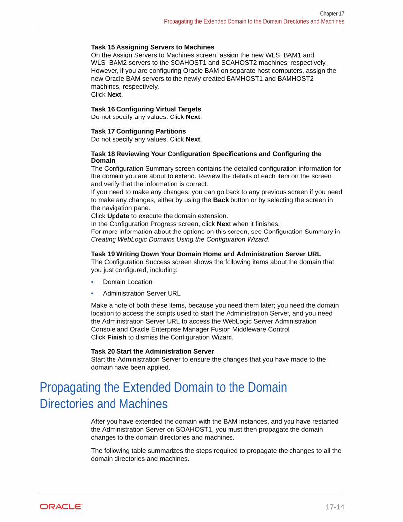
Task 15 Assigning Servers to MachinesOn the Assign Servers to Machines screen, assign the new WLS_BAM1 andWLS_BAM2 servers to the SOAHOST1 and SOAHOST2 machines, respectively.However, if you are configuring Oracle BAM on separate host computers, assign thenew Oracle BAM servers to the newly created BAMHOST1 and BAMHOST2machines, respectively.Click Next.
Task 16 Configuring Virtual TargetsDo not specify any values. Click Next.
Task 17 Configuring PartitionsDo not specify any values. Click Next.
Task 18 Reviewing Your Configuration Specifications and Configuring theDomainThe Configuration Summary screen contains the detailed configuration information forthe domain you are about to extend. Review the details of each item on the screenand verify that the information is correct.If you need to make any changes, you can go back to any previous screen if you needto make any changes, either by using the Back button or by selecting the screen inthe navigation pane.Click Update to execute the domain extension.In the Configuration Progress screen, click Next when it finishes.For more information about the options on this screen, see Configuration Summary inCreating WebLogic Domains Using the Configuration Wizard.
Task 19 Writing Down Your Domain Home and Administration Server URLThe Configuration Success screen shows the following items about the domain thatyou just configured, including:
• Domain Location
• Administration Server URL
Make a note of both these items, because you need them later; you need the domainlocation to access the scripts used to start the Administration Server, and you needthe Administration Server URL to access the WebLogic Server AdministrationConsole and Oracle Enterprise Manager Fusion Middleware Control.Click Finish to dismiss the Configuration Wizard.
Task 20 Start the Administration ServerStart the Administration Server to ensure the changes that you have made to thedomain have been applied.
Propagating the Extended Domain to the DomainDirectories and Machines
After you have extended the domain with the BAM instances, and you have restartedthe Administration Server on SOAHOST1, you must then propagate the domainchanges to the domain directories and machines.
The following table summarizes the steps required to propagate the changes to all thedomain directories and machines.
Chapter 17Propagating the Extended Domain to the Domain Directories and Machines
17-14
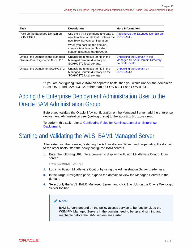
Task Description More Information
Pack up the Extended Domain onSOAHOST1
Use the pack command to create anew template jar file that contains thenew BAM Servers configuration.
When you pack up the domain,create a template jar file calledsoadomaintemplateExtBAM.jar.
Packing Up the Extended Domain onSOAHOST1
Unpack the Domain in the ManagedServers Directory on SOAHOST1*
Unpack the template jar file in theManaged Servers directory onSOAHOST1 local storage.
Unpacking the Domain in theManaged Servers Domain Directoryon SOAHOST1
Unpack the Domain on SOAHOST2 Unpack the template jar file in theManaged Servers directory on theSOAHOST2 local storage.
Unpacking the Domain onSOAHOST2
*If you are configuring Oracle BAM on separate hosts, then you would unpack the domain onBAMHOST1 and BAMHOST2, rather than on SOAHOST1 and SOAHOST2.
Adding the Enterprise Deployment Administration User to theOracle BAM Administration Group
Before you validate the Oracle BAM configuration on the Managed Server, add the enterprisedeployment administration user (weblogic_soa) to the BAMAdministrator group.
To perform this task, refer to Configuring Roles for Administration of an EnterpriseDeployment.
Starting and Validating the WLS_BAM1 Managed ServerAfter extending the domain, restarting the Administration Server, and propagating the domainto the other hosts, start the newly configured BAM servers.
1. Enter the following URL into a browser to display the Fusion Middleware Control loginscreen:
http://ADMINVHN:7001/em
2. Log in to Fusion Middleware Control by using the Administration Server credentials.
3. In the Target Navigation pane, expand the domain to view the Managed Servers in thedomain.
4. Select only the WLS_BAM1 Managed Server, and click Start Up on the Oracle WebLogicServer toolbar.
Note:
BAM Servers depend on the policy access service to be functional, so theWSM-PM Managed Servers in the domain need to be up and running andreachable before the BAM servers are started.
Chapter 17Adding the Enterprise Deployment Administration User to the Oracle BAM Administration Group
17-15

5. When the startup operation is complete, navigate to the Domain home page andverify that the WLS_BAM1 Managed Server is up and running.
6. To verify that the BAM software is configured properly:
a. Enter the following URL in the browser:
http://SOAHOST1:9001/bam/composer
The login screen for BAM's composer appears.
If you configured Oracle BAM on separate host computers, enter BAMHOST1in the URL, rather than SOAHOST1.
b. Enter the weblogic_soa login credentials.
The BAM Composer screen appears.
Note:
To validate the server URLs, disable (set to blank) the front-end host untilyou have completed the configuration for the web tier. If you do notdisable the front-end host, all requests fail because they are redirected tothe front-end address.
7. Enter the following URL:
http://SOAHOST1:9001/inspection.wsil/
If you configured Oracle BAM on separate host computers, enter BAMHOST1 inthe URL, rather than SOAHOST1.
You should see an XML response with a list of links.
8. Enter the following URL in the browser:
http://SOAHOST1:9001/bam/cqservice/
If you configured Oracle BAM on separate host computers, enter BAMHOST1 inthe URL, rather than SOAHOST1.
You should get a message in the browser indicating BAM CQService is running.
Starting and Validating the WLS_BAM2 Managed ServerAfter you start the WLS_BAM2 managed server, you must verify that the server statusis reported as Running in the Admin Console and access the URLs to verify the statusof the servers.
1. Log in to Fusion Middleware Control by using the Administration Servercredentials.
2. In the Target Navigation pane, expand the domain to view the Managed Servers inthe domain.
3. Select only the WLS_BAM2 Managed Server, and click Start Up on the OracleWebLogic Server tool bar.
Chapter 17Starting and Validating the WLS_BAM2 Managed Server
17-16

4. When the startup operation is complete, navigate to the Domain home page and verifythat the WLS_BAM2 Managed Server is up and running. Access the equivalent URLs forthe WLS_BAM2:
http://SOAHOST2:9001/bam/composer
The login screen for BAM's composer appears. Enter the login credentials. The BAMcomposer's menu is displayed.
5. Enter the following URL:
http://SOAHOST2:9001/inspection.wsil/
You should see a response with a list of links.
6. Enter the following URL in the browser:
http://SOAHOST2:9001/bam/cqservice/
You should get a message in the browser indicating BAM CQService is running.
Note:
If you configured Oracle BAM on separate host computers, enter BAMHOST2in the URL, rather than SOAHOST2.
Modifying the Upload and Stage Directories to an Absolute PathAfter you configure the domain and unpack it to the Managed Server domain directories onall the hosts, verify and update the upload and stage directories for Managed Servers in thenew clusters. See Modifying the Upload and Stage Directories to an Absolute Path in anEnterprise Deployment.
Configuring the Web Tier for the Extended DomainConfigure the web server instances on the web tier so that the instances route requests forboth public and internal URLs to the proper clusters in the extended domain.
For additional steps in preparation for possible scale-out scenarios, see Updating CrossComponent Wiring Information.
• Configuring Oracle HTTP Server for the WLS_BAM Managed ServersMake the following modifications to the Oracle HTTP Server instance configuration filesto ensure that the Oracle HTTP Server instances in the web tier can route Oracle BAMrequests correctly to the Oracle BAM software on the Oracle SOA Suite cluster.
• Configuring the WebLogic Proxy Plug-InSet the WebLogic Plug-In Enabled parameter for the BAM cluster.
Chapter 17Modifying the Upload and Stage Directories to an Absolute Path
17-17

Configuring Oracle HTTP Server for the WLS_BAM Managed ServersMake the following modifications to the Oracle HTTP Server instance configurationfiles to ensure that the Oracle HTTP Server instances in the web tier can route OracleBAM requests correctly to the Oracle BAM software on the Oracle SOA Suite cluster.
Note that these instructions assume that you are configuring Oracle BAM on the samehost as Oracle SOA Suite. If you use separate hosts for Oracle BAM, you must modifythe WebLogicCluster parameter in the Oracle HTTP Server configuration files toreference the BAMHOST computers, rather than the SOAHOST computers.
To enable Oracle HTTP Server to route requests to Oracle BAM:
1. Log in to WEBHOST1 and change directory to the configuration directory for thefirst Oracle HTTP Server instance (ohs1):
cd WEB_DOMAIN_HOME/config/fmwconfig/components/OHS/ohs1/moduleconf
2. Add the following directives inside the <VirtualHost> tag in the soa_vh.conf file:
<Location /bam/composer > WLSRequest ON WebLogicCluster SOAHOST1:9001,SOAHOST2:9001 WLProxySSL ON WLProxySSLPassThrough ON</Location>
<Location /OracleBAMWS> WLSRequest ON WebLogicCluster SOAHOST1:9001,SOAHOST2:9001 WLProxySSL ON WLProxySSLPassThrough ON</Location>
<Location /oracle/bam/> WLSRequest ON WebLogicCluster SOAHOST1:9001,SOAHOST2:9001 WLProxySSL ON WLProxySSLPassThrough ON</Location>
3. Log in to WEBHOST2 and change directory to the following location so that you canupdate the configuration file for the second Oracle HTTP Server instance (ohs2):
cd WEB_DOMAIN_HOME/config/fmwconfig/components/OHS/ohs2/moduleconf
4. Open the soa_vh.conf file and add the BAM directives to the <VirtualHost> tag.
5. Restart the Oracle HTTP Server instances on WEBHOST1 and WEBHOST2.
Configuring the WebLogic Proxy Plug-InSet the WebLogic Plug-In Enabled parameter for the BAM cluster.
1. Log in to the Oracle WebLogic Server Administration Console.
2. In the Domain Structure pane, expand the Environment node.
3. Click on Clusters.
Chapter 17Configuring the Web Tier for the Extended Domain
17-18

4. Select the BAM_Cluster cluster to which you want to proxy requests from Oracle HTTPServer.
The Configuration: General tab is displayed.
5. Scroll down to the Advanced section and expand it.
6. Click Lock and Edit.
7. Set the WebLogic Plug-In Enabled to yes.
8. Click Save, and then click Activate Changes. Restart the BAM servers for the changesto be effective.
Validating Access to Oracle BAM Through the Hardware LoadBalancer
Verify that Oracle BAM URLs are successfully routing requests from the hardware loadbalancer to the Oracle HTTP Server instances to the Oracle BAM software in the middle tier.
You can also use this procedure to test the failover of the Managed Servers where OracleBAM is configured.
To verify the URLs:
1. While the WLS_BAM1 Managed Server is running, stop the WLS_BAM2 ManagedServer by using the Oracle WebLogic Server Administration console.
2. Access the following URL and verify the HTTP response as indicated in StartingWLS_BAM1 Managed Server:
https://soa.example.com/bam/composer
3. Access the following URL to be sure the software is running as expected:
https://soa.example.com/oracle/bam/server
4. Start WLS_BAM2 from the Oracle WebLogic Server Administration console.
5. Stop WLS_BAM1 from the Oracle WebLogic Server Administration console.
6. Access the URL again, and verify that the HTTP response is still valid, as indicated in Starting and Validating the WLS_BAM2 Managed Server.
Enabling JDBC Persistent Stores for BAMOracle recommends that you use JDBC stores, which leverage the consistency, dataprotection, and high availability features of an Oracle database and makes resourcesavailable for all the servers in the cluster.
If you have made the following selections in the High Availability Options screen, asrecommended in this guide for static clusters, then JDBC persistent stores are alreadyconfigured for both JMS and TLOGS:
• Set JTA Transaction Log Persistence to JDBC TLog Store.
• Set JMS Server Persistence to JMS JDBC Store.
In case you did not select JDBC for JMS and TLOGS persistent in the High AvailabilityOptions screen, you can still configure JDBC stores manually in a post step. For specific
Chapter 17Validating Access to Oracle BAM Through the Hardware Load Balancer
17-19

instructions to configure them manually, see Using JDBC Persistent Stores for TLOGsand JMS in an Enterprise Deployment.
Enabling Automatic Service Migration for BAMBy default, the BAM Managed Servers are always configured with Automatic ServiceMigration. Specific BAM migratable targets with the appropriate migration policies arecreated and the cluster database leasing is configured for the BAM cluster during theConfiguration Wizard session.
You can validate the configuration as described in Validating Automatic ServiceMigration in Static Clusters.
Note:
BAM is configured for automatic service migration regardless of whether ornot you select Enable Automatic Service Migration in the High AvailabilityOptions screen during domain configuration. Automatic Service Migration isa requirement for BAM because it uses singleton services.
If you configure Oracle BAM in its own domain, then you can use the BAM leasingdata source (BamLeasingDatasource). However, in a more typical environment, whereyou are configuring both Oracle BAM with Oracle SOA suite or Oracle Service Bus,then Oracle recommends that you use a central automatic service migration datasource, such as WLSSchemaDataSource that is used by the rest of the components.
Backing Up the ConfigurationIt is an Oracle best practices recommendation to create a backup after yousuccessfully extend a domain or at another logical point. Create a backup after youverify that the installation so far is successful. This is a quick backup for the expresspurpose of immediate restoration in case of problems in later steps.
The backup destination is the local disk. You can discard this backup when theenterprise deployment setup is complete. After the enterprise deployment setup iscomplete, you can initiate the regular deployment-specific Backup and Recoveryprocess.
For information about backing up your configuration, see Performing Backups andRecoveries in the SOA Enterprise Deployments.
Chapter 17Enabling Automatic Service Migration for BAM
17-20

18Extending the Domain with Oracle B2B
The procedures explained in this chapter guide you through the process of extending theenterprise deployment domain to include Oracle B2B.The Oracle B2B and Healthcare distribution includes the software required to configureOracle B2B or Oracle SOA for Healthcare.
Note:
Healthcare in a WebLogic Domain option is deprecated in Fusion Middleware12.2.1.4.0 and will be removed in the next release. Therefore, the chapter titledExtending the Domain with Oracle SOA Suite for Healthcare Integration is no longerincluded in this guide. This chapter covers the procedure to include B2B only.
• Variables Used When Configuring Oracle B2BAs you perform the tasks in this chapter, you reference the directory variables that arelisted in this section.
• Support for Dynamic Clusters in Oracle B2BOracle B2B supports two different topologies: static clusters-based topology and dynamicclusters-based topology. When choosing the dynamic cluster topology, there are somedifferences with respect to the conventional static clusters configuration.
• Support for Reference Configuration in Oracle B2BOracle B2B supports both SOA classic domains and SOA Reference Configurationdomains. There is a specific B2B template when B2B is added to a classic SOA domain(the B2B classic template), and a specific B2B template when B2B is added to aReference Configuration SOA domain (B2B Reference Configuration template).
• Prerequisites for Extending the SOA Domain to Include Oracle B2BBefore you extend the current domain, ensure that your existing deployment meets theprerequisites specified in this section.
• Installing Oracle B2B for an Enterprise DeploymentUse the following sections to install the Oracle Fusion Middleware Infrastructure softwarein preparation for configuring a new domain for an enterprise deployment.
• Running the Configuration Wizard to Extend for Oracle B2BTo extend the domain to include Oracle B2B, refer to the following sections.
• Propagating the Extended Domain to the Domain Directories and MachinesAfter you have extended the domain with the B2B instances, and have restarted theAdministration Server on SOAHOST1, you must propagate the domain changes to thedomain directories and machines.
• Starting the B2B Suite ComponentsFor configuration changes and start scripts to be effective, you must start the WLS_SOAserver to which B2B has been added. Since B2B extends an already existing SOAsystem, the Administration Server and the respective Node Managers are alreadyrunning in SOAHOST1 and SOAHOST2.
18-1

• Updating the B2B Instance Identifier for TransportsTo set up File, FTP, or Email transports in a high availability environment, set theb2b.HAInstance property to true.
• Configuring the Web Tier for the Extended DomainConfigure the web server instances on the web tier so that the instances routerequests for both public and internal URLs to the proper clusters in the extendeddomain.
• Adding the B2BAdmin Role to the SOA Administrators GroupBefore you validate the Oracle B2B configuration on the Managed Servers, addthe B2BAdmin administration role to the enterprise deployment administration group(SOA Administrators).
• Validating Access to Oracle B2B Through the Load BalancerUse the following steps to verify that the appropriate routing and failover is workingfrom the load balancer to the HTTP Server instances to the B2B SuiteComponents on the Oracle SOA Suite Managed Server.
• Enabling JDBC Persistent Stores for Oracle B2BIn the enterprise topology, Oracle B2B is configured on the existing Oracle SOASuite Managed Servers and uses the persistent stores of the SOA cluster. Oraclerecommends that you use JDBC stores, which leverage the consistency, dataprotection, and high availability features of an Oracle database and makesresources available for all the servers in the cluster.
• Enabling Automatic Service Migration for Oracle B2BIn the enterprise topology, Oracle B2B is configured on the existing Oracle SOASuite Managed Servers. To ensure that B2B is configured for high availability, youmust configure the SOA Servers for service migration.
• Backing Up the ConfigurationIt is an Oracle best practices recommendation to create a backup after yousuccessfully configure a domain or at another logical point. Create a backup afteryou verify that the installation so far is successful. This is a quick backup for theexpress purpose of immediate restoration in case of problems in later steps.
Variables Used When Configuring Oracle B2BAs you perform the tasks in this chapter, you reference the directory variables that arelisted in this section.
The values for several directory variables are defined in File System and DirectoryVariables Used in This Guide.
• ORACLE_HOME
• ASERVER_HOME
• MSERVER_HOME
• WEB_DOMAIN_HOME
• JAVA_HOME
In addition, you reference the following virtual IP (VIP) addresses that are defined in Physical and Virtual IP Addresses Required by the Enterprise Topology:
• ADMINVHN
Actions in this chapter are performed on the following host computers:
Chapter 18Variables Used When Configuring Oracle B2B
18-2

• SOAHOST1
• SOAHOST2
• WEBHOST1
• WEBHOST2
Support for Dynamic Clusters in Oracle B2BOracle B2B supports two different topologies: static clusters-based topology and dynamicclusters-based topology. When choosing the dynamic cluster topology, there are somedifferences with respect to the conventional static clusters configuration.
Static clusters, also called configured clusters, are conventional clusters where you manuallyconfigure and add each server instance. A dynamic cluster includes a new "server-template"object that is used to define a centralized configuration for all generated (dynamic) serverinstances. When you create a dynamic cluster, the dynamic servers are preconfigured andautomatically generated for you. This feature enables you to scale up the number of serverinstances in the dynamic cluster when you need additional server capacity. You can simplystart the dynamic servers without having to first manually configure and add them to thecluster.
The steps in this section include instructions to configure the domain for both static ordynamic topologies. The differences between the two types of configurations are listed below:
• The Configuration Wizard process may differ for each case. For example, you shoulddefine server templates for dynamic clusters instead of servers.
• For dynamic clusters, you should perform the server-specific configurations such assetting the listen address, configuring the upload and staging directories, or configuringthe keystores in the server template instead of in the server.
• Service migration is configured in a different way for dynamic clusters. Dynamic clustersdo not use migratable targets, instead, the JMS resources are targeted to the cluster, anduse migration policies. For dynamic and static cluster, all the configuration related withService Migration can be automatically performed by the Configuration Wizard and this isthe approach used in this guide.
Mixed clusters (clusters that contains both dynamic and configured server instances) are notsupported in the Oracle SOA Suite enterprise deployment.
Support for Reference Configuration in Oracle B2BOracle B2B supports both SOA classic domains and SOA Reference Configuration domains.There is a specific B2B template when B2B is added to a classic SOA domain (the B2Bclassic template), and a specific B2B template when B2B is added to a ReferenceConfiguration SOA domain (B2B Reference Configuration template).
Prerequisites for Extending the SOA Domain to Include OracleB2B
Before you extend the current domain, ensure that your existing deployment meets theprerequisites specified in this section.
Chapter 18Support for Dynamic Clusters in Oracle B2B
18-3

• Back up the installation. If you have not yet backed up the existing FusionMiddleware Home and domain, Oracle recommends backing it up now.
To back up the existing Fusion Middleware Home and domain, see PerformingBackups and Recoveries in the SOA Enterprise Deployments.
• There is an existing WL_HOME and SOA ORACLE_HOME (binaries) installed inprevious chapters on a shared storage and available from SOAHOST1 andSOAHOST2.
• Node Manager, Admin Server, SOA Servers, and WSM Servers exist and havebeen configured as described in previous chapters to run a SOA system.
• You do not need to run RCU to load additional schemas for B2B, these are part ofthe SOA repository and were loaded into the DB in the SOA chapter.
• You do not need to create an additional cluster because B2B components areadded to the previously created SOA_cluster.
Installing Oracle B2B for an Enterprise DeploymentUse the following sections to install the Oracle Fusion Middleware Infrastructuresoftware in preparation for configuring a new domain for an enterprise deployment.
• Starting the Oracle B2B and Healthcare Installer on SOAHOST1
• Navigating the Oracle B2B Installation Screens
• Installing the Software on Other Host Computers
• Verifying the B2B or Healthcare Installation
Starting the Oracle B2B and Healthcare Installer on SOAHOST1To start the installation program, perform the following steps.
1. Log in to SOAHOST1.
2. Go to the directory where you downloaded the installation program.
3. Launch the installation program by invoking the java executable from the JDKdirectory on your system, as shown in the example below.
JAVA_HOME/bin/java -d64 -jar distribution_file_name.jar
In this example:
• Replace JAVA_HOME with the environment variable or actual JDK location onyour system.
• Replace distribution_file_name with the actual name of the distribution jar file.
Note that if you download the distribution from the Oracle Technology Network(OTN), then the jar file is typically packaged inside a downloadablecompressed file.
To install the software required for the B2B domain, the distribution that youwant to install is fmw_12.2.1.4.0_b2bhealthcare_generic.jar.
For more information about the actual file names of each distribution, see Identifying and Obtaining Software Downloads for an Enterprise Deployment.
Chapter 18Installing Oracle B2B for an Enterprise Deployment
18-4

When the installation program appears, you are ready to begin the installation. See Navigating the Installation Screens for a description of each installation program screen.
Navigating the Oracle B2B Installation ScreensTable 18-1 provides description of each installation program screen.
Table 18-1 Oracle B2B Install Screens
Screen Description
Installation Inventory Setup On UNIX operating systems, if this is the first time youare installing any Oracle product on this host, this screenappears. Specify the location where you want to createyour central inventory. Make sure that the operatingsystem group name selected on this screen has writepermissions to the central inventory location.
For more information about the central inventory, see Understanding the Oracle Central Inventory in InstallingSoftware with the Oracle Universal Installer.
Note:
Oracle recommends thatyou configure the centralinventory directory on theproducts shared volume.Example: /u01/oracle/products/oraInventory
You may also need toexecute thecreateCentralinventory.sh script as root fromthe oraInventory folderafter the installercompletes.
Welcome This screen introduces you to the product installer.
Auto Updates Use this screen to automatically search My OracleSupport for available patches or automatically search alocal directory for patches that you’ve alreadydownloaded for your organization.
Installation Location Use this screen to specify the location of your Oraclehome directory.
For more information about Oracle Fusion Middlewaredirectory structure, see Selecting Directories forInstallation and Configuration in Planning an Installationof Oracle Fusion Middleware.
Chapter 18Installing Oracle B2B for an Enterprise Deployment
18-5

Table 18-1 (Cont.) Oracle B2B Install Screens
Screen Description
Installation Type Use this screen to select the type of installation andconsequently, the products and feature sets that youwant to install.
Select B2B
NOTE: The topology in this document does not includethe examples, Oracle strongly recommends that you donot install the examples into a production environment.
Prerequisite Checks This screen verifies that your system meets theminimum necessary requirements.
If there are any warning or error messages, you canrefer to one of the following documents in Roadmap forVerifying Your System Environment in Installing andConfiguring the Oracle Fusion Middleware Infrastructure.
Installation Summary Use this screen to verify the installation options that youselected. If you want to save these options to a responsefile, click Save Response File and provide the locationand name of the response file. Response files can beused later in a silent installation situation.
For more information about silent or command-lineinstallation, see Using the Oracle Universal Installer inSilent Mode in Installing Software with the OracleUniversal Installer.
Click Install to begin the installation.
Installation Progress This screen allows you to see the progress of theinstallation.
Click Next when the progress bar reaches 100%complete.
Installation Complete Review the information on this screen, then click Finishto dismiss the installer.
Installing the Software on Other Host ComputersIf you have configured a separate shared storage volume or partition for SOAHOST2,then you must also install the software on SOAHOST2. For more information, see Shared Storage Recommendations When Installing and Configuring an EnterpriseDeployment.
Note that the location where you install the Oracle home (which contains the softwarebinaries) varies, depending upon the host. To identify the proper location for yourOracle home directories, refer to the guidelines in File System and Directory VariablesUsed in This Guide.
Verifying the B2B or Healthcare InstallationAfter you complete the installation, you can verify it by successfully completing thefollowing tasks.
• Reviewing the Installation Log Files
Chapter 18Installing Oracle B2B for an Enterprise Deployment
18-6

• Checking the Directory Structure
• Viewing the Contents of Your Oracle Home
Reviewing the Installation Log FilesReview the contents of the installation log files to make sure that no problems wereencountered. For a description of the log files and where to find them, see UnderstandingInstallation Log Files in Installing Software with the Oracle Universal Installer.
Checking the Directory StructureThe contents of your installation vary based on the options that you select during theinstallation process.
The addition of Oracle B2B adds the following directory and sub-directories:
ls --format=single-column ORACLE_HOME/soa/soa/thirdparty/edifecs/
CommonXEngine
For more information about the directory structure you should see after installation, see Whatare the Key Oracle Fusion Middleware Directories? in Understanding Oracle FusionMiddleware.
Viewing the Contents of Your Oracle HomeYou can also view the contents of your Oracle home by using the viewInventory script. See Viewing the contents of an Oracle home in Installing Software with the Oracle UniversalInstaller.
Running the Configuration Wizard to Extend for Oracle B2BTo extend the domain to include Oracle B2B, refer to the following sections.
• Starting the Configuration Wizard
• Navigating the Configuration Wizard Screens for Oracle B2B
Chapter 18Running the Configuration Wizard to Extend for Oracle B2B
18-7

Starting the Configuration Wizard
Note:
If you added any customizations directly to the start scripts in the domain,those are overwritten by the configuration wizard. To customize serverstartup parameters that apply to all servers in a domain, you can create a filecalled setUserOverridesLate.sh and configure it to, for example, addcustom libraries to the WebLogic Server classpath, specify additional JAVAcommand-line options for running the servers, or specify additionalenvironment variables. Any customizations that you add to this file arepreserved during domain upgrade operations, and are carried over to remoteservers when you use the pack and unpack commands.
To start the Configuration Wizard:
1. From the WebLogic Server Console, stop any managed servers that are modifiedby this domain extension. Managed Servers that are not effected can remain on-line.
Note:
This specific domain extension for Oracle B2B component modifies theWLS_SOAn managed servers. Be sure to shut down these ManagedServers.
2. Verify the status of the managed servers, and then stop the Administration Server.
3. Navigate to the following directory and start the WebLogic Server ConfigurationWizard.
cd ORACLE_HOME/oracle_common/common/bin./config.sh
Navigating the Configuration Wizard Screens for Oracle B2BFollow the instructions in this section to extend the domain for Oracle B2B, with staticor dynamic clusters. The steps are same for both types of clusters.
Note:
This procedure assumes that you are extending an existing domain. If yourneeds do not match the instructions given in the procedure, ensure that youmake your selections accordingly, or refer to the supporting documentationfor additional details.
Domain creation and configuration includes the following tasks:
Chapter 18Running the Configuration Wizard to Extend for Oracle B2B
18-8

• Task 1, Selecting the Domain Type and Domain Home Location
• Task 2, Selecting the Configuration Template
• Task 3, Providing the GridLink Oracle RAC Database Connection Details
• Task 4, Testing the JDBC Connections
• Task 5, Selecting Advanced Configuration
• Task 6, Reviewing Your Configuration Specifications and Configuring the Domain
• Task 7, Writing Down Your Domain Home and Administration Server URL
• Task 8, Start the Administration Server
Task 1 Selecting the Domain Type and Domain Home LocationOn the Configuration Type screen, select Update an existing domain.In the Domain Location field, select the value of the ASERVER_HOME variable, which representsthe complete path to the Administration Server domain home you created in Creating theInitial Infrastructure Domain for an Enterprise Deployment.For more information about the directory location variables, see File System and DirectoryVariables Used in This Guide
Tip:
More information about the other options on this screen can be found in Configuration Type in Creating WebLogic Domains Using the Configuration Wizard.
Task 2 Selecting the Configuration TemplateOn the Templates screen, make sure Update Domain Using Product Templates isselected, then select the following templates:
• Oracle B2B Reference Configuration [soa]
In addition, the following additional templates should already be selected, because they wereused to create the initial domain and extend it to SOA:
• Basic Weblogic Server Domain [wlserver]
• Oracle SOA Suite Reference Configuration [soa]
• Oracle Enterprise Manager [em]
• Oracle WSM Policy Manager [oracle_common]
• Oracle JRF [oracle_common]
• WebLogic Coherence Cluster Extension [wlserver]
Tip:
More information about the options on this screen can be found in Templates inCreating WebLogic Domains Using the Configuration WizardCreating WebLogicDomains Using the Configuration Wizard.
Chapter 18Running the Configuration Wizard to Extend for Oracle B2B
18-9

Note:
If you are extending B2B on a Classic SOA domain, you need to select theB2B classic extension template. To select the B2B Classic extensiontemplate:
1. Select Update Domain Using Custom Template.
2. Browse to $ORACLE_HOME/soa/common/templates/wls.
3. Select oracle.soa.b2b_template.jar.
Do not select oracle.soa.b2b.classic.domain_template.jartemplate. This classic template is to create domains from zero, not to extenddomains.
Task 3 Providing the GridLink Oracle RAC Database Connection DetailsAll fields are pre-populated because you already configured the domain to referencethe Fusion Middleware schemas that are required for the Infrastructure domain. B2Buses the existing data sources for SOA and no new data sources need to be added tothe domain.
Note:
Any custom data sources that were created before the extension (such asLEASING data sources) will show up before this screen. Check theDatasources row and click Next. The test data source screen will verify itsvalidity.
Click Next.
Task 4 Testing the JDBC ConnectionsOn the Test JDBC Data Sources screen, confirm that all connections were successful.The connections are tested automatically. The Status column displays the results. Ifall connections are not successful, click Previous to return to the previous screen andcorrect your entries.Click Next when all the connections are successful.
Task 5 Selecting Advanced ConfigurationTo complete domain configuration for the topology, do not select any additionaloptions on the Advanced Configuration screen and Click Next. B2B applications andrequired artifacts will be targeted automatically to the existing SOA servers
Task 6 Reviewing Your Configuration Specifications and Configuring theDomainThe Configuration Summary screen contains the detailed configuration information forthe domain you are about to extend. Review the details of each item on the screenand verify that the information is correct.If you need to make any changes, you can go back to any previous screen , either byusing the Back button or by selecting the screen in the navigation pane.Click Update to execute the domain extension.In the Configuration Progress screen, click Next when it finishes.
Chapter 18Running the Configuration Wizard to Extend for Oracle B2B
18-10

Tip:
More information about the options on this screen can be found in ConfigurationSummary in Creating WebLogic Domains Using the Configuration Wizard.
Task 7 Writing Down Your Domain Home and Administration Server URLThe Configuration Success screen will show the following items about the domain you justconfigured:
• Domain Location
• Administration Server URL
You must make a note of both items as you will need them later; the domain location isneeded to access the scripts used to start the Administration Server, and the URL is neededto access the Administration Server.Click Finish to dismiss the configuration wizard.
Task 8 Start the Administration ServerStart the Administration Server to ensure the changes you have made to the domain havebeen applied.
Propagating the Extended Domain to the Domain Directoriesand Machines
After you have extended the domain with the B2B instances, and have restarted theAdministration Server on SOAHOST1, you must propagate the domain changes to thedomain directories and machines.
The following table summarizes the steps required to propagate the changes to all thedomain directories and machines.
Task Description More Information
Pack up the Extended Domain onSOAHOST1
Use the pack command to create anew template jar file that contains thenew BAM Servers configuration.
When you pack up the domain,create a template jar file calledsoadomaintemplateExtB2B.jar.
Packing Up the Extended Domain onSOAHOST1
Unpack the Domain in the ManagedServers Directory on SOAHOST1
Unpack the template jar file in theManaged Servers directory onSOAHOST1 local storage.
Unpacking the Domain in theManaged Servers Domain Directoryon SOAHOST1
Unpack the Domain on SOAHOST2 Unpack the template jar file in theManaged Servers directory on theSOAHOST2 local storage.
Unpacking the Domain onSOAHOST2
Starting the B2B Suite ComponentsFor configuration changes and start scripts to be effective, you must start the WLS_SOAserver to which B2B has been added. Since B2B extends an already existing SOA system,
Chapter 18Propagating the Extended Domain to the Domain Directories and Machines
18-11

the Administration Server and the respective Node Managers are already running inSOAHOST1 and SOAHOST2.
To start the added B2B components, start the SOA managed servers:
1. Log into the Oracle WebLogic Server Administration Console at:
http://ADMINVHN:7001/em
In this example:
Replace ADMINVHN with the host name assigned to the ADMINVHN Virtual IPaddress in Identifying and Obtaining Software Downloads for an EnterpriseDeployment.
Port 7001 is the typical port used for the Administration Server console andFusion Middleware Control. However, you should use the actual URL that wasdisplayed at the end of the Configuration Wizard session when you created thedomain.
2. In the Domain Structure window, expand the Environment node, then selectServers.
The Summary of Servers page appears.
3. Click the Control tab.
4. Select WLS_SOA1 from the Servers column of the table.
Note:
SOA servers depend on the policy access service to be functional. Thisdependency implies that the WSM-PM servers in the domain need to bereachable before the SOA servers are started.
5. Click Start.
6. Repeat steps 2 through 5 for WLS_SOA2.
Updating the B2B Instance Identifier for TransportsTo set up File, FTP, or Email transports in a high availability environment, set theb2b.HAInstance property to true.
To do this follow these steps:
1. Log in to Oracle Enterprise Manager Fusion Middleware Control with the username and password specified for the domain administration.
2. Display the Target Navigation pane, by clicking the target navigation icon near theleft top corner of the screen.
3. In the navigation tree, expand SOA, and then right click the soa-infra(server_name), and select the SOA Administration, and then B2B ServerProperties from the context menu.
If there are multiple soa-infra (server_name), add the property only once.
4. Click More B2B Configuration Properties.
Chapter 18Updating the B2B Instance Identifier for Transports
18-12

B2BConfig b2b should already be selected.
5. Click the Operations tab.
6. Click addProperty in the list on the right.
7. In the Key field enter b2b.HAInstance.
8. In the value field enter true.
This property is stored in MDS and needs to be created only once for the cluster.
9. Click Invoke.
After you define high availability properties, you can view them on the Attributes tab. To viewthe properties, click the Attributes tab and then click Properties. Expand the Element nodesin the Value table to verify the property names and values.
Configuring the Web Tier for the Extended DomainConfigure the web server instances on the web tier so that the instances route requests forboth public and internal URLs to the proper clusters in the extended domain.
For additional steps in preparation for possible scale-out scenarios, see Updating CrossComponent Wiring Information.
• Configuring Oracle HTTP Server for Oracle B2BMake the following modifications to the Oracle HTTP Server instance configuration filesto ensure that the Oracle HTTP Server instances in the web tier can route Oracle B2Brequests correctly to the Oracle B2B software on the Oracle SOA Suite cluster.
Configuring Oracle HTTP Server for Oracle B2BMake the following modifications to the Oracle HTTP Server instance configuration files toensure that the Oracle HTTP Server instances in the web tier can route Oracle B2B requestscorrectly to the Oracle B2B software on the Oracle SOA Suite cluster.
To enable Oracle HTTP Server to route requests to Oracle B2B Console and to Oracle B2Bservices:
1. Log in to WEBHOST1 and change directory to the configuration directory for the firstOracle HTTP Server instance (ohs1):
cd WEB_DOMAIN_HOME/config/fmwconfig/components/OHS/ohs1/moduleconf
2. Add the following directives inside the <VirtualHost> tag in the soa_vh.conf file:
Chapter 18Configuring the Web Tier for the Extended Domain
18-13

Note:
Configure the port numbers appropriately as assigned for your static ordynamic cluster. Dynamic clusters with the Calculate Listen Port optionselected have incremental port numbers for each dynamic managedserver that is created automatically.
The WebLogicCluster directive needs only a sufficient number ofredundant server:port combinations to guarantee initial contact in case ofa partial outage. The actual total list of cluster members is retrieveautomatically upon first contact with any given node.
# B2B<Location /b2bconsole> WLSRequest ON WebLogicCluster SOAHOST1:8001,SOAHOST2:8001 WLProxySSL ON WLProxySSLPassThrough ON</Location>
# B2B<Location /b2b/services> WLSRequest ON WebLogicCluster SOAHOST1:8001,SOAHOST2:8001 WLProxySSL ON WLProxySSLPassThrough ON</Location>
# B2B<Location /b2b/httpreceiver> WLSRequest ON WebLogicCluster SOAHOST1:8001,SOAHOST2:8001 WLProxySSL ON WLProxySSLPassThrough ON</Location>
3. Restart the ohs1 instance:
a. Change directory to the following location:
cd WEB_DOMAIN_HOME/bin
b. Enter the following commands to stop and start the instance:
./stopComponent.sh ohs1
./startComponent.sh ohs1
4. Log in to WEBHOST2 and copy the soa_vh.conf file to the configuration directoryfor the second Oracle HTTP Server instance (ohs_2):
WEB_DOMAIN_HOME/config/fmwconfig/components/OHS/ohs2/moduleconf
5. Edit the soa_vh.conf file to change any references to WEBHOST1 toWEBHOST2.
6. Restart the ohs2 instance:
a. Change directory to the following location:
cd WEB_DOMAIN_HOME/bin
Chapter 18Configuring the Web Tier for the Extended Domain
18-14

b. Enter the following commands to stop and start the instance:
./stopComponent.sh ohs2
./startComponent.sh ohs2
Adding the B2BAdmin Role to the SOA Administrators GroupBefore you validate the Oracle B2B configuration on the Managed Servers, add the B2BAdminadministration role to the enterprise deployment administration group (SOA Administrators).
To perform this task, refer to Configuring Roles for Administration of Oracle SOA SuiteProducts.
Validating Access to Oracle B2B Through the Load BalancerUse the following steps to verify that the appropriate routing and failover is working from theload balancer to the HTTP Server instances to the B2B Suite Components on the OracleSOA Suite Managed Server.
1. Enter the following URL to access the Oracle B2B Console through the load balancer:
https://soa.example.com/b2bconsole
2. Log in by using weblogic_soa user. You should see the Oracle B2B Partner, Agreement,and Profile screen.
3. Enter the following URL to access the Oracle B2B Web services endpoint:
https://soa.example.com/b2b/services
You see the links to the different B2B endpoints test.
Enabling JDBC Persistent Stores for Oracle B2BIn the enterprise topology, Oracle B2B is configured on the existing Oracle SOA SuiteManaged Servers and uses the persistent stores of the SOA cluster. Oracle recommends thatyou use JDBC stores, which leverage the consistency, data protection, and high availabilityfeatures of an Oracle database and makes resources available for all the servers in thecluster.
If you have made the following selections in the High Availability Options screen, asrecommended in this guide both for static and static clusters, then JDBC persistent stores arealready configured for both JMS and TLOGS:
• Set JTA Transaction Log Persistence to JDBC TLog Store.
• Set JMS Server Persistence to JMS JDBC Store.
In case you did not select JDBC for JMS and TLOGS persistent in the High AvailabilityOptions screen, you can still configure JDBC stores manually in a post step. For specificinstructions to configure them manually, see Using JDBC Persistent Stores for TLOGs andJMS in an Enterprise Deployment.
Chapter 18Adding the B2BAdmin Role to the SOA Administrators Group
18-15

Note:
The High Availability Options screen appears during the ConfigurationWizard session for the first time when you create a cluster that usesAutomatic Service Migration or JDBC stores or both. All subsequent clustersthat are added to the domain by using the Configuration Wizard,automatically apply the selected HA options.
Enabling Automatic Service Migration for Oracle B2BIn the enterprise topology, Oracle B2B is configured on the existing Oracle SOA SuiteManaged Servers. To ensure that B2B is configured for high availability, you mustconfigure the SOA Servers for service migration.
Automatic Service Migration is already configured if you have selected EnableAutomatic Service Migration with Database Leasing in the High Availability Optionsscreen, as recommended in this guide for both static and dynamic clusters. When thatoption is selected, Database Leasing is configured and the migratable targets (whenusing static cluster) or the persistent stores (when using dynamic clusters) are createdwith the appropriate migration policies for the cluster.
If you have implemented this setting, validate the configuration as described in Validating Automatic Service Migration in Static Clusters.
In case you do not select this option during the Configuration Wizard session, you canconfigure automatic migration manually in a post step. For instructions, see Configuring Automatic Service Migration in an Enterprise Deployment.
Note:
The High Availability Options screen appears during the ConfigurationWizard session for the first time when you create a cluster that usesAutomatic Service Migration or JDBC stores or both. All subsequent clustersthat are added to the domain by using the Configuration Wizard,automatically apply the selected HA options.
Backing Up the ConfigurationIt is an Oracle best practices recommendation to create a backup after yousuccessfully configure a domain or at another logical point. Create a backup after youverify that the installation so far is successful. This is a quick backup for the expresspurpose of immediate restoration in case of problems in later steps.
The backup destination is the local disk. You can discard this backup when theenterprise deployment setup is complete. After the enterprise deployment setup iscomplete, you can initiate the regular deployment-specific Backup and Recoveryprocess. See Performing Backups and Recoveries for an Enterprise Deployment.
Chapter 18Enabling Automatic Service Migration for Oracle B2B
18-16

19Configuring Oracle Managed File Transfer inan Enterprise Deployment
The procedures explained in this chapter guide you through the process of adding OracleManaged File Transfer to your enterprise deployment.
• About Oracle Managed File TransferOracle Managed File Transfer (MFT) provides a standards-based file gateway. It featuresdesign, deployment, and monitoring of file transfers by using a web-based design-timeconsole that includes transfer prioritization, file encryption, scheduling, and embeddedFTP and sFTP servers.
• Variables Used When Configuring Managed File TransferThe procedures for installing and configuring Managed File Transfer reference use aseries of variables that you can replace with the actual values used in your environment.
• Support for Dynamic Clusters in Managed File TransferManaged File Transfer supports two different topologies: static clusters-based topologyand dynamic clusters-based topology. When choosing the dynamic cluster topology, thereare some differences with respect to the conventional static clusters configuration.
• Synchronizing the System ClocksBefore you extend the domain to include Oracle SOA Suite, verify that the system clockson each host computer are synchronized.
• Prerequisites for Creating the Managed File Transfer DomainBefore you create the Managed File Transfer domain, ensure that your existingdeployment meets the following prerequisites.
• Installing the Software for an Enterprise DeploymentThe procedure to install the software for an enterprise deployment is explained in thissection.
• Creating the Managed File Transfer Database SchemasBefore you can configure an Managed File Transfer domain, you must install the requiredschemas in a certified database for use with this release of Oracle Fusion Middleware.
• Creating the Managed File Transfer Domain for an Enterprise Deployment
• Configuring Node Manager for the Managed File Transfer DomainThe Managed File Transfer domain uses a per host Node Manager, which allows theNode Manager to control multiple domains on the same host.
• Creating the boot.properties FileYou must create a boot.properties if you want to start the Administrator Serverwithout being prompted for the Administrator Server credentials. This step is required inan enterprise deployment. When you start the Administration Server, the credentials thatyou enter in this file are encrypted.
• Starting the Node Manager on MFTHOST1After you manually set up the Node Manager to use a per-host Node Managerconfiguration, you can start the Node Manager on MFTHOST1by using thestartNodeManager.sh script.
19-1

• Configuring the Node Manager Credentials and TypeBy default, a per-host Node Manager configuration does not use Secure SocketLayer (SSL) for Node Manager-to-server communications. As a result, you mustconfigure each system in the domain to use a communication type of plain, ratherthan SSL. In addition, you should set the Node Manager credentials so that youcan connect to the Administration Server and Managed Servers in the domain.
• Configuring the Domain Directories and Starting the Servers on MFTHOST1After the domain is created and the node manager is configured, you can thenconfigure the additional domain directories and start the Administration Server andthe Managed Servers on MFTHOST1.
• Propagating the Domain and Starting the Servers on MFTHOST2After you start and validate the Administration Server and WLS_MFT1 ManagedServer on MFTHOST1, you can then perform the following tasks on MFTHOST2.
• Modifying the Upload and Stage Directories to an Absolute Path
• Configuring Listen Addresses When Using Dynamic Clusters
• Configuring the Web Tier for the Extended DomainConfigure the web server instances on the web tier so that the instances routerequests for both public and internal URLs to the proper clusters in the extendeddomain.
• Validating the Managed File Transfer URLs Through the Load Balancer
• Configuring and Enabling the SSH-FTP Service for Managed File TransferThe Oracle Managed File Transfer enterprise deployment topology is based on theSecure File Transfer Protocol (SFTP) for file transfer. SFTP is a separate protocol,packaged with SSH and designed to work similar to FTP, but over a secureconnection.
• Creating a New LDAP Authenticator and Provisioning Users for Managed FileTransferWhen you configure an Oracle Fusion Middleware domain, the domain isconfigured by default to use the WebLogic Server authentication provider(DefaultAuthenticator). However, for an enterprise deployment, Oraclerecommends that you use a dedicated, centralized LDAP-compliant authenticationprovider.
• Enabling JDBC Persistent Stores for Oracle Managed File TransferOracle recommends that you use JDBC stores, which leverage the consistency,data protection, and high availability features of an Oracle database and makesresources available for all the servers in the cluster.
• Enabling Automatic Service Migration for Oracle Managed File TransferTo ensure that Oracle Managed File Transfer (MFT) is configured for highavailability, you must configure the MFT Servers for service migration.
• Backing Up the ConfigurationIt is an Oracle best practices recommendation to create a backup after yousuccessfully extended a domain or at another logical point. Create a backup afteryou verify that the installation so far is successful. This is a quick backup for theexpress purpose of immediate restoration in case of problems in later steps.
About Oracle Managed File TransferOracle Managed File Transfer (MFT) provides a standards-based file gateway. Itfeatures design, deployment, and monitoring of file transfers by using a web-based
Chapter 19About Oracle Managed File Transfer
19-2

design-time console that includes transfer prioritization, file encryption, scheduling, andembedded FTP and sFTP servers.
For more information about Oracle MFT, see Understanding Oracle Managed File Transfer inUsing Oracle Managed File Transfer.
• About Managed File Transfer in an Enterprise Deployment
• Characteristics of the Managed File Transfer Domain
About Managed File Transfer in an Enterprise DeploymentManaged File Transfer runs in its own domain, separate from other components, such asOracle SOA Suite, Oracle Service Bus, and Business Activity Monitoring. Typically, youcreate the domain and configure the Managed Servers for Managed File Transfer in a singleconfiguration wizard session.
Managed File Transfer uses Oracle Web Services Manager (OWSM), and runs the OWSMservices on the same servers as the Managed File Transfer applications.
If you configure a web tier, then Managed File Transfer requires Oracle Traffic Director, whichprovide TCP communication load balancing for the Managed File Transfer SFTP requests.
Figure 19-1 illustrates the Managed File Transfer deployment topology.
For a description of the standard elements shown in the diagram, see Understanding theTypical Enterprise Deployment Topology Diagram.
For a description of the elements shown in the diagram, see Understanding the PrimaryOracle SOA Suite Topology Diagrams.
Chapter 19About Oracle Managed File Transfer
19-3

Figure 19-1 Managed File Transfer Topology
389/636 (OPSS Authentication)
RAC DBProduct Schemas;OPSS Authorization Store
Database
1521
1521Firewall FW3 DMZIntranet Zone(Database Tier)
Ports Open:389,636,
1521, 6200
DBHOST2DBHOST1
RAC
389/636 (OPSS Authentication)
HTTP
SFTP HTTP
HTTP
SFTPSFTP
NAT’d Intranet URLs NAT’d Intranet URLs
HOST1
Admin Server
JRF/JPS
Admin Console
Enterprise Manager
ProductConsole
WLS_WSM1 WLS_PROD1
JRF/JPS JRF/JPS
WSM-PM WLS_MFT1
HOST2
WLS_WSM2 WLS_MFT2
JRF/JPS JRF/JPS
WSM-PM
edginternal.example.com admin.example.com
Firewall FM2 DMZSecure Zone(Application Tier)
Ports Open:HTTP, MbeanProxy, SFTP
Firewall FW1 DMZPublic Zone(Web Tier)
Ports Open:443, 80,
7501(SFTP)
SFTP 7501HTTPS: 443
Internet
Workstation Workstation
WEBHOST1
OTD1
WEBHOST2
OTD2
7777 7777
7777 7777
VIP1: mft.example.com xxx.yyy.zzz.220LBR:
OHS with VS, pools, and tcp proxy for SFTP
db-scan.example.com
The Managed File Transfer domain can be configured on the same host as other FMWcomponents. For this reason, Oracle recommends that you use a per host NodeManager configuration. In this configuration, a single Node Manager can controldifferent domains on the same machine. See Configuring a Per Host Node Managerfor an Enterprise Deployment.
Characteristics of the Managed File Transfer DomainThe following table lists some of the key characteristics of the domain that you areabout to create. By reviewing and understanding these characteristics, you can betterunderstand the purpose and context of the procedures used to configure the domain.
Many of these characteristics are described in more detail in Understanding a TypicalEnterprise Deployment.
Chapter 19About Oracle Managed File Transfer
19-4

Characteristic of the Domain More Information
Uses a separate virtual IP (VIP) address for theAdministration Server.
Configuration of the Administration Server and ManagedServers Domain Directories
Uses separate domain directories for the AdministrationServer and the Managed Servers in the domain.
Configuration of the Administration Server and ManagedServers Domain Directories
Uses Oracle Web Services Manager, which is deployedto the same servers as Managed File Transfer
Using Oracle Web Services Manager in the ApplicationTier
Requires Oracle Traffic Director for routing SFTPrequests from the web tier.
About Oracle Traffic Director in an EnterpriseDeployment
Uses a single Configuration Wizard session to configurethe Infrastructure and Managed File Transfer softwareon the Managed File Transfer Managed Servers. Thedomain is later extended to include Oracle TrafficDirector.
Creating the Managed File Transfer Domain for anEnterprise Deployment
Uses a per host Node Manager configuration. About the Node Manager Configuration in a TypicalEnterprise Deployment
Requires a separately installed LDAP-basedauthentication provider.
Understanding OPSS and Requests to theAuthentication and Authorization Stores
Variables Used When Configuring Managed File TransferThe procedures for installing and configuring Managed File Transfer reference use a series ofvariables that you can replace with the actual values used in your environment.
The following directory location variables are used in these procedures:
• WEB_ORACLE_HOME
• ASERVER_HOME
• MSERVER_HOME
• WEB_DOMAIN_HOME
• JAVA_HOME
• NM_HOME
See File System and Directory Variables Used in This Guide.
In addition, you reference the following virtual IP (VIP) address that are defined in Reservingthe Required IP Addresses for an Enterprise Deployment:
• ADMINVHN
Actions in this chapter are performed on the following host computers:
• APPHOST1
• APPHOST2
• WEBHOST1
• WEBHOST2
Chapter 19Variables Used When Configuring Managed File Transfer
19-5

Note:
Note that for this chapter, APPHOST1 and APPHOST2 provide a moregeneric variable for the application tier hosts. This is because, dependingupon the domain you are creating, the host name variable varies.
For example, if you are configuring Oracle Traffic Director for an Oracle SOASuite domain, APPHOST1 is the same as SOAHOST1. However, if you areconfiguring Oracle Traffic Director for an Oracle Managed File Transferdomain, which is typically configured in its own domain, then APPHOST1 isthe same as MFTHOST1.
Support for Dynamic Clusters in Managed File TransferManaged File Transfer supports two different topologies: static clusters-basedtopology and dynamic clusters-based topology. When choosing the dynamic clustertopology, there are some differences with respect to the conventional static clustersconfiguration.
Static clusters, also called configured clusters, are conventional clusters where youmanually configure and add each server instance. A dynamic cluster includes a new"server-template" object that is used to define a centralized configuration for allgenerated (dynamic) server instances. When you create a dynamic cluster, thedynamic servers are preconfigured and automatically generated for you. This featureenables you to scale up the number of server instances in the dynamic cluster whenyou need additional server capacity. You can simply start the dynamic servers withouthaving to first manually configure and add them to the cluster.
The steps in this section include instructions to configure the domain for both static ordynamic topologies. The differences between the two types of configurations are listedbelow:
• The Configuration Wizard process may differ for each case. For example, youshould define server templates for dynamic clusters instead of servers.
• For dynamic clusters, you should perform the server-specific configurations suchas setting the listen address, configuring the upload and staging directories, orconfiguring the keystores in the server template instead of in the server.
• Service migration is configured in a different way for dynamic clusters. Dynamicclusters do not use migratable targets, instead, the JMS resources are targeted tothe cluster, and use migration policies. For dynamic and static cluster, all theconfiguration related with Service Migration can be automatically performed by theConfiguration Wizard and this is the approach used in this guide.
Mixed clusters (clusters that contains both dynamic and configured server instances)are not supported in the Oracle SOA Suite enterprise deployment.
Chapter 19Support for Dynamic Clusters in Managed File Transfer
19-6

Synchronizing the System ClocksBefore you extend the domain to include Oracle SOA Suite, verify that the system clocks oneach host computer are synchronized.
Oracle recommends the use of the Network Time Protocol (NTP). See Configuring a Host toUse an NTP (time) Server.
To verify the time synchronization, query the NTP service by running the ntpstat commandon each host.
Sample output:
$ ntpstatsynchronised to NTP server (10.132.0.121) at stratum 3 time correct to within 42 ms polling server every 16 s
Prerequisites for Creating the Managed File Transfer DomainBefore you create the Managed File Transfer domain, ensure that your existing deploymentmeets the following prerequisites.
• Verify that you have installed a supported JDK.
• You must have an existing Oracle home where you have installed the Oracle FusionMiddleware Infrastructure software binaries. This must be a dedicated Oracle home forthe Managed File Transfer domain. The Oracle home is typically on shared storage andis available from MFTHOST1 and MFTHOST2. See Shared Storage RecommendationsWhen Installing and Configuring an Enterprise Deployment.
Note that you should not configure the Infrastructure domain, only install the OracleFusion Middleware Infrastructure software.
To create the Infrastructure Oracle home, see Installing the Oracle Fusion MiddlewareInfrastructure on SOAHOST1.
• Back up the installation. If you have not yet backed up the existing Fusion MiddlewareHome, Oracle recommends backing it up now.
To back up the existing Fusion Middleware Home and domain, see Performing Backupsand Recoveries in the SOA Enterprise Deployments.
• If you have not done so already, verify that the system clocks on each host computer aresynchronized. You can do this by running the date command as simultaneously aspossible on the hosts in each cluster.
Alternatively, there are third-party and open-source utilities that you can use for thispurpose.
Installing the Software for an Enterprise DeploymentThe procedure to install the software for an enterprise deployment is explained in this section.
• Starting the Managed File Transfer Installer on MFTHOST1
Chapter 19Synchronizing the System Clocks
19-7

• Navigating the Installation Screens When Installing Managed File Transfer
• Installing the Software on Other Host Computers
• Verifying the Installation
Starting the Managed File Transfer Installer on MFTHOST1To start the installation program:
1. Log in to MFTHOST1.
2. Go to the directory where you downloaded the installation program.
3. Launch the installation program by invoking the java executable from the JDKdirectory on your system, as shown in the example below.
JAVA_HOME/bin/java -d64 -jar Installer File Name
Be sure to replace the JDK location in these examples with the actual JDK locationon your system.
Replace Installer File Name with the name of the actual installer file for yourproduct listed in Identifying and Obtaining Software Distributions for an EnterpriseDeployment.
When the installation program appears, you are ready to begin the installation.
Navigating the Installation Screens When Installing Managed FileTransfer
The installation program displays a series of screens, in the order listed in thefollowing table.
If you need additional help with any of the installation screens, click the screen name.
Screen Description
Welcome This screen introduces you to the product installer.
Auto Updates Use this screen to automatically search My Oracle Support for availablepatches or automatically search a local directory for patches that you havealready downloaded for your organization.
Installation Location Use this screen to specify the location of your Oracle home directory. ThisOracle home should already contain Oracle Fusion MiddlewareInfrastructure.
For more information about Oracle Fusion Middleware directory structure,see Selecting Directories for Installation and Configuration in Planning anInstallation of Oracle Fusion Middleware.
Prerequisite Checks This screen verifies that your system meets the minimum necessaryrequirements.
If there are any warning or error messages, you can refer to one of thedocuments in the Roadmap for Verifying Your System Environment sectionin Installing and Configuring the Oracle Fusion Middleware Infrastructure.
Installation Summary Use this screen to verify the installation options that you selected.
Click Install to begin the installation.
Chapter 19Installing the Software for an Enterprise Deployment
19-8

Screen Description
Installation Progress This screen allows you to see the progress of the installation.
Click Next when the progress bar reaches 100% complete.
Installation Complete Review the information on this screen, then click Finish to dismiss theinstaller.
Installing the Software on Other Host ComputersIf you have configured a separate shared storage volume or partition for SOAHOST2, thenyou must also install the software on SOAHOST2. For more information, see Shared StorageRecommendations When Installing and Configuring an Enterprise Deployment.
Note that the location where you install the Oracle home (which contains the softwarebinaries) varies, depending upon the host. To identify the proper location for your Oraclehome directories, refer to the guidelines in File System and Directory Variables Used in ThisGuide.
Verifying the InstallationAfter you complete the installation, you can verify it by successfully completing the followingtasks.
• Reviewing the Installation Log Files
• Checking the Directory Structure for Managed File Transfer
Reviewing the Installation Log FilesReview the contents of the installation log files to make sure that no problems wereencountered. For a description of the log files and where to find them, see UnderstandingInstallation Log Files in Installing Software with the Oracle Universal Installer.
Checking the Directory Structure for Managed File TransferThe contents of your installation vary based on the options that you select during installation.
Use the ls --format=single-colum command to check the list of directory and sub-directories in the /u01/oracle/products/fmw directory:
cfgtoollogscoherenceeminventorymftOPatchoracle_commonoraInst.locosbouisoawlserver
Chapter 19Installing the Software for an Enterprise Deployment
19-9

For more information about the directory structure you should see after installation,see What are the Key Oracle Fusion Middleware Directories? in Understanding OracleFusion Middleware.
Creating the Managed File Transfer Database SchemasBefore you can configure an Managed File Transfer domain, you must install therequired schemas in a certified database for use with this release of Oracle FusionMiddleware.
• Starting the Repository Creation Utility (RCU)
• Navigating the RCU Screens to Create the Managed File Transfer Schemas
• Verifying Schema Access
Starting the Repository Creation Utility (RCU)To start the Repository Creation Utility (RCU):
1. Navigate to the ORACLE_HOME/oracle_common/bin directory on your system.
2. Make sure that the JAVA_HOME environment variable is set to the location of acertified JDK on your system. The location should be up to but not including thebin directory. For example, if your JDK is located in /u01/oracle/products/jdk:
On UNIX operating systems:
export JAVA_HOME=/u01/oracle/products/jdk
3. Start RCU:
On UNIX operating systems:
./rcu
Note:
If your database has Transparent Data Encryption (TDE) enabled, andyou want to encrypt your tablespaces that are created by the RCU,provide the -encryptTablespace true option when you start RCU.
This defaults the appropriate RCU GUI Encrypt Tablespace checkboxselection on the Map Tablespaces screen without further effort during theRCU execution. See Encrypting Tablespaces in Creating Schemas withthe Repository Creation Utility.
Navigating the RCU Screens to Create the Managed File TransferSchemas
Schema creation involves the following tasks:
• Task 1, Introducing RCU
• Task 2, Selecting a Method of Schema Creation
• Task 3, Providing Database Connection Details
Chapter 19Creating the Managed File Transfer Database Schemas
19-10
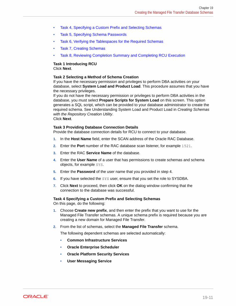
• Task 4, Specifying a Custom Prefix and Selecting Schemas
• Task 5, Specifying Schema Passwords
• Task 6, Verifying the Tablespaces for the Required Schemas
• Task 7, Creating Schemas
• Task 8, Reviewing Completion Summary and Completing RCU Execution
Task 1 Introducing RCUClick Next.
Task 2 Selecting a Method of Schema CreationIf you have the necessary permission and privileges to perform DBA activities on yourdatabase, select System Load and Product Load. This procedure assumes that you havethe necessary privileges.If you do not have the necessary permission or privileges to perform DBA activities in thedatabase, you must select Prepare Scripts for System Load on this screen. This optiongenerates a SQL script, which can be provided to your database administrator to create therequired schema. See Understanding System Load and Product Load in Creating Schemaswith the Repository Creation Utility.Click Next.
Task 3 Providing Database Connection DetailsProvide the database connection details for RCU to connect to your database.
1. In the Host Name field, enter the SCAN address of the Oracle RAC Database.
2. Enter the Port number of the RAC database scan listener, for example 1521.
3. Enter the RAC Service Name of the database.
4. Enter the User Name of a user that has permissions to create schemas and schemaobjects, for example SYS.
5. Enter the Password of the user name that you provided in step 4.
6. If you have selected the SYS user, ensure that you set the role to SYSDBA.
7. Click Next to proceed, then click OK on the dialog window confirming that theconnection to the database was successful.
Task 4 Specifying a Custom Prefix and Selecting SchemasOn this page, do the following:
1. Choose Create new prefix, and then enter the prefix that you want to use for theManaged File Transfer schemas. A unique schema prefix is required because you arecreating a new domain for Managed File Transfer.
2. From the list of schemas, select the Managed File Transfer schema.
The following dependent schemas are selected automatically:
• Common Infrastructure Services
• Oracle Enterprise Scheduler
• Oracle Platform Security Services
• User Messaging Service
Chapter 19Creating the Managed File Transfer Database Schemas
19-11

• Audit Services
• Audit Services Append
• Audit Services Viewer
• Metadata Services
• Weblogic Services
The custom prefix is used to logically group these schemas together for use in thisdomain only; you must create a unique set of schemas for each domain as schemasharing across domains is not supported.
Tip:
For more information about custom prefixes, see Understanding CustomPrefixes in Creating Schemas with the Repository Creation Utility.For more information about how to organize your schemas in a multi-domainenvironment, see Planning Your Schema Creation in Creating Schemas withthe Repository Creation Utility.
Click Next to proceed, then click OK on the dialog window confirming that prerequisitechecking for schema creation was successful.
Task 5 Specifying Schema PasswordsSpecify how you want to set the schema passwords on your database, then specifyand confirm your passwords. Ensure that the complexity of the passwords meet thedatabase security requirements before you continue. RCU proceeds at this point evenif you do not meet the password polices. Hence, perform this check outside RCUitself.
Tip:
You must make a note of the passwords you set on this screen; you needthem later on during the domain creation process.
Click Next.
Task 6 Verifying the Tablespaces for the Required SchemasOn the Map Tablespaces screen, review the information, and then click Next toaccept the default values.Click OK in the confirmation dialog box.
Task 7 Creating SchemasReview the summary of the schemas to be loaded, and click Create to completeschema creation.
Chapter 19Creating the Managed File Transfer Database Schemas
19-12

Note:
If failures occurred, review the listed log files to identify the root cause, resolve thedefects, and then use RCU to drop and recreate the schemas before you continue.
Task 8 Reviewing Completion Summary and Completing RCU ExecutionWhen you reach the Completion Summary screen, verify that all schema creations havebeen completed successfully, and then click Close to dismiss RCU.
Verifying Schema AccessVerify schema access by connecting to the database as the new schema users created bythe RCU. Use SQL*Plus or another utility to connect, and provide the appropriate schemanames and passwords entered in the RCU.
For example:
Note:
If the database is a plugable database (PDB), the apropriate tns alias that points tothe PDB must be used in the sqlplus command.
./sqlplus FMW12214_MFT/<mft_schema_password>
SQL*Plus: Release 19.0.0.0.0 - Production on Tue May 26 06:04:29 2020 Version 19.6.0.0.0
Copyright (c) 1982, 2019, Oracle. All rights reserved.
Last Successful login time: Tue Apr 07 2020 01:04:10 -07:00
Connected to:Oracle Database 19c Enterprise Edition Release 19.0.0.0.0 - 64bit ProductionVersion 19.6.0.0.0
SQL>
Creating the Managed File Transfer Domain for an EnterpriseDeployment
You create a separate Managed File Transfer domain by using the Fusion MiddlewareConfiguration Wizard.
• Starting the Configuration WizardStart the Configuration Wizard as the first step to extend the existing enterprisedeployment domain.
• Navigating the Configuration Wizard Screens for MFT
Chapter 19Creating the Managed File Transfer Domain for an Enterprise Deployment
19-13

Starting the Configuration WizardStart the Configuration Wizard as the first step to extend the existing enterprisedeployment domain.
Note:
If you added any customizations directly to the start scripts in the domain,those are overwritten by the configuration wizard. To customize serverstartup parameters that apply to all servers in a domain, you can create a filecalled setUserOverridesLate.sh and configure it, for example, add customlibraries to the WebLogic Server classpath, specify Additional JAVAcommand line options for running the servers, or specify additionalenvironment variables. Any customizations you add to this file are preservedduring domain upgrade operations, and are carried over to remote serverswhen using the pack and unpack commands.
To start the Configuration Wizard:
1. From the WebLogic Server Console, stop any managed servers that are modifiedby this domain extension. Managed Servers that are not effected can remain on-line.
2. For any managed servers to be modified, verify that the managed server shutdownhas completed.
3. Stop the Administration Server once all managed servers are in a steady state.
4. Navigate to the following directory and start the WebLogic Server ConfigurationWizard.
cd ORACLE_HOME/oracle_common/common/bin./config.sh
Navigating the Configuration Wizard Screens for MFTFollow the instructions in these sections to create and configure the domain for thetopology, with static or dynamic clusters.
• Configuring the Domain with Static Clusters
• Configuring the Domain with Dynamic Clusters
Configuring the Domain with Static ClustersFollow the instructions in this section to create and configure the domain for MFT, withstatic clusters.
Domain creation and configuration includes the following tasks.
• Task 1, Selecting the Domain Type and Domain Home Location
• Task 2, Selecting the Configuration Templates
• Task 3, Configuring High Availability Options
Chapter 19Creating the Managed File Transfer Domain for an Enterprise Deployment
19-14

• Task 4, Selecting the Application Home Location
• Task 5, Configuring the Administrator Account
• Task 6, Specifying the Domain Mode and JDK
• Task 7, Specifying the Database Configuration Type
• Task 8, Specifying JDBC Component Schema Information
• Task 9, Providing the GridLink Oracle RAC Database Connection Details
• Task 10, Testing the JDBC Connections
• Task 11, Specifying the Keystore
• Task 12, Selecting Advanced Configuration
• Task 13, Configuring the Administration Server Listen Address
• Task 14, Setting the Node Manager Type (Per Host)
• Task 15, Configuring Managed Servers
• Task 16, Configuring a Cluster
• Task 17, Assigning Server Templates
• Task 18, Configuring Dynamic Servers
• Task 16, Configuring a Cluster
• Task 19, Assigning Managed Servers to the Cluster
• Task 20, Configuring Coherence Clusters
• Task 21, Creating Machines
• Task 22, Assigning Servers to Machines
• Task 23, Creating Virtual Targets
• Task 24, Creating Partitions
• Task 25, Reviewing Your Configuration Specifications and Configuring the Domain
• Task 26, Writing Down Your Domain Home and Administration Server URL
Task 1 Selecting the Domain Type and Domain Home LocationYou must select a Domain home directory location, optimally outside the Oracle homedirectory.Oracle recommends that you locate your Domain home in accordance with the directorystructure in What Are the Key Oracle Fusion Middleware Directories? in UnderstandingOracle Fusion Middleware, where the Domain home is located outside the Oracle homedirectory. This directory structure helps avoid issues when you need to upgrade or reinstallsoftware.To specify the Domain type and Domain home directory:
1. On the Configuration Type screen, select Create a new domain.
2. In the Domain Location field, specify your Domain home directory.
For more information about this screen, see Configuration Type in Creating WebLogicDomains Using the Configuration Wizard
Chapter 19Creating the Managed File Transfer Domain for an Enterprise Deployment
19-15

Task 2 Selecting the Configuration TemplatesOn the Templates screen, make sure Create Domain Using Product Templates isselected, then select the following templates:
• Oracle Managed File Transfer [mft]
Selecting this template automatically selects the following dependencies:
– Oracle Enterprise Manager
– Oracle B2B Client
– Oracle JRF
– Oracle WSM Policy Manager
– WebLogic Coherence Cluster Extension
For more information about the options on this screen, see Templates in CreatingWebLogic Domains Using the Configuration Wizard.
Task 3 Configuring High Availability OptionsThis screen appears for the first time when you create a cluster that uses AutomaticService Migration or JDBC stores or both. After you select HA Options for a cluster, allsubsequent clusters that are added to the domain by using the Configuration Wizard,automatically apply HA options (that is, the Configuration Wizard creates JDBC storesand configures ASM for them).On the High Availability Options screen:
• Select Enable Automatic Service Migration with Database Basis.
• Set JTA Transaction Log Persistence to JDBC TLog Store.
• Set JMS Server Persistence to JMS JDBC Store.
Note:
Oracle recommends that you use JDBC stores, which leverage theconsistency, data protection, and high availability features of an Oracledatabase and makes resources available for all the servers in the cluster.So, the Configuration Wizard steps assume that the JDBC persistent storesare used along with Automatic Service Migration.When you choose JDBC persistent stores, additional unused File Stores areautomatically created but are not targeted to your clusters. Ignore these FileStores.If, for any reason, you want to use Files Stores, you can retain the defaultvalues for TLOGs and JMS persistent store options in this screen andconfigure them in a shared location later. See Task 12, Selecting AdvancedConfiguration. Shared location is required to resume JMS and JTA in afailover scenario.You can also configure TLOGs and JMS persistent stores manually in a poststep. For information about the differences between JDBC and Files Stores,and for specific instructions to configure them manually, see UsingPersistent Stores for TLOGs and JMS in an Enterprise Deployment.
Click Next.
Chapter 19Creating the Managed File Transfer Domain for an Enterprise Deployment
19-16

Task 4 Selecting the Application Home LocationOn the Application Location screen, specify the value of the APPLICATION_HOME variable,as defined in File System and Directory Variables Used in This Guide.For more information about the options on this screen, see Application Location in CreatingWebLogic Domains Using the Configuration Wizard.
Task 5 Configuring the Administrator AccountOn the Administrator Account screen, specify the user name and password for the defaultWebLogic Administrator account for the domain.Make a note of the user name and password specified on this screen; you need thesecredentials later to boot and connect to the domain's Administration Server.
Task 6 Specifying the Domain Mode and JDKOn the Domain Mode and JDK screen:
• Select Production in the Domain Mode field.
• Select the Oracle Hotspot JDK in the JDK field.
Selecting Production Mode on this screen gives your environment a higher degree ofsecurity, requiring a user name and password to deploy applications and to start theAdministration Server.For more information about the options on this screen, including the differences betweendevelopment mode and production mode, see Domain Mode and JDK in Creating WebLogicDomains Using the Configuration Wizard.In the production mode, a boot identity file can be created to bypass the need to provide auser name and password when you start the Administration Server. See Creating theboot.properties File.
Task 7 Specifying the Database Configuration TypeOn the Database Configuration Type screen:
• Select RCU Data to activate the fields on this screen.
The RCU Data option instructs the Configuration Wizard to connect to the database andService Table (STB) schema to automatically retrieve schema information for theschemas needed to configure the domain.
• Verify that the Vendor is Oracle and the Driver is *Oracle's Driver (Thin) forService Connections; Versions: Any.
• Verify that Connection Parameters is selected.
Note:
If you select Manual Configuration on this screen, you must manually fill in theparameters for your schema on the JDBC Component Schema screen.
After you select RCU Data, fill in the fields as shown in the following table:
Chapter 19Creating the Managed File Transfer Domain for an Enterprise Deployment
19-17

Field Description
DBMS/Service Enter the service name for the Oracle RAC databasewhere you install the product schemas. For example:
orcl.example.com
Be sure this is the common service name that is used toidentify all the instances in the Oracle RAC database; donot use the host-specific service name.
Host Name Enter the Single Client Access Name (SCAN) Addressfor the Oracle RAC database, which you entered in theEnterprise Deployment Workbook.
Port Enter the port number on which the database listens.For example, 1521.
Schema OwnerSchema Password
Enter the user name and password to connect to thedatabase's Service Table schema.This is the schema user name and password that wasspecified for the Service Table component on theSchema Passwords screen in RCU. See Creating theDatabase Schemas.The default user name is prefix_STB, where prefix isthe custom prefix that you have defined in RCU.
Click Get RCU Configuration when you finished specifying the database connectioninformation. The following output in the Connection Result Log indicates that theoperating succeeded:
Connecting to the database server...OKRetrieving schema data from database server...OKBinding local schema components with retrieved data...OK
Successfully Done.
Click Next if the connection to the database is successful.For more information about the RCU Data option, see Understanding the ServiceTable Schema in Creating Schemas with the Repository Creation Utility.For more information about the other options on this screen, see Datasource Defaultsin Creating WebLogic Domains Using the Configuration Wizard.
Task 8 Specifying JDBC Component Schema InformationVerify that the values on the JDBC Component Schema screen are correct for allschemas.The schema table should be populated, because you selected Get RCU Data on theprevious screen. As a result, the Configuration Wizard locates the databaseconnection values for all the schemas required for this domain.At this point, the values are configured to connect to a single-instance database.However, for an enterprise deployment, you should use a highly available RealApplication Clusters (RAC) database, as described in Preparing the Database for anEnterprise Deployment.In addition, Oracle recommends that you use an Active GridLink datasource for eachof the component schemas. For more information about the advantages of usingGridLink data sources to connect to a RAC database, see Database Considerations inthe High Availability Guide.To convert the data sources to GridLink:
Chapter 19Creating the Managed File Transfer Domain for an Enterprise Deployment
19-18

1. Select all the schemas by selecting the checkbox in the first header row of the schematable.
2. Click Convert to GridLink and click Next.
Task 9 Providing the GridLink Oracle RAC Database Connection DetailsOn the GridLink Oracle RAC Component Schema screen, provide the information that isrequired to connect to the RAC database and component schemas, as shown in followingtable.
Element Description and Recommended Value
SCAN, Host Name, and Port Select the SCAN check box.In the Host Name field, enter the Single Client AccessName (SCAN) Address for the Oracle RAC database.In the Port field, enter the SCAN listening port for thedatabase (for example, 1521).
ONS Host and Port These values are not required when you are using anOracle 12c database or higher versions because theONS list is automatically provided from the database tothe driver.Complete these values only if you are using Oracle 11gdatabase:• In the ONS Host field, enter the SCAN address for
the Oracle RAC database.
• In the Port field, enter the ONS Remote port(typically, 6200).
Enable Fan Verify that the Enable Fan check box is selected, so thatthe database can receive and process FAN events.
For more information about specifying the information on this screen, as well as informationabout how to identify the correct SCAN address, see Configuring Active GridLink DataSources with Oracle RAC in the High Availability Guide.You can also click Help to display a brief description of each field on the screen.
Task 10 Testing the JDBC ConnectionsA green check mark in the Status column indicates a successful test. If you encounter anyissues, see the error message in the Connection Result Log section of the screen, fix theproblem, then try to test the connection again.By default, the schema password for each schema component is the password you specifiedwhile creating your schemas. If you want different passwords for different schemacomponents, manually edit them in the previous screen (JDBC Component Schema) byentering the password you want in the Schema Password column, against each row. Afteryou specify the passwords, select the check box that correspond to the schemas that youchanged the password in and test the connection again.For more information about the other options on this screen, see Test Component Schema inCreating WebLogic Domains Using the Configuration Wizard.
Task 11 Specifying the KeystoreUse the Keystore screen in the Configuration Wizard to specify details about the keystore tobe used in the domain.For a typical enterprise deployment, you can leave the default values. See Keystore inCreating WebLogic Domains Using the Configuration Wizard
Chapter 19Creating the Managed File Transfer Domain for an Enterprise Deployment
19-19

Task 12 Selecting Advanced ConfigurationTo complete domain configuration for the topology, select the following options on theAdvanced Configuration screen:
• Administration Server
This is required to properly configure the listen address of the AdministrationServer.
• Node Manager
This is required to configure Node Manager.
• Topology
This is required to add, delete, or modify the Settings for Server Templates,Managed Servers, Clusters, Virtual Targets, and Coherence.
Note:
• When you use the Advanced Configuration screen in the ConfigurationWizard, if any of the above options are not available on the screen, thenreturn to the Templates screen and ensure that you have selected therequired templates for this topology.
• JDBC stores are recommended and selected in Task 3, ConfiguringHigh Availability Options so there is no need to configure File Stores.
If you choose File Stores in Task 3, Configuring High AvailabilityOptions, you have to select the File Stores option here to configurethem in a shared location in ORACLE_RUNTIME/domain_name/MFT_Cluster/jms. Shared location is required to resume JMS and JTAin a failover scenario.
Task 13 Configuring the Administration Server Listen AddressOn the Administration Server screen:
1. In the Server Name field, retain the default value-AdminServer.
2. In the Listen Address field, enter the virtual host name that corresponds to theVIP of the ADMINVHN that you had procured in Procuring Resources for anEnterprise Deployment and had enabled in Preparing the Host Computers for anEnterprise Deployment.
For more information on the reasons for using the ADMINVHN virtual host, see Reserving the Required IP Addresses for an Enterprise Deployment.
3. Leave the other fields at their default values.
In particular, be sure that no server groups are assigned to the AdministrationServer.
Task 14 Setting the Node Manager Type (Per Host)Select Manual Node Manager Setup as the Node Manager type.
Chapter 19Creating the Managed File Transfer Domain for an Enterprise Deployment
19-20

Note:
• For more information about the options on this screen, see Node Manager inCreating WebLogic Domains Using the Configuration Wizard.
• For more information about per domain and per host Node Managerimplementations, see About the Node Manager Configuration in a TypicalEnterprise Deployment.
• For information about Node Manager configuration, see Configuring NodeManager on Multiple Machines in Administering Node Manager for OracleWebLogic Server.
Task 15 Configuring Managed ServersUse the Managed Servers screen to create the Managed Servers that are required in theManaged File Transfer domain.
1. Change the default server name to WLS_MFT1 in the Server name column.
2. Click Add and repeat this process to create a second Managed Server named WLS_MFT2.
3. Use the information in #unique_516/unique_516_Connect_42_GUID-7D93184C-43B4-4ED8-920C-F9A25E57B17B to fill inthe rest of the columns for each MFT Managed Server.
The Managed Server names suggested in this procedure (WLS_MFT1 and WLS_MFT2) arereferenced throughout this document; if you choose different names then be sure to replacethem as needed,For more information about the options on this screen, see Managed Servers in CreatingWebLogic Domains Using the Configuration Wizard.
Server Name Listen Address ListenPort
EnableSSL
SSL ListenPort
Server Groups
WLS_MFT1 MFTHOST1 7500 No Disabled MFT-MGD-SVRS
WLS_MFT2 MFTHOST2 7500 No Disabled MFT-MGD-SVRS
The selected server group ensures that the Managed File Transfer and Oracle Web ServicesManager (OWSM) software is targeted to the Managed Server.There is another server group called MFT-MGD-SVRS-ONLY that targets only MFT but notOracle Web Services Manager (OWSM) to the server. This is typically used if you want tohave Oracle Web Services Manager (OWSM) in a different server rather than with the MFTserver.The server groups target Fusion Middleware applications and services to one or moreservers by mapping defined groups of application services to each defined server group. Anyapplication services that are mapped to a given server group are automatically targeted to allservers that are assigned to that group. See Application Service Groups, Server Groups, andApplication Service Mappings in Domain Template Reference.
Task 16 Configuring a ClusterUse the Clusters screen to create a new cluster:
1. Click the Add button.
2. Specify MFT_Cluster in the Cluster Name field.
Chapter 19Creating the Managed File Transfer Domain for an Enterprise Deployment
19-21

3. Leave the Address field blank.
4. Specify mft.example.com in the Frontend Host field.
5. Specify 80 as the Frontend HTTP port and 443 as the Frontend HTTPS port.
For more information about the options on this screen, see Clusters in CreatingWebLogic Domains Using the Configuration Wizard.
Task 17 Assigning Server TemplatesClick Next.
Task 18 Configuring Dynamic ServersVerify that all dynamic server options are disabled for clusters that are to remain asstatic clusters.
1. Confirm that the Calculated Machine Names and Calculated Listen Portcheckboxes on this screen are unchecked.
2. Confirm that the Server Template and Dynamic Server Groups selections areUnspecified.
3. Click Next.
Task 19 Assigning Managed Servers to the ClusterUse the Assign Servers to Clusters screen to assign Managed Servers to the newcluster.
1. In the Clusters pane, select the cluster to which you want to assign the servers;in this case, MFT_Cluster.
2. In the Servers pane, assign WLS_MFT1 to MFT_Cluster by doing one of thefollowing:
• Click once on WLS_MFT1 to select it, then click on the right arrow to move itbeneath the selected cluster (MFT_Cluster)) in the Clusters pane.
or
• Double-click on WLS_MFT1 to move it beneath the selected cluster(MFT_Cluster) in the clusters pane.
3. Repeat these steps to assign the WLS_MFT2 Managed Server to MFT_Cluster.
For more information about the options on this screen, see Assign Servers to Clustersin Creating WebLogic Domains Using the Configuration Wizard.
Task 20 Configuring Coherence ClustersUse the Coherence Clusters screen to configure the Coherence cluster that isautomatically added to the domain.In the Cluster Listen Port, enter 9991.For Coherence licensing information, Oracle Coherence Products in Oracle FusionMiddleware Licensing Information User Manual.
Task 21 Creating MachinesUse the Machines screen to create five new machines in the domain. A machine isrequired in order for the Node Manager to be able to start and stop the servers.
1. Select the Unix Machine tab.
2. Click the Add button to create five new UNIX machines.
Chapter 19Creating the Managed File Transfer Domain for an Enterprise Deployment
19-22

Use the values in Table 19-1 to define the Name and Node Manager Listen Address ofeach machine.
3. Verify the port in the Node Manager Listen Port field.
The port number 5556, shown in this example, may be referenced by other examples inthe documentation. Replace this port number with your own port number as needed.
Note:
If you are installing on a host where additional domains were alreadyconfigured, and you have already configured a per host Node Manager, thenthe address and port configured in this screen must be for the existing per hostNode Manager.
Name Node Manager Listen Address Node Manager ListenPort
MFTHOST1 The value of the MFTHOST1 host name variable or MFTHOST1alias. For example, MFTHOST1.example.com.
5556
MFTHOST2 The value of the MFTHOST2 host name variable or MFTHOST2alias. For example, MFTHOST2.example.com.
5556
ADMINHOST Enter the value of the ADMINVHN variable. 5556
For more information about the options on this screen, see Machines in Creating WebLogicDomains Using the Configuration Wizard.
Task 22 Assigning Servers to MachinesUse the Assign Servers to Machines screen to assign the Administration Server and the twoManaged Servers to the appropriate machine.The Assign Servers to Machines screen is similar to the Assign Managed Servers toClusters screen. Select the target machine in the Machines column, select the ManagedServer in the left column, and click the right arrow to assign the server to the appropriatemachine.Assign the servers as follows:
• Assign the AdminServer to the ADMINHOST machine.
• Assign the WLS-MFT1 Managed Server to the MFTHOST1 machine.
• Assign the WLS-MFT2 Managed Server to the MFTHOST2 machine.
For more information about the options on this screen, see Assign Servers to Machines inCreating WebLogic Domains Using the Configuration Wizard.
Task 23 Creating Virtual TargetsClick Next.
Task 24 Creating PartitionsClick Next.
Task 25 Reviewing Your Configuration Specifications and Configuring the DomainThe Configuration Summary screen contains detailed configuration information for thedomain that you are about to create. Review the details of each item on the screen andverify that the information is correct.
Chapter 19Creating the Managed File Transfer Domain for an Enterprise Deployment
19-23

If you need to make any changes, you can go back to any previous screen either byusing the Back button or by selecting the screen in the navigation pane.Domain creation does not begin until you click Create.In the Configuration Progress screen, click Next when it finishes.For more information about the options on this screen, see Configuration Summary inCreating WebLogic Domains Using the Configuration Wizard.
Task 26 Writing Down Your Domain Home and Administration Server URLThe Configuration Success screen shows the following items about the domain youjust configured:
• Domain Location
• Administration Server URL
You must make a note of both items as you need them later; the domain location isneeded to access the scripts used to start the Administration Server.Click Finish to dismiss the Configuration Wizard.
After you have completed extending the domain with static clusters, go to ConfiguringNode Manager for the Managed File Transfer Domain.
Configuring the Domain with Dynamic ClustersFollow the instructions in this section to create and configure the domain for MFT, withdynamic clusters.
Domain creation and configuration includes the following tasks.
• Task 1, Selecting the Domain Type and Domain Home Location
• Task 2, Selecting the Configuration Templates
• Task 3, Configuring High Availability Options
• Task 4, Selecting the Application Home Location
• Task 5, Configuring the Administrator Account
• Task 6, Specifying the Domain Mode and JDK
• Task 7, Specifying the Database Configuration Type
• Task 8, Specifying JDBC Component Schema Information
• Task 9, Providing the GridLink Oracle RAC Database Connection Details
• Task 10, Testing the JDBC Connections
• Task 11, Specifying the Keystore
• Task 12, Selecting Advanced Configuration
• Task 13, Configuring the Administration Server Listen Address
• Task 14, Setting the Node Manager Type (Per Host)
• Task 15, Configuring Managed Servers
• Task 16, Configuring a Cluster
• Task 17, Assigning Server Templates
• Task 18, Configuring Dynamic Servers
• Task 19, Configuring Coherence Clusters
Chapter 19Creating the Managed File Transfer Domain for an Enterprise Deployment
19-24

• Task 20, Creating Machines
• Task 21, Assigning Servers to Machines
• Task 22, Creating Virtual Targets
• Task 23, Creating Partitions
• Task 24, Reviewing Your Configuration Specifications and Configuring the Domain
• Task 25, Writing Down Your Domain Home and Administration Server URL
Task 1 Selecting the Domain Type and Domain Home LocationYou must select a Domain home directory location, optimally outside the Oracle homedirectory.Oracle recommends that you locate your Domain home in accordance with the directorystructure in What Are the Key Oracle Fusion Middleware Directories? in UnderstandingOracle Fusion Middleware, where the Domain home is located outside the Oracle homedirectory. This directory structure helps avoid issues when you need to upgrade or reinstallsoftware.To specify the Domain type and Domain home directory:
1. On the Configuration Type screen, select Create a new domain.
2. In the Domain Location field, specify your Domain home directory.
For more information about this screen, see Configuration Type in Creating WebLogicDomains Using the Configuration Wizard
Task 2 Selecting the Configuration TemplatesOn the Templates screen, make sure that Create Domain Using Product Templates isselected, then select the following templates:
• Oracle Managed File Transfer [mft]
Selecting this template automatically selects the following dependencies:
– Oracle B2B Client
– Oracle Enterprise Manager
– Oracle WSM Policy Manager
– Oracle JRF
– WebLogic Coherence Cluster Extension
For more information about the options on this screen, see Templates in Creating WebLogicDomains Using the Configuration Wizard.
Task 3 Configuring High Availability OptionsThis screen appears for the first time when you create a cluster that uses Automatic ServiceMigration or JDBC stores or both. After you select HA Options for a cluster, all subsequentclusters that are added to the domain by using the Configuration Wizard, automatically applythese HA options.On the High Availability Options screen:
1. Select Enable Automatic Service Migration with Database Basis.
2. Set JTA Transaction Log Persistence to JDBC TLog Store.
3. Set JMS Server Persistence to JMS JDBC Store.
Chapter 19Creating the Managed File Transfer Domain for an Enterprise Deployment
19-25

Note:
Oracle recommends that you use JDBC stores, which leverage theconsistency, data protection, and high availability features of an oracledatabase and makes resources available for all the servers in the cluster.So, the Configuration Wizard steps assume that the JDBC persistent storesare used along with Automatic Service Migration.When you choose JDBC persistent stores, additional unused File Stores areautomatically created but are not targeted to your clusters. Ignore these FileStores.If, for any reason, you want to use Files Stores, you can retain the defaultvalues for TLOGs and JMS persistent store options in this screen andconfigure them in a shared location later. See Task 12, Selecting AdvancedConfiguration. Shared location is required to resume JMS and JTA in afailover scenario.You can also configure TLOGs and JMS persistent stores manually in a poststep. For information about the differences between JDBC and Files Stores,and for specific instructions to configure them manually, see UsingPersistent Stores for TLOGs and JMS in an Enterprise Deployment.
Click Next.
Task 4 Selecting the Application Home LocationOn the Application Location screen, specify the value of the APPLICATION_HOMEvariable, as defined in File System and Directory Variables Used in This Guide.For more information about the options on this screen, see Application Location inCreating WebLogic Domains Using the Configuration Wizard.
Task 5 Configuring the Administrator AccountOn the Administrator Account screen, specify the user name and password for thedefault WebLogic Administrator account for the domain.Make a note of the user name and password specified on this screen; you need thesecredentials later to boot and connect to the domain's Administration Server.
Task 6 Specifying the Domain Mode and JDKOn the Domain Mode and JDK screen:
• Select only Production in the Domain Mode field.
• Select the Oracle Hotspot JDK in the JDK field.
Selecting Production Mode on this screen gives your environment a higher degree ofsecurity, requiring a user name and password to deploy applications and to start theAdministration Server.For more information about the options on this screen, including the differencesbetween development mode and production mode, see Domain Mode and JDK inCreating WebLogic Domains Using the Configuration Wizard.In the production mode, a boot identity file can be created to bypass the need toprovide a user name and password when starting the Administration Server. See Creating the boot.properties File.
Task 7 Specifying the Database Configuration TypeOn the Database Configuration Type screen:
Chapter 19Creating the Managed File Transfer Domain for an Enterprise Deployment
19-26

• Select RCU Data to activate the fields on this screen.
The RCU Data option instructs the Configuration Wizard to connect to the database andService Table (STB) schema to automatically retrieve schema information for theschemas needed to configure the domain.
• Verify that the Vendor is Oracle and the Driver is *Oracle's Driver (Thin) forService Connections; Versions: Any.
• Verify that Connection Parameters is selected.
Note:
If you select Manual Configuration on this screen, you must manually fill in theparameters for your schema on the JDBC Component Schema screen.
After you select RCU Data, fill in the fields as shown in the following table:
Field Description
DBMS/Service Enter the service name for the Oracle RAC databasewhere you install the product schemas. For example:
orcl.example.com
Be sure this is the common service name that is used toidentify all the instances in the Oracle RAC database; donot use the host-specific service name.
Host Name Enter the Single Client Access Name (SCAN) Addressfor the Oracle RAC database, which you entered in theEnterprise Deployment Workbook.
Port Enter the port number on which the database listens.For example, 1521.
Schema OwnerSchema Password
Enter the user name and password to connect to thedatabase's Service Table schema.This is the schema user name and password that wasspecified for the Service Table component on theSchema Passwords screen in RCU. See Creating theDatabase Schemas.The default user name is prefix_STB, where prefix isthe custom prefix that you have defined in RCU.
Click Get RCU Configuration when you finished specifying the database connectioninformation. The following output in the Connection Result Log indicates that the operation issuccessful:
Connecting to the database server...OKRetrieving schema data from database server...OKBinding local schema components with retrieved data...OK
Successfully Done.
Click Next if the connection to the database is successful.For more information about the RCU Data option, see Understanding the Service TableSchema in Creating Schemas with the Repository Creation Utility.
Chapter 19Creating the Managed File Transfer Domain for an Enterprise Deployment
19-27

For more information about the other options on this screen, see Datasource Defaultsin Creating WebLogic Domains Using the Configuration Wizard.
Task 8 Specifying JDBC Component Schema InformationVerify that the values on the JDBC Component Schema screen are correct for allschemas.The schema table should be populated, because you selected Get RCU Data on theprevious screen. As a result, the Configuration Wizard locates the databaseconnection values for all the schemas required for this domain.At this point, the values are configured to connect to a single-instance database.However, for an enterprise deployment, you should use a highly available RealApplication Clusters (RAC) database, as described in Preparing the Database for anEnterprise Deployment.In addition, Oracle recommends that you use an Active GridLink datasource for eachof the component schemas. For more information about the advantages of usingGridLink data sources to connect to a RAC database, see Database Considerations inthe High Availability Guide.To convert the data sources to GridLink:
1. Select all the schemas by selecting the checkbox in the first header row of theschema table.
2. Click Convert to GridLink and click Next.
Task 9 Providing the GridLink Oracle RAC Database Connection DetailsOn the GridLink Oracle RAC Component Schema screen, provide the informationrequired to connect to the RAC database and component schemas, as shown infollowing table.
Element Description and Recommended Value
SCAN, Host Name, and Port Select the SCAN check box.In the Host Name field, enter the Single Client AccessName (SCAN) Address for the Oracle RAC database.In the Port field, enter the SCAN listening port for thedatabase (for example, 1521).
ONS Host and Port These values are not required when you are using anOracle 12c database or higher versions because theONS list is automatically provided from the database tothe driver.Complete these values only if you are using Oracle 11gdatabase:• In the ONS Host field, enter the SCAN address for
the Oracle RAC database.
• In the Port field, enter the ONS Remote port(typically, 6200).
Enable Fan Verify that the Enable Fan check box is selected, so thatthe database can receive and process FAN events.
For more information about specifying the information on this screen, as well asinformation about how to identify the correct SCAN address, see Configuring ActiveGridLink Data Sources with Oracle RAC in the High Availability Guide.You can also click Help to display a brief description of each field on the screen.
Chapter 19Creating the Managed File Transfer Domain for an Enterprise Deployment
19-28

Task 10 Testing the JDBC ConnectionsA green check mark in the Status column indicates a successful test. If you encounter anyissues, see the error message in the Connection Result Log section of the screen, fix theproblem, then try to test the connection again.By default, the schema password for each schema component is the password that youspecified while creating your schemas. If you want different passwords for different schemacomponents, manually edit them in the previous screen (JDBC Component Schema) byentering the password that you want in the Schema Password column, against each row.After you specify the passwords, select the check box that corresponds to the schemas thatyou changed the password in and test the connection again.For more information about the other options on this screen, see Test Component Schema inCreating WebLogic Domains Using the Configuration Wizard.
Task 11 Specifying the KeystoreUse the Keystore screen in the Configuration Wizard to specify details about the keystore tobe used in the domain.For a typical enterprise deployment, you can leave the default values. See Keystore inCreating WebLogic Domains Using the Configuration Wizard.
Task 12 Selecting Advanced ConfigurationTo complete domain configuration for the topology, select the following options on theAdvanced Configuration screen:
• Administration Server
This is required to properly configure the listen address of the Administration Server.
• Node Manager
This is required to configure Node Manager.
• Topology
This is required to add, delete, or modify the Settings for Server Templates, ManagedServers, Clusters, Virtual Targets, and Coherence.
Note:
• JMS JDBC stores are recommended and selected in Task 3, Configuring HighAvailability Options so there is no need to configure File Stores.
If you choose JMS File Stores in Task 3, Configuring High Availability Options,you have to select the File Stores option to configure them in a shared locationin ORACLE_RUNTIME/domain_name/MFT_Cluster/jms. Shared location isrequired to resume JMS and JTA in a failover scenario.
• When you use the Advanced Configuration screen in the Configuration Wizard,if any of the above options are not available on the screen, then return to theTemplates screen and ensure that you have selected the required templatesfor this topology.
Task 13 Configuring the Administration Server Listen AddressOn the Administration Server screen:
1. In the Server Name field, retain the default value-AdminServer.
Chapter 19Creating the Managed File Transfer Domain for an Enterprise Deployment
19-29

2. In the Listen Address field, enter the virtual host name that corresponds to theVIP of the ADMINVHN that you had procured in Procuring Resources for anEnterprise Deployment and had enabled in Preparing the Host Computers for anEnterprise Deployment.
For more information on the reasons for using the ADMINVHN virtual host, see Reserving the Required IP Addresses for an Enterprise Deployment.
3. In the Listen Port field, enter the port number to access the administration server.This guide recommends you to use the default port 7001.
Leave the other fields at their default values. In particular, be sure that no servergroups are assigned to the Administration Server.
Task 14 Setting the Node Manager Type (Per Host)Select Manual Node Manager Setup as the Node Manager type.
Note:
• For more information about the options on this screen, see NodeManager in Creating WebLogic Domains Using the ConfigurationWizard.
• For more information about per domain and per host Node Managerimplementations, see About the Node Manager Configuration in aTypical Enterprise Deployment.
• For information about Node Manager configuration, see ConfiguringNode Manager on Multiple Machines in Administering Node Manager forOracle WebLogic Server.
Task 15 Configuring Managed ServersOn the Managed Servers screen, a new Managed Server for Oracle Managed FileTransfer appears in the list of servers.Static Managed Server definitions are not needed for dynamic cluster configurations.To remove the default Managed Server, complete the following steps:
1. Delete the default Managed Server.
2. Click Next to proceed to the next screen.
Task 16 Configuring a ClusterUse the Clusters screen to create a new cluster:
1. Click the Add button.
2. Specify MFT_Cluster in the Cluster Name field.
3. Leave the Address field blank.
4. Specify mft.example.com in the Frontend Host field.
5. Specify 80 as the Frontend HTTP port and 443 as the Frontend HTTPS port.
For more information about the options on this screen, see Clusters in CreatingWebLogic Domains Using the Configuration Wizard.
Chapter 19Creating the Managed File Transfer Domain for an Enterprise Deployment
19-30

Task 17 Assigning Server TemplatesUse the Server Templates screen to configure the template:
1. Verify that mft-server-template is selected in the Name field.
2. Specify 7499 in the Listen Port field.
3. Leave the Enable SSL option unchecked.
4. Click Next.
Task 18 Configuring Dynamic ServersUse the Dynamic Clusters screen to configure the required clusters:
1. Specify MFT_Cluster in the Cluster Name field.
2. From the Server Template drop-down list, select MFT-server-template.
3. Specify WLS_MFT in the Server Name Prefix field.
4. Specify 2 in the Dynamic Cluster Size field.
5. Specify MFTHOST* in the Machine Name Match Expression field and select CalculatedMachine Names.
Note:
The dynamic cluster Calculated Machine Names and Machine Name MatchExpression attributes control how server instances in a dynamic cluster areassigned to a machine. If the Calculated Machine Names attribute is set toFalse, the dynamic servers are not assigned to a machine. If the CalculatedMachine Names attribute is set to True, the Machine Name MatchExpression attribute is used to select the set of machines that is used for thedynamic servers. If the Machine Name Match Expression attribute is not set,all of the machines in the domain get selected. Assignments are made byusing a round robin algorithm.
To make things easier regardless of your actual physical hostname, Oraclerecommends that you use MFTHOSTn as your WebLogic machine names, asexplained in Task 20, Creating Machines, where n is a sequential number. Thisconvention makes it easy for dynamic clusters to determine where to start eachcluster member. If you want to follow this convention, in the Machine MatchExpression field, enter MFTHOST*.
If you do not adopt this convention, the cluster members are started on eachmachine that you define in Task 20, Creating Machines, including that ofADMINHOST. This situation is undesirable as you would end you with twocluster members that run on the same physical server but are attached to twodifferent domain homes.
6. Select the Calculated Listen Ports check box.
Chapter 19Creating the Managed File Transfer Domain for an Enterprise Deployment
19-31

Note:
Dynamic clusters with the Calculated Listen Port option selected haveincremental port numbers for each dynamic managed server that iscreated automatically: dynamic server 1 uses Listen Port+1, dynamicserver 2 uses Listen Port+2.
Since the Listen Port that is configured is 7499 and calculated ports ischecked, MFT dynamic servers uses the following port numbers:
• WLS_MFT1 server listens in 7500 port
• WLS_MFT2 server listens in 7501 port
7. Select the Dynamic Server Group MFT-DYN-CLUSTER.
8. Click Next.
Note:
The Configuration Wizard does not allow you to specify a specific listenaddress for dynamic servers. For information about setting a specific listenaddress for WebLogic servers that are members of a dynamic cluster, see Configuring Listen Addresses in Dynamic Cluster Server Templates.
Task 19 Configuring Coherence ClustersUse the Coherence Clusters screen to configure the Coherence cluster that isautomatically added to the domain.In the Cluster Listen Port, enter 9991.For Coherence licensing information, Oracle Coherence Products in Oracle FusionMiddleware Licensing Information User Manual.
Task 20 Creating MachinesUse the Machines screen to create three new machines in the domain. A machine isrequired in order for the Node Manager to be able to start and stop the servers.
1. Select the Unix Machine tab.
2. Click the Add button to create three new UNIX machines.
Use the values in Table 19-2 to define the Name and Node Manager ListenAddress of each machine.
3. Verify the port in the Node Manager Listen Port field.
The port number 5556, shown in this example, may be referenced by otherexamples in the documentation. Replace this port number with your own portnumber as needed.
Chapter 19Creating the Managed File Transfer Domain for an Enterprise Deployment
19-32

Note:
If you are installing on a host where additional domains were alreadyconfigured, and you have already configured a per host Node Manager, thenthe address and port configured in this screen must be for the existing per hostNode Manager.
Name Node Manager Listen Address Node Manager ListenPort
MFTHOST1 The value of the MFTHOST1 host name variable or MFTHOST1alias. For example, MFTHOST1.example.com.
5556
MFTHOST2 The value of the MFTHOST2 host name variable or MFTHOST2alias. For example, MFTHOST2.example.com.
5556
ADMINHOST Enter the value of the ADMINVHN variable. 5556
Note:
The name of the machine should reflect the value that you have specified in theMachine Match Expression field with the addition of a sequential number. Thatis , if you have specified SOAHOST* in the Machine Match Expression field, thenthe names of your machines should be SOAHOST1, SOAHOST2, and so on.
Tip:
More information about the options on this screen can be found in Machines inCreating WebLogic Domains Using the Configuration Wizard.
Task 21 Assigning Servers to MachinesUse the Assign Servers to Machines screen to assign the Administration Server and the twoManaged Servers to the appropriate machine.The Assign Servers to Machines screen is similar to the Assign Managed Servers toClusters screen. Select the target machine in the Machines column, select the ManagedServer in the left column, and click the right arrow to assign the server to the appropriatemachine.Assign the server AdminServer to the ADMINHOST machine.For more information about the options on this screen, see Assign Servers to Machines inCreating WebLogic Domains Using the Configuration Wizard.
Task 22 Creating Virtual TargetsClick Next.
Task 23 Creating PartitionsClick Next.
Chapter 19Creating the Managed File Transfer Domain for an Enterprise Deployment
19-33

Task 24 Reviewing Your Configuration Specifications and Configuring theDomainThe Configuration Summary screen contains detailed configuration information for thedomain that you are about to create. Review the details of each item on the screenand verify that the information is correct.If you need to make any changes, you can go back to any previous screen, either byusing the Back button or by selecting the screen in the navigation pane.Domain creation does begin until you click Create.In the Configuration Progress screen, click Next when it finishes.For more information about the options on this screen, see Configuration Summary inCreating WebLogic Domains Using the Configuration Wizard.
Task 25 Writing Down Your Domain Home and Administration Server URLThe Configuration Success screen shows the following items about the domain thatyou just configured:
• Domain Location
• Administration Server URL
You must make a note of both items as you need them later; the domain location isneeded to access the scripts used to start the Administration Server.Click Finish to dismiss the Configuration Wizard.
Configuring Node Manager for the Managed File TransferDomain
The Managed File Transfer domain uses a per host Node Manager, which allows theNode Manager to control multiple domains on the same host.
If you are configuring Node Manager for the first time on MFTHOST1, then follow thesteps described in Configuring a Per Host Node Manager for an EnterpriseDeployment. Note that the domain name and directories must match the values for theManaged File Transfer domain.
If you have already configured a per host Node Manager on MFTHOST1, then you canadd the new domain to the existing Node Manager configuration:
1. Change directory to the per host Node Manager home directory on MFTHOST1:
cd NM_HOME
2. Open the nodemanager.domains file with a text editor.
3. Add the path to the both the Administration Server domain home and the ManagedServer domain home to the nodemanager.domains file.
Separate the domain paths with a semicolon. For example:
mftedg_domain=/u02/oracle/config/domains/mftedg_domain;/u01/oracle/config/domains/mftedg_domain
4. Perform steps 1 to 2 on MFTHOST2, and add the following domain home paths inthe nodemanager.domains file:
mftedg_domain=/u02/oracle/config/domains/mftedg_domain
Chapter 19Configuring Node Manager for the Managed File Transfer Domain
19-34

Creating the boot.properties FileYou must create a boot.properties if you want to start the Administrator Server withoutbeing prompted for the Administrator Server credentials. This step is required in an enterprisedeployment. When you start the Administration Server, the credentials that you enter in thisfile are encrypted.
To create a boot.properties file for the Administration Server:
1. Create the following directory structure:
mkdir -p ASERVER_HOME/servers/AdminServer/security
2. In a text editor, create a file called boot.properties in the security directory that youcreated in the previous step, and enter the Administration Server credentials that youdefined when you ran the Configuration Wizard to create the domain:
username=adminuserpassword=password
Note:
When you start the Administration Server, the username and password entries inthe file are encrypted.
For security reasons, minimize the amount of time the entries in the file are leftunencrypted; after you edit the file, you should start the server as soon aspossible so that the entries are encrypted.
3. Save the file and close the editor.
Starting the Node Manager on MFTHOST1After you manually set up the Node Manager to use a per-host Node Manager configuration,you can start the Node Manager on MFTHOST1by using the startNodeManager.sh script.
To start the Node Manager on MFTHOST1:
1. Change directory to the Node Manager home directory:
cd NM_HOME
2. Run the following command to start the Node Manager and send the output of thecommand to an output file, rather than to the current terminal shell:
nohup ./startNodeManager.sh > ./nodemanager.out 2>&1 &
3. Monitor the nodemanager.out file; make sure that the NodeManager starts successfully.The output should eventually contain a string similar to the following:
<INFO><Plain socket listener started on port 5556>
Chapter 19Creating the boot.properties File
19-35

Configuring the Node Manager Credentials and TypeBy default, a per-host Node Manager configuration does not use Secure Socket Layer(SSL) for Node Manager-to-server communications. As a result, you must configureeach system in the domain to use a communication type of plain, rather than SSL. Inaddition, you should set the Node Manager credentials so that you can connect to theAdministration Server and Managed Servers in the domain.
The following procedure temporarily starts the Administration Server with the defaultstart script, so that you can perform these tasks. After you perform these tasks, youcan stop this temporary session and use the Node Manager to start the AdministrationServer.
1. Start the Administration Server, by using the default start script:
a. Change directory to the following directory:
cd ASERVER_HOME/bin
b. Run the start script:
./startWebLogic.sh
Watch the output to the terminal, until you see the following:
<Server state changed to RUNNING>
2. Log in to the WebLogic Server Administration Console, by using the WebLogicadministrator user and password.
3. Configure the Node Manager type:
Note:
Be sure to perform this task for each WebLogic Server system in thedomain.
a. Click Lock & Edit.
b. In the Domain Structure navigation tree, expand Domain, and thenEnvironment.
c. Click Machines.
d. Click the link for the ADMINHOST machine.
e. Click the Node Manager tab.
f. Change the Type property from SSL to Plain.
g. Click Save.
h. Repeat this task for each machine in the domain.
i. Click Activate Changes.
4. Set the Node Manager credentials:
a. Click Lock & Edit.
b. In the Domain Structure navigation pane, click the name of the domain.
Chapter 19Configuring the Node Manager Credentials and Type
19-36

c. Select the Security tab.
The Security > General tab should be selected.
d. Scroll down and expand the Advanced security options.
e. Make a note of the user name in the NodeManager Username field.
Optionally, you can edit the value to create a new Node Manager user name.
f. Enter a new password in the NodeManager Password and confirm NodeManagerPassword fields.
g. Click Save and then Activate Changes.
h. Restart AdminServer.
5. In a new terminal window, use the following steps to refresh theSystemSerialized.dat file. Without this step, you cannot connect to the NodeManager and use it to start the servers in domain:
a. Change directory to the
cd ORACLE_COMMON_HOME/common/bin
b. Start the WebLogic Server Scripting Tool (WLST):
./wlst.sh
c. Connect to the Administration Server, by using the following WLST command:
connect('admin_user','admin_password','admin_url')
For example:
connect('weblogic','<password>','t3://ADMINVHN:7001')
d. Use the nmEnroll command to enables the Node Manager to manage servers in aspecified WebLogic domain.
nmEnroll('ASERVER_HOME')For example:
nmEnroll('/u01/oracle/config/domains/mftedg_domain')
6. Optionally, if you want to customize any startup properties for the Administration Server,you can use the following WLST command to create a startup.properties file for theAdministration Server:
nmGenBootStartupProps('AdminServer')The startup.properties file is created in the following directory:
ASERVER_HOME/servers/AdminServer/data/nodemanager/
7. Return to the terminal window where you started the Administration Server with the startscript.
8. Press Ctrl/C to stop the Administration Server process.
Wait for the Administration Server process to end and for the terminal command promptto appear.
Chapter 19Configuring the Node Manager Credentials and Type
19-37

Configuring the Domain Directories and Starting the Serverson MFTHOST1
After the domain is created and the node manager is configured, you can thenconfigure the additional domain directories and start the Administration Server and theManaged Servers on MFTHOST1.
• Disabling the Derby Database
• Starting the Administration Server Using the Node ManagerAfter you have configured the domain and configured the Node Manager, you canstart the Administration Server by using the Node Manager. In an enterprisedeployment, the Node Manager is used to start and stop the Administration Serverand all the Managed Servers in the domain.
• Validating the Administration ServerBefore you proceed with the configuration steps, validate that the AdministrationServer has started successfully by making sure that you have access to the OracleWebLogic Server Administration Console and Oracle Enterprise Manager FusionMiddleware Control; both of these are installed and configured on theAdministration Servers.
• Creating a Separate Domain Directory for Managed Servers on MFTHOST1When you initially create the domain for enterprise deployment, the domaindirectory resides on a shared disk. This default domain directory is used to run theAdministration Server. You can now create a copy of the domain on the localstorage for both MFTHOST1 and MFTHOST2. The domain directory on the local(or private) storage is used to run the Managed Servers.
• Starting and Validating the WLS_MFT1 Managed Server on MFTHOST1After you have configured Node Manager and created the Managed Serverdomain directory, you can use Oracle Enterprise Manager Fusion MiddlewareControl to start the WLS_MFT1 Managed Server on MFTHOST1.
Disabling the Derby DatabaseBefore you create the Managed Server directory and start the Managed Servers,disable the embedded Derby database, which is a file-based database, packaged withOracle WebLogic Server. The Derby database is used primarily for developmentenvironments. As a result, you must disable it when you configure a production-readyenterprise deployment environment; otherwise, the Derby database process startautomatically when you start the Managed Servers.
To disable the Derby database:
1. Navigate to the following directory in the Oracle home.
WL_HOME/common/derby/lib
2. Rename the Derber library jar file:
mv derby.jar disable_derby.jar
3. Complete steps 1 through 2 on each ORACLE_HOME for MFTHOST1 andMFTHOST2 if they use separate shared file systems.
Chapter 19Configuring the Domain Directories and Starting the Servers on MFTHOST1
19-38

Starting the Administration Server Using the Node ManagerAfter you have configured the domain and configured the Node Manager, you can start theAdministration Server by using the Node Manager. In an enterprise deployment, the NodeManager is used to start and stop the Administration Server and all the Managed Servers inthe domain.
To start the Administration Server by using the Node Manager:
1. Start the WebLogic Scripting Tool (WLST):
cd ORACLE_COMMON_HOME/common/bin./wlst.sh
2. Connect to Node Manager by using the Node Manager credentials:
wls:/offline>nmConnect('nodemanager_username','nodemanager_password', 'ADMINVHN','5556','domain_name', 'ASERVER_HOME','PLAIN')
Note:
This user name and password are used only to authenticate connectionsbetween Node Manager and clients. They are independent of the serveradministrator ID and password and are stored in the nm_password.propertiesfile located in the following directory:
ASERVER_HOME/config/nodemanager
3. Start the Administration Server:
nmStart('AdminServer')
Note:
When you start the Administration Server, it attempts to connect to Oracle WebServices Manager for WebServices policies. It is expected that the WSM-PMManaged Servers are not yet started, and so, the following message appears inthe Administration Server log:
<Warning><oracle.wsm.resources.policymanager><WSM-02141><Unable to connect to the policy access service due to Oracle WSM policy manager host server being down.>
4. Exit WLST:
exit()
Chapter 19Configuring the Domain Directories and Starting the Servers on MFTHOST1
19-39

Validating the Administration ServerBefore you proceed with the configuration steps, validate that the AdministrationServer has started successfully by making sure that you have access to the OracleWebLogic Server Administration Console and Oracle Enterprise Manager FusionMiddleware Control; both of these are installed and configured on the AdministrationServers.
To navigate to Fusion Middleware Control, enter the following URL, and log in with theOracle WebLogic Server administrator credentials:
ADMINVHN:7001/em
To navigate to the Oracle WebLogic Server Administration Console, enter the followingURL, and log in with the same administration credentials:
ADMINVHN:7001/console
Creating a Separate Domain Directory for Managed Servers onMFTHOST1
When you initially create the domain for enterprise deployment, the domain directoryresides on a shared disk. This default domain directory is used to run theAdministration Server. You can now create a copy of the domain on the local storagefor both MFTHOST1 and MFTHOST2. The domain directory on the local (or private)storage is used to run the Managed Servers.
Placing the MSERVER_HOME on local storage is recommended to eliminate thepotential contention and overhead cause by servers writing logs to shared storage. It isalso faster to load classes and jars need from the domain directory, so any tmpdirectory or cache data that the Managed Servers use from the domain directory isprocessed quicker.
As described in Preparing the File System for an Enterprise Deployment, the path tothe Administration Server domain home is represented by the ASERVER_HOMEvariable, and the path to the Managed Server domain home is represented by theMSERVER_HOME variable.
To create the Managed Server domain directory:
1. Log in to MFTHOST1 and run the pack command to create a template as follows:
cd ORACLE_COMMON_HOME/common/bin ./pack.sh -managed=true -domain=ASERVER_HOME -template=complete_path/mftdomaintemplate.jar -template_name=create_domain_template
In this example:
• Replace ASERVER_HOME with the actual path to the domain directory thatyou created on the shared storage device.
• Replace complete_path with the complete path to the location where you wantto create the domain template jar file. You need to reference this location whenyou copy or unpack the domain template jar file.
Chapter 19Configuring the Domain Directories and Starting the Servers on MFTHOST1
19-40

• mftdomaintemplate is a sample name for the jar file that you are creating, whichcontains the domain configuration files.
• mft_domain_template is the name assigned to the domain template file.
2. Make a note of the location of the template jar file that you created with the packcommand.
Tip:
For more information about the pack and unpack commands, see Overview ofthe Pack and Unpack Commands in Creating Templates and Domains Usingthe Pack and Unpack Commands.
3. If you haven't already, create the recommended directory structure for the ManagedServer domain on the MFTHOST1 local storage device.
Use the examples in File System and Directory Variables Used in This Guide as a guide.
4. Run the unpack command to unpack the template in the domain directory onto the localstorage, as follows:
cd ORACLE_COMMON_HOME/common/bin
./unpack.sh -domain=MSERVER_HOME \ -overwrite_domain=true \ -template=complete_path/mftdomaintemplate.jar \ -log_priority=DEBUG \ -log=/tmp/unpack.log \ -app_dir=APPLICATION_HOME
Note:
The -overwrite_domain option in the unpack command allows unpacking amanaged server template into an existing domain and existing applicationsdirectories. For any file that is overwritten, a backup copy of the original iscreated. If any modifications had been applied to the start scripts and ear filesin the managed server domain directory, they must be restored after thisunpack operation.
Additionally, to customize server startup parameters that apply to all servers ina domain, you can create a file called setUserOverridesLate.sh andconfigure it to, for example, add custom libraries to the WebLogic Serverclasspath, specify additional java command-line options for running the servers,or specify additional environment variables. Any customizations you add to thisfile are preserved during domain upgrade operations, and are carried over toremote servers when you use the pack and unpack commands.
In this example:
• Replace MSERVER_HOME with the complete path to the domain home to becreated on the local storage disk. This is the location where the copy of the domain isunpacked.
Chapter 19Configuring the Domain Directories and Starting the Servers on MFTHOST1
19-41

• Replace complete_path with the complete path to the location where youcreated or copied the template jar file.
• mftdomaintemplate.jar is the name of the template jar file that you createdwhen you ran the pack command to pack up the domain on the sharedstorage device.
• Replace APPLICATION_HOME with the complete path to the applicationsdirectory for the domain on shared storage.
Tip:
For more information about the pack and unpack commands, see Overview of the Pack and Unpack Commands in Creating Templatesand Domains Using the Pack and Unpack Commands.
5. Change directory to the newly created Managed Server directory and verify thatthe domain configuration files were copied to the correct location on theMFTHOST1 local storage device.
Starting and Validating the WLS_MFT1 Managed Server onMFTHOST1
After you have configured Node Manager and created the Managed Server domaindirectory, you can use Oracle Enterprise Manager Fusion Middleware Control to startthe WLS_MFT1 Managed Server on MFTHOST1.
1. Enter the following URL into a browser to display the Fusion Middleware Controllogin screen:
http://ADMINVHN:7001/em
In this example:
• Replace ADMINVHN with the host name assigned to the ADMINVHN VirtualIP address in Identifying and Obtaining Software Downloads for an EnterpriseDeployment.
• Port 7001 is the typical port used for the Administration Server console andFusion Middleware Control. However, you should use the actual URL that wasdisplayed at the end of the Configuration Wizard session when you createdthe domain.
Tip:
For more information about managing Oracle Fusion Middlewareusing Oracle Enterprise Manager Fusion Middleware, see GettingStarted Using Oracle Enterprise Manager Fusion Middleware Controlin Administering Oracle Fusion Middleware.
2. Log in to Fusion Middleware Control by using the Administration Servercredentials.
3. Select the Servers pane to view the Managed Servers in the domain.
Chapter 19Configuring the Domain Directories and Starting the Servers on MFTHOST1
19-42
4. Select only the WLS_MFT1 Managed Server, and then click Control > Start on the toolbar.
5. To verify that the Managed Server is working correctly, open your browser and enter thefollowing URLs:
MFTHOST1:7500/wsm-pm/ MFTHOST1:7500/mftconsole/
Note:
• To validate the server URLs, disable (set to blank) the front-end host untilyou have completed the configuration for Oracle Traffic Director. If you donot disable the front-end host, all requests fail because they are redirectedto the front-end address.
• Use the port number appropriately, as assigned for your static or dynamiccluster. If you select the Calculate Listen Port option for dynamic clusters,the port number for each dynamic managed server that is automaticallycreated is incremented by one: dynamic server 1 uses Listen Port+1,dynamic server 2 uses Listen Port+2.
Since the Listen Port configured for Dynamic Cluster is 7499 andcalculated ports is checked, MFT dynamic servers uses the following portnumbers:
MFTHOST1:7500/wsm-pm/ MFTHOST1:7500/mftconsole/
MFTHOST2:7501/wsm-pm/ MFTHOST2:7501/mftconsole/
Enter the domain admin user name and password when prompted.
Propagating the Domain and Starting the Servers onMFTHOST2
After you start and validate the Administration Server and WLS_MFT1 Managed Server onMFTHOST1, you can then perform the following tasks on MFTHOST2.
• Unpacking the Domain Configuration on MFTHOST2
• Starting the Node Manager on MFTHOST2
• Starting and Validating the WLS_MFT2 Managed Server on MFTHOST2
Unpacking the Domain Configuration on MFTHOST2Now that you have the Administration Server and the first WLS_WSM1 Managed Serverrunning on MFTHOST1, you can configure the domain on MFTHOST2.
1. Log in to MFTHOST2.
Chapter 19Propagating the Domain and Starting the Servers on MFTHOST2
19-43

2. If you haven't already, create the recommended directory structure for theManaged Server domain on the MFTHOST2 storage device.
Use the examples in File System and Directory Variables Used in This Guide as aguide.
3. Make sure that the mftedgdomaintemplate.jar file is accessible to MFTHOST2.
For example, if you are using a separate shared storage volume or partition forMFTHOST2, then copy the template to the volume or partition mounted toMFTHOST2.
4. Run the unpack command to unpack the template in the domain directory onto thelocal storage, as follows:
cd ORACLE_COMMON_HOME/common/bin
./unpack.sh -domain=MSERVER_HOME \ -overwrite_domain=true \ -template=/complete_path/mftdomaintemplate.jar \ -log_priority=DEBUG \ -log=/tmp/unpack.log \ -app_dir=APPLICATION_HOME
In this example:
• Replace MSERVER_HOME with the complete path to the domain home to becreated on the local storage disk. This is the location where the copy of thedomain is unpacked.
• Replace full_path with the complete path and file name of the domain templatejar file that you created when you ran the pack command to pack up thedomain on the shared storage device.
• Replace APPLICATION_HOME with the complete path to the Applicationdirectory for the domain on shared storage. For more information about thevariables, see File System and Directory Variables Used in This Guide.
Tip:
For more information about the pack and unpack commands, see Overview of the Pack and Unpack Commands in Creating Templatesand Domains Using the Pack and Unpack Commands.
5. Change directory to the newly created MSERVER_HOME directory and verify thatthe domain configuration files were copied to the correct location on theMFTHOST2 local storage device.
Starting the Node Manager on MFTHOST2After you manually set up the Node Manager to use a per host Node Managerconfiguration, you can start the Node Manager by using the following commands onMFTHOST2:
1. Change directory to the Node Manager home directory:
cd NM_HOME
Chapter 19Propagating the Domain and Starting the Servers on MFTHOST2
19-44
2. Run the following command to start the Node Manager and send the output of thecommand to an output file, rather than to the current terminal shell:
nohup ./startNodeManager.sh > nodemanager.out 2>&1 &
Starting and Validating the WLS_MFT2 Managed Server on MFTHOST2Use the procedure that is explained in Starting and Validating the WLS_MFT1 ManagedServer on MFTHOST1 to start and validate the WLS_MFT2 Managed Server on MFTHOST2.
Modifying the Upload and Stage Directories to an Absolute PathAfter you configure the domain and unpack it to the Managed Server domain directories onall the hosts, verify and update the upload and stage directories for Managed Servers in thenew clusters. See Modifying the Upload and Stage Directories to an Absolute Path in anEnterprise Deployment.
Configuring Listen Addresses When Using Dynamic ClustersThe default configuration for dynamic managed servers in dynamic clusters is to listen on allavailable network interfaces. In most cases, the default configuration may be undesirable. Tolimit the listen address to a specific address when you use dynamic clusters, see ConfiguringListen Addresses in Dynamic Cluster Server Templates. Reverify the test URLs that areprovided in the previous sections after you change the listen address and restart theclustered managed servers.
Configuring the Web Tier for the Extended DomainConfigure the web server instances on the web tier so that the instances route requests forboth public and internal URLs to the proper clusters in the extended domain.
For additional steps in preparation for possible scale-out scenarios, see Updating CrossComponent Wiring Information.
• Configuring Oracle Traffic Director for Managed File TransferOracle Traffic Director can be used as an alternative to Oracle HTTP Server on the webtier. Similar to Oracle HTTP Server, it can route HTTP requests from the front-end loadbalancer to the application-tier WebLogic Managed Servers. However, only Oracle TrafficDirector provides TCP load balancing and failover. As a result, Oracle Traffic Director isrequired by Oracle Managed File Transfer, which requires TCP for the routing of secureFTP requests.
• Configuring the WebLogic Proxy Plug-In
Configuring Oracle Traffic Director for Managed File TransferOracle Traffic Director can be used as an alternative to Oracle HTTP Server on the web tier.Similar to Oracle HTTP Server, it can route HTTP requests from the front-end load balancerto the application-tier WebLogic Managed Servers. However, only Oracle Traffic Directorprovides TCP load balancing and failover. As a result, Oracle Traffic Director is required byOracle Managed File Transfer, which requires TCP for the routing of secure FTP requests.
For complete instructions on configuring Oracle Traffic Director, see Configuring OracleTraffic Director for an Enterprise Deployment.
Chapter 19Modifying the Upload and Stage Directories to an Absolute Path
19-45

Configuring the WebLogic Proxy Plug-InBefore you can validate that requests that are routed correctly through the OracleHTTP Server or Oracle Traffic Director instances, you must set the WebLogic Plug-InEnabled parameter for the clusters that you just configured. To configure the WebLogicProxy Plug-in:
1. Log in to the Oracle WebLogic Server Administration Console.
2. In the Domain Structure pane, expand the Environment node.
3. Click Lock & Edit in the Change Center.
4. Click Clusters.
5. Select the cluster to which you want to proxy requests from Oracle HTTP Server.
The Configuration: General tab is displayed.
6. Scroll down to the Advanced section and expand it.
7. Set WebLogic Plug-In Enabled to yes.
8. Click Save.
9. If more than one cluster was deployed for the latest domain extension, repeatsteps 4 through 8 until all the clusters are consistently updated.
10. Click Activate Changes in the Change Center.
11. Restart all Managed Servers in all the clusters that you modified in this chapter.
Validating the Managed File Transfer URLs Through theLoad Balancer
To validate the configuration of Oracle Traffic Director and to verify that the hardwareload balancer routes requests through the OTD instances to the application tier:
1. Verify that the server status is reported as Running in the Administration Console.If the server is shown as Starting or Resuming, wait for the server status tochange to Started. If another status (such as Admin or Failed) is reported, checkthe server output log files for errors.
2. Verify that you can access the following URL:
https://mft.example.com:443/mftconsole
Configuring and Enabling the SSH-FTP Service forManaged File Transfer
The Oracle Managed File Transfer enterprise deployment topology is based on theSecure File Transfer Protocol (SFTP) for file transfer. SFTP is a separate protocol,packaged with SSH and designed to work similar to FTP, but over a secureconnection.
Chapter 19Validating the Managed File Transfer URLs Through the Load Balancer
19-46

SFTP allows you to limit the number of ports used for file transfer connections. It is preferableto FTP because of its underlying security features and ability to use a standard SSHconnection.
• Generating the Required SSH KeysTo enable SFTP, you must generate SSH keys. This procedure needs to be done onlyonce on one of the Managed Servers, because Managed File Transfer shares the sameSFTP key for all the servers in the cluster.
• Configuring the SFTP PortsBefore you can use the Secure File Transfer Protocol (SFTP) for Oracle Managed FileTransfer, you must configure the SFTP Ports.
• Additional SFTP Configuration Steps for Managed File TransferThere are several additional configuration steps that you should perform when you useSFTP with Managed File Transfer.
Generating the Required SSH KeysTo enable SFTP, you must generate SSH keys. This procedure needs to be done only onceon one of the Managed Servers, because Managed File Transfer shares the same SFTP keyfor all the servers in the cluster.
Without a valid private key, SSH-FTP server fails to start. To comply with security bestpractices, you should always use a password-protected private key. The password you usemust match the one specified in the Managed File Transfer Console. To locate the passwordin the Console, select Keystores > SSH Keystores > Private Key Password.
1. a. Run the ssh-keygen command to generate a key.
For example:
ssh-keygen \-t rsa \-b 2048
ssh-keygen is a standard Unix and Linux command. Refer to your Operating Systemdocumentation for more information.
Make a note of the location of the generated key. You need this information later.
2. Import the key into the Managed File Transfer keystore:
a. Make sure that the Managed File Transfer Managed Servers are up and running.
b. Change directory to the following location:
ORACLE_COMMON_HOME/common/bin
c. Start the WebLogic Server Scripting Tool (WLST):
./wlst.sh
d. Connect to the first Managed Server, by using the following command syntax:
connect('admin_user','admin_password','server_url')For example:
connect('weblogic','<password>','t3://MFTHOST1:7500')
e. Run the following WLST command to import the key:
importCSFKey('SSH', 'PRIVATE', 'alias', 'pvt_key_file_path')
Replace alias with the a name that you can use to identify the Managed Server.
Chapter 19Configuring and Enabling the SSH-FTP Service for Managed File Transfer
19-47

Replace pvt_key_file_path with the name and directory location of the key thatyou generated earlier in this procedure. See importCSFKey in WLSTCommand Reference for SOA Suite
3. After you successfully import the SSH key, enable SSH-FTP and select the privatekey alias:
a. Connect to the Managed File Transfer console at the following URL, by usingthe domain administration user and password:
mft.mycompany.com:80/mftconsole
b. Navigate to the Administration tab, and then Keystore Management.
c. In the SSH Keystore field, enter the keystore password that you createdearlier in this procedure.
d. Save the changes that you just made.
e. Select the Administration tab, and in the navigation tree, expand EmbeddedServers.
f. On the SFTP tab, select Enabled.
g. Select the private key alias you created earlier in this procedure from the HostKey Alias drop-down menu.
h. Leave the Authentication Type to Password.
i. Save your changes.
j. Click Start to start the SSH-FTP service.
Configuring the SFTP PortsBefore you can use the Secure File Transfer Protocol (SFTP) for Oracle Managed FileTransfer, you must configure the SFTP Ports.
1. Connect to the Managed File Transfer console, by using the domain admin username and password:
mft.example.com:80/mftconsole
2. Select the Administration tab.
3. In the left navigation pane, expand Embedded Servers.
4. Click Ports.
5. Enter 7022 as the Configured Port for the Managed File Transfer servers SFTPservices.
6. Click Save.
7. Select all and click Restart to restart the server instances.
Additional SFTP Configuration Steps for Managed File TransferThere are several additional configuration steps that you should perform when you useSFTP with Managed File Transfer.
1. Connect to the Managed File Transfer console at the following URL:
mft.example.com:80/mftconsole
Chapter 19Configuring and Enabling the SSH-FTP Service for Managed File Transfer
19-48

2. Select Administration, and then in the navigation tree, select Embedded Servers.
a. Update the root directory so that it points to a shared storage.
For example:
ORACLE_RUNTIME/mftedg_domain/MFT_Cluster/ftp_root
b. Click Save.
3. Select Administration, and then in the navigation tree, select Server Properties.
4. Update the High Availability Properties:
a. Update the payload and callout directories so that they point to a shared storagelocation that can be accessed by the different servers in the cluster.
For example:
ORACLE_RUNTIME/mftedg_domain/MFT_Cluster/storage
ORACLE_RUNTIME/mftedg_domain/MFT_Cluster/callouts
b. Set the Control Directory to a shared location.
For example:
ORACLE_RUNTIME/mftedg_domain/MFT_Cluster/control_dir
The Control Directory is the directory path that the Managed File Transfer File andFTP adapters use to handle high availability use cases. This field is required if theMFT is running in HA environment. You must set it to a shared location if multipleOracle WebLogic Server instances run in a cluster.
c. Verify the values in the following fields.
• Verify that the value for Inbound Datasource is set to jdbc/MFTDataSource.
• Verify that the value for Outbound Datasource is set to jdbc/MFTDataSource.
d. Save the changes that you made so far.
e. In the Navigation tree, expand Advanced Delivery Properties.
The Advanced Delivery Properties capture the Internal Address and ExternalAddress (IP addresses) and the FTP, FTPS, and SFTP ports that the load balanceruses.
Use these settings when Oracle Managed File Transfer sends a payload as an FTPor SFTP reference. If the values are set, they are used to construct the FTPreference (FTP/SFTP host address and ports).
If Managed File Transfer is running behind internal and external proxies, then theInternal and External IP addresses are required.
• Internal Address: Leave this field blank, unless you use an internal loadbalancer for SFTP. The default enterprise deployment uses an external loadbalancer, but not an internal load balancer.
• External Address: Enter the address that is used as the entry point for your SFTrequests through the external load balancer.
For example, enter sftp.example.com as the address and 7022 as SFTP port.
f. Save the changes you made and exit the console.
5. Restart the WLS_MFT Managed servers.
Chapter 19Configuring and Enabling the SSH-FTP Service for Managed File Transfer
19-49

6. Use any standard SFTP client application to verify that you can use SFTP toaccess the Managed File Transfer servers.
For example:
sftp -o "Port 7022" weblogic@MFTHOST1Connecting to MFTHOST1 ... Password authentication Password:sftp>
7. Use any standard SFTP client application to verify that you can use SFTP toaccess the Managed File Transfer servers through the load balancer.
For example:
sftp -o "Port 7022" [email protected] to mft.example.com ... Password authentication Password:sftp>
Creating a New LDAP Authenticator and Provisioning Usersfor Managed File Transfer
When you configure an Oracle Fusion Middleware domain, the domain is configuredby default to use the WebLogic Server authentication provider (DefaultAuthenticator).However, for an enterprise deployment, Oracle recommends that you use a dedicated,centralized LDAP-compliant authentication provider.
This procedure is required for each new Oracle Fusion Middleware domain. For anOracle Managed File Transfer domain, you can perform the following tasks:
1. Review Creating a New LDAP Authenticator and Provisioning EnterpriseDeployment Users and Group to understand the required concepts and to createthe new LDAP Authenticator.
2. When you provision the users and groups, use the following user and groupnames for Managed File Transfer administration authentication:
Administrative user: weblogic_mft
Administrative group: MFT Administrators
3. Assign product-specific administration role to the group by logging in to OracleEnterprise Manager Fusion Middleware Control. See Configuring Roles forAdministration of an Enterprise Deployment.
Chapter 19Creating a New LDAP Authenticator and Provisioning Users for Managed File Transfer
19-50

Enabling JDBC Persistent Stores for Oracle Managed FileTransfer
Oracle recommends that you use JDBC stores, which leverage the consistency, dataprotection, and high availability features of an Oracle database and makes resourcesavailable for all the servers in the cluster.
If you have made the following selections in the High Availability Options screen, asrecommended in this guide both for static and static clusters, then JDBC persistent stores arealready configured for both JMS and TLOGS:
• Set JTA Transaction Log Persistence to JDBC TLog Store.
• Set JMS Server Persistence to JMS JDBC Store.
In case you did not select JDBC for JMS and TLOGS persistent in the High AvailabilityOptions screen, you can still configure JDBC stores manually in a post step. For specificinstructions to configure them manually, see Using JDBC Persistent Stores for TLOGs andJMS in an Enterprise Deployment.
Note:
The High Availability Options screen appears during the Configuration Wizardsession for the first time when you create a cluster that uses Automatic ServiceMigration or JDBC stores or both. All subsequent clusters that are added to thedomain by using the Configuration Wizard, automatically apply the selected HAoptions.
Enabling Automatic Service Migration for Oracle Managed FileTransfer
To ensure that Oracle Managed File Transfer (MFT) is configured for high availability, youmust configure the MFT Servers for service migration.
Automatic Service Migration is already configured if you have selected Enable AutomaticService Migration with Database Leasing in the High Availability Options screen, asrecommended in this guide for both static and dynamic clusters. When that option is selected,Database Leasing is configured and the migratable targets (when using static cluster) or thepersistent stores (when using dynamic clusters) are created with the appropriate migrationpolicies for the cluster.
If you have implemented this setting, validate the configuration as described in ValidatingAutomatic Service Migration in Static Clusters.
In case you do not select this option during the Configuration Wizard session, you canconfigure automatic migration manually in a post step. For instructions, see ConfiguringAutomatic Service Migration in an Enterprise Deployment.
Chapter 19Enabling JDBC Persistent Stores for Oracle Managed File Transfer
19-51

Note:
The High Availability Options screen appears during the ConfigurationWizard session for the first time when you create a cluster that usesAutomatic Service Migration or JDBC stores or both. All subsequent clustersthat are added to the domain by using the Configuration Wizard,automatically apply the selected HA options.
Backing Up the ConfigurationIt is an Oracle best practices recommendation to create a backup after yousuccessfully extended a domain or at another logical point. Create a backup after youverify that the installation so far is successful. This is a quick backup for the expresspurpose of immediate restoration in case of problems in later steps.
The backup destination is the local disk. You can discard this backup when theenterprise deployment setup is complete. After the enterprise deployment setup iscomplete, you can initiate the regular deployment-specific Backup and Recoveryprocess.
For information about backing up your configuration, see Performing Backups andRecoveries for an Enterprise Deployment.
Chapter 19Backing Up the Configuration
19-52

Part IVCommon Configuration and ManagementProcedures for an Enterprise Deployment
There are certain configuration and management procedures that are recommended for atypical enterprise deployment.
The following topics contain configuration and management procedures that are required fora typical enterprise deployment.
• Common Configuration and Management Tasks for an Enterprise DeploymentThe configuration and management tasks that may need to be performed on theenterprise deployment environment are detailed in this section.
• Using Whole Server Migration and Service Migration in an Enterprise DeploymentThe Oracle WebLogic Server migration framework supports Whole Server Migration andService Migration. The following sections explain how these features can be used in anOracle Fusion Middleware enterprise topology.
• Scaling Procedures for an Enterprise DeploymentThe scaling procedures for an enterprise deployment include scale out, scale in, scaleup, and scale down. During a scale-out operation, you add managed servers to newnodes. You can remove these managed servers by performing a scale in operation.During a scale-up operation, you add managed servers to existing hosts. You can removethese servers by performing a scale-down operation.
• Configuring Single Sign-On for an Enterprise DeploymentYou need to configure the Oracle HTTP Server WebGate in order to enable single sign-on with Oracle Access Manager.

20Common Configuration and ManagementTasks for an Enterprise Deployment
The configuration and management tasks that may need to be performed on the enterprisedeployment environment are detailed in this section.
• Configuration and Management Tasks for All Enterprise DeploymentsThese are some of the typical configuration and management tasks you are likely need toperform on an Oracle Fusion Middleware enterprise deployment.
• Configuration and Management Tasks for an Oracle SOA Suite Enterprise DeploymentThese are some of the key configuration and management tasks that you likely need toperform on an Oracle SOA Suite enterprise deployment.
• Considerations for Cross-Component WiringCross-Component Wiring (CCW) enables the FMW components to publish and bind tosome of the services available in a WLS domain, by using specific APIs.
Configuration and Management Tasks for All EnterpriseDeployments
These are some of the typical configuration and management tasks you are likely need toperform on an Oracle Fusion Middleware enterprise deployment.
• Verifying Appropriate Sizing and Configuration for the WLSSchemaDataSourceWLSSchemaDataSource is the common datasource that is reserved for use by the FMWcomponents for JMS JDBC Stores, JTA JDBC stores, and Leasing services.WLSSchemaDataSource is used to avoid contention in critical WLS infrastructure servicesand to guard against dead-locks.
• Verifying Manual Failover of the Administration ServerIn case a host computer fails, you can fail over the Administration Server to another host.The steps to verify the failover and failback of the Administration Server from SOAHOST1and SOAHOST2 are detailed in the following sections.
• Configuring Listen Addresses in Dynamic Cluster Server TemplatesThe default configuration for dynamic managed servers in dynamic clusters is to listen onall available network interfaces. In most cases, this may be undesirable.
• Modifying the Upload and Stage Directories to an Absolute Path in an EnterpriseDeploymentAfter you configure the domain and unpack it to the Managed Server domain directorieson all the hosts, verify and update the upload and stage directories for Managed Serversin the new clusters. Also, update the upload directory for the AdminServer to have thesame absolute path instead of relative, otherwise deployment issues can occur. If youimplement dynamic clusters, the configuration of the server template assigned to eachnewly added cluster should be verified and updated, otherwise, verify and update everystatically-defined Managed Server for the newly added clusters.
20-1

• Setting the Front End Host and Port for a WebLogic ClusterYou must set the front-end HTTP host and port for the Oracle WebLogic Servercluster that hosts the Oracle SOA Suite servers. You can specify these values inthe Configuration Wizard while you are specifying the properties of the domain.However, when you add a SOA Cluster as part of an Oracle SOA Suite enterprisedeployment, Oracle recommends that you perform this task after you verify theSOA Managed Servers.
• Enabling SSL Communication Between the Middle Tier and the Hardware LoadBalancerIt is important to understand how to enable SSL communication between themiddle tier and the hardware load balancer.
• Configuring Roles for Administration of an Enterprise DeploymentIn order to manage each product effectively within a single enterprise deploymentdomain, you must understand which products require specific administration rolesor groups, and how to add a product-specific administration role to the EnterpriseDeployment Administration group.
• Using Persistent Stores for TLOGs and JMS in an Enterprise DeploymentThe persistent store provides a built-in, high-performance storage solution forWebLogic Server subsystems and services that require persistence.
• About JDBC Persistent Stores for Web ServicesBy default, web services use the WebLogic Server default persistent store forpersistence. This store provides high-performance storage solution for webservices.
• Best Configuration Practices When Using RAC and Gridlink DatasourcesOracle recommends that you use GridLink data sources when you use an OracleRAC database. If you follow the steps described in the Enterprise Deploymentguide, the datasources will be configured as GridLink.
• Performing Backups and Recoveries for an Enterprise DeploymentIt is recommended that you follow the below mentioned guidelines to make surethat you back up the necessary directories and configuration data for an OracleSOA Suite enterprise deployment.
Verifying Appropriate Sizing and Configuration for theWLSSchemaDataSource
WLSSchemaDataSource is the common datasource that is reserved for use by the FMWcomponents for JMS JDBC Stores, JTA JDBC stores, and Leasing services.WLSSchemaDataSource is used to avoid contention in critical WLS infrastructureservices and to guard against dead-locks.
To reduce the WLSSchemaDataSource connection usage, you can change the JMSJDBC and TLOG JDBC stores connection caching policy from Default to Minimal byusing the respective connection caching policy settings. When there is a need toreduce connections in the back-end database system, Oracle recommends that youset the caching policy to Minimal . Avoid using the caching policy None because itcauses a potential degradation in performance. For a detailed tuning advice aboutconnections that are used by JDBC stores, see Configuring a JDBC Store ConnectionCaching Policy in Administering the WebLogic Persistent Store.
The default WLSSchemaDataSource connection pool size is 75 (size is double in thecase of a GridLink DataSource). You can tune this size to a higher value depending on
Chapter 20Configuration and Management Tasks for All Enterprise Deployments
20-2

the size of the different FMW clusters and the candidates that are configured for migration.For example, consider a typical SOA EDG deployment with the default number of workerthreads per store. If more than 25 JDBC Stores or TLOG-in-DB instances or both can failover to the same Weblogic server, and the Connection Caching Policy is not changed fromDefault to Minimal, possible connection contention issues could arise. In these cases,increasing the default WLSSchemaDataSource pool size (maximum capacity) becomesnecessary (each JMS store uses a minimum of two connections, and leasing and JTA arealso added to compete for the pool).
Verifying Manual Failover of the Administration ServerIn case a host computer fails, you can fail over the Administration Server to another host. Thesteps to verify the failover and failback of the Administration Server from SOAHOST1 andSOAHOST2 are detailed in the following sections.
Assumptions:
• The Administration Server is configured to listen on ADMINVHN, and not on localhost oron any other host’s address.
For more information about the ADMINVHN virtual IP address, see Reserving theRequired IP Addresses for an Enterprise Deployment.
• These procedures assume that the Administration Server domain home(ASERVER_HOME) has been mounted on both host computers. This ensures that theAdministration Server domain configuration files and the persistent stores are saved onthe shared storage device.
• The Administration Server is failed over from SOAHOST1 to SOAHOST2, and the twonodes have these IPs:
– SOAHOST1: 100.200.140.165
– SOAHOST2: 100.200.140.205
– ADMINVHN : 100.200.140.206. This is the Virtual IP where the Administration Serveris running, assigned to a virtual sub-interface (for example, eth0:1), to be available onSOAHOST1 or SOAHOST2.
• Oracle WebLogic Server and Oracle Fusion Middleware components have been installedin SOAHOST2 as described in the specific configuration chapters in this guide.
Specifically, both host computers use the exact same path to reference the binary files inthe Oracle home.
The following topics provide details on how to perform a test of the Administration Serverfailover procedure.
• Failing Over the Administration Server When Using a Per Host Node ManagerThe following procedure shows how to fail over the Administration Server to a differentnode (SOAHOST2). Note that even after failover, the Administration Server will still usethe same Oracle WebLogic Server machine (which is a logical machine, not a physicalmachine).
• Validating Access to the Administration Server on SOAHOST2 Through Oracle HTTPServerIf you have configured the web tier to access AdminServer, it is important to verify thatyou can access the Administration Server after you perform a manual failover of theAdministration Server, by using the standard administration URLs.
Chapter 20Configuration and Management Tasks for All Enterprise Deployments
20-3

• Failing the Administration Server Back to SOAHOST1 When Using a Per HostNode ManagerAfter you have tested a manual Administration Server failover, and after you havevalidated that you can access the administration URLs after the failover, you canthen migrate the Administration Server back to its original host.
Failing Over the Administration Server When Using a Per Host Node ManagerThe following procedure shows how to fail over the Administration Server to a differentnode (SOAHOST2). Note that even after failover, the Administration Server will stilluse the same Oracle WebLogic Server machine (which is a logical machine, not aphysical machine).
This procedure assumes you’ve configured a per host Node Manager for theenterprise topology, as described in Creating a Per Host Node Manager Configuration.For more information, see About the Node Manager Configuration in a TypicalEnterprise Deployment.
To fail over the Administration Server to a different host:
1. Stop the Administration Server on SOAHOST1.
2. Stop the Node Manager on SOAHOST1.
You can use the script stopNodeManager.sh that was created in NM_HOME.
3. Migrate the ADMINVHN virtual IP address to the second host:
a. Run the following command as root on SOAHOST1 (where X is the currentinterface used by ADMINVHN) to check the virtual IP address at its CIDR:
ip addr show dev ethX
For example:
ip addr show dev eth0
b. Run the following command as root on SOAHOST1 (where X is the currentinterface used by ADMINVHN):
ip addr del ADMINVHN/CIDR dev ethX
For example:
ip addr del 100.200.140.206/24 dev eth0
c. Run the following command as root on SOAHOST2:
ip addr add ADMINVHN/CIDR dev ethX label ethX:Y
For example:
ip addr add 100.200.140.206/24 dev eth0 label eth0:1
Note:
Ensure that the CIDR and interface to be used match the availablenetwork configuration in SOAHOST2.
4. Update the routing tables by using arping, for example:
Chapter 20Configuration and Management Tasks for All Enterprise Deployments
20-4

arping -b -A -c 3 -I eth0 100.200.140.206
5. From SOAHOST1, change directory to the Node Manager home directory:
cd NM_HOME
6. Edit the nodemanager.domains file and remove the reference to ASERVER_HOME.
The resulting entry in the SOAHOST1 nodemanager.domains file should appear asfollows:
soaedg_domain=MSERVER_HOME;
7. From SOAHOST2, change directory to the Node Manager home directory:
cd NM_HOME
8. Edit the nodemanager.domains file and add the reference to ASERVER_HOME.
The resulting entry in the SOAHOST2 nodemanager.domains file should appear asfollows:
soaedg_domain=MSERVER_HOME;ASERVER_HOME
9. Start the Node Manager on SOAHOST1 and restart the Node Manager on SOAHOST2.
10. Start the Administration Server on SOAHOST2.
11. Test that you can access the Administration Server on SOAHOST2 as follows:
a. Ensure that you can access the Oracle WebLogic Server Administration Consoleusing the following URL:
http://ADMINVHN:7001/console
b. Check that you can access and verify the status of components in Fusion MiddlewareControl using the following URL:
http://ADMINVHN:7001/em
Validating Access to the Administration Server on SOAHOST2 Through OracleHTTP Server
If you have configured the web tier to access AdminServer, it is important to verify that youcan access the Administration Server after you perform a manual failover of theAdministration Server, by using the standard administration URLs.
From the load balancer, access the following URLs to ensure that you can access theAdministration Server when it is running on SOAHOST2:
• http://admin.example.com/console
This URL should display the WebLogic Server Administration console.
• http://admin.example.com/em
This URL should display Oracle Enterprise Manager Fusion Middleware Control.
Chapter 20Configuration and Management Tasks for All Enterprise Deployments
20-5

Failing the Administration Server Back to SOAHOST1 When Using a Per HostNode Manager
After you have tested a manual Administration Server failover, and after you havevalidated that you can access the administration URLs after the failover, you can thenmigrate the Administration Server back to its original host.
This procedure assumes that you have configured a per host Node Manager for theenterprise topology, as described in Creating a Per Host Node Manager Configuration.For more information, see About the Node Manager Configuration in a TypicalEnterprise Deployment.
1. Stop the Administration Server on SOAHOST2.
2. Stop the Node Manager on SOAHOST2.
3. Run the following command as root on SOAHOST2.
ip addr del ADMINVHN/CIDR dev ethX
For example:
ip addr del 100.200.140.206/24 dev eth0
4. Run the following command as root on SOAHOST1:
ip addr add ADMINVHN/CIDR dev ethX label ethX:Y
For example:
ip addr add 100.200.140.206/24 dev eth0 label eth0:1
Note:
Ensure that the CIDR and interface to be used match the availablenetwork configuration in SOAHOST1.
5. Update the routing tables by using arping on SOAHOST1:
arping -b -A -c 3 -I eth0 100.200.140.206
6. From SOAHOST2, change directory to the Node Manager home directory:
cd NM_HOME
7. Edit the nodemanager.domains file and remove the reference toASERVER_HOME.
8. From SOAHOST1, change directory to the Node Manager home directory:
cd NM_HOME
9. Edit the nodemanager.domains file and add the reference to ASERVER_HOME.
10. Start the Node Manager on SOAHOST2 and restart the Node Manager onSOAHOST1.
11. Start the Administration Server on SOAHOST1.
Chapter 20Configuration and Management Tasks for All Enterprise Deployments
20-6

12. Test that you can access the Oracle WebLogic Server Administration Console by usingthe following URL:
http://ADMINVHN:7001/console
13. Check that you can access and verify the status of components in the Oracle EnterpriseManager by using the following URL:
http://ADMINVHN:7001/em
Configuring Listen Addresses in Dynamic Cluster Server TemplatesThe default configuration for dynamic managed servers in dynamic clusters is to listen on allavailable network interfaces. In most cases, this may be undesirable.
In preparation for disaster recovery, Oracle recommends that you use host name aliases thatcan be mapped to different IPs in different data centers (for example, SOAHOST1,SOAHOST2) to set each server's listen address to a specific network interface. With dynamicclusters, each server cannot be configured specifically. There is only one listen addressconfiguration in the cluster's server-template. To effectively set the listen-address properly foreach dynamic server in the cluster, a calculated macro must be used. WebLogic Server provides the "${id}" macro which corresponds to the index number of thedynamic server in the cluster. This index starts at the numeral one ("1") and increments tothe current managed server count for the cluster. This sequentially-numbered server IDmacro can be used with the recommended host naming pattern to have the Listen addresscalculated for each Dynamic Server to listen on a specific network interface.
This approach is recommended for enterprise deployment environments where there is onlyone managed server per host per cluster and the cluster is expected to scale-out horizontallyonly.
To configure the server-template Listen Address using the ${id} macro:
1. Verify that the required SOAHOSTn entries in /etc/hosts are configured to theappropriate IP address for the intended machines.
For example:
10.229.188.205 host1.example.com host1 SOAHOST110.229.188.206 host2.example.com host2 SOAHOST210.229.188.207 host3.example.com host3 WEBHOST110.229.188.208 host4.example.com host4 WEBHOST2
For information about the requirements for name resolution, see Verifying IP Addressesand Host Names in DNS or Hosts File.
2. Browse to the Oracle WebLogic Server Administration console, and sign in with youradministrative credentials.
http://adminvhn:7001/console
3. Lock & Edit the domain.
4. Navigate to Clusters > Server Templates, and select the server template to be modified.
5. Set the Listen Address value to the appropriate abstracted listener hostname, with thevariable assignment as written.
For example:
wsmpm-server-template Listen Address = SOAHOST${id}
Chapter 20Configuration and Management Tasks for All Enterprise Deployments
20-7

Figure 20-1 Image Showing the Listen Address Value Set to SOAHOST${id}
6. Click Save.
7. Repeat from step 4 if additional server templates need to be modified.
8. Click Activate Changes.
9. Restart the servers that use the template, for the changes to be effective.
• Configuring Server Template Listen Addresses Using the Machine Name
Configuring Server Template Listen Addresses Using the Machine NameIf your host naming or aliasing convention does not follow a sequential numberingpattern starting at 1, to correlate to the internal ID number of each dynamic server, oryou desire the cluster to scale-up with multiple managed servers per host percluster, then an alternative configuration may be preferred. In this case, you can usethe ${machineName} macro value to specify the listen address instead of using a hostname prefix and server ID macro pattern. The ${machineName} macro will use thedisplay name of the machine that is dynamically assigned to the server, and requiresthat the machine name be resolvable to an IP address.
To configure the server-template Listen Address with the ${machineName} macro:
1. Browse to the Oracle WebLogic Server Administration console, and sign in withyour administrative credentials:
http://adminvhn:7001/console
2. Navigate to Machines to review the list of machine names.
3. Validate to ensure that these names are resolvable as network addresses, usingthe OS commands such as ping.
4. Lock & Edit the domain.
5. Navigate to Clusters and then Server Templates, and select the server-templatethat you want to modify.
6. Set the Listen Address value to ${machineName} as written here. Do not substituteany other value.
7. Click Save.
8. Repeat from step 5 if you want to modify additional server-templates.
9. Click Activate Changes.
10. Restart the servers that use the modified server-template, for the changes to beeffective.
Chapter 20Configuration and Management Tasks for All Enterprise Deployments
20-8

Modifying the Upload and Stage Directories to an Absolute Path in anEnterprise Deployment
After you configure the domain and unpack it to the Managed Server domain directories onall the hosts, verify and update the upload and stage directories for Managed Servers in thenew clusters. Also, update the upload directory for the AdminServer to have the sameabsolute path instead of relative, otherwise deployment issues can occur. If you implementdynamic clusters, the configuration of the server template assigned to each newly addedcluster should be verified and updated, otherwise, verify and update every statically-definedManaged Server for the newly added clusters.
This step is necessary to avoid potential issues when you perform remote deployments andfor deployments that require the stage mode.
To update the directory paths for the Deployment Stage and Upload locations, complete thefollowing steps:
1. Log in to the Oracle WebLogic Server Administration Console.
2. In the left navigation tree, expand Domain, and then Environment.
3. Click Lock & Edit.
4. Navigate to and edit the appropriate objects for your cluster type.
a. For Static Clusters, navigate to Servers and click the name of the Managed Serveryou want to edit.
b. For Dynamic Clusters, navigate to Clusters > Server Templates, and click on thename of the server template to be edited.
5. For each new Managed Server or Server Template to be edited:
a. Click the Configuration tab, and then click the Deployment tab.
b. Verify that the Staging Directory Name is set to the following:
MSERVER_HOME/servers/server_or_template_name/stage
Replace MSERVER_HOME with the full path for the MSERVER_HOME directory.
If you use static clusters, update with the correct name of the Managed Server thatyou are editing.
If you use dynamic clusters, leave the template name intact. For example: /u02/oracle/config/domains/soaedg_domain/servers/XYZ-server-template/stage
c. Update the Upload Directory Name to the following value:
ASERVER_HOME/servers/AdminServer/upload
Replace ASERVER_HOME with the directory path for the ASERVER_HOME directory.
d. Click Save.
e. Return to the Summary of Servers or Summary of Server Templates screen asapplicable.
6. Repeat the previous steps for each of the new managed servers or dynamic clusterserver templates.
7. Navigate to and update the Upload Directory Name value for the AdminServer:
Chapter 20Configuration and Management Tasks for All Enterprise Deployments
20-9

a. Navigate to Servers, and select the AdminServer.
b. Click the Configuration tab, and then click the Deployment Tab.
c. Verify that the Staging Directory Name is set to the following absolute path:
ASERVER_HOME/servers/AdminServer/stage
d. Update the Upload Directory Name to the following absolute path:
ASERVER_HOME/servers/AdminServer/upload
Replace ASERVER_HOME with the directory path for the ASERVER_HOME directory.
e. Click Save.
8. When you have modified all the appropriate objects, click Activate Changes.
9. Restart all Managed Servers for the changes to take effect. If you are following theEDG steps in-order and are not going to make any deployments immediately, youcan wait until the next restart.
Note:
If you continue directly with further domain configurations, a restart to enablethe stage and upload directory changes is not strictly necessary at this time.
Setting the Front End Host and Port for a WebLogic ClusterYou must set the front-end HTTP host and port for the Oracle WebLogic Server clusterthat hosts the Oracle SOA Suite servers. You can specify these values in theConfiguration Wizard while you are specifying the properties of the domain. However,when you add a SOA Cluster as part of an Oracle SOA Suite enterprise deployment,Oracle recommends that you perform this task after you verify the SOA ManagedServers.
To set the frontend host and port from the Weblogic Server Administration Console:
1. Log in to the WebLogic Server Administration Console.
2. In the Change Center, click Lock & Edit.
3. In the Domain Structure panel, expand Environment, and click Clusters.
4. On the Clusters page, click the cluster that you want to modify, and then select theHTTP tab.
5. Use the information in Table 20-1 to add the required frontend hostname and portto each cluster.
Table 20-1 The Frontend Hostname and Port for Each Cluster
Name Cluster Address Frontend Host Frontend HTTP Port Frontend HTTPs
SOA_Cluster Leave it empty soa.example.com 80 443
WSM-PM_Cluster Leave it empty soainternal.example.com
80 Leave it empty
OSB_Cluster Leave it empty osb.example.com 80 443
Chapter 20Configuration and Management Tasks for All Enterprise Deployments
20-10

Table 20-1 (Cont.) The Frontend Hostname and Port for Each Cluster
Name Cluster Address Frontend Host Frontend HTTP Port Frontend HTTPs
ESS_Cluster Leave it empty soa.example.com 80 443
BAM_Cluster Leave it empty soa.example.com 80 443
MFT_Cluster Leave it empty mft.example.com 80 443
6. Click Save.
7. Click Activate Changes.
8. Restart the managed servers of the cluster.
Enabling SSL Communication Between the Middle Tier and the HardwareLoad Balancer
It is important to understand how to enable SSL communication between the middle tier andthe hardware load balancer.
Note:
The following steps are applicable if the hardware load balancer is configured withSSL and the front-end address of the system has been secured accordingly.
• When is SSL Communication Between the Middle Tier and Load Balancer Necessary?
• Generating Self-Signed Certificates Using the utils.CertGen Utility
• Creating an Identity Keystore Using the utils.ImportPrivateKey Utility
• Creating a Trust Keystore Using the Keytool Utility
• Importing the Load Balancer Certificate into the Truststore
• Adding the Updated Trust Store to the Oracle WebLogic Server Start Scripts
• Configuring OTD Node Manager to Use the Custom Keystores
• Configuring WebLogic Servers to Use the Custom Keystores
• Testing Composites Using SSL Endpoints
When is SSL Communication Between the Middle Tier and Load BalancerNecessary?
In an enterprise deployment, there are scenarios where the software running on the middletier must access the front-end SSL address of the hardware load balancer. In thesescenarios, an appropriate SSL handshake must take place between the load balancer andthe invoking servers. This handshake is not possible unless the Administration Server andManaged Servers on the middle tier are started by using the appropriate SSL configuration.
For example, in an Oracle SOA Suite enterprise deployment, the following examples apply:
• Oracle Business Process Management and SOA Composer require access to the front-end load balancer URL when they attempt to retrieve role and security information
Chapter 20Configuration and Management Tasks for All Enterprise Deployments
20-11

through specific web instances. Some of these invocations require not only thatthe LBR certificate is added to the weblogic server's trust store but also that theappropriate identity key certificates are created for the SOA server's listenaddresses.
• Oracle Service Bus performs invocations to endpoints exposed in the LoadBalancer SSL virtual servers.
• Oracle SOA Suite composite applications and services often generate callbacksthat need to perform invocations by using the SSL address exposed in the loadbalancer.
• Finally, when you test a SOA Web services endpoint in Oracle Enterprise ManagerFusion Middleware Control, the Fusion Middleware Control software that isrunning on the Administration Server must access the load balancer front-end tovalidate the endpoint.
Generating Self-Signed Certificates Using the utils.CertGen UtilityThis section describes the procedure to create self-signed certificates on SOAHOST1.Create certificates for every app-tier host by using the network name or alias of eachhost.
The directory where keystores and trust keystores are maintained must be on sharedstorage that is accessible from all nodes so that when the servers fail over (manuallyor with server migration), the appropriate certificates can be accessed from the failovernode. Oracle recommends that you use central or shared stores for the certificatesused for different purposes (for example, SSL set up for HTTP invocations). See theinformation on filesystem specifications for the KEYSTORE_HOME location providedin About the Recommended Directory Structure for an Enterprise Deployment.
For information on using trust CA certificates instead, see the information aboutconfiguring identity and trust in Administering Security for Oracle WebLogic Server.
About Passwords
The passwords used in this guide are used only as examples. Use secure passwordsin a production environment. For example, use passwords that include both uppercaseand lowercase characters as well as numbers.
To create self-signed certificates:
1. Temporarily, set up your environment by running the following script:
. WL_HOME/server/bin/setWLSEnv.sh
Note that there is a dot(.) and space( ) preceding the script name in order tosource the shell script in the current shell.
2. Verify that the CLASSPATH environment variable is set:
echo $CLASSPATH
3. Verify that the shared configuration directory folder has been created and mountedto shared storage correctly, as described in Preparing the File System for anEnterprise Deployment.
For example, use the following command to verify that the shared configurationdirectory is available to each host:
Chapter 20Configuration and Management Tasks for All Enterprise Deployments
20-12

df -h | grep -B1 SHARED_CONFIG_DIR
Replace SHARED_CONFIG_DIR with the actual path to your shared configurationdirectory.
You can also do a listing of the directory to ensure that it is available to the host:
ls -al SHARED_CONFIG_DIR
4. Create the keystore home folder structure if does not already exist.
For example:
cd SHARED_CONFIG_DIRmkdir keystoreschown oracle:oinstall keystoreschmod 750 keystoresexport KEYSTORE_HOME=SHARED_CONFIG_DIR/keystores
5. Change directory to the keystore home:
cd KEYSTORE_HOME
6. Run the utils.CertGen tool to create the certificates for hostnames or aliases used bythe managed servers and node managers, one per host.
Note:
You must run the utils.CertGen tool to create certificates for all the other hoststhat run the Manager Servers.
Syntax:
java utils.CertGen key_passphrase cert_file_name key_file_name [export | domestic] [hostname]
Examples:
java utils.CertGen password ADMINVHN.example.com_cert \ ADMINVHN.example.com_key domestic ADMINVHN.example.com
java utils.CertGen password SOAHOST1.example.com_cert \ SOAHOST1.example.com_key domestic SOAHOST1.example.com
7. Repeat the above step for all the remaining hosts used in the system.
8. For Dynamic clusters, in addition to ADMINVHN and one certificate for each host, acertificate matching a wildcard URL should also be generated.
For example:
java utils.CertGen password WILDCARD.example.com_cert \ WILDCARD.example.com_key domestic \*.example.com
Creating an Identity Keystore Using the utils.ImportPrivateKey UtilityThis section describes how to create an Identity Keystore on SOAHOST1.example.com.
Chapter 20Configuration and Management Tasks for All Enterprise Deployments
20-13

In previous sections you have created certificates and keys that reside on sharedstorage. In this section, the certificate and private keys created earlier for all hosts andADMINVHN are imported into a new Identity Store. Make sure that you use a differentalias for each of the certificate and key pair imported.
Note:
The Identity Store is created (if none exists) when you import a certificateand the corresponding key into the Identity Store by using theutils.ImportPrivateKey utility.
1. Import the certificate and private key for ADMINVHN and SOAHOST1 into theIdentity Store. Make sure that you use a different alias for each of the certificateand key pair imported.
Syntax:
java utils.ImportPrivateKey -certfile cert_file -keyfile private_key_file [-keyfilepass private_key_password] -keystore keystore -storepass storepass [-storetype storetype] -alias alias [-keypass keypass]
Note:
The default keystore_type is jks.
Examples:
java utils.ImportPrivateKey \ -certfile KEYSTORE_HOME/ADMINVHN.example.com_cert.pem \ -keyfile KEYSTORE_HOME/ADMINVHN.example.com_key.pem \ -keyfilepass password \ -keystore appIdentityKeyStore.jks \ -storepass password \ -alias ADMINVHN \ -keypass password
java utils.ImportPrivateKey \ -certfile KEYSTORE_HOME/SOAHOST1.example.com_cert.pem \ -keyfile KEYSTORE_HOME/SOAHOST1.example.com_key.pem \ -keyfilepass password \ -keystore appIdentityKeyStore.jks \ -storepass password \
Chapter 20Configuration and Management Tasks for All Enterprise Deployments
20-14

-alias SOAHOST1 \ -keypass password
2. Repeat the java importPrivateKey command for each of the remaining host-specific certificate and key pairs. (for example, for SOAHOST1, SOAHOST2).
Note:
Make sure to use a unique alias for each certificate and key pair imported.
3. For Dynamic clusters, import the wildcard certificate and private key pair by using thecustom id alias of WILDCARD.
Example:
${JAVA_HOME}/bin/java utils.ImportPrivateKey \ -certfile ${KEYSTORE_HOME}/WILDCARD.example.com_cert.pem \ -keyfile ${KEYSTORE_HOME}/WILDCARD.example.com_key.pem \ -keyfilepass password \ -keystore ${KEYSTORE_HOME}/appIdentityKeyStore.jks \ -storepass password \-alias WILDCARD \ -keypass password
Creating a Trust Keystore Using the Keytool UtilityTo create the Trust Keystore on SOAHOST1.example.com:
1. Copy the standard java keystore to create the new trust keystore since it already containsmost of the root CA certificates needed.
Oracle does not recommend modifying the standard Java trust key store directly. Copythe standard Java keystore CA certificates located under the WL_HOME/server/libdirectory to the same directory as the certificates. For example:
cp WL_HOME/server/lib/cacerts KEYSTORE_HOME/appTrustKeyStore.jks
2. Use the keytool utility to change the default password.
The default password for the standard Java keystore is changeit. Oracle recommendsthat you always change the default password, as follows:
keytool -storepasswd -new NewPassword -keystore TrustKeyStore -storepass Original_Password
For example:
keytool -storepasswd -new password -keystore appTrustKeyStore.jks -storepass changeit
3. Import the CA certificate into the appTrustKeyStore by using the keytool utility.
The CA certificate CertGenCA.der is used to sign all certificates generated by theutils.CertGen tool and is located at WL_HOME/server/lib directory.
Use the following syntax to import the certificate:
Chapter 20Configuration and Management Tasks for All Enterprise Deployments
20-15

keytool -import -v -noprompt -trustcacerts -alias AliasName -file CAFileLocation -keystore KeyStoreLocation -storepass KeyStore_Password
For example:
keytool -import -v -noprompt -trustcacerts -alias clientCACert -file WL_HOME/server/lib/CertGenCA.der -keystore appTrustKeyStore.jks -storepass password
Importing the Load Balancer Certificate into the TruststoreFor the SSL handshake to act properly, the load balancer's certificate must be addedto the WLS servers truststore. To add a load balancer’s certificate:
1. Access the site on SSL with a browser (this adds the server's certificate to thebrowser's repository).
2. Obtain the certificate from the load balancer. You can obtain the load balancercertificate using a browser such as Firefox. From the browser's certificatemanagement tool, export the certificate to a file that is on the server's file system(with a file name such as soa.example.com.crt). Alternatively, you can obtainthe certificate using the openssl command. The syntax of the commands is asfollows:
openssl s_client -connect LOADBALANCER -showcerts </dev/null 2>/dev/null|openssl x509 -outform PEM > KEYSTORE_HOME/LOADBALANCER.pemFor example:
openssl s_client -connect soa.example.com:443 -showcerts </dev/null2>/dev/null|openssl x509 -outform PEM > KEYSTORE_HOME/soa.example.com.crt
3. Use the keytool to import the load balancer's certificate into the truststore:
For example:
keytool -import -file /oracle/certificates/soa.example.com.crt -v -keystore appTrustKeyStore.jks -alias aliasSOA -storepass passwordkeytool -import -file /oracle/certificates/osb.example.com.crt -v -keystore appTrustKeyStore.jks -alias aliasOSB -storepass password
4. Repeat this procedure for each SSL load balancer virtual host in your deployment.
Note:
The need to add the load balancer certificate to the WLS server truststoreapplies only to self-signed certificates. If the load balancer certificate isissued by a third-party CA, you have to import the public certificates of theroot and the intermediate CAs into the truststore.
Adding the Updated Trust Store to the Oracle WebLogic Server Start ScriptsThe setDomainEnv.sh script is provided by Oracle WebLogic Server and is used tostart the Administration Server and the Managed Servers in the domain. To ensurethat each server accesses the updated trust store, edit the setDomainEnv.sh script ineach of the domain home directories in the enterprise deployment.
1. Log in to SOAHOST1 and open the following file with a text editor:
Chapter 20Configuration and Management Tasks for All Enterprise Deployments
20-16

ASERVER_HOME/bin/setDomainEnv.sh
2. Replace reference to the existing DemoTrust.jks entry with the following entry:
Note:
All the values for EXTRA_JAVA_PROPERTIES must be on one line in the file,followed by the export command on a new line.
EXTRA_JAVA_PROPERTIES="-Djavax.net.ssl.trustStore=/u01/oracle/config/keystores/appTrustKeyStore.jks ${EXTRA_JAVA_PROPERTIES} ......." export EXTRA_JAVA_PROPERTIES
3. Make the same change to the setDomainEnv.sh file in the MSERVER_HOME/bin directorySOAHOST1, SOAHOST2.
Note:
The setDomainEnv.sh file cannot be copied between ASERVER_HOME/bin andMSERVER_HOME/bin as there are differences in the files for these two domainhome locations. TheMSERVER_HOME/bin/setDomainEnv.sh file can be copiedbetween hosts.
WebLogic Serverautomatically overwrites the setDomainEnv.sh file after eachdomain extension. Some patches may also replace this file. Verify yourcustomizations to setDomainEnv.sh after each of these types of maintenanceoperations.
Configuring OTD Node Manager to Use the Custom KeystoresThe Node Managers of Oracle Traffic Director instances in web tier use SSL to communicatewith AdminServer in the application tier. The WEBHOSTs are located in DMZ and Oraclerecommends that you use SSL protocol in DMZ for security reasons. To configure theseNode Managers to use the custom keystores, add the following lines to the end of thenodemanager.properties files located in the WEB_DOMAIN_HOME/nodemanagerdirectory in each web tier node:
KeyStores=CustomIdentityAndCustomTrustCustomIdentityKeyStoreFileName=Identity KeyStoreCustomIdentityKeyStorePassPhrase=Identity KeyStore PasswdCustomIdentityAlias=Identity Key Store AliasCustomIdentityPrivateKeyPassPhrase=Private Key used when creating Certificate
Ensure that you use the correct value for CustomIdentityAlias for the Node Manager'slisten address. In WEBHOST1, use the alias WEBHOST1 and in WEBHOST2, use the aliasWEBHOST2, as described in Creating an Identity Keystore Using the utils.ImportPrivateKeyUtility.
Chapter 20Configuration and Management Tasks for All Enterprise Deployments
20-17

Example for WEBHOST1:
KeyStores=CustomIdentityAndCustomTrustCustomIdentityKeyStoreFileName=WEB_KEYSTORE_HOME/appIdentityKeyStore.jksCustomIdentityKeyStorePassPhrase=passwordCustomIdentityAlias=WEBHOST1CustomIdentityPrivateKeyPassPhrase=password
In this example, WT_KEYSTORE_HOME is a local folder in WEBHOSTs, as described in Table 7-3. Ensure that you copy appIdentityKeyStore.jks from the applicationtier to the WT_KEYSTORE_HOME location of each web tier. For more security, you can useappIdentityKeyStore.jks that includes only the web host keys.
You have to start the node manager for the changes to be effective. The passphraseentries in the nodemanager.properties file are encrypted when you start NodeManager, as described in Starting the Node Manager on WEBHOST1 andWEBHOST2. For security reasons, minimize the time the entries in thenodemanager.properties file are left unencrypted. After you edit the file, restart NodeManager immediately so that the entries are encrypted.
Configuring WebLogic Servers to Use the Custom KeystoresConfigure the WebLogic Servers to use the custom keystores by using the OracleWebLogic Server Administration Console. Complete this procedure for theAdministration Server and the Managed Servers that require access to the front-endLBR on SSL.
To configure the identity and trust keystores:
1. Log in to the Administration Console, and click Lock & Edit.
2. Navigate based on the Managed Server type:
For configured Managed Servers:
a. In the Domain Structure pane, expand Environment and select Servers.
b. Click the name of the server for which you want to configure the identity andtrust keystores.
For dynamic Managed Servers:
a. In the Domain Structure pane, expand Environment, then Clusters, and thenselect Server Templates.
b. Click the name of the appropriate server template for which you want toconfigure the identity and trust keystores.
3. Select Configuration, and then Keystores.
4. In the Keystores field, click Change, and select Custom Identity and CustomTrust method for storing and managing private keys and digital certificate pairsand trusted CA certificates, and click Save.
5. In the Identity section, define attributes for the identity keystore.
• Custom Identity Keystore: Enter the fully qualified path to the identity keystore:
KEYSTORE_HOME/appIdentityKeyStore.jks
• Custom Identity Keystore Type: Leave this field blank, it defaults to JKS.
Chapter 20Configuration and Management Tasks for All Enterprise Deployments
20-18

• Custom Identity Keystore Passphrase: Enter the password Keystore_Password youprovided in Creating an Identity Keystore Using the utils.ImportPrivateKey Utility
This attribute may be optional or required depending on the type of keystore. Allkeystores require the passphrase in order to write to the keystore. However, somekeystores do not require the passphrase to read from the keystore. WebLogic Serverreads only from the keystore, so whether or not you define this property depends onthe requirements of the keystore.
6. In the Trust section, define properties for the trust keystore:
• Custom Trust Keystore: Enter the fully qualified path to the trust keystore:
KEYSTORE_HOME/appTrustKeyStore.jks
• Custom Trust Keystore Type: Leave this field blank, it defaults to JKS.
• Custom Trust Keystore Passphrase: The password you provided as theNew_Password value in Creating a Trust Keystore Using the Keytool Utility.
As mentioned in the previous step, this attribute may be optional or requireddepending on the type of keystore.
7. Click Save.
8. To activate these changes, in the Change Center of the Administration Console, clickActivate Changes.
9. Click Lock & Edit.
10. Select Configuration, then SSL.
11. Update the SSL Identity details as follows:
a. In the Private Key Alias field, enter the alias value for the appropriate private key.
• With a Static Cluster: Enter the alias that corresponds to the host the managedserver listens on.
• With a Dynamic Cluster: Enter the wildcard alias so any dynamic managedserver can match any server.
b. In the Private Key Passphrase and the Confirm Private Key Passphrase fields,enter the password for the keystore that you created in Creating an Identity KeystoreUsing the utils.ImportPrivateKey Utility.
12. Click Save.
13. If you are updating a server template SSL configuration for a dynamic cluster, performthese additional tasks:
a. Click the Advanced link at the bottom of the SSL view.
b. Select the Custom Hostname Verifier option from the HostName Verification menu.
c. Set the Custom Hostname Verifier value to:weblogic.security.utils.SSLWLSWildcardHostnameVerifier.
d. Click Save.
14. Click Activate Changes in the Administration Console's Change Center to make thechanges take effect.
15. Restart the Administration Server.
16. Restart the Managed Servers where the keystore has been updated.
Chapter 20Configuration and Management Tasks for All Enterprise Deployments
20-19

Note:
The fact that servers can be restarted by using the AdministrationConsole and Node Manager is a good verification that thecommunication between Node Manager, Administration Server, and themanaged servers is correct.
17. If you use Oracle Traffic Director, restart OTD instances where the node managerkeystore was updated.
Testing Composites Using SSL EndpointsOnce SSL has been enabled, composites endpoints can be verified on SSL fromOracle Enterprise Manager FMW Control. To test an SSL endpoint, follow these steps:
1. Enter the following URL into a browser to display the Fusion Middleware Controllogin screen:
http://ADMINVHN:7001/em
In this example:
• Replace ADMINVHN with the host name that is assigned to the ADMINVHNVirtual IP address in Identifying and Obtaining Software Distributions for anEnterprise Deployment.
• Port 7001 is the typical port used for the Administration Server console andFusion Middleware Control. However, you should use the actual URL that wasdisplayed at the end of the Configuration Wizard session when you createdthe domain.
2. Log in to Fusion Middleware Control by using the administrative user credentials.
3. From the tree on the left, expand SOA, then click soa-infra (WLS_SOA1).
4. Click the Deployed Composites navigation tab link.
5. Click Composite to open the composite's dashboard view.
6. Click the Test button and select one of the services from drop-down.
7. In the WSDL or WADL address, replace the base URL (http://SOAHOST1:8001)with the front-end load balancer base url (https://soa.example.com:443) keepingthe URI resource path and query string intact.
8. Click Parse WSDL or WADL.
9. Verify that the Endpoint URL shown is SSL, and no errors are returned.
10. Test the composite. If the response is as expected for the web service, the SSLcommunication between the Administration Server and the Load Balancer hasbeen configured properly.
Configuring Roles for Administration of an Enterprise DeploymentIn order to manage each product effectively within a single enterprise deploymentdomain, you must understand which products require specific administration roles or
Chapter 20Configuration and Management Tasks for All Enterprise Deployments
20-20

groups, and how to add a product-specific administration role to the Enterprise DeploymentAdministration group.
Each enterprise deployment consists of multiple products. Some of the products havespecific administration users, roles, or groups that are used to control administration accessto each product.
However, for an enterprise deployment, which consists of multiple products, you can use asingle LDAP-based authorization provider and a single administration user and group tocontrol access to all aspects of the deployment. See Creating a New LDAP Authenticator andProvisioning a New Enterprise Deployment Administrator User and Group.
To be sure that you can manage each product effectively within the single enterprisedeployment domain, you must understand which products require specific administrationroles or groups, you must know how to add any specific product administration roles to thesingle, common enterprise deployment administration group, and if necessary, you mustknow how to add the enterprise deployment administration user to any required product-specific administration groups.
For more information, see the following topics.
• Summary of Products with Specific Administration Roles
• Summary of Oracle SOA Suite Products with Specific Administration Groups
• Adding a Product-Specific Administration Role to the Enterprise DeploymentAdministration Group
• Adding the Enterprise Deployment Administration User to a Product-SpecificAdministration Group
Summary of Products with Specific Administration RolesThe following table lists the Fusion Middleware products that have specific administrationroles, which must be added to the enterprise deployment administration group (SOAAdministrators), which you defined in the LDAP Authorization Provider for the enterprisedeployment.
Use the information in the following table and the instructions in Adding a Product-SpecificAdministration Role to the Enterprise Deployment Administration Group to add the requiredadministration roles to the enterprise deployment Administration group.
Product Application Stripe Administration Role to beAssigned
Oracle Web Services Manager wsm-pm policy.updater
SOA Infrastructure soa-infra SOAAdmin
Oracle Service Bus Service_Bus_Console MiddlewareAdministrator
Enterprise Scheduler Service ESSAPP ESSAdmin
Oracle B2B b2bui B2BAdmin
Oracle MFT mftapp MFTAdmin
Oracle MFT mftes MFTESAdmin
Chapter 20Configuration and Management Tasks for All Enterprise Deployments
20-21

Summary of Oracle SOA Suite Products with Specific Administration GroupsTable 20-2 lists the Oracle SOA Suite products that need to use specific administrationgroups.
For each of these components, the common enterprise deployment Administrationuser must be added to the product-specific Administration group; otherwise, you won'tbe able to manage the product resources by using the enterprise manageradministration user that you created in Provisioning an Enterprise DeploymentAdministration User and Group.
Use the information in Table 20-2 and the instructions in Adding the EnterpriseDeployment Administration User to a Product-Specific Administration Group to add therequired administration roles to the enterprise deployment Administration group.
Table 20-2 Oracle SOA Suite Products with a Product-Specific AdministrationGroup
Product Product-Specific Administration Group
Oracle Business Activity Monitoring BAMAdministrator
Oracle Business Process Management Administrators
Oracle Service Bus Integration IntegrationAdministrators
MFT OracleSystemGroup
Note:
MFT requires a specific user, namely OracleSystemUser, to be added to thecentral LDAP. This user must belong to the OracleSystemGroup group. Youmust add both the user name and the user group to the central LDAP toensure that MFT job creation and deletion work properly.
Adding a Product-Specific Administration Role to the Enterprise DeploymentAdministration Group
For products that require a product-specific administration role, use the followingprocedure to add the role to the enterprise deployment administration group:
1. Sign-in to the Fusion Middleware Control by using the administrator's account (forexample: weblogic_soa), and navigate to the home page for your application.
These are the credentials that you created when you initially configured thedomain and created the Oracle WebLogic Server Administration user name(typically, weblogic_soa) and password.
2. From the WebLogic Domain menu, select Security, and then ApplicationRoles.
3. For each production-specific application role, select the corresponding applicationstripe from the Application Stripe drop-down menu.
Chapter 20Configuration and Management Tasks for All Enterprise Deployments
20-22

4. Click Search Application Roles icon to display all the application roles available in thedomain.
5. Select the row for the application role that you are adding to the enterprise deploymentadministration group.
6. Click the Edit icon to edit the role.
7. Click the Add icon on the Edit Application Role page.
8. In the Add Principal dialog box, select Group from the Type drop-down menu.
9. Search for the enterprise deployment administrators group, by entering the group name(for example, SOA Administrators) in the Principal Name Starts With field and clickingthe right arrow to start the search.
10. Select the administrator group in the search results and click OK.
11. Click OK on the Edit Application Role page.
Adding the Enterprise Deployment Administration User to a Product-SpecificAdministration Group
For products with a product-specific administration group, use the following procedure to addthe enterprise deployment administration user (weblogic_soa to the group. This allows you tomanage the product by using the enterprise manager administrator user:
1. Create an ldif file called product_admin_group.ldif similar to the following:
dn: cn=product-specific_group_name, cn=groups, dc=us, dc=oracle, dc=comdisplayname: product-specific_group_display_nameobjectclass: topobjectclass: groupOfUniqueNamesobjectclass: orclGroupuniquemember: cn=weblogic_soa,cn=users,dc=us,dc=oracle,dc=comcn: product-specific_group_namedescription: Administrators Group for the Domain
In this example, replace product-specific_group_name with the actual name of theproduct administrator group, as shown in Table 20-2.
Replace product-specific_group_display_name with the display name for the group thatappears in the management console for the LDAP server and in the Oracle WebLogicServer Administration Console.
2. Use the ldif file to add the enterprise deployment administrator user to the product-specific administration group.
For Oracle Unified Directory:
OUD_INSTANCE_HOME/bin/ldapmodify -a -D "cn=Administrator" -X -p 1389 -f product_admin_group.ldif
For Oracle Internet Directory:
OID_ORACLE_HOME/bin/ldapadd -h oid.example.com -p 389 -D cn="orcladmin" -w <password>
Chapter 20Configuration and Management Tasks for All Enterprise Deployments
20-23

-c -v -f product_admin_group.ldif
Using Persistent Stores for TLOGs and JMS in an EnterpriseDeployment
The persistent store provides a built-in, high-performance storage solution forWebLogic Server subsystems and services that require persistence.
For example, the JMS subsystem stores persistent JMS messages and durablesubscribers, and the JTA Transaction Log (TLOG) stores information about thecommitted transactions that are coordinated by the server but may not have beencompleted. The persistent store supports persistence to a file-based store or to aJDBC-enabled database. Persistent stores’ high availability is provided by server orservice migration. Server or service migration requires that all members of a WebLogiccluster have access to the same transaction and JMS persistent stores (regardless ofwhether the persistent store is file-based or database-based).
For an enterprise deployment, Oracle recommends using JDBC persistent stores fortransaction logs (TLOGs) and JMS.
This section analyzes the benefits of using JDBC versus File persistent stores andexplains the procedure for configuring the persistent stores in a supported database. Ifyou want to use File persistent stores instead of JDBC stores, the procedure forconfiguring them is also explained in this section.
• Products and Components that use JMS Persistence Stores and TLOGs
• JDBC Persistent Stores vs. File Persistent Stores
• Using JDBC Persistent Stores for TLOGs and JMS in an Enterprise Deployment
• Using File Persistent Stores for TLOGs and JMS in an Enterprise Deployment
Products and Components that use JMS Persistence Stores and TLOGsDetermining which installed FMW products and components utilize persistent storescan be done through the WebLogic Server Console in the Domain Structure navigationunder DomainName > Services > Persistent Stores. The list indicates the name ofthe store, the store type (FileStore and JDBC), and the target of the store. The storeslisted that pertain to MDS are outside the scope of this chapter and should not beconsidered.
These components (as applicable) use stores by default:
Component/Product JMS Stores TLOG Stores
B2B Yes Yes
BAM Yes Yes
BPM Yes Yes
ESS No No
HC Yes Yes
Insight Yes Yes
MFT Yes Yes
Chapter 20Configuration and Management Tasks for All Enterprise Deployments
20-24

Component/Product JMS Stores TLOG Stores
OSB Yes Yes
SOA Yes Yes
WSM No No
JDBC Persistent Stores vs. File Persistent StoresOracle Fusion Middleware supports both database-based and file-based persistent stores forOracle WebLogic Server transaction logs (TLOGs) and JMS. Before you decide on apersistent store strategy for your environment, consider the advantages and disadvantages ofeach approach.
Note:
Regardless of which storage method you choose, Oracle recommends that fortransaction integrity and consistency, you use the same type of store for both JMSand TLOGs.
• About JDBC Persistent Stores for JMS and TLOGs
• Performance Considerations for TLOGs and JMS Persistent Stores
About JDBC Persistent Stores for JMS and TLOGsWhen you store your TLOGs and JMS data in an Oracle database, you can take advantageof the replication and high availability features of the database. For example, you can useOracle Data Guard to simplify cross-site synchronization. This is especially important if youare deploying Oracle Fusion Middleware in a disaster recovery configuration.
Storing TLOGs and JMS data in a database also means that you do not have to identity aspecific shared storage location for this data. Note, however, that shared storage is stillrequired for other aspects of an enterprise deployment. For example, it is necessary forAdministration Server configuration (to support Administration Server failover), fordeployment plans, and for adapter artifacts, such as the File and FTP Adapter control andprocessed files.
If you are storing TLOGs and JMS stores on a shared storage device, then you can protectthis data by using the appropriate replication and backup strategy to guarantee zero dataloss, and you potentially realize better system performance. However, the file systemprotection is always inferior to the protection provided by an Oracle Database.
For more information about the potential performance impact of using a database-basedTLOGs and JMS store, see Performance Considerations for TLOGs and JMS PersistentStores.
Performance Considerations for TLOGs and JMS Persistent StoresOne of the primary considerations when you select a storage method for Transaction Logsand JMS persistent stores is the potential impact on performance. This topic provides some
Chapter 20Configuration and Management Tasks for All Enterprise Deployments
20-25

guidelines and details to help you determine the performance impact of using JDBCpersistent stores for TLOGs and JMS.
Performance Impact of Transaction Logs Versus JMS Stores
For transaction logs, the impact of using a JDBC store is relatively small, because thelogs are very transient in nature. Typically, the effect is minimal when compared toother database operations in the system.
On the other hand, JMS database stores can have a higher impact on performance ifthe application is JMS intensive. For example, the impact of switching from a file-based to database-based persistent store is very low when you use the SOA FusionOrder Demo (a sample application used to test Oracle SOA Suite environments),because the JMS database operations are masked by many other SOA databaseinvocations that are much heavier.
Factors that Affect Performance
There are multiple factors that can affect the performance of a system when it is usingJMS DB stores for custom destinations. The main ones are:
• Custom destinations involved and their type
• Payloads being persisted
• Concurrency on the SOA system (producers on consumers for the destinations)
Depending on the effect of each one of the above, different settings can be configuredin the following areas to improve performance:
• Type of data types used for the JMS table (using raw versus lobs)
• Segment definition for the JMS table (partitions at index and table level)
Impact of JMS Topics
If your system uses Topics intensively, then as concurrency increases, theperformance degradation with an Oracle RAC database will increase more than forQueues. In tests conducted by Oracle with JMS, the average performance degradationfor different payload sizes and different concurrency was less than 30% for Queues.For topics, the impact was more than 40%. Consider the importance of thesedestinations from the recovery perspective when deciding whether to use databasestores.
Impact of Data Type and Payload Size
When you choose to use the RAW or SecureFiles LOB data type for the payloads,consider the size of the payload being persisted. For example, when payload sizesrange between 100b and 20k, then the amount of database time required bySecureFiles LOB is slightly higher than for the RAW data type.
More specifically, when the payload size reach around 4k, then SecureFiles tend torequire more database time. This is because 4k is where writes move out-of-row. Ataround 20k payload size, SecureFiles data starts being more efficient. When payloadsizes increase to more than 20k, then the database time becomes worse for payloadsset to the RAW data type.
One additional advantage for SecureFiles is that the database time incurred stabilizeswith payload increases starting at 500k. In other words, at that point it is not relevant
Chapter 20Configuration and Management Tasks for All Enterprise Deployments
20-26

(for SecureFiles) whether the data is storing 500k, 1MB or 2MB payloads, because the writeis asynchronized, and the contention is the same in all cases.
The effect of concurrency (producers and consumers) on the queue’s throughput is similar forboth RAW and SecureFiles until the payload sizes reach 50K. For small payloads, the effecton varying concurrency is practically the same, with slightly better scalability for RAW.Scalability is better for SecureFiles when the payloads are above 50k.
Impact of Concurrency, Worker Threads, and Database Partioning
Concurrency and worker threads defined for the persistent store can cause contention in theRAC database at the index and global cache level. Using a reverse index when enablingmultiple worker threads in one single server or using multiple Oracle WebLogic Serverclusters can improve things. However, if the Oracle Database partitioning option is available,then global hash partition for indexes should be used instead. This reduces the contention onthe index and the global cache buffer waits, which in turn improves the response time of theapplication. Partitioning works well in all cases, some of which will not see significantimprovements with a reverse index.
Using JDBC Persistent Stores for TLOGs and JMS in an Enterprise DeploymentThis section explains the guidelines to use JDBC persistent stores for transaction logs(TLOGs) and JMS. It also explains the procedures to configure the persistent stores in asupported database.
• Recommendations for TLOGs and JMS Datasource ConsolidationTo accomplish data source consolidation and connection usage reduction, use a singleconnection pool for both JMS and TLOGs persistent stores.
• Roadmap for Configuring a JDBC Persistent Store for TLOGsThe following topics describe how to configure a database-based persistent store fortransaction logs.
• Roadmap for Configuring a JDBC Persistent Store for JMSThe following topics describe how to configure a database-based persistent store forJMS.
• Creating a User and Tablespace for TLOGsBefore you can create a database-based persistent store for transaction logs, you mustcreate a user and tablespace in a supported database.
• Creating a User and Tablespace for JMSBefore you can create a database-based persistent store for JMS, you must create auser and tablespace in a supported database.
• Creating GridLink Data Sources for TLOGs and JMS StoresBefore you can configure database-based persistent stores for JMS and TLOGs, youmust create two data sources: one for the TLOGs persistent store and one for the JMSpersistent store.
• Assigning the TLOGs JDBC Store to the Managed ServersIf you are going to accomplish data source consolidation, you will reuse the<PREFIX>_WLS tablespace and WLSSchemaDatasource for the TLOG persistent store.Otherwise, ensure that you create the tablespace and user in the database, and youhave created the datasource before you assign the TLOG store to each of the requiredManaged Servers.
Chapter 20Configuration and Management Tasks for All Enterprise Deployments
20-27

• Creating a JDBC JMS StoreAfter you create the JMS persistent store user and table space in the database,and after you create the data source for the JMS persistent store, you can thenuse the Administration Console to create the store.
• Assigning the JMS JDBC store to the JMS ServersAfter you create the JMS tablespace and user in the database, create the JMSdatasource, and create the JDBC store, then you can assign the JMS persistencestore to each of the required JMS Servers.
• Creating the Required Tables for the JMS JDBC StoreThe final step in using a JDBC persistent store for JMS is to create the requiredJDBC store tables. Perform this task before you restart the Managed Servers inthe domain.
Recommendations for TLOGs and JMS Datasource ConsolidationTo accomplish data source consolidation and connection usage reduction, use a singleconnection pool for both JMS and TLOGs persistent stores.
Oracle recommends you to reuse the WLSSchemaDatasource as is for TLOGs and JMSpersistent stores under non-high workloads and consider increasing theWLSSchemaDatasource pool size. Reuse of datasource forces to use the same schemaand tablespaces, and so the PREFIX_WLS_RUNTIME schema in the PREFIX_WLStablespace is used for both TLOGs and JMS messages.
High stress (related with high JMS activity, for example) and contention in thedatasource can cause stability and performance problems. For example:
• High contention in the DataSource can cause persistent stores to fail if noconnections are available in the pool to persist JMS messages.
• High Contention in the DataSource can cause issues in transactions if noconnections are available in the pool to update transaction logs.
For these cases, use a separate datasource for TLOGs and stores and a separatedatasource for the different stores. You can still reuse the PREFIX_WLS_RUNTIMEschema but configure separate custom datasources to the same schema to solve thecontention issue.
Roadmap for Configuring a JDBC Persistent Store for TLOGsThe following topics describe how to configure a database-based persistent store fortransaction logs.
1. Creating a User and Tablespace for TLOGs
2. Creating GridLink Data Sources for TLOGs and JMS Stores
3. Assigning the TLOGs JDBC Store to the Managed Servers
Note:
Steps 1 and 2 are optional. To accomplish data source consolidation andconnection usage reduction, you can reuse PREFIX_WLS tablespace andWLSSchemaDatasource as described in Recommendations for TLOGs andJMS Datasource Consolidation.
Chapter 20Configuration and Management Tasks for All Enterprise Deployments
20-28

Roadmap for Configuring a JDBC Persistent Store for JMSThe following topics describe how to configure a database-based persistent store for JMS.
1. Creating a User and Tablespace for JMS
2. Creating GridLink Data Sources for TLOGs and JMS Stores
3. Creating a JDBC JMS Store
4. Assigning the JMS JDBC store to the JMS Servers
5. Creating the Required Tables for the JMS JDBC Store
Note:
Steps 1 and 2 are optional. To accomplish data source consolidation andconnection usage reduction, you can reuse PREFIX_WLS tablespace andWLSSchemaDatasource as described in Recommendations for TLOGs and JMSDatasource Consolidation.
Creating a User and Tablespace for TLOGsBefore you can create a database-based persistent store for transaction logs, you mustcreate a user and tablespace in a supported database.
1. Create a tablespace called tlogs.
For example, log in to SQL*Plus as the sysdba user and run the following command:
SQL> create tablespace tlogs logging datafile 'path-to-data-file-or-+asmvolume' size 32m autoextend on next 32m maxsize 2048m extent management local;
2. Create a user named TLOGS and assign to it the tlogs tablespace.
For example:
SQL> create user TLOGS identified by password;
SQL> grant create table to TLOGS;
SQL> grant create session to TLOGS;
SQL> alter user TLOGS default tablespace tlogs;
SQL> alter user TLOGS quota unlimited on tlogs;
Creating a User and Tablespace for JMSBefore you can create a database-based persistent store for JMS, you must create a userand tablespace in a supported database.
1. Create a tablespace called jms.
For example, log in to SQL*Plus as the sysdba user and run the following command:
Chapter 20Configuration and Management Tasks for All Enterprise Deployments
20-29

SQL> create tablespace jms logging datafile 'path-to-data-file-or-+asmvolume' size 32m autoextend on next 32m maxsize 2048m extent management local;
2. Create a user named JMS and assign to it the jms tablespace.
For example:
SQL> create user JMS identified by password;
SQL> grant create table to JMS;
SQL> grant create session to JMS;
SQL> alter user JMS default tablespace jms;
SQL> alter user JMS quota unlimited on jms;
Creating GridLink Data Sources for TLOGs and JMS StoresBefore you can configure database-based persistent stores for JMS and TLOGs, youmust create two data sources: one for the TLOGs persistent store and one for the JMSpersistent store.
For an enterprise deployment, you should use GridLink data sources for your TLOGsand JMS stores. To create a GridLink data source:
1. Sign in to the Oracle WebLogic Server Administration Console.
2. If you have not already done so, in the Change Center, click Lock & Edit.
3. In the Domain Structure tree, expand Services, then select Data Sources.
4. On the Summary of Data Sources page, click New and select GridLink DataSource, and enter the following:
• Enter a logical name for the data source in the Name field.
For the TLOGs store, enter TLOG; for the JMS store, enter JMS.
• Enter a name for JNDI.
For the TLOGs store, enter jdbc/tlogs; for the JMS store, enter jdbc/jms.
• For the Database Driver, select Oracle's Driver (Thin) for GridLinkConnections Versions: Any.
• Click Next.
5. In the Transaction Options page, clear the Supports Global Transactions checkbox, and then click Next.
6. In the GridLink Data Source Connection Properties Options screen, select Enterindividual listener information and click Next.
7. Enter the following connection properties:
• Service Name: Enter the service name of the database with lowercasecharacters. For a GridLink data source, you must enter the Oracle RACservice name. For example:
soaedg.example.com
Chapter 20Configuration and Management Tasks for All Enterprise Deployments
20-30

• Host Name and Port: Enter the SCAN address and port for the RAC database,separated by a colon. For example:
db-scan.example.com:1521
Click Add to add the host name and port to the list box below the field.
You can identify the SCAN address by querying the appropriate parameter in thedatabase using the TCP Protocol:
SQL>show parameter remote_listener;
NAME TYPE VALUE -------------------------------------------------- remote_listener string db-scan.example.com
Note:
For Oracle Database 11g Release 1 (11.1), use the virtual IP and port ofeach database instance listener, for example:
dbhost1-vip.example.com (port 1521)
and
dbhost2-vip.example.com (1521)
• Database User Name: Enter the following:
For the TLOGs store, enter TLOGS; for the JMS persistent store, enter JMS.
• Password: Enter the password that you used when you created the user in thedatabase.
• Confirm Password: Enter the password again and click Next.
8. On the Test GridLink Database Connection page, review the connection parameters andclick Test All Listeners.
Here is an example of a successful connection notification:
Connection test for jdbc:oracle:thin:@(DESCRIPTION=(ADDRESS_LIST=(ADDRESS=(PROTOCOL=TCP)(HOST=db-scan.example.com)(PORT=1521)))(CONNECT_DATA=(SERVICE_NAME=soaedg.example.com))) succeeded.
Click Next.
9. In the ONS Client Configuration page, do the following:
• Select FAN Enabled to subscribe to and process Oracle FAN events.
• Enter the SCAN address: ONS remote port for the RAC database and the ONSremote port as reported by the database (see the following example) and click Add:
[orcl@db-scan1 ~]$ srvctl config nodeapps -s ONS exists: Local port 6100, remote port 6200, EM port 2016
• Click Next.
Chapter 20Configuration and Management Tasks for All Enterprise Deployments
20-31

Note:
For Oracle Database 11g Release 1 (11.1), use the hostname and port ofeach database's ONS service, for example:
custdbhost1.example.com (port 6200)
and
custdbhost2.example.com (6200)
10. On the Test ONS Client Configuration page, review the connection parametersand click Test All ONS Nodes.
Here is an example of a successful connection notification:
Connection test for db-scan.example.com:6200 succeeded.
Click Next.
11. In the Select Targets page, select the cluster that is using the persistent store, andthen select All Servers in the cluster.
12. Click Finish.
13. To activate these changes, in the Change Center of the Administration Console,click Activate Changes.
14. Repeat step 4 through step 13 to create the GridLink Data Source for JMS FileStores.
Assigning the TLOGs JDBC Store to the Managed ServersIf you are going to accomplish data source consolidation, you will reuse the<PREFIX>_WLS tablespace and WLSSchemaDatasource for the TLOG persistent store.Otherwise, ensure that you create the tablespace and user in the database, and youhave created the datasource before you assign the TLOG store to each of the requiredManaged Servers.
1. Log in to the Oracle WebLogic Server Administration Console.
2. In the Change Center, click Lock and Edit.
3. To configure the TLOG of a Managed Server, in the Domain Structure tree:
a. For static clusters: expand Environment, then Servers, and then click thename of the Managed Server.
b. For dynamic cluster: expand Environment, then Cluster, and ServerTemplates. Click the name of the server template.
4. Select the Configuration > Services tab.
5. Under Transaction Log Store, select JDBC from the Type menu.
6. From the Data Source menu, select WLSSchemaDatasource to accomplish datasource consolidation. The <PREFIX>_WLS tablespace will be used for TLOGs.
7. In the Prefix Name field, specify a prefix name to form a unique JDBC TLOG storename for each configured JDBC TLOG store
8. Click Save.
Chapter 20Configuration and Management Tasks for All Enterprise Deployments
20-32

9. Repeat steps 3 to 7 for each additional managed server or server template.
10. To activate these changes, in the Change Center of the Administration Console, clickActivate Changes.
Creating a JDBC JMS StoreAfter you create the JMS persistent store user and table space in the database, and after youcreate the data source for the JMS persistent store, you can then use the AdministrationConsole to create the store.
1. Log in to the Oracle WebLogic Server Administration Console.
2. If you have not already done so, in the Change Center, click Lock & Edit.
3. In the Domain Structure tree, expand Services, then select Persistent Store.
4. Click New, and then click JDBC Store.
5. Enter a persistent store name that easily relates it to the pertaining JMS servers that isusing it.
Note:
The length of the prefix name must not exceed 30 characters for DB versionsthat are below 12.2.x.x.x.
6. To accomplish data source consolidation, select WLSSchemaDatasource. The<PREFIX>_WLS tablespace will be used for JMS persistent stores.
7. Target the store to the entity that hosts the JTA services.
In the static cluster case, with a server that uses service migration, the entity is themigratable target to which the JMS server belongs.
In the case of a dynamic cluster, target to the cluster itself.
For more information about using dynamic clusters, see Simplified JMS Configurationand High Availability Enhancements in Administering JMS Resources for OracleWebLogic Server.
8. Repeat steps 3 through 7 for each additional JMS server in the cluster.
9. To activate these changes, in the Change Center of the Administration Console, clickActivate Changes.
Assigning the JMS JDBC store to the JMS ServersAfter you create the JMS tablespace and user in the database, create the JMS datasource,and create the JDBC store, then you can assign the JMS persistence store to each of therequired JMS Servers.
To assign the JMS persistence store to the JMS servers:
1. Log in to the Oracle WebLogic Server Administration Console.
2. In the Change Center, click Lock and Edit.
Chapter 20Configuration and Management Tasks for All Enterprise Deployments
20-33

3. In the Domain Structure tree, expand Services, then Messaging, and then JMSServers.
4. Click the name of the JMS Server that you want to use the persistent store.
5. From the Persistent Store menu, select the JMS persistent store you createdearlier.
6. Click Save.
7. Repeat steps 3 to 6 for each of the additional JMS Servers in the cluster.
8. To activate these changes, in the Change Center of the Administration Console,click Activate Changes.
Creating the Required Tables for the JMS JDBC StoreThe final step in using a JDBC persistent store for JMS is to create the required JDBCstore tables. Perform this task before you restart the Managed Servers in the domain.
1. Review the information in Performance Considerations for TLOGs and JMSPersistent Stores, and decide which table features are appropriate for yourenvironment.
There are three Oracle DB schema definitions provided in this release and wereextracted for review in the previous step. The basic definition includes the RAWdata type without any partition for indexes. The second uses the blob data type,and the third uses the blob data type and secure files.
2. Create a domain-specific well-named folder structure for the custom DDL file onshared storage. The ORACLE_RUNTIME shared volume is recommended so it isavailable to all servers.
Example:
mkdir -p ORACLE_RUNTIME/domain_name/ddl
3. Create a jms_custom.ddl file in new shared ddl folder based on yourrequirements analysis.
For example, to implement an optimized schema definition that uses both securefiles and hash partitioning, create the jms_custom.ddl file with the followingcontent:
CREATE TABLE $TABLE ( id int not null, type int not null, handle int not null, record blob not null,PRIMARY KEY (ID) USING INDEX GLOBAL PARTITION BY HASH (ID) PARTITIONS 8)LOB (RECORD) STORE AS SECUREFILE (ENABLE STORAGE IN ROW);
This example can be compared to the default schema definition for JMS stores,where the RAW data type is used without any partitions for indexes.
Note that the number of partitions should be a power of two. This ensures thateach partition is of similar size. The recommended number of partitions variesdepending on the expected table or index growth. You should have your database
Chapter 20Configuration and Management Tasks for All Enterprise Deployments
20-34
administrator (DBA) analyze the growth of the tables over time and adjust the tablesaccordingly. See Partitioning Concepts in Database VLDB and Partitioning Guide.
4. Use the Administration Console to edit the existing JDBC Store you created earlier;create the table that is used for the JMS data:
a. Login in to the Oracle WebLogic Server Administration Console.
b. In the Change Center, click Lock and Edit.
c. In the Domain Structure tree, expand Services, then Persistent Stores.
d. Click the persistent store you created earlier.
e. Under the Advanced options, enter ORACLE_RUNTIME/domain_name/ddl/jms_custom.ddl in the Create Table from DDL File field.
f. Click Save.
g. To activate these changes, in the Change Center of the Administration Console, clickActivate Changes.
5. Restart the Managed Servers.
Using File Persistent Stores for TLOGs and JMS in an Enterprise DeploymentThis section explains the procedures to configure TLOGs and JMS File persistent stores in ashared folder.
• Configuring TLOGs File Persistent Store in a Shared Folder
• Configuring JMS File Persistent Store in a Shared Folder
Configuring TLOGs File Persistent Store in a Shared FolderOracle WebLogic Server uses the transaction logs to recover from system crashes or networkfailures.
Each Managed Server uses a transaction log that stores information about committedtransactions that are coordinated by the server and that may not have been completed.
Oracle WebLogic Server uses this transaction log for recovery from system crashes ornetwork failures. To leverage the migration capability of the Transaction Recovery Service forthe Managed Servers within a cluster, store the transaction log in a location accessible toeach Managed Server and its backup server.
Chapter 20Configuration and Management Tasks for All Enterprise Deployments
20-35

Note:
To enable migration of the Transaction Recovery Service, specify a locationon a persistent storage solution that is available to other servers in thecluster. All Managed Servers in the cluster must be able to access thisdirectory. This directory must also exist before you restart the server.
The recommended location is a dual-ported SCSI disk or on a Storage AreaNetwork (SAN). Note that it is important to set the appropriate replication andbackup mechanisms at the storage level to guarantee protection in cases ofa storage failure.
This information applies for file-based transaction logs. You can alsoconfigure a database-based persistent store for translation logs. See UsingPersistent Stores for TLOGs and JMS in an Enterprise Deployment.
Configuring the default store directory should be performed for both static and dynamicclusters, although the procedure differs slightly in each case. Modify each server in astatic cluster, or the server template in a dynamic cluster.
• Configuring TLOGs File Persistent Store in a Shared Folder with a Static Cluster
• Configuring TLOGs File Persistent Store in a Shared Folder with a DynamicCluster
• Validating the Location and Creation of the Transaction Logs
Configuring TLOGs File Persistent Store in a Shared Folder with a Static Cluster
To set the location for the default persistence stores for each managed server in astatic cluster, complete the following steps:
1. Log into the Oracle WebLogic Server Administration console:
ADMINVHN:7001/console
Note:
If you have already configured web tier, use http://admin.example.com/console.
2. In the Change Center section, click Lock & Edit.
3. For each of the Managed Servers in the cluster:
a. In the Domain Structure window, expand the Environment node, and thenclick the Servers node.
The Summary of Servers page appears.
b. Click the name of the server (represented as a hyperlink) in the Name columnof the table.
The settings page for the selected server appears and defaults to theConfiguration tab.
c. On the Configuration tab, click the Services tab.
Chapter 20Configuration and Management Tasks for All Enterprise Deployments
20-36

d. In the Default Store section of the page, enter the path to the folder where the defaultpersistent stores stores its data files.
For the enterprise deployment, use the ORACLE_RUNTIME directory location. Thissubdirectory serves as the central, shared location for transaction logs for the cluster.See File System and Directory Variables Used in This Guide.
For example:
ORACLE_RUNTIME/domain_name/cluster_name/tlogs
In this example, replace ORACLE_RUNTIME with the value of the variable for yourenvironment. Replace domain_name with the name you assigned to the domain.Replace cluster_name with the name of the cluster you just created.
e. Click Save.
4. Complete step 3 for all servers in the SOA_Cluster.
Note:
If you are configuring a default persistence store for ESS, BAM, or OSB, useESS_Cluster, BAM_Cluster, and OSB_Cluster respectively, instead ofSOA_Cluster.
5. Click Activate Changes.
Note:
You validate the location and the creation of the transaction logs later in theconfiguration procedure.
Configuring TLOGs File Persistent Store in a Shared Folder with a Dynamic Cluster
To set the location for the default persistence stores for a dynamic cluster, update the servertemplate:
1. Log into the Oracle WebLogic Server Administration Console:
ADMINVHN:7001/console
Note:
If you have already configured web tier, use http://admin.example.com/console.
2. In the Change Center section, click Lock & Edit.
3. Navigate to the server template for the cluster:
a. In the Domain Structure window, expand the Environment and Clusters nodes, andthen click the Server Templates node.
The Summary of Server Templates page appears.
Chapter 20Configuration and Management Tasks for All Enterprise Deployments
20-37

b. Click the name of the server template (represented as a hyperlink) in theName column of the table.
The settings page for the selected server template appears and defaults to theConfiguration tab.
c. On the Configuration tab, click the Services tab.
d. In the Default Store section of the page, enter the path to the folder where thedefault persistent stores stores its data files.
For the enterprise deployment, use the ORACLE_RUNTIME directory location.This subdirectory serves as the central, shared location for transaction logs forthe cluster. See File System and Directory Variables Used in This Guide.
For example:
ORACLE_RUNTIME/domain_name/cluster_name/tlogs
In this example, replace ORACLE_RUNTIME with the value of the variable foryour environment. Replace domain_name with the name that you assigned tothe domain. Replace cluster_name with the name of the cluster you justcreated.
e. Click Save.
4. Click Activate Changes.
Note:
You validate the location and the creation of the transaction logs later in theconfiguration procedure.
Validating the Location and Creation of the Transaction Logs
After the WLS_SERVER_TYPE1 and WLS_SERVER_TYPE2 managed Servers areup and running, verify that the transaction log directory and transaction logs arecreated as expected, based on the steps that you performed in Configuring TLOGsFile Persistent Store in a Shared Folder with a Static Cluster and Configuring TLOGsFile Persistent Store in a Shared Folder with a Dynamic Cluster:
ORACLE_RUNTIME/domain_name/OSB_Cluster/tlogs
• _WLS_WLS_SERVER_TYPE1000000.DAT
• _WLS_WLS_SERVER_TYPE2000000.DAT
Configuring JMS File Persistent Store in a Shared FolderIf you have already configured and extended your domain, the JMS Persistent Filesare already configured in a shared location. If you need to change any other persistentstore file to the shared folder, perform the following steps:
1. Log in to the Oracle WebLogic Server Administration Console.
2. Navigate to Domain > Services > Persistent Store and click the name of thepersistent store that you want to move to the shared folder.
The Configuration: General tab is displayed.
Chapter 20Configuration and Management Tasks for All Enterprise Deployments
20-38

3. Change the directory to ORACLE_RUNTIME/domain_name/soa_cluster/jms.
4. Click Save.
5. Click Activate Changes.
About JDBC Persistent Stores for Web ServicesBy default, web services use the WebLogic Server default persistent store for persistence.This store provides high-performance storage solution for web services.
The default web service persistence store is used by the following advanced features:
• Reliable Messaging
• Make Connection
• SecureConversation
• Message buffering
You also have the option to use a JDBC persistence store in your WebLogic Server webservice, instead of the default store. For information about web service persistence, see Managing Web Service Persistence.
Best Configuration Practices When Using RAC and Gridlink DatasourcesOracle recommends that you use GridLink data sources when you use an Oracle RACdatabase. If you follow the steps described in the Enterprise Deployment guide, thedatasources will be configured as GridLink.
GridLink datasources provide dynamic load balancing and failover across the nodes in anOracle Database cluster, and also receive notifications from the RAC cluster when nodes areadded or removed. For more information about GridLink datasources, see Using ActiveGridLink Data Sources in Administering JDBC Data Sources for Oracle WebLogic Server.
Here is a summary of the best practices when using GridLink to connect to the RACdatabase:
• Use a database service (defined with srvctl) different from the default database serviceIn order to receive and process notifications from the RAC database, the GridLink needsto connect to a database service (defined with srvctl) instead to a default databaseservice. These services monitor the status of resources in the database cluster andgenerate notifications when the status changes. A database service is used in EnterpriseDeployment guide, created and configured as described in Creating Database Services.
• Use the long format database connect string in the datasourcesWhen Gridlink datasources are used, the long format database connect string must beused. The Configuration Wizard does not set the long format string, it sets the shortformat instead. You can modify it manually later to set the long format. To update thedatasources:
1. Connect to the WebLogic Server Console and navigate to Domain Structure >Services > Datasources.
2. Select a datasource, click the Configuration tab, and then click the ConnectionPool tab.
3. Within the JDBC URL, change the URL from jdbc:oracle:thin:[SCAN_VIP]:[SCAN_PORT]/[SERVICE_NAME] tojdbc:oracle:thin:@(DESCRIPTION=(ADDRESS_LIST=(ADDRESS=(PROTOCOL=TCP)
Chapter 20Configuration and Management Tasks for All Enterprise Deployments
20-39

(HOST=[SCAN_VIP])(PORT=[SCAN_PORT])))(CONNECT_DATA=(SERVICE_NAME=[SERVICE_NAME])))For example:
jdbc:oracle:thin:@(DESCRIPTION=(ADDRESS_LIST=(LOAD_BALANCE=ON)(ADDRESS=(PROTOCOL=TCP)(HOST=db-scan-address)(PORT=1521)))(CONNECT_DATA=(SERVICE_NAME=soaedg.example.com)))
• Use auto-onsIf you are using an Oracle 12c database, the ONS list is automatically providedfrom the database to the driver. You can leave the ONS Nodes list empty in thedatasources configuration.
• Test Connections On ReserveVerify that the Test Connections On Reserve is checked in the datasources.
Eventhough the GridLink datasources receive FAN events when a RAC instancesbecomes unavailable, it is a best practice to enable the Test Connections OnReserve in the datasource and ensure that the connection returned to theapplication is good.
• Seconds to Trust an Idle Pool ConnectionFor a maximum efficiency of the test, you can also set Seconds to Trust an IdlePool Connection to 0, so the connections are always verified. Setting this valueto zero means that all the connections returned to the application will be tested. Ifthis parameter is set to 10, the result of the previous test will be valid for 10seconds and if a connection is reused before the lapse of 10 seconds, the resultwill still be valid.
• Test FrequencyVerify that the Test Frequency parameter value in the datasources is not 0. Thisis the number of seconds a WebLogic Server instance waits between attemptswhen testing unused connections. The default value of 120 is normally enough.
Performing Backups and Recoveries for an Enterprise DeploymentIt is recommended that you follow the below mentioned guidelines to make sure thatyou back up the necessary directories and configuration data for an Oracle SOA Suiteenterprise deployment.
Note:
Some of the static and runtime artifacts listed in this section are hosted fromNetwork Attached Storage (NAS). If possible, backup and recover thesevolumes from the NAS filer directly rather than from the application servers.
For general information about backing up and recovering Oracle Fusion Middlewareproducts, see the following sections in Administering Oracle Fusion Middleware:
• Backing Up Your Environment
• Recovering Your Environment
Table 20-3 lists the static artifacts to back up in a typical Oracle SOA Suite enterprisedeployment.
Chapter 20Configuration and Management Tasks for All Enterprise Deployments
20-40

Table 20-3 Static Artifacts to Back Up in the Oracle SOA Suite Enterprise Deployment
Type Host Tier
Database Oracle home DBHOST1 and DBHOST2 Data Tier
Oracle Fusion Middleware Oraclehome
WEBHOST1 and WEBHOST2 Web Tier
Oracle Fusion Middleware Oraclehome
SOAHOST1 and SOAHOST2 (orNAS Filer)
Application Tier
Installation-related files WEBHOST1, WEHOST2, andshared storage
N/A
Table 20-4 lists the runtime artifacts to back up in a typical Oracle SOA Suite enterprisedeployment.
Table 20-4 Run-Time Artifacts to Back Up in the Oracle SOA Suite Enterprise Deployment
Type Host Tier
Administration Server domain home(ASERVER_HOME)
SOAHOST1 (or NAS Filer) Application Tier
Application home(APPLICATION_HOME)
SOAHOST1 (or NAS Filer) Application Tier
Oracle RAC databases DBHOST1 and DBHOST2 Data Tier
Scripts and Customizations Per host Application Tier
Deployment Plan home(DEPLOY_PLAN_HOME)
SOAHOST1 (or NAS Filer) Application Tier
OHS/OTD Configuration directory WEBHOST1 and WEBHOST2 Web Tier
• Online Domain Run-Time Artifacts Backup/Recovery Example
Online Domain Run-Time Artifacts Backup/Recovery ExampleThis section describes an example procedure to implement a backup of the domain runtimeartifacts. This approach can be used during the EDG configuration process, for example,before extending the domain to add a new component.
This example has the following features:
• App tier Runtime Artifacts are backed up/recovered in this example:
Artifact Host Tier
Administration Server domain home(ASERVER_HOME)
SOAHOST1 (or NAS Filer) Application Tier
Application home(APPLICATION_HOME)
SOAHOST1 (or NAS Filer) Application Tier
Deployment Plan home(DEPLOY_PLAN_HOME)
SOAHOST1 (or NAS Filer) Application Tier
Runtime artifacts (adapter controlfiles) (ORACLE_RUNTIME)
SOAHOST1 (or NAS Filer) Application Tier
Chapter 20Configuration and Management Tasks for All Enterprise Deployments
20-41

Artifact Host Tier
Scripts and Customizations Per host Application Tier
• This backup procedure is suitable for cases when a major configuration change isdone to the domain (that is, domain extension). If something goes wrong, or if youmake incorrect selections, you can restore the domain configuration to the earlierstate.Database backup/restore is not mandatory for this sample procedure, but steps tobackup/restore the database are included as optional.
Artifact Host Tier
Oracle RAC database(optional)
Oracle RAC database(optional)
Data Tier
• Operating system tools are used in this example. Some of the run-time artifactslisted in this section are hosted from Network Attached Storage (NAS). If possible,do the backup and recovery of these volumes from the NAS filer directly ratherthan from the application servers.
• Managed servers are running during the backup. MSERVER_HOME is not backedup and pack/unpack procedure is used later to recover MSERVER_HOME.Therefore, managed server lock files are not included in the backup.
• AdminServer can be running during the backup if .lok files are excluded from thebackup. To avoid an inconsistent backup, do not make any configuration changesuntil the backup is complete. To ensure that no changes are made in theWebLogic Server domain, you can lock the WebLogic Server configuration.
Note:
Excluding these:
– AdminServer/data/ldap/ldapfiles/EmbeddedLDAP.lok
– AdminServer/tmp/AdminServer.lok
• Back Up the Domain Run-Time Artifacts
• Restore the Domain Run-Time Artifacts
Back Up the Domain Run-Time ArtifactsTo backup the domain runtime artifacts, perform the following steps:
1. Log in to SOAHOST1 with user oracle and ensure that you define and export thefollowing variables:
Variable Example Value Description
BAK_TAG BEFORE_BPM Descriptive tag used in thenames of the backup filesand database restore point.
BAK_DIR /backups Host folder where backupfiles are stored.
Chapter 20Configuration and Management Tasks for All Enterprise Deployments
20-42

Variable Example Value Description
DOMAIN_NAME soaedg_domain Domain name
For example:
export BAK_TAG=BEFORE_BPMexport DOMAIN_NAME=soaedg_domainexport BAK_DIR=/backups
2. Ensure that the following domain variables are set with the values of the domain:
Variable Example Value
ASERVER_HOME /u01/oracle/config/domains/soaedg_domain
DEPLOY_PLAN_HOME /u01/oracle/config/dp
APPLICATION_HOME /u01/oracle/config/applications/soaedg_domain
ORACLE_RUNTIME /u01/oracle/runtime
See Table 7-2.
3. Before you make the backup, lock the domain configuration, so you prevent otheraccounts from making changes during your edit session. To lock the domain configurationfrom Fusion Middleware Control:
a. Log in to http://ADMINVHN:7001/em.
b. Locate the Change Center at the top of Fusion Middleware Control.
c. From the Changes menu, select Lock & Edit to lock the configuration edit for thedomain.
Note:
To avoid an inconsistent backup, do not make any configuration changes untilthe backup is complete.
4. Log in to SOAHOST1 and clean the logs and backups applications before the backup:
find ${ASERVER_HOME}/servers/AdminServer/logs -type f -name "*.out0*" ! -size 0c -print -exec rm -f {} \+find ${ASERVER_HOME}/servers/AdminServer/logs -type f -name "*.log0*" ! -size 0c -print -exec rm -f {} \+find ${APPLICATION_HOME} -type f -name "*.bak*" -print -exec rm -f {} \;
5. Perform the backup of each artifact by using tar:
tar -cvzf ${BAK_DIR}/backup_aserver_home_${DOMAIN_NAME}_${BAK_TAG}.tgz ${ASERVER_HOME} --exclude ".lok"
tar -cvzf ${BAK_DIR}/backup_dp_home_${DOMAIN_NAME}_${BAK_TAG}.tgz ${DEPLOY_PLAN_HOME}/${DOMAIN_NAME}
Chapter 20Configuration and Management Tasks for All Enterprise Deployments
20-43

tar -cvzf ${BAK_DIR}/backup_app_home_${DOMAIN_NAME}_${BAK_TAG}.tgz ${APPLICATION_HOME}
tar -cvzf ${BAK_DIR}/backup_runtime_${DOMAIN_NAME}_${BAK_TAG}.tgz ${ORACLE_RUNTIME}/${DOMAIN_NAME}
ls --format=single-column ${BAK_DIR}/backup_aserver_*.tgzls --format=single-column ${BAK_DIR}/backup_dp_*.tgzls --format=single-column ${BAK_DIR}/backup_app_*.tgzls --format=single-column ${BAK_DIR}/backup_runtime_*.tgz
6. Release the domain lock.
a. Log in to http://ADMINVHN:7001/em.
b. Locate the Change Center at the top of Fusion Middleware Control.
c. From the Changes menu, select Release Configuration to release theconfiguration edit for the domain.
7. Backup your scripts and customizations, if needed.
8. (Optional) Log in to the database and create a flashback database restore point:
Note:
Flash database technology is used in this example for databaserecovery. Check your database version’s documentation for moreinformation about Flashback.
a. Create flashback guaranteed checkpoint.
sqlplus / as sysdbaSQL> create restore point BEFORE_BPM guarantee flashback database;SQL> alter system switch logfile;
b. Verify.
SQL> set linesize 300SQL> column name format a30SQL> column time format a32SQL> column storage_size format 999999999999SQL> SELECT name, guarantee_flashback_database, time, storage_size FROM v$restore_point ORDER BY time;
Example:NAME GUA TIME STORAGE_SIZE------------------------------ --- -------------------------------- -------------SOAEDG_BEFORE_BPM YES 12-MAY-17 03.29.28.000000000 AM 8589934592exit
Chapter 20Configuration and Management Tasks for All Enterprise Deployments
20-44

Restore the Domain Run-Time ArtifactsTo recover the domain to the point where the backups where made, follow these steps:
1. Log in to SOAHOST1 using the oracle user.
2. Stop all the servers in the domain, including the AdminServer.
${ORACLE_COMMON_HOME}/common/bin/wlst.shconnect('<weblogic_admin_username>','<password>','t3://adminvhn:7001'))
shutdown('OSB_Cluster', 'Cluster', force='true')shutdown('ESS_Cluster', 'Cluster', force='true')shutdown('BAM_Cluster','Cluster', force='true')shutdown('MFT_Cluster','Cluster', force='true')shutdown('SOA_Cluster','Cluster', force='true')shutdown('WSM-PM_Cluster','Cluster', force='true')
state('SOA_Cluster', 'Cluster')state('OSB_Cluster', 'Cluster')state('ESS_Cluster', 'Cluster')state('BAM_Cluster', 'Cluster')state('MFT_Cluster', 'Cluster')state('WSM-PM_Cluster' , 'Cluster')
shutdown('AdminServer', force='true', block='true')
3. Ensure that the following domain variables are set with the values of the domain:
Variable Example Value
ASERVER_HOME /u01/oracle/config/domains/soaedg_domain
DEPLOY_PLAN_HOME /u01/oracle/config/dp
APPLICATION_HOME /u01/oracle/config/applications/soaedg_domain
ORACLE_RUNTIME /u01/oracle/runtime
4. Remove the current folders by renaming them. You can remove these folders completelyat the end of the process after you have verified the recovered domain.
a. In SOAHOST1:
mv ${ASERVER_HOME} ${ASERVER_HOME}_DELETEmv ${DEPLOY_PLAN_HOME}/${DOMAIN_NAME} ${DEPLOY_PLAN_HOME}/${DOMAIN_NAME}_DELETEmv ${APPLICATION_HOME} ${APPLICATION_HOME}_DELETEmv ${ORACLE_RUNTIME}/${DOMAIN_NAME} ${ORACLE_RUNTIME}/${DOMAIN_NAME}_DELETE
b. In each SOAHOSTN:
mv ${MSERVER_HOME} ${MSERVER_HOME}_DELETE
Chapter 20Configuration and Management Tasks for All Enterprise Deployments
20-45

5. Locate and identify the backups in the backup folder. Ensure that you define andexport the following variables with the correct values of the backup you want torecover:
Variable Example Value Description
BAK_TAG BEFORE_BPM Descriptive tag used in thenames of the backup filesand database restore point.
BAK_DIR /backups Host folder where backupfiles are stored.
DOMAIN_NAME soaedg_domain Domain name
For example:
export BAK_TAG=BEFORE_BPMexport DOMAIN_NAME=soaedg_domainexport BAK_DIR=/backups
6. Perform the recovery of the files by extracting the files.
Note:
TAR files will recreate the structure beginning with /, so you need to goto / folder.
cd /tar -xzvf ${BAK_DIR}/backup_aserver_home_${DOMAIN_NAME}_${BAK_TAG}.tgz tar -xzvf ${BAK_DIR}/backup_dp_home_${DOMAIN_NAME}_${BAK_TAG}.tgz tar -xzvf ${BAK_DIR}/backup_app_home_${DOMAIN_NAME}_${BAK_TAG}.tgz tar -xzvf ${BAK_DIR}/backup_runtime_${DOMAIN_NAME}_${BAK_TAG}.tgz
7. (Optional) If you need to recover the database to the flashback recovery point,perform the following steps:
a. Log in to DBHOST with oracle user and stop the database:
srvctl stop database -database soaedgdb
b. Log in to the database and flashback database to the restore point:
sqlplus / as sysdbaSQL> startup mountSQL> FLASHBACK DATABASE TO RESTORE POINT BEFORE_BPM; Flashback complete.
c. Start database with this command:
SQL> ALTER DATABASE OPEN RESETLOGS;
Chapter 20Configuration and Management Tasks for All Enterprise Deployments
20-46

8. Start AdminServer:
${ORACLE_COMMON_HOME}/common/bin/wlst.shwls:/offline> nmConnect('nodemanager','password','ADMINVHN','5556', 'domain_name','ASERVER_HOME','PLAIN')Connecting to Node Manager ...Successfully Connected to Node Manager.wls:/nm/domain_name > nmStart('AdminServer')
9. Propagate the domain to the Managed Servers.
a. Sign in to SOAHOST1 and run the pack command to create the template, as follows:
cd ${ORACLE_COMMON_HOME}/common/bin./pack.sh -managed=true -domain=ASERVER_HOME \ -template=/full_path/recover_domain.jar \ -template_name=recover_domain_template \ -log_priority=DEBUG \ -log=/tmp/pack.log
• Replace ASERVER_HOME with the actual path to the domain directory youcreated on the shared storage device.
• Replace /full_path/ with the complete path where you want to create the domaintemplate jar file.
• recover_domain.jar is an example of the name for the jar file that you arecreating.
• recover_domain_template is an example of the name for the jar file that youare creating.
b. Run the unpack command in every SOAHOST, as follows:
cd ORACLE_COMMON_HOME/common/bin
./unpack.sh -domain=MSERVER_HOME \ -overwrite_domain=true \ -template=/full_path/recover_domain.jar -log_priority=DEBUG \ -log=/tmp/unpack.log \ -app_dir=APPLICATION_HOME \
• Replace MSERVER_HOME with the complete path to the domain home to becreated on the local storage disk. This is the location where the copy of thedomain will be unpacked.
• Replace /full_path/ recover_domain.jar with the complete path and filename of the domain template jar file that you created when you ran the packcommand to pack up the domain on the shared storage device.
10. Recover/perform customizations, if needed.
11. Start the servers and verify the domain.
12. After checking that everything is correct, you can delete the previous renamed folders:
Chapter 20Configuration and Management Tasks for All Enterprise Deployments
20-47

a. In SHOAHOST1:
rm –rf ${ASERVER_HOME}_DELETErm –rf ${KEYSTORE_HOME}_DELETErm –rf ${DEPLOY_PLAN_HOME}/${DOMAIN_NAME}_DELETErm –rf ${APPLICATION_HOME}_DELETErm –rf ${ORACLE_RUNTIME}/${DOMAIN_NAME}_DELETE
b. In every SOAHOSTN:
rm –rf ${MSERVER_HOME}_DELETE
Configuration and Management Tasks for an Oracle SOASuite Enterprise Deployment
These are some of the key configuration and management tasks that you likely needto perform on an Oracle SOA Suite enterprise deployment.
• Deploying Oracle SOA Suite Composite Applications to an Enterprise Deployment
• Using Shared Storage for Deployment Plans and SOA Infrastructure ApplicationsUpdates
• Managing Database Growth in an Oracle SOA Suite Enterprise Deployment
• Managing the JMS Messages in a SOA Server
Deploying Oracle SOA Suite Composite Applications to an EnterpriseDeployment
Oracle SOA Suite applications are deployed as composites, consisting of differentkinds of Oracle SOA Suite components. SOA composite applications include thefollowing:
• Service components such as Oracle Mediator for routing, BPEL processes fororchestration, BAM processes for orchestration (if Oracle BAM Suite is alsoinstalled), human tasks for workflow approvals, spring for integrating Javainterfaces into SOA composite applications, and decision services for working withbusiness rules.
• Binding components (services and references) for connecting SOA compositeapplications to external services, applications, and technologies.
These components are assembled into a single SOA composite application.
When you deploy an Oracle SOA Suite composite application to an Oracle SOA Suiteenterprise deployment, be sure to deploy each composite to a specific server orcluster address and not to the load balancer address (soa.example.com).
Deploying composites to the load balancer address often requires direct connectionfrom the deployer nodes to the external load balancer address. As a result, you haveto open additional ports in the firewalls.
Chapter 20Configuration and Management Tasks for an Oracle SOA Suite Enterprise Deployment
20-48

For more information about Oracle SOA Suite composite applications, see the followingsections in Administering Oracle SOA Suite and Oracle Business Process ManagementSuite:
• Deploying SOA Composite Applications
• Monitoring SOA Composite Applications
• Managing SOA Composite Applications
Using Shared Storage for Deployment Plans and SOA InfrastructureApplications Updates
When you redeploy a SOA infrastructure application or resource adapter within the SOAcluster, the deployment plan along with the application bits should be accessible to all serversin the cluster.
SOA applications and resource adapters are installed using nostage deployment mode.Because the administration sever does not copy the archive files from their source locationwhen the nostage deployment mode is selected, each server must be able to access thesame deployment plan.
To ensure deployment plan location is available to all servers in the domain, use theDeployment Plan home location described in File System and Directory Variables Used inThis Guide and represented by the DEPLOY_PLAN_HOME variable in the EnterpriseDeployment Workbook.
Managing Database Growth in an Oracle SOA Suite EnterpriseDeployment
When the amount of data in the Oracle SOA Suite database grows very large, maintainingthe database can become difficult, especially in an Oracle SOA Suite enterprise deploymentwhere potentially many composite applications are deployed.
See the following sections in Administering Oracle SOA Suite and Oracle Business ProcessManagement Suite:
• Developing a Database Growth Management Strategy
• Managing Database Growth
Managing the JMS Messages in a SOA ServerThere are several procedures to manage JMS messages in a SOA server. You may need toperform these procedures in some scenarios, for example, to preserve the messages duringa scale-in operation.
This section explains some of these procedures in detail.
• Draining the JMS Messages from a SOA Server
• Importing the JMS Messages into a SOA Server
Chapter 20Configuration and Management Tasks for an Oracle SOA Suite Enterprise Deployment
20-49
Draining the JMS Messages from a SOA ServerThe process of draining the JMS messages helps you clear out the messages from aparticular WebLogic server. A basic approach to drain stores consists of stopping themessage production in the appropriate JMS Servers and allowing the applications toconsume the messages.
This procedure, however, is application dependent, and could take an unpredictableamount of time. As an alternative, general instructions are provided here for saving thecurrent messages from their current JMS destinations and, when/if required, importingthem into a different server.
The draining procedure is useful in scale-in/down scenarios, where the size of thecluster is reduced by removing one or more servers. You can ensure that nomessages are lost by draining the messages from the server that you delete, and thenimporting them into another server in the cluster.
You can also use this procedure in some disaster recovery maintenance scenarios,when the servers are started in a secondary location by using an Snapshot Standbydatabase. In this case, you may need to drain the messages from the domain beforestarting it in the secondary location to avoid their consumption in the standby domainwhen you start the domain (otherwise, duplicate executions could take place). Youcannot import messages in this scenario.
To drain the JMS messages from a server, perform the following steps:
1. Stop a new workload by pausing production for the JMS Server. You must do thisactivity for each JMS Server of the server that is affected in the operation:
a. Navigate to the WebLogic Console and click Environment > Services> JMSServer ><JMS Server name>> Control.
b. Select the JMS Server of the server that you want to delete.
c. Click Production, and then click Pause.
2. Drain the messages from the destinations. To drain the JMS messages, you canlet applications consume the pending messages. However, this task is applicationdependent and may take time. Hence, Oracle recommends you to export themessages of each destination. Verify which destinations have messages:
a. Navigate to the WebLogic Console and click Environment > Services> JMSServer> Monitoring > Active Destination.
b. Look whether the destination members of the server that you want to deletehave current messages. Identify the destination name and its JMS Module.
c. Repeat this activity for each JMS Server that is running in the server that youwant to delete.
• Drain messages from queues: For those queue destinations that havecurrent messages:
a. Navigate to the WebLogic Console and click Environment > Services >JMS Module > <JMS module name> > <destination name>.
b. Click Monitoring.
c. Select the queue corresponding with the server that you want to deleteand click Show Messages.
Chapter 20Configuration and Management Tasks for an Oracle SOA Suite Enterprise Deployment
20-50

d. Select Export > Export All and export the messages to a file. Make a note of thefile name for later use
e. Delete the exported messages by using the Delete All option. This step isimportant to avoid message duplications.
• Drain messages from topics
Oracle recommends you to drain and import messages from topics only if they havea critical business impact. See Table 20-5 for details about the purpose and businessimpact for each topic. Only the loss of messages in the topic dist_EDNTopic_auto,used by EDN, has a business impact.
Table 20-5 Details of the Purpose and Business Impact for Each Topic of aComponent
Component JMS Module JMS TopicName
Purpose BusinessImpact ofMessage Loss
BPM BPMJMSModule dist_MeasurementTopic_auto
Used forpublishingprocess metricsmessages to theinternal processstar schema.
Low impact.
Will affect somedashboardnumber appearing in the PCSworkspacedashboards and BAM dashboardsbased on theprocess starschema dataobject.
BPM BPMJMSModule dist_PeopleQueryTopic_auto
Used forupdating logicalgroupmemberships.
Low impact.
The groupmembership willbe recalculatedbased on ascheduler.
SOA SOAJMSModule dist_B2BBroadcastTopic_auto
Used by B2B,messages aremeant to beconsumedimmediately.
No impact.
SOA SOAJMSModule dist_EDNTopic_auto
Used for EDN,contains eventmessages forapplications.
Business impact.
Applications thatconsume theseEDN eventmessages willlose them.
SOA SOAJMSModule dist_TenantTopic_auto
No longer used. No impact.
SOA SOAJMSModule dist_XmlSchemaChangeNotificationTopic_auto
No longer used. No impact.
Chapter 20Configuration and Management Tasks for an Oracle SOA Suite Enterprise Deployment
20-51

Table 20-5 (Cont.) Details of the Purpose and Business Impact for Each Topicof a Component
Component JMS Module JMS TopicName
Purpose BusinessImpact ofMessage Loss
Insight ProcMonJMSModule
dist_ProcMonActivationTopic_auto
Used by Insightfor lifecycleoperations - foractivating aninsight modelacross differentnodes of thecluster.
No impact.
BAM BAMJMSSystemResource
dist_oracle.beam.cqs.activedata_auto
Not used inproduction.
No impact.
BAM BAMJMSSystemResource
dist_oracle.beam.persistence.activedata_auto
Data changenotifications sentfrom persistenceto the continuousquery processorin support ofactive-dataqueries.
Low impact.
Message losscould only causeincorrect data tobe displayed inthe active-datadashboards.Refreshing thedashboards orrestarting theactive-query willrestore thecorrect data.
BAM BAMJMSSystemResource
dist_oracle.beam.server.event.reportcache.changelist_auto
Data changessent from thereport cache tothe active-datadashboards.
BAM BAMJMSSystemResource
dist_oracle.beam.server.metadatachange_auto
Metadatachanges sent tothe downstreamlisteners ifartifacts (queries,views,dashboards) aremodified.
MFT MFTJMSModule dist_MFTSystemEventTopic_auto
Used forpublishing eventsthat requiresynch in all thenodes, such asactivation of thelistening source,adding the PGPkey, Mbeanpropertychanges, and soon.
Low impact.
These messagesare very shortlived and theirfrequency is low.If there is anymessage loss, arestart ensuresthat all nodes insync.
Follow these steps drain messages from the topics:
a. Navigate to the WebLogic Console and click Environment > Services >JMS Module > <JMS module name> > <topic name>.
b. Click Monitoring, and then click Durable Subscribers.
Chapter 20Configuration and Management Tasks for an Oracle SOA Suite Enterprise Deployment
20-52

c. Select the topic corresponding to the server that you want to delete and clickApply. The page displays the subscriptions only for the selected member topic.
d. Select the Durable Subscriber that has current messages and clickShowMessages.
e. Click Export > Export All and export the messages to a file. Make a note of thefile name for later use.
f. Delete the exported messages from the subscriber by clicking Delete > DeleteAll. This step is important to avoid message duplications.
g. Repeat the export process for any subscriber in the topic that has currentmessages.
Importing the JMS Messages into a SOA ServerMessages that have been previously exported can be imported in another or the samemember of the JMS destination. This procedure is used in scale-in/down scenarios, to importthe messages from the server that you want to remove, to another member in the cluster.
To import the JMS messages, perform the following steps:
• Import messages in a queue:
1. Navigate to the WebLogic Console and click Environment > Services > JMSModule > <JMS module name> > <queue name>.
2. Click Monitoring.
3. Select the destination of the server where you want to import the messages and clickShow Messages.
4. Select Import to import the messages of this destination.
5. Repeat the steps for each queue destination.
• Import messages in a topic:
1. Navigate to the WebLogic Console and click Environment > Services > JMSModule > <JMS module name> > <topic name>.
2. Click Monitoring, and then click Durable Subscribers.
3. Choose the topic member where you want to import the messages and click Apply.
4. Select the durable subscriber where you want to import the messages and clickShow Messages.
5. Click Import and select the file with the messages of this subscriber.
6. Repeat the steps for each subscriber in the topic where you have to importmessages.
Considerations for Cross-Component WiringCross-Component Wiring (CCW) enables the FMW components to publish and bind to someof the services available in a WLS domain, by using specific APIs.
CCW performs a bind of the wiring information only during the Configuration Wizard sessionor when manually forced by the WLS domain Administrator. When you add a WeblogicServer to a cluster (in a scale out and scale up operation in a static or dynamic cluster),although the new server publishes its services, all the clients that use the service are not
Chapter 20Considerations for Cross-Component Wiring
20-53

automatically updated and bound to the new service provider. The update does nothappen because the existing servers that are already bound to a CCW table, do notautomatically know about the new member that joins the cluster. It is the same casewith ESS and WSMPM when they provide their services to SOA: both publish theirservice to the service table dynamically, but SOA servers do not know about theseupdates unless a bind is forced again.
Note:
There is an additional cross-component wiring information similar to the oneused by the OHS configuration, which is not affected by this wiring becauseof the proxy plug-in behavior. For more information, see the followingsections:
• Wiring Components to Work Together in Administering Oracle FusionMiddleware.
• Oracle-Developed Modules for Oracle HTTP Server in AdministeringOracle HTTP Server
• Cross-Component Wiring for WSMPM and ESSThe cross-component wiring t3 information is used by WSMPM and ESS to obtainthe list of severs to be used in a JNDI invocation URL.
• Using the cluster_name Syntax with WSMPMThis procedure makes WSMPM use a t3 syntax that accounts for servers beingadded or removed from the WSMPM cluster without having to reupdate the CCWinformation.
Cross-Component Wiring for WSMPM and ESSThe cross-component wiring t3 information is used by WSMPM and ESS to obtain thelist of severs to be used in a JNDI invocation URL.
The CCW t3 information limits the impact of the lack of dynamic updates. When theinvocation is done, the JNDI URL is used to obtain the RMI stubs with the list ofmembers in the cluster. The JNDI URL does not need to contain the entire list ofservers. The RMI stubs contain the list of all the servers in the cluster at any giventime, and are used to load balance requests across all of them. Therefore, without abind, the servers that are added to the cluster are used even if not present in the bindURL. The only drawback is that at least one of the original servers provided in the firstCCW bind must be up to keep the system working when the cluster expands orshrinks. To avoid this issue, you can use the cluster name syntax in the service tableinstead of using the static list of members.
The cluster name syntax is as follows:
cluster:t3://cluster_name
When you use cluster:t3://cluster_name, the CCW invocation fetches thecomplete list of members in the cluster at any given time, thus avoiding anydependencies on the initial servers and accounting for every member that is alive inthe cluster then.
Chapter 20Considerations for Cross-Component Wiring
20-54

Using the cluster_name Syntax with WSMPMThis procedure makes WSMPM use a t3 syntax that accounts for servers being added orremoved from the WSMPM cluster without having to reupdate the CCW information.
The CCW t3 information is configured to use the cluster syntax by default. You only need toverify that the cluster syntax is used and edit, if required.
1. Sign-in to the Fusion Middleware Control by using the administrator's account. Forexample: weblogic_soa.
2. From the WebLogic Domain drop-down menu, select Cross component Wiring-Service Tables.
3. Select the OWSM Policy Manager urn:oracle:fmw.owsm-pm:t3 row.
4. Verify that the cluster syntax is used. If not, click Edit and update the t3 and t3s valueswith the cluster name syntax.
5. Click OK.
6. From the WebLogic Domain drop-down menu, select Cross component Wiring -Components.
7. Select OWSM Agent.
8. In the Client Configuration section, select the owsm-pm-connection-t3 row and clickBind.
9. Click OK.
Note:
The wiring table is updated with each cluster scale out or scale up, but it does notreplace the cluster syntax until a manual rebind is used. Hence, it withstands allupdates (additions and removals) in the lifecycle of the cluster.
Chapter 20Considerations for Cross-Component Wiring
20-55

21Using Whole Server Migration and ServiceMigration in an Enterprise Deployment
The Oracle WebLogic Server migration framework supports Whole Server Migration andService Migration. The following sections explain how these features can be used in anOracle Fusion Middleware enterprise topology.
• About Whole Server Migration and Automatic Service Migration in an EnterpriseDeploymentOracle WebLogic Server provides a migration framework that is an integral part of anyhighly available environment. The following sections provide more information about howthis framework can be used effectively in an enterprise deployment.
• Creating a GridLink Data Source for LeasingWhole Server Migration and Automatic Service Migration require a data source for theleasing table, which is a tablespace created automatically as part of the Oracle WebLogicServer schemas by the Repository Creation Utility (RCU).
• Configuring Whole Server Migration for an Enterprise DeploymentAfter you have prepared your domain for whole server migration or automatic servicemigration, you can configure Whole Server Migration for specific Managed Servers withina cluster.
• Configuring Automatic Service Migration in an Enterprise DeploymentYou may need to configure automatic service migration for specific services in anenterprise deployment.
About Whole Server Migration and Automatic Service Migrationin an Enterprise Deployment
Oracle WebLogic Server provides a migration framework that is an integral part of any highlyavailable environment. The following sections provide more information about how thisframework can be used effectively in an enterprise deployment.
• Understanding the Difference between Whole Server and Service Migration
• Implications of Using Whole Server Migration or Service Migration in an EnterpriseDeployment
• Understanding Which Products and Components Require Whole Server Migration andService Migration
Understanding the Difference between Whole Server and ServiceMigration
The Oracle WebLogic Server migration framework supports two distinct types of automaticmigration:
21-1

• Whole Server Migration, where the Managed Server instance is migrated to adifferent physical system upon failure.
Whole server migration provides for the automatic restart of a server instance, withall its services, on a different physical machine. When a failure occurs in a serverthat is part of a cluster which is configured with server migration, the server isrestarted on any of the other machines that host members of the cluster.
For this to happen, the servers must use a floating IP as listen address and therequired resources (transactions logs and JMS persistent stores) must beavailable on the candidate machines.
See Whole Server Migration in Administering Clusters for Oracle WebLogicServer.
• Service Migration, where specific services are moved to a different ManagedServer within the cluster.
To understand service migration, it's important to understand pinned services.
In a WebLogic Server cluster, most subsystem services are hostedhomogeneously on all server instances in the cluster, enabling transparent failoverfrom one server to another. In contrast, pinned services, such as JMS-relatedservices, the JTA Transaction Recovery Service, and user-defined singletonservices, are hosted on individual server instances within a cluster—for theseservices, the WebLogic Server migration framework supports failure recovery withservice migration, as opposed to failover.
See Understanding the Service Migration Framework in Administering Clusters forOracle WebLogic Server.
Implications of Using Whole Server Migration or Service Migration inan Enterprise Deployment
Using Whole Server Migration (WSM) or Automatic Service Migration (ASM) in anEnterprise Deployment has implications in the infrastructure and configurationrequirements.
The implications are:
• The resources used by servers must be accessible to both the original and failoversystem
In its initial status, resources are accessed by the original server or service. Whena server or service is failed over/restarted in another system, the same resources(such as external resources, databases, and stores) must be available in thefailover system. Otherwise, the service cannot resume the same operations. It isfor this reason, that both whole server and service migration require that allmembers of a WebLogic cluster have access to the same transaction and JMSpersistent stores (whether the persistent store is file-based or database-based).
Oracle allows you to use JDBC stores, which leverage the consistency, dataprotection, and high availability features of an oracle database and makesresources available for all the servers in the cluster. Alternatively, you can useshared storage. When you configure persistent stores properly in the database orin shared storage, you must ensure that if a failover occurs (whole servermigration or service migration), the failover system is able to access the samestores without any manual intervention.
Chapter 21About Whole Server Migration and Automatic Service Migration in an Enterprise Deployment
21-2

• Leasing Datasource
Both server migration and service migration (whether in static or dynamic clusters)require the configuration of a leasing datasource that is used by servers to store alivetimestamps. These timestamps are used to determine the health of a server or service,and are key to the correct behavior of server and service migration (they are used tomarks servers or services as failed and trigger failover).
Note:
Oracle does not recommend that you use consensus leasing for HA purposes.
• Virtual IP address
In addition to shared storage, Whole Server Migration requires the procurement andassignment of a virtual IP address (VIP) for each individual server and the correspondingVirtual Host Name which is mapped to this IP and used as the listen address for theinvolved server. When a Managed Server fails over to another machine, the VIP isenabled in the failover node by Node Manager. Service migration does not require a VIP.
Since server migration requires a full restart of a managed server, it involves a higher failoverlatency than service migration. Table 21-1 summarizes the different aspects.
Table 21-1 Different Aspects of WSM and ASM
ClusterProtection
Failover Time CapacityPlanning
Reliability SharedStorage/DB
VIP perManaged Server
WSM 4–5 mins Full Serverrunning
DB Leasing
Yes
Yes
ASM 30 secs
Mem/CPU ofservices
DB Leasing
Yes
No
Understanding Which Products and Components Require Whole ServerMigration and Service Migration
Note that the table lists the recommended best practice. It does not preclude you from usingWhole Server or Automatic Server Migration for those components that support it.
Component Whole Server Migration (WSM) Automatic Service Migration(ASM)
Oracle Web Services Manager(OWSM)
NO NO
Oracle SOA Suite NO YES
Oracle Service Bus NO YES
Oracle Business ProcessManagement
NO YES
Oracle Enterprise Scheduler NO NO
Oracle Business Activity Monitoring NO YES
Chapter 21About Whole Server Migration and Automatic Service Migration in an Enterprise Deployment
21-3

Component Whole Server Migration (WSM) Automatic Service Migration(ASM)
Oracle B2B NO YES
Managed File Transfer NO YES
Creating a GridLink Data Source for LeasingWhole Server Migration and Automatic Service Migration require a data source for theleasing table, which is a tablespace created automatically as part of the OracleWebLogic Server schemas by the Repository Creation Utility (RCU).
Note:
To accomplish data source consolidation and connection usage reduction,you can reuse the WLSSchemaDatasource as is for database leasing. Thisdatasource is already configured with the FMW1221_WLS_RUNTIME schema,where the leasing table is stored.
For an enterprise deployment, you should create a GridLink data source:
1. Log in to the Oracle WebLogic Server Administration Console.
2. If you have not already done so, in the Change Center, click Lock & Edit.
3. In the Domain Structure tree, expand Services, then select Data Sources.
4. On the Summary of Data Sources page, click New and select GridLink DataSource, and enter the following:
• Enter a logical name for the data source in the Name field. For example,Leasing.
• Enter a name for JNDI. For example, jdbc/leasing.
• For the Database Driver, select Oracle's Driver (Thin) for GridLinkConnections Versions: Any.
• Click Next.
5. In the Transaction Options page, clear the Supports Global Transactions checkbox, and then click Next.
6. In the GridLink Data Source Connection Properties Options screen, select Enterindividual listener information and click Next.
7. Enter the following connection properties:
• Service Name: Enter the service name of the database with lowercasecharacters. For a GridLink data source, you must enter the Oracle RACservice name. For example:
soaedg.example.com
• Host Name and Port: Enter the SCAN address and port for the RACdatabase, separated by a colon. For example:
Chapter 21Creating a GridLink Data Source for Leasing
21-4

db-scan.example.com:1521
Click Add to add the host name and port to the list box below the field.
You can identify the SCAN address by querying the appropriate parameter in thedatabase using the TCP Protocol:
SQL>show parameter remote_listener;
NAME TYPE VALUE -------------------------------------------------- remote_listener string db-scan.example.com
Note:
For Oracle Database 11g Release 1 (11.1), use the virtual IP and port ofeach database instance listener, for example:
dbhost1-vip.mycompany.com (port 1521)
and
dbhost2-vip.mycompany.com (1521)
For Oracle Database 10g, use multi data sources to connect to an OracleRAC database. For information about configuring multi data sources, see Using Multi Data Sources with Oracle RAC.
• Database User Name: Enter the following:
FMW1221_WLS_RUNTIME
In this example, FMW1221 is the prefix you used when you created the schemas asyou prepared to configure the initial enterprise manager domain.
Note that in previous versions of Oracle Fusion Middleware, you had to manuallycreate a user and tablespace for the migration leasing table. In Fusion Middleware12c (12.2.1), the leasing table is created automatically when you create the WLSschemas with the Repository Creation Utility (RCU).
• Password: Enter the password you used when you created the WLS schema inRCU.
• Confirm Password: Enter the password again and click Next.
8. On the Test GridLink Database Connection page, review the connection parameters andclick Test All Listeners.
Here is an example of a successful connection notification:
Connection test for jdbc:oracle:thin:@(DESCRIPTION=(ADDRESS_LIST=(ADDRESS=(PROTOCOL=TCP)(HOST=db-scan.example.com)(PORT=1521)))(CONNECT_DATA=(SERVICE_NAME=soaedg.example.com))) succeeded.
Click Next.
9. In the ONS Client Configuration page, do the following:
Chapter 21Creating a GridLink Data Source for Leasing
21-5

• Select FAN Enabled to subscribe to and process Oracle FAN events.
• Enter the SCAN address in the ONS Host and Port field, and then click Add.
This value should be the ONS host and ONS remote port for the RACdatabase. To find the ONS remote port for the database, you can use thefollowing command on the database host:
[orcl@db-scan1 ~]$ srvctl config nodeapps -s ONS exists: Local port 6100, remote port 6200, EM port 2016
• Click Next.
Note:
For Oracle Database 11g Release 1 (11.1), use the hostname and port ofeach database's ONS service, for example:
custdbhost1.example.com (port 6200)
and
custdbhost2.example.com (6200)
10. On the Test ONS Client Configuration page, review the connection parametersand click Test All ONS Nodes.
Here is an example of a successful connection notification:
Connection test for db-scan.example.com:6200 succeeded.
Click Next.
11. In the Select Targets page, select the cluster that you are configuring for WholeServer Migration or Automatic Service Migration, and then select All Servers inthe cluster.
12. Click Finish.
13. Click Activate Changes.
Configuring Whole Server Migration for an EnterpriseDeployment
After you have prepared your domain for whole server migration or automatic servicemigration, you can configure Whole Server Migration for specific Managed Serverswithin a cluster.
Chapter 21Configuring Whole Server Migration for an Enterprise Deployment
21-6

Note:
As mentioned earlier, for migration to work, servers must use a virtual hostnamethat matches a floating IP, as the listen address. You can specify the listen addressdirectly in the Configuration Wizard or update it in the administration console.
• Editing the Node Manager's Properties File to Enable Whole Server Migration
• Setting Environment and Superuser Privileges for the wlsifconfig.sh Script
• Configuring Server Migration Targets
• Testing Whole Server Migration
Editing the Node Manager's Properties File to Enable Whole ServerMigration
Use the section to edit the Node Manager properties file on the two nodes where the serversare running.
1. Locate and open the following file with a text editor:
MSERVER_HOME/nodemanager/nodmeanager.properties
2. If not done already, set the StartScriptEnabled property in thenodemanager.properties file to true.
This is required to enable Node Manager to start the managed servers.
3. Add the following properties to the nodemanager.properties file to enable servermigration to work properly:
• Interface
Interface=eth0
This property specifies the interface name for the floating IP (eth0, for example).
Note:
Do not specify the sub interface, such as eth0:1 or eth0:2. This interface isto be used without the :0, or :1.
The Node Manager's scripts traverse the different :X enabled IPs todetermine which to add or remove. For example, the valid values in Linuxenvironments are eth0, eth1, or, eth2, eth3, ethn, depending on thenumber of interfaces configured.
• NetMask
NetMask=255.255.255.0
This property specifies the net mask for the interface for the floating IP.
• UseMACBroadcast
Chapter 21Configuring Whole Server Migration for an Enterprise Deployment
21-7

UseMACBroadcast=true
This property specifies whether to use a node's MAC address when sendingARP packets, that is, whether to use the -b flag in the arping command.
4. Restart the Node Manager.
5. Verify in the output of Node Manager (the shell where the Node Manager isstarted) that these properties are in use. Otherwise, problems may occur duringmigration. The output should be similar to the following:
...SecureListener=trueLogCount=1eth0=*,NetMask=255.255.255.0...
Setting Environment and Superuser Privileges for the wlsifconfig.shScript
Use this section to set the environment and superuser privileges for thewlsifconfig.sh script, which is used to transfer IP addresses from one machine toanother during migration. It must be able to run ifconfig, which is generally onlyavailable to superusers.
For more information about the wlsifconfig.sh script, see Configuring AutomaticWhole Server Migration in Administering Clusters for Oracle WebLogic Server.
Refer to the following sections for instructions on preparing your system to run thewlsifconfig.sh script.
• Setting the PATH Environment Variable for the wlsifconfig.sh Script
• Granting Privileges to the wlsifconfig.sh Script
Setting the PATH Environment Variable for the wlsifconfig.sh ScriptEnsure that the commands listed in the following table are included in the PATHenvironment variable for each host computers.
File Directory Location
wlsifconfig.sh MSERVER_HOME/bin/server_migration
wlscontrol.sh WL_HOME/common/bin
nodemanager.domains MSERVER_HOME/nodemanager
Granting Privileges to the wlsifconfig.sh ScriptGrant sudo privilege to the operating system user (for example, oracle) with nopassword restriction, and grant execute privilege on the /sbin/ifconfig and /sbin/arping binaries.
Chapter 21Configuring Whole Server Migration for an Enterprise Deployment
21-8

Note:
For security reasons, sudo should be restricted to the subset of commands requiredto run the wlsifconfig.sh script.
Ask the system administrator for the sudo and system rights as appropriate toperform this required configuration task.
The following is an example of an entry inside /etc/sudoers granting sudo execution privilegefor oracle to run ifconfig and arping:
Defaults:oracle !requirettyoracle ALL=NOPASSWD: /sbin/ifconfig,/sbin/arping
Configuring Server Migration TargetsTo configure migration in a cluster:
1. Sign in to the Oracle WebLogic Server Administration Console.
2. In the Domain Structure window, expand Environment and select Clusters. TheSummary of Clusters page is displayed.
3. Click the cluster for which you want to configure migration in the Name column of thetable.
4. Click the Migration tab.
5. Click Lock & Edit.
6. Select Database as Migration Basis. From the drop-down list, select Leasing as DataSource For Automatic Migration.
7. Under Candidate Machines For Migratable Server, in the Available filed, select theManaged Servers in the cluster and click the right arrow to move them to Chosen.
8. Click Save.
9. Set the Candidate Machines for Server Migration. You must perform this task for all of themanaged servers as follows:
a. In Domain Structure window of the Oracle WebLogic Server Administration Console,expand Environment and select Servers.
b. Select the server for which you want to configure migration.
c. Click the Migration tab.
d. Select Automatic Server Migration Enabled and click Save.
This enables the Node Manager to start a failed server on the target nodeautomatically.
For information on targeting applications and resources, see Using Multi DataSources with Oracle RAC.
e. In the Available field, located in the Migration Configuration section, select themachines to which to allow migration and click the right arrow.
Chapter 21Configuring Whole Server Migration for an Enterprise Deployment
21-9

In this step, you are identifying the host to which the Managed Server shouldfailover if the current host is unavailable. For example, for the Managed Serveron the HOST1, select HOST2; for the Managed Server on HOST2, selectHOST1.
Tip:
Click Customize this table in the Summary of Servers page, moveCurrent Machine from the Available Window to the Chosen window toview the machine on which the server is running. This is different fromthe configuration if the server is migrated automatically.
10. Click Activate Changes.
11. Restart the Administration Server and the servers for which server migration hasbeen configured.
Testing Whole Server MigrationPerform the steps in this section to verify that automatic whole server migration isworking properly.
To test from Node 1:
1. Stop the managed server process.
kill -9 pid
pid specifies the process ID of the managed server. You can identify the pid in thenode by running this command:
2. Watch the Node Manager console (the terminal window where you performed thekill command): you should see a message indicating that the managed server'sfloating IP has been disabled.
3. Wait for the Node Manager to try a second restart of the Managed Server. NodeManager waits for a period of 30 seconds before trying this restart.
4. After node manager restarts the server and before it reaches Running state, killthe associated process again.
Node Manager should log a message indicating that the server will not berestarted again locally.
Note:
The number of restarts required is determined by the RestartMaxparameter in the following configuration file:
The default value is RestartMax=2.
To test from Node 2:
1. Watch the local Node Manager console. After 30 seconds since the last try torestart the managed server on Node 1, Node Manager on Node 2 should prompt
Chapter 21Configuring Whole Server Migration for an Enterprise Deployment
21-10

that the floating IP for the managed server is being brought up and that the server isbeing restarted in this node.
2. Access a product URL by using the same IP address. If the URL is successful, then themigration was successful.
Verification From the Administration Console
You can also verify migration using the Oracle WebLogic Server Administration Console:
1. Log in to the Administration Console.
2. Click Domain on the left console.
3. Click the Monitoring tab and then the Migration subtab.
The Migration Status table provides information on the status of the migration.
Note:
After a server is migrated, to fail it back to its original machine, stop the managedserver from the Oracle WebLogic Administration Console and then start it again.The appropriate Node Manager starts the managed server on the machine to whichit was originally assigned.
Configuring Automatic Service Migration in an EnterpriseDeployment
You may need to configure automatic service migration for specific services in an enterprisedeployment.
• Setting the Leasing Mechanism and Data Source for an Enterprise Deployment Cluster
• Configuring Automatic Service Migration for Static Clusters
• Configuring Automatic Service Migration for Dynamic Clusters
Setting the Leasing Mechanism and Data Source for an EnterpriseDeployment Cluster
Before you can configure automatic service migration, you must verify the leasing mechanismand data source that is used by the automatic service migration feature. You must configurethe leasing mechanism and datasource for both static and dynamic clusters.
Chapter 21Configuring Automatic Service Migration in an Enterprise Deployment
21-11

Note:
To accomplish data source consolidation and connection usage reduction,you can reuse the WLSSchemaDatasource datasource as is for databaseleasing. This datasource is already configured with theFMW1221_WLS_RUNTIME schema, where the leasing table is stored.
The following procedure assumes that you have configured the Leasing datasource either by reusing the WLSSChemaDatasource or a custom datasourcethat you created as described in Creating a GridLink Data Source forLeasing.
1. Log in to the Oracle WebLogic Server Administration Console.
2. Click Lock & Edit.
3. In the Domain Structure window, expand Environment and select Clusters.
The Summary of Clusters page appears.
4. In the Name column of the table, click the cluster for which you want to configuremigration.
5. Click the Migration tab.
6. Verify that Database is selected in the Migration Basis drop-down menu.
7. From the Data Source for Automatic Migration drop-down menu, select theLeasing data source that you created in Creating a GridLink Data Source forLeasing. Select the WLSSchemaDatasource for data source consolidation.
8. Click Save.
9. Activate changes.
10. Restart the managed servers for the changes to be effective. If you are configuringother aspects of ASM in the same configuration change session, you can use afinal unique restart to reduce downtime.
After you complete the database leasing configuration, continue with the configurationof the service migration, with static or dynamic cluster:
• See Configuring Automatic Service Migration for Static Clusters
• See Configuring Automatic Service Migration for Dynamic Clusters
Configuring Automatic Service Migration for Static ClustersAfter you have configured the leasing for the cluster as described in Setting theLeasing Mechanism and Data Source for an Enterprise Deployment Cluster, you canconfigure automatic service migration for specific services in an enterprisedeployment. The following sections explain how to configure and validate AutomaticService Migration for static clusters.
• Changing the Migration Settings for the Managed Servers in the Cluster
• About Selecting a Service Migration Policy
• Setting the Service Migration Policy for Each Managed Server in the Cluster
Chapter 21Configuring Automatic Service Migration in an Enterprise Deployment
21-12

• Validating Automatic Service Migration in Static Clusters
• Failing Back Services After Automatic Service Migration
Changing the Migration Settings for the Managed Servers in the ClusterAfter you set the leasing mechanism and data source for the cluster, you can then enableautomatic JTA migration for the Managed Servers that you want to configure for servicemigration. Note that this topic applies only if you are deploying JTA services as part of yourenterprise deployment.
To change the migration settings for the Managed Servers in each cluster:
1. If you haven’t already, log in to the Administration Console, and click Lock & Edit.
2. In the Domain Structure pane, expand the Environment node and then click Servers.
The Summary of Servers page appears.
3. Click the name of the server you want to modify in Name column of the table.
The settings page for the selected server appears and defaults to the Configuration tab.
4. Click the Migration tab.
5. From the JTA Migration Policy drop-down menu, select Failure Recovery.
6. In the JTA Candidate Servers section of the page, select the Managed Servers in theAvailable list box, and then click the move button to move them into the Chosen list box.
7. In the JMS Service Candidate Servers section of the page, select the Managed Serversin the Available list box, and then click the move button to move them into the Chosenlist box.
8. Click Save.
9. Restart the managed servers and the Administration Server for the changes to beeffective. If you are configuring other aspects of ASM in the same configuration changesession, you can use a final unique restart to reduce downtime.
About Selecting a Service Migration PolicyWhen you configure Automatic Service Migration, you select a Service Migration Policy foreach cluster. This topic provides guidelines and considerations when selecting the ServiceMigration Policy.
For example, products or components running singletons or using Path services can benefitfrom the Auto-Migrate Exactly-Once policy. With this policy, if at least one Managed Serverin the candidate server list is running, the services hosted by this migratable target are activesomewhere in the cluster if servers fail or are administratively shut down (either gracefully orforcibly). This can cause multiple homogenous services to end up in one server on startup.
When you use this policy, you should monitor the cluster startup to identify what servers arerunning on each server. You can then perform a manual failback, if necessary, to place thesystem in a balanced configuration.
Other Fusion Middleware components are better suited for the Auto-Migrate Failure-Recovery Services policy.
Based on these guidelines, the following policies are recommended for an Oracle SOA Suiteenterprise topology:
• SOA_Cluster: Auto-Migrate Failure-Recovery Services
Chapter 21Configuring Automatic Service Migration in an Enterprise Deployment
21-13

• OSB_Cluster: Auto-Migrate Failure-Recovery Services
• BAM_Cluster: Auto-Migrate Exactly-Once Services
• MFT_Cluster: Auto-Migrate Failure-Recovery Services
See Policies for Manual and Automatic Service Migration in Administering Clusters forOracle WebLogic Server.
Setting the Service Migration Policy for Each Managed Server in the ClusterAfter you modify the migration settings for each server in the cluster, you can thenidentify the services and set the migration policy for each Managed Server in thecluster, using the WebLogic Administration Console:
1. If you have not already, log in to the Administration Console, and click Lock &Edit.
2. In the Domain Structure pane, expand Environment, then expand Clusters, thenselect Migratable Targets.
3. Click the name of the first Managed Server in the cluster.
4. Click the Migration tab.
5. From the Service Migration Policy drop-down menu, select the appropriatepolicy for the cluster.
See About Selecting a Service Migration Policy.
6. Click Save.
7. Repeat steps 2 through 6 for each of the additional Managed Servers in thecluster.
8. Activate the changes.
9. Restart the managed servers for the changes to be effective. If you are configuringother aspects of ASM in the same configuration change session, you can use afinal unique restart to reduce downtime.
Validating Automatic Service Migration in Static ClustersAfter you configure automatic service migration for your cluster and Managed Servers,validate the configuration, as follows:
1. If you have not already done so, log in to the Administration Console.
2. In the Domain Structure pane, expand Environment, and then expand Clusters.
3. Click Migratable Targets.
4. Click the Control tab.
The console displays a list of migratable targets and their current hosting server.
5. In the Migratable Targets table, select a row for the one of the migratable targets.
6. Note the value in the Current Hosting Server column.
7. Use the operating system command line to stop the first Managed Server.
Use the following command to end the Managed Server Process and simulate acrash scenario:
kill -9 pid
Chapter 21Configuring Automatic Service Migration in an Enterprise Deployment
21-14

In this example, replace pid with the process ID (PID) of the Managed Server. You canidentify the PID by running the following UNIX command:
ps -ef | grep managed_server_name
Note:
After you kill the process, the Managed Server might be configured to startautomatically. In this case, you must kill the second process using the kill –9command again.
8. Watch the terminal window (or console) where the Node Manager is running.
You should see a message indicating that the selected Managed Server has failed. Themessage is similar to the following:
<INFO> <domain_name> <server_name> <The server 'server_name' with process id 4668 is no longer alive; waiting for the process to die.><INFO> <domain_name> <server_name> <Server failed during startup. It may be retried according to the auto restart configuration.><INFO> <domain_name> <server_name><Server failed but will not be restarted because the maximum number of restart attempts has been exceeded.>
9. Return to the Oracle WebLogic Server Administration Console and refresh the table ofmigratable targets; verify that the migratable targets are transferred to the remaining,running Managed Server in the cluster:
• Verify that the Current Hosting Server for the process you killed is now updated toshow that it has been migrated to a different host.
• Verify that the value in the Status of Last Migration column for the process isSucceeded.
10. Open and review the log files for the Managed Servers that are now hosting the services;look for any JTA or JMS errors.
Chapter 21Configuring Automatic Service Migration in an Enterprise Deployment
21-15

Note:
For JMS tests, it is a good practice to get message counts fromdestinations and make sure that there are no stuck messages in any ofthe migratable targets:
For example, for uniform distributed destinations (UDDs):
a. Access the JMS Subdeployment module in the AdministrationConsole:
In the Domain Structure pane, select Services, then Messaging,and then JMS Modules.
b. Click the JMS Module.
c. In the Summary of Resources table, click Destinations, and thenclick the Monitoring tab.
d. Review the Messages Total and Messages Pending values. ClickCustomize table to add these columns to the table, if these valuesdo not appear in the table.
Failing Back Services After Automatic Service MigrationWhen Automatic Service Migration occurs, Oracle WebLogic Server does not supportfailing back services to their original server when a server is back online and rejoinsthe cluster.
As a result, after the Automatic Service Migration migrates specific JMS services to abackup server during a fail-over, it does not migrate the services back to the originalserver after the original server is back online. Instead, you must migrate the servicesback to the original server manually.
To fail back a service to its original server, follow these steps:
1. If you have not already done so, in the Change Center of the AdministrationConsole, click Lock & Edit.
2. In the Domain Structure tree, expand Environment, expand Clusters, and thenselect Migratable Targets.
3. To migrate one or more migratable targets at once, on the Summary of MigratableTargets page:
a. Click the Control tab.
b. Use the check boxes to select one or more migratable targets to migrate.
c. Click Migrate.
d. Use the New hosting server drop-down to select the original ManagedServer.
e. Click OK.
A request is submitted to migrate the JMS-related service. In the MigratableTargets table, the Status of Last Migration column indicates whether therequested migration has succeeded or failed.
f. Release the edit lock after the migration is successful.
Chapter 21Configuring Automatic Service Migration in an Enterprise Deployment
21-16

Configuring Automatic Service Migration for Dynamic ClustersAfter you have configured the leasing for the cluster as described in Setting the LeasingMechanism and Data Source for an Enterprise Deployment Cluster, you can continue withthe Service Migration configuration.
Dynamic Clusters simplify the configuration for service migration because the services aretargeted to the entire cluster. However, you still have to configure the migration policy at thecustom persistent store level and for the JTA service. These policies determine the migrationbehavior of JMS and JTA services, respectively.
• About Selecting a Service Migration Policy for Dynamic Clusters
• Changing the Migration Settings for the Persistent Stores
• Changing the Migration Settings for the JTA Service
• Validating Automatic Service Migration in Dynamic Clusters
• Failing Back Services After Automatic Service Migration
About Selecting a Service Migration Policy for Dynamic ClustersWhen you configure service migration for dynamic clusters, you select a Service MigrationPolicy for each persistent store. This topic provides guidelines and considerations when youselect the Service Migration Policy. The following options are available:
• Off: Disables migration and restart support for cluster-targeted JMS service objects,including the ability to restart a failed persistent store instance and its associatedservices. You cannot combine this policy with the Singleton Migration Policy.
• On-Failure: Enables automatic migration and restart of instances on the failure of asubsystem Service or the WebLogic Server instance, including automatic fail-back andload balancing of instances.
• Always: Provides the same behavior as On-Failure and automatically migrates instanceseven if a graceful shutdown or a partial cluster start occurs.
Products or components that run singletons or use Path services can benefit from theAlways policy. With this policy, if at least one Managed Server is running, the instancesremain active somewhere in the cluster if servers fail or are administratively shut down (eithergracefully or forcibly). This type of failure or shutdown can cause multiple homogenousservices to end up in one server on startup.
Other Fusion Middleware components are better suited for the On-Failure policy.
Based on these guidelines, the following policies are recommended for an Oracle SOA Suiteenterprise topology:
• SOA_Cluster: On-Failure
• OSB_Cluster: On-Failure
• MFT_Cluster: On-Failure
For information about the JMS configuration for high availability, see Simplified JMS Clusterand High Availability Configuration.
Chapter 21Configuring Automatic Service Migration in an Enterprise Deployment
21-17

Changing the Migration Settings for the Persistent StoresAfter you choose the migration policy for each cluster, you can identify the persistentstores of the cluster and set the migration policy for each cluster by using theWebLogic Administration Console:
1. Log in to the Administration Console, if you have not already done so, and clickLock & Edit.
2. In the Domain Structure pane, expand Environment, expand Services, and thenselect Persistent Stores.
3. Click the name of the Persistent Store that you want to modify.
Note:
When you use JDBC persistent stores, additional unused File Stores areautomatically created but are not targeted to your clusters. Ignore theseFile Stores.
4. Click the High Availability tab.
5. From the Migration Policy drop-down menu, select the appropriate policy for thecluster. See About Selecting a Service Migration Policy for Dynamic Clusters.
6. Click Save.
7. Repeat steps 2 through 6 for each additional persistent store in the cluster.
8. Click Activate Changes.
9. Restart the managed servers for the changes to be effective. If you are configuringother aspects of service migration in the same configuration change session, youcan use a final unique restart to reduce downtime.
Changing the Migration Settings for the JTA ServiceYou must set the appropriate migration policy for the JTA service in each server so thatany member in the cluster can resume the XA logs in the event of a failure orshutdown of one of the members of the dynamic cluster. To set the migration policy forthe servers in a dynamic cluster, follow these steps:
1. Log in to the FMW Control Console by accessing ADMINVHN:7001/em and by usingthe required credentials.
2. Click the lock icon on the upper right corner and click Lock & Edit.
3. On the target navigation tree on the left, select the relevant domain.
4. Click Weblogic Domain > Environment > Server templates.
5. Click the relevant template and then, click the Migration tab.
6. From the JTA Migration Policy drop-down list, select the required migrationpolicy for the service. The settings required for each SOA component is as follows.(Some may not be shown, depending on what has been installed.):
• SOA_Cluster: Failure Recovery
• OSB_Cluster: Failure Recovery
Chapter 21Configuring Automatic Service Migration in an Enterprise Deployment
21-18

• MFT_Cluster: Failure Recovery
7. Click Save.
8. Click the lock icon on the upper right corner and click Activate Changes.
9. Restart the managed servers and the Administration Server for the changes to beeffective.
Validating Automatic Service Migration in Dynamic ClustersAfter you configure service migration for your dynamic cluster, validate the configuration, asfollows:
1. Log in to the Administration Console, if you have not already done so.
2. In the Domain Structure pane, select Environment, and then Clusters.
3. Click in the cluster where you want to verify the service migration.
4. Click the Monitoring tab, then Health.
The console displays a list of the servers of the cluster and their state.
5. Expand each managed server and verify that its persistent stores are okay.
6. In Domain Structure pane, select Environment > Services > Messaging > JMSServers.
7. Click on one of the JMS Servers of the cluster, and then click the Monitoring tab.
Verify that you see two instances (one per dynamic server) and each instance is runningon one of the dynamic servers.
8. Use the operating system command line to stop the first Managed Server. Use thefollowing command to end the Managed Server process and simulate a crash scenario:
kill -9 pid
In this example, replace pid with the process ID (PID) of the Managed Server. You canidentify the PID by running the following UNIX command:
ps -ef | grep managed_server_name
Note:
You can configure the Managed Server to start automatically after you initiallykill the process. In this case, you must kill the second process by using the kill–9 command again.
9. Watch the terminal window (or console) where the Node Manager is running.
You see a message indicating that the selected Managed Server has failed. Themessage appears as follows:
<INFO> <domain_name> <server_name><The server 'server_name' with process id 4668 is no longer alive; waiting for the process to die.><INFO> <domain_name> <server_name>
Chapter 21Configuring Automatic Service Migration in an Enterprise Deployment
21-19

<Server failed during startup. It may be retried according to the auto restart configuration.><INFO> <domain_name> <server_name><Server failed but will not be restarted because the maximum number of restart attempts has been exceeded.>
10. Return to the Oracle WebLogic Server Administration Console and refresh thetable of Cluster > Monitoring > Health. Verify that the persistent stores are nowrunning in the remaining Managed Server that is still running.
11. In Domain Structure pane, select Environment > Services > Messaging > JMSServers.
12. Click on one of the JMS Servers of the cluster, and then click the Monitoring tab.
Verify that both the instances continue to run on the remaining Managed Serverthat is still running.
13. Open and review the log files for the Managed Servers that are now hosting theservices. Look for any JTA or JMS errors.
Note:
For JMS tests, it is a good practice to get message counts fromdestinations and ensure that messages are not stuck in the migratabletargets. For example, for uniform distributed destinations (UDDs):
a. Access the JMS Subdeployment module in the AdministrationConsole.
b. In the Domain Structure pane, select Services > Messaging > JMSModules.
c. Click the JMS Module.
d. In the Summary of Resources table, click Destinations, and thenclick the Monitoring tab. Review the Messages Total andMessages Pending values.
Click Customize table to add these columns to the table, if these valuesdo not appear in the table.
14. Review the logs. The messages appear as follows in the remaining server:
<Info> <Cluster> <soahost1> <WLS_SOA1> <[STANDBY] ExecuteThread: '43' for queue: 'weblogic.kernel.Default (self-tuning)'> <<WLS Kernel>> <> <49c99f17-a5d6-487d-a710-65eef0262ebc-0000063c> <1489481002608> <[severity-value: 64] [rid: 0] [partition-id: 0] [partition-name: DOMAIN] > <BEA-000189> <The Singleton Service UMSJMSJDBCStore_auto_1_WLS_SOA2 is now active on this server.>
<Info> <Cluster> <soahost1> <WLS_SOA1> <[STANDBY] ExecuteThread: '43' for queue: 'weblogic.kernel.Default (self-tuning)'> <<WLS Kernel>> <> <49c99f17-a5d6-487d-a710-65eef0262ebc-0000063c> <1489481002609> <[severity-value: 64] [rid: 0] [partition-id: 0] [partition-name: DOMAIN] > <BEA-003130>
Chapter 21Configuring Automatic Service Migration in an Enterprise Deployment
21-20

<UMSJMSJDBCStore_auto_1_WLS_SOA2 successfully activated on server WLS_SOA1.>
For more information, you can debug with the following flags:
-Dweblogic.debug.DebugSingletonServices=true -Dweblogic.debug.DebugServerMigration=true
Failing Back Services After Automatic Service MigrationWith dynamic clustering, when a distributed instance is migrated from its preferred server, ittries to fail back when the preferred server is restarted. Therefore, after the service migrationprocess migrates specific persistent store services to a backup server during a failover, itmigrates the services back to the original server after the original server is back online.
Chapter 21Configuring Automatic Service Migration in an Enterprise Deployment
21-21

22Scaling Procedures for an EnterpriseDeployment
The scaling procedures for an enterprise deployment include scale out, scale in, scale up,and scale down. During a scale-out operation, you add managed servers to new nodes. Youcan remove these managed servers by performing a scale in operation. During a scale-upoperation, you add managed servers to existing hosts. You can remove these servers byperforming a scale-down operation.
This chapter describes the procedures to scale out/in and scale up/down static and dynamicclusters.
• Scaling Out the TopologyWhen you scale out the topology, you add new managed servers to new nodes.
• Scaling in the TopologyWhen you scale in the topology, you remove managed servers that were added to newhosts.
• Scaling Up the TopologyWhen you scale up the topology, you add new managed servers to the existing hosts.
• Scaling Down the TopologyWhen you scale down the topology, you remove the managed servers that were added tothe existing hosts.
Scaling Out the TopologyWhen you scale out the topology, you add new managed servers to new nodes.
This section describes the procedures to scale out the SOA topology with static and dynamicclusters.
• Scaling Out the Topology for Static Clusters
• Scaling Out the Topology for Dynamic Clusters
Scaling Out the Topology for Static ClustersThis section lists the prerequisites, explains the procedure to scale out the topology withstatic clusters, describes the steps to verify the scale-out process, and finally the steps toscale down (shrink).
• Prerequisites for Scaling Out
• Scaling Out a Static Cluster
• Verifying the Scale Out of Static Clusters
22-1

Prerequisites for Scaling OutBefore you perform a scale out of the topology, you must ensure that you meet thefollowing requirements:
• The starting point is a cluster with managed servers already running.
• The new node can access the existing home directories for WebLogic Server andSOA. Use the existing installations in shared storage. You do not need to installWebLogic Server or SOA binaries in a new location. However, you do need to runpack and unpack commands to bootstrap the domain configuration in the newnode.
• It is assumed that the cluster syntax is used for all internal RMI invocations, JMSadapter, and so on.
Scaling Out a Static ClusterThe steps provided in this procedure use the SOA EDG topology as a reference.Initially there are two application tier hosts (SOAHOST1 and SOAHOST2), eachrunning one managed server of each cluster. A new host SOAHOST3 is added toscale up the clusters with a third managed server. WLS_XYZn is the generic name givento the new managed server that you add to the cluster. Depending on the cluster thatis being extended and the number of existing nodes, the actual names are WLS_SOA3,WLS_OSB3, WLS_ESS3, and so on.To scale out the cluster, complete the following steps:
1. On the new node, mount the existing FMW Home, which should include the SOAinstallation and the domain directory. Ensure that the new node has access to thisdirectory, similar to the rest of the nodes in the domain.
2. Locate the inventory in the shared directory (for example, /u01/oracle/products/oraInventory), per Oracle’s recommendation. So you do not needto attach any home, but you may want to execute the script: /u01/oracle/products/oraInventory/createCentralInventory.sh.
This command creates and updates the local file /etc/oraInst.loc in the newnode to point it to the oraInventory location.
If there are other inventory locations in the new host, you can use them,but /etc/oraInst.loc file must be updated accordingly for updates in eachcase.
3. Update the /etc/hosts files to add the alias SOAHOSTn for the new node, asdescribed in Verifying IP Addresses and Host Names in DNS or Hosts File.
For example:
10.229.188.204 host1-vip.example.com host1-vip ADMINVHN10.229.188.205 host1.example.com host1 SOAHOST110.229.188.206 host2.example.com host2 SOAHOST210.229.188.207 host3.example.com host3 WEBHOST110.229.188.208 host4.example.com host4 WEBHOST210.229.188.209 host5.example.com host5 SOAHOST3
4. Configure a per host node manager in the new node, as described in Creating aPer Host Node Manager Configuration.
Chapter 22Scaling Out the Topology
22-2

5. Log in to the Oracle WebLogic Administration Console to create a new machine:
a. Go to Environment > Machines.
b. Click New to create a new machine for the new node.
c. Set Name to SOAHOSTn (or MFTHOSTn or BAMHOSTn).
d. Set Machine OS to Linux.
e. Click Next.
f. Set Type to Plain.
g. Set Listen Address to SOAHOSTn.
h. Click Finish, and then click Activate Changes.
6. Use the Oracle WebLogic Server Administration Console to clone the first managedserver in the cluster into a new managed server.
a. In the Change Center section, click Lock & Edit.
b. Go to Environment > Servers.
c. Select the first managed server in the cluster to scale out and click Clone.
d. Use Details of the Cluster to be Scaled Out to set the correspondent name, listenaddress, and listen port, depending on the cluster that you want to scale out.
e. Click the new managed server, and then Configuration > General.
f. Update the Machine from SOAHOST1 to SOAHOSTn.
g. Click Save, and then click Activate Changes.
Table 22-1 Details of the Cluster to be Scaled Out
Cluster to ScaleOut
Server to Clone New ServerName
Server ListenAddress
Server ListenPort
WSM-PM_Cluster WLS_WSM1 WLS_WSM3 SOAHOST3 7010
SOA_Cluster WLS_SOA1 WLS_SOA3 SOAHOST3 8001
ESS_Cluster WLS_ESS1 WLS_ESS3 SOAHOST3 8021
OSB_Cluster WLS_OSB1 WLS_OSB3 SOAHOST3 8011
BAM_Cluster WLS_BAM1 WLS_BAM3 SOAHOST3 9001
MFT_Cluster WLS_MFT1 WLS_MFT3 MFTHOST3 7500
7. Update the deployment Staging Directory Name of the new server, as described in Modifying the Upload and Stage Directories to an Absolute Path.
8. Create a new key certificate and update the private key alias of the server, as describedin Enabling SSL Communication Between the Middle Tier and the Hardware LoadBalancer.
9. By default, the cloned server uses default store for TLOGs. If the rest of the servers in thecluster that you are scaling-out are using TLOGs in JDBC persistent store, update theTLOG persistent store of the new managed server:
a. Go to Environment > Servers > WLS_XYZn > Configuration > Services.
b. Expand Advanced.
Chapter 22Scaling Out the Topology
22-3

c. Change Transaction Log Store to JDBC.
d. Change Data Source to WLSSchemaDatasource.
e. Click Save, and then click Activate Changes.
Use the following table to identify the clusters that use JDBC TLOGs by default:
Table 22-2 The Name of Clusters that Use JDBC TLOGs by Default
Cluster to Scale Out New Server Name TLOG Persistent Store
WSM-PM_Cluster WLS_WSM3 Default (file)
SOA_Cluster WLS_SOA3 JDBC
ESS_Cluster WLS_ESS3 Default (file)
OSB_Cluster WLS_OSB3 JDBC
BAM_Cluster WLS_BAM3 JDBC
MFT_Cluster WLS_MFT3 JDBC
10. If the cluster that you are scaling out is configured for automatic service migration,update the JTA Migration Policy to the required value.
a. Go to Environment > Servers > WLS_XYZn > Configuration > Migration.
b. Use Table 22-3 to set the recommended JTA Migration Policy depending onthe cluster that you want to scale out.
Table 22-3 The Recommended JTA Migration Policy for the Cluster tobe Scaled Out
Cluster to Scale Out New Server Name JTA Migration Policy
WSM-PM_Cluster WLS_WSM3 Manual
SOA_Cluster WLS_SOA3 Failure Recovery
ESS_Cluster WLS_ESS3 Manual
OSB_Cluster WLS_OSB3 Failure Recovery
BAM_Cluster WLS_BAM3 Failure Recovery
MFT_Cluster WLS_MFT3 Failure Recovery
c. Click Save, and then click Activate Changes.
d. For the rest of the servers already existing in the cluster, update the list of JTAcandidate servers for JTA migration to include the new server.
• Go to Environment > Servers > server > Configuration > Migration.
• Go to JTA Candidate Servers: leave the list empty (leaving it emptybecause all server in the cluster are JTA candidate servers).
• Click Save, and then click Activate Changes. Although you need torestart the servers for this change to be effective, you can do a uniquerestart later, after you complete all the required configuration changes.
11. If the cluster you are scaling out is configured for automatic service migration, usethe Oracle WebLogic Server Administration Console to update the automaticallycreated WLS_XYZn (migratable) with the recommended migration policy, becauseby default it is set to Manual Service Migration Only.
Chapter 22Scaling Out the Topology
22-4

Use the following table for the list of migratable targets to update:
Table 22-4 The Recommended Migratable Targets to Update
Cluster to Scale Out Migratable Target to Update Migration Policy
WSM-PM_Cluster NA NA
SOA_Cluster WLS_SOA3 (migratable) Auto-Migrate Failure RecoveryServices
ESS_Cluster NA NA
OSB_Cluster WLS_OSB3 (migratable) Auto-Migrate Failure RecoveryServices
BAM_Cluster WLS_BAM3 (migratable) Auto-Migrate Exactly-OnceServices
MFT_Cluster WLS_MFT3 (migratable) Auto-Migrate Failure RecoveryServices
a. Go to Environment > Cluster > Migratable Servers.
b. Click Lock & Edit.
c. Click WLS_XYZ3 (migratable).
d. Go to the tab Configuration > Migration.
e. Change the Service Migration Policy to the value listed in the table.
f. Leave the Constrained Candidate Server list blank in case there are chosenservers. If no servers are selected, you can migrate this migratable target to anyserver in the cluster.
g. Click Save, and then click Activate Changes.
12. For components that use multiple migratable targets, in addition to step 11, we have tocreate another migratable target. BAM is used here as an example: use the OracleWebLogic Server Administration Console to clone WLS_BAM3 (migratable) into a newmigratable target.
a. Go to Environment > Cluster > Migratable Servers.
b. Click Lock & Edit.
c. Click WLS_BAM3 (migratable) and click Clone.
d. Name the new target WLS_BAM3_bam-exactly-once (migratable).
e. Click the new migratable server.
f. Go to the tab Configuration > Migration.
g. If not set, change the Service Migration Policy to Auto-Migrate Exactly-OnceServices.
h. Leave the Constrained Candidate Server list blank. If no servers are selected, youcan migrate this migratable target to any server in the cluster.
i. Click Save, and then click Activate Changes.
13. Update the Constrained Candidate Server list in the existing migratable servers in thecluster that you are scaling because by default they are pre-populated with onlyWLS_XYZ1 and WLS_XYZ2 servers.
Chapter 22Scaling Out the Topology
22-5

a. Go to each migratable server.
b. Go to the tab Configuration > Migration > Constrained Candidate Server.
You can leave the server list blank to make these migratable targets migrate toany server in this cluster, including the newly created managed server.
Use the following table to identify the migratable servers that have to beupdated:
Table 22-5 The Existing Migratable Targets to Update
Cluster to Scale Out Existing MigratableTarget to Update
Constrained CandidateServer
WSM-PM_Cluster NA Leave empty
SOA_Cluster WLS_SOA1 (migratable)
WLS_SOA2 (migratable)
Leave empty
ESS_Cluster NA Leave empty
OSB_Cluster WLS_OSB1 (migratable)
WLS_OSB2 (migratable)
Leave empty
BAM_Cluster WLS_BAM1 (migratable)
WLS_BAM2 (migratable)
WLS_BAM1_bam-exactly-once (migratable)
WLS_BAM2_bam-exactly-once (migratable)
Leave empty
MFT_Cluster WLS_MFT1 (migratable)
WLS_MFT2 (migratable)
Leave empty
c. Click Save, and then click Activate Changes. Although you need to restartthe servers for this change to be effective, you can do a unique restart later,after you complete all the required configuration changes.
14. Create the required persistent stores for the JMS servers.
a. Log in to WebLogic Console and go to Services > Persistent Stores.
b. Click New and select Create JDBCStore.
Use the following table to create the required persistent stores:
Chapter 22Scaling Out the Topology
22-6

Note:
The number in names and prefixes in the existing resources were assignedautomatically by the Configuration Wizard during the domain creation. Forexample:
• UMSJMSJDBCStore_auto_1 — soa_1
• UMSJMSJDBCStore_auto_2 — soa_2
• BPMJMSJDBCStore_auto_1 — soa_3
• BPMJMSJDBCStore_auto_2 — soa_4
• SOAJMSJDBCStore_auto_1 — soa_5
• SOAJMSJDBCStore_auto_2 — soa_6
So review the existing prefixes and select a new and unique prefix and namefor each new persistent store.
To avoid naming conflicts and simplify the configuration, new resources arequalified with the scaled tag and are shown here as an example.
Table 22-6 The New Resources Qualified with the Scaled Tag
Cluster to ScaleOut
Persistent Store Prefix Name Data Source Target
WSM-PM_Cluster NA NA NA NA
SOA_Cluster UMSJMSJDBCStore_soa_scaled_3
soaums_scaled_3 WLSSchemaDataSourc
WLS_SOA3(migratable)
SOAJMSJDBCStore_ soa_scaled_3
soajms_scaled_3 WLSSchemaDataSourc
WLS_SOA3(migratable)
BPMJMSJDBCStore_soa_scaled_3
soabpm_scaled_3 WLSSchemaDataSourc
WLS_SOA3(migratable)
ESS_Cluster NA NA NA NA
OSB_Cluster UMSJMSJDBCStore_osb_scaled_3
osbums_scaled_3 WLSSchemaDataSourc
WLS_OSB3(migratable)
OSBJMSJDBCStore_osb_scaled_3
osbjms_scaled_3 WLSSchemaDataSourc
WLS_OSB3(migratable)
BAM_Cluster UMSJMSJDBCStore_bam_scaled_3
bamums_scaled_3
WLSSchemaDataSourc
WLS_BAM3_bam-exactly-once(migratable)
BamPersistenceJmsJDBCStore_bam_scaled_3
bamP_scaled_3 WLSSchemaDataSourc
WLS_BAM3_bam-exactly-once(migratable)
BamReportCacheJmsJDBCStore_bam_scaled_3
bamR_scaled_3 WLSSchemaDataSourc
WLS_BAM3_bam-exactly-once(migratable)
BamAlertEngineJmsJDBCStore_bam_scaled_3
bamA_scaled_3 WLSSchemaDataSourc
WLS_BAM3_bam-exactly-once(migratable)
Chapter 22Scaling Out the Topology
22-7

Table 22-6 (Cont.) The New Resources Qualified with the Scaled Tag
Cluster to ScaleOut
Persistent Store Prefix Name Data Source Target
BamJmsJDBCStore_bam_scaled_3
bamjms_scaled_3 WLSSchemaDataSourc
WLS_BAM3_bam-exactly-once(migratable)
BamCQServiceJmsJDBCStore_bam_scaled_3
bamC_scaled_3 WLSSchemaDataSourc
WLS_BAM3*
MFT_Cluster MFTJMSJDBCStore_mft_scaled_3
mftjms_scaled_3 WLSSchemaDataSourc
WLS_MFT3(migratable)
Note:
(*) BamCQServiceJmsServers host local queues for the BAM CQService(Continuous Query Engine) and are meant to be local. They areintentionally targeted to the WebLogic servers directly and not to themigratable targets.
15. Create the required JMS Servers for the new managed server.
a. Go to WebLogic Console > Services > Messaging > JMS Servers.
b. Click Lock & Edit.
c. Click New.
Use the following table to create the required JMS Servers. Assign to each JMSServer the previously created persistent stores:
Note:
The number in the names of the existing resources are assignedautomatically by the Configuration Wizard during domain creation.
So review the existing JMS server names and select a new and uniquename for each new JMS server.
To avoid naming conflicts and simplify the configuration, new resourcesare qualified with the product_scaled_N tag and are shown here as anexample.
Cluster to ScaleOut
JMS Server Name Persistent Store Target
WSM-PM_Cluster NA NA NA
SOA_Cluster UMSJMSServer_soa_scaled_3
UMSJMSJDBCStore_soa_scaled_3
WLS_SOA3(migratable)
SOAJMSServer_soa_scaled_3
SOAJMSJDBCStore_ soa_scaled_3
WLS_SOA3(migratable)
Chapter 22Scaling Out the Topology
22-8

Cluster to ScaleOut
JMS Server Name Persistent Store Target
BPMJMSServer_soa_scaled_3
BPMJMSJDBCStore_ soa_scaled_3
WLS_SOA3(migratable)
ESS_Cluster NA NA NA
OSB_Cluster UMSJMSServer_osb_scaled_3
UMSJMSJDBCStore_osb_scaled_3
WLS_OSB3(migratable)
wlsbJMSServer_osb_scaled_3
OSBJMSJDBCStore_osb_scaled_3
WLS_OSB3(migratable)
BAM_Cluster UMSJMSServer_bam_scaled_3
UMSJMSJDBCStore_bam_scaled_3
WLS_BAM3_bam-exactly-once(migratable)
BamPersistenceJmsServer_bam_scaled_3
BamPersistenceJmsJDBCStore_bam_scaled_3
WLS_BAM3_bam-exactly-once(migratable)
BamReportCacheJmsServer_bam_scaled_3
BamReportCacheJmsJDBCStore_bam_scaled_3
WLS_BAM3_bam-exactly-once(migratable)
BamAlertEngineJmsServer_bam_scaled_3
BamAlertEngineJmsJDBCStore_bam_scaled_3
WLS_BAM3_bam-exactly-once(migratable)
BAMJMSServer_bam_scaled_3
BamJmsJDBCStore_bam_scaled_3
WLS_BAM3_bam-exactly-once(migratable)
BamCQServiceJmsServer_bam_scaled_3
BamCQServiceJmsJDBCStore_bam_scaled_3
WLS_BAM3*
MFT_Cluster MFTJMSServer_mft_scaled_3
MFTJMSJDBCStore_mft_scaled_3
WLS_MFT3(migratable)
Note:
(*) BamCQServiceJmsServers host local queues for the BAM CQService(Continuous Query Engine) and are meant to be local. They are intentionallytargeted to the WebLogic servers directly and not to the migratable targets.
16. Update the SubDeployment Targets for JMS Modules (if applicable) to include therecently created JMS servers.
a. Expand the Services > Messaging > JMS Modules.
b. Click the JMS module. For example: BPMJMSModule.
Use the following table to identify the JMS modules to update, depending on thecluster that you are scaling out:
Table 22-7 The JMS Modules to Update
Cluster to Scale Out JMS Module to Update JMS Server to Add to theSubdeployment
WSM-PM_Cluster NA NA
Chapter 22Scaling Out the Topology
22-9

Table 22-7 (Cont.) The JMS Modules to Update
Cluster to Scale Out JMS Module to Update JMS Server to Add to theSubdeployment
SOA_Cluster UMSJMSSystemResource * UMSJMSServer_soa_scaled_3
SOAJMSModule SOAJMSServer_soa_scaled_3
BPMJMSModule BPMJMSServer_soa_scaled_3
ESS_Cluster NA NA
OSB_Cluster UMSJMSSystemResource * UMSJMSServer_osb_scaled_3
jmsResources (scope Global) wlsbJMSServer_osb_scaled_3
BAM_Cluster BamPersistenceJmsSystemModule
BamPersistenceJmsServer_bam_scaled_3
BamReportCacheJmsSystemModule
BamReportCacheJmsServer_bam_scaled_3
BamAlertEngineJmsSystemModule
BamAlertEngineJmsServer_bam_scaled_3
BAMJMSSystemResource BAMJMSServer_bam_scaled_3
BamCQServiceJmsSystemModule
N/A (no subdeployment)
UMSJMSSystemResource * UMSJMSServer_bam_scaled_3
MFT_Cluster MFTJMSModule MFTJMSServer_mft_scaled_3
(*) Some modules (UMSJMSystemResource, ProcMonJMSModule) may betargeted to more than one cluster. Ensure that you update the appropriatesubdeployment in each case.
c. Go to Configuration > Subdeployment.
d. Add the corresponding JMS Server to the existing subdeployment.
Note:
The subdeployment module name is a random name in the form ofSOAJMSServerXXXXXX, UMSJMSServerXXXXXX, or BPMJMSServerXXXXXX,resulting from the Configuration Wizard JMS configuration for thefirst two servers (WLS_SOA1 and WLS_SOA2).
e. Click Save, and then click Activate Changes.
17. In case you are scaling out a BAM cluster, you need to create some local queuesfor the new server in the BamCQServiceJmsSystemModule module. Follow thesesteps to create them:
a. Go to WebLogic Console>Services>Messaging>JMS Modules.
Chapter 22Scaling Out the Topology
22-10

b. Click Lock & Edit.
c. Click in BamCQServiceJmsSystemModule.
d. Click Targets.
e. Add WLS_BAM3 to the targets and click Save.
f. Click New.
g. Select Queue and click Next.
h. Name it BamCQServiceAlertEngineQueue_auto_3 and click Next.
i. Create a new Subdeployment with the target BamCQServiceJmsServer_bam_scaled_3and select it for the queue.
j. Click Finish.
k. Click in the newly created queue BamCQServiceAlertEngineQueue_auto_3
l. Go to Configuration>General>Advanced.
m. Set Local JNDI Name to queue/oracle.beam.cqservice.mdbs.alertengine.
n. Click Save.
o. Repeat these steps to create the other queueBamCQServiceReportCacheQueue_auto_3 with the information in Table 22-8.
p. After you finish, you have these new local queues.
Table 22-8 Information to Create the Local Queues
Name Type Local JNDI Name Subdeployment
BamCQServiceAlertEngineQueue_auto_3
Queue queue/oracle.beam.cqservice.mdbs.alertengine
BamCQServiceJmsServer_auto_3
BamCQServiceReportCacheQueue_auto_3
Queue queue/oracle.beam.cqservice.mdbs.reportcache
BamCQServiceJmsServer_auto_3
q. Click Activate Changes.
18. Restart all servers (except the newly created server) for the previous changes to beeffective. You can restart in a rolling manner to eliminate downtime.
19. The configuration is finished. Now sign in to SOAHOST1 and run the pack command tocreate a template pack, as follows:
cd ORACLE_COMMON_HOME/common/bin./pack.sh -managed=true -domain=ASERVER_HOME -template=/full_path/scaleout_domain.jar -template_name=scaleout_domain_template -log_priority=DEBUG -log=/tmp/pack.log
In this example:
• Replace ASERVER_HOME with the actual path to the domain directory that youcreated on the shared storage device.
Chapter 22Scaling Out the Topology
22-11

• Replace full_path with the complete path to the location where you want tocreate the domain template jar file. You need to reference this location whenyou copy or unpack the domain template jar file. Oracle recommends that youchoose a shared volume other than ORACLE_HOME, or write to /tmp/ andcopy the files manually between servers.
You must specify a full path for the template jar file as part of the -templateargument to the pack command:
SHARED_CONFIG_DIR/domains/template_filename.jar
• scaleout_domain.jar is a sample name for the jar file that you arecreating, which contains the domain configuration files.
• scaleout_domain_template is the label that is assigned to the templatedata stored in the template file.
20. Run the unpack command on SOAHOSTN to unpack the template in the managedserver domain directory, as follows:
cd ORACLE_COMMON_HOME/common/bin./unpack.sh -domain=MSERVER_HOME -overwrite_domain=true -template=/full_path/scaleout_domain.jar -log_priority=DEBUG -log=/tmp/unpack.log -app_dir=APPLICATION_HOME
In this example:
• Replace MSERVER_HOME with the complete path to the domain home to becreated on the local storage disk. This is the location where the copy of thedomain is unpacked.
• Replace /full_path/scaleout_domain.jar with the complete path andfile name of the domain template jar file that you created when you ran thepack command to pack up the domain on the shared storage device
• Replace APPLICATION_HOME with the complete path to the Applicationdirectory for the domain on shared storage. See File System and DirectoryVariables Used in This Guide.
21. When scaling out the SOA_Cluster:
a. If BPM Web Forms are used, update the startWebLogic.sh customizations forBPM to include the new node, as explained in Updating SOA BPM Servers forWeb Forms.
b. Update the setDomain.sh to include appTrustKeyStore.jks, as explained in Adding the Updated Trust Store to the Oracle WebLogic Server Start Scripts.
22. When scaling out OSB_Cluster:
• Restart the Admin Server to see the new server in the Service BusDashboard.
23. When scaling out MFT_Cluster:
Chapter 22Scaling Out the Topology
22-12

• Default SFTP/FTP ports are used in the new server. If you are not using the defaults,configure the ports in the SFTP server as described in Configuring the SFTP Ports toconfigure the ports in the SFTP server.
24. Start Node Manager on the new host.
cd $NM_HOMEnohup ./startNodeManager.sh > ./nodemanager.out 2>&1 &
25. Start the new managed server.
26. Update the web tier configuration to include the new server:
a. If you are using OTD, log in to Enterprise Manager and update the correspondingorigin pool, as explained in Creating the Required Origin Server Pools to add the newserver to the pool.
b. If you are using OHS, there is no need to add the new server to OHS. By default, theDynamic Server List is used, which means that the list of servers in the cluster isautomatically updated when a new node becomes part of the cluster. So, adding it tothe list is not mandatory. The WebLogicCluster directive needs only a sufficientnumber of redundant server:port combinations to guarantee the initial contact incase of a partial outage.
If there are expected scenarios where the Oracle HTTP Server is restarted and onlythe new server is up, update the WebLogicCluster directive to include the newserver.
For example:
<Location /osb> WLSRequest ON WebLogicCluster SOAHOST1:8011,SOAHOST2:8011,SOAHOST3:8011 WLProxySSL ON WLProxySSLPassThrough ON</Location>
Verifying the Scale Out of Static ClustersAfter scaling out and starting the server, proceed with the following verifications:
1. Verify the correct routing to web applications.
For example:
a. Access the application on the load balancer:
soa.example.com/soa-infra
b. Check that there is activity in the new server also:
Go to Cluster > Deployments > soa-infra > Monitoring > Workload.
c. You can also verify that the web sessions are created in the new server:
• Go to Cluster > Deployments.
• Expand soa-infra, click soa-infra Web application.
• Go to Monitoring to check the web sessions in each server.
Chapter 22Scaling Out the Topology
22-13

You can use the sample URLs and the corresponding web applications thatare identified in the following table, to check if the sessions are created in thenew server for the cluster that you are scaling out:
Cluster to Verify Sample URL to Test Web Application Module
WSM-PM_Cluster http://soainternal.example.com/wsm-pm
wsm-pm > wsm-pm
SOA_Cluster https://soa.example.com/soa-infra
soa-infra > soa-infra
ESS_Cluster https://soa.example.com/ESSHealthCheck
ESSHealthCheck
OSB_Cluster https://osb.example.com/sbinspection.wsil
Service Bus WSIL
MFT_Cluster https://mft.example.com/mftconsole
mftconsole
BAM_Cluster https://soa.example.com/bam/composer
BamComposer > /bam/composer
2. Verify that JMS messages are being produced and consumed to the destinations,and produced and consumed from the destinations, in the three servers.
a. Go to JMS Servers.
b. Click JMS Server > Monitoring.
3. Verify the service migration, as described in Validating Automatic ServiceMigration in Static Clusters.
Scaling Out the Topology for Dynamic ClustersThis section lists the prerequisites, explains the procedure to scale out the topologywith dynamic clusters, describes the steps to verify the scale-out process, and finallythe steps to scale down (shrink).
• Prerequisites for Scaling Out
• Scaling Out a Dynamic Cluster
• Verifying the Scale Out of Dynamic Clusters
Prerequisites for Scaling OutBefore you perform a scale out of the topology, you must ensure that you meet thefollowing requirements:
• The starting point is a cluster with managed servers already running.
• The new node can access the existing home directories for WebLogic Server andSOA. Use the existing installations in shared storage. You do not need to installWebLogic Server or SOA binaries in a new location. However, you do need to run
Chapter 22Scaling Out the Topology
22-14

pack and unpack commands to bootstrap the domain configuration in the new node.
• It is assumed that the cluster syntax is used for all internal RMI invocations, JMS adapter,and so on.
Scaling Out a Dynamic ClusterThe steps provided in this procedure use the SOA EDG topology as a reference. Initiallythere are two application tier hosts (SOAHOST1 and SOAHOST2), each running onemanaged server of each cluster. A new host SOAHOST3 is added to scale up the clusterswith a third managed server. WLS_XYZn is the generic name given to the new managed serverthat you add to the cluster. Depending on the cluster that is being extended and the numberof existing nodes, the actual names are WLS_SOA3, WLS_OSB3, WLS_ESS3, and so on.To scale out the topology in a dynamic cluster, complete the following steps:
1. On the new node, mount the existing shared volumes for FMW Home (NFS Volume1),shared config (NFS Volume 3), and runtime (NFS Volume 4), as described in Table 7-4.
2. Locate the inventory in the shared directory (for example, /u01/oracle/products/oraInventory), per Oracle’s recommendation. So you do not need to attach any home,but you may want to execute the script: /u01/oracle/products/oraInventory/createCentralInventory.sh.
This command creates and updates the local file /etc/oraInst.loc in the new nodeto point it to the oraInventory location.
If there are other inventory locations in the new host, you can still use them, but /etc/oraInst.loc file must be updated accordingly for updates in each case.
3. Update the /etc/hosts files to add the alias SOAHOSTN for the new node, as describedin Verifying IP Addresses and Host Names in DNS or Hosts File.
For example:
10.229.188.204 host1-vip.example.com host1-vip ADMINVHN10.229.188.205 host1.example.com host1 SOAHOST110.229.188.206 host2.example.com host2 SOAHOST210.229.188.207 host3.example.com host3 WEBHOST110.229.188.208 host4.example.com host4 WEBHOST210.229.188.209 host5.example.com host5 SOAHOST3
4. Configure a per host Node Manager in the new node, as described in Creating a PerHost Node Manager Configuration.
5. Log in to the Oracle WebLogic Administration Console to create a new machine for thenew node.
6. Update the machine's Node Manager address to map the IP of the node that is beingused for scale out.
7. Use the Oracle WebLogic Server Administration Console to increase the dynamic clusterto include a new managed server:
a. Click Lock & Edit.
b. Go to Domain > Environment > Clusters.
c. Select the cluster to want to scale out.
d. Go to Configuration > Servers.
e. Set Dynamic Cluster Size to 3. By default, the cluster size is 2.
Chapter 22Scaling Out the Topology
22-15

Note:
In case of scaling-out to more than three servers, we also need toupdate Number of servers in cluster Address that is 3 by default.Although Oracle recommends you to use the cluster syntax for t3calls, the cluster address is used if calling from external elements viat3, for EJB stubs, and so on.
8. Sign in to SOAHOST1 and run the pack command to create a template pack asfollows:
cd ORACLE_COMMON_HOME/common/bin./pack.sh -managed=true -domain=ASERVER_HOME -template=/full_path/scaleout_domain.jar -template_name=scaleout_domain_template -log_priority=DEBUG -log=/tmp/pack.log
In this example:
• Replace ASERVER_HOME with the actual path to the domain directory thatyou created on the shared storage device.
• Replace full_path with the complete path to the location where you want tocreate the domain template jar file. You need to reference this location whenyou copy or unpack the domain template jar file. Oracle recommends that youchoose a shared volume other than ORACLE_HOME, or write to /tmp/ andcopy the files manually between servers.
You must specify a full path for the template jar file as part of the -templateargument to the pack command:
SHARED_CONFIG_DIR/domains/template_filename.jar
• scaleout_domain.jar is a sample name for the jar file that you arecreating, which contains the domain configuration files.
• scaleout_domain_template is the label that is assigned to the templatedata stored in the template file.
9. Run the unpack command on SOAHOSTN to unpack the template in the managedserver domain directory, as follows:
cd ORACLE_COMMON_HOME/common/bin./unpack.sh -domain=MSERVER_HOME -overwrite_domain=true -template=/full_path/scaleout_domain.jar -log_priority=DEBUG -log=/tmp/unpack.log -app_dir=APPLICATION_HOME
In this example:
Chapter 22Scaling Out the Topology
22-16

• Replace MSERVER_HOME with the complete path to the domain home to becreated on the local storage disk. This is the location where the copy of the domain isunpacked.
• Replace /full_path/scaleout_domain.jar with the complete path and filename of the domain template jar file that you created when you ran the packcommand to pack up the domain on the shared storage device
• Replace APPLICATION_HOME with the complete path to the Application directoryfor the domain on shared storage. See File System and Directory Variables Used inThis Guide.
10. When scaling out the SOA_Cluster:
a. If BPM Web Forms are used, update the startWebLogic.sh customizations for BPMto include the new node, as explained in Updating SOA BPM Servers for Web Forms.
b. Update the setDomain.sh to include appTrustKeyStore.jks, as explained in Addingthe Updated Trust Store to the Oracle WebLogic Server Start Scripts.
11. When scaling out OSB_Cluster:
• Restart Admin Server to see the new server in the Service Bus Dashboard.
12. When scaling out MFT_Cluster:
• Default SFTP/FTP ports will be used in the new server. If you are not using thedefaults, follow the steps described in Configuring the SFTP Ports to configure theports in the SFTP server.
13. Start Node Manager on the new host.
cd $NM_HOMEnohup ./startNodeManager.sh > ./nodemanager.out 2>&1 &
14. Start the new managed Server.
15. Update the web tier configuration to include this new server:
a. If using OTD, log in to Enterprise Manager and update the corresponding origin pool,as explained in Creating the Required Origin Server Pools to add the new server tothe pool.
b. If using OHS, there is no need to add the new server to OHS.
By default, the Dynamic Server list is used, which means that the list of servers in thecluster is automatically updated when a new node becomes part of the cluster. Soadding the new node to the list is not mandatory. The WebLogicCluster directiveneeds only a sufficient number of redundant server:port combinations to guaranteethe initial contact in the case of a partial outage.
If there expected scenarios where the Oracle HTTP Server is restarted and only thenew server would be up, update the WebLogicCluster directive to include the newserver.
For example:
<Location /osb> WLSRequest ON WebLogicCluster SOAHOST1:8011,SOAHOST2:8012,SOAHOST3:8013 WLProxySSL ON
Chapter 22Scaling Out the Topology
22-17

WLProxySSLPassThrough ON</Location>
Verifying the Scale Out of Dynamic ClustersAfter scaling out and starting the server, proceed with the following verifications:
1. Verify the correct routing to web applications.
For example:
a. Access the application on the load balancer:
soa.example.com/soa-infra
b. Check that there is activity in the new server also:
Go to Cluster > Deployments > soa-infra > Monitoring > Workload.
c. You can also verify that the web sessions are created in the new server:
• Go to Cluster > Deployments.
• Expand soa-infra, click soa-infra Web application.
• Go to Monitoring to check the web sessions in each server.
You can use the sample URLs and the corresponding web applications thatare identified in the following table, to check if the sessions are created in thenew server for the cluster that you are scaling out:
Cluster to Verify Sample URL to Test Web Application Module
WSM-PM_Cluster http://soainternal.example.com/wsm-pm
wsm-pm > wsm-pm
SOA_Cluster https://soa.example.com/soa-infra
soa-infra > soa-infra
ESS_Cluster https://soa.example.com/ESSHealthCheck
ESSHealthCheck
OSB_Cluster https://osb.example.com/sbinspection.wsil
Service Bus WSIL
MFT_Cluster https://mft.example.com/mftconsole
mftconsole
BAM_Cluster https://soa.example.com/bam/composer
BamComposer > /bam/composer
2. Verify that JMS messages are being produced and consumed to the destinations,and produced and consumed from the destinations, in the three servers.
a. Go to JMS Servers.
b. Click JMS Server > Monitoring.
Chapter 22Scaling Out the Topology
22-18

3. Verify the service migration, as described in Validating Automatic Service Migration inDynamic Clusters.
Scaling in the TopologyWhen you scale in the topology, you remove managed servers that were added to new hosts.
• Scaling in the Topology for Static Clusters
• Scaling in the Topology for Dynamic Clusters
Scaling in the Topology for Static ClustersTo scale in the topology for a static cluster:
1. To scale in the cluster without any JMS data loss, perform the steps described in Managing the JMS Messages in a SOA Server:
• To drain the messages, see Draining the JMS Messages from a SOA Server.
• To import the messages into another member of the cluster, see Importing the JMSMessages into a SOA Server.
After you complete the steps, continue with the scale-in procedure.
2. Check the pending JTA. Before you shut down the server, review if there are any activeJTA transactions in the server that you want to delete. Navigate to the WebLogic Consoleand click Environment > Servers > <server name> > Monitoring > JTA > Transactions
Note:
If you have used the Shutdown Recovery policy for JTA, the transactions arerecovered in another server after you shut down the server.
3. Shut down the server by using the When works completes option.
Note:
This operation can take long time if there are active HTTP sessions or longtransactions in the server. For more information about graceful shutdown, see Using Server Life Cycle Commands in Administering Server Startup andShutdown for Oracle WebLogic Server
4. Use the Oracle WebLogic Server Administration Console to delete the migratable targetthat is used by the server that you want to delete.
a. Click Lock & Edit.
b. Go to Domain > Environment > Cluster > Migratable Target.
c. Select the migratable target that you want to delete.
d. Click Delete.
e. Click Yes.
f. Click Activate Changes.
Chapter 22Scaling in the Topology
22-19

5. Use the Oracle WebLogic Server Administration Console to delete the new server:
a. Click Lock & Edit.
b. Go to Domain > Environment > Servers.
c. Select the server that you want to delete.
d. Click Delete.
e. Click Yes.
f. Click Activate Changes.
Note:
If migratable target was not deleted in the previous step, you get thefollowing error message:
The following failures occurred: --MigratableTargetMBean WLS_SOA3_soa-failure-recovery (migratable) does not have a preferred server set.Errors must be corrected before proceeding.
6. Use the Oracle WebLogic Server Administration Console to update thesubdeployment of each JMS Module that is used by the cluster that you areshrinking.
Use the following table to identify the module for each cluster and perform thisaction for each module:
Cluster to Scale in Persistent Store JMS Server to Delete fromthe Subdeployment
WSM-PM_Cluster Not applicable Not applicable
SOA_Cluster UMSJMSSystemResource
SOAJMSModule
BPMJMSModule
UMSJMSServer_soa_scaled_3
SOAJMSServer_soa_scaled_3
BPMJMSServer_soa_scaled_3
ESS_Cluster Not applicable Not applicable
OSB_Cluster UMSJMSSystemResource
jmsResources (scopeGlobal)
UMSJMSServer_osb_scaled_3
wlsbJMSServer_osb_scaled_3
Chapter 22Scaling in the Topology
22-20

Cluster to Scale in Persistent Store JMS Server to Delete fromthe Subdeployment
BAM_Cluster BamPersistenceJmsSystemModule
BamReportCacheJmsSystemModule
BamAlertEngineJmsSystemModule
BAMJMSSystemResource
BamCQServiceJmsSystemModule
BamPersistenceJmsServer_bam_scaled_3
BamReportCacheJmsServer_bam_scaled_3
BamAlertEngineJmsServer_bam_scaled_3
BAMJMSServer_bam_scaled_3
Not applicable (nosubdeployment)
MFT_Cluster MFTJMSModule MFTJMSServer_mft_scaled_3
a. Click Lock & Edit.
b. Go to Domain > Services > Messaging > JMS Modules.
c. Click the JMS module.
d. Click subdeployment.
e. Unselect the JMS server that was created for the deleted server.
f. Click Save.
g. Click Activate Changes.
7. In case you want to scale in a BAM cluster, use the Oracle WebLogic ServerAdministration Console to delete the local queues that are created for the new server:
a. Click Lock & Edit.
b. Go to WebLogic Console>Services>Messaging> JMS Modules.
c. Click in BamCQServiceJmsSystemModule.
d. Delete the local queues that are created for the new server:
• BamCQServiceAlertEngineQueue_auto_3
• BamCQServiceReportCacheQueue_auto_3
e. Click Activate Changes.
8. Use the Oracle WebLogic Server Administration Console to delete the JMS servers:
a. Click Lock & Edit.
b. Go to Domain > Services > Messaging > JMS Servers.
c. Select the JMS Servers that you created for the new server.
d. Click Delete.
e. Click Yes.
f. Click Activate Changes.
9. Use the Oracle WebLogic Server Administration Console to delete the JMS persistentstores:
a. Click Lock & Edit.
b. Go to Domain > Services > Persistent Stores.
Chapter 22Scaling in the Topology
22-21

c. Select the Persistent Stores that you created for the new server.
d. Click Delete.
e. Click Yes.
f. Click Activate Changes.
10. Update the web tier configuration to remove references to the new server.
Scaling in the Topology for Dynamic ClustersTo scale in the topology for a dynamic cluster:
1. To scale in the cluster without any JMS data loss, perform the steps described in Managing the JMS Messages in a SOA Server:
• To drain the messages, see Draining the JMS Messages from a SOA Server.
• To import the messages into another member of the cluster, see Importing theJMS Messages into a SOA Server.
After you complete the steps, continue with the scale-in procedure.
2. Check the pending JTA. Before you shut down the server, review if there are anyactive JTA transactions in the server that you want to delete. Navigate to theWebLogic Console and click Environment > Servers > <server name> >Monitoring > JTA > Transactions.
Note:
If you have used the Shutdown Recovery policy for JTA, thetransactions are recovered in another server after you shut down theserver.
3. Shut down the server by using the When works completes option.
Note:
• This operation can take long time if there are active HTTP sessionsor long transactions in the server. For more information aboutgraceful shutdown, see Using Server Life Cycle Commands inAdministering Server Startup and Shutdown for Oracle WebLogicServer
• In Dynamic Clusters, the JMS servers that are running in the serverthat you want to delete, and use “Always” as the migration policy, aremigrated to another member in the cluster at this point (its serverwas just shutdown). The next time you restart the member that hoststhem, these JMS servers will not start because their preferred serveris not present in the cluster anymore. But you must check if they getany new messages during this interim period because the messagescould be lost. To preserve the messages, pause the production andexport the messages from these JMS servers before you restart anyserver in the cluster.
Chapter 22Scaling in the Topology
22-22

4. Use the Oracle WebLogic Server Administration Console to reduce the dynamic cluster:
a. Click Lock & Edit.
b. Go to Domain > Environment > Clusters.
c. Select the cluster that you want to scale in.
d. Go to Configuration > Servers.
e. Set the Dynamic Cluster size to 2.
5. If you are using OSB, restart the Admin Server.
Scaling Up the TopologyWhen you scale up the topology, you add new managed servers to the existing hosts.
This section describes the procedures to scale up the topology with static and dynamicclusters.
• Scaling Up the Topology for Static ClustersThis section lists the prerequisites, explains the procedure to scale up the topology withstatic clusters, describes the steps to verify the scale-out process, and finally the steps toscale down (shrink).
• Scaling Up the Topology for Dynamic ClustersThis section lists the prerequisites, explains the procedure to scale out the topology withdynamic clusters, describes the steps to verify the scale-up process, and finally the stepsto scale down (shrink).
Scaling Up the Topology for Static ClustersThis section lists the prerequisites, explains the procedure to scale up the topology with staticclusters, describes the steps to verify the scale-out process, and finally the steps to scaledown (shrink).
You already have a node that runs a managed server that is configured with FusionMiddleware components. The node contains a WebLogic Server home and an Oracle FusionMiddleware SOA home in shared storage. Use these existing installations and domaindirectories, to create the new managed servers. You do not need to install WLS or SOAbinaries or to run pack and unpack because the new server is going to run in the existingnode.
• Prerequisites for Scaling Up
• Scaling Up a Static Cluster
• Verifying the Scale Up of Static Clusters
Prerequisites for Scaling UpBefore you perform a scale up of the topology, you must ensure that you meet the followingrequirements:
• The starting point is a cluster with managed servers already running.
• It is assumed that the cluster syntax is used for all internal RMI invocations, JMS adapter,and so on.
Chapter 22Scaling Up the Topology
22-23

Scaling Up a Static ClusterUse the SOA EDG topology as a reference, with two application tier hosts(SOAHOST1 and SOAHOST2), each running one managed server of each cluster.The example explains how to add a third managed server to the cluster that runs inSOAHOST1. WLS_XYZn is the generic name given to the new managed server that youadd to the cluster. Depending on the cluster that is being extended and the number ofexisting nodes, the actual names are WLS_SOA3, WLS_OSB3, WLS_ESS3, and so on.
To scale up the cluster, complete the following steps:
1. Use the Oracle WebLogic Server Administration Console to clone the firstmanaged server in the cluster into a new managed server.
a. In the Change Center section, click Lock & Edit.
b. Go to Environment > Servers.
c. Select the first managed server in the cluster to scale up and click Clone.
d. Use Table 22-9 to set the correspondent name, listen address, and listen portdepending on the cluster that you want to scale out. Note that the default listenport is increment by 1 to avoid binding conflicts with the managed server thatis already created and running in the same host.
e. Click the new managed server, and then select Configuration > General.
f. Click Save, and then click Activate Changes.
Table 22-9 List of Clusters that You Want to Scale Up
Cluster toScale Up
Server toClone
New ServerName
Server ListenAddress
Server ListenPort
WSM-PM_Cluster
WLS_WSM1 WLS_WSM3 SOAHOST1 7011
SOA_Cluster WLS_SOA1 WLS_SOA3 SOAHOST1 8002
ESS_Cluster WLS_ESS1 WLS_ESS3 SOAHOST1 8022
OSB_Cluster WLS_OSB1 WLS_OSB3 SOAHOST1 8012
BAM_Cluster WLS_BAM1 WLS_BAM3 SOAHOST1 9002
MFT_Cluster WLS_MFT1 WLS_MFT3 MFTHOST1 7501
2. Update the deployment Staging Directory Name of the new server, as described in Modifying the Upload and Stage Directories to an Absolute Path.
3. Create a new key certificate and update the private key alias of the server, asdescribed in Enabling SSL Communication Between the Middle Tier and theHardware Load Balancer.
4. By default, the cloned server uses default store for TLOGs. If the rest of theservers in the cluster that you are scaling-out are using TLOGs in JDBC persistentstore, update the TLOG persistent store of the new managed server:
Use the following table to identify the clusters that use JDBC TLOGs by default:
Chapter 22Scaling Up the Topology
22-24

Table 22-10 The Name of Clusters that Use JDBC TLOGs by Default
Cluster to Scale Up New Server Name TLOG Persistent Store
WSM-PM_Cluster WLS_WSM3 Default (file)
SOA_Cluster WLS_SOA3 JDBC
ESS_Cluster WLS_ESS3 Default (file)
OSB_Cluster WLS_OSB3 JDBC
BAM_Cluster WLS_BAM3 JDBC
MFT_Cluster WLS_MFT3 JDBC
Complete the following steps
a. Go to Environment > Servers > WLS_XYZn > Configuration > Services.
b. Expand Advanced.
c. Change Transaction Log Store to JDBC.
d. Change Data Source to WLSSchemaDatasource.
e. Click Save, and then click Activate Changes.
5. If the cluster you are scaling up is configured for automatic service migration, update theJTA Migration Policy to the required value.
Use the following table to identify the clusters for which you have to update the JTAMigration Policy:
Table 22-11 The Recommended JTA Migration Policy for the Cluster to be ScaledUp
Cluster to Scale Up New Server Name JTA Migration Policy
WSM-PM_Cluster WLS_WSM3 Manual
SOA_Cluster WLS_SOA3 Failure Recovery
ESS_Cluster WLS_ESS3 Manual
OSB_Cluster WLS_OSB3 Failure Recovery
BAM_Cluster WLS_BAM3 Failure Recovery
MFT_Cluster WLS_MFT3 Failure Recovery
Complete the following steps:
a. Go to Environment > Servers > WLS_XYZn > Configuration > Migration.
b. Use Table 22-11 to set the recommended JTA Migration Policy depending on thecluster that you want to scale out.
c. Click Save, and then click Activate Changes.
d. For the rest of the servers already existing in the cluster, update the list of JTAcandidate servers for JTA migration to include the new server.
• Go to Environment > Servers > server > Configuration > Migration.
• Go to JTA Candidate Servers: leave the list empty (leave it empty because allservers in the cluster are JTA candidate servers).
Chapter 22Scaling Up the Topology
22-25

• Click Save, and then click Activate Changes. Although you need torestart the servers for this change to be effective, you can do a uniquerestart later, after you complete all the required configuration changes.
6. If the cluster you are scaling up is configured for automatic service migration, usethe Oracle WebLogic Server Administration Console to update the automaticallycreated WLS_XYZn (migratable) with the recommended migration policy, becauseby default it is set to Manual Service Migration Only.
Use the following table for the list of migratable targets to update:
Table 22-12 The Recommended Migratable Targets to Update
Cluster to Scale Up Migratable Target toUpdate
Migration Policy
WSM-PM_Cluster Not applicable Not applicable
SOA_Cluster WLS_SOA3 (migratable) Auto-Migrate FailureRecovery Services
ESS_Cluster Not applicable Not applicable
OSB_Cluster WLS_OSB3 (migratable) Auto-Migrate FailureRecovery Services
BAM_Cluster WLS_BAM3 (migratable) Auto-Migrate Exactly-OnceServices
MFT_Cluster WLS_MFT3 (migratable) Auto-Migrate FailureRecovery Services
a. Go to Environment > Cluster > Migratable Servers.
b. Click Lock and Edit.
c. Click WLS_XYZ3 (migratable).
d. Go to the Configuration tab and then Migration.
e. Change the Service Migration Policy to the value listed in the table.
f. Leave the Constrained Candidate Server list blank in case there are chosenservers. If no servers are selected, you can migrate this migratable target toany server in the cluster.
g. Click Save, and then click Activate Changes.
7. For components that use multiple migratable targets, such as BAM, in addition tostep 6, create another migratable target. BAM is used here as an example: use theOracle WebLogic Server Administration Console to clone WLS_BAM3 (migratable)into a new migratable target.
a. Go to Environment > Cluster > Migratable Servers.
b. Click Lock and Edit.
c. Click WLS_BAM3 (migratable) and click Clone.
d. Name the new target as WLS_BAM3_bam-exactly-once (migratable).
e. Click the new migratable server.
f. Go to the Configuration tab and select Migration.
g. If not set, change the Service Migration Policy to Auto-Migrate Exactly-Once Services.
Chapter 22Scaling Up the Topology
22-26

h. Leave the Constrained Candidate Server list blank. If no servers are selected, youcan migrate this migratable target to any server in the cluster.
i. Click Save, and then click Activate Changes.
8. Update the Constrained Candidate Server list in the existing migratable servers in thecluster that you are scaling because by default they are pre-populated with onlyWLS_XYZ1 and WLS_XYZ2 servers.
Use the following table to identify the migratable servers that have to be updated:
Table 22-13 The Existing Migratable Targets to Update
Cluster to Scale Up Existing Migratable Target toUpdate
Constrained CandidateServer
WSM-PM_Cluster Not applicable Leave empty
SOA_Cluster WLS_SOA1 (migratable)
WLS_SOA2 (migratable)
Leave empty
ESS_Cluster Not applicable Leave empty
OSB_Cluster WLS_OSB1 (migratable)
WLS_OSB2 (migratable)
Leave empty
BAM_Cluster WLS_BAM1 (migratable)
WLS_BAM2 (migratable)
WLS_BAM1_bam-exactly-once(migratable)
WLS_BAM2_bam-exactly-once(migratable)
Leave empty
MFT_Cluster WLS_MFT1 (migratable)
WLS_MFT2 (migratable)
Leave empty
a. Go to each migratable server.
b. Go to the tab Configuration > Migration > Constrained Candidate Server.
You can leave the server list blank to make these migratable targets migrate to anyserver in this cluster, including the newly created managed server.
c. Click Save and Activate Changes. Although you need to restart the servers for thischange to be effective, you can do a unique restart later, after you complete all therequired configuration changes.
9. Create the required persistent stores for the JMS servers.
a. Sign in to WebLogic Console and go to Services > Persistent Stores.
b. Click New and select Create JDBCStore.
Use the following table to create the required persistent stores:
Chapter 22Scaling Up the Topology
22-27

Note:
The number in the names and prefixes in the existing resources wereassigned automatically by the Configuration Wizard during the domaincreation.
For example:
UMSJMSJDBCStore_auto_1 — soa_1UMSJMSJDBCStore_auto_2 — soa_2BPMJMSJDBCStore_auto_1 — soa_3BPMJMSJDBCStore_auto_2 — soa_4SOAJMSJDBCStore_auto_1 — soa_5SOAJMSJDBCStore_auto_2 — soa_6
Review the existing prefixes and select a new and unique prefix andname for each new persistent store.
To avoid naming conflicts and simplify the configuration, new resourcesare qualified with the scaled tag and are shown here as an example.
Table 22-14 The New Resources Qualified with the Scaled Tag
Cluster toScale Up
PersistentStore
Prefix Name Data Source Target
WSM-PM_Cluster
Not applicable Not applicable Not applicable Not applicable
SOA_Cluster UMSJMSJDBCStore_soa_scaled_3
soaums_scaled_3
WLSSchemaDataSourc
WLS_SOA3(migratable)
SOAJMSJDBCStore_soa_scaled_3
soajms_scaled_3
WLSSchemaDataSourc
WLS_SOA3(migratable)
BPMJMSJDBCStore_soa_scaled_3
soabpm_scaled_3
WLSSchemaDataSourc
WLS_SOA3(migratable)
ESS_Cluster Not applicable Not applicable Not applicable Not applicable
OSB_Cluster UMSJMSJDBCStore_osb_scaled_3
osbums_scaled_3
WLSSchemaDataSourc
WLS_OSB3(migratable)
OSBJMSJDBCStore_osb_scaled_3
osbjms_scaled_3
WLSSchemaDataSourc
WLS_OSB3(migratable)
BAM_Cluster UMSJMSJDBCStore_bam_scaled_3
bamums_scaled_3
WLSSchemaDataSourc
WLS_BAM3_bam-exactly-once(migratable)
BamPersistenceJmsJDBCStore_bam_scaled_3
bamP_scaled_3 WLSSchemaDataSourc
WLS_BAM3_bam-exactly-once(migratable)
Chapter 22Scaling Up the Topology
22-28

Table 22-14 (Cont.) The New Resources Qualified with the Scaled Tag
Cluster toScale Up
PersistentStore
Prefix Name Data Source Target
BamReportCacheJmsJDBCStore_bam_scaled_3
bamR_scaled_3 WLSSchemaDataSourc
WLS_BAM3_bam-exactly-once(migratable)
BamAlertEngineJmsJDBCStore_bam_scaled_3
bamA_scaled_3 WLSSchemaDataSourc
WLS_BAM3_bam-exactly-once(migratable)
BamJmsJDBCStore_bam_scaled_3
bamjms_scaled_3
WLSSchemaDataSourc
WLS_BAM3_bam-exactly-once(migratable)
BamCQServiceJmsJDBCStore_bam_scaled_3
bamC_scaled_3 WLSSchemaDataSourc
WLS_BAM3*
MFT_Cluster MFTJMSJDBCStore_mft_scaled_3
mftjms_scaled_3 WLSSchemaDataSourc
WLS_MFT3(migratable)
Note:
(*) BamCQServiceJmsServers host local queues for the BAM CQService(Continuous Query Engine) and are meant to be local. They are intentionallytargeted to the WebLogic servers directly and not to the migratable targets.
10. Create the required JMS Servers for the new managed server.
a. Go to WebLogic Console > Services > Messaging > JMS Servers.
b. Click Lock and Edit.
c. Click New.
Use the following table to create the required JMS Servers. Assign to each JMS Serverthe previously created persistent stores:
Note:
The number in the names of the existing resources are assigned automaticallyby the Configuration Wizard during domain creation. Review the existing JMSserver names and select a new and unique name for each new JMS server. Toavoid naming conflicts and simplify the configuration, new resources arequalified with the product_scaled_N tag and are shown here as an example.
Cluster to Scale Up JMS Server Name Persistent Store Target
WSM-PM_Cluster Not applicable Not applicable Not applicable
SOA_Cluster UMSJMSServer_soa_scaled_3
UMSJMSJDBCStore_soa_scaled_3
WLS_SOA3(migratable)
Chapter 22Scaling Up the Topology
22-29

Cluster to Scale Up JMS Server Name Persistent Store Target
SOAJMSServer_soa_scaled_3
SOAJMSJDBCStore_soa_scaled_3
WLS_SOA3(migratable)
BPMJMSServer_soa_scaled_3
BPMJMSJDBCStore_soa_scaled_3
WLS_SOA3(migratable)
ESS_Cluster Not applicable Not applicable Not applicable
OSB_Cluster UMSJMSServer_osb_scaled_3
UMSJMSJDBCStore_osb_scaled_3
WLS_OSB3(migratable)
wlsbJMSServer_osb_scaled_3
OSBJMSJDBCStore_osb_scaled_3
WLS_OSB3(migratable)
BAM_Cluster UMSJMSServer_bam_scaled_3
UMSJMSJDBCStore_bam_scaled_3
WLS_BAM3_bam-exactly-once(migratable)
BamPersistenceJmsServer_bam_scaled_3
BamPersistenceJmsJDBCStore_bam_scaled_3
WLS_BAM3_bam-exactly-once(migratable)
BamReportCacheJmsServer_bam_scaled_3
BamReportCacheJmsJDBCStore_bam_scaled_3
WLS_BAM3_bam-exactly-once(migratable)
BamAlertEngineJmsServer_bam_scaled_3
BamAlertEngineJmsJDBCStore_bam_scaled_3
WLS_BAM3_bam-exactly-once(migratable)
BAMJMSServer_bam_scaled_3
BamJmsJDBCStore_bam_scaled_3
WLS_BAM3_bam-exactly-once(migratable)
BamCQServiceJmsServer_bam_scaled_3
BamCQServiceJmsJDBCStore_bam_scaled_3
WLS_BAM3*
MFT_Cluster MFTJMSServer_mft_scaled_3
MFTJMSJDBCStore_mft_scaled_3
WLS_MFT3(migratable)
Note:
(*) BamCQServiceJmsServers host local queues for the BAM CQService(Continuous Query Engine) and are meant to be local. They areintentionally targeted to the WebLogic servers directly and not to themigratable targets.
11. Update the SubDeployment Targets for JMS Modules (if applicable) to include therecently created JMS servers.
a. Expand the Services>Messaging>JMS Modules.
b. Click the JMS module. For example: BPMJMSModule.
Use the following table to identify the JMS modules to update depending onthe cluster that you are scaling up:
Cluster to Scale-up JMS Module to Update JMS Server to Add to theSubdeployment
WSM-PM_Cluster Not applicable Not applicable
Chapter 22Scaling Up the Topology
22-30

Cluster to Scale-up JMS Module to Update JMS Server to Add to theSubdeployment
SOA_Cluster UMSJMSSystemResource*
UMSJMSServer_soa_scaled_3
SOAJMSModule SOAJMSServer_soa_scaled_3
BPMJMSModule BPMJMSServer_soa_scaled_3
ESS_Cluster Not applicable Not applicable
OSB_Cluster UMSJMSSystemResource*
UMSJMSServer_osb_scaled_3
jmsResources (scopeGlobal)
wlsbJMSServer_osb_scaled_3
BAM_Cluster BamPersistenceJmsSystemModule
BamPersistenceJmsServer_bam_scaled_3
BamReportCacheJmsSystemModule
BamReportCacheJmsServer_bam_scaled_3
BamAlertEngineJmsSystemModule
BamAlertEngineJmsServer_bam_scaled_3
BAMJMSSystemResource BAMJMSServer_bam_scaled_3
BamCQServiceJmsSystemModule
Not applicable (nosubdeplyemnt)
UMSJMSSystemResource*
UMSJMSServer_bam_scaled_3 *
MFT_Cluster MFTJMSModule MFTJMSServer_mft_scaled_3
(*) Some modules (UMSJMSystemResource, ProcMonJMSModule) may be targetedto more than one cluster. Ensure that you update the appropriate subdeployment ineach case.
c. Go to Configuration > Subdeployment.
d. Add the corresponding JMS Server to the existing subdeployment.
Note:
The Subdeployment module name is a random name in the form ofSOAJMSServerXXXXXX, UMSJMSServerXXXXXX, or BPMJMSServerXXXXXX,resulting from the Configuration Wizard JMS configuration for the first twoservers (WLS_SOA1 and WLS_SOA2).
e. Click Save, and then click Activate Changes.
12. In case you are scaling up a BAM cluster, you need to create some local queues for thenew server in the BamCQServiceJmsSystemModule module. Follow these steps to createthem:
a. Go to WebLogic Console>Services>Messaging>JMS Modules.
b. Click Lock & Edit.
Chapter 22Scaling Up the Topology
22-31

c. Click in BamCQServiceJmsSystemModule.
d. Click Targets.
e. Add WLS_BAM3 to the targets and click Save.
f. Click New.
g. Select Queue and click Next.
h. Name it BamCQServiceAlertEngineQueue_auto_3, and click Next.
i. Create a new Subdeployment with the targetBamCQServiceJmsServer_bam_scaled_3 and select it for the queue.
j. Click Finish.
k. Click in the newly created queue BamCQServiceAlertEngineQueue_auto_3
l. Go to Configuration>General>Advanced.
m. Set Local JNDI Name to queue/oracle.beam.cqservice.mdbs.alertengine.
n. Click Save.
o. Repeat these steps to create the other queueBamCQServiceReportCacheQueue_auto_3 with the information in Table 22-8.
p. After you finish, you have these new local queues. You have to create twolocal queues for the new server with the information in Table 22-8.
Table 22-15 Information to Create the Local Queues
Name Type Local JNDI Name Subdeployment
BamCQServiceAlertEngineQueue_auto_3
Queue queue/oracle.beam.cqservice.mdbs.alertengine
BamCQServiceJmsServer_auto_3
BamCQServiceReportCacheQueue_auto_3
Queue queue/oracle.beam.cqservice.mdbs.reportcache
BamCQServiceJmsServer_auto_3
q. Click Activate Changes.
13. Restart all servers (except the newly created server) for all the previous changesto be effective. You can restart in a rolling manner to eliminate downtime.
14. Start the new managed server.
15. When scaling up the MFT_Cluster:
Default SFTP/FTP ports are used in the new server. If you are not using thedefaults, follow the steps described in Configuring the SFTP Ports to configure theports in the SFTP server . When scaling up, use different ports SFTP/FTP for thenew server that do not conflict with the existing server in the same machine.
16. Update the web tier configuration to include this new server:
• If you are using OTD, login to Enterprise Manager and update thecorresponding origin pool as explained in Creating the Required Origin ServerPools to add the new server to the pool.
Chapter 22Scaling Up the Topology
22-32

• If you are using OHS, there is no need to add the new server to OHS. By defaultDynamic Server List is used, which means that the list of the servers in the cluster isautomatically updated when a new node become part of the cluster, so adding it tothe list is not mandatory. The WebLogicCluster directive needs only a sufficientnumber of redundant server:port combinations to guarantee initial contact in caseof a partial outage.
If there are expected scenarios where the Oracle HTTP Server is restarted and onlythe new server would be up, update the WebLogicCluster directive to include the newserver.
<Location /osb> WLSRequest ON WebLogicCluster SOAHOST1:8011,SOAHOST2:8012,SOAHOST3:8013 WLProxySSL ON WLProxySSLPassThrough ON</Location>
Verifying the Scale Up of Static ClustersAfter scaling out and starting the server, proceed with the following verifications:
1. Verify the correct routing to web applications.
For example:
a. Access the application on the load balancer:
soa.example.com/soa-infra
b. Check that there is activity in the new server also:
Go to Cluster > Deployments > soa-infra > Monitoring > Workload.
c. You can also verify that the web sessions are created in the new server:
• Go to Cluster > Deployments.
• Expand soa-infra, click soa-infra Web application.
• Go to Monitoring to check the web sessions in each server.
You can use the sample URLs and the corresponding web applications that areidentified in the following table, to check if the sessions are created in the new serverfor the cluster that you are scaling out:
Cluster to Verify Sample URL to Test Web Application Module
WSM-PM_Cluster http://soainternal.example.com/wsm-pm
wsm-pm > wsm-pm
SOA_Cluster https://soa.example.com/soa-infra
soa-infra > soa-infra
ESS_Cluster https://soa.example.com/ESSHealthCheck
ESSHealthCheck
Chapter 22Scaling Up the Topology
22-33

Cluster to Verify Sample URL to Test Web Application Module
OSB_Cluster https://osb.example.com/sbinspection.wsil
Service Bus WSIL
MFT_Cluster https://mft.example.com/mftconsole
mftconsole
BAM_Cluster https://soa.example.com/bam/composer
BamComposer > /bam/composer
2. Verify that JMS messages are being produced and consumed to the destinations,and produced and consumed from the destinations, in the three servers.
a. Go to JMS Servers.
b. Click JMS Server > Monitoring.
3. Verify the service migration, as described in Validating Automatic ServiceMigration in Static Clusters.
Scaling Up the Topology for Dynamic ClustersThis section lists the prerequisites, explains the procedure to scale out the topologywith dynamic clusters, describes the steps to verify the scale-up process, and finallythe steps to scale down (shrink).
You already have a node that runs a managed server that is configured with FusionMiddleware components. The node contains a WebLogic Server home and an OracleFusion Middleware SOA home in shared storage. Use these existing installations anddomain directories, to create the new managed servers. You do not need to installWLS or SOA binaries or to run pack and unpack commands, because the new serveris going to run in the existing node.
• Prerequisites for Scaling Up
• Scaling Up a Dynamic Cluster
• Verifying the Scale Up of Dynamic Clusters
Prerequisites for Scaling Up
Before performing a scale up of the topology, you must ensure that you meet thefollowing prerequisites:
• The starting point is a cluster with managed servers already running.
• It is assumed that the cluster syntax is used for all internal RMI invocations, JMSadapter, and so on.
Scaling Up a Dynamic ClusterUse the SOA EDG topology as a reference, with two application tier hosts(SOAHOST1 and SOAHOST2), each running one managed server of each cluster.The example explains how to add a third managed server to the cluster that runs inSOAHOST1. WLS_XYZn is the generic name given to the new managed server that you
Chapter 22Scaling Up the Topology
22-34

add to the cluster. Depending on the cluster that is being extended and the number ofexisting nodes, the actual names will be WLS_SOA3, WLS_OSB3, WLS_ESS4, and so on.
To scale up the cluster, complete the following steps:
1. In scale-up, there is no need of adding a new machine to the domain as the new serverwould be added to an existing machine.
If the CalculatedMachineNames attribute is set to true, then theMachineNameMatchExpression attribute is used to select the set of machines used forthe dynamic servers. Assignments are made by using a round-robin algorithm.
This following table lists examples of machine assignments in a dynamic cluster.
Table 22-16 Examples of machine assignments in a dynamic cluster
Machines in Domain MachineNameMatchExpression Configuration
Dynamic Server MachineAssignments
SOAHOST1 ,SOAHOST2 SOAHOST* dyn-server-1: SOAHOST1
dyn-server-2: SOAHOST2
dyn-server-3: SOAHOST1
dyn-server-4: SOAHOST2
...
SOAHOST1 ,SOAHOST2,SOAHOST3
SOAHOST* dyn-server-1: SOAHOST1
dyn-server-2: SOAHOST2
dyn-server-3: SOAHOST3
dyn-server-4: SOAHOST1
...
See https://docs.oracle.com/middleware/1212/wls/CLUST/dynamic_clusters.htm#CLUST678.
2. If you are using SOAHOST{$id} as listen address in the template, update the /etc/hostsfiles to add the alias SOAHOSTN for the new node as described in the Verifying IPAddresses and Host Names in DNS or Hosts File.
The new server WLS_XYZn listens in SOAHOSTn. This alias must be resolved to thecorresponding IP address of the system host where the new managed server runs. See Table 22-16.
Example:
10.229.188.204 host1-vip.example.com host1-vip ADMINVHN 10.229.188.205 host1.example.com host1 SOAHOST1 SOAHOST310.229.188.206 host2.example.com host2 SOAHOST2 10.229.188.207 host3.example.com host3 WEBHOST1 10.229.188.208 host4.example.com host4 WEBHOST2
If you are using the machine name macro ${machineName} in the listen address of thetemplate, the new server WLS_xYZn listens in the address of SOAHOSTn machine. In thiscase, adding aliases to /etc/hosts file is not necessary when you scale up thedynamic cluster. See Configuring Listen Addresses in Dynamic Cluster Server Templates.
3. Use the Oracle WebLogic Server Administration Console to increase the dynamic clusterto include a new managed server:
Chapter 22Scaling Up the Topology
22-35

a. Click Lock & Edit.
b. Go to Domain > Environment > Clusters.
c. Select the cluster to want to scale out.
d. Go to Configuration > Servers.
e. Set Dynamic Cluster Size to 3. By default, the cluster size is 2.
f. Click Saveand then, click Activate Changes.
Note:
In case of scaling-out to more than three servers, we also need toupdate Number of servers in cluster Address that is 3 by default.Although, Oracle recommends that you use the cluster syntax for t3calls, the cluster address is used if calling from external elementsthrough t3, for EJB stubs, and so on.
4. When scaling up the SOA_Cluster:
If BPM Web Forms are used, update the startWebLogic.sh in MSERVER_HOMEcustomizations for BPM to include the new node as described in Updating SOABPM Servers for Web Forms.
5. When scaling up the OSB_Cluster:
Restart the Admin Server to view the new server in the Service Bus Dashboard.
6. When scaling up the MFT_Cluster:
Default SFTP/FTP ports are used in the new server. If you are not using thedefault values, follow the steps described in Configuring the SFTP Ports toconfigure the ports in the SFTP server, .When scaling up, use different ports SFTP/FTP for the new server that does notconflict with the existing server in the same machine.
7. Update the web tier configuration to include this new server:
• If you are using OTD, login to Enterprise Manager and update thecorresponding origin pool as explained in Creating the Required Origin ServerPools to add the new server to the pool.
• If you are using OHS, there is no need to add the new server to OHS. Bydefault Dynamic Server List is used, which means that the list of the servers inthe cluster is automatically updated when a new node become part of thecluster, so adding it to the list is not mandatory. The WebLogicCluster directiveneeds only a sufficient number of redundant server:port combinations toguarantee initial contact in case of a partial outage.
If there are expected scenarios where the Oracle HTTP Server is restartedand only the new server would be up, update the WebLogicCluster directive toinclude the new server.
For example:
<Location /osb> WLSRequest ON WebLogicCluster SOAHOST1:8011,SOAHOST2:8012,SOAHOST3:8013
Chapter 22Scaling Up the Topology
22-36

WLProxySSL ON WLProxySSLPassThrough ON</Location>
8. Start the new managed server from the Oracle WebLogic Server.
9. Verify that the newly created managed server is running.
Verifying the Scale Up of Dynamic ClustersAfter you scale out and start the server, proceed with the following verifications:
1. Verify the correct routing to web applications.
For example:
a. Access the application on the load balancer:
soa.example.com/soa-infra
b. Check that there is activity in the new server also:
Go to Cluster > Deployments > soa-infra > Monitoring > Workload.
c. You can also verify that the web sessions are created in the new server:
• Go to Cluster > Deployments.
• Expand soa-infra, click soa-infra Web application.
• Go to Monitoring to check the web sessions in each server.
You can use the sample URLs and the corresponding web applications that areidentified in the following table, to check if the sessions are created in the new serverfor the cluster that you are scaling out:
Cluster to Verify Sample URL to Test Web Application Module
WSM-PM_Cluster http://soainternal.example.com/wsm-pm
wsm-pm > wsm-pm
SOA_Cluster https://soa.example.com/soa-infra
soa-infra > soa-infra
ESS_Cluster https://soa.example.com/ESSHealthCheck
ESSHealthCheck
OSB_Cluster https://osb.example.com/sbinspection.wsil
Service Bus WSIL
MFT_Cluster https://mft.example.com/mftconsole
mftconsole
BAM_Cluster https://soa.example.com/bam/composer
BamComposer > /bam/composer
Chapter 22Scaling Up the Topology
22-37

2. Verify that JMS messages are being produced and consumed to the destinations,and produced and consumed from the destinations, in the three servers.
a. Go to JMS Servers.
b. Click JMS Server > Monitoring.
3. Verify the service migration, as described in Configuring Automatic ServiceMigration for Dynamic Clusters.
Scaling Down the TopologyWhen you scale down the topology, you remove the managed servers that were addedto the existing hosts.
• Scaling Down the Topology for Static Clusters
• Scaling Down the Topology in a Dynamic Cluster
Scaling Down the Topology for Static ClustersTo scale down the topology for static clusters:
1. To scale down the cluster without any JMS data loss, perform the steps describedin Managing the JMS Messages in a SOA Server:
• To drain the messages, see Draining the JMS Messages from a SOA Server.
• To import the messages into another member of the cluster, see Importing theJMS Messages into a SOA Server.
After you complete the steps, continue with the scale-down procedure.
2. Check the pending JTA. Before you shut down the server, review if there are anyactive JTA transactions in the server that you want to delete. Navigate to theWebLogic Console and click Environment > Servers > <server name> >Monitoring > JTA > Transactions.
Note:
If you have used the Shutdown Recovery policy for JTA, thetransactions are recovered in another server after you shut down theserver.
3. Shut down the server by using the When works completes option.
Note:
This operation can take long time if there are active HTTP sessions orlong transactions in the server. For more information about gracefulshutdown, see Using Server Life Cycle Commands in AdministeringServer Startup and Shutdown for Oracle WebLogic Server
4. Use the Oracle WebLogic Server Administration Console to delete the migratabletarget that is used by the server that you want to delete.
Chapter 22Scaling Down the Topology
22-38

a. Click Lock & Edit.
b. Go to Domain > Environment > Cluster > Migratable Target.
c. Select the migratable target that you want to delete.
d. Click Delete.
e. Click Yes.
f. Click Activate Changes.
5. Use the Oracle WebLogic Server Administration Console to delete the new server:
a. Click Lock & Edit.
b. Go to Domain > Environment > Servers.
c. Select the server that you want to delete.
d. Click Delete.
e. Click Yes.
f. Click Activate Changes.
Note:
If migratable target was not deleted in the previous step, you get the followingerror message:
The following failures occurred: --MigratableTargetMBean WLS_SOA3_soa-failure-recovery (migratable) does not have a preferred server set.Errors must be corrected before proceeding.
6. Use the Oracle WebLogic Server Administration Console to update the subdeployment ofeach JMS Module that is used by the cluster you are shrinking.
Use the following table to identify the module for each cluster and perform this action foreach module:
Cluster to Scale Down Persistent Store JMS Server to Delete fromthe Subdeployment
WSM-PM_Cluster Not applicable Not applicable
SOA_Cluster UMSJMSSystemResource
SOAJMSModule
BPMJMSModule
UMSJMSServer_soa_scaled_3
SOAJMSServer_soa_scaled_3
BPMJMSServer_soa_scaled_3
ESS_Cluster Not applicable Not applicable
OSB_Cluster UMSJMSSystemResource
jmsResources (scope Global)
UMSJMSServer_osb_scaled_3
wlsbJMSServer_osb_scaled_3
Chapter 22Scaling Down the Topology
22-39

Cluster to Scale Down Persistent Store JMS Server to Delete fromthe Subdeployment
BAM_Cluster BamPersistenceJmsSystemModule
BamReportCacheJmsSystemModule
BamAlertEngineJmsSystemModule
BAMJMSSystemResource
BamCQServiceJmsSystemModule
BamPersistenceJmsServer_bam_scaled_3
BamReportCacheJmsServer_bam_scaled_3
BamAlertEngineJmsServer_bam_scaled_3
BAMJMSServer_bam_scaled_3
Not applicable (nosubdeployment)
MFT_Cluster MFTJMSModule MFTJMSServer_mft_scaled_3
a. Click Lock & Edit.
b. Go to Domain > Services > Messaging > JMS Modules.
c. Click the JMS module.
d. Click subdeployment.
e. Unselect the JMS server that was created for the deleted server.
f. Click Save.
g. Click Activate Changes.
7. In case you are want to scale down a BAM cluster, use the Oracle WebLogicServer Administration Console to delete the local queues that are created for thenew server:
a. Click Lock & Edit.
b. Go to WebLogic Console>Services>Messaging> JMS Modules.
c. Click in BamCQServiceJmsSystemModule.
d. Delete the local queues that are created for the new server:
• BamCQServiceAlertEngineQueue_auto_3
• BamCQServiceReportCacheQueue_auto_3
e. Click Activate Changes.
8. Use the Oracle WebLogic Server Administration Console to delete the JMSservers:
a. Click Lock & Edit.
b. Go to Domain > Services > Messaging > JMS Servers.
c. Select the JMS Servers that you created for the new server.
d. Click Delete.
e. Click Yes.
f. Click Activate Changes.
9. Use the Oracle WebLogic Server Administration Console to delete the JMSpersistent stores:
a. Click Lock & Edit.
Chapter 22Scaling Down the Topology
22-40

b. Go to Domain > Services > Persistent Stores.
c. Select the Persistent Stores that you created for the new server.
d. Click Delete.
e. Click Yes.
f. Click Activate Changes.
10. Update the Web tier configuration to remove references to the new server.
Scaling Down the Topology in a Dynamic ClusterTo scale down the topology in a dynamic cluster:
1. To scale down the cluster without any JMS data loss, perform the steps described in Managing the JMS Messages in a SOA Server:
• To drain the messages, see Draining the JMS Messages from a SOA Server.
• To import the messages into another member of the cluster, see Importing the JMSMessages into a SOA Server.
After you complete the steps, continue with the scale-down procedure.
2. Check the pending JTA. Before you shut down the server, review if there are any activeJTA transactions in the server that you want to delete. Navigate to the WebLogic Consoleand click Environment > Servers > <server name> > Monitoring > JTA >Transactions.
Note:
If you have used the Shutdown Recovery policy for JTA, the transactions arerecovered in another server after you shut down the server.
3. Shut down the server by using the When works completes option.
Note:
• This operation can take long time if there are active HTTP sessions or longtransactions in the server. For more information about graceful shutdown,see Using Server Life Cycle Commands in Administering Server Startupand Shutdown for Oracle WebLogic Server
• In Dynamic Clusters, the JMS servers that are running in the server thatyou want to delete, and use “Always” as the migration policy, are migratedto another member in the cluster at this point (its server was just shutdown).The next time you restart the member that hosts them, these JMS serverswill not start because their preferred server is not present in the clusteranymore. But you must check if they get any new messages during thisinterim period because the messages could be lost. To preserve themessages, pause the production and export the messages from these JMSservers before you restart any server in the cluster.
4. Use the Oracle WebLogic Server Administration Console to reduce the dynamic cluster:
Chapter 22Scaling Down the Topology
22-41

a. Click Lock & Edit.
b. Go to Domain > Environment > Clusters.
c. Select the cluster to want to scale-down.
d. Go to Configuration > Servers.
e. Set again the Dynamic Cluster Size to 2.
Chapter 22Scaling Down the Topology
22-42

23Configuring Single Sign-On for an EnterpriseDeployment
You need to configure the Oracle HTTP Server WebGate in order to enable single sign-onwith Oracle Access Manager.
• About Oracle HTTP Server WebgateOracle HTTP Server WebGate is a web server plug-in that intercepts HTTP requests andforwards them to an existing Oracle Access Manager instance for authentication andauthorization.
• General Prerequisites for Configuring Oracle HTTP Server WebGateBefore you can configure Oracle HTTP Server WebGate, you must have installed andconfigured a certified version of Oracle Access Manager.
• Enterprise Deployment Prerequisites for Configuring OHS 12c WebgateWhen you are configuring Oracle HTTP Server Webgate to enable single sign-on for anenterprise deployment, consider the prerequisites mentioned in this section.
• Configuring Oracle HTTP Server 12c WebGate for an Enterprise DeploymentYou need to perform the following steps in order to configure Oracle HTTP Server 12cWebGate for Oracle Access Manager on both WEBHOST1 and WEBHOST2.
• Registering the Oracle HTTP Server WebGate with Oracle Access ManagerYou can register the WebGate agent with Oracle Access Manager by using the OracleAccess Manager Administration console.
• Setting Up the WebLogic Server Authentication ProvidersTo set up the WebLogic Server authentication providers, back up the configuration files,set up the Oracle Access Manager Identity Assertion Provider and set the order ofproviders.
• Configuring Oracle ADF and OPSS Security with Oracle Access ManagerSome Oracle Fusion Middleware management consoles use Oracle ApplicationDevelopment Framework (Oracle ADF) security, which can integrate with Oracle AccessManager Single Sign On (SSO). These applications can take advantage of OraclePlatform Security Services (OPSS) SSO for user authentication, but you must firstconfigure the domain-level jps-config.xml file to enable these capabilities.
About Oracle HTTP Server WebgateOracle HTTP Server WebGate is a web server plug-in that intercepts HTTP requests andforwards them to an existing Oracle Access Manager instance for authentication andauthorization.
For Oracle Fusion Middleware 12c, the Oracle WebGate software is installed as part of theOracle HTTP Server 12c software installation. See Registering and Managing OAM 11gAgents in Adminstrator’s Guide for Oracle Access Management.
23-1

General Prerequisites for Configuring Oracle HTTP ServerWebGate
Before you can configure Oracle HTTP Server WebGate, you must have installed andconfigured a certified version of Oracle Access Manager.
For the most up-to-date information, see the certification document for your release onthe Oracle Fusion Middleware Supported System Configurations page.
For WebGate certification matrix, click and open http://www.oracle.com/technetwork/middleware/id-mgmt/downloads/oam-webgates-2147084.html, then click theCertification Matrix for 12c Access Management WebGates link to download thecertification matrix spreadsheet.
Note:
For production environments, it is highly recommended that you installOracle Access Manager in its own environment and not on the machines thatare hosting the enterprise deployment.
For more information about Oracle Access Manager, see the latest Oracle Identity andAccess Management documentation, which you can find in the Middlewaredocumentation on the Oracle Help Center.
Enterprise Deployment Prerequisites for Configuring OHS12c Webgate
When you are configuring Oracle HTTP Server Webgate to enable single sign-on foran enterprise deployment, consider the prerequisites mentioned in this section.
• Oracle recommends that you deploy Oracle Access Manager as part of a highlyavailable, secure, production environment. For more information about deployingOracle Access Manager in an enterprise environment, see the EnterpriseDeployment Guide for your version of Oracle Identity and Access Mangement.
• To enable single sign-on for the WebLogic Server Administration Console and theOracle Enterprise Manager Fusion Middleware Control, you must add a centralLDAP-provisioned administration user to the directory service that Oracle AccessManager is using (for example, Oracle Internet Directory or Oracle UnifiedDirectory). For more information about the required user and groups to add to theLDAP directory, follow the instructions in Creating a New LDAP Authenticator andProvisioning Enterprise Deployment Users and Group.
Note:
It is recommended that you use the WebGate version that is certified withyour Oracle Access Manager deployment.
Chapter 23General Prerequisites for Configuring Oracle HTTP Server WebGate
23-2

Configuring Oracle HTTP Server 12c WebGate for an EnterpriseDeployment
You need to perform the following steps in order to configure Oracle HTTP Server 12cWebGate for Oracle Access Manager on both WEBHOST1 and WEBHOST2.
In the following procedure, replace the directory variables, such as WEB_ORACLE_HOMEand WEB_CONFIG_DIR, with the values, as defined in File System and Directory VariablesUsed in This Guide.
1. Perform a complete backup of the web tier domain.
2. Change directory to the following location in the Oracle HTTP Server Oracle home:
cd WEB_ORACLE_HOME/webgate/ohs/tools/deployWebGate/
3. Run the following command to create the WebGate Instance directory and enableWebGate logging on OHS Instance:
./deployWebGateInstance.sh -w WEB_CONFIG_DIR -oh WEB_ORACLE_HOME
4. Verify that a webgate directory and subdirectories was created by thedeployWebGateInstance command:
ls -lat WEB_CONFIG_DIR/webgate/total 16drwxr-x---+ 8 orcl oinstall 20 Oct 2 07:14 ..drwxr-xr-x+ 4 orcl oinstall 4 Oct 2 07:14 .drwxr-xr-x+ 3 orcl oinstall 3 Oct 2 07:14 toolsdrwxr-xr-x+ 3 orcl oinstall 4 Oct 2 07:14 config
5. Run the following command to ensure that the LD_LIBRARY_PATH environment variablecontains WEB_ORACLE_HOME/lib directory path:
export LD_LIBRARY_PATH=$LD_LIBRARY_PATH:WEB_ORACLE_HOME/lib
6. Change directory to the following directory
WEB_ORACLE_HOME/webgate/ohs/tools/setup/InstallTools
7. Run the following command from the InstallTools directory.
./EditHttpConf -w WEB_CONFIG_DIR -oh WEB_ORACLE_HOME -o output_file_name
Note:
The -oh WEB_ORACLE_HOME and -o output_file_name parameters are optional.
This command:
• Copies the apache_webgate.template file from the Oracle HTTP Server Oracle hometo a new webgate.conf file in the Oracle HTTP Server configuration directory.
• Updates the httpd.conf file to add one line, so it includes the webgate.conf.
Chapter 23Configuring Oracle HTTP Server 12c WebGate for an Enterprise Deployment
23-3

• Generates a WebGate configuration file. The default name of the file iswebgate.conf, but you can use a custom name by using the -ooutput_file_name argument to the command.
Registering the Oracle HTTP Server WebGate with OracleAccess Manager
You can register the WebGate agent with Oracle Access Manager by using the OracleAccess Manager Administration console.
For more information about OAM registration, see Registering an OAM Agent Usingthe Console in Administrator's Guide for Oracle Access Management.
• About RREG In-Band and Out-of-Band Mode
• Updating the Standard Properties in the OAM11gRequest.xml File
• Updating the Protected, Public, and Excluded Resources for an EnterpriseDeployment
• Running the RREG Tool
• Files and Artifacts Generated by RREG
• Copying Generated Artifacts to the Oracle HTTP Server WebGate InstanceLocation
• Insert OHS SimpleCA Certificate into the Wallet Artifact
• Enable MD5 Certificate Signatures for the Oracle HTTP Server Instances
• Restarting the Oracle HTTP Server Instance
About RREG In-Band and Out-of-Band ModeYou can run the RREG Tool in one of the two modes: in-band and out-of-band.
Use in-band mode when you have the privileges to access the Oracle AccessManager server and run the RREG tool yourself from the Oracle Access ManagerOracle home. You can then copy the generated artifacts and files to the web serverconfiguration directory after you run the RREG Tool.
Use out-of-band mode if you do not have privileges or access to the Oracle AccessManager server. For example, in some organizations, only the Oracle Access Managerserver administrators have privileges to access the server directories and performadministration tasks on the server. In out-of-band mode, the process can work asfollows:
1. The Oracle Access Manager server administrator provides you with a copy of theRREG archive file (RREG.tar.gz).
2. Untar the RREG.tar.gz file that was provided to you by the server administrator.
For example:
gunzip RREG.tar.gz
tar -xvf RREG.tar
After you unpack the RREG archive, you can find the tool for registering the agentin the following location:
Chapter 23Registering the Oracle HTTP Server WebGate with Oracle Access Manager
23-4

RREG_HOME/bin/oamreg.sh
In this example, RREG_Home is the directory in which you extracted the contents of RREGarchive.
3. Use the instructions in Updating the Standard Properties in the OAM11gRequest.xml Fileto update the OAM11GRequest.xml file, and send the completed OAM11GRequest.xml file tothe Oracle Access Manager server administrator.
4. The Oracle Access Manager server administrator then uses the instructions in Runningthe RREG Tool in Out-Of-Band Mode to run the RREG Tool and generate theAgentID_response.xml file.
5. The Oracle Access Manager server administrator sends the AgentID_response.xml fileto you.
6. Use the instructions in Running the RREG Tool in Out-Of-Band Mode to run the RREGTool with the AgentID_response.xml file and generate the required artifacts and files onthe client system.
Updating the Standard Properties in the OAM11gRequest.xml FileBefore you can register the Webgate agent with Oracle Access Manager, you must updatesome required properties in the OAM11gRequest.xml file.
Note:
• If you plan to use the default values for most of the parameters in the providedXML file, then you can use the shorter version (OAM11gRequest_short.xml, inwhich all non-listed fields take a default value.
• In the primary server list, the default names are mentioned as OAM_SERVER1and OAM_SERVER2 for OAM servers. Rename these names in the list if theserver names are changed in your environment.
To perform this task:
1. If you are using in-band mode, then change directory to the following location on one ofthe OAM Servers:
OAM_ORACLE_HOME/oam/server/rreg/input
If you are using out-of-band mode, then change directory to the location where youunpacked the RREG archive on the WEBHOST1 server.
2. Make a copy of the OAM11GRequest.xml file template with an environment-specific name.
cp OAM11GRequest.xml OAM11GRequest_edg.xml
3. Review the properties listed in the file, and then update your copy of theOAM11GRequest.xml file to make sure that the properties reference the host names andother values specific to your environment.
Chapter 23Registering the Oracle HTTP Server WebGate with Oracle Access Manager
23-5

Table 23-1 Fields in the OAM11GRequest.xml file.
OAM11gRequest.xml Property Set to...
serverAddress The host and the port of the Administration Server forthe Oracle Access Manager domain.
agentName Any custom name for the agent. Typically, you use aname that identifies the Fusion Middleware product thatyou are configuring for single sign-on.
applicationDomain A value that identifies the web tier host and the FMWcomponent you are configuring for single sign-on.
security Must be set to the security mode configured on theOracle Access Management server. This is one of thethree modes: open, simple, or certificate.
Note:
For an enterprisedeployment, Oraclerecommends simple mode,unless additionalrequirements exist toimplement custom securitycertificates for theencryption ofauthentication andauthorization traffic.
In most cases, avoid usingopen mode, because inopen mode, traffic to andfrom the Oracle AccessManager server is notencrypted.
For more information using certificate mode or aboutOracle Access Manager supported security modes ingeneral, see Securing Communication Between OAMServers and WebGates in Administrator's Guide forOracle Access Management.
cachePragmaHeader private
cacheControlHeader private
ipValidation 0
<ipValidation>0</ipValidation>
If ipValidation is set to ‘1’, the IP address stored in thecookie must match the client's IP address, otherwise, theSSO cookie is rejected and the user mustreauthenticate. This can cause problems with certainWeb applications. For example, Web applicationsmanaged by a proxy server typically change the user'sIP address, substituting the IP address of the proxy.Setting to ‘0’ Disables IP validation.
Chapter 23Registering the Oracle HTTP Server WebGate with Oracle Access Manager
23-6

Table 23-1 (Cont.) Fields in the OAM11GRequest.xml file.
OAM11gRequest.xml Property Set to...
ipValidationExceptions Can be empty when ipValidation is ‘0’.
If IP Validation is true, the IP address is compared to theIP Validation Exceptions list. If the address is found onthe exceptions list, it does not need to match the IPaddress stored in the cookie. You can add as many IPaddresses as needed. For example, the IP address ofthe front end load balancer:
<ipValidationExceptions> <ipAddress>130.35.165.42</ipAddress></ipValidationExceptions>
agentBaseUrl Fully-qualified URL with the host and the port of thefront-end Load Balancer VIP in front of the WEBHOSTnmachines on which Oracle HTTP 12c WebGates areinstalled.
For example:
<agentBaseUrl> https://soa.example.com:443 </agentBaseUrl>
virtualHost Set to true when protecting more than theagentBaseUrl, such as SSO protection for theadministrative VIP.
hostPortVariationsList Add hostPortVariation host and port elements foreach of the load-balancer URLs that are protected bythe WebGates.
For example:
<hostPortVariationsList> <hostPortVariations> <host>soainternal.example.com</host> <port>80</port> </hostPortVariations> <hostPortVariations> <host>admin.example.com</host> <port>80</port> </hostPortVariations> <hostPortVariations> <host>osb.example.com</host> <port>443</port> </hostPortVariations> </hostPortVariationsList>
Chapter 23Registering the Oracle HTTP Server WebGate with Oracle Access Manager
23-7

Table 23-1 (Cont.) Fields in the OAM11GRequest.xml file.
OAM11gRequest.xml Property Set to...
logOutUrls Leave it empty.
The Logout URL triggers the logout handler, whichremoves the cookie and requires the user to re-authenticate the next time the user accesses a resourceprotected by Access Manager. If Logout URL is notconfigured, the request URL is checked for logout. and,if found (except logout.gif and logout.jpg), also triggersthe logout handler. If a value is set to this property, allused logout URLs must be added.
primaryServerList Verify that the host and the port of the OAM ManagedServers matches with this list. Example:
<primaryServerList> <Server> <host>wls_oam1</host> <port>14100</port> <numOfConnections>1</numOfConnections></Server><Server> <host>wls_oam2</host> <port>14100</port> <numOfConnections>2</numOfConnections> </Server></primaryServerList>
Updating the Protected, Public, and Excluded Resources for anEnterprise Deployment
When you set up an Oracle Fusion Middleware environment for single sign-on, youidentify a set of URLs that you want Oracle Access Manager to protect with singlesign-on. You identify these using specific sections of the OAM11gRequest.xml file. Toidentify the URLs:
1. If you have not already opened the copied OAM11GRequest_edg.xml file for editing,locate, and open the file in a text editor.
See Updating the Standard Properties in the OAM11gRequest.xml File
2. Remove the sample entries from the file, and then enter the list of protected,public, and excluded resources in the appropriate sections of the file, as shown inthe following example.
Chapter 23Registering the Oracle HTTP Server WebGate with Oracle Access Manager
23-8

Note:
If you are using Oracle Access Manager 11g Release 2 (11.1.2.2) or later, thennote that the entries with the wildcard syntax (“.../*”) are included in thisexample for backward compatibility with previous versions of Oracle AccessManager.
<protectedResourcesList> <resource>/integration/worklistapp</resource> <resource>/integration/worklistapp/.../*</resource> <resource>/workflow/sdpmessagingsca-ui-worklist</resource> <resource>/workflow/sdpmessagingsca-ui-worklist/.../*</resource> <resource>/b2bconsole</resource> <resource>/b2bconsole/.../*</resource> <resource>/sdpmessaging/userprefs-ui</resource> <resource>/sdpmessaging/userprefs-ui/.../*</resource> <resource>/workflow/DefaultToDoTaskFlow</resource> <resource>/workflow/DefaultToDoTaskFlow/.../*</resource> <resource>/DefaultToDoTaskFlow</resource> <resource>/DefaultToDoTaskFlow/.../*</resource> <resource>/ess</resource> <resource>/ess/.../*</resource> <resource>/EssHealthCheck</resource> <resource>/EssHealthCheck/.../*</resource> <resource>/em</resource> <resource>/em/.../*</resource> <resource>/console</resource> <resource>/console/.../*</resource> <resource>/servicebus</resource><!-- (For OSB systems only) --> <resource>/servicebus/.../*</resource><!-- (For OSB systems only) --> <resource>/sbconsole</resource><!-- (For OSB systems only) --> <resource>/sbconsole/.../*</resource><!-- (For OSB systems only) --> <resource>/lwpfconsole</resource><!-- (For OSB systems only) --> <resource>/lwpfconsole/.../*</resource><!-- (For OSB systems only) --> <resource>/soa/composer</resource> <resource>/soa/composer/.../*</resource> <resource>/OracleBAM</resource><!-- (For BAM systems only) --> <resource>/OracleBAM/.../*</resource><!-- (For BAM systems only) --> <resource>/oracle/bam/server</resource><!-- (For BAM systems only) --> <resource>/oracle/bam/server/.../*</resource><!-- (For BAM systems only) --> <resource>/bam/composer</resource><!-- (For BAM systems only) --> <resource>/bam/composer/.../*</resource><!-- (For BAM systems only) --> <resource>/bpm/composer</resource> <!-- (For BPM systems only) --> <resource>/bpm/composer/.../*</resource> <!-- (For BPM systems
Chapter 23Registering the Oracle HTTP Server WebGate with Oracle Access Manager
23-9

only) --> <resource>/bpm/workspace</resource><!-- (For BPM systems only) --> <resource>/bpm/workspace/.../*</resource><!-- (For BPM systems only) --> <resource>/frevvo</resource><!-- (For BPM systems only) --> <resource>/frevvo/.../*</resource><!-- (For BPM systems only) --> <resource>/soa-infra</resource> <resource>/soa-infra/deployer</resource> <resource>/soa-infra/deployer/.../*</resource> <resource>/soa-infra/events/edn-db-log</resource> <resource>/soa-infra/events/edn-db-log/.../*</resource> <resource>/soa-infra/cluster/info</resource> <resource>/soa-infra/cluster/info/.../*</resource> <resource>/inspection.wsil</resource> <resource>/healthcare/.../*</resource><!-- (For HC systems only) --> <resource>/healthcare</resource><!-- (For HC systems only) --> <resource>/ess-async/*</resource> <resource>/ess-wsjob/.../*</resource></protectedResourcesList><publicResourcesList> <resource>/soa-infra/directWSDL</resource> <resource>/sbinspection.wsil</resource><!-- (For OSB systems only) --></publicResourcesList><excludedResourcesList> <resource>/wsm-pm</resource> <resource>/wsm-pm/.../*</resource> <resource>/soa-infra</resource> <resource>/soa-infra/services/.../*</resource> <resource>/OracleBAMWS</resource> <!-- (For BAM systems only) --> <resource>/OracleBAMWS/.../*</resource><!-- (For BAM systems only) --> <resource>/ucs/messaging/webservice</resource> <resource>/ucs/messaging/webservice/.../*</resource> <resource>/sbresource</resource><!-- (For OSB systems only) --> <resource>/sbresource/.../*</resource><!-- (For OSB systems only) --> <resource>/integration/services/.../*</resource> <resource>/integration/services</resource> <resource>/b2b/services/</resource> <resource>/b2b/services/.../*</resource></excludedResourcesList>
3. Save and close the OAM11GRequest_edg.xml file.
Running the RREG ToolThe following topics provide information about running the RREG tool to register yourOracle HTTP Server Webgate with Oracle Access Manager.
Chapter 23Registering the Oracle HTTP Server WebGate with Oracle Access Manager
23-10

• Running the RREG Tool in In-Band Mode
• Running the RREG Tool in Out-Of-Band Mode
Running the RREG Tool in In-Band ModeTo run the RREG Tool in in-band mode:
1. Change to the RREG home directory.
If you are using in-band mode, the RREG directory is inside the Oracle Access ManagerOracle home:
OAM_ORACLE_HOME/oam/server/rreg
If you are using out-of-band mode, then the RREG home directory is the location whereyou unpacked the RREG archive.
2. Change to the following directory:
• (UNIX) RREG_HOME/bin
• (Windows) RREG_HOME\bin
cd RREG_HOME/bin/
3. Set the permissions of the oamreg.sh command so that you can execute the file:
chmod +x oamreg.sh
4. Enter the following command:
./oamreg.sh inband RREG_HOME/input/OAM11GRequest_edg.xml
In this example:
• It is assumed that the edited OAM11GRequest.xml file is located in the RREG_HOME/inputdirectory.
• The output from this command is saved to the following directory:
RREG_HOME/output/
The following example shows a sample RREG session:
Welcome to OAM Remote Registration Tool!Parameters passed to the registration tool are: Mode: inbandFilename: /u01/oracle/products/fmw/iam_home/oam/server/rreg/client/rreg/input/OAM11GRequest_edg.xmlEnter admin username:weblogic_idmUsername: weblogic_iamEnter admin password: Do you want to enter a Webgate password?(y/n):nDo you want to import an URIs file?(y/n):n
----------------------------------------Request summary:OAM11G Agent Name:SOA12213_EDG_AGENTBase URL: https://soa.example.com:443URL String:null
Chapter 23Registering the Oracle HTTP Server WebGate with Oracle Access Manager
23-11

Registering in Mode:inbandYour registration request is being sent to the Admin server at: http://host1.example.com:7001----------------------------------------
Jul 08, 2015 7:18:13 PM oracle.security.jps.util.JpsUtil disableAuditINFO: JpsUtil: isAuditDisabled set to trueJul 08, 2015 7:18:14 PM oracle.security.jps.util.JpsUtil disableAuditINFO: JpsUtil: isAuditDisabled set to trueInband registration process completed successfully! Output artifacts are created in the output folder.
Running the RREG Tool in Out-Of-Band ModeTo run the RREG Tool in out-of-band mode on the WEBHOST server, the administratoruses the following command:
RREG_HOME/bin/oamreg.sh outofband input/OAM11GRequest.xml
In this example:
• Replace RREG_HOME with the location where the RREG archive file wasunpacked on the server.
• The edited OAM11GRequest.xml file is located in the RREG_HOME/input directory.
• The RREG Tool saves the output from this command (the AgentID_response.xmlfile) to the following directory:
RREG_HOME/output/
The Oracle Access Manager server administrator can then send theAgentID_response.xml to the user who provided the OAM11GRequest.xml file.
To run the RREG Tool in out-of-band mode on the web server client machine, use thefollowing command:
RREG_HOME/bin/oamreg.sh outofband input/AgentID_response.xml
In this example:
• Replace RREG_HOME with the location where you unpacked the RREG archivefile on the client system.
• The AgentID_response.xml file, which was provided by the Oracle AccessManager server administrator, is located in the RREG_HOME/input directory.
• The RREG Tool saves the output from this command (the artifacts and filesrequired to register the Webgate software) to the following directory on the clientmachine:
RREG_HOME/output/
Files and Artifacts Generated by RREGThe files that are generated by the RREG Tool vary, depending on the security levelthat you are using for communications between the WebGate and the Oracle AccessManager server. See Securing Communication Between OAM Servers and WebGatesin Administrator's Guide for Oracle Access Management.
Chapter 23Registering the Oracle HTTP Server WebGate with Oracle Access Manager
23-12

Note that in this topic any references to RREG_HOME should be replaced with the path to thedirectory where you ran the RREG tool. This is typically the following directory on the OracleAccess Manager server, or (if you are using out-of-band mode) the directory where youunpacked the RREG archive:
OAM_ORACLE_HOME/oam/server/rreg/client
The following table lists the artifacts that are always generated by the RREG Tool, regardlessof the Oracle Access Manager security level.
File Location
cwallet.sso RREG_HOME/output/Agent_ID/
Note:
This is for OHS 12.2.1.3.For earlier releases ofOHS, see Oracle IDMdocumentation.
ObAccessClient.xml RREG_HOME/output/Agent_ID/
The following table lists the additional files that are created if you are using the SIMPLE orCERT security level for Oracle Access Manager:
File Location
aaa_key.pem RREG_HOME/output/Agent_ID/
aaa_cert.pem RREG_HOME/output/Agent_ID/
password.xml RREG_HOME/output/Agent_ID/
aaa_chain.pem (CERT level only) RREG_HOME/output/Agent_ID/
Note that the password.xml file contains the obfuscated global passphrase to encrypt theprivate key used in SSL. This passphrase can be different than the passphrase used on theserver.
You can use the files generated by RREG to generate a certificate request and get it signedby a third-party Certification Authority. To install an existing certificate, you must use theexisting aaa_cert.pem and aaa_chain.pem files along with password.xml and aaa_key.pem.
Copying Generated Artifacts to the Oracle HTTP Server WebGate InstanceLocation
After the RREG Tool generates the required artifacts, manually copy the artifacts from theRREG_Home/output/agent_ID directory to the Oracle HTTP Server configuration directory onthe web tier host.
The location of the files in the Oracle HTTP Server configuration directory depends upon theOracle Access Manager security mode setting (OPEN, SIMPLE, or CERT).
Chapter 23Registering the Oracle HTTP Server WebGate with Oracle Access Manager
23-13

The following table lists the required location of each generated artifact in the OracleHTTP Server configuration directory, based on the security mode setting for OracleAccess Manager. In some cases, you might have to create the directories if they donot exist already. For example, the wallet directory might not exist in the configurationdirectory.
Note:
For an enterprise deployment, Oracle recommends simple mode, unlessadditional requirements exist to implement custom security certificates for theencryption of authentication and authorization traffic. The information aboutusing open or certification mode is provided here as a convenience.
Avoid using open mode, because in open mode, traffic to and from theOracle Access Manager server is not encrypted.
For more information about using certificate mode or about Oracle AccessManager supported security modes in general, see Securing CommunicationBetween OAM Servers and WebGates in Administrator's Guide for OracleAccess Management.
Table 23-2 Web Tier Host Location to Copy the Generated Artifacts
File Location WhenUsing OPENMode
Location When Using SIMPLEMode
Location WhenUsing CERT Mode
wallet/cwallet.sso1 WEB_CONFIG_DIR/webgate/config/wallet
WEB_CONFIG_DIR/webgate/config/wallet/By default the wallet folder is notavailable. Create the wallet folderunder WEB_CONFIG_DIR/webgate/config/.
WEB_CONFIG_DIR/webgate/config/wallet/
ObAccessClient.xml WEB_CONFIG_DIR/webgate/config
WEB_CONFIG_DIR/webgate/config/
WEB_CONFIG_DIR/webgate/config/
password.xml N/A WEB_CONFIG_DIR/webgate/config/
WEB_CONFIG_DIR/webgate/config/
aaa_key.pem N/A WEB_CONFIG_DIR/webgate/config/simple/
WEB_CONFIG_DIR/webgate/config/
aaa_cert.pem N/A WEB_CONFIG_DIR/webgate/config/simple/
WEB_CONFIG_DIR/webgate/config/
1 Copy cwallet.sso from the wallet folder and not from the output folder. Even though there are 2 files with the same namethey are different. The one in the wallet sub directory is the correct one.
Chapter 23Registering the Oracle HTTP Server WebGate with Oracle Access Manager
23-14

Note:
If you need to redeploy the ObAccessClient.xml to WEBHOST1 and WEBHOST2, deletethe cached copy of ObAccessClient.xml and its lock file, ObAccessClient.xml.lckfrom the servers. The cache location on WEBHOST1 is:
WEB_DOMAIN_HOME/servers/ohs1/cache/
And you must perform the similar step for the second Oracle HTTP Server instanceon WEBHOST2:
WEB_DOMAIN_HOME/servers/ohs2/cache/
Insert OHS SimpleCA Certificate into the Wallet ArtifactIf the OHS servers have been configured with an 11g or earlier version of the OAM server,there is a need to insert the OHS SimpleCA certificate into the wallet file artifact that wasdeployed in Copying Generated Artifacts to the Oracle HTTP Server WebGate InstanceLocation.
Complete the following steps:
1. On WEBHOST1, go to the following directory:
WEB_CONFIG_DIR/webgate/config/wallet
2. Run the following command to insert the SimpleCA certificate into the wallet file:
WEB_ORACLE_HOME/oracle_common/bin/orapki wallet add -wallet ./ -trusted_cert -cert WEB_ORACLE_HOME/webgate/ohs/tools/openssl/simpleCA/cacert.pem -auto_login_only
The following output is displayed:
simpleCA/cacert.pem -auto_login_only Oracle PKI Tool : Version 12.2.1.3.0 Copyright (c) 2004, 2017, Oracle and/or its affiliates. All rights reserved.
Operation is successfully completed.
3. Validate the certificate insertion with the following command:
WEB_ORACLE_HOME/oracle_common/bin/orapki wallet display -wallet ./
The following output is displayed:
Oracle PKI Tool : Version 12.2.1.3.0 Copyright (c) 2004, 2017, Oracle and/or its affiliates. All rights reserved.
Requested Certificates:
Chapter 23Registering the Oracle HTTP Server WebGate with Oracle Access Manager
23-15

User Certificates: Oracle Secret Store entries: OAMAgent@#3#@wcedgRwse01Env1Ps3_Key Trusted Certificates: Subject: CN=NetPoint Simple Security CA - Not for General Use,OU=NetPoint,O=Oblix\, Inc.,L=Cupertino,ST=California,C=US
4. Repeat steps 1 through 3 on WEBHOST2.
Enable MD5 Certificate Signatures for the Oracle HTTP ServerInstances
Some releases of Oracle Access Management Server implement simple modesecurity certificates by using MD5 signatures unless upgraded or patchedappropriately. Oracle Recommends that, if possible, the OAM certificates are upgradedto SHA-2 certificates. This might not be possible for customers who have severalversions of Oracle HTTP server to contend with.
If upgrading the certificates is not possible, support for MD5 signatures must beenabled manually to make Oracle HTTP server 12.2.1.x work with Oracle AccessManager 11g's MD5 certificates when you use a webgate in simple security mode.
To enable MD5 certificate signatures on each OHS instance, complete the followingsteps:
1. On WEBHOST1, change to the following directory:
WEB_DOMAIN_HOME/config/fmwconfig/components/OHS/ohs1
2. Open the ohs.plugins.nodemanager.properties file, add the following line, andsave the file.
environment.ORACLE_SSL_ALLOW_MD5_CERT_SIGNATURES = 1
3. Repeat steps 1 and 2 for all other instances on the WEBHOSTn servers.
For example, the ohs2 instance on WEBHOST2
Note:
The change takes effect when the instances are restarted in the nexttopic.
Restarting the Oracle HTTP Server InstanceFor information about restarting the Oracle HTTP Server instance, see RestartingOracle HTTP Server Instances by Using WLST in Administering Oracle HTTP Server.
If you have configured Oracle HTTP Server in a WebLogic Server domain, you canalso use Oracle Fusion Middleware Control to restart the Oracle HTTP Serverinstances. See Restarting Oracle HTTP Server Instances by Using Fusion MiddlewareControl in Administering Oracle HTTP Server.
Chapter 23Registering the Oracle HTTP Server WebGate with Oracle Access Manager
23-16

Setting Up the WebLogic Server Authentication ProvidersTo set up the WebLogic Server authentication providers, back up the configuration files, setup the Oracle Access Manager Identity Assertion Provider and set the order of providers.
The following topics assumes that you have already configured the LDAP authenticator byfollowing the steps in Creating a New LDAP Authenticator and Provisioning EnterpriseDeployment Users and Group. If you have not already created the LDAP authenticator, thendo so before you continue with this section.
• Backing Up Configuration Files
• Setting Up the Oracle Access Manager Identity Assertion Provider
• Updating the Default Authenticator and Setting the Order of Providers
Backing Up Configuration FilesTo be safe, you should first back up the relevant configuration files:
ASERVER_HOME/config/config.xmlASERVER_HOME/config/fmwconfig/jps-config.xmlASERVER_HOME/config/fmwconfig/system-jazn-data.xml
Also back up the boot.properties file for the Administration Server:
ASERVER_HOME/servers/AdminServer/security/boot.properties
Setting Up the Oracle Access Manager Identity Assertion ProviderSet up an Oracle Access Manager identity assertion provider in the Oracle WebLogic ServerAdministration Console.
To set up the Oracle Access Manager identity assertion provider:
1. Log in to the WebLogic Server Administration Console, if not already logged in.
2. Click Lock & Edit.
3. Click Security Realms in the left navigation bar.
4. Click the myrealm default realm entry.
5. Click the Providers tab.
6. Click New, and select the asserter type OAMIdentityAsserter from the drop-down menu.
7. Name the asserter (for example, OAM ID Asserter), and click OK.
8. Click the newly added asserter to see the configuration screen for the Oracle AccessManager identity assertion provider.
9. Set the control flag to REQUIRED.
10. Under Chosen types, select both the ObSSOCookie and OAM_REMOTE_USERoptions, if they are not selected by default.
11. Click Save to save the settings.
12. Click Activate Changes to propagate the changes.
Chapter 23Setting Up the WebLogic Server Authentication Providers
23-17

Updating the Default Authenticator and Setting the Order of ProvidersSet the order of identity assertion and authentication providers in the WebLogic ServerAdministration console.
To update the default authenticator and set the order of the providers:
1. Log in to the WebLogic Server Administration Console, if not already logged in.
2. Click Lock & Edit.
3. From the left navigation, select Security Realms.
4. Click the myrealm default realm entry.
5. Click the Providers tab.
6. From the table of providers, click the DefaultAuthenticator.
7. Set the Control Flag to SUFFICIENT.
8. Click Save to save the settings.
9. From the navigation breadcrumbs, click Providers to return to the list of providers.
10. Click Reorder.
11. Sort the providers to ensure that the OAM Identity Assertion provider is first andthe DefaultAuthenticator provider is last.
Table 23-3 Sort order
Sort Order Provider Control Flag
1 OAMIdentityAsserter REQUIRED
2 LDAP AuthenticationProvider
SUFFICIENT
3 DefaultAuthenticator SUFFICIENT
4 Trust Service IdentityAsserter
N/A
5 DefaultIdentityAsserter N/A
12. Click OK.
13. Click Activate Changes to propagate the changes.
14. Shut down the Administration Server, Managed Servers, and any systemcomponents, as applicable.
15. Restart the Administration Server.
16. If you are going to configure ADF consoles with SSO, you can keep the managedservers down and restart them later. If not, you need to restart managed serversnow.
Chapter 23Setting Up the WebLogic Server Authentication Providers
23-18

Configuring Oracle ADF and OPSS Security with Oracle AccessManager
Some Oracle Fusion Middleware management consoles use Oracle Application DevelopmentFramework (Oracle ADF) security, which can integrate with Oracle Access Manager SingleSign On (SSO). These applications can take advantage of Oracle Platform Security Services(OPSS) SSO for user authentication, but you must first configure the domain-level jps-config.xml file to enable these capabilities.
The domain-level jps-config.xml file is located in the following location after you create anOracle Fusion Middleware domain:
ASERVER_HOME/config/fmwconfig/jps-config.xml
Note:
The domain-level jps-config.xml should not be confused with the jps-config.xmlthat is deployed with custom applications.
To update the OPSS configuration to delegate SSO actions in Oracle Access Manager,complete the following steps:
1. Change to the following directory:
ORACLE_COMMON_HOME/common/bin
2. Start the WebLogic Server Scripting Tool (WLST):
./wlst.sh
3. Connect to the Administration Server, by using the following WLST command:
connect(‘admin_user’,’admin_password’,’admin_url’)
For example:
connect(‘weblogic_soa’,’mypassword’,’t3://ADMINVHN:7001’)
4. Run the addOAMSSOProvider command, as shown:
addOAMSSOProvider(loginuri="/${app.context}/adfAuthentication",logouturi="/oamsso/logout.html")
The following table defines the expected value for each argument in theaddOAMSSOProvider command.
Chapter 23Configuring Oracle ADF and OPSS Security with Oracle Access Manager
23-19
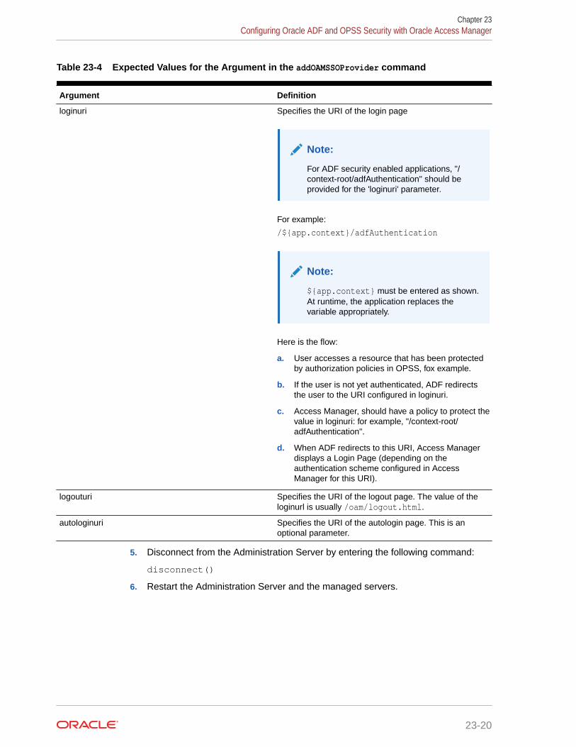
Table 23-4 Expected Values for the Argument in the addOAMSSOProvider command
Argument Definition
loginuri Specifies the URI of the login page
Note:
For ADF security enabled applications, "/context-root/adfAuthentication" should beprovided for the 'loginuri' parameter.
For example:
/${app.context}/adfAuthentication
Note:
${app.context} must be entered as shown.At runtime, the application replaces thevariable appropriately.
Here is the flow:
a. User accesses a resource that has been protectedby authorization policies in OPSS, fox example.
b. If the user is not yet authenticated, ADF redirectsthe user to the URI configured in loginuri.
c. Access Manager, should have a policy to protect thevalue in loginuri: for example, "/context-root/adfAuthentication".
d. When ADF redirects to this URI, Access Managerdisplays a Login Page (depending on theauthentication scheme configured in AccessManager for this URI).
logouturi Specifies the URI of the logout page. The value of theloginurl is usually /oam/logout.html.
autologinuri Specifies the URI of the autologin page. This is anoptional parameter.
5. Disconnect from the Administration Server by entering the following command:
disconnect()
6. Restart the Administration Server and the managed servers.
Chapter 23Configuring Oracle ADF and OPSS Security with Oracle Access Manager
23-20

AUsing Multi Data Sources with Oracle RAC
Oracle recommends that you use GridLink data sources when you develop new Oracle RACapplications. However, if you are using legacy applications and databases that do not supportGridLink data sources, refer to the information in this appendix.
This appendix provides information about multi data sources and Oracle RAC and procedurefor configuring multi data sources for an Enterprise Deployment.
• About Multi Data Sources and Oracle RACA multi data source provides an ordered list of data sources to use to satisfy connectionrequests.
• Typical Procedure for Configuring Multi Data Sources for an Enterprise DeploymentYou need to configure data sources when you configure a domain. If you want to useMulti Data Sources instead of GridLink data sources, replace the GridLink instructionswith the instructions provided in this section.
About Multi Data Sources and Oracle RACA multi data source provides an ordered list of data sources to use to satisfy connectionrequests.
Normally, every connection request to this kind of multi data source is served by the first datasource in the list. If a database connection test fails and the connection cannot be replaced,or if the data source is suspended, a connection is sought sequentially from the next datasource on the list.
For more information about configuring Multi Data Sources with Oracle RAC, see Using MultiData Sources with Oracle RAC in Administering JDBC Data Sources for Oracle WebLogicServer.
Typical Procedure for Configuring Multi Data Sources for anEnterprise Deployment
You need to configure data sources when you configure a domain. If you want to use MultiData Sources instead of GridLink data sources, replace the GridLink instructions with theinstructions provided in this section.
For example, when you are configuring the initial Administration domain for an EnterpriseDeployment reference topology, you use the configuration wizard to define the characteristicsof the domain, as well as the data sources.
The procedures for configuring the topologies in this Enterprise Deployment Guide includespecific instructions for defining GridLink data sources with Oracle RAC. If you want to useMulti Data Sources instead of GridLink data sources, replace the GridLink instructions withthe following:
1. In the Configure JDBC Component Schema screen:
A-1

a. Select the appropriate schemas.
b. For the RAC configuration for component schemas, Convert to RAC multidata source.
c. Ensure that the following data source appears on the screen with the schemaprefix when you ran the Repository Creation Utility.
d. Click Next.
2. The Configure RAC Multi Data Sources Component Schema screen appears(#unique_656/unique_656_Connect_42_BABEJFFB).
In this screen, do the following:
a. Enter values for the following fields, specifying the connect information for theOracle RAC database that was seeded with RCU.
• Driver: Select Oracle driver (Thin) for RAC Service-Instanceconnections, Versions:10, 11.
• Service Name: Enter the service name of the database.
• Username: Enter the complete user name (including the prefix) for theschemas.
• Password: Enter the password to use to access the schemas.
b. Enter the host name (vip address), instance name, and port.
c. Click Add.
d. Repeat this for each Oracle RAC instance.
e. Click Next.
3. In the Test JDBC Data Sources screen, the connections are tested automatically.The Status column displays the results. Ensure that all connections weresuccessful. If not, click Previous to return to the previous screen and correct yourentries.
Click Next when all the connections are successful.
Appendix ATypical Procedure for Configuring Multi Data Sources for an Enterprise Deployment
A-2

BTargeting Applications and Resources toServers
The component-wise list of targets is used to verify that the value used in the config.xml fileis correct.
This appendix lists the applications, library, startup class, shutdown class, JMS systemresource, and JDBC system resource targets for an Oracle SOA enterprise deployment.
• Oracle SOA Enterprise Application Targets
• Oracle SOA Enterprise Deployment Library Targets
• Oracle SOA Enterprise Deployment Startup Class Targets
• Oracle SOA Enterprise Deployment Shutdown Class Targets
• Oracle SOA Enterprise Deployment JMS System Resource Targets
• Oracle SOA Enterprise Deployment JDBC System Resource Targets
Oracle SOA Enterprise Application TargetsThis table lists the Oracle SOA enterprise deployment application targets.
Table B-1 SOA Application Targets
Application Targets
api-console AdminServer, OSB_Cluster, SOA_Cluster, WSM-PM_Cluster
AqAdapter OSB_Cluster, AdminServer, SOA_Cluster
b2bui SOA_Cluster
BamComposer BAM_Cluster
BamCQService BAM_Cluster
BamServer BAM_Cluster
Basic12212App SOA_Cluster
BPMComposer SOA_Cluster
Cloudsdk AdminServer, OSB_Cluster
coherence-transaction-rar AdminServer, BAM_Cluster, ESS_Cluster,OSB_Cluster, SOA_Cluster, WSM-PM_Cluster
DbAdapter AdminServer, OSB_Cluster, SOA_Cluster
DefaultToDoTaskFlow SOA_Cluster
DMS Application (12.2.1.1.0) AdminServer, BAM_Cluster, ESS_Cluster,OSB_Cluster, SOA_Cluster, WSM-PM_Cluster
em AdminServer
B-1

Table B-1 (Cont.) SOA Application Targets
Application Targets
ESSAPP ESS_Cluster
EssNativeHostingApp (V1.0) ESS_Cluster
FileAdapter AdminServer, OSB_Cluster, SOA_Cluster
frevvo SOA_Cluster
FtpAdapter AdminServer, OSB_Cluster, SOA_Cluster
insight BAM_Cluster
insight-service-bus-agent OSB_Cluster
insight-soa-agent SOA_Cluster
insight-ui BAM_Cluster
MQSeriesAdapter SOA_Cluster
OAAPredictionService SOA_Cluster
opss-rest AdminServer, BAM_Cluster
OracleAppsAdapter SOA_Cluster
OracleBPMBACServerApp SOA_Cluster
OracleBPMComposerRolesApp SOA_Cluster
OracleBPMBACServerApp SOA_Cluster
OracleBPMComposerRolesApp SOA_Cluster
OracleBPMProcessRolesApp SOA_Cluster
OracleBPMWorkspace SOA_Cluster
procmon-listener SOA_Cluster
Service Bus Domain Singleton Marker Application WLS_OSB1
Service Bus DSP Transport Provider AdminServer, OSB_Cluster
Service Bus EJB Transport Provider AdminServer, OSB_Cluster
Service Bus Email Transport Provider AdminServer, OSB_Cluster
Service Bus File Transport Provider AdminServer, OSB_Cluster
Service Bus Framework Starter Application AdminServer, OSB_Cluster
Service Bus FTP Transport Provider AdminServer, OSB_Cluster
Service Bus JCA Transport Provider AdminServer, OSB_Cluster
Service Bus JEJB Transport Provider AdminServer, OSB_Cluster
Service Bus JMS Reporting Provider OSB_Cluster
Service Bus Kernel AdminServer, OSB_Cluster
Service Bus Logging AdminServer, OSB_Cluster
Service Bus LWPF_Console AdminServer
Service Bus Message Reporting Purger OSB_Cluster
Service Bus MQ Transport Provider AdminServer, OSB_Cluster
Service Bus OWSM Initializer AdminServer, OSB_Cluster
Service Bus Publish AdminServer, OSB_Cluster
Appendix BOracle SOA Enterprise Application Targets
B-2

Table B-1 (Cont.) SOA Application Targets
Application Targets
Service Bus Resource OSB_Cluster
Service Bus Result Cache OSB_Cluster
Service Bus Routing AdminServer, OSB_Cluster
Service Bus SB Transport Provider AdminServer, OSB_Cluster
Service Bus SFTP Transport Provider AdminServer, OSB_Cluster
Service Bus SOA-DIRECT Transport Provider AdminServer, OSB_Cluster
Service Bus Subscription Listener OSB_Cluster
Service Bus Test Framework AdminServer, OSB_Cluster
Service Bus Transform AdminServer, OSB_Cluster
Service Bus Tuxedo Transport Provider AdminServer, OSB_Cluster
Service Bus UDDI Manager AdminServer
Service Bus WS Transport Async Response OSB_Cluster
Service Bus WS Transport Provider OSB_Cluster
Service Bus WSIL OSB_Cluster
service-bus AdminServer
SimpleApprovalTaskFlow SOA_Cluster
soa-infra SOA_Cluster
soa-webapps SOA_Cluster
state-management-provider-memory-rar AdminServer, BAM_Cluster, ESS_Cluster,OSB_Cluster, SOA_Cluster, WSM-PM_Cluster
UMSAdapter SOA_Cluster
usermessagingdriver-apns OSB_Cluster
usermessagingdriver-email BAM_Cluster, OSB_Cluster, SOA_Cluster
usermessagingdriver-extension OSB_Cluster
usermessagingdriver-gcm OSB_Cluster
usermessagingdriver-smpp OSB_Cluster
usermessagingdriver-twitter OSB_Cluster
usermessagingdriver-xmpp OSB_Cluster
usermessagingserver BAM_Cluster, OSB_Cluster, SOA_Cluster
worklistapp SOA_Cluster
wsm-pm WSM-PM_Cluster
Oracle SOA Enterprise Deployment Library TargetsThis table lists the Oracle SOA enterprise deployment library targets.
Appendix BOracle SOA Enterprise Deployment Library Targets
B-3

Table B-2 SOA Library Targets
Library Targets
adf.oracle.businesseditor(1.0,12.2.1.1.0) AdminServer, BAM_Cluster, ESS_Cluster,OSB_Cluster, SOA_Cluster, WSM-PM_Cluster
adf.oracle.domain(1.0,12.2.1.1.0) AdminServer, BAM_Cluster, ESS_Cluster,OSB_Cluster, SOA_Cluster, WSM-PM_Cluster
adf.oracle.domain.webapp(1.0,12.2.1.1.0) AdminServer, BAM_Cluster, ESS_Cluster,OSB_Cluster, SOA_Cluster, WSM-PM_Cluster
BamClientLibrary(12.2.1,12.2.1) BAM_Cluster
BamDatacontrol(12.2.1,12.2.1) BAM_Cluster
beam.em Admin Server
beehive-controls-1.0.1-10.0-war(1.0,1.0.2.2) AdminServer, OSB_Cluster
beehive-netui-1.0.1-10.0(1.0,1.0.2.2) AdminServer, OSB_Cluster
beehive-netui-resources-1.0.1-10.0(1.0,1.0.2.2)
AdminServer, OSB_Cluster
com.bea.wlp.lwpf.console.app(10.3.0,10.3.0) AdminServer, OSB_Cluster
com.bea.wlp.lwpf.console.web(10.3.0,10.3.0) AdminServer, OSB_Cluster
emagentsdkimplpriv_jar(12.4,12.1.0.4.0) AdminServer
emagentsdkimpl_jar(12.4,12.1.0.4.0) AdminServer
emagentsdk_jar(12.4,12.1.0.4.0) AdminServer
emai.ess.fmwctrl.dep AdminServer
emai.fmwctrl.dep AdminServer
emas AdminServer
emcore AdminServer
emcoreclient_jar AdminServer
emcorecommon_jar AdminServer
emcoreconsole_jar AdminServer
emcoreintsdk_jar(11.2.0.1.0,12.1.0.0.0) AdminServer
emcorepbs_jar AdminServer
emcoresdkimpl_jar(11.2.0.1.0,12.1.0.0.0) AdminServer
emcoresdk_jar(11.2.0.1.0,12.1.0.0.0) AdminServer
emcore_jar AdminServer
em_common(12.4,12.1.0.4.0) AdminServer
em_core_ppc_pojo_jar AdminServer
em_error(12.4,12.1.0.4.0) AdminServer
em_sdkcore_ppc_public_pojo_jar AdminServer
ess.em AdminServer
JCAFrameworkImpl(12.1.2.0,12.1.2.0) AdminServer, OSB_Cluster
JmsAdapter AdminServer, OSB_Cluster, SOA_Cluster
Appendix BOracle SOA Enterprise Deployment Library Targets
B-4

Table B-2 (Cont.) SOA Library Targets
Library Targets
jsf(2.0,1.0.0.0_2-2-8) AdminServer, BAM_Cluster, ESS_Cluster,OSB_Cluster, SOA_Cluster, WSM-PM_Cluster
jstl(1.2,1.2.0.1) AdminServer, BAM_Cluster, ESS_Cluster,OSB_Cluster, SOA_Cluster, WSM-PM_Cluster
log4j_jar(1.3,1.2.15) AdminServer
odl.clickhistory(1.0,12.2.1) AdminServer, BAM_Cluster, ESS_Cluster,OSB_Cluster, SOA_Cluster, WSM-PM_Cluster
odl.clickhistory.webapp(1.0,12.2.1) AdminServer, BAM_Cluster, ESS_Cluster,OSB_Cluster, SOA_Cluster, WSM-PM_Cluster
ohw-rcf(5,12.2.1.1.0) AdminServer, BAM_Cluster, ESS_Cluster,OSB_Cluster, SOA_Cluster, WSM-PM_Cluster
ohw-uix(5,12.2.1.1.0) AdminServer, BAM_Cluster, ESS_Cluster,OSB_Cluster, SOA_Cluster, WSM-PM_Cluster
oracle.adapter.ext(12.1.2,12.1.2) AdminServer, SOA_Cluster
oracle.adf.dconfigbeans(1.0,12.2.1.1.0) AdminServer, BAM_Cluster, ESS_Cluster,OSB_Cluster, SOA_Cluster, WSM-PM_Cluster
oracle.adf.desktopintegration(1.0,12.2.1.1.0) AdminServer, BAM_Cluster, ESS_Cluster,OSB_Cluster, SOA_Cluster, WSM-PM_Cluster
oracle.adf.desktopintegration.model(1.0,12.2.1.1.0)
AdminServer, BAM_Cluster, ESS_Cluster,OSB_Cluster, SOA_Cluster, WSM-PM_Cluster
oracle.adf.management(1.0,12.2.1.1.0) AdminServer, BAM_Cluster, ESS_Cluster,OSB_Cluster, SOA_Cluster, WSM-PM_Cluster
oracle.advancedanalytics.prediction(11.1.1,12.1.3)
AdminServer, SOA_Cluster
oracle.bi.adf.model.slib(1.0,12.2.1.1.0) AdminServer, BAM_Cluster, ESS_Cluster,OSB_Cluster, SOA_Cluster, WSM-PM_Cluster
oracle.bi.adf.view.slib(1.0,12.2.1.1.0) AdminServer, BAM_Cluster, ESS_Cluster,OSB_Cluster, SOA_Cluster, WSM-PM_Cluster
oracle.bi.adf.webcenter.slib(1.0,12.2.1.1.0)v AdminServer, BAM_Cluster, ESS_Cluster,OSB_Cluster, SOA_Cluster, WSM-PM_Cluster
oracle.bi.composer(11.1.1,0.1) AdminServer, BAM_Cluster, ESS_Cluster,OSB_Cluster, SOA_Cluster, WSM-PM_Cluster
oracle.bi.jbips(11.1.1,0.1) AdminServer, BAM_Cluster, ESS_Cluster,OSB_Cluster, SOA_Cluster, WSM-PM_Cluster
oracle.bpm.bac(11.1.1,12.1.3) AdminServer, SOA_Cluster
oracle.bpm.client(11.1.1,12.1.3) AdminServer, SOA_Cluster
oracle.bpm.composerlib(11.1.1,12.1.3) AdminServer, SOA_Cluster
oracle.bpm.management.webapp(12.1.3,12.1.3)
AdminServer
oracle.bpm.processviewer(11.1.1,12.1.3) BAM_Cluster
oracle.bpm.projectlib(11.1.1,12.1.3) AdminServer, SOA_Cluster
oracle.bpm.runtime(11.1.1,12.1.3) AdminServer, SOA_Cluster
Appendix BOracle SOA Enterprise Deployment Library Targets
B-5

Table B-2 (Cont.) SOA Library Targets
Library Targets
oracle.bpm.webapp.common(11.1.1,12.1.3) AdminServer, SOA_Cluster
oracle.bpm.workspace(11.1.1,12.1.3) AdminServer, SOA_Cluster
oracle.cloud.adapter(12.1.2,12.1.2) AdminServer, SOA_Cluster
oracle.dconfig-infra(2.0,12.2.1) AdminServer, BAM_Cluster, ESS_Cluster,OSB_Cluster, SOA_Cluster, WSM-PM_Cluster
oracle.ess(12,12.2.1.2.0) AdminServer, ESS_Cluster
oracle.ess.admin(12,12.2.1.2.0) AdminServer
oracle.ess.client(12,12.2.1.2.0) AdminServer, ESS_Cluster
oracle.ess.client.api(12,12.2.1.2.0) AdminServer, ESS_Cluster
oracle.ess.runtime(12,12.2.1.2.0) AdminServer, ESS_Cluster
oracle.ess.thin.client(12,12.2.1.2.0) AdminServer, ESS_Cluster, OSB_Cluster,SOA_Cluster
oracle.jrf.system.filter AdminServer, BAM_Cluster, ESS_Cluster,OSB_Cluster, SOA_Cluster, WSM-PM_Cluster
oracle.jsp.next(12.2.1,12.2.1) AdminServer, BAM_Cluster, ESS_Cluster,OSB_Cluster, SOA_Cluster, WSM-PM_Cluster
oracle.pwdgen(2.0,12.2.1) AdminServer, BAM_Cluster, ESS_Cluster,OSB_Cluster, SOA_Cluster, WSM-PM_Cluster
oracle.rules(11.1.1,12.1.3) AdminServer, SOA_Cluster
oracle.sdp.client(2.0,12.2.1.2.0) AdminServer, BAM_Cluster, ESS_Cluster,OSB_Cluster, SOA_Cluster, WSM-PM_Cluster
oracle.sdp.messaging(2.0,12.2.1.2.0) AdminServer, BAM_Cluster, ESS_Cluster,OSB_Cluster, SOA_Cluster, WSM-PM_Cluster
oracle.soa.apps(11.1.1,12.1.2) AdminServer, SOA_Cluster
oracle.soa.bpel(11.1.1,12.1.2) AdminServer, SOA_Cluster
oracle.soa.common.dvmxref(12.1.1,12.1.2) AdminServer, SOA_Cluster
oracle.soa.common.functions(12.2.1,12.1.2) AdminServer, SOA_Cluster
oracle.soa.common.resequencer(12.1.1,12.1.2)
AdminServer, SOA_Cluster
oracle.soa.common.sequencing(11.1.1,12.1.2) AdminServer, SOA_Cluster
oracle.soa.commonconsole.dependencies(12.1.2,12.1.2)
AdminServer, SOA_Cluster, BAM_Cluster
oracle.soa.commonconsole.webapp(12.1.2,12.1.2)
AdminServer, SOA_Cluster, BAM_Cluster
oracle.soa.composer.webapp(11.1.1,12.1.2) AdminServer, SOA_Cluster
oracle.soa.ess.dc(12,12.2.1.0.0) AdminServer
oracle.soa.ext(11.1.1,12.1.2) AdminServer, SOA_Cluster
oracle.soa.management.webapp(12.1.2,12.1.2)
AdminServer
oracle.soa.mediator(11.1.1,12.1.2) AdminServer, SOA_Cluster
Appendix BOracle SOA Enterprise Deployment Library Targets
B-6

Table B-2 (Cont.) SOA Library Targets
Library Targets
oracle.soa.procmon(12.2.1,12.2.1) BAM_Cluster
oracle.soa.procmon.agent(12.2.1,12.2.1) SOA_Cluster
oracle.soa.procmon.ui(12.2.1,12.2.1) BAM_Cluster
oracle.soa.rules_dict_dc.webapp(11.1.1,11.1.1)
AdminServer, SOA_Cluster
oracle.soa.sb.em.adf.mgmt(1.0,12.1.2.0.0) AdminServer, OSB_Cluster
oracle.soa.webmapper(11.1.1,12.1.2) AdminServer, SOA_Cluster
oracle.soa.webmapper(12.1.3,12.1.3) AdminServer, OSB_Cluster
oracle.soa.workflow(11.1.1,12.1.2) AdminServer, SOA_Cluster
oracle.soa.workflow.wc(11.1.1,12.1.2) AdminServer, SOA_Cluster
oracle.soa.worklist(11.1.1,12.1.2) AdminServer, SOA_Cluster
oracle.soa.worklist.webapp(11.1.1,11.1.1) AdminServer, SOA_Cluster
oracle.soa.xquery(11.1.1,12.1.2) AdminServer, SOA_Cluster
oracle.ucs.userprefs.webapp(2.0,12.2.1.2.0) BAM_Cluster, OSB_Cluster, SOA_Cluster
oracle.webcenter.composer(2.0,12.2.1) AdminServer
oracle.webcenter.skin(2.0,12.2.1) AdminServer
oracle.wsm.console.core.view(1.0,12.2.1.2) AdminServer
oracle.wsm.seedpolicies(2.0,12.2.1.2) AdminServer, BAM_Cluster, ESS_Cluster,OSB_Cluster, SOA_Cluster, WSM-PM_Cluster
orai18n-adf(11,11.1.1.1.0) AdminServer, BAM_Cluster, ESS_Cluster,OSB_Cluster, SOA_Cluster, WSM-PM_Cluster
osb.em AdminServer
owasp.esapi(2.0,12.2.1) AdminServer, BAM_Cluster, ESS_Cluster,OSB_Cluster, SOA_Cluster, WSM-PM_Cluster
resource-mq-connection(12.1.3,12.1.3) AdminServer, OSB_Cluster
soa.em AdminServer
stage-logging(12.1.3,12.1.3) AdminServer, OSB_Cluster
stage-publish(12.1.3,12.1.3) AdminServer, OSB_Cluster
stage-routing(12.1.3,12.1.3) AdminServer, OSB_Cluster
stage-transform(12.1.3,12.1.3) AdminServer, OSB_Cluster
stage-utils(12.1.3,12.1.3) AdminServer, OSB_Cluster
struts-1.2(1.2,1.2.9) AdminServer, OSB_Cluster
transport-bpel10g(12.1.3,12.1.3) AdminServer, OSB_Cluster
transport-dsp(12.1.3,12.1.3) AdminServer, OSB_Cluster
transport-ejb(12.1.3,12.1.3) AdminServer, OSB_Cluster
transport-email(12.1.3,12.1.3) AdminServer, OSB_Cluster
transport-file(12.1.3,12.1.3) AdminServer, OSB_Cluster
transport-ftp(12.1.3,12.1.3) AdminServer, OSB_Cluster
Appendix BOracle SOA Enterprise Deployment Library Targets
B-7

Table B-2 (Cont.) SOA Library Targets
Library Targets
transport-jejb(12.1.3,12.1.3) AdminServer, OSB_Cluster
transport-mq(12.1.3,12.1.3) AdminServer, OSB_Cluster
transport-pollersdk(12.1.3,12.1.3) AdminServer, OSB_Cluster
transport-sftp(12.1.3,12.1.3) AdminServer, OSB_Cluster
transport-soa(12.1.3,12.1.3) AdminServer, OSB_Cluster
transport-tuxedo(12.1.3,12.1.3) AdminServer, OSB_Cluster
UIX(11,12.2.1.1.0) AdminServer, BAM_Cluster, ESS_Cluster,OSB_Cluster, SOA_Cluster, WSM-PM_Cluster
weblogic-controls-10.0-war(10.0,10.2) AdminServer, OSB_Cluster
wlp-framework-common-web-lib(10.3.0,10.3.0) AdminServer, OSB_Cluster
wlp-framework-struts-1.2-web-lib(10.3.0,10.3.0)
AdminServer, OSB_Cluster
wlp-light-web-lib(10.3.0,10.3.0) AdminServer, OSB_Cluster
wlp-lookandfeel-web-lib(10.3.0,10.3.0) AdminServer, OSB_Cluster
wls-commonslogging-bridge-war(1.0,1.1) AdminServer, OSB_Cluster
Oracle SOA Enterprise Deployment Startup Class TargetsThis table lists the Oracle SOA enterprise deployment Startup Class targets.
Table B-3 SOA Startup Class Targets
Class Targets
AWT Application Context Startup Class AdminServer, BAM_Cluster, ESS_Cluster,OSB_Cluster, SOA_Cluster, WSM-PM_Cluster
DMS-Startup AdminServer, BAM_Cluster, ESS_Cluster,OSB_Cluster, SOA_Cluster, WSM-PM_Cluster
JRF Startup Class AdminServer, BAM_Cluster, ESS_Cluster,OSB_Cluster, SOA_Cluster, WSM-PM_Cluster
ODL-Startup AdminServer, BAM_Cluster, ESS_Cluster,OSB_Cluster, SOA_Cluster, WSM-PM_Cluster
OSB JCA Transport Post-Activation StartupClass
OSB_Cluster, AdminServer
SOAStartupClass SOA_Cluster
Web Services Startup Class AdminServer, BAM_Cluster, ESS_Cluster,OSB_Cluster, SOA_Cluster, WSM-PM_Cluster
WSM Startup Class AdminServer, BAM_Cluster, ESS_Cluster,OSB_Cluster, SOA_Cluster, WSM-PM_Cluster
Appendix BOracle SOA Enterprise Deployment Startup Class Targets
B-8

Oracle SOA Enterprise Deployment Shutdown Class TargetsThis table lists the Oracle SOA enterprise deployment Shutdown Class targets.
Table B-4 SOA Shutdown Class Targets
Class Targets
DMSShutdown AdminServer, BAM_Cluster, ESS_Cluster,OSB_Cluster, SOA_Cluster, WSM-PM_Cluster
Oracle SOA Enterprise Deployment JMS System ResourceTargets
This table lists the Oracle SOA enterprise deployment JMS System Resource targets.
Table B-5 SOA JMS System Resource Targets
JMS Resource Targets
BamAlertEngineJmsSystemModule BAM_Cluster
BamCQServiceJmsSystemModule BAM_Cluster BamCQServiceJmsSystemModule BAM_Cluster
BAMJMSSystemResource BAM_Cluster
BamPersistenceJmsSystemModule BAM_Cluster
BamPersistenceJmsSystemModule BAM_Cluster
BamReportCacheJmsSystemModule BAM_Cluster
BPMJMSModule SOA_Cluster
jmsResources OSB_Cluster
ProcMonJMSModule SOA_Cluster
SOAJMSModule SOA_Cluster
UMSJMSSystemResource BAM_Cluster, OSB_Cluster, SOA_Cluster
Oracle SOA Enterprise Deployment JDBC System ResourceTargets
This table lists the Oracle SOA enterprise deployment JDBC System Resource targets.
Table B-6 SOA JDBC System Resource Targets
JDBC Resource Targets
BamDataSource BAM_Cluster, SOA_Cluster
BamJobSchedDataSource BAM_Cluster
BamLeasingDataSource BAM_Cluster
Appendix BOracle SOA Enterprise Deployment Shutdown Class Targets
B-9

Table B-6 (Cont.) SOA JDBC System Resource Targets
JDBC Resource Targets
BamNonJTADataSource BAM_Cluster, SOA_Cluster
EDNDataSource SOA_Cluster
EDNLocalTxDataSource SOA_Cluster
EssDS ESS_Cluster
EssInternalDS ESS_Cluster
EssXADS ESS_Cluster
JMS BAM_Cluster, OSB_Cluster, SOA_Cluster, WSM-PM_Cluster
Leasing BAM_Cluster, OSB_Cluster, SOA_Cluster
LocalSvcTblDataSource AdminServer, ESS_Cluster
mds-bam AdminServer, BAM_Cluster, SOA_Cluster
mds-ESS_MDS_DS ESS_Cluster
mds-owsm AdminServer, WSM-PM_Cluster
mds-soa AdminServer, SOA_Cluster
opss-audit-DBDS AdminServer, BAM_Cluster, ESS_Cluster,OSB_Cluster, SOA_Cluster, WSM-PM_Cluster
opss-audit-viewDS AdminServer, BAM_Cluster, ESS_Cluster,OSB_Cluster, SOA_Cluster, WSM-PM_Cluster
opss-data-source AdminServer, BAM_Cluster, ESS_Cluster,OSB_Cluster, SOA_Cluster, WSM-PM_Cluster
OraSDPMDataSource BAM_Cluster, OSB_Cluster, SOA_Cluster
SOADataSource AdminServer, OSB_Cluster, SOA_Cluster
SOALocalTxDataSource SOA_Cluster
TLOG BAM_Cluster, ESS_Cluster, OSB_Cluster,SOA_Cluster, WSM-PM_Cluster
wlsbjmsrpDataSource AdminServer, OSB_Cluster
Appendix BOracle SOA Enterprise Deployment JDBC System Resource Targets
B-10