
Enhancing Command and Control (C2) Assessment through ...
41
16 th ICCRTS “Collective C2 in Multinational Civil-Military Operations” Enhancing Command and Control (C2) Assessment through Semantic Systems Topic: (4) – Information and Knowledge Exploitation Authors: Anton DeFrancesco Securboration Inc. Redvers Thompson Securboration Inc. Phil Warlick Securboration Inc. Point of Contact: Anton DeFrancesco Securboration Inc. 1050 W. NASA Blvd. Suite 157 Melbourne FL, 32901 (321) 409-5252 x21 [email protected]
-
Upload
khangminh22 -
Category
Documents
-
view
2 -
download
0
Transcript of Enhancing Command and Control (C2) Assessment through ...

16th
ICCRTS
“Collective C2 in Multinational Civil-Military Operations”
Enhancing Command and Control (C2) Assessment through Semantic Systems
Topic:
(4) – Information and Knowledge Exploitation
Authors: Anton DeFrancesco
Securboration Inc.
Redvers Thompson Securboration Inc.
Phil Warlick Securboration Inc.
Point of Contact:
Anton DeFrancesco Securboration Inc.
1050 W. NASA Blvd. Suite 157
Melbourne FL, 32901 (321) 409-5252 x21

1
1. Abstract Assessment, conducted at all levels of civil-military operations - strategic, operational, and tactical, provides commanders with analysis that is essential to the successful execution of campaigns and delivery of their objectives. The failings of assessment in recent operations, including ad-hoc processes, paucity of IT support tools, and limitations of data acquisition, correlation, analysis and visualization are well documented. This shortfall in assessment capability has undoubtedly hampered most recent operations and certainly has the potential to derail even the best of future operational plans. The variability of data sources, analyst confidence, and the ability to readily access and visualize evidence from the operational environment all provide obstacles in the collation, integration, and analysis of assessment data. To address these issues, this paper proposes utilizing abstract models to re-align data and semantic networks to provide reasoning and inferencing of higher level concepts. One such capability focuses on the integration of data from disparate structured and unstructured sources into data abstractions while another focuses on re-orienting data to provide a more comprehensive view of the information for human analysis. These capabilities, combined with others, provide additional resources to commanders and analysts for timely decision making and achievement of objectives.
2. Introduction Operational Assessment (OA) is a critical component of executing a modern military campaign. Without advancements in assessment, commanders have severely limited capability to evaluate whether their actions are achieving desired effects. By way of recent example, Operation IRAQI FREEDOM (OIF) was a thoroughly planned joint campaign, for which United States Air Force Central (USCENTAF) planners had developed a detailed supporting Joint Air Operations Plan (JAOP) designed to attain air and space power objectives. However, there were weaknesses in the assessment chain, “…weaknesses that might have resulted in significant fog and friction had the plan not been so well thought out or the enemy more competent.”1
Determining operational effects is critical to executing component strategies, and during OIF, the Air Component Commander (ACC) needed to know the effects that his operations were having on the Iraqi Regime, Ground and Air Forces. However, a lack of timely assessment limited his ability to effectively review and adjust the air strategy. Moreover, the inability to assess air power effects also affected the Land Component Commander’s (LCC) maneuver decisions. The same lack of assessment limited the LCC’s ability to determine strength and movement of Iraqi ground forces in front of his forces, an uncertainty which forced him to change his strategy to a much less efficient form of offensive maneuver - “maneuver to contact.”2
While the above has focused explicitly on assessment, it is commonly recognized that successful operations are, like the proverbial three-legged stool, dependent almost equally on three facets of
1 David C. Hathaway, Lt Col, USAF, “Operational assessment during Operation Iraqi Freedom - Assessment or Assumption?”, Air War College Research Paper, 25 May 2005, pg 18. 2 Ibid, pg 15.

2
Command and Control (C2): planning, execution and assessment; each by necessity having to support and enable the other two. This has been evidenced in many U.S. Department of Defense (DoD)-sponsored C2 research and development projects, which have included problem statements that stated that it was necessary “…to provide critical and actionable insight into planning and execution while supporting both co-located and distributed teams…” through the application of “…agile data integration…”3
These Air-related C2 problems and capability shortfalls are symptomatic of capability gaps that are endemic across all U.S. Government (USG) operational Inter-Agency (IA) domains and the whole of the DoD’s Joint Planning and Execution Community (JPEC). Therefore in working to address any OA problem area the solution approach should be extensible to, or integrate-able with, all IA, JPEC, Coalition and Non-Government Organizations’ (NGO) domains.
This paper is structured to first identify the short comings of current OA in Section 3. Section 4 will address many of the issues through the Comprehensive Adaptive Planning and Execution (CAPE) methodology, and finally Section 4 discusses an implementation of the CAPE methodology, the Semantic Analysis Engine (SAE).
3. Problem Description: “C2 - The Failing Domain” Poor Cross-Domain Operational Planning, Execution, and Assessment
The U.S. Air Force (AF) has sought to address the fact that Air Operations Centers (AOCs) are significantly lacking in their capability to access, visualize, or develop understanding of underlying data, systems, and impacts from on-going operational planning, execution, and assessment. AOCs’ processes and support tools have been found deficient in their ability to capture, convey and display National Strategic intent and objectives, through both the Joint Force Commander’s (JFC) and ACC’s operational-level plans, to the ACC’s detailed day-to-day direction in his Air Operations Directive (AOD).4 5
Finally, the multiple mission-specifics of the daily Air Tasking Order (ATO) must be executed through the ‘fog and friction’ of combat operations, while undergoing a continuous assessment and recommendation cycle. Just as these deficiencies exist within a single component acting at a single level of war, it is equally true that there are no current capabilities to capture and visualize operational plans and data either horizontally across the various Service, Functional and IA domains, or vertically through the various levels of war i.e. National Strategic - Theater Strategic - Operational - Tactical.
As a contribution to the Project on National Security Reform’s study of the USG’s IA process, a paper, “Choosing War: The Decision to Invade Iraq and Its Aftermath”6
3 Air Force, Electronic Systems Command, Small Business Innovation Research Topic AF093-025, “Visualization of Cross-Domain C2ISR Operations”, Topic Pre-release Intent Statement, July 2009.
, stated that “…the future is likely to
4 Ibid, Topic Description: http://www.afsbirsttr.com/TopicPreRelease/Profile.aspx?pk=20201 5 Author’s (Redvers Thompson, Wg Cdr, RAF (Ret.)) personal operational experiences from Op ALLIED FORCE (Vicenza AOC, Strategy Div, April-June 1999), Op ENDURING FREEDOM (HQUSCENTCOM, J5, September-December 2001) and Op IRAQI FREEDOM (HQUSCENTAF, Strategy Division, July-December 2002, and PSAB-CENTAF AOC, Strategy Division, January-April 2003). 6 Joseph J. Collins, Institute for National Strategic Studies, Occasional Paper 5 (National Defense University Press, Washington, D.C., April 2008)

3
present complex contingencies that will require significant capabilities in which the power of the entire government will be needed to make plans to solve multifaceted problems overseas…” In a related study on crisis planning7
, Dr. Williamson Murray, a Senior Fellow at the Institute of Defense Analysis and a member of the National Strategic Studies Group, stated that “…no matter how impressive the conduct of [..] operations might be at the tactical level, there is no guarantee that linkages will exist to the strategic and operational levels without a considerable intellectual effort to think through the potential effects of policy decisions and strategy, or the possible contributions that tactical actions might make to achieving operational or strategic effects.”
Against the backdrop of the changes required across the whole of the USG and DoD’s JPEC, the operational AOCs have the following challenges:
• Providing a leading or contributory role in designing, planning, executing and assessing operations to deter or defeat dynamic threats in multiple domains.
• Synchronizing Air, Space, Cyber, and Intelligence, Surveillance, and Reconnaissance (ISR) actions, by time, space, and resource, across multi-capable component elements, and with other functional and service components and agencies.
• Dynamic assessment of ongoing operations to better inform decision makers and provide
appropriate recommendations.
Problematic Integration, Coordination and Visualization of Operational Plans and Operational Environment Knowledge
A particularly problematic area in the C2 domain is the integration, coordination, and consequent visualization of information from strategic guidance, operational plans, on-going combat operations, intelligence sources, and an ever-morphing Operational Environment (OE). Many efforts over the past several years have made strides in creating User Defined Operational Pictures (UDOP) or Common Operational Pictures (COP) 8
, but none have fully met requirements to provide a holistic view of the OE that is customizable and navigable by users at various levels of command performing various functions.
Many of these problematic issues were identified as factors in causing the problems in assessing air operations during the initial phases of OIF. These included: the format of Mission Report (MISREP) messages that prevented rapid processing; incompatible Joint and AOC IT systems that hindered the ability to effectively share assessment information; and a speed of campaign that served only to compound these, and other, problems. To address these issues, recommendations have included instituting systems that streamline the processing of MISREPs and the enabling and promotion of the cross-domain use of common databases for targeting and Battle Damage Assessment (BDA) information.9
7 Dr. Williamson Murray, Thoughts on Effects-Based Operations, Strategy, and the Conduct of War (Institute for Defense Analyses: Alexandria, VA, January 2004)
8 http://www.jfcom.mil/about/fact_safcop.html 9 David C. Hathaway, Lt Col, USAF, “Operational assessment during Operation Iraqi Freedom - Assessment or Assumption?”, Air War College Research Paper, 25 May 2005, pg 19.

4
Dislocated and Distributed Command and Control
As the AF continues to implement the Component Numbered Air Force (C-NAF) organizational structure and distributed operations concepts, fewer AOC functions will be forward deployed. Therefore, both co-located and geographically separated teams will need workspaces which provide critical and actionable insight into an AOC’s operations, generate situational awareness (SA), situational understanding (SU), and synchronize collective Air, Space, Cyber, C2, and ISR activities. Moreover, as with cross-domain planning, execution, and assessment, the problems of dislocated and distributed C2 are not solely those of C-NAFs and their AOCs, but are inherently ubiquitous across all operational USG, IA and DoD domains. DoD has also identified that current C2 and planning paradigms are too slow and cumbersome, often resulting in plans that address conditions that no longer exist, and that are insufficiently adaptive to the demands of today’s dynamically changing security environment. These paradigms also offer no mechanisms to facilitate early and frequent consultation between military and civilian leaderships regarding plan development and refinement.10 11
The multi-faceted nature of current and future crises will demand that all the USG’s national Instruments of Power (IOPs) ‘plan and fight as a team’; the logical extension of this need is to ‘plan, fight and assess as a team.’ Commanders will adjust operations based on their assessment to ensure military objectives are met. Their assessment process must be continuous and directly tied to the commanders’ decisions throughout planning, preparation, and execution of operations.12
It is therefore necessary that C2 support tools should enable the effective integration of assessment processes and data across all domains and levels of war.
Lack of Visualization supporting C2 Planning, Situation Awareness and Decision-Making
Currently, C2 tools range from custom applications to Microsoft Office™ to PostIt™ sticky notes. For the most part, these tools are used to support specific C2 tasks. To the authors’ knowledge, there are no fielded C2 support tools that explicitly relate, in data terms, tasked tactical missions with: 1) their associated operational and/or tactical objective(s), 2) the entities in the OE that the missions are to directly ‘interact’ with (e.g. targets), and 3) those entities on which any consequential effects were intended to be achieved. And, as these basic data relationships aren’t maintained, the visualization of those relationships is somewhat problematic. One of the greatest limitations in the current implementation of the planning, execution and assessment cycle is that teams performing one element of the cycle have limited insight into decisions and products of prior elements. The information and decisions generated in prior cycle elements are not being brought forward and presented in ways that effectively frame and support good decisions that maximize achievement of larger strategy goals. For example, within the AOC, current systems do not maintain the linkage between the strategy or plan elements (e.g. operational and tactical objectives and tactical tasks), targets, and missions to aid in execution decisions and assessment.
10 DUSD(AS&C) Powerpoint Presentation, “Adaptive Planning Pilot (APP) - Joint Capability Technology Demonstration (JCTD) - FY08 Rolling Start”, 21 December 2007. 11 DUSD(AS&C), “Adaptive Planning Roadmap II – 2008”, March 2008. 12 JP 3-0, Joint Operations, 17 September 2006, Change 2, 22 March 2010, pg IV-30.

5
As AOCs manage ever increasing cross-domain operations, support tools and visualizations will be needed that help planners apply separate and combined air, space and cyberspace resources to achieve an ACC’s operational objectives; as well as understanding their respective parts in the overall Joint campaign. Knowledge of the progress towards those objectives and the situational understanding of their relevance and interactions within the campaign are dependent on an integrated and holistic AOC assessment process that can readily generate timely output that is easily and rapidly assimilated.
4. Solution Approach: “Unifying and Visualizing Operational Plans and Environment through Dynamic Modeling”
‘Unifying’ Cross-Domain Planning, Execution, and Assessment To address the deficiencies in cross-domain operational planning, execution, and assessment, as discussed above, it is now recognized within DoD, and most other USG Departments, that there should be a close integration and execution of any cross-government strategy that seeks to resolve any major crisis or conflict.13 As a consequence, there is the widely held belief of the need for a fully inclusive, Comprehensive Approach (CA) to the conduct of future national and coalition operations.14 15
The foremost and driving imperative of such an approach is the determination and delivery of end-state conditions and the necessary intermediate, enabling and/or contributory conditions within an OE. And, that the two key elements of such a conditions-based approach to crisis and contingency planning, which can be applied in any operational domain, are a holistic understanding of the OE, and a focus on the required outputs of change in the OE. Therefore, a vital precursor to providing commanders and staffs with tailored support tools and visualizations based on common operational understanding, it is first necessary to identify a construct or methodology that is capable of capturing the ‘unifying logic’ of conditions-based operational plans. Moreover, the construct or methodology should also have ‘comprehensive’ utility and meaning across all JPEC, IA, Coalition and NGO domains. This methodology has been developed and named: Comprehensive Adaptive Planning and Execution (CAPE). It is proposed that only with the benefit of such a unifying logical construct established, would it be possible to enable the effective coordination, adaptive planning, execution, and assessment of complex cross-domain, horizontally and vertically coordinated, full-spectrum operations, and the visualization of the same. CAPE: The ‘Unifying’ Construct As clear strategic guidance is universally considered essential to the planning of operations, CAPE’s construct utilizes, at its highest level, Strategic End-State Conditions (SECs), which would collectively comprise the Strategic End-State (SES). While a defined Military End-State (MES) represents the military’s overall goal, other SECs will likely be associated with other national IOPs. The military commander, having established the MES, will identify the various constituent Military End-state Conditions (MECs) that will define achievement of all military objectives.
13 DUSD(AS&C), “Adaptive Planning Roadmap II – 2008”, March 2008. 14 http://www.nato.int/cps/en/natolive/topics_51633.htm 15 http://www.fas.org/irp/doddir/usmc/irreg.pdf

6
The concept of a ‘Line of Effort’ (LOE) is a key construct element within CAPE16, which the authors defined as a logical line [representing a causal chain] that defines the orientation of actions, causal links, effects, objectives, and/or end-state conditions in sequence and purpose within an operational design. Also, the LOE is utilized in CAPE as the main construct for logic-based visualizations, as shown in Figure 1. This figure depicts a national-strategic level plan visualization, where a number of notional ‘Strategic LOEs’ (SLEs) (Diplomatic, Military, Economic, and Information) are shown delivering specific individual SECs, along with a MES comprising multiple MECs.
Figure 1 – CAPE Construct – Strategic LOEs and Operational Objectives
A Joint military campaign is conducted primarily at the operational level of war, and it is the achievement of sequenced and/or aggregated operational-level effects that will deliver the MECs. Therefore, these intended operational-level effects become the Operational Objectives (OOs) normally tasked to component/subordinate commanders for achievement. In essence, an OO is either an ‘enabling’ milestone effect or final ‘contributory’ effect required to achieve a MEC. A Military LOE (MLE), comprising sequenced OOs, can be developed and depicted for each required MEC, along with any established relationships or dependencies between them and other SLEs, and the assigned responsibility to a subordinate commander (i.e. the ‘supported commander’); this can all be depicted by CAPE, as shown in the center of Figure 1 above, where the circles represent OOs within each of the MLEs and their color-coding representing their Joint Force (JF) component assignment.
16 This development and advocacy of LOEs pre-dates the concept’s recent parallel adoption within US Army planning doctrine in FM 3-0, Feb 2008, which states: “A line of effort links multiple tasks and missions using the logic of purpose—cause and effect—to focus efforts toward establishing operational and strategic conditions.”

7
While only the strategic and operational level planning elements have been introduced and illustrated in Figure 1, the CAPE construct has been developed down to the lowest level of tactical missions, actions, and targets; an example of which is discussed in the next section, and illustrated in Figure 4.
The development of this under-pinning, logical planning construct included the identification, classification and definition of every planning element within the construct. While many of the planning elements (or terms) where derived from existing U.S. military doctrine (e.g. Joint Publication (JP) 3-0 “Joint Operations” and JP 5-0 “Joint Operation Planning”) and author operational experience, the continuing extant problem within the C2 domain is that the vast majority of even the most widely used planning elements, e.g. Operational Objective (OO), Tactical Objective (TO), and Tactical Task (TT), have no formal definition nor common schema for writing or applying them. These deficiencies have been specifically rectified within CAPE through the development of the following:
• Lexicon of CAPE Planning Terms and Elements, including a formal definition of each term and element, based mainly on extant and evolving Joint and Service doctrine17
• CAPE Planning Element – Syntax Schema, which defines the structured syntax to be employed for the description and data capture of each category of CAPE planning element. This formalized structure enables automated extraction of the contextual and semantic detail contained within all the individual elements of an operational plan, and supports subsequent modeling of their relationships with other plan elements and the OE; the schema is detailed in Appendix C.
, but includes many derived by the authors. Appendix B is an abridged version of the CAPE lexicon containing the main planning elements.
• Logical Abstraction of CAPE Planning Terms and Elements, which details the logical and semantic relationships between all the planning elements as they would exist within an operational plan. An example high level abstraction of some primary CAPE elements is shown in Figure 2 below, while examples of more detailed models are at Appendix D.
Figure 2 also highlights one the key innovations within the CAPE construct, which is the identification of both ‘Objects of Action’ (OoAs) and ‘Objects of Effect’ (OoEs) as plan elements; these are defined within the CAPE lexicon, respectively as, an “operational environment element against which an action is planned or actually directed” and an “operational environment element on which an effect is intended or actually produced”. The full relevance of these particular plan elements will be discussed later.
17 Draws from work undertaken by Headquarters Air Force Doctrine Center (HQ AFDC), the Effects-Based Operations (EBO) Integrated Process Team (IPT), the Air Force Assessment Task Force (AFATF), the 505th Command and Control Wing (CCW) at Hurlburt Field, Florida, the Dynamic Air and Space Effects-Based Assessment (DASEA) Subject-Matter Expert (SME) User’s Group and Air University’s College of Aerospace Doctrine, Research and Education (CADRE), as well as some of the efforts conducted by US Joint Forces Command (USJFCOM).

8
Figure 2 – Logical Abstraction of CAPE Elements
Integration of Operational Knowledge through Dynamic Modeling
The authors developed a unique methodology and technical solution for the automated creation of dynamic, user-defined Operational Environment Models (OEMs) which provide multiple views of the OE through the integration of multiple intelligence and operations data sources, ontological definitions of systems of interest, and understanding of user roles and responsibilities. In the same manner that a full logical abstraction was developed for all CAPE’s planning elements, multiple similar abstractions were developed for an exemplar range of entities that will exist in most OEs e.g. electricity power (EP) plants, EP substations, airfields, air defense missile sites, hospitals, refugee camps, and petroleum distribution nodes. A diagrammatic representation of an exemplar logical abstraction that was developed (for Military Production and Distribution) is at Appendix E. It is upon these logical abstractions that semantic OEMs can be produced and visualizations created as shown at Figure 3 below. In this example, five entities (circles; color-coded by PMESII18
18 PMESII - Political, Military, Economic, Social, Infrastructure and Information;
category) are shown as being related (by arrows; color-coded by relationship-link type (i.e. logical, functional, or physical)); four of those entities, which having been identified as ‘targets’, are shown linked to their respective constituent facilities. These OEMs provide more than a “snapshot in time” of friendly, neutral, and enemy systems; they provide understanding of the relationships between these systems and how friendly actions against specific targets affect these inter-related systems, enabling richer understanding of current and evolving challenges and threats.
http://pmesii.dm2research.com/wiki/index.php/Main_Page

9
Figure 3 – Logical Representations of Entities in an Operational Environment.
An extension of developing these dynamic, user-defined OEMs is to use the logical abstractions of the CAPE construct to develop a complete operational planning, execution, and assessment ontology that, with tool or system support, allows an operational plan model (OPM) to be built and maintained ‘on-the-fly’ as commanders and staffs plan, execute and assess an operation. Key to the practical employment of these OPMs is that the logical construct establishes both a standard method for planning and defines semantic relationships among an OE’s constituent system elements and the various elements of a comprehensive, conditions-based plan (CBP). And it is exactly here, in realizing this inter-connection between an OPM and related OEM, that ‘OoAs’ and ‘OoEs’ play a pivotal role. They act as one of two logical bridges, or ‘touch points’, between the two model types, in that the OPM’s OoAs and OoEs are also discretely represented as system entities with the OEM, and therefore enabling modeling interaction between them. Another key innovation of the CAPE approach, and acting as the second of the two logical bridges or ‘touch points’ between OPMs and OEMs, is the recognition, capture, and visualization of causal links, which have been defined as “an identified mechanism that causes a given effect to be produced that is of a different nature to that of the contributory effect or action.” A visualization of some of CAPE’s tactical-level planning elements, including the use of causal links (CLs), is shown in Figure 4 below. The figure depicts a tactical scheme for the delivery of the Tactical Objective (TO): “Enemy Mechanized Infantry (Mech. Inf.) Brigade X unable to affect friendly ground assault”. The planners identified that Brigade (Bde) X was required to cross a local river in order to possibly affect the friendly assault and that there were four key bridges across that river. Therefore, the planners devised a Tactical LOE that involved a single Tactical Task (TT), with a single ATO aircraft mission (Msn), i.e. Msn XYZ, tasked to deliver ‘functional kills’ on the four bridges with the direct effect (DE) that all the bridges would be unusable by Mech. Inf. The planner’s assumption was that the consequence of this action

10
would be to deliver an intermediate indirect effect (IE) of “Mech. Inf. Bde X unable to cross river”, which was the actual purpose and objective of the TT (i.e. the Tactical Task’s Objective (TTO)). Then, as the 3rd
order consequence, the planner’s believed the intended TO would be delivered.
CAPE ConstructCausal Links: Action Effects Objective
Figure 4 – Causal Links within an Operational Plan.
Therefore, in this example, the OoA was collectively the “Four Key Bridges” and the common OoE (i.e. common to both 2nd and 3rd
order effects) was the enemy’s “Mech. Inf. Bde X”. However, it must be noted that the scheme was seeking to affect two different specific capabilities of Bde X, in the first place, its capability to cross the river, and then secondly its capability to affect the friendly assault. This is evidenced by the two discrete CLs that the planners assumed were in play. In the first case, the assumed CL was that “Enemy Bde X requires 4 key bridges to cross river”, and, in the second case, the assumed CL was that “Enemy Bde X requires to cross river to affect friendly ground assault”. The relevance of identifying and considering CLs is self-evident for, as can be seen in the above example, if an assumed CL proves to be false or ‘not in play’ the intended outcome or effect is unlikely to be delivered other than by some other unidentified causal mechanism or fortuitous happenstance, but certainly not by the intended “cause and effect” scheme that was planned for.
In the majority of cases, the CLs that are employed within a plan are deduced during the various operational design and planning processes, as illustrated in the example above. It can therefore be seen that, within the CAPE approach, a CL so identified and employed within an operational plan will be instantiated within the OPM, and should relate to some form of link (physical, functional or logical) that actually exists between system entities in the OE (e.g. between OoA and OoE), and should be captured and represented within the respective OEM. In other words, and as depicted in Figure 5 below, an OPM’s CLs can be directly related to discrete system links in an OEM, as can OoAs and OoEs be similarly directly related to system entities in the OEM.

11
CAPE ConstructInter-Connection of OPMs and OEMs
NodeNode Link
Node
Node
Node
Node
Node
Node
Link
Link
Link
Operational Environment Model(OEM)
Action
DirectEffect
Intended EffectEffect
IndirectEffect
CausalLink 1
Causal Link 2
Operational Plan Model(OPM)
Objectof Effect 1
Objectof Effect 2
Object of Action
Figure 5 – Inter-connections between OPMs and OEMs.
5. Solution Technology: “Generating and Integrating Semantic Models”
Semantic Modeling of Cross-Domain Operational Plans and the Operational Environment Central to the CAPE approach is the use of semantic models, which from the perspective of cross-domain operational plans means formalizing knowledge in a machine readable/process-able format that spans strategy design, planning, execution and assessment across the OE. Encoding this knowledge in a semantic model enables automated reasoning to be performed that supports a UDOP inclusive of the user’s role and information needs across domains.
Semantic models are more than just object models or data models, as they can change dynamically to accommodate growth of the domain or new knowledge based on reasoning. Another benefit of semantic models is that they provide a standard syntax that allows formalization of the domain, which is the first step toward machine-assisted understanding of that domain.
As detailed above, this approach enables the development of a semantic representation of an OEM that, combined with the semantic representation of an OPM, positions the approach ideally for adaptive planning capabilities. These OEMs include taxonomies ranging from facilities, equipment, and organizations to an OE’s “soft” factors (e.g. political, cultural, and social). These semantic OEMs have two main dimensions:

12
• A Stereotypical OEM: Modeled after widely used data and artifacts such as Mission Integration Database (MIDB) data, products from an Intelligence Preparation of the Operational Environment (IPOE), and inputs from operational subject matter experts (SMEs); classified by type and then semantically defined using a series of semantic patterns in the form of dependencies, capabilities, and vulnerabilities. Also included, for purposes of OA, are constructs that define possible mechanisms for measurement and indication for a specific element type. Representation of these definitions enables users to reason about and make inferences towards the state of specific OEM objects (e.g. OoAs and OoEs) and the effect of that state on related objects throughout the OE.
• An Instantiated OEM: These model constructs provide adversary and/or campaign specificity to the stereotypical OEM. They are data that represent a specific adversary, battle-space, or campaign and are populated as instances of the stereotypical constructs discussed above. The majority of the instantiated OEM can be populated from MIDB products; however, a small but critical part of the instantiated OEM is achieved through IPOE products. Operational process definitions within CAPE’s semantic model and a user’s planning domain and tools would define the necessary tasks required for creation and maintenance of the instantiated OEM, along with available tools or services that can be used to accomplish these tasks. Once populated, the instantiated OEM is related to the OPM to complete a comprehensive semantic model.
Realization of CAPE and the Semantic Assessment Engine An initial proof-of-concept implementation of the CAPE methodology has been undertaken in the context of developing an OA support system, which was deliberately limited to just the Tactical Assessment (TA) function within the broader OA domain. The Semantic Assessment Engine (SAE) is the resulting actualization of the approach outlined above; it is a system designed to implement semantic technologies in order to integrate, and analyze data in relation to the OEM and OPM. The SAE, as shown in Figure 6 below, is composed of four primary components: the Plan Reader, the Ingestor Module, the Ontology Engine, and the Network Analyzer. The following sections will elaborate on each of the modules design and how they contribute to the technical delivery of the SAE. The SAE is part of a larger ‘system’ that makes up the entire assessment engine. Other components include the application server, database, web services, and the user interface. Although these components play a primary role in the assessment technologies, they are implemented using standard industry techniques and as such do not warrant discussion within the paper with the exception of the user interface which is discussed later. The SAE begins by reading an Extensible Markup Language (XML) based plan through the Plan Reader. Plan elements are extracted and matched with ontological structures in the OPM and OEM where they are categorized and relations between the structures are established. The ontology undergoes an initial reasoning cycle to determine if additional inferences can be made to the plan. Plan entities are checked for geographical, infrastructure, and physical dependencies and if any are present, the additional dependencies are added to the system. An example of this may be a hospital and power distribution node acquiring a logical dependency due to their immediate geographic proximity (as shown in center of Figure 3 above).

13
Figure 6 - Semantic Assessment Engine
The Ingestor Module receives data from disparate sources and uses the Semantic Grounding Mechanism (SGM), which consists of semantic patterns for actors, physical entities, concepts, and composites meshed with the relational types of capabilities, dependencies, and vulnerabilities, to identify and classify the information. New messages are analyzed against a set of known patterns and algorithms and if a match is detected, the message data is passed through a series of predetermined procedures for handling; statistical data from OA processes or a MISREP message would fall under this category. If the data does not match any pre-determined criteria, it is passed to the Natural Language Processor (NLP) for data extraction, e.g. as may be found in the free text portions of a Daily Intelligence Summary (DISUM). The NLP engine analyzes text by breaking sentences or expression blocks down into smaller, more manageable statements. This is accomplished by moving statements from passive to active voice, breaking up conjunctions, and by splitting up sentences based on overall complexity that including elements such as sub-clauses or multiple time-manner-places, as shown by some examples in Table 1 below. Extracting meaningful information from the simplified statements is an easier and more reliable task since the grammar elements more closely align with current pattern and grammar technologies19. Sentences are broken down into their parts of speech through ‘General Architecture for Text Engineering’ (GATE)20. Verbs are extracted and analyzed through VerbNet21 and all other parts of speech are processed through a comprehensive word database, WordNet22
19 Attila Ondi and Anthony Stirtzinger; “Information Discovery Using VerbNet: Managing Complex Sentences”; Proceedings ICAI’10 WORLDCOMP10, July 2010.
. The extracted sentence elements are then fed into the semantic model to augment current definitions or provide new ones.
20 The University of Sheffield, General Architecture for Text Engineering, http://gate.ac.uk/ 21 Martha Palmer, A Class-Based Verb Lexicon, http://verbs.colorado.edu/~mpalmer/projects/verbnet.html 22 George A. Miller, Christiane Fellbaum, Randee Tengi, Helen Langone, Adam Earnst, Lavanya Jose, WordNet,

14
Complex Statement Simple Statement Kennedy (subject-passive) was (aux-pass) killed (verb) in 1963.
1. Somebody (subject) killed (verb) Kennedy (object) in 1963.
Mary, John and Joe were jumping and singing on the shore.
1. Mary was jumping. 2. Mary was singing on the shore. 3. John was jumping. 4. John was singing on the shore. 5. Joe was jumping. 6. Joe was singing on the shore.
1. Somebody observed local civilians. Somebody observed local civilians traveling in the field to exchange weapons for large boxes of cigarettes.
2. Local civilians travel in the field. 3. Local civilians exchange weapons for
large boxes of cigarettes.
Table 1 – Complex to Simple Statement Conversion23
The Ontology Engine provides the primary semantic processing for the SAE by providing both a comprehensive model of the OEM and OPM and the state of system’. All of this information is kept using the Web Ontology Language
24
(OWL). OWL was chosen as the underlying model representation because of its good performance, expressivity, and metadata support. OWL’s metadata support allows users to define their own properties and can extend and enhance the overall capabilities of the system allowing for complex domain relationships. These user properties combined with built-in OWL properties provide a powerful platform for doing inferencing within a system. Examples of some of these properties include transitive and symmetric properties.
A transitive property states that for each property P, if P is a property of X and Y; and P is a property of Y and Z; then P is a property of X and Z:
The preceding rule may apply to different situations and one example with regard to assessment is physical and logical dependencies. For example, if site A has a critical dependency on site B, and site B has a critical dependency on site C. If site C is disabled, we can infer that site A and B are also disabled. Another powerful aspect of OWL is support for the Semantic Web Rule Language 25
(SWRL) which allows users to extend properties and build complex expressions and statements for evaluating OWL ontologies. For example, the statement below says if entity X provides air cover and Y is within X’s air radius, then air cover is provided to Y.
http://wordnet.princeton.edu/ 23 Attila Ondi and Anthony Stirtzinger; “Information Discovery Using VerbNet: Managing Complex Sentences”; Proceedings ICAI’10 WORLDCOMP10, July 2010. 24 Herman, Ivan, 2007, Web Ontology Language(OWL), http://www.w3.org/2004/OWL/ 25 Horrocks, Patel-Schneidr, Boley, Tabet, Grosof, and Dean, SWRL: A Semantic Web Rule Language Combining OWL and RuleML, Semantic Web Rule Language (SWRL), http://www.w3.org/Submission/SWRL/

15
The semantic model leverages OWL and SWRL technologies to define the ontological framework. Constructs, such as objects, properties, and SWRL rules, are then implemented on top of these technologies in order to focus the domain model towards assessment. The Network Analyzer sub-system provides dynamic updates to the system and augments the system by providing coverage of any inadequacies in the ontology models. The analyzer is implemented as a network graph that reflects the OEM and OPM as network nodes and edges. Entities within the semantic model are represented as network nodes and the relations between the entities are graph edges; see Figure 7 below, which on the left shows a Network Graph while the right shows the ontological representation and while similar in logic, they differ in implementation and capabilities.
Figure 7 – Network Graphs and Ontological Representations.
Dynamic algorithms are added to the nodes or edges based on the contents of the plan. An example is an OPM objective that requires all descendant target nodes to be “disabled” within the context of the plan. This objective could be implemented within the Ontological Engine, but the rules required would be non-trivial. When implemented as an algorithm within the network, the task becomes a simple iteration algorithm. Due to the symbiotic relationship between the Ontology Engine and Network Analyzer, all information obtained by one is shared with the other. Another benefit of this semantic model-based approach is the ready ability to organize and present the data in well-formed, human readable and easily understandable formats. The research focused on visual depictions of the data along with standard formats providing multiple angles for viewing the data. Hierarchical data is presented in tree, graph, and a LOE format while more free-form data is presented using concentric viewpoint graphs. The reason for the additional visuals is to better understand the impact of decisions. An example would be a hospital being in close proximity to a high value target. Using a standard scenario an analyst may not be cognizant of that relationship, but by providing the means of detecting the potential link via the semantic models and a visual way of depicting the logical relationship, the analysts can be forewarned of potential issues with the hospital. Some examples of assessment visualization may be found in Appendix F Visual Representations of Operational Plan Models and Operational Environment Models.

16
6. Solution Verification The assessment technologies presented in this paper proved challenging in terms of testing and validation due to the partially subjective nature of assessment. Initial testing focused on qualitative analysis based on SME review. As will be described below, the domain chosen for system and integration testing was AOC-based TA. The validity of both CAPE's methodology and its technical implementation has undergone validation through a set of integrated test suites designed to exercise the depth and breadth of the models and the associated data. System testing was conducted in a sandbox environment that enabled the isolation of individual tests and reduction of unintended variation. All data input data, including the full OEM and OPM plus all periodic messages that included Mission Report (MISREP), Battle Damage Assessment Report (BDAREP), and DISUM messages, were assembled and a baseline was determined. Tests were executed in phases with results for each phase compared against a corresponding baseline. Integration testing consisted initially of a sub-set of an operational plan, produced on the Strategic Worldwide Integration Capability (SWIC)26
, being imported, and from which an OPM was automatically generated; Figure F-3 shows a particular visualization of that generated OPM. In parallel, MIDB data for an exemplar sub-set of OE entities was imported, via a web services from Joint Targeting Toolbox (JTT) service, from which an OEM was generated; it is an example visualization of that OEM that is shown at Figure 3. Also through JTT, a related Joint Prioritized Integrated Target List (JPITL) was imported that identified a further sub-set of the imported OE entities as being 'targets', with each being discretely related to a TT and/or Mission Task (MT). Those relationships were captured and represented within the OPM; Figure F-2 shows an OPM visualization of the assignment of a single target, with four sub-facilities, to an MT. Additionally, the automated inter-connection between the OPM and OEM was evidenced by the fact that, as shown in Figure 3, only those OE entities that were identified as 'targets' (i.e. OoAs) in the OPM were represented with their 'targeted' sub-facilities in the OEM.
The inter-connectivity of the OPM and OEM models was also proven through the flow of ATO and TA data. Sub-sets of a number of imported ATOs were parsed to identify and relate discrete aircraft missions to the plan's MTs and assigned targets. Later in the testing each MISREP was automatically associated with its respective MT and target, and in turn the TA-related data in that MISREP was parsed out and associated with that MT and target. Within the OPM and to the degree allowed by TA-related algorithms, that target-level TA data was automatically 'rolled up' to provide 'inferred' assessments of parent-level plan elements i.e. TTs and TTOs. This TA data provided the data sources of the 'assessment boxes' related to OPM elements as shown in Figure F-2. The TA data that was related to the respective 'targets' (i.e. OoAs) within the OPM, was also related to their parallel instances as OE entities within the OEM, thus allowing similar 'assessment boxes' to be related to them as OEM entities. Quantitative analysis of the assessment engine is still under investigation due to the complexities of the natural language parsing and the subjective nature of report analysis.
7. Exemplar Solution Employment: “Dynamic Tactical Assessment”
26 SWIC is an AF initiative designed to deliver planning and execution capabilities needed for USSTRATCOM’s Joint Functional Component Command for Global Strike and Integration and the Air Forces Strategic Command AOC.

17
While the clear potential to employ CAPE’s solution approach in cross-domain C2 at all levels of warfare and in other governmental endeavors was a foundational concept, it was necessary for the authors to focus in on a particular operational domain within which to develop a proof-of-concept implementation. To that end, the TA functions of the TA Cell within a standard AOC was used as the exemplar case. This section will describe the specific employment developed for the TA domain while also showing how the solution approach could benefit, and be applied in, the cross-domain CA to the whole planning, execution, and assessment cycle. An AOC TA Cell works directly with the Operational Assessment Team (OAT) in the Strategy Division:
“The purpose of TA within the AOC is to provide physical, functional and target system assessments that the OAT will use to answer the following question, “Have our forces achieved the desired effects and ultimately, the ACC’s objectives?” The TA cell must be thoroughly familiar with ACC objectives, the OPLAN, other component commanders’ objectives, sortie allocation and target systems being analyzed.”27
The TA Cell uses existing targeting tools and databases, spreadsheets, email, chat, and various other manual means to track mission completion and results in order to aggregate those results and report them to the OAT. The TA Cell will likely have responsibility to create Physical Damage and Functional Assessment Reports on specific target systems contained in BDAREPs. Currently, TA processes are data intensive requiring largely manual correlation of incoming data (e.g. MISREPs, outside BDAREPs, etc.). Because of limitations in existing AOC systems, TA analysts must track mission changes and associate mission results and target statuses reported in messages back to their corresponding strategy elements (e.g. Tactical Tasks) with no automated assistance. Due to the overwhelming amount of incoming data, TA cells typically struggle to maintain awareness of mission results and target status changes and report on their assigned target systems. Very little, if any, in depth analysis is accomplished, and few recommendations are made beyond ones generated based on a planned strike not accomplishing its direct effect on the target. These limitations in current processes largely disappear with the employment of the SAE described in Section 5. With the SAE, the TA Cell will have the following capabilities:
• Fully maintained relationships between plan and OE elements • Automated data gathering and correlation • Automated first order evaluation of evidence against measures and indicators • Multiple ways to visualize information based on user roles
Plan and OE Element Relationships As previously discussed and shown in Figure 1, the CAPE construct is implemented in the OPM and can include all entities and relationships within a plan. For the AOC, the JAOP, AOD, JPITL, and ATO are the
27 AFTTP 3-3.AOC, 1 November 2007. Paragraph 6.4.2.2.

18
planning artifacts which provide the actual entities for inclusion in the OPM. The relationships between objectives and tasks found in the JAOP and AOD, between tasks and targets found in the JPITL, and between targets and missions found in the ATO are all maintained in the OPM. All targets, i.e. OoAs, are also represented in the OEM as objects existing in the OE, along with any relationships between them. These relationships between the plan and OE are not currently maintained in a singular AOC system. Therefore, reasoning across these different elements must be done manually. With the SAE, models are dynamically updated as information becomes available, and analysts can easily search the models for effects or allow the Network Analyzer to assist in reporting more complex indications of effects. The relationships between elements of a plan and objects in the real world are not unique to air operations or even to military operations in general. Any structured plan seeking to affect change in an environment can be represented by OPM and OEM interactions. Data Gathering and Correlation The greatest current challenge for a TA Cell is acquiring, managing, and making sense of the large amount of data needed to assess tactical actions. New tools and databases have been developed to assist with data gathering and management for structured messages, but there are still capability gaps with regard to parsing and correlating structured and unstructured messages to the appropriate objects in the environment and associated plan elements. For example, a MISREP for Msn X arrives which describes the results of a strike against target Y. Because of the structured format of the MISREP it is relatively easy to correlate Msn X and target Y to the associated TT through the associations maintained in the OPM/OEM. However, a DISUM, which is unstructured text, may also include information pertinent to the same TT. The SAE Ingestor Engine and its NLP engine can analyze this unstructured prose to extract relevant information, semantically relate it appropriate to model elements, and present it to the user. Therefore, with the SAE, both structured and unstructured text can be automatically correlated with little to no user interaction required. These data gathering and correlation capabilities inherent in the SAE are applicable beyond the AOC environment. Many governmental and NGOs are bogged down by the vast amounts of data needing to be processed and analyzed. The SAE speeds this process greatly by automating the basic correlation and processing of the information to allow users to concentrate on higher-level cognitive tasks. Evidence Evaluation Well-developed operational plans include methods for evaluating that plan. Measures of Effect (MOEs) and Measures of Performance (MOPs) are among the common terms used in the AOC. Collectively, these measures and indicators (M&Is) must be individually evaluated based on incoming evidence contained in messages and other data sources. In addition to basic correlation and parsing of messages, the SAE also assists the analyst with the evaluation process. TA is primarily concerned with the evaluation of the M&Is associated with TTs. Often this evaluation requires aggregation of results against a group of targets. The SAE Network Analyzer allows the analyst to, not only to see the results against individual targets and groups of targets, but it also allows the analyst to evaluate the relationships between directly affected targets and other objects in the OE. Again, evidence evaluation is not only an AOC TA Cell issue. The capability to

19
compare new information against a standard measure is required in many endeavors across a myriad of domains. With the C2 domain it is critical to understanding whether desired effects are being achieved. Information Visualization As explained in the final paragraph of Section 5, the capability to visualize information was also an important aspect of this research. While the processing of information through the SAE is critical to achieving understanding, without the ability to present that information to the user, the processing would be of marginal benefit. Appendix F includes representative examples of the visualizations developed by the authors to help commanders, planners and analysts see the relationships between plan elements and objects in an OE as well as relationships between various domains and levels of a full strategic campaign plan. These views offer all users additional ways to understand information beyond the common tabular and tree views used on most systems today. The value of visualization is in the usefulness to the user. Because of the semantic relationships maintained in an OPM and OEM, the options for visualizing the data contained therein are almost limitless. Views can be created for any level of war, IOP, or organization based on the needs of the each discrete user.
8. Solution Benefits: “Enabling Unified and Dynamic C2”
Employment of the CAPE logical construct, semantic models (OPMs and OEMs), and the SAE described in this paper offers the potential for several significant benefits to the Command and Control domain. The solution has broad application across military, government, IA, and coalition domains at all levels (Strategic, Operational, and Tactical). While, as a proof-of-concept, the authors only developed a specific implementation addressing the TA domain within an AOC, related semantic models reflecting the operational plan and environment, when combined with an analysis engine to reason across them, has clear potential to assist C2 planning, execution, and assessment in any domain. The CAPE approach allows the OPM to be generated automatically during the creation of a plan. The process identifies constituent OoAs, OoEs and CLs and enables the OEM to be similarly created if it does not already exist. Additionally, during later planning or subsequent operations, as open source information, intelligence reports, and/or OA outputs update OE data within an OEM, where that data affects OEM entities and links that are identified as also existing in the OPM, appropriate updates and warning flags can be generated for the OPM user. The approach will also make it possible that an operation’s OPM, OEM, and their interactions could provide the basis for algorithms enabling multiple visualizations of an operation’s plan, execution, assessment, and environment. For example, they could highlight key relationships that must be managed for mission success (e.g., a planning visualization that helps cyber and air strike planners synchronize interdependent actions). They can support complex analysis activities (e.g., an OA visualization that allows users to “drill-down” through objectives and tasks and associated M&Is to understand the underlying cause for poor performance against an OO). Finally, the solution proposed takes full advantage of existing web services, databases, and other data sources. The approach does not require a new ‘system’ with a unique architecture. Rather, the realized solution, using CAPE, semantic models and the SAE, was developed as web services within a service oriented architecture, taking full advantage of existing services within the current C2 domain.

20
9. Conclusion With the above CAPE-based solution capabilities in play, not only will cross-domain commanders and staffs and IA, Coalition, and NGO actors be able to communicate meaning and intent in a more structured, well-understood way, but the door will be opened for technology to truly assist (through semantic reasoning) in operational design, plan development, execution, and, not least, assessment. With appropriate system support, an OPM will in real-time, or as required by the user, be able to interact with any or all available OE data or OEMs. For the first time this would permit both ‘interactive, real-time feed-back’ during Course of Action and detailed plan development and the potential for high fidelity strategic, operational and higher-tactical wargaming, which would be well beyond the current norm of ‘white-boarding’ or a ‘RoC Drill’28
where a commander and staff ‘mechanically’ consider friendly and enemy actions and counter-actions.
During operations, this approach would enable the realization of ‘living’ plans - through the constant interaction of the ‘living’ OPM of the ever changing plan with streaming and changing outputs from the ‘living’ OEM, which is being constantly updated with data from, inter alia, both open source and intelligence reports from the OE, live operations execution data, and outputs of tactical, operational, and strategic assessment processes. The authors’ believe there are few impediments to rapidly realize this approach across all U.S. military, IA and coalition domains. This being due, in the first instance, to the under-pinning CAPE construct being fundamentally an evolution of existing operational design and planning constructs, which minimizes required changes to military doctrine, education and training, but now with the innovative benefit of ontological definitions of all elements of the construct. And, secondly, the use of the CAPE construct along with a SOA-based implementation, allows the solution set to be made readily available to any and all domains, while still allowing the continued use of existing planning systems and tools, from which planning artifacts can be simply imported and ‘translated’. Indeed, although the research and concepts presented in this paper have yet to be employed in a broader C2 context, the authors have received very positive feedback from various domains and levels of DoD.29 30 31
28 ROC, as in “ROC drill”, stands for Rehearsal of Concept. It can be accomplished using small objects like rocks to represent soldiers, vehicles, units, etc and then move them around on a simulated battlefield such as a sand table.
At the time of writing, arrangements were being finalized with USCENTCOM for their support of advanced development and potential operational transition of these concepts and their technical implementation.
29 CAPE briefing to Col Martin, OSD/P, and Col Tolbert, Joint Staff J7, Pentagon, January 15,2008. 30 CAPE briefing to Mr Callicutt, USSTRATCOM J7, USSTRATCOMHQ, August 5, 2009. 31 Briefing and follow-on discussions with COL Legg, Chief of Targets, USCENTCOMHQ, March 28, 2011 and following.

21
References David C. Hathaway, Lt Col, USAF, “Operational assessment during Operation Iraqi Freedom - Assessment or Assumption?”, Air War College Research Paper, 25 May 2005. Air Force, Electronic Systems Command, Small Business Innovation Research Topic AF093-025, “Visualization of Cross-Domain C2ISR Operations”, Topic Pre-release Intent Statement, July 2009. Joseph J. Collins, Institute for National Strategic Studies, Occasional Paper 5 (National Defense University Press, Washington, D.C., April 2008) Dr. Williamson Murray, Thoughts on Effects-Based Operations, Strategy, and the Conduct of War
(Institute for Defense Analyses: Alexandria, VA, January 2004)
DUSD (AS&C) PowerPoint Presentation, “Adaptive Planning Pilot (APP) - Joint Capability Technology Demonstration (JCTD) - FY08 Rolling Start”, 21 December 2007. DUSD (AS&C), “Adaptive Planning Roadmap II – 2008”, March 2008. JP 3-0, Joint Operations, 17 September 2006, Change 2, 22 March 2010. PMESII (Political, Military, Economic, Social, Infrastructure and Information systems);
http://pmesii.dm2research.com/wiki/index.php/Main_Page
The University of Sheffield, General Architecture for Text Engineering,
http://gate.ac.uk/
Martha Palmer, A Class-Based Verb Lexicon,
http://verbs.colorado.edu/~mpalmer/projects/verbnet.html
George A. Miller, Christiane Fellbaum, Randee Tengi, Helen Langone, Adam Earnst, Lavanya Jose, WordNet,
http://wordnet.princeton.edu/
Herman, Ivan, 2007, Web Ontology Language(OWL), http://www.w3.org/2004/OWL/ Horrocks, Patel-Schneidr, Boley, Tabet, Grosof, and Dean, SWRL: A Semantic Web Rule Language Combining OWL and RuleML, Semantic Web Rule Language (SWRL), http://www.w3.org/Submission/SWRL/ Air Force Tactics, Techniques and Procedures (AFTTP) 3-3.AOC, 1 November 2007. Phil Warlick and Redvers Thompson, Tactical Assessment Tools for EBA (TATE) – Air Force Research Labs Phase I Final Technical Report. Contract No. FA8650-07-M-6808 Attila Ondi and Anthony Stirtzinger; “Information Discovery Using VerbNet: Managing Complex Sentences”; Proceedings ICAI’10 WORLDCOMP10, July 2010.

A-1
Appendix A
Acronyms ACC Air Component Commander AF Air Force AOC Air Operations Center AOD Air Operations Directive ATO Air Tasking Order BDA Battle Damage Assessment BDAREP Battle Damage Assessment Report BDE Brigade CA Comprehensive Approach CAPE Comprehensive Adaptive Planning and Execution CBP Conditions-Based Plan CL Causal Link COA Course of Action COP Common Operational Picture C2 Command and Control C2ISR Command and Control Intelligence, Surveillance, and Reconnaissance C2PC Command and Control Personal Computer C-NAF Component Numbered Air Force DE Direct Effect DISUM Daily Intelligence Summary DoD Department of Defense EP Electrical Power GATE General Architecture for Text Engineering GCCS-J Global Command and Control System - Joint IA Inter-Agency IE Indirect Effect IOP Instrument of Power IPOE Intelligence Preparation of the Operational Environment ISR Intelligence, Surveillance, and Reconnaissance IT Information Technology JADOCS Joint Automated Deep Operations Coordination System JAOP Joint Air Operations Plan JDPI Joint Designated Point of Impact JF Joint Force JFACC Joint Force Air Component Commander JFC Joint Force Commander JFCOM Joint Forces Command JPEC Joint Planning and Execution Community JPITL Joint Prioritized Integrated Target List JTT Joint Targeting Toolbox

A-2
LCC Land Component Commander LOE Line of Effort MEC Military End-State Condition MES Military End-State MLE Military Line of Effort M&I Measure and Indicator MIDB Mission Integration Database MISREP Mission Report MOE Measure of Effect MOP Measure of Performance MSN Mission MT Mission Task NGO Non-Government(al) Organization NLP Natural Language Processor OA Operational Assessment OAT Operational Assessment Team OE Operational Environment OEM Operational Environment Model OIF Operation Iraqi Freedom OO Operational Objective OoA Object of Action OoE Object of Effect OPM Operational Plan Model OWL Web Ontology Language PMESII Political, Military, Economic, Social, Infrastructure, and Information R&D Research and Development SA Situational Awareness SAE Semantic Assessment Engine SEC Strategic End-State Condition SES Strategic End-State SGM Semantic Grounding Mechanism SLE Strategic Line of Effort SME Subject Matter Expert SU Situational Understanding SWIC Strategic Worldwide Integration Capability SWRL Semantic Web Rule Language TA Tactical Assessment TO Tactical Objective TT Tactical Task UDOP User Defined Operational Picture USCENTAF United States Air Force Central USG United States Government WMD Weapons of Mass Destruction XML Extensible Markup Language

B-1
Appendix B Lexicon of CAPE Terminology (Abridged) action The performance of an activity. (AFDD 2) aggregate link(age) (AL)
An identified mechanism or circumstance whereby a ‘contributory effect (or objective)’, being of essentially the same or complementary nature to that of an intended effect (or objective), contributes through cumulative aggregation to the achievement of the intended effect (or objective). (Securboration, Inc.)
causal link(age) (CL)
An identified mechanism that causes a given effect to be produced that is of a different nature to that of the contributory effect or action. (Securboration, Inc.)
condition A state, form, or situation of a system, organization, or individual (AFDD 2-1)
contributory effect
An effect that directly contributes, intentionally or unintentionally, to the cumulative achievement of a higher-order effect or objective. (EBO IPT)
contributory link(age)
An identified ‘causal mechanism’ or ‘effect aggregation’ by which an effect or objective contributes to the cumulative achievement of a higher-order effect or objective. (Securboration, Inc.)
contributory objective
An objective that directly contributes to the cumulative achievement of a higher-order objective. (EBO IPT)
cumulative effect
An effect resulting from the aggregation of multiple, contributory, direct or indirect effects. (AFDD 2)
direct effect (DE)
First-order result of an action with no intervening mechanism between action and outcome. (AFDD 2)
effect 1. The physical or behavioral state of a system that results from an action, a set of actions or another effect. 2. The result, outcome or consequence of an action. 3. A change to a condition, behavior or degree of freedom. (JP 3-0)
effect indicator (EI)
Independent qualitative or quantitative condition(s) that indicates the achievement of an effect. (Draft AFDD 2-1, Oct 07)
enabling effect An effect that is created to facilitate or make possible the subsequent delivery of another effect or objective. (505 CCW)
enabling objective
An objective that is achieved to make possible the subsequent delivery of another objective. (505 CCW)
end-state Set of conditions that needs to be achieved to resolve a situation or conflict on satisfactory terms, as defined by appropriate authority.(AFDD 2)
end-state condition
An intended condition within an operational environment that constitutes an element of a desired end-state. (505 CCW)
indirect effect (IE)
A second, third, or nth-order effect created through an intermediate effect or causal linkage following a causal action. (AFDD 2)
intended effect A pro-actively sought effect. (AFDD 2) line of effort (LOE)
Logical line [representing a causal chain] that defines the orientation of actions, causal links, effects, objectives, and/or end-state conditions in sequence and purpose within an operational design. (Securboration, Inc.)

B-2
link A logical, physical, or functional relationship between nodes in a system.
(Securboration, Inc.) measure of effect (MOE)
An independent, qualitative or quantitative empirical measure assigned to an intended effect, against which the effect’s achievement is assessed. (AFDD 2)
measure of performance (MOP)
A quantitative empirical measure of achieved actions against associated planned/required actions and against which a task’s or other action’s accomplishment is assessed. (AFDD 2-1.9)
military end-state condition (MEC)
An intended condition within an operational environment that constitutes an element of a desired military end-state. (Securboration, Inc.)
mission task (MT)
The one (or more) discrete task(s) assigned to a tactical unit(s) or entity(s) as a mission that collectively comprise a tactical task. (Securboration, Inc.)
object of action (OoA)
Operational environment element against which an action is planned or actually directed. (Securboration, Inc.)
object of effect (OoE)
Operational environment element on which an effect is intended or actually produced. (Securboration, Inc.)
objective The clearly defined, decisive, and attainable goal toward which every operation is directed. (JP 1-02)
operational environment (OE)
The air, land, sea, space and associated adversary, friendly and neutral systems (political, military, economic, social, infrastructure, informational, and others) that are relevant to a specific joint operation, regardless of geographic boundaries. (USJFCOM Handbook)
operational line of effort (OLE)
Logical line that defines, in sequence and purpose, the orientation of operational-level actions and associated causal links and effects, tactical lines of effect and their associated tactical objectives and any additional causal linkages in the delivery of an operational objective. (505 CCW)
operational objective (OO)
A goal, articulated as an intended operational-level effect, which is key to the accomplishment of the joint campaign plan and the attainment of the required military end-state, and achieved through the delivery of tactical objectives. (EBO IPT)
strategic end-state (SES)
The broadly expressed political, military, economic, social, informational, and other conditions that should exist after the conclusion of a campaign or operation (JP 5-0, Dec 06; pg III-21)
strategic end-state condition (SEC)
An intended condition within an operational environment that constitutes an element of a desired strategic end-state. (Securboration, Inc)
strategic line of effort (SLE)
Logical line that defines, in sequence and purpose, the orientation of national strategic-level actions and associated causal links and effects, DIMEFIL lines of effect and their associated end-state conditions, and any additional causal linkages in the delivery of one or more strategic end-state conditions. (AFTTP 2-1.1 Re-write Conf.)
tactical line of effort (TLE)
Logical line that defines, in sequence and purpose, the orientation of tactical task lines of effect, their associated intended tactical effects, and any additional causal linkages in the delivery of a tactical objective. (EBO IPT)
tactical objective (TO)
A goal, articulated as an intended higher-order tactical-level effect, which enables or contributes to the accomplishment of an operational objective, supporting

B-3
objective or operational task. (EBO IPT) tactical task (TT)
A discrete scheme of tactical action undertaken to produce an intended tactical-level direct effect. (505 CCW)
tactical task line of effort (TTLE)
Logical line that defines, in sequence and purpose, the orientation of tactical actions, consequential direct and indirect effects, and associated causal linkages in the delivery of an intended tactical effect. (505 CCW)
tactical task objective (TTO)
An intended, discrete tactical-level effect that directly contributes to or enables the achievement of a tactical objective, and is delivered through a tactical task line of effort. (505 CCW)
target Entities or objects considered for possible engagement or action. (AFDD 2-1) target set A contextual grouping of targets (Securboration, Inc.) task An action or set of actions assigned to be accomplished. (EBO IPT) undesired effect
Negative outcome within the OE that a commander does not want to create. (EBO IPT)
unintended effect
An outcome of an action (whether positive or negative) that is not part of the commander’s original intent. (AFDD 2)

C-1
Appendix C CAPE Planning Element – Syntax Schema Action Statement:
[Plan Unique ID] + [Action Entity] + [Action verb] + [Object of Action (OoA)] + [Effect Descriptor {if req.}] + [Temporal Descriptor] Example:
[TA 3.1.1.1] [Msn XYZ] [Destroy] [JDPI 12345] [by 1100Z D+2]
Effect, Objectives (Operational, Tactical, and Tactical Task) (OO/TO/TTO), or End State (ES) Statement:
[Plan Unique ID] + [Object of Effect (OoE)] + [Effect State (e.g. Neutralized)] or [Effect Descriptor (e.g. description of desired behavior (outcome, event or consequence)] + [Temporal Descriptor] Examples:
[OO3] [WMD production capability] [Disrupted] [by D+2]
[TO4.2] [Bde X] [Fixed] [unable to maneuver beyond] [River Y] [by D+3]
Additional Individual ‘Effect State’ Schema:
Blocked [movement through] or [movement into] or [movement out of] + [Effect Qualifier {geospatial reference}] + [is prevented] or [is restricted]
Contained [movement] or [[spread of] + [Effect Qualifier]] or [[influence of] + [Effect Qualifier]] + [is prevented] or [is restricted]
Defeated N/A - Object of Effect (OoE) loses in battle causing its objective(s) to fail or to fall short of realization
Degraded N/A - OoE’s quality or performance of its capability(ies) made worse Destroyed N/A - OoE so damaged that it can neither function as intended nor be restored to
a usable condition Denied [prevented from having] or [prevented from doing] + [Effect Qualifier] Disrupted N/A - OoE’s usual course of activities interrupted and/or their order or orderly
progression prevented Fixed [unable to move from] + [Effect Qualifier {geospatial ref.}] or [unable to
maneuver beyond] + [Effect Qualifier {geospatial ref.}] or [unable to maneuver to employ] + [Effect Qualifier {operational capability}]
Isolated [[unable to have contact with] or [unable to obtain support from]] + [Effect Qualifier {OE Entity}]
Neutralized N/A - OoE’s capability(ies) made ineffective and unable to act as a threat(s) or obstacle(s)

C-2
Measure of Effect (MOE) Statement:
[Plan Unique ID]-[Element Unique ID] + [Object of Effect] or [OE object associated w. OoE] + [[measurable behavior] + [past-tense verb] + ‘to’ + [numeric comparator (e.g. < > =){if req.}] + [numeric descriptor]] or [Destroyed] [Element Unique ID] = [(‘ME’ for MoE) or (‘MP’ for MoP) or (‘IE’ for ‘EI)’] + [Number ID] Examples:
[TO3.1]-[ME][1] [WMD production] [output] [reduced] to [<][50%] [TT4.2.1]-[ME][2] [Command Center] [Destroyed]
(Note: The latter case will only be employed where the stated effect required is the actual physical destruction of the OoE rather than affecting a state change.)
OR (to allow for use of absolute figures vice percentages or comparatives) [Plan Unique ID]-[Element Unique ID] + [numeric comparator (e.g. < > =){if req.}] + [numeric descriptor] + [Object of Effect] or [OE object associated w. OoE] + [measurable behavior] Examples:
[TO5.2]-[ME][1] [Nil] [Red Air Force] [Combat Mission Flying]
[TO5.2]-[ME][2] [<][50] [Red Air Force] [Daily Combat Sorties]
Effect Indicator (EI) Statement:
[Plan Unique ID]-[Element Unique ID] + [Object of Effect] or [OE object associated w. OoE] + [new measurable behavior] + [past-tense verb] + ‘to’ + [numeric comparator (e.g. < > =){if req}] + [percentage value]’%’ + ‘relative to’ or ‘of’ + [original behavior] Example:
[TO5.2]-[IE][2] [TBM Units] [current arming activities] [reduced] to [>][50]% relative to [D-Day arming activities]
OR [Plan Unique ID]-[Element Unique ID] + [Object of Effect] or [OE object associated w. OoE] + [measurable behavior] + [numeric comparator (e.g. < > =){if req}] + [percentage value (if req.)]’%’ (if req.) + ‘of’ (if req.) [Object of Effect] or [OE object associated w. OoE] + [measurable behavior] Example:
[TO5.4]-[IE][3] [Blue DCA Capability] [On-Station CAP Manning] [>] [40]% of [Red Air Offensive Capability] [Surge sortie potential]

C-3
Measure of Performance (MOP) Statement:
For absolute MOPs: [Plan Unique ID]-[Element Unique ID] + [Number of action attributes successfully accomplished] + [Object of Action] + [Tactical Task’s action-related mission attribute] + ‘successful’ + [{if req.} Commander’s Definition of ‘successful’]. Example:
[TTO3.1]-[MP][1] [70] [CN IADS] [JDPI attacks] successful (Destroyed).
For relative MOPs: [Plan Unique ID]-[Element Unique ID] + [Number of action attributes successfully accomplished] + ‘of planned’ + [Number of action attributes planned] + [Object of Action] + [Tactical Task’s action-related mission attribute] + ‘successful’+ [{if req.} (Definition of ‘successful’)]. Example:
[TTO3.1]-[MP][1] [95] of planned [250] [CN AD Airfield] [JDPI attacks] successful (Destroyed).
For relative percentage MOPs (also see above): [Plan Unique ID]-[Element Unique ID] + [{Number of action attributes successfully accomplished} as a percentage of {Number of action attributes planned}]’%’ + ‘of planned’ [Number of action attributes planned] + [Object of Action] + [Tactical Task’s action-related mission attribute] + ‘successful’+ [{if req.} (Definition of ‘successful’)]. Example:
[TTO3.1]-[MP][1] [90]% of planned [10] [CN SA-5 Sites] [jamming] successful. Note: The above construct methodology involves the conjunction of both the “Measure Criteria” e.g. “Successful JDPI attacks” and the “Measure Value(s)” e.g. “70”, “95 of 250” or “35% of 250”.

C-4

D-1
Appendix D - Logical Abstractions of CAPE Elements
Figure D-1 – Generic Line of Effort Model

D-2
Figure D-2 – National Instrument of Power Model

D-3
Figure D-3 – Lines of Effort Relationships Model

D-4
Figure D-4 – Line of Effort Schema Model
D-5
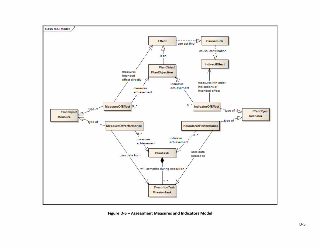
Figure D-5 – Assessment Measures and Indicators Model

D-6
Figure D-6 – Mission Task Model

D-7
Figure D-7 – High-Level Operational Planning Model
E-1
Appendix E
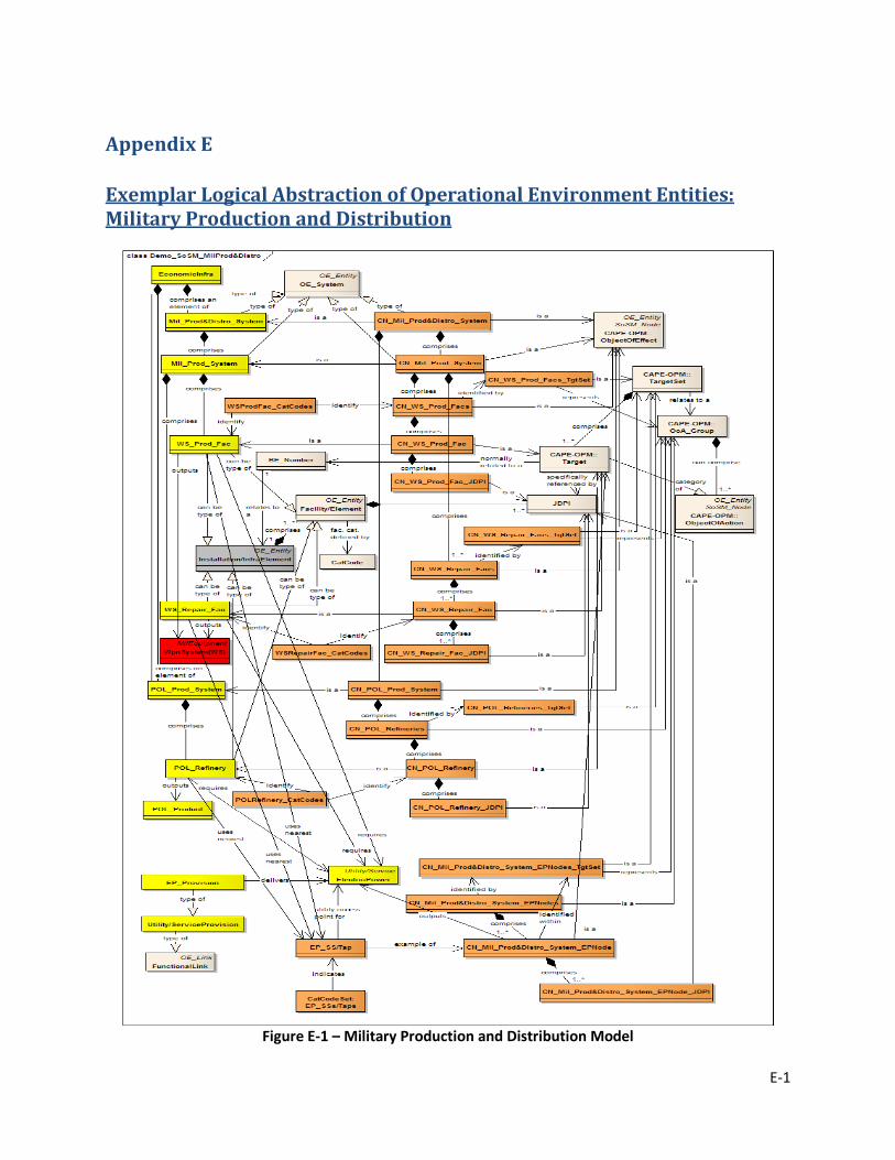
Exemplar Logical Abstraction of Operational Environment Entities: Military Production and Distribution
Figure E-1 – Military Production and Distribution Model

F-1
Appendix F
Visual Representations of Operational Plan Models and Operational Environment Models
Figure F-1 – Visualization of OEM depicting entity states and relationships.
Notes: 1) The type of node and connector (i.e. link) is indicated by the shown legend.
2) The boxes adjacent to each OE node (circles) and subordinate facilities (triangles) provide related TA data; box color indicates ‘System Status’ while the embedded ‘A’ or ‘I’ character indicates
whether the status is ‘Inferred’ by the SAE or formally ‘assessed’ from within a BDAREP.

F-2
Figure F-2 – Visualization of both OPM and OEM Elements.
Note: Depicts a Mission Task (MT) with its related assigned target, and four facility elements within that target,
along with assessment boxes (as described under Figure F-1).
Figure F-3 – Visualization of Lines of Effort
Notes:
1. Visualization depicts three OOs and their respective OLEs; one OLE is ‘expanded’ to show a single constituent TO and its TLE, which in turn comprises three TTOs and their TTLEs; each TTLE has a single TT, the first having two
MTs, the second having one MT, and the third TT comprising of five MTs. 2. Each MT represents an executed, current or future aircraft mission; once a MT is associated with an ATO
mission, the MT representation would be linked to all respective ATO mission and TA data.