ENHANCEMENT OF FLUID FLOW AND HEAT TRANSFER IN ...
7
International Journal of Mechanical and Production Engineering, ISSN(p): 2320-2092, ISSN(e): 2321-2071 Volume- 6, Issue-6, Jun.-2018, http://iraj.in Enhancement of Fluid Flow and Heat Transfer in Tunnel Kilns 63 ENHANCEMENT OF FLUID FLOW AND HEAT TRANSFER IN TUNNEL KILNS 1 HOSNY Z. ABOU-ZIYAN, 2 MOSAB A. ALRAHMANI, 3 ISSA F. ALMESRI, 4 JABER H. ALMUTAIRI Mech. Power Eng. Dept., College of Technological Studies, PAAET, Kuwait E-mail: 1 [email protected], 2 [email protected], 3 [email protected], 4 [email protected] Abstract - The improper size of channels cause non-uniform flow in tunnel kilns and unequal convective heat transfer coefficients of longitudinal and transverse bricks in the lattice setting arrangement. This paper reports an approach used to optimize the dimensions of the kiln channels using a 3D-CFD model with a grid size of 4.78M cells and incorporated k- turbulence model. The CFD model was validated against experimental data for pressure drop and temperature in tunnel kilns. The effects of kiln channels on flow uniformity were thoroughly investigated and uniform flow and equal convective heat transfer coefficients of longitudinal and transverse bricks were achieved by optimizing the dimensions of wall, column, ceiling, and external channels. The optimum dimensions of the kiln channels are related to the column width of the lattice brick setting as follows: width of column channel is 0.5; width of wall channel is 0.25; ceiling channel height is 0.2; and extension channel spacing is 0.36. The pressure drop in the optimum case was larger than that in the case of non-uiform flow, however, the advantages of quality improvement and quantity enhancement of the produced bricks would surpass the increase in pumping power considerably. Index Terms - Tunnel kilns, fluid flow, flow uniformity, heat transfer I. INTRODUCTION The manufacturing of ceramic materials is comprised of shaping, drying and firing steps [1-3]. Tunnel kilns are used to dry and bake ceramic products made of clay minerals such as bricks, wall and floor tiles, roof tiles, sanitary ware, vitrified clay products, table-and ornamental ware, etc. These kilns are tunnels of 90- 180m long, 3-4.24m wide, and 2.4-3.6m high and require extensive use of energy [4]. A tunnel kiln is divided into three main zones, i.e., the preheating zone, the firing zone, and the cooling zone. It is considered as counter flow heat exchanger because the unprocessed products enter the kiln in the preheating zone where the combustion gases exit. Although tunnel kilns become the most popular kilns for about seven decades now, their design still being reviewed and developed to enhance their performance and productivity and to improve the quality of their products [5]. This may be explained knowing that the actual specific energy consumption of brick making, as an example, is generally more than double the theoretical consumption, which is 550kJ/kg [4]. This is mainly due to the large heat loss from kilns, non- uniform flow in the intricate kiln channels, complicated setting of the unprocessed products, and unequal heat transfer coefficients across the kilns. Therefore, experimental and theoretical efforts are still contributing to the improvement of the performance of tunnel kilns and to reduce the specific energy consumption of the products. It is to be noted that the specific consumption is defined as the energy used to produce one kg of fired-ceramic. For certain kiln and product setting, the uniformity of fluid flow and the rates of heat and mass transfer across the tunnel kiln control the drying and baking time and the quality of the products. Thus, convective heat transfer coefficients play an important role in the drying and baking processes in tunnel kilns. The convection heat transfer coefficients between brick settings and an air or gas flows were determined in laboratory experiments with a scale of 1:4 by Abou- Ziyan [4] and a scale 1:10 of actual kilns by Dugwell and Oakley [6]. Both investigations provided Nusselt number (Nu) correlations to evaluate the convective heat transfer between brick settings and the air (or gas) flow. Generalized equations for convective heat transfer in channels and in the extensions of brick settings were developed by Vogt and Beckmann [7]. Also, heat losses from the wall and roof of kilns [8] and effects of thermal radiation on the setting geometry [9] were studied experimentally. Simple (1D) mathematical models and numerical solutions were developed by Almeida [10] for drying hollow ceramic bricks and Tahirbegović et al. [11] for heat transfer to ceramic elements of the cross-flow of gas in tunnel kilns. The authors [11] showed that the heat transfer in tunnel kilns was affected by the method of setting of the processed elements, the setting height, the available cross passages, densities of the elements, heating/ cooling rate, and the characteristic temperature in the voids between set elements. Oba et al. [5] studied the temperature and heat flux profiles inside the kiln using 3D modeling for a known profile of gas flow in tunnel kiln. This is done without solving the Navier-Stokes equations for the flow field of flue gas inside the kiln in order to save computational time and cost. Oba et al. [5] pointed out the need for studies on more complex 3D numerical models applied to tunnel kilns with results capable of identifying critical spots inside the kiln and the load.
-
Upload
khangminh22 -
Category
Documents
-
view
3 -
download
0
Transcript of ENHANCEMENT OF FLUID FLOW AND HEAT TRANSFER IN ...

International Journal of Mechanical and Production Engineering, ISSN(p): 2320-2092, ISSN(e): 2321-2071 Volume- 6, Issue-6, Jun.-2018, http://iraj.in
Enhancement of Fluid Flow and Heat Transfer in Tunnel Kilns
63
ENHANCEMENT OF FLUID FLOW AND HEAT TRANSFER IN TUNNEL KILNS
1HOSNY Z. ABOU-ZIYAN, 2MOSAB A. ALRAHMANI, 3ISSA F. ALMESRI, 4JABER H. ALMUTAIRI
Mech. Power Eng. Dept., College of Technological Studies, PAAET, Kuwait
E-mail: [email protected], [email protected], [email protected], [email protected] Abstract - The improper size of channels cause non-uniform flow in tunnel kilns and unequal convective heat transfer coefficients of longitudinal and transverse bricks in the lattice setting arrangement. This paper reports an approach used to optimize the dimensions of the kiln channels using a 3D-CFD model with a grid size of 4.78M cells and incorporated k- turbulence model. The CFD model was validated against experimental data for pressure drop and temperature in tunnel kilns. The effects of kiln channels on flow uniformity were thoroughly investigated and uniform flow and equal convective heat transfer coefficients of longitudinal and transverse bricks were achieved by optimizing the dimensions of wall, column, ceiling, and external channels. The optimum dimensions of the kiln channels are related to the column width of the lattice brick setting as follows: width of column channel is 0.5; width of wall channel is 0.25; ceiling channel height is 0.2; and extension channel spacing is 0.36. The pressure drop in the optimum case was larger than that in the case of non-uiform flow, however, the advantages of quality improvement and quantity enhancement of the produced bricks would surpass the increase in pumping power considerably. Index Terms - Tunnel kilns, fluid flow, flow uniformity, heat transfer
I. INTRODUCTION The manufacturing of ceramic materials is comprised of shaping, drying and firing steps [1-3]. Tunnel kilns are used to dry and bake ceramic products made of clay minerals such as bricks, wall and floor tiles, roof tiles, sanitary ware, vitrified clay products, table-and ornamental ware, etc. These kilns are tunnels of 90-180m long, 3-4.24m wide, and 2.4-3.6m high and require extensive use of energy [4]. A tunnel kiln is divided into three main zones, i.e., the preheating zone, the firing zone, and the cooling zone. It is considered as counter flow heat exchanger because the unprocessed products enter the kiln in the preheating zone where the combustion gases exit. Although tunnel kilns become the most popular kilns for about seven decades now, their design still being reviewed and developed to enhance their performance and productivity and to improve the quality of their products [5]. This may be explained knowing that the actual specific energy consumption of brick making, as an example, is generally more than double the theoretical consumption, which is 550kJ/kg [4]. This is mainly due to the large heat loss from kilns, non-uniform flow in the intricate kiln channels, complicated setting of the unprocessed products, and unequal heat transfer coefficients across the kilns. Therefore, experimental and theoretical efforts are still contributing to the improvement of the performance of tunnel kilns and to reduce the specific energy consumption of the products. It is to be noted that the specific consumption is defined as the energy used to produce one kg of fired-ceramic. For certain kiln and product setting, the uniformity of fluid flow and the rates of heat and mass transfer across the tunnel kiln control the drying and baking time and the quality of the products. Thus, convective
heat transfer coefficients play an important role in the drying and baking processes in tunnel kilns. The convection heat transfer coefficients between brick settings and an air or gas flows were determined in laboratory experiments with a scale of 1:4 by Abou-Ziyan [4] and a scale 1:10 of actual kilns by Dugwell and Oakley [6]. Both investigations provided Nusselt number (Nu) correlations to evaluate the convective heat transfer between brick settings and the air (or gas) flow. Generalized equations for convective heat transfer in channels and in the extensions of brick settings were developed by Vogt and Beckmann [7]. Also, heat losses from the wall and roof of kilns [8] and effects of thermal radiation on the setting geometry [9] were studied experimentally. Simple (1D) mathematical models and numerical solutions were developed by Almeida [10] for drying hollow ceramic bricks and Tahirbegović et al. [11] for heat transfer to ceramic elements of the cross-flow of gas in tunnel kilns. The authors [11] showed that the heat transfer in tunnel kilns was affected by the method of setting of the processed elements, the setting height, the available cross passages, densities of the elements, heating/ cooling rate, and the characteristic temperature in the voids between set elements. Oba et al. [5] studied the temperature and heat flux profiles inside the kiln using 3D modeling for a known profile of gas flow in tunnel kiln. This is done without solving the Navier-Stokes equations for the flow field of flue gas inside the kiln in order to save computational time and cost. Oba et al. [5] pointed out the need for studies on more complex 3D numerical models applied to tunnel kilns with results capable of identifying critical spots inside the kiln and the load.
International Journal of Mechanical and Production Engineering, ISSN(p): 2320-2092, ISSN(e): 2321-2071 Volume- 6, Issue-6, Jun.-2018, http://iraj.in
Enhancement of Fluid Flow and Heat Transfer in Tunnel Kilns
64
Computational Fluid Dynamics (CFD) modeling is capable of flow visualization providing extensive details with a high degree of flexibility. The technique is considered as a good alternative to comprehensive experimental programs that are expensive and time consuming [12]-[13]. Recently, Almutairi et al. [14] investigated the air flow in tunnel kilns using a comprehensive 3D-CFD model. In this study, the authors reported a non-uniform flow in the tunnel kiln loaded with lattice brick setting that has the same dimensions used in industry and in the experiment of Abou-Ziyan [4]. Large amount of air flow was flowing in the less resistance channels (i.e., ceiling and wall channels) while a relatively small amount of air was found flowing in the more effective channels (column channels). The work also reported an interesting asymmetric phenomenon of long separation zone downstream one of the brick columns in a symmetric tunnel kiln. In another study, by the same research team “Submitted for publication”, Abou-Ziyan et al. [15] indicated that the uneven velocities in the kiln channels caused unequal convective heat transfer coefficients for the bricks arranged in longitudinal and transverse direction of the air flow in tunnel kilns. The authors reported different convective heat transfer coefficients of the faces of the bricks and indicated that the brick baking is asymmetric process. In addition, the effect of kiln walls and setting layers on the faces and area averaged convective heat transfer coefficients were reported. In this paper, an optimization of the column-wall channel width, ceiling channel height, and extension channel spacing was conducted through a parametric study using a 3D-CFD model incorporated with k- turbulence model and a mesh size of 4.78M cells. The effect of these channels on the average velocity in each channel, the overall mean velocity in all kiln channels, the pressure drop in the kiln, and the area-averaged convective heat transfer coefficients of the longitudinal and transverse bricks are investigated. II. NUMERICAL MODELING AND SIMULATION The air flow pattern, air velocity and heat transfer in the lattice bricks arrangement in a wind tunnel were numerically modeled using commercial CFD code (FLUENT). The second-order upwind scheme was used for pressure, momentum, energy, and turbulent kinetic energy. The pressure-velocity coupling algorithm, i.e. “coupled” was used. The simulation was assumed converged if the residuals for the energy equation were less than 10-8 and for the equations of continuity and momentum were less than 10-7. The equations solved in each computational cell were the Navier-Stokes equations, i.e. conservation of mass (continuity), conservation of momentum, and conservation of energy as given in equations 1-3, respectively.
+ (ρu ) = 0 (1)
(ρu ) + ρu u = − + μ + +
ρg (2) (ρT) + (ρu T) = + S (3)
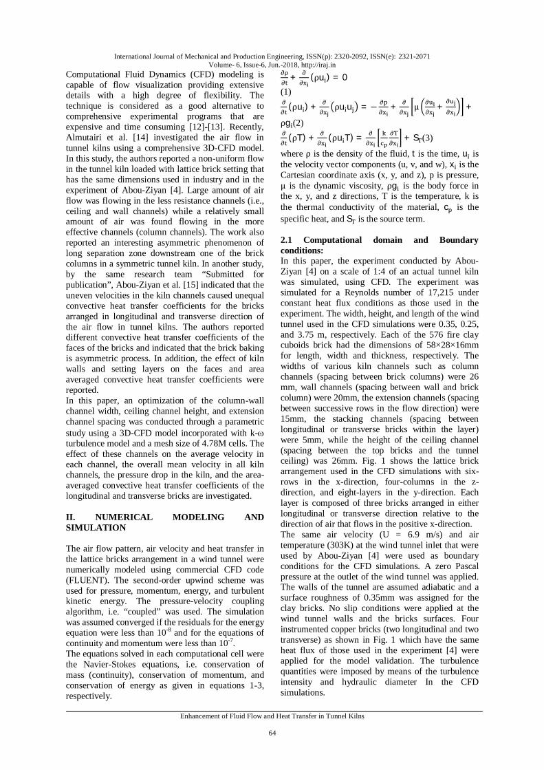
where ρ is the density of the fluid, t is the time, u is the velocity vector components (u, v, and w), x is the Cartesian coordinate axis (x, y, and z), p is pressure, μ is the dynamic viscosity, ρg is the body force in the x, y, and z directions, T is the temperature, k is the thermal conductivity of the material, c is the specific heat, and S is the source term. 2.1 Computational domain and Boundary conditions: In this paper, the experiment conducted by Abou-Ziyan [4] on a scale of 1:4 of an actual tunnel kiln was simulated, using CFD. The experiment was simulated for a Reynolds number of 17,215 under constant heat flux conditions as those used in the experiment. The width, height, and length of the wind tunnel used in the CFD simulations were 0.35, 0.25, and 3.75 m, respectively. Each of the 576 fire clay cuboids brick had the dimensions of 58×28×16mm for length, width and thickness, respectively. The widths of various kiln channels such as column channels (spacing between brick columns) were 26 mm, wall channels (spacing between wall and brick column) were 20mm, the extension channels (spacing between successive rows in the flow direction) were 15mm, the stacking channels (spacing between longitudinal or transverse bricks within the layer) were 5mm, while the height of the ceiling channel (spacing between the top bricks and the tunnel ceiling) was 26mm. Fig. 1 shows the lattice brick arrangement used in the CFD simulations with six-rows in the x-direction, four-columns in the z-direction, and eight-layers in the y-direction. Each layer is composed of three bricks arranged in either longitudinal or transverse direction relative to the direction of air that flows in the positive x-direction. The same air velocity (U = 6.9 m/s) and air temperature (303K) at the wind tunnel inlet that were used by Abou-Ziyan [4] were used as boundary conditions for the CFD simulations. A zero Pascal pressure at the outlet of the wind tunnel was applied. The walls of the tunnel are assumed adiabatic and a surface roughness of 0.35mm was assigned for the clay bricks. No slip conditions were applied at the wind tunnel walls and the bricks surfaces. Four instrumented copper bricks (two longitudinal and two transverse) as shown in Fig. 1 which have the same heat flux of those used in the experiment [4] were applied for the model validation. The turbulence quantities were imposed by means of the turbulence intensity and hydraulic diameter In the CFD simulations.
International Journal of Mechanical and Production Engineering, ISSN(p): 2320-2092, ISSN(e): 2321-2071 Volume- 6, Issue-6, Jun.-2018, http://iraj.in
Enhancement of Fluid Flow and Heat Transfer in Tunnel Kilns
65
2.2 Grid size and turbulence model selection: Table 1 lists the grid sensitivity analysis that was conducted using k- turbulence model. Almutairi et al. [14] showed that Grid-2 with size of 4.78M Cell was sufficiently refined so that the pressure drops obtained do not depend on the grid used. Also, Abou-Ziyan et al. [15] proved that the same grid produced accurate surface temperature for both the longitudinal and transverse bricks at a reasonable computational time. Turbulence was accounted for by time-averaging equations 1-3 to produce the Reynolds Averaged Navier-Stokes (RANS) equations. A “two-equation” turbulence model was used to solve for the additional terms that are generated for RANS process. The selection of the appropriate turbulence model was discussed in details in [14] and [15] and the k- turbulence model predicted closer results to the experimental data than the other tested models (standard k − ε and RNG k − ε), see Table 2. Therefore, the numerical model was validated against the experimental pressure drop and surface temperature of both the longitudinal and transverse bricks acquired from Abou-Ziyan [4] using Grid 2 and the k − ω turbulence model. The numerically predicted values were in good agreement with the experimental data as listed in Table 2.
Fig. 1. Locations of the instrumented bricks (a) longitudinal (b)
transverse
Table 1. Grid sensitivity analysis using k- turbulence model
Table 2. Selection of the turbulence model using grid 2
III. RESEARCH METHODOLOGY Three dimensional modeling is used to determine the optimum fluid channels in tunnel kilns. These optimum channels provide a uniform flow in the kiln and allow more air to flow through the stacking
narrow channels and to circulate in the extension channels. This will lead to even and enhanced heat transfer coefficients of longitudinal and transverse bricks. As a result, the kiln productivity and the quality of the produced bricks are improved. Optimum sizes of kiln channels were attained by changing either the width of column-wall channels, height of the ceiling channel or the spacing of the extension channels, individually. Then, the resulted air velocity in all kiln channels was estimated in the middle of the extension channel between the fifth and sixth rows. The effect of each channel on the flow uniformity in the tunnel kiln was used to determine the optimum size of this channel. The dimensions of all channels that produce similar air velocity (uniform flow) in all kiln channels were considered the optimum channel dimensions. This was measured by the standard deviation of the air velocities in all channels. On the other hand, the multifaceted convective heat transfer coefficients (CHTCs) of the longitudinal and transverse bricks are determined using the local approach. For each face of the brick (i.e. left, right, front and back), the heat flux (qf) and the surface temperature (Tf) of that face is determined from the numerical simulation. Also, the air temperature (Ta) in the middle of the channel close to the face is calculated. Then, the CHTC of the face is calculated using equation 4. Then, the local CHTC of each brick face (hf) along with the surface area of that face (Af) can be used to determine the convective area averaged CHTC (hav) for each brick using equation 5. It is to be noted that the top and bottom faces are in contact with the bricks in the layers above and below the studied bricks.
IV. RESULTS AND DISCUSSION The results presented in this section cover the velocity distribution and the area averaged convective heat transfer coefficients of the longitudinal and transverse bricks for various cases of different dimensions of side wall channels, column channels, ceiling channel, and extension channels. The base case had values of 20, 26, 26, and 15 mm for the stated channels, respectively. The results presented are for superficial Re = 1.21×10⁵ in the empty wind tunnel and the interstitial Re = 1.72×10⁴ around the bricks. 4.1 Fluid Flow and Heat Transfer for the Base Case The flow pattern around the lattice brick setting is complex due to the complicated arrangement of the setting and the existence of many fluid channels in the kiln. The velocity distribution in all the kiln channels for the base case that was used in the
International Journal of Mechanical and Production Engineering, ISSN(p): 2320-2092, ISSN(e): 2321-2071 Volume- 6, Issue-6, Jun.-2018, http://iraj.in
Enhancement of Fluid Flow and Heat Transfer in Tunnel Kilns
66
experiment [4] is given in Table 3. It is clear that the velocity is not similar as it ranges from 12.93m/s in mid column channel to 17.81m/s in the ceiling channel with a standard deviation of 1.89m/s around the mean velocity in the kiln. Also, large portion of the air (26.85%) is ineffective as it flows in the ceiling channel. This means the bricks will need different baking time according to their locations in the setting. The bricks in the top layer will be baked earlier than the bricks in the column channels which, by the time they bake, others may get damaged (burned out or shrink).
Table 3. Air velocity and percentage flow distribution in the various kiln channels for the base case
Table 4. CHTCs of longitudinal and transverse bricks for the base case
Table 4 indicated that the CHTCs of the longitudinal and transverse bricks are unequal with about 23% difference. The CHTCs of the transverse and longitudinal bricks were measured in the fourth and fifth layers, respectively, in the fifth row. In addition to the non uniform flow in tunnel kiln channels and the unequal CHTCs of the longitudinal and transverse bricks, Almutairi et al [14] showed an intriguing separation phenomenon downstream of one of the brick columns. Although the kiln and the brick setting are geometrically similar about the middle axis of the kiln, this long separation zone took place behind only one column. The separation zone changed its location when the rows numbers, wall-column channels width, ceiling channel height or extension channel spacing were changed [14]. 4.2. Optimization of Tunnel Kiln Channels Section 4.1 described the malfunctions in both fluid flow and heat transfer for the base case that was tested during the experimental study [4]. In this section, the effect of each kiln channel size on the fluid flow and heat transfer was investigated to achieve the optimum dimensions of the channels that satisfied the uniform flow and heat transfer conditions in the kiln as described in section 3. The simulations, for all cases in this section, were conducted for a constant superficial velocity of 6.9 m/s. The heat transfer data presented in this section is for the right longitudinal brick and the last transverse brick in the fifth row.
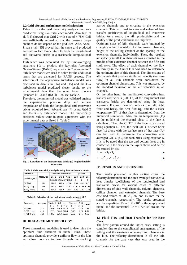
4.2.1 Column and wall channel width The width of the column and wall channels is interrelated because the kiln width and the brick size are fixed. In addition to the base case (column-wall channels width of 26-20mm), three other cases of various column-wall channels width (28-17, 29-15.5, and 30-14 mm) were numerically simulated with a constant ceiling channel height of 26mm and extension channels spacing of 15mm. Fig.2a shows the average air velocities in all kiln channels for the four cases studied at various column-wall channels widths. Air velocities increased in the column channels by 5-7% and decreased in the wall channels by about 10% as the column channel width was increased. But, the variations in air velocity in the ceiling channel were less than 1.2% for the examined column-wall channels widths. Thus, the column-wall channels width is effective on the average magnitude of air velocity in column-wall channels and insignificant in the ceiling channel. The amount of air flow increased in the column channels by 8.4% and decreased in the wall channels by 8.2% as the column channel width was increased. Accordingly, the variations of the overall mean velocity of air in all kiln channels were minute because the total width of column-wall channels in the kiln was fixed.
Fig. 2: Effect of column-wall channels (C-WC) width on (a) air velocity in the various kiln channels and on (b) the CHTCs of
the longitudinal and transverse bricks (for constant ceiling channel height of 26mm and extension channel spacing of
15mm). On the other hand, Fig. 2b depicts the effect of column-wall channels on the convective heat transfer coefficients. The enhancement in the CHTCs was marginal and did not exceed 5.3 and 3% for the longitudinal and transverse bricks respectively. This was expected because the increase in the overall mean velocity in all kiln channels was about 1%. The CHTCs of the longitudinal bricks were larger than those of the transverse bricks. 4.2.2 Ceiling channel height The ceiling channel height may be varied either by changing the number of brick layers in the setting or by adjusting the base of the kiln cars that hold the bricks. The second method had finer control on the ceiling height than the first one. In this case, the height of the kiln was not fixed because the level of
International Journal of Mechanical and Production Engineering, ISSN(p): 2320-2092, ISSN(e): 2321-2071 Volume- 6, Issue-6, Jun.-2018, http://iraj.in
Enhancement of Fluid Flow and Heat Transfer in Tunnel Kilns
67
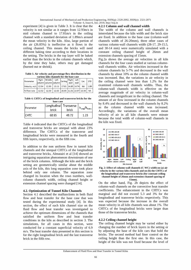
the car base was adjusted. Hence, the air flow rate was altered in order to attain the constant superficial velocity of 6.9m/s in the kiln section. In the current study, four ceiling channel heights of 26mm (base case), 19.75, 13.5 and 10mm were considered in the analysis as shown in Fig. 3. Accordingly, kiln height was reduced from 0.25 to 0.234m.
Fig. 3. Effect of ceiling channel height (CC) on (a) air velocity
in the various kiln channels and on (b) the CHTCs of the longitudinal and transverse bricks (for constant wall and
column channels width of 20 and 26mm, and extension channel of 15mm)
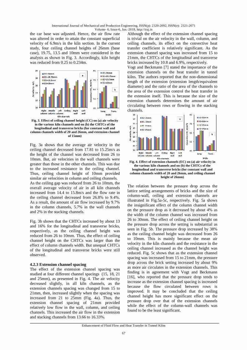
Fig. 3a shows that the average air velocity in the ceiling channel decreased from 17.81 to 15.25m/s as the height of the channel was decreased from 26 to 10mm. But, air velocities in the wall channels were greater than those in the other channels. This was due to the increased resistance in the ceiling channel. Thus, ceiling channel height of 10mm provided similar air velocities in column and ceiling channels. As the ceiling gap was reduced from 26 to 10mm, the overall average velocity of air in all kiln channels increased from 14.4 to 15.8m/s and the flow rate in the ceiling channel decreased from 26.8% to 9.4%. As a result, the amount of air flow increased by 9.7% in the column channels, 5.7% in the wall channels and 2% in the stacking channels. Fig. 3b shows that the CHTCs increased by about 13 and 16% for the longitudinal and transverse bricks, respectively, as the ceiling channel height was reduced from 26 to 10mm. Thus, the effect of ceiling channel height on the CHTCs was larger than the effect of column channels width. But unequal CHTCs of the longitudinal and transverse bricks were still observed. 4.2.3 Extension channel spacing The effect of the extension channel spacing was studied at four different channel spacings (15, 18, 21 and 25mm), as presented in Fig. 4. The air velocity decreased slightly, in all kiln channels, as the extension channels spacing was changed from 15 to 21mm, then, increased slightly when the spacing was increased from 21 to 25mm (Fig. 4a). Thus, the extension channel spacing of 21mm provided relatively low flow in the wall, column, and ceiling channels. This increased the air flow in the extension and stacking channels from 13.66 to 16.33%.
Although the effect of the extension channel spacing is trivial on the air velocity in the wall, column, and ceiling channels, its effect on the convective heat transfer coefficient is relatively significant. As the extension channel spacing was increased from 15 to 21mm, the CHTCs of the longitudinal and transverse bricks increased by 10.8 and 6.9%, respectively. Vogt and Beckmann [7] stated the importance of the extension channels on the heat transfer in tunnel kilns. The authors reported that the non-dimensional length of the extension (extension length/equivalent diameter) and the ratio of the area of the channels to the area of the extension control the heat transfer in the extension itself. This is because the size of the extension channels determines the amount of air circulating between rows or flowing in the stacking channels.
Fig. 4. Effect of extension channels (EC) on (a) air velocity in
the various kiln channels and on (b) the CHTCs of the longitudinal and transverse bricks (for constant wall and
column channels width of 20 and 26mm, and ceiling channel height of 26mm)
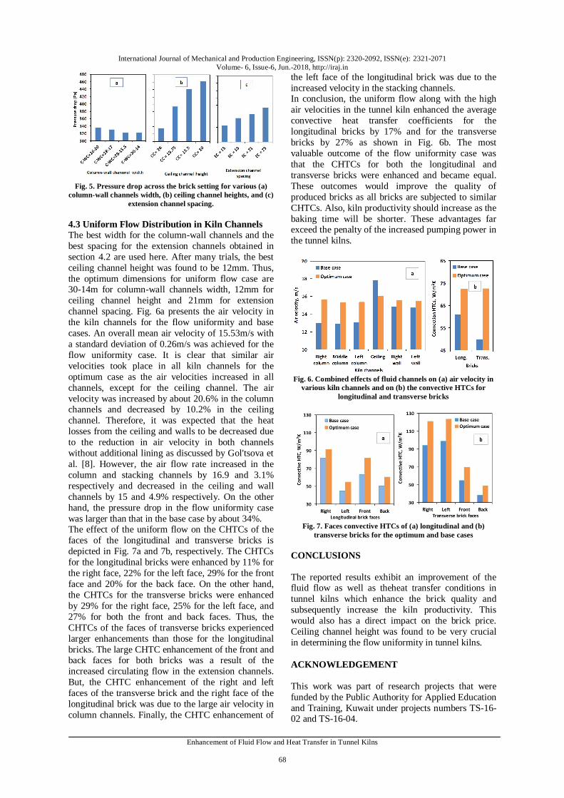
The relation between the pressure drop across the lattice setting arrangements of bricks and the size of column-wall, ceiling and extension channels are illustrated in Fig.5a-5c, respectively. Fig. 5a shows the insignificant effect of the column channel width on the pressure drop as it decreased by about 4% as the width of the column channel was increased from 26 to 30mm. The effect of ceiling channel height on the pressure drop across the setting is substantial as seen in Fig. 5b. The pressure drop increased by 38% as the ceiling channel height was decreased from 26 to 10mm. This is mainly because the mean air velocity in the kiln channels and the resistance in the ceiling channel increased as the channel height was reduced. Fig. 5c shows that as the extension channel spacing was increased from 15 to 21mm, the pressure drop across the brick setting increased by about 9% as more air circulates in the extension channels. This finding is in agreement with Vogt and Beckmann [16], who reported that the pressure drop tends to increase as the extension channel spacing is increased because the flow circulated between rows is improved. It may be concluded that the ceiling channel height has more significant effect on the pressure drop over that of the extension channels while the effect of the column-wall channels was found to be the least significant.
International Journal of Mechanical and Production Engineering, ISSN(p): 2320-2092, ISSN(e): 2321-2071 Volume- 6, Issue-6, Jun.-2018, http://iraj.in
Enhancement of Fluid Flow and Heat Transfer in Tunnel Kilns
68
Fig. 5. Pressure drop across the brick setting for various (a)
column-wall channels width, (b) ceiling channel heights, and (c) extension channel spacing.
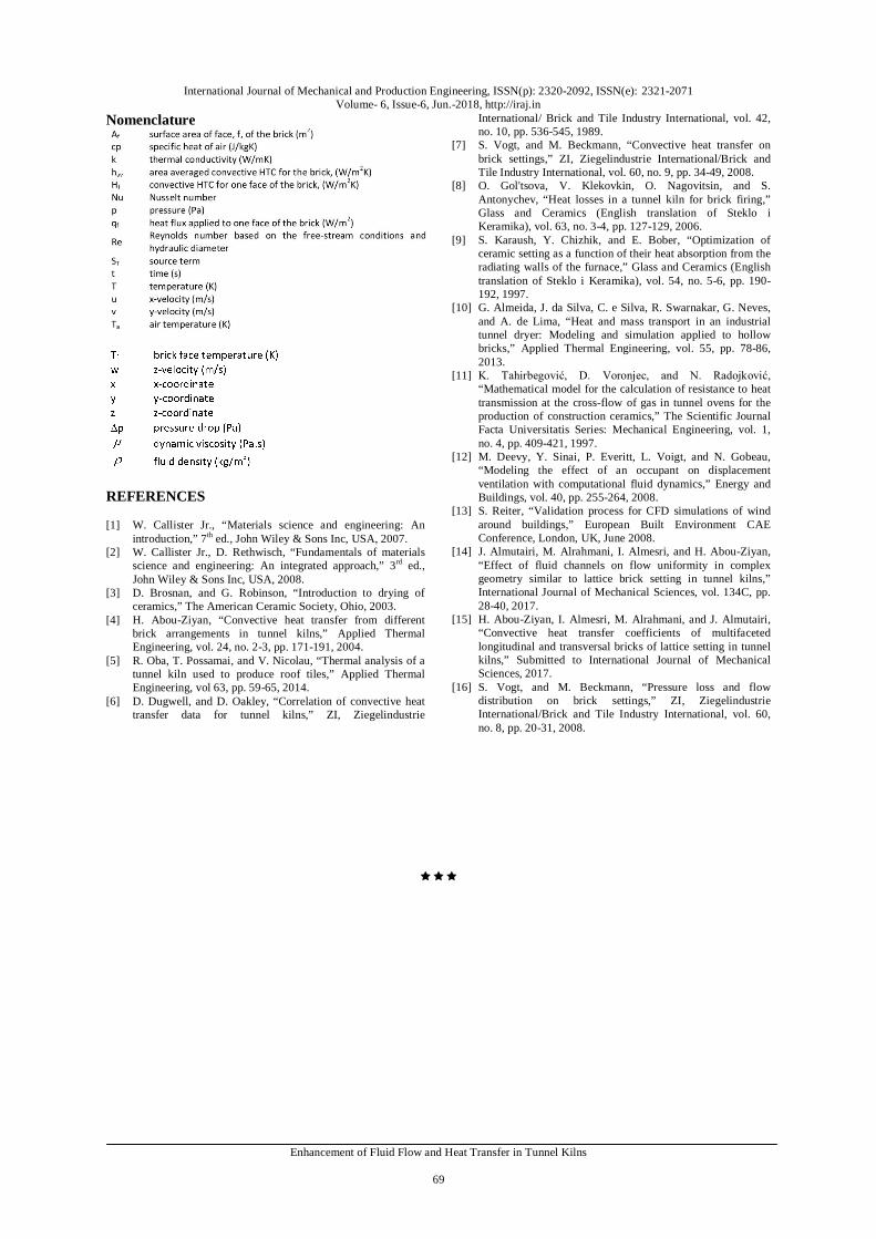
4.3 Uniform Flow Distribution in Kiln Channels The best width for the column-wall channels and the best spacing for the extension channels obtained in section 4.2 are used here. After many trials, the best ceiling channel height was found to be 12mm. Thus, the optimum dimensions for uniform flow case are 30-14m for column-wall channels width, 12mm for ceiling channel height and 21mm for extension channel spacing. Fig. 6a presents the air velocity in the kiln channels for the flow uniformity and base cases. An overall mean air velocity of 15.53m/s with a standard deviation of 0.26m/s was achieved for the flow uniformity case. It is clear that similar air velocities took place in all kiln channels for the optimum case as the air velocities increased in all channels, except for the ceiling channel. The air velocity was increased by about 20.6% in the column channels and decreased by 10.2% in the ceiling channel. Therefore, it was expected that the heat losses from the ceiling and walls to be decreased due to the reduction in air velocity in both channels without additional lining as discussed by Gol'tsova et al. [8]. However, the air flow rate increased in the column and stacking channels by 16.9 and 3.1% respectively and decreased in the ceiling and wall channels by 15 and 4.9% respectively. On the other hand, the pressure drop in the flow uniformity case was larger than that in the base case by about 34%. The effect of the uniform flow on the CHTCs of the faces of the longitudinal and transverse bricks is depicted in Fig. 7a and 7b, respectively. The CHTCs for the longitudinal bricks were enhanced by 11% for the right face, 22% for the left face, 29% for the front face and 20% for the back face. On the other hand, the CHTCs for the transverse bricks were enhanced by 29% for the right face, 25% for the left face, and 27% for both the front and back faces. Thus, the CHTCs of the faces of transverse bricks experienced larger enhancements than those for the longitudinal bricks. The large CHTC enhancement of the front and back faces for both bricks was a result of the increased circulating flow in the extension channels. But, the CHTC enhancement of the right and left faces of the transverse brick and the right face of the longitudinal brick was due to the large air velocity in column channels. Finally, the CHTC enhancement of
the left face of the longitudinal brick was due to the increased velocity in the stacking channels. In conclusion, the uniform flow along with the high air velocities in the tunnel kiln enhanced the average convective heat transfer coefficients for the longitudinal bricks by 17% and for the transverse bricks by 27% as shown in Fig. 6b. The most valuable outcome of the flow uniformity case was that the CHTCs for both the longitudinal and transverse bricks were enhanced and became equal. These outcomes would improve the quality of produced bricks as all bricks are subjected to similar CHTCs. Also, kiln productivity should increase as the baking time will be shorter. These advantages far exceed the penalty of the increased pumping power in the tunnel kilns.
Fig. 6. Combined effects of fluid channels on (a) air velocity in
various kiln channels and on (b) the convective HTCs for longitudinal and transverse bricks
Fig. 7. Faces convective HTCs of (a) longitudinal and (b)
transverse bricks for the optimum and base cases CONCLUSIONS The reported results exhibit an improvement of the fluid flow as well as theheat transfer conditions in tunnel kilns which enhance the brick quality and subsequently increase the kiln productivity. This would also has a direct impact on the brick price. Ceiling channel height was found to be very crucial in determining the flow uniformity in tunnel kilns. ACKNOWLEDGEMENT This work was part of research projects that were funded by the Public Authority for Applied Education and Training, Kuwait under projects numbers TS-16-02 and TS-16-04.
International Journal of Mechanical and Production Engineering, ISSN(p): 2320-2092, ISSN(e): 2321-2071 Volume- 6, Issue-6, Jun.-2018, http://iraj.in
Enhancement of Fluid Flow and Heat Transfer in Tunnel Kilns
69
Nomenclature
REFERENCES [1] W. Callister Jr., “Materials science and engineering: An
introduction,” 7th ed., John Wiley & Sons Inc, USA, 2007. [2] W. Callister Jr., D. Rethwisch, “Fundamentals of materials
science and engineering: An integrated approach,” 3rd ed., John Wiley & Sons Inc, USA, 2008.
[3] D. Brosnan, and G. Robinson, “Introduction to drying of ceramics,” The American Ceramic Society, Ohio, 2003.
[4] H. Abou-Ziyan, “Convective heat transfer from different brick arrangements in tunnel kilns,” Applied Thermal Engineering, vol. 24, no. 2-3, pp. 171-191, 2004.
[5] R. Oba, T. Possamai, and V. Nicolau, “Thermal analysis of a tunnel kiln used to produce roof tiles,” Applied Thermal Engineering, vol 63, pp. 59-65, 2014.
[6] D. Dugwell, and D. Oakley, “Correlation of convective heat transfer data for tunnel kilns,” ZI, Ziegelindustrie
International/ Brick and Tile Industry International, vol. 42, no. 10, pp. 536-545, 1989.
[7] S. Vogt, and M. Beckmann, “Convective heat transfer on brick settings,” ZI, Ziegelindustrie International/Brick and Tile Industry International, vol. 60, no. 9, pp. 34-49, 2008.
[8] O. Gol'tsova, V. Klekovkin, O. Nagovitsin, and S. Antonychev, “Heat losses in a tunnel kiln for brick firing,” Glass and Ceramics (English translation of Steklo i Keramika), vol. 63, no. 3-4, pp. 127-129, 2006.
[9] S. Karaush, Y. Chizhik, and E. Bober, “Optimization of ceramic setting as a function of their heat absorption from the radiating walls of the furnace,” Glass and Ceramics (English translation of Steklo i Keramika), vol. 54, no. 5-6, pp. 190-192, 1997.
[10] G. Almeida, J. da Silva, C. e Silva, R. Swarnakar, G. Neves, and A. de Lima, “Heat and mass transport in an industrial tunnel dryer: Modeling and simulation applied to hollow bricks,” Applied Thermal Engineering, vol. 55, pp. 78-86, 2013.
[11] K. Tahirbegović, D. Voronjec, and N. Radojković, “Mathematical model for the calculation of resistance to heat transmission at the cross-flow of gas in tunnel ovens for the production of construction ceramics,” The Scientific Journal Facta Universitatis Series: Mechanical Engineering, vol. 1, no. 4, pp. 409-421, 1997.
[12] M. Deevy, Y. Sinai, P. Everitt, L. Voigt, and N. Gobeau, “Modeling the effect of an occupant on displacement ventilation with computational fluid dynamics,” Energy and Buildings, vol. 40, pp. 255-264, 2008.
[13] S. Reiter, “Validation process for CFD simulations of wind around buildings,” European Built Environment CAE Conference, London, UK, June 2008.
[14] J. Almutairi, M. Alrahmani, I. Almesri, and H. Abou-Ziyan, “Effect of fluid channels on flow uniformity in complex geometry similar to lattice brick setting in tunnel kilns,” International Journal of Mechanical Sciences, vol. 134C, pp. 28-40, 2017.
[15] H. Abou-Ziyan, I. Almesri, M. Alrahmani, and J. Almutairi, “Convective heat transfer coefficients of multifaceted longitudinal and transversal bricks of lattice setting in tunnel kilns,” Submitted to International Journal of Mechanical Sciences, 2017.
[16] S. Vogt, and M. Beckmann, “Pressure loss and flow distribution on brick settings,” ZI, Ziegelindustrie International/Brick and Tile Industry International, vol. 60, no. 8, pp. 20-31, 2008.