Enhanced single-and two-phase transport phenomena using flow separation in a microgap with copper...
8
Enhanced single- and two-phase transport phenomena using flow separation in a microgap with copper woven mesh coatings Xianming Dai, Fanghao Yang, Ruixian Fang, Tsegaye Yemame, Jamil A. Khan, Chen Li * Department of Mechanical Engineering, University of South Carolina, 300 Main Street, Columbia, SC 29208, United States highlights < The temperature difference on a heating wall between the inlet and outlet was reduced by a flow separation technique. < The pressured drop was reduced by a flow separation technique. < The single- and two-phase convection heat transfer coefficients were enhanced by a flow separation technique. < The enhancement mechanisms were studied. article info Article history: Received 27 July 2012 Accepted 27 January 2013 Available online 13 February 2013 Keywords: Single-phase convection Two-phase convection Microgap Flow separation abstract The temperature difference on a heating wall between the inlet and outlet is usually large during the convective heat transfer in microgaps or microchannels due to the subcooling of the liquid and the entrance effects. In this study, a flow separation technique was developed to experimentally demonstrate that the overall transport processes including pressure drop and heat transfer could be significantly improved. “Flow separation” denotes routing of a portion of the incoming flow through a passive microjet. This flow arrangement was observed to effectively reduce the temperature difference along the flow direction, interrupt the growth of boundary layer in the single-phase regime, as well as to introduce mixing and manage the bubble expansion rate in the two-phase regime. The primary reasons for the pressure drop reduction could be the increased flow area because of the additional auxiliary channel and the effective management of the bubble expansion rate. Specifically, compared with a conventional microgap in the similar working conditions, the average wall temperature during convective boiling was reduced by 2.9 0.6 C in the steady state at a mass flux of 83 kg/(m 2 s) with a 60.4% reduction in the pressure drop. Moreover, CHF in the two-phase regime reached 311 W/cm 2 at a mass flux of 373.5 kg/ (m 2 s). Ó 2013 Elsevier Ltd. All rights reserved. 1. Introduction Compact heat exchangers (CHEs) are of great interest [1e3] for their high thermal efficiencies, installation flexibilities, and high resistances to fouling, as well as reduced volume, weight and cost [4,5]. Nonetheless, heat transfer rate in CHEs is still hindered by laminar flow. Significant progresses have been achieved to enhance single-phase heat transfer using porous structures [6,7] and novel configurations [8]. On the other hand, for two-phase heat transfer in microchannels or microgaps, the low heat transfer rate could result from the pre-mature critical heat flux (CHF) conditions caused by two-phase flow instabilities [9,10]. Without modifying the heat transfer surfaces, two-phase heat transfer rate could be enhanced by reducing the channel size [11,12] and increasing the mass flux, but usually with a significant penalty in the pumping power [13]. Impingement jets [14e17] were developed to promote CHF [17], however, additional power supply was required. Heat transfer rate could be improved using nanofluids with higher thermal conductivities [18], but the high viscosity nature of nano- fluids resulted in extraneous pumping power. Surface modifica- tions, such as nanowires [19], microporous structures [20] and micro pin fins [21] were developed to enhance the heat transfer by augmenting the surface areas, inducing mixing and disrupting the growth of boundary layers [22]. The enhancements of heat transfer rate by those techniques aforementioned usually led to a penalty of pumping power. According to this brief literature review, it appears that a trade-off between the enhancement of heat transfer rate and the reduction of pressure drop persists. In this study, a flow * Corresponding author. Tel.: þ1 803 777 7155; fax: þ1 518 928 6128. E-mail addresses: [email protected], [email protected] (C. Li). Contents lists available at SciVerse ScienceDirect Applied Thermal Engineering journal homepage: www.elsevier.com/locate/apthermeng 1359-4311/$ e see front matter Ó 2013 Elsevier Ltd. All rights reserved. http://dx.doi.org/10.1016/j.applthermaleng.2013.01.030 Applied Thermal Engineering 54 (2013) 281e288
Transcript of Enhanced single-and two-phase transport phenomena using flow separation in a microgap with copper...

at SciVerse ScienceDirect
Applied Thermal Engineering 54 (2013) 281e288
Contents lists available
Applied Thermal Engineering
journal homepage: www.elsevier .com/locate/apthermeng
Enhanced single- and two-phase transport phenomena using flowseparation in a microgap with copper woven mesh coatings
Xianming Dai, Fanghao Yang, Ruixian Fang, Tsegaye Yemame, Jamil A. Khan, Chen Li*
Department of Mechanical Engineering, University of South Carolina, 300 Main Street, Columbia, SC 29208, United States
h i g h l i g h t s
< The temperature difference on a heating wall between the inlet and outlet was reduced by a flow separation technique.< The pressured drop was reduced by a flow separation technique.< The single- and two-phase convection heat transfer coefficients were enhanced by a flow separation technique.< The enhancement mechanisms were studied.
a r t i c l e i n f o
Article history:Received 27 July 2012Accepted 27 January 2013Available online 13 February 2013
Keywords:Single-phase convectionTwo-phase convectionMicrogapFlow separation
* Corresponding author. Tel.: þ1 803 777 7155; faxE-mail addresses: [email protected], chen.li@sc.
1359-4311/$ e see front matter � 2013 Elsevier Ltd.http://dx.doi.org/10.1016/j.applthermaleng.2013.01.03
a b s t r a c t
The temperature difference on a heating wall between the inlet and outlet is usually large during theconvective heat transfer in microgaps or microchannels due to the subcooling of the liquid and theentrance effects. In this study, a flow separation technique was developed to experimentally demonstratethat the overall transport processes including pressure drop and heat transfer could be significantlyimproved. “Flow separation” denotes routing of a portion of the incoming flow through a passivemicrojet. This flow arrangement was observed to effectively reduce the temperature difference along theflow direction, interrupt the growth of boundary layer in the single-phase regime, as well as to introducemixing and manage the bubble expansion rate in the two-phase regime. The primary reasons for thepressure drop reduction could be the increased flow area because of the additional auxiliary channel andthe effective management of the bubble expansion rate. Specifically, compared with a conventionalmicrogap in the similar working conditions, the average wall temperature during convective boiling wasreduced by 2.9 � 0.6 �C in the steady state at a mass flux of 83 kg/(m2 s) with a 60.4% reduction in thepressure drop. Moreover, CHF in the two-phase regime reached 311 W/cm2 at a mass flux of 373.5 kg/(m2 s).
� 2013 Elsevier Ltd. All rights reserved.
1. Introduction
Compact heat exchangers (CHEs) are of great interest [1e3] fortheir high thermal efficiencies, installation flexibilities, and highresistances to fouling, as well as reduced volume, weight and cost[4,5]. Nonetheless, heat transfer rate in CHEs is still hindered bylaminar flow. Significant progresses have been achieved to enhancesingle-phase heat transfer using porous structures [6,7] and novelconfigurations [8]. On the other hand, for two-phase heat transferin microchannels or microgaps, the low heat transfer rate couldresult from the pre-mature critical heat flux (CHF) conditionscaused by two-phase flow instabilities [9,10]. Without modifying
: þ1 518 928 6128.edu (C. Li).
All rights reserved.0
the heat transfer surfaces, two-phase heat transfer rate could beenhanced by reducing the channel size [11,12] and increasing themass flux, but usually with a significant penalty in the pumpingpower [13]. Impingement jets [14e17] were developed to promoteCHF [17], however, additional power supply was required. Heattransfer rate could be improved using nanofluids with higherthermal conductivities [18], but the high viscosity nature of nano-fluids resulted in extraneous pumping power. Surface modifica-tions, such as nanowires [19], microporous structures [20] andmicro pin fins [21] were developed to enhance the heat transfer byaugmenting the surface areas, inducing mixing and disrupting thegrowth of boundary layers [22]. The enhancements of heat transferrate by those techniques aforementioned usually led to a penalty ofpumping power. According to this brief literature review, it appearsthat a trade-off between the enhancement of heat transfer rate andthe reduction of pressure drop persists. In this study, a flow
Nomenclature
G mass fluxk thermal conductivity of copperq00 heat fluxT temperatureTs1 surface temperature near the inlet, 2 mm from the
edge of the heat sinkTs3 surface temperature in the center of the heat sink,
13 mm from the edgeT2eT4 measured temperature in the top rowT6eT8 measured temperature in the bottom rowTi temperature along the flow directionTi,s surface temperature along the flow directionDx distance between the two rows of thermocouplesDx0 distance between the top surface and the first
thermocouple rowDT superheatDp pressure drop through the microgapDpm measured pressure dropDp1 pressure drop through the microgap without microjet
Dp2 pressure drop through the auxiliary channel, microjetand the downstream of the microgap while the inlet isblocked
Dpc1, Dpc2 contraction pressure lossesDpe1, Dpe2 expansion pressure lossesRj flow resistance through the microjetRj2 flow resistance of the microjet while the inlet is
blockedRc flow resistance through the auxiliary channelRc2 flow resistance through the auxiliary channel while
the inlet of the microgap is blockedRg1 flow resistance through themicrogap withoutmicrojetRgd2 flow resistance of the downstream of the microgapRgu flow resistance through the upstream of the microgap
Subscriptsin inlet fluidout outlet fluids surfacesat saturated fluid
X. Dai et al. / Applied Thermal Engineering 54 (2013) 281e288282
separation technique was developed to experimentally demon-strate the feasibility that convective heat transfer can be effectivelypromoted with a significant pressure drop reductionsimultaneously.
2. Experiments
2.1. Test apparatus
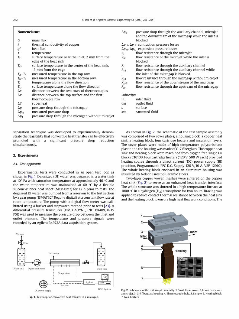
Experimental tests were conducted in an open test loop asshown in Fig. 1. Deionized (DI) water was degassed in a water tankat 104 Pa with saturation temperature at approximately 46 �C andthe water temperature was maintained at 60 �C by a flexiblesilicone-rubber heat sheet (McMaster) for 12 h prior to tests. Thedegassed DI water was pumped from a reservoir to the test sectionby a gear pump (ISMATEC� Regol-z digital) at a constant flow rate atroom temperature. The pump with a digital flow meter was cali-brated using a bucket and stopwatch method prior to tests [23]. Adifferential pressure transducer (OMEGADYNE, INC. PX409, 0-15PSI) was used to measure the pressure drop between the inlet andoutlet plenums. The temperature and pressure signals wererecorded by an Agilent 34972A data acquisition system.
DC power supply
Water tank Water tank
Test section
DAQ System
Digital gear pump
Agilent
Vacuum
Microscope
Pressure
Temperature
Valve
Fig. 1. Test loop for convective heat transfer in a microgap.
As shown in Fig. 2, the schematic of the test sample assemblywas comprised of two cover plates, a housing block, a copper heatsink, a heating block, four cartridge heaters and insulation layers.The cover plates were made of high temperature polycarbonateplastic and the housingwasmade of G-7 fiberglass. The copper heatsink and heating block were machined from oxygen free single Cublocks C10100. Four cartridge heaters (120 V, 500Weach) providedheating source through a direct current (DC) power supply (BKprecision, Programmable PFC D.C. Supply 120 V/10 A, VSP 12010).The whole heating block enclosed in an aluminum housing wasinsulated by Nelson Firestop Ceramic Fibers.
Two-layer copper woven meshes were sintered on the copperheat sink (Fig. 2) to serve as an enhanced heat transfer interface.The whole structure was sintered in a high temperature furnace at1000 �C in a hydrogen (H2) atmosphere for two hours. Brazing wasapplied to reduce contact thermal resistance between the heat sinkand the heating block to ensure high heat flux work conditions. The
Fig. 2. Schematic of the test sample assembly. 1, Small lexan cover. 2, Lexan cover witha microjet. 3, G-7 fiberglass housing. 4, Thermocouple hole. 5, Sample. 6, Heating block.7, Four heaters.

Fig. 3. (a) Setup overview. 1, Groove for sealing. 2, Inlet water. 3, Inlet pressuretransducer hole. 4, Inlet plenum. 5, Fiberglass. 6, Outlet pressure transducer hole 7,Water outlet. (b) Function of the flow separation. 1, Fiberglass housing. 2, High tem-perature RTV silicone. 3, Thermocouple 1e8, where, Dx ¼ 4.5 mm and Dx0 ¼ 3 mm. 4,Inlet water. 5, Inlet restrictor. 6, Lexan housing. 7, Main channel flow. 8, Separated flow.9, Microjet. 10, Microgap. 11, Two-layer copper meshes. 12, Outlet water.
X. Dai et al. / Applied Thermal Engineering 54 (2013) 281e288 283
copper heat sink was assembled into the G-7 fiberglass housing(Fig. 2). High temperature RTV silicone was used to ensure thermalinsulations and sealing. As shown in Fig. 3, eight holes were drilledin two rows to house thermocouples. Good contact conditionsbetween the thermocouples and heating block were achieved bysoldering.
2.2. Experimental study
A desired flow ratewas set by the digital gear pump. The electricpower was supplied to four heaters by a DC power supply at a givenstep increment until CHF conditions were approached. The surfacetemperature of the heat sinkwas estimated from the input heat fluxand temperature profile by a one-dimensional (1-D) conductionmode. Two K-type thermocouples were placed in the inlet andoutlet plenum to measure the water inlet and outlet temperatures,respectively. The steady state temperature and pressure weremonitored and recorded. The saturated water temperature was
Fig. 4. Temperature distribution on the heating wall in a microgap along the flow direction. (cm2. (b) Surface temperature distribution in two-phase heat transfer at a heat flux of 104.3
estimated from the average working pressure. Two hundred sets ofdata were collected in steady state, defined as the point at whichthe temperature reading for all thermocouples varied by less than0.2 �C over a period of ten minutes.
The experimental data was categorized into two groups. One isthe surface temperature (Ts) versus heat flux (q00) curves at a givenmass flux, and the other is the pressure drop (Dp) versus mass flux(G) curves at a fixed input heat flux.
2.3. Data reduction
Heat flux was estimated from the two rows of thermocouplesaccording to the Fourier’s law. As shown in Fig. 3, the effective inputheat flux can be calculated as:
q00 ¼ kDTDx
(1)
DT ¼ T6 þ T7 þ T83
� T2 þ T3 þ T43
(2)
where, q00 is the effective input heat flux, k is the thermal conduc-tivity of copper, and Dx is the distance between the two rows ofthermocouples as shown in Fig. 3. The locations of T2eT4 and T6eT8are shown in Fig. 3 as well. The average surface temperature Ts wasgiven by:
Ts ¼ 15
X5
1
Ti;s (3)
Ti;s ¼ Ti � q00Dx0
kði ¼ 1� 5Þ (4)
where, Ti,s is the surface temperature along the flow direction, Ti isthe corresponding thermocouple reading, and Dx0 is the distancebetween the first thermocouple row and the top surface as shownin Fig. 3.
The measured pressure drop, Dpm, is between the inlet and theoutlet plenums. To eliminate the inlet contraction and outletexpansion pressure losses, the pressure drop (Dp) through themicrogap was calculated as [24]:
Dp ¼ Dpm � ðDpc1 þ Dpc2Þ � ðDpe1 þ Dpe2Þ (5)
where Dpc1 and Dpc2 are the contraction pressure losses from thedeep plenum to the shallow plenum and from the shallow plenumto the microgap, respectively; Dpe1 and Dpe2 are the expansion
a) Surface temperature distribution in single-phase heat transfer at a heat flux of 8.9 W/W/cm2.
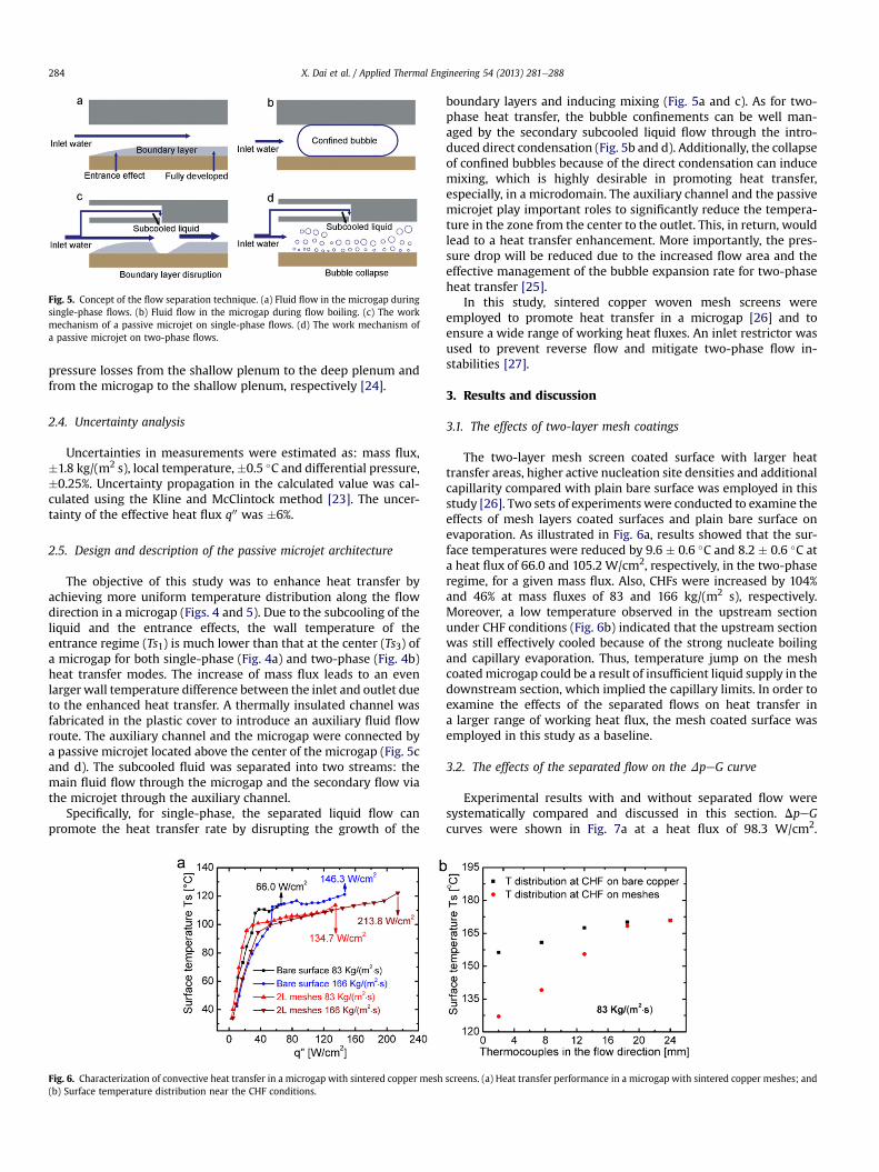
Fig. 5. Concept of the flow separation technique. (a) Fluid flow in the microgap duringsingle-phase flows. (b) Fluid flow in the microgap during flow boiling. (c) The workmechanism of a passive microjet on single-phase flows. (d) The work mechanism ofa passive microjet on two-phase flows.
X. Dai et al. / Applied Thermal Engineering 54 (2013) 281e288284
pressure losses from the shallow plenum to the deep plenum andfrom the microgap to the shallow plenum, respectively [24].
2.4. Uncertainty analysis
Uncertainties in measurements were estimated as: mass flux,�1.8 kg/(m2 s), local temperature,�0.5 �C and differential pressure,�0.25%. Uncertainty propagation in the calculated value was cal-culated using the Kline and McClintock method [23]. The uncer-tainty of the effective heat flux q00 was �6%.
2.5. Design and description of the passive microjet architecture
The objective of this study was to enhance heat transfer byachieving more uniform temperature distribution along the flowdirection in a microgap (Figs. 4 and 5). Due to the subcooling of theliquid and the entrance effects, the wall temperature of theentrance regime (Ts1) is much lower than that at the center (Ts3) ofa microgap for both single-phase (Fig. 4a) and two-phase (Fig. 4b)heat transfer modes. The increase of mass flux leads to an evenlarger wall temperature difference between the inlet and outlet dueto the enhanced heat transfer. A thermally insulated channel wasfabricated in the plastic cover to introduce an auxiliary fluid flowroute. The auxiliary channel and the microgap were connected bya passive microjet located above the center of the microgap (Fig. 5cand d). The subcooled fluid was separated into two streams: themain fluid flow through the microgap and the secondary flow viathe microjet through the auxiliary channel.
Specifically, for single-phase, the separated liquid flow canpromote the heat transfer rate by disrupting the growth of the
Fig. 6. Characterization of convective heat transfer in a microgap with sintered copper mesh(b) Surface temperature distribution near the CHF conditions.
boundary layers and inducing mixing (Fig. 5a and c). As for two-phase heat transfer, the bubble confinements can be well man-aged by the secondary subcooled liquid flow through the intro-duced direct condensation (Fig. 5b and d). Additionally, the collapseof confined bubbles because of the direct condensation can inducemixing, which is highly desirable in promoting heat transfer,especially, in a microdomain. The auxiliary channel and the passivemicrojet play important roles to significantly reduce the tempera-ture in the zone from the center to the outlet. This, in return, wouldlead to a heat transfer enhancement. More importantly, the pres-sure drop will be reduced due to the increased flow area and theeffective management of the bubble expansion rate for two-phaseheat transfer [25].
In this study, sintered copper woven mesh screens wereemployed to promote heat transfer in a microgap [26] and toensure a wide range of working heat fluxes. An inlet restrictor wasused to prevent reverse flow and mitigate two-phase flow in-stabilities [27].
3. Results and discussion
3.1. The effects of two-layer mesh coatings
The two-layer mesh screen coated surface with larger heattransfer areas, higher active nucleation site densities and additionalcapillarity compared with plain bare surface was employed in thisstudy [26]. Two sets of experiments were conducted to examine theeffects of mesh layers coated surfaces and plain bare surface onevaporation. As illustrated in Fig. 6a, results showed that the sur-face temperatures were reduced by 9.6 � 0.6 �C and 8.2 � 0.6 �C ata heat flux of 66.0 and 105.2 W/cm2, respectively, in the two-phaseregime, for a given mass flux. Also, CHFs were increased by 104%and 46% at mass fluxes of 83 and 166 kg/(m2 s), respectively.Moreover, a low temperature observed in the upstream sectionunder CHF conditions (Fig. 6b) indicated that the upstream sectionwas still effectively cooled because of the strong nucleate boilingand capillary evaporation. Thus, temperature jump on the meshcoatedmicrogap could be a result of insufficient liquid supply in thedownstream section, which implied the capillary limits. In order toexamine the effects of the separated flows on heat transfer ina larger range of working heat flux, the mesh coated surface wasemployed in this study as a baseline.
3.2. The effects of the separated flow on the DpeG curve
Experimental results with and without separated flow weresystematically compared and discussed in this section. DpeGcurves were shown in Fig. 7a at a heat flux of 98.3 W/cm2.
screens. (a) Heat transfer performance in a microgap with sintered copper meshes; and
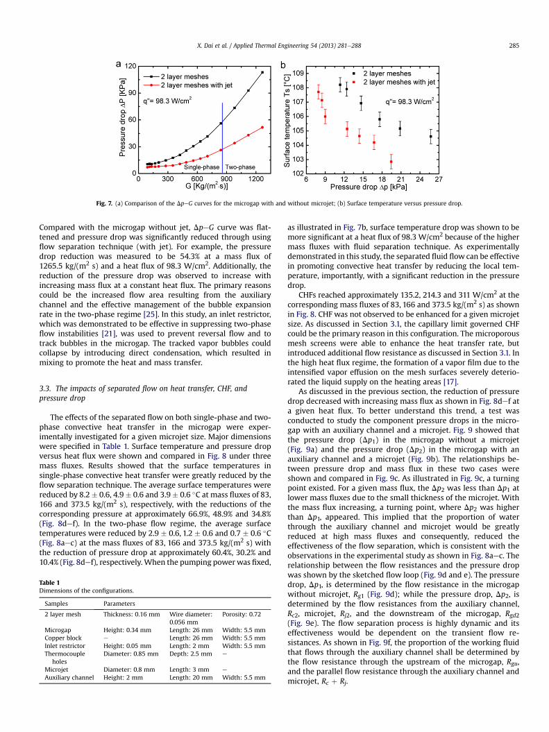
Fig. 7. (a) Comparison of the DpeG curves for the microgap with and without microjet; (b) Surface temperature versus pressure drop.
X. Dai et al. / Applied Thermal Engineering 54 (2013) 281e288 285
Compared with the microgap without jet, DpeG curve was flat-tened and pressure drop was significantly reduced through usingflow separation technique (with jet). For example, the pressuredrop reduction was measured to be 54.3% at a mass flux of1265.5 kg/(m2 s) and a heat flux of 98.3 W/cm2. Additionally, thereduction of the pressure drop was observed to increase withincreasing mass flux at a constant heat flux. The primary reasonscould be the increased flow area resulting from the auxiliarychannel and the effective management of the bubble expansionrate in the two-phase regime [25]. In this study, an inlet restrictor,which was demonstrated to be effective in suppressing two-phaseflow instabilities [21], was used to prevent reversal flow and totrack bubbles in the microgap. The tracked vapor bubbles couldcollapse by introducing direct condensation, which resulted inmixing to promote the heat and mass transfer.
3.3. The impacts of separated flow on heat transfer, CHF, andpressure drop
The effects of the separated flow on both single-phase and two-phase convective heat transfer in the microgap were exper-imentally investigated for a given microjet size. Major dimensionswere specified in Table 1. Surface temperature and pressure dropversus heat flux were shown and compared in Fig. 8 under threemass fluxes. Results showed that the surface temperatures insingle-phase convective heat transfer were greatly reduced by theflow separation technique. The average surface temperatures werereduced by 8.2� 0.6, 4.9� 0.6 and 3.9� 0.6 �C at mass fluxes of 83,166 and 373.5 kg/(m2 s), respectively, with the reductions of thecorresponding pressure at approximately 66.9%, 48.9% and 34.8%(Fig. 8def). In the two-phase flow regime, the average surfacetemperatures were reduced by 2.9 � 0.6, 1.2 � 0.6 and 0.7 � 0.6 �C(Fig. 8aec) at the mass fluxes of 83, 166 and 373.5 kg/(m2 s) withthe reduction of pressure drop at approximately 60.4%, 30.2% and10.4% (Fig. 8def), respectively.When the pumping powerwas fixed,
Table 1Dimensions of the configurations.
Samples Parameters
2 layer mesh Thickness: 0.16 mm Wire diameter:0.056 mm
Porosity: 0.72
Microgap Height: 0.34 mm Length: 26 mm Width: 5.5 mmCopper block e Length: 26 mm Width: 5.5 mmInlet restrictor Height: 0.05 mm Length: 2 mm Width: 5.5 mmThermocouple
holesDiameter: 0.85 mm Depth: 2.5 mm e
Microjet Diameter: 0.8 mm Length: 3 mm e
Auxiliary channel Height: 2 mm Length: 20 mm Width: 5.5 mm
as illustrated in Fig. 7b, surface temperature drop was shown to bemore significant at a heat flux of 98.3 W/cm2 because of the highermass fluxes with fluid separation technique. As experimentallydemonstrated in this study, the separated fluid flow can be effectivein promoting convective heat transfer by reducing the local tem-perature, importantly, with a significant reduction in the pressuredrop.
CHFs reached approximately 135.2, 214.3 and 311 W/cm2 at thecorresponding mass fluxes of 83, 166 and 373.5 kg/(m2 s) as shownin Fig. 8. CHF was not observed to be enhanced for a given microjetsize. As discussed in Section 3.1, the capillary limit governed CHFcould be the primary reason in this configuration. The microporousmesh screens were able to enhance the heat transfer rate, butintroduced additional flow resistance as discussed in Section 3.1. Inthe high heat flux regime, the formation of a vapor film due to theintensified vapor effusion on the mesh surfaces severely deterio-rated the liquid supply on the heating areas [17].
As discussed in the previous section, the reduction of pressuredrop decreased with increasing mass flux as shown in Fig. 8def ata given heat flux. To better understand this trend, a test wasconducted to study the component pressure drops in the micro-gap with an auxiliary channel and a microjet. Fig. 9 showed thatthe pressure drop (Dp1) in the microgap without a microjet(Fig. 9a) and the pressure drop (Dp2) in the microgap with anauxiliary channel and a microjet (Fig. 9b). The relationships be-tween pressure drop and mass flux in these two cases wereshown and compared in Fig. 9c. As illustrated in Fig. 9c, a turningpoint existed. For a given mass flux, the Dp2 was less than Dp1 atlower mass fluxes due to the small thickness of the microjet. Withthe mass flux increasing, a turning point, where Dp2 was higherthan Dp1, appeared. This implied that the proportion of waterthrough the auxiliary channel and microjet would be greatlyreduced at high mass fluxes and consequently, reduced theeffectiveness of the flow separation, which is consistent with theobservations in the experimental study as shown in Fig. 8aec. Therelationship between the flow resistances and the pressure dropwas shown by the sketched flow loop (Fig. 9d and e). The pressuredrop, Dp1, is determined by the flow resistance in the microgapwithout microjet, Rg1 (Fig. 9d); while the pressure drop, Dp2, isdetermined by the flow resistances from the auxiliary channel,Rc2, microjet, Rj2, and the downstream of the microgap, Rgd2(Fig. 9e). The flow separation process is highly dynamic and itseffectiveness would be dependent on the transient flow re-sistances. As shown in Fig. 9f, the proportion of the working fluidthat flows through the auxiliary channel shall be determined bythe flow resistance through the upstream of the microgap, Rgu,and the parallel flow resistance through the auxiliary channel andmicrojet, Rc þ Rj.
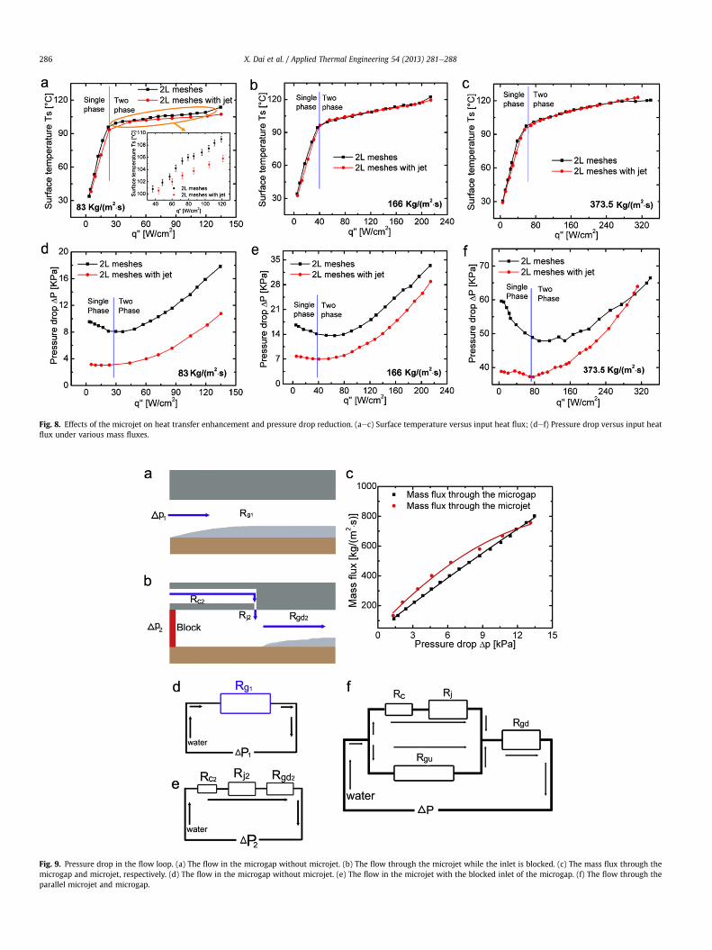
Fig. 8. Effects of the microjet on heat transfer enhancement and pressure drop reduction. (aec) Surface temperature versus input heat flux; (def) Pressure drop versus input heatflux under various mass fluxes.
Fig. 9. Pressure drop in the flow loop. (a) The flow in the microgap without microjet. (b) The flow through the microjet while the inlet is blocked. (c) The mass flux through themicrogap and microjet, respectively. (d) The flow in the microgap without microjet. (e) The flow in the microjet with the blocked inlet of the microgap. (f) The flow through theparallel microjet and microgap.
X. Dai et al. / Applied Thermal Engineering 54 (2013) 281e288286
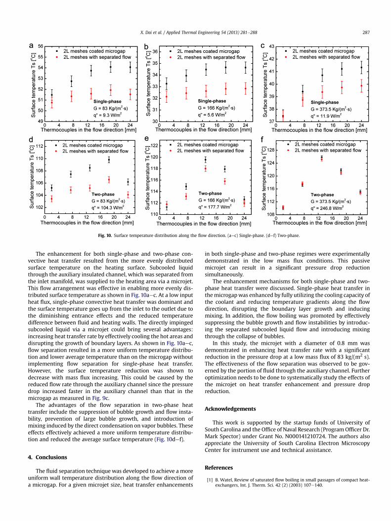
Fig. 10. Surface temperature distribution along the flow direction. (aec) Single-phase. (def) Two-phase.
X. Dai et al. / Applied Thermal Engineering 54 (2013) 281e288 287
The enhancement for both single-phase and two-phase con-vective heat transfer resulted from the more evenly distributedsurface temperature on the heating surface. Subcooled liquidthrough the auxiliary insulated channel, which was separated fromthe inlet manifold, was supplied to the heating area via a microjet.This flow arrangement was effective in enabling more evenly dis-tributed surface temperature as shown in Fig. 10aec. At a low inputheat flux, single-phase convective heat transfer was dominant andthe surface temperature goes up from the inlet to the outlet due tothe diminishing entrance effects and the reduced temperaturedifference between fluid and heating walls. The directly impingedsubcooled liquid via a microjet could bring several advantages:increasing heat transfer rate by effectively cooling the hot areas anddisrupting the growth of boundary layers. As shown in Fig. 10aec,flow separation resulted in a more uniform temperature distribu-tion and lower average temperature than on the microgap withoutimplementing flow separation for single-phase heat transfer.However, the surface temperature reduction was shown todecrease with mass flux increasing. This could be caused by thereduced flow rate through the auxiliary channel since the pressuredrop increased faster in the auxiliary channel than that in themicrogap as measured in Fig. 9c.
The advantages of the flow separation in two-phase heattransfer include the suppression of bubble growth and flow insta-bility, prevention of large bubble growth, and introduction ofmixing induced by the direct condensation on vapor bubbles. Theseeffects effectively achieved a more uniform temperature distribu-tion and reduced the average surface temperature (Fig. 10def).
4. Conclusions
The fluid separation technique was developed to achieve a moreuniform wall temperature distribution along the flow direction ofa microgap. For a given microjet size, heat transfer enhancements
in both single-phase and two-phase regimes were experimentallydemonstrated in the low mass flux conditions. This passivemicrojet can result in a significant pressure drop reductionsimultaneously.
The enhancement mechanisms for both single-phase and two-phase heat transfer were discussed. Single-phase heat transfer inthemicrogapwas enhanced by fully utilizing the cooling capacity ofthe coolant and reducing temperature gradients along the flowdirection, disrupting the boundary layer growth and inducingmixing. In addition, the flow boiling was promoted by effectivelysuppressing the bubble growth and flow instabilities by introduc-ing the separated subcooled liquid flow and introducing mixingthrough the collapse of bubbles.
In this study, the microjet with a diameter of 0.8 mm wasdemonstrated in enhancing heat transfer rate with a significantreduction in the pressure drop at a low mass flux of 83 kg/(m2 s).The effectiveness of the flow separation was observed to be gov-erned by the portion of fluid through the auxiliary channel. Furtheroptimization needs to be done to systematically study the effects ofthe microjet on heat transfer enhancement and pressure dropreduction.
Acknowledgements
This work is supported by the startup funds of University ofSouth Carolina and the Office of Naval Research (ProgramOfficer Dr.Mark Spector) under Grant No. N000141210724. The authors alsoappreciate the University of South Carolina Electron MicroscopyCenter for instrument use and technical assistance.
References
[1] B. Watel, Review of saturated flow boiling in small passages of compact heat-exchangers, Int. J. Therm. Sci. 42 (2) (2003) 107e140.

X. Dai et al. / Applied Thermal Engineering 54 (2013) 281e288288
[2] L.S. Ismail, R. Velraj, C. Ranganayakulu, Studies on pumping power in terms ofpressure drop and heat transfer characteristics of compact plate-fin heat ex-changers e a review, Renew. Sust. Energ. Rev. 14 (1) (2010) 478e485.
[3] P.A. Kew, D.A. Reay, Compact/micro-heat exchangers e their role in heatpumping equipment, Appl. Therm. Eng. 31 (5) (2011) 594e601.
[4] Q. Li, G. Flamant, X. Yuan, P. Neveu, L. Luo, Compact heat exchangers: a reviewand future applications for a new generation of high temperature solar re-ceivers, Renew. Sust. Energ. Rev. 15 (9) (2011) 4855e4875.
[5] D.A. Reay, Compact heat exchangers, enhancement and heat pumps, Int. J.Refrigeration 25 (4) (2002) 460e470.
[6] K. Boomsma, D. Poulikakos, F. Zwick, Metal foams as compact high perfor-mance heat exchangers, Mech. Mater. 35 (12) (2003) 1161e1176.
[7] L. Tadrist, M. Miscevic, O. Rahli, F. Topin, About the use of fibrous materials incompact heat exchangers, Exp. Therm. Fluid Sci. 28 (2e3) (2004) 193e199.
[8] F. Pra, P. Tochon, C. Mauget, J. Fokkens, S. Willemsen, Promising designs ofcompact heat exchangers for modular HTRs using the Brayton cycle, Nucl. Eng.Des. 238 (11) (2008) 3160e3173.
[9] R. Revellin, V. Dupont, T. Ursenbacher, J.R. Thome, I. Zun, Characterization ofdiabatic two-phase flows in microchannels: flow parameter results for R-134ain a 0.5 mm channel, Int. J. Multiphase Flow 32 (7) (2006) 755e774.
[10] S.G. Kandlikar, Heat transfer mechanisms during flow boiling in micro-channels, J. Heat Trans.-T. ASME 126 (1) (2004) 8e16.
[11] S.G. Kandlikar, Scale effects on flow boiling heat transfer in microchannels:a fundamental perspective, Int. J. Therm. Sci. 49 (7) (2010) 1073e1085.
[12] Z.Y. Guo, Z.X. Li, Size effect on microscale single-phase flow and heat transfer,Int. J. Heat Mass Transf. 46 (1) (2003) 149e159.
[13] G.M. Mala, D.Q. Li, Flow characteristics of water in microtubes, Int. J. HeatFluid Flow 20 (2) (1999) 142e148.
[14] S.V. Garimella, V.P. Schroeder, Local heat transfer distributions in confinedmultiple air jet impingement, J. Electron. Packaging 123 (3) (2001) 165e172.
[15] M.Y. Wen, K.J. Jang, An impingement cooling on a flat surface by using circularjet with longitudinal swirling strips, Int. J. Heat Mass Transf. 46 (24) (2003)4657e4667.
[16] M.K. Sung, I. Mudawar, Single-phase and two-phase heat transfer character-istics of low temperature hybrid micro-channel/micro-jet impingementcooling module, Int. J. Heat Mass Transf. 51 (15e16) (2008) 3882e3895.
[17] M.K. Sung, I. Mudawar, CHF determination for high-heat flux phase changecooling system incorporating both micro-channel flow and jet impingement,Int. J. Heat Mass Transf. 52 (3e4) (2009) 610e619.
[18] L.X. Cheng, E.P. Bandarra, J.R. Thome, Nanofluid two-phase flow and thermalphysics: a new research frontier of nanotechnology and its challenges,J. Nanosci. Nanotechnol. 8 (7) (2008) 3315e3332.
[19] A. Morshed, F.H. Yang, M.Y. Ali, J.A. Khan, C. Li, Enhanced flow boiling ina microchannel with integration of nanowires, Appl. Therm. Eng. 32 (2012)68e75.
[20] M.S. Sarwar, Y.H. Jeong, S.H. Chang, Subcooled flow boiling CHF enhancementwith porous surface coatings, Int. J. Heat Mass Transf. 50 (17e18) (2007)3649e3657.
[21] Y. Peles, A. Kosar, C. Mishra, C.J. Kuo, B. Schneider, Forced convective heattransfer across a pin fin micro heat sink, Int. J. Heat Mass Transf. 48 (17)(2005) 3615e3627.
[22] S. Krishnamurthy, Y. Peles, Flow boiling heat transfer on micro pin finsentrenched in a microchannel, J. Heat Trans.-T. ASME 132 (4) (2010)041007.
[23] J.P. Holman, Experimental Methods for Engineers, sixth ed., McGraw-Hill,1994.
[24] W.L. Qu, I. Mudawar, Experimental and numerical study of pressure drop andheat transfer in a single-phase micro-channel heat sink, Int. J. Heat MassTransf. 45 (12) (2002) 2549e2565.
[25] F. Yang, X. Dai, C. Li, High frequency microbubble-switched oscillationsmodulated by microfluidic transistors, Appl. Phys. Lett. 101 (7) (2012).
[26] C. Li, G.P. Peterson, Y. Wang, Evaporation/boiling in thin capillary wicks (I) ewick thickness effects, J. Heat Trans.-T. ASME 128 (12) (2006) 1312e1319.
[27] G. Wang, P. Cheng, A.E. Bergles, Effects of inlet/outlet configurations on flowboiling instability in parallel microchannels, Int. J. Heat Mass Transf. 51 (9e10)(2008) 2267e2281.