Enhanced Analysis of WCDMA Networks with Repeaters Deployment
11
IEEE TRANSACTIONS ON WIRELESS COMMUNICATIONS, VOL. 6, NO. 9, SEPTEMBER 2007 3429 Enhanced Analysis of WCDMA Networks with Repeaters Deployment Mario Garcia-Lozano, Luis Alonso, Member, IEEE, Fernando Casadevall, Member, IEEE, Silvia Ruiz, Member, IEEE, and Luis M. Correia, Senior Member, IEEE Abstract— This paper addresses the analysis of WCDMA systems with repeaters deployment. A generic and compact expression for up- and downlinks evaluation has been mathe- matically derived so that transmission powers and other radio resource management parameters can be calculated without simplifications. In particular, the real different path delays, taking into account the repeaters presence and the finite nature of the time window of Rake receivers are considered. This allows an enhanced analysis with respect to classical approaches from a system level viewpoint. Furthermore, higher reliable and accurate predictions on network performance can be obtained, which can be remarkably useful for network planning and management. By using these expressions, relevant network parameters have been evaluated and compared with the ones obtained using the classical approximations. The differences in the obtained metrics are highlighted, putting in evidence the improvement provided by the proposed analysis. Index Terms— Network planning, repeaters, WCDMA. I. I NTRODUCTION M OBILE communications systems often work under high heterogeneous conditions, in both time and space domains. Optimizing the design of radio access networks is a technical and economical challenge for operators. In this sense, active repeaters (non-regenerative) are of special interest when considering the coverage of a mobile communications system in a certain set of situations, which include filling in coverage holes in valleys, tunnels, buildings or extending the service area beyond cells boundaries. Despite their use in 2G (second generation) networks, repeaters are expected to play even a major role in planning WCDMA (Wideband Code Division Multiple Access) systems. Some of the reasons are: • Since adjacent cells share the same power, repeaters are a cost-effective option to reduce inter-cell interference, particularly in environments with hotspots. If properly adjusted, they can reduce the coupling loss between the base station (BS) and mobile terminals (MT) that are close to the repeater. Therefore, in the uplink (UL), Manuscript received February 14, 2006; revised October 6, 2006; accepted November 21, 2006. The associate editor coordinating the review of this paper and approving it for publication was K. B. Lee. This work was supported by the European Network of Excellence NEWCOM (Contract number 507325) and by the Spanish Research Council CICYT+FEDER through the projects TEC2005-07326-C02-01/TCM, TIC2003-08609, and TEC2006-09109. M. Garcia-Lozano, L. Alonso, F. Casadevall, and S. Ruiz are with the Universitat Politècnica de Catalunya (UPC), Av. Canal Olímpic s/n., 08860 Barcelona, Spain (e-mail: {mariogarcia, luisg, ferranc, silvia}@tsc.upc.edu). L. M. Correia is with the Instituto Superior Técnico (IST), Technical University of Lisbon, Av. Rovisco Pais, IT/DEEC Torre Norte, 1049-001 Lisboa, Portugal (e-mail: [email protected]). Digital Object Identifier 10.1109/TWC.2007.06114. MTs use a lower output power and the interference in neighbouring cells is reduced. The work in [1] studies the use of repeaters in WCDMA systems with hotspots and reveals this fact among others. Subsequently, the BS that is connected to a repeater will be denoted as its donor BS. • Radio over fibre and optical wireless are mature enough technologies to allow a dense deployment of repeaters, especially in urban environments. Paper [2] describes two radio over fibre systems, for GSM and UMTS networks. In the first case, the article also describes a real and complete system as well as results obtained in field- tests, which were designed to improve coverage inside a building. • Indeed the use of higher frequencies in WCDMA systems will imply higher propagation losses. Repeaters can be key devices to guarantee indoor coverage at a low cost. • During the last years, repeaters have improved in terms of operation and maintenance capabilities. Unfortunately, since repeaters are not noiseless devices, they modify the interference and thermal noise patterns of the donor BS receiver (RX). This implies an effect in both the coverage and capacity of the cell. Since the noise floor of the donor is raised, its effective coverage area is shrunk. However, this will be clearly compensated by the new areas, covered by the repeaters. On the other hand, the maximum allowed load factor is more likely to be reached, and so another effect is the reduction of the admission region in the donor BS [3]. In a mobile communications system with repeaters, signal contributions from the donor BS and from repeaters arrive through different paths, and those ones passing through a re- peater are usually ’longer’ (both in spatial and time domains). This is because of the delay introduced by the link between the repeater and the donor BS, and the internal delay of the repeater itself. In fact, the link can be established via various transmission media, such as fiber optic or copper, which show some advantages compared to radio, but also imply lower propagation velocities. On the other hand, the Rake RX performs a delay profile characterization [4] and just those components within a certain time window are constructively combined. Therefore, with the introduction of repeaters, the system analysis is significantly modified and must be revised. Although much previous research efforts have been focused on the analysis of CDMA-based systems ([5]–[7]), only to cite a few), not many studies in the literature analyze the effect of repeaters on the capacity and feasibility conditions 1536-1276/07$25.00 c 2007 IEEE
-
Upload
independent -
Category
Documents
-
view
4 -
download
0
Transcript of Enhanced Analysis of WCDMA Networks with Repeaters Deployment

IEEE TRANSACTIONS ON WIRELESS COMMUNICATIONS, VOL. 6, NO. 9, SEPTEMBER 2007 3429
Enhanced Analysis of WCDMA Networks withRepeaters Deployment
Mario Garcia-Lozano, Luis Alonso, Member, IEEE, Fernando Casadevall, Member, IEEE,Silvia Ruiz, Member, IEEE, and Luis M. Correia, Senior Member, IEEE
Abstract— This paper addresses the analysis of WCDMAsystems with repeaters deployment. A generic and compactexpression for up- and downlinks evaluation has been mathe-matically derived so that transmission powers and other radioresource management parameters can be calculated withoutsimplifications. In particular, the real different path delays,taking into account the repeaters presence and the finite natureof the time window of Rake receivers are considered. This allowsan enhanced analysis with respect to classical approaches from asystem level viewpoint. Furthermore, higher reliable and accuratepredictions on network performance can be obtained, which canbe remarkably useful for network planning and management.By using these expressions, relevant network parameters havebeen evaluated and compared with the ones obtained using theclassical approximations. The differences in the obtained metricsare highlighted, putting in evidence the improvement providedby the proposed analysis.
Index Terms— Network planning, repeaters, WCDMA.
I. INTRODUCTION
MOBILE communications systems often work underhigh heterogeneous conditions, in both time and space
domains. Optimizing the design of radio access networks isa technical and economical challenge for operators. In thissense, active repeaters (non-regenerative) are of special interestwhen considering the coverage of a mobile communicationssystem in a certain set of situations, which include fillingin coverage holes in valleys, tunnels, buildings or extendingthe service area beyond cells boundaries. Despite their usein 2G (second generation) networks, repeaters are expected toplay even a major role in planning WCDMA (Wideband CodeDivision Multiple Access) systems. Some of the reasons are:
• Since adjacent cells share the same power, repeaters area cost-effective option to reduce inter-cell interference,particularly in environments with hotspots. If properlyadjusted, they can reduce the coupling loss between thebase station (BS) and mobile terminals (MT) that areclose to the repeater. Therefore, in the uplink (UL),
Manuscript received February 14, 2006; revised October 6, 2006; acceptedNovember 21, 2006. The associate editor coordinating the review of this paperand approving it for publication was K. B. Lee. This work was supported bythe European Network of Excellence NEWCOM (Contract number 507325)and by the Spanish Research Council CICYT+FEDER through the projectsTEC2005-07326-C02-01/TCM, TIC2003-08609, and TEC2006-09109.
M. Garcia-Lozano, L. Alonso, F. Casadevall, and S. Ruiz are with theUniversitat Politècnica de Catalunya (UPC), Av. Canal Olímpic s/n., 08860Barcelona, Spain (e-mail: {mariogarcia, luisg, ferranc, silvia}@tsc.upc.edu).
L. M. Correia is with the Instituto Superior Técnico (IST), TechnicalUniversity of Lisbon, Av. Rovisco Pais, IT/DEEC Torre Norte, 1049-001Lisboa, Portugal (e-mail: [email protected]).
Digital Object Identifier 10.1109/TWC.2007.06114.
MTs use a lower output power and the interference inneighbouring cells is reduced. The work in [1] studiesthe use of repeaters in WCDMA systems with hotspotsand reveals this fact among others. Subsequently, the BSthat is connected to a repeater will be denoted as its donorBS.
• Radio over fibre and optical wireless are mature enoughtechnologies to allow a dense deployment of repeaters,especially in urban environments. Paper [2] describes tworadio over fibre systems, for GSM and UMTS networks.In the first case, the article also describes a real andcomplete system as well as results obtained in field-tests, which were designed to improve coverage insidea building.
• Indeed the use of higher frequencies in WCDMA systemswill imply higher propagation losses. Repeaters can bekey devices to guarantee indoor coverage at a low cost.
• During the last years, repeaters have improved in termsof operation and maintenance capabilities.
Unfortunately, since repeaters are not noiseless devices, theymodify the interference and thermal noise patterns of the donorBS receiver (RX). This implies an effect in both the coverageand capacity of the cell. Since the noise floor of the donoris raised, its effective coverage area is shrunk. However, thiswill be clearly compensated by the new areas, covered bythe repeaters. On the other hand, the maximum allowed loadfactor is more likely to be reached, and so another effect isthe reduction of the admission region in the donor BS [3].
In a mobile communications system with repeaters, signalcontributions from the donor BS and from repeaters arrivethrough different paths, and those ones passing through a re-peater are usually ’longer’ (both in spatial and time domains).This is because of the delay introduced by the link betweenthe repeater and the donor BS, and the internal delay of therepeater itself. In fact, the link can be established via varioustransmission media, such as fiber optic or copper, whichshow some advantages compared to radio, but also implylower propagation velocities. On the other hand, the Rake RXperforms a delay profile characterization [4] and just thosecomponents within a certain time window are constructivelycombined. Therefore, with the introduction of repeaters, thesystem analysis is significantly modified and must be revised.
Although much previous research efforts have been focusedon the analysis of CDMA-based systems ([5]–[7]), only tocite a few), not many studies in the literature analyze theeffect of repeaters on the capacity and feasibility conditions
1536-1276/07$25.00 c© 2007 IEEE
3430 IEEE TRANSACTIONS ON WIRELESS COMMUNICATIONS, VOL. 6, NO. 9, SEPTEMBER 2007
for a CDMA mobile communications system. In [8], theauthors study repeaters as coverage extenders and how theymodify interference in highways environments. Similarly, [3]and [9] deal with coverage, but also investigate variations incapacity due to the noise rise that appears in the donor BSwhen repeaters are installed. In order to minimize this effect,[10] proposes an automatic on-off switching repeater. Finallyan analytic scheme for estimating the received signal powerrequired at the BS front-end in an environment with fibre-optic repeaters is found in [11]. On the other hand, publishedstudies always consider one of following assumptions:
1) RXs receive power just through the radio-link withthe donor BS or through one of its repeaters. Othercontributions are not considered in any way [10], [11].
2) All the contributions are always perfectly combinedin the MT. Ideal maximum ratio combining (MRC) isapplied [1], [3], [8].
The work in [9] evaluates the two situations independently,and also another one that is in the middle of them.
However, in comparison to classical approaches, in realsystems the Rake RX has to perform a delay profile mea-surement to designate the time offsets of the strongest signalcomponents. Only those paths within a certain time windoware constructively combined, the others not being consideredand causing a certain level of ‘self-interference’. UMTS (Uni-versal Mobile Telecommunications System) BSs and MTs canusually handle a 20 μs time delay between two paths [12], andthis value must be considered when repeaters are deployed,since MTs can incur into high levels of multi-path [13].
The novelty of this paper is a generic and complete analysisof a WCDMA system with repeaters from a system levelviewpoint. Compact expressions for the UL and downlinks(DL) are derived, so that transmission powers and other radioresource management (RRM) parameters can be calculatedwithout any of the previously mentioned simplifications. Thisallows an enhanced prediction of the network performancewhen studying WCDMA environments with repeaters deploy-ment. Moreover, a comparison with the results obtained usingclassical approaches has also been done. Different relevantparameters that characterize networks performance have beenevaluated and compared. The differences with respect tosimplified analysis are shown to be remarkable, stressing theimprovement provided by the proposed analysis.
The paper is organized in 5 differentiated sections. After thisintroduction, the model is explained, as well as the notationsubsequently used, in Section II. Next, in Section III themathematical approach is developed along two subsections,the first one being devoted to the UL and the second one tothe DL, some comments on final equations being also given.Section IV contains numerical results and, finally, Section Vcloses the paper with the conclusions derived from the work.
II. SYSTEM MODEL
Let us consider a mobile communications systems consist-ing of any number NBS of BSs, each one of them connectedto any number of repeaters, NRep (j) being the number ofrepeaters connected to BS j. The system layout can be com-pletely generic, with no restriction on the spatial configuration
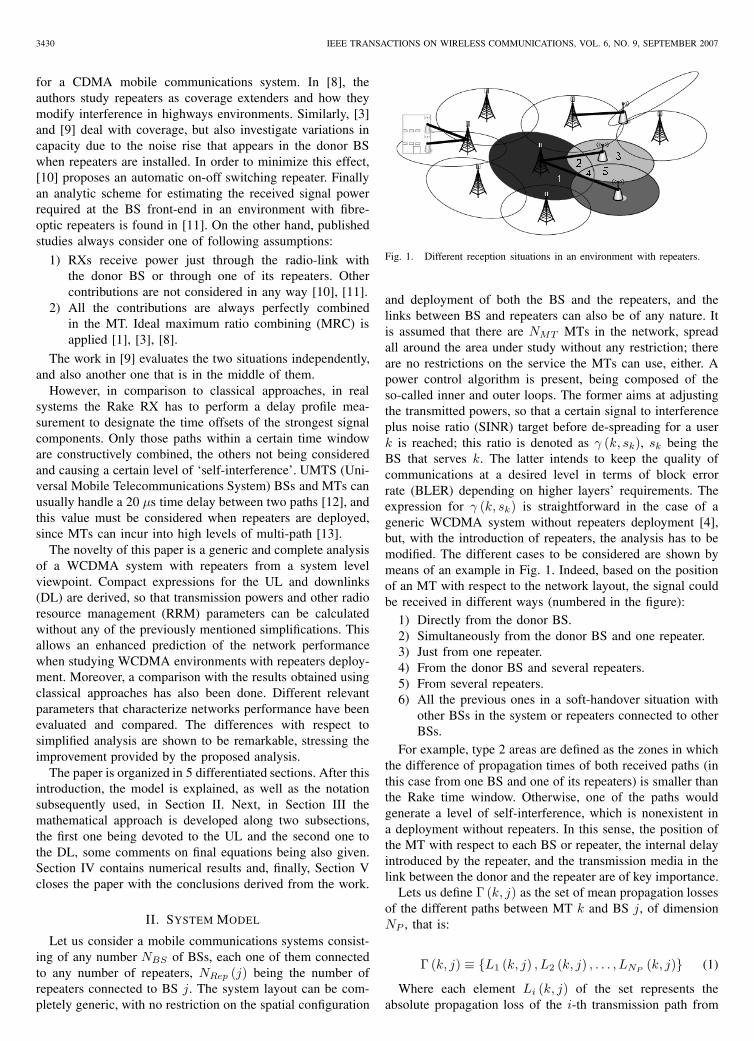
Fig. 1. Different reception situations in an environment with repeaters.
and deployment of both the BS and the repeaters, and thelinks between BS and repeaters can also be of any nature. Itis assumed that there are NMT MTs in the network, spreadall around the area under study without any restriction; thereare no restrictions on the service the MTs can use, either. Apower control algorithm is present, being composed of theso-called inner and outer loops. The former aims at adjustingthe transmitted powers, so that a certain signal to interferenceplus noise ratio (SINR) target before de-spreading for a userk is reached; this ratio is denoted as γ (k, sk), sk being theBS that serves k. The latter intends to keep the quality ofcommunications at a desired level in terms of block errorrate (BLER) depending on higher layers’ requirements. Theexpression for γ (k, sk) is straightforward in the case of ageneric WCDMA system without repeaters deployment [4],but, with the introduction of repeaters, the analysis has to bemodified. The different cases to be considered are shown bymeans of an example in Fig. 1. Indeed, based on the positionof an MT with respect to the network layout, the signal couldbe received in different ways (numbered in the figure):
1) Directly from the donor BS.2) Simultaneously from the donor BS and one repeater.3) Just from one repeater.4) From the donor BS and several repeaters.5) From several repeaters.6) All the previous ones in a soft-handover situation with
other BSs in the system or repeaters connected to otherBSs.
For example, type 2 areas are defined as the zones in whichthe difference of propagation times of both received paths (inthis case from one BS and one of its repeaters) is smaller thanthe Rake time window. Otherwise, one of the paths wouldgenerate a level of self-interference, which is nonexistent ina deployment without repeaters. In this sense, the position ofthe MT with respect to each BS or repeater, the internal delayintroduced by the repeater, and the transmission media in thelink between the donor and the repeater are of key importance.
Lets us define Γ (k, j) as the set of mean propagation lossesof the different paths between MT k and BS j, of dimensionNP , that is:
Γ (k, j) ≡ {L1 (k, j) , L2 (k, j) , . . . , LNP (k, j)} (1)
Where each element Li (k, j) of the set represents theabsolute propagation loss of the i-th transmission path from
GARCIA-LOZANO et al.: ENHANCED ANALYSIS OF WCDMA NETWORKS WITH REPEATERS DEPLOYMENT 3431
MT k to BS j:
Γ (k, j) ={
LMT−BS (k, j) ,LMT−Rep[k,r1(j)]·LRep−BS[r1(j),j]
GRep[r1(j)],
...,LMT−Rep
�k,rNRep(j)(j)
�·LRep−BS
�rNRep(j)(j),j
�
GRep
�rNRep(j)(j)
�}
(2)Where:
• LMT−BS (k, j) is the radio propagation loss between kand j.
• LMT−Rep (k, r) is the radio propagation loss between kand a repeater r.
• LRep−BS (r, j) is the loss between repeater r and j, ri (j)being the i-th repeater connected to j.
• GRep (r) is the power gain provided by repeater r, beingproperly selected in order to avoid the saturation of therepeater amplifier.
The subset Ψ (k, j) ⊂ Γ (k, j) is defined as the one contain-ing the paths that are constructively combined by the Rake RX,that is, those within the Rake observing time window limits.
III. SIR ANALYSIS
The objective of this section is to derive a generic expressionso that transmission powers can be realistically found in orderto achieve the system requirements. This is done for eachlink (UL and DL), valid for all types of system layouts,irrespectively of the position of the MTs with respect to theBS or the repeaters. The following subsections are devotedseparately to each link.
A. Uplink
Taking the system model and definitions into account, theSINR for MT k in UL before de-spreading γUL (k, sk), canbe written as:
γUL (k, sk) ≡ (3)
≡
∑i∈Ψ(k,sk)
PULTX/Li (k, sk)
IUL (k, sk) + P̃RX (k, sk) + nBS (sk) + nRX,Rep (sk)
Where:
• PULTX (k): The transmission power used by k.
• IUL (k, sk): The UL multi-user interference power re-ceived by the connection between k and sk, for bothinter- and intra-cells.
• P̃RX (k, sk) The self-interference power of k at sk, beinggenerated by signal replicas from k that arrive with sucha delay that fall out of the Rake window.
• nBS (j): The thermal noise power produced by the BSRX.
• nRX,Rep (j): The received thermal noise power producedby all repeaters connected to BS j:
nRX,Rep (j) =NRep(j)∑
i=1
nRep [ri (j)] · GRep (ri)LRep−BS [ri (j) , j]
(4)
Note that the last two terms in the denominator are constantand can be grouped in a single thermal noise term, which iscalled n (sk).
The numerator of (3) is the constructive addition of thesignal’s replicas that can be combined in the Rake RX. Onthe other hand, the term IUL (k, sk) takes into account allthe possible paths of interfering signals for all users in thesystem. Moreover, the self-interference level of k at sk can beexpressed as:
P̃RX (k, sk) ≡∑
i∈Γ(k,sk)i/∈Ψ(k,sk)
PULTX (k)/Li (k, sk) (5)
Consequently, using the previous expressions, (3) can berewritten as:
γUL (k, sk) = (6)
=
∑i∈Ψ(k,sk)
P ULT X (k)
Li(k,sk)
NMT∑m=1m �=k
∑i∈Γ(k,sk)
P ULT X (m)
Li(m,sk) +∑
i∈Γ(k,sk)j /∈Ψ(k,sk)
P ULT X (k)
Li(k,sk) + n (sk)
Some papers dealing with repeaters (e.g., [8]) tend to makeuse of the quotient Iother/Iself ,the ratio of other cell to owncell interferences. The use of this factor is justified in manycases to obtain tendencies and first ideas about the behaviourof a network. However, in this case, for both UL and DL, thisrelationship has been avoided because the proposal aims atsolving the system realistically.
From (6), it can be seen that the useful received power at sk
from k (numerator) can be expressed as the product betweenthe transmitted power and a certain term that only depends onpropagation conditions. Then, it is possible to see the inverseof this factor as an ‘effective’ equivalent loss. Looking at thenumerator, this term is calculated as the parallel (using anelectrical equivalency) of the loss of the paths inside the timewindow of the Rake RX. It can also be observed that thisidea can be extrapolated to other terms of (6). Indeed, theself-interference can also be written as the transmitted powerdivided by another effective loss, which is evaluated as theparallel of those paths not being constructively combined atthe Rake RX. Finally, interference from any other MT m inthe system is its transmitted power divided by the parallelof all paths between itself and the BS. Then, the followingnotation definitions are taken:
LefΓ (k, j) =
⎛⎝ ∑
i∈Γ(k,sk)
1Li (k, j)
⎞⎠
−1
(7)
LefΨ (k, j) =
⎛⎝ ∑
i∈Ψ(k,sk)
1Li (k, j)
⎞⎠
−1
(8)
LefΓ−Ψ (k, j) =
⎛⎜⎜⎝ ∑
i∈Γ(k,sk)i/∈Ψ(k,sk)
1Li (k, j)
⎞⎟⎟⎠
−1
(9)

3432 IEEE TRANSACTIONS ON WIRELESS COMMUNICATIONS, VOL. 6, NO. 9, SEPTEMBER 2007
which correspond, respectively, to the effective path loss ofall possible propagation paths between k and j, the effectivepath loss of only the paths constructively combined within theRake RX, and the effective path loss considering the paths withsuch a delay that they appear outside the Rake time window.With this notation, some terms in (6) can be simplified as:
PULTX (k)
∑i∈Ψ(k,sk)
1Li (k, sk)
=PUL
TX (k)LefΨ (k, sk)
(10)
P̃RX (k, sk) = PULTX (k)
∑i/∈Ψ(k,sk)i∈Γ(k,sk)
1Li (k, sk)
=PUL
TX (k)LefΓ−Ψ (k, sk)
(11)
PULTX (m)
∑i∈Γ(k,sk)
1Li (m, sk)
=PUL
TX (m)LefΓ (m, sk)
, ∀m|m �= k
(12)Using all these notations in (6), we can write a more
compact expression for γUL (k, sk):
γUL (k, sk) =P UL
T X (k)LefΨ(k,sk)
NMT∑i=1
P ULT X (i)
LefΓ(i,sk) −P UL
T X (k)
LefΨ(k,sk) + n (sk)
=P UL
T X (k)LefΨ(k,sk)
PULRX,tot (sk) − P UL
T X (k)
LefΨ(k,sk)
(13)
where PULRX,tot (j) is the total power received at j, including
all the signal and thermal noise terms.
PULRX,tot(j) =
NMT∑i=1
PULTX (i)/LefΓ(i, j) + n(j) (14)
Next, in order to further simplify (13), let us define φUL asthe SSIR (Signal to Signal-plus-Interference-plus-Noise Ratio)measured in the UL:
φUL (k, sk) ≡ γUL (k, sk)1 + γUL (k, sk)
=PUL
TX (k)PUL
RX,tot (sk) · LefΨ (k, sk)(15)
Thus, we finally obtain a compact and general expressionthat allows calculating the power that an MT must transmit toreach a certain SIR target:
PULTX (k) = φUL (k, sk) · PUL
RX,tot (sk) · LefΨ (k, sk) (16)
Notice that the required transmission power depends onthe total amount of power received at the server BS and theeffective path loss (parallel) of those paths within the Raketime window. Obviously, it also depends on the SIR target.Observe that the total effective loss, that is, considering alltransmission paths, is also being considered within the totalreceived power term.
It is obvious that the greater the number of repeaters, thehigher the dimension of Γ , but also, potentially, the dimension
of Ψ. This would imply a decrease in LefΓ (k, sk) and conse-quently an interference increase; on the other hand, it wouldalso imply a decrease in LefΨ (k, sk) and therefore a reductionin the required power, see (8). Then, the global increase orreduction of PUL
TX (k) depends on the relative position of theBS and repeaters with respect to the users, not strictly onlyin a geographical viewpoint but also in the radiofrequencypropagation domain. From (16), it is clear that the transmittedpowers can be calculated by solving the NMT th-order linearequations system formed by the application of this expressionfor each one of the MTs in the system. In general, NMT ishigh, therefore, this type of ‘microscopic’ approach requiresa lot of computational power, especially if it has to be solvedon a frame-by-frame basis. Nevertheless, a second relationshipbetween PUL
RX,tot (j) and the individual UL transmitted powerswas established in (14), so that the complexity of the problemcan be turned into a ‘macroscopic’ approach, while remarkablyreducing the computational cost. Indeed, we can write that:
PULRX,tot (j) = (17)
=NMT∑i=1
[LefΨ (i, si)LefΓ (i, j)
· φUL (i, si) · PULRX,tot (si)
]+ n (j)
where (16) has been used to substitute the numerator of thefirst term of (14). As a consequence, the dimension of theequations system can be reduced to NBS , in the same wayas it is usually done in WCDMA systems without repeatersdeployment [14], [15]. Since NBS is far smaller than NMT ,the analysis is considerably reduced in terms of computationalcost. The final linear equations system can be expressed inmatrix notation as follows:
ΩUL·ΠULRX,tot = NUL (18)
where ΠULRX,tot is a vector containing the unknowns, that
is, the total received power at each BS:
ΠULRX,tot (j) = PUL
RX,tot (j) (19)
NUL is a vector with the total thermal noise power (receivedfrom repeaters and the BS itself).
NUL (j) = n (j) (20)
and ΩUL representing a NBS×NBS matrix with individualelements calculated as follows, δj,i being the Kronecker delta:
ΩUL (j, i) = δj,i −NMT∑m=1m∈i
LefΨ (m, i)LefΓ (m, j)
· φ (m, i) (21)
The summation is calculated over the MTs connected toBS i, which is indicated by ‘m ∈ i’, m being the summationindex.
Note that the number of equations does not depend on thenumber of installed repeaters. Therefore, the computationalcost to analyze the network with repeaters deployment isindependent of their number, and we can afford using as muchrepeaters as needed without adding significant complexity

GARCIA-LOZANO et al.: ENHANCED ANALYSIS OF WCDMA NETWORKS WITH REPEATERS DEPLOYMENT 3433
to the network planning. Once the total received power hasbeen calculated, the individual MT transmitted power can becalculated by using (16).
MTs in soft handover can be also considered with minorchanges in the formulation, which is an additional usefulness.In order to take these users into account, the different BSsto which the MT is connected (subsequently called activeset) should be evaluated independently and, a posteriori, theconnection that requires less power from the user should beselected. From an analysis viewpoint, if MT k has ε (k) BSsin its active set, it would be characterized as ε (k) independentMTs, each one connected to a different BS. Obviously, thisindirectly implies a higher number of connections in thenetwork and a more hostile scenario in terms of interference,as:
NMT∑i=1
ε(i) = N ′MT ≥ NMT (22)
In this situation, it is necessary to solve the linear equationssystem twice. Firstly, a coarse adjust is done, with all virtualconnections. Subsequently, a refined one should be done,once the optimum connection is chosen and the others areeliminated. Note that the BS that requires less power from theMT may not be the same as the best BS in the active set,which is selected according to the Ec/I0 levels measured onthe common pilot channel.
B. Downlink
For DL, the objective of the analysis is to find a genericexpression to evaluate the power that a certain BS j has totransmit to a given MT k, PDL
TX (j, k), in order to meet allthe users’ requirements. Similarly to UL, and using the samenotation, it is possible to write one single equation to calculateSINR:
γDL (j, k) =PDL
TX (j, k) /LefΨ (k, j)IDLInter(j, k) + IDL
Intra(j, k) + nMT (k)(23)
where IDLInter (j, k) is the inter-cell interference, IDL
Intra (j, k)stands for intra-cell one, and nMT (k) represents the totalthermal noise power measured at MT k. Note that, in order tosimplify notation, the same denomination for effective propa-gation losses has been used in both links, although these valuesmay not match in FDD systems. Then, LefΨ (k, j) stands forthe effective path loss from BS j to MT k considering onlythe paths that will be constructively added in the Rake receiverat k.
Note that in WCDMA systems such as UMTS, on the DL,all BSs in the active set are simultaneously transmitting. Soif the user is in soft handover, IDL
Inter (j, k) will depend onthe specific BS link that is evaluated. Moreover, if j does notbelong to the MT’s active set, then PDL
TX (j, k) = 0. Therefore,IDLInter (j, k) can be written as:
IDLInter(j, k) ≡
NBS∑i=1i�=j
PDLTX,tot(i)
LefΓ (k, i)(24)
where PDLTX,tot(j) is the total transmission power of BS j
including the power devoted to MTs and control channels.Concerning, IDL
Intra (j, k), the interference measured by k atthe link with j, and caused by the BS itself, it is the summationof powers transmitted by the BS towards the rest of users in thecell plus the power devoted to control channels c (j), measuredat k. Ideally, the interference should be zero, because of theuse of orthogonal codes [4] (OVSF family codes in the UMTScase); however, in a real system a certain loss of orthogonalityexists due to multi-path propagation. The effective interferencewill be then characterized by a fraction of the total power, bymeans of the so-called orthogonality factor ρ (j, k) ∈ [0, 1],whose value will depend on the type of environment and onthe power delay profile of the channel. Note that we defineρ = 1 as a situation with full loss of orthogonality. It mustbe pointed out that if j does not belong to the active setof k, the intra-cell interference will be zero. Finally, a self-interference term can also potentially appear in DL, and it isalso included as part of the intra-cell interference. Given allthese definitions, IDL
Intra (j, k) can be expressed as (25). Notethat the summation is calculated over the MTs connected toBS j, which is indicated by ‘i ∈ j’, i being the summationindex.
IDLIntra(j, k) ≡
≡ ρ(j, k)
⎡⎢⎢⎢⎢⎣
c (j)LefΓ (k, j)
+PDL
TX (j, k)LefΓ−Ψ (k, j)
+NMT∑i=1i�=ki∈j
PDLTX (j, i)
LefΓ (k, j)
⎤⎥⎥⎥⎥⎦
= ρ(j, k)
[PDL
TX,tot (j)LefΓ (k, j)
+PDL
TX (j, k)LefΓ−Ψ (k, j)
− PDLTX (j, k)
LefΓ (k, j)
]
= ρ(j, k)
[PDL
TX,tot (j)LefΓ (k, j)
− PDLTX (j, k)
LefΨ (k, j)
](25)
Note that the total power transmitted by a BS j, PDLTX,tot (j),
is expressed as:
PDLTX,tot (j) ≡ c (j) +
NMT∑i=1i∈j
PDLTX (j, i) (26)
If these expressions are substituted in (23), a new expressionfor γDL (j, k) can be obtained:
γDL (j, k) = (27)
=P DL
T X (j,k)LefΨ(k,j)
NBS∑i=1i�=j
P DLT X,tot(i)
LefΓ(k,i) + ρ (j,k)[
P DLT X,tot(j)
LefΓ(k,j) − P DLT X (j,k)
LefΨ(k,j)
]+ nMT (k)
=P DL
T X (j,k)LefΨ(k,j)
PDLRX,tot(k) − ρ(j, k) P DL
T X (j,k)
LefΨ(k,j)
The total received power at k, PDLRX,tot(k), has been used
in the equation, being given by:
3434 IEEE TRANSACTIONS ON WIRELESS COMMUNICATIONS, VOL. 6, NO. 9, SEPTEMBER 2007
PDLRX,tot(k) =
NBS∑i=1i�=j
PDLTX,tot(i)
LefΓ (k, i)+ρ(j, k)
PDLTX,tot(j)
LefΓ (k, j)+nMT (k)
(28)Similarly to the UL case, this expression can be manipulated
and simplified. However, in this case the SSIR will not bedirectly used. Instead, a derived term φρ (j, k) containing theorthogonality factor is defined and simplified by using (28):
φρ (j, k) ≡ γDL (j, k)1 + ρ (j, k) · γDL
=PDL
TX (j, k)LefΨ (k, j) · PDL
RX,tot(k)(29)
Finally, from the previous expression, it is possible to obtainthe power that j should transmit to k. Note that if j does notappear in the active set of k, γDL (j, k) , and thus PTX (j, k),are equal to zero. Then, this power can be formulated as:
PDLTX (j, k) = φρ (j, k) · LefΨ (k, j) · PDL
RX,tot(k) (30)
It can be seen that this expression is almost symmetricalto the one obtained for UL, and that the conclusions drawnare applicable. Again, this final equation allows finding theunknowns, PDL
TX (j, k), by solving a NMT th-order linear equa-tions system. Again, a dimensionality reduction will be animportant issue to attain. Then, we propose a procedure similarto that performed for the UL.
Firstly, the total received power by k can be found directlyfrom the total transmitted power by all BSs, (28). On the otherhand, PDL
TX,tot (j) is the sum of the individual transmittedpowers to the MTs connected to j plus the power devotedto control channels. Obviously, this sum cannot exceed themaximum power available at the BS, PDL
TX,max (j). Moreover,note that a user with several BSs in its active set will contributeto all the summations of those BSs as:
PDLTX,tot(j) ≡
NMT∑i=1i∈j
PDLTX (j, i) + c(j) ≤ PDL
TX,max(j) (31)
Given this, if (30) is substituted in (31), we get the expres-sion that will allow reducing the dimension of the problem,
PDLTX,tot(j) =
NMT∑m=1m∈j
φρ(j, m) · LefΨ (j, m) · (32)
·[
NBS∑i=1
PDLTX,tot(i) · ρ(i, m)
LefΓ(m, i)+ nMT (m)
]+ c(j)
From this point, the problem can be posed again as aNBSth-order linear equations system,
ΩDL · ΠDLTX,tot = ΦDL (33)
where ΠDLTX,tot is a vector of dimension NBS containing
the unknowns:
ΠDLTX,tot(j) = PDL
TX,tot(j) (34)
ΩDL represents a matrix of dimension NBS × NBS withindividual values calculated as follows:
ΩDL(j, i) = δj,i −NMT∑m=1m∈j
[LefΨ(j, m) · ρ(i, m)
LefΓ (m, i)· φρ (j, m)
]
(35)and ΦDL is a vector of dimension NBS with individual
elements calculated as follows:
ΦDL(j) = c(j) +NMT∑i=1i∈j
φρ(j, i) · LefΨ(j, i)·nMT (i) (36)
Thus, after solving (33), the individual transmitted powerscan be calculated for each MT by applying (30). Since theresolution of the linear equations system can give impossiblesolutions not fulfilling the inequality in (31), before calculatingthe individual powers the terms in ΠDL
TX,tot should be limitedto the maximum available power at each BS.
In this way, a complete description and analysis ofWCDMA networks is given when repeaters are deployed.We want to remark that all this analysis does not includeany type of approximation regarding the combination of thesignals at the Rake RX and all the signal terms presentin the system (both useful and interference). Therefore, itallows characterizing the system with the same computationalcost as classical approaches do, but considering the inclusionof repeaters in the system deployment and getting a higheraccurate solution.
IV. NUMERICAL RESULTS
In order to evaluate several performance indicators of aWCDMA network, and to quantify the differences obtainedwhen using the proposed analysis with respect to classicalapproaches (which include some approximations and simplifi-cations), simulations have been run. All the numerical analysesdescribed in the previous section have been embedded in thesimulator, along with the assumptions that were described inSection II. Particularly, a system level simulator has been de-veloped based on Monte Carlo experiments, which means thatseveral snapshots of the network are sequentially generatedand simulated. Experiments are independent among them, asa consequence MTs are randomly and uniformly scatteredaround the scenario at the beginning of each sample. Thenumber of MTs in the first set of simulations has been adjustedso that the number of users not reaching the Eb/N0 requiredby the power control is 5% when using the MRC approach.This implies 93 users inside the pilot channel coverage area(details on coverage calculations will be given later on).
The study case scenario consists of a long road or railwaylike scenario, with one BS and one repeater that has been usedas a coverage extender. The distance between the donor BSand the repeater is 4 km and the repeater has been installedin the direction of maximum gain of the BS’s antenna. Theobjective is to cover a long portion of the road or railway. Thelink between them is considered to be an optical fibre withrefraction index of 1.48 in the core and a length of 4.5 km.

GARCIA-LOZANO et al.: ENHANCED ANALYSIS OF WCDMA NETWORKS WITH REPEATERS DEPLOYMENT 3435
TABLE I
SIMULATION PARAMETERS
Maximum number of BSs in the active set 3
Macrodiversity window size 3 dB
Minimum required common pilot channel Ec/I0 -12 dB
BS Max. transmission power 43 dBm
Noise Figure 5 dB
MT Max. transmission power 21 dBm
Noise Figure 8 dB
Repeater Max. transmission power 43 dBm
Noise Figure 5 dB
UL Eb/N0 target 2.9 dB
DL Eb/N0 target 4.4 dB
Maximum DL power per connection 21 dBm
Service Bit Rate 12.2 kbps
It is considered that the fibre is not installed along a perfectstraight line between the BS and the repeater, but rather itcan be part of a ring, continue railway path, etc. The gainsof the transmitter and receiver in the link and the internalgain of the repeater are adjusted so that there is no amplifiersaturation at the repeater. For radio propagation evaluation,the classical COST231-Hata propagation model for suburbanareas has been used [16], considering a 2 GHz carrier andradiation patterns from commercial antennas [17]. A summaryof the main parameters values is shown in Table I.
Different curves show the behaviour of MTs for differentinternal delays at the repeater and other active devices in thelink between the donor BS and the repeater (from 5 to 11μs), however note that what it is important is the differencebetween the absolute delays of the paths. The same resultscan be obtained for smaller internal delays in the repeaters,but for a longer fibre, etc. The curves with caption MRC andSEL stand for the cases in which classical approaches wereused. Specifically:
• SEL: RXs receive power just through the radio-linkwith the BS or through one of the repeaters. Othercontributions are not considered in any way. Note that thiscase is different from our proposal when only one pathis recovered: those paths that are not used to recover thesignal do generate interference and are taken into accountas well.
• MRC: All contributions are always perfectly combinedin the MT irrespectively of their different delays. Idealmaximum ratio combining of all paths is applied. Pleasesee Section I for references about SEL and MRC cases.
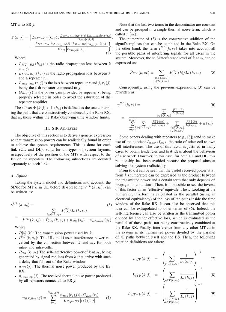
Because of the scenario structure, one of the first parametersto evaluate is the MT’s transmission power as a function ofthe distance to the BS. From Fig. 2, it can be seen thatall curves show an expected upwards trend in the requiredtransmission power as the MT gets farther away from theBS and enters the repeater’s area of influence. By comparingcases, one can observe that differences with respect to thefull MRC approach reach up to 3 dB for the case of arepeater with 9 or 11 μs delay, because the path from theBS is out of the Rake time window (20 μs). This implies twofacts: first, it puts in evidence the presence of a term of self-
13.5
14.5
15.5
16.5
17.5
3 4 5 6 7
Distance to the BS [km]
Aver
age
tx p
ower
[dBm
]
11 us9 us7 us5 usSELMRC
Fig. 2. UL transmission power as a function of the distance to the donorBS, for classical approaches and different internal delays at the repeater.
interference that causes an increase of the transmission power;second, in this situation, fewer paths can be combined, andtherefore the attenuation suffered by the MT is greater thanthe one measured in a full MRC case. The percentage of areain which all the paths cannot be constructively combined isdirectly proportional to the repeater internal delay, therefore,the degradation observed with respect to the too optimisticclassical consideration will also increase. Notice that with aninternal repeater delay of 5 μs, there are very few areas inwhich all the paths cannot be combined, hence, results arevery similar to the full MRC case. For distances over 7 km,we can show that the error obtained when using a classicalapproach keeps reducing until reaching a constant value of1.5 dB. Under some circumstances, inaccuracies of this ordermay not be tolerable.
On the other hand, if just the best path is considered (SELcase) and the repeater had an internal delay of 5 μs, an erroraround 2 dB occurs by the approximated analysis along 1 km.The SEL curve tends to the MRC case when the MT is close tothe BS. This behaviour is coherent, since the propagation paththrough the repeater is more than 10 dB below than that ofthe path through the BS, therefore, this signal contribution canbe considered negligible. Conversely, when the MT reachesthe repeater and continues moving away from the BS, thecurve tends to the 9 μs case. The curve does not tend to the11 μs case because the SEL approximation only considersone path, the others not being taken into account, and thennot generating any kind of interference. Between these twoclear areas, the results are more or less accurate depending onthe internal delay of the repeater and the actual possibility ofsome signal replicas to be out of the Rake window.
Considering that all MTs have a maximum available trans-mission power (21 dBm-Table I- in our scenario), the previousreasoning induces to think that there are also important differ-ences in the prevision of the percentage of users not reachingtheir Eb/N0 target (degraded users) between the classicalapproaches and the proposed analysis. Some results for thisevaluation are shown in Table II, which actually shows themean percentage of correctly served users. These values are
3436 IEEE TRANSACTIONS ON WIRELESS COMMUNICATIONS, VOL. 6, NO. 9, SEPTEMBER 2007
TABLE II
EVOLUTION OF CORRECTLY SERVED USERS FOR CLASSICAL
APPROACHES AND DIFFERENT INTERNAL DELAYS AT THE REPEATER
Classical Approach / Internal Delay Users [%]
MRC 95.3
SEL 94.4
5 μs 93.9
7 μs 93.0
9 μs 89.5
11 μs 86.1
obtained after analyzing all MTs at the end of each simulatedsnapshot. According to the full MRC or SEL approximations,around 95 % of users can be correctly served, which is atypical design constraint. However, this value is reduced to86 % when the repeater has an internal delay of 11 μs.Therefore, the optimistic result may lead to accept as goodan inappropriate system design when not using the proposedanalysis. The differences are always higher with respect to theMRC approach, which is the most optimistic as it considersthat all paths are always constructively combined. Even witha repeater with very low internal delay (5 μs) a difference of1.4 % of users arises.
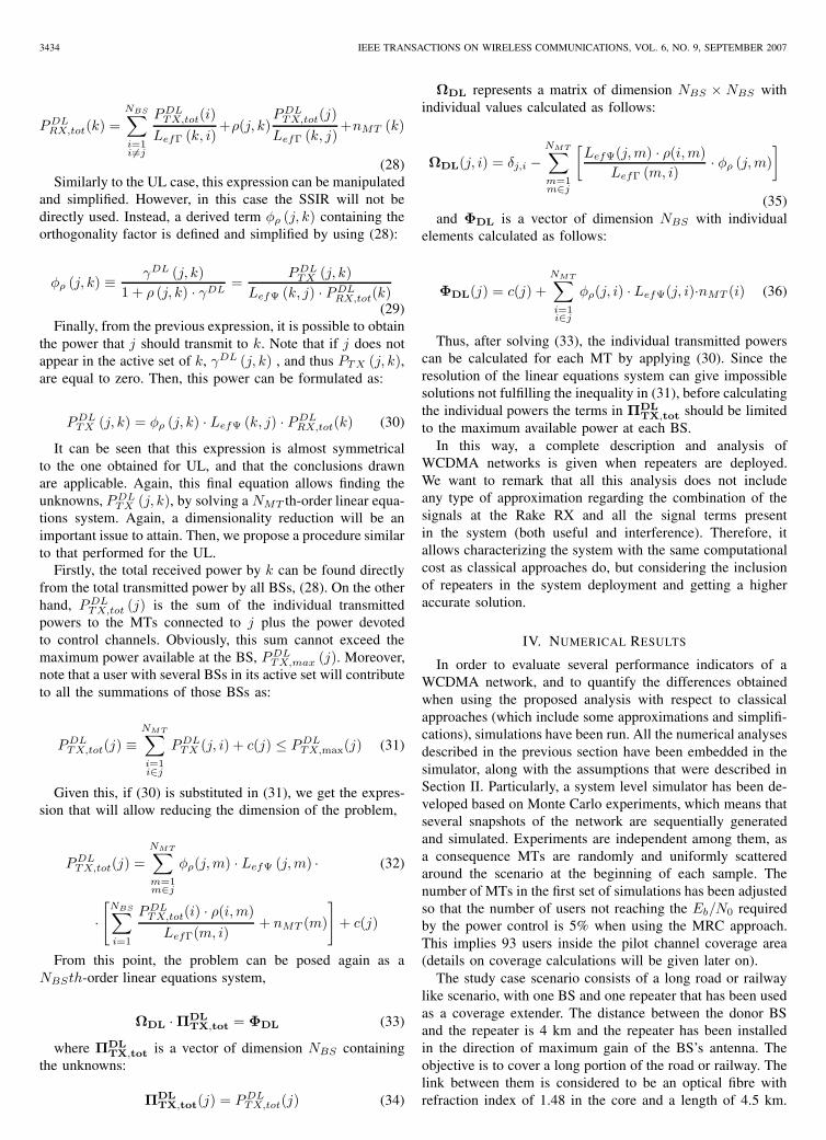
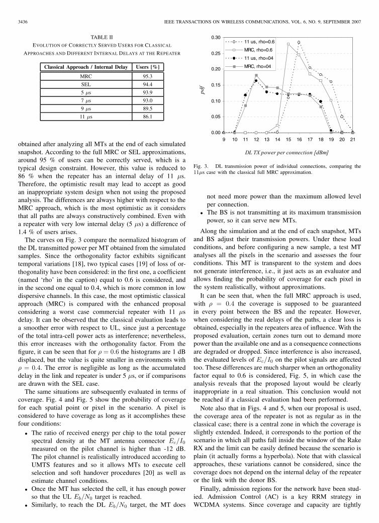
The curves on Fig. 3 compare the normalized histogram ofthe DL transmitted power per MT obtained from the simulatedsamples. Since the orthogonality factor exhibits significanttemporal variations [18], two typical cases [19] of loss of or-thogonality have been considered: in the first one, a coefficient(named ‘rho’ in the caption) equal to 0.6 is considered, andin the second one equal to 0.4, which is more common in lowdispersive channels. In this case, the most optimistic classicalapproach (MRC) is compared with the enhanced proposalconsidering a worst case commercial repeater with 11 μsdelay. It can be observed that the classical evaluation leads toa smoother error with respect to UL, since just a percentageof the total intra-cell power acts as interference; nevertheless,this error increases with the orthogonality factor. From thefigure, it can be seen that for ρ = 0.6 the histograms are 1 dBdisplaced, but the value is quite smaller in environments withρ = 0.4. The error is negligible as long as the accumulateddelay in the link and repeater is under 5 μs, or if comparisonsare drawn with the SEL case.
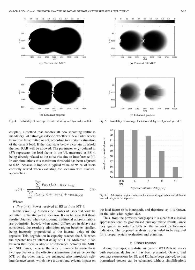
The same situations are subsequently evaluated in terms ofcoverage. Fig. 4 and Fig. 5 show the probability of coveragefor each spatial point or pixel in the scenario. A pixel isconsidered to have coverage as long as it accomplishes thesefour conditions:
• The ratio of received energy per chip to the total powerspectral density at the MT antenna connector Ec/I0
measured on the pilot channel is higher than -12 dB.The pilot channel is realistically introduced according toUMTS features and so it allows MTs to execute cellselection and soft handover procedures [20] as well asestimate channel conditions.
• Once the MT has selected the cell, it has enough powerso that the UL Eb/N0 target is reached.
• Similarly, to reach the DL Eb/N0 target, the MT does
0.00
0.05
0.10
0.15
0.20
0.25
0.30
9 10 11 12 13 14 15 16 17 18 19 20 21
DL TX power per connection [dBm]
11 us, rho=0.6
MRC, rho=0.6
11 us, rho=04
MRC, rho=04
Fig. 3. DL transmission power of individual connections, comparing the11μs case with the classical full MRC approximation.
not need more power than the maximum allowed levelper connection.
• The BS is not transmitting at its maximum transmissionpower, so it can serve new MTs.
Along the simulation and at the end of each snapshot, MTsand BS adjust their transmission powers. Under these loadconditions, and before configuring a new sample, a test MTanalyses all the pixels in the scenario and assesses the fourconditions. This MT is transparent to the system and doesnot generate interference, i.e., it just acts as an evaluator andallows finding the probability of coverage for each pixel inthe system realistically, without approximations.
It can be seen that, when the full MRC approach is used,with ρ = 0.4 the coverage is supposed to be guaranteedin every point between the BS and the repeater. However,when considering the real delays of the paths, a clear loss isobtained, especially in the repeaters area of influence. With theproposed evaluation, certain zones turn out to demand morepower than the available one and as a consequence connectionsare degraded or dropped. Since interference is also increased,the evaluated levels of Ec/I0 on the pilot signals are affectedtoo. These differences are much sharper when an orthogonalityfactor equal to 0.6 is considered, Fig. 5, in which case theanalysis reveals that the proposed layout would be clearlyinappropriate in a real situation. This conclusion would notbe reached if a classical evaluation had been performed.
Note also that in Figs. 4 and 5, when our proposal is used,the coverage area of the repeater is not as regular as in theclassical case; there is a central zone in which the coverage isslightly extended. Indeed, it corresponds to the portion of thescenario in which all paths fall inside the window of the RakeRX and the limit can be easily defined because the scenario isplain (it actually forms a hyperbola). Note that with classicalapproaches, these variations cannot be considered, since thecoverage does not depend on the internal delay of the repeateror the link with the donor BS.
Finally, admission regions for the network have been stud-ied. Admission Control (AC) is a key RRM strategy inWCDMA systems. Since coverage and capacity are tightly
GARCIA-LOZANO et al.: ENHANCED ANALYSIS OF WCDMA NETWORKS WITH REPEATERS DEPLOYMENT 3437
x [m]
y [m
]
1250 2500 3750 5000 6250 7500 8750 10000
500
1000
1500
2000
0 0.1 0.2 0.3 0.4 0.5 0.6 0.7 0.8 0.9 1
(a) Classical full MRC
x [m]
y [m
]
1250 2500 3750 5000 6250 7500 8750 10000
500
1000
1500
2000
(b) Enhanced proposal
Fig. 4. Probability of coverage for internal delay = 11μs and ρ = 0.4.
coupled, a method that handles all new incoming traffic ismandatory. AC strategies decide whether a new radio accessbearer can be admitted or not, according to a certain estimationof the current load. If the load stays below a certain thresholdthe new RAB will be allowed. The parameter η (j) defined in(37) represents the load factor in the UL measured at BS j,being directly related to the noise rise due to interference [4].In our simulations this maximum threshold has been adjustedto 0.85, because it implies a typical value of 95 % of userscorrectly served when evaluating the scenario with classicalapproaches.
η (j) =
NMT∑i=1
PRX (j, i) + nRX,Rep(j)
NMT∑i=1
PRX (j, i) + nBS (j) + nRX,Rep(j)
(37)
Where:• PRX (j, i): Power received at BS m from MT i.In this sense, Fig. 6 shows the number of users that could be
admitted in the study-case scenario. It can be seen that thoseresults obtained when considering traditional approximationsare optimistic. Indeed, when actual differences in delays areconsidered, the resulting admission region becomes smaller,being inversely proportional to the internal delay of therepeater. This degradation in capacity reaches the 8 % whenthe repeater has an internal delay of 11 μs. Moreover, it canbe seen that there is almost no difference between the MRCand SEL cases, because the only difference between thesetwo approaches is the effective attenuation that perceives theMT; on the other hand, the enhanced also introduces self-interference terms, which have a direct and evident impact on
x [m]
y [m
]
1250 2500 3750 5000 6250 7500 8750 10000
500
1000
1500
2000
0 0.1 0.2 0.3 0.4 0.5 0.6 0.7 0.8 0.9 1
(a) Classical full MRC
x [m]y
[m]
1250 2500 3750 5000 6250 7500 8750 10000
500
1000
1500
2000
(b) Enhanced proposal
Fig. 5. Probability of coverage for internal delay = 11μs and ρ = 0.6.
84
85
86
87
88
89
90
91
92
93
MRCSEL
5 7 9 11
Repeater internal delay [us]
Num
ber o
f adm
itted
use
rs
Fig. 6. Admission region evolution for classical approaches and differentinternal delays at the repeater.
the load factor (it is increased), and therefore, as it is shown,on the admission region size.
Thus, from the previous paragraphs it is clear that classicalapproaches tend to give biased and optimistic results, sincethey ignore important effects on the network performanceindicators. The proposed analysis is concluded to be requiredfor a proper system evaluation and planning.
V. CONCLUSIONS
Along this paper, a realistic analysis of WCDMA networkswith repeaters deployment has been presented. Generic andcompact expressions for UL and DL have been derived, so thattransmitted powers can be calculated without simplifications

3438 IEEE TRANSACTIONS ON WIRELESS COMMUNICATIONS, VOL. 6, NO. 9, SEPTEMBER 2007
and the effect of interference generated by signal replicas withsuch a delay that fall out of the Rake RX window has beenconsidered realistically. In our mathematical approach, afterdefining different sets of mean propagation losses, effectiveequivalent losses have been introduced, allowing obtainingmore compact and generic expressions. Similarly, for the samepurpose, the SSIR in the UL and a derived term in theDL considering the ρ factor have been introduced so thatthe problem has been able to be posed as an NMT th-orderlinear equations system. However, thanks to the relationshipsbetween PTX and PTX,tot (for the UL and DL) a dimensionreduction of the power control problem has been attained andhas allowed its resolution with the same computational costas in basic WCDMA systems. Moreover, solving the obtainedequations systems is independent of the number of repeatersand, therefore, the proposed approach does not introduce newextra computational cost. The proposal considers realisticallythe paths delays and the finite duration of the time windowin Rake RXs, which is why more accurate metrics can beobtained from a system level viewpoint.
Furthermore, with the help of numerical simulations, onehas tested which are the major differences between the re-sults obtained by the proposed analysis and the ones bythe classical approaches. Different performance indicators ofWCDMA networks have been studied, being shown thatclassical approximations lead to unrealistic and too optimisticresults. This, for example, could lead to accept bad plannednetworks as good designs. UL and DL transmitted powershave been evaluated, UL being the most affected link interms of transmitted power with differences up to 3 dB.Because of the use of orthogonal codes, the differences inDL with respect to the classical approaches are smoothed, butespecially higher accurate metrics are obtained in scenarioswith high loss of orthogonality. The previsions on the numberof non degraded mode users in the network would be also quiteoptimistic when classical approaches are used; in our examplethis value evolved from 95 % to 86 % when using the proposedmethod. Important reductions of coverage have been observedwhen the realistic behavior of the paths is considered. Finally,admission regions have been also compared, showing, onemore time, that traditional approximations lead to inadequatetoo optimistic results. In the simulated layout, reductions inthe number of admitted users can reach 8 % when the analysisis done with the presented proposal.
Therefore, we conclude that the proposed analysis is ahighly useful tool to plan and manage WCDMA networksthat include the presence of repeaters.
REFERENCES
[1] M. Rahman and P. Ernstrom, “Repeaters for hotspot capacity in DS-CDMA networks,” IEEE Trans. Veh. Technol., vol. 53, no. 3, pp. 626–633, May 2004.
[2] E. Gago and L. Cucala, “Radio on fibre systems for practical 2G and3G deployment,” COST 273, Athens (Greece), Tech. Rep. available asTD(04)001, Jan. 2004.
[3] M. Garcia-Lozano, L. Alonso, F. Casadevall, and S. Ruiz, “Capacityand coverage tradeoff in WCDMA environments with repeaters deploy-ment,” Wireless Pers. Commun., vol. 40, no. 3, pp. 329–342, 2007.
[4] H. Holma and A. Toskala, WCDMA for UMTS Radio Access for ThirdGeneration Mobile Communications, 2nd ed. Chichester, UK: JohnWiley & Sons, 2002.
[5] J. Zander, “Performance of optimum transmitter power control incellular radio systems,” IEEE Trans. Veh. Technol., vol. 41, no. 1, pp.57–62, Feb. 1992.
[6] S. Jafar and A. Goldsmith, “Adaptive multirate CDMA for uplinkthroughput maximization,” IEEE Trans. Wireless Commun., vol. 2, no. 2,pp. 218–228, Mar. 2003.
[7] A. Baier, U. Fiebig, W. Granzow, W. Koch, P. Teder, and J. Thielecke,“Design study for a CDMA-based third-generation mobile radio sys-tem,” IEEE J. Select. Areas Commun., vol. 12, no. 4, pp. 733–743, May1994.
[8] W. Lee and D. Lee, “The impact of repeaters on CDMA systemperformance,” in Proc. IEEE 51st Veh. Technol. Conf. (VTC 2000-Spring), May 2000, pp. 1763–1767.
[9] M. Patwary, P. Rapajic, and I. Oppermann, “Capacity and coverageincrease with repeaters in UMTS urban cellular mobile communicationenvironment,” IEEE Trans. Commun., vol. 53, no. 10, pp. 1620–1624,Oct. 2005.
[10] W. Choi, Y. Cho, and T. Ban, “Automatic on-off switching repeater forDS/CDMA reverse link capacity improvement,” IEEE Commun. Lett.,vol. 5, no. 4, pp. 138–141, Apr. 2001.
[11] K. Jeong, J. Cheong, T. Park, T. Kim, and S. Park, “Performance analysisof DS-CDMA reverse link with fiber-optics repeaters,” in Proc. IEEE51st Veh. Technol. Conf. (VTC 2000-Spring), May 2000, pp. 2439–2443.
[12] TR 25.956 (Release4) - UTRA Repeaters Planning Guidelines andSystem Analysis, 3GPP Specification [Online]. Available: http://www.3gpp.org/
[13] J. Laiho, A. Wacker, and T. Novosad, Radio Network Planning andOptimisation for UMTS, 2nd ed. Chichester, UK: John Wiley & Sons,2006.
[14] S. Handly, “Congestion measures in DS-CDMA networks,” IEEE Trans.Commun., vol. 47, no. 3, pp. 426–437, Mar. 1999.
[15] L. Mendo and J. Hernando, “On dimension reduction for the powercontrol problem,” IEEE Trans. Commun., vol. 49, no. 2, pp. 243–248,Feb. 2001.
[16] E. Damoso and L. M. Correia, “COST 231 Final Report - DigitalMobile Radio: Evolution Towards Future Generation Systems,” COSTSecretariat, Brussels (Belgium), Tech. Rep., 1999.
[17] Kathrein website, 2006 [Online]. Available: http://www.kathrein.de/
[18] N. Mehta, L. Greenstein, T. Willis, and Z. Kostic, “Analysis andresults for the orthogonality factor in WCDMA downlinks,” IEEE Trans.Wireless Commun., vol. 2, no. 6, pp. 1138–1149, Nov. 2003.
[19] N. Mehta, A. Molisch, and L. Greenstein, “Orthogonality factor inWCDMA downlinks in urban macrocellular environments,” in Proc.IEEE Global Telecommun. Conf. (GLOBECOM 2005), Nov./Dec. 2005,vol. 6.
[20] TS 25.133 (Release5) - Requirement for Support of Radio ResourceManagement (FDD), 3GPP Specification [Online]. Available: http://www.3gpp.org/
Mario Garcia-Lozano received the Degree inTelecommunications Engineering from the Techni-cal University of Catalonia (UPC), Spain, in 2001.Currently, he is working toward the Ph.D. degreein Telecommunications Engineering. From 1999 to2002 he was a member of the technical staff atRetevision, Spain, where he worked on the designand development of LMDS networks. In 2002 hejoined the Department of Signal Theory and Com-munications at UPC, where he worked as a ResearchAssistant until 2003 under a grant from the Catalan
Government. He currently lectures at the Castelldefels School of Technol-ogy (EPSC-UPC). He has actively participated in several research projects,funded by the European Union, the Spanish and Catalan Governments, andprivate companies. His research activities are focused in the field of mobilecommunication systems, especially radio network planning and radio resourcemanagement issues and optimization of cellular networks.

GARCIA-LOZANO et al.: ENHANCED ANALYSIS OF WCDMA NETWORKS WITH REPEATERS DEPLOYMENT 3439
Luis Alonso (M’99) received the Engineer ofTelecommunications degree from the Technical Uni-versity of Catalonia (UPC), Spain, in 1997. In 1998he joined the School of Telecommunications Engi-neering of Barcelona (ETSETB), Spain. He receivedthe Ph.D. in Telecommunications Engineering fromthe Technical University of Catalonia (UPC) in2001. The same year, he moved to the Castellde-fels School of Technology (EPSC-UPC), Spain, inanother campus within the same university, where hegot a lecturer position while working in the Radio
Communications Research Group of the Department of Signal Theory andCommunications. In the beginning of 2006, he has reached a permanenttenured position in the university, becoming an Associate Professor (ProfesorTitular). He has participated in several research programs, networks of excel-lence, COST actions, and integrated projects funded by the European Unionand the Spanish Government, always working on the design and analysisof different mechanisms and techniques to improve wireless communicationssystems. He has also collaborated with some telecommunications companiesas Telefónica, Alcatel, and Sener, working as a consultant for several researchprojects. He has also supervised a great number of masters theses, some ofthem developed by students working in companies such as Tradia, Orange, orEricsson. He is currently the Project Coordinator of a Marie Curie Transferof Knowledge Action (funded by the European Union) in collaboration withINA, a Greek Research Institute, and he is also the Scientific in Charge ofa three-year research project funded by the Spanish Ministry of Science andTechnology. His current research interests are within the fields of mediumaccess protocols, radio resource management, cross-layer optimization, andQoS features for all kinds of wireless communications systems.
Fernando J. Casadevall (M’86) received the En-gineer of Telecommunication and Dr. Engineeringdegrees from the Technical University of Catalonia(UPC), Spain, in 1977 and 1983 respectively. In1978 he joined UPC, where he was an AssociateProfessor from 1983 to 1991. He is currently FullProfessor in the Signal Theory and CommunicationsDepartment. After graduation he was concernedwith equalisation techniques for digital fibre opticsystems. He has also been working in the field ofdigital communications with particular emphasis on
digital radio and its performance under multipath propagation conditions. Inthe last fifteen years, he has mainly been concerned with the performanceanalysis and development of digital mobile radio systems. In particular,his research interests include cellular and personal communication systems,multipath transceiver design (including Software Radio techniques), Mobilityand Radio Resources Management, and End-to-End QoS issues. During thelast ten years he participated in more than thirty research projects funded byboth public and private organizations. In particular, he actively participatedin ten research projects founded by the European Commission, being theProject Manager of three of them: ARROWS, EVEREST and AROMA.(See http://www.gcr.tsc.upc.edu for details.) Prof. Casadevall has publishedaround one hundred technical papers in both international conferences andmagazines; most of them correspond to IEEE publications. He has alsobeen a Technical Program Committee member of different international IEEEsupported conferences, as well as a reviewer of several IEEE magazines.From October 1992 to January 1996 he was responsible for the InformationTechnology Area in the National Agency for Evaluation and Forecasting(Spanish Nation Research Council).
Silvia Ruiz (M’86) received the Engineer and Doc-tor Engineer degrees in telecommunication from theTechnical University of Catalonia (UPC), Spain, in1986 and 1989 respectively. She joined the SignalTheory and Communications Department, becomingAssociate Professor in 1992. She has participated inseveral UE projects, COST actions, and Network ofExcellence projects, as well as in projects fundedby the Spanish government and private companies(Alcatel, Vodafone. Telefónica Móviles, etc.) Shehas also strongly collaborated in university manage-
ment issues and has been Vice-Dean of Academic Affairs for three years,and Assistant Director of External Relations of the Castelldefels School ofTechnology (EPSC-UPC) since December 2005. Her research interests are inthe field of mobile communication systems, especially radio network planningissues and optimization of 3G and heterogeneous networks.
Luis M. Correia (S’85-M’91-SM’03) was born inPortimao, Portugal, in October 1958. He receivedthe Ph.D. in Electrical and Computer Engineer-ing from IST-TUL (Technical University of Lis-bon) in 1991, where he is currently a Professor inTelecommunications, with his work focused in wire-less/mobile communications in the areas of prop-agation, channel characterisation, radio networks,traffic, and services. He has acted as a consultantfor Portuguese GSM operators and the telecommu-nications regulator. Besides being responsible for
research projects at the national level, he has been active in various ones withinEuropean frameworks (RACE, ACTS, IST, and COST). He participated in andwas co-editor of the Final Report for COST 231, and Chairman and Editor ofthe Final Reports of COST 259 and COST 273. He was and is responsible forthe supervision of students at both the M.Sc. and Ph.D. levels, having authoredmany papers and communications in international journals and conferences,for which he has served also as a reviewer, editor, and board member. He hasserved as evaluator and auditor in ACTS, ESPRIT, and IST frameworks. Hewas the Chairman of the Technical Programme Committee of PIMRC’2002.He is part of the Expert Advisory Group and of the Steering Board of theEuropean eMobility platform, and of the COST Domain Committee on ICT.