Repeaters - 3GPP2
70
© 2012 3GPP2 3GPP2 and its Organizational Partners claim copyright in this document and individual Organizational Partners may copyright and issue documents or standards publications in individual Organizational Partner's name based on this document. Requests for reproduction of this document should be directed to the 3GPP2 Secretariat at [email protected]. Requests to reproduce individual Organizational Partner's documents should be directed to that Organizational Partner. See www.3gpp2.org for more information. 3GPP2 C.S0051-A Version 1.0 April 2012 Recommended Minimum Performance Standards for cdma2000 ® Repeaters
-
Upload
khangminh22 -
Category
Documents
-
view
1 -
download
0
Transcript of Repeaters - 3GPP2

© 2012 3GPP2 3GPP2 and its Organizational Partners claim copyright in this document and individual Organizational Partners may copyright and issue documents or standards publications in individual Organizational Partner's name based on this document. Requests for reproduction of this document should be directed to the 3GPP2 Secretariat at [email protected]. Requests to reproduce individual Organizational Partner's documents should be directed to that Organizational Partner. See www.3gpp2.org for more information.
3GPP2 C.S0051-A Version 1.0 April 2012
Recommended Minimum Performance Standards for cdma2000® Repeaters

3GPP2 C.S0051-A v1.0
Revision History
Revision Description of Changes Date
Rev 0 v1.0 Initial publication February 2006
Rev A v1.0 Added Japan Radio Law related changes, including BC6 emission, BC3 disband, and BC0 subclasses 2,3
April 2012

3GPP2 C.S0051-A v1.0
CONTENTS
i
FOREWORD .................................................................................................................... vii
NOTES ........................................................................................................................... viii
1 INTRODUCTION .......................................................................................................... 1-1
1.1 Scope .................................................................................................................... 1-1
1.2 Terms and Definitions ........................................................................................... 1-1
1.3 References ............................................................................................................. 1-3
2 CDMA INPUT PORTS MINIMUM STANDARDS ............................................................. 2-1
2.1 Frequency Coverage Requirements ........................................................................ 2-1
2.1.1 Definition ......................................................................................................... 2-1
2.1.2 Method of Measurement .................................................................................. 2-1
2.1.3 Minimum Standard ......................................................................................... 2-3
2.2 Input Sensitivity .................................................................................................... 2-4
2.2.1 Definition ......................................................................................................... 2-4
2.2.2 Method of Measurement .................................................................................. 2-4
2.2.3 Minimum Standard ......................................................................................... 2-5
2.3 Single Tone Desensitization ................................................................................... 2-5
2.3.1 Definition ......................................................................................................... 2-5
2.3.2 Method of Measurement .................................................................................. 2-5
2.3.3 Minimum Standard ......................................................................................... 2-7
2.4 Input Intermodulation ........................................................................................... 2-8
2.4.1 Definition ......................................................................................................... 2-8
2.4.2 Method of Measurement .................................................................................. 2-8
2.4.3 Minimum Standard ....................................................................................... 2-10
3 CDMA OUTPUT PORTS MINIMUM STANDARDS .......................................................... 3-1
3.1 Frequency Tolerance ............................................................................................. 3-1
3.1.1 Definition ......................................................................................................... 3-1
3.1.2 Method of Measurement .................................................................................. 3-1
3.1.3 Minimum Standard ......................................................................................... 3-1
3.2 Waveform Quality .................................................................................................. 3-2
3.2.1 Definition ......................................................................................................... 3-2
3.2.2 Method of Measurement .................................................................................. 3-2

3GPP2 C.S0051-A v1.0
CONTENTS
ii
3.2.3 Minimum Standard ......................................................................................... 3-2
3.3 Repeater Gain and Coupling Loss ......................................................................... 3-3
3.3.1 Definition ........................................................................................................ 3-3
3.3.2 Method of Measurement .................................................................................. 3-3
3.3.3 Minimum Standard ......................................................................................... 3-3
3.4 Output Power, Linearity and Overload ................................................................... 3-3
3.4.1 Definition ........................................................................................................ 3-3
3.4.2 Method of Measurement .................................................................................. 3-3
3.4.3 Minimum Standard ......................................................................................... 3-5
3.5 Output Intermodulation ........................................................................................ 3-6
3.5.1 Definition ........................................................................................................ 3-6
3.5.2 Method of Measurement .................................................................................. 3-6
3.5.3 Minimum Standard ......................................................................................... 3-7
3.6 Out-of-Band and Spurious Emissions ................................................................... 3-7
3.6.1 Receiver Conducted Spurious Emissions ......................................................... 3-8
3.6.2 Out-of-Band and Spurious Emissions ............................................................. 3-8
3.6.3 Transmitter Conducted Spurious Emissions ................................................... 3-8
3.6.3.1 Definition .................................................................................................. 3-8
3.6.3.2 Method of Measurement ............................................................................ 3-8
3.6.3.3 Minimum Standard ................................................................................... 3-9
3.6.4 Radiated Emissions ....................................................................................... 3-10
3.6.4.1 Definition ................................................................................................ 3-10
3.6.4.2 Method of Measurement .......................................................................... 3-10
3.6.4.3 Minimum Standard ................................................................................. 3-14
3.6.5 AC Power Line Conducted Emissions ............................................................ 3-15
3.6.5.1 Definition ................................................................................................ 3-15
3.6.5.2 Method of Measurement .......................................................................... 3-15
3.6.5.3 Minimum Standard ................................................................................. 3-16
3.7 Repeater Delay .................................................................................................... 3-17
3.7.1 Definition ...................................................................................................... 3-17
3.7.2 Method of Measurement ................................................................................ 3-17
3.7.3 Minimum Standard ....................................................................................... 3-17

3GPP2 C.S0051-A v1.0
CONTENTS
iii
3.8 Exposure of Humans to RF Fields ....................................................................... 3-17
4 CDMA GENERAL REQUIREMENTS ............................................................................. 4-1
4.1 Extreme Test Environment .................................................................................... 4-1
4.1.1 Definition ......................................................................................................... 4-1
4.1.2 Method of Measurement .................................................................................. 4-1
4.1.3 Minimum Standard ......................................................................................... 4-2
4.2 Vibration ............................................................................................................... 4-3
4.2.1 Definition ......................................................................................................... 4-3
4.2.2 Method of Measurement .................................................................................. 4-4
4.2.3 Minimum Standard ......................................................................................... 4-4
5 CDMA STANDARD TEST CONDITIONS ....................................................................... 5-1
5.1 Test Environment .................................................................................................. 5-1
5.1.1 Definition ......................................................................................................... 5-1
5.1.2 Standard Test Environment ............................................................................. 5-1
5.2 General Testing Requirements ............................................................................... 5-1
5.2.1 Operational Requirements ............................................................................... 5-1
5.2.2 Adjustable Passband Span .............................................................................. 5-2
5.2.3 Adjustable Supported CDMA Channels ............................................................ 5-2
5.2.4 Maximum Number of Supported Carriers in a Passband ................................. 5-2
5.2.5 Output Power .................................................................................................. 5-2
5.2.5.1 Manufacturer Rates Maximum Output Power per Passband: ..................... 5-2
5.2.5.2 Manufacturer Does Not Rate Maximum Output Power per Passband: ........ 5-2
6 TEST DIAGRAMS ........................................................................................................ 6-1
6.1 Test Configurations ............................................................................................... 6-1
6.2 CDMA Test Signal Definition ................................................................................. 6-6
6.3 Technical Requirements for the Test Equipment .................................................... 6-6
6.3.1 Rho Meter ........................................................................................................ 6-6
6.3.2 CW Generator .................................................................................................. 6-8
6.3.3 Spectrum Analyzer .......................................................................................... 6-9
6.3.4 Average Power Meter ...................................................................................... 6-10
6.3.5 RF Output Load ............................................................................................. 6-10
7 OUTPUT PORTS CONDUCTED EMISSIONS LIMITS ..................................................... 7-1

3GPP2 C.S0051-A v1.0
CONTENTS
iv
7.1 Limits for Band Class 0, 2, 5, 7, 9 and 10 ............................................................. 7-1
7.2 Limits for Band Class 1, 4, 6, 8, 14 and 15 ........................................................... 7-3
7.3 Limits for Band Class 3 ......................................................................................... 7-5
7.4 Additional Limits for Band Class 6 ........................................................................ 7-7
7.5 Limits for Band Class 11 and 12 ........................................................................... 7-9
7.6 Additional Limits for Band Class 10 .................................................................... 7-10

3GPP2 C.S0051-A v1.0
FIGURES
v
Figure 6.1-1 Frequency Coverage Test Diagram .............................................................. 6-1 1
Figure 6.1-2 Input Sensitivity Test Diagram ................................................................... 6-1 2
Figure 6.1-3 Single Tone Desensitization Test Diagram .................................................. 6-2 3
Figure 6.1-4 Input Intermodulation Test Diagram .......................................................... 6-2 4
Figure 6.1-5 Frequency Tolerance Test Diagram ............................................................. 6-3 5
Figure 6.1-6 Waveform Quality Test Diagram ................................................................. 6-3 6
Figure 6.1-7 Output Power, Linearity and Overload Test Diagram .................................. 6-4 7
Figure 6.1-8 Output Intermodulation Test Diagram ....................................................... 6-4 8
Figure 6.1-9 Output Ports Conducted Spurious Emissions Test Diagram ....................... 6-5 9
Figure 6.1-10 Repeater Delay ......................................................................................... 6-5 10
11

3GPP2 C.S0051-A v1.0
TABLES
vi
Table 2.1-1 Upper Attenuation and Gain Measurement Intervals ................................... 2-2 1
Table 2.1-2 Lower Attenuation and Gain Measurement Intervals ................................... 2-2 2
Table 2.1-3 Filter Requirements ..................................................................................... 2-4 3
Table 2.2-1 Required Repeater Noise Figure ................................................................... 2-5 4
Table 2.4-1 Input Intermodulation Test Parameters ....................................................... 2-8 5
Table 2.4-2 Frequencies levels for deployment-based input intermodulation tests ....... 2-10 6
Table 3.4-1 Repeater Mean Output Power Per Carrier; Input Overload Test 7
Conditions ............................................................................................................... 3-6 8
Table 3.4-2 Repeater Mean Output Power Per Carrier; Extreme Test Conditions ............ 3-6 9
Table 3.6-1 Maximum Allowable Radiated Spurious Emissions for Band Classes 0, 10
1, 7, 10, 14 and 15 ................................................................................................. 3-14 11
Table 3.6-2 Maximum Allowable Radiated Spurious Emissions for Band Classes 2, 12
3, 4, 5, 6, 8, 9, 11 and 12 ....................................................................................... 3-14 13
Table 4.1-1 Extreme Environmental Requirements ........................................................ 4-3 14
Table 5.1-1 Limits of conditions for Standard Test Environment .................................... 5-1 15
Table 6.2-1 CDMA Signal Waveform Requirements ........................................................ 6-6 16
Table 6.3-1 Accuracy of Waveform Quality Measurement Equipment ............................. 6-8 17
Table 7.1-1 Band Class 0, 2, 5, 7, 9, and 10 Spurious Emission Limits ......................... 7-2 18
Table 7.2-1 Band Class 1, 4, 6, 8, 14 and 15 Spurious Emission Limits ........................ 7-4 19
Table 7.3-1 Band Class 3 Spurious Emissions Limits .................................................... 7-6 20
Table 7.4-1 Additional Band Class 6 Forward Link Spurious Emission Limits................ 7-7 21
Table 7.4-2 Additional Band Class 6 Reverse Link Spurious Emission Limits ................ 7-8 22
Table 7.5-1 Band Class 11 and 12 Spurious Emission Limits ........................................ 7-9 23
Table 7.5-2 Additional Band Class 11 and 12 Reverse Link Spurious Emission Lim .... 7-10 24
Table 7.6-1 Additional Band Class 10 Spurious Emission Limits for North American 25
Operation ............................................................................................................... 7-10 26
27

3GPP2 C.S0051-A v1.0
vii
FOREWORD 1
(This foreword is not part of this Standard) 2
This Standard was prepared by Technical Specification Group C of the Third Generation 3
Partnership Project 2 (3GPP2). This Standard contains recommended minimum 4
performance standards for cdma2000®1 Repeaters. 5
6
1 cdma2000® is the trademark for the technical nomenclature for certain specifications and standards of the Organizational Partners (OPs) of 3GPP2. Geographically (and as of the date of publication), cdma2000® is a registered trademark of the Telecommunications Industry Association (TIA-USA) in the United States

3GPP2 C.S0051-A v1.0
viii
NOTES 1
1. This Standard uses the following verbal forms: “Shall” and “shall not” identify 2
requirements to be followed strictly to conform to the standard and from which no 3
deviation is permitted. “Should” and “should not” indicate that one of several 4
possibilities is recommended as particularly suitable, without mentioning or 5
excluding others; that a certain course of action is preferred but not necessarily 6
required; or that (in the negative form) a certain possibility or course of action is 7
discouraged but not prohibited. “May” and “need not” indicate a course of action 8
permissible within the limits of the Standard. “Can” and “cannot” are used for 9
statements of possibility and capability, whether material, physical, or causal. 10
2. Those wishing to deploy systems compliant with this Standard should also be 11
compliant with local radio regulations. For example, operation within the United 12
States of America shall comply with CFR 47, Parts 2, 15, 22, 24, and 27 of the Code 13
of Federal Regulations. 14
3. The following operators define mathematical operations: 15
indicates multiplication.• × 16
/ indicates division.• 17
indicates addition.• + 18
indicates subtraction.• − 19
* indicates complex conjugation.• 20
indicates the largest integer less than or equal to x: 1.1 1, 1.0 1.x• = = 21
indicates the absolute value of x: 17 17, 17 17.x• − = = 22
4. The Standard applies only to Band Classes 0, 1, 2, (Band Subclasses 0, 1, and 2), 3, 23
4, 5 (Band Subclasses 0 through 7), 6, 7, 8, 9, 10 (Band Subclasses 0 through 4), 24
11 (Band Subclasses 0 through 5), and 12 (Band Subclasses 0 and 1) as defined in 25
[3]. Operation with other band classes and band subclasses may not be supported 26
by this Standard. 27

3GPP2 C.S0051-A v1.0
1-1
1 INTRODUCTION 1
1.1 Scope 2
This Standard details definitions, methods of measurement, and minimum performance 3
requirements for Code Division Multiple Access (CDMA) repeaters. This Standard shares 4
the purpose of [2] and [4] (and subsequent revisions thereof) by ensuring that a mobile 5
station can obtain service in any system that meets the compatibility requirements of [2] 6
and [4]. 7
Compatibility, as used in connection with this Standard, [2] and [4], is understood to mean 8
that any mobile station is able to place and receive calls in any system. Conversely, all 9
systems are able to place and receive calls with any mobile station. 10
This Standard details definitions, methods of measurement, and minimum performance 11
requirements for Code Division Multiple Access (CDMA) Repeaters. Test methods are 12
recommended in this document; however, methods other than those recommended may 13
suffice for the same purpose. 14
1.2 Terms and Definitions 15
AGC. (Automatic Gain Control). A feature that automatically adjusts the gain of the 16
repeater based on changes to a signal level. 17
ALC. (Automatic Level Control). A feature that automatically adjusts the level of the 18
output signal of the repeater to compensate for changes in the input signal level. 19
Band Class. A set of frequency channels and a numbering scheme for these channels. 20
Base station. A fixed station used for communicating with mobile stations. Depending 21
upon the context, the term Base station may refer to a cell, a sector within a cell, an 22
MSC, an EV-DO Access Point or other part of the wireless system. 23
CDMA. (Code Division Multiple Access). A technique for spread-spectrum multiple-24
access digital communications that creates channels through the use of unique code 25
sequences. 26
CDMA Channel. The set of channels transmitted from the Base station and the mobile 27
stations on a given frequency. 28
CDMA Channel Bandwidth. The spacing between CDMA carriers necessary to support 29
the Spreading Rate of a CDMA signal, which follows the CDMA Frequency Assignment 30
Scheme for a given band class. 31
CDMA Channel Number. An 11-bit number corresponding to the center of the CDMA 32
frequency assignment. 33
CDMA Frequency Assignment. A 1.23 MHz segment of spectrum. For Band Class 0, 34
the channel is centered on one of the 30 KHz channels. For Band Classes 1, 4, 6, 7, 8, 35
9, and 10 the channel is centered on one of the 50 KHz channels. For Band Classes 2, 36
3, 11, and 12, the channel is centered on one of the 25 KHz channels. For Band Class 37
5, the channel is centered on one of the 20 or 25 KHz channels. 38

3GPP2 C.S0051-A v1.0
1-2
CDMA Preferred Set. The set of CDMA channel numbers in a CDMA system 1
corresponding to frequency assignments that a mobile station will normally search to 2
acquire a CDMA Pilot Channel. 3
CW. (Continuous Wave). A signal that can be mathematically described by a single 4
sinusoidal function. 5
dBc. The ratio (in dB) of the sideband power of a signal, measured in a given bandwidth 6
at a given frequency offset from the center frequency of the same signal, to the total in-7
band power of the signal. For CDMA, the total in-band power of the signal is measured 8
in the channel bandwidth around the center frequency of the CDMA signal 9
dBm. A measure of power expressed in terms of its ratio (in dB) to one milliwatt. 10
dBm/Hz. A measure of power spectral density. The ratio, dBm/Hz, is the power in one 11
Hertz of bandwidth, where power is expressed in units of dBm. 12
Donor Coupling Loss. The path loss, in dB, between the Base station that is supplying 13
the Forward link signal used in the repeater, and the repeater. This loss may be from 14
radiated or conducted mechanisms. 15
Doppler-Correcting Repeater. A repeater that attempts to remove or minimize the 16
shift in frequency occurring from motion of the repeater with respect to one or more 17
base stations. 18
Forward Link. A signal path transmitted from the base station to the mobile station. 19
Frequency-Translating Repeater. A repeater used for communicating with mobile 20
stations by receiving a Forward CDMA channel from a remote Base station and 21
retransmitting the signal with the same PN offset on a different frequency and receiving 22
a Reverse CDMA channel and retransmitting the signal on a different frequency for 23
reception at a remote Base station. 24
Mobile Station. A station intended to be used while in motion or during halts at 25
unspecified points. Mobile stations include portable units (e.g., hand-held personal 26
units) and units installed in vehicles. 27
Noise Figure. The ratio, in dB, of the total noise power in the output to the input noise 28
power when the input termination is at 290ºK, the gain of the repeater is accounted for 29
and the same bandwidth is used on the input and output. 30
= +-out inNF P P G 31
Where: 32
NF Noise Figure at the frequency under test, expressed in dB 33
outP Total noise power in the output, expressed in a dB power unit 34
inP Input noise power when the input termination is at 290K, expressed 35
in the same dB power unit used for inP 36
G Gain of the system at the frequency under test, expressed in dB 37

3GPP2 C.S0051-A v1.0
1-3
Non-Translating Repeater. A repeater used for communicating with mobile stations by 1
receiving a Forward CDMA channel from a remote Base station and retransmitting the 2
signal with the same PN offset and the same frequency and receiving a Reverse CDMA 3
channel and retransmitting the signal on the same frequency for reception at a remote 4
Base station. 5
Over the Air Repeater. A repeater using over the air (radiated) links with the base 6
station. 7
Passband. A continuous range of frequencies over which a repeater is designed to 8
operate such that it meets the requirements of operation detailed in this Standard. A 9
repeater may have more than one passband in a given signal path. 10
Pilot Ec/I0. The ratio, in dB, between the pilot energy accumulated over one PN chip 11
period (Ec) to the total power spectral density (I0) in the received bandwidth. 12
Port. An access location where radio frequency energy may be supplied or withdrawn 13
from the repeater. 14
Repeater. A device used for communicating with mobile stations by receiving a 15
Forward CDMA channel from a remote Base station and retransmitting the signal and 16
receiving a Reverse CDMA channel and retransmitting the signal for reception at a 17
remote Base station. A repeater can be a device that receives, amplifies and transmits 18
one or more radiated or conducted CDMA channels both in the Forward and Reverse 19
link directions. 20
Reverse Link. A signal path transmitted from the mobile station to the base station. 21
Rho (ρ). The Greek symbol used to represent a specific measurement of the quality of a 22
CDMA waveform. Full measurement test equipment details are given in [2]. 23
RMS. Root of Mean Square 24
Spreading Rate (SR). The PN chip rate of the Forward CDMA channel or the Reverse 25
CDMA Channel, defined as a multiple of 1.2288 Mcps. 26
Spreading Rate 1. Spreading Rate 1 is often referred to as “1X.” A Spreading Rate 1 27
Forward CDMA Channel uses a single direct-sequence spread carrier with a chip rate of 28
1.2288 Mcps. A Spreading Rate 1 Reverse CDMA Channel uses a single direct-sequence 29
spread carrier with a chip rate of 1.2288 Mcps. 30
1.3 References 31
Normative reference: 32
The following standards contain provisions which, through reference in this text, constitute 33
provisions of this Standard. At the time of publication, the editions indicated were valid. All 34
standards are subject to revision, and parties to agreements based on this Standard are 35
encouraged to investigate the possibility of applying the most recent editions of the 36
standards indicated below. ANSI and TIA maintain registers of currently valid national 37
standards published by them. 38
1. IEC 60068-2-6, Environmental testing - Part 2: Tests - Test Fc: Vibration (sinusoidal), 39
1995-03 (including Corr.1 (1995-03)). 40

3GPP2 C.S0051-A v1.0
1-4
2. 3GPP2 C.S0010-E, Recommended Minimum Performance Standards for cdma2000® 1
Spread Spectrum Base stations. 2
3. 3GPP2 C.S0057-E, Band Class Specification for cdma2000® Spread Spectrum 3
Systems. 4
4. 3GPP2 C.S0011-E, Recommended Minimum Performance Standards for cdma2000® 5
Spread Spectrum Mobile Stations. 6
5. 3GPP2 C.S0032-D, Recommended Minimum Performance Standards for cdma2000® 7
High Rate Packet Data Access Network 8
6. IEEE C63.4-2009, American National Standard for Methods of Measurement of 9
Radio–Noise Emissions from Low-Voltage Electrical and Electronic Equipment in the 10
Range of 9 kHz to 40 GHz, 2009. 11
7. CFR Title 47, Code of Federal Regulations, October 2005 12

3GPP2 C.S0051-A v1.0
2-1
2 CDMA INPUT PORTS MINIMUM STANDARDS 1
2.1 Frequency Coverage Requirements 2
2.1.1 Definition 3
Frequency coverage of the repeater is dependent upon the amplifiers and filtering 4
contained within the repeater. The intended use of a repeater in a system is to amplify the 5
in-band signals and not to amplify the out-of-band emissions of the donor Base station or 6
other ambient signals. 7
2.1.2 Method of Measurement 8
1. Connect the equipment as shown in Figure 6.1-1 for the Forward link signal path. 9
2. Configure the repeater to its maximum gain setting. If the repeater supports an 10
adjustable passband span or adjustable supported channels, see 5.2 for additional 11
test requirements. 12
3. Configure the signal generator at the repeater input port to produce a CW signal at 13
an amplitude approximately 5 dB below the level that would cause the maximum 14
rated mean output power from the repeater for the configured gain setting at the 15
center of its passband. 16
4. Sweep the signal generator from 30 MHz to at least 4 times the maximum operating 17
frequency of the repeater while recording the gain versus frequency response of the 18
repeater with a spectrum (or network) analyzer using a resolution bandwidth of 3.0 19
MHz. 20
5. Re-sweep the signal generator over all frequencies that are found to be 6 dB or more 21
above the noise floor of the spectrum (or network) analyzer in step 4 as follows. 22
Start the sweep at least 100 MHz below the lowest frequency from step 4 where the 23
recorded gain is 6 dB or more above the noise floor and sweep to at least 100 MHz 24
above the highest frequency from step 4 where the recorded gain is 6 dB or more 25
above the noise floor while recording the gain versus frequency response of the 26
repeater with a spectrum (or network) analyzer using a resolution bandwidth of 30 27
kHz. 28
6. Measure the minimum attenuation relative to the minimum gain in the passband 29
under test at frequency offsets from the highest supported CDMA channel center 30
frequency, using the data from 5, as detailed in Table 2.1-1. 31

3GPP2 C.S0051-A v1.0
2-2
Table 2.1-1 Upper Attenuation and Gain Measurement Intervals 1
For ∆f within the range
< 2.50 MHz to 3.75 MHz
< 3.75 MHz to 12.50 MHz
< 12.50 MHz to 50 MHz
< 50 MHz to 4 times the maximum operating
frequency of the repeater
2
7. Measure the minimum attenuation relative to the minimum gain in the passband 3
under test at frequency offsets from the lowest supported CDMA channel center 4
frequency, using the data from 5, as detailed in Table 2.1-2. 5
Table 2.1-2 Lower Attenuation and Gain Measurement Intervals 6
For ∆f within the range
< -2.50 MHz to -3.75 MHz
<-3.75 MHz to -12.50 MHz
<-12.50 MHz to -50 MHz
< -50 MHz
7
8. Measure the maximum gain at frequency offsets from the highest supported CDMA 8
channel center frequency in the passband under test, using the data from 5, as 9
detailed in Table 2.1-1. 10
9. Measure the maximum gain at frequency offsets from the lowest supported CDMA 11
channel center frequency in the passband under test, using the data from 5, as 12
detailed in Table 2.1-2. 13
10. Measure the minimum and maximum gain between 615 kHz below the lowest 14
supported channel center frequency and 615 KHz above the highest supported 15
channel center frequency in the passband under test, using the data from 5. 16
11. Repeat steps 3 through 9 for each passband supported by the repeater. (Each 17
passband is independently evaluated; i.e., gain from a passband that is not under 18
test is ignored.) 19
12. Repeat steps 3 through 11 for the Reverse link signal path of the repeater. 20
13. Repeat step 5 with the repeater configured to its minimum gain setting, except that 21
the sweep need only be preformed over the passbands identified during the 22
maximum gain measurements. Then repeat steps 10 through 12 using the gain 23
versus frequency response data recorded at minimum gain. 24

3GPP2 C.S0051-A v1.0
2-3
2.1.3 Minimum Standard 1
1. The manufacturer shall declare the CDMA channel numbers supported for each 2
passband in the repeater and these channels shall comply with the frequency 3
coverage requirements of [3]. 4
2. For each passband, the difference between the measured minimum and maximum 5
gain between 615 KHz below the center frequency of the lowest supported channel 6
and 615 KHz above the center frequency of the highest supported channel, as 7
measured in step 10, shall be no more than 6.0 dB. 8
3. The manufacturer shall declare the minimum and maximum gain for each repeater 9
passband. 10
4. The minimum gain, as measured when the repeater is set to its maximum gain 11
setting, in the passband under test, shall be no less than 4.0 dB below the 12
maximum gain rated by the manufacturer, for each passband. (Each passband is 13
independently evaluated (i.e., gain from a passband that is not under test is 14
ignored).) 15
5. The maximum gain, as measured when the repeater is set to its minimum gain 16
setting, in the passband under test, shall be no greater than 4.0 dB above the 17
minimum gain rated by the manufacturer, for each passband. (Each passband is 18
independently evaluated (i.e., gain from a passband that is not under test is 19
ignored).) 20
6. For passbands in which the maximum measured gain from 10 is more than 40 dB 21
when the repeater is set to the maximum gain setting of the repeater, shall comply 22
with the minimum attenuation limits in Table 2.1-3 as measured in 6 and 7, for 23
each passband. For passbands in which the maximum measured gain from 10 is 40 24
dB or less, when the repeater is set to the maximum gain setting of the repeater, 25
shall comply with the maximum gain limits in Table 2.1-3 as measured in 8 and 9, 26
for each passband. This requirement only applies at the repeaters maximum gain 27
setting. 28

3GPP2 C.S0051-A v1.0
2-4
Table 2.1-3 Filter Requirements 1
For |∆f| Within the Range Limits
Minimum Attenuation Maximum Gain
2.50 MHz to 3.75 MHz ≥ 40 dB ≤ 40 dB
3.75 MHz to 12.50 MHz ≥ 40 dB ≤ 35 dB
12.50 MHz to 50.00 MHz ≥ 40 dB ≤ 30 dB
> 50.00 MHz ≥ 40 dB ≤ -10 dB
Note: For passbands that only support a single channel: ∆f = center frequency of supported channel - measurement frequency (f). For passbands supporting two or more channels, ∆f is defined
• for positive ∆f as the center frequency of the highest supported channel - measurement frequency (f) and
• for negative ∆f as the center frequency of the lowest supported channel - measurement frequency (f).
The limits shall apply for all values of ∆f regardless of whether the measurement frequency falls inside or outside of the band or block.
2
2.2 Input Sensitivity 3
2.2.1 Definition 4
The repeater sensitivity is determined by its noise figure. 5
2.2.2 Method of Measurement 6
1. Connect the equipment as shown in Figure 6.1-2 for the Forward link signal path. 7
2. Configure the repeater to the maximum rated gain setting. If the repeater supports 8
an adjustable passband span or adjustable supported channels, see 5.2 for 9
additional test requirements. 10
3. Configure the noise measuring equipment and the filters to operate in the passband 11
under test and ensure that the input and output filters have the same bandwidth. 12
Ensure that the bandwidth used is fully contained in the passband under test. 13
4. Measure the noise figure of the repeater. 14
5. Configure the repeater to the minimum rated gain setting. If the repeater supports 15
an adjustable passband span or adjustable supported channels, see 5.2 for 16
additional test requirements. 17
6. Configure the noise measuring equipment and the filters to operate in the passband 18
under test and ensure that the input and output filters have the same bandwidth. 19
Ensure that the bandwidth used is fully contained in the passband under test. 20
7. Measure the repeater’s noise figure. 21

3GPP2 C.S0051-A v1.0
2-5
8. Repeat steps 2 through 7 for each passband supported by the repeater in the link 1
under test. 2
9. Repeat steps 2 through 8 for the Reverse link signal path of the repeater. 3
2.2.3 Minimum Standard 4
The measured noise figure shall comply with the requirements contained in Table 2.2-1 5
under all test conditions. 6
Table 2.2-1 Required Repeater Noise Figure 7
PIN
(dBm)
Repeater Noise Figure
(dB)
≤ -70 ≤ 10
> -70 ≤ 10+(PIN+70)
Where:
PIN is the minimum repeater input power of a single carrier, in dBm, required to develop the maximum rated mean output power of the repeater, under the specified test condition, using a CDMA input signal as specified in Section 6.2. See 5.2.5 for guidance in determining the output power used to determine PIN
8
2.3 Single Tone Desensitization 9
2.3.1 Definition 10
This test determines the effect of an out of passband signal on the mean output power of a 11
signal within the passband. If the repeater is specified by the manufacturer as not suitable 12
for use as an over the air repeater, this test only applies to the Reverse link. 13
2.3.2 Method of Measurement 14
1. Connect the equipment as shown in Figure 6.1-3 for the Forward link signal path. 15
2. Configure the repeater to its maximum gain setting as specified by the 16
manufacturer. 17
3. Input a CW signal, located at the center frequency of the CDMA channel nearest the 18
center of the passband under test at a level that results in the output signal level of 19
the maximum mean output power rating of the repeater. 20
4. Measure the mean power of the output CW signal described in step 3 with ten or 21
more averages. 22
5. Input the appropriate second signal from the following 4 cases depending on the 23
specifications of the manufacturer and the passband under test as described below: 24

3GPP2 C.S0051-A v1.0
2-6
a. For tests in any passband where the repeater is specified by the 1
manufacturer as having a maximum gain in the passband under test of less 2
than or equal to 40 dB, input a second CW signal to the input of the 3
repeater at a level which is the lesser of 30 dB higher than the input signal 4
above or 0 dBm, but offset in frequency by 50.0 MHz above the center 5
frequency of the highest supported channel in the passband under test, and 6
outside the passband under test of the repeater and perform step 6. 7
b. For tests in passbands that contain all or part of Band Class 0 and the 8
repeater is specified by the manufacturer as having a maximum gain in the 9
passband under test that is greater than 40 dB and the manufacturer has 10
specified the repeater as suitable for use where Band Class 0 may contain 11
technologies other than CDMA, input a second CW signal to the input of the 12
repeater at a level of -30 dBm, but offset in frequency by 900 kHz above the 13
center frequency of the highest supported channel in the passband under 14
test, and outside the passband under test of the repeater and perform step 15
6. 16
c. For tests in passbands that contain all or part of Band Class 0 and the 17
repeater is specified by the manufacturer as having a maximum gain in the 18
passband under test that is greater than 40 dB and the manufacturer has 19
specified the repeater as suitable for use where Band Class 0 may contain 20
only CDMA technologies, input a second CW signal to the input of the 21
repeater at a level of -40 dBm, but offset in frequency by 1.25 MHz above the 22
center frequency of the highest supported channel in the passband under 23
test, and outside the passband under test of the repeater and perform step 24
6. 25
d. For tests in passbands which do not contain any part of Band Class 0 and 26
the repeater is specified by the manufacturer as having a maximum gain in 27
the passband under test that is greater than 40 dB, input a second CW 28
signal to the input of the repeater at a level of -40 dBm, but offset in 29
frequency by 1.25 MHz above the center frequency of the highest supported 30
channel in the passband under test, and outside the passband under test of 31
the repeater and perform step 6. 32
6. Measure the mean power of the output CW signal described in step 3 with ten or 33
more averages when the interfering signal is present. 34
7. Input the appropriate second signal from the following 4 cases depending on the 35
specifications of the manufacturer and the passband under test as described below: 36
a. For tests in any passband where the repeater is specified by the 37
manufacturer as having a maximum gain in the passband under test of less 38
than or equal to 40 dB, input a second CW signal to the input of the 39
repeater at a level which is the lesser of 30 dB higher than the input signal 40
above or 0 dBm, but offset in frequency by 50.0 MHz below the center 41
frequency of the lowest supported channel in the passband under test, and 42
outside the passband under test of the repeater and perform step 6. 43

3GPP2 C.S0051-A v1.0
2-7
b. For tests in passbands that contain all or part of Band Class 0 and the 1
repeater is specified by the manufacturer as having a maximum gain in the 2
passband under test that is greater than 40 dB and the manufacturer has 3
specified the repeater as suitable for use where Band Class 0 may contain 4
technologies other than CDMA, input a second CW signal to the input of the 5
repeater at a level of -30 dBm, but offset in frequency by 900 kHz below the 6
center frequency of the lowest supported channel in the passband under 7
test, and outside the passband under test of the repeater and perform step 8
6. 9
c. For tests in passbands that contain all or part of Band Class 0 and the 10
repeater is specified by the manufacturer as having a maximum gain in the 11
passband under test that is greater than 40 dB and the manufacturer has 12
specified the repeater as suitable for use where Band Class 0 may contain 13
only CDMA technologies, input a second CW signal to the input of the 14
repeater at a level of -40 dBm, but offset in frequency by 1.25 MHz below the 15
center frequency of the lowest supported channel in the passband under 16
test, and outside the passband under test of the repeater and perform step 17
6. 18
d. For tests in passbands which do not contain any part of Band Class 0 and 19
the repeater is specified by the manufacturer as having a maximum gain in 20
the passband under test that is greater than 40 dB, input a second CW 21
signal to the input of the repeater at a level of -40 dBm, but offset in 22
frequency by 1.25 MHz below the center frequency of the lowest supported 23
channel in the passband under test, and outside the passband under test of 24
the repeater and perform step 6. 25
8. Measure the mean power of the output CW signal described in step 3 with ten or 26
more averages when the interfering signal is present. 27
9. Repeat steps 2 through 8 for each passband supported by the repeater. 28
10. Repeat steps 2 through 9 for the reverse link signal path of the repeater. 29
2.3.3 Minimum Standard 30
1. If the repeater supports all or part of Band Class 0, the manufacturer shall declare 31
whether or not the repeater is suitable for use in regions where technologies other 32
than CDMA may be used in Band Class 0. 33
2. The mean power of the CW signal measured in step 4 shall be within +2.0 and 34
-4.0 dB of the mean power of the CW signal measured in step 6, for each passband 35
and signal path. 36
3. The mean power of the CW signal measured in step 4 shall be within +2.0 and 37
-4.0 dB of the mean power of the CW signal measured in step 8, for each passband 38
and signal path. 39

3GPP2 C.S0051-A v1.0
2-8
2.4 Input Intermodulation 1
2.4.1 Definition 2
Input intermodulation spurious response attenuation is a measure of the ability of the 3
repeater to rebroadcast an in-band signal in the presence of two interfering out-of-band CW 4
signals at the input of the repeater. For repeaters specified by the manufacturer as not 5
suitable for use as an over the air repeater, this test only applies to the reverse link. 6
2.4.2 Method of Measurement 7
1. Connect the equipment as shown in Figure 6.1-4 for the Forward link signal path. 8
2. Configure the repeater to its maximum gain setting. If the repeater supports 9
adjustable passband span or adjustable supported channels, see 5.2 for additional 10
test requirements. 11
3. For the band class and band subclass under test perform steps 4 through 12. 12
Table 2.4-1 Input Intermodulation Test Parameters 13
Band Class and Band Subclass CW Generator Power at RF input port of
Repeater
CW Generator Frequencies
0 (Band Subclass 0 except China), 2, 3, 5, 9, 11, and 12
-40 dBm F1-900 kHz and F1-1800 kHz
-40 dBm F2+900 kHz and F2+1800 kHz
0 (Band Subclass 0 for China) -40 dBm F1-1110 kHz and F1-2220 kHz
-40 dBm F2+1110 kHz and F2+2220 kHz
1, 4, 6, 7, 8, and 10 -40 dBm F1-1.25 MHz and F1-2.50 MHz
-40 dBm F2+1.25 MHz and F2+2.50 MHz
Where:
F1 = Center frequency of the lowest supported CDMA channel in the passband under test.
F2 = Center frequency of the highest supported CDMA channel in the passband under test.
14
4. Adjust the CW generators as required to obtain the input power level listed in Table 15
2.4-1 for the F1 test. 16
5. Measure the mean output power of the repeater with ten or more averages by 17
integrating the power contained in the lowest supported CDMA channel in the 18
passband under test (centered about F1), using a 10 kHz resolution bandwidth. 19
6. Remove the signal generators from the input of the repeater and terminate the input 20
with 50 ohms. 21

3GPP2 C.S0051-A v1.0
2-9
7. Measure the mean output power of the repeater with ten or more averages by 1
integrating the power contained in the lowest supported CDMA channel in the 2
passband under test (centered about F1), using a 10 kHz resolution bandwidth. 3
8. Adjust the CW generators as required to obtain the input power level listed in Table 4
2.4-1 for the F2 test. 5
9. Measure the mean output power of the repeater with ten or more averages by 6
integrating the power contained the highest supported CDMA channel in the 7
passband under test (centered about F2), using a 10 kHz resolution bandwidth. 8
10. Remove the signal generators from the input of the repeater and terminate the input 9
with 50 ohms. 10
11. Measure the mean output power of the repeater with ten or more averages by 11
integrating the power contained in the highest supported CDMA channel in the 12
passband under test (centered about F2), using a 10 kHz resolution bandwidth. 13
12. If the manufacturer has specified that the repeater is not suitable for deployment in 14
a co-existence or co-location environment with GSM900 and/or DCS1800 skip to 15
step 17. If the passband under test is declared to support CDMA channel numbers 16
that would contain the interfering frequencies listed in Table 2.4-2 skip to step 17. 17
If neither of these exclusions is valid, perform steps 13 through 16. 18
13. Remove the 50-ohm termination from the repeater input and re-connect the signal 19
generators. Apply two CW signals at the levels and frequencies as indicated in Table 20
2.4-2 such that the lowest order intermodulation products are located in the center 21
of the passband under test (so that both intermodulation products are within ± 100 22
KHz of the center of the passband under test). 23
14. Measure the mean output power of the repeater with ten or more averages by 24
integrating the power contained in the CDMA channel located nearest to the center 25
of the passband under test, using a 10 kHz resolution bandwidth. 26
15. Remove the signal generators from the input of the repeater and terminate the input 27
with 50 ohms. 28
16. Measure the mean output power of the repeater with ten or more averages by 29
integrating the power contained in the CDMA channel located nearest to the center 30
of the passband under test, using a 10 kHz resolution bandwidth. 31
17. Repeat steps 2 through 17 for each passband supported by the repeater. 32
18. Repeat steps 2 through 18 for the reverse link signal path of the repeater. 33

3GPP2 C.S0051-A v1.0
2-10
Table 2.4-2 Frequencies levels for deployment-based input intermodulation tests 1
Deployment Environment
Frequencies of interfering CW signals
Interfering CW signal levels
Co-existence with GSM900 and/or
DCS1800 in same geographic area
876 - 915 MHz
921 - 960 MHz -15 dBm
1710 - 1785 MHz
1805 - 1880 MHz -15 dBm
Co-location with GSM900 and/or
DCS1800 Base stations or
Repeaters
876 - 915 MHz
921 - 960 MHz +16 dBm
1710 - 1785 MHz
1805 - 1880 MHz +16 dBm
2
2.4.3 Minimum Standard 3
The mean output power measured in 5 shall be no more than 10.0 dB higher then the 4
mean output power measured in 7 and the mean output power measured in 9 shall be no 5
more than 10.0 dB higher then the mean output power measured in 11 for every test 6
condition. Also, if applicable, the mean output power measured in 14 shall be no more 7
than 10.0 dB higher than the mean output power measured in 16 for every specified test. 8

3GPP2 C.S0051-A v1.0
3-1
3 CDMA OUTPUT PORTS MINIMUM STANDARDS 1
3.1 Frequency Tolerance 2
3.1.1 Definition 3
Frequency tolerance is the measure of the difference between the input and transmitted 4
frequencies. This requirement applies to both Forward and Reverse link signal paths of the 5
repeater. 6
3.1.2 Method of Measurement 7
1. Connect the equipment as shown in Figure 6.1-5 for the Forward link signal path. 8
Both the signal generator and the frequency counter shall use the same reference 9
frequency. Testing may be performed in any single passband. 10
2. Configure the repeater to its maximum gain setting and adjust the input CW signal 11
to achieve the maximum nominal rated mean output power. 12
3. Measure the frequency of the output signal ( outF ) and record the frequency of the 13
input CW signal ( inF ). 14
4. Repeat steps 2 and 3 for the Reverse link signal path of the repeater. 15
3.1.3 Minimum Standard 16
Non-translating repeater: 17
For each signal path, the difference between measured output and recorded input 18
frequencies of a non-translating repeater shall comply with the following: 19
( 0.01 ) 12in out outF F F ppm Hz− ≤ × + 20
Frequency-translating repeater: 21
1. Frequency-translating repeaters without subsequent waveform processing must comply 22
with the requirements for repeaters contained in this Standard as well as the 23
requirements listed below: 24
The manufacturer shall declare the theoretical frequency shift of the repeater and the 25
repeater shall comply with the following requirement. 26
( )− ≤ + × +0.01 12in out ShiftTheoretical outF F F F ppm Hz 27
Where: 28
= The theoretical difference between the input and output frequenciesShiftTheoreticalF 29
2. Frequency translating repeaters that subsequently process the waveform must comply 30
with the requirements for repeaters contained in this Standard as well as all of the 31
requirements for Base stations contained in [2]. 32

3GPP2 C.S0051-A v1.0
3-2
Doppler-correcting repeaters shall meet the requirements for a non-translating 1
repeater when the input frequency is not subject to frequency errors. When the 2
maximum Doppler shift ( )dopplerF specified by the manufacturer is applied, the 3
average difference between measured output and recorded input frequencies of a 4
Doppler-correcting repeater shall comply with the following: 5
( 0.01 ) 62in out doppler outF F F F ppm Hz− ≤ + × + 6
when averaged over a period of 5 seconds. 7
3.2 Waveform Quality 8
3.2.1 Definition 9
This requirement ensures that a repeater does not significantly contribute to the 10
degradation of the CDMA waveform as measured by ρ. 11
3.2.2 Method of Measurement 12
1. Connect the equipment as shown in Figure 6.1-6 for the Forward link signal path. 13
2. Configure the repeater to its maximum gain setting and input a CDMA signal (see 14
6.2) at a level that will cause the maximum rated power output from the repeater at 15
the lowest supported CDMA channel in the passband under test. If the repeater 16
supports an adjustable passband span or adjustable supported channels, see 5.2 17
for additional test requirements. The input signal shall have a ρ of 0.985 or greater. 18
3. Measure the input signal ρ. 19
4. Measure the output signal ρ. 20
5. Repeat steps 2 through 4 with the carrier located at the CDMA channel nearest the 21
center of the passband under test. 22
6. Repeat steps 2 through 4 with the carrier located at the highest supported CDMA 23
channel in the passband under test. 24
7. Repeat steps 2 through 6 for each passband in the signal path under test. 25
8. Repeat steps 2 through 7 except configure the repeater to its minimum gain setting. 26
9. Repeat steps 2 through 8 for the Reverse link signal path of the repeater. 27
10. Repeat steps 2 through 9 using the extreme test environment requirements and 28
method contained in 4.1. 29
3.2.3 Minimum Standard 30
The difference between the input signal ρ and the output signal ρ, in every case, shall not 31
exceed 0.025. 32
3GPP2 C.S0051-A v1.0
3-3
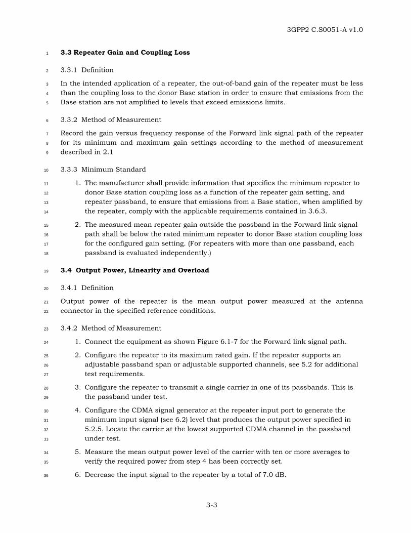
3.3 Repeater Gain and Coupling Loss 1
3.3.1 Definition 2
In the intended application of a repeater, the out-of-band gain of the repeater must be less 3
than the coupling loss to the donor Base station in order to ensure that emissions from the 4
Base station are not amplified to levels that exceed emissions limits. 5
3.3.2 Method of Measurement 6
Record the gain versus frequency response of the Forward link signal path of the repeater 7
for its minimum and maximum gain settings according to the method of measurement 8
described in 2.1 9
3.3.3 Minimum Standard 10
1. The manufacturer shall provide information that specifies the minimum repeater to 11
donor Base station coupling loss as a function of the repeater gain setting, and 12
repeater passband, to ensure that emissions from a Base station, when amplified by 13
the repeater, comply with the applicable requirements contained in 3.6.3. 14
2. The measured mean repeater gain outside the passband in the Forward link signal 15
path shall be below the rated minimum repeater to donor Base station coupling loss 16
for the configured gain setting. (For repeaters with more than one passband, each 17
passband is evaluated independently.) 18
3.4 Output Power, Linearity and Overload 19
3.4.1 Definition 20
Output power of the repeater is the mean output power measured at the antenna 21
connector in the specified reference conditions. 22
3.4.2 Method of Measurement 23
1. Connect the equipment as shown Figure 6.1-7 for the Forward link signal path. 24
2. Configure the repeater to its maximum rated gain. If the repeater supports an 25
adjustable passband span or adjustable supported channels, see 5.2 for additional 26
test requirements. 27
3. Configure the repeater to transmit a single carrier in one of its passbands. This is 28
the passband under test. 29
4. Configure the CDMA signal generator at the repeater input port to generate the 30
minimum input signal (see 6.2) level that produces the output power specified in 31
5.2.5. Locate the carrier at the lowest supported CDMA channel in the passband 32
under test. 33
5. Measure the mean output power level of the carrier with ten or more averages to 34
verify the required power from step 4 has been correctly set. 35
6. Decrease the input signal to the repeater by a total of 7.0 dB. 36

3GPP2 C.S0051-A v1.0
3-4
7. Measure the mean output power level of the carrier with ten or more averages at 1
least 3.0 seconds after performing 5. 2
8. Increase the input signal to the repeater by a total of 17.0 dB. 3
9. Measure the mean output power level of the carrier with ten or more averages at 4
least 3.0 seconds after performing 7. 5
10. Repeat steps 4 through 9, but with the carrier located at the CDMA channel nearest 6
the center of the passband under test. 7
11. Repeat steps 4 through 9, but with the carrier located at the highest supported 8
CDMA channel in the passband under test 9
12. If the passband of the repeater under test is capable of supporting two or three 10
carriers (see 5.2), configure the CDMA signal generators at the input port to 11
generate the maximum number of CDMA carriers that the passband under test is 12
capable of supporting at the minimum input signal (see Section 6.2) level that 13
produces the output power specified in 5.2.5. Always locate a carrier at the lowest 14
and highest supported CDMA channels in the passband under test. The third 15
carrier, if applicable, is located at the CDMA channel nearest the center of the 16
passband under test. If the repeater supports adjustable passband span or 17
adjustable supported channels, see 5.2 for additional test requirements. Perform 18
steps 13 through 17. If the repeater does not support at least two carriers in the 19
passband under test, skip to step 26. If the repeater is capable of supporting four or 20
more carriers in the passband under test, skip to step 18. 21
13. Measure the mean output power level of the carriers with ten or more averages to 22
verify the required power from step 13 has been correctly set. 23
14. Decrease the input signals to the repeater by a total of 7.0 dB. 24
15. Measure the mean output power level of the carriers with ten or more averages at 25
least 3.0 seconds after performing 14. 26
16. Increase the input signals to the repeater by a total of 17.0 dB. 27
17. Measure the mean output power level of the carriers with ten or more averages at 28
least 3.0 seconds after performing 16. 29
18. If the passband of the repeater under test is capable of supporting four or more 30
carriers (see 5.2), configure the CDMA signal generator at the input port to generate 31
4 CDMA carriers at the minimum input signal (see 6.2) level that produces the 32
output power specified in 5.2.5. Locate the first carrier at the lowest supported 33
CDMA channel in the passband under test and locate the remaining 3 carriers 34
contiguously above the first carrier on the next channel number one carrier spacing 35
away. If the repeater supports adjustable passband span or adjustable supported 36
channels, see 5.2 for additional test requirements. Perform steps 19 through 23. If 37
the repeater is not capable of supporting four or more carriers in the passband 38
under test, skip to step 26. 39
19. Measure the mean output power level of the carriers with ten or more averages to 40
verify the required power from step 19 has been correctly set. 41

3GPP2 C.S0051-A v1.0
3-5
20. Decrease the input signals to the repeater by a total of 7.0 dB. 1
21. Measure the mean output power level of the carriers with ten or more averages at 2
least 3.0 seconds after performing 20. 3
22. Increase the input signals to the repeater by a total of 17.0 dB. 4
23. Measure the mean output power level of the carriers with ten or more averages at 5
least 3.0 seconds after performing 22. 6
24. If the difference between the center frequency of the lowest supported CDMA 7
channel and the center frequency of the highest supported CDMA channel in the 8
passband under test is greater than 9 MHz, repeat steps 19 through 23, but with 9
the four contiguously spaced carriers centered about the CDMA channel nearest the 10
center of the passband under test, and then perform step 25. If the difference 11
between the center frequency of the lowest supported CDMA channel and the center 12
frequency of the highest supported CDMA channel in the passband under test is 13
less than or equal to 9 MHz, skip to step 26. 14
25. Repeat steps 19 through 23, but with the four carriers located such that the first 15
carrier is at the highest supported CDMA channel in the passband under test and 16
locate the remaining 3 carriers contiguously below the first carrier on the next 17
channel number, one carrier spacing away. 18
26. Repeat steps 2 through 25 for each passband of the repeater. 19
27. Repeat steps 2 through 26 for the Reverse link signal path of the repeater. 20
28. Configure the repeater to its minimum gain setting and repeat steps 2 through 27. 21
29. Repeat steps 2 through 28, using the extreme test environment requirements and 22
method contained in 4.1. 23
3.4.3 Minimum Standard 24
The repeater shall comply with the following requirements. 25
1. When tested using the standard test environmental requirements as specified in 26
5.1.2, the mean output power of the repeater, as measured in steps 7, 15, and 21 27
shall have decreased by at least 6.0 dB and by no more than 8.0 dB from the mean 28
output power measured in step 5 under every specified test. 29
2. When tested using the standard test environmental requirements as specified in 30
5.1.2, the repeater’s mean output power, as measured in steps 9, 17, and 23 shall 31
remain within limits specified in Table 3.4-1 relative to the manufacturer's rated 32
mean output under every specified test. 33

3GPP2 C.S0051-A v1.0
3-6
Table 3.4-1 Repeater Mean Output Power Per Carrier; Input Overload Test Conditions 1
Repeater rated mean output power Deviation Limit
P ≥ 43 dBm +2.0 dB and -2.0 dB
39 ≤ P < 43 dBm +2.0 dB and -2.0 dB
31 ≤ P < 39 dBm +2.0 dB and -2.0 dB
P < 31 dBm +3.0 dB and -3.0 dB
2
3. When tested using the extreme environmental test conditions and method specified 3
in 4.1, the mean output power of the repeater as measured in steps 5, 13, and 19 4
shall remain within limits specified in Table 3.4-2 relative to the mean output power 5
rated by the manufacturer. 6
Table 3.4-2 Repeater Mean Output Power Per Carrier; Extreme Test Conditions 7
Repeater rated mean output power
Deviation Limit
P ≥ 43 dBm +2.0 dB and -4.0 dB
39 ≤ P < 43 dBm +2.0 dB and -4.0 dB
31 ≤ P < 39 dBm +2.0 dB and -4.0 dB
P < 31 dBm +3.5 dB and -5.5 dB
8
3.5 Output Intermodulation 9
3.5.1 Definition 10
Output intermodulation is a measure of the ability of the repeater to inhibit the generation 11
of intermodulation product signals created by the presence of an interfering signal reaching 12
the repeater via an output port. This test only applies to the Forward link signal path of the 13
repeater. 14
3.5.2 Method of Measurement 15
1. Connect the equipment as shown in Figure 6.1-8 for the Forward link signal path. 16
2. Configure the repeater to its maximum gain setting. If the repeater supports an 17
adjustable passband span, adjustable supported channels, or the manufacturer has 18
not specified the maximum rated output power per carrier, see 5.2 for additional 19
test requirements. 20
3. Connect a signal generator to the circulator on the input port of the repeater. 21
Connect another signal generator to the circulator on the output port and make 22
sure the power from the signal generator is directed to the repeater output port. 23

3GPP2 C.S0051-A v1.0
3-7
4. Configure this signal generator at the repeater input port to generate a CDMA signal 1
(see 6.2) that produces the maximum mean output power specified by the 2
manufacturer from the repeater at the CDMA channel nearest the center of the 3
passband under test. 4
5. Configure the signal generator on the circulator connected to the output port of the 5
repeater (interfering signal) to generate a CDMA signal (see 6.2) that produces a 6
signal power corresponding to 30 dB below the maximum mean output power 7
specified by the manufacturer of the repeater with a frequency offset of one carrier 8
channel spacing (1.23 or 1.25 MHz between channel center frequencies depending 9
on the band class under test) above the repeater output frequency. 10
6. Measure the emission at the third and fifth order intermodulation products of the 11
repeater output signal and the interfering signal using a true RMS detector and the 12
bandwidth specified for the frequency offset based on the band class under test as 13
specified in Section 7. 14
7. Configure the signal generator on the circulator connected to the output port of the 15
repeater (interfering signal) to generate a CDMA signal (see 6.2) that produces a 16
signal power corresponding to 30 dB below the maximum mean output power 17
specified by the manufacturer of the repeater with a frequency offset of one carrier 18
channel spacing (1.23 or 1.25 MHz between channel center frequencies depending 19
on the band class under test) below the repeater output frequency. 20
8. Measure the emission at the third and fifth order intermodulation products of the 21
repeater output signal and the interfering signal using a true RMS detector and the 22
bandwidth specified for the frequency offset based on the band class under test as 23
specified in Section 7. 24
9. Repeat steps 5 through 8 using frequency offsets of 2 times the carrier channel 25
spacing. 26
10. Repeat steps 5 through 8 using frequency offsets of 3 times the carrier channel 27
spacing. 28
11. Repeat steps 4 through 10 for each forward link passband supported by the 29
repeater. 30
3.5.3 Minimum Standard 31
The power contained in the intermodulation products measured in steps 6 and 8 shall not 32
exceed the requirements listed in the appropriate section of Section 7 based upon the band 33
class under test and the frequency offset of the measurement from the repeater output 34
frequency. 35
3.6 Out-of-Band and Spurious Emissions 36
The requirements in this section apply to both Forward and Reverse paths. The tests are to 37
be conducted sequentially. 38

3GPP2 C.S0051-A v1.0
3-8
3.6.1 Receiver Conducted Spurious Emissions 1
Not applicable to repeaters. 2
3.6.2 Out-of-Band and Spurious Emissions 3
The requirements in this section apply to both Forward and Reverse paths. The tests are to 4
be conducted sequentially 5
3.6.3 Transmitter Conducted Spurious Emissions 6
3.6.3.1 Definition 7
Conducted spurious emissions are emissions at frequencies that are outside the assigned 8
CDMA Channel, measured at a repeater output port. 9
3.6.3.2 Method of Measurement 10
1. Connect the equipment as shown in Figure 6.1-9 for the Forward link signal path. 11
2. Configure the repeater to its maximum rated gain. If the repeater supports an 12
adjustable passband span or adjustable supported channels, see 5.2 for additional 13
test requirements. 14
3. Configure the repeater to transmit a single carrier in one of its passbands. This is 15
the passband under test. 16
4. Configure the CDMA signal generator at the repeater input port to generate the 17
minimum input signal (see 6.2) level that produces the output power specified in 18
5.2.5. Locate the carrier at the lowest supported CDMA channel in the passband 19
under test. 20
5. Increase the input signal level by 10 dB. 21
6. Measure the mean output power level of the carrier with ten or more averages. 22
7. Measure the mean spurious emission levels with ten or more averages. 23
8. Repeat steps 4 through 7, but with the carrier located at the CDMA channel nearest 24
the center of the passband under test. 25
9. Repeat steps 4 through 7, but with the carrier located at the highest supported 26
CDMA channel in the passband under test 27
10. If the passband of the repeater under test is capable of supporting two or three 28
carriers (see 5.2), configure the CDMA signal generators at the input port to 29
generate the maximum number of CDMA carriers that the passband under test is 30
capable of supporting at the minimum input signal (see Section 6.2) level that 31
produces the output power specified in 5.2.5. Always locate a carrier at the lowest 32
and highest supported CDMA channels in the passband under test. The third 33
carrier, if applicable, is located at the CDMA channel nearest the center of the 34
passband under test. If the repeater supports adjustable passband span or 35
adjustable supported channels, see 5.2 for additional test requirements. Perform 36
steps 11 through 13. If the repeater does not support at least two carriers in the 37

3GPP2 C.S0051-A v1.0
3-9
passband under test, skip to step 20. If the repeater is capable of supporting four or 1
more carriers in the passband under test, skip to step 14. 2
11. Increase the power of each input signal CDMA carrier by 10 dB. 3
12. Measure the total RF mean output power of all carriers with ten or more averages. 4
13. Measure the mean spurious emission levels with ten or more averages. 5
14. If the passband of the repeater under test is capable of supporting four or more 6
carriers (See 5.2), configure the CDMA signal generators at the input port to 7
generate 4 CDMA carriers at the minimum input signal (see 6.2) level that produces 8
the output power specified in 5.2.5. Locate the first carrier at the lowest supported 9
CDMA channel in the passband under test and locate the remaining 3 carriers 10
contiguously above the first carrier on the next channel number, one carrier 11
spacing away. If the repeater supports adjustable passband span or adjustable 12
supported channels, see 5.2 for additional test requirements. Perform steps 15 13
through 17. If the repeater is not capable of supporting four or more carriers in the 14
passband under test, skip to step 20. 15
15. Increase the power of each input signal CDMA carrier by 10 dB. 16
16. Measure the total RF mean output power of all the carriers with ten or more 17
averages. 18
17. Measure the mean spurious emission levels with ten or more averages. 19
18. If the difference between the center frequency of the lowest supported CDMA 20
channel and the center frequency of the highest supported CDMA channel in the 21
passband under test is greater than 9 MHz, repeat steps 15 through 17, but with 22
the four contiguously spaced carriers centered about the CDMA channel nearest the 23
center of the passband under test, and then perform step 19. If the difference 24
between the center frequency of the lowest supported CDMA channel and the center 25
frequency of the highest supported CDMA channel in the passband under test is 26
less than or equal to 9 MHz, continue directly to step 19. 27
19. Repeat steps 15 through 17, but with the four carriers located such that the first 28
carrier is at the highest supported CDMA channel in the passband under test and 29
locate the remaining 3 carriers contiguously below the first carrier on the next 30
channel number, one carrier spacing away. 31
20. Repeat steps 3 through 19 for each passband of the repeater. 32
21. Repeat steps 3 through 20 for the Reverse link signal path of the repeater. 33
22. Configure the repeater to its minimum gain setting and repeat steps 3 through 21. 34
3.6.3.3 Minimum Standard 35
The mean output power levels measured in steps 6, 12, and 16 shall be within the 36
tolerances listed in Table 3.4-1 when compared to the manufacturers rated mean output 37
power for every specified test. The mean spurious emissions levels measured in steps 7, 13 38
and 17 shall comply with the applicable band class limits contained in Section 7 for every 39
specified test. 40
3GPP2 C.S0051-A v1.0
3-10
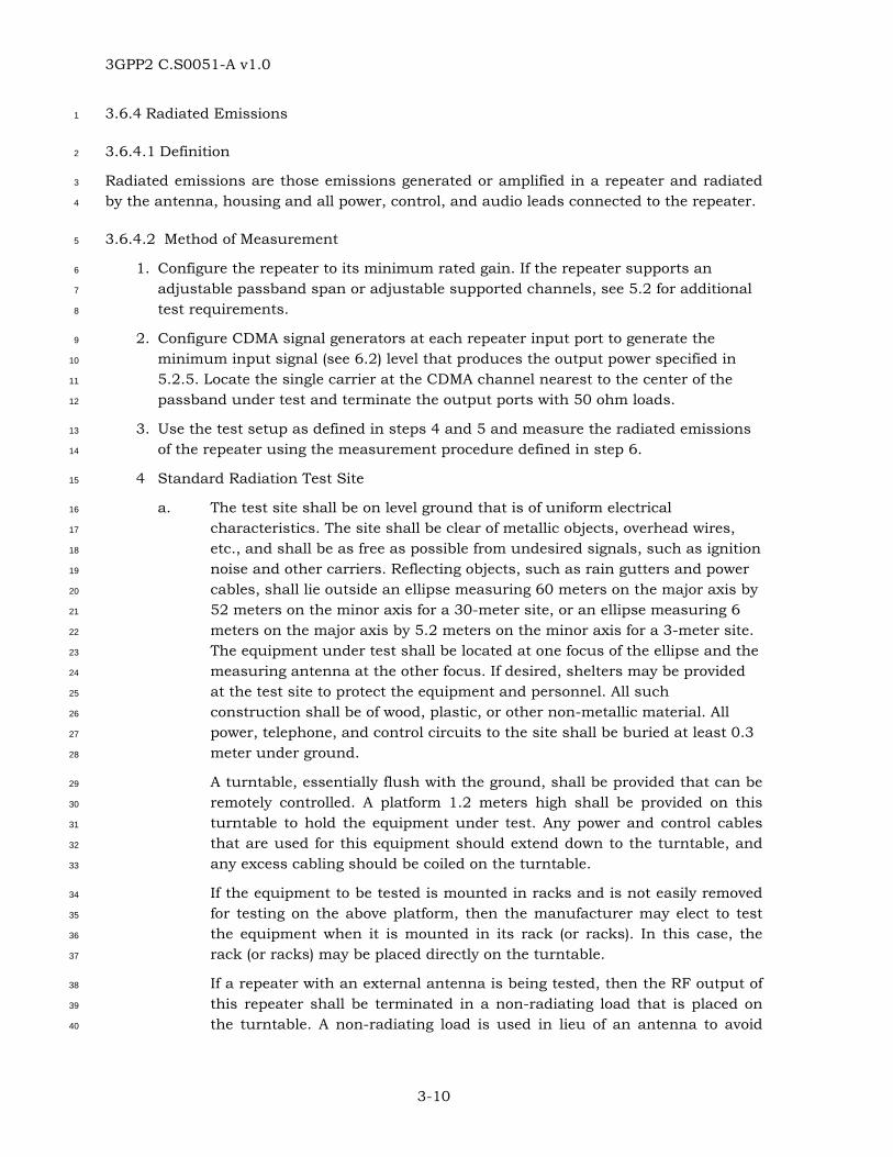
3.6.4 Radiated Emissions 1
3.6.4.1 Definition 2
Radiated emissions are those emissions generated or amplified in a repeater and radiated 3
by the antenna, housing and all power, control, and audio leads connected to the repeater. 4
3.6.4.2 Method of Measurement 5
1. Configure the repeater to its minimum rated gain. If the repeater supports an 6
adjustable passband span or adjustable supported channels, see 5.2 for additional 7
test requirements. 8
2. Configure CDMA signal generators at each repeater input port to generate the 9
minimum input signal (see 6.2) level that produces the output power specified in 10
5.2.5. Locate the single carrier at the CDMA channel nearest to the center of the 11
passband under test and terminate the output ports with 50 ohm loads. 12
3. Use the test setup as defined in steps 4 and 5 and measure the radiated emissions 13
of the repeater using the measurement procedure defined in step 6. 14
4 Standard Radiation Test Site 15
a. The test site shall be on level ground that is of uniform electrical 16
characteristics. The site shall be clear of metallic objects, overhead wires, 17
etc., and shall be as free as possible from undesired signals, such as ignition 18
noise and other carriers. Reflecting objects, such as rain gutters and power 19
cables, shall lie outside an ellipse measuring 60 meters on the major axis by 20
52 meters on the minor axis for a 30-meter site, or an ellipse measuring 6 21
meters on the major axis by 5.2 meters on the minor axis for a 3-meter site. 22
The equipment under test shall be located at one focus of the ellipse and the 23
measuring antenna at the other focus. If desired, shelters may be provided 24
at the test site to protect the equipment and personnel. All such 25
construction shall be of wood, plastic, or other non-metallic material. All 26
power, telephone, and control circuits to the site shall be buried at least 0.3 27
meter under ground. 28
A turntable, essentially flush with the ground, shall be provided that can be 29
remotely controlled. A platform 1.2 meters high shall be provided on this 30
turntable to hold the equipment under test. Any power and control cables 31
that are used for this equipment should extend down to the turntable, and 32
any excess cabling should be coiled on the turntable. 33
If the equipment to be tested is mounted in racks and is not easily removed 34
for testing on the above platform, then the manufacturer may elect to test 35
the equipment when it is mounted in its rack (or racks). In this case, the 36
rack (or racks) may be placed directly on the turntable. 37
If a repeater with an external antenna is being tested, then the RF output of 38
this repeater shall be terminated in a non-radiating load that is placed on 39
the turntable. A non-radiating load is used in lieu of an antenna to avoid 40

3GPP2 C.S0051-A v1.0
3-11
interference with other radio users. The RF cable to this load should be of 1
minimum length. The transmitter shall be tuned and adjusted to its rated 2
output value before starting the tests. 3
In order to conduct unintentional radiator tests as specified in Part 15, 4
subpart B of [7], the radiation site must comply with Sections 5.4.6 through 5
5.5 of [6] as required by Part 2.948 of [7]. 6
b. Search Antenna 7
For narrow-band dipole adjustable search antennas, the dipole length shall 8
be adjusted for each measurement frequency. This length may be 9
determined from a calibration ruler that is normally supplied with the 10
equipment. 11
The search antenna shall be mounted on a movable non-metallic horizontal 12
boom that can be raised or lowered on a wooden or other non-metallic pole. 13
The cable connected to the search antenna shall be at a right angle to the 14
antenna. The cable shall be dressed at least 3 meters, either through or 15
along the horizontal boom, in a direction away from the equipment being 16
measured. The search antenna cable may then be dropped from the end of 17
the horizontal boom to ground level for connection to the field-strength 18
measuring equipment. 19
The search antenna shall be capable of being rotated 90 degrees on the end 20
of the horizontal boom to allow measurement of both vertically and 21
horizontally polarized signals. When the antenna length of a vertically 22
mounted antenna does not permit the horizontal boom to be lowered to its 23
minimum specified search range, adjust the minimum height of the boom 24
for 0.3 meter clearance between the end of the antenna and the ground. 25
c. Field-Strength Measurement 26
A field-strength meter shall be connected to a search antenna. The field-27
strength meter shall have sufficient sensitivity and selectivity to measure 28
signals over the required frequency ranges at levels at least 10 dB below the 29
levels specified in any document, standard, or specification that references 30
this measurement procedure. The calibration of the measurement 31
instruments (field-strength meter, antennas, etc.) shall be checked 32
frequently to ensure that their accuracy is in accordance with the current 33
standards. Such calibration checks shall be performed at least once per 34
year. 35
d. Frequency Range of Measurements 36
When measuring radiated signals from repeaters with input CDMA signals, 37
the measurements shall be made from the lowest radio frequency (but no 38
lower than 25 MHz) generated in the equipment to the tenth harmonic of the 39
carrier, except for that region close to the carrier equal to ±250% of the 40
authorized bandwidth. 41

3GPP2 C.S0051-A v1.0
3-12
When measuring radiated signals from repeaters with input and output 1
ports terminated in 50 Ohms, the measurements shall be made from 25 2
MHz to at least 6 GHz. 3
5. Test Ranges 4
a. 30 Meter Test Range 5
Measurement of radiated signals shall be made at a point 30 meters from 6
the center of the turntable. The search antenna is to be raised and lowered 7
from 1 to 4 meters in both horizontally and vertically polarized orientations. 8
The field-strength measuring meter may be placed on a suitable table or 9
tripod at the foot of the mast. 10
b. 3-Meter Test Range 11
Measurement of radiated signals may be made at a point 3 meters from the 12
center of the turntable, provided the following three conditions can be met: 13
• A ground screen that covers an elliptical area at least 6 meters on the 14
major axis by 5.2 meters on the minor axis is used, with the 15
measuring antenna and turntable mounted 3 meters apart. The 16
measuring antenna and turntable shall lie on the major axis and 17
shall be equidistant from the minor axis of the elliptical area. 18
• The maximum dimension of the equipment shall be 3 meters or less. 19
When measuring radiated signals from receivers, the maximum 20
dimension shall include the antenna if it is an integral part of the 21
device. 22
• The field-strength measuring equipment is either mounted below the 23
ground level at the test site or is located a sufficient distance away 24
from the equipment being tested and from the search antenna to 25
prevent corruption of the measured data. 26
The search antenna is to be raised and lowered over a range from 1 to 4 27
meters in both horizontally and vertically polarized orientations. When the 28
search antenna is vertically oriented, the minimum height of the center of 29
the search antenna shall be defined by the length of the lower half of the 30
search antenna. 31
The 3-meter test range may be used for determining compliance with limits 32
specified at 30 meters (or other distances), provided that: 33
• The ground reflection variations between the two distances have been 34
calibrated for the frequencies of interest at the test range, or 35
• A 5 dB correction factor is added to the specified radiation limit(s) to 36
allow for average ground reflections. 37
Radiated field strength (volt/meter) varies inversely with distance, so that a 38
measurement made on the 3-meter test range divided by 10 gives the 39
equivalent value that would be measured on a 30-meter test range for the 40

3GPP2 C.S0051-A v1.0
3-13
same EIRP (effective isotropic radiated power). The 30-meter field strength in 1
volt/meter can be calculated from the EIRP by using the following formula: 2
µV/m @ 30 meters = 5773.5 × 10EIRP(dBm)/20 3
6. Radiated Signal Measurement Procedures 4
Radiated signals having significant levels shall be measured on the 30-meter or 3-5
meter test range by using the following procedure: 6
• For each observed radiated signal, raise and lower the search antenna to 7
obtain a maximum reading on the field-strength meter with the antenna 8
horizontally polarized. Then rotate the turntable to maximize the reading. 9
Repeat this procedure of raising and lowering the antenna and rotating the 10
turntable until the highest possible signal has been obtained. Record this 11
maximum reading. 12
• Repeat above step for each observed radiated signal with the antenna 13
vertically polarized. 14
• Remove the equipment being tested and replace it with a half-wave antenna. 15
The center of the half-wave antenna should be at the same approximate 16
location as the center of the equipment being tested. 17
• Feed the half-wave antenna replacing the equipment under test with a signal 18
generator connected to the antenna by means of a non-radiating cable. With 19
the antennas at both ends horizontally polarized and with the signal 20
generator tuned to the observed radiated signal, raise and lower the search 21
antenna to obtain a maximum reading on the field-strength measuring 22
meter. Adjust the level of the signal generator output until the previously 23
recorded maximum reading for this set of conditions is obtained. Record the 24
signal generator power output. 25
• Repeat above steps above with both antennas vertically polarized. 26
• Calculate the power into a reference ideal isotropic antenna by: 27
− First reducing the readings obtained above by the power loss in the cable 28
between the generator and the source antenna, and 29
− Then correcting for the gain of the source antenna used relative to an 30
ideal isotropic antenna. The reading thus obtained is the equivalent 31
effective isotropic radiated power (EIRP) level for the spurious signal 32
being measured. 33
• Repeat all above steps in 6 for all observed signals from the equipment being 34
tested. 35
• Repeat steps 1 through 6, except terminate both the input and output ports 36
with 50 Ohms. 37

3GPP2 C.S0051-A v1.0
3-14
3.6.4.3 Minimum Standard 1
The mean radiated power levels from the repeater, when measured using the procedure in 2
step 6, shall not exceed the levels specified in 3
Table 3.6-1 Maximum Allowable Radiated Spurious Emissions 4
for Band Classes 0, 1, 7, 10, 14 and 15 5
Frequency Range Maximum Allowable EIRP
30 to 88 MHz -55 dBm
88 to 216 MHz -52 dBm
216 to 960 MHz -49 dBm
960 MHz to 5 GHz (Band Classes 0,7, and 10) -41 dBm
960 MHz to 10 GHz (Band Class 1) -41 dBm
6
Table 3.6-2 Maximum Allowable Radiated Spurious Emissions 7
for Band Classes 2, 3, 4, 5, 6, 8, 9, 11 and 12 8
Frequency Range Maximum Allowable EIRP
25 to 70 MHz -45 dBm
70 to 130 MHz -41 dBm
130 to 174 MHz -41 to -32 dBm*
174 to 260 MHz -32 dBm
260 to 470 MHz -32 to -26 dBm*
470 MHz to 5 GHz (Band Classes 2, 3, 5, 9, 11, and 12)
-21 dBm
470 MHz to 10 GHz (Band Classes 4, 6, and 8)
-21 dBm
1 GHz to 12.75 GHz (Band Class 6)
-6 dBm
*Interpolate linearly on a log frequency scale. 9
Current region-specific radio regulation rules shall also apply. 10
For example, a repeater operating in Band Class 7 under US regional requirements shall 11
limit radiated mean spurious emissions to less than -70 dBW/MHz EIRP in the GPS band 12
from 1559 to 1610 MHz. 13

3GPP2 C.S0051-A v1.0
3-15
3.6.5 AC Power Line Conducted Emissions 1
3.6.5.1 Definition 2
Conducted emissions from all sources within the repeater are measured for compliance 3
with region specific regulations. 4
AC power line conducted emissions tests shall be performed on all equipment that directly 5
connects to the public utility power line. For equipment that receives power from a device 6
that is directly connected to the public utility power line (such as a DC power supply), the 7
conducted emissions tests shall be performed on the power supply device, with the 8
equipment under test connected, to insure that the supply continues to meet the current 9
emissions standards. AC power line conducted emissions tests are not required for 10
equipment that contains an internal power source or battery supply with no means for 11
connection to the public utility power line. 12
3.6.5.2 Method of Measurement 13
1. Configure the repeater to its minimum rated gain. If the repeater supports an 14
adjustable passband span or adjustable supported channels, see 5.2 for additional 15
test requirements. 16
2. Configure the CDMA signal generators at each repeater input port to generate the 17
minimum input signal (see 6.2) level that produces the output power specified in 18
5.2.5. Locate the single carrier at the CDMA channel nearest to the center of the 19
passband under test and terminate the output ports with a 50 ohm load. 20
3. Use the test setup as defined in steps 4 and 5 and measure the conducted 21
emissions of the repeater using the measurement procedure defined in step 6. 22
4. Standard AC Power Line Conducted Emissions Test Site 23
a. The test site shall be on level ground that is covered with an earth-grounded, 24
conductive surface that is at least 2 meters by 2 meters in size. The ground 25
plane shall extend at least 0.5 meter beyond the foot print of the equipment 26
under test. 27
b. A vertical conducting plane is optional for a standard (open area) test site 28
and is only required for measurements made on table-top devices. If a 29
vertical conducting plane is used, it shall be at least 2 meters by 2 meters in 30
size and shall be electrically attached to the conductive ground plane at 31
maximum intervals of one meter along its entire length. 32
5. Line Impedance Stabilization Network (LISN) Unit 33
A Line Impedance Stabilization Network (LISN) shall be used for equipment that is 34
tested on a standard test site and connects directly to the public utility power line, 35
or receives power from a device that connects to the public utility power line. The 36
LISN shall be placed on top of or directly underneath the conductive ground plane 37
and shall be electrically grounded to it. Power line filters between the power source 38
and LISN may be used to reduce the ambient noise level on the public utility line. 39
6. Standard Test Site Measurements 40

3GPP2 C.S0051-A v1.0
3-16
a. Floor Standing Equipment 1
Floor standing equipment shall be placed directly on the conductive ground 2
plane. If a vertical conducting plane is used, the equipment under test shall 3
be located 40 cm from the vertical conducting surface. All other conductive 4
objects (including the LISN) shall be located at least 80 cm from any surface 5
on the equipment under test. 6
b. Table Top Mounted Equipment 7
Table top equipment shall be placed on top of a non-conductive platform, 8
with nominal long dimension of 1.5 meters, and located 80 cm above the 9
horizontal conducting ground plane. The equipment under test shall be 10
placed 40 cm from the vertical conductive surface, with all other conductive 11
objects located at least 80 cm from any surface on the equipment under test. 12
c. Measurement Procedure 13
A radio noise meter employing a quasi-peak detector shall be used to test for 14
radio noise between each current carrying conductor and the ground 15
conductor. Each current carrying conductor shall be tested individually with 16
all unused connections on the LISN terminated in a 50Ω resistive load. The 17
ground (safety) conductor on the equipment under test shall be individually 18
connected to the power source through the LISN. Any adapters used 19
between the LISN power socket and the equipment under test shall be no 20
more than 20 cm long and shall contain only one input and only one output. 21
The equipment under test shall be tested in various modes of operation with 22
numerous cable orientations. The emissions level shall be recorded for the 23
mode of operation and cable orientation that maximizes the radio noise level. 24
This maximizing technique shall be repeated for measurements on each 25
current carrying conductor. 26
d. Frequency Range of Measurements 27
When measuring AC power line conducted emissions, the measurements 28
shall be made at frequencies between 450 kHz and 30 MHz. 29
7. End User or Manufacturing Plant Test Sites 30
For equipment that cannot be tested at a standard (open area) test site, an AC 31
power line conducted emissions test may be performed at the end user’s location or 32
at the manufacturing plant. Refer to Section 5.6 of [6] for specifications and 33
requirements of such tests. 34
3.6.5.3 Minimum Standard 35
Current region specific regulations apply 36
The radio frequency voltage, as measured in step 6, shall not exceed 1 mV for frequencies 37
between 450 and 1705 kHz and shall not exceed 3 mV for frequencies between 1.705 and 38
30 MHz. 39

3GPP2 C.S0051-A v1.0
3-17
3.7 Repeater Delay 1
3.7.1 Definition 2
Repeater delay is the difference between the measured pilot time and the expected pilot 3
time caused by passing through the repeater, taking into account CDMA System Time and 4
pilot offset. This test is only applicable to the Forward link. 5
3.7.2 Method of Measurement 6
1. Connect the equipment as shown in Figure 6.1-10 for the Forward link signal path. 7
If the repeater includes a fiber optic link to the donor Base station, use 10 meters or 8
less of fiber optic cable. 9
2. Configure the repeater to its maximum gain setting and input a single CDMA signal 10
(see 6.2) at a level that will cause the maximum rated power output from the 11
repeater at the lowest supported CDMA channel in the passband under test. If the 12
repeater supports adjustable passband span or adjustable supported channels, see 13
5.2 for additional test requirements. 14
3. Measure the pilot time alignment error (delay) between the output of the CDMA 15
signal source and at the output of the Forward link of the repeater. 16
4. Repeat steps 2 and 3 for each supported carrier in the passband under test, 17
stepping the CDMA channel center frequency up by 1.23 or 1.25 MHz, depending 18
on the band class under test, but always testing the highest supported CDMA 19
channel even if the last step is less than 1.23 or 1.25 MHz. 20
5. Repeat steps 2 through 4 for each passband in the Forward link signal path. 21
3.7.3 Minimum Standard 22
1. The manufacturer shall declare the repeaters rated delay in μs. 23
2. The delay, as measured by the pilot time alignment error between the output of the 24
CDMA signal source and the output of the repeater shall be within ± 20% of the 25
manufacturers rated delay for every specified test. (In actual use, repeaters will 26
have additional delay based upon the distance between the donor Base station and 27
the repeater as well as the means by which the donor Base station is coupled to the 28
repeater (e.g., a fiber optic link). It will be necessary to evaluate the impact of the 29
additional delay on the network and possibly mitigate the effect of the delay by 30
advancing Base station timing or increasing the pilot search window size. 31
3. For repeaters that may simultaneously support more than one CDMA channel, the 32
difference in delay between the CDMA channel with the least delay and the CDMA 33
channel with the most delay, for every passband, shall be less than 2.0 μs. 34
3.8 Exposure of Humans to RF Fields 35
Current region specific regulations apply. 36
37
38

3GPP2 C.S0051-A v1.0
3-18
This page intentionally left blank. 1

3GPP2 C.S0051-A v1.0
4-1
4 CDMA GENERAL REQUIREMENTS 1
4.1 Extreme Test Environment 2
Selected tests are performed using the extreme test environment defined within this section 3
to simulate expected extreme environmental conditions. 4
4.1.1 Definition 5
The extreme temperature range is specified by the manufacturer and represents the range 6
over which the repeater was designed for operation. The extreme power supply input 7
voltage represents the voltage fluctuations expected in normal use. The extreme humidity 8
level is a single point test for the effects of moderate humidity at high temperature. 9
4.1.2 Method of Measurement 10
1. The repeater shall be installed in its normal configuration (i.e., in its normal 11
enclosure, cabinet or rack mounting arrangement with all normally supplied covers 12
installed) and placed in a temperature chamber. 13
2. The temperature chamber shall be stabilized at the highest specified operating 14
temperature specified by the manufacturer. 15
3. Operate the repeater continuously with all transmitters outputting full rated power 16
for a period of 24 hours. During this 24 hour period, the input voltage shall be 17
varied between the minimum and maximum values specified in Table 4.1-1. With 18
the repeater operating, the temperature is to be maintained at the specified test 19
temperature without forced circulation of air from the temperature chamber being 20
directly applied to the repeater. During the entire 24 hour cycle, perform the 21
required measurements using the measurement procedure from the referring 22
section. At the completion of the 24 hours of testing the repeater shall be powered 23
off for 5 minutes and then powered on. The repeater shall again be tested to the 24
referring sections requirements to ensure it will operate normally after being 25
powered on. The temperature chamber shall be kept at the same temperature used 26
in the 24 hour test during the power off and on operational verification test. 27
4. Turn the repeater off, stabilize the equipment in the chamber at the coldest 28
operating temperature specified by the manufacturer and maintain this 29
temperature for 24 hours. After a 15-minute standby warm up period, operate all 30
transmitters at full rated power and vary the input voltage between minimum and 31
maximum values specified in Table 4.1-1 while performing the measurements from 32
the referring section. Maintain the temperature chamber at the coldest temperature 33
specified by the manufacturer without forced circulation of air from the temperature 34
chamber being directly applied to the repeater while tests are preformed. 35
5. The repeater shall be installed in its normal configuration (i.e., in its normal cabinet 36
or rack mounting arrangement with all normally supplied covers installed) and 37
placed in a humidity chamber. 38

3GPP2 C.S0051-A v1.0
4-2
6. Operate the humidity chamber at 40% relative humidity at the highest operating 1
temperature specified by the manufacturer for a period of not less than eight hours 2
during which the repeater is inoperative. While in the chamber and at the end of 3
this period, the repeater shall be turned on and allowed a 15-minute standby warm 4
up period before the tests from the referring section are performed. 5
4.1.3 Minimum Standard 6
The manufacturer shall declare the operating temperature range over which the repeater is 7
designed for operation. Extreme test environmental conditions are applied for selected 8
tests. The repeater shall comply with the performance requirements contained in the 9
section that references testing under extreme environmental conditions. 10

3GPP2 C.S0051-A v1.0
4-3
Table 4.1-1 Extreme Environmental Requirements 1
Condition Requirement
Barometric pressure1 86 kPa - 106 kPa
Temperature minimum Specified by manufacturer
Temperature maximum Specified by manufacturer
Relative Humidity2 20% - 85%
AC Power supply voltage3 ±10 % of nominal as specified by the manufacturer
DC Power supply voltage Nominal, minimum and maximum4
Power supply frequency Nominal as specified by the manufacturer
Vibration Negligible
Notes:
1. If it is not possible to maintain this parameter within the specified limits, the actual values shall be recorded in the test report.
2. For testing other than the specified humidity test. If it is not possible to maintain this parameter within the specified limits, the actual values shall be recorded in the test report.
3. Power supplies that support multiple input ratings are tested at each input rating. Power supplies rated to support a continuous range of input voltages are tested by applying -10% to the lowest voltage in the input range and +10% to the highest voltage in the input range. If the supply supports more than one input range, the test is applied to each input range.
4. The standard (or nominal) DC test voltage battery specified by the manufacturer shall be equal to the standard test voltage of the type of accumulator to be used multiplied by the number of cells minus an average DC power cable loss value that the manufacturer determines as being typical (or applicable) for a given installation. Since accumulator batteries may or may not be under charge and, in fact, may be in a state of discharge when the equipment is being operated, the manufacturer shall also test the equipment at anticipated voltage extremes above and below the standard voltage.
2
4.2 Vibration 3
Selected tests are performed while the repeater is subjected to vibration if the 4
manufacturer has declared vibration performance. 5
4.2.1 Definition 6
Vibration tests subject the repeater to a specified vibration profile while evaluating selected 7
RF performance tests. 8

3GPP2 C.S0051-A v1.0
4-4
4.2.2 Method of Measurement 1
1. When the manufacturer has declared vibration performance for the repeater, the 2
repeater shall be subjected to the vibration sequence specified by the manufacturer 3
as follows. 4
2. The environmental test equipment and methods of inducing the required 5
environmental phenomena in to the repeater shall conform to the test procedure of 6
[1]. 7
3. Other environmental conditions shall be within the ranges specified in Table 5.1-1. 8
Testing using the simultaneous combination of vibration and extreme 9
environmental conditions is not required. 10
4. The repeater shall be subjected to the tests contained in 3.1, 0, and 3.4 while 11
subjected to the vibration levels declared by the manufacturer using the vibration 12
procedures contained in [1]. (The higher levels of vibration may induce undue 13
physical stress in equipment after a prolonged series of tests. The testing body 14
should only vibrate the equipment during the specified RF measurement process.) 15
4.2.3 Minimum Standard 16
1. If the manufacturer has chosen to specify vibration performance, the specification 17
shall be based upon the guidance contained in [1]. 18
2. The repeater shall comply with the requirements contained in 3.1, 0, and 3.4 while 19
being vibrated at the test levels declared by the manufacturer using the test 20
procedure contained in [1]. 21

3GPP2 C.S0051-A v1.0
5-1
5 CDMA STANDARD TEST CONDITIONS 1
5.1 Test Environment 2
5.1.1 Definition 3
The humidity, temperature and voltage ranges denote the ranges of ambient temperature 4
and power supply input voltages over which the repeater will operate and meet the 5
requirements of this Standard. The ambient humidity is the average humidity of the air 6
surrounding the repeater equipment. The ambient temperature is the average temperature 7
of the air surrounding the repeater equipment. The power supply voltage is the voltage 8
applied at the input terminals of the repeater equipment. 9
5.1.2 Standard Test Environment 10
All tests should be performed within the minimum and maximum limits of the standard 11
conditions stated Table 5.1-1, unless otherwise specified in a test. 12
Table 5.1-1 Limits of conditions for Standard Test Environment 13
Condition Minimum Maximum
Barometric pressure 86 kPa 106 kPa
Temperature 15°C 30°C
Relative Humidity 20% 85%
Power supply voltage Nominal, as declared by the manufacturer
Power supply frequency Nominal, as declared by the manufacturer
Vibration Negligible
14
The ranges of barometric pressure, temperature, and humidity represent the maximum 15
variation expected in the uncontrolled environment of a test laboratory. If it is not possible 16
to maintain these parameters within the specified limits, the actual values shall be 17
recorded in the test report. (This may, for instance, be the case for measurements of 18
radiated emissions performed on an open field test site.) 19
5.2 General Testing Requirements 20
5.2.1 Operational Requirements 21
Unless otherwise specified in a specific test, when a test method specifies setting the 22
repeater at maximum or minimum gain, the repeater AGC or ALC, if equipped, shall be 23
enabled and operating at the desired power output set point specified in the test. 24

3GPP2 C.S0051-A v1.0
5-2
5.2.2 Adjustable Passband Span 1
Repeaters that allow adjustment to the span of one or more passbands shall be tested with 2
the widest configurable passband span. 3
5.2.3 Adjustable Supported CDMA Channels 4
Repeaters that allow adjustment of the CDMA channels supported by the repeater in one or 5
more passbands shall be tested, for every test, with the highest channels selected for each 6
passband, the lowest channels selected for each passband, and the center channels 7
selected for each passband. 8
5.2.4 Maximum Number of Supported Carriers in a Passband 9
The number of supported carriers in a given passband is taken, for the purpose of this 10
Standard, to equal the result of the following expression: 11
( ) /1.23c c cN H L MHz= − 12
Where: 13
cN = Number of supported carriers in the passband under test 14
cH = Highest supported CDMA channel center frequency in passband under test 15
cL = Lowest supported CDMA channel center frequency in passband under test 16
5.2.5 Output Power 17
5.2.5.1 Manufacturer Rates Maximum Output Power per Passband: 18
If the manufacturer has specified the maximum rated mean output power on a per 19
passband basis, the following shall be used to specify the maximum output power of the 20
repeater: 21
1. When a test specifies operating the repeater with a single CDMA carrier, the 22
maximum output power of the single carrier shall be set to the maximum rated 23
output power specified by the manufacturer for the passband under test. 24
2. When a test specifies operating the repeater with more than one CDMA carrier, the 25
maximum output power of each carrier shall be set to the maximum rated output 26
power specified by the manufacturer for the passband under test divided by the 27
number of carriers used in the test. 28
5.2.5.2 Manufacturer Does Not Rate Maximum Output Power per Passband: 29
If the manufacturer has not specified the maximum rated mean output power on a per 30
passband basis, the following shall be used to specify the maximum output power of the 31
repeater: 32
1. When a test specifies operating the repeater with a single CDMA carrier, the 33
maximum output power of the single carrier shall be set to the maximum rated 34
output power specified by the manufacturer for the repeater. 35

3GPP2 C.S0051-A v1.0
5-3
2. When a test specifies operating the repeater with more than one CDMA carrier, the 1
maximum output power of each carrier shall be set to the maximum rated output 2
power specified by the manufacturer for the repeater divided by the number of 3
carriers used in the test. 4
5
6

3GPP2 C.S0051-A v1.0
5-4
This page intentionally left blank. 1

3GPP2 C.S0051-A v1.0
6-1
6 TEST DIAGRAMS 1
6.1 Test Configurations 2
3
RepeaterUnder Test
SpectrumAnalyzer
InputPort
OutputPort
Load
Atten.
CWSignal
Generator
Repeater Output
RepeaterInput Reference Clock
50Ohms
Connections shown for FWD Link testing
4
Figure 6.1-1 Frequency Coverage Test Diagram 5
6
RepeaterUnder Test
InputPort
OutputPort
NoiseMeasuringEquipment
RepeaterOutput
RepeaterInput
Filter
Filter
Connections shown for FWD Link testing
7
Figure 6.1-2 Input Sensitivity Test Diagram 8
9
10

3GPP2 C.S0051-A v1.0
6-2
RepeaterUnder Test
SpectrumAnalyzer
InputPort
OutputPort
Load
Atten.Repeater Output
RepeaterInput
50Ohms
CWSignal
Generator
CWSignal
Generator
Σ
Connections shown for FWD Link testing
1
Figure 6.1-3 Single Tone Desensitization Test Diagram 2
3
4
RepeaterUnder Test
SpectrumAnalyzer
InputPort
OutputPort
Load
Atten.Repeater Output
RepeaterInput
CWSignal
Generator
CWSignal
Generator
Σ
50Ohms
Connections shown for FWD Link testing 5
Figure 6.1-4 Input Intermodulation Test Diagram 6

3GPP2 C.S0051-A v1.0
6-3
RepeaterUnder Test
FrequencyCounter
InputPort
OutputPort
Load
Atten.
CW SignalGenerator
Repeater Output
Reference Clock
50Ohms
Repeater Input
Connections shown for FWD Link testing
1
Figure 6.1-5 Frequency Tolerance Test Diagram 2
3
RepeaterUnder Test
WaveformAnalyzer
InputPort
OutputPort
Load
Atten.
CDMASignal
Generator
Path for InputWaveform Quality
Measurement
Path for OutputWaveform Quality
Measurement
50Ohms
Connections shown for FWD Link testing
4
Figure 6.1-6 Waveform Quality Test Diagram 5
6
7
8
9

3GPP2 C.S0051-A v1.0
6-4
RepeaterUnder Test
SpectrumAnalyzer
Input Port
Output Port
Load
Atten.Filter
AsRequired
CDMASignal
Generator
CDMASignal
Generator
Σ
50Ohms
Reference ClockMultiple signal generators as
required
Connections shown for FWD Link testing 1
Figure 6.1-7 Output Power, Linearity and Overload Test Diagram 2
3
4
RepeaterUnder Test
SpectrumAnalyzer
InputPort
OutputPort
CDMASignal Generator
CDMASignal Generator
Load
Atten.
50Ohms
Test only applies to FWD Link
5
Figure 6.1-8 Output Intermodulation Test Diagram 6
7

3GPP2 C.S0051-A v1.0
6-5
RepeaterUnder Test
SpectrumAnalyzer
Input Port
Output Port
Load
Atten.FilterAs
Required
CDMASignal
Generator
CDMASignal
Generator
Σ
50Ohms
Reference ClockMultiple signal generators as
required
Connections shown for FWD Link testing 1
Figure 6.1-9 Output Ports Conducted Spurious Emissions Test Diagram 2
3
4
5
RepeaterUnder Test
WaveformAnalyzer
InputPort
OutputPort
Load
CDMASignal
Generator
50Ohms
RepeaterInput
ReferenceClock
Atten.Path for CDMA Signal Source Pilot
Time Alignment Measurement
Path for Repeater OutputPilot Time Alignment
Measurement
Test only applies to FWD Link
6
Figure 6.1-10 Repeater Delay 7
8

3GPP2 C.S0051-A v1.0
6-6
6.2 CDMA Test Signal Definition 1
For the repeater tests that require a CDMA signal source be applied to the repeater, the 2
configuration shown in Table 6.2-1 shall be used. This waveform is used for both Forward 3
link and Reverse link signal path directions of the repeater. 4
Table 6.2-1 CDMA Signal Waveform Requirements 5
Channel Type
Number of Channels
(1)
Fraction of Power (linear)
Fraction of Power (dB)
Comments
Forward Pilot 1 0.2000 -7.0 Code channel
640W
Sync 1 0.0471 -13.3 Code channel 64
32 W ; always 1/8 rate
Paging 1 0.1882 -7.3 Code channel
641W ; full
rate only
Traffic M 0.5647/ M 2.48 10 log( )M− − ∗ Variable code channel assignments; full rate only
(1) For the Output Power and Linearity Test (3.4) and Conducted Spurious Emissions tests (3.6.3), M shall be 37. For all other tests, M shall be 6.
6
6.3 Technical Requirements for the Test Equipment 7
6.3.1 Rho Meter 8
Equipment capable of performing waveform cross-correlation shall be used for the 9
measurement of forward link frequency tolerance, pilot time tolerance, and waveform 10
compatibility. 11
Various equipment implementations are possible. The equipment used shall provide results 12
equivalent to those produced by equipment that use the following algorithms: 13
The ideal transmitter signal is given as 14
∑ ω=i
tji ce )t(R)t(s 15
Where: 16
ωc is the nominal carrier frequency of the signal, 17
Re[s] denotes the real part of the complex number s. 18
Ri(t) is the complex envelope of the ideal ith code channel, given as 19

3GPP2 C.S0051-A v1.0
6-7
( ) ( ) ( ) ( ) ( )
φ−+φ−= ∑ ∑
k kk,ick,icii sinkTtgjcoskTtgatR 1
Where: 2
ai is the amplitude of the ith code channel, 3
g(t) is the unit impulse response of the cascaded transmit filter and phase equalizer 4
described in 3.1.3.1.14 of [3], 5
φi,k is the phase of the kth chip for the ith code channel, occurring at discrete time tk = 6
kTc. 7
Modulation accuracy is the ability of the transmitter to generate the ideal signal s(t). 8
The actual transmitter signal is given by 9
( ) ( ) ( )[ ] ( ) ( )[ ]∑ θ+τ+ω∆+ω−+τ+=i
t jiiii iicetEtRbtx 10
Where: 11
bi is the amplitude of the actual signal relative to the ideal signal for the ith code 12
channel, 13
τi is the time offset of the actual signal relative to the ideal signal for the ith code 14
channel, 15
∆ω is the radian frequency offset of the signal, 16
θi is the phase offset of the actual signal relative to the ideal signal for the ith code 17
channel, and 18
Ei(t) is the complex envelope of the error (deviation from ideal) of the actual transmit 19
signal for the ith code channel. 20
Estimates of the radian frequency offset ∆ω=2π∆f and the time offset τ0, of the pilot shall be 21
obtained to the accuracy specified below in Table 6.4.2.1-1. These estimates ∆ ˆ ω , τ 0 , and 22
ˆ θ 0 , shall be used to compensate x(t) by introducing a time correction and a complex 23
multiplicative factor to produce y(t), a compensated version of x(t): 24
( ) ( ) ( )[ ]0cˆtˆ j
0 e ˆtxty θ+ω∆+ωτ−= 25
The radian frequency offset ∆ ˆ ω is converted to hertz frequency offset by ∆ˆ f =
∆ ˆ ω 2π
. The 26
compensated signal, y(t), shall be passed through a complementary filter to remove the 27
inter-symbol interference (ISI) introduced by the transmit filter and by the transmit phase 28
equalizer to yield an output z(t). The overall impulse response of the filter chain resulting 29
from cascading the complementary filter with the ideal transmit filter and equalizer shall 30
approximately satisfy Nyquist’s criterion for zero ISI. The Nyquist criterion shall be 31
approximated by filter null levels at least 50 dB below the on-time response at the 32
appropriate sample times. The noise bandwidth of the complementary low pass filter shall 33
be less than 625 kHz. 34

3GPP2 C.S0051-A v1.0
6-8
The idealized output of the complementary filter is 1
( ) ( )∑=i
i tR~tr 2
Where: 3
( ) ( ) ( )[ ]k,ik,iiki sin jcosatR~ φ+φ= 4
Modulation accuracy is measured by determining the fraction of power at the 5
complementary filter output, z(t), that correlates with ( )k0 tR~ , the compensated pilot signal. 6
The filter output is sampled at the ideal decision points when the transmitter is modulated 7
only by the Pilot Channel (the 0th code channel). The waveform quality factor (ρ) is defined 8
as 9
=ρ
∑∑
∑
==
=M
1k
2k
M
1k
2k,0
2M
1k
*k,0k
ZR~
R~ Z
10
where Zk = z[k] is the kth sample of the output of the complementary filter, and 11
[ ]kR~R~ 0k,0 = is the corresponding sample of the ideal output of the complementary filter for 12
the Pilot Channel. 13
Modulation accuracy shall be measured by using the k complex-valued samples, z(tk), over 14
a time interval M, in chips, of at least one power control group and an integer multiple of 15
512 chips. 16
The accuracy of the waveform quality measurement equipment shall be as shown in Table 17
6.3-1. 18
Table 6.3-1 Accuracy of Waveform Quality Measurement Equipment 19
Parameter Symbol Accuracy Requirement
Waveform Quality ρ ±5×10⁻⁴ from 0.90 to 1.0
Frequency Offset (exclusive of test equipment time base errors)
∆f ±10 Hz
Pilot Time Alignment Offset τ0 ±135 ns
20
Accuracy of Waveform Quality Measurement Equipment 21
6.3.2 CW Generator 22
• Output Frequency Range: Tunable over applicable range of radio frequencies for band 23
class under test. For Band Class 6, the upper limit shall be 12.75 GHz to support the 24
receiver blocking spec. 25
• Frequency Accuracy: ± 1 ppm. 26

3GPP2 C.S0051-A v1.0
6-9
• Frequency Resolution: 100 Hz. 1
• Output Range: -50 dBm to -10 dBm, and off. 2
• Output Accuracy: ± 1.0 dB. 3
• Output Resolution: 0.1 dB. 4
• Output Phase Noise at –20 dBm Power: 5
-149 dBc/Hz at a frequency of 1 GHz as measured at a 285 kHz offset (Band 6
Groups 450 and 800. 7
-144 dBc/Hz at a frequency of 2 GHz as measured at a 655 kHz offset (Band 8
Groups). 9
6.3.3 Spectrum Analyzer 10
The spectrum analyzer shall provide the following functionality: 11
• General purpose frequency domain measurements. 12
• Integrated channel power measurements for measurement bandwidths of 100 kHz and 13
greater. 14
• Integrated channel power measurements (power spectral density in 1.23 MHz) 15
The spectrum analyzer shall meet the following minimum performance requirements: 16
• Frequency Range: Tunable over applicable range of radio frequencies. 17
• Frequency Resolution: 1 kHz. 18
• Frequency Accuracy: ± 0.2 ppm. 19
• Displayed Dynamic Range: 70 dB. 20
• Display Log Scale Fidelity: ±1 dB over the above displayed dynamic range. 21
• Amplitude Measurement Range for signals from 10 MHz to either 2.6 GHz for Band 22
Groups 450 and 800 or 6 GHz for Band Group 1900: 23
Power measured in 30 kHz Resolution Bandwidth: -90 to +20 dBm. 24
Integrated 1.23 MHz Channel Power: -70 to +47 dBm. 25
Note: The Standard RF Output Load described in 6.4.8 may be used to meet the 26
high power end of these measurements. 27
• Absolute Amplitude Accuracy in the CDMA transmit and receive bands for integrated 28
1.23 MHz channel power measurements: 29
±1 dB over the range of -40 dBm to +20 dBm 30
±1.3 dB over the range of -70 dBm to +20 dBm. 31
• Relative Flatness: ±1.5 dB over frequency range 10 MHz to either 2.6 GHz for Band 32
Groups 450 and 800or 6 GHz for Band Group 1900. 33

3GPP2 C.S0051-A v1.0
6-10
• Resolution Bandwidth Filter: Synchronously tuned or Gaussian (at least 3 poles) with 3 1
dB bandwidth selections of 1 MHz, 300 kHz, 100 kHz, and 30 kHz. 2
• Post Detection Video Filters: Selectable in decade steps from 100 Hz to at least 1 MHz. 3
• Detection Modes: Selectable to be either Peak or Sample. 4
• RF Input Impedance: Nominal 50 ohm 5
6.3.4 Average Power Meter 6
The power meter shall provide the following functionality: 7
• Average power measurements. 8
• True RMS detection for both sinusoidal and non-sinusoidal signals 9
• Absolute power in linear (watt) and logarithmic (dBm) units. 10
• Relative (offset) power in dB and % units. 11
• Automatic calibration and zeroing. 12
• Averaging of multiple readings. 13
The power meter shall meet the following minimum performance requirements: 14
• Frequency Range: 10 MHz to either 1 GHz for Band Groups 450 and 800 or 2 GHz for 15
Band Group 1900. 16
• Power Range: -70 dBm (100 pW) to +47 dBm (50 W) 17
• Different sensors may be required to optimally provide this power range. The RF output 18
load described in 6.4.8 may be used to meet the high power end of these 19
measurements. 20
• Absolute and Relative Power Accuracy: ±0.2 dB (5%) 21
• Excludes sensor and source mismatch (VSWR) errors, zeroing errors (significant at 22
bottom end of sensor range), and power linearity errors (significant at top end of sensor 23
range). 24
• Power Measurement Resolution: Selectable 0.1 and 0.01 dB. 25
• Sensor VSWR: 1.15:1 26
6.3.5 RF Output Load 27
The base station transmitter output shall be connected through suitable means to the 28
measurement equipment or mobile station simulator. The means shall be non-radiating 29
and capable of continuously dissipating the full transmitter output power. The VSWR seen 30
by the transmitter over the 1.23 MHz band centered at the nominal transmit frequency 31
under test shall be less than 1.1:1. 32
The base station transmitter signal may be terminated and sampled using a dummy load, 33
attenuator, directional coupler, or combination thereof. 34

3GPP2 C.S0051-A v1.0
7-1
7 OUTPUT PORTS CONDUCTED EMISSIONS LIMITS 1
7.1 Limits for Band Class 0, 2, 5, 7, 9 and 10 2
When transmitting in Band Class 0, 2, 5, 7, 9, or 10 the mean spurious emissions shall be 3
less than all of the limits specified in Table 7.1-1 for both the Forward and Reverse signal 4
paths with the exception that for limits expressed in dBc, the emissions shall be less than 5
the higher of the dBc value or -41 dBm/30 kHz. 6
7

3GPP2 C.S0051-A v1.0
7-2
Table 7.1-1 Band Class 0, 2, 5, 7, 9, and 10 Spurious Emission Limits 1
For |∆f| Within the Range Applies to Multiple Carriers
Emission Limit
750 KHz to 1.98 MHz No -45 dBc / 30 KHz
1.98 MHz to 4.00 MHz No -60 dBc / 30 KHz; Pout ≥ 33 dBm -27 dBm / 30 KHz; 28 dBm ≤ Pout < 33 dBm
-55 dBc / 30 KHz; Pout < 28 dBm
3.25 MHz to 4.00 MHz (Band Class 7 only)
Yes -46 dBm / 6.25 KHz
> 4.00 MHz (ITU Category A only)
Yes -13 dBm / 1 KHz; -13 dBm / 10 KHz; -13 dBm/100 KHz; -13 dBm / 1 MHz;
9 KHz < f < 150 KHz 150 KHz < f < 30 MHz 30 MHz < f < 1 GHz 1 GHz < f < 5 GHz
> 4.00 MHz (ITU Category B only)
Yes -36 dBm / 1 KHz; -36 dBm / 10 KHz; -30 dBm / 1 MHz;
9 KHz < f < 150 KHz 150 KHz < f < 30 MHz 1 GHz < f < 12.5 GHz
4.00 to 6.40 MHz
(ITU Category B only)
Yes -36 dBm / 1 KHz 30 MHz < f < 1 GHz
6.40 to 16 MHz
(ITU Category B only)
Yes -36 dBm / 10 KHz 30 MHz < f < 1 GHz
> 16 MHz
(ITU Category B only)
Yes -36 dBm / 100 KHz 30 MHz < f < 1 GHz
Note: All frequencies in the measurement bandwidth shall satisfy the restrictions on |∆f| where ∆f = center frequency - closer measurement edge frequency (f). The emissions requirements shall apply for all values of ∆f regardless of whether the measurement frequency falls inside or outside of the band or block edge. Compliance with the -46 dBm / 6.25 KHz limit is based on the use of measurement instrumentation such that the reading taken with any resolution bandwidth setting should be adjusted to indicate spectral power in a 6.25 KHz segment. For multiple-carrier testing, ∆f is defined for positive ∆f as the center frequency of the highest carrier - closer measurement edge frequency (f) and for negative ∆f as the center frequency of the lowest carrier - closer measurement edge frequency (f).
2
3
4
5

3GPP2 C.S0051-A v1.0
7-3
7.2 Limits for Band Class 1, 4, 6, 8, 14 and 15 1
When transmitting in Band Class 1, 4, 6 (except Japan), 8, 14 and 15 the mean spurious 2
emissions shall be less than all of the limits specified in Table 7.2-1 for both the Forward 3
and Reverse signal paths with the exception that for limits expressed in dBc, the emissions 4
shall be less than the higher of the dBc value or -41 dBm/30 kHz. When transmitting in 5
Band Class 6 in Japan, the mean spurious emissions shall be less than all of the limits 6
specified in Table 7.2-1 for both the Forward and Reverse signal paths. 7
8

3GPP2 C.S0051-A v1.0
7-4
Table 7.2-1 Band Class 1, 4, 6, 8, 14 and 15 Spurious Emission Limits 1
For |∆f| Within the Range Applies to Multiple Carriers
Emission Limit
885 KHz to 1.25 MHz No -45 dBc / 30 KHz
1.25 to 1.98 MHz No More stringent of -45 dBc / 30 KHz or -9 dBm / 30 KHz
1.25 to 2.25 MHz (MC tests only)
Yes -9 dBm / 30 KHz
1.25 to 1.45 MHz (Band Class 6 only)
Yes -13 dBm / 30 KHz
1.45 to 2.25 MHz (Band Class 6 only)
Yes -[13 + 17 × (|∆f| – 1.45 MHz)] dBm / 30 KHz
1.98 MHz to 2.25 MHz No -55 dBc / 30 KHz; Pout ≥ 33 dBm -22 dBm / 30 KHz; 28 dBm ≤ Pout < 33 dBm
-50 dBc / 30 KHz; Pout < 28 dBm
2.25 MHz to 4.00 MHz Yes -13 dBm / 1 MHz
> 4.00 MHz (ITU Category A only)
Yes -13 dBm / 1 KHz; -13 dBm / 10 KHz; -13 dBm/100 KHz; -13 dBm / 1 MHz;
9 KHz < f < 150 KHz 150 KHz < f < 30 MHz 30 MHz < f < 1 GHz 1 GHz < f < 5 GHz
> 4.00 MHz (ITU Category B only)
Yes -36 dBm / 1 KHz; -36 dBm / 10 KHz; -36 dBm/100 KHz
9 KHz < f < 150 KHz 150 KHz < f < 30 MHz 30 MHz < f < 1 GHz
4.00 to 16.0 MHz
(ITU Category B only)
Yes -30 dBm / 30 KHz 1 GHz < f < 12.5 GHz
16.0 to 19.2 MHz
(ITU Category B only)
Yes -30 dBm / 300 KHz 1 GHz < f < 12.5 GHz
> 19.2 MHz
(ITU Category B only)
Yes -30 dBm / 1 MHz 1 GHz < f < 12.5 GHz
Note: All frequencies in the measurement bandwidth shall satisfy the restrictions on |∆f| where ∆f = center frequency - closer measurement edge frequency (f). The emissions requirements shall apply for all values of ∆f regardless of whether the measurement frequency falls inside or outside of the band or block edge. The -9 dBm requirement is based on CFR 47 Part 24 –13 dBm/12.5 KHz specification. For multiple-carrier testing, ∆f is defined for positive ∆f as the center frequency of the highest carrier - closer measurement edge frequency (f) and for negative ∆f as the center frequency of the lowest carrier - closer measurement edge frequency (f).

3GPP2 C.S0051-A v1.0
7-5
1
7.3 Limits for Band Class 3 2
When transmitting in Band Class 3, the mean spurious emissions shall be less than all of 3
the limits specified in Table 7.3-1 for both the Forward and Reverse signal paths with the 4
exception that for limits expressed in dBc, the emissions shall be less than the higher of 5
the dBc value or -41 dBm/30 kHz.. 6
7

3GPP2 C.S0051-A v1.0
7-6
Table 7.3-1 Band Class 3 Spurious Emissions Limits 1
Measurement Frequency
Applies to Multiple Carriers
For |∆f| Within the Range
Emissions Limit
> 832 MHz and ≤ 834 MHz,
> 838 MHz and ≤ 846 MHz,
> 860 MHz and ≤ 895 MHz
No ≥ 750 kHz and ≤ 1.98 MHz
-45 dBc / 30 kHz
No
≥ 1.98 MHz
25 μW (-16 dBm) / 100 kHz; Pout ≤ 30 dBm
-60 dBc / 100 kHz; 30 dBm < Pout ≤ 47 dBm Less stringent of 50 μW (-13 dBm) / 100 kHz or -70 dBc / 100 kHz; Pout >
47 dBm
> 810 MHz and ≤ 860 MHz, except
> 832 MHz and ≤ 834 MHz, > 838
MHz and ≤ 846 MHz
No
< 1.98 MHz
25 μW (-16 dBm) / 30 kHz; Pout ≤ 30 dBm
More stringent of -60 dBc / 30 kHz and 25 μW
(-16 dBm) / 30 kHz; Pout > 30 dBm
No ≥ 1.98 MHz 25 μW (-16 dBm) / 100 kHz; Pout ≤ 30 dBm More stringent of -60 dBc
/ 100 kHz and 25 μW (-16 dBm) / 100 kHz;
Pout > 30 dBm
≤ 810 MHz and > 895 MHz
Yes
N/A
25 μW (-16 dBm) / 1 MHz; Pout ≤ 44 dBm
-60 dBc / 1 MHz; 44 dBm < Pout ≤ 47 dBm Less stringent of 50 μW (-13 dBm) / 1 MHz or -70 dBc / 1 MHz; Pout
> 47 dBm
Note: All frequencies in the measurement bandwidth shall satisfy the restrictions on |∆f| where |∆f| = center frequency – closer measurement edge frequency (f). The emissions requirements shall apply for all values of ∆f regardless of whether the measurement frequency falls inside or outside of the band or block edge. For multiple-carrier testing, ∆f is defined for positive ∆f as the center frequency of the highest carrier – closer measurement edge frequency (f) and for negative ∆f as the center frequency of the lowest carrier – closer measurement edge frequency (f). The upper and lower limits of the frequency measurement are 10 MHz and 3 GHz.
2
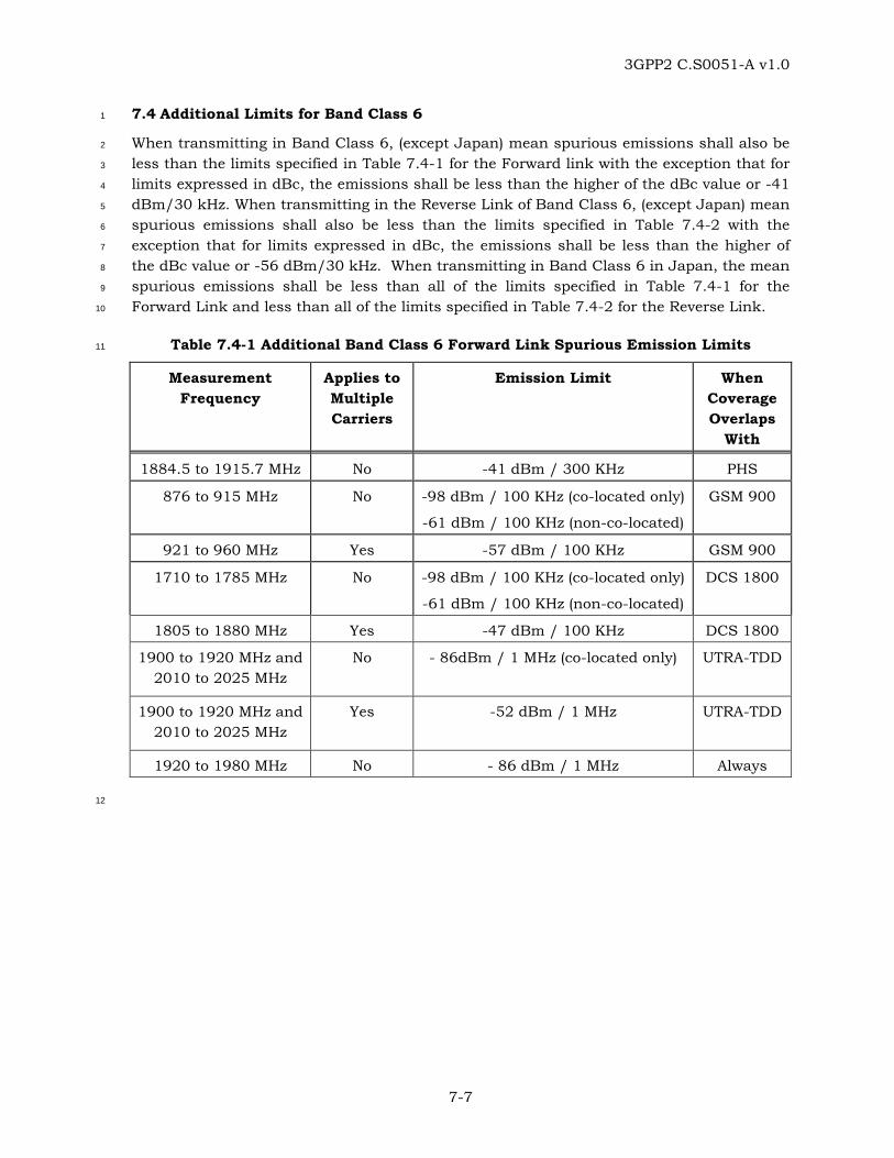
3GPP2 C.S0051-A v1.0
7-7
7.4 Additional Limits for Band Class 6 1
When transmitting in Band Class 6, (except Japan) mean spurious emissions shall also be 2
less than the limits specified in Table 7.4-1 for the Forward link with the exception that for 3
limits expressed in dBc, the emissions shall be less than the higher of the dBc value or -41 4
dBm/30 kHz. When transmitting in the Reverse Link of Band Class 6, (except Japan) mean 5
spurious emissions shall also be less than the limits specified in Table 7.4-2 with the 6
exception that for limits expressed in dBc, the emissions shall be less than the higher of 7
the dBc value or -56 dBm/30 kHz. When transmitting in Band Class 6 in Japan, the mean 8
spurious emissions shall be less than all of the limits specified in Table 7.4-1 for the 9
Forward Link and less than all of the limits specified in Table 7.4-2 for the Reverse Link. 10
Table 7.4-1 Additional Band Class 6 Forward Link Spurious Emission Limits 11
Measurement Frequency
Applies to Multiple Carriers
Emission Limit When Coverage Overlaps
With
1884.5 to 1915.7 MHz No -41 dBm / 300 KHz PHS
876 to 915 MHz No -98 dBm / 100 KHz (co-located only)
-61 dBm / 100 KHz (non-co-located)
GSM 900
921 to 960 MHz Yes -57 dBm / 100 KHz GSM 900
1710 to 1785 MHz No -98 dBm / 100 KHz (co-located only)
-61 dBm / 100 KHz (non-co-located)
DCS 1800
1805 to 1880 MHz Yes -47 dBm / 100 KHz DCS 1800
1900 to 1920 MHz and 2010 to 2025 MHz
No - 86dBm / 1 MHz (co-located only) UTRA-TDD
1900 to 1920 MHz and 2010 to 2025 MHz
Yes -52 dBm / 1 MHz UTRA-TDD
1920 to 1980 MHz No - 86 dBm / 1 MHz Always
12

3GPP2 C.S0051-A v1.0
7-8
Table 7.4-2 Additional Band Class 6 Reverse Link Spurious Emission Limits 1
Measurement
Frequency
Emission Limit
(applies to single
and multiple carriers)
When Coverage
Overlaps with:
1884.5 to 1915.7MHz -41 dBm / 300 KHz PHS
925 to 935 MHz -67 dBm / 100 KHz GSM 900
935 to 960 MHz -79 dBm / 100 KHz GSM 900
1805 to 1880 MHz -71 dBm / 100 KHz DCS 1800
Note: Measurements apply only when the measurement frequency is at least 5.625 MHz from the CDMA center frequency. The non-PHS band measurements are made on frequencies which are integer multiples of 200 KHz. As exceptions, up to five measurements with a level up to the spurious emission limits in Table 7.4-2 are allowed.
2

3GPP2 C.S0051-A v1.0
7-9
7.5 Limits for Band Class 11 and 12 1
When transmitting in Band Class 11 and 12, mean spurious emissions shall be less than 2
the limits specified in Table 7.5-1 for both the Forward and Reverse link with the exception 3
that for limits expressed in dBc, the emissions shall be less than the higher of the dBc 4
value or -41 dBm/30 kHz. When transmitting in the Reverse Link of Band Class 11 and 12, 5
mean spurious emissions shall be less than the limits specified in Table 7.5-2 with the 6
exception that for limits expressed in dBc, the emissions shall be less than the higher of 7
the dBc value or -56 dBm/30 kHz. 8
9
Table 7.5-1 Band Class 11 and 12 Spurious Emission Limits 10
For |∆f| Within the Range
Applies to Multiple Carriers
Emission Limit
750 to 885 KHz No -45-15(|∆f|-750)/135 dBc in 30 KHz
885 to 1125 KHz No -60-5(|∆f|-885)/240 dBc in 30 KHz
1.125 to 1.98 MHz No -65 dBc / 30KHz
1.98 to 4.00 MHz No -75 dBc / 30KHz
4.00 to 6.00 MHz Yes -36 dBm / 100KHz
> 6.00 MHz Yes -36 dBm / 1 KHz; -36 dBm / 10 KHz; -45 dBm/100 KHz; -30 dBm / 1 MHz;
9 KHz < f < 150 KHz 150 KHz < f < 30 MHz 30 MHz < f < 1 GHz
1 GHz < f < 12.75 GHz
Note: All frequencies in the measurement bandwidth shall satisfy the restrictions on |∆f| where ∆f = center frequency - closer measurement edge frequency (f). ∆f is positive offset from the highest valid CDMA channel in the band subclass or negative offset from the lowest valid CDMA channel in the band subclass. The emission limits for Band Class 11 and 12 (European PAMR bands) are designed to allow co-existence with incumbent services in Europe and are tighter than ITU Category B requirements.
11
12

3GPP2 C.S0051-A v1.0
7-10
Table 7.5-2 Additional Band Class 11 and 12 Reverse Link Spurious Emission Lim 1
For |∆f| Within the Range Emission Limit for Band Class 11
(applies to single and multiple carriers)
Emission Limit for Band Class 12
(applies to single and multiple carriers)
885 KHz to 1.125 MHz -47 – 7 × (|∆f| – 885) / 240 dBc in 30 KHz
-47 – 7 × (|∆f| – 885) / 240 dBc in 30 KHz
1.125 MHz to 1.98 MHz -54 – 13 × (|∆f| – 1125) / 855 dBc in 30 KHz
-54 – 13 × (|∆f| – 1125) / 855 dBc in 30 KHz
1.98 MHz to 4.00 MHz -67 – 15 × (|∆f| – 1980) / 2020 dBc in 30 KHz
-67 – 15 × (|∆f| – 1980) / 2020 dBc in 30 KHz
4.00 MHz to 10.0 MHz -51 dBm in 100 KHz -51 dBm in 100 KHz
Note: All frequencies in the measurement bandwidth shall satisfy the restrictions on |∆f| where ∆f = center frequency – closer measurement edge frequency (f). ∆f is positive offset from the highest valid CDMA channel in the band subclass or negative offset from the lowest valid CDMA channel in the band subclass. The emissions limits for Band Class 11 and 12 (European PAMR bands) are designed to allow co-existence with incumbent services in Europe and are tighter than ITU Category B requirements.
2
7.6 Additional Limits for Band Class 10 3
When transmitting in Band Class 10, mean spurious emissions shall also be less than the 4
limits specified in Table 7.6-1 for both the Forward and Reverse links. 5
Table 7.6-1 Additional Band Class 10 Spurious Emission Limits for North American 6
Operation 7
Measurement Frequency
Emission Limit
(applies to single and multiple carriers)
854.75 to 861 MHz -40 dBm / 30 KHz
866 to 869 MHz -40 dBm / 30 KHz
Note: The Band Class 10 spurious emissions limit is designed to allow marginal co-existence with North American PMRS 800 MHz Public Safety services and is far tighter than the CFR 47 Part 90.691(a)(7) requirement.
8