Engineering - Research and Science Today
12
September 2017 213 Engineering ADVANTAGES AND DISADVANTAGES OF THE PURE PNEUMATIC MOTOR USED ON COMPRESSED AIR CARS Ghinea MIHALACHE 1 Agud MIHAI 2 Ioana-Loredana NICA 3 Daniel STANCIU-ROBERT 4 Ungureanu LIVIU 5 ABSTRACT: THE AIR CAR INTRODUCED IN THIS PAPER IS A VEHICLE THAT IMITATES THE SIMPLE OPERATING PRINCIPLE OF A THREE WHEELS BICYCLE. THE MOTOR IS COMPOSED OF TWO SIMPLE PNEUMATIC PISTONS (32 MM AND 63 MM AND THE STROKE IS 320 MM), WHICH ARE CONTROLLED BY MECHANICAL VALVES. NO ELECTRONIC DEVICES ARE USED. THE VEHICLE CAN OPERATE IN TWO MODES: "SAVING ENERGY MODE" AND "SPEED MODE". IN ORDER TO INNOVATE, WE USE A HIGH-PERFORMANCE SHIMANO GEARBOX, AND ALSO A MODERN STRUCTURE WITH HIGH- RIGIDITY. THE GAS BOTTLE IS ISOLATED BY A 3 MM THICKNESS ALUMINIUM SHEET, AND THUS PROTECTING THE DRIVER. THE ENGINE IS PROVIDED WITH A PROFESSIONAL SHIFTER THAT IS QUITE A TECHNICAL CHALLENGE. THE FIRST OBJECTIF OF THE PROJECT IS TO BUILD AN EFFICIENT PNEUMATIC MOTOR WITH A SIMPLE DESIGN, TAKING INTO CONSIDERATION THE CONSTRAINTS OF THE COMPETITION IN CASE: THE SPONSORS IMPOSE TO THE COMPETITORS TO USE JUST THEIR RANGE OF PNEUMATICAL COMPONENTS. ANOTHER IMPORTANT OBJECTIF IS TO MANUFACTURE THE AIR CAR USING PROPULSED JUST BY “LINEAR MOVEMENT”, WHICH MEANS PNEUMATIC PISTONS UTILIZATION. REGARDING THE CONTROL AND COMAND OF THE ENGINE, IT CAN BE REALIZED BOTH BY PNEUMATIC VALVES AND DISTRIBUTORS AND BY PLC’S. PNEUMOBIL COMPETITION IS A TOUGH COMPETITION, THEREFORE IN ORDER TO SUCCESFULLY PARTICIPATE, THE TEAM OF UNIVERSITY POLITEHNICA OF BUCHAREST CHOSE A PURE PNEUMATIC MOTOR, THUS AVOIDING THE POSSIBLE PROBLEMS OF AN ELECTRO-PNEUMATIC MOTOR. KEY WORDS: PNEUMATICS, AIR CAR, MECHATRONICS, VALVES, PISTON INTRODUCTION "UPBair no. 48" is an experimental vehicle using compressed air, designed to participate in the race "PNEUMOBIL 2017" organized by company Aventics GmbH for ten 1 Assistant Professor, PhD, University POLITEHNICA of Bucharest, Romania, [email protected] 2 Master student, University of Oradea, Oradea, Romania, [email protected] 3 Bachelor student, University POLITEHNICA of Bucharest, Romania 4 Bachelor student, University POLITEHNICA of Bucharest, Romania 5 Bachelor student, University POLITEHNICA of Bucharest, Romania
-
Upload
khangminh22 -
Category
Documents
-
view
0 -
download
0
Transcript of Engineering - Research and Science Today
September 2017
213
Engineering
ADVANTAGES AND DISADVANTAGES OF THE PURE
PNEUMATIC MOTOR USED ON COMPRESSED AIR CARS
Ghinea MIHALACHE1
Agud MIHAI2
Ioana-Loredana NICA 3
Daniel STANCIU-ROBERT4
Ungureanu LIVIU5
ABSTRACT: THE AIR CAR INTRODUCED IN THIS PAPER IS A VEHICLE THAT IMITATES THE SIMPLE OPERATING
PRINCIPLE OF A THREE WHEELS BICYCLE. THE MOTOR IS COMPOSED OF TWO SIMPLE
PNEUMATIC PISTONS (32 MM AND 63 MM AND THE STROKE IS 320 MM), WHICH ARE CONTROLLED
BY MECHANICAL VALVES. NO ELECTRONIC DEVICES ARE USED. THE VEHICLE CAN OPERATE IN
TWO MODES: "SAVING ENERGY MODE" AND "SPEED MODE". IN ORDER TO INNOVATE, WE USE A
HIGH-PERFORMANCE SHIMANO GEARBOX, AND ALSO A MODERN STRUCTURE WITH HIGH-
RIGIDITY. THE GAS BOTTLE IS ISOLATED BY A 3 MM THICKNESS ALUMINIUM SHEET, AND THUS
PROTECTING THE DRIVER. THE ENGINE IS PROVIDED WITH A PROFESSIONAL SHIFTER THAT IS
QUITE A TECHNICAL CHALLENGE. THE FIRST OBJECTIF OF THE PROJECT IS TO BUILD AN
EFFICIENT PNEUMATIC MOTOR WITH A SIMPLE DESIGN, TAKING INTO CONSIDERATION THE
CONSTRAINTS OF THE COMPETITION IN CASE: THE SPONSORS IMPOSE TO THE COMPETITORS TO
USE JUST THEIR RANGE OF PNEUMATICAL COMPONENTS. ANOTHER IMPORTANT OBJECTIF IS TO
MANUFACTURE THE AIR CAR USING PROPULSED JUST BY “LINEAR MOVEMENT”, WHICH MEANS
PNEUMATIC PISTONS UTILIZATION. REGARDING THE CONTROL AND COMAND OF THE ENGINE, IT
CAN BE REALIZED BOTH BY PNEUMATIC VALVES AND DISTRIBUTORS AND BY PLC’S. PNEUMOBIL
COMPETITION IS A TOUGH COMPETITION, THEREFORE IN ORDER TO SUCCESFULLY PARTICIPATE,
THE TEAM OF UNIVERSITY POLITEHNICA OF BUCHAREST CHOSE A PURE PNEUMATIC MOTOR,
THUS AVOIDING THE POSSIBLE PROBLEMS OF AN ELECTRO-PNEUMATIC MOTOR.
KEY WORDS: PNEUMATICS, AIR CAR, MECHATRONICS, VALVES, PISTON
INTRODUCTION
"UPBair no. 48" is an experimental vehicle using compressed air, designed to
participate in the race "PNEUMOBIL 2017" organized by company Aventics GmbH for ten
1 Assistant Professor, PhD, University POLITEHNICA of Bucharest, Romania, [email protected] 2 Master student, University of Oradea, Oradea, Romania, [email protected] 3 Bachelor student, University POLITEHNICA of Bucharest, Romania 4 Bachelor student, University POLITEHNICA of Bucharest, Romania 5 Bachelor student, University POLITEHNICA of Bucharest, Romania

Research and Science Today Supplement No. 2/2017
214
years6. After nine editions, the competition became a well organized one, with clear and very
strict rules. Two of the most important rules are: firstly, the motor must use just components
produced by the Aventics, the main sponsor of the competition, and secondly, for creating
movement only pneumatic pistons could be used. During the competition, more than twenty
cars had serious technical injuries, most of them being in impossibility to participate to the
races. Therefore, creating an air car using a pure pneumatic motor or an electro-pneumatic
one represents a real challenge. Forward, we bring a few arguments in favor of UPBair
motor, in comparison with a mechatronic system controlled by a PLC or another electronic
device/assembly7.
The specific features of the races are meant to highlight the quality of these air motors
together with the air cars design. For example, the acceleration race aims to emphasize the
engines able to develop high speed, given the same gas bottle for being used by all the
competing cars. The competition record exceeds 60 km/h. As for the long distance race, the
cars must go through the longest distance, under the condition of a constant average speed
exceeding 15 km/h.8
STRUCTURE AND DESIGN
The idea of the UPBair vehicle came from the simple design of the trike called delta
(figure 1). In order to avoid the swinging sideways of the car, the gravity center must be
correctly located (CoG), and thus giving the position of the driver itself (figure 2).
Consequently, the prototype was provided with three wheels: one driven in the front place,
and two in the rear (left wheel steered, right wheel driven)9.
Figure 1. Types of tribike
6 Agud, M., Nica, L.I., Stanciu, R.D., Ungureanu, L. Tehnical_document_upbair_no.48_v2.0, The 10th edition
of the PNEUMOBIL competition (2016) 7 Agud, M., Nica, L.I., Stanciu, R.D., Ungureanu, L. Tehnical_document_upbair_no.48_v2.0, The 10th edition
of the PNEUMOBIL competition (2016); Ghinea, M. Objectif function development in optimization's problems
for engineering, Course notes, University POLITEHNICA of Bucharest (2012) 8 Agud, M., Nica, L.I., Stanciu, R.D., Ungureanu, L. Tehnical_document_upbair_no.48_v2.0, The 10th edition
of the PNEUMOBIL competition (2016); Ghinea, M. Objectif function development in optimization's problems
for engineering, Course notes, University POLITEHNICA of Bucharest (2012) 9 www.jetrike.com
September 2017
215
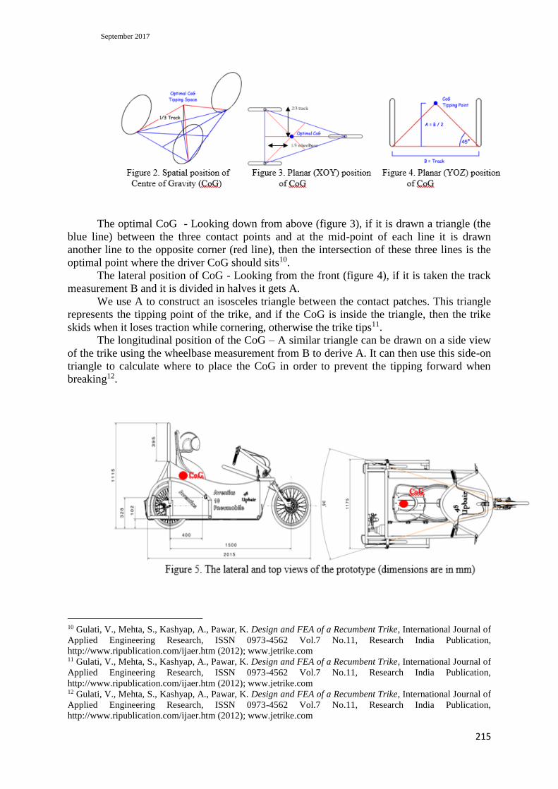
The optimal CoG - Looking down from above (figure 3), if it is drawn a triangle (the
blue line) between the three contact points and at the mid-point of each line it is drawn
another line to the opposite corner (red line), then the intersection of these three lines is the
optimal point where the driver CoG should sits10.
The lateral position of CoG - Looking from the front (figure 4), if it is taken the track
measurement B and it is divided in halves it gets A.
We use A to construct an isosceles triangle between the contact patches. This triangle
represents the tipping point of the trike, and if the CoG is inside the triangle, then the trike
skids when it loses traction while cornering, otherwise the trike tips11.
The longitudinal position of the CoG – A similar triangle can be drawn on a side view
of the trike using the wheelbase measurement from B to derive A. It can then use this side-on
triangle to calculate where to place the CoG in order to prevent the tipping forward when
breaking12.
10 Gulati, V., Mehta, S., Kashyap, A., Pawar, K. Design and FEA of a Recumbent Trike, International Journal of
Applied Engineering Research, ISSN 0973-4562 Vol.7 No.11, Research India Publication,
http://www.ripublication.com/ijaer.htm (2012); www.jetrike.com 11 Gulati, V., Mehta, S., Kashyap, A., Pawar, K. Design and FEA of a Recumbent Trike, International Journal of
Applied Engineering Research, ISSN 0973-4562 Vol.7 No.11, Research India Publication,
http://www.ripublication.com/ijaer.htm (2012); www.jetrike.com 12 Gulati, V., Mehta, S., Kashyap, A., Pawar, K. Design and FEA of a Recumbent Trike, International Journal of
Applied Engineering Research, ISSN 0973-4562 Vol.7 No.11, Research India Publication,
http://www.ripublication.com/ijaer.htm (2012); www.jetrike.com

Research and Science Today Supplement No. 2/2017
216
Based on these calculations, it can be established the correct position of the driver for
our UPBair trike. The car length is 2015 mm with the width of 1175 mm. The engine and the
back wheels are protected by metal plates and the car frame. The driver’s head and back are
protected by a 395 mm height aluminum tube. The ground clearance is 102 mm which is
more than enough to protect the bottom of the automobile against obstacles that may appear
on the race track.
The center of mass is closer to the back of the car at 400 mm from the back wheel and
at 328 mm height, which gives a good stability as shown in figure 513.
In the figure 5, the dimensions of the vehicle are shown to be in compliance with
competition rules, and the center of gravity (G) is determined by the CAD program.
FRAME AND STRUCTURE
The structure of the vehicle is made of 35 mm diameter aluminum tubes (the wall
thickness of 3 mm) and boards of 10-20 mm thick aluminum are both designed to support all
the other car components. At the bottom, a platform composed of five sleepers faces the
driver's weight, engine and the compressed air bottle14.
Therefore, the vehicle is designed to protect the driver in case of accidents (Agud et al.,
2016). For the same reason, the frame welding was the responsibility assumed by a company
authorized in welding aluminum vehicle, while its assembly was done with removable
mechanical assembly (screw and nut).
13 Agud, M., Nica, L.I., Stanciu, R.D., Ungureanu, L. Tehnical_document_upbair_no.48_v2.0, The 10th edition
of the PNEUMOBIL competition (2016); Ghinea, M. Objectif function development in optimization's problems
for engineering, Course notes, University POLITEHNICA of Bucharest (2012); Gulati, V., Mehta, S., Kashyap,
A., Pawar, K. Design and FEA of a Recumbent Trike, International Journal of Applied Engineering Research,
ISSN 0973-4562 Vol.7 No.11, Research India Publication, http://www.ripublication.com/ijaer.htm (2012);
www.jetrike.com 14 Agud, M., Nica, L.I., Stanciu, R.D., Ungureanu, L. Tehnical_document_upbair_no.48_v2.0, The 10th edition
of the PNEUMOBIL competition (2016); Ghinea, M. Objectif function development in optimization's problems
for engineering, Course notes, University POLITEHNICA of Bucharest (2012)
September 2017
217
Considering that aluminum density is around one third of the steel’s or copper’s, in
other words one of the lightest commercially available metals, the resultant high strength to
weight ratio makes it an important structural material allowing increased payloads or fuel
savings for transport industries in particular. The UPBair vehicle has the body frame all made
of 35mm aluminum tube (fig.7), thus providing it with a good resistance while keeping the
weight as low as possible. The frame covers the car as a 6 point cage protecting the inside
parts, and especially the driver. Moreover, the vehicle floor is reinforced with 3 transversal
aluminum tubes. As seen in the picture 6, the back is also provided with a protecting bended
tube. As for the front side, a two bended tubes windshield is meant to protect the driver from
debris15.
The internal components are tight on the frame due to some adaptors specially
designed. This way, as figures 7 and 8 show, rigidity is maintained and vibrations reduced
(for not affecting the mechanical components).
As previously mentioned, welds was the concern of a specialized company working
with the latest technology in the field. The utilized types of aluminum are: 5754, H1111 (for
sheets), 6060, T6 (for pipes) and 5083, H111 (for plates).
THE ENGINE
The motor of the UPBair vehicle consists in two Aventics cylinders, one piston (P2)
Ø 63x320mm and another (P1) Ø32x320mm which are operated by a simple pneumatic
assembly (see the scheme in fig.
10)16.
The engine operates in two modes, the energy saving mode and speed mode. In
economic mode the engine works with the small piston (32 mm diameter), the large piston
(63 mm diameter) being disabled pneumatically and mechanically. In the economic mode, the
small piston (P1, fig.8) is controlled by the distributor D1 (figure 9), when the valve V1
(Roller Pneumatic Manual Control Valve) is closed and valve V2 (Roller Pneumatic Manual
Control Valve) is opened17.
In the speed mode, the engine works with both pistons. The piston P2 actuates the
transmission. At the output, it commands the distributor D1 (fig.8 and 9), the valve V1 opens
and the valve V2 closes, and at the input the small piston withdraws the whole system. All
steps of speed mode running, from pneumatic point of view, are presented in figures 11a,
b….14 a, b.
15 Agud, M., Nica, L.I., Stanciu, R.D., Ungureanu, L. Tehnical_document_upbair_no.48_v2.0, The 10th edition
of the PNEUMOBIL competition (2016); Ghinea, M. Objectif function development in optimization's problems
for engineering, Course notes, University POLITEHNICA of Bucharest (2012) 16 Agud, M., Nica, L.I., Stanciu, R.D., Ungureanu, L. Tehnical_document_upbair_no.48_v2.0, The 10th edition
of the PNEUMOBIL competition (2016); Ghinea, M. Objectif function development in optimization's problems
for engineering, Course notes, University POLITEHNICA of Bucharest (2012); Vladislav Blagojević, Miodrag
Stojiljković Mathematical and Simulink Model of the Pneumatic System with Bridging of the Dual Action
Cylinder Chambers, FACTA UNIVERSITATIS Series: Mechanical Engineering Vol. 5, No 1, pp. 23 - 31,
(2007); www.jetrike.com 17 Vladislav Blagojević, Miodrag Stojiljković Mathematical and Simulink Model of the Pneumatic System with
Bridging of the Dual Action Cylinder Chambers, FACTA UNIVERSITATIS Series: Mechanical Engineering
Vol. 5, No 1, pp. 23 - 31, (2007); www.jetrike.com
Research and Science Today Supplement No. 2/2017
218
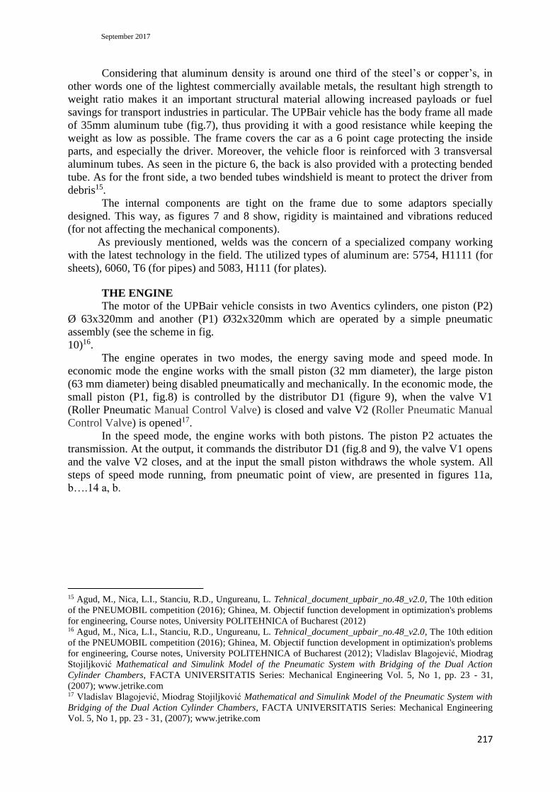
Figure 8. The original mounting of the engine system (CAD model)
The fixing of the engine frame is in three points, two side straps and a lock screw in the
middle (fig. 8 and 9 partially). Transmitting motion from the engine to the wheel, the axle is
driven via a chain and sprockets. The yellow part in figure 8, made by special plastic
material, connects the pistons and ensures the chain linear movement with the alternate
displacement of the pistons. As shown in figures 8 and 9, the engine is designed as a single
structural unit connected to the car frame (fig.9)18. When the piston P2 pushes the yellow
element, which drags the chain along a linear guide, the linear guide helps the linear
movement of the pistons. The mechanical parts are fixed with screws, thus allowing an easy
access to all the elements in case of any calibrations or repairs needed. For a better precision
and tolerance, all the mechanical parts were machined with special tools. The 18 tooth pinion
Shimano is fixed on an original shaft that is hold in place by two bearings facilitating rotation
with less friction. As for a smooth and vibration-free movement, a linear track from Aventics
was used (see figure 8).
The transmission is quite simple: piston P2 pushes the yellow element which is
connected to the chain, and thus, practically the linear chain movement spins the mechanism
of the speed hub, which rotates the rear wheel. The speed on the wheel is given by the
number of spins on the cogwheel multiplied by the gear transmission. This way, we get
better performance than just going without the speed hub. With the inferior gear we get a
better start and by going into higher gears we increase the maximum speed. When the rod of
the piston P2 is complete and touches the sensor of the valve V1, the piston P1 starts the
movement in the opposite direction, until the yellow element touches the sensor of the valve
18 Agud, M., Nica, L.I., Stanciu, R.D., Ungureanu, L. Tehnical_document_upbair_no.48_v2.0, The 10th edition
of the PNEUMOBIL competition (2016); Ghinea, M. Objectif function development in optimization's problems
for engineering, Course notes, University POLITEHNICA of Bucharest (2012); Vladislav Blagojević, Miodrag
Stojiljković Mathematical and Simulink Model of the Pneumatic System with Bridging of the Dual Action
Cylinder Chambers, FACTA UNIVERSITATIS Series: Mechanical Engineering Vol. 5, No 1, pp. 23 - 31,
(2007)

September 2017
219
V2. This cycle is repeated as long as pedal P is depressed (see fig. 9). In fact, this pedal
acting an
Aventics fine setting valve, which allows filling the piston P2 chamber with gas19.
Figure 9. The photos of the air car motor
The motor also contains components of the MISWP (Manual Infinetely Setupable
Working Pressure) and ESS (Emergency-Stop Switching), both imposed by the competition
rules in order to avoid any accident specific for high pressure instalations.
PNEUMATIC SCHEME & SIMULATION
As presented before, the pneumatic scheme (fig. 10) of the UPBair vehicle is simple,
thus reducing malfunctions. From the air/gas bottle (N2), the pressure is controlled by the
components of the ESS and MISWP, in other words, the gas can be released toward the
motor or stopped, if an emergency situation appears20.
For simulating the dynamic behaviour of the pneumatic motor, a model based on
pneumatic components was conceived (figure 10)21. Unfortunately, mechanical assembly
cannot be used in this software, thus the mechanical linkage betweeen pistons (using plastic
component) cannot be used. Therefore, a piston system (PS) is used in the model. This
simulates the behavior of the real pistons assembly. Furthermore, figures 11….14 show the
equivalence between simulation of the PS with both P1 and P2 running, while figures 11,
a….14, a show the double strokes for both pistons P1 and P2.
19 Vladislav Blagojević, Miodrag Stojiljković Mathematical and Simulink Model of the Pneumatic System with
Bridging of the Dual Action Cylinder Chambers, FACTA UNIVERSITATIS Series: Mechanical Engineering
Vol. 5, No 1, pp. 23 - 31, (2007); www.jetrike.com 20 Ghinea, M. Objectif function development in optimization's problems for engineering, Course notes,
University POLITEHNICA of Bucharest (2012); Vladislav Blagojević, Miodrag Stojiljković Mathematical and
Simulink Model of the Pneumatic System with Bridging of the Dual Action Cylinder Chambers, FACTA
UNIVERSITATIS Series: Mechanical Engineering Vol. 5, No 1, pp. 23 - 31, (2007); www.jetrike.com;
https://resources.hkedcity.net/res_files/201101/20110128101153_259037.pdf 21 Documentation of Automation Studio 5.2 (Trial version)

Research and Science Today Supplement No. 2/2017
220
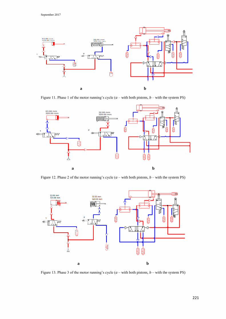
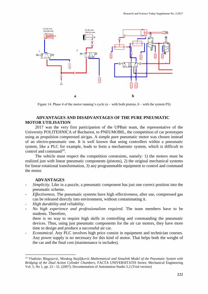
In figure 11, a, the piston P2 acts the chain producing propulsion for the vehicle, then,
in figure 12, a, the sensor of valve V1 is touched, and the distributor D1 starts to fill the
piston P1 which pushing back the assembly PS (unload running). In figure 13, a, the sensor
of the valve V2 is touched, whereas in figure 14, a, the filling of the chamber of piston P2
starts again, thus producing a new propulsion of the vehicle22.
Similarly, figures 11, b…14, b display the simulations for the assembly PS, during the
four phases (due to the PrintScreen shooting some arrows have or have not the proper
representation).
Not insisting anymore on the pneumatic motor running, we still emphasize the fact that
the dynamics of the assembly is not proper for a professional car. In fact, the main objectiv of
the team UPBAIR was to obtain a running air car, not a performing one. It is easy to observe
that when the piston P1 works, and the PS moves back, the air car does not have propulsion.
That means that the propulsion is
discontinuous and the maximum speed cannot be reached23.
Figure 10. The screen shooting of the simulation of the air car motor model
22 www.jetrike.com; Documentation of Automation Studio 5.2 (Trial version) 23 Agud, M., Nica, L.I., Stanciu, R.D., Ungureanu, L. Tehnical_document_upbair_no.48_v2.0, The 10th edition
of the PNEUMOBIL competition (2016); www.jetrike.com; Documentation of Automation Studio 5.2 (Trial
version)
September 2017
221
a b
Figure 11. Phase 1 of the motor running’s cycle (a – with both pistons, b – with the system PS)
a b
Figure 12. Phase 2 of the motor running’s cycle (a – with both pistons, b – with the system PS)
a b
Figure 13. Phase 3 of the motor running’s cycle (a – with both pistons, b – with the system PS)
Research and Science Today Supplement No. 2/2017
222
a b
Figure 14. Phase 4 of the motor running’s cycle (a – with both pistons, b – with the system PS)
ADVANTAGES AND DISADVANTAGES OF THE PURE PNEUMATIC
MOTOR UTILISATION
2017 was the very first participation of the UPBair team, the representative of the
University POLITEHNICA of Bucharest, to PNEUMOBIL, the competition of car prototypes
using as propulsion compressed air/gas. A simple pure pneumatic motor was chosen instead
of an electro-pneumatic one. It is well known that using controllers within a pneumatic
system, like a PLC for example, leads to form a mechatronic system, which is difficult to
control and command24.
The vehicle must respect the competition constraints, namely: 1) the motors must be
realized just with linear pneumatic components (pistons), 2) the original mechanical systems
for linear-rotational transformation, 3) any programmable equipment to control and command
the motor.
ADVANTAGES
- Simplicity. Like in a puzzle, a pneumatic component has just one correct position into the
pneumatic scheme.
- Effectiveness. The pneumatic systems have high effectiveness, after use, compressed gas
can be released directly into environment, without contaminating it.
- High durability and reliability.
- No high experience and professionalism required. The team members have to be
students. Therefore,
there is no way to require high skills in controlling and commanding the pneumatic
devices. Thus, using just pneumatic components for the air car motors, they have more
time to design and produce a successful air car.
- Economical. Any PLC involves high price consist in equipment and technician courses.
Any power supply is no necessary for this kind of motor. That helps both the weight of
the car and the final cost (maintenance is includes).
24 Vladislav Blagojević, Miodrag Stojiljković Mathematical and Simulink Model of the Pneumatic System with
Bridging of the Dual Action Cylinder Chambers, FACTA UNIVERSITATIS Series: Mechanical Engineering
Vol. 5, No 1, pp. 23 - 31, (2007); Documentation of Automation Studio 5.2 (Trial version)
September 2017
223
DISADVANTAGES
- Few ways to control and command. All participants receive the same bottle gas. When
needing to save gas, the range of pneumatic devices is really poor. Thus, a lot of gas is
lost during the car running, which means low performances regarding the long distance
races.
- Low accuracy. Pneumatic systems are powered by the force provided by compressed air,
their operation depends on the volume and the temperature of the compressed air. As the
volume of air may change when compressed or heated, the supply of air to the system
may not be precise, causing a low accuracy of the system25.
- High compressed air consumption. In this case, the piston P1 practically works just to
move back the system that pulls the chain, wasting a lot of compressed air.
- Uneven moving speed. As air can easily be compressed, the moving speeds of the pistons
are relatively uneven, as it shown in graphs in figure 10.
CONCLUSION
As it is already known, pneumatic motors have existed in many forms over the past
two centuries, ranging in size from hand-held motors to engines of up to several hundred
horsepower. Some types rely on pistons and cylinders; others on slotted rotors with vanes
(vane motors) and others use turbines. Many compressed air engines improve their
performance by heating the incoming air or the engine itself. Pneumatic motors have found
widespread success in the hand-held tool industry, but are also used stationary in a wide
range of industrial applications. Continual attempts are being made to expand their use to the
transportation industry. However, pneumatic motors must overcome inefficiencies before
being seen as a viable option in the transportation industry. As long as vehicles exist,
engineers will try to find out the best solution to propel them.
Apart of competitions like PNEUMOBIL, the designers of the air cars take into
consideration both solutions, pure pneumatic and electro-pneumatic motors. Of course, to
reach the best performances, all the time they will use any novelty in the field of
mechatronics.
25 www.aventics.com; Documentation of Automation Studio 5.2 (Trial version)
Research and Science Today Supplement No. 2/2017
224
REFERENCES
1. Agud, M., Nica, L.I., Stanciu, R.D., Ungureanu, L. Tehnical_document_upbair_no.48_v2.0, The
10th edition of the PNEUMOBIL competition (2016).
2. Ghinea, M. Objectif function development in optimization's problems for engineering, Course notes,
University POLITEHNICA of Bucharest (2012).
3. Gulati, V., Mehta, S., Kashyap, A., Pawar, K. Design and FEA of a Recumbent Trike, International
Journal of Applied Engineering Research, ISSN 0973-4562 Vol.7 No.11, Research India Publication,
http://www.ripublication.com/ijaer.htm (2012).
4. Vladislav Blagojević, Miodrag Stojiljković Mathematical and Simulink Model of the Pneumatic
System with Bridging of the Dual Action Cylinder Chambers, FACTA UNIVERSITATIS Series:
Mechanical Engineering Vol. 5, No 1, pp. 23 - 31, (2007).
5. www.aventics.com
6. www.jetrike.com
7. https://resources.hkedcity.net/res_files/201101/20110128101153_259037.pdf
8. Documentation of Automation Studio 5.2 (Trial version)