Engineering Nature-Inspired Heuristics for the Open Shortest ...
265
Engineering Nature-Inspired Heuristics for the Open Shortest Path First Weight Setting Problem by Mohammed Aijaz Mohiuddin (Student # 11365162) Submitted in partial fulfillment of the requirements for the degree Philosophiae Doctor in the Faculty of Engineering, Built Environment, and Information Technology University of Pretoria Pretoria April 2018
-
Upload
khangminh22 -
Category
Documents
-
view
0 -
download
0
Transcript of Engineering Nature-Inspired Heuristics for the Open Shortest ...

Engineering Nature-Inspired Heuristics for the
Open Shortest Path First Weight Setting Problem
by
Mohammed Aijaz Mohiuddin(Student # 11365162)
Submitted in partial fulfillment of the requirements for the degree Philosophiae Doctor
in the Faculty of Engineering, Built Environment, and Information Technology
University of Pretoria
Pretoria
April 2018

Engineering Nature-Inspired Heuristics for the Open Shortest PathFirst Weight Setting Problem
byMohammed Aijaz Mohiuddin
Abstract
Optimizing network performance is a challenging task. Network links may become
under-utilized or over-utilized. It is important to find routes that will ensure a good
balance between utilization and congestion. One approach to find the routes in the
network is the open shortest path first (OSPF) routing protocol. The open shortest
path first weight setting problem (OSPFWS) is an approach to find the best routes
by finding a set of numerical weights that will achieve optimal routing. The OSPFWS
problem, an NP-hard problem, is a multi-objective optimization problem, with the
following conflicting objectives: to minimize the maximum utilization, to minimize
the number of congested links, and to minimize the number of unused links. In order
to solve this multi-objective optimization problem, a fuzzy operator is used to ag-
gregate the sub-objectives into one objective function. A number of nature-inspired
iterative heuristic algorithms are adapted in this thesis to solve the OSPFWS prob-
lem. These algorithms are simulated annealing (SA), simulated evolution (SimE),
and particle swarm optimization (PSO). Moreover, a hybrid version of PSO, namely,
fuzzy evolutionary PSO (FEPSO), is proposed and studied. A sensitivity analysis of
the control parameters of these algorithms is presented. The proposed algorithms are
i

compared with some well-established multi-objective optimization algorithms such
as the non-dominating sorting genetic algorithm (NSGA-II), weighted aggregation
particle swarm optimization (WAPSO), and Pareto-dominance particle swarm opti-
mization (PDPSO).
Keywords: Optimization, Open shortest path first routing, Fuzzy logic, Simu-lated annealing, Simulated evolution, Swarm intelligence, Particle swarm optimiza-tion, Multi-objective optimization.
Thesis Supervisor: Prof. Andries P. EngelbrechtThesis Co-supervisor: Dr. Salman A. KhanDepartment of Computer ScienceDegree: Doctor of Philosophy
ii

Acknowledgements
All praise be to God Almighty, for his limitless blessing and guidance. He is the
one, who made this thesis possible by His will and mercy.
I would like to sincerely thank my supervisor, Professor Andries P. Engelbrecht
and co-supervisor, Dr Salman A. Khan for their help, support, and encouragement
throughout this research endeavor. I commend and acknowledge them for their valu-
able time, consistent support and stimulating discussions. Every step working with
them towards the completion of this thesis was fascinating, enjoyable and insightful.
I was motivated and supported fully by my beloved parents. My wife deserves
a special mention for her dedication, patience and understanding. I also thank my
colleagues at my workplace for their support.

Contents
List of Tables ix
List of Figures ix
1 Introduction 11.1 Motivation . . . . . . . . . . . . . . . . . . . . . . . . . . . . . . . . . 31.2 Objectives . . . . . . . . . . . . . . . . . . . . . . . . . . . . . . . . . 51.3 Methodology . . . . . . . . . . . . . . . . . . . . . . . . . . . . . . . 71.4 Contributions . . . . . . . . . . . . . . . . . . . . . . . . . . . . . . . 81.5 Organization of Thesis . . . . . . . . . . . . . . . . . . . . . . . . . . 10
2 Optimization and Optimization Approaches 132.1 Optimization . . . . . . . . . . . . . . . . . . . . . . . . . . . . . . . 14
2.1.1 Weighted Sum Method . . . . . . . . . . . . . . . . . . . . . . 182.1.2 ε-Constraint Method . . . . . . . . . . . . . . . . . . . . . . . 192.1.3 Lexicographic Ordering . . . . . . . . . . . . . . . . . . . . . . 202.1.4 Goal Programming . . . . . . . . . . . . . . . . . . . . . . . . 212.1.5 Dominance-based Approach . . . . . . . . . . . . . . . . . . . 22
2.2 Fuzzy Logic and Multi-objective Optimization . . . . . . . . . . . . . 232.2.1 Fuzzy Set Theory . . . . . . . . . . . . . . . . . . . . . . . . . 252.2.2 Fuzzy Reasoning . . . . . . . . . . . . . . . . . . . . . . . . . 282.2.3 Linguistic Variables . . . . . . . . . . . . . . . . . . . . . . . . 282.2.4 Fuzzy Rules . . . . . . . . . . . . . . . . . . . . . . . . . . . . 292.2.5 Fuzzy Logic System . . . . . . . . . . . . . . . . . . . . . . . . 302.2.6 Common Fuzzy Operators . . . . . . . . . . . . . . . . . . . . 31
2.3 Optimization Algorithms . . . . . . . . . . . . . . . . . . . . . . . . . 342.3.1 Simulated Annealing . . . . . . . . . . . . . . . . . . . . . . . 362.3.2 Simulated Evolution . . . . . . . . . . . . . . . . . . . . . . . 412.3.3 Genetic Algorithms . . . . . . . . . . . . . . . . . . . . . . . . 452.3.4 Non-dominating sorting genetic algorithm II . . . . . . . . . . 48
iv

2.3.5 Particle Swarm Optimization . . . . . . . . . . . . . . . . . . 502.4 MOO performance measures . . . . . . . . . . . . . . . . . . . . . . . 612.5 Conclusion . . . . . . . . . . . . . . . . . . . . . . . . . . . . . . . . . 63
3 Routing and Open Shortest Path First Protocol 643.1 Routing in Computer Networks . . . . . . . . . . . . . . . . . . . . . 653.2 Routing Information Protocol . . . . . . . . . . . . . . . . . . . . . . 663.3 Open Shortest Path First Routing Protocol . . . . . . . . . . . . . . 693.4 Literature review of the OSPF weight setting problem . . . . . . . . . 733.5 Conclusion . . . . . . . . . . . . . . . . . . . . . . . . . . . . . . . . . 81
4 Open Shortest Path First Weight Setting Problem 824.1 Formal description of OSPFWS Problem . . . . . . . . . . . . . . . . 83
4.1.1 Traffic Load Calculation . . . . . . . . . . . . . . . . . . . . . 854.2 Fuzzy Logic Cost Function for the OSPFWS Problem . . . . . . . . . 864.3 Details of Test Cases . . . . . . . . . . . . . . . . . . . . . . . . . . . 904.4 Conclusion . . . . . . . . . . . . . . . . . . . . . . . . . . . . . . . . . 92
5 Fuzzy Simulated Annealing Algorithm for the OSPFWS Problem 935.1 Fuzzy Simulated Annealing Algorithm . . . . . . . . . . . . . . . . . 945.2 Solutions Archiving in FSA . . . . . . . . . . . . . . . . . . . . . . . 985.3 Experimental setup . . . . . . . . . . . . . . . . . . . . . . . . . . . . 99
5.3.1 Comparison of SqalliCF and FuzzyCF using SA . . . . . . . . 1015.4 Conclusion . . . . . . . . . . . . . . . . . . . . . . . . . . . . . . . . . 116
6 Fuzzy Simulated Evolution Algorithm for the OSPFWS Problem 1176.1 Fuzzy Simulated Evolution Algorithm . . . . . . . . . . . . . . . . . . 1186.2 Experimental setup . . . . . . . . . . . . . . . . . . . . . . . . . . . . 1226.3 Results and Discussion . . . . . . . . . . . . . . . . . . . . . . . . . . 1246.4 Conclusion . . . . . . . . . . . . . . . . . . . . . . . . . . . . . . . . . 134
7 Particle Swarm Optimization Algorithm Variants and NSGA-II forthe OSPFWS Problem 1367.1 Fuzzy Particle Swarm Optimization Algorithm . . . . . . . . . . . . . 137
7.1.1 Particle Position and Velocity Representation . . . . . . . . . 1387.1.2 Velocity Update . . . . . . . . . . . . . . . . . . . . . . . . . . 1397.1.3 Particle Position Update . . . . . . . . . . . . . . . . . . . . . 1437.1.4 Control Parameter Tuning for Fuzzy Particle Swarm Optimization145
7.2 Fuzzy Evolutionary Particle Swarm Optimization Algorithm . . . . . 154
v

7.2.1 Control Parameter Tuning for Fuzzy Evolutionary Particle SwarmOptimization . . . . . . . . . . . . . . . . . . . . . . . . . . . 156
7.3 Weighted Aggregation Particle Swarm Optimization Algorithm . . . . 1587.3.1 Control Parameter Tuning for Weighted Aggregation Particle
Swarm Optimization . . . . . . . . . . . . . . . . . . . . . . . 1617.4 Pareto-dominance Particle Swarm Optimization Algorithm . . . . . . 164
7.4.1 Control Parameter Tuning for Pareto-dominance Particle SwarmOptimization . . . . . . . . . . . . . . . . . . . . . . . . . . . 168
7.5 Non-dominating Sorting Genetic Algorithm II . . . . . . . . . . . . . 1687.5.1 Control Parameter Tuning for Non-dominating Sorting Genetic
Algorithm II . . . . . . . . . . . . . . . . . . . . . . . . . . . . 1757.6 Conclusion . . . . . . . . . . . . . . . . . . . . . . . . . . . . . . . . . 175
8 Empirical Comparison of the Algorithms 1778.1 Experimental Setup . . . . . . . . . . . . . . . . . . . . . . . . . . . . 1788.2 Comparison of Simulated Annealing and Simulated Evolution Algorithms1788.3 Comparison of Fuzzy Particle Swarm Optimization and Fuzzy Evolu-
tionary Particle Swarm Optimization . . . . . . . . . . . . . . . . . . 1848.4 Comparison of all the algorithms with respect to diversity . . . . . . 1908.5 Comparison of all the algorithms with respect to MOO performance
measures . . . . . . . . . . . . . . . . . . . . . . . . . . . . . . . . . . 1968.6 Conclusion . . . . . . . . . . . . . . . . . . . . . . . . . . . . . . . . . 206
9 Conclusion 2109.1 Summary . . . . . . . . . . . . . . . . . . . . . . . . . . . . . . . . . 2119.2 Future Research . . . . . . . . . . . . . . . . . . . . . . . . . . . . . . 214
Bibliography 217
Appendix 245
vi

List of Tables
4.1 Test cases for the OSPFWS problem . . . . . . . . . . . . . . . . . . 91
5.1 Best average FuzzyCF values for the test cases h50N148a, h50N212a,h100N280a, h100N360a, r50N228a and r50N245a . . . . . . . . . . . . 102
5.2 Best average FuzzyCF values for the test cases r100N403a, r100N503a,w50N169a, w50N230a, w100N391a and w100N476a . . . . . . . . . . 103
5.3 Results of average cost for different values of Markov chain parameter(M) for SqalliCF and FuzzyCF . . . . . . . . . . . . . . . . . . . . . 108
5.4 MU, NOC, NUL, and average execution time corresponding to two costfunctions using SA . . . . . . . . . . . . . . . . . . . . . . . . . . . . 113
5.5 Comparison of FuzzyCF and SqalliCF using SA . . . . . . . . . . . . 114
6.1 Effect of bias value on the quality of solution for the test cases h50N148a,h50N212a, h100N280a and h100N360a . . . . . . . . . . . . . . . . . 125
6.2 Effect of bias value on the quality of solution for the test cases r50N228a,r50N245a, r100N403a and r100N503a . . . . . . . . . . . . . . . . . . 126
6.3 Effect of bias value on the quality of solution for the test cases w50N169a,w50N230a, w100N391a and w100N476a . . . . . . . . . . . . . . . . . 127
6.4 MU, NOC, NUL, and average execution time corresponding to two costfunctions using SimE . . . . . . . . . . . . . . . . . . . . . . . . . . . 132
6.5 Comparison of FuzzyCF and SqalliCF using SimE . . . . . . . . . . . 133
7.1 Best average FuzzyCF values for the test cases h50N148a, h50N212a,r50N228a, r50N245a, w50N169a and w50N230a for the experimentedswarm sizes with respect to FPSO . . . . . . . . . . . . . . . . . . . . 147
7.2 Best average FuzzyCF values for the test cases h100N280a, h100N360a,r100N403a, r100N503a, w100N391a and w100N476a for the experi-mented swarm sizes with respect to FPSO . . . . . . . . . . . . . . . 148
7.3 Average FuzzyCF values for all the test cases for experimented Vmax
values with respect to FPSO . . . . . . . . . . . . . . . . . . . . . . . 149
vii

7.4 Percentage difference of FuzzyCF values for the test cases where Vmax =5 performed better with respect to FPSO . . . . . . . . . . . . . . . . 150
7.5 Percentage difference of FuzzyCF values for the test cases where Vmax =15 performed better with respect to FPSO . . . . . . . . . . . . . . . 150
7.6 Best parameter combinations obtained for FPSO for each test case . . 1517.7 Best parameter combinations obtained for FEPSO for each test case . 1577.8 Best parameter combinations obtained for WAPSO for each test case 1627.9 Experimented weight combinations for WAPSO . . . . . . . . . . . . 1637.10 Best parameter combinations obtained for PDPSO for each test case . 1697.11 Best parameter combinations obtained for NSGA-II for each test case 176
8.1 Statistical results of SimE vs SA with respect to FuzzyCF and SqalliCFcost functions for the objective MU . . . . . . . . . . . . . . . . . . . 180
8.2 Statistical results of SimE vs SA with respect to FuzzyCF and SqalliCFcost functions for the objective NOC . . . . . . . . . . . . . . . . . . 182
8.3 Statistical results of SimE vs SA with respect to FuzzyCF and SqalliCFcost functions for the objective NUL . . . . . . . . . . . . . . . . . . 183
8.4 Comparison of FPSO and FEPSO with respect to fuzzy cost . . . . . 1898.5 Comparison of FPSO and FEPSO with respect to average goodness of
weights associated with links . . . . . . . . . . . . . . . . . . . . . . . 1958.6 Average and standard deviation values of ONVG metric for all the
algorithms, for all the test cases . . . . . . . . . . . . . . . . . . . . . 2028.7 Statistical results of FSA vs FSimE with respect to ONVG metric . . 2038.8 Comparison of algorithms with respect to ONVG metric . . . . . . . 2038.9 Comparison of algorithms with respect to ONVG metric (Continued) 2038.10 Comparison of algorithms with respect to ONVG metric (Continued) 2048.11 Average and standard deviation values of spacing metric for all the
algorithms, for all the test cases . . . . . . . . . . . . . . . . . . . . . 2048.12 Statistical results of FSA vs FSimE with respect to spacing metric . . 2058.13 Comparison of algorithms with respect to spacing metric . . . . . . . 2058.14 Comparison of algorithms with respect to spacing metric (Continued) 2058.15 Comparison of algorithms with respect to spacing metric (Continued) 2068.16 Average and standard deviation values of hypervolume metric for all
the algorithms, for all the test cases . . . . . . . . . . . . . . . . . . . 2078.17 Statistical results of FSA vs FSimE with respect to hypervolume metric2088.18 Comparison of algorithms with respect to hypervolume metric . . . . 2088.19 Comparison of algorithms with respect to hypervolume metric (Con-
tinued) . . . . . . . . . . . . . . . . . . . . . . . . . . . . . . . . . . . 2088.20 Comparison of algorithms with respect to hypervolume metric (Con-
tinued) . . . . . . . . . . . . . . . . . . . . . . . . . . . . . . . . . . . 209
viii

List of Figures
2.1 Membership function for a fuzzy set Y . . . . . . . . . . . . . . . . . 262.2 Fuzzy logic system . . . . . . . . . . . . . . . . . . . . . . . . . . . . 312.3 NSGA-II algorithm . . . . . . . . . . . . . . . . . . . . . . . . . . . . 512.4 Crowding distance of a solution . . . . . . . . . . . . . . . . . . . . . 52
3.1 A network with link costs . . . . . . . . . . . . . . . . . . . . . . . . 683.2 Cost function curve . . . . . . . . . . . . . . . . . . . . . . . . . . . . 76
4.1 Representation of a topology with assigned weights . . . . . . . . . . 854.2 Membership function of the objective to be optimized . . . . . . . . . 88
5.1 Sequence of moves in FSA . . . . . . . . . . . . . . . . . . . . . . . . 975.2 Plots of FSA average best cost for the test cases (a) h50N148a (b)
h50N212a and (c) r50N228a . . . . . . . . . . . . . . . . . . . . . . . 1045.3 Plots of FSA average best cost for the test cases (a) r50N245a (b)
w50N169a and (c) w50N230a . . . . . . . . . . . . . . . . . . . . . . 1055.4 Plots of FSA average best cost for the test cases (a) h100N280a (b)
h100N360a and (c) r100N403a . . . . . . . . . . . . . . . . . . . . . . 1065.5 Plots of FSA average best cost for the test cases (a) r100N503a (b)
w100N391a and (c) w100N476a . . . . . . . . . . . . . . . . . . . . . 1075.6 Average cost and associated standard deviation curves of FSA for all
the test cases with 50 nodes (FuzzyCF) . . . . . . . . . . . . . . . . . 1095.7 Average cost and associated standard deviation curves of FSA for all
the test cases with 100 nodes (FuzzyCF) . . . . . . . . . . . . . . . . 1105.8 Average cost and associated standard deviation curves of SA for all
the test cases with 50 nodes (SqalliCF) . . . . . . . . . . . . . . . . . 1115.9 Average cost and associated standard deviation curves of SA for all
the test cases with 100 nodes (SqalliCF) . . . . . . . . . . . . . . . . 112
6.1 Sequence of moves in FSimE within the allocate function . . . . . . . 1196.2 Average goodness of weights for test case r100N503a . . . . . . . . . 1236.3 Selection set size for test case r100N503a . . . . . . . . . . . . . . . . 123
ix

6.4 Average goodness vs selection set size for test case r100N503a . . . . 1246.5 Plots of FSimE average best cost for the test cases (a) h50N148a (b)
h50N212a and (c) r50N228a . . . . . . . . . . . . . . . . . . . . . . . 1286.6 Plots of FSimE average best cost for the test cases (a) r50N245a (b)
w50N169a and (c) w50N230a . . . . . . . . . . . . . . . . . . . . . . 1296.7 Plots of FSimE average best cost for the test cases (a) h100N280a (b)
h100N360a and (c) r100N403a . . . . . . . . . . . . . . . . . . . . . . 1306.8 Plots of FSimE average best cost for the test cases (a) r100N503a (b)
w100N391a and (c) w100N476a . . . . . . . . . . . . . . . . . . . . . 131
7.1 Average Fuzzy cost and associated standard deviation curves of FPSOfor all the test cases with 50 nodes . . . . . . . . . . . . . . . . . . . 152
7.2 Average Fuzzy cost and associated standard deviation curves of FPSOfor all the test cases with 100 nodes . . . . . . . . . . . . . . . . . . . 153
7.3 Results obtained for different bias values for FEPSO . . . . . . . . . 1587.4 Average Fuzzy cost and associated standard deviation curves of FEPSO
for all the test cases with 50 nodes . . . . . . . . . . . . . . . . . . . 1597.5 Average Fuzzy cost and associated standard deviation curves of FEPSO
for all the test cases with 100 nodes . . . . . . . . . . . . . . . . . . . 1607.6 Weighted cost for ten weight combinations (λ1, λ2 and λ3) for WAPSO
for all the test cases . . . . . . . . . . . . . . . . . . . . . . . . . . . . 1647.7 Average weighted cost and associated standard deviation curves of
WAPSO for all the test cases with 50 nodes . . . . . . . . . . . . . . 1657.8 Average weighted cost and associated standard deviation curves of
WAPSO for all the test cases with 100 nodes . . . . . . . . . . . . . . 166
8.1 Comparison of SimE and SA using SqalliCF and FuzzyCF functions . 1818.2 Plots of average goodness of weights for the test cases (a) h50N212a,
(b) r50N228a, and (c) w50N230a (FSA and FSimE) . . . . . . . . . . 1858.3 Plots of average goodness of weights for the test cases (a) h50N148a,
(b) r50N245a, and (c) w50N169a (FSA and FSimE) . . . . . . . . . . 1868.4 Plots of average goodness of weights for the test cases (a) h100N360a,
(b) r100N503a, and (c) w100N391a (FSA and FSimE) . . . . . . . . . 1878.5 Plots of average goodness of weights for the test cases (a) h100N280a,
(b) r100N403a, and (c) w100N476a (FSA and FSimE) . . . . . . . . . 1888.6 Plots of average current cost of FEPSO and FPSO for all the test cases
with 50 nodes . . . . . . . . . . . . . . . . . . . . . . . . . . . . . . . 1918.7 Plots of average current cost of FEPSO and FPSO for all the test cases
with 100 nodes . . . . . . . . . . . . . . . . . . . . . . . . . . . . . . 192
x

8.8 Plots of average number of selected weights associated with links forall the test cases with 50 nodes . . . . . . . . . . . . . . . . . . . . . 193
8.9 Plots of average number of selected weights associated with links forall the test cases with 100 nodes . . . . . . . . . . . . . . . . . . . . . 194
8.10 Swarm diversity plots for the test cases (a) h50N148a, (b) h50N212a,and (c) r50N228a . . . . . . . . . . . . . . . . . . . . . . . . . . . . . 197
8.11 Swarm diversity plots for the test cases (a) r50N245a, (b) w50N169a,and (c) w50N230a . . . . . . . . . . . . . . . . . . . . . . . . . . . . . 198
8.12 Swarm diversity plots for the test cases (a) h100N280a, (b) h100N360a,and (c) r100N403a . . . . . . . . . . . . . . . . . . . . . . . . . . . . 199
8.13 Swarm diversity plots for the test cases (a) r100N503a, (b) w100N391a,and (c) w100N476a . . . . . . . . . . . . . . . . . . . . . . . . . . . . 200
xi

List of Algorithms
2.1 Simulated annealing (S0, T0, α, β,M, Tmax) [150] . . . . . . . . . . . . 372.2 Metropolis (CurS, CurCost, BestS, BestCost, T , M) [150] . . . . . 382.3 Simulated Evolution(M, L) [150] . . . . . . . . . . . . . . . . . . . . 422.4 Selection(m, B) [150] . . . . . . . . . . . . . . . . . . . . . . . . . . . 442.5 PSO() . . . . . . . . . . . . . . . . . . . . . . . . . . . . . . . . . . . 543.1 Bellman-Ford Algorithm (Steps taken at node i) [111] . . . . . . . . . 693.2 Dijkstras Algorithm [111] . . . . . . . . . . . . . . . . . . . . . . . . . 737.1 Selection(B); Weight replacement function of FEPSO. . . . . . . . . . 156
xii

Chapter 1
Introduction
The Internet has become an integral part of our lives. Internet users demand un-
interrupted and smooth functioning of various applications. One important element
of this smooth functioning is to ensure that data loss should be minimized, if not
totally eliminated. This demands utilization of network resources such as network
bandwidth and the number of available links at their best, or rather, at optimal lev-
els. The challenge lies in how such optimal levels can be achieved. For example, if the
flow of data is optimally mapped or distributed onto the available network resources,
then the data packets will not be dropped, thus achieving optimal performance with
respect to data flow. This concern about optimal utilization of network resources is
the primary focus of the ideas and methods presented in this work.
Optimization is a significant topic of research in various research domains including
1

2
science, medicine, engineering, business, and humanities. In many of these disciplines,
optimization simply refers to “doing better”. However, in the context of this thesis,
optimization refers to a process of providing the best possible (optimal) solution to
an NP-hard problem under the constraint of a limited computational budget.
The specific problem considered herein is known as the open shortest path first
weight setting (OSPFWS) problem, which is classified as an NP-hard problem [47].
The OSPFWS problem is related to the open shortest path first (OSPF) routing
protocol [119], which is widely used in Internet Protocol (IP) networks. In this thesis,
the terms “network” and “graph” are used interchangeably and these terms represent
a communication network. The term “link” is used under the context of the term
“network” and the term “arc” or “edge” is used under the context of the term “graph”.
In the context of the OSPFWS problem, a node represents a network router and an
edge represents a network link. The focus of this thesis is on adapting and applying a
number of optimization techniques and their variants to the OSPFWS optimization
problem, modelled as a multi-objective optimization problem. These sub-objectives
have to be simultaneously optimized, namely to minimize “maximum utilization”, to
minimize the number of congested links, and to minimize the number of unused links.
In the context of the OSPFWS problem, the ratio of load on the link to the capacity
of the link is referred to as the “utilization” of that link. The maximum utilization
value amongst all the network links is termed as “maximum utilization”. Note that

3
these objectives are in conflict with one another, because minimizing one objective
may increase or decrease the other two objectives and vice versa. An optimal solution
is thus required, which provides a balance among the objectives.
This thesis applies various optimization techniques, including SA [91], SimE [93],
and PSO [78] to solve the multi-objective OSPFWS problem.
This chapter provides the motivation of the thesis followed by objectives and
methodology adopted in the thesis. The contributions of this thesis are then summa-
rized. The organization of the thesis is discussed in the last section of this chapter.
1.1 Motivation
In practice, network administrators often aim to use network resources efficiently.
Routing is an important factor in enhancing the efficiency of a network. OSPF
routing is widely used by large organizations, both as an open standard and a mature
protocol. It is also supported by most vendors of routing hardware and software.
The OSPF routing protocol assigns a weight to each link, where a weight represents a
numeric integer value. The weights are then used to find the shortest paths for each
destination node from other nodes. The OSPF routing protocol does not take the
capacities of the links into consideration when these shortest paths are determined.
Consequently, some links are left unused while others become congested depending
on traffic demands. To balance the distribution of traffic demands onto the existing

4
network links is therefore a challenge.
In its simplest form, the OSPFWS problem can be described as finding a weight
setting that leads to an efficient distribution of traffic demands onto the network.
There are different mechanisms that guide the setting of these weights. Cisco sets the
default weights of links as inversely proportional to the links’ capacities [45]. However,
Cisco does not take traffic demands into consideration, which may result in congested
or unutilized links. Thus, Cisco’s policy of assigning weights may not always be
optimum. Another possibility is to assign the unity weight to all the links. However,
this will lead to inefficient utilization of the links. This inefficiency will happen
because links with less capacity might be used frequently to obtain the shortest paths
between source and destination nodes. Contrary to this, higher capacity links might
not be selected for shortest paths and thus might not be used at all.
As the size of a network grows (which depends on the number of nodes and
links), the solution space for the OSPFWS problem grows exponentially. Under such
circumstances, intelligent heuristics are good candidates to be explored for better
performance. The reason for being good candidates is that the intelligent heuristics
explore the promising regions of the search space, instead of the whole search space.
Literature has shown that well-established heuristics, such as SA, SimE, and PSO,
have been successfully applied to several NP-hard problems similar to the OSPFWS
problem [6, 71, 102, 104, 106, 109, 148, 157, 163, 164, 167, 170]. In addition, research
5
has revealed that hybridization of heuristics has generally shown to be more efficient
and effective [90, 129, 161, 168, 176, 177] on other problems. This particular aspect
provides the motivation to develop hybrid heuristics for the OSPFWS problem. The
motivation for the research work undertaken in this study therefore stems from the
complexity of the problem, utilizing nature-inspired algorithms to optimize the OSPF
weights, and designing hybrid versions of the algorithms specifically to solve the multi-
objective OSPFWS problem.
The OSPFWS problem is a multi-objective problem, where the objectives are in
conflict with one another. Minimizing one objective may increase or decrease the other
two objectives and vice versa. A great deal of research has been dedicated to address
issues related to multi-objective optimization [28, 69, 87, 117, 148]. Amongst many
other approaches [18, 22, 27, 54, 55, 63, 74, 113, 122, 179], fuzzy logic [180, 181] has
been used as an approach to solve multi-objective optimization problems. Therefore,
the motivation also arises to utilize fuzzy logic in the above algorithms to address the
conflicting multi-objective nature of the OSPFWS problem.
1.2 Objectives
The primary objectives of this thesis are summarized as follows:
1. To model the OSPFWS problem as a multi-objective optimization problem

6
using fuzzy logic operators.
2. To formulate the fuzzy logic based cost function for the multi-objective OSPFWS
problem.
3. To propose and analyze a multi-objective fuzzy simulated annealing (FSA) algo-
rithm for the OSPFWS problem, and to study the performance of the algorithm.
4. To propose and analyze a multi-objective fuzzy simulated evolution (FSimE)
algorithm for the OSPFWS problem, and to study the performance of the al-
gorithm.
5. To propose a multi-objective fuzzy particle swarm optimization (FPSO) al-
gorithm and its hybrid variants for the OSPFWS problem, and to study the
performance of these algorithms. Furthermore, a sub-objective of the study
is to compare the proposed PSO algorithms with two well-known PSO vari-
ants, namely WAPSO [133] and PDPSO [2]. This is to compare the proposed
fuzzy logic approach with another single-objective function approach (weighted-
aggregation) and with a Pareto-dominance approach.
6. To perform mutual comparisons of the proposed algorithms in order to de-
termine which performs best, as well as to compare these algorithms with a
well-established multi-objective optimization algorithm, such as NSGA-II.

7
1.3 Methodology
The following methodology is adopted for this research work:
1. A detailed review of the OSPFWS problem is done to understand the complexity
of the problem. Limitations of the existing approaches to solve the OSPFWS
problem are also reviewed.
2. A literature review of related work with respect to the OSPFWS problem is
done.
3. The OSPFWS problem is formulated as a multi-objective problem using fuzzy
logic.
4. Each proposed algorithm is described in detail, its control parameters optimized,
and its efficiency in solving the OSPFWS problem is empirically analyzed.
5. Archiving of non-dominated solutions is performed for all the implemented al-
gorithms in order to obtain a set of non-dominated solutions that balances the
trade-off amongst the objectives of the OSPFWS problem. Multi-objective op-
timization (MOO) performance measures, namely overall non-dominated vector
generation (ONVG), spacing and hypervolume [38, 68, 152] are used to compare
the performance of the implemented algorithms.
6. All the implemented algorithms are evaluated on a number of test cases, and

8
their performances are compared amongst one another and to other start-of-
the-art multi-objective algorithms.
7. Following the standard practice for evaluating the performance of any non-
deterministic algorithm, the results are statistically validated through non-
parametric testing using the Wilcoxon ranked-sum test [65].
1.4 Contributions
As discussed above, Internet traffic load balancing refers to the distribution of incom-
ing network traffic across the available network links. This thesis studies the problem
of obtaining optimal load balancing in a network when the OSPF routing protocol is
used. Earlier work on the OSPFWS problem has considered only a single objective.
This thesis modelled the OSPFWS problem as a multi-objective problem, and devel-
ops a number of heuristics to solve this multi-objective problem. Accordingly, the key
contributions of this thesis are a more realistic model of the OSPFWS problem, as
well as adaptation and improvement of algorithms to solve the problem. The specific
contributions in terms of artifacts are enumerated as follows:
1. The OSPFWS problem is formulated as a multi-objective optimization problem
consisting of three objectives. These objectives are to minimize maximum uti-
lization, to minimize the number of congested links, and to minimize the number
9
of unused links. The aforementioned formulation has not been attempted in any
previous studies.
2. Fuzzy logic is used to develop the cost function for the multi-objective OSPFWS
problem.
3. SA, SimE, and PSO algorithms are developed to solve the multi-objective
OSPFWS problem. In addition, Pareto-dominance PSO, weighted sum PSO
and NSGA-II are used to compare the performance of the new algorithms to
existing approaches.
4. A hybrid variant of PSO incorporating the characteristics of the SimE algorithm
is developed.
5. The performance of all the implemented algorithms is empirically analyzed and
mutually compared to assess which algorithm has the best performance amongst
the tested algorithms.
The following are the contributions to the field of multi-objective optimization:
1. Developing an objective function involving the third objective, namely the num-
ber of unused links in the network besides the existing two objectives, namely
maximum utilization and the number of congested links for a communication
network problem.

10
2. Developing a set-based fuzzy hybridized evolutionary PSO algorithm, called
FEPSO.
3. A first application and study of FEPSO on the OSPFWS problem.
4. Comparing the performance of FEPSO with six other algorithms, namely FSA,
FSimE, FPSO, WAPSO, PDPSO and NSGA-II to determine which approach
performs best.
5. The proposed algorithms and methodology can be applied on any traffic load
balancing problem modelled as graphs.
1.5 Organization of Thesis
Chapter 2 provides a general overview of optimization methods. The chapter starts
with a short discussion of optimization. This is followed by a more focused dis-
cussion of multi-objective optimization and multi-objective aggregation techniques.
Another focus of this chapter is the background on fuzzy logic, relating to its use in
multi-objective optimization. Some well-known fuzzy operators are discussed, with
an emphasis on the unified and-or fuzzy operator which has been utilized in this the-
sis. This is followed by a discussion of the iterative optimization algorithms used in
this thesis. In this context, detailed discussions of SimE, SA, and PSO are provided.

11
Chapter 3 provides a discussion on routing in general, followed by the discus-
sion of two well-known routing protocols, namely the routing information protocol
(RIP) and the open shortest path first protocol (OSPF). The chapter also provides a
comprehensive literature review on the OSPFWS problem.
Chapter 4 reviews the multi-objective OSPFWS problem addressed in this the-
sis in sufficient detail. It includes a formal description of the problem, notation,
assumptions, objective functions, and test cases used.
Chapter 5 provides the details of the multi-objective fuzzy SA algorithm developed
for the OSPFWS problem. The proposed fuzzy logic based objective function is
incorporated into the fuzzy SA algorithm. A detailed sensitivity analysis of the control
parameters is done and the performance of the algorithm is evaluated. An empirical
analysis and comparison with an existing objective function proposed by Sqalli et al.
[149, 160] is done to evaluate the effectiveness of the fuzzy objective function in the
context of the SA algorithm.
Chapter 6 follows an approach similar to that adopted in Chapter 5, but with
respect to the SimE algorithm. The chapter first provides details of the implemen-
tation of the multi-objective fuzzy SimE algorithm for the OSPFWS problem, using
the fuzzy logic based objective function. A sensitivity analysis of the bias parameter,
which is the only control parameter of the SimE algorithm, is performed. Further-
more, the performance of the proposed fuzzy SimE algorithm is evaluated through

12
empirical analysis and comparison with the objective function proposed by Sqalli et
al. [149, 160].
Chapter 7 discusses the implementation of five algorithms namely FPSO, FEPSO,
WAPSO, PDPSO and NSGA-II for the OSPFWS problem. For each algorithm,
control parameters are also tuned in this chapter.
Chapter 8 summarizes and compares the results obtained in Chapters 5 to 7. A
comprehensive comparison of all the proposed algorithms is presented. The focus of
this chapter is to determine which of the proposed algorithms performs the best.
Chapter 9 highlights the conclusions of this thesis and provides directions for
future research.
The appendices provide lists of symbols and terminology used in this thesis, as
well as a list of publications derived from the work discussed in this thesis.

Chapter 2
Optimization and Optimization
Approaches
This chapter provides a brief overview of optimization and concepts used in the the-
sis. The chapter covers both single-objective and multi-objective optimization, with
emphasis on the latter. Since fuzzy logic is used to develop the multi-objective func-
tion, the necessary concepts of fuzzy logic are reviewed. The chapter also includes
the details of iterative heuristics, with a focus on those used in this thesis. It ends
with the discussion of MOO performance measures.
The outline of the chapter is as follows: Section 2.1 provides a brief discussion
of optimization. This section also discusses scalarized and non-dominance based
approaches for solving MOO problems. Fuzzy logic is discussed in Section 2.2. Op-
13

14
timization algorithms used in this thesis are discussed in Section 2.3. Section 2.4
discusses MOO performance measures used in this thesis to evaluate the performance
of MOO algorithms.
2.1 Optimization
Optimization is the process of modifying a system such that some features of the
system work more efficiently or use fewer resources. The main idea of optimization is
to determine a solution that represents the values of a set of parameters in such a way
that the objective function is maximized or minimized, subject to certain constraints
[7]. A solution is a feasible solution if it satisfies all the design constraints. Thus the
optimal solution is the best solution amongst all available feasible solutions.
Many real-world problems are optimization problems. Disciplines such as engi-
neering, science, medicine, and business employ optimization algorithms on problems
such as structural design, resource allocation, and planning.
With respect to constraints, there are three kinds of optimization problems: un-
constrained, boundary constrained and constrained. Unconstrained problems do not
have any type of predefined conditions or restrictions on the values that can be as-
signed to variables of the problem. Boundary constrained problems are also uncon-
strained problems with an exception. The values that can be assigned to decision
variables are constrained to be in a certain range. Contrary to this, constrained

15
problems have one or more predefined conditions on the values that can be assigned
to variables of the problem. The aim for unconstrained, boundary constrained and
constrained problems, is to minimize or maximize an objective function. A formal
definition of unconstrained maximization is given below [124]:
Given f : RN → R
Find x∗ ∈ R for which f(x∗) ≥ f(x)
(2.1)
The vector x∗ in Equation (2.1) is referred to as a global maximizer. The global
maximum value of f is given by f(x∗). The maximum value within the complete
search space is referred to as the global maximum, while the maximum value within
a small region of search space is referred to as a local maximum. One characteristic
that is used to classify optimization problems is the modality of the search space.
A unimodal problem has only one optimum, while a multi-modal problem has many
optima.
Constrained optimization problems have certain predefined conditions to be satis-
fied while optimizing the objective function. A solution that does not satisfy all of the
conditions or constraints is referred to as an infeasible solution. A formal definition
of a constrained maximization problem is given below:

16
Given f : RN → R
Find x∗ ∈ R for which f(x∗) ≥ f(x) ∀ x ∈ R′⊆ R
n
Subject to gm(x) ≤ 0, m = 1, · · · , ng
hm(x) = 0, m = ng + 1, · · · , ng + nh
(2.2)
where gm and hm are the inequality and equality constraints, and ng and nh are
respectively the number of inequality and equality constraints.
A next level of categorization of optimization problems are based on the number
of objectives. If only one objective is to be optimized, then the problem is referred to
as a single objective optimization (SOO) problem. Contrary to this, a multi-objective
optimization problem has more than one objective. In some cases of multiple objec-
tives, optimizing one objective automatically optimizes the others. Such problems
are considered as SOO problems. Contrary to this, for some problems optimizing one
objective degrades at least one other objective. MOO algorithms have been developed
to solve optimization problems with such conflicting objectives. A MOO algorithm
has to find solutions that provide a trade-off between conflicting objectives. The set
of solutions that achieve such a balance is referred to as the Pareto front [151].
Mathematically, a MOO problem is defined as follows:

17
Optimize : f(x) = (f1(x), f2(x), · · · , fno(x))
Subject to gm(x) ≤ 0, m = 1, · · · , ng
hm(x) = 0, m = ng + 1, · · · , ng + nh
x ∈ [xmin, xmax]nx
(2.3)
where no is the number of objectives and nx is the number of decision variables. The
boundary constraints are represented by x ∈ [xmin, xmax]nx . There are at least two
conflicting objective functions (i.e. no ≥ 2). Here, x = (x1, x2, ..., xnx) is called the
vector of decision variables. In multi-objective optimization, vectors are regarded as
optimal if their components can not be improved without deterioration of any one
of the other components [113]. This is referred to as Pareto optimality. The output
of a multi-objective optimization algorithm is a set of optimal solutions known as
Pareto-optimal solutions. Pareto-optimal solutions are also known as non-dominated,
non-inferior, or Pareto-efficient. A non Pareto-optimal solution is a solution where
one optimization criterion can be improved without degrading any others.
One way to solve a multi-objective optimization problem is to scalarize multiple
objectives into a single-objective function and then to optimize this single-objective
function. Thus each candidate solution to the problem during the search will be
evaluated using this scalarized single-objective function. The second way is to handle
individual objectives separately and judge the candidate solution using the domi-

18
nance relation. The following sub-sections discuss a number of popular approaches to
scalarize a MOO problem. The section also discusses the dominance based approach.
2.1.1 Weighted Sum Method
The weighted sum method [54, 179] is one of the first methods used to solve MOO
problems. The constrained MOO problem [3, 158] is reformulated as a constrained
SOO problem as follows:
Maximize∑no
k=1 λkfk(x)
Subject to gm(x) ≤ 0, m = 1, · · · , ng
hm(x) = 0, m = ng + 1, · · · , n + nh
x ∈ [xmin, xmax]nx
(2.4)
where λk ≥ 0 for all k = 1, ..., no, and∑no
k=1 λk = 1. A solution to the above problem
is weakly Pareto-optimal. A weak Pareto-optimal solution refers to a solution in
which all criteria can not simultaneously be improved. It is Pareto-optimal if λk > 0
for all k = 1, ..., no, or if the solution is unique [113]. The values of λk are usually
set by the user and are problem dependent. The above weight values need to be
tuned for each new problem to obtain the best results. These weights are used to
scale the objectives to be in the same range with respect their output values. The
purpose of these weights is also to define the relative importance of the individual
objectives during the optimization process. A larger weight assigned to one objective

19
with respect to other objectives would guide the search into a region where this
specific objective results in relatively better objective function values than the other
objectives.
2.1.2 ε-Constraint Method
The ε-constraint approach [63] to solve a MOO problem optimizes with respect to one
of the objectives while considering the other objectives as constraints. The decision-
maker identifies the most important objective to optimize. The optimization problem
is formulated as:
Maximize fk∗(x)
Subject to fk(x) ≤ εk for all k = 1, ..., no, k 6= k∗
gm(x) ≤ 0, m = 1, · · · , ng
hm(x) = 0, m = n + 1, · · · , ng + nh
x ∈ [xmin, xmax]nx
(2.5)
where k∗ ∈ 1, ..., no, and εk are upper bounds for the objectives fk 6= fk∗ . The
solution to Equation (2.5) is weakly Pareto-optimal, because the main objective is
optimized while satisfying other objectives within a certain bound. These bounds are
user defined. However, a solution x∗ is Pareto-optimal if and only if Equation (2.5)
is solved for every k∗ = 1, ..., no, where εk = fk(x∗) for k = 1, ..., no, and k 6= k∗
[113]. To ensure Pareto optimality with this method, no different problems have to

20
be solved to optimize each of the no objectives.
2.1.3 Lexicographic Ordering
Lexicographic ordering ranks the objectives in order of their importance [22]. The
decision maker assigns the importance to various objectives. The optimum solution,
x∗, is then obtained by optimizing the objective functions individually in order of
their importance. The solution found by the current objective is fed into the next
objective.
The subscripts of the objectives denote the objective function number as well as
the priority of the objective. Therefore, f1(x) and fno(x) represent the most and
least important objective functions, respectively. Consequently, the first problem is
formulated as follows:
Maximize f1(x)
Subject to gm(x) ≤ 0, m = 1, · · · , ng
hm(x) = 0, m = ng + 1, · · · , n + nh
x ∈ [xmin, xmax]nx
(2.6)
The solution of Equation (2.6) is referred to as x∗1. Then, the second problem is
formulated as:

21
Maximize f2(x)
Subject to gm(x) ≤ 0, m = 1, · · · , ng
hm(x) = 0, m = ng + 1, · · · , n + nh
x ∈ [xmin, xmax]nx
and f1(x) = x∗
(2.7)
The solution of Equation (2.7) is referred to as x∗2. This procedure is then continued
until solutions to all no objectives are found. The solution, x∗no
, obtained at the end
is the desired solution, x∗.
2.1.4 Goal Programming
Goal programming [18, 74] is one of the first methods exclusively developed for MOO
[113]. The ideal values of the objectives are defined as targets. These ideal values
could be maximum or minimum attainable values depending on the type of objec-
tive. These targets are then incorporated into the optimization problem [22]. The
decision-maker specifies the ideal values Tk (k = 1, ..., no) of the objectives. Absolute
deviations from these target values are minimized as much as possible [113]. For a
maximization problem, goals are of the form fk(x) ≥ Tk. The simplest form of goal
programming [35] is formulated as follows:

22
Maximize∑no
k=1 |fk(x) − Tk|
Subject to gm(x) ≤ 0, m = 1, · · · , ng
hm(x) = 0, m = ng + 1, · · · , ng + nh
x ∈ [xmin, xmax]nx
(2.8)
2.1.5 Dominance-based Approach
When simultaneously optimizing all of the objectives of a MOO problem, an approach
is needed to determine if one solution is better than another with reference to all the
objectives. The dominance relation provides such a relational operator. A formal
definition of domination by considering the MOO problem defined in Equation (2.3)
is as follows.
Domination: A decision vector x1 dominates a decision vector x2 (denoted by
x1 ≺ x2) if and only if
1. x1 is not worse than x2 in all objectives, i.e. fk(x1) ≥ fk(x2),∀ k = 1, ..., no,
and
2. x1 is strictly better than x2 in at least one objective, i.e. ∃ k = 1, ..., no :
fk(x1) > fk(x2).
Similarly, an objective vector f1 dominates another objective vector f2 if f1 is not
worse than f2 in all objective values, and f1 is better than f2 in at least one of the

23
objective values. Objective vector dominance is denoted by f1 ≺ f2. Thus, solution
x1 is better than solution x2 if x1 ≺ x2 (i.e. x1 dominates x2), which happens when
f1 ≺ f2. Amongst a set of solutions Q′, the non-dominated set of solutions Q are
those that are not dominated by any member of the set Q′. MOO algorithms that
evaluate the candidate solution based on the dominance relation produce a set of
non-dominated solutions. The task of a MOO algorithm is to find and maintain
a diverse set of non-dominated solutions. Two dominance-based MOO algorithms
namely Pareto-dominance PSO (PDPSO) [2] and NSGA-II [28] are used in this thesis.
A description of NSGA-II is presented in Section 2.3.3 and PDPSO is described in
Section 7.4.
2.2 Fuzzy Logic and Multi-objective Optimization
In addition to the aforementioned multi-objective aggregation techniques, fuzzy logic
has also been used for multi-objective optimization. A number of studies have re-
ported the use of fuzzy logic for MOO applications in a variety of domains [20, 76,
127, 130]. Since one of the focuses of this thesis is on fuzzy logic, an overview of fuzzy
logic is provided in this section.
The theory of fuzzy sets [180, 181] is based on multi-valued logic wherein a state-
ment can be partly true and partly false at the same time. Fuzzy logic expresses the
degree of truthfulness of a statement by a membership function, µ, in the range [0,1].

24
A value of µ = 1 indicates that the statement is true, whereas µ = 0 indicates that
the statement is false. One distinction between fuzzy logic and binary logic is that
the latter allows a statement to be only completely false or completely true, which is
not the case with fuzzy logic.
Fuzzy logic approaches to MOO replace the vector-based objective function with
a fuzzy scalar function [155]. This approach is useful to determine solutions for the
problems with uncertainties. For example, if the target is to optimize the utilization of
network, then the terms such as “low utilization” or “high utilization” are uncertain.
Such uncertain situations can be formulated in optimization algorithms to optimize
multiple objectives of the problem. A framework for reflecting such uncertainties is
conveniently provided by fuzzy logic, thus giving a strong motivation for considering
a fuzzy logic approach to MOO problems.
Most MOO problems, many of which are also combinatorial optimization problems
are constrained or unconstrained. These problems have been shown to be NP-hard
in nature [155]. To solve these NP-hard problems, heuristics are employed, which
are based on human knowledge acquired through experience and understanding of
problems. Such human knowledge can be expressed in natural language of fuzzy
logic. The fuzzy logic includes numerical information (examples like traffic flow on
each link and delay on each link) and linguistic information (examples like maximum
utilization of network and non-congestion). This natural language representation of

25
the problem further supports the use of fuzzy logic for solving MOO problems.
The outline of subsequent sub-sections is as follows: Section 2.2.1 discusses fuzzy
sets. A brief discussion of fuzzy reasoning is presented in Section 2.2.2. Section 2.2.3
defines the linguistic variable. Fuzzy rules and fuzzy logic systems are discussed in
Sections 2.2.4 and 2.2.5 respectively. Lastly, some commonly used fuzzy operators
are described in Section 2.2.6.
2.2.1 Fuzzy Set Theory
A crisp set, C, is usually defined as a set of elements or objects, c ∈ C, that can
be finite, countable, or uncountable. Each element either belongs to a set or not.
However, for most practical problems, objects do not have crisp (1 or 0) membership
to sets. Fuzzy set theory (FST) aims to represent uncertain information, such as “low
utilization” or “high utilization”. Such vague information is difficult to represent in
classical (crisp) set theory.
A fuzzy set is characterized by a membership function which provides a measure
of the degree that each element belongs to the fuzzy set [112, 185]. A fuzzy set, Y , of
a universe of discourse, C, is defined as Y = (c, µY (c))| ∀ c ∈ C, where µY (c) is a
membership function of c with respect to fuzzy set Y . Figure 2.1 shows an example
of a membership function.
Set operations such as union, intersection, and complement, which are used in

26
Figure 2.1: Membership function for a fuzzy set Y .
crisp sets, are also defined on fuzzy sets. A number of operators exist to represent
fuzzy union and fuzzy intersection. Fuzzy union operators are known as s-norm op-
erators. The s-norm operators are commonly known as “ORing” functions since they
implement the OR operation between the membership functions under consideration.
In terms of their mathematical properties, an s-norm operator satisfies the commu-
tativity, monotonicity, associativity, and µY⋃
0 = µY properties. Some examples
of s-norm operators are given below (where Y and Z are fuzzy sets of universe of
discourse, C) [112]:
• Maximum operator: µY⋃
Z(c) = maxµY (c), µZ(c).
• Bounded sum operator: µY⋃
Z(c) = min1, µY (c) + µZ(c).

27
• Algebraic sum operator: µY⋃
Z(c) = µY (c) + µZ(c) − µY (c)µZ(c).
• Drastic sum operator: µY⋃
Z(c) = µY (c) if µZ(c) = 0, µY⋃
Z(c) = µZ(c) if
µY (c) = 0, or µY⋃
Z(c) = 1 if µY (c), µZ(c) > 0.
Fuzzy intersection operators are known as t-norm operators. The t-norm operators
represent the “ANDing” function since they implement the AND operation between
the membership functions under consideration. t-norms also satisfy the commuta-
tivity, monotonicity, associativity, and µY⋂
1 = µY properties. Examples of fuzzy
intersection operators are [112]:
• Minimum operator: µY⋂
Z(c) = minµY (c), µZ(c).
• Algebraic product operator: µY⋂
Z(c) = µY (c)µZ(c).
• Bounded product operator: µY⋂
Z(c) = max0, µY (c) + µZ(c) − 1.
• Drastic product operator: µY⋂
Z(c) = µY (c) if µZ(c) = 1, µY⋂
Z(c) = µZ(c) if
µY (c) = 1, or µY⋂
Z(c) = 0 if µY (c), µZ(c) < 1.
The membership function for the fuzzy complement operator is defined as
µZ(c) = 1 − µZ(c)

28
2.2.2 Fuzzy Reasoning
Fuzzy logic [181] is a mathematical discipline that was exclusively developed to map
the reasoning to mathematical representation. In contrast to classical reasoning,
where a proposition is either true or false, fuzzy logic establishes an approximate
truth value for a proposition based on linguistic variables and inference rules. A
linguistic variable represents a variable whose values are words or sentences in natural
or artificial language [180]. A domain expert creates rules with linguistic variables
by using hedges, e.g. “more”, “less”, “few”, and connectors such as AND, OR, and
NOT. These rules are then used by an inference engine to facilitate decision-making.
2.2.3 Linguistic Variables
A linguistic variable is characterized by a quintuple (Ω, T (Ω), C, R, ℵ), where
• Ω is the name of the linguistic variable,
• T (Ω) is the term-set of Ω, i.e. the collection of its linguistic values,
• C is a universe of discourse,
• R is a syntactic rule which generates the terms in T (Ω), and
• ℵ is a semantic rule which associates a meaning with each linguistic value.

29
ℵ(κ) denotes a fuzzy subset of C for each κ ∈ T (Ω). To clarify the meaning of
a linguistic variable, consider the following example: Let C be the universe of link
utilization, U is the fuzzy subset link utilization near 0.5, and µU(•) is the membership
function for U . Here, link utilization is a linguistic variable, i.e. Ω = link utilization.
The linguistic values of link utilization can be defined as T (Ω) = very low utilization,
low utilization, utilization near 0.5, high utilization, very high utilization. Each
linguistic value is related with a membership function which associates a meaning to
that value. The universe of discourse, C, is a possible range of link utilization. ℵ(κ)
defines a fuzzy set for each linguistic value, κ ∈ T (Ω).
2.2.4 Fuzzy Rules
A major component of a fuzzy logic system are rules. The rules are expressed as
logical implications, constructed as “IF-THEN” rules. The rules define relations
between linguistic values of outcome (i.e. the consequent) and linguistic values of
condition (i.e. the antecedent) [1]. For example, IF link utilization is low and number
of congested links is low and number of unused links is low THEN the solution is good.
Here link utilization, number of congested links, number of unused links, and solution
are linguistic variables and low and good are linguistic values.
Rules are generally formed by domain experts, but can also be extracted from
numerical data, depending on the nature of the problem. While constructing a rule,

30
the following important aspects should be considered [1]:
• understanding of linguistic variables,
• quantifying linguistic variables by using fuzzy membership functions,
• logical connections for linguistic variables,
• implications, i.e. “IF A THEN B”, and
• how different rules can be combined together to form other rules.
2.2.5 Fuzzy Logic System
A fuzzy logic system (FLS) [112] is a model of fuzzy based decision making in various
applications, such as in the engineering domain, as illustrated in Figure 2.2. A FLS
consists of three components: a fuzzifier, inference engine, and a defuzzifier. The
fuzzifier converts crisp input data into fuzzy input sets. The fuzzifier is needed to ac-
tivate rules, which are expressed in terms of linguistic variables. The inference engine
is governed by the rules which are stored in a knowledge base. The inference engine
carries out the decision-making process. The output of the decision-making process
is fuzzy sets. A defuzzifier converts fuzzy output to crisp values. The defuzzifier is
used if an application requires crisp output data. In many optimization applications,
crisp output is not required, in which case the defuzzifier is not used.

31
Figure 2.2: Fuzzy logic system.
2.2.6 Common Fuzzy Operators
t-norms play an important role in fuzzy logic and many other areas [5]. Since multi-
objective optimization problems require simultaneous optimization of all objectives
under consideration, the “AND” operator in a fuzzy rule plays a crucial role in defin-
ing that rule. Consequently, a need arises to develop t-norm operators that will
effectively handle the multi-objective nature of a problem by efficiently incorporat-
ing the characteristics of different objectives (through their membership functions)
into one fuzzy rule. Furthermore, since the OSPFWS problem also deals with simul-
taneous optimization of objectives, it is necessary to elaborate on different t-norm
operators. A number of t-norm operators have been proposed in the literature, in-

32
cluding Dombi’s operator [31, 32], Einstein’s operator [105], Hamacher’s operator [64],
Frank’s operator [49], Weber’s operators [171], Dubois and Prade’s operator [33, 34],
Schweizer’s operators [153], Mizumoto’s operators [114, 115], Werners operator [105],
and the unified and-or operator [86]. These operators are defined below:
Dombi : D(µY , µZ) =1
1 +
(
(
1µY
− 1)δ
+(
1µZ
− 1)δ
)1
δ
, δ > 0 (2.9)
Einstein : E(µY , µZ) =µY µZ
2 − (µY + µZ − µY µZ)(2.10)
Hamacher : H(µY , µZ) =µY µZ
δ + (1 − δ)(µY + µZ − µY µZ), δ ≥ 0 (2.11)
Frank : F (µY , µZ) = logδ
(
1 +(δµY − 1)(δµZ − 1)
δ − 1
)
, δ > 0, δ 6= 1 (2.12)
Weber 1 : W1(µY , µZ) = max
0,
(
µY + µZ − 1 + δµY µZ
1 + δ
)
, δ > −1 (2.13)
Weber 2 : W2(µY , µZ) =
max 0, (1 + δ)µY + (1 + δ)µZ − δµY µZ − (1 + δ), δ > −1 (2.14)
Dubois and Prade : DP (µY , µB) =µY µZ
maxµY , µZ , δ, 0 ≤ δ ≤ 1 (2.15)
Schweizer 1 : S1(µY , µZ) = δ
√
max
0, (µδY + µδ
Z − 1)
, δ > 0 (2.16)

33
Schweizer 2 : S2(µY , µZ) =
1 - δ√
(1 − µY )δ + (1 − µZ)δ − (1 − µY )δ(1 − µZ)δ , δ > 0 (2.17)
Werners : Y (µY , µZ) = δ × min µY , µZ + (1 − δ) ×1
2(µY + µZ), 0 ≤ δ ≤ 1
(2.18)Unified and-or (UAO):
U(µY , µZ) =µY µZ + ν maxµY , µZ
ν + maxµY , µZ=
I? = µY ∪Z(c) if ν > 1
I∗ = µY ∩Z(c) if 0 ≤ ν ≤ 1
(2.19)
In Equation (2.19), µY represents the membership value of set Y , µZ represents
the membership value of set Z, and U(µY , µZ) represents the value of the overall
objective function; I∗ represents the AND operation using the UAO operator, and
I? denotes the OR operation using the UAO operator. There are certain limitations
for many of the above operators. For example, the Einstein, Hamacher, and Dubois
and Prade operators result in a zero overall membership value if the membership
value of any one of the objectives is zero, thus totally negating the impact of the
membership values of other objectives. This is due to the multiplication between the
membership values of the objectives in the numerator. For the operators of Dombi,
Frank, Weber 1, Weber 2, Schweizer 1, and Schweizer 2, the parameter δ is bounded
by a lower limit, but there is no upper limit defined. This makes it quite difficult
to find an appropriate value of δ. The same concern also exists for Dombi’s and

34
Frank’s operators. The above issues, however, are not found with Werners’ operator
and the unified and-or operator, which make them appealing for applications with
multi-criteria decision-making. Furthermore, in comparison to the Werners’ operator
(and all other operators mentioned above), the UAO operator has a unique feature:
The UAO operator has the capability to behave as a t-norm or an s-norm by using
a single equation. This is in contrast to all other operators mentioned above, which
maintain two different equations for t-norm and s-norm representation. The behavior
of the UAO operator is controlled by a variable ν ≥ 0, whose value decides whether
the function would behave as AND or OR. The UAO operator has been used in
a number of applications in the domain of fuzzy multi-objective optimization and
decision-making [83, 85, 86, 87, 88, 89].
2.3 Optimization Algorithms
For an optimization problem, a set of possible solutions may exist. In combinatorial
optimization (CO) as well as in non-CO, the best solution is a candidate solution
selected from a set of possible, feasible solutions. CO has a strong relationship with
discrete mathematics, probability theory, algorithmic computer science, and complex-
ity theory [131].
CO algorithms can be grouped into two broad categories of algorithms, namely
exact algorithms and approximation algorithms. Exact algorithms try to reach an ex-

35
act solution. Approximation algorithms try to reach an approximate solution closer
to the best (or rather optimal) solution. Approximation algorithms may use either
a deterministic or a random (stochastic) search strategy. Examples of exact algo-
rithms include linear programming, dynamic programming, branch-and-bound, and
backtracking [67]. Examples of approximation algorithms include local search, con-
structive greedy methods, and many general iterative algorithms.
Many CO problems are NP-hard. Due to their complexity, NP-hard problems can
not be solved by exact techniques. Instead, approximation algorithms, also known as
heuristics, are rather used. A heuristic explores only a sub-region of the total search
space [150]. A heuristic aims to obtain “excellent” feasible solutions instead of the
best solution. Because of this feature, the execution time for a heuristic, in general,
is remarkably less than that of an exact algorithm.
Heuristic algorithms which attempt to improve a complete solution by making
controlled stochastic moves are called iterative heuristics. Heuristic algorithms which
attempt to construct a solution in a piecewise manner are called constructive heuris-
tics. Constructive heuristics are faster than iterative heuristics, but may produce
solutions of lower quality when compared to iterative heuristics [150]. For highly
constrained problems, constructive heuristics may even fail to find a feasible solu-
tion [150]. Esau-William’s algorithm [41], Prim’s algorithm [138], and Kruskal’s
algorithm [97] are examples of constructive heuristics. Contrary to this, iterative

36
heuristics have proven to be effective for a variety of NP-hard problems in the field
of engineering [13, 14, 37, 82, 98] and science [25, 144, 178].
The subsequent sections provide an overview of a number of heuristic algorithms,
namely SA [121], SimE [92, 94], NSGA-II [28], and PSO [79].
2.3.1 Simulated Annealing
SA is a popular heuristic algorithm proposed by Kirkpatrick et al. [91]. It is derived
from the analogy of the physical annealing process of metals. SA operates on a
single solution. The neighborhood solution of the candidate (or current) solution is
generated by randomly selecting an element and changing its value, which is known
as a move or perturbation. If a move results in an improvement in objective function
value, then such a move is referred to as a good move. Consequently, if a move
does not result in an improvement in objective function value, then such a move is
referred to as a bad move. All good moves are accepted. However, bad moves are
stochastically accepted. The probability of accepting bad moves is controlled by a
cooling schedule. In the early stage of the search, bad moves are accepted with high
probability. However, as the search progresses, a decrease in temperature leads to a
decrease in the probability of accepting bad moves. In the last part of the search, SA
behaves as a greedy search algorithm, accepting only good moves.
A general outline of the SA algorithm is given in Algorithm 2.1. SA takes an initial

37
solution, S0, initial temperature, T0, cooling rate, α, and the length of the Markov
chain, M , as inputs. The Markov chain M represents the amount of time for which
the annealing must be applied at a particular temperature. The temperature, T , is
reduced per iteration by the cooling rate. The value of M increases as the temperature
decreases, allowing the algorithm to perform more moves when the probability of
selecting bad moves is low. This increase in the value of M is controlled by a constant
β.
Algorithm 2.1 Simulated annealing (S0, T0, α, β,M, Tmax) [150]
1: (*S0 is the initial solution *)2: (*BestS is the best solution *)3: (*T0 is the initial temperature *)4: (*α is the cooling rate *)5: (*β a constant *)6: (*Tmax is the total allowed time for the annealing process *)7: (*M represents the time until the next parameter update *)8: begin9: T = T0;
10: CurS = S0;11: BestS = CurS; /* BestS is the best solution seen so far */12: CurCost = Cost(CurS);13: BestCost = Cost(BestS);14: T ime = 0;15: repeat16: Call Metropolis(CurS, CurCost, BestS, BestCost, T , M);17: T ime = T ime + M ;18: T = αT ;19: M = βM ;20: until (T ime ≥ Tmax);21: return (BestS)22: end
The core function of the SA algorithm is done in the Metropolis procedure (see

38
Algorithm 2.2 Metropolis (CurS, CurCost, BestS, BestCost, T , M) [150]
1: begin2: repeat3: NewS = Neighbor(CurS);4: NewCost = Cost(NewS);5: ∆Cost = (NewCost − CurCost);6: if (∆Cost > 0) then7: CurS = NewS;8: if (NewCost > BestCost) then9: BestS = NewS;
10: end if11: else12: if (r < e−∆Cost/T ) then13: CurS = NewS;14: end if15: end if16: M = M − 1;17: until (M = 0)18: end (* of Metropolis *)
Algorithm 2.2), which simulates the annealing process at a given temperature T . It
takes the current solution CurS, current temperature T , and a value of M . In each
iteration, a neighbor solution, NewS, of the current solution, CurS, is generated. If
the cost of NewS, i.e. NewCost assuming maximization, is greater than the cost of
CurS, i.e. CurCost, then CurS is replaced by NewS. If NewCost is also greater
than the BestCost, then the best solution, BestS, found so far is replaced by CurS.
If NewCost is greater than CurCost then a random number r is sampled from
a uniform distribution in the range (0, 1). If r < e−∆/T , where ∆Cost = CurCost -
NewCost, then the current solution is replaced by the new solution. The probability
of accepting bad moves is given by P (r < e−∆/T ).

39
The aforementioned control parameters have an impact on the convergence and
quality of solutions produced by the SA algorithm [150]. Therefore, it is necessary
that appropriate values of these parameters are determined for best results. One
parameter that affects the convergence of SA is the initial temperature, T0. The
initial temperature should be appropriately set, so that all transitions (i.e. moves) are
accepted initially. A very high initial temperature increases the algorithm’s execution
time, since the algorithm would extensively navigate the search space in a haphazard
manner (thus increasing exploration). In contrast, a very low value of T0 favors too
much exploitation, leading to premature convergence, because the algorithm rejects
bad solutions even in the early steps of the search. A number of approaches have
been reported in the literature to find a suitable value for T0 [21, 75, 110, 135].
With reference to the cooling rate, α, a high value causes the temperature to
decrease slowly. This may help the algorithm to escape from local minima, since the
capability of the algorithm for accepting bad solutions would persist for a considerable
amount of time. In other words, the algorithm is inclined towards more exploration.
Contrary to this, a very low value of α forces the algorithm to quickly lose the tendency
of accepting a bad solution, thus causing the algorithm to become stuck in a local
minimum. Since small changes in the solution are desired, the value of α is typically
chosen in the range of 0.8 to 0.99 [100].
The length of the Markov chain, denoted by M , is also an important parameter.

40
The Markov chain represents the number of times that the algorithm makes pertur-
bations at a particular temperature. An appropriate value of M is determined so as
to accept a minimum number of transitions in each iteration. A very high value of
M increases the execution time, since the algorithm performs more transitions than
necessary. If M is too small, the solution might not be perturbed enough to search
for better solutions in the current neighborhood. Thus, M controls a balance between
exploration and exploitation.
Parameter β (where β > 1) is used to increase the value of M as temperature
is decreased to allow the algorithm to make more moves at lower temperatures. In
the early stages of the algorithm execution, a few moves are performed as these are
sufficient to escape local minima. As the temperature is decreased, the algorithm’s
tendency to accept bad moves is reduced, thus reducing the chances of escaping local
minima. In this scenario, more moves are desired at a particular temperature to
escape local minima, thus requiring a higher value of M.
Some applications of simulated annealing in multi-objective optimization
Suppapitnarm [163] proposed a SA algorithm for multi-objective optimization where
an archive of non-dominated solutions are maintained amongst the competing ob-
jectives. When the search ends, the designer chooses a particular solution from the
obtained Pareto-optimal solutions. A weighted sum approach was used to aggregate

41
the objectives into a single objective function. Bandyopadhyay [6] attempted a sim-
ilar approach as that of Suppapitnarm [163], and tested it on many mathematical
problems. Bandyopadhyay evaluated the new solution on domination status against
the current solution and the solutions present in the archive. Smith [157] proposed
a multi-objective SA algorithm for optimizing code division multiple access (CDMA)
mobile telecommunication networks. Venanzy and Materazzi [170] designed a multi-
objective optimization approach based on SA for optimizing wind-excited structures.
Li and Landa-Silva [104] implemented an evolutionary multi-objective SA algorithm
incorporating both local and evolutionary search. They found improved results on
bi-objective travelling salesman problem instances.
2.3.2 Simulated Evolution
SimE is a search strategy proposed by Kling and Banerjee in 1987 [95]. It is de-
rived from the analogy of a biological evolution process, which results in heritable
changes over many generations. SimE operates on a single solution, where this solu-
tion is known as the population as per the terminology used in [95]. Each population
consists of elements or individuals. Pseudo-code for the SimE algorithm is given in Al-
gorithm 2.3. The algorithm iteratively carries out three steps: Evaluation, Selection
and Allocation. These steps are explained below.

42
Algorithm 2.3 Simulated Evolution(M, L) [150]
1: /* M : Set of movable elements; */2: /* L: Set of locations; */3: /* B: Selection bias; */4: /* Stopping criteria and selection bias can be automatically adjusted; */5: INITIALIZATION ;6: repeat7: EV ALUATION :8: ForEach m ∈ M Do gm = Om
CmEndForEach;
9: SELECTION :10: ForEach m ∈ M Do11: If Selection(m,B) Then Ps = Ps ∪ m12: Else Pr = Pr ∪ m13: EndIf14: EndForEach;15: Sort the elements of Ps;16: ALLOCATION :17: ForEach m ∈ Ps Do Allocation(m) EndForEach;18: until A stopping criterion is met;19: Return (BestSolution);20: End Simulated Evolution

43
Evaluation
In the evaluation step, the goodness of each element is calculated. The goodness lies
in the range [0, 1]. Goodness is defined as follows [150]:
gi =Oi
Ci
(2.20)
where Oi is an estimate of the optimal cost of individual i, and Ci is the actual cost
of i in its current location. The goodness measure quantifies the closeness of the
element to its optimal value. A higher goodness value means that the element is near
to its optimal value.
Selection
Selection is the process of selecting those elements which have low goodness in the
current solution. These elements are referred to as bad elements. In this step, for each
element, a uniform random number r, in the range (0, 1) is generated. If r ≤ 1 −
gm + B, then the element is selected for change. gm is the goodness of a movable
element. B is a selection bias used to control the number of individuals selected. A
high value of B allows more individuals to be selected for relocation, thus allowing
more changes in the current solution. A low value of B indicates small changes in the
current solution. A typical range for B is [−0.2, 0.2]. Inputs to the selection process

44
are elements of population P and their respective goodness values, whereas outputs
are a selection set Ps and the set of remaining elements Pr of population P . The
whole process is illustrated in Algorithm 2.4.
Algorithm 2.4 Selection(m, B) [150]
1: /* m: is a particular movable element; */2: /* B: Selection Bias; */3: If r ≤ 1 − gm + B Then Return True4: Else Return False5: EndIf6: End Selection
Allocation
After selection, the next step is to re-allocate the bad elements. Therefore, input to
the allocation step is the elements from selection set Ps. Each element from Ps is
considered individually and trial alterations are made (different random values are
assigned to the element). The trial that leads to the best population with respect to
the objective being optimized is accepted and made part of the solution. After the
allocation step, the solution is always accepted, irrespective of whether the solution
is of higher quality or lower quality than the one from which it was generated. This
allows the algorithm to perform up-hill and down-hill moves through the search space,
thus enabling the algorithm to escape local minima.

45
Some applications of simulated evolution in multi-objective optimization
A multi-objective SimE algorithm was proposed to improve a manufacturing cell in
the design of aircraft and gas turbine engines [164]. Tang et al. discussed several SimE
based multi-objective techniques [166]. Lee et al. [102] proposed a multi-objective
SimE algorithm and applied it to a multi-objective aircraft spare parts allocation
problem to find a set of non-dominated solutions. Sait et al. [148] solved a multi-
objective VLSI cell placement problem by proposing a multi-objective fuzzy SimE
algorithm.
2.3.3 Genetic Algorithms
Genetic algorithms (GAs) are the most frequently used and oldest iterative opti-
mization algorithms. GAs emulate the natural process of evolution as a means of
progressing toward an optimum. Initially suggested by Fraser [50], Fraser and Bur-
nell [51], and Crosby [24], and popularized by Holland [66], the GA was inspired by
Darwinian theory [26]. The foundation of GAs is based on the theory of natural selec-
tion, whereby individuals having certain positive characteristics have a better chance
to survive and reproduce, and hence transfer their characteristics to their offspring.
A GA operates on a set of solutions, referred to as a population. Each solution in
this population is referred to as a chromosome, comprised of individual elements called
genes. In every iteration, a new set of solutions is generated. These new solutions

46
are known as offspring. To generate offspring, a GA performs three operations in an
iterative manner. These operations are selection, crossover, and/or mutation. The
mutation operation is optional.
One crucial element of a GA is efficient representation of candidate solutions
in the form of a chromosome. Furthermore, a suitable fitness function needs to be
formulated to reflect the quality of each chromosome, or solution. It is important that
the fitness function is an accurate reflection of the problem domain. An improper
selection of fitness function and representation may lead to poor performance. As the
search progresses, better quality solutions are expected to be produced.
An overview of the main operators of GAs, namely, selection, crossover, and mu-
tation is presented below.
Selection
A pair of chromosomes (called parents) is selected to generate offspring. Generation
of high-quality offspring is dependent on the choice of parents. The selection process
usually favors chromosomes with high fitness values (though chromosomes with low
fitness also have a non-zero probability of being selected as parents), because these
chromosomes are more likely to produce stronger offspring. The selection operator
is also used to select the new population. A number of selection methods such as
roulette-wheel selection [61], rank-based selection [62], tournament selection [61], and

47
elitism [62] have been proposed in the literature.
Crossover
The primary function of crossover is to provide an inheritance mechanism whereby
offspring inherit characteristics of both the parents. Crossover facilitates diversifi-
cation in the search only with respect to the finite values assigned to genes during
initialization. Crossover is applied at a user-defined probability, with values typically
varying between 0.4 and 0.8 [172]. Many crossover mechanisms have been reported
in the literature such as simple [61], cyclic [126], order [61], partially mapped [60],
uniform [165], arithmetic [61], and heuristic crossover [173], amongst others.
Mutation
The key purpose of mutation is to perturb chromosomes in order to introduce char-
acteristics which are absent in the parent population. The purpose of mutation is to
increase population diversity so as to favor the exploration. Mutation is performed
on the offspring produced by the crossover operator. The mutation operation is also
applied at a user-specified probability, referred to as the mutation rate, pm. The most
suitable value of pm is problem-dependent [128].

48
2.3.4 Non-dominating sorting genetic algorithm II
To solve multi-objective optimization problems, a number of variants of GA have
been developed. One such variant is NSGA-II which is by far the most successful GA
approach exclusively developed to solve MOO problems [28]. The NSGA-II algorithm
was used in this thesis to compare with other implemented algorithms. NSGA-II
produces a set of Pareto-optimal solutions.
NSGA-II employs the concept of non-domination between two solutions in order
to determine if one solution is better than another. NSGA-II uses crowding distance
to ensure that a diverse set of non-dominated solutions are found. The steps involved
in the NSGA-II algorithm is summarized in Figure 2.3. These steps are described
below.
1. This step initializes the population using uniformly distributed random num-
bers.
2. All the objective function values are calculated in this step.
3. The population is ranked in this step according to non-dominating criteria.
The first non-dominating front is generally assigned a rank of one. Similarly
the second non-dominating front has a rank of two and so on.
4. Parents are selected and the crossover operation is applied to generate the off-
spring solutions. The mutation operator is then applied to these offspring solu-

49
tions.
5. The offspring and parent populations are combined together in order to imple-
ment elitism and non-dominating sorting is applied on the combined population.
6. The crowding distance of each solution is calculated in this step. The crowding
distance is measured as the distance of the biggest cuboid containing the two
neighboring solutions of the same non-dominating front in the objective space
(see Figure 2.4). The higher the value of the crowding distance, the higher
is the probability of the solution to be selected for the next generation. The
solutions at the extremes of the non-dominating front are assigned a large value
of crowding distance so as to incorporate the extremities of the non-dominating
front.
7. Selection is done according to the crowding distance operator. The crowding
distance operator functions as follows: a solution x wins the tournament with
another solution y if (a) solution x has a better rank than solution y, or, (b) if
the solutions x and y have the same rank, but solution x has a larger crowding
distance than solution y.
8. Replace the old parent population by the better members of the combined pop-
ulation. The solutions of the lower ranking fronts are selected initially to replace
the parent population. If all the solutions of a front can not be accommodated

50
in the parent population, the solutions having large crowding distance will have
preference to replace the parent solutions.
Some applications of genetic algorithms in multi-objective optimization
There are a huge number of applications of NSGA-II in a variety of disciplines. Only a
few of them are discussed here. Fonseca [42] developed a multi-objective optimization
genetic algorithm for controller design and non-linear system identification. Abdullah
et al. [96] presented several approaches related to the development of multi-objective
genetic algorithms for multi-objective problems in the field of reliability design and
optimization. Murata et al. [120] applied a multi-objective genetic algorithm to a
flowshop scheduling problem to optimize three objectives, namely makespan, tardi-
ness, and flowtime. Rabbani et al. [139] used NSGA-II combined with a clustering
approach to solve the bi-objective location routing problem for waste collection. Hu
et al. [70] used NSGA-II for multi-objective optimization for combined gas and elec-
tricity network expansion planning.
2.3.5 Particle Swarm Optimization
PSO is a population-based iterative heuristic, inspired by the flocking behavior of
birds. It was proposed by Kennedy and Eberhart [79]. PSO maintains a swarm of
candidate solutions. Each candidate solution is referred to as a particle, and possesses

51
!
"
#
Figure 2.3: NSGA-II algorithm [28].

52
Figure 2.4: Crowding distance of a solution [28].
a memory to hold the neighborhood best position and the particle’s personal best
position.
PSO is initialized with a group of random particles. In every iteration, each
particle position is updated by following two “best” vectors. The first vector is the
best solution that the particle has achieved so far. This vector is referred to as the
personal best position. Another “best” vector that is tracked by the PSO is the best
vector obtained so far by particles in a neighborhood. This best vector is referred to
as the neighborhood best position.
Each particle in the swarm maintains the following information:
1. xi: the current position of the particle;

53
2. vi: the current velocity of the particle;
3. yi: the personal best position of the particle; and
4. yi: the neighborhood best position of the particle.
The velocity update step is specified separately for each dimension, j = 1, ..., nd,
where vij represents the jth dimension of the velocity vector associated with the ith
particle. The velocity or step size of each particle i is updated using
vij(t + 1) = wvij(t) + c1r1j(t)[yij(t) − xij(t)] + c2r2j(t)[yj(t) − xij(t)] (2.21)
where w is the inertia weight, c1 and c2 are acceleration coefficients, and r1j, r2j ∼
U(0,1) are two independent random values. These random values induce a stochastic
component in the search process. Apart from vij, Equation (2.21) has two other main
components: the cognitive component, c1r1[yi(t) − xi], and the social component,
c2r2[yi(t) − xi]. These components represent a stochastic weighting between the
particle position and personal best position. The position xi of particle i is updated
using xi(t + 1) = xi(t) + vi(t + 1). Pseudo-code for the standard PSO algorithm is
given in Algorithm 2.5.
Particles within a swarm move to become more similar to their “better” neighbors.
Particles within a neighborhood influence one another by exchanging information
about the success of each particle in that neighborhood. Two well known PSO versions

54
Algorithm 2.5 PSO()
1: (* ns is the size of the swarm *)2: For Each particle i ∈ 1...ns Do3: Randomly initialize xi
4: Initialize vi to zero5: Set yi = xi
6: End For7: Repeat8: For each particle i ∈ 1...ns Do9: Evaluate the fitness of particle i
10: Update yi
11: Update yi
12: For each dimension j ∈ 1...nd Do13: Apply velocity update using Equation (2.21)14: End For15: Apply position update using xi(t + 1) = xi(t) + vi(t + 1)16: End For17: Until some convergence criterion is satisfied18: End PSO
differ in the neighborhood topology used: These topologies are the star topology and
the ring topology. All particles are interconnected in the star topology and thus each
particle communicates with every other particle. For each particle, the entire swarm
becomes its neighborhood. The result of the star topology is that all particles are
attracted to one global best position. The implementation of the PSO using the star
topology is referred to as the global best (gbest) PSO.
Contrary to this, the ring topology has each particle connected to nN number of
immediate neighbors. Each particle’s neighborhood includes itself and its immediate
neighbors. Each particle tries to imitate its best neighbor by moving closer to the
best solution found within the neighborhood. The implementation of the PSO using

55
the ring topology is referred to as the local best (lbest) PSO.
Due to faster transfer of best position knowledge throughout the swarm, gbest
PSO usually converges faster than lbest PSO. Early research claimed that gbest PSO
should not be used because of its faster or premature convergence [72, 80, 108, 134]
and susceptibility of being trapped in a local minimum [36, 38, 81]. Recently, Engel-
brecht [39] disproved this claim and found that on a number of test functions, lbest
PSO converged prematurely than gbest PSO, and lbest PSO is equally susceptible of
being trapped in a local minimum as gbest PSO. Engelbrecht [39] claimed that both
the algorithms (lbest PSO and gbest PSO) are equally good at finding good solutions
and equally bad at finding worse solutions. Best of lbest PSO and gbest PSO is very
problem dependent.
PSO Parameters
The performance of PSO algorithms depends on several control parameters [78].
These include the swarm size, inertia weight, acceleration coefficients, and velocity
clamping. The influence of these parameters on performance is discussed below:
• Swarm size
A larger swarm size results in increased computational complexity per iteration
(because larger parts of the search space is covered), but favors higher diversity.
Higher diversity facilitates more exploration of the search space [4]. Thus, a

56
larger swarm size may need fewer iterations to reach a good solution compared
to smaller swarms. The optimal swarm size value should be determined for each
problem instance.
• Acceleration coefficients c1 and c2
The acceleration coefficients, c1 and c2, associated with the cognitive and so-
cial components respectively play an important role in the convergence ability
of PSO algorithms. Varying these parameters has the effect of varying the
strength of the pull towards the two best positions. Values of c1 = c2 = 0 indi-
cates absence of both the cognitive and social components, and particles keep
moving at their current speed until they hit a boundary of the search space [38].
With c1 > 0 and c2 = 0, each particle does hill climbing. Each particle searches
for the best position in its neighborhood, and replaces the current best posi-
tion if the new position is better [38]. However, with c2 > 0 and c1 = 0, the
entire swarm is attracted to a single point, y. The entire swarm becomes a
stochastic hill-climber. Furthermore, having c1 >> c2 causes each particle to
be attracted to its own personal best position to a very high extent, resulting in
excessive wandering. Contrary to this, c2 >> c1 results in particles being more
strongly attracted to the neighborhood best position, thus causing particles to
rush prematurely towards optima [38].

57
• Velocity clamping Vmax
The velocity update by Equation (2.21) includes three terms. These three terms
provide the step size of particles. This velocity update quickly explodes to large
values, specially for particles far from the neighborhood best and personal best
positions [38]. If a particle’s velocity exceeds a specified maximum velocity
(Vmax), the particle’s velocity is set to the maximum velocity. Thus, velocity
clamping confines the step size determined from the Equation (2.21). The value
of Vmax is very important and problem dependent. Global exploration is possible
with large values of Vmax while smaller values facilitate local exploitation. A
too small value of Vmax may take more time to reach an optimum. A too large
value of Vmax risks the possibility of ignoring promising regions of the search
space. This leads to faster movement of the particles. Thus a good value of
Vmax should be found for each different problem to balance between (1) moving
too fast or too slow, and (2) exploration and exploitation. However, the use of
Vmax is optional.
• Inertia weight
The inertia weight, w, was introduced into PSO by Shi and Eberhart [154] in an
attempt to control the velocity or step sizes. The purpose of the inertia weight
is to control the impact of the previous velocities on the current velocity, thus

58
influencing the trade-offs between exploration and exploitation abilities of the
algorithm. A larger value of w helps in searching new areas and hence increases
diversity. A smaller value of w helps in concentrating a promising search area
to refine a candidate solution. However, the impact of w also depends on the
values of c1 and c2 for ensuring a guaranteed convergence to an equilibrium
state [38].
Set based PSO
The solution representation for the OSPFWS problem is a set of weights on the
network links. This particular aspect provides the motivation to reformulate
the representation of PSO particles as sets in this thesis. This section provides
a review of existing discrete PSO algorithms.
Correa et al. [23] proposed an algorithm having set-based characteristics for the
ontology alignment problem. This algorithm possesses problem specific charac-
teristics where each element of a particle position have its own partial objective
function value. Veenhuis attempted to propose a generic set-based implementa-
tion of the PSO algorithm [169]. Velocities and positions are defined as sets. In
each iteration, updating velocities and positions always increases the set size.
To avoid this, a size reduction operator was introduced that uses the distance
between any two set elements. Neethling and Engelbrecht proposed a set-based

59
PSO called the SetPSO for the RNA structure prediction problem [123]. Par-
ticles were defined as a set of stems. Though the SetPSO was a generic set
implementation, its performance was found to be poor for the multidimensional
knapsack problem (MKP) [101] compared to other PSO methods. Chen et al.
proposed a generic set-based PSO called the S-PSO [19]. The S-PSO was ap-
plied to the travelling salesman problem (TSP) and the MKP. Each particle
position is a fixed size set where for each “dimension” of the set an element is
chosen from a set of available elements. Velocity is defined as a set which grows
in size as the algorithm is executed. Wu et al. applied a variant of the S-PSO
to the problem of cloud computing workflow scheduling [174]. Khan and Engel-
brecht applied a set based fuzzy PSO to optimize topology design of distributed
local area networks [89]. Velocities and positions are defined as a set of links.
The velocity update is defined as a link exchange operation, which removes a
single link in the position and replaces it by another. The size of the position set
is fixed in their implementation. Langeveld and Engelbrecht formulated PSO
algorithm in terms of set-theory and applied it to the MKP and the feature
selection problem (FSP) [101]. The algorithm proposed by Langeveld and En-
gelbrecht is generic and does not include any problem domain specific features.
Xiao et al. [175] presented a set-based PSO to address mapping and schedul-
ing problems on heterogenous embedded systems. Xiao et al. [175] found the

60
performance of the proposed set-based PSO to be better than other heuristics
such as ant colony optimization (ACO).
Some applications of particle swarm optimization in multi-objective
optimization
Masehian and Sedighizadeh [109] presented a PSO based multi-objective al-
gorithm for robot motion planning. The goal was to determine shortest and
smoothest paths from a source location to the destination location. The multi-
objective aspect of the flexible job-shop scheduling problem was addressed by
Huang et al. [71]. The goal was to optimize the utilization of multiple ma-
chine resources. Urade and Patel [167] proposed a dynamic PSO algorithm for
mathematical functions with multiple objectives by setting a dynamic value for
swarm size. Lian [106] presented a multi-objective PSO algorithm for a job-shop
scheduling problem. The goal was to optimize three objectives, namely the run
time of every machine, earlierness time (no tardiness), and the processing time
of every job.

61
2.4 MOO performance measures
One of the main aims of multi-objective optimization is to find a set of best solutions,
i.e. the Pareto front. To assess the quality of Pareto fronts, many performance
metrics, namely generational distance, spread, spacing, overall non-dominated vector
generation (ONVG) and the hypervolume have been suggested in the literature [38, 68,
152]. To calculate the generational distance and spread, knowledge of the true Pareto
front (desired Pareto front) is required. For the OSPFWS problem, such knowledge of
the true Pareto front is not available. Because of this reason, in this thesis, three MOO
performance metrics, namely overall non-dominated vector generation (ONVG) [68],
spacing [28, 29, 68, 152], and hypervolume [28] are used to evaluate the performance
of each implemented algorithm.
The ONVG metric measures the number of distinct non-dominated solutions ob-
tained in the Pareto front. The higher the value of the ONVG measure, the better
the performance of the algorithm.
The spacing metric represents a relative distance measure between consecutive
solutions in the obtained non-dominated set. In other words, the spacing measure in-
dicates the distance variance of neighboring solutions in the obtained non-dominated
set. Spacing is calculated by the following equation:
S =
√
√
√
√
1
|Q|
|Q|∑
i=1
(di − d)2
(2.22)

62
where di = mink∈Q∑M
m=1 |fim − fk
m| and d is the average value of all di’s, d =
∑|Q|i=1
di
|Q|. Here, Q represents the obtained non-dominated solution set and f i
m is the mth
objective function value of solution i belonging to the set Q. The distance measure is
the minimum value of the sum of the absolute difference in objective function values
between the ith solution and any other solution in the obtained non-dominated set.
When the solutions are nearly spaced, the corresponding distance measure will be
small. Thus, an algorithm finding a set of non-dominated solutions having smaller
spacing (S) is better.
The hypervolume is the n-dimensional space that is enclosed by a n-dimensional
set of points. With respect to multi-objective optimization, this set of points are
treated as n-dimensional objective values. The hypervolume metric calculates the
volume in the objective space covered by the members of obtained Pareto front.
Mathematically, for each solution i, a hypercube is constructed with reference point
W and the solution i as the diagonal corners of the hypercube. The reference point
can simply be found by constructing a vector of worst objective function values.
Thereafter, the hypervolume (HV) is calculated as follows:
HV =
|Q|∑
i=1
hi (2.23)
where Q represents the obtained non-dominated solution set and hi is the volume of
the hypercube constructed with solution i. An algorithm with a large value for HV

63
metric is desirable.
2.5 Conclusion
This chapter provided a brief overview of some optimization methods with an empha-
sis on evolutionary and swarm intelligence techniques. Most of the methods discussed
in the chapter are used in this thesis to solve the OSPFWS problem. The problem
is modelled as a multi-objective optimization problem using fuzzy logic. A formal
definition of this problem is given and discussed in the next chapter.

Chapter 3
Routing and Open Shortest Path
First Protocol
This chapter starts by discussing routing in computer networks. It is followed by
a description of two interior gateway routing protocols (IGP), namely, the routing
information protocol (RIP) and the open shortest path first (OSPF) routing protocol.
Since the focus of this thesis is on OSPF routing and weight setting on network links, a
detailed review of existing research work related to the OSPFWS problem is provided.
The outline of the chapter is as follows: Section 3.1 discusses the fundamental
concepts of routing in computer networks. Section 3.2 describes the RIP and the
Bellman-Ford algorithm. Details of the OSPF routing protocol and Dijkstra’s algo-
rithm are presented in Section 3.3. Lastly, the literature review related to OSPFWS
64

65
is provided in Section 3.4.
3.1 Routing in Computer Networks
Routing is a fundamental task in any computer network, consisting of finding a best
or shortest path from a source node to a destination node. Routing is performed
by routers in computer networks. These routers route the packets based on their
destination addresses. Routing tables help routers to determine the path from the
source to the destination. The routing table provides the address of the next hop
router to be visited to reach a destination. The routing information present in these
routing tables is collected by routing protocols.
Routing is a complex problem in large networks (such as the Internet), due to many
potential intermediate nodes a packet may traverse before reaching its destination.
These intermediate nodes route the traffic based on the routing tables.
Routing protocols are categorized into two general classes: (1) distance vector
routing protocols and (2) link state protocols. Distance vector routing protocols use
the Bellman-Ford algorithm [111]. A distance vector routing protocol enables a router
to inform topology changes periodically to all the neighbors of the router. Each router
share its routing table with all its neighbors. A router using a distance vector protocol
does not have knowledge of the entire path to a destination. An example of a distance
vector routing protocol is RIP. Contrary to this, link state routing protocols use the

66
Dijkstra algorithm [99]. In the link state routing protocol, every router constructs
a map of complete connectivity from one router to another router in the form of a
graph. An example of a link state protocol is OSPF.
Routing protocols are also categorized as interior gateway routing protocols (IGP)
and exterior gateway routing protocols (EGP). An autonomous system is a group of
networks and routers under the authority of a single administration. A protocol
that works within an autonomous system is referred to as an IGP. A protocol that
manages routing between autonomous systems is referred to as an exterior gateway
routing protocol (EGP). OSPF [119] and RIP [145] are examples of IGP, while the
border gateway protocol (BGP) is an example of an EGP. Because the focus of this
research is on IGP, the following two sections describe the RIP and OSPF routing
protocols.
3.2 Routing Information Protocol
RIP is based on request and response message communication [145]. Each router
broadcasts a request message to all its neighbors and waits for response messages. In
response, all the neighboring routers send their latest routing table to the requesting
router. Then the router uses the latest routing table to perform routing. The routing
metric in RIP is hop count, which is limited to 15 hops. If the hop count exceeds 15,
then the route is considered as unreachable. By this phenomenon, RIP prevents the

67
formation of routing loops. Each RIP router transmits a full update of routing tables
every 30 seconds. In the early days of RIP development, the networks were small
and traffic was not significant. As networks grew in size, massive traffic bursts for
every 30 seconds was evident. The disadvantage of RIP is that it takes much time to
converge initially (i.e., for each router to have the latest and complete routing table
information) and it is not scalable. There is no concept of areas or boundaries in RIP
networks. RIP is suitable for small networks or autonomous systems. The compu-
tation of the shortest paths for RIP is performed using the Bellman-Ford algorithm,
described below.
Bellman-Ford Algorithm
The Bellman-Ford algorithm determines the shortest path between the source and
destination nodes of the network [111]. In a network, nodes may be directly or
indirectly connected. For example, nodes 1 and 2 are directly connected and nodes
1 and 5 are indirectly connected as shown in Figure 3.1. A value is assigned to each
link referred to as the “link cost”. Consider dij as the cost between nodes i and j
and also assume that Dij is the computed minimum cost from node i to node j. If
the two nodes are directly connected, then the cost dij takes a finite value. Based on
the observation in Figure 3.1, nodes 4 and 6 are directly connected, thus d46 = 15.
Nodes 1 and 6 are not directly connected, thus d16 = ∞. For nodes 4 and 6, the
minimum cost is 2 if the path 4-3-6 is considered. Thus D46 = 2. For nodes 1 and

68
Figure 3.1: A network with link costs.
6, the minimum cost is 3 if the path 1-4-3-6 is considered. In order to calculate the
minimum cost between two nodes in the network, intermediate nodes are considered
if available. Consider a generic node k directly connected to the source node i. Thus,
dik will have a finite value. The following equations must be satisfied by the shortest
path from node i to node j:
Dii = 0, for all i
Dij = mini6=kdik + Dkj, for all i 6= j
The pseudo-code of the Bellman-Ford algorithm is given in Algorithm 3.1. For
simplicity, assume that node k, which is directly connected to node i, is sending the
computed distance Dkj(t) at time t to other directly connected nodes, such as i.
Assume that the shortest path from node 1 to node 6 has to be found. Node 1 has
nodes 2 and 4 as neighbors. Thus,

69
D16(t) = mind12(t) + D26(t), d14(t) + D46(t).
At time t = 0: D46(0) = ∞, D26(0) = ∞, D16(0) = min1 + ∞, 1 + ∞ = ∞.
At time t = 1: D46(1) = 15, D26(1) = ∞, D16(1) = min1 + 15, 1 + ∞ = 16.
At time t = 2: D46(2) = 2, D26(2) = 3, D16(2) = min1 + 2, 1 + 3 = 3.
Algorithm 3.1 Bellman-Ford Algorithm (Steps taken at node i) [111]
1: Begin2: Initialize3: Dii(t) = 04: Dij(t) = ∞ (for node j that node i is aware of)5: For (nodes j that node i is aware of) Do6: Dij(t) = mink directly connected to idik(t) + Dkj(t), for j 6= i7: End For8: End
3.3 Open Shortest Path First Routing Protocol
OSPF is a routing protocol developed for IP networks by the OSPF working group
of the Internet engineering task force (IETF). It is the most commonly used intra-
domain Internet routing protocol [10, 43, 73, 99, 118, 119]. OSPF enables each router
to learn the complete network topology.
Each OSPF router monitors the cost (called the link state or link weight) of the
link to each of its neighbors and then floods the link-state information to all other
routers in the network. For this reason, OSPF is often referred to as a link-state
protocol. The flooding of the link-state information allows each router to build a

70
link-state database (or topological database) that describes the complete network
topology [53]. This link-state database will be identical across all the routers.
At a steady state, the routers will have the same link-state database, and so they
will know how many routers are in the network, the interfaces and links between them,
and the cost associated with each link. The information in the link-state database
allows a router to build the shortest-path tree with itself as the root. The computation
of the shortest paths is performed using Dijkstra’s algorithm.
Some of the features of OSPF include:
1. Support for variable-length sub-netting (hierarchy of sub-nets of different sizes)
by including the sub-net mask in the routing message.
2. A more flexible link cost that can range from 1 to 65,535. The cost can be based
on any criteria, such as distance or delay.
3. Distribution of traffic (load balancing) over multiple paths that have equal cost
to the destination. Equal-cost multipath is a simple form of traffic engineering.
4. Authentication schemes to ensure that routers are exchanging information with
trusted neighbors.
5. Multicast rather than broadcast of its messages to reduce the load on systems
that do not understand OSPF.

71
6. OSPF is used in large networks.
7. Unlike RIP, OSPF updates only when a change in a routing table occurs.
Dijkstra’s Algorithm
The Dijkstra algorithm finds shortest paths from a source node to all other destina-
tion nodes in a network [111]. Consider a generic node i in a network of nn nodes.
It is intended to compute the shortest paths from node i to all other nodes in the
network. The list of nn nodes is denoted as N = 1, 2, 3, ..., nn. Also consider a
generic destination node denoted as j (j 6= i). Consider that dij is the cost between
nodes i and j, and also consider that Dij is the minimum cost between node i and
node j.
The Dijkstra algorithm maintains the list N as two separate lists: a permanent
list L and a temporary list L′. Nodes present in the permanent list, L, are already
considered, while nodes present in the temporary list L′ are not yet considered. As
the algorithm progresses, L expands (new nodes are added) and L′ shrinks (nodes
are deleted). The algorithm stops when L′ becomes empty. Initially, L = i and
L′ = N\i (all nodes in N except node i). The algorithm expands the list L at each
iteration by considering a neighboring node k of node i with the least cost path from
node i. At each iteration, the algorithm then considers the neighboring nodes of k
which are not already in L to see if the minimum cost changes from the last iteration.
Consider Figure 3.1 and assume that all the shortest paths from node 1 to other
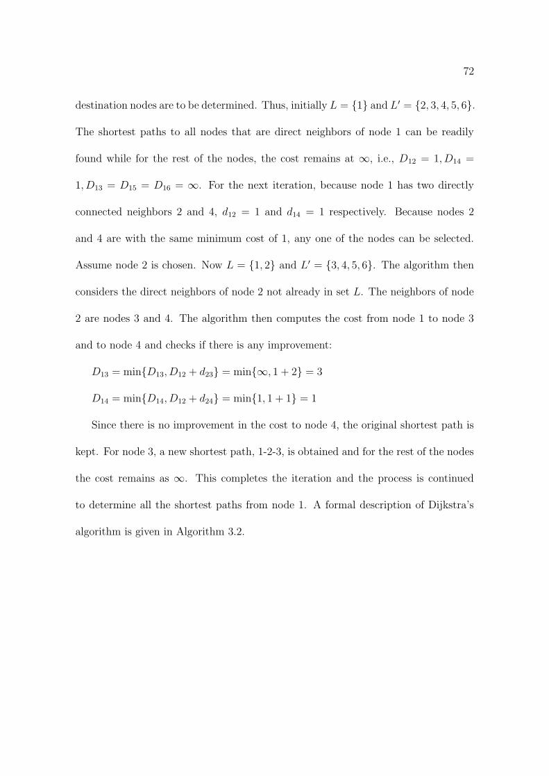
72
destination nodes are to be determined. Thus, initially L = 1 and L′ = 2, 3, 4, 5, 6.
The shortest paths to all nodes that are direct neighbors of node 1 can be readily
found while for the rest of the nodes, the cost remains at ∞, i.e., D12 = 1, D14 =
1, D13 = D15 = D16 = ∞. For the next iteration, because node 1 has two directly
connected neighbors 2 and 4, d12 = 1 and d14 = 1 respectively. Because nodes 2
and 4 are with the same minimum cost of 1, any one of the nodes can be selected.
Assume node 2 is chosen. Now L = 1, 2 and L′ = 3, 4, 5, 6. The algorithm then
considers the direct neighbors of node 2 not already in set L. The neighbors of node
2 are nodes 3 and 4. The algorithm then computes the cost from node 1 to node 3
and to node 4 and checks if there is any improvement:
D13 = minD13, D12 + d23 = min∞, 1 + 2 = 3
D14 = minD14, D12 + d24 = min1, 1 + 1 = 1
Since there is no improvement in the cost to node 4, the original shortest path is
kept. For node 3, a new shortest path, 1-2-3, is obtained and for the rest of the nodes
the cost remains as ∞. This completes the iteration and the process is continued
to determine all the shortest paths from node 1. A formal description of Dijkstra’s
algorithm is given in Algorithm 3.2.

73
Algorithm 3.2 Dijkstras Algorithm [111]
1: Start with source node i in the permanent list of nodes considered, i.e., L = i;2: All the rest of the nodes are put in the tentative list labelled as L
′
3: Dij = dij, for all j ∈ L′
4: Identify a neighboring node k not in the current list S with the minimum costpath from node i, i.e., find k ∈ L
′such that Dik = minm∈L
′ Dim.5: Add k to the permanent list L, i.e., L = L ∪ k6: Drop k from the tentative list L
′, i.e., L
′= L
′\ k
7: If L′is empty, stop
8: Consider the list of neighboring nodes, Nk, of the intermediary k (but do notconsider nodes already in L), to check for improvement in the minimum costpath, i.e.,
9: Dij = minDij, Dik + dkj, for j ∈ Nk ∩ L′
10: Go to Step 4
3.4 Literature review of the OSPF weight setting
problem
This section provides an overview of existing work from literature to solve the OSPFWS
problem. Notable research in optimizing OSPF weights has been reported in the liter-
ature [8, 11, 12, 15, 40, 46, 48, 56, 77, 103, 107, 125, 132, 137, 142, 143, 146, 147, 156,
160, 162, 182]. The pioneering work on the OPSF weight setting problem was done
by Fortz and Thorup [45, 47, 48], who used maximum utilization as the optimization
objective. The term “maximum utilization” refers to the maximum of all link uti-
lization values over all the link capacities in the network. A cost function based on
utilization ranges was first formulated by Fortz and Thorup [46], who applied tabu
search [59] to minimize “maximum utilization”. The optimization function defined

74
by Fortz and Thorup is as follows:
minimize Φ =∑
a∈A
Φa(la) (3.1)
subject to the constraints:
la =∑
(s,t)∈N×N
f (s,t)a , a ∈ A, (3.2)
f (s,t)a ≥ 0 (3.3)
where Φ is the cost function, Φa is the cost associated with arc a, la is the total traffic
load on arc a, f(s,t)a represents traffic flow from node s to t over arc a, N defines the
set of nodes, and A represents the set of arcs. Equation (3.2) indicates that the total
load (traffic) on arc a is equal to the sum of the traffic load on arc a and the traffic
load on all incoming arcs to arc a. The constraint in Equation (3.3) states that the
traffic flow from node s to t over arc a has to be greater than or equal to zero.
In Equation (3.1), Φa represents piecewise linear functions, with Φa(0) = 0, and
the derivative, Φ′
a(la), is calculated using the below equation.

75
Φ′
a(la) =
1 for 0 ≤ la/ca < 1/3,
3 for 1/3 ≤ la/ca < 2/3,
10 for 2/3 ≤ la/ca < 9/10,
70 for 9/10 ≤ la/ca < 1,
500 for 1 ≤ la/ca < 11/10,
5000 for 11/10 ≤ la/ca < ∞
(3.4)
Figure 3.2 illustrates the corresponding behavior of Equation (3.4). The above
function indicates that the utilization (which represents the load to capacity ratio)
of a link is acceptable within 100% of the link’s capacity. Fortz and Thorup em-
ployed a dynamic shortest path algorithm [44, 52, 140] to obtain multiple equidistant
shortest paths between a source-destination pair. By this mechanism, traffic load was
distributed equally across the links.
Subsequent to the work of Fortz and Thorup, many other researchers attempted
to solve the OSPF weight setting problem with different algorithms and different
objective functions. Ramakrishnan and Rodrigues [147] proposed a local search pro-
cedure using the same cost function as that of Fortz and Thorup. The main difference
between the two approaches was that Rodrigues and Ramakrishnan’s technique in-
creases the link metric (i.e. the OSPF weight assigned to a link) for heavily used

76
Figure 3.2: Cost function curve [46].
links. Ericsson et al. [40] developed a genetic algorithm [66] to solve the OSPFWS
problem, also using the cost function by Fortz and Thorup. Kandula et al. [77]
compared the performance of three OSPF weight optimizers while considering max-
imum link utilization as the optimization objective. Bhagat [8] proposed a hybrid
genetic algorithm for the OSPF weight setting problem while using the cost model of
Fortz and Thorup. Abo Ghazala et al. [58] performed a survey of various algorithms
applied to the OSPFWS problem, and also proposed a technique based on iterative
local search, while considering link utilization as the optimization objective. The
underlying cost function was the same as that proposed by Fortz and Thorup. In
a subsequent research article, Abo Ghazala et al. [56] assumed maximization of un-
used bandwidth as the optimization objective and employed SA and hybrid GAs for

77
weight optimization. Parmar et al. [132] formulated the OSPF weight setting prob-
lem as a mixed-integer linear programming problem and developed a branch-and-cut
algorithm while assuming minimization of network congestion as the optimization ob-
jective. Pioro et al. [137] considered the maximum load on any link in the network as
the measure of congestion and proposed two heuristic approaches for weight setting.
Srivastava et al. [162] also considered minimization of maximum load on any link
and proposed heuristic algorithms based on Lagrangian relaxation to determine fea-
sible solutions for the weight setting problem. Buriol et al. [15] extended the genetic
algorithm proposed in [40] to a memetic algorithm by adding a local search proce-
dure while using the same cost function as that of Fortz and Thorup. Bley [11, 12]
proposed unsplittable shortest path routing (UPSR) and claimed that the proposed
approach can be applied to other routing schemes such as OSPF, while considering
minimization of maximum congestion over all arcs. Zagozdzon et al. [182] proposed a
two-phase algorithm for resolving the OSPF weight setting problem while considering
the residual capacity as the optimization objective. This residual capacity resulted
from setting the link weights proportional to the inverse of their capacity. Reis et
al. [141] proposed a memetic algorithm for weight setting in OSPF and distributed
exponentially-weighted flow splitting (DEFT) protocols while considering minimiza-
tion of total link utilization. Lin and Gen [107] proposed a priority-based genetic
algorithm for shortest path routing in OSPF. Their results indicated that the pro-

78
posed GA could be used for weight setting in OSPF and other routing algorithms.
Retvari et al. [142, 143] studied the OSPF weight setting problem considering maxi-
mization of network throughput and proposed some algorithms that could efficiently
optimize the link weights. Nucci et al. [125] proposed a tabu search heuristic for
choosing link weights that takes into account both service level agreement (SLA)
requirements and link failures with the objective of optimizing link utilizations. Shir-
mali et al. [156] devised an approach based on Nash bargaining and decomposition
[122]. It was claimed that the proposed approach could easily be modified to yield
a mechanism for setting link weights for ISPs using OSPF in a way similar to that
of Fortz and Thorup. Riedl [146] presented an algorithm based on SA [91] to opti-
mize link metrics in OSPF networks. The algorithm took into account the original
routing configuration and allowed trade-off considerations between routing optimality
and adaptation impact. Lee et al. [103] modelled the optimal link weight assignment
problem as an integer linear programming problem while considering minimization of
total energy consumption of all links.
It is noteworthy to mention that, generally, the aforementioned approaches con-
sidered a single objective in the optimization process. For example, the cost function
proposed by Fortz and Thorup (Equation (3.1)), on which many subsequent attempts
were based [8, 15, 40, 57, 58, 147, 156], considered minimization of maximum link uti-
lization. Other researchers [77, 137, 162] also assumed minimization of maximum link

79
utilization. Other objectives considered in the optimization process were maximiza-
tion of unused link bandwidth [56], minimization of network congestion [11, 12, 132],
residual capacity of links [182], minimization of total link utilization [141], maximiza-
tion of network throughput [142, 143], and minimization of total energy consumption
over all links [103].
Exceptions from these single-objective optimization approaches were Nucci et al.
[125] and Sqalli et al. [149, 160]. Nucci et al. [125] considered link failure and link
no-failure states as the optimization objectives. Sqalli et al. [149, 160] considered
minimization of maximum utilization and minimization of congested links as the
optimization objectives to address OSPFWS problem.
A cost function developed by Sqalli et al. [149, 160] evolved from the earlier work
by Fortz and Thorup. The reason for using the cost function of Fortz and Thorup
was that the function was employed in many studies as mentioned above. One novel
aspect of the work of Sqalli et al. was the addition of another optimization objective
(i.e. minimization of congested links) in addition to minimization of maximum link
utilization. This resulted in better distribution of traffic in the network, since one
fundamental requirement of network traffic engineering is properly distributed traffic.
The objective function employed by Sqalli et al. is defined as
Φ = MU +
∑
a∈SetCA (la − ca)
|A|(3.5)

80
where MU is the maximum utilization of the network. SetCA defines the set of
congested links, |A| represents the total number of links in the network, ca refers to
the capacity of link a, and la is the total traffic on link a. Equation (3.5) is denoted
as “SqalliCF”.
The second term in Equation (3.5) defines the extra load on the network. This
extra load is divided by the total number of links present in the network to normalize
the entire function. For an uncongested network, the second term results as zero.
Thus, Equation (3.5) results in minimization of maximum utilization provided that
there is no congestion in the network. If congestion exists, then the function results in
the minimization of maximum utilization as well as the minimization of the number
of congested links. Sqalli et al. concluded that the cost function in Equation (3.5)
results in more efficient minimization of the number of congested links compared to
the cost function of Fortz and Thorup [46]. Furthermore, Sqalli et al. discovered that
the results for maximum utilization using Equation (3.5) were comparable to those
obtained by the approach of Fortz and Thorup. Using the cost function of Equation
(3.5), Sqalli et al. applied the SimE algorithm [93] to the OSPFWS problem and
compared the results with the results of SA [149]. Tabu search using the cost function
of Sqalli et al. [160] has also been applied to the OSPFWS problem [159].
A limitation of the cost function of Fortz and Thorup is that it minimizes “max-
imum utilization” only. This may lead to the existence of links which are either

81
congested or unused. The cost function proposed by Sqalli et al. (Equation (3.5))
was aimed at simultaneous optimization of maximum utilization and the number of
congested links, without any consideration of unused links. It is, therefore, not guar-
anteed that optimizing maximum utilization and the number of congested links would
implicitly optimize the number of unused links as well. This observation points to
the fact that to have a more stable traffic flow, traffic from congested links should
be shifted to unused links. Therefore, in order to overcome this issue, this thesis
proposes a fuzzy logic based cost function that addresses the simultaneous optimiza-
tion of maximum utilization, number of congested links, and number of unused links
through fuzzy logic based aggregation. The details of this cost functions is present in
a subsequent chapter.
3.5 Conclusion
This chapter described routing concepts, followed by a description of the RIP and
OSPF routing protocols. The Bellman-Ford and Dijkstra’s shortest path algorithms
have also been discussed. Lastly, a brief description of existing research work pertain-
ing to the OSPFWS problem was presented. The next chapter defines the OSPFWS
as a multi-objective optimization problem.

Chapter 4
Open Shortest Path First Weight
Setting Problem
This chapter provides a formal description of the OSPFWS problem. The problem
is formulated as a multi-objective optimization problem using fuzzy logic. Therefore,
the formation of membership functions for the design objectives is discussed along
with the fuzzy logic based fitness function used to evaluate a solution.
The outline of the chapter is as follows: Section 4.1 provides the formal descrip-
tion of the OSPFWS problem. The description of Fuzzy logic cost function for the
OSPFWS problem is given in Section 4.2. Section 4.3 provides the details of the test
cases used in this thesis.
82

83
4.1 Formal description of OSPFWS Problem
The purpose of this section is to describe the OSPFWS problem. Section 4.1.1 enu-
merates the steps to calculate the traffic load on each link, after assigning a set of
weights to the network links.
The OSPFWS problem is formulated as follows: Given a network topology and
predicted traffic demands, find a set of OSPF weights that optimizes network perfor-
mance. More precisely, given a directed network G = (N,A), a demand matrix D,
and capacity Ca for each arc a ∈ A, determine a positive integer weight ωa ∈ [1, ωmax]
for each arc a ∈ A such that the objective function or cost function Φ is minimized.
The maximum value of this weight, ωmax, is a user-defined upper limit. Fortz and
Thorup [45] discovered that a small range of values of weight significantly reduces
the overhead of the algorithm. By experimentation, they set ωmax to 20. The chosen
weights on arcs determine the shortest paths, which in turn completely determine the
routing of traffic flow, the loads on the arcs, and the value of the cost function. The
quality of OSPF routing is highly dependent on the selection of weights. Figure 4.1
shows a topology with weights assigned to each arc. These weights are in the range
[1, 20]. A solution for this topology can be (18, 1, 7, 15, 3, 17, 5, 14, 19, 13, 18, 4, 16, 16).
The weights for this solution are arranged through a breadth-first traversal of the
graph. For example, for node A, the weights on the outgoing links are 18 and 1. For
node B, the weights on outgoing links are 7 and 15, and so on.

84
As discussed in the previous chapter, the existing literature considered optimizing
up to two objectives, namely, maximum utilization and the number of congested
links. In this thesis, a third objective, namely minimization of the number of unused
links, is also considered as an optimization objective. Minimization of the number of
unused links is a conflicting objective, because the less the number of unused links, the
higher the maximum utilization and number of congested links. Minimizing maximum
utilization will lead to a better distribution of network traffic across all links such that
congestion can be avoided and the network can be utilized well as per its capacity [47].
Network administrators desire less congested links. However, if a network is highly
congested, then the preference is to reduce the congestion by at least minimizing the
total number of congested links. For example, assume a network with 50 congested
links and 20 unused links. It would be preferred to accommodate some or all of the
extra traffic of the 50 congested links on the 20 unused links. This will reduce, and
even eliminate, data loss in the network since data on a link will not be exceeding
the capacity of the link. Thus, such distribution will have a positive impact on the
performance of the network in terms of the prevention of data loss [116]. Therefore,
a new solution might create new routing paths such that traffic on congested links
may be distributed on unused links.

85
Figure 4.1: Representation of a topology with assigned weights.
4.1.1 Traffic Load Calculation
Given a weight setting, ωa | a ∈ A,ωa ≥ 1, the arc loads la are calculated in five
steps. For all demand pairs, dst ∈ D, consider one destination t at a time and compute
partial arc loads, lta ∀ t ∈ N ⊆ N , where N is the set of destination nodes and N is
the set of all nodes. The steps are as follows:
1. Compute the shortest distances dtu from each node u ∈ N to t using Dijkstra’s
shortest path algorithm [30]. Dijkstra’s algorithm usually computes the dis-
tances away from source s, but since it is required to compute the distance to
the destination node t from all other nodes, the algorithm is applied on the
graph obtained by reversing all arcs in G.

86
2. Compute the set At of arcs on shortest paths to t from all other nodes as
At = (u, v) ∈ A : ω(u,v) = dtu − dt
v
3. For each node u, let δtu denote its outdegree in Gt = (N,At), i.e.,
δtu = | v ∈ N : (u, v) ∈ At |
If δtu > 1, then traffic flow is split at node u to balance the load.
4. The partial loads lta are computed as follows:
(a) Nodes v ∈ N are visited in order of decreasing distance dtv to t.
(b) When visiting a node v, for all (v, h) ∈ At, set
lt(v,h) = 1/[δtv(dvt +
∑
(u,v)∈At lt(u,v))]
5. The arc load la is now summed from the partial loads as:
la =∑
t∈N lta
4.2 Fuzzy Logic Cost Function for the OSPFWS
Problem
This section describes the fuzzy logic cost function for the OSPFWS problem. A
solution to the OSPFWS problem is found by assigning weights to each network

87
link. The best solution is that one which optimizes the network resources efficiently.
The design objectives of the OSPFWS problem include maximum utilization (MU),
number of congested links (NOC), and number of unused links (NUL). These ob-
jectives individually on their own do not provide adequate information for deciding
the quality of a solution. The conflicting nature of these objectives further amplifies
the complexity of the problem. To address this complexity, a mechanism is required
to find a solution that provides the best trade-off covering all the objectives. Fuzzy
logic is one approach that can conveniently and efficiently handle the trade-off issues
between multiple objectives.
The rest of this section discusses the use of fuzzy logic to combine the three con-
flicting objectives into a single overall objective function which is a scalar quantity.
To formulate the overall objective function, the membership values of individual ob-
jectives need to be determined first, through membership functions. This process is
described below.
To define the membership function for MU, two extreme values, the minimum
and maximum, are determined first. These values are found from prior knowledge.
Figure 4.2 shows the membership function of the objective to be optimized (MU
in this case). Point “A” refers to minimum MU (MUmin) and point “B” refers to
maximum MU (MUmax). The membership value for MU, µMU , is determined as
follows:

88
1.0
0.8
0.6
0.4
0.2
0
µ
A B
Figure 4.2: Membership function of the objective to be optimized.
µMU(x) =
1 if MU ≤ MUmin
MUmax−MUMUmax−MUmin
if MUmin < MU ≤ MUmax
0 if MU > MUmax
(4.1)
The membership function for NOC, µNOC , is defined in a similar way. With
reference to Figure 4.2, point “A” then refers to minimum NOC (NOCmin) and “B”
refers to maximum NOC (NOCmax). The membership function of NOC is defined as
follows:

89
µNOC(x) =
1 if NOC ≤ NOCmin
NOCmax−NOCNOCmax−NOCmin
if NOCmin < NOC ≤ NOCmax
0 if NOC > NOCmax
(4.2)
Finally, the membership function for NUL, µNUL, is defined as
µNUL(x) =
1 if NUL ≤ NULmin
NULmax−NULNULmax−NULmin
if NULmin < NUL ≤ NULmax
0 if NUL > NULmax
(4.3)
where minimum (NULmin) and maximum (NULmax) values correspond to “A” and
“B” respectively in Figure 4.2.
A good solution to the OSPFWS problem is one that is characterized by a low
MU, low NOC, and low NUL. In fuzzy logic, this can be stated by the following fuzzy
rule:
Rule: IF a solution X has low MU AND low NOC AND low NUL THEN it is a
good solution.
The words “low MU”, “low NOC” and “low NUL” are linguistic variables, each
defining a fuzzy subset of solutions. Using the UAO operator [86], the above fuzzy
rule reduces to the following equation:

90
µ(x) =µMU(x)µNOC(x)µNUL(x) + ν × maxµMU(x), µNOC(x), µNUL(x)
ν + maxµMU(x), µNOC(x), µNUL(x)(4.4)
where µ(x) is the membership value for solution x in the fuzzy set “good OSPF weight
set” and ν is a constant in the range [0,1]. The solution which results in the maximum
value for Equation (4.4) is reported as the best solution.
As an example, consider an arbitrary solution S1, having µMU = 0.19, µNOC = 0.2,
and µNUL = 0.17. Also assume that ν = 0.5. Then, Equation (4.4) results in a value
of 0.152. Similarly, consider µMU = 0.22, µNOC = 0.23, and µNUL = 0.09 associated
with another arbitrary solution S2. Again assume that ν = 0.5. Then, Equation (4.4)
evaluates to 0.164. Thus, solution S2 is better than solution S1 in terms of quality.
Equation (4.4) is employed as a fuzzy cost function for solving the OSPFWS problem
and is denoted as “FuzzyCF”.
4.3 Details of Test Cases
This research work used the test cases proposed by Fortz and Thorup [46]. Table 4.1
shows the characteristics of the test cases. For each test case, the table lists its network
type, the number of nodes, and the number of links. The 2-level hierarchical networks
are generated using the GT-ITM generator [183], based on the model of Calvert [17]

91
and Zegura [184]. In hierarchical networks, short distance arcs have capacities equal
to 200, while long distance arcs have capacities equal to 1000. In random networks
and Waxman networks1, capacities are set at 1000 for all arcs. Fortz and Thorup
generated the demands to force some nodes to be more active senders or receivers
than others, thus modelling hot spots2 on the network. The demands generated by
Fortz and Thorup assign higher demands to closely located node pairs. Further details
on the assignment process of generated demands can be found in Fortz and Thorup
[47].
Table 4.1: Test cases for the OSPFWS problem (N = number of nodes, A = numberof arcs.). Smallest test case is in italics and the biggest test case is in boldface.
Test Code Network type N A
h100N280a 2-level hierarchical graph 100 280h100N360a 2-level hierarchical graph 100 360h50N148a 2-level hierarchical graph 50 148
h50N212a 2-level hierarchical graph 50 212r100N403a Random graph 100 403r100N503a Random graph 100 503
r50N228a Random graph 50 228r50N245a Random graph 50 245w100N391a Waxman graph 100 391w100N476a Waxman graph 100 476w50N169a Waxman graph 50 169w50N230a Waxman graph 50 230
1Waxman graphs are frequently chosen in simulations as topologies resembling communicationsnetworks. Waxman graphs are named after Bernard M. Waxman.
2A hot spot is a network point or router having heavy incoming and outgoing traffic.

92
4.4 Conclusion
This chapter defined the OSPFWS problem as a multi-objective optimization prob-
lem. Three design objectives, namely, maximum utilization, number of congested
links, and number of unused links are considered as the optimization objectives. The
three objectives are aggregated using the unified and-or operator.
The next chapter discusses the application of a multi-objective FSA algorithm to
solve the OSPFWS problem.

Chapter 5
Fuzzy Simulated Annealing
Algorithm for the OSPFWS
Problem
This chapter discusses the multi-objective FSA algorithm developed to solve the
OSPFWS problem. The fuzzy cost function (denoted as FuzzyCF) described in Chap-
ter 4 has been used as the underlying objective function. The chapter also provides a
sensitivity analysis of the FSA control parameters. The results of FSA are compared
with existing work in the literature.
The outline of the chapter is as follows: Section 5.1 provides implementation
details of the FSA algorithm. Section 5.2 describes the solution archiving mechanism
93

94
used by the FSA algorithm. Section 5.3 discusses the experimental setup used for FSA
simulations. This section also discusses the effect of the cooling rate parameter α on
the quality of solutions with respect to FuzzyCF. Section 5.3.1 provides a comparison
of the SqalliCF and FuzzyCF cost functions using the SA algorithm.
5.1 Fuzzy Simulated Annealing Algorithm
An algorithmic description of SA was given in Section 2.3.1. SA is applied as a multi-
objective algorithm to solve the OSPFWS problem by maximizing the cost function,
FuzzyCF, given in Equation (4.4). The OSPFWS problem requires an assignment of
a set of weights to the links in the network. This set of weights is a solution to the
OSPFWS problem. Thus in the context of the FSA algorithm, the weights are the
movable elements. A change in the weight of a link leads to different shortest paths
between source and destination pairs, resulting in a new solution, and thus providing
a different cost.
The FSA algorithm executes three main steps, namely, initialization, the metropo-
lis procedure, and evaluation. These steps are described below.
Initialization
The initialization step generates a random solution (i.e. a random set of weights).
The FSA control parameters, i.e. the initial temperature T0, the cooling rate α, the
constant β, maximum time for the annealing process Tmax (in terms of the number

95
of iterations), and the length of Markov chain, M , are also initialized.
The FSA control parameters have an impact on the convergence of the algorithm.
For example, the initial temperature T0 is set to an appropriate value, so that all
moves are accepted initially. The appropriate value is determined by a trail and error
approach. A very high initial temperature causes the algorithm to search blindly.
Contrary to this, a very low initial temperature results in bad solutions to be rejected
in the early stage of the search, therefore limiting exploration. A number of methods
have been proposed in the literature to determine an appropriate initial temperature
[21, 75, 91, 110, 135]. This thesis adopts the method proposed by Kirkpatrick [91],
where the value of T0 is chosen such that the initial acceptance ratio, X(T0), is close
to unity. The acceptance ratio is calculated using
X(T0) =NT0
TT0
(5.1)
where NT0is the number of moves accepted at temperature T0 and TT0
is the total
number of moves attempted at temperature T0.
The cooling rate, α, controls the rate of decrease in temperature. The higher the
value of α, the lower the decrease in temperature, and vice versa. A typical value of
α ranges from 0.8 to 0.99 [100].
Parameter M also has an impact on the convergence of FSA, and it is very im-
portant to determine an appropriate value of M . A very high value of M increases

96
the execution time. As an example, consider M = 35. This means that, at a given
temperature, the algorithm will attempt 35 moves. It is quite probable that the
same quality of solution is achieved with M = 15. Therefore, 20 moves are wasted.
Similarly, when M is very low (for example 5), then the algorithm may result in
poor quality solutions, simply because of the fact that the algorithm does not have
sufficient time to explore the search space for a given temperature.
Metropolis procedure
The core procedure of the annealing algorithm is known as the metropolis procedure.
This procedure is repeated for a given number of iterations. During the metropolis
procedure, a solution is perturbed through a move. For the OSPFWS problem, a
move involves selecting a weight from the set of given weights, and replacing the
selected weight with a different weight. For example, with reference to Figure 4.1, a
solution for this topology is (18, 1, 7, 15, 3, 17, 5, 14, 19, 13, 18, 4, 16, 16). FSA selects
a link randomly and replaces its weight with another random weight. Changing any
weight from the above solution will lead to a different solution in the search space.
Thus a new solution can be (18, 1, 7, 15, 3,5, 5, 14, 19, 13, 18, 4, 16, 16) by changing the
weight 17 to 5 on the link between node C and E. As shown in Figure 5.1, in the
subsequent iterations, weight 18 is changed to 9 on the link between nodes F and
D, weight 18 is changed to 10 on the link between nodes A and B, and weight 7 is
changed to 6 on the link between nodes B and C. Note that after each step shown, a

97
Figure 5.1: Sequence of moves in FSA.
new solution is generated. This solution is evaluated and compared with the previous
solution. If the cost of a new solution is better than the cost of the immediate previous
solution, then the new solution is accepted. If the cost of the new solution is less than
the cost of the immediate previous solution, then the new solution is probabilistically
accepted as explained in Section 2.3.1.
Evaluation of a solution
Once a new solution is generated, its cost should be computed. This is done using
FuzzyCF (Equation (4.4)). For each individual objective, minimum and maximum
values are a prerequisite for obtaining the membership values. These extreme values
are found as follows: For objective MU, the minimum value, MUmin, is taken as

98
the minimum utilization of the initial solution given to the algorithm during the
initialization phase. The maximum value for MU, MUmax, is taken as the maximum
utilization of the initial solution. The minimum value for objective NOC, NOCmin,
is set to zero. The maximum value for NOC, NOCmax, is taken as the number of
congested links obtained from the initial solution. In the same way, NULmin is set
to zero, while NULmax is taken as the number of unused links obtained from the
initial solution. In the subsequent steps, membership values for each objective are
calculated by using Equations (4.1), (4.2) and (4.3).
Stopping criterion
The algorithm is stopped when a maximum number of iterations has been reached.
The next section describes the archiving procedure used in FSA.
5.2 Solutions Archiving in FSA
In MOO there is a set of Pareto-optimal solutions, also known as the Pareto front. The
Pareto-optimal solutions are trade-off non-dominated solutions, and all of them are
global optimum solutions [6]. Since FSA is an iterative single-solution based algorithm
that generates a single solution in each iteration, the algorithm can not produce
Pareto-optimal solutions by its nature. In this thesis, a simple archiving scheme is
implemented during the execution of the proposed FSA. This is to determine whether
FSA has the capability to yield a set of non-dominated solutions. The initialization

99
step places the first solution in the archive. Then, the following procedure is used to
maintain the archive during subsequent iterations:
1. If the obtained new solution is non-dominating with all the members of archive,
then new solution is added to the archive.
2. If all the members of archive are dominated by the new solution, then all the
members are deleted from the archive and the new solution is added to the
archive.
3. If the new solution is not dominating any one of the members of archive, then
the new solution is not added to the archive.
5.3 Experimental setup
This section discusses the parameters used for SA with respect to FuzzyCF and
SqalliCF. For each test case (refer to Section 4.3 for the details on these test cases),
30 independent runs were executed for 5000 iterations. The average of the best cost
and the standard deviation over these 30 runs were calculated. For all experiments
with respect to SqalliCF, the parameters α = 0.965 and β = 1.01 were used as
recommended in a previous study by Sqalli et al [160]. Experiments were conducted
to obtain the best parameter values of α and M with respect to FuzzyCF. The first
set of experiments focussed on obtaining the best cooling rate parameter, α. Initially,

100
the values β = 1.01 and M = 20 were used. The initial α value was set as 0.99
for each test case. Subsequently, the α value was decreased by 0.01. As soon as
a lower α value produced a statistically significant worse result than a previously
evaluated higher α value, the higher α value was considered as the best value. For
example, if the α value 0.95 produced statistically significant worse result than the
result of α value 0.96, then the α value 0.96 was considered as the best α value.
Tables 5.1 and 5.2 provide the quality of solutions with respect to FuzzyCF obtained
for all the experimented cooling rate values. The penultimate column of the table
represents the percentage difference between the average fuzzy cost values obtained
for two consecutive α values. Because an α value of 0.99 is used as the initial value,
the percentage difference value for α = 0.99 is NA.
Besides these tables, graphic representations of the search progress for each ex-
perimented value of α with respect to all test cases are also shown in Figures 5.2,
5.3, 5.4 and 5.5. The results show that α = 0.96 performed well for all the test
cases and hence motivated the use of α = 0.96 for all further experiments. After
setting the value of α, further experimentation was done with values of the Markov
chain parameter M = 20 and M = 30 for all test cases with respect to FuzzyCF and
SqalliCF. As observed from Table 5.3, in general, M = 20 produced better results
for both SqalliCF (a lower value is desired) and FuzzyCF (a higher value is desired).
There are exceptions with respect to test cases h50N148a, r100N503a and w50N169a

101
for the FuzzyCF cost function. However, since M = 20 requires less perturbations,
and thus results in less execution time, M = 20 is preferred over M = 30. Therefore,
all experiments were conducted using M = 20 for both FuzzyCF and SqalliCF.
Figures 5.6 and 5.7 show the plots of the average fuzzy cost and standard devia-
tion for all the test cases over 30 independent runs with respect to FSA. The search
accepted bad solutions in the early phases of execution, and behaved greedily towards
the end, accepting only the good solutions. As the search progresses, successive tem-
perature values decrease depending on the value of cooling rate α. The decrease in
temperature decreases the probability of accepting bad moves. It is also observed
from the figures that the standard deviation decreased over time. A decrease in stan-
dard deviation confirms that all the results over these 30 independent runs converge
towards similar optimal solutions. Similar search progress trends and convergence
towards similar optimal solutions were also found with respect to SqalliCF as shown
in Figures 5.8 and 5.9. Note that FuzzyCF is a maximization function, while SqalliCF
was modelled as a minimization function.
5.3.1 Comparison of SqalliCF and FuzzyCF using SA
Table 5.4 summarizes the results obtained for FSA using SqalliCF and FuzzyCF.
Furthermore, the average runtime for each test case with respect to the two cost
functions is also provided. Table 5.5 shows the percentage improvement achieved by

102
Table 5.1: Best average FuzzyCF values for the test cases h50N148a, h50N212a,h100N280a, h100N360a, r50N228a and r50N245a with respect to experimented cool-ing rate values. Statistically significant differences are in italics. NA = Not Applicable(% Difference is calculated between the average fuzzy cost values obtained for twoconsecutive cooling rate values).
Test Case Cooling rate α Best Fuzzy Cost % Difference p-values0.99 0.348 ± 0.102 NA NA0.98 0.391 ± 0.021 11 0.043
h50N148a 0.97 0.431 ± 0.095 9.28 0.0370.96 0.547 ± 0.072 21.21 0.0050.95 0.522 ± 0.099 -4.79 0.1870.99 0.361 ± 0.068 NA NA0.98 0.417 ± 0.083 13.43 0.016
h50N212a 0.97 0.473 ± 0.072 11.84 0.0380.96 0.575 ± 0.075 17.74 0.030.95 0.517 ± 0.008 -11.22 0.2160.99 0.3 ± 0.041 NA NA0.98 0.328 ± 0.041 8.54 0.011
h100N280a 0.97 0.356 ± 0.116 7.87 0.0140.96 0.585 ± 0.154 39.15 0.0240.95 0.554 ± 0.078 -5.6 0.1260.99 0.287 ± 0.114 NA NA0.98 0.312 ± 0.096 8.01 0.012
h100N360a 0.97 0.333 ± 0.036 6.31 0.0090.96 0.6 ± 0.055 44.5 0.0330.95 0.57 ± 0.048 -5.26 0.1190.99 0.351 ± 0.006 NA NA0.98 0.426 ± 0.116 17.61 0.017
r50N228a 0.97 0.502 ± 0.047 15.14 0.0140.96 0.581 ± 0.025 13.6 0.0350.95 0.542 ± 0.114 -7.2 0.1670.99 0.307 ± 0.002 NA NA0.98 0.413 ± 0.062 25.67 0.03
r50N245a 0.97 0.52 ± 0.014 20.58 0.0350.96 0.613 ± 0.028 15.17 0.040.95 0.571 ± 0.114 -7.36 0.245

103
Table 5.2: Best average FuzzyCF values for the test cases r100N403a, r100N503a,w50N169a, w50N230a, w100N391a and w100N476a with respect to experimentedcooling rate values. Statistically significant differences are in italics. NA = NotApplicable (% Difference is calculated between the average fuzzy cost values obtainedfor two consecutive cooling rate values).
Test Case Cooling rate α Best Fuzzy Cost % Difference p-values0.99 0.309 ± 0.056 NA NA0.98 0.321 ± 0.084 3.74 0.017
r100N403a 0.97 0.333 ± 0.111 3.6 0.0210.96 0.487 ± 0.185 31.62 0.0140.95 0.482 ± 0.125 -1.04 0.1860.99 0.265 ± 0.023 NA NA0.98 0.274 ± 0.072 3.28 0.029
r100N503a 0.97 0.283 ± 0.107 3.18 0.0370.96 0.507 ± 0.32 44.18 0.0320.95 0.479 ± 0.008 -5.85 0.1740.99 0.432 ± 0.023 NA NA0.98 0.509 ± 0.053 15.13 0.008
w50N169a 0.97 0.587 ± 0.055 13.29 0.0320.96 0.692 ± 0.018 15.17 0.0290.95 0.668 ± 0.125 -3.59 0.1520.99 0.302 ± 0.006 NA NA0.98 0.355 ± 0.053 14.93 0.003
w50N230a 0.97 0.502 ± 0.076 29.28 0.0410.96 0.705 ± 0.138 28.79 0.0220.95 0.667 ± 0.078 -5.7 0.2340.99 0.376 ± 0.129 NA NA0.98 0.416 ± 0.068 9.62 0.017
w100N391a 0.97 0.456 ± 0.115 8.77 0.0240.96 0.628 ± 0.065 27.39 0.0140.95 0.602 ± 0.109 -4.32 0.2180.99 0.359 ± 0.053 NA NA0.98 0.445 ± 0.075 19.33 0.005
w100N476a 0.97 0.53 ± 0.061 16.04 0.0360.96 0.606 ± 0.032 12.54 0.0210.95 0.542 ± 0.032 -11.81 0.157

104
Figure 5.2: Plots of FSA average best cost for all the values of α with respect to thetest cases (a) h50N148a (b) h50N212a and (c) r50N228a. Search with value α = 0.96produced better results.

105
Figure 5.3: Plots of FSA average best cost for all the values of α with respect to thetest cases (a) r50N245a (b) w50N169a and (c) w50N230a. Search with value α = 0.96produced better results.

106
Figure 5.4: Plots of FSA average best cost for all the values of α with respect tothe test cases (a) h100N280a (b) h100N360a and (c) r100N403a. Search with valueα = 0.96 produced better results.

107
Figure 5.5: Plots of FSA average best cost for all the values of α with respect tothe test cases (a) r100N503a (b) w100N391a and (c) w100N476a. Search with valueα = 0.96 produced better results.

108
Table 5.3: Results of average cost for different values of Markov chain parameter(M) for SqalliCF and FuzzyCF. Imp. shows % improvement achieved with M = 20relative to M = 30. Significant % improvement is in boldface. Inferior performancewith M = 20 for FuzzyCF is in italics.
Test Case SqalliCF FuzzyCFM = 20 M = 30 % Imp. M = 20 M = 30 % Imp.
h50N148a 2.451±0.04 3.223±0.12 23.95 0.428±0.27 0.518±0.03 -21.03h50N212a 2.498±0.37 3.395±0.03 26.42 0.461±0.10 0.261±0.01 43.38h100N280a 2.654±0.10 2.688±0.02 1.27 0.543±0.04 0.519±0.02 4.42h100N360a 3.003±0.03 4.994±0.03 39.87 0.308±0.02 0.217±0.01 29.55r50N228a 14.618±1.23 30.453±2.03 52.00 0.588±0.09 0.561±0.01 4.59r50N245a 36.437±6.12 55.253±5.01 34.05 0.56±0.04 0.552±0.03 1.43r100N403a 26.811±2.30 49.309±5.01 45.63 0.457±0.02 0.375±0.09 17.94r100N503a 29.145±2.05 59.54±4.03 51.05 0.291±0.02 0.44±0.05 -51.20w50N169a 3.6±0.01 13.461±1.12 73.26 0.558±0.03 0.591±0.01 -5.91w50N230a 3.436±0.19 10.84±0.31 68.30 0.586±0.03 0.264±0.10 54.95w100N391a 2.666±0.06 8.065±0.04 66.94 0.455±0.02 0.257±0.01 43.52w100N476a 6.145±0.07 18.94±2.03 67.56 0.592±0.06 0.561±0.09 5.24

109
!"#
$!$
$$#
$"
% !&'
% $(
Figure 5.6: Average cost and associated standard deviation curves of FSA for allthe test cases with 50 nodes with respect to FuzzyCF (maximization function); α =0.96, β = 1.01 and M = 20.

110
!"
#$
%#
&#
' #(
' %)$
Figure 5.7: Average cost and associated standard deviation curves of FSA for allthe test cases with 100 nodes with respect to FuzzyCF (maximization function);α = 0.96, β = 1.01 and M = 20.

111
!
""
""!
"
# $%
# "&
Figure 5.8: Average cost and associated standard deviation curves of SA for allthe test cases with 50 nodes with respect to SqalliCF (minimization function); α =0.965, β = 1.01 and M = 20.

112
!"
#!
$!
% !&
% #'"
Figure 5.9: Average cost and associated standard deviation curves of SA for allthe test cases with 100 nodes with respect to SqalliCF (minimization funtion); α =0.965, β = 1.01 and M = 20 .

113
Table 5.4: MU, NOC, NUL, and average execution time corresponding to SqalliCFand FuzzyCF using FSA.
Test case Traffic SqalliCF FuzzyCFDemand MU NOC NUL Time MU NOC NUL Time(bytes) (sec) (sec)
h100N280a 4605 1.36± 10.17± 13.13± 1177± 1.50± 8.93± 0.70± 859.1±0.017 2.422 3.181 12.084 0.352 1.388 3.313 8.658
h100N360a 12407 1.66± 16.20± 16.93± 1091.1± 2.01± 21.03± 0.20± 796.5±0.157 3.067 4.401 8.016 0.531 6.300 0.484 5.138
h50N148a 4928 1.40± 9.63± 3.07± 135.2± 1.51± 8.40± 0.00± 98.2±0.058 2.251 1.460 1.095 0.100 1.670 0.000 3.097
h50N212a 3363 1.47± 5.63± 43.70± 145.7± 1.68± 5.17± 0.07± 102.1±0.277 1.670 5.977 1.23 0.080 0.791 0.254 1.592
r100N403a 70000 1.93± 63.50± 3.00± 1335.5± 2.72± 62.60± 0.03± 1017.2±0.184 5.124 1.681 13.798 0.576 6.579 0.183 13.792
r100N503a 100594 1.86± 83.60± 5.87± 1390.4± 3.58± 82.33± 6.57± 1069.8±0.143 6.184 2.713 14.209 0.416 26.212 16.079 18.918
r50N228a 42281 1.58± 26.97± 5.80± 160.3± 2.02± 22.03± 0.03± 116.1±0.154 3.347 2.441 1.466 0.134 2.251 0.183 1.408
r50N245a 53562 2.24± 41.83± 5.10± 159.1± 2.83± 28.77± 0.23± 117.2±0.276 4.913 2.056 1.788 0.239 2.622 0.504 2.329
w100N391a 48474 1.44± 2.33± 4.80± 1355.5± 1.75± 42.10± 7.23± 1029.2±0.046 1.647 1.954 13.423 0.708 19.921 6.185 22.928
w100N476a 63493 1.42± 23.83± 14.73± 1383.3± 2.24± 41.70± 4.73± 1048.2±0.043 6.923 3.433 13.392 0.219 15.647 11.694 21.955
w50N169a 25411 1.27± 8.60± 2.93± 153.7± 1.41± 8.80± 0.00± 110.7±0.021 1.792 1.552 1.552 0.086 1.808 0.000 1.78
w50N230a 39447 1.23± 4.90± 6.13± 158.6± 1.55± 14.40± 1.37± 113.8±0.017 1.493 2.674 1.938 0.151 19.08 4.537 2.497

114
Table 5.5: Comparison of FuzzyCF and SqalliCF in percentage using SA. Superiorperformance of FuzzyCF is in boldface and inferior performance of FuzzyCF is initalics.
Test Case MU p-value NOC p-value NUL p-value% diff % diff % diff
h100N280a -10.29 0.022 12.19 0.019 94.67 0.013h100N360a -21.08 0.001 -29.81 0.027 98.82 0.011h50N148a -7.86 0.031 12.77 0.019 100.00 0.010h50N212a -14.29 0.022 8.17 0.172 99.84 0.010r100N403a -40.93 0.003 1.42 0.557 99.00 0.027r100N503a -92.47 0.001 1.52 0.798 -11.93 0.815r50N228a -27.85 0.021 18.32 0.041 99.48 0.009r50N245a -26.34 0.034 31.22 0.035 95.49 0.020
w100N391a -21.53 0.021 -1706.87 0.000 -50.63 0.044w100N476a -57.75 0.009 -74.99 0.008 67.89 0.032w50N169a -11.02 0.033 -2.33 0.669 100.00 0.010w50N230a -26.02 0.017 -193.88 0.001 77.65 0.000
FuzzyCF when compared to SqalliCF. The results in both tables are displayed with
respect to the three design objectives, i.e. MU, NOC, and NUL.
From Table 5.4, it is observed that SqalliCF was able to generate lower levels of
MU as compared to FuzzyCF for all test cases. More specifically, MU for SqalliCF
was generally in the range 1.23 to 1.93, with the exception of r50N245a (having an
MU level of 2.24). For FuzzyCF, MU was generally in the range 1.41 to 3.58. The
difference between the MU levels of the two approaches were statistically evaluated
for significance in terms of the percentage improvements as shown in Table 5.5. The
results in the second column of table suggest that, for the objective MU, the results
obtained by FuzzyCF were of inferior quality than those of SqalliCF.

115
With respect to the second objective (NOC), the results were somewhat mixed
as shown in Table 5.4. For all the Waxman graphs as well as test case h100N360a,
SqalliCF resulted in a lower number of congested links, while for the remaining test
cases, the FuzzyCF cost function showed better performance. This was confirmed by
the values in Table 5.5, which showed statistically better results for FuzzyCF than
SqalliCF for four test cases (h100N280a, h50N148a, r50N228a, and r50N245a), while
SqalliCF performed statistically significantly better than FuzzyCF for the other four
cases (h100N360a, w100N391a, w100N476a, and w50N230a). For the remaining four
cases, both FuzzyCF and SqalliCF had the same quality of results.
The third objective (i.e. NUL) is reflected in Table 5.4, highlighting the dominant
trend that FuzzyCF performed significantly better than SqalliCF for over 80% (i.e.
10 out of 12) of the test cases. As seen in Table 5.5, the results obtained by FuzzyCF
were significantly better than that of SqalliCF, except for test case w100N391a while
for r100N503a, the results were of the same quality.
With regard to the execution time, it is observed from Table 5.4 that the average
execution time per run for FuzzyCF was less than that of SqalliCF.
Based on the above observations and analysis, it can be suggested that overall,
FuzzyCF performed better than SqalliCF.

116
5.4 Conclusion
This chapter presented the FSA algorithm for the OSPFWS problem. The fuzzy
logic based objective function, FuzzyCF, was incorporated in the FSA algorithm. A
sensitivity analysis of the parameters of FSA was performed, which indicated that α
= 0.965 and M = 20 produced the best results for FSA. FSA was compared with
another SA algorithm based on the SqalliCF cost function. The results indicated
that:
• for the MU objective, FuzzyCF produced results of inferior quality as compared
to that of SqalliCF.
• for the NOC objective, FuzzyCF performed statistically significantly better than
SqalliCF for 4 out of 12 test cases. FuzzyCF performance was comparable to
SqalliCF for 4 out of 12 test cases.
• for the NUL objective, FuzzyCF performed better than SqalliCF for 10 out of
12 test cases.
Furthermore, archiving of solutions is implemented in FSA to obtain a set of non-
dominated solutions. This archive of solutions will be used in Chapter 8 to compare
the performance of FSA with other population-based algorithms.

Chapter 6
Fuzzy Simulated Evolution
Algorithm for the OSPFWS
Problem
This chapter presents the multi-objective FSimE algorithm for the OSPFWS problem.
The fuzzy cost function, FuzzyCF, described in Chapter 4 has been used as the
underlying objective function. The results are compared with a SimE algorithm
employing the SqalliCF cost function.
The outline of the chapter is as follows: Section 6.1 provides implementation
details of the FSimE algorithm. Section 6.2 provides the experimental setup used
for the FSimE simulations. Section 6.3 discusses the effect of the bias parameter,
117

118
B, on the quality of solutions with respect to FuzzyCF. Section 6.3 also provides a
comparison of the SqalliCF and FuzzyCF cost functions using the SimE algorithm.
6.1 Fuzzy Simulated Evolution Algorithm
A detailed algorithmic description of SimE was given in Section 2.3.2. The SimE
algorithm updates a single solution, but unlike SA, navigates the search space by
employing compound moves (takes more than one move per iteration) as shown in
Figure 6.1, which corresponds to the topology given in Figure 4.1. The underlined
numbers are the new weights on their respective links of the network. The algorithm
repetitively iterates between the evaluation, selection, and allocation steps before
a pre-defined stopping criterion is reached. Furthermore, the concept of archiving
(as explained in Section 5.2) is also applied to FSimE. Similar to FSA, FSimE also
yielded an archive of non-dominated solutions. The implementation of the main steps
of FSimE are described below:
Evaluation
For the OSPFWS problem, each element is a weight on a link, for which goodness
needs to be evaluated. The goodness function is one of the key factors that affects
the performance of the FSimE algorithm, and should therefore be carefully designed.
This thesis uses the goodness function defined by Sqalli et al. [149] for both cost
functions (SqalliCF and FuzzyCF). The goodness function is defined as

119
Figure 6.1: Sequence of moves in FSimE within the allocate function.
gi =
1 − ui for MU ≤ 1
1 − ui/MU + ui/MU2 for MU > 1
(6.1)
where ui represents the utilization on link i and MU refers to the maximum utilization.
To illustrate how the above goodness function works, examine the following example:
consider two links e1 and e2 of a particular solution. Let the maximum utilization be
0.9. Assume that the utilizations on links e1 and e2 are 0.6 and 0.1, respectively. By
substituting the above values in the goodness function in Equation (6.1), ge1= 0.4
and ge2= 0.9 are obtained. In the next iteration, e1 is more probable to be selected
for replacement than e2. This is because the goodness of e1 is worse than that of e2.

120
Now, consider the maximum utilization to be 1.8, and let the utilization on links e1
and e2 be 0.7 and 1.4, respectively. From Equation (6.1), ge1= 0.827 and ge2
= 0.655.
In the next iteration, e2 is more probable to be selected for replacement than e1.
Selection
In the selection phase, for each link, i, a random number is sampled from a uniform
distribution in the range [0,1]. If this random number is larger than gi + B, the
corresponding weight is selected for allocation.
The bias B is used to control the size of the set of selected weights. A low
value of B increases the number of elements selected in each iteration, thus allowing
the algorithm to explore more. This may lead to high quality solutions, but at the
expense of higher computational effort. A high value of B inflates the goodness
of each element. This may result in a reduced number of elements selected for re-
allocation. Consequently, the execution time of the algorithm is reduced, but at the
risk of premature convergence to a sub-optimal (or local optimal) solution.
Since it is computationally expensive to find the best bias value by a process of
trial-and-error, different approaches have been proposed in the literature [84, 148] to
use a dynamic bias, instead of a user-defined static bias. The approach by Sait et al.
[148] calculates the bias based on the quality of the current solution and changes in
every iteration. The corresponding dynamic bias is given by
B(t) = 1 − G(t) (6.2)

121
where B(t) is the bias in iteration t and G(t) is the average goodness of all the elements
at the start of that iteration. The average goodness of elements is a measure of how
many “good” elements are present in the solution. For a detailed analysis of the
dynamic bias, refer to Sait et al. [148].
Allocation
During the allocation step of the algorithm, the selected weights are removed from the
solution one at a time. For each removed weight, new weights are tried in such a way
that they result in an overall better solution. The following allocation scheme was
adopted: For all iterations, a weight window of size 4 is kept. Therefore, if weight
6 was selected for replacement, then weight values 4, 5, 7, and 8 are tried. This
results in a beam search and is done to have less disturbance in the solutions in each
iteration.
Figures 6.2 and 6.3 illustrate a typical behavior of the proposed FSimE algorithm.
These figures respectively plot the average goodness of weights and the cardinality of
the selection set for the test case r100N503a as an example. It is observed in Figure
6.2 that the average goodness increases with time. In the initial stages of the search,
the goodness increases significantly. However, as the search progresses, the average
goodness increases slowly. Figure 6.3 illustrates the cardinality of the selection set.
It is observed that the number of selected elements (i.e., weights) decreases as the
number of iterations increases. This suggests that, on average, the weights have been

122
assigned to their optimal values, and the algorithm reached a level of convergence.
Therefore, fewer elements (i.e., weights) are selected for perturbation. If the two
trends in Figures 6.2 and 6.3 are considered together, the general observation is that
the convergence of the FSimE algorithm towards a better solution is correlated with
the average goodness of links. The increase in average goodness with a decrease in
the selection set size indicates that most of the links are in their optimal or near
optimal positions and therefore less moves are made. This relationship between av-
erage goodness and selection set size is also illustrated in Figure 6.4 for the test case
r100N503a. When the average goodness of weights is low, the selection set size is
big and vice versa. Thus bad elements (i.e. weights) were differentiated from good
elements and were subjected to be changed with better weights.
6.2 Experimental setup
For each test case, 30 independent runs were executed for 100 iterations and the
average of the best solutions found in each run was recorded, together with the
standard deviation. Static bias values of -0.02, -0.1, 0, 0.1, 0.2, 0.3 and a dynamic
bias (see Equation (6.2)) were used for analysis with respect to FuzzyCF. For the
SqalliCF cost function, a bias value of -0.02 was used as reported by Sait et al. [149].
The Wilcoxon rank-sum test [65] was used to validate the significance of the results.
A confidence level of 95% was used.

123
Figure 6.2: Average goodness of weights for test case r100N503a.
Figure 6.3: Selection set size for test case r100N503a.

124
Figure 6.4: Average goodness vs selection set size for test case r100N503a.
6.3 Results and Discussion
The purpose of this section is to discuss the effect of the bias parameter, B, on the
quality of solutions with respect to FuzzyCF. This section also provides a comparison
of the SqalliCF and FuzzyCF cost functions using the SimE algorithm.
The average cost over 30 independent runs for each bias value is shown in Tables
6.1, 6.2 and 6.3 for the 12 test cases (details of the test cases are presented in Sec-
tion 4.3). Graphic illustrations of the search progress for each experimented value of
the bias with respect to all test cases are shown in Figures 6.5, 6.6, 6.7 and 6.8. It is
observed that a bias value of -0.1 produced the best results (i.e. having the highest
value for FuzzyCF) for all the test cases. Furthermore, a dynamic bias was not able
to produce high quality results. Therefore, for all experiments involving FSimE with
FuzzyCF, a bias value of -0.1 was used.
The average value of MU for all test cases was lower for SqalliCF than that of

125
Table 6.1: Effect of bias value on the quality of solution for the test cases h50N148a,h50N212a, h100N280a and h100N360a. Statistically significant improvement achievedby value -0.1 over other values is in boldface. NA = Not Applicable (The value -0.1is used to calculate % improvement over other values).
Test Case Bias Value Avg. Cost % Impr.-0.02 0.4±0.151 19.679-0.1 0.498±0.078 NA0 0.374±0.038 24.9
h50N148a 0.1 0.23±0.076 53.8150.2 0.268±0.062 46.1850.3 0.181±0.089 63.655Dynamic 0.306±0.027 38.554-0.02 0.415±0.017 10.944-0.1 0.466±0.144 NA0 0.395±0.015 15.236
h50N212a 0.1 0.287±0.045 38.4120.2 0.266±0.093 42.9180.3 0.22±0.045 52.79Dynamic 0.293±0.096 37.124-0.02 0.2±0.003 64.789-0.1 0.568±0.117 NA0 0.345±0.028 39.261
h100N280a 0.1 0.369±0.001 35.0350.2 0.262±0.088 53.8730.3 0.203±0.076 64.261Dynamic 0.186±0.04 67.254-0.02 0.37±0.064 27.875-0.1 0.513±0.162 NA0 0.429±0.037 16.374
h100N360a 0.1 0.348±0.044 32.1640.2 0.293±0.031 42.8850.3 0.166±0.061 67.641Dynamic 0.357±0.074 30.409

126
Table 6.2: Effect of bias value on the quality of solution for the test cases r50N228a,r50N245a, r100N403a and r100N503a. Statistically significant improvement achievedby value -0.1 over other values is in boldface. NA = Not Applicable (The value -0.1is used to calculate % improvement over other values).
Test Case Bias Value Avg. Cost % Impr.-0.02 0.538±0.118 11.658-0.1 0.609±0.134 NA0 0.276±0.058 54.68
r50N228a 0.1 0.493±0.015 19.0480.2 0.45±0.091 26.1080.3 0.382±0.099 37.274Dynamic 0.279±0.029 54.187-0.02 0.298±0.098 51.702-0.1 0.617±0.132 NA0 0.572±0.08 7.293
r50N245a 0.1 0.29±0.092 52.9980.2 0.474±0.098 23.1770.3 0.336±0.085 45.543Dynamic 0.508±0.198 17.666-0.02 0.3±0.037 47.826-0.1 0.575±0.03 NA0 0.206±0.053 64.174
r100N403a 0.1 0.258±0.081 55.130.2 0.24±0.019 58.2610.3 0.1666±0.028 71.026Dynamic 0.24±0.033 58.261-0.02 0.3±0.082 52.607-0.1 0.633±0.101 NA0 0.3±0.058 52.607
r100N503a 0.1 0.494±0.058 21.9590.2 0.471±0.103 25.5920.3 0.293±0.074 53.712Dynamic 0.492±0.111 22.275

127
Table 6.3: Effect of bias value on the quality of solution for the test casesw50N169a, w50N230a, w100N391a and w100N476a. Statistically significant improve-ment achieved by value -0.1 over other values is in boldface. NA = Not Applicable(The value -0.1 is used to calculate % improvement over other values).
Test Case Bias Value Avg. Cost % Impr.-0.02 0.61±0.078 7.855-0.1 0.662±0.093 NA0 0.547±0.065 17.372
w50N169a 0.1 0.478±0.037 27.7950.2 0.453±0.051 31.5710.3 0.352±0.051 46.828Dynamic 0.491±0.065 25.831-0.02 0.302±0.089 57.284-0.1 0.707±0.031 NA0 0.276±0.098 60.962
w50N230a 0.1 0.457±0.061 35.3610.2 0.39±0.089 44.8370.3 0.335±0.076 52.617Dynamic 0.493±0.098 30.269-0.02 0.333±0.076 54.57-0.1 0.733±0.068 NA0 0.638±0.005 12.96
w100N391a 0.1 0.61±0.095 16.780.2 0.55±0.012 24.9660.3 0.25±0.071 65.894Dynamic 0.562±0.082 23.329-0.02 0.652±0.093 14.548-0.1 0.763±0.091 NA0 0.611±0.026 19.921
w100N476a 0.1 0.507±0.052 33.5520.2 0.504±0.073 33.9450.3 0.348±0.034 54.391Dynamic 0.542±0.096 28.965

128
Figure 6.5: Plots of FSimE average best cost for all the bias values with respect tothe test cases (a) h50N148a (b) h50N212a and (c) r50N228a. Search with bias value-0.1 produced better results.

129
Figure 6.6: Plots of FSimE average best cost for all the bias values with respect tothe test cases (a) r50N245a (b) w50N169a and (c) w50N230a. Search with bias value-0.1 produced better results.

130
Figure 6.7: Plots of FSimE average best cost for all the bias values with respect tothe test cases (a) h100N280a (b) h100N360a and (c) r100N403a. Search with biasvalue -0.1 produced better results.

131
Figure 6.8: Plots of FSimE average best cost for all the bias values with respect tothe test cases (a) r100N503a (b) w100N391a and (c) w100N476a. Search with biasvalue -0.1 produced better results.

132
Table 6.4: MU, NOC, NUL, and average execution time corresponding to two costfunctions using SimE.
Test case Traffic SqalliCF FuzzyCFDemand MU NOC NUL Time MU NOC NUL Time(bytes) (sec) (sec)
h100N280a 4605 1.34± 10.73± 21.33± 1220.4 1.41± 8.50± 1.23± 875.90.000 2.449 3.078 0.058 1.432 0.898
h100N360a 12407 1.42± 15.63± 17.67± 1189.6 1.72± 16.13± 0.93± 826.60.088 2.189 3.708 0.092 2.240 1.015
h50N148a 4928 1.42± 10.93± 3.67± 148.1 1.62± 10.37± 0.07± 128.60.051 2.518 1.668 0.119 2.025 0.254
h50N212a 3363 1.32± 7.60± 46.07± 151 1.67± 4.93± 2.77± 137.50.096 1.714 5.705 0.102 0.740 1.924
r100N403a 70000 1.44± 53.13± 0.83± 1597.9 1.86± 44.73± 0.13± 1588.50.064 4.562 0.648 0.074 2.490 0.346
r100N503a 100594 1.41± 37.77± 1.63± 1479.2 2.19± 52.80± 0.17± 1334.10.059 5.283 0.890 0.166 2.809 0.379
r50N228a 42281 1.36± 24.83± 2.20± 160 1.80± 19.77± 0.10± 152.20.054 3.130 1.808 0.121 1.305 0.305
r50N245a 53562 2.14± 39.20± 2.03± 167.2 2.60± 26.20± 0.80± 114.40.182 3.872 0.999 0.193 1.972 0.887
w100N391a 48474 1.41± 1.10± 5.03± 1371 1.42± 7.17± 0.03± 1132.30.006 0.305 1.829 0.033 2.692 0.183
w100N476a 63493 1.32± 7.07± 12.63± 1374.6 1.46± 17.07± 0.60± 1174.90.003 1.143 1.712 0.070 2.363 0.814
w50N169a 25411 1.26± 9.37± 2.80± 178.4 1.44± 8.37± 0.03± 134.80.016 2.205 1.375 0.078 1.189 0.183
w50N230a 39447 1.23± 3.67± 5.27± 189.1 1.44± 9.13± 0.27± 112.80.007 0.959 1.741 0.088 1.570 0.583

133
Table 6.5: Comparison of FuzzyCF and SqalliCF in percentage using SimE. Superiorperformance of FuzzyCF is in boldface and inferior performance of FuzzyCF is initalics.
Test Case MU p-value NOC p-value NUL p-value% diff % diff % diff
h100N280a -5.22 0.032 20.78 0.040 94.23 0.019h100N360a -21.13 0.027 -3.20 0.385 94.74 0.018h50N148a -14.08 0.020 5.12 0.341 98.09 0.020h50N212a -26.52 0.022 35.13 0.033 93.99 0.011r100N403a -29.17 0.020 15.81 0.031 84.34 0.010r100N503a -55.32 0.016 -39.79 0.027 89.57 0.012r50N228a -32.35 0.019 20.38 0.019 95.45 0.034r50N245a -21.50 0.011 33.16 0.020 60.59 0.023
w100N391a -0.71 0.045 -551.82 0.000 99.40 0.011w100N476a -10.61 0.022 -141.44 0.001 95.25 0.025w50N169a -14.29 0.020 10.67 0.033 98.93 0.019w50N230a -17.07 0.015 -148.77 0.001 94.88 0.021
FuzzyCF. From the third column of Table 6.4, note that MU using SqalliCF was in
the range 1.23 to 1.44, with the exception of r50N245a (with MU level of 2.14). For
FuzzyCF, the MU was generally in the range of 1.41 to 1.72; with the exception of
r100N503a and r50N245a, having an MU of 2.19 and 2.60, respectively. The outcome
of a statistical test on the percentage improvement (second column of Table 6.5)
suggests that FuzzyCF produced inferior results compared to SqalliCF for all test
cases.
For the NOC objective, the results in Table 6.4 show superior performance by
FuzzyCF for seven cases out of which six are statistically significant as shown in
Table 6.5. For two test cases (h100N360a and h50N148a), the results were of the same

134
quality. Furthermore, SqalliCF showed statistically significantly better performance
for the remaining cases (r100N503a, w100N391a, w100N476a, and w50N230a).
For the NUL objective, FuzzyCF had a lower number of unutilized links (which
is desired) than SqalliCF for all test cases, as depicted in Table 6.4. As suggested
by the values in Table 6.5, all results obtained by FuzzyCF were significantly better
than SqalliCF.
As far as execution time is concerned, the results depict more or less the same
trend as observed for FSA. Table 6.4 shows that the average execution time per run
for FuzzyCF was less than that of SqalliCF.
In view of the above results and analysis, the overall assessment is that FuzzyCF
performed better than SqalliCF.
6.4 Conclusion
This chapter proposed and investigated a fuzzy multi-objective algorithm based on
the SimE algorithm developed to solve the OSPFWS problem. The proposed algo-
rithm utilizes the fuzzy logic based objective function, namely, FuzzyCF. The FSimE
algorithm was compared with a SimE algorithm that uses the SqalliCF cost function.
An empirical analysis showed that the performance of FuzzyCF was:
• worse than SqalliCF with respect to MU for all test cases;

135
• better than SqalliCF for the majority of test cases with respect to NOC; and
• better than SqalliCF for all test cases with respect to NUL.
Furthermore, archiving of solutions is implemented in FSimE to get a set of non-
dominated solutions. This archive set of solutions will be used in Chapter 8 to
compare the performance of FSimE with other population-based algorithms.

Chapter 7
Particle Swarm Optimization
Algorithm Variants and NSGA-II
for the OSPFWS Problem
This chapter presents the PSO algorithm variants to solve the OSPFWS problem.
These algorithm variants are FPSO, FEPSO, WAPSO, and PDPSO. The fuzzy cost
function (denoted as FuzzyCF) described in Chapter 4 is used as the underlying
objective function for FPSO and FEPSO. The weighted sum (or aggregation) method
described in Section 2.1.1 is used as the cost function for WAPSO, while the PDPSO
algorithm uses the non-dominance criterion to solve the OSPFWS problem. The
NSGA-II algorithm is then discussed. Control parameters are optimized for all the
136

137
algorithms presented in this chapter.
The outline of the chapter is as follows: Section 7.1 provides the implementation
details of the FPSO algorithm. FEPSO is discussed in Section 7.2. The chapter
is then followed by a discussion of WAPSO in Section 7.3. Section 7.4 describes
the PDPSO algorithm for the OSPFWS problem. Lastly, NSGA-II is discussed in
Section 7.5.
7.1 Fuzzy Particle Swarm Optimization Algorithm
The purpose of this section is to describe the implementation details of the FPSO
algorithm. Section 7.1.1 discusses the particle position and velocity representation
for the OSPFWS problem. The velocity update step of FPSO is discussed in Sec-
tion 7.1.2. Lastly, the particle position update of the FPSO implementation is given
in Section 7.1.3, followed by control parameter tuning in Section 7.1.4.
The original PSO algorithm was discussed in Chapter 2. Just like standard PSO,
FPSO navigates the search space by maintaining a swarm of candidate solutions, with
each candidate solution referred to as a particle. Each particle explores new positions
in the search space through its own history of traversing the search space, and from
the experience of other particles in the particle’s neighborhood. With respect to the
OSPFWS problem, each particle reaches a new candidate solution by changing a few
weights on the links of the network. As with the basic PSO, the guidance in changing

138
these weights is provided by the particle’s current position, its own best position so
far, and the global best position obtained so far by the entire algorithm. Each step
of the proposed FPSO algorithm is discussed in the following sub-sections in detail
with the aid of examples.
7.1.1 Particle Position and Velocity Representation
The standard PSO uses floating-point vectors to represent positions and velocities.
For the OSPFWS problem the solution representation is a set of weights on the
network links. Therefore, this study uses a fixed size set representation for particles.
The size of each set is equal to the number of links in the network. Therefore, for an
arbitrary network, each particle position is defined as a set
Xi(t) = ωab : (a, b) ∈ E
where ωab is the weight assigned to the link between nodes a and b in the network, and
E is a set of edges. W = |Xi(t)| is the number of weights in the solution, which is also
equal to the number of links in the network. The velocity of particle i is represented
as
Vi(t) = (ω ⇒ ω′)ab
which represents a sequence of replacement operators, where the weight ω of link
(a, b) is replaced with a new value, ω′, and |Vi(t)| gives the total number of changes

139
to particle i subject to the constraint, 0 ≤ |Vi(t)| ≤ W .
Example 1: Consider the topology given in Figure 4.1. Note that the total
number of links is 14. The assigned weights in this figure represents a possible con-
figuration at time t, whereas the configuration represents a solution (i.e. a particle).
A solution for this topology can be (18, 1, 7, 15, 3, 17, 5, 14, 19, 13, 18, 4, 16, 16). This
current solution is represented as
Xi(t) =
18AB, 1AF , 7BC , 15BD, 3CE, 17CF , 5DA, 14EA, 19EG, 13FB, 18FD, 4FG, 16GB, 16GD
Also assume that, at time t, Vi(t) = (19 ⇒ 18)AB, (2 ⇒ 1)AF , (4 ⇒ 7)BC , (12 ⇒
15)BD, (4 ⇒ 3)CE, (15 ⇒ 17)CF , (6 ⇒ 5)DA, (12 ⇒ 14)EA, (13 ⇒ 19)EG, (10 ⇒
13)FB, (11 ⇒ 18)FD, (9 ⇒ 4)FG, (17 ⇒ 16)GB, (17 ⇒ 16)GD. That is, the above
solution, Xi(t), was obtained by replacing weight 19 on link AB with a weight of 18,
weight 2 on link AF was replaced with a weight of 1, and so on. The particle Xi(t)
is then updated in subsequent steps as discussed in the following sub-sections.
7.1.2 Velocity Update
The velocity of particle i is updated using
Vi(t + 1) = w ⊗ Vi(t) ⊕ c1r1(t) ⊗ [Pi(t) Xi(t)] ⊕ c2r2(t) ⊗ [Pg(t) Xi(t)] (7.1)

140
where Pi(t) represents the particle’s own best position, and Pg(t) represents the
global best position. It is noted that the sets Xi(t), Pi(t) and Pg(t) have the same
set of links for a given network topology.
Equation (7.1) uses the operator ⊗ in three terms namely in the calculation of
the inertia component, the cognitive component, and the social component. For these
three terms, the same constant is multiplied with a set, generally expressed as c ⊗ X,
where c is a constant. The operator is implemented by randomly selecting bc × |X|c
elements from X as the result of the operator. For the different terms of Equation
(7.1), this means that:
1. Inertia component: bw×|Vi(t)|c elements are randomly selected from Vi(t). If
bw × |Vi(t)|c > |Vi(t)|, then all the elements from Vi(t) are selected.
2. Cognitive component: bc1r1(t)×|Pi(t)Xi(t)|c elements are randomly selected
from the set Pi(t) Xi(t). r1(t) is a random value in the range [0, 1] sampled
from a uniform distribution. The operator is a “replacement” operator, which
replaces weights on the links in Xi(t) by the weights on the corresponding links
in Pi(t). If bc1r1(t) × |Pi(t) Xi(t)|c > |Pi(t) Xi(t)|, then all the elements
from the set Pi(t) Xi(t) are selected.
3. Social component: bc2r2(t) × |Pg(t) Xi(t)|c elements are randomly selected
from the set Pg(t) Xi(t). r2(t) is a random value in the range [0, 1] sampled

141
from a uniform distribution. The operator replaces weights on the links in
Xi(t) by the weights on the corresponding links in Pg(t). If bc2r2(t)× |Pg(t)
Xi(t)|c > |Pg(t) Xi(t)|, then all the elements from the set Pg(t) Xi(t) are
selected.
The operator ⊕ implements the set addition (union) operator.
Example 2: Continuing with Example 1, assume the following parameter values:
w = 0.5, Vmax = 2, c1 = c2 = 0.5, r1 = 0.52 (randomly generated), r2 = 0.75
(randomly generated). Further assume that the best fitness so far for particle i was
generated by the position:
Pi(t) =
18AB, 12AF , 7BC , 15BD, 3CE, 16CF , 5DA, 13EA, 19EG, 13FB, 8FD, 4FG, 12GB, 16GD
Also assume that the best solution so far generated by the entire swarm was
achieved by:
Pg(t) =
18AB, 2AF , 7BC , 15BD, 3CE, 15CF , 5DA, 13EA, 19EG, 13FB, 9FD, 4FG, 1GB, 16GD
The inertia weight, w, determines the number of replacements that will be ran-
domly selected from Vi(t) (mentioned in Example 1 above). Since w = 0.5, and
|Vi(t)| = 14, the number of randomly selected replacements is b0.5 × |Vi(t)|c = 7.
Thus, any seven replacements from the set Vi(t) can be taken randomly. Consider

142
that those replacements are (2 ⇒ 1)AF , (4 ⇒ 7)BC , (4 ⇒ 3)CE, (6 ⇒ 5)DA, (12 ⇒
14)EA, (13 ⇒ 19)EG, (10 ⇒ 13)FB.
The difference between the particle’s current position and its own best position,
Pi(t) Xi(t), is calculated by replacing the weight on each link in Xi(t) with the
weight of the corresponding link in Pi(t) as:
Pi(t) Xi(t) = (18 ⇒ 18)AB, (1 ⇒ 12)AF , (7 ⇒ 7)BC , (15 ⇒ 15)BD, (3 ⇒
3)CE, (17 ⇒ 16)CF , (5 ⇒ 5)DA, (14 ⇒ 13)EA, (19 ⇒ 19)EG, (13 ⇒ 13)FB, (18 ⇒
8)FD, (4 ⇒ 4)FG, (16 ⇒ 12)GB, (16 ⇒ 16)GD.
Now, c1 × r1 ⊗ (Pi(t)Xi(t)) = b0.5 × 0.52 × |Pi(t)Xi(t)|c. Replacements in-
volving new and old weights having the same value are ignored. Thus, the cardinality
of Pi(t) Xi(t) is 5. This implies that 0.5 × 0.52 ⊗ |Pi(t) Xi(t)| = 1.3 = 1. This
means that any one of the five elements in Pi(t)Xi(t) is randomly chosen. Assume
that c1 × r1 ⊗ (Pi(t) Xi(t)) = (18 ⇒ 8)FD.
Similarly,
Pg(t) Xi(t) = (18 ⇒ 18)AB, (1 ⇒ 2)AF , (7 ⇒ 7)BC , (15 ⇒ 15)BD, (3 ⇒
3)CE, (17 ⇒ 15)CF , (5 ⇒ 5)DA, (14 ⇒ 13)EA, (19 ⇒ 19)EG, (13 ⇒ 13)FB, (18 ⇒
9)FD, (4 ⇒ 4)FG, (16 ⇒ 1)GB, (16 ⇒ 16)GD.
The cardinality of the above set is 5. Therefore, b0.5 × 0.75 × |Pg(t) Xi(t)|c =
0.5 × 0.75 × 5 = 1.3 = 1 replacement. Assume (17 ⇒ 15)CF is randomly chosen.
Substitution of the results above in Equation (7.1) gives Vi(t + 1) containing 9

143
elements, i.e.
Vi(t + 1) = (2 ⇒ 1)AF , (4 ⇒ 7)BC , (4 ⇒ 3)CE, (6 ⇒ 5)DA, (12 ⇒ 14)EA, (13 ⇒
19)EG, (10 ⇒ 13)FB, (18 ⇒ 8)FD, (17 ⇒ 15)CF.
Since Vmax = 2, only two replacements from Vi(t + 1) are randomly chosen. As-
sume that (18 ⇒ 8)FD and (17 ⇒ 15)CF are chosen. Then,
Vi(t + 1) = (18 ⇒ 8)FD, (17 ⇒ 15)CF.
7.1.3 Particle Position Update
The position Xi(t) of a particle i is updated using
Xi(t + 1) = Xi(t)⊎
Vi(t + 1) (7.2)
where⊎
is a special operator that updates the links in Xi(t) on the basis of weight
replacements in Vi(t + 1), to obtain the new position Xi(t + 1).
Example 3: Consider Example 2, for which
Xi(t + 1) = Xi(t)⊎
Vi(t + 1) = 18AB, 1AF , 7BC , 15BD, 3CE, 17CF ,
5DA, 14EA, 19EG, 13FB, 18FD, 4FG, 16GB, 16GD⊎
(17 ⇒ 15)CF , (18 ⇒ 8)FD =
18AB, 1AF , 7BC , 15BD, 3CE,15CF, 5DA, 14EA, 19EG, 13FB,8FD, 4FG, 16GB, 16GD.
Thus, in the new solution, weight 18 on link FD is replaced by 8 and weight 17
on link CF is replaced by 15. Subsequently, the cost of the new solution is calculated

144
as explained in Chapter 4 and the algorithm continues until the stopping criterion
is satisfied. It is noteworthy to discuss the similarities and differences between the
proposed set based approach and earlier research work. For the OSPFWS problem, a
fixed size set representation for particles is used in this thesis, which is similar to the
approach taken by Chen et al. [19], and Khan and Engelbrecht [89] in their respective
work. The differences are as follows:
1. The particle position is defined as a set of links between network nodes in
the work of Khan and Engelbrecht [89]. For OSPFWS the particle position is
defined as a set of OSPF weights on the network links.
2. Khan and Engelbrecht [89] defined particle velocity as a set of link exchange
operations. For the approach proposed here, the particle velocity is defined as
a set of OSPF weight replacements on the network links.
3. Because the set-based PSO approach proposed in this thesis incorporates the
OSPFWS problem specific elements, for example fixed set sizes, it is not a
generic true set-based PSO as proposed by Langeveld and Engelbrecht [101].

145
7.1.4 Control Parameter Tuning for Fuzzy Particle Swarm
Optimization
This section discusses the process of obtaining best parameter combination for the
FPSO algorithm with respect to each test case. The parameter combination that
resulted in the best quality solutions with respect to FuzzyCF is considered as the
best parameter combination. For each test, 30 independent runs were executed. The
average of the best fuzzy cost and the standard deviation over 30 runs were calculated.
The Wilcoxon rank-sum test [65] was used to validate the significance of the results.
A confidence level of 95% was used. The first set of experiments focussed on obtaining
the best swarm size. The values c1 = c2 = 1.49, w = 0.72 and Vmax = 5 were used.
The initial swarm size was set to 20 for each test case. Subsequently, the swarm
size was increased by 20. As soon as a higher swarm size produced a result that
is statistically significantly worse than a previously evaluated lower swarm size, the
lower swarm size was considered as the best swarm size.
Tables 7.1 and 7.2 provide the quality of solutions with respect to FuzzyCF ob-
tained for all the evaluated swarm sizes. Column 1 represents the test case. Column 2
represents the swarm size. Column 3 represents the average cost of the best solutions
obtained over the 30 independent runs using FuzzyCF. Column 4 represents the per-
centage difference between the average fuzzy cost values obtained for two consecutive
swarm sizes. Because swarm size 20 is used as the initial value, the percentage dif-

146
ference value for swarm size 20 is NA (not applicable). A swarm size of 40 produced
the best quality solutions with respect to FuzzyCF for the five test cases h100N280a,
h50N148a, r50N245a, w50N169a, and w50N230a. For the rest of the test cases, a
swarm size of 100 produced the best quality solutions.
After setting the value of the swarm size for each test case, further experimentation
was done to obtain the best value for Vmax. As discussed in Section 2.3.5, Vmax confines
the step size of particles. In other words Vmax confines the level of perturbation. With
respect to the OSPF protocol, changes on very few weights of the links may establish a
completely different route. To avoid such undesirable large changes or perturbations,
values of 5, 10, 15, and 20 for Vmax were evaluated. These values correspond to
perturbation rates of 3% to 5%.
Table 7.3 shows the obtained best average fuzzy cost values with respect to FPSO
over 30 independent runs. It is observed from the table that Vmax = 5 produced
the best results for test cases h100N280a, h50N148a, r50N245a, w50N169a, and
w50N230a. For the rest of the test cases, Vmax = 15 produced the best results.
The results produced by Vmax = 5 was compared with the results produced by Vmax
= 10, Vmax = 15 and Vmax = 20 using Wilcoxon rank-sum test [65].
Table 7.4 shows that all the results were statistically significant except the test case
h100N280a, where the result produced by Vmax = 5 is statistically insignificant when
compared with the result produced by Vmax = 10. Similarly, the results produced

147
Table 7.1: Best average FuzzyCF values for the test cases h50N148a, h50N212a,r50N228a, r50N245a, w50N169a and w50N230a for the experimented swarm sizes.Statistically significant differences are in italics. NA = Not Applicable (% Differenceis calculated between the average fuzzy cost values obtained for two consecutive swarmsizes).
Test Case Swarm Size Best Fuzzy Cost % Difference p-values20 0.353±0.014 NA NA
h50N148a 40 0.45±0.017 21.55 0.02460 0.456±0.026 1.31 0.16720 0.389±0.062 NA NA40 0.47±0.025 17.23 0.021
h50N212a 60 0.482±0.026 2.4 0.01380 0.5±0.02 3.6 0.026100 0.504±0.018 0.79 0.014120 0.508±0.016 0.78 0.11520 0.443±0.013 NA NA40 0.482±0.026 8.09 0.037
r50N228a 60 0.514±0.015 6.22 0.04580 0.532±0.024 3.38 0.024100 0.543±0.013 2.02 0.037120 0.544±0.019 0.18 0.22720 0.444±0.027 NA NA
r50N245a 40 0.499±0.025 11.02 0.04360 0.54±0.028 7.59 0.13220 0.506±0.032 NA NA
w50N169a 40 0.541±0.019 6.46 0.01260 0.543±0.026 0.36 0.14620 0.4±0.083 NA NA
w50N230a 40 0.504±0.035 20.63 0.03860 0.506±0.034 0.39 0.187

148
Table 7.2: Best average FuzzyCF values for the test cases h100N280a, h100N360a,r100N403a, r100N503a, w100N391a and w100N476a for the experimented swarmsizes. Highest average cost values are in boldface. Statistically significant differ-ences are in italics. NA = Not Applicable (% Difference is calculated between theaverage fuzzy cost values obtained for two consecutive swarm sizes).
Test Case Swarm Size Best Fuzzy Cost % Difference p-values20 0.433±0.033 NA NA
h100N280a 40 0.471±0.025 8.06 0.01560 0.473±0.025 0.42 0.10320 0.434±0.039 NA NA40 0.48±0.035 9.58 0.006
h100N360a 60 0.514±0.03 6.61 0.02580 0.529±0.024 2.83 0.027100 0.543±0.033 2.57 0.001120 0.545±0.037 0.36 0.15420 0.392±0.011 NA NA40 0.425±0.037 7.76 0.005
r100N403a 60 0.447±0.024 4.92 0.02380 0.47±0.024 4.89 0.022100 0.481±0.027 2.28 0.04120 0.483±0.017 0.41 0.11520 0.41±0.012 NA NA40 0.474±0.03 13.5 0.014
r100N503a 60 0.506±0.026 6.32 0.01980 0.52±0.023 2.69 0.016100 0.543±0.043 4.23 0.004120 0.547±0.013 0.73 0.220 0.409±0.078 NA NA40 0.49±0.062 16.53 0.027
w100N391a 60 0.563±0.037 12.96 0.02880 0.582±0.042 3.26 0.039100 0.609±0.032 4.43 0.047120 0.61±0.039 0.16 0.14320 0.489±0.024 NA NA40 0.573±0.022 14.65 0.031
w100N476a 60 0.614±0.052 6.67 0.04280 0.630±0.072 2.53 0.03100 0.657 ±0.095 4.1 0.034120 0.66±0.025 0.45 0.116

149
by Vmax = 15 was compared with the results produced by Vmax = 5, Vmax = 10 and
Vmax = 20. Table 7.5 shows that all the results were statistically significant except for
the test cases h50N212a, r50N228a, and w100N476a when compared with the results
produced by Vmax = 20.
Table 7.3: Average FuzzyCF values for all the test cases with respect to FPSO.Experimented Vmax values were 5, 10, 15 and 20. Best FuzzyCF values are highlightedin boldface.
Test Case Vmax = 5 Vmax = 10 Vmax = 15 Vmax = 20Set (1) Set (2) Set (3) Set (4)
h100N280a 0.471±0.033 0.462±0.028 0.455±0.018 0.45±0.021h100N360a 0.475±0.033 0.482±0.051 0.543±0.034 0.503±0.039h50N148a 0.45±0.017 0.414±0.026 0.4±0.019 0.387±0.023h50N212a 0.465±0.018 0.479±0.019 0.504±0.022 0.485±0.038r100N403a 0.435±0.027 0.457±0.014 0.481±0.031 0.46±0.017r100N503a 0.485±0.025 0.52±0.023 0.543±0.029 0.512±0.02r50N228a 0.487±0.053 0.517±0.021 0.543±0.032 0.52±0.023r50N245a 0.499±0.025 0.48±0.024 0.465±0.03 0.458±0.093
w100N391a 0.498±0.022 0.528±0.05 0.609±0.063 0.572±0.083w100N476a 0.587±0.025 0.625±0.023 0.657±0.022 0.632±0.013w50N169a 0.541±0.041 0.523±0.033 0.51±0.019 0.482±0.026w50N230a 0.504±0.035 0.482±0.08 0.475±0.038 0.478±0.019
After setting the value of Vmax, the best values for the parameters inertia weight,
w, and acceleration coefficients, c1 and c2, were determined. The experiments were
conducted using all the values of w ∈ 0.1, 0.2, 0.3, 0.4, 0.5, 0.6, 0.7, 0.8, 0.9 with all
the values of c1, c2 ∈ 0.0, 0.5, 1.0, 1.5, 2.0. The values of w, c1 and c2 that resulted
in the best quality solutions with respect to FuzzyCF for FPSO are tabulated in
Table 7.6 for all the test cases. An archive of non-dominated solutions was maintained

150
Table 7.4: Percentage difference of FuzzyCF values for the test cases where Vmax = 5performed better. Significant differences are highlighted in boldface.
Test Case 5 vs p-values 5 vs p-values 5 vs p-values10 15 20
h100N280a 1.91 0.164 3.4 0.008 4.46 0.016h50N148a 8 0.021 11.11 0.026 14 0.025r50N245a 3.81 0.03 6.81 0.018 8.22 0.019w50N169a 3.33 0.004 5.73 0.015 10.91 0.011w50N230a 4.37 0.011 5.75 0.006 5.16 0.021
Table 7.5: Percentage difference of FuzzyCF values for the test cases where Vmax = 15performed better. Significant differences are highlighted in boldface.
Test Case 15 vs p-values 15 vs p-values 15 vs p-values5 10 20
h100N360a 12.52 0.003 11.23 0.013 7.37 0.015h50N212a 7.74 0.011 4.96 0.019 3.77 0.142r100N403a 9.56 0.042 4.99 0.029 4.37 0.002r100N503a 10.68 0.012 4.24 0.013 5.71 0.019r50N228a 10.31 0.032 4.79 0.037 4.24 0.135
w100N391a 18.23 0.009 13.3 0.02 6.08 0.025w100N476a 10.65 0.037 4.87 0.017 3.81 0.128

151
for FPSO as described in Section 5.2.
Table 7.6: Best parameter combinations obtained for FPSO for each test case.
Test Case Swarm Size c1 c2 w Vmax FPSO fuzzy costh100N280a 40 1.5 1.5 0.7 5 0.531±0.018h100N360a 100 1.5 1.5 0.7 15 0.543±0.036h50N148a 40 1.5 1.5 0.7 5 0.437±0.021h50N212a 100 1.5 1.5 0.7 15 0.504±0.015r100N403a 100 1.5 1.5 0.7 15 0.481±0.017r100N503a 100 1.5 1.5 0.7 15 0.543±0.013r50N228a 100 1.5 1.5 0.7 15 0.543±0.019r50N245a 40 1.5 1.5 0.7 5 0.557±0.019
w100N391a 100 1.5 1.5 0.7 15 0.609±0.029w100N476a 100 1.5 1.5 0.7 15 0.657±0.025w50N169a 40 1.5 1.5 0.7 5 0.595±0.021w50N230a 40 1.5 1.5 0.7 5 0.591±0.029
To study the convergence behavior of FPSO, the average fuzzy cost of all the
particles over 30 independent runs and the associated standard deviation is plotted
against the iterations in Figures 7.1 and 7.2 for all the test cases. These experiments
were conducted by using the optimized parameter combinations given in Table 7.6.
Observe from the figures that the average fuzzy cost of all the particles increased over
time. Contrary to this, the standard deviation decreased over time and became almost
zero. This shows good convergence because all the particles reached the optimal region
by having a zero or negligible difference between their cost values.

152
!"#
$!$
$$#
$"
% !&'
% $(
Figure 7.1: Average Fuzzy cost and associated standard deviation curves of FPSOfor all the test cases with 50 nodes.

153
!"
#$
%#
&#
' #(
' %)$
Figure 7.2: Average Fuzzy cost and associated standard deviation curves of FPSOfor all the test cases with 100 nodes.

154
7.2 Fuzzy Evolutionary Particle Swarm Optimiza-
tion Algorithm
This section discusses the implementation of FEPSO for the OSPFWS problem. Con-
trol parameter tuning for FEPSO is described in Section 7.2.1. In addition to the
FPSO algorithm for the OSPFWS problem, a hybrid variant of the FPSO using the
SimE algorithm was also developed to avoid replacement of high quality weights. This
hybrid variant is referred to as the FEPSO. The weight replacement for the OSPFWS
problem involves replacing old weights with new weights on the links. Furthermore,
the total number of performed replacements is limited by the parameter Vmax in PSO.
It is possible that, for a link i, a replacement may remove a weight (to be replaced
with another weight), which might already be an optimum (or near-optimum) weight
for that link. Note that this replacement is done “blindly”, that is, the value of
the new weight is chosen randomly. If these blind replacements continue for other
links having optimum weights, then it will take a significant amount of time for the
algorithm to converge. Rather than having a blind replacement, it would be more
appropriate to replace a weight based on its quality. A weight with low quality will
have a high probability of being removed from its current position, and vice versa.
The question is how to measure the quality of a weight. This can be answered
by incorporating the evaluation and selection phases of the SimE algorithm into the

155
FPSO algorithm, as discussed in Section 6.1. The evaluation is performed for all
current weights which are part of the set Vi(t + 1) as defined by Equation (7.1).
Once the goodness of each existing weight in Vi(t + 1) is evaluated, the selection
phase chooses the weights that would be replaced with new weights. This selection is
done probabilistically based on the quality of existing weights in Vi(t+1). A random
number, r, in the range [0,1] is generated. If r ≤ 1 − gij + B, then the existing
weight is selected for replacement, otherwise no replacement is done. In the above
expression, gij refers to the goodness of the current weight on the link connecting
nodes i and j, and B is the selection bias. Algorithm 7.1 provides pseudo-code of
the selection function for FEPSO. The selection process is illustrated by the following
example.
Example 4: In Example 2, Vi(t + 1) was found as follows:
Vi(t + 1) = (2 ⇒ 1)AF , (4 ⇒ 7)BC , (4 ⇒ 3)CE, (6 ⇒ 5)DA, (12 ⇒ 14)EA, (13 ⇒
19)EG, (10 ⇒ 13)FB, (18 ⇒ 8)FD, (17 ⇒ 15)CF
In FEPSO, the replacements will be done based on the goodness of weights. As-
sume that weight 2 on link AF , weight 4 on link CE, weight 10 on link FB, weight
18 on link FD and weight 17 on link CF are of low goodness. Out of these 5 links
assume that the replacements (4 ⇒ 3)CE, (10 ⇒ 13)FB and (17 ⇒ 15)CF were prob-
abilistically selected based on the selection procedure. However, since Vmax = 2, only
two replacements were selected randomly out of the three. So, a possible result could

156
be
Vi(t + 1) = (10 ⇒ 13)FB, (17 ⇒ 15)CF
Algorithm 7.1 Selection(B); Weight replacement function of FEPSO.
1: /* B: Selection Bias; */2: Get the set of possible replacements Vi(t + 1) from Equation (7.1)3: For all the current weights in the set Vi(t + 1) Do4: Calculate the goodness gij of the weight on link between nodes i and j using5: Equation (6.1)6: If r ≤ 1 − gij + B Then7: Allow the replacement of the old weight with the new weight;8: Else9: Do not allow the replacement of the old weight with the new weight;
10: End If11: End For12: End Selection;
7.2.1 Control Parameter Tuning for Fuzzy Evolutionary Par-
ticle Swarm Optimization
The best swarm size and Vmax values found for the FPSO were used for the FEPSO.
Further experiments were conducted to determine the best values of the parameters
inertia weight, w, and acceleration coefficients, c1 and c2. For each test, 30 inde-
pendent runs were executed. The average of the best fuzzy cost and the standard
deviation over 30 runs were calculated. Similar to FPSO, the experiments were con-
ducted using each of the values of w ∈ 0.1, 0.2, 0.3, 0.4, 0.5, 0.6, 0.7, 0.8, 0.9 with each
of the values of c1, c2 ∈ 0.0, 0.5, 1.0, 1.5, 2.0. The values of w, c1 and c2 that re-

157
sulted in the best quality solutions with respect to FuzzyCF for FEPSO are tabulated
in Table 7.7 for all the test cases. During the search, an archive of non-dominated
solutions was maintained as described in Section 5.2.
Table 7.7: Best parameter combinations obtained for FEPSO for each test case.
Test Case Swarm Size c1 c2 w Vmax FEPSO fuzzy costh100N280a 40 1.5 1.5 0.7 5 0.526±0.015h100N360a 100 1.5 1.5 0.7 15 0.605±0.012h50N148a 40 1.5 1.5 0.7 5 0.469±0.019h50N212a 100 1.5 1.5 0.7 15 0.528±0.013r100N403a 100 1.5 1.5 0.7 15 0.595±0.011r100N503a 100 1.5 1.5 0.7 15 0.710±0.012r50N228a 100 1.5 1.5 0.7 15 0.610±0.016r50N245a 40 1.5 1.5 0.7 5 0.644±0.014
w100N391a 100 1.5 1.5 0.7 15 0.725±0.010w100N476a 100 1.5 1.5 0.7 15 0.757±0.011w50N169a 40 1.5 1.5 0.7 5 0.640±0.012w50N230a 40 1.5 1.5 0.7 5 0.711±0.022
After determining the c1, c2 and w values, further experimentation was done to de-
termine the parameter bias, B. A bias value in the range [−0.2, 0.2] was recommended
by Sait and Youssef [150]. For the FEPSO algorithm, a best value for the bias pa-
rameter was determined from the set of values −0.3,−0.2,−0.1, 0, 0.1, 0.2, 0.3. For
each test, 30 independent runs were executed with these bias values. Figure 7.3 illus-
trates the best average results of FuzzyCF for all the test cases. A bias value of -0.2
was found to generate statistically significantly better quality solutions than other
bias values. Hence, a bias value of -0.2 was used for the FEPSO algorithm runs.
Figures 7.4 and 7.5 plot the average fuzzy cost versus standard deviation for all the

158
Figure 7.3: Results obtained for different bias values for FEPSO.
test cases over 30 independent runs. The figures illustrate that the average fuzzy cost
increased and that the standard deviation decreased over time for all the test cases.
Thus, all the particles converged to the optimal region.
7.3 Weighted Aggregation Particle Swarm Opti-
mization Algorithm
The purpose of this section is to describe the WAPSO algorithm for the OSPFWS
problem. Section 7.3.1 discusses the control parameter tuning for WAPSO. The
FPSO and FEPSO algorithms were based on the fuzzy cost function (FuzzyCF).
WAPSO is based on the concept of a weighted sum of objectives as discussed in
Section 2.1.1. Both the fuzzy and the weighted-aggregation approaches convert the

159
!"#
$!$
$$#
$"
% !&'
% $(
Figure 7.4: Average Fuzzy cost and associated standard deviation curves of FEPSOfor all the test cases with 50 nodes.

160
!"
#$
%#
&#
' #(
' %)$
Figure 7.5: Average Fuzzy cost and associated standard deviation curves of FEPSOfor all the test cases with 100 nodes.

161
multi-objective optimization problem into a single-objective optimization problem.
The fuzzy approach evaluates a candidate solution based on the membership values
obtained for each objective. Contrary to this, the weighted aggregation approach
associates weights to each objective. The values of these weights are decided based
on three aspects: (1) the importance of each objective in the optimization process, (2)
to balance conflicting objectives, and (3) to normalize the objectives into the same
range. For the OSPFWS problem, the objective MU is usually a fraction ranging
between 0 to 10, while NOC and NUL are integers. In order to normalize these
objectives, each objective is divided by its corresponding maximum value. Thus, the
single-objective problem is formulated as:
f(x) =
(
λ1 ∗MU(x)
MUmax
)
+
(
λ2 ∗NOC(x)
NOCmax
)
+
(
λ3 ∗NUL(x)
NULmax
)
(7.3)
where λ1, λ2 and λ3 are the weights associated with the objectives MU, NOC, and NUL
respectively (the sum of all these weights should be equal to 1). Because the objectives
of the OSPFWS problem are to be minimized, the above function is minimized.
7.3.1 Control Parameter Tuning for Weighted Aggregation
Particle Swarm Optimization
The best swarm size and Vmax values found for the FPSO were used for the WAPSO.
Further experiments were conducted to determine the best values for the inertia

162
weight, w, and the acceleration coefficients, c1 and c2. For each control param-
eter value configuration, 30 independent runs were executed. The average of the
best weighted aggregation cost and the standard deviation over 30 runs were cal-
culated. Similar to FPSO, the experiments were conducted using each of the val-
ues of w ∈ 0.1, 0.2, 0.3, 0.4, 0.5, 0.6, 0.7, 0.8, 0.9 with each of the values of c1, c2 ∈
0.0, 0.5, 1.0, 1.5, 2.0. The values of w, c1 and c2 that resulted in the best quality
solutions with respect to Equation (7.3) for WAPSO are tabulated in Table 7.8 for
all the test cases. As for PSO and FEPSO, an archive of non-dominated solutions
was maintained for WAPSO.
Table 7.8: Best parameter combinations obtained for WAPSO for each test case.
Test Case Swarm Size c1 c2 w Vmax Weighted aggregation costh100N280a 40 1.5 1.5 0.7 5 0.301 ± 0.063h100N360a 100 1.5 1.5 0.7 15 0.266 ± 0.077h50N148a 40 1.5 1.5 0.7 5 0.366 ± 0.192h50N212a 100 1.5 1.5 0.7 15 0.325 ± 0.091r100N403a 100 1.5 1.5 0.7 15 0.361 ± 0.052r100N503a 100 1.5 1.5 0.7 15 0.305 ± 0.043r50N228a 100 1.5 1.5 0.7 15 0.306 ± 0.167r50N245a 40 1.5 1.5 0.7 5 0.263 ± 0.018
w100N391a 100 1.5 1.5 0.7 15 0.218 ± 0.045w100N476a 100 1.5 1.5 0.7 15 0.209 ± 0.114w50N169a 40 1.5 1.5 0.7 5 0.227 ± 0.032w50N230a 40 1.5 1.5 0.7 5 0.235 ± 0.086
In order to find the best objective function weight values, ten weight combinations
were evaluated as given in Table 7.9. A motivation for each weight combination is also
provided in Table 7.9. Figure 7.6 illustrates the cost values for all the test cases with

163
respect to these six weight combinations. It is evident from the figure that weight
combination λ1 = 0.333, λ2 = 0.333 and λ3 = 0.333 performed better than the other
combinations for all the test cases. Thus, in this thesis equal importance is given to
all the three objectives.
Table 7.9: Experimented weight combinations for WAPSO.
Serial No λ1 λ2 λ3 Description1 0.333 0.333 0.333 Equal importance is given to all2 0.5 0.25 0.25 Importance is given to MU3 0.25 0.5 0.25 Importance is given to NOC4 0.25 0.25 0.5 Importance is given to NUL5 0.4 0.4 0.2 Less importance is given to NUL than other
two objectives6 0.4 0.2 0.4 Less importance is given to NOC than other
two objectives7 0.2 0.4 0.4 Less importance is given to MU than other
two objectives8 0.6 0.3 0.1 Importance is given in the
decreasing order: MU, NOC and NUL9 0.3 0.6 0.1 Importance is given in the
decreasing order: NOC, MU and NUL10 0.3 0.1 0.6 Importance is given in the
decreasing order: NUL, MU and NOC
Figures 7.7 and 7.8 show the average weighted cost versus the standard deviation
for all the test cases over 30 independent runs. The figures illustrate that the average
weighted cost decreased and that the corresponding standard deviation decreased over
time for all the test cases. This shows the convergence behaviour of all the particles
towards an optimal region.

164
Figure 7.6: Weighted cost for ten weight combinations (λ1, λ2 and λ3) for WAPSOfor all the test cases.
7.4 Pareto-dominance Particle Swarm Optimiza-
tion Algorithm
This section discusses the PDPSO algorithm for the OSPFWS problem. It is followed
by a description of the control parameter tuning for PDPSO in Section 7.4.1. PSO
achieves a balance between exploration and exploitation by progressing towards both
the global best solution and particle best solutions. These global best and particle
best solutions are referred to as the global and local guides, respectively. PDPSO is a
dominance-based PSO. In this method an archive of non-dominated solutions is main-
tained to track all the obtained non-dominated solutions so far and to select global
and local guides for each particle. Julio et al. [2] found that such selection of guides

165
!!
!!
!
" #$
" !%
Figure 7.7: Average weighted cost and associated standard deviation curves ofWAPSO for all the test cases with 50 nodes.

166
!
"
#
$ %
$ "&!
Figure 7.8: Average weighted cost and associated standard deviation curves ofWAPSO for all the test cases with 100 nodes.

167
from an archive provides both good convergence and widespread coverage. In this
thesis, PDPSO is implemented to solve the OSPFWS problem. The implementation
details are given in subsequent paragraphs.
During initialization of the PDPSO, non-dominating particle positions are added
to the archive. In subsequent iterations, if members of archive are dominated by
the new position of any particle, then these members are deleted from the archive.
Contrary to this, if the new position of any particle in the current swarm is not
dominated by any member of the archive, then this new position is added to the
archive. This process ensures a non-dominated set of solutions in the archive.
Local guides (personal best positions) are initialized to the particle’s initial posi-
tion (or solution). In subsequent iterations, if the new position of a particle dominates
the particle’s current local guide or both the new position and the particle’s current
local guide are mutually non-dominating each other, then the particle’s current local
guide is set to the new position.
The global guide is initialized to a randomly chosen member of the archive. In
subsequent iterations, if the new position of a particle is not already part of the
archive, then the global guide of this particle is chosen randomly from the members
of the archive that dominates the new position. Contrary to this, if the new position
of a particle is already present in the archive, then the global guide of this particle is
chosen randomly from the entire archive.

168
7.4.1 Control Parameter Tuning for Pareto-dominance Par-
ticle Swarm Optimization
Because PDPSO is a dominance-based approach, no scalarized cost function is avail-
able to evaluate the current solution in each iteration. Therefore, the MOO hy-
pervolume performance measure (discussed in Section 2.4) is used to evaluate the
performance of PDPSO in this thesis.
The best swarm size and Vmax values found for the FPSO were used for the
PDPSO. For each test, 30 independent runs were executed. Further experimen-
tations were done to determine the best values for the inertia weight, w, and the
acceleration coefficients, c1 and c2. Similar to FPSO, the experiments were con-
ducted using the values of w ∈ 0.1, 0.2, 0.3, 0.4, 0.5, 0.6, 0.7, 0.8, 0.9 and the values
of c1, c2 ∈ 0.0, 0.5, 1.0, 1.5, 2.0. The values of w, c1 and c2 that resulted in the best
quality solutions with respect to hypervolume metric for PDPSO are tabulated in
Table 7.10 for all the test cases over 30 independent runs.
7.5 Non-dominating Sorting Genetic Algorithm II
The implementation details of NSGA-II for the OSPFWS problem is presented in
this section. Section 7.5.1 describes the control parameter tuning for NSGA-II. An
algorithmic description of NSGA-II was given in Section 2.3.1. Implementation of

169
Table 7.10: Best parameter combinations obtained for PDPSO for each test case.
Test Case Swarm Size c1 c2 w Vmax hypervolumeh100N280a 40 1.5 1.5 0.7 5 3.924± 0.109h100N360a 100 1.5 1.5 0.8 15 2.212± 0.226h50N148a 40 1.5 1.5 0.6 5 3.592± 0.047h50N212a 100 1.5 1.5 0.7 15 4.018± 0.363r100N403a 100 1.5 1.5 0.7 15 4.865± 0.175r100N503a 100 1.5 1.5 0.7 15 5.131± 0.139r50N228a 100 1.5 1.5 0.7 15 4.185± 0.117r50N245a 40 1.5 1.5 0.6 5 2.702± 0.185
w100N391a 100 1.5 1.5 0.7 15 6.401± 0.187w100N476a 100 1.5 1.5 0.5 15 4.929± 0.058w50N169a 40 1.5 1.5 0.7 5 4.202± 0.172w50N230a 40 1.5 1.5 0.8 5 6.382± 0.036
NSGA-II for the OSPFWS problem is described below with an example using a
population size of 10 and a crossover rate of 0.5.
1. Assume that the population has the following solutions in a particular iteration,
given in the format of (MU, NOC, NUL) values:
S1 (4.8213, 21, 9)S2 (2.84269, 20, 8)S3 (3.24488, 21, 10)S4 (3.59829, 21, 7)S5 (2.67229, 17, 7)S6 (2.32255, 18, 8)S7 (2.35034, 27, 9)S8 (2.35034, 23, 10)S9 (2.42047, 18, 3)S10 (2.67229, 21, 3)
2. Assume that the following five offspring are generated:
S11 (2.94400, 18, 4)

170
S12 (4.20384, 16, 2)S13 (2.03553, 22, 11)S14 (5.04003, 15, 2)S15 (3.24220, 10, 4)
3. NSGA-II employs the elitist approach in selecting the population. The initial
population and offspring solutions are combined and the best 10 solutions are
selected from this combined population. The next step ranks the combined
population based on non-dominance. Let nD be the number of non-dominated
solutions and SD be the set of dominated solutions. Solution S1 is dominated by
nine solutions, S2, S4, S5, S6, S9, S10, S11, S12, and S15. Upon further observation,
solution S1 does not dominate any other solution. It is worth noting that
solutions S3, S7, S8, S13, and S14 are neither dominating nor dominated by S1.
The same task is repeated for each solution and the following matrix is obtained
in the format (solution, nD, SD):
(S1, 9, )(S2, 3, S1, S3)(S3, 7, )(S4, 5, S1)(S5, 0, S1, S2, S3, S4)(S6, 0, S1, S2, S3, S7, S8)(S7, 1, )(S8, 1, )(S9, 0, S1, S2, S3, S4, S10, S11)(S10, 1, S1, S3, S4)(S11, 1, S1, S3, S4)(S12, 0, S1)(S13, 0, )(S14, 0, )

171
(S15, 0, S1, S3, S4)
4. The next step is to categorize the solutions into non-dominating fronts (F1, F2, ...,
FnF). Every solution with an nD value of 0 is assigned to front F1. Thus,
F1 = S5, S6, S9, S12, S13, S14, S15.
5. Now the next step is to determine the second front, F2. Mark all the solu-
tions present in F1. Take the first solution from F1 i.e, S5. S5 has SD as
S1, S2, S3, S4. Reduce nD values from solutions S1, S2, S3 and S4 by 1. Thus
the following matrix is obtained:
(S1, 8, )(S2, 2, S1, S3)(S3, 6, )(S4, 4, S1)
(S(1)5 , 0, S1, S2, S3, S4)
(S(1)6 , 0, S1, S2, S3, S7, S8)
(S7, 1, )(S8, 1, )
(S(1)9 , 0, S1, S2, S3, S4, S10, S11)
(S10, 1, S1, S3, S4)(S11, 1, S1, S3, S4)
(S(1)12 , 0, S1)
(S(1)13 , 0, )
(S(1)14 , 0, )
(S(1)15 , 0, S1, S3, S4)
6. Repeat the above step for other solutions of F1 i.e. S6, S9, S12, S13, S14 and S15.
During the process, if nD of any solution becomes 0 then it is assigned to the
current front F2. The following matrix is obtained:

172
(S1, 4, )
(S(2)2 , 0, S1, S3)
(S3, 3, )(S4, 2, S1)
(S(1)5 , 0, S1, S2, S3, S4)
(S(1)6 , 0, S1, S2, S3, S7, S8)
(S(2)7 , 0, )
(S(2)8 , 0, )
(S(1)9 , 0, S1, S2, S3, S4, S10, S11)
(S(2)10 , 0, S1, S3, S4)
(S(2)11 , 0, S1, S3, S4)
(S(1)12 , 0, S1)
(S(1)13 , 0, )
(S(1)14 , 0, )
(S(1)15 , 0, S1, S3, S4)
Thus, F2 = S2, S7, S8, S10, S11.
7. The above process is repeated to produce four fronts. These fronts are then
ranked based on non-dominance. These fronts are F1 = S5, S6, S9, S12, S13, S14,
S15, F2 = S2, S7, S8, S10, S11, F3 = S3, S4 and F4 = S1.
8. The 10 best solutions are selected from these fronts. The seven solutions from
F1 are selected, and the remaining three solutions are selected from F2. The
crowding distance, cd, is calculated on front F2 to choose the three solutions.
The calculation of cd is described in the subsequent steps.
9. The solutions of front F2 are sorted in ascending order with respect to first
objective MU:

173
S7 (2.35034, 27, 9)S8 (2.35034, 23, 10)S10 (2.67229, 21, 3)S2 (2.84269, 20, 8)S11 (2.944, 18, 4)
10. Assign cd as ∞ to the first and last solution. The crowding distance for the
rest of the solutions in F2 is calculated using (MUprevious −MUnext)/(MUlast −
MUfirst) with respect to MU. The crowding distance of solution S8 is (2.67229−
2.35034)/(2.944 − 2.35034) = 0.54231. The following matrix in the format
(solution, cd) is obtained:
S7,∞S8, 0.54231S10, 0.82419S2, 0.45768S11,∞
11. As for the above step, the calculated crowding distance for front F2 with respect
to the second objective, NOC, after sorting are as follows:
S11,∞S2, 0.33333S10, 0.33333S8, 0.66666S7,∞
12. Similarly, the calculated crowding distance for front F2 with respect to the third
objective, NUL, after sorting are as follows:
S10,∞

174
S11, 0.71428S2, 0.71428S7, 0.28571S8,∞
13. All the crowding distances are added as follows:
S2, 0.45768 + 0.33333 + 0.71428 = 1.50529S7,∞ + ∞ + 0.28571 = ∞S8, 0.54231 + 0.66666 + ∞ = ∞S10, 0.82419 + 0.33333 + ∞ = ∞S11,∞ + ∞ + 0.71428 = ∞
14. The solutions with largest crowding distances are picked. Because the four
solutions S7, S8, S10, and S11 have ∞ any three solutions are randomly picked.
Assume that S7, S8, and S11 are selected. Thus, the 10 solutions picked from the
combined population (old population and new offspring) are S5, S6, S7, S8, S9, S11
, S12, S13, S14, S15. The parent population is replaced by these solutions. Par-
ent solutions are selected from this new population and the simple crossover
[61] operator is applied to generate offspring. A mutation operator is then ap-
plied to the offspring. Likewise, the algorithm continues to proceed for the next
iteration.

175
7.5.1 Control Parameter Tuning for Non-dominating Sorting
Genetic Algorithm II
Similar to PDPSO, NSGA-II is also a dominance-based approach and generates a
set of non-dominated solutions. No scalarized cost function is therefore available to
evaluate the current solution in each iteration. The MOO hypervolume performance
measure (discussed in Section 2.4) is used to evaluate the performance of NSGA-II in
this thesis.
The best swarm size found for the FPSO was set as the initial population size for
NSGA-II with respect to each test case. The best Vmax values found for the FPSO were
taken as the mutation rate in NSGA-II to match the level of perturbations between
FPSO and NSGA-II. Further experiments were done to determine the best values for
the crossover rate. The values of 0.1, 0.2, 0.3, 0.4, 0.5, 0.6, 0.7, 0.8, 0.9 were evaluated
for the crossover rate. The crossover rate that resulted in the best quality solutions
with respect to the hypervolume metric for NSGA-II are tabulated in Table 7.11 for
all the test cases.
7.6 Conclusion
This chapter presented five population based algorithms for the OSPFWS problem.
These algorithms are FPSO, FEPSO, WAPSO, PDPSO and NSGA-II. The fuzzy logic
based objective function, FuzzyCF, was incorporated into the FPSO and FEPSO

176
Table 7.11: Best parameter combinations obtained for NSGA-II for each test case.
Test Case Population size Vmax crossover rate hypervolumeh100N280a 40 5 0.7 6.004± 0.184h100N360a 100 15 0.7 2.517± 0.152h50N148a 40 5 0.6 2.812± 0.145h50N212a 100 15 0.8 3.629± 0.112r100N403a 100 15 0.8 3.181± 0.114r100N503a 100 15 0.8 3.03± 0.145r50N228a 100 15 0.7 4.611± 0.254r50N245a 40 5 0.5 3.101± 0.212
w100N391a 100 15 0.8 4.893± 0.211w100N476a 100 15 0.6 1.79± 0.124w50N169a 40 5 0.8 2.765± 0.085w50N230a 40 5 0.8 4.857± 0.272
algorithms. A weighted sum (or aggregation) cost function is used for WAPSO.
The PDPSO and NSGA-II algorithms are pareto-dominant based algorithms. The
control parameters were tuned for all the algorithms presented in this chapter. The
next chapter evaluates the performance of all the algorithms presented in this thesis
by using the obtained results from this chapter.

Chapter 8
Empirical Comparison of the
Algorithms
Chapters 5 to 7 presented a number of optimization algorithms as applied to the
OSPFWS problem. This chapter presents an overall comparison of the results ob-
tained for each of the proposed algorithms. The proposed algorithms are grouped
into two categories: single-solution based (FSA and FSimE) and population based
(fuzzy PSO, variants of PSO, and NSGA-II). The chapter first presents a compari-
son of the SA and SimE algorithms with respect to the FuzzyCF and SqalliCF cost
functions. The next comparison is done between FPSO and FEPSO. This is fol-
lowed by a comprehensive comparison of all algorithms, including a comparison with
a state-of-the-art multi-objective genetic algorithm, NSGA-II.
177

178
The outline of the chapter is as follows: Section 8.1 specifies the experimental
setup used for this chapter. A comparison of SA and SimE is done in Section 8.2.
Section 8.3 discusses the performance between FPSO and FEPSO. All the imple-
mented algorithms are compared with respect to diversity in Section 8.4 and with
respect to the MOO performance measures in Section 8.5.
8.1 Experimental Setup
The results of FSA and FSimE presented in Chapters 5 and 6 are used in this chapter,
along with the results of FPSO, FEPSO, WAPSO, PDPSO and NSGA-II presented
in Chapter 7. Thirty independent runs were performed. The Wilcoxon rank-sum test
[65] was used to validate the significance of the results. A confidence level of 95% was
used.
8.2 Comparison of Simulated Annealing and Sim-
ulated Evolution Algorithms
A comparative study of SA and SimE with respect to the three design objectives using
the SqalliCF and FuzzyCF functions was performed. Figure 8.1 shows different plots
with respect to MU, NOC, and NUL. Figures 8.1(a) and 8.1(b) compare SimE and

179
SA with respect to both cost functions (FuzzyCF and SqalliCF) for the objective MU.
SimE performed significantly better than SA for eight test cases using the FuzzyCF.
For the remaining four test cases (h100N280a, h50N148a, h50N212a and w50N169a),
there was no statistically significant difference in performance. In the case of SqalliCF,
SimE performed significantly better than SA for seven test cases. For the other five
cases (h100N280a, h50N148a, w100N391a, w50N169a and w50N230a), there was no
statistically significant difference in performance. Thus, with reference to MU, SimE
outperformed SA in the majority of test cases with respect to both cost functions.
Results for the statistical tests are given in Table 8.1.
With reference to NOC, Figure 8.1(c) shows that SimE performed statistically
significantly better than SA for eight test cases (h100N360a, r100N403a, r100N503a,
r50N228a, r50N245a, w100N391a, w100N476a and w50N230a) with respect to FuzzyCF.
For the other four cases (h50N148a, h100N280a, h50N212a and w50N169a), the per-
formance of SimE and SA was comparable. Figure 8.1(d) shows that for seven
test cases (h50N212a, r50N228a, r50N245a, r100N403a, r100N503a, w50N230a and
w100N476a), SimE performed statistically significantly better than SA with respect to
SqalliCF. For the other five test cases (h100N280a, h50N148a, h100N360a, w50N169a
and w100N391a), there was no statistically significant difference in performance.
Thus, SimE outperformed SA for the majority of the test cases for both the cost
functions with respect to NOC. Results of the statistical tests are provided in Ta-

180
ble 8.2.
Finally, for the third objective, NUL, SimE performed significantly better than
SA for four test cases (r100N503a, w100N391a, w100N476a and w50N230a) with
respect to FuzzyCF as shown in Figure 8.1(e). SA performed significantly better
than SimE for two test cases (h100N280a and h50N212a). For the rest of the test
cases, there was no significant difference in performance. Figure 8.1(f) shows that
SimE performed better than SA for six test cases (r100N403a, r100N503a, r50N228a,
r50N245a, w100N476a, and w50N230a) with respect to SqalliCF. SA performed sig-
nificantly better than SimE in one test case (h100N280a). For the rest of the test
cases, the performance was comparable. Results of the statistical tests are given in
Table 8.3.
Table 8.1: Statistical results of SimE vs SA with respect to FuzzyCF and SqalliCFcost functions for the objective MU.
Test case FuzzyCF (for MU) SqalliCF (for MU)SimE vs SA (% diff.) p-value SimE vs SA (% diff.) p-value
h100N280a 6.38 0.329 1.49 0.342
h100N360a 16.86 0.031 16.9 0.011
h50N148a -6.79 0.234 -1.41 0.154
h50N212a 0.6 0.112 11.36 0.017
r100N403a 46.24 0.035 34.03 0.043
r100N503a 63.47 0.013 31.91 0.018
r50N228a 12.22 0.008 16.18 0.028
r50N245a 8.85 0.004 4.67 0.025
w100N391a 23.24 0.044 2.13 0.132
w100N476a 53.42 0.028 7.58 0.014
w50N169a -2.08 0.255 0.79 0.285
w50N230a 7.64 0.014 0 0

181
! "#
! $
! "#
! $
! #
! %
! #
! %
Figure 8.1: Comparison of SimE and SA using SqalliCF and FuzzyCF functions. (a)MU for FuzzyCF: SimE vs SA (b)MU for SqalliCF: SimE vs SA (c) NOC for FuzzyCF:SimE vs SA (d) NOC for SqalliCF: SimE vs SA (e) NUL for FuzzyCF: SimE vs SA(f) NUL for SqalliCF: SimE vs SA.

182
Table 8.2: Statistical results of SimE vs SA with respect to FuzzyCF and SqalliCFcost functions for the objective NOC.
Test case FuzzyCF (for NOC) SqalliCF (for NOC)SimE vs SA (% diff.) p-value SimE vs SA (% diff.) p-value
h100N280a 5.06 0.234 -5.22 0.322
h100N360a 30.38 0.036 3.65 0.314
h50N148a -19 0.129 -11.89 0.136
h50N212a 4.87 0.143 40.75 0.003
r100N403a 39.95 0.027 19.52 0.021
r100N503a 55.93 0.042 121.34 0.035
r50N228a 11.43 0.012 8.62 0.012
r50N245a 9.81 0.039 6.71 0.042
w100N391a 487.17 0.028 111.82 0.176
w100N476a 144.29 0.007 237.06 0.029
w50N169a 5.14 0.072 -8.22 0.232
w50N230a 57.72 0.02 33.51 0.021
The overall better performance of SimE compared to SA is attributed to the
fact that the search in SA is carried out blindly, and moves are done randomly.
This may result in replacing an optimally placed weight on a link with a weight
resulting in a lower quality solution. However, in SimE, perturbations to a solution
are done on the basis of goodness, i.e. moves are done intelligently, rather than
blindly. Figures 8.2, 8.3, 8.4 and 8.5 show the plots of average goodness of weights
for all the test cases with respect to FSA and FSimE. For all the plots, FSA shows a
random trend for the average goodness of weights. The corresponding FSimE plots
show an increase in average goodness of weights after a few initial iterations. Once
the weights settled to optimum or near-optimum values (evaluated by goodness),

183
Table 8.3: Statistical results of SimE vs SA with respect to FuzzyCF and SqalliCFcost functions for the objective NUL.
Test case FuzzyCF (for NUL) SqalliCF (for NUL)SimE vs SA (% diff.) p-value SimE vs SA (% diff.) p-value
h100N280a -43.09 0.038 -38.44 0.037
h100N360a -78.49 0.139 -4.19 0.113
h50N148a -100 0.223 -16.35 0.075
h50N212a -97.47 0.035 -5.14 0.141
r100N403a -76.92 0.122 261.45 0.033
r100N503a 3764.71 0.043 260.12 0.013
r50N228a -70 0.252 163.64 0.025
r50N245a -71.25 0.307 151.23 0.009
w100N391a 24000 0.023 -4.57 0.126
w100N476a 688.33 0.028 16.63 0.046
w50N169a -100 0.225 4.64 0.174
w50N230a 407.41 0.022 16.32 0.012
FSimE did not replace these settled weights. This is not the case with FSA, where
weights are replaced blindly irrespective of their goodness. Thus, weights with high
goodness have a lower probability of being removed, while weights with low goodness
are more prone to being replaced. Hence, FSimE performed more intelligently than
FSA, resulting in higher quality solutions.
As far as time complexity is concerned, the time complexity of FSA is O(|A|) +
O(I), where |A| is total number of arcs and I is number of iterations. The first term,
O(|A|), represents the time required to initialize a random single solution and the
second term, O(I), represents the time required for performing the search. Contrary
to this, FSimE has an extra step of goodness evaluation of the weights on all the

184
edges. Because of this, the time complexity of FSimE is O(|A|) + O(|A| ∗ I). Hence,
a single iteration of FSimE would take more time than a single iteration of FSA.
8.3 Comparison of Fuzzy Particle Swarm Optimiza-
tion and Fuzzy Evolutionary Particle Swarm
Optimization
The purpose of this section is to compare the performance of the FPSO and FEPSO
algorithms. Experiments were conducted using the best parameter combinations
found for both the algorithms (refer to Tables 7.6 and 7.7). Table 8.4 summarizes the
results of the comparison with respect to fuzzy cost function. It is clearly observed
from the table that the improvements achieved by FEPSO were statistically significant
for all test cases, with the exception of h100N280a (for which FEPSO had a slightly
inferior performance with a degradation of 0.91% in the average fitness). However,
this difference is not significant. Therefore, it can be confidently claimed that FEPSO
outperformed FPSO in terms of the quality of solutions with respect to fuzzy cost
function.
Although the proposed hybridization between FPSO and SimE seems promising in
generating high quality results, the approach has some limitations. One major issue is

185
Figure 8.2: Plots of average goodness of weights for three sample test cases of size50 with respect to FSA and FSimE. (a) h50N212a-FSA, (b) h50N212a-FSimE, (c)r50N228a-FSA, (d) r50N228a-FSimE, (e) w50N230a-FSA, and (f) w50N230a-FSimE.

186
Figure 8.3: Plots of average goodness of weights for three sample test cases of size50 with respect to FSA and FSimE. (a) h50N148a-FSA, (b) h50N148a-FSimE, (c)r50N245a-FSA, (d) r50N245a-FSimE, (e) w50N169a-FSA, and (f) w50N169a-FSimE.

187
Figure 8.4: Plots of average goodness of weights for three sample test cases of size100 with respect to FSA and FSimE. (a) h100N360a-FSA, (b) h100N360a-FSimE,(c) r100N503a-FSA, (d) r100N503a-FSimE, (e) w100N391a-FSA, and (f) w100N391a-FSimE.

188
Figure 8.5: Plots of average goodness of weights for three sample test cases of size100 with respect to FSA and FSimE. (a) h100N280a-FSA, (b) h100N280a-FSimE,(c) r100N403a-FSA, (d) r100N403a-FSimE, (e) w100N476a-FSA, and (f) w100N476a-FSimE.

189
Table 8.4: Comparison of FPSO and FEPSO with respect to fuzzy cost. Significantdifferences are highlighted in boldface. % Imp = percentage improvement.
Test Case FPSO fuzzy cost FEPSO fuzzy cost % Imp p-valuesh100N280a 0.531±0.018 0.526±0.015 -0.91 0.323h100N360a 0.543±0.036 0.605±0.012 11.40 0.042h50N148a 0.437±0.021 0.469±0.019 7.22 0.021h50N212a 0.504±0.015 0.528±0.013 4.94 0.023r100N403a 0.481±0.017 0.595±0.011 23.73 0.011r100N503a 0.543±0.013 0.710±0.012 30.83 0.033r50N228a 0.543±0.019 0.610±0.016 12.27 0.003r50N245a 0.557±0.019 0.644±0.014 15.67 0.007
w100N391a 0.609±0.029 0.725±0.010 18.94 0.017w100N476a 0.657±0.025 0.757±0.011 15.24 0.039w50N169a 0.595±0.021 0.640±0.012 7.47 0.043w50N230a 0.591±0.029 0.711±0.022 20.48 0.015
the need for tuning an additional parameter, namely, the bias (B), in addition to the
parameters of the FPSO algorithm. This adds extra effort and time to find the best
combination out of many possible combinations of all design parameters. Another
issue is that the complexity of the algorithm increases, thus increasing the execution
time. By considering Algorithm 2.5, If ns is the swarm size, and |A| is the total
number of arcs in the network, then the time complexity of steps 1 to 5 is O(ns ∗ |A|).
The time complexity of the rest of the steps 6 to 16 is O(ns ∗ I), where I is the
number of iterations the algorithm runs. Thus, the total time complexity of FPSO
is O(ns ∗ |A|) + O(ns ∗ I). Contrary to this, FEPSO has an extra step of goodness
evaluation for each existing weight in the set Vi(t + 1) as given in Algorithm 7.1.
Because of this, the time complexity of FEPSO is O(ns ∗ |A|) + O(ns ∗ |Vi(t + 1)| ∗ I).
Thus, a single iteration of FEPSO will take more time than a single iteration of FPSO.

190
The proposed hybridization will allow faster convergence of FEPSO to an optimal or
sub-optimal solution and will produce higher quality solutions as compared to FPSO.
This is confirmed by the graphs shown in Figures 8.6 and 8.7.
Figures 8.8 and 8.9 show the plots of the average number of selected weights associ-
ated with links for replacement with respect to FEPSO and FPSO. All of these figures
indicate that FEPSO selected fewer weights than FPSO. This shows that FEPSO did
not select optimum or near-optimum position weights (evaluated by goodness) for re-
placement. This is not the case for FPSO, where weights are selected for replacement
irrespective of their goodness. The average goodness of weights associated with links
for FPSO and FEPSO is tabulated in Table 8.5. FEPSO performed statistically sig-
nificantly better than FPSO for 10 test cases. For the other two test cases, h50N212a
and w50N169a, the better performance of FEPSO is statistically insignificant.
8.4 Comparison of all the algorithms with respect
to diversity
The purpose of this section is to understand the exploration and exploitation tradeoff
of all the algorithms. Because FSA and FSimE are not population based algorithms
but single solution algorithms, they are excluded from this comparison. Diversity is
described as the variation amongst the candidate solutions (or particles w.r.t PSO) in

191
Figure 8.6: Plots of average current cost of FEPSO and FPSO for all the test caseswith 50 nodes.

192
Figure 8.7: Plots of average current cost of FEPSO and FPSO for all the test caseswith 100 nodes.

193
Figure 8.8: Plots of average number of selected weights associated with links ofFEPSO and FPSO for all the test cases with 50 nodes.

194
!
Figure 8.9: Plots of average number of selected weights associated with links ofFEPSO and FPSO for all the test cases with 100 nodes.

195
Table 8.5: Comparison of FPSO and FEPSO with respect to average goodness ofweights associated with links. Significant differences are highlighted in boldface. %Imp = percentage improvement.
Test Case FPSO average goodness FEPSO average goodness % Imp p-valuesh100N280a 0.886±0.018 0.929±0.017 4.629 0.017h100N360a 0.894±0.013 0.928±0.018 3.664 0.012h50N148a 0.891±0.027 0.921±0.016 3.257 0.022h50N212a 0.938±0.054 0.951±0.067 1.367 0.066r100N403a 0.862±0.082 0.937±0.083 8.004 0.019r100N503a 0.877±0.074 0.933±0.036 6.002 0.006r50N228a 0.865±0.042 0.928±0.061 6.789 0.012r50N245a 0.873±0.013 0.932±0.067 6.331 0.024
w100N391a 0.884±0.062 0.948±0.061 6.751 0.011w100N476a 0.891±0.043 0.935±0.072 4.706 0.016w50N169a 0.892±0.015 0.911±0.021 2.086 0.185w50N230a 0.885±0.023 0.933±0.012 5.145 0.026
the population [9]. The calculation of swarm diversity is explained subsequently with
an example. Assume three solutions, S1 = 18, 1, 7, 15, 3, 17, 14, 19, 13, 18, 4, 16, 16, S2 =
18, 1, 14, 15, 3, 17, 15, 19, 13, 18, 4, 16, 16 and S3 = 18, 1, 7, 15, 3, 17, 14, 19, 11, 18, 4,
16, 9, in an iteration for the topology given in Figure 4.1. Also assume that S3 is
the global best solution obtained in that iteration. By considering the global best
solution in each iteration as reference, the difference in elements between S1 and S3
is 2. Similarly, the difference in elements between S2 and S3 is 4. Because S3 is the
global best solution, the difference between S3 and the global best solution is 0. The
swarm diversity is then calculated as the average of these obtained values (i.e, 2, 4 and
0) and is equal to 2. Figures 8.10, 8.11, 8.12 and 8.13 compares the swarm diversity
with respect to the FPSO, FEPSO, WAPSO, PDPSO and NSGA-II algorithms for

196
all the test cases. These figures were plotted by taking the average diversity over 30
independent runs. Similar exploration and exploitation trends with respect to all the
algorithms were found for test cases r50N245a, w50N230a, h50N148a, and h100N280a.
FEPSO exploited more than the other algorithms for the test case h100N360a. A bet-
ter exploration ability of NSGA-II compared to the other algorithms was found for
test cases h50N212a, h100N360a, and r100N503a. NSGA-II exploited more than the
other algorithms for test case w50N169a. NSGA-II and WAPSO exploited more for
test case r50N228a. FPSO explored better than the other algorithms for test cases
r100N403a, w50N169a, and r50N228a. Based on the above observations, the diversity
trends were found to be unpredictable across all the test cases for all the algorithms.
8.5 Comparison of all the algorithms with respect
to MOO performance measures
Three MOO performance measures, namely ONVG, spacing, and hypervolume were
discussed in Section 2.4. Table 8.6 provides the average ONVG values for all the
implemented algorithms over 30 independent runs. A comparison between FSA and
FSimE with respect to ONVG is given in Table 8.7. FSA and FSimE are comparable
in performance (i.e, no statistically significant differences were found) for six test cases
(h50N212a, r100N403a, r50N245a, w100N391a, w100N476a, and w50N230a). For the

197
Figure 8.10: Swarm diversity plots with respect to FPSO, FEPSO, WAPSO, PDPSOand NSGA-II algorithms for the test cases (a) h50N148a, (b) h50N212a, and (c)r50N228a.

198
Figure 8.11: Swarm diversity plots with respect to FPSO, FEPSO, WAPSO, PDPSOand NSGA-II algorithms for the test cases (a) r50N245a, (b) w50N169a, and (c)w50N230a.

199
Figure 8.12: Swarm diversity plots with respect to FPSO, FEPSO, WAPSO, PDPSOand NSGA-II algorithms for the test cases (a) h100N280a, (b) h100N360a, and (c)r100N403a.

200
Figure 8.13: Swarm diversity plots with respect to FPSO, FEPSO, WAPSO, PDPSOand NSGA-II algorithms for the test cases (a) r100N503a, (b) w100N391a, and (c)w100N476a.

201
rest of the test cases, FSimE performed statistically significantly better than FSA.
Summing the wins and losses of both the algorithms shows that FSimE performed
better in the majority of the test cases. Hence, FSimE performed better than FSA
with respect to the ONVG metric. The final winners are tabulated in Tables 8.8, 8.9
and 8.10 after following a similar process of comparison. Out of the 7 algorithms,
FEPSO showed the best performance in all the comparisons with respect to ONVG
metric.
Average spacing values are provided in Table 8.11 for all the implemented algo-
rithms over 30 independent runs. A sample comparison between FSA and FSimE with
respect to spacing is given in Table 8.12. No statistically significant difference was
found in the performance between FSA and FSimE for two test cases (h50N212a and
r50N228a). For the rest of the test cases, FSimE performed statistically significantly
better than FSA. Summing the wins and losses of both the algorithms shows that
FSimE performed better in the majority of the test cases. Hence, FSimE performed
better than FSA with respect to the spacing metric. The final winners are tabulated
in Tables 8.13, 8.14 and 8.15 after following a similar process of comparison. FSimE
showed comparable performance to PDPSO. Out of all 7 algorithms, FEPSO showed
the best performance in all the comparisons with respect to the spacing metric.
Table 8.16 provides the average hypervolume values and their standard deviations
for the implemented algorithms over 30 independent runs. A sample comparison be-

202
Table 8.6: Average and standard deviation values of ONVG metric for all the algo-rithms, for all the test cases.
Test Case FSA FSimE FPSO FEPSO WAPSO PDPSO NSGA-II
h100N280a 6.82± 5.83± 13.12± 15.21± 13.4± 14.83± 14.33±1.48 0.75 3.24 3.67 3.43 2.83 3.21
h100N360a 5.75± 6.64± 9.17± 9.32± 7.22± 7.234± 8.154±0.87 1.43 1.25 1.83 1.34 2.52 1.62
h50N148a 5.16± 7.143± 6.71± 5.4± 5.37± 6.43± 7.37±0.65 2.54 1.52 0.81 0.87 1.54 1.56
h50N212a 8.46± 8.14± 11.48± 12.35± 12.66± 11.6± 10.63±1.13 1.54 2.23 1.23 1.56 1.65 2.38
r100N403a 10.52± 9.57± 12.84± 13.12± 12.33± 11.342± 12.47±2.4 2.24 1.78 2.02 1.47 2.23 2.78
r100N503a 5.65± 6.45± 10.23± 14.72± 9.41± 9.46± 11.51±0.82 1.26 1.7 1.67 1.85 1.23 2.06
r50N228a 4.37± 6.42± 9.16± 10.634± 9.29± 8.62± 9.55±0.74 1.62 1.56 1.84 1.81 1.23 1.83
r50N245a 10.74± 11.75± 15.25± 15.74± 14.63± 13.46± 12.75±2.32 1.93 3.23 3.82 3.56 2.25 2.21
w100N391a 11.48± 10.81± 16.27± 13.37± 13.25± 17.76± 18.8±1.89 2.25 3.56 3.22 3.25 3.23 3.52
w100N476a 7.84± 8.54± 10.67± 10.7± 11.62± 8.54± 9.41±1.23 1.03 1.76 2.33 2.05 1.56 1.78
w50N169a 6.42± 5.51± 8.25± 7.55± 7.46± 4.62± 6.66±2.32 0.83 1.34 1.37 1.66 0.78 1.53
w50N230a 8.34± 7.73± 14.51± 14.51± 12.74± 9.72± 10.07±1.56 2.65 3.76 3.13 1.9 1.85 2.72

203
Table 8.7: Statistical results of FSA vs FSimE with respect to ONVG metric.
Test case FSA FSimE FSA vs p-value FSA FSA FSimE FSimEFSimE (%diff.) wins losses wins losses
h100N280a 6.82 5.83 14.52 0.036 1 0 0 1
h100N360a 5.75 6.64 -15.48 0.042 0 1 1 0
h50N148a 5.16 7.143 -38.43 0.013 0 1 1 0
h50N212a 8.46 8.14 3.78 0.266 1 0 1 0
r100N403a 10.52 9.57 9.03 0.111 1 0 1 0
r100N503a 5.65 6.45 -14.16 0.025 0 1 1 0
r50N228a 4.37 6.42 -46.91 0.013 0 1 1 0
r50N245a 10.74 11.75 -9.4 0.181 1 0 1 0
w100N391a 11.48 10.81 5.84 0.149 1 0 1 0
w100N476a 7.84 8.54 -8.93 0.118 1 0 1 0
w50N169a 6.42 5.51 14.17 0.031 1 0 0 1
w50N230a 8.34 7.73 7.31 0.134 1 0 1 0
Table 8.8: Comparison of algorithms with respect to ONVG metric.
Comp- FSA FSA FSA FSA FSA FSA FSimEarison of vs vs vs vs vs vs vs
FSimE FPSO FEPSO WAPSO PDPSO NSGA-II FPSOWinner FSimE FPSO FEPSO WAPSO PDPSO NSGA-II FPSO
Table 8.9: Comparison of algorithms with respect to ONVG metric (Continued).
Comp- FSimE FSimE FSimE FSimE FPSO FPSO FPSOarison of vs vs vs vs vs vs vs
FEPSO WAPSO PDPSO NSGA-II FEPSO WAPSO PDPSOWinner FEPSO WAPSO PDPSO NSGA-II FEPSO FPSO FPSO

204
Table 8.10: Comparison of algorithms with respect to ONVG metric (Continued).
Comp- FPSO FEPSO FEPSO FEPSO WAPSO WAPSO PDPSOarison of vs vs vs vs vs vs vs
NSGA-II WAPSO PDPSO NSGA-II PDPSO NSGA-II NSGA-IIWinner FPSO FEPSO FEPSO FEPSO PDPSO WAPSO NSGA-II
Table 8.11: Average and standard deviation values of spacing metric for all the algo-rithms, for all the test cases.
Test Case FSA FSimE FPSO FEPSO WAPSO PDPSO NSGA-II
h100N280a 1.144± 0.514± 0.424± 0.357± 0.362± 0.361± 1.00±0.17 0.064 0.036 0.16 0.083 0.024 0.014
h100N360a 5.433± 1.385± 0.861± 0.416± 0.479± 0.959± 4.84±0.36 0.55 0.051 0.022 0.075 0.143 0.42
h50N148a 1.831± 0.364± 0.552± 1.333± 0.511± 0.584± 0.67±0.15 0.067 0.023 0.877 0.087 0.016 0.023
h50N212a 0.545± 0.518± 0.449± 0.041± 0.382± 0.837± 0.45±0.035 0.0284 0.021 0.01 0.066 0.06 0.01
r100N403a 2.044± 0.392± 0.625± 0.511± 0.398± 0.606± 3.33±0.326 0.048 0.08 0.073 0.053 0.034 0.18
r100N503a 1.59± 1.804± 0.507± 0.494± 1.049± 0.725± 0.643±0.22 0.148 0.025 0.031 0.134 0.061 0.028
r50N228a 0.368± 0.356± 0.518± 0.473± 0.303± 0.465± 0.464±0.145 0.057 0.0677 0.083 0.062 0.034 0.0245
r50N245a 0.691± 0.414± 0.453± 0.466± 0.965± 0.269± 0.79±0.0363 0.0323 0.013 0.042 0.043 0.021 0.055
w100N391a 1.197± 1.415± 0.479± 0.0145± 0.277± 0.591± 1.12±0.242 0.111 0.028 0.001 0.061 0.075 0.225
w100N476a 1.442± 0.706± 0.557± 0.492± 0.629± 0.811± 1.36±0.286 0.041 0.033 0.064 0.023 0.027 0.028
w50N169a 0.481± 0.821± 0.374± 0.388± 0.523± 0.687± 0.38±0.0342 0.076 0.044 0.037 0.061 0.032 0.043
w50N230a 5.835± 0.378± 0.119± 0.258± 0.264± 0.46± 1.95±0.545 0.053 0.074 0.012 0.041 0.041 0.192

205
Table 8.12: Statistical results of FSA vs FSimE with respect to spacing metric.
Test case FSA FSimE FSA vs p-value FSA FSA FSimE FSimEFSimE (%diff.) wins losses wins losses
h100N280a 1.144 0.514 55.07 0.025 0 1 1 0
h100N360a 5.433 1.385 74.51 0.011 0 1 1 0
h50N148a 1.831 0.364 80.12 0.032 0 1 1 0
h50N212a 0.545 0.518 4.95 0.194 1 0 1 0
r100N403a 2.044 0.392 80.82 0.025 0 1 1 0
r100N503a 1.59 1.804 -13.46 0.038 1 0 0 1
r50N228a 0.368 0.356 3.26 0.607 1 0 1 0
r50N245a 0.691 0.414 40.09 0.024 0 1 1 0
w100N391a 1.197 1.415 -18.21 0.012 1 0 0 1
w100N476a 1.442 0.706 51.04 0.035 0 1 1 0
w50N169a 0.481 0.821 -70.69 0.031 1 0 0 1
w50N230a 5.835 0.378 93.52 0.038 0 1 1 0
Table 8.13: Comparison of algorithms with respect to spacing metric.
Comp- FSA FSA FSA FSA FSA FSA FSimEarison of vs vs vs vs vs vs vs
FSimE FPSO FEPSO WAPSO PDPSO NSGA-II FPSOWinner FSimE FPSO FEPSO WAPSO PDPSO NSGA-II FPSO
Table 8.14: Comparison of algorithms with respect to spacing metric (Continued).
Comp- FSimE FSimE FSimE FSimE FPSO FPSO FPSOarison of vs vs vs vs vs vs vs
FEPSO WAPSO PDPSO NSGA-II FEPSO WAPSO PDPSOWinner FEPSO WAPSO FSimE FSimE FEPSO WAPSO FPSO
andPDPSO

206
Table 8.15: Comparison of algorithms with respect to spacing metric (Continued).
Comp- FPSO FEPSO FEPSO FEPSO WAPSO WAPSO PDPSOarison of vs vs vs vs vs vs vs
NSGA-II WAPSO PDPSO NSGA-II PDPSO NSGA-II NSGA-IIWinner FPSO FEPSO FEPSO FEPSO WAPSO WAPSO PDPSO
tween FSA and FSimE with respect to the hypervolume metric is given in Table 8.17.
For two test cases (h50N148a and h50N212a), there was no statistically significant
difference in performance between FSA and FSimE. For the rest of the test cases,
FSimE performed statistically significantly better than FSA. Aggregating the wins
and losses of both the algorithms shows that FSimE performed better in the majority
of the test cases. Hence, FSimE performed better than FSA with respect to the hyper-
volume metric. A similar process was followed to compare the rest of the algorithms.
The final winners are tabulated in Tables 8.18, 8.19 and 8.20. Observe from these
tables that FPSO showed comparable performance to PDPSO and FEPSO showed
comparable performance to WAPSO. Out of all the algorithms, FEPSO showed the
best performance in all the comparisons with respect to the hypervolume.
8.6 Conclusion
This chapter presented a comparison of the algorithms developed for solving the
OSPFWS problem. A comparison of the single-solution algorithms, namely SA and

207
Table 8.16: Average and standard deviation values of hypervolume metric for all thealgorithms, for all the test cases.
Test Case FSA FSimE FPSO FEPSO WAPSO PDPSO NSGA-II
h100N280a 2.056± 1.451± 4.363± 6.68± 6.652± 3.924± 6.004±0.054 0.141 0.178 0.373 0.193 0.109 0.184
h100N360a 1.815± 2.762± 2.311± 4.309± 4.628± 2.212± 2.517±0.171 0.136 0.124 0.207 0.187 0.226 0.152
h50N148a 2.643± 2.734± 3.656± 3.322± 2.46± 3.592± 2.812±0.613 0.013 0.212 0.153 0.078 0.047 0.145
h50N212a 2.573± 2.567± 2.113± 4.789± 6.196± 4.018± 3.629±0.112 0.131 0.28 0.208 0.209 0.363 0.112
r100N403a 2.417± 3.01± 5.611± 5.899± 6.591± 4.865± 3.181±0.312 0.262 0.345 0.137 0.225 0.175 0.114
r100N503a 1.872± 2.839± 4.838± 6.192± 6.179± 5.131± 3.03±0.164 0.118 0.156 0.138 0.121 0.139 0.145
r50N228a 1.506± 2.083± 3.908± 4.565± 5.417± 4.185± 4.611±0.172 0.258 0.102 0.184 0.137 0.117 0.254
r50N245a 2.689± 3.463± 5.092± 3.764± 3.26± 2.702± 3.101±0.089 0.176 0.889 0.112 0.157 0.185 0.212
w100N391a 2.911± 3.143± 5.877± 5.864± 5.186± 6.401± 4.893±0.126 0.155 0.841 0.267 0.345 0.187 0.211
w100N476a 2.539± 2.247± 4.507± 5.025± 5.523± 4.929± 1.79±0.273 0.123 0.112 0.226 0.195 0.058 0.124
w50N169a 3.571± 1.798± 4.254± 2.665± 2.639± 4.202± 2.765±0.192 0.248 0.274 0.067 0.131 0.172 0.085
w50N230a 2.2± 1.81± 5.223± 5.065± 5.687± 6.382± 4.857±0.173 0.123 0.332 0.295 0.258 0.036 0.272

208
Table 8.17: Statistical results of FSA vs FSimE with respect to hypervolume metric.
Test case FSA FSimE FSA vs p-value FSA FSA FSimE FSimEFSimE (%diff.) wins losses wins losses
h100N280a 2.056 1.451 29.43 0.006 1 0 0 1
h100N360a 1.815 2.762 -52.18 0.035 0 1 1 0
h50N148a 2.643 2.734 -3.44 0.221 1 0 1 0
h50N212a 2.573 2.567 0.23 0.172 1 0 1 0
r100N403a 2.417 3.01 -24.53 0.033 0 1 1 0
r100N503a 1.872 2.839 -51.66 0.046 0 1 1 0
r50N228a 1.506 2.083 -38.31 0.032 0 1 1 0
r50N245a 2.689 3.463 -28.78 0.021 0 1 1 0
w100N391a 2.911 3.143 -7.97 0.017 0 1 1 0
w100N476a 2.539 2.247 11.5 0.012 1 0 0 1
w50N169a 3.571 1.798 49.65 0.014 1 0 0 1
w50N230a 2.2 1.81 17.73 0.027 1 0 0 1
Table 8.18: Comparison of algorithms with respect to hypervolume metric.
Comp- FSA FSA FSA FSA FSA FSA FSimEarison of vs vs vs vs vs vs vs
FSimE FPSO FEPSO WAPSO PDPSO NSGA-II FPSOWinner FSimE FPSO FEPSO WAPSO PDPSO NSGA-II FPSO
Table 8.19: Comparison of algorithms with respect to hypervolume metric (Contin-ued).
Comp- FSimE FSimE FSimE FSimE FPSO FPSO FPSOarison of vs vs vs vs vs vs vs
FEPSO WAPSO PDPSO NSGA-II FEPSO WAPSO PDPSOWinner FEPSO WAPSO PDPSO NSGA-II FEPSO WAPSO FPSO
andPDPSO

209
Table 8.20: Comparison of algorithms with respect to hypervolume metric (Contin-ued).
Comp- FPSO FEPSO FEPSO FEPSO WAPSO WAPSO PDPSOarison of vs vs vs vs vs vs vs
NSGA-II WAPSO PDPSO NSGA-II PDPSO NSGA-II NSGA-IIWinner FPSO FEPSO FEPSO FEPSO WAPSO WAPSO PDPSO
andWAPSO
SimE, with respect to both FuzzyCF and SqalliCF revealed that SimE performed
better than SA. A comparison of FPSO and FEPSO with respect to FuzzyCF revealed
that FEPSO performed better than FPSO. Diversity trends across the algorithms
are found to be comparable. This means that all the algorithms showed similar
exploration and exploitation capabilities with few exceptions. With respect to the
MOO performance measures, FEPSO performed better than the other algorithms.

Chapter 9
Conclusion
This thesis considered an optimization problem known as the open shortest path first
weight setting (OSPFWS) problem. The OSPFWS problem is modelled as a multi-
objective optimization problem. The first main objective of the thesis was to address
the multi-objective nature of the problem. This was accomplished by using fuzzy
logic to aggregate individual objectives into a multi-objective aggregation function.
The second main objective was the design and analysis of iterative heuristics to
solve the OSPFWS problem. This objective was accomplished by developing a num-
ber of algorithms, including simulated annealing (SA), simulated evolution (SimE),
and set-based particle swarm optimization (PSO) algorithms. A new hybrid PSO
algorithm that incorporates characteristics of the SimE was also proposed and eval-
uated in the context of the OSPFWS problem.
210

211
The following sections briefly highlight the key findings and contributions of this
thesis, followed by a short discussion on directions for future research.
9.1 Summary
The summary and main findings of this research work is as follows:
1. The first objective of this thesis was to model OSPFWS as a multi-objective op-
timization problem. An extensive literature review was thus conducted on the
OSPFWS problem. The work of Fortz and Thorup [46] considered only optimiz-
ing Maximum Utilization (MU), while the work of Sqalli et al. [160] considered
optimizing two objectives: MU and number of congested links (NOC). In a
preliminary analysis, upon employing the cost functions of Fortz et al. and
Sqalli et al., a number of unused links (NUL) were available. This observation
points to the fact that, to have a more stable traffic flow in the network, traf-
fic from congested links can be shifted to these unused links. It was also not
guaranteed that optimizing MU only would implicitly optimize NOC and NUL
and vice versa. Thus, it was concluded that a multi-objective formulation of
OSPFWS was not yet available. Besides the existing two objectives, namely
MU and NOC, a third objective, NUL, was incorporated in the formulation of
the OSPFWS problem. Fuzzy logic was employed to scalarize these multiple

212
objectives into a single-objective function, named FuzzyCF.
2. The next objective of this thesis was to develop a multi-objective fuzzy simulated
annealing (FSA) algorithm. The FuzzyCF cost function was employed in the
FSA algorithm. The control parameters of FSA, namely the cooling rate, α,
and the length of the Markov chain, M , were tuned for all the test cases. It
was found that α = 0.96 and M = 20 produced better results.
3. The next objective of this thesis was to develop a multi-objective fuzzy simulated
evolution (FSimE) algorithm. As for the FSA, the FuzzyCF cost function was
also used in the FSimE algorithm. The control parameter, namely bias, B, was
tuned for all the test cases. It was found that B = −0.1 produced better results.
It was also determined that a dynamic bias could not produce better results.
4. The next objective of this thesis was to develop the fuzzy particle swarm op-
timization (FPSO) and a hybridized PSO, namely fuzzy evolutionary particle
swarm optimization (FEPSO). The FuzzyCF was employed in both the algo-
rithms. For the OSPFWS problem, the solution representation is defined as a
set of weights on the network links. The control parameters namely swarm size,
velocity clamping, acceleration coefficients, and the inertia weight were tuned
for FPSO for all the test cases. After developing FPSO, a hybrid variant of
FPSO using the SimE algorithm was developed to avoid replacement of high

213
quality (or fitness) weights on the network links. This was done by employ-
ing the evaluation and selection phases of the SimE algorithm in the FPSO
algorithm. The best values obtained for the swarm size and velocity clamping
for FPSO were then used for FEPSO. The acceleration coefficients and iner-
tia weight parameters were tuned for FEPSO. This was done to ensure fair
comparisons between the algorithms.
5. The next objective of this thesis was to develop the weighted-aggregation PSO
(WAPSO) and Pareto-dominance PSO (PDPSO) algorithms. The aim was
to compare the proposed fuzzy logic approach with another single-objective
function approach, namely the weighted-aggregation method (used in WAPSO)
and with a Pareto-dominance approach (used in PDPSO). The best values for
swarm size and velocity clamping obtained for FPSO were used for WAPSO
and PDPSO. The acceleration coefficients and inertia weight parameters were
then tuned for both WAPSO and PDPSO.
6. The next objective was to compare the algorithms developed in this thesis
to a well-established MOO algorithm, namely non-dominating sorting genetic
algorithm (NSGA-II).
7. The next objective was to perform pairwise comparisons of all the algorithms.
At first, FSA and FSimE were compared. It was found that FSimE performed

214
better than FSA. Then FPSO and FEPSO were compared. It was revealed that
FEPSO performed better than FPSO. All the algorithms were then compared
with respect to diversity. It was found that all the algorithms showed similar
exploration and exploitation capabilities. Lastly, a comparison of all the algo-
rithms with respect to the MOO performance measures ONVG, spacing, and
hypervolume showed that FEPSO performed better than the other algorithms.
9.2 Future Research
Some directions for future research are summarized below.
Application of Other Techniques to OSPF Weight Setting
Problem
While this thesis engineered and investigated a number of iterative algorithms to solve
the OSPF weight setting problem, there are other techniques that can be applied to
the underlying problem. Some of these techniques are biogeography based optimiza-
tion, cuckoo search, the bat algorithm, the firefly algorithm, and the harmony search
algorithm. These techniques have less parameters to tune compared to the PSO algo-
rithm. Furthermore, application of these techniques to the domain of networking have
been very limited, which motivates their application on the OSPFWS problem. Such

215
a study can further be enhanced by linking performance of algorithms to problem
characteristics, through fitness landscape analysis.
Hyper-heuristic Approaches
A hyper-heuristic is a heuristic search method that involves several simpler heuristics
(or meta-heuristics) to efficiently solve NP-hard problems. Hyper-heuristics [16, 136]
provide a more comprehensive framework of solving a problem through an automated,
intelligent process that allows selection of appropriate heuristics or meta-heuristics
during different phases of the optimization process. Hyper-heuristic finds a solution
to an optimization problem as well as finds the best heuristic for solving an optimiza-
tion problem. A hyper-heuristic based approach can be developed encompassing the
heuristics studied in this thesis (and including other as well) to solve the OSPFWS
problem. This is because different algorithms have been shown to be best for different
test cases. No one algorithm performed best for all the test cases.
Extension of the Problem into a Many-objective Optimization
Problem
The current study considered three optimization objectives, namely, maximum uti-
lization, number of congested links, and number of unused links. This motivated the
use of fuzzy logic based multi-objective approach. However, more design objectives,

216
such as reliability, network delay, and link failure can be considered in the decision-
making process. This would shift the paradigm of the problem from multi-objective
to many-objective optimization. The many-objective optimization has its own chal-
lenges and highlights the need for new and more efficient algorithms that can handle
more than three objectives. One possible direction could be the analysis of various
fuzzy operators for many-objective optimization problems.
Other Aggregation Techniques
While the current study employed a fuzzy logic based approach for aggregation of
multiple objectives, other approaches discussed in Chapter 2, such as goal program-
ming, lexicographic ordering amongst others can also be exploited and compared with
the results of the fuzzy logic based approach.

Bibliography
[1] H. Adiche. Fuzzy Genetic Algorithm for VLSI Floorplan Design. MS Thesis,
King Fahd University, Saudi Arabia, 1997.
[2] J. Alvarez-Benitez, R. Everson, and J. Fieldsend. A MOPSO Algorithm Based
Exclusively on Pareto Dominance Concepts. 3rd International Conference on
Evolutionary Multi-criterion Optimization, Lecture Notes in Computer Science,
3410:459–473, March 2005.
[3] M. Alves and J. Climaco. A Review of Interactive Methods for Multi-objective
Integer and Mixed-integer Programming. European Journal of Operations Re-
search, 180(1):99–115, July 2007.
[4] P. Angeline. Evolutionary Optimization Versus Particle Swarm Optimization:
Philosophy and Performance Differences. V. W. Porto, N. Saravanan, D. Waa-
gen, and A. Eiben (Eds.) Evolutionary Programming VII, 1447:601–610, March
1998.
217

218
[5] H. Bandemer and S. Gottwald. Fuzzy Sets, Fuzzy Logic, Fuzzy Methods with
Applications. John Wiley & Sons, 1996.
[6] S. Bandyopadhyay, S. Saha, U. Maulik, and K. Deb. A Simulated Annealing
Based Multi-objective Optimization Algorithm: AMOSA. IEEE Transactions
on Evolutionary Computation, 12(3):269–283, June 2009.
[7] F. V. D. Bergh. An Analysis of Particle Swarm Optimizers. PhD Thesis,
University of Pretoria, 2001.
[8] N. H. Bhagat. A New Hybrid Approach to OSPF Weight Setting Problem. In-
ternational Journal on Recent and Innovation Trends in Computing and Com-
munication, 1(5):443–450, 2013.
[9] M. Bhattacharya. Evolutionary Landscape and Management of Population Di-
versity. Combinations of Intelligent Methods and Applications, 46:1–18, January
2016.
[10] U. N. Black. IP Routing Protocols. Prentice Hall Series, 2000.
[11] A. Bley. On the Approximability of the Minimum Congestion Unsplittable
Shortest Path Routing Problem. In Integer Programming and Combinatorial
Optimization, Lecture Notes in Computer Science, volume 3509, pages 97–210,
June 2005.

219
[12] A. Bley. Approximability of Unsplittable Shortest Path Routing Problems.
Networks, 54(1):23–46, August 2009.
[13] A. L. Blumel, E. G. Hughes, and B. A. White. Fuzzy Auto Pilot Design Using
a Multi-objective Evolutionary Algorithm. IEEE Congress on Evolutionary
Computation, pages 80–83, 1999.
[14] M. S. Bright and T. Arslan. Multi-objective Design Strategies for High-level
Low-power Design of DSP Systems. IEEE International Symposium on Circuits
and Systems, pages 80–83, 1999.
[15] L. Buriol, M. Resende, C. Rebeiro, and M. Thorup. A Memetic Algorithm for
OSPF Routing. In 6th INFORMS Telecom, pages 187–188, 2002.
[16] E. K. Burke, M. Gendreau, M. Hyde, G. Kendall, G. Ochoa, E. Ozcan, and
R. Qu. Hyper-heuristics: A Survey Of The State Of The Art. Journal of the
Operational Research Society, 64:1695–1724, 2013.
[17] K. Calvert, M. Doar, and E. W. Zegura. Modeling Internet Topology. IEEE
Communications Magazine, (35):160–163, 1997.
[18] A. Charnes and W. W. Cooper. Management Models and Industrial Applica-
tions of Linear Programming. John Wiley, New York, 1, 1961.
[19] W. N Chen, J. Zhang, H. Chung, W. L Zhong, W. G Wu, and Y. Shi. A

220
Novel Set-Based Particle Swarm Optimization Method for Discrete Optimiza-
tion Problems. IEE Transactions on Evolutionary Computation, 14(2):278–300,
2010.
[20] M. Chiampi, C. Ragusa, and M. Repetto. Fuzzy Approach for Multi-objective
Optimization in Magnetics. IEEE Transactions on Magnetics, 32:1234–1237,
1996.
[21] H. Cho, S. Oh, and D. Choi. A New Evolutionary Programming Approach
Based on Simulated Annealing with Local Cooling Schedule. Proceedings of the
IEEE World Congress on Computational Intelligence, pages 598–602, 1998.
[22] C. A. C. Coello. A Comprehensive Survey of Evolutionary-Based Multi-
objective Optimization Techniques. Knowledge and Information Systems, 1:
269–308, August 1999.
[23] E. Correa, A. Freitas, and C. Johnson. A New Discrete Particle Swarm Op-
timization Algorithm Applied to Attribute Selection in a Bioinformatics Data
Set. Proceedings of the Genetic and Evolutionary Computation Conference,
pages 35–42, 2006.
[24] J. Crosby. Computer Simulation in Genetics. John Wiley & Sons, 1973.
[25] A. G. Cunha, P. Oliveira, and A. J. Covas. Genetic Algorithms in Multi-

221
objective Optimization Problems: an Application to Polymer Extrusion. Ge-
netic and Evolutionary Computation Conference, pages 129–130, 1999.
[26] C. Darwin. Inception of Darwin’s Evolutionary Theory. April 19 2008.
http://en.wikipedia.org/wiki/Charles Darwin.
[27] I. Das and J. Dennis. Normal-boundary Interaction: A New Method for Gen-
erating the Pareto Surface in Nonlinear Multicriteria Optimization Problems.
SIAM Journal of Optimization, 8:631–657, 1998.
[28] K. Deb. Multi-objective Optimization Using Evolutionary Algorithms. John
Wiley and Sons, 2001.
[29] K. Deb, A. Pratap, S. Agarwal, and T. Meyarivan. A Fast and Elitist Multi-
objective Genetic Algorithm: NSGA-II. IEEE Transactions on Evolutionary
Computation, 6(2):182–197, 2002.
[30] E. W. Dijkstra. A Node on Two Problems in Connection of Graphs. Numerical
Mathematics, 1959.
[31] J. Dombi. A General Class of Fuzzy Operators, The De Morgan Class of Fuzzy
Operators and Fuzziness Measures Induced by Fuzzy Operators. Fuzzy Sets and
Systems, 8:149–163, 1982.

222
[32] J. Dombi. Basic Concepts for a Theory of Evaluation: The Aggregative Oper-
ator. European Journal of Operational Research, 10:282–293, 1982.
[33] D. Dubois and H. Prade. Operations in Fuzzy-valued Logic. Information and
Control, 43:224–240, 1979.
[34] D. Dubois and H. Prade. A Class of Fuzzy Measures Based on Triangular
Norms. International Journal of General Systems, 8:105–116, 1982.
[35] L. Duckstein. Multi-objective Optimization in Structural Design: The Model
Choice Problem. North-Holland, Amsterdam, 1984.
[36] W. Elshamy, H. Emara, and A. Bahgat. Clubs-based Particle Swarm Optimiza-
tion. Proceedings of the IEEE Swarm Intelligence Symposium, 2007.
[37] T. A. Ely, W. A. Crossley, and E. A. Williams. Satellite Constellation Design
for Zonal Coverage Using Genetic Algorithms. 8th AAS/AIAA Space Flight
Mechanics Meeting, pages 124–129, 1998.
[38] A. P. Engelbrecht. Fundamentals of Computational Swarm Intelligence. John
Wiley & Sons, 2005.
[39] A. P. Engelbrecht. Particle Swarm Optimization: Global Best or Local Best
? BRICS Congress on Computational Intelligence and 11th Brazilian Congress
on Computational Intelligence, pages 124–135, September 2013.

223
[40] M. Ericsson, M. G. C. Resende, and P. M. Pardalos. A Genetic Algorithm
for the Weight Setting Problem in OSPF Routing. Journal of Combinatorial
Optimisation conference, 2002.
[41] L. R. Esau and K. C Williams. On Teleprocessing System Design. A Method for
Approximating the Optimal Network. IBM Systems Journal, 5:142–147, 1966.
[42] C. M. M. Fonseca. Multi-objective Genetic Algorithms with Application to
Control Engineering Problems. Phd Thesis, University of Sheffield, September
1995.
[43] Internet Engineering Task Force. OSPF Version 2. Technical Report RFC 1583,
1994.
[44] B. Fortz. Combinatorial Optimization and Telecommunications.
http://www.poms.ucl.ac.be/staff/bf/en/COCom-5.pdf.
[45] B. Fortz, J. Rexford, and M. Thorup. Traffic Engineering with Tradional IP
Routing Protocols. IEEE Communications Magazine, pages 118–124, 2002.
[46] B. Fortz and M. Thorup. Internet Traffic Engineering by Optimizing OSPF
Weights. IEEE Conference on Computer Communications, pages 519–528,
March 2000.

224
[47] B. Fortz and M. Thorup. Increasing Internet Capacity using Local Search.
Computational Optimization and Applications, 29(1):13–48, October 2004.
[48] B. Fortz and M. Thorup. Optimizing OSPF/IS-IS Weights in a Changing World.
IEEE Journal on Selected Area in Communications, 20(4):756–767, September
2006.
[49] M. Frank. On the Simultaneous Associativity of F (x, y) and x + y − F (x, y).
Aequationes Mathematicae, 19:194–226, 1979.
[50] A. Fraser. Simulation of Genetic Systems by Automatic Digital Computers.
Australian Journal of Biological Sciences, 10:484–491, 1957.
[51] A. Fraser and D. Burnell. Computer Models in Genetics. McGraw-Hill, 1970.
[52] D. Frigioni, M. Loffreda, U. Nanni, and G. Pasqualone. Experimental Analysis
of Dynamic Algorithms for the Single Source Shortest Paths Problem. ACM
Journal of Experimental Algorithms, 1998.
[53] A. L. Garcia and I. Widjaja. Communication Networks: Fundamental Concepts
and Key Architectures. McGraw Hill Higher Education.
[54] S. Gass and T. Saaty. The Computational Algorithm for the Parametric Ob-
jective Function. Naval Research Logistics, 2:39–45, March 1955.

225
[55] F. Gembicki. Vector Optimization for Control with Performance and Parameter
Sensitivity Indices. Ph.D. Thesis, Case Western Reserve University, USA, 1974.
[56] A. A. Ghazala and A. E. Sayed. Open Shortest Path First Weight Setting
(OSPFWS) Solving Algorithms Comparison and New Method for Updating
Weights. International Journal of Computer Science and Network Security, 9
(5):191–197, May 2009.
[57] A. A. Ghazala, A. E. Sayed, and M. Mousa. A New Approach for Open Shortest
Path Weight Setting (OSPFWS) Problem. Convergence and Hybrid Informa-
tion Technology, pages 188–193, November 2008.
[58] A. A. Ghazala, A. E. Sayed, and M. Mousa. A Survey for Open Shortest Path
First Weight Setting (OSPFWS) Problem. The 2nd International Conference
on Information Security and Assurance, pages 24–26, April 2008.
[59] F. Glover and M. Laguna. Tabu Search. Kluwer Academic Publishers, 1997.
[60] D. Goldberg and R. Lingle. Alleles, Loci, and the Traveling Salesman Problem.
1st International Conference on Genetic Algorithms, pages 154–159, 1985.
[61] D. E. Goldberg. Genetic Algorithms in Search, Optimization, and Machine
Learning. Addison-Wesley Publishing Company, 1989.
[62] P. Gray, W. Hart, L. Painton, C. Phillips, M. Trahan, and J. Wagner. A

226
Survey of Global Optimization Methods. In Sandia National Laboratories, 1997.
http://www.cs.sandia/gov/opt/survey.
[63] Y. Y. Haimes, L. S. Lasdon, and D.A. Wismer. On a Bicriterion Formulation
of the Problems of Integrated System Identification and System Optimization.
IEEE Transactions on Systems, Man, and Cybernetics, 1:296–297, 1971.
[64] H. Hamacher. Ueber Logische Verknupfungen Unschalfer Aussagen und deren
Zugehoerige Bewertungs-funktione. Progress in Cybernetics and Systems Re-
search, 3:276–288, 1978.
[65] W. Hines and D. Montgomery. Probability and Statistics in Engineering and
Management Science, 3rd Ed. John Wiley & Sons, 1990.
[66] J. H. Holland. Adaptation in Natural and Artificial Systems. University of
Michigan Press, Ann Arbor, 1975.
[67] E. Horowitz and S. Sahni. Fundamentals of Computer Algorithms. Computer
Science Press, 1984.
[68] S. M. H. Hosseini. A Multi-objective Genetic Algorithm (MOGA) for Hybrid
Flow Shop Scheduling Problem with Assembly Operation. Journal of Industrial
and Systems Engineering, 10:132–154, February 2017.

227
[69] X. Hu and R. Eberhart. Multi-objective Optimization Using Dynamic Neigh-
borhood Particle Swarm Optimization. IEEE Congress on Evolutionary Com-
putation, pages 1677–1681, May 2002.
[70] Y. Hu, Z. Bie, T. Ding, and Y. Lin. An NSGA-II based Multi-objective Opti-
mization for Combined Gas and Electricity Network Expansion Planning. Ap-
plied Energy, 167:280–293, 2016.
[71] S. Huang, N. Tian, Y. Wang, and Z. Ji. Multi-objective Flexible Job-shop
Scheduling Problem Using Modified Discrete Particle Swarm Optimization.
SpringerPlus, 5, August 2016.
[72] T. Huang and A. Mohan. Significance of Neighborhood Topologies for the
Reconstruction of Microwave Images using Particle Swarm Optimization. Pro-
ceedings of the Asia-Pacific Microwave Conference, 1, December 2005.
[73] T. Thomas II. OSPF Network Design Solutions. Cisco Press, 1998.
[74] Y. Ijiri. Management Goals and Accounting for Control. North-Holland, Ams-
terdan, 1965.
[75] Y. Jeon, J. C. Kim, J. O. Kim, J. Shin, and K. Lee. An Efficient Simulated
Annealing Algorithm for Network Reconfiguration in Large-Scale Distribution
Systems. IEEE Transactions Power Delivery, pages 1070–1078, 2002.

228
[76] C. Kahraman, D. Ruan, and I. Doan. Fuzzy Group Decision-making for Facility
Location Selection. Information Sciences, 157:135–153, 2003.
[77] S. Kandula, D. Katabi, B. Davie, and A. Charny. Walking the Tightrope:
Responsive Yet Stable Traffic Engineering. In ACM 2005 Conference on Appli-
cations, Technologies, Architectures, and Protocols for Computer Communica-
tions, pages 253–264, 2005.
[78] J. Kennedy and R. Eberhart. The Particle Swarm: Social Adaptation in Infor-
mation Processing Systems. D. Corne, M. Dorigo, and F. Glover (Eds.), New
Ideas in Optimization, McGraw-Hill, pages 379-387, 1999.
[79] J. Kennedy and R. C. Eberhart. Particle Swarm Optimization. Proceedings
of the IEEE International Conference on Neural Networks, pages 1942–1948,
1995.
[80] J. Kennedy and R. Mendes. Population Structure and Particle Swarm Per-
formance. Proceedings of the IEEE Congress on Evolutionary Computation, 2:
1671–1676, May 2002.
[81] J. Kennedy and R. Mendes. Neighborhood Topologies in Fully-Informed and
Best-of-Neighborhood Particle Swarms. IEEE Transactions on Systems, Man,
and Cybernetics, Part C: Applications and Reviews, 36(4):515–519, July 2006.

229
[82] S. Khajehpour and D. Grierson. Conceptual Design using Adaptive Computing.
Genetic and Evolutionary Computation Conference, pages 62–67, 2001.
[83] S. Khan and S. Rehman. On the Use of Unified And-Or Fuzzy Aggregation
Operator for Multi-criteria Decision Making in Wind Farm Design Process Us-
ing Wind Turbines in 500 kW to 750 kW Range. IEEE World Congress on
Computational Intelligence, pages 1–6, 2012.
[84] S. A. Khan. Design and Analysis of Evolutionary and Swarm Intelligence Tech-
niques for Topology Design of Distributed Local Area Networks. PhD Thesis,
University of Pretoria, 2009.
[85] S. A. Khan and Z. A. Baig. On the Use of Unified And-Or Fuzzy Operator
for Distributed Node Exhaustion Attack Decision-making in Wireless Sensor
Networks. IEEE 2010 International Conference on Fuzzy Systems, pages 1–7,
2010.
[86] S. A. Khan and A. P. Engelbrecht. A New Fuzzy Operator and its Application
to Topology Design of Distributed Local Area Networks. Information Sciences,
177(12):2692–2711, 2007.
[87] S. A. Khan and A. P. Engelbrecht. Application of Ordered Weighted Averaging
and Unified And-Or Operators to Multi-objective Particle Swarm Optimization

230
Algorithm. IEEE 6th International Conference on Fuzzy Systems and Knowl-
edge Discovery, pages 176–180, 2009.
[88] S. A. Khan and A. P. Engelbrecht. Fuzzy Hybrid Simulated Annealing Algo-
rithms for Topology Design of Switched Local Area Networks. Soft Computing,
3(1):45–61, 2009.
[89] S. A. Khan and A. P. Engelbrecht. A Fuzzy Particle Swarm Optimization
Algorithm for Computer Communication Network Topology Design. Applied
Intelligence, 36:161–177, 2012.
[90] H. Kim, Y. Hayashi, and K. Nara. The Performance of Hybridized Algorithm of
GA, SA and TS for Thermal Unit Maintenance Scheduling. Proceedings of the
IEEE International Conference on Evolutionary Computation, pages 114–119,
November 1995.
[91] S. Kirkpatrick, C. Gelatt, and M. Vecchi. Optimization by Simulated Annealing.
Science, 220(4598):498–516, May 1983.
[92] R. Kling and P. Banerjee. Optimization by Simulated Evolution with Applica-
tions to Standard Cell Placement. In Proceedings of 27th Design Automation
Conference, pages 20–25, 1990.
[93] R. Kling and P. Banerjee. Empirical and Theoretical Studies of the Simulated

231
Evolution Method Applied to Standard Cell Placement. IEEE Transactions on
Computer-Aided Design, 10(10):1303–1315, October 1991.
[94] R. Kling and P. Banerjee. Empirical and Theoretical Studies of the Simulated
Evolution Method Applied to Standard Cell Placement. IEEE Transactions on
Computer-Aided Design, pages 1303–1305, October 1991.
[95] R. M. Kling and P. Banerjee. ESP: A New Standard Cell Placement Package
Using Simulated Evolution. Proceedings of 24th Design Automation Conference,
pages 60–66, 1987.
[96] A. Konak, D. W. Coit, and A. E. Smith. Multi-objective Optimization Using
Genetic Algorithms: A Tutorial. Reliability Engineering and System Safety, 91
(9):992–1007, September 2006.
[97] J. B. Kruskal. On the Shortest Spanning Subtree of a Graph and the Traveling
Salesman Problem. American Mathematical Society, (7(1)):48–50, 1956.
[98] A. Kurapati and S. Azarm. Immune Network Simulation with Multi-objective
Genetic Algorithms for Multidisciplinary Design Optimization. Engineering
Optimization, pages 245–260, 2000.
[99] J. F. Kurose and K. W. Ross. Computer Networking: A Top-Down Approach
Featuring the Internet. Prentice Hall Series, 2002.

232
[100] P. Laarhoven and E. Aarts. Simulated Annealing: Theory and Applications.
Kluwer Academic, Norwell, Massachusetts, 1987.
[101] J. Langeveld and A. P. Engelbrecht. A Generic Set-Based Particle Swarm
Optimization Algorithm. International Conference on Swarm Intelligence, June
2011.
[102] L. H. Lee, E. P. Chew, and Y. Chen. Multi-objective Simulation-based Evolu-
tionary Algorithm for an Aircraft Spare Parts Allocation Problem. European
Journal of Operational Research, 189:476–491, 2008.
[103] S. Lee, T. Po-Kai, and A. Chen. Link Weight Assignment and Loop-free Routing
Table Update for Link State Routing Protocols in Energy-aware Internet. 28:
437–445, 2012.
[104] H. Li and D. Landa-Silva. Evolutionary Multi-objective Simulated Annealing
with Adaptive and Competitive Search Direction. IEEE Congress on Evolu-
tionary Computation, pages 3310–3317, 2008.
[105] H. Li and V. Yen. Fuzzy Sets and Fuzzy Decision-Making. CRC Press, USA,
1995.
[106] Z. Lian. A United Search Particle Swarm Optimization Algorithm for Multi-

233
objective Scheduling Problem. Applied Mathematical Modelling, 34:3518–3526,
November 2010.
[107] L. Lin and M. Gen. Priority-Based Genetic Algorithm for Shortest Path Routing
Problem in OSPF. Intelligent and Evolutionary Systems, Studies in Computa-
tional Intelligence, 187:91–104, 2009.
[108] Y. Marinakis and M. Marinaki. Particle Swarm Optimization with Expanding
Neighborhood Topology for the Permutation Flowshop Scheduling Problem.
Soft Computing, 2013.
[109] E. Masehian and D. Sedighizadeh. A Multi-objective PSO-based Algorithm for
Robot Path Planning. Industrial Technology, IEEE International Conference,
March 2010.
[110] I. MatSuba. Optimal Simulated Annealing Method and its Application to Com-
binatorial Problems. Proceedings of the International Joint Conference on Neu-
ral Networks, pages 541–546, 1989.
[111] D. Medhi and K. Ramasamy. Network Routing: Algorithms, Protocols, and
Architectures. 2010.
[112] J. M. Mendel. Fuzzy Logic Systems for Engineering: A Tutorial. Proceedings
of the IEEE, 83(3):345–377, March 1995.

234
[113] K. Miettinen. Some Methods for Nonlinear Multi-objective Optimization.
IEEE/ACM 1st International Conference on Evolutionary Multi-Criterion Op-
timization, Lecture notes in Computer Science, 1993:1–20, July 2001.
[114] M. Mizumoto. Fuzzy Sets and Their Operations. Information and Control, 48:
30–48, 1981.
[115] M. Mizumoto. Comparison of Various Fuzzy Reasoning Methods. In 2nd Inter-
national Fuzzy Systems Association Congress, volume 8, pages 253–283, 1982.
[116] M. Mohiuddin, S. A. Khan, and A. P. Engelbrecht. Simulated Evolution and
Simulated Annealing Algorithms for Solving Multi-objective Open Shortest
Path First Weight Setting Problem. Applied Intelligence, Springer, 40(3):1–
20, 2014.
[117] S. Mostaghim and J. Teich. Strategies for Finding Good Local Guides in Multi-
objective Particle Swarm Optimization (MOPSO). IEEE Swarm Intelligence
Symposium, pages 26–33, 2003.
[118] J. T. Moy. OSPF version 2, April 1998.
[119] J. T. Moy. OSPF: Anatomy of an Internet Routing Protocol. Addison-Wesley,
1999.
[120] T. Murata, H. Ishibuchi, and H. Tanaka. Multi-objective Genetic Algorithm

235
and its Applications to Flowshop Scheduling. Computers and Industrial Engi-
neering, 30:957–968, September 1996.
[121] S. Nahar, S. Sahni, and E. Shragowitz. Experiments with Simulated Annealing.
22nd Design Automation Conference, pages 748–752, 1985.
[122] J. F. Nash. The Bargaining Problem. Econometrica, 18:155–162, 1950.
[123] C. Neethling and A. Engelbrecht. Determining RNA Secondary Structure Using
Set-based Particle Swarm Optimization. Proceedings of the IEEE Congress on
Evolutionary Computation, pages 1670–1677, 2006.
[124] G. Nemhauser, A. Rinnooy Kan, and M. Todd (Eds.). Optimization. North-
Holland, 1989.
[125] A. Nucci, S. Bhattacharyya, N. Taft, and C. Diot. IGP Link Weight Assignment
for Operational Tier-1 Backbones. IEEE/ACM Transactions on Networking, 15
(4):789–802, 2007.
[126] I. Oliver, D. Smith, and J. Holland. A Study of Permutation Operators on the
Traveling Salesman Problem. J. J. Grefenstette (Ed.), Genetic Algorithms and
Their Applications: Proceedings of the 2nd International Conference on Genetic
Algorithms, 1986.

236
[127] G. Oltean, C. Miron, and E. Moccan. Multi-objective Optimization for Ana-
log Circuits Design Based on Fuzzy Logic. 9th International Conference on
Electronics, Circuits and Systems, pages 777–780, September 2002.
[128] M. Omran. Particle Swarm Optimization Methods for Pattern Recognition and
Image Processing. PhD Thesis, University of Pretoria, 2005.
[129] I. H. Osman. Metastrategy Simulated Annealing and Tabu Search Algorithms
for the Vehicle Routing Problem. Annals of Operation Research, (41):421–451,
1993.
[130] S. Palaniappan, S. Zein-Sabatto, and A. Sekmen. Dynamic Multi-objective
Optimization of War Resource Allocation using Adaptive Genetic Algorithms.
IEEE Southeast Conference, pages 160–165, March 2001.
[131] C. Papadimiriou and K. Steiglitz. Combinatorial Optimization: Algorithms
and Complexity. Dover Publications, 1998.
[132] A. Parmar, S. Ahmed, and J. Sokol. An Integer Programming Approach to the
OSPF Weight Setting Problem. NSF Technical Report no. DMI-0457066, 2006.
[133] K. Parsopoulos and M. Vrahatis. Particle Swarm Optimization Method in
Multi-objective Problems. ACM Symposium on Applied Computing, pages 603–
607, March 2002.

237
[134] E. Peer, F. van den Bergh, and A. Engelbrecht. Using Neighborhoods with the
Guaranteed Convergence PSO. Proceedings of the IEEE Swarm Intelligence
Symposium, pages 235–242, 2003.
[135] C. Perttunen. Non-parametric Cooling Schedules in Simulated Annealing Us-
ing the Normal Score Transformations. Proceedings of the IEEE International
Conference on Systems, Man, and Cybernetics, pages 609–612, 1991.
[136] S. Petrovic and R. Qu. Case-based Reasoning as a Heuristic Selector in a Hyper-
Heuristic for Course Timetaling. Sixth International Conference on Knowledge-
based Intelligent Information and Engineering Systems, September 2002.
[137] M. Pioro, A. Szentsi, J. Harmatos, A. Juttner, P. Gajownicczek, and
S. Kozdrowski. On Open Shortest Path First Related Network Optimization
Problems. Performance Evaluation, 48(4):201–223, 2002.
[138] R. C. Prim. Shortest Connection Networks and Some Generalizations. Bell
System Technical Journal, 36:1389–1401, 1957.
[139] M. Rabbani, H. Farrokhi-Asl, and B. Asgarian. Solving a Bi-objective
Location Routing Problem by a NSGA-II Combined with Clustering Ap-
proach: Application in Waste Collection Problem. Journal of Industrial
Engineering International, 13(1):13–27, Mar 2017. ISSN 2251-712X. URL
https://doi.org/10.1007/s40092-016-0172-8.

238
[140] G. Ramalingam and T. Reps. An Incremental Algorithm for a Generalization
of the Shortest Path Problem. Journal of Algorithms, pages 267–305, 1996.
[141] R. Reis, M. Ritt, L. Buriol, and M. Resende. A Memetic Algorithm for the
Weight Setting Problem in DEFT. In COMCEV 2007, pages 1–6, 2007.
[142] G. Retvari, J. Biro, and T. Cinkler. On Improving the Accuracy of OSPF Traffic
Engineering. In NETWORKING 2006, Lecture Notes in Computer Science,
Vol. 3976, pages 51–62, 2006.
[143] G. Retvari and T. Cinkler. Practical OSPF Traffic Engineering. IEEE Com-
mununications Letters, 8:689–691, 2004.
[144] J. H. Reynolds and E. D. Ford. Multi-criteria Assessment of Ecological Process
Models. Ecology, pages 538–553, 1999.
[145] RFC1058. Routing Information Protocol.
[146] A. Riedl. Optimized Routing Adaptation in IP Networks Utilizing OSPF and
MPLS. In IEEE International Conference on Communications, pages 1754–
1758, 2003.
[147] M. Rodrigues and K. G. Ramakrishnan. Optimal Routing in Data Networks.
Bell Labs Technical Journal, 6(1):117–138, 2002.

239
[148] S. Sait, H. Youssef, and A. Hussain. Fuzzy Simulated Evolution Algorithm
for Multi-objective Optimization of VLSI Placement. In IEEE Congress on
Evolutionary Computation, Washington, pages 91–97, 1999.
[149] S. M. Sait, M. H. Sqalli, and M. A. Mohiuddin. Engineering Evolutionary
Algorithm to Solve Multi-objective OSPF Weight Setting Problem. Australian
Conference on Artificial Intelligence, 4304:950–955, 2006.
[150] S. M. Sait and H. Youssef. Iterative Computer Algorithms and their Application
to Engineering. IEEE Computer Society Press, December 1999.
[151] D. Savic. Single-objective vs. Multi-objective Optimization for Integrated De-
cision Support. Technical Report, University of Exeter, 2001.
[152] J. R. Schott. Fault Tolerant Design Using Single and Multi-criteria Genetic
Algorithm Optimization. Master’s Thesis, Department of Aeronautics and As-
tronautics, Massachusetts Institute of Technology, USA, 1995.
[153] B. Schweizer and A. Sklar. Associative Functions and Abstract Semigroups.
Publicationes Mathematicae Debrecen, 10:69–81, 1963.
[154] Y. Shi and R. C Eberhart. Parameter Selection in Particle Swarm Optimiza-
tion. In: Porto VW, Saravanan N, Waagen D, Eiben A (eds) Evolutionary
programming VII. Springer, Berlin.

240
[155] E. Shragowitz, J. Lee, and E. Kang. Application of Fuzzy Logic in Computer-
aided VLSI Design. IEEE Transactions on Fuzzy Systems, 6(1):163–172, 1998.
[156] G. Shrimali, A. Akella, and A. Mutapcic. Cooperative Interdomain Traffic En-
gineering Using Nash Bargaining and Decomposition. IEEE/ACM Transactions
on Networking, 18(2):341–352, 2010.
[157] K. I. Smith. A Study of Simulated Annealing Techniques for Multi-objective
Optimization. Phd Thesis, University of Exeter, October 2006.
[158] R. Soland. Multi-criteria Optimization: A General Characterization of Efficient
Solutions. Decision Sciences, 10:26–38, 1979.
[159] M. H. Sqalli, S. M. Sait, and S. Asadullah. Minimizing the Number of Congested
Links in OSPF Routing. ATNAC, December 2008.
[160] M. H. Sqalli, S. M. Sait, and M. A. Mohiuddin. An Enhanced Estimator to
Multi-objective OSPF Weight Setting Problem. Network Operations and Man-
agement Symposium, NOMS, April 2006.
[161] D. Srinivasan and T. H Seow. Particle Swarm Inspired Evolutionary Algo-
rithm (PS-EA) for Multi-objective Optimization Problems. IEEE Congress on
Evolutionary Computation, pages 2292–2297, 2003.
[162] S. Srivastava, G. Agarwal, D. Medhi, and M. Pioro. Determining Feasible

241
Link Weight Systems Under Various Objectives for OSPF Networks. IEEE
eTransactions on Network and Service Management, 2(1), 2005.
[163] A. Suppapitnarm, K. A. Seffen, G. T. Parks, and P. J. Clarkson. A Simulated
Annealing Algorithm For Multi-objective Optimization. Engineering Optimiza-
tion, 33:59–85, April 2007.
[164] A. Syberfeldt, A. Ng, R. I. John, and P. Moore. Multi-objective Evolutionary
Simulation-optimization of a Real-world Manufacturing Problem. Robotics and
Computer-Integrated Manufacturing, pages 926–931, 2009.
[165] G. Sywerda. Uniform Crossover in Genetic Algorithms. 3rd International Con-
ference on Genetic Algorithms, pages 2–9, 1989.
[166] K. S. Tang, T. M. Chan, R. J. Yin, and K. F Man. Multi-objective Optimization
Methodology: A Jumping Gene Approach. CRC Press Taylor and Francis Group,
2012.
[167] H. S. Urade and R. Patel. Dynamic Particle Swarm Optimization to Solve
Multi-objective Optimization Problem. 2nd International Conference on Com-
munication, 6:283–290, 2012.
[168] M. Vazquez and L. D. Whitley. A Hybrid Genetic Algorithm for the Quadratic

242
Assignment Problem. Genetic and Evolutionary Computation Conference,
pages 169–178, 2000.
[169] C. Veenhuis. A Set-Based Particle Swarm Optimization Method. Proceedings
of the Problem Solving from Nature Conference, 5199:971–980, 2008.
[170] I. Venanzy and A. L. Materazzi. Multi-objective Optimization of Wind-excited
Structures. Engineering Structures, 29:983–990, 2007.
[171] S. Weber. A General Concept of Fuzzy Connectives, Negations and Implications
Based on t-Norms and t-Conorms. Fuzzy Sets & Systems, 11:115–134, 1983.
[172] H. Weiss. Genetic Algorithm and Optimum Robot Design. Technical Report,
Institute of Robotics and Mechatronics, 2003.
[173] A. Wright. Genetic Algorithms for Real Parameter Optimization. G. J Rawlins
(Ed.), Foundations of Genetic Algorithms I, Morgan Kaufmann, San Mateo,
pages 205–218, 1991.
[174] Z. Wu, Z. Ni, L. Gu, and X. Liu. A Revised Discrete Particle Swarm Op-
timization for Cloud Workflow Scheduling. Proceedings of the International
Conference on Computational Intelligence and Security, pages 184–188, 2010.
[175] X. X. Xu, X. M. Hu, W. N. Chen, and Y. Li. Set-based Particle Swarm Opti-
mization for Mapping and Scheduling Tasks on Heterogeneous Embedded Sys-

243
tems. Eighth International Conference on Advanced Computational Intelligence,
pages 318–325, February 2016.
[176] H. Youssef, S. Sait, and S. Khan. Fuzzy Evolutionary Hybrid Metaheuristic
for Network Topology Design. IEEE/ACM 1st International Conference on
Evolutionary Multi-Criterion Optimization, Lecture Notes in Computer Science,
1993:400–415, 2001.
[177] H. Youssef, S. Sait, and S. Khan. Topology Design of Switched Enterprise Net-
works using a Fuzzy Simulated Evolution Algorithm. Engineering Applications
of Artificial Intelligence, 15:327–340, 2002.
[178] Y. Yu. Multi-objective Decision Theory for Computational Optimization in
Radiation Therapy. Medical Physics, pages 1445–1454, 1997.
[179] L. A. Zadeh. Optimality and Non-Scalar-Valued Performance Criteria. IEEE
Transactions on Automatic Control, 8:59–60, January 1963.
[180] L. A. Zadeh. Fuzzy Sets. Information Control, 8:338–353, 1965.
[181] L. A. Zadeh. The Concept of a Linguistic Variable and its Application to
Approximate Reasoning. Information Sciences, 8:199–249, 1975.
[182] M. Zagozdzon, M. Dzida, and M. Pioro. Traffic Flow Optimization in Networks

244
with Combined OSPF/MPLS Routing. In IEEE 15th International Conference
on Advanced Computing and Communications, pages 131–137, 2007.
[183] E. W. Zegura. GT-ITM: Georgia Tech Internetwork Topology Models (soft-
ware). 1996. http://www.cc.gatech.edu/faq/Ellen.Zegura/gt-itm/gt-itm.tar.gz.
[184] E. W. Zegura, K. L. Calvert, and S. Bhattacharjee. How To Model An Inter-
network. 15th IEE Conference on Computer Communications, pages 594–602,
1996.
[185] H.J Zimmerman. Fuzzy Set Theory and its Applications. Kluwer Academic
Publishers, third edition, 1996.

245
Appendix
Symbols
This appendix defines the commonly used symbols in this thesis. Symbols are listed
under each chapter according to their first appearance.
Chapter 2
f The fitness function
x∗ The global optimum solution vector
hm The equality constraints
gm The inequality constraints
ng The number of inequality constraints
nh The number of equality constraints
no The number of objectives
nx The number of decision variables
xmin The minimum boundary constraint
xmax The maximum boundary constraint
λk The weight value in weighted sum method for the objective k
εk The upper bound for the objective k
Q′
The set of solutions

246
Q The non-dominated set of solutions
µ The fuzzy logic membership function
C Crisp set
U Fuzzy set
Ω A linguistic variable
T (Ω) Collection of values for a linguistic variable
R Syntactic rule to characterize a linguistic variable
ℵ Semantic rule to characterize a linguistic variable
S0 Initial solution
T0 Initial temperature in SA algorithm
α Cooling rate parameter
M Markov chain parameter
β Constant value by which Markov chain parameter is increased
Tmax Maximum amount of time
r A random number sampled from a uniform distribution in the range (0,1)
gi Goodness of individual i in SimE algorithm
Oi Optimal cost of individual i in SimE algorithm
Ci Actual cost of individual i in SimE algorithm
B Selection bias parameter of SimE algorithm
P Population set

247
pm Mutation rate
xi Current position of particle i in PSO
vi Current velocity of particle i in PSO
yi The personal best position of particle i in PSO
yi The global best position of particle i in PSO
w Inertia weight
c1 Cognitive acceleration constant
c2 Social acceleration constant
nN Number of immediate neighbors in ring topology
ns Swarm size
nd Number of dimensions in PSO
Vmax Velocity clamping
S Spacing, MOO performance measure
f im The mth objective function value of solution i
hi The volume of the hypercube constructed with non-dominating solution i
Chapter 3
dij The cost between nodes i and j of the network
Dij The computed minimum cost from node i to node j
N Set of nodes in the graph
L Set of permanent list of nodes used in Dijkstra algorithm

248
L′ Set of temporary list of nodes used in Dijkstra algorithm
Φ The cost function
la The total traffic load on arc a
Φa The cost associated with arc a
A Set of arcs
ca Capacity of arc a in the graph
f(s,t)a Traffic flow from node s to t over arc a
Chapter 4
G Graph
At Set of arcs representing shortest paths from all sources to destination node t
a A single element in set A. It can also be represented as (i, j)
D Demand matrix
ωmax The maximum value of a weight on the network link
N Set of destination nodes
dtu Shortest distance from node u to the destination node t
ωij Weight on arc (i, j); if a = (i, j), then it can also be represented as ωa
δtu Outdegree of node u when destination node is t
Gt Sub graph when t is the destination node
lt(v,h) The traffic load on the link (v, h) when t is the destination node
MUmin The minimum value of maximum utilization

249
MUmax The maximum value of maximum utilization
µMU The membership value for maximum utilization
NOCmin The minimum value of number of congested links
NOCmax The maximum value of number of congested links
µNOC The membership value for number of congested links
NULmin The minimum value of number of unused links
NULmax The maximum value of number of unused links
µNUL The membership value for number of unused links
Chapter 5
NT0The number of moves accepted at temperature T0 in SA algorithm
TT0The total number of moves attempted at temperature T0 in SA algorithm
Chapter 6
gi The goodness of link i
ui The utilization of link i
Chapter 7
nD The number of non-dominated solutions
SD The set of dominated solutions
cd The crowding distance

250
Acronyms
Below is a list of acronyms used in this thesis in alphabetic order.
CO Combinatorial optimization
EGP Exterior Gateway Routing Protocol
FEPSO Fuzzy Evolutionary Particle Swarm Optimization
FPSO Fuzzy Particle Swarm Optimization
FSA Fuzzy Simulated Annealing
FSimE Fuzzy Simulated Evolution
GA Genetic Algorithm
HV Hypervolume, MOO performance measure
IP Internet Protocol
IGP Interior Gateway Routing Protocol
MOO Multi-objective Optimization
MU Maximum Utilization
NOC Number of Congested Links/Arcs
NSGA-II Non-dominating Sorting Genetic Algorithm-II
NUL Number of Unused Links/Arcs
ONVG Overall non-dominated vector generation
OSPF Open Shortest Path First Algorithm

251
OSPFWS Open Shortest Path First Algorithm Weight Setting
PSO Particle Swarm Optimization
RIP Routing Information Protocol
SA Simulated Annealing
SimE Simulated Evolution
SOO Single-objective Optimization

252
Derived Journal Publications
1. Mohammed A. Mohiuddin, Salman A. Khan and Andries P. Engelbrecht, “Sim-
ulated Evolution and Simulated Annealing Algorithms for Solving Multi-objective
Open Shortest Path First Weight Setting Problem”, Applied Intelligence, Springer,
Vol. 41, September 2014, pp. 348-365.
2. Mohammed A. Mohiuddin, Salman A. Khan and Andries P. Engelbrecht, “Fuzzy
Particle Swarm Optimization Algorithms for the Open Shortest Path First
Weight Setting Problem”, Applied Intelligence, Springer, Vol. 45, October 2016,
pp. 598-621.