ENGINE REMOVAL (2JZ–GTE) - Mike's 94 Supra Turbo
11
ENGINE REMOVAL (2JZ–GTE) 1. REMOVE HOOD 2. REMOVE RADIATOR ASSEMBLY (See radiator removal in Cooling System) 3. DRAIN ENGINE OIL 4. DRAIN FUEL FROM FUEL TANK 5. REMOVE NO.1 AIR HOSE 6. DISCONNECT CONTROL CABLES FROM THROTTLE BODY Disconnect these cables: • Accelerator cable • Cruise control actuator cable 7. REMOVE AIR CLEANER AND MAF METER ASSEMBLY (a) Remove the 3 bolts. (b) Loosen the hose clamp, disconnect the air hose from the intake air connector. (c) Disconnect the MAF meter wire from the clamp on the air cleaner case. (d) Disconnect the MAF meter connector, and remove the air cleaner and MAF meter assembly. 8. M/T: REMOVE DRIVE BELT TENSIONER DAMPER (See step 2 in timing belt removal) 9. REMOVE DRIVE BELT, FAN, FLUID COUPLING ASSEMBLY AND WATER PUMP PULLEY (See step 6 in water pump removal in Cooling System) 10. REMOVE CHARCOAL CANISTER 11. DISCONNECT HEATER WATER HOSES 12. DISCONNECT BRAKE BOOSTER VACUUM HOSE 13. DISCONNECT EVAP HOSE
-
Upload
khangminh22 -
Category
Documents
-
view
0 -
download
0
Transcript of ENGINE REMOVAL (2JZ–GTE) - Mike's 94 Supra Turbo

(c) Lift the engine out of the vehicle slowly and carefully.NOTICE: Remove the engine and transmission assembly care-fully without damaging the shift lever retainer (M/ T), A/C com-pressor or PS solenoid valve.
(d) Make sure the engine is clear of all wiring, hoses and cables.(e) Place the engine and transmission assembly onto the stand.
ENGINE REMOVAL (2JZ–GTE)1. REMOVE HOOD2. REMOVE RADIATOR ASSEMBLY
(See radiator removal in Cooling System)3. DRAIN ENGINE OIL4. DRAIN FUEL FROM FUEL TANK5. REMOVE NO.1 AIR HOSE6. DISCONNECT CONTROL CABLES FROM THROTTLE
BODY
Disconnect these cables:• Accelerator cable• Cruise control actuator cable
7. REMOVE AIR CLEANER AND MAF METER ASSEMBLY(a) Remove the 3 bolts.(b) Loosen the hose clamp, disconnect the air hose from the
intake air connector.(c) Disconnect the MAF meter wire from the clamp on the air
cleaner case.(d) Disconnect the MAF meter connector, and remove the air
cleaner and MAF meter assembly.8. M/T:
REMOVE DRIVE BELT TENSIONER DAMPER(See step 2 in timing belt removal)
9. REMOVE DRIVE BELT, FAN, FLUID COUPLINGASSEMBLY AND WATER PUMP PULLEY(See step 6 in water pump removal in Cooling System)
10. REMOVE CHARCOAL CANISTER
11. DISCONNECT HEATER WATER HOSES12. DISCONNECT BRAKE BOOSTER VACUUM HOSE13. DISCONNECT EVAP HOSE
–ENGINE ENGINE MECHANICALEG–85

14. DISCONNECT WIRES AND CONNECTORS(a) Disconnect these connectors:
(1) Solenoid resistor connector(2) Noise filter connector(3) Igniter connectors
(b) Disconnect the engine wire from the PS reservoir tankprotector.
(c) Disconnect the connector from the engine room main wire.(d) Disconnect the engine wire from the 2 wire clamps.
(e) Remove the rubber cap and nut, and disconnect thegenerator wire.
(f) Disconnect the wire clamp and PS solenoid valve connector.
(g) Remove the bolt and disconnect the ground strap from thecylinder block.
EG–86–ENGINE ENGINE MECHANICAL

(h) Disconnect the starter wire from the LH engine mountingbracket.
(i) Remove the rubber cap and nut, and disconnect the starterwire.
15. DISCONNECT FUEL HOSES(a) Remove the union bolt and 2 gaskets, and disconnect the
fuel inlet hose.HINT:• Put a suitable container or shop rag under the fuel pipe
support.• Slowly loosen the union bolt.
(b) Suspend the hose union end upward.
(c) Disconnect the fuel return hose from the clamp of the dipstickguide.
(d) Disconnect the fuel return hose from the fuel return pipe. Plugthe hose end.
16. DISCONNECT PS PUMP WITHOUT DISCONNECTINGHOSES
(a) Disconnect these hoses:(1) Air hose from throttle body(2) Air hose from air intake chamber
(b) Remove the 2 bolts, and disconnect the pump housing fromthe pump bracket.HINT: Put aside the pump housing, and suspend it securely.
(c) Remove the 3 bolts and pump bracket.
–ENGINE ENGINE MECHANICALEG–87
17. DISCONNECT PS PRESSURE TUBE FROM ENGINERemove the 2 clamp bolts and disconnect the pressure tube.
18. DISCONNECT A/C COMPRESSOR WITHOUTDISCONNECTING HOSES
(a) Remove the 2 bolts.
(b) Disconnect the compressor connector.(c) Remove the bolt and nut.(d) Using a torx socket (E10), remove the stud bolt, and
disconnect the compressor from the engine.HINT: Put aside the compressor, and suspend it securely.
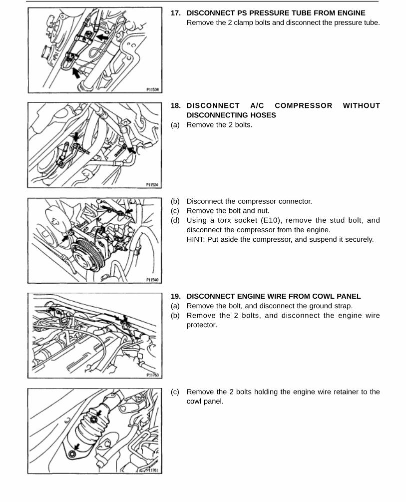
19. DISCONNECT ENGINE WIRE FROM COWL PANEL(a) Remove the bolt, and disconnect the ground strap.(b) Remove the 2 bolts, and disconnect the engine wire
protector.
(c) Remove the 2 bolts holding the engine wire retainer to thecowl panel.
EG–88–ENGINE ENGINE MECHANICAL

20. DISCONNECT ENGINE WIRE FROM CABIN(a) Remove the scuff plate.(b) Take out the front side of the floor carpet.(c) Remove the 2 nuts and ECM protector.(d) Remove the nut, and disconnect the ECM from the floor
panel.
(e) Disconnect the 2 connectors from the ECM.(f) Disconnect the connector from the TRAC ECU.(g) Disconnect the connector from the instrument panel wire.
(h) Disconnect the connectors from the connector cassette.
(j) Pull out the engine wire from the cabin.
21. M/T:REMOVE UPPER CONSOLE PANEL, SHIFT LEVERBOOTS AND HOLDING BOLTS
(a) Remove the shift lever knob.(b) Using a screwdriver, pry out the upper console panel.
–ENGINE ENGINE MECHANICALEG–89

(c) Remove the 4 bolts holding the lever boot to the transmissioncover.
(d) Remove the shift & select lever boots.
(e) Remove the 4 bolts holding the shift lever to the shift leverretainer.
22. M/T:DISCONNECT CLUTCH RELEASE CYLINDER ANDGROUND STRAP FROM TRANSMISSION
(a) Remove the 2 bolts, and disconnect clutch release cylinder.(b) Remove the bolt, and disconnect the clutch line tube.(c) Remove the bolt, and disconnect ground strap.
23. DISCONNECT SUB HEATED OXYGEN SENSOR FROMFRONT EXHAUST PIPERemove the 2 nuts and sensor cover, and disconnect oxygensensor and gasket.
24. REMOVE EXHAUST PIPE ASSEMBLY(a) Remove the 2 bolts and nuts holding the front exhaust pipe
to the No.2 front exhaust pipe.(b) Remove the 2 bolts and pipe support bracket.(c) Remove the gasket, and disconnect the front exhaust pipe.
EG–90–ENGINE ENGINE MECHANICAL

(d) Disconnect the hook of the tailpipe from the 2 rings.(e) Disconnect the 2 rings on the exhaust pipe from the exhaust
pipe brackets, and remove the exhaust pipe assembly.
25. REMOVE NO.2 FRONT EXHAUST PIPERemove the 3 nuts, front exhaust pipe and gasket.
26. REMOVE EXHAUST PIPE HEAT INSULATORRemove the 4 nuts and heat insulator.
27. REMOVE REAR CENTER FLOOR CROSSMEMBERBRACERemove the 4 bolts (Normal roof) or 6 bolts (Sport Roof) andcrossmember brace.
28. REMOVE PROPELLER SHAFT(See propeller shaft removal in Propeller Shaft)
29. A/T:DISCONNECT TRANSMISSION CONTROL RODRemove the nut, and disconnect the control rod from the shiftlever.
–ENGINE ENGINE MECHANICALEG–91

30. M/T:REMOVE TRANSMISSION SHIFT LEVER
(a) Remove the bolt and nut.(b) Remove the transmission shift lever, inside of vehicle.31. PLACE JACK UNDER TRANSMISSION
NOTICE (A/T): Be sure to put a wooden block between the jackand the transmission oil pan to prevent damage.
32. REMOVE REAR SUPPORT MEMBER(a) Remove the 4 nuts holding the member to the engine rear
mounting insulator.(b) Remove the 4 bolts and rear support member.
33. REMOVE ENGINE AND TRANSMISSION ASSEMBLYFROM VEHICLE
(a) Attach the engine hoist chain to the 2 engine hangers.
(b) Remove the 2 nuts holding the engine front mountinginsulators to the front suspension crossmember.
(c) Lift the engine out of the vehicle slowly and carefully.NOTICE: Remove the engine and transmission assembly care-fully without damaging the shift lever retainer (M/ T), A/C com-pressor or PS solenoid valve
(d) Make sure the engine is clear of all wiring, hoses and cables.(e) Place the engine and transmission assembly onto the stand.
EG–92–ENGINE ENGINE MECHANICAL

COMPONENTS FOR ENGINE &TRANSMISSION SEPERATION ANDASSEMBLY
–ENGINE ENGINE MECHANICALEG–93

ENGINE & TRANSMISSION SEPARATION
1. A/T:REMOVE OIL DIPSTICK GUIDE FOR TRANSMISSION
(a) Remove the bolt.(b) Pull out the dipstick and guide from the transmission.(c) Remove the O–ring from the dipstick guide.
2. DISCONNECT ENGINE WIRE FROM TRANSMISSION(a) Disconnect the connectors.(b) Disconnect the wire clamps from the brackets.3. REMOVE STARTER(a) Disconnect the starter connector.(b) Remove the 2 bolts, engine wire bracket and starter.
4. 2JZ–GE A/T:DISCONNECT THROTTLE CABLE
(a) Disconnect the throttle cable from the throttle body.(b) Disconnect the throttle cable from the cable bracket on the
cylinder head.5. A/T:
REMOVE OIL COOLER TUBES FOR TRANSMISSION(a) Remove the 2 hose clamp bolts and tube clamp bolt.(b) Loosen the 2 union nuts, and remove the oil cooler tubes.
EG–94–ENGINE ENGINE MECHANICAL

6. 2JZ–GTE M/T:REMOVE CLUTCH COVER SET BOLTS
(a) Remove the 2 bolts and service hole cover.(b) Place the matchmarks on the flywheel and clutch cover.(c) Remove the 6 bolts.
7. A/T:REMOVE TORQUE CONVERTER CLUTCH MOUNTINGBOLTS
(a) Remove the hole plug.(b) Turn the crankshaft to gain access to each bolt.
Remove the 6 bolts.
8. SEPARATE ENGINE AND TRANSMISSIONRemove the 6 bolts and transmission.HINT: The ”17” is 17 mm head bolt, and ”14” is 14 mm headbolt.
9. 2JZ–GE M/T:REMOVE CLUTCH COVER AND DISC
(a) Place matchmarks on the flywheel and clutch cover.(b) Loosen each bolt one turn at a time until spring tension is
released.(c) Remove the bolts, and pull off the clutch cover with the clutch
disc.NOTICE: Do not drop the clutch disc.
–ENGINE ENGINE MECHANICALEG–95