T-34C Turbo Mentor - USER MANUAL - Steam
81
Virtavia T-34C Turbo Mentor – DTG Steam Edition Manual Version 2 0 T-34C Turbo Mentor USER MANUAL
-
Upload
khangminh22 -
Category
Documents
-
view
4 -
download
0
Transcript of T-34C Turbo Mentor - USER MANUAL - Steam
Virtavia T-34C Turbo Mentor – DTG Steam Edition Manual Version 2
0
T-34C Turbo Mentor
USER MANUAL

Virtavia T-34C Turbo Mentor – DTG Steam Edition Manual Version 2
1
Introduction
The Beechcraft T-34 Mentor is a propeller-driven, single-engine, military
trainer aircraft derived from the Beechcraft Model 35 Bonanza. The
earlier versions of the T-34, dating from around the late 1940s to the
1950s, were piston-engine. These were eventually succeeded by the
upgraded T-34C Turbo Mentor, powered by a turboprop engine. The T-
34 remains in service almost six decades after it was first designed. The
T-34C Turbine Mentor is powered by a Pratt & Whitney Canada PT6A-
25 turboprop engine and was developed in 1973, with the final example
rolling off the production line in 1990.
The aircraft operation is fictional and for simulation purposes only.

Virtavia T-34C Turbo Mentor – DTG Steam Edition Manual Version 2
2
Support
Should you experience difficulties or require extra information about the
Virtavia T-34C Turbo Mentor, please e-mail our technical support on
Copyright Information
Please help us provide you with more top quality flight simulator models
like this one by NOT using pirate copies.
These files may not be copied (other than for backup purposes),
transmitted or passed to third parties or altered in any way without the
prior permission of the publisher.
The source code for this product is closed. No modifications or reverse
engineering may be carried out without prior consent from Virtavia.
All rights reserved – copyright Virtavia 2016
T-34C Turbo Mentor is a trademark of Textron Aviation Inc. and is used
under license to RailSimulator.com Ltd d/b/a Dovetail Games.

Virtavia T-34C Turbo Mentor – DTG Steam Edition Manual Version 2
3
Sound Controller
The Virtavia sound controller allows numerous realistic noises to be
heard at specific points during operation. When the T-34C is first loaded
into the simulator, noises may be heard. This is normal and cannot be
avoided.
When FSX is first run with the T-34C installed, a window will appear.
Please click 'Run' to allow the sound controller to be added to the FSX
trusted gauges list.
Clicking 'Yes' at the next pop up window will allow the sound controller to
run automatically every time the simulator is loaded.
Following the above steps will mean that the process will only have to be
performed once and not every time the simulator is launched.
Exterior Model
The exterior model has all the usual animations such as ailerons,
elevators and flaps. There are some additional animations on the model:
Crew Access
The pilot’s canopy can be open or closed using shift-E. The rear canopy
can also be opened using the FSX 2nd Exit command, Shift-E+2.

Virtavia T-34C Turbo Mentor – DTG Steam Edition Manual Version 2
4
Exterior Lighting
Pressing the L key will turn on all lights. You may however wish to turn
them on using the appropriate switches in the cockpit, as the L key also
turns the on navigation, landing lights and flood lighting in the cockpit,
which should ideally be switched separately. Please refer to the cockpit
section of this manual for information regarding light switch location.
Shift-L will toggle the nav lights and the cockpit lights.
Crtl-L will toggle the landing lights.
Visual Load Editor (VLE)
By pressing Shift + 3 in any view, you can bring up the VLE. The VLE
allows you to easily control features of the model without having to
reload or reconfigure the simulator. Clicking the text in the top right of
the utility allows the associated feature to be toggled.

Virtavia T-34C Turbo Mentor – DTG Steam Edition Manual Version 2
5
Main Panel
Key
1. Propeller pitch control
2. Throttle
3. Landing gear lever
4. Landing lights switch
5. KLN900 GPS
6. Landing gear position indicator
7. Flap position indicator
8. BuNo tag
9. Upper warning light console
10. AOA indicator
11. AOA indexer
12. Wiskey compass
13. KA41 Control Unit
14. IVSI
15. Left pedal toe-brake
16. Right pedal toe-brake
17. Parking brake lever
18. Engine Air Inlet Bypass
handle

Virtavia T-34C Turbo Mentor – DTG Steam Edition Manual Version 2
6
19. Ignition & Starter panel
20. ASI
21. Altimeter
22. Turn & Slip indicator
23. Accelerometer
24. Forward- main warning light
console
25. RMI unit
26. CDI unit
27. Artificial Horizon
28. NACWS unit
29. COM radio controls
30. Clock
31. Power load indicator
32. Torque indicator
33. ITT indicator
34. Prop tachometer
35. Fuel flow indicator
36. Engine tachometer
37. Oil system indicator
38. Left fuel tank contents
indicator
39. Right fuel tank contents
indicator

Virtavia T-34C Turbo Mentor – DTG Steam Edition Manual Version 2
7
Left Side Console
Key
1. COM radio console
2. Flap control lever
3. Fuel pump toggle lever
4. Aileron trim control
5. Rudder trim control
6. Elevator trim control
7. Control lock (Click to engage or
disengage)
8. Propeller pitch control
9. Throttle lever
10. Landing light switches
11. Landing gear lever
8. Propeller pitch control
9. Throttle lever
10. Landing light switches
11. Landing gear lever
12. Landing gear position
indicators
13. KLN900 GPS
14. KA41
15. IVSI
16. Turn & Slip indicator
17. Altimeter
18. Fuel cut-off lever

Virtavia T-34C Turbo Mentor – DTG Steam Edition Manual Version 2
8
Right Side Console
Key
1. Warning lights main
console
2. Left fuel tank contents
indicator
3. Right fuel tank contents
indicator
4. Engine tachometer
5. Oil system indicator
6. Prop tachometer
7. Fuel flow indicator
8. Ignition & Starter panel
9. Parking brake lever
10. Engine Air Inlet Bypass
handle
11. Electrical control panel
12. Emergency landing gear
extension handle
13. Oxygen system panel
14. ADF system panel
15. VOR system panel
16. KT67 Transponder
17. Audio control panel
18. Avionics control panel
19. Lighting control panels
20. Hobbs meter
21. Circuit breaker panel

Virtavia T-34C Turbo Mentor – DTG Steam Edition Manual Version 2
9
Warning lts and Annunciator Panels
Light Reason for
illumination
Light Reason for
illumination
INVERTER Loss or failure of
115-vac or 26-
vac power.
GENERATOR Starter ON, low
voltage output or
generator failed.
L FUEL LOW Left wing fuel
quantity below
approx 90 lbs
useable.
R FUEL LOW Right wing fuel
quantity below
approx 90 lbs
useable.
FUEL PRESS Low pressure
output from
engine-driven
boost pump.
CHIP Metal particles
present in oil
system.
LDG LIGHT Landing lights
ON.
BLEED AIR Cockpit heating
(bleed) air over-
temperature.
IGNITION Ignition energized by starter switch or auto ignition.
AUTO IGNITION Auto ignition
switch ON,
system armed.
N/A TO T-34C N/A TO T-34C N/A TO T-34C N/A TO T-34C

Virtavia T-34C Turbo Mentor – DTG Steam Edition Manual Version 2
10
Annunciator Test Console
This panel is situated directly below the warning light console illustrated
above.
The PROP OVSP GOV push-button will limit propeller RPM to 2000, +/-
50. It is used to test the functionality of the Prop Over-speed Governor.
The ANN push-button will illuminate all annunciator panels when
pressed. To extinguish the lamps, click a second time.
The AOA spring-loaded switch has two test functions:
- APPCH will set AOA to 20 units and illuminate the amber doughnut on
the AOA indexer.
- STALL will set AOA to 29 units and illuminate the green chevron on
the AOA indexer.

Virtavia T-34C Turbo Mentor – DTG Steam Edition Manual Version 2
11
Annunciator Console Upper
WHEELS 1. Flaps extended prior to gear. 2. Throttle & pitch below 5% power with gear up. 3. Gear handle up while aircraft on ground. 4. Gear not locked in down position.
LH OPEN Left inboard gear door open. RH OPEN Right inboard gear door open. MASTER CAUTION 1. Fault warning.
2. Stall. FIRE Fire detector system activated- land
immediately.
Virtavia T-34C Turbo Mentor – DTG Steam Edition Manual Version 2
12
Individual Gauges
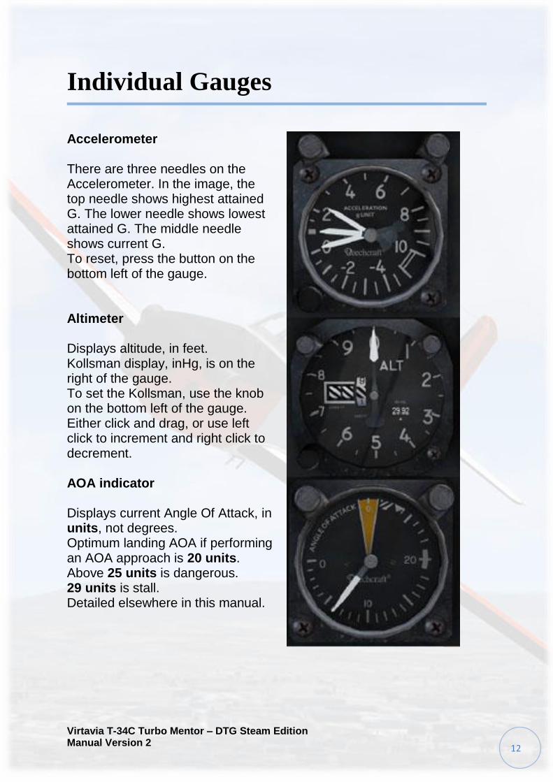
Accelerometer There are three needles on the Accelerometer. In the image, the top needle shows highest attained G. The lower needle shows lowest attained G. The middle needle shows current G. To reset, press the button on the bottom left of the gauge.
Altimeter Displays altitude, in feet. Kollsman display, inHg, is on the right of the gauge. To set the Kollsman, use the knob on the bottom left of the gauge. Either click and drag, or use left click to increment and right click to decrement. AOA indicator Displays current Angle Of Attack, in units, not degrees. Optimum landing AOA if performing an AOA approach is 20 units. Above 25 units is dangerous. 29 units is stall. Detailed elsewhere in this manual.

Virtavia T-34C Turbo Mentor – DTG Steam Edition Manual Version 2
13
AOA indexer
Detailed elsewhere in this manual.
Airspeed Indicator
Displays current air speed, in knots.
VNE is 280 knots, 0-20000ft.
VNE above 20000ft is 245 knots.
BuNo Plate
Displays current aircraft BuNo or
registration.
Clock
Displays local time in minutes and
hours.
Press button to activate timer function.
Press again to reset.

Virtavia T-34C Turbo Mentor – DTG Steam Edition Manual Version 2
14
Turbine Tachometer
Turbine N speed.
101.5% maximum.
102.6% max engine acceleration
for 2 seconds.
Flap indicator
Displays flap position, in a
percentage value.
Fuel flow indicator
Displays current fuel flow, in
Pounds Per Hour x 100.
Landing gear position indicator
See elsewhere in this manual.
Virtavia T-34C Turbo Mentor – DTG Steam Edition Manual Version 2
15
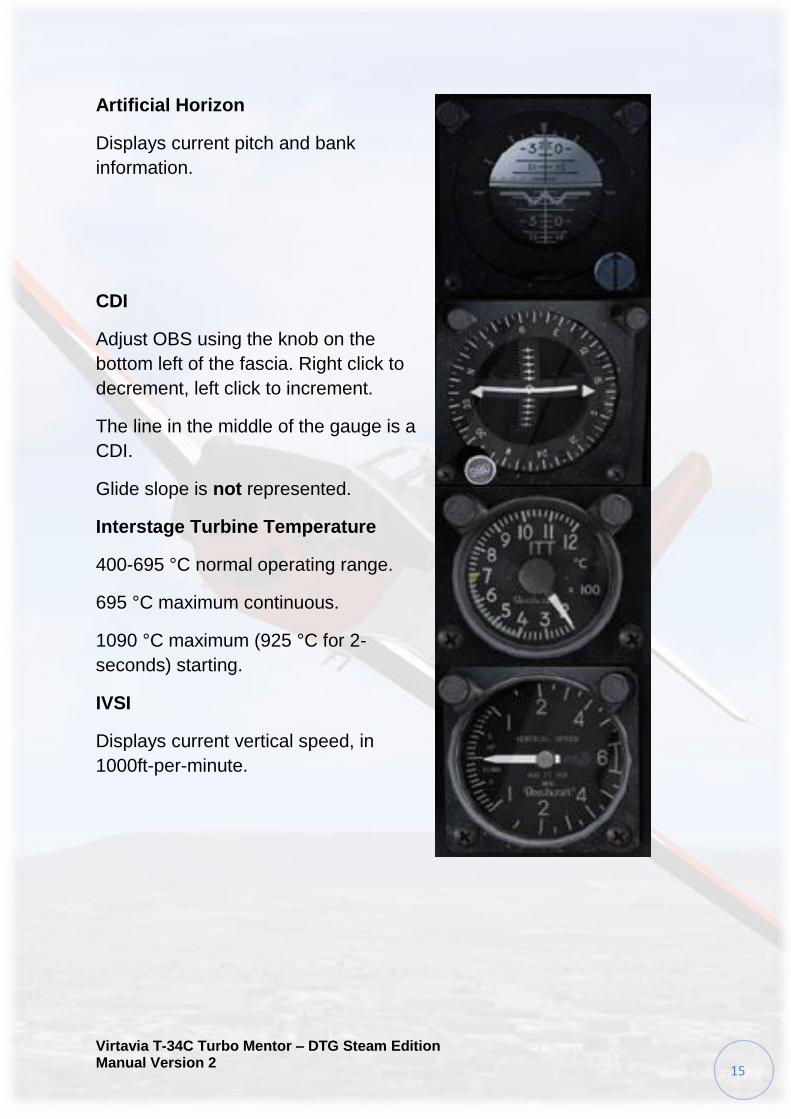
Artificial Horizon
Displays current pitch and bank
information.
CDI
Adjust OBS using the knob on the
bottom left of the fascia. Right click to
decrement, left click to increment.
The line in the middle of the gauge is a
CDI.
Glide slope is not represented.
Interstage Turbine Temperature
400-695 °C normal operating range.
695 °C maximum continuous.
1090 °C maximum (925 °C for 2-
seconds) starting.
IVSI
Displays current vertical speed, in
1000ft-per-minute.
Virtavia T-34C Turbo Mentor – DTG Steam Edition Manual Version 2
16
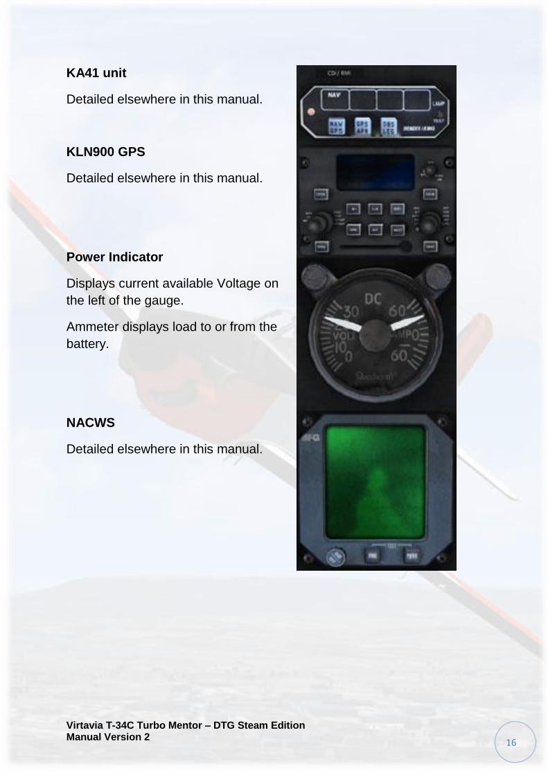
KA41 unit
Detailed elsewhere in this manual.
KLN900 GPS
Detailed elsewhere in this manual.
Power Indicator
Displays current available Voltage on
the left of the gauge.
Ammeter displays load to or from the
battery.
NACWS
Detailed elsewhere in this manual.

Virtavia T-34C Turbo Mentor – DTG Steam Edition Manual Version 2
17
Oil Temperature & Pressure
Oil Temperature- upper.
- 10-99 °C Normal operating range.
- 100 °C Maximum.
Oil pressure- lower.
- 40 PSI minimum.
- 65-80 PSI normal operating range
with N1 > 75 %.
- 100 PSI maximum.
Outside Air Temperature
Displays outside air temperature in
degrees C.
Propeller Tachometer
1800-2200 RPM normal operating
range.
2200 +/- 25 RPM maximum.
Virtavia T-34C Turbo Mentor – DTG Steam Edition Manual Version 2
18
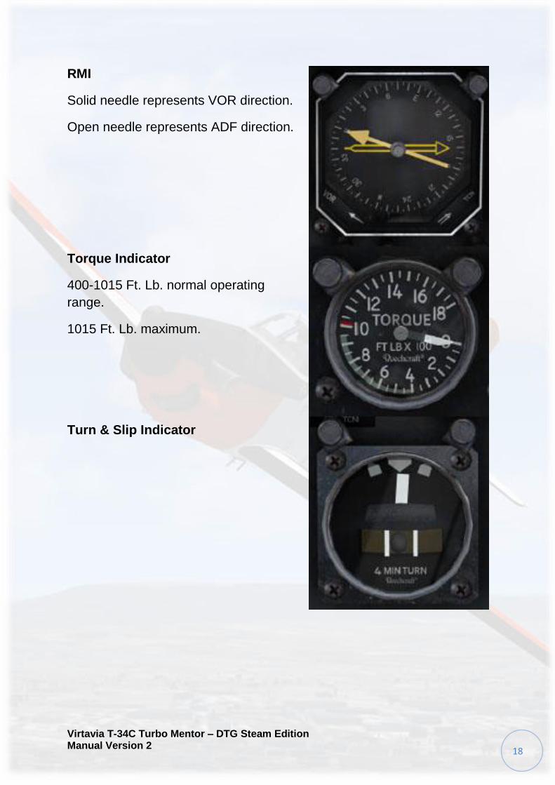
RMI
Solid needle represents VOR direction.
Open needle represents ADF direction.
Torque Indicator
400-1015 Ft. Lb. normal operating
range.
1015 Ft. Lb. maximum.
Turn & Slip Indicator

Virtavia T-34C Turbo Mentor – DTG Steam Edition Manual Version 2
19
Aircraft Systems and Operation
This section of the manual details individual systems and how to operate
them correctly.
Please read this section carefully to ensure that your next T-34C flight is
problem-free.
Visual Load Editor (VLE)
By pressing Shift + 3 in any view, you can bring up the VLE. The VLE
allows you to easily control features of the model without having to
reload or reconfigure the simulator. Clicking the text in the top right of
the utility allows the associated feature to be toggled.
Instructor will display or hide the pilot in the rear cockpit.
Student will display or hide the pilot in the front cockpit.
Tags & Blanks will toggle remove-before-flight tags and exhaust blanks.
Cover toggles the canopy cover.
Chocks toggles a set of wheel chocks.
Hood toggles the rear cockpit blind-flying hood, visible from both the VC
and exterior.

Virtavia T-34C Turbo Mentor – DTG Steam Edition Manual Version 2
20
Blind-Flying
The T-34C rear cockpit is equipped for blind-flying training.
To install the hood, first use the VLE. Then switch to the Instructors
viewpoint using the FSX camera system.
This feature is only available with the FSX version, and is only available
in the rear cockpit.

Virtavia T-34C Turbo Mentor – DTG Steam Edition Manual Version 2
21
AOA Indicator
The approach can be flown by coordinating throttle and stick movements
to establish the desired glidepath at optimum Angle Of Attack.
The stick is used to bring AOA to the optimum value, whilst the throttle is
manipulated to control the rate of descent so as to establish the desired
glidepath.
The AOA indicator does not display absolute angles of attack. It instead
displays arbitrary units grouped around the optimum with specific areas
of interest.
Whilst on the ground, the AOA system will not represent any particular
angle of attack. Erratic readings are normal until airborne.
Stall is at 29 Units.
Optimum AOA for approaches is at 20 Units.

Virtavia T-34C Turbo Mentor – DTG Steam Edition Manual Version 2
22
AOA Indexer
The AOA indexer is comprised of three lights. The light indications are a
green chevron ( v ) showing 'too high AOA' at the top, a yellow doughnut
( O ) showing proper AOA in the centre, and a red chevron ( ^ ) showing
'too low AOA' at the bottom.
As AOA goes high or low, with resulting decrease or increase in
airspeed, the indexer upper or lower chevron will be illuminated to point
the direction in which the nose should be moved to return to the
optimum AOA.
A green chevron indicates that the nose must be lowered and the
throttle manipulated to suit.
An amber doughnut indicates that AOA is optimum for the approach.
A red chevron indicates that the nose must be raised and the throttle
manipulated to suit.
At intermediate stages the AOA indexer may also display two symbols at
a time. For example, a doughnut and a green chevron would indicate
that the aircraft is nearing optimum AOA, providing the nose is lowered
further. A doughnut and a red chevron would indicate the opposite.
Optimum AOA is usually achieved around 100 knots (no flaps) or 90
knots (full flaps) and 20 Units AOA.

Virtavia T-34C Turbo Mentor – DTG Steam Edition Manual Version 2
23
Emergency Gear Operation
In event of emergency, the landing gear can be extended and locked
DOWN.
To perform this function, click the emergency lever. The lever can be
located on the right hand wall of the forward cockpit.
The gear will lock extend and lock in the DOWN position.
The gear cannot be retracted unless the system is reset. To do this, the
lever must be returned to the armed (handle pointing down) position.
In event of gear malfunction or failure, the system should be locked
down. This will prevent the gear from retracting during the landing
phase.

Virtavia T-34C Turbo Mentor – DTG Steam Edition Manual Version 2
24
Trim system
All surfaces of the T-34C can be manipulated using the trims.
Rudder Trim
Rudder trim is at neutral when the green marking on the inner side is
level with the white line on top of the elevator trim unit.
To trim the rudder to the right, click and drag the knob in a clockwise
motion. Dragging the knob anti-clockwise will trim the rudder to the left.
Elevator Trim
The elevator trim tabs are located on the trailing inboard ends of the
elevators. The elevator trim tab wheel and position indicator are located
on the left console in each cockpit. Forward rotation of the wheel raises
the trim tab and lowers the nose of the aircraft. Rearward rotation lowers
the tab and raises the aircraft nose.
As the wheel is turned, the tab position indicator that functions as an
integral part of the tab control wheel shows the amount of tab deflection
in degrees. 3 degrees of nose-up trim should be applied for takeoff.

Virtavia T-34C Turbo Mentor – DTG Steam Edition Manual Version 2
25
Aileron Trim
The aileron trim tabs are located on the inboard trailing edge of each
aileron. The aileron trim tab wheel and trim tab position indicator are
located on the left console in each cockpit.
Rotation of the wheel clockwise raises the tab on the left aileron and
raises the left wing. Anti-clockwise rotation lowers the tab and lowers the
left wing.
The trim tab position indicator operates as an integral part of the trim tab
wheel. As the wheel is turned, the degrees of tab deflection are shown
on an indexed scale visible through the window adjacent to the tab
control.

Virtavia T-34C Turbo Mentor – DTG Steam Edition Manual Version 2
26
Ignition - Starter Panel
The ignition and starter panel is located in the lower-right corner of the
forward area in the cockpit.
Engine Starter Switch A two-position starter switch is located at the top left of the panel. When placed in the ON position, the switch completes the starter circuit for engine rotation, energises the igniter plugs for fuel combustion, and activates the green IGNITION and yellow GENERATOR annunciator lights. The starter switch will motor the starter only if the ignition is not set to ON.
Engine Ignition Switch The ignition switch is located on the top right of the panel. For starting, the switch should be set to the ON position. This will also illuminate the IGNITION annunciator light. When the engine has started, set the switch to the OFF position.
Auto-Ignition system The T-34C Ignition & Starter panel also features an Auto-Ignition switch. The ON position initiates a readiness mode for the auto-ignition system of the engine and illuminates the green AUTO IGN annunciator light. The OFF position disarms the system. The auto-ignition system is triggered from a "read condition" to an "operating condition" when engine torque drops into the 300 to 180ft-lb torque range. Therefore, with the auto-ignition system armed, once the system is triggered to an operating condition, the igniters will remain energised continuously until torque is increased above the trigger range.

Virtavia T-34C Turbo Mentor – DTG Steam Edition Manual Version 2
27
Oxygen system
Operation of the oxygen system is critical when flying the T-34C at
altitude. If the system is not functioning correctly, flying should not take
place above 10,000ft. Doing so will risk incapacitation of the crew.
The oxygen panel is made up of five main parts. These are detailed
below.
Oxygen Cylinder Pressure Indicator
The OCPI gauge indicates the current pressure of the oxygen system.
By default the system is powered down, and as a result the needle
should sit at the 0 mark.
When the system is energised, the needle will slowly rise to the
maximum attainable pressure.
Oxygen Flow Indicator
When the oxygen system is energised and functioning correctly, the flow
indicator will display a horizontal pattern. When not functioning, the
display appears blank.
Supply Control
The two-position supply switch is located on the right-most side of the
panel. Setting the switch to the OFF position will disarm the oxygen
system. Setting the switch to the ON position arms the system and
allows the oxygen system to pressurise.
Virtavia T-34C Turbo Mentor – DTG Steam Edition Manual Version 2
28
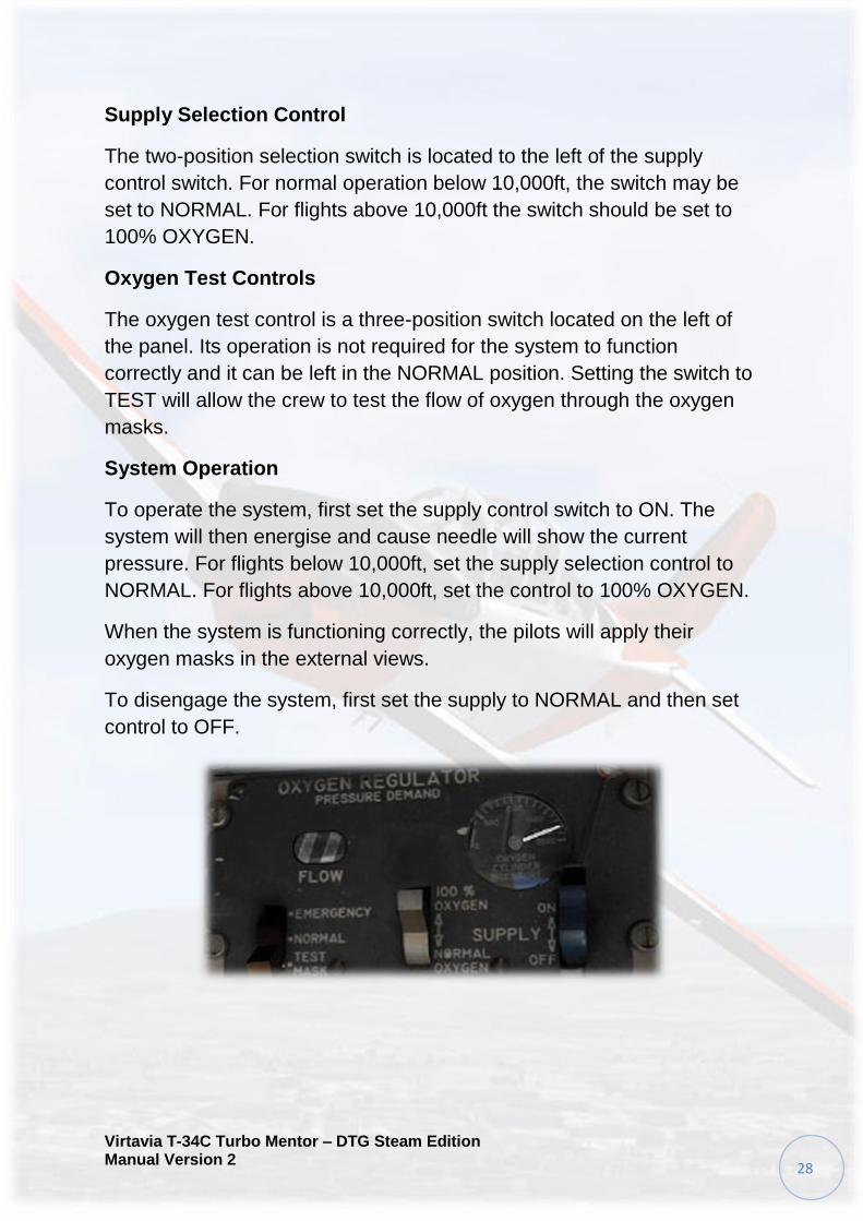
Supply Selection Control
The two-position selection switch is located to the left of the supply
control switch. For normal operation below 10,000ft, the switch may be
set to NORMAL. For flights above 10,000ft the switch should be set to
100% OXYGEN.
Oxygen Test Controls
The oxygen test control is a three-position switch located on the left of
the panel. Its operation is not required for the system to function
correctly and it can be left in the NORMAL position. Setting the switch to
TEST will allow the crew to test the flow of oxygen through the oxygen
masks.
System Operation
To operate the system, first set the supply control switch to ON. The
system will then energise and cause needle will show the current
pressure. For flights below 10,000ft, set the supply selection control to
NORMAL. For flights above 10,000ft, set the control to 100% OXYGEN.
When the system is functioning correctly, the pilots will apply their
oxygen masks in the external views.
To disengage the system, first set the supply to NORMAL and then set
control to OFF.

Virtavia T-34C Turbo Mentor – DTG Steam Edition Manual Version 2
29
Electrical Panel
The electrical panel is located at the top of the right-hand console.
The system is comprised of four switches, each explained below.
Master Battery
The master battery switch is located at the top of the electrical panel. To
energise the aircraft battery, set the switch to the up -ON- position. To
cut battery power to the aircraft, set the switch to the down -OFF-
position.
A visual cue is provided by the warning annunciator panels when the
system is set to ON.
Generator Control
The engine generator control switch is located at the right on the panel.
When set to the down OFF position, the engine generator will not
provide power. When the engine is running and the switch is set to the
ON position, the unit will provide system power. The unit is rated at 200
amperes DC. The generator should be set to ON for engine starting.
Inverter Selector Control
The generator circuit can be switched using the control underneath the
master battery switch. Unless a fault develops, the generator should be
set to the NO.1 position. If the switch is in the neutral (middle) position,

Virtavia T-34C Turbo Mentor – DTG Steam Edition Manual Version 2
30
the Inverters will be set to OFF. Pushing the switch down will set the
generator to NO.2.
Electrical System Control Switch
The electrical system control switch is located on the left of the panel. By
default this switch is set to the down CONT TRANS position. When the
battery switch is set to the ON position, the control switch should be set
to the TAKE COMMAND position. The lamp above the switch will
illuminate and will remain lit so long as the system is functioning
correctly.

Virtavia T-34C Turbo Mentor – DTG Steam Edition Manual Version 2
31
Avionics Panel
The avionics control panel is comprised of four switches, detailed below.
The panel is located on the right console, below the navigation radios.
RMI control switch
The RMI control switch is a two-position switch located on the right of
the panel. By default the switch is set to the OFF position. When set to
ON, the cockpit RMI navigation system will function correctly. Without
the switch set to the ON position, RMI indications cannot be relied upon
for accurate navigation.
Gyro control switch
The gyro control switch is a two-position switch, set to OFF by default.
Setting the switch to the ON position will energise the avionic gyro
system.
Avionics Master Control
The avionics master control switch should be set to the OFF position
whilst the engine is offline. Once the engine has been started and power
indications have settled, setting the switch to the ON position will allow
the aircraft avionics systems to power up.
Operation of systems such as the NAV, COM and ADF radio are
impossible without the switch being set to the ON position.
Virtavia T-34C Turbo Mentor – DTG Steam Edition Manual Version 2
32
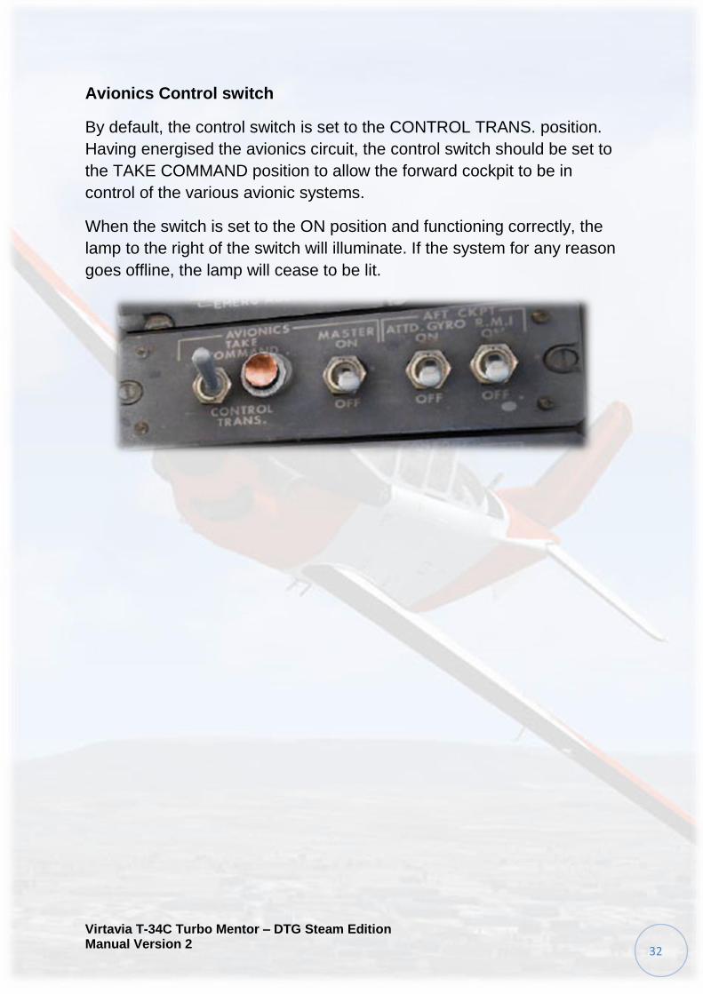
Avionics Control switch
By default, the control switch is set to the CONTROL TRANS. position.
Having energised the avionics circuit, the control switch should be set to
the TAKE COMMAND position to allow the forward cockpit to be in
control of the various avionic systems.
When the switch is set to the ON position and functioning correctly, the
lamp to the right of the switch will illuminate. If the system for any reason
goes offline, the lamp will cease to be lit.

Virtavia T-34C Turbo Mentor – DTG Steam Edition Manual Version 2
33
Lighting Control Panel
The lighting control panel is located at the end of the right console. It is
divided into two main parts, those being internal and external controls,
detailed below.
Internal Lighting
Instrument Lighting
Instrument back-lighting can be controlled using the knobs located at the
top-left of the lighting panel. Clicking them will toggle the back-lights.
Console Lighting
Console and cockpit flood-lighting can be controlled using the knobs
located at the top-right of the lighting panel. Clicking them will toggle the
lights.
Virtavia T-34C Turbo Mentor – DTG Steam Edition Manual Version 2
34
External Lighting
Navigation Lights
The navigation light switch is located at the left of the external light
control panel. When set to the OFF position, power to the lamps is cut.
When set to the BRIGHT position, the lamps will illuminate.
Strobe Lights
The strobe light switch is located to the right of the navigation light
switch. Setting the switch to OFF will cut power to the circuit. Setting the
switch to ON will energise the strobe light circuit and provide power to
the lamps.
Virtavia T-34C Turbo Mentor – DTG Steam Edition Manual Version 2
35
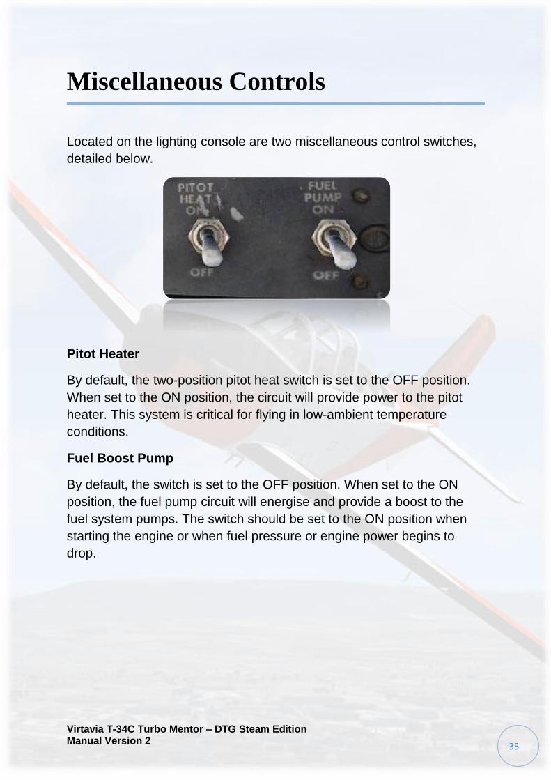
Miscellaneous Controls
Located on the lighting console are two miscellaneous control switches,
detailed below.
Pitot Heater
By default, the two-position pitot heat switch is set to the OFF position.
When set to the ON position, the circuit will provide power to the pitot
heater. This system is critical for flying in low-ambient temperature
conditions.
Fuel Boost Pump
By default, the switch is set to the OFF position. When set to the ON
position, the fuel pump circuit will energise and provide a boost to the
fuel system pumps. The switch should be set to the ON position when
starting the engine or when fuel pressure or engine power begins to
drop.

Virtavia T-34C Turbo Mentor – DTG Steam Edition Manual Version 2
36
Cockpit Blower System
Operation
The blower control system is located on the left shoulder of the front
cockpit.
The blower system can be activated by pushing the control lever
forward. When the system is active it will produce a 'blowing' noise
audible amongst the cockpit ambient noises. After a short time, the
sound of the blower may quieten, however, the system will still be in an
operational state. Air conditioning temperature can be controlled using
the lever on the top of the console. By default the switch is set to OFF.
Bleed Air
Should the cockpit blower system malfunction or be allowed to run for
too long, the main warning annunciator panel will display a BLEED AIR
light. In order to rectify the situation the pilot may take one of two
actions:
1- The cockpit blower system can be turned off and the cockpit
environment be allowed to cool for approximately one minute.
2- The pilot may descend to an altitude where use of the cockpit blower
system is not required, if available.
Once the annunciator light is extinguished, the system may be restarted.

Virtavia T-34C Turbo Mentor – DTG Steam Edition Manual Version 2
37
Whilst the system can function whilst a BLEED AIR situation exists, it
may become uncomfortable for the crew.
Failure of the blower system
Under certain circumstances, the blower system is critical to maintain
safe flying conditions. Should the blower system fail or not be activated,
the canopy may fail.
If the canopy fails in flight and the blower system is not activated,
immediately rectify the situation by setting the control to the ON position.
After a few moments of operation the canopy should clear and normal
flight operation may resume.
Should the canopy not clear or the system fail completely, descend to an
altitude that does not require the system to be operation. Careful
observation of the outside air temperature gauge will allow the pilot to
anticipate conditions that require use of the blower system.
If operating in a below-zero environment where no safe altitude exists,
immediately open the canopy and land as soon as possible.
Failure can be associated with a number of factors, including:
- Inability to turn the blower system on
- Canopy failure
- Exterior canopy icing

Virtavia T-34C Turbo Mentor – DTG Steam Edition Manual Version 2
38
Typical Failure Situation
The below image is a typical example of a canopy failure in-flight.
Note the extreme lack of visibility from the cockpit.
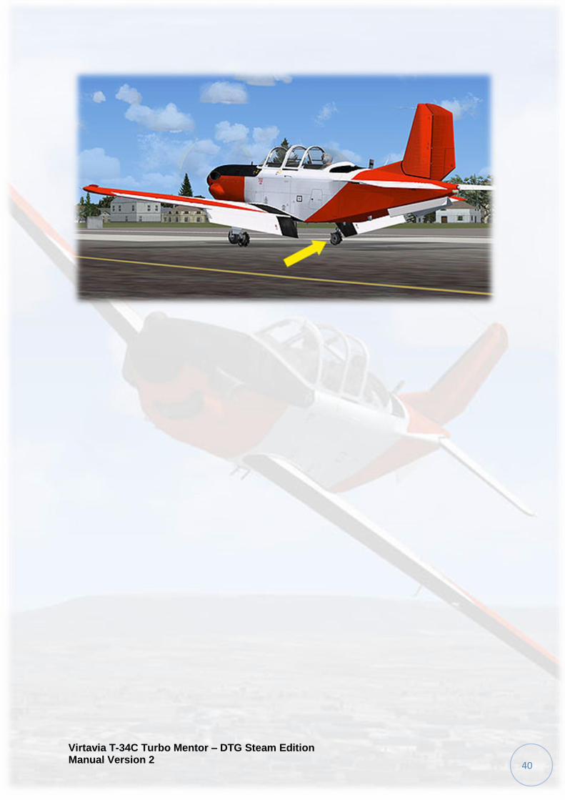
Braking System
Outline
Though the T-34C is a primary trainer, it is still possible to cause brake
failure should the brakes be improperly operated.
Virtavia T-34C Turbo Mentor – DTG Steam Edition Manual Version 2
39
The T-34C has only differential brakes. Nose-wheel power steering is
not available. To taxi the aircraft, the pilot must rely on precise toe brake
control, along with prop wash manipulation.
Using the rudder with small amounts of power will help in taxiing the
aircraft.
Failures
Full use of the toe-brakes at speeds above 70 knots is prohibited,
instead rudder being the preferred method of steering the aeroplane.
When landing the aircraft, brakes should not be applied to their full
capacity until speed is below 70 knots. Applying full brake at speeds
over 70 knots can and will cause brake failure. Tyre failure is also
possible and almost certain if the brakes are over-used.
Tyre and brake pressure will build up over time unless the brake system
is bled. When landing brakes should only be used for short periods.
Releasing the brakes completely will allow them to bleed, ensuring that
pressure does not build up.
Excessive use of brakes upon landing will also cause failure in both tyre
and braking systems.
When the brakes are nearing fail-point, an audible warning will be heard.
If the brakes or tyres fail, the result will be an audible bang followed by
loss of braking power. In this situation, the emergency gear lever should
be activated and the canopies opened.
Should one of the brake or tyre system fail, immediately use the
remaining brake to slow the aircraft without putting excessive pressure
on the system. Flaps should be retracted at the earliest opportunity, and
the stick held fully forward to counter any aerodynamic effects. The fuel
cut-off lever should also be operated to stop the engine as soon as
possible.
Immediately alert the control tower of any failures as soon as they
happen. When the aircraft has come to a complete stop, first ensure that
the AC and DC systems are OFF and then alight as quickly as possible.
Virtavia T-34C Turbo Mentor – DTG Steam Edition Manual Version 2
40

Virtavia T-34C Turbo Mentor – DTG Steam Edition Manual Version 2
41
Control Lock
The aircraft control locks can be activated to ensure that the surfaces do
not move when the aircraft is not manned.
The control lock is located in front of the centre console, and is painted
red.
To engage, ensure that the aircraft is first shut-down. Click the lock to
raise it into position. To disengage the lock, click it once more to return it
to default.

Virtavia T-34C Turbo Mentor – DTG Steam Edition Manual Version 2
42
Circuit Breakers
At any time during flight, the circuit breakers can trip. When a breaker
trips an audible noise will be heard. Failure of a circuit breaker is
however a very rare occurrence.
To reset a breaker, simply click it.
To experiment and see the result of a certain breaker popping, click
once on it to cause it to break. Clicking it again will reset the breaker.
The breaker panel is located to the right of the pilots seat.
Virtavia T-34C Turbo Mentor – DTG Steam Edition Manual Version 2
43
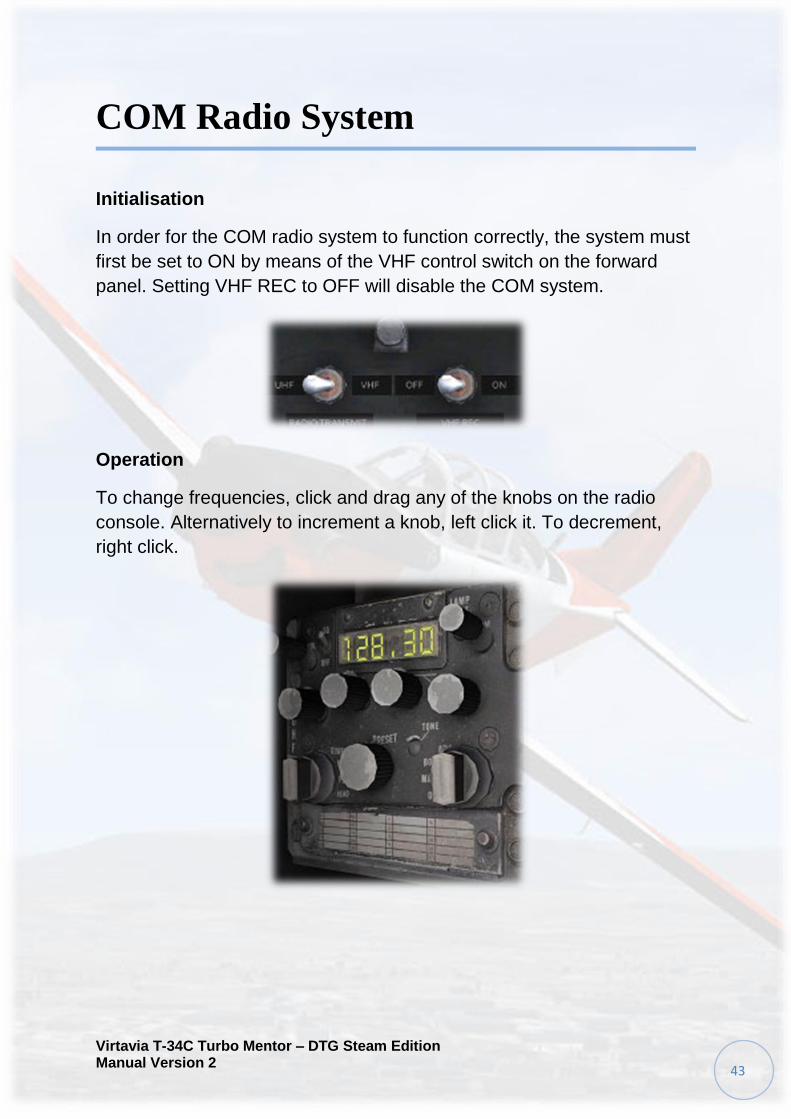
COM Radio System
Initialisation
In order for the COM radio system to function correctly, the system must
first be set to ON by means of the VHF control switch on the forward
panel. Setting VHF REC to OFF will disable the COM system.
Operation
To change frequencies, click and drag any of the knobs on the radio
console. Alternatively to increment a knob, left click it. To decrement,
right click.

Virtavia T-34C Turbo Mentor – DTG Steam Edition Manual Version 2
44
Audio Control Panel
The audio control panel is located at the bottom of the ADF and VOR
stack. Its function is described below.
This T-34C simulation has replaced the TACAN system with an
operational ADF system. Where TACAN is seen in the cockpit, it may be
replaced with ADF.
CALL switch
Selects CALL, HM, or CM mode.
HM
Enables interphone communication only between cockpits without need
to use microphone select switch on throttle lever.
CM
Enables interphone communication between cockpits or UHF voice
transmission from either junction with the microphone switch selection
CALL
Enables interphone communication between cockpits by overriding but
not deleting UHF communications.

Virtavia T-34C Turbo Mentor – DTG Steam Edition Manual Version 2
45
AUDIO switches
Enable normal or emergency audio reception to respective headsets
from UHF, ADF (TACAN) and VOR.
VOL switch
Adjusts volume of amplified interphone, ADF (TACAN), VOR, NACWS
and UHF audio.
ADF Radio System
This T-34C simulation has replaced the TACAN system with an
operational ADF system. Where TACAN is seen in the cockpit, it may be
replaced with ADF.
Initialisation
The ADF unit must first be powered-up in order for it to function
correctly. The power switch is located on the bottom left corner of the
console. Setting the switch to OFF will turn the unit off. Setting the
switch to T/R will power the unit up.
Operation
To tune the ADF radio, click and drag any of the knobs on the radio
console. Alternatively to increment a knob, left click it. To decrement,
right click. Volume can be toggled using the VOL knob. The selected
frequency is displayed on the screen.
Virtavia T-34C Turbo Mentor – DTG Steam Edition Manual Version 2
46
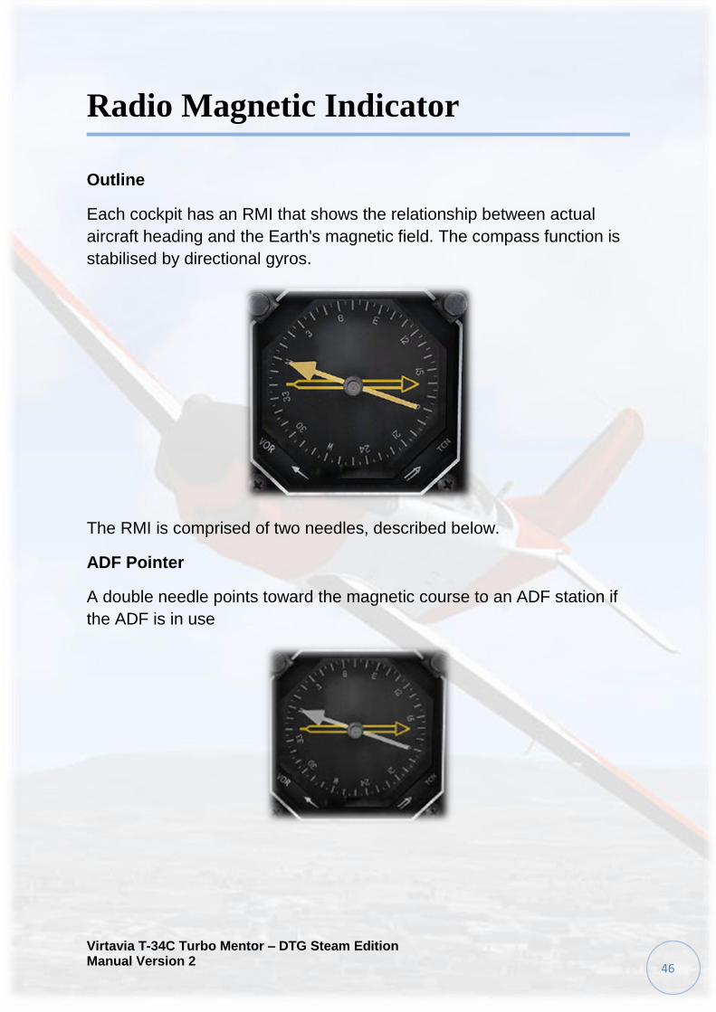
Radio Magnetic Indicator
Outline
Each cockpit has an RMI that shows the relationship between actual
aircraft heading and the Earth's magnetic field. The compass function is
stabilised by directional gyros.
The RMI is comprised of two needles, described below.
ADF Pointer
A double needle points toward the magnetic course to an ADF station if
the ADF is in use

Virtavia T-34C Turbo Mentor – DTG Steam Edition Manual Version 2
47
VOR Pointer
A single needle points toward the magnetic course to a VOR station if
the VOR system is in use.
VOR Radio System
Initialisation
The VOR unit must first be powered-up in order for it to function
correctly. The power switch is located on the bottom left corner of the
console. Setting the switch to OFF will turn the unit off. Setting the
switch to ON will power the unit up.

Virtavia T-34C Turbo Mentor – DTG Steam Edition Manual Version 2
48
Operation
To tune the VOR radio, click and drag any of the knobs on the radio
console. Alternatively to increment a knob, left click it. To decrement,
right click.
Volume can be toggled using the VOL knob. The selected frequency is
displayed on the screen.
Course Deviation Indicator
Outline
Each cockpit is equipped with a CDI to indicate the aircraft's actual
course of flight relative to a course selected with the OBS knob.

Virtavia T-34C Turbo Mentor – DTG Steam Edition Manual Version 2
49
Operation
The CDI in each cockpit is set to a desired course heading with the
respective OBS knob. The CDI needle will deflect left or right of centre if
the flight course drifts. The amount of drift will be indicated in degrees of
course deviation to the right or left of centred alignment per mark.
To correct for a course deviation drift, proper sensing is determined and
the aircraft is turned toward the direction of needle deflection. When
course alignment is re-established, the CDI needle will be at the centre
vertical position.
The TO/FROM indicators in the CDI will indicate whether the course
selected by the OBS knob will take the aircraft to or from the selected
NAVAID.
NACWS
Initialisation :
The NACWS display is located on the upper section of the forward
panel. By default it is set to the OFF state.
Virtavia T-34C Turbo Mentor – DTG Steam Edition Manual Version 2
50
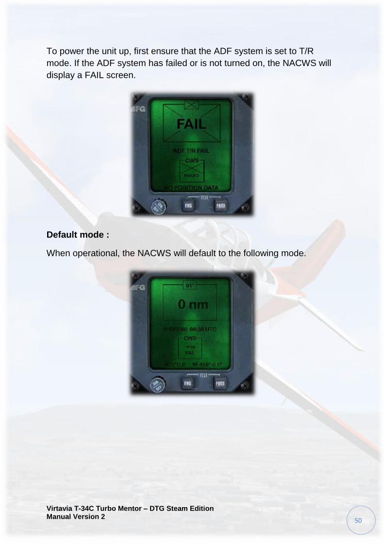
To power the unit up, first ensure that the ADF system is set to T/R
mode. If the ADF system has failed or is not turned on, the NACWS will
display a FAIL screen.
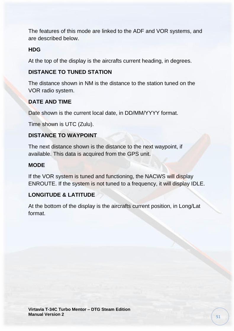
Default mode :
When operational, the NACWS will default to the following mode.
Virtavia T-34C Turbo Mentor – DTG Steam Edition Manual Version 2
51
The features of this mode are linked to the ADF and VOR systems, and
are described below.
HDG
At the top of the display is the aircrafts current heading, in degrees.
DISTANCE TO TUNED STATION
The distance shown in NM is the distance to the station tuned on the
VOR radio system.
DATE AND TIME
Date shown is the current local date, in DD/MM/YYYY format.
Time shown is UTC (Zulu).
DISTANCE TO WAYPOINT
The next distance shown is the distance to the next waypoint, if
available. This data is acquired from the GPS unit.
MODE
If the VOR system is tuned and functioning, the NACWS will display
ENROUTE. If the system is not tuned to a frequency, it will display IDLE.
LONGITUDE & LATITUDE
At the bottom of the display is the aircrafts current position, in Long/Lat
format.
Virtavia T-34C Turbo Mentor – DTG Steam Edition Manual Version 2
52
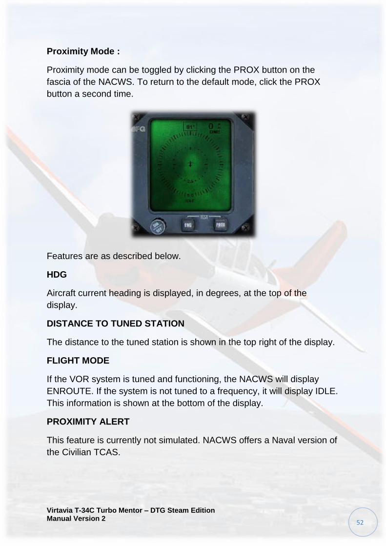
Proximity Mode :
Proximity mode can be toggled by clicking the PROX button on the
fascia of the NACWS. To return to the default mode, click the PROX
button a second time.
Features are as described below.
HDG
Aircraft current heading is displayed, in degrees, at the top of the
display.
DISTANCE TO TUNED STATION
The distance to the tuned station is shown in the top right of the display.
FLIGHT MODE
If the VOR system is tuned and functioning, the NACWS will display
ENROUTE. If the system is not tuned to a frequency, it will display IDLE.
This information is shown at the bottom of the display.
PROXIMITY ALERT
This feature is currently not simulated. NACWS offers a Naval version of
the Civilian TCAS.

Virtavia T-34C Turbo Mentor – DTG Steam Edition Manual Version 2
53
RANGE Mode :
Clicking the RNG button when in PROX mode will change the range at
which the unit displays waypoints and traffic information.
Range is shown at the bottom of each circle, in NM.

Virtavia T-34C Turbo Mentor – DTG Steam Edition Manual Version 2
54
KLN GPS
Outline
Both cockpits of the T-34C have a simulated KLN900 GPS unit located
on the lower left area of the forward panel.
Currently the KLN900 in this simulation is only a customised default
GPS500 unit. A future upgrade may be released to simulate the KLN900
system completely.
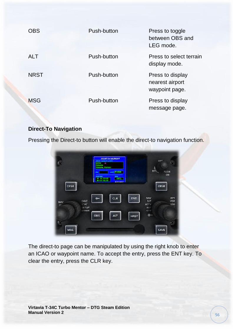
Controls
The KLN900 controls include buttons for the DIRECT TO, CLEAR,
ENTER, OBS/LEG mode, ALT (TERRAIN), NEAREST and MESSAGE
functions. Data entry and some control functions are enabled by left and
right concentric knobs and the CURSOR button.
To power the display, click the PUSH ON button on the top right of the
fascia. To cut power to the display, click the PUSH ON knob a second
time.

Virtavia T-34C Turbo Mentor – DTG Steam Edition Manual Version 2
55
The outer right knob is used to select the required function. The inner
knob is used to select the required page. To scroll right through options,
left click the knob. To scroll left through options, right click the knob.
To zoom the display, use the inner left knob. Zoom in by left clicking and
zoom out by right clicking the control knob.
Control Type Function
Power Knob/ switch Push to turn on. Pull to
turn off.
CRSR Push-button Press to activate/
deactivate cursor.
Left Outer Knob Knob Left click to increase
zoom. Right click to
decrease zoom.
Right Outer Knob Knob Left click to increase
function selection.
Right click to decrease
function selection.
Right Inner Knob Knob Left click to scroll
forwards through
pages. Right click to
scroll backwards
through pages.
Direct To Push-button Press to activate
direct-to navigation
function.
CLR Push-button Press to clear current
entry.
ENT Push-button Press to approve
current display or
entry.
Virtavia T-34C Turbo Mentor – DTG Steam Edition Manual Version 2
56
OBS Push-button Press to toggle
between OBS and
LEG mode.
ALT Push-button Press to select terrain
display mode.
NRST Push-button Press to display
nearest airport
waypoint page.
MSG Push-button Press to display
message page.
Direct-To Navigation
Pressing the Direct-to button will enable the direct-to navigation function.
The direct-to page can be manipulated by using the right knob to enter
an ICAO or waypoint name. To accept the entry, press the ENT key. To
clear the entry, press the CLR key.

Virtavia T-34C Turbo Mentor – DTG Steam Edition Manual Version 2
57
Nearest Function
Pressing the NRST key will display a list of near-by airports and facilities.
The list can be scrolled using the right outer knob.
Pressing the CRSR key will allow an entry to be selected. When the
desired entry is selected, pressing the ENT key will display information
regarding it.

Virtavia T-34C Turbo Mentor – DTG Steam Edition Manual Version 2
58
Pressing the Direct-to key when the desired entry is highlighted will
display the direct-to page. Direct-to information will be pre-completed.
Pressing the ENT key will create a route to the selected entry.
Message Function
Pressing the MSG key will display any important messages or
information.

Virtavia T-34C Turbo Mentor – DTG Steam Edition Manual Version 2
59
ALT/ Terrain Display Function
Pressing the ALT key will toggle the moving-map display mode.

Virtavia T-34C Turbo Mentor – DTG Steam Edition Manual Version 2
60
KA Control Unit
Outline
In the real-world, the true KA41 is a GPS control unit. This T-34C
simulation does not have a true KLN-900, therefore the unit is
inoperable.
Instead we have decided to equip the T-34C with a very basic autopilot
for those that want to enjoy autopilot functions.
Each cockpit is equipped with a KA41 control unit, located on the
forward panel. Though basic, the KA41 is a useful tool, detailed below.
Controls
The KA41 is comprised of four
main buttons. Button
Function
1. NAV/ GPS button Click to toggle NAV and GPS
modes.
2. GPS/ APR button Click to arm and engage the
autopilot.
3. OBS/ LEG button Click to engage NAV hold mode.
4. LAMP TEST button Click to test the functionality of all
lamps.

Virtavia T-34C Turbo Mentor – DTG Steam Edition Manual Version 2
61
Operation
The KA41 unit will power up automatically when the aircraft battery
system is online. When power is available the lamp on the left of the unit
will illuminate. The unit will be set to NAV mode by default and should
always be checked to ensure the master lamp is OFF.
NAV/ GPS Function
By default the KA41 is set to NAV mode. GPS mode can be toggled by
clicking the NAV GPS button a single time. The display will change to
GPS to show that GPS mode is active. The unit will now direct the
aircraft to the desired GPS waypoint or destination. Use of these modes
is coupled with the OBS LEG function.
Virtavia T-34C Turbo Mentor – DTG Steam Edition Manual Version 2
62
GPS APR Function
To engage the KA41 autopilot unit, click the GPS APR button. The
display will illuminate to show that the GPS is armed and active. To
disengage the autopilot, click the GPS APR button a second time. An
audible warning tone will be heard and the autopilot will cease to direct
the aircraft.
OBS LEG Function
Engaging the OBS LEG function will allow the aircraft to be directed by
the autopilot. The NAV GPS function controls how the function is
directed. Pressing OBS LEG once will arm the function. Pressing a
second time will disarm the function. When armed, the display will
illuminate.

Virtavia T-34C Turbo Mentor – DTG Steam Edition Manual Version 2
63
LAMP TEST Function
Operation of the KA41 annunciator lamps can be tested by pressing the
LAMP TEST button. To end the test function, click the button a second
time. If the KA41 is functioning correctly, all lamps will illuminate.

Virtavia T-34C Turbo Mentor – DTG Steam Edition Manual Version 2
64
Transponder
Outline
The transponder is an identification, position tracking, altitude reporting
and emergency tracking device. An operating transponder responds to
interrogations by search radar. Dual transponders are installed: one
located in each cockpit.
The transponder is located on the outer edge of the right console. By
default it is turned OFF.
Operation
Setting the unit to ON will allow the transponder to function.
The code selector switches can be used to select the desired code. To
increase digits, left click a knob. To decrease selected digits, right click a
knob.
When power is available to the unit, the green LED will illuminate.
Virtavia T-34C Turbo Mentor – DTG Steam Edition Manual Version 2
65
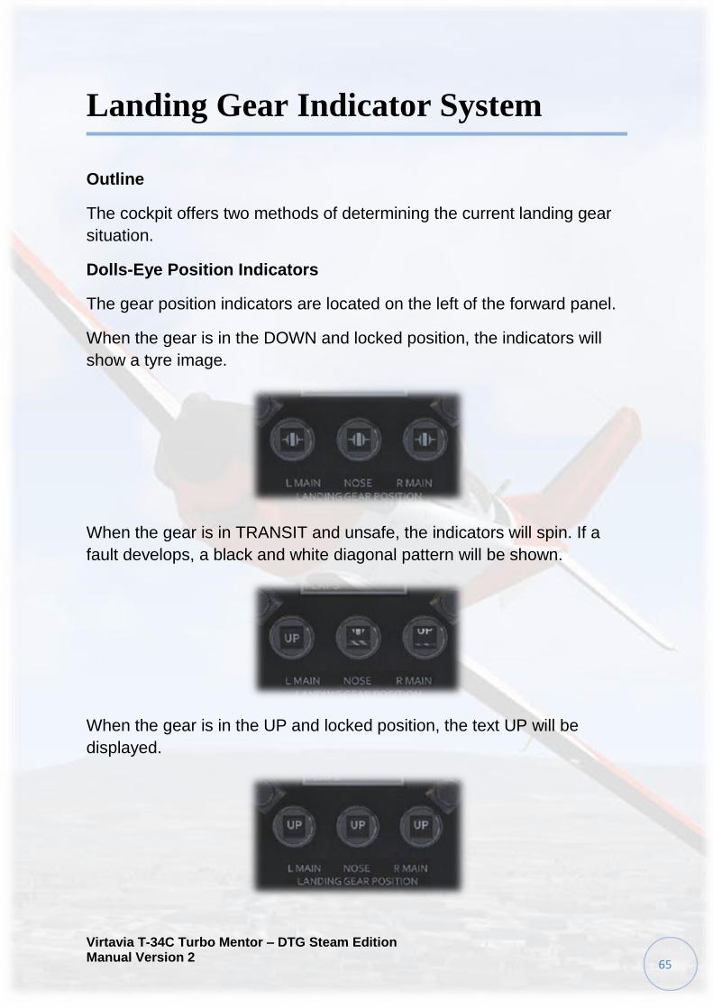
Landing Gear Indicator System
Outline
The cockpit offers two methods of determining the current landing gear
situation.
Dolls-Eye Position Indicators
The gear position indicators are located on the left of the forward panel.
When the gear is in the DOWN and locked position, the indicators will
show a tyre image.
When the gear is in TRANSIT and unsafe, the indicators will spin. If a
fault develops, a black and white diagonal pattern will be shown.
When the gear is in the UP and locked position, the text UP will be
displayed.
Virtavia T-34C Turbo Mentor – DTG Steam Edition Manual Version 2
66
Landing Gear Lever
The landing gear lever is located on the forward left pedestal.
When the gear is in the DOWN and locked position, the lever will be
down and white.
When the gear is in the UP and locked position, the lever will be up and
white.
When the gear is in TRANSIT and unsafe, the lever will be in either
position and red.
Pressing the WARN TEST button will also illuminate the landing gear
lever warning lamp.

Virtavia T-34C Turbo Mentor – DTG Steam Edition Manual Version 2
67
CHECKLIST
Pre-start Checklist:
1. Parking brakes — SET.
2. Parachute — FASTENED/ADJUSTED.
3. Emergency fuel shutoff handle — DOWN, CLIP IN PLACE.
4. Wing flap lever — UP.
5. PCL — IDLE.
6. Condition lever — FUEL OFF.
7. EPL — DISCONNECT.
8. Friction lock knob — FULL DECREASE.
9. Cockpit environmental control — OFF.
10. Cockpit defog control — OFF.
11. Gear handle — DOWN.
12. Landing lights — OFF.
13. GPS — OFF.
14. Compass slave switch — SLAVE (both cockpits).
15. Air-conditioner switch — OFF (both cockpits).
16. Fire warning test switch — OFF.
17. NACWS — OFF (both cockpits).
18. Auto ignition — OFF (both cockpits).
19. Starter — OFF (both cockpits).
20. Engine air bypass — CLOSED.
21. Emergency landing gear handle crank — DISENGAGED.
Virtavia T-34C Turbo Mentor – DTG Steam Edition Manual Version 2
68
22. Inverters— OFF.
23. AVIONICS MASTER — OFF.
24. Aft cockpit attitude gyro and RMI — ON.
25. Navigation and strobe lights — OFF.
26. Pitot heat — OFF.
27. Standby fuel pump — OFF.
28. VHF Radio — OFF.
29. Circuit breakers — IN; UTILITY BUS SWITCHES ON.
30. Helmet — ON.
31. Battery — ON and Check for a minimum of 22 volts.
32. ICS — CHECK.
33. Instrument and console lights — AS DESIRED.
34. Navigation and strobe lights — REQUIRED.
35. Pitot heat — TEST.
o Turn switch ON.
o Note drop in ammeter.
o Turn switch OFF.
36. Canopy — CLOSED and LOCKED (both cockpits).
Engine Start Checklist:
1. Fire guard — POSTED.
2. Propeller — CLEAR.
3. Engine — START.

Virtavia T-34C Turbo Mentor – DTG Steam Edition Manual Version 2
69
o Starter switch — ON (check voltage for minimum of 10 volts,
IGNITION light on, FUEL PRES light out, oil pressure
indicated).
o Condition lever — FTHR WHEN N1 REACHES 12
PERCENT.
o ITT and N1 — MONITOR.
o Starter switch — OFF WHEN N1 REACHES 60 PERCENT.
4. Oil pressure — CHECKED.
o Check oil pressure for a minimum of 40 psi.
5. N1 — CHECKED.
6. GPU — DISCONNECTED.
7. Condition lever — FULL INCREASE.
8. Generator light — OUT (voltage).
o Check voltage between 27.0 to 29.5 volts.
9. Inverters — CHECKED/ON.
o Check INVERTER annunciator light out for each inverter.
o Turn on desired inverter.
10. Air-conditioner — AS REQUIRED.
11. AVIONICS MASTER — ON.
12. AVIONICS COMMAND — TEST.
13. RMI — ALIGNED AND SLAVED.
14. Angle-of-attack — TEST.
15. NACWS — ON (both cockpits).
16. GPS — ON.

Virtavia T-34C Turbo Mentor – DTG Steam Edition Manual Version 2
70
Pre Taxi Checklist:
1. Beta/Beta stop — CHECKED.
2. Friction lock knob — ADJUSTED.
3. Brakes — HOLD.
4. Parking brake — RELEASED.
5. Chocks — REMOVED.
6. Brakes — CHECKED (both cockpits).
7. Radios and NAVAIDs — CHECKED and SET.
o Set VHF/UHF Transmit and VHF receive switches to ON or
as required.
o Set UHF radio as required.
o Set transponder to standby.
o Set ADF as required.
o Set VOR as required.
o Set GPS as required.
o Select NAV or GPS mode as required.
8. Altimeter and NACWS — CHECKED and SET.
o Set altimeter to 29.92.
o Set altimeter to local barometric setting.
9. Landing lights — AS REQUIRED.
Ground Run-up Checklist:
1. Brakes — HOLD.
2. Propeller over speed governor — TEST.
o OVSP GOV switch — DEPRESS.

Virtavia T-34C Turbo Mentor – DTG Steam Edition Manual Version 2
71
o PCL — SLOWLY ADVANCE UNTIL PROPELLER RPM
STABILIZES.
o Check propeller rpm between 1,950 to 2,150.
o OVSP GOV switch — RELEASE AND CHECK FOR AN
INCREASE IN PROPELLER RPM.
3. Oil pressure — CHECKED.
o Check oil pressure 65 to 80 psi.
4. Auto ignition — TEST.
o Auto ignition switch —ON (check AUTO IGN annunciator
light ON).
o PCL — IDLE (check that IGNITION annunciator light comes
on between 180 and 300 ft-lb torque and that AUTO IGN
annunciator light goes out).
o Auto ignition switch — OFF.
5. Propeller feather — TEST.
o Check by moving the condition lever aft through the spring
detent to FTHR.
o After feathering action has stabilized (increased torque,
decreased propeller rpm, N1 stabilized between 60 to 65
percent), advance condition lever to FULL INCR RPM.
Takeoff Checklist:
1. Trim — SET.
2. Set 0° rudder, 3° up elevator, 0° aileron.
3. Flaps — CHECKED.
4. Check for proper extension and retraction of flaps.
5. Controls — FREE and CORRECT (both cockpits).

Virtavia T-34C Turbo Mentor – DTG Steam Edition Manual Version 2
72
6. Radios, NAVAIDS, NACWS, GPS — SET.
7. Instruments, fuel quantity — CHECKED.
Items to be completed just prior to takeoff:
1. Transponder — AS REQUIRED.
2. Pitot Heat — AS REQUIRED.
3. Strobes/Navigation Lights — AS REQUIRED.
Landing Checklist
1. Landing gear — DOWN and LOCKED (both cockpits).
2. Brakes — PARKING BRAKE OFF, BRAKES FIRM.
3. Instruments — CHECKED.
4. Landing lights — AS REQUIRED.
5. Flaps — AS REQUIRED.
After Landing Checklist
1. Flaps — UP.
2. Landing lights — AS REQUIRED.
3. Transponder — OFF.
4. Pitot heat — OFF.
5. Navigation and strobe lights — AS REQUIRED.
Engine Shutdown Checklist
1. Brakes — HOLD.
2. Parking brake — SET.

Virtavia T-34C Turbo Mentor – DTG Steam Edition Manual Version 2
73
3. NACWS — OFF (both cockpits).
4. GPS — OFF.
5. PCL — IDLE.
6. Inverter — OFF.
7. VHF Radio — OFF.
8. Avionics master — OFF.
9. Landing lights — OFF.
10. Condition lever — FUEL OFF.
11. ITT — MONITOR.
o Ensure ITT is below 610° C.
12. Navigation lights and strobe lights — OFF.
13. Diluter control lever — 100 percent (both cockpits).
14. Battery switch — OFF.
Post Flight Checklist
1. Control lock — INSTALLED.
2. Accelerometer — CHECK (both cockpits).
3. Trim tabs — NEUTRAL.
4. Wheels — CHOCK.
5. Parking brake — RELEASE
6. Canopy — AS REQUIRED.
7. Covers and tie downs — AS REQUIRED.

Virtavia T-34C Turbo Mentor – DTG Steam Edition Manual Version 2
74
REFERENCE NOTES
The Beechcraft T-34 Mentor is a propeller-driven, single-engined,
military trainer aircraft derived from the Beechcraft Model 35 Bonanza.
The earlier versions of the T-34, dating from around the late 1940s to the
1950s, were piston-engined. These were eventually succeeded by the
upgraded T-34C Turbo Mentor, powered by a turboprop engine. The T-
34 remains in service almost six decades after it was first designed. The
T-34C Turbine Mentor is powered by a Pratt & Whitney Canada PT6A-
25 turboprop engine and was developed in 1973, with the final example
rolling off the production line in 1990.
Specifications:
Two-seat Trainer
Empty weight: 3,000 lbs
Typical TO weight: 4,000 lbs
Max TO weight: 4,400 lbs
Fuel capacity: 135 US Gal / 130
Useable
Initial climb rate: 2,000 ft/min
Service ceiling: 25,000 ft

Virtavia T-34C Turbo Mentor – DTG Steam Edition Manual Version 2
75
Aircraft Limitations
Stall speed, clean: 70 KIAS
Max gear
extension: 150 KIAS
Max gear retraction: 120 KIAS
Max indicated airspeed is 280 KIAS.
Maximum speed: 230 KIAS at 5,000ft
Maximum G: +4.5/-2.3
Notes on configuration and load-out:
All applicable load stations are included in the configuration file. In the
event the user wishes to use a model with particular weapon settings,
they will need to add weight to the particular weapon station.
The recommended weights for each load station are as follows:
Station_load.0 Student
Pilot 185.00 lbs
Station_load.1 Instructor
Pilot 185.00 lbs
Station_load.2 Baggage Pilot’s discretion
Trim Characteristics
The aircraft will require only small trim adjustments throughout its flight
envelope, with the exception of landing, where the slower speeds will
require more elevator trim to compensate for reduced elevator
effectiveness. The aircraft is capable of trimming +/- 15° in either
direction. Use trim at your discretion to relieve control heaviness.

Virtavia T-34C Turbo Mentor – DTG Steam Edition Manual Version 2
76
General Notes on Handling & Maneuvers
The T-34C is a very forgiving aircraft to fly and is reasonably resistant to
spins. Stalls are mild and consist of a clean break and a quick
recovery. The aircraft is certified for a wide assortment of aerial combat
maneuvers so long as the G-limits are respected (4.5G in clean
configuration).
The following is a list of recommended maneuver speeds:
Wingover: 180 KIAS / 1015 ft-lbs
Steep Turns (45°+
bank): 180 KIAS / 1015 ft-lbs
Barrel Roll: 180 KIAS / 1015 ft-lbs
Aileron Roll: 180 KIAS / 1015 ft-lbs
Loop: 200 KIAS / 1015 ft-lbs
Immelmann: 200 KIAS / 1015 ft-lbs
Split-S: 120 KIAS / IDLE
Note: Performing aerial combat maneuvers at speeds below the ones
listed may resort in excessively high sink rates, particularly in high-bank
maneuvers. The aircraft may demonstrate a tendency to “slice” in high-
bank turns below 180 KIAS.
At or around 220 KIAS the aircraft begins to require excessive control
forces. Therefore, it is advised to restrict airspeed to no greater than
220 KIAS whenever possible to avoid having to exert heavy control
forces to maintain control. Be especially mindful of this in a dive.
Prohibited Maneuvers:
- Inverted Stalls
- Inverted flight above 220 KIAS
- Inverted flight lasting longer than 15 seconds
- Night formation flights (except in emergencies)

Virtavia T-34C Turbo Mentor – DTG Steam Edition Manual Version 2
77
- Intentional spins with flaps and/or gear extended
- Intentional spins with the propeller feathered
- Inverted spins
Taxi Notes:
1. The engine produces enough torque at idle to allow the aircraft to
taxi without an increase in power. Use the minimum amount of
power required to taxi the aircraft. Please note that the engine is
slow to spool on the low end. Therefore, care must be taken not to
“overshoot the mark” when adding in taxi power.
2. The T-34C does not have nosewheel steering. The T-34C is
steered on the ground with a combination of differential braking
and rudder input.
3. At low ground speeds or low prop RPMs the rudder will be
ineffective in steering the aircraft, and differential braking must be
used. At higher ground speeds or conditions where a moderate
amount of prop wash is passing around the vertical stabilizer the
rudder should be sufficient to maintain directional control on the
ground.
Normal Takeoff Notes:
1. Set pitch trim to 3.0° aircraft nose-up.
2. Ensure flap position is UP (Flap position 0).
3. Smoothly apply maximum takeoff power (100% throttle) with the
prop lever at FULL/INCR (100%).
4. Use the rudder to maintain directional control down the runway.
5. Begin to rotate the aircraft at 80 KIAS, the aircraft should unstick
shortly after.
6. Hold the takeoff pitch attitude and accelerate to 120 KIAS.
Minimum Run Takeoff Notes:
For a minimum run takeoff, apply brakes and slowly advance the PCL to
takeoff power. Maintain 1,015 ft-lb, release the brakes. Do no assume

Virtavia T-34C Turbo Mentor – DTG Steam Edition Manual Version 2
78
a nose-high attitude until reaching approximately 60 KIAS. At this time,
smoothly apply aft stick pressure to assume a nose-high (takeoff)
attitude so lift-off will occur as soon as minimum flying speed is
reached. Continue with normal climb procedure. Limit directional
control braking as much as possible to reduce takeoff roll.
Obstacle Clearance Takeoff Notes:
Use minimum run takeoff procedure to the point of assuming a nose-
high attitude. Do not assume the nose-high takeoff attitude until
reaching approximately 70 KIAS. When positive lift-off has occurred,
retract the landing gear and accelerate and maintain Vx (best angle of
climb airspeed, 75 KIAS) until the obstacle is cleared.
Short Field Takeoff Notes:
1. Set pitch trim to 3.0° aircraft nose-up.
2. Set flaps to 20% (Flap position 1).
3. While holding maximum brake pressure, smoothly apply maximum
takeoff power (100% throttle) with the prop lever at FULL/INCR
(100%).
4. Release brakes, use the rudder to maintain directional control
down the runway.
5. Begin to rotate the aircraft at 65 KIAS, the aircraft should unstick
shortly after.
6. Immediately retract landing gear, depress the brake to stop the
rotation of the main wheels.
7. Climb at 75 KIAS until approximately 200ft AGL.
8. At 200ft AGL, lower the nose and accelerate to 120 KIAS, raising
flaps at or above 90 KIAS.
Climb Notes:
1. After takeoff accelerate at takeoff power to 120 KIAS.
2. Reduce power per pilot discretion to maintain a desired vertical
speed, and use pitch to maintain 120 KIAS up to final cruising

Virtavia T-34C Turbo Mentor – DTG Steam Edition Manual Version 2
79
altitude.
NOTE: Climb at takeoff power authorized.
Cruise Notes:
1. The optimum cruise altitude is at or around 16,000ft MSL.
2. For cruise, reduce power as necessary to maintain the desired
cruise speed (Optimum cruise speed is at or around 135-140
KIAS).
3. Typically the T-34C will use approximately 70% of the total power
level travel to maintain the optimum cruise speed.
Fuel burn estimate at cruise condition:
Altitude Airspeed Fuel Burn
16,000
ft
138
KIAS
56.1 nm / 100lbs fuel
used
Descent Notes:
1. The T-34C can perform tactical descents. Reduce power to idle
and pitch down, mindful of G-load limitations and maximum speed.
Approach and Landing Notes (Flaps/No Flaps):
1. If in a tactical descent to landing, the gear can be lowered at up to
150 KIAS to aid in aerodynamic braking.
2. Set flaps 20% (flap position 1) at 105 KIAS.
3. Set flaps 60% (flap position 3) at 95 KIAS.
4. Set flaps 100% (flap position 5) at 85 KIAS.
5. Final approach speed with flaps fully extended is 85 KIAS. Final
approach speed with flaps retracted is 95 KIAS.
NOTE: Due to slow engine response and lag on the low end avoid
reducing power to idle unless in the flare. This may create a
situation in which the aircraft gets behind the drag curve and
excessive sink rates occur.

Virtavia T-34C Turbo Mentor – DTG Steam Edition Manual Version 2
80
6. At 5ft AGL, slowly retard the throttles.
7. Flare the aircraft several degrees and fly the aircraft onto the
runway. Slowly lower the nose onto the runway.
8. If sufficient runway length exists ( at least 3000ft) aerodynamic
braking or a long rollout is authorized, though it is more effective to
get all the wheels on the ground and use wheel brakes to slow the
aircraft.
NOTE: The T-34C prop has a small beta range ( -5°) that can be
used to provide additional braking. Use the F2 key to set the prop
into this range. To return the prop to the normal operating range,
simply move the power lever slightly forward. This will disengage
the reversing pitch.