DESIGN AND ANALYSIS OF SUPRA CHASSIS - IRJET
6
International Research Journal of Engineering and Technology (IRJET) e-ISSN: 2395-0056 Volume: 07 Issue: 05 | May 2020 www.irjet.net p-ISSN: 2395-0072 © 2020, IRJET | Impact Factor value: 7.529 | ISO 9001:2008 Certified Journal | Page 1505 DESIGN AND ANALYSIS OF SUPRA CHASSIS Swati Upadhyay 1 , Ganesh Badiger 2 1 BE Student, Department of Mechanical Engineering, SCOE, Pune, Maharashtra, India. 2 BE Student, Department of Mechanical Engineering, SCOE, Pune, Maharashtra, India. ------------------------------------------------------------------------***------------------------------------------------------------------------- Abstract: The main objective of this paper is to give detailed information on design and analysis of chassis of SUPRA SAE India race car. SUPRA SAE India is a competition organized by Society of Automobile Engineering. Under graduate and post graduate students from all over India can compete in it by designing and fabricating the car and strictly following the instructions given in the Rule book. Chassis plays a crucial role in automobile system. It supports all the functional members and components of system. Therefore, the chassis should be strong enough to resist shocks, vibrations and the stresses which acts on it during operating conditions. Along with all these factors the weight, cost and safety of the driver has to be considered while designing it. The chassis is designed using CAD software referred as CATIA and analysis is performed using ANSYS WORKBENCH, many other software are available which can be used as well. Based on the instructions mentioned in the rulebook of SUPRA SAE INDIA, the chassis is designed considering every necessary aspect including dimensional and stress parameters. The detailed calculation of the impact forces is given by performing the analysis on front, rear and side of the chassis with reference to dynamic conditions. 1. INTRODUCTION The competition named SUPRA SAE INDIA is organized by Society of Automobile Engineering, India. It turns out to be very beneficial for students as they get engaged more into practical implementation of knowledge. The goal of SUPRA SAE is to build platform for students to experience build and learn. The design of chassis and various components mounted on it is strictly made as per the dimensions in the rule book of SUPRA SAE. There are many different styles of chassis frames. Space frame, monocoque and ladder are examples of race car frames. Tubular space frame is the most preferred style for SUPRA SAE. Space frames are the number of tubes joined together to support the components of the car mounted on it. A truss bridge is formed by adding small members in a triangular pattern. These triangular patterns are probably in pure tension and compression. The chassis should not be complex in design, it should be easy to manufacture, repair and maintain. The structure of chassis must sternly support the weight of the components mounted on it and transmit loads that are caused due to longitudinal, vertical and lateral accelerations that are experienced while the car is on track in the racing environment. The chassis must be of light weight and low cost. It should be successfully be able to resist the shocks and vibrations along with temperature rise. The stiffness of the chassis is an important aspect, hence the material is chosen accordingly considering the aspects like availability, cost, strength and other relevant factors. Along with the dimensions and materials, the safety of the driver is given superior priority and therefore ergonomics also plays an important role. This paper also deals with the analysis of various impact forces on front, rear and side of it. The chassis is completely tubular space frame fabricated with AISI 4130 steel material. CATIA as a designing software is used for CAD model and analysis is done on ANSYS WORKBENCH. 2. DESIGN METHODOLOGY Chassis acts as a base of all the automobile system supporting all the components of vehicle. The whole structure of chassis is made by examining the rules given in SUPRA SAE rulebook. While designing the chassis the safety of the driver is given a special significance and design is made accordingly. The main goals of the design are simplicity, reliability and weight reduction. After the CAD model of the chassis is ready, the appropriate material is selected. This CAD model of the chassis is made by using the CATIA software then the file is transferred to ANSYS WORKBENCH for the analysis where impact forces on different sides are calculated. 2.1. Vehicle design parameters are as follows: a. Wheelbase and vehicle configuration: The wheelbase is measured from the centre of the ground contact of the front and rear tires when the wheels are pointing straight ahead. b. Track width: The smaller track of the vehicle must be no less than 70% of the larger track. c. Ground Clearance: the ground clearance is given to the car to avoid any parts of it from touching the ground other than tires (during the event) d. Templates: The vehicle chassis should follow all the rule template in the rule book.
-
Upload
khangminh22 -
Category
Documents
-
view
3 -
download
0
Transcript of DESIGN AND ANALYSIS OF SUPRA CHASSIS - IRJET

International Research Journal of Engineering and Technology (IRJET) e-ISSN: 2395-0056
Volume: 07 Issue: 05 | May 2020 www.irjet.net p-ISSN: 2395-0072
© 2020, IRJET | Impact Factor value: 7.529 | ISO 9001:2008 Certified Journal | Page 1505
DESIGN AND ANALYSIS OF SUPRA CHASSIS
Swati Upadhyay1, Ganesh Badiger2
1BE Student, Department of Mechanical Engineering, SCOE, Pune, Maharashtra, India. 2BE Student, Department of Mechanical Engineering, SCOE, Pune, Maharashtra, India.
------------------------------------------------------------------------***------------------------------------------------------------------------- Abstract: The main objective of this paper is to give detailed information on design and analysis of chassis of SUPRA SAE India race car. SUPRA SAE India is a competition organized by Society of Automobile Engineering. Under graduate and post graduate students from all over India can compete in it by designing and fabricating the car and strictly following the instructions given in the Rule book. Chassis plays a crucial role in automobile system. It supports all the functional members and components of system. Therefore, the chassis should be strong enough to resist shocks, vibrations and the stresses which acts on it during operating conditions. Along with all these factors the weight, cost and safety of the driver has to be considered while designing it. The chassis is designed using CAD software referred as CATIA and analysis is performed using ANSYS WORKBENCH, many other software are available which can be used as well. Based on the instructions mentioned in the rulebook of SUPRA SAE INDIA, the chassis is designed considering every necessary aspect including dimensional and stress parameters. The detailed calculation of the impact forces is given by performing the analysis on front, rear and side of the chassis with reference to dynamic conditions.
1. INTRODUCTION
The competition named SUPRA SAE INDIA is organized by Society of Automobile Engineering, India. It turns out to be very beneficial for students as they get engaged more into practical implementation of knowledge. The goal of SUPRA SAE is to build platform for students to experience build and learn. The design of chassis and various components mounted on it is strictly made as per the dimensions in the rule book of SUPRA SAE. There are many different styles of chassis frames. Space frame, monocoque and ladder are examples of race car frames. Tubular space frame is the most preferred style for SUPRA SAE. Space frames are the number of tubes joined together to support the components of the car mounted on it. A truss bridge is formed by adding small members in a triangular pattern. These triangular patterns are probably in pure tension and compression. The chassis should not be complex in design, it should be easy to manufacture, repair and maintain.
The structure of chassis must sternly support the weight of the components mounted on it and transmit loads that are caused due to longitudinal, vertical and lateral accelerations that are experienced while the car is on track in the racing environment. The chassis must be of light weight and low cost. It should be successfully be able to resist the shocks and vibrations along with temperature rise. The stiffness of the chassis is an important aspect, hence the material is chosen accordingly considering the aspects like availability, cost, strength and other relevant factors. Along with the dimensions and materials, the safety of the driver is given superior priority and therefore ergonomics also plays an important role. This paper also deals with the analysis of various impact forces on front, rear and side of it. The chassis is completely tubular space frame fabricated with AISI 4130 steel material. CATIA as a designing software is used for CAD model and analysis is done on ANSYS WORKBENCH.
2. DESIGN METHODOLOGY
Chassis acts as a base of all the automobile system supporting all the components of vehicle. The whole structure of chassis is made by examining the rules given in SUPRA SAE rulebook. While designing the chassis the safety of the driver is given a special significance and design is made accordingly. The main goals of the design are simplicity, reliability and weight reduction. After the CAD model of the chassis is ready, the appropriate material is selected. This CAD model of the chassis is made by using the CATIA software then the file is transferred to ANSYS WORKBENCH for the analysis where impact forces on different sides are calculated.
2.1. Vehicle design parameters are as follows: a. Wheelbase and vehicle configuration: The wheelbase is measured from the centre of the ground contact of
the front and rear tires when the wheels are pointing straight ahead. b. Track width: The smaller track of the vehicle must be no less than 70% of the larger track. c. Ground Clearance: the ground clearance is given to the car to avoid any parts of it from touching the ground
other than tires (during the event) d. Templates: The vehicle chassis should follow all the rule template in the rule book.

International Research Journal of Engineering and Technology (IRJET) e-ISSN: 2395-0056
Volume: 07 Issue: 05 | May 2020 www.irjet.net p-ISSN: 2395-0072
© 2020, IRJET | Impact Factor value: 7.529 | ISO 9001:2008 Certified Journal | Page 1506
Table 1. Dimension parameter of Chassis
Parameter Length Wheelbase 1663 mm Trackwidth 1610 mm Height 1101 mm Chassis length 2423 mm Chassis width 835 mm
Fig.1 CAD model of Chassis designed by using CATIA
2.2 Material selection:
Material selection is very crucial and difficult piece of work as chassis has to reinforce all the component of the vehicle and should succour all the forces and the loads acting on it, without any deformation. The material should be selected taking into account strength, strength to weight ratio and its cost. It should be resistant to high temperature and stiff enough to absorb all the vibration. According to the rulebook of SUPRA SAE the selected material should contain 0.3% of carbon in it.
Table 2: Materials selected as per rulebook.
Material name Tensile strength (N/mm2 )
Yield strength (N/mm2)
Mass density (kg/m2)
Cost (rupees/m)
AISI 4130
731 460 7850 450
AISI 1020 420.5 351.5 7900 375
AISI 1018 440 370 7870 390
Referring Table 1, the material AISI 4130 is selected. The cost of this material is high but strength to weight ratio is also high as compared to other grades of material. AISI 4130 alloy steel contains chromium and molybdenum as strengthening agents. It has low carbon content which imparts great working properties such as weld ability and machinability. The important properties of AISI 4130 is mentioned in the Table 2.
Table 3: Mechanical properties of AISI 4130
Elastic Modulus 2.05e+011 N/m2
Poison’s Ratio 0.285 N/A Shear modulus 8e+010 N/m2

International Research Journal of Engineering and Technology (IRJET) e-ISSN: 2395-0056
Volume: 07 Issue: 05 | May 2020 www.irjet.net p-ISSN: 2395-0072
© 2020, IRJET | Impact Factor value: 7.529 | ISO 9001:2008 Certified Journal | Page 1507
Mass density 7850 kg/m2
Tensile strength 731000000 N/m2
Yield strength 460000000 N/m2
Machinability (Annealed and cold drawn. Based on 100% machinability for AISI 1212 steel)
70
Elongation at break (in 50mm) 21.50% Thermal conductivity 42.7 W/ (m k) Specific heat 477 J/ (kg k) Material damping ratio N/A
3. ERGONOMICS
Ergonomics is the study of human and machine interaction. It includes study to understand the effects of occupant body dimensions with interior of the vehicle during the normal operating conditions. It also deals with design factors on the driver posture, position and comfort. It helps the designer to decide the amount of space the driver might need for safe and comfortable driving. The machine should be easy to operate without compromising the driver’s security. In ergonomics the position of driver’s helmet, elbow, foot etc is decided. Overall, the inclination of the driver is adjudicated and therefore ergonomics plays very important role in design of chassis. After ergonomics the deign is successfully started by setting out the space for steering, suspension and other components.
4. PROCEDURE OF ANALYSIS OF CHASSIS
The model of the chassis was designed on CATIA. Analysis is the next process subsequent to design and material selection which is done by using the ANSYS WORKBENCH. The proper analysis is carried out for design validation of chassis and ensuring proper safety of the driver
4.1. Pre processing
The tubular chassis was meshed in Ansys Mechanical. Following are the meshing characteristics.
Meshing Parameters:
Nodes: 228401
Elements: 47469
Element type: Quadrilateral Dominant
Element Size: 10 mm
Fig.2: Meshed body of Chassis.

International Research Journal of Engineering and Technology (IRJET) e-ISSN: 2395-0056
Volume: 07 Issue: 05 | May 2020 www.irjet.net p-ISSN: 2395-0072
© 2020, IRJET | Impact Factor value: 7.529 | ISO 9001:2008 Certified Journal | Page 1508
4.2. Impact Analysis
There are three types of dynamic analysis that has to be performed and they are as followed:
a. Front impact b. Side impact c. Rear impact
At the time of analysis, the weight of the car was assumed to be 190 kg.
4.2.1. Front impact: For the front impact, two position namely front suspension mounting points and rear wheel position are kept stable. The optimum speed of 70kmph is used to calculate the front impact. By constraining the other end of chassis, the loads are applied only to the front end. Time of impact is considered as 0.1s.
Calculation: Velocity = distance/time Distance(d)= velocity(v)*time of impact d= 19.44*0.1 Force =(0.5*m*v^2)/d Force =0.5*190*19.44*19.44/1.944 Therefore, impact force by speed limit =18468 N.
FIG.3: Total deformation
FIG.4: Equivalent Stress
International Research Journal of Engineering and Technology (IRJET) e-ISSN: 2395-0056
Volume: 07 Issue: 05 | May 2020 www.irjet.net p-ISSN: 2395-0072
© 2020, IRJET | Impact Factor value: 7.529 | ISO 9001:2008 Certified Journal | Page 1509
4.2.2. Side impact: The vehicle already in motion is the most probable condition for side impact. The velocity of the vehicle is considered as 40kmph and the side approaching the vehicle also as 40kmph. Time of impact is presumed as 0.3s. By applying load equivalent on the right side, Impact force was applied by constraining left side of the chassis.
Calculations : Hence, the relative velocity will be sqrt (40^2+40^2) =56.56 kmph=15.71 m/s Now, By using impulse formula, Force (=mass of the chassis*(relative velocity)/time of impact Force =(190*15.71)/0.3= 9949 N. Therefore, the side impact force is 9949 N
FIG.5: Total Deformation
FIG.6: Equivalent Stress
4.2.3. Rear impact: In case of collision for rear impact, let the vehicle speed be 25kmph and approaching vehicle
speed be 65kmph. By constraining the front suspension and rear suspension mountings points, Load is applied at the rear end. Time of impact was considered as 0.2s.
Calculation: Hence, relative speed =65-25=40 kmph=11.11 m/s Therefore, Force =(mass of the chassis*(relative velocity))/time of impact Force =(190*11.11)/0.2=10554 kN Hence, the rear impact force is 10554 kN
International Research Journal of Engineering and Technology (IRJET) e-ISSN: 2395-0056
Volume: 07 Issue: 05 | May 2020 www.irjet.net p-ISSN: 2395-0072
© 2020, IRJET | Impact Factor value: 7.529 | ISO 9001:2008 Certified Journal | Page 1510
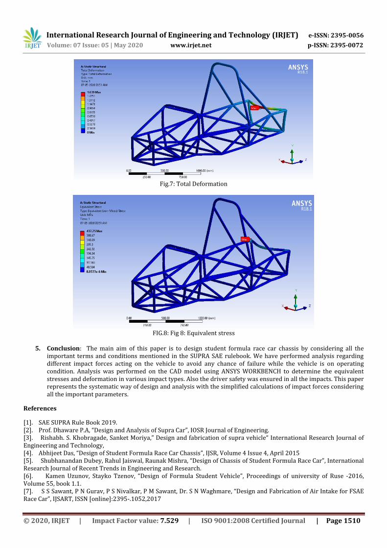
Fig.7: Total Deformation
FIG.8: Fig 8: Equivalent stress
5. Conclusion: The main aim of this paper is to design student formula race car chassis by considering all the
important terms and conditions mentioned in the SUPRA SAE rulebook. We have performed analysis regarding different impact forces acting on the vehicle to avoid any chance of failure while the vehicle is on operating condition. Analysis was performed on the CAD model using ANSYS WORKBENCH to determine the equivalent stresses and deformation in various impact types. Also the driver safety was ensured in all the impacts. This paper represents the systematic way of design and analysis with the simplified calculations of impact forces considering all the important parameters.
References
[1]. SAE SUPRA Rule Book 2019. [2]. Prof. Dhaware P.A, “Design and Analysis of Supra Car”, IOSR Journal of Engineering. [3]. Rishabh. S. Khobragade, Sanket Moriya,” Design and fabrication of supra vehicle“ International Research Journal of Engineering and Technology, [4]. Abhijeet Das, “Design of Student Formula Race Car Chassis”, IJSR, Volume 4 Issue 4, April 2015 [5]. Shubhanandan Dubey, Rahul Jaiswal, Raunak Mishra, “Design of Chassis of Student Formula Race Car”, International Research Journal of Recent Trends in Engineering and Research. [6]. Kamen Uzunov, Stayko Tzenov, “Design of Formula Student Vehicle”, Proceedings of university of Ruse -2016, Volume 55, book 1.1. [7]. S S Sawant, P N Gurav, P S Nivalkar, P M Sawant, Dr. S N Waghmare, “Design and Fabrication of Air Intake for FSAE Race Car”, IJSART, ISSN [online]:2395-.1052,2017