“RESEARCH CASE STUDY FOR TYPES, CAUSES ... - IRJET
26
International Research Journal of Engineering and Technology (IRJET) e-ISSN: 2395-0056 Volume: 06 Issue: 07 | July 2019 www.irjet.net p-ISSN: 2395-0072 © 2019, IRJET | Impact Factor value: 7.211 | ISO 9001:2008 Certified Journal | Page 1712 “RESEARCH CASE STUDY FOR TYPES, CAUSES, PREVENTIVE MEASURES AND ADVANCED RECTIFICATION TECHNIQUES OF CRACKS IN CONCRETE STRUCTURES” (TODAY IS THE BIGGEST CHALLENGES / PROBLEMS ALL OVER WORLD’S IN 21 ST CENTURY) Mr. Harshal Shankarrao Khode Manager (Corporate) - Technical/QA/QC/Structure/Audit, Pune, India ----------------------------------------------------------------------***--------------------------------------------------------------------- ABSTRACT : Cracking is a common problem in concrete structures in real-life service conditions all over the world’s. In fact, crack-free concrete structures are very rare to find in real world. Concrete can undergo early-age cracking depending on the mix composition, exposure environment, hydration rate, and curing conditions. Understanding the causes and consequences of cracking thoroughly is essential for selecting proper measures to resolve the early-age cracking problem in concrete. This paper will help to identify the major causes and consequences of the early-age cracking in concrete. Also, this paper will be useful to adopt effective remedial measures for reducing or eliminating the early-age cracking problem in concrete. Different types of early-age crack, the factors affecting the initiation and growth of early-age cracks, the causes of early-age cracking, and the modeling of early-age cracking are discussed in this paper. A number of examples for various early-age cracking problems of concrete found in different structural elements are also shown. Above all, some recommendations are given for minimizing the early-age cracking in concrete. It is hoped that the information conveyed in this paper will be beneficial to improve the service life of concrete structures. KEYWORDS: Concrete; Cracks; Crack sing mechanisms; curing; early-age cracking; mix composition; modelling; service life; Aggregates; anchorage (structural); cement aggregate reactions; concrete construction; concrete pavements; concrete slabs; cooling; corrosion; crack propagation; cracking (fracturing); crack width and spacing; drying shrinkage; shrinkage- compensating concrete; heat of hydration; mass concrete; micro cracking; polymer-modified concrete; Pre-stressed concrete; reinforced concrete; restraint; shrinkage; temperature; tensile stresses; thermal expansion; volume change. 1. INTRODUCTION Modern structures are comparatively tall and slender, have thin walls, are designed for higher stresses and are built at a fast pace. These structures are therefore, more crack-prone as compared with old structures which used to be low, had thick walls, were lightly stressed and were built at a slow pace. Moreover, moisture from rain can easily reach the inside and spoil the finish of a modern building which has thin walls. Thus measures for control of cracks in buildings have assumed much greater importance on account of the present trends in construction. Cracks in buildings are of common occurrence. A building component develops cracks whenever stress in the component exceeds its strength. Stress in a building component could be caused by externally applied forces, such as dead, live, wind or seismic loads, or foundation settlement or it could be induced internally due to thermal variations, moisture changes, chemical action, etc. Cracking in concrete is a phenomenon which is recognized world-wide. Some cracks in some situations do no harm and are entirely acceptable. In other concrete, cracks are serious defects, in that they adversely strength, function or appearance. There is considerable attention paid to the problems of cracking but the current reaction to cracking is often dissociated from the significance of the cracks in the situation in which it occurs. This reaction ranges from the extreme of concern about the presence of a single hair cracks to the blasé view that cracks are part of the nature of concrete and can be safely ignored wherever they occur and however wide they are. 2. WHY CONCRETE CRACKS First it is necessary to understand why the concrete cracks. There can be many reasons why the concrete cracks. These need to be understood from its reaction and setting pattern point of view. The main reason is improper concrete mix design and lying / jointing practice related to the inherent nature of concrete to change volumetrically due to moisture, reaction and thermal
-
Upload
khangminh22 -
Category
Documents
-
view
0 -
download
0
Transcript of “RESEARCH CASE STUDY FOR TYPES, CAUSES ... - IRJET

International Research Journal of Engineering and Technology (IRJET) e-ISSN: 2395-0056
Volume: 06 Issue: 07 | July 2019 www.irjet.net p-ISSN: 2395-0072
© 2019, IRJET | Impact Factor value: 7.211 | ISO 9001:2008 Certified Journal | Page 1712
“RESEARCH CASE STUDY FOR TYPES, CAUSES, PREVENTIVE MEASURES AND
ADVANCED RECTIFICATION TECHNIQUES OF CRACKS IN CONCRETE
STRUCTURES” (TODAY IS THE BIGGEST CHALLENGES / PROBLEMS ALL OVER
WORLD’S IN 21ST CENTURY)
Mr. Harshal Shankarrao Khode
Manager (Corporate) - Technical/QA/QC/Structure/Audit, Pune, India ----------------------------------------------------------------------***---------------------------------------------------------------------ABSTRACT : Cracking is a common problem in concrete structures in real-life service conditions all over the world’s. In fact, crack-free concrete structures are very rare to find in real world. Concrete can undergo early-age cracking depending on the mix composition, exposure environment, hydration rate, and curing conditions. Understanding the causes and consequences of cracking thoroughly is essential for selecting proper measures to resolve the early-age cracking problem in concrete. This paper will help to identify the major causes and consequences of the early-age cracking in concrete. Also, this paper will be useful to adopt effective remedial measures for reducing or eliminating the early-age cracking problem in concrete. Different types of early-age crack, the factors affecting the initiation and growth of early-age cracks, the causes of early-age cracking, and the modeling of early-age cracking are discussed in this paper. A number of examples for various early-age cracking problems of concrete found in different structural elements are also shown. Above all, some recommendations are given for minimizing the early-age cracking in concrete. It is hoped that the information conveyed in this paper will be beneficial to improve the service life of concrete structures.
KEYWORDS: Concrete; Cracks; Crack sing mechanisms; curing; early-age cracking; mix composition; modelling; service life; Aggregates; anchorage (structural); cement aggregate reactions; concrete construction; concrete pavements; concrete slabs; cooling; corrosion; crack propagation; cracking (fracturing); crack width and spacing; drying shrinkage; shrinkage-compensating concrete; heat of hydration; mass concrete; micro cracking; polymer-modified concrete; Pre-stressed concrete; reinforced concrete; restraint; shrinkage; temperature; tensile stresses; thermal expansion; volume change.
1. INTRODUCTION
Modern structures are comparatively tall and slender, have thin walls, are designed for higher stresses and are built at a fast pace. These structures are therefore, more crack-prone as compared with old structures which used to be low, had thick walls, were lightly stressed and were built at a slow pace. Moreover, moisture from rain can easily reach the inside and spoil the finish of a modern building which has thin walls. Thus measures for control of cracks in buildings have assumed much greater importance on account of the present trends in construction. Cracks in buildings are of common occurrence. A building component develops cracks whenever stress in the component exceeds its strength. Stress in a building component could be caused by externally applied forces, such as dead, live, wind or seismic loads, or foundation settlement or it could be induced internally due to thermal variations, moisture changes, chemical action, etc. Cracking in concrete is a phenomenon which is recognized world-wide. Some cracks in some situations do no harm and are entirely acceptable. In other concrete, cracks are serious defects, in that they adversely strength, function or appearance. There is considerable attention paid to the problems of cracking but the current reaction to cracking is often dissociated from the significance of the cracks in the situation in which it occurs. This reaction ranges from the extreme of concern about the presence of a single hair cracks to the blasé view that cracks are part of the nature of concrete and can be safely ignored wherever they occur and however wide they are.
2. WHY CONCRETE CRACKS
First it is necessary to understand why the concrete cracks. There can be many reasons why the concrete cracks. These need to be understood from its reaction and setting pattern point of view. The main reason is improper concrete mix design and lying / jointing practice related to the inherent nature of concrete to change volumetrically due to moisture, reaction and thermal

International Research Journal of Engineering and Technology (IRJET) e-ISSN: 2395-0056
Volume: 06 Issue: 07 | July 2019 www.irjet.net p-ISSN: 2395-0072
© 2019, IRJET | Impact Factor value: 7.211 | ISO 9001:2008 Certified Journal | Page 1713
effects etc. The incidence of cracks can be minimized by improving concrete mix design, laying time weather condition and jointing practices with timely saw cutting and properly managed curing.
Figure No. 1 Why the cracks happens in concrete structures
Concrete roads, RCC buildings, Industrial constructions properly designed and constructed, should require little, if any, maintenance over its design life. Still, proper and timed maintenance may extend the life of the Concrete roads, RCC buildings, and Industrial constructions even beyond designed service life. Concrete pavements undergo stress and strain due to traffic and climatic effects. However, as long as sub grade is properly compacted, any variation/change in support (due to moisture-changes) has little effect on performance. Proper weather during construction and laying / jointing practice will eliminate most premature distresses. Otherwise, some shrinkage cracking may appear before the road is opened to traffic. Normally, there is no reason why a concrete road should not perform well during the designed life span if properly laid and cared through maintenance. Same shall be applicable to construction of RCC building works and Industrial construction. It has been found in studies that the cracks formations are closely related with the tensile and compressive laodings on the concrete. Whenever there is a restraint to movement due to dimentional changes because of internal stresses, cracks occur. Internal stresses can be tensile, compressive or shear. Taking compressive case, before loading starts, volumetric changes occur in cement resulting in cracks on mortar and aggregate boundary. Till the laod applied is under 30% of the compressive strength of concrete, these boundary cracks do not go beyond the boundary but when the load is increased above this limit, cracks are formed throughout the concrete. Further increasing the compressive laod above 70%, these cracks tarvel even deeper in the concrete and keep going further with the increasing load. This keeps going till the concrete finally fail and collapse. In case of tensile load, this upper limit is of 60% of the tensile strength of concrete. Micro-cracking is not very dangerous for the concrete strucure generally but these micro-cracks may accumulate and may travel deeper thus creating problems for the structure. Some researchers say if micro-cracking occurs before the loading is initiated, cracks will not be affecting the strength of structure, but however this applies only to the case of least water cement ratios as per prior loading cracks formed will increase when met with the shrinkage cracks. Studies of stress-strain graphs have shown that beginning of major cracks relates accordingly with the poisson’s ratio of concrete. Cracks increases with increase in poisson’s ratio.
3. CLASSIFICATION OF CRACKS
Classifications of Cracks
Sr. No. Types of Cracks Form of Cracks Primary Cause Time of
Appearance
1 Plastic Settlement Over and aligned with reinforcement, subsidence under reinforcing bars
Poor mixture design leading to excessive bleeding, excessive vibrations
10 min to 3 hrs.
2 Plastic Shrinkage Diagonal or Random Excessive early evaporation 30 min to 6 hrs.
3 Thermal Expansion and Contraction
Transverse Excessive heat generation, excessive temperature gradients
1 day to 2 - 3 weeks

International Research Journal of Engineering and Technology (IRJET) e-ISSN: 2395-0056
Volume: 06 Issue: 07 | July 2019 www.irjet.net p-ISSN: 2395-0072
© 2019, IRJET | Impact Factor value: 7.211 | ISO 9001:2008 Certified Journal | Page 1714
4 Drying Shrinkage Transverse, pattern or map cracking
Excessive mixture water, inefficient joints, large joint spacing’s
Weeks to month
5 Freezing and thawing Parallel to the surface of concrete
Lack of proper air-void system, non-durable coarse aggregates
After one or more winter
6 Corrosion of Reinforcement
Over Reinforcement Inadequate cover, ingress of sufficient chloride
More than 2 years
7 Alkali - aggregate reaction
Pattern and longitudinal cracks parallel to the least restrained side
Reactive aggregate plus alkali hydroxides plus moisture
Typical more than 5 years, but weeks with a highly reactive materials
8 Sulfate attack Pattern Internal or External sulfates promoting the formation of ettringite
1 to 5 years
Table No. 1 Classification of Cracks and Classification of Intrinsic Cracks
4. TYPES AND CAUSES OF CRACKS IN CONCRETE
Types and Causes of cracks in concrete Structures I
Before Hardening
1 - Constructional Movement 2 - Settlement
Shrinkage 3 - Setting Shrinkage
1A - Subgrade Movement
2A - Reinforcement or
similar Obstruction
3A - Plastic Shrinkage 3B - Drying Shrinkage
1B - Formwork Movement 2B - Aggregates 3B(a) - Rapid
International Research Journal of Engineering and Technology (IRJET) e-ISSN: 2395-0056
Volume: 06 Issue: 07 | July 2019 www.irjet.net p-ISSN: 2395-0072
© 2019, IRJET | Impact Factor value: 7.211 | ISO 9001:2008 Certified Journal | Page 1715
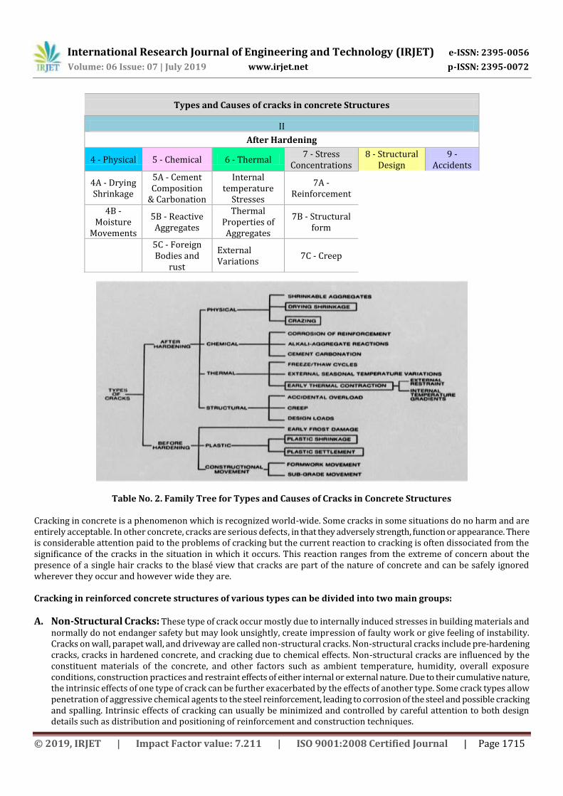
Table No. 2. Family Tree for Types and Causes of Cracks in Concrete Structures
Cracking in concrete is a phenomenon which is recognized world-wide. Some cracks in some situations do no harm and are entirely acceptable. In other concrete, cracks are serious defects, in that they adversely strength, function or appearance. There is considerable attention paid to the problems of cracking but the current reaction to cracking is often dissociated from the significance of the cracks in the situation in which it occurs. This reaction ranges from the extreme of concern about the presence of a single hair cracks to the blasé view that cracks are part of the nature of concrete and can be safely ignored wherever they occur and however wide they are. Cracking in reinforced concrete structures of various types can be divided into two main groups:
A. Non-Structural Cracks: These type of crack occur mostly due to internally induced stresses in building materials and normally do not endanger safety but may look unsightly, create impression of faulty work or give feeling of instability. Cracks on wall, parapet wall, and driveway are called non-structural cracks. Non-structural cracks include pre-hardening cracks, cracks in hardened concrete, and cracking due to chemical effects. Non-structural cracks are influenced by the constituent materials of the concrete, and other factors such as ambient temperature, humidity, overall exposure conditions, construction practices and restraint effects of either internal or external nature. Due to their cumulative nature, the intrinsic effects of one type of crack can be further exacerbated by the effects of another type. Some crack types allow penetration of aggressive chemical agents to the steel reinforcement, leading to corrosion of the steel and possible cracking and spalling. Intrinsic effects of cracking can usually be minimized and controlled by careful attention to both design details such as distribution and positioning of reinforcement and construction techniques.
Types and Causes of cracks in concrete Structures
II
After Hardening
4 - Physical 5 - Chemical 6 - Thermal 7 - Stress
Concentrations 8 - Structural
Design 9 -
Accidents
4A - Drying Shrinkage
5A - Cement Composition
& Carbonation
Internal temperature
Stresses
7A - Reinforcement
4B - Moisture
Movements
5B - Reactive Aggregates
Thermal Properties of Aggregates
7B - Structural form
5C - Foreign Bodies and
rust
External Variations
7C - Creep
International Research Journal of Engineering and Technology (IRJET) e-ISSN: 2395-0056
Volume: 06 Issue: 07 | July 2019 www.irjet.net p-ISSN: 2395-0072
© 2019, IRJET | Impact Factor value: 7.211 | ISO 9001:2008 Certified Journal | Page 1716
When an element of concrete dries or cools, it tries to shrink or contract respectively and, provided it is free to do so, it will not crack. However, if it is restrained, then stresses will be developed which are to some extent reduced by the mechanism of creep. If at any time the net stress exceeds the tensile strength of the concrete, cracks will form. Restraint may be external, as is usually the case when one element of concrete is cast against another which is older and hardened. External restraint can be reduced or even eliminated by the correct provision of movement joints. Restraint can be internal and occurs when one part of a concrete element is subject to different conditions from the rest. This is most common when the surface of a thick section dries and / or cools more rapidly than the core of the section. This phenomenon can be reduced by efficient curing of the concrete, both in the thermal and non-drying sense of the word.
If strains or restrains cannot be eliminated, the cracks can be controlled (as opposed to eliminate) by the provision of specially designed reinforcement often provided in slabs in the form of welded wire fabric or mesh.
B. Structural Cracks: Structural cracks results from incorrect design, faulty construction or overlapping and may endanger the safety of a building. The cracks in beam, column, slab and footing are constructed as structural cracks. The structural cracks are mainly sub-categorized into three types as:
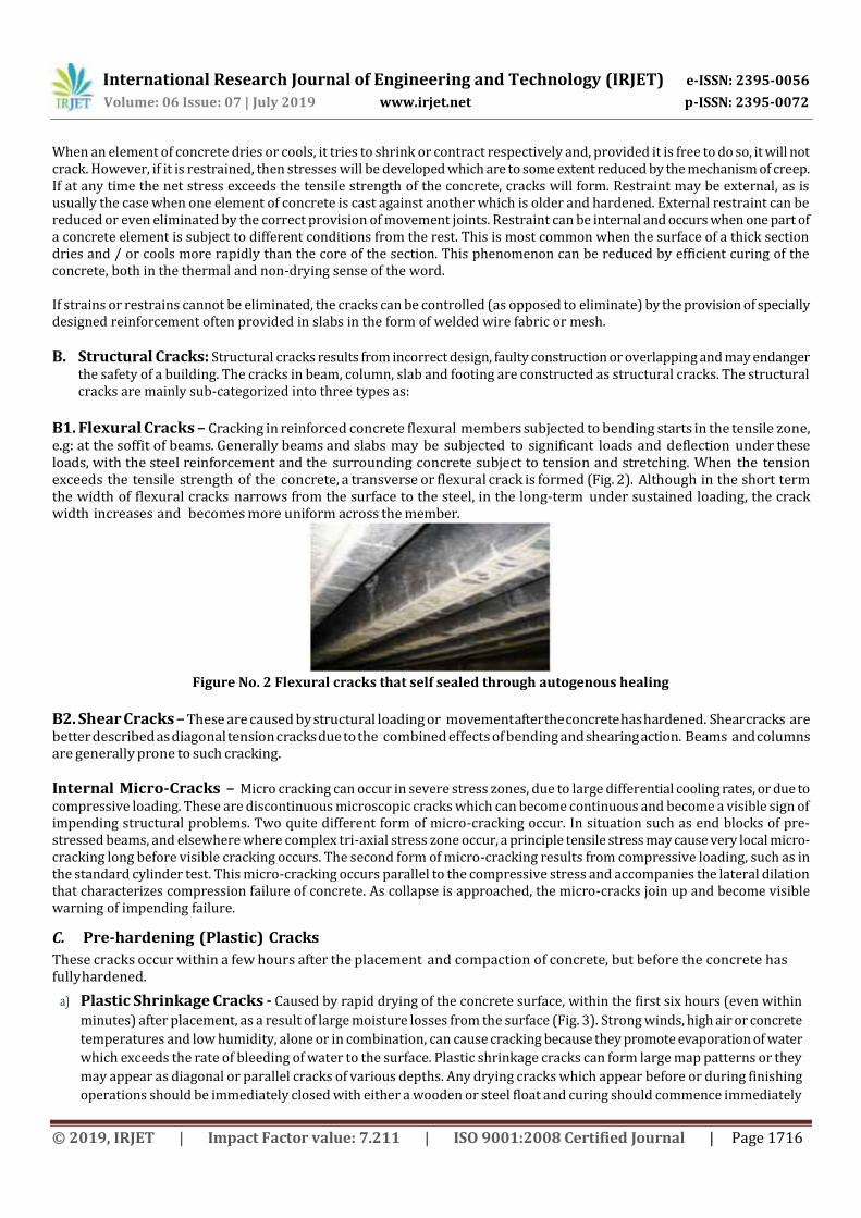
B1. Flexural Cracks – Cracking in reinforced concrete flexural members subjected to bending starts in the tensile zone, e.g: at the soffit of beams. Generally beams and slabs may be subjected to significant loads and deflection under these loads, with the steel reinforcement and the surrounding concrete subject to tension and stretching. When the tension exceeds the tensile strength of the concrete, a transverse or flexural crack is formed (Fig. 2). Although in the short term the width of flexural cracks narrows from the surface to the steel, in the long-term under sustained loading, the crack width increases and becomes more uniform across the member.
Figure No. 2 Flexural cracks that self sealed through autogenous healing
B2. Shear Cracks – These are caused by structural loading or movement after the concrete has hardened. Shear cracks are better described as diagonal tension cracks due to the combined effects of bending and shearing action. Beams and columns are generally prone to such cracking.
Internal Micro-Cracks – Micro cracking can occur in severe stress zones, due to large differential cooling rates, or due to compressive loading. These are discontinuous microscopic cracks which can become continuous and become a visible sign of impending structural problems. Two quite different form of micro-cracking occur. In situation such as end blocks of pre-stressed beams, and elsewhere where complex tri-axial stress zone occur, a principle tensile stress may cause very local micro-cracking long before visible cracking occurs. The second form of micro-cracking results from compressive loading, such as in the standard cylinder test. This micro-cracking occurs parallel to the compressive stress and accompanies the lateral dilation that characterizes compression failure of concrete. As collapse is approached, the micro-cracks join up and become visible warning of impending failure.
C. Pre-hardening (Plastic) Cracks
These cracks occur within a few hours after the placement and compaction of concrete, but before the concrete has fully hardened.
a) Plastic Shrinkage Cracks - Caused by rapid drying of the concrete surface, within the first six hours (even within
minutes) after placement, as a result of large moisture losses from the surface (Fig. 3). Strong winds, high air or concrete
temperatures and low humidity, alone or in combination, can cause cracking because they promote evaporation of water
which exceeds the rate of bleeding of water to the surface. Plastic shrinkage cracks can form large map patterns or they
may appear as diagonal or parallel cracks of various depths. Any drying cracks which appear before or during finishing
operations should be immediately closed with either a wooden or steel float and curing should commence immediately

International Research Journal of Engineering and Technology (IRJET) e-ISSN: 2395-0056
Volume: 06 Issue: 07 | July 2019 www.irjet.net p-ISSN: 2395-0072
© 2019, IRJET | Impact Factor value: 7.211 | ISO 9001:2008 Certified Journal | Page 1717
following the progressive completion of final finishing operations.
Figure No. 3 Plastic Shrinkage cracks
ACI 224.1R has prescribed requirements for controlling temperature, moisture evaporation limits and concreting operations to minimize the potential for plastic shrinkage cracking.
b) Plastic Settlement Cracks - Caused by concrete settling under its own weight, especially when there is excessive
bleeding and the settlement is impeded by a local restraint. The cracks occur in the hardening mass over restraints such
as steel reinforcement, deep sections and steps in formwork. The cracks can be further exacerbated by inadequate
compaction and the presence of voids under reinforcing bars. Plastic settlement cracks can be enlarged by subsequent
drying shrinkage and become more obvious. These cracks tend to form longitudinally over the steel reinforcement and
can be a cause of serious corrosion. Plastic settlement cracks can be prevented by ensuring that the concrete is a well
graded, well balanced mix at appropriate water content which enables good compaction, and the formwork is rigid and
not subject to movement.
c) Cracks Caused by Formwork Movement – Movement of formwork after the concrete has started to stiffen but
before it has gained enough strength to support its own weight, can cause cracking. Formwork must be left in place until
the concrete has gained sufficient strength to support itself. Formwork must also be sufficiently strong to avoid excessive
deflections.
D. Cracks in Hardened Concrete
Cracking in hardened concrete can be attributed to drying shrinkage (loss of moisture), early thermal contraction (movement) and structural and chemical effects.
(a) Craze Cracking – Characterized by a series of very fine closely spaced map pattern cracks which are caused by the
shrinkage of the cementitious material of the surface layer of concrete. The cracks are fairly shallow and affect the
appearance more so than the structural integrity or durability. They are mainly caused by the use of wet concrete mixes,
working the bleed water into the surface during finishing, and inadequate curing. Craze cracking can be prevented by
ensuring that final finishing of concrete surfaces is only carried out after all bleed water has been removed, power trowels
are not overused, driers such as dry sand, cement or stone dust are not used to absorb free water, by avoiding the use of
wet concrete and by adopting good curing practices.
Drying Shrinkage Cracks - Occur when concrete reduces in volume as a result of moisture losses into the atmosphere in its hardened state. If the concrete is unrestrained and free to move and undergo shortening without a buildup of shrinkage stresses, no shrinkage cracking will occur. However, the combination of shrinkage and sufficient restraint (for example, by another part of the structure) produces tensile stresses. When these stresses exceed the tensile strength of concrete, cracks (Fig. 4) will occur that, over time, can penetrate the full depth of the concrete. A significant proportion of shrinkage generally occurs within the first few weeks, with the drying environment surrounding the concrete having a major effect. Shrinkage cracks generally appear after several weeks or even months after casting. Drying shrinkage can be reduced by increasing the amount of aggregate, particularly the larger coarse aggregate, and more importantly by reducing the total water content. Other factors which influence cracking in hardened concrete such as restraints, geometry and construction practices need to be addressed. Adequate and correctly positioned steel reinforcement can more evenly distribute shrinkage stresses within a reinforced concrete member and better control crack widths. Generally drying shrinkage can range from 450 to 750 micro-strains for high quality special class concrete to about 1000 micro-strain for normal class concrete.

International Research Journal of Engineering and Technology (IRJET) e-ISSN: 2395-0056
Volume: 06 Issue: 07 | July 2019 www.irjet.net p-ISSN: 2395-0072
© 2019, IRJET | Impact Factor value: 7.211 | ISO 9001:2008 Certified Journal | Page 1718
Figure No. 4 Drying Shrinkage cracking
(b) Early Thermal Contraction (Movement) Cracks – All immature concrete elements are subject to thermal
contraction or movement for up to 14 days after placement, due to temperature rise from the heat of hydration of the
cementitious material. This is more pronounced in the case of higher quality special class concrete which contains higher
amounts of cementitious material. Thermal cracking may appear between one day and two weeks after construction.
Larger and thicker members (i.e. columns, beams, footings, etc.) are more susceptible due to the greater heat and higher
internal temperatures generated which can be as much as 45 oC to 65 oC. As the surface temperature falls to the ambient
level, a concrete element (i.e. cooler concrete surface) is subjected to thermal contraction or movement due to the
development of large temperature differentials (greater than 20oC) across the concrete element. If this contraction is
restrained by either an internal restraint such as the inner core or adjacent previous pours, tensile stresses are induced
which can cause cracking of the concrete once its low tensile strength capacity is exceeded. ACI 224.1R requires that
temperature differentials are monitored and precautions are implemented where the temperature differential within a
concrete element exceeds 20oC.
E. Cracks due to Chemical Effects
The expansive effects of chemical reaction products from corrosion of steel reinforcement on alkali-aggregate reaction can also cause cracking in hardened concrete.
Corrosion of Steel Reinforcement - Some cracks are induced by the expansive forces associated with corrosion of the steel reinforcement which crack and subsequently spall the concrete (Fig. 5). These cracks are mainly longitudinal in nature and are located directly above or below the reinforcement, run parallel with it and are often associated with shallow or porous cover concrete. Such cracking and spalling is noticeable at corners of columns and beams and usually show signs of rust stains. Cracking associated with corroded reinforcement usually takes a long time to become evident.
Figure No. 5 Longitudinal cracks at corners of crosshead associated with corrosion of steel reinforcement
(a) Alkali - Silica Reaction Cracks - The chemical reaction between the alkali hydroxide in the concrete and
reactive aggregates produces an expansive gel, causing map cracking or directional cracking (pre-stressed members)
in the structure. Other visible signs of damage may be aggregate pop out and discoloration.

International Research Journal of Engineering and Technology (IRJET) e-ISSN: 2395-0056
Volume: 06 Issue: 07 | July 2019 www.irjet.net p-ISSN: 2395-0072
© 2019, IRJET | Impact Factor value: 7.211 | ISO 9001:2008 Certified Journal | Page 1719
5. CRACK WIDTH
Cracking is a serious problem in concrete structures. Due to its various physical and chemical properties it is prone to cracking. Though cracking cannot be totally removed but it can be reduced to an extent that its visibility is on microscopic level. Cracking affects the overall efficiency of the structure whether it is related to sound insulation or aesthetics or some other. According to IS 456:2016, the surface width of crack should not exceed 0.3mm in members where cracking is not harmful and does not have any serious adverse effects upon the preservation of reinforcing steel, nor upon the durability of the structures. In the members where cracking in tensile zone is harmful either because they are exposed to moisture or in contact of soil or ground water, an upper limit of 0.2mm is suggested for maximum width of cracks. For particularly aggressive environment such as the ‘severe’ category, the assessed surface width of cracks should not in generally exceed 0.1mm. In IS 456:2016, it is given that limit state of serviceability covers below two main parameters:
1) Deflection. 2) Cracking.
Under normal exposure or favorable dry service conditions crack widths of less than 0.3 mm on the concrete surface do not pose any threat of corrosion of the steel reinforcement. In highly aggressive or corrosive environments however, the safe limit is considered to be 0.2 mm or less. In the most severe exposures (alternate wetting and drying) or in structures designed to retain or exclude liquids, the safe limit is considered to be 0.1 mm. In the case of bridge decks, cracks tend to grow in length and width due to the influence of the traffic and impact loading and therefore, even cracks of the order of 0.1 mm to 0.2 mm may become significant for long-term durability. Sometimes under favorable conditions, cracks which do not exceed 0.2 mm may seal by the process of autogenous healing (deposition of calcium carbonate). However, it is unlikely that cracks through which water has percolated for more than a few weeks will seal themselves later. The width of cracks varies between large limits and pre assessment of absolute maximum width is not possible or very difficult in many cases. Generally, the width of cracks should not be above 0.3 mm. At places where cracking in tensile areas is dangerous due to the exposure to the effects of the weather or regularly exposed to moist environment or in touch of soil or ground water, an above limit of 0.2mm is advised for the maximum width of cracks. For places and areas which are treated under severe category, the surface width of cracks should not be above 0.1mm generally. The cracks width can be controlled and governed by adequate detailing of reinforcement. A more number of smaller diameter bars which are placed and properly distributed in tension zone lessen the width of cracks more adequately than the larger diameter bars of the same area. At any stage after construction, cracks measured at the concrete surface should not be greater than the acceptable limits. When these crack widths are exceeded, consideration should be given to carrying out appropriate remedial measures during construction in accordance with the requirements of ACI 224.1R – Causes, Evaluation and Repair of Concrete Cracks.
The limit state of serviceability for such cracks width and detailing is discussed in IS 456:2016. It is stated that “Cracking of concrete should not adversely affects the appearance or durability of the structure, the acceptable limits of cracking would vary with the type of structure and environment.” Where specific attention is required to limit the designed cracks width to a particular value, cracks width calculation may be done using the formula given in IS 456:2016 and SP 25 (1984). To check whether the cracks width is not large, any of the two methods are used:-
i) Bar spacing controls. ii) Cracks width calculations.
Using any of the above methods, the cracking can be controlled up to a certain limit. Both of these methods are discussed in IS codes and should be referred for cracks width calculations.
6. CAUSES OF CARCKS IN CONCRETE STRUCTURES
The American Concrete Institute addresses this issue in ACI 302.1-2004. “Even with the best floor design and proper construction, it is unrealistic to expect crack-free and curl-free floors. Consequently, every owner should be advised by

International Research Journal of Engineering and Technology (IRJET) e-ISSN: 2395-0056
Volume: 06 Issue: 07 | July 2019 www.irjet.net p-ISSN: 2395-0072
© 2019, IRJET | Impact Factor value: 7.211 | ISO 9001:2008 Certified Journal | Page 1720
both the designers and contractor that it is normal to expect some amount of cracking and curling on every project, and that such occurrence does not necessary reflect adversely on either the adequacy of the floor’s design or the quality of its construction.” The cracks may be classified on the basis of their activeness, time of occurrence, their width and the components of buildings on which they are developed. On the basis of activeness cracks are two types’ active crack and dormant crack. Cracking caused in plastic concrete (Plastic Concrete cracks) occurs most commonly on the exposed surfaces of freshly placed floors and slabs or other elements with large surface areas when they are subjected to a very rapid loss of moisture caused by low humidity and wind or high temperature or both. Drying shrinkage cracking (Hardened concrete crack) is commonly associated with the loss of moisture form the cement paste constituent producing a corresponding decrease in volume, coupled with restraint by the subgrade or adjacent structural members. Concrete structures do not frequently fail due to lack of strength, rather due to inadequate durability or due to improper maintenance techniques. The most common cause of premature deterioration is attributed to the development of cracks (Mehta, 1992; Hobbs, 1999). Cracking can occur in concrete structures and pavements for several reasons that can primarily be grouped into either mechanical loading or environmental effects. It should also be noted that for most practical structures, reinforcement is used to bridge and hold cracks together when they develop, thereby assuring load transfer while adding ductility to a relatively brittle materials. Therefore not all cracking causes concern. For example continuously reinforced concrete pavements (CRCP) are designed with longitudinal steel in an amount adequate to hold shrinkage cracks tight, while joints exist only at locations of construction transitions and on-grade structures. In this pavement type wherein shrinkage cracks develop over time and stabilize over the first 3 to 4 years, cracking in the transverse direction in specific patterns is not detrimental to the structure as long as the cracks remain tight and retain good load transfer. Therefore, cause of cracking should be carefully identified to determine which cracks are common and acceptable and which cracks merit repair or further investigation. Several guides currently exist to assist in determining the cause of cracking including the American Concrete Institute reports “Guide for making and condition survey of concrete in service” (ACI 201-1992) and “Causes, Evaluation and Repair of cracks in concrete structures” (ACI 224-R1993). Mechanical loads induce strains that can exceed the strain capacity (or strength capacity) of concrete, thereby causing cracking. Concrete may be particularly susceptible to cracking that occurs at early-ages when concrete has a low tensile capacity (Kasai 1972). If the loads are applied repeatedly or over a long period of time, fatigue and creep can affects the strain (or strength) developments that can lead to failure (Bazant and Celodin, 1991) or reduce stresses (Shah et.al; 1998). Although numerous factors influence whether concrete would be expected to cracks due to environmental effects, it can be simply stated that cracking will occur if the stress that develops in response to internal expansion or the restraint of a volumetric contraction that results in stress development exceeds the strength (or fracture resistance) of the material. Internal expansion is primarily caused by chemical attack or freezing of the pore water while volumetric contraction is typically attributed to moisture changes, chemical reaction, and thermal changes. Some of the main causes held responsible can be listed below as:
a) Permeability of Concrete. b) Thermal Movement. c) Corrosion of Reinforcement. d) Moisture movement. e) Creep. f) Poor construction practices. g) Poor structural design and specifications h) Poor Maintenance. i) Movement due to chemical reaction. j) Indiscriminate additions and alterations. k) Foundation Settlement. l) Movement due to Elastic Deformation m) Bad quality of Materials used. n) Improper Concrete Mix Proportions o) Thermal Stresses Generations p) High Water Cement Ratio q) Richer Mix

International Research Journal of Engineering and Technology (IRJET) e-ISSN: 2395-0056
Volume: 06 Issue: 07 | July 2019 www.irjet.net p-ISSN: 2395-0072
© 2019, IRJET | Impact Factor value: 7.211 | ISO 9001:2008 Certified Journal | Page 1721
a) Permeability of Concrete As deterioration process in concrete begins with penetration of various aggressive agents, low permeability is the key to its durability. Concrete permeability is controlled by factors like water-cement ratio, degree of Hydration/Curing, air voids due to deficient compaction, micro-cracks due to loading and cyclic exposure to thermal variations. The Permeability of the concrete is a direct function of the porosity and interconnection of pores of the cement paste.
b) Thermal Movement Thermal movement is one of the most potent causes of cracking in buildings. All materials more or less expand on heating and contract on cooling. The thermal movement in a component depends on a number of factors such as temperature variations, dimensions, coefficient of thermal expansion and some other physical properties of materials. The coefficient of thermal expansion of brickwork in the vertical direction is fifty percent greater than that in the horizontal direction, because there is no restraint to movement in the vertical direction. Thermal variations in the inetrnal walls and inetrmediate floors are not much and thus do not cause cracking. It is mainly the external walls especially thin walls exposed to direct solar radiation and roof which are subjected to substantial thermal variations that are liable to cracking.
c) Corrosion of Reinforcement A properly designed and constructed concrete is initially water-tight and the reinforcement steel within it is well protected by a physical barrier of concrete cover which has low permeability and high protection. Steel will not corrode as long as concrete around it is impervious and does not allow moisture or chlorides to penetrate within the cover area. Steel corrosion will also not occur as long as concrete surrounding it is alkaline in nature having a high PH value. Concrete normally provides excellent protection to reinforcing steel. Notwithstanding this, there are large number of causes in which corrosion of reinforcement has caused damaged to concrete structures within a few years from the time of construction resulting in loss of mass, stiffness and bond in concrete and therefore concrete repairs becomes inevitable as considerable loss of strength takes place.
d) Moisture Movement The common cause of cracking in concrete is shrinkage due to drying. This type of shrinkage is caused by the loss of moisture from the cement paste constituent, which can shrink by as much as 1% per unit length. These moisture – induced volume changes are a characteristics of concrete. If the shrinkage of concrete could take place without any restraint, the concrete would not cracks. It is the combination of shrinakge and restraint, which is usually provided by another part of the structure or by the subgrade that causes tensile stresses to develop. When the tensile stresses of concrete are exceeded, it will crack. Cracks may propagate at much lower stresses than are required to cause crack initiation. Most of the building materials with pores in their structures in the form of inetrmolecular space expand on absorbing mositire and shrink on darying. These movements are cyclic in nature and are caused by increase or decrease in inter pore pressure with moisture changes. Initial Shrinkage occurs in all building materials that are cement / lime based such as concrete, mortar, masonry and plasters. Generally heavy aggregates concrete shows less shrinkage than light weight aggregates concrete.
e) Creep Concrete when subjecetd to sustained laoding exhibits a gardual and slow time dependent deformation known as creep.creep increases with increases in water and cement content, water cement ratio and temperature. It decreases with increases in humidity of surrounding atmosphere and age of materials at the time of laoding. Use of admixtures and pozzolona in concrete increases creep, amount of creep in steel increases with rise in temperature.
f) Poor Construction Practices The construction industry ha sin genearl fallen prey to non-technical person most of whom have little or no knowledge of correct construction practices. There is a general lack of good construction practices either due to ignorance, carelessness, greed or negligence. Or worse still, a combination of all of these. For a healthy building it is absoutely necessary for the
International Research Journal of Engineering and Technology (IRJET) e-ISSN: 2395-0056
Volume: 06 Issue: 07 | July 2019 www.irjet.net p-ISSN: 2395-0072
© 2019, IRJET | Impact Factor value: 7.211 | ISO 9001:2008 Certified Journal | Page 1722
construction agency and the owner to ensure good quality materials selection and good construction practices. All the way to building completion every step must be properly supervised and controlled without cutting corners. Some of the main causes for poor construction practices and inadequates quality of buildings are given below:
Improper selection of materials. Selection of poorquality cheap materials. Inadequate and improper proportioning of mix constituents of concrete, mortar etc. Inadequate control on various steps of concrete production such as batching, mixing, transporting, placing, finishing
and curing. Inadequate quality control and supervision causing large voids (Honey combs) and cracks resulting in leakages and
ultimately causing fasterr deterioration of concrete structures. Improper construction joints between subsequent concrete pours or between concrete framework and masonry. Addition of more or excess water in concrete and mortar mixes. Poor quality of plumbing and sanitation materials and practices.
g) Poor Structural Design and Specifications Very often,the building loses its durability on the blue print itself or at the time of preparation of specifications for concrete materials, concrete and various other related parameters.It is of crucial that the designer and specifier must first consider the environmenta;l conditions existing around the building site. It is also equally important to do geotechnical (Soil) investigation to determine the type of foundations, the type of concrete materials to be used in concrete and the garde of concrete depending on chemicals present in ground water and subsoil. It is critical for the structural designer and architect to know whether the agency proposed to carry out the construction ha sthe requisite skills experience to execute their designs. Often complicated designs with dense reinforcement steel in slender sections result in poor quality construction. In addition, inadequate skills and poor experience of the contractor, ultimately cuses deterioration of the building.
h) Poor Maintenance A structure needs to be maintained after a lapse of certain period from its construction completion. Some structures may need a very early looks into their deterioration problems, while other can sustain themselves very well for mahy years depending on the quality of design and cosntruction. But early identification of probable problems and correcting them within time is wise idea rather.
i) Movement due to Chemical Reactions The concrete may crack as a result of expansive raections between aggregates containing active silica and alkali derived from cement hydartion. The alkali silica reaction resultsin the formation of swelling gel, which tend to draw water from other portions of concrete. This causes local expansion results in cracks in the structures.
j) Indiscriminate Addition and Alterations
There have been some building collapses in our country due to indiscriminate additions and alterations done by interiors decorators at the instance of their clients. Generally, the first target of modifications is the balcony. Due to the requirement to occupy more floor area, balconies are generally enclosed and modified for different usages. Balconies and canopies are generally cantilever RCC slabs. Due to additional laoding they deflects and develops cracks. As the steel reinforcement in these slabs have less concrete cover and the balcony and canopy slab is exposed to more aggressive external environment, corrosion of steel reinforcement takes place and repairs become necessary.
k) Foundation Settlement The place where concreet commonly subsides is near a house. Whether the home is built on a basement or crawlspace, the over-dig is subsequently backfilled. Unless the backfill material is compacted in lifts as the over-dig is filled, it will settle over time. This settling will cause any concrete poured atop it to settle along with it. The other reasons for foundationto settle are change in moisture content of soil below or around the founadtions, overload of super structure and decay of organic matters present in subsoil. Uniform settlement up to some tolerance does not cause the problem but differential settlement is something that results in serve crack problems.

International Research Journal of Engineering and Technology (IRJET) e-ISSN: 2395-0056
Volume: 06 Issue: 07 | July 2019 www.irjet.net p-ISSN: 2395-0072
© 2019, IRJET | Impact Factor value: 7.211 | ISO 9001:2008 Certified Journal | Page 1723
l) Foundation Settlement The place where concreet commonly subsides is near a house. Whether the home is built on a basement or crawlspace, the over-dig is subsequently backfilled. Unless the backfill material is compacted in lifts as the over-dig is filled, it will settle over time. This settling will cause any concrete poured atop it to settle along with it. The other reasons for foundationto settle are change in moisture content of soil below or around the founadtions, overload of super structure and decay of organic matters present in subsoil. Uniform settlement up to some tolerance does not cause the problem but differential settlement is something that results in serve crack problems.
m) More Water In Concrete Mostly water used for concrete mix has an amount more than needed for hydartion although water required to gain strength after hydartion of the cement is in small amount. Since the main us of water is to achieve workability but with the increasing water amount strength decreases and later results in cracking due to the evaporation of the excess water. Shrinkage is the reason behind cracking either plastic shrinakge or drying shrinkage.
n) Richer Mix High cement ratio will lead to greater drying shrinkage. Thus comparatively more volume of aggregates will have lesser shrinakge but keeping in mind the necessary strength against loading is achieved in the provided cement percenatge in the concrete.
0) Movement due to Elastic Deformation Structural components of a building such as walls, columns, beams and slabs, generally consisting of materials ike masonry, concrete, steel, etc., undergo elastic deformation due to load in accordance with Hook’s law, the amount of deformation depending upon elastic modulus of the materials, magnitude of loading and dimensions of the components. This deformation, under circumtances such as those mentioned below, causes cracking in some portions: When walls are unevenly loaded with wide variations in stress in different parts, excessive shear strain is developed which
causes cracking in walls. When a beams or slab of large span undergoes excessive deflection and there is not much vertical load above the supports,
ends of beam/slab curl up causing cracks in supporting masonry. When two materials, having widely different elastic properties, are built side by side, under the effect of load, shear stress is
set up at the interface of the two materials, resulting in cracks at the junctions.
p) Cracking due to Vegetation Existence of vegetation, such as fast growing tress in the vicinity of compound walls can sometimes causes cracks in walls due to expansive action of roots growing under the foundation. Roots of a tree generally spread horizontally on all sides to the extent of height of the above the ground and when trees are located close to a awall; these should always be viewed with suspicion.
7. COMMON PRACTICES FOR THE PREVENTATION OF CRACKS The preventive measures to deal with cracks are two types; one is to prevent cracks and another to cure cracks. As per the saying “Preventation is better than cure” we should always try to avoid such problems by using adequate construction materials and techniques, proper design, and efficient supervision. Though there are technical methods for reducing the cracks but better way out is to give proper preventions so that the need for later cures is not raised. The things to be taken care of to avoid cracks can be listed as: Decreasing water – cement ratio. Lower the water higher the strength and hence lesser the cracks. This ratio should not
exceed 0.5. with changing temperature and moisture, concrete expands and shrinks and shrinkage pulls the slab apart thus showing as carcks on surface.
Curing should be done for sufficient time and no hurry should be made as rapid loss of water from surface may lead to cracks. Rapid drying may increase the cracks possibility largely.

International Research Journal of Engineering and Technology (IRJET) e-ISSN: 2395-0056
Volume: 06 Issue: 07 | July 2019 www.irjet.net p-ISSN: 2395-0072
© 2019, IRJET | Impact Factor value: 7.211 | ISO 9001:2008 Certified Journal | Page 1724
Proper vibration and placing should be done. Adequate compaction has to be done to avoid settlement of the soil beneath and thus avoiding cracks. If concrete is poured
over soft ground, it can be cracked even with the movement of the delivery used for bringing concrete. Appropriate amount of cememt and quality materials should be used to avoid cracks. Lesser cement will lead to cracking in
the same way as low grade materials will. If low grade aggregates they should be well graded and increased size amy lead to lesser shrinkage.
Providing control joints at regular intervals as t gives a control where the cracks should occur. However it should be well planned and checked whether the concrete cracks at that particular point only.
Proper finishing of the surface is also desired using good techniques. Over doing should be avoided as may lead to bleeding. Lastly remains the application of certain admixtures or sealers to prevent cracks. There are now different types of caotings
avaialble for reinforcement and concreet to protect them against liquid penetration. Check for predicted extreme temperature variance during the first 24 hours of expected placement. Review the mix design to ensure the mix is using the lowest water content for workability / performance purposes. Review the mix design to ebsure the maximum size of coarse aggregate is used. This will help to minimize the water used in
the mix. Review the mix design to ensure the contractor is familiar with finishing technique for the cementitious materials may
increase or decrease the rate of bleed water migration to the surafce. This, in turn, may shorten or lengthen the window of time for ease of finish ability.
During the pre-placement meeting; review the plan for subgrade preparation. The subgrade should be proeprly compacted at required density and mositure content. This preparation will ensure the subgrade will be able to uniformaly support the slab as well as not draw moisture form the slab/pavement during placement.
Have a plan in palce for curing the concrete for the specified period. This curing plan should include steps for both initial curing of the concrete during placementt while in a palstic state as well as after concrete has hardened.
There are chemical admixtures that may help to reduce the amount of drying shrinakge. There are synthetic fibers that may help control the extent of early drying shrinakge cracks. Construction on expansion/contraction joints so that temperature effects can be neutralized. If buildings are built without considering abive mentioned measures it is obvious that different types of cracks will start to appears sooner or later. Hence in cuh case the cracks are required to be cured before they cause serious problem. It is very important to read the characteristics of cracks and analyze carefully by experts in orders to come up with most effective and sustainable solution to deal with different concrete roblem. The scientific method of determining cause of carcking is: State Problems and Make observation Form hypothesis i.e; possible cause depending on observations made the basic idea of possible causes are made with the
help of expert’s opinions. Test the hypothesis by performing tests, making calculations, making more extensive observation. The surface cracks are
detected by dye penetration method, using optical comparator or by visual inspection and some simple measurements. The sub-surface cracks that do not show on the surface are detected by ultrasonic wave method, magnetic particle method, electric potential method and using Digital Rissmess system (DRS).
Analyze the results and iterate if necessary. Form conclusion
a. Measures for controlling cracks due to shrinkage
To avoid cracks in brickwork on account of initial expansion, a minimum period varying from 1 week to 2 weeks is recommended by authorities for storage of bricks after these are removed from Kilns.
Shrinkage cracks in masonry could be minimized by avoiding use of rich cement mortar in masonry and by delaying plaster work till masonry has dried after proper curing and has undergone most of its initial shrinkage.
Use of precast tiles in case of terrazzo flooring is an example of this measure. In case of in-situ/terrazzo flooring, cracks are controlled by laying the floor in small alternate panels or by introducing strips of glass, aluminum or some plastic material at close intervals in a grid pattern, so as to render the shrinkage cracks imperceptibly small.
In case of structural concrete, shrinkage cracks are controlled by use of reinforcement, commonly termed as 'temperature reinforcement'. This reinforcement is intended to control shrinkage as well as temperature effect in concrete and is more effective if bars are small in diameter and are thus closely spaced, so that, only thin cracks which are less perceptible, occur.
To minimize shrinkage cracks in rendering/plastering, mortar for plaster should not be richer than what is necessary from consideration of resistance to abrasion and durability.

International Research Journal of Engineering and Technology (IRJET) e-ISSN: 2395-0056
Volume: 06 Issue: 07 | July 2019 www.irjet.net p-ISSN: 2395-0072
© 2019, IRJET | Impact Factor value: 7.211 | ISO 9001:2008 Certified Journal | Page 1725
b. Measures for controlling cracks due to thermal variations
Wherever feasible, provision should be made in the design and construction of structures for unrestrained movement of parts, by introducing movement joints of various types, namely, expansion joints, control joints and slip joints.
Even when joints for movement are provided in various parts of a structure, some amount of restraint to movement due to bond, friction and shear is unavoidable. Concrete, being strong in compression, can stand expansion but, being weak in tension, it tends to develop cracks due to contraction and shrinkage, unless it is provided with adequate reinforcement for this purpose. . Members in question could thus develop cracks on account of contraction and shrinkage in the latter direction. It is, therefore, necessary to provide some reinforcement called 'temperature reinforcement" in that direction.
Over flat roof slabs, a layer of some insulating material or some other material having good heat insulation capacity, preferably along with a high reflectivity finish, should be provided so as to reduce heat load on the roof slab.
In case of massive concrete structures, rise in temperature due to heat of hydration of cement should be controlled. Provision of joints in structure.
Note: - For seismic Zones III, IV & V, expansion joints have to be much wider for which IS: 4326-1976 'Code of practice for earthquake resistant design and construction of buildings (first revision) should be referred 19.
c. Measures for prevention of cracks due to creep
Though it may not be possible to eliminate cracking altogether, following measures will considerably help in minimization of cracks due to elastic strain, creep and shrinkage:
Use concrete which has low shrinkage and low slump. Do not adopt a very fast pace of construction. Do not provide brickwork over a flexural RCC member (beam or slab) before removal of centering, and allow a time
interval of at least 2 weeks between removal of centering and construction of partition or panel wall over it. When brick masonry is to be laid abutting an RCC column, defer brickwork as much as possible. When RCC and brickwork occur in combination and are to be plastered over, allow sufficient time (at least one month)
to RCC and- brickwork to undergo initial shrinkage and creep before taking up plaster work. Also, either provide a groove in the plaster at the junction or fix a 10 cm wide strip of metal mesh or lathing over the junction to act as reinforcement for the plaster. (Central Building Research Institute, 1984)
In case of RCC members which are liable to deflect appreciably under load, for example, cantilevered beams and slabs, removal of centering and imposition of load should be deferred as much as possible (at least one month) so that concrete attains-sufficient strength, before it bears the load.
d. General measures for chemical attack
In case of structural concrete in foundation, if sulphate content in soil exceeds 0.2 percent or in ground water exceed 300 ppm, use very dense concrete and either increase richness of mix to 1:1/5:3 or use sulphate resisting Portland cement/super-sulphated cement or adopt a combination of the two methods depending upon the sulphate content of the soil. For superstructure masonry, avoid use of bricks containing too much of soluble sulphates (more than 1 percent in exposed situations, such as parapets, free standing walls and masonry in contact with damp soil as in foundation and retaining walls; and more than 3 percent in case of walls in less exposed locations) and if use of such bricks cannot be avoided, use rich cement mortar (1:1/2:4.5 or 1:1/4 :3) for masonry as well as plaster or use special cements mentioned earlier and take all possible precautions to prevent dampness in masonry. To prevent cracking due to corrosion in reinforcement and premature deterioration, it is desirable to specify concrete of richer mix (say 1:1/5:3) for thin sections in exposed locations and to take special care about grading, slump, compaction and curing of concrete. (Chand, October 2008) (CBRI, Roorkee)
e. To Prevent Cracks Due to Moisture Movement
Select materials having small moisture movement e.g. bricks, lime stones, marble etc. Plan for less rich cements content, larger size of aggregates and less water content. Porous aggregates (from sand stone, clinker etc.) prone for high shrinkage Plan for offsets in walls for length of more than 600 mm
International Research Journal of Engineering and Technology (IRJET) e-ISSN: 2395-0056
Volume: 06 Issue: 07 | July 2019 www.irjet.net p-ISSN: 2395-0072
© 2019, IRJET | Impact Factor value: 7.211 | ISO 9001:2008 Certified Journal | Page 1726
Use of composite cement-lime mortar of 1:1:6 mix or weaker for plastering work Plan for proper expansion/control/slip joints For brick work 2weeks time in summer and 3 weeks’ time in winter should be allowed before using from the date of
removal from kilns Delay plastering work till masonry dried after proper curing Proper curing immediately on initial setting brings down drying shrinkage.
f. To Prevent Cracks Due to Elastic Deformations
When large spans cannot be avoided, deflection of slabs or beams could be reduced by increasing depth of slabs and
beams so as to increase their stiffness. Adoption of bearing arrangement and provision of a groove in plaster at the junction of wall and ceiling will be of some
help in mitigating the cracks. Allow adequate time lag between work of wall masonry and fixing of tiles.
g. To prevent cracks due to Foundation Movement and Settlement of Soil
Plan for under-reamed piles in foundation for construction on shrinkable soils Plan for plinth protection around the building Slip / expansion joints to ensure that new construction is not bonded with the old construction and the two parts (Old
and new) are separated right from bottom to the top. When plastering the new work a deep groove should be formed separating the new work from the old.
For filling deep - say exceeding 1.0m, Soil used for filling should be free from organic matter, brick-bats and debris filling should be done in layers not exceeding 25 cm in thickness and each layer should be watered and well rammed.
If filling is more than 1 meter in depth, process of flooding and compaction should be carried out after every meter of fill.
h. To Prevent Cracks Due to Cracking Due to Vegetation
Do not let trees grow too close to buildings, compound-walls, garden walls, etc., taking extra care if soil under the
foundation happens to be shrinkable soil/ clay. If any saplings of trees start growing in fissures of walls, etc. remove them at the earliest opportunity.
If some large trees exist close to a building and these are not causing any problem, as far as possible, do not disturb these trees if soil under the foundation happens to be shrinkable clay.
If, from any site intended for new construction, vegetation including trees is removed and the soil is shrinkable clay, do not commence construction activity on that soil until it has undergone expansion after absorbing moisture and has stabilized.
8. SELECTION OF REPAIRING PROCEDURES FOR CRACKS IN CONCRETE STRUCTURES Based on the carfull evaluation of the extent and cause of cracking, procedures can be selected to accomplish one or more of the following objectives: Restore and increase strength; Restore and increase stiffness; Improve Functional performance; Provide watertightness; Improve appearance of the concrete surface; Improve durability; and /or; Prevent development of corrosive environment at reinforcement.
Depending on the nature of the damage, one or more repairs methods may be selected for example, tensile strength may be restored across a crack by injecting it with epoxy or other high strength bonding agent. However, it may be necessary to provide additional strength by adding reinforcement or using post-tensioning. Epoxy injection alone can be used to restore flexural stiffness if further cracking is not anticipated (ACI 503R).
International Research Journal of Engineering and Technology (IRJET) e-ISSN: 2395-0056
Volume: 06 Issue: 07 | July 2019 www.irjet.net p-ISSN: 2395-0072
© 2019, IRJET | Impact Factor value: 7.211 | ISO 9001:2008 Certified Journal | Page 1727
Cracks causing leaks in water –retaining or other storage structures should be repaired unless the leakage is considered minor or there is an indication that the crack is being sealed by autogrnous healing (See section K below). Repairs to stop leaks may be complicated by a need to make the reparts while the structures are in service. Cosmetic considerations may require the repair of cracks in concrete. However, the cracks locations may still be visible and it is likely that some from of coating over the entire surface may be required. To minimize future deterioration due to the corrosion of reinforcement, cracks exposed to a moist or corrosive environment should be sealed. The key methods of cracks repairs available to accomplish the objectives outlined are described in separate section
9. METHODS OF CRACKS REPAIRS
Following the evaluation of the cracked structure, a suitable repair procedure can be selected. Successful repair procedure take into account the causes of the cracking. For example, if the cracking was primarily due to drying shrinkage, then it is likely that after a period of time the cracks will stabilize. On the other hand, if the cracks are due to a continuing foundation settlement, repair will be of no use until the settlement problem is corrected. This section provides a survey of crack repair methods, including a summary of the characterisitics of the cracks that may be repaired with each procedure, the types of structures that have been repaired, and summary of the procedures that are used. Readers are also directed to ACI 546.IR and ACI complilation no. 5 (1980), which specifically address the subjects of concrete repair.
A) EPOXY INJECTIONS
Cracks as narrow as 0.002 inch (0.05mm) can be bonded by injection of epoxy. The technique generally consists of establishing entry and venting ports at close intervals along the cracks, sealing the cracks on exposed surfaces, and injecting the epoxy under pressure. Epoxy injection has been successfully used in the repair of cracks in buildings, bridges, dams, and other types of concrete structures (ACI 503R). However, unless the cause of the cracking has been corrected, it will probably recur near the original crack. If the cause of the cracks cannot be removed, then two options are available. One is to rout and seal the crack, thus treating it as a joint, or, establish a joint that will accommodate the movement and then inject the crack with epoxy or other suitable material. Epoxy materials used for structural repairs should conform to ASTM C881 (Type IV). ACI 504R describes practices for sealing joints, including joint design, available materials and methods of application. With the exception of certain moisture tolerant epoxies, this technique is not applicable if the cracks are actively leaking and cannot be dried out. Wet cracks can be injected using moisture tolerant materials, but contaminants in the cracks (including silt and water) can reduce the effectiveness of the epoxy to structurally repairs the cracks. The use of a low-modulus, flexible adhesive in a crack will not allow significant movement of the concrete structure. The effective modulus of elasticity of a flexible adhesive in a crack is substantially the same as that of a rigid adhesive because of the thin layer of material and high lateral restraint imposed by the surrounding concrete. Epoxy injection requires a high degree of skill for satisfactory execution, and application of the technique may be limited by the ambient temperature. Th egeneral procedures involved in epoxy injection are as follows (ACI 503R)
Clean the cracks. The first step is to clean the cracks that have been contaminated., to the extent this is possible and practical. Contaminants such as oil,grease,dirt or fine particles of concrete prevent epoxy penetration and bonding, and reduce the effectiveness of repairs. Preferably, contanmination should be removed by vacuuming or flushing with water or others specially effective cleaning solutions. The solution is then flushed out using compressed air and a neutralizing agent or adequate time is provided for air drying. It is important, however, to recognize the practical limitations of accomplishing complete crack cleaning. A reasonable evaluation should be made of the extent, and necessity, of cleaning. Trial cleaning may be required.
International Research Journal of Engineering and Technology (IRJET) e-ISSN: 2395-0056
Volume: 06 Issue: 07 | July 2019 www.irjet.net p-ISSN: 2395-0072
© 2019, IRJET | Impact Factor value: 7.211 | ISO 9001:2008 Certified Journal | Page 1728
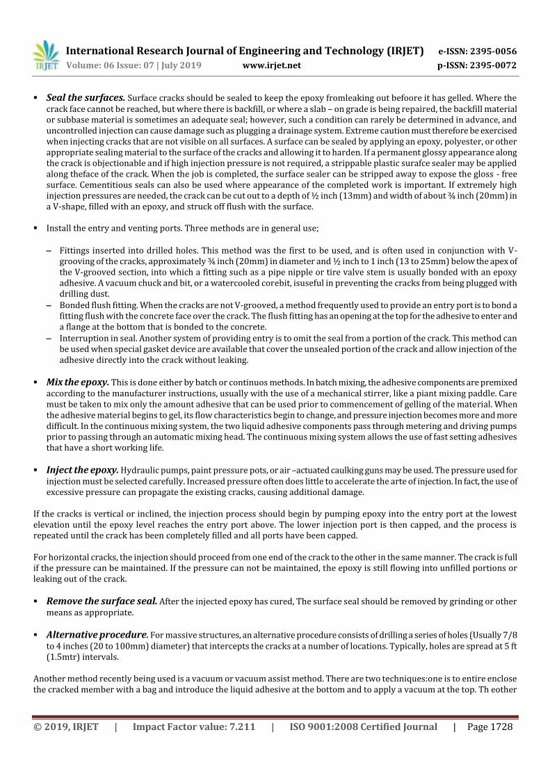
Seal the surfaces. Surface cracks should be sealed to keep the epoxy fromleaking out befoore it has gelled. Where the crack face cannot be reached, but where there is backfill, or where a slab – on grade is being repaired, the backfill material or subbase material is sometimes an adequate seal; however, such a condition can rarely be determined in advance, and uncontrolled injection can cause damage such as plugging a drainage system. Extreme caution must therefore be exercised when injecting cracks that are not visible on all surfaces. A surface can be sealed by applying an epoxy, polyester, or other appropriate sealing material to the surface of the cracks and allowing it to harden. If a permanent glossy appearance along the crack is objectionable and if high injection pressure is not required, a strippable plastic surafce sealer may be applied along theface of the crack. When the job is completed, the surface sealer can be stripped away to expose the gloss - free surface. Cementitious seals can also be used where appearance of the completed work is important. If extremely high injection pressures are needed, the crack can be cut out to a depth of ½ inch (13mm) and width of about ¾ inch (20mm) in a V-shape, filled with an epoxy, and struck off flush with the surface.
Install the entry and venting ports. Three methods are in general use;
Fittings inserted into drilled holes. This method was the first to be used, and is often used in conjunction with V-grooving of the cracks, approximately ¾ inch (20mm) in diameter and ½ inch to 1 inch (13 to 25mm) below the apex of the V-grooved section, into which a fitting such as a pipe nipple or tire valve stem is usually bonded with an epoxy adhesive. A vacuum chuck and bit, or a watercooled corebit, isuseful in preventing the cracks from being plugged with drilling dust.
Bonded flush fitting. When the cracks are not V-grooved, a method frequently used to provide an entry port is to bond a fitting flush with the concrete face over the crack. The flush fitting has an opening at the top for the adhesive to enter and a flange at the bottom that is bonded to the concrete.
Interruption in seal. Another system of providing entry is to omit the seal from a portion of the crack. This method can be used when special gasket device are available that cover the unsealed portion of the crack and allow injection of the adhesive directly into the crack without leaking.
Mix the epoxy. This is done either by batch or continuos methods. In batch mixing, the adhesive components are premixed according to the manufacturer instructions, usually with the use of a mechanical stirrer, like a piant mixing paddle. Care must be taken to mix only the amount adhesive that can be used prior to commencement of gelling of the material. When the adhesive material begins to gel, its flow characteristics begin to change, and pressure injection becomes more and more difficult. In the continuous mixing system, the two liquid adhesive components pass through metering and driving pumps prior to passing through an automatic mixing head. The continuous mixing system allows the use of fast setting adhesives that have a short working life.
Inject the epoxy. Hydraulic pumps, paint pressure pots, or air –actuated caulking guns may be used. The pressure used for injection must be selected carefully. Increased pressure often does little to accelerate the arte of injection. In fact, the use of excessive pressure can propagate the existing cracks, causing additional damage.
If the cracks is vertical or inclined, the injection process should begin by pumping epoxy into the entry port at the lowest elevation until the epoxy level reaches the entry port above. The lower injection port is then capped, and the process is repeated until the crack has been completely filled and all ports have been capped. For horizontal cracks, the injection should proceed from one end of the crack to the other in the same manner. The crack is full if the pressure can be maintained. If the pressure can not be maintained, the epoxy is still flowing into unfilled portions or leaking out of the crack.
Remove the surface seal. After the injected epoxy has cured, The surface seal should be removed by grinding or other means as appropriate.
Alternative procedure. For massive structures, an alternative procedure consists of drilling a series of holes (Usually 7/8 to 4 inches (20 to 100mm) diameter) that intercepts the cracks at a number of locations. Typically, holes are spread at 5 ft (1.5mtr) intervals.
Another method recently being used is a vacuum or vacuum assist method. There are two techniques:one is to entire enclose the cracked member with a bag and introduce the liquid adhesive at the bottom and to apply a vacuum at the top. Th eother

International Research Journal of Engineering and Technology (IRJET) e-ISSN: 2395-0056
Volume: 06 Issue: 07 | July 2019 www.irjet.net p-ISSN: 2395-0072
© 2019, IRJET | Impact Factor value: 7.211 | ISO 9001:2008 Certified Journal | Page 1729
technique is to inject the cracks from one side and pull a vacuum from other. Typically, epoxies are used; however,acrylics and polyesters hav ebeen successful. Stratton and McCollum (1974) describe the sue of epoxy injection as an effective inetrmediate –term repair procedure for delaminated bridge decks. As reported by stratton and McCollum the first, second and sixth steps are omitted and the process is terminated at a specific location when epxoy exits from the crack at some distance form the injection ports. This procedure does not arrest ongoing corrosion. This procedure can also be attempted forother applications, and is available as an option, although not accepted universally. Success of the repair depends on the absence of bond-inhibiting contaminants from the crackplane. Epoxy resins and injection procedures should be carefully selected when attempting to inject delaminations. Unless there is sufficient depth or anchorage to surrounding concrete the injection process can be unsuccessful or increase the extent of delamination. Smith (1992) provides information on bridge decks observed forup to seven years after injection. Smithson and whiting describe epoxy injection as a method to rebond delaminated bridge deck overlays. ACI committee 224 is developing additional information on this application for inclusion in a future revision of this report.
B) ROUTING & SEALING
Routing and sealing of cracks can be used in conditions requiring remedial repair and where structural repair is not necessary. This method involves enlarging the cracks along its exposed face and filling and sealing it with a suitable jint sealant (Figure no.6). This is a common technique for crack treatment and is relatively simple in comparison to the procedures and training required for epoxy injection. The procedure is most applicable to approximately flat horizontal surafces such as floors and pavements. However, routing and sealing can be accomlished on vertical surafces (with a non-sag sealent) as well as on curved surfaces (Pipes, piles and poles).
Figure No. 6 - Repairing of cracks by muting and sealing
Routing and sealing is used to treat both file pattern cracks and larger, isolated cracks. A common and effective use is for waterproofing by sealing cracks on the concrete surface where water stands, or where hydrostatic pressure is applied. This treatment reduces the ability of mositure to reach the reinforcing steel or pass through the concrete, causing surafce stains or other problems. The sealants may be any of several materials, including, epoxies, urethanes, silicones, polysulfides, asphaltic materials, oor ppolymer mortars. Cement grout should be avoided due to the likelihood of cracking. For floors, the sealant should be sufficient rigid to support the anticipated traffic. Satisfactory sealants should be able to withstand cyclic deformations and should not be brittle. The procedure consists of preparing a groove at the surface ranging in depth, typically from ¼ to 1 inch(6 to 25mm). A concrete saw, hand tools or pneumatic tools may be used. The groove is then cleaned by air balsting, sandblasting, or waterblasting, and dried. A sealent is placed into the dry groove and allowed to cure. A bond breaker ma be provided at the bottom of the groove to allow the seallant to change shape, without a concentration of stress on the bottom (Figure no.7). The bond breaker may be a polyethylene strip or tape which will not bond to the sealant.

International Research Journal of Engineering and Technology (IRJET) e-ISSN: 2395-0056
Volume: 06 Issue: 07 | July 2019 www.irjet.net p-ISSN: 2395-0072
© 2019, IRJET | Impact Factor value: 7.211 | ISO 9001:2008 Certified Journal | Page 1730
Figure no. 7 - Effect of bond breaker Careful attention should be applied when detailing the joint so that its width to depth aspect ratio will accommodate anticipated movement (ACI 504R). In some cases overbanding (strip coating) is used in dependently of or in conjunction with routing and sealing. This method is used to enhance protection from edge spalling and for aesthetic reasons to create a more uniform appearing treatment. A typical procedure for overbanding is to prepare an area approximately 1 to 3 inch (25 to 75mm) on each side of the crack by sandblasting or other means of surface preparation and apply a coating (Such as uretahne) 0.04 to 0.08 inch (1 to 2mm) thick in a band over the cracks, before overbanding in non-traffic areas a bond breaker is sometimes used over a cracks that has not been routed, or over crack previously routed and sealed. In traffic areas a bind breaker is not recommended. Cracks subject to minimal movement may be overbanded, but if significant movement can take place, routing and sealing must be used in conjunction with overbanding to ensure a waterproof repairs.
C) STITCHING
Stitching involves drilling holes on both sides of the crack and grouting in U-shaped metal units with short legs (Staples or stiching dogs) that span the crack as shown in Figure no. 8. Stitching may be used when tensile strength must be re-established across major cracks. Stitching a crack tends to stiffen the structure, and the stiffening may increase the overall structural restraint, causing the concrete to cracks else!where. Therefore, it may be necessary to strengthen the adjacent section or sections using technically corrected reinforcing methods. Because stresses are iften concentrated, using this method in conjuction with other methods may be necessary.
Figure No. 8 - Repair of crack by stitching
The stitching procedure consists of drilling holes on both sides of the crack, cleaning the holes, and anchoring the legs of the staples in the holes, with either a non-shrink or epoxy resin based bonding system. The staples should be variable in length, orientation, or both, and they should be located so that the tension transmitted across the crack is not applied to a single plane within the section but is spread over an area.
D) DRILLING AND PLUGGING
Drilling and pluging a crack consists of drilling down the length of the crack and grouting it to form a key Figure no.9 & 10.
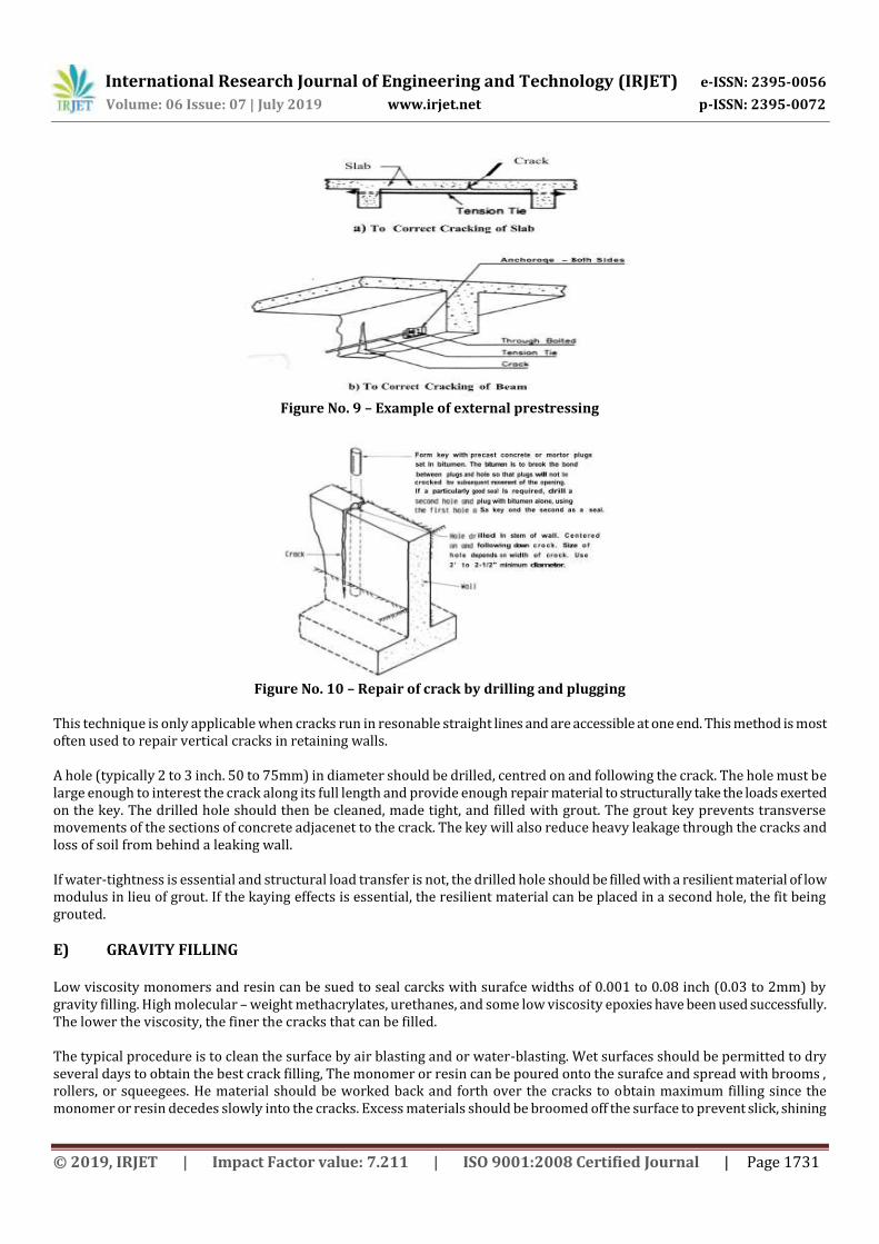
International Research Journal of Engineering and Technology (IRJET) e-ISSN: 2395-0056
Volume: 06 Issue: 07 | July 2019 www.irjet.net p-ISSN: 2395-0072
© 2019, IRJET | Impact Factor value: 7.211 | ISO 9001:2008 Certified Journal | Page 1731
Figure No. 9 – Example of external prestressing
Figure No. 10 – Repair of crack by drilling and plugging
This technique is only applicable when cracks run in resonable straight lines and are accessible at one end. This method is most often used to repair vertical cracks in retaining walls. A hole (typically 2 to 3 inch. 50 to 75mm) in diameter should be drilled, centred on and following the crack. The hole must be large enough to interest the crack along its full length and provide enough repair material to structurally take the loads exerted on the key. The drilled hole should then be cleaned, made tight, and filled with grout. The grout key prevents transverse movements of the sections of concrete adjacenet to the crack. The key will also reduce heavy leakage through the cracks and loss of soil from behind a leaking wall. If water-tightness is essential and structural load transfer is not, the drilled hole should be filled with a resilient material of low modulus in lieu of grout. If the kaying effects is essential, the resilient material can be placed in a second hole, the fit being grouted.
E) GRAVITY FILLING
Low viscosity monomers and resin can be sued to seal carcks with surafce widths of 0.001 to 0.08 inch (0.03 to 2mm) by gravity filling. High molecular – weight methacrylates, urethanes, and some low viscosity epoxies have been used successfully. The lower the viscosity, the finer the cracks that can be filled. The typical procedure is to clean the surface by air blasting and or water-blasting. Wet surfaces should be permitted to dry several days to obtain the best crack filling, The monomer or resin can be poured onto the surafce and spread with brooms , rollers, or squeegees. He material should be worked back and forth over the cracks to obtain maximum filling since the monomer or resin decedes slowly into the cracks. Excess materials should be broomed off the surface to prevent slick, shining

International Research Journal of Engineering and Technology (IRJET) e-ISSN: 2395-0056
Volume: 06 Issue: 07 | July 2019 www.irjet.net p-ISSN: 2395-0072
© 2019, IRJET | Impact Factor value: 7.211 | ISO 9001:2008 Certified Journal | Page 1732
areas after curing. If surface friction is important, sand should be broadcast over the surface before the monomer or resin cures. If the cracks contain signoficant amounts of silt, moisture or other contaminants, the selant cannot fill them. Water blasting followed by a darying time may be effective in cleaning and preparing these cracks. Cores taken at cracks can be used to evaluate the effectiveness of the crack filling. The depth of penetration of the sealant can be measured. Shear (or tension) tests can be performed with the load applied in a direction parallel to the repaired cracks (as long as reinforcing steel is not present in the core in or near the failure area). For some polymers the failure crack will occur outside the repaired crack.
F) GROUTING
Portland cement grouting – Wide cracks, particularly in gravity dams and thick concrete walls, may be repaired by filling with portland cement grout. This method is effective in stopping water leaks, but it will not structurally bond cracked sections. The procedure consists of cleaning o the concrete along the crack; installing built-up seats (grout nipples) at intervals astride the crack (to provide a pressure tight connection with the injection apparatus);sealing the crack between the seats with acement paint, sealant or grout;flushing the crack to clean it and test the seal; and then grouting the whole area. Grout mixtures may contain cement and water or cement plus sand and water, depending on the width of the crack. However, the water-cement ratio should be kept as low as practical to maximize the strength an dminimize shrinkage. Water reducer or other admixtures may be used to improve the proeprties of the grout. Foor small volumes, a manual injection gunmay be used;for larger volumes, a pump should be used. After the crack is filled, the pressure should be maintained for several minutes to insure good penetration.
Chemical Grouting – Chemical grouts consists of solutions of two or more chemicals (Such as urethanes, sodium silicates, and acrylomides) that combine to form a gel, a solid precipitate, or a foam, as opposed to cement grouts that consist of suspensions of solid particles in a fluid. Cracks in concrete as narrow as 0.002 inch (0.05mm) have been filled with chemical grout. The advantages of chemical grouts include applicability in moist environments (excess mositure available), wide limits of control of gel time, and their ability to be applied in very fine fractures. Disadvantages are the high degreee of skill needed for satisfactory use and their lack of strength.
G) DRYPACKING
Drypacking is the hand placement of a low water content mortar followed by tamping or ramming of the mortar into place, producing intimate contact between the mortar an dthe existing concrete (U.S Bureau of Reclamination 1978). Because of the low water – cement ratio of the material, there is little shrinkage, and the patch remains tight and can have good quality with respect to durability, strength and watertightness. Drypack can be used for filling narrow slots cut for the repair of dormant cracks. The use of drypack is not advisable for filling or repairing active cracks. Before a crack is repaired by drypacking, the portion adjacent to the surface should be widened to a slot about 1 inch (25mm) wide and 1 in (25mm) deep. The slot should be undercut so that the base width is slightly greater than the surface width. After the slot is thoroughly cleaned and dried, a bond coat, consisting of cement slurry or equa quantities ofcement and fine sand mixed with water to a fluid paste consistency, or an appropriate latex onding compound (ASTM C1059), should be applied. Placing of the dry pack mortar should begin immediately. The mortar consists of one part cement, one to three parts sandpassing a no. 16 (1.18mm) sieve, and just enough water so that the mortar will stick together when molded into a ball by hand. If the patch must match the colour of the surrounding concrete, a ablend of grey portlandcement and white portland cement may be used. Normally, about one-third white cement is adequate, but the precise proportions can be determined only by trial. To minimize shrinkage in place, the mortar should stand for ½ hour after mixing and then should be remixed prior to use. The mortar should be placed in layers about 3/8 inch (10mm) thick. Each layer should be thoroughly compacted over the surface

International Research Journal of Engineering and Technology (IRJET) e-ISSN: 2395-0056
Volume: 06 Issue: 07 | July 2019 www.irjet.net p-ISSN: 2395-0072
© 2019, IRJET | Impact Factor value: 7.211 | ISO 9001:2008 Certified Journal | Page 1733
using a blunk stick or hammer, and each underlying should be scratched to facilitate bonding with the next layer. There need be no time delays between layers. The mortar may be finished by laying the flat side of a hardwood piece against it and striking it several times with a hammer. Surface appearance may be improved by a few light strokes with a rag or sponge float. The repairs should be cured by using either water or a curing compound. The simplest method of moist curing is to support a strip of folded wet burlap along the length of the crack.
H) CRACKS ARREST
During construction of massive concrete structures, cracks dueto surafce cooling or others causes may develop and propagate into new concrete as construction progresses. Such cracks may be arrested by blocking the crack and spreading the tensile stress over a larger area (U.S Army Corps of Engineers 1945). A piece of bind-breaking membrane or a grid of steel mat may be placed over the crack as concreting continues. A semicircular pipe placed over the crack may also be used (Figure no. 11). A description of installation procedures for semicircular pipes used during the construction of a massive concrete structure follows:
Figure No. 11 – Crack arrest method of crack repair
1) The semi-circular pipe is made by splitting an 8 inch (200mm), 16-gauge pipe and bending it to a semicircular section
with about a 3 inch (75mm) flange on each side. 2) The area in the vicinity of the crack is cleaned; 3) The pipe is placed in sections so as to remain centered on the crack; 4) The sections are then welded together; 5) Holes are cut in the top of the pipe to receive grout pipes and ; 6) After setting the grout pipe, the installation is covered with concrete placed concentrically over the pipe by hand. The
installaed grout pipes are used for grouting the crack at a later date, thereby restoring all or a portion of the structural continuity.
I) POLYMER IMPREGNATION
Monomer systems can be used for effective repair of some cracks. A monomer system is a liquid consisting of monomers which will polymerize into a solid. Suitable monomers have varying degrees of volatility, toxicity and flammability, and they do not mix with water. They are very low in viscosity and will soak into dry concrete, filling the cracks, much as water does. The most common monomer used for this purpose is methyl methacrylate. Monomer system used for impregnation contain a catalyst or initiator plus the basic monomer (or combination of monomers). They may also contain a cross-linking agent. When heated, the monomer join together, or polymerize, creating a tough, strong, durable plastic that greatly enhances a number of concrete properties. If a cracked concrete surface is dried, flooded with the monomer, and polymerized in place, some of the cracka will be filled and structurally repaired. However, if the cracks contain moisture, the monomer will not soak into the concrete at each crack face, and consequently, the repair will be unsatisfactory. If a volatile monomer evaporates before polymerization, it will be ineffective. Polymer impregnation has not been used successfully to repair fine cracks. Polymer impregnation has primarily been used to provide more durable, impermeable surfaces.

International Research Journal of Engineering and Technology (IRJET) e-ISSN: 2395-0056
Volume: 06 Issue: 07 | July 2019 www.irjet.net p-ISSN: 2395-0072
© 2019, IRJET | Impact Factor value: 7.211 | ISO 9001:2008 Certified Journal | Page 1734
Badly fractured beams have been repaired using polymer impregnation. The procedure consists of drying the fracture, temporarily encasing it in a watertight (monomer proof) band of sheet metal, soaking the fractures with monomer, and polymerzing the monomer. Large voids or broken areas in compression zones can be filled with fine and coarse aggregates before being flooded with monomer, providing a polymer concrete repairs. A more detailed discussion of polymer is given in ACI 548R.
J) OVERLAY AND SURFACE TREATMENTS
Fine surface cracks in structural slabs and pavements may be repaired using either a bonded overlay or surface treatment if there will not be further significant movement across the cracks, Unbonded overlays may be used to cover, but not necessary repair a slab. Overlays and surface treatments can be appropriate for cracks caused by one – time occurrences and which do not completely penetrate the slab. These techniques are not appropriate for repairs of progressive cracking, such as that induced by raective aggregates, and D-cracking. Slabs-on-grade in freesing climates should not be repaired by an overlay or surface treatment that is a vapour barrier. An impervious barrier will cause condensation of moisture passing from the subgrade, leading to critical saturation of the concrete and rapid disintegration during cycles of freezing and thawing.
Surface Treatment:- Low solids and low viscosity resin-based system have been used to seal the concrete surfaces, including treatment of very fine cracks. They are most suited for surface not subject to significant wear. Bridge deck and parking structures slabs, as well as other interior slabs may be coated effectively after carcks are treated by injecting with epoxy or by routing and sealing. Materials such as urethanes, epoxies, polyesters, and acrylics have been applied in thickness of 0.04 to 2.0 inch (1 to 50mm), depending on the materials and purpose of the treatment. Skid-resistance aggregates are often mixed into the materials or broadcast onto the surface to improve traction.
Overlays:- Slabs containing find dormant cracks can be repaired by aplying an overlay, such as polymer-modified portland cement mortar or concrete, or by silica fume concrete. Slab with working cracks can be overlaid if joints are placed in the overlay directly over the working cracks. In highway bridge applications, an overlays thickness as low 1-1/4 inch (30mm) has been used successfully (NCHRP Synthesis 57). Suitable polymers include styrene butadiene or acrylic latexes. The resin solids should be at least 15 percent by weight of the portland cement, with 20% usually being optimum. The surface to be overlaid should be cleaned to remove laitance, carbonated or otherwise weak materail, or contaminants, such as grease or oil. A bond coat consisting of the mortar fraction broom applied, or an epoxy adhesive should be applied immediately before placing the overlay. Since polymer-modified concretes normally solidify rapidly, continuous batching and mixing equipment should be used. Polymer – modified overlays should be mixed, placed and finished rapidly (Within 15min in warm weather). A 24hrs moist curing is typical for these overlays.
K) AUTOGENUOS HEALING
A natural process of cracks repairs known as “autogenuos healing” can occur in concrete in the presence of moisture and the absence of tensile stress. It has practical application for closing. Dormant cracks in a moist environment, such as may be found in mass concrete structures. Healing occurs through the continued cement hydration and the carbonation of calcuim hydroxide in the cement paste by carbon dioxide, which is present in the surrounding air and water. Calcuim carbonate and calcuim hydroxide crystal precipitate, accumulate, and grow within the cracks. The crystals inetrlace and twine, producing a mechanical bonding between adjacent crystals and between the crystals and the surfaces of the paste and the aggregates. As a result, some of the tensile strength of the concrete is restored across the cracked section, and the crack may become sealed. Healing will not occurs if the crack is active and is subjected to movement during the healing period. Healing will also not occurs if there is a positive flow of water through the crack, which dissolves and washes away the lime deposit, unless the flow of water is so slow that complete evaporation occurs at the exposed face causing redeposition of the dissolved salts. Saturation of the cracks and the adjacent concrete with water during the healing process is essential for developing any substantial strength. Submergence of the cracked section is desirable. Alternatively, water may be ponded on the concrete
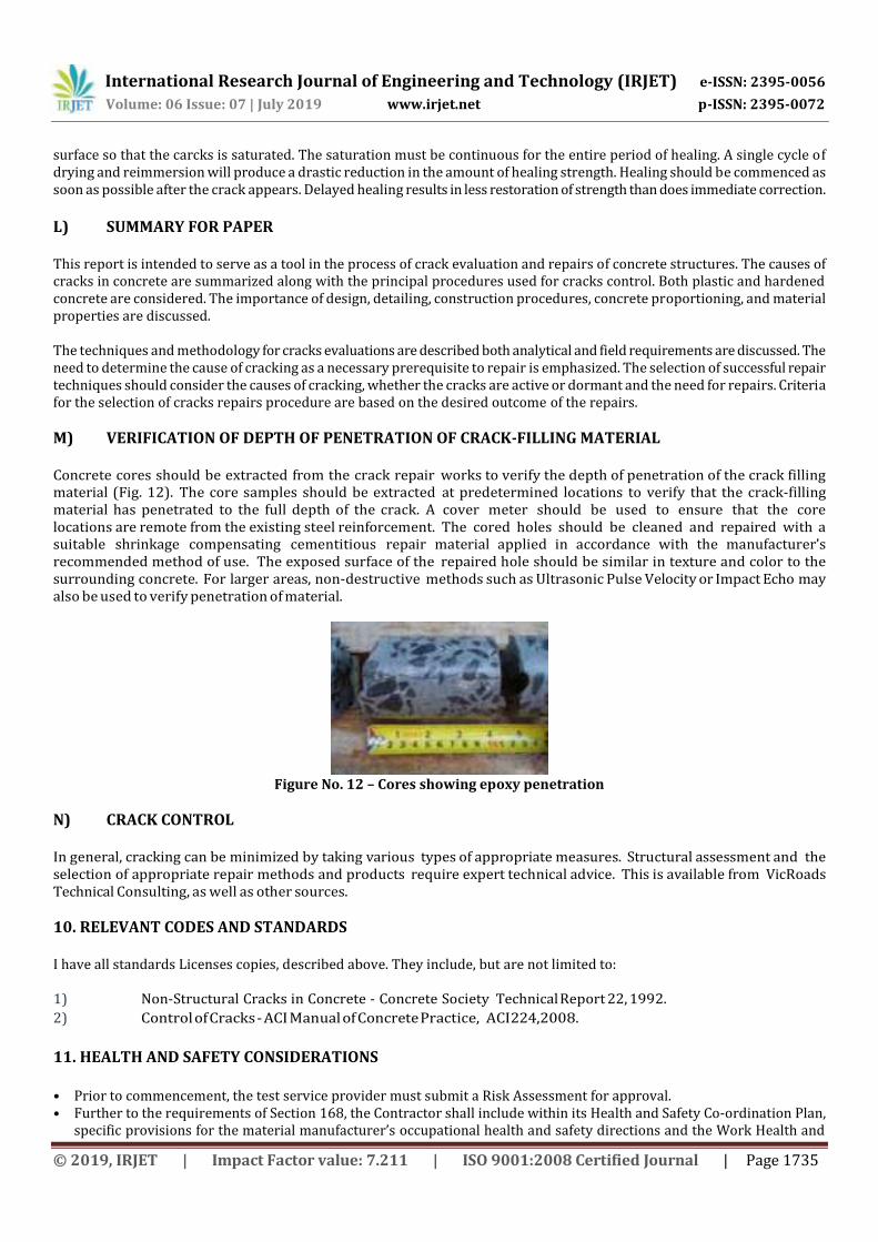
International Research Journal of Engineering and Technology (IRJET) e-ISSN: 2395-0056
Volume: 06 Issue: 07 | July 2019 www.irjet.net p-ISSN: 2395-0072
© 2019, IRJET | Impact Factor value: 7.211 | ISO 9001:2008 Certified Journal | Page 1735
surface so that the carcks is saturated. The saturation must be continuous for the entire period of healing. A single cycle of drying and reimmersion will produce a drastic reduction in the amount of healing strength. Healing should be commenced as soon as possible after the crack appears. Delayed healing results in less restoration of strength than does immediate correction.
L) SUMMARY FOR PAPER
This report is intended to serve as a tool in the process of crack evaluation and repairs of concrete structures. The causes of cracks in concrete are summarized along with the principal procedures used for cracks control. Both plastic and hardened concrete are considered. The importance of design, detailing, construction procedures, concrete proportioning, and material properties are discussed. The techniques and methodology for cracks evaluations are described both analytical and field requirements are discussed. The need to determine the cause of cracking as a necessary prerequisite to repair is emphasized. The selection of successful repair techniques should consider the causes of cracking, whether the cracks are active or dormant and the need for repairs. Criteria for the selection of cracks repairs procedure are based on the desired outcome of the repairs.
M) VERIFICATION OF DEPTH OF PENETRATION OF CRACK-FILLING MATERIAL
Concrete cores should be extracted from the crack repair works to verify the depth of penetration of the crack filling material (Fig. 12). The core samples should be extracted at predetermined locations to verify that the crack-filling material has penetrated to the full depth of the crack. A cover meter should be used to ensure that the core locations are remote from the existing steel reinforcement. The cored holes should be cleaned and repaired with a suitable shrinkage compensating cementitious repair material applied in accordance with the manufacturer’s recommended method of use. The exposed surface of the repaired hole should be similar in texture and color to the surrounding concrete. For larger areas, non-destructive methods such as Ultrasonic Pulse Velocity or Impact Echo may also be used to verify penetration of material.
Figure No. 12 – Cores showing epoxy penetration
N) CRACK CONTROL
In general, cracking can be minimized by taking various types of appropriate measures. Structural assessment and the selection of appropriate repair methods and products require expert technical advice. This is available from VicRoads Technical Consulting, as well as other sources.
10. RELEVANT CODES AND STANDARDS
I have all standards Licenses copies, described above. They include, but are not limited to: 1) Non-Structural Cracks in Concrete - Concrete Society Technical Report 22, 1992.
2) Control of Cracks - ACI Manual of Concrete Practice, ACI 224, 2008.
11. HEALTH AND SAFETY CONSIDERATIONS
• Prior to commencement, the test service provider must submit a Risk Assessment for approval. • Further to the requirements of Section 168, the Contractor shall include within its Health and Safety Co-ordination Plan,
specific provisions for the material manufacturer’s occupational health and safety directions and the Work Health and

International Research Journal of Engineering and Technology (IRJET) e-ISSN: 2395-0056
Volume: 06 Issue: 07 | July 2019 www.irjet.net p-ISSN: 2395-0072
© 2019, IRJET | Impact Factor value: 7.211 | ISO 9001:2008 Certified Journal | Page 1736
Safety Act, Regulations and Codes of Practice. All material safety data sheets (MSDS) shall be kept on site at all times and be readily available.
• Waste materials including liquid wastes shall be deposited in suitable containers and disposed of at sites to be located by the Contractor that are acceptable to the EPA and other relevant authorities.
• Liquid or other waste material shall not be disposed of in creeks, waterways or the storm water drainage systems. • Further to the requirements of OSHAS the Contractor shall include within its Environmental Management Plan, specific
provisions regarding the collection, segregation, handling, control and disposal of waste generated during repair of concrete cracks, and clean up.
• Normal health and safety procedures as regards edge protection and/or fall arrest facilities, (in compliance with HSE Regulations), must be fully operational prior to the test. If an electrically conductive edge protection system is removed temporarily, another means of fall restraint must be provided in the interim.
12. CONCLUSIONS
Thus in the concluding paragraph, we can say cracking may occur anywhere in concrete but if above given preventions and causes are kept in ind, it may lead far betetr results and much lesser visible cracks and hence a better safer and stronger structure. Cracking is overlooked may result in big and hazardous accidents also. This paper covers all the basic reasons and their preventions that need to be taken care of in construction process on a small or medium level. With the growing technology, there are many post construction methods available for the cracks removal or healing. Also they are now some special types of concretes discovered such as “Self healing concrete” that themselves repair and heal the cracked portions, thus saving a lot of money, energy and time for post methods. There are polymer composites available to improve resistance against wearing, compressive strength, impermeability, durability as well as chemical attacks resistance. And if not above mentioned admixtures or polymers are used in initial phase then there are many repairs techniques to be followed at a later stage like stitching , sealing, routing and grouting. Though with the help of all above techniques cracks can be covered up even at later stage but again it is always focused to adopt preventation rather than looking for cures afterwards. From the above paper description and some case study we have concluded that some prevention could be taken care of during the construction process itself. Any lack of attentiveness can lead to a cause for damage in the building in its future, which can also lead to the failure of structure.
Cracks may occur due to various reasons, as discussed earlier. The occurrence of cracks cannot be stopped but particular measures can be taken to restrict them to reduce the level and degree of consequences.
13. RECOMMENDED REFERENCES
The documents of the various standards – producing organizations referred to in this document are listed below with their serial designation. American Concrete Institute
201.IR - Guide for Making a Condition Survey of Concrete in Service. 201. 2R - Guide to Durable Concrete. 207.1R - Mass Concrete. 207. 2R - Effects of Restraint, volume changes, and Reinforcement on Cracking of Mass Concrete. 207. 4r - Cooling and Insulating System for Mass Concrete. 224R - Control of Cracking in concrete Structures. 224.2R – Cracking of Concrete Members in Direct Tension. 224.3R - Joints in Concrete Construction. 302.IR – Guide to Concrete, Floor slab Construction. 304R – Guide for Measuring, Mixing Transportation and Placing Concrete. 305R – Hot Weather Concreting. 308 – Standards Practice For Curing Concrete. 309R – Guide for Consolidation of Concrete. 318 – Building Code Requirement For Reinforced Concrete. 347R – Guide to Concrete Formwork. 503R – Use of Epoxy Compound with Concrete.

International Research Journal of Engineering and Technology (IRJET) e-ISSN: 2395-0056
Volume: 06 Issue: 07 | July 2019 www.irjet.net p-ISSN: 2395-0072
© 2019, IRJET | Impact Factor value: 7.211 | ISO 9001:2008 Certified Journal | Page 1737
Transportation Research Board – 500 Fifth Street, NW Washington DC – 20001; www.trb.org.
PCA – Concrete Technology and Codes.
Central Building Research Institute, R. (1984). Handbook on Causes and Prevention of cracks. IS. SP. 25.
"Identifying Cracks in Slabs". Concrete Construction. Web. July 31, 2014.
Interval, V. "Concrete Cracks: An Overview of Types of Cracking/Deterioration and Their Implications." Wiki-spaces
Classroom. Web.
Portland cements Association. "IS-177 Concrete Slab Surface Defects- Causes, Prevention, Repair". Concrete Information.
2001.
www.onlinepubs.trb.org/onlinepubs/circulars/ec107.pdf
14. AUTHOR PROFILE
Mr. Harshal Shankar Rao Khode is working as Manager Technical (Corporate) - Consultant and Technical Researcher. He has done B. Tech in Civil Engineering from Nagpur University in 2004. He will receive him Executive MBA IN Business Administration and Specialization in Project and Quality Management system in July 2012 form Delhi University. Harshal are especially area of Research and development is Advance Concrete Technology. He has published this year (2019-2020) about 8 papers till date in national and international conference and in other International journals also. He is the life and license member of Institute of Engineer, Bureau of Indian Standards, ACI, ASTM, BSI and many more Technical organizations. He is continuously involved in research, development and analysis of new concepts evolving in Technical, Project Management, Quality Management system and construction aspects. Aspiring researchers for new horizons of trends in Civil and Structural engineering.