Analysis of Uplink Detection Methods for MIMO Systems - IRJET
9
International Research Journal of Engineering and Technology (IRJET) e-ISSN: 2395-0056 Volume: 07 Issue: 06 | June 2020 www.irjet.net p-ISSN: 2395-0072 © 2020, IRJET | Impact Factor value: 7.529 | ISO 9001:2008 Certified Journal | Page 1653 Analysis of Uplink Detection Methods for MIMO Systems Pooja Dayananda K 1 , Dr. B. Roja Reddy 2 1 Student, Dept. of Digital Communication Engineering, RV College of Engineering, Bengaluru, India 2 Associate Professor, Department of Telecommunication, RV College of Engineering, Bengaluru, India ---------------------------------------------------------------------***--------------------------------------------------------------------- Abstract - To achieve the requirements of networks of 5G, Massive Multiple-Input Multiple Output (MIMO) technology has been proposed over the last few years which is considered to be the most prominent and efficient technology. Though being very efficient, one of the challenges that this technology faces is the signal recognition for Uplink at Base Station (BS) and this becomes more complex as there is raise in the amount of antennas. Thus, there is a requirement to develop appropriate signal detection algorithms for Massive MIMO systems to have less complexity and as well as a better Bit Error Rate (BER) performance. This article shows how to implement two Uplink detection techniques for Massive MIMO systems like Least Square Regressor (LSR) choice algorithm and Advanced Approximate Message Passing (AAMP) algorithm. The simulations are done in MATLAB R2019a and the results obtained shows that the two algorithms provide a better BER performance and are proved to be effective Uplink detection methods when contrasted with the linear detectors in terms of intricacy as well as BER. Key Words: Massive MIMO, Base Station, LSR, AAMP, Bit Error Rate 1. INTRODUCTION In the recent times, the advancement in the rapid communication growth has raised the demand to boost the data transmission over the wireless media in which a quick and a feasible communication can be accomplished. Also, due to the development of cell phones, super computers, tablets etc, there is an immense growth in the versatile information traffic or the mobile data traffic and is anticipated to hike up subsequently. Hence every single mobile user requires higher data rate with greater accuracy and reliability. So as to accommodate this immense data traffic, “Fifth Generation” (5G) networks is launched [1]. The technology which has been thought to meet the prerequisites of the 5G networks is seen as MIMO systems. MIMO devices are now referred to as communication channels between multiple transmitters and receivers. MIMO technology has become an integral part in Wireless technologies like Wi-Fi and LTE’s (Long Term Evaluation). Massive MIMO is an expansion of MIMO that consists of numerous antenna elements at the transmitters as well as at the base station to enhance spectral and energy effectiveness [2]. Massive MIMO devices are orders-of- magnitude larger and hence may consist of 100’s or even 1000’s of antenna channels in the array. A Massive MIMO scenario is given in Figure1. Massive MIMO devices promise to provide 10’s of Gbps data for real time wireless devices without consuming extra spectral bandwidth [3][4]. The Massive MIMO system boosts the data rates and serves more terminals by using a greater amount of receiver station antennas, by thus decreasing the radiated power. It improves the link reliability and performance irrespective of noise measurements, and provides more degrees of freedom in the spatial domain. The only prime challenges in Massive MIMO is the signal detection at the base stations in order to discrete the transmitted signals by individual user from the signals received which turns out to be crucial with huge number of antennas. Also, in Massive MIMO systems, the users transmit the signals and those signals are superimposed at the base stations which intervenes with each other. It is also very complex due to the greater amount of antennas and provides a Bit Error Rate (BER) which is very poor in its performance [5]. In order to discover an Optimum Uplink detector for massive MIMO frameworks, researches have been done which incorporates linear and non-linear detectors. “Zero Forcing” (ZF), “Minimum Mean Square Error” (MMSE) and “Vertical Bell Labs layered space time” (V-BLAST) are the sorts of linear detectors and the “Maximum Likelihood” (ML) and “Sphere Decoder” (SD) comes under non-linear detectors [6]. ML and SD are extremely hard to execute with an abundant number of antennas because of increment in multifaceted nature. In such a situation, linear recognition techniques or traditional identifiers such as ZF and MMSE will be helpful for Uplink discovery strategies since they are less perplexing than non-linear detectors [7-9]. Fig-1: Massive MIMO Scenario [3]
-
Upload
khangminh22 -
Category
Documents
-
view
0 -
download
0
Transcript of Analysis of Uplink Detection Methods for MIMO Systems - IRJET

International Research Journal of Engineering and Technology (IRJET) e-ISSN: 2395-0056
Volume: 07 Issue: 06 | June 2020 www.irjet.net p-ISSN: 2395-0072
© 2020, IRJET | Impact Factor value: 7.529 | ISO 9001:2008 Certified Journal | Page 1653
Analysis of Uplink Detection Methods for MIMO Systems
Pooja Dayananda K1, Dr. B. Roja Reddy2
1Student, Dept. of Digital Communication Engineering, RV College of Engineering, Bengaluru, India 2Associate Professor, Department of Telecommunication, RV College of Engineering, Bengaluru, India
---------------------------------------------------------------------***---------------------------------------------------------------------
Abstract - To achieve the requirements of networks of 5G, Massive Multiple-Input Multiple Output (MIMO) technology has been proposed over the last few years which is considered to be the most prominent and efficient technology. Though being very efficient, one of the challenges that this technology faces is the signal recognition for Uplink at Base Station (BS) and this becomes more complex as there is raise in the amount of antennas. Thus, there is a requirement to develop appropriate signal detection algorithms for Massive MIMO systems to have less complexity and as well as a better Bit Error Rate (BER) performance. This article shows how to implement two Uplink detection techniques for Massive MIMO systems like Least Square Regressor (LSR) choice algorithm and Advanced Approximate Message Passing (AAMP) algorithm. The simulations are done in MATLAB R2019a and the results obtained shows that the two algorithms provide a better BER performance and are proved to be effective Uplink detection methods when contrasted with the linear detectors in terms of intricacy as well as BER.
Key Words: Massive MIMO, Base Station, LSR, AAMP, Bit
Error Rate
1. INTRODUCTION In the recent times, the advancement in the rapid communication growth has raised the demand to boost the data transmission over the wireless media in which a quick and a feasible communication can be accomplished. Also, due to the development of cell phones, super computers, tablets etc, there is an immense growth in the versatile information traffic or the mobile data traffic and is anticipated to hike up subsequently. Hence every single mobile user requires higher data rate with greater accuracy and reliability. So as to accommodate this immense data traffic, “Fifth Generation” (5G) networks is launched [1]. The technology which has been thought to meet the prerequisites of the 5G networks is seen as MIMO systems. MIMO devices are now referred to as communication channels between multiple transmitters and receivers. MIMO technology has become an integral part in Wireless technologies like Wi-Fi and LTE’s (Long Term Evaluation). Massive MIMO is an expansion of MIMO that consists of numerous antenna elements at the transmitters as well as at the base station to enhance spectral and energy effectiveness [2]. Massive MIMO devices are orders-of-magnitude larger and hence may consist of 100’s or even 1000’s of antenna channels in the array. A Massive MIMO
scenario is given in Figure1. Massive MIMO devices promise to provide 10’s of Gbps data for real time wireless devices without consuming extra spectral bandwidth [3][4]. The Massive MIMO system boosts the data rates and serves more terminals by using a greater amount of receiver station antennas, by thus decreasing the radiated power. It improves the link reliability and performance irrespective of noise measurements, and provides more degrees of freedom in the spatial domain. The only prime challenges in Massive MIMO is the signal detection at the base stations in order to discrete the transmitted signals by individual user from the signals received which turns out to be crucial with huge number of antennas. Also, in Massive MIMO systems, the users transmit the signals and those signals are superimposed at the base stations which intervenes with each other. It is also very complex due to the greater amount of antennas and provides a Bit Error Rate (BER) which is very poor in its performance [5]. In order to discover an Optimum Uplink detector for massive MIMO frameworks, researches have been done which incorporates linear and non-linear detectors. “Zero Forcing” (ZF), “Minimum Mean Square Error” (MMSE) and “Vertical Bell Labs layered space time” (V-BLAST) are the sorts of linear detectors and the “Maximum Likelihood” (ML) and “Sphere Decoder” (SD) comes under non-linear detectors [6]. ML and SD are extremely hard to execute with an abundant number of antennas because of increment in multifaceted nature. In such a situation, linear recognition techniques or traditional identifiers such as ZF and MMSE will be helpful for Uplink discovery strategies since they are less perplexing than non-linear detectors [7-9].
Fig-1: Massive MIMO Scenario [3]

International Research Journal of Engineering and Technology (IRJET) e-ISSN: 2395-0056
Volume: 07 Issue: 06 | June 2020 www.irjet.net p-ISSN: 2395-0072
© 2020, IRJET | Impact Factor value: 7.529 | ISO 9001:2008 Certified Journal | Page 1654
Even though linear detection methods are less composite, they have a much-diminished performance and not that effective. These methods involve the matrix to be inversed thereby causing the system intricacy to increase. Also, with an enormous number of antennas, the intricacy rises [10-12]. Thus, in Massive MIMO systems, relevant Uplink detection methods have to be implemented to minimize the complicatedness of the system and to produce an improved BER performance. We demonstrate effective Uplink detection algorithms in this paper, on the basis of “Least Square Regressor” (LSR) choice and “Advanced Approximate Message Passing” (AAMP) algorithms. The remaining paper is divided as mentioned below. In Section 2, we described the overall description of the system model. Then, LSR algorithm is described in Section 3. AAMP algorithm is discussed in Section 4. In Section 5, Extensive simulations and discussions are provided to demonstrate the effectiveness of the approaches given in Section 3 and 4 in the form of Bit Error Rate (BER) accomplishment and intricacy, followed by the Section 6 which gives the conclusion of the paper.
2. SYSTEM ARCHITECTURE The system architecture consists of an Uplink Immense
MIMO system of antennas connected to the base station
and number of operating user mobile devices which has
individual antenna where >> and which are
communicating with the base station at the same time. It is depicted in Figure 2. “Channel state information” (CSI) is pretended to be perfect between the base station and user, and “Rayleigh fading channel” which is the most generally used channel is regarded for the simulation. The bitstream
of each of the users are encoded, and the encoded stream
of bits is outlined into gathering point within the limited set of alphabets, that is “Binary Phase Shift Keying (BPSK), Quadrature Phase Shift Keying (QPSK) and Quadrature Amplitude Modulation (QAM)”. The vector which is received is represented by
where, and the
vector which is sent is represented by
where, . Hence, the
signal vector which is received [5] is represented as,
(1)
In the above equation (1), an uplink channel matrix is
represented by of order and whose
components are “independent and identically distributed (i.i.d)” having a mean of 0 and variance is unity that is
and . “Additive White
Gaussian Noise (AWGN)” is represented by and every
component of is i.i.d and it also has a mean of 0 but with
finite variance that is and . The
minimization of Euclidean distance [15]
between and is denoted by,
(2)
Therefore, ZF and MMSE are some of the different linear detection methods which can be used to solve equation (2).
Fig-2: Uplink Massive MIMO system model [5]
The Zero-Forcing equalizer is perfect when the channel is noiseless since all ISI is eliminated. But, with a noisy channel, in an effort to invert the channel entirely, the zero-forcing equalizer amplifies the noise extremely at certain frequencies [13]. Therefore, it is necessary in ZF to invert
and factorize the matrix of order . By applying the
inverse of , linear transformation of the signal
received is performed by ZF, which removes interference but ZF still suffers from noise enrichment. The ZF solution [15] is,
(3)
(4)
The core idea of “Minimum Mean Square Error” (MMSE) detection is the reduction of mean square error. The noise variance is regarded in the MMSE detection and uses the minimum mean square error equalization matrix to decrease the noise enrichment. This concept takes into account the noise power while the filtering matrix is built using the MMSE performance-based criterion which mollifies the noise increasing problem. With the MMSE equalizer the ISI is not completely eliminated, instead the full noise power and the ISI elements that is present in the output are reduced, which helps in accomplishing near-optimum performance with

International Research Journal of Engineering and Technology (IRJET) e-ISSN: 2395-0056
Volume: 07 Issue: 06 | June 2020 www.irjet.net p-ISSN: 2395-0072
© 2020, IRJET | Impact Factor value: 7.529 | ISO 9001:2008 Certified Journal | Page 1655
approximately low complication in Massive MIMO systems [14]. MMSE has a signal matrix [18] which is represented as,
(5)
where, Symbol Energy is represented as . Hence, due to
the inversion of the matrices, linear detectors such as ZF and MMSE are complex and have a degraded error performance.
3. LSR ALGORITHM The executed algorithm depends on Least Square Regressor choice that discovers the best fit from accessible regressors. Least Squares technique is a measurable strategy to locate the best fit for a lot of data or information points by limiting the aggregate of residuals of focuses from the curve which is plotted. This technique is broadly utilized due to its application in different fields, for example, Artificial Intelligence (AI) and Machine Learning (ML), financial matters, remote communications, and measurements so on.
An uplink enormous MIMO framework with reception
apparatuses at the receiver station is thought of and
( number of dynamic users which has only one
antenna exchanges information or communicates with the receiving antennas at the same time. The LSR algorithm chiefly focuses on the minimization issue which determines the best Optimum arrangement from the accessible regressors or the accessible information points. In LSR, if the data is fitted across the point in a curve, that point will be considered as the best Optimal value. LSR makes a variable update in every iteration a lot easier and through every
iteration, variables such as , and are updated by
solving an Optimisation problem. Through every variable update in each iteration, error also keeps on reducing.
In the Pseudo-code of LSR Algorithm, the signal and
Channel matrix are given as inputs to the system or
the LSR algorithm. Initially, “Dual variable” , “Augmented
Lagrangian parameter” > 1, “Step size” 0 < <1 and
“vector” are initialized. Next, after the Initialisation, the
update of during the iteration stage involves the
Gram matrix inversion. “Gram matrix” is represented by
. The matrix can be calculated through the
multiplication of matrices where is known as the
“Regularization parameter” and I is nothing but the “Identity matrix” [15]. It is given in Step 6 in the Pseudo-code of LSR algorithm. To diminish the unpredictability of the calculation or to minimize the Uplink detection algorithm complexity, inversion is done from “Cholesky Decomposition” in the stage of Pre-Processing. Squeezing is also done which is given Step 8. The multiplication of triangular matrix with its
transpose represents the matrix from the Cholesky
factorization. It is given by,
(6)
In equation (6), is lower triangular matrix and this is
given as “Cholesky factor”. Matrix vector multiplication is carried out in the Pre-processing stage in order to minimize the computation in the Iteration stage. This is given in Step 10 in the Pseudo-code of
LSR. Minimization of was done by keeping and
constant during the beginning of the iteration. Next, in order
to update of the LSR algorithm, the prognosis or
projection into the set C which is non-convex is done. It is given by,
(7)
3.1 Pseudo-Code of LSR Algorithm:
1. Inputs:
2. Initialization:
3.
4.
5. Pre-Processing:
6.
7.
8.
9.
10.
11. Iteration:
12.
13.
14.
15.
16.
17.
18. Output:
Here, the projection retains biggest components from
and remaining of the components are formed
to be null. In brief, the -update resembles “Intermediate
Sorting”. The update is provided by,
(8)

International Research Journal of Engineering and Technology (IRJET) e-ISSN: 2395-0056
Volume: 07 Issue: 06 | June 2020 www.irjet.net p-ISSN: 2395-0072
© 2020, IRJET | Impact Factor value: 7.529 | ISO 9001:2008 Certified Journal | Page 1656
In equation (8), denotes the Step size of the LSR
algorithm, where 0 < <1 and it assures convergence in
it. During each iteration step, one value will get eliminated and the minimal possible value is considered.
is the updated transmitted bits per symbol after
minimization [16]. After updating , and values,
current states of the symbols transmitted are found. Finally, from this the BER or SER are calculated. Hence, this gives the complete description of LSR algorithm.
4. AAMP ALGORITHM “Approximate Message Passing” or AMP is basically developed for solving the problem of “Compressed sensing”. The reconstruction of the sparse signals is done by AMP algorithm. So as to estimate the transmitted signal sent by the transmitter from the signal which is received by the base station, iterative thresholding is utilized by AMP algorithm. Although AMP algorithm is not very complex, it has a very poor error performance when compared to ZF, MMSE and LSR. AMP does not perform well since it will not have any regression action. It gives constant BER values as the SNR goes higher or lower. So, “Advanced AMP” (AAMP) is implemented which gives a better BER efficiency and the intricacy of AAMP algorithm is significantly less. AAMP algorithm which is similar to AMP, is also a Convergence algorithm used for transferring information or data from the transmitter to the receiver. Approximation is mainly done at the receiving end so as to rebuild the signal that is received by giving some approximate values built in to fill some gap on the received signal so that the received signal can be obtained without any interference. So, randomly giving few values which gets periodically altered at the Iteration level is the Approximation [17]. From this, the signal which is received at the base station will not be disturbed. Based on the “Advanced Approximate Message Passing” (AAMP) algorithm, a less complex and effective algorithm will be implemented for Uplink Detection of Massive MIMO systems. The BS of the system is attached with considerable
amount of antennas that is = 32, 64,128,256. Assume the
BS communicates with that is = 8 or 16 number of
users which have only one antenna each. For simplicity, consider that the user systems contain an antenna. In between the transmitter and the receiver which is the Base station, a perfect CSI is assumed. The Pseudo-Code for the AAMP algorithm is given below. It has mainly 2 important steps that is Initialization and Iteration part. Iteration part is the main step in the Uplink detection of Massive MIMO systems so as to minimize the error and to provide an improved BER performance.
4.1 Pseudo-Code of AAMP Algorithm:
1. Initialization: 2. Initialization:
3. 4. Iteration: 5.
6.
7.
8.
9. *
10.
11. end
12. return
At first, Initialization is done. Initially, the remaining
value or the Residual value is initialized as the gotten
signal or the signal that is received at the BS and this
in turn depends on the Channel matrix . Hence, this id
represented as where . Next, the yield
signal which is also the Output signal is initialized as
a vector of Zero having as the dimension of the
matrix. This is represented as where is the
number of transmitters or users in Massive MIMO systems.
Also, the “Proportionality Factor” is also initialized as the
product of the transpose of Channel matrix and the
received signal [18]. It is used in the Iteration step so as to
update the values. This is represented as,
(9)
The Second Important part of the AAMP algorithm is the Iteration part. In this, the iteration is set to some threshold point, until it reaches that point, it keeps on Updating in every single iteration. Iteration actually plays a very major role in minimizing the errors. As the number of iteration increases, the parameters or variables present in the algorithm which are used to solve the Optimization problem keeps on updating simultaneously reducing the error rate.
Initially in the Iteration, the first step is to calculate
which is known as the “Convergence Factor”. It is used for
converging the data points. is given as the sum of the
signal which is transmitted i.e., multiplying it with the
channel matrix transpose and the normalization of the
residual value . Therefore, can be given as,
(10)
International Research Journal of Engineering and Technology (IRJET) e-ISSN: 2395-0056
Volume: 07 Issue: 06 | June 2020 www.irjet.net p-ISSN: 2395-0072
© 2020, IRJET | Impact Factor value: 7.529 | ISO 9001:2008 Certified Journal | Page 1657
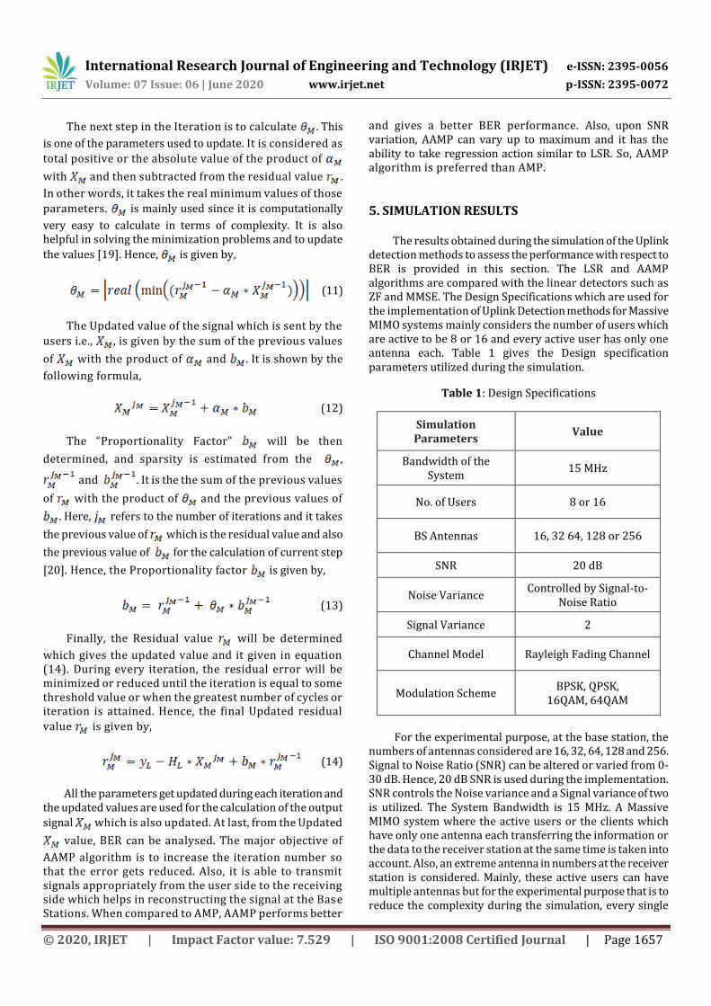
The next step in the Iteration is to calculate . This
is one of the parameters used to update. It is considered as
total positive or the absolute value of the product of
with and then subtracted from the residual value .
In other words, it takes the real minimum values of those
parameters. is mainly used since it is computationally
very easy to calculate in terms of complexity. It is also helpful in solving the minimization problems and to update
the values [19]. Hence, is given by,
(11)
The Updated value of the signal which is sent by the
users i.e., , is given by the sum of the previous values
of with the product of and . It is shown by the
following formula,
(12)
The “Proportionality Factor” will be then
determined, and sparsity is estimated from the ,
and . It is the the sum of the previous values
of with the product of and the previous values of
. Here, refers to the number of iterations and it takes
the previous value of which is the residual value and also
the previous value of for the calculation of current step
[20]. Hence, the Proportionality factor is given by,
(13)
Finally, the Residual value will be determined
which gives the updated value and it given in equation (14). During every iteration, the residual error will be minimized or reduced until the iteration is equal to some threshold value or when the greatest number of cycles or iteration is attained. Hence, the final Updated residual
value is given by,
(14)
All the parameters get updated during each iteration and the updated values are used for the calculation of the output
signal which is also updated. At last, from the Updated
value, BER can be analysed. The major objective of
AAMP algorithm is to increase the iteration number so that the error gets reduced. Also, it is able to transmit signals appropriately from the user side to the receiving side which helps in reconstructing the signal at the Base Stations. When compared to AMP, AAMP performs better
and gives a better BER performance. Also, upon SNR variation, AAMP can vary up to maximum and it has the ability to take regression action similar to LSR. So, AAMP algorithm is preferred than AMP.
5. SIMULATION RESULTS The results obtained during the simulation of the Uplink detection methods to assess the performance with respect to BER is provided in this section. The LSR and AAMP algorithms are compared with the linear detectors such as ZF and MMSE. The Design Specifications which are used for the implementation of Uplink Detection methods for Massive MIMO systems mainly considers the number of users which are active to be 8 or 16 and every active user has only one antenna each. Table 1 gives the Design specification parameters utilized during the simulation.
Table 1: Design Specifications
Simulation Parameters
Value
Bandwidth of the System
15 MHz
No. of Users 8 or 16
BS Antennas 16, 32 64, 128 or 256
SNR 20 dB
Noise Variance Controlled by Signal-to-
Noise Ratio
Signal Variance 2
Channel Model Rayleigh Fading Channel
Modulation Scheme BPSK, QPSK,
16QAM, 64QAM
For the experimental purpose, at the base station, the numbers of antennas considered are 16, 32, 64, 128 and 256. Signal to Noise Ratio (SNR) can be altered or varied from 0-30 dB. Hence, 20 dB SNR is used during the implementation. SNR controls the Noise variance and a Signal variance of two is utilized. The System Bandwidth is 15 MHz. A Massive MIMO system where the active users or the clients which have only one antenna each transferring the information or the data to the receiver station at the same time is taken into account. Also, an extreme antenna in numbers at the receiver station is considered. Mainly, these active users can have multiple antennas but for the experimental purpose that is to reduce the complexity during the simulation, every single

International Research Journal of Engineering and Technology (IRJET) e-ISSN: 2395-0056
Volume: 07 Issue: 06 | June 2020 www.irjet.net p-ISSN: 2395-0072
© 2020, IRJET | Impact Factor value: 7.529 | ISO 9001:2008 Certified Journal | Page 1658
user which is outfitted with only one antenna each is estimated. The random binary bits or symbols which are produced or generated are sent along “Rayleigh Fading Channel” and the noise that is “Additive White Gaussian Noise” (AWGN) is taken into consideration. And finally, in order for the analysis and comparison of the results, discrete schemes of Modulation like BPSK, QPSK, 16-QAM and 64-QAM are taken up. The simulations are carried out in MATLAB R2019a under Windows 10 OS.
5.1 BER Performance
In this section, the performance of BER versus average SNR per receive antenna in dB of the LSR and AAMP algorithm is shown. The Simulation is done for 16-QAM modulation with varying the number of antennas at the user side as well as at the receiving end or at the BS and is given in Figure 3, Figure 4 and Figure 5. Also, the BER performance of LSR and AAMP is contrasted with the linear detectors of Massive MIMO such as ZF and MMSE. The BER performance
for = 8 and = 8 using 16-QAM modulation in LSR
and AAMP is shown in Figure 3. From the BER versus SNR graph shown below, it is noticed that except ZF detector, all the other three detectors such as MMSE, LSR and AAMP have a similar BER performance at lower SNR and as SNR is higher LSR outperforms the other detectors.
Fig-3: Comparison of LSR and AAMP with ZF & MMSE
w.r.t BER using 8 BS antennas ( ), 8 Users ( ) and 16-
QAM modulation
From the above graph, it is seen that at 18 dB SNR, LSR has a BER of 0.0575 whereas AAMP has a BER of 0.0722.
The BER analysis for = 16 and = 16 with the help
of 16-QAM modulation in LSR and AAMP is shown in Figure 4. From the BER versus SNR graph shown below, it is observed that at lower SNR, the uplink detectors such as MMSE, LSR and AAMP gives a similar BER performance, outperforming ZF detector since ZF has a poor BER performance compared to others. At higher SNR, LSR detector slightly deviates from the MMSE and AAMP
detectors and provides an excellent BER performance when contrasted to the other two. From the graph shown below, it is seen that at 18 dB SNR, LSR has a BER of 0.0697 whereas AAMP has a BER of 0.0811.
Fig-4: Comparison of LSR and AAMP with ZF & MMSE w.r.t
BER using 16 BS antennas ( ), 16 Users ( ) and 16-
QAM modulation
Hence, for an 16x16 systems, LSR algorithm performs better as the SNR increases.
The BER performance for = 32 and = 16 using
16-QAM modulation in LSR and AAMP is shown in Figure 5.
Fig-5: Comparison of LSR and AAMP with ZF & MMSE
w.r.t BER using 32 BS antennas ( ), 16 Users ( ) and
16-QAM modulation
From the BER versus SNR graph shown below, it is observed that all the Uplink detectors have the same BER performance at lower SNR range. But as the SNR increases, LSR outperforms a little from all the other detectors and provides a good BER compared to the other three detectors. From the graph shown above, it is seen that

International Research Journal of Engineering and Technology (IRJET) e-ISSN: 2395-0056
Volume: 07 Issue: 06 | June 2020 www.irjet.net p-ISSN: 2395-0072
© 2020, IRJET | Impact Factor value: 7.529 | ISO 9001:2008 Certified Journal | Page 1659
at 16 dB SNR, LSR has a BER of 0.0017 whereas AAMP has a BER of 0.0025. Hence, for a 32x16 systems also, LSR detector performs better as the SNR increases. And, with the raise in the BS antennas in-terms of number or quantity, the BER efficiency gets better in both LSR as well as AAMP algorithm and is shown in Figure 6 and Figure 7 respectively. The BER versus SNR performance for
differing number of Base station antennas i.e., = 16, 32,
64, 128 and 256 and for the users to be =16 is utilized
in the simulation. From the graph shown below, it can be remarked that as the number of Base station antennas rises, the BER performance is increased to a great extent.
Fig-6: BER of LSR with different number of BS antennas
( ), 16 Users ( ) and 16-QAM modulation
Fig-7: BER of AAMP with different number of BS antennas
( ), 16 Users ( ) and 16-QAM modulation
In other words, the error gets reduced for 256 BS antennas when compared to 128, 64, 32 or 16 BS
antennas. The receiver performance is actually improved for a higher number of BS antennas. From the graph given
in Figure 6 of the LSR algorithm, at BER= , 3.3 dB gain is
achieved when the BS antenna’s number is changed from 64 to 128 and an extra gain of 2.4 dB gain is obtained when the amount of BS antennas further increases to 256. Similarly, from the graph given in Figure 7 of the AAMP algorithm, at
BER= , 3.1 dB gain is achieved when the BS antenna’s
number is changed from 64 to 128 and an extra gain of 3.9 dB gain is obtained when the amount of BS antennas further increases to 256. Finally, the BER versus SNR [dB] performance is demonstrated for discrete modulation types such as BPSK, QPSK, 16-QAM and 64-QAM for both LSR and AAMP algorithms and is given in Figure 8 and Figure 9 respectively. The BER performance of LSR and AAMP for discrete modulation systems such as BPSK, QPSK, 16-QAM and 64-
QAM utilizes =16 BS antennas and =16 Users for the
simulation. From the graph shown below in Figure 8 of the
LSR algorithm, at BER= , there is a 2 dB loss when the
scheme of modulation changes from BPSK to QPSK.
Fig-8: BER of LSR with discrete modulation schemes (BPSK, QPSK,16-QAM and 64-QAM) with 16 BS antennas
( ), 16 Users ( )
Similarly, there is 8 dB loss when the modulation scheme further changes to 16-QAM modulation scheme from QPSK. BPSK has a lower modulation order when compared to all the other modulation schemes and it has an excellent BER performance. From the graph shown in Figure 9 of the AAMP
algorithm, at BER= , there is a 6 dB loss when the
modulation technique switches from BPSK to QPSK. Similarly, there is 9 dB loss when the modulation scheme further changes to 16-QAM modulation scheme from QPSK.

International Research Journal of Engineering and Technology (IRJET) e-ISSN: 2395-0056
Volume: 07 Issue: 06 | June 2020 www.irjet.net p-ISSN: 2395-0072
© 2020, IRJET | Impact Factor value: 7.529 | ISO 9001:2008 Certified Journal | Page 1660
It is noticed that BPSK has a better error performance when contrasted to the other modulation schemes since it has a lower modulation order when compared to all the other modulation schemes even for AAMP algorithm also.
Fig-9: BER of AAMP with various modulation schemes (BPSK, QPSK,16-QAM and 64-QAM) using16 BS antennas
( ), 16 Users ( )
Thus, as there is a rise in the modulation order, the BER performance of the Uplink detection algorithms will be reduced.
6. CONCLUSION In this paper, the analysis of various Uplink Detection methods for Massive MIMO systems that are based on LSR algorithm and AAMP algorithm are given. The BER performance of these Uplink detection methods are compared with the Uplink MIMO linear detectors such as ZF and MMSE. The simulations are done by differing the amount of antennas and it is observed that when the antennas at the receiver end or at the base station are more, BER performance improves to a great extent. Also, if the modulation order increases, the BER performance of LSR and AAMP algorithm decreases. In terms of complexity, LSR algorithm is quite less complex when compared to AAMP algorithm. From the results obtained, it is observed that for an 32x16 Massive MIMO systems, at 16 dB, ZF has a BER of 0.0027, MMSE and AAMP have a BER of 0.0025 whereas LSR detector has BER of 0.0017.
Also, in LSR algorithm, at BER= , there is a 2 dB loss
when the modulation scheme changes from BPSK to QPSK which is better when compared to the literature survey done in [15] which has a 3.3 dB loss. Finally, after the comparison, it can be concluded that all the Uplink detectors perform well but out of all LSR algorithm gives a better BER performance with quite lesser error at higher SNR and also with less complexity. The future
scope of improvement of this project work would include the testing of these Uplink detection simulations by incorporating a lot of network parameters.
REFERENCES [1] Noor Hidayah Muhamad Adnan, Islam Md. Rafiqul and
AHM Zahirul Alam, “Massive MIMO for Fifth Generation (5G): Opportunities and Challenges”, Published in International Conference on Computer & Communication Engineering, 2016.
[2] Thomas L.Marzetta, “Noncooperative Cellular Wireless with Unlimited Number of Base Station Antennas”, Published in IEEE Transactions on Wireless, IEEE, Volume: 9(11), November 2010, pp. 3590-3600.
[3] Robin Chataut and Robert Akl, “Optimal pilot reuse factor based on user environments in 5G Massive MIMO”, Published in 8th Annual Computing and Communication Workshop and Conference (UUWC), IEEE, 8-10 January 2018.
[4] Tae Ho Im, Sungwook Yu and Yong Soo Cho, “A signal detection method for uplink multiuser MIMO systems”, Published in MTT-S International Microwave Workshop Series on Intelligent Radio for Future Personal Terminals, IEEE, 24-25 August 2011.
[5] Robin Chataut and Robert Akl, “Huber Fitting Based ADMM Detection for Uplink 5G Massive MIMO Systems”, Published in 9th Annual Ubiquitous Computing, Electronics and Mobile Communication Conference (UEMCON), IEEE, 8-10 November 2018.
[6] Bei Yin, Michael Wu, Christoph Studer, Joseph R. Cavallaro and Chris Dick, “Implementation trade-offs for linear detection in large-scale MIMO systems”, Published in International Conference on Acoustics, Speech and Signal Processing, IEEE, 26-31 May 2013.
[7] Jaskirat Kaur and Harmandar Kaur, “Study and Analysis of MIMO-OFDM Linear and Non-Linear Detection Strategies”, International Journal of Technology Enhancements and Emerging Engineering Research, IJTEEE, Volume: 3(07), July 2015.
[8] Jakob Hoydis, Stephan ten Brink and Merouane Debbah, “Massive MIMO in the UL/DL of Cellular Networks: How Many Antennas Do We Need?”, Published in IEEE Journal on Selected Areas in Communications, IEEE, Volume: 31(02), February 2013, pp. 160-171.
[9] Hien Quoc Ngo, Michail Matthajou, Trung Q.Duong, Erik G. Larsson, “Uplink Performance Analysis of Multicell MU-SIMO Systems with ZF Receivers”, Published in IEEE Transactions on Vehicular Technology, IEEE, Volume: 62(9), November 2013, pp. 4471-4483.

International Research Journal of Engineering and Technology (IRJET) e-ISSN: 2395-0056
Volume: 07 Issue: 06 | June 2020 www.irjet.net p-ISSN: 2395-0072
© 2020, IRJET | Impact Factor value: 7.529 | ISO 9001:2008 Certified Journal | Page 1661
[10] Xinyu Gao, Linglong Dai, Chau Yuen and Yu Zhang, “Low Complexity MMSE Signal Detection based on Richardson Method for Large-Scale MIMO Systems”, Published in 80th Vehicular Technology Conference (VTC), IEEE, 14-17 September 2014.
[11] Zhizhen Wu, Lulu Ge, Xiaohu You and Chuan Zhang, “Efficient near-MMSE detector for large scale MIMO systems”, Published in International Workshop on Signal Processing Systems (SiPS), IEEE, 3-5 October 2017.
[12] Byunggi Kang, Ji-Hwan Yoon and Jongsun Park, “Low complexity massive MIMO detection architecture based on Neumann method”, Published in International SoC Design Conference (ISOCC), IEEE, 2-5 November 2015.
[13] Michael Wu, Bei Yin, Aida Vosoughi, Christoph Studer and Chris Dick, “Approximate matrix inversion for high-throughput data detection in the large-scale MIMO uplink”, Published in International Symposium on Circuits and Systems (ISCAS), IEEE, 19-23 May 2013.
[14] Oscar Gustafsson, Erik Bertilsson, Johannes Klasson and Carl Ingemarsson, “Approximate Neumann Series or Exact Matrix Inversion for Massive MIMO?”, Published in 24th Symposium on Computer Arithmetic (ARITH), IEEE, 24-26 July 2017.
[15] Robin Chataut, Robert Akl and Utpal Kumar Dey, “Least Square Regressor Selection based Detection for Uplink 5G Massive MIMO Systems”, Published in 20th Wireless and Microwave Technology Conference (WAMICON), IEEE, 8-9 April 2019.
[16] Manish Mandloi and Vimal Bhatia, “Low-Complexity Near-Optimal Iterative Sequential Detection for Uplink Massive MIMO Systems”, Published in Communications Letters, IEEE, Volume: 21(3), March 2017, pp. 568-571.
[17] Bang Chul Jung and Woohyuk Chang, “A Message Passing Algorithm for Compressed Sensing in Wireless Random-Access Networks”, Published in Asia-Pacific Conference on Communications (APCC), IEEE, 29-31 August 2013.
[18] Robin Chataut and Robert Akl, “Efficient and low complex uplink detection for 5G massive MIMO systems”, Published in 19th Wireless and Microwave Technology Conference (WAMICON), IEEE, 9-10 April 2018.
[19] Charles Jeon, Ramina Ghods, Arian Maleki and Christoph Studer, “Optimality of Large MIMO Detection via Approximate Message Passing”, Published in International Symposium on Information Theory (ISIT), IEEE, 14-19 June 2015.
[20] Shanxiang Lyu and Cong Ling, “Hybrid Vector Perturbation Precoding: The Blessing of Approximate Message Passing”, Published in Transactions on Signal Processing, IEEE, Volume: 67(1), 22 October 2018, pp. 178-193.