ENGINE (5VZ-FE) - Toyota 4Runner Forum
636
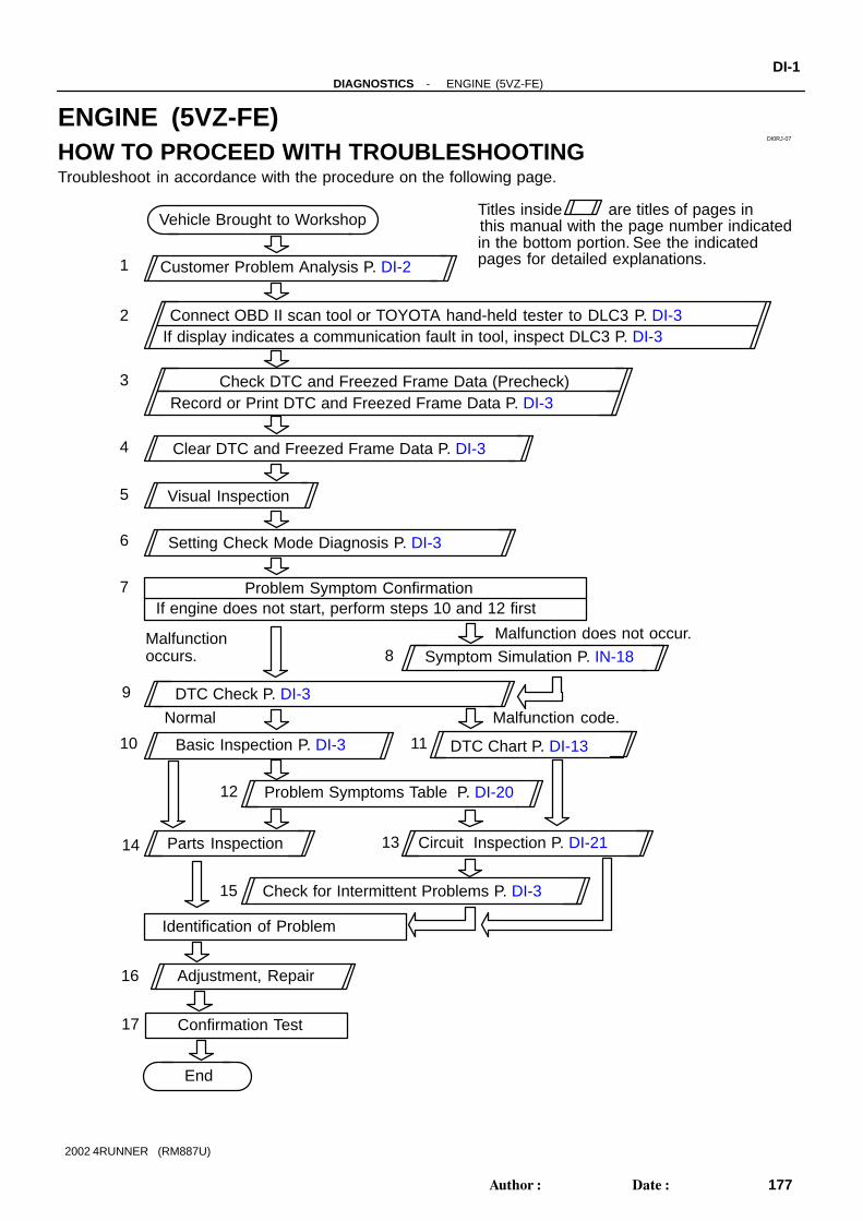
DI0RJ-07 Vehicle Brought to Workshop Customer Problem Analysis P. DI-2 Problem Symptom Confirmation If engine does not start, perform steps 10 and 12 first Connect OBD II scan tool or TOYOTA hand-held tester to DLC3 P. DI-3 If display indicates a communication fault in tool, inspect DLC3 P. DI-3 Check DTC and Freezed Frame Data (Precheck) Record or Print DTC and Freezed Frame Data P. DI-3 Clear DTC and Freezed Frame Data P. DI-3 Visual Inspection Setting Check Mode Diagnosis P. DI-3 Symptom Simulation P. IN-18 DTC Chart P. DI-13 Problem Symptoms Table P. DI-20 Circuit Inspection P. DI-21 Adjustment, Repair DTC Check P. DI-3 Titles inside are titles of pages in in the bottom portion. See the indicated pages for detailed explanations. this manual with the page number indicated Malfunction occurs. Malfunction does not occur. Parts Inspection Check for Intermittent Problems P. DI-3 Identification of Problem Confirmation Test End 1 2 3 4 5 6 7 10 8 9 11 12 13 15 14 16 Normal Malfunction code. 17 Basic Inspection P. DI-3 - DIAGNOSTICS ENGINE (5VZ-FE) DI-1 177 Author: Date: 2002 4RUNNER (RM887U) ENGINE (5VZ-FE) HOW TO PROCEED WITH TROUBLESHOOTING Troubleshoot in accordance with the procedure on the following page.
-
Upload
khangminh22 -
Category
Documents
-
view
0 -
download
0
Transcript of ENGINE (5VZ-FE) - Toyota 4Runner Forum
DI0RJ-07
Vehicle Brought to Workshop
Customer Problem Analysis P. DI-2
Problem Symptom ConfirmationIf engine does not start, perform steps 10 and 12 first
Connect OBD II scan tool or TOYOTA hand-held tester to DLC3 P. DI-3If display indicates a communication fault in tool, inspect DLC3 P. DI-3
Check DTC and Freezed Frame Data (Precheck)Record or Print DTC and Freezed Frame Data P. DI-3
Clear DTC and Freezed Frame Data P. DI-3
Visual Inspection
Setting Check Mode Diagnosis P. DI-3
Symptom Simulation P. IN-18
DTC Chart P. DI-13
Problem Symptoms Table P. DI-20
Circuit Inspection P. DI-21
Adjustment, Repair
DTC Check P. DI-3
Titles inside are titles of pages in
in the bottom portion. See the indicatedpages for detailed explanations.
this manual with the page number indicated
Malfunctionoccurs.
Malfunction does not occur.
Parts Inspection
Check for Intermittent Problems P. DI-3
Identification of Problem
Confirmation Test
End
1
2
3
4
5
6
7
10
8
9
11
12
13
15
14
16
Normal Malfunction code.
17
Basic Inspection P. DI-3
-DIAGNOSTICS ENGINE (5VZ-FE)DI-1
177Author: Date:
2002 4RUNNER (RM887U)
ENGINE (5VZ-FE)HOW TO PROCEED WITH TROUBLESHOOTINGTroubleshoot in accordance with the procedure on the following page.

DI0RK-06
ENGINE CONTROL SYSTEM Check Sheet
Customer’s Name
Driver’s Name
Date VehicleBrought in
License No.
Model and ModelYear
Frame No.
Engine Model
Odometer Readingkmmiles
Pro
blem
Sym
ptom
s
Engine doesnot Start
Difficult toStart
Poor Idling
PoorDriveability
Engine Stall
Others
Engine does not crank No initial combustion No complete combustion
Engine cranks slowlyOther
Incorrect first idle Idling rpm is abnormal High ( rpm) Low ( rpm)Rough idling Other
Hesitation Back fire Muffler explosion (after-fire) SurgingKnocking Other
Soon after starting After accelerator pedal depressedAfter accelerator pedal released During A/C operationShifting from N to D Other
Dates ProblemOccurred
Problem Frequency
Con
ditio
n W
hen
Pro
blem
Occ
urs
Weather
Engine Operation
Engine T emperature
Place
OutdoorTemperature
Constant Sometimes ( times per day/month) Once onlyOther
Fine Cloudy Rainy Snowy Various/Other
Hot Warm Cool Cold (approx. °F/ °C)
Highway Suburbs Inner city Uphill DownhillRough road Other
Cold Warming up After warming up Any temperature Other
Starting Just after starting ( min.) Idling RacingDriving Constant speed Acceleration DecelerationA/C switch ON/OFF Other
Condition of MIL Remains on Sometimes lights up Does not light up
Normal Malfunction code(s) (code )Freezed frame data ( )
Normal Malfunction code(s) (code )Freezed frame data ( )
Normal Mode(Precheck)
Check Mode
DTC Inspection
Inspector’sName
DI-2-DIAGNOSTICS ENGINE (5VZ-FE)
178Author: Date:
2002 4RUNNER (RM887U)
CUSTOMER PROBLEM ANALYSIS CHECK

DI8XG-01
A00032
A00026
TOYOTA Hand-Held Tester
DLC3
-DIAGNOSTICS ENGINE (5VZ-FE)DI-3
179Author: Date:
2002 4RUNNER (RM887U)
PRE-CHECK1. DIAGNOSIS SYSTEM(a) Description
When troubleshooting OBD II vehicles, the only dif-ference from the usual troubleshooting procedureis that you connect the vehicle to the OBD II scantool complying with SAE J1978 or TOYOTA hand-held tester, and read off various data output fromthe vehicle’s ECM.
OBD II regulations require that the vehicle’s on-board computer lights up the Malfunction IndicatorLamp (MIL) on the instrument panel when the com-puter detects a malfunction in the emission controlsystem/components or in the powertrain controlcomponents which affect vehicle emissions, or amalfunction in the computer. In addition to the MILlighting up when a malfunction is detected, the ap-plicable Diagnostic Trouble Codes (DTCs) pre-scribed by SAE J2012 are recorded in the ECMmemory (See page DI-13 ).
If the malfunction does not reoccur in 3 consecutive trips, theMIL goes off but the DTCs remain recorded in the ECM memory.
To check the DTC, connect the OBD II scan tool orTOYOTA hand-held tester to the Data Link Con-nector 3 (DLC3) on the vehicle. The OBD II scantool or TOYOTA hand-held tester also enables youto erase the DTC and check freezed frame data andvarious forms of engine data (For operating instruc-tions, see the OBD II scan tool’s instruction book.).DTC include SAE controlled codes and manufac-turer controlled codes. SAE controlled codes mustbe set as prescribed by the SAE, while manufactur-er controlled codes can be set freely by themanufacturer within the prescribed limits (See DTCchart on page DI-13 ).

DI-4-DIAGNOSTICS ENGINE (5VZ-FE)
180Author: Date:
2002 4RUNNER (RM887U)
The diagnosis system operates in normal modeduring normal vehicle use. It also has a check modefor technicians to simulate malfunction symptomsand troubleshoot. Most DTC use 2 trip detectionlogic* to prevent erroneous detection, and ensurethorough malfunction detection. By switching theECM to check mode when troubleshooting, thetechnician can cause the MIL to light up for a mal-function that is only detected once or momentarily(TOYOTA hand-held tester only). (See step 2)
*2 trip detection logic: When a malfunction is 1st detected, the malfunctionis temporarily stored in the ECM memory. (1st trip)
If the same malfunction is detected again during the seconddrive test, this second detection causes the MIL to light up. (2ndtrip) (However, the ignition switch must be turned OFF betweenthe 1st trip and 2nd trip.).
Freeze frame data:Freeze frame data records the engine conditionwhen a misfire (DTCs P0300 - P0306) or fuel trimmalfunction (DTCs P0171,P0172, P0174 andP0175) or other malfunction (first malfunction only),is detected. Because freeze frame data records theengine conditions (fuel system, calculated load, en-gine coolant temperature, fuel trim, engine speed,vehicle speed, etc.) when the malfunction is de-tected. When troubleshooting, it is useful for deter-mining whether the vehicle was running or stopped,the engine was warmed up or not, the air-fuel ratiowas lean or rich, etc. at the time of the malfunction.
Priorities for troubleshooting:If troubleshooting priorities for multiple DTC are given in the ap-plicable DTC chart, these should be followed.If no instructions are given, troubleshoot DTC according to thefollowing priorities.
(1) DTC other than fuel trim malfunction (DTCs P0171,P0172, P0174 and P0175) and misfire (DTCsP0300 - P0306).
(2) Fuel trim malfunction (DTCs P0171, P0172, P0174and P0175).
(3) Misfire (DTCs P0300 - P0306).

A04550
DLC3
1 2 3 4 5 6 7 8
9 10 1112 1314 15 16
A00032
-DIAGNOSTICS ENGINE (5VZ-FE)DI-5
181Author: Date:
2002 4RUNNER (RM887U)
(b) Check the DLC3.The vehicle’s ECM uses ISO 9141-2 for communication.The terminal arrangement of the DLC3 complies withSAE J1962 and matches the ISO 9141-2 format.
Terminal No. Connection/Voltage or Resistance Condition
7 Bus Line/Pulse generation During transmission
4 Chassis Ground ↔ Body Ground/1 Ω or less Always
5 Signal Ground ↔ Body Ground/1 Ω or less Always
16 Battery Positive ↔ Body Ground/9 - 14 V Always
HINT:If your display shows UNABLE TO CONNECT TO VEHICLEwhen you have connected the cable of the OBD II scan tool orTOYOTA hand-held tester to the DLC3, turned the ignitionswitch ON and operated the scan tool, there is a problem on thevehicle side or tool side. If communication is normal when the tool is connected to
another vehicle, inspect the DLC3 on the original vehicle. If communication is still not possible when the tool is con-
nected to another vehicle, the problem is probably in thetool itself, so consult the Service Department listed in thetool’s instruction manual.
2. INSPECT DIAGNOSIS (Normal Mode)(a) Check the MIL.
(1) The MIL comes on when the ignition switch is turnedON and the engine is not running.
HINT:If the MIL does not light up, troubleshoot the combination meter(See page BE-2 ).
(2) When the engine started, the MIL should go off. Ifthe lamp remains on, the diagnosis system has de-tected a malfunction or abnormality in the system.
(b) Check the DTC.NOTICE: If there is no DTC in the normal mode, check the 1st
trip DTC using Continuous Test Results function(Mode 7 for SAE J1979) on the OBDII scan tool or TOY-OTA hand-held tester.

DI-6-DIAGNOSTICS ENGINE (5VZ-FE)
182Author: Date:
2002 4RUNNER (RM887U)
TOYOTA hand-held tester only:When the diagnosis system is switched from the nor-mal mode to the check mode, it erases all DTC andfreezed frame data recorded in the normal mode. Sobefore switching modes, always check the DTC andfreezed frame data, and note them down.(1) Prepare the OBD II scan tool (complying with SAE
J1978) or TOYOTA hand-held tester.(2) Connect the OBD II scan tool or TOYOTA hand-
held tester to the DLC3 at the lower center of theinstrument panel.
(3) Turn the ignition switch ON and push the OBD IIscan tool or TOYOTA hand-held tester switch ON.
(4) Use the OBD II scan tool or TOYOTA hand-heldtester to check the DTC and freezed frame data andnote them down (For operating instructions, see theOBD II scan tool’s instruction book.).
If there is no DTC in the normal mode, check the 1st trip DTCusing Continuous Test Results function (Mode 7 for SAE J1979)on the OBDII scan tool or TOYOTA hand-held tester.
(5) See page DI-3 to confirm the details of the DTC.NOTICE: When simulating symptoms with an OBD II scan tool
(excluding TOYOTA hand-held tester) to check theDTC, use the normal mode. For code on the DTC chartsubject to ”2 trip detection logic”, performe the fol-lowing either action.
Turn the ignition switch OFF after the symptom issimulated the 1st time. Then repeat the simulationprocess again. When the problem has been simulatedtwice, the MIL lights up and the DTCs are recorded inthe ECM.
Check the 1st trip DTC using Mode 7 (Continuous TestResults) for SAE J1979.
(c) Clear the DTC.The DTCs and freezed frame data will be erased by eitheraction.
Operating the OBD II scan tool (complyingwith SAE J1978) or TOYOTA hand-held tes-ter to erase the codes. (See the OBD II scantool’s instruction book for operating instruc-tions.)
Disconnecting the battery terminals or EFIfuse.

FI3605
Flashing
ON
OFF
0.13 Seconds
-DIAGNOSTICS ENGINE (5VZ-FE)DI-7
183Author: Date:
2002 4RUNNER (RM887U)
NOTICE:If the TOYOTA hand-held tester switches the ECM from thenormal mode to the check mode or vice-versa, or if theignition switch is turned from ON to ACC or OFF during thecheck mode, the DTCs and freezed frame data will beerased.3. INSPECT DIAGNOSIS (Check Mode)HINT:TOYOTA hand-held tester only: Compared to the normal mode, the check mode has an in-creased sensitivity to detect malfunctions. Furthermore, thesame diagnostic items which are detected in the normal modecan also be detected in the check mode.(a) Check the DTC.
(1) Initial conditions. Battery positive voltage 11 V or more Throttle valve fully closed Transmission in P or N position A/C switched OFF
(2) Turn the ignition switch OFF.(3) Prepare the TOYOTA hand-held tester.(4) Connect the TOYOTA hand- held tester to the
DLC3 at the lower center of the instrument panel.(5) Turn the ignition switch ON and push the TOYOTA
hand-held tester switch ON.
(6) Switch the TOYOTA hand-held tester from the nor-mal mode to the check mode (Check that the MILflashes.).
NOTICE:If the TOYOTA hand-held tester switches the ECM from thenormal mode to the check mode or vice-versa, or if theignition switch is turned from ON to ACC or OFF during thecheck mode, the DTC and freezed frame data will beerased.
(7) Start the engine (The MIL goes out after the enginestart.).
(8) Simulate the conditions of the malfunction de-scribed by the customer.
NOTICE:Leave the ignition switch ON until you have checked theDTC, etc.
(9) After simulating the malfunction conditions, use theTOYOTA hand-held tester diagnosis selector tocheck the DTC and freezed frame data, etc.

DI-8-DIAGNOSTICS ENGINE (5VZ-FE)
184Author: Date:
2002 4RUNNER (RM887U)
HINT:Take care not to turn the ignition switch OFF. Turning the ignitionswitch OFF switches the diagnosis system from check mode tonormal mode. So all DTC, etc. are erased.
(10) After checking the DTC, inspect the applicable cir-cuit.
4. FAIL-SAFE CHARTIf any of the following codes is recorded, the ECM enters fail-safe mode.
DTC No. Fail-Safe Operation Fail-Safe Deactivation Conditions
P0100 Ignition timing fixed at 10° BTDC Returned to normal condition
P0110 Intake air temp. is fixed at 20°C (68°F) Returned to normal condition
P0115 Engine coolant temp. is fixed at 80°C (176°F) Returned to normal condition
P0120 VTA is fixed at 0°
Following condition must be repeated at least 2 times consec-
utively:
(a) VTA 0.1 V and 0.95 V, Vehicle speed= 0 km/h (only
ECT)
(b) Vehicle speed: 0 km/h (0 mph) (only for A/T)
P0135
P0141
The heater circuit in witch an abnormality is detected is
turned offIgnition switch OFF
P0325
P0330Max. timing retardation Ignition switch OFF
P1300 Fuel cut Returned to normal condition
5. CHECK FOR INTERMITTENT PROBLEMSHINT:TOYOTA hand-held tester only:By putting the vehicle’s ECM in the check mode, 1 trip detection logic is possible instead of 2 trip detectionlogic and sensitivity to detect open circuits is increased. This makes it easier to detect intermittent problems.(a) Clear the DTCs (See step 2).(b) Set the check mode (See step 3).(c) Perform a simulation test (See page IN-18 ).(d) Check the connector and terminal (See page IN-28 ).(e) Handle the connector (See page IN-28 )6. BASIC INSPECTIONWhen the malfunction code is not confirmed in the DTC check, troubleshooting should be performed in orderfor all possible circuits to be considered as the causes of the problems. In many cases, by carrying out thebasic engine check shown in the following flow chart, the location causing the problem can be found quicklyand efficiently. Therefore, use of this check is essential in engine troubleshooting.
1 Is battery positive voltage 11 V or more when engine is stopped?
NO Charge or replace battery.
YES
2 Is engine cranked?

P00495
Outside
Inside
-DIAGNOSTICS ENGINE (5VZ-FE)DI-9
185Author: Date:
2002 4RUNNER (RM887U)
NO Proceed to page ST-15 , and continue to trouble-shoot.
YES
3 Does engine start?
NO Go to step 7.
YES
4 Check air filter.
PREPARATION:Remove the air filter.CHECK:Visually check that the air filter is not dirty or excessive oily.HINT:If necessary, clean the air filter with compressed air. First blowfrom inside thoroughly, then blow from outside of the air filter.
NG Repair or replace.
OK
5 Check idle speed (See page EM-10 ).
OK:Idle speed: 650 - 750 rpm
NG Proceed to problem symptoms table on pageDI-20 .
OK

DI-10-DIAGNOSTICS ENGINE (5VZ-FE)
186Author: Date:
2002 4RUNNER (RM887U)
6 Check ignition timing (See page EM-9 ).
NG Proceed to page IG-1 , and continue to trouble-shoot.
OK
Proceed to problem symptoms table on pageDI-20 .
7 Check fuel pressure (See page SF-7 ).
NG Proceed to page SF-7 , and continue to trouble-shoot.
OK
8 Check for spark (See page IG-1 ).
NG Proceed to page IG-1 , and continue to trouble-shoot.
OK
Proceed to problem symptoms table on pageDI-20 .
7. ENGINE OPERATING CONDITIONNOTICE:The values given below for ”Normal Condition” are representative values, so a vehicle may still benormal even if its value varies differ from those listed here. So do not decide whether a part is faultyor not solely according to the ”Normal Condition” here.(a) CARB mandated signals.
TOYOTA hand-held tester display Measurement Item Normal Condition*
FUEL SYS #1
Fuel System Bank 1
OPEN: Air-fuel ratio feedback stopped
CLOSED: Air-fuel ratio feedback operating
Idling after warming up: CLOSED

-DIAGNOSTICS ENGINE (5VZ-FE)DI-1 1
187Author: Date:
2002 4RUNNER (RM887U)
CALC LOADCalculator Load: Current intake air volume as a
proportion of max. intake air volume
Idling: 14.9 - 21.3 %
Racing without load (2,500rpm): 16.6 - 23.5 %
COOLANT TEMP Engine Coolant Temp. Sensor Value After warming up: 80 - 95°C (176 - 203°F)
SHORT FT #1 Short-term Fuel Trim Bank 1 0 ± 20 %
LONG FT #1 Long-term Fuel Trim Bank 1 0 ± 20 %
SHORT FT #2 Short-term Fuel Trim Bank 2 0 ± 20 %
LONG FT #2 Long-term Fuel Trim Bank 2 0 ± 20 %
ENGINE SPD Engine Speed Idling: 650 - 750 rpm
VEHICLE SPD Vehicle Speed Vehicle stopped: 0 km/h (0 mph)
IGN ADVANCE Ignition Advance: Ignition Timing of Cylinder No.1 Idling: BTDC 12.5 - 22.0°
INTAKE AIR Intake Air Temp. Sensor Value Equivalent to ambient temp.
MAF Air Flow Rate Through Mass Air Flow Meter
Idling: 3.3 - 4.7 gm/sec.
Racing without load (2,500 rpm):
12.9 - 18.3 gm/sec.
THROTTLE POSVoltage Output of Throttle Position Sensor Calcu-
lated as a percentage: 0 V → 0 %, 5 V → 100 %
Throttle valve fully closed: 7 - 11 %
Throttle valve fully open: 65 - 75 %
AFS B1 S1Voltage Output of Oxygen Sensor Bank 1 Sensor
1Idling: 0.1 - 0.9 V
AFFT B1 S1Oxygen Sensor Fuel Trim Bank 1 Sensor 1
(Same as SHORT FT #1)0 ± 20 %
O2S B1 S2Voltage Output of Oxygen Sensor Bank 1 Sensor
2Driving 50 km/h (31 mph): 0.1 - 0.9 V
*: If no conditions are specifically stated for ”ldling”, it means the shift lever is at N or P position, the A/C switchis OFF and all accessory switches are OFF.(b) TOYOTA Enhanced Signals.
TOYOTA hand-held tester display Measurement Item Normal Condition*
MISFIRE RPM Engine RPM for first misfire range Misfire 0: 0 rpm
MISFIRE LOAD Engine load for first misfire range Misfire 0: 0 g/r
INJECTOR Fuel injection time for cylinder No.1 Idling: 1.82 - 3.15 ms
STARTER SIG Starter Signal Cranking: ON
CTP SIG Closed Throttle Position Signal Throttle Fully Closed: ON
PS OIL PRESS SW Power Steering Oil Pressure Switch Signal Turn steering wheel: ON
A/C SW A/C Switch Signal A/C ON: ON
PNP SW Park/Neutral Position Switch Signal P or N position: ON
STOP LIGHT SW Stop Light Switch Signal Stop light switch ON: ON
FC IDLFuel Cut Idle: Fuel cut when throttle valve fully
closed, during decelerationFuel cut operating: ON
FC TAU Fuel Cut TAU: Fuel cut during very light load Fuel cut operating: ON
CYL#1 - CYL#6 Abnormal revolution variation for each cylinder 0 %
IGNITIONTotal number of ignition for every 1,000 revolu-
tions0 - 3,000
A/C CUT SIG A/C Cut Signal A/C SW OFF: ON
FUEL PUMP / SPD Fuel Pump Signal Idling: ON
EVAP VSV EVAP VSV Signal VSV operating: ON
VAPOR PRESS VSV Vapor Pressure VSV Signal VSV operating: ON (TANK)
THROTTLE POS #2 Throttle position sensor No.2 output voltageThrottle fully closed: 2.0 - 2.9 V
Throttle fully open: 4.7 - 5.1 V

DI-12-DIAGNOSTICS ENGINE (5VZ-FE)
188Author: Date:
2002 4RUNNER (RM887U)
ACCEL POS #1Accelerator pedal position sensor No.1 output
voltage
Accelerator pedal released: 0.3 - 0.9 V
Accelerator pedal depressed: 3.2 - 4.8 V
ACCEL POS #2Accelerator pedal position sensor No.2 output
voltage
Accelerator pedal released: 1.8 - 2.7 V
Accelerator pedal depressed: 4.7 - 5.1 V
THROTTLE TARGET Target position of throttle valve Idling: 0.4 - 1.1 V
DUTY Throttle motor opening duty ratio
Throttle fully closed: 0 %
When accelerator pedal is depressed, duty ratio
is increased
THROTL CLS DUTY Throttle motor closed duty ratio
Throttle fully closed: 0 %
When accelerator pedal is quick released, duty
ratio is increased
THROTTLE MOT Whether or not throttle motor control is permitted Idling: ON
CLUTCHWhether or not magnetic clutch control is per-
mittedIdling: ON
+BMWhether or not electric throttle control system
power is inputtedIdling: ON
ACCEL IDL POSWhether or not accelerator pedal position sensor
is detecting idleIdling: ON
THROTTL IDL POSWhether or not throttle position sensor is detect-
ing idleIdling: ON
FAIL #1 Whether or not fail safe function is executed ETCS is failed: ON
FAIL #2 Whether or not fail safe function is executed ETCS is failed: ON
THROTTLE INITIAL Throttle fully closed learning value 0.4 - 0.8 V
ACCEL LEARN VAL Accelerator fully closed learning value 0.4 - 0.8 V
THROTTLE MOT Throttle motor control current Idling: 0 - 3.0 A
CLUTCH Magnetic clutch control current 0.8 - 1.0 A
TOTAL FT #1Total Fuel Trim Bank 1: Average value for fuel
trim system of bank 1Idling: 0.8 - 1.2 V
O2 LR B1 S1
Oxygen Sensor Lean Rich Bank 1 Sensor 1:
Response time for oxygen sensor output to
switch from lean to rich
Idling after warmed up: 0 - 1,000 msec.
O2 RL B1 S1
Oxygen Sensor Rich Lean Bank 1 Sensor 1:
Response time for oxygen sensor output to
switch from rich to lean
Idling after warmed up: 0 - 1,000 msec.
*: If no conditions are specifically stated for ”ldling”, it means the shift lever is at N or P position, the A/C switchis OFF and all accessory switches are OFF.

DI0RM-16
-DIAGNOSTICS ENGINE (5VZ-FE)DI-13
189Author: Date:
2002 4RUNNER (RM887U)
DIAGNOSTIC TROUBLE CODE CHARTHINT:Parameters listed in the chart may not be exactly the same as your reading due to the type of instrumentor other factors.If a malfunction code is displayed during the DTC check in check mode, check the circuit for the codes listedin the table below. For details of each code, turn to the page referred to under the ’’See page’’ for the respec-tive ’’DTC No.’’ in the DTC chart. SAE CONTROLLED
DTC No.
(See page)Detection Item Trouble Area MIL*1 Memory
P0100
(DI-21 )
Mass Air Flow Circuit Malfunc-
tion
Open or short in mass air flow meter circuit
Mass air flow meter
ECM
P0101
(DI-25 )
Mass Air Flow Circuit Range/
Performance ProblemMass air flow meter
P0110
(DI-26 )
Intake Air Temp. Circuit Malfunc-
tion
Open or short in intake air temp. sensor circuit
Intake air temp. sensor (built into mass air flow meter)
ECM
P0115
(DI-30 )
Engine Coolant Temp. Circuit
Malfunction
Open or short in engine coolant temp. sensor circuit
Engine coolant temp. sensor
ECM
P0116
(DI-34 )
Engine Coolant Temp. Circuit
Range/Performance Problem
Cooling system
Engine coolant temp. sensor
P0120
(DI-36 )
Throttle/Pedal Position Sensor/
Switch ”A” Circuit Malfunction
Open or short in throttle position sensor circuit
Throttle position sensor
ECM
P0121
(DI-41 )
Throttle/Pedal Position Sensor/
Switch ”A” Circuit Range/Perfor-
mance Problem
Throttle position sensor
P0125
(DI-42 )
Insufficient Coolant Temp. for
Closed Loop Fuel Control
Open or short in A/F sensor (bank 1 sensor 1) circuit
A/F sensor (bank 1 sensor 1)
Air induction system
Fuel pressure
Injector
Gas leakage on exhaust system
PCV valve and hose
ECM
P0128
(DI-47 )Thermostat Malfunction
Thermostat
Cooling system
Engine Coolant temp. sensor
ECM
P0136
(DI-48 )
Oxygen Sensor Circuit Malfunc-
tion (Bank 1 Sensor 2)
Open or short in heated oxygen sensor circuit
Heated oxygen sensor
P0141
(DI-50 )
Oxygen Sensor Heater Circuit
Malfunction (Bank 1 Sensor 2)Same as DTC No. P0135
DI-14-DIAGNOSTICS ENGINE (5VZ-FE)
190Author: Date:
2002 4RUNNER (RM887U)
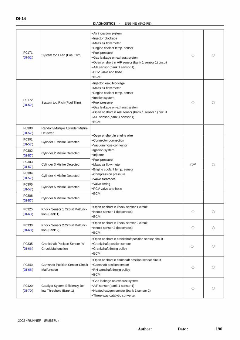
P0171
(DI-52 )System too Lean (Fuel Trim)
Air induction system
Injector blockage
Mass air flow meter
Engine coolant temp. sensor
Fuel pressure
Gas leakage on exhaust system
Open or short in A/F sensor (bank 1 sensor 1) circuit
A/F sensor (bank 1 sensor 1)
PCV valve and hose
ECM
P0172
(DI-52 )System too Rich (Fuel Trim)
Injector leak, blockage
Mass air flow meter
Engine coolant temp. sensor
Ignition system
Fuel pressure
Gas leakage on exhaust system
Open or short in A/F sensor (bank 1 sensor 1) circuit
A/F sensor (bank 1 sensor 1)
ECM
P0300
(DI-57 )
Random/Multiple Cylinder Misfire
DetectedOpen or short in engine wire
P0301
(DI-57 )Cylinder 1 Misfire Detected
Open or short in engine wire
Connector connection
Vacuum hose connector
P0302
(DI-57 )Cylinder 2 Misfire Detected
Vacuum hose connector
Ignition system
Injector
P0303
(DI-57 )Cylinder 3 Misfire Detected
Fuel pressure
Mass air flow meter
Engine coolant temp sensor
*2
P0304
(DI-57 )Cylinder 4 Misfire Detected
Engine coolant temp. sensor
Compression pressure
Valve clearance
P0305
(DI-57 )Cylinder 5 Misfire Detected
Valve clearance
Valve timing
PCV valve and hose
P0306
(DI-57 )Cylinder 6 Misfire Detected
ECM
P0325
(DI-63 )
Knock Sensor 1 Circuit Malfunc-
tion (Bank 1)
Open or short in knock sensor 1 circuit
Knock sensor 1 (looseness)
ECM
P0330
(DI-63 )
Knock Sensor 2 Circuit Malfunc-
tion (Bank 2)
Open or short in knock sensor 2 circuit
Knock sensor 2 (looseness)
ECM
P0335
(DI-66 )
Crankshaft Position Sensor ”A”
Circuit Malfunction
Open or short in crankshaft position sensor circuit
Crankshaft position sensor
Crankshaft timing pulley
ECM
P0340
(DI-68 )
Camshaft Position Sensor Circuit
Malfunction
Open or short in camshaft position sensor circuit
Camshaft position sensor
RH camshaft timing pulley
ECM
P0420
(DI-70 )
Catalyst System Efficiency Be-
low Threshold (Bank 1)
Gas leakage on exhaust system
A/F sensor (bank 1 sensor 1)
Heated oxygen sensor (bank 1 sensor 2)
Three-way catalytic converter

-DIAGNOSTICS ENGINE (5VZ-FE)DI-15
191Author: Date:
2002 4RUNNER (RM887U)
P0440
(DI-73 )
Evaporative Emission Control
System Malfunction
Hose or tube cracked, holed, damaged or loose seal ((3) in
Fig. 1)
Fuel tank cap incorrectly installed
Fuel tank cap cracked or damaged
Vacuum hose cracked, holed, blocked, damaged or discon-
nected ((1) or (2) in Fig. 1)
Fuel tank cracked, holed or damaged
Charcoal canister cracked, holed or damaged
Open or short in vapor pressure sensor circuit
Vapor pressure sensor
ECM
P0441
(DI-83 )
Evaporative Emission Control
System Incorrect Purge Flow
Vacuum hose cracks, holed, damaged or disconnected ((1),
(4), (5), (6) and (7) in Fig. 1)
Open or short in vapor pressure sensor circuit
Vapor pressure sensor
Open or short in VSV circuit for EVAP
VSV for EVAP
Open or short in VSV circuit for vapor pressure sensor
VSV for vapor pressure sensor
Charcoal canister cracks, holed or damaged
ECM
P0442
(DI-73 )
Evaporative Emission Control
System Leak detected (Small
Leak)
Same as DTC No. P0440
P0446
(DI-83 )
Evaporative Emission Control
System Vent Control Malfunction
Vacuum hose cracks, holed, damaged or disconnected ((1),
(4), (5), (6) and (7) in Fig. 1)
Open or short in vapor pressure sensor circuit
Vapor pressure sensor
Open or short in VSV circuit for EVAP
VSV for EVAP
Open or short in VSV circuit for vapor pressure sensor
VSV for vapor pressure sensor
Charcoal canister cracks, holed or damaged
ECM
P0450
(DI-101 )
Evaporative Emission Control
System Pressure Sensor Mal-
function Open or short in vapor pressure sensor circuit
V
P0451
(DI-101 )
Evaporative Emission Control
System Pressure Sensor Range/
Performance
Vapor pressure sensor
ECM
P0500
(DI-103 )
Vehicle Speed Sensor Malfunc-
tion
Speedometer cable
Open or short in speed signal circuit
ECM
P0505
(DI-105 )Idle Control System Malfunction
Air induction system
Electric throttle control system
PCV valve and hose
*1: MIL lights up.*2: MIL lights up or blinking.MANUFACTURER CONTROLLED
DTC No.
(See page)Detection Item Trouble Area MIL* Memory
P1120
(DI-107 )
Accelerator Pedal Position Sen-
sor Circuit Malfunction
Open or short in accelerator pedal position sensor circuit
Accelerator pedal position sensor
ECM

DI-16-DIAGNOSTICS ENGINE (5VZ-FE)
192Author: Date:
2002 4RUNNER (RM887U)
P1121
(DI-112)
Accelerator Pedal Position Sen-
sor Range/Performance ProblemAccelerator pedal position sensor
P1125
(DI-113)
Throttle Control Motor Circuit
Malfunction
Open or short in throttle control motor circuit
Throttle control motor
ECM
P1126
(DI-115)
Magnetic Clutch Circuit Malfunc-
tion
Open or short in magnetic clutch circuit
Magnetic clutch
ECM
P1127
(DI-118)
ETCS Actuator Power Source
Circuit Malfunction
Open in ETCS power source circuit
ECM
P1128
(DI-121 )
Throttle Control Motor Lock Mal-
function
Throttle control motor
Throttle body assembly
P1129
(DI-121 )
Electric Throttle Control System
Malfunction
Electric throttle control system
ECM
P1130
(DI-122 )
A/F Sensor Circuit Range/Perfor-
mance Malfunction (Bank 1 Sen-
sor 1)
Open or short in A/F sensor circuit
A/F sensor
Air induction system
Fuel pressure
Injector
ECM
P1133
(DI-126 )
A/F Sensor Circuit Response
Malfunction (Bank 1 Sensor 1)
Open or short in A/F sensor circuit
A/F sensor
Air induction system
Fuel pressure
Injector
ECM
P1135
(DI-130 )
A/F Sensor Heater Circuit Mal-
function (Bank1 Sensor 1)
Open or short in heater circuit of A/F sensor
A/F sensor heater
ECM
P1300
(DI-132 )Igniter Circuit Malfunction
Ignition system
Open or short in IGF and IGT circuits from igniter to ECM
Igniter
Ignition coil
ECM
P1335
(DI-137 )
Crankshaft Position Sensor Cir-
cuit Malfunction (During engine
running)
Open or short in crankshaft position sensor circuit
Crankshaft position sensor
Signal plate
ECM
-
P1520
(DI-138 )
Stop Light Switch Signal Mal-
function
Short in stop light switch signal circuit
Stop light switch
ECM
P1600
(DI-141 )ECM BATT Malfunction
Open in back up power source circuit
ECM
P1633
(DI-143 )ECM Malfunction (ETCS Circuit) ECM
P1780
(DI-144 )
Park/Neutral Position Switch
Malfunction (Only for A/T)
Short in park/neutral position switch circuit
Park/neutral position switch
ECM
*: ... MIL lights up. - ... MIL does not light up.

DI0RN-11
A15328
ECM
DLC3 Ignition Switch
Engine CoolantTemp. Sensor
Igniter
Mass Air FlowMeter
Throttle PositionSensor
Vapor Pressure Sensor
Combination Meter(Speedometer)
Heated Oxygen Sensor(Bank 1 Sensor 2)
Fuel Pump
Park/Neutral PositionSwitch
A/F Sensor (Bank 1 Sensor 1)*1
Heated Oxygen Sensor(Bank 1 Sensor 1)*2
VSV for EVAP
VSV for CCV
Injector
Crankshaft Position Sensor
Knock Sensor 1
Camshaft PositionSensor
DLC1
Knock Sensor 2
IgnitionCoil
Injector
*1: California Spec.*2: Except California Spec.
VSV for Pressure SwitchingValve
Throttle ControlMotor
Accelerator PedalPosition Sensor
-DIAGNOSTICS ENGINE (5VZ-FE)DI-17
193Author: Date:
2002 4RUNNER (RM887U)
PARTS LOCATION

DI4DE-03
A02016
E11 E14E12
31 30 29 28 27
17192021
2223242526
11121314
123456789
10
ECM Terminals
151618
1234567
8910111213141516
18
8
2021222324 1719
123456
79101112
1314151617
123456789
1012 1113141516171819
202123 222426 252728
1234567
89101112131415
16171819202122
E10E9
DI-18-DIAGNOSTICS ENGINE (5VZ-FE)
194Author: Date:
2002 4RUNNER (RM887U)
TERMINALS OF ECM
Symbols (Terminal No.) Wiring Color Condition STD Voltage (V)
BATT (E14-16) - E1 (E10-17) L-R ↔ BR Always 9 - 14
+B (E14-1) - E1 (E10-17) W-L ↔ BR IG switch ON 9 - 14
VC (E9-25) - E2 (E9-11) G-B ↔ L-B IG switch ON 4.5 - 5.5
VTA (E9 15) E2 (E9 11) B Y L BIG switch ON, Throttle valve fully closed 0.3 - 1.0
VTA (E9-15) - E2 (E9-11) B-Y ↔ L-BIG switch ON, Throttle valve fully open 2.7 - 5.2
VTA2 (E11 4) E2 (E9 11) G Y L BIG switch ON, Throttle valve fully closed 0.3 - 1.0
VTA2 (E11-4) - E2 (E9-11) G-Y ↔ L-BIG switch ON, Throttle valve fully open 2.7 - 5.2
VG (E9-12) - E2G (E9-10) R-W ↔ B-W Idling, A/C switch OFF 1.1 - 1.5
NE+ (E10-12) - NE- (E10-21) L ↔ G IdlingPulse generation
(See page DI-66 )
G2 (E10-13) - NE- (E10-21) R ↔ G IdlingPulse generation
(See page DI-66 )
THA (E9-13) - E2 (E9-11) Y-G ↔ L-B Idling, Intake air temp. 20°C (68°F) 0.5 - 3.4
THW (E9-18) - E2 (E9-11) G ↔ L-B Idling, Engine coolant temp. 80°C (176°F) 0.2 - 1.0
STA (E14-7) - E1 (E10-17) B-W ↔ BR Cranking 6.0 or more
#10 (E10-6) - E01 (E9-4)
#20 (E10-5) - E01 (E9-4)
#30 (E10 4) E01 (E9 4)
R ↔ W-B
W ↔ W-B
G W B
IG switch ON 9 - 14
#30 (E10-4) - E01 (E9-4)
#40 (E10-3) - E01 (E9-4)
#50 (E10-1) - E01 (E9-4)
#60 (E10-8) - E01 (E9-4)
G ↔ W-B
R-B ↔ W-B
L ↔ W-B
Y ↔ W-B
IdlingPulse generation
(See page DI-57 )
IGT1 (E10-11) - E1 (E10-17) B-L ↔ BR
IGT2 (E10-10) - E1 (E10-17) L-Y ↔ BR IdlingPulse generation
(See page DI 132 )IGT3 (E10-9) - E1 (E10-17) G-W ↔ BR
Idling(See page DI-132 )
IG switch ON 4.5 - 5.5
IGF (E10-2) - E1 (E10-17) B-Y ↔ BRIdling
Pulse generation
(See page DI-132 )
FC (E14 22) E01 (E9 4) G Y W BIG switch ON 9 - 14
FC (E14-22) - E01 (E9-4) G-Y ↔ W-BIdling 0 - 3.0
EVP1 (E10-14) - E01 (E9-4) W-G ↔ W-B IG switch ON 9 - 14
CCV (E10-19) - E01 (E9-4) L-B ↔ W-B IG switch ON 9 - 14
OX2B (E9-27) - E1 (E10-17) B ↔ BR Maintain engine speed at 2,500 rpm for 3 min. after warming upPulse generation
(See page DI-70 )
HT2B (E9 29) E03 (E9 7) G Y W BIdling Below 3.0
HT2B (E9-29) - E03 (E9-7) G-Y ↔ W-BIG switch ON 9 - 14
KNK1 (E9-23) - E1 (E10-17) B ↔ BRIdli
Pulse generation
KNK2 (E9-22) - E1 (E10-17) GR ↔ BRIdling
Pulse generation
(See page DI-63 )

-DIAGNOSTICS ENGINE (5VZ-FE)DI-19
195Author: Date:
2002 4RUNNER (RM887U)
NSW (E12 3) E1 (E10 17) B BRIG switch ON, Other shift position in P, N 9 - 14
NSW (E12-3) - E1 (E10-17) B ↔ BRIG switch ON, Shift position in P, N 0
TBP (E10-20) - E01 (E9-4) R-Y ↔ W-BIG switch ON, Disconnect vacuum hose from vapor pressure
sensor9 - 14
PTNK (E9 24) E2 (E9 11) Y L BIG switch ON 2.9 - 3.7
PTNK (E9-24) - E2 (E9-11) Y ↔ L-BIG switch ON, Apply vacuum 4.0 kPa (30 mmHg, 1.18 in.Hg) 0.5 or less
SIL (E14-14) - E1 (E10-17) W ↔ BR During transmission Pulse generation
STP (E14 20) E1 (E10 17) G W BRIG switch ON, Brake pedal depressed 7.5 - 14
STP (E14-20) - E1 (E10-17) G-W ↔ BRIG switch ON, Brake pedal released Below 1.5
AF1+ (E9-14) - E1 (E10-17) W ↔ BR IG switch ON 3.0 - 3.6
AF1- (E9-26) - E1 (E10-17) B ↔ BR IG switch ON 2.7 - 3.3
HAFF (E9 21) E04 (E9 8) L W BIdling Below 3.0
HAFF (E9-21) - E04 (E9-8) L ↔ W-BIG switch ON 9 - 14
KSW (E14 11) E1 (E10 17) Y R BRAt time of inserting key Below 1.5
KSW (E14-11) - E1 (E10-17) Y-R ↔ BRIn condition without key inserted 4 - 5
CODE (E14-5) - E1 (E10-17) GR-R ↔ BR At time of inserting key Pulse generation
IGSW (E14-15) - E1 (E10-17) B-L ↔ BR IG switch ON 9 - 14
TXCT (E14-19) - E1 (E10-17) P-B ↔ BR At time of inserting key Pulse generation
IMLD (E14-12) - E1 (E10-17) L ↔ BR In condition without key inserted Pulse generation
MREL (E14-4) - E1 (E10-17) GR-B ↔ BR IG switch ON 9 - 14

DI0RP-10
DI-20-DIAGNOSTICS ENGINE (5VZ-FE)
196Author: Date:
2002 4RUNNER (RM887U)
PROBLEM SYMPTOMS TABLESymptom Suspect Area See page
Engine does not crank (Does not start)10.Starter
11.Starter relay
ST-15
ST-17
No initial combustion (Does not start)
1. ECM power source circuit
2. Fuel pump control circuit
3. ECM
DI-148
DI-151
IN-28
No complete combustion (Does not start) 1. Fuel pump control circuit DI-151
Engine cranks normally (Difficult to start)
1. Starter signal circuit
2. Fuel pump control circuit
3. Compression
DI-145
DI-151
EM-3
Cold engine (Difficult to start)1. Starter signal circuit
2. Fuel pump control circuit
DI-145
DI-151
Hot engine (Difficult to start)1. Starter signal circuit
2. Fuel pump control circuit
DI-145
DI-151
High engine idle speed (Poor idling)
1. A/C signal circuit (Compressor circuit)
2. ECM power source circuit
DI-632
AC-89
DI-148
Low engine idle speed (Poor idling)
1. A/C signal circuit (Compressor circuit)
2. Fuel pump control circuit
DI-632
AC-89
DI-151
Rough idling (Poor idling)1. Compression
2. Fuel pump control circuit
EM-3
DI-151
Hunting (Poor idling)1. ECM power source circuit
2. Fuel pump control circuit
DI-148
DI-151
Hesitation/Poor acceleration (Poor driveability)1. Fuel pump control circuit
2. A/T faulty
DI-151
DI-175
Surging (Poor driveability) 1. Fuel pump control circuit DI-151
Soon after starting (Engine stall) 1. Fuel pump control circuit DI-151
During A/C operation (Engine stall)
1. A/C signal circuit (Compressor circuit)
2. ECM
DI-632
AC-89
IN-28

DI0RQ-16
FI6929FI6972 A00098
A B
TemperatureSensor
+B
Power Transistor
Platinum Hot Wire
Output Voltage
TemperatureSensor
Platinum Hot Wire
-DIAGNOSTICS ENGINE (5VZ-FE)DI-21
197Author: Date:
2002 4RUNNER (RM887U)
CIRCUIT INSPECTION
DTC P0100 Mass Air Flow Circuit Malfunction
CIRCUIT DESCRIPTIONThe mass air flow meter uses a platinum hot wire. The hot wire air flow meter consists of a platinum hot wire,temperature sensor and a control circuit installed in a plastic housing. The hot wire air flow meter works onthe principle that the hot wire and temperature sensor located in the intake air bypass of the housing detectany changes in the intake air temperature. The hot wire is maintained at the set temperature by controllingthe current flow through the hot wire. This current flow is then measured as the output voltage of the massair flow meter.The circuit is constructed so that the platinum hot wire and temperature sensor provide a bridge circuit, withthe power transistor controlled so that the potential of A and B remains equal to maintain the set temperature.
DTC No. DTC Detecting Condition Trouble Area
P0100
Open or short in mass air flow meter circuit with engine speed
4,000 rpm or less Open or short in mass air flow meter circuit
M i fl tP0100Open or short in mass air flow meter circuit with engine speed
4,000 rpm or more (2 trip detection logic)
Mass air flow meter
ECM
HINT:After confirming DTC P0100, use the OBD II scan tool or TOYOTA hand-held tester to confirm the massair flow ratio from the CURRENT DATA.
Mass Air Flow Value (gm/sec.) Malfunction
Approx. 0Mass air flow meter power source circuit open
VG circuit open or short
11.0 - 25.1 (idling after warmed up) E3 circuit open

A18086
L-R
Engine Room R/B
D
Engine Room R/B
EF
I
W
214
2
23
2
5
1
J2
J1
A
A
J/C
W-L
3
1 B-W
+B
E9VG
E2G
EFI Relay
ECM
E9
E14
M1Mass Air Flow Meter
2
W-L
W-B
2
2
2
1
1
10
12
13
J7
J7
R-W
D
W-LIG1
IG1
W-L
W-B
2
GR-B GR-B
EBBattery
II4
J/C
4MREL
DI-22-DIAGNOSTICS ENGINE (5VZ-FE)
198Author: Date:
2002 4RUNNER (RM887U)
WIRING DIAGRAM
INSPECTION PROCEDUREHINT:Read freeze frame data using TOYOTA hand-held tester or OBD II scan tool. Because freeze frame recordsthe engine conditions when the malfunction is detected. When troubleshooting, it is useful for determiningwhether the vehicle was running or stopped, the engine was warmed up or not, the air-fuel ratio was leanor rich, etc. at the time of the malfunction.
1 Connect OBD II scan tool or TOYOTA hand-held tester, and read value of massair flow rate.
PREPARATION:(a) Connect the OBD II scan tool or TOYOTA hand-held tester to the DLC3.(b) Turn the ignition switch ON and push the OBD II scan tool or TOYOTA hand-held tester main switch
ON.(c) Start the engine.CHECK:Read the mass air flow rate on the OBD II scan tool or TOYOTA hand-held tester.RESULT:
Type I Type II
Mass Air Flow Rata (gm/sec.) Approx. 0 11.0 ∼ 25.1 (idling after warmed up)
Type I Go to step 2.
Type II Go to step 5.

BE6653
P24310 A00099
ON
1
(+)
(-)
A15296
VG
(+) (-)
-DIAGNOSTICS ENGINE (5VZ-FE)DI-23
199Author: Date:
2002 4RUNNER (RM887U)
2 Check voltage of mass air flow meter power source.
PREPARATION:(a) Disconnect the mass air flow meter connector.(b) Turn the ignition switch ON.CHECK:Measure the voltage between terminal 1 of the mass air flowmeter connector and body ground.OK:
Voltage: 9 - 14 V
NG Check for open in harness and connector be-tween EFI main relay (Marking: EFI) and massair flow meter (See page IN-28 ).
OK
3 Check voltage between terminal VG of ECM connector and body ground.
PREPARATION:(a) Remove the glove compartment (See page SF-54 ).(b) Start the engine.CHECK:Measure the voltage between terminal VG of the ECM connec-tor and body ground while the engine is idling.OK:
Voltage: 1.1 - 1.5 V (P or N position and A/C switch OFF)
OK Check and replace ECM (See page IN-28 ).
NG
4 Check for open and short in harness and connector between mass air flow meterand ECM (See page IN-28 ).
NG Repair or replace harness or connector.
OK

A15297
E2G
DI-24-DIAGNOSTICS ENGINE (5VZ-FE)
200Author: Date:
2002 4RUNNER (RM887U)
Replace mass air flow meter.
5 Check continuity between terminal E2G of ECM connector and body ground.
PREPARATION:Remove the glove compartment (See page SF-54 ).CHECK:Check the continuity between terminal E2G of the ECM con-nector and body ground.OK:
Continuity (1 Ω or less)
NG Check and replace ECM (See page IN-28 ).
OK
6 Check for open in harness and connector between mass air flow meter and ECM(See page IN-28 ).
NG Repair or replace harness or connector.
OK
Replace mass air flow meter.

-DIAGNOSTICS ENGINE (5VZ-FE)DI-25
201Author: Date:
2002 4RUNNER (RM887U)
DTC P0101 Mass Air Flow Circuit Range/PerformanceProblem
CIRCUIT DESCRIPTIONRefer to DTC P0100 on page DI-21 .
DTC No. DTC Detecting Condition Trouble Area
P0101
After engine is warmed up, conditions (a) and (b) continue with
engine speed 900 rpm or less: (2 trip detection logic)
(a) Throttle valve fully closed
(b) Mass air flow meter output 2.2 VM i fl tP0101
Conditions (a) and (b) continue with engine speed 1,500 rpm or
more: (2 trip detection logic)
(a) VTA 0.63 V
(b) Mass air flow meter output 1.06 V
Mass air flow meter
INSPECTION PROCEDUREHINT:Read freeze frame data using TOYOTA hand-held tester or OBD II scan tool. Because freeze frame recordsthe engine conditions when the malfunction is detected. When troubleshooting, it is useful for determiningwhether the vehicle was running or stopped, the engine was warmed up or not, the air-fuel ratio was leanor rich, etc. at the time of the malfunction.
1 Are there any other codes (besides DTC P0101) being output?
NO Replace mass air flow meter.
YES
Go to relevant DTC chart (See page DI-13 ).
DI0RR-09

FI4741
Fig. 1
Acceptable
Res
ista
nce
kΩ
Temp.°C (°F)
30
20
10
5
3
2
1
0.50.3
0.2
0.1
200- 20 40 60 80 100(68)(32)(- 4) (104)(140) (176) (212)
DI-26-DIAGNOSTICS ENGINE (5VZ-FE)
202Author: Date:
2002 4RUNNER (RM887U)
DTC P0110 Intake Air Temp. Circuit Malfunction
CIRCUIT DESCRIPTIONThe intake air temperature sensor is built into the mass air flowmeter and senses the intake air temperature.A thermistor built in the sensor changes the resistance valueaccording to the intake air temperature.The lower the intake air temperature, the greater the thermistorresistance value, and the higher the intake air temperature, thelower the thermistor resistance value (See Fig. 1).The intake air temperature sensor is connected to the ECM(See below ). The 5 V power source voltage in the ECM is ap-plied to the intake air temp. sensor from terminal THA via resis-tor R.That is, resistor R and the intake air temperature sensor areconnected in series. When the resistance value of the intake airtemperature sensor changes in accordance with changes in theintake air temperature, the potential at terminal THA alsochanges. Based on this signal, the ECM increases the fuel in-jection volume to improve driveability during cold engine opera-tion. If the ECM detects the DTC P0110, it operates the fail safefunction in which the intake air temperature is assumed to be20°C (68°F).
DTC No. DTC Detecting Condition Trouble Area
P0110 Open or short in intake air temp. sensor circuit
Open or short in intake air temp. sensor circuit
Intake air temp. sensor (built into mass air flow meter)
ECM
HINT:After confirming DTC P0110, use the OBD II scan tool or TOYOTA hand-held tester to confirm the intakeair temperature from the CURRENT DATA.
Temperature Displayed Malfunction
-40 °C (-40°F) Open circuit
140°C (284°F) or more Short circuit
DI0RS-16

A10940
M1Intake Air Temp. Sensor (Built into Mass Air Flow Meter)
4
5
Y-G
L-B
E9THA
ECM
E1
R
E9
11E2
5 V
13
-DIAGNOSTICS ENGINE (5VZ-FE)DI-27
203Author: Date:
2002 4RUNNER (RM887U)
WIRING DIAGRAM
INSPECTION PROCEDUREHINT: If DTCs P0110, P0115 and P0120 are output simultaneously, E2 (sensor ground) may be open. Read freeze frame data using TOYOTA hand-held tester or OBD II scan tool. Because freeze frame
records the engine conditions when the malfunction is detected. When troubleshooting, it is useful fordetermining whether the vehicle was running or stopped, the engine was warmed up or not, the air-fuelratio was lean or rich, etc. at the time of the malfunction.
1 Connector OBD II scan tool or TOYOTA hand-held tester, and read value of in-take air temperature
PREPARATION:(a) Connect the OBD II scan tool or TOYOTA hand-held tester to the DLC3.(b) Turn the ignition switch ON and push the OBD II scan tool or TOYOTA hand-held tester main switch
ON.CHECK:Read the temperature value on the OBD II scan tool or TOYOTA hand-held tester.OK:
Same as actual intake air temperature.HINT: If there is open circuit, OBD II scan tool or TOYOTA hand-held tester indicates -40°C (−40°F).
If there is short circuit, OBD II scan tool or TOYOTA hand-held tester indicates 140°C (284°F) or more.
NG -40 °C (-40°F) ... Go to step 2.140°C (284°F) or more ... Go to step 4.
OK
Check for intermittent problems (See page DI-3 ).

A12232BE6653
A12237
ON
Intake Air Temp. Sensor
ECM
5VTHA
E2
4
5
R
A15298
Intake Air Temp. Sensor
ON
E2THA
ECM
5VTHA
E2
4
5
R
DI-28-DIAGNOSTICS ENGINE (5VZ-FE)
204Author: Date:
2002 4RUNNER (RM887U)
2 Check for open in harness or ECM.
PREPARATION:(a) Disconnect the mass air flow meter connector.(b) Connect the sensor wire harness terminals together.(c) Turn the ignition switch ON.CHECK:Read the temperature value on the OBD II scan tool or TOYO-TA hand-held tester.OK:
Temperature value: 140 °C (284°F) or more
OK Confirm good connection at sensor. If OK, re-place mass air flow meter.
NG
3 Check for open in harness or ECM.
PREPARATION:(a) Remove the glove compartment (See page SF-54 ).(b) Connect between terminals THA and E2 of the ECM con-
nector.HINT:The mass air flow meter connector is disconnected. Beforechecking, do a visual and contact pressure check for the ECMconnector (See page IN-28 ).CHECK:Read the temperature value on the OBD II scan tool or TOYO-TA hand-held tester.OK:
Temperature value: 140 °C (284°F) or more
OK Open in harness between terminals E2 andTHA, repair or replace harness.
NG
Confirm good connection at ECM. If OK,check and replace ECM (See page IN-28 ).

A12234BE6653
A12238
ON
Intake Air Temp. Sensor
ECM
5VTHA
E2
4
5
R
A15299
ON
Intake Air Temp. Sensor
E9 Connector
ECM
5VTHA
E2
4
5
R
-DIAGNOSTICS ENGINE (5VZ-FE)DI-29
205Author: Date:
2002 4RUNNER (RM887U)
4 Check for short in harness and ECM.
PREPARATION:(a) Disconnect the mass air flow meter connector.(b) Turn the ignition switch ON.CHECK:Read the temperature value on the OBD II scan tool or TOYO-TA hand-held tester.OK:
Temperature value: -40 °C (-40°F)
OK Replace mass air flow meter.
NG
5 Check for short in harness or ECM.
PREPARATION:(a) Remove the glove compartment (See page SF-54 ).(b) Disconnect the E9 connector from the ECM.HINT:The mass air flow meter connector is disconnected.(c) Turn the ignition switch ON.CHECK:Read the temperature value on the OBD II scan tool or TOYO-TA hand-held tester.OK:
Temperature value: -40 °C (-40°F)
OK Repair or replace harness or connector.
NG
Check and replace ECM (See page IN-28 ).

A12242
Engine Coolant Temp. Sensor
2
1
G-Y
L-B
E9 THW
ECM
E1
R
E9
11E2
5 V
18G
BR-B
2EC1
EC11
DI-30-DIAGNOSTICS ENGINE (5VZ-FE)
206Author: Date:
2002 4RUNNER (RM887U)
DTC P0115 Engine Coolant Temp. Circuit Malfunction
CIRCUIT DESCRIPTIONA thermistor built into the engine coolant temp. sensor changes the resistance value according to the enginecoolant temperature.The structure of the sensor and connection to the ECM is the same as in the DTC P0110 shown on pageDI-26
DTC No. DTC Detecting Condition Trouble Area
P0115 Open or short in engine coolant temp. sensor circuit
Open or short in engine coolant temp. sensor circuit
Engine coolant temp. sensor
ECM
HINT:After confirming DTC P0115, use the OBD II scan tool or TOYOTA hand-held tester to confirm the enginecoolant temperature from the CURRENT DATA.
Temperature Displayed Malfunction
-40 °C (-40°F) Open circuit
140° (284°F) or more Short circuit
WIRING DIAGRAM
INSPECTION PROCEDUREHINT: If DTCs P0110, P0115 and P0120 are output simultaneously, E2 (sensor ground) may be open. Read freeze frame data using TOYOTA hand-held tester or OBDII scan tool. Because freeze frame
records the engine conditions when the malfunction is detected. When troubleshooting, it is useful fordetermining whether the vehicle was running or stopped, the engine was warmed up or not, the air-fuelratio was lean or rich, etc. at the time of the malfunction.
DI0RT-11

A12232BE6653
A12237
THW
ECM
R5 VEngine Coolant Temp.
Sensor
ON
E2
2
1
-DIAGNOSTICS ENGINE (5VZ-FE)DI-31
207Author: Date:
2002 4RUNNER (RM887U)
1 Connect OBD II scan tool or TOYOTA hand-held tester, and read value of enginecoolant temperature.
PREPARATION:(a) Connect the OBD II scan tool or TOYOTA hand-held tester to the DLC3.(b) Turn the ignition switch ON and push the OBD II scan tool or TOYOTA hand-held tester main switch
ON.CHECK:Read the temperature value on the OBD II scan tool or TOYOTA hand-held tester.OK:
Same as actual engine coolant temperature.HINT: If there is open circuit, OBD II scan tool or TOYOTA hand-held tester indicates -40°C (-40°F).
If there is open circuit, OBD II scan tool or TOYOTA hand−held tester indicates 140°C (284°F) or more.
NG -40 °C (-40°F) ... Go to step 2.140°C (284°F) or more ... Go to step 4.
OK
Check for intermittent problems (See pageDI-3 ).
2 Check for open in harness or ECM.
PREPARATION:(a) Disconnect the engine coolant temp. sensor connector.(b) Connect the sensor wire harness terminals together.(c) Turn the ignition switch ON.CHECK:Read the temperature value on the OBD II scan tool or TOYO-TA hand-held tester.OK:
Temperature value: 140 °C (284°F) or more
OK Confirm good connection at sensor. If OK, re-place engine coolant temperature sensor.
NG

A15300
THW E2
THW
ECM
R
5 V
Engine Coolant Temp.Sensor
ON
E2
2
1
A12234BE6653
A12238
THW
ECM
R5 V
Engine Coolant Temp.Sensor
ON
E2
2
1
DI-32-DIAGNOSTICS ENGINE (5VZ-FE)
208Author: Date:
2002 4RUNNER (RM887U)
3 Check for open in harness or ECM.
PREPARATION:(a) Remove the glove compartment (See page SF-54 ).(b) Connect between terminals THW and E2 of the ECM con-
nector.HINT:The engine coolant temperature sensor connector is discon-nected. Before checking, do a visual and contact pressurecheck for the ECM connector (See page IN-28 ).(c) Turn the ignition switch ON.CHECK:Read the temperature value on the OBD II scan tool or TOYO-TA hand-held tester.OK:
Temperature value: 140 °C (284°F) or more
OK Open in harness between terminals E2 andTHW, repair or replace harness.
NG
Confirm good connection at ECM. If OK,check and replace ECM (See page IN-28 ).
4 Check for short in harness and ECM.
PREPARATION:(a) Disconnect the engine coolant temperature sensor con-
nector.(b) Turn the ignition switch ON.CHECK:Read the temperature value on the OBD II scan tool or TOYO-TA hand-held tester.OK:
Temperature value: -40 °C (-40°F)
OK Replace engine coolant temperature sensor(See page SF-43 ).
NG

A15299
E9 Connector
THW
ECM
R
5 V
Engine Coolant Temp. Sensor
ON
E2
2
1
-DIAGNOSTICS ENGINE (5VZ-FE)DI-33
209Author: Date:
2002 4RUNNER (RM887U)
5 Check for short in harness or ECM.
PREPARATION:(a) Remove the glove compartment (See page SF-54 ).(b) Disconnect the E9 connector from the ECM.HINT:The engine coolant temperature sensor connector is discon-nected.(c) Turn the ignition switch ON.CHECK:Read the temperature value on the OBD II scan tool or TOYO-TA hand-held tester.OK:
Temperature value: -40 °C (-40°F)
OK Repair or replace harness or connector.
NG
Check and replace ECM (See page IN-28 ).

DI-34-DIAGNOSTICS ENGINE (5VZ-FE)
210Author: Date:
2002 4RUNNER (RM887U)
DTC P0116 Engine Coolant Temp. Circuit Range/Perfor-mance Problem
CIRCUIT DESCRIPTIONRefer to DTC P0115 on page DI−30.
DTC No. DTC Detecting Condition Trouble Area
If THW -7°C (19.4°F) at engine start, 20 min. or more after
starting engine, engine coolant temp. sensor value is 15°C
(59°F) or less (2 trip detection logic)
P0116
If THW -7°C (19.4°F) and 10°C (50°F) at engine start, 5
min. or more after starting engine, engine coolant temp. sensor
value is 17°C (62.6°F) or less (2 trip detection logic)
If THW 10°C (50°F) at engine start, 2 min. or more after
starting engine, engine coolant temp. sensor value is 35°C
(95°F) or less. (2 trip detection logic)
Cooling system
Engine coolant temp. sensor
When THW 35°C (95°F) and < 60°C (140°F), and THA
-6.7 °C (19.9°F), and when starting engine, conditions (a) and
(b) continue: (2 trip detection logic)
(a) Vehicle speed is changing (Not stable)
(b) THW change is lower than 3°C (5.4°F) from THW since
when starting engine
INSPECTION PROCEDUREHINT: If DTCs P0115 and P0116 are output simultaneously, engine coolant temp. sensor circuit may be open.
Perform troubleshooting of DTC P0115 first. Read freeze frame data using TOYOTA hand-held tester or OBD II scan tool. Because freeze frame
records the engine conditions when the malfunction is detected. When troubleshooting, it is useful fordetermining whether the vehicle was running or stopped, the engine was warmed up or not, the air-fuelratio was lean or rich, etc. at the time of the malfunction.
1 Are there any other codes (besides DTC P0116) being output?
YES Go to relevant DTC chart (See page DI-13 ).
NO
DI0RU-11

-DIAGNOSTICS ENGINE (5VZ-FE)DI-35
211Author: Date:
2002 4RUNNER (RM887U)
2 Check thermostat (See page CO-1 1).
NG Replace thermostat.
OK
Replace engine coolant temperature sensor.

A02396A02395 A02624
Thr
ottle
Pos
ition
Sen
sor
Out
put V
olta
ge (
V)
0
1.5
Throttle Valve Opening Angle (deg)
70 125
VTA
VTA25
VTA2 VTAE2 VC
Movable Range
Usable Range
Usable Range*1 *2
*1
*2
Movable Range
UsableRange
*2
*1
Accelerator pedalreleased (15°)
Accelerator pedaldepressed (about100°)
*2:
*1:
Throttle valve opening position expressed as percentage and voltage
Accelerator pedal released Accelerator pedal depressed
THROTTLE POS THROTTLE POS #2 THROTTLE POS THROTTLE POS #2
0 %
0 %
100 %
8 - 20 %
0 V
2.0 - 2.9 V
0 V
5 V
0 %
0 %
100 %
0 V
4.7 - 5.1 V
0 V
5 V
Trouble area
VC circuit open
VTA circuit open or ground short
E2 circuit open
64 - 96 % VTA2 circuit open or ground short
DI-36-DIAGNOSTICS ENGINE (5VZ-FE)
212Author: Date:
2002 4RUNNER (RM887U)
DTC P0120 Throttle/Pedal Position Sensor/Switch ”A”Circuit Malfunction
CIRCUIT DESCRIPTIONThrottle position sensor is mounted on the throttle body and it have the 2 sensors to detect the throttle open-ing angle and the malfunction of the throttle position sensor’s own.The voltage applied to the terminals VTA and VTA2 of the ECM changes between 0 V and 5 V in proportionto the opening angle of the throttle valve.The ECM judges the current opening angle of the throttle valve from these signals input from terminals VTAand VTA2, and the ECM controls the throttle motor to make the throttle valve angle properly in response todriving condition.If this DTC is stored, the ECM shuts down the power for the throttle motor and the electromagnetic clutch,and the throttle valve is fully closed by the return spring.However, the opening angle of the throttle valve can be controlled by the accelerator pedal through thethrottle cable.
DTC No. DTC Detecting Condition Trouble Area
P0120
Condition (a), (b), (c), (d) or (e) continues for 2.0 seconds:
(a) VTA 0.2 V
(b) VTA2 0.5 V
(c) VTA 4.8 V
(d) When VTA 0.2 V and 2.0 V, and VTA2 4.97 V
(e) VTA-VTA2 0.02 V, or VTA2-VTA 0.02V
Open or short in throttle position sensor circuit
Throttle position sensor
ECM
Condition (a) continues for 0.4 seconds:
(a) VTA 0.2 V and VTA2 0.5 V
HINT:After confirming DTC P0120, use the OBD II scan tool or TOYOTA hand-held tester to confirm the throttlevalve opening percentage and closed throttle position switch condition.
DI1LH-14

A03843
T2Throttle Position Sensor ECM
2
1
3
4
B-Y
G-B
G-Y
L-B
15
25
4
11
VTA
VC
VTA2
E2
E9
E9
E11
E9
E1
FI7052
-DIAGNOSTICS ENGINE (5VZ-FE)DI-37
213Author: Date:
2002 4RUNNER (RM887U)
WIRING DIAGRAM
INSPECTION PROCEDUREHINT: If DTCs P0110, P0115, P0120, P0450 and P1120 are output simultaneously, E2 (sensor ground) may
be open. Read freeze frame data using TOYOTA hand-held tester or OBD II scan tool. Because freeze frame
records the engine conditions when the malfunction is detected. When troubleshooting it is useful fordetermining whether the vehicle was running or stopped, the engine was warmed up or not, the air-fuelratio was lean or rich, etc. at the time of the malfunction.
TOYOTA hand-held tester:
1 Connect TOYOTA hand-held tester, and read throttle valve opening percentage.
PREPARATION:(a) Connect the TOYOTA hand-held tester to DLC3.(b) Turn the ignition switch ON and push the TOYOTA hand-
held tester main switch ON.CHECK:Read the throttle valve opening percentage for the VTA circuitand read the voltage for the VTA2 circuit.OK:
Accelerator pedal
Throttle valve opening
position expressed
as percentage (VTA)
Voltage
(VTA2)
Released 8 - 20 % 2.0 - 2.9 V
Depressed 64 - 96 % 4.7 - 5.1 V
OK Check and replace ECM (See page IN-28 ).
NG

A15301
E2
VC
ON
(+)(-)
A15302
ON
VTA
E2
VTA2
(+) (-)
DI-38-DIAGNOSTICS ENGINE (5VZ-FE)
214Author: Date:
2002 4RUNNER (RM887U)
2 Check voltage between terminals VC and E2 of ECM connector.
PREPARATION:(a) Remove the glove compartment door.(b) Turn the ignition switch ON.CHECK:Measure the voltage between terminals VC and E2 of the ECMconnector.OK:
Voltage: 4.5 - 5.5 V
NG Check and replace ECM (See page IN-28 ).
OK
3 Check voltage between terminals VTA and E2, and VTA2 and E2 of ECM connec-tor.
PREPARATION:(a) Remove the glove compartment door.(b) Turn the ignition switch ON.CHECK:Measure the voltage between terminals VTA and E2, and VTA2and E2 of the ECM connector.OK:
A l t d lVoltage
Accelerator pedalVTA - E2 VTA2 - E2
Released 0.4 - 1.0 V 2.0 - 2.9 V
Depressed 3.2 - 4.8 V 4.7 - 5.1 V
OK Check and replace ECM (See page IN-28 ).
NG
4 Check throttle position sensor (See page SF-30 ).
NG Replace throttle position sensor (See page SF-32 ).
OK

A15301
E2
VC
ON
(+)(-)
A15302
ON
VTA
E2
VTA2
(+) (-)
-DIAGNOSTICS ENGINE (5VZ-FE)DI-39
215Author: Date:
2002 4RUNNER (RM887U)
Check for open and short in harness and connector in VC, VTA, VTA2 and E2 circuits betweenECM and throttle position sensor (See page IN-28 ).
OBD II scan tool (excluding TOYOTA hand-held tester):
1 Check voltage between terminals VC and E2 of ECM connector.
PREPARATION:(a) Remove the glove compartment door.(b) Turn the ignition switch ON.CHECK:Measure the voltage between terminals VC and E2 of the ECMconnector.OK:
Voltage: 4.5 - 5.5 V
NG Check and replace ECM (See page IN-28 ).
OK
2 Check voltage between terminals VTA and E2, and VTA2 and E2 of ECM connec-tor.
PREPARATION:(a) Remove the glove compartment door.(b) Turn the ignition switch ON.CHECK:Measure the voltage between terminals VTA and E2, and VTA2and E2 of the ECM connector.OK:
A l t d lVoltage
Accelerator pedalVTA - E2 VTA2 - E2
Released 0.4 - 1.0 V 2.0 - 2.9 V
Depressed 3.2 - 4.8 V 4.7 - 5.1 V
OK Check and replace ECM (See page IN-28 ).
NG

DI-40-DIAGNOSTICS ENGINE (5VZ-FE)
216Author: Date:
2002 4RUNNER (RM887U)
3 Check throttle position sensor (See page SF-30 ).
NG Replace throttle position sensor (See page SF-32 ).
OK
Check for open and short in harness and connector in VC, VTA, VTA2 and E2 circuits betweenECM and throttle position sensor (See page IN-28 ).

-DIAGNOSTICS ENGINE (5VZ-FE)DI-41
217Author: Date:
2002 4RUNNER (RM887U)
DTC P0121 Throttle/Pedal Position Sensor/Switch ”A”Circuit Range/Performance Problem
CIRCUIT DESCRIPTIONRefer to DTC P0120 on page DI−36.
DTC No. DTC Detecting Condition Trouble Area
P0121
While vehicle speed drops from 30 km/h (19 mph) or more to 0
km/h ( 0 mph), output value of throttle position sensor is out of
applicable range (2 trip detection logic)
Throttle position sensor
INSPECTION PROCEDUREHINT:Read freeze frame data using TOYOTA hand-held tester or OBD II scan tool. Because freeze frame recordsthe conditions when the malfunction is detected. When troubleshooting, it is useful for determining whetherthe vehicle was running or stopped, the engine was warmed up or not, the air-fuel ratio was lean or rich,etc. at the time of the malfunction.
1 Are there any other codes (besides DTC P0121) being output?
YES Go to relevant DTC chart (See page DI−13).
NO
Replace throttle position sensor.
DI0RW-07

P21242 FI7210 A00027
Atmosphere
Cover
FlangePlatinum ElectrodeSolid Electrolyte
HeaterCoating (Ceramic)
Platinum Electrode
Exhaust Gas
Richer - Air Fuel Ratio - Leaner
Out
put
Vol
tage
Ideal Air - Fuel Mixture
DI-42-DIAGNOSTICS ENGINE (5VZ-FE)
218Author: Date:
2002 4RUNNER (RM887U)
DTC P0125 Insufficient Coolant Temp. for Closed LoopFuel Control
CIRCUIT DESCRIPTIONTo obtain a high purification rate for the CO, HC and NOx components of the exhaust gas, a three-way cata-lytic converter is used, but for the most efficient use of the three-way catalytic converter, the air-fuel ratiomust be precisely controlled so that it is always close to the stoichiometric air-fuel ratio.The A/F sensor has the characteristic that provides output voltage* approximately proportional to the existingair-fuel ratio. The A/F sensor output voltage* is used to provide feedback for the ECM to control the air-fuelratio. By the A/F sensor output, the ECM can determine the deviation amount from the stoichiometric air-fuelratio and control the proper injection time immediately. If the A/F sensor is malfunctioning, ECM is unableto perform accurate air-fuel ratio control.The A/F sensor is equipped with a heater which heats the zirconia element. The heater is controlled by theECM. When the intake air volume is low (the temp. of the exhaust gas is low), current flows to the heaterto heat the sensor for accurate oxygen concentration detection.*: The voltage value changes at the inside of the ECM only.
DTC No. DTC Detecting Condition Trouble Area
P0125
After engine is warmed up, A/F sensor output* does not
change when conditions (a), (b) and (c) continue for at least
1.5 min.:
*: Output value changes at inside of ECM only
(a) Engine speed: 1,500 rpm or more
(b) Vehicle speed: 40 - 100 km/h (25 - 62 mph)
(c) Throttle valve does not fully closed
(d) After starting engine 140 sec.
Open or short in A/F sensor (bank 1 sensor 1) circuit
A/F sensor (bank 1 sensor 1)
Air induction system
Fuel pressure
Injector
Gas leakage on exhaust system
PCV valve and hose
ECM
HINT: After confirming DTC P0125, use the OBD II scan tool or TOYOTA hand−held tester to confirm voltage
output of the heated oxygen sensor (bank 1 sensor 1) from the CURRENT DATA.
The ECM controls the voltage of the AF1+ and AF1- terminals of the ECM to the fixed voltage. There-fore, it is impossible to confirm the A/F sensor output voltage without OBD II scan tool or TOYOTAhand-held tester.
OBD II scan tool (excluding TOYOTA hand-held tester) displays the one fifth of the A/F sensor outputvoltage which is displayed on the TOYOTA hand-held tester.
DI5C4-08

A15462
2 2
2 2
1
2 5
EF
I Rel
ay
GR - B
IG114
W - LIG1
1 W - L D
J7
W - B2
2
2
1
EF
I
J2
J1
A
A
EngineRoomR/B
W - B
EBBattery
J7D W - L
II413
GR - B
W - L
2
1
3
4
W
L
B
B
BREC
G - YE9
29 HT2B
E9
27 OX2B
E9
26AF1-
E9
21 HTAF
E04
E9
14AF1+
E14
4MREL
B+
ECM
E03
3
EngineRoomR/B
W
J/C
3
1 4
2
W - L
J/C
L - R
H4
Heated Oxygen
Sensor (Bank 1 Sensor 2)
A27
A/F Sensor
-DIAGNOSTICS ENGINE (5VZ-FE)DI-43
219Author: Date:
2002 4RUNNER (RM887U)
WIRING DIAGRAM
INSPECTION PROCEDUREHINT:Read freeze frame data using TOYOTA hand-held tester or OBD II scan tool. Because freeze frame recordsthe engine conditions when the malfunction is detected. When troubleshooting, it is useful for determiningwhether the vehicle was running or stopped, the engine was warmed up or not, the air-fuel ratio was leanor rich, etc. at the time of the malfunction.
1 Are there any other codes (besides DTC P0125) being output?
YES Go to relevant DTC chart.
NO

DI-44-DIAGNOSTICS ENGINE (5VZ-FE)
220Author: Date:
2002 4RUNNER (RM887U)
2 Check connection of PCV valve and hose
NG Repair or replace PCV valve and hose
OK
3 Connect OBD II scan tool or TOYOTA hand-held tester, and read value for volt-age output of A/F sensor (bank 1 sensor 1).
PREPARATION:(a) Connect the OBD II scan tool or TOYOTA hand-held tester to the DLC3.(b) Warm up the A/F sensor with the engine speed at 2,500 rpm for approx. 90 sec.CHECK:Read the voltage value of the A/F sensor on the screen of the OBD II scan tool or TOYOTA hand-held testerwhen you perform all the following conditions.HINT:The voltage of AF1+ terminal of the ECM is 3.3 fixed and the AF1- terminal is 3.0 V fixed. Therefore, it isimpossible to check the A/F sensor output voltage at the terminals (AF1+/AF1-) of the ECM.OK:
Condition A/F Sensor Voltage value
Engine idlingN t i t 3 3 V (0 660 V*)
E i idliNot remains at 3.3. V (0.660 V*)
Engine idlingNot remains at 3.3. V (0.660 V )
Not remains at 3 8 V (0 76 V*) or moreDriving at engine speed 1,500 rpm or more and vehicle
speed 40 km/h (25 mph) or move, and operate throttle valve
open and close
Not remains at 3.8 V (0.76 V*) or more
Not remains at 2.8 V (0.56 V*) or less
*: When you use the OBD II scan tool (excluding TOYOTA hand-held tester)
HINT: During fuel enrichment, there is a case that the output voltage of the A/F sensor is below 2.8 V (0.56
V*), it is normal.
During fuel cut, there is a case that the output voltage of the A/F sensor is above 3.8 V (0.76 V*), it is
normal.
If the output voltage of the A/F sensor remains at 3.30 V (0.660 V*) even after performing all the aboveconditions, the A/F sensor circuit may be open.
If the output voltage of the A/F sensor remains at 3.8 V (0.76 V*) or more, or 2.8 V (0.56 V*) or lesseven after performing all the above conditions, the A/F sensor circuit may be short.
*: When you use the OBD II scan tool (excluding TOYOTA hand-held tester).
OK Go to step 9.
NG

-DIAGNOSTICS ENGINE (5VZ-FE)DI-45
221Author: Date:
2002 4RUNNER (RM887U)
4 Check for open and short in harness and connector between ECM and A/F sen-sor (bank 1 sensor 1) (See page IN-28 ).
NG Repair or replace harness or connector.
OK
5 Check resistance of A/F sensor heater (bank 1 sensor 1) (See page SF-51 ).
NG Replace A/F sensor.
OK
6 Check air induction system (See page SF-1 ).
NG Repair or replace.
OK
7 Check fuel pressure (See page SF-7 ).
NG Check and repair fuel pump, pressure regulator,fuel pipe line and filter (See page SF-1 ).
OK
8 Check injector injection (See page SF-21 ).
NG Replace injector.
OK

DI-46-DIAGNOSTICS ENGINE (5VZ-FE)
222Author: Date:
2002 4RUNNER (RM887U)
9 Check gas leakage on exhaust system.
NG Repair or replace.
OK
Replace A/F sensor (bank 1 sensor 1).
10 Perform confirmation driving pattern (See page DI-122 ).
Go
11 Is there DTC P0125 being output again?
YES Check and replace ECM (See page IN-28 ).
NO
12 Did vehicle runs out of fuel in past?
NO Check for intermittent problems (See page DI-3 ).
YES
DTC P0125 is caused by running out of fuel.

-DIAGNOSTICS ENGINE (5VZ-FE)DI-47
223Author: Date:
2002 4RUNNER (RM887U)
DTC P0128 Thermostat Malfunction
CIRCUIT DESCRIPTIONIf the water temperature doesn’t get to 75°C (167°F) even after warming up, it is abnormal.
DTC No. DTC Detection Condition Trouble Area
P0128
Condition (a), (b) and (c):
(a) Cold start
(b) After engine is warmed up
(c) Engine coolant temp. < 75°C (167°F)
Thermostat
Cooling system
Engine coolant temp. sensor
ECM
INSPECTION PROCEDUREHINT:Read freeze frame data using TOYOTA hand-held tester or OBD II scan tool. Because freeze frame recordsthe engine conditions when the malfunction is detected. When troubleshooting, it is useful for determiningwhether the vehicle was running or stopped, the engine was warmed up or not, the air-fuel ratio was leanor rich, etc. at the time of the malfunction.
1 Check thermostat. (See page CO-1 1)
NG Replace thermostat.
YES
2 Are there any other codes (besides DTC P0128) being output?
YES Go to relevant DTC chart. (See page DI−13)
NG
Check and replace ECM. (See page IN-28 )
DI6I2-06
DI-48-DIAGNOSTICS ENGINE (5VZ-FE)
224Author: Date:
2002 4RUNNER (RM887U)
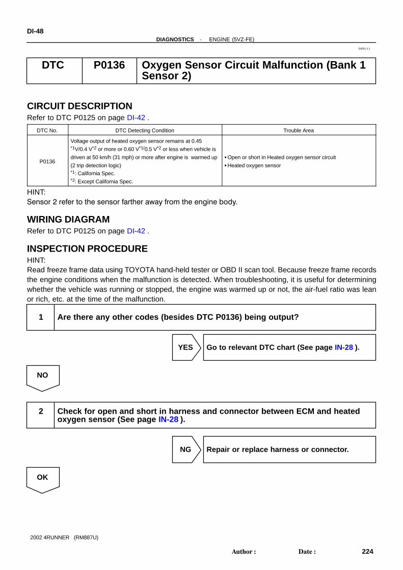
DTC P0136 Oxygen Sensor Circuit Malfunction (Bank 1Sensor 2)
CIRCUIT DESCRIPTIONRefer to DTC P0125 on page DI-42 .
DTC No. DTC Detecting Condition Trouble Area
P0136
Voltage output of heated oxygen sensor remains at 0.45*1V/0.4 V*2 or more or 0.60 V*1/0.5 V*2 or less when vehicle is
driven at 50 km/h (31 mph) or more after engine is warmed up
(2 trip detection logic)*1: California Spec.*2: Except California Spec.
Open or short in Heated oxygen sensor circuit
Heated oxygen sensor
HINT:Sensor 2 refer to the sensor farther away from the engine body.
WIRING DIAGRAMRefer to DTC P0125 on page DI-42 .
INSPECTION PROCEDUREHINT:Read freeze frame data using TOYOTA hand-held tester or OBD II scan tool. Because freeze frame recordsthe engine conditions when the malfunction is detected. When troubleshooting, it is useful for determiningwhether the vehicle was running or stopped, the engine was warmed up or not, the air-fuel ratio was leanor rich, etc. at the time of the malfunction.
1 Are there any other codes (besides DTC P0136) being output?
YES Go to relevant DTC chart (See page IN-28 ).
NO
2 Check for open and short in harness and connector between ECM and heatedoxygen sensor (See page IN-28 ).
NG Repair or replace harness or connector.
OK
DI0S1-11

-DIAGNOSTICS ENGINE (5VZ-FE)DI-49
225Author: Date:
2002 4RUNNER (RM887U)
3 Check output voltage of heated oxygen sensor.
PREPARATION:(a) Connect the OBD II scan tool or TOYOTA hand-held tester to the DLC3.(b) Warm up the engine to normal operating temperature.CHECK:Read the voltage output of the heated oxygen sensor when the engine is suddenly raced.HINT:Perform quick racing to 4,000 rpm 3 min. using the accelerator pedal.OK:
Heated oxygen sensor output voltage:Alternates from 0.45 V *1/0.4 V*2 or less to 0.60 V *1/0.5 V*2 or more.*1: California Spec.*2: Except California Spec.
OK Check that each connector is properly con-nected.
NG
Replace heated oxygen sensor.

A15303
ON
(+) (-)
HT2B
DI-50-DIAGNOSTICS ENGINE (5VZ-FE)
226Author: Date:
2002 4RUNNER (RM887U)
DTC P0141 Oxygen Sensor Heater Circuit Malfunction(Bank 1 Sensor 2)
CIRCUIT DESCRIPTIONRefer to DTC P0125 on page DI-42 .
DTC No. DTC Detecting Condition Trouble Area
P0141
When heater operates, heater current exceeds 2.35 A
(2 trip detection logic) Open or short in heater circuit of heated oxygen sensor
H t d h tP0141Heater current of 0.2 A or less when heater operates
(2 trip detection logic)
Heated oxygen sensor heater
ECM
HINT: Sensor 1 refer to the sensor closer to the engine body.
Sensor 2 refer to the sensor farther away from the engine body.
WIRING DIAGRAMRefer to DTC P0125 on page DI-42 .
INSPECTION PROCEDUREHINT:Read freeze frame data using TOYOTA hand-held tester or OBD II scan tool. Because freeze frame recordsthe engine conditions when the malfunctions is detected. When troubleshooting, it is useful for determiningwhether the vehicle was running or stopped, the engine was warmed up or not, the air-fuel ratio was leanor rich, etc. at the time of the malfunction.
1 Check voltage between terminals HT2B of ECM connectors and body ground.
PREPARATION:(a) Remove the glove compartment (See page SF-54 ).(b) Turn the ignition switch ON.CHECK:Measure the voltage between terminals HT2B of the ECM con-nectors and body ground.OK:
Voltage: 9 - 14 V
OK Check and replace ECM (See page IN-28 ).
NG
DI0S0-11

-DIAGNOSTICS ENGINE (5VZ-FE)DI-51
227Author: Date:
2002 4RUNNER (RM887U)
2 Check resistance of heated oxygen sensor heater (See page SF-52 ).
NG Replace heated oxygen sensor.
OK
Check and repair harness or connector between EFI main relay (Marking: EFI) and heated oxygensensor, and heated oxygen sensor and ECM (See page IN-28 ).

DI-52-DIAGNOSTICS ENGINE (5VZ-FE)
228Author: Date:
2002 4RUNNER (RM887U)
DTC P0171 System too Lean (Fuel Trim)
DTC P0172 System too Lean (Fuel Trim)
CIRCUIT DESCRIPTIONFuel trim refers to the feedback compensation value compared to the basic injection time. Fuel trim includesshort-term fuel trim and long-term fuel trim.Short-term fuel trim is the short-term fuel compensation used to maintain the air-fuel ratio at its idealtheoretical value. The signal from the A/F sensor is approximately proportional to the existing air-fuel ratio,and ECM comparing it with the ideal theoretical value, the ECM reduces fuel volume immediately if the air-fuel ratio is rich and increases fuel volume if it is lean.Long-term fuel trim compensates for the deviation from the central value of the short-term fuel trim storedup by each engine tolerance, and the deviation from the central value due to the passage of time andchanges of environment.If both the short-term fuel trim and long-term fuel trim exceed a certain value, it is detected as a malfunctionand the MIL lights up.
DTC No. DTC Detecting Condition Trouble Area
P0171
When air fuel ratio feedback is stable after engine warming up,
fuel trim is considerably in error on RICH side
(2 trip detection logic)
Air induction system
Injector blockage
Mass air flow meter
Engine coolant temp. sensor
Fuel pressure
Gas leakage on exhaust system
Open or short in A/F sensor (bank 1 sensor 1) circuit
A/F sensor (bank 1 sensor 1)
PCV valve and hose
ECM
P0172
When air fuel ratio feedback is stable after engine warming up,
fuel trim is considerably in error on LEAN side
(2 trip detection logic)
Injector leak, blockage
Mass air flow meter
Engine coolant temp. sensor
Ignition system
Fuel pressure
Gas leakage on exhaust system
Open or short in A/F sensor (bank 1 sensor 1) circuit
A/F sensor (bank 1 sensor 1)
ECM
HINT: When the DTC P0171 is recorded, the actual air-fuel ratio is on the LEAN side. When DTC P0172 is
recorded, the actual air-fuel ratio is on the RICH side. If the vehicle runs out of fuel, the air-fuel ratio is lean and DTC P0171 is recorded. The MIL then comes
on. If the total of the short-term fuel trim value and long-term fuel trim value is within ±35 % (80°C (176°F)
or more), the system is functioning normally. The A/F sensor (bank 1 sensor 1) output voltage and the short-term fuel trim value can be read using
the OBD II scan tool or TOYOTA hand-held tester.
DI5C7-08

-DIAGNOSTICS ENGINE (5VZ-FE)DI-53
229Author: Date:
2002 4RUNNER (RM887U)
The ECM controls the voltage of the AF1- and AF1- terminals of the ECM to the fixed voltage. There-fore, it is impossible to confirm the A/F sensor output voltage without OBD II scan tool or TOYOTAhand-held tester.
OBD II scan tool (excluding TOYOTA hand-held tester) displays the one fifth of the A/F sensor outputvoltage which is displayed on the TOYOTA hand-held tester.
WIRING DIAGRAMRefer to DTC P0125 on page DI-42 .
INSPECTION PROCEDUREHINT:Read freeze frame data using TOYOTA hand-held tester or OBD II scan tool. Because freeze frame recordsthe engine conditions when the malfunction is detected. When troubleshooting, it is useful for determiningwhether the vehicle was running or stopped, the engine was warmed up or not, the air-fuel ratio was leanor rich, etc. at the time of the malfunction.
1 Check connection of PCV valve and hose.
NG Repair or replace PCV valve and hose.
OK
2 Check air induction system (See page SF-1 ).
NG Repair or replace.
OK
3 Check injector injection (See page SF-21 ).
NG Replace injector.
OK

DI-54-DIAGNOSTICS ENGINE (5VZ-FE)
230Author: Date:
2002 4RUNNER (RM887U)
4 Check mass air flow meter (See page SF-28 ) and engine coolant temperaturesensor (See page SF-44 ).
NG Repair or replace.
OK
5 Check for spark and ignition (See page IG-1 ).
NG Repair or replace.
OK
6 Check fuel pressure (See page SF-7 ).
NG Check and repair fuel pump, pressure regulator,fuel pipe line and filter (See page SF-1 ).
OK
7 Check gas leakage on exhaust system.
NG Repair or replace.
OK

-DIAGNOSTICS ENGINE (5VZ-FE)DI-55
231Author: Date:
2002 4RUNNER (RM887U)
8 Check output voltage A/F sensor (bank 1 sensor 1).
PREPARATION:(a) Connect the OBDII scan tool or TOYOTA hand-held tester to the DLC3.(b) Warm up the A/F sensor with the engine speed at 2,500 rpm for approx. 90 sec.CHECK:Read the voltage value of the A/F sensor on the screen of the OBDII scan tool or TOYOTA hand-held testerwhen you perform all the following conditions.HINT:The voltage of the AF1+ terminal of the ECM is 3.3 fixed and AF1- terminal is 3.0 V fixed. Therefore, it isimpossible to check the A/F sensor output voltage at the terminals (AF1+/AF1-) of the ECM.OK:
Condition A/F Sensor Voltage value
Engine idling
Engine racingNot remains at 3.30 V (0.660 V*)
Not remains at 3 8 V (0 76 V*) or moreDriving at engine speed 1,500 rpm or more and vehicle
speed 40 km/h (25mph) or more, and operate throttle valve
open and close
Not remains at 3.8 V (0.76 V*) or more
Not remains at 2.8 V (0.56 V*) or less
*: When you use the OBDII scan tool (excluding TOYOTA hand-held tester)
HINT: During fuel enrichment, there is a case that the output voltage of the A/F sensor is below 2.8 V (0.56
V*), it is normal. During fuel cut, there is case that the output voltage of the A/F sensor is above 3.8 V (0.76 V*), it is
normal. If the output voltage of the A/F sensor remains at 3.30 V (0.660 V*) even after performing all the above
conditions, the A/F sensor circuit may be open. If the output voltage of the A/F sensor remains at 3.8 V (0.76 V*) or more, or 2.8 V (0.56 V*) or less
even after performing all the above conditions, the A/F sensor circuit may be short.*: When you use the OBDII scan tool (excluding TOYOTA hand-held tester).
OK Go to step 9.
NG
9 Check for open and short in harness and connector between ECM and A/F sen-sor (bank 1 sensor 1) (See page IN-28 ).
NG Repair or replace harness or connector.
OK
Replace A/F sensor.

DI-56-DIAGNOSTICS ENGINE (5VZ-FE)
232Author: Date:
2002 4RUNNER (RM887U)
10 Perform confirmation driving pattern (See page DI-122 ).
Go
11 Is there DTC P0171 or P0172 being output again?
YES Check and replace ECM (See page IN-28 ).
NO
12 Did vehicle runs out of fuel in past?
NO Check for intermittent problems (See page DI-3 ).
YES
DTC P0171 or P0172 is caused by running out of fuel.

-DIAGNOSTICS ENGINE (5VZ-FE)DI-57
233Author: Date:
2002 4RUNNER (RM887U)
DTC P0300 Random/Multiple Cylinder Misfire Detected
DTC P0301 Cylinder 1 Misfire Detected
DTC P0302 Cylinder 2 Misfire Detected
DTC P0303 Cylinder 3 Misfire Detected
DTC P0304 Cylinder 4 Misfire Detected
DTC P0305 Cylinder 5 Misfire Detected
DTC P0306 Cylinder 6 Misfire Detected
CIRCUIT DESCRIPTIONMisfire: The ECM uses the crankshaft position sensor and camshaft position sensor to monitor changes inthe crankshaft rotation for each cylinder. The ECM counts the number of times the engine speed changerate indicates that misfire has occurred. When the misfire rate equals or exceeds the count indicating thatthe engine condition has deteriorated, the MIL lights up.If the misfire rate is high enough and the driving conditions will cause catalyst overheating, the MIL blinkswhen misfiring occurs.
DI8XH-02

A07547 A12632
2
B-R
E106
1
2 1
2 1
2 1
B-R
B-R
B-R
No. 1
No. 2
No. 3
No. 4
1J1I4 7
II41
EC
W-B
B-R
ECM
#10
#20
#30
#40
E01
E02
Driver Side J/B
67B-R
IG SW
Engine Room R/B
W-R
2
2
R
W
R-B
G
2
1
#50
#60
E10
E10
E10
E10
E10
E9
E9
5
4
3
1
8
4
5W-B
Injector
L
Y
2 1
2 1
Battery
AM
2
B-R
B-R
B-R
No. 5
No. 6
W
I14
DI-58-DIAGNOSTICS ENGINE (5VZ-FE)
234Author: Date:
2002 4RUNNER (RM887U)
DTC No. DTC Detecting Condition Trouble Area
P0300Misfiring of random cylinders is detected during any particular
200 or 1,000 revolutions
Open or short in engine wire
Connector connection
Vacuum hose connector
Ignition system
P0301
P0302
P0303
For any particular 200 revolutions for engine, misfiring is de-
tected which can cause catalyst overheating
(This causes MIL to blink)
Ignition system
Injector
Fuel pressure
Mass air flow meter
Engine coolant temp. sensorP0303
P0304
P0305
P0306
For any particular 1,000 revolutions of engine, misfiring is de-
tected which causes a deterioration in emission
(2 trip detection logic)
Compression pressure
Valve clearance
Valve timing
PCV valve and hose
ECM
HINT:When the 2 or more codes for a misfiring cylinder are recorded repeatedly but no random misfire code isrecorded, it indicates that the misfires were detected and recorded at different times.
WIRING DIAGRAM
CONFIRMATION DRIVING PATTERN(a) Connect the TOYOTA hand-held tester or OBD II scan tool.(b) Record DTC and the freeze frame data.(c) Use the TOYOTA hand-held tester to set to the check mode (See page DI-3 ).

-DIAGNOSTICS ENGINE (5VZ-FE)DI-59
235Author: Date:
2002 4RUNNER (RM887U)
(d) Drive the vehicle several times with the engine speed, load and its surrounding range shown with theENGINE SPD, CALC LOAD in the freeze frame data or the MISFIRE RPM, MISFIRE LOAD in the datalist.
If you have no TOYOTA hand-held tester, turn the ignition switch OFF after the symptom is simulated thefirst time. Then repeat the simulation process again.HINT:In order to memorize DTC of misfire, it is necessary to drive around the MISFIRE RPM, MISFIRE LOAD inthe data list for the following period of time.
Engine Speed Time
Ignition 3 minutes 30 seconds or more
1000 rpm 3 minutes or more
2000 rpm 1 minute 30 seconds or more
3000 rpm 1 minute or more
(e) Check whether there is misfire or not by monitoring DTC and the freeze frame data. After that, recordthem.
(f) Turn the ignition switch OFF and wait at least 5 seconds.
INSPECTION PROCEDUREHINT: If is case that DTC besides misfire is memorized simultaneously, first perform the troubleshooting for
them. Read freeze frame data using TOYOTA hand-held tester or OBD II scan tool. Because freeze frame
data records the engine conditions when the malfunction is detected. When troubleshooting, it is usefulfor determining whether the vehicle was running or stopped, the engine was warmed up or not, theair-fuel ratio was lean or rich, etc. at the time of the malfunction.
When the vehicle is brought to the workshop and the misfire is not occurred, misfire can be confirmedby reproducing the condition or freeze frame data. Also, after finishing the repair, confirm that thereis no misfire (See the confirmation driving pattern).
When either of the SHORT FT #1, LONG FT #1, SHORT FT #2 or LONG FT #2 in the freeze framedata is besides the range of ±20%, there is a possibility that the air-fuel ratio is inclining either to RICH(-20 % or less) or LEAN (+20 % or more).
When the COOLANT TEMP in the freeze frame data is less than 80°C (176°F), there is a possibilityor misfire only during warming up.
In the case that misfire cannot be reproduced, the reason may be because of the driving with lack orfuel, the use of improper fuel, a stain of ignition plug, and etc.
1 Check connection of PCV valve and hose
NG Repair or replace PCV valve and hose
OK

DI-60-DIAGNOSTICS ENGINE (5VZ-FE)
236Author: Date:
2002 4RUNNER (RM887U)
2 Check wire harness, connector and vacuum hose in engine room.
CHECK:(a) Check the connection conditions of wire harness and connector.(b) Check the disconnection, piping and break of vacuum hose.
NG Repair or replace, then confirm that there is nomisfire (See confirnation drive pattern).
OK
3 Check spark plug and spark of misfiring cylinder (See page IG-1 ).
NG Replace or check ignition system (See page IG-1 ).
OK

A15304
ON
#60
(+) (-)
#50#40#30#20#10
FI6588 FI6538
A00064
Injector Signal Waveform
10V/Division
GND
100 msec./Division (Idling)
10V/Division
GND
1 msec./Division (Idling)
Injection duration
(Magnification)
-DIAGNOSTICS ENGINE (5VZ-FE)DI-61
237Author: Date:
2002 4RUNNER (RM887U)
4 Check voltage of ECM terminal for injector of failed cylinder.
PREPARATION:(a) Remove the glove compartment (See page SF-54 ).(b) Turn the ignition switch ON.CHECK:Measure the voltage between applicable terminals of the ECMconnector and body ground.OK:
Voltage: 9 - 14 V
Reference: INSPECTION USING OSCILLOSCOPEWith the engine idling, check the waveform between terminals #10 - #60 and E01 of the ECM connector.HINT:The correct waveform is as shown.
OK Go to step 4.
NG

DI-62-DIAGNOSTICS ENGINE (5VZ-FE)
238Author: Date:
2002 4RUNNER (RM887U)
5 Check resistance of injector of misfiring cylinder (See page SF-21 ).
NG Replace injector.
OK
Check for open and short in harness and con-nector between injector and ECM (See pageIN-28 ).
6 Check fuel pressure (See page SF-7 ).
NG Check and repair fuel pump, pressure regulator,fuel pipe line and filter (See page SF-1 ).
OK
7 Check injector injection (See page SF-21 ).
NG Replace injector.
OK
8 Check mass air flow meter (See page SF-28 ) and engine coolant temperaturesensor (See page SF-44 ).
NG Repair or replace.
OK
Check compression pressure, valve clear-ance and valve timing.

A03381
ECM
KNK1
KNK2
E1
E1
E9
22
23
E9
B
GR
1
2
EB1
EB1B
GR
1
1
K2Knock Sensor 1(on Right Bank)
K3Knock Sensor 2(on Left Bank)
-DIAGNOSTICS ENGINE (5VZ-FE)DI-63
239Author: Date:
2002 4RUNNER (RM887U)
DTC P0325 Knock Sensor 1 Circuit Malfunction (Bank 1)
DTC P0330 Knock Sensor 2 Circuit Malfunction (Bank 2)
CIRCUIT DESCRIPTIONKnock sensors are fitted one to the right bank and left bank of the cylinder block to detect engine knocking.This sensor contains a piezoelectric element which generates a voltage when it becomes deformed, whichoccurs when the cylinder block vibrates due to knocking. If engine knocking occurs, ignition timing is retardedto suppress it.
DTC No. DTC Detecting Condition Trouble Area
P0325No knock sensor 1 signal to ECM with engine speed between
2000 rpm and 5,600 rpm
Open or short in knock sensor 1 circuit
Knock sensor 1 (looseness)
ECM
P0330No knock sensor 2 signal to ECM with engine speed between
2000 rpm and 5,600 rpm
Open or short in knock sensor 2 circuit
Knock sensor 2 (looseness)
ECM
WIRING DIAGRAM
INSPECTION PROCEDUREHINT: DTC P0325 is for the right bank knock sensor circuit. DTC P0330 is for the left bank knock sensor circuit.
DI0S4-11

A00053
A00054
A03539
A00053
A00054
A03539
A03394
ECM
KNK1
KNK2
E9
MaleFemale
1
EB1
Knock Sensor
Connector Connector
27
22
1
E9
EB1
28
FI6510FI6607 A00113
KNK Signal Waveform0.5V/Division
0V
5 msec./Division
200mV/Division
0V
0.1 msec./Division
DI-64-DIAGNOSTICS ENGINE (5VZ-FE)
240Author: Date:
2002 4RUNNER (RM887U)
Read freeze frame data using TOYOTA hand-held tester or OBD II scan tool. Because freeze framerecords the engine conditions when the malfunction is detected. When troubleshooting, it is useful fordetermining whether the vehicle was running or stopped, the engine was warmed up or not, the air-fuelratio was lean or rich, etc. at the time of the malfunction.
1 Connect OBD II scan tool or TOYOTA hand-held tester, and check knock sensorcircuit.
PREPARATION:(a) Connect the OBD II scan tool or TOYOTA hand-held tes-
ter to the DLC3.(b) Disconnect the EB1 connector.(c) Connect the terminals of the disconnected EB1 male con-
nector and EB1 female as follows.
Male connector ↔ Female connector
Terminal 1 ↔ Terminal 2
Terminal 2 ↔ Terminal 1
(d) Turn the ignition switch ON and push the OBDII scan toolor TOYOTA hand-held tester main switch ON.
(e) After the engine is warmed up, perform quick racing to4,000 rpm 3 times.
CHECK:Check the DTC.RESULT:
Type IDTC same as when vehicle brought in
P0325 → P0325 or P0330 → P0330
Type IIDTC different to when vehicle brought in
P0325 → P0330 or P0330 → P0325
Reference: INSPECTION USING OSCILLOSCOPE With the engine racing (4,000 rpm), check the waveform
between terminals KNK1, KNK2 of the ECM connectorand body ground.
HINT:The correct waveform is as shown.
Spread the time on the horizontal axis, and confirm thatperiod of the wave is 0.141 msec. (Normal mode vibrationfrequency of knock sensor: 7.1 kHz)
HINT:If normal mode vibration frequency is not 7.1 kHz, the sensoris malfunctioning.
Type II Go to step 3.

-DIAGNOSTICS ENGINE (5VZ-FE)DI-65
241Author: Date:
2002 4RUNNER (RM887U)
Type I
2 Check for open and short in harness and connector between EB1 connector andECM (See page IN-28 ).
NG Repair or replace harness or connector.
OK
Check and replace ECM (See page IN-28 ).
3 Check for open and short in harness and connector between EB1 connector andknock sensor (See page IN-28 ).
HINT: If DTC P0325 has changed to P0330, check the knock sensor circuit on the right bank side. If DTC P0330 has changed to P0325, check the knock sensor circuit on the left bank side.
NG Repair or replace harness or connector.
OK
Replace knock sensor.
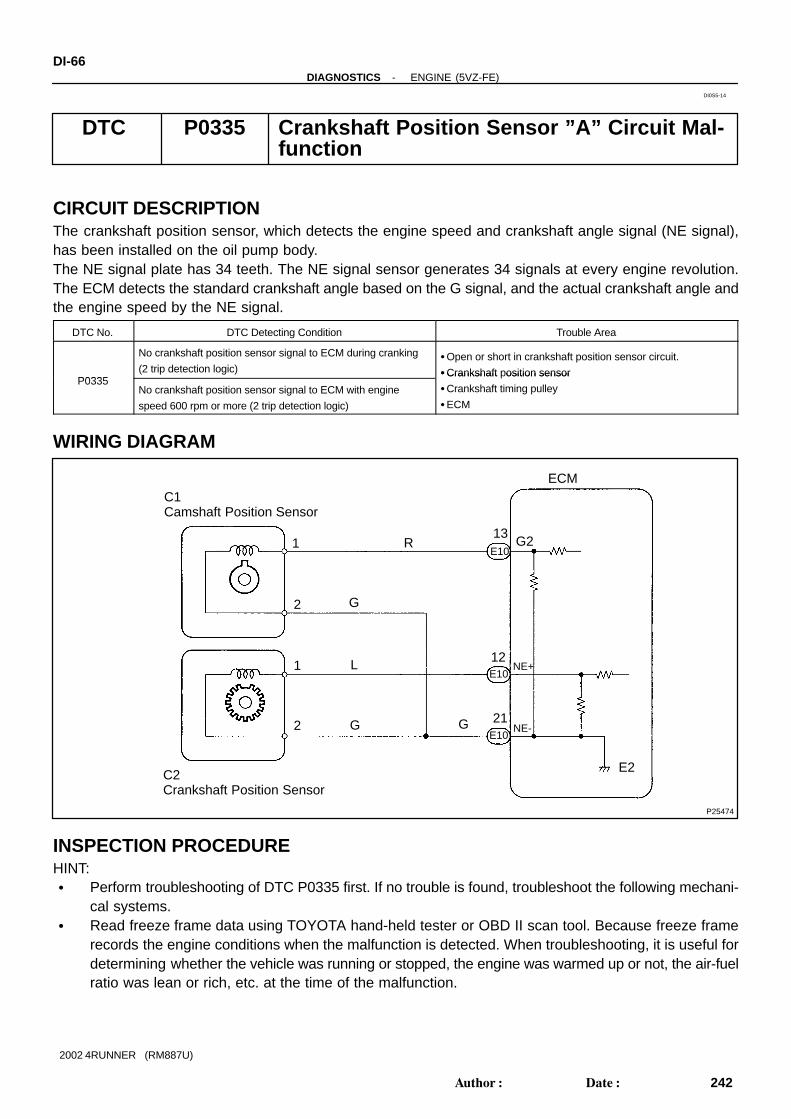
P25474
C1Camshaft Position Sensor
C2Crankshaft Position Sensor
1
1
2
R
L
G
G G NE-
NE+
G2
ECM
21
E10
12
E2
13
2
E10
E10
DI-66-DIAGNOSTICS ENGINE (5VZ-FE)
242Author: Date:
2002 4RUNNER (RM887U)
DTC P0335 Crankshaft Position Sensor ”A” Circuit Mal-function
CIRCUIT DESCRIPTIONThe crankshaft position sensor, which detects the engine speed and crankshaft angle signal (NE signal),has been installed on the oil pump body.The NE signal plate has 34 teeth. The NE signal sensor generates 34 signals at every engine revolution.The ECM detects the standard crankshaft angle based on the G signal, and the actual crankshaft angle andthe engine speed by the NE signal.
DTC No. DTC Detecting Condition Trouble Area
P0335
No crankshaft position sensor signal to ECM during cranking
(2 trip detection logic)Open or short in crankshaft position sensor circuit.
Crankshaft position sensorP0335
No crankshaft position sensor signal to ECM with engine
speed 600 rpm or more (2 trip detection logic)
Crankshaft osition sensor
Crankshaft timing pulley
ECM
WIRING DIAGRAM
INSPECTION PROCEDUREHINT: Perform troubleshooting of DTC P0335 first. If no trouble is found, troubleshoot the following mechani-
cal systems. Read freeze frame data using TOYOTA hand-held tester or OBD II scan tool. Because freeze frame
records the engine conditions when the malfunction is detected. When troubleshooting, it is useful fordetermining whether the vehicle was running or stopped, the engine was warmed up or not, the air-fuelratio was lean or rich, etc. at the time of the malfunction.
DI0S5-14
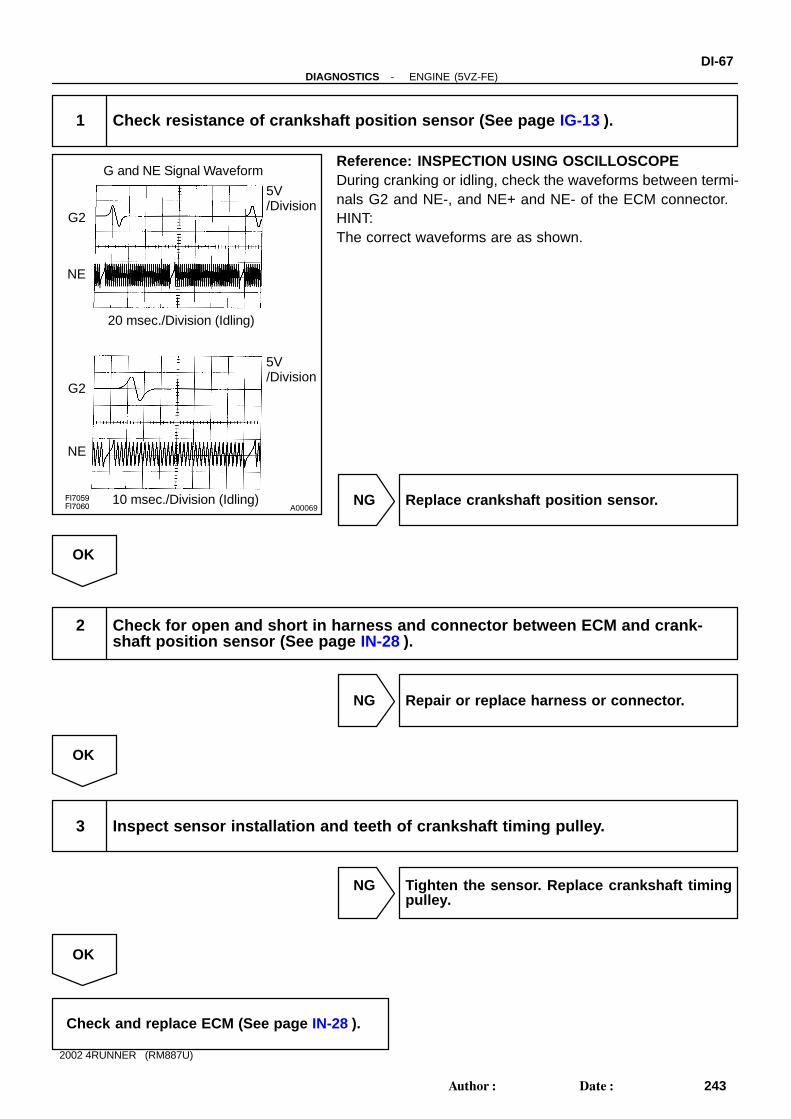
FI7059FI7060 A00069
G and NE Signal Waveform
G2
NE
5V/Division
20 msec./Division (Idling)
G2
NE
5V/Division
10 msec./Division (Idling)
-DIAGNOSTICS ENGINE (5VZ-FE)DI-67
243Author: Date:
2002 4RUNNER (RM887U)
1 Check resistance of crankshaft position sensor (See page IG-13 ).
Reference: INSPECTION USING OSCILLOSCOPEDuring cranking or idling, check the waveforms between termi-nals G2 and NE-, and NE+ and NE- of the ECM connector.HINT:The correct waveforms are as shown.
NG Replace crankshaft position sensor.
OK
2 Check for open and short in harness and connector between ECM and crank-shaft position sensor (See page IN-28 ).
NG Repair or replace harness or connector.
OK
3 Inspect sensor installation and teeth of crankshaft timing pulley.
NG Tighten the sensor. Replace crankshaft timingpulley.
OK
Check and replace ECM (See page IN-28 ).
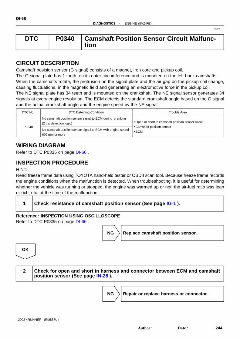
DI-68-DIAGNOSTICS ENGINE (5VZ-FE)
244Author: Date:
2002 4RUNNER (RM887U)
DTC P0340 Camshaft Position Sensor Circuit Malfunc-tion
CIRCUIT DESCRIPTIONCamshaft posision sensor (G signal) consists of a magnet, iron core and pickup coil.The G signal plate has 1 tooth, on its outer circumference and is mounted on the left bank camshafts.When the camshafts rotate, the protrusion on the signal plate and the air gap on the pickup coil change,causing fluctuations, in the magnetic field and generating an electromotive force in the pickup coil.The NE signal plate has 34 teeth and is mounted on the crankshaft. The NE signal sensor generates 34signals at every engine revolution. The ECM detects the standard crankshaft angle based on the G signaland the actual crankshaft angle and the engine speed by the NE signal.
DTC No. DTC Detecting Condition Trouble Area
P0340
No camshaft position sensor signal to ECM during cranking
(2 trip detection logic) Open or short in camshaft position sensor circuit
C h ft itiP0340No camshaft position sensor signal to ECM with engine speed
600 rpm or more
Camshaft position sensor
ECM
WIRING DIAGRAMRefer to DTC P0335 on page DI-66 .
INSPECTION PROCEDUREHINT:Read freeze frame data using TOYOTA hand-held tester or OBDII scan tool. Because freeze frame recordsthe engine conditions when the malfunction is detected. When troubleshooting, it is useful for determiningwhether the vehicle was running or stopped, the engine was warmed up or not, the air-fuel ratio was leanor rich, etc. at the time of the malfunction.
1 Check resistance of camshaft position sensor (See page IG-1 ).
Reference: INSPECTION USING OSCILLOSCOPERefer to DTC P0335 on page DI-66 .
NG Replace camshaft position sensor.
OK
2 Check for open and short in harness and connector between ECM and camshaftposition sensor (See page IN-28 ).
NG Repair or replace harness or connector.
DI0S6-08

-DIAGNOSTICS ENGINE (5VZ-FE)DI-69
245Author: Date:
2002 4RUNNER (RM887U)
OK
3 Inspect sensor installation and tooth of RH camshaft timing pulley.
NG Tighten sensor. Replace RH camshaft timingpulley
OK
Check and replace ECM (See page IN-28 ).

A07722
Waveform ofA/F Sensor Normal Catalyst Waveform of Heated Oxygen
Sensor Behind Catalyst
Abnormal Catalyst
DI-70-DIAGNOSTICS ENGINE (5VZ-FE)
246Author: Date:
2002 4RUNNER (RM887U)
DTC P0420 Catalyst System Efficiency Below Threshold(Bank 1)
CIRCUIT DESCRIPTIONThe ECM observes the waveform of the heated oxygen sensor located behind the catalyst to determinewhether the catalyst is performance has deteriorated. If the catalyst is functioning normally, the waveformof the heated oxygen sensor located behind the catalyst switches back and forth between rich and lean muchmore slowly. When the waveform of the heated oxygen sensor located behind the catalyst alternates flatter-ingly between rich and lean, it indicates that catalyst performance has deteriorated.
DTC No. DTC Detecting Condition Trouble Area
P0420
After engine and catalyst are warmed up, and while vehicle is
driven within set vehicle and engine speed range, waveform of
heated oxygen sensor (bank 1 sensor 2) alternates flatteringly
between rich and lean (2 trip detection logic)
Gas leakage on exhaust system
A/F sensor (bank 1 sensor 1)
Heated oxygen sensor (bank 1 sensor 2)
Three-way catalytic converter
DI5C9-06
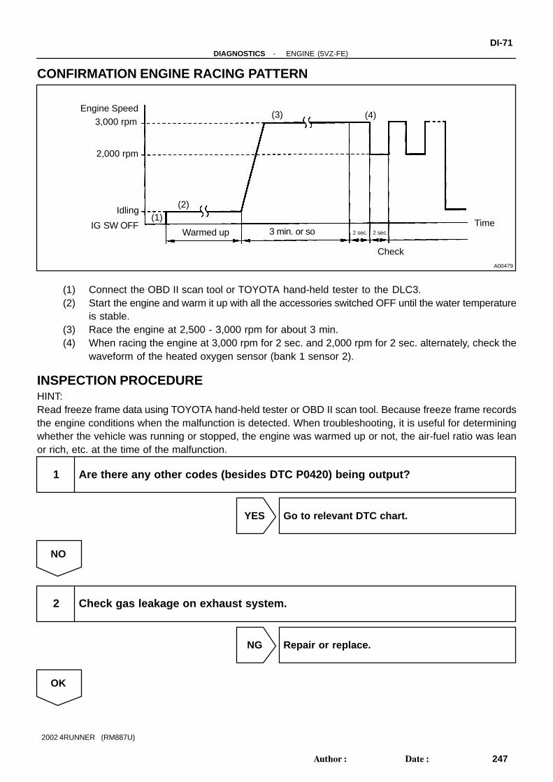
A00479
Engine Speed3,000 rpm
2,000 rpm
Idling
IG SW OFF(1)
Warmed up 3 min. or so 2 sec. 2 sec.
Check
Time
(2)
(3) (4)
-DIAGNOSTICS ENGINE (5VZ-FE)DI-71
247Author: Date:
2002 4RUNNER (RM887U)
CONFIRMATION ENGINE RACING PATTERN
(1) Connect the OBD II scan tool or TOYOTA hand-held tester to the DLC3.(2) Start the engine and warm it up with all the accessories switched OFF until the water temperature
is stable.(3) Race the engine at 2,500 - 3,000 rpm for about 3 min.(4) When racing the engine at 3,000 rpm for 2 sec. and 2,000 rpm for 2 sec. alternately, check the
waveform of the heated oxygen sensor (bank 1 sensor 2).
INSPECTION PROCEDUREHINT:Read freeze frame data using TOYOTA hand-held tester or OBD II scan tool. Because freeze frame recordsthe engine conditions when the malfunction is detected. When troubleshooting, it is useful for determiningwhether the vehicle was running or stopped, the engine was warmed up or not, the air-fuel ratio was leanor rich, etc. at the time of the malfunction.
1 Are there any other codes (besides DTC P0420) being output?
YES Go to relevant DTC chart.
NO
2 Check gas leakage on exhaust system.
NG Repair or replace.
OK
DI-72-DIAGNOSTICS ENGINE (5VZ-FE)
248Author: Date:
2002 4RUNNER (RM887U)
3 Check A/F sensor (bank 1 sensor 1) (See page SF-51 ).
NG Repair or replace.
OK
4 Check heated oxygen sensor (bank 1 sensor 2) (See page SF-52 ).
NG Repair or replace.
OK
Replace three-way catalytic converter.

A11954
ECM
VSVfor EVAP
Charcoal Canister Fuel Tank
Fig. 1
(2)
(3)
(4)
(6)
(8)(9)
(1)(5)Fuel Tank OverFill Check Valve
(7)
Vapor PressureSensor
VSV forCCV
VSV for pressure SwitchingValve
(10)
(11)
-DIAGNOSTICS ENGINE (5VZ-FE)DI-73
249Author: Date:
2002 4RUNNER (RM887U)
DTC P0440 Evaporative Emission Control System Mal-function
DTC P0442 Evaporative Emission Control System LeakDetected (Small Leak)
CIRCUIT DESCRIPTIONThe vapor pressure sensor, VSV for canister closed valve (CCV) and VSV for pressure switching valve areused to detect abnormalities in the evaporative emission control system.The ECM decides whether there is an abnormality in the evaporative emission control system based on thevapor pressure sensor signal.DTC P0440 is recorded by the ECM when evaporative emissions leak from the components within the dottedline in Fig. 1 below, or when the vapor pressure sensor malfunctions.
DI9O0-01

A14661
VSV for CCV
VSV forPressure Switching Valve
VSV for EVAP
Cold StartECT/IAT near same temp.
NegativePressureOccurs
Tank & CanisterLeak Check
VSV for PressureSwitching Valve, CCVTesting
Open
Closed Open
Closed
Open
Closed
Closed Closed
Open Open
P0441 P0440, P0442 P0446
DI-74-DIAGNOSTICS ENGINE (5VZ-FE)
250Author: Date:
2002 4RUNNER (RM887U)
DTC No. DTC Detecting Condition Trouble Area
P0440
P0442
After cold engine start.
After VSV for EVAP operation, the VSV for EVAP is turned off
sealing the vacuum in the system and the ECM begins to mon-
itor the pressure increase.
Some increase is normal. A very rapid, sharp increase in pres-
sure indicates a leak in the EVAP system and sets the DTC
P0440.
This monitoring method is also able to distinguish what is
called the small leak detection.(DTC P0442)
A pressure rise just above normal indicates a very small hole.
Hose or tube cracked, hole, damaged or loose seal ((3) or (9)
in Fig. 1)
Fuel tank cap incorrectly installed
Fuel tank cap cracked or damaged
Vacuum hose cracked, holed, blocked, damaged or discon-
nected ((1), (2), (4), (5), (6), (7), (8), (10)and (11) in Fig. 1)
Fuel tank cracked, holed or damaged
Charcoal canister cracked, holed or damaged
Open or short in vapor pressure sensor circuit
Vapor pressure sensor
Fuel tank over fill check valve cracked or damaged
ECM

A18087
ECM
E9
E9
E9
E10
E10
E10
E14
25
24
11
14
20
19
4
VC
E2
PTNK
EVP1
CCV
TBP
MREL
Y
L-B
G-BG-B
YY
L-BL-B
II4
II4
IE3
IE3
IE3BN2
BN2
BN2
14
26
3
2
4
3
5
4
G-BII46
G-B
Y
L-B
Vapor Pressure Sensor3
2
1
VC
PTNK
E2
Engnie Room J/B
Battery
EFI Relay
EFI22
2 2
22
12
12
5 3
EB
W-B
J1
J2
J/C
W-B
L-R
A
A
W
1
1 1 1
1
1
1
2
2
2
2 511
14
BN2
BN2
IE3
II4
II4
IG1
BZ1
BZ1
IG1
IE3
13
16
W-L W-L W-L
W-L
W-LW-LW-L
W-L
J/CD D
GR-B
R-YR-YR-Y
V7VSV for EVAP
J7J7
V13VSV for CCV
VSV for Pressure SwitchingValve
W-L
W-G
L-B
R-Y
GR-B
R-Y
-DIAGNOSTICS ENGINE (5VZ-FE)DI-75
251Author: Date:
2002 4RUNNER (RM887U)
WIRING DIAGRAM

MISFIRE MON ..................... AVAIL
READINESS TESTS
CAT EVAL ........................ INCMPL
HTD CAT EVAL ...................... N/A
EVAP EVAL ....................... INCMPL
2nd AIR EVAL .......................... N/A
A/C EVAL ................................ N/A
O2S EVAL .......................... INCMPL
O2S HTR EVAL .................. INCMPL
EGR EVAL ......................... INCMPL
COMP MON ........................ AVAIL
FUEL SYS MON ................... AVAIL
A15402
MISFIRE MON ...................... AVAIL
READINESS TESTS
CAT EVAL .......................... COMPL
HTD CAT EVAL ....................... N/A
EVAP EVAL ........................ COMPL
2nd AIR EVAL ........................... N/A
A/C EVAL ................................. N/A
O2S EVAL ........................... COMPL
O2S HTR EVAL .................... COMPL
EGR EVAL .......................... COMPL
COMP MON .......................... AVAIL
FUEL SYS MON .................... AVAIL
A15403
Time$01 CID$01 ..................... Pass
NON−CONTINUOUS TESTS
Time$02 CID$01 ..................... Pass
Time$02 CID$02 ..................... Pass
Time$02 CID$03 ..................... Pass
Time$02 CID$04 ..................... Pass
Time$04 CID$00 ..................... Pass
Time$04 CID$02 ..................... Pass
Time$05 CID$01 ..................... Pass
Time$06 CID$01 ..................... Pass
Time$07 CID$01 ..................... Pass
A15404
MISFIRE MON ....................... AVAIL
READINESS TESTS
CAT EVAL .......................... COMPL
HTD CAT EVAL ....................... N/A
EVAP EVAL ....................... INCMPL
2nd AIR EVAL ........................... N/A
A/C EVAL ................................. N/A
O2S EVAL ........................... COMPL
O2S HTR EVAL .................... COMPL
EGR EVAL ................................ N/A
COMP MON ........................... AVAIL
FUEL SYS MON ..................... AVAIL
A15405
DI-76-DIAGNOSTICS ENGINE (5VZ-FE)
252Author: Date:
2002 4RUNNER (RM887U)
CONFIRMATION READINESS TESTFirst Trip Procedure(a) Vehicle must be cold, ambient temperature approximate-
ly between 50°F - 95°F.(b) Intake Air Temp. (IAT) and Engine Coolant Temp. (ECT)
sensor almost same value.
(c) Clear DTC’s. Disconnecting the battery terminals or EFI fuse. Readiness tests will show INCMPL (incomplete).
(d) Drive the vehicle according to LA#4 drive cycle. Note thestate of Readiness Tests. They will change to COMPL asthe evaluation monitors operate and if the system passes.This procedure may take approximately 20 minutes ormore.
NOTICE:Do not shut off the engine - the results will be invalid.Pass Condition - No Problem Found by the ECMIf the EVAP evaluation monitor shows COMPL, go to the Non-Continuous Test screen.NOTICE:Do not shut off the engine - the results will be invalid.
To get there, go to Advanced OBD II, OnboardTests, Non-continuous Tests.
If all of the tests in the time $02 category Tests showPass, the evaluation monitor has operated and noproblem was detected.
Fail Condition - Problem Detected by the ECMIf the EVAP evaluation monitor shows INCMPL, go to the Non-Continuous Test screen.

Time$01 CID$01 ..................... Pass
NON−CONTINUOUS TESTS
Time$02 CID$01 ...................... Fail
Time$02 CID$02 ...................... Fail
Time$02 CID$03 ...................... Fail
Time$02 CID$04 ...................... Fail
Time$04 CID$00 ..................... Pass
Time$04 CID$02 ..................... Pass
Time$05 CID$01 ..................... Pass
Time$06 CID$01 ..................... Pass
Time$07 CID$01 ..................... Pass
A15406
CONTINUOUS TESTSECU: $10 (Engine)Number of Tsts: 3
P0440EVAP Control System Malfunction
P0441EVAP Control System IncorrectPurge Flow
P0446EVAP Control System Vent ControlCircuit Malfunction
A15407
MISFIRE MON ...................... AVAIL
READINESS TESTS
CAT EVAL .......................... COMPL
HTD CAT EVAL ....................... N/A
EVAP EVAL ........................ COMPL
2nd AIR EVAL ........................... N/A
A/C EVAL ................................. N/A
O2S EVAL ........................... COMPL
O2S HTR EVAL .................... COMPL
EGR EVAL .......................... COMPL
COMP MON .......................... AVAIL
FUEL SYS MON .................... AVAIL
A15403
CONTINUOUS TESTSECU: $10 (Engine)Number of Tsts: 3
P0440EVAP Control System Malfunction
P0441EVAP Control System IncorrectPurge Flow
P0446EVAP Control System Vent ControlCircuit Malfunction
A15407
-DIAGNOSTICS ENGINE (5VZ-FE)DI-77
253Author: Date:
2002 4RUNNER (RM887U)
(1) If all Tests show Pass, the following may have oc-curred. The EVAP evaluation monitor did not oper-
ate. The EVAP evaluation monitor did not finish. The ECM withheld judgement.
(2) If one or more of the tests in the time $02 categoryshow Fail, the EVAP evaluation monitor did operateand the ECM detected a problem.
(3) Go to Continuous Tests screen. This is the onlyplace DTC’s are listed for the first trip.
NOTICE:The DTC listed may not be valid. A second trip is neededto confirm the DTC.
Second Trip Procedure(a) Vehicle must be cold, ambient temperature approximate-
ly between 50°F - 95°F.(b) Go to Readiness Tests screen.(c) Drive the vehicle according to LA#4 drive cycle. Note the
state of EVAP evaluation monitor. This procedure maytake approximately 20 minutes or more.
NOTICE:Do not shut off the engine - the results will be invalid.
(d) If Readiness Tests changes to COMPL, the EVAP evalua-tion monitor has operated. Check for any stored DTC’s. If a DTC has stored, the problem has been detected
and confirmed by the ECM. If no DTC was found, the EVAP monitor operated
but no problem was detected.

A10193
DI-78-DIAGNOSTICS ENGINE (5VZ-FE)
254Author: Date:
2002 4RUNNER (RM887U)
INSPECTION PROCEDUREHINT: If DTC P0441, P0446, P0450 or P0451 is output after DTC P0440 or P0442 first troubleshoot DTC
P0441, P0446, P0450 or P0451. If no malfunction is detected, troubleshoot DTC P0440 or P0442 next. Ask the customer whether, after the MIL came on, the customer found the fuel tank cap loose and tight-
ened it. Also ask the customer whether the fuel tank cap was loose when refuelling. If the fuel tank capwas not loose, it was the cause of the DTC. If the fuel tank cap was not loose or if the customer wasnot sure if it was loose, troubleshoot according to the following procedure.
Read freeze frame data using TOYOTA hand-held tester or OBD II scan tool. Because freeze framerecords the engine conditions when the malfunction is detected. When troubleshooting, it is useful fordetermining whether the vehicle was running or stopped, the engine was warmed up or not, the air-fuelratio was lean or rich, etc. at the time of the malfunction.
When the ENGINE RUN TIME in the freeze frame data is less than 200 seconds, carefully check thevapor pressure sensor.
1 Check whether hose close to fuel tank have been modified, and check whetherthere are signs of any accident near fuel tank or charcoal canister.
CHECK:Check for cracks, deformation and loose connection of theseparts:
Fuel tank Charcoal canister Fuel tank filler pipe Hoses and tubes around the fuel tank and charcoal
canister
NG Repair or replace.
OK
2 Check that fuel tank cap is TOYOTA genuine parts.
NG Replace to TOYOTA genuine parts.
OK

-DIAGNOSTICS ENGINE (5VZ-FE)DI-79
255Author: Date:
2002 4RUNNER (RM887U)
3 Check that fuel tank cap is correctly installed.
NG Correctly install fuel tank cap.
OK
4 Check fuel tank cap (See page EC-6 ).
NG Replace fuel tank cap.
OK
5 Check filler neck for damage.
PREPARATION:Remove the fuel tank cap.CHECK:Visually inspect the filler neck for damage.
NG Replace filler pipe.
OK

DI-80-DIAGNOSTICS ENGINE (5VZ-FE)
256Author: Date:
2002 4RUNNER (RM887U)
6 Check vacuum hoses between vapor pressure sensor and fuel tank, charcoalcanister and VSV for pressure switching valve, and VSV for pressure switchingvalve and charcoal canister.
CHECK:(a) Check that the vacuum hose is connected correctly.(b) Check the vacuum hose for looseness and disconnection.(c) Check the vacuum hose for cracks, hole and damage.
NG Repair or replace.
OK
7 Check hose and tube between fuel tank and charcoal canister.
CHECK:(a) Check for proper connection of the fuel tank and fuel evap pipe (See page EC-6 ), fuel evap pipe and
fuel tube under the floor, fuel tube under the floor and charcoal canister.(b) Check the hose and tube for cracks, hole and damage.
NG Repair or replace.
OK
8 Check charcoal canister for cracks, hole and damage (See page EC-6 ).
NG Replace charcoal canister.
OK

A15301
ON
VC
E2
(-)(+)
A15305
E2
PTNK
(-) (+)
-DIAGNOSTICS ENGINE (5VZ-FE)DI-81
257Author: Date:
2002 4RUNNER (RM887U)
9 Check voltage between terminals VC and E2 of ECM connector.
CHECK:(a) Remove the grove compartment.(b) Turn the ignition switch ON.CHECK:Measure the voltage between terminals VC and E2 of the ECMconnector.OK:
Voltage: 4.5 - 5.5 V
NG Check and replace ECM (See page IN-28 ).
OK
10 Check voltage between terminals PTNK and E2 of ECM connectors.
PREPARATION:(a) Remove the grove compartment.(b) Remove the fuel tank cap.(c) Turn the ignition switch ON.CHECK:Measure the voltage between terminals PTNK and E2 of theECM connectors.OK:
Voltage: 3.3 V
OK Go to step 12.
NG
11 Check for open and short in harness and connector between vapor pressuresensor and ECM (See page IN-28 ).
NG Repair or replace harness or connector.
OK
Replace vapor pressure sensor.

DI-82-DIAGNOSTICS ENGINE (5VZ-FE)
258Author: Date:
2002 4RUNNER (RM887U)
12 Check fuel tank and fuel tank over fill check valve for cracks and damage.
NG Replace fuel tank or fuel tank over fill checkvalve.
OK
It is likely that vehicle user did not properly close fuel tank cap. Please explain to customer howto properly install fuel tank cap.

A10142
ECM
Fuel TankCharcoal Canister
VSV forEVAP (1)
Fig. 1
(2)
(3)
(4)(5)
(6)
(7)
Fuel Tank Over Fill Check Valve
(10)
(9)
Vapor Pressure Sensor
VSV forCCV
VSV for Pressure Switching Valve
(8) (11)
-DIAGNOSTICS ENGINE (5VZ-FE)DI-83
259Author: Date:
2002 4RUNNER (RM887U)
DTC P0441 Evaporative Emission Control System Incor-rect Purge Flow
DTC P0446 Evaporative Emission Control System VentControl Malfunction
CIRCUIT DESCRIPTIONThe vapor pressure sensor, VSV for canister closed valve (CCV), VSV for pressure switching valve are usedto detect abnormalities in the evaporative emission control system.The ECM decides whether there is an abnormality in the evaporative emission control system based on thevapor pressure sensor signal.DTCs P0441 and P0446 are recorded by the ECM when evaporative emissions leak from the componentswithin the dotted line in Fig. 1 below, or when there is a malfunction in either the VSV for EVAP, the VSV forpressure switching valve, or in the vapor pressure sensor itself.
DI8XJ-01

A14661
VSV for CCV
VSV forPressure Switching Valve
VSV for EVAP
Cold StartECT/IAT near same temp.
NegativePressureOccurs
Tank & CanisterLeak Check
VSV for PressureSwitching Valve, CCVTesting
Open
Closed Open
Closed
Open
Closed
Closed Closed
Open Open
P0441 P0440 P0446
DI-84-DIAGNOSTICS ENGINE (5VZ-FE)
260Author: Date:
2002 4RUNNER (RM887U)
DTC No. DTC Detecting Condition Trouble Area
P0441
Pressure in charcoal canister and fuel tank does not drop or
drop in pressure increased beyond the specified limit during
purge control (2 trip detection logic)
Vacuum hose cracks, holed blocked, damaged or discon-
nected ((1), (2), (3), (4), (5), (6), (7), (8), (9), (10) and (11) in
Fig. 1)
Fuel tank cap incorrectly installed
Fuel tank cap cracked or damaged
P0446
When the vapor pressure rises to a specified point, the ECM
opens the VSV for CCV. Pressure will increase rapidly be-
cause of the air allowed into the system. No increase or an
increase below specified rate of pressure increase indicates a
restriction on the air inlet side.
Fuel tank cap cracked or damaged
Open or short in vapor pressure sensor circuit
Vapor pressure sensor
Open or short in VSV circuit for EVAP
VSV for EVAP
Open or short in VSV circuit for CCV
VSV for CCVP0446
The ECM closes the VSV for pressure switching valve. The
pressure rise is no longer as great. If there was no change in
pressure, the ECM will conclude the VSV for pressure switch-
ing valve did not close.
Open or short in VSV circuit for pressure switching valve
VSV for pressure switching valve
Fuel tank cracked, holed or damaged
Charcoal canister cracked, holed or damaged
Fuel tank over fill check valve cracked damaged
ECM
WIRING DIAGRAMRefer to DTC P0440 on page DI-73 .
CONFIRMATION READINESS TESTRefer to DTC P0440 on page DI-73 .

-DIAGNOSTICS ENGINE (5VZ-FE)DI-85
261Author: Date:
2002 4RUNNER (RM887U)
INSPECTION PROCEDUREHINT: If DTC P0441, P0446, P0450 or P0451 is output after DTC P0440 first troubleshoot DTC P0441,
P0446, P0450 or P0451. If no malfunction is detected, troubleshoot DTC P0440 next. Read freeze frame data using TOYOTA hand-held tester or OBD II scan tool. Because freeze frame
records the engine conditions when the malfunction is detected. When troubleshooting, it is useful fordetermining whether the vehicle was running or stopped, the engine was warmed up or not, the air-fuelratio was lean or rich, etc. at the time of the malfunction.
When the ENGINE RUN TIME in the freeze frame data is less than 200 seconds, carefully check thevapor pressure sensor.
TOYOTA hand-held tester:
1 Check whether hose close to fuel tank have been modified, and check whetherthere are signs of any accident near fuel tank or charcoal canister (See pageDI-73 , step 1).
NG Repair or replace.
OK
2 Check that fuel tank cap is TOYOTA genuine parts (See page DI-73 ,step 2).
NG Replace to TOYOTA genuine parts.
OK
3 Check that fuel tank cap is correctly installed (See page DI-73 , step 3).
NG Correctly install fuel tank cap.
OK
4 Check fuel tank cap (See page DI-73 , step 4).
NG Replace fuel tank cap.

DI-86-DIAGNOSTICS ENGINE (5VZ-FE)
262Author: Date:
2002 4RUNNER (RM887U)
OK
5 Check filler neck for damage (See page DI-73 , step 5).
NG Replace filler pipe.
OK
6 Check vacuum hoses between vapor pressure sensor and fuel tank, charcoalcanister and VSV for pressure switching valve, and VSV for pressure switchingvalve and charcoal canister (See page DI-73 , step 6).
NG Repair or connect VSV or sensor connector.
OK
7 Check hose and tube between fuel tank and charcoal canister (See page DI-73 , step 7).
NG Repair or replace.
OK
8 Check VSV connector for EVAP, VSV connector for CCV, VSV connector for pres-sure switching valve and vapor pressure sensor connector for looseness anddisconnection.
NG Repair or connect VSV or sensor connector.
OK

-DIAGNOSTICS ENGINE (5VZ-FE)DI-87
263Author: Date:
2002 4RUNNER (RM887U)
9 Check vacuum hoses ((8), (9), (10) and (11) in Fig. 1 in circuit description).
CHECK:(a) Check that the vacuum hose is connected correctly.(b) Check the vacuum hose for looseness and disconnection.(c) Check the vacuum hose for cracks, hole, damage and blockage.
NG Repair or replace.
OK
10 Check voltage between terminals VC and E2 of ECM connector (See page DI-73 , step 9).
NG Check and replace ECM (See page IN-28 ).
OK
11 Check voltage between terminals PTNK and E2 of ECM connectors (See pageDI-73 , step 10).
OK Go to step 13.
NG
12 Check for open and short in harness and connector between vapor pressuresensor and ECM (See page IN-28 ).
NG Repair or replace harness or connector.
OK
Replace vapor pressure sensor.

A15306
VSV is ON
VSV is OFF
DI-88-DIAGNOSTICS ENGINE (5VZ-FE)
264Author: Date:
2002 4RUNNER (RM887U)
13 Check purge flow.
PREPARATION:(a) Connect the TOYOTA hand-held tester to the DLC3.(b) Select the ACTIVE TEST mode on the TOYOTA hand-
held tester.(c) Disconnect the vacuum hose for the VSV for the EVAP
from the charcoal canister.(d) Start the engine.CHECK:When the VSV for the EVAP is operated by the TOYOTA hand-held tester, check whether the disconnected hose applies suc-tion to your finger.OK:
VSV is ON:Disconnected hose applies suction to your finger.VSV is OFF:Disconnected hose applies no suction to your finger.
OK Go to step 17.
NG
14 Check vacuum hose between intake manifold and VSV for EVAP, and VSV forEVAP and charcoal canister.
CHECK:(a) Check that the vacuum hose is connected correctly.(b) Check the vacuum hose for looseness and disconnection.(c) Check the vacuum hose for cracks, hole, damage and blockage.
NG Repair or replace.
OK
15 Check operation of VSV for EVAP (See page SF-39 ).
OK Go to step 16.
NG

A15308
VSV is ON VSV is OFF
ON
Air
F
Air E
F
E
-DIAGNOSTICS ENGINE (5VZ-FE)DI-89
265Author: Date:
2002 4RUNNER (RM887U)
Replace VSV and charcoal canister, and then clean vacuum hoses between throttle body andVSV for EVAP, and VSV for EVAP and charcoal canister.
16 Check for open and short in harness and connector between EFI main relay(Marking: EFI) and VSV for EVAP, and VSV for EVAP and ECM (See page IN-28 ).
NG Repair or replace harness or connector.
OK
Check and replace ECM (See page IN-28 ).
17 Check VSV for CCV.
PREPARATION:(a) Connect the TOYOTA hand-held tester to the DLC3.(b) Disconnect the vacuum hose for the VSV for the CCV
from the charcoal canister.(c) Turn the ignition switch ON and push the TOYOTA hand-
held tester main switch ON.(d) Select the ACTIVE TEST mode on the TOYOTA hand-
held tester.CHECK:Check the VSV operation when it is operated by the TOYOTAhand-held tester.OK:
VSV is ON:Air does not flow from port E to port F.VSV is OFF:Air from port E flows out through port F.
OK Go to step 21.
NG

DI-90-DIAGNOSTICS ENGINE (5VZ-FE)
266Author: Date:
2002 4RUNNER (RM887U)
18 Check vacuum hose between VSV for CCV and charcoal canister.
CHECK:(a) Check that the vacuum hose is connected correctly.(b) Check the vacuum hose for looseness and disconnection.(c) Check the vacuum hose for cracks, hole damage and blockage.
NG Repair or replace.
OK
19 Check operation of VSV for CCV (See page SF-40 ).
OK Go to step 20.
NG
Replace VSV and charcoal canister, and then clean vacuum hose between charcoal canister andVSV for CCV.
20 Check for open and short in harness and connector between EFI main relay(Marking: EFI) and VSV for CCV, and VSV for CCV and ECM (See page IN-28 ).
NG Repair or replace harness or connector.
OK
Check and replace ECM (See page IN-28 ).

BE6653
A10606
A10607A10628
VSV is ON VSV is OFF
ON
Air Air
EF
EF
-DIAGNOSTICS ENGINE (5VZ-FE)DI-91
267Author: Date:
2002 4RUNNER (RM887U)
21 Check VSV for pressure switching valve .
PREPARATION:(a) Connect the TOYOTA hand-held tester to the DLC3.(b) Turn the ignition switch ON and push the TOYOTA hand-
held tester main switch ON.(c) Select the ACTIVE TEST mode on the TOYOTA hand-
held tester.CHECK:Check the VSV operation when it is operated by the TOYOTAhand-held tester.OK:
VSV is ON:Air from port E flows out through port F.VSV is OFF:Air does not flow from port E to port F.
OK Go to step 24.
NG
22 Check operation of VSV for pressure switching valve (See page SF-42 ).
OK Go to step 23.
NG
Replace VSV and charcoal canister, and then clean vacuum hose between charcoal canister andVSV for pressure switching valve, and VSV for pressure switching valve and fuel tank.
23 Check for open and short in harness and connector between EFI main relay(Marking: EFI) and VSV for pressure switching valve, and VSV for pressureswitching valve and ECM (See page IN-28 ).
NG Repair or replace harness or connector.
OK
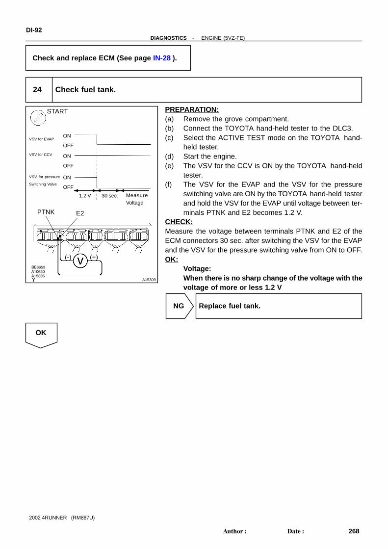
A10620
BE6653
A15305A15309
START
ON
VSV for pressure
Switching Valve
OFFVSV for EVAP
1.2 V
ON
OFF
E2PTNK
(-) (+)
ON
OFF
VSV for CCV
MeasureVoltage
30 sec.
DI-92-DIAGNOSTICS ENGINE (5VZ-FE)
268Author: Date:
2002 4RUNNER (RM887U)
Check and replace ECM (See page IN-28 ).
24 Check fuel tank.
PREPARATION:(a) Remove the grove compartment.(b) Connect the TOYOTA hand-held tester to the DLC3.(c) Select the ACTIVE TEST mode on the TOYOTA hand-
held tester.(d) Start the engine.(e) The VSV for the CCV is ON by the TOYOTA hand-held
tester.(f) The VSV for the EVAP and the VSV for the pressure
switching valve are ON by the TOYOTA hand-held testerand hold the VSV for the EVAP until voltage between ter-minals PTNK and E2 becomes 1.2 V.
CHECK:Measure the voltage between terminals PTNK and E2 of theECM connectors 30 sec. after switching the VSV for the EVAPand the VSV for the pressure switching valve from ON to OFF.OK:
Voltage:When there is no sharp change of the voltage with thevoltage of more or less 1.2 V
NG Replace fuel tank.
OK

BE6653A10621A15305
A15310
ON
OFF
ON
OFF
E2PTNK
(-) (+)
ON
OFF
VSV for pressure
Switching Valve
VSV for EVAP
VSV for CCV
1.2 V MeasureVoltage
START
30 sec.
-DIAGNOSTICS ENGINE (5VZ-FE)DI-93
269Author: Date:
2002 4RUNNER (RM887U)
25 Check charcoal canister.
PREPARATION:(a) Remove the grove compartment.(b) Connect the TOYOTA hand-held tester to the DLC3.(c) Select the ACTIVE TEST mode on the TOYOTA hand-
held tester.(d) Start the engine.(e) The VSV for the CCV and the VSV for the pressure
switching valve are ON by the TOYOTA hand-held tester.(f) The VSV for the EVAP is ON by the TOYOTA hand-held
tester and hold the VSV for the EVAP until voltage be-tween terminals PTNK and E2 becomes 1.2 V.
CHECK:Measure the voltage between terminals PTNK and E2 of theECM connectors 30 sec. after switching the VSV for the EVAPfrom ON to OFF.OK:
Voltage:When there is no sharp change of the voltage with thevoltage of more or less 1.2 V
NG Replace charcoal canister.
OK
26 Remove charcoal canister and check it (See page EC-6 ).
NG Replace charcoal canister.
OK
27 Check fuel tank over fill check valve (See page EC-6 ).
NG Replace fuel tank over fill check valve or fueltank.
OK

DI-94-DIAGNOSTICS ENGINE (5VZ-FE)
270Author: Date:
2002 4RUNNER (RM887U)
Check and replace charcoal canister (Seepage EC-6 ).
OBD II scan tool (excluding TOYOTA hand-held tester):
1 Check whether hose close to fuel tank have been modified, and check whetherthere are signs of any accident near fuel tank or charcoal canister (See page DI-73 , step 1).
NG Repair or replace.
OK
2 Check that fuel tank cap is TOYOTA genuine parts (See page DI-73 , step 2).
NG Replace to TOYOTA genuine parts.
OK
3 Check that fuel tank cap is correctly installed (See page DI-73 , step 3).
NG Correctly install fuel tank cap.
OK
4 Check fuel tank cap (See page DI-73 step, 4).
NG Replace fuel tank cap.
OK

-DIAGNOSTICS ENGINE (5VZ-FE)DI-95
271Author: Date:
2002 4RUNNER (RM887U)
5 Check filler neck for damage (See page DI-73 , step 5).
NG Replace filler pipe.
OK
6 Check vacuum hoses between vapor pressure sensor and fuel tank, charcoalcanister and VSV for pressure switching valve, and VSV for pressure switchingvalve and charcoal canister (See page DI-73 , step 6).
NG Repair or connect VSV or sensor connector.
OK
7 Check hose and tube between fuel tank and charcoal canister (See page DI-73 , step 7).
NG Repair or replace.
OK
8 Check VSV connector for EVAP, VSV connector for CCV, VSV connector for pres-sure switching valve and vapor pressure sensor connector for looseness anddisconnection.
NG Repair or connect VSV or sensor connector.
OK

DI-96-DIAGNOSTICS ENGINE (5VZ-FE)
272Author: Date:
2002 4RUNNER (RM887U)
9 Check vacuum hoses ((8), (9) , (10) and (11) in Fig. 1 in circuit description).
CHECK:(a) Check that the vacuum hose is connected correctly.(b) Check the vacuum hose for looseness and disconnection.(c) Check the vacuum hose for cracks, hole damage and blockage.
NG Repair or replace.
OK
10 Check voltage between terminals VC and E2 of ECM connector (See page DI-73 , step 9).
NG Check and replace ECM (See page IN-28 ).
OK
11 Check voltage between terminals PTNK and E2 of ECM connectors (See pageDI-73 , step 10).
OK Go to step 13.
NG
12 Check for open and short in harness and connector between vapor pressuresensor and ECM (See page IN-28 ).
NG Repair or replace harness or connector.
OK
Replace vapor pressure sensor.

A15307
VSV is ON VSV is OFF
EVP1
ON
ON OFF
Air
E
F
Air
E
F
-DIAGNOSTICS ENGINE (5VZ-FE)DI-97
273Author: Date:
2002 4RUNNER (RM887U)
13 Check VSV for EVAP.
PREPARATION:(a) Remove the glove compartment.(b) Turn the ignition switch ON.CHECK:Check the VSV function.
(1) Connect between terminal EVP1 of the ECM con-nector and body ground (ON).
(2) Disconnect between terminal EVP1 of the ECMconnector and body ground (OFF).
OK:(1) VSV is ON:Air from port E frows out through port F.(2) VSV is OFF:Air does not flow from port E to port F.
OK Go to step 16.
NG
14 Check operation of VSV for EVAP (See page SF-39 ).
OK Go to step 15.
NG
Replace VSV and clean vacuum hoses between throttle body and VSV for EVAP, and VSV forEVAP and charcoal canister, and then check charcoal canister.
15 Check for open and short in harness and connector between EFI main relay(Marking: EFI) and VSV for EVAP, and VSV for EVAP and ECM (See page IN-28 ).
NG Repair or replace harness or connector.
OK

A15312BE6653
A15308A15313
ON
CCV
OFF
ON
AirE
AirE
VSV is ON
F
VSV is OFF
F
DI-98-DIAGNOSTICS ENGINE (5VZ-FE)
274Author: Date:
2002 4RUNNER (RM887U)
Check and replace ECM (See page IN-28 ).
16 Check VSV for CCV.
PREPARATION:(a) Remove the grove compartment.(b) Turn the ignition switch ON.CHECK:Check the VSV function.
(1) Connect between terminal CCV of the ECM con-nector and body ground (ON).
(2) Disconnect between terminal CCV of the ECM con-nector and body ground (OFF).
OK:VSV is ON:Air does not flow from port E to port F.VSV is OFF:Air from port E flows out through port F.
OK Go to step 19.
NG
17 Check operation of VSV for CCV (See page SF-40 ).
OK Go to step 18.
NG
Replace VSV and charcoal canister, and then clean vacuum hose between charcoal canister andVSV for CCV.

BE6653
A15314
A10143A10144
A15315
ON
TBP
OFFON
VSV is ON VSV is OFF
AirAir
E
F
E
F
-DIAGNOSTICS ENGINE (5VZ-FE)DI-99
275Author: Date:
2002 4RUNNER (RM887U)
18 Check for open and short in harness and connector between EFI main relay(Marking: EFI) and VSV for CCV , and VSV for CCV and ECM (See page IN-28 ).
NG Repair or replace harness or connector.
OK
Check and replace ECM (See page IN-28 ).
19 Check VSV for pressure switching valve.
PREPARATION:(a) Remove the grove compartment.(b) Turn the ignition switch ON.CHECK:Check the VSV function.
(1) Connect between terminal TBP of the ECM connec-tor and body ground (ON).
(2) Disconnect between terminal TBP of the ECM con-nector and body ground (OFF).
OK:(1) VSV is ON:Air from port E flows out through port F.(2) VSV is OFF:Air does not flow from port E to port F.
OK Go to step 22
NG
20 Check operation of VSV for pressure switching valve (See page SF-42 ).
OK Go to step 21.
NG

DI-100-DIAGNOSTICS ENGINE (5VZ-FE)
276Author: Date:
2002 4RUNNER (RM887U)
Replace VSV and charcoal canister, and then clean vacuum hoses between charcoal canisterand VSV for pressure switching valve, and VSV for pressure switching valve and fuel tank.
21 Check for open and short in harness and connector between EFI main relay(Marking: EFI) and VSV for pressure switching valve , and VSV for pressureswitching valve and ECM (See page IN-28 ).
NG Repair or replace harness or connector.
OK
Check and replace ECM (See page IN-28 ).
22 Check fuel tank over fill check valve (See page EC-6 ).
NG Replace fuel tank over fill check valve or fueltank.
OK
Check and replace charcoal canister (Seepage EC-6 ).

A10145
ECM
Fuel TankCharcoal Canister
VSV forEVAP
Fuel Tank Over Fill Check Valve
Vapor Pressure Sensor
VSV forCCV
VSV for Pressure Switching Valve
-DIAGNOSTICS ENGINE (5VZ-FE)DI-101
277Author: Date:
2002 4RUNNER (RM887U)
DTC P0450 Evaporative Emission Control System Pres-sure Sensor Malfunction
DTC P0451 Evaporative Emission Control System Pres-sure Sensor Range/Performance
CIRCUIT DESCRIPTIONThe vapor pressure sensor, VSV for canister closed valve (CCV) and VSV for pressure switching valve areused to detect abnormalities in the evaporative emission control system.The ECM decides whether there is an abnormality in the evaporative emission control system based on thevapor pressure sensor signal.DTC P0450 or P0451 is recorded by the ECM when the vapor pressure sensor malfunction.
DTC No. DTC Detecting Condition Trouble Area
P0450
10 seconds or less after engine starting condition vapor pres-
sure sensor fixed value continues for fixed value or more: (2
trip detection logic)
P0451
Vapor pressure sensor output extremely changes under condi-
tions of (a) and (b): (2 trip detection logic)
(a) Vehicle speed: 0 km/h (0mph), Engine speed: Idling and
VSV for pressure switching valve is OFF
(b) vavor pressure sensor value opening pressure valve of
charcoal canister
Open or short in vapor pressure sensor circuit
Vapor pressure sensor
ECM
DI09X-09

DI-102-DIAGNOSTICS ENGINE (5VZ-FE)
278Author: Date:
2002 4RUNNER (RM887U)
WIRING DIAGRAMRefer to DTC P0440 on page DI-73 .
INSPECTION PROCEDUREHINT: If DTC P0441, P0446, P0450 or P0451 is output after DTC P0440 first trouble shoot DTC P0441,
P0446 P0450 or P0451. If no malfunction is detected, troubleshoot DTC P0440 next. Read freeze frame data using LEXUS hand-held tester or OBD II scan tool. Because freeze frame
records the engine conditions when the malfunction is detected. When troubleshooting, it is useful fordetermining whether the vehicle was running or stopped, the engine was warmed up or not, the air-fuelratio was lean or rich, etc. at the time of the malfunction.
When the ENGINE RUN TIME in the freeze frame data is less than 200 seconds, carefully check thevapor pressure sensor.
1 Check voltage between terminals VC and E2 of ECM connector (See pageDI-73 , step 9).
NG Check and replace ECM (See page IN-28 ).
OK
2 Check voltage between terminals PTNK and E2 of ECM connectors (See pageDI-73 , step 10).
OK Check and replace ECM (See page IN-28 ).
NG
3 Check for open and short in harness and connector between vapor pressuresensor and ECM (See page IN-28 ).
NG Repair or replace harness or connector.
OK
Replace vapor pressure sensor.

A00022
FromSpeed Sensor ABS ECU
4-pulse
CombinationMeter
ECM
4-pulse
A15618
Combination Meter3
C28 3E
Center J/B
G-O
ECM
5V
E1
SP1G-O3E
3E
3E
8
5
6
10E146
From A/C Amprifire
From 4WD ECU
-DIAGNOSTICS ENGINE (5VZ-FE)DI-103
279Author: Date:
2002 4RUNNER (RM887U)
DTC P0500 Vehicle Speed Sensor Malfunction
CIRCUIT DESCRIPTIONThe speed sensor for ABS detects the wheel speed and sends the appropriate signals to the ABS ECU. TheECU converts these signals into a 4-pulse signal and outputs it to the combination meter. After this signalis converted into a more precise rectangular waveform by the waveform shaping circuit inside the combina-tion meter, it is then transmitted to the ECM. The ECM determines the vehicle speed based on the frequencyof these pulse signals.
DTC No. DTC Detecting Condition Trouble Area
P0500
No vehicle speed sensor signal to ECM under following condi-
tions: (2 trip detection logic)
For A/T:
(a) Park/neutral position switch is OFF
(b) Vehicle is being driven
For M/T:
(a) Engine speed is between 1,800 rpm and 3,500 rpm
Speedometer cable
Open or short in speed signal circuit
ECM
WIRING DIAGRAM
INSPECTION PROCEDUREHINT:Read freeze frame data using TOYOTA hand-held tester or OBD II scan tool. Because freeze frame recordsthe engine conditions when the malfunction is detected. When troubleshooting, it is useful for determiningwhether the vehicle was running or stopped, the engine was warmed up or not, the air-fuel ratio was leanor rich, etc. at the time of the malfunction.
DI0SB-12

A15316
E12 Connector
SP1
AT7809
4 - 6 V
Turn the Wheel
DI-104-DIAGNOSTICS ENGINE (5VZ-FE)
280Author: Date:
2002 4RUNNER (RM887U)
1 Check operation of speedometer.
CHECK:Drive the vehicle and check if the operation of the speedometer in the combination meter is normal.HINT:The vehicle speed is operating normally if the speedometer display is normal.
NG Check speedometer circuit (See page BE-40 ).
OK
2 Check voltage between terminal SP1 of ECM connector and body ground.
PREPARATION:(a) Remove the glove compartment (See page SF-54 ).(b) Disconnect the E12 connector from the ECM.(c) Shift the shift lever to the neutral.(d) Jack up a rear wheel on one side.(e) Turn the ignition switch ON.CHECK:Measure the voltage between terminal SP1 of the ECM connec-tor and body ground when the wheel is turned slowly.OK:
Voltage is generated intermittently.
NG Check and repair harness and connector be-tween combination meter and ECM.
OK
Check and replace ECM (See page IN-28 ).

-DIAGNOSTICS ENGINE (5VZ-FE)DI-105
281Author: Date:
2002 4RUNNER (RM887U)
DTC P0505 Idle Control System Malfunction
CIRCUIT DESCRIPTIONThe idle speed is controlled by the Electric Throttle Control System (ETCS).ETCS is composed of the throttle motor to operate the throttle valve, the magnetic clutch to connect thethrottle motor with the throttle valve, the throttle position sensor to detect the opening angle of the throttlevalve, the accelerator pedal position sensor to detect the accelerator pedal position, the ECM to control theETCS and the one valve type throttle body.The ECM controls the throttle motor to make the throttle valve opening angle properly for the target idlespeed.
DTC No. DTC Detecting Condition Trouble Area
P0505Idle speed continues to vary greatly from target speed
(2 trip detection logic)
Air induction system
Electric throttle control system
PCV valve and hose
INSPECTION PROCEDUREHINT:Read freeze frame data using TOYOTA hand-held tester or OBD II scan tool. Because freeze frame recordsthe engine conditions when the malfunction is detected. When troubleshooting it is useful for determiningwhether the vehicle was running or stopped, the engine was warmed up or not, the air-fuel ratio was leanor rich, etc. at the time of the malfunction.
1 Are there any other codes (besides P0505) being output?
YES Go to relevant DTC chart (See page DI-13 ).
NO
2 Check connection of PCV valve and hose
NG Repair or replace PCV valve and hose
OK
DI1LY-11

DI-106-DIAGNOSTICS ENGINE (5VZ-FE)
282Author: Date:
2002 4RUNNER (RM887U)
3 Check air induction system (See page SF-1 ).
NG Repair or replace.
OK
Check electric throttle control system (Seepage SF-30 ).

A02396A02395 A02624
0
1.5
Throttle Valve Opening Angle (deg)
70 125
VPA
VPA25
Movable Range
Usable Range
Usable Range*1 *2
*1
*2
Movable Range
UsableRange
*2
*1
Accelerator pedalreleased (15°)
Accelerator pedaldepressed (about100°)
Acc
eler
ator
Ped
al
Pos
ition
Sen
sor
Out
put V
olta
ge (
V)
VPA2 VPAE2 VC
*2:
*1:
VPA2 circuit open or ground short
Accelerator pedal position expressed as voltage
Accelerator pedal released Accelerator pedal depressed
ACCEL POS #1
0 V
0 V
0 V
1.8 - 2.7 V
0 V
5 V
0 V
4.7 - 5.1 V
0 V
5 V
Trouble area
VC circuit open
VPA circuit open or ground short
E2 circuit open
ACCEL POS #2 ACCEL POS #1 ACCEL POS #2
0.3 - 0.9 V
5 V
0 V
0 V
3.2 - 4.8 V
5 V
-DIAGNOSTICS ENGINE (5VZ-FE)DI-107
283Author: Date:
2002 4RUNNER (RM887U)
DTC P1120 Accelerator Pedal Position Sensor Circuit Malfunction
CIRCUIT DESCRIPTIONAccelerator pedal position sensor is mounted on the throttle body and it has the 2 sensors to detects theaccelerator position and a malfunction of the accelerator position’s own.The accelerator pedal position sensor is connected with the accelerator pedal by the accelerator wire andthe voltage applied to the terminals VPA and VPA2 of the ECM changes between 0 V and 5 V in proportionto the opening angle of the accelerator pedal.The ECM judges the current opening angle of the accelerator pedal from these signals input from terminalsVPA and VPA2 and the ECM controls the throttle motor based on these signals.If this DTC is stored, the ECM shuts down the power for the throttle motor and the magnetic clutch, and thethrottle valve is fully closed by the return spring.However, the opening angle of the throttle valve can be controlled by the accelerator pedal through thethrottle cable.
DTC No. DTC Detecting Condition Trouble Area
P1120
Condition (a), (b), (c), (d) or (e) continues for 2.0 seconds:
(a) VPA 0.2 V
(b) VPA2 0.5 V
(c) VPA 4.8 V
(d) When VPA 0.2 V and 1.8 V, and VPA2 4.97 V
(e) VPA-VPA2 0.02 V, or VPA2-VPA 0.02 V
Open or short in accelerator pedal position sensor circuit
Accelerator pedal position sensor
ECM
Condition (a) continues for 0.4 seconds:
(a) VPA 0.2 V and VPA2 0.5 V
HINT:After confirming DTC P1120, use the OBD II scan tool or TOYOTA hand-held tester to confirm the throttlevalve opening percentage.
DI1LZ-14

A03843
ECMA38Accelerator Pedal Position Sensor
VC
VPAGR
G-B
10
L-B
25
3
2
4
11E9
1
LE11
E9
E11
15
E1
VPA2
E2
FI7052
DI-108-DIAGNOSTICS ENGINE (5VZ-FE)
284Author: Date:
2002 4RUNNER (RM887U)
WIRING DIAGRAM
INSPECTION PROCEDUREHINT: If DTCs P0110, P0115, P0120, P0450 and P1120 are output simultaneously, E2 (sensor ground) may
be open. Read freeze frame data using TOYOTA hand-held tester or OBD II scan tool. Because freeze frame
records the engine conditions when the malfunction is detected. When troubleshooting it is useful fordetermining whether the vehicle was running or stopped, the engine was warmed up or not, the air-fuelratio was lean or rich, etc. at the time of the malfunction.
TOYOTA hand-held tester:
1 Connect TOYOTA hand-held tester, and read the voltage for accelerator pedalposition sensor data.
PREPARATION:(a) Connect the TOYOTA hand-held tester to the DLC3.(b) Turn the ignition switch ON and push the TOYOTA hand-
held tester main switch ON.CHECK:Read the voltage for the accelerator pedal position sensor data.OK:
Accelerator Pedal VPA VPA2
Released 0.3 - 0.9 V 1.8 - 2.7 V
Depressed 3.2 - 4.8 V 4.7 - 5.1 V
OK Check and replace ECM (See page IN-28 ).
NG

A15301
E2VC
ON
(+)(-)
A15317
ON
VPA VPA2E2
(+)(-)
-DIAGNOSTICS ENGINE (5VZ-FE)DI-109
285Author: Date:
2002 4RUNNER (RM887U)
2 Check voltage between terminals VC and E2 of ECM connector.
PREPARATION:(a) Remove the glove compartment door.(b) Turn the ignition switch ON.CHECK:Measure the voltage between terminals VC and E2 of the ECMconnector.OK:
Voltage: 4.5 - 5.5 V
NG Check and replace ECM (See page IN-28 ).
OK
3 Check voltage between terminals VPA and E2, and VPA2 and E2 of ECM connec-tor.
PREPARATION:(a) Remove the glove compartment door.(b) Turn the ignition switch ON.CHECK:Measure the voltage between terminals VPA and E2, and VPA2and E2 of the ECM connector.OK:
A l t d lVoltage
Accelerator pedalVPA - E2 VPA2 - E2
Released 0.3 - 0.9 V 1.8 - 2.7 V
Depressed 3.2 - 4.8 V 4.7 - 5.1 V
OK Check and replace ECM (See page IN-28 ).
NG
4 Check accelerator pedal position sensor (See page SF-30 ).
NG Replace accelerator pedal position sensor (Seepage SF-32 ).
OK

A15301
E2VC
ON
(+)(-)
A15317
ON
VPA VPA2E2
(+)(-)
DI-1 10-DIAGNOSTICS ENGINE (5VZ-FE)
286Author: Date:
2002 4RUNNER (RM887U)
Check for open and short in harness and connector in VC, VPA, VPA2 and E2 circuits betweenECM and accelerator pedal position sensor (See page IN-28 ).
OBD II scan tool (excluding TOYOTA hand-held tester):
1 Check voltage between terminals VC and E2 of ECM connector.
PREPARATION:(a) Remove the glove compartment door.(b) Turn the ignition switch ON.CHECK:Measure the voltage between terminals VC and E2 of the ECMconnector.OK:
Voltage: 4.5 - 5.5 V
NG Check and replace ECM (See page IN-28 ).
OK
2 Check voltage between terminals VPA and E2, and VPA2 and E2 of ECM connec-tor.
PREPARATION:(a) Remove the glove compartment door.(b) Turn the ignition switch ON.CHECK:Measure the voltage between terminals VPA and E2, and VPA2and E2 of the ECM connector.OK:
A l t d lVoltage
Accelerator pedalVPA - E2 VPA2 - E2
Released 0.3 - 0.9 V 1.8 - 2.7 V
Depressed 3.2 - 4.8 V 4.7 - 5.1 V
OK Check and replace ECM (See page IN-28 ).
NG

-DIAGNOSTICS ENGINE (5VZ-FE)DI-1 11
287Author: Date:
2002 4RUNNER (RM887U)
3 Check accelerator pedal position sensor (See page SF-30 ).
NG Replace accelerator pedal position sensor (Seepage SF-32 ).
OK
Check for open and short in harness and connector in VC, VPA, VPA2 and E2 circuits betweenECM and accelerator pedal position sensor (See page IN-28 ).

DI-1 12-DIAGNOSTICS ENGINE (5VZ-FE)
288Author: Date:
2002 4RUNNER (RM887U)
DTC P1121 Accelerator Pedal Position Sensor Range/Performance Problem
CIRCUIT DESCRIPTIONRefer to DTC P1120 on page DI-107 .
DTC No. DTC Detecting Condition Trouble Area
P1121Condition (a) continues for 2.0 seconds:
(a) Difference between VPA and VPA2 is out of thresholdAccelerator pedal position sensor
INSPECTION PROCEDUREHINT:Read freeze frame data using TOYOTA hand-held tester or OBD II scan tool. Because freeze frame recordsthe engine conditions when the malfunction is detected. When troubleshooting it is useful for determiningwhether the vehicle was running or stopped, the engine was warmed up or not, the air-fuel ratio was leanor rich, etc. at the time of the malfunction.
Replace accelerator pedal position sensor (See page SF-32 ).
DI1M0-10

A02990 A09802
T7Throttle Control Motorwith Magnetic Switch
2
1
3
4
R
G
Y
L
ECM
9
31
2
M+
M-
CL+
CL-
E9
E9
E11
8
E11
-DIAGNOSTICS ENGINE (5VZ-FE)DI-1 13
289Author: Date:
2002 4RUNNER (RM887U)
DTC P1125 Throttle Control Motor Circuit Malfunction
CIRCUIT DESCRIPTIONThrottle motor is operated by the ECM and it opens and closes the throttle valve.The opening angle of the throttle valve is detected by the throttle position sensor which is mounted on thethrottle body and it provides feedback to the ECM to control the throttle motor in order to the throttle valveopening angle properly in response to driving condition.If this DTC is stored, the ECM shuts down the power for the throttle motor and the magnetic clutch, and thethrottle valve is fully closed by the return spring.However, the opening angle of the throttle valve can be controlled by the accelerator pedal through thethrottle cable.
DTC No. DTC Detecting Condition Trouble Area
Conditions (a) and (b) continue for 0.5 seconds:
(a) Throttle control motor output duty 80 %
(b) Throttle control motor current < 0.5 A Open or short in throttle control motor circuit
P1125Throttle control motor current 16 A
Throttle control motor
ECMCondition (a) continues for 0.6 seconds:
(a) Throttle control motor current 7 A
ECM
WIRING DIAGRAM
INSPECTION PROCEDUREHINT:Read freeze frame data using TOYOTA hand-held tester or OBD II scan tool. Because freeze frame recordsthe engine conditions when the malfunction is detected. When troubleshooting it is useful for determiningwhether the vehicle was running or stopped, the engine was warmed up or not, the air-fuel ratio was leanor rich, etc. at the time of the malfunction.
DI8XK-01

A03403
A03404 A03675
M+ Signal Waveform5 V/Division
GND
1 msec./Division
M- Signal Waveform
GND
5 V/Division
1 msec./Division
DI-1 14-DIAGNOSTICS ENGINE (5VZ-FE)
290Author: Date:
2002 4RUNNER (RM887U)
1 Check throttle control motor circuit.
When not using TOYOTA hand-held tester:PREPARATION:(a) Connect the oscilloscope between terminals M+ or M-
and E1 of the ECM connector.(b) Start the engine.CHECK:Check the waveform between terminals M+ or M- and E1 of theECM when the engine is idling.OK:
The correct waveforms are as shown.HINT:The waveform frequency varies depending on the throttleopening.
OK Check and replace ECM (See page IN-28 ).
NG
2 Check throttle control motor (See page SF-30 ).
NG Replace throttle control motor (See page SF-32 ).
OK
3 Check for open and short in harness and connector between throttle control mo-tor and ECM (See page IN-28 ).
NG Repair or replace.
OK
Check and replace ECM (See page IN-28 ).

-DIAGNOSTICS ENGINE (5VZ-FE)DI-1 15
291Author: Date:
2002 4RUNNER (RM887U)
DTC P1126 Magnetic Clutch Circuit Malfunction
CIRCUIT DESCRIPTIONMagnetic clutch is mounted between the throttle motor and the valve, and it connects the throttle motor withthe throttle valve.Therefore, the throttle motor opens and closes the throttle valve through the magnetic clutch.If the electric throttle control system has a malfunction, the magnetic clutch separates the throttle motor fromthe throttle valve in order not to operate the throttle valve by the throttle motor.If this DTC is stored, the ECM shuts down the power for the throttle motor and the magnetic clutch, and thethrottle valve is fully closed by the return spring.However, the opening angle of the throttle valve can be controlled by the accelerator pedal through thethrottle cable.
DTC No. DTC Detecting Condition Trouble Area
P1126
Condition (a) continues for 0.8 seconds:
(a) Magnetic clutch current 1.4 A or 0.4 A Open or short in magnetic clutch circuit
M ti l t hP1126Condition (a) continues for 1.5 seconds:
(a) Magnetic clutch current 1.0 A or 0.8 A
Magnetic clutch
ECM
WIRING DIAGRAMRefer to DTC P1125 on page DI-1 13.
INSPECTION PROCEDUREHINT:Read freeze frame data using TOYOTA hand-held tester or OBD II scan tool. Because freeze frame recordsthe engine conditions when the malfunction is detected. When troubleshooting it is useful for determiningwhether the vehicle was running or stopped, the engine was warmed up or not, the air-fuel ratio was leanor rich, etc. at the time of the malfunction.
1 Check magnetic clutch circuit.
When using TOYOTA hand-held tester:PREPARATION:(a) Connect the TOYOTA hand-held tester to the DLC3.(b) Turn the ignition switch ON and push the TOYOTA hand-held tester main switch ON.CHECK:Read the magnetic clutch current value on the TOYOTA hand-held tester.OK:
Current: 0.8 - 1.0 A
DI8XL-01

A03405
CL Signal Waveform
5 V/Division
GND
5 msec./Division
DI-1 16-DIAGNOSTICS ENGINE (5VZ-FE)
292Author: Date:
2002 4RUNNER (RM887U)
When not using TOYOTA hand-held tester:PREPARATION:(a) Connect the oscilloscope between terminals CL+ and
CL- of the ECM connector.(b) Start the engine.CHECK:Check the waveform between terminals CL+ and CL- of theECM connector when the engine is idling.OK:
The correct waveform is as shown.
NG Go to step 4.
OK
2 Check magnetic clutch (See page SF-30 ).
NG Replace throttle control motor with magneticclutch (See page SF-32 ).
OK
3 Check for open and short in harness and connector between magnetic clutchand ECM (See page IN-28 ).
NG Repair or replace.
OK

-DIAGNOSTICS ENGINE (5VZ-FE)DI-1 17
293Author: Date:
2002 4RUNNER (RM887U)
4 Check operation of magnetic clutch.
CHECK:(a) Clear the DTC.(b) Perform the following steps and check the DTC.
(1) Turn the ignition switch ON.(2) Start the engine.(3) Turn the ignition switch OFF and wait 3 seconds.(4) Turn the ignition switch ON.
OK:DTC P1126 is not stored.
NG Replace throttle control motor with magneticclutch (See page SF-32 ).
OK
Check and replace ECM (See page IN-28 ).

A15460
ECM
+BME14
8G
Battery
ETCS
Engine Room R/B
IG1G24
W-R
2 2
22
W
21
DI-1 18-DIAGNOSTICS ENGINE (5VZ-FE)
294Author: Date:
2002 4RUNNER (RM887U)
DTC P1127 ETCS Actuator Power Source Circuit Malfunction
CIRCUIT DESCRIPTIONBattery positive voltage is supplied to terminal +BM of the ECM even once when the ignition switch is OFFfor the electric ETCS control system.If this DTC is stored, the ECM shuts down the power for the ETCS motor and the magnetic clutch, and theETCS valve is fully closed by the return spring.However, the opening angle of the ETCS valve can be controlled by the accelerator pedal through the ETCScable.
DTC No. DTC Detecting Condition Trouble Area
P1127 Open in ETCS power source circuitOpen in ETCS power source circuit
ECM
WIRING DIAGRAM
INSPECTION PROCEDUREHINT:Read freeze frame data using TOYOTA hand-held tester or OBD II scan tool. Because freeze frame recordsthe engine conditions when the malfunction is detected. When troubleshooting it is useful for determiningwhether the vehicle was running or stopped, the engine was warmed up or not, the air-fuel ratio was leanor rich, etc. at the time of the malfunction.
DI1M4-14

A15318
Engine Room R/B
ETCS Fuse
A15319
+BM
LOCK
(+) (-)
-DIAGNOSTICS ENGINE (5VZ-FE)DI-1 19
295Author: Date:
2002 4RUNNER (RM887U)
1 Check ETCS fuse.
PREPARATION:Remove the ETCS fuse from the engine room R/B.CHECK:Check the countinuity of the ETCS fuse.OK:
Continuity
NG Check for short in all harness and componentsconnected to ETCS fuse.
OK
2 Check voltage between terminal +BM of ECM connector and body ground.
PREPARATION:Remove the glove compartment door.CHECK:Measure the voltage between terminal +BM of the ECM con-nector and body ground.OK:
Voltage: 9 - 14 V
OK Check and replace ECM (See page IN-28 ).
NG
Check and repair harness or connector between battery and ETCS fuse, and ETCS fuse and ECM(See page IN-28 ).

DI-120-DIAGNOSTICS ENGINE (5VZ-FE)
296Author: Date:
2002 4RUNNER (RM887U)
DTC P1128 Throttle Control Motor Lock Malfunction
CIRCUIT DESCRIPTIONThrottle motor is operated by the ECM and it opens and closes the throttle valve. The opening angle of thethrottle valve is detected by the throttle position sensor which is mounted on the throttle body and it providesfeedback to the ECM to control the throttle motor in order the throttle valve opening angle properly in re-sponse to driving condition. If this DTC is stored, the ECM shuts down the power for the throttle motor andthe magnetic clutch, and the throttle valve is fully closed by the return spring. However, the opening angleof the throttle valve can be controlled by the accelerator pedal through the throttle cable.
DTC No. DTC Detecting Condition Trouble Area
P1128 Lock throttle control motor during control throttle control motorThrottle control motor
Throttle body
INSPECTION PROCEDUREHINT:Read freeze frame data using TOYOTA hand-held tester or OBD II scan tool. Because freeze frame recordsthe engine conditions when the malfunction is detected. When troubleshooting it is useful for determiningwhether the vehicle was running or stopped, the engine was warmed up or not, the air-fuel ratio was leanor rich, etc. at the time of the malfunction.
1 Check throttle control motor (See page DI-1 13).
NG Replace throttle control motor (See page SF-32 ).
OK
2 Visualy check throttle valve.
PREPARATION:Remove the intake air connector.CHECK:Check whether or not a foreign body is caught between the throttle valve and the housing.
NG Remove a foreign body and clean throttle body.
OK
Replace throttle body.
DI8XM-01
-DIAGNOSTICS ENGINE (5VZ-FE)DI-121
297Author: Date:
2002 4RUNNER (RM887U)
DTC P1129 Electric Throttle Control System Malfunction
CIRCUIT DESCRIPTIONElectric Throttle Control System (ETCS) is composed of the throttle motor to operate the throttle valve, theelectromagnetic clutch to connect the throttle motor with the throttle valve, the throttle position sensor to de-tect the opening angle of the throttle valve, the accelerator pedal position sensor to detect the acceleratorpedal position, the ECM to control the ETCS and the one valve type throttle body.The ECM controls the throttle motor to make the throttle valve opening angle properly in response drivingcondition.The throttle position sensor which is mounted on the throttle body detects the opening angle of the throttlevalve, and it provides feedback to the ECM to control the throttle motor.If the ETCS has a malfunction, the ECM shuts down the power for the throttle motor and the magnetic clutch,and the throttle valve is fully closed by the return spring.However, the opening angle of the throttle valve can be controlled by the accelerator pedal through thethrottle cable.
DTC No. DTC Detecting Condition Trouble Area
P1129Throttle opening angle continues to vary great from target
throttle opening angle
Electric throttle control system
ECM
WIRING DIAGRAMRefer to DTC P1125 on page DI-1 13.
INSPECTION PROCEDUREHINT:Read freeze frame data using TOYOTA hand-held tester or OBD II scan tool. Because freeze frame recordsthe engine conditions when the malfunction is detected. When troubleshooting it is useful for determiningwhether the vehicle was running or stopped, the engine was warmed up or not, the air-fuel ratio was leanor rich, etc. at the time of the malfunction.
Replace ECM, and clear DTC. If DTC P1129 is memorized again, and then replace throttle body.
DI1M6-10

A00364
Vehicle Speed
60 - 120 km/h(38 - 75 mph)
IdlingIG SW OFF
3 - 5 min. Time
(1)(2)
(3)
(4)
DI-122-DIAGNOSTICS ENGINE (5VZ-FE)
298Author: Date:
2002 4RUNNER (RM887U)
DTC P1130 A/F Sensor Circuit Range/Performance Mal-function (Bank 1 Sensor 1)
CIRCUIT DESCRIPTIONRefer to DTC P0125 on page DI-42 .
DTC No. DTC Detecting Condition Trouble Area
Voltage output* of A/F sensor remains at 3.8 V or more, or
2.8 V or less, during engine running after engine is warmed
up (2 trip detection logic)
*: Output value changes at inside of ECM only
Open or short in A/F sensor circuit
A/F sensor
P1130 Voltage output* of A/F sensor does not change from 3.30 V,
during engine running after engine is warmed up
(2 trip detection logic)
*: Output value changes at inside of ECM only
Air induction system
Fuel pressure
Injector
ECM
Open or short in A/F sensor circuit (2 trip detection logic)
HINT: After confirming DTC P1130, use the OBD II scan tool or TOYOTA hand-held tester to confirm voltage
output of the A/F sensor (AFS B1 S1/O2S B1 S1) from the CURRENT DATA. The A/F sensor’s output voltage and the short-term fuel value can be read using the OBD II scan tool
or TOYOTA hand-held tester. The ECM controls the voltage of AF1+ and AF1- terminals of the ECM to the fixed voltage. Therefore,
it is impossible to confirm the A/F sensor output voltage without OBD II scan tool or TOYOTA hand-held tester.
OBD II scan tool (excluding TOYOTA hand-held tester) displays the one fifth of the A/F sensor outputvoltage which is displayed on the TOYOTA hand-held tester.
WIRING DIAGRAMRefer to DTC P0125 on page DI-42 .
CONFIRMATION DRIVING PATTERN
(1) Connect the TOYOTA hand-held tester to the DLC3.(2) Switch the TOYOTA hand-held tester from the normal mode to the check mode (See page
DI-3 ).
DI5CA-07

-DIAGNOSTICS ENGINE (5VZ-FE)DI-123
299Author: Date:
2002 4RUNNER (RM887U)
(3) Start the engine and warm it up with all the accessory switches OFF.(4) Drive the vehicle at 60 - 120 km/h (38 - 75 mph) and the engine speed at 1,600 - 3,200 rpm
for 3 - 5 min.HINT:If a malfunction exists, the MIL will light up during step (4).NOTICE: If the conditions in this test are not strictly followed, detection of the malfunction will not be
possible. If you do not have a TOYOTA hand-held tester, turn the ignition switch OFF after performing
steps (3) and (4), then perform steps (3) and (4) again.
INSPECTION PROCEDUREHINT: If DTC P1130 is displayed, check the bank 1 sensor 1 circuit. Read frame freeze data using the TOYOTA hand-held tester or OBD II scan tool. Because freeze
frame records the engine conditions when the malfunction is detected. When troubleshooting, it is use-ful for determining whether the vehicle was running or stopped, the engine was warmed up or not, theair-fuel ratio was lean or rich, etc. at the time of the malfunction.
1 Are there any other codes (besides DTC P1130) being output?
YES Go to relevant DTC chart.
NO
2 Connect OBDII scan tool or TOYOTA hand-held tester, and read value for volt-age output of A/F sensor.
PREPARATION:(a) Connect the OBD II scan tool or TOYOTA hand-held tester to the DLC3.(b) Warm up the A/F sensor with the engine speed at 2,500 rpm for approx. 90 sec.CHECK:Read the voltage of the A/F sensor on the screen of OBD II scan tool or TOYOTA hand-held tester whenyou perform all the following conditions.HINT:The voltage of the AF1+ terminals of the ECM is fixed at 3.3 V and the voltage of the AF1- terminals is fixedat 3.0 V. Therefore, it is impossible to check the A/F sensor output voltage at the terminals (AF1+/AF1-) ofthe ECM.OK:
Condition A/F Sensor Voltage value
Engine idling
Engine racingNot remains at 3.30 V (0.660 V*)
Not remains at 3 8 V (0 76 V*) or moreDriving at engine speed 1,500 rpm or more and vehicle
speed 40 km/h (25 mph) or more, and operate throttle valve
open and close
Not remains at 3.8 V (0.76 V*) or more
Not remains at 2.8 V (0.56 V*) or less
*: When you use the OBD II scan tool (excluding TOYOTA hand-held tester)

DI-124-DIAGNOSTICS ENGINE (5VZ-FE)
300Author: Date:
2002 4RUNNER (RM887U)
HINT: During fuel enrichment, there is a case that the output voltage of the A/F sensor is below 2.8 V (0.56
V*), it is normal. During fuel cut, there is a case that the output voltage of the A/F sensor is above 3.8 V (0.76 V*), it
is normal. If the output voltage of the A/F sensor remains at 3.30 V (0.660 V*) even after performing all the above
conditions, the A/F sensor circuit may be open. If the output voltage of the A/F sensor remains at 3.8 V (0.76V*) or more, or 2.8 V (0.56 V*) or less even
after performing all the above conditions, the A/F sensor circuit may be short.*: When you use the OBD II scan tool (excluding TOYOTA hand-held tester).
OK Go to step 8.
NG
3 Check for open and short in harness and connector between ECM and A/F sen-sor (See page IN-28 ).
NG Repair or replace harness or connector.
OK
4 Check resistance of A/F sensor heater (See page SF-51 ).
NG Replace A/F sensor.
OK
5 Check air induction system (See page SF-1 ).
NG Repair or replace.
OK
6 Check fuel pressure (See page SF-7 ).

-DIAGNOSTICS ENGINE (5VZ-FE)DI-125
301Author: Date:
2002 4RUNNER (RM887U)
NG Check and repair fuel pump, pressure regulator,fuel pipe line and filter (See page SF-1 ).
OK
7 Check injector injection (See page SF-21 ).
NG Replace injector.
OK
Replace A/F sensor.
8 Perform confirmation driving pattern.
Go
9 Is there DTC P1130 being output again?
YES Check and replace ECM (See page IN-28 ).
NO
10 Did vehicle runs out of fuel in past?
NO Check for intermittent problems (See page DI-3 ).
YES
DTC P1130 is caused by running out of fuel.

DI-126-DIAGNOSTICS ENGINE (5VZ-FE)
302Author: Date:
2002 4RUNNER (RM887U)
DTC P1133 A/F Sensor Circuit Response Malfunction(Bank 1 Sensor 1)
CIRCUIT DESCRIPTIONRefer to DTC P0125 on page DI-42 .
DTC No. DTC Detecting Condition Trouble Area
P1133
After engine is warmed up and during vehicle driving at
engine speed 1,400 rpm or more and vehicle speed 60
km/h (38 mph) or more, if response characteristic of A/F
sensor becomes deteriorated (2 trip detection logic)
Open or short in A/F sensor circuit
A/F sensor
Air induction system
Fuel pressure
Injector
ECM
WIRING DIAGRAMRefer to DTC P0125 on page DI-42 .
INSPECTION PROCEDUREHINT:Read freeze frame data using the TOYOTA hand-held tester or OBD II scan tool. Because freeze framerecords the engine conditions when the malfunction is detected. When troubleshooting, it is useful for deter-mining whether the vehicle was running or stopped, the engine was warmed up or not, the air-fuel ratio waslean or rich, etc. at the time of the malfunction.
1 Are there any other codes (besides DTC P1133) being output?
YES Go to relevant DTC chart.
NO
2 Connect OBDII scan tool or TOYOTA hand-held tester, and read value for volt-age output of A/F sensor.
PREPARATION:(a) Connect the OBD II scan tool or TOYOTA hand-held tester to the DLC3.(b) Warm up the A/F sensor with the engine speed at 2,500 rpm for approx. 90 sec.CHECK:Read the voltage of the A/F sensor on the screen of the OBD II scan tool or TOYOTA hand-held tester whenyou perform all the following conditions.HINT:The voltage of the AF1+ terminal of the ECM is fixed at 3.3 V and the voltage of the AF1- terminal is fixedat 3.0 V. Therefore, it is impossible to check the A/F sensor output voltage at the terminals (AF1+/AF1-) ofthe ECM.
DI5CB-07

-DIAGNOSTICS ENGINE (5VZ-FE)DI-127
303Author: Date:
2002 4RUNNER (RM887U)
OK:
Condition A/F Sensor Voltage value
Engine idling
Engine racingNot remains at 3.30 V (0.660 V*)
Not remains at 3 8 V (0 76 V*) or moreDriving at engine speed 1,500 rpm or more and vehicle
speed 40 km/h (25 mph) or more, and operate throttle valve
open and close
Not remains at 3.8 V (0.76 V*) or more
Not remains at 2.8 V (0.56 V*) or less
*: When you use the OBD II scan tool (excluding TOYOTA hand-held tester)
HINT: During fuel enrichment, there is a case that the output voltage of the A/F sensor is below 2.8 V (0.56
V*), it is normal. During fuel cut, there is a case that the output voltage of the A/F sensor is above 3.8 V (0.76 V*), it
is normal. If the output voltage of the A/F sensor remains at 3.30 V (0.660 V*) even after performing all the above
conditions, the A/F sensor circuit may be open. If the output voltage of the A/F sensor remains at 3.8 V (0.76V*) or more, or 2.8 V (0.56 V*) or less even
after performing all the above conditions, the A/F sensor circuit may be short.*: When you use the OBD II scan tool (excluding TOYOTA hand-held tester).
OK Go to step 8.
NG
3 Check for open and short in harness and connector between ECM and A/F sen-sor (See page IN-28 ).
NG Repair or replace harness or connector.
OK
4 Check resistance of A/F sensor heater (See page SF-51 ).
NG Replace A/F sensor.
OK
5 Check air induction system (See page SF-1 ).
NG Repair or replace.

DI-128-DIAGNOSTICS ENGINE (5VZ-FE)
304Author: Date:
2002 4RUNNER (RM887U)
OK
6 Check fuel pressure (See page SF-7 ).
NG Check and repair fuel pump, pressure regulator,fuel pipe line and filter (See page SF-1 ).
OK
7 Check injector injection (See page SF-21 ).
NG Replace injector.
OK
Replace A/F sensor.
8 Perform confirmation driving pattern (See page DI-122 ).
Go
9 Is there DTC P1133 being output again?
YES Check and replace ECM (See page IN-28 ).
NO
10 Did vehicle runs out of fuel in past?
NO Check for intermittent problems (See page DI-3 ).

-DIAGNOSTICS ENGINE (5VZ-FE)DI-129
305Author: Date:
2002 4RUNNER (RM887U)
YES
DTC P1133 is caused by running out of fuel.

A15319
HTAF1
(+) (-)
ON
DI-130-DIAGNOSTICS ENGINE (5VZ-FE)
306Author: Date:
2002 4RUNNER (RM887U)
DTC P1135 A/F Sensor Heater Circuit Malfunction (Bank1 Sensor 1) (California Spec.)
CIRCUIT DESCRIPTIONRefer to DTC P0125 on page DI-42 .
DTC No. DTC Detecting Condition Trouble Area
P1135
When heater operates, heater current exceeds 8 A
(2 trip detection logic) Open or short in heater circuit of A/F sensor
A/F h tP1135Heater current of 0.25 A or less when heater operates
(2 trip detection logic)
A/F sensor heater
ECM
WIRING DIAGRAMRefer to DTC P0125 on page DI-42 .
INSPECTION PROCEDUREHINT:Read freeze frame data using the TOYOTA hand-held tester or OBD II scan tool. Because freeze framerecords the engine conditions when the malfunction is detected. When troubleshooting, it is useful for deter-mining whether the vehicle was running or stopped, the engine was warmed up or not, the air-fuel ratio waslean or rich, etc. at the time of the malfunction.
1 Check voltage between terminal HTAF of ECM connector and body ground.
PREPARATION:(a) Remove the glove compartment (See page SF-53 ).(b) Turn the ignition switch ON.CHECK:Measure the voltage between terminals HTAF of the ECM con-nector and body ground.OK:
Voltage: 9 - 14 V
OK Check and replace ECM (See page IN-28 ).
NG
2 Check resistance of A/F sensor heater (See page SF-51 ).
NG Replace A/F sensor.
OK
DI5CC-07

-DIAGNOSTICS ENGINE (5VZ-FE)DI-131
307Author: Date:
2002 4RUNNER (RM887U)
Check and repair harness or connector between EFI main relay (Marking: EFI) and A/F sensor,and A/F sensor and ECM (See page IN-28 ).

S00251
Camshaft G
NE ECM
IGT1
IGF
IGT2
Spark Plug
No.1 Cylinder
No.4 Cylinder
To Tachometer
EXT
PositionSensor
CrankshaftPosition
Sensor
VariousSensor
IGT3 IGC3
IGC2
IGC1
GND
No.4 Cylinder
No.5 Cylinder
No.2 Cylinder
No.3 Cylinder
No.6 Cylinder
Ignition CoilFrom Battery
DI-132-DIAGNOSTICS ENGINE (5VZ-FE)
308Author: Date:
2002 4RUNNER (RM887U)
DTC P1300 Igniter Circuit Malfunction
CIRCUIT DESCRIPTIONA Direct Ignition System (DIS) has been adopted. The DIS improves the ignition timing accuracy, reduceshigh-voltage loss, and enhances the overall reliability of the ignition system by eliminating the distributor.The DIS is a 2-cylinder simultaneous ignition system which ignites 2 cylinders simultaneously with one igni-tion coil. In the 2-cylinder simultaneous ignition system, each of the 2 spark plugs is connected to the endof the secondary winding. High voltage generated in the secondary winding is applied directly to the sparkplugs. The sparks of the 2 spark plugs pass simultaneously from the center electrode to the ground elec-trode. The ECM determines ignition timing end outputs the ignition signals (IGT) for each cylinder. Basedon IGT signals, the igniter controls the primary ignition signals (IGC) for all ignition coils. At the same time,the igniter also sends an ignition confirmation signal (IGF) as a fail-safe measure to the ECM.
DTC No. DTC Detecting Condition Trouble Area
P1300
Condition (a) is repeated 3 times consecutively during 6 con-
secutively IGT signals while engine is running (a) IGF signal is
not input to ECM for 2 or more ignitions
Ignition system
Open or short in IGF and IGT circuits from igniter to ECM
Igniter
Ignition coil
ECM
DI0SD-15

A07550
ECM
IGT111E10
B-L
9
W-B
Battery
WA
M2
I14IG Switch
2
2
2
1
EC
IGT2
IGT3
IGF
5V
10
9
2
L-Y
G-W
B-Y
7
6
5
4
83
1
2
10
I2Igniter
Engine Room R/B
W-R
1I7
Driver Side J/B
1J B-R1
II3
I14 Igniter Coil
1
2
1
2
1
2
B-R
B-R
R
G
L
B-R
B-R
B-R
To SparkPlug
No.1
No.2
No.3
To Combination Meter
6
7 B-R4
E10
E10
E10
-DIAGNOSTICS ENGINE (5VZ-FE)DI-133
309Author: Date:
2002 4RUNNER (RM887U)
WIRING DIAGRAM
INSPECTION PROCEDUREHINT:Read freeze frame data using the TOYOTA hand-held tester or OBD II scan tool. Because freeze framerecords the engine conditions when the malfunction is detected. When troubleshooting, it is useful for deter-mining whether the vehicle was running or stopped, the engine was warmed up or not, the air-fuel ratio waslean or rich, etc. at the time of the malfunction.
1 Check spark plug and spark of misfiring cylinder (See page DI-57 ).
NG Go to step 4.
OK
2 Check for open and short in harness and connector in IGF signal circuit betweenECM and igniter (See page IN-28 ).
NG Repair or replace harness or connector.
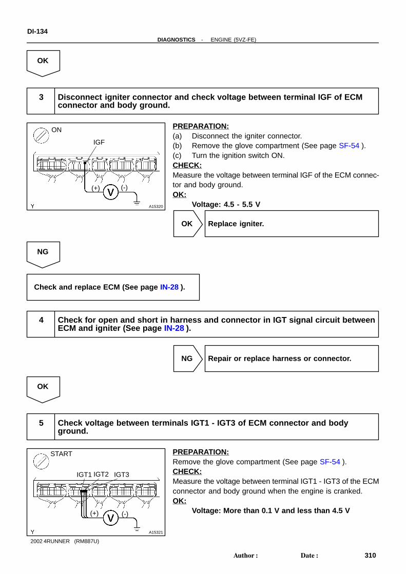
A15320
ON
IGF
(+) (-)
A15321
START
IGT3
(+) (-)
IGT1 IGT2
DI-134-DIAGNOSTICS ENGINE (5VZ-FE)
310Author: Date:
2002 4RUNNER (RM887U)
OK
3 Disconnect igniter connector and check voltage between terminal IGF of ECMconnector and body ground.
PREPARATION:(a) Disconnect the igniter connector.(b) Remove the glove compartment (See page SF-54 ).(c) Turn the ignition switch ON.CHECK:Measure the voltage between terminal IGF of the ECM connec-tor and body ground.OK:
Voltage: 4.5 - 5.5 V
OK Replace igniter.
NG
Check and replace ECM (See page IN-28 ).
4 Check for open and short in harness and connector in IGT signal circuit betweenECM and igniter (See page IN-28 ).
NG Repair or replace harness or connector.
OK
5 Check voltage between terminals IGT1 - IGT3 of ECM connector and bodyground.
PREPARATION:Remove the glove compartment (See page SF-54 ).CHECK:Measure the voltage between terminal IGT1 - IGT3 of the ECMconnector and body ground when the engine is cranked.OK:
Voltage: More than 0.1 V and less than 4.5 V

P20870
IGT and Signal WaveformVOLT
20 msec./Division (Idling)
IGT1
IGT2
IGT3IGF
50505050
A15321
START
IGT3
(+) (-)
IGT1 IGT2
BE6653P24329 A00124
ON START
9
(+)
(-)
-DIAGNOSTICS ENGINE (5VZ-FE)DI-135
311Author: Date:
2002 4RUNNER (RM887U)
Reference: INSPECTION USING OSCILLOSCOPEDuring idling, check waveform between terminals IGT1 - IGT3and E1, and IGF and E1 of the ECM connector.HINT:The correct waveform is as shown.
NG Check and replace ECM (See page IN-28 ).
OK
6 Disconnect igniter connector, and check voltage between terminals IGT1 - IGT3of ECM connector and body ground.
PREPARATION:(a) Disconnect the igniter connector.(b) Remove the glove compartment (See page SF-54 ).CHECK:Measure the voltage between terminals IGT1 - IGT3 of theECM connector and body ground when the engine is cranked.OK:
Voltage: More than 0.1 V and less than 5.0 V
NG Check and replace ECM (See page IN-28 ).
OK
7 Check voltage between terminal 9 of igniter connector and body ground.
PREPARATION:Disconnect the igniter connector.CHECK:Measure the voltage between terminal 9 of the igniter connec-tor and body ground when the ignition switch is turned to ONand START position.OK:
Voltage: 9 - 14 V
NG Check and repair igniter power source circuit.
OK

DI-136-DIAGNOSTICS ENGINE (5VZ-FE)
312Author: Date:
2002 4RUNNER (RM887U)
8 Check for open and short in harness and connector between ignition switch andignition coil, and ignition coil and igniter (See page IN-28 ).
NG Repair or replace harness or connector.
OK
9 Check ignition coil (See page IG-1 ).
NG Replace ignition coil.
OK
Replace igniter.

-DIAGNOSTICS ENGINE (5VZ-FE)DI-137
313Author: Date:
2002 4RUNNER (RM887U)
DTC P1335 Crankshaft Position Sensor Circuit Malfunc-tion (During engine running)
CIRCUIT DESCRIPTIONRefer to DTC P0335 on page DI-66 .
DTC No. DTC Detecting Condition Trouble Area
P1335No crankshaft position sensor signal to ECM with engine
speed 1,000 rpm or more
Open or short in crankshaft position sensor circuit
Crankshaft position sensor
Crankshaft timing pulley
ECM
WIRING DIAGRAMRefer to DTC P0335 on page DI-66 .
INSPECTION PROCEDURERefer to DTC P0335 on page DI-66 .HINT:Read freeze frame data using the TOYOTA hand-held tester or OBD II scan tool. Because freeze framerecords the engine conditions when the malfunction is detected. When troubleshooting, it is useful for deter-mining whether the vehicle was running or stopped, the engine was warmed up or not, the air-fuel ratio waslean or rich, etc. at the time of the malfunction.
DI0SE-08

A07744
Center J/B
3CG-Y 2 1
2
2
2
1
2
2
EngineR o o mR/B
Battery
G-W
BR14
W-B
BH
G-W
BR13
W-B
H8High MountedStop Light
G-W E14G-W20
ECM
STP
IE2
G-W
R7Stop LightLH
R8Stop LightRH
2 2
IL1
G-W
S4Stop LightSwitch
G-W G-W
W
2
1
3C
3C
G-W
W-R
G-W
B
BB
1115
16J14J/C
1F
1KS
TO
PJ/B
10
10Driver Side J/B
DI-138-DIAGNOSTICS ENGINE (5VZ-FE)
314Author: Date:
2002 4RUNNER (RM887U)
DTC P1520 Stop Light Switch Signal Malfunction
CIRCUIT DESCRIPTIONThis signal is used to detect when the brakes have been applied. The STP signal voltage is the same asthe voltage supplied to the stop lights. The STP signal is used mainly to control the fuel cut-off engine speed.(The fuel cut-off engine speed is reduced slightly when the vehicle is braking.)
DTC No. DTC Detecting Condition Trouble Area
P1520Stop light switch does not turn off even once vehicle is driven
(2 trip detection logic)
Short in stop light switch signal circuit
Stop light switch
ECM
HINT:In this circuit, diagnosis can only be made in the check mode.
WIRING DIAGRAM
INSPECTION PROCEDUREHINT:Read freeze frame data using the TOYOTA hand-held tester or OBD II scan tool. Because freeze framerecords the engine conditions when the malfunction is detected. When troubleshooting, it is useful for deter-mining whether the vehicle was running or stopped, the engine was warmed up or not, the air-fuel ratio waslean or rich, etc. at the time of the malfunction.
DI1D3-06

A15322
ON
Brake pedalBrake pedalDepressed Release
STP
BE6653
S04161BE6653Q06993
(+)(-)
-DIAGNOSTICS ENGINE (5VZ-FE)DI-139
315Author: Date:
2002 4RUNNER (RM887U)
1 Check operation of stop light.
CHECK:Check if the stop lights go on and off normally when the brake pedal is operated and released.
NG Check and repair stop light circuit (See pageBE-32 ).
OK
2 Check STP signal.
When using TOYOTA hand-held tester:PREPARATION:(a) Connect the TOYOTA hand-held tester to the DLC3.(b) Turn the ignition switch ON and push the TOYOTA hand-
held tester main switch ON.CHECK:Read the STP signal on the TOYOTA hand-held tester.OK:
Brake Pedal STP Signal
Depressed ON
Release OFF
When not using TOYOTA hand-held tester:PREPARATION:Turn the ignition switch ON.CHECK:Check the voltage between terminal STP of the ECM connectorand body ground.OK:
Brake Pedal Voltage
Depressed 7.5 - 14 V
Release Below 1.5 V
OK Check for intermittent problems (See page DI-20 ).
NG

DI-140-DIAGNOSTICS ENGINE (5VZ-FE)
316Author: Date:
2002 4RUNNER (RM887U)
3 Check harness and connector between stop light switch and ECM (See page DI-18 ).
NG Repair or replace harness or connector.
OK
Check and replace ECM (See page IN-28 ).

A03375
ECM
BATTE14
16L-R
IG1
7
2EFI
Engine Room R/B
W
Battery
22
L-R
1
-DIAGNOSTICS ENGINE (5VZ-FE)DI-141
317Author: Date:
2002 4RUNNER (RM887U)
DTC P1600 ECM BATT Malfunction
CIRCUIT DESCRIPTIONBattery positive voltage is supplied to terminal BATT of the ECM even when the ignition switch is OFF foruse by the DTC memory and air-fuel ratio adaptive control value memory, etc.
DTC No. DTC Detecting Condition Trouble Area
P1600 Open in back up power source circuitOpen in back up power source circuit
ECM
HINT:If DTC P1600 appear, the ECM does not store another DTC.
WIRING DIAGRAM
INSPECTION PROCEDUREHINT:Read freeze frame data using the TOYOTA hand-held tester or OBD II scan tool. Because freeze framerecords the engine conditions when the malfunction is detected. When troubleshooting, it is useful for deter-mining whether the vehicle was running or stopped, the engine was warmed up or not, the air-fuel ratio waslean or rich, etc. at the time of the malfunction.
DI0SG-11

A15323
LOCK
BATT
(-) (+)
A15318
EFI Fuse
Engine Room R/B
DI-142-DIAGNOSTICS ENGINE (5VZ-FE)
318Author: Date:
2002 4RUNNER (RM887U)
1 Check voltage between terminal BATT of ECM connector and body ground.
PREPARATION:Remove the glove compartment (See page SF-54 ).CHECK:Measure the voltage between terminal BATT of the ECM con-nector and body ground.OK:
Voltage: 9 - 14 V
OK Check and replace ECM (See page IN-28 ).
NG
2 Check EFI fuse.
PREPARATION:Remove the EFI fuse from the engine room R/B.CHECK:Check the continuity of the EFI fuse.OK:
Continuity
NG Check for short in all harness and componentsconnected to EFI fuse.
OK
Check and repair harness or connector be-tween battery and EFI fuse, and EFI fuse andECM.

-DIAGNOSTICS ENGINE (5VZ-FE)DI-143
319Author: Date:
2002 4RUNNER (RM887U)
DTC P1633 ECM Malfunction (ETCS Circuit)
CIRCUIT DESCRIPTIONRefer to DTC P1129 on page DI-121 .
DTC No. DTC Detecting Condition Trouble Area
P1633 ECM malfunction ECM
INSPECTION PROCEDUREHINT:Read freeze frame data using TOYOTA hand-held tester or OBD II scan tool. Because freeze frame recordsthe engine conditions when the malfunction is detected. When troubleshooting it is useful for determiningwhether the vehicle was running or stopped, the engine was warmed up or not, the air-fuel ratio was leanor rich, etc. at the time of the malfunction.
Replace ECM.
DI1MF-08

DI-144-DIAGNOSTICS ENGINE (5VZ-FE)
320Author: Date:
2002 4RUNNER (RM887U)
DTC P1780 Park/Neutral Position Switch Malfunction(Only for A/T)
CIRCUIT DESCRIPTIONThe park/neutral position switch go on when the shift lever is in the N or P shift position. When it goes onterminal NSW of the ECM is grounded to body ground via the starter relay, thus the terminal NSW voltagebecomes 0V. When the shift lever is in the D, 2, L or R position, the park/neutral position switch goes off,so the voltage of ECM. Terminal NSW becomes battery voltage, the voltage of the ECM internal powersource. If the shift lever is moved from the N position to the D position, this signal is used for air-fuel ratiocorrection and for idle speed control (estimated control), etc.
DTC No. DTC Detecting Condition Trouble Area
2 or more switches are ON simultaneously for P, R, N, D, 2
and L position (2 trip detection logic)
P1780When driving under conditions (a) and (b) for 30 sec. or more
park/neutral position switch is ON (N position): (2 trip detection
logic)
(a) Vehicle speed: 70 km/h (44 mph) or more
(b) Engine speed: 1,500 - 2,500 rpm
Short in park/neutral position switch circuit
Park/neutral position switch
ECM
HINT:After confirming DTC P1780, use the TOYOTA hand-held tester to confirm the PNP switch signal from theCURRENT DATA.
WIRING DIAGRAMRefer to DTC P1780 on page DI-203 .
INSPECTION PROCEDURERefer to DTC P1780 on page DI-203 .HINT:Read freeze frame data using the TOYOTA hand-held tester or OBD II scan tool. Because freeze framerecords the engine conditions when the malfunction is detected. When troubleshooting, it is useful for deter-mining whether the vehicle was running or stopped, the engine was warmed up or not, the air-fuel ratio waslean or rich, etc. at the time of the malfunction.
DI0SH-08

A15458
J/
J/C
C
ECM
NSW
E1
GAUGE1E
2
1
2
B
Park/Neutral
P1Position Switch
B
B-W
IG1
Driver Side J/BSTA
6
2
Eng
ine
Roo
m R
/B
Starter
Relay
ALT
AM2AM1
2 22
2
2
1
3
5
22 2
3W
S1
B-W
B-W11
S2
Starter
B-L
Battery
IG Switch
2 4
87
B-YW
W-RG-B
W
3
1
3
51I
1I
1F
9
B
2
1
2
12
1
6
EB
W-B
3E
3E
3E
B-W6
B-W
E14
E14
J2
J1
EA1
G1
IGGenerator
B
9 3
7 STA
R-L
R-L
R-L3
EA1
B-W
B-W
II1
II1
Center J/B
B
Driver Side J/B
-DIAGNOSTICS ENGINE (5VZ-FE)DI-145
321Author: Date:
2002 4RUNNER (RM887U)
Starter Signal Circuit
CIRCUIT DESCRIPTIONWhen the engine is cranked, the intake air flow is slow, so fuel vaporization is poor. A rich mixture is thereforenecessary in order to achieve good startability. While the engine is being cranked, the battery positive volt-age is applied to terminal STA of the ECM. The starter signal is mainly used to increase the fuel injectionvolume for the starting injection control and after-starter injection control.
WIRING DIAGRAM
INSPECTION PROCEDUREHINT:This diagnostic chart is based on the premise that the engine is cranked normally. If the engine is notcranked, proceed to the problem symptoms table on page DI-20 .
TOYOTA hand-held tester:
1 Connect TOYOTA hand-held tester, and check STA signal.
PREPARATION:(a) Connect the TOYOTA hand-held tester to the DLC3.(b) Turn the ignition switch ON and push the TOYOTA hand-held tester main switch ON.
DI0SI-14
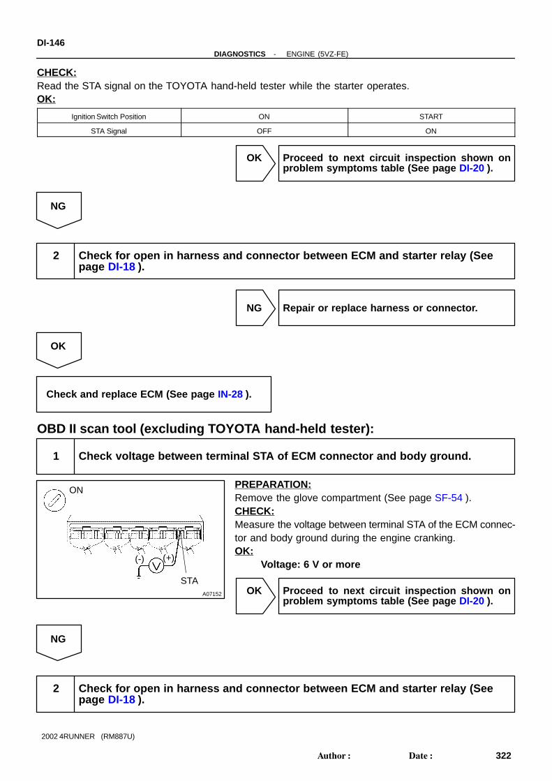
A07152
ON
STA
(+)(-)
DI-146-DIAGNOSTICS ENGINE (5VZ-FE)
322Author: Date:
2002 4RUNNER (RM887U)
CHECK:Read the STA signal on the TOYOTA hand-held tester while the starter operates.OK:
Ignition Switch Position ON START
STA Signal OFF ON
OK Proceed to next circuit inspection shown onproblem symptoms table (See page DI-20 ).
NG
2 Check for open in harness and connector between ECM and starter relay (Seepage DI-18 ).
NG Repair or replace harness or connector.
OK
Check and replace ECM (See page IN-28 ).
OBD II scan tool (excluding TOYOTA hand-held tester):
1 Check voltage between terminal STA of ECM connector and body ground.
PREPARATION:Remove the glove compartment (See page SF-54 ).CHECK:Measure the voltage between terminal STA of the ECM connec-tor and body ground during the engine cranking.OK:
Voltage: 6 V or more
OK Proceed to next circuit inspection shown onproblem symptoms table (See page DI-20 ).
NG
2 Check for open in harness and connector between ECM and starter relay (Seepage DI-18 ).

-DIAGNOSTICS ENGINE (5VZ-FE)DI-147
323Author: Date:
2002 4RUNNER (RM887U)
NG Repair or replace harness or connector.
OK
Check and replace ECM (See page IN-28 ).

A07746
ECM
IGSW
MREL
+B
E117E10
1
4
15B-L
GR-BIG114
DJ7
W-L
W-B
A J2
BR
EC
W-B
I14IG Switch Driver Side J/B
1FIGN
E14
E14
EB
A J1
DJ7 E14
+B
GR-B
1041IB-R
67W-R
2
2
2
2
2
Engine Room R/B
1
1
EFIAM
2
W
Battery
EFI Relay
Engine Room R/B
IG11
GR
-B
J/C
2 2
22
2
1
3
5
W-LW-L
L-R
J/C
A15324
+B
E1(+)(-)
DI-148-DIAGNOSTICS ENGINE (5VZ-FE)
324Author: Date:
2002 4RUNNER (RM887U)
ECM Power Source Circuit
CIRCUIT DESCRIPTIONWhen the ignition switch is turned ON, battery positive voltage is applied to the coil, closing the contacts ofthe EFI main relay (Marking: EFI) and supplying power to terminal +B of the ECM.
WIRING DIAGRAM
INSPECTION PROCEDURE
1 Check voltage between terminals +B and E1 of ECM connectors.
PREPARATION:(a) Remove the glove compartment (See page SF-54 ).(b) Turn the ignition switch ON.CHECK:Measure the voltage between terminals +B and E1 of the ECMconnectors.OK:
Voltage: 9 - 14 V
OK Proceed to next circuit inspection shown onproblem symptoms table (See page DI-20 ).
DI0SJ-08

-DIAGNOSTICS ENGINE (5VZ-FE)DI-149
325Author: Date:
2002 4RUNNER (RM887U)
NG
2 Check for open in harness and connector between terminal E1 of ECM and bodyground (See page IN-28 ).
NG Repair or replace harness or connector.
OK
3 Check EFI main relay (Marking: EFI) (See page SF-35 ).
NG Replace EFI main relay.
OK
4 Check EFI fuse (See page DI-148 , step 2).
NG Check for short in all harness and componentsconnected to EFI fuse.
OK
5 Check for open harness and connector between EFI main relay (Marking: EFI)and battery, and EFI main relay and ECM (See page IN-28 ).
NG Repair or replace harness or connector.
OK

A15325
IGN FuseDriver Side J/B
DI-150-DIAGNOSTICS ENGINE (5VZ-FE)
326Author: Date:
2002 4RUNNER (RM887U)
6 Check IGN fuse.
PREPARATION:Remove the IGN fuse from the driver side J/B.CHECK:Check the continuity of the IGN fuse.OK:
Continuity
NG Check for short in all harness and componentsconnected to IGN fuse.
OK
7 Check ignition switch (See page BE-12 ).
NG Replace ignition switch (See page SR-17 ).
OK
Check for open in harness and connector between ignition switch and EFI main relay (Marking:EFI), and EFI main relay and body ground (See page IN-28 ).

A18088
IG Switch ECM
FC
MREL
STA
NE
(STA Signal)
NE Signal
From Crankshaft Position Sensor
Fuel Pump
Circuit Opening Relay
EFI Relay
GaugeSTA
AM
2
Park/NeutralPositionSwitch
Stater
Generator
Battery
AM
1A
LT
Starter Relay
-DIAGNOSTICS ENGINE (5VZ-FE)DI-151
327Author: Date:
2002 4RUNNER (RM887U)
Fuel Pump Control Circuit
CIRCUIT DESCRIPTIONIn the diagram below, when the engine is cranked, current flows from terminal ST of the ignition switch tothe starter relay coil, the starter relay switches on and current flows to coil L1 of the circuit opening relay.Thus the circuit opening relay switches on, power is supplied to the fuel pump and the fuel pump oparates.When the STA signal and NE signal are input to the ECM, Tr is turned ON, current flows to coil L2 of the circuitopening relay, the relay switches on, and the fuel pump operates. While the NE signal is generated (enginerunning), the ECM keeps Tr ON (circuit opening relay ON) and the fuel pump also keeps operating.
DI8XN-02

A18104
GR-B
L-R
Starter
2 1
5 3
S2S1
EB BH
IGG1
W
6
4
2
2
2
2 2
2
22 2
2
2
2
2
2
22
2
2
2 2
2
2
5
5
1
1 1
1
1 1
1
1
B-L
5
IE1
IG1
IG1
FC
E14
1I
MREL
J7
BATT
J8
J1J2
D E
10EFI AM1
W-B
3E
1F
EFI Relay
4
L-R
IG1
IG1
W-L
W-B
L-O
B-W
3E3E1E
1E1I
1I
E14
E14IGN
EA1
GR-B
W
A
Starter Relay
B-W
A
BB
B
B
BJ1J2
B-W
W-B
B-W
W
EA1
3
I14Ignition SW C6 Circuit
Opening Relay
AM2ST2
L-R
Engine Room R/B
B-RW-R
W-L
II1
W-B
EB
Generator
R-L5 3
AM1
AM2
ALT
F10FuelPump
STA
6
9
B-W
R-L
J/C
3
12
R-L
G-B
B-Y
8
AM1 IG1
414
7 16
B-L
6AM2 IG2
Driver Side J/B
3
2
6
GAAUGE
STA
7
W
CP1Park/NeutralPosition SW
7
4
11
Battery
3
B-W
Center J/B
Driver Side J/BI14 Ignition Switch
L-O
J/C
J/C
ECM
NSW
3
22G-Y
1
Engine Room R/B
1W-L
E14
E12
DI-152-DIAGNOSTICS ENGINE (5VZ-FE)
328Author: Date:
2002 4RUNNER (RM887U)
WIRING DIAGRAM

-DIAGNOSTICS ENGINE (5VZ-FE)DI-153
329Author: Date:
2002 4RUNNER (RM887U)
INSPECTION PROCEDURETOYOTA hand-held tester:
1 Connect TOYOTA hand-held tester, and check operation of fuel pump (See pageSF-7 ).
OK Check for starter signal circuit (See page DI-145 ).
NG
2 Check for ECM power source circuit (See page DI-148 ).
NG Repair or replace.
OK
3 Check circuit opening relay (See page SF-37 ).
NG Replace circuit opening relay.
OK

A15326
ON
FC
(+)(-)
DI-154-DIAGNOSTICS ENGINE (5VZ-FE)
330Author: Date:
2002 4RUNNER (RM887U)
4 Check voltage between terminals FC of ECM and body ground.
PREPARATION:(a) Remove the glove compartment (See page SF-54 ).(b) Turn the ignition switch ON.CHECK:Measure the voltage between terminal FC of the ECM and bodyground.OK:
Voltage: 9 - 14 V
OK Go to step 5.
NG
Check for open in harness and connector between EFI main relay (Marking: EFI) and circuit open-ing relay, and circuit opening relay and ECM.
5 Check fuel pump (See page SF-7 ).
NG Repair or replace fuel pump.
OK
6 Check for open in harness and connector between circuit opening relay and fuelpump, and fuel pump and body ground (See page IN-28 ).
NG Repair or replace harness or connector.
OK
Check and replace ECM (See page IN-28 ).

-DIAGNOSTICS ENGINE (5VZ-FE)DI-155
331Author: Date:
2002 4RUNNER (RM887U)
OBD II scan tool (excluding TOYOTA hand-held tester):
1 Check operation of fuel pump (See page SF-7 ).
OK Check for starter signal circuit (See page DI-145 ).
NG
2 Check for ECM power source circuit (See page DI-148 ).
NG Repair or replace.
OK
3 Check circuit opening relay (See page SF-37 ).
NG Replace circuit opening relay.
OK
4 Check voltage between terminals FC of ECM connector and body ground (Seepage DI-151 , step 4).
OK Go to step 5.
NG
Check for open in harness and connector between EFI main relay (Marking: EFI) and circuit open-ing relay, and circuit opening relay and ECM.

DI-156-DIAGNOSTICS ENGINE (5VZ-FE)
332Author: Date:
2002 4RUNNER (RM887U)
5 Check fuel pump (See page SF-7 ).
NG Repair or replace fuel pump.
OK
6 Check for open in harness and connector between circuit opening relay and fuelpump, and fuel pump and body ground (See page IN-28 ).
NG Repair or replace harness or connector.
OK
Check and replace ECM (See page IN-28 ).

DI0SL-29
Vehicle Brought to Workshop
Customer Problem Analysis
Check DTC and Freeze Frame Data (Pre-check)Record or Print DTC and Freeze Frame Data P. DI-159
Clear DTC and Freeze Frame Data P. DI-159
Visual Inspection
Setting the Check Mode Diagnosis P. DI-159
1
Items inside are titles of pages in this manual, with thepage number indicated in the bottom portion. See the indicatedpages for detailed explanations.
P. DI-158
Connect an OBD II scan tool or hand-held tester to DLC3.If the display shows ”UNABLE TO CONNECT TO VEHICLE” when you have connected thescan tool/ hand-held tester, inspect DLC3 P. DI-159
2
3
4
5
6Symptom does not occur
Problem Symptom Confirmation 87 Symptom SimulationP. IN-18Symptom occurs
DTC CheckP. DI-159
OK Code 11 Preliminary CheckP. DI-159
DTC ChartP. DI-171
Mechanical System TestP. DI-159
Manual Shifting TestP. DI-159
OK
OK
Chapter 1(Electronic)
Chapter 2(On-V ehicle)
P. DI-175
OK Chapter 3(Off-V ehicle)OK
Matrix Chart of Problem Symptoms - P. DI-175
CircuitInspection A/T. P. Indicator Circuit Check
NG
Parts Inspection
NG
NG
NG
Identification of Problem Repair Confirmation Test End
NG
NG
12
NG 13
14
15 16
17
9
10
P. DI-175 P . DI-175
P. DI-182 to DI-218
18
Pattern Select Switch Circuit Check
-DIAGNOSTICS AUTOMATIC TRANSMISSIONDI-157
333Author: Date:
2002 4RUNNER (RM887U)
AUTOMATIC TRANSMISSIONHOW TO PROCEED WITH TROUBLESHOOTING

DI0SM-03
Transmission ControlSystem Check Sheet
Inspector’sName :
Customer’s Name
Registration No.
Registration Year
Frame No.
Date VehicleBrought In Odometer Reading km
mile
/ /
/ /
Date ProblemOccurredHow Often Problem Occurs?
/ /
Continuous Intermittent ( times a day)
Symptoms
Vehicle does not move ( Any position Particular position )
No up-shift ( 1st → 2nd 2nd → 3rd 3rd → O/D )
No down-shift ( O/D → 3rd 3rd → 2nd 2nd → 1st )
Lock-up malfunction
Shift point too high or too low
Harsh engagement ( N → D Lock-up Any drive position )
Slip or shudder
No kick-down
Others
Check Item MalfunctionIndicator Lamp
DTC Check 1st Time
2nd Time
Normal code Malfunction code (Code )
Normal Remains ON
Normal code Malfunction code (Code )
DI-158-DIAGNOSTICS AUTOMATIC TRANSMISSION
334Author: Date:
2002 4RUNNER (RM887U)
CUSTOMER PROBLEM ANALYSIS CHECK
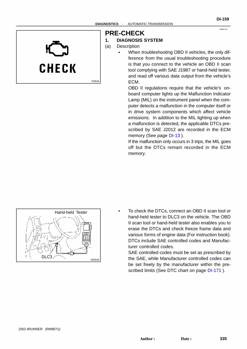
FI0534
DI8WD-02
A00026
Hand-held Tester
DLC3
-DIAGNOSTICS AUTOMATIC TRANSMISSIONDI-159
335Author: Date:
2002 4RUNNER (RM887U)
PRE-CHECK1. DIAGNOSIS SYSTEM(a) Description
When troubleshooting OBD II vehicles, the only dif-ference from the usual troubleshooting procedureis that you connect to the vehicle an OBD II scantool complying with SAE J1987 or hand-held tester,and read off various data output from the vehicle’sECM.OBD II regulations require that the vehicle’s on-board computer lights up the Malfunction IndicatorLamp (MIL) on the instrument panel when the com-puter detects a malfunction in the computer itself orin drive system components which affect vehicleemissions. In addition to the MIL lighting up whena malfunction is detected, the applicable DTCs pre-scribed by SAE J2012 are recorded in the ECMmemory (See page DI-13 ).If the malfunction only occurs in 3 trips, the MIL goesoff but the DTCs remain recorded in the ECMmemory.
To check the DTCs, connect an OBD II scan tool orhand-held tester to DLC3 on the vehicle. The OBDII scan tool or hand-held tester also enables you toerase the DTCs and check freeze frame data andvarious forms of engine data (For instruction book).DTCs include SAE controlled codes and Manufac-turer controlled codes.SAE controlled codes must be set as prescribed bythe SAE, while Manufacturer controlled codes canbe set freely by the manufacturer within the pre-scribed limits (See DTC chart on page DI-171 ).

N09214
DI-160-DIAGNOSTICS AUTOMATIC TRANSMISSION
336Author: Date:
2002 4RUNNER (RM887U)
The diagnosis system operates in normal modeduring normal vehicle use, and also has a checkmode for technicians to simulate malfunction symp-toms and perform troubleshooting. Most DTCs use2 trip detection logic(*) to prevent erroneous detec-tion. By switching the ECM to check mode whentroubleshooting, the technician can cause the MILto light up and for a malfunction that is only detectedonce or momentarily. (hand-held tester) (See page DI-159 )
*2 trip detection logic:When a logic malfunction is first detected, the mal-function is temporarily stored in the ECM memory.If the same malfunction is detected again during the2nd test drive, this 2nd detection causes the MIL tolight up.
(b) Inspect the DLC3.The vehicle’s ECM uses the V.P.W. (Variable Pulse Width)for communication to comply with SAE J1850. The termi-nal arrangement of DLC3 complies with SAE J1962 andmatches the V.P.W. format.
Terminal No. Connection / Voltage or Resistance Condition
2 Bus (+) Line / Pulse generation During communication
4 Chassis Ground ↔ Body / 1 Ω or less Always
5 Signal Ground ↔ Body / 1 Ω or less Always
16 Battery Positive ↔ Body / 9 ∼ 14 V Always
HINT:If your display shows ”UNABLE TO CONNECT TO VEHICLE”when you have connected the cable of OBD II scan tool orhand-held tester to DLC3, turned the ignition switch ON andoperated the scan tool, there is a problem on the vehicle sideor tool side. If communication is normal when the tool is connected to
another vehicle, inspect DLC3 on the original vehicle. If communication is still not possible when the tool is con-
nected to another vehicle, the problem is probably in thetool itself, so consult the Service Department listed in thetool’s instruction manual.

FI0534
A00026
Hand-held Tester
DLC3
-DIAGNOSTICS AUTOMATIC TRANSMISSIONDI-161
337Author: Date:
2002 4RUNNER (RM887U)
2. INSPECT DIAGNOSIS (NORMAL MODE)(a) Check the MIL.
(1) The MIL comes on when the ignition switch is turnedON and the engine is not running.
HINT:If the MIL does not light up, troubleshoot the combination meter(See page BE-2 ).
(2) When the engine is started, the MIL should go off.If the lamp remains on, the diagnosis system hasdetected a malfunction or abnormality in the sys-tem.
(b) Check the DTC.NOTICE:hand-held tester only: When the diagnostic system isswitched from normal mode to check mode, it erases allDTCs and freeze frame data recorded in normal mode. Sobefore switching modes, always check the DTCs andfreeze frame data, and note them down.
(1) Prepare an OBD II scan tool (complying with SAEJ1978) or hand-held tester.
(2) Connect the OBD II scan tool or hand-held testerto DLC3 at the lower of the instrument panel.
(3) Turn the ignition switch ON and turn the OBD II scantool or hand-held tester switch ON.
(4) Use the OBD II scan tool or hand-held tester tocheck the DTCs and freeze frame data and notethem down (For operating instructions, see theOBD II scan tool’s instruction book).
(5) See page DI-159 to confirm the details of the DTCs.
NOTICE:When simulating symptoms with an OBD II scan tool (ex-cluding hand-held tester) to check the DTCs, use normalmode. For codes on the DTCs chart subject to ”2 trip detec-tion logic”, turn the ignition switch OFF after the symptomshave been simulated the 1st time. Then repeat the simula-tion process again. When the program has DTCs, they arerecorded in the ECM.3. INSPECT DIAGNOSIS (CHECK MODE)HINT:hand-held tester only: Compared to the normal mode, thecheck mode has high sensing ability to detect malfunctions.Furthermore, the same diagnostic items which are detected inNormal mode can also be detected in Check mode.(a) Check the DTC.
(1) Check the initial conditions. Battery positive voltage 11 V or more. Throttle valve fully closed. Transmission in P position. Air conditioning switched OFF.

A00026
Hand-held Tester
DLC3
BR3904
ON
OFF
0.13 sec. 0.13 sec.
DI-162-DIAGNOSTICS AUTOMATIC TRANSMISSION
338Author: Date:
2002 4RUNNER (RM887U)
(2) Turn the ignition switch OFF.(3) Prepare a hand-held tester.
(4) Connect the hand-held tester to DLC3 at the lowerportion of the instrument panel.
(5) Turn the ignition switch ON and switch the hand-held tester ON.
(6) Switch the hand-held tester from Normal mode toCheck mode (Check that the MIL flashes).
(7) Start the engine (MIL goes out after the enginestarts).
(8) Simulate the conditions of the malfunction de-scribed by the customer.
NOTICE:Leave the ignition switch ON until you have checked theDTCs, etc.
(9) After simulating the malfunction conditions, use thehand-held tester diagnosis selector to check theDTCs and freeze frame data, etc.
HINT:Take care not to turn the ignition switch OFF, as turning it off thediagnosis system switches Check mode to Normal mode, so allDTCs, etc. are erased.
(10) After checking the DTC, inspect the applicable cir-cuit.
(b) Clear the DTC.The following operation will erase the DTC and freezeframe data. Operating an OBD II scan tool (complyingwith SAE J1978) or hand-held tester to erase the codes(See the OBD II scan tool’s instruction book for operatinginstructions.).
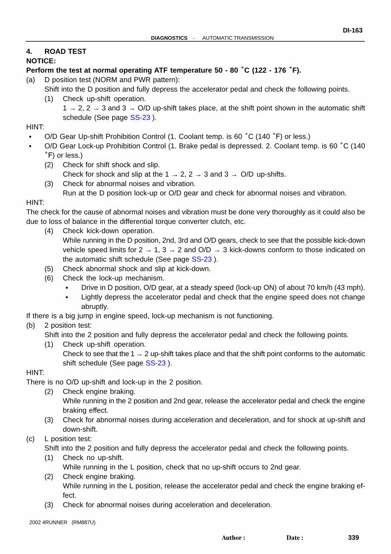
-DIAGNOSTICS AUTOMATIC TRANSMISSIONDI-163
339Author: Date:
2002 4RUNNER (RM887U)
4. ROAD TESTNOTICE:Perform the test at normal operating ATF temperature 50 - 80 °C (122 - 176 °F).(a) D position test (NORM and PWR pattern):
Shift into the D position and fully depress the accelerator pedal and check the following points.(1) Check up-shift operation.
1 → 2, 2 → 3 and 3 → O/D up-shift takes place, at the shift point shown in the automatic shiftschedule (See page SS-23 ).
HINT: O/D Gear Up-shift Prohibition Control (1. Coolant temp. is 60 °C (140 °F) or less.) O/D Gear Lock-up Prohibition Control (1. Brake pedal is depressed. 2. Coolant temp. is 60 °C (140
°F) or less.)(2) Check for shift shock and slip.
Check for shock and slip at the 1 → 2, 2 → 3 and 3 → O/D up-shifts.(3) Check for abnormal noises and vibration.
Run at the D position lock-up or O/D gear and check for abnormal noises and vibration.HINT:The check for the cause of abnormal noises and vibration must be done very thoroughly as it could also bedue to loss of balance in the differential torque converter clutch, etc.
(4) Check kick-down operation.While running in the D position, 2nd, 3rd and O/D gears, check to see that the possible kick-downvehicle speed limits for 2 → 1, 3 → 2 and O/D → 3 kick-downs conform to those indicated onthe automatic shift schedule (See page SS-23 ).
(5) Check abnormal shock and slip at kick-down.(6) Check the lock-up mechanism.
Drive in D position, O/D gear, at a steady speed (lock-up ON) of about 70 km/h (43 mph). Lightly depress the accelerator pedal and check that the engine speed does not change
abruptly.If there is a big jump in engine speed, lock-up mechanism is not functioning.(b) 2 position test:
Shift into the 2 position and fully depress the accelerator pedal and check the following points.(1) Check up-shift operation.
Check to see that the 1 → 2 up-shift takes place and that the shift point conforms to the automaticshift schedule (See page SS-23 ).
HINT:There is no O/D up-shift and lock-up in the 2 position.
(2) Check engine braking.While running in the 2 position and 2nd gear, release the accelerator pedal and check the enginebraking effect.
(3) Check for abnormal noises during acceleration and deceleration, and for shock at up-shift anddown-shift.
(c) L position test:Shift into the 2 position and fully depress the accelerator pedal and check the following points.(1) Check no up-shift.
While running in the L position, check that no up-shift occurs to 2nd gear.(2) Check engine braking.
While running in the L position, release the accelerator pedal and check the engine braking ef-fect.
(3) Check for abnormal noises during acceleration and deceleration.

AT3417
OK if hot
Add if hot
AT1347
DI-164-DIAGNOSTICS AUTOMATIC TRANSMISSION
340Author: Date:
2002 4RUNNER (RM887U)
(d) R position test:Shift into the R position and fully depress the accelerator pedal and check for slipping.
CAUTION:Before conducting this test ensure that the test area is free from people and obstruction.(e) P position test:
Stop the vehicle on a grade (more than 5°) and after shifting into the P position, release the parkingbrake. Then, check to see that the parking lock pawl holds the vehicle in place.
5. BASIC INSPECTION(a) Check the fluid level.HINT: Drive the vehicle so that the engine and transmission are
at normal operating temperature.Fluid temp.: 70 - 80 °C (158 - 176 °F)
Only use the COOL range on the dipstick as a rough refer-ence when the fluid is replaced or the engine does notrun.
(1) Park the vehicle on a level surface and set the park-ing brake.
(2) With the engine idling and the brake pedal de-pressed, shift the shift lever into all positions from Pto L position and return to P position.
(3) Pull out the dipstick and wipe it clean.(4) Push it back fully into the pipe.(5) Pull it out and check that the fluid level is in the HOT
range.If the level is not within the HOT range, add new fluid.
Fluid type: ATF D-II or DEXRON ®III (DEXRON®II)NOTICE:Do not overfill.(b) Check the fluid condition.If the fluid smells burnt or is black, replace it.
(c) Replace the ATF.(1) Remove the drain plug and drain the fluid.(2) Reinstall the drain plug securely.

AT6683
AT3417
OK if hot
Add if hot
AT3184
Neutral Position
Loosen this nut
-DIAGNOSTICS AUTOMATIC TRANSMISSIONDI-165
341Author: Date:
2002 4RUNNER (RM887U)
(3) With the engine OFF add new fluid through the oilfiller pipe.
Fluid type: ATF D-II or DEXRON ®III (DEXRON®II)Capacity: A340E: 1.6 liters (1.7 US qts, 1.4 Imp. qts)A340F: 2.0 liters (2.1 US qts, 1.8 Imp. qts)(4) Start the engine and shift the shift lever into all posi-
tions from P to L position and then shift into P posi-tion.
(5) With the engine idling, check the fluid level. Addfluid up to the COOL level on the dipstick.
(6) Check the fluid level at the normal operating tem-perature, 70 - 80 °C (158 - 176 °F), and add asnecessary.
NOTICE:Do not overfill.(d) Check the fluid leaks.
Check for leaks in the transmission.If leaks occurs, it is necessary to repair or replace O-rings,FIPGs, oil seals, plugs or other parts.(e) Inspect and adjust the shift lever position.
When shifting the shift lever from the N position to otherpositions, check that the lever can be shifted smoothlyand accurately to each position and that the position indi-cator is not aligned with the correct position.
If the indicator is not aligned with the correct position, carry outthe following adjustment procedures.
(1) Loosen the nut on the shift lever.(2) Push the control shaft fully rearward.(3) Return the control shaft lever 2 notches to N posi-
tion.
(4) Set the shift lever to N position.(5) While holding the shift lever lightly toward the R
position side, tighten the shift lever nut.Torque: 13 N·m (130 kgf·cm, 10 ft·lbf)(6) Start the engine and make sure that the vehicle
moves forward when shifting the lever from the N toD position and reverses when shifting it to the Rposition.

D05985
Neutral Basic line
Bolt
Groove
DI-166-DIAGNOSTICS AUTOMATIC TRANSMISSION
342Author: Date:
2002 4RUNNER (RM887U)
(f) Inspect and adjust the park/neutral position.Check that the engine can be started with the shift leveronly in the N or P position, but not in other positions.
If it is not as stated above, carry out the following adjustmentprocedures.
(1) Loosen the park/neutral position switch bolt and setthe shift lever to the N position.
(2) Align the groove with neutral basic line.(3) Hold in position and tighten the bolt.Torque: 13 N·m (130 kgf·cm, 10 ft·lbf)
HINT:For continuity inspection of the park/neutral position switch,See page DI-203 .(g) Check the idle speed.
Idle speed (In N position and air conditioner OFF): 700 ± 50 rpm
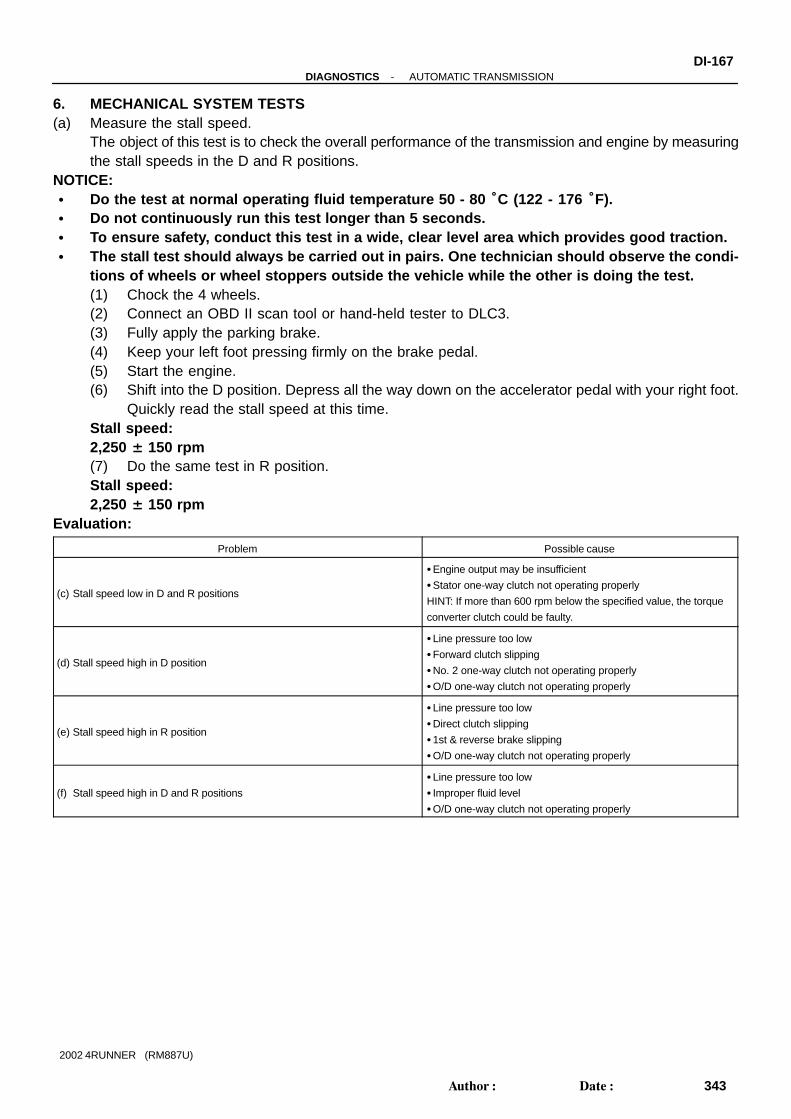
-DIAGNOSTICS AUTOMATIC TRANSMISSIONDI-167
343Author: Date:
2002 4RUNNER (RM887U)
6. MECHANICAL SYSTEM TESTS(a) Measure the stall speed.
The object of this test is to check the overall performance of the transmission and engine by measuringthe stall speeds in the D and R positions.
NOTICE: Do the test at normal operating fluid temperature 50 - 80 °C (122 - 176 °F). Do not continuously run this test longer than 5 seconds. To ensure safety, conduct this test in a wide, clear level area which provides good traction. The stall test should always be carried out in pairs. One technician should observe the condi-
tions of wheels or wheel stoppers outside the vehicle while the other is doing the test.(1) Chock the 4 wheels.(2) Connect an OBD II scan tool or hand-held tester to DLC3.(3) Fully apply the parking brake.(4) Keep your left foot pressing firmly on the brake pedal.(5) Start the engine.(6) Shift into the D position. Depress all the way down on the accelerator pedal with your right foot.
Quickly read the stall speed at this time.Stall speed:2,250 ± 150 rpm(7) Do the same test in R position.Stall speed:2,250 ± 150 rpm
Evaluation:
Problem Possible cause
(c) Stall speed low in D and R positions
Engine output may be insufficient
Stator one-way clutch not operating properly
HINT: If more than 600 rpm below the specified value, the torque
converter clutch could be faulty.
(d) Stall speed high in D position
Line pressure too low
Forward clutch slipping
No. 2 one-way clutch not operating properly
O/D one-way clutch not operating properly
(e) Stall speed high in R position
Line pressure too low
Direct clutch slipping
1st & reverse brake slipping
O/D one-way clutch not operating properly
(f) Stall speed high in D and R positions
Line pressure too low
Improper fluid level
O/D one-way clutch not operating properly

DI-168-DIAGNOSTICS AUTOMATIC TRANSMISSION
344Author: Date:
2002 4RUNNER (RM887U)
(b) Measure the time lag.When the shift lever is shifted while the engine is idling, there will be a certain time lapse or lag beforethe shock can be felt. This is used for checking the condition of the O/D direct clutch, forward clutch,and 1st & reverse brake.
NOTICE: Do the test at normal operating fluid temperature 50 - 80 °C (122 - 176 °F). Be sure to allow 1 minute interval between tests. Take 3 measurements and take the average value.
(1) Fully apply the parking brake.(2) Start the engine and check idle speed.Idle speed (In N position and air conditioner OFF): 700 ± 50 rpm(3) Shift the shift lever from N to D position. Using a stop watch, measure the time from when the
lever is shifted until the shock is felt.Time lag: N → D Less than 1.2 seconds(4) In the same manner, measure the time lag for N → R.Time lag: N → R Less than 1.5 seconds
Evaluation (If N → D time or N → R time lag is longer than specified):
Problem Possible cause
N → D time lag is longer
Line pressure too low
Forward clutch worn
O/D one-way clutch not operating properly
N → R time lag is longer
Line pressure too low
Direct clutch worn
1st & reverse brake worn
O/D one-way clutch not operating properly

-DIAGNOSTICS AUTOMATIC TRANSMISSIONDI-169
345Author: Date:
2002 4RUNNER (RM887U)
7. HYDRAULIC TESTMeasure the line pressure.NOTICE: Do the test at normal operation fluid temperature 50 - 80 °C (122 - 176 °F). The line pressure test should always be carried out in pairs. One technician should observe
the conditions of wheels or wheel stoppers outside the vehicle while the other is doing the test. Be careful to prevent SST’s hose from interfering with the exhaust pipe.
(1) Warm up the ATF.(2) Remove the test plug on the transmission case front left side and connect SST (See page
AT-18 for the location to connect SST).SST 09992-00095, 09992-00151, 09992-00271(3) Fully apply the parking brake and chock the 4 wheels.(4) Start the engine and check idling speed.(5) Keep your left foot pressing firmly on the brake pedal and shift into D position.(6) Measure the line pressure when the engine is idling.(7) Depress the accelerator pedal all the way down. Quickly read the highest line pressure when
engine speed reaches stall speed.(8) In the same manner, do the test in R position.Specified line pressure:
Condition D position kPa (kgf/cm2, psi) R position kPa (kgf/cm2, psi)
Idling 382 - 441 (3.9 - 4.5, 55 - 64) 598 - 696 (6.1 - 7.1, 87 - 101)
Stall 1,196 - 1,334 (12.2 - 13.6, 174 - 193) 1,598 - 1,942 (16.3 - 19.8, 232 - 282)
If the measured pressures are not up to the specified values, recheck the throttle cable adjustment and re-test.Evaluation
Problem Possible cause
If the measured values at all positions are higher
Shift solenoid valve SLT
Throttle valve defective
Regulator valve defective
If the measured values at all positions are lower
Shift solenoid valve SLT
Throttle valve defective
Regulator valve defective
Oil pump defective
O/D direct clutch defective
If pressure is low in the D position onlyD position circuit fluid leaks
Forward clutch defective
If pressure is low in the R position only
R position circuit fluid leakage
Direct clutch defective
1st & reverse brake defective

Q05336
DI-170-DIAGNOSTICS AUTOMATIC TRANSMISSION
346Author: Date:
2002 4RUNNER (RM887U)
8. MANUAL SHIFTING TESTHINT:With this test, it can be determined whether the trouble is withinthe electrical circuit or is a mechanical problem in the transmis-sion.(a) Disconnect the solenoid wire.(b) Inspect the manual driving operation.
Check that the shift and gear positions correspond withthe table below.While driving, shift through the L, 2 and D positions.Check that the gear change corresponds to the shift posi-tion.
Shift Position Gear Position
D O/D
2 3rd
L 1st
R Reverse
P Pawl Lock
HINT:If the L, 2 and D position gear positions are difficult to distin-guish, do the above read test.If any abnormality is found in the above test, the problem is inthe transmission itself.(c) Connect the solenoid wire.(d) Cancel out the DTC (See page DI-159 ).

DI0SO-19
-DIAGNOSTICS AUTOMATIC TRANSMISSIONDI-171
347Author: Date:
2002 4RUNNER (RM887U)
DIAGNOSTIC TROUBLE CODE CHARTIf a DTC is displayed during the DTC check, check the circuit listed for that code in the table below and pro-ceed to the page given.
DTC No.
(See Page)Detection Item Trouble Area MIL *1 Memory
P0500
(DI-179 )
Vehicle Speed Sensor Malfunc-
tion
Open or short in No. 1 vehicle speed sensor circuit
No. 1 vehicle speed sensor
Combination meter
ECM
Automatic transmission (clutch, bracket or gear etc.)
P0710
(DI-182 )
Transmission Fluid Temperature
Sensor Malfunction
Open or short in ATF temperature sensor circuit
ATF temperature sensor
ECM
P0750
(DI-184 )Shift Solenoid ”A” Malfunction
Shift solenoid valve No. 1 is stuck open or closed
Valve body is blocked up or stuck
P0753
(DI-186 )Shift Solenoid ”A” Electrical
Open or short in shift solenoid valve No. 1 circuit
Shift solenoid valve No. 1
ECM
P0755
(DI-184 )Shift Solenoid ”B” Malfunction
Shift solenoid valve No. 2 is stuck open or closed
Valve body is blocked up or stuck
P0758
(DI-186 )Shift Solenoid ”B” Electrical
Open or short in shift solenoid valve No. 2 circuit
Shift solenoid valve No. 2
ECM
P0770
(DI-190 )Shift Solenoid ”E” Malfunction
Shift solenoid valve SL is stuck open or closed
Valve body is blocked up or stuck
Lock-up clutch
P0773
(DI-192 )Shift Solenoid ”E” Electrical
Open or short in shift solenoid valve SL circuit
Shift solenoid valve SL
ECM
P1520
(DI-195 )
Stop Light Switch Circuit Mal-
function
Short in stop light switch signal circuit
Stop light switch
ECM
P1700
(DI-196 )Speed Sensor No. 2 Malfunction
Open or short in No. 2 vehicle speed sensor circuit
No. 2 vehicle speed sensor
ECM
P01760
(DI-200 )
Linear Solenoid for Line Pres-
sure Control Circuit Malfunction
Open or short in shift solenoid valve SLT circuit
Shift solenoid valve SLT
ECM
P1780
(DI-203 )
Park/Neutral Position Switch
Malfunction
Short in park/neutral position switch circuit
Park/neutral position switch
ECM
P1782 *2
(DI-208 )
Transfer L4 SW Circuit Malfunc-
tion
Transfer L4 position switch
Transfer L4 position switch circuit
ECM
P1783 *2
(DI-211)
Transfer N SW Circuit Malfunc-
tion
Transfer neutral position switch
Transfer neutral position switch circuit
ECM
* 1: ...MIL lights up.* 2: 4WD only.

DI8WE-01
D10499
ATF Temperature Sensor
DLC3
Stop Light Switch
Shift Solenoid Valve No. 2
Shift Solenoid Valve SLT
Park/Neutral Position Switch
Transfer NeutralPosition Switch
Transfer L4 Position Switch
No.2 Vehicle Speed Sensor
No.2 Vehicle Speed Sensor
Combination Meter
Shift Solenoid Valve SL
O/D Main Switch
Pattern Select Switch
ECM
No.1 Vehicle Speed Sensor
Shift Solenoid Valve No. 1
A340E:
O/D Direct Clutch Speed Sensor
DI-172-DIAGNOSTICS AUTOMATIC TRANSMISSION
348Author: Date:
2002 4RUNNER (RM887U)
PARTS LOCATION
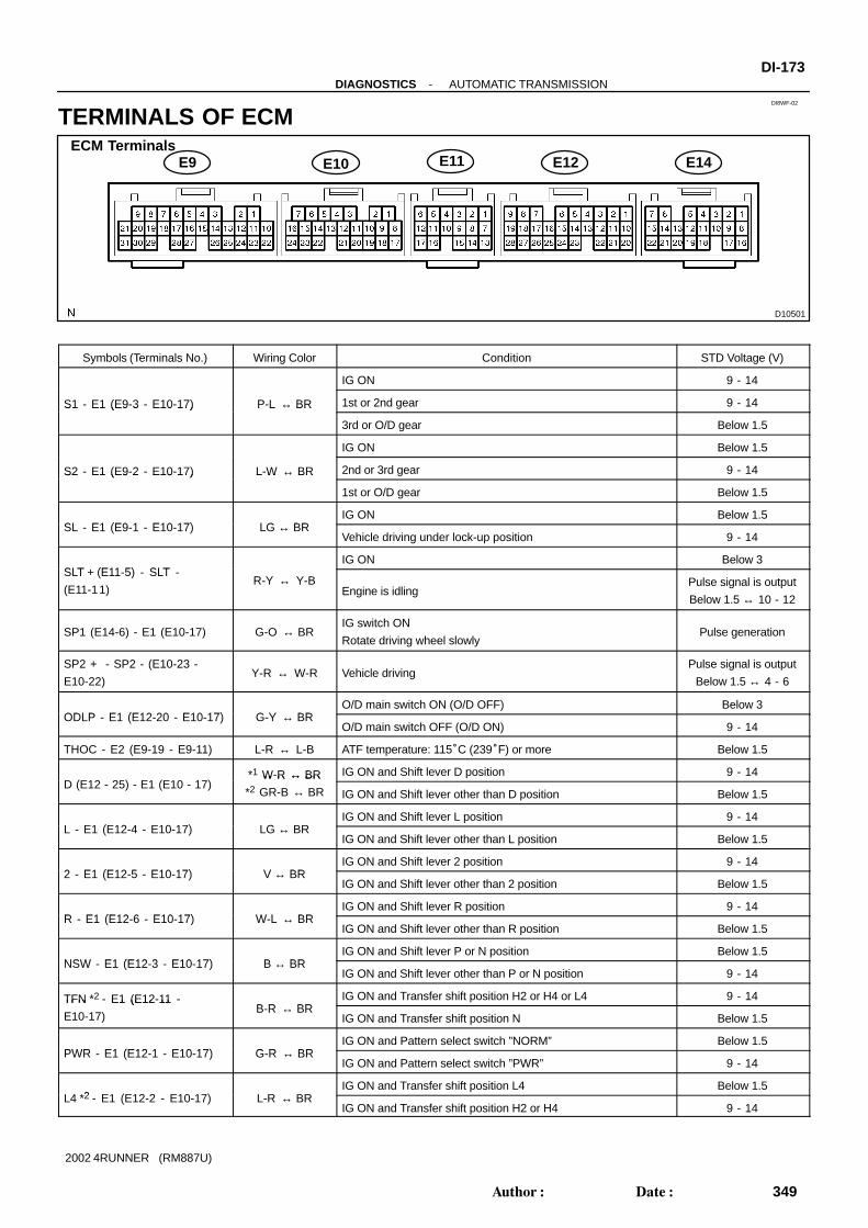
DI8WF-02
D10501
ECM TerminalsE9 E10 E12 E14E11
-DIAGNOSTICS AUTOMATIC TRANSMISSIONDI-173
349Author: Date:
2002 4RUNNER (RM887U)
TERMINALS OF ECM
Symbols (Terminals No.) Wiring Color Condition STD Voltage (V)
IG ON 9 - 14
S1 - E1 (E9-3 - E10-17) P-L ↔ BR 1st or 2nd gear 9 - 14S1 E1 (E9 3 E10 17) P L ↔ BR
3rd or O/D gear Below 1.5
IG ON Below 1.5
S2 - E1 (E9-2 - E10-17) L-W ↔ BR 2nd or 3rd gear 9 - 14S2 E1 (E9 2 E10 17) L W ↔ BR
1st or O/D gear Below 1.5
SL E1 (E9 1 E10 17) LG BRIG ON Below 1.5
SL - E1 (E9-1 - E10-17) LG ↔ BRVehicle driving under lock-up position 9 - 14
SLT (E11 5) SLTIG ON Below 3
SLT + (E11-5) - SLT -
(E11-11)R-Y ↔ Y-B
Engine is idlingPulse signal is output
Below 1.5 ↔ 10 - 12
SP1 (E14-6) - E1 (E10-17) G-O ↔ BRIG switch ON
Rotate driving wheel slowlyPulse generation
SP2 + - SP2 - (E10-23 -
E10-22)Y-R ↔ W-R Vehicle driving
Pulse signal is output
Below 1.5 ↔ 4 - 6
ODLP E1 (E12 20 E10 17) G Y BRO/D main switch ON (O/D OFF) Below 3
ODLP - E1 (E12-20 - E10-17) G-Y ↔ BRO/D main switch OFF (O/D ON) 9 - 14
THOC - E2 (E9-19 - E9-11) L-R ↔ L-B ATF temperature: 115°C (239°F) or more Below 1.5
D (E12 25) E1 (E10 17)*1 W-R ↔ BR IG ON and Shift lever D position 9 - 14
D (E12 - 25) - E1 (E10 - 17) W R ↔ BR
*2 GR-B ↔ BR IG ON and Shift lever other than D position Below 1.5
L E1 (E12 4 E10 17) LG BRIG ON and Shift lever L position 9 - 14
L - E1 (E12-4 - E10-17) LG ↔ BRIG ON and Shift lever other than L position Below 1.5
2 E1 (E12 5 E10 17) V BRIG ON and Shift lever 2 position 9 - 14
2 - E1 (E12-5 - E10-17) V ↔ BRIG ON and Shift lever other than 2 position Below 1.5
R E1 (E12 6 E10 17) W L BRIG ON and Shift lever R position 9 - 14
R - E1 (E12-6 - E10-17) W-L ↔ BRIG ON and Shift lever other than R position Below 1.5
NSW E1 (E12 3 E10 17) B BRIG ON and Shift lever P or N position Below 1.5
NSW - E1 (E12-3 - E10-17) B ↔ BRIG ON and Shift lever other than P or N position 9 - 14
TFN *2 - E1 (E12-11 -B R BR
IG ON and Transfer shift position H2 or H4 or L4 9 - 14TFN E1 (E12 11
E10-17)B-R ↔ BR
IG ON and Transfer shift position N Below 1.5
PWR E1 (E12 1 E10 17) G R BRIG ON and Pattern select switch ”NORM” Below 1.5
PWR - E1 (E12-1 - E10-17) G-R ↔ BRIG ON and Pattern select switch ”PWR” 9 - 14
L4 *2 E1 (E12 2 E10 17) L R BRIG ON and Transfer shift position L4 Below 1.5
L4 *2 - E1 (E12-2 - E10-17) L-R ↔ BRIG ON and Transfer shift position H2 or H4 9 - 14

DI-174-DIAGNOSTICS AUTOMATIC TRANSMISSION
350Author: Date:
2002 4RUNNER (RM887U)
OILW*2 - E1 (E12-21 -
E10-17)Y ↔ BR ATF temperature: 149°C (300°F) or more Below 1.5
ODMS - E1 (E12-14 -L R BR
IG ON 9 - 14ODMS E1 (E12 14
E10-17)L-R ↔ BR
IG ON and Press continuously O/D main switch Below 1.5
*1: 2WD*2: 4WD

DI0SR-12
-DIAGNOSTICS AUTOMATIC TRANSMISSIONDI-175
351Author: Date:
2002 4RUNNER (RM887U)
PROBLEM SYMPTOMS TABLEHINT:If a normal code is displayed during the diagnostic trouble code check but the trouble still occurs, check thecircuits for each symptom in the order given in the charts on the following pages and proceed to the pagegiven for troubleshooting.The Matrix Chart is divided into 3 chapters. If the instruction ”Proceed to next circuit inspection shown on matrix chart” is given in the flow chart
for each circuit, proceed to the circuit with the next highest number in the table to continue the check. If the trouble still occurs even though there are no abnormalities in any of the other circuits, then check
and replace the ECM.CHAPTER 1: ELECTRONIC CIRCUIT MATRIX CHART
Symptom Suspect Area See page
No up-shift
(A particular gear from 1st to 3rd gear is not up-shifted)1. ECM IN-28
No up-shift (3rd → O/D)3. O/D main switch & O/D OFF indicator light circuit
4. ECM
DI-218
IN-28
No down-shift (O/D → 3rd) 1. ECM IN-28
No down-shift
(A particular gear from 1st to 3rd gear is not down-shifted)1. ECM IN-28
No lock-up 1. ECM IN-28
No lock-up off 1. ECM IN-28
Shift point too high or too low1. Pattern select switch circuit
2. ECM
DI-214
IN-28
Up-shift to O/D from 3rd while main switch is off1. O/D main switch & O/D OFF indicator light circuit
2. ECM
DI-218
IN-28
Up-shift to O/D from 3rd while engine is cold 1. ECM IN-28
Poor acceleration 1. ECM IN-28
No pattern select1. Pattern select switch
2. ECM
DI-214
IN-28
Large shift shock or engine stalls when starting off or stopping 1. ECM IN-28

DI-176-DIAGNOSTICS AUTOMATIC TRANSMISSION
352Author: Date:
2002 4RUNNER (RM887U)
CHAPTER 2: ON-VEHICLE REPAIR(: A340E, A340F AUTOMATIC TRANSMISSION Repair Manual Pub. No. RM391U)(: A340F, A343F AUTOMATIC TRANSMISSION Repair Manual Pub. No. RM479U)
Symptom Suspect Area See page
Vehicle does not move in any forward position and reverse posi-
tion
1. Transmission control rod
2. Manual valve
3. Parking lock pawl
4. Off-vehicle repair matrix chart
DI-159
DI-175
Vehicle does not move in R position 1. Off-vehicle repair matrix chart DI-175
Vehicle does not move in particular position or positions
(except R position)1. Off-vehicle repair matrix chart DI-175
No up-shift (1st → 2nd)1. 1-2 shift valve
2. Off-vehicle repair matrix chart
DI-175
No up-shift (2nd → 3rd)1. 2-3 shift valve
2. Off-vehicle repair matrix chart
DI-175
No up-shift (3rd → O/D)1. 3-4 shift valve
2. Off-vehicle repair matrix chart
DI-175
No down-shift (O/D → 3rd)1. 3-4 shift valve
2. Off-vehicle repair matrix chart
DI-175
No down-shift (3rd → 2nd)1. 2-3 shift valve
2. Off-vehicle repair matrix chart
DI-175
No down-shift (2nd → 1st)1. 1-2 shift valve
2. Off-vehicle repair matrix chart
DI-175
No lock-up or No lock-up off
1. Lock-up control valve
2. Lock-up relay valve
3. Off-vehicle repair matrix chart
DI-175
Harsh engagement (N → D)
1. Accumulator control valve
2. Solenoid modulator valve
3. C1 accumulator
4. Orifice control valve
5. Off-vehicle repair matrix chart
DI-175
Harsh engagement (Lock-up)
1. Lock-up control valve
2. Lock-up relay valve
3. Solenoid relay valve
4. Off-vehicle repair matrix chart
DI-175
Harsh engagement (N → R)
1. Accumulator control valve
2. C2 accumulator
3. Solenoid modulator valve
4. Off-vehicle repair matrix chart
DI-175
Harsh engagement (N → L) 1. Low coast modulator valve
Harsh engagement (1st → 2nd → 3rd → O/D)1. Accumulator control valve
2. Solenoid modulator valve
Harsh engagement (2nd → 3rd)
1. Accumulator control valve
2. Solenoid modulator valve
3. C2 accumulator
4. Off-vehicle repair matrix chart
DI-175
Harsh engagement (3rd → O/D)
1. Accumulator control valve
2. Solenoid modulator valve
3. B0 accumulator
4. Off-vehicle repair matrix chart
DI-175

-DIAGNOSTICS AUTOMATIC TRANSMISSIONDI-177
353Author: Date:
2002 4RUNNER (RM887U)
Symptom Suspect Area See page
Harsh engagement (O/D → 3rd)
1. Accumulator control valve
2. Solenoid modulator valve
3. C0 accumulator
4. Off-vehicle repair matrix chart
DI-175
Slip or shudder (Forward and reverse)
1. Transmission control rod
2. Oil strainer
3. Pressure relief valve
4. Off-vehicle repair matrix chart
DI-159
DI-175
Slip or shudder (Particular position)1. Transmission control rod
2. Off-vehicle repair matrix chart
DI-159
DI-175
No engine braking (1st: L position)1. Low coast modulator valve
2. Off-vehicle repair matrix chart
DI-175
No engine braking (2nd: 2 position)1. 2nd coast modulator valve
2. Off-vehicle repair matrix chart
DI-175
No kick-down1. 1-2 shift valve
2. 2-3 shift valve

DI-178-DIAGNOSTICS AUTOMATIC TRANSMISSION
354Author: Date:
2002 4RUNNER (RM887U)
CHAPTER 3: OFF-VEHICLE REPAIR(: A340E, A340F AUTOMATIC TRANSMISSION Repair Manual Pub. No. RM391U)(: A340F, A343F AUTOMATIC TRANSMISSION Repair Manual Pub. No. RM479U)
Symptom Suspect Area See page
Vehicle does not move in any forward position and reverse posi-
tion
1. O/D one-way clutch (F0)
2. O/D direct clutch (C0)
3. O/D planetary gear unit
4. Torque converter clutch
Vehicle does not move in R position
1. Front and rear planetary gear unit
2. Direct clutch (C2)
3. 1st and reverse brake (B3)
4. O/D direct clutch (C0)
No up-shift (1st → 2nd)1. 2nd brake (B2)
2. No. 1 one-way clutch (F1)
No up-shift (2nd → 3rd) 1. Direct clutch (C2)
No up-shift (3rd → O/D) 1. O/D brake (B0)
No lock-up or No lock-up off 1. Torque converter clutch
Harsh engagement (N → D)
1. Forward clutch (C1)
2. O/D one-way clutch (F0)
3. No. 2 one-way clutch (F2)
Harsh engagement (N → R)
1. Direct clutch (C2)
2. 1st and reverse brake (B3)
3. O/D one-way clutch (F0)
Harsh engagement (N → 2)
1. Forward clutch (C1)
2. O/D one-way clutch (F0)
3. No. 2 one-way clutch (F2)
Harsh engagement (N → L)
1. Forward clutch (C1)
2. 1st and reverse brake (B3)
3. O/D one-way clutch (F0)
4. No. 2 one-way clutch (F2)
Harsh engagement (Lock-up) 1. Torque converter clutch
Slip or shudder (Forward and reverse: After warm-up)
1. Torque converter clutch
2. O/D one-way clutch (F0)
3. O/D direct clutch (C0)
Slip or shudder (Particular position: Just after engine starts) 1. Torque converter clutch
Slip or shudder (R position)1. Direct clutch (C2)
2. 1st and reverse brake (B3)
Slip or shudder (1st)1. Forward clutch (C1)
2. No. 2 one-way clutch (F2)
Slip or shudder (2nd)
1. 2nd brake (B2)
2. 2nd coast brake (B1)
3. No. 1 one-way clutch (F1)
Slip or shudder (3rd) 1. Direct clutch (C2)
Slip or shudder (O/D) 1. O/D brake (B0)
No engine braking (1st - 3rd: D position) 1. 2nd brake (B2)
No engine braking (1st: L position) 1. 1st and reverse brake (B3)
No engine braking (2nd: 2 position) 1. 2nd coast brake (B1)
Poor acceleration (All position) 1. Torque converter clutch
Poor acceleration (O/D)1. O/D direct clutch (C0)
2. O/D planetary gear unit
Engine stalls when starting off or stopping 1. Torque converter clutch

DI3BU-10
A00022
FromSpeed Sensor ABS ECU
4-pulse
CombinationMeter
ECM
4-pulse
D10532
Combination Meter
Center J/B
ECM
G-OSP1C28
3E146
3E 3E8 10
G-O
-DIAGNOSTICS AUTOMATIC TRANSMISSIONDI-179
355Author: Date:
2002 4RUNNER (RM887U)
CIRCUIT INSPECTION
DTC P0500 Vehicle Speed Sensor Malfunction
CIRCUIT DESCRIPTIONThe speed sensor for ABS detects the wheel speed and sends the appropriate signals to the ABS ECU. TheECU converts these signals into a 4-pulse signal and outputs it to the combination meter. After this signalis converted into a more precise rectangular waveform by the waveform shaping circuit inside the combina-tion meter, it is then transmitted to the ECM. The ECM determines the vehicle speed based on the frequencyof these pulse signals.
DTC No. DTC Detecting Condition Trouble Area
P0500
No vehicle speed sensor signal to ECM under conditions 1.
and 2. (2-trip detection logic).
1. Park/neutral position switch is OFF.
2. Vehicle is being driven.
Open or short in No. 1 vehicle speed sensor circuit
No. 1 vehicle speed sensor
Combination meter
ECM
Clutch or brake slips or gear is broken
ECM
Automatic transmission (clutch, brake or gear etc.)
HINT:Check the No. 1 vehicle speed sensor when DTC P0500 (Vehicle Speed Sensor Malfunction) is output.
WIRING DIAGRAM

D10502
ON
(+)(-)
SP1
AT7809
4.5 - 5.5 V
0Turn the wheel
DI-180-DIAGNOSTICS AUTOMATIC TRANSMISSION
356Author: Date:
2002 4RUNNER (RM887U)
INSPECTION PROCEDURE
1 Check operation of speedometer.
CHECK:Drive the vehicle and check if the operation of the speedometer in the combination meter is normal.HINT:The vehicle speed sensor is operating normally if the speedometer display is normal.
NG Check speedometer circuit (See page BE-40 ).
OK
2 Check voltage between terminal SP1 of ECM connector and body ground.
PREPARATION:(a) Shift the shift lever to neutral.(b) Jack up a rear wheels on one side.(c) Turn the ignition switch ON.CHECK:Measure voltage between terminal SP1 of ECM connector andbody ground when the wheel is turned slowly.OK:
Voltage is generated intermittently.
NG Check and repair harness and connector between combination meter and ECM (See page IN-28 ).
OK

-DIAGNOSTICS AUTOMATIC TRANSMISSIONDI-181
357Author: Date:
2002 4RUNNER (RM887U)
3 Check ECM (See page IN-28 ).
NG Replace the ECM.
OK
Check and repair the transmission (clutch,brake or gear etc.).

Q04346
ATF Temperature Sensor
THOCL-R
L-B
2
1
E2
ECM
19E9
E9
11
A3
4 - 6 V
DI-182-DIAGNOSTICS AUTOMATIC TRANSMISSION
358Author: Date:
2002 4RUNNER (RM887U)
DTC P0710 Transmission Fluid Temperature SensorMalfunction
CIRCUIT DESCRIPTIONThe ATF temperature sensor converts fluid temperature into a resistance value which is input into the ECM.
DTC No. DTC Detecting Condition Trouble Area
P0710
Either 1. or 2. is detected for 0.5 sec. or more
(2 trip detection logic).
1. Temp. sensor resistance is less than 79 Ω2. After the engine has been operating for 15 minutes or more,
the resistance at the temp. sensor is more than 156 kΩ
Open or short in ATF temp. sensor
ATF temp. sensor
ECM
WIRING DIAGRAM
DI0ST-18
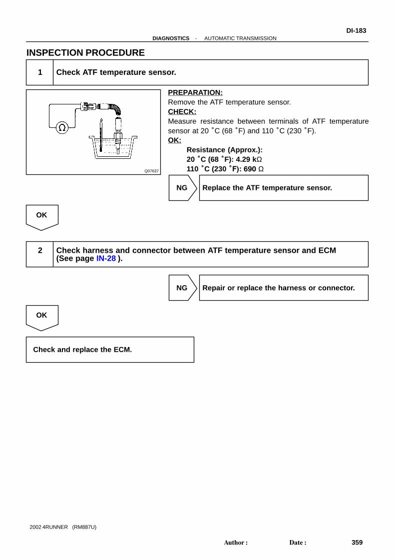
Q07637
-DIAGNOSTICS AUTOMATIC TRANSMISSIONDI-183
359Author: Date:
2002 4RUNNER (RM887U)
INSPECTION PROCEDURE
1 Check ATF temperature sensor.
PREPARATION:Remove the ATF temperature sensor.CHECK:Measure resistance between terminals of ATF temperaturesensor at 20 °C (68 °F) and 110 °C (230 °F).OK:
Resistance (Approx.):20 °C (68 °F): 4.29 kΩ110 °C (230 °F): 690 Ω
NG Replace the ATF temperature sensor.
OK
2 Check harness and connector between ATF temperature sensor and ECM(See page IN-28 ).
NG Repair or replace the harness or connector.
OK
Check and replace the ECM.

Q08221
Q08220
D00081
(+) (-)
(+) (-)
DI-184-DIAGNOSTICS AUTOMATIC TRANSMISSION
360Author: Date:
2002 4RUNNER (RM887U)
DTC P0750 Shift Solenoid ”A” Malfunction
DTC P0755 Shift Solenoid ”B” Malfunction
SYSTEM DESCRIPTIONThe ECM uses signals from the vehicle speed sensor to detect the actual gear position (1st, 2nd, 3rd or O/Dgear).Then the ECM compares the actual gear with the shift schedule in the ECM memory to detect mechanicaltrouble of the shift solenoid valves and valve body.
DTC No. DTC Detecting Condition Trouble Area
P0750
P0755
During normal driving, the gear required by the ECM does not
match the actual gear (2 trip detection logic).
Shift solenoid valve No. 1/No. 2 is stuck open or closed
Valve body is blocked up or stuck
HINT:Check the shift solenoid valve No. 1 when DTC P0750 (Shift Solenoid ”A” Malfunction) is output and checkshift solenoid valve No. 2 when DTC P0755 (Shift Solenoid ”B” Malfunction) is output.
INSPECTION PROCEDURE
1 Check shift solenoid valve No. 1 or No. 2 operation.
PREPARATION:(a) Remove the oil pan.(b) Remove the shift solenoid valve No. 1 or No. 2.CHECK:(a) Applying 490 kPa (5 kgf/cm2, 71 psi) of compressed air,
check that the solenoid valve does not leak air.(b) When battery positive voltage is supplied to the shift sole-
noid valve, check that the solenoid valve opens.OK:
(a) Solenoid valve does not leak air.(b) Solenoid valve opens.
NG Replace the shift solenoid valve No. 1 or No. 2.
OK
DI0SU-14

-DIAGNOSTICS AUTOMATIC TRANSMISSIONDI-185
361Author: Date:
2002 4RUNNER (RM887U)
2 Check the valve body (See page DI-175 ).
NG Repair or replace the valve body.
OK
Repair or replace the transmission(See page AT-18 and AT-22 ).

PositionNORMAL
SHIFT SOLENOID No. 1MALFUNCTIONING
SHIFT SOLENOID No. 2MALFUNCTIONING
BOTH SOLENOIDS MALFUNCTIONING
Solenoid valve Gear when shift selector ismanually operated
Solenoid valve Solenoid valveGear
D
No. 1
ON
Gear GearNo. 2 No. 1 No. 2 No. 1 No. 2
2
L
ON
ON
ON
ON
ON ON
ON
ON
ON
OFF
OFF
OFF
OFF
OFF
OFF
OFF
1st
1st
1st 1st
2nd
2nd
2nd 2nd
3rd
3rd
3rd
3rd
3rd
3rd
3rd
3rd
O/D O/D
X
X
X
X
X
X
X
X
X
X
X
X
X
X
X
X
X
X
ON
ON
ON
ON
ON
ON
ON
OFF
OFF
ON
ON
ON
ON
OFF
OFF
OFF
OFF
OFF
1st
1st
1st
1st
O/D
O/D
O/D
3rd
3rd
O/D
O/D
O/D
O/D
3rd
3rd
3rd
1st
1st
X: Malfunctions
ON
DI-186-DIAGNOSTICS AUTOMATIC TRANSMISSION
362Author: Date:
2002 4RUNNER (RM887U)
DTC P0753 Shift Solenoid ”A” Electrical
DTC P0758 Shift Solenoid ”B” Electrical
CIRCUIT DESCRIPTIONShifting from 1st to O/D is performed in combination with status (ON and OFF) of the shift solenoid valvesNo. 1 and No. 2 controlled by ECM. If an open or short circuit occurs in either of the shift solenoid valves,the ECM controls the remaining normal shift solenoid valve to allow the vehicle to be operated smoothly (Failsafe function).
HINT:Check the shift solenoid valve No. 1 when DTC P0753 (Shift Solenoid ”A” Electrical) is output and check theshift solenoid valve No. 2 when DTC P0758 (Shift Solenoid ”B” Electrial) is output.
DTC No. DTC Detecting Condition Trouble Area
P0753
P0758
The ECM checks for an open or short circuit in the shift sole-
noid valve No. 1 or No. 2 circuit when it changes.
The ECM records DTC P0753 or P0758 if condition 1. or 2. is
detected once, but it does not light up MIL.
After ECM detects condition 1. or 2. continuously 8 times or
more in one-trip, it causes the MIL light up until condition 1. or
2. disappears.
After that, if the ECM detects condition 1. or 2. once, it starts
lighting up MIL again.
1. Solenoid resistance is 8 Ω or less (short circuit) when the
solenoid is energized.
2. Solenoid resistance is 100 kΩ or more (open circuit) when
the solenoid is not energized.
Open or short in shift solenoid valve No. 1/No. 2 circuit
Shift solenoid valve No. 1/No. 2
ECM
DI0SV-22

D10503
Transmission
Shift SolenoidValve No. 1
ECM
P-L
L-W
Shift SolenoidValve No. 2
3
E9
2
E9
W
B
4
8
S1
S2
D10504S2S1
-DIAGNOSTICS AUTOMATIC TRANSMISSIONDI-187
363Author: Date:
2002 4RUNNER (RM887U)
Fail safe function:If either of the shift solenoid valve circuits develops an open or short, the ECM turns the other shift solenoidON and OFF to shift to the gear positions shown in the table above. The ECM also turns the shift solenoidvalve SL OFF at the same time. If both solenoids are malfunctioning, hydraulic control cannot be performedelectronically and must be done manually.Manual shifting as shown in the table above must be done (In the case of a short circuit, the ECM stops send-ing current to the short circuited solenoid).
WIRING DIAGRAM
INSPECTION PROCEDURE
1 Measure resistance between terminal S1 or S2 of ECM and body ground.
PREPARATION:Disconnect the connector from ECM.CHECK:Measure resistance between terminal S1 or S2 of ECM andbody ground.OK:
Resistance: 11 - 15 Ω at 20°C (68°F)
OK Check and replace the ECM (See page IN-28 ).
NG

D10505
S2S1S2
S1
D03074
(+) (-)
DI-188-DIAGNOSTICS AUTOMATIC TRANSMISSION
364Author: Date:
2002 4RUNNER (RM887U)
2 Check harness and connector between ECM and automatic transmission sole-noid connector.
PREPARATION:Disconnect the solenoid connector from the automatic trans-mission.CHECK:Check the harness and connector between terminal S1 or S2of ECM and terminal S1 or S2 of solenoid connector.OK:
There is no open and no short circuit.
NG Repair or replace the harness or connector.
OK
3 Check shift solenoid valve No. 1 or No. 2.
PREPARATION:(a) Remove the oil pan.(b) Remove the shift solenoid valve No. 1 or No. 2.CHECK:(a) Measure resistance between solenoid connector and
body ground.(b) Connect positive (+) lead to terminal of solenoid connec-
tor, negative (-) lead to solenoid body.OK:
(a) Resistance: 11 - 15 Ω at 20°C (68°F)(b) The solenoid makes an operation noise.
NG Replace the solenoid valve.
OK
-DIAGNOSTICS AUTOMATIC TRANSMISSIONDI-189
365Author: Date:
2002 4RUNNER (RM887U)
Repair or replace the solenoid wire.

D00076
DrainLinePressure
Q08219
Q08226 D00087
(+) (-)
(+) (-)
DI-190-DIAGNOSTICS AUTOMATIC TRANSMISSION
366Author: Date:
2002 4RUNNER (RM887U)
DTC P0770 Shift Solenoid ”E” Malfunction
SYSTEM DESCRIPTIONThe ECM uses the signals from the throttle position sensor, air-flow meter and crankshaft position sensor to monitor the en-gagement condition of the lock-up clutch.Then the ECM compares the engagement condition of thelock-up clutch with the lock-up schedule in the ECM memoryto detect mechanical trouble of the shift solenoid valve SL,valve body and torque converter clutch.
DTC No. DTC Detecting Condition Trouble Area
P0770
Lock-up does not occur when driving in the lock-up range
(normal driving at 80 km/h [50 mph]), or lock-up remains ON
in the lock-up OFF range (2 trip detection logic).
Shift solenoid valve SL is stuck open or closed
Valve body blocked up or stuck
Lock-up clutch
HINT:Check the shift solenoid valve SL when DTC P0770 (Shift Solenoid ”E” Malfunction) is output.
INSPECTION PROCEDURE
1 Check solenoid valve SL operation.
PREPARATION:(a) Remove the oil pan.(b) Remove the shift solenoid valve SL.CHECK:(a) Applying 490 kPa (5 kgf/cm2, 71 psi) of compressed air,
check that the solenoid valve does not leak air.(b) When battery voltage is supplied to the shift solenoid
valve, check that the solenoid valve opens.OK:
(a) Solenoid valve does not leak air.(b) Solenoid valve opens.
NG Replace the solenoid valve SL.
OK
DI0SW-15

-DIAGNOSTICS AUTOMATIC TRANSMISSIONDI-191
367Author: Date:
2002 4RUNNER (RM887U)
2 Check valve body (See page DI-175 ).
NG Repair or replace the valve body.
OK
Replace the torque converter clutch (See page AT-18 and AT-22 ).

D10506
TransmissionECM
LG SL
B+
Solenoid Valve SL1
E97
DI-192-DIAGNOSTICS AUTOMATIC TRANSMISSION
368Author: Date:
2002 4RUNNER (RM887U)
DTC P0773 Shift Solenoid ”E” Electrical
CIRCUIT DESCRIPTIONThe shift solenoid valve SL is turned ON and OFF by signals from the ECM to control the hydraulic pressureacting on the lock-up relay valve, which then controls operation of the lock-up clutch.
DTC No. DTC Detecting Condition Trouble Area
P0773
Either 1. or 2. is detected for 1 time
(2 - trip detection logic).
1. Solenoid resistance is 8 Ω or less (short circuit) when the
solenoid is energized.
2. Solenoid resistance is 100 kΩ or more (open circuit) when
the solenoid is not energized.
Open or short in shift solenoid valve SL circuit
Shift solenoid valve SL
ECM
Fail safe functionIf the ECM detects a malfunction, it turns the shift solenoid valve SL OFF.HINT:Check the shift solenoid valve SL when DTC P0773 (Shift Solenoid ”E” Electrical) is output.
WIRING DIAGRAM
DI0SX-20
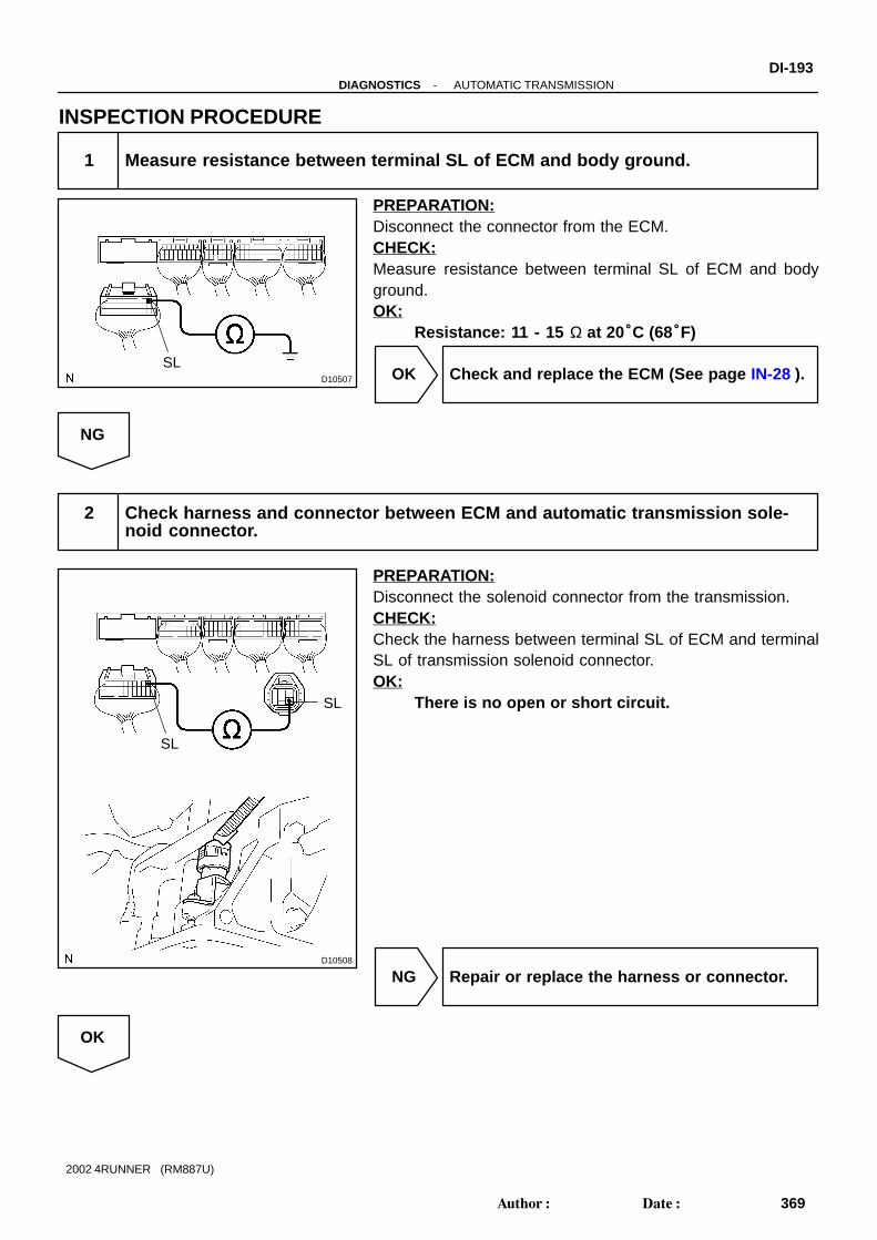
D10507
SL
D10508
SL
SL
-DIAGNOSTICS AUTOMATIC TRANSMISSIONDI-193
369Author: Date:
2002 4RUNNER (RM887U)
INSPECTION PROCEDURE
1 Measure resistance between terminal SL of ECM and body ground.
PREPARATION:Disconnect the connector from the ECM.CHECK:Measure resistance between terminal SL of ECM and bodyground.OK:
Resistance: 11 - 15 Ω at 20°C (68°F)
OK Check and replace the ECM (See page IN-28 ).
NG
2 Check harness and connector between ECM and automatic transmission sole-noid connector.
PREPARATION:Disconnect the solenoid connector from the transmission.CHECK:Check the harness between terminal SL of ECM and terminalSL of transmission solenoid connector.OK:
There is no open or short circuit.
NG Repair or replace the harness or connector.
OK

D03074
(+) (-)
DI-194-DIAGNOSTICS AUTOMATIC TRANSMISSION
370Author: Date:
2002 4RUNNER (RM887U)
3 Check shift solenoid valve SL.
PREPARATION:(a) Remove the oil pan.(b) Remove the shift solenoid valve SL.CHECK:(a) Measure resistance between terminal SL of shift solenoid
valve and solenoid body.(b) Connect positive (+) lead to terminal of solenoid connec-
tor, negative (-) lead to solenoid body.OK:
(a) Resistance: 11 - 15 Ω at 20°C (68°F)(b) The shift solenoid valve SL makes operationnoise.
NG Replace the shift solenoid valve SL.
OK
Repair or replace the solenoid wire.

-DIAGNOSTICS AUTOMATIC TRANSMISSIONDI-195
371Author: Date:
2002 4RUNNER (RM887U)
DTC P1520 Stop Light Switch Circuit Malfunction
CIRCUIT DESCRIPTIONThe purpose of this circuit is to prevent the engine from stalling, while driving in lock-up condition, whenbrakes are suddenly applied.When the brake pedal is operated, this switch sends a signals to ECM. Then the ECM cancels operationof the lock-up clutch while braking is in progress.
DTC No. DTC Detecting Condition Trouble Area
P1520The stop light switch does not turn off even once the vehicle is
driven (2 trip detection logic).
Short in stop light switch signal circuit
Stop light switch
ECM
WIRING DIAGRAMSee page DI-144 .
INSPECTION PROCEDURESee page DI-144 .
DI0SY-07

D00010
No. 2 Vehicle Speed Sensor
Rotor
ECM
Rotor
No. 2 Vehicle Speed Sensor
AT8761
5 V / Div.0 V
2 msec. / Div.
DI-196-DIAGNOSTICS AUTOMATIC TRANSMISSION
372Author: Date:
2002 4RUNNER (RM887U)
DTC P1700 Speed Sensor No. 2 Malfunction
CIRCUIT DESCRIPTIONThe No. 2 vehicle speed sensor detects the rotation speed of the transmission output shaft and sends sig-nals to the ECM. The ECM determines the vehicle speed based on these signals.An AC voltage is generated in the No. 2 vehicle speed sensor coil as the rotor mounted on the output shaftrotates, and this voltage is sent to the ECM.The gear shift point and lock-up timing are controlled by the ECM based on the signals from this vehiclespeed sensor and the throttle position sensor signal.If the No. 2 vehicle speed sensor malfunctions, the ECM uses input signals from the No. 1 vehicle speedsensor as a back-up signal.
DTC No. DTC Detecting Condition Trouble Area
P1700
All conditions below are detected 500 times or more continu-
ously (2 - trip detection logic).
1. No signal from No. 2 vehicle speed sensor is input to ECM
while 4 pulses of No. 1 vehicle speed sensor signal are
sent.
2. Vehicle speed: 9 km/h (5.6 mph) or more for at least 4 se-
conds.
3. Park/neutral position switch: OFF (Other than P or N)
4. Transfer position: Other than N position (A340F only)
Open or short in No. 2 vehicle speed sensor circuit
No. 2 vehicle speed sensor
ECM
HINT:Wave from between terminals SP2+ and SP2- when vehiclespeed is approx. 60 km/h (37 mph).
DI0SZ-27

D10509
No. 2Vehicle Speed Sensor
Y-R
W-R
1
SP2+
ECM
E10
E10SP2-
2 22
23
-DIAGNOSTICS AUTOMATIC TRANSMISSIONDI-197
373Author: Date:
2002 4RUNNER (RM887U)
WIRING DIAGRAM

D10510
SP2+ SP2-
DI-198-DIAGNOSTICS AUTOMATIC TRANSMISSION
374Author: Date:
2002 4RUNNER (RM887U)
INSPECTION PROCEDURE
1 Check vehicle speed value or resistance between terminals SP2 + and SP2- ofECM.
When using OBD II scan tool or hand-held tester:PREPARATION:(a) Remove the DLC3 cover.(b) Connect an OBD II scan tool or hand-held tester to the
DLC3.(c) Start the engine and turn OBD II scan tool or hand-held
tester main switch ON.CHECK:Drive the vehicle and read vehicle speed value.OK:
Vehicle speed matches tester speed value.When not using OBD II scan tool or hand-held tester:PREPARATION:Disconnect the connector from the ECM.CHECK:Check resistance between terminals SP2+ and SP2- of ECM.OK:
Resistance: 560 - 680 Ω at 20°C (68°F)
OK Check and replace the ECM (See page IN-28 ).
NG

Q08218
Q08292 D00012
A340E:Magnet
A340F: Magnet
(+) (-)
-DIAGNOSTICS AUTOMATIC TRANSMISSIONDI-199
375Author: Date:
2002 4RUNNER (RM887U)
2 Check No. 2 vehicle speed sensor.
PREPARATION:Remove the No. 2 vehicle speed sensor from the transmission.CHECK:(a) Measure resistance between terminals 1 and 2 of vehicle
speed sensor.(b) Check voltage between terminals 1 and 2 of vehicle
speed sensor when a magnet is put close to the front endof the vehicle speed sensor then taken away quickly.
OK:(a) Resistance: 560 - 680 Ω at 20°C (68°F)(b) Voltage is generated intermittently.
HINT:The voltage generated is extremely low.
NG Replace the No. 2 vehicle speed sensor.
OK
Check and repair the harness and connectorbetween ECM and No. 2 vehicle speed sensor(See page IN-28 ).

D02290
Line PressureControl Pressure
Current Flow to Solenoid
BE4056
ON
OFF1 cycle
Duty Ratio = A + BA
x 100 (%)
D01875
GND
5 V/Division
1 msec./Division
DI-200-DIAGNOSTICS AUTOMATIC TRANSMISSION
376Author: Date:
2002 4RUNNER (RM887U)
DTC P1760 Linear Solenoid for Line Pressure ControlCircuit Malfunction
CIRCUIT DESCRIPTIONThe throttle pressure that is applied to the primary regulatorvalve (which modulates line pressure) causes the solenoidvalve SLT, under electronic control, to precisely and minutelymodulate and generate line pressure according to the accelera-tor pedal effort, or the detected engine power output.This reduces the function of line pressure and provides smoothshifting characteristics.Upon receiving the throttle valve opening angle signal, ECMcontrols the line pressure by sending a predetermined (*) dutyratio to the solenoid valve, modulating the line pressure, andgenerating throttle pressure.(*) Duty RatioThe duty ratio is the ratio of the period of continuity in one cycle.For example, if A is the period of continuity in one cycle, and Bis the period of non-continuity, then
DTC No. DTC Detecting Condition Trouble Area
P1760
1. or 2. condition below is detected for 1 second or more.
1. SLT- terminal: 0 V
2. SLT- terminal: 12 V
Open or short in shift solenoid valve SLT circuit
Shift solenoid valve SLT
ECM
HINT:Waveform between terminals SLT+ and SLT- during engine id-ling is shown at left.
DI1O9-27

D05973
ECM
SLT+
SLT-E2
R-Y
Y-BE11
11
E2 E11
52
6
Shift SolenoidValve SLT
Transmission
-DIAGNOSTICS AUTOMATIC TRANSMISSIONDI-201
377Author: Date:
2002 4RUNNER (RM887U)
WIRING DIAGRAM

D01888D01889D01887 D02235
2 1
2
1(+) (-)
When battery positive voltage is applied.
When battery positive voltage is cut off.
Valve moves in directionin illustration at left.
Valve moves in directionin illustration at left.
DI-202-DIAGNOSTICS AUTOMATIC TRANSMISSION
378Author: Date:
2002 4RUNNER (RM887U)
INSPECTION PROCEDURE
1 Check shift solenoid valve SLT.
PREPARATION:(a) Remove the oil pan.(b) Disconnect the solenoid connector.Check solenoid resistance:CHECK:Measure resistance between terminals 1 and 2 of solenoid con-nector.OK:
Resistance: 5.0 - 5.6 Ω at 20 °C (68 °F)Check solenoid operation:CHECK:Connect positive (+) lead with an 8 - 10W bulb to terminal 1 ofsolenoid connector and negative (-) lead to terminal 2, thencheck the movement of the valve.OK:
NG Replace shift solenoid valve SLT.
OK
2 Check harness and connector between shift solenoid valve SLT and ECM (See page IN-28 ).
NG Repair or replace harness or connector.
OK
Check and replace ECM (See page IN-28 ).
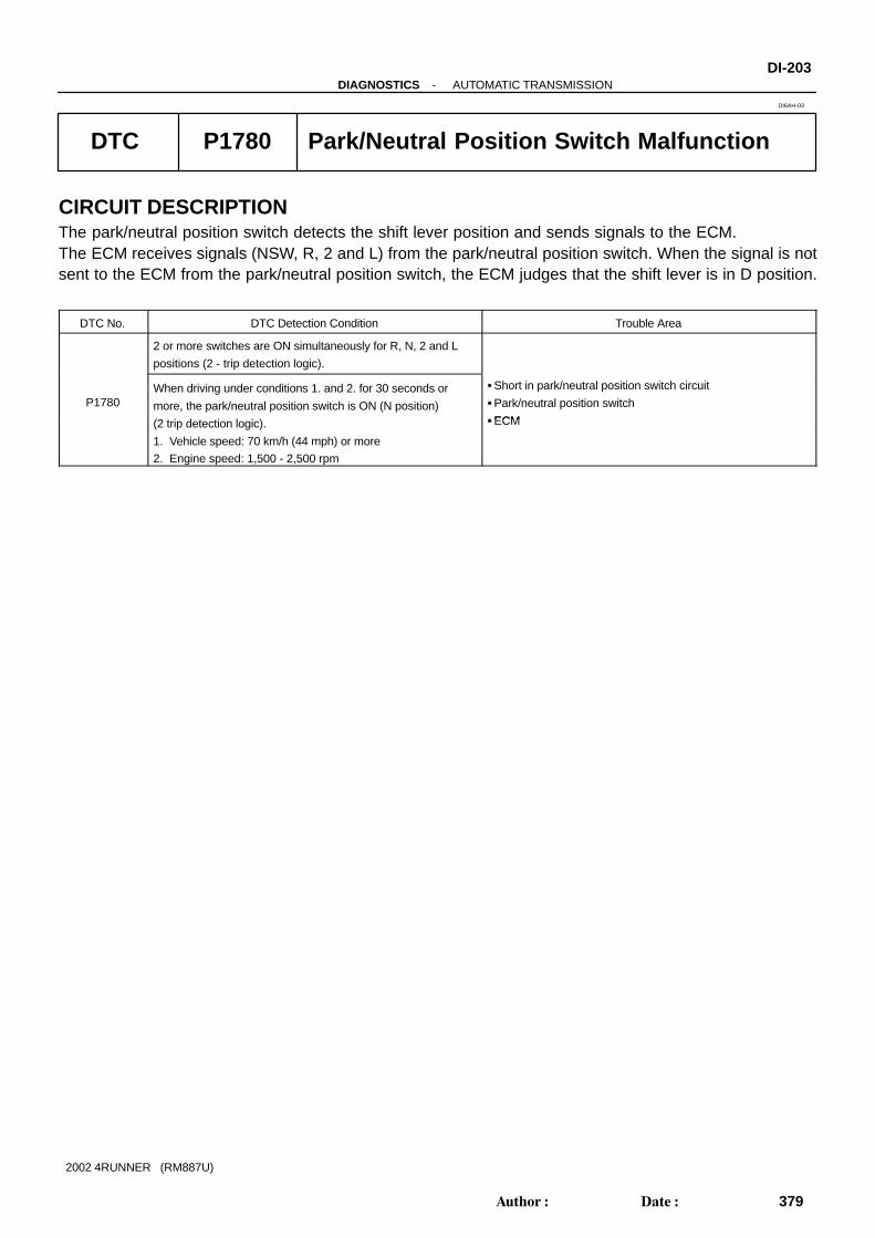
-DIAGNOSTICS AUTOMATIC TRANSMISSIONDI-203
379Author: Date:
2002 4RUNNER (RM887U)
DTC P1780 Park/Neutral Position Switch Malfunction
CIRCUIT DESCRIPTIONThe park/neutral position switch detects the shift lever position and sends signals to the ECM.The ECM receives signals (NSW, R, 2 and L) from the park/neutral position switch. When the signal is notsent to the ECM from the park/neutral position switch, the ECM judges that the shift lever is in D position.
DTC No. DTC Detection Condition Trouble Area
2 or more switches are ON simultaneously for R, N, 2 and L
positions (2 - trip detection logic).
P1780When driving under conditions 1. and 2. for 30 seconds or
more, the park/neutral position switch is ON (N position)
(2 t i d t ti l i )
Short in park/neutral position switch circuit
Park/neutral position switch
ECM(2 trip detection logic).
1. Vehicle speed: 70 km/h (44 mph) or more
2. Engine speed: 1,500 - 2,500 rpm
ECM
DI6AH-03

D10511
P1Park / NeutralPosition Switch
Engine ControlModal
Battery
Center J/B
2
3E 3E
3B
31I
B6
1F
7.5A STAG-B
BDriver Side J/B
B-W
9 6
RL W-L2
3 DL
7W-R
2L V4
LL LG8
B-Y
4
10
II1
5II1
II1
20II4
B-Y71F 1I
210A GAUGE
Driver Side J/BI14 Ignition Switch
2
G-B 8
AM1
ST2
IG1
AM2 7
4
W-R
B-Y
W
W2
1 2 1 22
21 2
120A ALT 40A AM1
30A AM2
J4Junction Connector
A W-B
17 C27
LG
V
W-R
W-L 3
C26
C26
C26
C26
5
6
7
R
D
2
L
IE
JunctionConnector
Driver Side J/B
Engine Room R/B
F7 4WD ECU
C/C
17D
W-R(4WD) 9
II1
4
1D
5
31D
1H
J7
J7
C
C
A
A
J8
J8
19
II4 W-L
GR-B
16 (4WD)
W-R(2WD)
B
LG
W-L
V
E12 D25
E123
E12 L
R
2
E12
E12
4
6
5
NSW
Combination Meter
3
II1
W-R
V
DI-204-DIAGNOSTICS AUTOMATIC TRANSMISSION
380Author: Date:
2002 4RUNNER (RM887U)
WIRING DIAGRAM

-DIAGNOSTICS AUTOMATIC TRANSMISSIONDI-205
381Author: Date:
2002 4RUNNER (RM887U)
INSPECTION PROCEDURE
1 Read PNP, REVERSE, 2ND and LOW signals.
When using hand-held tester:PREPARATION:(a) Remove the DLC3 cover.(b) Connect a hand-held tester to the DLC3.(c) Turn the ignition switch ON and hand-held tester main
switch ON.CHECK:Shift lever into the P, R, D, N, 2 and L positions, and read thePNP, REVERSE, 4TH/DRIVE 2ND and LOW signals on theTOYOTA hand-held tester.OK:
Shift position Signal
2 2ND OFF → ON
L LOW OFF → ON
D 4TH / DRIVE OFF → ON
R REVERSE OFF → ON
P, N PNP OFF → ON

D10512
R
D
2 LON
NSW
Position
P, N
R
D
2
L
NSW-Bodyground
R-Bodyground
2-Bodyground
L-Bodyground
0 V0 V 0 V 0 V
0 V
0 V
0 V
0 V
0 V
0 V
0 V
0 V
0 V
9 - 14 V*
9 - 14 V
9 - 14 V
9 - 14 V
7.5 - 14 V
7.5 - 14 V*
7.5 - 14 V
0 V
0 V
0 V
7.5 - 14 V
0 V
D-Bodyground
DI-206-DIAGNOSTICS AUTOMATIC TRANSMISSION
382Author: Date:
2002 4RUNNER (RM887U)
When not using hand-held tester:PREPARATION:Turn the ignition switch ON.CHECK:Measure voltage between terminals NSW, 2, L and R of ECMand body ground when the shift lever is shifted to the followingpositions.OK:
HINT:*: The voltage will drop slightly due to lighting up of the back uplight.
OK Check and replace the ECM (See page IN-28 ).
NG

D06561
5 4 3 2 1
68 79
-DIAGNOSTICS AUTOMATIC TRANSMISSIONDI-207
383Author: Date:
2002 4RUNNER (RM887U)
2 Check park/neutral position switch.
PREPARATION:(a) Jack up the vehicle.(b) Disconnect the park/neutral position switch connector.CHECK:Check continuity between each terminal shown below when theshift lever is moved to each position.OK:
Shift Position Terminal No. to continuity Terminal No. to continuity
P 6 - 9 1 - 3
R 2 - 3 -
N 6 - 9 3 - 5
D 3 - 7 -
2 3 - 4 -
L 3 - 8 -
NG Replace the park/neutral position switch.
OK
Repair or replace harness and connector between battery and park/neutral position switch, park/neutral position switch and ECM (See page IN-28 ).

D11934
ECM
Combination Meter
Driver Side J/BGA
UG
E
Battery
ALT
AM1
Driver Side J/B IG1
AM1
A/T
P
B-RE12
11TFN
J8 C
J8
C
C2514
C26 2
1F 7
1I 2
I11 2
J/C
B-R
L-Y
L-Y
P1Park/Neutral Position Switch
B-Y3
1
II4
20B-Y
B-Y
I14Ignition Switch
2
4
W
2
2
2
2
1
1
W
J7
AB-RII4
22
D5transfer Neutral Position switch
E12
2
L4J7
BJ/C
J8
BII4
7L-R L-R
D4transfer L4 Position switch
12
12W-BB-R
W-B W-B
4WD
DI-208-DIAGNOSTICS AUTOMATIC TRANSMISSION
384Author: Date:
2002 4RUNNER (RM887U)
DTC P1782 Transfer L4 SW Circuit Malfunction
CIRCUIT DESCRIPTIONThe ECM receive signal L4 from the indicator switch (LOW switch).
DTC No. DTC Detecting Condition Trouble Area
P1782
When driving under conditions (a) and (b) for 1.8 seconds or
more, the indicator switch (LOW switch) is ON .
(1-trip detection logic)
(a) Output shaft speed 3000 rpm or less
(b) Transfer shift position is H
Short in transfer L4 position switch (LOW switch) signal cir-
cuit
transfer L4 position switch (LOW switch)
ECM
WIRING DIAGRAM
DI9OB-01

F01140
Q07482 F03418
Push
Ohmmeter
D11998
L4
(-) (+)
ON
-DIAGNOSTICS AUTOMATIC TRANSMISSIONDI-209
385Author: Date:
2002 4RUNNER (RM887U)
INSPECTION PROCEDURE
1 Check transfer L4 position switch ( See page TR-1 1).
PREPARATION:Remove the transfer L4 position switch (See page TR-9 ).CHECK:Check that there is continuity between terminals, as shown.OK:
Switch position Specified condition
Push Continuity
Free No continuity
NG Replace transfer L4 position switch.
OK
2 Check voltage between terminal L4 of ECM and body ground.
PREPARATION:Remove the ECM with connectors still connected.CHECK:(a) Turn the ignition switch ON.(b) Measure voltage between terminal L4 of ECM and body
ground when transfer in L4 position.OK:
Transfer shift position Voltage (V)
L Below 1.5
Except L 9 - 14

DI-210-DIAGNOSTICS AUTOMATIC TRANSMISSION
386Author: Date:
2002 4RUNNER (RM887U)
OK Proceed to next circuit inspection shown inproblem symptoms chart (See page DI-175 ).
NG
3 Check for open or short circuit in harness and connector between transfer L4position switch and ECM ( See page IN-28 ).
NG Repair or replace harness or connector.
OK
Check and replace ECM.

D11934
ECM
Combination Meter
Driver Side J/BGA
UG
E
Battery
ALT
AM1
Driver Side J/B IG1
AM1 A/T
P
B-RE12
11TFN
J8 C
J8
C
C2514
C26 2
1F 7
1I 2
I11 2
J/C
B-R
L-Y
L-Y
P1Park/Neutral Position Switch
B-Y3
1
II4
20B-Y
B-Y
I14Ignition Switch
2
4
W
2
2
2
2
1
1
W
J7
AB-RII4
22
D5transfer Neutral Position
E12
2
L4J7
BJ/C
J8
BII4
7L-R L-R
D4transfer L4 Position
12
12W-BB-R
W-B W-B
4WD
-DIAGNOSTICS AUTOMATIC TRANSMISSIONDI-21 1
387Author: Date:
2002 4RUNNER (RM887U)
DTC P1783 Transfer N SW Circuit Malfunction
CIRCUIT DESCRIPTIONThe propeller shaft and wheels are free even when the transmission shift lever is set to P as long as thetransfer shift lever is in Neutral position. The A/T.P. indicator light lights up to warn the drive that the propellershaft and wheels are not locked.If the A/T.P. indicator light goes on, the transfer shift lever should be shifted out of N position.The ECM receive signal TFN from the indicator switch (neutral position switch).
DTC No. DTC Detecting Condition Trouble Area
P1783
While driving under conditions (a) and (b) for 30 seconds or
more, the indicator switch(TFN switch) is ON .
(2-trip detection logic)
(a) Vehicle speed: 25 km/h (16 mph) or more
(b) Transfer shift position is H
Short in transfer neutral position switch signal circuit
Transfer neutral position switch
ECM
WIRING DIAGRAM
DI9OC-01

F01140
Q07482 F03418
Push
Ohmmeter
DI-212-DIAGNOSTICS AUTOMATIC TRANSMISSION
388Author: Date:
2002 4RUNNER (RM887U)
INSPECTION PROCEDURE
1 Check park/neutral position switch (See page DI-203 ).
NG Replace the park/neutral position switch.
OK
2 Check transfer neutral position switch.
PREPARATION:Remove the transfer park/neutral position switch (See pageTR-9 ).CHECK:Check that there is continuity between terminals, as shown.OK:
Switch position Specified condition
Push Continuity
Free No continuity
OK Replace the transfer neutral position switch.
NG

D11997
TFNON
-DIAGNOSTICS AUTOMATIC TRANSMISSIONDI-213
389Author: Date:
2002 4RUNNER (RM887U)
3 Check combination meter (See page BE-45 ).
NG Repair or replace the combination meter.
OK
4 Check voltage between terminal TFN of ECM and body ground.
PREPARATION:Remove the ECM with connectors still connected.CHECK:Turn the ignition switch ON, measure voltage between terminalTFN of ECM and body ground when transfer shift lever is shiftedto the following position.OK:
Transfer shift position Voltage (V)
N Below 1.5
Except N 9 - 14
OK Proceed to next circuit inspection shown onproblem symptom chart (See page DI-175 ).
NG
5 Check for open or short circuit in harness and connector between transfer neu-tral position switch and ECM ( See page IN-28 ).
NG Repair or replace harness or connector.
OK
Check and replace ECM.

DI-214-DIAGNOSTICS AUTOMATIC TRANSMISSION
390Author: Date:
2002 4RUNNER (RM887U)
Pattern Select Switch Circuit
CIRCUIT DESCRIPTIONThe ECM memory contains the shift programs for the NORMAL and POWER patterns, 2 position, L positionand the lock-up patterns. Following the programs corresponding to the signals from the pattern selectswitch, the park/neutral position and other various sensors, the ECM switches the solenoid valves ON andOFF, and controls the transmission gear change and the lock-up clutch operation.
DI0T3-12

D10516
Driver Side J/B
120A ALT
Battery
10A GAUGE
IG1 AM1
J4JunctionConnector
I14Ignition Switch
Pattern Select Switch
ECM
40A AM1
Engine Room R/B
2 222 11
4 2
2
1I
9
1F 4 3
W
W
B-Y
PWR
NORM
G-R
G-RG-R 1E12
15C25
17
C27
Combination Meter
ECT PWR
W-B
A
IE
B-Y
PWR
-DIAGNOSTICS AUTOMATIC TRANSMISSIONDI-215
391Author: Date:
2002 4RUNNER (RM887U)
WIRING DIAGRAM

D10517
ON
(+)(-)PWR
DI-216-DIAGNOSTICS AUTOMATIC TRANSMISSION
392Author: Date:
2002 4RUNNER (RM887U)
INSPECTION PROCEDURE
1 Check PATTERN SEL SW signal.
When using TOYOTA hand-held tester:PREPARATION:(a) Remove the DLC3 cover.(b) Connect a TOYOTA hand-held tester to the DLC3.(c) Turn the ignition switch ON and TOYOTA hand-held tes-
ter main switch ON.CHECK:Read the PATTERN SEL SW signal on the TOYOTA hand-heldtester.OK:
Pattern select switch PATTERN SEL SW signal
Pushed in ON
Pushed out OFF
When not using TOYOTA hand-held tester:PREPARATION:Turn the ignition switch ON.CHECK:Measure voltage between terminal PWR of the ECM and bodyground when the pattern select switch set to the PWR (POW-ER) position and NORM (NORMAL) position.OK:
Pattern select switch Voltage
PWR 9 - 14 V
NORM Below 1.5 V
HINT:The ECM uses the normal pattern signal if the PWR signal is notinput.
OK Proceed to next circuit inspection shown onmatrix chart (See page DI-175 ).
NG

D10520
4 3
-DIAGNOSTICS AUTOMATIC TRANSMISSIONDI-217
393Author: Date:
2002 4RUNNER (RM887U)
2 Check pattern select switch.
PREPARATION:Disconnect the pattern select switch connector.CHECK:Check continuity between terminals 3 and 4 of pattern selectswitch connector when the select switch is set to PWR andNORM positions.OK:
Pattern select switch Specified condition
PWR Continuity
NORM No continuity
NG Replace the pattern select switch.
OK
3 Check harness and connector between battery and pattern select switch, patternselect switch and ECM (See page IN-28 ).
NG Repair or replace the harness or connector.
OK
Check and replace the ECM (See page IN-28 ).

D10513
Driver Side J/B
Battery
ECM
AM1
120A ALT
Center J/BJ9JunctionConnector
O/D OFF10A GAUGE
I14Ignition Switch
ODLP
ODMS
B-Y
1F
IG1
1I2 8
C2912
C261
40A AM1
E1220
2 22121
3E16
3E22
E1214
510A
IF
W
W
B-Y G-Y
L-WW-BW-B
Engine Room R/B
S3O/D Main Switch
24
DI-218-DIAGNOSTICS AUTOMATIC TRANSMISSION
394Author: Date:
2002 4RUNNER (RM887U)
O/D Main Switch & O/D OFF Indicator Light Circuit
CIRCUIT DESCRIPTIONThe O/D main switch is a momentary type switch. When pressing the O/D OFF main switch, the O/D OFFindicator light lights up and ECM prohibit shifting to O/D, and when pressing it again, the O/D OFF indicatorlight goes off and ECM allows shifting to O/D. Turning the IG switch OFF will reset the O/D OFF indicatorlight.
WIRING DIAGRAM
DI1CP-14

Q30003
4 32 198 67
5
10
-DIAGNOSTICS AUTOMATIC TRANSMISSIONDI-219
395Author: Date:
2002 4RUNNER (RM887U)
INSPECTION PROCEDURE
1 Check operation of O/D main switch.
PREPARATION:Turn the ignition switch ON.CHECK:(a) Check O/D OFF indicator light when O/D main switch is
pushed in to ON.(b) Check O/D OFF Indicator light when O/D main switch is
pushed again.OK:
(a) O/D OFF indicator light lights up.(b) O/D OFF indicator light goes off.
OK Proceed to next inspection shown on problemsymptoms table (See page DI-175 ).
NG
2 Check and replace combination meter (See page BE-45 ).
NG Replace the combination meter.
OK
3 Check O/D main switch.
PREPARATION:Disconnect the O/D main switch connector.CHECK:Check continuity between 5 and 10 of the O/D main switch con-nector.OK:
O/D main switch condition Specified condition
Press continuously O/D main switch Continuity
Release O/D main switch No continuity
NG Replace and repair O/D main switch.
OK

D10514
ON
(+)ODMS
(-)
D10515
ON
(+)
ODLP
(-)
DI-220-DIAGNOSTICS AUTOMATIC TRANSMISSION
396Author: Date:
2002 4RUNNER (RM887U)
4 Check voltage between terminal ODMS of ECM and body ground.
PREPARATION:Turn the ignition switch ON.CHECK:Check voltage between terminal ODMS of the ECM and bodyground when O/D main switch is ON and OFF.OK:
O/D main switch Specified voltage
Press continuously O/D main switch Below 1.5 V
Release O/D main switch 9 - 14 V
OK Check and replace the ECM (See page IN-28 ).
NG
5 Check voltage between terminal ODLP of ECM and body ground.
PREPARATION:(a) Disconnect the connector of ECM.(b) Turn the ignition switch ON.CHECK:Check voltage between terminal ODLP of the ECM and bodyground.OK:
O/D main switch Specified voltage
Press continuously O/D main switch Below 3 V
Release O/D main switch 9 - 14 V
OK Check and replace the ECM (See page IN-28 ).
NG
Check and replace harness and connector between combination meter and ECM, O/D mainswitch and ECM, O/D main switch and body ground (See page IN-28 ).

DI6BA-04
Vehicle Brought to Workshop
Customer Problem AnalysisP. DI-222
Check and Clear DTC (Pre-check)P. DI-224
Items inside are titles of pages in this manual,with the page number in the bottom portion. Seethe pages for detailed explanations.
Problem Symptom Confirmation Symptom SimulationP. IN-18
Symptomdoes not occur
Symptomoccurs
DTC Check
Sensor CheckCircuit Inspection
P. DI-244 to DI-372
DTC ChartP. DI-234
Malfunction code
Problem Symptoms TableP. DI-242
Check for Fluid Leakage
Identification of Problem
Normal code
Repair
Confirmation Test
End
1
2
3 4
5
6 7
89
10
11
Step 2, 5, 8, 9, 11: Diagnostic steps permitting the use of thehand-held tester.
P. DI-224
P. DI-374
Fail safe function:When a failure occurs in the ABS & BA & TRAC & VSC system, the ABS and VSC TRAC warning light islit and the ABS & BA & TRAC & VSC operation is prohibited. In addition to this, when the failure that disablesthe EBD operation occurs, the brake warning light is lit as well and the EBD operation is prohibited.
-DIAGNOSTICS ABS WITH EBD & BA & TRAC & VSC SYSTEMDI-221
397Author: Date:
2002 4RUNNER (RM887U)
ABS WITH EBD & BA & TRAC & VSC SYSTEMHOW TO PROCEED WITH TROUBLESHOOTINGTroubleshooting in accordance with the procedure on the following pages.

DI6BB-03
ABS Check Sheet Inspector’sName :
Customer’s Name
Date VehicleBrought In
Registration Date
Registration No.
Frame No.
Odometer Reading
/ /
/ /
Date Problem First Occurred
Frequency Problem Occurs
/ /
Continuous Intermittent ( times a day)
ABS does not operate.
ABS does not operate efficiently.
ABS Warning LightAbnormal
Remains ON Does not Light Up
DTC Check1st Time
2nd Time
Normal Code Malfunction Code (Code )
Normal Code Malfunction Code (Code )
Symptoms
kmmiles
BRAKE WarningLight Abnormal(PKB released)
Brake WarningBuzzer Abnormal
Remains ON Does not Light Up
Sounds Does not sound
BA does not operate.
DI-222-DIAGNOSTICS ABS WITH EBD & BA & TRAC & VSC SYSTEM
398Author: Date:
2002 4RUNNER (RM887U)
CUSTOMER PROBLEM ANALYSIS CHECK
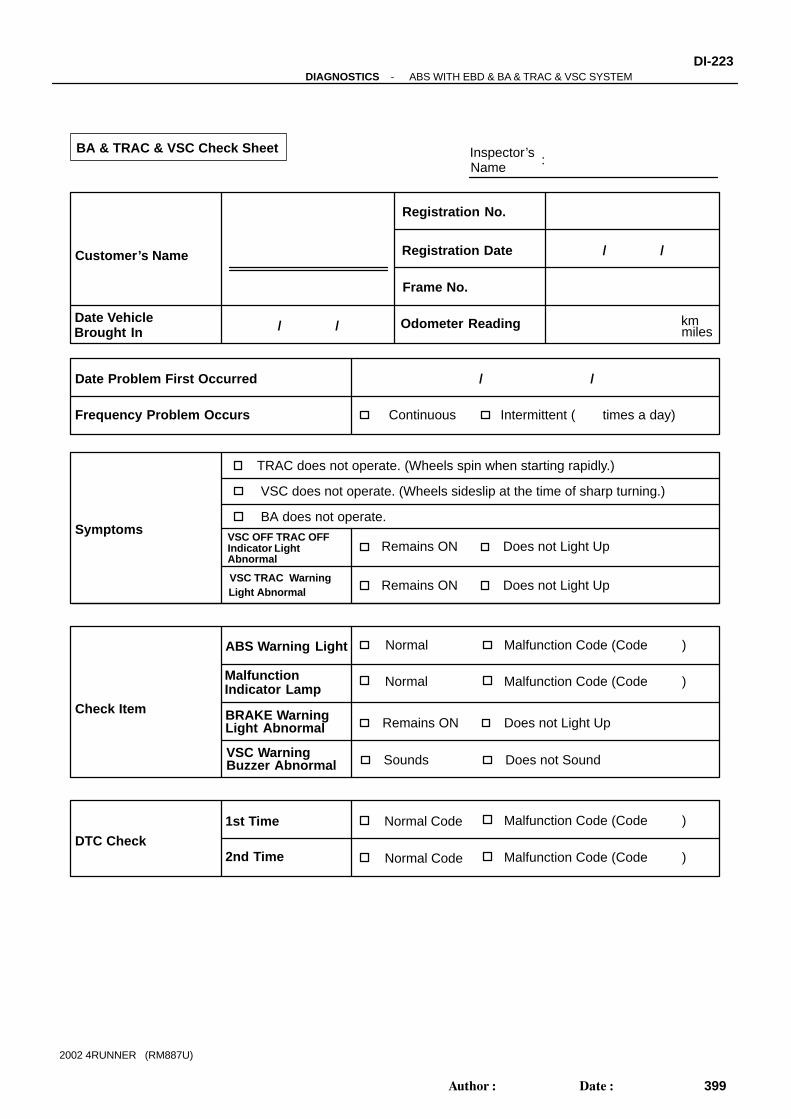
Inspector’sName :
Customer’s Name
Date VehicleBrought In
Registration Date
Registration No.
Frame No.
Odometer Reading
/ /
/ /
Date Problem First Occurred
Frequency Problem Occurs
/ /
Continuous Intermittent ( times a day)
TRAC does not operate. (Wheels spin when starting rapidly.)
Remains ON Does not Light Up
DTC Check
1st Time
2nd Time
Normal Code Malfunction Code (Code )
Normal Code Malfunction Code (Code )
Symptoms
kmmiles
Remains ON Does not Light Up
Check Item
Normal Malfunction Code (Code )
Normal Malfunction Code (Code )
ABS Warning Light
MalfunctionIndicator Lamp
BA & TRAC & VSC Check Sheet
VSC does not operate. (Wheels sideslip at the time of sharp turning.)
VSC TRAC WarningLight Abnormal
Remains ON Does not Light UpBRAKE WarningLight Abnormal
Sounds Does not SoundVSC WarningBuzzer Abnormal
BA does not operate.
AbnormalIndicator LightVSC OFF TRAC OFF
-DIAGNOSTICS ABS WITH EBD & BA & TRAC & VSC SYSTEMDI-223
399Author: Date:
2002 4RUNNER (RM887U)

F14323
CANADA:
USA:
4WD:
2WD:
DI8XO-02
F02201
DLC1E1
Tc
DI-224-DIAGNOSTICS ABS WITH EBD & BA & TRAC & VSC SYSTEM
400Author: Date:
2002 4RUNNER (RM887U)
PRE-CHECK1. DIAGNOSIS SYSTEM(a) Inspect the battery positive voltage.
Battery positive voltage: 10 - 14 V(b) Check the warning lights and buzzer.
(1) Release the parking brake lever.(2) When the ignition switch is ON, check that the ABS,
BRAKE, VSC TRAC warning lights, VSC or TRACOFF and SLIP indicator lights go on for 3 sec.
(3) 4WD:Check that the center diff. lock indicator light andVSC OFF indicator light light up when the centerdiff. lock switch is pressed.
(4) Depressing the brake pedal repeatedly may lightthe warning light and sound the buzzer.
HINT: If the ECU stores DTC, ABS or VSC TRAC indicator light
is ON. If the indicator check result is not normal, proceed to trou-
bleshooting for the circuits of the ABS, BRAKE warninglights,VSC or TRAC OFF, SLIP, center diff. lock indicatorlights.
Trouble Area See page
ABS warning light circuit DI-351
BRAKE warning light circuit DI-365
VSC TRAC warning light circuit DI-354
VSC OFF indicator light circuit (4WD) DI-357
TRAC OFF indicator light circuit (2WD) DI-360
SLIP indicator light circuit DI-363
Center diff. lock indicator light circuit (4WD) DI-357
VSC buzzer circuit DI-367
(c) In case of not using the hand-held tester:Check the DTC.(1) Using SST, connect terminals Tc and E1 of DLC1.SST 09843-18020(2) Turn the ignition switch ON.(3) Read the DTC from the ABS or VSC TRAC warning
lights on the combination meter.

R01346
Normal Code
0.25 sec.
0.25 sec.
2 sec.
ON
OFF
ON
OFF
0.5 sec. 0.5 sec.
Code 11 and 21
4 sec.
1.5 sec.
2.5 sec.
Code 11 Code 21
F13739
Hand-held Tester
DLC3
BR3890
-DIAGNOSTICS ABS WITH EBD & BA & TRAC & VSC SYSTEMDI-225
401Author: Date:
2002 4RUNNER (RM887U)
HINT: If no code appears, inspect the diagnostic circuit, ABS or
VSC TRAC warning light circuit.
Trouble Area See page
Tc terminal circuit DI-370
ABS warning light circuit DI-351
VSC TRAC warning light circuit DI-354
As an example, the blinking patterns for normal code andcodes 11 and 21 are shown on the left.(4) Codes are explained in the code table on page
DI-234 .(5) After completing the check, disconnect terminals Tc
and E1 of DLC1, and turn off the display.If 2 or more malfunctions are indicated at the same time, thelowest numbered DTC will be displayed 1st.
(d) In case of using the hand-held tester: Check the DTC.(1) Hook up the hand-held tester to DLC3.(2) Turn the ignition switch ON.(3) Read the DTC by following the prompts on the tes-
ter screen.HINT:Please refer to the hand-held tester operator’s manual for fur-ther details.
(e) In case of not using the hand-held tester:Clear the DTC.(1) Using SST, connect terminals Tc and E1 of DLC1.SST 09843-18020(2) Turn the ignition switch ON.(3) Clear the DTC stored in ECU by depressing the
brake pedal 8 times or more within 5 sec.(4) Check that the warning light shows the normal code
blinking pattern.

F13739
Hand-held Tester
DLC3
F02201
DLC1E1
TcTs
BR3904
ON
OFF
0.13 sec. 0.13 sec.
DI-226-DIAGNOSTICS ABS WITH EBD & BA & TRAC & VSC SYSTEM
402Author: Date:
2002 4RUNNER (RM887U)
(5) Remove the SST from terminals Tc and E1 of DLC1.SST 09843-18020
(f) In case of using the hand-held tester:Clear the DTC.(1) Hook up the hand-held tester to DLC3.(2) Turn the ignition switch ON.(3) Operate the hand-held tester to erase the codes.
HINT:Please refer to the hand-held tester operator’s manual for fur-ther details.
2. In case of not using the hand-held tester:ABS SENSOR SIGNAL CHECK (TEST MODE)
HINT:If the ignition switch is turned from ON to ACC or LOCK duringthe test mode, DTC will be erased.(a) Procedures for the test mode:
(1) Turn the ignition switch OFF.(2) Shift the shift lever to P range.(3) Using SST, connect terminals Ts and E1 of DLC1.SST 09843-18020(4) Check that the steering wheel is in the straight-
ahead position.(5) Turn the ignition switch ON.
(6) Check that the ABS warning light blinks.HINT:If the ABS warning light does not blink, inspect the ABS warninglight circuit or the Ts terminal circuit.
Trouble Area See page
Ts terminal circuit DI-372
ABS warning light circuit DI-351

BR3893
Malfunction Code (Example Code 72, 76)
7 2 67
ON
OFF
0.5 sec.0.5 sec.0.5 sec.0.5 sec.
1.5 sec. 2.5 sec. 4 sec.
Repeat
-DIAGNOSTICS ABS WITH EBD & BA & TRAC & VSC SYSTEMDI-227
403Author: Date:
2002 4RUNNER (RM887U)
(b) Check the deceleration sensor.Keep the vehicle in a stationary condition on a level placefor 1 sec. or more.
(c) Check the master cylinder pressure sensor.Leaving the vehicle in a stationary condition and thebrake pedal in free condition for 1 sec. or more, continueto depress the brake pedal with the force of 98 N (10 kgf,22 lbf) or more for 1 sec. or more.
HINT:At this time, the ABS warning light goes on for 3 sec.(d) 4WD:
Check the center diff. lock switch.Turn the center diff. lock switch from OFF to ON and OFFagain.
(e) 4WD:Check the L4 position switch.(1) Shift the transfer lever to L4 position and turn the
center diff. lock switch ON.(2) Shift the transfer lever to H4 position.
(f) Check the speed sensor signal.Drive the vehicle straight forward.Drive the vehicle with a speed faster than 45 km/h (28mph) for several seconds. Check that the ABS warninglight comes off.
HINT:The sensor check may not be completed if the wheels spin orthe steering wheel is steered during this check.(g) Stop the vehicle.(h) Using SST, connect terminals Tc and E1 of DLC1.
SST 09843-18020(i) Read the number of blinks of the ABS warning light.HINT: See the list of DTC on the next page. If every sensor is normal, a normal code is output (A cycle
of 0.25 sec. ON and 0.25 sec. OFF is repeated). If 2 or more malfunctions are indicated at the same time,
the lowest number code will be displayed 1st.
(j) After doing the check, disconnect SST from the terminalsof DLC1 and turn the ignition switch OFF.SST 09843-18020
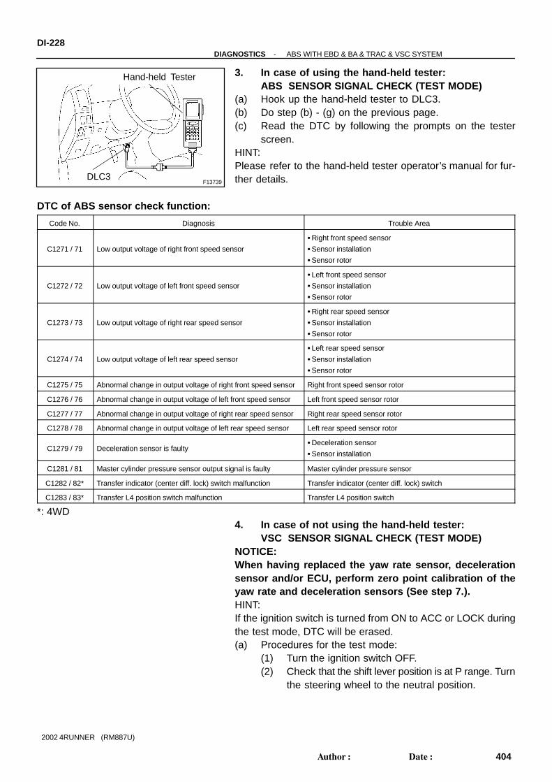
F13739
Hand-held Tester
DLC3
DI-228-DIAGNOSTICS ABS WITH EBD & BA & TRAC & VSC SYSTEM
404Author: Date:
2002 4RUNNER (RM887U)
3. In case of using the hand-held tester:ABS SENSOR SIGNAL CHECK (TEST MODE)
(a) Hook up the hand-held tester to DLC3.(b) Do step (b) - (g) on the previous page.(c) Read the DTC by following the prompts on the tester
screen.HINT:Please refer to the hand-held tester operator’s manual for fur-ther details.
DTC of ABS sensor check function:
Code No. Diagnosis Trouble Area
C1271 / 71 Low output voltage of right front speed sensor
Right front speed sensor
Sensor installation
Sensor rotor
C1272 / 72 Low output voltage of left front speed sensor
Left front speed sensor
Sensor installation
Sensor rotor
C1273 / 73 Low output voltage of right rear speed sensor
Right rear speed sensor
Sensor installation
Sensor rotor
C1274 / 74 Low output voltage of left rear speed sensor
Left rear speed sensor
Sensor installation
Sensor rotor
C1275 / 75 Abnormal change in output voltage of right front speed sensor Right front speed sensor rotor
C1276 / 76 Abnormal change in output voltage of left front speed sensor Left front speed sensor rotor
C1277 / 77 Abnormal change in output voltage of right rear speed sensor Right rear speed sensor rotor
C1278 / 78 Abnormal change in output voltage of left rear speed sensor Left rear speed sensor rotor
C1279 / 79 Deceleration sensor is faultyDeceleration sensor
Sensor installation
C1281 / 81 Master cylinder pressure sensor output signal is faulty Master cylinder pressure sensor
C1282 / 82* Transfer indicator (center diff. lock) switch malfunction Transfer indicator (center diff. lock) switch
C1283 / 83* Transfer L4 position switch malfunction Transfer L4 position switch
*: 4WD4. In case of not using the hand-held tester:
VSC SENSOR SIGNAL CHECK (TEST MODE)NOTICE:When having replaced the yaw rate sensor, decelerationsensor and/or ECU, perform zero point calibration of theyaw rate and deceleration sensors (See step 7.).HINT:If the ignition switch is turned from ON to ACC or LOCK duringthe test mode, DTC will be erased.(a) Procedures for the test mode:
(1) Turn the ignition switch OFF.(2) Check that the shift lever position is at P range. Turn
the steering wheel to the neutral position.

F02201
DLC1E1
TcTs
BR3904
0.13 sec. 0.13 sec.
ON
OFF
F02135
Start Position
End Position
Within ± 5°
-DIAGNOSTICS ABS WITH EBD & BA & TRAC & VSC SYSTEMDI-229
405Author: Date:
2002 4RUNNER (RM887U)
(3) Using SST, connect terminals Ts and E1 of DLC1.SST 09843-18020(4) Start the engine.
(5) Check that the VSC TRAC warning light blinks.HINT:If the VSC TRAC warning light does not blink, inspect the VSCTRAC warning light circuit or the Ts terminal circuit.
Trouble Area See page
Ts terminal circuit DI-372
VSC TRAC warning light circuit DI-354
(b) Check the steering angle sensor.Turn the steering wheel either to left or right for 450° ormore from the vehicle stationary condition, and turn backthe steering wheel to the straight ahead position.
(c) Check the yaw rate sensor.Shift the shift lever to the D position and drive the vehicleat the vehicle speed of approx. 5 km/h (3 mph), turn thesteering wheel either to left or right for 90° or more, andmaintain wheel 180° circular drive for the vehicle.Stop the vehicle and shift the shift lever to the P position,check that the VSC buzzer sounds for 3 sec.
HINT: If the VSC buzzer sounds, the sensor check is in normal
completion. If the VSC buzzer does not sound, check the VSC buzzer
circuit, then do the sensor check again.
Trouble Area See page
VSC buzzer circuit DI-367
If the VSC buzzer still won’t sound, there is malfunctionin the VSC sensor, so check the DTC.
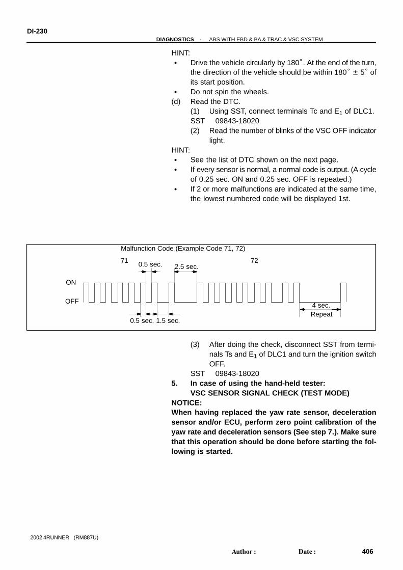
Malfunction Code (Example Code 71, 72)
ON
OFF
0.5 sec.
0.5 sec.
1.5 sec.
2.5 sec.
4 sec.Repeat
71 72
DI-230-DIAGNOSTICS ABS WITH EBD & BA & TRAC & VSC SYSTEM
406Author: Date:
2002 4RUNNER (RM887U)
HINT: Drive the vehicle circularly by 180°. At the end of the turn,
the direction of the vehicle should be within 180° ± 5° ofits start position.
Do not spin the wheels.(d) Read the DTC.
(1) Using SST, connect terminals Tc and E1 of DLC1.SST 09843-18020(2) Read the number of blinks of the VSC OFF indicator
light.HINT: See the list of DTC shown on the next page. If every sensor is normal, a normal code is output. (A cycle
of 0.25 sec. ON and 0.25 sec. OFF is repeated.) If 2 or more malfunctions are indicated at the same time,
the lowest numbered code will be displayed 1st.
(3) After doing the check, disconnect SST from termi-nals Ts and E1 of DLC1 and turn the ignition switchOFF.
SST 09843-180205. In case of using the hand-held tester:
VSC SENSOR SIGNAL CHECK (TEST MODE)NOTICE:When having replaced the yaw rate sensor, decelerationsensor and/or ECU, perform zero point calibration of theyaw rate and deceleration sensors (See step 7.). Make surethat this operation should be done before starting the fol-lowing is started.

F13739
Hand-held Tester
DLC3
-DIAGNOSTICS ABS WITH EBD & BA & TRAC & VSC SYSTEMDI-231
407Author: Date:
2002 4RUNNER (RM887U)
(a) Hook up the hand-held tester to DLC3.(b) Do steps (a)-(2), (a)-(4), (b) and (c) on the previous
pages.(c) Read the DTC by following the prompts on the tester
screen.HINT:Please refer to the hand-held tester operator’s manual for fur-ther details.
DTC of VSC sensor check function:
Code No. Diagnosis Trouble Area
C0371/71 Yaw rate sensor output signal malfunctionYaw rate sensor
Yaw rate sensor circuit
C1208/72 Steering position sensor output signal malfunctionSteering position sensor
Steering position sensor circuit
6. DECELERATION SENSOR OPERATION DIAGNOSISSYSTEM
CAUTION:While the deceleration sensor operating diagnosis systemis checked, ABS does not work.7. IF NECESSARY, YAW RATE SENSOR ZERO POINT
CALIBRATIONHINT: When having replaced the yaw rate sensor, deceleration
sensor or the ECU, make sure to perform yaw rate and de-celeration sensors zero point calibration.
This operation is also required when the decelerationsensor or yaw rate sensor has been replaced since thecalibrated zero point of both sensors will be erased.
NOTICE: While obtaining the zero point, do not give any vibra-
tion to the vehicle by tilting, moving or shaking it andkeep it in a stationary condition. (Do not start the en-gine.)
Be sure to do this on a level surface (within an inclina-tion of 1%).
(a) Clear the zero point of the yaw rate and deceleration sen-sors.(1) Shift the shift lever to P range.(2) Turn the ignition switch ON in a stationary condition.

F02201
DLC1E1
Ts
F02201
DLC1E1
Ts
DI-232-DIAGNOSTICS ABS WITH EBD & BA & TRAC & VSC SYSTEM
408Author: Date:
2002 4RUNNER (RM887U)
(3) With the ignition switch ON, using SST, repeat acycle of connect and disconnect between terminalsTs and E1 of DLC1 4 times or more within 8 sec.Check that the VSC TRAC warning light is lit indicat-ing the recorded zero point is erased.
SST 09843-18020(4) Turn the ignition switch OFF.
(b) Obtain zero point of the yaw rate sensor.(1) Make terminals Ts and E1 of DLC1 disconnected.(2) Turn the ignition switch ON.
HINT:The vehicle should be in a stationary condition with the shift le-ver in P range.
(3) Check that the lit VSC TRAC warning light goes offabout 15 sec. after the ignition switch is turned ON.
HINT:Even if the ignition switch is not turned OFF in step (a)-(4) andremains ON, the yaw rate sensor zero point calibration can becompleted. In this case, the VSC TRAC warning light is lit forabout 15 sec. and starts blinking. (Normal code)
(4) After ensuring that the VSC warning light remainsOFF for 2 sec., turn the ignition switch OFF.
HINT:If the ignition switch is not turned OFF in step (a)-(4), make surethat the light blinks for 2 sec. and turn the ignition switch OFF.(c) Perform deceleration sensor zero point calibration.NOTICE:After step (b) (the yaw rate sensor zero point calibration),the VSC TRAC warning light goes off. At this time, if the ve-hicle is driven without preforming step (c) (decelerationsensor zero point calibration), deceleration sensor zeropoint calibration malfunction will be detected and the VSCwarning light will light up.Therefore, perform step (c) right after step (b).
(1) Using SST, connect terminals Ts and E1 of DLC1.SST 09843-18020(2) Turn the ignition switch ON.
HINT:Make sure that the vehicle is in a stationary condition with theshift lever in P range.
(3) After turning the ignition switch ON, check that theVSC TRAC warning light is lit for about 4 sec. andthen starts quick blinking at 0.13 sec. intervals.

-DIAGNOSTICS ABS WITH EBD & BA & TRAC & VSC SYSTEMDI-233
409Author: Date:
2002 4RUNNER (RM887U)
(4) After making sure that the VSC TRAC warning lightblinks for 2sec., turn the ignition switch OFF.
(5) Remove SST and make terminals Ts and E1 ofDLC1 disconnected.

DI6BD-04
DI-234-DIAGNOSTICS ABS WITH EBD & BA & TRAC & VSC SYSTEM
410Author: Date:
2002 4RUNNER (RM887U)
DIAGNOSTIC TROUBLE CODE CHARTNOTICE:When removing the part, turn the ignition switch OFF.HINT: Using SST 09843-18020, connect terminals Tc and E1 of DLC1. If any abnormality is not found when parts are inspected, inspect the ECU. If a malfunction code is displayed during the DTC check, check the circuit listed that code. For details
of each code, turn to the page in the ”See page” for respective ”DTC No.” in the DTC chart. EBD shall be checked according to the ABS trouble code chart.
DTC chart of ABS:
DTC No.
(See Page)Detection Item Trouble Area
C0200 / 31*1
(DI-244 )Right front wheel speed sensor signal malfunction
C0205 / 32*1
(DI-244 )Left front wheel speed sensor signal malfunction
Right front, left front, right rear and left rear speed sensor
E h d i itC0210 / 33*1
(DI-244 )Right rear wheel speed sensor signal malfunction
Each speed sensor circuit
Sensor rotor
C0215 / 34*1
(DI-244 )Left rear wheel speed sensor signal malfunction
C0226 / 21
(DI-250 )
Open or short circuit in hydraulic brake booster solenoid circuit
(SFR circuit)
Hydraulic brake booster
SFRR or SFRH circuit
C0236 / 22
(DI-250 )
Open or short circuit in hydraulic brake booster solenoid circuit
(SFL circuit)
Hydraulic brake booster
SFLR or SFLH circuit
C0246 / 23
(DI-250 )
Open or short circuit in hydraulic brake booster solenoid circuit
(SRR circuit)
Hydraulic brake booster
SRRR or SRRH circuit
C0256 / 24
(DI-250 )
Open or short circuit in hydraulic brake booster solenoid circuit
(SRL circuit)
Hydraulic brake booster
SRLR or SRLH circuit
C0278 / 11
(DI-253 )Open or short circuit in ABS SOL relay circuit
ABS SOL relay
C0279 / 12
(DI-253 )B+ short circuit in ABS SOL relay circuit
ABS SOL relay
ABS SOL relay circuit
C1225 / 25
(DI-270 )
Open or short circuit in hydraulic brake booster solenoid circuit
(SA1 circuit)
Hydraulic brake booster
SA1 circuit
C1226 / 26
(DI-270 )
Open or short circuit in hydraulic brake booster solenoid circuit
(SA2 circuit)
Hydraulic brake booster
SA2 circuit
C1227 / 27
(DI-270 )
Open or short circuit in hydraulic brake booster
solenoid circuit (SA3 circuit)
Hydraulic brake booster
SA3 circuit
C1228 / 28
(DI-270 )
Open or short circuit in hydraulic brake booster solenoid circuit
(STR circuit)
Hydraulic brake booster
STR circuit
C1237 / 37
(DI-284 )Some tire’s different size is from the other tires’ Tire size
C1241 / 41
(DI-285 )
Low battery positive voltage or abnormally high battery positive
voltage
Battery
Charging system
Power source circuit
C1242 / 42*2
(DI-288 )Open circuit in IG2 circuit
Battery
Charging system
Power source circuit
C1243 / 43
(DI-291 )Malfunction in deceleration sensor (constant output)
Deceleration sensor
Wire harness for deceleration sensor system

-DIAGNOSTICS ABS WITH EBD & BA & TRAC & VSC SYSTEMDI-235
411Author: Date:
2002 4RUNNER (RM887U)
C1244 / 44
(DI-276 )Open or short circuit in deceleration sensor circuit
Deceleration sensor
Deceleration sensor circuit
C1245 / 45
(DI-291 )Malfunction in deceleration sensor
Deceleration sensor
Wire harness for deceleration sensor system
C1246 / 46
(DI-294 )Malfunction in master cylinder pressure sensor
Master cylinder pressure sensor
Master cylinder pressure sensor circuit
C1249 / 49
(DI-297 )Open circuit in stop light switch circuit Stop light switch circuit
C1251 / 51*2
(DI-300 )
Pump motor is locked
Open circuit in pump motor groundHydraulic brake booster pump motor
C1252 / 52*2
(DI-303 )Hydraulic brake booster pump motor malfunction
Hydraulic brake booster pump motor
Hydraulic brake booster pump motor circuit
Pressure switch (PH or PL)
C1253 / 53*2
(DI-309 )Hydraulic brake booster pump motor relay malfunction
ABS or TRC MTR relay
ABS or TRC MTR relay circuit
Hydraulic brake booster pump motor circuit
C1254 / 54*2
(DI-314 )Pressure switch malfunction
Pressure switch (PH or PL)
Pressure switch circuit
C1256 / 56*2
(DI-317 )Accumulator low pressure malfunction
Accumulator
Pressure switch (PH or PL)
Hydraulic brake booster pump motor
C1257 / 57*2
(DI-317 )Power supply drive circuit malfunction
Battery
Power source circuit
Skid control ECU
C1268 / 68*3
(DI-331 )Transfer L4 position signal transmission failure
Transfer L4 position switch
Transfer L4 position switch circuit
C1269 / 69
(DI-334 )Malfunction in PNP switch circuit (R range)
PNP switch
PNP switch circuit (R range)
Always ON
(DI-343 )Malfunction in skid control ECU
Battery
Charging system
Power source circuit
Skid control ECU
*1: As the DTC cannot be erased by replacing parts alone, do either one of the following operations.(1) Clear DTC (See page DI-224 ).(2) At the vehicle speed of 20 km/h (12 mph), drive the vehicle for 30 sec. or more.*2: Using the following table, troubled parts can be specified.*3: 4WD

ECU
Power source*
Hydraulic brake booster
Motor relay circuit
Accumulator malfunction
Pump motor circuit
Pressure switch PH
PL
Pump motor
MTT wire harness
MT+ wire harnessMT- wire harness
MR1 open circuit
MR2 open circuit
MR1 welded contact
MR2 welded contact
Pressure leaks
IG2 open circuitPower supply circuit
Light Buzzer Light Light Light Light Light LightBuzzer Buzzer Buzzer Buzzer Buzzer Buzzer
DTC
Brake warning light and buzzer
C1242/42
*: When IG1 circuit is open, ABS warning light and brake warning light come on.
C1251/51 C1252/52 C1253/53 C1256/56 C1257/57C1254/54
DI-236-DIAGNOSTICS ABS WITH EBD & BA & TRAC & VSC SYSTEM
412Author: Date:
2002 4RUNNER (RM887U)
Table of trouble Part and DTC:

-DIAGNOSTICS ABS WITH EBD & BA & TRAC & VSC SYSTEMDI-237
413Author: Date:
2002 4RUNNER (RM887U)
DTC chart of VSC:
DTC No.
(See Page)Detection Item Trouble Area
C1201 / 51
(DI-259 )ECM system malfunction Engine control system
C1203 / 53
(DI-260 )ECM communication circuit malfunction
TRC+ or TRC- circuit
ENG+ or ENG- circuit
ECM
C1207 / 37
(DI-262 )Malfunction in neutral start switch (P/R range)
PNP switch
PNP switch circuit (P/R range)
C1210 / 36
(DI-264 )Zero point calibration of yaw rate sensor undone
Yaw rate sensor
Yaw rate sensor circuit
PNP switch circuit (P range)
C1223 / 43
(DI-267 )Malfunction in ABS control system ABS control system
C1224 / 44
(DI-268 )Open or short circuit in NE signal circuit
NEO circuit
ECM
Skid control ECU
C1231 / 31
(DI-272 )Malfunction in steering angle sensor
Steering angle sensor
Steering angle sensor circuit
C1232 / 32
(DI-276 )Malfunction in deceleration sensor
Deceleration sensor
Deceleration sensor circuit
C1233 / 33
(DI-280 )Open or short circuit in yaw rate sensor circuit
Yaw rate sensor
Yaw rate sensor circuit
C1234 / 34
(DI-280 )Malfunction in yaw rate sensor
Yaw rate sensor
Yaw rate sensor circuit
C1258 / 58*
(DI-328 )Transfer 4WD position signal transmission failure
Transfer 4WD position switch
Transfer 4WD position switch circuit
C1336 / 39
(DI-337 )Zero point calibration of deceleration sensor undone
Deceleration sensor
Deceleration sensor circuit
PNP switch (P range) circuit
C1340 / 47*
(DI-341 )Open circuit in center differential lock signal
Center differential lock system
Center differential lock circuit
Center differential lock indicator light circuit
Always ON
(DI-347 )
Malfunction in skid control ECU
Open circuit in VSC TRAC warning indicator circuit
Power source circuit
VSC TRAC warning light circuit
*: 4WDHINT:There is a case that the hand-held tester cannot be used when the VSC TRAC warning light is always on.

DI6BE-02
F14326
TRC MTR Relay
ABS Solenoid Relay
ABS MTRRelay
Front Speed Sensor Rotor
DLC1
Hydraulic Brake Booster
Rear Speed Sensor
Rear Speed Sensor Rotor
MasterCylinder Pressure Sensor
Front Speed Sensor
Steering Angle SensorCombination Meter ABS Warning Light VSC TRAC Warning Light VSC OFF Indicator Light (4WD) TRAC OFF Indicator Light (2WD) SLIP Indicator Light Brake Warning Light
ECM
Yaw Rate Sensor
Deceleration Sensor
DLC3
Skid control ECU
Stop Light SwitchVSC Warning Buzzer
VSC R/B
Brake Fluid Level Warning Switch
TRAC OFF Switch (2WD)
Driver Side ECU
DI-238-DIAGNOSTICS ABS WITH EBD & BA & TRAC & VSC SYSTEM
414Author: Date:
2002 4RUNNER (RM887U)
PARTS LOCATION

DI8XP-02
F02094
V19V18V17V16
1
-DIAGNOSTICS ABS WITH EBD & BA & TRAC & VSC SYSTEMDI-239
415Author: Date:
2002 4RUNNER (RM887U)
TERMINALS OF ECU
Symbols (Terminals No.) Wiring Color Condition STD Voltage (V)
SA1 (V16 - 2) - GND (V16 - 6,
31, V19 - 8, 16)B-R ↔ W-B IG switch ON, ABS warning light OFF 10 - 14
SA2 (V16 - 3) - GND (V16 - 6,
31, V19 -8, 16)W-L ↔ W-B IG switch ON, ABS warning light OFF 10 - 14
SA3 (V16 - 4) - GND (V16 - 6,
31, V19 - 8, 16)W-R ↔ W-B IG switch ON, ABS warning light OFF 10 - 14
STR (V16 - 5) - GND (V16 - 6,
31, V19 - 8, 16)Y-G ↔ W-B IG switch ON, ABS warning light OFF 10 - 14
SFLR (V16 - 7) - GND (V16 -
6, 31, V19 - 8, 16)Y-R ↔ W-B IG switch ON, ABS warning light OFF 10 - 14
SRRH (V16 - 8) - GND (V16 -
6, 31, V19 - 8, 16)G-Y ↔ W-B IG switch ON, ABS warning light OFF 10 - 14
SRRR (V16 - 9) - GND (V16 -
6, 31, V19 - 8, 16)LG ↔ W-B IG switch ON, ABS warning light OFF 10 - 14
VCM (V16 - 10) - GND (V16 -
6, 31, V19 - 8, 16)B ↔ W-B IG switch ON 4.5 - 5.5
PH (V16 - 11) - GND (V16 - 6,LG B W B
IG switch ON, pressure switch (PH) ON Below 0.9PH (V16 11) GND (V16 6,
31, V19 - 8, 16)LG-B ↔ W-B
IG switch ON, pressure switch (PH) OFF 5 - 8
FR+ (V16 - 14) - FR- (V16 -
13)LG ↔ L IG switch ON, right front wheel is turned slowly Pulse generation
FL+ (V16 - 16) - FL- (V16 -
15)W ↔ R IG switch ON, left front wheel is turned slowly Pulse generation
SR (V16 - 19) - R1+ (V16 - 1) G-B ↔ R-B IG switch ON, ABS warning light OFF 10 - 14
SFLH (V16 - 21) - GND (V16 -
6, 31, V19 - 8, 16)L-B ↔ W-B IG switch ON, ABS warning light OFF 10 - 14
PMC (V16 - 22) - E2 (V16 -
23)W ↔ R IG switch ON, stop light switch released 0.3 - 0.7
MSS (V16 - 24) - GND (V16 -
6, 31, V19 - 8, 16)BR ↔ W-B IG switch OFF Continuity
MMT (V16 - 27) - GND (V16 -
6, 31, V19 - 8, 16)P-B ↔ W-B IG switch ON, (Motor relay is OFF) Below 1.5
MT+ (V16 - 28) - MT- (V16 -
18)GR ↔ O IG switch ON, (Motor relay is OFF) Below 1.5
MR1 (V16 - 29) - R1+ (V16 -
1)L-B ↔ R-B IG switch ON, hydraulic brake booster pump motor running 10 - 14
MR2 (V17 - 1) - R2+ (V17 - 2) P-B ↔ Y-B IG switch ON, hydraulic brake booster pump motor running 10 - 14

DI-240-DIAGNOSTICS ABS WITH EBD & BA & TRAC & VSC SYSTEM
416Author: Date:
2002 4RUNNER (RM887U)
SRLR (V17 - 3) - GND (V16 -
6, 31, V19 - 8, 16)R ↔ W-B IG switch ON, ABS warning light OFF 10 - 14
SRLH (V17 - 4) - GND (V16 -
6, 31, V19 - 8, 16)L ↔ W-B IG switch ON, ABC warning light OFF 10 - 14
SFRR (V17 - 5) - GND (V16 -
6, 31, V19 - 8, 16)Y ↔ W-B IG switch ON, ABS warning light OFF 10 - 14
SFRH (V17 - 6) - GND (V16 -
6, 31, V19 - 8, 16)G ↔ W-B IG switch ON, ABS warning light OFF 10 - 14
PL (V17 - 8) - GND (V16 - 6,L W W B
IG switch ON, pressure switch ON 3 - 5PL (V17 8) GND (V16 6,
31, V19 - 8, 16)L-W ↔ W-B
IG switch ON, pressure switch OFF 7 - 11
AST (V17 - 10) - GND (V16 -
6, 31, V19 - 8, 16)LG-B ↔ W-B IG switch ON, ABS warning light OFF 10 - 14
IG2 (V17 - 18) - GND (V16 -
6, 31, V19 - 8, 16)GR-B ↔ W-B IG switch ON 10 - 14
VGS (V18 - 1) - GGND (V18 -
21)G ↔ B IG switch ON 4.5 - 5.5
EXI*1 (V18 - 3) - GND (V16 -R B W B
IG switch ON, center diff. lock switch ON Below 2.0EXI (V18 3) GND (V16
6, 31, V19 - 8, 16)R-B ↔ W-B
IG switch ON, center diff. lock switch OFF 10 - 14
VSCW (V18 - 4) - GND (V16 -V W W B
IG switch ON, VSC TRAC warning light ON Below 2.0VSCW (V18 4) GND (V16
6, 31, V19 - 8, 16)V-W ↔ W-B
IG switch ON, VSC TRAC warning light OFF 10 - 14
BRL (V18 - 5) - GND (V16 - 6,O W B
IG switch ON, brake warning light ON 10 - 14BRL (V18 5) GND (V16 6,
31, V19 - 8, 16)O ↔ W-B
IG switch ON, brake warning light OFF Below 2.0
IND (V18 - 6) - GND (V16 - 6,R W W B
IG switch ON, SLIP indicator light ON Below 2.0IND (V18 6) GND (V16 6,
31, V19 - 8, 16)R-W ↔ W-B
IG switch ON, SLIP indicator light OFF 10 - 14
WT (V18 - 7) - GND (V16 - 6,L W W B
IG switch ON, VSC (TRAC) OFF indicator light ON Below 2.0WT (V18 7) GND (V16 6,
31, V19 - 8, 16)L-W ↔ W-B
IG switch ON, VSC (TRAC) OFF indicator light OFF 10 - 14
EXI3*1 (V18 - 8) - GND (V16 -B L W B
IG switch ON, ADD switch ON (4WD) Below 2.0EXI3 (V18 8) GND (V16
6, 31, V19 - 8, 16)B-L ↔ W-B
IG switch ON, ADD switch OFF (2WD) 10 - 14
VYS (V18 - 9) - GND (V16 - 6,
31, V19 - 8, 16)R ↔ W-B IG switch ON 4.5 - 5.5
GL2 (V18 - 10) - GGND (V18 -
21)R ↔ LB IG switch ON, vehicle is placed on the horizontal surface 2.0 - 3.0
GSS (V18 - 11) - GND (V16 -
6, 31, V19 - 8, 16)BR ↔ W-B IG switch OFF Continuity
SS1+ (V18 - 14) - SS1- (V18 -
23)P ↔ V Engine idling, steering wheel is turned slowly. Pulse generation
SP1 (V18 - 16) - GND (V16 -GR L W B V hi l d i t b t 20 k /h (12 h) P l ti
SP1 (V18 16) GND (V16
6, 31, V19 - 8, 16)GR-L ↔ W-B Vehicle drive at about 20 km/h (12mph) Pulse generation
EXI4*1 (V18 - 17) - GND (V16L R W B
IG switch ON, transfer in L4 position Below 2.0EXI4 (V18 17) GND (V16
- 6, 31, V19 - 8, 16)L-R ↔ W-B
IG switch ON, transfer in except L4 position 10 - 14
YSS (V18 - 18) - GND (V16 -BR B W B IG it h OFF C ti it
YSS (V18 18) GND (V16
6, 31, V19 - 8, 16)BR-B ↔ W-B IG switch OFF Continuity
YD (V18 - 19) - GYAW (V18 -Y B IG it h ON ABS i li ht OFF 4 5 5 3
YD (V18 19) GYAW (V18
27)Y ↔ B IG switch ON, ABS warning light OFF 4.5 - 5.3
GGND (V18 - 21) - GND (V16B W B IG it h OFF C ti it
GGND (V18 21) GND (V16
- 6, 31, V19 - 8, 16)B ↔ W-B IG switch OFF Continuity
GL1 (V18 - 22 - GGND (V18 -W LB IG it h ON ABS i li ht OFF 2 0 3 0
GL1 (V18 22 GGND (V18
21)W ↔ LB IG switch ON, ABS warning light OFF 2.0 - 3.0

-DIAGNOSTICS ABS WITH EBD & BA & TRAC & VSC SYSTEMDI-241
417Author: Date:
2002 4RUNNER (RM887U)
CD*1 (V18 - 24) - GND (V16 -P G W B
IG switch ON, center diff. lock indicator ON Below 2.0CD (V18 24) GND (V16
6, 31, V19 - 8, 16)P-G ↔ W-B
IG switch ON, center diff. lock indicator OFF 10 - 14
TF*1 (V18 - 25) - GND (V16 -B R W B
IG switch ON, transfer in N position Below 2.0TF (V18 25) GND (V16
6, 31, V19 - 8, 16)B-R ↔ W-B
IG switch ON, transfer in except N position 10 - 14
CSW*2 (V18 - 26) - GND (V16L W B
IG switch ON, TRAC OFF switch OFF 10 - 14CSW (V18 26) GND (V16
- 6, 31, V19 - 8, 16)L ↔ W-B
IG switch ON, TRAC OFF switch ON Below 1.5
YAW (V18 - 28) - GYAW (V18
- 27)W ↔ B IG switch ON, ABS warning light OFF 2.42 - 2.58
WA (V19 - 1) - GND (V16 - 6,B L W B
IG switch ON, ABS warning light ON 10 - 14WA (V19 1) GND (V16 6,
31, V19 - 8, 16)B-L ↔ W - B
IG switch ON, ABS warning light OFF Below 2.0
NEO (V19 - 2) - GND (V16 -
6, 31, V19 - 8, 16)V-W ↔ W - B Engine idling Pulse generation
P (V19 - 3) - GND (V16 - 6,L Y W B
IG switch ON, PNP switch in P position 10 - 14P (V19 3) GND (V16 6,
31, V19 - 8, 16)L-Y ↔ W-B
IG switch ON, PNP switch in except P position Below 1.5
TRC+ (V19 - 4) - TRC- (V19 -
17)BR-Y ↔ Y-G Engine idling Pulse generation
ENG+ (V19 - 6) - ENG- (V19
- 5)L ↔ P Engine idling Pulse generation
IG1 (V19 - 7) - GND (V16 - 6,
31, V19 - 8, 16)Y ↔ W-B IG switch ON 10 - 14
PKB (V19 - 9) - GND (V16 - 6,R W W B
IG switch ON, parking brake switch ON Below 1.5PKB (V19 9) GND (V16 6,
31, V19 - 8,16)R-W ↔ W-B
IG switch OFF, parking brake switch OFF 10 - 14
R (V19 - 10) - GND (V16 - 6,W L W B
IG switch ON, PNP switch in R position 10 - 14R (V19 10) GND (V16 6,
31, V19 - 8, 16)W-L ↔ W-B
IG switch ON, PNP switch in except R position Below 1.5
Ts (V19 - 11) - GND (V16 - 6,G R W B
IG switch ON and terminals Ts-E 1 of DLC1 connected Below 1.5Ts (V19 11) GND (V16 6,
31, V19 - 8, 16)G-R ↔ W-B
IG switch ON and terminals Ts-E 1 of DLC1 not connected 10 - 14
Tc (V19 - 12) - GND (V16 - 6,GR W B
IG switch ON and terminals Tc-E 1 of DLC1 connected Below 1.5Tc (V19 12) GND (V16 6,
31, V19 - 8, 16)GR ↔ W-B
IG switch ON and terminals Tc-E 1 of DLC1 not connected 10 - 14
STP (V19 - 13) - GND (V16 -G W W B
Stop light switch OFF Below 1.5STP (V19 13) GND (V16
6, 31, V19 - 8, 16)G-W ↔ W-B
Stop light switch ON 8 - 14
DG (V19 - 15) - GND (V16 - 6,
31, V19 - 8, 16)W ↔ W-B IG switch ON 10 - 14
RR+ (V19 - 19) - RR- (V19 -
18)B ↔ W IG switch ON, right rear wheel is turned slowly Pulse generation
RL+ (V19 - 21) - RL- (V19 -
20)R ↔ G IG switch ON, left rear wheel is turned slowly Pulse generation
BZ (V19 - 22) - GND (V16 - 6,L B W B
IG switch ON, VSC buzzer is sounded Below 1.0 ↔ 10 - 14BZ (V19 22) GND (V16 6,
31, V19 - 8, 16)L-B ↔ W-B
IG switch ON, VSC buzzer is not sounded 10 - 14
*1: 4WD*2: 2WD

DI6BG-03
DI-242-DIAGNOSTICS ABS WITH EBD & BA & TRAC & VSC SYSTEM
418Author: Date:
2002 4RUNNER (RM887U)
PROBLEM SYMPTOMS TABLEIf a normal code is displayed during the DTC check but the problem still occurs, check the circuits for eachproblem symptom in the order given in the table below and proceed to the relevant troubleshooting page.NOTICE:When replacing skid control ECU, sensor or etc., turn the ignition switch OFF.
Symptom Suspect Area See page
ABS does not operate
BA does not operate
If the symptoms still occur even after the following circuits
in suspect areas are inspected and proved normal, replace
the skid control ECU.
1. Check the DTC, reconfirming that the normal code is
output
2. IG power source circuit
3. Speed sensor circuit
4. Check the hydraulic brake booster with a checker or
hand-held tester.
If abnormal, check the hydraulic circuit for leakage (See
page DI-374 ).
DI-224
DI-285
DI-244
BR-26
ABS does not operate efficiently
BA does not operate
If the symptoms still occur even after the following circuits
in suspect areas are inspected and proved normal, replace
the skid control ECU.
1. Check the DTC, reconfirming that the normal code is
output
2. Speed sensor circuit
3. Stop light switch circuit
4. Check the hydraulic brake booster with a checker or
hand-held tester.
If abnormal, check the hydraulic circuit for leakage (See
page DI-374 ).
DI-224
DI-244
DI-297
BR-26
ABS warning light abnormal1. ABS warning light circuit
2. Skid control ECU
DI-351
IN-28
DTC check cannot be done
If the symptoms still occur even after the following circuits
in suspect areas are inspected and proved normal, replace
the skid control ECU.
1. ABS warning light circuit
2. Tc terminal circuit
DI-351
DI-370
Speed sensor signal check cannot be done1. Ts terminal circuit
2. Skid control ECU
DI-372
IN-28
TRAC does not operate
If the symptoms still occur even after the following circuits
in suspect areas are inspected and proved normal, replace
the skid control ECU.
1. Check the DTC, reconfirming that the normal code is
output.
2. IG power source circuit
3. Check the hydraulic circuit for leakage.
4. Speed sensor circuit
DI-224
DI-285
DI-374
DI-244

-DIAGNOSTICS ABS WITH EBD & BA & TRAC & VSC SYSTEMDI-243
419Author: Date:
2002 4RUNNER (RM887U)
VSC does not operate
If the symptoms still occur even after the following circuits
in suspect areas are inspected and proved normal, replace
the skid control ECU.
1. Check the DTC, reconfirming that the normal code is
output.
2. IG power source circuit
3. Check the hydraulic circuit for leakage.
4. Speed sensor circuit
5. Deceleration sensor circuit
6. Yaw rate sensor circuit
7. Steering angle sensor circuit
DI-224
DI-285
DI-374
DI-244
DI-276
DI-280
DI-272
VSC TRAC warning light abnormal
If the symptoms still occur even after the following circuits
in suspect areas are inspected and proved normal, replace
the skid control ECU.
1. VSC TRAC warning light circuit
2. Skid control ECU
DI-354
IN-28
SLIP indicator light abnormal SLIP indicator light circuit DI-363
VSC OFF or TRAC OFF indicator abnormal
If the symptoms still occur even after the following circuits
in suspect areas are inspected and proved normal, replace
the skid control ECU.
1. VSC OFF or TRAC OFF indicator light circuit
2. Center diff. lock indicator switch circuit
DI-357
DI-360
DI-341
Center diff. lock indicator light abnormal Center diff. lock indicator light circuit DI-357
DTC check cannot be done
If the symptoms still occur even after the following circuits
in suspect areas are inspected and proved normal, replace
the skid control ECU.
1. VSC TRAC warning light circuit
2. Tc terminal circuit
DI-354
DI-370

DI6BH-03
BR3583BR3582 F00010
RotorSpeed Sensor
Magnet
To ECU
+V
-V
High Speed
Low Speed
CoilN S
DI-244-DIAGNOSTICS ABS WITH EBD & BA & TRAC & VSC SYSTEM
420Author: Date:
2002 4RUNNER (RM887U)
CIRCUIT INSPECTION
DTC C0200 / 31 - C0215 / 34 Speed Sensor Circuit
CIRCUIT DESCRIPTIONThe speed sensor detects wheel speed and sends the ap-propriate signals to the ECU. These signals are used for controlof both the ABS & BA & TRAC & VSC control system. The frontand rear rotors each have 48 serrations.When the rotors rotate, the magnetic field emitted by the perma-nent magnet in the speed sensor generates an AC voltage.Since the frequency of this AC voltage changes in direct propor-tion to the speed of the rotor, the frequency is used by the ECUto detect the speed of each wheel.
DTC No. DTC Detecting Condition Trouble Area
C0200 / 31
C0205 / 32
C0210 / 33
C0215 / 34
Detection of any of conditions 1. through 4.:
1. At vehicle speed of 10 km/h (6 mph) or more, pulses are
not input for 15 sec.
2. Momentary interruption of the speed sensor signal oc-
curs at least 7 times in the time between turning the igni-
tion switch ON and turning it OFF.
3. Continuous noise occurs in the speed sensor signals
with the vehicle speed of 20 km/h (12 mph) or more.
4. The condition that the speed sensor signal circuit is
open continues for 0.12 sec. or more.
Right front, left front, right rear and left rear speed sensor
Each speed sensor circuit
Sensor rotor
HINT: DTC No. C0200 / 31 is for the right front speed sensor. DTC No. C0205 / 32 is for the left front speed sensor. DTC No. C0210 / 33 is for the right rear speed sensor. DTC No. C0215 / 34 is for the left rear speed sensor.

F14342
Skid Control ECU
A25ABS Speed Sensor Rear RH
A24ABS Speed Sensor Rear LH
A9ABS Speed Sensor Front RH
A8ABSSpeed Sensor Front LH
FL+
FL-
FR+
FR-
RL+
RL-
RR+
RR-
18
19
20
21
13
14
15
16
IE2 V19
W
V16
W
B
G
R
L
R
LG
17
6
7
18
BN2
10
9
6
7
1
2V19
V19
V19
V16
V16
V16
IE2
IE2
IE2
W
B
G
R
W
B
G
R
BN2
BN2
BN2
1
2
1
2
1
2
-DIAGNOSTICS ABS WITH EBD & BA & TRAC & VSC SYSTEMDI-245
421Author: Date:
2002 4RUNNER (RM887U)
WIRING DIAGRAM

R14205
2
1Front
DI-246-DIAGNOSTICS ABS WITH EBD & BA & TRAC & VSC SYSTEM
422Author: Date:
2002 4RUNNER (RM887U)
INSPECTION PROCEDUREHINT:Start the inspection from step 1 in case of using the hand-held tester and start from step 2 in case of notusing the hand-held tester.
1 Check output value of speed sensor.
PREPARATION:(a) Connect the hand-held tester to DLC3.(b) Turn the ignition switch ON and push the hand-held tester main switch ON.(c) Select the DATALIST mode on the hand-held tester.CHECK:Check that there is no difference between the speed value output from the speed sensor displayed on thehand-held tester and the speed value displayed on the speedometer when driving the vehicle.OK:
There is almost no difference in the displayed speed value.HINT:There is tolerance of ± 10 % in the speedometer indication.
OK Go to step 4.
NG
2 Check speed sensor.
Front:PREPARATION:(a) Make sure that there is no looseness at the connector
lock part and connecting part of the connector.(b) Disconnect the speed sensor connector.CHECK:Measure resistance between terminals 1 and 2 of the speedsensor connector.OK:
Resistance: 1.4 - 1.8 k ΩCHECK:Measure resistance between terminals 1 and 2 of the speedsensor connector and body ground.OK:
Resistance: 1 M Ω or higher

R14205
2
1Rear
-DIAGNOSTICS ABS WITH EBD & BA & TRAC & VSC SYSTEMDI-247
423Author: Date:
2002 4RUNNER (RM887U)
Rear:PREPARATION:(a) Make sure that there is no looseness at the connector
lock part and connecting part of the connector.(b) Disconnect the speed sensor connector.CHECK:Measure resistance between terminals 1 and 2 of the speedsensor connector.OK:
Resistance: 1.0 - 1.4 k ΩCHECK:Measure resistance between terminal 1 or 2 of the speed sen-sor connector and body ground.OK:
Resistance: 1 M Ω or higher
NG Replace speed sensor.
NOTICE:Check the speed sensor signal last (See page DI-224 ).
OK
3 Check for open and short circuit in harness and connector between each speedsensor and skid control ECU (See page IN-28 ).
NG Repair or replace harness or connector.
OK

BR3795
OK NG
W04200
Normal Signal Waveform
1 V / Division2 m/s / Division
GND
DI-248-DIAGNOSTICS ABS WITH EBD & BA & TRAC & VSC SYSTEM
424Author: Date:
2002 4RUNNER (RM887U)
4 Check sensor installation.
CHECK:Check the speed sensor installation.OK:
The installation bolt is tightened properly and there isno clearance between the sensor and the front steer-ing knuckle or the rear axle carrier.Torque: 8.0 N.m (82 kgf.cm, 71 in.·lbf)
NG Replace speed sensor.
NOTICE:Check the speed sensor signal last (See page DI-224 ).
OK
5 Check speed sensor and sensor rotor serrations.
(REFERENCE) INSPECTION USING OSCILLOSCOPEPREPARATION:(a) Remove the skid control ECU with the connector still con-
nected.(b) Connect the oscilloscope to terminals FR+ - FR-, FL+ -
FL-, RR+ - RR- and RL+ - RL- of the skid control ECU.CHECK:Drive the vehicle at about 20 km/h (12 mph), and check the sig-nal waveform.HINT: As the vehicle speed (wheel revolution speed) increases,
a cycle of the waveform becomes shorter and the fluctua-tion in the output voltage becomes geater.
When noise is identified in the waveform on the oscillo-scope, error signals are generated due to the speed sen-sor rotor’s scratches, looseness or foreign matter depos-ited on it.
OK Check and replace skid control ECU.
NG

R07880
W02871
-DIAGNOSTICS ABS WITH EBD & BA & TRAC & VSC SYSTEMDI-249
425Author: Date:
2002 4RUNNER (RM887U)
6 Check sensor rotor and sensor tip.
Front:PREPARATION:Remove the front axle hub (See page SA-9 ).CHECK:Check the sensor rotor serrations.OK:
No scratches, missing teeth or foreign objects.PREPARATION:Remove the front speed sensor (See page BR-46 ).CHECK:Check the sensor tip.OK:
No scratches or foreign objects on the sensor tip.HINT:If foreign matter (including that on the sensor rotor side) is iden-tified, remove it and after reassembling, check the output wave-form.Rear:PREPARATION:Remove the rear axle shaft (See Page SA-80 ).CHECK:Check the sensor rotor serrations.OK:
No scratches, missing teeth or foreign objects.PREPARATION:Remove the rear speed sensor (See Page BR-49 ).CHECK:Check the sensor tip.OK:
No scratches or foreign objects on the sensor tip.HINT:If foreign matter (including that on the sensor rotor side) is iden-tified, remove it and after reassembling, check the output wave-form.
NG Replace speed sensor or rotor.
NOTICE:Check the speed sensor signal last (See page DI-224 ).
OK
Check and replace skid control ECU.

DI-250-DIAGNOSTICS ABS WITH EBD & BA & TRAC & VSC SYSTEM
426Author: Date:
2002 4RUNNER (RM887U)
DTC C0226 / 21 - C0256 / 24 ABS Solenoid Circuit
CIRCUIT DESCRIPTIONThis solenoid goes on when signals are received from the ECU and controls the pressure acting on the wheelcylinders thus controlling the braking force.
DTC No. DTC Detecting Condition Trouble Area
C0226 / 21Open or short circuit in SFRH or SFRR circuit continues for
0.015 sec. or more.
Hydraulic brake booster
SFRH or SFRR circuit
C0236 / 22Open or short circuit in SFLH or SFLR circuit continues for
0.015 sec. or more.
Hydraulic brake booster
SFLH or SFLR circuit
C0246 / 23Open or short circuit in SRRH or SRRR circuit continues for
0.015 sec. or more.
Hydraulic brake booster
SRRH or SRRR circuit
C0256 / 24Open or short circuit in SRLH or SRLR circuit continues for
0.015 sec. or more.
Hydraulic brake booster
SRLH or SRLR circuit
DI6BI-03

F14339
Skid Control ECU
R1+
SR
SRRH
SRLH
SFLH
SFRH
SRRR
SFLR
SRLR
SFRR
1V16
V17
19
8
4
21
6
9
7
3
5
G-Y
L
L-B
G
V12
2
4
8
10
1
7
3
9
Hydraulic Brake Booster
4V10
R-BS65
G-B
Short Connector
V16
V16
V16
V17
V16
V16
V17
V17
V12
V12
V12
V12
V12
V12
V12
SRRH
SRLH
SFLH
SFRH
SRRR
SFLR
SRLR
SFRR
5S5
1
3
4
7
Y
R
Y-R
LG
S5
S5
S5
S5
S6
S6
S6
S6
1
3
4
7
R-B
ABS SOL RelayVSC R/B
5
5
5
5
6
3
4
1
R+ SR
BS+BS
222 1
ABS
Engine Room R/BB
W
Battery
LG
Y-R
R
Y
R-B
BS
-DIAGNOSTICS ABS WITH EBD & BA & TRAC & VSC SYSTEMDI-251
427Author: Date:
2002 4RUNNER (RM887U)
WIRING DIAGRAM

F02855
LOCK
V10
V12
4
12
34
10 9 8
7
DI-252-DIAGNOSTICS ABS WITH EBD & BA & TRAC & VSC SYSTEM
428Author: Date:
2002 4RUNNER (RM887U)
INSPECTION PROCEDURE
1 Check hydraulic brake booster solenoid.
PREPARATION:Disconnect the 2 connectors (V10, V12) from the hydraulicbrake booster.CHECK:Check continuity between each of the terminals V10 - 4 andV12 - 1, 2, 3, 4, 7, 8, 9 and 10 of hydraulic brake booster con-nector.OK:
ContinuityHINT:Resistance of each solenoid at 20 °C (68 °F)SFRH, SFLH, SRRH, SRLH: 4.75 - 5.25 ΩSFRR, SFLR, SRRR, SRLR: 2.00 - 2.40 Ω
NG Replace hydraulic brake booster.
OK
2 Check for open and short circuit in harness and connector between skid controlECU and hydraulic brake booster (See page DI-224 ).
NG Repair or replace harness or connector.
OK
If the same code is still output after the DTC is deleted, check the contact condition of each con-nection. If the connections are normal, ECU may be defective.

-DIAGNOSTICS ABS WITH EBD & BA & TRAC & VSC SYSTEMDI-253
429Author: Date:
2002 4RUNNER (RM887U)
DTC C0278 / 11, C0279 / 12 ABS SOL Relay Circuit
CIRCUIT DESCRIPTIONThis relay supplies power to each ABS solenoid. After the ignition switch is turned ON, if the initial check isOK, the relay goes on.
DTC No. DTC Detecting Condition Trouble Area
C0278 / 11
Conditions 1. and 2. continue for 0.2 sec. or more:
1. ECU terminal IG1 voltage is 9.5 V to 17.0 V and the
ABS SOL relay is ON, however, the contact point of the
ABS SOL relay is OFF.
2. With ABS SOL relay ON, ECU terminal IG1 voltage be-
comes 9.5 V or less and the contact point of the ABS
SOL relay does not become ON.
ABS SOL relay
ABS SOL relay circuit
C0279 / 12
Immediately after ECU terminal IG1 becomes ON, ABS
SOL relay is OFF. However, the condition that the ABS
SOL relay remains ON due to the contact point continues
for 0.2 sec. or more.
DI6BJ-03

F14340
Skid Control ECU
R1+
SR
AST
V16
1
19
10
V17
R-B
ECU
LG-B
G-B
5
VSC R/B
S5
ABS1
V12
V11AST
BS4
V10
Hydraulic Brake Booster
Short Connector
V16
V12
S55
R-B
5
5
5
5
4
W
6
31
ABS SOL Relay
R+
+BS
SR
BS
22 2 1
Engine Room R/B
Battery
R-B
1
B
DI-254-DIAGNOSTICS ABS WITH EBD & BA & TRAC & VSC SYSTEM
430Author: Date:
2002 4RUNNER (RM887U)
WIRING DIAGRAM
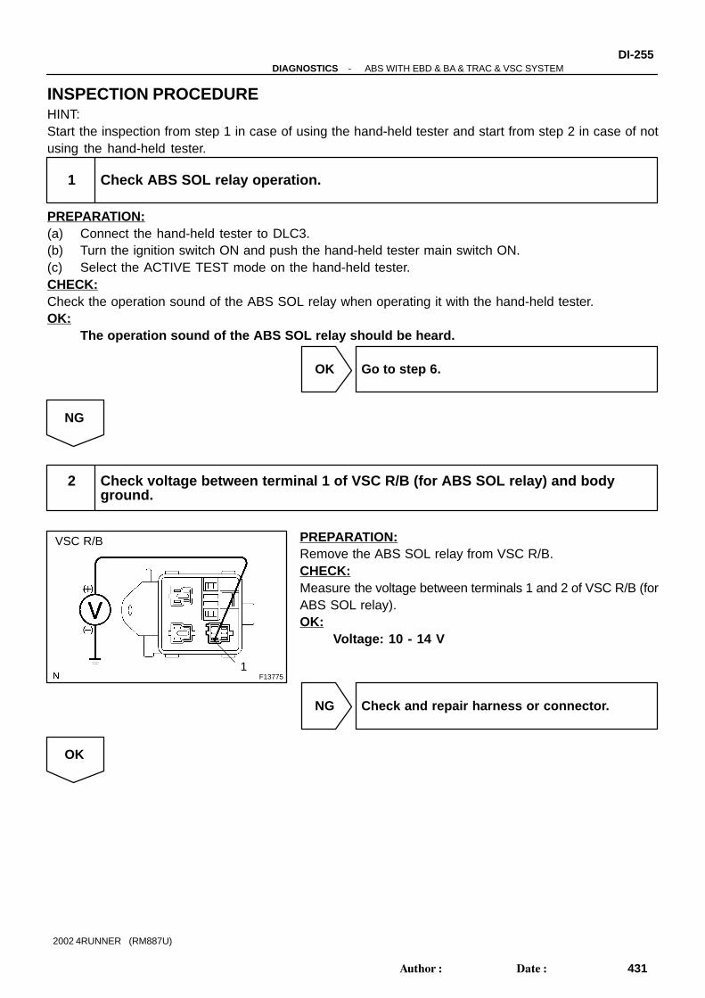
F137751
VSC R/B
-DIAGNOSTICS ABS WITH EBD & BA & TRAC & VSC SYSTEMDI-255
431Author: Date:
2002 4RUNNER (RM887U)
INSPECTION PROCEDUREHINT:Start the inspection from step 1 in case of using the hand-held tester and start from step 2 in case of notusing the hand-held tester.
1 Check ABS SOL relay operation.
PREPARATION:(a) Connect the hand-held tester to DLC3.(b) Turn the ignition switch ON and push the hand-held tester main switch ON.(c) Select the ACTIVE TEST mode on the hand-held tester.CHECK:Check the operation sound of the ABS SOL relay when operating it with the hand-held tester.OK:
The operation sound of the ABS SOL relay should be heard.
OK Go to step 6.
NG
2 Check voltage between terminal 1 of VSC R/B (for ABS SOL relay) and bodyground.
PREPARATION:Remove the ABS SOL relay from VSC R/B.CHECK:Measure the voltage between terminals 1 and 2 of VSC R/B (forABS SOL relay).OK:
Voltage: 10 - 14 V
NG Check and repair harness or connector.
OK

F00042
13
4
6
Open
(+)
(-)
123
4
4
56
123
2
56
5
Continuity
Continuity
Continuity
Open
DI-256-DIAGNOSTICS ABS WITH EBD & BA & TRAC & VSC SYSTEM
432Author: Date:
2002 4RUNNER (RM887U)
3 Check ABS SOL relay.
CHECK:Check continuity between each terminal of ABS SOL relay.OK:
Terminals 4 and 6Continuity
(Reference value 80 Ω)
Terminals 2 and 3 Continuity
Terminals 1 and 3 Open
CHECK:(a) Apply battery positive voltage between terminals 4 and 6.(b) Check continuity between each terminal of ABS SOL
relay.OK:
Terminals 2 and 3 Open
Terminals 1 and 3 Continuity
NG Replace ABS SOL relay.
OK

F14494
ECU
ABS SolenoidRelay
BrakeBooster
3
4
AST
V10
1
V11
-DIAGNOSTICS ABS WITH EBD & BA & TRAC & VSC SYSTEMDI-257
433Author: Date:
2002 4RUNNER (RM887U)
4 Check continuity between terminal 3 of VSC R/B (for ABS SOL relay) and termi-nal AST of skid contorl ECU.
CHECK:Check continuity between terminal 3 of VSC R/B (for ABS SOLrelay) and terminal AST of the skid control ECU.OK:
ContinuityHINT:There is a resistance of 33 ± 3 Ω between terminal 4 of connec-tor V10 and terminal 1 of connector V11.
NG Repair or replace harness or hydraulic brakebooster.
OK
5 Check for open and short circuit in harness and connector between VSC R/B andskid control ECU (See page IN-28 ).
NG Repair or replace harness or connector.
OK
If the same code is still output after the DTC is deleted, check the contact condition of each con-nection. If the connections are normal, ECU may be defective.

DI-258-DIAGNOSTICS ABS WITH EBD & BA & TRAC & VSC SYSTEM
434Author: Date:
2002 4RUNNER (RM887U)
6 Check for open circuit in harness and connector between terminals AST of hy-draulic brake booster and skid control ECU (See page IN-28 ).
NG Repair or replace harness and connector.
OK
Check and replace skid control ECU.

-DIAGNOSTICS ABS WITH EBD & BA & TRAC & VSC SYSTEMDI-259
435Author: Date:
2002 4RUNNER (RM887U)
DTC C1201 / 51 Engine Control System Malfunction
CIRCUIT DESCRIPTIONIf trouble occurs in the engine control system, the ECU prohibits TRAC and VSC control.
DTC No. DTC Detecting Condition Trouble Area
C1201 / 51
Conditions 1. and 2. continue for 5 sec.:
1. Engine speed: 500 rpm or more.
2. A trouble signal in the engine control system is input.
Engine control system
INSPECTION PROCEDURE
1 Check DTC for engine.
*1 Repair engine control system according to theoutput code.
*2
Check for ECM connected to malfunction in-dicator light.
*1: Output NG code*2: Malfunction indicator light remains ON
DI6CD-03

F02659
ENG-
ENG+
TRC+
TRC-
19
18
27
28
5
6
4
17
L
P
V19
ECM
ENG+
ENG-
TRC+
TRC-
Skid Control ECU
E12
V19
V19
V19
BR-Y
Y-G
E12
E12
E12
DI-260-DIAGNOSTICS ABS WITH EBD & BA & TRAC & VSC SYSTEM
436Author: Date:
2002 4RUNNER (RM887U)
DTC C1203 / 53 ECM Communication Circuit Malfunc-tion
CIRCUIT DESCRIPTIONThe circuit is used to send TRAC & VSC control information from the skid control ECU to the ECM (TRC+,TRC-), and engine control information from the ECM to the skid control ECU (ENG+, ENG-).
DTC No. DTC Detecting Condition Trouble Area
C1203 / 53
Either the condition 1. or 2. continues for 5 sec.:
1. ECU IG1 terminal voltage is 9.5 V to 17.0 V and data
transmission to the ECM is impossible.
2. ECU IG1 terminal voltage is 9.5 V to 17.0 V, engine
speed is 500 rpm or more or vehicle speed is 60 km/h
(36 mph) or more and data receiving from the ECM is
impossible.
TRC+ or TRC- circuit
ENG+ or ENG- circuit
ECM
WIRING DIAGRAM
DI6CE-03

F10171
Normal Signal Waveform
1 V / Division 2 m/s / Division
GND
-DIAGNOSTICS ABS WITH EBD & BA & TRAC & VSC SYSTEMDI-261
437Author: Date:
2002 4RUNNER (RM887U)
INSPECTION PROCEDURE
1 Check skid control ECU communication.
(REFERENCE) INSPECTION USING OSCILLOSCOPEPREPARATION:(a) Remove the skid control ECU with the connector still con-
nected.(b) Connect the oscilloscope to each of terminals ENG+ -
ENG- and TRC+ - TRC- of the skid control ECU.CHECK:Start the engine and check the signal waveform.
OK Check and replace skid control ECU.
NG
2 Check for open and short circuit in harness and connector between each of ter-minals ENG+, ENG-, TRC+, TRC- of skid control ECU and ECM (See pageIN-28 ).
NG Repair or replace harness or connector.
OK
Check and replace ECM.

F14354
Skid Control ECUP1PNP Switch 10
V19W-L
Driver Side J/B
GAUGE
B-YP
3
V19
R
IG11I
2
L-Y
3
AM1
7
1F4
II4
2
19
ALT
2
Engine Room R/B
Battery
W
I14Ignition Switch
1
2
II120
W-L
L-Y
2
II4B-Y
B-Y
AM1
222 1 1
W
RL
PL
DI-262-DIAGNOSTICS ABS WITH EBD & BA & TRAC & VSC SYSTEM
438Author: Date:
2002 4RUNNER (RM887U)
DTC C1207 / 37 PNP Switch Circuit (P/R Range)
CIRCUIT DESCRIPTIONDTC No. DTC Detection Condition Trouble Area
C1207 / 37
When any of the condition 1. through 3. is detected:
1. At vehicle speed of 15 km/h (9 mph) or less, the condi-
tions that P signal open circuit of park/neutral position
switch is detected and the voltage of IG1 terminal is 9.5
V to 17 V continue for 5 sec. or more.
2. At vehicle speed of 15 km/h (9 mph) or more, the condi-
tion that P signal from park/neutral position switch is ON,
and the the shift lever position information from the ECM
is other than in P or N position continues for 60 sec. or
more.
3. At vehicle speed of 15 km/h (9 mph) or less, the condi-
tions that P signal open circuit of park/neutral position
switch is ON and the voltage of IG1 terminal is 9.5 V
to17 V continue for 5 sec. or more.
PNP switch
PNP switch circuit (P/R range)
WIRING DIAGRAM
DI6CF-03

F13411
3 1
2
-DIAGNOSTICS ABS WITH EBD & BA & TRAC & VSC SYSTEMDI-263
439Author: Date:
2002 4RUNNER (RM887U)
INSPECTION PROCEDURE
1 Check PNP switch (P/R range).
PREPARATION:(a) Jack up the vehicle.(b) Disconnect the PNP switch connector.CHECK:Check continuity between each terminal shown below when theshift lever is moved to each range.OK:
P range Terminals 3 - 1 Continuity
R range Terminals 3 - 2 Continuity
NG Replace PNP switch.
OK
2 Check for open and short circuit in harness and connector between terminals Pand R of skid control ECU and PNP switch (See page IN-28 ).
NG Repair or replace harness or connector.
OK
Check and replace skid control ECU.

F14346
Y1Yaw Rate Sensor
YD
GYAW
YAW2
VYS
(Shielded)
YSS
Skid Control ECU
W
9
19
18
28
YD
GYAW
YAW
VYSR
B27
5
1
3
4
YV18
V18
V18
V18
V18BR-B
DI-264-DIAGNOSTICS ABS WITH EBD & BA & TRAC & VSC SYSTEM
440Author: Date:
2002 4RUNNER (RM887U)
DTC C1210 / 36 Zero Point Calibration of Yaw RateSensor Undone
CIRCUIT DESCRIPTIONDTC No. DTC Detecting Condition Trouble Area
C1210 / 36
When either the condition 1. or 2. is detected:
1. After battery terminal was connected, ECU terminal IG1
is turned ON for the first time. Within 15 sec. the shift
lever is moved to any position except P range.
2. When the yaw rate sensor zero point recorded in ECU is
deleted.
Yaw rate sensor
Yaw rate sensor circuit
PNP switch circuit (P range)
WIRING DIAGRAM
DI8XQ-02
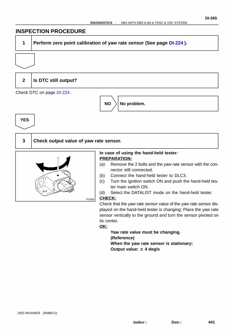
F02808
-DIAGNOSTICS ABS WITH EBD & BA & TRAC & VSC SYSTEMDI-265
441Author: Date:
2002 4RUNNER (RM887U)
INSPECTION PROCEDURE
1 Perform zero point calibration of yaw rate sensor (See page DI-224 ).
2 Is DTC still output?
Check DTC on page DI-224 .
NO No problem.
YES
3 Check output value of yaw rate sensor.
In case of using the hand-held tester:PREPARATION:(a) Remove the 2 bolts and the yaw rate sensor with the con-
nector still connected.(b) Connect the hand-held tester to DLC3.(c) Turn the ignition switch ON and push the hand-held tes-
ter main switch ON.(d) Select the DATALIST mode on the hand-held tester.CHECK:Check that the yaw rate sensor value of the yaw rate sensor dis-played on the hand-held tester is changing: Place the yaw ratesensor vertically to the ground and turn the sensor pivoted onits center.OK:
Yaw rate value must be changing.(Reference)When the yaw rate sensor is stationary:Output value: ± 4 deg/s

F14495
ON
(-)(+)
(-) (+)
DI-266-DIAGNOSTICS ABS WITH EBD & BA & TRAC & VSC SYSTEM
442Author: Date:
2002 4RUNNER (RM887U)
In case of not using the hand-held tester:PREPARATION:(a) Remove the consol box, then the yaw rate sensor with the
connector still connected.(b) Turn the ignition switch ON.CHECK:Measure voltage between terminals YAW2 (1) - GYAW (3), andterminals YD (4) - GYAW (3) of the yaw rate sensor.OK:
Terminals 1 and 3
(YAW - GYAW)About 2.42 - 2.58 V
Terminals 4and 3
(YD - GYAW)About 4.5 - 5.3 V
NG Replace yaw rate sensor.
OK
4 Check for open and short circuit in harness and connector between yaw ratesensor and skid control ECU (See page IN-28 ).
NG Repair or replace harness or connector.
OK
Check and replace skid control ECU.
-DIAGNOSTICS ABS WITH EBD & BA & TRAC & VSC SYSTEMDI-267
443Author: Date:
2002 4RUNNER (RM887U)
DTC C1223 / 43 ABS Control System Malfunction
CIRCUIT DESCRIPTIONDTC No. DTC Detecting Condition Trouble Area
C1223 / 43 ABS control system is abnormal. ABS control system
INSPECTION PROCEDURE
1 Check DTC for ABS (See page DI-224 ).
*1 Repair ABS control system according to thecode output.
*2
Check ECU connected to malfunction indica-tor light.
*1: Output NG code*2: Malfunction indicator light remains ON
DI6CH-03

F05504
2
V19
ECM Skid Control ECU
8
E12V-W
NEONEO
DI-268-DIAGNOSTICS ABS WITH EBD & BA & TRAC & VSC SYSTEM
444Author: Date:
2002 4RUNNER (RM887U)
DTC C1224 / 44 NE Signal Circuit
CIRCUIT DESCRIPTIONThe ABS & BA & TRAC & VSC ECU receives engine revolution speed signals (NE signals) from the ECM.
DTC No. DTC Detecting Condition Trouble Area
C1224 / 44
When either the condition 1. or 2. is detected:
1. At vehicle speed of 30 km/h (19 mph) or more, and
when data received from the ECM is in normal condition,
and open or short circuit for engine revolution signal
circuit continues for 10 sec. or more.
2. While TRAC is operating, the conditions that open or
short circuit in engine revolution signal circuit is de-
tected, main throttle opening degree is 0 and IDL switch
is OFF continue for 0.24 sec. or more.
NEO circuit
ECM
Skid control ECU
WIRING DIAGRAM
DI6CI-03

F13774
ON V192
F03007
(Reference)
3 - 6 V
Below 1 V
-DIAGNOSTICS ABS WITH EBD & BA & TRAC & VSC SYSTEMDI-269
445Author: Date:
2002 4RUNNER (RM887U)
INSPECTION PROCEDURE
1 Check for open and short circuit in harness and connector between terminalNEO of skid control ECU and terminal NEO of ECM (See page IN-28 ).
NG Repair or replace harness and connector.
OK
2 Check voltage between terminal NEO of skid control ECU and body ground.
PREPARATION:Remove the skid control ECU with the connectors still con-nected.CHECK:(a) Turn the ignition switch ON.(b) Measure voltage between terminal NEO (V19 - 2) of the
skid control ECU and body ground for the engine condi-tions below.
OK:
Engine condition Voltage
OFF (IG ON) 3 - 6 V or below 1 V
ON (Idling) 3 - 6 V ↔ below 1 V (Pulse)
NG Check and replace skid control ECU or ECM.
OK
If the same codes is still output after the DTC is deleted, check the contact condition of each con-nection.

F14341
Skid Control ECU
R1+
SR
SA1
SA2
SA3
V161
19
2
3
4
5
B-R
W-L
W-R
V12
R-B
G-B
12
11
5
6
V16
V16
V16
V16
V16
V12
V12
V12
SA1
SA2
SA3
STR
STR
BS4
V10R-B
5
6
S6S5
Short Connector
Hydraulic Brake Booster
5
S6S5
6
Y-G
Y-G
VSC R/B
ABS SOL Relay
R+
+BS
SR
BS
W
Battery
ABS1
Engine Room R/BB
55
55
4 6
31
222 1
R-B
DI-270-DIAGNOSTICS ABS WITH EBD & BA & TRAC & VSC SYSTEM
446Author: Date:
2002 4RUNNER (RM887U)
DTC C1225 / 25 - C1228 / 28 TRAC & VSC Solenoid Circuit
CIRCUIT DESCRIPTIONThe TRAC & VSC solenoid operates in accordance with signals from the ECU and raises and lowers thefluid pressure in the brake cylinders.
DTC No. DTC Detecting Condition Trouble Area
C1225 / 25Open or short circuit for SA1 circuit continues for 0.015 sec.
or more.
Hydraulic brake booster
SA1 circuit
C1226 / 26Open or short circuit for SA2 circuit continues for 0.015 sec.
or more.
Hydraulic brake booster
SA2 circuit
C1227 / 27Open or short circuit for SA3 circuit continues for 0.015 sec.
or more.
Hydraulic brake booster
SA3 circuit
C1228 / 28Open or short circuit for STR circuit continues for 0.015
sec. or more.
Hydraulic brake booster
STR circuit
WIRING DIAGRAM
DI6BK-03

F02857
LOCK
4
56
1112
V12
V10
-DIAGNOSTICS ABS WITH EBD & BA & TRAC & VSC SYSTEMDI-271
447Author: Date:
2002 4RUNNER (RM887U)
INSPECTION PROCEDURE
1 Check TRAC & VSC solenoid.
PREPARATION:Disconnect the 2 connectors (V10, V12) from the hydraulicbrake booster.CHECK:Check continuity between terminals V10 - 4 and V12 - 5, 6, 11and 12 of the hydraulic brake booster.OK:
ContinuityHINT:Resistance of each solenoid at 20 °C (68 °F)SA1, SA2, STR: 3.5 - 3.9 ΩSA3: 4.75 - 5.25 Ω
NG Replace hydraulic brake booster.
OK
2 Check for open and short circuit in harness and connector between skid controlECU and hydraulic brake booster (See page IN-28 ).
NG Repair or replace harness or connector.
OK
If the same code is still output after the DTC is deleted, check the contact condition of each con-nection. If the connections are normal, ECU may be defective.

F14353
SS1-
SS1+
IF
V1823
14
V
P
6
3
SS1-
SS1+
IG
EESW-B
1
2
Y
Skid Control ECUS9Steering Angle Sensor
Center J/B
3E
1416
EE
J7 J/C
3E V18
W-BJ9
AJ/C I14
Ignition Switch
24 IG1 AM1
B-Y
W
1I1H
Driver Side J/B
ECU-IG
Engine Room R/B
ALT
Battery
Y
24
222
211
AM1W
DI-272-DIAGNOSTICS ABS WITH EBD & BA & TRAC & VSC SYSTEM
448Author: Date:
2002 4RUNNER (RM887U)
DTC C1231 / 31 Steering Angle Sensor Circuit
CIRCUIT DESCRIPTIONDTC No. DTC Detecting Condition Trouble Area
C1231 / 31
Detection of any of conditions 1. through 3.:
1. When the condition that ECU terminal IG1 voltage is 9.5
V or more, and ECU does not receive a data from steer-
ing angle sensor continues for 1 sec. or more.
2. When the steering angle sensor value changes by 360°
or more with SSC signal from steering angle sensor
remaining ON or OFF.
3. When the condition that difference between the steering
angle valve output by SSC when the steering wheel is
positioned straight-forward, and the one when the steer-
ing wheel is turned for 360° is out of the range from
355.5° - 364.5° occurs 10 times or more.
Steering angle sensor
Steering angle sensor circuit
WIRING DIAGRAM
DI6CJ-03

-DIAGNOSTICS ABS WITH EBD & BA & TRAC & VSC SYSTEMDI-273
449Author: Date:
2002 4RUNNER (RM887U)
INSPECTION PROCEDUREHINT:Start the inspection from step 1 in case of using the hand-held tester and start from step 3 in case of notusing the hand-held tester.
1 Check output value of steering angle sensor.
PREPARATION:(a) Connect the hand-held tester to DLC3.(b) Turn the ignition switch ON and push the hand-held tester main switch ON.(c) Select the DATALIST mode on the hand-held tester.CHECK:Check that the steering wheel turning angle value of the steering angle position sensor displayed on thehand-held tester is changing when the steering wheel is turned.HINT:It is necessary to drive the vehicle straight-forward at 35 km/h (22 mph) or more for 1 sec. or more so thatthe hand-held tester can measure and output the data.OK:
Steering wheel turning angle value must be changing.
OK Go to step 3.
NG
2 Replace ECU and check whether or not the trouble occurs again.
OK Replace steering angle sensor.
NG
END

F03003
1
2
6
3 (+)
(-)
(+) (-)
(Oscilloscope)
LOCK
F04441
(Reference)
3 ms
2,288 µs
104 µs
5 V
0 V
5 V
0 V
ÇÇÇÇ
DI-274-DIAGNOSTICS ABS WITH EBD & BA & TRAC & VSC SYSTEM
450Author: Date:
2002 4RUNNER (RM887U)
3 Check steering angle sensor.
PREPARATION:(a) Remove the steering wheel lower covers, steering wheel
pad, steering wheel column upper and lower covers (Seepage SR-22 ).
(b) Disconnect the combination switch connector (for thesteering angle sensor).
(c) Connect the oscilloscope to terminals 3 and 6 of the com-bination switch connector (for the steering angle sensor).
(d) Apply battery positive voltage between terminals 1 and 2.CHECK:Turns the steering wheel slowly and check the signal waveform.OK:
HINT:The above signal waveform does not repeat ON and OFF regu-larly and this combination changes case by case according tothe data.
NG Replace steering angle sensor.
OK
4 Check that slits of the steering sensor disc are clogged up.
NG Repair or replace steering sensor disc.
OK

-DIAGNOSTICS ABS WITH EBD & BA & TRAC & VSC SYSTEMDI-275
451Author: Date:
2002 4RUNNER (RM887U)
5 Check for open and short circuit in harness and connector between steeringangle sensor and skid control ECU (See page IN-28 ).
NG Repair or replace harness or connector.
OK
Check and replace skid control ECU.

DI-276-DIAGNOSTICS ABS WITH EBD & BA & TRAC & VSC SYSTEM
452Author: Date:
2002 4RUNNER (RM887U)
DTC C1232 / 32, C1244 / 44 Deceleration Sensor Circuit
CIRCUIT DESCRIPTIONThis sensor detects deceleration on the vehicle. The sensor signal is used in ABS & BA & TRAC & VSC.If the sensor functions abnormally, the ABS warning light comes on.
CIRCUIT DESCRIPTIONDTC No. DTC Detecting Condition Trouble Area
C1232 / 32
Detection of either the condition 1. or 2.:
1. At the vehicle speed of 10 km/h (6 mph) or more, when
the condition that ECU terminal GL1 signal change
range is less than 20 mV, and ECU terminal GL2 signal
change range swings by 468 mV or more occurs for 30
sec. or more.
2. At the vehicle speed of 10 km/h (6 mph) or more, the
condition that ECU terminal GL2 signal change range is
less than 20 mV, and ECU terminal GL1 signal change
range swings by 468 mV or more occurs for 30 sec. or
more.
Deceleration sensor
Deceleration sensor circuit
C1244 / 44
Any of the conditions 1. through 4. is detected:
1. The condition that ECU terminals GL1 and GL2 values
are -1.5 G or less or 1.5 G or more continues for 1.2
sec. or more.
2. The condition that the deceleration sensor terminal VGS
voltage is 4.4 V or less or 5.6 V or more continues for
1.2 sec. or more.
3. At the vehicle speed of 0 km/h (0 mph), after the differ-
ence of output value between deceleration sensor termi-
nals GL1 and GL2 becomes 0.6 G or more, the condi-
tion that it does not become 0.4 G or less continues for
60 sec. or more.
4. Deceleration sensor signal momentary open occurs for
7 times or more.
Deceleration sensor
Deceleration sensor circuit
DI8XR-02

F14346
BRGSS
GGND
VGS
GL2
GL1
2
3
5
1
V18
11
21
1
10
22
Skid Control ECUV15 VSC Deceleration Sensor
(Shielded)
B
G
R
W
V18
V18
V18
V18
GGND
VGS
GL2
GL1
-DIAGNOSTICS ABS WITH EBD & BA & TRAC & VSC SYSTEMDI-277
453Author: Date:
2002 4RUNNER (RM887U)
WIRING DIAGRAM

F02098
GL1
GGND
GL2
VGS
Forward
Rearward
Front
DI-278-DIAGNOSTICS ABS WITH EBD & BA & TRAC & VSC SYSTEM
454Author: Date:
2002 4RUNNER (RM887U)
INSPECTION PROCEDURE
1 Check for open and short circuit in harness and connector between decelerationsensor and skid control ECU (See page IN-28 ).
NG Repair or replace harness or connector.
OK
2 Check deceleration sensor.
In case of using the hand-held tester:PREPARATION:(a) Connect the hand-held tester to DLC3.(b) Turn the ignition switch ON and turn the hand-held tester main switch ON.(c) Select the DATALIST mode on the hand-held tester.CHECK:Check that the deceleration value of the deceleration sensor observed in the hand-held tester is changingas the vehicle is tilted.OK:
Deceleration value must be changing.In case of not using the hand-held tester:PREPARATION:(a) Remove the consol box.(b) Connect 3 dry batteries of 1.5 V in series.(c) Connect VGS terminal to the batteries’ positive (+) termi-
nal, and GGND terminal to the batteries’ negative (-) ter-minal, apply about 4.5 V between VGS and GGND termi-nals.
NOTICE:Do not apply voltage of 6 V or more to terminals VYS andGYAW.CHECK:Check the output voltage of GL1 and GL2 terminals when thesensor is tilted forward and rearward.OK:
Symbols Condition Standard Value
GL1 Horizontal About 2.3 V
GL1 Lean forward 0.4 V - about 2.3 V
GL1 Lean rearward About 2.3 V - 4.1 V
GL2 Horizontal About 2.3 V
GL2 Lean forward About 2.3 V - 4.1 V
GL2 Lean rearward 0.4 V - about 2.3 V

-DIAGNOSTICS ABS WITH EBD & BA & TRAC & VSC SYSTEMDI-279
455Author: Date:
2002 4RUNNER (RM887U)
HINT: If the sensor is tilted too much it may show the wrong val-
ue. If dropped, the sensor should be replaced with a new one. The sensor removed from the vehicle should not be
placed upside down.
NG Replace deceleration sensor.
OK
Check and replace skid control ECU.

DI-280-DIAGNOSTICS ABS WITH EBD & BA & TRAC & VSC SYSTEM
456Author: Date:
2002 4RUNNER (RM887U)
DTC C1233 / 33, C1234 / 34 Yaw Rate Sensor Circuit
CIRCUIT DESCRIPTIONDTC No. DTC Detecting Condition Trouble Area
C1233 / 33
When any of the conditions 1. through 4. is detected:
1. ECU terminal IG1 voltage is 9.5 V to 17.0 V, and the
condition that yaw rate sensor voltage is out of the range
from 0.25 V to 4.75 V continues for 1 sec. or more.
2. The conditions that yaw rate sensor open detect circuit
signal is ON and the voltage of ECU terminal IG1 is 9.5
V to 17 V continue for 1 sec. or more.
3. The conditions that yaw rate sensor power source volt-
age is out of the range from 4.4 V to 5.6 V and the volt-
age of ECU terminal IG1 is 9.5 V to 17 V continue for 1
sec. or more.
4. The condition that yaw rate sensor signal is momentarily
open occurs 10 times or more and the voltage of ECU
terminal IG1 is 9.5 V to 17 V.
Yaw rate sensor
Yaw rate sensor circuit
C1234 / 34
Condition 1. or 2. is detected:
1. The conditions that yaw rate sensor VYS terminal volt-
age is 4.75 V to 5.25 V and YD malfunction signal of
yaw rate sensor is ON continue for 5 sec. or more.
2. Shift lever position is in P range and output voltage of
yaw rate sensor is out of the range from 2.4 V to 2.6 V
or after the difference from zero point calibration voltage
of yaw rate sensor has become 0.08 V or more and
when the condition that the vehicle speed exceeds 15
km/h (9 mph) while output condition of yaw rate sensor
has been repeated more than 3 times.
DI6CL-03
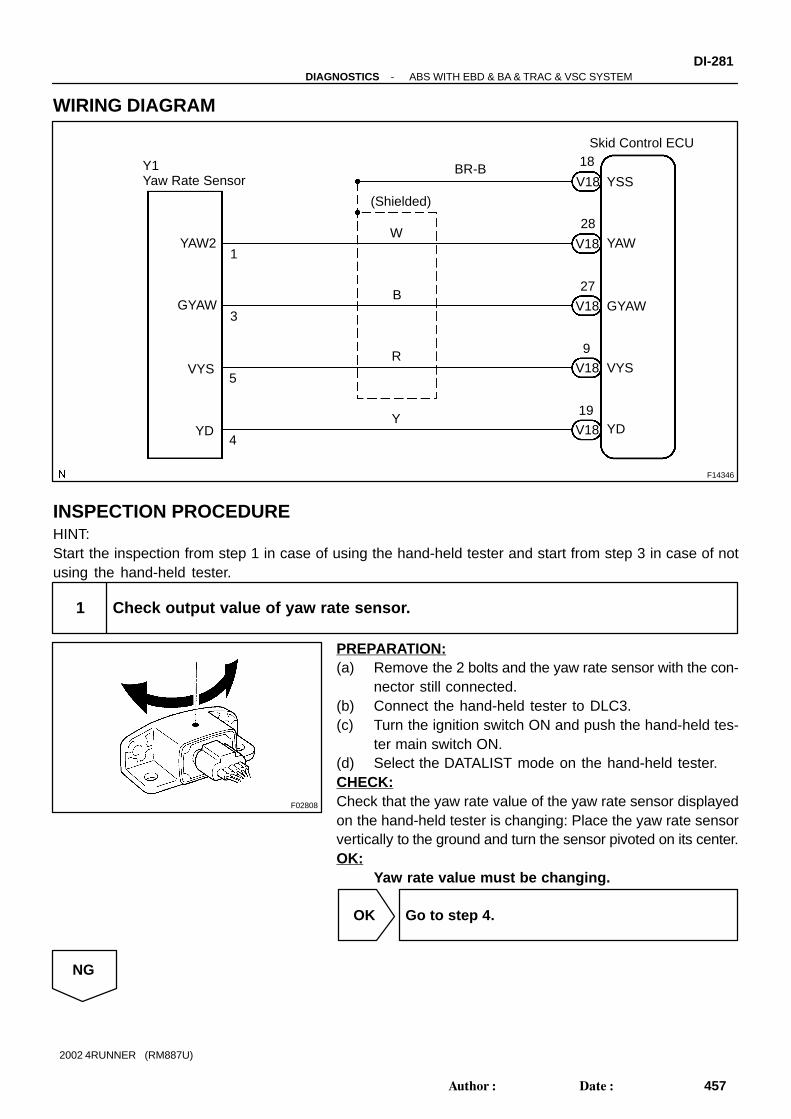
F14346
Y1Yaw Rate Sensor
YD
GYAW
YAW2
VYS
(Shielded)
YSS
Skid Control ECU
W
9
19
18
28
YD
GYAW
YAW
VYSR
B27
5
1
3
4
YV18
V18
V18
V18
V18BR-B
F02808
-DIAGNOSTICS ABS WITH EBD & BA & TRAC & VSC SYSTEMDI-281
457Author: Date:
2002 4RUNNER (RM887U)
WIRING DIAGRAM
INSPECTION PROCEDUREHINT:Start the inspection from step 1 in case of using the hand-held tester and start from step 3 in case of notusing the hand-held tester.
1 Check output value of yaw rate sensor.
PREPARATION:(a) Remove the 2 bolts and the yaw rate sensor with the con-
nector still connected.(b) Connect the hand-held tester to DLC3.(c) Turn the ignition switch ON and push the hand-held tes-
ter main switch ON.(d) Select the DATALIST mode on the hand-held tester.CHECK:Check that the yaw rate value of the yaw rate sensor displayedon the hand-held tester is changing: Place the yaw rate sensorvertically to the ground and turn the sensor pivoted on its center.OK:
Yaw rate value must be changing.
OK Go to step 4.
NG

F13776
ON
8
V19V16 V18
16196
31
DI-282-DIAGNOSTICS ABS WITH EBD & BA & TRAC & VSC SYSTEM
458Author: Date:
2002 4RUNNER (RM887U)
2 Check whether continuity exists between terminal YD of yaw rate sensor and ter-minal skid control ECU.
NG Repair or replace harness or connector.
OK
3 Check voltage between terminals YD and GND of skid control ECU.
PREPARATION:Remove the skid control ECU with the connector still con-nected.CHECK:(a) Turn the ignition switch ON.(b) Measure voltage between terminals YD (V18 - 19) and
GND (V16 - 6, 31, V19 - 8, 16) of the skid control ECU.OK:
Voltage: 4.5 - 5.3 V
NG Replace yaw rate sensor.
OK
Check and replace skid control ECU.

F02123
14
3
(+)
(-)
(-)
(+)
-DIAGNOSTICS ABS WITH EBD & BA & TRAC & VSC SYSTEMDI-283
459Author: Date:
2002 4RUNNER (RM887U)
4 Check yaw rate sensor.
CHECK:(a) Turn the ignition switch ON.(b) Measure voltage between terminals 1 and 3, 3 and 4 of
the yaw rate sensor with the connector still connected.OK:
Terminals 1 and 3
(YAW - GYAW)Approx. 2.5 V
Terminals 3 and 4
(GYAW - YD)Approx. 4.5 V - 5.3 V
NG Replace yaw rate sensor.
OK
Check and replace skid control ECU.

DI-284-DIAGNOSTICS ABS WITH EBD & BA & TRAC & VSC SYSTEM
460Author: Date:
2002 4RUNNER (RM887U)
DTC C1237 / 37 Tires of Different Size
CIRCUIT DESCRIPTIONDTC No. DTC Detecting Condition Trouble Area
C1237 / 37
The condition of driving at more than 30 km/h (19 mph) for
more than 20 seconds with 1 or 2 tires of different size is
detected 3 times continuously.
Tire size
INSPECTION PROCEDURE
1 Check tire size.
NG Replace tires so that all 4 tires are of the samesize.
OK
Check and replace skid control ECU.
DI6BL-03

F14343
IG1
GND2
GND1
GND3
GND4
Battery
V19
V16
7
6
31
8
16
Y1G1I
ECU-IGB-Y
42 AM1 IG1
W
I14Ignition Switch Driver Side J/B
Engine Room R/B
21
ALT
Skid Control ECU
V16
V19
V19
AM1
22 21
W
W-B
W-B
W-B
W-B
J9
J/CA
J4
IEIFEA J/CA
2 3
-DIAGNOSTICS ABS WITH EBD & BA & TRAC & VSC SYSTEMDI-285
461Author: Date:
2002 4RUNNER (RM887U)
DTC C1241 / 41 IG Power Source Circuit
CIRCUIT DESCRIPTIONDTC No. DTC Detecting Condition Trouble Area
C1241 / 41
Detection of any of conditions 1. through 4.:
1. Vehicle speed is 3 km/h (1.9 mph) or more and voltage
of ECU terminal IG remains below 9.5 V for more than
10 sec.
2. While the condition that the ABS SOL relay is ON con-
tinues, ECU terminal IG1 voltage becomes 9.5 V or less,
and the condition that the contact point of the ABS SOL
relay is OFF continues for 0.2 sec. or more.
3. The condition that ECU terminal IG1 voltage is more
than 17.0 V continues for 1.2 sec. or more.
4. While the ABS SOL relay outputs ON signal, ECU termi-
nal IG1 voltage becomes more than 17.0 V, and the
condition that the contact point of the ABS SOL relay is
OFF continues for 0.2 sec. or more.
Battery
Charging system
Power source circuit
WIRING DIAGRAM
DI6BM-03
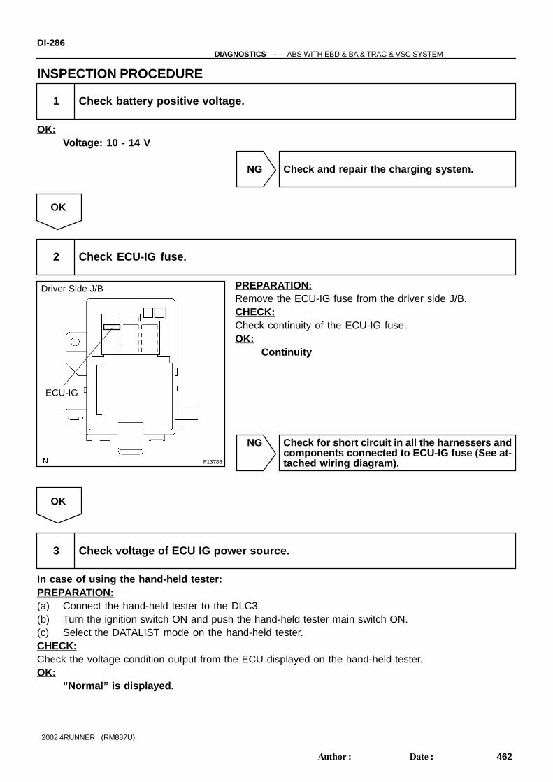
F13788
Driver Side J/B
ECU-IG
DI-286-DIAGNOSTICS ABS WITH EBD & BA & TRAC & VSC SYSTEM
462Author: Date:
2002 4RUNNER (RM887U)
INSPECTION PROCEDURE
1 Check battery positive voltage.
OK:Voltage: 10 - 14 V
NG Check and repair the charging system.
OK
2 Check ECU-IG fuse.
PREPARATION:Remove the ECU-IG fuse from the driver side J/B.CHECK:Check continuity of the ECU-IG fuse.OK:
Continuity
NG Check for short circuit in all the harnessers andcomponents connected to ECU-IG fuse (See at-tached wiring diagram).
OK
3 Check voltage of ECU IG power source.
In case of using the hand-held tester:PREPARATION:(a) Connect the hand-held tester to the DLC3.(b) Turn the ignition switch ON and push the hand-held tester main switch ON.(c) Select the DATALIST mode on the hand-held tester.CHECK:Check the voltage condition output from the ECU displayed on the hand-held tester.OK:
”Normal” is displayed.

F13777
V19V16
ON
16
86
31
7
F13783
V19V16
LOCK
31
16
8
6
-DIAGNOSTICS ABS WITH EBD & BA & TRAC & VSC SYSTEMDI-287
463Author: Date:
2002 4RUNNER (RM887U)
In case of not using the TOYOTA hand-held tester:PREPARATION:Remove the skid control ECU with the connectors still con-nected.CHECK:(a) Turn the ignition switch ON.(b) Measure voltage between terminals IG1 (V19 - 7) and
GND (V16 - 6, 31, V19 - 8, 16) of the skid control ECU.OK:
Voltage: 10 - 14 V
OK Check and replace skid control ECU.
NG
4 Check continuity between terminal GND of skid control ECU connector and bodyground.
PREPARATION:Disconnect the connectors (V16, V19) from the skid controlECU.CHECK:Measure resistance between terminal GND (V16 - 6, 31, V19- 8, 16) of the skid control ECU harness side connector andbody ground.OK:
Resistance: 1 Ω or less
NG Repair or replace harness or connector.
OK
Check for open circuit in harness and connector between skid control ECU and battery (See page IN-28 ).
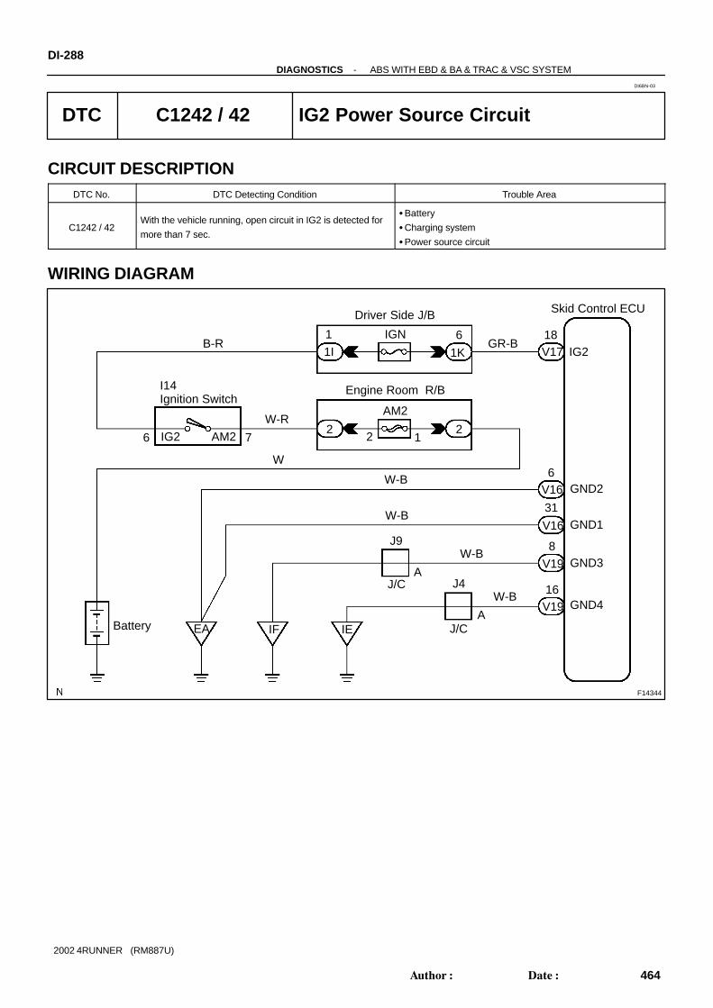
F14344
W-R
B-R
7
61I
IGN 18IG2
31GND1
6GND2
8GND3
16GND4
W-B
W-B
A
W-B
A
IEIF
2
AM2
1
Battery
I14Ignition Switch
Driver Side J/B
J/CW-B
Engine Room R/B
EA
J9
2
1
Skid Control ECU
V17
V19
V16
V16
V19
GR-B1K
6
W
2
J4
J/C
AM2IG2
DI-288-DIAGNOSTICS ABS WITH EBD & BA & TRAC & VSC SYSTEM
464Author: Date:
2002 4RUNNER (RM887U)
DTC C1242 / 42 IG2 Power Source Circuit
CIRCUIT DESCRIPTIONDTC No. DTC Detecting Condition Trouble Area
C1242 / 42With the vehicle running, open circuit in IG2 is detected for
more than 7 sec.
Battery
Charging system
Power source circuit
WIRING DIAGRAM
DI6BN-03

F13784
V19V16LOCK
31 16 86
V17
18
-DIAGNOSTICS ABS WITH EBD & BA & TRAC & VSC SYSTEMDI-289
465Author: Date:
2002 4RUNNER (RM887U)
INSPECTION PROCEDURE
1 Check battery positive voltage.
OK:Voltage: 10 - 14 V
NG Check and repair the charging system.
OK
2 Check voltage of ECU IG power source.
In case of using the hand-held tester:PREPARATION:(a) Connect the hand-held tester to DLC3.(b) Turn the ignition switch ON and push the hand-held tester main switch ON.(c) Select the DATALIST mode on the hand-held tester.CHECK:Check the voltage condition output from the ECU displayed on the hand-held tester.OK:
”Normal” is displayed.
In case of not using the hand-held tester:PREPARATION:Remove the skid control ECU with the connectors still con-nected.CHECK:(a) Turn the ignition switch ON.(b) Measure voltage between terminals IG2 (V17 - 18) and
GND (V16 - 6, 31, V19 - 8, 16) of the skid control ECU.OK:
Voltage: 10 - 14 V
OK Check and replace skid control ECU.
NG

F13783
V19V16
LOCK
31
16
8
6
DI-290-DIAGNOSTICS ABS WITH EBD & BA & TRAC & VSC SYSTEM
466Author: Date:
2002 4RUNNER (RM887U)
3 Check continuity between terminal GND of skid control ECU connector and bodyground.
PREPARATION:Disconnect the connectors (V16, V19) from the skid controlECU.CHECK:Measure resistance between terminal GND (V16 - 6, 31, V19- 8, 16) of the skid control ECU connector and body ground.OK:
Resistance: 1 Ω or less
NG Repair or replace harness or connector.
OK
Check for open circuit in harness and connector between skid control ECU and battery (See page IN-28 ).

F14346
BRGSS
GGND
VGS
GL2
GL1
2
3
5
1
V18
11
21
1
10
22
Skid Control ECUV15 VSC Deceleration Sensor
(Shielded)
B
G
R
W
V18
V18
V18
V18
GGND
VGS
GL2
GL1
-DIAGNOSTICS ABS WITH EBD & BA & TRAC & VSC SYSTEMDI-291
467Author: Date:
2002 4RUNNER (RM887U)
DTC C1243 / 43, C1245 / 45 Malfunction in Deceleration Sensor
CIRCUIT DESCRIPTIONDTC No. DTC Detecting Condition Trouble Area
C1243 / 43
While vehicle speed becomes 0 km/h (0 mph) from 30 km/h
(18 mph), the condition that GL1 and GL2 signals of ECU ter-
minals do not change 40 mV or less continues 16 times in
sequence.Deceleration sensor
C1245 / 45
At the vehicle speed of 30 km/h (18 mph) or more, the condi-
tion that the difference between acceleration and deceleration
values of computation from deceleration sensor and vehicle
speed becomes more than 0.35 G continues for 60 sec. or
more.
Deceleration sensor
Wire harness for deceleration sensor system
WIRING DIAGRAM
DI8XS-02

DI-292-DIAGNOSTICS ABS WITH EBD & BA & TRAC & VSC SYSTEM
468Author: Date:
2002 4RUNNER (RM887U)
INSPECTION PROCEDUREHINT:Start the inspection from step 1 in case of using the hand-held tester, and go to step 3 in case of not usingthe hand-held tester.
1 Check output value of deceleration sensor.
PREPARATION:(a) Connect the hand-held tester to DLC3.(b) Turn the ignition switch ON and turn the hand-held tester main switch ON.(c) Select the DATALIST mode on the hand-held tester.CHECK:Check that the deceleration value of the deceleration sensor observed in the hand-held tester is changingwhen the vehicle is tilted.OK:
Deceleration value must be changing.
OK Go to step 3.
NG
2 Check for open and short circuit in harness and connector between decelerationsensor and skid control ECU (See page IN-28 ).
NG Repair or replace harness or connector.
OK
Replace deceleration sensor.
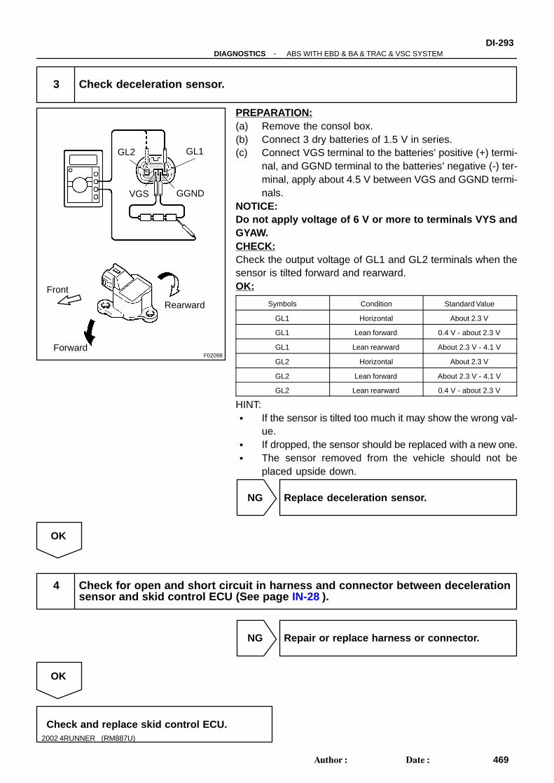
F02098
GL1
GGND
GL2
VGS
Forward
Rearward
Front
-DIAGNOSTICS ABS WITH EBD & BA & TRAC & VSC SYSTEMDI-293
469Author: Date:
2002 4RUNNER (RM887U)
3 Check deceleration sensor.
PREPARATION:(a) Remove the consol box.(b) Connect 3 dry batteries of 1.5 V in series.(c) Connect VGS terminal to the batteries’ positive (+) termi-
nal, and GGND terminal to the batteries’ negative (-) ter-minal, apply about 4.5 V between VGS and GGND termi-nals.
NOTICE:Do not apply voltage of 6 V or more to terminals VYS andGYAW.CHECK:Check the output voltage of GL1 and GL2 terminals when thesensor is tilted forward and rearward.OK:
Symbols Condition Standard Value
GL1 Horizontal About 2.3 V
GL1 Lean forward 0.4 V - about 2.3 V
GL1 Lean rearward About 2.3 V - 4.1 V
GL2 Horizontal About 2.3 V
GL2 Lean forward About 2.3 V - 4.1 V
GL2 Lean rearward 0.4 V - about 2.3 V
HINT: If the sensor is tilted too much it may show the wrong val-
ue. If dropped, the sensor should be replaced with a new one. The sensor removed from the vehicle should not be
placed upside down.
NG Replace deceleration sensor.
OK
4 Check for open and short circuit in harness and connector between decelerationsensor and skid control ECU (See page IN-28 ).
NG Repair or replace harness or connector.
OK
Check and replace skid control ECU.

F14345
M4Master Cylinder Pressure Sensor
(Shielded)
MSS
VCM
E2
22PMC
10
24
VCM
PMC
E2
B
W
R23
BR
1
2
3
V16
Skid Control ECU
V16
V16
V16
DI-294-DIAGNOSTICS ABS WITH EBD & BA & TRAC & VSC SYSTEM
470Author: Date:
2002 4RUNNER (RM887U)
DTC C1246 / 46 Master Cylinder Pressure Sensor Circuit
CIRCUIT DESCRIPTIONDTC No. DTC Detecting Condition Trouble Area
C1246 / 46
Any of the conditions 1. through 5. is detected:
1. At the vehicle speed of 7 km/h (4 mph) or more, ECU
terminal PMC voltage becomes more than 0.86 V and
the condition that 0.01 V or less does not change con-
tinues for 30 sec.
2. Interference occurs to ECU terminal PMC 7 times or
more in 5 sec.
3. ECU terminal STP is OFF, and the condition that termi-
nal PMC voltage becomes more than 0.86 V or less than
0.3 V continues for 5 sec. or more.
4. The condition that ECU terminal IG1 voltage is 9.5 V to
17.0 V, and terminal VCM voltage is out of the range
from 4.4 V to 5.6 V continues for 1.2 sec. or more.
5. The condition that ECU terminal VCM voltage is 4.4 V to
5.6 V, and terminal PMC voltage is out of the range from
0.14 V to 4.85 V continues for 1.2 sec. or more.
Master cylinder pressure sensor
Master cylinder pressure sensor circuit
WIRING DIAGRAM
DI6BQ-04

F12700
PMC
E2
-DIAGNOSTICS ABS WITH EBD & BA & TRAC & VSC SYSTEMDI-295
471Author: Date:
2002 4RUNNER (RM887U)
INSPECTION PROCEDUREHINT:Start the inspection from step 1 in case of using the hand-held tester and start from step 2 in case of notusing the hand-held tester.
1 Check output value of master cylinder pressure sensor.
PREPARATION:(a) Connect the hand-held tester to DLC3.(b) Turn the ignition switch ON and push the hand-held tester main switch ON.(c) Select the DATALIST mode on the hand-held tester.CHECK:Check that the brake fluid pressure value of the master cylinder pressure sensor displayed on the hand-heldtester is changing when the brake pedal is depressed.OK:
Brake fluid pressure value must be changing.
OK Go to step 4.
NG
2 Check master cylinder pressure sensor.
PREPARATION:Install LSPV gauge to the front caliper bleeder plug portion, andbleed LSPV gauge.
SST 09709-29018CHECK:Start the engine and depress the brake pedal, then check therelation between the fluid pressure and voltage of PMC and E2terminals of the master cylinder pressure sensor with the con-nector still connected.OK:
Front brake caliper fluid pressure Voltage
0 kPa (0 Kgf/cm2, 0 psi) 0.37 - 0.63 V
5,883 kPa (60 kgf/cm2, 853 psi) 1.57 - 1.83 V
11,768 kPa (120 kgf/cm2, 1,706 psi) 2.77 - 3.03 V
HINT:Voltage of between terminals VCM and E2: 4.7 - 5.3 V
NG Replace master cylinder pressure sensor.
OK
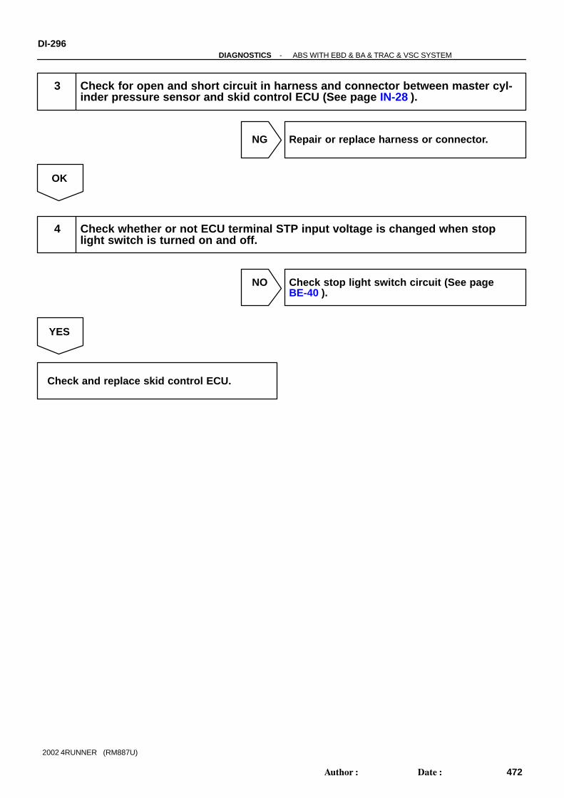
DI-296-DIAGNOSTICS ABS WITH EBD & BA & TRAC & VSC SYSTEM
472Author: Date:
2002 4RUNNER (RM887U)
3 Check for open and short circuit in harness and connector between master cyl-inder pressure sensor and skid control ECU (See page IN-28 ).
NG Repair or replace harness or connector.
OK
4 Check whether or not ECU terminal STP input voltage is changed when stoplight switch is turned on and off.
NO Check stop light switch circuit (See pageBE-40 ).
YES
Check and replace skid control ECU.

F14347
H8 High Mounted Stop Light
2
1
J/B
21K 1F
3C10 16
3C
B
14 13
G-W
G-W
4 3
G-W
G-WJ14J/C
G-W
G-W
G-W
2
V19
2
W-B
W-B
W-R
BH
10
S4Stop Light Switch
Engine Room R/B
2
IE2
W
15
2
IL1
1
2
BR1
Battery
R7Stop Light LH
R8Stop Light RH
G-W
G-WG-YSTP
G-W
Driver Side J/B Center J/B
2 1
Skid Control ECU
3C
STOP
BB
BR1
-DIAGNOSTICS ABS WITH EBD & BA & TRAC & VSC SYSTEMDI-297
473Author: Date:
2002 4RUNNER (RM887U)
DTC C1249 / 49 Stop Light Switch Circuit
CIRCUIT DESCRIPTIONDTC No. DTC Detecting Condition Trouble Area
C1249 / 49
ECU terminal IG1 voltage is 9.5 to 17.2 V and ABS is in
non-operation, the open circuit in stop light switch circuit
continues for 0.3 sec. or more.
Stop light switch circuit
WIRING DIAGRAM
DI6BR-03

F13785
V1913
DI-298-DIAGNOSTICS ABS WITH EBD & BA & TRAC & VSC SYSTEM
474Author: Date:
2002 4RUNNER (RM887U)
INSPECTION PROCEDURE
1 Check operation of stop light switch.
CHECK:Check that the stop light lights up when the brake pedal is depressed and turns OFF when the brake pedalis released.
OK Go to step 3.
NG
2 Check stop light circuit (See page BE-40 ).
NG Repair or replace stop light circuit.
OK
3 Check voltage between terminal STP of skid control ECU and body ground.
PREPARATION:Remove the skid control ECU with the connectors still con-nected.CHECK:Measure voltage between terminal STP (V19 - 13) of the skidcontrol ECU and body ground when the brake pedal is de-pressed.OK:
Voltage: 10 - 14 V
OK Proceed to next circuit inspection shown inproblem symptoms table (See page DI-242 ).
NG

-DIAGNOSTICS ABS WITH EBD & BA & TRAC & VSC SYSTEMDI-299
475Author: Date:
2002 4RUNNER (RM887U)
4 Check for open circuit in harness and connector between skid control ECU andstop light switch (See page IN-28 ).
NG Repair or replace harness or connector.
OK
5 Check stop light bulb.
NG Replace stop light bulb.
OK
Check and replace skid control ECU.

F14348
Battery
1
2
R1+
MR1
MR2
27
28
18
Hydraulic Brake Booster
R2+
2 A
R
Y-B
W-R
Engine Room J/B
ABS2
1
3 14
2
2
TRC MTR Relay
ABS MTR RelayW
8
J1
7
EB
6
GND1
GRW-B
L
5
O
3
MR2
29
V16
MMT
MT+
MT-
Skid Control ECU
V17
V11 V16
V16
V16
V16
V17
R-B
P-B5
5
5
5
5
5
5
VSC R/B
BM2
R2+
+BM2
BM1+BM1
MR1R1+
1 2
3 4
R
P-B
V11
V11
V11
V11
V10
V10
5
MTT
MT+
MT-
BM2
BM1
GHD2
1
W-BA
J2
J/C
W-B
EA
F13Fuse Box
R
1 2
2W L-B
DI-300-DIAGNOSTICS ABS WITH EBD & BA & TRAC & VSC SYSTEM
476Author: Date:
2002 4RUNNER (RM887U)
DTC C1251 / 51 Hydraulic Brake Booster Pump MotorMalfunction
CIRCUIT DESCRIPTIONDTC No. DTC Detecting Condition Trouble Area
C1251 / 51
Either of the condition 1. or 2. is detected:
1. After the ignition switch is turned ON, the current of
more than 30 A flows to the motor for more than 1 sec.
2. After the ignition switch is turned ON, less than 7 A
change in current is detected more than 3 times continu-
ously when the motor is ON.
Hydraulic brake booster pump motor
WIRING DIAGRAM
DI6BS-08

F02859
(-) (+)
(-)
(+)
BM2
BM1EM1
EM2
F04505
BM1
EM1MT
MT+
MT-
BM2EM2
-DIAGNOSTICS ABS WITH EBD & BA & TRAC & VSC SYSTEMDI-301
477Author: Date:
2002 4RUNNER (RM887U)
INSPECTION PROCEDURE
1 Check operation of hydraulic brake booster pump motor.
PREPARATION:Disconnect the 2 connectors from the hydraulic brake booster.CHECK:Connect battery positive (+) lead to BM1 or BM2 terminal andbattery negative (-) lead to EM1 or EM2 terminal of the hydrau-lic brake booster (pump motor) connector.OK:
The operation sound of the pump motor should beheard.
NG Go to step 4.
OK
2 Check hydraulic brake booster resistance.
PREPARATION:Disconnect the 2 connectors from the hydraulic brake booster.CHECK:Check resistance between terminals MT+ and MT-, BM1 andMT, BM2 and MT, EM1 and MT+, EM2 and MT+ of the hydraulicbrake booster connector.OK:
30 - 36 Ω
NG Replace hydraulic brake booster assembly.
OK

DI-302-DIAGNOSTICS ABS WITH EBD & BA & TRAC & VSC SYSTEM
478Author: Date:
2002 4RUNNER (RM887U)
3 Check for open circuit in harness and connector between hydraulic brake boost-er (MT+, MT-) and skid control ECU (See page IN-28 ).
NG Repair or replace harness or connector.
OK
Check and replace skid control ECU.
4 Check for open and short circuit in harness and connector between hydraulicbrake booster pump motor and hydraulic brake booster (See page IN-28 ).
NG Replace wire harness.
OK
5 Check hydraulic brake booster pump motor (See page BR-42 ).
NG Replace hydraulic brake booster pump motor.
OK
Replace hydraulic brake booster.

F14348
Battery
1
2
R1+
MR1
MR2
27
28
18
Hydraulic Brake Booster
R2+
2 A
R
Y-B
W-R
Engine Room J/B
ABS2
1
3 14
2
2
TRC MTR Relay
ABS MTR RelayW
8
J1
7
EB
6
GND1
GRW-B
L
5
O
3
MR2
29
V16
MMT
MT+
MT-
Skid Control ECU
V17
V11 V16
V16
V16
V16
V17
R-B
P-B5
5
5
5
5
5
5
VSC R/B
BM2
R2+
+BM2
BM1+BM1
MR1R1+
1 2
3 4
R
P-B
V11
V11
V11
V11
V10
V10
5
MTT
MT+
MT-
BM2
BM1
GHD2
1
W-BA
J2
J/C
W-B
EA
F13Fuse Box
R
1 2
2W L-B
-DIAGNOSTICS ABS WITH EBD & BA & TRAC & VSC SYSTEMDI-303
479Author: Date:
2002 4RUNNER (RM887U)
DTC C1252 / 52 Hydraulic Brake Booster Pump MotorON Time Abnormally Long
CIRCUIT DESCRIPTIONDTC No. DTC Detecting Condition Trouble Area
C1252 / 52After the ignition switch has been turned ON, the power is
supplied to the pump motor for more than 5 minutes.
Hydraulic brake booster pump motor
Hydraulic brake booster pump motor circuit
Pressure switch (PH or PL)
WIRING DIAGRAM
DI6BT-08

F02859
(-) (+)
(-)
(+)
BM2
BM1EM1
EM2
V10
V11
DI-304-DIAGNOSTICS ABS WITH EBD & BA & TRAC & VSC SYSTEM
480Author: Date:
2002 4RUNNER (RM887U)
INSPECTION PROCEDURE
1 Check operation of hydraulic brake booster pump motor.
PREPARATION:Disconnect the 2 connectors from (V10, V11) the hydraulicbrake booster.CHECK:Connect battery positive (+) lead to BM1 or BM2 terminal andbattery negative (-) lead to EM1 or EM2 terminal of the hydrau-lic brake booster (pump motor) connector.OK:
The operation sound of the pump motor should beheard.
NG Go to step 9.
OK
2 Check for short circuit (to B+) in harness and connector between BM1 or BM2 ofhydraulic brake booster and ABS MTR relay or TRC MTR relay (See page IN-28 ).
NG Repair or replace harness or connector.
OK
3 Check for short circuit (to B+) in harness and connector between MT of hydrau-lic brake booster and skid control ECU (See page IN-28 ).
NG Repair or replace harness or connector.
OK

F02861
LOCK ON
PH
PHG
V10
-DIAGNOSTICS ABS WITH EBD & BA & TRAC & VSC SYSTEMDI-305
481Author: Date:
2002 4RUNNER (RM887U)
4 Check pressure switch (PH).
In case of using the hand-held tester:PREPARATION:(a) Connect the hand-held tester to DLC3.(b) Turn the ignition switch ON and push the hand-held tester main switch ON.(c) Select the DATALIST mode on the hand-held tester.CHECK:Depress the brake pedal more than 40 times with the ignition switch OFF then turn the ignition switch ONand check the pressure switch (PH) condition.HINT:When the pressure in power supply system is released, reaction force becomes heavy and stroke becomesshorter.OK:
”OFF” turns to ”ON”.HINT:OFF: Low pressureON: High pressureIn case of not using the hand-held tester:
PREPARATION:(a) Disconnect the connector (V10) from the hydraulic brake
booster.(b) With the ignition switch OFF, depress the brake pedal
more than 40 times to decrease the accumulator pres-sure.
HINT:When the pressure in power supply system is released, reac-tion force becomes heavy and stroke becomes shorter.CHECK:Measure resistance between terminals PH and PHG of the hy-draulic brake booster connector.OK:
Resistance: 1.0 k ΩPREPARATION:(a) Connect the connector (V10) to the hydraulic brake
booster.(b) Disconnect the connector (V10) after the ignition switch
has been ON and the pump motor has stopped.CHECK:Measure resistance between terminals PH and PHG of the hy-draulic brake booster connector.OK:
Resistance: 0 ΩHINT:After inspection, connect the connector and clear the DTC (Seepage DI-224 ).
NG Replace hydraulic brake booster assembly.

F02863
LOCK ONPL
PLG
V11
DI-306-DIAGNOSTICS ABS WITH EBD & BA & TRAC & VSC SYSTEM
482Author: Date:
2002 4RUNNER (RM887U)
OK
5 Check pressure switch (PL).
In case of using the hand-held tester:PREPARATION:(a) Connect the hand-held tester to DLC3.(b) Turn the ignition switch ON and push the hand-held tester main switch ON.(c) Select the DATALIST mode on the hand-held tester.CHECK:Depress the brake pedal more than 40 times with the ignition switch OFF then turn the ignition switch ONand check the pressure switch (PL) condition.HINT:When the pressure in power supply system is released, reaction force becomes heavy and stroke becomesshorter.OK:
”OFF” turns to ”ON”.HINT:OFF: Low pressureON: High pressureIn case of not using the hand-held tester:
PREPARATION:(a) Disconnect the connector (V11) from the hydraulic brake
booster.(b) With the ignition switch OFF, depress the brake pedal
more than 40 times to decrease the accumulator pres-sure.
HINT:When the pressure in power supply system is released, reac-tion force becomes heavy and stroke becomes shorter.CHECK:Measure resistance between terminals PL and PLG of the hy-draulic brake booster connector.OK:
Resistance: 5.7 k ΩPREPARATION:(a) Connect the connector (V11) to the hydraulic brake
booster.(b) Disconnect the connector (V11) after the ignition switch
has been ON and the pump motor has stopped.CHECK:Measure resistance between terminals PL and PLG of the hy-draulic brake booster connector.OK:
Resistance: 1.0 k Ω

F00044
1
2
34
(+)
(-)
Continuity
12
34
1
2
3
4
Open
Continuity
-DIAGNOSTICS ABS WITH EBD & BA & TRAC & VSC SYSTEMDI-307
483Author: Date:
2002 4RUNNER (RM887U)
HINT:After inspection, connect the connector and clear the DTC (Seepage DI-224 ).
NG Replace hydraulic brake booster assembly.
OK
6 Check for short circuit (to B+) in harness and connector between pressureswitch and skid control ECU (See page IN-28 ).
NG Repair or replace harness or connector.
OK
7 Check ABS MTR relay and TRC MTR relay.
PREPARATION:Remove the ABS MTR relay and TRC MTR relay from VSC R/B.CHECK:Check continuity between each pair of terminals of the motorrelay.OK:
Terminals 3 and 4Continuity
(Reference value ∗1)
Terminals 1 and 2 Open
*1: ABS MTR relay 62 Ω TRC MTR relay 54 Ω
CHECK:(a) Apply battery positive voltage between terminals 3 and 4.(b) Check continuity between terminals.OK:
Terminals 1 and 2 Continuity

DI-308-DIAGNOSTICS ABS WITH EBD & BA & TRAC & VSC SYSTEM
484Author: Date:
2002 4RUNNER (RM887U)
NG Replace ABS MTR relay or TRC MTR relay.
OK
8 Check for short circuit in harness and connector between ABS MTR relay or TRCMTR relay and skid control ECU (See page IN-28 ).
NG Repair or replace harness or connector.
OK
Check and replace skid control ECU.
9 Check for open and short circuit in harness and connector between hydraulicbrake booster pump motor and hydraulic brake booster (See page IN-28 ).
NG Replace wire harness.
OK
10 Check hydraulic brake booster pump motor (See page BR-42 ).
NG Replace hydraulic brake booster pump motor.
OK
Replace hydraulic brake booster.

-DIAGNOSTICS ABS WITH EBD & BA & TRAC & VSC SYSTEMDI-309
485Author: Date:
2002 4RUNNER (RM887U)
DTC C1253 / 53 Motor Relay Circuit
CIRCUIT DESCRIPTIONThe ABS MTR relay and TRC MTR relay supply power to the hydraulic brake booster pump motor. Whilethe ABS & BA & TRAC & VSC are activated, the ECU switches the motor relay ON and operates the hydraulicbrake booster pump motor.
DTC No. DTC Detecting Condition Trouble Area
C1253 / 53
When any of the condition 1. through 4. is detected:
1. After the ignition switch is turned ON, open in the relay
coil is detected for more than 1 sec.
2. When the pressure switch does not control motor
driving, the status that the motor relay is always ON
continues for more than 1 sec. due to short circuit.
3. When the pressure switch (PH) detects the low
pressure or while the pump motor operates to increase
the pressure, the status that the motor relay does not
turn ON continues for more than 0.2 sec.
4. When pressure switch does not control motor driving,
the status that the motor relay is always ON due to the
welded contact continues for more than 2 sec.
ABS MTR relay or TRC MTR relay
ABS MTR relay or TRC MTR relay circuit
Hydraulic brake booster pump motor circuit
DI6BU-08
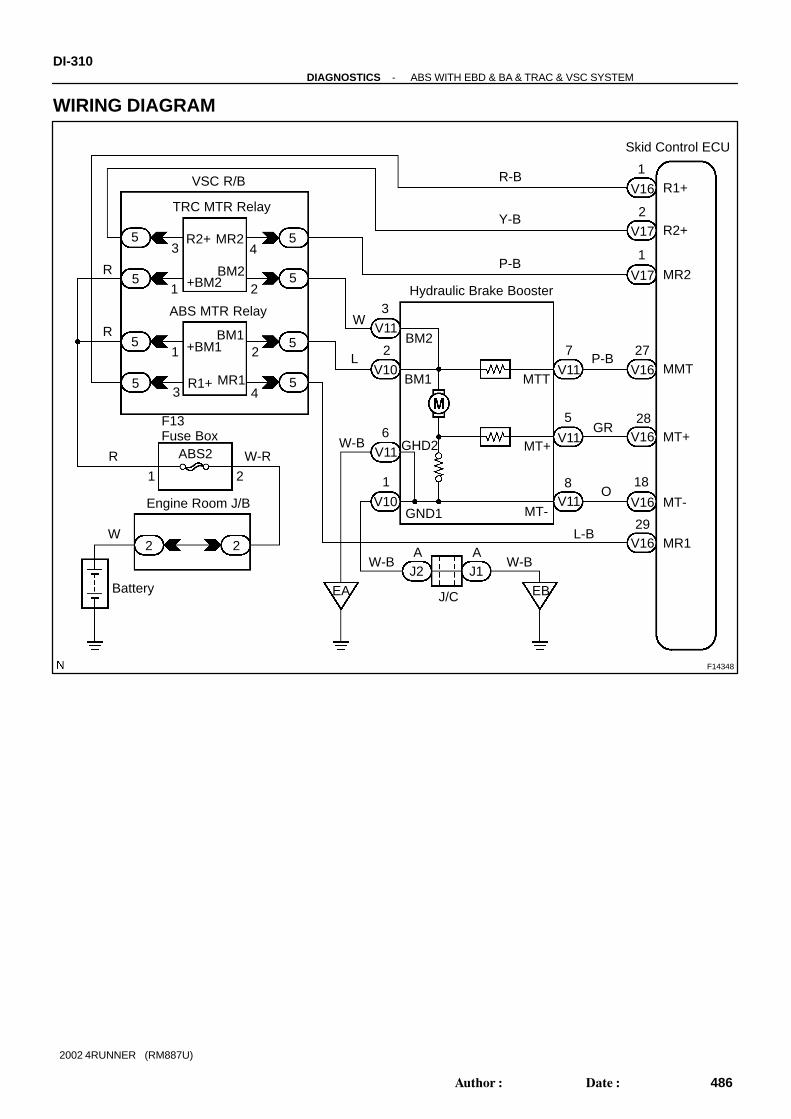
F14348
Battery
1
2
R1+
MR1
MR2
27
28
18
Hydraulic Brake Booster
R2+
2 A
R
Y-B
W-R
Engine Room J/B
ABS2
1
3 14
2
2
TRC MTR Relay
ABS MTR RelayW
8
J1
7
EB
6
GND1
GRW-B
L
5
O
3
MR2
29
V16
MMT
MT+
MT-
Skid Control ECU
V17
V11 V16
V16
V16
V16
V17
R-B
P-B5
5
5
5
5
5
5
VSC R/B
BM2
R2+
+BM2
BM1+BM1
MR1R1+
1 2
3 4
R
P-B
V11
V11
V11
V11
V10
V10
5
MTT
MT+
MT-
BM2
BM1
GHD2
1
W-BA
J2
J/C
W-B
EA
F13Fuse Box
R
1 2
2W L-B
DI-310-DIAGNOSTICS ABS WITH EBD & BA & TRAC & VSC SYSTEM
486Author: Date:
2002 4RUNNER (RM887U)
WIRING DIAGRAM

-DIAGNOSTICS ABS WITH EBD & BA & TRAC & VSC SYSTEMDI-31 1
487Author: Date:
2002 4RUNNER (RM887U)
INSPECTION PROCEDUREHINT:Start the inspection from step 1 in case of using the hand-held tester and start from step 3 in case of notusing the hand-held tester.
1 Check ABS MTR relay and TRC MTR relay operation.
PREPARATION:(a) Connect the hand-held tester to DLC3.(b) Turn the ignition switch ON and push the hand-held tester main switch ON.(c) Select the ACTIVE TEST mode on the hand-held tester.CHECK:Check the operation sound of the ABS MTR relay and TRC MTR relay individually when operating them withthe hand-held tester.OK:
The operation sound of the ABS MTR relay and TRC MTR relay should be heard.
NG Go to step 3.
OK
2 Check for short circuit (to B+) in harness and connector between MT of hydrau-lic brake booster and skid control ECU (See page IN-28 ).
NG Repair or replace harness or connector.
OK
Check and replace skid control ECU.

TRC MTR Relay
F09168
(+)(-)
VSC R/B
1
1
ABS MTR Relay
F00044
1
2
34
(+)
(-)
Continuity
12
34
1
2
3
4
Open
Continuity
DI-312-DIAGNOSTICS ABS WITH EBD & BA & TRAC & VSC SYSTEM
488Author: Date:
2002 4RUNNER (RM887U)
3 Check voltage between terminal 1 of VSC R/B (for ABS MTR relay and TRC MTRrelay) and body ground.
PREPARATION:Remove the ABS MTR relay and TRC MTR relay from VSC R/B.CHECK:Measure voltage between terminal 1 of VSC R/B (for ABS MTRrelay and TRC MTR relay) and body ground.OK:
Voltage: 10 - 14 V
NG Check and repair harness or connector.
OK
4 Check ABS MTR relay and TRC MTR relay.
CHECK:Check continuity between each pair of terminals of the motorrelay.OK:
Terminals 3 and 4Continuity
(Reference value ∗1)
Terminals 1 and 2 Open
*1: ABS MTR relay 62 Ω TRC MTR relay 54 Ω
CHECK:(a) Apply battery positive voltage between terminals 3 and 4.(b) Check continuity between terminals.OK:
Terminals 1 and 2 Continuity
NG Replace ABS MTR relay or TRC MTR relay.
OK

F02840
ABS MTRRelay 2
2 TRC MTR Relay
Motor Relay3 2
23
ECU
7
MMT
VSC R/B
-DIAGNOSTICS ABS WITH EBD & BA & TRAC & VSC SYSTEMDI-313
489Author: Date:
2002 4RUNNER (RM887U)
5 Check continuity between each terminal BM1 and BM2 and terminal MMT of skidcontrol ECU.
CHECK:(a) Check continuity between terminal BM1 of the ABS MTR
relay and terminal MMT of the skid control ECU.(b) Check continuity between terminal BM2 of the TRC MTR
relay and terminal MMT of the skid control ECU.OK:
ContinuityHINT:There is resistance of 33 ± 3 Ω between terminal BM1or BM2and MT of the hydraulic brake booster.
NG Repair or replace harness, connector or hy-draulic brake booster.
OK
6 Check for open and short circuit in harness and connector between ABS MTRand TRC MTR relay and skid control ECU (See page IN-28 ).
NG Repair or replace harness or connector.
OK
Check and replace skid control ECU.

F14349
Skid Control ECU
R2+
MR2
PL
PH
MMT
MT+
MT-
MR-
1V16
2
V17
8
11
27
28
18
29
1V17
V17
V16
V16
V16
V16
V16
L-W
LG-B
P-B
GR
O
L-B
V11
V10
V11
V11
V11
4
3
7
5
8
R-B
Y-B
P-B
PL
PH
MTT
MT+
MT-
Pressure Sensor (PL)
Hydraulic Brake Booster
Pressure Sensor (PH)
BM2
BM1
PLG
GND2
GND1
V11
V11
V11
V10
V10
V10
3
2
2
6
5
1
W
L
W-B W-B
W-B
W-B
W-B A
EB
J/C
J1J2
J2
A
A
VSC R/B
TRC MTR Relay
ABS MTR Relay
5
5
5
5
5
5
5
5
43
21
21
43
R
R
R
F13 Fuse Box
ABS2
Engine Room J/B
Battery EA
W
W-R
21
2 2
R1+
PHG
R2+MR2
+BM2BM2
R1+MR1
+BM1BM1
DI-314-DIAGNOSTICS ABS WITH EBD & BA & TRAC & VSC SYSTEM
490Author: Date:
2002 4RUNNER (RM887U)
DTC C1254 / 54 Pressure Switch Circuit
CIRCUIT DESCRIPTIONDTC No. DTC Detecting Condition Trouble Area
C1254 / 54
Either of the condition 1. or 2. is detected:
1. After the ignition switch is turned ON, short or open
circuit in pressure switch (PL) continues for more than 1
sec.
2. After the ignition switch is turned ON, open circuit in
pressure switch (PH) continues for more than 1 sec.
Pressure switch (PH or PL)
Pressure switch circuit
WIRING DIAGRAM
DI6BV-08
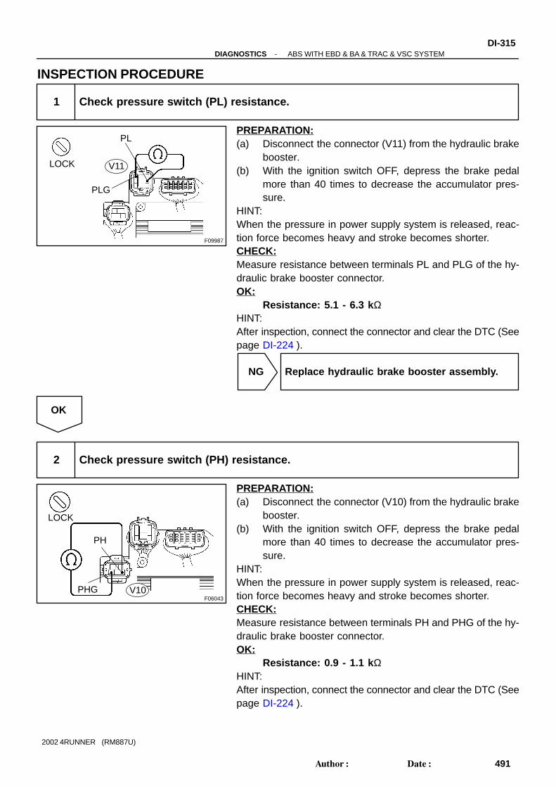
F09987
LOCK
PLG
PL
V11
F06043
LOCK
PH
PHG V10
-DIAGNOSTICS ABS WITH EBD & BA & TRAC & VSC SYSTEMDI-315
491Author: Date:
2002 4RUNNER (RM887U)
INSPECTION PROCEDURE
1 Check pressure switch (PL) resistance.
PREPARATION:(a) Disconnect the connector (V11) from the hydraulic brake
booster.(b) With the ignition switch OFF, depress the brake pedal
more than 40 times to decrease the accumulator pres-sure.
HINT:When the pressure in power supply system is released, reac-tion force becomes heavy and stroke becomes shorter.CHECK:Measure resistance between terminals PL and PLG of the hy-draulic brake booster connector.OK:
Resistance: 5.1 - 6.3 k ΩHINT:After inspection, connect the connector and clear the DTC (Seepage DI-224 ).
NG Replace hydraulic brake booster assembly.
OK
2 Check pressure switch (PH) resistance.
PREPARATION:(a) Disconnect the connector (V10) from the hydraulic brake
booster.(b) With the ignition switch OFF, depress the brake pedal
more than 40 times to decrease the accumulator pres-sure.
HINT:When the pressure in power supply system is released, reac-tion force becomes heavy and stroke becomes shorter.CHECK:Measure resistance between terminals PH and PHG of the hy-draulic brake booster connector.OK:
Resistance: 0.9 - 1.1 k ΩHINT:After inspection, connect the connector and clear the DTC (Seepage DI-224 ).

DI-316-DIAGNOSTICS ABS WITH EBD & BA & TRAC & VSC SYSTEM
492Author: Date:
2002 4RUNNER (RM887U)
NG Replace hydraulic brake booster assembly.
OK
3 Check for open and short circuit in harness and connector between pressureswitch and skid control ECU (See page IN-28 ).
NG Repair or replace harness or connector.
OK
Check and replace skid control ECU.

-DIAGNOSTICS ABS WITH EBD & BA & TRAC & VSC SYSTEMDI-317
493Author: Date:
2002 4RUNNER (RM887U)
DTC C1256 / 56 Accumulator Low Pressure Malfunc-tion
CIRCUIT DESCRIPTIONDTC No. DTC Detecting Condition Trouble Area
C1256 / 56
Any of the conditions 1. through 5. is detected:
1. With the vehicle running and ABS, TRAC or VSC not in
operation, the pressure switch (PL) detects low pressure
for 1.4 sec. or more while the pressure switch (PH) de-
tects high pressure.
2. With the vehicle running and ABS, TRAC or VSC not in
operation, the pressure switch (PL) detects low pressure
for 0.2 sec. or more while the pressure switch (PH) de-
tects high pressure.
3. After the ignition switch is turned ON, the pressure
switch (PL) detects low pressure for 60 sec. or more.
4. With the vehicle running and after the ignition switch is
turned ON, the pressure switch (PL) remains ON while
ABS, TRAC or VSC does not operate for 1.4 sec. or
more.
5. With the vehicle running and after the ignition switch is
turned OFF, the pressure switch (PL) remains ON while
ABS, TRAC or VSC operates for 0.2 sec. or more.
Accumulator
Pressure switch (PH or PL)
Hydraulic brake booster pump motor
DI6BW-08

F14349
Skid Control ECU
R2+
MR2
PL
PH
MMT
MT+
MT-
MR-
1V16
2
V17
8
11
27
28
18
29
1V17
V17
V16
V16
V16
V16
V16
L-W
LG-B
P-B
GR
O
L-B
V11
V10
V11
V11
V11
4
3
7
5
8
R-B
Y-B
P-B
PL
PH
MTT
MT+
MT-
Pressure Sensor (PL)
Hydraulic Brake Booster
Pressure Sensor (PH)
BM2
BM1
PLG
GND2
GND1
V11
V11
V11
V10
V10
V10
3
2
2
6
5
1
W
L
W-B W-B
W-B
W-B
W-B A
EB
J/C
J1J2
J2
A
A
VSC R/B
TRC MTR Relay
ABS MTR Relay
5
5
5
5
5
5
5
5
43
21
21
43
R
R
R
F13 Fuse Box
ABS2
Engine Room J/B
Battery EA
W
W-R
21
2 2
R1+
PHG
R2+MR2
+BM2BM2
R1+MR1
+BM1BM1
DI-318-DIAGNOSTICS ABS WITH EBD & BA & TRAC & VSC SYSTEM
494Author: Date:
2002 4RUNNER (RM887U)
WIRING DIAGRAM

F02859
(-) (+)
(-)
(+)
BM2
BM1EM1
EM2V11
V10
-DIAGNOSTICS ABS WITH EBD & BA & TRAC & VSC SYSTEMDI-319
495Author: Date:
2002 4RUNNER (RM887U)
INSPECTION PROCEDURE
1 Check accumulator operation.
PREPARATION:(a) Turn the ignition switch OFF, and depress the brake pedal 40 times or more.HINT:When the pressure in the power supply system is released, reaction force becomes heavy and stroke be-comes shorter.(b) Install the LSPV gauge (SST) to the rear wheel cylinder and bleed air.
SST 09709-29018CHECK:Depress the brake pedal with force of more than 343 N (35 kgf, 77 lbf) and turn the ignition switch ON, thencheck the rear wheel cylinder pressure when an increase of pressure changes from acutely to mildly.OK:
5,099 - 8,924 kPa (52 - 91 kgf/cm 2, 740 - 1,294 psi) at 20 °C (68°F)HINT:If the value is not within the standard, cool the engine room and check it again.
NG Replace accumulator.
OK
2 Check operation of hydraulic brake booster pump motor.
PREPARATION:Disconnect the 2 connectors (V10, V11) from the hydraulicbrake booster.CHECK:Connect battery positive (+) lead to BM1 or BM2 terminal andbattery negative (-) lead to EM1 or EM2 terminal of the hydrau-lic brake booster (pump motor) connector.OK:
The operation sound of the pump motor should beheard.
NG Go to step 7.
OK
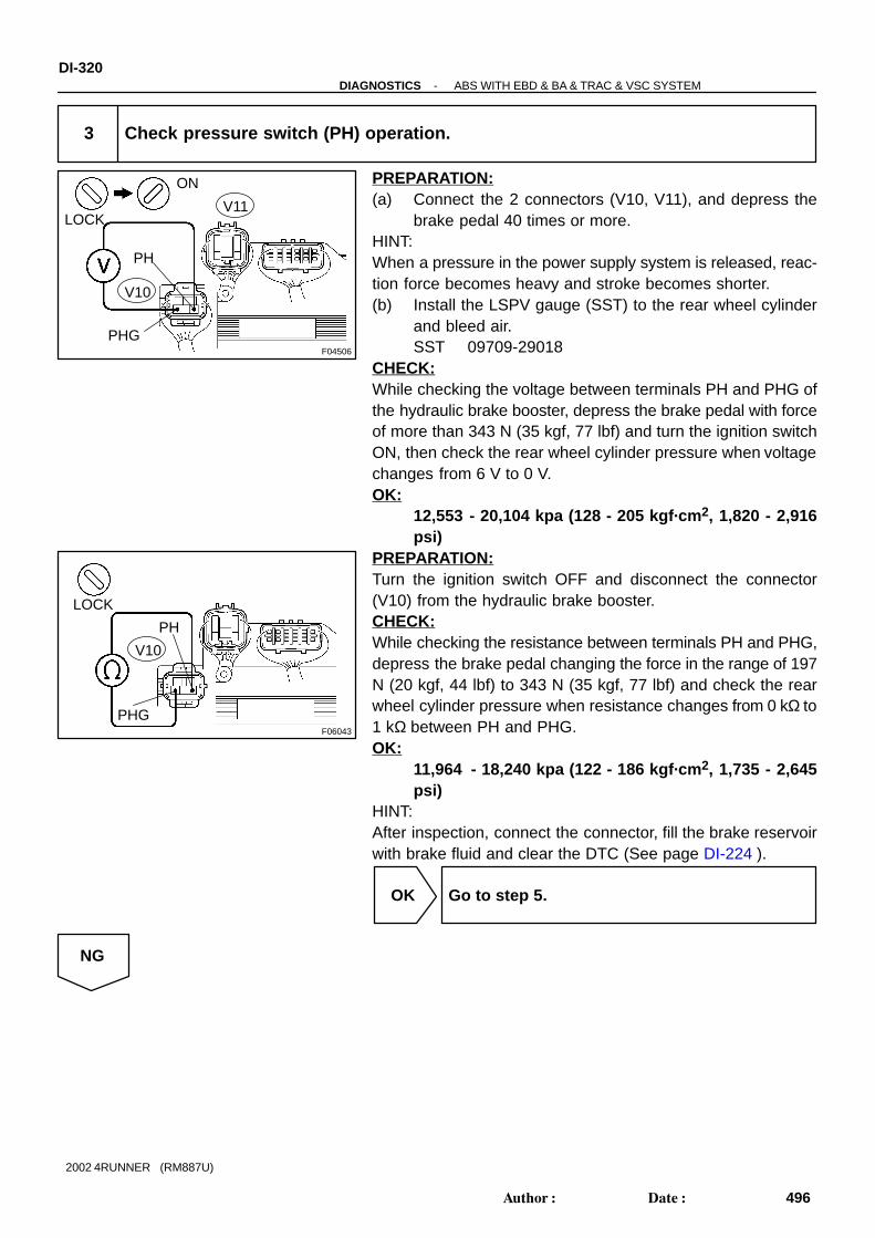
F04506
LOCK
ON
PH
PHG
V11
V10
F06043
LOCK
PH
PHG
V10
DI-320-DIAGNOSTICS ABS WITH EBD & BA & TRAC & VSC SYSTEM
496Author: Date:
2002 4RUNNER (RM887U)
3 Check pressure switch (PH) operation.
PREPARATION:(a) Connect the 2 connectors (V10, V11), and depress the
brake pedal 40 times or more.HINT:When a pressure in the power supply system is released, reac-tion force becomes heavy and stroke becomes shorter.(b) Install the LSPV gauge (SST) to the rear wheel cylinder
and bleed air.SST 09709-29018
CHECK:While checking the voltage between terminals PH and PHG ofthe hydraulic brake booster, depress the brake pedal with forceof more than 343 N (35 kgf, 77 lbf) and turn the ignition switchON, then check the rear wheel cylinder pressure when voltagechanges from 6 V to 0 V.OK:
12,553 - 20,104 kpa (128 - 205 kgf·cm 2, 1,820 - 2,916psi)
PREPARATION:Turn the ignition switch OFF and disconnect the connector(V10) from the hydraulic brake booster.CHECK:While checking the resistance between terminals PH and PHG,depress the brake pedal changing the force in the range of 197N (20 kgf, 44 lbf) to 343 N (35 kgf, 77 lbf) and check the rearwheel cylinder pressure when resistance changes from 0 kΩ to1 kΩ between PH and PHG.OK:
11,964 - 18,240 kpa (122 - 186 kgf·cm 2, 1,735 - 2,645psi)
HINT:After inspection, connect the connector, fill the brake reservoirwith brake fluid and clear the DTC (See page DI-224 ).
OK Go to step 5.
NG

F06042
LOCK ON
PLG
PL
V11
-DIAGNOSTICS ABS WITH EBD & BA & TRAC & VSC SYSTEMDI-321
497Author: Date:
2002 4RUNNER (RM887U)
4 Check for open circuit in harness and connector between pressure switch (PH)and skid control ECU (See page IN-28 ).
NG Repair or replace harness or connector.
OK
Replace hydraulic brake booster assembly.
5 Check pressure switch (PL) operation.
PREPARATION:(a) Turn the motor switch OFF, and depress the brake pedal
40 times or more.HINT:When a pressure in the power supply system is released, reac-tion force becomes heavy and stroke becomes shorter.(b) Install the LSPV gauge (SST) to the rear wheel cylinder
and bleed air.SST 09709 -29018
(c) Disconnect the connector (V11) from the hydraulic brakebooster.
CHECK:While checking the resistance between terminals PL and PLGof the hydraulic brake booster, depress the brake pedal withforce of more than 343 N (35 kgf, 77 lbf) and turn the ignitionswitch ON, then check the rear wheel cylinder pressure whenthe resistance changes from 5.7 kΩ to 1.0 kΩ.OK:
9,022 - 15,102 kpa (92 - 154 kgf·cm 2, 1,308 - 2,190 psi)PREPARATION:Turn the ignition switch OFF and disconnect the connector(V11) from the hydraulic brake booster.CHECK:While checking the resistance between terminals PL and PLGof the hydraulic brake booster, depress the brake pedal chang-ing the force in the range of 197 N (20 kgf, 44 lbf) to 343 N (35kgf, 77 lbf) and check the rear wheel cylinder pressure when re-sistance changes from 1.0 kΩ to 5.7 kΩ.OK:
8,532 - 13,337 kpa (87 - 136 kgf·cm 2, 1,237 - 1,934 psi)HINT:After inspection, connect the connector, fill the brake reservoirwith brake fluid and clear the DTC (See page DI-224 ).

DI-322-DIAGNOSTICS ABS WITH EBD & BA & TRAC & VSC SYSTEM
498Author: Date:
2002 4RUNNER (RM887U)
NG Replace hydraulic brake booster assembly.
OK
6 Check pressure switch (PH) and pressure switch (PL)
CHECK:Compare the pressure value of the rear wheel cylinder measured in the check pressure switch (PL) operationwith the one measured in the check pressure switch (PH) operation.OK: Pressure when the voltage between PH and PHG becomes 6 to 0 V > pressure when the resis-
tance between PL and PLG becomes 5.7 k Ω to 1.0 k Ω. Pressure w hen the resistance between PH and PHG becomes 0 k Ω to 1 k Ω > pressure when the
resistance between PL and PLG becomes 1.0 k Ω to 5.7 k Ω.
NG Replace hydraulic brake booster assembly.
OK
Check and replace skid control ECU.
7 Check for open and short circuit in harness and connector between hydraulicbrake booster pump motor and hydraulic brake booster (See page IN-28 ).
NG Replace wire harness.
OK
8 Check hydraulic brake booster pump motor (See page BR-42 ).
NG Replace hydraulic brake booster pump motor.
OK

-DIAGNOSTICS ABS WITH EBD & BA & TRAC & VSC SYSTEMDI-323
499Author: Date:
2002 4RUNNER (RM887U)
Replace hydraulic brake booster.

F14343
IG1
GND2
GND1
GND3
GND4
Battery
V19
V16
7
6
31
8
16
Y1G1I
ECU-IGB-Y
42 AM1 IG1
W
I14Ignition Switch Driver Side J/B
Engine Room R/B
21
ALT
Skid Control ECU
V16
V19
V19
AM1
22 21
W
W-B
W-B
W-B
W-B
J9
J/CA
J4
IEIFEA J/CA
2 3
DI-324-DIAGNOSTICS ABS WITH EBD & BA & TRAC & VSC SYSTEM
500Author: Date:
2002 4RUNNER (RM887U)
DTC C1257 / 57 Power Supply Drive Circuit
CIRCUIT DESCRIPTIONDTC No. DTC Detecting Condition Trouble Area
C1257 / 57 When malfunction inside ECU is detected.
Battery
Power source circuit
Skid control ECU
WIRING DIAGRAM
DI6BX-03

F13788
Driver Side J/B
ECU-IG
-DIAGNOSTICS ABS WITH EBD & BA & TRAC & VSC SYSTEMDI-325
501Author: Date:
2002 4RUNNER (RM887U)
INSPECTION PROCEDURE
1 Check battery positive voltage.
OK:Voltage: 10 - 14 V
NG Check and repair the charging system.
OK
2 Check ECU-IG fuse.
PREPARATION:
Remove the ECU-IG fuse from the driver side J/B.CHECK:Check continuity of the ECU-IG fuse.OK:
Continuity
NG Check for short circuit in all the harnesses andcomponents connected to ECU-IG fuse (See at-tached wiring diagram).
OK

F13777
V19V16
ON
16
86
31
7
DI-326-DIAGNOSTICS ABS WITH EBD & BA & TRAC & VSC SYSTEM
502Author: Date:
2002 4RUNNER (RM887U)
3 Check voltage of ECU IG power source.
In case of using the hand-held tester:PREPARATION:(a) Connect the hand-held tester to DLC3.(b) Turn the ignition switch ON and push the hand-held tester main switch ON.(c) Select the DATALIST mode on the hand-held tester.CHECK:Check the voltage condition output from the ECU displayed on the hand-held tester.OK:
”Normal” is displayed.In case of not using the hand-held tester:PREPARATION:Remove the skid control ECU with the connectors still con-nected.CHECK:(a) Turn the ignition switch ON.(b) Measure voltage between terminals IG1 (V19 - 7) and
GND (V16 - 6, 31, V19 - 8, 16) of the skid control ECUconnector.
OK:Voltage: 10 - 14 V
OK Check and replace skid control ECU.
NG

F13783
V19V16
LOCK
31
16
8
6
-DIAGNOSTICS ABS WITH EBD & BA & TRAC & VSC SYSTEMDI-327
503Author: Date:
2002 4RUNNER (RM887U)
4 Check continuity between terminal GND of skid control ECU and body ground.
PREPARATION:Disconnect the 2 connectors (V16, V14) from the skid controlECU.CHECK:Measure resistance between terminal GND (V16 - 6, 31, V19- 8, 16) of the skid control ECU and body ground.OK:
Resistance: 1 Ω or less
NG Repair or replace harness or connector.
OK
Check for open circuit in harness and connector between skid control ECU and battery (See pageIN-28 ).

F14363
Skid Control ECUECM
4WD E1213
B-L8
V18 EXI 3
4WD ECU
ADD19F7II4
12ED2
1G-BA39
3+B
ADDActuator
B-L
B-L B-L B-L
B-L
DI-328-DIAGNOSTICS ABS WITH EBD & BA & TRAC & VSC SYSTEM
504Author: Date:
2002 4RUNNER (RM887U)
DTC C1258 / 58 Transfer 4WD Position Switch Circuit
CIRCUIT DESCRIPTIONDTC No. DTC Detecting Condition Trouble Area
C1258 / 58 Open or short circuit in transfer 4WD position switch circuit.Transfer 4WD position switch
Transfer 4WD indicator switch circuit
WIRING DIAGRAM
DI8XT-02

F14335
ONV18
8
(-) (+)
-DIAGNOSTICS ABS WITH EBD & BA & TRAC & VSC SYSTEMDI-329
505Author: Date:
2002 4RUNNER (RM887U)
INSPECTION PROCEDURE
1 Check voltage between terminal EXI3 of skid control ECU and body ground.
PREPARATION:Remove the skid control ECU with the connectors still con-nected.CHECK:(a) Turn the ignition switch ON.(b) Measure voltage between terminal EXI3 (V18 - 8) of the
skid control ECU and body ground with the transfer shiftlever in 4WD position and in other than 4WD position.
OK:Voltage:4WD position: Below 2.0 VExcept 4WD position: 10 - 14 V
OK Proceed to next circuit inspection shown inproblem symptoms table (See page DI-242 ).
NG
2 Check transfer 4WD position switch (See page TR-1 1).
NG Replace transfer 4WD position switch.
OK
3 Check for open and short circuit in harness and connector between transfer4WD position switch and skid control ECU (See page IN-28 ).
NG Repair or replace harness or connector.
OK

DI-330-DIAGNOSTICS ABS WITH EBD & BA & TRAC & VSC SYSTEM
506Author: Date:
2002 4RUNNER (RM887U)
4 Check for open and short circuit in harness and connector between skid controlECU and ECM (See page IN-28 ).
NG Repair or replace harness or connector.
OK
Check and replace skid control ECU.

F14338
W-B
A
J/C
W-B
2 1J8
IFC
B
L-R
J9 J/C
17
B
L-RL-RJ7
W-B W-BC
EXI4
Skid Control ECU
(4WD)V18
7
II43II2
Center J/B
3E
1618
D4Detection SW
3E
J3 J/C
-DIAGNOSTICS ABS WITH EBD & BA & TRAC & VSC SYSTEMDI-331
507Author: Date:
2002 4RUNNER (RM887U)
DTC C1268 / 68 Transfer L4 Position Switch Circuit
CIRCUIT DESCRIPTIONDTC No. DTC Detecting Condition Trouble Area
C1268 / 68 Open or short circuit in transfer L4 position switch circuit.Transfer L4 position switch
Transfer L4 indicator switch circuit
WIRING DIAGRAM
DI6BY-03

F13787
ONV1817
(-) (+)
DI-332-DIAGNOSTICS ABS WITH EBD & BA & TRAC & VSC SYSTEM
508Author: Date:
2002 4RUNNER (RM887U)
INSPECTION PROCEDURE
1 Check voltage between terminal EXI4 of skid control ECU and body ground.
PREPARATION:Remove the skid control ECU with the connectors still con-nected.CHECK:(a) Turn the ignition switch ON.(b) Measure voltage between terminal EXI4 (V18 - 17) of the
skid control ECU and body ground with the transfer shiftlever in L4 position and in other than L4 position.
OK:Voltage:L4 position: Below 2.0 VExcept L4 position: 10 - 14 V
OK Proceed to next circuit inspection shown inproblem symptoms table (See page DI-242 ).
NG
2 Check transfer L4 position switch (See page TR-1 1).
NG Replace transfer L4 position switch.
OK
3 Check for open and short circuit in harness and connector between transfer L4position switch and skid control ECU (See page IN-28 ).
NG Repair or replace harness or connector.
OK

-DIAGNOSTICS ABS WITH EBD & BA & TRAC & VSC SYSTEMDI-333
509Author: Date:
2002 4RUNNER (RM887U)
4 Check for open and short circuit in harness and connector between skid controlECU and ECM (See page IN-28 ).
NG Repair or replace harness or connector.
OK
Check and replace skid control ECU.

F14361
ALT
Battery
II4
2
3
PNP Switch
1I V19
4
B-YR
W-L
W
7
1F2
AM1
Driver Side J/B
GAUGE 1019
IG1
20
Skid Control ECU
W-LB-YII4
2B-Y
Engine Room J/B
222 11
W
2AM1
I14Ignition Switch
RB
RL
DI-334-DIAGNOSTICS ABS WITH EBD & BA & TRAC & VSC SYSTEM
510Author: Date:
2002 4RUNNER (RM887U)
DTC C1269 / 69 PNP Switch Circuit (R range)
CIRCUIT DESCRIPTIONDTC No. DTC Detecting Condition Trouble Area
C1269 / 69With the vehicle speed less than 15 km/h (9 mph), open
circuit in R signal circuit is detected for more than 2 sec.
PNP switch
PNP switch circuit (R range)
WIRING DIAGRAM
DI6BZ-03

-DIAGNOSTICS ABS WITH EBD & BA & TRAC & VSC SYSTEMDI-335
511Author: Date:
2002 4RUNNER (RM887U)
INSPECTION PROCEDUREHINT:Start the inspection from step 1 in case of using the hand-held tester and start from step 2 in case of notusing the hand-held tester.
1 Check operation of PNP switch (R range) circuit.
PREPARATION:(a) Connect the hand-held tester to DLC3.(b) Turn the ignition switch ON and push the hand-held tester main switch ON.(c) Select the ACTIVE TEST mode on the hand-held tester.CHECK:Set the shift lever in the R range, and read the R signal on the hand-held tester.OK:
”ON” is displayed.
OK Check and replace skid control ECU.
NG
2 Check PNP switch (R range) (See page DI-159 ).
NG Repair or replace PNP switch.
OK

F13786
ON
V1910
(+)(-)
DI-336-DIAGNOSTICS ABS WITH EBD & BA & TRAC & VSC SYSTEM
512Author: Date:
2002 4RUNNER (RM887U)
3 Check voltage between terminal R of skid control ECU and body ground.
PREPARATION:Remove the skid control ECU with the connectors still con-nected.CHECK:(a) Turn the ignition switch ON.(b) Measure voltage between terminal R (V19 - 10) of the
skid control ECU and body ground when the brake pedalis depressed and shift the shift lever to R position.
OK:Voltage: 10 - 14 V
NG Go to step 4.
OK
If the same code is still output after the DTC is deleted, check the contact condition of each con-nection. If the connections are normal, ECU may be defective.
4 Check for open circuit in harness and connector between PNP switch (R range)and skid control ECU (See page IN-28 ).
NG Repair or replace harness or connector.
OK
Check and replace skid control ECU.

F14346
Yaw Rate Sensor
YD
GYAW
YAW2
VYS
(Shielded)
YSS
Skid Control ECU
W
9
19
18
28
YD
GYAW
YAW
VYSR
B27
5
1
3
4
YV18
V18
V18
V18
V18BR-B
-DIAGNOSTICS ABS WITH EBD & BA & TRAC & VSC SYSTEMDI-337
513Author: Date:
2002 4RUNNER (RM887U)
DTC C1336 / 39 Zero Point Calibration of DecelerationSensor Undone
CIRCUIT DESCRIPTIONDTC No. DTC Detecting Condition Trouble Area
C1336 / 39
Either the condition 1. or 2. is detected:
1. In TEST mode, the shift lever is shifted to any position
except P range within 2 sec. after ECU terminal IG1 is
turned ON for the first time.
2. The deceleration sensor zero point recorded in ECU is
deleted.
Deceleration sensor
Deceleration sensor circuit
PNP switch circuit (P range)
WIRING DIAGRAM
DI8XU-02

DI-338-DIAGNOSTICS ABS WITH EBD & BA & TRAC & VSC SYSTEM
514Author: Date:
2002 4RUNNER (RM887U)
INSPECTION PROCEDUREHINT:After step 1 and 2, go to step 3 in case of using the hand-held tester, and go to step 5 in case of not usingthe hand-held tester.
1 Perform zero point calibration of Deceleration sensor (See page DI-224 ).
2 Is DTC still output?
Check DTC on page DI-224 .
NO No problem.
YES
3 Check output value of deceleration sensor.
PREPARATION:(a) Connect the hand-held tester to DLC3.(b) Turn the ignition switch ON and turn the hand-held tester main switch ON.(c) Select the DATALIST mode on the hand-held tester.CHECK:Check that the deceleration value of the deceleration sensor observed in the hand-held tester is changingwhen the vehicle is tilted.OK:
Deceleration value must be changing.
OK Go to step 3.
NG

F02098
GL1
GGND
GL2
VGS
Forward
Rearward
Front
-DIAGNOSTICS ABS WITH EBD & BA & TRAC & VSC SYSTEMDI-339
515Author: Date:
2002 4RUNNER (RM887U)
4 Check for open and short circuit in harness and connector between decelerationsensor and skid control ECU (See page IN-28 ).
NG Repair or replace harness or connector.
OK
Replace deceleration sensor.
5 Check deceleration sensor.
PREPARATION:(a) Remove the consol box.(b) Connect 3 dry batteries of 1.5 V in series.(c) Connect VGS terminal to the batteries’ positive (+) termi-
nal, and GGND terminal to the batteries’ negative (-) ter-minal, apply about 4.5 V between VGS and GGND termi-nals.
NOTICE:Do not apply voltage of 6 V or more to terminals VYS andGYAW.CHECK:Check the output voltage of GL1 and GL2 terminals when thesensor is tilted forward and rearward.OK:
Symbols Condition Standard Value
GL1 Horizontal About 2.3 V
GL1 Lean forward 0.4 V - about 2.3 V
GL1 Lean rearward About 2.3 V - 4.1 V
GL2 Horizontal About 2.3 V
GL2 Lean forward About 2.3 V - 4.1 V
GL2 Lean rearward 0.4 V - about 2.3 V
HINT: If the sensor is tilted too much it may show the wrong val-
ue. If dropped, the sensor should be replaced with a new one. The sensor removed from the vehicle should not be
placed upside down.
NG Replace deceleration sensor.
OK

DI-340-DIAGNOSTICS ABS WITH EBD & BA & TRAC & VSC SYSTEM
516Author: Date:
2002 4RUNNER (RM887U)
6 Check for open and short circuit in harness and connector between decelerationsensor and skid control ECU (See page IN-28 ).
NG Repair or replace harness or connector.
OK
Check and replace skid control ECU.

F14337
Skid Control ECU24
CDV18
P-G
3C29
CenterDiff Lock
Combination Meter
12C29
81F
GAUGE21I
P-G
B-Y
I14Ignition Switch
IG14 AM1 2
20F7IND2
4WD ECU
W2
2
AM1
1 2 1
ALT2
W 3EXIV18R-B
6F7P1
7II2 R-B
D31Detection SW
2 1
W-B3II2
J3J/C
C
C
W-B
W-B
Center J/B
3E3E1816
AW-BJ9
J/C
IFBattery
Driver Side J/B
Engine Room R/B
B-Y
R-B
R-B
P-G
-DIAGNOSTICS ABS WITH EBD & BA & TRAC & VSC SYSTEMDI-341
517Author: Date:
2002 4RUNNER (RM887U)
DTC C1340 / 47 Center Differential Lock Circuit
CIRCUIT DESCRIPTIONDTC No. DTC Detecting Condition Trouble Area
C1340 / 47 Open or short circuit in center differential lock circuit.
Center differential lock system
Center differential lock circuit
Center differential lock indicator light circuit
WIRING DIAGRAM
DI6CN-03

DI-342-DIAGNOSTICS ABS WITH EBD & BA & TRAC & VSC SYSTEM
518Author: Date:
2002 4RUNNER (RM887U)
INSPECTION PROCEDURE
1 Check that center differential is free and center diff. lock switch is OFF.
NG Repair center differential lock system.
OK
2 Is DTC output?
Check DTC on page DI-224 .
NO Normal.
YES
3 Check that bulb for center diff. lock indicator light is not burnt out.
YES Replace indicator light.
NO
4 Check for open circuit in harness and connector between center diff. lock switchand skid control ECU, skid control ECU and center diff. lock indicator light (Seepage IN-28 ).
NG Repair or replace harness or connector.
OK
Check and replace skid control ECU.
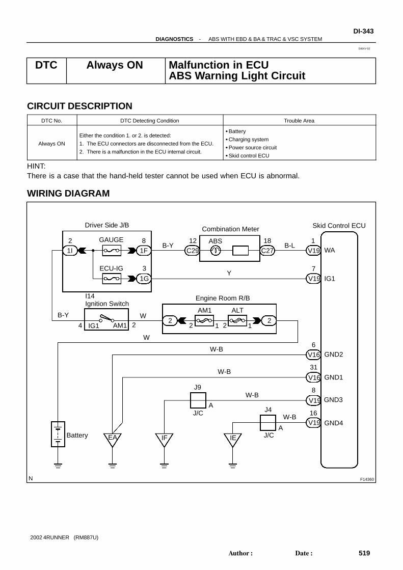
F14360
I14Ignition Switch
Driver Side J/B
Engine Room R/B
B-Y B-L
W6
31
16
8
7
W-B
A
A
J/C
2
1
ALTAM1
22
Battery
W-B
IF IE
24
18
1F
ECU-IG
8
IG1
GND1
GND2
GND3
GND4
EA
J4
W-B
J/C
J9
W-B
WA1I
1G
Skid Control ECU
GAUGE
V19
V16
C29 C27
V19
V19
V19
V16
ABS
Combination Meter
Y
12
3
2
B-Y WAM1IG1 1 12
-DIAGNOSTICS ABS WITH EBD & BA & TRAC & VSC SYSTEMDI-343
519Author: Date:
2002 4RUNNER (RM887U)
DTC Always ON Malfunction in ECUABS Warning Light Circuit
CIRCUIT DESCRIPTIONDTC No. DTC Detecting Condition Trouble Area
Always ON
Either the condition 1. or 2. is detected:
1. The ECU connectors are disconnected from the ECU.
2. There is a malfunction in the ECU internal circuit.
Battery
Charging system
Power source circuit
Skid control ECU
HINT:There is a case that the hand-held tester cannot be used when ECU is abnormal.
WIRING DIAGRAM
DI8XV-02

DI-344-DIAGNOSTICS ABS WITH EBD & BA & TRAC & VSC SYSTEM
520Author: Date:
2002 4RUNNER (RM887U)
INSPECTION PROCEDURE
1 Is DTC output?
Check DTC on page DI-224 .
YES Repair circuit indicated by the output code.
NO
2 Check that ECU connectors are securely connected to ECU.
NO Connect the connector to ECU.
YES
3 Check battery positive voltage.
CHECK:Check the battery positive voltage.OK:
Voltage: 10 - 14 V
NG Check and repair charging system.
OK

F13777
V19V16
ON
16
86
31
7
-DIAGNOSTICS ABS WITH EBD & BA & TRAC & VSC SYSTEMDI-345
521Author: Date:
2002 4RUNNER (RM887U)
4 Check voltage of ECU IG power source.
In case of using the hand-held tester:PREPARATION:(a) Connect the hand-held tester to DLC3.(b) Turn the ignition switch ON and push the hand-held tester main switch ON.(c) Select the DATALIST mode on the hand-held tester.CHECK:Check the voltage condition output from the ECU displayed on the hand-held tester.OK:
”Normal” is displayed.In case of not using the hand-held tester:PREPARATION:Remove the skid control ECU with the connectors still con-nected.CHECK:(a) Turn the ignition switch ON.(b) Measure voltage between terminals IG1 (V19 - 7) and
GND (V16 - 6, 31, V19 - 8, 16) of the skid control ECU.OK:
Voltage: 10 - 14 V
OK Check and replace skid control ECU.
NG

DI-346-DIAGNOSTICS ABS WITH EBD & BA & TRAC & VSC SYSTEM
522Author: Date:
2002 4RUNNER (RM887U)
5 Check operation of ABS warning light.
In case of using the hand-held tester:PREPARATION:(a) Connect the hand-held tester to DLC3.(b) Turn the ignition switch ON and push the hand-held tester main switch ON.(c) Select the ACTIVE TEST mode on the hand-held tester.CHECK:Check that ”ON” and ”OFF” of the ABS warning light can be shown on the combination meter by the hand-held tester.In case of not using the hand-held tester:PREPARATION:(a) Turn the ignition switch OFF.(b) Disconnect the connector from the skid control ECU.(c) Turn the ignition switch ON.CHECK:Check that the ABS warning light goes off.
OK Check and replace combination meter (Seepage BE-40 ).
NG
6 Check for short circuit in harness and connector between combination meter and skidcontrol ECU (See page IN-28 ).
NG Repair or replace harness or connector.
OK
Check and replace skid control ECU.
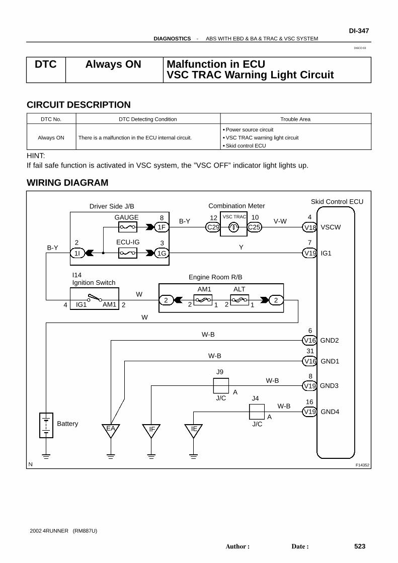
F14352
Skid Control ECU
VSCW
IG1
GND2
GND1
GND3
GND4
EA
V18
V19
4
7
6
31
8
16
V16
V-WC25C29
VSC TRAC 1012
Combination Meter
Engine Room R/B
Y
B-Y1F
1G1I
GAUGE
ECU-IG
Driver Side J/B
V16
V19
V19
B-Y
8
32
ALTAM1
222 2 11
W
AM1 2IG14
W-B
I14Ignition Switch
W
W-B
J9
Battery
J/CA
IEIF
J4
J/CA
W-B
W-B
-DIAGNOSTICS ABS WITH EBD & BA & TRAC & VSC SYSTEMDI-347
523Author: Date:
2002 4RUNNER (RM887U)
DTC Always ON Malfunction in ECU VSC TRAC Warning Light Circuit
CIRCUIT DESCRIPTIONDTC No. DTC Detecting Condition Trouble Area
Always ON There is a malfunction in the ECU internal circuit.
Power source circuit
VSC TRAC warning light circuit
Skid control ECU
HINT:If fail safe function is activated in VSC system, the ”VSC OFF” indicator light lights up.
WIRING DIAGRAM
DI6CO-03

DI-348-DIAGNOSTICS ABS WITH EBD & BA & TRAC & VSC SYSTEM
524Author: Date:
2002 4RUNNER (RM887U)
INSPECTION PROCEDURE
1 Check that ECU connectors are securely connected to ECU.
NO Connect the connector to ECU.
YES
2 Is DTC output for VSC?
Check DTC on page DI-224 .
YES Repair circuit indicated by the output code.
NO
3 Does VSC TRAC warning light go off?
YES Check for open and short circuit in harness andconnector between ECU-IG fuse and ECU (Seepage IN-28 ).
NO

-DIAGNOSTICS ABS WITH EBD & BA & TRAC & VSC SYSTEMDI-349
525Author: Date:
2002 4RUNNER (RM887U)
4 Check battery positive voltage.
CHECK:Check the battery positive voltage.OK:
Voltage: 10 - 14 V
NG Check and repair the charging system.
OK
5 Check operation of VSC TRAC warning light.
In case of using the hand-held tester:PREPARATION:(a) Connect the hand-held tester to DLC3.(b) Turn the ignition switch ON and push the hand-held tester main switch ON.(c) Select the ACTIVE TEST mode on the hand-held tester.CHECK:Check that ”ON” and ”OFF” of the VSC TRAC warning light can be shown on the combination meter on thehand-held tester.In case of not using the hand-held tester:PREPARATION:(a) Turn the ignition switch OFF.(b) Disconnect the connector from the skid control ECU.(c) Turn the ignition switch ON.CHECK:Check that the VSC TRC warning light goes off.
NG Check and replace combination meter ( See page BE-40 ).
OK
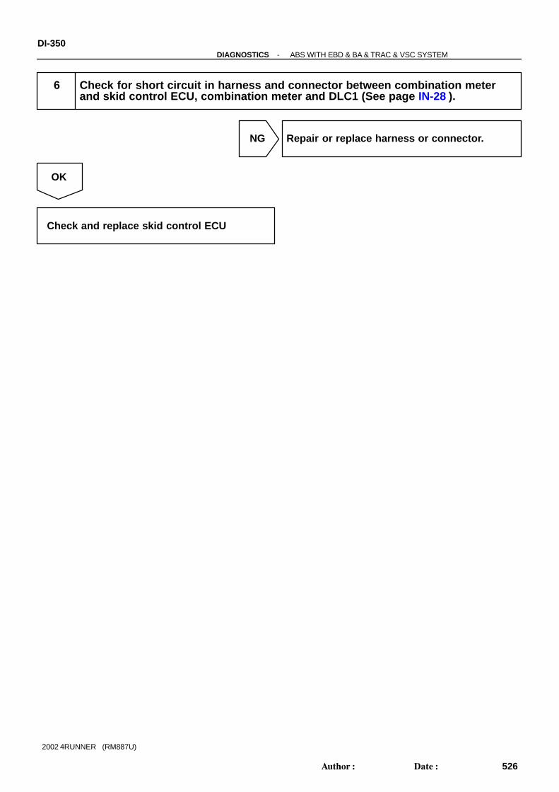
DI-350-DIAGNOSTICS ABS WITH EBD & BA & TRAC & VSC SYSTEM
526Author: Date:
2002 4RUNNER (RM887U)
6 Check for short circuit in harness and connector between combination meterand skid control ECU, combination meter and DLC1 (See page IN-28 ).
NG Repair or replace harness or connector.
OK
Check and replace skid control ECU

F14359
Driver Side J/B
B-L
Battery
ABSGAUGE
IG1
W
V198
2
C291F WA18
12
Engine Room R/B
2 1 22
ALT AM1
I14Ignition Switch
4
2 B-Y1I
12
C27
Combination Meter
1
AM1
B-Y W
Skid Control ECU
-DIAGNOSTICS ABS WITH EBD & BA & TRAC & VSC SYSTEMDI-351
527Author: Date:
2002 4RUNNER (RM887U)
ABS Warning Light Circuit
CIRCUIT DESCRIPTIONIf the ECU detects trouble, it lights the ABS warning light while prohibiting ABS control. At this time, the ECUrecords DTC in memory.Connect terminals Tc and E1 of DLC1 to make the ABS warning light blink and output the DTC.
WIRING DIAGRAM
DI8XW-02
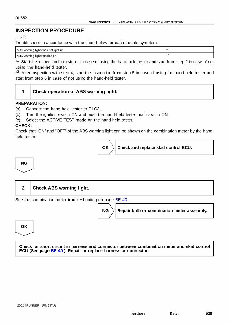
DI-352-DIAGNOSTICS ABS WITH EBD & BA & TRAC & VSC SYSTEM
528Author: Date:
2002 4RUNNER (RM887U)
INSPECTION PROCEDUREHINT:Troubleshoot in accordance with the chart below for each trouble symptom.
ABS warning light does not light up *1
ABS warning light remains on *2
*1: Start the inspection from step 1 in case of using the hand-held tester and start from step 2 in case of notusing the hand-held tester.*2: After inspection with step 4, start the inspection from step 5 in case of using the hand-held tester andstart from step 6 in case of not using the hand-held tester.
1 Check operation of ABS warning light.
PREPARATION:(a) Connect the hand-held tester to DLC3.(b) Turn the ignition switch ON and push the hand-held tester main switch ON.(c) Select the ACTIVE TEST mode on the hand-held tester.CHECK:Check that ”ON” and ”OFF” of the ABS warning light can be shown on the combination meter by the hand-held tester.
OK Check and replace skid control ECU.
NG
2 Check ABS warning light.
See the combination meter troubleshooting on page BE-40 .
NG Repair bulb or combination meter assembly.
OK
Check for short circuit in harness and connector between combination meter and skid controlECU (See page BE-40 ). Repair or replace harness or connector.
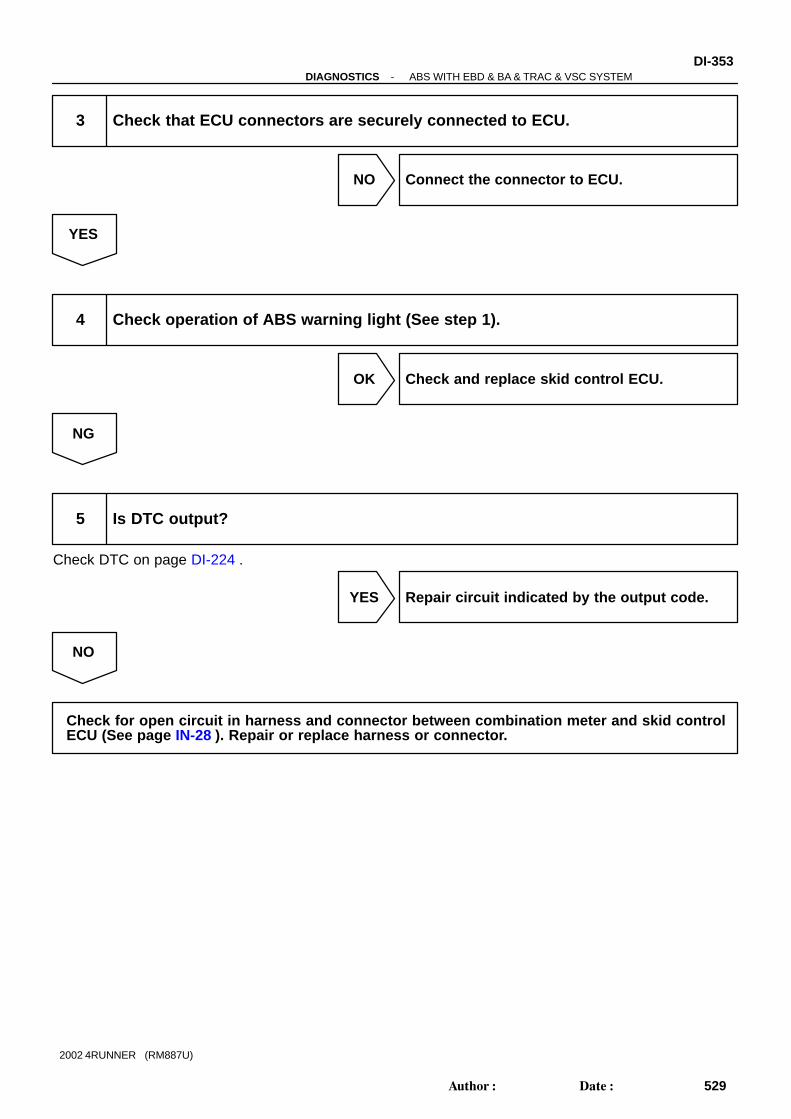
-DIAGNOSTICS ABS WITH EBD & BA & TRAC & VSC SYSTEMDI-353
529Author: Date:
2002 4RUNNER (RM887U)
3 Check that ECU connectors are securely connected to ECU.
NO Connect the connector to ECU.
YES
4 Check operation of ABS warning light (See step 1).
OK Check and replace skid control ECU.
NG
5 Is DTC output?
Check DTC on page DI-224 .
YES Repair circuit indicated by the output code.
NO
Check for open circuit in harness and connector between combination meter and skid controlECU (See page IN-28 ). Repair or replace harness or connector.

F14350
Skid Control ECU
VSCW4
V18V-W
C25C291012
Combination Meter
VSC TRAC
B-Y1F1I
2 8GAUGE
Driver Side J/B
Engine Room R/BI14Ignition Switch
ALTAM1
1IG1
W
Battery
B-Y
AM1 242
2 212
W
DI-354-DIAGNOSTICS ABS WITH EBD & BA & TRAC & VSC SYSTEM
530Author: Date:
2002 4RUNNER (RM887U)
VSC TRAC Warning Light Circuit
CIRCUIT DESCRIPTIONIf the ECU stores DTC, the VSC TRAC warning light lights on the combination meter.
WIRING DIAGRAM
DI6CP-03

-DIAGNOSTICS ABS WITH EBD & BA & TRAC & VSC SYSTEMDI-355
531Author: Date:
2002 4RUNNER (RM887U)
INSPECTION PROCEDUREHINT:Start the inspection from step 1 in case of using the hand-held tester and start from step 2 in case of notusing the hand-held tester.
1 Check operation of VSC TRAC warning indicator.
PREPARATION:(a) Connect the hand-held tester to DLC3.(b) Turn the ignition switch ON and push the hand-held tester main switch ON.(c) Select the ACTIVE TEST mode on the hand-held tester.CHECK:Check that ”ON” and ”OFF” of the VSC TRAC warning light can be shown on the combination meter by thehand-held tester.
OK Check and replace skid control ECU.
NG
2 Is DTC output for VSC?
YES Repair circuit indicated by the output code.
NO
3 Check for open and short circuit in harness and connector between skid controlECU and VSC TRAC warning light (See page IN-28 ).
NG Repair or replace harness or connector.
OK

DI-356-DIAGNOSTICS ABS WITH EBD & BA & TRAC & VSC SYSTEM
532Author: Date:
2002 4RUNNER (RM887U)
4 Check VSC TRAC warning light.
NG Repair or replace combination meter.
OK
Check and replace skid control ECU.

F14362
24CDV18
P-G
3C29
CenterDiff. Lock
Combination Meter
12C29
81F
GAUGE21I
P-G
B-Y
I14Ignition SW
20F7IND2
4WD ECU
VSC OFF
W
Engine Room R/B
J3J/C
CCW-B
W-B
Center J/B
3E3E1816
AW-BJ9
J/C
IF Battery
Driver Side J/B
B-Y
P-G
87
GRF77
DL
C30Center Diff.Lock SW
21212
2W2AM1IG14
C25 L-W6
V18 WT7
Skid Control ECU
AM1 ALT
-DIAGNOSTICS ABS WITH EBD & BA & TRAC & VSC SYSTEMDI-357
533Author: Date:
2002 4RUNNER (RM887U)
4WD:VSC OFF Indicator Light, Center Diff. Lock Switch Circuit
CIRCUIT DESCRIPTIONWhen the center differential is locked, VSC control goes off and the VSC OFF indicator lights up. Also, theVSC OFF indicator light goes on when the VSC system is at the fail safe control.
WIRING DIAGRAM
DI6CR-03

DI-358-DIAGNOSTICS ABS WITH EBD & BA & TRAC & VSC SYSTEM
534Author: Date:
2002 4RUNNER (RM887U)
INSPECTION PROCEDUREHINT:Start the inspection from step 1 in case of using the hand-held tester and start from step 2 in case of notusing the hand-held tester.
1 Check operation of VSC OFF indicator light.
PREPARATION:(a) Connect the hand-held tester to DLC3.(b) Turn the ignition switch ON and push the hand-held tester main switch ON.(c) Select the ACTIVE TEST mode on the hand-held tester.CHECK:Check that ”ON” and ”OFF” of the VSC OFF indicator light can be shown on the combination meter by thehand-held tester.
NG Go to step 4.
OK
2 Check center diff. lock switch (See page TR-1 1).
NG Replace center diff. lock switch.
OK
3 Check for open and short circuit in harness and connector between terminal EXIof skid control ECU and center diff. lock switch and body ground (See page IN-28 ).
NG Repair or replace harness or connector.
OK

-DIAGNOSTICS ABS WITH EBD & BA & TRAC & VSC SYSTEMDI-359
535Author: Date:
2002 4RUNNER (RM887U)
4 Check VSC OFF indicator light.
NG Repair or replace combination meter.
OK
5 Check for open and short circuit in harness and connector between terminal WTof skid control ECU and VSC OFF indicator light (See page IN-28 ).
NG Repair or replace harness or connector.
OK
Check and replace skid control ECU.

F14351
B-Y
1
L-W12 7
W-B
T8TRAC OFF Switch
L
6
WT
CSW
V18
26
C25C29
Skid Control ECUCombination Meter
1F1I
8
Driver Side J/B
GAUGE2B-Y
TRAC OFF
Engine Room R/B
222 1
2
IF
W ALTAM1
I14Ignition Switch
AM1 2IG14
W
V18(2WD)
4
1
W-B
Center J/B
14163E
J9
AJ/C
Battery
3E
DI-360-DIAGNOSTICS ABS WITH EBD & BA & TRAC & VSC SYSTEM
536Author: Date:
2002 4RUNNER (RM887U)
2WD:TRAC OFF Indicator, TRAC OFF Switch Circuit
CIRCUIT DESCRIPTIONThis is the TRAC control main switch. When the TRAC OFF switch is pushed on, TRAC control goes off andthe TRAC OFF indicator light lights up. This indicator blinks for warnings when the trouble occurs and fordisplaying DTC.
WIRING DIAGRAM
DI3JI-04

F00052
14
(+) (-)
3 2
-DIAGNOSTICS ABS WITH EBD & BA & TRAC & VSC SYSTEMDI-361
537Author: Date:
2002 4RUNNER (RM887U)
INSPECTION PROCEDURE
1 Check DTC.
Check DTC on page DI-224 .
YES Repair circuit indicated by the output code.
NO
2 Check TRAC OFF switch.
PREPARATION:(a) Remove the TRAC OFF switch.(b) Disconnect the TRAC OFF switch connector.CHECK:Measure resistance between terminals 1 and 4 of the TRACOFF switch when the TRAC OFF switch is ON and OFF.OK:
TRAC OFF switch Resistance
Pushed in Continuity
Released 1 MΩ or higher
NG Replace TRAC OFF switch.
OK
3 Check for open and short circuit in harness and connector between terminalCSW of skid control ECU and TRAC OFF switch and body ground (See page IN-28 ).
NG Repair or replace combination meter.
OK

DI-362-DIAGNOSTICS ABS WITH EBD & BA & TRAC & VSC SYSTEM
538Author: Date:
2002 4RUNNER (RM887U)
4 Check TRAC OFF indicator light.
See the combination meter troubleshooting on page BE-2 .
NG Repair or replace combination meter.
OK
5 Check for open and short circuit in harness and connector between terminal WTof skid control ECU and TRAC OFF indicator light (See page IN-28 ).
NG Repair or replace harness connector.
OK
Check and replace skid control ECU.

F14350
Skid Control ECU
IND6
V18R-W
C25C29312
Combination Meter
SLIP
B-Y1F1I
2 8GAUGE
Driver Side J/B
Engine Room R/BI14Ignition Switch
ALTAM1
1IG1
W
Battery
B-Y
AM1 242
2 212
W
-DIAGNOSTICS ABS WITH EBD & BA & TRAC & VSC SYSTEMDI-363
539Author: Date:
2002 4RUNNER (RM887U)
SLIP Indicator Light Circuit
CIRCUIT DESCRIPTIONThe SLIP indicator blinks during VSC operation.
WIRING DIAGRAM
DI6CQ-03

DI-364-DIAGNOSTICS ABS WITH EBD & BA & TRAC & VSC SYSTEM
540Author: Date:
2002 4RUNNER (RM887U)
INSPECTION PROCEDURE
1 Check that SLIP indicator light is ON for 3 sec. soon after ignition switch isturned ON.
OK Check and replace skid control ECU.
NG
2 Check SLIP indicator light.
NG Repair or replace combination meter check.
OK
3 Check for open and short circuit in harness and connector between skid controlECU and SLIP indicator light (See page IN-28 ).
NG Repair or replace harness or connector.
OK
Check and replace skid control ECU.

F14358
Skid Control ECU
BRL
PKBV19
V18
5O
C27
C25
4
10
Combination Meter
BRAKE
C29
12
B-Y G-WIG1
23
2 1
B2 Brake Fluid Level Warning Switch
G-W
I14 Ignition Switch
24 IG1 AM1B-Y
1I1F
GAUGE
Driver Side J/B
8 2
W
22
ALT
2 112
Engine Room R/B
AM1W
W-B
EA
9R-W
1P2 Parking Brake Switch
Battery
-DIAGNOSTICS ABS WITH EBD & BA & TRAC & VSC SYSTEMDI-365
541Author: Date:
2002 4RUNNER (RM887U)
BRAKE Warning Light Circuit
CIRCUIT DESCRIPTIONThe BRAKE warning light lights up when the brake fluid is insufficient, the parking brake is applied or theEBD is defective.
WIRING DIAGRAM
INSPECTION PROCEDURE
1 Check parking brake switch circuit (See page BE-45 ).
NG Repair or replace parking brake switch circuit.
OK
DI6C2-03

DI-366-DIAGNOSTICS ABS WITH EBD & BA & TRAC & VSC SYSTEM
542Author: Date:
2002 4RUNNER (RM887U)
2 Check brake fluid level warning switch circuit (See page BE-45 ).
NG Repair or replace brake fluid level warningswitch circuit.
OK
3 Is DTC output for ABS ?
Yes Repair circuit indicated by the output code.
No
4 Check BRAKE warning light.
See the combination meter troubleshooting on page BE-40 .
NG Repair or replace combination meter.
OK
Check and replace skid control ECU.
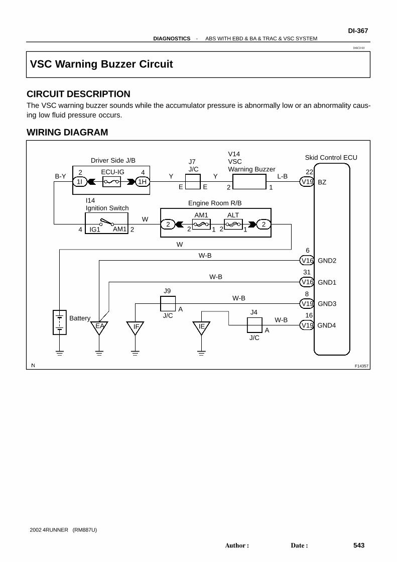
F14357
Skid Control ECUV14VSC Warning Buzzer
BZ
GND2
GND1
GND3
GND4IF
22
V19
6
V16
31
8
V19
16
L-B
12E
J7 J/C
Y41H1I
Driver Side J/B
ECU-IGB-Y
Engine Room R/B
E
Y2
222
211
ALTAM1
2
W
I14Ignition Switch
IG14 AM1
W
V16
V19
W-B
W-B
W-B
W-BJ4
J/CAIE
J9
J/CA
EABattery
-DIAGNOSTICS ABS WITH EBD & BA & TRAC & VSC SYSTEMDI-367
543Author: Date:
2002 4RUNNER (RM887U)
VSC Warning Buzzer Circuit
CIRCUIT DESCRIPTIONThe VSC warning buzzer sounds while the accumulator pressure is abnormally low or an abnormality caus-ing low fluid pressure occurs.
WIRING DIAGRAM
DI6C3-03
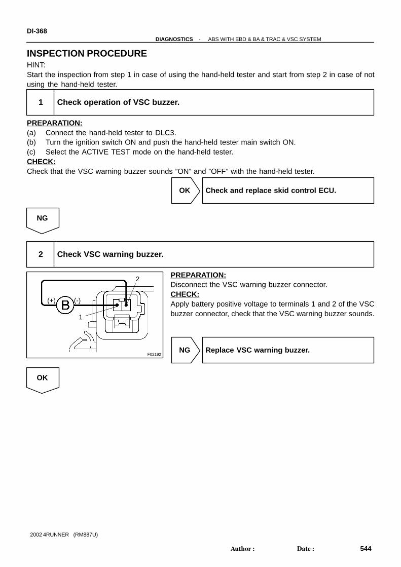
F02192
1
2
(+) (-)
DI-368-DIAGNOSTICS ABS WITH EBD & BA & TRAC & VSC SYSTEM
544Author: Date:
2002 4RUNNER (RM887U)
INSPECTION PROCEDUREHINT:Start the inspection from step 1 in case of using the hand-held tester and start from step 2 in case of notusing the hand-held tester.
1 Check operation of VSC buzzer.
PREPARATION:(a) Connect the hand-held tester to DLC3.(b) Turn the ignition switch ON and push the hand-held tester main switch ON.(c) Select the ACTIVE TEST mode on the hand-held tester.CHECK:Check that the VSC warning buzzer sounds ”ON” and ”OFF” with the hand-held tester.
OK Check and replace skid control ECU.
NG
2 Check VSC warning buzzer.
PREPARATION:Disconnect the VSC warning buzzer connector.CHECK:Apply battery positive voltage to terminals 1 and 2 of the VSCbuzzer connector, check that the VSC warning buzzer sounds.
NG Replace VSC warning buzzer.
OK

-DIAGNOSTICS ABS WITH EBD & BA & TRAC & VSC SYSTEMDI-369
545Author: Date:
2002 4RUNNER (RM887U)
3 Check for open and short circuit in harness and connector between skid controlECU and VSC warning buzzer (See page IN-28 ).
NG Repair or replace harness or connector.
OK
Check and replace skid control ECU.

F14356
TcV19
12
Skid Control ECU
GR
J6 J/C
BII423
11TcE1
DLC1
3
BR
EC
GRGR
B
DI-370-DIAGNOSTICS ABS WITH EBD & BA & TRAC & VSC SYSTEM
546Author: Date:
2002 4RUNNER (RM887U)
Tc Terminal Circuit
CIRCUIT DESCRIPTIONConnecting terminals Tc and E1 of DLC1 causes the ECU to display the DTC by flashing the ABS warninglight and VSC TRAC warning light.
WIRING DIAGRAM
DI6C4-03

AB0119
S08097 F00445
E1
Tc
DLC1ON(-)
(+)
-DIAGNOSTICS ABS WITH EBD & BA & TRAC & VSC SYSTEMDI-371
547Author: Date:
2002 4RUNNER (RM887U)
INSPECTION PROCEDURE
1 Check voltage between terminals Tc and E 1 of DLC1.
CHECK:(a) Turn the ignition switch ON.(b) Measure voltage between terminals Tc and E1 of DLC1.OK:
Voltage: 10 - 14 V
OK If ABS warning light does not blink even after Tcand E1 have been connected, ECU may be de-fective.
NG
2 IG switch OFF, and check for open and short circuit in harness and connectorbetween skid control ECU and DLC1, DLC1 and body ground (See page IN-28 ).
NG Repair or replace harness or connector.
OK
Check and replace skid control ECU.

F14355
3Ts
Skid Control ECU
V19
DLC111
16Ts
17
EC
E1 II4G-RBR G-R
DI-372-DIAGNOSTICS ABS WITH EBD & BA & TRAC & VSC SYSTEM
548Author: Date:
2002 4RUNNER (RM887U)
Ts Terminal Circuit
CIRCUIT DESCRIPTIONThe sensor check circuit detects abnormalities in the speed sensor signal which cannot be detected by theDTC check.Connecting terminals Ts and E1 of DLC1 or Tc starts the check.
WIRING DIAGRAM
DI6C5-03

AB0119S08096
F00446
E1
Ts
DLC1ON
(-)
(+)
-DIAGNOSTICS ABS WITH EBD & BA & TRAC & VSC SYSTEMDI-373
549Author: Date:
2002 4RUNNER (RM887U)
INSPECTION PROCEDURE
1 Check voltage between terminals Ts and E 1 of DLC1.
CHECK:(a) Turn the ignition switch ON.(b) Measure voltage between terminals Ts and E1 of DLC1.OK:
Voltage: 10 - 14 V
OK If ABS warning light does not blink even after Tsand E1 have been connected, ECU may be de-fective.
NG
2 IG switch OFF, and check for open and short circuit in harness and connectorbetween skid control ECU and DLC1, DLC1 and body ground (See page IN-28 ).
NG Repair or replace harness or connector.
OK
Check and replace skid control ECU.

F14324
DI-374-DIAGNOSTICS ABS WITH EBD & BA & TRAC & VSC SYSTEM
550Author: Date:
2002 4RUNNER (RM887U)
Check for Fluid Leakage
Check for fluid leakage from the actuator or the hydraulic lines.
DI6CU-02

DI18J-16
Vehicle Brought to Workshop
Customer Problem Analysis
Warning Light Check
DTC Check
DTC Chart
DI-383
Circuit Inspection
Remains ON
Normal and Malfunction Code
Symptom Simulation
DTC Check
Identification of Problem
Warning Light Check
Confirmation Test
Warning Light ON
Warning Light Remains OFF
END
Normal
Normal
1
2
3
4
7
Repair
8
5
6
Step , : Diagnostic steps permitting the useof the TOYOTA hand-held tester.
3 6
DI-376
DI-377 IN-18
DI-388
DI-377
DI-377
DI-377
-DIAGNOSTICS SUPPLEMENTAL RESTRAINT SYSTEMDI-375
551Author: Date:
2002 4RUNNER (RM887U)
SUPPLEMENTAL RESTRAINT SYSTEMHOW TO PROCEED WITH TROUBLESHOOTING

DI18K-03
Supplemental Restraint System Check Sheet
Date Problem Occurred
Customer’s Name
Registration No.
Registration Year
Frame No.
Odometer Reading
Weather
Temperature
Vehicle Operation
Road Conditions
Details Of Problem
Vehicle Inspection and RepairHistory Prior to Occurrence ofMalfunction (Including Supple-mental Restraint System)
Diagnosis System Inspection
SRS Warning Light Inspection
DTC Inspection
1st Time
2nd Time
1st Time
2nd Time
Inspector’s Name
Fine Cloudy Rainy Snowy Other
Approx.
Starting Idling
Driving [ Constant speed Acceleration DecelerationOther ]
Remains ON Sometimes Lights Up Does Not Light Up
Remains ON Sometimes Lights Up Does Not Light Up
Normal Code Malfunction Code
Normal Code Malfunction Code
[ Code. ]
[ Code. ]
kmMiles
/ /
/ /
/ /
Date Vehicle Brought In
DI-376-DIAGNOSTICS SUPPLEMENTAL RESTRAINT SYSTEM
552Author: Date:
2002 4RUNNER (RM887U)
CUSTOMER PROBLEM ANALYSIS CHECK

W01632
DI58G-01
R13006
DLC1
E1 Tc
-DIAGNOSTICS SUPPLEMENTAL RESTRAINT SYSTEMDI-377
553Author: Date:
2002 4RUNNER (RM887U)
PRE-CHECK1. SRS WARNING LIGHT CHECK(a) Turn the ignition switch to the ACC or ON position and
check that the SRS warning light lights up.(b) Check that the SRS warning light goes out after approx.
6 seconds.HINT: When the ignition switch is at ACC or ON and the SRS
warning light remains ON or flashes, the airbag sensorassembly has detected a malfunction code.
If, after approx. 6 seconds have elapsed, the SRS warn-ing light sometimes lights up or the SRS warning lightlights up even when the ignition switch is OFF, a short inthe SRS warning light circuit can be considered likely.Proceed to ”SRS warning light circuit malfunction” onpage DI-459 , DI-461 .
2. DTC CHECK (Using diagnosis check wire)(a) Present trouble codes:
Output the DTC.(1) Turn the ignition switch to the ACC or ON position
and wait for approx. 20 seconds.(2) Using SST, connect terminals Tc and E1 of the
DLC1.SST 09843-18020
NOTICE:Pay due attention to the terminal connecting position toavoid a malfunction.(b) Past trouble codes:
Output the DTC.(1) Using SST, connect Terminals Tc and E1 of the
DLC1.SST 09843-18020(2) Turn the ignition switch to the ACC or ON position
and wait for approx. 20 seconds.NOTICE:Pay due attention to the terminal connecting position toavoid a malfunction.

AT0716
AB0056 H08231
Normal Code
Code 11 and 31
ON
OFF
0.25
0.25
ON
OFF
0.5 2.5 4.0
0.51.5 Repeat
DTC 11 DTC 31
H07370
DLC1
DLC3
TOYOTA Hand-Held Tester
DI-378-DIAGNOSTICS SUPPLEMENTAL RESTRAINT SYSTEM
554Author: Date:
2002 4RUNNER (RM887U)
(c) Read the DTC.Read the 2-digit DTC as indicated by the number of timesthe SRS warning light blinks. As an example, the blinkingpatterns, normal, 11 and 31 are shown in the illustration.
Normal code indicationThe light will blink 2 times per second.
Malfunction code indication The first blinking output indicates the first digitof a 2-digit DTC. After a 1.5-second pause,the second blinking output will indicate thesecond digit.
If there are 2 or more codes, there will be a 2.5-second pausebetween each code. After all the codes have been output, therewill be a 4.0-second pause and they will all be repeated.HINT: In the event of a number of trouble codes, indication will
start from the smallest numbered code. If a DTC is not output or a DTC is output without terminal
connection, proceed to the Tc terminal circuit inspectionon page DI-465 .
3. DTC CHECK (Using TOYOTA hand-held tester)(a) Hook up the TOYOTA hand-held tester to the DLC1 or
DLC3.(b) Read the DTCs by following the prompts on the tester
screen.HINT:Please refer to the TOYOTA hand-held tester operator’s manu-al for further details.4. DTC CLEARANCE (Not using service wire)When the ignition switch is turned OFF, the diagnostic troublecode is cleared.5. DTC CLEARANCE (Using service wire)(a) Connect the 2 service wires to terminals Tc and AB of
DLC1.(b) Turn the ignition switch to ACC or ON and wait for approx.
6 seconds.

H01461
W01632 H07394
AB
Terminal
Tc
AB
OFF
Body Ground
OFF
ON
OFF
SeveralSeconds
50 msec.
50 msec.
1 second
(± 0.5 sec.)
Tc
Body Ground
1 second
(± 0.5 sec.)
1
2
3
4
5
-DIAGNOSTICS SUPPLEMENTAL RESTRAINT SYSTEMDI-379
555Author: Date:
2002 4RUNNER (RM887U)
(c) Starting with the Tc terminal, ground alternately terminalTc and terminal AB twice each in cycles of 1.0 second.Make sure that the terminals are grounded. Ensure theterminal Tc remains grounded.
HINT:When alternately grounding terminals Tc and AB, releaseground from one terminal and immediately ground the other ter-minal within an interval of 0.2 seconds.If DTCs are not cleared, repeat the above procedure until thecodes are cleared.
(d) Several seconds after doing the clearing procedure, theSRS warning light will blink in a 50 msec. cycle to indicatethe codes which have been cleared.
6. Past trouble codes:DTC CLEARANCE(See step 5.)

DI-380-DIAGNOSTICS SUPPLEMENTAL RESTRAINT SYSTEM
556Author: Date:
2002 4RUNNER (RM887U)
7. RELEASE METHOD OF AIRBAG ACTIVATION PRE-VENTION MECHANISM
An airbag activation prevention mechanism is built into the con-nector for the squib circuit of the SRS.When release of the airbag activation prevention mechanism isdirected in the troubleshooting procedure, as shown in the il-lustrations on the following pages, insert paper which has thesame thickness as the male terminal between the terminal andthe short spring.CAUTION:Never release the airbag activation prevention mechanismunless specifically directed by the troubleshooting proce-dure.NOTICE:If the inserted paper is too thick the terminal and shortspring may be damaged, so always use paper with thesame thickness as the male terminal.

H07353
Airbag SensorAssembly
Front Passenger AirbagAssembly (Squib)
Seat BeltPretensioner (RH)
Seat BeltPretensioner (LH)
Steering Wheel Pad (Squib)
No.1 J/B
Spiral Cable1 7
2
3
5
4
6
8
9
10 11
Front AirbagSensor (RH)
Front AirbagSensor (LH)
12
-DIAGNOSTICS SUPPLEMENTAL RESTRAINT SYSTEMDI-381
557Author: Date:
2002 4RUNNER (RM887U)

H01233
AB0130
AB0045 AB0046
H02248
H09168
H09169
Airbag Sensor Assembly Connector
Before Release
Paper
After Release
Before Release After Release
Connector
Short Spring
Short Spring
Paper
1
7 Connector
Paper
Short Spring
Short Spring Short Spring
2 3
6 89
DI-382-DIAGNOSTICS SUPPLEMENTAL RESTRAINT SYSTEM
558Author: Date:
2002 4RUNNER (RM887U)

DI161-37
-DIAGNOSTICS SUPPLEMENTAL RESTRAINT SYSTEMDI-383
559Author: Date:
2002 4RUNNER (RM887U)
DIAGNOSTIC TROUBLE CODE CHARTIf a malfunction code is displayed during the DTC check, check the circuit listed for that code in the tablebelow (Proceed to the page given for that circuit.).
DTC No.
(See Page)Detection Item Trouble Area
SRS
Warning Light
B0100/13
(DI-388 )
Short in D squib circuit Steering wheel pad (squib)
Spiral cable
Airbag sensor assembly
Wire harness
ON
B0101/14
(DI-393 )
Open in D squib circuit Steering wheel pad (squib)
Spiral cable
Airbag sensor assembly
Wire harness
ON
B0102/11
(DI-397 )
Short in D and P squib circuit
(to ground)
Steering wheel pad (squib)
Front passenger airbag assembly (Squib)
Spiral cable
Airbag sensor assembly
Wire harness
ON
B0103/12
(DI-404 )
Short in D and P squib circuit
(to B+)
Steering wheel pad (squib)
Front passenger airbag assembly (Squib)
Spiral cable
Airbag sensor assembly
Wire harness
ON
B0105/53
(DI-410 )
Short in P squib circuit Front passenger airbag assembly (squib)
Airbag sensor assembly
Wire harness
ON
B0106/54
(DI-414 )
Open in P squib circuit Front passenger airbag assembly (squib)
Airbag sensor assembly
Wire harness
ON
B0130/63
(DI-417 )
Short in P/T squib (RH) circuit Seat belt pretensioner RH (squib)
Airbag sensor assembly
Wire harness
ON
B0131/64
(DI-421 )
Open in P/T squib (RH) circuit Seat belt pretensioner RH (squib)
Airbag sensor assembly
Wire harness
ON
B0132/61
(DI-424 )
Short in LH and RH P/T squib (RH)
circuit (to ground)
Seat belt pretensioners (squib)
Airbag sensor assembly
Wire harness
ON
B0133/62
(DI-429 )
Short in LH and RH P/T squib (RH)
circuit (to B+)
Seat belt pretensioners (squib)
Airbag sensor assembly
Wire harness
ON
B0135/73
(DI-434 )
Short in P/T squib (LH) circuit Seat belt pretensioner LH (squib)
Airbag sensor assembly
Wire harness
ON
B0136/74
(DI-438 )
Open in P/T squib (LH) circuit Seat belt pretensioner LH (squib)
Airbag sensor assembly
Wire harness
ON
B1100/31
(DI-441 )
Airbag sensor assembly malfunction Airbag sensor assemblyON

DI-384-DIAGNOSTICS SUPPLEMENTAL RESTRAINT SYSTEM
560Author: Date:
2002 4RUNNER (RM887U)
DTC No.
(See Page)Detection Item Trouble Area
SRS
Warning Light
B1156/B1157/
15
(DI-443 )
Front airbag sensor assembly (RH)
malfunction
Front airbag sensor assembly (RH)
Wire harness ON
B1158/B1159/
16
(DI-448 )
Front airbag sensor assembly (LH)
malfunction
Front airbag sensor assembly (LH)
Wire harness ON
N lSystem normal - OFF
Normal
(DI-459 )Voltage source drop Battery
Airbag sensor assemblyON
HINT: When the SRS warning light remains lit up and the DTC is the normal code, this means a voltage source
drops.This malfunction is not stored in memory by the airbag sensor assembly and if the power source volt-age returns to normal, the SRS warning light will automatically go out.
When 2 or more codes are indicated, the codes will be displayed in numeral order starting from thelowest numbered code.
If a code not listed on the chart is displayed, the airbag sensor assembly is faulty.
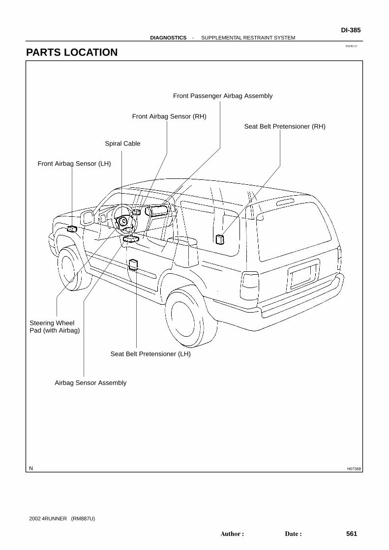
DI1HD-17
H07368
Spiral Cable
Front Passenger Airbag Assembly
Seat Belt Pretensioner (RH)
Seat Belt Pretensioner (LH)
Front Airbag Sensor (RH)
Front Airbag Sensor (LH)
Airbag Sensor Assembly
Steering Wheel Pad (with Airbag)
-DIAGNOSTICS SUPPLEMENTAL RESTRAINT SYSTEMDI-385
561Author: Date:
2002 4RUNNER (RM887U)
PARTS LOCATION

DI1B1-31
H01357
C21C20 C22
28
789101617
18
AB 123456
111215 14 13
A AB B
192021222324252627
123456
789101112
123456
789101112
DI-386-DIAGNOSTICS SUPPLEMENTAL RESTRAINT SYSTEM
562Author: Date:
2002 4RUNNER (RM887U)
TERMINALS OF ECU
No. Symbol Terminal Name
A - Electrical Connector Check Mechanism
B - Electrical Connector Check Mechanism
C20 - 1 PL- Squib (Seat Belt Pretensioner, LH)
C20 - 2 PL+ Squib (Seat Belt Pretensioner, LH)
C20-11 LBE+ Seat Belt Buckle Switch (LH)
C21 - 3 LA SRS Warning Light
C21 - 5 IG2 Power Source (IGN Fuse)
C21 - 6 IG1 Power Source (ECU-IG Fuse)
C21 - 9 +SR Front Airbag Sensor (RH)
C21 - 10 P+ Squib (Passenger)
C21 - 11 P- Squib (Passenger)
C21 - 12 SIL Diagnosis
C21 - 13 D- Squib (Driver)
C21 - 14 D+ Squib (Driver)
C21 - 15 +SL Front Airbag Sensor (LH)
C21 - 19 Tc Diagnosis
C21 - 20 -SR Front Airbag Sensor (RH)
C21 - 26 -SL Front Airbag Sensor (LH)
C21 - 27 E1 Ground
C21 - 28 E2 Ground
C22 - 5 PR+ Squib (Seat Belt Pretensioner, RH)
C22 - 6 PR- Squib (Seat Belt Pretensioner, RH)
C22 - 8 RBE+ Seat Belt Buckle Switch (LH)

DI18P-05
-DIAGNOSTICS SUPPLEMENTAL RESTRAINT SYSTEMDI-387
563Author: Date:
2002 4RUNNER (RM887U)
PROBLEM SYMPTOMS TABLEProceed with troubleshooting of each circuit in the table below.
Symptom Suspect Area See page
With the ignition switch at ACC or ON, the SRS warning light
sometimes lights up after approx. 6 seconds have elapsed. SRS warning light circuitDI 459
SRS warning light is always lit up even when ignition switch is in
the LOCK position.
SRS warning light circuit
(Always lights up when ignition switch is in LOCK position.)DI-459
With the ignition switch at ACC or ON, the SRS warning light does
not light up.
SRS warning light circuit
(Does not light up when ignition switch is turned to ACC or
ON.)
DI-461
DTC is not displayed.
SRS warning light is always lit up in a DTC check procedure. Tc terminal circuit DI-465
DTC is displayed without Tc and E1 terminal connection.
Tc terminal circuit DI 465

DI18Q-35
H01451
A21D Squib (Steering Wheel Pad)
Spiral Cable
Y-B
P-B
Airbag Sensor Assembly
14C21
C2113
D+
D-
1
2
DI-388-DIAGNOSTICS SUPPLEMENTAL RESTRAINT SYSTEM
564Author: Date:
2002 4RUNNER (RM887U)
CIRCUIT INSPECTION
DTC B0100/13 Short in D Squib Circuit
CIRCUIT DESCRIPTIONThe D squib circuit consists of the airbag sensor assembly, spiral cable and steering wheel pad. It causes the airbag to deploy when the airbag deployment conditions are satisfied.For details of the function of each component, see OPERATION on page RS-2 .DTC B0100/13 is recorded when a short is detected in the D squib circuit.
DTC No. DTC Detecting Condition Trouble Area
B0100/13
Short circuit between D+ wire harness and D- wire har-
ness of squib
D squib malfunction
Spiral cable malfunction
Airbag sensor assembly malfunction
Steering wheel pad (D squib)
Spiral cable
Airbag sensor assembly
Wire harness
WIRING DIAGRAM

H01001
H02142 H02193
D Squib
SpiralCable
AirbagSensorAssembly
D+
← →
(-) (+)
D-
-DIAGNOSTICS SUPPLEMENTAL RESTRAINT SYSTEMDI-389
565Author: Date:
2002 4RUNNER (RM887U)
INSPECTION PROCEDURE
1 Prepare for inspection. (See step 1 on page DI-456 )
2 Check D squib circuit.
PREPARATION:Release the airbag activation prevention mechanism of theconnector (on the airbag sensor assembly side) between theairbag sensor assembly and the spiral cable. (See page DI-377 )CHECK:For the connector (on the spiral cable side) between the spiralcable and the steering wheel pad, measure the resistance be-tween D+ and D-.OK:
Resistance: 1 M Ω or Higher
NG Go to step 5.
OK

FI1390
AB0118R13006
AB0119H01002
H07478
D Squib
SpiralCable
AirbagSensorAssembly
E1 Tc
ON
or
DTC B0100/13
→ ←ACC
DLC1
DI-390-DIAGNOSTICS SUPPLEMENTAL RESTRAINT SYSTEM
566Author: Date:
2002 4RUNNER (RM887U)
3 Check airbag sensor assembly.
PREPARATION:(a) Connect the connector to the airbag sensor assembly.(b) Connect negative (-) terminal cable to the battery, and
wait at least for 2 seconds.CHECK:(a) Turn ignition switch to ACC or ON and wait at least for 20
seconds.(b) Clear DTC stored in memory.
(See page DI-377 )(c) Turn ignition switch to LOCK, and wait at least for 20 se-
conds.(d) Turn ignition switch to ACC or ON, and wait at least for 20
seconds.(e) Check DTC.
(See page DI-377 )OK:
DTC B0100/13 is not output.HINT:Codes other than code B0100/13 may be output at this time, butthey are not relevant to this check.
NG Replace airbag sensor assembly.
OK

AB0118R13006
AB0119FI1390
H01003
H01136
D Squib
SpiralCable
AirbagSensorAssembly
E1 Tc
ACC ON
orDTC B0100/13
DLC1
→ ←
-DIAGNOSTICS SUPPLEMENTAL RESTRAINT SYSTEMDI-391
567Author: Date:
2002 4RUNNER (RM887U)
4 Check D squib.
PREPARATION:(a) Turn ignition switch to LOCK.(b) Disconnect negative (-) terminal cable from the battery,
and wait at least for 90 seconds.(c) Connect the steering wheel pad connector.(d) Connect negative (-) terminal cable to the battery, and
wait at least for 2 seconds.CHECK:(a) Turn ignition switch to LOCK, and wait at least for 20 se-
conds.(b) Turn ignition switch to ACC or ON, and wait at least for 20
seconds.(c) Clear DTC stored in memory.
(See page DI-377 )(d) Turn ignition switch to LOCK, and wait at least for 20 se-
conds.(e) Turn ignition switch to ACC or ON, and wait at least for 20
seconds.(f) Check DTC.
(See page DI-377 )OK:
DTC B0100/13 is not output.HINT:Codes other than code B0100/13 may be output at this time, butthey are not relevant to this check.
NG Replace steering wheel pad.
OK
From the results of the above inspection, the malfunctioning part can now be considered normal.To make sure of this, use the simulation method to check.

H01000H02142 H02195
D Squib
SpiralCable
AirbagSensorAssembly
D+
← →
D-
R14286H01004
H01138
D Squib
SpiralCable
AirbagSensorAssembly
D+
← →
(-) (+)
D-
DI-392-DIAGNOSTICS SUPPLEMENTAL RESTRAINT SYSTEM
568Author: Date:
2002 4RUNNER (RM887U)
5 Check spiral cable.
PREPARATION:(a) Disconnect the connector between the airbag sensor as-
sembly and the spiral cable.(b) Release the airbag activation prevention mechanism of
the spiral cable connector on the airbag sensor assemblyside. (See page DI-377 )
CHECK:For the connector (on the spiral cable side) between the spiralcable and the steering wheel pad, measure the resistance be-tween D+ and D-.OK:
Resistance: 1 M Ω or Higher
NG Repair or replace spiral cable.
OK
6 Check harness between airbag sensor assembly and spiral cable.
PREPARATION:Release the airbag activation prevention mechanism of theconnector (on the airbag sensor assembly side) between theairbag sensor assembly and the spiral cable. (See page DI-377 )CHECK:For the connector (on the spiral cable side) between the airbagsensor assembly and the spiral cable, measure the resistancebetween D+ and D-.OK:
Resistance: 1 M Ω or Higher
NG Repair or replace harness or connector be-tween airbag sensor assembly and spiral cable.
OK
From the results of the above inspection, the malfunctioning part can now be considered normal.To make sure of this, use the simulation method to check.

H01001H02142 H02196
D Squib
SpiralCable
AirbagSensorAssembly
D+
← →
(-) (+)
D-
-DIAGNOSTICS SUPPLEMENTAL RESTRAINT SYSTEMDI-393
569Author: Date:
2002 4RUNNER (RM887U)
DTC B0101/14 Open in D Squib Circuit
CIRCUIT DESCRIPTIONThe D squib circuit consists of the airbag sensor assembly, spiral cable and steering wheel pad.It causes the airbag to deploy when the airbag deployment conditions are satisfied.For details of the function of each component, see OPERATION on page RS-2 .DTC B0101/14 is recorded when an open is detected in the D squib circuit.
DTC No. DTC Detecting Condition Trouble Area
B0101/14
Open circuit in D+ wire harness or D- wire harness of
squib
D squib malfunction
Spiral cable malfunction
Airbag sensor assembly malfunction
Steering wheel pad (D squib)
Spiral cable
Airbag sensor assembly
Wire harness
WIRING DIAGRAMSee page DI-388 .
INSPECTION PROCEDURE
1 Prepare for inspection. (See step 1 on page DI-456 )
2 Check D squib circuit.
CHECK:For the connector (on the spiral cable side) between the spiralcable and the steering wheel pad, measure the resistance be-tween D+ and D-.OK:
Resistance: Below 1 Ω
NG Go to step 5.
OK
DI18R-18
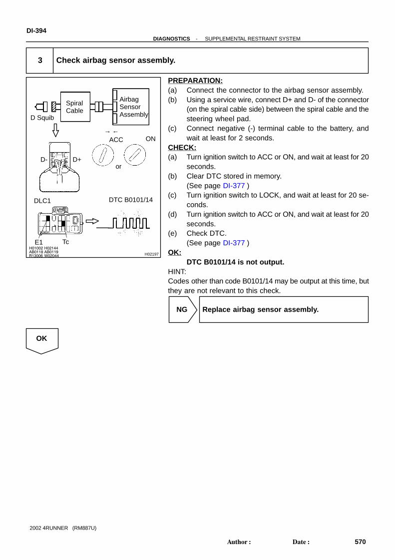
H01002AB0118R13006
H02144AB0119W02044 H02197
D Squib
SpiralCable
AirbagSensorAssembly
Tc
ACC ON
or
DTC B0101/14DLC1
→ ←
D+D-
E1
DI-394-DIAGNOSTICS SUPPLEMENTAL RESTRAINT SYSTEM
570Author: Date:
2002 4RUNNER (RM887U)
3 Check airbag sensor assembly.
PREPARATION:(a) Connect the connector to the airbag sensor assembly.(b) Using a service wire, connect D+ and D- of the connector
(on the spiral cable side) between the spiral cable and thesteering wheel pad.
(c) Connect negative (-) terminal cable to the battery, andwait at least for 2 seconds.
CHECK:(a) Turn ignition switch to ACC or ON, and wait at least for 20
seconds.(b) Clear DTC stored in memory.
(See page DI-377 )(c) Turn ignition switch to LOCK, and wait at least for 20 se-
conds.(d) Turn ignition switch to ACC or ON, and wait at least for 20
seconds.(e) Check DTC.
(See page DI-377 )OK:
DTC B0101/14 is not output.HINT:Codes other than code B0101/14 may be output at this time, butthey are not relevant to this check.
NG Replace airbag sensor assembly.
OK

W02044
H01003AB0118R13006
AB0119H01141
→ ←
D SquibSpiralCable
AirbagSensorAssembly
E1 Tc
ACC ON
or
DTC B0101/14DLC1
-DIAGNOSTICS SUPPLEMENTAL RESTRAINT SYSTEMDI-395
571Author: Date:
2002 4RUNNER (RM887U)
4 Check D squib.
PREPARATION:(a) Turn ignition switch to LOCK.(b) Disconnect negative (-) terminal cable from the battery,
and wait at least for 90 seconds.(c) Connect the steering wheel pad connector.(d) Connect negative (-) terminal cable to the battery, and
wait at least for 2 seconds.CHECK:(a) Turn ignition switch to ACC or ON, and wait at least for 20
seconds.(b) Clear DTC stored in memory.
(See page DI-377 )(c) Turn ignition switch to LOCK, and wait at least for 20 se-
conds.(d) Turn ignition switch to ACC or ON, and wait at least for 20
seconds.(e) Check DTC.
(See page DI-377 )OK:
DTC B0101/14 is not output.HINT:Codes other than code B0101/14 may be output at this time, butthey are not relevant to this check.
NG Replace steering wheel pad.
OK
From the results of the above inspection, the malfunctioning part can now be considered normal.To make sure of this, use the simulation method to check.

H01000H02142 H02195
D Squib
AirbagSensorAssembly
D+
← →
D-
SpiralCable
(-) (+)
H01004
R14286 H01143
D Squib
SpiralCable
AirbagSensorAssembly
D+
(-) (+)
D-
DI-396-DIAGNOSTICS SUPPLEMENTAL RESTRAINT SYSTEM
572Author: Date:
2002 4RUNNER (RM887U)
5 Check spiral cable.
PREPARATION:Disconnect the connector between the airbag sensor assemblyand the spiral cable.CHECK:For the connector (on the spiral cable side) between the spiralcable and the steering wheel pad, measure the resistance be-tween D+ and D-.OK:
Resistance: Below 1 Ω
NG Repair or replace spiral cable.
OK
6 Check harness between airbag sensor assembly and spiral cable.
CHECK:For the connector (on the spiral cable side) between the airbagsensor assembly and the spiral cable, measure the resistancebetween D+ and D-.OK:
Resistance: Below 1 Ω
NG Repair or replace harness or connector be-tween airbag sensor assembly and spiral cable.
OK
From the results of the above inspection, the malfunctioning part can now be considered normal.To make sure of this, use the simulation method to check.

H03605
A21D Squib (Steering Wheel Pad)
Y-G
Y-R
P-B
Y-B
Spiral Cable
Airbag Sensor Assembly
1
2
1
2
14C21
13
10
11
D+
D-
P+
P-
C21
C21
C21
A20P Squib (Front Passenger Airbag Assembly)
-DIAGNOSTICS SUPPLEMENTAL RESTRAINT SYSTEMDI-397
573Author: Date:
2002 4RUNNER (RM887U)
DTC B0102/11 Short in D and P Squib Circuit (to Ground)
CIRCUIT DESCRIPTIONThe D and P squib circuits consist of the airbag sensor assembly, spiral cable, steering wheel pad and frontpassenger airbag assembly. It causes the SRS to deploy when the SRS deployment conditions are satisfied.For details of the function of each component, see OPERATION on page RS-2 .DTC B0102/11 is recorded when ground short is detected in the D and P squib circuits.
DTC No. DTC Detecting Condition Trouble Area
B0102/11
Short circuit in D squib wire harness (to ground)
Short circuit in P squib wire harness (to ground)
D squib malfunction
P squib malfunction
Spiral cable malfunction
Airbag sensor assembly malfunction
Steering wheel pad (D squib)
Front passenger airbag assembly (P squib)
Spiral cable
Airbag sensor assembly
Wire harness
WIRING DIAGRAM
DI58K-02

H03099
H02145 H03019
D Squib
SpiralCable
AirbagSensorAssembly
D+
(-) (+)
DI-398-DIAGNOSTICS SUPPLEMENTAL RESTRAINT SYSTEM
574Author: Date:
2002 4RUNNER (RM887U)
INSPECTION PROCEDURE
1 Prepare for inspection. (See step 1 on page DI-456 )
2 Check D squib circuit.
CHECK:For the connector (on the spiral cable side) between the spiralcable and steering wheel pad, measure the resistance betweenD+ and body ground.OK:
Resistance: 1 M Ω or Higher
NG Go to step 7.
OK

H03100
H02145
H03101
P Squib
SpiralCable
AirbagSensorAssembly
P+
(-) (+)
-DIAGNOSTICS SUPPLEMENTAL RESTRAINT SYSTEMDI-399
575Author: Date:
2002 4RUNNER (RM887U)
3 Check P squib circuit.
CHECK:For the connector (on the front passenger airbag assemblyside) between the front passenger airbag assembly and airbagsensor assembly, measure the resistance between P+ andbody ground.OK:
Resistance: 1 M Ω or Higher
NG Repair or replace harness or connector be-tween front passenger airbag assembly and air-bag sensor assembly.
OK

H03103 H02144
AB0118R13006
AB0118W02042
H02144
H03102
D SquibSpiralCable
AirbagSensorAssembly
D+
E1
D-
Tc
ACC ON
or
DTC B0102/11DLC1
P Squib
P+P-
DI-400-DIAGNOSTICS SUPPLEMENTAL RESTRAINT SYSTEM
576Author: Date:
2002 4RUNNER (RM887U)
4 Check airbag sensor assembly.
PREPARATION:(a) Connect the connector to the airbag sensor assembly.(b) Using a service wire, connect D+ and D- of the connector
(on the spiral cable side) between the spiral cable andsteering wheel pad.
(c) Using a service wire, connect P+ and P- of the connector(on the front passenger airbag assembly side) betweenthe front passenger airbag assembly and airbag sensorassembly.
(d) Connect negative (-) terminal cable to the battery, andwait at least for 2 seconds.
CHECK:(a) Turn ignition switch to ACC or ON and wait at least 20 se-
conds.(b) Clear DTC stored in memory.
(See step 5 on page DI-377 )(c) Turn ignition switch to LOCK, and wait at least 20 se-
conds.(d) Turn ignition switch to ACC or ON, and wait at least 20 se-
conds.(e) Check DTC.
(See page DI-377 )OK:
DTC B0102/11 is not output.HINT:Codes other than DTC B0102/11 may be output at this time, butthey are not relevant to this check.
NG Replace airbag sensor assembly.
OK

H03104AB0118R13006
AB0119W02042 H03105
D Squib
SpiralCable
AirbagSensorAssembly
E1Tc
ACC ON
DTC B0102/11DLC1
or
-DIAGNOSTICS SUPPLEMENTAL RESTRAINT SYSTEMDI-401
577Author: Date:
2002 4RUNNER (RM887U)
5 Check D squib.
PREPARATION:(a) Turn ignition switch to LOCK.(b) Disconnect negative (-) terminal cable from the battery,
and wait at least for 90 seconds.(c) Connect the steering wheel pad connector.(d) Connect negative (-) terminal cable to the battery, and
wait at least for 2 seconds.CHECK:(a) Turn ignition switch to ACC or ON, and wait at least for 20
seconds.(b) Clear DTC stored in memory.
(See step 5 on page DI-377 )(c) Turn ignition switch to LOCK, and wait at least for 20 se-
conds.(d) Turn ignition switch to ACC or ON, and wait at least for 20
seconds.(e) Check DTC.
(See page DI-377 )OK:
DTC B0102/11 is not output.HINT:Codes other than DTC B0102/11 may be output at this time, butthey are not relevant to this check.
NG Replace steering wheel pad.
OK

H03106AB0118R13006
AB0119W02042 H03107
P Squib
SpiralCable
AirbagSensorAssembly
E1 Tc
ACC ON
or
→ ←
DTC B0102/11DLC1
DI-402-DIAGNOSTICS SUPPLEMENTAL RESTRAINT SYSTEM
578Author: Date:
2002 4RUNNER (RM887U)
6 Check P squib.
PREPARATION:(a) Turn ignition switch to LOCK.(b) Disconnect negative (-) terminal cable from the battery,
and wait at least for 90 seconds.(c) Connect the front passenger airbag assembly connector.(d) Connect negative (-) terminal cable to the battery, and
wait at least for 2 seconds.CHECK:(a) Turn ignition switch to ACC or ON, and wait at least for 20
seconds.(b) Clear DTC stored in memory.
(See step 5 on page DI-377 )(c) Turn ignition switch to LOCK, and wait at least for 20 se-
conds.(d) Turn ignition switch to ACC or ON, and wait at least for 20
seconds.(e) Check DTC.
(See page DI-377 )OK:
DTC B0102/11 is not output.HINT:Codes other than DTC B0102/11 may be output at this time, butthey are not relevant to this check.
NG Replace front passenger airbag assembly.
OK
From the results of the above inspection, the malfunctioning part can now be considered normal.To make sure of this, use the simulation method to check. If the malfunctioning part can not bedetected by the simulation method, replace all SRS components including the wire harness.

H02145
H01000H03021
D Squib
SpiralCable
AirbagSensorAssembly
D+
← →
(-) (+)
R14301H01004
H06304
D Squib
SpiralCable
AirbagSensorAssembly
D+
(-) (+)
-DIAGNOSTICS SUPPLEMENTAL RESTRAINT SYSTEMDI-403
579Author: Date:
2002 4RUNNER (RM887U)
7 Check spiral cable.
PREPARATION:Disconnect the connector between the airbag sensor assemblyand spiral cable.CHECK:For the connector (on the spiral cable side) between the steer-ing wheel pad and spiral cable, measure the resistance be-tween D+ and body ground.OK:
Resistance: 1 M Ω or Higher
NG Repair or replace spiral cable.
OK
8 Check harness between airbag sensor assembly and spiral cable.
CHECK:For the connector (on the spiral cable side) between the spiralcable and airbag sensor assembly, measure the resistance be-tween D+ and body ground.OK:
Resistance: 1 M Ω or Higher
NG Repair or replace harness between airbag sen-sor assembly and spiral cable.
OK
From the results of the above inspection, the malfunctioning part can now be considered normal.To make sure of this, use the simulation method to check. If the malfunctioning part can not bedetected by the simulation method, replace all SRS components including the wire harness.
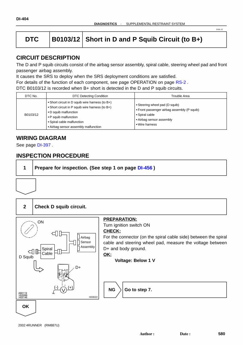
H03099H02146
AB0119
H03022
D Squib
SpiralCable
AirbagSensorAssembly
D+
(-) (+)
ON
DI-404-DIAGNOSTICS SUPPLEMENTAL RESTRAINT SYSTEM
580Author: Date:
2002 4RUNNER (RM887U)
DTC B0103/12 Short in D and P Squib Circuit (to B+)
CIRCUIT DESCRIPTIONThe D and P squib circuits consist of the airbag sensor assembly, spiral cable, steering wheel pad and frontpassenger airbag assembly. It causes the SRS to deploy when the SRS deployment conditions are satisfied.For details of the function of each component, see page OPERATION on page RS-2 .DTC B0103/12 is recorded when B+ short is detected in the D and P squib circuits.
DTC No. DTC Detecting Condition Trouble Area
B0103/12
Short circuit in D squib wire harness (to B+)
Short circuit in P squib wire harness (to B+)
D squib malfunction
P squib malfunction
Spiral cable malfunction
Airbag sensor assembly malfunction
Steering wheel pad (D squib)
Front passenger airbag assembly (P squib)
Spiral cable
Airbag sensor assembly
Wire harness
WIRING DIAGRAMSee page DI-397 .
INSPECTION PROCEDURE
1 Prepare for inspection. (See step 1 on page DI-456 )
2 Check D squib circuit.
PREPARATION:Turn ignition switch ONCHECK:For the connector (on the spiral cable side) between the spiralcable and steering wheel pad, measure the voltage betweenD+ and body ground.OK:
Voltage: Below 1 V
NG Go to step 7.
OK
DI58L-02
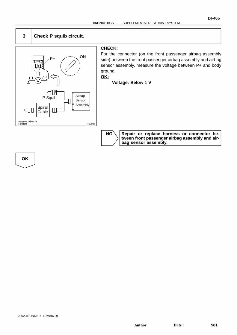
H03100H02146 AB0119
H03035
P Squib
SpiralCable
AirbagSensorAssembly
P+
(-) (+)
ON
-DIAGNOSTICS SUPPLEMENTAL RESTRAINT SYSTEMDI-405
581Author: Date:
2002 4RUNNER (RM887U)
3 Check P squib circuit.
CHECK:For the connector (on the front passenger airbag assemblyside) between the front passenger airbag assembly and airbagsensor assembly, measure the voltage between P+ and bodyground.OK:
Voltage: Below 1 V
NG Repair or replace harness or connector be-tween front passenger airbag assembly and air-bag sensor assembly.
OK

H02144
AB0118
R13006
AB0119
W02043
H03103H02144
H03023
D SquibSpiralCable
AirbagSensorAssembly
D+
E1
D-
Tc
ACC ON
or
DTC B0103/12DLC1
P Squib
P+P-
DI-406-DIAGNOSTICS SUPPLEMENTAL RESTRAINT SYSTEM
582Author: Date:
2002 4RUNNER (RM887U)
4 Check airbag sensor assembly.
PREPARATION:(a) Connect the connector to the airbag sensor assembly.(b) Using a service wire, connect D+ and D- of the connector
(on the spiral cable side) between the spiral cable andsteering wheel pad.
(c) Using a service wire, connect P+ and P- of the connector(on the front passenger airbag assembly side) betweenthe front passenger airbag assembly and airbag sensor.
(d) Connect negative (-) terminal cable to the battery, andwait at least for 2 seconds.
CHECK:(a) Turn ignition switch to ACC or ON and wait at least for 20
seconds.(b) Clear DTC stored in memory.
(See step 5 on page DI-377 )(c) Turn ignition switch to LOCK, and wait at least for 20 se-
conds.(d) Turn ignition switch to ACC or ON, and wait at least for 20
seconds.(e) Check DTC.
(See page DI-377 )OK:
DTC B0103/12 is not output.HINT:Codes other than DTC B0103/12 may be output at this time, butthey are not relevant to this check.
NG Replace airbag sensor assembly.
OK

R13006AB0118 AB0019
W02043
H03104
H03108
SpiralCable
E1 Tc
ACC ON
or
AirbagSensorAssembly
D Squib
DTC B0103/12DLC1
-DIAGNOSTICS SUPPLEMENTAL RESTRAINT SYSTEMDI-407
583Author: Date:
2002 4RUNNER (RM887U)
5 Check D squib.
PREPARATION:(a) Turn ignition switch to LOCK.(b) Disconnect negative (-) terminal cable from the battery,
and wait at least for 90 seconds.(c) Connect the steering wheel pad connector.(d) Connect negative (-) terminal cable to the battery, and
wait at least for 2 seconds.CHECK:(a) Turn ignition switch to ACC or ON, and wait at least for 20
seconds.(b) Clear DTC stored in memory.
(See step 5 on page DI-377 )(c) Turn ignition switch to LOCK, and wait at least for 20 se-
conds.(d) Turn ignition switch to ACC or ON, and wait at least for 20
seconds.(e) Check DTC.
(See page DI-377 )OK:
DTC B0103/12 is not output.HINT:Codes other than DTC B0103/12 may be output at this time, butthey are not relevant to this check.
NG Replace steering wheel pad.
OK

R13006AB0118 AB0019
W02043
H03106
H03109
SpiralCable
E1 Tc
ACC ON
or
AirbagSensorAssembly
P Squib
DTC B0103/12DLC1
DI-408-DIAGNOSTICS SUPPLEMENTAL RESTRAINT SYSTEM
584Author: Date:
2002 4RUNNER (RM887U)
6 Check P squib.
PREPARATION:(a) Turn ignition switch to LOCK.(b) Disconnect negative (-) terminal cable from the battery,
and wait at least for 90 seconds.(c) Connect the front passenger airbag connector.(d) Connect negative (-) terminal cable to the battery, and
wait at least for 2 seconds.CHECK:(a) Turn ignition switch to ACC or ON, and wait at least for 20
seconds.(b) Clear DTC stored in memory.
(See step 5 on page DI-377 )(c) Turn ignition switch to LOCK, and wait at least for 20 se-
conds.(d) Turn ignition switch to ACC or ON, and wait at least for 20
seconds.(e) Check DTC.
(See page DI-377 )OK:
DTC B0103/12 is not output.HINT:Codes other than DTC B0103/12 may be output at this time, butthey are not relevant to this check.
NG Replace front passenger airbag assembly.
OK
From the results of the above inspection, the malfunctioning part can now be considered normal.To make sure of this, use the simulation method to check. If the malfunctioning part can not bedetected by the simulation method, replace all SRS components including the wire harness.

H02146R14288
H01000
H03024
D Squib
SpiralCable
AirbagSensorAssembly
D+
← →
(-) (+)
ON
H01004R14288
AB0119
H08261
D Squib
SpiralCable
AirbagSensorAssembly
D+
(-) (+)
ON
-DIAGNOSTICS SUPPLEMENTAL RESTRAINT SYSTEMDI-409
585Author: Date:
2002 4RUNNER (RM887U)
7 Check spiral cable.
PREPARATION:(a) Turn ignition switch to LOCK.(b) Disconnect the connector between the airbag sensor as-
sembly and spiral cable.CHECK:(a) Turn ignition switch to ON.(b) For the connector (on the spiral cable side) between the
spiral cable and steering wheel pad, measure the voltagebetween D+ and body ground.
OK:Voltage: Below 1 V
NG Repair or replace spiral cable.
OK
8 Check spiral cable.
CHECK:(a) Turn ignition switch to ON.(b) For the connector (on the spiral cable side) between the
spiral cable and airbag sensor assembly, measure thevoltage between D+ and body ground.
OK:Voltage: 0 V
NG Repair or replace harness between airbag sen-sor assembly and spiral cable.
OK
From the results of the above inspection, the malfunctioning part can now be considered normal.To make sure of this, use the simulation method to check. If the malfunctioning part can not bedetected by the simulation method, replace all SRS components including the wire harness.

H01454
A20P Squib (Front Passenger Airbag Assembly)
10
Airbag Sensor Assembly
2
Y-RC21
Y-G
1
11
P+
P-C21
DI-410-DIAGNOSTICS SUPPLEMENTAL RESTRAINT SYSTEM
586Author: Date:
2002 4RUNNER (RM887U)
DTC B0105/53 Short in P Squib Circuit
CIRCUIT DESCRIPTIONThe P squib circuit consists of the airbag sensor assembly and front passenger airbag assembly.It causes the SRS to deploy when the SRS deployment conditions are satisfied.For details of the function of each component, see OPERATION on page RS-2 .DTC B0105/53 is recorded when a short is detected in the P squib circuit.
DTC No. DTC Detecting Condition Trouble Area
B0105/53
Short circuit in P squib wire harness
P squib malfunction
Airbag sensor assembly malfunction
Front passenger airbag assembly (P squib)
Airbag sensor assembly
Wire harness
WIRING DIAGRAM
DI1B6-36
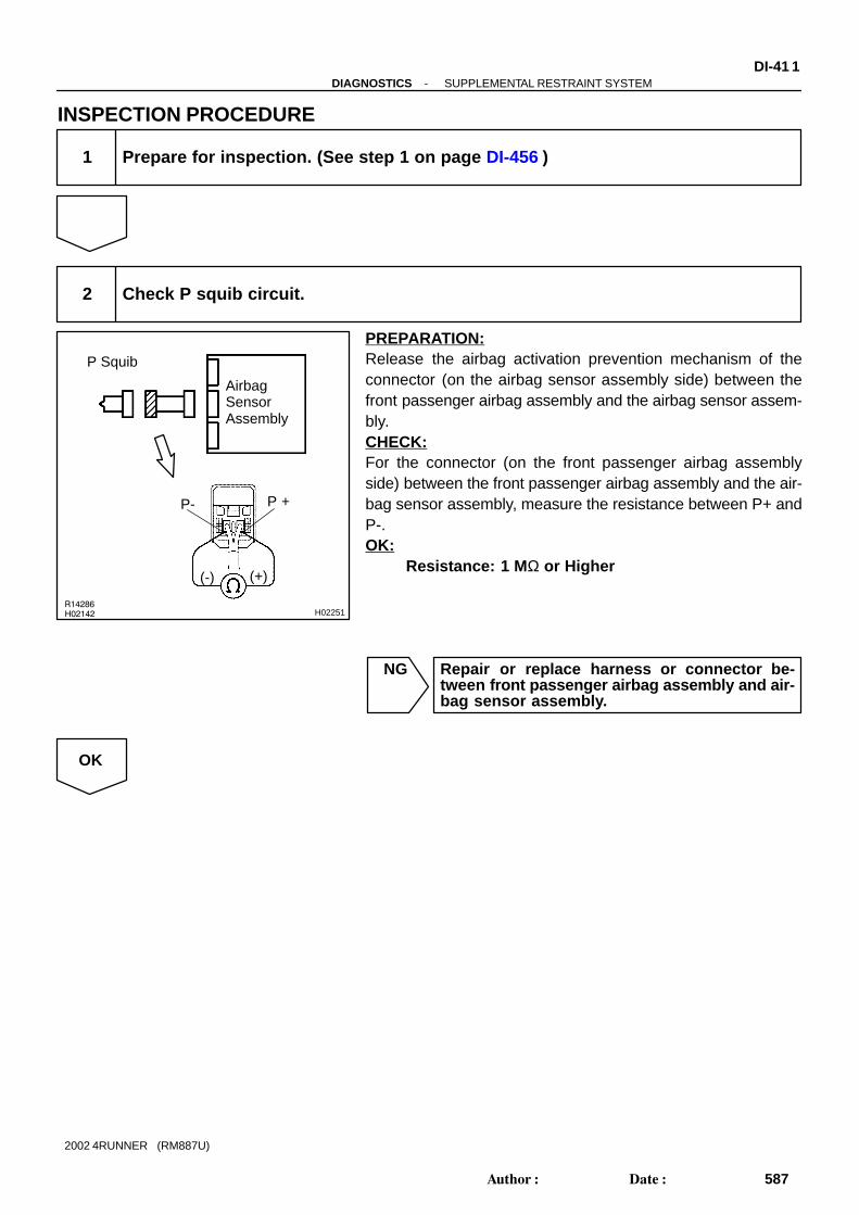
R14286
H02142 H02251
P Squib
AirbagSensorAssembly
P +P-
(-) (+)
-DIAGNOSTICS SUPPLEMENTAL RESTRAINT SYSTEMDI-41 1
587Author: Date:
2002 4RUNNER (RM887U)
INSPECTION PROCEDURE
1 Prepare for inspection. (See step 1 on page DI-456 )
2 Check P squib circuit.
PREPARATION:Release the airbag activation prevention mechanism of theconnector (on the airbag sensor assembly side) between thefront passenger airbag assembly and the airbag sensor assem-bly.CHECK:For the connector (on the front passenger airbag assemblyside) between the front passenger airbag assembly and the air-bag sensor assembly, measure the resistance between P+ andP-.OK:
Resistance: 1 M Ω or Higher
NG Repair or replace harness or connector be-tween front passenger airbag assembly and air-bag sensor assembly.
OK

H01023
AB0118 AB0119
R13006 H01077 H07479
P Squib
AirbagSensorAssembly
ACC
or
DTC B0105/53DLC1
E1 Tc
ON
→ ←
DI-412-DIAGNOSTICS SUPPLEMENTAL RESTRAINT SYSTEM
588Author: Date:
2002 4RUNNER (RM887U)
3 Check airbag sensor assembly.
PREPARATION:(a) Connect the connector to the airbag sensor assembly.(b) Connect negative (-) terminal cable to the battery, and
wait at least for 2 seconds.CHECK:(a) Turn ignition switch to ACC or ON and wait at least for 20
seconds.(b) Clear DTC stored in memory.
(See page DI-377 )(c) Turn ignition switch to LOCK, and wait at least for 20 se-
conds.(d) Turn ignition switch to ACC or ON, and wait at least for 20
seconds.(e) Check DTC.
(See page DI-377 )OK:
DTC B0105/53 is not output.HINT:Codes other than code B0105/53 may be output at this time, butthey are not relevant to this check.
NG Replace airbag sensor assembly.
OK

H01024
AB0118 AB0119
R13006 H01077 H01202
→ ←
E1 Tc
ACC ON
or
DTC B0105/53DLC1
AirbagSensorAssembly
P Squib
-DIAGNOSTICS SUPPLEMENTAL RESTRAINT SYSTEMDI-413
589Author: Date:
2002 4RUNNER (RM887U)
4 Check P squib.
PREPARATION:(a) Turn ignition switch to LOCK.(b) Disconnect negative (-) terminal cable from the battery,
and wait at least for 90 seconds.(c) Connect the front passenger airbag assembly connector.(d) Connect negative (-) terminal cable to the battery, and
wait at least for 2 seconds.CHECK:(a) Turn ignition switch to LOOK, and wait at least for 20 se-
conds.(b) Turn ignition switch to ACC or ON, and wait at least for 20
seconds.(c) Clear DTC stored in memory.
(See page DI-377 )(d) Turn ignition switch to LOCK, and wait at least for 20 se-
conds.(e) Turn ignition switch to ACC or ON, and wait at least for 20
seconds.(f) Check DTC.
(See page DI-377 )OK:
DTC B0105/53 is not output.HINT:Codes other than code B0105/53 may be output at this time, butthey are not relevant to this check.
NG Replace front passenger airbag assembly.
OK
From the results of the above inspection, the malfunctioning part can now be considered normal.To make sure of this, use the simulation method to check.
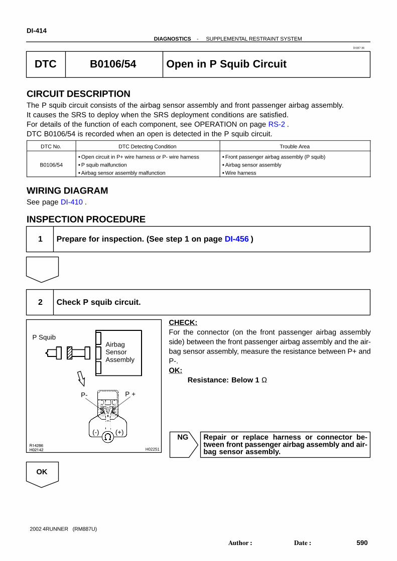
R14286H02142 H02251
P SquibAirbagSensorAssembly
P +P-
(-) (+)
DI-414-DIAGNOSTICS SUPPLEMENTAL RESTRAINT SYSTEM
590Author: Date:
2002 4RUNNER (RM887U)
DTC B0106/54 Open in P Squib Circuit
CIRCUIT DESCRIPTIONThe P squib circuit consists of the airbag sensor assembly and front passenger airbag assembly.It causes the SRS to deploy when the SRS deployment conditions are satisfied.For details of the function of each component, see OPERATION on page RS-2 .DTC B0106/54 is recorded when an open is detected in the P squib circuit.
DTC No. DTC Detecting Condition Trouble Area
B0106/54
Open circuit in P+ wire harness or P- wire harness
P squib malfunction
Airbag sensor assembly malfunction
Front passenger airbag assembly (P squib)
Airbag sensor assembly
Wire harness
WIRING DIAGRAMSee page DI-410 .
INSPECTION PROCEDURE
1 Prepare for inspection. (See step 1 on page DI-456 )
2 Check P squib circuit.
CHECK:For the connector (on the front passenger airbag assemblyside) between the front passenger airbag assembly and the air-bag sensor assembly, measure the resistance between P+ andP-.OK:
Resistance: Below 1 Ω
NG Repair or replace harness or connector be-tween front passenger airbag assembly and air-bag sensor assembly.
OK
DI1B7-36

H01023
AB0118 AB0119
R13006 H01078
H02144
H02253
P SquibAirbagSensorAssembly
P +P-ACC
or
DTC B0106/54DLC1
ON
→ ←
E1 Tc
-DIAGNOSTICS SUPPLEMENTAL RESTRAINT SYSTEMDI-415
591Author: Date:
2002 4RUNNER (RM887U)
3 Check airbag sensor assembly.
PREPARATION:(a) Connect the connector to the airbag sensor assembly.(b) Using a service wire, connect P+ and P- of the connector
(on the front passenger airbag assembly side) betweenthe front passenger airbag assembly and the airbag sen-sor assembly.
(c) Connect negative (-) terminal cable to the battery, andwait at least for 2 seconds.
CHECK:(a) Turn ignition switch to ACC or ON and wait at least for 20
seconds.(b) Clear DTC stored in memory.
(See page DI-377 )(c) Turn ignition switch to LOCK, and wait at least for 20 se-
conds.(d) Turn ignition switch to ACC or ON, and wait at least for 20
seconds.(e) Check DTC.
(See page DI-377 )OK:
DTC B0106/54 is not output.HINT:Codes other than code B0106/54 may be output at this time, butthey are not relevant to this check.
NG Replace airbag sensor assembly.
OK

H01024AB0118 AB0119R13006 H01078 H01205
→ ←
E1 Tc
ACC ON
or
DTC B0106/54DLC1
AirbagSensorAssembly
P Squib
DI-416-DIAGNOSTICS SUPPLEMENTAL RESTRAINT SYSTEM
592Author: Date:
2002 4RUNNER (RM887U)
4 Check P squib.
PREPARATION:(a) Turn ignition switch to LOCK.(b) Disconnect negative (-) terminal cable from the battery,
and wait at least for 90 seconds.(c) Connect the front passenger airbag assembly connector.(d) Connect negative (-) terminal cable to the battery, and
wait at least for 2 seconds.CHECK:(a) Turn ignition switch to ACC or ON, and wait at least for 20
seconds.(b) Clear DTC stored in memory.
(See page DI-377 )(c) Turn ignition switch to LOCK, and wait at least for 20 se-
conds.(d) Turn ignition switch to ACC or ON, and wait at least for 20
seconds.(e) Check DTC.
(See page DI-377 )OK:
DTC B0106/54 is not output.HINT:Codes other than code B0106/54 may be output at this time, butthey are not relevant to this check.
NG Replace front passenger airbag assembly.
OK
From the results of the above inspection, the malfunctioning part can now be considered normal.To make sure of this, use the simulation method to check.

H01454
P28P/T Squib (RH)
Airbag Sensor Assembly
PR+
PR-
1
2 6
5C22
Y-B
YC22
-DIAGNOSTICS SUPPLEMENTAL RESTRAINT SYSTEMDI-417
593Author: Date:
2002 4RUNNER (RM887U)
DTC B0130/63 Short in P/T Squib (RH) Circuit
CIRCUIT DESCRIPTIONThe P/T squib (RH) circuit consists of the airbag sensor assembly and seat belt pretensioner (RH).It causes the seat belt pretensioner (RH) to activate when the seat belt pretensioner (RH) activation condi-tions are satisfied.For details of the function of each component, see OPERATION on page RS-2 .DTC B0130/63 is recorded when a short is detected in the P/T squib (RH) circuit.
DTC No. DTC Detecting Condition Trouble Area
B0130/63
Short circuit between PR+ wire harness and PR- wire
harness of squib
P/T squib (RH) malfunction
Airbag sensor assembly malfunction
Seat belt pretensioner (RH)
Airbag sensor assembly
Wire harness
WIRING DIAGRAM
DI16S-43

H01019H02141 H02203
P/T Squib (RH)AirbagSensorAssembly
PR+ PR-
(-)(+)
DI-418-DIAGNOSTICS SUPPLEMENTAL RESTRAINT SYSTEM
594Author: Date:
2002 4RUNNER (RM887U)
INSPECTION PROCEDURE
1 Prepare for inspection. (See step 1 on page DI-456 )
2 Check P/T squib (RH) circuit.
PREPARATION:Release the airbag activation prevention mechanism of theconnector (on the airbag sensor assembly side) between theairbag sensor assembly and the seat belt pretensioner (RH).(See page DI-377 )CHECK:For the connector (on the seat belt pretensioner side) betweenthe seat belt pretensioner (RH) and the airbag sensor assem-bly, measure the resistance between PR+ and PR-.OK:
Resistance: 1 M Ω or Higher
NG Repair or replace harness or connector be-tween seat belt pretensioner (RH) and airbagsensor assembly.
OK

H01020
AB0118 AB0119R13006 H01082 H07485
P/T Squib (RH)AirbagSensorAssembly
ACC
or
DTC B0130/63
ON
→ ←
E1Tc
DLC1
-DIAGNOSTICS SUPPLEMENTAL RESTRAINT SYSTEMDI-419
595Author: Date:
2002 4RUNNER (RM887U)
3 Check airbag sensor assembly.
PREPARATION:(a) Connect the connector to the airbag sensor assembly.(b) Connect negative (-) terminal cable to the battery, and
wait at least for 2 seconds.CHECK:(a) Turn ignition switch to ACC or ON and wait at least for 20
seconds.(b) Clear DTC stored in memory.
(See page DI-377 )(c) Turn ignition switch to LOCK, and wait at least for 20 se-
conds.(d) Turn ignition switch to ACC or ON, and wait at least for 20
seconds.(e) Check DTC.
(See page DI-377 )OK:
DTC B0130/63 is not output.HINT:Codes other than code B0130/63 may be output at this time, butthey are not relevant to this check.
NG Replace airbag sensor assembly.
OK

H01021AB0118 AB0119R13006 H01082 H01214
→ ←
E1 Tc
ACC ON
or
AirbagSensorAssembly
P/T Squib (RH)
DTC B0130/63DLC1
DI-420-DIAGNOSTICS SUPPLEMENTAL RESTRAINT SYSTEM
596Author: Date:
2002 4RUNNER (RM887U)
4 Check P/T squib (RH).
PREPARATION:(a) Turn ignition switch to LOCK.(b) Disconnect negative (-) terminal cable from the battery,
and wait at least for 90 seconds.(c) Connect the seat belt pretensioner (RH) connector.(d) Connect negative (-) terminal cable to the battery, and
wait at least for 2 seconds.CHECK:(a) Turn ignition switch to LOOK, and wait at least for 20 se-
cond.(b) Turn ignition switch to ACC or ON, and wait at least for 20
seconds.(c) Clear DTC stored in memory.
(See page DI-377 )(d) Turn ignition switch to LOCK, and wait at least for 20 se-
conds.(e) Turn ignition switch to ACC or ON, and wait at least for 20
seconds.(f) Check DTC.
(See page DI-377 )OK:
DTC B0130/63 is not output.HINT:Codes other than code B0130/63 may be output at this time, butthey are not relevant to this check.
NG Replace seat belt pretensioner (RH).
OK
From the results of the above inspection, the malfunctioning part can now be considered normal.To make sure of this, use the simulation method to check.

H01019H02141 H02205
P/T Squib (RH)AirbagSensorAssembly
PR-
(+) (-)
PR+
-DIAGNOSTICS SUPPLEMENTAL RESTRAINT SYSTEMDI-421
597Author: Date:
2002 4RUNNER (RM887U)
DTC B0131/64 Open in P/T Squib (RH) Circuit
CIRCUIT DESCRIPTIONThe P/T squib circuit (RH) consists of the airbag sensor assembly and seat belt pretensioner (RH).It causes the seat belt pretensioner (RH) to activate when the seat belt pretensioner (RH) activation condi-tions are satisfied.For details of the function of each component, see OPERATION on page RS-2 .DTC B0131/64 is recorded when an open is detected in the P/T squib (RH) circuit.
DTC No. DTC Detecting Condition Trouble Area
B0131/64
Open circuit in PR+ wire harness or PR- wire harness of
squib
P/T squib (RH) malfunction
Airbag sensor assembly malfunction
Seat belt pretensioner (RH)
Airbag sensor assembly
Wire harness
WIRING DIAGRAMSee page DI-417 .
INSPECTION PROCEDURE
1 Prepare for inspection. (See step 1 on page DI-456 )
2 Check P/T squib (RH) circuit.
CHECK:For the connector (on the seat belt pretensioner side) betweenthe seat belt pretensioner (RH) and the airbag sensor assem-bly, measure the resistance between PR+ and PR-.OK:
Resistance: Below 1 Ω
NG Repair or replace harness or connector be-tween seat belt pretensioner (RH) and airbagsensor assembly.
OK
DI1BG-34

H01020H02139AB0118 AB0119R13006 H01083 H02206
P/T Squib (RH)AirbagSensorAssembly
PR+ PR-ACC
or
DTC B0131/64
→ ←
E1Tc
ON
DLC1
DI-422-DIAGNOSTICS SUPPLEMENTAL RESTRAINT SYSTEM
598Author: Date:
2002 4RUNNER (RM887U)
3 Check airbag sensor assembly.
PREPARATION:(a) Connect the connector to the airbag sensor assembly.(b) Using a service wire, connect PR+ and PR- of the con-
nector (on the seat belt pretensioner side) between theseat belt pretensioner (RH) and the airbag sensor assem-bly.
(c) Connect negative (-) terminal cable to the battery, andwait at least for 2 seconds.
CHECK:(a) Turn ignition switch to ACC or ON and wait at least for 20
seconds.(b) Clear DTC stored in memory.
(See page DI-377 )(c) Turn ignition switch to LOCK, and wait at least for 20 se-
conds.(d) Turn ignition switch to ACC or ON, and wait at least for 20
seconds.(e) Check DTC.
(See page DI-377 )OK:
DTC B0131/64 is not output.HINT:Codes other than code B0131/64 may be output at this time, butthey are not relevant to this check.
NG Replace airbag sensor assembly.
OK

AB0118R13006
AB0119H01021
H01083 H01217
→ ←
E1 Tc
ACC ON
or
AirbagSensorAssembly
P/T Squib (RH)
DTC B0131/64DLC1
-DIAGNOSTICS SUPPLEMENTAL RESTRAINT SYSTEMDI-423
599Author: Date:
2002 4RUNNER (RM887U)
4 Check P/T squib (RH).
PREPARATION:(a) Turn ignition switch to LOCK.(b) Disconnect negative (-) terminal cable from the battery,
and wait at least for 90 seconds.(c) Connect the seat belt pretensioner (RH) connector.(d) Connect negative (-) terminal cable to the battery, and
wait at least for 2 seconds.CHECK:(a) Turn ignition switch to ACC or ON, and wait at least for 20
seconds.(b) Clear DTC stored in memory.
(See page DI-377 )(c) Turn ignition switch to LOCK, and wait at least for 20 se-
conds.(d) Turn ignition switch to ACC or ON, and wait at least for 20
seconds.(e) Check DTC.
(See page DI-377 )OK:
DTC B0131/64 is not output.HINT:Codes other than code B0131/64 may be output at this time, butthey are not relevant to this check.
NG Replace seat belt pretensioner (RH).
OK
From the results of the above inspection, the malfunctioning part can now be considered normal.To make sure of this, use the simulation method to check.

H03606
P27P/T Squib (LH)
1
2
Y-B
Y
C202
1C20
PL+
PL-
C225
PR+
6PR-
P28P/T Squib (RH)
Airbag Sensor Assembly
Y-B
Y
1
2 C22
DI-424-DIAGNOSTICS SUPPLEMENTAL RESTRAINT SYSTEM
600Author: Date:
2002 4RUNNER (RM887U)
DTC B0132/61 Short in LH and RH P/T Squib Circuit (to Ground)
CIRCUIT DESCRIPTIONThe LH and RH P/T squib circuits consist of the airbag sensor assembly and LH and RH seat belt pretension-ers.It causes the pretensioner to activate when the pretensioner activation conditions are satisfied.For details of the function of each component, see OPERATION on page RS-2 .DTC B0132/61 is recorded when a ground short is detected in the LH and RH P/T squib circuits.
DTC No. DTC Detecting Condition Trouble Area
B0132/61
Short circuit in P/T squib (LH) wire harness (to ground)
Short circuit in P/T squib (RH) wire harness (to ground)
P/T squib (RH) malfunction
P/T squib (LH) malfunction
Airbag sensor assembly malfunction
Seat belt pretensioner (LH)
Seat belt pretensioner (RH)
Airbag sensor assembly
Wire harness
WIRING DIAGRAM
DI58N-02
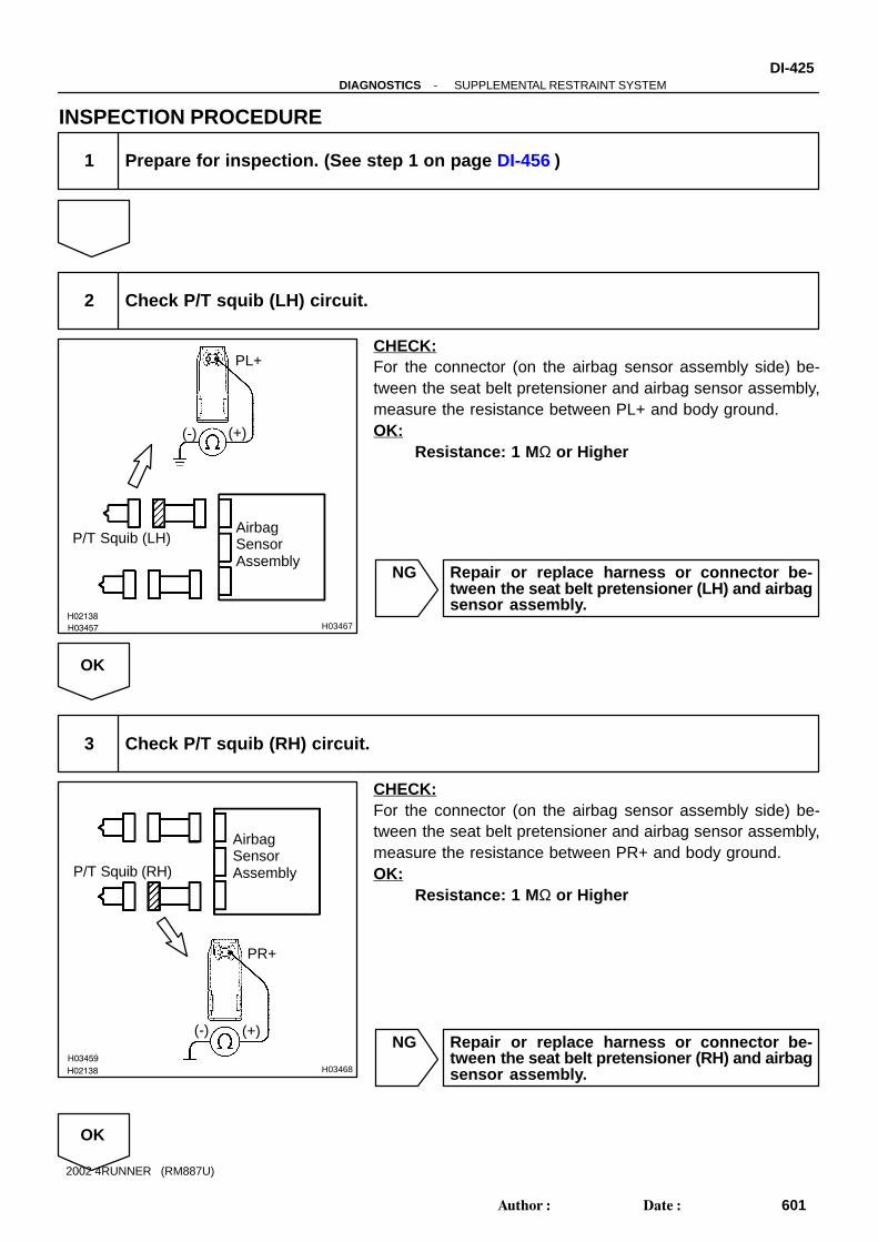
H03457
H02138
H03467
P/T Squib (LH)AirbagSensorAssembly
PL+
(+)(-)
H03459
H02138 H03468
P/T Squib (RH)
AirbagSensorAssembly
PR+
(+)(-)
-DIAGNOSTICS SUPPLEMENTAL RESTRAINT SYSTEMDI-425
601Author: Date:
2002 4RUNNER (RM887U)
INSPECTION PROCEDURE
1 Prepare for inspection. (See step 1 on page DI-456 )
2 Check P/T squib (LH) circuit.
CHECK:For the connector (on the airbag sensor assembly side) be-tween the seat belt pretensioner and airbag sensor assembly,measure the resistance between PL+ and body ground.OK:
Resistance: 1 M Ω or Higher
NG Repair or replace harness or connector be-tween the seat belt pretensioner (LH) and airbagsensor assembly.
OK
3 Check P/T squib (RH) circuit.
CHECK:For the connector (on the airbag sensor assembly side) be-tween the seat belt pretensioner and airbag sensor assembly,measure the resistance between PR+ and body ground.OK:
Resistance: 1 M Ω or Higher
NG Repair or replace harness or connector be-tween the seat belt pretensioner (RH) and airbagsensor assembly.
OK

AB0118R13006
AB0119H02139H03461
H02139
H01079 H03469
P/T Squib (RH)
AirbagSensorAssembly
PR+PR-
ACC
or
DTC B0132/61
ON
→ ←
E1 Tc
DLC1
→ ←P/T Squib (LH)
PL+PL-
DI-426-DIAGNOSTICS SUPPLEMENTAL RESTRAINT SYSTEM
602Author: Date:
2002 4RUNNER (RM887U)
4 Check airbag sensor assembly.
PREPARATION:(a) Connect the connectors to the airbag sensor assembly.(b) Using a service wire, connect PL+ and PL- of the connec-
tor (on the seat belt pretensioner side) between the seatbelt pretensioner (LH) and airbag sensor assembly.
(c) Using a service wire, connect PR+ and PR- of the con-nector (on the seat belt pretensioner side) between theseat belt pretensioner (RH) and airbag sensor assembly.
(d) Connect negative (-) terminal cable to the battery, andwait at least for 2 seconds.
CHECK:(a) Turn ignition switch to ACC or ON and wait at least for 20
seconds.(b) Clear DTC stored in memory.
(See step 5 on page DI-377 )(c) Turn ignition switch to LOCK, and wait at least for 20 se-
conds.(d) Turn ignition switch to ACC or ON, and wait at least for 20
seconds.(e) Check DTC.
(See page DI-377 )OK:
DTC B0132/61 is not output.HINT:Codes other than DTC B0132/61 may be output at this time, butthey are not relevant to this check.
NG Replace airbag sensor assembly.
OK

AB0118 AB0119R13006
H03463
H01079 H03470
→ ←
E1 Tc
ACC ON
or
AirbagSensorAssembly
P/T Squib (LH)
DTC B0132/61DLC1
-DIAGNOSTICS SUPPLEMENTAL RESTRAINT SYSTEMDI-427
603Author: Date:
2002 4RUNNER (RM887U)
5 Check P/T squib (LH).
PREPARATION:(a) Turn ignition switch to LOCK.(b) Disconnect negative (-) terminal cable from the battery,
and wait at least for 90 seconds.(c) Connect the seat belt pretensioner (LH) connector.(d) Connect negative (-) terminal cable to the battery, and
wait at least for 2 seconds.CHECK:(a) Turn ignition switch to ACC or ON, and wait at least for 20
seconds.(b) Clear DTC stored in memory.
(See step 5 on page DI-377 )(c) Turn ignition switch to LOCK, and wait at least for 20 se-
conds.(d) Turn ignition switch to ACC or ON, and wait at least for 20
seconds.(e) Check DTC. (See page DI-377 )OK:
DTC B0132/61 is not output.HINT:Codes other than DTC B0132/61 may be output at this time, butthey are not relevant to this check.
NG Replace seat belt pretensioner (LH).
OK

AB0118 AB0119R13006
H03465
H01079 H03471
→ ←
E1 Tc
ACC ON
or
AirbagSensorAssembly
P/T Squib (RH)
DTC B0132/61DLC1
DI-428-DIAGNOSTICS SUPPLEMENTAL RESTRAINT SYSTEM
604Author: Date:
2002 4RUNNER (RM887U)
6 Check P/T squib (LH).
PREPARATION:(a) Turn ignition switch to LOCK.(b) Disconnect negative (-) terminal cable from the battery,
and wait at least for 90 seconds.(c) Connect the seat belt pretensioner (RH) connector.(d) Connect negative (-) terminal cable to the battery, and
wait at least for 2 seconds.CHECK:(a) Turn ignition switch to ACC or ON, and wait at least for 20
seconds.(b) Clear DTC stored in memory.
(See step 5 on page DI-377 )(c) Turn ignition switch to LOCK, and wait at least for 20 se-
conds.(d) Turn ignition switch to ACC or ON, and wait at least for 20
seconds.(e) Check DTC. (See page DI-377 )OK:
DTC B0132/61 is not output.HINT:Codes other than DTC B0132/61 may be output at this time, butthey are not relevant to this check.
NG Replace seat belt pretensioner (RH).
OK
From the results of the above inspection, the malfunctioning part can now be considered normal.To make sure of this, use the simulation method to check. If the malfunctioning part can not bedetected by the simulation method, replace all SRS components including the wire harness.

-DIAGNOSTICS SUPPLEMENTAL RESTRAINT SYSTEMDI-429
605Author: Date:
2002 4RUNNER (RM887U)
DTC B0133/62 Short in LH and RH P/T Squib Circuits(to B+)
CIRCUIT DESCRIPTIONThe LH and RH P/T squib circuits consist of the airbag sensor assembly and LH and RH seat belt pretension-ers.It causes the pretensioner to activate when the pretensioner activation conditions are satisfied.For details of the function of each component, see OPERATION on page RS-2 .DTC B0133/62 is recorded when B+ is detected in the LH and RH P/T squib circuits.
DTC No. DTC Detecting Condition Trouble Area
B0133/62
Short circuit in seat belt pretensioner (LH) wire harness
(to B+)
Short circuit in seat belt pretensioner (RH) wire harness
(to B+)
P/T squib (LH) malfunction
P/T squib (RH) malfunction
Airbag sensor assembly malfunction
Seat belt pretensioner (LH)
Seat belt pretensioner (RH)
Airbag sensor assembly
Wire harness
WIRING DIAGRAMSee page DI-424 .
INSPECTION PROCEDURE
1 Prepare for inspection. (See step 1 on page DI-456 )
DI58O-01

H03457H02137AB0119
H03458
P/T Squib (LH)AirbagSensorAssembly
PL+ON
(-) (+)
H03459H02137
AB0119
H03460
P/T Squib (RH)
PR+
AirbagSensorAssembly
ON
(-) (+)
DI-430-DIAGNOSTICS SUPPLEMENTAL RESTRAINT SYSTEM
606Author: Date:
2002 4RUNNER (RM887U)
2 Check P/T squib (LH) circuit.
PREPARATION:Turn ignition switch ON.CHECK:For the connector (on the airbag sensor assembly side) be-tween the seat belt pretensioner (LH) and airbag sensor as-sembly, measure the voltage between PL+ and body ground.OK:
Voltage: Below 1 V
NG Repair or replace harness or connector be-tween the seat belt pretensioner (RH) and airbagsensor assembly.
OK
3 Check P/T squib (RH) circuit.
PREPARATION:Turn ignition switch ON.CHECK:For the connector (on the airbag sensor assembly side) be-tween the seat belt pretensioner (RH) and airbag sensor as-sembly, measure the voltage between PR+ and body ground.OK:
Voltage: Below 1 V
NG Repair or replace harness or connector be-tween the seat belt pretensioner (RH) and airbagsensor assembly.
OK

AB0118R13006
AB0119H02139
H01081
H03461
H02139
H03462
P/T Squib (RH)
AirbagSensorAssembly
PR+PR-
ACC
or
DTC B0133/62
ON
E1 Tc
DLC1
P/T Squib (LH)
PL+PL-
-DIAGNOSTICS SUPPLEMENTAL RESTRAINT SYSTEMDI-431
607Author: Date:
2002 4RUNNER (RM887U)
4 Check airbag sensor assembly.
PREPARATION:(a) Connect the connector to the airbag sensor assembly.(b) Using a service wire, connect PL+ and PL- of the connec-
tor (on the pretensioner side) between the seat belt pre-tensioner (LH) and airbag sensor assembly.
(c) Using a service wire, connect PR+ and PR- of the con-nector (on the pretensioner side) between the seat beltpretensioner (RH) and airbag sensor assembly.
(d) Connect negative (-) terminal cable to the battery, andwait at least for 2 seconds.
CHECK:(a) Turn ignition switch to ACC or ON and wait at least for 20
seconds.(b) Clear DTC stored in memory.
(See step 5 on page DI-377 )(c) Turn ignition switch to LOCK, and wait at least for 20 se-
conds.(d) Turn ignition switch to ACC or ON, and wait at least for 20
seconds.(e) Check DTC.
(See page DI-377 )OK:
DTC B0133/62 is not output.HINT:Codes other than DTC B0133/62 may be output at this time, butthey are not relevant to this check.
NG Replace airbag sensor assembly.
OK
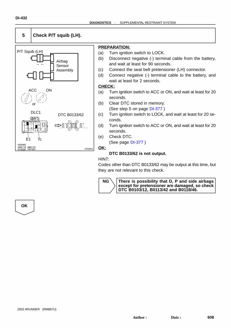
AB0118 AB0119R13006 H01081
H03463
H03464
→ ←
E1 Tc
ACC ON
or
AirbagSensorAssembly
P/T Squib (LH)
DTC B0133/62DLC1
DI-432-DIAGNOSTICS SUPPLEMENTAL RESTRAINT SYSTEM
608Author: Date:
2002 4RUNNER (RM887U)
5 Check P/T squib (LH).
PREPARATION:(a) Turn ignition switch to LOCK.(b) Disconnect negative (-) terminal cable from the battery,
and wait at least for 90 seconds.(c) Connect the seat belt pretensioner (LH) connector.(d) Connect negative (-) terminal cable to the battery, and
wait at least for 2 seconds.CHECK:(a) Turn ignition switch to ACC or ON, and wait at least for 20
seconds.(b) Clear DTC stored in memory.
(See step 5 on page DI-377 )(c) Turn ignition switch to LOCK, and wait at least for 20 se-
conds.(d) Turn ignition switch to ACC or ON, and wait at least for 20
seconds.(e) Check DTC.
(See page DI-377 )OK:
DTC B0133/62 is not output.HINT:Codes other than DTC B0133/62 may be output at this time, butthey are not relevant to this check.
NG There is possibility that D, P and side airbagsexcept for pretensioner are damaged, so checkDTC B0103/12, B0113/42 and B0118/46.
OK

AB0118 AB0119R13006 H01081
H03465
H03466
→ ←
E1 Tc
ACC ON
or
AirbagSensorAssembly
P/T Squib (RH)
DTC B0133/62DLC1
-DIAGNOSTICS SUPPLEMENTAL RESTRAINT SYSTEMDI-433
609Author: Date:
2002 4RUNNER (RM887U)
6 Check P/T squib (RH).
PREPARATION:(a) Turn ignition switch to LOCK.(b) Disconnect negative (-) terminal cable from the battery,
and wait at least for 90 seconds.(c) Connect the seat belt pretensioner (RH) connector.(d) Connect negative (-) terminal cable to the battery, and
wait at least for 2 seconds.CHECK:(a) Turn ignition switch to ACC or ON, and wait at least for 20
seconds.(b) Clear DTC stored in memory.
(See step 5 on page DI-377 )(c) Turn ignition switch to LOCK, and wait at least for 20 se-
conds.(d) Turn ignition switch to ACC or ON, and wait at least for 20
seconds.(e) Check DTC.
(See page DI-377 )OK:
DTC B0133/62 is not output.HINT:Codes other than DTC B0133/62 may be output at this time, butthey are not relevant to this check.
NG There is possibility that D, P and side airbagsexcept for pretensioner are damaged, so checkDTC B0103/12, B0113/42 and B0118/46.
OK
From the results of the above inspection, the malfunctioning part can now be considered normal.To make sure of this, use the simulation method to check. If the malfunctioning part can not bedetected by the simulation method, replace all SRS components including the wire harness.

H01454
P27P/T Squib (LH)
PL+
PL-
1
2 1
2C20
C20
Y-B
Y
Airbag Sensor Assembly
DI-434-DIAGNOSTICS SUPPLEMENTAL RESTRAINT SYSTEM
610Author: Date:
2002 4RUNNER (RM887U)
DTC B0135/73 Short in P/T Squib (LH) Circuit
CIRCUIT DESCRIPTIONThe P/T squib (LH) circuit consists of the airbag sensor assembly and seat belt pretensioner (LH).It causes the seat belt pretensioner (LH) to activate when the seat belt pretensioner (LH) activation condi-tions are satisfied.For details of the function of each component, see OPERATION on page RS-2 .DTC B0135/73 is recorded when a short is detected in the P/T squib (LH) circuit.
DTC No. DTC Detecting Condition Trouble Area
B0135/73
Short circuit between PL+ wire harness and PL- wire har-
ness of squib
P/T squib (LH) malfunction
Airbag sensor assembly malfunction
Seat belt pretensioner (LH)
Airbag sensor assembly
Wire harness
WIRING DIAGRAM
DI16W-44

H01016H02141 H02211
P/T Squib (LH)AirbagSensorAssembly
PL+ PL-
(+) (-)
-DIAGNOSTICS SUPPLEMENTAL RESTRAINT SYSTEMDI-435
611Author: Date:
2002 4RUNNER (RM887U)
INSPECTION PROCEDURE
1 Prepare for inspection. (See step 1 on page DI-456 )
2 Check P/T squib (LH) circuit.
PREPARATION:Release the airbag activation prevention mechanism of theconnector (on the airbag sensor assembly side) between theairbag sensor assembly and the seat belt pretensioner (LH).(See page DI-377 )CHECK:For the connector (on the seat belt pretensioner side) betweenthe seat belt pretensioner (LH) and the airbag sensor assembly,measure the resistance between PL+ and PL-.OK:
Resistance: 1 M Ω or Higher
NG Repair or replace harness or connector be-tween seat belt pretensioner (LH) and airbagsensor assembly.
OK

H01017
AB0118 AB0119R13006 H01086 H07487
P/T Squib (LH)
AirbagSensorAssembly
ACC
or
DTC B0135/73
ON
E1 Tc
→ ←
DLC1
DI-436-DIAGNOSTICS SUPPLEMENTAL RESTRAINT SYSTEM
612Author: Date:
2002 4RUNNER (RM887U)
3 Check airbag sensor assembly.
PREPARATION:(a) Connect the connector to the airbag sensor assembly.(b) Connect negative (-) terminal cable to the battery, and
wait at least for 2 seconds.CHECK:(a) Turn ignition switch to ACC or ON and wait at least for 20
seconds.(b) Clear DTC stored in memory.
(See page DI-377 )(c) Turn ignition switch to LOCK, and wait at least for 20 se-
conds.(d) Turn ignition switch to ACC or ON, and wait at least for 20
seconds.(e) Check DTC.
(See page DI-377 )OK:
DTC B0135/73 is not output.HINT:Codes other than code B0135/73 may be output at this time, butthey are not relevant to this check.
NG Replace airbag sensor assembly.
OK

H01018
AB0118 AB0119
R13006 H01086 H01229
→ ←
E1 Tc
ACC ON
or
AirbagSensorAssembly
P/T Squib (LH)
DTC B0135/73DLC1
-DIAGNOSTICS SUPPLEMENTAL RESTRAINT SYSTEMDI-437
613Author: Date:
2002 4RUNNER (RM887U)
4 Check P/T squib (LH).
PREPARATION:(a) Turn ignition switch to LOCK.(b) Disconnect negative (-) terminal cable from the battery,
and wait at least for 90 seconds.(c) Connect the seat belt pretensioner (LH) connector.(d) Connect negative (-) terminal cable to the battery, and
wait at least for 2 seconds.CHECK:(a) Turn ignition switch to LOOK, and wait at least for 20 se-
cond.(b) Turn ignition switch to ACC or ON, and wait at least for 20
seconds.(c) Clear DTC stored in memory.
(See page DI-377 )(d) Turn ignition switch to LOCK, and wait at least for 20 se-
conds.(e) Turn ignition switch to ACC or ON, and wait at least for 20
seconds.(f) Check DTC.
(See page DI-377 )OK:
DTC B0135/73 is not output.HINT:Codes other than code B0135/73 may be output at this time, butthey are not relevant to this check.
NG Replace seat belt pretensioner (LH).
OK
From the results of the above inspection, the malfunctioning part can now be considered normal.To make sure of this, use the simulation method to check.

H01016H02141 H02213
P/T Squib (LH)AirbagSensorAssembly
PL+ PL-
(+) (-)
DI-438-DIAGNOSTICS SUPPLEMENTAL RESTRAINT SYSTEM
614Author: Date:
2002 4RUNNER (RM887U)
DTC B0136/74 Open in P/T Squib (LH) Circuit
CIRCUIT DESCRIPTIONThe P/T squib circuit (LH) consists of the airbag sensor assembly and seat belt pretensioner (LH).It causes the seat belt pretensioner (LH) to activate when the seat belt pretensioner (LH) activation condi-tions are satisfied.For details of the function of each component, see OPERATION on page RS-2 .DTC B0136/74 is recorded when an open is detected in the P/T squib (LH) circuit.
DTC No. DTC Detecting Condition Trouble Area
B0136/74
Open circuit in PL+ wire harness or PL- wire harness of
squib
P/T squib (LH) malfunction
Airbag sensor assembly malfunction
Seat belt pretensioner (LH)
Airbag sensor assembly
Wire harness
WIRING DIAGRAMSee page DI-434 .
INSPECTION PROCEDURE
1 Prepare for inspection. (See step 1 on page DI-456 )
2 Check P/T squib (LH) circuit.
CHECK:For the connector (on the seat belt pretensioner side) betweenthe seat belt pretensioner (LH) and the airbag sensor assembly,measure the resistance between PL+ and PL-.OK:
Resistance: Below 1 Ω
NG Repair or replace harness or connector be-tween seat belt pretensioner (LH) and airbagsensor assembly.
OK
DI1BJ-16

H01017H02139AB0118 AB0119R13006 H01087 H02214
P/T Squib (LH)
AirbagSensorAssembly
PL+ PL- ACC
or
DTC B0136/74
ON
E1 Tc
DLC1
-DIAGNOSTICS SUPPLEMENTAL RESTRAINT SYSTEMDI-439
615Author: Date:
2002 4RUNNER (RM887U)
3 Check airbag sensor assembly.
PREPARATION:(a) Connect the connector to the airbag sensor assembly.(b) Using a service wire, connect PL+ and PL- of the connec-
tor (on the seat belt pretensioner side) between the seatbelt pretensioner (LH) and the airbag sensor assembly.
(c) Connect negative (-) terminal cable to the battery, andwait at least for 2 seconds.
CHECK:(a) Turn ignition switch to ACC or ON and wait at least for 20
seconds.(b) Clear DTC stored in memory.
(See page DI-377 )(c) Turn ignition switch to LOCK, and wait at least for 20 se-
conds.(d) Turn ignition switch to ACC or ON, and wait at least for 20
seconds.(e) Check DTC.
(See page DI-377 )OK:
DTC B0136/74 is not output.HINT:Codes other than code B0136/74 may be output at this time, butthey are not relevant to this check.
NG Replace airbag sensor assembly.
OK

AB0118R13006
AB0119
H01018
H01087 H01232
→ ←
E1 Tc
ACC ON
or
AirbagSensorAssembly
P/T Squib (LH)
DTC B0136/74DLC1
DI-440-DIAGNOSTICS SUPPLEMENTAL RESTRAINT SYSTEM
616Author: Date:
2002 4RUNNER (RM887U)
4 Check P/T squib (LH).
PREPARATION:(a) Turn ignition switch to LOCK.(b) Disconnect negative (-) terminal cable from the battery,
and wait at least for 90 seconds.(c) Connect the seat belt pretensioner (LH) connector.(d) Connect negative (-) terminal cable to the battery, and
wait at least for 2 seconds.CHECK:(a) Turn ignition switch to ACC or ON, and wait at least for 20
seconds.(b) Clear DTC stored in memory.
(See page DI-377 )(c) Turn ignition switch to LOCK, and wait at least for 20 se-
conds.(d) Turn ignition switch to ACC or ON, and wait at least for 20
seconds.(e) Check DTC.
(See page DI-377 )OK:
DTC B0136/74 is not output.HINT:Codes other than code B0136/74 may be output at this time, butthey are not relevant to this check.
NG Replace seat belt pretensioner (LH).
OK
From the results of the above inspection, the malfunctioning part can now be considered normal.To make sure of this, use the simulation method to check.

AB0119
H01298 H01299
(-) (+)
ONAirbag Sensor Assembly
ACC IG2
-DIAGNOSTICS SUPPLEMENTAL RESTRAINT SYSTEMDI-441
617Author: Date:
2002 4RUNNER (RM887U)
DTC B1100/31 Airbag Sensor Assembly Malfunction
CIRCUIT DESCRIPTIONThe airbag sensor assembly consists of a airbag sensor, safing sensor, drive circuit, diagnosis circuit andignition control, etc.It receives signals from the airbag sensor, judges whether or not the SRS must be activated, and detectsdiagnosis system malfunction.DTC B1100/31 is recorded when occurrence of a malfunction in the airbag sensor assembly is detected.
DTC No. DTC Detecting Condition Trouble Area
B1100/31 Airbag sensor assembly malfunction Airbag sensor assembly
INSPECTION PROCEDUREHINT:When a malfunction code other than code B1100/31 is displayed at the same time, first repair the malfunctionindicated by the malfunction code other than code B1100/31.
1 Prepare for inspection. (See step 1 on page DI-456 )
2 Check voltage at IG2 and ACC of airbag sensor assembly.
CHECK:(a) Turn ignition switch to ON.(b) Measure the voltage between body ground and each of
terminals IG2 and ACC of the airbag sensor assemblyconnector.
OK:Voltage: Below 10 - 14 V
NG Check that an abnormality occurs on the batteryand charging system.
OK
DI1BM-21

AB0118R13006
AB0119FI1394 H00022
ACC ON
or
DLC1
E1 Tc
DTC B1100/31
DI-442-DIAGNOSTICS SUPPLEMENTAL RESTRAINT SYSTEM
618Author: Date:
2002 4RUNNER (RM887U)
3 Is DTC B1100/31 output again?
PREPARATION:Clear DTC.(See step 5 on page DI-377 )CHECK:(a) Turn ignition switch to LOCK, and wait at least for 20 se-
conds.(b) Turn ignition switch to ACC or ON, and wait at least for 20
seconds.(c) Repeat operation in step (a) and (b) at least 5 times.(d) Check DTC.
(See page DI-377 )HINT:Codes other than code B1100/31 may be output at this time, butthey are not relevant to this check.
NO Using simulation method, reproduce malfunc-tion symptoms. (See page IN-18 )
YES
Replace airbag sensor assembly.

H02751
Airbag Sensor AssemblyA29Front Airbag Sensor (RH)
+SR
-SR
C21
C21
9
20
B-W
2
1
+SR
-SRBR-W
-DIAGNOSTICS SUPPLEMENTAL RESTRAINT SYSTEMDI-443
619Author: Date:
2002 4RUNNER (RM887U)
DTC B1156/B1157/15 Front Airbag Sensor (RH) Malfunction
CIRCUIT DESCRIPTIONThe front airbag sensor (RH) circuit consists of the airbag sensor assembly and front airbag sensor (RH).For details of the function of each component, see OPERATION on page RS-2 .DTC B1156/B1157/15 is recorded when malfunction is detected in the front airbag sensor (RH) circuit.
DTC No. DTC Detecting Condition Trouble Area
B1156/B1157/15 Front airbag sensor (RH) malfunction
Front airbag sensor (RH)
Wire harness
Engine room main wire harness
Airbag sensor assembly
WIRING DIAGRAM
DI58P-04

H01370AB0119H03363 H07387
(-)
(+) SR+
SR-
AirbagSensorAssembly
Front AirbagSensor (RH) Airbag Sensor
AssemblyON
H01370
H03361 H07386
AirbagSensorAssembly
Front AirbagSensor (RH)
SR+
SR-(-)
(+)
Airbag SensorAssembly
DI-444-DIAGNOSTICS SUPPLEMENTAL RESTRAINT SYSTEM
620Author: Date:
2002 4RUNNER (RM887U)
INSPECTION PROCEDURE
1 Prepare for inspection. (See step 1 on page DI-456 )
2 Check wire harness (to B+).
CHECK:(a) Turn ignition switch to ON.(b) For the connector (on the airbag sensor assembly side)
between the front airbag sensor (RH) and the airbag sen-sor assembly, measure the voltage between body groundand each of SR+ and SR-.
OK:Voltage: Below 1 V
NG Repair or replace harness or connector be-tween front airbag sensor (RH) and airbag sen-sor assembly.
OK
3 Check wire harness (to ground).
CHECK:For the connector (on the airbag sensor assembly side) be-tween the front airbag sensor (RH) and the airbag sensor as-sembly, measure the resistance between body ground andeach of SR+ and SR-.OK:
Resistance: 1 M Ω or Higher
NG Repair or replace harness or connector be-tween front airbag sensor (RH) and airbag sen-sor assembly.
OK

H03356
H01370
H09170
AirbagSensorAssembly
Front AirbagSensor (RH)
(+) SR+
(-)SR-
Airbag SensorAssembly
H09521H03356
H09526
H09171
Front AirbagSensor (RH)
AirbagSensorAssembly
(+) SR+
Airbag SensorAssembly
(-) SR-
SR+ SR-
-DIAGNOSTICS SUPPLEMENTAL RESTRAINT SYSTEMDI-445
621Author: Date:
2002 4RUNNER (RM887U)
4 Check wire harness.
CHECK:For the connector (on the airbag sensor assembly side) be-tween the front airbag sensor (RH) and the airbag sensor as-sembly, measure the resistance between SR+ and SR-.OK:
Resistance: 1 M Ω or Higher
NG Repair or replace harness or connector be-tween front airbag sensor (RH) and airbag sen-sor assembly.
OK
5 Check wire harness.
PREPARATION:Using a service wire, connect SR+ and SR- of the connector(on the front airbag sensor (RH) side) between the airbag sen-sor assembly and the front airbag sensor (RH).CHECK:For the connector (on the airbag sensor assembly side) be-tween the front airbag sensor (RH) and the airbag sensor as-sembly, measure the resistance between SR+ and SR-.OK:
Resistance: Below 1 Ω
NG Repair or replace harness or connector be-tween front airbag sensor (RH) and airbag sen-sor assembly.
OK

H01009H01371
H01155
AirbagSensorAssembly
Front AirbagSensor (RH)
(+)
SR+
(-)
SR-
DI-446-DIAGNOSTICS SUPPLEMENTAL RESTRAINT SYSTEM
622Author: Date:
2002 4RUNNER (RM887U)
6 Check front airbag sensor (RH).
CHECK:For the connector (on the front airbag sensor (RH)), measurethe resistance between SR+ and SR-.OK:
Resistance: 300 - 1500 Ω
NG Replace front airbag sensor (RH).
OK
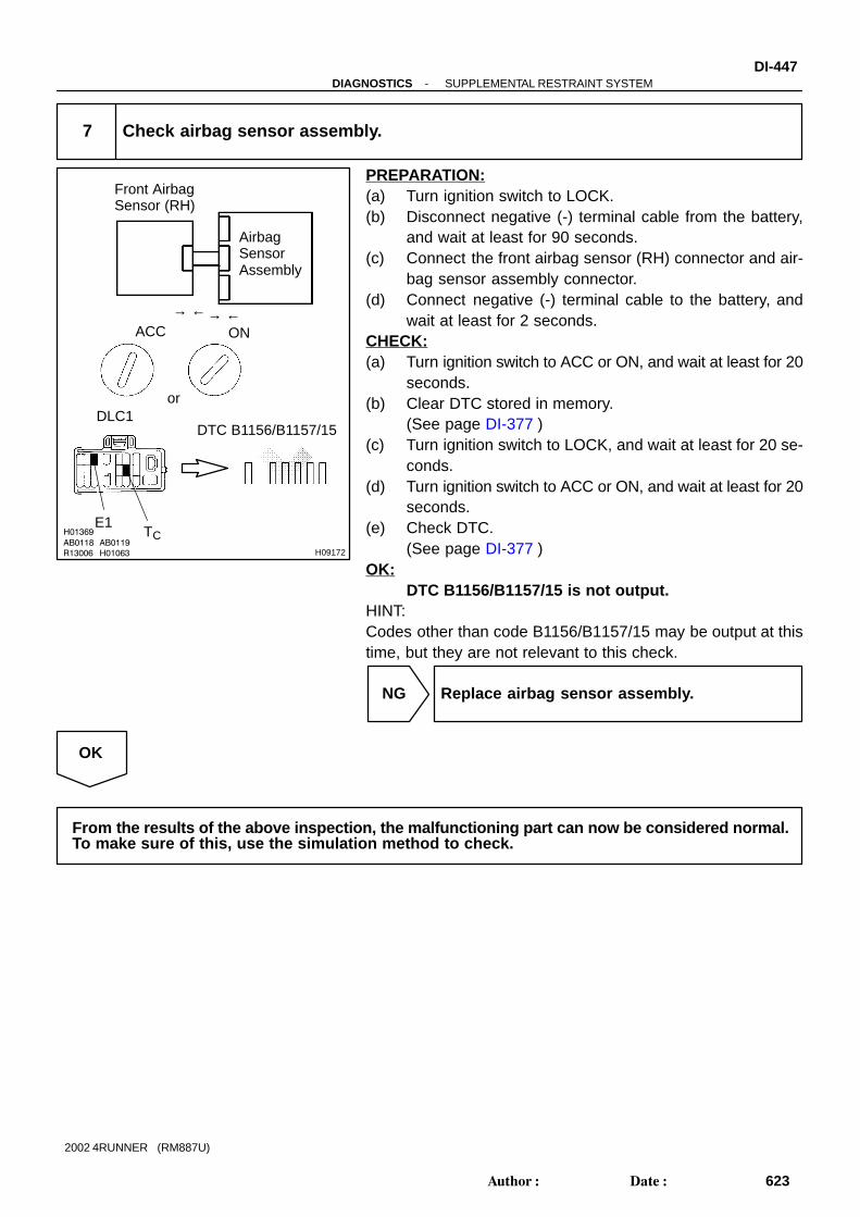
R13006 H01063
H01369
AB0118 AB0119
H09172
AirbagSensorAssembly
Front AirbagSensor (RH)
ACC ON
orDLC1
DTC B1156/B1157/15
→ ←
E1
→ ←
TC
-DIAGNOSTICS SUPPLEMENTAL RESTRAINT SYSTEMDI-447
623Author: Date:
2002 4RUNNER (RM887U)
7 Check airbag sensor assembly.
PREPARATION:(a) Turn ignition switch to LOCK.(b) Disconnect negative (-) terminal cable from the battery,
and wait at least for 90 seconds.(c) Connect the front airbag sensor (RH) connector and air-
bag sensor assembly connector.(d) Connect negative (-) terminal cable to the battery, and
wait at least for 2 seconds.CHECK:(a) Turn ignition switch to ACC or ON, and wait at least for 20
seconds.(b) Clear DTC stored in memory.
(See page DI-377 )(c) Turn ignition switch to LOCK, and wait at least for 20 se-
conds.(d) Turn ignition switch to ACC or ON, and wait at least for 20
seconds.(e) Check DTC.
(See page DI-377 )OK:
DTC B1156/B1157/15 is not output.HINT:Codes other than code B1156/B1157/15 may be output at thistime, but they are not relevant to this check.
NG Replace airbag sensor assembly.
OK
From the results of the above inspection, the malfunctioning part can now be considered normal.To make sure of this, use the simulation method to check.

H02750
Airbag Sensor AssemblyA28Front Airbag Sensor (LH)
+SL
-SL
C2115
26
2
1
+SLW-R
BR-Y-SL C21
W-R
BR-Y
2
1
IG2
IG2
DI-448-DIAGNOSTICS SUPPLEMENTAL RESTRAINT SYSTEM
624Author: Date:
2002 4RUNNER (RM887U)
DTC B1158/B1159/16 Front Airbag Sensor (LH) Malfunction
CIRCUIT DESCRIPTIONThe front airbag sensor (LH) circuit consists of the airbag sensor assembly and front airbag sensor (LH).For details of the function of each component, see OPERATION on page RS-2 .DTC B1158/B1159/16 is recorded when malfunction is detected in the front airbag sensor (LH) circuit.
DTC No. DTC Detecting Condition Trouble Area
B1158/B1159/16 Front airbag sensor (LH) malfunction
Front airbag sensor (LH)
Wire harness
Airbag sensor assembly
WIRING DIAGRAM
DI58Q-07

AB0119H08065
H03355
H09173
AirbagSensorAssembly
Front Airbag Sensor (LH)
(+) SL+
(-)SL-
Airbag SensorAssembly
ON
H08399
H01370
H03353
H09174
AirbagSensorAssembly
(+)SL+
(-)SL-
Airbag SensorAssembly
Front Airbag Sensor (LH)
-DIAGNOSTICS SUPPLEMENTAL RESTRAINT SYSTEMDI-449
625Author: Date:
2002 4RUNNER (RM887U)
INSPECTION PROCEDURE
1 Prepare for inspection. (See step 1 on page DI-456 )
2 Check wire harness (to B+).
CHECK:(a) Turn ignition switch to ON.(b) For the connector (on the airbag sensor assembly side)
between the front airbag sensor (LH) and the airbag sen-sor assembly, measure the voltage between body groundand each of SL+ and SL-.
OK:Voltage: Below 1 V
NG Go to step 8.
OK
3 Check wire harness (to ground).
CHECK:For the connector (on the airbag sensor assembly side) be-tween the front airbag sensor (LH) and the airbag sensor as-sembly, measure the resistance between body ground andeach of SL+ and SL-.OK:

H01370H08058
H03355
H09175
AirbagSensorAssembly
Front AirbagSensor (LH)
(+) SL+
(-) SL-
Airbag SensorAssembly
H09521H08058
H03353H09176
Front AirbagSensor (LH)
AirbagSensorAssembly
(+) SL+
Airbag SensorAssembly
(-) SL-
SL+ SL-
DI-450-DIAGNOSTICS SUPPLEMENTAL RESTRAINT SYSTEM
626Author: Date:
2002 4RUNNER (RM887U)
Resistance: 1 M Ω or Higher
NG Go to step 9.
OK
4 Check wire harness.
CHECK:For the connector (on the airbag sensor assembly side) be-tween the front airbag sensor (LH) and the airbag sensor as-sembly, measure the resistance between SL+ and SL-.OK:
Resistance: 1 M Ω or Higher
NG Go to step 10.
OK
5 Check wire harness.
PREPARATION:Using a service wire, connect SL+ and SL- of the connector (onthe front airbag sensor (LH) side) between the airbag sensorassembly and the front airbag sensor (LH).CHECK:For the connector (on the airbag sensor assembly side) be-tween the front airbag sensor (LH) and the airbag sensor as-sembly, measure the resistance between SL+ and SL-.OK:
Resistance: Below 1 Ω
NG Go to step 11.
OK

H04504H01062 H08346
AirbagSensorAssembly
Front AirbagSensor (LH)
(+)
SL+
(-)
SL-
-DIAGNOSTICS SUPPLEMENTAL RESTRAINT SYSTEMDI-451
627Author: Date:
2002 4RUNNER (RM887U)
6 Check front airbag sensor (LH).
CHECK:For the connector (on the front airbag sensor (LH)), measurethe resistance between SL+ and SL-.OK:
Resistance: 300 - 1500 Ω
NG Replace front airbag sensor (LH).
OK

AB0118R13006
AB0119H01064
H02757
H09177
Front AirbagSensor (LH)
AirbagSensorAssembly
ON
or
DTC B1158/B1159/16
ACC
DLC1
E1 Tc
DI-452-DIAGNOSTICS SUPPLEMENTAL RESTRAINT SYSTEM
628Author: Date:
2002 4RUNNER (RM887U)
7 Check airbag sensor assembly.
PREPARATION:(a) Turn ignition switch to LOCK.(b) Disconnect negative (-) terminal cable from the battery,
and wait at least for 90 seconds.(c) Connect the front airbag sensor (LH) connector and air-
bag sensor assembly connector.(d) Connect negative (-) terminal cable to the battery, and
wait at least for 2 seconds.CHECK:(a) Turn ignition switch to ACC or ON, and wait at least for 20
seconds.(b) Clear DTC stored in memory.
(See page DI-377 )(c) Turn ignition switch to LOCK, and wait at least for 20 se-
conds.(d) Turn ignition switch to ACC or ON, and wait at least for 20
seconds.(e) Check DTC.
(See page DI-377 )OK:
DTC B1158/B1159/16 is not output.HINT:Codes other than code B1158/B1159/16 may be output at thistime, but they are not relevant to this check.
NG Replace airbag sensor assembly.
OK
From the results of the above inspection, the malfunctioning part can now be considered normal.To make sure of this, use the simulation method to check.
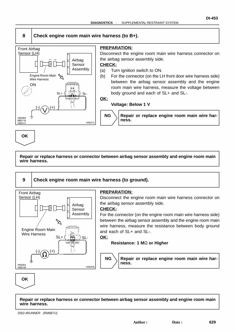
H03354
H06141
AB0119H08272
AirbagSensorAssembly
Front Airbag Sensor (LH)
(+)
SL+
(-)
SL-
ON
Engine Room MainWire Harness
← →
H03354H06140 H08258
AirbagSensorAssembly
Front AirbagSensor (LH)
(+)
SL+
(-)
SL-
Engine Room MainWire Harness
-DIAGNOSTICS SUPPLEMENTAL RESTRAINT SYSTEMDI-453
629Author: Date:
2002 4RUNNER (RM887U)
8 Check engine room main wire harness (to B+).
PREPARATION:Disconnect the engine room main wire harness connector onthe airbag sensor assembly side.CHECK:(a) Turn ignition switch to ON.(b) For the connector (on the LH front door wire harness side)
between the airbag sensor assembly and the engineroom main wire harness, measure the voltage betweenbody ground and each of SL+ and SL-.
OK:Voltage: Below 1 V
NG Repair or replace engine room main wire har-ness.
OK
Repair or replace harness or connector between airbag sensor assembly and engine room mainwire harness.
9 Check engine room main wire harness (to ground).
PREPARATION:Disconnect the engine room main wire harness connector onthe airbag sensor assembly side.CHECK:For the connector (on the engine room main wire harness side)between the airbag sensor assembly and the engine room mainwire harness, measure the resistance between body groundand each of SL+ and SL-.OK:
Resistance: 1 M Ω or Higher
NG Repair or replace engine room main wire har-ness.
OK
Repair or replace harness or connector between airbag sensor assembly and engine room mainwire harness.

H03354H09519 H09520
AirbagSensorAssembly
Front AirbagSensor (LH)
(-)
SL+ SL-
Engine Room MainWire Harness
(+)
← →
DI-454-DIAGNOSTICS SUPPLEMENTAL RESTRAINT SYSTEM
630Author: Date:
2002 4RUNNER (RM887U)
10 Check engine room main wire harness.
PREPARATION:Disconnect the engine room main wire harness connector onthe airbag sensor assembly side.CHECK:For the connector (on the engine room main wire harness side)between the airbag sensor assembly and the engine room mainwire harness, measure the resistance between SL+ and SL-.OK:
Resistance: 1 M Ω or Higher
NG Repair or replace engine room main wire har-ness.
OK
Repair or replace harness or connector between airbag sensor assembly and engine room mainwire harness.

H03352
H09519H09521 H09522
AirbagSensorAssembly
Front AirbagSensor (LH)
(+)
SL+
(-)
SL-
Engine Room MainWire Harness
SL+ SL-
← →
-DIAGNOSTICS SUPPLEMENTAL RESTRAINT SYSTEMDI-455
631Author: Date:
2002 4RUNNER (RM887U)
11 Check engine room main wire harness.
PREPARATION:(a) Disconnect the engine room main wire harness connector
on the airbag sensor assembly side.(b) Using a service wire, connect SL+ and SL- of the connec-
tor (on the engine room main wire harness side) betweenthe engine room main wire harness and the front airbagsensor (LH).
CHECK:For the connector (on the engine room main wire harness side)between the airbag sensor assembly and the engine room mainwire harness, measure the resistance between SL+ and SL-.OK:
Resistance: Below 1 Ω
NG Repair or replace engine room main wire har-ness.
OK
Repair or replace harness or connector between airbag sensor assembly and engine room mainwire harness.

H17125
Airbag SensorAssembly
IG1
IG2
E2
E1
6C21
5C21
28C21
27C21
BRBR
IGID
YD
J8
J/C
GR-B
EJ7Y
41H
31L
ECU-IG
IGN
21I
41I
B-Y
4IG1AM12
6B-R
IG2AM27
W-R
W
W
2
2
2
2
AM2
1
AM1
1 2 12
Battery
I14Ignition Switch
Driver Side J/B
Engine Room R/B
DI-456-DIAGNOSTICS SUPPLEMENTAL RESTRAINT SYSTEM
632Author: Date:
2002 4RUNNER (RM887U)
DTC Normal Source Voltage Drop
CIRCUIT DESCRIPTIONThe SRS is equipped with a voltage-increase circuit (DC-DC converter) in the airbag sensor assembly incase the source voltage drops.When the battery voltage drops, the voltage-increase circuit (DC-DC converter) functions to increase thevoltage of the SRS to normal voltage.The diagnosis system malfunction display for this circuit is different from other circuits that is when the SRSwarning light remains lit up and the DTC is a normal code, source voltage drop is indicated.Malfunction in this circuit is not recorded in the airbag sensor assembly, and the source voltage returns tonormal, the SRS warning light automatically goes off.
DTC No. Diagnosis
(Normal) Source voltage drop
WIRING DIAGRAM
DI18Z-33

H07389
AB0117
N H07390
AirbagSensorAssembly
P/T Squib (LH)
P/T Squib (RH)
D Squib
P Squib
SpiralCable
Front AirbagSensor (RH)
Front Airbag Sensor (LH)
LOCK
-DIAGNOSTICS SUPPLEMENTAL RESTRAINT SYSTEMDI-457
633Author: Date:
2002 4RUNNER (RM887U)
INSPECTION PROCEDURE
1 Prepare for inspection.
PREPARATION:(a) Disconnect negative (-) terminal cable from the battery,
and wait at least for 90 seconds.(b) Remove the steering wheel pad. (See page SR-13 )(c) Disconnect the connector of the front passenger airbag
assembly. (See page RS-25 )(d) Disconnect the connectors of the seat belt pretensioner
RH and LH. (See page BO-121 )(e) Disconnect the connectors of the airbag sensor assem-
bly. (See page RS-38 )(f) Disconnect the connectors of the front airbag sensor RH
and LH. (See page RS-43 )CAUTION:Store the steering wheel pad with the front surface facingupward.

AB0119
H01298 H01299
Airbag Sensor AssemblyON
ACC IG2(+)(-)
H01249
ON
DI-458-DIAGNOSTICS SUPPLEMENTAL RESTRAINT SYSTEM
634Author: Date:
2002 4RUNNER (RM887U)
2 Check source voltage.
PREPARATION:(a) Connect negative (-) terminal cable to the battery.(b) Turn ignition switch to ON.CHECK:Operating electric system (defogger, wiper, headlight, heaterblower, etc.), measure the voltage between each of IG2 andACC of sensor and body ground.OK:
Voltage: 10 - 14 V
NG Check harness between battery and airbag sen-sor assembly, and check battery and chargingsystem.
OK
3 Does SRS warning light turn OFF?
PREPARATION:(a) Turn ignition switch to LOCK.(b) Connect the steering wheel pad connector.(c) Connect the front passenger airbag assembly connector.(d) Connect the seat belt pretensioner connector RH and LH.(e) Connect the airbag sensor assembly connector.(f) Turn ignition switch to ON.CHECK:Operate electric system (defogger, wiper, headlight, heaterblower, etc.) and check that SRS warning light goes off.
NO Check for DTCs. If a DTC is output, perform trou-bleshooting for the DTC. If a normal code is out-put, replace airbag sensor assembly.
YES
From the results of the above inspection, the malfunctioning part can now be considered normal.To make sure of this, use the simulation method to check.

H17126
Airbag SensorAssembly
LA
3C21L
C
J5 J/C
CL
8C28
SRS Warning Light (Combination Meter)
5C25GR-B
111F
IGN41IB-R
6IG2AM27
W-R 2 2 1
AM22
W
Battery
I14Ignition SW
Driver Side J/B
Engine Room R/B
-DIAGNOSTICS SUPPLEMENTAL RESTRAINT SYSTEMDI-459
635Author: Date:
2002 4RUNNER (RM887U)
SRS Warning Light Circuit Malfunction (Always lights up, whenignition switch is in LOCK position.)
CIRCUIT DESCRIPTIONThe SRS warning light is located on the combination meter.When the SRS is normal, the SRS warning light lights up for approx. 6 seconds after the ignition switch isturned from the LOCK position to ACC or ON position, and then turns OFF automatically.If there is a malfunction in the SRS, the SRS warning light lights up to inform the driver of the abnormality.When terminals Tc and E1 of the DLC1 are connected, the DTC is displayed by blinking the SRS warninglight.
WIRING DIAGRAM
DI2I5-21

AB0117 H01293 H01295
Airbag Sensor AssemblyLOCK
DI-460-DIAGNOSTICS SUPPLEMENTAL RESTRAINT SYSTEM
636Author: Date:
2002 4RUNNER (RM887U)
INSPECTION PROCEDURE
1 Prepare for inspection. (See step 1 on page DI-456 )
2 Does SRS warning light turn OFF?
PREPARATION:(a) Turn ignition switch to LOCK.(b) Disconnect negative (-) terminal cable from the battery,
and wait at least for 90 seconds.(c) Disconnect the airbag sensor assembly connector.(d) Connect negative (-) terminal cable to the battery.CHECK:Check operation of SRS warning light.
NO Check SRS warning light circuit or terminal ABcircuit of DLC1.
YES
Replace airbag sensor assembly.

N14677
Fuse
-DIAGNOSTICS SUPPLEMENTAL RESTRAINT SYSTEMDI-461
637Author: Date:
2002 4RUNNER (RM887U)
SRS Warning Light Circuit Malfunction (Does not light up, whenignition switch is turned to ACC or ON.)
CIRCUIT DESCRIPTIONThe SRS warning light is located on the combination meter.When the SRS is normal, the SRS warning light lights up for approx. 6 seconds after the ignition switch isturned from LOCK position to ACC or ON position, and then turns OFF automatically.If there is a malfunction in the SRS, the SRS warning light lights up to inform the driver of the abnormalityWhen terminals Tc and E1 of the DLC1 are connected, the DTC is displayed by blinking the SRS warninglight.
WIRING DIAGRAMSee page DI-459 .
INSPECTION PROCEDURE
1 Check ECU-B Fuse.
PREPARATION:Remove ECU-B fuse.CHECK:Check continuity of ECU-B fuse.OK:
ContinuityHINT: Fuse may be burnt out even if it appears to be OK during
visual inspection. If fuse is OK, install it.
NG Go to step 5.
OK
2 Prepare for inspection. (See step 1 on page DI-456 )
DI191-23
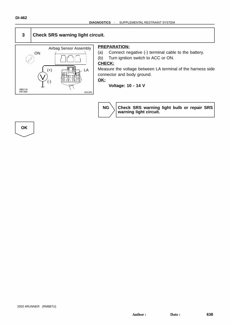
AB0119H01300 H01301
Airbag Sensor AssemblyON
LA(+)
(-)
DI-462-DIAGNOSTICS SUPPLEMENTAL RESTRAINT SYSTEM
638Author: Date:
2002 4RUNNER (RM887U)
3 Check SRS warning light circuit.
PREPARATION:(a) Connect negative (-) terminal cable to the battery.(b) Turn ignition switch to ACC or ON.CHECK:Measure the voltage between LA terminal of the harness sideconnector and body ground.OK:
Voltage: 10 - 14 V
NG Check SRS warning light bulb or repair SRSwarning light circuit.
OK

H07391
W01632
H07392
D SquibSpiralCable
AirbagSensorAssembly
P Squib
P/T Squib (LH)
P/T Squib (RH)
Front Airbag Sensor (LH)
Front Airbag Sensor (RH)
-DIAGNOSTICS SUPPLEMENTAL RESTRAINT SYSTEMDI-463
639Author: Date:
2002 4RUNNER (RM887U)
4 Does SRS warning light come on?
PREPARATION:(a) Disconnect negative (-) terminal cable from the battery.(b) Connect the airbag sensor assembly connector.(c) Connect negative (-) terminal cable to the battery, and
wait at least for 2 seconds.(d) Turn ignition switch to ACC or ON.CHECK:Check operation of SRS warning light.
NO Check terminal LA of airbag sensor assembly.If normal, replace airbag sensor assembly.
YES
From the results of the above inspection, the malfunctioning part can now be considered normal.To make sure of this, use simulation method to check.

DI-464-DIAGNOSTICS SUPPLEMENTAL RESTRAINT SYSTEM
640Author: Date:
2002 4RUNNER (RM887U)
5 Is new ECU-B fuse burnt out again?
NO Using simulation method, reproduce malfunc-tion symptoms. (See page IN-18 )
YES
Check harness between ECU- B fuse andSRS warning light.

H07399
D1DLC1
J6J/C
Airbag Sensor Assembly
19
E1
Tc TcC2111
23
3 BR
BII4
EC
BGR GRG-R
AB0117 AB0118 AB0119
W01632 H07393
LOCKACC ON
or
-DIAGNOSTICS SUPPLEMENTAL RESTRAINT SYSTEMDI-465
641Author: Date:
2002 4RUNNER (RM887U)
Tc Terminal Circuit
CIRCUIT DESCRIPTIONBy connecting terminals Tc and E1 of the DLC1 the airbag sensor assembly is set in the DTC output mode.The DTCs are displayed by blinking the SRS warning light.
WIRING DIAGRAM
INSPECTION PROCEDUREIf the DTC is not displayed, do the following troubleshooting.
1 Does SRS warning light light up for approx. 6 seconds?
PREPARATION:Check operation of the SRS warning light after ignition switchis turned from LOCK position to ACC or ON position.
NO Check SRS warning light system.(See page DI-377 )
YES
DI192-33

AB0118R14305
AB0119H00030
ACC ON
or
E1Tc
(+)(-)
AB0118R14304
AB0119H00031
ACC ON
orTc
(+)(-)
DI-466-DIAGNOSTICS SUPPLEMENTAL RESTRAINT SYSTEM
642Author: Date:
2002 4RUNNER (RM887U)
2 Check voltage between terminals Tc and E1 of DLC1.
PREPARATION:Turn ignition switch to ACC or ON.CHECK:Measure the voltage between terminals Tc and E1 of DLC1.OK:
Voltage: 10 - 14 V
OK Go to step 4.
NG
3 Check voltage between terminal Tc of DLC1 and body ground.
CHECK:Measure the voltage between terminal Tc of DLC1 and bodyground.OK:
Voltage: 10 - 14 V
OK Check harness between terminal E1 of DLC1and body ground.
NG

AB0117 AB0118 AB0119
H01302 H01303
LOCK ACC ON
or
Airbag Sensor Assembly
Tc
-DIAGNOSTICS SUPPLEMENTAL RESTRAINT SYSTEMDI-467
643Author: Date:
2002 4RUNNER (RM887U)
4 Check airbag sensor assembly.
PREPARATION:(a) Turn ignition switch to LOCK.(b) Disconnect negative (-) terminal cable from the battery,
and wait at least for 90 seconds.(c) Disconnect the airbag sensor assembly connector.(d) Insert service wire into terminal Tc from back side as
shown in the illustration.(e) Connect the airbag sensor assembly connector with ser-
vice wire.(f) Connect negative (-) terminal cable to the battery.(g) Turn ignition switch to ACC or ON and wait at least for 20
seconds.(h) Connect service wire of terminal Tc to body ground.CHECK:Check operation of SRS warning light.OK:
SRS waning light comes on.NOTICE:Pay due attention to the terminal connecting position toavoid a malfunction.
OK Check harness between the airbag sensor as-sembly and DLC1.
NG
Replace airbag sensor assembly.

AB0119H01304 H01305
LOCK Airbag Sensor Assembly
Tc
(+)(-)
DI-468-DIAGNOSTICS SUPPLEMENTAL RESTRAINT SYSTEM
644Author: Date:
2002 4RUNNER (RM887U)
If the DTC is displayed without a DTC check procedure, perform the followingtroubleshooting.
1 Check resistance between terminal Tc of airbag sensor assembly and bodyground.
PREPARATION:(a) Turn ignition switch to LOCK.(b) Disconnect negative (-) terminal cable from the battery,
and wait at least for 90 seconds.(c) Disconnect the airbag sensor assembly connector.CHECK:Check the resistance between terminal Tc of the airbag sensorassembly connector and body ground.OK:
Resistance: 1 M Ω or Higher
NG Repair or replace harness or connector.
OK
Replace airbag sensor assembly.
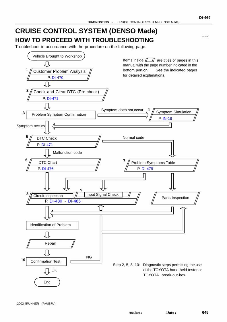
DI0QT-04
Customer Problem Analysis
Check and Clear DTC (Pre-check)
Vehicle Brought to Workshop
Problem Symptom ConfirmationSymptom SimulationSymptom does not occur
DTC Check Normal code
DTC Chart Problem Symptoms Table
Circuit Inspection Input Signal CheckParts Inspection
Identification of Problem
Repair
Confirmation Test
End
Items inside are titles of pages in thismanual with the page number indicated in thebottom portion. See the indicated pagesfor detailed explanations.
1
2
34
5
6 7
89
10Step 2, 5, 8, 10: Diagnostic steps permitting the use
of the TOYOTA hand-held tester orTOYOTA break-out-box.
P. DI-470
P. DI-471
P. DI-471
P. DI-476
P. IN-18
P. DI-479
P. DI-480 - DI-485
OK
NG
Symptom occurs
Malfunction code
-DIAGNOSTICS CRUISE CONTROL SYSTEM (DENSO Made)DI-469
645Author: Date:
2002 4RUNNER (RM887U)
CRUISE CONTROL SYSTEM (DENSO Made)HOW TO PROCEED WITH TROUBLESHOOTINGTroubleshoot in accordance with the procedure on the following page.

DI0QU-03
CRUISE CONTROL SYSTEM Check SheetInspector’s name:
Customer’s Name
Date of Vehicle
Registration No.
Registration Year
Frame No.
Odometer Reading / / kmMile
Condition ofProblem Occurrence
Date of Problem
Frequency
Occurrence
Problem Occurs?
Vehicle Speed whenProblem Occurred
/ /
Continuous Intermittent ( Times a day)
kmMile
Brought in
Auto cancel occurs
Driving condition City driving Freeway Up hill Down hill
After cancel occurred, did the driver activate cruise control again? Yes No
Cancel does not occur
With brake ON Except D position shift When control SW turns to CANCEL position
Cruise control malfunction
Slip to acceleration side Slip to deceleration side Hunting occurs O/D cut off does not occur O/D does not return
Switch malfunction SET ACC COAST RES CANCEL
Cruise main indicator light Remains ON Does not light up Blinks
Symptoms
DTC Check1st Time
2nd Time
Normal Code Malfunction Code (Code )
Normal Code Malfunction Code (Code )
DI-470-DIAGNOSTICS CRUISE CONTROL SYSTEM (DENSO Made)
646Author: Date:
2002 4RUNNER (RM887U)
CUSTOMER PROBLEM ANALYSIS CHECK
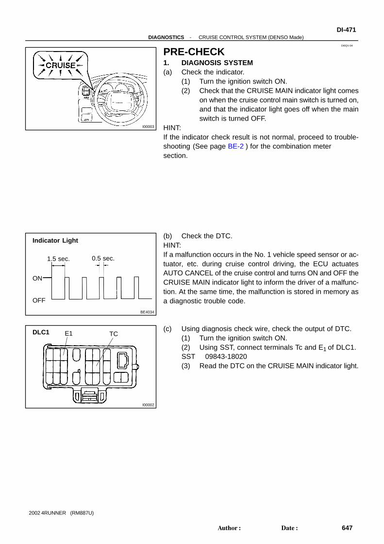
I00003
DI0QV-04
BE4034
Indicator Light
1.5 sec. 0.5 sec.
ON
OFF
I00002
DLC1 E1 TC
-DIAGNOSTICS CRUISE CONTROL SYSTEM (DENSO Made)DI-471
647Author: Date:
2002 4RUNNER (RM887U)
PRE-CHECK1. DIAGNOSIS SYSTEM(a) Check the indicator.
(1) Turn the ignition switch ON.(2) Check that the CRUISE MAIN indicator light comes
on when the cruise control main switch is turned on,and that the indicator light goes off when the mainswitch is turned OFF.
HINT:If the indicator check result is not normal, proceed to trouble-shooting (See page BE-2 ) for the combination meter section.
(b) Check the DTC.HINT:If a malfunction occurs in the No. 1 vehicle speed sensor or ac-tuator, etc. during cruise control driving, the ECU actuatesAUTO CANCEL of the cruise control and turns ON and OFF theCRUISE MAIN indicator light to inform the driver of a malfunc-tion. At the same time, the malfunction is stored in memory asa diagnostic trouble code.
(c) Using diagnosis check wire, check the output of DTC.(1) Turn the ignition switch ON.(2) Using SST, connect terminals Tc and E1 of DLC1.SST 09843-18020(3) Read the DTC on the CRUISE MAIN indicator light.

BE4032
BE4033 I00021
Normal Code
0.25 sec.0.25 sec.
ON
OFF
ON
OFF
4 sec. 1.5 sec.
0.5 sec.
2.5 sec.
0.5 sec.
1.5 sec.
Malfunction codes 11 and 21
Code 11 Code 21
N09348
TOYOTA hand-held tester
TOYOTA Break-out-box
I01915
(b)DLC1
(d) 5 timesWithin 3 seconds
E1 TC (c)
DI-472-DIAGNOSTICS CRUISE CONTROL SYSTEM (DENSO Made)
648Author: Date:
2002 4RUNNER (RM887U)
HINT:If the DTC is not output, inspect the diagnosis circuit.As an example, the blinking patterns for codes; normal 11 and21 are shown in the illustration.
2. ECU TERMINAL VALUES MEASUREMENT BY USINGTOYOTA BREAK-OUT-BOX AND TOYOTA HAND-HELD TESTER
(a) Hook up the TOYOTA break- out- box and TOYOTAhand-held tester to the vehicle.
(b) Read the ECU input/output values by following theprompts on the tester screen.
HINT:TOYOTA hand-held tester has a ”Snapshot” function. This re-cords the measured values and is effective in the diagnosis ofintermittent problems.Please refer to the TOYOTA hand-held tester/TOYOTA break-out-box operator’s manual for further details.
3. DTC CLEARANCE (ERASE MODE)HINT:Under the erase mode, diag detection does not work.(a) Drive at about 15 km/h or below.(b) Using SST, connect terminals Tc and E1 of DLC1.
SST 09843-18020(c) Pull the cruise control switch to CANCEL.(d) On the above metioned condition, turn on the cruise con-
trol main switch 5 times within 3 seconds.

I00001
I00001
I00001
-DIAGNOSTICS CRUISE CONTROL SYSTEM (DENSO Made)DI-473
649Author: Date:
2002 4RUNNER (RM887U)
4. PROBLEM SYMPTOM CONFIRMATION(ROAD TEST)
(a) Inspect the SET switch.(1) Push the main switch ON.(2) Drive at a desired speed (40 km/h (25 mph) or high-
er).(3) Press the control switch to the SET/COAST.(4) After releasing the switch, check that the vehicle
cruises at the desired speed.
(b) Inspect the ACCEL switch.(1) Push the main switch ON.(2) Drive at a desired speed (40 km/h (25 mph) or high-
er).(3) Press the control switch to the SET/COAST.(4) Check that the vehicle speed increases while the
control switch is turned to RES/ACC, and that thevehicle cruises at the set speed when the switch isreleased.
(5) Momentarily press the control switch upward toRES/ACC and then immediately release it. Checkthat the vehicle speed increases by about 1.6 km/h(1 mph) (Tap-up function).
(c) Inspect the COAST.(1) Push the main switch ON.(2) Drive at a desired speed (40 km/h (25 mph) or high-
er).(3) Press the control switch to the SET/COAST.(4) Check that the vehicle speed decreases while the
control switch is turned to SET/COAST, and the ve-hicle cruises at the set speed when the switch is re-leased.
(5) Momentarily press the control switch downward toSET/COAST, and then immediately release it.Check that the vehicle speed decreases by about1.6 km/h (1 mph) (Tap-down function).
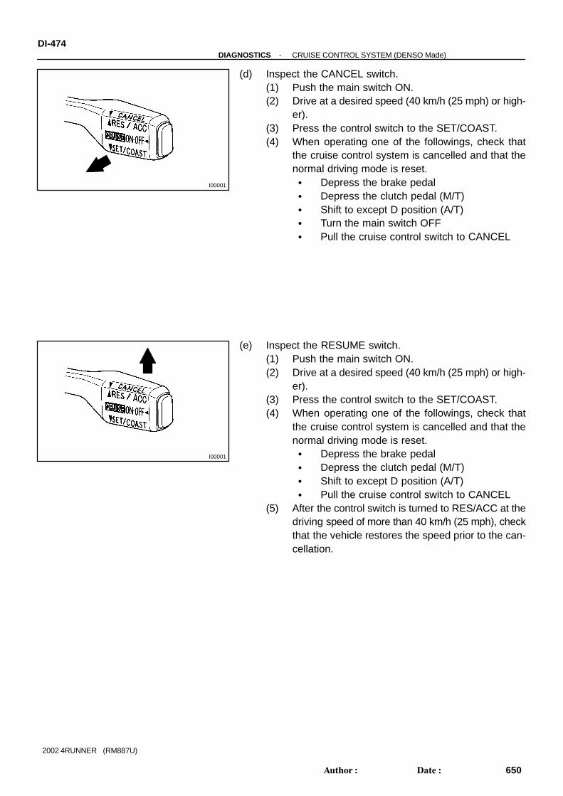
I00001
I00001
DI-474-DIAGNOSTICS CRUISE CONTROL SYSTEM (DENSO Made)
650Author: Date:
2002 4RUNNER (RM887U)
(d) Inspect the CANCEL switch.(1) Push the main switch ON.(2) Drive at a desired speed (40 km/h (25 mph) or high-
er).(3) Press the control switch to the SET/COAST.(4) When operating one of the followings, check that
the cruise control system is cancelled and that thenormal driving mode is reset. Depress the brake pedal Depress the clutch pedal (M/T) Shift to except D position (A/T) Turn the main switch OFF Pull the cruise control switch to CANCEL
(e) Inspect the RESUME switch.(1) Push the main switch ON.(2) Drive at a desired speed (40 km/h (25 mph) or high-
er).(3) Press the control switch to the SET/COAST.(4) When operating one of the followings, check that
the cruise control system is cancelled and that thenormal driving mode is reset. Depress the brake pedal Depress the clutch pedal (M/T) Shift to except D position (A/T) Pull the cruise control switch to CANCEL
(5) After the control switch is turned to RES/ACC at thedriving speed of more than 40 km/h (25 mph), checkthat the vehicle restores the speed prior to the can-cellation.

BE6443
1
1
2
No. Operation MethodCRUISE MAIN Indicator LightBlinking Pattern
Diagnosis
1 Turn SET/COAST switch ON
2 Turn RES/ACC switch ON
3
Turn CANCEL switch ON
Turn stop light switch ONDepress brake pedal
4
Drive at about 40 km/h (25 mph)or higher
Drive at about 40 km/h(25 mph) or below
Light ON
OFF
LightON
OFF
LightON
OFF
Switch ON
Switch OFF
LightON
OFF
Switch OFF
Switch ON
SET/COAST switch circuitis normal
RES/ACC switch circuitis normal
CANCEL switch circuitis normal
Stop light switch circuitis normal
Park/Neutral Position switchcircuit is normal
Vehicle Speed Sensor isnormal
LightON
OFF
Light ON
OFF
1sec.
0.25 sec. 0.25 sec.
Turn clutch switch OFF(Depress clutch pedal)
Clutch switch circuit isnormal
Turn Park/Neutral Positionswitch OFF(Shift to except D position)
-DIAGNOSTICS CRUISE CONTROL SYSTEM (DENSO Made)DI-475
651Author: Date:
2002 4RUNNER (RM887U)
5. INPUT SIGNAL CHECKHINT:(1) For check No.1 ∼ No.2 Turn the ignition switch ON.
(2) For check No.3 Turn ignition switch ON. Shift to D position.
(3) For check No.4 Jack up the vehicle. Start the engine. Shift to D position.
(a) Press the control switch to SET/COAST or RES/ACCposition and hold it down or hold it up respecively (1)
(b) Push the main switch ON (2).(c) Check that the CRUISE MAIN indicator light blinks twice
or 3 times repeatedly after 3 seconds.(d) Turn the SET/COAST or RES/ACC switch OFF.(e) Operate each switch as listed in the table below.(f) Read the blinking pattern of the CRUISE MAIN indicator
light.(g) After performing the check, turn the main switch OFF.HINT:When 2 or more signals are input to the ECU, the lowest num-bered code will be displayed first.

DI0QW-04
DI-476-DIAGNOSTICS CRUISE CONTROL SYSTEM (DENSO Made)
652Author: Date:
2002 4RUNNER (RM887U)
DIAGNOSTIC TROUBLE CODE CHARTIf a malfunction code is displayed during the diagnostic trouble code check, check the circuit listed for thatcode in the table below and proceed to the appropriate page.
DTC No.
(See page)Detection Item Trouble Area
P0500/21, 23
(DI-480 )Vehicle Speed Signal Abnormal
Combination meter
Harness or connector between ECM and vehicle speed sen-
sor
Vehicle speed sensor
ECM
P1520/52
(DI-481 )Short in Stop Light Switch Circuit
Stop light switch
Harness or connector between ECM and stop light switch
ECM
P1566/54
(DI-485 )Input Signal Circuit ECM
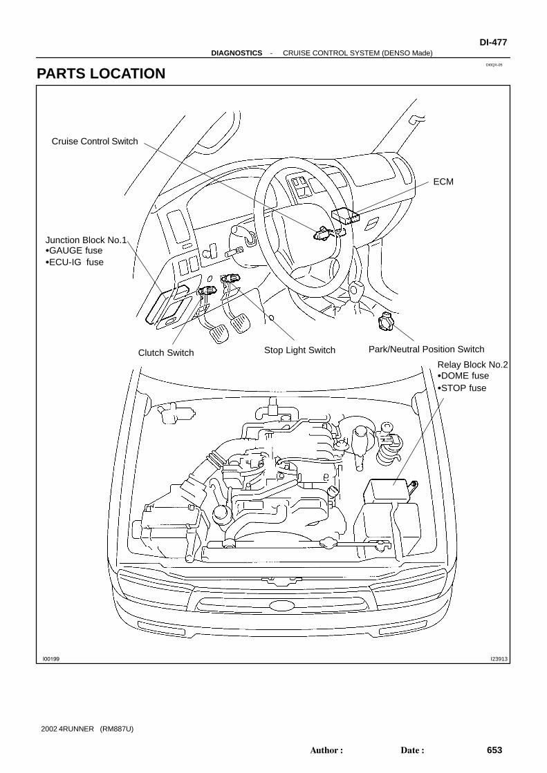
DI0QX-05
I00199 I23913
Junction Block No.1GAUGE fuseECU-IG fuse
Clutch Switch Stop Light Switch
Cruise Control Switch
ECM
Relay Block No.2DOME fuseSTOP fuse
Park/Neutral Position Switch
-DIAGNOSTICS CRUISE CONTROL SYSTEM (DENSO Made)DI-477
653Author: Date:
2002 4RUNNER (RM887U)
PARTS LOCATION

DI1CQ-04
A02016
E14E12E11ECM Terminals
E9
31 30 29 28 27
17192021
2223242526
11121314
123456789
10151618
1234567
8910111213141516
182021222324 1719
123456789
1012 1113141516171819
202123 222426 252728
1234567
89101112131415
16171819202122
123456
891011 712
1314151617
E10
DI-478-DIAGNOSTICS CRUISE CONTROL SYSTEM (DENSO Made)
654Author: Date:
2002 4RUNNER (RM887U)
TERMINALS OF ECU
Symbols (Terminal No.) Wiring Color Condition STD Voltage
STP (E14 20) E1 (E10 17) G W BRDepress brake pedal 7.5 - 14 V
STP (E14-20) - E1 (E10-17) G-W - BRRelease brake pedal 0 - 1.5 V
Ignition switch ON 9 - 14 V
Ignition switch ON MAIN switch hold ON Below 1 V
CCS (E12-22) - E1 (E10-17) G - BR Ignition switch ON CANCEL switch hold ON 6.0 - 10.1 VCCS (E12 22) E1 (E10 17) G BR
Ignition switch ON SET/COAST switch hold ON 4.0 - 7.1 V
Ignition switch ON RES/ACC switch hold ON 2.1 - 4.0 V
I iti it h ON C i t l i it h ON 0 3 VPI (E14 17) E1 (E10 17) GR BR
Ignition switch ON Cruise control main switch ON 0 - 3 VPI (E14-17) - E1 (E10-17) GR - BR
I iti it h ON C i t l i it h OFF 9 14 VPI (E14 17) E1 (E10 17) GR BR
Ignition switch ON Cruise control main switch OFF 9 - 14 V
ST1 (E12 9) E1 (E10 17) R B BRDepress brake pedal 0 - 1.5 V
ST1- (E12-9) - E1 (E10-17) R-B - BRRelease brake pedal 7.5 - 14 V

DI0QZ-05
-DIAGNOSTICS CRUISE CONTROL SYSTEM (DENSO Made)DI-479
655Author: Date:
2002 4RUNNER (RM887U)
PROBLEM SYMPTOMS TABLESymptom Suspected Area See page
SET not occurring or CANCEL occurring
(DTC is Normal)
1. Input signal circuit
2. Vehicle speed sensor circuit
3. Stop light switch circuit
4. Park/neutral position switch circuit
5. ECM
DI-485
DI-480
DI-481
DI-203
IN-28
SET not occurring or CANCEL occurring
(DTC is not output)1. ECM IN-28
Actual vehicle speed deviates above or below the set speed1. Input signal circuit
2. ECM
DI-485
IN-28
Gear shifting occurs frequently between 3rd and O/D when driving
on uphill road (Hurting)1. ECM IN-28
Cruise control not cancelled, even when brake pedal is depressed1. Stop light switch circuit
2. ECM
DI-481
IN-28
Cruise control not cancelled, even when transmission is shifted to
N position
1. Park/neutral position switch circuit
2. ECM
DI-203
IN-28
Cruise control not cancelled, even when clutch pedal is de-
pressed1. ECM IN-28
Control switch does not operate
(SET/COAST, ACC/RES, CANCEL not possible)
1. Cruise control switch circuit
2. ECM
DI-486
IN-28
SET possible at 40 km/h (25 mph) or less, or CANCEL does not
operate at 40 km/h (25 mph) or less
1. Input signal circuit
2. ECM
DI-485
IN-28
Poor response is ACC and RES modes 1. ECM IN-28
O/D does not resume, even though the road is not uphill 1. ECM IN-28
DTC memory is erased 1. ECM IN-28
DTC is not output, or is output when should not be1. Diagnosis circuit
2. ECM
-
IN-28
Cruise main indicator light remains on or falls to lighting up1. Input signal circuit
2. ECM
DI-485
IN-28

DI3CI-09
DI-480-DIAGNOSTICS CRUISE CONTROL SYSTEM (DENSO Made)
656Author: Date:
2002 4RUNNER (RM887U)
CIRCUIT INSPECTION
DTC P0500/21, 23 Vehicle Speed Sensor Circuit
CIRCUIT DESCRIPTIONSee page DI-179 .
DTC No. DTC Detection Condition Trouble Area
P0500/21, 23 Speed signal is not input to ECM while cruise control is set
Combination meter
Harness or connector between ECM and vehicle speed sen-
sor
Vehicle speed sensor
ECM
WIRING DIAGRAMSee page DI-179 .
INSPECTION PROCEDURESee page DI-179 ..

I21251I22540
9E12
ECM
ST1-
G-W20
E14 STP
S4Stop Light S/W
G-WG-Y
R-B
113C
15
13C
4
2
3
Center J/B
B-L
From Battery
From Ignition SW
-DIAGNOSTICS CRUISE CONTROL SYSTEM (DENSO Made)DI-481
657Author: Date:
2002 4RUNNER (RM887U)
DTC P1520/52 Stop light switch circuit
CIRCUIT DESCRIPTIONWhen the brake pedal is depressed, the stop light switch sends a signal to the ECM. When the ECM receivesthis signal, it cancels the cruise control.A fail-safe function is provided so that the cancel functions normally, even if there is a malfunction in the stoplight signal circuit.The cancel condition is that battery positive voltage is supplied to terminal STP.When the brake is on, battery positive voltage is normally applied through the STOP fuse and stop lightswitch to terminal STP of the ECM, and the ECM turns the cruise control OFF.If the harness connected to terminal STP has an open circuit, terminal STP will have battery positive voltageand the cruise control will be turned OFF.
DTC No. DTC Detection Condition Trouble Area
P1520/52 Stop light switch circuit
Stop light switch
Harness or connector between ECM and stop light switch
ECM
WIRING DIAGRAM
DI3CJ-18

DI-482-DIAGNOSTICS CRUISE CONTROL SYSTEM (DENSO Made)
658Author: Date:
2002 4RUNNER (RM887U)
INSPECTION PROCEDUREHINT:In case of using the TOYOTA hand-held tester, start the inspection from step 1 and in case of not using theTOYOTA hand-held tester, start it from step 2.
1 Check stop light switch using TOYOTA hand-held tester.
PREPARATION:Connect the TOYOTA hand-held tester to the DLC3.CHECK:Check the stop light switch using DATA LIST.OK:
Condition STP LIGHT SW1-S (Sub CPU) STP LIGHT SW2-S (Sub CPU) STP LIGHT SW2-M (Main CPU)
Depressed ON ON ON
Released OFF OFF OFF
HINT: STP LIGHT SW1 has a function to disconnect the connection (OFF) when depressing the pedal, how-
ever, the ECM is control by the logic reverse, so with the TOYOTA hand-held tester, it displays ON. STP LIGHT SW1 indicates an input of the ST1- terminal and STP LIGHT SW2 indicates an input of
the STP terminal.
OK Proceed to next circuit inspection shown inproblem symptoms table (See page DI-479 ).
NG
2 Check operation of stop light.
CHECK:Check that the stop light comes on when the brake pedal is depressed, and goes off when the brake pedalis released.
NG Check stop light system (See page BE-32 ).
OK

I21252 I22539
ON
STP
(+) (-)
I21253 I22541
ON
ST1-
(+) (-)
-DIAGNOSTICS CRUISE CONTROL SYSTEM (DENSO Made)DI-483
659Author: Date:
2002 4RUNNER (RM887U)
3 Check voltage between terminal STP of ECM connector and body ground.
PREPARATION:(a) Remove the ECM with connectors being connected.(b) Turn the ignition switch ON.CHECK:Measure the voltage between terminal STP of the ECM con-nector and the body ground when the brake pedal is depressedand released.OK:
Brake Pedal Voltage
Depressed 7.5 - 14 V
Released 0 - 1.5 V
OK Proceed to next circuit inspection shown inproblem symptoms table (See page DI-479 ).
NG
4 Check voltage between terminal ST1- of ECM connector and body ground.
PREPARATION:(a) Remove the ECM with connectors being connected.(b) Turn the ignition switch ON.CHECK:Measure the voltage between terminal ST1- of the ECM con-nector and the body ground when the brake pedal is depressedand released.OK:
Brake Pedal Voltage
Depressed Below 1 V
Released 7.5 - 14 V
OK Proceed to next circuit inspection shown inproblem symptoms table (See page DI-479 ).
NG

DI-484-DIAGNOSTICS CRUISE CONTROL SYSTEM (DENSO Made)
660Author: Date:
2002 4RUNNER (RM887U)
5 Check harness and connector between terminal STP of ECM and stop lightswitch, and terminal ST1- of ECM and stop light switch (See page IN-28 ).
NG Repair or replace harness or connector.
OK
Check and replace ECM (See page IN-28 ).

-DIAGNOSTICS CRUISE CONTROL SYSTEM (DENSO Made)DI-485
661Author: Date:
2002 4RUNNER (RM887U)
DTC P1566/54 Input Signal Circuit
CIRCUIT DESCRIPTIONSee page DI-481 .
DTC No. DTC Detection Condition Trouble Area
P1566/54 Input signal abnormal ECM
INSPECTION PROCEDURE
Check and replace ECM (See page IN-28 ).
DI3CL-12

I23849
BR
3
C14Cruise Control S/W (Combination SW)
RE
SU
ME
/A
CC
EL
SE
T/C
OA
ST
CA
NC
EL
ECM
5
EC
22CCSE12
G
EP
BRII4
4
CR
UIS
E
DI-486-DIAGNOSTICS CRUISE CONTROL SYSTEM (DENSO Made)
662Author: Date:
2002 4RUNNER (RM887U)
Control Switch Circuit (Cruise Control Switch)
CIRCUIT DESCRIPTIONThis circuit Sends the SET/COAST, RES/ACC and CANCEL signals (each voltage) to the ECM.
WIRING DIAGRAM
DI3CK-12

I21250 I22543
ON
CCS
(+) (-)
-DIAGNOSTICS CRUISE CONTROL SYSTEM (DENSO Made)DI-487
663Author: Date:
2002 4RUNNER (RM887U)
INSPECTION PROCEDURE
1 Check voltage between terminal CCS of ECM connector and body ground.
PREPARATION:(a) Remove the ECM with connector being connected.(b) Turn the ignition switch ON.CHECK:Measure the voltage between terminals CCS of the ECM con-nector and the body ground when each control switch is oper-ated.
Switch position Voltage
Neutral 9 - 14 V
MAIN Below 1 V
RES/ACC 2.1 - 4.0 V
SET/COAST 4.0 - 7.1 V
CANCEL 6.0 - 10.1 V
NG Proceed to next circuit inspection shown inproblem symptoms table (See page DI-479 ).
OK

I05156
RES/ACC
CANCELSET/COAST54
DI-488-DIAGNOSTICS CRUISE CONTROL SYSTEM (DENSO Made)
664Author: Date:
2002 4RUNNER (RM887U)
2 Check control switch continuity.
PREPARATION:(a) Remove the steering wheel center pad.(b) Disconnect the control switch connector.CHECK:Measure the resistance between terminals 4 and 5 of the con-trol switch connector when the control switch is operated.
Switch Position Resistance
Neutral ∞ (No continuity)
RES/ACC 210 - 270 Ω
SET/COAST 560 - 700 Ω
CANCEL 1380 - 1700 Ω
NG Replace control switch.
OK
3 Check harness and connector between ECM and cruise control switch, andcruise control switch and body ground (See page IN-28 ).
NG Repair or replace harness or connector.
OK
4 Check cruise control indicator light (See combination meter).
NG Replace combination meter.
OK
Check and replace ECM (See page IN-28 ).

DI1KE-05
Vehicle Brought to Workshop
Customer Problem Analysis
Check and Clear DTC (Pre-check)
Items inside are titles of pages in this manual,with the page number in the bottom portion. Seethe pages for detailed explanations.
Problem Symptom Confirmation Symptom Simulation
Symptomdoes not occur
Symptomoccurs
DTC Check
Circuit Inspection and part Inspection
DTC Chart
Malfunction code
Problem Symptoms Table
Identification of Problem
Normal code
Repair
Confirmation Test
End
1
2
3 4
5
6 7
8
9
10
Step 2, 5 : Diagnostic steps permitting the use of theTOYOTA hand-held tester or TOYOTAbreak-out-box.
P. DI-490
P. DI-491
P. IN-18
P. DI-497
P. DI-491
P. DI-494
P. DI-498 - DI-509
-DIAGNOSTICS ENGINE IMMOBILISER SYSTEMDI-489
665Author: Date:
2002 4RUNNER (RM887U)
ENGINE IMMOBILISER SYSTEMHOW TO PROCEED WITH TROUBLESHOOTINGTroubleshooting in accordance with the procedure on the following pages.

DI1KF-05
ENGINE IMMOBILISER Check SheetInspector’sName :
Customer’s Name
Date VehicleBrought In
Registration Year
Registration No.
Frame No.
Odometer Reading
/ /
/ /
Date Problem First Occurred
Frequency Problem Occurs
/ /
Continuous Intermittent ( times a day)
DTC Check
1st Time
2nd Time
Normal Code Malfunction Code (Code )
Normal Code Malfunction Code (Code )
Symptoms
kmmiles
Engine does not start.
Check ItemMalfunctionIndicator Light Normal Remains ON Does not Light Up
Immobiliser is not set.(Engine starts with key codes other than the registered key code.)
DI-490-DIAGNOSTICS ENGINE IMMOBILISER SYSTEM
666Author: Date:
2002 4RUNNER (RM887U)
CUSTOMER PROBLEM ANALYSIS CHECK

A00026
TOYOTA Hand-held Tester
DLC3
DI1KG-10
N09214
-DIAGNOSTICS ENGINE IMMOBILISER SYSTEMDI-491
667Author: Date:
2002 4RUNNER (RM887U)
PRE-CHECK1. DIAGNOSIS SYSTEM(a) Description
ECM controls the function of immobiliser on this vehicle.Data of the immobiliser or DTC can be read form DLC3 ofthe vehicle. When a trouble occurs in immobiliser, MILdoes not light ON but DTC inspection is performed.Therefore when there seems to be a trouble with immobi-liser, use TOYOTA hand-held tester or SST to check andtroubleshoot it.
(b) Inspect the DLC3.The vehicle’s ECM uses ISO 9141-2 for communication.The terminal arrangement of DLC3 complies withSAEJ1962 and matches the ISO 9141-2 format.
Tester connection Condition Specified condition
7 (Bus line) - 5 (Signal ground) During communication Pulse generation
4 (Chassis ground) - Body Always 1 Ω or less
5 (Signal ground) - Body Always 1 Ω or less
16 (B+) - Body Always 9 - 14 V
HINT:If your display shows ”UNABLE TO CONNECT TO VEHICLE”when you have connected the cable of OBD ll scan tool or TOY-OTA hand-held tester to DLC3, turned the ignition switch ONand operated the scan tool, there is a problem on the vehicleside or tool side. If communication is normal when the tool is connected to
another vehicle, inspect DLC3 on the original vehicle. If communication is still impossible when the tool is con-
nected to another vehicle, the problem is probably in thetool itself, so consult the Service Department listed in thetool’s instruction manual.

I01190
DLC1
TCE1
BR3904
0.25 sec. 0.25 sec.
Normal Code
DI-492-DIAGNOSTICS ENGINE IMMOBILISER SYSTEM
668Author: Date:
2002 4RUNNER (RM887U)
2. INSPECT DIAGNOSIS(a) Check the DTC (Using TOYOTA hand-held tester).
(1) Prepare the OBD ll scan tool (complying with SAEJ1978) or TOYOTA hand-held tester.
(2) Connect the OBD ll scan tool or TOYOTA hand-held tester to DLC3 under the instrument panel low-er pad.
(3) Turn the ignition switch ON and turn the OBD ll scantool or TOYOTA hand-held tester switch ON.
(4) Use the OBD ll scan tool or TOYOTA hand-heldtester to check the DTCs and freeze frame data;note them down (For operating instructions, see theOBD ll scan tool’s instruction book.).
(5) See page DI-494 to confirm the details of the DTCs.
(b) Check the DTC (Using diagnosis check wire).(1) Turn the ignition switch ON.(2) Using SST, connect between terminals 11 (TC) and
3 (E1) of the DLC1.SST 09843-18040
(3) Read the diagnostic trouble code from malfunctionindicator lamp.
HINT: If a diagnostic trouble code is not output, check the TC ter-
minal circuit . ECM controls the immobiliser function on this vehicle,
DTC is out put with DTC of engine.
As an example, the blinking patterns for codes; normal,12 and 99 are as shown in the illustration.

I02680
0.5 sec. 0.5 sec.
1.5 sec. 2.5 sec. One Cycle4.5 sec.
Malfunction Code (Example Code 12, 99)
Code 12 Code 99
-DIAGNOSTICS ENGINE IMMOBILISER SYSTEMDI-493
669Author: Date:
2002 4RUNNER (RM887U)
(4) When DTC ”99” is output, there is a trouble withimmobiliser. Start troubleshooting referring toPROBLEM SYMPTOM TABLE.
(5) After completing the check, disconnect terminals 13(TC) and 4 (CG) and turn OFF the display.
HINT:In the event of 2 or more malfunction codes. indication will beginfrom the smaller numbered code and continue in order to thelarger.(c) Clear the DTC.
The following procedures will erase the DTCs and freezeframe data.(1) Operating the OBD ll scam tool (complying with
SAEJ1978) or TOYOTA hand-held tester to erasethe codes. (See the OBD ll scan tool’s instructionbook for operating instructions.)
(2) Disconnecting the battery terminals or EFI fuse.

DI1KH-09
DI-494-DIAGNOSTICS ENGINE IMMOBILISER SYSTEM
670Author: Date:
2002 4RUNNER (RM887U)
DIAGNOSTIC TROUBLE CODE CHARTDTC No.
(See page)Detection Item Trouble Area
B2785
(DI-498 )Ignition Switch ON Malfunction Ignition switch
EFI main relay
B2786
(DI-498 )Ignition Switch OFF Malfunction
EFI main relay
Wire harness
ECM
B2791
(DI-502 )Key Unlock Warning Switch OFF Malfunction
Key unlock warning switch
Wire harness
ECM
B2795
(DI-504 )Unmatched Key Code
Key
Unregistered key inserted before
B2796
(DI-505 )No Communication in Immobiliser System
Key
Transponder key coil
Transponder key amplifier
Wire harness
ECM
B2797
(DI-507 )Communication Malfunction No. 1
Communication contests
Unregistered key inserted before
ECM
B2798
(DI-509 )Communication Malfunction No. 2
Key
Transponder key coil
Transponder key amplifier
Wire harness
ECM
HINT:To reduce the unnecessary exchange of ECM, check that a trouble occurs with the original ECM at the timeof exchanging ECM and the trouble will disappear with a new ECM.

DI1KI-09
I21708I21844 I22132
Transponder Key Amplifier
ECM
Engine Room R/B EFI Main Relay (Marking: EFI) AM2 M-Fuse EFI Fuse
Driver Side J/B IGN Fuse
Ignition Switch
Security Indicator
Transponder Key Coil
Key Unlock Warning Switch
-DIAGNOSTICS ENGINE IMMOBILISER SYSTEMDI-495
671Author: Date:
2002 4RUNNER (RM887U)
PARTS LOCATION

DI1KJ-10
A02016
E9 E10 E11 E14
31 30 29 28 27
17192021
2223242526
11121314
123456789
10151618
1234567
8910111213141516
182021222324 1719
123456789
1012 1113141516171819
202123 222426 252728
1234567
89101112131415
16171819202122
123456
891011 712
1314151617
E12
DI-496-DIAGNOSTICS ENGINE IMMOBILISER SYSTEM
672Author: Date:
2002 4RUNNER (RM887U)
TERMINALS OF ECM
Symbols (Terminal No.) Wiring Color Condition STD Voltage (V)
CODE (E14-5) -
E1 (E10-17)GR-R - BR Ignition switch ON 10 - 14
TXCT (E14-19) -
E1 (E10-17)P-B - BR Ignition switch ON 10 - 14
KSW (E14-11) -
E1 (E10-17)Y-R - BR Ignition switch ON 10 - 14
EOM (E14-10) -
E1 (E10-17)W-B - BR Ignition switch ON 4.5 - 5.5
RXCK (E14-18) -
E1 (E10-17)R-B - BR Ignition switch ON 10 - 14

DI1KK-08
-DIAGNOSTICS ENGINE IMMOBILISER SYSTEMDI-497
673Author: Date:
2002 4RUNNER (RM887U)
PROBLEM SYMPTOMS TABLESymptom Suspect Area See page
Immobiliser is not set
(Engine starts with key codes other than the registered key code)3. ECM IN-28
Engine does not start
1. Key
2. Wire harness
3. Transponder key coil
4. Transponder key amplifier
5. ECM
*1
IN-28
BE-172
-
IN-28
Security indicator is always ON
1. Security indicator
2. Wire harness
3. ECM
*2
IN-28
IN-28
Security indicator is always ON
(Although code has been registered in the automatic registration
mode, indicator is not OFF)
1. Wire harness
2. Transponder key coil
3. Transponder key amplifier
4. ECM
IN-28
BE-172
-
IN-28
Security indicator is OFF
(When DTC of immobiliser is output)
1. Wire harness
2. Transponder key coil
3. Transponder key amplifier
4. ECM
IN-28
BE-172
-
IN-28
Security indicator is OFF
(When DTC of immobiliser is not output)
1. Wire harness
2. ECM
IN-28
IN-28
Security indicator is abnormally blinking1. Wire harness
2. ECM
IN-28
IN-28
*1: Check that the key which did not start the engine has been registered and that it is possible to start withother already registered key codes.*2: Finish the automatic registration mode because the mode might still remain.

DI1KL-08
I10141
ECM
MREL
+B
IGSW
E14
1
4
E14
E1415B-L
IGN
Driver Side J/B
1I 1F4 10
B-R
I14IgnitionSwitch
7 6W-R
2
2
2
AM2
EFI
W
Battery
Engine RoomR/B
L-R2 2
22
2
1
5
3
EFIRelay
W-B
Engine RoomR/B
W-L 1IG1
W-LD D
J/C
J7 J7 W-L
GR-BGR-B 14IG1
A AJ/C
J1J2 W-B
EB
2
21
1
DI-498-DIAGNOSTICS ENGINE IMMOBILISER SYSTEM
674Author: Date:
2002 4RUNNER (RM887U)
CIRCUIT INSPECTION
DTC B2785/99 IG Switch ON Malfunction
DTC B2786/99 IG Switch OFF Malfunction
CIRCUIT DESCRIPTIONDTC No. DTC Detection Condition Trouble Area
B2785/99Short circuit in IG switch circuit
Ignition switch adheres to ON position Ignition switch
EFI main relay
B2786/99Open circuit in IG switch circuit
Ignition switch adheres to OFF position
EFI main relay
Wire harness
ECM
WIRING DIAGRAM

I02686
E1
+B
(-) (+)
-DIAGNOSTICS ENGINE IMMOBILISER SYSTEMDI-499
675Author: Date:
2002 4RUNNER (RM887U)
INSPECTION PROCEDURE
1 Check voltage between terminals +B and E1 of ECM connectors.
PREPARATION:(a) Remove the glove compartment.(b) Turn the ignition switch ON.CHECK:Measure the voltage between terminals +B and E1 of the ECMconnectors.OK:
Voltage: 9 - 14 V
OK Proceed to next circuit inspection shown inproblem symptoms (See page DI-497 ).
NG
2 Check for open in harness and connector between terminal E1 of ECM and bodyground (See page IN-28 ).
NG Repair or replace harness or connector.
OK
3 Check EFI main relay (Marking: EFI) (See page SF-35 ).
NG Replace EFI main relay.
OK
4 Check EFI fuse.
NG Check for short in all harness and componentsconnected to EFI fuse.
OK

I09233
IGN Fuse
DI-500-DIAGNOSTICS ENGINE IMMOBILISER SYSTEM
676Author: Date:
2002 4RUNNER (RM887U)
5 Check for open harness and connector between EFI main relay (Marking: EFI)and battery, and EFI main relay and ECM (See page IN-28 ).
NG Repair or replace harness or connector.
OK
6 Check IGN fuse.
PREPARATION:Remove the IGN fuse from the driver side J/B.CHECK:Check the continuity of the IGN fuse.OK:
Continuity
NG Check for short in all harness and componentsconnected to IGN fuse.
OK
7 Check ignition switch (See page BE-12 ).
NG Replace ignition switch.
OK

-DIAGNOSTICS ENGINE IMMOBILISER SYSTEMDI-501
677Author: Date:
2002 4RUNNER (RM887U)
8 Check for open circuit in harness and connector between ignition switch and EFImain relay (Marking: EFI), and EFI main relay and body ground (See page IN-28 ).
NG Repair or replace harness or connector.
OK
Replace ECM.

I10142
ECM
KSWY-R1
IE
J4J/C
AE1411
J6J/C
Y-RA2
U1Key UnlockWarning Switch
W-B
A
DI-502-DIAGNOSTICS ENGINE IMMOBILISER SYSTEM
678Author: Date:
2002 4RUNNER (RM887U)
DTC B2791/99 Key Unlock Warning SW OFF Malfunction
CIRCUIT DESCRIPTIONDTC No. DTC Detection Condition Trouble Area
B2791/99Open circuit in key unlock warning switch circuit
Key unlock warning switch adheres to OFF position
Key unlock warning switch
Wire harness
ECM
WIRING DIAGRAM
DI1KM-07

-DIAGNOSTICS ENGINE IMMOBILISER SYSTEMDI-503
679Author: Date:
2002 4RUNNER (RM887U)
INSPECTION PROCEDURE
1 Check key unlock warning switch (See page BE-12 ).
NG Replace key unlock warning switch.
OK
2 Check harness and connector between key unlock warning switch and ECM (Seepage IN-28 ).
NG Repair or replace harness or connector.
OK
Replace ECM
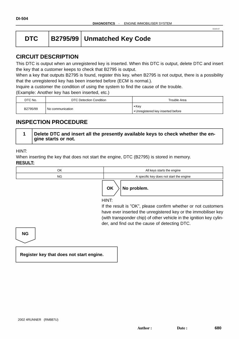
DI-504-DIAGNOSTICS ENGINE IMMOBILISER SYSTEM
680Author: Date:
2002 4RUNNER (RM887U)
DTC B2795/99 Unmatched Key Code
CIRCUIT DESCRIPTIONThis DTC is output when an unregistered key is inserted. When this DTC is output, delete DTC and insertthe key that a customer keeps to check that B2795 is output.When a key that outputs B2795 is found, register this key. when B2795 is not output, there is a possibilitythat the unregistered key has been inserted before (ECM is normal.).Inquire a customer the condition of using the system to find the cause of the trouble.(Example: Another key has been inserted, etc.)
DTC No. DTC Detection Condition Trouble Area
B2795/99 No communicationKey
Unregistered key inserted before
INSPECTION PROCEDURE
1 Delete DTC and insert all the presently available keys to check whether the en-gine starts or not.
HINT:When inserting the key that does not start the engine, DTC (B2795) is stored in memory.RESULT:
OK All keys starts the engine
NG A specific key does not start the engine
OK No problem.
HINT:If the result is ”OK”, please confirm whether or not customershave ever inserted the unregistered key or the immobiliser key(with transponder chip) of other vehicle in the ignition key cylin-der, and find out the cause of detecting DTC.
NG
Register key that does not start engine.
DI1KN-07

I03114
T6Transponder Key Amplifier
E14GR-R
19
18
52
3
4
CODE
RXCK
ECM
TXCT
E14
E14
R-B
P-B
CODE
RXCK
TXCT
-DIAGNOSTICS ENGINE IMMOBILISER SYSTEMDI-505
681Author: Date:
2002 4RUNNER (RM887U)
DTC B2796/99 No Communication in Immobiliser System
CIRCUIT DESCRIPTIONDTC No. DTC Detection Condition Trouble Area
B2796/99 No communication
Key
Transponder key coil
Transponder key amplifier
Wire harness
ECM
WIRING DIAGRAM
DI1KO-09

DI-506-DIAGNOSTICS ENGINE IMMOBILISER SYSTEM
682Author: Date:
2002 4RUNNER (RM887U)
INSPECTION PROCEDURE
1 Check transponder key coil (See page BE-172 ).
NG Replace transponder key coil.
OK
2 Check harness and connector between transponder key amplifier and ECM (Seepage IN-28 ).
NG Repair or replace harness or connector.
OK
3 Does it operate normally after replacement of transponder key amplifier?
Yes Replace transponder key amplifier.
No
Replace ECM.

I03114
T6Transponder Key Amplifier
E14GR-R
19
18
52
3
4
CODE
RXCK
ECM
TXCT
E14
E14
R-B
P-B
CODE
RXCK
TXCT
-DIAGNOSTICS ENGINE IMMOBILISER SYSTEMDI-507
683Author: Date:
2002 4RUNNER (RM887U)
DTC B2797/99 Communication Malfunction No. 1
CIRCUIT DESCRIPTIONThis code is detected when although the communication has been performed normally, an error occurs.(Example: Some noise is included in communication line.)
DTC No. DTC Detection Condition Trouble Area
B2797/99 Communication error
Wire harness
Transponder key amplifier
ECM
WIRING DIAGRAM
DI1KP-10

I02681
Noise
DI-508-DIAGNOSTICS ENGINE IMMOBILISER SYSTEM
684Author: Date:
2002 4RUNNER (RM887U)
INSPECTION PROCEDURE
1 Check noise.
PREPARATION:Insert already registered master key in the key cylinder.CHECK:Using an oscilloscope or TOYOTA hand-held tester, check thatnoise is included in terminal CODE of the ECM.OK:
No noise is detected.
NG Try to find cause of noise and remove it.
OK
2 Does it operate normally after replacement of transponder key amplifier?
Yes Replace transponder key amplifier.
No
Replace ECM.

I03114
T6Transponder Key Amplifier
E14GR-R
19
18
52
3
4
CODE
RXCK
ECM
TXCT
E14
E14
R-B
P-B
CODE
RXCK
TXCT
-DIAGNOSTICS ENGINE IMMOBILISER SYSTEMDI-509
685Author: Date:
2002 4RUNNER (RM887U)
DTC B2798/99 Communication Malfunction No. 2
CIRCUIT DESCRIPTIONDTC No. DTC Detection Condition Trouble Area
B2798/99 Communication error
Key
Transponder key coil
Transponder key amplifier
Wire harness
ECM
WIRING DIAGRAM
DI1KQ-08

DI-510-DIAGNOSTICS ENGINE IMMOBILISER SYSTEM
686Author: Date:
2002 4RUNNER (RM887U)
INSPECTION PROCEDURE
1 Check transponder key coil (See page BE-172 ).
NG Replace transponder key coil.
OK
2 Check harness and connector between transponder key amplifier and ECM (Seepage IN-28 ).
NG Repair or replace harness or connector.
OK
3 Does it operate normally after replacement of transponder key amplifier?
Yes Replace transponder key amplifier.
No
Replace ECM.

DI1OD-09
Customer Problem Analysis
Vehicle Brought to Workshop
Problem Symptom Confirmation Symptom Simulation
Symptom does notoccur
Circuit Inspection
Identification of Problem
Repair
Confirmation Test
End
Titles inside are titles of pages in thismanual, with the page number indicated inthe bottom portion. See the indicated pagesfor detailed explanations.
1
23
5
4
7
P. IN-18
P. DI-512
P. DI-518 - DI-549
Symptomoccur
Step 5, 7 : Diagnostic steps permitting the use of the TOYOTA hand-held tester .
6
Problem Symptoms Table
P. DI-517
-DIAGNOSTICS BODY CONTROL SYSTEMDI-51 1
687Author: Date:
2002 4RUNNER (RM887U)
BODY CONTROL SYSTEMHOW TO PROCEED WITH TROUBLESHOOTING

DI1OE-09
BODY CONTROL SYSTEM Check Sheet
Inspector’s name:
Customer’s Name
Date Vehicle
Registration No.
Registration Year
Frame No.
Odometer Reading / / kmMile
Weather ConditionsWhen ProblemOccurred
Date Problem First Occurred
Frequency Problem Occurs
Weather
/ /
Once only
Brought in
MalfunctionSystem
Outdoor Temperature
Fine Cloudy Rainy Snowy Various/ Others
Hot Warm Cool Cold (Approx. °F ( °C))
Constant Sometimes ( times per day, month)
Defogger System
Rear Washer System
Power Door Lock Control System
Theft Deterrent System
Others
DI-512-DIAGNOSTICS BODY CONTROL SYSTEM
688Author: Date:
2002 4RUNNER (RM887U)
CUSTOMER PROBLEM ANALYSIS CHECK

DI56U-04
I22491I22495I22494 I22527
Theft Deterrent Horn
Horn
Engine Hood Courtesy Switch
Theft Deterrent Indicator(Security Indicator)
Key Unlock Warning Switch
Door Key Lock & Unlock Switch
Door Courtesy Switch
Back Door Lock Motor
Door Lock Motor & Door Unlock Detection Switch Back Door ECU
Engine Room R/B Headlight Relay (Marking: HEAD) Taillight Relay (Marking TAIL) ALT H-Fuse AM1 M-Fuse J/B M-Fuse MPX-B Fuse
Driver Side J/B Body ECU POWER M-Fuse ECU-IG Fuse HORN, HAZ Fuse ACC Fuse WIPER Fuse
Ignition SwitchRear Washer Motor
Door Lock Control SwitchBack Door Window Lock Switch*2
Back Door WindowLock Switch*1
*1: w/o Power Window*2: w/ Power Window
Back Window Control Switch
Rear Wiper andWasher Switch
Daytime Running LightRelay (Main)
Door Lock ControlSwitch
-DIAGNOSTICS BODY CONTROL SYSTEMDI-513
689Author: Date:
2002 4RUNNER (RM887U)
PARTS LOCATION

DI1OG-19
I09495
1 15
B17 B16 R1
DI-514-DIAGNOSTICS BODY CONTROL SYSTEM
690Author: Date:
2002 4RUNNER (RM887U)
TERMINALS OF ECU
Symbols (Terminal No.) Wiring Color Condition STD Voltage (V)
HORN SW (B16-1) - G R
Horn switch OFF 10 - 14HORN SW (B16 1)
Body groundG-R
Horn switch ON Below 1.0
KSW (B16 2) B d d Y RKey unlock warning switch OFF (Key not inserted) 10 - 14
KSW (B16-2) - Body ground Y-RKey unlock warning switch ON (Key inserted) Below 1.0
DIND (B16 3) B d d LG RRear window defogger operating Below 2.0
DIND (B16-3) - Body ground LG-RRear window defogger not operating 10 - 14
DOWN (B16 4) B d d R BBack door power window switch OFF or UP position 10 - 14
DOWN (B16-4) - Body ground R-BBack door power window switch DOWN position Below 1.0
UP (B16 5) B d d RBack door power window switch OFF or DOWN position 10 - 14
UP (B16-5) - Body ground RBack door power window switch UP position Below 1.0
ACC (B16 9) B d d GRIgnition switch OFF Below 1.0
ACC (B16-9) - Body ground GRIgnition switch ACC or ON 10 - 14
ECU-B (B16-10) -
Body groundL-R Constant 10 - 14
L2 (B16 11) B d d BR W
Driver and passenger door key lock & unlock switch OFF or
UNLOCK position10 - 14
L2 (B16-11) - Body ground BR-WDriver or passenger door key lock & unlock switch LOCK posi-
tionBelow 1.0
UL2 (B16 12) B d d G YPassenger door key lock & unlock switch OFF or LOCK position 10 - 14
UL2 (B16-12) - Body ground G-YPassenger door key lock & unlock switch UNLOCK position Below 1.0
UL3 (B16 13) B d d L BDriver door key lock & unlock switch OFF or LOCK position 10 - 14
UL3 (B16-13) - Body ground L-BDriver door key lock & unlock switch UNLOCK position Below 1.0
LSWP (B16 14) B d d L YDriver door unlock detection switch OFF (Locked) 10 - 14
LSWP (B16-14) - Body ground L-YDriver door unlock detection switch ON (Unlocked) Below 1.0
RCTY (B16 15) B d d B RRear door courtesy switch OFF (Closed) 10 - 14
RCTY (B16-15) - Body ground B-RAny rear door courtesy switch ON (Open) Below 1.0
PCTY (B16 16) B d d B WPassenger door courtesy switches OFF (Closed) 10 - 14
PCTY (B16-16) - Body ground B-WPassenger door courtesy switch ON (Open) Below 1.0
LSWD (B16 17) B d d R LDriver door unlock detection switch OFF (Locked) 10 - 14
LSWD (B16-17) - Body ground R-LDriver door unlock detection switch ON (Unlocked) Below 1.0

-DIAGNOSTICS BODY CONTROL SYSTEMDI-515
691Author: Date:
2002 4RUNNER (RM887U)
DEF SW (B16-18) - LG B
Rear defogger switch OFF 10 - 14DEF SW (B16 18)
Body groundLG-B
Rear defogger switch ON Below 1.0
DCTY (B16 19) B d d BDriver door courtesy switch OFF (Closed) 10 - 14
DCTY (B16-19) - Body ground BDriver door courtesy switch ON (Open) Below 1.0
R/W ON (B16-20) - GR G
Rear wiper switch OFF or INT 10 - 14R/W ON (B16 20)
Body groundGR-G
Rear wiper switch ON Below 1.0
R/W INT (B16-21) - GR R
Rear wiper switch OFF or ON 10 - 14R/W INT (B16 21)
Body groundGR-R
Rear wiper switch INT Below 1.0
B/D CTY (B16-22) - G W
Back door courtesy switch OFF (Closed) 10 - 14B/D CTY (B16 22)
Body groundG-W
Back door courtesy switch ON (Open) Below 1.0
ACTD (B16 23) B d d B YPower door lock operating to LOCK 10 - 14
ACTD (B16-23) - Body ground B-YPower door lock not operating or operating to UNLOCK Below 1.0
SEC IND (B17-1) - L
Security indicator light lights up 10 - 14SEC IND (B17 1)
Body groundL
Security indicator dies not light up Below 1.0
SH (B17 2) B d d R WSecurity horn sounding 10 - 14
SH (B17-2) - Body ground R-WSecurity horn not sounding Below 1.0
HRY (B17 3) B d dR*2 Headlight relay OFF 10 - 14
HRY (B17-3) - Body groundR
G*3 Headlight relay ON Below 1.0
TRY (B17 4) B d d R GTaillight relay OFF 10 - 14
TRY (B17-4) - Body ground R-GTaillight relay ON Below 1.0
HOOD SW (B17-7) - G O
Hood courtesy switch OFF (Closed) 10 - 14HOOD SW (B17 7)
Body groundG-O
Hood courtesy switch ON (Open) Below 1.0
LSWR (B17 8) B d d LGRear door unlock detection switch OFF (Locked) 10 - 14
LSWR (B17-8) - Body ground LGRear door unlock detection switch ON (Unlocked) Below 1.0
HORN (R1 1) GND (R1 8)Horn switch OFF Below 1.0
HORN (R1-1) - GND (R1-8) -Horn switch ON 10 - 14
POWER (R1-3) - GND (R1-8) - Constant 10 - 14
P/W (R1 2) GND (R1 8)Ignition switch OFF or ACC*1 Below 1.0
P/W (R1-2) - GND (R1-8) -Ignition switch ON 10 - 14
DEF (R1 4) GND (R1 8)Rear defogger not operating 10 - 14
DEF (R1-4) - GND (R1-8) -Rear defogger operating Below 1.0
HAZ (R1-7) - GND (R1-8) - Constant 10 - 14
GND (R1-8) - Body ground - Constant Below 1.0
WIP (R1 9) GND (R1 8)Ignition switch OFF or ACC Below 1.0
WIP (R1-9) GND (R1-8) -Ignition switch ON 10 - 14
ECU-IG (R1-10) - Ignition switch OFF or ACC Below 1.0ECU IG (R1 10)
GND (R1-8)-
Ignition switch ON 10 - 14
L1 (R1 11) GND (R1 8)Driver or passenger door lock control switch OFF or UNLOCK 10 - 14
L1 (R1-11) - GND (R1-8) -Driver or passenger door lock control switch LOCK Below 1.0
UL1 (R1 12) GND (R1 8)Driver or passenger door lock control switch OFF or LOCK 10 - 14
UL1 (R1-12) - GND (R1-8) -Driver or passenger door lock control switch UNLOCK Below 1.0
WMTR (R1 13) GND (R1 8)Rear washer switch OFF 10 - 14
WMTR (R1-13) - GND (R1-8) -Rear washer switch ON Below 1.0
ACT (R1 14) GND (R1 8)Power door lock not operating or operating to UNLOCK Below 1.0
ACT+ (R1-14) - GND (R1-8) -Power door lock operating to LOCK 10 - 14

DI-516-DIAGNOSTICS BODY CONTROL SYSTEM
692Author: Date:
2002 4RUNNER (RM887U)
ACT (R1 15) GND (R1 8)Power door lock not operating or operating to LOCK Below 1.0
ACT- (R1-15) - GND (R1-8) -Power door lock operating to UNLOCK twice 10 - 14
*1 (Exceptions): During 60 seconds after the ignition switch is turned ON to OFF (ACC) or until driver or pas-senger door is opened after the ignition switch is turned ON to OFF (ACC).*2: w/o Daytime running light*3: w/ Daytime running light

DI56V-03
-DIAGNOSTICS BODY CONTROL SYSTEMDI-517
693Author: Date:
2002 4RUNNER (RM887U)
PROBLEM SYMPTOMS TABLEDOOR LOCK CONTROL
Symptom Suspect Area See page
Lock or unlock cannot be operated with door lock control switch3. Door lock control switch circuit (D or P)
4. Body ECU
DI-533
IN-28
Door key linked function does not operate1. Door key lock and unlock switch circuit (D or P)
2. Body ECU
DI-535
IN-28
Key confinement prevention function does not operate1. Key unlock warning switch circuit
2. Body ECU
DI-527
IN-28
THEFT DETERRENT SYSTEM
Symptom Suspect Area See page
No alerting condition is operated (System cannot be set)
1. Security indicator circuit
2. Key unlock warning switch circuit
3. Courtesy switch circuit
4. Door unlock detection switch circuit
5. Engine hood courtesy switch circuit
6. Back door courtesy switch circuit
7. Back door ECU
8. Body ECU
DI-543
DI-527
DI-539
DI-533
DI-541
DI-562
IN-28
IN-28
Cannot be canceled when ignition switch is ON with a key
1. Key unlock warning switch circuit
2. Ignition switch
3. Body ECU
DI-527
BE-12
IN-28
Cannot be canceled when unlocking the back door with a key1. Back door courtesy switch circuit
2. Body ECU
DI-562
IN-28
Some of the system does not operate (Headlight does not light
up)
1. Headlight relay circuit
2. Body ECU
DI-526
IN-28
Taillight does not light up1. Taillight relay circuit
2. Body ECU
DI-525
IN-28
Theft deterrent horn or horn does not sound
1. Security horn circuit
2. Horn circuit
3. Body ECU
DI-547
DI-545
IN-28
During warning condition, cannot be canceled by unlocking the
door with a key
1. Door key lock and unlock switch circuit
2. Body ECU
DI-535
IN-28
During warning condition, cannot be canceled by unlocking the
door with a key (Transmitter)
1. Transmitter
2. Back door ECU
3. Body ECU
BE-93
IN-28
IN-28
During warning condition, cannot be cancelled by turning the ON
with a key
1. Ignition switch
2. Key unlock warning switch circuit
3. Body ECU
BE-12
DI-527
IN-28
The system operated for more 60 records 1. Body ECU IN-28

DI56W-03
I10125
Engine Room R/B
MPX-B1 2 2 L-R 13
IG1 L-R10B16
Body ECU
ECU-B
J/B
1 2 2
1 21 2
22
W-R
L-R
Driver Side J/B
GR 9B16 ACC
11I
ACC
POWER
1G 11
3 POWER2
1K
HORN HAZ
7 HAZ
ECU-IG
B-Y
I14IgnitionSwitch
W
423
21I
WIPER
81J
10
9
ECU-IG
GND8
WIP
Battery
W-B
IF
AJ9J/C
Center J/B
163E
213E
W-B
ALT AM1
W
1 2
DI-518-DIAGNOSTICS BODY CONTROL SYSTEM
694Author: Date:
2002 4RUNNER (RM887U)
CIRCUIT INSPECTION
Power Source Circuit
CIRCUIT DESCRIPTIONThis circuit provides power to operate the body ECU.
WIRING DIAGRAM

I09488
WIPER
ECU-IG
(+) (-)
I09490
HORN, HAZ
POWER
(-)(+)
-DIAGNOSTICS BODY CONTROL SYSTEMDI-519
695Author: Date:
2002 4RUNNER (RM887U)
INSPECTION PROCEDURE
1 Check POWER M-fuse, WIPER, ACC, HORN, HAZ, MPX-B and ECU-IG fuses.
CHECK:Check the continuity of the POWER M-fuse, the WIPER, ACC, HORN, HAZ, MPX-B and ECU-IG fuses.OK:
Continuity
NG Replace failure fuse.
OK
2 Check voltage between terminals WIPER, ACC, HORN, HAZ, POWER, ECU-B,ECU-IG and GND of body ECU connector and body ground.
PREPARATION:(a) Disconnect the 2 connectors and remove the cover.(b) Turn the ignition switch ON.CHECK:Measure the voltage between terminals WIPER, ECU-IG andbody ground.OK:
Voltage: 10 - 14 V
PREPARATION:Turn the ignition switch OFF.CHECK:Measure the voltage between terminals HORN, HAZ, POWERand body ground.OK:
Voltage: 10 - 14 V

I09491
ACC
(+)
(-)
I22496
ECU-B
(+)
(-)
I09489
GND
DI-520-DIAGNOSTICS BODY CONTROL SYSTEM
696Author: Date:
2002 4RUNNER (RM887U)
PREPARATION:Turn the ignition switch ON.CHECK:Measure the voltage between terminal ACC and body ground.OK:
Voltage: 10 - 14 V
PREPARATION:Turn the ignition switch OFF.CHECK:Measure the voltage between terminal ECU- B and bodyground.OK:
Voltage: 10 - 14 V
NG Proceed to next circuit inspection shown onproblem symptoms table (See page DI-517 ).
OK
3 Check continuity between terminal GND and body ground.
PREPARATION:Disconnect the 2 connectors and remove the cover.CHECK:Check the continuity between terminal GND and body ground.OK:
Continuity
NG Repair or replace driver side J/B, harness orconnector.
OK
Replace driver side J/B.

I22497
Body ECU
WASHER
OFF
INT
ON
WASHER
12 10 13
P
W1Rear Washer Motor
4LG
Driver Side J/B8
1H13
WMTR
GR-R
GR-G20
B16 R/W ON
21B16 R/W INT
2
W-BA
J4J/C
IE
3*1
5*2
*1: w/o Daytime Running Light*2: w/ Daytime Running Light
C15Rear Wiper and Washer Switch(Combination Switch)
WR +1R C1R EW
-DIAGNOSTICS BODY CONTROL SYSTEMDI-521
697Author: Date:
2002 4RUNNER (RM887U)
Rear Wiper Switch Circuit
CIRCUIT DESCRIPTIONBody ECU judges the switch position with the terminal voltage of the rear wiper switch and runs the wipermotor.
WIRING DIAGRAM
DI56X-05

DI-522-DIAGNOSTICS BODY CONTROL SYSTEM
698Author: Date:
2002 4RUNNER (RM887U)
INSPECTION PROCEDURE
1 Check rear wiper and washer switch (See page BE-34 ).
NG Replace rear wiper and washer switch.
OK
2 Check harness and connector between rear wiper and washer switch and bodyECU (See page IN-28 ).
NG Repair or replace harness or connector.
OK
Proceed to next circuit inspection shown onproblem symptoms table (See page DI-517 ).
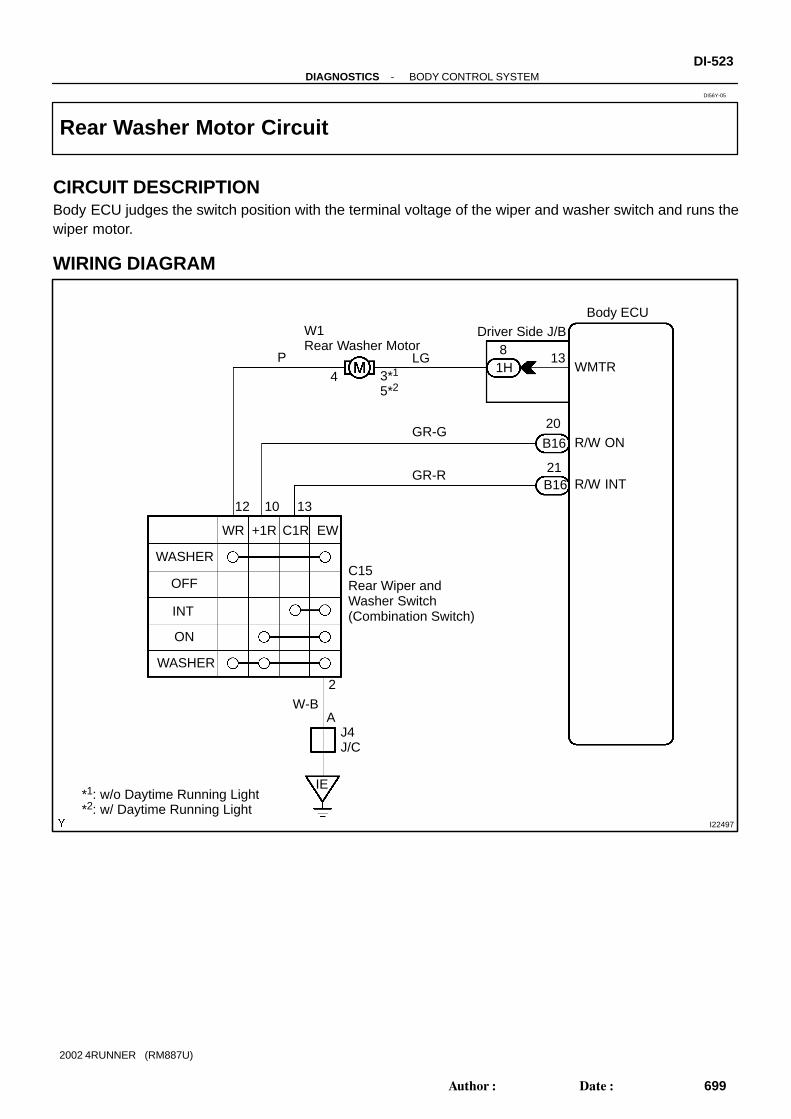
I22497
Body ECU
WASHER
OFF
INT
ON
WASHER
12 10 13
P
W1Rear Washer Motor
4LG
Driver Side J/B8
1H13
WMTR
GR-R
GR-G20
B16 R/W ON
21B16 R/W INT
2
W-BA
J4J/C
IE
3*1
5*2
*1: w/o Daytime Running Light*2: w/ Daytime Running Light
C15Rear Wiper and Washer Switch(Combination Switch)
WR +1R C1R EW
-DIAGNOSTICS BODY CONTROL SYSTEMDI-523
699Author: Date:
2002 4RUNNER (RM887U)
Rear Washer Motor Circuit
CIRCUIT DESCRIPTIONBody ECU judges the switch position with the terminal voltage of the wiper and washer switch and runs thewiper motor.
WIRING DIAGRAM
DI56Y-05

DI-524-DIAGNOSTICS BODY CONTROL SYSTEM
700Author: Date:
2002 4RUNNER (RM887U)
INSPECTION PROCEDURE
1 Check rear wiper and washer switch (See page BE-34 ).
NG Replace rear wiper and washer switch.
OK
2 Check rear washer motor (See page BE-34 ).
NG Replace wiper motor.
OK
3 Check harness and connector between rear wiper and washer switch and bodyECU (See page IN-28 ).
NG Repair or replace harness or connector.
OK
Proceed to next circuit inspection shown onproblem symptoms table (See page DI-517 ).

I10129
Body ECUTAIL Relay
Battery
W 21
ALT
2 1
5
2
3
2
2
To TAIL Fuse
R-G15IG1 R-G
BB
BR-G
ToCombinationSwitch
J5J/C 4
B17 TRY
Engine Room R/B
B
R-G
-DIAGNOSTICS BODY CONTROL SYSTEMDI-525
701Author: Date:
2002 4RUNNER (RM887U)
Taillight Relay Circuit
CIRCUIT DESCRIPTIONWhen the panic signal is received, the control of the taillight relay is performed.
WIRING DIAGRAM
INSPECTION PROCEDURE
1 Check harness and connector between taillight relay (Marking: TAIL) and bodyECU (See page IN-28 ).
NG Repair or replace harness or connector.
OK
Check and replace body ECU.
DI56Z-03

I22498
Body ECU
4 32
1
Engine Room R/BDriver Side J/B
Battery
W
2
HEAD Relay
2
2
R5 6
1K 1CR
To HEAD Fuse
Daytime RunningLight Relay (Main)
R
J3J/C
DD
D
7D8
*1
*2G
3B17 HRY
R
*1: w/o Daytime Running Light*2: w/ Daytime Running Light
D86
DI-526-DIAGNOSTICS BODY CONTROL SYSTEM
702Author: Date:
2002 4RUNNER (RM887U)
Headlight Relay Circuit
CIRCUIT DESCRIPTIONWhen the panic signal is received, the control of the headlight relay is performed.
WIRING DIAGRAM
INSPECTION PROCEDURE
1 Check harness and connector between headlight relay (Marking: HEAD) andbody ECU, and battery and headlight relay (See page IN-28 ).
NG Repair or replace harness or connector.
OK
Check and replace body ECU.
DI570-03

I10134
Body ECU
B16 KSW
IE
J4J/C
A
W-B1 2
U1Key UnlockWarning Switch
Y-RA A
J6J/C
Y-R2
-DIAGNOSTICS BODY CONTROL SYSTEMDI-527
703Author: Date:
2002 4RUNNER (RM887U)
Key Unlock Warning Switch Circuit
CIRCUIT DESCRIPTIONThe key unlock warning switch goes on when the ignition key is inserted in the key cylinder and goes off whenthe ignition key is removed.
WIRING DIAGRAM
DI571-05

DI-528-DIAGNOSTICS BODY CONTROL SYSTEM
704Author: Date:
2002 4RUNNER (RM887U)
INSPECTION PROCEDURE
1 Check key unlock warning switch (See page BE-12 ).
NG Replace key unlock warning switch.
OK
2 Check harness and connector between key unlock warning switch and bodyECU (See page IN-28 ).
NG Repair or replace harness or connector.
OK
Proceed to next circuit inspection shown onproblem symptoms table (See page DI-517 ).

I10132
IF
J9J/C
A
W-B
Center J/B
163E
193E
7W-B
10
B5Back WindowLock Switch
L-W* 2
Power WindowMaster Switch
14P7
13P7
G G
Y Y
7IF2
8IF2
D11Diode (Back Window)
*1
L-W2 A
AA
J5J/C
L-W6
C23
Back Window Control Switch(Center Cluster Switch)
2C23
C231
R
R-B
Body ECU
5B16 UP
4B16 DOWN
*1: w/ Power Window System*2: w/o Power Window System
RRD
RRU
1
3
Up
Down
-DIAGNOSTICS BODY CONTROL SYSTEMDI-529
705Author: Date:
2002 4RUNNER (RM887U)
Back Door Power Window Switch Circuit
WIRING DIAGRAM
DI572-05

DI-530-DIAGNOSTICS BODY CONTROL SYSTEM
706Author: Date:
2002 4RUNNER (RM887U)
INSPECTION PROCEDURE
1 Check back door power window switch (See page BE-65 ).
NG Replace back door power window switch.
OK
2 Check harness and connector between power window switch and body ECU(See page IN-28 ).
NG Repair or replace harness or connector.
OK
Proceed to next circuit inspection shown onproblem symptoms table (See page DI-517 ).

I23890
B-Y
B-Y
EJ10
J10E
J/C
D25Passenger DoorLock Motor
DJ11
3 2B-Y L-W E
J11
J/C
J10
DJ10
L-W
L-WB-YB-Y4
3 2
D27Rear RH DoorLock Motor
1
L-WL-W 2
23
Driver DoorLock Motor
P-G3B-Y
B-Y 4 B-Y
Rear LH DoorLock Motor
23L-WL-W 1
L-W2
3
L-W4 5L-W L-W
8
B-Y B-Y B-Y B-Y
B-Y
10 10 11
1H ACT+
DriverSide J/B
L-W
61H ACT-
B10Back DoorLock Motor
L-W
14
D24
D26
15
23
B16 ACTD
D
7
Body ECU
BX1BX1
IF2 IF2
BW1 BW1
BS1
BS1
BR1
BR1
IE1
IE1
-DIAGNOSTICS BODY CONTROL SYSTEMDI-531
707Author: Date:
2002 4RUNNER (RM887U)
Door Lock Motor Circuit
WIRING DIAGRAM
DI573-05

DI-532-DIAGNOSTICS BODY CONTROL SYSTEM
708Author: Date:
2002 4RUNNER (RM887U)
INSPECTION PROCEDURE
1 Check door lock motor (See page BE-76 ).
NG Replace door lock motor.
OK
2 Check harness and connector between door lock motor and body ECU (Seepage IN-28 ).
NG Repair or replace harness or connector.
OK
Check and replace body ECU.

I10127
W-B
W-B W-B
W-B
W-B W-B
W-BW-B
3BW1 BW11 4
Rear LH Door UnlockDetection Switch
LG 7 LG LG
LGLG
8B17 LSWR
3
Rear RH Door UnlockDetection Switch
1 4
Driver Door UnlockDetection Switch
R-L R-L12 17B16 LSWD
7
1
1 4
1 4
6
A
A
J4J/C
Passenger Door UnlockDetection Switch
L-Y L-Y13B16 LSWP14
D27
D24
D25
IF
J9J/C
AW-B
16
3E13
3E
W-B
IE
A
CenterJ/B
Body ECUD26
BX1BX1
IF2IF2
IK1IK1
-DIAGNOSTICS BODY CONTROL SYSTEMDI-533
709Author: Date:
2002 4RUNNER (RM887U)
Door Unlock Detection Switch Circuit
CIRCUIT DESCRIPTIONThe door unlock detection switch is built in the door lock motor assembly. This switch is ON when the doorlock knob is in the unlock position and OFF when the lock knob is in the lock position. The ECU detects thedoor lock knob conditions is this circuit. It is used as one of the operating conditions for the key confinementprevention function, wireless door lock control system and theft deterrent system.
WIRING DIAGRAM
DI574-03

DI-534-DIAGNOSTICS BODY CONTROL SYSTEM
710Author: Date:
2002 4RUNNER (RM887U)
INSPECTION PROCEDURE
1 Check door unlock detection switch (See page BE-76 ).
NG Replace door lock motor.
OK
2 Check harness and connector between door unlock detection switch and bodyECU (See page IN-28 ).
NG Repair or replace harness or connector.
OK
Proceed to next circuit inspection shown onproblem symptoms table (See page DI-517 ).

I10128
IE
A AJ4J/C
W-B W-B
W-B W-B
6IK1
1IF2 2
2
Driver Door Key Lock& Unlock Switch
UNLOCK
LOCK
3
1
L-BL-B 12IF1
IF12BR-W BR-W
BR-W
BR-W
13B16
Body ECU
UL3
11B16 L2
BR-W 14LOCK
UNLOCK
1
3
Passenger Door KeyLock & Unlock Switch
G-Y 4IK1
IK1 G-Y12B16 UL2
D20
D21
-DIAGNOSTICS BODY CONTROL SYSTEMDI-535
711Author: Date:
2002 4RUNNER (RM887U)
Door Key Lock and Unlock Switch Circuit
CIRCUIT DESCRIPTIONThe door key lock and unlock switch is installed to the door key cylinder. When the key is turned to the lockside, terminal 1 of the switch is grounded and when the key is turned to the unlock side, terminal 3 of theswitch is grounded.
WIRING DIAGRAM
DI575-03

DI-536-DIAGNOSTICS BODY CONTROL SYSTEM
712Author: Date:
2002 4RUNNER (RM887U)
INSPECTION PROCEDURE
1 Check door key lock and unlock switch (See page BE-76 ).
NG Replace door key lock and unlock switch.
OK
2 Check harness and connector between door key lock and unlock switch andbody ECU (See page IN-28 ).
NG Repair or replace harness or connector.
OK
Proceed to next circuit inspection shown onproblem symptoms table (See page DI-517 ).

I10133
IE
J4J/C
AA
W-B W-B6IK1
IF21 W-B
P7*1, D22*2
Driver Door LockControl Switch
LOCK
UNLOCK4
R-W6*1
3*2
12*1
2*2
R R
3IF14
IF1
R-WLOCK
UNLOCK3*1
4*2
Driver Side J/BBody ECU
101H
11L1
R
IK1
IK1
R-W
R R6*1
3*2
5*1
2*2
5
15 91H
12UL1
*1: w/ Power Window System*2: w/o Power Window System
W-B
D23Passenger Door LockControl Switch
R-W R-W
-DIAGNOSTICS BODY CONTROL SYSTEMDI-537
713Author: Date:
2002 4RUNNER (RM887U)
Door Lock Control Switch Circuit
WIRING DIAGRAM
DI576-03

DI-538-DIAGNOSTICS BODY CONTROL SYSTEM
714Author: Date:
2002 4RUNNER (RM887U)
INSPECTION PROCEDURE
1 Check door lock control switch (See page BE-76 ).
NG Replace door lock control switch.
OK
2 Check harness and connector between door lock control switch and body ECU(See page IN-28 ).
NG Repair or replace harness or connector.
OK
Proceed to next circuit inspection shown onproblem symptoms table (See page DI-517 ).

I10137 I22525
Rear LHDoorCourtesySwitch
PassengerDoorCourtesySwitch
DriverDoorCourtesySwitch
Rear RHDoorCourtesySwitch
1 1 1 1D19D18D17D16
B
B-W
B-R
B-R
B-R
B-R
B-R
Body ECU
19B16
B16
B16
16
1514IE2
IL18
DCTY
PCTY
RCTY
-DIAGNOSTICS BODY CONTROL SYSTEMDI-539
715Author: Date:
2002 4RUNNER (RM887U)
Front and Rear Door Courtesy Switch Circuit
CIRCUIT DESCRIPTIONThe door courtesy switch ON when the door is opened and OFF when door is closed.
WIRING DIAGRAM
DI577-03

DI-540-DIAGNOSTICS BODY CONTROL SYSTEM
716Author: Date:
2002 4RUNNER (RM887U)
INSPECTION PROCEDURE
1 Check door courtesy switch (See page BE-26 ).
NG Replace door courtesy switch.
OK
2 Check harness and connector between door courtesy switch and body ECU (Seepage IN-28 ).
NG Repair or replace harness or connector.
OK
Proceed to next circuit inspection shown onproblem symptoms table (See page DI-517 ).

I10135
W-B
E13Hood CourtesySwitch
W-B
21
EB
J1
J2
A
A
J/C
G-O G-O18IG1 B17
7HOOD SW
Body ECU
-DIAGNOSTICS BODY CONTROL SYSTEMDI-541
717Author: Date:
2002 4RUNNER (RM887U)
Hood Courtesy Switch Circuit
CIRCUIT DESCRIPTIONThe hood courtesy switch is built into the engine hood lock assembly and goes on when the engine hoodis opened and goes off when the engine hood is closed.
WIRING DIAGRAM
DI578-02
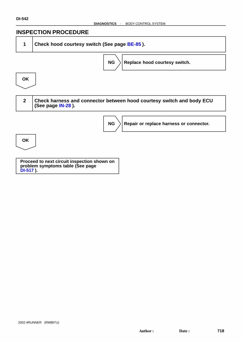
DI-542-DIAGNOSTICS BODY CONTROL SYSTEM
718Author: Date:
2002 4RUNNER (RM887U)
INSPECTION PROCEDURE
1 Check hood courtesy switch (See page BE-85 ).
NG Replace hood courtesy switch.
OK
2 Check harness and connector between hood courtesy switch and body ECU(See page IN-28 ).
NG Repair or replace harness or connector.
OK
Proceed to next circuit inspection shown onproblem symptoms table (See page DI-517 ).

I10136
Body ECU
IF
W-B SEC IND6
A
3W-B L
J9J/C
Center J/B163E 3E
13C24 C24
Security Indicator Light(Center Cluster Switch)
1B17
-DIAGNOSTICS BODY CONTROL SYSTEMDI-543
719Author: Date:
2002 4RUNNER (RM887U)
Theft Deterrent Indicator Circuit
CIRCUIT DESCRIPTIONWhen the theft deterrent system is preparing to set, this circuit lights up the indicator light. When the systemhas been set, it continually turns the indicator light on for 1 second and turns it off for 1 second, thus blinkingthe indicator light. This theft deterrent indicator is connected to the ECM and outputs the key judgment of the immobilizer.
WIRING DIAGRAM
DI579-02

DI-544-DIAGNOSTICS BODY CONTROL SYSTEM
720Author: Date:
2002 4RUNNER (RM887U)
INSPECTION PROCEDURE
1 Check theft deterrent indicator (See page BE-85 ).
NG Replace theft deterrent indicator.
OK
2 Check harness and connector between theft deterrent indicator and body ECU,and theft deterrent indicator and body ground (See page IN-28 ).
NG Repair or replace harness or connector.
OK
Proceed to next circuit inspection shown onproblem symptoms table (See page DI-517 ).

I10138
C14HornSwitch
6
G-R 1B16
HornSwitch
HornSwitch
Driver Side J/B
1 1
B
Body ECU
81E 1 HORN
B
H6 H5
HORN SW
-DIAGNOSTICS BODY CONTROL SYSTEMDI-545
721Author: Date:
2002 4RUNNER (RM887U)
Horn Circuit
CIRCUIT DESCRIPTIONThe horn is connected to the body ECU and activated by the body ECU during warning of the theft deterrentsystem and horn switch ON.
WIRING DIAGRAM
DI57A-03

DI-546-DIAGNOSTICS BODY CONTROL SYSTEM
722Author: Date:
2002 4RUNNER (RM887U)
INSPECTION PROCEDURE
1 Check horn.
NG Replace horn.
OK
2 Check horn switch.
NG Replace horn switch.
OK
3 Check harness and connector between horn and body ECU, and body ECU andhorn switch (See page IN-28 ).
NG Repair or replace harness or connector.
OK
Check and replace driver side J/B.

I10139
2B17
Body ECU
SHR-W
1T5Theft DeterrentHorn
-DIAGNOSTICS BODY CONTROL SYSTEMDI-547
723Author: Date:
2002 4RUNNER (RM887U)
Theft Deterrent Horn Circuit
CIRCUIT DESCRIPTIONDuring warning of the theft deterrent system, the body ECU activates the theft deterrent horn.
WIRING DIAGRAM
DI57B-02

DI-548-DIAGNOSTICS BODY CONTROL SYSTEM
724Author: Date:
2002 4RUNNER (RM887U)
INSPECTION PROCEDURE
1 Check theft deterrent horn (See page BE-85 ).
NG Replace theft deterrent horn.
OK
2 Check harness and connector between theft deterrent horn and body ECU (Seepage IN-28 ).
NG Repair or replace harness or connector.
OK
Proceed to next circuit inspection shown onproblem symptoms table (See page DI-517 ).

I10140
Body ECU
B165
Back Door ECU
MPX118
B18V-W
BS1V-W V-W V-W4
BR2 IE28 7
MPX1
-DIAGNOSTICS BODY CONTROL SYSTEMDI-549
725Author: Date:
2002 4RUNNER (RM887U)
MPX Circuit
CIRCUIT DESCRIPTIONThis circuit communicates information of the wireless door lock control system, rear defogger system, opendoor warning, luggage light, theft deterrent system, rear wiper washer system and back door power windowsystem between the body ECU and back door ECU.
WIRING DIAGRAM
DI57C-04

DI-550-DIAGNOSTICS BODY CONTROL SYSTEM
726Author: Date:
2002 4RUNNER (RM887U)
INSPECTION PROCEDURE
1 Check harness and connector between back door ECU and body ECU (See pageIN-28 ).
NG Repair or replace harness or connector.
OK
Proceed to next circuit inspection shown onproblem symptoms table (See page DI-517 ).

DI57D-01
Customer Problem Analysis
Vehicle Brought to Workshop
Problem Symptom Confirmation Symptom Simulation
Symptom does notoccur
Circuit Inspection
Identification of Problem
Repair
Confirmation Test
End
Titles inside are titles of pages in thismanual, with the page number indicated inthe bottom portion. See the indicated pagesfor detailed explanations.
1
23
5
4
7
P. IN-18
P. DI-552
P. DI-557 - DI-574
Symptomoccur
Step 5, 7 : Diagnostic steps permitting the use of the TOYOTA hand-held tester.
6
Problem Symptoms Table
P. DI-556
-DIAGNOSTICS BACK DOOR CONTROL SYSTEMDI-551
727Author: Date:
2002 4RUNNER (RM887U)
BACK DOOR CONTROL SYSTEMHOW TO PROCEED WITH TROUBLESHOOTINGHINT:This ECU is connected to the multiplex communication system. Therefore, be sure to check that there is notroubles in the multiplex communication system before performing the troubleshooting.

DI57E-01
BACK DOOR CONTROL SYSTEM Check Sheet
Inspector’s name:
Customer’s Name
Date Vehicle
Registration No.
Registration Year
Frame No.
Odometer Reading / / kmMile
Weather ConditionsWhen ProblemOccurred
Date Problem First Occurred
Frequency Problem Occurs
Weather
/ /
Once only
Brought in
MalfunctionSystem
Outdoor Temperature
Fine Cloudy Rainy Snowy Various/ Others
Hot Warm Cool Cold (Approx. °F ( °C))
Constant Sometimes ( times per day, month)
Wireless Door Lock Control System
Power Door Lock Control System
Theft Deterrent System
Others
DI-552-DIAGNOSTICS BACK DOOR CONTROL SYSTEM
728Author: Date:
2002 4RUNNER (RM887U)
CUSTOMER PROBLEM ANALYSIS CHECK

DI57F-03
I22493I21848I22492 I22526
Back Door ECU
Engine Room R/B ALT H-Fuse AM1 M-Fuse JCB M-Fuse MPX-B Fuse
Driver Side J/B Body ECU POWER M-Fuse ECU-IG Fuse
Ignition Switch
Back Door Control Switch
Back DoorPower Window Motor
Back Window Limit Switch
Rear Wiper Motor
Wireless Door Lock Buzzer
Back Door Unlock Detection Switch
Back Door Courtesy Switch
-DIAGNOSTICS BACK DOOR CONTROL SYSTEMDI-553
729Author: Date:
2002 4RUNNER (RM887U)
PARTS LOCATION

DI57G-05
I09496
DI-554-DIAGNOSTICS BACK DOOR CONTROL SYSTEM
730Author: Date:
2002 4RUNNER (RM887U)
TERMINALS OF ECU
Symbols (Terminal No.) Wiring Color Condition STD Voltage (V)
POWE (B18-1) -
GND (B18-26)L - W-B
C t t 10 14ECU-B (B18-2) -
GND (B18-26)L-R - W-B
Constant 10 - 14
IG (B18 3) GND (B18 26) Y W BIgnition switch OFF or ACC Below 1.0
IG (B18-3) - GND (B18-26) Y - W-BIgnition switch ON 10 - 14
BZR1 (B18 5) BZR2 (B18 4) P B P GWireless door lock buzzer sounded 10 - 14
BZR1 (B18-5) - BZR2 (B18-4) P-B - P-GWireless door lock buzzer not sounded Below 1.0
BCTY (B18-7) - L W W B
Back door courtesy switch OFF (Closed) 10 - 14BCTY (B18 7)
GND (B18-26)L-W - W-B
Back door courtesy switch ON (Open) Below 1.0
CLS (B18 9) GND (B18 26) G R W BBack door control switch OFF or DOWN 10 - 14
CLS (B18-9) - GND (B18-26) G-R - W-BBack door control switch UP Below 1.0
OPN (B18-10) - G Y W B
Back door control switch OFF or UP 10 - 14OPN (B18 10)
GND (B18-26)G-Y - W-B
Back door control switch DOWN Below 1.0
CLSM (B18-11) - R W B
Back door power window not operating Below 1.0CLSM (B18 11)
GND (B18-26)R - W-B
Back door power window operating upward 10 - 14
OPNM (B18-12) - G W B
Back door power window not operating Below 1.0OPNM (B18 12)
GND (B18-26)G - W-B
Back door power window operating downward 10 - 14
LMTW (B18-13) - R L W B
Window limit switch OFF (Closed) 10 - 14LMTW (B18 13)
GND (B18-26)R-L - W-B
Window limit switch ON (Open) Below 1.0
LSWB (B18-20) - L B W B
Back door unlock detection switch OFF (Locked) 10 - 14LSWB (B18 20)
GND (B18-26)*L-B - W-B
Back door unlock detection switch ON (Unlocked) Below 1.0
LMT2 (B18-22) - GR W B
Rear wiper arm storing position 10 - 14LMT2 (B18 22)
GND (B18-26)GR - W-B
Rear wiper arm not storing position Below 1.0
LMT1 (B18-23) - GR R W B
Rear wiper arm between stopping and reversing position 10 - 14LMT1 (B18 23)
GND (B18-26)GR-R - W-B
Rear wiper arm except stopping and reversing position Below 1.0
WIP- (B18-24) - L B W B
Rear wiper motor not operating Below 1.0WIP (B18 24)
GND (B18-26)L-B - W-B
Rear wiper motor rotates reversely 10 - 14

-DIAGNOSTICS BACK DOOR CONTROL SYSTEMDI-555
731Author: Date:
2002 4RUNNER (RM887U)
WIP+ (B18-25) - L Y W B
Rear wiper motor not operating Below 1.0WIP+ (B18 25)
GND (B18-26)L-Y - W-B
Rear wiper motor rotates 10 - 14
GND (B18-26) - Body groundW-B -
Body groundConstant Below 1.0
*: w/ Theft deterrent system

DI57H-01
DI-556-DIAGNOSTICS BACK DOOR CONTROL SYSTEM
732Author: Date:
2002 4RUNNER (RM887U)
PROBLEM SYMPTOMS TABLEWIRELESS DOOR LOCK CONTROL
Symptom Suspect Area See page
All function of wireless door lock control system do not operate
2. Transmitter
3. Key unlock warning switch circuit
4. Back door ECU
5. MPX circuit
6. Body ECU
BE-93
DI-527
IN-28
DI-549
IN-28
Lock (or unlock) function does not operate
1. Door key lock and unlock switch circuit
2. Door unlock detection switch circuit
3. Body ECU
DI-535
DI-533
IN-18
Automatic lock function operates even if any door is opened within
30 seconds after all doors are unlocked by wireless door lock
control system
1. Door courtesy switch circuit
2. Back door ECU
DI-539
IN-18
Wireless door lock operates, but the buzzer does not sound
1. Wireless door lock buzzer circuit
2. MPX circuit
3. Back door ECU
DI-574
DI-549
IN-18
Buzzer sound, but wireless door lock function does not operate 1. Body ECU IN-18
Back door window open control system does not operate
1. Back door power window motor circuit
2. Rear wiper limit switch circuit
3. Back door ECU
DI-570
DI-568
IN-18
REAR WIPER AND WASHER
Symptom Suspect Area See page
Rear wiper does not operate
1. Wiper switch circuit
2. Wiper motor circuit
3. Body ECU
4. Back door ECU
DI-521
DI-523
IN-18
IN-18
Rear washer does not operate
1. Washer switch circuit
2. Washer motor
3. Wire harness
4. Body ECU
DI-521
DI-521
-
IN-18
Wiper does not operate when washer switch is ON1. Wiper switch circuit
2. Body ECU
DI-521
IN-18

DI57I-05
I23891
YIG
ECU-B
GND
3611
2
26
1IYYY
1GECU-IG
13
Driver Side J/B
W-R
W
3 W-B
42
Engine Room R/B
2
2
AM1
ALT
1 2
1
1 2 2
2
MPX-B
Battery
L-R L-R L-R L-R L-R2 8 8
6
W-BW-B 3
BH
2 2Back Door ECU
I14Ignition Switch
W
Center J/B
IE2 BR1 BS1 B18
IE1 BR1 BS1IG1
B18
B18
B18BR1 BS1
2
POWE
J/B
2
1
1K 1C2 4POWER
3C
3C
L
L
L
L LBS2
BR2
IE1
5
1
6
B-Y
3
2
1
-DIAGNOSTICS BACK DOOR CONTROL SYSTEMDI-557
733Author: Date:
2002 4RUNNER (RM887U)
CIRCUIT INSPECTION
Power Source Circuit
CIRCUIT DESCRIPTIONThis circuit provides power to operate the back door ECU.
WIRING DIAGRAM

DI-558-DIAGNOSTICS BACK DOOR CONTROL SYSTEM
734Author: Date:
2002 4RUNNER (RM887U)
INSPECTION PROCEDURE
1 Check POWER and JCB M-fuses, and MPX-B and ECU-IG fuses.
CHECK:Check the continuity of the POWER and JCB M-fuses, and MPX-B and ECU-IG fuse.OK:
Continuity
NG Replace failure fuse.
OK
2 Check voltage between terminals POWE/ECU-B/IG and GND of back door ECUconnector.
PREPARATION:Turn the ignition switch ON.CHECK:Measure the voltage between terminals IG and GND.OK:
Voltage: 10 - 14 VPREPARATION:(a) Turn the ignition switch OFF.(b) Disconnect the back door ECU connector.CHECK:Measure the voltage between terminals POWE/ECU-B and GND.OK:
Voltage: 10 - 14 V
OK Proceed to next circuit inspection shown onproblem symptoms table (See page DI-556 ).
NG

-DIAGNOSTICS BACK DOOR CONTROL SYSTEMDI-559
735Author: Date:
2002 4RUNNER (RM887U)
3 Check harness and connector between back door ECU and body ground (Seepage IN-28 ).
NG Repair or replace harness or connector.
OK
Check and repair harness and connector be-tween back door ECU and battery.

I10122
Back Door ECU
CLS
OPN
B18
B1810
9
T4Back Door Control Switch
G-R
G-Y1
2
UP
DOWN3
W-BW-B
W-B
33BS1BR1
BH
DI-560-DIAGNOSTICS BACK DOOR CONTROL SYSTEM
736Author: Date:
2002 4RUNNER (RM887U)
Back Door Control Switch Circuit
WIRING DIAGRAM
DI57J-03

-DIAGNOSTICS BACK DOOR CONTROL SYSTEMDI-561
737Author: Date:
2002 4RUNNER (RM887U)
INSPECTION PROCEDURE
1 Check back door control switch (See page BE-65 ).
NG Replace back door control switch.
OK
2 Check harness and connector between back door control switch and back doorECU.
NG Repair or replace harness or connector.
OK
Proceed to next circuit inspection shown onproblem symptoms table (See page DI-556 ).

I10119
Back Door ECU
BCTYB187
21W-BW-BW-B 33
BS1BR1
BH
L-W
B9Back DoorCourtesy Switch
DI-562-DIAGNOSTICS BACK DOOR CONTROL SYSTEM
738Author: Date:
2002 4RUNNER (RM887U)
Back Door Courtesy Switch Circuit
CIRCUIT DESCRIPTIONThe back door courtesy switch is built in the back door lock.This switch goes on when the back door is opened and goes off when back door is closed.
WIRING DIAGRAM
DI57K-03

-DIAGNOSTICS BACK DOOR CONTROL SYSTEMDI-563
739Author: Date:
2002 4RUNNER (RM887U)
INSPECTION PROCEDURE
1 Check back door courtesy switch (See page BE-26 ).
NG Replace back door courtesy.
OK
2 Check harness and connector between back door courtesy switch and backdoor ECU (See page IN-28 ).
NG Repair or replace harness or connector.
OK
Proceed to next circuit inspection shown onproblem symptoms table (See page DI-556 ).

I10119
Back Door ECU
LSWBB1820
41W-BW-B
W-B
33BS1BR1
BH
L-B
B10Back Door UnlockDetection Switch
DI-564-DIAGNOSTICS BACK DOOR CONTROL SYSTEM
740Author: Date:
2002 4RUNNER (RM887U)
Back Door Unlock Detection Switch Circuit (w/ Theft DeterrentSystem)
CIRCUIT DESCRIPTIONThe door unlock detection switch is built in the door lock motor assembly. This switch is ON when the doorlock knob is in the unlock position and OFF when the lock knob is in the lock position. The ECU detects thedoor lock knob conditions is this circuit. It is used as one of the operating conditions for the theft deterrentsystem.
WIRING DIAGRAM
DI57L-05

-DIAGNOSTICS BACK DOOR CONTROL SYSTEMDI-565
741Author: Date:
2002 4RUNNER (RM887U)
INSPECTION PROCEDURE
1 Check back door unlock detection switch (See page BE-76 ).
NG Replace door lock motor.
OK
2 Check harness and connector between door unlock detection switch and backdoor ECU (See page IN-28 ).
NG Repair or replace harness or connector.
OK
Proceed to next circuit inspection shown onproblem symptoms table (See page DI-556 ).

I10119
Back Door ECU
LMTWB1813
12W-BW-B
W-B
33BS1BR1
BH
R-L
B11Back WindowLimit Switch
DI-566-DIAGNOSTICS BACK DOOR CONTROL SYSTEM
742Author: Date:
2002 4RUNNER (RM887U)
Window Limit Switch Circuit
CIRCUIT DESCRIPTIONThis switch functions to turn ”OFF” before the top dead center, and ECU reads this ”OFF signal resulting inclosing the window fully.
WIRING DIAGRAM
DI57M-04

-DIAGNOSTICS BACK DOOR CONTROL SYSTEMDI-567
743Author: Date:
2002 4RUNNER (RM887U)
INSPECTION PROCEDURE
1 Check window limit switch (See page BE-65 ).
NG Replace window limit switch.
OK
2 Check harness and connector between window limit switch and back door ECU(See page IN-28 ).
NG Repair or replace harness or connector.
OK
Proceed to next circuit inspection shown onproblem symptoms table (See page DI-556 ).

I10120
Back Door ECU
B18
B18
B18
B1823
22
25
24
GR
GR-R
FurthestPosition
ReturnPosition
L-BWIP-
WIP+
LMT1
LMT2
L-Y1
3
4
6
Stop
R19Rear Wiper Motor
5
P
W
W-BW-B
W-B
BH
BR13 3
BS1
DI-568-DIAGNOSTICS BACK DOOR CONTROL SYSTEM
744Author: Date:
2002 4RUNNER (RM887U)
Rear Wiper Limit Switch Circuit
CIRCUIT DESCRIPTIONRear wiper limit switch is built-in the rear wiper motor. LMT1 switch is ON when the rear wiper arm is in thebetween stopping and reversing position and OFF when the rear wiper arm is in the except between stoppingand reversing position. LMT2 switch is ON when the rear wiper arm is in the except storing position and OFFwhen the rear wiper arm is in the storing position.
WIRING DIAGRAM
DI57N-03

-DIAGNOSTICS BACK DOOR CONTROL SYSTEMDI-569
745Author: Date:
2002 4RUNNER (RM887U)
INSPECTION PROCEDURE
1 Check rear wiper motor continuity (See page BE-65 ).
NG Replace rear wiper motor.
OK
2 Check harness and connector between rear wiper motor and back door ECU(See page IN-28 ).
NG Repair or replace harness or connector.
OK
Proceed to next circuit inspection shown onproblem symptoms table (See page DI-556 ).

I10123
Back Door ECU
B18
B18
11
12
1
2
R
G
B12Back DoorPower WindowMotor
CLSM
OPNM
DI-570-DIAGNOSTICS BACK DOOR CONTROL SYSTEM
746Author: Date:
2002 4RUNNER (RM887U)
Back Door Power Window Motor Circuit
WIRING DIAGRAM
DI57O-03

-DIAGNOSTICS BACK DOOR CONTROL SYSTEMDI-571
747Author: Date:
2002 4RUNNER (RM887U)
INSPECTION PROCEDURE
1 Check back door power window motor (See page BE-65 ).
NG Replace back door power window motor.
OK
2 Check harness and connector between back door power window motor andback door ECU (See page IN-28 ).
NG Repair or replace harness or connector.
OK
Proceed to next circuit inspection shown onproblem symptoms table (See page DI-556 ).

I10120
Back Door ECU
B18
B18
B18
B1823
22
25
24
GR
GR-R
FurthestPosition
ReturnPosition
L-BWIP-
WIP+
LMT1
LMT2
L-Y
1
3
4
6
Stop
R19Rear Wiper Motor
5
P
W
W-BW-B
W-B
BH
BR13 3
BS1
DI-572-DIAGNOSTICS BACK DOOR CONTROL SYSTEM
748Author: Date:
2002 4RUNNER (RM887U)
Rear Wiper Motor Circuit
CIRCUIT DESCRIPTIONWiper motor is controlled by the back door ECU.
WIRING DIAGRAM
DI57P-05

-DIAGNOSTICS BACK DOOR CONTROL SYSTEMDI-573
749Author: Date:
2002 4RUNNER (RM887U)
INSPECTION PROCEDURE
1 Check rear wiper motor (See page BE-34 ).
NG Replace rear wiper motor.
OK
2 Check harness and connector between wiper motor and back door ECU (Seepage IN-28 ).
NG Repair or replace harness or connector.
OK
Proceed to next circuit inspection shown onproblem symptoms table (See page DI-556 ).

I10124
2
1
K4Wireless DoorLock Buzzer
P-B
P-G 5BZR2
BZR116 P-B P-B P-B
IE2 BR2 BS2 B18
B18BS2BR2IE2 P-G P-G P-G3
3
4
2
Back Door ECU
4
5
DI-574-DIAGNOSTICS BACK DOOR CONTROL SYSTEM
750Author: Date:
2002 4RUNNER (RM887U)
Wireless Door Lock Buzzer Circuit
WIRING DIAGRAM
DI57Q-02

-DIAGNOSTICS BACK DOOR CONTROL SYSTEMDI-575
751Author: Date:
2002 4RUNNER (RM887U)
INSPECTION PROCEDURE
1 Check wireless door lock buzzer (See page BE-93 ).
NG Replace wireless door lock buzzer.
OK
2 Check harness and connector between wireless door lock buzzer and back doorECU (See page IN-28 ).
NG Repair or replace harness or connector.
OK
Proceed to next circuit inspection shown onproblem symptoms table (See page DI-556 ).

DI3VS-09
Customer Problem Analysis
Check and Clear DTC (Pre-check)
Vehicle Brought to Workshop
Problem Symptom Confirmation Symptom Simulation
Symptom does notoccur
DTC Check Normal code
DTC Chart Problem Symptoms Table
Circuit Inspection Actuator CheckParts Inspection
Identification of Problem
Repair
Confirmation Test End
Items inside are titles of pages in thismanual with the page number indicated in thebottom portion. See the indicated pagesfor detailed explanations.
1
2
3 4
5
6 7
89
12
P DI-578
P. IN-18
P. DI-582 P. DI-586
P. DI-588 - DI-632
P. DI-578
Malfunction code
P. DI-577
10
11
DI-576-DIAGNOSTICS AIR CONDITIONING SYSTEM
752Author: Date:
2002 4RUNNER (RM887U)
AIR CONDITIONING SYSTEMHOW TO PROCEED WITH TROUBLESHOOTINGPerform troubleshooting in accordance with the procedure on the following page.
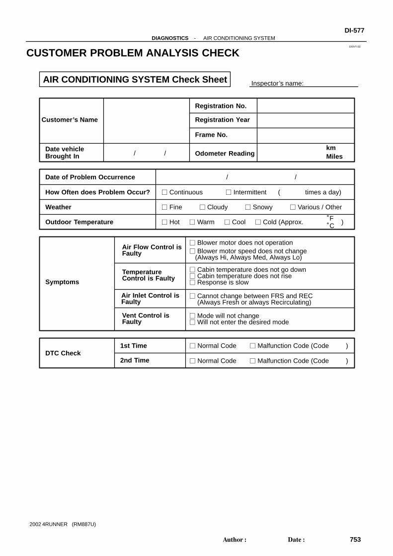
DI3VT-02
Inspector’s name:
Customer’s Name
Registration No.
Registration Year
Frame No.
Odometer ReadingkmMiles
Date vehicleBrought In / /
Date of Problem Occurrence
How Often does Problem Occur?
Weather
Outdoor Temperature
/ /
Continuous Intermittent ( times a day)
Fine Cloudy Snowy Various / Other
Hot Warm Cool Cold (Approx. °F°C )
Symptoms
Blower motor does not operation Blower motor speed does not change (Always Hi, Always Med, Always Lo)
Air Flow Control isFaulty
Cabin temperature does not go down
Response is slow
Cannot change between FRS and REC(Always Fresh or always Recirculating)
Will not enter the desired mode
TemperatureControl is Faulty
Air Inlet Control isFaulty
Vent Control isFaulty
DTC Check1st Time
2nd Time
Normal Code Malfunction Code (Code )
Normal Code Malfunction Code (Code )
AIR CONDITIONING SYSTEM Check Sheet
Cabin temperature does not rise
Mode will not change
-DIAGNOSTICS AIR CONDITIONING SYSTEMDI-577
753Author: Date:
2002 4RUNNER (RM887U)
CUSTOMER PROBLEM ANALYSIS CHECK

DI5CD-01
Turn ignition switch ON with AUTO andR/F switches held down.
Indicator Check
DTC Check (Sensor Check)(continuous operation)
DTC Check (Sensor Check)(stepped operation)
Cancel check mode and can startA/C control
Actuator Check(continuous operation)
Actuator Check(stepped operation)
If both AUTO switch and R/F switchare not pressed at the same time.
OFF
OFF
OFF
OFF
R/F
R/F R/F
AUTO
AUTOAUTO
: Indicates a switch operation.
DEF DEF
DEF DEF
DI-578-DIAGNOSTICS AIR CONDITIONING SYSTEM
754Author: Date:
2002 4RUNNER (RM887U)
PRE-CHECK1. LIST OF OPERATION METHODSBy operating each of the A/C control switches as shown in the diagram below, it is possible to enter the diag-nosis check mode.

I09224
R/F Switch
AUTO Switch
I00339
Blinking Pattern
4 times
1 sec.1 sec.
ON
OFF
I09224
Code Display
I09224
Front DEF Switch
-DIAGNOSTICS AIR CONDITIONING SYSTEMDI-579
755Author: Date:
2002 4RUNNER (RM887U)
2. INDICATOR CHECK(a) Turn the ignition switch to ON while pressing the air condi-
tioning control AUTO switch and R/F switch simulta-neously.
(b) Check that all the indicators light up and go off at 1 secondintervals 4 times in succession.
HINT: After the indicator check is ended, the system enters the
DTC begins automatically. Press the OFF switch when desiring to cancel the check
mode.
3. DTC CHECK (SENSOR CHECK)(a) Perform an indicator check. After the indicator check is
completed, the system enters the DTC check mode auto-matically.
(b) Read the code displayed on the panel. Refer to the list ofDTCs on page DI-582 when reading the DTCs. (DTCsare output at the temperature display).
(c) If the slower display is desired, press the front DEF switchand change it to stepped operation. Each time the frontDEF switch is pressed, the display changes by 1 step.

I09233
No. 1 J/B
ECU-B Fuse
DI-580-DIAGNOSTICS AIR CONDITIONING SYSTEM
756Author: Date:
2002 4RUNNER (RM887U)
4. CLEARING DTC(a) Pull out the ECU-B fuse in No. 1 J/B for 10 sec., or longer
to clear the DTC memory.(b) After reinserting the fuse, check that the normal code is
output.

I09224
R/F Switch Front DEF Switch
OFF Switch
Step No.Display code
Conditions
Blower motor Air flow vent Air inlet damper Magnetic clutch Air mix damper
1
2
3
4
5
6
7
8
9
10
0
1
3
2
4
5
6
7
8
9
OFF FACE
BI-LEVEL
OFF
FOOT
FOOT/DEF
DEF
FRESH
RECIRC
ON
Cool side(0 % open)
Cool / Hot(50 % open)
Hot side(100 % open)
1
16
16
16
16
16
16
16
31
FACE
FACE
FACE
FACE
FOOT
FRESH
FRESH
FRS/REC
RECIRC
RECIRC
RECIRC
RECIRC
RECIRC
OFF
ON
ON
ON
ON
ON
ON
ON
Cool / Hot(50 % open)
Cool side(0 % open)
Cool side(0 % open)
Cool side(0 % open)
Hot side(100 % open)
Hot side(100 % open)
Hot side(100 % open)
-DIAGNOSTICS AIR CONDITIONING SYSTEMDI-581
757Author: Date:
2002 4RUNNER (RM887U)
5. ACTUATOR CHECK(a) After entering the DTC check mode (Sensor Check
Mode) press the R/F switch.(b) Since each damper, motor and relay automatically oper-
ates at 1 second intervals beginning in order from 10 inthe temperature display, check the temperature and airflow visually and by hand.If a slower display is desired, press the FRONT DEFswitch and change it to a stepped operation. Each timethe FRONT DEF switch is pressed, the display changesby 1 step.
HINT: Code are displayed in order from the smaller to the larger
numbers. To cancel the check mode, press the Off switch.

DI3VV-06
DI-582-DIAGNOSTICS AIR CONDITIONING SYSTEM
758Author: Date:
2002 4RUNNER (RM887U)
DIAGNOSTIC TROUBLE CODE CHART
If malfunction code is displayed during the DTC check (sensor check), check the circuit listed for that codein the table below (Proceed to the page given for that circuit).
DTC No.
(See Page)Detection Item Trouble Area Memory
00 Normal - -
11*1
(DI-588 )
Room temperature sensor circuit Room temp. Sensor
A/C control assembly
Harness or connector between room temp. sensor and A/C
control assembly
(8.5 min. or more)
12*2
(DI-591 )
Ambient temperature sensor circuit Ambient temp. Sensor
Harness or connector between ambient temp. sensor and
A/C control assembly
A/C control assembly
(8.5 min. or more)
13
(DI-594 )
Evaporator temperature sensor circuit Evaporator temp. Sensor
Harness or connector between evaporator temp. sensor and
A/C control assembly
A/C control assembly
(8.5 min. or more)
14
(DI-597 )
Engine coolant temperature sensor cir-
cuit
Engine coolant temp. sensor
Harness or connector between engine coolant temp. sensor
and A/C control assembly
A/C control assembly
-
21*3
(DI 600 )
Solar sensor circuit (short) Solar sensor
Harness or connector between solar sensor and A/C control
assembly
(8.5 min. or more)(DI-600 )
Solar sensor circuit (open)assembly
A/C control assembly -
23
(DI-603 )
Pressure switch circuit Pressure switch
Harness or connector between pressure switch and A/C
control assembly
Refrigerant pipe line
A/C control assembly
-
31
(DI-606 )
Air mix damper position sensor circuit Air mix damper position sensor
A/C control assembly
Harness or connector between air mix damper position sen-
sor and A/C control assembly
(1 min. or more)
32
(DI-609 )
Air inlet damper position sensor circuit Air inlet damper position sensor
A/C control assembly
Harness or connector between air inlet damper position
sensor and A/C control assembly
(1 min. or more)
41
(DI-606 ,
DI-612 )
Air mix control servomotor Air mix control servomotor
Air mix damper position sensor
Harness or connector between air mix damper servomotor
and A/C control assembly
A/C control assembly
(15 sec.)
42
(DI-609 ,
DI-616 )
Air inlet control servomotor Air inlet control servomotor
Air inlet damper position sensor
Harness or connector between air inlet damper servomotor
and A/C control assembly
A/C control assembly
(15 sec.)

-DIAGNOSTICS AIR CONDITIONING SYSTEMDI-583
759Author: Date:
2002 4RUNNER (RM887U)
HINT:
*1: If the room temp. is approx. -18.6°C (-3.7°F) or lower, trouble code 11 may be output even thoughthe system is normal.
*2: If the ambient temp. is approx. -52.9°C (-61.4°F) or lower, a malfunction code may be output eventhough the system is normal.
*3: If the check is being performed in a dark place, DTC 21 (solar sensor circuit abnormal) could bedisplayed.
The A/C control assembly memorizes the DTC of the respective malfunction it has occurred for theperiod of the time indicated in the brackets.

DI3VW-08
I00371
A31
12345678910
21
111213
14 1516171819202223242526
48
13141615
123567
9101112
A30
DI-584-DIAGNOSTICS AIR CONDITIONING SYSTEM
760Author: Date:
2002 4RUNNER (RM887U)
TERMINALS OF ECU
Symbols (Terminals No.) Wiring Color Condition STD Voltage (V)
TAM (A30 3) SG (A31 1) B L GRIG ON. Ambient temp.: 25 °C (77 °F) 1.35 - 1.75 V
TAM (A30 - 3) - SG (A31 - 1) B-L - GRIG ON. Ambient temp.: 40 °C (104 °F) 0.85 - 1.25 V
TR (A30 4) SG (A31 1) B Y GRIG ON. Room temp.: 25 °C (77 °F) 1.8 - 2.2 V
TR (A30 - 4) - SG (A31 - 1) B-Y - GRIG ON. Room temp.: 40 °C (104 °F) 1.2 - 1.6 V
TS (A30 5) SG (A31 1) P GRIG ON. Sensor subjected to electrical light. 1.0 V or more
TS (A30 - 5) - SG (A31 - 1) P - GRIG ON. Sensor covered by cloth Below 1.0 V
TE (A30 6) SG (A31 1) W R GRIG ON. Evaporator temp.: 0 °C (32 °F) 2.0 - 2.4 V
TE (A30 - 6) - SG (A31 - 1) W-R - GRIG ON. Evaporator temp.: 15 °C (59 °F) 1.4 - 1.8 V
TPI (A30 7) SG (A31 1) V GRIG ON. Push REC switch 3.5 - 4.5 V
TPI (A30 - 7) - SG (A31 - 1) V - GRIG ON. Push FRS switch 0.5 - 1.8 V
TP (A30 8) SG (A31 1) B GRSet temp.: Max. Cool 3.5 - 4.5 V
TP (A30 - 8) - SG (A31 - 1) B - GRSet temp.: Max. Hot 0.5 - 1.8 V
PSW(A30 9) GND (A31 14) O W BIG ON. Below 1.0 V
PSW(A30-9) - GND (A31-14) O - W-BIG ON. Disconnect the pressure switch connector. 10 - 14 V
ACT (A30 10) GND (A31 14) L B W BStart the Engine (Idling). Operate the compressor 10 - 14 V
ACT (A30-10) - GND (A31-14) L-B - W-BStart the Engine (Idling). Do not operate compressor Below 1.5 V
VER1 (A30-11)
- GND (A31-14)
W-B
- W-BIG ON. Below 1.0 V
AC1 (A30 13) GND (A31 14) L Y W BStart the engine, AUTO switch ON and magnetic clutch ON. Below 1.0 V
AC1 (A30-13) - GND (A31-14) L-Y - W-BStart the engine, AUTO switch ON and magnetic clutch OFF. 10 - 14 V
BLW (A30-16)
- GND (A31-14)
R-W
- W-BIG ON. Operate the blower motor Below 1.5 V
SG (A31-1) - Body GroundGR
- Body GroundAlways 1 Ω or less
FACE (A31-4) - GND (A31-14) G-B - W-B IG ON. Air Flow: FACE Below 1.0 V
AIF (A31-6) - AIR - (A31-7) Y-G - R-G IG ON. No voltage
AMC (A31-8) - AMH (A31-9) W - R IG ON. 13 - 19 Ω
HR (A31 10) GND (A31 14) Y R W BIG ON. Operate the blower motor Below 1.0 V
HR (A31-10) - GND (A31-14) Y-R - W-BIG ON. Do not operate the blower motor 10 - 14 V
S5 (A31-11) - SG (A31-1) Y - GR IG ON. 4 - 6 V
S5 (A31 11) TS (A30 5) Y PIG ON. Solar sensor subjected to electrical light. Below 4.0 V
S5 (A31-11) - TS (A30-5) Y - PIG ON. Solar sensor covered by a cloth. 4.0 - 4.5 V
B (A31-13) - GND (A31-14) L-R - W-B IG OFF. 10 - 14 V
GND (A31-14) - Body GroundW-B
- Body GroundAlways 1 Ω or less
SPD (A31-15) - GND (A31-14) G-O - W-B Turn propeller shaft slowly Pulse

-DIAGNOSTICS AIR CONDITIONING SYSTEMDI-585
761Author: Date:
2002 4RUNNER (RM887U)
B/L (A31-17) - GND (A31-14) G-W - W-B IG ON. Air Flow: BI-LEVEL. Below 1.0 V
FOOT (A31-18)
- GND (A31-14)
R-L
- W-BIG ON. Air Flow: FOOT. Below 1.0 V
F/D (A31-19) - GND (A31-14) P-B - W-B IG ON. Air Flow: FOOT/DEF Below 1.0 V
DEF (A31-20) - GND (A31-14) Y-B - W-B IG ON. Air Flow: DEF Below 1.0 V
FR (A31 23) GND (A31 14) R Y W BIG ON. Operate blower motor Below 1.0 V
FR (A31-23) - GND (A31-14) R-Y - W-BIG ON. Do not operate blower motor 10 - 14 V
IG+ (A31-26) - GND (A31-14) B-Y - W-B IG ON. 10 - 14 V

DI3VX-02
DI-586-DIAGNOSTICS AIR CONDITIONING SYSTEM
762Author: Date:
2002 4RUNNER (RM887U)
PROBLEM SYMPTOMS TABLESymptom Suspect Area See page
Whole functions of the A/C system does not operate.3. IG power source circuit
4. A/C control assembly
DI-622
IN-28
Air Flow Control: No blower operation
1. Heater main relay circuit
2. Blower motor circuit
3. Engine coolant temperature sensor circuit
4. IG power source circuit
5. A/C control assembly
DI-627
DI-630
DI-597
DI-622
IN-28
Air Flow Control: No blower control
1. Blower motor circuit
2. IG power source circuit
3. Heater main relay circuit
DI-630
DI-622
DI-627
Air Flow Control: Insufficient air out 1. Blower motor circuit DI-630
Temperature Control: No cool air comes out
1. Volume of refrigerant
2. Drive belt tension
3. Inspect refrigeration system with manifold gauge set
4. Compressor circuit
5. Pressure switch circuit
6. Air mix control servomotor circuit
7. Air mix damper position sensor circuit
8. Room temp. sensor circuit
9. Ambient temp. sensor circuit
10.A/C control assembly
AC-3
AC-16
AC-3
DI-632
DI-603
DI-612
DI-606
DI-588
DI-591
IN-28
Temperature Control: No warm air comes out
1. Air mix control servomotor circuit
2. Air mix damper position sensor circuit
3. Ambient temp. sensor circuit
4. Room temp. sensor circuit
5. Evaporator temp. sensor circuit
6. A/C control assembly
7. Heater radiator (in heater unit)
DI-612
DI-606
DI-591
DI-588
DI-594
IN-28
AC-34
Temperature Control: Output air is warmer or cooler than the set
temperature or response is slow.
1. Volume of refrigerant
2. Drive belt tension
3. Inspect refrigeration system with manifold gauge set
4. Ambient temp. sensor circuit
5. Evaporator temp. sensor circuit
6. Solar sensor circuit
7. Air mix damper position sensor circuit
8. Engine coolant temp. sensor circuit
9. Air mix control servomotor circuit
10.Compressor
11.Condenser
12.Receiver
13.Evaporator
14.Heater radiator (in heater unit)
15.Expansion valve
16.A/C control assembly
AC-3
AC-16
AC-3
DI-591
DI-594
DI-600
DI-606
DI-597
DI-612
AC-49
AC-60
AC-57
AC-29
AC-34
AC-24
IN-28
Temperature Control: No temperature control
(only Max. cool or Max. warm)
1. Air mix control servomotor circuit
2. Air mix damper position sensor circuit
3. A/C control assembly
DI-612
DI-606
IN-28
No air outlet control1. Air outlet control servomotor circuit
2. A/C control assembly
DI-619
IN-28
Engine idle up does not occur, or is continuous1. Compressor circuit
2. A/C control assembly
DI-632
IN-28

-DIAGNOSTICS AIR CONDITIONING SYSTEMDI-587
763Author: Date:
2002 4RUNNER (RM887U)
Symptom Suspect Area See page
Set temperature value displayed does not match up with operation
of temperature control switch.1. A/C control assembly IN-28
Brightness does not change when rheostat volume or light control
switch is turned.
1. Illumination light system
2. A/C control assembly
BE-15
IN-28
Unable to access the diagnosis mode. A/C control assembly IN-28
DTC not recorded. Set mode is cleared when IG switch is turned
off.
1. Back-up power source circuit
2. A/C control assembly
DI-625
IN-28

DI3VY-09
I08282
A/C Amplifier
TR
4
A30
1
B-Y
2
1
A33Room Temp. Sensor
GRA31 SG
DI-588-DIAGNOSTICS AIR CONDITIONING SYSTEM
764Author: Date:
2002 4RUNNER (RM887U)
CIRCUIT INSPECTION
DTC 11 Room Temperature Sensor Circuit
CIRCUIT DESCRIPTION
This sensor detects the temperature inside the cabin and sends the appropriate signals to the A/C controlassembly.
DTC No. Detection Item Trouble Area
Room temperature sensor
11 Open or short in room temperature sensor circuit.Harness or connector between room temp. sensor and A/C
control assemblycontrol assembly
A/C control assembly
WIRING DIAGRAM

BE3840I00316 I00333
ON
TR(+)SG(-)
I00317
-DIAGNOSTICS AIR CONDITIONING SYSTEMDI-589
765Author: Date:
2002 4RUNNER (RM887U)
INSPECTION PROCEDURE
1 Check voltage between terminals TR and SG of A/C control assembly connector.
PREPARATION:(a) Remove A/C control assembly with connectors still con-
nected (See page AC-84 ).(b) Turn ignition switch to ON.CHECK:Check voltage between terminals TR and SG of A/C control as-sembly connector at each temperature.OK:
at 25 °C (77 °F) : 1.8 - 2.2 Vat 40 °C (104 °F) : 1.2 - 1.6 V
HINT:As the temperature increases, the voltage decreases.
NG Go to step 2.
OK
Proceed to next circuit inspection shown on problem symptoms table (See page DI-586 ). Howev-er, if DTC 11 is displayed, check and replace A/C control assembly.
2 Check room temperature sensor.
PREPARATION:(a) Remove room temperature sensor from lower No. 1 panel
(See page AC-74 ).(b) Disconnect room temperature sensor connector.CHECK:Check resistance between terminals 1 and 2 of room tempera-ture sensor connector at each temperature.OK:
at 25 °C (77 °F) : 1.6 - 1.8 kΩat 40 °C (104 °F) : 0.5 - 1.7 kΩ
HINT:As the temperature increases, the resistance decreases.
NG Replace room temperature sensor.
OK
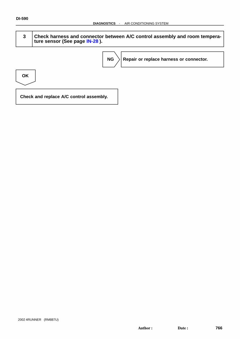
DI-590-DIAGNOSTICS AIR CONDITIONING SYSTEM
766Author: Date:
2002 4RUNNER (RM887U)
3 Check harness and connector between A/C control assembly and room tempera-ture sensor (See page IN-28 ).
NG Repair or replace harness or connector.
OK
Check and replace A/C control assembly.

I21900
TAM
3
A30
SG
1
A31
A26Ambient Temp. Sensor
1
2
B-L B-LIG1
GR GRIG1
19
26
A/C Amplifier
-DIAGNOSTICS AIR CONDITIONING SYSTEMDI-591
767Author: Date:
2002 4RUNNER (RM887U)
DTC 12 Ambient Temperature Sensor Circuit
CIRCUIT DESCRIPTION
This sensor detects the ambient temperature and sends the appropriate signals to the A/C control assembly.
DTC No. Detection Item Trouble Area
Ambient temperature sensor
12 Open or short in ambient temperature sensor circuit.Harness or connector between ambient temperature sensor
and A/C control assemblyand A/C control assembly
A/C control assembly
WIRING DIAGRAM
DI3VZ-10

BE3840
I00319 I00334
TAM(+)
ON
SG(-)
I09223
Ω
2 1
DI-592-DIAGNOSTICS AIR CONDITIONING SYSTEM
768Author: Date:
2002 4RUNNER (RM887U)
INSPECTION PROCEDURE
1 Check voltage between terminals TAM and SG of A/C control assembly connec-tor.
PREPARATION:(a) Remove A/C control assembly with connectors still con-
nected (See page AC-84 ).(b) Turn ignition switch to ON.CHECK:Check voltage between terminals TAM and SG of A/C controlassembly connector at each temperature .OK:
Voltage at 25 °C (77 °F) : 1.35 - 1.75 V at 40 °C (104 °F) : 0.85 - 1.25 V
HINT:As the temperature increases, the voltage decreases.
NG Go to step 2.
OK
Proceed to the next circuit inspection shown on problem symptoms table (See page DI-586 ).However, if DTC 12 is displayed, check and replace A/C control assembly.
2 Check ambient temperature sensor.
PREPARATION:Disconnect ambient temperature sensor connector.CHECK:Check resistance between terminals 1 and 2 of ambient tem-perature sensor connector at each temperature.OK:
Resistance at 25 °C (77 °F) : 1.6 - 1.8 kΩ at 40 °C (104 °F) : 0.5 - 0.7 kΩ
HINT:As the temperature increase, the resistance decrease.
NG Replace ambient temperature sensor.
OK

-DIAGNOSTICS AIR CONDITIONING SYSTEMDI-593
769Author: Date:
2002 4RUNNER (RM887U)
3 Check harness and connector between A/C control assembly and ambient tem-perature sensor (See page IN-28 ).
NG Repair or replace harness or connector.
OK
Check and replace A/C control assembly.

I21760
A/C Amplifier
TE
6
A30
SG
1
A31
W-R
A14Thermistor
B
1
2
IJ1
B-RIJ1
GR
5
6
DI-594-DIAGNOSTICS AIR CONDITIONING SYSTEM
770Author: Date:
2002 4RUNNER (RM887U)
DTC 13 Evaporator Temperature Sensor Circuit
CIRCUIT DESCRIPTION
This sensor detects the temperature inside the A/C unit and sends the appropriate signals to the A/C controlassembly.
DTC No. Detection Item Trouble Area
Evaporator temperature sensor
13 Open or short in evaporator temperature sensor circuit.Harness or connector between evaporator temperature sen-
sor and A/C control assemblysor and A/C control assembly
A/C control assembly
WIRING DIAGRAM
DI3W0-10

I00322BE3840
I00335
ON
TE(+)SG(-)
AC0175
Thermometer
Ice
Thermistor Ohmmeter
Morethan10 cm(3.94 in.)
-DIAGNOSTICS AIR CONDITIONING SYSTEMDI-595
771Author: Date:
2002 4RUNNER (RM887U)
INSPECTION PROCEDURE
1 Check voltage between terminals TE and SG of A/C control assembly connector.
PREPARATION:(a) Remove A/C control assembly with connectors still con-
nected (See page AC-84 ).(b) Turn ignition switch to ON.CHECK:Measure voltage between terminals TE and SG of A/C controlassembly connector at each temperature.OK:
Voltage at 0 °C (32 °F) : 2.0 - 2.4 V at 15 °C (59 °F) : 1.4 - 1.8 V
HINT:As the temperature increases, the voltage decreases.
NG Go to step 2.
OK
Proceed to next circuit inspection shown on problem symptoms table (See page DI-586 ). Howev-er, if DTC 13 is displayed, check and replace A/C control assembly.
2 Check evaporator temperature sensor.
PREPARATION:Remove evaporator temperature sensor (See page AC-28 ).CHECK:Check resistance between terminals 1 and 2 of evaporator tem-perature sensor connector at each temperature.OK:
Resistance at 0 °C (32 °F) : 4.6. - 5.1 kΩ at 15 °C (59 °F) : 2.1 - 2.6 kΩ
HINT:As the temperature increases, the resistance decreases.
NG Replace evaporator temperature sensor.
OK

DI-596-DIAGNOSTICS AIR CONDITIONING SYSTEM
772Author: Date:
2002 4RUNNER (RM887U)
3 Check harness and connector between A/C control assembly and evaporatortemperature sensor (See page IN-28 ).
NG Repair or replace harness or connector.
OK
Check and replace A/C control assembly.

I08282
A/C Amplifier
A36Engine Coolant Temp. Sensor
1
A31 TW
5B-R
3
GR1
A31 SG
TW
G
-DIAGNOSTICS AIR CONDITIONING SYSTEMDI-597
773Author: Date:
2002 4RUNNER (RM887U)
DTC 14 Engine Coolant Temperature Sensor Circuit
CIRCUIT DESCRIPTION
This sensor detects the engine coolant temperature and sends the appropriate signals to the A/C controlassembly. These signals are used for warm up control when the engine is cold.
DTC No. Detection Item Trouble Area
14 O h t i i l t t t i it
Engine coolant temperature sensor
Harness or connector between engine coolant temp. sensor14 Open or short in engine coolant temperature sensor circuit.
Harness or connector between engine coolant tem . sensor
and A/C control assembly
A/C control assembly
WIRING DIAGRAM
DI5CE-02
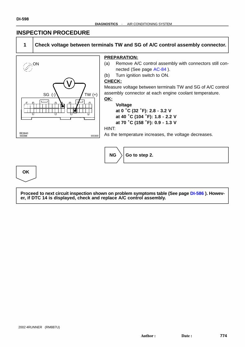
BE3840I00398 I00369
ON
SG (-) TW (+)
DI-598-DIAGNOSTICS AIR CONDITIONING SYSTEM
774Author: Date:
2002 4RUNNER (RM887U)
INSPECTION PROCEDURE
1 Check voltage between terminals TW and SG of A/C control assembly connector.
PREPARATION:(a) Remove A/C control assembly with connectors still con-
nected (See page AC-84 ).(b) Turn ignition switch to ON.CHECK:Measure voltage between terminals TW and SG of A/C controlassembly connector at each engine coolant temperature.OK:
Voltageat 0 °C (32 °F): 2.8 - 3.2 Vat 40 °C (104 °F): 1.8 - 2.2 Vat 70 °C (158 °F): 0.9 - 1.3 V
HINT:As the temperature increases, the voltage decreases.
NG Go to step 2.
OK
Proceed to next circuit inspection shown on problem symptoms table (See page DI-586 ). Howev-er, if DTC 14 is displayed, check and replace A/C control assembly.

I09234
Ω
13
1 3
Sensor
Thermometer
Ice
Sensor
Thermistor
-DIAGNOSTICS AIR CONDITIONING SYSTEMDI-599
775Author: Date:
2002 4RUNNER (RM887U)
2 Check engine coolant temperature sensor.
PREPARATION:Remove engine coolant temperature sensor (See page AC-28 ).CHECK:Measure resistance between terminals 1 and 3 of engine cool-ant temperature sensor connector at each temperature.OK:
Resistance :at 0°C (32°F) : Below 50 k Ωat 40°C (104°F) : 2.5 - 2.7 kΩat 100 °C (212°F): Over 0.3 k Ω
HINT:As the temperature increases, the resistance decreases gradu-ally.
NG Replace engine coolant temperature sensor.
OK
3 Check harness and connector between A/C control assembly and engine coolanttemperature sensor (See page IN-28 ).
NG Repair or replace harness or connector.
OK
Check and replace A/C control assembly.

Res
ista
nce
of p
hoto
diod
e
High
LowWeak Strong
Strength of solar radiation
I09244
A/C Amplifier
S511A31
TS5A30
P
A34Solar Sensor
Y
2
1
DI-600-DIAGNOSTICS AIR CONDITIONING SYSTEM
776Author: Date:
2002 4RUNNER (RM887U)
DTC 21 Solar Sensor Circuit
CIRCUIT DESCRIPTION
A photo diode in the solar sensor detects solar radiation andsends signals to the A/C control assembly.
DTC No Detection Item Trouble Area
21
Open or short in solar sensor circuit.
Please note that display of diagnostic trouble code 21 is not
abnormal when the sensor is not receiving solar radiation.
Solar sensor
Harness or connector between solar sensor and A/C control
assembly
A/C control assembly
WIRING DIAGRAM
DI3W2-11

BE3840I00324 I00336
ON
S5 (-) TS (+)
-DIAGNOSTICS AIR CONDITIONING SYSTEMDI-601
777Author: Date:
2002 4RUNNER (RM887U)
INSPECTION PROCEDURE
1 Check voltage between terminals S5 and TS of A/C control assembly connector.
PREPARATION:Remove A/C control assembly with connectors still connected.CHECK:(a) Turn ignition switch to ON.(b) Measure voltage between terminals S5 and TS of A/C
control assembly connector when the solar sensor is sub-jected to an electric light, and when the sensor is coveredby a cloth.
OK:
Condition Voltage
Sensor subjected to electric light Below 4.0 V
Sensor covered by a cloth 4.0 - 4.5 V
HINT:As the inspection light is moved away from the sensor, the volt-age increases.
NG Go to step 2.
OK
Proceed to next circuit inspection shown on problem symptoms table (See page DI-586 ). Howev-er, if DTC 21 is displayed, check and replace A/C control assembly.

I00325
DI-602-DIAGNOSTICS AIR CONDITIONING SYSTEM
778Author: Date:
2002 4RUNNER (RM887U)
2 Check solar sensor.
PREPARATION:Remove solar sensor (See page AC-73 ).CHECK:(a) Cover the sensor with a cloth.(b) Measure resistance between terminals 1 and 2 of solar
sensor connector.HINT:Connect positive (+) lead of ohmmeter to terminal 1 and nega-tive (-) lead to terminal 2 of the solar sensor.OK:
Resistance : ∞ Ω (no continuity)PREPARATION:(a) Remove the cloth from the solar sensor and subject the
sensor to electric light.(b) Measure resistance between terminals.OK:
Resistance : Approx. 10 k Ω (continuity)HINT:As the electric light is moved away from the sensor, the resis-tance increases.
NG Replace solar sensor.
OK
3 Check harness and connector between A/C control assembly and solar sensor(See page IN-28 ).
NG Repair or replace harness or connector.
OK
Check and replace A/C control assembly.
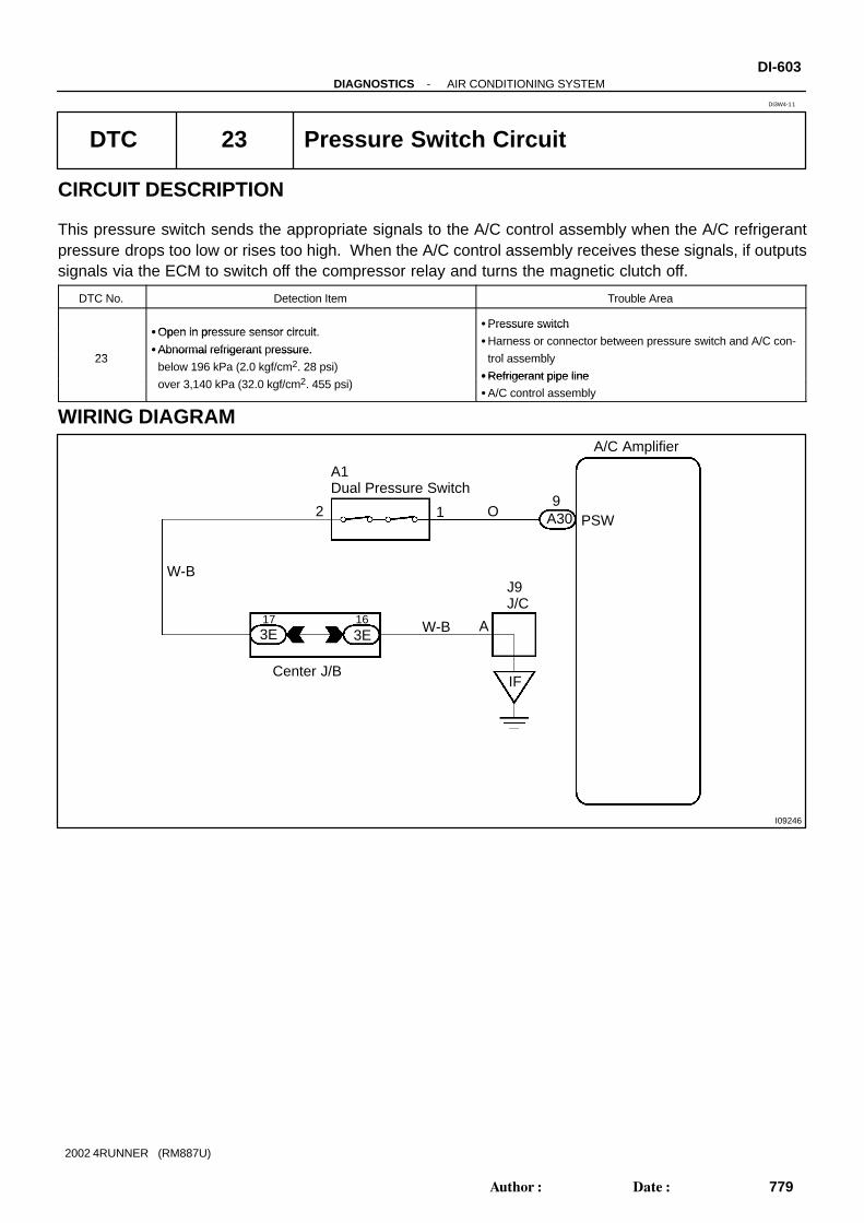
I09246
A/C Amplifier
PSW9
A30
16
2 1
A1Dual Pressure Switch
3E17
W-B
O
3E W-B A
J9J/C
IFCenter J/B
-DIAGNOSTICS AIR CONDITIONING SYSTEMDI-603
779Author: Date:
2002 4RUNNER (RM887U)
DTC 23 Pressure Switch Circuit
CIRCUIT DESCRIPTION
This pressure switch sends the appropriate signals to the A/C control assembly when the A/C refrigerantpressure drops too low or rises too high. When the A/C control assembly receives these signals, if outputssignals via the ECM to switch off the compressor relay and turns the magnetic clutch off.
DTC No. Detection Item Trouble Area
Open in pressure sensor circuitPressure switch
23
Open in pressure sensor circuit.
Abnormal refrigerant pressure.
Pressure switch
Harness or connector between pressure switch and A/C con-
t l bl23Abnormal refrigerant ressure.
below 196 kPa (2.0 kgf/cm2. 28 psi)2
trol assembly
Refrigerant pipe lineover 3,140 kPa (32.0 kgf/cm2. 455 psi)
Refrigerant pipe line
A/C control assembly
WIRING DIAGRAM
DI3W4-11

BE3840I00368 I00370
ON
(-)
PSW(+)
Low Pressure Cut Side Referaence : High Pressure Cut SIde
ON (0 V)
OFF (12V)
196 kPa
225 kPa
ON (0 V)
2,550 kPa
OFF (12V)
3,140 kPa
DI-604-DIAGNOSTICS AIR CONDITIONING SYSTEM
780Author: Date:
2002 4RUNNER (RM887U)
INSPECTION PROCEDURE
1 Check voltage between terminals PSW of A/C control assembly and bodyground.
PREPARATION:(a) Install the manifold gauge set (See page AC-19 ).(b) Remove the A/C control assembly with connectors still
connected.(c) Turn ignition switch to ON.CHECK:Check voltage between terminals PSW of A/C control assemblyconnector and body ground when refrigerant pressure ischanged.OK:
The voltage changes refrigerant pressure, as shownin the chart below.
OK Proceed to next circuit inspection shown onproblem symptoms table (See page DI-586 ).
NG

N17985
12
Low Pressure Cut Side Referaence : High Pressure Cut SIde
ON (continuity)
OFF (no continuity)
196 kPa
225 kPa
ON (continuity)
2,550 kPa
OFF (nocontinuity)
3,140 kPa
-DIAGNOSTICS AIR CONDITIONING SYSTEMDI-605
781Author: Date:
2002 4RUNNER (RM887U)
2 Check pressure switch.
PREPARATION:Disconnect pressure switch connector.CHECK:Check continuity between terminals 1 and 2 of pressure switchwhen refrigerant is changed.OK:
The continuity changes with refrigerant pressure asshown in the chart below.
NG Replace pressure switch.
OK
3 Check harness and connector between A/C control assembly and pressureswitch, pressure switch and body ground (See page IN-28 ).
NG Repair or replace harness or connector.
OK
Check and replace A/C control assembly.

4(V)
1
0 100%
TP
I te
rmin
al v
olta
ge
Damper opening angle
I10328
A36Air Mix Damper Position Sensor (Air Mix Control Servomotor)
VZ
PT
SG
6
7
5
Y
B
GR
11
A31 S5
8A30
1A31
TP
SG
A/C Amplifier
G
B
Y
DI-606-DIAGNOSTICS AIR CONDITIONING SYSTEM
782Author: Date:
2002 4RUNNER (RM887U)
DTC 31, 41 Air Mix Damper Position Sensor Circuit
CIRCUIT DESCRIPTION
This sensor detects the position of the air inlet damper andsends the appropriate signals to the A/C control assembly. Theposition sensor is built into the air inlet control servomotor.
DTC No. Detection Item Trouble Area
31Short to ground or power source circuit in air mix damper posi-
Air mix damper position sensor31
Short to ground or ower source circuit in air mix dam er osi
tion sensor circuit.Air mix damper position sensor
Harness or connector between air inlet control servomotor
41Air mix damper position sensor value does not change even if
A/C control assembly operates air inlet control servomotor.
Harness or connector between air inlet control servomotor
and A/C control assembly
A/C assembly
WIRING DIAGRAM
DI3W5-09

BE3840
I00329 I00337
ON
TP(+)SG(-)
-DIAGNOSTICS AIR CONDITIONING SYSTEMDI-607
783Author: Date:
2002 4RUNNER (RM887U)
INSPECTION PROCEDURE
1 Check voltage between terminals TP and SG of A/C control assembly connector.
PREPARATION:(a) Remove A/C control assembly with connectors still con-
nected (See page AC-84 ).(b) Turn ignition switch to ON.CHECK:Change the set temperature to activate the air mix damper, andmeasure the voltage between terminals TP and SG of A/C con-trol assembly connector each time when the set temperature ischanged.OK:
Set Temperature Voltage
Max. cool 3.5 - 4.5 V
Max. hot 0.5 - 1.8 V
HINT:As the set temperature increases, the voltage decreases grad-ually without interruption.
NG Go to step 2.
OK
Proceed to next circuit inspection shown on problem symptoms table (See page DI-586 ). Howev-er, if DTC 31 or 41 is displayed, check and replace A/C control assembly.

I09231
Max. Cool
Max. Hot
4
5
3Ω
DI-608-DIAGNOSTICS AIR CONDITIONING SYSTEM
784Author: Date:
2002 4RUNNER (RM887U)
2 Check air mix damper position sensor.
PREPARATION:Remove air mix control servomotor (See page AC-34 ).CHECK:Measure resistance between terminals 4 and 5 of air inlet con-trol servomotor connector.OK:
Resistance: 4.8 - 7.2 k ΩCHECK:While operating air mix control servomotor as shown in the pro-cedure on page DI-612 , measure resistance between termi-nals 3 and 5 of air mix control servomotor connector.OK:
Position Resistance
Max. cool 3.8 - 5.8 kΩ
Max. hot 0.95 - 1.45 kΩ
HINT:As the air inlet control servomotor moves from cool side to hotside, the resistance decreases gradually without interruption.
NG Replace air mix control servomotor.
OK
3 Check harness and connector between A/C control assembly and air mix controlservomotor. (See page IN-28 ).
NG Repair or replace harness or connector.
OK
Check and replace A/C control assembly.

4(V)
1
0100%
TP
I te
rmin
al v
olta
ge
Damper opening angle
4.1 V
0.9 V
I10328
A3111
7A30
A311
S5
SG
4
5
A35Air Inlet Damper Position Sensor(Air Inlet Control Servomotor)
A/C Amplifier
TPI
VZ
PT
GND
3
Y
V
GR
-DIAGNOSTICS AIR CONDITIONING SYSTEMDI-609
785Author: Date:
2002 4RUNNER (RM887U)
DTC 32, 42 Air Inlet Damper Position Sensor Circuit
CIRCUIT DESCRIPTION
This sensor detects the position of the air inlet damper andsends the appropriate signals to the A/C control assembly. Theposition sensor is built into the air inlet control servomotor.
DTC No. Detection Item Trouble Area
32Short to ground or power source circuit in air inlet damper posi-
Air inlet damper position sensor32
Short to ground or ower source circuit in air inlet dam er osi
tion sensor circuit.Air inlet damper position sensor
Harness or connector between air inlet control servomotor
42Air inlet damper position sensor value does not change even if
A/C control assembly operates air inlet control servomotor.
Harness or connector between air inlet control servomotor
and A/C control assembly
A/C control assembly
WIRING DIAGRAM
DI3W6-09

BE3840I00331 I00338
ON
SG(-) TP1(+)
DI-610-DIAGNOSTICS AIR CONDITIONING SYSTEM
786Author: Date:
2002 4RUNNER (RM887U)
INSPECTION PROCEDURE
1 Check voltage between terminals TPI and SG of A/C control assembly connector.
PREPARATION:(a) Remove A/C control assembly with connectors still con-
nected (See page AC-84 ).(b) Turn ignition switch to ON.CHECK:Press REC/FRS switch to change air inlet between fresh andrecirculation air and measure voltage between terminals TP1and SG of A/C control assembly when the air inlet servomotoroperates.OK:
REC/FRS Switch Voltage
REC 3.5 - 4.5 V
FRS 0.5 - 1.8 V
HINT:As the air inlet control servomotor is moved from REC side toFRS side, the voltage decreases gradually without interruption.
NG Go to step 2.
OK
Proceed to next circuit inspection shown on problem symptoms table (See page DI-586 ). Howev-er, if DTC 32 or 42 is displayed, check and replace A/C control assembly.

I09225
REC
FRS
5
Ω
4
3
-DIAGNOSTICS AIR CONDITIONING SYSTEMDI-61 1
787Author: Date:
2002 4RUNNER (RM887U)
2 Check air inlet damper position sensor.
PREPARATION:(a) Remove air inlet control servomotor (See page AC-46 ).(b) Disconnect air inlet control servomotor connector.CHECK:Measure resistance between terminals 4 and 5 of air inlet con-trol servomotor connector.OK:
Resistance : 4.2 - 7.8 k ΩCHECK:While operating air inlet control servomotor as in the procedureon page, measure resistance between terminals 3 and 4 of airinlet control servomotor connector.OK:
Resistance :
Damper Position Resistance
REC side 3.4 - 6.4 kΩ
FRS side 0.76 - 1.4 kΩ
HINT:As the air inlet control servomotor is moved from REC side toFRS side, the resistance decreases gradually without interrup-tion.
NG Replace air inlet control servomotor.
OK
3 Check harness and connector between A/C control assembly and air inlet con-trol servomotor. (See page AC-84 ).
NG Repair or replace harness or connector.
OK
Check and replace A/C control assembly.

I09247
IG+A31
GNDA31
8AMC
A31
A31
9
26
14
Driver Side J/B
21I
GAUGE 51F
93D
23D
B-Y
4
I14Ignition Switch
2W
W
Battery
Engine Room R/B
2
2
2
AM1
1
1 2
ALT
A36Air MixControlServomotor
R
4
2
W
W-B
173E
163EW-B
J/CJ9
A
IF
M
B-Y B-Y
Center J/B
IG1AM1
AMH
Center J/B
A/C Amplifier
DI-612-DIAGNOSTICS AIR CONDITIONING SYSTEM
788Author: Date:
2002 4RUNNER (RM887U)
DTC 41 Air Mix Control Servomotor Circuit
CIRCUIT DESCRIPTION
This air mix control servomotor is controlled by the A/C control assembly and moves the air mix damper tothe desired position.
DTC No. Detection Item Trouble Area
Air mix control servomotor
Air mix damper position sensor
41Air mix damper position sensor value does not change even if
A/C control assembly operates air mix control servomotor.
Air mix damper position sensor
Harness or connector between A/C control assembly and airA/C control assembly o erates air mix control servomotor.
mix control servomotor, air mix damper position sensor
A/C control assembly
WIRING DIAGRAM
DI3W7-07

-DIAGNOSTICS AIR CONDITIONING SYSTEMDI-613
789Author: Date:
2002 4RUNNER (RM887U)
INSPECTION PROCEDURE
1 Actuator check
PREPARATION:(a) Warm up the engine.(b) Set to the actuator check mode (See page DI-578 ).(c) Press the DEF switch and change it to step operation.CHECK:Press the DEF switch and check the operation of the air mix damper and the condition of the blower.OK:
Display Code Air Mix Damper Condition
0 - 3 0 % (Fully closed) Cool air comes out
4 - 5 50 %
6 - 9 100 % (Fully opened) Warm air comes out
OK Proceed to next circuit inspection shown onproblem symptoms table (See page DI-586 ).
NG

I09230
To Cool 1
2(+) (-)
B
I09229
To Hot
1
2(+)(-) B
DI-614-DIAGNOSTICS AIR CONDITIONING SYSTEM
790Author: Date:
2002 4RUNNER (RM887U)
2 Check air mix control servomotor.
PREPARATION:Remove air mix control servomotor (See page AC-34 ).CHECK:Connect positive (+) lead to terminal 1 and the negative (-) leadto terminal 2.OK:
The lever turns smoothly to COOL side.
CHECK:Connect negative (-) lead to terminal 1 and positive (+) lead toterminal 2.OK:
The lever turns smoothly to HOT side.
NG Repair or replace harness or connector.
OK
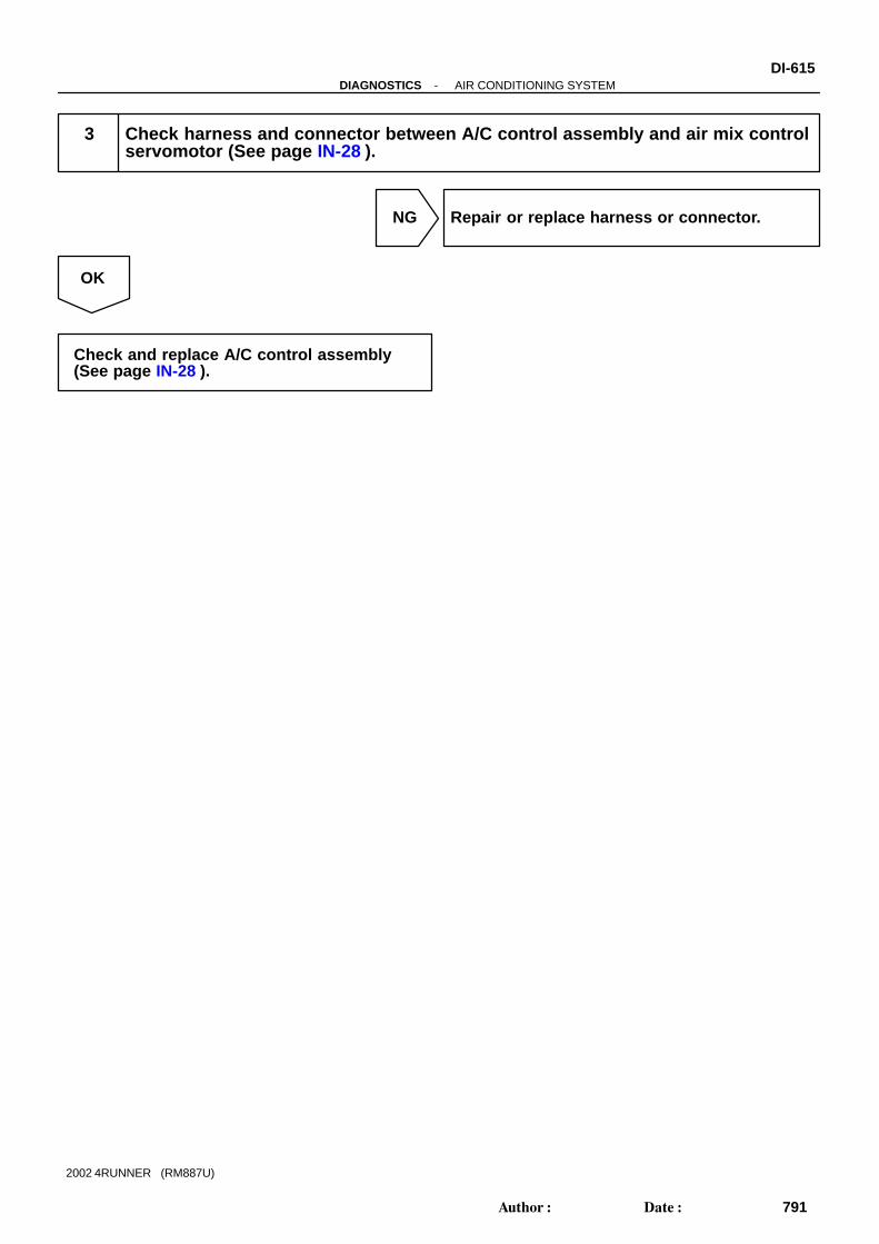
-DIAGNOSTICS AIR CONDITIONING SYSTEMDI-615
791Author: Date:
2002 4RUNNER (RM887U)
3 Check harness and connector between A/C control assembly and air mix controlservomotor (See page IN-28 ).
NG Repair or replace harness or connector.
OK
Check and replace A/C control assembly(See page IN-28 ).

I09247
A/C Amplifier
IG+A31
GNDA31
AIF
7AIR
A31
A31
6
26
14
21I
GAUGE 51F
93D
23D
B-Y
4
I14Ignition Switch
2W
W
Battery
2
2
2AM1
1
1 2ALT
A35Air InletControlServomotor
Y-G
2
1
W-B173E
163EW-B
J/CJ9
A
IF
M
R-G
B-Y B-Y
Driver Side J/B Center J/B
Engine Room R/B
IG1AM1
Center J/B
DI-616-DIAGNOSTICS AIR CONDITIONING SYSTEM
792Author: Date:
2002 4RUNNER (RM887U)
DTC 42 Air Inlet Control Servomotor Circuit
CIRCUIT DESCRIPTION
The air inlet control servomotor is controlled by the A/C control assembly and moves the air inlet damperto the desired position.
DTC No. Detection Item Trouble Area
Air inlet damper position sensor
42Air inlet damper position sensor value does not change even if
A/C control assembly operates air inlet control servomotorHarness or connector between air inlet control servomotor
and A/C control assemblyA/C control assembly operates air inlet control servomotor. and A/C control assembly
A/C control assembly
WIRING DIAGRAM
DI3W8-04
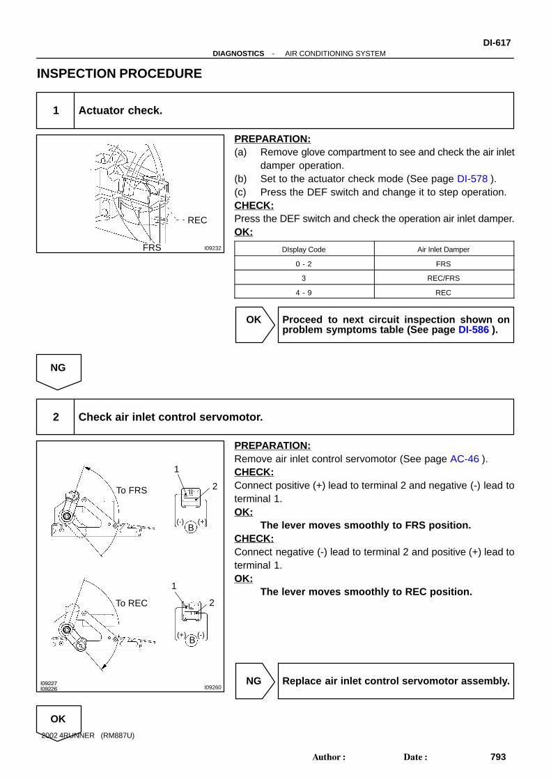
I09232
REC
FRS
I09227I09226 I09260
To FRS
To REC
1
2
B(-) (+)
1
2
(-)(+)B
-DIAGNOSTICS AIR CONDITIONING SYSTEMDI-617
793Author: Date:
2002 4RUNNER (RM887U)
INSPECTION PROCEDURE
1 Actuator check.
PREPARATION:(a) Remove glove compartment to see and check the air inlet
damper operation.(b) Set to the actuator check mode (See page DI-578 ).(c) Press the DEF switch and change it to step operation.CHECK:Press the DEF switch and check the operation air inlet damper.OK:
DIsplay Code Air Inlet Damper
0 - 2 FRS
3 REC/FRS
4 - 9 REC
OK Proceed to next circuit inspection shown onproblem symptoms table (See page DI-586 ).
NG
2 Check air inlet control servomotor.
PREPARATION:Remove air inlet control servomotor (See page AC-46 ).CHECK:Connect positive (+) lead to terminal 2 and negative (-) lead toterminal 1.OK:
The lever moves smoothly to FRS position.CHECK:Connect negative (-) lead to terminal 2 and positive (+) lead toterminal 1.OK:
The lever moves smoothly to REC position.
NG Replace air inlet control servomotor assembly.
OK

DI-618-DIAGNOSTICS AIR CONDITIONING SYSTEM
794Author: Date:
2002 4RUNNER (RM887U)
3 Check harness and connector between A/C control assembly and air inlet con-trol servomotor. (See page IN-28 ).
NG Repair or replace harness or connector.
OK
Check and replace A/C control assembly.

I21901
A31
A31
A31
A31
A31
4
17
18
19
20
FACE
B/L
FOOT
F/D
DEF
B-Y93D
23D
1F5
GAUGE
1I2
B-Y4
I14Ignition Switch
2
W
W 21 2 1 2
2
ALT AM1Battery
B-Y2
+ FACE
B/L
FOOT
F/D
DEF
4
5
6
7
8
G-B
G-W
R-L
P-B
Y-B
1-
W-B
173E
163E
J9J/C
A
IF
W-B
A37Air OutletControl Servomotor
Driver Side J/B
Engine Room R/B
Center J/B
Center J/B
IG1 AM1
A/C Amplifier
-DIAGNOSTICS AIR CONDITIONING SYSTEMDI-619
795Author: Date:
2002 4RUNNER (RM887U)
Air Outlet Control Servomotor Circuit
CIRCUIT DESCRIPTIONThis circuit turns the servomotor and changes each mode damper position by signals from the A/C controlassembly. When the AUTO switch is ON, the A/C control assembly changes the mode automatically be-tween FACE, BI-LEVEL and FOOT according to the temperature setting.
WIRING DIAGRAM
DI3W9-10

Display Code Air Flow Mode
0 - 4
5
6 - 7
8
9
FACE
BI-LEVEL
FOOT
FOOT/DEF
DEF
I09228
FACE
B/L
FOOT
F/D DEF
12
45
6
78
B(+) (-)
DI-620-DIAGNOSTICS AIR CONDITIONING SYSTEM
796Author: Date:
2002 4RUNNER (RM887U)
INSPECTION PROCEDURE
1 Actuator check.
PREPARATION:(a) Set to the actuator check mode (See page DI-578 ).(b) Press the DEF switch and change to step operation.CHECK:Press the DEF switch in order and check the condition of air flowmode by hand.OK:
The mode changes with the change in the tempera-ture display as shown in the table.
OK Proceed to next circuit inspection shown onproblem symptoms table (See page DI-586 ).
NG
2 Check air outlet control servomotor.
PREPARATION:Remove air outlet control servomotor (See page AC-72 ).CHECK:(a) Connect positive (+) lead to terminal 2 and negative (-)
lead to terminal 1.(b) Check the lever operation when the negative (-) lead is
connected to the terminals shown below.OK:
The lever moves smoothly to the position for eachmode.
Ground Terminals Mode
8 DEF.
7 FOOT/DEF
6 FOOT
5 B/L
4 FACE
NG Replace air outlet control servomotor.
OK
-DIAGNOSTICS AIR CONDITIONING SYSTEMDI-621
797Author: Date:
2002 4RUNNER (RM887U)
3 Check harness and connector between A/C control assembly and air outlet con-trol servomotor, air outlet control servomotor and battery, air outlet control ser-vomotor and body ground (See page IN-28 ).
NG Repair or replace harness or connector.
OK
Repair or replace A/C control assembly.

I21902
A/C Amplifier
IG+
GND
A3126
A3114
21I
ALTBattery
GAUGE 51F B-Y
93D
23D B-Y
B-Y
4
I14Ignition Switch
2 W 2
2
2
1
AM1
2W
IF
J9J/C
A
W-B
163E
173E W-B
1
Driver Side J/B
Engine Room R/B
Center J/B
Center J/B
IG1 AM1
DI-622-DIAGNOSTICS AIR CONDITIONING SYSTEM
798Author: Date:
2002 4RUNNER (RM887U)
IG Power Source Circuit
CIRCUIT DESCRIPTION
This is the power source for the A/C control assembly (contains the ECU) and servomotors, etc.
WIRING DIAGRAM
DI3WA-14

BE3840I00356 I00372
ON
GND(-)
IG(+)
I00373
LOCK
GND(-)
-DIAGNOSTICS AIR CONDITIONING SYSTEMDI-623
799Author: Date:
2002 4RUNNER (RM887U)
INSPECTION PROCEDURE
1 Check voltage between terminals IG and GND of A/C control assembly connec-tor.
PREPARATION:(a) Remove A/C control assembly with connectors still con-
nected (See page AC-84 ).(b) Turn ignition switch to ON.CHECK:Measure voltage between terminals IG and GND of A/C controlassembly.OK:
Voltage : 10 - 14 V
OK Proceed to next circuit inspection shown onproblem symptoms table (See page DI-586 ).
NG
2 Check continuity between terminal GND of A/C control assembly and bodyground.
PREPARATION:Turn ignition switch to LOCK.CHECK:Measure resistance between terminal GND of A/C control as-sembly and body ground.OK:
Resistance : Below 1 Ω
NG Repair or replace harness or connector.
OK

I09233
No. 1 J/B
GAUGE Fuse
DI-624-DIAGNOSTICS AIR CONDITIONING SYSTEM
800Author: Date:
2002 4RUNNER (RM887U)
3 Check GAUGE fuse.
PREPARATION:Remove GAUGE fuse from No. 1 J/B.CHECK:Check continuity of GAUGE fuse.OK:
Continuity exists.
NG Check for shot in all the harness and compo-nents connected to the GAUGE fuse (See pageIN-28 ).
OK
Check and repair harness and connector between A/C control assembly and battery.

I21903
A/C Amplifier
41B
ECU-B2
1K
Battery
W-R
L-R 13A31 B
22
J/B2 W
1
Driver Side J/B
Engine Room R/B
-DIAGNOSTICS AIR CONDITIONING SYSTEMDI-625
801Author: Date:
2002 4RUNNER (RM887U)
Back Up Power Source Circuit
CIRCUIT DESCRIPTION
This is the back-up power source for the A/C control assembly. Power is supplied even when the ignitionswitch is off and is used for DTC memory, etc..
WIRING DIAGRAM
DI3WB-08

I00352
(-)
B+ (+)
I09233
No. 1 J/B
ECU-BFuse
DI-626-DIAGNOSTICS AIR CONDITIONING SYSTEM
802Author: Date:
2002 4RUNNER (RM887U)
INSPECTION PROCEDURE
1 Check voltage between terminal B+ of A/C control assembly connector and bodyground.
PREPARATION:Remove A/C control assembly with connectors still connected(See page AC-84 ).CHECK:Measure voltage between terminal B+ of A/C control assemblyconnector and body ground.OK:
Voltage : 10 - 14 V
OK Proceed to next circuit inspection shown onproblem symptoms table (See page DI-586 ).
NG
2 Check ECU-B fuse.
PREPARATION:Remove ECU-B fuse from No. 1 J/B.CHECK:Check continuity of ECU-B fuse.OK:
No continuity exists.
NG Check for short in all the harness and compo-nents connected to the ECU-B fuse (See at-tached wiring diagram).
OK
Check and repair harness and connector between A/C control assembly and battery.

I21904
A/C Amplifier2
ALT
1 2 1 2
HEATER2
L-R
From GAUGE Fuse
W
Battery
R-L
2 2
W-B
A
A
J/CJ1
EB
2
HeaterRelay
1 5
4
2 3
2 2
Blower Motor
Y-R
11IG1
Y-R
10A31 HR
Engine Room R/B
Engine Room R/B
W-B
R
-DIAGNOSTICS AIR CONDITIONING SYSTEMDI-627
803Author: Date:
2002 4RUNNER (RM887U)
Heater Main Relay Circuit
CIRCUIT DESCRIPTION
The heater main relay is switched on by signals from the A/C control assembly. It supplies power to the blow-er motor.
WIRING DIAGRAM
DI3WC-17

I00347
(-)
HR(+)
DI-628-DIAGNOSTICS AIR CONDITIONING SYSTEM
804Author: Date:
2002 4RUNNER (RM887U)
INSPECTION PROCEDURE
1 Check voltage between terminal HR of A/C control assembly connector and bodyground.
PREPARATION:Remove A/C control assembly with connectors still connected(See page AC-84 ).CHECK:Measure voltage between terminal HR of A/C control assemblyand body ground when ignition switch is ON and OFF.OK:
Ignition Switch Voltage
OFF 0 V
ONBlower ON 0 V
ONBlower OFF 10 - 14 V
OK Proceed to next circuit inspection shown onproblem symptoms table (See page DI-586 ).
NG

BE1850 BE1844 I00312
3 4 5
1 2
3 4 5
1 2
I09497
No. 2 R/B
HEATER Fuse
-DIAGNOSTICS AIR CONDITIONING SYSTEMDI-629
805Author: Date:
2002 4RUNNER (RM887U)
2 Check heater main relay.
PREPARATION:Remove heater main relay from No. 2 R/B.CHECK:Check continuity between each pair of terminals of heater mainrelay shown below.OK:
Tester connection Specified condition
1 - 4 No continuity
2 - 4 Continuity
3 - 5 62.5 - 90.9 Ω
PREPARATION:Apply battery positive voltage between terminals 3 and 5.CHECK:Check continuity between each pair of terminal shown below.OK:
Tester connection Specified condition
1 - 2 Continuity
2 - 4 No continuity
NG Replace hater main relay.
OK
3 Check HEATER fuse
PREPARATION:Remove HEATER fuse from No. 2 R/B.CHECK:Check continuity of HEATER fuse.OK:
Continuity exists.
NG Check for short in all the harness and compo-nents connected to the HEATER fuse (See at-tached wiring diagram).
OK
Check and repair harness and connector be-tween A/C control assembly and battery.

I21761
A/C AmplifierB14A/C Blower Motor Linear Controller
B6Blower Motor
W-L
3
4
B+
VM
SI
GND
2
1
A30 BLW
A
J/C
1
2
L-R R-W
W-B
16
IF
J9
W-L
4 2
3B3B
Center J/B
DI-630-DIAGNOSTICS AIR CONDITIONING SYSTEM
806Author: Date:
2002 4RUNNER (RM887U)
Blower Motor Circuit
CIRCUIT DESCRIPTION
This is the power source for the blower motor.
WIRING DIAGRAM
DI3WD-09

I00346
12
-DIAGNOSTICS AIR CONDITIONING SYSTEMDI-631
807Author: Date:
2002 4RUNNER (RM887U)
INSPECTION PROCEDURE
1 Check blower motor.
PREPARATION:Remove blower motor (See page AC-66 ).CHECK:Connect positive (+) lead connected to terminal 2 of blower mo-tor connector, negative (-) lead to terminal 1.OK:
Blower motor operates smoothly.
NG Replace blower motor.
OK
2 Check harness and connector between battery and blower motor, blower motorand body ground (See page IN-28 ).
NG Repair or replace harness or connector.
OK
Proceed to next circuit inspection shown onproblem symptoms table (See page DI-586 ).

I21905
A/C Amplifier
B-Y
93D
23D
1L-W
A32Magnetic ClutchRelay
4
9B-W
3IJ1 G-B
2A30 MGC
B-Y
2
IJ1
W-GII425
1A2MagneticClutch
ECM
AC1
ACT
9E14
3E14
L-Y
L-B
13A30
10A30
AC1
ACT
1F5
GAUGE
1I2
B-Y 4 2
I14Ignition Switch
W
W 21 2 1 2
ALT AM12
Battery
B-Y
4
IJ1
Center J/B
Driver Side J/B
Engine Room R/BAM1IG1
W-G
DI-632-DIAGNOSTICS AIR CONDITIONING SYSTEM
808Author: Date:
2002 4RUNNER (RM887U)
Compressor Circuit
CIRCUIT DESCRIPTION
The A/C control assembly outputs the magnetic clutch ON signal from terminal AC1 to the ECM. When theECM receives this signal, it sends a signal from terminal ACT and switches the A/C magnetic clutch relayON, thus turning on the A/C magnetic clutch.
WIRING DIAGRAM
DI3WF-08

I00344
(-) MGCR(+)
I09222
4 1
9 7
4 1
9
7
-DIAGNOSTICS AIR CONDITIONING SYSTEMDI-633
809Author: Date:
2002 4RUNNER (RM887U)
INSPECTION PROCEDURE
1 Check voltage between terminal MGC of A/C control assembly connector andbody ground.
PREPARATION:(a) Remove A/C control assembly with connectors still con-
nected (See page AC-84 ).(b) Start the engine and push AUTO switch.CHECK:Check voltage between terminal MGC of A/C control assemblyconnector and body ground when magnetic clutch is ON andOFF by A/C switch.OK:
A/C switch Voltage
ON Below 1 V
OFF 10 - 14 V
NG Go to step 5.
OK
2 Check magnetic clutch relay.
PREPARATION:Remove magnetic clutch relay from cooling unit (See page AC-28 ).CHECK:Check continuity between each pair of terminals shown belowof magnetic clutch relay.OK:
Tester connection Specified condition
1 - 4 62.5 - 90.9 Ω
7 - 9 Continuity
PREPARATION:Apply battery positive (+) voltage between terminals 1 and 4.CHECK:Check continuity between terminals 1 and 9.OK:
Continuity exists.
NG Replace magnetic clutch relay.
OK

N13080
DI-634-DIAGNOSTICS AIR CONDITIONING SYSTEM
810Author: Date:
2002 4RUNNER (RM887U)
3 Check A/C magnetic clutch.
PREPARATION:Disconnect magnetic clutch connector.CHECK:Connect positive (+) lead connected to battery to magneticclutch connector and negative (-) lead connected to battery tobody ground.OK:
Magnetic clutch is energized.
NG Repair A/C magnetic clutch.
OK
4 Check harness and connector between magnetic clutch relay and A/C compres-sor, A/C compressor and body ground (See page IN-28 ).
NG Repair or replace harness or connector.
OK
Proceed to next circuit inspection shown onproblem symptoms table (See page DI-586 ).

I00340
AC1(+)(-)
I00341
AC1(+)
(-)
-DIAGNOSTICS AIR CONDITIONING SYSTEMDI-635
811Author: Date:
2002 4RUNNER (RM887U)
5 Check voltage between terminal AC1 of A/C control assembly connector sideand body ground.
PREPARATION:(a) Disconnect A/C control connector.(b) Ignition switch to ON.CHECK:Check voltage between terminal AC1 of A/C control assemblyharness side connector.OK:
Voltage : 10 - 14 V
NG Check and replace ECM.
OK
6 Check voltage between terminal AC1 of A/C control assembly connector andbody ground.
PREPARATION:(a) Remove A/C control assembly with connector still con-
nected (See page AC-84 ).(b) Start the engine and push AUTO switch.CHECK:Check the voltage between terminal AC1 of A/C control assem-bly connector and body ground when magnetic clutch is ONand OFF by A/C switch.OK:
Magnetic clutch Voltage
ON Below 1 V
OFF 10 - 14 V
NG Check and replace A/C control assembly.
OK

I00342
(-)
ACT(+)
DI-636-DIAGNOSTICS AIR CONDITIONING SYSTEM
812Author: Date:
2002 4RUNNER (RM887U)
7 Check voltage between terminal ACT of A/C control assembly and body ground.
PREPARATION:(a) Remove A/C control assembly with connectors still con-
nected (See page AC-84 ).(b) Start the engine and push AUTO switch.CHECK:Check the voltage between terminal ACT of A/C control assem-bly and body ground.OK:
A/C switch Voltage
ON 10 - 14 V
OFF Below 1.5 V
NG Check and replace ECM.
OK
8 Check voltage between terminal ACT of ECM connector and body ground (Seepage DI-18 ).
NG Check and replace ECM.
OK
9 Check harness and connector between A/C control assembly and ECM (Seepage IN-28 ).
NG Repair or replace harness or connector.
OK
Proceed to next circuit inspection shown onproblem symptoms table (See page DI-586 ).