
EnergyBalance Modeling and Discrete Control for Single-Phase Grid-Connected PV Central Inverters
10
2734 IEEE TRANSACTIONS ON INDUSTRIAL ELECTRONICS, VOL. 55, NO. 7, JULY 2008 Energy-Balance Modeling and Discrete Control for Single-Phase Grid-Connected PV Central Inverters Carlos Meza, Member, IEEE, Juan J. Negroni, Member, IEEE, Domingo Biel, Member, IEEE, and Francisco Guinjoan, Member, IEEE Abstract—This paper presents a two-control loop design consid- ering the nonlinear time-varying characteristics of a single-phase grid-connected photovoltaic (PV) full-bridge central inverter. The control scheme design is based on the energy-balance modeling of the PV system and enables the design of a voltage loop linear discrete controller ensuring the stability of the system for the whole range of PV array operating conditions. A set of experi- mental results carried out on a laboratory prototype is provided to validate the proposed approach. Index Terms—Photovoltaic power systems, power control, power electronics. I. I NTRODUCTION P HOTOVOLTAIC (PV) energy generation provides several advantages such as being harmless for the environment and renewable. Furthermore, grid-connected PV (GPV) energy generation represents a renewable energy-growing alternative that is becoming more competitive due to the new favorable governmental laws and policies as recently introduced. For instance, most of the programs supporting PV systems have promoted, among others, the expansion of small residential PV systems up to 5 kW connected to the single-phase grid primarily installed in roofs [1], [2]. In this regard, a GPV system based on a single central inverter is one of the most prevailing configurations since, under uniform irradiance conditions of the PV panels, it represents a good tradeoff between the extracted energy and the design complexity of the power inverter [3], [4]. In this configuration, all the available PV panels are series–parallel connected to the input of a single full-bridge power inverter by means of a dc-link capacitor, as shown in Fig. 1. Manuscript received October 15, 2007; revised March 19, 2008. This work was supported in part by the Ministerio de Ciencia y Tecnología, Spain, DPI2006-15627-C03-01, DPI2007-62582 by the European Union (FEDER). C. Meza and D. Biel are with the Institute of Industrial and Control Engi- neering, Universitat Politecnica de Catalunya (UPC), 08034 Barcelona, Spain (e-mail: [email protected]; [email protected]). J. J. Negroni is with the Department of Electrical Engineering, Facultad de Ingeniería, Universidad Tecnológica Metropolitana del Estado de Chile, 1242 Santiago, Chile (e-mail: [email protected]). F. Guinjoan is with the Department of Electronic Engineering, Univer- sitat Politecnica de Catalunya, 08034 Barcelona, Spain (e-mail: guinjoan@ eel.upc.edu). Color versions of one or more of the figures in this paper are available online at http://ieeexplore.ieee.org. Digital Object Identifier 10.1109/TIE.2008.922595 The control strategy driving the central inverter is essential for the maximum dc power extraction and its proper transfer to the grid. This control strategy needs to fulfill the following objectives. • The proper conversion of the dc input power into an ac output current that has to be injected to the grid. This current has to exhibit low harmonic contents and must be in phase with respect to the grid voltage to perform the power transfer at unity power factor. • The regulation of the capacitor’s voltage to a value that assures maximum power extraction from the PV array. The aforementioned control requirements have been gener- ally carried out by means of a strategy based on two cascaded control loops using a pulse width modulation (PWM) scheme, as shown in Fig. 1 [5], where the inner current loop is in charge of establishing the duty ratio for the generation of a sinusoidal output current that is in phase with the grid voltage. In turn, the outer voltage loop has to settle the PV array operating point at its maximum power value whatever the temperature and irradiance variations are with the help of maximum power point tracking (MPPT) algorithms such as Perturb and Observe or more advanced ones [6]–[9]. The outer loop delivers to the inner one the current reference amplitude corresponding to the PV array maximum power, thereby ensuring the power transfer to the grid. Several of the works dealing with the central inverter GPV configuration mainly address the inner current loop design and have shown that continuous-time linear controllers based on a proportional + resonant (P + R) structure give satisfac- tory results and can be properly designed by means of linear control techniques from the PV system output linear model [10]–[13]. Except for the work of Femia et al., where One-Cycle control is addressed [14], the outer voltage loop design with a PWM modulator has, in contrast, paid less attention in the literature. The difficulties of the outer voltage loop design mainly stem from the analytical complexity of the PV system dynamical model since it exhibits, on one hand, a nonlinear parametric dependence on the PV array current-to-voltage (I –V ) charac- teristics with the irradiance and temperature levels, and, on the other hand, a sinusoidal time dependence due to the PV system grid connection. Continuous and discrete-time linear controllers properly achieving the expected voltage control requirements for a specific application have been proposed in 0278-0046/$25.00 © 2008 IEEE
-
Upload
independent -
Category
Documents
-
view
3 -
download
0
Transcript of EnergyBalance Modeling and Discrete Control for Single-Phase Grid-Connected PV Central Inverters

2734 IEEE TRANSACTIONS ON INDUSTRIAL ELECTRONICS, VOL. 55, NO. 7, JULY 2008
Energy-Balance Modeling and Discrete Control forSingle-Phase Grid-Connected PV Central Inverters
Carlos Meza, Member, IEEE, Juan J. Negroni, Member, IEEE, Domingo Biel, Member, IEEE,and Francisco Guinjoan, Member, IEEE
Abstract—This paper presents a two-control loop design consid-ering the nonlinear time-varying characteristics of a single-phasegrid-connected photovoltaic (PV) full-bridge central inverter. Thecontrol scheme design is based on the energy-balance modelingof the PV system and enables the design of a voltage loop lineardiscrete controller ensuring the stability of the system for thewhole range of PV array operating conditions. A set of experi-mental results carried out on a laboratory prototype is providedto validate the proposed approach.
Index Terms—Photovoltaic power systems, power control,power electronics.
I. INTRODUCTION
PHOTOVOLTAIC (PV) energy generation provides severaladvantages such as being harmless for the environment
and renewable. Furthermore, grid-connected PV (GPV) energygeneration represents a renewable energy-growing alternativethat is becoming more competitive due to the new favorablegovernmental laws and policies as recently introduced. Forinstance, most of the programs supporting PV systems havepromoted, among others, the expansion of small residential PVsystems up to 5 kW connected to the single-phase grid primarilyinstalled in roofs [1], [2].
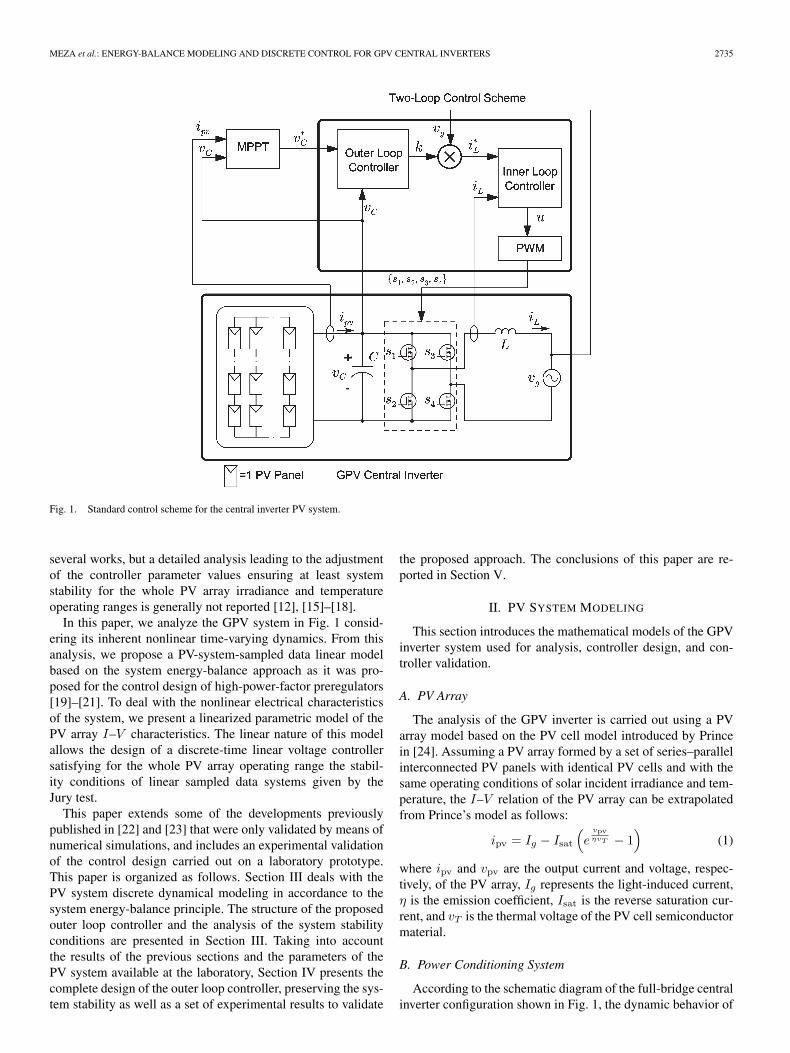
In this regard, a GPV system based on a single centralinverter is one of the most prevailing configurations since, underuniform irradiance conditions of the PV panels, it representsa good tradeoff between the extracted energy and the designcomplexity of the power inverter [3], [4]. In this configuration,all the available PV panels are series–parallel connected tothe input of a single full-bridge power inverter by means of adc-link capacitor, as shown in Fig. 1.
Manuscript received October 15, 2007; revised March 19, 2008. This workwas supported in part by the Ministerio de Ciencia y Tecnología, Spain,DPI2006-15627-C03-01, DPI2007-62582 by the European Union (FEDER).
C. Meza and D. Biel are with the Institute of Industrial and Control Engi-neering, Universitat Politecnica de Catalunya (UPC), 08034 Barcelona, Spain(e-mail: [email protected]; [email protected]).
J. J. Negroni is with the Department of Electrical Engineering, Facultad deIngeniería, Universidad Tecnológica Metropolitana del Estado de Chile, 1242Santiago, Chile (e-mail: [email protected]).
F. Guinjoan is with the Department of Electronic Engineering, Univer-sitat Politecnica de Catalunya, 08034 Barcelona, Spain (e-mail: [email protected]).
Color versions of one or more of the figures in this paper are available onlineat http://ieeexplore.ieee.org.
Digital Object Identifier 10.1109/TIE.2008.922595
The control strategy driving the central inverter is essentialfor the maximum dc power extraction and its proper transferto the grid. This control strategy needs to fulfill the followingobjectives.
• The proper conversion of the dc input power into an acoutput current that has to be injected to the grid. Thiscurrent has to exhibit low harmonic contents and must bein phase with respect to the grid voltage to perform thepower transfer at unity power factor.
• The regulation of the capacitor’s voltage to a value thatassures maximum power extraction from the PV array.
The aforementioned control requirements have been gener-ally carried out by means of a strategy based on two cascadedcontrol loops using a pulse width modulation (PWM) scheme,as shown in Fig. 1 [5], where the inner current loop is in chargeof establishing the duty ratio for the generation of a sinusoidaloutput current that is in phase with the grid voltage. In turn,the outer voltage loop has to settle the PV array operatingpoint at its maximum power value whatever the temperatureand irradiance variations are with the help of maximum powerpoint tracking (MPPT) algorithms such as Perturb and Observeor more advanced ones [6]–[9]. The outer loop delivers to theinner one the current reference amplitude corresponding to thePV array maximum power, thereby ensuring the power transferto the grid.
Several of the works dealing with the central inverter GPVconfiguration mainly address the inner current loop designand have shown that continuous-time linear controllers basedon a proportional + resonant (P + R) structure give satisfac-tory results and can be properly designed by means of linearcontrol techniques from the PV system output linear model[10]–[13].
Except for the work of Femia et al., where One-Cycle controlis addressed [14], the outer voltage loop design with a PWMmodulator has, in contrast, paid less attention in the literature.The difficulties of the outer voltage loop design mainly stemfrom the analytical complexity of the PV system dynamicalmodel since it exhibits, on one hand, a nonlinear parametricdependence on the PV array current-to-voltage (I–V ) charac-teristics with the irradiance and temperature levels, and, onthe other hand, a sinusoidal time dependence due to the PVsystem grid connection. Continuous and discrete-time linearcontrollers properly achieving the expected voltage controlrequirements for a specific application have been proposed in
0278-0046/$25.00 © 2008 IEEE
MEZA et al.: ENERGY-BALANCE MODELING AND DISCRETE CONTROL FOR GPV CENTRAL INVERTERS 2735
Fig. 1. Standard control scheme for the central inverter PV system.
several works, but a detailed analysis leading to the adjustmentof the controller parameter values ensuring at least systemstability for the whole PV array irradiance and temperatureoperating ranges is generally not reported [12], [15]–[18].
In this paper, we analyze the GPV system in Fig. 1 consid-ering its inherent nonlinear time-varying dynamics. From thisanalysis, we propose a PV-system-sampled data linear modelbased on the system energy-balance approach as it was pro-posed for the control design of high-power-factor preregulators[19]–[21]. To deal with the nonlinear electrical characteristicsof the system, we present a linearized parametric model of thePV array I–V characteristics. The linear nature of this modelallows the design of a discrete-time linear voltage controllersatisfying for the whole PV array operating range the stabil-ity conditions of linear sampled data systems given by theJury test.
This paper extends some of the developments previouslypublished in [22] and [23] that were only validated by means ofnumerical simulations, and includes an experimental validationof the control design carried out on a laboratory prototype.This paper is organized as follows. Section III deals with thePV system discrete dynamical modeling in accordance to thesystem energy-balance principle. The structure of the proposedouter loop controller and the analysis of the system stabilityconditions are presented in Section III. Taking into accountthe results of the previous sections and the parameters of thePV system available at the laboratory, Section IV presents thecomplete design of the outer loop controller, preserving the sys-tem stability as well as a set of experimental results to validate
the proposed approach. The conclusions of this paper are re-ported in Section V.
II. PV SYSTEM MODELING
This section introduces the mathematical models of the GPVinverter system used for analysis, controller design, and con-troller validation.
A. PV Array
The analysis of the GPV inverter is carried out using a PVarray model based on the PV cell model introduced by Princein [24]. Assuming a PV array formed by a set of series–parallelinterconnected PV panels with identical PV cells and with thesame operating conditions of solar incident irradiance and tem-perature, the I–V relation of the PV array can be extrapolatedfrom Prince’s model as follows:
ipv = Ig − Isat
(e
vpvηvT − 1
)(1)
where ipv and vpv are the output current and voltage, respec-tively, of the PV array, Ig represents the light-induced current,η is the emission coefficient, Isat is the reverse saturation cur-rent, and vT is the thermal voltage of the PV cell semiconductormaterial.
B. Power Conditioning System
According to the schematic diagram of the full-bridge centralinverter configuration shown in Fig. 1, the dynamic behavior of
2736 IEEE TRANSACTIONS ON INDUSTRIAL ELECTRONICS, VOL. 55, NO. 7, JULY 2008
the GPV system can be characterized by the following set ofdifferential equations:
CdvC
dt= − uiL + ipv (2)
LdiLdt
= uvC − vg. (3)
Here, vC and iL represent the input capacitor voltageand the output inductor current, respectively. Furthermore, asconcluded from (1), the current ipv generated by the PV arraystrongly depends on the incident solar irradiance, the temper-ature, and the input capacitor voltage (vpv = vC). The utilitygrid voltage vg is assumed to be sinusoidal with a constantamplitude A and a constant frequency ω, i.e., vg = A sin(ωt).The full-bridge inverter control signal u ∈ {−1, 1} is generatedby the GPV inverter’s controller.
To facilitate the control design, the next section establishes asimpler dynamical model that mitigates the analytical complex-ity resulting from (1)–(3).
C. Energy-Balance Modeling
This section presents a sampled data model for the GPVinverter based on the energy-balance equations of the system.The model is based on the approach described in [19]–[21]for the control design of high-power-factor preregulators. Themodeling methodology that is next presented represents anextension of the one presented in [22], [25], and [26].
The main requirement for the single-phase single-stage GPVinverter is the output current injection at unity power factor.This requirement implies a steady-state output current propor-tional to the grid voltage, i.e.,
i∗L = kvg = kA sin(ωt) (4)
where kA is the amplitude of the output current. We choose kto be time varying to deal with the varying input power (to be atthe maximum power point), i.e., given that the output root meansquare power is proportional to k as
Poutrms = 0.5kA2
and that in steady state without losses Pout = Pin, the onlyway there is to adjust the input power is by changing k.To reduce the output total harmonic distortion and to keep aunity power factor, the current reference amplitude kA is onlyupdated at the grid cycle’s multiples. Since the changes of thevariables that modify the PV input power (temperature andsolar irradiance) are slow, choosing this updating frequency fork does not compromise the power extraction efficiency of thesystem.
For the rest of the present analysis, we assume that the outputcurrent is sinusoidal in phase with the utility grid voltage. Thisapproach is carried out by designing a current controller with afast transient response and negligible settling time, as pointedout in Section III-B.
In terms of instantaneous power, the system can be charac-terized by the following energy-balance equation:
dEsto
dt= Ppv − Pout − LiL
diLdt
(5)
where Ppv is the input power from the PV array, and Esto is theenergy stored in the dc-link capacitor, namely,
Esto = 0.5Cv2C . (6)
Substituting i∗L = kvg and integrating (5) over one grid pe-riod T yields the following energy-balance equation:
Esto(nT ) − Esto ((n − 1)T ) = Epv − 12k ((n − 1)T ) A2T
(7)where k((n − 1)T is the value of k at time (n − 1)T , and
Epv(nT ) =
nT∫(n−1)T
Ppv(τ)dτ.
Applying the Z-transform to (7) yields
Esto(z) = Z{Epv}z
z − 1− k(z)
2(z − 1)A2T. (8)
Notice that there is a nonlinear relationship between Epv andEsto as can be easily derived from (1) and (7), i.e.,
Epv =
nT∫(n−1)T
(Ig + Isat) − Isate
(√2Esto
Cη2v2T
)
√2Esto
Cdτ.
(9)
To obtain a linear model, the aforementioned relationship islinearized around E∗
sto, i.e.,
Epv ≈ E∗pv + m (Esto − E∗
sto) (10)
where
E∗pv = Epv(E∗
sto) (11)
m=dEpv
dEsto
∣∣∣∣Esto=E∗
sto
m=
nT∫(n−1)T
1√2CE∗
sto
((Ig+Isat)
−Isat exp
(√2E∗
sto
Cη2v2T
)(1+
√2E∗
sto
Cη2v2T
))dτ. (12)
Consequently, the T-sampled storage energy (Esto) behavioris approximated by the following expression:
Esto(z)=[E∗
pv(z)+m(Esto(z)−E∗
sto(z))] z
z−1
− k(z)2(z−1)
A2T. (13)

MEZA et al.: ENERGY-BALANCE MODELING AND DISCRETE CONTROL FOR GPV CENTRAL INVERTERS 2737
Fig. 2. Block diagram of the energy-balance control.
Fig. 3. Experimental setup block diagram.
The previous expression shows to be very useful when design-ing the outer loop voltage controller, as explained in the nextsection.
III. CONTROL DESIGN APPROACH
A. Outer Loop
In the typical two-control loop scheme (see Fig. 1), the outerloop regulates the capacitor voltage to a desired value usuallyprovided by an MPPT algorithm. Here, we follow a similarapproach with the difference that instead of controlling thecapacitor voltage, we regulate the energy stored in the capacitor,i.e., Esto = 0.5Cv2
C . We assume that an external algorithm(e.g., a P and O MPPT) provides the desired capacitor voltagereference value v∗
C and thus also E∗sto.
To regulate Esto to its desired value E∗sto, a linear con-
troller GC is added to the linear model of (13), as shownin Fig. 2.
The closed-loop response of the T-sampled linear modelshown in Fig. 2 is obtained from (13) as
Esto(z)=zE∗
pv(z)−E∗sto
(0.5A2TzGC(z)+zm
)z−1−(0.5A2TGC(z)+zm)
. (14)
From (14), it can be deduced that to avoid any steady-stateerror in front of a step reference of amplitude E∗
sto, GC mustinclude an integral term, since in steady state (14) reduces to
limt→∞
Esto(t)=E∗sto− lim
z→1
(E∗
pv
0.5GC(z)A2T +mz
). (15)
Therefore, choosing the outer loop controller to be
GC = γz − α
z − 1
we proceed to analyze the stability of the system according tothe characteristic equation of the closed-loop system (denotedas q(z)) from (14) as
q(z) = (1 − m)z2 +(−2 − γ
A2T
2+ m
)z + 1 + γ
A2T
2α.
(16)
With the Jury test, we can determine the necessary andsufficient conditions for the roots of the characteristic in (16) tolie inside the unit circle. These conditions are summarized next.
• Condition 1: q(z)|z=1 > 0 implies that given α < 1
γ < 0. (17)
2738 IEEE TRANSACTIONS ON INDUSTRIAL ELECTRONICS, VOL. 55, NO. 7, JULY 2008
TABLE IPARAMETERS OF THE CASE UNDER STUDY
Fig. 4. Power versus voltage curves of the experimentally simulated andtested PV array.
• Condition 2: q(z)|z=−1 > 0 implies that
m < 2 + 0.25A2Tγ(1 + α) (18)
|γ| <4 − 2m
0.5A2T (1 + α). (19)
• Condition 3: |1 + 0.5A2Tγα| < 1 − m implies that
m < 1 −∣∣1 + 0.5A2Tγα
∣∣ (20)
m
0.5A2Tα< |γ| <
2m
0.5A2Tα. (21)
The aforementioned conditions allow the proper design ofthe outer loop voltage controller parameters (α, γ) to assure thestability of the system within its whole range of operation. Thisrange is determined by the evolution of the parameter m, as itwill be clarified with a practical example in Section IV.
B. Current Control Loop
The current controller takes the output current referencevalue given by the energy-balance controller and delivers thesignals needed to control the H-bridge inverter. As concernsthe outer loop design, the main requirements of the innercurrent control loop are fast transient response and negligiblesettling time with respect to the grid period. This requirementcan be achieved by means of linear controllers such as theP+ Resonant structure described in [10] and applied to GPVsystems in [11] and [13], or also by means of sliding-modecontrollers [27] that have been successfully used to control theGPV inverter output current [22], [25].
Fig. 5. Parameter m for a solar incident irradiance of 1000 Wm−2.
IV. CASE STUDY: CONTROL DESIGN AND
EXPERIMENTAL RESULTS
This section applies the presented approach to design thecontrol loops of a laboratory prototype GPV inverter for subse-quent experimental validation purposes. A block diagram of thelaboratory prototype is presented in Fig. 3. The experimentalsetup consists on a full-bridge power inverter with passiveelements, as shown in Table I. A Solar Array Simulator (SAS)(Agilent E4350B #J02) delivering a maximum output voltageof 80 V was used to program the PV array electrical character-istics. Due to the SAS low output voltage level, the GPV full-bridge inverter prototype was connected to the grid by meansof a step-up power transformer. All the measurements weredone in the low-voltage side of the transformer, which exhibitsa voltage amplitude of 33 V at 50 Hz.
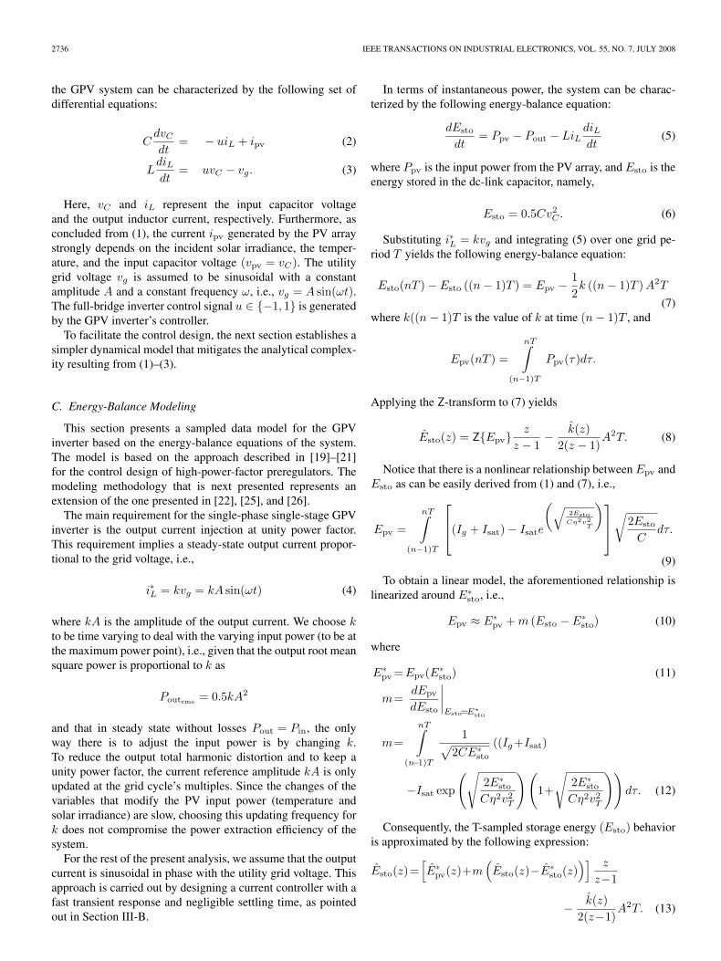
The parameters of the experimentally simulated and testedprototype are presented in Table I. The electrical characteristicsof the PV array used are shown in Fig. 4 for two different solarincident irradiances.
A. Control Design
The control scheme was implemented in a field-programmable gate array (Xilinx Spartan 3E) and consists of anouter loop controller, such as the one explained in Section III-A,and a sliding mode inner loop controller, as mentioned inSection III-B. Focusing on the outer loop, the parameter αneeds to be set to a value close to 1 to mitigate the instabilityeffect of the integral component of GC . Therefore, to focus onthe selection of γ, α is fixed to 0.875.
On the other hand, the design of the controller gainγ is strongly related with system stability. As shown inSection III-A, the stability of the closed-loop GPV system isdetermined by the parameter m and the controller GC . Thevalue of parameter m depends on the input capacitance andthe electrical characteristics of the PV array [see (12)]. Fig. 5depicts a numerical simulation of the variation of m for thesystem with the parameters of Table I and the PV array withthe electrical characteristics of Fig. 4 with a solar irradianceof 1000 Wm−2. The operating range shown in Fig. 5 lies
MEZA et al.: ENERGY-BALANCE MODELING AND DISCRETE CONTROL FOR GPV CENTRAL INVERTERS 2739
Fig. 6. Parameter m for different solar irradiances.
Fig. 7. Ranges of stability for different values of γ.
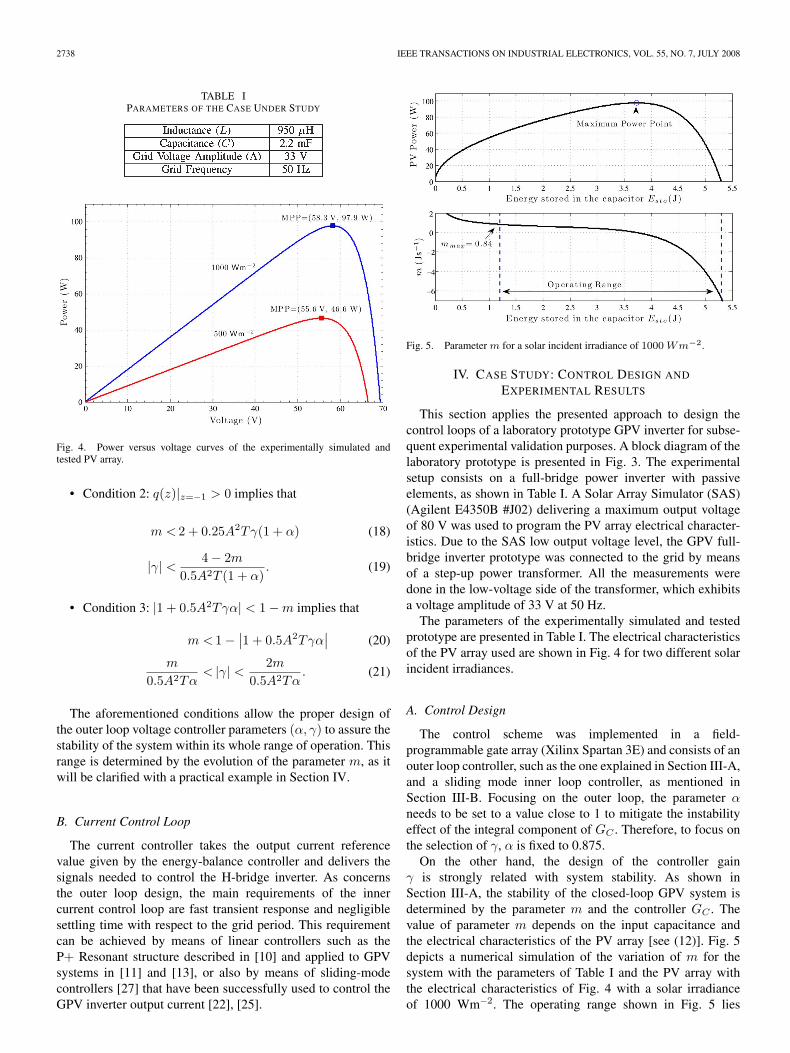
between the open circuit voltage of the PV Panel Array and theminimum voltage required for inversion (i.e., vC > A). Noticethat for this range of operation, the maximum value that m cantake is 0.84. This maximum value mmax also holds for lowerirradiances, as shown in Fig. 6.
The maximum value of m is required to choose the gain γ ofthe outer loop controller GC and to assure the stability of theclosed-loop system in the whole range of operation, as shown in(18)–(20). Fig. 7 shows the ranges of stability (i.e., the valuesof m in which the system is stable) for different values of γ.Even more, given that m depends on the energy stored in thecapacitor (Esto = 0.5Cv2
C), the selected value of γ determinesthe range of vC in which the system is stable. This situation canbe confirmed in the example depicted in Fig. 8 that shows theresults of the simulation of the system using different values
Fig. 8. Regulation of Esto using different values of γ.
Fig. 9. Root locus of (16) for different values of m.
of γ for the controller GC = γ(z − 0.875/z − 1) (the verticalaxis of the lower plots corresponds to the time variable to makeeasier the comparison). In this example, the reference energyE∗
sto is varied from 4.9 J (v∗C = 67 V) to 3.3 J (v∗
C = 55 V)at t = 4 s and to 2.2 J (v∗
C = 45 V) at t = 8 s. Notice thataccording to Fig. 7, E∗
sto = 3.3 J is outside the stability range ofthe controller with γ = −0.25. Moreover, the energy referencevalue of 2.2 J is outside the stability range not only for thecontroller with a gain of γ = −0.25 but also for the case inwhich a gain of γ = −0.05 is used. As can be concluded fromthe stability range analysis depicted in Fig. 7, the only controllerthat is able to properly regulate the system for all the referencesgiven is that one with γ = −0.1.
2740 IEEE TRANSACTIONS ON INDUSTRIAL ELECTRONICS, VOL. 55, NO. 7, JULY 2008
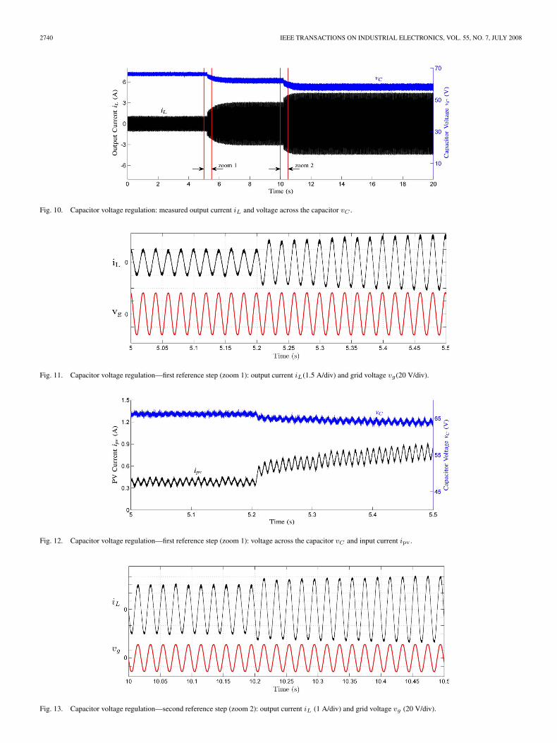
Fig. 10. Capacitor voltage regulation: measured output current iL and voltage across the capacitor vC .
Fig. 11. Capacitor voltage regulation—first reference step (zoom 1): output current iL(1.5 A/div) and grid voltage vg(20 V/div).
Fig. 12. Capacitor voltage regulation—first reference step (zoom 1): voltage across the capacitor vC and input current ipv.
Fig. 13. Capacitor voltage regulation—second reference step (zoom 2): output current iL (1 A/div) and grid voltage vg (20 V/div).
MEZA et al.: ENERGY-BALANCE MODELING AND DISCRETE CONTROL FOR GPV CENTRAL INVERTERS 2741
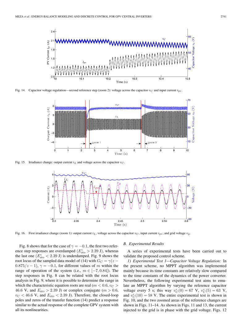
Fig. 14. Capacitor voltage regulation—second reference step (zoom 2): voltage across the capacitor vC and input current ipv.
Fig. 15. Irradiance change: output current iL and voltage across the capacitor vC .
Fig. 16. First irradiance change (zoom 1): output current iL, voltage across the capacitor vC , input current ipv , and grid voltage vg .
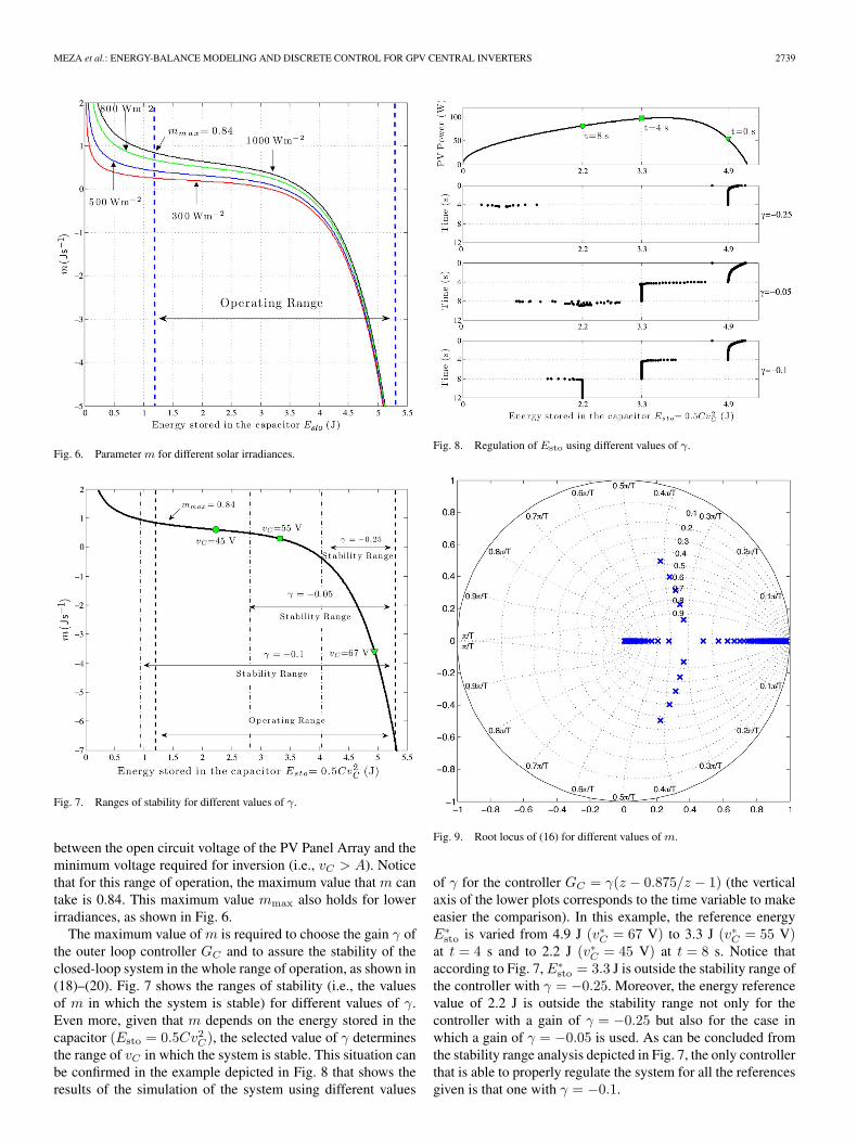
Fig. 8 shows that for the case of γ = −0.1, the first two refer-ence step responses are overdamped (E∗
sto > 2.39 J), whereasthe last one (E∗
sto < 2.39 J) is underdamped. Fig. 9 shows theroot locus of the sampled data model of (14) with GC = γ(z −0.875/z − 1), γ = −0.1, for different values of m within therange of operation of the system (i.e., m ∈ [−7, 0.84]). Thestep responses in Fig. 8 can be related with the root locusanalysis in Fig. 9, where it is possible to determine the range inwhich the characteristic equation roots are real (m < 0.6, vC >46.6 V, and Esto > 2.39 J) or complex conjugate (m > 0.6,vC < 46.6 V, and Esto < 2.39 J). Therefore, the closed-looppoles and zeros of the transfer function (14) predict a responsesimilar to the actual response of the complete GPV system withall its nonlinearities.
B. Experimental Results
A series of experimental tests have been carried out tovalidate the proposed control scheme.1) Experimental Test 1—Capacitor Voltage Regulation: In
the present scheme, no MPPT algorithm was implementedmainly because its time constants are relatively slow comparedto the time constants of the dynamics of the power converter.Nevertheless, the following experimental test aims to emu-late an MPPT algorithm by varying the reference capacitorvoltage every 5 s; this way v∗
C(0) = 67 V, v∗C(5) = 63 V,
and v∗C(10) = 58 V. The entire experimental test is shown in
Fig. 10, and the two zoomed areas of the reference changes areshown in Figs. 11–14. As shown in Figs. 11 and 13, the currentinjected to the grid is in phase with the grid voltage. Figs. 12

2742 IEEE TRANSACTIONS ON INDUSTRIAL ELECTRONICS, VOL. 55, NO. 7, JULY 2008
Fig. 17. Second irradiance change (zoom 2): output current iL, voltage across the capacitor vC , input current ipv, and grid voltage vg .
and 14 show the voltage and the current presented in the PVarray simulator. Notice the smooth overdamped dynamics ofboth variables related to the fact that (E∗
sto > 2.39 J), and thus,the closed-loop poles of the sampled data system are real, asshown in Section IV-A.2) Experimental Test 2—Irradiance Change: The last real-
ized experimental test consisted of an abrupt solar irradiancechange from 1000 to 500 Wm−2, which corresponds to theworst-case scenario (e.g., sudden shadowing caused by a bigcloud). The PV array power curves for both irradiances areshown in Fig. 4. The reference voltage value is held at v∗
C =58 V. The entire experimental test is shown in Fig. 15, andthe two zoomed areas of the irradiance changes are shownin Figs. 16 and 17. Fig. 16 shows the output current (iL),input current (ipv), voltage across the capacitor (vC), and gridvoltage (vg) for the step-down irradiance change (i.e., from1000 to 500 Wm−2). Fig. 17 illustrates the same variables forthe step-up solar irradiance change. As can be seen in thesefigures, after a small transient time, the voltage across thecapacitor maintains its reference value. In addition, notice thatthe output current is always in phase with the grid voltage.
V. CONCLUSION
This paper has addressed the design of the voltage loopcontroller involved in a single-phase GPV system based on afull-bridge central inverter. The design is based on the energy-balance model of the system and on the linearization of thePV array electrical characteristics. This approach yielded avoltage loop linear discrete controller of PI type that can beeasily designed by means of conventional linear discrete controltechniques. In particular, the parameters of the controller canbe designed by taking into account the restrictions given bythe Jury’s stability test. The obtained criteria to choose theparameters of the controller constitute one of the features of theproposed approach, since the controller design ensures systemstability for the whole operating range of the PV array interms of irradiance and temperature. As a proof of concept,the proposed design has been experimentally validated on alaboratory prototype that represents a power-scaled versionof a real GPV system. Finally, it can be pointed out thatthis approach can also be applied to other PV inverter struc-tures such as the preliminary works presented in [23], [25],and [26].
REFERENCES
[1] B. Jigjid, “Photovoltaics: An energy option for sustainable development,”in Proc. 3rd World Conf. Photovoltaic Energy Convers., May 2003,pp. 2518–2521.
[2] Renovalia, Situación de las Energías Renovables en España, Mar. 2005.[3] M. Meinhardt, “Past, present and future of grid connected photovoltaic
and hybrid-power-systems,” in Proc. IEEE Power Eng. Soc. SummerMeeting, Jul. 2000, vol. 2, pp. 1283–1288.
[4] S. B. Kjaer, J. K. Pedersen, and F. Blaabjerg, “A review of single-phasegrid-connected inverters for photovoltaic modules,” IEEE Trans. Ind.Appl., vol. 41, no. 5, pp. 1292–1306, Sep./Oct. 2005.
[5] F. Blaabjerg, R. Teodorescu, M. Liserre, and A. V. Timbus, “Overviewof control and grid synchronization for distributed power generationsystems,” IEEE Trans. Ind. Electron., vol. 53, no. 5, pp. 1398–1409,Oct. 2006.
[6] W. Xiao, M. G. J. Lind, W. G. Dunford, and A. Capel, “Real-time identifi-cation of optimal operating points in photovoltaic power systems,” IEEETrans. Ind. Electron., vol. 53, no. 4, pp. 1017–1026, Jun. 2006.
[7] I. Kim and M. Youn, “New maximum power point tracker using sliding-mode observer for estimation of solar array current in the grid-connectedphotovoltaic system,” IEEE Trans. Ind. Electron., vol. 53, no. 4, pp. 1027–1035, Jun. 2006.
[8] N. Mutoh, M. Ohno, and T. Inoue, “A method for MPPT control whilesearching for parameters corresponding to weather conditions for PVgeneration systems,” IEEE Trans. Ind. Electron., vol. 53, no. 4, pp. 1055–1065, Jun. 2006.
[9] R. Leyva, C. Alonso, I. Queinnec, A. Cid-Pastor, D. Lagrange, andL. Martinez-Salamero, “MPPT of photovoltaic systems using extremum-seeking control,” IEEE Trans. Aerosp. Electron. Syst., vol. 42, no. 1,pp. 249–258, Jan. 2006.
[10] D. Zmood and D. Holmes, “Stationary frame current regulation of PWMinverters with zero steady-state error,” IEEE Trans. Power Electron.,vol. 18, no. 3, pp. 814–822, May 2003.
[11] M. Liserre, R. Teodorescu, and F. Blaabjerg, “Stability of grid-connectedPV inverters with large grid impedance variation,” in Proc. Annu. IEEEPower Electron. Spec. Conf., 2004, pp. 4773–4779.
[12] M. Ciobotaru, R. Teodorescu, and F. Blaabjerg, “Control of single-stagesingle-phase PV inverter,” in Proc. Eur. Conf. Power Electron. Appl.,2005, pp. 1–10.
[13] R. Teodorescu, F. Blaabjerg, M. Liserre, and P. Loh, “Proportional-resonant controllers and filters for grid-connected voltage-source con-verters,” Proc. Inst. Electr. Eng.—Electr. Power Appl., vol. 153, no. 5,pp. 750–762, Sep. 2006.
[14] N. Femia, D. Granozio, G. Petrone, G. Spagnuolo, and M. Vitelli, “Op-timized one-cycle control in photovoltaic grid-connected applications,”IEEE Trans. Aerosp. Electron. Syst., vol. 42, no. 3, pp. 954–972, Jul. 2006.
[15] M. Nikraz, H. Dehbonei, and C. Curtin, “Digital control of a voltagesource inverter in photovoltaic applications,” in Proc. IEEE 35th Annu.Power Electron. Spec. Conf., 2004, vol. 5, pp. 3266–3271.
[16] C. Rodriguez and G. Amaratunga, “Energy control for long lifetime pho-tovoltaic AC module inverter,” in Proc. 37th IEEE Power Electron. Spec.Conf., 2006, pp. 1–6.
[17] J. Chang, W. Chang, and S. Chung, “Single-phase grid-connected PVsystem using three-arm rectifier-inverter,” IEEE Trans. Aerosp. Electron.Syst., vol. 42, no. 1, pp. 211–219, Jan. 2006.
[18] A. Kotsopoulos, J. L. Duarte, and M. A. M. Hendrix, “Predictive DC volt-age control of single-phase PV inverters with small DC link capacitance,”in Proc. IEEE Int. Symp. Ind. Electron., 2003, pp. 793–797.
MEZA et al.: ENERGY-BALANCE MODELING AND DISCRETE CONTROL FOR GPV CENTRAL INVERTERS 2743
[19] K. Mahabir, G. Verghese, V. Thottuvelil, and A. Heyman, “Linear av-eraged and sampled data models for large signal control of high powerfactor AC–DC converter,” in Proc. IEEE Power Electron. Spec. Conf.,1990, pp. 291–299.
[20] A. Mitwalli, S. Leeb, G. Verghese, and V. Thottuvelil, “An adaptivedigital controller for a unity power factor converter,” IEEE Trans. PowerElectron., vol. 11, no. 2, pp. 374–382, Mar. 1996.
[21] J. Kassakian, M. Schlecht, and G. Verghese, Principles of Power Electron-ics. Reading, MA: Addison-Wesley, 1991.
[22] J. J. Negroni, C. Meza, D. Biel, and F. Guinjoan, “Control of a buckinverter for grid-connected PV systems: A digital and sliding mode con-trol approach,” in Proc. IEEE Int. Symp. Ind. Electron., Jun. 2005,pp. 739–744.
[23] C. Meza, J. J. Negroni, D. Biel, and F. Guinjoan, “Inverter configurationscomparative for residential PV-grid connected systems,” in Proc. IEEEInt. Conf. Ind. Electron., Nov. 2006, pp. 4361–4366.
[24] M. Prince, “Silicon solar energy converters,” J. Appl. Phys., vol. 26, no. 5,pp. 534–540, May 1955.
[25] C. Meza, J. J. Negroni, D. Biel, and F. Guinjoan, “Considerations on thecontrol design of DC-link based inverters in grid-connected photovoltaicsystems,” in Proc. IEEE Int. Symp. Circuits Syst., May 2006.
[26] J. J. Negroni, C. Meza, D. Biel, and F. Guinjoan, “Energy-sampleddata modeling of a cascade H-bridge multilevel converter for grid-connected PV systems,” in Proc. IEEE Int. Power Electron. Congr.,Oct. 2006, pp. 1–6.
[27] V. Utkin, Sliding Mode and Their Applications in Variable StructureSystems. Moscow, Russia: MIR, 1978.
Carlos Meza (M’04) received the B.S. degree inelectronics engineering from the Costa Rica Instituteof Technology, Cartago, Costa Rica, and the M.Eng.degree in embedded systems design from ALaRI,University of Lugano, Lugano, Switzerland, in 2003.He is currently working toward the Ph.D. degree inadvanced automation and robotics at the UniversitatPolitecnica de Catalunya, Barcelona, Spain. His dis-sertation research concerns the analysis and controlof grid-connected PV systems.
He is currently a Research Assistant with theInstitute of Industrial and Control Engineering, Universitat Politecnica deCatalunya. His research interests include nonlinear control and energy systems.
Juan J. Negroni (M’04) received the degree in elec-tronics engineering from the Universidad Tecnológ-ica Metropolitana del Estado de Chile, Santiago,Chile, and the Ph.D. degree in electronics engineer-ing from the Universitat Politecnica de Catalunya,Barcelona, Spain, in 2007.
Since 1999, he has been an Associate Professorwith the Department of Electric Engineering, Uni-versidad Tecnoloógica Metropolitana del Estado deChile, where he teaches courses on power electron-ics. His research interests include power electronics
for renewable energy systems.
Domingo Biel (S’97-M’99) received the B.S., M.S.,and Ph.D. degrees from the Universitat Politecnicade Catalunya, Barcelona, Spain, in 1990, 1994, and1999, respectively, all in telecommunications engi-neering. His dissertation research concerned the ap-plication of sliding-mode control to signal generationin dc-to-dc switching converters.
Since 1994, he has been an Assistant Professorwith the Electronic Engineering Department, Uni-versitat Politecnica de Catalunya, where he teachescourses on power electronics and control theory. He
is the author/coauthor of several papers and communications presented atinternational congresses and workshops. His research fields are related tononlinear control, sliding-mode control, and power electronics.
Francisco Guinjoan (M’92) received the Ingenierode Telecomunicación and Doctor Ingeniero de Tele-comunicación degrees from the Universitat Politec-nica de Catalunya, Barcelona, Spain, in 1984 and1990, respectively, and the Docteur es Sciences de-gree from the Université Paul Sabatier, Toulouse,France, in 1992.
He is currently an Associate Professor with theDepartamento de Ingenieria Electrónica, EscuelaTécnica Superior de Ingenieros de TelecomunicaciónBarcelona, Universitat Politècnica de Catalunya,
where the teaches courses on power electronics. His research interests includepower electronics modeling and control for renewable energy systems.