Energy-efficient encoding techniques for off-chip data buses
10
Power Efficient Encoding Techniques for Off-chip Data Buses Dinesh C Suresh Banit Agrawal Jun Yang Walid Najjar Laxmi Bhuyan Computer Science and Engineering University of California, Riverside, CA 92521 {dinesh, bagrawal, junyang, najjar, bhuyan}@cs.ucr.edu ABSTRACT Reducing the power consumption of computing devices has gained a lot of attention recently. Many research works have focused on reducing power consumption in the off-chip buses as they consume a significant amount of total power. Since the bus power consumption is proportional to the switching activity, reducing the bus switching is an effective way to reduce bus power. While numerous techniques exist for reducing bus power in address buses, only a handful of techniques have been proposed for data-bus power reduction, where Frequent Value Encoding (FVE) is the best existing scheme to reduce the transition activity on the data buses. In this paper, we propose improved frequent value data-bus encoding techniques aimed at reducing more switching activity and hence, more power consumption. We propose three new schemes and five new variations to exploit bit-wise temporal and spatial locality in the data bus values. Our technique does not use additional external control signal and captures bit-wise locality to efficiently encode data values. For all the embedded and SPEC applications we tested, the overall average switching reduction is 53% over unencoded data and 11% more than the conventional FVE scheme. Categories and Subject Descriptors C.4 [performance of systems]: Design studies – data bus encoding, low power design. General Terms Algorithms,Measurement, Performance, Design, Experimentation. Keywords Low power, bus encoding, data bus, FV, FV-MSB-LSB 1 INTRODUCTION Power consumption is becoming an increasingly critical design criterion for embedded systems and especially more so, for mobile computing devices [12]. This is because those devices draw their current from batteries that place a limited amount of energy at the system’s disposal. Consequently, reduced power and energy consumption of embedded devices translates to longer battery lives and reduced cooling requirements. Off-chip and On-chip bus lines in VLSI circuits are associated with very large capacitances and they have been shown to be a major contributor to a system’s total power consumption [13]. The power consumption in the bus drivers is in direct proportion to the product of the average number of signal transitions and the line capacitance. It has been shown that the capacitive load of off- chip buses is orders of magnitude larger than that of internal switching nodes [6][7][15], and this trend is likely to continue [12]. Hence, at the expense of a small internal energy cost, if one can encode data prior to transmission, significant bus power can be saved during off-chip-transmission. Both off-chip address buses and data buses are potential targets for bus encoding. Most of the previous research [1][8][3] have focused on address bus encoding to exploit the sequential and stride behavior of instruction and data addresses. However, encoding data values on off-chip data-buses is not that easy since the data streams are less regular than address streams. Data bus encoding schemes like bus-invert coding[14], adaptive coding[3] and frequent value encoding [1][16] do not assume any prior knowledge of the application. This is highly desirable because in many application- domains knowing the data in advance might prove to be a very stringent requirement. Bus-invert coding transfers a data value either in its original form or in its complement form depending on whose hamming distance with the previous bus transmission is smaller. It is a simple method that assumes values are uniformly distributed across the entire representable space. The adaptive encoding scheme, taking the next step further, is capable of on-line adaptation to the value streams by learning the statistics on the fly. As collecting the accurate statistics for the value streams can be very expensive, the proposed adaptive encoding operates bit-wise rather than word- wise. Thus, it looses the correlation among the bits within a single value. The frequent value-encoding (FVE) scheme is by far the most effective way of reducing the transition rate for data buses. It is based on the observation that a sizeable amount of data values occurs frequently within a certain time window (or, temporal locality) [17]. Thus, reoccurring frequent values can be transmitted using minimum number of bus switches, namely 1. This technique has been shown to work very well for off-chip data buses. Lv et.al. [10] proposed an adaptive dictionary based scheme (ADES) for data buses that exploits the correlation between adjacent bits of a word sent on the data bus. The original FVE scheme is limited by the number of FV’s captured in the encoder and the decoder [16]. In this paper, we Permission to make digital or hard copies of all or part of this work for personal or classroom use is granted without fee provided that copies are not made or distributed for profit or commercial advantage and that copies bear this notice and the full citation on the first page. To copy otherwise, or republish, to post on servers or to redistribute to lists, requires prior specific permission and/or a fee. CASES ’03, Oct 30 – Nov 2, 2003, San Jose, California, USA. Copyright 2003 ACM 1-58113-676-5/03/0010…$5.00.
-
Upload
independent -
Category
Documents
-
view
0 -
download
0
Transcript of Energy-efficient encoding techniques for off-chip data buses
Power Efficient Encoding Techniques for Off-chip Data Buses
Dinesh C Suresh Banit Agrawal Jun Yang Walid Najjar Laxmi Bhuyan Computer Science and Engineering
University of California, Riverside, CA 92521 {dinesh, bagrawal, junyang, najjar, bhuyan}@cs.ucr.edu
ABSTRACT Reducing the power consumption of computing devices has gained a lot of attention recently. Many research works have focused on reducing power consumption in the off-chip buses as they consume a significant amount of total power. Since the bus power consumption is proportional to the switching activity, reducing the bus switching is an effective way to reduce bus power. While numerous techniques exist for reducing bus power in address buses, only a handful of techniques have been proposed for data-bus power reduction, where Frequent Value Encoding (FVE) is the best existing scheme to reduce the transition activity on the data buses. In this paper, we propose improved frequent value data-bus encoding techniques aimed at reducing more switching activity and hence, more power consumption. We propose three new schemes and five new variations to exploit bit-wise temporal and spatial locality in the data bus values. Our technique does not use additional external control signal and captures bit-wise locality to efficiently encode data values. For all the embedded and SPEC applications we tested, the overall average switching reduction is 53% over unencoded data and 11% more than the conventional FVE scheme.
Categories and Subject Descriptors C.4 [performance of systems]: Design studies – data bus encoding, low power design. General Terms Algorithms,Measurement, Performance, Design, Experimentation.
Keywords Low power, bus encoding, data bus, FV, FV-MSB-LSB
1 INTRODUCTION Power consumption is becoming an increasingly critical design criterion for embedded systems and especially more so, for mobile computing devices [12]. This is because those devices draw their current from batteries that place a limited amount of energy at the system’s disposal. Consequently, reduced power and energy consumption of embedded devices translates to longer
battery lives and reduced cooling requirements.
Off-chip and On-chip bus lines in VLSI circuits are associated with very large capacitances and they have been shown to be a major contributor to a system’s total power consumption [13]. The power consumption in the bus drivers is in direct proportion to the product of the average number of signal transitions and the line capacitance. It has been shown that the capacitive load of off-chip buses is orders of magnitude larger than that of internal switching nodes [6][7][15], and this trend is likely to continue [12]. Hence, at the expense of a small internal energy cost, if one can encode data prior to transmission, significant bus power can be saved during off-chip-transmission.
Both off-chip address buses and data buses are potential targets for bus encoding. Most of the previous research [1][8][3] have focused on address bus encoding to exploit the sequential and stride behavior of instruction and data addresses. However, encoding data values on off-chip data-buses is not that easy since the data streams are less regular than address streams. Data bus encoding schemes like bus-invert coding[14], adaptive coding[3] and frequent value encoding [1][16] do not assume any prior knowledge of the application. This is highly desirable because in many application- domains knowing the data in advance might prove to be a very stringent requirement.
Bus-invert coding transfers a data value either in its original form or in its complement form depending on whose hamming distance with the previous bus transmission is smaller. It is a simple method that assumes values are uniformly distributed across the entire representable space. The adaptive encoding scheme, taking the next step further, is capable of on-line adaptation to the value streams by learning the statistics on the fly. As collecting the accurate statistics for the value streams can be very expensive, the proposed adaptive encoding operates bit-wise rather than word-wise. Thus, it looses the correlation among the bits within a single value.
The frequent value-encoding (FVE) scheme is by far the most effective way of reducing the transition rate for data buses. It is based on the observation that a sizeable amount of data values occurs frequently within a certain time window (or, temporal locality) [17]. Thus, reoccurring frequent values can be transmitted using minimum number of bus switches, namely 1. This technique has been shown to work very well for off-chip data buses. Lv et.al. [10] proposed an adaptive dictionary based scheme (ADES) for data buses that exploits the correlation between adjacent bits of a word sent on the data bus.
The original FVE scheme is limited by the number of FV’s captured in the encoder and the decoder [16]. In this paper, we
Permission to make digital or hard copies of all or part of this work for personal or classroom use is granted without fee provided that copies are not made or distributed for profit or commercial advantage and that copies bear this notice and the full citation on the first page. To copy otherwise, or republish, to post on servers or to redistribute to lists, requires prior specific permission and/or a fee. CASES ’03, Oct 30 – Nov 2, 2003, San Jose, California, USA. Copyright 2003 ACM 1-58113-676-5/03/0010…$5.00.
walid najjar
Int. Conf. on Compilers, Architectures and Synthesis for Embedded Systems (CASES), October 2003, San Jose, CA.

first propose a new data bus encoding technique that exceeds this limit to encode far more number of FV’s. To do so, we multiplex the data bus with encoding results from multiple encoders that serve different purposes. The most important difficulty we solved here is not to increase the number of control signals outside the data bus. Secondly, the original FVE scheme exploits temporal locality in full-width data value streams but it has overlooked the abundant temporal locality available in partial-width data value streams. We therefore propose a few more innovative schemes to exploit temporal locality in partial-width data values.
Our schemes make no prior assumptions regarding the data and are truly dynamic in nature. Besides encoding entire data values, we encode the MSB and LSB portion of the data values whenever possible. Our encoding schemes are also capable of maintaining a larger history of data values than the maximum possible history length in the FVE scheme and hence, our schemes have a higher probability of encoding incoming data values.
In the next section, a brief overview of general bus encoding scheme and frequent value bus encoding scheme are provided. In section 3, we provide the intuition behind our schemes. Then in section 4, we describe all the proposed schemes in detail. We describe our experimental setup in section 5. Power and delay analysis are discussed in Section 6. Section 7 concludes.
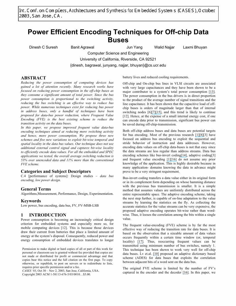
2 BACKGROUND Figure 1 shows a symmetric pair of coders that are usually used for bus encoding. An encoder/decoder (codec) is placed at the memory side and the processor side of the off-chip data bus. The codec decides whether the data value should be encoded or not,
before placing the value on the data bus. When the codec encodes data values, it asserts a control signal to let the destination know that the current value is encoded and hence, it should not be interpreted “as-is”. The codec design is symmetrical in nature to handle both read and write operations by the CPU. In case of a CPU read, the processor side codec works as a decoder; while the memory side codec encodes the value to minimize bus switching. In case of a CPU write, the processor side works as an encoder and the memory side codec works as a decoder. FVE is a symmetric table-based scheme that operates in a manner similar to the scheme described above. The FV codec has a k-bit, k-entry table to store previously seen data values. Here, k is the width of the data bus. Before placing a data value on the data bus, the encoder compares the data value with the values stored in the table. A hit in the table implies that the current data value had been encountered in the recent past. In case of a hit, the codec generates a code corresponding to the hit index in the table. The code has the form of “one-hot” code meaning that there is only a single “1” and its position corresponds to the hit index in the table. In the event of a miss in the table, the data value is stored at the encoder and it is then sent over the bus “as-is”. The decoder checks to see if the data bus value is a one-hot code. If yes, the decoder reads the data value from the table by using the one-hot code as an index to the table. If the data bus value is not encoded, the decoder stores the value in the table and sends the value “as-is”. Data values are maintained in the table using the LRU replacement policy. As used in other encoding techniques, a pair of correlator and decorrelator is added at the two ends of buses. They are inverse functions of each other and their purpose is to reduce the
Figure 1. A symmetric codec for data bus
Normalized Average Hits for MSB, LSB and MSB-LSB
0
0.2
0.4
0.6
0.8
1
2 3 4 5 6 7 8 9 10 11 12 13 14 15 16 17 18 19 20 21 22 23 24 25 26 27 28 29No of MSB bits
Nor
mal
ized
hit
valu
e
MSB
LSB
MSB-LSB
Figure 2. Average hit rates for varying bit lengths for all benchmarks
correlations between successive values. For example, transmitting “01" after “10" normally introduces two transitions. With decorrelator on the sending side, only one transition is introduced to the bus. This is simply achieved by using an XOR gate on each bus wire.
3 MOTIVATION Through our experiments, we found that off-chip data traces exhibit abundant temporal locality on partial width data value streams. i.e., the high order bits (MSBs) and the low order bits (LSBs) of a data value occur a lot more frequently than the entire data value. We propose that, besides storing the values seen in the recent past, one should also store the high-order and low-order bits of the values in separate tables. The intuition behind doing so is that, for every repeating data value, there might be many non-repeating data values that contain the same high-order or low-order bits. For example, if the value 80485678 occurs 10,000 times, then, one can safely assume that 8048 occurs at least 10,000 times in the high order bits and the value 5678 occurs at least 10,000 times in the low-order bits of data values. In other words, partial data value locality must be at least as abundant as data value locality. For the rest of this paper, we will refer to repeating values as frequent values (FV) and non-repeating values as non-frequent values. We analyzed a wide range of benchmarks from the NetBench [11], MediaBench [9] and the SPEC2000 application suites and we plotted the hits in the MSB and LSB portion of data values. Figure 2 shows the average normalized hits for the MSB, LSB and the MSB-LSB for a set of benchmarks. As shown in the graph, if we encode both MSBs and LSBs, then we can send encoded values over the buses most of the time, hence we can exploit the large hit rate of MSB-LSB. On observing the hit
pattern, we devised a scheme that would capture the locality in the entire data, MSB and the LSB portions of the data value. We call this scheme as FV-MSB-LSB scheme.
4 OUR ENCODING SCHEMES In this section, we propose a few innovative low-power bus-encoding techniques for efficient processor to memory communication. We will first describe the high-level design methodologies including how to implement a larger value history table size and how to incorporate MSB and LSB values. We then elaborate each technique and its variations in detail.
4.1 Design Methodologies 4.1.1 Increasing the table size The FVE scheme sends a one-hot code for a data value, if it is contained in the frequent value table. However, the size of the frequent value table has the following limitation: For a k-bit wide data bus, the number of entries stored in the frequent value table, cannot exceed k. Consequently, a value can be encoded only if it contained in the k stored entries. By storing more than k entries, one has a higher probability of encoding an incoming data value. However, if we try to encode more values within the framework provided by the FVE scheme, we would require additional external control signals. Control signals require the availability of a free pin on the chip and are hence very expensive to provide. So, we propose a framework that does not increase the number of control signals required by the original FVE (which is one) when we increase the table size. However, increasing the table size does require more number of control signals. The trick is to utilize portion of data bus wires as control signals. We will call them internal control signals. If the enlarged table size is a multiple of the base table size, the internal control signals can serve as the index to the
Figure 3. Codec structure for FV-i Encoding Scheme
Figure 4. Codec Structure for the FV-MSB-LSB scheme

different portion in the table. For example, a double sized table needs only one internal control signal to indicate whether the code is generated from the first half or the second half of the table. Note that the effective base encoding table size is also reduced by one due to the internal control signal. The next question is what portion of the data bus should be selected as internal control signals. Through our experiments, we found that the transition activity in the lower order bits of the data bus is often slightly higher than the activity in the high order bits. Hence, while sending encoded values, we choose to make the least significant bits as control signals. By doing so, they will not contribute much to the total switching. In summary, our proposed method for increasing the table size can be put formally as follows: Let us consider a k-bit wide data bus. In order to keep a history of more than k, k-bit values, the number of entries stored in the table is of the form (k – m)*2m, where m represents the number of internal control signals. Using the first k –m lines, we send a one hot code corresponding to i mod (k-m) where i is the hit index in the enlarged frequent table. The last m lines along with the index transmitted on the bus are used to specify the position of the data within the table. For this scheme, the maximum number of
transitions while sending any encoded value is m+1
4.1.2 Bit-width of stored values As stated earlier, besides storing entire data values, we also store the MSB and LSB portions of the data value in separate tables. In order to determine the optimal width of the MSB and LSB entries, we varied the bit-width of the entries from 2 to 29 bits in steps of 1 and observe the switching reduction for each case. The results would be presented in section 6. Since we encode table hits using one-hot code, the number of table entries should be equal to the bit-width of the stored entries. However, using the framework provided in section 4.1.1, the size of the MSB, LSB and frequent tables can be increased similarly.
4.2 FV-i Encoding FV-i scheme overcomes the limitations of FVE by maintaining larger sized tables and can hence, encode more data values. FV-i maintains larger tables using the method described in section 4.1.1. When i=0, FV-i scheme becomes the FVE scheme. We evaluate the performance of FV-i scheme for three values of i: 0,1 and 2. For a 32-bit wide data bus, the number of table entries for
1: for each data value do 2: if data value not in FV TABLE nor MSB TABLE nor LSB TABLE then 3: encode signal = 0 /* value not in any of the tables. */ 4: send data unencoded 5: else 6: encode signal = 1 7: if hit in FV TABLE then /* it is a frequent value */ 8: send one-hot code 9: else 10: if both MSB and LSB TABLE hit then 11: encode high-ordered bits (one-hot code) 12: encode low-ordered bits (one-hot code) 13: else /* Check for an MSB hit and encode if necessary */ 14: if only MSB TABLE hit 15: if no of ones in LSB >=2 16: encode high-ordered bits (one-hot code) 17: send low-ordered bits unencoded 18: end if 19: end if /*Check for LSB hit */ 20: if only LSB TABLE hit 21: if no of ones in MSB >=2 22: encode low-ordered bits (one-hot code) 23: send high-ordered bits unencoded 24: end if 25: end if 26: end if 27: end if 28: end if 29: end for
Figure 5. Algorithm for FV-MSB-LSB scheme

FV-1 and FV-2 are 62 ((32-1)*2) and 120 ((32-2)*4) respectively.
4.2.1 FV-1 encoding: FV-1 encoding uses a 62-entry FV table to store 62, 32-bit values. The last line (0th bit) of the data bus is used as a control signal. As stated earlier, we picked the 0th bit because, for many applications, the 0th bit changes very frequently in the data, so it will not add much to the control switching. The 0th LSB of the data bus acts as a regular data bus line while sending unencoded data. When the encode signal is high, the destination interprets the 0th line as control signal and searches the table accordingly.
4.2.2 FV-2 encoding: FV-2 encoding scheme uses a 120-entry FV table to store 120, 32-bit values. The last two lines (0th and first LSB) of the data bus are used as control signals. When the encode signal is high, the destination interprets the 0th and 1st lines as the portion index and searches the table accordingly. Figure 3 shows the codec structure for the FV-i scheme. The following paragraphs illustrate the
encoder and decoder operation for the FV-i codec.
4.2.3 FV-i encoder The encoder receives the data value from the processor/memory and it decides whether the data should be encoded before it gets placed on the off-chip data bus. For every incoming data value, the encoder looks up the FV table to check for past occurrences of the data value. The selection logic sees the output of the tables and decides whether the data should be encoded or not. If the selection logic decides to encode the data, it asserts the encode signal and declares the encoded data as the current data bus value, else it lowers the encode signal and sends the data value “as-is”. The data bus value passes through the correlator before it finally gets placed on the data bus.
4.2.4 FV-i decoder The decoder can receive encoded or unencoded data from the data bus. The data bus value passes through the decorrelator and then reaches the selection logic. The selection logic checks the encode
Figure 6. FV–i-MSB-j Codec structure
1: for each data value do 2: if data value not in FV nor U-MSB TABLE nor L-MSB TABLE then 3: encode signal = 0 4: send data unencoded 5: else 6: encode signal = 1 7: if hit in FV TABLE then /* Frequent value */ 8: send one-hot code 9: else 10: if U-MSB TABLE hit then /* MSB hit in the first r-1 entries */ 11: encode high-ordered bits (one-hot code) 12: Rth bit of data bus = 1 13: send low-ordered bits unencoded 14: end if 15: if L-MSB TABLE hit then /* MSB hit in the next r-1 entries */ 16: encode high-ordered bits (one-hot code) 17: Rth bit of data bus = 0 18: send low-ordered bits unencoded 19: end if 20: end if 21: end if 22: end for
Figure 7. Algorithm for FV-1-MSB-2 scheme

signal to see if the data is encoded. If the data is unencoded, it is forwarded as-is to the processor/memory. Otherwise, using the one-hot code contained in the encoded portion plus the internal control signals, the selection logic picks up the data value from the FV table to construct the decoded value. The decoded value is then forwarded to the processor/memory.
4.3 FV-MSB-LSB encoding Figure 5 shows the algorithm for the FV-MSB-LSB scheme. The FV-MSB-LSB scheme aggressively encodes incoming data values by sending one-hot codes for the entire data value, the MSB portion and the LSB portion whenever possible. To accomplish this, FV-MSB-LSB uses three tables: a FV table, MSB table and an LSB table. Figure 4 shows the codec structure for this scheme. The following paragraphs illustrate the codec’s functionality as an encoder and a decoder.
4.3.1 Encoder operation For every incoming data value, the encoder looks up the FV, MSB and LSB tables to check for past occurrences of the entire data value, MSB portion and the LSB portion respectively. In the event of a hit in multiple tables, the FV hit takes precedence. If the selection logic is informed to encode the data, it asserts the encode signal and declares the encoded data as the current data bus value, else it lowers the encode signal and sends data value “as-is”. The data bus value passes through the correlator before it
finally gets placed on the data bus.
4.3.2 Decoder operation The decoder can receive encoded or unencoded data from the data bus. On an incoming data bus value, the selection logic checks the encode signal to see if the data is encoded. If the data is unencoded, it is forwarded as-is to the processor/memory. Otherwise, using the one-hot code contained in the encoded portion, the selection logic picks up the data value from one or more of the stored tables to accurately reconstruct the decoded value. For example, if the selection logic finds that there is a hit in the MSB table only, and then it picks up the MSB portion from the table and uses the LSB portion of the data “as-is” to get back the data value. The decoded value is then forwarded to the processor/memory.
4.4 FV-i-MSB-j encoding: In this scheme, we have two tables: FV table and an MSB table. The FV table stores the entire data value while the MSB table stores the “r most significant bits” of an incoming data value. Here, “r” is a number that is fixed by the designer and is subject to the constraint that “r < k,” where k is the data bus width. We evaluate the performance of two instances of this scheme: FV-1-MSB-2 and FV-2-MSB-2. i and j refers to the factors by which the appropriate tables are increased. For example, If we store k-bit wide and r-bit wide entries in the FV and MSB tables
1: for each data value do 2: if data value not in FV TABLE nor U-MSB TABLE nor L-MSB TABLE then 3: encode signal = 0 /* value not in any of the tables */ 4: send data unencoded 5: else 6: encode signal = 1 7: if hit in U-FV TABLE then /* FV-hit is in the first k-1 entries */ 8: send one-hot code 9: 0th bit of data bus = 1 10: else 11: if hit in L-FV TABLE then /* FV-hit is in the next k-1 entries */ 12: send one-hot code 13: 0th bit of data bus = 0 14: else 15: if U-MSB TABLE hit then /* MSB hit is in first r-1 entries */ 16: encode high-ordered bits (one-hot code) 17: Rth bit of data bus = 1 18: send low-ordered bits unencoded 19: end if 20: if L-MSB TABLE hit then /* MSB hit is in the next r-1 entries */ 21: encode high-ordered bits (one-hot code) 22: Rth bit of data bus = 0 23: send low-ordered bits unencoded 24: end if 25: end if 26: end if 27: end if 28: end for
Figure 8. Algorithm for FV-2-MSB-2 scheme
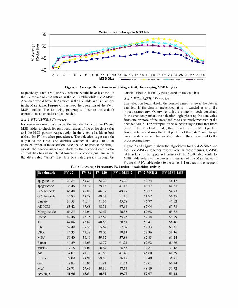
respectively, then FV-1-MSB-2 scheme would have k-entries in the FV table and 2r-2 entries in the MSB table while FV-2-MSB-2 scheme would have 2k-2 entries in the FV table and 2r-2 entries in the MSB table. Figure 6 illustrates the operation of the FV-i-MSB-j codec. The following paragraphs illustrate the codec’s operation as an encoder and a decoder.
4.4.1 FV-i-MSB-j Encoder For every incoming data value, the encoder looks up the FV and MSB tables to check for past occurrences of the entire data value and the MSB portion respectively. In the event of a hit in both tables, the FV hit takes precedence. The selection logic sees the output of the tables and decides whether the data should be encoded or not. If the selection logic decides to encode the data, it asserts the encode signal and declares the encoded data as the current data bus value, else it lowers the encode signal and sends the data value “as-is”. The data bus value passes through the
correlator before it finally gets placed on the data bus.
4.4.2 FV-i-MSB-j Decoder The selection logic checks the control signal to see if the data is encoded. If the data is unencoded, it is forwarded as-is to the processor/memory. Otherwise, using the one-hot code contained in the encoded portion, the selection logic picks up the data value from one or more of the stored tables to accurately reconstruct the decoded value. For example, if the selection logic finds that there is hit in the MSB table only, then it picks up the MSB portion from the table and uses the LSB portion of the data “as-is” to get back the data value. The decoded value is then forwarded to the processor/memory. Figure 7 and Figure 8 show the algorithms for FV-1-MSB-2 and the FV-2-MSB-2 schemes respectively. In these figures, U-MSB table refers to the upper r-1 entries of the MSB table while L-MSB table refers to the lower r-1 entries of the MSB table. In Figure 8, U-FV table refers to the upper k-1 entries of the frequent
Variation with change in MSB bits
40
45
50
55
2 3 4 5 6 7 8 9 10 11 12 13 14 15 16 17 18 19 20 21 22 23 24 25 26 27 28 29MSB Size
% A
vera
ge
Red
uctio
n
FV-MSB FV-MSB-LSB FV-2-MSB-2 FV-1-MSB-2
Figure 9. Average Reduction in switching activity for varying MSB lengths
Table 1. Average Percentage Reduction in switching activity
Benchmark FV-32 FV-62 FV-120 FV-1-MSB-2 FV-2-MSB-2 FV-MSB-LSB
Jpegencode 20.85 33.84 38.20 33.20 42.25 36.42 Jpegdecode 33.46 38.22 39.16 41.18 43.77 40.63 G721decode 45.48 46.80 46.77 49.27 50.27 54.93 G721encode 46.83 48.29 48.53 51.10 51.92 56.27 Unepic 39.53 41.14 41.66 45.78 46.77 47.12 ADPCM 65.42 67.68 68.31 67.64 67.94 67.78 Mpegdecode 66.85 68.04 68.67 70.33 69.68 69.72 Route 44.46 47.28 47.89 55.25 57.14 59.09 TL 44.84 47.82 48.53 50.51 53.41 56.46 URL 52.48 55.50 55.62 57.08 58.33 61.21 DRR 44.35 47.59 48.06 50.13 53.36 56.36 MD5 50.40 58.19 59.32 57.88 62.83 61.24 Parser 44.39 48.69 48.79 61.21 62.62 65.86 Vortex 17.18 20.01 20.67 28.53 32.81 31.48 Art 34.07 40.13 41.88 41.40 45.60 40.29 Equake 27.09 28.98 29.56 36.12 37.40 36.91 Gcc 48.93 51.91 51.81 51.54 53.01 60.94 Mcf 28.71 29.63 30.30 47.54 48.19 51.72 Average 41.96 45.54 46.32 49.77 52.07 53.02

value table while L-FV table refers to the lower k-1 entries of the frequent value table.
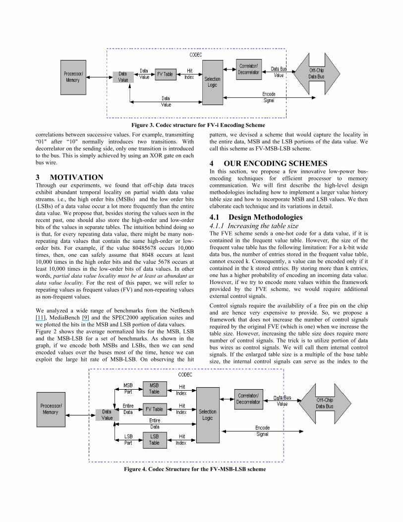
5 EXPERIMENTAL SETUP We modified the sim-outorder simulator in the Simplescalar toolset [5] in order to get the data value traces. We applied our bus encoding techniques on the data traces of the SPEC2000 benchmark suite with train data set and embedded applications provided in the MediaBench and NetBench benchmark suites . For MSB/LSB based schemes, we varied the number of bits captured from 2 to 29 bits in steps of 1. Based on the average reduction in switching activity for different benchmarks, finally we fixed the number of bits to be captured for each scheme Figure 9 shows the percentages of average reduction in switching activity for varying bit lengths. Based on the figure shown, we fixed the number of MSB bits for FV-MSB-LSB, FV-2-MSB-2 and FV-1-MSB-2 to be 20, 19 and 20 bits respectively.
6 ANALYSIS Table 1 shows the percentage reduction in switching activity obtained for our encoding schemes. For parser application, FV-MSB-LSB gives 21% improvement over FVE scheme. For MCF benchmark, we get nearly 18% improvement over FVE scheme. For Route and jpegencode, FV-MSB-LSB provides an additional
15% switching reduction on top of FVE-32. For parser and MCF, the MSB-based schemes yield a switching reduction of nearly 20% on top of FVE. These applications (parser and MCF) are very pointer intensive and are hence very conducive to MSB-based encoding schemes. On an average, FV-MSB-LSB yields 11% improvement over FVE-32 scheme. Figure 10 shows the percentage reduction in switching activity for all benchmarks. Let us analyze the Energy consumption due to our encoding schemes and the impact of our encoding schemes on the overall performance of the system.
6.1 Energy Consumption We modeled the functionality of various components in our encoding scheme by doing an accurate layout-level description using TSMC 0.18µ technology. We derive our energy calculations based on the results shown in Table 2. For our
Percentage reduction in Switching activity
01020304050607080
Jpeg
enco
de
Jpeg
deco
de
G721d
ecod
e
G721e
ncod
e
unep
ic
ADPCM
Mpegd
ecod
eRou
te TLURL
DRRMD5
parse
r
vorte
x art
equa
ke gcc
mcf
Averag
e
Benchmark
% R
educ
tion
in
switc
hing
act
ivity
FV-0 FV-1 FV-2 FV-1-MSB-2 FV-2-MSB-2 FV-MSB-LSB
Figure 10. Average Percentage Reduction in switching activity
Table 2. Energy measurements for different components
Component Energy Delay Selection logic 3.04pJ 0.2ns XOR gates 0.095pJ/Transition pair 0.1ns Timestamps 0.07pJ 0.5ns 32-bit, 32-entry table 13.6pJ 0.2ns
Percentage Energy reduction
01020304050607080
Jpeg
enco
de
Jpeg
deco
de
G721d
ecod
e
G721e
ncod
e
unep
ic
ADPCM
Mpegd
ecod
eRou
te TLURL
DRRMD5
parse
r
vorte
x art
equa
ke gcc
mcf
Averag
e
Benchmark
% E
nerg
y R
educ
tion
FV-0 FV-1 FV-2 FV-1-MSB-2 FV-2-MSB-2 FV-MSB-LSB
Figure 11. Average Percentage Energy Reduction

encoding schemes, the total energy consumption due to the internal capacitances is the sum of the energy consumed in the FV tables, MSB/LSB tables, timestamps, correlator/decorrelator (XOR gates) and the selection logic:
Energy Energy Energy Energy Energy
logicselection_
timestampstablestotal
+++=
Correlator
Using the above formula, we calculated the value of Energytotal for FV-0, FV-1, FV-2, FV-1-MSB-2, FV-2-MSB-2 and FV-MSB-LSB to be 17.38pJ, 34.65 pJ, 52.42pJ, 36.65, 42.65 and 37.88 respectively. The off-chip bus energy per wire (E) is given by the formula:
ACVE 2 α
Where C is the off-chip bus capacitance, V is the supply voltage and A is the number of bus transitions on the wire. The total energy consumed is the sum total of the energy consumed during bus transitions and the energy consumed by the encoder and the decoder. Figure 11 shows the energy savings for our encoding schemes. On an average, FV-MSB-LSB scheme provides a 10% energy improvement on top of the FVE scheme.
6.2 Effect on Performance In the absence of a prefetching scheme, the off-chip bus traffic is mainly due to cache misses. Through our experiments, we found that our table based encoding scheme introduces an additional cycle delay at the encoder and decoder ends. Since requests to/from memory is carried out at the granularity of cache blocks, extra latency in encoding/decoding consecutive intra-block entries can be eliminated through pipelining. Hence, the latency in the off-chip bus traffic can be assumed to be independent of the number of entries in a block. We would encounter an additional 2-cycle penalty on every block that gets requested due to a cache miss. Assuming the value of off-chip latency to be 100 cycles, we measured the performance penalty while executing all applications. On an average, our scheme incurred a penalty of 0.23% in terms of the total number of execution cycles.
7 CONCLUSION We proposed and evaluated a few table-based data-bus-encoding schemes. Our scheme makes no prior assumptions regarding the input data and is truly dynamic in nature. We tested our scheme on a subset of applications from the MediaBench, NetBench, SPECINT2000 and SPECfp2000 benchmark suites. Our best scheme provides nearly 53% switching reduction over unencoded data and nearly 11% improvement over the FVE scheme. Capturing variable lengths MSBs would yield higher benefits. The capacity of the tables in FV-MSB-LSB can also be increased using the same methods described in FV-i and FV-i-MSB-j schemes.
8 ACKNOWLEDGMENTS This work was supported in part by NSF award ITR 0083080
9 REFERENCES [1] K. Basu, A. Choudhary, J. Pisharath, M. Kandemir , “Power
Protocol: Reducing Power Dissipation on Off-Chip Data
Buses” , 35th Annual IEEE/ACM International Symposium on Microarchitecture (MICRO-35), Istanbul, Turkey, November 2002
[2] L. Benini, A. Macci, E. Macii, M. Poncino, and R. Scarsi, “Architectures and synthesis algorithms for power-efficient bus interfaces,” IEEE Transactions on Computer Aided Design of Circuits and Systems, vol.19, no.9, September 2000.
[3] L. Benini, G. De Micheli, E. Macii, D. Sciuto, and C. Silvano, “Asymptotic zero-transition activity encoding for address buses in low-power microprocessor-based systems,” Great Lakes VLSI Symposium, pp. 77-82 Urbana IL, March 13-15, 1997
[4] L. Benini, A. Macii, E. Macii, M. Poncino, and R. Scarsi, “Synthesis of Low-Overhead Interfaces for Power-Efficient Communication Over Wide Buses,” ACM/IEEE Design Automation Conference, pages 128–133, 1999.
[5] D. Burger and T. M. Austin. “The SimpleScalar Tool Set, Version 2.0. Technical report”, University of Wisconsin-Madison Computer Science Department, 1997
[6] J.H. Chern, J. Jurang, L. Arledge, P. Li and P. Yang, “Multilevel Metal Capacitance Models for CAD Design Synthesis Systems”, IEEE Electron Device Letters, Vol13, pp.32-34, January 1992.
[7] T. Givargis, F. Vahid “Interface Exploration for Reduced Power in Core-Based Systems”, International Symposium on System Synthesis, December 1998
[8] T. Givargis, D. Eppstein, “Reference Caching Using Unit Distance Redundant Codes for Activity Redcution on Address Buses”, International Workshop on Embedded System Hardware/Software Codesign (ESCODES), San Jose, September 2002
[9] C. Lee, M. Potkonjak, and W. Mangione-Smith, “MediaBench: a tool for evaluating and synthesizing multimedia and communications systems”, In International Symposium on Microarchitecture, pages 330-335, 1997
[10] T. Lv, J. Henkel, H. Lekatsas, W. Wolf, “An Adaptive Dictionary Encoding Scheme for SOC Data Buses”, DATE02, Paris France, Mar 2002.
[11] G. Memik, W. H. Mangione Smith, and W. Hu, “NetBench: A Benchmarking suite for Netwokr Processors”, In International Conference on Computer Aided Design (ICCAD), pp 39-42, Nov2001, San Jose, CA.
[12] “National Technology Roadmap for Semiconductors”. Semiconductor Industry Association, 2001
[13] A. Raghunathan, N.K. Jha, S.Dey, “High-level Power Analysis and Optimization”, Kluwer Academic Publishers, Norwell, MA, 1998
[14] M. R. Stan. and Burleson,W. P., “Bus-invert coding for low-power I/O,” IEEE Transactions on Very Large Scale Integration (VLSI) Systems, pages 49–58, Vol. 3, 1995.
[15] N.H.E. Weste, K. Eshraghian. “Principles of CMOS VLSI Design”. Addison Wesley, 1998.

[16] J. Yang, R. Gupta, “FV Encoding for Low-Power Data I/O,” ACM/IEEE International Symposium on Low Power Electronic Design, pages 84–87, 2001.
[17] Y. Zhang, J. Yang, R. Gupta, “Frequent Value Locality and Value-Centric Data Cache Design,” ACM The Ninth International Conference on Architectural Support for
Programming Languages and Operating Systems, pages 150-159, 2000.