Data Encoding komdat
31
Networks: Data Encoding 1 Physical Layer – Part 2 Data Encoding Techniques
-
Upload
independent -
Category
Documents
-
view
1 -
download
0
Transcript of Data Encoding komdat
Networks: Data Encoding 1
Physical Layer – Part 2
Data Encoding Techniques

Networks: Data Encoding 2
Analog and Digital Transmissions
Figure 2-23.The use of both analog and digital transmissions for a computer to computer call. Conversion is done by the modems and codecs.

Networks: Data Encoding 3
Data Encoding Techniques
• Digital Data, Analog Signals [modem]• Digital Data, Digital Signals [wired LAN]
• Analog Data, Digital Signals [codec]– Frequency Division Multiplexing (FDM)– Wave Division Multiplexing (WDM) [fiber]
– Time Division Multiplexing (TDM)– Pulse Code Modulation (PCM) [T1]– Delta Modulation

Networks: Data Encoding 4
Digital Data, Analog Signals
[Example – modem]• Basis for analog signaling is a continuous, constant-frequency signal known as the carrier frequency.
• Digital data is encoded by modulating one of the three characteristics of the carrier: amplitude, frequency, or phase or some combination of these.

Networks: Data Encoding 5
A binary signal
Frequencymodulation
Amplitudemodulation
Phase modulation
Figure 2-24.

Networks: Data Encoding 6
Modems• All advanced modems use a combination of
modulation techniques to transmit multiple bits per baud.
• Multiple amplitude and multiple phase shifts are combined to transmit several bits per symbol.
• QPSK (Quadrature Phase Shift Keying) uses multiple phase shifts per symbol.
• Modems actually use Quadrature Amplitude Modulation (QAM).
• These concepts are explained using constellation points where a point determines a specific amplitude and phase.

Networks: Data Encoding 7
Constellation Diagrams
(a) QPSK. (b) QAM-16. (c) QAM-64.
Figure 2-25.

Networks: Data Encoding 8
Digital Data, Digital Signals
[the technique used in a number of LANs]• Digital signal – is a sequence of
discrete, discontinuous voltage pulses.
• Bit duration :: the time it takes for the transmitter to emit the bit.
• Issues– Bit timing– Recovery from signal– Noise immunity

Networks: Data Encoding 9
NRZ ( Non-Return-to-Zero) CodesUses two different voltage levels (one
positive and one negative) as the signal elements for the two binary digits.
NRZ-L ( Non-Return-to-Zero-Level)The voltage is constant during the bit interval.
NRZ-L is used for short distances between terminal and modem or terminal and computer.
1 negative voltage0 positive voltage

Networks: Data Encoding 10
NRZ ( Non-Return-to-Zero) Codes
NRZ-I ( Non-Return-to-Zero-Invert on ones)The voltage is constant during the bit interval.
NRZI is a differential encoding (i.e., the signal is decoded by comparing the polarity of adjacent signal elements.)
1 existence of a signal transition at the beginning of the bit time (either a low-to-high or a high-to-low transition)
0 no signal transition at the beginning of the bit time

Networks: Data Encoding 11
Bi –Phase CodesBi- phase codes – require at least one transition per bit time and may have as many as two transitions.
the maximum modulation rate is twice that of NRZ greater transmission bandwidth is required.
Advantages:Synchronization – with a predictable transition per bit time the receiver can “synch” on the transition [self-clocking].
No d.c. componentError detection – the absence of an expected transition can used to detect errors.

Networks: Data Encoding 12
Manchester encoding • There is always a mid-bit transition {which is used as a clocking mechanism}.
• The direction of the mid-bit transition represents the digital data.
Consequently, there may be a second transition at the beginning of the bit interval.
Used in 802.3 baseband coaxial cable and CSMA/CD twisted pair.
1 low-to-high transition
0 high-to-low transition
Textbooksdisagreeon this
definition!!

Networks: Data Encoding 13
Differential Manchester encoding
• mid-bit transition is ONLY for clocking.
Differential Manchester is both differential and bi-phase.
Note – the coding is the opposite convention from NRZI.
Used in 802.5 (token ring) with twisted pair.* Modulation rate for Manchester and Differential Manchester is twice the data rate inefficient encoding for long-distance applications.
1 absence of transition at the beginning of the bit interval 0 presence of transition at the beginning of the bit interval

Networks: Data Encoding 14
Bi-Polar Encoding
• Has the same issues as NRZI for a long string of 0’s.
• A systemic problem with polar is the polarity can be backwards.
1 alternating +1/2 , -1/2 voltage
0 0 voltage
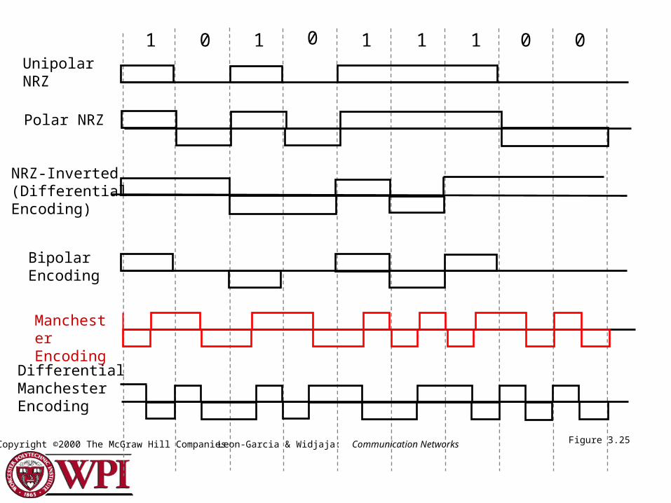
1 0 1 0 1 1 0 01UnipolarNRZ
NRZ-Inverted(DifferentialEncoding)
BipolarEncoding
DifferentialManchesterEncoding
Polar NRZ
Figure 3.25Copyright ©2000 The McGraw Hill CompaniesLeon-Garcia & Widjaja: Communication Networks
ManchesterEncoding
Networks: Data Encoding 16
Analog Data, Digital Signals
[Example – PCM (Pulse Code Modulation)]The most common technique for using
digital signals to encode analog data is PCM.
Example: To transfer analog voice signals off a local loop to digital end office within the phone system, one uses a codec.
Because voice data limited to frequencies below 4000 HZ, a codec makes 8000 samples/sec. (i.e., 125 microsec/sample).

Networks: Data Encoding 17
B B
C C
A A
B
C
A
B
C
A
MUXMUX
(a) (b)Trunkgroup
Figure 4.1Copyright ©2000 The McGraw Hill Companies
Multiplexing
Leon-Garcia & Widjaja: Communication Networks

Networks: Data Encoding 18
A CBf
Cf
Bf
Af
H
H
H
0
0
0
(a) Individual signals occupy H Hz
(b) Combined signal fits into channel bandwidth
Figure 4.2Copyright ©2000 The McGraw Hill CompaniesLeon-Garcia & Widjaja: Communication Networks
Frequency-division Multiplexing

Networks: Data Encoding 19
Figure 2-31. (a) The original bandwidths. (b) The bandwidths raised in frequency. (c) The multiplexed channel.
Frequency-division Multiplexing

Networks: Data Encoding 20
Wavelength division multiplexing.
Wavelength Division Multiplexing
Figure 2-32.

Networks: Data Encoding 21
(a) Each signal transmits 1 unit every 3T seconds
(b) Combined signal transmits 1 unit every T seconds
tA1 A2
tB1 B2
tC1 C2
3T0T 6T
3T0T 6T
3T0T 6T
tB1 C1 A2 C2B2A1
0T 1T 2T 3T 4T 5T 6T Figure 4.3Copyright ©2000 The McGraw Hill CompaniesLeon-Garcia & Widjaja: Communication Networks
Time-division Multiplexing

Networks: Data Encoding 22
Time-division Multiplexing

Networks: Data Encoding 23
Statistical Multiplexing - Concentrator

Networks: Data Encoding 24
Pulse Code Modulation (PCM)
• Analog signal is sampled.• Converted to discrete-time continuous-amplitude signal (Pulse Amplitude Modulation)
• Pulses are quantized and assigned a digital value.– A 7-bit sample allows 128 quantizing levels.

Networks: Data Encoding 25
Pulse Code Modulation (PCM)
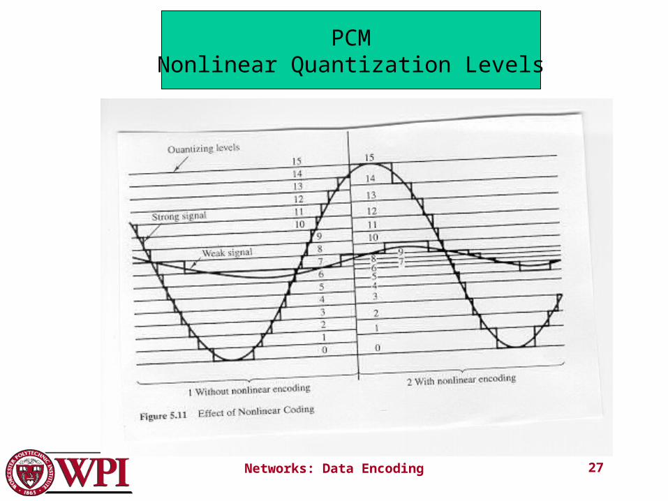
• PCM uses non-linear encoding, i.e., amplitude spacing of levels is non-linear.– There is a greater number of quantizing steps for low amplitude.
– This reduces overall signal distortion.• This introduces quantizing error (or noise).• PCM pulses are then encoded into a digital bit stream.
• 8000 samples/sec x 7 bits/sample = 56 Kbps for a single voice channel.

Networks: Data Encoding 26
Networks: Data Encoding 27
PCMNonlinear Quantization Levels

Networks: Data Encoding 28
2
24
1
MUXMUX
1
2
24
24 b1 2 . . .b2322frame
24
. .
.
. .
.
Figure 4.4Copyright ©2000 The McGraw Hill CompaniesLeon-Garcia & Widjaja: Communication Networks
T1 System

Networks: Data Encoding 29
The T1 carrier (1.544 Mbps).
TDM
Figure 2-33.T1 Carrier (1.544Mbps)

Networks: Data Encoding 30
Delta Modulation (DM)• The basic idea in delta modulation is to approximate the derivative of analog signal rather than its amplitude.
• The analog data is approximated by a staircase function that moves up or down by one quantization level at each sampling time. output of DM is a single bit.
• PCM preferred because of better SNR characteristics.

Networks: Data Encoding 31
Delta Modulation DCC 6th Ed.
W.Stallings