Energy absorption of foamed concrete from low-velocity impacts Energy absorption of foamed concrete...
11
Magazine of Concrete Research, 2013, 65(4), 209–219 http://dx.doi.org/10.1680/macr.12.00054 Paper 1200054 Received 09/03/2012; revised 16/08/2012; accepted 29/08/2012 Published online ahead of print 14/12/2012 ICE Publishing: All rights reserved Magazine of Concrete Research Volume 65 Issue 4 Energy absorption of foamed concrete from low-velocity impacts Jones and Zheng Energy absorption of foamed concrete from low-velocity impacts M. Roderick Jones Concrete Technology Unit, Division of Civil Engineering, University of Dundee, Dundee, Scotland, UK Li Zheng Concrete Technology Unit, Division of Civil Engineering, University of Dundee, Dundee, Scotland, UK Foamed concrete has existing uses as an energy absorber for large-scale and low-cost applications, such as explosion prevention in mines and military engineering projects and aircraft arresting systems. However, there is little information enumerating the energy absorption characteristics of different foamed concretes; this paper describes a study that determined these using low-velocity impact tests. A range of foamed concretes were tested with plastic densities varying from 500 to 1400 kg/m 3 , which are typical of those produced commercially. The tests used hemispherical projectiles with a range of masses from 1 . 2 to 8 . 4 kg, dropped from a fixed height of 4 . 7 m. The resulting ‘damage’ was measured and related to the impact energy imparted to the test specimen. A classification, using five different failure modes, was established and the mode in which the test specimen neither caused ‘rebound’ of the projectile nor itself fractured was selected as representing ‘ideal’ energy absorption behaviour. Making the assumption of no energy losses and using the conservation of energy law, the energy absorption capacity of foamed concrete was calculated and was found to vary from 4 to 15 MJ/m 3 for different mixes. The optimum energy absorption was noted for the 1000 kg/m 3 mix at water to cement (w/c) ratios from 0 . 6 to 0 . 7, which allowed a debris field of crushed foamed concrete to form and be pushed into the concrete bubble space ahead of the nose of the projectile, without fracturing. Notation a n nominal deceleration, which is the average deceleration assuming the projectile is fully stopped after indenting distance of d ind (m/s 2 ) D plastic density of foamed concrete (kg/m 3 ) d indent diameter (mm) d ind indent depth (mm) E potential energy (J), which for the purposes of these tests was assumed equal to impact energy in the drop test (i.e. any aerodynamic drag was ignored for simplicity) E abs energy absorption per indent volume (MJ/m 3 ) g gravity (taken as 9 . 81 m/s 2 ) h fall height in the drop test (in this case fixed at 4 . 7 m) m projectile mass (kg) R radius of the hemispherical nose of the projectile (¼ 31 . 72 mm) V indent volume duo to embedment of projectile (mm 3 ) v velocity of the projectile before impact (¼ 9 . 6 m/s) w/c water/cement ratio of foamed concrete Introduction Foamed concrete has reached a mature commercial position in the market and is now widely used for a variety of purposes in the civil engineering and building fields (e.g. Jones and McCarthy, 2005, 2006; Jones et al., 2005, 2009). Foamed con- crete can be produced with a wide range of recycled and secondary aggregates, and can be easily crushed and reused; therefore, it is a sustainable material (Jones et al., 2012). Polymer foam materials are widely used to absorb impact energy to protect goods in transit and other similar applications, but, based on cost, these materials are not suitable for large-scale applica- tions, such as aircraft runway arrestors (Kazda and Caves, 2007), mines explosion protection (Weiss et al., 1996) and so on. Precast foamed concrete block targets have been used by the military in firing ranges. Bullets enter the foamed concrete blocks without fragmenting (which can lead to environmental contamination) and are, therefore, ‘caught’ by embedment and can be disposed of in a safe manner (Huntsman et al., 2001; Tom, 2002). Indeed, commercial products based on foamed concrete for these purposes are now on the civilian market. However, the underlying mechanistic behaviour of foamed concrete has not been established and the influence of its characteristics on energy absorption potential has not been evaluated. Foamed con- cretes can be produced with a wide range of characteristics, for example plastic densities from 1400 down to 500 kg/m 3 (and, indeed, below this density) and w/c ratios from 0 . 40 to 0 . 80; these 209
Transcript of Energy absorption of foamed concrete from low-velocity impacts Energy absorption of foamed concrete...

Magazine of Concrete Research, 2013, 65(4), 209–219
http://dx.doi.org/10.1680/macr.12.00054
Paper 1200054
Received 09/03/2012; revised 16/08/2012; accepted 29/08/2012
Published online ahead of print 14/12/2012
ICE Publishing: All rights reserved
Magazine of Concrete ResearchVolume 65 Issue 4
Energy absorption of foamed concrete fromlow-velocity impactsJones and Zheng
Energy absorption of foamedconcrete from low-velocityimpactsM. Roderick JonesConcrete Technology Unit, Division of Civil Engineering, University ofDundee, Dundee, Scotland, UK
Li ZhengConcrete Technology Unit, Division of Civil Engineering, University ofDundee, Dundee, Scotland, UK
Foamed concrete has existing uses as an energy absorber for large-scale and low-cost applications, such as explosion
prevention in mines and military engineering projects and aircraft arresting systems. However, there is little
information enumerating the energy absorption characteristics of different foamed concretes; this paper describes a
study that determined these using low-velocity impact tests. A range of foamed concretes were tested with plastic
densities varying from 500 to 1400 kg/m3, which are typical of those produced commercially. The tests used
hemispherical projectiles with a range of masses from 1.2 to 8.4 kg, dropped from a fixed height of 4.7 m. The
resulting ‘damage’ was measured and related to the impact energy imparted to the test specimen. A classification,
using five different failure modes, was established and the mode in which the test specimen neither caused
‘rebound’ of the projectile nor itself fractured was selected as representing ‘ideal’ energy absorption behaviour.
Making the assumption of no energy losses and using the conservation of energy law, the energy absorption
capacity of foamed concrete was calculated and was found to vary from 4 to 15 MJ/m3 for different mixes. The
optimum energy absorption was noted for the 1000 kg/m3 mix at water to cement (w/c) ratios from 0.6 to 0.7, which
allowed a debris field of crushed foamed concrete to form and be pushed into the concrete bubble space ahead of
the nose of the projectile, without fracturing.
Notationan nominal deceleration, which is the average deceleration
assuming the projectile is fully stopped after indenting
distance of dind (m/s2)
D plastic density of foamed concrete (kg/m3)
d indent diameter (mm)
dind indent depth (mm)
E potential energy (J), which for the purposes of these
tests was assumed equal to impact energy in the drop
test (i.e. any aerodynamic drag was ignored for
simplicity)
Eabs energy absorption per indent volume (MJ/m3)
g gravity (taken as 9.81 m/s2)
h fall height in the drop test (in this case fixed at 4.7 m)
m projectile mass (kg)
R radius of the hemispherical nose of the projectile
(¼ 31.72 mm)
V indent volume duo to embedment of projectile (mm3)
v velocity of the projectile before impact (¼ 9.6 m/s)
w/c water/cement ratio of foamed concrete
IntroductionFoamed concrete has reached a mature commercial position in
the market and is now widely used for a variety of purposes in
the civil engineering and building fields (e.g. Jones and
McCarthy, 2005, 2006; Jones et al., 2005, 2009). Foamed con-
crete can be produced with a wide range of recycled and
secondary aggregates, and can be easily crushed and reused;
therefore, it is a sustainable material (Jones et al., 2012). Polymer
foam materials are widely used to absorb impact energy to
protect goods in transit and other similar applications, but, based
on cost, these materials are not suitable for large-scale applica-
tions, such as aircraft runway arrestors (Kazda and Caves, 2007),
mines explosion protection (Weiss et al., 1996) and so on. Precast
foamed concrete block targets have been used by the military in
firing ranges. Bullets enter the foamed concrete blocks without
fragmenting (which can lead to environmental contamination)
and are, therefore, ‘caught’ by embedment and can be disposed
of in a safe manner (Huntsman et al., 2001; Tom, 2002). Indeed,
commercial products based on foamed concrete for these
purposes are now on the civilian market.
However, the underlying mechanistic behaviour of foamed concrete
has not been established and the influence of its characteristics on
energy absorption potential has not been evaluated. Foamed con-
cretes can be produced with a wide range of characteristics, for
example plastic densities from 1400 down to 500 kg/m3 (and,
indeed, below this density) and w/c ratios from 0.40 to 0.80; these
209

result in a wide range of mechanical properties. There is, therefore,
a need to identify the foamed concrete mix characteristics that give
optimum energy absorption performance and enable engineers to
design efficient, safe protection systems.
In response to this need, the current paper reports a laboratory-
scale research project that examined a wide range of foamed
concretes for their energy absorption using low-velocity impact
drop tests. A series of failure modes was observed and these were
classified based on visual observations; absorbed energy was
evaluated by the amount of crushing (i.e. indent volume) of the
specimen. Using these data optimum mix characteristics could be
established.
Experimental details
Background
Energy absorption systems convert, totally or partially, impact
energy into other forms of energy. The conversion of energy is
either reversible, for example pressure in compressible fluids and
elastic strain energy in solids, or irreversible, such as plastic
deformation. Foamed concrete acts using the latter form, whereby
crushing of the bubble walls provides the energy absorption from
the embedment of a projectile that possesses kinetic energy.
There are a number of established tests to determine impact
energy absorption potential, for example the Taylor impact test,
split Hopkinson pressure bar (SHPB)/tension bar (SHTB) tests
and drop hammer/projectile tests (Grytten, 2008). The Taylor
impact test is used for high- (i.e. ordnance) to hyper-velocity
projectiles, whereas SHPB/SHTB is usually used for sub-
ordnance to ordnance energy levels. In the present study,
low-velocity impact tests on test specimens subjected to a
hemispherical weight of various magnitudes dropped through a
fixed height of 4.7 m were carried out. The height was arbitrarily
selected, but, for convenience, was equal to a one-storey height
platform of the laboratory.
Materials and foamed concrete test specimens
The cement used for foamed concrete was Portland cement
(CEM I, BS EN 197-1 (BSI, 2011)) mixed with a natural fine
aggregate with a maximum particle size of 4 mm (GF85:0/4(MP),
BS EN 12620 (BSI, 2002)). The foam was preformed, in a
standard manner, using commercial protein-based surfactant
diluted with water, using a laboratory-scale foam generator,
before mixing with the base mortar mix.
The mix design described previously by Jones and McCarthy
(2005) was used to produce foamed concretes with plastic
densities of 500, 600, 1000 and 1400 kg/m3 at water/cement
(w/c) ratios varying from 0.4 to 0.8 and a CEM I content of
300 kg/m3 for all mixes. The foamed concrete mixes were
generally designed for the lowest w/c ratio that gave flowing and
self-compacting rheology. This was between 0.5 and 0.6 for 500–
600 kg/m3 and between 0.6 and 0.7 for 1000–1400 kg/m3 mixes;
the latter group required more free water owing to lower foam
and higher aggregate contents. These are typical of commercial,
large-scale fill applications and the mix proportions are sum-
marised in Table 1.
Target plastic
density: kg/m3
w/c Mix constituent proportions: kg/m3 Air:
vol%
Free water Sand Foam
500 0.50 150 50 57.4 73.5
600 0.40 120 180 55.9 71.6
0.50 150 150 54.4 69.8
0.60 180 120 53.0 67.9
0.70 210 90 51.5 66.0
1000 0.40 120 580 44.0 56.4
0.50 150 550 42.6 54.6
0.60 180 520 41.1 52.7
0.70 210 490 39.6 50.8
0.80 240 460 38.2 49.0
1400 0.40 120 980 32.1 41.2
0.50 150 950 30.7 39.4
0.60 180 920 29.2 37.5
0.70 210 890 27.8 35.6
0.80 240 860 26.3 33.7
Note that CEM I ¼ 300 kg/m3:
Table 1. Foamed concrete mix proportions
210
Magazine of Concrete ResearchVolume 65 Issue 4
Energy absorption of foamed concretefrom low-velocity impactsJones and Zheng

For each mix, three to six test slab specimens were cast and
sealed-cured; the slab dimensions were 300 3 300 3 100 mm, as
shown in Table 2. This was a convenient size for handling, given
the large number of different mix options. In addition, 100 mm
cubes were prepared to determine the 28-day sealed-cured
strength of the mixes.
Low-velocity impact tests
Low-velocity projectile impact tests, defined as v , 50 m/s
(Grytten, 2008), were selected, which allowed for straightforward
health and safety requirements (as compared to using high-
velocity munitions that would have required special licensing). A
simple apparatus was designed, which consisted of a 70 mm
internal diameter, 4.7 m long, unplasticised polyvinyl chloride
(UPVC) guide pipe and a 62 mm hemispherical-ended projectile
with an adjustable mass, as shown in Figure 1. In the test, the
projectile with specific mass was dropped on to the test specimen
slab lying at the bottom end of the pipe. The foamed concrete test
specimen was located directly on a thick concrete slab (forming
part of a heavy-duty unloading bay at the laboratory), which
prevented any backward movement as the projectile impacted the
surface. The specimen was not restrained further to allow any
lateral or other deformation or fracture to take place unimpeded.
Using a hemispherical projectile with the guide pipe facilitated a
near vertical impact on the test specimen. Conical and flat-nosed
Impact/kinetic energy levela
1 2 3 4 5 6 7
Mass of projectile, kg 1.164 2.173 3.569 4.578 5.974 6.983 8.379
Kinetic energy:a J 54 100 165 211 275 322 386
Foamed concrete specimenb
w/c Plastic density:
kg/m3
28-day s/c cube
strength: N/mm2
Visual rating of the failure modec
0.4 600 0.66 b c d
1000 0.71 ‘b’d c d e
1400 0.99 ‘b’d c d e
0.5 500 0.79 ‘b’d c d d
600 1.45 b c d
1000 1.45 b b c d d
1400 1.93 a b b d9 d9 d9
0.6 600 1.44 a b c d e
1000 1.93 a b b c ‘d’d
1400 4.47 b b b b d9
0.7 600 1.00 ‘b’d c d e
1000 1.81 b c d
1400 4.31 b b d9
0.8 1000 1.37 b c d
1400 3.15 b d9 d9
a Fixed drop height ¼ 4.7 mb Test specimen: 300 mm 3 300 mm 3 100 mm deepc See Figure 2 for visual rating of the failure mode: a, low indentation and high rebound; b, partial indentation and rebound; c, full indentionwithout rebound; d, indention with local cracking (d9 indicates that rebounding was still noticed); e, complete specimen fractured Not tested but expected failure mode is stated
Table 2. Applied impact energy levels and visual rating of test
specimen failure modes of the drop tests
211
Magazine of Concrete ResearchVolume 65 Issue 4
Energy absorption of foamed concretefrom low-velocity impactsJones and Zheng

projectiles were tried during primary trials but did not give
repeatable results because they were found to impact the test
specimen non-uniformly (presumably owing to the effects of
aerodynamic forces inside the drop pipe). It was not possible
during this work to investigate how these different geometries
could be tested, but one possibility is to use a much larger ratio
of test specimen to projectile volume to reduce the incidence of
cracking and fracture. The lack of uniformity, however, would
4·7
m
1·164 kg
2·405 kg2·405 kg
2·405 kg
1·009 kg
62 mm
25 m
m23
mm
Figure 1. Drop testing apparatus: UPVC guide pipe (left) and test
projectile (right), hemispherical ended with adjustable mass
212
Magazine of Concrete ResearchVolume 65 Issue 4
Energy absorption of foamed concretefrom low-velocity impactsJones and Zheng

make this approach problematic for the accurate measurement of
energy absorption.
With a series of primary tests, procedures for low-velocity impact
tests were established, using the fixed drop height, h, of 4.7 m
and the hemispherical-ended projectile with mass, m, varying
from 1.2 to 8.4 kg, giving variations of impact energy up to seven
levels, as summarised in Table 2. The tests were carried out with
gradually increased impact energy until the test specimen frac-
tured. The energy applied to the specimens was calculated with
the standard equation for potential energy, E, as follows
E ¼ mgh1:
Assuming negligible losses and, therefore, that the potential
energy is equal to the kinetic energy for the drop test, the
terminal velocity at the moment of impact was calculated to be
9.6 m/s and the time taken to impact from the release point was
0.98 s.
During the test, the series of projectile masses with different
energy levels were dropped on to the foamed concrete test
specimens and a visual assessment of the impact damage was
carried out. Provided the specimens had not failed by fracturing,
the indent volume, V, was determined by placing a layer of
domestic food wrapping (cling) film over the indent and measur-
ing the volume of water to fill the void. The energy absorption
per indent volume, Eabs, was calculated as
Eabs ¼ E=V2:
The indent depth, dind, could not be measured directly and, hence,
it was calculated from measured indent diameter and volume with
the following equations for a hemisphere (see Figure 1)
dind ¼
ffiffiffiffiffiffiffiffiffiffiffiffiffiffiffiffiffiffiffiffiffiffiffiffiffiffiffiffiffiffiffiffiffiffiffiffiffiffiffiffiffiffiffiffiffiffiffiffiffi3V
�þ
ffiffiffiffiffiffiffiffiffiffiffiffiffiffiffiffiffiffiffiffiffiffiffiffiffiffiffiffiffiffiffiffiffi3V
2�
� �2
þ d
2
� �6s
3
vuut
þ
ffiffiffiffiffiffiffiffiffiffiffiffiffiffiffiffiffiffiffiffiffiffiffiffiffiffiffiffiffiffiffiffiffiffiffiffiffiffiffiffiffiffiffiffiffiffiffiffiffi3V
��
ffiffiffiffiffiffiffiffiffiffiffiffiffiffiffiffiffiffiffiffiffiffiffiffiffiffiffiffiffiffiffiffiffi3V
2�
� �2
þ d
2
� �6s
3
vuutfor V < 45 920 mm3
3:
or
dind ¼ 25þ 4(V � 45920)
�d2for V . 45 920 mm3
4:
In addition, when V , 45 920 mm3 (i.e. d , 62 mm), the indent
depth was also calculated by
dind ¼ R�
ffiffiffiffiffiffiffiffiffiffiffiffiffiffiffiffiffiffiffiffiffiffiffiR2 � d
2
� �2s
for V < 45 920 mm3
5:
If the calculated depth results between Equations 3 and 5 were
significant, repeat measurements were carried out. With this
calculation, the influence of any cracks around the indentation
was minimised.
The nominal deceleration, an, was calculated as
an ¼1000E
mdind
¼ 1000v2
2dind6:
The calculated deceleration was thought to be proportional to the
Janssen factor (Woolam, 1968) assuming the projectile is fully
stopped after embedment distance of dind, which can be used to
evaluate the energy absorption efficiency of a material under
impact (Hilyard and Djiauw, 1971; Neto and Mourao, 2002;
Zhang and Ashby, 1994).
Results and discussion
Visual rating of failure modes
The visual rating, based on ‘damage’ type, was divided into five
different failure modes, a to e, as shown in Figure 2, and the
visual rating results for all specimens tested are given in Table 2,
together with their seal-cured, 28-day cube strength values.
j Mode a: the applied impact energy was low, the projectile
made only a shallow indentation and rebound was observed
(Figure 2(a)).
j Mode b: the depth of indent increased with an increase in
impact energy and rebound was reduced quickly, or was
unlikely to occur in most cases of this mode (Figure 2(b)).
j Mode c: the projectile was fully trapped in the specimen and
there was no rebound (Figure 2(c)).
j Mode d: the projectile caused cracking around the embedded
depth (Figure 2(d)). For 1400 kg/m3 foamed concrete, partial
rebound was still observed and this case was denoted d9
(Figure 2(e)).
j Mode e: further increase of impact energy caused extensive
cracking and complete fracture of the test specimen (Figure
2(f)).
The optimum mode for determining energy absorption was where
the projectile was fully embedded, without any rebound or
cracking of the test specimen, in other words mode c.
As expected, for each particular foamed concrete, its failure mode
213
Magazine of Concrete ResearchVolume 65 Issue 4
Energy absorption of foamed concretefrom low-velocity impactsJones and Zheng

(a) (b)
(c) (d)
(e) (f)
Figure 2. Visual rating of the failure mode: (a) mode a – low
indentation and high rebound (D ¼ 1400 kg/m3, w/c ¼ 0.5,
E ¼ 100 J); (b) mode b – partial indentation and rebound
(D ¼ 600 kg/m3, w/c ¼ 0.5, E ¼ 100 J); (c) mode c – full
indentation without rebound (D ¼ 500 kg/m3, w/c ¼ 0.5,
E ¼ 100 J); (d) mode d – indentation with local cracking
(D ¼ 500 kg/m3, w/c ¼ 0.5, E ¼ 211 J); (e) mode d’ – indentation
with local cracking and rebound ((D ¼ 1400 kg/m3, w/c ¼ 0.8,
E ¼ 386 J); (f) mode e – complete specimen fracture
(D ¼ 600 kg/m3, w/c ¼ 0.6, E ¼ 275 J)
214
Magazine of Concrete ResearchVolume 65 Issue 4
Energy absorption of foamed concretefrom low-velocity impactsJones and Zheng
changed from mode a to e as projectile mass and hence impact
energy was increased. The mode was also affected by w/c ratio,
density and strength of foamed concrete (Table 2). For compressive
strengths , 0.8 N/mm2, the full indention, mode c was observed
with 100 J impact energy. For strengths between 1.0 and 1.8 N/
mm2, mode c occurred with 165–211 J impact energy. One speci-
men with strength 1.9 N/mm2 showed mode c behaviour with 275 J
impact energy. Therefore, specimens with higher strength, which
reflects the strength and number of bubble walls, tended to allow
more impact energy to be absorbed. However, it was also noted that
for the foamed concrete with highest strength (. 1.9 N/mm2) and
high density (1400 kg/m3), the projectile did not embed into the
foamed concrete and tended to either fracture or rebound mode d’.
After several trials, an experienced operator could obtain a
repeatable result with three drop tests with varying projectile
masses. The mass for the first strike was estimated and, depend-
ing on the resulting failure mode, the second and third impacts
were adjusted with either higher or lower masses, as required, to
produce a mode c failure.
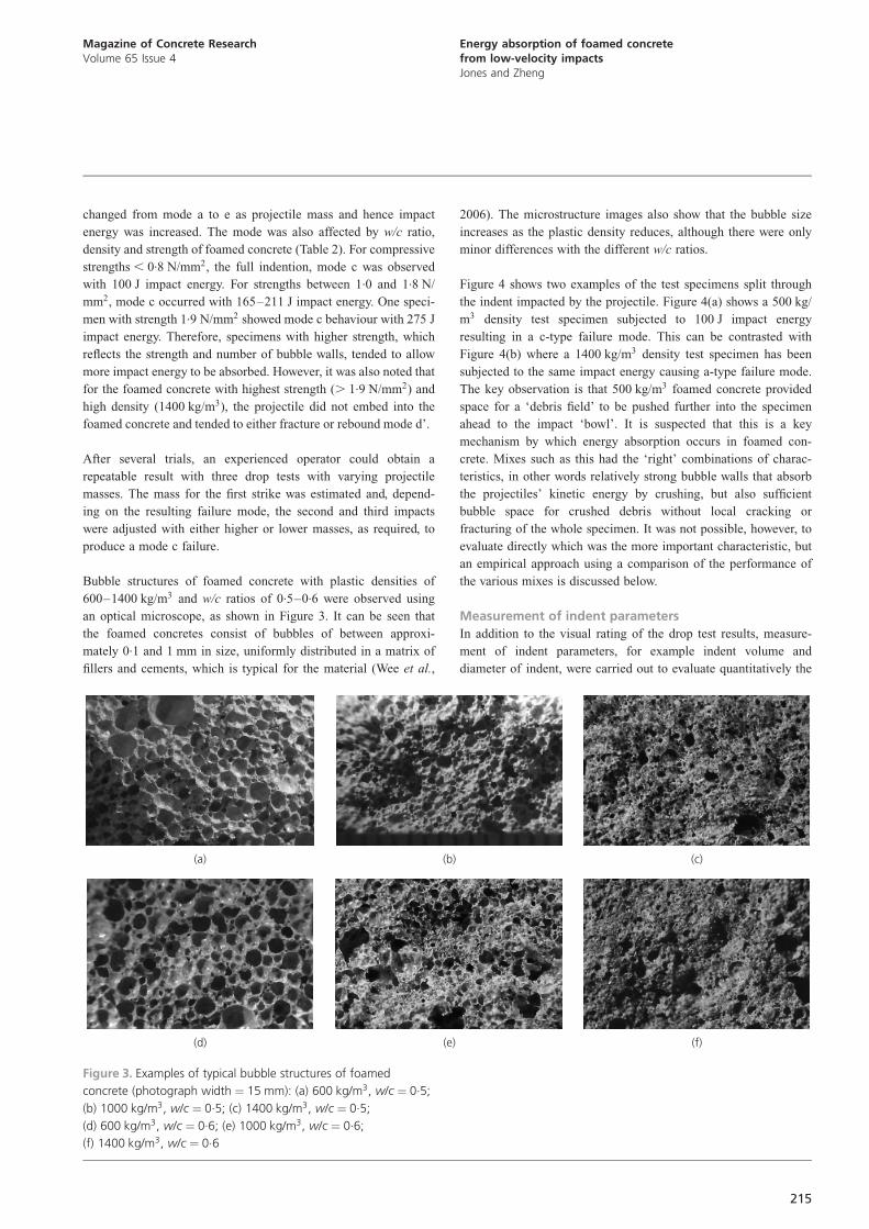
Bubble structures of foamed concrete with plastic densities of
600–1400 kg/m3 and w/c ratios of 0.5–0.6 were observed using
an optical microscope, as shown in Figure 3. It can be seen that
the foamed concretes consist of bubbles of between approxi-
mately 0.1 and 1 mm in size, uniformly distributed in a matrix of
fillers and cements, which is typical for the material (Wee et al.,
2006). The microstructure images also show that the bubble size
increases as the plastic density reduces, although there were only
minor differences with the different w/c ratios.
Figure 4 shows two examples of the test specimens split through
the indent impacted by the projectile. Figure 4(a) shows a 500 kg/
m3 density test specimen subjected to 100 J impact energy
resulting in a c-type failure mode. This can be contrasted with
Figure 4(b) where a 1400 kg/m3 density test specimen has been
subjected to the same impact energy causing a-type failure mode.
The key observation is that 500 kg/m3 foamed concrete provided
space for a ‘debris field’ to be pushed further into the specimen
ahead to the impact ‘bowl’. It is suspected that this is a key
mechanism by which energy absorption occurs in foamed con-
crete. Mixes such as this had the ‘right’ combinations of charac-
teristics, in other words relatively strong bubble walls that absorb
the projectiles’ kinetic energy by crushing, but also sufficient
bubble space for crushed debris without local cracking or
fracturing of the whole specimen. It was not possible, however, to
evaluate directly which was the more important characteristic, but
an empirical approach using a comparison of the performance of
the various mixes is discussed below.
Measurement of indent parameters
In addition to the visual rating of the drop test results, measure-
ment of indent parameters, for example indent volume and
diameter of indent, were carried out to evaluate quantitatively the
(a) (b) (c)
(d) (e) (f)
Figure 3. Examples of typical bubble structures of foamed
concrete (photograph width ¼ 15 mm): (a) 600 kg/m3, w/c ¼ 0.5;
(b) 1000 kg/m3, w/c ¼ 0.5; (c) 1400 kg/m3, w/c ¼ 0.5;
(d) 600 kg/m3, w/c ¼ 0.6; (e) 1000 kg/m3, w/c ¼ 0.6;
(f) 1400 kg/m3, w/c ¼ 0.6
215
Magazine of Concrete ResearchVolume 65 Issue 4
Energy absorption of foamed concretefrom low-velocity impactsJones and Zheng

energy absorption properties of foamed concrete. As the elastic
recovery percentage of foamed concrete is negligible, these
geometrical measurements of the deformation of the test speci-
men provide meaningful information.
Indent volume
The volumes of crushed foamed concrete attributable to the
impact of the projectile into the test specimens are given in
Figure 5 in relation to the impact energy. As expected, the indent
volume generally increased with impact energy. The curves could
be divided into two types: accelerating (d2V=dE2 . 0, exponen-
tial type trend curve) and decelerating (d2V=dE2 , 0, logarithmic
type trend curve), which are separated by a dashed line, as shown
in Figure 5. All relatively weak specimens (density , 1000 kg/m3
and cube strength , 1.5 N/mm2) exhibited accelerating indent
volume increases with impact energy, whereas the rigid speci-
mens (density . 1000 kg/m3 and cube strength . 1.5 N/mm2)
exhibited decelerating indent volume increases. This difference in
behaviour is considered to be attributable to the ability of a
particular mix to ‘absorb’ the debris of crushed foamed concrete,
as observed in Figure 4. It is not clear, however, whether this can
be attributed to the volume of the bubble phase, the local strength
of the bubble walls and/or the size of the bubbles. However, the
visual evidence (Figure 4) shows that the 1400 kg/m3 density
concrete was not able to absorb any debris, owing to insufficient
bubble space, and hence its energy absorption potential was poor.
Assuming the kinetic energy of the projectile is fully absorbed in
foamed concrete with the indent volume in mode c and there are
no other losses, the calculated energy absorptions per indent
volume for the different specimens are compared in Figure 6.
The figure indicates that the highest energy absorption was
around 14 MJ/m3 for the 1000 kg/m3 plastic density test speci-
men with w/c ratios from 0.6 to 0.7 and cube strengths 1.8–
1.9 N/mm2: The other test specimens had significantly lower
values in the range 4–7 MJ/m3:
Depth of indent
The depth of indent was calculated from measured indent volume
and diameter by Equations 3–5. As the indent depth is relevant
to volume, its relationship to impact energy is similar to the
relationship of volume to impact energy. The average deceleration
assuming the projectile is fully stopped at the indent depth was
calculated using Equation 6 and the results are shown in Figure
7. Generally, deceleration increases with plastic density but
decreases with impact energy tending to a minimum value. The
calculated deceleration is considered to be proportional to the
Janssen factor (Woolam, 1968), except for those test specimens
that cracked (mode d) or fractured (mode e), where the minimum
point expected in full indention (mode c) was not observed.
Lower deceleration/Janssen factor was thought to have higher
energy absorption efficiency for that particular impact energy
applied during the impact test (Hilyard and Djiauw, 1971; Neto
and Mourao, 2002; Zhang and Ashby, 1994).
Energy absorption efficiency
Energy absorption efficiency can be evaluated in terms of the
ability of a particular foamed concrete mix to absorb a wide
range of energies without rebound or fracture failure, that is those
mixes which ‘fail’ with mode c (Figure 2). Using these criteria,
Table 2 shows that the optimum was the 1000 kg/m3 mix at a w/c
ratio of 0.6. This mix absorbed the energy of the highest dropped
projectile mass, namely 275 J, with mode c.
However, the mix with the highest overall energy absorption is
again the 1000 kg/m3 foamed concrete, but in this case with a
w/c of 0.7, in other words with slightly weaker bubble walls. This
mix could absorb 15 MJ/m3 compared with 14 MJ/m3 for the
‘stronger’ mix with a w/c of 0.6.
The 1000 kg/m3 mixes were significantly better at absorbing
energy than the other mixes, for example the stronger 1400 kg/m3
mix absorbs 70% less energy, and it was a similar picture with
(b)
`Debris field’ahead of
impact `bowl’
(a)
Figure 4. Split section through the indent of the impacted
specimens, indicating indent ‘bowl’ and ‘debris field’:
(a) 500 kg/m3, w/c ¼ 0.5, 100 J, indent ¼ 13.1 mm;
(b) 1400 kg/m3, w/c ¼ 0.5, 100 J; indent ¼ 4.1 mm
216
Magazine of Concrete ResearchVolume 65 Issue 4
Energy absorption of foamed concretefrom low-velocity impactsJones and Zheng

the 600 kg/m3 mixes, which absorbed 60% less energy. At this
stage, the reasons for this can only be derived from the
observations summarised in Figure 2. The projectile impact
crushes the wall of the bubbles in the foamed concrete and
produces a ‘debris’ field (see Figure 4). If there is insufficient
‘space’ to accommodate this around the impact indent, then the
concrete builds up a tensile stress and fractures in a brittle
manner; this was the case for the 1400 kg/m3 mixes. However,
with the lower density foamed concretes, which have thinner
bubble walls owing to their higher air contents, there is insuffi-
cient strength to resist the projectile impact, which was the case
for the 500 and 600 kg/m3 mixes.
Based on this hypothesis, the conclusion is that the 1000 kg/m3,
with w/c ratios from 0.6 to 0.7, have optimum characteristics of
stronger bubble walls and space for the impact debris field to be
accommodated. Given the significantly lower performance of the
higher and lower density mixes, these combined characteristics
are vital to energy absorption efficiency and neither can be
compromised.
ConclusionsUsing low-velocity dropped weight impact tests with variable
mass (1.2–8.4 kg) hemispherical projectiles dropped from 4.7 m
in free air, the energy absorption capabilities of a wide range of
foamed concretes, varying from 500 to 1400 kg/m3 and w/c ratios
from 0.40 to 0.80, were measured. Five different failure modes
0
10
20
30
40
50
60
70
80
90
0 50 100 150 200 250 300 350 400 450
Inde
nt v
olum
e: 1
0m
m3
3
Impact energy: J
Plastic density: kg/m / / ratio3 w c
500/0·5
600/0·6
1000/0·5
1000/0·8
1400/0·6
600/0·4
600/0·7
1000/0·6
1400/0·4
1400/0·7
600/0·5
1000/0·4
1000/0·7
1400/0·5
1400/0·8
Acceler
ating
Deceler
ating
Figure 5. Relationship between indent volume and impact energy
applied for the various foamed concrete mixes
0
2
4
6
8
10
12
14
16
Ener
gy a
bsor
ptio
n: M
J/m
inde
nt v
olum
e3
w c/ ratio0·5 0·4 0·5 0·6 0·7 0·4 0·5 0·6 0·7 0·8 0·4
500 600 600 600 600 100010001000100010001400
Plastic density: kg/m3
Figure 6. Energy absorption per indent volume for specimen
failure in mode c
217
Magazine of Concrete ResearchVolume 65 Issue 4
Energy absorption of foamed concretefrom low-velocity impactsJones and Zheng

were noted and the one in which the test specimen neither caused
‘rebound’ of the projectile nor fractured (denoted mode c) was
adopted as representing ‘ideal’ behaviour in terms of energy
absorption. Foamed concrete was found to provide energy absorp-
tion values from 4 to 15 MJ/m3:
It was found that there was a relationship between density, w/c
ratios (which closely control bulk strength) and energy absorption
capacity of foamed concrete. The mix with optimum energy
absorption was the 1000 kg/m3 mix at w/c ¼ 0.6 (judged by
maximum impact energy at failure mode c) or at w/c ¼ 0.7
(judged by maximum energy absorption per indent volume).
Through observation, the ideal mix had a balance of high bubble
wall strength and large bubble volume to accommodate the
crushed debris material. The walls are too ‘weak’ because they
are thin in the low-density mixes and only a limited amount of
kinetic energy could be accommodated. However, with the higher
density mixes with stronger walls, attributable to the lower air
content and fewer and smaller bubbles, there was insufficient
‘space’ to accommodate the ‘crushed debris field’ and brittle
fracture resulted. At this stage, it was not possible to formulate a
generalised model from which a numerical equation could be
derived for designers; further work is on-going at Dundee
university to address this need. Although only hemispherical-
nosed projectiles were tested in this work, the observation of the
need for ‘space’ to accommodate the debris field pushed ahead of
the projectile as it impacts the foamed concrete suggests that
other projectile shapes would behave in a similar manner. There
is also a need for further work to determine energy absorption
metrics for high-velocity munitions, but the evidence for foamed
concrete targets used on firing ranges suggests that the general
behaviour is similar to that reported here. There is also compa-
nion work to be done investigating stress and shear wave
propagation/absorption in foamed concrete to develop a generali-
sed behavioural model that could be applied to other situations.
AcknowledgementsThomas Tonderai Kachisi is thanked for his impact experimental
data and Dr Maziah Mohammad for her images of bubble
structures of the specimens. Professor Alan Vardy assisted with
the design of, and provided technical advice on, the drop test.
0
2
4
6
8
10
12
0 50 100 150 200 250 300 350 400 450
Dec
eler
atio
n:10
m/s
�3
2
Impact energy: J
Plastic density: kg/m / / ratio3 w c
500/0·5
600/0·6
1000/0·5
1000/0·8
1400/0·6
600/0·4
600/0·7
1000/0·6
1400/0·4
1400/0·7
600/0·5
1000/0·4
1000/0·7
1400/0·5
1400/0·8
Figure 7. Relationship between deceleration and impact energy
for the various foamed concrete mixes
218
Magazine of Concrete ResearchVolume 65 Issue 4
Energy absorption of foamed concretefrom low-velocity impactsJones and Zheng

The materials support provided by Propump Engineering Ltd is
gratefully acknowledged.
REFERENCES
BSI (2002) BS EN 12620:2002: Aggregates for concrete. BSI,
London, UK.
BSI (2011) BS EN 197-1:2011: Cement. Composition,
specifications and conformity criteria for common cements.
BSI, London, UK.
Grytten F (2008) Low-Velocity Penetration of Aluminium Plates.
PhD thesis, Norwegian University of Science and Technology,
Trondheim, Norway.
Hilyard NC and Djiauw LK (1971) Observations on the impact
behaviour of polyurethane foams: I. the polymer matrix.
Journal of Cellular Plastics 7(1): 33–42.
Huntsman BL, Huntsman BE, Malone PG, Tom JG and Weiss Jr
CA (2001) Development of a new bullet trap design using
shock-absorbing concrete (SaconTM). In Proceedings of the
4th Tri-Service Environmental Technology Symposium, San
Diego, California. Terran Corporation, Beavercreek, OH,
USA, see http://www.terrancorp.com (accessed 19/10/2012).
Jones MR and McCarthy A (2005) Utilising unprocessed
low-lime coal fly ash in foamed concrete. Fuel 84(11): 1398–
1409.
Jones MR and McCarthy A (2006) Heat of hydration in foamed
concrete: effect of mix constituents and plastic density.
Cement and Concrete Research 39(6): 1032–1041.
Jones MR, McCarthy A, Kharidu S and Nicol L (2005) Foamed
concrete – development and applications. Concrete 39(8):
41–43.
Jones MR, Ansell T and Aldridge D (2009) Foamed concrete for
sustainable construction. Concrete 43(5): 16–18.
Jones MR, Zheng L, Yerramala A and Rao KS (2012) Use of
recycled and secondary aggregates in foamed concretes.
Magazine of Concrete Research 64(6): 513–525.
Kazda A and Caves RE (2007) Airport Design and Operation, 2nd
edn. Elsevier Science Ltd, Oxford, UK.
Neto MM and Mourao RP (2002) Regional dual-purpose cask for
the storage and transport of research reactor spent fuel. In
Proceedings of the International Meeting on Reduced
Enrichment for Research and Test Reactors, Bariloche,
Argentina, Art-01.
Tom JG (2002) Shored trenches as vehicle barriers. In
Proceedings of the 18th National Defense Industrial
Association (NDIA) Security Division Symposium and
Exhibition, Reston, VA, USA, presentation.
Wee T, Babu DS, Tamilselvan T and Lim H (2006) Air-void system
of foamed concrete and its effect on mechanical properties.
ACI Materials Journal 103(1): 45–52.
Weiss ES, Slivensky WA, Schultz MJ, Stephan CR and Jackson KW
(1996) Evaluation of Polymer Construction Material and
Water Trap Designs for Underground Coal Mine Seals.
Pittsburgh Research Center, United States Department of
Energy, USA, Report of Investigations 9634.
Woolam WE (1968) A study of the dynamics of low energy
cushioning materials using scale models. Journal of Cellular
Plastics 4(2): 79–83.
Zhang J and Ashby MF (1994) Mechanical selection of foams and
honeycombs used for packaging and energy absorption.
Journal of Materials Science 29(1): 157–163.
WHAT DO YOU THINK?
To discuss this paper, please submit up to 500 words to
the editor at www.editorialmanager.com/macr by 1
August 2013. Your contribution will be forwarded to the
author(s) for a reply and, if considered appropriate by
the editorial panel, will be published as a discussion in a
future issue of the journal.
219
Magazine of Concrete ResearchVolume 65 Issue 4
Energy absorption of foamed concretefrom low-velocity impactsJones and Zheng