Lightweight Computation to Robust Cloud Infrastructure for ...
Upload
khangminh22Category
view
0download
0
Page 1/25
Development of High Strength Lightweight FoamedConcrete with Low Cement ContentM.Y. Khan
ZHCET, Aligarh Muslim UniversityA. Baqi
ZHCET, Aligarh Muslim UniversityMd. R. Sadique ( [email protected] )
ZHCET, Aligarh Muslim UniversityRizwan A. Khan
ZHCET, Aligarh Muslim University
Research Article
Keywords: Cellular lightweight concrete, Particle size, Foaming agent, Supplementary cementitiousmaterials.
Posted Date: June 10th, 2022
DOI: https://doi.org/10.21203/rs.3.rs-1721278/v1
License: This work is licensed under a Creative Commons Attribution 4.0 International License. Read Full License
Page 2/25
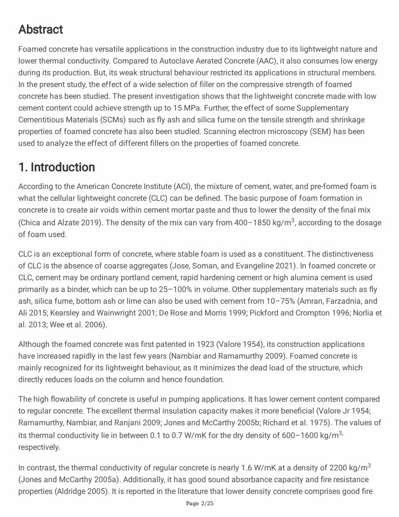
AbstractFoamed concrete has versatile applications in the construction industry due to its lightweight nature andlower thermal conductivity. Compared to Autoclave Aerated Concrete (AAC), it also consumes low energyduring its production. But, its weak structural behaviour restricted its applications in structural members.In the present study, the effect of a wide selection of �ller on the compressive strength of foamedconcrete has been studied. The present investigation shows that the lightweight concrete made with lowcement content could achieve strength up to 15 MPa. Further, the effect of some SupplementaryCementitious Materials (SCMs) such as �y ash and silica fume on the tensile strength and shrinkageproperties of foamed concrete has also been studied. Scanning electron microscopy (SEM) has beenused to analyze the effect of different �llers on the properties of foamed concrete.
1. IntroductionAccording to the American Concrete Institute (ACI), the mixture of cement, water, and pre-formed foam iswhat the cellular lightweight concrete (CLC) can be de�ned. The basic purpose of foam formation inconcrete is to create air voids within cement mortar paste and thus to lower the density of the �nal mix(Chica and Alzate 2019). The density of the mix can vary from 400–1850 kg/m3, according to the dosageof foam used.
CLC is an exceptional form of concrete, where stable foam is used as a constituent. The distinctivenessof CLC is the absence of coarse aggregates (Jose, Soman, and Evangeline 2021). In foamed concrete orCLC, cement may be ordinary portland cement, rapid hardening cement or high alumina cement is usedprimarily as a binder, which can be up to 25–100% in volume. Other supplementary materials such as �yash, silica fume, bottom ash or lime can also be used with cement from 10–75% (Amran, Farzadnia, andAli 2015; Kearsley and Wainwright 2001; De Rose and Morris 1999; Pickford and Crompton 1996; Norlia etal. 2013; Wee et al. 2006).
Although the foamed concrete was �rst patented in 1923 (Valore 1954), its construction applicationshave increased rapidly in the last few years (Nambiar and Ramamurthy 2009). Foamed concrete ismainly recognized for its lightweight behaviour, as it minimizes the dead load of the structure, whichdirectly reduces loads on the column and hence foundation.
The high �owability of concrete is useful in pumping applications. It has lower cement content comparedto regular concrete. The excellent thermal insulation capacity makes it more bene�cial (Valore Jr 1954;Ramamurthy, Nambiar, and Ranjani 2009; Jones and McCarthy 2005b; Richard et al. 1975). The values ofits thermal conductivity lie in between 0.1 to 0.7 W/mK for the dry density of 600–1600 kg/m3,
respectively.
In contrast, the thermal conductivity of regular concrete is nearly 1.6 W/mK at a density of 2200 kg/m3
(Jones and McCarthy 2005a). Additionally, it has good sound absorbance capacity and �re resistanceproperties (Aldridge 2005). It is reported in the literature that lower density concrete comprises good �re

Page 3/25
resisting values. Concrete with densities 950 kg/m3 to 1200 kg/m3 can withstand �re for 3.5 hours and 2hours, respectively (Ramamurthy, Kunhanandan Nambiar, and Indu Siva Ranjani 2009). Lightweightfoamed concrete gives an economical solution in large scale construction of structural members such aspartition walls, road embankment �ll, building blocks, wall panels, soil stabilization and �lling grades, etc.(Ramamurthy, Kunhanandan Nambiar, and Indu Siva Ranjani 2009; Uddin et al. 2006; Tarasov et al. 2010;Tikalsky, Pospisil, and MacDonald 2004).
With so many added bene�ts CLC possesses high drying shrinkage due to the absence of coarseaggregate. In the previous studies, up to 10 times shrinkage was observed while comparing CLC withnormal weight concrete. For the �rst 20 days of casting, the shrinkage rate is maximum, and it occursfrom 0.1–0.35% of the total volume of hardened concrete (McGovern 2000; Roslan, Awang, and Mydin2013). The addition of a small amount of �y ash reduces the drying shrinkage of foamed concrete(Elrahman et al., n.d.). Some researchers also suggest a low amount of use of supplementary cementmaterial to mitigate the effect of shrinkage. Also, shrinkage decreases with the decrease in the density offoam concrete; this effect occurs due to the lower paste content in lower density concrete (Valore Jr 1954;Schubert 1983; Nmai 1997).
Several factors are associated with the strength and shrinkage behaviour of foamed concrete, such asthe selection of foaming agent, method of foam production, distribution of air voids, type of cement, sizeof aggregate, water-cement ratio, the volume of foam, use of plasticizer and use of other constituentmaterials such as silica fume, �bre etc. (Jones and McCarthy 2006; Ramamurthy, Kunhanandan Nambiar,and Indu Siva Ranjani 2009).
The strength of foamed concrete is mostly affected by the foam content and not the water-cement ratio.In contrast, the importance of water is important in another way, as lower water content causes the mix tobe stiff. Hence, bubbles break during mixing, which increases density. Similarly, more water contentcauses the slurry to be too thin to hold the bubbles, which causes segregation of foam from the mix(Nambiar and Ramamurthy 2006b, 2006a). Previous studies suggest that the water to cement ratioshould be between 0.4 to 1.25 or in the range of 6.5–14.5% of the target density (Kearsley 2006; Kearsleyand Visagie 1999). Some researchers suggest that the amount of water should not be predetermined andshould be seen at the time of mixing by visualizing the consistency of the mix (Valore Jr 1954; Valore1954). But water purity is essential in foam concrete as impure water may negatively affect the usage ofprotein-based foam agents (Kearsley 2006).
Protein-based and synthetic-based are the common forms of foaming agents used in the production offoamed concrete. If a protein-based foaming agent is used, it helps to create a more closed-cell bubblestructure that provides more stable air voids, while a synthetic one helps to form a lower density mixtureas it yields more signi�cant expansion (De Rose and Morris 1999; Tikalsky, Pospisil, and MacDonald2004; Bening�eld, Gaimster, and Gri�n 2005). The type of foaming agent greatly affects the strength offoaming concrete. It is found that the protein-based foaming agent called Foaming C leads to 10 timeshigher potency than synthetic-based foaming agents (Falliano et al. 2018).
Page 4/25
The strength of CLC is also affected by the use of plasticizer, and it was seen that �uorosurfactant (FS1)is generally used to reduce the amount of mixing water and also marginally accelerates the strength gainof foam concrete, the dosage should not be increased from 0.45–0.5% of cement, as it creates theinstability of foam (De Rose and Morris 1999).
A study on the effect of �bre in foamed concrete shows that chopped �bre in a range of 1–3 kg/m3 hasbeen essential to enhancing the shear behaviour of foam concrete equivalent to that of normal weightconcrete. Fibre also reduces the brittle behaviour of concrete, signi�cantly improves mechanical andimpact properties of concrete by obstructing the micro crack and increasing the energy absorption rate(Zollo 1997; Zollo and Hays 1998). Mostly synthetic and natural �bres are used in foam concrete such asglass, polypropylene, steel and oil palm. A study shows a 66% improvement in compressive strength onadding 0.55% volume of �bre (Bing, Zhen, and Ning 2011b; Panesar 2013; Akil et al. 2011; Yap et al.2014). It was also reported that the addition of polypropylene �bre reduces the drying shrinkage of foamconcrete (Bing, Zhen, and Ning 2011b).
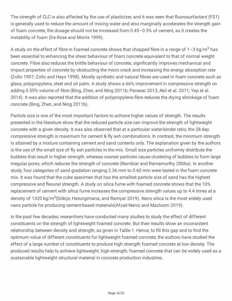
Particle size is one of the most important factors to achieve higher values of strength. The resultspresented in the literature show that the reduced particle size can improve the strength of lightweightconcrete with a given density. It was also observed that at a particular water-binder ratio, the 28-daycompressive strength is maximum for cement & �y ash combinations. In contrast, the minimum strengthis attained by a mixture containing cement and sand contents only. The explanation given by the authorsis the use of the small size of �y ash particles in the mix. Small size particles uniformly distribute thebubbles that result in higher strength, whereas coarser particles cause clustering of bubbles to form largeirregular pores, which reduces the strength of concrete (Nambiar and Ramamurthy 2006a). In anotherstudy, four categories of sand gradation ranging 2.36 mm to 0.60 mm were tested in the foam concretemix. It was found that the cube specimen that has the smallest particle size of sand has the highestcompressive and �exural strength. A study on silica fume with foamed concrete shows that the 10%replacement of cement with silica fume increases the compressive strength values up to 4.4 times at adensity of 1320 kg/m3(Gökçe, Hatungimana, and Ramyar 2019). Nano silica is the most widely usednano particle for producing cement-based materials(Afzali-Naniz and Mazloom 2019).
In the past few decades, researchers have conducted many studies to study the effect of differentconstituents on the strength of lightweight foamed concrete. But their results show an inconsistentrelationship between density and strength, as given in Table 1. Hence, to �ll this gap and to �nd theoptimum value of different constituents for lightweight foamed concrete, the authors have studied theeffect of a large number of constituents to produce high strength foamed concrete at low density. Theproduced results help to achieve lightweight, high-strength, foamed concrete that can be widely used as asustainable lightweight structural material in concrete production industries.

Page 5/25
Table 1Strength of foamed concrete at different densities stated by various researchers.
Materials Density(kg/m3)
Compressivestrength (MPa)
Cement, �y ash and sand (Tanveer, Jagdeesh, and Ahmed 2017) 1200 10
Cement and �y ash (Nambiar and Ramamurthy 2006a) 1100 11
Cement, sand and �y ash (Durack and Weiqing 1998) 1185 6
Cement, sand and �y ash (Van Deijk 1919) 1200 10
Cement and coarse sand (Kunhanandan Nambiar and Ramamurthy2008)
1350 7
Cement and �ne sand (Ramamurthy, Kunhanandan Nambiar, and InduSiva Ranjani 2009; Nambiar and Ramamurthy 2009)
1200 11
Cement, �ne, coarse and �y ash (Jones and McCarthy 2005b) 1400 7
Cement, �y ash, �bre, superplasticizer (Bing, Zhen, and Ning 2011a) 1028 13
Cement, �y ash, slag silica fume (Pan, Hiromi, and Wee 2007) 1020 4.2
2. Experimental ProgramThe experimental program consists of tests on cubes, cylinder and prisms using two types of cement(ultimate strength 43 Mpa and 53 Mpa), coarse sand (maximum particle size 1.18 mm and 2.36 mm),class F �y ash, silica fume, polypropylene �ber, water-cement ratio with and without superplasticizer andlow-density foam in different proportions were used in each mix. Twenty different types of foamedconcrete specimens were prepared using different ingredients. Specimens were cast in the form of cubes,cylinders, and prisms based on the test requirement. The water curing of each of the specimens wascarried out at 27°C throughout the experimental program. The size of each cubic specimen for thecompressive strength test was (0.07 m x0.07 m x0.07 m). Whereas the specimens for splitting tensilestrength test were cast in the form of a cylinder having a diameter of 100 mm and a height of 200 mm.Additionally, a prism of size 40 mm x 40 mm x 160 mm was cast to study foam concrete's shrinkagebehaviour. The density of specimens for each test was maintained at to1150 kg/m3. All the compressivestrength tests were conducted with the help of a compressive testing machine having a maximumloading capacity of 1000 kN.
2.1 Constituent materials and Their Properties
2.1.1 CementTwo different grades of cement, OPC 43 and OPC 53 were used in the design mix, meeting thespeci�cation of IS 8112 (1989) equivalent to ASTM C 150 (ASTM International 2007). The 28-day
Page 6/25
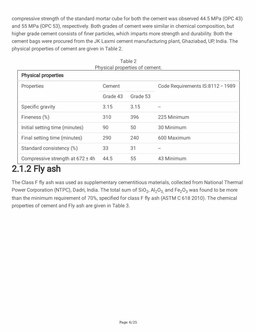
compressive strength of the standard mortar cube for both the cement was observed 44.5 MPa (OPC 43)and 55 MPa (OPC 53), respectively. Both grades of cement were similar in chemical composition, buthigher grade cement consists of �ner particles, which imparts more strength and durability. Both thecement bags were procured from the JK Laxmi cement manufacturing plant, Ghaziabad, UP, India. Thephysical properties of cement are given in Table 2.
Table 2Physical properties of cement.
Physical properties
Properties Cement Code Requirements IS:8112 − 1989
Grade 43 Grade 53
Speci�c gravity 3.15 3.15 --
Fineness (%) 310 396 225 Minimum
Initial setting time (minutes) 90 50 30 Minimum
Final setting time (minutes) 290 240 600 Maximum
Standard consistency (%) 33 31 --
Compressive strength at 672 ± 4h 44.5 55 43 Minimum
2.1.2 Fly ashThe Class F �y ash was used as supplementary cementitious materials, collected from National ThermalPower Corporation (NTPC), Dadri, India. The total sum of SiO2, Al2O3, and Fe2O3 was found to be morethan the minimum requirement of 70%, speci�ed for class F �y ash (ASTM C 618 2010). The chemicalproperties of cement and Fly ash are given in Table 3.

Page 7/25
Table 3Chemical properties of cement and �y ash.
Components OPC (%) Fly Ash (%)
(Class F)
SiO2 20.99 57.6
Al2O3 5.98 30.5
Fe2O3 4.10 3.72
CaO 60.78 1.10
MgO 0.96 0.38
SO3 2.86 0.22
K2O 1.18 1.35
Na2O 0.86 0.10
TiO2 0.25 1.72
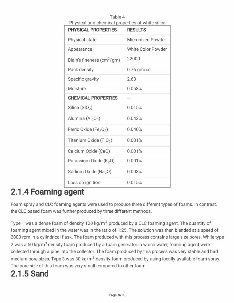
2.1.3 Silica fume and micro silicaSilica is used to enhance the mechanical properties, durability, and constructability of concrete. Silicafume has low speci�c gravity and an average particle size of 0.1µm. The white colour powder is a veryreactive and effective pozzolanic material due to its �ne particle size and high purity of SiO2 (99.5%)content. Some physical and chemical properties are given in Table 4 as provided by the supplier.
Page 8/25
Table 4Physical and chemical properties of white silica
PHYSICAL PROPERTIES RESULTS
Physical state Micronized Powder
Appearance White Color Powder
Blain’s �neness (cm2/gm) 22000
Pack density 0.76 gm/cc
Speci�c gravity 2.63
Moisture 0.058%
CHEMICAL PROPERTIES ---
Silica (SIO2) 0.015%
Alumina (Al2O3) 0.043%
Ferric Oxide (Fe2O3) 0.040%
Titanium Oxide (TiO2) 0.001%
Calcium Oxide (CaO) 0.001%
Potassium Oxide (K2O) 0.001%
Sodium Oxide (Na2O) 0.003%
Loss on ignition 0.015%
2.1.4 Foaming agentFoam spray and CLC foaming agents were used to produce three different types of foams. In contrast,the CLC based foam was further produced by three different methods.
Type 1 was a dense foam of density 120 kg/m3, produced by a CLC foaming agent. The quantity offoaming agent mixed in the water was in the ratio of 1:25. The solution was then blended at a speed of2800 rpm in a cylindrical �ask. The foam produced with this process contains large size pores. While type2 was a 50 kg/m3 density foam produced by a foam generator in which water, foaming agent werecollected through a pipe into the collector. The foam produced by this process was very stable and hadmedium pore sizes. Type 3 was 30 kg/m3 density foam produced by using locally available foam spray.The pore size of this foam was very small compared to other foam.
2.1.5 Sand

Page 9/25
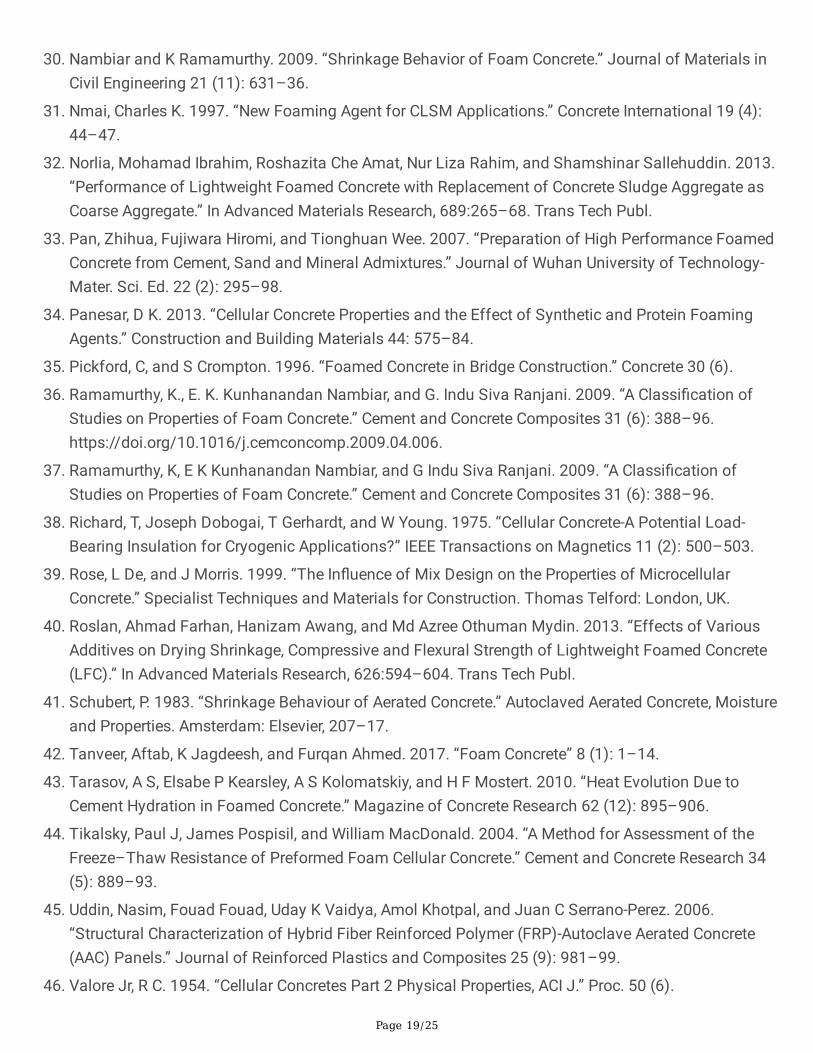
Locally available natural sand conforming to ASTM C 33 (ASTM 2016) was used in this experimentalstudy,. The sand was found to lie in zone II as per IS 383 (1970) with water absorption of 0.80%, �nenessmodulus of 2.79 and a speci�c gravity of 2.6. Figure 1 illustrates the particle size distribution of sandused in the study.
2.1.6 Water and plasticizerThe Normal portable tap water of drinkable quality is used for mixing as well as for curing purposes.While the plasticizer used in the experimental work was based on Sulphonated Naphthalene Polymershaving a commercial name of Conplast SP430, it was supplied by Forsoc constructive solutions Pvt. Ltd.The chemical and physical properties of the plasticizer were provided by its manufacturer as given in theinternet source (“Https://Fosroc.Com/Assets/ProductDatasheets/UAE-Data/Admixtures/Conplast-SP430.Pdf” 2014).
2.1.7 FiberPolypropylene �ber of average length 12 mm were used in the mix as given in Table 5.
Table 5Properties of polypropylene �berMerge CP112GDC
Denier 1.5
Polymer Polyester
Length 12 mm
Speci�c gravity 1.31–1.37
Melting point 240–260°C
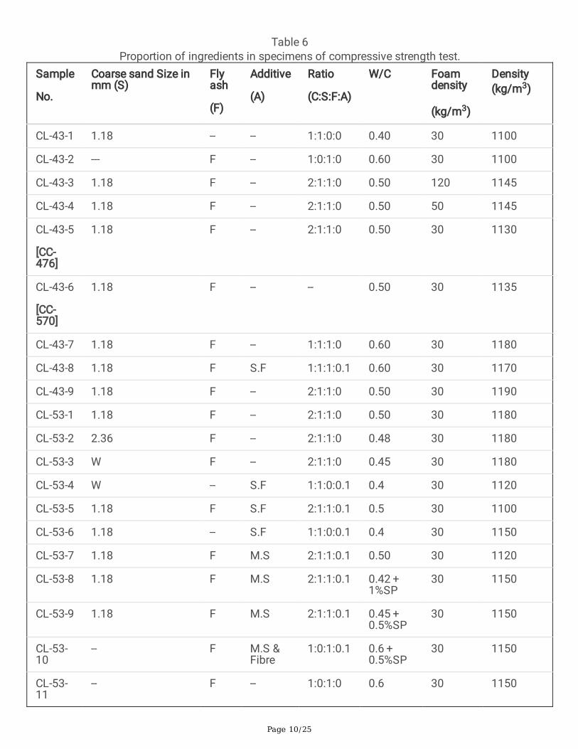
2.2 Testing programTwenty types of foamed concrete specimens produced in the laboratory using different ingredients aregiven in Table 6, where it can be seen that the ratio of ingredients was varied along with water-cementratio and foam density to achieve high strength lightweight concrete mix.
Page 10/25
Table 6Proportion of ingredients in specimens of compressive strength test.
Sample
No.
Coarse sand Size inmm (S)
Flyash
(F)
Additive
(A)
Ratio
(C:S:F:A)
W/C Foamdensity
(kg/m3)
Density(kg/m3)
CL-43-1 1.18 -- -- 1:1:0:0 0.40 30 1100
CL-43-2 --- F -- 1:0:1:0 0.60 30 1100
CL-43-3 1.18 F -- 2:1:1:0 0.50 120 1145
CL-43-4 1.18 F -- 2:1:1:0 0.50 50 1145
CL-43-5
[CC-476]
1.18 F -- 2:1:1:0 0.50 30 1130
CL-43-6
[CC-570]
1.18 F -- -- 0.50 30 1135
CL-43-7 1.18 F -- 1:1:1:0 0.60 30 1180
CL-43-8 1.18 F S.F 1:1:1:0.1 0.60 30 1170
CL-43-9 1.18 F -- 2:1:1:0 0.50 30 1190
CL-53-1 1.18 F -- 2:1:1:0 0.50 30 1180
CL-53-2 2.36 F -- 2:1:1:0 0.48 30 1180
CL-53-3 W F -- 2:1:1:0 0.45 30 1180
CL-53-4 W -- S.F 1:1:0:0.1 0.4 30 1120
CL-53-5 1.18 F S.F 2:1:1:0.1 0.5 30 1100
CL-53-6 1.18 -- S.F 1:1:0:0.1 0.4 30 1150
CL-53-7 1.18 F M.S 2:1:1:0.1 0.50 30 1120
CL-53-8 1.18 F M.S 2:1:1:0.1 0.42 + 1%SP
30 1150
CL-53-9 1.18 F M.S 2:1:1:0.1 0.45 + 0.5%SP
30 1150
CL-53-10
-- F M.S &Fibre
1:0:1:0.1 0.6 + 0.5%SP
30 1150
CL-53-11
-- F -- 1:0:1:0 0.6 30 1150

Page 11/25
Note: Some abbreviations used in the table stands as [CL-43-1/53 − 1 (Cellular lightweight concrete with43/53 grade cement of sample no 1); CC (Cement content); S.F (Silica fume); M.S (Micro silica); F(Class FFly ash); SP (Superplasticizer); W(without sieve)].
A detailed discussion about the effect of each ingredient on the compressive strength of foamed concreteis carried out in the forthcoming section. Further, the tensile strength and shrinkage properties of foamedconcrete are also studied in section 3.2 and section 3.3, respectively. Additionally, SEM analysis is carriedout in section 4 to understand the effect of each ingredient on the molecular structure of foamedconcrete.
3. Results And Discussion
3.1 Compressive strengthThe compressive strength tests performed from section 3.1.1 to section 3.1.9 show that foamed concretecube specimens at a speci�c ratio of ingredients can achieve a compressive strength up to 15 MPa at thedensity of 1150 kg/m3. The results of all the tests performed are given in Table 7.
Table 7Compressive strength of different cubic specimens after 28 days of water curing.
Sample No. 28 days comp-strength (MPa) Sample No. 28 days comp-strength (MPa)
CL-43-1 3.8 CL-53-2 5.2
CL-43-2 4.9 CL-53-3 4.4
CL-43-3 1.8 CL-53-4 3.8
CL-43-4 2.9 CL-53-5 8.0
CL-43-5 4.2 CL-53-6 5.3
CL-43-6 5.0 CL-53-7 9.2
CL-43-7 3.1 CL-53-8 11.0
CL-43-8 4.2 CL-53-9 11.9
CL-43-9 3.9 CL-53-10 15.0
CL-53-1 5.5 CL-53-11 9.0
Small particles with low speci�c gravity are found to be favourable for producing high-strengthlightweight foamed concrete. The use of larger size aggregate lowers the value compressive and tensilestrength. Also, it creates non-uniform voids in the foamed concrete. The substitution of coarse sand to �yash in foamed concrete was found to be favourable. It increases the compressive strength up to 30%.Similarly, the addition of �ner silica particles helps to increase the compressive strength of the foamed
Page 12/25
concrete. A considerable improvement in strength was found when 43-grade cement was replaced with53-grade cement in foamed concrete. The lower density foam helped to improve the particle holdingcapacity and stability of the mix. It creates small-size pores in foamed concrete, resulting in highcompressive strength. Also, the addition of a small amount of �bre improves the stability of foamedconcrete. It helps to resist the formation of vertical cracks, which allows the specimen to sustain someadditional load before the crushing. A detailed discussion about the effect of various ingredients on thecompressive strength of foamed concrete is given in the forthcoming section.
3.1.1 Effect of cementTo study the effect of the type of cement on the compressive strength of foamed concrete, three cubicalspecimens were tested under compression for each sample given in Table 6. It can be seen from Table 7that the samples CL-43-9 and CL-53-1 have similar ingredients and w/c ratio, but their strength differedsigni�cantly. The sample containing 53-grade cement shows 42% more compressive strength than thesample containing 43-grade cement. After 28 days of curing, only 3.9 MPa compressive strength wasachieved by the sample CL-43-9 compared to 5.5 MPa by CL-53-1. The smaller particle size of the 53-grade cement helps to achieve higher strength. Hence the use of high-grade cement is recommended forthe production of lightweight foamed concrete.
3.1.2 Effect of foamThe results of the samples CL-43-3, CL-43-4 and CL-43-5 made up of different types of foam are shown inTable 7. It can be seen that the sample obtained using the least density foam (30 kg/m3) has the higheststrength to weight ratio compared to the other two. On the other hand, the samples prepared using high-density foam (120 kg/m3) has the lowest strength. The size of voids in the low-density foam was seen tobe very small, which helps to produce a thick quality foam. Hence, it helps to produce concrete having alarge number of uniformly connected small pores, lesser in volume and have a connected web of binderparticles. Whereas the foam having higher density has fewer non-uniform large size pores, weakens thebond between binder’s particles of the foamed concrete.
On the other hand, the stability of the locally available foam spray was found to be inadequate. Hence,the concrete fails to achieve a stable mix at the initial time of casting. But the addition of cold water oftemperatures below 5°C signi�cantly improved the stability in the concrete. Thus, the low-density sprayfoam with cold water was found to be very effective to achieve high strength foamed concrete. It can beobserved from Fig. 2 that the concrete produced using the lowest density foam has the least number ofobservable voids and have the most uniform surface.
3.1.3 Effect of cement contentThe increase in cement content improves the strength of the foamed concrete. From Table 7, it can beseen that the sample CL-43-5 is able to achieve 4.2 MPa compressive strength at low cement content(476 kg/m3) compared to 4.7 MPa by sample CL-43-6 at higher cement content (560 kg/m3). The 28-day

Page 13/25
strength increased from 4.2 MPa to 4.7 MPa, i.e. only 12% of increment. Hence, lower cement content andSupplementary Cementitious Materials (SCMs) are recommended for foamed concrete production. Ithelps to produce sustainable concrete at a low cost.
3.1.4 Effect of aggregate sizeThe particle size is inversely proportional to the strength of foamed concrete. A 5% increase in strength ofconcrete was observed when big size particles (2.36 mm) of coarse sand in sample CL-53-2 werereplaced by smaller size particles (1.18 mm) of coarse sand in sample CL-53-1, see Table 7. Similarly,when 1.18 mm coarse sand was replaced by normal coarse sand, a sharp fall of 20% in compressivestrength was observed. The uniform distribution of smaller particles helps achieve a higher strength infoamed concrete compared to large irregular pores created by coarser sand. The same has beendiscovered through SEM analysis performed in section 4.
3.1.5 Effect of �y ashThe comparison of cement and coarse sand-based sample (CL-43-1) with a cement and �y ash basedsample (CL-43-2) in Table 7 shows a 29% increment in compressive strength. Similar behaviour wasobserved in samples CL-53-10 and CL-53-11, i.e. the overall 15% of increment. Coarser particles causebubbles clustering to form large irregular pores in the foamed concrete mix, resulting in low compressivestrength. The microscopic images of Fig. 3 clearly show that the smaller particle size of �y ash and silicahelps reduce the size of the voids in the cubical sample, resulting in the high compressive strength offoamed concrete.
The failure pattern of the cube specimen can be seen in Fig. 4. Initially, the vertical cracks were observedon the cube's face, and then the specimen was crushed completely. The obtained results were matchedwith the study conducted by E.K et.al (Nambiar and Ramamurthy 2006a).
3.1.7 Effect of superplasticizerIt was observed from the test conducted on samples CL-53-7 and CL-53-9 that the small decrease inwater content with the addition of 0.5% of superplasticizer to the weight of the cement helps to gain the29% increase in compressive strength of the foamed concrete. A small amount of addition ofsuperplasticizer reduces the quantity of water to form a workable and stiff mix and helps to produce thelower density of foamed concrete. Similar results were observed in the literature (Bagheri and Samea2018).
3.1.8 Effect of silicaThe addition of a small number of silica particles increased the compressive strength considerably. FromTable 6, it can be noticed that when 10% cement was replaced by silica fume in sample CL-43-8, 35%increase in the compressive strength was observed in sample CL-43-7. On the other hand, the use of silicafume with 53 grade of cement helps to to gain the compressive strength of foamed concrete up to 45%.

Page 14/25
3.1.9 Effect of FibreIn all the above failure cases, the vertical cracks were observed from top to bottom of the cube specimen,as shown in Fig. 4(a). While in the sample CL-53-9 & CL-53-10, the inclined cracks were observed due tothe addition of a small amount of �bre see Fig. 4(b). The addition of �bre resists the formation of verticalcracks, and the cube specimen was able to sustain additional load prior to the failure. It can be observedfrom samples CL-53-9 and CL-53-10 that the addition of just 1% volume of polypropylene �bre increasesthe compressive strength of the cube sample from 11.9 MPa to 13 MPa. Here, the small non-uniforminclined cracks were developed on the surface of the specimen from top to bottom. Also, the failurebehaviour changes from brittle to ductile.
3.2 Splitting tensile strengthTo understand the tensile behavior of foamed concrete. Three cylindrical specimens having the sameingredients ratio as of the cube sample CL-53-1, CL-53-10 and CL-53-11 of Table 6 were prepared. Thespecimen of diameter of 100 mm and height of 200 mm were cast in the form of a cylinder. All the testswere conducted in accordance with ASTM C496. The average values of the test results are given inTable 8, where it can be seen that the sample ST-2 shows the highest splitting tensile strength comparedto other samples. Similar behaviour was observed in the samples tested for the compressive strengthtest.
Table 8Average tensile strength of different cylindrical specimens after 28 days of curing
SampleNo.
Material sample tested as a cube inTable 6
Splitting tensile strength after 28 days(MPa)
ST-1 CL-53-1 1.66
ST-2 CL-53-10 1.97
ST-3 CL-53-11 1.79
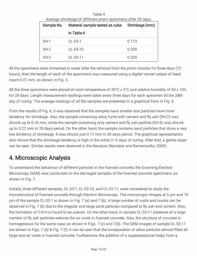
3.3 Shrinkage behaviourTo study the shrinkage behaviour, a test was carried out in accordance with IS6441-part II (Bureau ofIndian Standards 1972) on a prism of size 40 mm x 40 mm x160 mm. The DEMEC points were attachedat both ends of the prism to measure the total change in length. Three prism samples were tested foreach of the mix of Table 6 (CL-53-1, CL-53-10, and CL-53-11). The average values of the test results aregiven in Table 9.
Page 15/25
Table 9Average shrinkage of different prism specimens after 28 days.
Sample No. Material sample tested as cube
in Table 6
Shrinkage (mm)
SH-1 CL-53-1 0.173
SH-2 CL-53-10 0.205
SH-3 CL-53-11 0.205
All the specimens were immersed in water after the removal from the prism moulds for three days (72hours), then the length of each of the specimens was measured using a digital vernier caliper of leastcount 0.01 mm, as shown in Fig. 5.
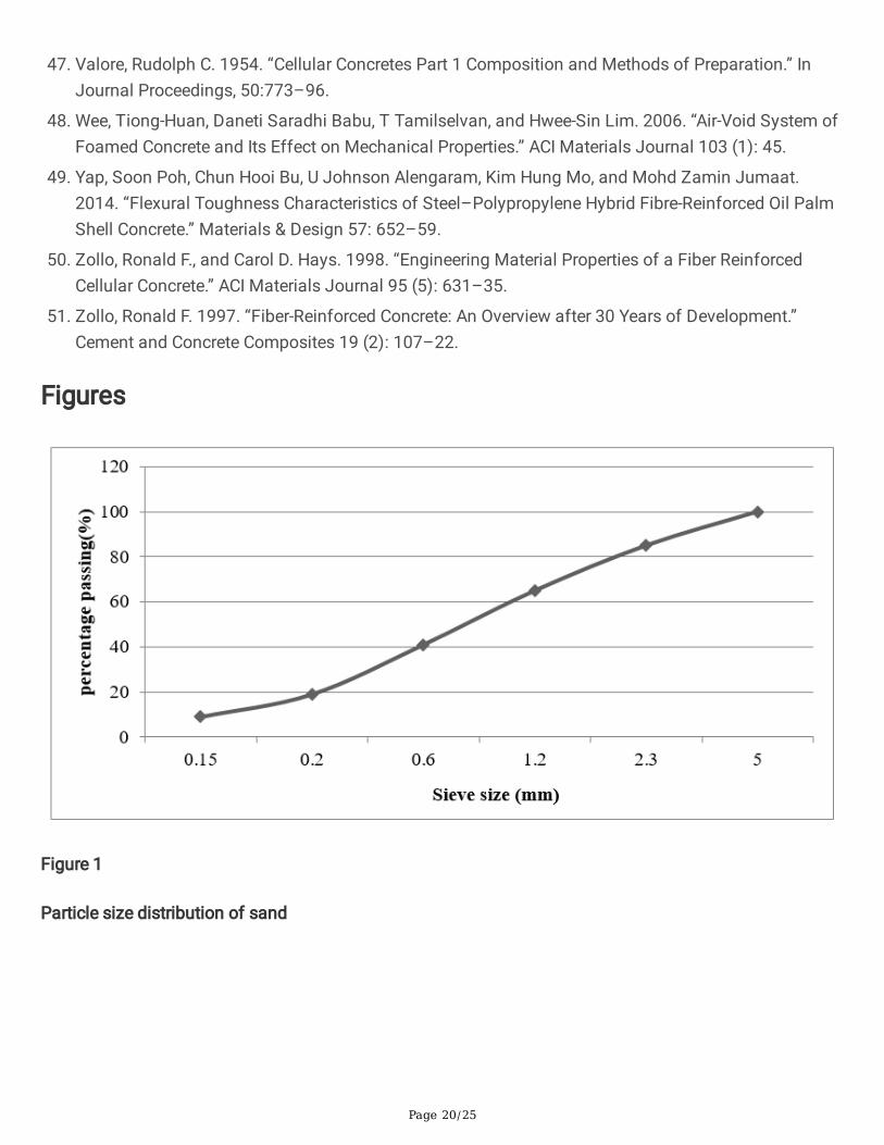
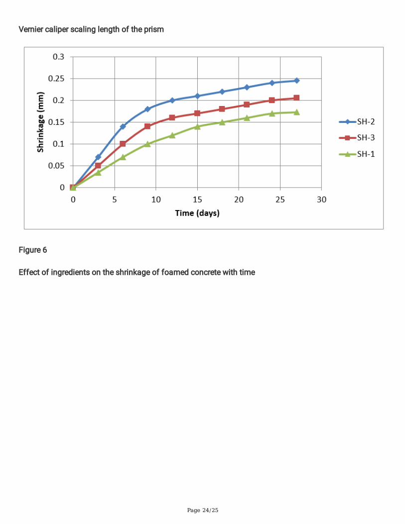
All the three specimens were placed at room temperature of 30°C ± 5°C and relative humidity of 60 ± 10%for 28 days. Length measurement readings were taken every three days for each specimen till the 28thday of curing. The average readings of all the samples are presented in a graphical form in Fig. 6.
From the results of Fig. 6, it was observed that the samples have smaller size particles have moretendency for shrinkage. Also, the sample containing silica fume with cement and �y ash (SH-2) wasshrunk up to 0.26 mm, while the sample containing only cement and �y ash particle (SH-3) was shrunkup to 0.22 mm in 28 days period. On the other hand, the sample contains sand particles that show a verylow tendency of shrinkage. It was shrunk just 0.17 mm in 28 days period. The graphical representationalso shows that the shrinkage tendency is high in the initial 3–9 days of curing. After that, a gentle slopecan be seen. Similar results were observed in the literature (Nambiar and Ramamurthy 2009).
4. Microscopic AnalysisTo understand the behaviour of different particles in the foamed concrete, the Scanning ElectronMicroscopy (SEM) was conducted on the damaged samples of the foamed concrete specimens, asshown in Fig. 7.
Initially, three different samples, CL-53-1, CL-53-10, and CL-53-11, were considered to study themicrostructure of foamed concrete through Electron Microscopy. The microscopic images at 5 µm and 10µm of the sample CL-53-1 is shown in Fig. 7 (a) and 7 (b). A large number of voids and cracks can beobserved in Fig. 7 (b) due to the irregular and large sand particles compared to �y ash and cement. Also,the formation of C-S-H is found to be uneven. On the other hand, in sample CL-53-11 presence of a largenumber of �y ash particles reduces the air voids in foamed concrete. Also, the structure of concrete ishomogeneous for the same case, as shown in Figs. 7 (c) and 7(d). The SEM images of sample CL-53-11are shown in Figs. 7 (e) & Fig. 7 (f); it can be seen that the incorporation of silica particles almost �lled alllarge size air voids in foamed concrete. Furthermore, the addition of a superplasticizer helps form a

Page 16/25
homogeneous mixture of C-S-H gel, which helps achieve higher strength in foamed concrete. Also, thesmall addition of polypropylene �bre resists the propagation of vertical cracks in compression.
5. ConclusionsThe present study aimed to produce a lightweight foamed concrete of higher strength by using thedifferent possible ingredients. A series of experiments have been carried out to establish the mechanicaland micro properties of the newly developed lightweight foamed concrete. The following conclusionswere drawn.
Small size ingredients particles with low speci�c gravity are favourable to produce high strengthlightweight foamed concrete. Whereas the use of large size aggregate lowers the value compressiveand tensile strength. Also, it creates non-uniform voids in the foamed concrete.
The substitution of coarse sand in place of �y ash in foamed concrete was found to be favourable. Itincreases the compressive strength up to 30%. Similarly, the addition of �ner silica particles up to10% helps to increase the compressive strength of the foamed concrete from 5.5 Mpa to 9.2 Mpa.
A 40% improvement in strength was found when 43-grade cement was replaced with 53-gradecement in foamed concrete.
Lower density foam ≤ 30 kg/m3 has a high particle holding capacity and good stability. It createssmall-size pores in foamed concrete, resulting in high compressive strength.
The addition of a small amount of �ber up to 1% improves the strength of foamed concrete. It helpsto resist the formation of vertical cracks, which allows the specimen to sustain some additional loadbefore the crushing.
Smaller size aggregate ≤ 1.18 mm helps to increase the strength of foamed concrete. But, it alsoincreases the shrinkage.
DeclarationsCompeting interests
On behalf of all authors, the corresponding author states that there is no con�ict of interest. The authorshave no relevant �nancial or non-�nancial interests to disclose.
FundingThe authors declare that no funds, grants, or other support were received during the preparation of thismanuscript
References

Page 17/25
1. Afzali-Naniz, Oveys, and Moosa Mazloom. 2019. “Assessment of the In�uence of Micro- and Nano-Silica on the Behavior of Self-Compacting Lightweight Concrete Using Full Factorial Design.” AsianJournal of Civil Engineering 20 (1): 57–70. https://doi.org/10.1007/s42107-018-0088-2.
2. Akil, HMl, M F Omar, A A M Mazuki, SZAM Sa�ee, Z A Mohd Ishak, and A Abu Bakar. 2011. “KenafFiber Reinforced Composites: A Review.” Materials & Design 32 (8–9): 4107–21.
3. Aldridge, D. 2005. “Introduction to Foamed Concrete: What, Why, How?” In Use of Foamed Concrete inConstruction: Proceedings of the International Conference Held at the University of Dundee, Scotland,UK on 5 July 2005, 1–14. Thomas Telford Publishing.
4. Amran, Y. H.Mugahed, Nima Farzadnia, and A. A.Abang Ali. 2015. “Properties and Applications ofFoamed Concrete, A Review.” Construction and Building Materials 101: 990–1005.https://doi.org/10.1016/j.conbuildmat.2015.10.112.
5. ASTM. 2016. “ASTM C33 / C33M - 16e1 Standard Speci�cation for Concrete Aggregates.” ASTMInternational, 11. https://doi.org/10.1520/C0033.
�. ASTM C 618. 2010. “Standard Speci�cation for Coal Fly Ash and Raw or Calcined Natural Pozzolanfor Use in Concrete.” Annual Book of ASTM Standards, 3–6. https://doi.org/10.1520/C0618.
7. ASTM International. 2007. “Standard Speci�cation for Portland Cement.” Annual Book of ASTMStandards I (April): 1–8. https://doi.org/10.1520/C0150.
�. Bagheri, A., and S. A. Samea. 2018. “Parameters In�uencing the Stability of Foamed Concrete.”Journal of Materials in Civil Engineering 30 (6): 04018091. https://doi.org/10.1061/(asce)mt.1943-5533.0002290.
9. Bening�eld, N, R Gaimster, and P Gri�n. 2005. “Investigation into the Air Void Characteristics ofFoamed Concrete.” In Use of Foamed Concrete in Construction: Proceedings of the InternationalConference Held at the University of Dundee, Scotland, UK on 5 July 2005, 51–60. Thomas TelfordPublishing.
10. Bing, Chen, Wu Zhen, and Liu Ning. 2011a. “Experimental Research on Properties of High-StrengthFoamed Concrete.” Journal of Materials in Civil Engineering 24 (1): 113–18.
11. C. Bing, W. Zhen, and L. Ning, 2011b. “Experimental Research on Properties of High-Strength FoamedConcrete.” Journal of Materials in Civil Engineering 24 (1): 113–18.https://doi.org/10.1061/(asce)mt.1943-5533.0000353.
12. Chica, Lina, and Albert Alzate. 2019. “Cellular Concrete Review: New Trends for Application inConstruction.” Construction and Building Materials 200: 637–47.https://doi.org/10.1016/j.conbuildmat.2018.12.136.
13. Deijk, Simon Van. 1919. “Foam Concrete.” Concrete 25 (5).
14. Durack, J M, and L Weiqing. 1998. “The Properties of Foamed Air Cured Fly Ash Based Concrete forMasonry Production.” In Proceedings of the Fifth Australasian Masonry Conference, 129–38.Gladstone.
15. Elrahman, Mohamed Abd, Mohamed E El Madawy, Sang-yeop Chung, and Pawel Sikora. n.d. “AppliedSciences Preparation and Characterization of Ultra-Lightweight Foamed Concrete Incorporating
Page 18/25
Lightweight Aggregates.” https://doi.org/10.3390/app9071447.
1�. Falliano, Devid, Dario De Domenico, Giuseppe Ricciardi, and Ernesto Gugliandolo. 2018.“Experimental Investigation on the Compressive Strength of Foamed Concrete: Effect of CuringConditions, Cement Type, Foaming Agent and Dry Density.” Construction and Building Materials 165:735–49. https://doi.org/10.1016/j.conbuildmat.2017.12.241.
17. Gökçe, H. Süleyman, Daniel Hatungimana, and Kambiz Ramyar. 2019. “Effect of Fly Ash and SilicaFume on Hardened Properties of Foam Concrete.” Construction and Building Materials 194: 1–11.https://doi.org/10.1016/j.conbuildmat.2018.11.036.
1�. “Https://Fosroc.Com/Assets/ProductDatasheets/UAE-Data/Admixtures/Conplast-SP430.Pdf.” 2014.2014.
19. Jones, M R, and A McCarthy. 2005a. “Behaviour and Assessment of Foamed Concrete for Fill andHighway Applications.” In 2005 International Congress’ Global Construction: Ultimate ConcreteOpportunities’, 61–88. Thomas Telford.
20. M. R. Jones and A. McCarthy. 2005b. “Preliminary Views on the Potential of Foamed Concrete as aStructural Material.” Magazine of Concrete Research 57 (1): 21–31.
21. M. R. Jones and A. McCarthy, 2006. “Heat of Hydration in Foamed Concrete: Effect of MixConstituents and Plastic Density.” Cement and Concrete Research 36 (6): 1032–41.
22. Jose, Sajan K., Mini Soman, and Y. Sheela Evangeline. 2021. “Quarry Fines: An Ideal Material for theManufacture of Foamed Concrete.” Asian Journal of Civil Engineering 22 (2): 241–47.https://doi.org/10.1007/s42107-020-00310-7.
23. Kearsley, E P. 2006. “The Use of Foamcrete for Affordable Development in Third World Countries.”Concrete in the Service of Mankind: Appropriate Concrete Technology 3: 232–42.
24. Kearsley, E P, and M Visagie. 1999. “Micro-Properties of Foamed Concrete. Specialist Techniques andMaterials for Construction.” London: Thomas Telford.
25. Kearsley, E P, and P J Wainwright. 2001. “The Effect of High Fly Ash Content on the CompressiveStrength of Foamed Concrete.” Cement and Concrete Research 31 (1): 105–12.
2�. Kunhanandan Nambiar, E K, and K Ramamurthy. 2008. “Fresh State Characteristics of FoamConcrete.” Journal of Materials in Civil Engineering 20 (2): 111–17.
27. McGovern, G. 2000. “Manufacture and Supply of Ready-Mix Foamed Concrete.” In One-DayAwareness Seminar on Foamed Concrete: Properties, Applications and Potential, 12-2S.
2�. Nambiar, E. K.Kunhanandan, and K. Ramamurthy. 2006a. “In�uence of Filler Type on the Propertiesof Foam Concrete.” Cement and Concrete Composites 28 (5): 475–80.https://doi.org/10.1016/j.cemconcomp.2005.12.001.
29. Nambiar, E K Kunhanandan, and K Ramamurthy. 2006b. “Models Relating Mixture Composition tothe Density and Strength of Foam Concrete Using Response Surface Methodology.” Cement andConcrete Composites 28 (9): 752–60.
Page 19/25
30. Nambiar and K Ramamurthy. 2009. “Shrinkage Behavior of Foam Concrete.” Journal of Materials inCivil Engineering 21 (11): 631–36.
31. Nmai, Charles K. 1997. “New Foaming Agent for CLSM Applications.” Concrete International 19 (4):44–47.
32. Norlia, Mohamad Ibrahim, Roshazita Che Amat, Nur Liza Rahim, and Shamshinar Sallehuddin. 2013.“Performance of Lightweight Foamed Concrete with Replacement of Concrete Sludge Aggregate asCoarse Aggregate.” In Advanced Materials Research, 689:265–68. Trans Tech Publ.
33. Pan, Zhihua, Fujiwara Hiromi, and Tionghuan Wee. 2007. “Preparation of High Performance FoamedConcrete from Cement, Sand and Mineral Admixtures.” Journal of Wuhan University of Technology-Mater. Sci. Ed. 22 (2): 295–98.
34. Panesar, D K. 2013. “Cellular Concrete Properties and the Effect of Synthetic and Protein FoamingAgents.” Construction and Building Materials 44: 575–84.
35. Pickford, C, and S Crompton. 1996. “Foamed Concrete in Bridge Construction.” Concrete 30 (6).
3�. Ramamurthy, K., E. K. Kunhanandan Nambiar, and G. Indu Siva Ranjani. 2009. “A Classi�cation ofStudies on Properties of Foam Concrete.” Cement and Concrete Composites 31 (6): 388–96.https://doi.org/10.1016/j.cemconcomp.2009.04.006.
37. Ramamurthy, K, E K Kunhanandan Nambiar, and G Indu Siva Ranjani. 2009. “A Classi�cation ofStudies on Properties of Foam Concrete.” Cement and Concrete Composites 31 (6): 388–96.
3�. Richard, T, Joseph Dobogai, T Gerhardt, and W Young. 1975. “Cellular Concrete-A Potential Load-Bearing Insulation for Cryogenic Applications?” IEEE Transactions on Magnetics 11 (2): 500–503.
39. Rose, L De, and J Morris. 1999. “The In�uence of Mix Design on the Properties of MicrocellularConcrete.” Specialist Techniques and Materials for Construction. Thomas Telford: London, UK.
40. Roslan, Ahmad Farhan, Hanizam Awang, and Md Azree Othuman Mydin. 2013. “Effects of VariousAdditives on Drying Shrinkage, Compressive and Flexural Strength of Lightweight Foamed Concrete(LFC).” In Advanced Materials Research, 626:594–604. Trans Tech Publ.
41. Schubert, P. 1983. “Shrinkage Behaviour of Aerated Concrete.” Autoclaved Aerated Concrete, Moistureand Properties. Amsterdam: Elsevier, 207–17.
42. Tanveer, Aftab, K Jagdeesh, and Furqan Ahmed. 2017. “Foam Concrete” 8 (1): 1–14.
43. Tarasov, A S, Elsabe P Kearsley, A S Kolomatskiy, and H F Mostert. 2010. “Heat Evolution Due toCement Hydration in Foamed Concrete.” Magazine of Concrete Research 62 (12): 895–906.
44. Tikalsky, Paul J, James Pospisil, and William MacDonald. 2004. “A Method for Assessment of theFreeze–Thaw Resistance of Preformed Foam Cellular Concrete.” Cement and Concrete Research 34(5): 889–93.
45. Uddin, Nasim, Fouad Fouad, Uday K Vaidya, Amol Khotpal, and Juan C Serrano-Perez. 2006.“Structural Characterization of Hybrid Fiber Reinforced Polymer (FRP)-Autoclave Aerated Concrete(AAC) Panels.” Journal of Reinforced Plastics and Composites 25 (9): 981–99.
4�. Valore Jr, R C. 1954. “Cellular Concretes Part 2 Physical Properties, ACI J.” Proc. 50 (6).
Page 20/25
47. Valore, Rudolph C. 1954. “Cellular Concretes Part 1 Composition and Methods of Preparation.” InJournal Proceedings, 50:773–96.
4�. Wee, Tiong-Huan, Daneti Saradhi Babu, T Tamilselvan, and Hwee-Sin Lim. 2006. “Air-Void System ofFoamed Concrete and Its Effect on Mechanical Properties.” ACI Materials Journal 103 (1): 45.
49. Yap, Soon Poh, Chun Hooi Bu, U Johnson Alengaram, Kim Hung Mo, and Mohd Zamin Jumaat.2014. “Flexural Toughness Characteristics of Steel–Polypropylene Hybrid Fibre-Reinforced Oil PalmShell Concrete.” Materials & Design 57: 652–59.
50. Zollo, Ronald F., and Carol D. Hays. 1998. “Engineering Material Properties of a Fiber ReinforcedCellular Concrete.” ACI Materials Journal 95 (5): 631–35.
51. Zollo, Ronald F. 1997. “Fiber-Reinforced Concrete: An Overview after 30 Years of Development.”Cement and Concrete Composites 19 (2): 107–22.
Figures
Figure 1
Particle size distribution of sand

Page 21/25
Figure 2
Cube specimen produced using different class of foam (a) Normal weight concrete (b) Foam density50kg/m3 (c) Foam density 30kg/m3 (d) Foam density 120kg/m3.

Page 22/25
Figure 3
Failure of the cube specimen in compression testing machine

Page 23/25
Figure 4
(a) Failure of the cube of sample CL-53-9 (b) Failure of the cube of sample CL-53-10
Figure 5
Page 24/25
Vernier caliper scaling length of the prism
Figure 6
Effect of ingredients on the shrinkage of foamed concrete with time

Page 25/25
Figure 7
Scanning Electron Microscopic images of different samples of foamed concrete
Copyright © 2022 FDOKUMEN