Foamed poly(lactic acid) composites with carbonaceous fillers for electromagnetic shielding
8
Foamed poly(lactic acid) composites with carbonaceous fillers for electromagnetic shielding Stanislaw Frackowiak a,⇑ , Joanna Ludwiczak a,1 , Karol Leluk a,1 , Kazimierz Orzechowski b,2 , Marek Kozlowski a,3 a Wroclaw University of Technology, Department of Environmental Engineering, Wybrzeze Wyspianskiego 27, Wroclaw 50-370, Poland b University of Wroclaw, Department of Chemistry, Joliot-Curie 14, Wroclaw 50-370, Poland article info Article history: Received 22 July 2014 Accepted 2 October 2014 Keywords: Polymer composites Electromagnetic shielding Polylactide Carbon fibers abstract Electromagnetic shielding is one the key factors for electronic devices in their use and transportation. Polylactide (PLA) is a biodegradable polymer with a moderate biodegradability and decent mechanical properties. Replacement of traditional materials by biodegradable polymers brings about the fossil resources savings and helps solving problems related to the plastic packaging waste. In this work com- posites of PLA with carbon black and carbon nanofibers were described. Improvement of the material mass/electromagnetic interference SE (shielding effectiveness) ratio can be obtained by introducing foaming technology into the material preparation process. Microporous structure can greatly improve material properties such as thermal isolation, mechanical properties and in case of composites filled with carbonaceous fillers such as carbon black carbon fibres – also the electrical conductivity. In order to improve their application range and reduce density, a cellular structure was created using chemical blowing agent. It was found that in low loaded composites (although above the percolation level) the shielding effectiveness relies on the amount of a conductive filler but it may be additionally enhanced by the foaming process. Electrical properties, electromagnetic shielding effectiveness and mor- phology of cellular composites for described polymer-filler systems have been presented. Ó 2014 Elsevier Ltd. All rights reserved. 1. Introduction In modern world full of the electronic hardware one of the most important but least noticeable issue is a need to shield the electric devices from electromagnetic interferences (EMI). Electric devices emit electromagnetic fields at various frequencies, which can cause a significant damage or poor performance of the equipment. Electromagnetic shielding can be addressed to the reflection and/ or absorption of electromagnetic radiation by a material. Reflection is regarded as a primary shielding mechanism and in order to perform shielding, the shield must interact with electromagnetic fields in the radiation due to mobile charge carriers. Secondary shielding mechanism – absorption, is realised by electric or magnetic dipoles that interact with electromagnetic fields in the radiation [1]. Therefore the shielding materials use to be conduc- tive and the most commonly they are metals. Although conductiv- ity is not necessary, it is advisable when shielding electronic devices. Electromagnetic radiation, especially that of high frequen- cies tends to interfere with electronics such as computers, contain- ing many microchips that can be harmed due to electrostatic discharges. Packaging/shielding material should be able to protect viable electronic goods both from the electromagnetic radiation and accidental electrostatic discharges. Both criteria meet metals but they are bulky and expensive in transportation. Polymer composites filled with electrically conductive carbon based materials (carbon black – CB, carbon nano fibers – CNF, carbon nanotubes – CNT) are by far lighter and easy to manufacture. In comparison with metals, polymer composites are semiconductors, but for good antistatic properties with a charge dissipation half-time of 2–10 s the surface resistivity of 10 10 – 10 11 [X cm] is required [2]. Such resistivity can be obtained for electroconductive polymer composites with most of the common fillers at a volume concentration close to the percolation threshold [3–7]. http://dx.doi.org/10.1016/j.matdes.2014.10.009 0261-3069/Ó 2014 Elsevier Ltd. All rights reserved. ⇑ Corresponding author. Tel.: +48 714686. E-mail addresses: [email protected] (S. Frackowiak), joanna. [email protected] (J. Ludwiczak), [email protected] (K. Leluk), kazimierz. [email protected] (K. Orzechowski), [email protected] (M. Kozlowski). 1 Tel.: +48 713204690. 2 Tel.: +48 713757114. 3 Tel.: +48 713206538. Materials and Design 65 (2015) 749–756 Contents lists available at ScienceDirect Materials and Design journal homepage: www.elsevier.com/locate/matdes
Transcript of Foamed poly(lactic acid) composites with carbonaceous fillers for electromagnetic shielding
Materials and Design 65 (2015) 749–756
Contents lists available at ScienceDirect
Materials and Design
journal homepage: www.elsevier .com/locate /matdes
Foamed poly(lactic acid) composites with carbonaceous fillersfor electromagnetic shielding
http://dx.doi.org/10.1016/j.matdes.2014.10.0090261-3069/� 2014 Elsevier Ltd. All rights reserved.
⇑ Corresponding author. Tel.: +48 714686.E-mail addresses: [email protected] (S. Frackowiak), joanna.
[email protected] (J. Ludwiczak), [email protected] (K. Leluk), [email protected] (K. Orzechowski), [email protected](M. Kozlowski).
1 Tel.: +48 713204690.2 Tel.: +48 713757114.3 Tel.: +48 713206538.
Stanislaw Frackowiak a,⇑, Joanna Ludwiczak a,1, Karol Leluk a,1, Kazimierz Orzechowski b,2,Marek Kozlowski a,3
a Wroclaw University of Technology, Department of Environmental Engineering, Wybrzeze Wyspianskiego 27, Wroclaw 50-370, Polandb University of Wroclaw, Department of Chemistry, Joliot-Curie 14, Wroclaw 50-370, Poland
a r t i c l e i n f o
Article history:Received 22 July 2014Accepted 2 October 2014
Keywords:Polymer compositesElectromagnetic shieldingPolylactideCarbon fibers
a b s t r a c t
Electromagnetic shielding is one the key factors for electronic devices in their use and transportation.Polylactide (PLA) is a biodegradable polymer with a moderate biodegradability and decent mechanicalproperties. Replacement of traditional materials by biodegradable polymers brings about the fossilresources savings and helps solving problems related to the plastic packaging waste. In this work com-posites of PLA with carbon black and carbon nanofibers were described. Improvement of the materialmass/electromagnetic interference SE (shielding effectiveness) ratio can be obtained by introducingfoaming technology into the material preparation process. Microporous structure can greatly improvematerial properties such as thermal isolation, mechanical properties and in case of composites filled withcarbonaceous fillers such as carbon black carbon fibres – also the electrical conductivity.
In order to improve their application range and reduce density, a cellular structure was created usingchemical blowing agent. It was found that in low loaded composites (although above the percolationlevel) the shielding effectiveness relies on the amount of a conductive filler but it may be additionallyenhanced by the foaming process. Electrical properties, electromagnetic shielding effectiveness and mor-phology of cellular composites for described polymer-filler systems have been presented.
� 2014 Elsevier Ltd. All rights reserved.
1. Introduction
In modern world full of the electronic hardware one of the mostimportant but least noticeable issue is a need to shield the electricdevices from electromagnetic interferences (EMI). Electric devicesemit electromagnetic fields at various frequencies, which can causea significant damage or poor performance of the equipment.Electromagnetic shielding can be addressed to the reflection and/or absorption of electromagnetic radiation by a material. Reflectionis regarded as a primary shielding mechanism and in order toperform shielding, the shield must interact with electromagneticfields in the radiation due to mobile charge carriers. Secondaryshielding mechanism – absorption, is realised by electric or
magnetic dipoles that interact with electromagnetic fields in theradiation [1]. Therefore the shielding materials use to be conduc-tive and the most commonly they are metals. Although conductiv-ity is not necessary, it is advisable when shielding electronicdevices. Electromagnetic radiation, especially that of high frequen-cies tends to interfere with electronics such as computers, contain-ing many microchips that can be harmed due to electrostaticdischarges. Packaging/shielding material should be able to protectviable electronic goods both from the electromagnetic radiationand accidental electrostatic discharges. Both criteria meet metalsbut they are bulky and expensive in transportation. Polymercomposites filled with electrically conductive carbon basedmaterials (carbon black – CB, carbon nano fibers – CNF, carbonnanotubes – CNT) are by far lighter and easy to manufacture. Incomparison with metals, polymer composites are semiconductors,but for good antistatic properties with a charge dissipationhalf-time of 2–10 s the surface resistivity of 1010 – 1011 [X cm] isrequired [2]. Such resistivity can be obtained for electroconductivepolymer composites with most of the common fillers at a volumeconcentration close to the percolation threshold [3–7].

750 S. Frackowiak et al. / Materials and Design 65 (2015) 749–756
Further improvement of the material mass/EMI SE (shieldingeffectiveness) ratio can be obtained by introducing foaming tech-nology into the material preparation process. Microporous struc-ture can greatly improve material properties such as thermalisolation, mechanical properties and in case of composites filledwith CB or CNF – also the electrical conductivity [8–10]. Filler par-ticles have less polymer volume to occupy which allows to obtainlower percolation threshold when compared to conventional solidcomposites. Polymer foams with carbon-based conductive fillerscan be an alternative to currently used materials, such as high costconductive polymers. They combine low weight and good EMIshielding with low cost and can be tailored for specific applications[11–15]. Zhang et al. [16] developed a novel composite materialconsisting of a syntactic foam (hollow carbon microspheres inresole resin) reinforced with CNF. The filler content was 0.7; 1.4;2.1 and 2.8 vol.%. The composite preparation took place in ahigh-shear homogenizer and the shielding effectiveness was eval-uated as a ratio between the incoming and outgoing power of anelectromagnetic wave. Maximum EMI shielding was ca. 25 dB fora composite containing 2.0% of the filler. Ameli et al. [17] presentedcomposites with a polypropylene matrix, filled with CNF for EMIshielding. Their work focused on the effect of foaming on thecarbon fibers orientation, aggregation and on the percolationthreshold. The EMI SE was measured in the X-band frequencyrange (8.0 – 12.4 GHz). They observed that a physical foaming ofPP-CF composite caused a change in its microstructure due to thebiaxial stretching of cells with the fibers and by the plasticizingeffect of a dissolved gas on the viscosity of composites. Also thedensity of composites was reduced by 25% as a result of foaming.Electrical properties were also improved due to higher fibersinter-connectivity as a result of the biaxial stretching during foam-ing. The percolation threshold was reduced from 8.75 to 7 vol.%,while EMI SE increased for over 65%.
Biopolymers have attracted recent years a great attention forreplacing the petrochemical based plastics due to the fossil fueldepletion, ecological hazards by the non-degradable plastics andan overall public concern. One of the most widely used alternativefor conventional plastics is polylactide (PLA) which has goodmechanical properties (similar to polystyrene), is fully biodegrad-able, biocompatible, of good chemical resistance and derived fromrenewable resources (e.g. corn starch). It can be processed withconventional processing methods (injection moulding, extrusion,spinning and others) [18,19]. Range of applications varies frommedicine implants and compostable packaging, to agriculture.When developing a novel packaging material for EMI shieldingone has to take in mind the ecological aspect of such. Packaginghas a very short life span and tends to be discarded soon afteruse and according to the best knowledge of the authors there areno papers concerning implementation of biodegradable polymersfor EMI shielding material.
Therefore the aim of the work reported was to develop alightweight biodegradable polymer composite filled with cheapconductive filler mainly for packaging application, with good EMISE properties along with ability to protect from electrostatic dis-charges, combining good mechanical and functional behaviourwith low density.
2. Materials and methods
2.1. Materials
Composites were prepared by melt mixing of polymer matrix,PLA 3052D from NatureWorks, with carbon based fillers. Mixingwas performed using a Thermo Scientific Polylab QC equipped withinternal mixer with chamber temperature of 180 �C and rotor
speed of 60 RPM. First was carbon black (CB) KetjenblackEC-300J from Akzo Chemicals which according to manufacturerspecifications has a very high specific surface area (approx.800 m2/g (BET)), low ash content and apparent bulk density of125–145 kg/m3 Second filler constituted nanosized carbon nanofi-bres (CNF) PR-19XT-HHT from Pyrograf Inc. According to the pro-ducer their CNF are heat-treated to temperatures up to 3000 �C.This high heat treatment creates the most graphitic carbon nanofi-bres and reduces the iron catalyst content to very low levels. Fillerconcentration for composites with CB was 2, 4, 6 and 8 vol.% and 4,8, 12 and 16 vol.% for CNF.
2.2. Preparation and foaming of composites
Foaming of composites was carried out using the exothermicblowing agent Luvomax AZ-C1 (Lehmann & Voss & Co.), which con-sists of azodicarbonamide (ADC) and ethylene propylene rubber(EPM) carrier. Thermal decomposition of azodicarbonamide occursat 200 �C resulting in the evolution of nitrogen, carbon monoxide,carbon dioxide, and ammonia gases. The chemical blowing agentwas used in this study in an amount of 0.5 wt.%.
Polymer matrix and nanocomposites with a dimensions of20 � 20 mm and a thickness of 3 mm were foamed by thermaldecomposition of the ADC in a vacuum oven at 220 �C for 10 min.
2.3. Cellular structure characterization
Scanning electron microscopy (SEM) was used to characterizemorphology of samples. Sputtering with gold was performed priorto SEM observations which were carried out with VEGA TESCANmicroscope.
The foam density was evaluated by a buoyancy method withthe density kit mounted on a balance from Mettler Toledo.
2.4. Thermal properties
The thermal analysis was performed using DSC Q20 from TAInstruments. All experiments were conducted at the heating rateof 10 �C/min, in the temperature range from 20 up to 220 �C. Thesamples of about 8 mg weight were placed in aluminum pans.After the first heating run, the samples were cooled down, and sub-sequently heated again with same rate. The glass transition tem-perature (Tg) and the melting temperature (Tm) were determinedfrom the second heating run.
2.5. Volume resistivity measurements
In order to estimate precisely the percolation threshold of eachpolymer/filler system, electrical measurements of the volumeresistivity as a function of the filler concentration were performed.Samples were prepared by press moulding in a form of plates andfor minimizing the contact resistance, gold electrodes were vapourdeposited on each sample. The current flow was measured usingKeithley 6512 electrometer from Keithley Instruments, while thevoltage supply was High Voltage Power Supply GPR-30H100 (GWInstek).
2.6. Electromagnetic shielding effectiveness
The measurements of real and imaginary part of electric per-mittivity were performed with HP 4282A (Agilent) Precision LCRMeter in the frequency range 100 Hz – 1 MHz. The apparatuswas set in Cp-D mode, the sample capacity (in the absence ofelectrical field) was calculated on the geometrical basis. All mea-surements were performed in ambient conditions (room tempera-ture: 24 �C, humidity level: 55%). Samples were produced in a form
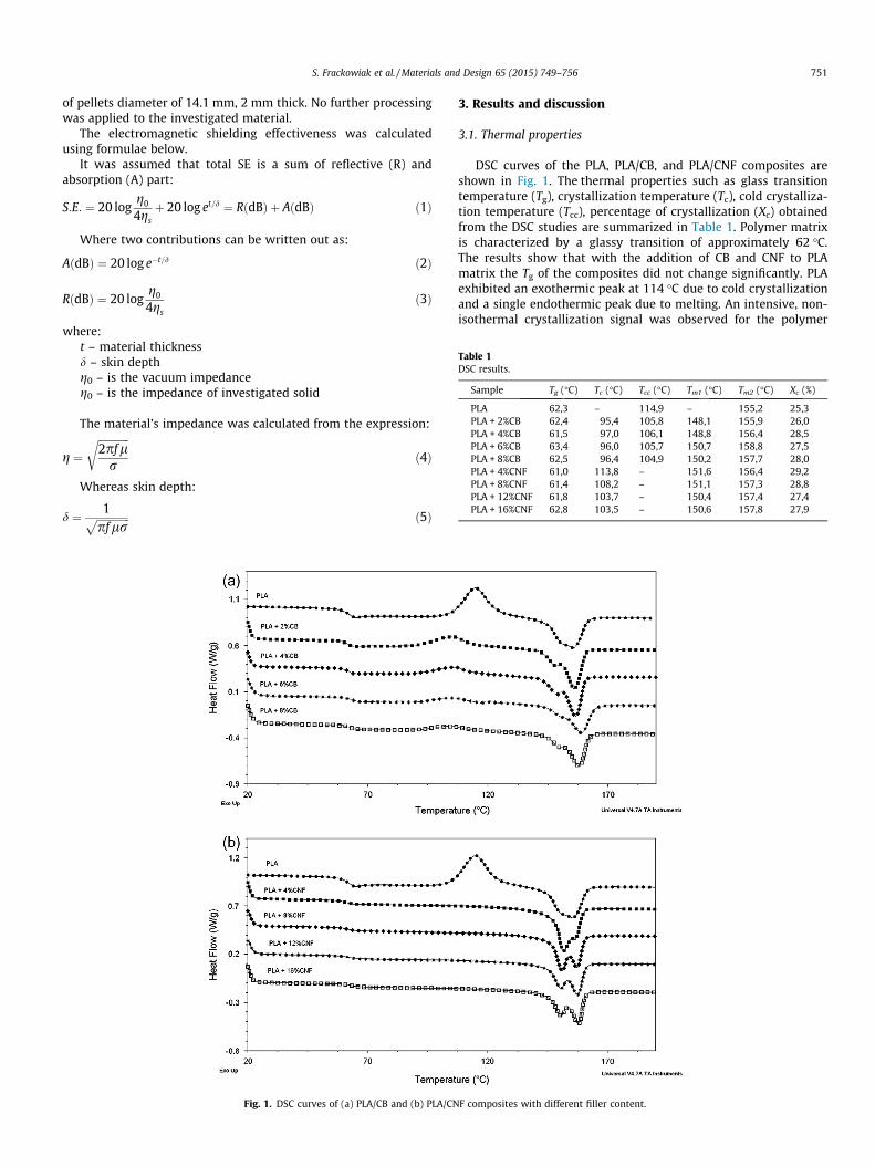
Table 1DSC results.
Sample Tg (�C) Tc (�C) Tcc (�C) Tm1 (�C) Tm2 (�C) Xc (%)
PLA 62,3 – 114,9 – 155,2 25,3PLA + 2%CB 62,4 95,4 105,8 148,1 155,9 26,0PLA + 4%CB 61,5 97,0 106,1 148,8 156,4 28,5PLA + 6%CB 63,4 96,0 105,7 150,7 158,8 27,5PLA + 8%CB 62,5 96,4 104,9 150,2 157,7 28,0PLA + 4%CNF 61,0 113,8 – 151,6 156,4 29,2PLA + 8%CNF 61,4 108,2 – 151,1 157,3 28,8PLA + 12%CNF 61,8 103,7 – 150,4 157,4 27,4PLA + 16%CNF 62,8 103,5 – 150,6 157,8 27,9
S. Frackowiak et al. / Materials and Design 65 (2015) 749–756 751
of pellets diameter of 14.1 mm, 2 mm thick. No further processingwas applied to the investigated material.
The electromagnetic shielding effectiveness was calculatedusing formulae below.
It was assumed that total SE is a sum of reflective (R) andabsorption (A) part:
S:E: ¼ 20 logg0
4gsþ 20 log et=d ¼ RðdBÞ þ AðdBÞ ð1Þ
Where two contributions can be written out as:
AðdBÞ ¼ 20 log e�t=d ð2Þ
RðdBÞ ¼ 20 logg0
4gsð3Þ
where:t – material thicknessd – skin depthg0 – is the vacuum impedanceg0 – is the impedance of investigated solid
The material’s impedance was calculated from the expression:
g ¼ffiffiffiffiffiffiffiffiffiffiffiffi2pfl
r
rð4Þ
Whereas skin depth:
d ¼ 1ffiffiffiffiffiffiffiffiffiffiffiffiffipflr
p ð5Þ
Fig. 1. DSC curves of (a) PLA/CB and (b) PLA/CN
3. Results and discussion
3.1. Thermal properties
DSC curves of the PLA, PLA/CB, and PLA/CNF composites areshown in Fig. 1. The thermal properties such as glass transitiontemperature (Tg), crystallization temperature (Tc), cold crystalliza-tion temperature (Tcc), percentage of crystallization (Xc) obtainedfrom the DSC studies are summarized in Table 1. Polymer matrixis characterized by a glassy transition of approximately 62 �C.The results show that with the addition of CB and CNF to PLAmatrix the Tg of the composites did not change significantly. PLAexhibited an exothermic peak at 114 �C due to cold crystallizationand a single endothermic peak due to melting. An intensive, non-isothermal crystallization signal was observed for the polymer
F composites with different filler content.
752 S. Frackowiak et al. / Materials and Design 65 (2015) 749–756
matrix. Addition of carbon black caused a decrease of the noniso-thermal crystallization peak, however during a cooling rate of5 �C/min the isothermal crystallization peak occurred. Addition ofCB reduced the cold crystallization temperature, which indicatesa nucleating effect of the filler.
The isothermal crystallization was observed during coolingnanocomposites filled with carbon fibers. Two melting peaks wereobserved for all nanocomposites. According to [20–22] the doublemelting behaviour is related to the presence of crystals withdifferent crystal forms. The lamellae of different size and perfectionare created during the cold and primary crystallization. The peak atthe lower temperature may be associated with melting of smallercrystallites formed during a cold crystallization while at a highertemperature melt the crystallites formed during a primary crystal-lization. The intensity of melting peaks is dependent on the nano-filler content. The addition of both CB and CNF caused an increasein the crystallinity of polylactide. In particular addition of 4% CNFbrought about a crystallinity level of 30%.
3.2. Composites morphology
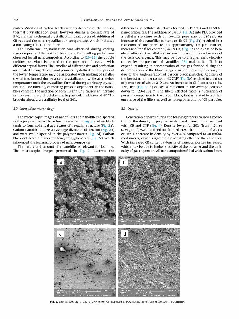
The microscopic images of nanofillers and nanofillers dispersedin the polymer matrix have been presented in Fig. 2. Carbon blacktends to form spherical aggregates of irregular structure (Fig. 2a).Carbon nanofibers have an average diameter of 150 nm (Fig. 2b)and were well dispersed in the polymer matrix (Fig. 2d). Carbonblack exhibited a higher tendency to agglomerate (Fig. 2c), whichinfluenced the foaming process of nanocomposites.
The nature and amount of a nanofiller is relevant for foaming.The microscopic images presented in Fig. 3 illustrate the
Fig. 2. SEM images of: (a) CB, (b) CNF, (c) 6% CB disperse
differences in cellular structures formed in PLA/CB and PLA/CNFnanocomposites. The addition of 2% CB (Fig. 3a) into PLA provideda cellular structure with an average pore size of 280 lm. Anincrease of the nanofiller content to 4% CB (Fig. 3b) resulted in areduction of the pore size to approximately 140 lm. Further,increase of the filler content (6%, 8% CB) (Fig. 3c and d) has no ben-eficial effect on the cellular structure of nanocomposite, because ofthe cells coalescence. This may be due to a higher melt viscositycaused by the presence of nanofiller [23], making it difficult toexpand, resulting in concentration of the gas formed during thedecomposition of the blowing agent inside the sample or may bedue to the agglomeration of carbon black particles. Addition ofthe lowest nanofiber content (4% CNF) (Fig. 3e) resulted in creationof pores size of about 210 lm. An increase in CNF content to 8%,12%, 16% (Fig. 3f–h) caused a reduction in the average cell sizedown to 120–170 lm. The fibers affected more a nucleation ofpores in comparison to the carbon black, that is related to a differ-ent shape of the fillers as well as to agglomeration of CB particles.
3.3. Density
Generation of pores during the foaming process caused a reduc-tion in the density of polymer matrix and nanocomposites filledwith CB and CNF (Fig. 4). Density lower for 20% (from 1.24 to0.94 g/dm3) was obtained for foamed PLA. The addition of 2% CBcaused a decrease in density by over 40% compared to an unfoa-med matrix, which suggested a nucleating effect of the nanofiller.With increased CB content a density of nanocomposites increased,which may be due to higher viscosity of the polymer and the diffi-culty of gas expansion. All nanocomposites filled with carbon fibers
d in PLA matrix, (d) 6% CNF dispersed in PLA matrix.
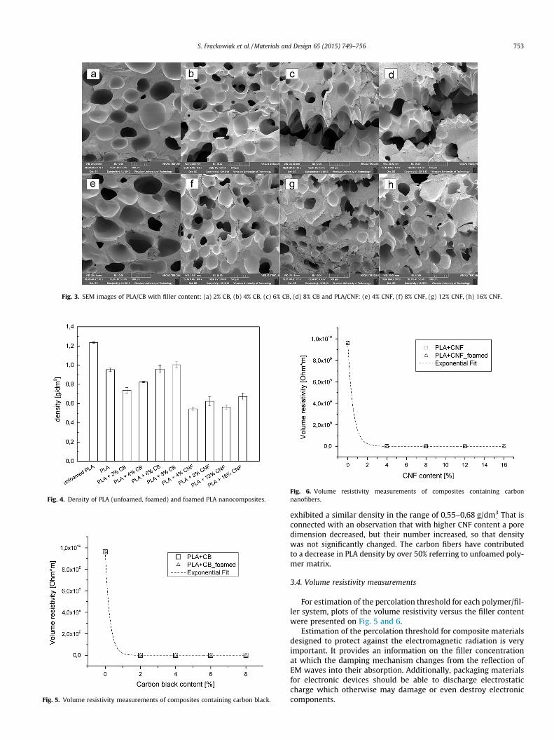
Fig. 3. SEM images of PLA/CB with filler content: (a) 2% CB, (b) 4% CB, (c) 6% CB, (d) 8% CB and PLA/CNF: (e) 4% CNF, (f) 8% CNF, (g) 12% CNF, (h) 16% CNF.
Fig. 4. Density of PLA (unfoamed, foamed) and foamed PLA nanocomposites.
Fig. 5. Volume resistivity measurements of composites containing carbon black.
Fig. 6. Volume resistivity measurements of composites containing carbonnanofibers.
S. Frackowiak et al. / Materials and Design 65 (2015) 749–756 753
exhibited a similar density in the range of 0,55–0,68 g/dm3. That is
connected with an observation that with higher CNF content a poredimension decreased, but their number increased, so that densitywas not significantly changed. The carbon fibers have contributedto a decrease in PLA density by over 50% referring to unfoamed poly-mer matrix.
3.4. Volume resistivity measurements
For estimation of the percolation threshold for each polymer/fil-ler system, plots of the volume resistivity versus the filler contentwere presented on Fig. 5 and 6.
Estimation of the percolation threshold for composite materialsdesigned to protect against the electromagnetic radiation is veryimportant. It provides an information on the filler concentrationat which the damping mechanism changes from the reflection ofEM waves into their absorption. Additionally, packaging materialsfor electronic devices should be able to discharge electrostaticcharge which otherwise may damage or even destroy electroniccomponents.
754 S. Frackowiak et al. / Materials and Design 65 (2015) 749–756
From the obtained results one can observe that the percolationthreshold for the composites containing carbon black is about1.5 vol.%, and for composites with carbon nanofibers it accountsto 2 vol.%. The difference is related to a tendency of carbon blackto form complex fractal structures, which in turn promote the gen-eration of electrically conductive pathways in the polymer matrix.There were no significant differences in this respect between thesolid and foamed materials.
3.5. Electromagnetic shielding effectiveness
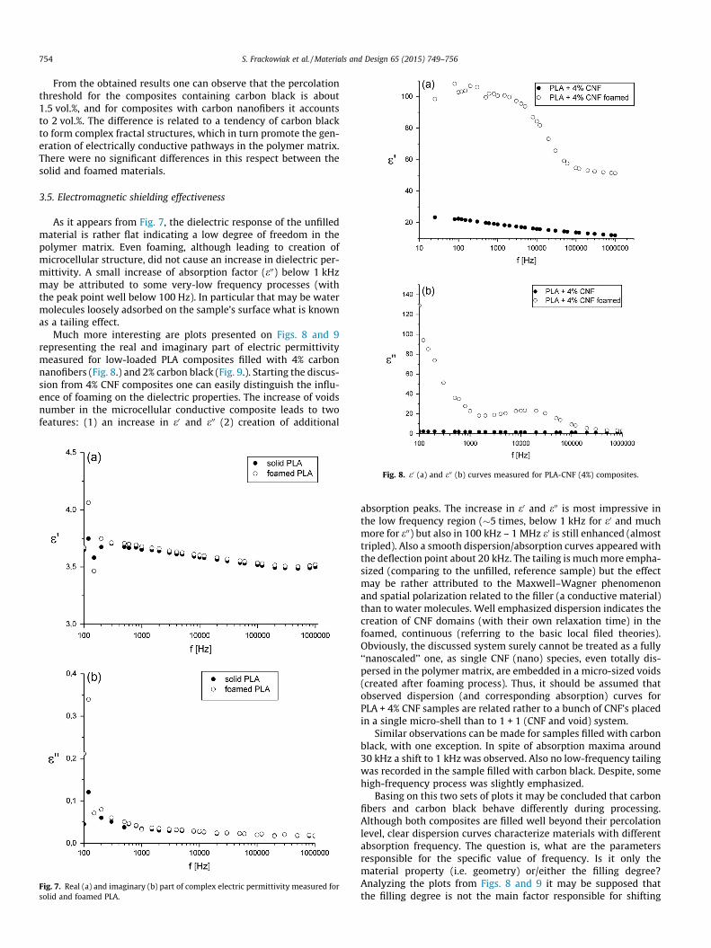
As it appears from Fig. 7, the dielectric response of the unfilledmaterial is rather flat indicating a low degree of freedom in thepolymer matrix. Even foaming, although leading to creation ofmicrocellular structure, did not cause an increase in dielectric per-mittivity. A small increase of absorption factor (e00) below 1 kHzmay be attributed to some very-low frequency processes (withthe peak point well below 100 Hz). In particular that may be watermolecules loosely adsorbed on the sample’s surface what is knownas a tailing effect.
Much more interesting are plots presented on Figs. 8 and 9representing the real and imaginary part of electric permittivitymeasured for low-loaded PLA composites filled with 4% carbonnanofibers (Fig. 8.) and 2% carbon black (Fig. 9.). Starting the discus-sion from 4% CNF composites one can easily distinguish the influ-ence of foaming on the dielectric properties. The increase of voidsnumber in the microcellular conductive composite leads to twofeatures: (1) an increase in e0 and e00 (2) creation of additional
Fig. 7. Real (a) and imaginary (b) part of complex electric permittivity measured forsolid and foamed PLA.
Fig. 8. e0 (a) and e00 (b) curves measured for PLA-CNF (4%) composites.
absorption peaks. The increase in e0 and e00 is most impressive inthe low frequency region (�5 times, below 1 kHz for e0 and muchmore for e00) but also in 100 kHz – 1 MHz e0 is still enhanced (almosttripled). Also a smooth dispersion/absorption curves appeared withthe deflection point about 20 kHz. The tailing is much more empha-sized (comparing to the unfilled, reference sample) but the effectmay be rather attributed to the Maxwell–Wagner phenomenonand spatial polarization related to the filler (a conductive material)than to water molecules. Well emphasized dispersion indicates thecreation of CNF domains (with their own relaxation time) in thefoamed, continuous (referring to the basic local filed theories).Obviously, the discussed system surely cannot be treated as a fully‘‘nanoscaled’’ one, as single CNF (nano) species, even totally dis-persed in the polymer matrix, are embedded in a micro-sized voids(created after foaming process). Thus, it should be assumed thatobserved dispersion (and corresponding absorption) curves forPLA + 4% CNF samples are related rather to a bunch of CNF’s placedin a single micro-shell than to 1 + 1 (CNF and void) system.
Similar observations can be made for samples filled with carbonblack, with one exception. In spite of absorption maxima around30 kHz a shift to 1 kHz was observed. Also no low-frequency tailingwas recorded in the sample filled with carbon black. Despite, somehigh-frequency process was slightly emphasized.
Basing on this two sets of plots it may be concluded that carbonfibers and carbon black behave differently during processing.Although both composites are filled well beyond their percolationlevel, clear dispersion curves characterize materials with differentabsorption frequency. The question is, what are the parametersresponsible for the specific value of frequency. Is it only thematerial property (i.e. geometry) or/either the filling degree?Analyzing the plots from Figs. 8 and 9 it may be supposed thatthe filling degree is not the main factor responsible for shifting

Fig. 9. e0 (a) and e00 (b) curves measured for PLA-CB (2%) composites.
Fig. 10. Dispersion (a), (c) and absorption (b), (d) cu
S. Frackowiak et al. / Materials and Design 65 (2015) 749–756 755
the absorption frequency. Also another one has to be taken intoconsideration: the processability of two components. As it is seenfrom the plots representing real part of the permittivity, the tailingeffect clearly appearing for CNF composite is not even marked forthat containing carbon black. If the tailing is caused by an excessof a filler in the composite it should be present on the e00 curvesof highly loaded materials. Results presented on Fig. 10 supportthat statement.
Shifting one step further – to the foamed 8% CNF and 4% CBcomposites, makes e0 ‘‘flat’’ in low – frequency region (CB filler)and whole spectrum (CNF). Moreover, one can observe for CB fillerthat e0 and e00 values in foamed material are lower comparing to thesolid one. This may be interpreted in terms of on decrease in thematerials density (and thus electric permittivity) due to foaming.
For all composites (and PLA as a reference) the shielding effec-tiveness calculations were performed for selected frequencies. Theresults have been presented in Table 2.
As the highly loaded materials are conductive, the S.E. wasmuch higher that 150 dB therefore it was not discussed, becausemost of engineering apparatus can measure attenuation up to150 dB.
The results presented in this paper illustrate subsequentchanges in attenuation related to an increased amount of the filler.The polymer matrix (foamed and solid) exhibited equal S.E. for fre-quencies above 1 kHz, what clearly indicates that only creation offree volumes (air filled) in the investigated material is not suffi-cient treatment for enhancing shielding properties in the absenceof electro-active filler. However, that parameter (S.E.) increasedin the row (values for 1 kHz): 4%CNF/2%CB (�25 dB) => 4% CNF/2%CB (both foamed) (�40 dB) => 4% CB foamed (�53 dB) =>8%CNF/8%CNF(foamed) (>�100 dB), which stays in a good agree-ment with theoretical considerations. Increasing conductive fillercontent (carbon black or carbon nanofiber) should lead to
rves of PLA + 4% CB and PLA + 8% CNF samples.

Table 2Shielding effectiveness calculated for selected frequencies.
f (Hz) 100 1000 10,000 100,000
Solid PLA 5,6 4,8 7 34Foamed PLA 12 3,9 6,5 31PLA + 4% CNF 23 25 51 >150PLA + 4% CNF foamed 42 42 138 >150PLA + 8% CNF 70 92 >150 >150PLA + 8% CNF foamed 88 140 >150 >150PLA + 12% CNF >150 >150 >150 >150PLA + 12% CNF foamed >150 >150 >150 >150PLA + 16% CNF >150 >150 >150 >150PLA + 16% CNF foamed >150 >150 >150 >150PLA + 2 CB 21 23 48 >150PLA + 2 CB foamed 26 38 63 >150PLA + 4% CB >150 >150 >150PLA + 4% CB foamed 49 51 87 >150PLA + 6% CB >150 >150 >150 >150PLA + 6% CB foamed 126 >150 >150 >150PLA + 8% CB >150 >150 >150 >150PLA + 8% CB foamed >150 >150 >150 >150
756 S. Frackowiak et al. / Materials and Design 65 (2015) 749–756
enhancement in shielding properties as the material gains in con-ductive properties. The increase corresponds to filler/polymermatrix ratio and presence of voids due to foaming process but isirrespective to the filler shape. Despite using fractal-type carbonblack or fibered carbon one can easily notice about 15 dB gain inattenuation due to formation of free volumes (4%CNF/2%CB:�25 dB vs. same foamed samples: �40 dB). The difference appearswhen comparing highly loaded samples: PLA + 2%CB/PLA + 4%CBand PLA + 4%CNF/PLA + 8%CNF (foamed and not foamed). In caseof nanofibered filler (CNF), increasing its content twice (from 4%to 8%) leads to more than 2,5 times gain in S.E., much greater com-paring to PLA + CB samples.
It may be concluded that in low loaded composites (althoughabove the percolation level) the shielding effectiveness relies onthe amount of a conductive filler but it may be additionallyenhanced by the foaming process. Further increase of the filleramount leads to conductive composites, whereas foaming has noremarkable influence on the composite’s electrical properties. Con-sidering only the value of S.E. at given frequency (not analysing thefrequency dependency) the influence of the filler on the electricproperties is irrespective to its morphology (shape, aspect ratio,surface area, etc.).
4. Conclusions
Based on results obtained, the most important factors influenc-ing material design for EMI SE are listed below.
(1) Foaming of conductive composites results in an increasedelectromagnetic shielding effectiveness for materials witha filler concentration close to the percolation threshold.
(2) Absorption peak for frequencies in the radio range wasobserved for composites with low filler content. Thataccounted to 1 kHz and 10 kHz for materials filled with car-bon black and carbon nanofibres, respectively.
(3) Higher shielding effectiveness at low filler concentrationwas obtained for composites containing rather carbon blackthan carbon nanofibres.
(4) More homogeneous and well dispersed cell structure wasobtained for materials filled with carbon nanofibres. Carbonblack exhibited tendency to form agglomerates which pro-moted overgrowing of cells. That was observed particularlyfor filler concentrations high above the percolation thresh-old (6–8%).
Acknowledgments
The research was supported by Wroclaw Research Center EIT+under the project ‘The Application of Nanotechnology in AdvancedMaterials’— NanoMat (POIG.01.01.02-02-002/08) financed by theEuropean Regional Development Fund (Innovative Economy Oper-ational Programme 1.1.2).
References
[1] Ping L, AikSeng L, YueYan S, GuatChoon O, XiJiang Y. EMI shieldingeffectiveness of CNTs composites. In: 2013 International conference onprocess equipment, mechatronics engineering and material science. Stafa-Zurich: Trans Tech Publications Ltd; 2013, p. 439–42.
[2] Electronic Industries Association, Packaging Material Standards for ESDSensitive Items, ANSI/EIA – 541; 1988.
[3] Mahmoodi M, Arjmand M, Sundararaj U, Park S. The electrical conductivity andelectromagnetic interference shielding of injection molded multi-walledcarbon nanotube/polystyrene composites. Carbon 2012;50:1455–64.
[4] Lei H, Pitt WG, McGrath LK, Ho CK. Modeling carbon black/polymer compositesensors. Sens. Actuators B Chem. 2007;125:396–407.
[5] Ezquerra TA, Martinez-Salazar J. Percolation threshold of conductivepolycarbonate/carbon composites as revealed by electron microscopy. J.Mater. Sci. Lett. 1986;5:1065–6.
[6] Rizvi R, Naguib H. Porosity and composition dependence on electrical andpiezoresistive properties of thermoplastic polyurethane nanocomposites. J.Mater. Res. 2013;28:2415–25.
[7] Frackowiak S, Maciejewska M, Szczurek A, Kozlowski M. Polymer compositesas sensing materials for liquid organic solvents – preliminary results. E-Polym.2013;11:362–70.
[8] Tran M-P, Detrembleur C, Alexandre M, Jerome C, Thomassin J-M. Theinfluence of foam morphology of multi-walled carbon nanotubes/poly(methyl methacrylate) nanocomposites on electrical conductivity.Polymer 2013;54:3261–70.
[9] Soares FA, Bohrz Nachtigall SM. Effect of chemical and physical foamingadditives on the properties of PP/wood flour composites. Polym. Test.2013;32:640–6.
[10] Ameli A, Jung PU, Park CB. Through-plane electrical conductivity of injection-molded polypropylene/carbon-fiber composite foams. Compos. Sci. Technol.2013;76:37–44.
[11] Yu L, Toikka G, Dean K, Bateman S, Yuan Q, Filippou C. Foaming behaviour andcell structure of poly(lactic acid) after various modifications. Polym. Int.2013;62:759–65.
[12] Saiz-Arroyo C, Rodriguez-Perez MA, Tirado J, Lopez-Gil A, de Saja JA. Structure–property relationships of medium-density polypropylene foams. Polym. Int.2013;62:1324–33.
[13] Chen L, Ozisik R, Schadler LS. The influence of carbon nanotube aspect ratio onthe foam morphology of MWNT/PMMA nanocomposite foams. Polymer2010;51:2368–75.
[14] Zhang H-B, Yan Q, Zheng W-G, He Z, Yu Z-Z. Tough graphene–polymermicrocellular foams for electromagnetic interference shielding. Acs Appl.Mater. Interf. 2011;3:918–24.
[15] Liu X-Y, Zhan M-S, Wang K. Preparation and characterization ofelectromagnetic interference shielding polyimide foam. J. Appl. Polym. Sci.2013;127:4129–37.
[16] Zhang L, Wang LB, See KY, Ma J. Effect of carbon nanofiber reinforcement onelectromagnetic interference shielding effectiveness of syntactic foam. J.Mater. Sci. 2013;48:7757–63.
[17] Ameli A, Jung PU, Park CB. Electrical properties and electromagneticinterference shielding effectiveness of polypropylene/carbon fiber compositefoams. Carbon 2013;60:379–91.
[18] Lim L-T, Auras R, Rubino M. Processing technologies for poly(lactic acid). Prog.Polym. Sci. 2008;33:820–52.
[19] Ribeiro I, Peças P, Henriques E. A life cycle framework to support materialsselection for Ecodesign: a case study on biodegradable polymers. Mater Des.2013;51:300–8.
[20] Xu Z, Niu YH, Yang L, Xie WY, Li H, Gan ZH. Morphology, rheology andcrystallization behavior of polylactide composites prepared through additionof five-armed star polylactide grafted multiwalled carbon nanotubes. Polymer2010;51:730–7.
[21] Zhizhong Su QL. Multiple melting behavior of poly(lactic acid) filled withmodified carbon black. J. Polym. Sci. Part B-Polym. Phys. – J POLYM SCI B-POLYM PHYS 2009;47:1971–80.
[22] Masirek R, Kulinski Z, Chionna D, Piorkowska E, Pracella M. Composites ofpoly(L-lactide) with hemp fibers: morphology and thermal and mechanicalproperties. J. Appl. Polym. Sci. 2007;105:255–68.
[23] Wang N, Zhang X, Ma X, Fang J. Influence of carbon black on the properties ofplasticized poly(lactic acid) composites. Polym. Degrad. Stab.2008;93:1044–52.