
EN FS-1 Humidity Sensor - SKF
20
EN for measuring relative humidity in machine tool spindles FS-1 Humidity Sensor Version 03 Component Lifecycle Manual (CLM)
-
Upload
khangminh22 -
Category
Documents
-
view
2 -
download
0
Transcript of EN FS-1 Humidity Sensor - SKF
EN
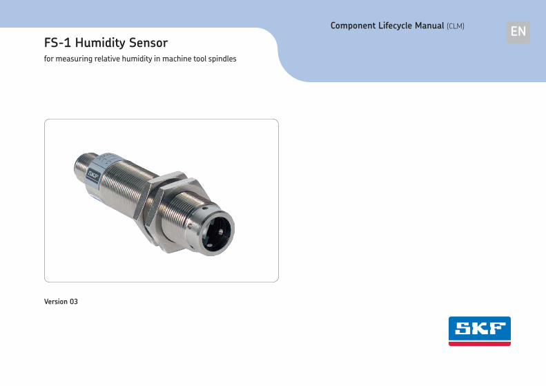
for measuring relative humidity in machine tool spindles
FS-1 Humidity Sensor
Version 03
Component Lifecycle Manual (CLM)
2
Masthead
Masthead
Warranty
The instructions do not contain any infor-
mation on the warranty. This can be found
in the General Conditions of Sales, which
are available at:
www.skf.com/lubrication.
Copyright / Integration of instructions
© SKF Lubrication Systems Germany AG.
All rights reserved.
These instructions are protected by copy-
right.
The use of the contents for the purpose of
integration into the documentation of the
machine manufacturer in whose product it
will be integrated is expressly allowed. This
also includes making copies solely for inter-
nal training purposes.
Any other usage of any kind without writ-
ten permission of the copyright holder is
prohibited and constitutes a breach of
copyright.
Manufacturer and service address
If you have questions, please contact:
SKF Lubrication Systems Germany GmbH
Berlin Plant
Motzener Strasse 35/37
12277 Berlin
Germany
Tel. +49 (0)30 72002-0
Fax +49 (0)30 72002-111
www.skf.com/lubrication
Hockenheim Plant
2. Industriestrasse 4
68766 Hockenheim
Germany
Tel. +49 (0)62 05 27-0
Fax +49 (0)62 05 27-101
www.skf.com/lubrication
EN

3
Table of contents
Masthead 2
Warranty 2
Manufacturer and service address 2
Table of contents 3
Explanation of symbols and signs 4
1. Safety instructions 6
1.1 General safety instructions 6
1.2 General behavior when handling the product 6
1.3 Qualiied technical personnel 7
1.4 Operation 7
1.5 Assembly / maintenance / malfunction / decommissioning / disposal 7
1.6 Intended use 8
1.7 Foreseeable misuse 8
1.8 Disclaimer of liability 8
1.9 Residual risks 8
2. Functional description 9
2.1 Installation in a machine tool spindle 9
3. Technical data 10
3.1 General technical data 10
4. Delivery, returns, and storage 12
4.1 Checking the delivery 12
4.2 Returns 12
4.3 Storage 12
4.4 Note on the rating plate 12
5. Assembly 13
5.1 General information 13
5.2 Assembly of the FS-1 Humidity Sensor 13
6. Operation/coniguration, ecommissioning and disposal 15
6.1 Operation/coniguration 15
6.2 Decommissioning and disposal 15
7. Maintenance 16
7.1 General information 16
8. Malfunctions, causes, and remedies 17
8.1 Commissioning, product, and system malfunctions 17
9. Accessories 18
EN
Table of contents
4
EN
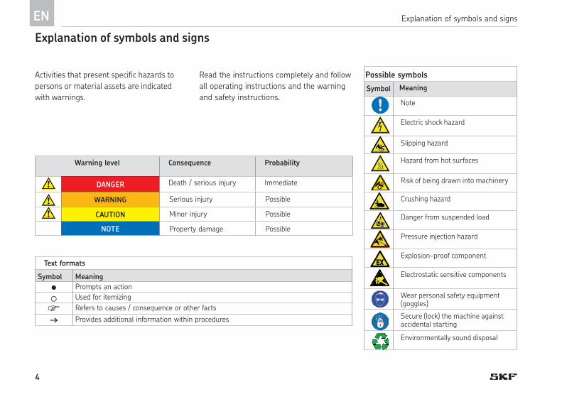
Possible symbols
Meaning
Note
Electric shock hazard
Slipping hazard
Hazard from hot surfaces
Risk of being drawn into machinery
Crushing hazard
Danger from suspended load
Pressure injection hazard
Explosion-proof component
Electrostatic sensitive components
Wear personal safety equipment (goggles)
Secure (lock) the machine against accidental starting
Environmentally sound disposal
Explanation of symbols and signs
Explanation of symbols and signs
Activities that present specific hazards to
persons or material assets are indicated
with warnings.
Read the instructions completely and follow
all operating instructions and the warning
and safety instructions.
Text formats
Symbol Meaning
Prompts an action
Used for itemizing
Refers to causes / consequence or other facts
Provides additional information within procedures
Warning level Consequence Probability
DANGER Death / serious injury Immediate
WARNING Serious injury Possible
CAUTION Minor injury Possible
NOTE Property damage Possible
Symbol
5
ENExplanation of symbols and signs
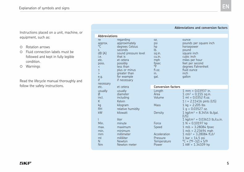
Instructions placed on a unit, machine, or
equipment, such as:
Rotation arrows
Fluid connection labels must be
followed and kept in fully legible
condition.
Warnings
Read the lifecycle manual thoroughly and
follow the safety instructions.
Abbreviations and conversion factors
Abbreviationsre regarding oz. ounceapprox. approximately psi pounds per square inch°C degrees Celsius hp horsepowers seconds lb. pounddB (A) sound pressure level sq.in. square inchi.e. that is cu.in. cubic inchetc. et cetera mph miles per hourposs. possibly fpsec feet per second< less than °F degrees Fahrenheit± plus or minus fl.oz. fluid ounce> greater than in. inche.g. for example gal. gallonif necessary
if necessary
etc. et cetera Conversion factors usually usually Length 1 mm = 0.03937 in.Ø diameter Area 1 cm² = 0.155 sq.in.incl. including Volume 1 ml = 0.0352 fl.oz.K Kelvin 1 l = 2.11416 pints (US)kg kilogram Mass 1 kg = 2.205 lbsRH relative humidity 1 g = 0.03527 oz.kW kilowatt Density 1 kg/cm³ = 8.3454 lb./gal.
(US)l liter 1 kg/cm³ = 0.03613 lb./cu.in.Min. minute Force 1 N = 0.10197 kpmax. maximum Speed 1 m/s = 3.28084 fpsecmin. minimum 1 m/s = 2.23694 mphmm millimeter Acceleration 1 m/s² = 3.28084 ft./s²ml milliliter Pressure 1 bar = 14.5 psiN Newton Temperature °C = (°F-32) x 5/9Nm Newton meter Power 1 kW = 1.34109 hp
6
NOTE
Avoid electrostatic discharge!
The sensor contains electronic com-
ponents that can be destroyed by
electrostatic discharge when
touched. Follow the safety measures
against electrostatic discharge laid
out in DIN EN 61340-1/-3.
ENEN
1. Safety instructions
1.1 General safety instructions
The operator must ensure that the instruc-
tions are read and fully understood by all
persons tasked with working on the product
or who supervise or instruct such persons.
The product described here was manufac-
tured according to the state of the art.
Risks may, however, arise from its usage
and may result in personal injury or damage
to material assets.
Any malfunctions affecting safety must be
remedied immediately.
In addition to the lifecycle manual, all statu-
tory regulations and other regulations for
accident prevention and environmental pro-
tection must be observed.
o The product may only be used in aware-
ness of the potential dangers, in proper
technical condition, and according to the
information in this manual.
o Personnel must familiarize themselves
with the functions and operation of the
product. The specified assembly and op-
erating steps and their sequences must
be observed.
o Any unclear points regarding proper con-
dition or correct assembly/operation must
be clarified. Operation is prohibited until
issues have been clarified.
o Unauthorized persons must be kept away.
o All safety instructions and in-house in-
structions relevant to the particular activ-
ity must be observed.
o Protective and safety mechanisms cannot
be removed, modified, nor disabled
1.2 General behavior when handling the product
during operation and must be checked
for proper function and completeness at
regular intervals.
If protective and safety mechanisms must
be removed, they must be reinstalled im-
mediately following conclusion of work
and checked for proper function.
o Observe the relevant safety data sheets
when handling lubricants/equipment.
1. Safety instructions

7
1
ENEN
1.3 Qualified technical personnel
Only qualified technical personnel may
install, operate, and maintain the products
described here.
Such persons are familiar with the relevant
standards, rules, accident prevention regu-
lations, and assembly conditions as a result
of their training, experience, and instruction.
They are qualified to carry out the required
activities and in doing so recognize and
avoid any potential hazards. The definition
of qualified personnel and the prohibition
against employing non-qualified person-
nel are laid down in DIN VDE 0105 and IEC
364. Relevant country-specific definitions of
qualified technical personnel apply for coun-
tries outside the scope of DIN VDE 0105 or
IEC 364.
The operator is responsible for assigning
tasks and the area of responsibility.
The personnel must be trained and in-
structed prior to beginning work if they do
not possess the requisite knowledge.
1.4 Operation
The following must be observed while work-
ing on the product.
o All information within this manual and
the information within the referenced
documents.
o All laws and regulations that the operator
must observe.
o All relevant persons (e.g., operating per-
sonnel, supervisors) must be informed of
the activity prior to beginning work. Pre-
cautionary operational measures / work
instructions must be observed.
o Take appropriate measures to ensure
that moving/detached parts are im-
mobilized during the work and that no
body parts can be pinched by unintended
movements.
1.5 Assembly / maintenance /
malfunction / decommissioning / disposal
o Assemble the product only outside the
operating range of moving parts, at an
adequate distance from sources of heat
or cold.
o Prior to performing work, the product
and the machine/system in which the
product will be integrated must be de-
pressurized and secured against unau-
thorized activation.
o All work on electrical components may be
performed only with voltage-insulated
tools.
o Fuses must not be bridged. Always re-
place fuses with fuses of the same type.
o Drill holes required for assembly only on
non-critical, non-load-bearing parts.
o Other units of the machine/the vehicle
must not be damaged or impaired in their
function by the installation.
1. Safety instructions

8
ENEN
1.6 Intended use
1. Safety instructions
1.9 Residual risks
Residual risk life cycle: Remedy
AssemblyCommissioning / operationSetup, retrofitMalfunction, troubleshooting, maintenance, repairShutdown, disposal
Contamination by foreign substances
Destruction by electrostatic discharge
• Remove any foreign substances and establish a contamination-free environment.
• Avoid electrostatic charge• Avoid fast discharge
1.7 Foreseeable misuse
Any usage of the FS-1 differing from the
aforementioned conditions and stated pur-
pose is strictly prohibited. Particularly pro-
hibited are use:
o In a critical explosion protection zone.
o To monitor Group 1 dangerous fluids ac-
cording to Directive 67/548/EEC.
o To monitor gases, liquefied gases, dis-
solved gases, vapors, or fluids whose va-
por pressure exceeds normal atmospheric
pressure (1013 mbar) by more than 0.5
bar at their maximum permissible operat-
ing temperature.
1.8 Disclaimer of liability
The manufacturer shall not be held liable for
damage resulting from:
o Failure to comply with these instructions.
o The use of lubricants/media not approved
for the unit type.
o Contaminated or unsuitable lubricants.
o Nappropriate usage.
o Improper assembly, configuration, or
filling.
o Improper response to malfunctions.
The FS-1 Humidity Sensor can detect the
relative humidity and transmit the reading
to the customer's control unit as an electri-
cal signal (4-20 mA).
Any other or additional usage of the FS-1
Humidity Sensor is deemed non-compliant
with the intended use.
9
222.1 Installation in a machine tool spindle
System description, Fig. 1
1
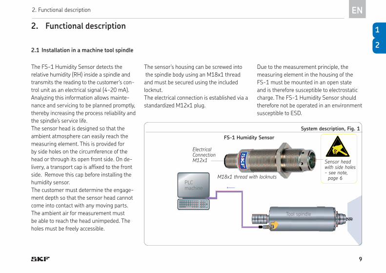
Sensor head with side holes- see note, page 6
EN2. Functional description
2. Functional description
The FS-1 Humidity Sensor detects the
relative humidity (RH) inside a spindle and
transmits the reading to the customer's con-
trol unit as an electrical signal (4-20 mA).
Analyzing this information allows mainte-
nance and servicing to be planned promptly,
thereby increasing the process reliability and
the spindle’s service life.
The sensor head is designed so that the
ambient atmosphere can easily reach the
measuring element. This is provided for
by side holes on the circumference of the
head or through its open front side. On de-
livery, a transport cap is affixed to the front
side. Remove this cap before installing the
humidity sensor.
The customer must determine the engage-
ment depth so that the sensor head cannot
come into contact with any moving parts.
The ambient air for measurement must
be able to reach the head unimpeded. The
holes must be freely accessible.
The sensor's housing can be screwed into
the spindle body using an M18x1 thread
and must be secured using the included
locknut.
The electrical connection is established via a
standardized M12x1 plug.
Due to the measurement principle, the
measuring element in the housing of the
FS-1 must be mounted in an open state
and is therefore susceptible to electrostatic
charge. The FS-1 Humidity Sensor should
therefore not be operated in an environment
susceptible to ESD.
FS-1 Humidity Sensor
M18x1 thread with locknuts
Electrical Connection M12x1
Tool spindle
PLCmachine
10
3. Technical data
3.1 General technical data
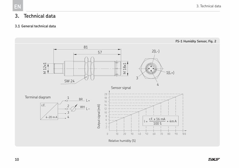
FS-1 Humidity Sensor, Fig. 2
81
SW 24
57 2(L-)
1(L+)
3
M 1
8x1
M 1
2x1
4
BR
WH
r.F. x 16 mA
100 %+ 4m Al =
4-20 m A
r.F.
1
2
3
4
Relative humidity (%)
Outp
ut si
gnal
(mA
)Terminal diagram
Sensor signal
EN 3. Technical data
11
3
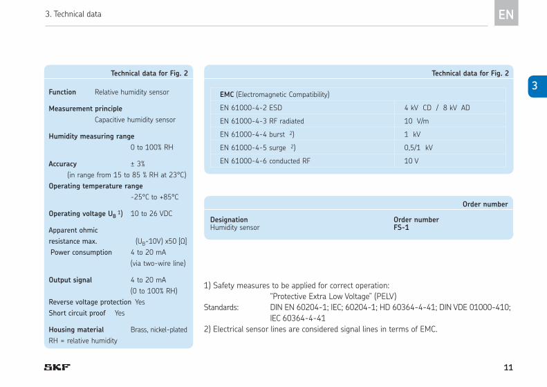
Technical data for Fig. 2
Function Relative humidity sensor
Measurement principle
Capacitive humidity sensor
Humidity measuring range
0 to 100% RH
Accuracy ± 3%
(in range from 15 to 85 % RH at 23°C)
Operating temperature range
-25°C to +85°C
Operating voltage UB 1) 10 to 26 VDC
Apparent ohmic
resistance max. (UB-10V) x50 [Ω]
Power consumption 4 to 20 mA
(via two-wire line)
Output signal 4 to 20 mA
(0 to 100% RH)
Reverse voltage protection Yes
Short circuit proof Yes
Housing material Brass, nickel-plated
RH = relative humidity
Order number
Designation Order numberHumidity sensor FS-1
Technical data for Fig. 2
EMC (Electromagnetic Compatibility)
EN 61000-4-2 ESD 4 kV CD / 8 kV AD
EN 61000-4-3 RF radiated 10 V/m
EN 61000-4-4 burst 2) 1 kV
EN 61000-4-5 surge 2) 0,5/1 kV
EN 61000-4-6 conducted RF 10 V
1) Safety measures to be applied for correct operation:
“Protective Extra Low Voltage” (PELV)
Standards: DIN EN 60204-1; IEC; 60204-1; HD 60364-4-41; DIN VDE 01000-410;
IEC 60364-4-41
2) Electrical sensor lines are considered signal lines in terms of EMC.
EN3. Technical data
12
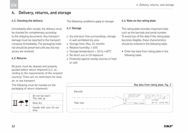
4.4 Note on the rating plate
The rating plate provides important data
such as the barcode and serial number.
To avoid loss of this data if the rating plate
becomes illegible, these characteristics
should be entered in the following table.
• Enter key data from rating plate in the
following table.
Key data from rating plate, Fig. 3
Barcode
Plain text UB = 10 ... 26 VDC, PELV
4. Delivery, returns, and storage
Immediately after receipt, the delivery must
be checked for completeness according
to the shipping documents. Any transport
damage must be reported to the transport
company immediately. The packaging mate-
rial should be preserved until any discrep-
ancies are resolved.
The following conditions apply to storage:
4.3 Storage
o dry and dust-free surroundings, storage
in well ventilated dry area
o Storage time: Max. 24 months
o Relative humidity: < 65%
o Storage temperature: + 10 to +40°C
o No direct sun or UV exposure
o Protected against nearby sources or heat
or cold
4.1 Checking the delivery
4.2 Returns
Do not top load / This side up
Keep dry
Handle with care, Do not drop
All parts must be cleaned and properly packed before return shipment (i.e., ac-cording to the requirements of the recipient
country). There are no restrictions for land,
air, or sea transport.
The following must be marked on the packaging of return shipments:
EN 4. Delivery, returns, and storage
13
5
NOTE
Persistent contamination with foreign sub-
stances can distort the measuring results.
Appropriate measures must therefore be
taken to prevent contamination.
4
EN5. Assembly
5. Assembly
5.1 General information
The sensor head is designed so that the am-
bient atmosphere can reach the measuring
element through side holes on the head's
circumference or through the open front
side. By default, a transport cap protecting
against mechanical damage is affixed on the
front side. It must be removed for measure-
ment operation.
The FS-1 Humidity Sensor comes standard
with two locknuts.
Depending on the type of installation, one of
the two locknuts can be eliminated.
The humidity sensor does not require
calibration.
5.2 Assembly of the FS-1 Humidity Sensor
• Remove the transport cap (1).
• If necessary, remove a locknut (2) from
the FS-1 Humidity Sensor (3).
• Carefully screw the FS-1 Humidity Sen-
sor into the M18 threaded hole (provided
by customer).
The engagement depth of the humid-
ity sensor depends on the customer's
installation and must be determined
prior to beginning assembly.
The sensor must not be touch moving
parts.
The ambient atmosphere for measure-
ment must be able to reach the sensing
head unimpeded. Its holes must be
open to ambient air.
• Align the FS-1 Humidity Sensor according
to the determined thread dimension.
• Depending on the customer's installation,
seal the FS-1 Humidity Sensor to the
housing.
• Secure the humidity sensor using a
locknut.
• Connect the electrical power lead on the
M12x1 plug of the humidity sensor.
• Ensure the power lead is laid in a stress-
free position.
14
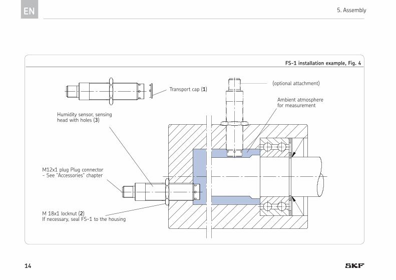
M12x1 plug Plug connector- See "Accessories" chapter
FS-1 installation example, Fig. 4
Ambient atmosphere for measurement
Humidity sensor, sensing head with holes (3)
(optional attachment) Transport cap (1)
M 18x1 locknut (2) If necessary, seal FS-1 to the housing
EN 5. Assembly

15
6
6.2 Decommissioning and disposal
If the product is to be shut down perma-
nently, observe the legal requirements for
disposal.
The product can also be returned to SKF
Lubrication Systems Germany AG for dis-
posal, in which case the customer is respon-
sible for reimbursing the costs incurred.
The parts are recyclable.
5
EN
6.1 Operation/configuration
Electrical configuration on the humidity
sensor is not provided for.
6. Operation/configuration, ecommissioning and disposal
6. Operation/configuration, ecommissioning and disposal
16
EN 7. Maintenance
7. Maintenance
7.1 General information
SKF products are low-maintenance. All con-
nections and fittings must be regularly in-
spected for proper seating to ensure proper
function. If necessary, the product can be
cleaned using mild cleaning agents that
are compatible with the product's materials
(non-alkaline, non-soap).

17
8
7
8.1 Commissioning, product, and system malfunctions
Malfunction Cause Remedy
No output signal on
customer's PLC
o Plug on the humidity sensor is not connected • Connect the plug
o Power lead is not wired correctly
o Power lead is defective
o Humidity sensor is not installed correctly
• Connect cables according to Chapter 3, "Technical data."
• Replace cables
• Arrange the FS-1 Humidity Sensor so as to provide ad-
equate clearance around the sensor head.
o Customer's PLC is not configured for the output
signal of 4 to 20 mA.
• Configure customer's PLC for the output signal.
8. Malfunctions, causes, and remedies
The following tables provide an overview of
possible malfunctions and their causes.
7
EN8. Malfunctions, causes, and remedies

18
9. Accessories
Accessories
Description Data Order No.
M12x1 socket without cable, with 4 pins, protection class IP 67 (mounted) 179-990-371
M12x1 angle plug without cable, with 4 pins, protection class IP 67 (mounted) 179-990-372
M12x1 plug, straight With 5 m cable, 4x 0,25 mm2, protection class IP 68 (mounted) 179-990-600
M12x1 angle plug With 5 m cable, 4x 0,25 mm2, protection class IP 68 (mounted) 179-990-601
NOTE
Additional data and electrical plug-in con-
nections are available in brochure No.
1-1730-EN, "Electric Plug-and-Socket
Connectors."
EN 9. Accessories

19
9
EN9. Accessories
skf.com
Bearings and units
SealsLubrication
systems
Mechatronics Services
SKF Lubrication Systems Germany GmbH
2. Industriestrasse 4 · 68766 Hockenheim · Germany
Tel. +49 (0)62 05 27-0
Fax +49 (0)62 05 27-101
www.skf.com/lubrication
SKF Lubrication Systems Germany GmbH
Motzener Strasse 35/37 · 12277 Berlin · Germany
PO Box 970444 · 12704 Berlin · Germany
Tel. +49 (0)30 72002-0
Fax +49 (0)30 72002-111
www.skf.com/lubrication
September 2016
951-230-011-EN
The contents of this publication are the copyright of the publisher and may not be reproduced (even ex-
tracts) without permission of SKF. Every care has been taken to ensure the accuracy of the information
contained in this publication. However, no liability can be accepted for any loss or damage, whether direct,
indirect, or consequential, arising out of use of the information contained herein.
All SKF products may be used only for their intended purpose as described in these assembly instructions
with associated operating instructions. If assembly/operating instructions are supplied together with the
products, they must be read and followed. Not all lubricants can be fed using centralized lubrication sys-
tems. SKF can, on request, inspect the suitability of the lubricant selected by the user for pumping in cen-
tralized lubrication systems. Lubrication systems and their components manufactured by SKF are not ap-
proved for use in conjunction with gases, liquefied gases, pressurized gases in solution, vapors or such
fluids whose vapor pressure exceeds normal atmospheric pressure (1013 mbar) by more than 0.5 bar at
their maximum permissible temperature.
Particular attention is called to the fact that hazardous materials of any kind, especially the materials classi-
fied as hazardous by EC Directive 67/548/EEC, Article 2, Para. 2, may only be filled into SKF centralized lu-
brication systems and components and delivered and/or distributed with the same after consultation with
and written approval from SKF.