P 215 - SKF
45
Installation Instructions Pump P 215 810-55177-1 Page 1 / 45 Rev. 013 2021/02/03 P 215
-
Upload
khangminh22 -
Category
Documents
-
view
2 -
download
0
Transcript of P 215 - SKF

Installation Instructions
Pump P 215
810-55177-1 Page 1 / 45
Rev. 013 2021/02/03
P 215

Installation Instructions
Pump P 215
810-55177-1 Page 2 / 45
Rev. 013 2021/02/03
Declaration of Incorporation (Following Machinery Directive 2006/42/EC, Appendix II, Part 1 B)
The Manufacturer SKF Lubrication Systems Germany GmbH, Heinrich-Hertz-Str. 2-8, 69190 Walldorf, Germany
hereby declares that the partly completed machinery
Designation: Multi-line pump for supplying lubricants within a centralized lubrication system
Type: P 215
Part numbers 660- XXXXX-X
Year of construction See type identification plate
Complies with the basic safety and health requirements stated in the following and laid down in the Machinery Directive 2006/42/EC when first being launched in the market.
1.1.2 ○ 1.1.3 ○ 1.3.2 ○ 1.3.4 ○ 1.3.7 ○ 1.5.8 ○ 1.5.9 ○ 1.7.1 ○ 1.7.3○ 1.7.4
The special technical documents following Machinery Directive 2006/42/EC Appendix VII Part B were prepared. We undertake to send this in electronic form to the respective national authorities upon justifiable request. Authorized representative of the technical documentation is the head of standardization. For address, see Manufacturer. Furthermore the following harmonized and other standards were applied in the respective areas:
Directive: 2014/30/EU EMC Directive 2011/65/EU RoHS Directive
Harmonized and other standards:
DIN EN ISO 12100:2011 DIN EN 61000-2 DIN EN 50581:2013
DIN EN 809-1:2011 DIN EN 60204-1
DIN 40050-9:1993-5 DIN EN 55011
The partly completed machine must not be put into service until the final machinery into which it is to be incorporated has been declared in conformity with the provisions of the EC Machinery Directive 2006/42/EC and all other directives to be applied.
Walldorf 2014/04/30
Jürgen Kreutzkämper
Manager R&D Germany SKF Lubrication Business Unit

Installation Instructions
Pump P 215
810-55177-1 Page 3 / 45
Rev. 013 2021/02/03
Declaration of Incorporation
Contents 1. Guidelines .......................................................................................................... 6
1.1 Warnings ....................................................................................................... 6
1.2 Illustrations .................................................................................................... 6
1.3 Copyright ....................................................................................................... 6
1.4 Abbreviations ................................................................................................. 7
1.5 Manufacturer and Service addresses ............................................................ 7
1.6 Warranty ........................................................................................................ 7
1.7 Disclaimer ...................................................................................................... 7 2. Safety information ............................................................................................. 8
2.1. Emergency stopping of pump ........................................................................ 8
2.2. Intended use .................................................................................................. 8
2.3. Pump operation ............................................................................................. 8
2.4. Foreseeable misuse ...................................................................................... 8
2.5. Prohibition of certain activities ....................................................................... 8
2.6. Conversions / modifications ........................................................................... 9
2.7. Inspections .................................................................................................... 9
2.8. Warning label on the pump ............................................................................ 9
2.9. Other applicable documents .......................................................................... 9
2.10. Sources of hazard ...................................................................................... 9
2.11. Moving, rotating parts ................................................................................. 9
2.12. Energies ................................................................................................... 10
2.13. Lubricants ................................................................................................. 10
2.14. Existing residual risks ............................................................................... 10
2.15. Persons authorized to operate the pump ................................................. 12
2.16. Protection of special groups of persons ................................................... 12
2.17. Safety recommendations to be complied with .......................................... 12
2.18. General behaviour when handling the machine ....................................... 12
2.19. Transport / installation / maintenance / repairs / servicing ........................ 13
2.20. Initial commissioning / daily start-up ......................................................... 14
2.21. Cleaning ................................................................................................... 15
2.22. Operator’s obligations .............................................................................. 15
2.23. Determination of hazards ......................................................................... 15
2.24. Provision of necessary information .......................................................... 15
2.25. Inspection for correct use ......................................................................... 15

Installation Instructions
Pump P 215
810-55177-1 Page 4 / 45
Rev. 013 2021/02/03
2.26. Briefing of external technicians ................................................................ 16
2.27. Provision of personal protective equipment .............................................. 16
2.28. Training courses ....................................................................................... 16
2.29. Inspection of the delivery .......................................................................... 16
2.30. Returns ..................................................................................................... 16
2.31. Disposal ................................................................................................... 16 3. Lubricant .......................................................................................................... 17
3.1. Selection of lubricants ................................................................................. 17
3.2. Specification .............................................................................................. 17
3.3. Ageing of lubricants .................................................................................. 18 4. Technical Data ................................................................................................. 19
4.1. Operating temperature ................................................................................ 19
4.2. Operating pressure ...................................................................................... 19
4.3. Installation position ...................................................................................... 19
4.4. Sound pressure level ................................................................................... 19
4.5. Weight ......................................................................................................... 19
4.6. Electrical connection .................................................................................... 19
4.7. IP protection classes ................................................................................... 19
4.8. Reservoir variants ........................................................................................ 20
4.9. Low-level signal / High-level signal .............................................................. 20
4.10. Tightening torques.................................................................................... 20
4.11. Flow rate .................................................................................................. 20
4.12. Connections / outlets ................................................................................ 21
4.13. Filling possibilities..................................................................................... 21
4.14. Rotational direction of the pump ............................................................... 21
4.15. Permitted speeds ..................................................................................... 21
4.16. Storage until first use ................................................................................ 21 5. Technical data of the ultrasonic sensor ........................................................ 22 6. Technical data of motors ................................................................................ 24 7. Brief description of the pump ........................................................................ 25

Installation Instructions
Pump P 215
810-55177-1 Page 5 / 45
Rev. 013 2021/02/03
8. Installation and commissioning ..................................................................... 26
8.1. Important note on the installation of the pump elements ............................. 26
8.2. Assembly of the pump elements (grease) ................................................... 27
8.3. Assembly of the pump elements (oil) ........................................................... 28
8.4. Adjustment of the pump elements ............................................................... 29
8.5. Filling the reservoir ...................................................................................... 30
8.6. Inadvertent filling with incorrect lubricant ..................................................... 31
8.7. Inspections prior to initial commissioning .................................................... 31
8.8. Activation of the pump ................................................................................. 32 9. Standard operation .......................................................................................... 33
9.1. Daily start-up ............................................................................................... 33
9.2. Inspections .................................................................................................. 33
9.3. Filling the reservoir during operation ........................................................... 33
9.4. Cleaning ...................................................................................................... 33 10. Maintenance ..................................................................................................... 34
10.1. Pump maintenance .................................................................................. 34 11. Troubleshooting .............................................................................................. 34 12. Spare parts ....................................................................................................... 35
12.1. Pump P 215 ............................................................................................. 35
12.2. Free shaft end .......................................................................................... 37
12.3. Oscillating drive ........................................................................................ 38
12.4. Double gear M 490:1 ................................................................................ 39 13. Dimensional drawings .................................................................................... 40 14. Type identification code ................................................................................. 44

Installation Instructions
Pump P 215
810-55177-1 Page 6 / 45
Rev. 013 2021/02/03
1. Guidelines As you read these instructions, you will notice a number of depictions and symbols which are to facilitate the navigation and understanding of these instructions. For reasons of better legibility, in these instructions we mainly use the male form for general references. Of course, the female form is also always intended. In the following the different meanings are explained.
1.1 Warnings Activities which generate actual hazards (to life and limb or possible damage of the machine) are marked by warnings. Definitely observe the instructions given in the warnings. The following warnings are possible:
Warning stage Effect Probability
DANGER Death / severe injury imminent
WARNING Serious injury possible
CAUTION Minor injury possible
ATTENTION Damage to property possible
1.2 Illustrations The illustrations used refer to a specific product. In the case of other products they may have a schematic character only. The basic functions, however, do not change.
1.3 Copyright © SKF. These instructions are protected by copyright. All rights reserved.
Text representations
Meaning
Bold print Highlighting of particularly important words / passages
• List 1 Marks lists o List 2 Marks lists
(parenthesis) Item numbers ➢ Instructions Instructions to personnel. These always
appear in chronological order.

Installation Instructions
Pump P 215
810-55177-1 Page 7 / 45
Rev. 013 2021/02/03
1.4 Abbreviations The following abbreviations may be used within these instructions.
max. maximum min. minimum min. minutes s. seconds e.g. for example ml millilitres ccm cubic cm mm millimetres °C degree Celsius °F degree Fahrenheit K Kelvin inch inch etc. et cetera kg kilogramme l litre mbar millibar no. number
Nm Newton metre incl. including i.e. this means approx. approximately Ø diametre ® registered trademark © copyright TM trademark % per cent dB (A) sound pressure level > greater than < less than ± plus minus AF across flat ESD electrostatic discharge N/A not applicable
1.5 Manufacturer and Service addresses Manufacturer Customer Service SKF Lubrication Systems Germany GmbH Heinrich-Hertz-Str. 2-8 D - 69190 Walldorf
SKF Lubrication Systems Germany GmbH Central Customer Service Dept. P.O. Box 1263 D - 69183 Walldorf
1.6 Warranty The instructions make no statement regarding warranty. To learn more about our warranty, see our General Terms and Conditions.
1.7 Disclaimer Observation of these instructions is the prerequisite for safe operation and the achievement of product characteristics and performance levels. The manufacturer shall bear no liability for damages - of any kind - resulting from the non-observance of these instructions.

Installation Instructions
Pump P 215
810-55177-1 Page 8 / 45
Rev. 013 2021/02/03
2. Safety information Safety information is to be read and observed by any persons entrusted with works on the machine or by those persons who supervise or instruct the before-mentioned group of persons. It is prohibited to commission or operate the machine prior to reading the Instructions. These Instructions must be kept at an accessible location for further use.
2.1. Emergency stopping of pump In case of an emergency, the pump can be shut down by: Switching off the machine or vehicle in which the pump is integrated.
2.2. Intended use Supply of lubricants within a centralized lubrication system following the specifications made in these instructions.
2.3. Pump operation Operation is permitted only, if in compliance with:
• All indications given in these instructions or stated in the applicable documents.
• Laws and regulations to be complied with by the user.
2.4. Foreseeable misuse Any other use and purpose of the machine than the ones described before are strictly prohibited. The use is expressly forbidden:
• In any explosion protection zone. • Outside the indicated operating temperature range. • For the supply / transport / stockpiling of hazard group I fluids following
Directive 67/548/EC. • For the supply / transport / stockpiling of gases, liquefied gases, dissolved
gases, vapours and fluids that reach a steam pressure of more than 0.5 bar above the normal atmospheric pressure (1013 mbar) at the maximum admissible operating temperature.
2.5. Prohibition of certain activities The following activities may be carried out by manufacturer specialists or authorized persons only due to potential sources of faults that may not be visible for the user:
• Replacement or changes to the pistons of the pump elements.
Installation Instructions
Pump P 215
810-55177-1 Page 9 / 45
Rev. 013 2021/02/03
2.6. Conversions / modifications Unauthorized conversions or modifications may result in unforeseeable impacts on safety. Therefore, any unauthorized reconstructions or changes are expressly prohibited.
2.7. Inspections The following inspections were carried out prior to delivery:
• Electrical inspections following EN 60204-1. • Safety and functional tests.
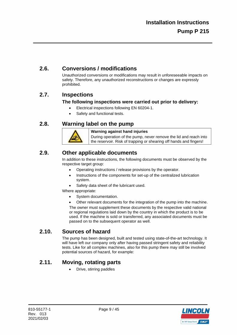
2.8. Warning label on the pump
Warning against hand injuries During operation of the pump, never remove the lid and reach into the reservoir. Risk of trapping or shearing off hands and fingers!
2.9. Other applicable documents In addition to these instructions, the following documents must be observed by the respective target group:
• Operating instructions / release provisions by the operator. • Instructions of the components for set-up of the centralized lubrication
system. • Safety data sheet of the lubricant used.
Where appropriate: • System documentation. • Other relevant documents for the integration of the pump into the machine. The owner must supplement these documents by the respective valid national or regional regulations laid down by the country in which the product is to be used. If the machine is sold or transferred, any associated documents must be passed on to the subsequent operator as well.
2.10. Sources of hazard The pump has been designed, built and tested using state-of-the-art technology. It will have left our company only after having passed stringent safety and reliability tests. Like for all complex machines, also for this pump there may still be involved potential sources of hazard, for example:
2.11. Moving, rotating parts • Drive, stirring paddles

Installation Instructions
Pump P 215
810-55177-1 Page 10 / 45
Rev. 013 2021/02/03
2.12. Energies • Electricity • Temperature (hot/cold surfaces) • Position energy (raised components) • Parts subject to (operating) pressure • Parts subject to spring tension
2.13. Lubricants • Greases • Oils
2.14. Existing residual risks
Residual risk Remedy
Transport lifecycle Tilting / falling of parts during transport, e.g. over inclines.
Secure parts against tilting / falling during transport (e.g. using tapes, belts, ropes etc.).
Installation lifecycle
Dropping of lifted parts/ tools. No people may remain under suspended loads. Keep unauthorized people away. Secure suspended loads using suitable hoisting equipment (e.g. tapes, belts, ropes etc.).
Falling of parts due to insufficient fixing to the machine.
Fix parts only to machine parts with a sufficient load capacity. Observe the weight. Observe the stated tightening torques. If no tightening torques are stated, the tightening torques are to be applied according to the screw size for 8.8 screws.
Electric shock when connecting the pump. Prior to connection of the pump, de-energize all affected electrical components. If necessary, please observe discharge times. The electrical connection may be carried out by commissioned and qualified electricians only and in accordance with the connection diagram.

Installation Instructions
Pump P 215
810-55177-1 Page 11 / 45
Rev. 013 2021/02/03
Residual risk Remedy
Installation lifecycle People falling due to contamination of floors with spilled lubricant.
Take care when filling. Bind / remove spilled lubricant immediately with a suitable agent. Observe the legal / company regulations on dealing with oils / greases and contaminated parts.
Ripping out / damage to lines when assembling movable machine parts (e.g. pivot arm).
If possible, do not mount onto movable parts. Should this not be possible, use flexible hose lines of sufficient lengths.
Deviating installation position: - Foreign objects falling into the motor
air intake.
- Borehole for drainage of condensation water is no longer at the lowest point of the motor.
Installation of a suitable protective roof over the air intake. Deviating installation position only if the formation of condensation water has been completed.
Commissioning / operation / maintenance lifecycle Lubricant spraying out due to incorrect screw connection of components / connection of lines.
Tighten all parts with appropriate tightening torques. Use suitable hydraulic screw connections and lines for the stated pressures. Check these prior to commissioning for correct connection and damage.
Contact with the stirring paddles when filling from the top during operation of the pump.
Fill preferably via the filling connection. Fill only from the top when the pump is not moving. When filling, do not reach into the reservoir.
Residual risk Remedy
Commissioning / operation / maintenance lifecycle Electric shock through reduced insulation resistance.
Check the formation of condensation water in the motor regularly. If applicable, drain off condensation water at the drain plug. Check the insulation resistance regularly.
Electric shock when connecting the pump. Prior to connection of the pump, de-energize all affected electrical components. If necessary, please observe discharge times. The electrical connection may only be carried out by commissioned and qualified electricians in accordance with the connection diagram.
Fault lifecycle Severe heat-up / defect on motor through blockage.
Switch off the pump. Allow the parts to cool down and remove the cause of the fault.
Disposal lifecycle Environmental contamination with lubricants and moistened parts.
Dispose of the parts in accordance with the valid legal / company regulations.

Installation Instructions
Pump P 215
810-55177-1 Page 12 / 45
Rev. 013 2021/02/03
2.15. Persons authorized to operate the pump Operator A person who is qualified by training and experience to carry out the functions and activities related to normal operation, including the avoidance of possible hazards that may arise during machine operation. Person qualified for maintenance and repair works A professionally trained and experienced person that is capable of recognizing risks and possible hazards when carrying out installation, maintenance, or repair works on the pump, and eliminating these by initiating adequate measures.
2.16. Protection of special groups of persons The respective legal employment restrictions do apply.
2.17. Safety recommendations to be complied with
2.18. General behaviour when handling the machine • Only operate the machine if it is in perfect technical condition, according to
its intended use, in awareness of safety and risks and in adherence to these Instructions.
• Familiarize yourself with the functions and working methods required. Always keep to the order of the indicated assembly and operating steps.
• If there are uncertainties regarding the proper condition or the correct assembly / operation, ensure clarification. The machine / pump must not be put into service until all uncertainties will have been clarified.
• Keep unauthorized people away from the machine. • All relevant safety provisions and in-house operational instructions
applicable to the respective activity must be adhered to. • Responsibilities for different activities must be clearly defined and adhered
to. Ambiguities greatly endanger safety. • During operation, safety-related protective and emergency devices must
not be removed, modified or affected otherwise in their function and are to be checked at regular intervals for completeness and function.
• Occurring faults are to be remedied in the frame of the responsibilities. Inform your superior in the case of faults beyond your competence.
• Do not open the reservoir lid during operation. Do not reach into the reservoir.
• Wear personal protective equipment always. • When handling lubricants etc., adhere to the respective safety data sheets. • Never use parts of the centralized lubrication system or of the machine as
standing or climbing aids.

Installation Instructions
Pump P 215
810-55177-1 Page 13 / 45
Rev. 013 2021/02/03
2.19. Transport / installation / maintenance / repairs / servicing
• All relevant persons (e. g. operating personnel, superiors) must be informed prior to carrying out any maintenance or repair works. Observe the company precautionary measures and work instructions.
• If protective and safety equipment has to be dismantled, it must be reassembled immediately after finishing the work, and then checked for correct function.
• Ensure through suitable measures that movable / loosened parts are blocked during the work and that no limbs can be trapped through inadvertent movements.
• Only carry out transport using suitable hoisting equipment. • If the motor is transported separately (e.g. repairs), this should be lifted by
the transport lugs / eyebolts. Check that the transport lugs / eyebolts are fixed tightly prior to lifting. Do not lift any other loads on the transport lugs / eyebolts. Motors may not be transported on the ventilator cover.
• All the parts to be mounted onto the shaft end of the motor are to be dynamically balanced according to the balancing system. With a direct coupling, please ensure that the parts align precisely (observe the manufacturer's guidelines).
• Assemble the pump only outside the working area of moving parts with sufficiently large distance to sources of heat or cold.
• Dry wet, slippery surfaces. • Cover hot or cold surfaces accordingly. • Prior to carrying out the work, de-energize and depressurize the pump and
secure it against unauthorized switch-on. Work on electrical components must be carried out by electrical specialists only. Observe any waiting periods for discharging if necessary.
• Carry out electrical connections only according to the information in the valid wiring diagram and taking the relevant regulations and the local connection conditions into account.
• Do not touch cables or electrical components with wet or damp hands. • Maintenance and repair work can be subject to restrictions in low or high
temperatures (e.g. changed flow properties of the lubricant). Therefore try to carry out maintenance and repair work at room temperature if possible.
• Carry out all work on electrical components only using voltage insulated tools.
• Fuses must not be bypassed. Always replace fuses by such of the same type.
• Ensure correct earthing of the electrical system.

Installation Instructions
Pump P 215
810-55177-1 Page 14 / 45
Rev. 013 2021/02/03
• Only undertake drilling at non-critical, non-supporting parts. Use any available boreholes. Do not damage lines and cables when drilling.
• Observe possible abrasion points. Protect the parts accordingly.
• Other aggregates of the machine / vehicle must not be adversely affected or damaged in function by the installation of the central lubrication system.
• All components used must be designed for:
o maximum operating pressure
o maximum / minimum ambient temperature
o lubricant to be conveyed
o operating / ambient conditions at the location of use
• Parts of the centralized lubrication system must never be subjected to torsion, shearing or bending.
• Check all parts prior to use for contamination and clean if necessary. Lubricant lines should be filled with lubricant prior to installation to make the subsequent ventilation of the system easier.
• Maintain the specified tightening torques. When tightening, use a calibrated torque wrench.
• When working with heavy parts, use suitable lifting tools. • Avoid confusion / incorrect installation of dismantled parts. Mark these
parts accordingly.
2.20. Initial commissioning / daily start-up Ensure that:
• All safety devices are completely available and functional. • All connections are correctly connected. • All parts are correctly installed. • All warning labels on the machine are completely available, highly visible
and undamaged. • Unreadable or missing warning labels must be replaced without delay.

Installation Instructions
Pump P 215
810-55177-1 Page 15 / 45
Rev. 013 2021/02/03
2.21. Cleaning • Risk of fire and explosion when using inflammable cleaning agents. Only
use non-flammable cleaning agents suitable for the purpose. • Do not use aggressive cleaning agents. • Do not use steam jet or high pressure cleaners. Electrical components may
be damaged. Observe the IP protection class. • Cleaning work on energized components may be carried out by specialists
only. • Do not touch cables or electrical components with wet or damp hands. • Mark damp areas accordingly.
Operator’s obligations
2.22. Determination of hazards The operator must determine all hazards resulting from the integration of the pump into the superordinate machine and the hazards at the location of operation of the machine, and carry out the measures necessary to ensure safety and health protection.
2.23. Provision of necessary information The operator must make the instructions required for the respective activity accessible to all people commissioned with operation, maintenance and repairs. He must ensure that these people have read the necessary instructions and have understood them. The same applies for all relevant safety data sheets, company instructions, accident prevention regulations, instructions for purchased parts and lubricant suppliers. Depending on the business organization, the relevant instructions may have to be made accessible to other people / departments.
2.24. Inspection for correct use The operator must check at regular intervals through suitable measures that the machine is being used according to its intended purpose, that no conversions or manipulations have been made to the machine and that all parts are fully functional.

Installation Instructions
Pump P 215
810-55177-1 Page 16 / 45
Rev. 013 2021/02/03
2.25. Briefing of external technicians Prior to commencing the activities, external technicians must be informed by the operator of the company safety provisions, the applicable accident prevention regulations to be maintained, and the functions of the superordinate machine and its protective devices.
2.26. Provision of personal protective equipment The operator must provide suitable personal protective equipment for the respective location of operation and the purpose of operation.
2.27. Training courses In order to provide a maximum of safety and economic viability, SKF carries out detailed training courses. It is recommended that the training courses are attended. Please contact SKF Customer Services for information.
2.28. Inspection of the delivery The delivery must be inspected for completeness based on the delivery papers. Transport damages must be reported to the forwarder immediately. The packaging material should be stored until any inconsistencies have been clarified.
2.29. Returns All parts must be cleaned and correctly packed prior to being returned. Returned goods are to be marked as follows on the packaging:
Do not apply any load / This side up
Protect against moisture
Handle with care! Fragile, do not throw!
2.30. Disposal At the end of its service lifetime, the pump must be dismantled correctly and disposed of according to the respective valid provisions. It is forbidden to use parts of a pump which is to be disposed of or to assemble these parts to make a new pump.

Installation Instructions
Pump P 215
810-55177-1 Page 17 / 45
Rev. 013 2021/02/03
3. Lubricant Lubricants are used specifically for certain application purposes. In order to fulfil their tasks, lubricants must fulfil various requirements to varying extents: The most important requirements for lubricants are:
• Reduction of abrasion and wear • Corrosion protection • Noise minimisation • Protection against contamination / penetration of foreign objects • Cooling (primarily with oils) • Longevity (physical / chemical stability) • Compatibility with as large a number of materials as possible. • Economic and ecological aspects
3.1. Selection of lubricants A suitable lubricant is selected already during design of the machine and forms the basis for the planning of the centralized lubrication system. The selection is made by the manufacturer / operator of the machine, preferably together with the lubricant supplier based on the requirement profile defined through the specific application purpose. Should you have little or no experience with the selection of lubricants for centralized lubrication systems, please contact SKF. You will avoid possible costly downtimes through damage to your machine / system or damage to the centralized lubrication system.
3.2. Specification Lubricants of the following consistency can in principle be conveyed using SKF centralized lubrication systems.
• Lubricating greases up to NLGI 2 • Solids content up to max. 5 % • Mineral oils with a viscosity of min. 40mm2/s at +40 °C
Lubricants must be compatible with the following materials: • Steel / brass / copper / aluminium • NBR / FBM / Polyurethane

Installation Instructions
Pump P 215
810-55177-1 Page 18 / 45
Rev. 013 2021/02/03
ATTENTION
Risk of damage to machine / system Do not mix lubricants. This may have unforeseeable effects on the usability and therefore on the function of the centralized lubrication system. Due to the multitude of possible additives, it is possible that individual lubricants, which - according to the manufacturer's data sheets - fulfil the necessary specification, are not in fact suitable for use in central lubrication systems (e.g. incompatibility between synthetic lubricants and materials). In order to avoid this, always use lubricants which have been tested by SKF. Please contact the Service Department for an overview of lubricants tested by SKF.
3.3. Ageing of lubricants After a prolonged downtime, the lubricant must be inspected prior to recommissioning as to whether it is still suitable for use due to chemical / physical ageing. We recommend that you undertake this inspection already after a machine downtime of 1 week. If doubts arise as to the suitability of the lubricant, please replace it prior to recommissioning and if necessary undertake initial lubrication manually.

Installation Instructions
Pump P 215
810-55177-1 Page 19 / 45
Rev. 013 2021/02/03
4. Technical Data
4.1. Operating temperature min. max. -25 °C +70 °C
4.2. Operating pressure Max. 350 bar All system parts must be designed for the maximum operating pressure. Each pump element is to be secured against higher pressures using a suitable pressure limiting valve.
4.3. Installation position Vertical, i.e. reservoir at top.
4.4. Sound pressure level < 70 dB (A)
4.5. Weight The weight of the empty pump lies between approx. 19 kg and approx. 35 kg depending on the equipment variation (e.g. number of pump elements, reservoir size, coupling, motor, and gear variations). The weight of the baseplate, the weight of the lubricant in the reservoir and the coupling may also have to be added.
4.6. Electrical connection The electrical connection is carried out in accordance with the general valid installation prescriptions for electrical systems: Tolerance voltage ± 5 % Tolerance frequency ± 2 % The waveform and mains symmetry must be maintained.
4.7. IP protection classes Motor: For IP protection class, see motor type plate. Ultrasonic sensor: IP 65

Installation Instructions
Pump P 215
810-55177-1 Page 20 / 45
Rev. 013 2021/02/03
4.8. Reservoir variants Size Material Variants
4 L Plastic XYBU XYN 8 L Plastic XYBU XYN
10 L Steel plate XYBU XYN 30 L Steel plate XYBU XYN
100 L Steel plate XYBU XYN
4.9. Low-level signal / High-level signal The low-level signal and high-level signals are realized by means of an Ultrasonic sensor
4.10. Tightening torques Component Tightening torques Pump element to housing 24 Nm Pressure relief valve to pump element 6 Nm Screw plug to housing 14 Nm Filling connection / return line 10 Nm Lubricating nipple / adapter for lubricating nipple 10 Nm Reservoir to pump housing 25 Nm Ultrasonic sensor to lid 1,5 ±0,2 Nm If no tightening torques are stated for screw connections, the tightening torques are to be applied according to the screw size for 8.8 screws.
4.11. Flow rate Flow rate per pump element K6 Piston Ø 6 mm approx. 0.16 ccm / stroke K7 Piston Ø 7 mm approx. 0.23 ccm / stroke
This information applies to greases in NLGI class 2 at +20 °C and 100 bar counterpressure. Deviating conditions such as different NLGI class, temperature and counterpressure may lead to a deviation in the flow rate. This should be taken into account when designing the lubrication points.

Installation Instructions
Pump P 215
810-55177-1 Page 21 / 45
Rev. 013 2021/02/03
4.12. Connections / outlets • 15 x outlet (pump element) • G1/4“ for lubrication lines
When using less than 15 pump elements, one outlet can be used as a filling connection. The following adapters are available as accessories. Filling adapter G ¼“ Filling adapter G ½
4.13. Filling possibilities • Via filling adapter • Via reservoir lid
4.14. Rotational direction of the pump
The rotational direction is always clockwise (CW). Observe the arrow on the reservoir. If the rotational direction deviates: switch off the pump immediately and check the electrical connection.
4.15. Permitted speeds Lubricants Minimum speed Maximum speed Grease 2.5 rpm. 20 rpm. Oil 2.5 rpm. 35 rpm. When supplying the pump without motor and gear, speeds must be maintained by selecting a suitable motor and gear.
4.16. Storage until first use • In the original packaging • In dry rooms with little dust • Without direct sun or UV radiation • Without aggressive, corrosive substances at the place of storage • Without vibrations • Protected against pests (insects, rodents etc.)
Temperature range: minimum - 20 °C maximum + 40 °C
Air humidity (relative): maximum 90 % relative humidity Storage time maximum 24 months
ATTENTION Risk of damage to machine Prior to initial use or after the storage time ends, prefilled components must be inspected and replaced, if necessary, in case the lubricant quality has changed, or filled with lubricant suitable for the application purpose.

Installation Instructions
Pump P 215
810-55177-1 Page 22 / 45
Rev. 013 2021/02/03
5. Technical data of the ultrasonic sensor High-level signal / low-level signal / minimum switching distance
Reservoir Switch point: high-level signal A Switch point: low-level signal B 4 XYBU approx. 65 mm approx. 180 mm 8 XYBU approx. 65 mm approx. 245 mm
10 XYBU approx. 65 mm approx. 210 mm 30 XYBU approx. 65 mm approx. 420 mm
100 XYBU approx. 220 mm approx. 670 mm The minimum distance between the lubricant and the ultrasonic sensor totals 60 mm. If this distance is underrun, incorrect measurement results may occur due to undefined ultrasonic sensor switching conditions.

Installation Instructions
Pump P 215
810-55177-1 Page 23 / 45
Rev. 013 2021/02/03

Installation Instructions
Pump P 215
810-55177-1 Page 24 / 45
Rev. 013 2021/02/03
6. Technical data of motors
Pump model 215-M100-M490 215-M049 215-M100-M490 215-M049 Unit
Motor type DIC 63B4 DIC 63L4 DIC 63B4 DIC 63L4
Multi-range Single-range Frequency 50 60 50 60 50 50 [Hz] Rated power 0,18 0,21 0,25 0,28 0,18 0,25 [kW] Rated speed 1370 1640 1350 1680 1370 1336 [min-1] Rated current at 220 - 240 V 1,38 2,40 [A] at 380 - 420 V 0,80 1,40 [A] at 250 - 275 V 1,38 2,80 [A] at 440 - 480 V 0,80 1,60 [A] at 290 V 1,11 1,66 [A] at 500 V 0,64 0,96 [A] Run-in current 3 3,6 2,5 2,6 Factor Performance factor
0,67 0,69 0,7 0,7 [cos φ]
Degree of effectivity
61 65 47 43 [η %]
Type of protection
IP 55 IP 55 IP 55 IP 55
Insulation class F F F F Construction size
63 63 63 63
Construction type
B14 B14 B14 B14
Weight 4,4 5,0 4,4 5,0 [kg] Flange Ø 90 Ø 90 Ø 90 Ø 90 [mm] Shaft end Ø 11 x 23 Ø 11 x 23 Ø 11 x 23 Ø 11 x 23 [mm]
The above mentioned motors can be operated in the following power networks. Voltage Frequency Tolerance 230/380 V 50 Hz ± 5 % 230/400 V 50 Hz ± 10 % 240/415 V 50 Hz ± 5 % 254/440 V 60 Hz ± 5 % 265/460 V 60 Hz ± 5 % 480 V 60 Hz ± 5 % 290/500 V 50 Hz ± 10 % Motors for other power networks (special versions) on request Condensation drain holes In case of operation at high humidity and significant temperature variations, the motors should be provided with condensation drain holes and space heaters.

Installation Instructions
Pump P 215
810-55177-1 Page 25 / 45
Rev. 013 2021/02/03
7. Brief description of the pump
Pump P 215 consists of the following main components:
(1) Reservoir lid
(2) Reservoir with stirring paddle
(3) Pump elements (1-15)
(4) Pump housing
(5) Gear
(6) Motor
DANGER
Electric shock Disconnect the pump from the mains prior to all work on electrical parts.
1
3
4
5
6
2

Installation Instructions
Pump P 215
810-55177-1 Page 26 / 45
Rev. 013 2021/02/03
Working method: The gear (5) reduces the motor speed (6) to the necessary speed of the eccentric shaft (7). The eccentric shaft (7) drives the pump elements (3) and the stirring paddle. The stirring paddle homogenizes and ventilates the lubricant and pushes it in the direction of the suction boreholes of the pump elements (3). The pump elements (3) convey the lubricant by the movement of the pistons. It is distinguished between the suction phase (suction of lubricant out of the reservoir) and the pressure phase (supply of lubricant into the lubrication line). If necessary, a sensor determines the reservoir filling-level (high-level or low-level signal).
8. Installation and commissioning
8.1. Important note on the installation of the pump elements
Pump elements are factory-set to minimum flow rate in order to improve the suction behaviour (minimum space of air in the pump element). After commissioning, the pump elements must be set to the required flow rate. For installation of the individual pump elements, see schematic on the right.
1
2
4 3
6
5
8
11
7 93
10
12
7
13
14
15
3
Installation Instructions
Pump P 215
810-55177-1 Page 27 / 45
Rev. 013 2021/02/03
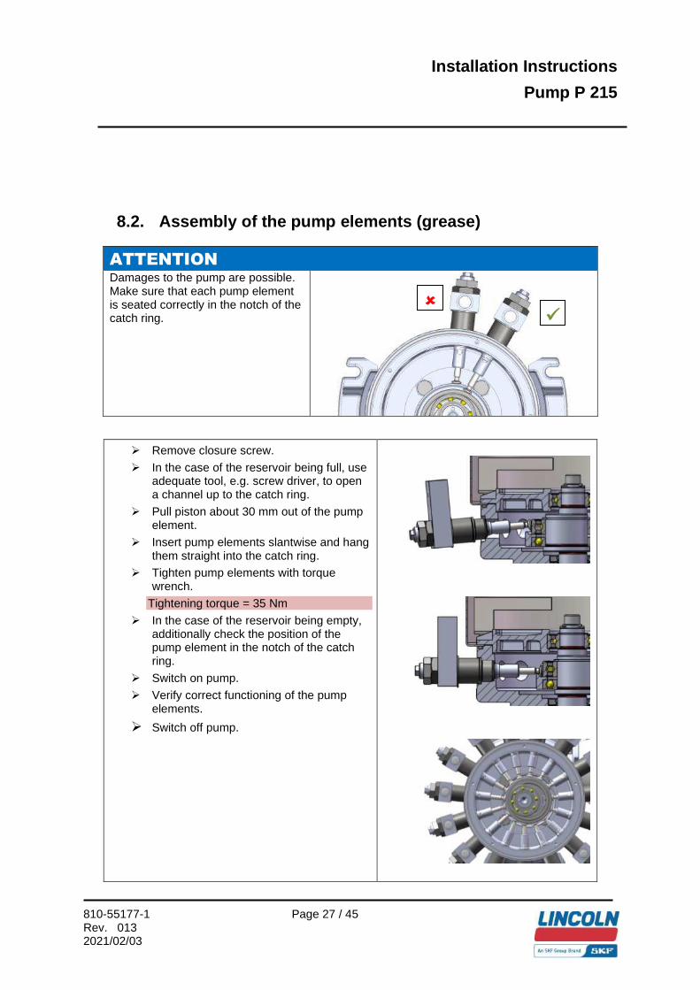
8.2. Assembly of the pump elements (grease)
ATTENTION Damages to the pump are possible. Make sure that each pump element is seated correctly in the notch of the catch ring.
➢ Remove closure screw.
➢ In the case of the reservoir being full, use adequate tool, e.g. screw driver, to open a channel up to the catch ring.
➢ Pull piston about 30 mm out of the pump element.
➢ Insert pump elements slantwise and hang them straight into the catch ring.
➢ Tighten pump elements with torque wrench.
Tightening torque = 35 Nm
➢ In the case of the reservoir being empty, additionally check the position of the pump element in the notch of the catch ring.
➢ Switch on pump.
➢ Verify correct functioning of the pump elements.
➢ Switch off pump.
✓

Installation Instructions
Pump P 215
810-55177-1 Page 28 / 45
Rev. 013 2021/02/03
8.3. Assembly of the pump elements (oil)
ATTENTION Damages to the pump are possible. Make sure that each pump element is seated correctly in the notch of the catch ring.
➢ In the case of the reservoir being full: Empty the reservoir down below the level of the pump elements.
➢ Remove closure screw.
➢ Pull piston about 30 mm out of the pump element.
➢ Insert pump elements slantwise and hang them straight into the catch ring.
➢ Tighten pump elements with torque wrench.
Tightening torque = 35 Nm
➢ Verify from the top the position of the pump element in the notch of the catch ring.
➢ Fill the reservoir.
➢ Switch on pump.
➢ Check correct functioning of the pump elements.
➢ Switch off pump.
✓

Installation Instructions
Pump P 215
810-55177-1 Page 29 / 45
Rev. 013 2021/02/03
8.4. Adjustment of the pump elements
NOTE: The output of the pump elements can be modified also during operation:
➢ Loosen counternut (1).
➢ In order to adjust the flow rate, turn the spindle (2).
= lower flow rate
= higher flow rate
The measure R states the approximate flow rate.
R = 22.0 mm Full supply
R = 20.5 mm ¾ supply
R = 19.0 mm ½ supply
R = 17.5 mm ¼ supply
➢ After adjusting the flow rate, retighten the counternut (1).
Tightening torque = 15 Nm – 1 Nm
1
2 R
Installation Instructions
Pump P 215
810-55177-1 Page 30 / 45
Rev. 013 2021/02/03
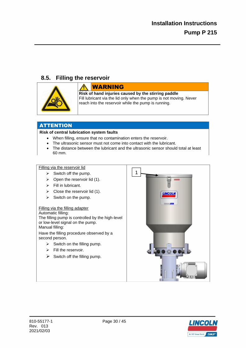
8.5. Filling the reservoir
WARNING
Risk of hand injuries caused by the stirring paddle Fill lubricant via the lid only when the pump is not moving. Never reach into the reservoir while the pump is running.
ATTENTION Risk of central lubrication system faults
• When filling, ensure that no contamination enters the reservoir. • The ultrasonic sensor must not come into contact with the lubricant. • The distance between the lubricant and the ultrasonic sensor should total at least
60 mm.
Filling via the reservoir lid
➢ Switch off the pump.
➢ Open the reservoir lid (1).
➢ Fill in lubricant.
➢ Close the reservoir lid (1).
➢ Switch on the pump.
Filling via the filling adapter Automatic filling: The filling pump is controlled by the high-level or low-level signal on the pump. Manual filling:
Have the filling procedure observed by a second person.
➢ Switch on the filling pump.
➢ Fill the reservoir.
➢ Switch off the filling pump.
1

Installation Instructions
Pump P 215
810-55177-1 Page 31 / 45
Rev. 013 2021/02/03
8.6. Inadvertent filling with incorrect lubricant Should incorrect lubricant have been filled, please proceed as follows.
➢ Switch off the pump and secure it against being switched on. ➢ Remove lubricant. ➢ Clean the reservoir, pump housing and, if applicable, the tubing system. ➢ Fill in lubricant of correct specification.
➢ Switch on pump.
➢ Inform your superior to ensure that the error does not occur again.
8.7. Inspections prior to initial commissioning
In order to warrant safety and function, a person assigned by the operator must inspect certain areas of the central lubrication system prior to initial commissioning. Detected defects must be reported without delay to a superior and remedied. The repair of defects must be carried out by a specialist only. The following points must be inspected prior to initial commissioning:
ATTENTION Risk of damage to the machine Fill the feed lines with lubricant and lubricate the lubrication points manually. Otherwise the bearing points may become damaged due to a lack of lubricant.
Check the entire system for accordance with the intended purpose and the planning documentation.
Ensure that all parameters and lubricants have been correctly adjusted or are present.
If deviations are detected, they must be remedied without delay.

Installation Instructions
Pump P 215
810-55177-1 Page 32 / 45
Rev. 013 2021/02/03
Electrics:
• Electrical connections carried out correctly. • Cable entries sealed correctly. • The voltage and frequency of the power network correspond to the
information on the type identification plate of the motor. • Monitoring devices and additional equipment (e.g. motor circuit breaker)
are correctly connected and adjusted. • All parts such as lines, cables, metering devices, etc. have been correctly
installed and are undamaged.
Mechanics:
• No loose or missing parts remaining (e.g. pressure relief valves, feed lines).
• No damages, deformations or cracks. • No smoke or smouldering spots. • No discolorations, contamination and/or corrosion. • No unusual humidity accumulations, odours, vibrations, or sounds. • No leakage of lubricant at connections and from lines.
8.8. Activation of the pump The pump is activated on:
• Installation into a machine o by switching on the machine contact. o by a control provided by the customer.

Installation Instructions
Pump P 215
810-55177-1 Page 33 / 45
Rev. 013 2021/02/03
9. Standard operation
9.1. Daily start-up Below find the activities to be carried out in case of standard operation.
9.2. Inspections With regard to “Inspections prior to initial commissioning”, the operator has to define suitable inspection intervals depending on the actual operating conditions.
9.3. Filling the reservoir during operation Fill the reservoir as described in Chapter “Installation and commissioning”.
9.4. Cleaning For cleaning, required protective clothes, cleaning agents and devices, observe valid operation guidelines provided by the operator.
DANGER
Danger to life Risk of fire and explosion when using inflammable cleaning agents. Do not use steam or high-pressure cleaners. Electrical components may be damaged. Do not touch cables or electrical components with wet or damp hands. Cleaning work on energized components may be carried out by electrical specialists only. Wear personal protective equipment.
Exterior cleaning
• Thorough cleaning of all surfaces. • Mark and secure wet areas.
Interior cleaning • Normally, interior cleaning is not required.
ATTENTION
Possible damage to the machine When using solvents for cleaning purposes, ensure their compatibility with plastic parts and lacquers. Do not use polar organic solvents like e. g. alcohol, methanol or acetone.

Installation Instructions
Pump P 215
810-55177-1 Page 34 / 45
Rev. 013 2021/02/03
10. Maintenance
DANGER
Electric shock Disconnect the pump from the mains electrically prior to all work on electrical parts.
10.1. Pump maintenance The pump is mainly maintenance-free. However, the following parts should be inspected and, if necessary, replaced by new parts at regular intervals:
• Pressure relief valves • Check valves • Pump elements.
Pressure relief valve tolerance + 5% / - 10 % Should this tolerance be exceeded, the pressure relief valves must be replaced.
11. Troubleshooting
Pump motor does not run Possible cause Observation Remedy Fault with superior machine / with the external control. Motor circuit breaker released.
No pump sound. Check power lines / external control / motor circuit breaker.
Motor runs, but pump does not function Possible cause Observation Possible cause Reservoir empty. Visual check Refill pump or refill reservoir of
filling pump Air in the lubricant. Bubbles in the lubricant. Vent the pump Suction borehole of pump element blocked.
After disassembling the pump element
Disassemble and clean pump element
Check valve defective or contaminated.
After disassembling the check valve
Replace check valve
Pump element worn Low pressurization Replace pump element Defective pressure relief valve / fault at the lubrication point.
Grease leaking from the pressure relief valve
Determine cause Replace pressure relief valve
Blockage in the downstream lubrication system.
Grease leaking from the pressure-relief valve
Determine and remedy cause
If the fault cannot be found / corrected in this way, please get in touch with our Customer Service Department.

Installation Instructions
Pump P 215
810-55177-1 Page 35 / 45
Rev. 013 2021/02/03
12. Spare parts 12.1. Pump P 215
Item Name Qty. Part no. 1.1 Housing assy. 1 560-60144-1 1.2 Rotary shaft seal 30x50x7 1 220-12231-4 2 Closure screw M22x1,5 / 303-19285-1 3.1 Eccentric shaft 1 460-24302-2 3.2 Key A 8x7x32 1 214-12176-3 3.3 Grooved dowel pin D4x10 1 206-12498-3 4 Catch ring assy. 1 560-36903-3 4.1 Grooved ball bearing D45/75x10 1 250-14064-3 4.2 Catch ring 1 460-24301-1 4.3 Grooved ball bearing D45/75x16 1 250-14064-4 5 Retaining ring A45x1,75 1 211-12164-9

Installation Instructions
Pump P 215
810-55177-1 Page 36 / 45
Rev. 013 2021/02/03
Item Name Qty. Part no. 6.1 Hexagonal screw M 10x35C 4 200-12008-6 6.2 Sealing M 10 4 220-13653-7 6.3 Washer A 10,5C 4 209-13077-2 6.4 Hexagonal nut M 10C 4 207-12136-1 7 Pump element with piston Ø 6 mm / 600-25046-3 7 Pump element with piston Ø 7 mm / 600-25047-3 7.1 Outlet stud with check valve / 560-32115-1 7.2 Gasket Ø 22,2 x Ø 27 x 1,5 / 306-17813-1 8 Gasket Ø 70x126x0,5 1 306-19640-1 9 O-ring Ø 186 x 3,5 1 219-12226-8 10 10 l reservoir with lid 1 560-32012-1 10 30 l reservoir with lid 1 560-32010-1 10 4 l reservoir 1 444-24673-1 10 8 l reservoir 1 444-24674-1 10 Lid for 4 / 8 L reservoir 1 444-24234-1 10.2 Stirring paddle assy. for 4/8/10 L reservoir 1 560-32128-1 10.2 Stirring paddle assy. for 30 L reservoir 1 560-32129-1 10.2 Stirring paddle assy. for100 L reservoir 1 560-32798-1 10.3 Fixed paddle 1 460-24566-1 10.4 Washer A 10,5C 1 209-13077-2 10.5 Hexagonal socket head screw M 10 x 25C 1 201-12027-6 11 Intermediate bottom for plastic reservoir 460-24567-1 11 Intermediate bottom for steel reservoir 460-24568-1 12 Hexagonal socket head screw M 5x20C 201-13668-4 13 Retaining ring A25 211-12164-6 20 Drive preassembled with multi-range motor(s) gear 100:1 0,18 / 0,21 kW 245-13915-1 20 Drive preassembled with multi-range motor(s) gear 49:1 0,25 / 0,29 kW 245-13916-1 20 Drive preassembled with single-range motor(s) gear 100:1 0,18 kW 245-13921-1 20 Drive preassembled with single-range motor(s) gear 49:1 0,25 kW 245-13922-1 20.1 Multi-range motors 50/60 Hz 380-420 V / 440-480 V
AC flange motor Gear 100:1 0,18 / 0,21 kW
245-13913-1
20.1 Multi-range motors 50/60 Hz 380-420 V / 440-480 V AC flange motors Gear 49:1 0,25 / 0,29 kW
245-13914-1
20.1 Single-range motors 50 Hz 290-500 V / 440-480 V AC flange motor Gear 100:1 0,18 kW
245-13919-1
20.1 Single-range motors 50 Hz 290-500 V / 440-480 V AC flange motor Gear 49:1 0,25 kW
245-13920-1
20.2 Gasket 60x90x0,5 306-19415-1 20.3 Hexagonal screw M 5 x 16C 200-13017-9 20.4 Gear i = 100:1
I = 49:1 246-14145-1
246-14145-2 With-out
Sealing kit consisting of items 1.2, 6.2, 8, 9, 20.2 560-36919-2
With-out
Sealing kit for pump element consisting of: 1 x Outlet stud with check valve, 2 x O-rings 22 x 2, 1 x O-ring 15,3 x 24 1 x Gasket 22,2 x 27 x 1,5
1
560-36903-4

Installation Instructions
Pump P 215
810-55177-1 Page 37 / 45
Rev. 013 2021/02/03
12.2. Free shaft end
Item Name Qty. Part no. 23 Drive for free shaft end with: Gear i = 7:1 1 660-28645-1 Gear i = 49:1 1 660-28573-1 Gear i = 100:1 1 660-28574-1 Gear i = 490:1 1 660-28572-1 23.1 Rotary shaft seal Ø 15x 35 x 7 1 220-13087-2 23.2 Retaining ring J 35 x 1,5 1 211-12166-6 23.3 Retaining ring A 15 x 1,0 2 211-12164-4 23.4 Angular ball bearing D 15/35 x 15,9 1 250-14003-1 23.5 Feather key A 5 x 5 x 20 1 214-12174-2 23.6 Drive shaft 1 460-24320-1 23.7 Feather key A 4 x 4 x 25 1 214-12173-5 23.8 Bearing flange 1 460-24319-1 23.9 Gasket 60 x 90 x 0,5 1 306-19415-1 23.10 Hexagonal screw M 5 x 16C 4 200-13017-9 23.11 Gear i = 7:1 1 246-14145-4 i = 49:1 1 246-14145-2 i = 100:1 1 246-14145-1 i = 490:1 1 246-14146-1 Sealing kit consisting of items:
1.2, 6.2; 8, 9, 23.2, 23.9 1 560-36919-1

Installation Instructions
Pump P 215
810-55177-1 Page 38 / 45
Rev. 013 2021/02/03
12.3. Oscillating drive
Item Name Qty. Part no.: 22 Oscillating drive assy. 1 660-28575-1 22.1 Retaining ring A15 x 1,0 1 211-12164-4 22.2 Washer 1 318-19101-1 22.3 O-ring Ø15 x 3 1 219-13045-6 22.4 Ratchet gear housing 1 400-22817-2 22.5 Lever rod 1 402-20129-1 22.6 Ratchet wheel assy. 1 560-36903-2 22.7 Shaft 1 460-24321-1 22.9 Retaining ring J 30 x 1,2 1 211-12165-2 22.10 Grooved ball bearing D12 x 30 x 8 1 250-14000-3 22.11 O-ring Ø 59 x 3 1 219-13045-5 22.12 Brake ring 1 400-22819-2 22.13 Retaining ring A 12 x 1,0 1 211-12164-2 22.14 Gasket 60 x 90 x 0,5 1 306-19415-1 22.15 Bearing flange 1 460-24322-1 22.16 Hexagonal screw M 6 x 20 C 4 200-13022-7 22.17 Hexagonal screw M 5 x 16 C 4 200-13017-9 22.18 Gear 7:1 1 246-14145-4 Sealing kit consisting of items:
1.2, 6.2, 8, 9, 22.3, 22.11, 22.14 1 560-36919-3

Installation Instructions
Pump P 215
810-55177-1 Page 39 / 45
Rev. 013 2021/02/03
–––
12.4. Double gear M 490:1
Item Name Qty. Part no. 21 Gear assy. Gear 490:1 motor 0,18 / 0,21 kW 380-420 / 440 – 480 V 1 245-13918-1 Gear 490:1 motor 0,18 kW 290 / 500 V 1 245-13923-1 21.1 Three-phase flange motor 380-420 / 440-480 V, 0,18/0,21 KW, 1500/1800 rpm 1 245-13913-1 290/500 V, 0,18 KW, 1500 rpm 1 245-13919-1 21.2 Gasket 60 x 90 x 0,5 1 306-19415-1 21.3 Hexagonal screw M 5 x 16 C 4 200-13017-9 21.4 Gear M 490 : 1 1 246-14146-1 Sealing kit consisting of items:
1.2, 6.2, 8, 9, 20.2 1 560-36919-2
Part numbers – ultrasonic sensor Reservoir 4 L 664-85314-1 Reservoir 8 L 664-85314-2 Reservoir 10 L 664-85313-8 Reservoir 30 L 664-85313-9 Reservoir 100 L 664-85315-8

Installation Instructions
Pump P 215
810-55177-1 Page 40 / 45
Rev. 013 2021/02/03
13. Dimensional drawings
M100 / M049 - 10XN / 10YN / 30XN / 30YN
M100 / M049 - 4XN / 8XN

Installation Instructions
Pump P 215
810-55177-1 Page 41 / 45
Rev. 013 2021/02/03
F100 / F049 - 10XN / 10YN / 30XN / 30YN – with free shaft end
10XN / 10YN / 30XN / 30YN - ... with oscillating drive

Installation Instructions
Pump P 215
810-55177-1 Page 42 / 45
Rev. 013 2021/02/03
M 490- 10XN / 10YN / 30XN / 30YN - ... with double gear and motor

Installation Instructions
Pump P 215
810-55177-1 Page 43 / 45
Rev. 013 2021/02/03
M100 / M049 – 100XY…

Installation Instructions
Pump P 215
810-55177-1 Page 44 / 45
Rev. 013 2021/02/03
14. Type identification code
- - - - Basic pump type
P 215 Drive assy. M Three-phase flange motor
Additional designations for voltage and frequency are added to the end of the type identification code.
F Free shaft end P Oscillating drive
Gear ratio i 490 i = 490 : 1
i = 100 : 1 i = 049 : 1 i = 007 : 1 (for P and F drive assemblies only)
100 049 007
Reservoir variations 4 Plastic 4 L
L L L L
8 Plastic 8 10 Steel plate 10 30 Steel plate 30 100 Steel plate 100
XY Reservoir for grease and oil
N BU
Reservoir without filling-level monitoring Reservoir with filling-level monitoring (ultrasonic sensor)
Pump elements 1-15 Number of pump elements
K6 or K7 Piston diameter in mm
Addition to motor designation 380-420 440-480
Multi-range motor for power networks380 -420 V / 50 Hz and 440-480 V / 60 Hz for connections via star connection
500 Single-range motor for power networks 500 V / 50 Hz 000 Pump without motor but with connection flange
P 215 M 490 10 XY BU 12 K6 500

Installation Instructions
Pump P 215
810-55177-1 Page 45 / 45
Rev. 013 2021/02/03
SKF Lubrication Systems Germany GmbH Walldorf Facilities Heinrich-Hertz-Str. 2-8 DE - 69190 Walldorf Phone: +49 (0) 6227 33-0 Fax: +49 (0) 6227 33-259 E-mail: [email protected] www.skf.com/lubrication