EN / ACS580-01 drives quick installation and start-up guide
15
1 This guide is applicable to the global IEC and NEC North American installations. Safety instructions WARNING! Obey these instructions. If you ignore them, injury or death, or damage to the equipment can occur. If you are not a qualified electrical professional, do not do electrical installation or maintenance work. WARNING! If you activate the automatic fault reset or automatic restart functions of the drive control program, make sure that no dangerous situations can occur. These functions reset the drive automatically and continue operation after a fault or supply break. If these functions are activated, the installation must be clearly marked as defined in IEC/EN/UL 61800-5-1, subclause 6.5.3, for example, “THIS MACHINE STARTS AUTOMATICALLY”. • Do not do work on the drive, motor cable, motor, or control cables when the drive is connected to the input power. Before you start the work, isolate the drive from all dangerous voltage sources and measure that there are no dangerous voltages. Always wait for 5 minutes after disconnecting the input power to let the intermediate circuit capacitors discharge. • Do not do work on the drive when a rotating permanent magnet motor is connected to it. A rotating permanent magnet motor energizes the drive, including its input and output terminals. • Make sure that debris from drilling, cutting and grinding. does not enter the drive. • Frames R6 and R8: Use the lifting eyes of the drive when you lift the drive. Do not tilt the drive. The drive is heavy and its center of gravity is high. An overturning drive can cause physical injury. 1. Unpack the drive Keep the drive in its package until you are ready to install it. After unpacking, protect the drive from dust, debris and moisture. Make sure that these items are included: drive, mounting template, control panel, quick installation and start-up guide, multilingual residual voltage warning stickers, hardware and firmware manuals (if ordered), options in separate packages (if ordered). Make sure that there are no signs of damage to the items. 2. Reform the capacitors If the drive has not been powered up for a year or more, you must reform the DC link capacitors. See Related documents or contact ABB technical support. Documentation in other languages Ecodesign information (EU 2019/1781 and SI 2021 No. 745) About this document 3AXD50000803057 Rev A EN 2021-09-01 © 2021 ABB. All rights reserved. Original instructions. — DRIVES FOR WATER ACQ580-31 Quick installation and start-up guide
-
Upload
khangminh22 -
Category
Documents
-
view
0 -
download
0
Transcript of EN / ACS580-01 drives quick installation and start-up guide
1
This guide is applicable to the global IEC and NEC North American installations.
Safety instructions
WARNING! Obey these instructions. If you ignore them, injury or death, or damage to the equipment can occur. If you are not a qualified electrical professional, do not do electrical installation or maintenance work.
WARNING! If you activate the automatic fault reset or automatic restart functions of the drive control program, make sure that no dangerous situations can occur. These functions reset the drive automatically and continue operation after a fault or supply break. If these functions are activated, the installation must be clearly marked as
defined in IEC/EN/UL 61800-5-1, subclause 6.5.3, for example, “THIS MACHINE STARTS AUTOMATICALLY”.
• Do not do work on the drive, motor cable, motor, or control cables when the drive is connected to the input power. Before you start the work, isolate the drive from all dangerous voltage sources and measure that there are no dangerous voltages. Always wait for 5 minutes after disconnecting the input power to let the intermediate circuit capacitors discharge.
• Do not do work on the drive when a rotating permanent magnet motor is connected to it. A rotating permanent magnet motor energizes the drive, including its input and output terminals.
• Make sure that debris from drilling, cutting and grinding. does not enter the drive.
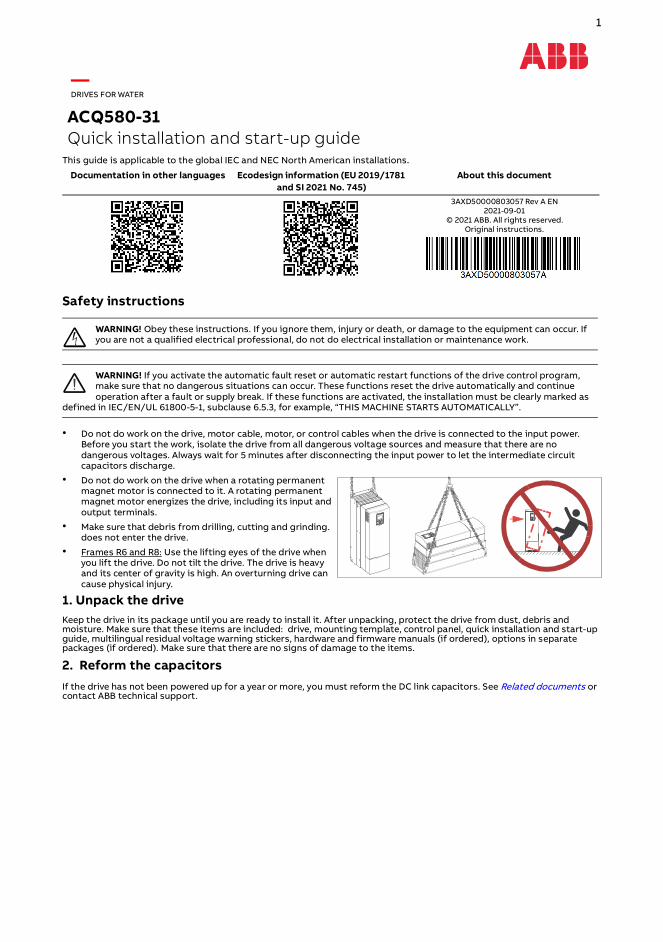
• Frames R6 and R8: Use the lifting eyes of the drive when you lift the drive. Do not tilt the drive. The drive is heavy and its center of gravity is high. An overturning drive can cause physical injury.
1. Unpack the driveKeep the drive in its package until you are ready to install it. After unpacking, protect the drive from dust, debris and moisture. Make sure that these items are included: drive, mounting template, control panel, quick installation and start-up guide, multilingual residual voltage warning stickers, hardware and firmware manuals (if ordered), options in separate packages (if ordered). Make sure that there are no signs of damage to the items.
2. Reform the capacitorsIf the drive has not been powered up for a year or more, you must reform the DC link capacitors. See Related documents or contact ABB technical support.
Documentation in other languages Ecodesign information (EU 2019/1781 and SI 2021 No. 745)
About this document
3AXD50000803057 Rev A EN 2021-09-01
© 2021 ABB. All rights reserved. Original instructions.
—DRIVES FOR WATER
ACQ580-31Quick installation and start-up guide

2
3. Select the cables and fuses• Select the power cables. Obey the local regulations.
• Input power cable: Use symmetrical shielded cable (VFD cable) for the best EMC performance. NEC installations: Conduit with continuous conductivity is also allowed and must be grounded on both ends.
• Motor cable: ABB recommends symmetrically shielded VFD motor cable to reduce bearing current and wear and stress on motor insulation and to provide the best EMC performance. Although not recommended, conductors inside continuously conductive conduit is allowed in NEC installations. Ground conduit on both ends.
• Power cable types: IEC installations: Use copper cables. Aluminum cables can only be used with frame sizes R6 and R8, except the biggest R8. NEC installations: Only copper conductors are allowed.
• Current rating: max. load current.• Voltage rating (minimum): IEC installations: 600 V AC cable is accepted for up to 500 V AC. NEC installations: 1000 V
AC for 480 V AC motors. 600 V AC for 480 V AC power line.• Temperature rating: IEC installations: Select a cable rated for at least 70 °C maximum permissible temperature of
conductor in continuous use. NEC installations: Use 75 °C conductors minimum. Insulation temperature can be higher as long as the ampacity is based on 75 °C conductors.
• Select the control cables.
• Use double-shielded twisted-pair cable for analog signals. Use double-shielded or single-shielded cable for the digital, relay and I/O signals. Do not run 24 V and 115/230 V signals in the same cable.
• Protect the drive and input power cable with the correct fuses. See Ratings, fuses and typical power cables.
4. Examine the installation siteExamine the drive installation site. Make sure that:• The installation site is sufficiently ventilated or cooled to remove heat from the drive.
• The ambient conditions of the drive meet the specifications. See Ambient conditions.
• The wall behind the drive and the material above and below the unit is of non-flammable material.
• The installation surface is as close to vertical as possible and strong enough to support the drive.
• There is sufficient free space around the drive for cooling, maintenance and operation. For the minimum free space requirements, refer to Dimensions, weights and free space requirements.
• There are no sources of strong magnetic fields such as high-current single-core conductors or contactor coils near the drive. A strong magnetic field can cause interference or inaccuracy in the operation of the drive.
5. Install the drive on the wallSelect fasteners that comply with local requirements applicable to wall surface materials, drive weight and application. For drive weights, refer to Dimensions, weights and free space requirements.
R3 R6 R8mm in mm in mm in
a 474 18.66 753 29.64 945 37.20b 160 6.29 213 8.38 263 10.35
a
b
300
200
[7.8
7]
[11.
81]
1 2
3
4
R3: M5 (#10)R6: M8 (5/16”)R8: M8 (5/16”)

3
6. Remove the covers.
7. Make sure that the drive is compatible with the grounding systemYou can connect all drives to a symmetrically grounded TN-S system (center-grounded wye). If you install the drive to a different system, you may need to remove the EMC screw (disconnect the EMC filter) and/or remove the VAR screw (disconnect the varistor circuit).
8. Measure the insulation resistance of the power cables and the motorMeasure the insulation resistance of the input cable before you connect it to the drive. Obey local regulations.
Measure the insulation resistance of the motor cable and motor when the cable is disconnected from the drive. Measure the insulation resistance between each phase conductor and the PE conductor. Use a measuring voltage of 1000 V DC. The insulation resistance of an ABB motor must be more than 100 Mohm (reference value at 25 °C). For the insulation resistance of other motors, see the manufacturer’s instructions. Moisture inside the motor decreases the insulation resistance. If you think that there is moisture, dry the motor and do the measurement again.
Frame Symmetrically grounded TN-S systems (center-grounded wye)
Corner-grounded delta and midpoint-grounded delta systems
IT systems (ungrounded or high-resistance grounded)
TT systems 1) 2)
1) A residual current device must be installed in the supply system. In NEC installations the residual current device is only required at or above 1000 amps.2) ABB does not guarantee the EMC category or the operation of the ground leakage detector built inside the drive.
R3 Do not remove EMC AC or VAR screws.
Do not remove EMC or VAR screws.
Remove EMC and VAR screws.
Remove EMC and VAR screws.
R6 Do not remove EMC AC or VAR screws.
Remove EMC DC screw. Do not remove EMC AC or VAR screws. See Note 1 below.
Remove EMC AC, EMC DC and VAR screws.
Remove EMC AC, EMC DC and VAR screws.
R8 Do not remove EMC AC or VAR screws.
Remove EMC DC and VAR screws.
Remove EMC DC and VAR screws.
Remove EMC DC and VAR screws.
2
1
IP21 (UL Type 1) – R3 IP21 (UL Type 1) – R6, R8 IP55 (UL Type 12) – R6, R8
2
1b
1a
IP55 (UL Type 12) – R3
2
1b
1a
3a
3b
4
1000 V DC,> 100 Mohm
U1-PE, V1-PE, W1-PE
ohm
M3~
U1
V1
W1PE

4
9. Connect the power cables
IEC connection diagram with shielded cables
NEC connection diagram with symmetrically shielded cable or conduit
Note: NEC installation can include separate insulated conductors inside a conduit, shielded VFD cable in conduit, or shielded VFD cable without conduit. The normal dashed symbol (3) in this diagram represents the shield of shielded VFD cable. The same solid symbol (2) represents conduit.
2. Use a separate grounding cable or a cable with a separate PE conductor for the line side, if the conductivity of the fourth conductor or shield does not meet the requirements for the PE conductor.
3. Use a separate grounding cable for the motor side, if the conductivity of the shield is not sufficient, or if there is no symmetrically constructed PE conductor in the cable.
4. 360-degree grounding of the cable shield is required for the motor cable. It is also recommended for the input power cable.
5. If necessary, install an external filter (du/dt, common mode, or sine filter). Filters are available from ABB.
1. Two protective earth (ground) conductors. Drive safety standard IEC/EN 61800-5-1 requires two PE conductors, if the cross-sectionalarea of the PE conductor is less than 10 mm2 Cu or 16 mm2 Al. For example, you can use the cable shield in addition to the fourth conductor.
PE
PE
L1 L2 L3 UDC+
U1 W1M
3
T1/U T2/V T3/W
V1
(PE) (PE) L1 L2 L3
PE
UDC-
12
3
4 4
5
3. Shield of a VFD shielded cable: Ground the shield 360° under drive's grounding clamp, then twist with the ground conductors and connect under the drive's ground terminal. Ground the shield also 360° at the motor end, then twist and connect under the motor's ground terminal. For a conduit installation see 2.
4. Symmetrically constructed grounding conductors inside a VFD shielded cable: Twist together, combine with the shield and connect under the drive's ground terminal and under the motor's ground terminal. For a conduit installation see 1.
5. If necessary, install an external filter (du/dt, common mode, or sine filter). Filters are available from ABB.
Note: All openings in the drive enclosure must be closed with UL listed devices having the same Type rating as the drive Type.
1. Insulated ground conductor in a conduit: Ground to drive's PE terminal and to the distribution panel ground bus. For a VFD cable installation see 4.
2. Conduit ground: Bond the conduit to the drive's conduit box and to the distribution panel enclosure. For a VFD cable installation see 3.
PE
PE
L1 L2 L3
U1 W1M
3
T1/U T2/V T3/W
V1
L1 L2 L3
PE
3
UDC-UDC+
5
4
4
1
2
3

5
Connection procedure with VFD cable
For connection procedure with conduits, see Connection procedure with conduit. 1. Attach a residual voltage warning sticker in the local language.
2. Frames R6 and R8: Remove the shroud on the power cable terminals. Frame R8: For easier installation, you can remove the side plates.
3. Prepare the power cables:• Remove the rubber grommets of the cables to be installed from the cable entry plate. Remove the unused grommets
and reinstall with the cone pointing down (3a).• Cut a sufficient hole in the rubber grommet. Slide the grommet onto the cable (3b) with the remaining cone pointing
down.• Prepare the ends of the input power cable and motor cable as illustrated in the applicable figure (3c). • Slide the cables through the holes in the cable entry and attach the grommets to the holes.
4. Connect the power cables. For the tightening torques, refer to Terminal data. • Ground the shield 360 degrees by tightening the clamp of the power cable grounding shelf onto the stripped part of
the cable (4a).• Connect the twisted shield of the cable shields to the grounding terminals (4b).• Frame R8: to install the common mode filter, see Related documents.• Connect the phase conductors of the motor cable to the T1/U, T2/V and T3/W terminals. Connect the phase
conductors of the input power cable to the L1, L2 and L3 terminals (4c).• Tighten the screws to the torque given in the installation drawing below.
R6 R8 R8R8R6
3b
3c PEPE
3a
L1 L2 L3 UD
C+
UD
C-
T1/U
T2/V
T3/W
4b
4c
1.7 N·m
4a
1.7 N·m
1.7 N·m
1.7 N·m
L1, L2, L3, T1/U, T2/V, T3/W: 1.7 N·m (15 lbf·in)
R3
(15 lbf·in)

6
5. Frame R8: Install the side plates if removed in step 2. Attach the cables outside the drive mechanically.
6. Install the shroud onto the power cable connection terminals.
7. Ground the motor cable shield at the motor end. For minimum radio frequency interference, ground the motor cable shield 360 degrees at the cable entry of the motor terminal box.
4b
4c
2.9 N·m 2.9 N·m
2 N·m
L1, L2, L3, T1/U, T2/V, T3/W: 5.6 N·m (4.1 lbf·ft)
R6
4a
(2.1 lbf·ft)
4b
4c
2 N·m
4a
L1, L2, L3: 30 N·m (22.0 lbf·ft)T1/U, T2/V, T3/W: 30 N·m (22.0 lbf·ft)
R8
9.8 N·m 9.8 N·m(7.2 lbf·ft)
R6 R8
7
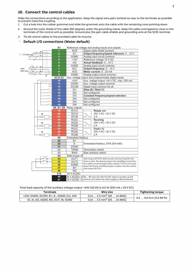
10. Connect the control cablesMake the connections according to the application. Keep the signal wire pairs twisted as near to the terminals as possible to prevent inductive coupling.1. Cut a hole into the rubber grommet and slide the grommet onto the cable with the remaining cone pointing down.
2. Ground the outer shield of the cable 360 degrees under the grounding clamp. Keep the cable unstripped as close to the terminals of the control unit as possible. Ground also the pair-cable shields and grounding wire at the SCR1 terminal.
3. Tie all control cables to the provided cable tie mounts.
Default I/O connections (Water default)
Total load capacity of the auxiliary voltage output +24V (X2:10) is 6.0 W (250 mA / 24 V DC).
Terminals Wire size Tightening torque+24V, DGND, DCOM, B+, A-, DGND, Ext. 24V 0.14 … 2.5 mm2 (26 … 14 AWG)
0.5 … 0.6 N·m (0.4 lbf·ft)DI, AI, AO, AGND, RO, OUT, IN, SGND 0.14 … 2.5 mm2 (26 … 14 AWG)
R6… R only: Ext 24V AC/DC input to power up the control unit when the main supply is disconnected.

8Control cable installation examples
11. Install optional modules, if included in the delivery
12. Install the cover(s)
1.7 N·m
R3 R8R6
1.7 N·m (15 lbf·in)
2 N·m (1.5 lbf·ft) 2 N·m 2 N·m
2 N·m (1.5 lbf·ft)
1
2
1
2
IP21 (UL Type 1), R3 IP55 (UL type 12), R3 IP21 (UL type 1), R6, R8 IP55 (UL type 12),R6, R8
2 N·m (17 lbf·in)
2
1
4
3
2 N·m (17 lbf·in) 2 N·m (17 lbf·in)

9
Connection procedure with conduit1. Connect the power cables. ABB recommends symmetrically shielded VFD cable for connecting the motor.
• Remove the covers as instructed in Remove the covers. Attach the residual voltage warning sticker and remove the shroud on the power cable terminals as instructed in Connection procedure with VFD cable.
• Remove the rubber grommets from the conduit plate for the conduit to be connected. If you remove the cable shelves, reinstall the four screw plugs to avoid moisture exchange through the empty holes.
• Attach the conduit to the drive conduit plate, and to the motor or source of power distribution. Make sure conduit is correctly bonded at both ends of the conduit. Ensure conductivity of the conduit. Slide the VFD shielded cable or discrete conductors through the conduit and strip the cable ends.
• If you use a symmetrically shielded VFD cable, twist the grounding wires together with the cable shield and connect them to the grounding terminals. Ground the shield 360 degrees at the grounding clamp. If you use discrete conductors connect the insulated ground conductor to the ground terminal.
• Connect the input and motor conductors and tighten cable terminals. For the tightening torques, refer to Terminal data.
• Reinstall the shroud on the power cable terminals.
2. Connect the control cables• Frame R3: Pull the control panel holder up.• Attach the cable conduits to the drive conduit plate. Make sure conduit is
correctly bonded at both ends and that the conductivity is consistent throughout the conduit. Slide the control cables through the conduit.
• Cut to suitable length (note the extra length of the grounding conductors) and strip the conductors.
• Ground the outer shields of all control cables 360 degrees at a grounding clamp. Route the cable as shown in the figures below.
• Secure the cables inside the drive mechanically.• Ground the pair-cable shields and grounding wire at the grounding terminal
(SCR) of the control unit.• Reinstall the front covers as instructed in Install the cover(s).
R3 R6 R8
Max250 mA
R3 R8 R6
10
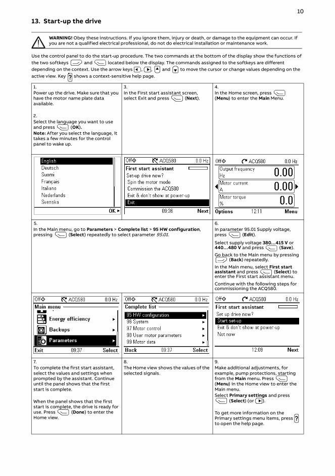
13. Start-up the drive
WARNING! Obey these instructions. If you ignore them, injury or death, or damage to the equipment can occur. If you are not a qualified electrical professional, do not do electrical installation or maintenance work.
Use the control panel to do the start-up procedure. The two commands at the bottom of the display show the functions of the two softkeys and located below the display. The commands assigned to the softkeys are different depending on the context. Use the arrow keys , , and to move the cursor or change values depending on the active view. Key shows a context-sensitive help page.
1.Power up the drive. Make sure that you have the motor name plate data available.
2.Select the language you want to use and press (OK).Note: After you select the language, it takes a few minutes for the control panel to wake up.
3.In the First start assistant screen, select Exit and press (Next).
4. In the Home screen, press (Menu) to enter the Main Menu.
5.In the Main menu, go to Parameters > Complete list > 95 HW configuration, pressing (Select) repeatedly to select parameter 95.01.
6.In parameter 95.01 Supply voltage, press (Edit).
Select supply voltage 380…415 V or 440…480 V and press (Save).
Go back to the Main menu by pressing (Back) repeatedly.
In the Main menu, select First start assistant and press (Select) to enter the First start assistant menu.
Continue with the following steps for commissioning the ACQ580.
7.To complete the first start assistant, select the values and settings when prompted by the assistant. Continue until the panel shows that the first start is complete.
When the panel shows that the first start is complete, the drive is ready for use. Press (Done) to enter the Home view.
8.The Home view shows the values of the selected signals.
9.Make additional adjustments, for example, pump protections, starting from the Main menu. Press (Menu) in the Home view to enter the Main menu.Select Primary settings and press
(Select) (or ).
To get more information on the Primary settings menu items, press to open the help page.
?
?

11
Motor overload protection
The motor thermal overload protection can use motor temperature devices or can be estimated using a motor model defined by parameters. The motor thermal overload protection is set to motor current and motor class curves as default. To enable protection using motor model parameters or measurement devices, set parameter 35.11 and subsequent parameters through 35.55. To adjust motor class curves (default is class 20), change parameters 35.56 and 35.57.
Use the information key ( ) on the drive control panel for more information on setting group 35 parameters. You must set the drive overload parameters correctly, or motor damage could occur.
Fieldbus communication
To configure the embedded fieldbus communication for Modbus RTU, you must set at least these parameters:
Other parameters related to the fieldbus configuration:
Warnings and faults
Parameter Setting Description20.01 Ext1 commands Embedded
fieldbusSelects fieldbus as the source for the start and stop commands when EXT1 is selected as the active control location.
22.11 Speed ref1 source EFB ref1 Selects a reference received through the embedded fieldbus interface as speed reference 1.
28.11 Frequency ref1 source EFB ref1 Selects a reference received through the embedded fieldbus interface as frequency reference 1.
58.01 Protocol enable Modbus RTU Initializes embedded fieldbus communication.58.03 Node address 1 (default) Node address. There must be no two nodes with the same node
address on-line.58.04 Baud rate 19.2 kbps (default) Defines the communication speed of the link. Use the same setting as
in the master station.58.05 Parity 8 EVEN 1 (default) Selects the parity and stop bit setting. Use the same setting as in the
master station.58.06 Communication control Refresh settings Validates any changed EFB configuration settings. Use this after
changing any parameters in group 58.
58.14 Communication loss action
58.17 Transmit delay 58.28 EFB act1 type 58.34 Word order
58.15 Communication loss mode
58.25 Control profile 58.31 EFB act1 transparent source
58.101 Data I/O 1 …58.114 Data I/O 1458.16 Communication loss
time58.26 EFB ref1 type 58.33 Addressing mode
Warning Fault Aux. code Description- 2281 Current calibration Fault: Output phase current measurement fault.
A2B1 2310 Overcurrent The output current is more than the internal limit. This can also be caused by an earth fault or phase loss.
A2B3 2330 Earth leakage A load unbalance that is typically caused by an earth fault in the motor or the motor cable.
A2B4 2340 Short circuit There is a short-circuit in the motor or the motor cable.3E00 3130 Input phase loss The intermediate DC circuit voltage oscillates due to missing input power
line phase.- 3181 Wiring or earth fault Incorrect input and motor cable connection.
A3A1 3210 DC link overvoltage Intermediate DC circuit voltage is too high.A3A2 3220 DC link undervoltage Intermediate DC circuit voltage is too low.
- 3381 Output phase loss All three phases are not connected to the motor.- 5090 STO hardware failure STO hardware diagnostics has detected hardware failure. Contact ABB.
A5A0 5091 Safe torque off The Safe torque off (STO) function is active.A7CE 6681 EFB comm loss Break in embedded fieldbus communication.A7C1 7510 FBA A communication Communication lost between drive (or PLC) and fieldbus adapter.A7AB - Extension I/O
configuration failureThe I/O extension module types and locations specified by parameters do not match the detected configuration.
AFF6 - Identification run The motor ID run occurs at the next start.- FA81 Safe torque off 1 loss The Safe torque off circuit 1 is broken.- FA82 Safe torque off 2 loss The Safe torque off circuit 2 is broken.
?

12
Ratings, fuses and typical power cables1) Typical motor power with no overload capacity (nominal use). The kilowatt ratings apply to most IEC 4-pole motors. The
horsepower ratings apply to most NEMA 4-pole motors.
2) For IEC installations, ABB recommends aR fuses. The gG fuses can be used for frames R3 and R6 if they operate rapidly enough (max. 0.1 seconds). The operating time depends on the supply network impedance and the cross-sectional area and length of the supply cable. Obey the local regulations. See hardware manual for guidelines in selecting between aR and gG fuses, and for additional fuse alternatives.3) The recommended branch protection fuses must be used to maintain the IEC/EN/UL 61800-5-1 and CSA C22.2 No. 274 certifications. Refer to note 6 for circuit breaker protection.
4) IEC 61439-1: The drive is suitable for use on a circuit capable of delivering not more than 65 kA when protected by the fuses given in this table. 5) UL 61800-5-1, CSA C22.2 No. 274: The drive is suitable for use on a circuit capable of delivering not more than 100 kA symmetrical amperes (rms) at 480 V maximum when protected by the ABB recommended fuses.
6) Refer to Alternate Fuses, MMPs and Circuit Breakers for ABB Drives (3AXD50000645015 [English]) for additional UL fuses and circuit breakers that can be used as branch circuit protection.
7) Class J, CC, and CF fuses are also allowed at the same nominal current and voltage ratings.
8) These losses are not calculated according to IEC 61800-9-2.
9) IEC Installations: The cable sizing is based on max. 9 cables laid on a cable ladder side by side, three ladder type trays one on top of the other, ambient temperature 30 °C, PV insulation, surface temperature 70 °C (EN 60204-1 and IEC 60364-5-52/2001). For other conditions, size the cables according to local safety regulations, appropriate input voltage and the load current of the drive.
10) NEC Installations: The cable sizing is based on NEC Table 310-16 for copper wires, 75 °C (167 °F) wire insulation at 40 °C (104 °F) ambient temperature. Not more than three current-carrying conductors in raceway or cable or earth (directly buried). For other conditions, size the cables according to local safety regulations, appropriate input voltage and the load current of the drive.
ACQ580-31-…
IEC ratings
Frame size
Input rating Output ratings
Motor power1)
Fuses3) Typical power cable9) Typical
power loss 8)gG fuse4)
(DIN 43620)aR fuse2)4) (DIN
43620) Copper
I1 I2 ILd PLd ABB type Bussmann type mm2 WA A A kWUn = 3-phase 400 V09A5-4 R3 8 9.4 8.9 4.0 OFAF000H16 170M1561 3x2,5+2,5 22612A7-4 R3 10 12.6 12.0 5.5 OFAF000H16 170M1561 3x2,5+2,5 329018A-4 R3 14 17.0 16.2 7.5 OFAF000H25 170M1563 3x2,5+2,5 395026A-4 R3 20 25 23.8 11 OFAF000H32 170M1563 3x6+6 579033A-4 R6 27 32 30 15 OFAF000H40 170M1565 3x10+10 625039A-4 R6 33 38 36 18.5 OFAF000H50 170M1565 3x10+10 751046A-4 R6 40 45 43 22 OFAF000H63 170M1566 3x16+16 912062A-4 R6 51 62 59 30 OFAF000H80 170M1567 3x25+16 1088073A-4* R6 63 73 69 37 OFAF000H100 170M1568 3x35+16 1502088A-4* R6 76 88 84 45 OFAF000H100 170M1568 3x50+25 1904106A-4 R8 94 106 101 55 - 170M1569 3x70+35 1877145A-4 R8 128 145 138 75 - 170M3817 3x95+50 2963169A-4 R8 154 169 161 90 - 170M5808 3x120+70 3168206A-4 R8 188 206 196 110 - 170M5809 3x150+70 3990
ACQ580-31-…
IEC ratings
Frame size
Input rating Output ratings
Motor power1)
Fuses3) Typical power cable9) Typical
power loss 8)gG fuse4)
(DIN 43620)aR fuse2)4)
(DIN 43620) Copper
I1 I2 ILd PLd ABB type Bussmann type mm2 W
A A A kWUn = 3-phase 480 V09A5-4 R3 7.0 7.6 7.6 4.0 OFAF000H16 170M1561 3x2.5+2.5 21912A7-4 R3 9.0 12.0 12.0 5.5 OFAF000H16 170M1561 3x2.5+2.5 278018A-4 R3 12.0 14.0 14.0 7.5 OFAF000H25 170M1563 3x2.5+2.5 321026A-4 R3 17.0 23.0 23.0 11 OFAF000H32 170M1563 3x6+6 473033A-4 R6 24 27 27 15 OFAF000H40 170M1565 3x10+10 625039A-4 R6 29 34 34 18.5 OFAF000H50 170M1565 3x10+10 711046A-4 R6 34 44 44 22 OFAF000H63 170M1566 3x16+16 807062A-4 R6 44 52 52 30 OFAF000H80 170M1567 3x25+16 960073A-4* R6 54 65 65 37 OFAF000H100 170M1568 3x35+16 1223088A-4* R6 66 77 77 45 OFAF000H100 170M1568 3x50+25 1560106A-4 R8 82 96 96 55 - 170M1569 3x70+35 1678145A-4 R8 111 124 124 75 - 170M3817 3x95+50 2237169A-4 R8 134 156 156 90 - 170M5808 3x120+70 2796206A-4 R8 163 180 180 110 - 170M5809 3x150+70 3356

13
* These ratings are not to be used for drives with degree of protection of IP55 (UL Type 12) option +B056.
Terminal data
For tightening torques of grounding terminals, see section Connect the power cables.
* Maximum cable diameter accepted.
Notes:• The minimum specified wire size does not necessarily have sufficient current carrying capacity at maximum load. Make
sure the installation complies with local laws and regulations.
• For IEC installations using mm2 cable, the terminals do not accept a conductor that is one size larger than the recommended wire size. For NEC installations using AWG cable, this applies only to the R8 frame 206A drive.
• The maximum number of conductors per terminal is 1.
Dimensions, weights and free space requirements
200 mm (7.9 in) free space is required at top of the drive. 300 mm (11.8 in) free space (when measured from the drive base without the cable box) is required at bottom of the drive.
Ambient conditions
ACQ580-31-… NEC
ratings
Frame size
Input rating Output ratingsMotor
power1)Fuses3) Typical
power cableTypical
power loss 8)UL class T5)6)7) Copper
I1 I2 ILd PLd Bussmann type AWG 10) WA A A hp
Un = 3-phase 480 V07A6-4 R3 7.0 7.6 7.6 5.0 JJS-15 14 219012A-4 R3 9.0 12.0 12.0 7.5 JJS-20 14 278014A-4 R3 12.0 14.0 14.0 10 JJS-25 14 321023A-4 R3 17.0 23.0 23.0 15 JJS-35 10 473027A-4 R6 24 27 27 20 JJS-40 8 625034A-4 R6 29 34 34 25 JJS-50 8 711044A-4 R6 34 44 44 30 JJS-60 6 807052A-4 R6 44 52 52 40 JJS-80 4 960065A-4* R6 54 65 65 50 JJS-90 2 1223077A-4* R6 66 77 77 60 JJS-110 2 1560096A-4 R8 82 96 96 75 JJS-150 1/0 1678124A-4 R8 111 124 124 100 JJS-200 2/0 2237156A-4 R8 134 156 156 125 JJS-225 4/0 2796180A-4 R8 163 180 180 150 JJS-300 250 MCM 3356
Frame size
Cable entries L1, L2, L3, T1/U, T2/V, T3/W, UDC+ and UDC- terminals
pcsMax. cable diameter* Wire size Tightening torque
mm in mm2 AWG N·m lbf·ftR3 3 23 0.91 0.5…16.0 20…6 1.7 1.3R6 3 45 1.77 6.0…70.0 10…2/0 5.6 4.1R8 3 45 1.77 25…150 4…300MCM 30 22.5
Frame size
Weight Height Width Depthkg lb mm in mm in mm in
IP21, UL Type 1R3 21.3 46.97 495 19.49 205 8.06 354 13.93R6 61.0 134.51 771 30.35 252 9.91 393 15.46R8 118 260.19 965 38.01 300 11.81 438 17.23IP55, UL Type 12 (option +B056)R3 21.3 46.97 490 19.29 205 8.06 360 14.17R6 63.0 138.92 771 30.35 252 9.92 448 17.65R8 124 273.42 965 37.99 300 11.81 496 19.53
Installation altitude 0 … 4000 m (0 … 13123 ft) above sea level. The output current must be derated at altitudes above 1000 m (3281 ft). The derating is 1% for each 100 m (328 ft) above 1000 m (3281 ft).
Surrounding air temperature Operation: -15 … +50 °C (5 … 122 °F). Frost is not permitted. The rated output current must be derated by 1% for each 1 °C (1.8 °F) over 40 °C (104 °F). Storage (in the package): -40 to +70 °C (-40 to +158 °F).

14
Safe torque off (STO)The drive has a Safe torque off function (STO) in accordance with IEC/EN 61800-5-2. It can be used, for example, as the final actuator device of safety circuits that stop the drive in case of danger (such as an emergency stop circuit).
When activated, the STO function disables the control voltage of the power semiconductors of the drive output stage, thus preventing the drive from generating the torque required to rotate the motor. The control program generates an indication as defined by parameter 31.22. If the motor is running when Safe torque off is activated, it coasts to a stop. Closing the activation switch deactivates the STO. Any faults generated must be reset before restarting.
The STO function has a redundant architecture, that is, both channels must be used in the safety function implementation. The safety data given in this manual is calculated for redundant use, and does not apply if both channels are not used.
WARNING! The STO function does not disconnect the voltage from the main and auxiliary circuits of the drive.
Notes:• If stopping by coasting is not acceptable, stop the drive and machinery using the appropriate stop mode before
activating the STO.• The STO function overrides all other functions of the drive.
Wiring
The safety contacts must open/close within 200 ms of each other.
Double-shielded twisted-pair cable is recommended for the connection. The maximum length of the cabling between the switch and the drive control unit is 300 m (1000 ft). Ground the shield of the cable at the control unit only.
Validation
To ensure the safe operation of a safety function, a validation test is required. The test must be carried out by a competent person with adequate expertise and knowledge of the safety function. The test procedures and report must be documented and signed by this person. Validation instructions of the STO function can be found in the drive hardware manual.
Technical data
• Minimum voltage at IN1 and IN2 to be interpreted as “1”: 13 V DC• STO reaction time (shortest detectable break): 1 ms• STO response time: Frames R3 and R6: 2 ms (typical), 10 ms (maximum) Frame R8: 2 ms (typical), 15 ms (maximum)• Fault detection time: Channels in different states for longer than 200ms• Fault reaction time: Fault detection time + 10ms• STO fault indication (parameter 31.22) delay: < 500 ms• STO warning indication (parameter 31.22) delay: < 1000 ms• Safety integrity level (EN 62061): SIL 3• Performance level (EN ISO 13849-1): PL e
The drive STO is a type A safety component as defined in IEC 61508-2.
For the full safety data, exact failure rates and failure modes of the STO function, refer to the drive hardware manual.

15
MarkingsThe applicable markings are shown on the type designation label of the drive.
Related documents
Declarations of Conformity
CE UL RCM EAC EIP green WEEE TÜV Nord UKCA KC
Document Code (English)ACQ580-31 hardware manual 3AXD50000045935ACQ580 pump control program firmware manual 3AXD50000035867ACx-AP-x assistant control panels user’s manual 3AUA0000085685Drive composer PC tool user's manual 3AUA0000094606Converter module capacitor reforming instructions 3BFE64059629Common mode filter kit for ACS880-01 frame R7, and for ACS880-11, ACS880-31, ACH580-31 and ACQ580-31 frame R8 installation instructions
3AXD50000015179
Declaration of ConformitySupply of Machinery (Safety) Regulations 2008
xxxxxxxxxxxxxxxxxxxxxxxxxxxxxxxxxxxxxxxxx xxxxxxxxxxxxxxxxxxxxxxxxxxx
WeManufacturer:Address:Phone:
Frequency converters
with regard to the safety function
The following harmonized standards have been applied:EN 61800-5-2:2007
EN 62061:2005+ AC:2010 + A1:2013 + A2:2015
EN ISO 13849-1:2015
EN ISO 13849-2:2012
EN 60204-1:2018
The following other standards have been applied:IEC 61508:2010, parts 1-2
IEC 61800-5-2:2016
Helsinki, March 30, 2021Signed for and on behalf of:
Tuomo TarulaLocal Division Manager, ABB Oy
Document number 3AXD10001329525
Product Unit Manager, ABB Oy
Person authorized to compile the technical file:
Name and address: Jussi Vesti, Hiomotie 13, 00380 Helsinki, Finland.
Harri Mustonen
The product(s) referred in this declaration of conformity fulfil(s) the relevant provisions of other UK statutory requirements, which are notified ina single declaration of conformity 3AXD10001326271.
Functional safety of electrical / electronic / programmable electronic safety-related systemsAdjustable speed electrical power drive systems – Part 5-2: Safety requirements -Functional
Safety of machinery – Safety-related parts of control systems. Part 1: GeneralrequirementsSafety of machinery – Safety-related parts of the control systems. Part 2:ValidationSafety of machinery – Electrical equipment of machines – Part 1: Generalrequirements
is in conformity with all the relevant safety component requirements of the Supply of Machinery (Safety) Regulations 2008, when the listed safetyfunction is used for safety component functionality.
Adjustable speed electrical power drive systems – Part 5-2: Safety requirements -FunctionalSafety of machinery – Functional safety of safety-related electrical, electronic andprogrammable electronic control systems
declare under our sole responsibility that the following product:
ACQ580-01/-31
Safe Torque Off
ABB OyHiomotie 13, 00380 Helsinki, Finland.+358 10 22 11
Page 1 of 1
EU Declaration of ConformityMachinery Directive 2006/42/EC
xxxxxxxxxxxxxxxxxxxxxxxxxxxxxxxxxxxxxxxxxxxxxxxxxxxxxxxxxxxxxxxxxxxx
WeManufacturer:Address:Phone:
Frequency converters
with regard to the safety function
The following harmonized standards have been applied:EN 61800-5-2:2007
EN 62061:2005+ AC:2010 + A1:2013 + A2:2015
EN ISO 13849-1:2015
EN ISO 13849-2:2012
EN 60204-1:2018
The following other standards have been applied:IEC 61508:2010, parts 1-2
IEC 61800-5-2:2016
Helsinki, March 30, 2021Signed for and on behalf of:
Tuomo TarulaLocal Division Manager, ABB Oy
Document number 3AXD10000486283
Name and address: Jussi Vesti, Hiomotie 13, 00380 Helsinki, Finland.
Harri MustonenProduct Unit Manager, ABB Oy
Functional safety of electrical / electronic / programmable electronic safety-related systemsAdjustable speed electrical power drive systems – Part 5-2: Safetyrequirements - Functional
The product(s) referred in this Declaration of conformity fulfil(s) the relevant provisions of other European Union Directives which arenotified in Single EU Declaration of conformity 3AXD10000497692.
Person authorized to compile the technical file:
Hiomotie 13, 00380 Helsinki, Finland.+358 10 22 11
declare under our sole responsibility that the following product:
ACQ580-01/-31
Safe Torque Off
is in conformity with all the relevant safety component requirements of EU Machinery Directive 2006/42/EC, when the listed safety functionis used for safety component functionality.
Adjustable speed electrical power drive systems – Part 5-2: Safetyrequirements - FunctionalSafety of machinery – Functional safety of safety-related electrical, electronicand programmable electronic control systems
Safety of machinery – Safety-related parts of control systems. Part 1: GeneralrequirementsSafety of machinery – Safety-related parts of the control systems. Part 2:ValidationSafety of machinery – Electrical equipment of machines – Part 1: Generalrequirements
ABB Oy
Page 1 of 1