Elektor Magazine
54
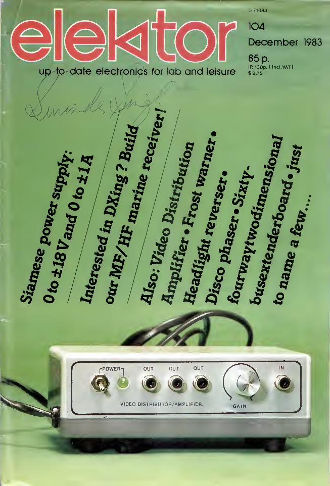
D 71683 -date electronics for lab and leisure 104 December 1983 85 p. IR 130p. ( incl.VAT) $2.75 or 8 IT* U W a & • x • if 8 ;F c A : # f? fir <? . J? 8 Z *8 * 8 & • ** « & *8r <fr i? £ <7 * f £ 1 J « S 2 p — . -» *Jy *w #5r fir *f *? Q ^ 5 L Jtrsf
-
Upload
khangminh22 -
Category
Documents
-
view
7 -
download
0
Transcript of Elektor Magazine
D 71683
-date electronics for lab and leisure
104
December 1983
85 p.IR 130p. ( incl.VAT)
$2.75
or
8IT* U Wa & • x •
if 8 ;F c A :# f? fir <? .
J? 8 Z *8 *8 &• ** « & *8r
<fri? £ <7
*
f £ 1
1
J « S 2 p—. -» *Jy *w #5r fir
*f *? Q ^ 5
L
Jtrsf

selektor 12-20
64-way 2-dimensional bus board 12-22A new, perfectly symmetrical, extension bus with no less than 7 connec-tors for those who feel that their present bus is becoming inadequate.
MF/HF USB marine receiver 12-24Simple and inexpensive to build, this receiver is intended for the manythousands who are interested in what's going on in the 1600 . . . 4000kHz marine band.
LED ornaments 12-30Some decorative, colourful, electronic 'ornaments' suitable for hangingon the Christmas tree or as a unique Christmas gift.
symmetrical power supply 12-32Many electronic applications require a symmetrical power supply: this
one provides two precise identical voltages of 0 to ± 18 V with adjust-
able current-limiting.
video amplifier . . 12-36Suitable for use anywhere in a video chain, this amplifier provides three
identical outputs. Input and output impedances are, of course, 75 ohms.
missing link 12-39
PC board pages 12-40
cumulative index 1983 12-41
locomotive headlamp reverser 12-44The high frequency generator for lighting model railway coaches (Elektor— November 1982) can also be used for changing over locomotive head-lamps according to the direction of travel.
frost warning device 12-47With winter approaching fast, this circuit should prove useful for anyonewho has to know if and when the outside temperature is getting nearfreezing point.
Our graphical departmentseem to have got into the
'Christmas spirit' cabinet a
bit early this year, but at least
they managed to get the pic-
ture of our video distribution
amplifier straight. This is also
in keeping with the seasonal
cheer that is likely to beabundant at this time as it
can have you seeing notdouble but treble. And whatabout a two-dimensional busboard, or a Siamese powersupply! As you may gather
from this, it is not only the
graphical department whohave been at the 'Christmas
spirit' a bit early!
disco phaser 12-50Studio quality phasers can be very complex and therefore very expensive,but simpler methods do exist as this circuit proves.
banking program 12-56A useful and instructive program for DOS Junior Computer owners:it helps you control your finances and is also a good introduction toindirect files.
NOVRAM: data storage without batteries 12-58A very interesting new memory 1C will shortly become available in
Britain: the NOVRAM (NOn-Volatile RAM). It combines the access-
ibility of a RAM with the power-down storage of an EPROM.
bus extension 12-62An extension which can be used with any personal computer providedthis has a buffered output bus.
market . . .
switchboard
12-64 A selection fromnext month's issue:
12-69 • universal active filter
• digital cassette recording12-80 • how accurate is your
watch?12-82 • wind direction indicator
• address decoding• fault finding in audio
equipment• EPROM programmer
12-03

elektor december 1983
HOME LIGHTING KITSThase kill contain a" ngtnM' y compornnl! and K>'
instruction* A aft designed lo replete a Mandard we*Mitdi and control up to 300w o' lighting
TDA300K Remote Control £14.30
WK8 T .».»* :r.r (O' Ibov. £ 4.20/^ov. £ 4 20/
TD300K Touchdimmer £7.00 L
TS300K Touch»w.tcH £7.00T0€’X Extension kit lo< 2-way _ _A
switching for TD300K 12.90
ELECTRONIC LOCK KIT XK101
This KIT contains a purpose designed lock 1C,
10-way keyboard, PCBs and all components
to construct a Digital Lock, requiring a 4-key
sequence to open and providing over 5000
different combinations. The open sequence
may be easily changed by means of a pre-
wired plug. Size: 7x6x3 cms. Supply: 5V to
15 V d.c. at 40uA. Ouput: 750mA maxHundreds of uses for doors and garages, car
anti-theft device, electronic equipment, etc
Will drive most relays direct. Full instructions
supplied. ONLY £10.50
Electric lock machaniam for use with latch
locks and above kit £1
3
5Q
"OPEN-SESAME"The XK 103 >s a gene'ai ou'oote infra red transmitter•eceiver with one momentary (normally ooeni relay
contact and two latched transistor outputs
Designed primarily for controlling motorised ga'agedoors and two auxilary outputs *or drive garagelights at a r*nge of up to 40 tt The unit a'so hasnumerous applications n the home fo' switchinglights. Tv ciosmg curtams. etc ideal fo» aged 0'
disabled personsThe Kn comprises a mams powered receiver a tour
button transmitter complete with pre d'-ned bo*requiring a 9v battery and one opto isolated so id
state switch k<t for inter facing the receive' to mamsappliances As with an ou' kits fuH instructions a>e
DISCO LIGHTING KITSDL IOOOKThis va*ue for money » 1
‘aa
tures a b« direction* ee
quence. speed of seq^e*;*and frequency of direc?o'Change, being veneb'e b» : • -
t-ometers and inco'DO's-es s -»> 1
dimming control£ T4
0LZ1000KA lower cost version Of the aoc-e w. ;
undirectional channel seo-e-'ie - — «•*:variable by means of a P's ee* ;c- :... 1
sw.tchedoniyatmamsie'c c-see*-* >1 — s
to reduce radio interference te •—
Optional opto input OlA!Allowing audio I beat jr-
responsePL3000KThis 3 channel sound to ©~ «
zero voltage switchingcontrol and built m mic No comspeaker or amp required No knot
simply connect to mams l
lamps ( IKw channelIfN « i
Only £1195
BEGINNERSSTARTER PACKSContaining selection of electronic components including transistors. LEDs, diodes,
capacitors. ICs etc together with a descriptive booklet with 10 easy to-buikj projects plus
a solderless circuit board enabling the components to be re-used Requires 9V battery
Discreet component pack Ino ICs) €5.00 Integrated circuit pack £6 .00
STOCKING FILLERS All full spec, branded devices.
PACK (1) 650 Resistors 47 ohm to lOMohm - 10 per value £4.00PACK (2) 40 x 16V Electrolytic Capacitors 10pF to lOOOpF - 5 per value £3.25PACK (3) 60 Polyester Capacitors 0.01 to 1pF/250V - 5 per value £5.55PACK (4) 45 Sub-miniature Presets 100 ohm to 1 Mohm - 5 per value £2.90PACK (5) 30 Low Profile 1C Sockets 8, 14. and 16 pin — 10 of each £2.40PACK (6) 25 Red LEDs (5mm dia.) £1.25
NoSofSi-COMPUTER rlSHOWROOM
Hours Mon-Fri 10am 6pm Sat 10am <
ONLY £23.75
Have you got our
FREE GREEN CATALOGUE ve»1NO >l Se.»ilS A E 6 9 TODAY"
It'S pecked w»1h rtrljuH of *1 our KITS |*|* twqr rjnqH
of SEMICONDUCTORS mcluiSmq CMOS IS TTl
linear microprocessor* and mctWOnt* .IiA ura*' of
LEO* ceperitor* tv*tot* hardware reieyv switches
etc We ehostock VERO end Ante* product* a* wvfi
.n book* from Ti>ia* Instrument*. Bebem and Clekltv
AU AT VERY COMPETITIVE PRICES
ORDERING IS EVEN EASIER JUST RINGTHE NUMBER YOU CAN T
FORGET FOR PRICES YOU CAN T RESIST
5 6 7 8-9-10iind give u* your Acres* or OarrLm.Ktl Noiv write onclotmg cheque or postal order
Official order* accented from schools. etc
Answering service evngs &wnds
MICROPROCESSOR CONTROLLEDMULTI-PURPOSE TIMER
Now you can run your central heat-ng, lighting, hi-fi system and lots
more with just one programmable timer At your selection it is
designed lo control four mams outputs independently, switching onand off at pre set times over a 7 day cycle, e g to control your central
heating (including different switching times for weekends I. |usl
connect it to your system programme end set it and forget it—theclock will do the rest a •
FEATURES INCLUDE •/*?>[
HOME CONTROL CENTRETh.s kit enables you to control uo to ’€ : "e-rappliances anywhere »n the house '-on ucomfort of you' armchair The !»**“ !miects coded ouises mt© the ma 's «** t- a
decoded by 'active' modules connec*ec •;
seme mams SuPO'v and used to s* •:*
appliance addressed ’he fens— »
i
mciudesaCOMPuTER interface so vb. :e" :
gramme you' favounte m.cro leg Z*6‘switch lights heatmg electric bia«»e - -*>your mommg coffee, etc auto-e* ;aWithout rewirmg you' house JUST THINK C
THE POSSIBILITIES The k-t mciudes a 9 Cfand components *or one transmiiter a'd tvreceivers o'us a pre drilled bo* »o- tt
transmitter
Order as XK112. £42.00. Additional Receivers XK111 £10 00
REMOTE CONTROL KITSFOP A DETAILED BOOKLET ON REMOTE CONTROL
send 30p - « • 9 S A E
MK6 SIMPLE INFRA RED TRANSMITTERSupplied wiin nend ne-d plastic bo* Reaves 9viFH»3)bette-, £4 20MK7 INFRA RED RECEIVERMain* powered w th r- sc Output to switch up to
500W at 2*0v sc “s'g# appro* 20 ft on otf o'
momentary contre £9 00iRC 500K - spec a o- ee *0' MK6MK7MK9 4 WAY KEYBOARD C 12 SOI
We also stock peripherals and
accessories disc drives, printers,
joy sticks etc together with a
wide range of books and the latest I
software for all the abovecomputers including ZX81
SEND S A E FOR LIST TODAY!
Outputs (O' switchingMK18 cased on tn« Sl490components to mass a codedPR3baneiy endkevbos'd it*
8 • 2 » 3em R*n e, ,
MK13 ’’ wav kevbos'3 *o- .»
ALL PRICES EXCLUDE VAT
Now only £39.00(Kit includes all components PCS.box assembly and programminginstructions)
Order as CT6000
24 HOUR CLOCK/APPLIANCE TIMER KIT
Switches any appliance up to ikW on end off at
preset limes once per day K<t contains
Av 5 1230 lC 0 5" LED display mams Supply
display dnva's switches LEDs macs PCBsand lull matroctrons
CTIOOOKBeeicK.1 €14 90
56 131 7lmml C17 40 V
Ready Bu.m €22 50
DVM/ULTRA SENSITIVETHERMOMETER KIT
This new design is based on .
the ICL7126 la lower powerversion of the ICL7106 ehtpi
l-r qua]and a 3’^ digit liquid cry*!* 1 * *
dispay This kit will form the
basis of a digital multimeter
(only a few additional resistors and switches
are required—details supplied I, or a sensitive
digital thermometer 1-50*0 to *t50*C)
reeding to 0.1*C The basic kit has a
sensitivity of 200mV for a full scale reeding,
automatic polarity indication and an ultra
low power requirement—giving a 2 year
typical binary Ma from a standard 9V PP3
when used 8 hours a day. 7 days a weak
Price £15.50
Add 65p postage & packing * 15% VAT to
total Overseas Customers.Add £2 50 (Europe). £6 00 (elsewhere! for
D&PSend S A E for further STOCK DETAILSGoods by return subject to availability
/vr*CM 9am to 5pm (Mon to Fri)
vJr tIM 10am to 4pm (Sat)
ELECTRONICS11-13 Boston RoadLondon W7 3SJ
TEL 01 567 8910 ORDERS01 579 9794 ENQUIRIES01-579 2842 TECHNICAL after jpm ,
12-10

advertisement elektor december 1983
TELEPHONEMAIL ORDERCALL IN AND SEE USWHERE TO FIND USMAIL ORDER041-332-4133SHOP AND STOCKENQUIRIES041-332-4133TELEX261507 REF. 2194
WE REGRET WE CANNOTANSWER MAIL ORDER/STOCK ENQUIRIESWITHOUT AN S.A.E.SAME DAY SERVICETRADE AND EXPORTENQUIRIES WELCOME
9-5.30 MON TO FRI9-5.00 SATEXPRESS MAIL ORDERSACCESS/BARCLAYCARDSWELCOMESAME DAY mSERVICE fc » »
THE NEW MARSHALL'S 1984 CATALOGUE is now available - one of
the biggest and best catalogues ever produced by MARSHALL'S.
56 pages crammed from cover to cover with components, accessories
and testgear.
New products include I.D.C. Plugs & Sockets, 'D' Plugs & Sockets, DIL
Headers, Ribbon Cable, Kits, Toroidal Transformers, I.C.'s, Capacitors,
Test Probes, and lots more — something for everyone.
TRADE, EXPORT, RETAIL AND MAIL ORDER SUPPLIED.
75p to callers, £1.00 post paid — Europe, £1.50 rest of the world.
Junior-Paperware
(in 2 vols.)
The floppy disk is probably the most significant
mass storage medium for microcomputers. It seems
incredible that so much data can be stored on a
simple plastic disk at such speed and with such
precision.
Unfortunately, it is not enough to just connect a
floppy disk drive to a microcomputer. Without
software the hardware is useless! Where can youget all the necessary source listings, hex-dumps,
and EPROM modifications? In the Elektor Junior
paperware, of course!
Junior paperware 1 contains the modifications of
the PM/PME EPROM and the source listings andhex-dump of the software cruncher and puncher;
Junior paperware 2 gives the source listing of the
bootstrap loader for Ohio Scientific Floppys andthe hex-dump of the EPROM.
Elektor
Publishers Ltd
Canterbury
Price £ 2.00 + 50p postage &packing per volume (outside U.K.£ 1 .00 ).
To order, please use the prepaidorder card at the end of this issue.
The K5000 Metal Detector Kit combines the challenge of Dl Yelectronics assembly with the reward and excitement of
discovering Britain's buried past.
As a Metal Detector-the K5000 boasts the provenpedigree of C-Scope, Europe's leading detector manufacturer.
As a Kit—simplified assembly techniques require little technical
knowledge, and no complex electronic test equipment. All stages
of assembly are covered in a finely-detailed 36 page manual.
Detector Features Analytical Discrimination AGround Exclusion
Ask at your local Hobby/Electronics shop or use the coupon and
send with your remittance to:-
C-Scope International Ltd., PO Box 36, Ashford, Kent TN23 2LN
Please send me K5000 Kits @ £1 19.99(+£3.00 p+p) each.
(MA. Marshall (London) Ltd.
Electronic Component Distributors
85 WEST REGENT STREETGLASGOW G2 2AW
TELEPHONE: 041 332 4133
MARSHALL (LONDON) LTD
1984 CATALOGUENOW OUT!
12-11

advertisement elektor december 1983
The NUMBER 1 cataloguefortheelectronics,
computing, communications, audio and
video engineering enthusiasts
GETYOURS NOW!!ambitINTERNATIONAL
200, North Service Road,Brentwood, Essex CM144SG
12-13
Telephone: (0277) 230909 Telex: 9951 94 AmbitG200, North Service Road, Brentwood, Essex CM14
Use the voucher alongside and deduct £ 1 from a prepaid
order from the Ambit catalogue where the total
value exceeds £ 1 5 (excluding VAT)
Alternatively— use it to obtain a FREE COPYof the Ambit Catalogue (minus the discount vouchers
supplied to purchasers paying the RRPof 80p)

elektor december 1983
Universal logic:
more potential in the chip
Inputs All possible output functions f (xj, Xj
)
xi
xi
fo ft f 2 fa <4 fs ft fl fs f 9 f 10 fll M2 f 13 f 14 f 15
0 0 0 0 0 0 0 0 0 0 1 1 1 1 1 1 1 1
0 1 0 0 0 0 1 1 1 1 0 0 0 0 1 1 1 1
1 0 0 0 1 1 0 0 1 1 0 0 1 1 0 0 1 1
1 1 0 1 0 1 0 1 0 1 0 1 0 1 0 1 0 1
Functions which can be obtained from various gates with two inputs. For three input
variables there are 256 possible output functions.
Most silicon chips are cheap because
they embody conventional circuits
of the sort generally needed in
electronic equipment and are mass-
produced. Many others are neededfor special applications, but makingsmall batches of chips designed to
do specific, less common-place jobs
is complicated and expensive. A newapproach to this problem, based onwhat is called universal logic, is a
design for a chip with the potential
of virtually any kind of computer-logic circuit and which can be used
as a 'universal' building block in
electronic systems.
A new and highly original line of
development in microelectronics waspioneered by Dr Stanley Hurst, a
senior lecturer in the school of
electrical engineering at the University
of Bath, in the West of England sometime ago.
Microprocessors, computer control
processors on tiny slivers of silicon,
are cheap and plentiful; but they are
so only because of immense sales.
The range available from the world's
manufacturers is relatively inflexible,
which means that users have to sur-
round the microprocessor with other
integrated-circuit devices to get the
operation they require. So there is
already a market, one which will
increase in the mid 1980s andonwards, where makers of equipmentneed specific digital microelectronics
devices designed to their individual
needs. The difficulty here is that the
cost of designing a silicon-chip device
is enormous, involving many highly-
skilled scientists and engineers over a
very long time, even with computer-aided design, and needing very
complex and expensive equipment.
This huge cost is quickly recovered
when there are large, world-wide
sales; but such a project cannot beconsidered by an equipment manu-facturer who needs but one or at
most a few types of special digital
devices designed for his particular
application.
Dr Hurst is not the only one to see
this. Indeed, one British firm has
already won a Queen's Award for
technology for what it calls its
uncommitted logic array, based onblocks of conventional circuits
already incorporated in each chip
but not connected to each other
until the customer's needs are
known.Dr Hurst's approach is quite different.
Though, as he says, there has been
and will continue to be tremendousdevelopment in design and manu-
facturing techniques, there has notbeen much 'evolution or revolution
at the fundamental level'. If there
were a general-purpose basic design,
needing only the final maskingprocedure for arranging the inter-
connecting links to make a device
to suit a specific purpose, the small-
quantity market could be satisfied
economically. So he has researched
what the calls his Universal Logic.
In this context, logic is the appli-
cation of Boolean algebra to a digital
process using binary arithmetic.
Boole was an English logician andmathematician who wrote a paper onthe mathematical analysis of deduct-
ive reasoning in 1847, a paper re-
discovered in 1938 and applied first
to relays and switches. It was seized
on in the mid-1940s for electronic
computing. A computer and anysimilar digital device is an immensemultiplicity of electronic switches,
known as 'gates', which pass onbinary information (that is, a 0 for
'off' and a 1 for 'on') from one or
more input signals.
Lacking Power
From the evidence of digital com-puting it must be agreed that standard
gates have been very successful, but
analytically they do not satisfy
Dr Hurst. In his words, they lack
logical power. It is easy to see that
there is an ambiguity in each gate.
With an AND gate, for example,
accepting inputs A and B, we can say
that when one input is in the off
state and the other in the on state
the output is 0, but it does not
indicate which one of A and B is
off or on. With three input things
are even more ambiguous. To put
it another way, the output of NORgate is unity only when all inputs
are 0, and of a NAND gate only
when all inputs are 1
.
The practical outcome of this lack
of logical power is that quite a
number of gates have to be com-bined to give a specified result. Forexample, in one simple device adding
numbers there are 16 gates. A
straightforward decoder (which trans-
lates from binary to ordinary decimal
numbers, among other tasks) needs
50 gates to do its basic job. A circuit
to compare one number with another
has 33 gates. (These figures are taken
from a random look at some pub-
lished circuits.) In a microprocessor
there may be at least 3000 gates.
The inefficient way orthodox gates
operate Boolean logic has set morethan one microelectronics engineer
or scientist thinking of possible
better circuits. But large manu-facturers have had such enormoussuccess in getting thousands of
gates on a silicon chip, making it
a cheap device, that they are in-
terested only in competitive techno-
logical improvements in getting moreand more on less and less. There is
no reason why they should be
interested in fundamental changes
in logic. In the market for small-
quantity, custom-built chips things
are different.
Mathematical
The approach of Dr Hurst and his
colleagues is fundamental yet uncon-
ventional. In trying to find out
whether one could get a basic circuit
that would do whatever logical step
was needed, according to the connec-
tions and the programming, their
thinking was primarily mathematical:
it made use of esoteric techniques
such as set theory, Walsh functions
and so on. They were able to showthat a universal logic gate was indeed
a possibility. With two input variables
there are 16 possible output func-
tions (see table 1, which is an exer-
cise to see what functions could be
obtained from various gates). Forthree input variables there are 256possible output functions. Could a
single circuit cope?Calling the circuits ULG2 (universal-
logic gate for two input variables)
and ULG3, Dr Hurst has shown that
an array of ULG2 gates will do all
the logical steps possible even for
three input variables and that oneULG3 will be capable of realising all
12-20

elektor december 1 983
1
J- v«
SR3
f(xi, x,)
869 S
Figure 1. Basic circuit of a ULG2, com-prising two transistors, two diodes andthree resistors. Although only two input
variables are applied, three input connec-
tions Is, t and rl are provided. This is to dowith the set-theory mathematics of the
device.
256 outputs — not all at once, of
course, for the result depends onwhich input terminals are used and
how the circuit internal wiring is
connected.
The number of ULG2 cells needed
to realise all the 256 functions of
three input variables has been calcu-
lated and compared with the equiv-
alent figure for orthodox gates. Theresults are shown in table 2.
We can see that the ULG2 is roughly
twice as powerful as a NANO or a
NOR. Incidentally, it should be
noted that although a ULG2 mayhave only two independent variables
as input, there may be three or four
physical connections. Figure 1 showsa circuit for a ULG2. It has twotransistors, two diodes, and three
resistors. Though there are but twoinput variables, there are three input
connections. This is to do with the
set-theory mathematics of the device
and need not concern us.
The circuit shown brings in elec-
tronics, which has so far not been
discussed and need not be considered
in detail. A gate is made of transis-
tors, diodes, resistors and, some-
times, capacitors. Up to now mostlogic gates have depended on bipolar
technology, that is, transistors with
two possible states. This is the onerepresented in the diagram. A newer
technique is based on MOS (metal-
oxide-semiconductor) devices, whichinvolve far fewer stages in manufac-ture and avoid the 'cross-talk' be-
tween adjacent conductors. Dr Hurst
considers that bipolar methods will
die out in the next decade and bereplaced by MOS circuitry.
The practical problem is concerned
with how big an area of silicon is
used up in a U LG as compared with
orthodox gates. It is easily seen that
a ULG3 would occupy much morespace. So is it better to use an array
of identical ULG2s or rely on a
ULG3? When such matters are de-
cided there will be available a set of
universal-logic gates which can be
supplied as units. All that the de-
signer then has to do is produce a
suitable mask, a task made simple bycomputer-aided design, which will
deposit the appropriate interconnec-
tions on the chip. The cost of design
for a custom-made device will there-
fore be drastically reduced, even if
the ULGs are themselves more ex-
pensive than orthodox gates —another question being researched.
Furthermore, as Dr Hurst has said, a
considerable amount of special logic
design in ULG form can be under-
taken and a library of standard inter-
connection details built up, ready for
individual customer requirements.
It is a long-term research develop-
ment programme for which full-
time staff will be recruited. It could
lead to a commanding position in the
ever-growing use of silicon chips for
specific purposes.
C.L. Boltz SPECTRUM 171
Taking the heat out of
electronics
Air cooling was traditionally used to
cool electronic units but as com-ponent densities are continually in-
creased in new designs of equipmentso the problem of cooling has grownto the point where liquid cooling is
having to be adopted. This is because
Table 2.
ULG2 1 NAND NOR
Total number of cells or gates to realise all 256 functions 683!
1118 1124Average number per function 2.67 4.36 4.39Maximum number per function 4 7 7
Average number of cell /gate connections per function 1i 10.68 17.44 17.56
Comparison between the capabilities of ULG2 cells and that of orthodox gates. Thetable shows that the ULG2 is roughly twice as powerful as a NAND or a NOR gate.
of its ability to offer higher heat
removal rates.
However, liquid cooling has brought|
its own constraints because its pipe-
work, pumps and fluids make it
much more difficult for service
engineers to get to the electronic
components.
Now the dynamics group of British
Aerospace claims to have solved the
problems with what it describes as
a 'new concept' in liquid cooling sys-
tems. Known as Flexiwall, the BAesystem is subject to a provisional
patent application and, at an inter-
national design engineering exhibition
recently held at Birmingham in the
English Midlands, has been chosen as
a good example of British inno-
vation.
A BAe spokesman said: 'The majorbenefit of Flexiwall is that un-
interrupted access can be obtained
to electronic units for servicing or
replacement without the need to
drain or disconnect the cooling sys-
tem, which is entirely separate andself-contained. Other attributes are
that it is a low-pressure system,
silent in operation, and is inexpensive
to manufacture and install. In terms
of volume occupied by a Flexiwall
system, it is significantly moreeffective in removing a given quan-tity of heat than air cooling systemsof comparable capacity.
Tests with a prototype system have
shown that an electronic unit con-
taining a large number of com-ponents tightly packed together anddissipating four kilowatts of heat can
be maintained at component tem-peratures below 70 degrees C.
This is achieved by circulating a
cooling fluid such as water glycol
through a convoluted chamber whichexpands like a bellows to allow a
flexible face to move forward until
it touches the electronics equipment.
It will then mould itself to the shape
of the component and the cooling
fluid rapidly removes heat being
conducted from inside the elec-
tronics unit. When the pressure onthe cooling fluid is switched off the
F lexiwall face retracts elastically clear
of the equipment being cooled.
This ability to retract when not
being used to cool the unit meansthat components can be freely re-
moved from their racks for servicing
or replacement. When maintenance
work is completed the Flexiwall
system is simply switched on and
the stainless steel foil face of the
cooling chamber advances to regain
contact.
Made in Britain/John. F. Webb
(895 S)
12-21

64-way bus boardelektor december 1983
The first time a microprocessor bus system is used it seems enormous, but
before long it begins to seem a bit limited, and then cramped, and finally
completely inadequate. So after our first bus with 3 connectors, and the
second with 5, we now introduce the new extension bus with no less than 7
connectors, which, unlike its predecessors, is perfectly symmetrical.
64-way bus boardand service aid in jjP systems
a new two-
dimensional
extension
bus with
7 + 2 con-
nectors
Parts list
The new Elektor universal bus differs from
its predecessors in that it has seven 64-wayfemale connectors, plus a male connector
at one end (the ‘input’) and a female con-
nector at the other end (the ‘output’). In
addition to this, its upper side (connector
side) is copper-clad and acts as a screen.
The layout of the board also allows easy
interconnection between lines.
An extension for testing
As can be seen from figure 2, the bus board
is in eurocard format. This is neither luck
nor simply the consequence of the numberof connectors used. It was, in fact, a delib-
erate choice to allow us to use the newboard as a service aid. Imagine a microcomputer constructed of eurocard-format
boards mounted on a bus board that is
hidden somewhere at the back of a 19inch rack. What happens if one of these
cards has to be tested and repaired? With-
out removing everything from the case the
cards are inaccessible.
This is where the new bus comes in. The
extension board can be plugged in in place
of the suspect one which is, in turn, pluggedinto the female connector on the bus board.
This leaves the board to be tested com-pletely outside the case of the computerand thus perfectly accessible. Obviouslythis makes childs play of something that
would otherwise be quite difficult. Thismethod of using the extension bus to
counter the problems of testing in tight
spaces can also serve as an aid for checkingsignals on the bus itself, with an oscilloscope
or logic analyer for example.
576 pins to solder
As we have already said there are 64 lines
and there is no interconnection betweenany pin in an ‘a’ row and a neighbouring‘c’ pin. At least, that is the idea. Careless
soldering could inadvertently change this.
Bear in mind that the vertical (1 ... 7)connectors are polarized and therefore mustbe mounted the right way round. Connector0 (the input) is a male right angle connector(note that the ‘a’ and ‘c’ rows are inter-
Seven 64-way straight
female connectors
(a + c rows). DIN 41612One 64-way right-angled
male connector (a + c
rows). DIN 4161
2
One 64-way right-angled
female connector (a + b
or a + c rows) DIN 4161 2
Two metal brackets (for
mounting connector
no. 8)
Mounting hardware and
ideally guide rails
1
Figure 1. This is how the
connectors are mounted.Particular care must be
taken with the two outside
connectors.
12-22

264-way bus boardelektor december 1983««««««««
® ® ® ® ^ _1
changed).
As there are two types of angled femaleconnectors available, one with 2.5 mmbetween the rows and the other with 5 mm,we have made the printed circuit boardcompatible with both ‘a + b’ and ‘a + c’
types.
Remember to connect the earth plane onthe upper side of the board to the ‘0 V’pins of connectors 0 and 8! N
This bus can easily be used for the Junior
Computer, but in this case connector no. 8should be omitted. In its place, the outputconnector of the interface card should be
connected by means of crossed wires, so •
that the 'a' row of the interface card is
linked to the 'c' row of the bus, and vice
versa.
Figure 2. The copper-clad
side of the board acts as
an earth plane. Connectors
0 and 8 mount parallel
to the board whereas all
the remaining (polarised)
connectors mount verti-
cally. If cards are to be
fitted and removed fre-
quently the female con-
connectors should be
provided with guide rails.
12-23

MF/HF USB marine
receiver
elektor december 1 983
For some time now, a number of our readers, fervent DXers, have been asking
for a follow-up to our short-wave SSB receiver (June 1982). DX literally
means 'distance X' or 'distance unknown' and DXers are therefore hobbyists
interested in long-distance radio communication (transmission and/or
reception). Apart from these enthusiasts there are thousands of other people
interested in listening to what goes on at sea and it was with them in mind
that we thought it would be a good idea to design an inexpensive receiver
for operation in the 1600 . . . 4000 kHz band.
MF/HF USBmarine receiver
Radio traffic in the 1600 . . . 4000 kHz
band comprises CW (ICW and MCW, often
just called ‘morse’), RTTY (radio teletype),
radio facsimile, and plain telephony. For
most DXers, morse and telephony are, of
course, the most interesting and it is these
that the receiver described in this article
is designed to process.
In principle, most of the 1600 . . . 4000 kHz
band is intended for medium range marine
communications: longer distances are served
by maritime bands on higher frequencies.
A substantial part of the traffic in this band
is concerned with
weather reports
warnings to shipping
storm and gale warnings
traffic lists
These are all services supplied free to
shipping by the various national administra-
tions and which can therefore be listened to
by anyone. It is as well to point out now
that it is NOT allowed to listen in to private
telephone conversations and like traffic:
if you do by accident, NEVER repeat it
to third parties.
The services mentioned above are invariably
preceded by an announcement on 2182 kHz,
the international distress and call frequency
in this band. This is therefore the frequency
to which DXers tune in. Although not so
pleasant for those at sea, the worse the
weather, the more lively things become for
the DXer. The number of weather reports
and warnings to shipping is approximately
directly proportional to the wind force!
However, even when the weather at sea is
good, there is much of interest going on . .
.
Traffic lists are lists of names of ships for
which a particular coast station has messages.
Such lists are transmitted regularly through-
out the day, always preceded by an announce-
ment on 2182 kHz. The announcement
includes the information at which fre-
12-24

1 MF/HF USB marinereceiver
elektor december 1983
Figure 1. Coast stations
which can be received
in Europe. Frequencies
cannot be given, but
these can be ascertained
by listening diligently
on the international distress
and call frequency of
2182 kHz.
quency the coast station is about to transmitthe lists. If a ship finds that its name is in-
cluded on the list, it will call the coast
station - again on 2182 kHz - to arrangethe frequencies on which the messages will
be transmitted and received.
A simple chart of the most importantEuropean coast stations is shown in figure 1.
It should be possible to receive most of thesestations when conditions are good. Unfor-tunately, frequencies in the 1600 . . . 4000kHz band are affected by the so-called D-layer which, in contrast to other layers
such as the E and F, absorbs rather thanreflects them. As long-distance radio com-munication depends heavily on reflected
waves, it is therefore badly curtailed in thepresence of the D-layer. However, after
sunset this layer disappears and receptionover much longer distances than duringdaytime becomes possible. The eveninghours are therefore best for DXing in this
particular band.
So much for a short introduction to the
why, where, and how? Now for the actual
receiver . .
.
Direct conversion
As we wanted the receiver to give goodperformance and yet be relatively simpleand inexpensive to build, we opted for a
direct-conversion design. For those whohave forgotten (or never read) our June1982 articles ‘the principles behind anSSB receiver’ and 'compact short-wave
SSB receiver’, here is a short resume.The basic principle of a direct-conver-
sion receiver is that the radio signal is
converted into an audio signal withoutthe use of intermediate frequencies.
The layout of such a receiver is strongly
reminiscent of that of a superheterodynebut the oscillator frequency is equal to the
12-25
MF/HF USB marinereceiver
elektor december 1983
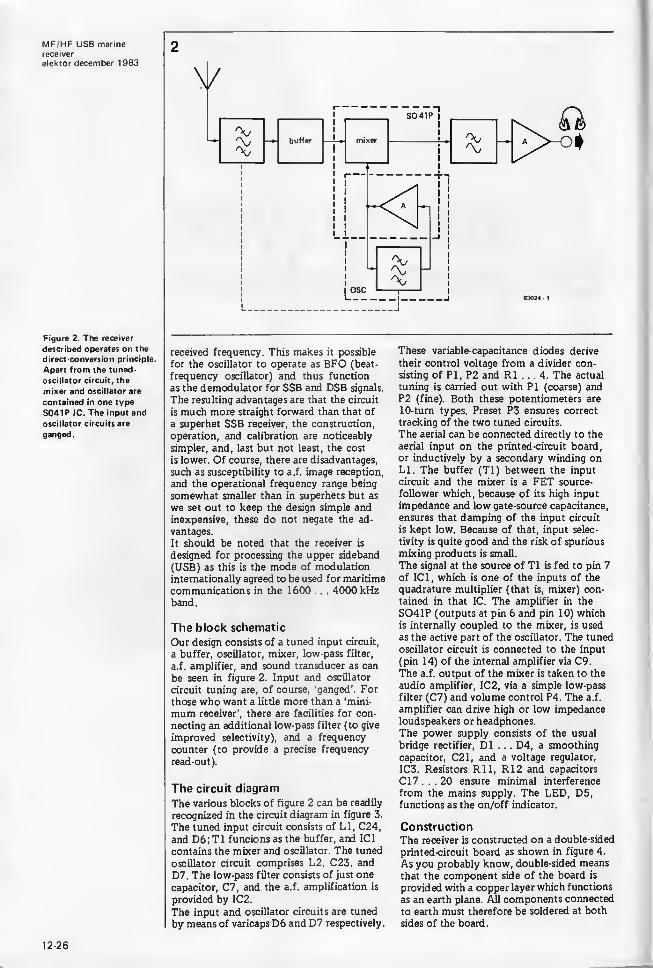
Figure 2. The receiver
described operates on the
direct conversion principle.
Apart from the tuned-
oscillator circuit, the
mixer and oscillator are
contained in one type
S041P 1C. The input and
oscillator circuits are
ganged.
received frequency. This makes it possible
for the oscillator to operate as BFO (beat-
frequency oscillator) and thus function
as the demodulator for SSB and DSB signals.
The resulting advantages are that the circuit
is much more straight forward than that of
a superhet SSB receiver, the construction,
operation, and calibration are noticeably
simpler, and, last but not least, the cost
is lower. Of course, there are disadvantages,
such as susceptibility to a.f. image reception,
and the operational frequency range being
somewhat smaller than in superhets but as
we set out to keep the design simple andinexpensive, these do not negate the ad-
vantages.
It should be noted that the receiver is
designed for processing the upper sideband
(USB) as this is the mode of modulation
internationally agreed to be used for maritime
communications in the 1600 . . . 4000 kHzband.
The block schematic
Our design consists of a tuned input circuit,
a buffer, oscillator, mixer, low-pass filter,
a.f. amplifier, and sound transducer as can
be seen in figure 2. Input and oscillator
circuit tuning are, of course, ‘ganged’. For
those who want a little more than a ‘mini-
mum receiver’, there are facilities for con-
necting an additional low-pass filter (to give
improved selectivity), and a frequency
counter (to provide a precise frequency
read-out).
The circuit diagram
The various blocks of figure 2 can be readily
recognized in the circuit diagram in figure 3.
The tuned input circuit consists of LI, C24,
and D6; T1 funcions as the buffer, and IC1
contains the mixer and oscillator. The tuned
oscillator circuit comprises L2, C23, and
D7. The low-pass filter consists of just one
capacitor, C7, and the a.f. amplification is
provided by IC2.
The input and oscillator circuits are tuned
by means of varicaps D6 andD7 respectively.
These variable-capacitance diodes derive
their control voltage from a divider con-
sisting of PI, P2 and R1 . . . 4. The actual
tuning is carried out with PI (coarse) andP2 (fine). Both these potentiometers are
10-turn types. Preset P3 ensures correct
tracking of the two tuned circuits.
The aerial can be connected directly to the
aerial input on the printed-circuit board,
or inductively by a secondary winding onLI. The buffer (Tl) between the input
circuit and the mixer is a FET source-
follower which, because of its high input
impedance and low gate-source capacitance,
ensures that damping of the input circuit
is kept low. Because of that, input selec-
tivity is quite good and the risk of spurious
mixing products is small.
The signal at the source of Tl is fed to pin 7
of IC1, which is one of the inputs of the
quadrature multiplier (that is, mixer) con-
tained in that IC. The amplifier in the
S041P (outputs at pin 6 and pin 10) whichis internally coupled to the mixer, is used
as the active part of the oscillator. The tuned
oscillator circuit is connected to the input
(pin 14) of the internal amplifier via C9.
The a.f. output of the mixer is taken to the
audio amplifier, IC2, via a simple low-pass
filter (C7) and volume control P4. The a.f.
amplifier can drive high or low impedanceloudspeakers or headphones.
The power supply consists of the usual
bridge rectifier, D1 . . . D4, a smoothing
capacitor, C21, and a voltage regulator,
IC3. Resistors Rll, R12 and capacitors
Cl 7 . . . 20 ensure minimal interference
from the mains supply. The LED, D5,functions as the on/off indicator.
ConstructionThe receiver is constructed on a double-sided
printed-circuit board as shown in figure 4.
As you probably know, double-sided means
that the component side of the board is
provided with a copper layer which functions
as an earth plane. All components connected
to earth must therefore be soldered at both
sides of the board.
12-26

An accidental advantage of the copper layer
is that it serves as a heat sink for IC3 which
can thus be mounted directly onto the board
(with the aid of some heat-sink compound).
Assuming that neither the mounting of the
components nor the connecting of the
potentiometers, power supply, and so onwill give you any problems, we turn to
some specifics and hints. First of all, the
coils: these will have to be wound by hand.
Fortunately, neither of them is bifilar,
nor do they have taps or coupling coils
(but see under aerial!). Coil LI consists of
25 turns enamelled copper wire SWG 30 on
a ferrite rod of 100 x 10 mm. The coil
should be wound so that it can be shifted
along the rod which can, for instance, be
achieved by laying the turns onto a tube
of thin cardboard around the rod. Thewhole is then mounted onto the board
by means of two spacers and some string:
holes for securing the string are provided.
Coil L2 consists of 50 turns of the samewire wound evenly onto a T50-2 toroid.
The whole assembly is mounted onto the
board with a nylon screw, nut, and washer.
Potentiometers PI and P2 must be 10-turn
types. We know there will be some of you
who, on cost considerations, will try to use
standard types: we must, however, strongly
advise against this, because tuning will
become almost impossible and certainly
will lead to very disappointing performance.
If you must economize, use a 10-turn
for PI and replace P2 by a wire bridge.
Tuning will then be a little more difficult
than it should be, but it will be possible.
The varicaps D6 and D7 also present a little
problem: they are manufactured as a pair
and must therefore be split into two (elec-
trically only!). Often they carry no indica-
tion as to cathode and anode, and these
have thus to be ascertained with the aid
of a multimeter. This can be done by com-parison with a known diode.
To ensure good stability, it is advisable to
house the entire receiver in a closed metal
case. It is also advisable to screen the input
stages from the remainder by fitting a tin
or brass partition where indicated by a
dotted line in figures 3 and 4.
MF/HF USB marine
receiver
elektor december 1 983
Figure 3. The circuit
diagram is conspicuous by
its simplicity: one FET,two ICs, a stabilizer, and
some passive components.
Tuning is effected bymeans of varicaps D6and D7.
3
12-27

MF/HF USB marinereceiver
elektor december 1983
Parts List
Resistors:
R1,R13 = 1 k
R2, R3 = 22 k
R4 = 1 00 k
R5, R8, R9 = 220 k
R6 - 820 fi
R7 = 3k9rio= ionR11, R12 - 220 nR 14 = 330
n
Capacitors:
Cl = 4p7C2, C4, C5, CIO, C16 -
100 n
C3 = 1 n
C6. Cl 2, C22 = 1 p/16 VC7, C11 - 22 n
C8 = 1 p/10 VC9 = 3p3C13 = 10 p/6 VC14 = 1 n
Cl 5 = 470 p/10 VCl 7 . . . C20 = 47 nC21 = 1 000 p/35 VC23, C24 = 40 p trimmer
Semiconductors:
T1 = BF 256CD1 . . . D4 « 1N4001D5 * LEDD6, D7 = KV 1 236IC1 - S041PIC2 = LM 386IC3 = 7812
Miscellaneous:
P1.P2 = 10 k 10-turn
potentiometer
P3 = 1 00 k preset
P4 = 10 k log potentio-
meter
LI - 25 turns enamelled
copper wire SWG 30 on1 00 x 10 mm ferrite rod
L2 = 50 turns enamelled
copper wire SWG 30 onT50-2 toroid
Trl = mains transformer
18 V/250 mASI m mains on/off switch
Figure 4. The printed-
circuit board is double
-
sided. The copper layer
at the component side
functions as an earth plane.
12-28

MF/HF USB marine
receiver
elektor december 1983
Figure 5. The selectivity
can be improved by
fitting this low-pass
filter between C8 and
volume control P4.
Figure 6. Spectrumanalyzer photograph
of the filter in figure 5.
The horizontal scale is
1 kHz per division: the
vertical 10 dB per divi-
sion.
5
Calibration
The receiver can be calibrated without the
use of expensive test instruments.
Use a length of wire of not less than three
metres as a test antenna and connect this
to the aerial terminal on the printed circuit
board.
Set C23, C24, and P3 to their mid-position.
Turn PI to the lowest frequency (lowest
tuning voltage) and then seek a broad-
casting station or interference whistle in
that region (of about 1600 kHz).
Shift LI along the ferrite rod until the
received signal is strongest.
Turn PI to the highest frequency band(3500 . . . 4000 kHz), seek a station, and
6
adjust C24 for maximum signal strength.
The receiver should amply cover the 80metre amateur band (3500 . . . 3800 kHz).
If it does not, adjust C23 until it does.
Once the range has been achieved, the
tracking of the input and oscillator
circuits must be set. Tune the receiver
to about the middle of the range (say,
2500 kHz), seek a station, and adjust P3for maximum signal strength. If this meansa substantial adjustment of P3, it is wise
to repeat the entire calibration procedure.
When the receiver has been calibrated
correctly, its sensitivity is of the order of
1 pV, which is quite good. However, because
the transmitter power of most vessels is not
high, it pays to have a good aerial. This
should be at least 3 metres, but the longer,
the better! If the length goes above, say,
twenty metres, it is advisable to use inductive
aerial coupling as already stated. The coup-
ling winding should consist of 1 ... 3 turns
enamelled copper wire SWG 30 woundaround the ‘earthy’ end of LI.
Extensions
Connect a frequency counter to terminal
G on the printed-circuit board (wherethe oscillator voltage of about 250 mV is
present) to obtain a precise frequency
read-out. Connecting a counter may, how-ever, cause the oscillator frequency to
shift. If the sensitivity of the counter is
good, this shift may be reduced by fitting
a large capacitor between the counter out-
put and earth. This capacitor should beso large that the counter just remains stable.
Better selectivity can be achieved by fitting
the low-pass filter shown in figure 5 be-
tween C8 and P4. This filter can be readily
constructed on a small piece of prototyping
(vero) board. Its pass band shown in figure 6was obtained from a spectrum analyzer:
65 dB additional attenuation at 6 kHzoff-tune is not bad for a receiver intendedfor beginners! M
12-29

LED ornamentselektor december 1983
Around this time of the year even the most hardened of electronic hobbyistsis likely to be thinking of a completely different type of circuit than theusual ones. Now a circuit does not necessarily have to do anything, exceptmaybe play a game or simply look decorative. Of course, electronics is totally
suited to this sort of task and, as we have always known, electronics can just
be good fun.
LED ornamentsseasonal
electronics
Figure 1 . Here we showjust a few of the countless
designs that can be madewith a few LEDs. Use yourimagination. Unfortunately
it is not possible to showthe colours here, but
almost all the colours in
the spectrum are available.
The purpose of this article is to give any‘not entirely sane’ handymen among you a
few ideas. What we have in mind is makingdecorative, colourful 'LED ornaments',
suitable for hanging on the Christmas tree,
or as an exclusive brooch (with a battery
in an inside pocket) or something similar.
To anyone not familiar with electronics,
especially children, it could be somethingtotally fascinating, and it is also an idea
for a unique Christmas present.
What we really mean is simple figures, suchas those shown in figure 1. They consist ofnothing more than a group of LEDs arranged
in a certain pattern. Exactly how it is madeand how big it is is a matter for each to
decide for himself. It could be anythingfrom a simple brooch to a fully fledged
star with all the options. We opted for a
star, cut from a piece of plywood withholes drilled for the LEDs and with a goodcoat of a suitable colour paint. We endedup with something like that shown in
figure 2. This is only intended as an exampleas it could be constructed in any number of
ways.
Flashing electronics
Simply having a display of LEDs is all very
well, but as an electronics hobbyist you are
more or less obliged to make the LEDs flash.
Only then can it really be called ‘eye-
catching’. It is not at all difficult, but there
are a few basic elements required. In its
simplest form the electronics needed consist
of an oscillator for the flash timing, a div-
ider, and the LED driver. A few suggestions
are shown in figure 3.
If there is not very much room to play withthen one of the four oscillators from figure
3a, the divider (figure 3c) and a few of thedriver stages drawn in figure 3d are all
that are strictly essential. If there is morespace available, taking a bit more time and a
few more components, the circuit can beexpanded.
Instead of using one oscillator, for example,four switchable oscillators could be substi-
tuted, as figure 3a shows, so that differ-
ent rhythms can be chosen. The clockfrequencies used is a question of taste.
Cl . . . C4 can have any value from 100 nto 1 00 ju and R 1 . . . R4 can be any resist-
ance from 10 k to 10 M. That gives a rangeof speeds from very slow to very fast. Thewiper of the four-way switch is connectedto the clock input (CL) of the divider IC(figure 3c).
The oscillator of figure 3b is also a nice
possibility. This automatically supplies dif-
ferent rhythms of its own accord, withoutany need for switching. When SI is open theCL output alternately supplies high and lowfrequency clock pulses. If SI is closed thehigh and low frequency pulses follow eachother at random.The divider circuit of figure 3c requires little
comment. This is a straightforward appli-
1
disco (tar Christmas star shoot irvg target
12-30

cation of a well known decade counter IC.
If all ten outputs are to be used, then the
reset input (pin 15) must be connected to
ground. Otherwise this pin should be con-
nected to one of the 0 ... 9 outputs, so that
whenever this output is reached the counter
goes back to ‘O’.
The LEDsNow the LED drivers. As the decade counter
of figure 3c cannot drive the LEDs directly,
each output must be followed by a transistor
stage. The simplest version is shown in
figure 3d. Each transistor can drive a numberof LEDs connected in series. The value of
the series resistor can be calculated bysubtracting the total voltage drop across the
LEDs from the supply voltage and then
dividing this by the current that is to flow
in the LEDs:
Ub-(n-ULED)
Both Uled^ ILED depend on the type
used. The voltage drop across red LEDs is
*
* *
generally 1.6 V; for yellow it is approxi-
mately 1.9 V and for green the norm is
about 2.2 V. The current required can vary
between 10 and 50 mA.An expanded LED driver stage is shown in
figure 3e. In this case transistor T1 is pro-
tected by the current limiting components,
T2 and R2. Given a supply of 15 V, this
stage can drive a maximum of six and a
minimum of three LEDs in series. FewerLEDs cannot be used here or T1 will have
to dissipate too much current. The LEDcurrent is determined by the choice of R2.
The value of this resistor is easily calculated
by dividing the voltage drop across this
resistor (= the base/emitter voltage of
T1 = 0.6 V) by the current required:
0 .
ILED
From theory to practice
By now you should have all the information
you need to start making your own original
LED ornaments (except maybe which end of
a fret saw is the sharp end).
The power supply can in principle be kept
very simple, but it should not be underrated.
The oscillator and divider certainly require
little current, but the LEDs need quite a bit
more. If a voltage of 15 V and the full ten
channels are to be used, then for a LEDcurrent of 10 mA the supply must be able
to provide at least 100 mA. If the LEDsdraw even more current the total consump-tion can rise to as much as 0.5 A (if ILED *s
50 mA). The final design of the power
supply therefore depends on the number andtype of LEDs used.
Finally . . . while we are on the subject of
LEDs. There seems to be an ever-increasing
number and variety of LEDs available today
and you may be wondering which to use.
The majority are perfectly suitable for our
purposes here, but the best are the diffused
coloured types. These have a wide viewing
angle and remain visible from a distance
even if you are not standing straight in front
of them. M
Figure 2. Our 'prototype'
shown here actually
involves more carpentry
than electronic ability.
Figure 3. Driving the
LEDs. Figures a and b
show two variations for the
oscillator. The output (CL)
goes to the decade counter
of figure c, each of the out-
puts (0 ... 9) of which can
be followed by a transistor
stage (d or e) driving one
or more LEDs.
12-31
symmetrical power supplyelektor december 1983
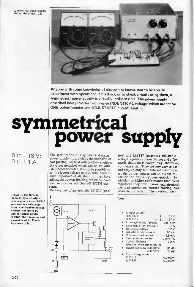
Anyone with some knowledge of electronics knows that to be able to
experiment with operational amplifiers, or to check circuits using them, a
symmetrical power supply is virtually indispensable. The power supplydescribed here provides two precise INDENTICAL voltages which are set byONE potentiometer and ADJUSTABLE current-limiting.
symmetricalpower supply
The specification of a symmetrical mainspower supply must include the provision oftwo precise, identical voltages (one positive,
the other negative) which can be set withONE potentiometer. It must be possible to
set the lowest voltage to 0 V. And, perhapsmost important of all, the unit must haveadjustable current-limiting, which on over-
load reduces or switches off BOTH cur-
rents.
We have not often used the LM317 (posi-
tive) and LM337 (negative) adjustable
voltage regulators in our designs and a fewwords about these devices may, therefore,
not come amiss. They are very easy to useand require only two external resistors to
set the output voltage and an output ca-
pacitor for frequency compensation. Inaddition to higher performance than fixedregulators, they offer thermal and electrical
overload protection, current limiting, andsafe-area protection. The overload pro-
Figure 1. The three-ter-
minal integrated, adjust-
able regulator type LM317operates as a series regu-
lator. The required outputvoltage is obtained byadding voltage divider
R1/R2. The minimum load
current is set to 10 mAby means of R 1.
Table 1
Output voltage
(LM 317) 1.2
(LM 337) -1.2Line regulation, typically
Load regulation, typically
Reference voltage
Adjustment pin current
Minimum load current
Temperature stability
Current limiting
(constant with temperature)
Ripple rejection (LM317)(LM 337)
Thermal regulation
(LM 317)
(LM 337)
. . . 37 V
. . . -37 V0.01%/V
0 . 1 %1.2 V50 nA
3.5 mA0.01%/°C
2.2 A
OPAMP
0.04%/W0.03%/W83121 1
12-32
tection circuitry remains fully functional
even if the adjustment terminal is dis-
connected. The ‘K’ versions are packaged in
the standard TO-3 transistor housing. Theoperating temperature range is 0 . . . 125°C.
Further features are shown in table 1.
For those who may have forgotten: a series
voltage regulator is a circuit in which a
‘ballast’ transistor, controlled by an ampli-
fier, is used as a preset resistor in series
with the load. This transistor absorbs anysuperfluous voltage.
Principle of operation
The operation of a voltage regulator (in this
case the LM 317) may be described with the
aid of figure 1 in which an operational am-
plifier (opamp) drives a power darlington
transistor. The opamp and the circuit pro-
viding the d.c. bias for the regulator are
arranged so that the quiescent current flows
to the output of the regulator instead of to
earth (hence no earth connection!). Thereference voltage of 1 .2 V appears between
the non-inverting input of the opamp andthe ADJ(ustment) pin. The quiescent cur-
rent for the reference-voltage source is set
to 50 nA and emerges from the ADJ pin.
In actual operation, the output voltage of
the IC is equal to the voltage at the ADJpin plus 1.2 V. If you therefore connect
the ADJ pin to earth, the regulator func-
tions as a 1.2 V reference voltage source.
Higher voltages are arranged by means of
voltage divider R1/R2. As the reference
voltage appears across Rl, a current of
10 mA flows through the voltage divider.
This current also flows through R2 and thus
increases the voltage at the ADJ pin. The
real output voltage is therefore given by the
formula
Uout= (12 (1 + R2/R1) + 50 x 10‘6 xR2]V
As we’re dealing with a series regulator, the
quiescent current is taken off the load cur-
rent. If the latter becomes very small, the
regulation is affected. It’s for that reason
that the minimum load current is set (by
means of Rl) at 10 mA.
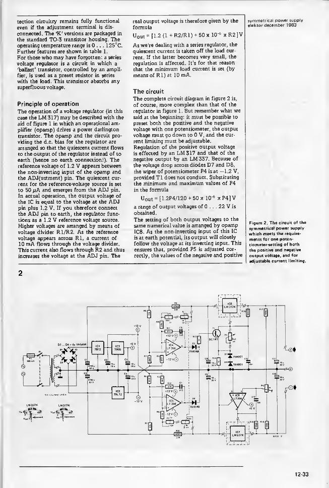
The circuit
The complete circuit diagram in figure 2 is,
of course, more complex than that of the
regulator in figure 1. But remember what wesaid at the beginning: it must be possible to
preset both the positive and the negative
voltage with one potentiometer, the output
voltage must go down to 0 V, and the cur-
rent limiting must be adjustable.
Regulation of the positive output voltage
is effected by an LM 317 and that of the
negative output by an LM337. Because of
the voltage drop across diodes D7 and D8,
the wiper of potentiometer P4 is at -1.2 V,
provided T1 does not conduct. Substituting
the minimum and maximum values of P4
in the formula
Uout = [1.2P4/120 + 50 x 10‘6 x P4] V
a range of output voltages of 0 ... 22 V is
obtained.
The setting of both output voltages to the
same numerical value is arranged by opampIC8. As the non-inverting input of this IC
is at earth potential, its output will closely
follow the voltage at its inverting input. This
ensures that, provided P5 is adjusted cor-
rectly, the values of the negative and positive
symmetrical power supply
elektor december 1983
Figure 2. The circuit of the
symmetrical power supply
which meets the require-
ments for one poten-
tiometer-setting of both
the positive and negative
output voltage, and for
adjustable current limiting.
2
12-33
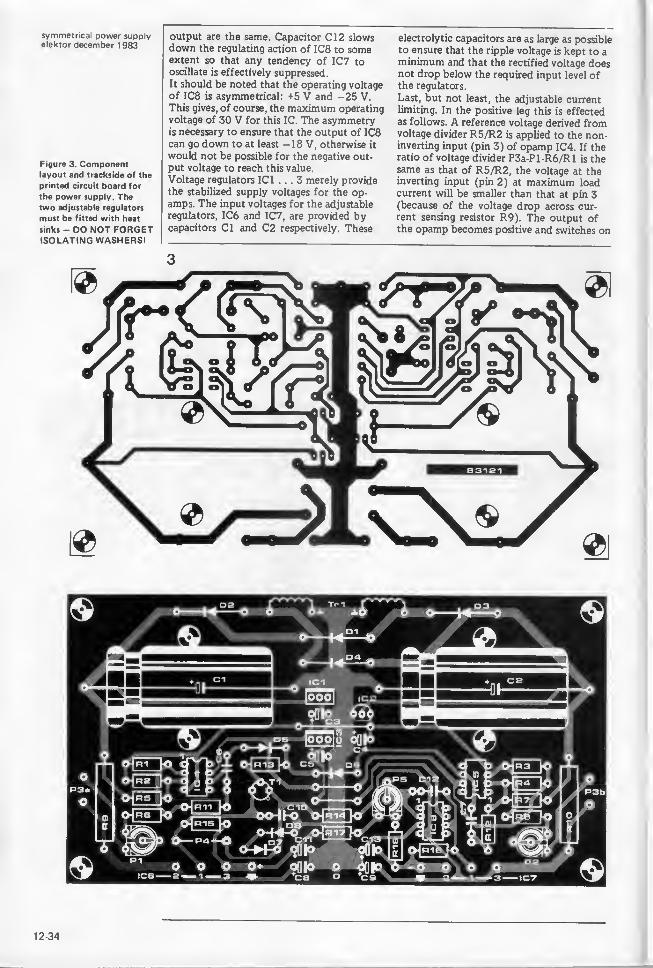
symmetrical power supplyelektor december 1983
Figure 3. Componentlayout and trackside of the
printed circuit board for
the power supply. Thetwo adjustable regulators
must be fitted with heat
sinks - DO NOT FORGETISOLATING WASHERS!
output are the same. Capacitor C12 slowsdown the regulating action of IC8 to someextent so that any tendency of IC7 tooscillate is effectively suppressed.It should be noted that the operating voltage
of IC8 is asymmetrical: +5 V and -25 V.This gives, of course, the maximum operating
voltage of 30 V for this IC. The asymmetryis necessary to ensure that the output of IC8can go down to at least -18 V, otherwise it
would not be possible for the negative out-
put voltage to reach this value.
Voltage regulators IC1 ... 3 merely providethe stabilized supply voltages for the op-
amps. The input voltages for the adjustable
regulators, IC6 and IC7, are provided bycapacitors Cl and C2 respectively. These
electrolytic capacitors are as large as possibleto ensure that the ripple voltage is kept to aminimum and that the rectified voltage doesnot drop below the required input level ofthe regulators.
Last, but not least, the adjustable currentlimiting. In the positive leg this is effectedas follows. A reference voltage derived fromvoltage divider R5/R2 is applied to the non-inverting input (pin 3) of opamp IC4. If theratio of voltage divider P3a-Pl-R6/Rl is thesame as that of R5/R2, the voltage at theinverting input (pin 2) at maximum loadcurrent will be smaller than that at pin 3(because of the voltage drop across cur-
rent sensing resistor R9). The output ofthe opamp becomes positive and switches on
12-34

transistor Tl. The resulting current throughT1 ensures that the output of both IC6and IC7 is returned to the predeterminedreference level. The level at which current
limiting commences is set by potentiometerP3a.
The current limiting action in the negative
leg is similar, but here the voltage level at
the non-inverting input (pin 3) of IC5becomes greater than that at pin 2 at the
onset of current limiting. Again, the opampswitches on transistor Tl and from then onthe action is as described for the positive leg
P3 is a stereo potentiometer so that the
current limiting can be set to commence at
the same level in both legs.
Construction and calibration
The use of the printed -circuit board shownin figure 3 makes the mounting of mostcomponents simplicity itself. The usual care
should be taken to observe polarity wherenecessary and to avoid dry soldering joints.
The remainder is primarily a problem of
constructing a suitable housing for the
unit.
The front panel should be provided withholes for P3 and P4, the output terminals,
and the mains on/off switch. The rear panel
must have holes for fitting the adjustable
regulator-ICs and their heat sinks, and mainsfuse. Once this work has been done, the
wiring between all these components andthe printed-circuit board can be completed.When the wiring has been completed andcarefully checked, the unit can be calibrated.
Set presets PI and P2, and potentiometerP3, to minimum resistance - check this
with an ohmmeter.Connect a voltmeter to the positive-
symmetrical power supply
elektor december 1 983
RIOa
831214
voltage output terminal; if a second one
is available, this may be connected to the
negative-voltage terminal. (Be careful to
observe polarity!)
Switch on the mains, and check that
adjusting P4 causes a change in bothoutput voltages. Adjust preset P5 to give
equal numerical values for these voltages.
Switch off the mains, and connect a
1 J2/5 W resistor to both the positive andnegative output terminals, in parallel with
the voltmeter(s).
Switch on the mains and adjust P4 for
maximum output voltage(s). Set P3 so
that the voltage across the 1 £1 resistors
increases; check that when P3 is turned
back, the voltage decreases.
Set P3 for maximum voltage across the
1 resistors and then adjust PI and P2so that the voltage across these resistors is
exactly 1.000 V. The current will then, of
course, be exactly 1 A. In our laboratory
prototype, it was possible with P3 to set the
current limiting between 15 mA and 1 A.Many of you will find it worthwhile to
build in the meters shown in figure 4. Thereading and setting of voltage and current
levels is then much easier. Do not, however,
calibrate these instruments until you are
sure that the supply unit is functioning
satisfactorily. M
Figure 4. Optional instru
ments for incorporating
in the power supply
enable direct reading of
output voltage and load
current.
Parts list
Resistors:
R1 . . . R4 = 8k2R5,R7,R11,R12 = 27 k
R6,R8 = 22 k
R9.R10 = 0,82 H/3WR13.R14 = 1 k
R15.R16 = 120 HR17.R18 = 100 k
PI ,P2 = 10 k preset
P3 = 1 k linear stereo
potentiometer
P4 = 2k2 linear preset
P5 = 1 k preset
Capacitors:
C1,C2 = 4700 p/63 Velectrolytic
C3.C4.C5 = 10 p/16 Vtantalum
C6.C7 = 2n2 ceramic
C8.C9.C11,
C13 = 10 m/30 Vtantalum
CIO = 10 n ceramic
Cl 2 = 1n8 ceramic
Semiconductors:
D1 . . . D4 = IN5408D5.D6 = 1N4148D7.D8 = 1N4001Tl = BC 141
IC1 = 7812IC2 = 79L12IC3 = 7805IC4.IC5.IC8 = LF 356IC6 = LM317KIC7 = LM 337K
Miscellaneous:
SI = double-pole mains
switch
FI = miniature fuse holder
and fuse 0.5 ATrl = mains transformer
2 x 18V/1.5AHeat sinks for twoTO-3 ICs
Printed circuit board
83121Output terminals
Four 100 mA meters as
required
12-35
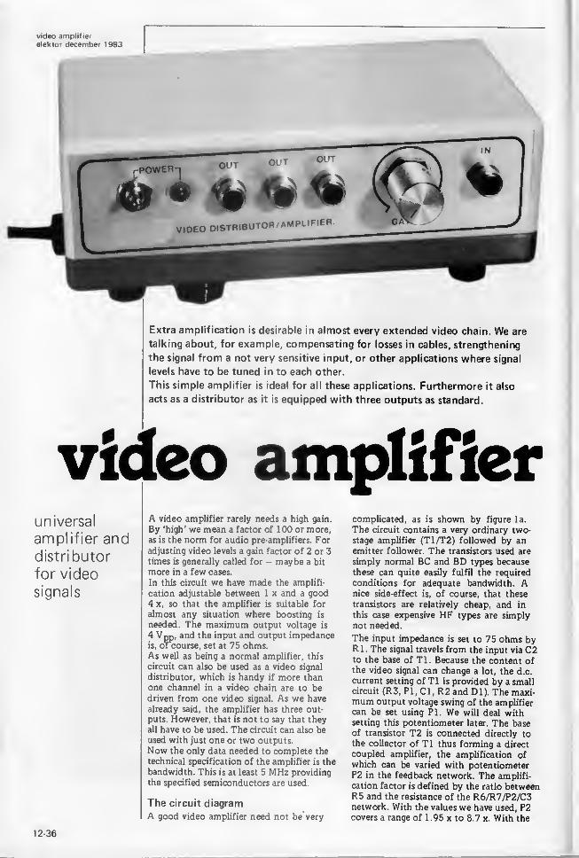
Extra amplification is desirable in almost every extended video chain. We are
talking about, for example, compensating for losses in cables, strengthening
the signal from a not very sensitive input, or other applications where signal
levels have to be tuned in to each other.
This simple amplifier is ideal for all these applications. Furthermore it also
acts as a distributor as it is equipped with three outputs as standard.
video amplifieruniversal
amplifier anddistributor
for video
signals
A video amplifier rarely needs a high gain.
By ‘high' we mean a factor of 100 or more,as is the norm for audio pre-amplifiers. For
adjusting video levels a gain factor of 2 or 3times is generally called for - maybe a bit
more in a few cases.
In this circuit we have made the amplifi-
cation adjustable between 1 x and a good4 x, so that the amplifier is suitable for
almost any situation where boosting is
needed. The maximum output voltage is
4 Vpp, and the input and output impedanceis, of course, set at 75 ohms.As well as being a normal amplifier, this
circuit can also be used as a video signal
distributor, which is handy if more thanone channel in a video chain are to be
driven from one video signal. As we have
already said, the amplifier has three out-
puts. However, that is not to say that theyall have to be used. The circuit can also beused with just one or two outputs.
Now the only data needed to complete the
technical specification of the amplifier is the
bandwidth. This is at least 5 MHz providing
the specified semiconductors are used.
The circuit diagram
A good video amplifier need not be very
complicated, as is shown by figure la.
The circuit contains a very ordinary two-
stage amplifier (T1/T2) followed by anemitter follower. The transistors used are
simply normal BC and BD types because
these can quite easily fulfil the required
conditions for adequate bandwidth. Anice side-effect is, of course, that these
transistors are relatively cheap, and in
this case expensive HF types are simply
not needed.
The input impedance is set to 75 ohms byRl. The signal travels from the input via C2to the base of Tl. Because the content ofthe video signal can change a lot, the d.c.
current setting of Tl is provided by a smallcircuit (R3, PI, Cl, R2 and Dl). The maxi-mum output voltage swing of the amplifiercan be set using PI. We will deal withsetting this potentiometer later. The baseof transistor T2 is connected directly tothe collector of Tl thus forming a direct
coupled amplifier, the amplification ofwhich can be varied with potentiometerP2 in the feedback network. The amplifi-
cation factor is defined by the ratio betweenR5 and the resistance of the R6/R7/P2/C3network. With the values we have used, P2covers a range of 1.95 x to 8.7 x. With the
12-36

Figure 1. The circuit is
very simple to construct
and contains very ordinary
components. The amplifi-
cation can be adjusted with
P2 between 1 x and 4 x.
1b
normal output load of 75 ohms the final
amplification is effectively halved, so that
the actual range is from 1 x to just over
4 x.
The T1/T2 stage is followed by a ‘bigger’
transistor (T3), which has to ensure the
desired low frequency output impedance.This demands a very small emitter resistor
(R9) and an accordingly high collector
current. The amplified signal leaves thecircuit by three 75 ohm outputs, made upof C5/C6/C7 and R10/R11/R12.If only one or two of the three outputs are
needed, then obviously the power consump-tion of the circuit will be correspondinglyless. The greatest part of the current con-sumption is in R9. If three outputs are usedR9 must be 56 ohms, with two outputs it
can be increased to 82 ohms and with oneoutput 150 ohms is sufficient. The total
current consumption for the three con-
ditions is then 150 mA, 110 mA and 70 mArespectively.
Adjustment
There are two ways of adjusting PI. The‘normal’ method, which gives satisfactory
results 90% of the time, and an alternative
for setting it up 'by eye’. In the first case,
PI is simply adjusted so that there is about1 V at the base of Tl. The voltage across
R8 should then be about 7.5 V (with nosignal).
The alternative method is somewhat moreinvolved. Start by setting PI to mid position
and with an input signal of about 1VPP,reduce the amplification to minimum withP2. Then a test image is fed into the input
(from a video recorder, for example),
and a TV set or monitor is connected
to the output. PI is now adjusted so that
all distortion is just eliminated.
Another point which may be of importance.
Although input signals a bit higher than the
nominal 1 Vpp are not a direct disadvan-
tage to the amplifier, they are actually of
little use. Significantly higher voltages can
therefore better be reduced. This can be
done by experimenting with R5 and using
a bigger resistor here (the maximum amplifi-
cation then decreases) or by placing anextra resistor in series with the input, so that
it forms a voltage divider with R1 . Then the
value of R 1 is reduced so that the total
resistance of the extra resistor and R1 addup to 75 ohms.
Construction
A simple power supply for the amplifier
is easily built, as figure lb shows. Bothamplifier and power supply are constructed
on the same printed circuit board, the layout
12-37

video amplifierelektor december 1983
Figure 2. The printed
circuit board contains
both the amplifier and
power supply. Only the
mains transformer is not
mounted on the board.
Resistors:
R1.R10 . . . R12 = 75 aR2 = 10kR3 = 8k2R4 = 1 k
R5.R7 = 180 aR6 = 3k3R8 = 470 aR9 = 56 a/5 W # *
PI = 2k 5 preset
P2 = 2k2 linear
*75 a * 1 50 a ii 150 a**see text
Very little needs be said about mechanical
construction for this project. Depending oncircumstances, it could be built into the
case of some existing equipment, or it could
be mounted in a case of its own. The only
important point is that the ‘amplification’
pot must be freely accessible. fr
of which is shown in figure 2.
‘Construction’ is really only a matter of
fitting everything correctly to the printed
circuit board and soldering it there. How-
ever, there are a few points to note. Whenthree outputs are in use voltage regulator
IC1 has to work reasonably hard and be-
cause of this it needs to be mounted on a
heatsink. The 75 ohm resistors (marked with
an asterisk) are not standard E12 values.
They actusdly consist of two 150 ohmsconnected in parallel.
Capacitors:
Cl ,C4 = 100 n
C2,C3 = 10 m/16 VC5 . . . C7 = 100 m/16 VC8 = 470 m/35 VC9 = 330 n
Semiconductors:
D1 = 1N4148D2 . . . D5 = 1N4001T1 = BC547BT2 = BC557BT3 = BD 137/139
IC1 = 7812
Miscellaneous:
SI = double pole mains
switch
FI =100 mA slow blow
fuse
Trl = 15 V, 0.8 A mains
transformer
Heatsink for IC1
Case, approximate dimen-
sions 1 20 x 65 x 65 mm
12-38

elektor december 1 983
Personal FM(September 1983,
page 9-46)
The 0.22 pH Toko coils
for LI and L2 should
be of the small axial-leaded
type. Alternatively, they
can quite easily be wound.The correct inductance can
be obtained by winding 13
turns of SWG 27 enamelled
copper wire on a 3.5 mm'former' (we used the plas-
tic refill for a well-known
ballpoint pen). L3 is listed
as stock number 35-01144in the Ambit catalogue
under the heading 'coil
style MC 120'.
Electronic voltage
regulator
(October 1983,
page 10-57)
The text for this article
states that this circuit will
work with a d.c. dynamo.The theory behind the
regulator does apply for
d.c. dynamos, but this par-
ticular circuit will only
work with an alternator.
7-day timer/
controller
(April 1983,
page 4-42)
In a few cases difficulties
are encountered with the
storing of the switching
data. This is caused by an
incorrect trigger level at
IC5. The remedy consists
of reducing the value of C8down to 1 nF (but not
lower), if necessary.
12-39

elektor december 1983
The following pages contain the
mirror images of the track layout of
the printed circuit boards (excluding
double-plated ones as these are very
tricky to make at home) relating to
projects featured in this issue to
enable you to etch your own boards.
To do this, you require: an
aerosol of ‘ISOdraft’ trans-
parentizer (available from yourlocal drawing office suppliers;
distributors for the UK: Cannon& Wrin), an ultraviolet lamp,
etching sodium, ferric chloride,
positive photo-sensitive boardmaterial (which can be either
bought or home made by applying
a film of photo-copying lacquer to
normal board material).
Wet the photo-sensitive (track)
side of the board thoroughly
with the transparent spray.
PC board pages
Lay the layout cut from the
relevant page of this magazine
with its printed side onto the wetboard. Remove any air bubbles bycarefully ‘ironing’ the cut-out withsome tissue paper.
The whole can now be exposedto ultra-violet light. Use a glass
plate for holding the layout in place
only for long exposure times, as
normally the spray ensures that the
paper sticks to the board. Bear in
mind that normal plate glass (but
not crystal glass or perspex) absorbs
some of the ultra-violet light so that
the exposure time has to be in-
creased slightly.
The exposure time is dependentupon the ultra-violet lamp used.
the distance of the lamp from the
board, and the photo-sensitive
board. If you use a 300 watt
UV lamp at a distance of about40 cm from the board and a sheet
of perspex, an exposure time of
4 ... 8 minutes should normallybe sufficient.
After exposure, remove the
layout sheet (which can beused again), and rinse the boardthoroughly under running water.
After the photo-sensitive film
has been developed in sodiumlye (about 9 grammes of etching
sodium to one litre of water), the
board can be etched in ferric chlo-
ride (500 grammes of FeCl3 to
one litre of water). Then rinse the
board (and your hands! ) thoroughly
under running water.
Remove the photo-sensitive film
from the copper tracks with
wire wool and drill the holes.
disco
Phaser:
oscillator
board
12-40

elektor december 1983
itive index 1983 cumulative index !
Audio and sound generation
accessories for the Crescendo power amplifier .. 1-28
audio traffic light 3-56
common base mixer 7-84
Crescendo revisited 11-62
cricket simulator 7-63
disco phaser 12-50
electronic switch for audio signals 7-78
electronic tuning fork 7.34electronic two-tone metronome 1 1-48
40 watt main amplifier 7-82Interlude 4-36logarithmic amplifier 7-37
machine gun sound generator 7-44
Maestro part 1 5-38
Maestro part 2 646MC/MM phono preamp 4-26
microphone amplifier with preset tone control . . 7-93
music quantizer 10-30
(missing link) 11-41
mini compressor 7-89personal FM 946(missing link) 12-39Prelude part 1 2-18
Prelude part 2 3-36
Prelude part 3 4-52Prelude buffer 7-50
Prelude class A headphone amplifier 2-34
Prelude p.s 5.33
preset the hard (ware) way 7-88
pseudo stereo 11-52RC equalizer 4-40sea murmur simulator 7-77
simple PA system 7-91
spectrum display 6-38ZN 41 5 — a complete AM radio tuner
(Applicator) 11-63
Car
autotest 9-22
car lights warning device (J. Glauser) 7-60
car PDM amplifier • 7-36
(missing link) 9-59
electronic voltage regulator 10-57
(missing link) 12-39
interior temperature control for cars 7-66
main beam dimmer 2-32
Domestic
alarm extension 9-51
anemometer 1040anti burglar lights 7-55
code lock with door opener 7-60
constant light source 7-29
doorbell memory 7-33
doorbell — or telephone — operated flash-light . . 11-23
drill speed controller 7-85
electronics and plant physiology 7-52
energy meter 6-24
frost warning device 12-47
fuse protector (H. Dominic) 2-39
LED ornaments 12-30
low cost CMOS lock 7-75
(missing link) 10-47
low power digital thermometer (E. Schmidt) . . . 4-22
portable egg timer 7-62
7-day timer/controller 4-42
stay awake alarm 7-54
talking clock extension (E.A.J. Bogers) 4-60
thermometer (A. van Olderen) 7-30
wattmeter 5-22
Fun and games
dexterity game 7-81
double dice 2-51
electronic pocket pinball (H.J. Walter) 7-70
horse paces simulator (B. Darnton) 7-58
reaction tester (L. van Boven) 3-50
trick battery (L. van Boven) 1 1-60
'HF'
MF/HF USB marine receiver 12-24
morse converter (R. Unterricker) 5-52
morse decoding with the Z80A (P. von Berg) . . . 5-60
personal FM 9-46
pseudo stereo 11 -52
RTTY decoder 6-30
Hobby
action flash 7-68
darkroom computer tips (H. Fietta) 1-33
darkroom light 7-61
flashing running light 7-42
locomotive headlamp reverser 12-44
power controller for model railways 1 1-26
programmable darkroom timer 4-56
servo tester (G. Luber) 3-23
solid state darkroom lighting 10-36
switching channel for radio control 6-28
Informative articles
a (re)new(ed) eight bitter: the 65C02(Applicator) 10-70
Basicode-2 10-27
Better way of depositing semiconductor compounds
(Selektor) 10-26
chips for digital audio (I) 1-36
chips for digital audio (I I) 2-54
coming soon 1-19
cutting costs with sparks (Selektor) 1-17
decoupling in digital circuits 11-30
discovering the infra-red universe (Selektor) .... 10-24
electrical language offish (Selektor) 5-19
fluorescent displays 3-18
Fourier synthesis (E. Muller) (Ejektor) 1-50
high speed CMOS 9-32
membrane switches . . . 4-34
morse and radio teletype (RTTY) 6-52
NOVRAM — data storage without batteries .... 12-58
0. 1C! 3-52
1241

elektor december 1983
983 cumulative index 1983 cumuliraindrops and radar (Selektor) 6-21
readership survey results 10-21
R5620 ... a programmable universal filter with
switched capacitors 2-58
stereo TV sound (Selektor) 5-21
taking the heat out of electronics (Selektor) ... 12-21
talking to computers (Selektor) 2-16
the potential of the bucket brigade 4-20
tomorrow's music 1-53
universal logic: more potential in the chip
(Selektor) 12-20
videographics 9-18
what is power? . 5-47
when electromagnetic waves came to light
(Selektor) 11-21
Measuring/test equipment
capacitance meter 7-34
energy meter 6-24
5 V logic tester (C. Bajeux) 7-92
heatsink thermometer 7-72
h pe tester 7-49
high and low tester (R. Storn) 7-97
LCD luxmeter 3-24
low power digital thermometer 4-22
mains wiring tester (A. Scragg) 7-56
milliohmmeter 1-24
multitester (E. Osterwick) 5-36
optical voltage indicator 7-71
resistance comparator 7-28
simple MOSFET test 9-58
temperature indicator 7-69
thermal indicator for heat sinks 7-96
thermometer (A. van Olderen) 7-30
transistor selector 10-62
voltage monitor 7-89
wattmeter 5-22
Microprocessor
acoustic 'flag' for the RS232 interface 7-91
acoustic telephone modem (J.J.M. Habets and
C.A. Truijens) 2-42
(missing link) 1 0-46
ASCII keyboard 5-26
banking program 12-56
Basicode-2 interface for the Junior Computer .. 10-51
bus extension 12-62
busy indicator for the Junior Computer
(W. Schaaij) 7-77
Centronics interface 7-45
CPU card 11-32
EPROMmer using the Junior Computer 10-68
fault finder for ASCII keyboard 7-94
fluorescent display (Applicator) 6-58
FSKleaner 10-64
joystick interface 7-46
Junior program tester (P. Wild) 4-51
Junior synthesizer 9-56
microprocessor aid 7-80
/^Processor fault finder 7-95
microprocessor 'stethoscope' 7-31
morse converter (R. Unterricker) 5-52
(missing link) 9-59
morse decoding with the Z80A (P. von Berg) . . .5-60
(missing link) 10-46
parallel-serial keyboard converter 5-50
(missing link) 10-46
RTTY decoder 6-30
simple baud rate generator 7-41
6809 DRAM controller (H. Fischer) 7-90
64 K on the 16 K Dynamic RAM card 9-29
(missing link) 11-41
64-way bus board 12-22
software RAM tester 749traffic-light control system (D. Herzberg) 1-46
2650 single step 7-43
universal memory card 3-28
universal terminal 11-56
upper and lower case on the Elekterminal
(D. Paulsen) 1-56
(missing link) 11-41
VAM — video/audio modulator 2-27
VDU card 9-38
vector control for the Junior Computer(N. Humphreys) 7-79
Miscellaneous
amplified triac drive 7-68
automatic display dimmer 3-46
auto trigger 7-46
battery economizer 7-51
capacitive switch 7-98
decimal-to-binary converter 11-40
distance meter for thunderstorms 7-84
economic LED 7-47
electronic aerial switch (C. Abegg) 6-36
electronic switch for audio signals 7-78
electronic tuning fork 7-34
four quadrant multiplier 7-79
frequency comparator 7-62
glitch suppressor 7-76
horse paces simulator (B. Darnton) 7-58
inexpensive 45 MHZ crystal filter 7-74
key bleep 8-00
LED amplifier 7-47
LED current source 7-39
lie detector 7-69
movement detector 1145noise and vibration detector 7-35
on/off with a single push button 7-74
precision voltage divider 9-50
reproducible delay 7-38
signal purifier for SSB telegraphy receiver
(P. von Berg) 7-57
simple D/A converter 7-86
solar tracking system 740S.P.T.S 7-85
stable zener 7-38
symmetrical voltages from a doorbell transformer
(R. Storn) 7-39
ultrasonic/infra-red barrier 11-58
universal AFC 7-99
useful tip . . . 2N3055 Super Darlington pair . . . 10-67
12-42

elektor december 1 983
itive index 1983 cumulative index
I
Missing link
acoustic telephone modem(February 1983, page 2-42) 10-46
car PDM amplifier
(Summer circuits 1983, page 7-36) 9-59
Crescendo (December 1982, page 12-32) 1141
drum interface (November 1982, page 11-20) . . 11-41
electronic voltage regulator
(October 1983, page 10-57) 12-39
floppy disk interface for the Junior Computer
(December 1982, page 1248) 9-59,11-41
in-car ioniser (December 1982, page 1245) .... 1 141
infocard 55 9-59
infocard 70 9-59
Video
VAM — video/audio modulator . .
video amplifier
video effect generator (L. Heylen)
video pattern generator
2-27
12-36
6-
50
7-
58
variable zener 7-88
very narrow crystal filter 7-56
VFO with variable inductor (A.B. Bradshaw) . . . 7-67
window comparator (R. de Boer) 7-76
zero crossing detector (O.M. Kellogg) 7-83
Power supplies/generators
battery eliminator 10-60
current source for photodiodes 7-94
DC-DC converter (A. Bovee) 7-61
d.c. voltage doubler using a 4049 (G. Ramm) . . . 7-53
emergency mains cut-out 7-41
high-voltage regulator 10-38
LED current source 7-39
negative printhead supply 7-83
offset-less rectifier 7-64
180 watt DC/AC converter 8-00
1 MHz time-base without crystal 7-44
power back-up for CMOS ICs during mains failures 7-32
programmable power supply 1049
pulse/pulse train generator 7-64
RC generator (W. Meislinger) 7-65
78L voltage regulators . . . and 79L 5-59
simple baud rate generator 741
simple power supply regulator 7-98
simple regulated power supply 7-48
simple sawtooth generator (R. Oppelt) 7-71
simple stabilizer 7-78
stepped voltage generator 7-32
synchronous, constant amplitude,
sawtooth generator 7-87
symmetrical harmonic oscillator 7-31
symmetrical power supply 12-32
symmetrical voltages from a doorbell transformer
(R.Storn) 7-39
3 A computer power supply 1-43
video effect generator (L. Heylen) 6-50
video pattern generator 7-58
voltage booster regulator 7-54
low cost CMOS lock
(Summer circuits 1983, page 7-75) 1047
morse decoding with the Z80A
(May 1983, page 5-60) 10-46
morse converter (May 1983, page 5-52) 9-59
music quantisizer (October 1983, page 10-33) .. 1141
personal FM (September 1983, page 946) 12-39
parallel-serial keyboard converter
(May 1983, page 5-50) 10-46
7-day timer/controller (April 1983, page 4-42) . . 12-39
single channel infra-red remote control
(January 1982, page 1-52) 11-41
64 K on the 16 K dynamic RAM card
(September 1983, page 9-31 )11-41
upper and lower case on the Elekterminal
(January 1983, page 1-56) 1141
1243

The generator described in our November1982 issue superimposes a high-frequencyalternating voltage (ul) onto the direct-
voltage output (Up) of the power controller.
Capacitors are used both at the output ofthe generator and at the input to the coachlamps to prevent the d.c. from the controller
interfering with the lighting system.The composite voltage (uc) is applied to the
input (A, B) of the reversing circuit shown in
figure 1. This circuit ensures appropriatecontrol of the reed relay in accordance with
In our November 1982 issue wepublished the design of a high-
frequency generator for the lighting of
model railway coaches independent of
the locomotive power supply. It
occurred to us that this generator
could also be used for changing the
headlamps to the direction of travel
on double-ended locomotives.
locomotive headlampreverse r
elektor december 1983
the direction of travel of the locomotive(which can, of course, be detected from thepolarity of Up). As space in model railway
locomotives is restricted, all componentsused are, of course, miniature or sub-minia-
ture types.
Depending upon the position of the relay
contact, either Laf or Lar is connectedto the input voltage, uc, via capacitor
Cl,. The value of Cl is calculated fromCl = 1/(2 n fXc) Farad, where f is thefrequency of the generator (19 kHz) and
Xc is the reactance of Cl. This reactance
should preferably be not more than 1/5of the value of the lamp resistance. If
thus, for instance, a 12 V, 50 mA lampis used (resistance = 240 SI), Xc shouldnot exceed 48 S2 and
Cl = 1/(2 x 3.142 x 19 x 103x 48)
= 175 x lO'9 = 175 nF.
The nearest (higher) standard value of
220 nF should thus be used.
The operating voltage for the circuit is
derived from uc. The h.f. component is
rectified in diodes D1 and D2 and smoothedby capacitors Cl and C2.
Opamp IC1 is used as a comparator: its
non-inverting input lies at the centre of
voltage divider R2-R3 which is connectedacross Up. If 'B' is positive with respect to
‘A’, that is, when the locomotive is reversing,
capacitor C2 charges and the inverting input,
pin 2, of the opamp is more negative than
the non-inverting input, pin 3: the outputof the comparator is then positive. Transis-
tor T1 conducts, and the consequent voltage
across zener diode D4 and voltage regulator
IC2 actuates the relay. The relay operates
and connects Lar to ul-
When the locomotive goes forward again
(and 'A' is positive with respect to ‘B’), the
voltage across Cl becomes greater than that
across C2, the output of the comparatorgoes negative, T1 stops conducting, the relay
is no longer actuated, and Laf is again
connected across ul-Zener diode D3 is included as a high-voltage
protection, but can be omitted if ul is
smaller than 35 Vpp-The zener voltage, Uz, of diode D4 is calcu-
lated from Uz = ULpp - 20 V.
Miniature reed relays are available in DILpackage and these are ideal for our purpose.
If a relay with integral diode is used, D5 can,
of course, be omitted. However, take note
that the integral diode may be of either
polarity. This should be carefully checkedbefore wiring the relay. M
addition to
model train
lighting
Figure 1. The circuit dia-
gram of the locomotive
headlamp reverser. Ter
minals A and B are the
external connections
across which a composite
voltage (19 kHz super-
imposed onto the d.c.
control voltage) is applied.
The supply voltage for the
circuit is derived from the
a.c. component.
(A)XJ-
* IC2 V
78L05
Figure 2. The internal
construction and pin
layout of the reed relay.
In spite of their small
size, many miniature
relays have an integral
diode-
83136 -2
1244
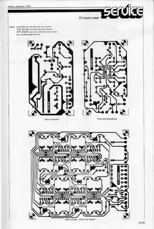
elektor december 1983
PC board pages
Note: the PCBs for the 64-way bus board
(EPS 831021 and the marine receiver
(EPS 83024) are not included since these
are double-sided boards.
1 4 \ \1
video amplifier
1 m-s
frost warning device
m
disco phaser: delay line board
OSrCB


frost warning device
elektor december 1983
in the
In spite of the
cold weather we have had
since the summer disappeared, winter has
just begun and the worst weather almost invariably comes
first few months of the year. Then the weather forecast is
nearly always the same: 'cold . ..possibility of sleet or snow . . . watch out for
ice . . .', and so on. However, meteorologists cannot give a detailed an accurate
weather forecast for the whole of the country, particularly considering the
effect that local geography has on the weather. All our efforts to design a
'weather controller' have so far been in vain, but we did come up with this
frost warning device which should be a bit less hazardous than the usual suck
it and see' method.
frost
warningdevice
with
a memory
While Britain is normally spared the worst
extremes of weather, there are times when it
does not seem like that. This is particularly
so in winter when the cold seems to be able
to creep through any number of layers of
woolen clothing. It’s unpleasant, but we just
have to grumble and bear it. It would be
very convenient, however, if you knewbefore stepping outside whether it is merely
‘cold’ or ‘very very cold’. If you have a
thermometer the problem is solved, except,
of course, that it has to be left outside -
which sort of defeats the purpose. Whatis really needed is a temperature sensor
mounted outside giving an indication inside.
For motorists the problem is somewhat dif-
ferent as weather conditions can vary quite
considerably in the course of a journey.
Gardeners are often interested in one par-
ticular weather condition - frost. In this
case, of course, it would be invaluable to
know if the temperature has dropped below
freezing point overnight, for example.
These are the principle applications weconsidered for this frost warning device
but, because the temperature to be detected
can be adjusted, the circuit here has manymore possible applications than a simple
freezing-point detector.
Operation
The circuit diagram for this frost wamer is
shown in figure 1. The temperature is sensed
by the LM 335Z which gives a specific value
(A) in mV proportional to the measured
temperature. This provides one of the inputs
to comparator Al. The second input (B) is a
reference voltage which can be adjusted with
PI. When the sensor voltage at point A be-
comes lower than the reference voltage at
point B the output of Al goes high. This
causes the oscillator around A2 to start and
LED D1 flashes about once per second.
At the same time the one-shot at A3 will
go high for almost two seconds and during
this time a second oscillator based on A4drives the piezo buzzer at a frequency of
about 1 kHz.
As far as the user is concerned, this is whathappens: when the temperature first drops
12-47
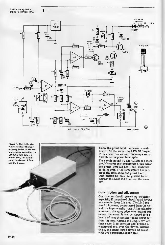
frost warning device
elektor december 1983
max. 45 mA
Figure 1. This is the cir-
cuit diagram of the frost
warning device. When the
temperature sensed by theLM 335Z falls below a
preset level, this is indi-
cated by the two LEDsand the buzzer.
below the preset level the buzzer soundsbriefly. At the same time LED D1 beginsto flash and flashes until the temperaturerises above the preset level again.
The circuit around T2 and T3 acts as a mem-ory. Whenever the temperature drops belowthe preset level D2 lights and continues
to do so even if the temperature has sub-
sequently risen above the preset level.
Push button SI must be pressed to ex-
tinguish this LED and thus reset the mem-ory.
Construction and adjustment
Construction should present no problems,especially if the printed circuit board layoutas shown in figure 2 is used. The LM 335Zshould, however, be protected from the wet,
and this is quite easily done. After soldering
wires onto the appropriate two leads of this
sensor, the assembly can be slipped into a
length of heat shrinkable tubing about Vi"
from the end. Heating this empty Vi' will
then cause it to contract and provide a
waterproof seal over the device. Alterna-
tively, the sensor could simply be sealed
with two-component epoxy glue.
12-48

frost warning device
elektor december 1983
Parts list
Resistors:
R1 = 2k2
R2.R3.R5 . . R12,
R16 . . . R19 = 100 k
R4 = 120 k
R13.R21.R22 = 10 k
R14,R23 = 470 (1
R 15 = 560 k
R20- 10 nPI = 10 k preset
Capacitors:
Cl - 10 p/16 VC2 = 1 p/16 VC3,C4 = 10 p/35 VC5 = 10 n
C6 = 470 p/25 V
Semiconductors:
01,D2 = LEDD3,D4,D6 = 1N4148D5 = 1N4001T1.T3 = BC550CT2 = BC 560CIC1 = 78L05IC2 = 324
IC3 = LM 335Z
Miscellaneous:
Bz = piezo buzzer (Toko
PB 2720)
SI = push to makepushbutton
Case, dimensions
120 x 65 x 65
A mixture of crushed ice and water is
needed to adjust the circuit. Stirring the
mixture with the sensor for a minute or
two will cause the sensor to be at freezing
point. Potentiometer PI is then adjusted
until LED D1 just lights and the buzzer
sounds briefly. Some people may consider
this as a case of shutting the stable doorafter the horse has bolted as freezing can
occur at any temperature below about+3°C. However, if a thermometer is usedas a reference, this temperature could just
as easily be used as the preset value.
The maximum current consumption of the
circuit is about 45 mA, and with its supply
voltage of 12 . . . 15 V it can be poweredby a car battery. If it is to be used in the
home a suitable power supply will have
to be added, of course.
Even though this circuit may seem
eminently suitable for use in a car as
an ice warning device, there are a few
problems to be considered first. Thesensor would have to be mounted some-
where out of the air stream but where
it is not affected by engine (or cabin)
heat. Even if your car has a suitable
mounting location, this will still leave
the sensor several inches above the
road (which is where the sensor really
should be). Also temperature is not the
only factor affecting the formation of
ice and just measuring one parameter
cannot be considered as a reliable indi-
cation. It is rather doubtful, therefore,
whether any so-called frost warning
device is of any use in a car. However,
if you are going on a long journey the
weather (and road) conditions maychange a lot, so if your frost wamerstarts to flash before you are half wayto your destination then at least youknow you should be on your guard!
Figure 2. This is the
printed circuit board
layout for the circuit
showing where all the
components are mounted.
1249

Phasing is an effect well known to musicians. In electronic parlance it is, in fact, a comb filter so called
because the response is the attenution and amplification of a number of equally spaced frequencies in
the audio spectrum. It lends itself particularly well to sounds rich in harmonics and is therefore ideal
for use with recordings, musicassettes, or records containing much percussion. E-string guitar music, or
choral works; it is not really suitable for solo instruments.
comb fitter
with switched
resistors
The filter response which provides the
phasing effect is illustrated in figure 1. Fromthis it is easy to see why it is called a combfilter. There are a number of ways in which
this can be achieved in practical terms.
Studio quality systems can be very complex
and therefore very expensive, but simpler
methods do exist and, while not giving hi-fi
performance, do give a reasonable sound
quality. The easiest method, which is inci-
dentally the method used by virtually all
low-cost commercial phasers, is to use a
string of wide-band filters. These form a
delay line with a delay which can normally
be varied between 1 and 15 ms. To be sure,
quite a number of electronic switches are
required, but the use of TL 084 JFETopamps and 4066 quad bilateral switches
keeps the number of components to a
minimum. Moreover, the circuit needs no
Figure 1. Frequencyresponse of a phaser. Thetypical comb shape is the
result of the amplification
or attenuation of certain
frequencies. By modulating
the clock output, the
'teeth' are stretched and
compressed like a concer-
tina.
12-50

calibration, it accepts all signals of which the
level lies between the two supply voltages,
it produces neither noise nor distortion, and
it requires no low-pass filters.
The circuit shown in figure 2 is one element
of the 16-stage delay line used in the phaser.
With the type of filter used, it is, perhaps,
better to speak of time shift rather than
phase shift. It is readily seen from figure 2how this shift is achieved: the larger
capacitor C, the greater the time shift.
Unfortunately, there’s a limit to this,
because the frequency response of the
filter tends to narrow with increasing C.
The only way to reconcile these two incom-patible factors is a compromise betweenthe number of switches (as few as possible!)
and the sound quality (good transfer charac-
teristic). We found that values of C = 4n7and R1 . . . 3 = 10 k gave the best results.
The delay line is housed on a separate
printed-circuit board from the oscillator
and control stages. This arrangement makesit possible for a number of delay lines to
be connected in series or for the delay line
to be used for purpose other than described
here.
Coupling capacitors C17 ... 19 are necess-
ary at the audio input and delay outputs 1
and 2 to prevent d.c. entering, or off-set
voltages produced by the many opampsleaving, the delay line.
It is, of course, vital that the delay line is
adjustable and the various means by whichthis can be achieved include OTAs (oper-
ational transconductance amplifiers), FETs(field-effect transistors), and so on. It is,
however, much cheaper to switch resistors
by means of CMOS switches which open andclose (under the control of the clock gener-
ator, Nl) at a high frequency. When the
switch is open, the flow of current is inter-
rupted and the associated capacitor doesnot charge. When the switch is closed, cur-
rent flows and the capacitor charges. Theswitching frequency is of little concern in
this application: what is important is howlong the switch is open or closed as this
determines the length of pulses and pauses.
Ideally, the duty cycle (that is, the pulse/
pause ratio) should be continuously variable
between 0 and 100 per cent, and all switches
should be controlled by the same clock. Theclock frequency should preferably be morethan twice the highest audio frequency, say,
40 ... 50 kHz. Be careful when using tape
recorders, however, as the erase oscillator
may work at the about the same frequency.
Oscillator
As stated, we need a pulse-width (clock)
generator which produces square waves at a
frequency of about 40 ... 50 kHz: this is
Schmitt trigger Nl and associated com-ponents (see figure 3b). The square-wavepulses are converted by low-pass filter
R12-C6 into a triangular wave form whichis then fed to opamp IC5. This IC functions
as a comparator and its trigger level is
determined by the voltage at its non-inverting input (pin 3). The pulse width at
the output (pin 6) of IC5 is also directly
dependent upon the voltage at pin 3. Schmitttrigger N2 merely restores the output pulsesto square waves.
2
As we said before, it must be possible to
vary the pulse-width at the output of N2,
and this can be done in two ways: manually,
with P3, and by means of an LFO (low-
frequency oscillator) consisting of integrator
A1 and trigger A2.As the phasing effect sounds better if the
pulse-width is modulated by a sine waverather than a triangular wave, buffer A3 andlimiting diodes D5 and D6 are connected in
series with the (triangular) output of the
LFO. The output level of the LFO is about
± 0.7 V which can be set to any value
within this range by means of P2. The out-
put of the LFO stages is taken across R 18 to
A4 (pin 13) where it is mixed with the
voltage from P3. The relation between these
two inputs is determined by the trigger level
of the mixer which is set by P3.
It may, unfortunately, happen that the
presetting range of P2 and P3 includes
an area where the output voltage of A4is too low or too high. This results in IC5clipping the triangular wave form at pin 2(see figure 4), which causes a loud click in
the loudspeaker. This trouble is encounteredparticularly when the pulse width is set too
narrow (duty cycle below about 2 or 3 per
cent).
A control stage is therefore needed to limit
the output of A4. A Schmitt trigger, N3,is triggered by the output signal of IC5(which has a variable duty cycle) andfunctions as a secondary clock generator:
its output is inverted by N4. The outputs
of N3 and N4 are integrated and converted
into d.c. voltages which are compared with
a reference voltage by IC1 and IC2 respect-
ively. The reference voltages are preset byP5 and P6 respectively. The d.c. levels
(which are thus proportional to the dutycycle) are used to control A4 so that the
output of this stage cannot exceed a dutycycle range of 10 ... 90 per cent (see
figure 4). An incidental advantage of this
arrangement is that the control stage is
independent of the clock generator and the
low-frequency oscillator. If necessary, it cantherefore be disconnected from A4 withoutany ill effect.
Additional points
The delay time of the sixteen-element delay
line is 6 ms. The delay time can, of course,
be lengthened by connecting a number of
delay lines in series. However, we found that
when more than two lines are used, the
sound becomes increasingly distorted andthe overall effect is one of impairmentrather than improvement.
disco phaser
elektor december 1983
Figure 2. Basic circuit of
a wide band filter: the
delay is determined by Cand R1.
12-51

disco phaser
elektor december 1983
Figure 3a. The circuit
diagram of the sixteen
active filters and the
(electronically) switched
input resistors which form
the delay line.

disco phaserelektor december 1983
Xx7© © © aIC1 IC2 IC3 IC4 IC5
lOOn s © © © a^"16V•4—
—
.-I XXX
N1 ... N4 = IC3 = 4093A1 ... A4 = IC4 = TL084
Figure 3b. The circuit
diagram of the oscillator
and control stages.
break-through of clock trgnal
i \
Figure 4. The most likely
fault is the breaking
through of the clock signal
when the pulse/pause
ratio becomes too large
or too small. The control
stage limits the ratio.

disco phaser
elektor december 1983
Parts list - delay line
Resistors:
R1 . . . R49 = 10 k
R50 = 100 k
PI = 100 k linear preset
Capacitors:
Cl . . . C16 = 4n7 ceramic
Cl 7 . . . C19 = 470 n
ceramic
C20 * 100 n ceramic
C21.C22 = 10 jlx/16 Velectrolytic
Semiconductors:
IC1 . . . IC4 = TL 084IC5 . . . IC8 = 4066IC9 = 741
Miscellaneous:
printed-circuit board83120-1
Parts list — oscillator
Resistors:
R1 ,R2,R9,R10,R12 = 10kR3,R4,R13,R14 = 47 k
R5,R6,R15,R16,R20 = 100 k
R7,R8 = 47 k
R11 = 27 k
R17 = 15 k
R 18 = 22 k
R19= 390kPI = 1 M linear preset
P2,P3 = 100 k linear preset
P4 = 25 k preset
P5.P6 = 47 k preset
Capacitors:
C1.C2.C11 = 100 n
ceramic
C3 = 220 /i/16 Velectrolytic
C4.C9.C10 = 22 /i/16 Velectrolytic
C5.C6 = 1 n ceramic
C7.C8 = 2ju2/16 Velectrolytic
C12.C13 = 10 /i/16 Velectrolytic
Semiconductors:
D1 . . . D6 = 1N4148IC1.IC2 = LF 356IC3 = 4093IC4 = TL 084IC5 = 3140
Miscellaneous:
SI = SPST switch
Printed-circuit board
83120-2
The mixer output should not be used whenconnecting delay lines in series: use output
delay 1 (eight filters) or delay 2 (sixteen
filters) only. The preset PI can be omitted
from all but the last in a series of delay
lines, but it must then be replaced by a
100 k resistor to earth as shown in dotted
lines in figure 3a.
The outputs of the delay lines are wired
to the input resistors, R51 . . . R54, of
mixer IC9. Four inputs are provided to
enable two delay lines to be wired in series.
12-54

disco phaserelektor december 1983
Figure 5. Layout andtrackside of the printed-
circuit board for the delayline: provision is madefor resistors R51 . . . 54.
This then forms a delay line of 8, 16, 24,and 32 stages. The least delayed soundshould be connected to the highest resist-
ance. The resistors can be of the followingvalues: 1M (R51), 470 k (R52), 220 k(R53), 100 k (R54). These values are, of
course, entirely arbitrary and you mayfind other values more pleasing to you.Furthermore, different phasing effects canbe found by switching the outputs of thedelay lines to the mixer. M
Figure 6. Layout andtrackside of the printed-
circuit board for the
oscillator and control
stages.
12-55

banking programelektor december 1983
One of the most interesting characteristics of combining a BASIC compiler
with a Disk Operating System is the possibility of creating data files accessed
by one or more programs written in BASIC. For Junior Computer owners
the procedure is described briefly in the Ohio notes, but when this banking
program was sent in by a reader we saw it as an excellent opportunity to
delve a bit deeper into the operation of indirect files.
banking programa financial
control pro-
gram using
indirect filing
on the Junior
Computer
L. Germain
Table 1. Program PRPDA3is only used for entering
the (secret) security code
into file DATA3.
Before we start in earnest it is important
to note the difference between direct and
indirect files. If a programmer writes a
program with line numbers, he has direct
access while he is editing, modifying and
listing it. When this same program generates
data due to calculations, compiles the
results and makes a new (‘data’) file saved
on disk under another name using the
OPEN, CLOSE, GET and PUT instructions,
this is known as indirect access. In effect,
the user cannot add to, remove from, or
even inspect the data directly in this file.
How to prepare indirect files
As a general rule the first task is to assign
names to the files. In our example, these
are ‘DATA2’ and ‘DATA3’, which are
the indirect files, ‘BANK’, which is the
main program and ‘PRPDA3’ (for ‘prepare
DATA3'). ‘DATA3’ is an indirect randomfile which is only used to save the total of
the count, the number of the last operation
(these are both initialised automatically
by ‘PRPDA3’) and a security code to re-
fuse access to anybody who does not knowit (if the RUN at the end of line 45 of
‘BANK’ is replaced by NEW the program
automatically erases itself if the code is
wrong). The instruction POKE 741,10 could
also be included at the start of line 20 of
‘BANK’ to prevent the program from being
listed.
‘DATA2’ contains the financial operations
(amounts, date and nature) registered
by the program ‘BANK’. Before storing
the programs ‘BANK’ and ‘PRPDA3’ in
memory, buffer zones must be created
using option 7 of BEXEC*. Two buffers
are needed for ‘BANK’ (‘DATA2’ and‘DATA3’) and a single one for ‘PRPDA3’.Initially four tracks of diskette could be
reserved for ‘BANK’, one for ‘DATA3’,
one for ‘PRPDA3’ and at least ten for
‘DATA2’ (enough for about a year’s use).
When all of table 1 has been saved ondiskette, ‘PRPDA3’ must be run, a code
entered, and then ‘BANK’ run. When the
correct code has been entered, the screen
will then display the eight options available
to the user.
The routines used
At the start of each of the specific routines
the program will seek two fundamental data
values on the diskette: the remaining balance
(variable S) and the number of the last
operation specified (variable C). This is donestarting at line 500. The subroutine at line
525 reverses the procedure at the end of
each routine.
Input and output routines
The program first asks the number of credits
or debits to be processed. Then it requests
the amount of the first operation, its nature
(or category) and its date.
The date is always indicated by six figures,
first the day, then the month and finally
the year, with two numbers for each. Thecategory is registered as a string of charac-
ters, so it could consist of names (‘taxes’ for
example), numbers (such as cheques) or
abbreviations.
Request routine
It is possible to get a complete list of all
credits or debits, or a listing per month or
even of a certain operation (identified byamount, category and date). If one or twoof the required parameters are not known(amount/category/date) write ‘X’.
Balance routine
This routine displays the balance available.
Adding routines
As the name implies, these options are used
for compiling totals for the different types
of operations.
When the program is used for the first time,
option ‘1’ must be used to register at least
one credit, otherwise the program will refuse
all attempts to get it to work. As it wouldtake far too much space to deal with all the
various details of this program, we will have
to be content with the bare minimum, so wewill go no further. We are sure that anyinterested readers will make short work of
sorting out this program and will use nothing
but indirect files from now on. M
Table 15 REM PRPDA310 PRINT: PRINT: INPUT”INPUT CODE " ;E$ : C=0 :S*020 DISK CPEN,6,”DATA3":DISK GET,
1
30 PRINTS6..1 DISK PUT:DISK GET,
2
40 PRINTS6 ,2 ;
",
" ;C ;
",
" ;S: DISK PUT: DISK CLOSE,
6
12-56

Table 2 banking programelektor december 1983
1 REM BANK5 PRINT:PRINT: PRINT:POKE 2888 , 0 : P0KE8722 ,
0
10 PRINTTABC 16 ) "‘FINANCIAL CONTROL PROGRAM*" : PRINT : PRINT20 PRINTrPRINT: INPUT" CODE "; A$ : PRINT : PRINT30 DISK OPEN ,6, "DATA 3" : DISK GET ,
1
45 INPUT §6 , R , B$ : DISK CLOSE, 6 : IFA$OB$ THEN RUN70 CLEAF:PRINT:PRINTTAB(3) m
1 = CREDITS"80 PRINTTABC 3 )"2 = DEBITS"
* REQUESTS"BALANCE"MONTHLY TOTAL"ANNUAL TOTAL-TOTAL PER CATEGORY"EXIT"
90 PRINTTAB( 3)"
3
95 PRINTTABC 3)"4 =
96 PRINTTABC 3) "5 =
97 PRINTTABC 3) "6 =
98 PRINTTABC 3)"7 =
100 PRINTTAEC 3 )"8105 PRINT :INPUT"NUMBER SELECTED ";A110 ON A GOTO 130,200,250,330,3^0,380,^30, 1000120 G0T070’2 * REM130 G0SUB500 :PRINT:PRINT:PRINTTABC 16) "CREDIT ROUTINE"145 PRINT : PRINT : INPUT"NUMBER OF CREDITS" : D : PRINT : PRI NT150 DISK OPEN , 6
, "DATA2"155 FOR R = C«-1 TO C+D160 INPUT" AMOUNT "; E : SsS«-E : PRINT : PRINT'61 INPUT-OPERATION OR CATEGORY "; A$ : PRINT : PRINT170 INPUT-DATE ( DA Y/MONTH/ YEAR ) "; b$ : S$= "C" : PR INT : PRINT : DISK GET180 PRINT§6 , R
;
",
" ; E;
",
" ; A$ ;
",
" ; B$ ;
",
" ; S$185 DISK PUT:NEXTR:C=R-1 :GOSUB525:GOTO70
>R
186 REM200 GOSUB500 : S$= "D" : PRINT : PRINT : PRINTTABC 16) "DEBIT ROUTINE" : PRINT: PRINT205 DISK OPEN , 6
, "DATA2" : INPUT"NUMBER OF DEBITS B : PRINT : PRINT215 FOR R=C+ 1 TO C+B220 INPUT" AMOUNT E : PRINT : PRINT221 IF(S-E)<0THEN PRINT"YOU ONLY HAVE ";S;" POUNDS !": PRINT : PRINT :G0T0220225 S=S-E226 I NPUT"OPERATION OR CATEGORY A| : PRINT : PRINT227 INPUT"DATE (DAY/MONTH/YEAR) "; B$ : PRINT : PRINT235 DISK GET,R:PRINT§6,R;",";E;",";A$;",";B$;",";S$21*0 DISK PUT : NEXTR : DISK CLOSE , 6 : G0SUB525 : GOT070241 REM250 PRINT : PRINTTABC 16)"REQUEST ROUTINE" : PRINT : PRINT255 PR I NT" DO YOU WANT TO LOOK AT ";256 INPUT"CREDITS OR DEBITS (C/D) "; Z$ : PRINT : PRINT260 INPUT"DO YOU WANT A LIST (Y/N) ";X$:IF X$<>"Y" THEN 265 : PRINT : PRINT262 INPUT-DO YOU WANT A LIST PER MONTH ( Y/N )"; H$ : PRINT : PRINT : IF H$O"Y"THEN280263 GOSUB 500 :GOSUB 7 10 : V$r Z$ :G0T0345265 PRINTrPRINT: IN PUT" AMOUNT "; I $: PRINT : PRINT : IF I$<>"X" THEN 280270 IN PUT" OPERATION OR CATEGORY "; 1$ : PRINT : PRINT271 IF I$<>"X" THEN 280275 INPUT"DATE ";I$:IF I$="X" THENPRINT : PRINT" IMPOSSIBLE REQUEST !!":GOT070276 REM280 GOSUB 500 : DISK 0PEN,6,"DATA2"285 FOR R= 1 TO C : DISK GET,
R
290 IN PUT §6 ,R,E,A$,B$,S$:IF Z$OS$ THEN 320295 IF X$= "Y" THEN GOSUB600 :GOTO 320296 REM300 IF I$=A$ OR I$=B$ OR EsVALC 1$ ) THEN GOSUB 600320 IF Ws 15 THEN INPUT"CR TO CONTINUE ";W$:W=0321 NEXTR: IF Y=0 THEN PRINT : PRINT"DATA NOT FOUND "
322 DISK CL0SE,6:Y=0323 PRINT:PRINT: INPUT"CR TO CONTINUE ":W$:GOT070321* REM330 G0SUB500 : PRINT: PRI NT: PRINT" BALANCE :":S:" POUNDS" :GOTO 323331 REM340 X$=" MONTH " :GOSUB700345 PRINT : PRINT : INPUT"MONTH ";M:DISK OPEN , 6
," DATA2"
355 FOR Rs 1 TO C:DISK GET ,
R
357 INPUT $6,R,E,A$,B$,S$360 IF V$OS$ THEN 36536 I L=VAL(MID$(B$,4,2)) :0= VALC RIGHTI ( B$ , 2 )
)
363 IF H$= " Y" AND Q=0 AND M=L THEN G0SUB600:IF W=18 THEN 32036H if QsO AND M=L THEN LET T=T+E365 NEXTR370 PRINT : PRINT : PR INT" TOTAL OF ";V$;" FOR ";M:"/";Q;" : ":T:" POUNDS "
371 TsO : QsO375 GOTO 323376 REM380 X$="YEAR " :G0SUB700:D1SK OPEN ,6,"DATA2"1*00 FOR R= 1 TO C : DISK GET , R1*10 INPUT S6,R,E,A$,B$,S$415 IF V$OS$ THEN 425420 0sVAL(RIGHT$(B$,2))422 IF QsO THEN LET T = T4.E
425 NEXTR427 PRINT : PRINT : PR I NT- TOTAL OF ";V$;" FOR ":Q:" : ":T:" POUNDS" :T=0:G0T0 323428 REM430 X$=" CATEGORY " :GOSUB700 : PRINT : PRINT : INPUT-CATEGORY ":I1435 DISK OPEN , 6
, "DATA2"440 FOR Rs 1 TO C:DISK GET, R : INPUT §6 , R , E , A$ , B$ , S$442 IF V$OS$ THEN 450444 L = VALC RIGHT$ ( B$ , 2) ) : IF Q=L AND A$=I$ THEN LET TsT-fE450 NEXTR455 PRINT: PRINT :PRINT"TOTAL OF ";I$;" FOR ";Q;" s ";T;" POUNDS" :Ts0 :G0T0323456 REM500 DISK OPEN , 6
, "DATA 3"
510 DISK GET , 2 : INPUT S6 , R , C , S : DISK CLOSE , 6 : RETURN52.1 REM525 CsR- 1 : DISK OPEN , 6
, "DATA3" : DISK GET , 2 : PRINTS6 , 2 :
"," : C : " " :S
540 DISK PUT: DISK CLOSE , 6 : RETURN550 REM600 IF LEN(STR$(E))=9 THEN SPsO:GOTO 620602 KsLENCSTRICE)) :SP=(9-K)620 PRINT R ;TAB( 4
) "AMOUNT :
" ;SPC( SP ) ; E; "Pds /OPER. OR CAT. ";A$:
621 PRINTTABC 49 )" DATE :"; B$ ; " ";S$630 W = W^1 : Y = Y+ 1 : RETURN700 GOSUB 500: PRINT : PRINT" ADDING ROUTINE PER " ; \$705 PRINT: PRINT: INPUT" CREDITS OR DEBITS (C/D) ";V$710 PRINT : PRINT : IN PUT" YEAR " ;Q : RETURN1000 END
Table 2. The bankingprogram proper (BANK)works with two randomaccess files DATA2 andDATA3 for which twobuffers must be created
after entering the instruc-
tions here.
12-57
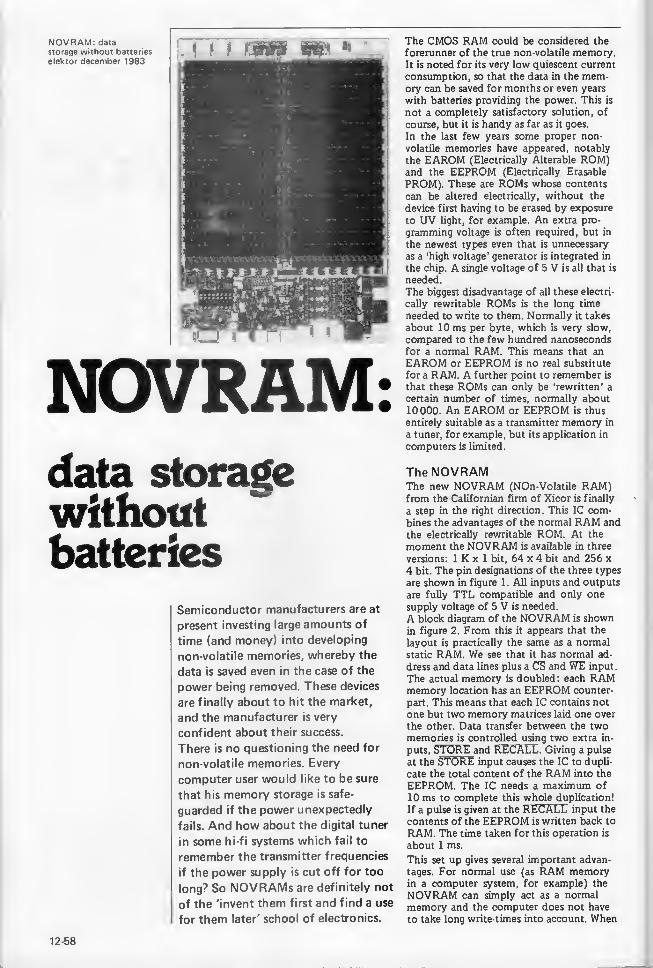
NOVRAM: datastorage without batteries
elektor december 1983
NOVRAM:data storagewithoutbatteries
Semiconductor manufacturers are at
present investing large amounts of
time (and money) into developing
non-volatile memories, whereby the
data is saved even in the case of the
power being removed. These devices
are finally about to hit the market,
and the manufacturer is very
confident about their success.
There is no questioning the need for
non-volatile memories. Every
computer user would like to be sure
that his memory storage is safe-
guarded if the power unexpectedly
fails. And how about the digital tuner
in some hi-fi systems which fail to
remember the transmitter frequencies
if the power supply is cut off for too
long? So NOVRAMs are definitely not
of the 'invent them first and find a use
for them later' school of electronics.
The CMOS RAM could be considered the
forerunner of the true non-volatile memory.It is noted for its very low quiescent current
consumption, so that the data in the mem-ory can be saved for months or even years
with batteries providing the power. This is
not a completely satisfactory solution, of
course, but it is handy as far as it goes.
In the last few years some proper non-
volatile memories have appeared, notably
the EAROM (Electrically Alterable ROM)and the EEPROM (Electrically Erasable
PROM). These are ROMs whose contents
can be altered electrically, without the
device first having to be erased by exposure
to UV light, for example. An extra pro-
gramming voltage is often required, but in
the newest types even that is unnecessary
as a ‘high voltage’ generator is integrated in
the chip. A single voltage of 5 V is all that is
needed.
The biggest disadvantage of all these electri-
cally rewritable ROMs is the long time
needed to write to them. Normally it takes
about 10 ms per byte, which is very slow,
compared to the few hundred nanoseconds
for a normal RAM. This means that anEAROM or EEPROM is no real substitute
for a RAM. A further point to remember is
that these ROMs can only be ‘rewritten’ a
certain number of times, normally about
10000. An EAROM or EEPROM is thus
entirely suitable as a transmitter memory in
a tuner, for example, but its application in
computers is limited.
The NOVRAMThe new NOVRAM (NOn-Volatile RAM)from the Californian firm of Xicor is finally
a step in the right direction. This IC com-
bines the advantages of the normal RAM and
the electrically rewritable ROM. At the
moment the NOVRAM is available in three
versions: 1 K x 1 bit, 64 x 4 bit and 256 x
4 bit. The pin designations of the three types
are shown in figure 1 . All inputs and outputs
are fully TTL compatible and only one
supply voltage of 5 V is needed.
A block diagram of the NOVRAM is shownin figure 2. From this it appears that the
layout is practically the same as a normal
static RAM. We see that it has normal ad-
dress and data lines plus a CS and WE input.
The actual memory is doubled: each RAMmemory location has an EEPROM counter-
part. This means that each IC contains not
one but two memory matrices laid one over
the other. Data transfer between the twomemories is controlled using two extra in-
puts, STORE and RECALL. Giving a pulse
at the STORE input causes the IC to dupli-
cate the total content of the RAM into the
EEPROM. The IC needs a maximum of
10 ms to complete this whole duplication!
If a pulse is given at the RECALL input the
contents of the EEPROM is written back to
RAM. The time taken for this operation is
about 1 ms.
This set up gives several important advan-
tages. For normal use (as RAM memoryin a computer system, for example) the
NOVRAM can simply act as a normal
memory and the computer does not have
to take long write-times into account. When
12-58
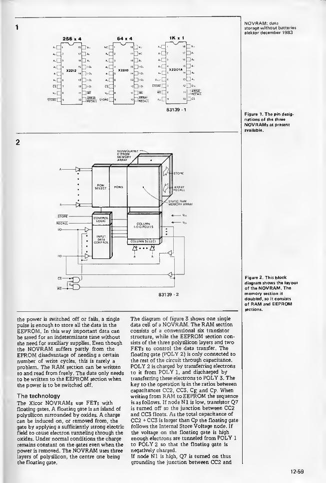
256 x 4 64 x 4 IK x 1
ps83139 1
2
NOVRAM: data
storage without batteries
elektor december 1983
Figure 1. The pin desig-
nations of the three
NOVRAMs at present
available.
Figure 2. This block
diagram shows the layout
of the NOVRAM. The
memory section is
doubled, so it consists
of RAM and EEPROMsections.
the power is switched off or fails, a single
pulse is enough to store all the data in the
EEPROM. In this way important data can
be saved for an indeterminate time without
the need for auxiliary supplies. Even though
the NOVRAM suffers partly from the
EPROM disadvantage of needing a certain
number of write cycles, this is rarely a
problem. The RAM section can be written
to and read from freely. The data only needs
to be written to the EEPROM section whenthe power is to be switched off.
The technology
The Xicor NOVRAMs use FETs with
floating gates. A floating gate is an island of
polysilicon surrounded by oxides. A charge
can be induced on, or removed from, the
gate by applying a sufficiently strong electric
field to cause electron tunneling through the
oxides. Under normal conditions the charge
remains constant on the gates even when the
power is removed. The NOVRAM uses three
layers of polysilicon, the centre one being
the floating gate.
The diagram of figure 3 shows one single
data cell of a NOVRAM. The RAM section
consists of a conventional six transistor
structure, while the EEPROM section con-
sists of the three polysilicon layers and twoFETs to control the data transfer. Thefloating gate (POLY 2) is only connected to
the rest of the circuit through capacitance.
POLY 2 is charged by transferring electrons
to it from POLY 1, and discharged bytransferring these electrons to POLY 3. Thekey to the operation is in the ratios between
capacitances CC2, CC3, Ce and Cp. Whenwriting from RAM to EEPROM the sequence
is as follows. If node N1 is low, transistor Q7is turned off so the junction between CC2and CC3 floats. As the total capacitance of
CC2 + CC3 is larger than Cp the floating gate
follows the Internal Store Voltage node. If
the voltage on the floating gate is high
enough electrons are tunneled from POLY 1
to POLY 2 so that the floating gate is
negatively charged.
If node N1 is high, Q7 is turned on thus
grounding the junction between CC2 and
12-59

NOVRAM: datastorage without batteries
elektor december 1983
Figure 3. Here we see a
single memory cell. The
RAM section consists
of the upper part,
while the lower area
is the EEPROM cell.
Vcca
4
RAW DC O-
Figure 4. This circuit
is used to detect anyfailure of the powersupply and it then gives
a STORE pulse to the
NOVRAM.
CC3. As CC2 is larger than Ce, it holdsthe floating gate near ground when the
Internal Store Voltage node is pulled high.
This causes a sufficient field between POLY2 and POLY 3 to tunnel electrons awayfrom the floating gate to leave it with a
positive charge.
The RECALL operation also takes advantageof capacitance ratios, in particular that C2 is
larger than Cl. When the external RECALLcommand is received, the internal powersupply, VcCA is first pulled low to make thevoltage at N1 and N2 equal. Then the supplyrises again and the node with the lesser
capacitance rises more rapidly than theother, and is then latched high by the flip-
flop. If the floating gate has a positive
charge, N2 is connected to C2 via Q8 andwill latch low. If the floating gate has a
negative charge, Q8 is turned off and N1 will
thus latch low.
How a NOVRAM is used
Nothing needs to be said about connecting
up the NOVRAM as this is almost the sameas for a normal RAM. The only signals whichare different are the STORE and RECALL.The RECALL pulse can be taken care of bythe software in the computer. The STOREsignal on the other hand can better begenerated by a separate circuit. This circuit
watches for power failures and, if one is
detected, supplies a pulse to the NOVRAM
to ensure that the data is saved. An exampleof such a circuit is shown in figure 4. If theinput voltage to the regulator drops, then at
a certain moment the voltage at the non-inverting input of comparator A will belower than the reference voltage at theinverting input. The output voltage thendrops from +5 V to zero. This transition canbe used to trigger the STORE pulse. Thecircuit reacts at an input voltage of about8 V. It should be remembered that the
5 volts must remain present for at least
10 ms after the input voltage has droppedbelow 8 V. This is the time needed by theNOVRAM to transfer data from RAM toEEPROM. The values of the supply ca-
pacitors should be made to suit this.
This NOVRAM is quite an interesting IC,
but, of course, every silver lining has a cloud,and in this case it is the higher price than‘normal’ memories and probably the dif-
ficulty of getting hold of them. However,this is bound to change! M
Literature:
Xicor application notes AN 101 .. . 103Xicor NOVRAM Memories data sheet.
Xicor 's U.K. suppliers are:
Micro Call Ltd.
Thame Park RoadThameOxon 0X9 3XDTelephone: 08442 15405
12-60
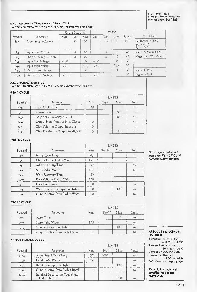
NOVRAM: datastorage without batteries
elektor december 1983
A.C. CHARACTERISTICST/\ = 0°C to 70°C, Vqq = +5 V ± 10%, unless otherwise specified.
READ CYCLE
Symbol Parameter
tRC Read Cycle Time
tA Access Time
tco Chip Select to Output Valid
tOH Output Hold from Address Change
tLZ Chip Select to Output in Low Z
tHZ Chip Deselect to Output in High Z
WRITE CYCLE
Symbol Parameter
twc Write Cycle Time
tew Chip Select to End of Write
tAS Address Set-up Time
tWP Write Pulse Width
tWR Write Recovery Time
tow Data Valid to End of Write
tOH Data Hold Time
twz Write Enable to Output in High Z
tow Output Active from End of Write
LIMITS
Typ'3 ' Max
LIMITS
Typ 0* MaxNote: typical values are
stated for Ta - 25°C andnominal supply voltages
STORE CYCLE
ARRAY RECALL CYCLE
ABSOLUTE MAXIMUMRATINGSTemperature Under Bias
-10°C to +85°CStorage Temperature
-€5°C to +1 25°CVoltage on Any Pin with
Respect to Ground-1.0 V to +6 V
D.C. Output Current 5 mA
Table 1. The technical
specifications of the
NOVRAM.
12-61
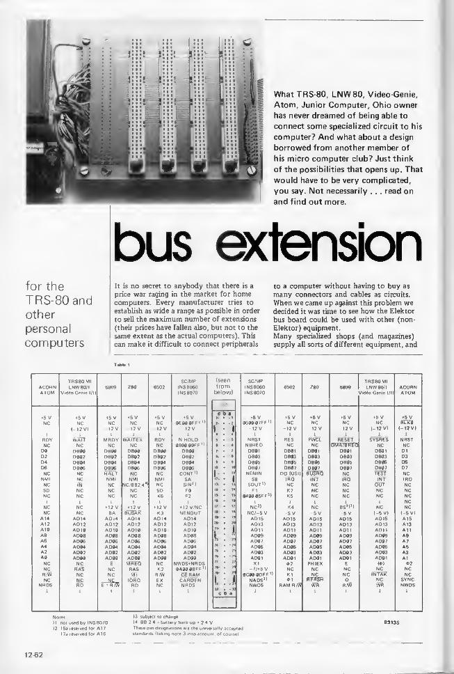
f Si
.
:
X 1 x iot|
What TRS-80, LNW80, Video Genie,
Atom, Junior Computer, Ohio owner
has never dreamed of being able to
connect some specialized circuit to his
computer? And what about a design
borrowed from another member of
his micro computer club? Just think
of the possibilities that opens up. That
would have to be very complicated,
you say. Not necessarily . . . read on
and find out more.
bus extensionfor the
TRS-80 andother
personal
computers
It is no secret to anybody that there is a
price war raging in the market for homecomputers. Every manufacturer tries to
establish as wide a range as possible in order
to sell the maximum number of extensions
(their prices have fallen also, but not to the
same extent as the actual computers). This
can make it difficult to connect peripherals
to a computer without having to buy as
many connectors and cables as circuits.
When we came up against this problem wedecided it was time to see how the Elektor
bus board could be used with other (non-
Elektor) equipment.Many specialized shops (and magazines)
supply all sorts of different equipment, and
T able 1
TRS80 Ml SC/MP (seen SC/MP TRS80MIACORN LNW80/I 6809 <•’80 6502 INS 8060 from INS 8060 6502 Z80 6809 LNW80/I ACORNATOM Vidfto Genie I/ll INS 8070 below) INS 8070 Vidfo Genie I/ll ATOM
5 V 5 V 5 V 5 V 5 V 5 V y • t 5 V 5 V 5 V 5 V 5 V 5 VNC NC NC NC NC OMWflFFF'l • -7 06MV7FF '1 NC NC NC NC 8u?0
(—12 V) 12 V 12 V -12 V 12 V1
- 112 V 12 V 12 V -12 V (-12 V) (-12 V)
1 1 1 1 1 1 4 • 4 1 1 1 1 1 1
ROY WAIT MRDY WAITE X ROY N HOLD ft • S NRST RES PWCl RESET SYSRES NRSTNC NC NC NC NC 08«J«9Ff'I I • 1 NBREO NC NC CMAT&RTG NC NCDO DBOO DBOO OB00 DBOO DBOO 7 • 7 OB01 DB01 0801 DB01 DB01 01D2 DB02 OB02 OB02 D802 DB02 A • « DB03 0803 0803 DB03 DB03 D304 DB04 OB04 OB04 0804 0804 • • f DB05 DB05 D805 DB05 DB05 D506 DB06 DB06 OB06 DB06 OB06 l» • 10 DB0/ DB07 080/ DB07 DB07 D7NC NC HALT NC NC CONT'I
1• v NENIN DD (OSD BLfSRQ NC TEST NC
NMI NC NMI NMI NMI SA * • i SB IRO INT IRQ INT IRQNC IN NC NC/BB2.4
4* NC SIN* IX • 13 SOUT 1 ) NC NC NC OUT NC
SO NC NC NC SO F0 14 • 14 FI K 7 NC NC NC NCNC NC NC NC K6 F2 1» • IS <muooijff 3
I K5 NC NC NC NC1 1 1 1 L 1
ift • 16i 1 1 i 1 NC
NC NC *12 V M2 V 12 V M2 V/NC 17 • 17 NC J > K4 NC 8S I>3> NC NC
NC NC BA buSak K3 NENOUT NC/ -5 V 5 V 5 V -5 V (-5 V) ( -5 V)A 14 AD 14 AD.
4
ADM ADM ADM AD15 AD 15 AD15 AD15 AD15 A 1
5
A12 A012 A012 AD 1
2
AD12 AD12 AD13 AD 13 AD13 AD 13 AD 13 A13A 10 A0 1
0
A0 10 AD10 AD10 AD 10 ’I AD1
1
AD 1
1
AD1
1
AD1
1
AD1
1
AllA8 A DO8 A 008 AD08 A 008 AD08 L „
A 009 A 009 AD09 AD09 A 009 A9A6 A 006 A 006 A 006 A 006 A 006 A 00 7 ADO 7 A DO 7 AD07 AD07 A7A4 A 004 A 004 A 004 A 004 AD04 74 • - H ADOb ADOb A DO5 AD05 AD05 A5A2 A 002 A 002 A DO2 AD02 AD02 A 003 AD03 A 003 AD03 AD03 A3AO A 000 AO00 AO00 A 000 A 000 7ft • - 7f AD0
1
AD0
1
AD0
1
AD0
1
AD01 A1NC NC E MREO NC NWDS*NRDS XI 02 PHIEX E (O) <t>2
NC RAS NC RAS K2 (lAWVBFF’l -//5 V NC NC NC NC NCR /W NC NC Ml R/W Cl RAM 7*- • rt 0C00 0DFF *> K1 NC NC iwtsr NCNC
NROSNCfu)
—a£_F ’ R/W
IORQRD
EXNC
CARDENNRDS !, : 1
NADS 0NWDS
4>1
RAM R/WrERSRWR
QR/W
NCWR
SYNCNWDS
» . w1 1
c b a
-1
Notes.
)1 not used by INS 8070
)2 15a reserved for A1
7
17a reserved for A16
)3 subject to change
)4 88 2 4 battery back up » 2 4 VThese pm designations are the universally acceptedstandards (taking note 3 into account, of course)
83135
12-62

bus extensionelektor december 1983
Figure 1. These are the
signals available at the
TRS-80 keyboard output
connector. The LNW80has an extra signal, CAS,
at pin 3.
Figure 2. This shows an
example of how the bus
extension can be adapted
for a TRS-80. Some of
the a and c pins are con-
nected together in this
design to reduce resistance
in the power supply lines
(earth, +5 V and —12 V).
seen from above
5 V 39
aOc
Q-i-0 39 *5 V
X 29/37
2D0-3-acm-o 29/37
X
2 33
2260
3026 so 3228 o* 18
20 o ion 24
23 "21 01212 Ol3 19
X 29/37
0*0isO
0160 29/37X
7
170180iso 10
6 200 5
9 021
0
4
17 220 11
36 0230 3835 24 0 31
34 25 0 4027 0260 25
27 0280 1
14 29 0
13
3000310 15
18 032-0 B1
o83135.2
Table 1. Here we list the
relation between the pins
of a 64-way connector and
the signals available onsome microprocessor or
microcomputer buses.
64-way
connector
TRS-80signals
TRS-80signals
64-wayconnector
5a SYSRES* 2 c 3 1 RAS* 28c
21c A10 4 c J 3 NC 1 NC20a A13 6 c J 5 A 12 20c
32a. c GND 8 c J 7 A15 19a
19c A14 10 c 9 All 21a
13a OUT* 12 c J 11 A8 22c
29a INTAK* 14 L J 13 WR* 31a
NC NC 16 C 15 RD* 31c
9c D4 18 L J 17 A9 22a
10a D7 20 c J 19 IN* 13c
7a D1 22 L J 21 INT* 12a
10c D6 24 L J 23 TEST* 11a
8a D3 26 L J 25 A# 26c
9a 05 28 C. J 27 A1 26a
7c 00 30 c 29 GND 4a,c/16a,c
8c 02 32 c 31 A4 24c
25a A3 34 L 3 33 WAIT* 5c
23a A7 36 c J 35 A5 24a
23c A6 38 c J 37 GND 4a.c/16a,c
25c A2 40 c 3 39 5 V 1a,c
Note:
• indicates negative logic (an input or output is
'true' at the low logic level)
1 CAS for the LNW80
83135-1
each circuit is more sophisticated than the
next. The very sight of them is enough to
bring out the ‘experimenter’ in every one of
us. To make proper experimentation feasible,
what is really needed is a bus board, which
has several connectors to accept one or a
number of cards, and preferably with its
own on-board supply.
What is a bus?
Obviously everybody could design their ownbus, to suit their own particular needs, but
this would almost certainly rule out the
possibility of borrowing a circuit from some-
body else with a similar computer.
This is why Elektor designed a bus board in
mid 1978 for the first microprocessor to
appear in any of our circuits, the SC/MP.
Gradually, as new micros started to appear
(the 6502, Z80 and 6809), the number of
lines needed began to increase. Originally
the bus was intended only for one computer,
the SC/MP. Eventually the Junior Computerarrived and the bus was used for this also.
As the TRS-80 is still a very popular micro
we decided that some rationalization was in
order to make it compatible with the Elek-
tor bus. The same applies for several other
computers and the most recent addition to
our list is the Acorn Atom.What we have in mind is more than simply
a modified and renewed bus. Since its incep-
tion, about five years ago, many micro com-puter buffs have used the Elektor bus for
their computer system, whether that is
Elektor’s SC/MP or Junior Computer or
something completely different. The layout
suggested here has the advantage that it
allows almost all the cards published by Elek-
tor to be used without any modification;
cards published elsewhere will also fit the
format defined by the bus. Some of our
cards have proved very popular, among themthe universal memory card, the EPROMprogrammer and the floppy disk interface.
Depending on what microprocessor the sys-
tem is based on, the various cards can be
used either without modification (6502), or
with a certain number of modifications for
some of them (Z80). Most of the Elektor
cards can very easily be adapted to almost
any system. Table 1 is a summary of the
conventions used by various systems.
Applications
This extension can be used with any
personal computer (possibly with some
modification with some of those we have
not mentioned), but it is absolutely im-
perative that the output bus of the com-
puter is buffered (with a 74LS367 in the
case of the TRS-80 model I).
It would be impossible to try to list all the
possible circuits that could be plugged into
the connectors of this bus extension. Someof the more interesting are: a speech syn-
thesizer (SC01), sound synthesizer (1 ... 3
AY-5-8910), EPROM programmer, all sorts
of converters, real-time clock, circuit emu-lator. Often these various circuits have a
large current consumption so it is a goodidea to give the bus extension its own supply
so that it can cope with these power-hungrycards. Circumstances dictate the character-
istics of the supply (+ and —5 V, + and-12 V).
If such a supply is added only the earth line
should be connected to the computer be-
cause the voltages supplied by the regulators
will probably be slightly different and this
could cause problems.
Nothing is more descriptive than an example,
and we chose the TRS-80 as our guinea-pig.
The signals available at the TRS-80 keyboard
output connector are given in figure 1 . Thecorresponding connections on the bus exten-
sion are illustrated in the drawing of figure
2 .
Using this example you should be able to
adapt this extension to any computer with
a buffered output bus.
The simplest way of making this bus exten-
sion is to use a suitable printed circuit board,
either the one described in the article ‘new
bus board for microprocessors' (January
1980, page 1-31), or the one described else-
where in this issue. In the first case up to
five connectors can be used, in the second
this goes up to seven. In either case it is
important that the components should be
carefully located on the plug-in cards, to
ensure that they can all be fitted. H
12-63

Temperature controlled
soldering station
In new SA-3 series temperature controlled
solder station from OK Industries is ideal
for all soldering applications. Tip mountedsensors and sophisticated control circuitry
ensure fast response and excellent stability
within 5% over 100-500°C.
Furthermore the mains powered unit
comes with a special 24 V 48 W low-
leakage iron and is earthed for MOS andCMOS applications.
Ease of use is a feature and the tool has
power and heater indicators, proportional
temperature control and a temperature
indicator. A variety of tips is offered.
A solder spool holder, to accept any size
of solder spools up to 7 in (178 mm)diameter is also available.
OK Industries UK Ltd,
Dutton Lane,
Eastleigh,
Hants, S05 4AA.Telephone: 0703 610944
(2772 M)
Compact rotary encoder
Hero Electronics is now stocking the
Sharp range of incremental rotary enco-
ders and slotted discs.
The GP-1R04 series which is shown in
the photograph is a photointerruptor type
of rotary encoder with a built in light
level compensating circuit consisting pri-
marily of an infra red light emitting diode
and integrated type photodiode. Other
encoders include the GP-1 52 (rotary
shaft encoder) and the GP-1R11 a smaller
version of the GP-1 R04.
The GP-1 R04 provides 3 types of output
2-phase output — A — (approximate sine
wave), — B — (approximate cosine wave)
and — Z — Index output. The GP-1R04series comprises 5 models with different
slotted discs. Their resolutions are 96,
100, 192, 200 and 360 pulses per rev-
olution.
The features of these encoders besides
their compact and lightweight design are
high accuracy in phase difference due to
laser trimming, high frequency response
because of the use of a laser diode and
very good thermal characteristics. Theencoders are excellent for detecting arc
elektor december 1983
angles the number of revolutions, ro-
tational speeds and directions.
Application are in typewriters and printers,
copiers, machine tools, robotics and in
various types of measuring instruments,
micrometers, venier calipers etc.
Hero Electronics Limited,
Dunstable Street,
Ampthill,
Bedfordshire, MK45 2JSTelephone: 0525 405015
(2771 M)
The Zicon 701 logic analyser
The Zicon 701 is a new 40 channel logic
analyser from Zicon Instruments Ltd of
Norwich.
Designed for use with 8-bit and 16-bit
microprocessors, its 4 clock inputs permit
full analysis of multiclock and multiplexed
AiP'S (such as the Z80 and 8085), to
which it can be connected directly with-
out personality probes. Its ability to de-
multiplex makes possible the simultaneous
display of address, data and status infor-
mation. It records 1000 bits per channel at
speeds up to 10 MHz, using a separate
monitor or TV set as a display.
A succession of fully interactive menus,
with a flashing cursor to indicate the
relevant input field, makes setting-up
quick and trouble-free. Invalid data
entry is blocked, and messages on screen
identify the errors.
The trigger and trace capabilities of the
Zicon 701 result in very flexible and
precise data capture. Triggering is via a
24-bit trigger word with separate trigger
qualifier and trigger count of 1 to 999events. The clock qualifier includes a
24-bit trace facility which filters andselectively captures significant infor-
mation. A delay feature allows the last
trigger event to be positioned anywherein the 1000 line memory to give a com-plete pre- and post-trigger analysis.
The data can be examined either (a)
'on screen' in normal listing format or
as data signatures, or (b) as hard copyprintout using the RS 232C output whichis fitted as standard. Transmission speeds
are selectable between 300 and 4800baud.
Data listing offers a choice of six different
formats of hex and/or binary code, with
either 11 or 22 displayed lines dependingon the format selected. The instrument
accepts a full-width 40-bit search word,and both trigger words and search wordsare highlighted. Scrolling by line, page,
trigger word or search word greatly
facilitates data location.
The instrument is compact, light (5lbs)
and portable, and thus ideally suited to
field servicing and bench work alike. It
is 100% British in design and manufacture.
Zicon Instruments Ltd were established in
1978 as a company specializing in the
design and manufacture of logic analysers.
Two of their earlier models, the Zicon 620(8 channel) and the Zicon 632 (16 chan-
nel) are still available for those users whoare looking for high performance linked
to low cost.
Zicon Instruments Ltd.,
23 Meteor Close,
Airport Industrial Estate,
Norwich NR6 6HQ.Telephone: 0603 400083
(2774 M)
12-64

elektor december 1983
PCB terminal multipin capacitor
Axiom electronics limited, who already
carry in-depth stocks of Sprague type
705D aluminium electrolytic capacitors,
have added a multipin pcb terminal
version of the device to their inventory.
In common with the other componentsin the range, the multipin terminal capaci-
tor features high ripple current, low ESR,and good high frequency characteristics,
and has the additional advantage of
mounting straight onto the printed circuit
board.
The number of pins varies between three
and five, depending on the diameter of thecapacitor, to give total stability. The705D multipin configuration conformsto DIN specification.
Sprague type 705D capacitors are equiv-
alent to the Mullard 050 series. Excep-tionally stable, they are ideal for use in
switch mode power supplies, instrumen-
tation, and telecommunications equip-
ment.
Axiom Electronics Limited
,
Turnpike Road,Cressex Estate,
High Wycombe,Bucks HP12 3NR.Telephone: High Wycombe 442181
(2807 M)
and colour combinations, which include
red on aluminium, black on yellow, blue
on clear plastic and black on white plastic,
create smart, bright labels or signs for
every use.
With the kit it can take a mere five mi-
nutes to make a Photolabel — at around
4 pence per square inch.
19" terminal cases
New to OK Industries' Elrack enclosure
series of enclosures, a range of 19in
terminal cases has been designed for
industrial, electronic, communications en-
gineering and equipment monitor appli-
cations.
How it works
The original artwork, which should either
be a negative or a drawing on tracing
paper, is placed onto the emulsion side of
the selected sheet of Photolabel material,
and both are then exposed to ultra-
violet light. Next, the sheet of material is
processed by rubbing it gently with a padsoaked in 3M developer. This entire
process may be carried out in daylight —no darkroom is required.
Additional protection from damage maybe given to the label by either laminating
it with 3M gloss or matt laminating film.
With the Photolabel's reverse side being
coated with a pressure sensitive adhesive,
the completed label may be positioned
on any rigid surface by simple peeling off
the backing paper and pressing it into
place. The new Kit permits the user to
custom-make a wide range of attractive
labels. Typical applications include logos,
nameplates, prototype panels, wiring dia-
grams, charts, dial faces, control panels,
electrical boxes, switching information,
safety instructions, warning signs, art
layouts, and a host of other labelling/
signing projects.
Industrial Marking Systems Group,3M United Kingdom PLC,3M House,
P.O. Box 1,
Bracknell,
Berkshire RG 12 1JU.
Telephone: 0344 58457
(2803 M)
Photolabel introductory kit
The new 3M photolabel introductory
kit from the company's industrial markingsystems group allows anyone to producebrightly coloured, self-adhesive metal andplastic labels in minutes — at a fraction of
the cost of having them factory-made or
printed.
The kit is an ideal introduction for a
company or original equipement manufac-turer wanting to make its own durable,
professional looking labels, signs or
markings for application to a smoothsurface. The only other additional item
required for their production is an ultra-
violet light source.
The kit's contents include 13 sheets of
photolabel material in assorted colours,
matt and gloss laminating film, reversal
film, developer solution and pads, anexposure guide and full instructions.
The light-sensitive emulsions are coatedonto four types of base — heavy or stan-
dard guage aluminium, and transparent
or coloured polyester. The range of base
The design is modular, utilising six differ-
ent kits to enable virtually any require-
ment to be met. Moulded from tough
ABS the components include cases,
extension kits, with ventilated side panels,
keyboards and keyboard/displays. Compo-nents can be supplied either complete or
in kit form for easy assembly.
Additionally the cases are available with
front panels to accept switches or instru-
mentation, front panel heights being
223.5, 312.5, 402 or 490.5 mm. Thestandard colour is beige but other colours
are available on request.
OK Industries UK Ltd.,
Dutton Lane,
Eastleigh,
Hants S05 4AA.Telephone: 0703 610944
(2801 M)
12-65

advertisement elektor december 1983
Matching AKG Microphone to suit 'with speech and musicfilter). Complete with lead ONLY £9 95 plus 75p p&p.
VHF STEREO TUNER KIT
STEREO CARTRIDGESPHILIPSMagnetic cartridge with diamondStylus Model No GP 397 III Output2mV Separation 22dB Stylus 0 6mm
£3.95 each piu, 60P p&p
.ARRARDScrotone Garrard Ceramic cartridge.
'V«V. Wuh turnover Sapphire
£2.95 plus 60p p&p
diameter magnet
125W HIGH POWER AMPMODULES finRn ni;.£10.50 £14.25
£1 .15 p&p < £1.1 5 p&p
The power amp kit is a module for high power applications
disco units, guitai amplifiers, public address systems andeven high power domestic systems The unit $ protected
aqamst short circuiting of the load and is safe in an open cir
curt condition A large safety margin exists by use of genei
ously rated components, result, a high powered rugged unit
The PC board is back printed, etched and ready to drill for
ease of construction and the aluminium chassis is preformedand ready to use
Supplied with all parts, circuit diagrams and instructions.
ACCESSORY. Steieo/mono nioins power supply kd withtransformer £10.50 plus £2.00 p&p.
( . I F If' A T I ( )NS
Tper.itmq voltage (OC) 50 - 80 maxoads 4 16 ohms-lequency lesponse measured (S> 100 watts 25H/ 20KH?,icnsitivdy for 100 watts 400mV@47Krypical T H D fy* 50 watts 4 ohms 0 1%Dimensions: 205 * 90 ami 190 x 36 mnv
T.V. SOUND TUNER BUILT ANDTESTED
PRACTICAL ELECTRONICSSTEREO CASSETTE
RECORDERKIT
In the cut-throat world of consumer electronics, one of the
questions designers apparently ponder over is "Will anyonenotice if we save money by chopping this out?" In the
domestic TV set, one of the first casualties seems to be the
sound quality Small speakers and no tone controls are
common and ail this is really quite sad, as the TV compan-ies do their best to transmit the highest quality sound.
Given this background a compact and independent TVtuner that connects direct to your Hi-Fi is a must for quality
reproduction. The unit is mains operated.
This TV SOUND TUNER offers full UHF coverage with
5 pre selected tuning controls. It can also be used in conjunct
ion with your video recorder Dimensions: i 1 m" x 8y?"x 3%".
version of above without chassis, case and hardware. £12 95 plus Cl 50 p&p
MONO MIXER AMPIdeal for Church o -
halls & Clubhouses lL^fD.UU * £2 00 p&p
50 WATT Six individually mixed inputs to: two pick upsfCer. or mag ), two moving coil microphones and twoauxiliary for tape tuner, organs, etc Eight slider controls
six for level and two for master bass and treble, four
extra treble controls for mic and aux inputs. Si/e13’*' *6 '/
-x3V app. Power output 50 watts RMSIcont ) for use with 4 to 8 ohm speakers Attractive black
vmyl case with matching fascia and knobs. Ready to use.
Steieo cassette tape decktransport with electronics
Manufac tuier s surplus
brand new and operational
sold without warranty
£11 95plus £2 50 p&p
Just requires mams nansformer and input 'output
sockets and a volumecontrol to complete
L- includes tape transport mechanism, ready punched andaac* printed quality circuit board and all electronic parts
r semiconductors, resistors capacitors, hardware tops*tr, printed scale and mains transformer. You only supplyorder and hook up wire. —Featured .n April issue p E SPECIAL OFFER 1
forint 50p Free with kit £31 00 plus £2 75 p&p5**f assembly simulated wood Complete with casemu £4 50 ‘£150 p&p
AUDAX 40WFERRO-FLUID HI-FI
TWEETERX/over on 5kH/?2kH/ 60mm f5 50square 8 ohm *60p p&p
£32.95 £2.75 p&pNOISE REDUCTION SYSTEM • AUTO STOP • TAPECUNTER • SWITCHABLE E Q . INDEPENDENT£ .EL CONTROLS • TWIN V.U METER • WOW &. JTTER 0 1% . RECORD'PLAYBACK I C WITH ELEC"R0NIC SWITCHING • FULLY VARIABLE RECORDINGAS FOR ACCURATE MATCHING OF ALL TAPES
SPEAKER
t»ass mid range and 3 .
«eter Complete with screws»e. crossover components«a cabinet Cabinet comes mr pre mitred 0 I Y formn.*h chipboard coveredsod simulate. si*e 14V*. « 4 PAIR lor ONI Y
Impedance 8 ohms
i mail to
K HIGH STREET, ACTON W3 6NG.re: Goods despatched to U K postal addresses onlyrems subiect to availability. Prices correct at
9 83 and subject to change without notice
jse allow 14 working days from receipt of order
despatch RTVC Limited reserve the right to up-
date their products without notice All enquiries send
S A E
AI L CALLERS TO 323 EDGWARE ROAD,LONDON W2. Telephone 01 723 8432<5 minutes walk from Edgware Road Tube Station)
Now open 6 days a week 9 6. P> ices include VAT.
Telephone or mail orders by ACCESS welcome

spotlight on Elektor booksRESI & TRANSIA series of strip cartoons in book form in
which two enterprising characters explore
the field of electronics in their own inimi-
table way. Their adventures are full of
tension, because they often go against the
current - whereby they encounter muchresistance - before they reach their goal.
These books familiarize the reader with
electronics in an unusual way: exciting,
playful, yet thorough. Part I comes com-plete with a printed-circuit board and resi-
meterPart I : Banish the Mysteries
of Electronics £ 5.75Part II : Hands off my Bike! . .
£4.50
TV GAMES COMPUTERThis book, provides a different - and. in
many ways, easier - approach to micro-
processors The TV games computer is
dedicated to one specific task, as the
name suggests. This provides an almostunique opportunity to have fun while
learning!
Pnce £ 6.75
DIGIBOOKProvides a simple step-by-step introduc-tion to the basic theory and applicationof digital electronics and gives dearexplanations of the fundamentals ofdigital circuitry, backed up by experiments designed to reinforce this newlyacquired knowledge. Supplied with anexperimenter's PCBPrice £ 6.00
300 CIRCUITS
For the home constructor - 300 projects
ranging from the basic to the very sophis-
ticated.
Price £ 5.50
MICROPROCESSOR HARDWAREThis book describes a range of peripheral
ec^jipment that can be connected andused with an assortment of personalcomputers which use the 6502, 6809. Z80or the 8080 CPUPrice £ 7.50
JUNIOR PAPERWARE 1
Modifications of the PM/PME EPROM:Source listings. Hex dump of the Softwarecruncher and puncher (Elektor 85, May1982)Price £2.00
JUNIOR PAPERWARE 2
Source listing of the bootstrap loaderfor Ohio Scientific Floppys: Hex dumpof the EPROM (ESS 515)p"ce £2.00
DATA SHEET BOOKHere at last is the book that designers havebeen waiting for: the Elektor Data SheetBook. In 240 pages it gives you a CMOS,a Linear, Special Function and Audio Data8ook: extensive information on 269 ofthe most important IC’s. A very useful
and economical reference book!Price £8.00
JUNIOR COMPUTER VIA 6522
This book deals with the well-knownVersatile Interface Adapter (VIA) type6522 Although it is an indispensable ad-dition to the four books already devotedto the Junior Computer, it is not aimedsolely at Junior users, but at anybody whohas a system with one or more 6522s. It
affords a complete familiarization withthis flexible and effective component.Price £3.25
JUNIOR COMPUTER BOOK 1
For anyone wishing to become familiar
with (micro)computers. this book gives
the opportunity to build and program a
personal computer at a very reasonablecost.
Price £6.50
JUNIOR COMPUTER BOOK 2
Follows in a logical continuation of
Book 1. and contains a detailed appraisal
of the software. Three major programmingtools, the monitor, an assembler and aneditor, are discussed together with practi-
cal proposals for input and peripherals.
Price £ 6.50
JUNIOR COMPUTER BOOK 3
The next, transforming the basic, single-
board Junior Computer into a completepersonal computer system.
Pnce £ 6.50
JUNIOR COMPUTER BOOK 4
Book 4. the last in the series, describes all
the software required to operate the com-plete system. A number of peripheral
devices, such as a printer and a video
terminal, may be 'hooked up' to the
computer. During the final stage in its
'growth', the machine is able to extendits linguistic skills, for a special version of
BASIC is now available on cassette.
Price £ 6.50
301 CIRCUITS
The book is a continuation of our popularand very successful 300 circuits publi-
cation. It is composed of 301 assorted
circuits ranging from simple to morecomplex designs, described and explainedin straightforward language.
Price £ 5.50
SC/MPUTER (1)
Describes htyw to build and operate yourown mitrup&e-cssof system - the first
book of a side’s - further books will
show how the system may be extended tomeet various requirements,Price £5.50
SC/MPUTER (2)
The second, book in series. An updatedversion of the monitor program (Elbug II)
is introduced together with a number of
expansion possibilities. By adding the
Elekterminal to the system described in
Book 1 the microcomputer becomes evenmore versatile.
Price £5.50
FORMANTComplete constructional details of the
Elektor Formant Synthesiser comeswith a FREE cassette of sounds that
the Formant is capable of producingtogether with advice on how to achievethem.Price £ 6.00
33 ELECTRONIC GAMES *
A selection of circuits which give as muchenjoyment in building them as actually
playing the games. The circuits are fasci-
nating although the electronics involvedaie not complex and therefore anyonewith a good soldering iron will find this
book satisfying. These are electronic gamesthat do not need a TV screen, and as aresult can be played just about anywhere.Price . . £4.50
To order please use the postage paid ordercard in this issue.
ADD 50p P 8. P U K. (OVERSEAS £ 1.00)
THENEWAMPUNCATALOGUEFOR84!
nwpuni
PROJECTS FOR THE HOME CONSTRUCTOR
NEW MAPLIN STORE IN SOUTHAMPTON
Choose from our huge
range of value- for-
money projects. Projects
like our Modem, Mosfetj
Stereo Amplifier, HomeSecurity System, Fre-
^*
j
quency Counter and — 4
Home Computer add- ' — .
on kits. Full construction details in our Project Books and brief
specifications in our new catalogue. Dozens of fascinating new
projects coming soon including a Keyboard for the ZXSpectrum with electronics to make all shifts, single- key
operations. Full details in Project Book 9 on sale 1 1th November1983. Order As XA09K. Pfice 70p.
Opening on 1st November 1983, our newsouth coast store is at 46-48 Bevois Valley
Road, Southampton (Tel: 0703 25831). Youwill find our full range of components,projects and computers on sale. We are within
easy reach of the city centre with good parking 5 V
close by. Call in and see us soon.
NOW WITHPRICESON THEPAGE
More data, more circuits, more
pictures, in the brand new 480 page Maplincatalogue. Take a look at the completely
revised Semiconductor section or the newHeathkit section with descriptions andpictures ofdozens of kits and educational
productsfrom digital clocks to 16-bit business
computers. The much expanded computer
section itself, gives details ofhundreds of
pieces ofsoftware for Atari, BBC, Commodore64, Dragon, Spectrum and VIC20. In
addition to all this you’llfind hundreds of
fascinating new items spread through the rest
ofthe catalogue.
As always, the Maplin catalogue is
tremendous value for money and now has
prices on the page!
Pick up a copy at any branch of
W.H.Smith or in one ofour shops forjust
£1.35 or send £1.65 including postage to our
Rayleigh address. On salefrom 1st Nov 198.
i
iiplfliaIS sun is
,
Post this coupon now for your copy of the 1984 catalogue.
Price £1.35 + 30p post and packing. If you live outside the
U K. send £2.20 or 11 International Reply Coupons.
I enclose £1.65.
Name
Address •
I-E 12/83
I
J
ffMpun ksss.Mail Order: P.O. Box 3. Rayleigh, Essex SS6 8LR. Tel: Southend(0702) 552911 • Shops at: 159 161 King Street, Hammersmith.London W6. Tel: 01 748 0926 • 8 Oxford Road, Manchester.Tel: 061 236 0281 • Lynton Square, Perry Barr. Birmingham.Tel: 021 356 7292 • 282 284 London Road. Westcliff on SeaEssex. Tel: 0702 554000 • *46 --48 Bevois Valley Road,Southampton. Tel: 0703 25831.•Opens 1 st November 1983. All shops closed Mondays.All prices include VAT and carriage. Please add 50p handlingcharge to orders under £5 total value (except catalogue).