Elektor-1993-09.pdf - World Radio History
84
AUDIO & HI-FI COMPUTERS & MICROPROCESSORS DESIGN IDEAS RADIO, TELEVISION & COMMUNICATIONS SCIENCE & TECHNOLOGY TEST & MEASUREMENT M
-
Upload
khangminh22 -
Category
Documents
-
view
8 -
download
0
Transcript of Elektor-1993-09.pdf - World Radio History

AU
DIO
& H
I-FI C
OM
PU
TE
RS
& M
ICR
OP
RO
CE
SS
OR
S D
ES
IGN
IDE
AS
RA
DIO
, TE
LEV
ISIO
N &
CO
MM
UN
ICA
TIO
NS
SC
IEN
CE
& T
EC
HN
OLO
GY
TE
ST
& M
EA
SU
RE
ME
NT
M

FROM CONCEE ARTWORK IN 1 DA
I - -'041 r.
5%1ULTIboardfULTIcap evaluation system. all features of the bigger versions full set of manuals design capacity 350 pins
Price Incl. S & H. excl. VAT:
Purchase price is 100% credited when upgradinga bigger version. Also suitable for study & hobby
Lit-L@LTI),-u-
-
Your d Ideas are quickly captured using the ULTIcap schematic design Tool ULTIcap usesREAL- checks to prevent logic errors. Schematic editing is painless; simply click your start and endpoints LTlcap automatically wires them for you. ULTIcap's auto snap to pin and auto junctionfeatures ensure your nettist is complete, thereby refiev ng you of tedious nellist checking
as
a
JL7.1s ell. the integrated user interface, makes sure allCE,sign information is transferred correctly from
LTic ip to ULTiboard. Good manual placement tools arevital tc the progress of your design, therefore ULTiboardgives mu a powerful suite of REAL-TIME functions suchas, FORCE VECTORS, RATS NEST RECONNECT andDENSITY HISTOGRAMS. Pin and gate swapping allowsyou to further optimise your layout.
a
quickly route your critical tracks.REAL-TIME DESIGN RULE CHECKyou to make illegal connections or
design rules. ULTlboard's powerfulTRACE SHOVE. and REROUTE -WHILE -MOVEalgorithms guarantee that any manual trackediting is flawless. Blind and buned vias andsurface mount designs are fully supported.
It you need partial ground planes, then
with the Dos extended board systems youcan automatically create copper polygonssimply by drawing the outline. The polygonIs then filled with copper of the desired net.all correct pins are connected to thepolygon with thermal relief connectionsand user defined gaps are respectedaround all other pads and tracks.
ULTlboard's autorouter allows you tocontrol which parts of your board areautorouted, either selected nets, or acomponent, or a window of the board, orthe whole board. ULTlboard's intelligentrouter uses copper sharing techniques tominimise route lengths. Automatic viaminimisation reduces the number of vias todecrease production costs. The autorouterwill handle up to 32 layers, as well as
II...single sided routing.
rd's backannotation automaticallyyour ULTIcap schematic with any pin
e swaps or component renumbering.Finally, your design is post processed to generatepen / photo plots, dot matrix/laser or postscriptprints and custom drill files.
ULTiboard PCB Design./ULTIcap
Schematic Design Systems are available
in low-cost DOS versions. fully compatible
with and upgradable to the 16 and 32 bit
DOS -extended and UNIX versions,
featuring unlimited design capacity.
ULTImate Technology UK Ltd. 2 Bacchus House, Calleva Park. Aldermaston Berkshire RG7 40W Fax: 0734 - 815323 Phone: 0734 - 812030

1.=.11.M.111 CONTENTSSeptember 1993
Volume 19
Number 214ISSN 0268/4519
In next month's issue
Microcontroller NiCdchargerProgrammable sine wave
generatorROM gate change -over
for AtariDigital frequencyread-outVHF/UHF TV tunerPower meter with digitaldisplayLow -frequency filter
Stereo mixerand others for yourcontinued interest
Front coverWith the associated software,the autoranging circuit is notonly a 33/4 -digit
PC -controlled digitalmultimeter with manyfacilities, but also a flexiblemeasurement input for acontrol system based onfuzzy logic. Whether a sensorconverts to current, voltageor resistance, the DMM canhandle its output signal. Asensor with a non-linearresponse presents noproblem to fuzzy logic. Thisissue describes a PC -drivenmultimeter, while next month
a fuzzy logic control systemthat makes use of the presentDMM will be discussed.
Copyright © 1993 Elektuur
ABCCONSUMER PRESS
Win a Maplin kit or one of our books with thePrize Crossword on page 41
AUDIO & HI -F1
44
61
PROJECT: Active 3 -way loudspeaker - Part 2Design by T. Giesberts and H. BaggenPROJECT: Digital output for CD playersDesign by T. Giesberts
- .
COMPUTERS & M1CROPROCES4 S
8 PROJECT: I2C alphanumerical displayDesign by J. Ruiters
# #
14 PROJECT: Harmonics enhancerBased on a design by M Eller
50 COURSE Figuring it out - Part 8 Complex numbersBy Owen Bishop
64 The analogue subsystem - Part 2By Joseph J. Carr
70 PROJECT: Mini micro clockDesign by A. Rietjens
' I i I 1
20 PROJECT: 950-1750 MHz converterDesign by B. Romijn
74 DX TelevisionBy Keith Hamer and Garry Smith
TEST & MEASUREMENT
29 PROJECT: Linear temperature gaugeDesign by H. Ktihne
36 PROJECT: Fuzzy logic multimeterDesign by H. Scholten
54 PROJECT: PC -aided transistor testerDesign by S. Aaltonen
S '
Electronics scene 5; New books 34;
Corrections & updates 73;
Product overview 76-77; Readers' services 78-79;
Terms of Business 80; Events 81; Switchboard 81;
Buyers' guide 82; Index of advertisers 82
Harmonics enhancer - p. 14
950-1750 MHz converter - p. 20
Active 3 -way loudspeaker - p. 44
it00
PC -aided transistor tester - p. 54
Elektor Electronics is published monthly, except in August, by Elektor Electronics (Publishing), P.O. Box 1414, Dorchester, Dorset DT2 8YH, England. The magazine isavailable from newsagents, bookshops, and electronics retail outlets, or on subscription at an annual (1993) post paid price of £25.00 in the United Kingdom; air speeded:£32.00 in Europe; £41.00 in Africa, the Middle East and South America; £43.00 in Australia, New Zealand and the Far East; and $56.00 in the USA and Canada. SecondClass Postage paid at RahWay N.J. Postmaster: Please send address corrections to Elektor Electronics, c/o Mercury Airfreight International Ltd Inc., 2323 RandolphAvenue, Avenel, New Jersey, N.J. 07001.
ELEKTOR ELECTRONICS SEPTEMBER 1993

4 Please mention ELEKTOR ELECTRONICS when contacting advertisers
EASY -PC, SCHEMATIC and PCB CAD
Over 17,000 Installationsin 70 Countries World-wide!
Runs on:- PC/XT/AT/286/ 386/ 486 withHercules, CGA, EGAor VGA display andmany DOS emulations.
Design:- Single sided,Double sided andMulti -layer (8) boards.
Provides full SurfaceMount support.
Standard outputincludes Dot Matrix /Laser / Ink -jet Printer,Pen Plotter, Photo -plotter and N.C. Drill.
Tech Support - free. Superbly easy to use.
StillOnly
£98.00!Plus P&P,VAT
BRITISH
DESIGNAWARD
1989
IC,
e ..---,o, , ('''' e
fu,;:,CI
RES
',et; 91,,.E1. _L .Ile.,
I C2
Gut
Options: -500 piece Surface Mount Symbol Library £48,1000 piece Symbol Library £38, Gerber Import facility £98.
Electronic Designs Right First Time?Ask for our fully functional Integrated Demo
Integrated Electronics CADAffordable Electronics CAD
Schematic CaptureUo
IIIIIIII
Analogue& Digital
Simulation
For Less than £400/$775!
EASY -PC: Low cost, entry level PCB andSchematic CAD.
$195.00 £98.00
EASY -PC Professional: SchematicCapture and PCB CAD. Links directlyto ANALYSER III and PULSAR.
$375.00 £195.00
PULSAR: Low cost Digital CircuitSimulator - 1500 gate capacity.
PULSAR Professional: Digital CircuitSimulator - 50,000 gate capacity.
ANALYSER Ill: Low cost LinearAnalogue Circuit Simulator- 130 node capability
ANALYSER Ill Professional: LinearAnalogue Circuit Simulator- 750 node capability.
Z -MATCH II: Smith Chart program for RFEngineers - direct import fromANALYSER Ill.
$195.00 £98.00
$375.00
$195.00
$375.00
$375.00
We operate a no penalty upgrade policy. You canupgrade at any time to the professional version of aprogram just for the difference in price.
US$ pricesinclude Postand Packing.
£195.00
£98.00
£195.00
£195.00
Sterling £pricesexclude P&Pand VAT
For full information, Write, Phone or Fax: -
Number One Systems Ltd. 1REF: EK, HARDING WAY, ST.IVES, HUNTINGDON, CAMBS, ENGLAND, PE17 4WR.Telephone: 0480 461778 (7 lines) Fax: 0480 494042International: +44 -480-461778, Fax:+44-480-494042 ACCESS, AMEX, MASTERCARD, VISA Welcome.
TECHNICAL SUPPORT FREE FOR LIFE! PROGRAMS NOT COPY PROTECTED. SPECIAL PRICES FOR EDUCATION.
ELEKTOR ELECTRONICS SEPTEMBER 1993

ELECTRONICS SCENECONGRATULATIONS ...
to Elektor Electronics India on their10th anniversary. In these ten years,the electronics scene in India has changedtremendously thanks to the lifting of thestifling import restrictions on electronicequipment and components in the mideighties. As most of its sister magazines,EEI is read by electronic engineers, tech-nicians, students and hobbyists through-out the sub -continent. We wish themcontinued success in their significant con-tribution to the electronics scene in India.
... AND WELCOME!to ElektorElektronik, the newest mem-ber of our growing family of magazines,which is due to start publication in Polandthis autumn. We wish it a warm recep-tion by the Polish electronics fraternity.
UNIVERSAL DEVICE PROGRAMMERSmart's ALL -07 programmer is ideallysuited to your PC, Notebook or Handbookcomputer. It can drive up to 256 pins, pro-viding ample capacity for ALL presentand future devices. It also programmesa wide range of microcontrollers includ-ing the latest PIC17C42 from Microchip.Smart Communications, 2 Field End,Arkley, Barnet EN5 3EZ, England.Telephone 081 441 3890. (See p. 43)
HIGH -PRECISION A -D CONVERTERFOR PCs
'PC -Precise' is a high -precision plug-involtmeter A -D converter card with up to21 bit resolution and input ranges from20 mV to 20 V. Universal language soft-ware device drivers and a Virtual Instrument'program are provided within the price.CIL Microsystems, 4 Wayside, CommerceWay, Lancing BN15 8TA, England.Telephone (0903) 765 225.
CIRKIT SUMMER CATALOGUEIf you have not already seen their adver-tisements in this magazine, Cirkit havenow published their Summer '93 CirkitConstructors' Catalogue. With 224 pages(32 up on the previous issue) and over4000 product lines, it's a must for everyelectronics constructor. It costs £1.90 andis available from most larger newsagentsor directly from Cirkit (add 30p for p&p).Cirkit Distribution Ltd, Park Lane,Broxbourne EN 1O 7NQ, England.Telephone (0992) 441 306.
NEW PULSE GENERATORSTwo new pulse generators have beenadded to the range of Levell test equip-ment for test and design engineers. Bothmodels have a range of 0.5-50 MHz, with
one (Model 233) offering many featuresfor versatile monitoring applications.Levell Electronics Ltd, TechnologyHouse, Mead Lane, Hertford SG137AW,England. Telephone (0992 501 231).
ROTARY POTENTIOMETERSCirkit have a new range of low-cost, high -quality rotary potentiometers available.Standard are 16 mm, PCB mountingtypes in single and dual gang versionswith logarithmic and linear laws. Otherstyles available include slider poten-tiometers,mono and stereo, 21 mm dia.potentiometers with mains rated switches,16 mm potentiometers with low currentswitches with solder tag or PCB termi-nations, and a range of miniature andsub -miniature slide switches.Cirkit Distribution Ltd, Park Lane,Broxbourne EN10 7NQ, England.Telephone (0992) 444 111.
STEREO 25 AMPLIFIER KITBased on the Series 700 Line IntegratedAmplifier, the Classic 25 Amplifier, thelatest addition to the Audio Innovationsproduct range, is a high -quality valve am-plifier kit. Its price, delivered anywherein mainland UK, is £699, which includesa comprehensive 40 -page manual.Audio Components Ltd, Albany Road,Granby Industrial Estate, Weymouth,Dorset DT4 9TH, England. Telephone(0305) 761 492.
UNIFICATION OF ENGINEERINGPROFESSION
In their initial response to the InterimReport of the Steering Group on theUnification of the Engineering Profession,22 Institutions representing IncorporatedEngineers and Engineering Technicianshave welcomed and fully supported therecommendation to establish a NewRelationship with a reformed and demo-cratically elected Engineering Council.It should be truly representative of all reg-istrable grades within the profession andimprove the public perception of engi-neering. They believe strongly that sucha New Relationship must bring about aradical change in culture that will strengthenand make more meaningful the existingRegister and the three registrable grades.
The Incorporated Engineering Institu-tions say that having reached unity onthe above central issues, they look for-ward to working for unity in the profes-sion which is so badly needed if engi-neering is to play its rightful role in theUnited Kingdom, in the rest of Europe andthroughout the world.IEEIE, Savoy Hill House, Savoy Hill,
London WC2R OBS, England. Telephone071 836 3357.
NEW DATA LOGGERSOrion Components have introduced twoultra -small, lightweight, low-cost dataloggers for humidity and temperatureapplications.
Tinytalk-RH logs the relative humid-ity in many situations, including aroundelectronic components, inside botani-cal and horticultural greenhouses andin air conditioning systems. It has an ac-curacy of ±3% from 0% to 100% RH.
Tinytalk-PT100 has been designed forapplications where a thermistor can-not be used for measuring tempera-ture, such as in engine oil and in cryo-genic chambers. It covers the range-50 °C to +300 °C.Orion Components Ltd, ScientificHouse, Terminus Road, Chichester,West Sussex P019 2UJ, England.Telephone (0243) 778 088.
16 -BIT MICROCONTROLLER WITHINTEGRAL CAN MODULE
Developed jointly by Bosch and Siemens,the SAB-C167C 16 -bit controller withintegral CAN (Controller Area Network) isnow available. Its main field of applica-tion is in automobile engineering wherehigh computing power and an extensiverange of peripheral devices are required:engine, automatic transmission and ABScontrol are typical examples. The chip canalso be used in process control applica-tions and in programmable controllers.Siemens Ltd, Siemens House, WindmillRoad, Sunbury -on -Thames TW16 8HS,England. Telephone (09327) 85691.
VOLTAGE -CONTROLLEDOSCILLATORS (1)
Wavelength Electronics have a range ofvoltage -controlled oscillators (VCOs) whichthey claim are the first widely availablefrom a European source (Eurowave) ofhigh specification VCOs.
The devices combine a very wide fre-quency range (100 MHz to 26 GHz) withhigh linearity and low phase noise andmicrophony in a wide range of packages.Wavelength Electronics Ltd, WavelengthHouse, 151 Bradstow Way, Broadstairs,Kent CT10 1AR, England. Telephone(0843) 602 869.
VOLTAGE -CONTROLLEDOSCILLATORS (2)
McKnight Fordahl, well-known for theirquality crystal products, have availablewhat they believe is the first voltage-
ELEKTOR ELECTRONICS SEPTEMBER 1993

6 ELECTRONICS SCENE
controlled oscillator (VCO) in a true sur-face mount package. These devices havea very wide pulling range, exceeding±100 p.p.m.; high frequency stability,±35 p.p.m. over the frequency range 0 °Cto +70 °C; and an operating tempera-ture range of -40 °C to +85 °C.
They also have a range of voltage -controlled crystal oscillators (VCXO) cov-ering the frequency range 2-45 MHz.These devices have a low curren drain(10-25 mA) and very wide pulling rangesof ±150 p.p.m.McKnight Fordahl, Hardley IndustrialEstate, Hythe, Southampton SO4 6ZY,England. Telephone (0703) 848 961.
VHF MOBILE TWO-WAY RADIOThe Diplomat VHF mobile two-way radiohas recently passed type approval test-ing to MPT 1326. At 151x181x36 mm itis believed to be one of the smallest25 W two-way radios to comply withthe standard.
The unit incorporates pin number pro-tection, remote stun and reset, electronicserial number, all European selcall stan-dard, autoconnect DTMF software fortelephone interconnect and IBIS trunk-ing software. It can, moreover, be pro-grammed from any PC with a serial portand the appropriate windows -style soft-ware.Diplomat Communication SystemsLtd, Unit 3, Summerlea Court, Herriard,Basingstoke RG25 2PN, England.Telephone (0256) 381 656.
NEW MICROCONTROLLER ANDNEW EEPROM
Microchip have introduced two new de -
vices: the PIC16C84 high-speed 8 -bitRISC microcontroller with on -chip EEP-ROM, and the 24C65 smart serial EEP-ROM.Arizona Microchip Technology Ltd,Unit 3, The Courtyard, Meadowbank,Furlong Road, Bourne End SL8 5AJ,England. Telephone (0628) 850 303.
ENCRYPTION SYSTEMSchlumberger Technologies have an-nounced SmartCrypt, a new encryptionsystem that liberates cable and satelliteTV broadcasters from traditional sub-scription -based methods of chargingfor services. SmartCrypt's dual smartcard interface provides an enabling tech-nology for the broadcasting industry thatallows completely new ways of pricing,packaging and distributing programmeentitlements, while ensuring the high-est level of security against fraud. WithSmartCrypt, viewers are free - for thefirst time - to access programmes on a`pay per view' basis by paying for enti-tlements by means of smart cards.
EPROM PROGRAMMER/EMULATORWhite House Systems have launched TheProgulator, a new combined program-mer and emulator, priced, all inclusive,at £180). The new tool programs and em-ulates all commonly used EPROMs for8 -bit work, that is, 27(C)64 to 27(C)512.
Seven different programming algo-rithms, including FAST LOW (mainlyfor CMOS EEPROMs), FAST HIGH (mainlyfor NMOS devices) and NATIONAL. Pro-gramming times are under a minute fora 2764 EPROM and under six minutesfor a 27512. (See p. 49)
White House Systems, 48 South Terrace,Esh Winning, Durham DH7 9PS, England.Telephone 091-373 4605.
IPRE ANNUAL LECTUREThe Annual Lecture of the IncorporatedPractitioners in Radio and Electronics(IPRE) - a specialist division of TheInstitution of Electronics and ElectricalIncorporated Engineers (IEEIE -was heldin London in June.
Entitled The Impact of ElectromagneticCompatibility (EMC) on ElectronicServicing', it dealt with the main typesof electromagnetic interference problemsassociated with electronic equipmentservicing; maintenance and repair; howto track down and remedy such prob-lems; and the essentials of good EMCpractice.
Membership of the IPRE offers a prac-tical way of keeping up to date with de-velopments in technology and the op-portunity of developing your career.IEEIE, Savoy Hill House, Savoy Hill,London WC2R OBS, England. Telephone071-836 3357.
FLOATING POINT ACCELERATORAcorn Computers has released an arith-metic coprocessor based on the FPA 10Floating Point Accelerator chip. It of-fers greater performance for the A540and A5000 series of Archimedes com-puters and the R260 UNIX workstation.The Floating Point Accelerartor is avail-able from any Acorn dealer.
Further information in the form of a62 -page data booklet, covering proces-sor schematic, programmer's model,instruction set and hardware/software
Produced and published by ELEICIOR Unit 4, Gibbs Reed Farm GERMANYELECTRONICS (Publishing) Pashley Road Elektor Verlag GbH Elektuur BV
TICEHURST TN5 7HE Ststerfeki Stralk 25 Peter Treckpoelstraat 2-4Editor/publisher Len Seymour Telephone. (0580) 200 657 (Nanonal) 5100 AACHEN 6191 VK REEKTechnical Editor. I. Baiting or +44 580 200 657 (huentational) Editor Exempt Editor: P.E.L. Kersemakers
Fax: (0580) 200 616 (National)Editorial & AdinintstradvoOfices; or +44 580 200 616 (international) GREECE POLANDP.O. Box 1414 Elektor EPE Elektor ElektromlDORCHESTER 0T2 8Y11 Head Office: Kariskaid 14 02-777 Warszawa 130England P.O. Box 75 16673 Voula-ATHENA Skrytica Pocztowa 271Telephone: (0305) 250 995 (Natio dalor +44 305 250 995 (International )
6190 AB BEEKThe Netherlands
Editor: E Kant/mobs Editor; W Mercian&
Fax (0305) 250 996 (Nammal) Telephone: +31 46 389444 HUNGARY PORTUGALor +44 305 250 996 (International) Thies; 56617 (elekt n1) Elektor Elektronikal fol Fcuvua & Bento Us.
Par +31 46 37 01 61 1015 Budapest Estefini. 32-10WC. Advertising On= Managing Director Battbyiny u. 13 1000 LISBOA3 Crescent Terrace Editor Lakatus Andnia Editor: E Ferreira da AlmeidaCHELTENHAM GL50 3PB Distribution:lIdephone: (0242) 510 760 SEYMOUR INDIA SPAINFar (0242) 226 626 1270 London Road IBektor Electronics PVT Ltd Resistor Elect:cake Aplitada
LONDON S'W16 40H Chhoosti Building Celle Maudes 15 Endo C.International Advertidag Office: 52C, Proctor Road. Grant Road (B) 28003 MADRIDElekniur BV Printed in the Netherlands by BOMBAY 400 007 Editor: Agustin GonzalesBadtaP.O. Box 75 Zoeterwoude Editor C.R. Chandanna6190 AB BEEK SWANThe Netherlands Overseas editions: ISRAEL Electronic Press ABTelephone: +31 46 38 94 44 FRANCE Elektorcal Box 5505Far +31 46 3101. 61 Eiektor sari PO Box 41096 14105 HUDDING13
Lea Trois MBank TEL AVIV 61410 Editor Bill CedruniSubscriptions: B.P. 59; 59850 NIEPPE Pnbiklier: M. ArnhemWorld Wide Service Ltd Editor G.C.P. Raederadarf
ELEKTOR ELECTRONICS SEPTEMBER 1993

ELECTRONICS SCENE
Books from Elektor Electronics (Publishing)
The following books are currently available:301 Circuits £9.95 $14.50302 Circuits £9.95 $14.50303 Circuits £10.95 $17.90
304 Circuits £12.95 $23.95
Microprocessor Data Book £10.95 $19.90Data Sheet Book 2 £9.95 $18.50Data Book 3: Peripheral Chips £10.95 $19.95Data Book 4: Peripheral Chips £10-95 $19.95Data Book 5: Application Notes £10-95 $19.95
The books may be obtained from bookshops*, OldColony Sound Lab (USA and Canadian readers only -for address, see order form on p. 79) or direct from ourDorchester office (private customers only*) on the orderform on page 79.* Orders other than from private customers, for instance,bookshops, schools, colleges, should be sent to
Gazelle Book Services LtdFalcon HouseQueen Square
Lancaster LA1 1RNEngland
Telephone (0524) 68765; Fax (0524) 63232
considerations may be obtained fromVector Services, 13 Dennington Way,Wellingborough NN8 2RL, England.
NEW SMARTFET TRANSISTORInternational Rectifier has announcedthe SmartFET' family of transistors, de-veloped to offer full protection featurescoupled with the simplicity of opera-tion and reliability intrinsic in a singlechip. The first device in the family, the70 mS2, 50 V, Type IRSF3010, is pin -for -pin compatible with existing de-signs using three -terminal DMOS powerMOSFETs, so it can be used immediatelyfor upgrading system protection.International Rectifier, Holland Road,Hurst Green, Oxted RH8 9BB, England.Telephone (0883) 714 234.
SATELLITE FILTERSComplementing its extensive range ofbaseband video and high -definition TV(HDTV) passive filters, Matthey Electronicshas introduced a range of satellite fil-ters suitable for use in SNG video up -converter equipment as well as profes-sional satellite receivers.
All are centred around 70 MHz andincorporate the amplitude and groupdelay shaping characteristics defined byEutelsat and Intelsat specifications forboth full and half transponder use.
WE HAVE THE WIDEST CHOICE OF USEDOSCILLOSCOPES IN THE COUNTRY
OSTRON 1061A 6.5 digit AuthCal Milner,wth Trhe V, 5, Current £1250DAMON ' ' ' 44 .4440091,,,,,,.wth 3 ' . with IEEE L600HEWLETT PACKARD 3491. 1. rw h D.gt AC/DC/Ohms. £200PHILLIPS PAD 4 Melt Fund ...... . . digit wrthC131133 EBB Only 0450MARCONI D .. Frequency. eter 2430A 10H4130MHz 1125MARCONI D II Frequency Meter 24315 10118200MHz 0150MARCONI HrIlv.r.11Counter rimer 2437 DC- 100MHz L175MARCONI U n 4 ^- ter Timer 2438 DC 520MHz 022SBLACK STAR De/Sq/in 0.1Hz-500KH7 070FEEDBACK Fl: . ' - Hz 1001011 060MULTIMETERS HAND HELD M2355 .. ranpi AC/DC 10 Amps Diode'Tranmstor Temp, ram, cOPMer £32.S0
TEKTRONIX 7000 SERIES OSCILLOSCOPES Dual Trace Plug In
wth TB from £200 Many PlughP options available 4 Trace D58,0501,4
PLUS -INS SOLD SEPERATELY
PHILLIPS 3070 Dual Trace 100 MHz Delay Sweep ',IC New Clever Cursors
Lmuld Crystal Display Ltmo
KIKUSUI D0551001.1 3 Channel i Ch4/Ch5 ing,ew1000,11 010, Sweep . 0600TEKTRONIX 475 Ms Trace 200 MHz Delay Sweep L550H.P. 17154 Dual Trace 200MHz Delay Sweep LS.TEKTRONIX 465 Dual Tmce 100 MHz Delay Sweep .50H.P.13404 Dai Trace 100MHz Delay Sweep £400PHILLIPS P03217 Dual Trace SOMHZ Delay Sweep £400
HITACHI v65050. -Race 60MHz Delay Sweep £400
TELEQUIPMENT 0.93 Dual Trace 50MHz Delay sweep £200
GOULD 0330006 Dual Trace 40MHz Deis,' Sweep L200
KIKUSUI 5530 Dual Trace 30MHz . L.°GOULD 051100 Dual Tram 30MHZ L160
GOULD 05300 Dual Trace 20MHz . ppGOULD 05250B Dua. Mace 150H/ £125
THIS IS KIST A SAMPLE- MANY OTHERS AVAILABLE
FARNELL ELECTRONIC LOAD RB1030 - 3511(1N 30Amp 35 Volt £600
H P. I69013 Sweep . 36970 Piugm. 26.5 40GHz . .0300RACAL /DANA REP 8 Meter 9104 . £800ACAL/DANA Dr.:. ' ..badge. Automate L.0 I' h 3 £350
WAYNE KERR hutornatic Precision Bridge
WAYNE KERR_ Automatic COmponest Bncl,;. I 0350ARNELL P. 1. JMK2.70V 5A/30V 10A.. 0300
FARREL ESU il 4/25060V: 0 25Amps Mwrwr Lsmo
FARREL P OE 0 301,0 5Arnps MeV' 080ARNEL El .10.310. 20Amps £250ARNEL B. 1./ 030V. 0Amps £200ELEQUIPMENT CT71 Curve Tract
MARCONI , _ 'XI UnNersal LCR o .50vo Va. ictershc Meter ACM £300
FARNELL h' .../ RF Power Amp. 1.5: rT1W £175RACAL 91 Allsorption Wattmeter 1MH7.1 W
TRIO ,Vow & ,utter Meter F1181). 0200L1.25
KIKUSUI 33M1123 AC 33331.er- 0.1 10110 3 L100
PHILLIPS PM5193 Programmable synthesizer/Function Generator 0.1MHZ 50MHZ IEEE -4813.As new £1500
MARCONI 2022 AM/EM Sig Gen 10KHz4GNI . 01200
MARCONI 2019 Synthesized AM/FM swangOKH,1040M HZ 02000
MARCONI 2018 Synthesized AM/FM Sig Gen 80KHz.520M HZ £950
IF 545 MIcrowaye Frequency Counts. 10He 186Hz . 01400
I/DANA 351D Microwave Frequency Counter 20Hz 195, £950RACAL 9921 Frequency Ceunter 3GHz . 0300
H.P. 339 Drstorton Manuring Sell OH, 110KHz 03500RACAL/DANA 1991Nanesecond Universal Counter £800
RACAL 9302 RF Milliyoltrneter True RMS 10191.1.6GHz L450RACAL 93018 RF Milliyollmeter True RMS 10KHz-1 531-1z 0300
RACAL 9009 Automatic Mod. Meter 1.(PAH,1.56hz 031c 03,,abon 0250
H.P. Pulse GeneratOr WC 2140
LYONS PG/SR Pulse Gen. PRE GU 200H1 £150
MARCONI 2610 True RMS Voltmeter . E.°GOULD Bernal°, MOOD Logic Analyser._E500
KEITHLEY 224 Programmable Current Source .000FARNELL PS152011 Stn IM,MM S. : n 1M m . DMHZ £600
LEADER LSG216 My FM Slg Gen - : , 0 1 22MH/ & 75 115MHZ 0000
FARNELL ISOLATING TRANSFORMERSGU500 240V 500AUn-Used £50
NEW EQUIPMENTHAMEG OSCILLOSCOPE 111,1 1005Th Me H ' 'HOWEDm, ilme9Pse L847HAMEG OSCILLOSCOPE HM 2 1...,I -.... NNW.Drlay ,3P £653HAMM OSCILLOSCOPE HM, ' p811. . e 20MHZ
Component tester 0362HOMES OSCILLOSCOPE 88205 3 oud AHZ.Digital Storage £653
M. other models avm,3318 all osD Dscupes suppled with 2 probes
BLACK STAR EQUIPMENT (p&p all units £51APOLLO 13 100MHZ ' ' ' Datio/Peio5 ',me WHAM HA
L222APOLLO 'Ll 1035411Z (As above wth mi -. L325METEOR 10 FREQUENCY COUNTER 10., . L109METEOR FREQUENCY COUNTER 600 . L135,METEOR. ) FREQUENCY COURIER 1GH2 .. L17811,1701? I RING PON GENERATOR C, HZ 5. . .5.,,- 0110ORION CO__ LIR BAR GENERATOR Par/TV/Video.. L229
A11.101019 ad Ste, Eftwoment as,:
MESEGO:=137:13:111111H.P. 141T 04,1 8555A & IF Plug In 10MHz 18tH/ £1800
H.P. 141T with 85545 & 8552B 50080 1250MHz L1300H.P. 140T with 8554L& 8552A 500KHz 1250MHz £1000
H.P.341T with 85566 & 8552B 2062 . 300KHz £1000
Hi'. 140T with 85538 & 8552A 160H2 /10MHz.. L900
MARCONI T12370. INF', 110MH7 ,y500
H.P. 1820 with 755E113 100H1 1500MHL £1500
H.P. 3582A 0.028 25 514Hz £2000 OSCILLOSCOPE PROBES Swachabr. . 04,0
Used Equipment Guaranteed Manuals supplied if possibleThus Is a VERY SMALL SAMPLE OF STOCK. SAE or Telephone for 11 3 Please check avallarmlIty before orderrm CARRIAGE all 2311 116
VAT In be added to To of Goods and Carriage
111713MSTEWART of READING
110 WYKEHAM ROAD, READING, BERKS RG6 IPL Ef3Telephone: (0734) 268041 Fax (0734) 351696 Callers Welcome 9am-5.30pm Mon -Fri (until 8pm Thus)
Special consideration has been paidto minimize their weight to make themsuitable for portable and 'flyaway' equip-ment.Matthey Electronics, Burslem, Stokeon Trent ST6 3AT, England. Telephone(0782) 577 588.
INTELLECTUAL PROPERTY RIGHTSAt its 17th General Assembly in July,ETSI approved the framework principleswith which it will implement its Intellec-tual Property Rights (IPR) Policy andUndertaking.
Building on the policies used by otherstandards bodies, the IPR Policy andUndertaking ensures that the IntellectualProperty Rights used in standards arelicensed on fair, reasonable and non-dis-criminatory terms and tries to mini-mize the risks to standardizers while atthe same time preserving the rights ofIPR holders.
The IPR Policy and Undertaking sub-stantially reduces the risk that, at theend of standardization work, an IPRholder may exercise his right to withholdhis IPR by refusing to grant licences onfair, reasonable and non-discriminatoryterms. In such a case, the standard inquestion would have to be redesignedto avoid the withheld IPR, causing de-lays and a commitment of additionalresources.
The IPR Policy and Undertaking is atool that is vital for ETSI in achievingits mission to produce the technicalstandards which are necessary to cre-ate a large, unified European telecom-munications market.
Further information from BeverlyWing, Kingston Public Relations,Telephone (0482) 52255
WIRE -WOUND RESISTORS WITHINCREASED CREEP DISTANCE
Two new additions to the MEC-CGSrange of the aluminium housed HS se-ries fixed wire -wound power resistorsoffer a greatly increased creep distance,making them ideal for use in creep -crit-ical applications.
The devices, rated at 25 W (creepdistance 7.5 mm) and 50 W (creep dis-tance 10 mm), both have additional in-sulation and extended nose cones com-pared with the standard HS units. Theyhave an isolation voltage of 3500 V a.c.(peak) and operate over the tempera-ture range of -55 °C to +200 °C.Meggitt Electronic Components Ltd,Ohmic House, Westmead IndustrialEstate, Westlea, Swindon SN5 7UH,England. Telephone (0793) 611 666.
ELEKTOR ELECTRONICS SEPTEMBER 1993

8
I2C ALPHANUMERICAL DISPLAY
Most alphanumerical LC display units lack an integrated PCinterface. Fortunately, this problem is readily solved with theaid of an I2C-compatible interface described here. In additionto describing this clever bit of hardware, we take theopportunity to present an extension to the existing I2Csoftware (in Turbo Pascal), that makes putting text on to anLCD just as easy as writing to PC files, or to the screen.
Design by J. Ruiters
THE text display capabilities of theI2C 7 -segment LED unit described
earlier (Ref. 1) are at best limited.Considering that the I2C bus is gearedmainly to stand-alone microprocessor -controlled equipment, it seems logicalto look at ways to have a PC processinformation other than numbers onlyvia the I2C bus. Implementing text out-put on a stand-alone microprocessor(or microcontroller) application, suchas a video recorder, almost invariablycalls for a liquid crystal display (LCD).Unfortunately, while LCDs come inwide variety of sizes, types with an on-board I2C interface are, sadly, notfound commercially, whence the pre-sent article.
The displayAs shown in Fig. 1, what we call an`LCD' actually consists of an LCDproper and an associated controllercircuit. It is, therefore, better to speakof an LCD unit, or LCD module. Themodule used here is a two-line, 40 -character, type from Hitachi. The ma-trix available for forming a character
consists of 5x8 dots. The majority ofcharacters stored in the characterROM, however, consist of 5x7 dots,since the lower dot row is reserved forthe cursor. None the less, the lower dotrow is used for a couple of specialcharacters only, and, if so pro-grammed, by user -defined characters.
The LCD module has an on -board
LCD controller, which has two func-tions: (1) arrange the position and se-lection of characters on the LCD, and(2) arrange the communication withthe computer. In the present case, thiscommunication is via the I2C interfaceto be described. Note that only fourbits, DB4-DB7, are used for the dataexchange between the LCD controllerand the I2C interface. Although thecontroller is perfectly capable of han-dling eight bits at a time, this wouldmake the I2C interface more complexthan necessary. Apart from the fourdata bits, there are four control lines.The functions of the R/W and the en-able signal are self-evident. The level ofthe D/I (data/instruction) signal indi-cates whether the bits on the datalinesare an instruction for the LCD con-troller, or data (i.e., a character) to beshown by the display. The fourth con-trol line, VLED, allows you to switch theLCD's backlight on and off. This back-light is formed by a number of LEDsfitted behind the display. The maxi-mum current consumption of theseLEDs is quite high, and causes themaximum current consumption of themodule to rise to 250 mA (170 mA typ.)from a 5-V supply. By comparison, thebacklight current of 1 to 3 mA as re-quired by other LCDs is quite low.
How the LCD controller handlesdata and instructions is discussed fur-ther on in the section about the soft-ware that has been developed for thisproject. First, however, we tackle thedescription of the 'other' bit of hard-ware, the I2C interface.
I2C interfaceThe circuit diagram of the I2C interfacefor the 2x40 character LCD module isgiven in Fig. 2. Those of you who have
rV LED
E
R/W
12c DT
interface
backlight
16LCD
LCDcontroller
DB4...DB7
+5V
contrast
DD
VO
LCDdriver
LCDdriver4
--01)1VSS
930044-12
Fig. 1. Block schematic showing the structure of the I2C interface and the LCD module.
ELEKTOR ELECTRONICS SEPTEMBER 1993

I2C ALPHANUMERICAL DISPLAY 9
SDA 0
11:.
SCLO
U+ 0
+5V0-
ov
Up
0
Up
0
T1
BC327
Cl
10µ 16V
R1
P7 (BL)
U+
IC1
C4 D1C5I=1 X MI
Too6V, 1700n1 *
1N4001
R2
5V
oK1 e
\P2PO
\P4
L
05V
DB6 13 '..14 L31.3DB4 11 12 (0..,1DB2 9 10 DB3
DBO 7 8 DB1
/W 5 0.SVO 3 4 DE
VSS 2 VDD
MIN JUpP1 Up10k
R5
C8
0R6
MOM
C947o
6 2
Up
0LO 00
C D
C6
16V
Up
0IC2 rIC3
100n 10µ16V
5V5V
K23 4
5V
K33 4
16 R4
\Ll_1'2
\P3 7
P4 9
16V
4 7
LV C+ C- OSC
v., IC3MAX660
.6
PO
P1
P2
P3
P4
PS
P6
P7
0
IC2
PCF
SDA
INT
SCL
8574 A
AO
5
3
330E2
4R3
OSDA
0 INT
0 SCL
0 U+
0+5V
0 ay
5V
07 C10
47n 100p 10V 47µ 16V
B
A
Up
Al A2
B
*see text
930044 - 11
Most components used in this projectare available from ViewcomElectronics (see advert on pages 18and 19).
Fig. 2. The interface electronics. 1C2 forms a buffer between the 12C bus and the display mod-ule input. Data is processed in 'chunks' of four bits.
read our earlier articles on I2C bus de-vices will recognize the standard busconnections and the 8 -bit I/O moduleType PCF8574. Actually, this IC formsthe complete interface between the I2Cbus and the display controller.However, since the PCF8574 has a`width' of only eight bits, it is not pos-sible to drive the display via eightdatabits and four control lines. A solu-tion to this problem would be to usetwo PCF8574s, but that, unfortu-nately, reduces the total number ofthese devices that can be connected tothe bus. Hence, only one I/O IC isused, and this is supplied with datavia four bits only (DB4-DB7). The ad-dress assigned to IC2 on the I2C bus isset with the aid of jumpers AO, Al andA2. The address has the followingstructure:
0 1 0 0 A2 Al AO R/W
Transistor Ti also forms part of theinterface between the LCD and the I2Cbus. The function of Tiis to allow theLCD back light to be switched on andoff under software control. The back-light LED current may be limited byR2, unless current limiting is alreadyimplemented on the LCD module, as,for instance, on the LM092LN used todevelop this project. In case LED cur-rent limiting is implemented on theLCD module, R2 is replaced by a wirelink. With displays that do require acurrent limiting resistor, the value ofR2 is type dependent.
Circuits ICI and IC3 are not, strictlyspeaking, part of the interface circuit,but form the 'finishing touch'. ICi andjumper C/D enable the I2C interfaceand the LCD module to be poweredfrom the +5-V line or the U+ line. Thisallows you to select the power supplymost suitable to the application (re-
member, the LCD module can draw upto 250 mA with the backlight on).
The negative supply voltage for thecontrast control is supplied by IC3.The negative voltage is, in principle,not required, since the contrast con-trol can also work with a positive volt-age only at the control input. Inpractice, however, a viewing angle of90° requires a contrast that can onlybe achieved by making the controlvoltage a little negative. The voltage atthe Vo terminal may not drop below6.5 V under the supply voltage, whichequals -1.5 V with respect to ground.This maximum negative value is en-sured by R5, which is inserted betweenthe contrast control, Pi, and the -5-Voutput of IC3. Although the -5-V sup-ply is only used for the contrast ad-justment, it is also connected to a freepin on connector 1{1. This is done toallow you to connect opamp circuits(e.g., comparators) to Ki. Evidently,the use of the present interface is notlimited to LCD control only.
Printed circuit boardFigure 3 shows the track layout andthe component mounting plan of thesingle -sided printed circuit board de-signed for the I2C LCD interface. Startthe construction by fitting the 12 wirelinks. A 13th wire is required in posi-tion R2 if you use the LM092LN dis-play. The remainder of theconstruction is straightforward, andsimply follows the parts list and thecomponent mounting plan.
The interface is connected to theLCD module via a length of flatcable.At the display side, the cable is fittedwith a plug -type IDC (press -on) con-nector, of which the pins are soldereddirectly to the display board (Fig. 6).This side of the cable is, therefore, notdetachable. The plug -type IDC connec-tor has a much lower overall heightthan a combination of a boxheader onthe display board and an IDC socketon the cable. The low -profile connec-tion will be particularly valued wherespace is tight, for instance, if the dis-play is fitted behind a front panel. Theother side of the cable is terminatedwith an IDC socket, which connects tothe box header on the I2C interfaceboard. The IDC socket is fitted suchthat pin 1 connects to pin 1 of the dis-play board.
SoftwareThe control software for the I2C LCDinterface is available ready -pro-grammed, and comes on a 5.25 -inchMS-DOS formatted floppy disk for IBMPCs and compatibles. If you haveTurbo Pascal on your PC, you maycompile the unit 'LCD' contained on
ELEKTOR ELECTRONICS SEPTEMBER 1993

10 COMPUTERS AND MICROPROCESSORS
Resistors:1 39001 407 (see text)2 330521 lki281 1001 1041 preset H
Capacitors:2 10pF 16V radial2 100nF1 10011F 16V radial1 1µF 16V radial1 10011F 10V radial1 47nF2 47RF 16V radial
Semiconductors:1 1N40011 BC327
' R1
R2R3;R4R5R6P1
Cl ;C3C2;C5C4C6C7C8C9;C10
D1
T1
1 78051 PCF85741 MAX660
IC1IC2IC3
Miscellaneous:1 16 -way box header K1
2 6 -way mini -DIN socket K2;K31 LM092LN LCD (Hitachi)1 16 -way PCB mount IDC socket1 16 -way IDC socketApprox. 30 cm 16 -way flatcable1 Printed circuit board plus software on
disk; set order code 930044 (seepage 78)
The control software is also availableseparately; order code 1851 (see page78)
R/W
DB7
DB6
DB5
DB4
/. Wli Wt. CD VI* CD //A
M MI= CM 4,711 CI) WM CD C> CD V
A1 ICI, CM CD CD CO CD OBIfr CD /a CD ft
INIZe 41* 4FAIP ACO 4fflikCo a)IRO
Instruction (IR) write Busy flag (BF) and i Data register (DR) readaddress counter (AC) read
930044 - 13
Fig. 4. Timing of data read and write operations.
Fig. 3. Printed circuit board design for theI2C-compatible interface for alphanumericalLCDs.
the disk without worrying about itsexact operation. Those of you who cannot, for whatever reason, make directuse of the unit, will need to modify it,which obviously calls for a short de-scription. First, however, we deal withthe control of the display module. Bythe way, the source listing of the con-trol software (LCD.PAS) is a greatsource of information if you want towrite your own control software, evenif you use a programming languageother than Pascal.
The main function of the software isproviding the display's data and con-trol lines with the correct information.Remember, the function of the I2C in-terface is limited to converting the ser-ial data on the I2C bus into paralleldata which is fed to the LCD. The soft-ware arranges the timing of the data,and the order in which it is presentedto the LCD module. Figure 4 shows atiming diagram that illustrates thedata read and write operations.Instructions and data are always con-veyed to the display in groups of fourbits (nibbles). The most significantnibble of a byte is transmitted first.
In the timing diagram, an instruc-tion is placed into the LCD the mo-ment the enable line (E) goes low. Thecentre part of the timing diagramshows how the software can read thebusy flag (BF). At the same time, thecontents of the address counter con-tained in the LCD controller are con-veyed. Since the LCD controller istemporarily 'stone deaf after data isreceived (40 µs to 1.6 ms, dependingon what the data does), the softwaremust check the busy flag before doingany read or write operation. The onlything that can be read at all times isthe byte containing the busy flag.
The third part of the timing diagramshows the data read operation. Data
ELEKTOR ELECTRONICS SEPTEMBER 1993

I2C ALPHANUMERICAL DISPLAY
program HelloLCD;(...************)
{ Compiler directives.} {$R-,S-,I-,F-,0-,A-,V+,B-,N-,E+,D-,L-}
{ Used units.
{ Address of PCF8574 I/O -port.
Start I2C-communication.Address I/O -chip.Put LCD into 4 -bit mode.Turn backlight on.Write to LCD "H"Write to LCD "e"Write toWrite toWrite to
LCDLCDLCD
"1"
"1"
"o"
Stop I2C-communication.
}usescrt,LCD,I2C2;
)const} IOAddr=$40;
}begin (* HelloLCD *
if Start(Bus)<>0 then halt;) if Address(I0Addr)<>0 then halt;} InitLCD;} BackLight:=true;I WriteCharLCD($48);I WriteCharLCD($65);
WriteCharLCD($6C);I WriteCharLCD($6C);
WriteCharLCD($6F);
) close(Bus);)end. (* He11oLCD *)
must be read when E is logic high.As already mentioned, those of you
who use the Pascal unit 'LCD' need notbother about the above timing condi-tions, since they are all satisfied byfour procedures and one function.With the exception of the procedure`InitLCD' (the name speaks for itself),the procedures and the function(`GetAddrCntLCD1 are found inTable 1, together with the differentfunctions of the LCD controller, whichcan be actuated in this way. You neednot bother about the busy flag, sinceall procedures run a subroutine tomonitor the logic state of BF. All proce-
Fig. 5. Example of a Pascal program thatwrites 'Hello' on the display.
function1st 4 -bit cycle 2nd 4 -bit cycle
Description LCD.FAS procedure/functionD/I R/W DB7 DB6 DB5 DB4 DB7 DB6 D135 DB4
I: Clear display 0 0 0 0 0 0 0 0 0 1
Clears all display and returns thecursor to the home position(Address 0)
Write Instr LCD
2: return home 0 0 0 0 0 0 0 0 1
Returns the cursor to the home posi-tion (Address 0). Also returns the dis-play being shifted to the original po-sition. DD RAM contents remainunchanged.
Write Instr LCD
3: Entry modeset
0 0 0 0 0 0 0 1 I/D S
Sets the cursor move direction andspecifies or not to shift the display.These operations are performed dur-ing data write and read.
Write Instr LCD
4: Display ON/OFF control
0 0 0 0 0 0 1 D C B
Sets ON/OFF of all display (D), cursorON/OFF (C), and blink of cursor posi-tion character (B).
Write Instr LCD
5: Cursor anddisplay shift 0 0 0 0 0 I S/C R/L
Moves the cursor and shifts thedisplay without changing DD RAMcontents
Write Instr LCD
6: Function set 0 0 0 0 1 DL N F
Sets interface data length (DL)number of display lindes (L) andcharacter font (F).
Write Instr LCD
7: Set CG RAM
address.0 0 0 1 ACG
Sets the CG RAM address. DD RAMdata is sent and received after thissetting.
Write Instr LCD
8: Set DD RAM
address0 0 1 ADD
Sets DD RAM address. DD RAM data
is sent and received after thissetting.
Write Instr LCD
9: Read busyflag&address 0 1 BF AC
Reads Busy flag (BF) indicatinginternal operation is being performedand reads address counter contents.
Get Addr (nt LCD)
10: Write datato CG orDD RAM
1 1 Write Data Writes data into DD RAM or CG RAM. Write Char LCD
I I: Read datafrom CO orDD RAM
I I Read data Reads data from DD RAM or CG RAM. Read Char LCD
I/D = 1: Increment (+1) I/D = 0: Decrement (-1) DD RAM: Display data RAMS = 1: Accompanies display shift. CG RAM: Character generator RAMS/C = 1: Display shift S/C =0: Cursor move Aco : CG RAM addressR/L = 1: Shift to the right. ADD : DD RAM addressR/L = 0: Shift to the left. Corresponds to cursor address.DL = 1: 8 bits DL = 0: 4 bits AC : Address counter used for bothN = 1: 2 lines N = 0: 1 line of DD and CO RAM addressF = 1: 5810 dots F = 0: 587 dotsBF = 1: Internally operatingBF = 0: Can accept instruction
Table 1. LM092LN LCD display functions.
ELEKTOR ELECTRONICS SEPTEMBER 1993

COMPUTERS AND MICROPROCESSORS
HighclIr bit4611
0000 0010 0011 0100 1)101 0110 0111 1010 1011 1100 1101 1110 1111
xxxx0000C GRAM(I)
MO% .:_ ili
.%: m'''':1'00(0001 IL
::
MISI ;
: :
XXX0010 31
:
-
o :. _
-
X0011.1 )
I
1
a.1
1 : ._:
1
11:1::
.I il 0
111!
t
000 'oil)) (I
" .1
:,) 1
1
1 :! ...
-
0110 " : :i
f am
As : : ._
ml1 ::
',,111
.1
::
:l
( ::."1n : : 1
1 : L
I x ( , I 00 ()
I
-,e: : :: :
, : :(_
1 :":L 0. 1
: :
-i-:L T_.
1t - E L i_
:_ :::: : I
` I () I ti31
I
::_ (_: _I_ 1
IOU 4,
)
) :I
i :1 l
:_ 1
1 : :1 :1 :[
:":
xxx x1100 : I
: :
XXXX1101i
:
-.-
: .:I
xxxx111 0 (7) m ' :
xx xxIlli (Si
-- - :
I
:
Note: CG ROM is a character generator RAM having a storage function of character pattern whichenable to change freely by user's program.
Table 2. LM092LN character set.
let line
2nd line
00 01 02 03 04 _. 26 27uEx DD -RAM address
40 41 42 43 44 .- 66 67HEx address counter
1 2 3 4 5 ._ 39 40oEc display position
Table 3. Data memory organization of two-line disp ay (N=1).
dures also check the variable`Backlight'. If it is `true', the displaybacklight is switched on. This meansthat making this variable 'true' is onlyeffective when data is being exchangedwith the display.
To give you an impression of theway in which the LCD procedures maybe used in a program, Fig. 5 shows anexample of a program that writes`Hello' on the LCD. The floppy disk(order code 1851, supplied with the
Fig. 6. Suggested flatcable connection onthe LCD board.
PCB, but also available separately)contains more examples, including aroutine to write a string of charactersto the display.
The letters, numbers and (Japanese)characters that can be displayed, andthe associated binary codes, are listedin Table 2. Fortunately, the letters andnumbers, and some of the 'specials',have codes that correspond to those inthe ASCII set. Obviously, this helps tokeep text programming straightforward.The first column of the table (highestfour bits 0000) shows eight numbers inbrackets. These are the characters youcan define yourself. For this purpose,the LCD controller has a small on -chipRAM area called 'CG RAM' (for charactergenerator RAM). Alternatively, this RAMmay be used to store data instead ofcharacters.
Finally, you need to know whichmemory location in the display dataRAM (DD RAM; this is the text mem-ory) corresponds to a certain characterposition on the display. This informa-tion is provided by Table 3.
The floppy disk supplied for thisproject also contains the program`LCDTEST', which uses all possibilitiesof the display. Apart from being an ex-cellent hardware test, `LCDTEST' alsoprovides a lot of background informa-tion on the operation of the LCD mod-ule and the I2C interface. One functionof the LCD is, however, not covered by`LCDTEST', and may be the first youwish to tackle on your own: the LCDcontroller is capable of putting 5x10matrix characters on one line.However, with the LCD module usedhere, this makes sense for user -de-fined characters only, since the screenis divided into two lines with a heightof 8 dots and separated by an emptyspace. This possibility, like many oth-ers offered by the combination of theI2C interface and the LCD module, isopen to experimentation.
Reference:1. I2C LED display. Elektor ElectronicsJune 1992.
ELEKTOR ELECTRONICS SEPTEMBER 1993

Please mention ELEKTOR ELECTRONICS when contacting advertisers
POWER AMPLIFIER MODULES -TURNTABLES -DIMMERS -LOUDSPEAKERS -19 INCH STEREO R
V
SERVICE * LARGE CA4l S.A.E., SOp STAMPED FOR CATALOGUE *
OMP MOS-FET POWER AMPLIFIERSHIGH POWER, TWO CHANNEL 19 INCH RACK
THOUSANDS PURCHASEDBY PROFESSIONAL USERS
THE RENOWNED MXF SERIES OF POWER AMPLIFIERSFOUR MODELS:- MXF200 (100W + 100W) MXF400 (200W + 200W)
MXF600 (300W + 300W) MXF900 (450W + 450W)ALL POWER RATINGS R.M.S INTO 4 OHMS, BOTH CHANNELS DRIVEN
FEATURES: *Independent power supplies with two toroidal transformers * Twin LED Vu meters *Level controls * Illuminated on/off switch * XLR connectors * Standard 775mV inputs * Open and short circuitproof * Latest Mos-Fels for stress free power delivery into virtually any load * High slew rate * Very lowdistortion * Aluminium cases * MXF600 & MXF900 tan cooled with D C loudspeaker and thermal protection
USED THE WORLD OVER IN CLUBS, PUBS, CINEMAS, DISCOS ETC
SIZES:- MXF200 W19"x143,z" (2U)x1311"MXF400 W19"xN5,4" (3U)xD12"MXF600 M/1 9"xH5',4" (3U)vD13"MXF900 W19"x115,4" (3U)rD14. 4"
PRICES:- MXF200 £175.00 MXF400 £233 85MXF600 £329.00 MXF900 £449 15SPECIALIST CARRIER DEL. £12 50 EACH
Advanced 3 -Way Stereo Active Cross -Over, housed in a 19 x 1U case Each channel has three level controlsbass, mid & lop. The removable front fascia allows access to the programmable DIL switches to adjust thecross -over frequency: Bass -Mid 2501500/800Hz Mid Top 1 8/3/5KHz, all at 24dB per octave Bass invert switcheson each bass channel. Nominal 775mV input/output Fully compatible with OMP rack amplifier and modules
Price 0117.44 4- £5.00 P&P
STEREO DISCO MIXER with 2 x 7 bandL & R graphic equalisers with bar graphLED Vu meters. MANY OUTSTANDINGFEATURES:- including Echo with repeat &speed control, DJ Mic with talk -overswitch, 6 Channels with individual fadersplus cross fade, Cue Headphone Monitor. 8Sound Effects. Useful combination of thefollowing inputs:- 3 turntables (mag), 3mics, 5 Line for CD, Tape, Video etc,
Price £144.99 + £5.00 P&P SIZE: 482 x 240 x 120mm
* ECHO & SOUND EFFECTS*
!or,j1,,,(4...-aj d asyji ;11,',11iiij)4;1,,,[].irpr4.1 SUPPLIED READY BUILT AND TESTED.These modules now enjoy a world-wide reputation for quality, reliability and performance at a realistic price. Fourmodels are available to suit the needs of the professional and hobby market i.e. Industry, Leisure, Instrumental and Hi-Fietc. When comparing prices, NOTE that all models include toroidal power supply. integral heat sink, glass fibre P.C.B. anddrive circuits lo power a compatible Vu meter. All models are open and short circuit proof.
THOUSANDS OF MODULES PURCHASED BY PROFESSIONAL USERSOMP/MF 100 Mos-Fet Output power 110 wattsR.M.S. into 4 ohms, frequency response 1Hz - 100KHz-3dB, Damping Factor -- 300, Slew Rate 45V/uS,T.H.D. typical 0.002%, Input Sensitivity 500mV, S.N.R.-110 dB. Size 300 x 123 x 60mm.PRICE £40.85 I £3.50 P&P
OMP/MF 200 Mos-Fet Output power 200 wattsR.M.S. into 4 ohms, frequency response 1Hz - 100KHz-3dB, Damping Factor 300, Slew Rate 50V/uS,T.H.D. typical 0.001%, Input Sensitivity 500mV, S.N.R.-110 dB. Size 300 x 155 x 100mm.PRICE £64.35 + £4.00 P&P
OMP/MF 300 Mos-Fet Output power 300 watts- R.M.S. into 4 ohms, frequency response 1Hz - 100KHz
-3dB, Damping Factor > 300, Slew Rate 60V/uS,T.H.D. typical 0.001%, Input Sensitivity 500mV, S.N.R.-110 dB. Size 330 x 175 x 100mm.PRICE £81.75 - £5.00 P&P
OMP/MF 450 Mos-Fet Output power 450 wattsR.M.S. into 4 ohms, frequency response 1Hz - 100KHz-3dB, Damping Factor -- 300, Slew Rate 75V/uS,T.H.D. typical 0.001%, Input Sensitivity 500mV, S.N.R.
V -110 dB, Fan Cooled, D.C. Loudspeaker Protection, 2T Second Anti -Thump Delay. Size 385 x 210 x 105mm.
PRICE £132.85 - £5.00 P&P
OMP/MF 1000 Mos-Fet Output power 1000 wattsR.M.S. into 2 ohms, 725 watts R.M.S. into 4 ohms,frequency response 1Hz - 100KHz -3dB, DampingFactor 300, Slew Rate 75V/uS, T.H.D. typical0.002%, Input Sensitivity 500mV, S.N.R. -110 dB, FanCooled, D.C. Loudspeaker Protection, 2 SecondAnti -Thump Delay. Size 422 x 300 x 125mm.PRICE £259.00 I £12.00 P&P
NOTE MOS-FET MODULES ARE AVAILABLE IN TWO VERSIONS:STANDARD - INPUT SENS 500mV, BAND WIDTH 'I OOKHz.PEC (PROFESSIONAL EQUIPMENT COMPATIBLE) - INPUT SENS775mV, BAND WIDTH 50KHz. ORDER STANDARD OR PEC.
;
Join the Piezo revolution! The low dynamic mass (no voice coil) of a Piezo tweeter produces an improvedtransient response with a lower distortion level than ordinary dynamic tweeters. As a crossover is not requiredthese units can be added to existing speaker systems of up to 100 watts (more if two are put in series. FREEEXPLANATORY LEAFLETS ARE SUPPLIED WITH EACH TWEETER.
TYPE 'A' (KSN1036A) 3" round with protective wire mesh. Ideal forbookshelf and medium sized Hi-Fi apeakers. Price £4.90 - 50p P&P.TYPE 'B' (I(SN1005A) 3%" super horn for general purpose speakers,disco and P.A. systems etc. Price £5.99 - 50p P&P.TYPE 'C' (1(SN1016A) 2"x5" wide dispersion horn for quality Hi-Fi sys-tems and quality discos etc. Price £6.99 50p P&P.TYPE 'D' (KSN1025A) 2"x6" wide dispersion horn. Upper frequencyresponse retained extending down to mid -range (2KHz). Suitable for highquality Hi-Fi systems and quality discos. Price £9.99 - 50p P&P.TYPE 'E' (KSN1038A) 344" horn tweeter with attractive silver finish trim.Suitable for Hi-Fi monitor systems etc. Price £5.99 - 50p P&P.LEVEL CONTROL Combines, on a recessed mounting plate, level controland cabinet input jack socket. 85x85mm. Price £4.10 r 50p P&P.
DSPE .
A new range of quality loudspeakers, designed to take advantage of tne latestspeaker technology and enclosure designs. Both models utilize studio quality12" cast aluminium loudspeakers with factory fined grilles. wide dispersionconstant directivity horns. extruded aluminium corner protection and steelball corners, complimented with heavy duty black covering. The enclosuresare fitted as standard with top hats for optional loudspeaker stands.
POWER RATINGS QUOTED IN WATTS RMS FOR EACH CABINETFREQUENCY RESPONSE FULL RANGE 45Hz - 20KHz
ibl FC 1 2-100WATTS (100dB) PRICE £159.00 PER PAIRibl FC 1 2-200WATTS (100dB) PRICE £175.00 PER PAIR
SPECIALIST CARRIER DEL. C12.50 PER PAIR
OPTIONAL STANDS PRICE PER PAIR £49.00Delivery £6.00 per pair
; X I
*
PRICES: 150W £49.99 250W £99.99400W £109.95 P&P £2.00 EACH
POSTAL CHARGES PER ORDER £1 OD MINIMUM OFFICIALORDERS FROM SCHOOLS, COLLEGES, GOVT BODIES, PLC ETCPRICES INCLUSIVE OF VAT SALES COUNTER VISA AND VISA
ACCESS ACCEPTED BY POST, PHONE OR FAX
THREE SUPERB HIGH POWERCAR STEREO BOOSTER AMPLIFIERS150 WATTS (75 75) Stereo, 150WBridged Mono250 WATTS (125 - 125) Stereo, 250WBridged Mono400 WATTS (200 200) Stereo, 400WBridged MonoALL POWERS INTO 4 OHMSFeatures:* Stereo, bridgable mono * Choice ofhigh & low level inputs * L & R levelcontrols * Remote on -off * Speaker &
is
LARGE SELECTION OF SPECIALIST LOUDSPEAKERSAVAILABLE, INCLUDING CABINET FITTINGS, SPEAKERGRILLES, CROSS-OVERS AND HIGH POWER, NIGHFREQUENCY BULLETS AND HORNS, LARGE (A4) S.A.E.(60p STAMPED) FOR COMPLETE LIST.
McKenzie and Fane Loudspeakers are also available.
1. II
ALL EMINENCE UNITS 8 OHMS IMPEDANCE8' 100 WATT R.M.S. ME8-100 GEN. PURPOSE, LEAD GUITAR, EXCELLENT MID, DISCO.RES. FREQ. 72Hz, FREQ. RESP. TO 4KHz, SENS 9748. PRICE C32.71 C2.00 P&P10" 100 WATT R.M.S. ME10-100 GUITAR, VOCAL, KEYBOARD, DISCO, EXCELLENT MID.RES. FREQ. 71Hz, FREQ. RESP. TO 7KHz, SENS97dB. PRICE C33.74 £2.50 P&P10" 200 WATT R.M.S. ME104200 GUITAR, KEYB'D, DISCO, VOCAL, EXCELLENT HIGH POWER MID.RES. FREQ. 65Hz, FREQ. RESP. TO 3.5KHz, SENS 99dB. PRICE £43.47 C2.50 P&P12" 100 WATT R.M.S. ME1 24100LE GEN. PURPOSE, LEAD GUITAR, DISCO, STAGE MONITOR.RES.FREO. 49Hz, FREQ. RESP. TO 6KHz, SENS 100dB. PRICE C35.64 C3.50 P&P12" 100 WATT R.M.S. ME124100LT (TWIN CONE) WIDE RESPONSE, P.A., VOCAL, STAGEMONITOR. RES. FREQ 42Hz, FREQ. RESP. TO 10KHz, SENS 98dB. PRICE C36.67 - C3.50 P&P12" 200 WATT R.M.S. ME12-200 GEN. PURPOSE. GUITAR, DISCO, VOCAL, EXCELLENT MID.RES. FREQ. 58Hz, FREQ. RESP. TO 6KHz, SENS 98dB. PRICE C46.71 - C3.50 P&P12" 300 WATT R.M.S ME12-300GP HIGH POWER BASS, LEAD GUITAR, KEYBOARD, DISCO ETC.RES. FRED. 47Hz, FRED. RESP. TO 5KHz, SENS 103dB. PRICE C70.19 C3.50 P&P15" 200 WATT R.M.S. ME1 54200 GEN. PURPOSE BASS, INCLUDING BASS GUITAR.RES. FREQ. 46Hz, FREQ. RESP. TO 5KHz, SENS 99dB. PRICE £50.72 £4.00 P&P15" 300 WATT R.M.S. ME1 5-300 HIGH POWER BASS. INCLUDING BASS GUITAR.RES. FREQ. 39Hz, FREQ. RESP. TO 3KHz, SENS 103dB. PRICE £73.34 - C4.00 P&P
EARBENDERS:- HI-FI, STUDIO, IN -CAR, ETCALL EARBENDER UNITS 8 OHMS (Except EB8-50 & EB10-50 which are dual impedance tapped a 4 & 8 ohm)B ASS, SINGLE CONE, HIGH COMPLIANCE, ROLLED SURROUND8" 5Owatt EB8-50 DUAL IMPEDENCE, TAPPED 4/8 OHM BASS, HI-FI, IN -CAR.RES. FREQ. 40Hz, FREQ. RESP. TO 7KHz SENS 97dB. PRICE £8.90 ' C2.00 P&P10" SOWATT EB10-50 DUAL IMPEDENCE, TAPPED 4/8 OHM BASS. HI-FI, IN -CAR.RES. FREQ. 40Hz, FREQ. RESP. TO 5KHz, SENS. 99dB. PRICE £13.65 - C2.50 P&P10" I OOWATT EB104100 BASS. HI-FI, STUDIO.RES. FREQ. 35Hz, FREQ. RESP. TO 3KHz, SENS 96dB. PRICE £30.39 C3.50 P&P12" 100WATT EB12-100 BASS, STUDIO, HI -Ft. EXCELLENT DISCO.RES. FREQ. 26Hz. FREQ. RESP. TO 3KHz, SENS 9348. PRICE £42.12 £3.50 P&PFULL RANGE TWIN CONE, HIGH COMPLIANCE, ROLLED SURROUND5,4" 60WATT E85-60TC (TWIN CONE) HI-FI, MULTI -ARRAY DISCO ETC.RES. FRED. 63Hz, FREQ. RESP. TO 20KHz, SENS 92dB. PRICE £9.99 ' £1.50 P&P
60WATT EB6-60TC (TWIN CONE) HI-FI, MULTI -ARRAY DISCO ETC.RES. FREQ. 38Hz, FREQ. RESP. TO 20KHz, SENS 94dB. PRICE C10.99 1.50 P&P8" 60WATT EB8-60TC (TWIN CONE) HI-FI, MILTI-ARRAY DISCO ETC.RES. FREQ. 40Hz, FRED. RESP. TO 18KHz, SENS 89dB. PRICE £12.99 - C1.50 P&P10" 60WATT EB10-60TC (TWIN CONE) HI-FI, MULTI ARRAY DISCO ETC.RES. FREQ. 35Hz, FREQ. RESP. TO 12KHz, SENS 98dB. PRICE C16.49 - C2.00 P&P
p :f1,71-1L1112111:1:II 41:111PROVEN TRANSMITTER DESIGNS INCLUDING GLASS FIBREPRINTED CIRCUIT BOARD AND HIGH DUALITY COMPONENTS
COMPLETE WITH CIRCUIT AND INSTRUCTIONS3W TRANSMITTER 80-108MHz, VARICAP CONTROLLED PROFESSIONALPERFORMANCE. RANGE UP TO 3 MILES. SIZE 38 x 123mm. SUPPLY 12V a 0.5AMP.
PRICE £14.85 - C1.00 P&P
FM MICRO TRANSMITTER 100-108MHz. VARICAP TUNED. COMPLETE WITHVERY SENS FET MIC. RANGE 100-300m. SIZE 56146mm, SUPPLY 9V BATTERY,
B.K. ELECT_ U
PHOTO: 3W FM TRANSMITTER
MI

14
HARMONICS ENHANCERBased on a design by M. Eller
BW
tiyog,ms
Chun 22 nis .1 V
CH1 5v m2 10 m
The effect of the enhancer is based on the addition of highharmonics to the music signal. This increases the proportion
of high harmonics in the overall sound spectrumwhich makes the sound richer and clearer.
Come harmonics enhancers are capa-ble of processing the signal of only one
instrument. They are normally mono-phonic. Such units can, however, befinely matched to the one instrument.
It is often required, however, for thecombined signal from several instru-ments to be enhanced. Then, a stereo unitas described here is needed.
Principle of operationThe block diagram of the harmonics en-hancer-see Fig. 1-shows that the inputsignal is taken to the output by twopaths: directly and via a third -order high-pass filter and a clipping network. Thecut-off frequency of the filter is 3.2 kHz,which in most cases is high enough toprevent the fundamental frequencies ofthe instruments to be affected. Moreover,it is the upper limit of the part of the audiospectrum in which the human ear ismost sensitive to changes in the sound.
Although the harmonics enhancerdoes not give such a dramatic effect as,say, a fuzz box (in fact, its operation isfairly subtle), the filtered high harmon-ics are distorted drastically by the clip-ping network: the larger portion of thepositive half periods is chopped off. Thedegree of distortion is influenced by vary-ing the signal level. Because of the dis-tortion, a whole range of new harmonicsis generated in addition to the original
ones. All these harmonics, new and old,are added to the original signal via a po-tentiometer to make the final sound richerand clearer.
A gate circuit switches the effect onor off. It also ensures that during inter-vals there is minimum noise at the out-put. To that end, the signal to the filter
is branched off to a rectifier and buffercapacitor. This arrangement prevents theon/off switching following each and everyvariation in the input signal. It takessome time, therefore, before the effect isswitched off when the signal level is low,or is switched on when the signal levelis high enough.
Circuit descriptionThe enhancer is an assembly of smallbasic circuits based on opamps as shownin Fig. 2. There are buffers (IC la, lb, lC3a, 3d):
(_ _summing amplifiers ar--2a,2b); filters IC3b, 3c);a rectifier (IC4a), comparators (IC4b, 4c, 4d);an AND gate (IC7a, 7b); a bistable (IC7e, 7d).and a power supply.
The gate circuit, based on bistableIC7a, 7b, serves to switch the effect onand off: the state of the circuit is indicatedby LEDs D8 and Dg. It would, of course,have been possible to use a manuallyoperated switch, but the bistable hasthe advantage of aranging for the effectto be switched off automatically when thesupply is switched on. This prevents theaccidental use of the effect should theswitch be left on'. Capacitor C15 arrangesfor the bistable to remain disabled slightlylonger than the 'on' input when the supplyis switched on. The bistable controls thetwo LEDs via T1 and T2. The actual en-abling of the effect is arranged by gatesIC7a and IC7b, and analogue switchesIC5 and IC6.
The level indicator shows the (rela-tive) magnitude of the signal applied tothe filter, not that of the input signal.The signal for the indicator is taken fromthe same rectifier that is used in thenoise limiting gate. The indicator showsthree levels: too low (both LEDs out);correct (D11 lights); too high (D10 lights).The low level is detected by IC4d and in-
Fig. 1. Block diagram of the harmonics enhancer.
ELEKTOR ELECTRONICS SEPTEMBER 1993

dicated by D11. When this LED is on,the input level set with Pla, lb is highenough for proper operation of the en-hancer. If the level is set too high, theoutput of comparator IC4c changes state,which causes D10 to light. At the same
time, the change -over level of IC4d israised sufficiently via D7 and R42 to causethe quenching of D11. The two LEDs arepowered in tandem with the enhancervia T3.
In the left-hand channel (the right-
hand channel operates identically, ofcourse), IC ib buffers the input signal,which is then applied directly to poten-tiometer Pla and to summing amplifierIC2b via R3.
The signal at the wiper of Pla is fed to
A
C
47
a
5
P a
Ok
R25
R26
PIP 470p 1470p 470p
Ok
15V
C2
MM147p
/0 6
IC2b
0
IC7b I &t=I
R12C4
-47p2
IC5TL604
R37
4
7
6
15V (i 2x)BC547B
1334
°N C12.Si S2
X15OFF
134.1013n
63V15L
3IC2a 470Si R38 IR44 R45
-I I M3
0
IC6
C16O
TL604
J17
IC1 IC20
C18
T00n
7
6
BC547B
IC1 = TL072IC2 = NE5532IC3 = TL074IC4 = TL084IC7 = 4093I31...D7 = 1N4148
(1_;) .121IC3 IC4
T ® loon e
C20
TOOn
C22
TOOn
®IC5 IC61C00n O 100n ®
24
TOOn
R36
D9
OFF
847
8IC7
0
930025 - 12
Fig. 2. Circuit diagram of the harmonics enhancer.
ELEKTOR ELECTRONICS SEPTEMBER 1993

16 ELECTROPHONICS
the filter based on IC3b and to the recti-fier for the gate circuit and level indi-cator (IC4a)
The filter is a third -order type withBessel characteristic. Its output is appliedto clipping network D1 -R8, from where itis passed to potentiometer P2a, whichsets the level of the distorted signal.
The distorted signal is applied viabuffer IC3a to electronic switch IC5, withwhich the effect may be switched on oroff. The type of switch used can handle
the supply voltage (which a CMOS switchcan not). From the switch, the distortedsignal is applied to IC2b, where it is addedto the original signal.
The gate circuit, based on IC4b, is, likerectifier IC4a, common to both stereochannels. Itcompares the potential acrossC13 with the level set with P3. Since C13is charged faster than it can discharge,the circuit reacts quickly when the sig-nal level rises above the switching thresholdand rather more slowly when the signal
level drops. This obviates the continualswitching of the circuit.
The power supply is conventional: thesymmetrical 15 V power lines are pro-vided by two 3 -pin voltage regulators.These are themselves fed by a symmet-rical 15 V alternating voltage after thishas been rectified by bridge B1.
ConstructionThe enhancer is best built on the printed -
Fig. 3. The printed -circuit board for the harmonics enhancer.
ELEKTOR ELECTRONICS SEPTEMBER 1993

Please mention ELEKTOR ELECTRONICS when contacting advertisers
"... there is no doubt that running under Windows puts it ahead of theand makes it a visually attractive package." Electronics World +
Wireless World July 1993High Quality PCB and Schematic Design for Windows 3/3.1 and DOS
etr111111:
=("'eit
0 Supports over 150 including 9 or rt. v.printers/plotters ,... ,
LaserJet, Postscript,24 pin dot-matrix, DeskJet, .
and HPGL. Professional Edition imports GERBER . j i
.files, and exports GERBER and NC -DRILL files. lilt ' . '
0 Up to 200,000 pads/track nodes depending onmemory. Simple auto -router and schematic capturetools with SPICE compatible net -list output.
.
0 Low cost DOS version (reduced features) also all 1I
available. Ring for full details!I ikAt ,,1 I ei.iot
,,
"Quickroute provides a comprehensive and effective introduction to PCBdesign which is a pleasure to use" Radio Communication May 1993.
from
£39POWERware, Dept EK, 14 Ley Lane, Marple Bridge, Stockport, SK6 5DD, UK.
7i741Ring us on 061 449 7101 or write, for a full information pack.
POWERwareQuickroute is available for Windows 3/3.1 in Professional (£99.00) and Standard (£59.00) editions,Software .
Design and for DOS with reduced features (£39.00). All prices inclusive. Add £5 P+P outside UK.
PARTS LISTResistors:R1, R7, R8, R14 = 470 S2
R2, R9, R29, R38 = 100
R3 -R5. R10 -R12, R40, R44 = 10.0 Idr
R6, R13 = 3.32 k1R15, R20 = 1001(Q*
R16, R21 = 61.9 kEr
R17, R22 = 392 kWR18, R23, R28, R30, R32 -R34 = 10 k()
R19, R24, R45 = 1 MO,
R25, R26 = 221(0
R27 = 331d1
R31 = 10 INS1
R35, R36, R41, R46 = 1.8 kft
R37 = 4.71d2
R39 = 20.0 k.(1*
B42 = 220 C1
R43 = 221 kf/
R47 = 47 Id/
P1 = linear stereo potmeter 10 MIP2 = linear stereo potmeter 47 IQP3 = preset 500 SI
* 1% type
Capacitors:01 , 03 = 11.1.F
C2, C4 = 47 pF
C5 -C7, 09-C11 = 470 pFC8, 012 = 10 nF
C13 = 4.7 RF, 63 V
C14, C17 -C25 = 100 nF
015,C16 = 1 µF, 63 V
C26 -C29, 032, C33 = 47 nF, ceramicC30, C31 = 10 25 V
034, C35 = 470 µF, 40 V
Semiconductors:01-D7 = 1N4146D8, 09 = LED, yellow
D10 = LED, red011 = LED, greenB1 = B8001500 rectifier bridgeT1 -T3 = BC547BCl = TL07202 = NE5532C3 = TL074C4 = TL084
C5, IC6 = TL604
C7 = 4093
08 = 7815C9 = 7915
Miscellaneous:
S1, S2 = spring -loaded press -to -makeswitch
PCB No. 930025 (see p. 78)
circuit board shown in Fig. 3, which isavailable ready made. It is Eurocard size(100x160 mm - 4x63/8 in). Little needsto be said about the population of theboard, which is straightforward.
Generally, setting P3 to the centre ofits travel will give correct operation. WhenD11 lights, the level is sufficiently highfor a proper effect. Make sure, however,that the set resistance of the potentiometerdoes not exceed 400 52, because thenthe switching level is greater than the levelat which D11 lights.
When the enhancer is fitted betweenan input and output of a mixer panel,R3 and R113may be omitted. The additionalharmonics are then added to the origi-nal signal in the panel, not in the en-hancer. END
ELEKTOR ELECTRONICS SEPTEMBER 1993

18Please mention ELEKTOR ELECTRONICS when contacting advertisers
111 1 ir 1
IMM"' M': V9338
lEWCOMTLX 929709 VICOM G FAX 081-552 0946
7460356 0447450365 0337461366 03574170367 0.327450368 1357450373 0.417450374 0.387450375 0.517450377 0.517450386 0.19
74501165 0.5274501166 0.5274507173 0.5274501174 0.5274501175 0.5274501181 2.4874501182 0.9674507190 16474507191 03474507192 0.64M5M4464P-15
74F SERIES 7450109 0.617450138 0.68
0657450151 1687450153 1657450157 0.657450158 0.657450163 1727440169 1.71
7440174 ass
78L05ACZ 02878712 0.28787125 0.2878712ACZ 0.3078715 0.2878124 0.2878L56 1.10
76M05 0.3278M055 0.3678M12 0 32
ZENER DIODES5.0 WATT
3.3V to 2000Price.42p each
ZENER DIODESSTUD MOUNT
20 WATT7.5V to 75VPrice: £4.94 ea.
24, 32, 408 50MHzPrice m.40 ea
8pin DILSealed Metal
PackageHCMOS Output
13.2mm sq.
44025652-1 0 6.95440256-8 530511000-85 845HM48416AP-15 4.60HM484165P-20 425HY53C256LS-80 1.60HY53C46440-80 3.95H25511000-85 8.45KM9402565210 6.95
A60
74000745013974002 am74004 0.2874006 0.7474F07 0,74
74008 0.2874F10 02874011 0.28
TEL 081-471
DIGITAL INTEGRATED CIRCUIT SPECIALIST 7491390 am7450393 0.41
74507193 0.6474507194 am
74013 06274014 041
7451175 0.807440191 1 12
78M125 0.36780135 065 BRIDGE
Pins spaced atcorners of 8pinD17
MK41165-54 2.80MK45645-15 1.00
7450423 0.647450521 164
747107195 0.7874607221 098
74020 0.2874F27 0.28
7440240 0.867451241 0.88
78M15 03278005 048
RECTIFIERS 0114= 0,718,
/ 07 2.16,NMC37645-15 160UPD414640-12 4204000 SERIES 45126 0.30 4013131 036 74163 0.80 741_5174 028 741_0642 082
45136 2.60 401587 067 74164 0.56 74 1_0175 0.24 7418642-1 2.48 7460533 am7460534 0.60
74507237 0.94741907238 0.51
74030 0.28 7440249 0.88 78012 54878515 0.55
0.95/20001/4 0.383 04/2000 5170.57
20,24,32,40 8 50Price: £4.20 each
061414640-15 4.20
400013 0.1290000B 0.14
45146 0.7245158 0.72
401661 0.34401791 062
74165 0 9874166 0.66
7470181 1 407440182 1.58
7470643 0.847475643-1 2.48 7460540 0.69 74507240 0,44
74012 0.2874037 D.41
7440245 1.107440251 060 7905 0.28 64/1000 OIL 1.60
UPD416C.2 3 40UPD4160-3 3.65
40014 0.12 45168 0.30 401881 0.62 74174 0 68 7475183 1.56 7475644 0.84 7960541 0.58 74601241 0.44 74038 0.44 7441253 060 79055 0.32 84/200V SIL 1.96 174 Output 0614461-1 260
4001B 0.12 4517B 092 4020131 0.76 74175 0.53 74401895 1.88 7440644-1 2.48 7450563 0 59 74501242 0.76 74E40 0.66 7440258 ono 7905E8 0.60 355/1000 Sqr 2.98 14p1n DIL Layout
400100 0.14 45186 0.27 402161 052 74184 2.95 7470190 0.30 7475645 0.56 7460564 0.597460573 0.64
74507243 06474507244 044
74051 044 7450273 7107450299 206
7909 0.557912 0.30
KBPC1002 1.64K8P03502 298
Sealed Metal4pin Pkg
STATIC RAM
40020 0.1240066 0.30
45198 02845206 0.28
402361 0.25402487 031
74185 1.1074192 0.72
741_0191 0.367470192 0.38
7418645-1 1287475646 7.62 741705735 0.68 74501245 044
74064 0.3274F74 0.30 7450373 0.88 79124 0.36 W005-1A/50V Freq.= MHz
-1z2114-31_ 340
4007U6 0.14 45218 0.60 402587 0.25 70193 1.03 7440193 0.38 7470647 6.68 7460574 0.64 74501251 058 74089 2.36 7450374 one 79120A 0.78 0.32 1M1 £8.90 ea. 6264LP-10 2.40
40088 0.31 45226 0.72 402781 0.36 74221 1.42 7470194 0.38 7470648 6.68 7450589 1.10 74507253 0.34 74066 0.41 7450377 0.64 7915 0.30 WO2G- 1.5A 0413 6264LP-12 2.40
40095E 0.18 45268 040 402867 0.45 74259 2.45 74751944 0.44 7470649 868 74710590 080 74501257 048 740109 0.42 7450540 0.98 7918 0.300.30
2W02 0402666109/SIL 066
4,4.9152,8,8,9.8304, 62256LP-12 4.95
400900 0.22 45276 0.38 4029137 0.79 74265 0.80 74701954 042 7475651 6.30 7450592 ono 74601258 0.48 740112 0.72 7450591 0.98 7924 10,12,15,16, 62256LP-10 4.95
0 224010874605954528B 0.40 40408T 0 65 74273 240 7470196 0 42 7470652 6.94 7460593 1.120.84
74607259 0.7874607273 068
740113 1.12 7450573 1.26 791_125 0.3579L12ACP 0.35
2666209/SIL 0.701380015008g 0.35
18.432, 196608,20. 24. 25 8 30MHz
0DM61164E3 830
40116 0.14401108 0.14
4529B 0.4445306 1.48
4042131 0.59404681 113
74276 2.4074279 1.73
741_0197 0 407475221 038
7475653 5.587470654 5.58 7450597 0.79 74507280 0.98
740114 1 .12
740125 0.60
7450648 3.867440548 3.86 79M05 042 B8001500017 0.60
P05Price: E3.52 ea.
CDM6117423 885HM1-6116-5 438
40124E 1124012B 0.14
45316 0.884532B 144
404787 0854049BT 0.85
74283 0.6874298 2.60
7470224 24.50741_0240 0.32
7440668 083741_0669 0.56CRYSTALS7450620 1.097460623 1.09
74507283 0.9674607299 1.64
74F128 0.89740132 0.52 74C SERIES
790055 0.4279M05FA 0.65
0686008/60430. 32, 32.768,
HM3-6116-5 3.60HM6116LP-2 2.60
40136 0.1740148 0.30
45346 39845368 098
405081 0384051BT 0.67
74365 0.4474367 0 66
7445241 0.327470242 0.32
791_0670 0687470673 28 46
7450633 1 097450640 0.89
74507354 0.8674507356 0.86
740139 0.58740139 0.52 74000 ass
79M12 0.50790124 0.60 6149/ 17018/0)
33.33. 40 8. 50MHzP5i6e: £4.45 ea.
HM6116LP-3 260HM61174P-3 5.75
40158 0.30401613 0 18
45386 0444539B 0 62
4053 794053BT 0 86
74393 2.0574403 POA
7475243 0.327470244 0.32
74L0682 1].607470682 2.62
7450643 0.897450645 0.94
74501365 0.5474507366 0.54
746148 0.9074E151 0.52
74/02 08674C0/3 0.56
LM3177 0.50LM317MP 1.06
Freq.MHz1 843200 1.60 Pr4f9"..'441.
HM622567P-10 7.93HM626457P-12 3.95
40176 0.2640186 0.28
4541B 0.3245438 0.44
4060131 0.57406667 147
74423 POA 74L0245 0.32741_0247 0.34
7475683 2.857475684 3.85
7460646 1.1974190648 1.19
74507367 05474501368 0.54
740153 0.82740157 0.54
74110 15674014 0.56
LM317LZ 0.5571,1338K 4.45
2000000. 1.662 457600 1.49
CrystalOscillators
HM6264ASP-20 3.95HM62671,35 5.07
40195 0.20 45448 1 62 406867 0.25 744S SERIES 7475248 0.38 7470685 2.82 74190651 0 99 74501373 0.44 74015B 0.54 74020 098 U578GUIC 1.02 1276800 0.98 HM628128LP-80
40204E 0.2940206 0 30
45478 1.7845498 POA
4069067 0.254070131 am
7470249 0.687470251 0.22
7475686 3.647470687 242
7450652 1997460658 3.02
74507374 04474601377 0.64
740160 1,2874F1605 1.29
74030 0.9874032
05790010 1.02RC41955 1 80
1579545 1.10
3.686400 1.02
EX0-3C SERIESapIn OIL Plastic
1885HM662044-12 1880747000 0.12
40218 0 31 4551B 1.36 407161 0.25 741_501 0.12 7470253 0.34 741_0688 1.68 7460659 3.02 74607390 0.66 740161 1.28 741.42 0.98 DIODES 4000000 1.02Package KM62256ALP-10 4.60
40226 132 45536 1.62 4075137 025 741_302 0.12 7470256 0.50 741_0689 245 7450664 3.02 74607393 one 74F162 1.28 74048 1.98 4.096000 1.10Freq.= MHz L951642-107 2.40
40236 0.14 45546 462 407751 028 744103 0.12 7470257 0.24 7475693 4.90 7450665 102 74607394 0.96 74F163 1.28 74073 1.15 15298666 1320 4.194304 1.1012, 14 31818, 16, 0211447-2 3.40
4023UB 0.17 45556 0.32 4078E11 0.25 741_104 0.12 7413257A 0.34 7475697 15 84 7450670 0.74 7411075215 1.10 740164 1.28 74074 068 153881 2.54 4 433619 1.1016.304,19.66088 0211457-4 140
402456 0.2140240 0.21
40258 0.14
45568 0.3845576 1 884558B 1.68
408161 025409367 0.35409467 am
741.105 0.12741.006 0.39744507 0.39
7475258 0.2474752585 0.327470259 0.48
7441716 6.587441718 6387441724 1.24
7460677 2557450678 3 987460680 2.58
74/1C1533 0.6874507534 0.6474507540 0 64
740168 4,32746168 3.4074F169 3.40
74/76 11574585 1.52
74090 1.25
1N39975 6.55154001 0.041N4002 0.04
4.608000 1.104.915200 1.205200000/5 1a2
245,"''3c' 47 1.'44,
ea.PCD5101P4
3.30UPD43256AGU104
8.33
40268 0.38 45606 1.16 450867 1.64 744109 0.12 7470260 0.20 7441748 1.15 7490682 2.84 74501541 0.64 740174 0.76 79093 2.10 164003 0.04 5068800 1.10. DIL Plastic..24' '1.- "a.. 0P0432580-12 5.60
40276 0.18 4561B 1.34 451061 0.81 744109 0.12 7475266 0.20 7441794 8.86 7490684 3.647440688 079
74501563 0.6674507560 0.66
740175 0.76 74C95 1.60745150 6.10
154006 0.04 8242880 1.20 P858890Programmable for
06143640-15 470
40286 0.2840296 027
45626 39845668 1.60
4511E11 1.08451267 0.52
741110 0.12741.111 0.12
74LS273 0.327470275 5.10
7445795 1347470796 2.34 7460690 1.09 74607573 0.64
0.64
740181 3,36740182 1,22 740151 4.16
164007 0.04164148 0.03
5.888200 1.806000000 1.02 57 04451e,""y UVPROMS
40300 0.1640318 080
45680 39845698 2.34
451461 1 764516131 0 81
74L512 0.12741_313 0.18
7470279 0.25741_0280 0.86
7470797 234741_0848 120
7450691 1.09
7450692 1.167450693 1.16
74110157474601583 1.2674601640 0.80
740189 436740190 212
740154 2.9874C157 2.48
1114149 0.061144150 08
6.144000 1.026.400000 1.64 SPG8640AN
0.005 to 1300k57270128-25 2.95
403213 0.5440338 0.54
457208 0.304573P P05
451881 0.94452081 0.94
741.314 0.1874L515 012
7470283 044741_0290 024
74170 SERIES 7450596 P05 74501643 0.90740191 2.92740192 2.92
741164 1.52740185 1 23
159406 0.061547285 0.24
6.552000 1406553600 1.21
27564A-15 274271256-15 3.95
746000 0 1340346 1.10 45806 680 452161 086 747.320 0.14 7470292 18 35 74110697 1.06 74607645 0.75 740193 74C221 1 54 1547355 024 7.372900 , 7, SPG8640135 270256-25 3.95
4035B 0.30 45816 296 452207 0.90 79-521 0.14 7470293 0.24 74500274110698 1.06 74607646 1.28 740194 1.31 740240 2.08 1547364 0.24 8.00.00 1 00 0.0083 to 1M817 D27256 5.40
40366 1.98 45828 1.68 452861 0.70 744122 0.14 7475294 1835 034'1,1
''7450699 1.06 741107648 1 28 740195 2.90 740244 2 08 1947405 0.24 8 867230 1.34 HM270101G-20 980
403713 0.98 45836 0 86 453465 i 3 42 744124 0.33 741_5295 058 0.1574504002 024 74901651 1.10 740219 4.38 741373 208 '1597435 0.24 9.830400 1.20 SPUNMCN 1-1112701029HG10
40388 0.6040398 2.48
458413 0 4445850 0.38
4538131 0.84454187 0.84
741.026 0.14747627 0.14
741_0295A 0.64741_0298 063
0.19749005 0.14
74504015 0.7274504016 0.43
74501652 POA74501670 1.10
74E224 13274E240 0.62
74C374 2.08740901 0.86
1547445 a241547565 124
10.00000 11010 69500 1.90
0.064 to 768857
.,,,,16.63
1-14127064FP-201 3 40
40406 0.29 45970P 440 454361 0.82455561 070
741_128 0.10744130 0.14
7470299 1.187470321 5.62
74504017 an74504020 049
745/7673 1.1974601688 1.10
740241 0.62740244 0,62
740902 0.86740903 1.52
1652266 0.09141523213 0.09
11 00000 1.1012.00,9 0.92
.4' 7555°M0.00083 to 100kHz
13827064G-15 4.2019527064G-20 4.204041B 0.32
40428 0.2245986 44045996 3.42 455687 0.84 744531 1.96 7470322 1.58
746010 0.197471011 0.13
74604022 0.38 745014002 0.26 740245 572 740906 0.86 15523413 0.09 1367500 2.40 55462532P 450
4043B 0.213 47206 POA 4585BT 0.76 744132 0.13 741_3322A 1.60154
7411014 0.2474604024 0.3374504028 0.39
745014015 076745014015 0.52
740251 0.6274F2514 0,66
790907 1.52740908 2.80
1553376 0.481N53498 0.48
14.00000 1.6444
' r., 4.' 4 1- 4 4.44 08' 554827128G-254.55654827645 3304044B 030
40456 0.724720V POA47236 POA
401066T 14240244BT 1.08
74L533 0.13744537 0.14
744932374L9347 1.40
7411014A 0.26745020 0.18
74604040 133 745014017 0.68 740911 1442 1553526 0.4814.31818/5 0.8514.74580/1 1.10
DC to DC
C4w'rter.HY6264LP-10 2.40
40468 0.3240476 0.27
4724B POA4731 VP 7.20
4037387 1 82 74L338 0.13744340 0.13
74L9348 1.1874L9352 0.84
745121 0 19
1,1.
74504046 1.3074504049 0.37
746014020 0.74746074024 0.68
740257 03274F2575 066
740912 830740914 1.18
14153576 0481553656 043
14.74560 1.1015.00000/0 1 10
M2716 -1F1 3.50M5L2732K 4.40
40486 0,32 4737VP 17.30 74 SERIES 741.542 7443353 0.08 ,',
.0.1';74504050 136 745074040 0.70 740258 062 740915 2.74 1553668 048 16.00000 102
TDK CE -0344 5.60
50/5R 15 15 27.50
m542764K 3.30
40498 0.20404906 0.20
4738VP 17.5047500530.20
DIL 741144 1.62744547 .42
7470363 1.387470364 1.38
74/1C32.1.
74HC42 0.29
74504051 0.6474504052 0.7474604053 0.68
746014046 2.107411014051 064745074052 084
740259 3.7274F260 060740269 826
74C922 4.35741923 4.35740925 9.30
1553701 0.461553808 0.48
0.11
16.00000/S 1.2018.43200/6 1.10
IPL 0.010 23.40MBM271.939-20/21V
4.90M6M270128-30 4.2040508 0.20
40516 0.2540528 0.25
4752VP31.714753013 POA4754VP POA
7400 0.207402 5 2074030.D.20
79_548 0.46741199 0.62744151 0.12
7445365 D.21
74753655 0.267470366 28
0.187441058 0.28
0.23
746040535 0 7474504060 0.3274504061 1.70
7471074053 0.84746074060 084745074066 0.66
740273 2.2020740280 0.62
740926 9.30740926740929 9.30
155401155402 0.111116287A 1.55
1966060/5 1.2020.00000/1 1.602211840/5 1.68
1 Watt DC/DCInput _Output
OIL & SIL by
ME1M275256-30 5.10N1002702560-25
745 SERIES40536 0.25 40085 0 94 7406 0.25 741.054 0.12 74133665 0.32 7411C74 3 32740283 078 141825 1.80 24.00000/S 1.82
Newport4.95
40546 0.52 40097 0.487405 0.25 741155 0.30 7470367 0.21 74604066 0.31 745014067 74F299 3.36 111825A 1.34 27.648008 1.20 NMA0505L5VNA/10270640-25 3 66
405513 0.48 40098 0.48 7106 D.30 74L573 0.17 741_0367A 0.301;..::
746040665 0.36 7411014075 136 740323 4.48 74000 0.44 15827 30.00000/0 6.99NMA55554531
18102516.17-45 4.58
40566 0.36 40100 1.19 0.33 744173A 0.24 741_0368 0.28 748C7774604072 0.30 745014094 084 740350 1.50 74002 0.44 100252 0.20 32.00000/5 1.40 58150512912V
T002712317-25 430
40596 2.98 40101 0.30 741.074 0.16 74703685 1.32 Z..0.32.
74604075 0.25 745014316 0.68 74F352 0.64 74003 0.51 5082-2800 0.66 48.00000/5 1.68 NMA051515VT00271E:J7-45 4.60
40606 0.30 40102 0.92 74076 0.32 744174A 0.18 74L5373 0.32 74604078 0.310.49
745014351 1.04745074510 1.04
740353 1.14 74304 0.42 5082-2810 1.40 s Series1
Priee'P7'9008'UP5272560/21V 5.60
40638 0.28 40103 0.68 7408 0.237410 0.15
741175 0.20744176 0.22
7443374 0.327441375 0.32
7450107 0.267450409474604316 0.68 746014511 0.94
740365 1.26740388 1.30
74108 0.4274109 0.48
5082.2835 0.4444119 0.60 M
UP527324/21V 4.95UPD2702562-15 5304066B 0.22 40105 0.64
7412 0.40 74LS76A 0.24 741_1177 02674410109 0.24 74504351 0.89 746014514 1.64 740382 1.38 74310 0/4144 0.7 DC/DC Converters 0P02715120.15 6.9640678 1,42
40688 0 1440106 0.3040107 0.27 7413 0.27 74L577 0.42 741_3378 0.62
74E40112 0.277450113
74504511 0.5574504514 1.19
746014515 1 660.204800746074516 1 08
74F368 1.30740373 0.62
74011 0.48 45Z15 ass50.217 0.58
8 230.307200 699
by ComputerProducts
0PD270640-25 4.95
4069UB 0.16 40108 POA 7414 0.287416 0.33
741178 0.22744183
7470379 0.86741_5381A 3.05
7450123 0.34 74504515 1 19 746014520 0.90 740374 06274120 0.4874192 am e421 8 G48 1.000000 3.95 PM623 24.60 EEPROMS90706 0 16
40718 0.1640109 0.5040110 0.80 7417 0.30 744383A 0.34 741_0385 2.22
7460125 317450126 0.32
74504518 0.54 745014538 1 021.84320074F378 1.56 74340 0.25 BAVIO aoe 3]1 PM671 26.70
40728 0.16 40114 1.96 7420 0.20 74L085 0.34 7475386 048 0.3574604520 0.59 741-1C17007 0 26 740381 3.68 74351 136 BAV45 4.98 2 000000 465
2.097152 3.71
PM672 26.70PM903 44.00
51280256-1520
40736 0.164075B 0.16
40116 9.6040117 1.66
7425 1.157426 0.20
741196 0.20744590 0.24
7470390 5307475393 0.34
7450132 0.277450133 0.31
79604538 07474504543 0.55
745017046 2.807450740102 1.642.457800740385 11.1874F395 328
74164 13674574 0.98
BAW62 0.06BAX16 0.0646.001.92 PM95128.50
4728064-25 9.80
40768 0.3240776 0.16
40147 0.9540160 0.46
7427 D.
7 0.22744591 0.50741192 0.32
7470395 0.3674753955 0.66
7460137 0.4474110138 0.32
74607001 0.6874507002 0.56
7450740103 1 482.50000074410140104 1.623.00000074F399 09874F412 5.02
74058 1.12740112 1.08
BB204 0.32BB2I 2 2.48
1.922.25
RESISTORS 5128064-15 10.95KM280256-20 25.84
METAL FILM40786 0.16 40161 0.46 0.27 741_193 0.24 7475396 1.88 7460139 0.2174507032 038 7450740105 1.40 740413 19.66 740124 2.42 B640513 0.22 HC49/U4H KM280256-15 27.50
40816 0.134082B 0.1640856 0.3240868 0.29
40162 0.4640163 0.4640174 0.3440175 ase
7437 0.247438 0.387440 0.48
0.39
744195 0.38741196 0.46741_0107 0.23741_0107A 0.28
741_5398 1.2274L0399 0.627443923 1.82741_0445 1.88
7460141 0.4174115147 0.417455198 0.377450151 0.31
70507266 0.5674H07074 1.3474607292 0.7774507294 0.77
7414C SERIESSURFACEMOUNT
740432 448.
74F521 1.20740524 7.2674E533 1.20
.740132 098740133 0.73740134 1.95745139 0.88
191179 0.4281260.200 35887261-200 3 98
3.276800 1.,,3,57 --
1.585068800 2.25
0.25W 1%E24 Series106 to 1M 39 eachN B Min Oty. Order
KM28C64-25 9200281651 5.1002816AP-25 5.1002864AP-35 1220
745000M 0.2140898 0.54 40181 POA 7445 0.70 7441109 0.20 7440450 5.60 7455153 0 31745040102 0.84 74F534 1.20 740139 0.88 BYV28-100 0.99 7.864320 1 49 Min. °P" per value
40936 0.14 40192 0.4137446 0.84 74701095 0.26 7470461 4.45 74190154745040103 0.84
741-1002M 0.21 740537 1.60 740140 0.78 8YV32-50 1.60 8 000000 1.14MISC. MEMORIES
90949 0.30 40193 0.52 7447 0.84 7470112 0.20 741_5461A 5.40 745C155 0.47745040105 1.40 745003M 0.21 7405313 1.80
1.80740153 1.26 008805 0.60
50160 0.40i-,1u 00000 225 METAL FILM
PRECISION40950 0.5440960
40194 POA40195 0.78
7447A 0.90
7451 0.25741112A 0.267465113 0.20
7475465 3.827418467 3.82
7450157 0.33741-151511 032
74HCT SERIES741-1004M 0.217460004 0.21
740539740540 1.78
740157 1.72745163 2.60 MV1404 15.90
11 05920 2 41012.00000 1. 4
0.25 WATT 0.1%6341-1J 458A492148-4500 844
40978 - 40240 1.367464 0.40 7441113A 0.26 741_0468 3.82 7460180 143 74HCO8M 0.21 740541 1.76 740174 00209 14 00000 2 25 196 Series 51,9270281PC 3.98
40986 0.31 40244 1 36 7470 0.27 7445114 0.22 7470469 5.62 7465161 0.38741-10700 0.22
745010M 0.21 740543 4.92 745175 1. 05200 0.10 16...000 1.14' 100R to 255K IDT7130LA-100P
40996 0.38 40245 1.36 7472 0.18 74451144 0.28 7404694 6.70,,,,,-,,,
7450102 02274HC14M 034 740544 4.92 740182 05202 0.20 20.00,00 1.02 Price: £0.94 each 10.43
4104P 0.78 40257 1.32 7473 0.23 741.1122 0.30 7470490 0.90 744'1'01n. 7450703 0.22 7491200 0.21 740545 336 740189 2.14 0547 0.14 24 00000 1.90 10771321A -100P
4106B 0 58 40373 1.10 7474 0.35 7411123 0.30 74704914 5.98 74,c,4844 ..'7.:
',-741: 8
7450114 0.22 7450300 0.21 740547 6.04 795195 2.40 0590 0.14 HIGH PRECISION 11 19
41608 065 40374 1.10 7475 0.25 7443125 0.21 7475502 260.075.40
7460108 0.2274HC32M 0.21 740563 224 745240 1.00 P66E368 0.88 UM -1 NON -INDUCTIVE ME38414E 4.95
41616 0 65 450006 POA 7476 0.23 7440125A 0.28 7475540 0.93 24,70.1b 7460710 0.2274110745 127 740564 2.24 740241 1.12 P6KE47A 0.88 WIRE WOUND MCM4027A13 230
4163B 0.9841746 0 9841756 088
45026 140748045027 4.6145028 3.457485
0.7974830.60
0.28
7475126 0.28741_0126A 0.287475132 0.20
7470541 0.767441546 4.43741_0548 4.18
7450173 0.517450174 0.327450175 0.32
7461111 0.2274HC119 0267451120 0.26
795085WM 0.65741-1086M 0.34
740573 1.6074E574 1 6074F579 654
745244 1 77740257 1 22
740258 1.22
REC53A 0.40ZPD2.7V 006
8.000000 2.258.192000 2.0210 00000 2.25
0.15 WAIT 0.1%
Temp.Coeff.3pprn
582S12659 2.4958201535 5.8058251815N 6.09
41948 1.10 45040 7.44 0.26 7470133 0.18 7970549 4.18 74410181 1.307450721 0.26 745C1235M 0.42 740604 5 08 740260 0 70 ZENER DIODES 1110000 2.25 1019,5019.1005,25019, NM06504J-9 3.40
44096 8 50 45041 7.88 7490 7475136 0.22 791_0568 1.62 74601627490127 0.22
7450125M 0.46 740620 3.98 740273 2 44 MISC. 12.28800 266 106 100K 5009306N 1.45
4410P 12.654411P 16.60
45100 1.6345106 5.40
7490A 0.727491 1.60
7445137 0.627440138 0.24
7411569 1.147440573 1.34
7450190 a7450191 D48
7450130 12245
7450732 0.22746013214 142746C138M 0.34
74F621 3.52740623 398
745274 2.42740280 0.96 5ZY93C7V5 2.66
15 00000 2.2517 73447 2.80
Price: E3.85 each P51014-1 3.90TBP1800309 1.74
4412F P05 45109 3.09 7492 0.42 7411139 0.26 7440574 1.34 7460192 0827450192 0.46 7450139M 134 740646 5.35 740263 190 BZY93015 2.66 18.00000 2.50 HIGH PRECISION 786240106 190
44120L POA 45138 1.48 7492A 0.70 7470145 0.54 7440590 4.53 7460193 040 7460173 -7 7 741-10154WM 148 74F646 5.15 740374 2.18 6ZY93C188 2.66 20 00000 2.25 NON -INDUCTIVE 113172413109 3.15
441206 POA 45145 9.25 7493 0.54 7440147 0.86 741_0591 6.58 7960194 0.457460174 0.26
74190157M 0.34 740676 10.60 740394 2.10 BZY93020 2.66 21.00000 2.25 WIRE WOUND 705501P 3.50
4416P POA4419P POA
45146 10.4445151 15.00
74935 0.617495A 0.69
7440148 0.70744S151 0.29
7470592 5.287475593 6.25
74110195 0.327450221 0.41
7460175 ---7460785 0.607450161M 0 42745016414 0.46
74F821 3.98740823 3.98
740412 2.10740436 2.62
BZ19930240 2.66BZY930336 2.66
24.00000 2.80 0.33 WATT 0.1% 1055045F7.2 340105516P7-15 420
4429PB 5604433P 15.85
45152 16.5045156 13.50
74100 0.4274107 0.30
74401537445154 0.70
741_5595 3.76741_0597 4.64
7450237 0.497450238 0.50
7450786 0367460793 0.58
-79
7450173M 0.44
740825 3.98740827 3.98
740437 2.62745472 2.32
BZ1030120 0.40BZX6109V2 0.09
CRYSTALS MISC. TemoCoett.3ppm1R5F1,10R,2017,5013
1105517AP-2 420705565P7-15 360
4443P 8.90 45157 11.06 74110 4.16 7411155 D.24 7470604 A46 7450240 14474507107 540 74501740 038 740828 4.48 740734 2.62 BZX61024V 0.09 504371 Price: £3.60 each TMS4014JD7 340
4447P 9.78 45158 11.94 74116 3.1074118 3.95
7445156 D.247443157 0.22
741_0605 4.467470606 4.46
7.45C24174507109 0.4274507112 142 7450221AM 0.65 740841 948
74E843 4 30ZENER DIODES
400mw1.000000 699
100R,12012, 250R,VOLTAGE
4468P 6.7544690 24.104489P 12.854490P 190
45159 18.9045406 2.1045407 4.9845411 POA
74119 1.9674121 0.4874123 0.32
7445158 0.24741_3160 0.3274111604 0.36
7440610 9.957449611 11.947443612 6.66
7450242 0.54
'0Z7450245 0.44
74501123 0.6474800125 0.5674501126 0.56
7450240W81 0.557450244WM 0.5574502455W 0.6174110251M 0.34
74084, 4:307401242 2417401243 2 41
REGULATORS 2.40 to 75VPrice. 6p each
MINI CYLINDER0.032788 0.88
WATCH
500131/7 28, 56,10K,20KPrice: E3.10 each780085P 1 1544
44907 9.80 45414 10.55 74125 0.37 7470161 0.32 7449620 1.38 7450251 0 2474501132 0.50 74502599 0.69 7401244 2 12 ' x44 " 73
78055 032 ZENER DIODES 0.032768 0.82Multilayer Ceramic
MEMORIES4495P 4.82 45428 POA 74126 0.54 74701615 0.36 7449821 1.76 74501137 0.52
74HC273WM 0.55 76050A 0.45500mW 03 VOLI
70AC SERIESCRYSTAL
OSC. MODULES4497P 10 45 45433 POA 74128 7475162 0.32 7940622 1.66 7450257 0 3274501138 0.3274601139 145 67WM 0.53 7806 028 2.4V to 2000 DYNAMIC RAM
Ca, Size: 12115
L2LWI.25mm4499P 4 804500B 14.96
45440 12.7545441 POA
74132 0.5174150 1.36
74701625 0.367470163 132
7440623 1.287440624 2.10
7460258 0497460259 0.44
74601147 0.54a52
74HC373WM74573_
.....,_74WM 0.55 745000 0.38
7808 5287809 0.32
price 6' "45Spin DIL 4164-10 1 20 -
4501716 0.27450213 0.34
45453 POA 74151 0.42741515 0.62
74701635 0.367470164 0.26
7440625 2.28741_0626 2.18
7450266 0.327450273 041
7450115174601153 0.4474501154 1.18
_ 0 ,_ __u 5,
745002 0.49745004 149
7812 0.287812A a32
ZENER DIODES1.3 WAIT
cii .1 I.Plastic pvgTTL Output
416472 1.004164-15 1 00
mph 11pti 31pli 470-. '
11111p4 231pF 33001
47021 1000p1. 2.2AX/pf4000 Series
45038 0 30 SutlaceMount
74154 1.56 7445165 0.46 7470627 2.33 7450279 0.34 74507157 0.44c940wm 0 76 744008 0.49 7812CTC 0.32 2.7010 200V 4 Pins spaced at 41256-8 1.60 3300,30 4700pF 10000.
45048 127 74155 0.78 7475166 0.52 741_0628 2.18 7461280 0.60 74601158 144 74H0541WM OT6 745510 0.49 7,1, 0.28 Price.10p each corners of 805511- 41256.10 1.50 120000 330000'4001BT 0 2545058 3.40 74157 0.43 741_3168 0.58 7470629 0.93 7450283 0.38 74501160 0.56745c0-730/8I 1.09 745011 049 41256-12 1.40 p..,,, I,p ,,,,t,
4506U ase45086 172
400267 0 25401161 0.25
74156 0.9874159 3.20
7441169 0.527449170 0.66
7475631 42.20741_0640 0.84
7450298 0 497450299 1.04
74501161 0.5670501162 0.56
74WM 0.84741-10688WM 0.84
745014 0.49745020 0.49
7024
781_05 0.24
ZENER DIODES3.0 WATT
Freq.= MHz4, 49152, 8, 10.
41464-12 4.95414547
:0
4 45 4700070 100000704510B 0.2645116 0.32
40110670.25401267 025
74160 0.47741615 1.60
7470173 0.3074701734 0.42
7470641 0.8674706471 128
7450323 1.077460354 137
74501163 0.5674501164 0.52
741904017M 144745040200 144
745032 0 49745074 0.49
0 284464-10781.055
78705507130.40
7.5010 2700Price 40p each
12,16 8 20.Price £2.98 00
aso4142565-70 3.90
rr,:,,p,,,
19Please mention ELEKTOR ELECTRONICS when contacting advertisers
MICROPROCESSOR& SUPPORT ICs
EP610PC-35 POAVI01-0 1 65-5 10 96H0/ 46813AP 020H03-6402-9 6.16953-6440-9HD3-6495-9 8.8919044883 9.52H046505SP 9.85#046802P 5.50H063219 4.20H063485P532 32.50
SAB50C32P 5.95
SAB8155-P 3.82SAB8259AP 3.59SA882C54-2-P 4.12S8082C55A-2-P 4.50SC800451.86413.60006266112c1628 3 35SCN266177n28 335PAL16R4-15CN 2.98TL16C552FN 12 58TMP7002NL-2 4.97
TIL100 19813/111 060T11113 0.50111117 0.85T1L119 1.20
TIL311 9.65TLP504A 1.58T1P521-4GB 4.201060173 4.96TOTX173 4.96
CL7621DCPA 1.98
017622 POAC175500PD 4.48
L7650SCPD 5.64176528CP0 824
CL7652CPD 8.24CL7660CPA 1.40
17660SCPA 3.80ICL7662CPA 3.80CL7663BCJA 878
1766300PA 5.10
LM343H 8.80LM346N 3.96LM3480P 0.40LM3486 0.40LM350/1 6.85LM351N 2.60LM358N 0.32LM359N 4.68LM360H 770LM361 M/SMD 6A0LM363H-100 16.50
NE5530N 3E2NE5532AN 1.58NE55329 0.805E5534AN 180NE555N 0205E556/SM0 0.70NE556N 0.38NE558N 2.28NE5649 3426E565N 2.94NE5675 0.65
T1071CP 0.48TL0724CP 18431072014 0.50TL072CP 0.50TL074ACN 285TL074CN 084TL081 CP 034TL082CP E36TL084CN 0.481127L2CD/SMO 1.40TL497ACN 3.14
LN2001AN 04411120024 144[14230345 044L52004AN 1.40L520244 1.40L520324 1.40LN2803AN 084M5100 POAM5101 39082211CP PO4TR110KP 9.961112/11 4.60
75452 0.28754528 14875453 06475453B 0.6475454 0.64
0.9875982 0.9875463 1.1075468 3.6075469 1.3075470 POA
2N4401 0.182114403 0.182114921 140255401 0.13255415 0.72255449 0.88255459 052255485 a482N5876 1.322716034 0.722106037 0.72
100114DEC 740100141DC 9 801P
4 2063263485C732/sm 19.9563B03XP 10.076502 2.94
85P02A 4.40a 90
6
6522 4 40 LINEAR & MISCS.6522A 5,26
H063E1030 11.950068000-8 11.59
TMP8085AP-2 598TMS3477NL 6.68
CL7664CPA 7.95CL7665ACPA 4.98
LM369DN 3.82LM36904C 3.70
NE568N 385NE570N 4.60
TL507CP 4.03TL77024CP 2.04 N1445 POA
75471 1.8875472 1.48
2N6050 3.122N6051 3.49
6551 4.436551A 443 HI:16645SP 6.92 TMS370060B 878 363086198 3.40
49620/86 90417673CPA 1.26 1M36014 1.20 NE57114 340 TL-(7054CP 2.04 64142 1.04 75473 1.48 21'46054 2.20
65002P2 5-84H068A52P 5.60 TMS3702ANS 8 78CL8052ACPD
-TIMER 0.208.73 LM381AN 7.88 NE589N 425 1L7705CP 2.04 14415E 1.84 75474 2.25 2N6056 1.94
65CO2P3 6.'98006892175554.29413-7159-5 20.98
TMS3835ANS 7.55TN/07700191 10.70 6341-1, PO4
CL8068AJD 9.650180690000 3.75
LM3852-1.2 2.20LM3952-2.5 2.20
5E592/SMD 1.80
965924) 1.40TL77094CP 2.04TL7770-5C 3.82
N423 2.2016425E-8 4.46
75477 2.1075491 0.68
256057 2.24256068 268
65C102P2 7.004.8065C22P2 450
H13'71594.5 23.40HM10422 14.30
TMS9900NL 24.40TMS9901NL 19.16
741-0PAMP 0.18AD0P07CN 214
1806900SO 2.65L806900ZR 2.85
LM386M.1/SMD 1.65LM3136N-1 1 40
NE592N14 D.92
NE602AN 288TL783CKC 3.06TLC2201CP 3.08
5426E-8N428E-9 5.98
75410176 2.8875ALS192 2.88
256109 0.782N6125 2.88
65051E-1 380650518-2 4.38 0820866 17 06 71599024111 15.94 50520.94 POA
A0524018211 CPA 2.28 LIN38616-3 1 80 NE6026 2.25 TLC2202CP 3.06 9429E-8 2.32
N449E 4.7675ALS1933 3.22 2166388 098
68000P-10/12 POAM640241PL 7.09M64021PL 3.73
TMS9914ANL 23.1021'52TM89928ANL 7.40 AD53.-1H ./24
CL8212CPA 1 10M7170IPG 7.66
LM386N-4 260LM387AN 5.90
NE604AN 7.20NE612AN 2.87
TLC2274CN 2.85TLC251CP 2.54
75C1154 2.8875C1406 2.73
2N6517 9342N6519 0.34
68000P-16 POAM64031PL POA TMS9995JDL 6985 40537JH POA CM7207AIPD 6.80 LM38814-1 4.25 NJM4556D 1.20 TLC2652CP 4.46 750165 3.98 296868 1.4068000P-8 495192MS2600915 440 UA9636ACP 1.98 AD54,0N 1.52 M72071P0 880 LM3899 3.40 NJM4558S 1.20 TLC2654CP 429 75107 750186 1.20 29698 026
64006P-8 POA64010P-12 POA
NS8250N 78013NS8250N- 7.80
UA9637A 1.05
U4963827 1.960058134
42/578.18 P006.967501M7209IPA 3.75M7211AMIPL 4.02
1139006 1.60LM39096 2.64
NJM4558DX 1.20
NJM4558S 1.20TLC271CP 0.84TLC272CP 1.30
751074 10275108 1.80
7501694 1.3289AD 112
257064 0.482041015 0.10
6802P 285M5M82C5 1 AP 4 20 U49639C7 198 AD581KCSA/SMD7.85 M7211MIPL 4.02 1M3914N 4.40 OPO7CJ 3.60 TLC274CN 2.40 7,108A 1.84 75180176 280 2041048/0 0.14
20010489 0 146803AP 4.986805E3E 918 M5M82C54P'6 5.40
MAB8031AH129 4.56UM6845B 4R5UM9151 POA
4258540 24.80AD592CN 14.68
M7212AMIPL 3 20M7213I PD 4.58
LM3934LM393P 0.30
OPO7CN 0 95OPO7CP 0.95
TLC339CN 1.45
TLC372CP 1.40
751088 2.08
751094 2.46 TRANSISTORS 2SA1096R 0746810P 435
MAB80351-1L-67 5.98 UM9151-3 POA 4259440 10.56 M721641.11 18.05 LM394CN 5.98 0707EP 3.10 TLC551CP 3.682541100751104 1.36 THYRISTORS a5268218 152392190101039 1.98 1/9138238 POA A050SAD 6.69 0M7217A1P1 720 LM3999Z 2.76 OP11GP 5135 TLC555CP 0.65 75113 & TR1ACS 2S41102 2.10
68409 220 MC101151 3.21 UP86262C 4.98 4064" 3.40 0197217810 10.42 LA43991-1 7.85 09177F9 3.71 TLC558Chl 1.14 75114 3.04 2SA1104 2.106844P 17'20AD707JN
48668459AD711JN684507 5.40
MC10115P 1.98MC146805E2P 9.18
UPB8284AD 4.98M7217IJI09882860 4.98
2.821.802.34
40712214
1042M721BAIJI 6.85
LM4250J 11.82LM555CN 0.28
OP27GP 2.89OP42F2 7.44
TLC7524CN 6.88TLE2061CP 2.20
75115
75116 3.3075121 2.60
2N2219A 0.282N2222 0-282N2222A 0.20
2SA1111 1.182541115 0.80
7.0266400P427245J6MC68000712/16 POA UP070108C-10 9.10POA334
M721BAIPI 6.85 LM565CN 7.48 OP77GP 2.07 TLE2062CP 141175122 242369 0.24
2541145 0.80
665097 762'
MC68010P10/12 POAMC6802P 2.47
UP070108C9 6.952041263628270116C-10 12.90 5074169 3.89
M7218019 6.85CM7218EIJL 14.76
LM710CH 2.80LM723CH 2.80
OPO7CN 0.95PM7548HP 14.04
TLE2064CN 3.45TLE2161CP 2.42 75130 2623694 0.20
1.7025412646 2.8068A21P2N2484MC6809P 6.78 131370116C-8 9.20 427523KN 6.80 CM72241PL 7 77 LM723CN 0.70 PC413610 090 TMS3477NL 5.98 751380.32 2SA1265N 2.766844072428942' MC6821P 1 80 UPD71055C 4.38 A0753"N 27.11 CM7226AILL 26 12 LM733CN 285 11041935 POA TPIC2405NE 7.14 751400.78 2041283 0.24
68450P 2.82MC68401. 5.05 UPD72014C 1.85 427537LN CM7226BIPL 25.04 LM741CJ-14 2.20 PC41946 2 85 TPIC2802KV 8.40 751500'2°1.00 252905 2141295 2/6
68009P MC6844P 18.40 UPD7201C 6.80 40754269 11.98 M7249IDM POA LM741CN 0.45 RC4207GN 1.92 TPIC6259N 3.28 75150M 2.65 2629054 0.32 2541302 17468821P 1'
MC6845P 7.38 UPD7654C 5.42 407543JCWE POA M7555IBA 2.40 LM7470-1 604556 0 90 TPIC6273N 3.28 75152 6.36 262907 0.27 2541399 0.786804091.75MC6850P 3.35 UPD765AC 5.42 AD7578" 40.15 CM7555IPA 0.64 11,47.47CN 0.90FIC45587 960 TPIC659511 3.28 75154 2629074 0.30 2041482 0.7880800 4'9'
MC68705R37 25.35 UPD780C-1 4.76 AD844AN CM7556IPD 1.30 LM78GCP REFOI CP 2.10 TSC426CPA POA 75154M 1.75 262923 0.30 2541515 a788085411-2 MC684007 7 02 UP D80C39HC 8.42 ADC0804LCN M6403IPL 10.80 LM79GCP REFOI HP 2.98 TSC500CPE POA 75155 1.20 292243 0.78 2541516 3.72
8086 3'4°MC684097 7 380815540 5.84 42C0820CCNI 22.40 L272 2.10LM8336 2.82 REF020P 2.30 TSUI 06CPL 6.81 4.40751520.322N3053 204156 1.40
8056-2 3.90800286-12/pga 48.50
M083198 6.6019C1968107 3.00UP06253C-2
UF0825 AFC 9.063.32
ADC0834CCN 7.4540C804LCWJA 12.10
1272. 2.70,25,3, 3.90
1028548 2.40L52880 3.60
REF03GP 2.30REF25Z 1.12
TSC71150PL 5.25TSC7128CPL 5.35
75159 5.4575160A
2N3055 0.762k43441 1.20
254235 1.60204485 1.80800286-8/010C 24 40A0084KG-10
'800854 4.95 MCM68A1OP 5.35
MM53200N 3.40UPD8253C-5 3.32UPD8286C POA
12.66ADC908HP 16.424.92,..2878 4.89L4805CV 2.20
LS7210 4.40LT1006CNB 2.72
525604 POASAA1027 6.51
TSC766OCPA 1.40
210968
75161A 8.47751624
263553 0.93263684 1.68
2SA545 0.78
800854.2 5'9'MM58167BN 10.64 UPD8741AD 12.52 40040609 19.74 L487 315 LT1 010CT 4.58 SAA1043P 7.98 320666 2.64 75172NG 3.68 293702 010 IC SOCKETS
8118-5CH 7.60MM58174AN 14.80 3906749HC 13.98 4002014694 4.86 L4960 315 LT1026C68 7.32 SAA3049P 9.92 324006 5.50 75173 3.68 263704 010 LOW PROFILE
9304649304614
4.40 MM582740N 9.18
MSM5832RS 3.39V20-10MHz 9.10V20-8MHz 6.95
40OPO7CN 1.60
AH0015CD 17.20L70213 2 94LA6250 P0A
LT1032CN 4.70LT1070CT 9.14
502150250 .
SA460024 10.80U66413
8.851_142240PC 1.400.7875174 3.2075174NG 3.68
263706 0.102N3725 No Pin Gold Tin Gold931.34002.50MSM80035RS 4.90 V30-10MHz 12.90 A9'3-1270 3.60 LA5358 POA LT1083CP 8.82 5455600 3.40 444709CP 0.85 751752.76243789 of spacTurn old, shir
AM25LS25687 2.68AM25LS25897 2.803
MSM80039/S1406.45N194800854 3.95
V30-8MHz 9.20V61C30P 7.80
AT -5-1013 3.20AT -5-1013A 5.24
,5510 P0ALA6520 PO4
LT1086CT 2.90LTC1052 7.97
SED2000FVA 9.60SFC2301ADC 6.78
LIA709PC 0.85UA715HC 9.50
75176A 1.6075176B 2.29
263819 0.38263866 T20
Pins -ing Pin Tail TO6 0.3 18p 8p 18p
AM2602PC 2.30 MSM80085A-2 5.98 VC0106166 8.60 AV -5-1250 704 LC7132 2.30 LTC965C1110 2.16 SFC2741OC 0.16 U4723CP 0.70 7517613T 253904 8 0.3 18p 6p 18p41261031 DC 2.30AM26LS31PC 12,, 10180066 7.60 20809110700 16.90 47.5 -360° -PRO 325BA61091075221,68
RDA LTC490 4.40 SG35246 4.60 U4733C-1 2.98 7517775178
2163905253906
14 0.3 31p 13p 31p
AM27S191ADC 10.201951981055 4.60MSM82C51A 3.58
20868112750 3.20Z180'MPU POA 866200 140
LC7555 POAL0111401 FDA
M5216ALM5220 POA
517660CJ 1.92011452 6.75
UA741MP 0.60UA741TC 0.28 75182 2.60 2163958 2.12
16 0.9 337 10p 33516 0.3 39p 11p 39p
AM27S281PC 6.25AM2964130C t2.364M296500 6.36
M0M8275.3-2 3.98MSM82063-5 3.58MSM82054-2 4.20
2000113-61sU 11.96780143008VSC 8.252804 -CPU 1.25
043348 351CA3048(SMD)CA3054
0-590.94
1.91350810 1820LF311H 1099LF347N 1.10
4152361 P08M5298PM70681 1.25
SL2364C 3.970131179 POASL486DP 2.98
IJ4748CP 0.3624748704748TC 0.52LIA77000UIC POA
75183 2.6075188
75189 0.85
2N4037 0.4829405254062 0.32
20 0.3 45p 12p 45722 0.9 54p 14p24 0.3 54p 14p
AM2966PC 3,95MSM82059A-2 3.98 280A-CTC 1.98 043053 LF351N 0.60 MAX1232CNG POA SL490B 2.51 UA798TC 3.80 7518371 264091 24 0.6 54p 14p
412982600 3.344168501 9.82
MSM82C84A 130MSM82C84A-2 3.60
Z80A'DART 3.15Z/OA-DMA 196°.050430713AT 2.42
043079LF353N 0.42LF355N 0.70
MAX1232CPA 3.57MAX1259CPE POA
SL560CDP 3.000162700 3.30
UCN58004LICN158014 2.60
75381 2.75595
254123254124 0.20
28 0.6 607 16p32 0.6 65p 22p
AM8238PC 5.60AM9050CLIC 4.96AM9050CPC 0
4.6
MS6182088 12.60N800286-10/4,1 24.505800286.12/71 29.54
2804-P10 1.25
Z504-510/0 3.40Z800-GPU 1.52
0430805043081
6.70
CA3089E6-3°1.22
LF356N 1.40183578N 4.98LF357M/SMO 4.98
14X16240110 PO4MAX232ACPE 4.84MAX232CPE 2.80
5L6700CDP 5.47UDN291114SN5281CN POA20112982455554511S3 POA
2.00754374100
1112 N61184 1.65
3.26
754508 0.84
70451 0.28
254125 0.19254126 0.322542214 2.00
40 0.6 70p 22p48 06 85p64 0 75 260p
4009102CPC 2AM9114130M 9..98
N80L286-8C2/p136.20 280B-CTC 300 CA309440 2.16CA30964E 3.48
LF357N 1.05 MAX232EWE 3.80 SOCI 2 0.20 UGN3501M POA 75451B 0.48 2N4236 172 64 0.9 260p
AM9551 PC B66 N82355 3.68N82649 3.68
2806 -DART 5.80Z806 -DMA POA 043096CE 2.67
L03984 2.75LF4IIGN 0.75
19402326 2.80MAX280CPA 6.94
SP1646DG 5.53SP4534 POA
PERSONAL COMPUTER - HARDWARE& SOFTWARE
AM96L02PC 3.35N825128AN 3.25 28013-P10 2.20 CA30976MOTHER2.80 LF412CN 1.21 MAX452CPA 5.38 SP4740DP 4 46
BOARDS
47-5-8136 6'45AY.5.8136-006 6.45 N82S1B1F 10.04
9516450N 4.662806910 4.50 0431206 POA
CA3130511- 19.20LF441CN 0.75LF442CN 0.99
MAX627089 2.96MA0660084 5.72
SP8629DP 3.44588660DP 4.96
Processor Bus Chip BIOS Ceche Expend Expansion BoardSize PirceIntel Set RAM Memory Slots In mm £ p
TELECOM & SPECIA01164/SMD 4 98C82314 59.00
N516550AFN 12 600454308
1100431404E 1.34
LE444C6 2.40 MAX630ACP4 6.58 1/47215P 720 80486E/02-65 ISA SIS AM804860X2-66 ISA ALI AM
256K 32MB 64165111,851 245 x 220 499.00256K 32MB 5x1661.2x8bit 220 x no 490.00FUNCTION ICs
6200890-U18 3/008253 3.60165080011-1 10 80P805149 043140E 0.°0
LH0002CN 10.801H0032C0 3160
MAX694CPA POAMAX697CPE POA
1472567 2.60747366P POA 8048600.50 ISA SIS AM 2566 32MB 6.616bit.148bit 245 x 220 450.00
CA80C85B 5.98C082C85 9.62
129158051414 1120P80524H/Basic 2195
707W02020 5.25733W00124 5.25
CA31406043160E
0 901.75
LMIOIAH 5.135
LM1OCN 924MX72190100 7.15MAX8211GPA 928
1/476581. A7478005AP POA
8048600-50 ISA ALI AM8048600-33 ISA SIS AM
256K 32MB 5/416bit.201399 220x220 404.002543K 32MB 64161911.148bit 245 x 220 349.00
008208611-5 9.74P1308I/A 990
41415030X8 4.65 00,24081 ° L811111-1 674 MAX901BCPE POA 7482004H POA 804860X-33 ISA ALI AM 2568 32MB 5x16b10209191 2204 220 325.00
00800286-12 9650100800285-18 65.00
P80854-2 698P808548-2 5.96
BM1505 1 .8°CLA25106/PLCC 5.95
04324061 2.1604324E 0.60
LM13600N 140111370011 2.32
MC137713MC14137 0.74
1484100 280TA8449P POA
8048650-25 ISA SIS AM803860X-40 ISA SIS AM
128K 32MB 641621.148M 245 x 220 220.0064K 1618 6416104.1x8bit 220 x 220 128.00
COM8135 645 ;..,' '''''''''
GA0500 7 G06 3.20 043260E 1.68 LM1391N 3.40 MC14411P 11.38 TA8659AN POA 80386SX-33 ISA SIS AM OK 16MB 6016130.108W 220 . 220 79.00
COM81017 8.15CP82C54 6.42
3.--P80C31BH 4.54780286AL-2 12.60
KS-49258/PLCC 5.92KJ 1454BB 7.65
CA3280AE 5.94043280E 312
Lm i 55, 6.60LM14589 0.45
MC14416L 1760MC14495P 4.82
7446614 POAT841205 0.60
80486002-66 VESA SIS AM804860X-50 VESA S1S AM
256K 32MB 706747024320/ESA) 2600 220 510.002560 32MB 7416(4721.32(VESA) 260.220 470.00
CRT -8004-001 9.65058205 8.92D3232 5.80
P81551-72 6.98P8185 18.10P8205
4,4,,..,.." " 9.7 3'8°00-147-7 2.40P130352303 4.35
CA555CE 0.20CA7410E 0.18CS5503-KD PO4
LM1498N 2.95LM1801N 7.9211188111 3.60
M01454067 2.10MC14557 0.40MC145591 0.60
1042409 POATBA570 704T84620MT MA
8048600-33 VESA SIS AMAll Mother Boards are supplled
CONNER HARD DISK DRIVES
2580 32MB 7416/01I 2,326/113/ 260 x 220 349.00with Zero K bytes of RAM. Add 028 per MegaByte of RAM.
MICROPROCESSORS08086 64808086-2 680082024 70488254-2 642
P8212 2'4°P8226 2.40P82514 3.90P8253
PP34C108 6.6004704 3.600195181375 7.98086/180 6.95
0079258 POA016901 P0A0400800109 4.10DAC0832LCN 10.67
LM188/21N 7.40LM189416 4.16LM215H 15.75LM239N 3.90
MC1468P 0.32MC 14661 2.4014 C -1488P 0.58MC14894 0.80
TBA920 POA784990 POATC9106BP POATCA335A POA
CP-30104E 120MB 19msec 3.2 LP 218900 80286-16MHz INTEL 265.00CP-30174E 1701,16 19msec 3.5" LP £219.00 803860X -40M97 AMD £75.0009-30244 343193 13m5e6 3.5" LP 2575.00 80486SX-25MHz INTEL 6125.00
8048600-33MHz INTEL 8275.00082844 190
P82554-5 3.900141/1801111 7.85 DACO8CP 2.60 LM2901N 1.18 MC1489AL 2.25 TCA965 POA QUANTUM HARD DISK DRIVE 13048600-50MHz INTEL C375.00
08288 6.48 P8259OMVI4CW1 7.65 DACO8EP 3.84 1_812903N 0.65,AN
MC148 0.80 T0M1520AP 198 ELS-170 1701413 17mseo 3.5"LP T170.00 80456002-66MHz INTEL £350.000820284-12 9.60,0820284-8 7.85
P8259A ''0140250 8.42OMV624W1 6.90
0401008105 10.73DAC1222LCN 20.40
11290411 0.85 1014091 2.20 TCM1531P POA FLOPPY DISK DRIVES
0820288-10 1096 P8274 04534-AIA1 4.20 00201ABK 3.53LM2917N.14 MC1489P 0.46 7011705411 POA TEAC F0-235HF 1.44MB 3.5' 23600 CO -PROCESSORS
D820288-12 11.85P8279-5 amP8282
,..s.
0,4336931 2.95 DG211 1.56LM2917N-8LM2940CT15 2.73
MC149610 2.20MC1559L 3.32
TCM3105N 897T0M50876 2.40
TEAC FD-55GFR 1.2MB 5.25' C39.00 80267-8 INTEL T40.00
TEAC F0-505 a5.8 5.22 595.00 80287-10 INTEL 248.00D820288-8 9.36087480 9.950M96019 2.45DP82286DP523810 6.
DP8304BN 2.34ULA2ORK008E159.72
P8288 3.60LM2940CT5P82054 4'10P82054-2 4.
PALI OL8CNPAL121-11305 1.90LM308NPALI 6R4BCN
SAA5025D 5.40
50M56115P 3.400007P050 4.55SP145013 5.76ULI1RB029E1 6.80
DG508ACJ 5.95DG508CJ 3.2505148811 0.30DS14C88WSMD 1.65D014089N 165SIMMDS14C89AN 1 65
2.10LI02984CT 7.50LM301AN 0.361121307N 094
1.10LM3109
MC16487 12.40MC1650P 12.78MC1709CPI 1.20MC 1723CP 1.20
MC1741CP 0.45MC3242AP 7.54
TCM508916 2.401241083 2.60T2410854 2.9870410850 3.80TDA1151 1.10TD411705 2.80
MITSUMI 0359T3 1.44MB 3.5' £35.00 80287-91- INTEL C35.00
MITSUMI 3509V3 1.2MB 5.25' £32.00 8038700-33MHz INTEL £65.00
MITSUBISHI MF355C/2513MG 1.49MB 3.5" 029.00 MEMORIESMITSUBISHI MF504CI318MP 1.2MB 5.25" Z35.00
1Mx9x9 CHIP 700s 226.20CANON MD5501-96 3.5'45.25" 299.00
SIMM 1Mx9x3 CHIP 7089 229.00
DP831 IN 6.54001221 6.44
PA120110CNS 435PAL20X8CNS 3 32
09-T5683 380261A2L029180 3.80
HA /2017 / 44I-1413426 11.98
11213115 0.30LM311N-14 2.15
14033019 088MC3302P 0.60
70415154 4.98TIDA15214 4.37
FLOPPY DISKS SIMM 4Mx9,9 ci-10,7008 £107.00
MANUF. 3.2/1.94MB 5.25./1.2MB SIMM 4M2.923 CHIP 700S 0107.00
061231-20 4.44PALC161.00-25C0
ZNPCM1J-BS 8 95 HA17723 1.10 1M3121-1 8.95 MC3340P 1.60 TDA15715 2.85 TDK 0 10.65 6 7.45 SIMM 2061X49 CHIP 8088 210.00
001232 3.266.10 OPTO H0751897 P00, L1931741 2.80 19033577 220 30415784 3.60 SONY 2 10.10 2 7.65
2534869 3.20 PALC20L8Z-45005 ELECTRONICS HEF4764V 22.20 LM317T 0.52 MC3403P 1.40 TDA2595 3.32 FUJI T 10.10 C 7.65 SOFTWARE2034074 120
5.17 1111-0201-5 160 LM317T-SGS 0.52 M03446AP E75 70430489 1.85 MITSUBISHI 610.70 £7.00 MICROSOFT ORIGINAL
4N25 0.60DS34C8616 4.80PALC22V10H-350S 1111-508A-5 11.21 LM318N 2.60 MC3479P 7.92 TDA3505 POA UNBRANDED E 6.50 C4.50 MS DOS 5 C40.00
DS342876 4.80 8.34 4526 0.60 HI1-549-5 POA LM319N 1.60 mC3523U 5.80 TDA3310 POA Price per Box of 10 Disks MS DOS 5ANINDOWS 3 1 £829000363181 3.33
PC085849 8.28 4N33 0.40 011-57440D-5 42.50 LM32OLZ-12 0.34 MC4024 P 12.78 TDA440 P00 MS DOS 6 P.0 A.00363214 2.810536339 3.33DS3634N 2.61
P008588P 8.28PCF85667 8.28
4'1138 0-561.60"1,39
°I7^35 0.38
013-02171-53.20
H13-05094-5 7.15
013201-5 3.20
11324411 3.86LM324J 120
MCT2 084M0T61 1.18
1044510 3.38TDA4563 3.38
GRAPHIC CARDSTRIDENT TVGA 13900 Trident 1MB SVGA 241.00TRIDENT TVGA 890001 New Trident 1MB SVGA 244.00 IMPORTANT
DS3691N 4.96RCF85707 7.85051917-3 0.60 HilLI P06
1132411 0.35 MF1OGCN 895 7044680 POA CIRRUS LOGIC %%X% 1MB SVGA 052.00 All prices quoted are
DS38626 7.38005000-32-12 47.50
PCF85737 6.72PCF8574P 5.90 0692116 POA
0F08 0.40#5574 -AK 18.20CL710416CPL26.08
LM325N 9.40LM330110 2.60
ML924 490MM5309N 5 76
T047010T PDAT047052 2.52
TSENG LAB ET -4000 1MB SVGA 260.00METIHEUS Premier 1280 101 New Premier S3 C259.00
Excluding V.A.T.
DS864014 1'2° PCF8574T 590PCF859IP 9.35 HOPI -2200 5.98 CL7107COH/PLCC
,004, 1.60Lm33, 2.16
MM531056 496MM60C956 1.44
1049702 6.227E41045 PO4
METHEUS Premier GA TSENG LABS E74000 02,10.00KEYBOARD & MICE
Postage & PackingCharge 01E3.00 is
0086204N 2,25
008832N 268R650247 5.70 FICPL-2231 5.98
HCPL-2602 5.8852°
CL7109CPL 9.85043362-2.5 1.28 MP7570JD POA 1941060 4.20 MITSUMI KPO E99YC 102 UK KeyBo d. Reguiar Size 220.00 epplicable to all goods
098836N 2.44008837N 2 40
R65207 4.4066522 4.40 HCPL-2630 3.88
HCPL.2730 3.45CL71113CPL 5.25CL7117CPL 5.25
LM338Z-5.0 1.20Lm3,. 1.15MUX24E0 980MUX24FP 9.60
TEA5620 POATIPC2801KV 840
MITSUMI KPOIE994/0 102 UK BL. Space Saver 220.00BTC 78498 102 UK K Board. Regular Size £24.00
under the heading of'Personal Computer
0088386 2 40R652247 5 80
HCPL-2731 3.20 CL7126CPL 5.35LM339AN 1 10 MV50007 3.05 TL026CP 1.84 MSI SYSTEM MOUSE 3 Button Se"rial 2100 Hardware & Software'.
EF68o3A-114 3.80655,282 5,
HCPL.4200 5.98 CL7135C71 8.32,m055, 0 24 MV601DP 3.36 TL062CN 0.48 0 CARDS
EF6803P 380 R6500273 890ILD74 1.44 CL7138CPL 6.55
LM340AT12 1.68 MV8873DP 5.52 TL062CP 0.48 0 29118/16 with cables 210.00 Postage & Packing will
EF6821P 1:30
EF681309P 3.18
1465CO274 8.95665010282 6.85 1101 1.60
1L074 2 25CL7137CPL 6.98OL7606CJN 1224
LM3407-5 0.30LM340T12 130
NE5020N 10.845552714 3.71
TL06403 0.98TL064CN 048
DE 2HD/2FD itvl h cables £10.68
DE 2HD,72FEe2S117.11 Gj5121d3 with cables £1500be charged at cost forall destinations outside
EF68821P 1.44 F16502172 5.9410074 2.25 01_7611DCPA 1.32
11340715 0.30 NE532N 060 TL0641D/SMD 2 10 DE99/512k CACHE Controller. 2MB RAM. Max 8.5MB 089 00 the United Kingdom.R65C22P2 4.80 LM340T5 0.30 NE536H 4.90 TL071 ACP 1.84 0E9912.5MB CACHE Controllex 25MB RAM, Max 8.5140 012500
PLEASE SEE PREVIOUS ISSUES FOR OTHER ITEMS & FEB/MAR 1992 ISSUES FOR LElls,DISPLAYS & RELAYS.
VIEWCOM ELECTRONICS PLEASE ADD 95p P & P and then 17.5% VAT. OFFICIAL ORDERS from Govt. & Educational Establish-ments are accepted. VAT at 17.5% is chrageable to all orders received from EC Member Countries unless
77 UPPERTON ROAD WEST VAT Number is quoted. OVERSEAS orders, postage AIR/SURFACE will be charged at cost. VAT is not
PLAISTOW, LONDON El 3 9LT applicable for EXPORT orders from Non -EC Member Countries. Stock items by return of post.N.B. All prices are subject to change without notice & stock availability.
PLEASE PHONE/WRITE FOR ITEMS NOT LISTED Retail Shop: 139, New City Road, Plaistow, London E13 9PX

20
950-1750 MHz CONVERTER
An inexpensive tuner module obtained in the electronicssurplus trade allows anyone who has successfully built theVHF/UHF receiver (described a few months ago) to listen tosignals in the ether above 900 MHz. This brings you, amongothers, the complete 23 -cm amateur radio band, the future 900 -MHz CB band, car telephone repeaters and short-rangecordless telephones. A mini-discone antenna with a built-inwideband preamplifier designed for the SHF band is alsodescribed.
Design by B. Romijn
AT the heart of the present con-verter is a tuner module salvaged
from a Ferguson SRB-1 ex-BSB(British Satellite Broadcasting) satel-lite TV receiver. The tuner used is des-ignated 'AS SAT 5601', and is alsoavailable as a single part from elec-tronics surplus outlets. With somedexterity, and provided connection de-tails are to hand, other, similar, tunersmay also be used. Satellite TV tunermodules come in an immense varietyof makes with only marginally differentspecifications, and can often be pickedup at bargain prices at radio amateurjumble sales, car booth sales, and ral-lies.
The input frequency of theAS SAT 5601 tuner is 950-1750 MHz.The internal local oscillator is varicap-tuned and covers a frequency range of1430-2230 MHz. The IF (intermediatefrequency) is 480 MHz, and may be`tapped' from a clearly marked point in
the tuner. This signal may be fed to theantenna input of the VHF/UHF re-ceiver (Ref. 1), or that of a scanner. Bytuning the receiver (or scanner) a littlehigher or lower, it is possible to go over1750 MHz, or lower than 950 MHz. Ifthe VHF/UHF receiver is used, this en-ables virtually continuous frequencycoverage from 86 MHz to 1800 MHz tobe achieved.
About the tunerThe photographs in Figs. 1 and 2 showthe tuner module with the cover platesremoved. It is very well possible thatyour tuner does not even have solderon its pins, simply because it is brandnew.
Not all of the ten connecting pinsare used for the present application -see the circuit diagram in Fig. 5. Also,the 480 MHz IF output signal is takenfrom point `BP03' inside the tuner
module via a 2.2-pF coupling capaci-tor. A printed circuit board is not usedto fit the tuner module - all compo-nents mentioned below are soldereddirectly to the relevant pins and/or thetuner module enclosure. Where wiresare used, these should be kept asshort as possible.
Pins 2 and 5 are grounded, i.e., con-nected to the tuner enclosure via theshortest possible wires. The supplyvoltage pins, 3 and 7, are intercon-nected, and fitted with 150-pF decou-pling capacitors direct at the pins. Thesame goes for the tuning voltage pins,4 and 8. The 'regular' tuner supply andthe tuning voltage supply are dis-cussed further on. Three pins of thetuner are not used: pin 6, which sup-plies the baseband signal (FM demod-ulator output); pin 10, the +5-V supplyconnection for the internal prescaler(-2); and pin 9, the prescaler output.
AmplificationThe antenna signal is fed to the tunerinput, pin 1, via a 2.2-pF coupling ca-pacitor. Since the tuner itself is notsensitive enough for direct connectionto an antenna, it is driven by a two -stage wideband preamplifier based onMAR6 integrated amplifiers (Fig. 4).One stage of the preamplifier is fittedon to the tuner module (Fig. 5), whilethe other MAR6 (the input stageproper) is part of the roof -mounted ac-tive mini discone antenna.
The construction of the MAR6 RFamplifier on the tuner is illustrated bythe photograph in Fig. 6. The input pinof the MAR6 is marked by a white dotas well as a tapered end. The out-put/supply pin is directly across thedevice. The other two pins are theground connections. They are bentdown and then sideways, so that theMAR6 body is a little above the mod-ule. The 2.2-pF output coupling capac-itor, C3, and the power supply resistor,R2, are soldered to the MAR6 outputpin as shown in the photograph. Theterminals of R2 are turned into chokesLea and L2b by winding them threetimes around a 1 -mm precision screw-driver bit or similar. Stretch the turnsas shown.
Although the input coupling capaci-tor, C2, may be fitted directly betweenthe core of the coax cable and theinput pin of the MAR6, some of youmay prefer to make this junction on asolder spot. This may be achieved byglueing a small piece of veroboard (orsimilar) on to the tuner module, andusing a single copper spot to join theMAR6 input pin to C2. A second copper
ELEKTOR ELECTRONICS SEPTEMBER 1993

950-1750 MHz CONVERTER
\\\,N<,\\,\ s; \".
,, ,
Fig. 1. One side of the AS SAT 5601 tuner has no cover. The IFoutput signal is 'tapped' from a terminal marked BP03 near theSL1451 demodulator IC.
Fig. 2. The other side of the tuner is partly screened by a tin platecover. Note that most of the components used are SMT (surfacemount technology) types.
86
45
LE
151
1 2 3 411 HA 1111
5 6 7 8 9 10
1 INPUT 6 Output Compose VIDEO
2 GROUND 7 + 15V
3 + 15V 8 Tuning Voltage
4 Tuning Voltage 9 Output Frequency Divider
5 GROUND 10 + 5V
936029X - 11
Fig. 3. Enclosure dimensions and pinout of the AS SAT 5601 tuner module. Not all pins areused in the present application.
spot may then be used to make thejunction between the other terminal ofC2 and the core of the coax cable. Thebraid of the input coax cable is sol-dered securely to the tuner moduleover a length of 1-2 cm. The other endof the coax cable is connected to an N -type or BNC-type RF input socket fit-ted on the rear panel of the converterenclosure. Ordinary 75-Q TV coax isfine for this application. The resis-tor/choke combination Ri/Li (Fig. 5),via which the mini discone antenna ispowered, is soldered directly to thecentre pin of the RF input socket.
Inductors Lia and Lib are made in thesame way as 1,2a and L2b (see above).Decoupling capacitors C5 and CI I arefitted as close as possible to the supplyside of Lia.
The IF output signal is taken fromterminal `13P03' inside the tuner, via a2.2-pF coupling capacitor. The braid ofthe output coax cable is again soldereddirectly to the tuner module to providestrain relief for the brittle capacitor.The other end of this coax cable is con-nected to an RF output socket (BNC orsimilar) fitted on the rear panel of theconverter enclosure. The braid is also
Fig. 4. Tiny but effective: the MAR6 inte-grated wideband monolithic amplifier fromMiniCircuits Laboratories. The white dot indi-cates the supply/output terminal.
connected to the socket ground termi-nal. Again, TV coax can be used with-out problems since only short piecesare involved.
Power supplyThe power supply for the converter isconventional, and consists of twoparts; the 'regular' 12-V power supply,and the tuning voltage (0-30 V) supply.The unregulated voltage on CI (approx.35 V) is stepped down to 30 V by regu-lator IC!. This stabilized voltage is fedto the 100-kQ multiturn tuning poten-tiometer (Pi in Fig. 5) via a 10-162 mul-titurn potentiometer (P2 in Fig. 5). Thetuning voltage is taken from the wiperof P1. At a tuning voltage of 0 V (wiperturned to ground), the capacitance ofthe varicaps in the tuner module ismaximum, and the tuner is tuned to950 MHz (roughly). With the wiper
ELEKTOR ELECTRONICS SEPTEMBER 1993

RADIO AND TELEVISION
750 coax
Most components used in this project are available fromViewcom Electronics (see advert on pages 18 and 19).
IC1
12V
ion 20p
500coax
L1a
L1b
500coax
- -C2
2p2
12V
150p
2p2
950...1750MHz
150p
C4
O12V
8
150p
M1
30V
dMi
480MHz
C12
63V
30V950...1750MHz
0P2
10kMT
P1
100kMT
936029X - 12
Fig. 5. Complete circuit diagram of the converter and the associated active antenna.
turned to the other extreme position,the capacitance of the varicaps is min-imum, and the tuner is tuned to1750 MHz. A voltage span of 30 V,therefore, covers a frequency range ofabout 800 MHz. The resulting tuningrate is quite large at 27 MHz per volt,and calls for a fine tuning even if amultiturn tuning potentiometer isused. That is the purpose of Pi, whichacts as a fine tuning control.
Alternatively, the frequency range of950-1750 MHz may be divided into,say, ten small bands of about 80 MHzeach. This is achieved by inserting avoltage divider with 2x10 taps betweenICI and the 100-kSI potentiometer.This enables the fixed terminals of thetuning potentiometer to be taken to apair of successive taps on the voltagedividers.
To suppress switching noises and50 -Hz hum, the tuning voltage is de -coupled by a 1-µF electrolytic capaci-tor, C12, which is soldered betweenpin 8 of the tuner (+ side) and thetuner enclosure (ground). The wirethat carries the tuning voltage fromthe wiper of Pi to tuner pin 8 shouldbe kept well removed from the mainstransformer. In case hum persists, tryusing screened wire.
The 12-V supply voltage for thetuner is obtained from a 7812 regula-tor (IC2) whose input voltage is stepped
down by a zener diode, D1, to reducethe regulator dissipation. The currentdrawn from both supplies is relativelylow (approx. 100 mA), so that heat -sinks on ICI and IC2 are not neces-
sary. Finally, do not be surprised ifyou find that the zener diode dropsabout 0.6 V more than the specified8.2 V - this is normal once this typeof zener has reached its normal oper-
11106 tiIMO
us
Fig. 6. Close up of the tuner module with the amplifier components fitted as external parts.Note that inductors L2a and L2b are made from the wires of resistor R2.
ELEKTOR ELECTRONICS SEPTEMBER 1993

950-1750 MHz CONVERTER
Fig. 7. Circuit diagram of the converter power supply.
ating temperature.The power supply may be built on a
UPBS-1 (universal prototyping boardsize -1) printed circuit board, which isavailable through our ReadersServices. A suggested componentarrangement on this board is shown inFig. 8. For the sake of safety, themains transformer is mounted on aseparate piece of veroboard. The solderpins of the transformer and the twoPCB terminal blocks (one for the mainsside and one for the 24-V side) are in-serted into the board, and soldered.Next, all copper within a distance of1 cm of the pins is removed with asharp knife. The mains pins of thetransformer are connected to the ter-minal block pins using short pieces ofsturdy, flexible, insulated wire. Thesame kind of wire is used for the con-nections between the terminal block,the mains switch and the mains appli-ance socket on the enclosure rearpanel, as well as for the connection be-tween the 24-V AC terminal block andthe AC terminals of the bridge rectifieron the power supply board (Fig. 9). Thetransformer board is fitted on to theenclosure bottom panel with the aid offour 10 -mm high plastic or nylon PCBpillars, and plastic or nylon screwsand nuts. The wire connections on themains switch and the mains appliancesocket should be protected with smallpieces of heat -shrink sleeving.
Converter assemblyFigure 10 shows the internal layout ofour finished prototype. The enclosureused is quite large, offering plenty of
space for extension circuits. Soldereyes are soldered to the four corners ofthe tuner modules. This allows theunit to be secured to the enclosurebottom plate using four sets of PCBpillars, screws and nuts. The groundconnection between the tuner enclo-
Fig. 8. Suggested component arrangementon the UPBS-1 board.
CONVERTER PLUS ANTENNA
Resistors:2 56001 10k0 multiturn pot P1
1 100k0 multiturn pot P2
Capacitors:4 2pF26 100-150pF1 10nF ceramic or MKT1 1p,F 63V
inductors:2 Choke; home-made,
see text2 MAR6*
Rl;R2
C1 -C4C5 -C10C11C12
L1;12IC1;1C2
Miscellaneous:1 Satellite TV tuner module 950-
1750MHz type AS SAT 5600 or ASSAT5601**
Length of 50Q coax cable, or 75Q TVcoax2 RF sockets and 2 plugs (see text)
CONVERTER POWER SUPPLY
Resistors:1 6k52211% R1
1 2700 1% R2
Capacitors:1 1000pF 40V3 100nF2 101.LF 63V
ClC2,C4;C5C3,C6
Semiconductors:1 B40C1500/10001 8.2V 1.3W zener diode1 LM317T1 7812
B1
D1
IC1
IC2
Miscellaneous:1 Mains transformer
24V/350mA Trl1 Mains switch with internal
neon light S11 Mains appliance socket
with inegral fuseholder, plus100mA(T) fuse K1
1 30V moving -coil meter(see text) M1
2 (optional) 2 -way PCBterminal block 7.5m pitch
1 (optional) board UPBS-1(see page 78)
1 Metal enclosure dim. approx.80x250x180mm, e.g., Telet LC860**
* MiniCircuit Labs USA. In the UK: CirkitDistribution Ltd. (0992) 444111.
** C -I Electronics, P.O. Box 22089, 6360AB Nuth, Holland. Fax: +31 45 241877.
ELEKTOR ELECTRONICS SEPTEMBER 1993

24 RADIO AND TELEVISION
Fig. 9. Completed power supply board.
sure and the converter enclosure is es-tablished by the braids of the coax ca-bles.
Suggested layouts for the front andrear panel are given in Fig. 11. The30-V moving coil meter is providedwith an appropriate tuning scale(Fig. 12) that gives a rough frequencyindication. If a meter with a lowermaximum voltage is used (e.g., 10 V),connect a 5 to 50 kf2 preset in serieswith the meter, and adjust it for fullscale deflection at 30 V.
Wideband active SHFband antennaFinding or designing a suitable an-tenna for the SHF converter is not easybecause of two requirements: (1) agood wideband characteristic(800 MHz!), and (2) an omnidirectionalreception pattern. This means that theloop yagi (familiar to radio amateursactive in the 23 -cm band) is really outof the question. Unless, of course, the
yagi is made for a specific frequencyrange, and is mounted on a rotor. Theusable bandwidth of a home-madeloop yagi is of the order of 50 MHz.
The antenna proposed here is a so-called discone type, which is a combi-nation of a disc and a cone (Fig. 13).Just as with the more familiar dipoleand ground plane antennas, the fre-quency range of the discone is deter-mined by its size. Both the cone andthe disc are cut from tin-plated sheetmetal, or, for a more solid construc-tion, from brass. The side of the conehas a length equal to lAth the largestwavelength, while the diameter of thedisc equals about %rd the largestwavelength. The discone antenna is anunbalanced type, and has a feed im-pedance of 50-80 f2. Assuming that thelowest frequency to be received is1,000 MHz (1 GHz, wavelength 30 cm),the side of the cone is about 7.5 cmlong CA x 30 cm), and the disc has a di-ameter of about 5 cm. Whereas thesetwo dimensions determine to a large
Fig. 10. A look into our completed prototype of the converter.
extent the lowest frequency at whichhe discone antenna can be used, theyhave a far smaller effect on the upperfrequency limit. In fact, the theoreticalhighest/lowest frequency ratio of adiscone antenna is 10:1. In practice,however, there will always be a few ir-regularities (dips) in the impedancecharacteristic over such a wide range.Also, the upper limit of 2 GHz assumedhere is determined by the maximuminput frequency of the antenna ampli-fier rather than the behaviour of thediscone antenna.
Active!As already mentioned, the antenna forthe 950-1750 MHz converter is 'active',i.e., it has an integral preamplifier. Thepreamplifier is a wideband type basedon the MAR6 from MiniCircuitsLaboratories. The prototype of the pre-amplifier is shown in Fig. 14. TheMAR6 is fitted on a small piece of ver-oboard, which is (temporarily) securedinside the cone with the aid of groundwires. The input of the preamplifier isformed by the wire of the 2.2-pF ca-pacitor. This wire is soldered to a shortpiece of thick copper wire which is in-serted into the hole in the centre of thedisc. In this way, the disc is held at adistance of 2 mm above the top of thecone. To enable the preamplifier boardto be fitted as far up in the cone aspossible, you may want to cut or file itstop end into an angle of about 60°. The2.2-pF capacitor serves to isolate theMAR6 input from ground. If you areable to give the disc solid isolationfrom the cone (for instance, by using aTeflon bush made to measure), theinput capacitor may be omitted, andthe disc connected to the MARS inputby a short piece of thick copper wire.
The masthead preamplifier is pow-ered via the downlead coax cable. The12-V supply voltage is obtained fromthe converter.
Cutting and bendingBefore tackling the construction of thediscone antenna, you are well advisedto practise on pieces of cardboard.Figure 15 shows the dimensions of theparts that make up the antenna: onetin-plate disc with a radius of 30 mm,and one half of a larger, 100 -mm ra-dius, disc. Use calipers to mark thetwo circles (30 mm and 100 mm ra-dius) on the tin-plate (or brass) sheet.Next, the discs are cut out using plateshears. Drill a 2 -mm hole in the centreof the small disc, and a 20 -mm hole inthe centre of the large disc. Next, cutthe large disc into two (Fig. 15). Onehalf is formed into a cone. This is donewith the aid of a 10 -mm dia. woodenstick clamped into a vise. Put the hole
ELEKTOR ELECTRONICS SEPTEMBER 1993

950-1750 MHz CONVERTER
Alk AlkIII MI
\4110111111111/10/////4.4
CKI20
ma :
AlkVP
9.36029X - F
Fig. 11. Suggested front and rear panel layouts.
11
910\ A
12 13 14 15 16 17
I
FREQUENCYx 100 MHz
1818.5
KI 2.0
0 0 0 1
926029X - 13
Fig. 12. This tuning scale is easily used to replace the scale card in the moving coil meter.
in the half disc over the stick. The coneshape is achieved by turning the platematerial around the stick, and care-fully bending the material until theends meet. The lower rim of the cone isfairly easily shaped. To make sure thatthe top end is also round, the woodenstick has to be replaced, at a certainmoment, by a thinner (metal) pin, forinstance, a thick screwdriver bit. Sincethe tin plate at the top of the cone willbecome more difficult to bend intoshape as the 'circle' starts to close, youwill find it necessary at some time toapply a little more force using a plasticor rubber hammer.
Once the shape of the cone is satis-factory, the edges of the tin plate mate-rial are pressed together and joined bysoldering over the full length of theseam. Next, the cone is finished by fil-ing always burrs, and rounding the10 -mm hole at the top. The preampli-fier board is carefully mounted insidethe cone (Fig. 15), and the side wires(ground) are soldered to the tin plate.Insert the preamplifier input wire intothe hole in the disc. Position the discso that it is at a distance of about2 mm above the cone, and solder thewire in the centre hole.
Once the preamplifier board and thedisc are firmly in place, it is recom-mended to strengthen the ground con-nection at the top of the board bysoldering it to the inside of the cone.
If you happen to live high up in ablock of flats, the discone antenna re-quires no further finishing, and maybe placed on a window sill. In all othercases, the unit must be fitted out ofdoors, and has to be protected againstthe weather. One way of doing this isto fit the antenna into a plastic box, forwhich a suggested construction isshown in Fig. 17. The underside of thebox is secured to a metal pipe whichallows the unit to be mounted to anantenna mast. The box is best sealedwith acid -free silicone compound asused for aquariums. To avoid it beingcorroded by condensation, the an-tenna rests on a polystyrene block cutto fit in the box. Alternatively, glue aplastic rod inside the box. The rod isdrilled to pass the downlead coax, andserves to support the mini discone an-tenna
Finally, if the downlead cable is rel-atively long, it is recommended to usea MAR8 instead of a MARE in the pre-amplifier to compensate the highercable loss between the antenna andthe converter. The MAR8, however, re-quires an input impedance of exactly
Fig. 13. A discone antenna consists of a discand a cone. Here, the parts are shown beforeand after assembly.
ELEKTOR ELECTRONICS SEPTEMBER 1993

26 RADIO AND TELEVISION
Fig. 14. Believe it or not, but the two compo-nents on the board form a wideband pream-plifier for use with the discone antenna. Thewires at the sides of the board serve to tem-poralily secure the unit inside the cone.
50 C1, which can only be achieved bymaking the distance between the discand the top of the cone adjustable.Failing to adjust the input impedanceto 50 S2 may cause the MAR8 preampli-
2 2mm
bend into cone and solder
0.66...0.7 x1/4 X for lowest frequency
^i01
1/4 k for lowest frequency
tin plate
solder or threading(disc -cone distance adjustable)
5011 coaxto converter
936029X - 16
Fig. 15. Discone antenna dimensions and construction details.
fier to start oscillating.
References:1. VHF/UHFElectronics May 1993.
receiver. Elektor
Fig. 16. The preamplifier board is temporarily secured in the top of the cone using two wires.Later, the top of the board is soldered flush to the cone, and the wires are removed.
Fig. 17. In nearly all cases, the discone an-tenna has to be mounted out of doors to en-sure good reception of SHF signals, whichtravel virtually by line of sight. Here, a sug-gested construction is shown to protect theunit from the weather.
ELEKTOR ELECTRONICS SEPTEMBER 1993

Please mention ELEKTOR ELECTRONICS when contacting advertisers
I
A 0 A
Easy to use yet extremelypowerful schematic entry systemwith all the features you need tocreate input for ARES or otherCAD software Now available in asuper -fast 32 bit version capableof handling huge designs even onAO -sized sheets
V:4
Graphical User Interface givesexceptional ease of use - two mouseclicks will place & route a wire.
Automatic wire routing, dotplacement, label generation.
2D drawing capability with symbollibrary.
Comprehensive device libraries. Heterogeneous devices (e.g. relay
and coil) allowed in different placeson the schematic.
Special support for connector pins -put each pin just where you want it.Output to printers, plotters,Postscript.Export designs to DTP and WPpackages.Netlist formats for most popular PCB& simulation software.Bill of Materials and Electrical RulesCheck reports.Multi -sheet and hierarchical designsupport.
Automatic annotation/packaging. ASCII data import database facility.
from
£275
apcenL
Advanced netlist based PCBlayout software newly updatedto version 2 5 Major newfeatures include SMT library,real time snap (for those trickySMT spacings), thermal reliefpower planes and enhancedautorouting
112MayliMithyl,11132
Graphical User Interface. Real time snap. Auto track necking. Curved, 45/90 or any angle tracks. Extensive through hole and SMT
package libraries as standard. 2D drawing capability with symbol
library Connectivity highlight.is Output to printers, plotters,
Postscript, Gerber and NC drill. Gerber View facility. Graphics export for DTP etc. Advanced netlist management with
forward design modification. Component renumber and
back -annotate to ISIS.Full physical and electrical designrule checks.
Autorouter handles single, double omulti -layer boards.
Power plane generator with reliefs. Strategy & DRC information
loadable from ISIS. Gerber import utility available.
from
£275
Schematic capture for MSWindows 3 1 - produces highquality schematics like you seein the magazines with yourchoice of line thicknesses, fillstyles, fonts colours etc Onceentered drawings can becopied to most Windowssoftware through the clipboard
New version 2 includesnetlisting, bill of materials,hierarchy, and much more.An ideal front end forWindows Simulation andPCB design.
new low prices from
£99
CADPAK - BUDGET PRICE CAD
Two programs - ISISSUPERSKETCH and PCB II -
for the price of one.
CADPAK has everything youneed to produce circuitdiagrams and PCBs on yourPC and is exceptionally easyto use.
superb value at only
6 i i doCall us today on 0274 542868 or
fax 0274 481078 for a demo pack.Combination, multi -copy and educational
discounts available. Ptices exc P&P and VAT
14 Marriner's Drive, Bradford, BD9 4JT.
ELEKTOR ELECTRONICS SEPTEMBER 1993

28 Please mention ELEKTOR ELECTRONICS when contacting advertisers
Surplus alwayswanted for cash' THE ORIGINAL SURPLUS WONDERLAND! Surplus always
wanted for cash!
LOW COST PC SPECIALISTS - ALL EXPANDABLE - ALL PC COMPATIBLE8088 XT - PC99
ook*
NrEMAtnMN- 256k RAM - expandable
to 640k 4.7 Mhz speed 360k 5-1/4" floppy 2 serial & 1 parallel ports MS-DOS 4.01
Factory burnt -in Standard 84 key
keyboard 12" green screen
included In good used condition
Optional FITTED extras: 640K RAM £39. 12" CGA colourmonitor with card £39. 2nd 5-1/4" 360K floppy £29.95. 20mbyte MFM hard drive £99.
only£99 00_ (F)FLOPPY DISK DRIVES
51/4" from £22.95 - 31/2" from £21.95!Massive purchases of standard 51/4" and 31/2" drives enables usto present prime product at industry beating low prices! All units(unless stated) are removed from often brand new equipmentand are fully tested, aligned and shipped to you with a 90 dayguarantee and operate from standard voltages and are of stand-ard size. All are IBM-PC compatible (if 31/2" supported).3.5" Panasonic JU363/4 720K or equivalent £29.95(B)3.5" Mitsubishi MF355C-L. 1.4 Meg. Laptops only' £29.95(B)3.5" Mitsubishi MF355C-D. 1.4 Meg. Non laptop £29.95(B)5.25" EXTRA SPECIAL BRAND NEW Mitsubishi MF501B
360K. Absolutely standard fits most computers £22.95(B)Data cable included in price.
Shugart 800/801 SS refurbished & tested £175.00(E)Shugart 851 double sided refurbished & tested £275.00(E)Mitsubishi M2894-63 double sided switchable
hard or soft sectors- BRAND NEW £250.00(E)Dual 8" drives with 2 mbyte capacity housed in a smart casewith built in power supply! /deal as exterior drives! £499.00(F)End of line purchase scoop! Brand new NEC D2246 8" 85megabyte of hard disk storage! Full CPU control and industrystandard SM D interface. Ultra hi speed transfer and access timeleaves the good old ST506 interface standing. In mint conditionand comes complete with manual. Onl £299(E)
THE AMAZING TELEBOX!Converts your colour monitor into a
QUALITY COLOUR TV!!
TV SOUND& VIDEOTUNER!
The TELEBOX consists of an attractive fully cased mainspowered unit, containing all electronics ready to plug into a hostof video monitors made by manufacturers such asMICROVITEC, ATARI, SANYO, SONY, COMMODORE,PHILIPS, TATUNG, AMSTRAD and many more. The compositevideo output will also plug directly into most video recorders,allowing reception of TV channels not normally receivable onmost television receivers (TELEBOX MB). Push button controlson the front panel allow reception of 8 fully tuneable 'off air' UHFcolour television or video channels. TELEBOX MB covers vir-tually all television frequencies VHF and UHF including theHYPERBAND as used by most cable TV operators. Compositeand RGB video outputs are located on the rear panel for directconnection to most makes of monitor. For complete compatibility- even for monitors without sound - an integral 4 watt audioamplifier and low level Hi Fi audio output are provided asstandard.Telebox ST for composite video input monitors £32.95Telebox STL as ST but with integral speaker £36.50Telebox MB as ST with Multiband tuner VHF -UHF -Cable.
& hyperband For overseas PAL versions state5.5 or 6mhz sound specification. £69.95
Telebox RGB for analogue RGB monitors (15khz) £69.95Shipping code on all Teleboxes is (B)
RGB Telebox also suitable for IBM multisync monitors with RGBanalog and composite sync. Overseas versions VHF & UHF call.
SECAM / NTSC not available.
No Break Uninterruptable PSU'sBrand new and boxed 230 volts uninterruptable power suppliesfrom Densei. Model MUK 0565-AUAF is 0.5 kva and MUD1085-AHBH is 1 kva. Both have sealed lead acid batteries. MUKare internal, MUD has them in a matching case. Times frominterrupt are 5 and 15 minutes respectively. Complete with fulloperation manuals MUK £249 (F) MUD £525 (G)
286 AT - PC286
'941:gi$
640k RAM expandablewith standard SIMMS
12 Mhz Landmark speed 20 meg hard disk 1.2 meg 5-1/4" floppy 1.4 meg 3-1/2" floppy EGA driver on board
2 serial & 1 parallelports
MS-DOS 4.01 Co -processor socket Enhanced 102 key
keyboard Clock & calendar with
battery back upBRAND NEW AND BOXED!
oniYE249.00 (F)
(The Philips 9CM073 is suggested for the PC286 and the!CM8873 for the PC386. Either may use the SVGA MTS-9600if a suitable card is installed. We can fit this at a cost of £49.00
for the PC286 and £39.00 for the PC386.
POWER SUPPLIESPower One SPL200-5200P 200 watt (250 w peak).Semi openframe giving +5v 35a, -5v 1.5a, +12v 4a (8a peak), -12v 1.5a,+24v 4a (6a peak). All outputs fully regulated with over voltageprotection on the +5v output. AC input selectable for 110/240vac. Dimsl 3" x 5" x 2.5". Fully guaranteed RFE. £85.00 (B)
Power One SPL130. 130 watts. Selectable for 12v (4A) or 24 v(2A). 5v @ 20A. ± 12v @ 1.5A. Switch mode. New. £59.95(B)Astec AC -8151 40 watts. Switch mode. +5v @ 2.5a. +12v @2a. -12v @ 0.1a.6.1/4" x4" x 1-3/4".New £22.95(B)Greendale 19ABOE 60 watts switch mode.+5v @ 6a,±12v1a,+15v @ la. RFE and fully tested.11 x 20 x5.5cms. £24.95(C)Conver AC130. 130 watt hi -grade VDE spec.Switch mode.+5v
15a, -5v (4! 1a,±12v @ 6a.27 x 12.5 x 6.5cms.New. £49.95(C)Boshert 13090.Switch mode.ldeal for drives & system. +5v 6a,+12v @ 2.5a, -12v @ 0.5a, -5v @ 0.5a. £29.95(B)Famell G6/40A. Switch mode. 5v @ 40a.Encased £95.00(C)Farnell G24/5S. As above but 24v @ 5a. £65.00(C)
BBC Model B APM Board£100 CASH FOR THE
MOST NOVELDEMONSTRATABLE
APPLICATION!
allows us to offer you the PROFESSIONAL version of the BBCcomputer at a parts only price. Used as a front end graphicssystem on large networked systems the architecture of the BBCboard has so many similarities to the regular BBC model B thatwe are sure that with a bit of experimentation and ingenuity manyuseful applications will be found for this board!! It is suppliedcomplete with a connector panel which brings all the I/O to 'D'and BNC type connectors - all you have to do is provide +5 and± 12 v DC. The APM consists of a single PCB with most majoric's socketed. The ic's are too numerous to list but include a6502, RAM and an SAA5050 teletext chip. Three 27128EPROMS contain the custom operating system on which wehave no data, On application of DC power the system boots andprovides diagnostic information on the video output. On boardDIP switches and jumpers select the ECONET address andenable the four extra EPROM sockets for user software. Appx.dims: main board 13" x 10". I/O board 14" x 3". Supplied testedwith circuit diagram, data and competition entry form.
Only £29.95 or 2 for £53 (B)
(F)
-14" Forefront Model MTS-9600 SVGAmultisync with resolution of 1024 x 768 0 28pitch "Text" switch for word processing etcOverscan switch included Ideal for the PC -386 or PC -286 with SVGA card added Alsocompatibe with BBC, Amiga, Atari (includingthe monochrome high resolution mode), Ar-
chimedes etc. In good used condition (possible minor screen
14" Philips Model CM8873 VGA multisyncburns). 90 day guarantee. 15" x 14" x 12". Only £159(E)
14" 5 9(E)with 640 x 480 resolution. CGA, EGA orVGA, digital/analog, switch selectable.Sound with volume control. There is also aspecial "Text" switch for word processing,spreadsheets and the like. Compatible withIBM PC's, Amiga, Atari (excluding themonochrome high resolution mode), BBC,
Archimedes etc. Good used condition (possible minor screenburns) 90 day guarantee. 15" x 14" x 12". Only £139(E)Philips 9CM073 similar (not identical) to above for EGA/CGAPC and compats. 640 x 350 resolution. With Text switch withamber or green screen selection. 14" x 12" x 13-1/2"........£99(E)KME 10" high definition colour monitors. Nicetight 0.28" dot pitch for superb clarity andmodern styling. Operates from any 15.625 khzsync RGB video source, with RGB analog andcomposite sync such as Atari, CommodoreAmiga, Acorn Archimedes & BBC. Measuresonly 13.5" x 12" x 11". Also works as quality Tv witn our Hut3
BBC Model B type computer on a board. A major purchase Telebox. Good used condition. 90 day guarantee. Only £125 (E)KME as above for PC EGA standard £145 (E)Brand new Centronic 14" monitor for IBM PC and compatiblesat a lower than ever price! Completely CGA equivalent. Hi-resMitsubishi 0.42 dot pitch giving 669 x 507 pixels. Big 28 Mhzbandwidth. A super monitor in attractive style moulded case.Full90 day guarantee. Only £129 (E)NEC CGA 12" IBM-PC compatible. Highquality ex -equipment fully tested with a 90day guarantee. In an attractive two toneribbed grey plastic case measuring 15"L x13"W x 12"H. The front cosmetic bezel hasbeen removed for contractual
(E)reasons. Only .....20", 22" and 26" AV SPECIALS
Superbly made UK manufacture. PIL all solid state colourmonitors, complete with composite video & sound inputs. Attrac-tive teak style case. Perfect for Schools,Shops,Disco, Clubs.In EXCELLENT little used condition with full 90 day guarantee.
20"....£135 22"....£155 26" £185 (F)CALL FOR PRICING ON NTSC VERSIONS!
Superb Quality 6 foot 40uSPECIAL INTEREST
Trio 0-18 vdc bench PSU. 30 amps. NewFujitsu M3041 600 LPM band printerDEC LS/02 CPU boardRhode & Schwarz SBUF TV test transmitter
25-1000mhz. Complete with SBTF2 ModulatorCalcomp 1036 large drum 3 pen plotterThurlby LA 160B logic analyser1.5kw 115v 60hz power sourceAnton Pillar 400 Hz 3 phase frequency converter 75Kw POANewton Derby 400 Hz 70 Kw converter POANikon PL -2 Projection lens meter/scope £750Sekonic SD 150H 18 channel Hybrid recorder £2000HP 7580A Al 8 pen high speed drum plotter £1850Kenwood DA -3501 CD tester, laser pickup simulator
£ 470£2950£ 150
£6500£ 650£ 375£ 950
19" Rack CabinetsMassive Reductions
Virtually New, Ultra Smart!Less Than Half Price!
Top quality 19" rack cabinets made in UKby Optima Enclosures Ltd. Units featuredesigner, smoked acrylic lockable frontdoor, full height lockable half louvered backdoor and removable side panels. Fully ad-justable internal fixing struts, ready
E 350 punched for any configuration of equipment mounting plus readymounted integral 12 way 13 amp socket switched mains distribu-tion strip make these racks some of the most versatile we haveever sold. Racks may be stacked side by side and thereforerequire only two side panels or stand singly. Overall dimensionsare 77-1/2"H x 32-1/2"D x 22"W. Order as:Rack 1 Complete with removable side panels £275.00 (G)Rack 2 Less side panels £145.00 (G)
1992 Winter Issue of Display News now available - send large SAE - POCKED with bargains!
BRAND NEW PRINTERS
386 AT - PC386
2 meg RAM expandedby slots
20 Mhz with 32k cache.Expandable to 64k
40 meg hard disk 1.2 meg 5-1/4" floppy VGA card installed
a-
2 serial & 1 parallelports
MS-DOS 4.01 Co -processor socket Enhanced 102 keyboard Kwik Disk AcceleratorSoftware - FREE
BRAND NEW AND BOXED!
onlyE425.00
100.
..
Microline 183. NU) 17x17 dot matrix. Full width. £139 (D)Hyundai HDP-920. NLQ 24x18 dot matrix full width. £149 (D)Qume LetterPro 20 daisy. Qume QS -3 interface. £39.95 (D)Centronics 152-2 9 x 7 dot matrix. Full width. £149 (D)Centronics 159-4 9 x 7 dot matrix Serial. 9-1/2" width £ 99 (D)
. I I 0
II :. -
0
-
I I
9 4
III
111Aso
. -
I I.
.
-ELECTRONICS-All prices for UK Mainland. UK customers add 17.5% VAT to TOTAL order amount. Minimum order £10. PO orders from Government,Universities,Schools & Local Autho lieswelcome -minimum account order £30. Carriage charges (A)=E2.00. (A1).£3.75. (B)=£5.50. (C).£13.50. (D)=£11.50. (E)=£14.00 (F)=£18.00 (G)=Call . Scotland surcharge: call.At goods supplied subject to our standard Conditions of Sale and unless otherwise stated guaranteed for 90 days. All guarantees on a retum to base basis.Rights reserved tochange prices & specifications without prior notice. Orders subject to stock. Quotations willingly given for higher quantities than those stated. Bulk surplus always wanted forcash.
ELEKTOR ELECTRONICS SEPTEMBER 1993

LINEAR TEMPERATURE GAUGE29
Design by H. Kiihne
mperature may be measured elec-Fronicallywith commercially availabletemperature -to -voltage converters. Sincegood -quality, calibrated ones are normallynot cheap, the linear temperature gaugedescribed uses an inexpensive silicontransistor as sensor.
Semiconductor silicon may be usedas a temperature sensor to cover a rangeof roughly -50 °C to +150 °C. Indeed, apartfrom complete ICs that have been designedfor measuring temperature, there are alsospecial semiconductor temperature sen-sors on the market. They all make useof the temperature coefficient of n -dopedsilicon. The characteristic of sensorsmade from this material is more or lessexponential and must, therefore, be madelinear. Unfortunately, the linearity pro-vided by a number of integrated sensorsis not good enough for many applications.Problems may also arise when the oper-ator wants to use a different sensor withthe temperature gauge, because this iscalibrated with its original sensor.
These drawbacks are overcome by adifferent approach as used in the pre-sent transducer. This uses a conven-tional silicon transistor as sensor. Thetransducer has good linearity and al-lows replacement of the sensor withoutthe necessity of recalibration.
Theoretical considerationsThe fact that the temperature of a sili-con wafer affects the potential acrossthe wafer is used in countless applica-tions. It is, however, often overlooked thatthe relationship of -2 mV K-1 appliesonly over a limited temperature range andeven then with a certain accuracy only.This becomes clear from the formula forthe junction voltage:
Ud = Eg/ Q Tk/ Q loge(AT IF), (V1
where Ud is the junction voltage; Eg isthe energy gap, that is, the distance be-tween the valence band and the con-duction band of the semiconductor ma-terial; Q is the elementary charge of1.602x10-19 C(oulomb); k is the Boltzmannconstant (1.38x10⁻²³ J K-1); T is the tem-perature; A is a factor that depends onthe geometry of the wafer; n = 3 in a p -njunction in silicon; and /F is the forwardcurrent through the junction. For a junc-
Power supplyMeasuring rangeSensitivityReaction timeSensor influenceStabilityMeasurement error (full scale)Sampling frequencyPower up delay
Brief parameters
6-12 V (current drain at 9 V is 15 mA)-20 °C to +120 °C10 mV °C-1<5 seconds<0.2 °C±0.01 °C<0.2 °C270 Hz10 seconds
tion in silicon, Eg/ Q = 1.1 V.It follows from this formula that there
is a linear relationship between junctionvoltage and temperature only if the for-ward current also increases at a powern: the quotient Tn/IF is then constant.When a constant current flows througha p -n junction, the drift dUd/dT, that is,the drift of the temperature coefficient,is of the order of -450 ppm K-1. The driftis given by:
d2Ud/ dT2 = -k(n/TQ). [V K-2]
Example: the absolute measurement errorof a linear temperature gauge resultingfrom the instability of the temperature co-efficient rises to over 0.5 °C when mea-surements are taken in the range -20 °Cto +120 °C. This practical value applieswhen the display (or the transfer) of themeasuring system is calibrated on thebasis of the difference in forward volt-age at 0 °C and +100 °C.
This shows that, in spite of the manyclaims to the contrary, an improvementin linearity cannot be achieved by a con-stant -current source. It is far better to
ELEKTOR ELECTRONICS SEPTEMBER 1993

30 TEST & MEASUREMENT
generate the current with an ideal volt-age source and series resistor. As statedearlier, the threshold voltage at the p -njunction drops when the temperaturechanges. Because of this, the currentthrough the junction rises, resulting inan improvement of the linearity. Assuminga resistance of 10 ki2 and a supply volt-age of 10V, the drift is about -400 ppm K-1.
Constant A, which depends on thetype as well as the model of semiconductordevice, causes a certain spread of the volt-age drop across the p -n junction and ofthe static temperature coefficient (d Ud/d T).This explains why after an exchange ofsensor the gauge must be recalibrated.Thermometers that can operate with anumber of sensors have a calibration pointfor each of them.
Much better results are obtained withthe dynamic sensor concept. In this, useis made of the temperature dependenceof the differential resistance rd (= d Ud/d1F)to determine the temperature of the p -njunction. From this and differentiationof the formula for Ud, it follows that:
rd = kT/QIF. IQ]
This equation throws up a number ofinteresting points. For instance, the dif-ferential resistance is directly proportionalto the temperature of the p -n junction.Also, the slope of the characteristic isdetermined by constants k and Q, andthe forward current through the junction.Moreover, Eg and A no longer play a role.It is clear that the differential resistanceis in no way dependent on the geometryof the crystal, the production process andthe material of the p -n junction. It shouldbe borne in mind, however, that this isa theoretical approach: there are differ-ences between theory and practice. Oneof these is caused by the self -resistanceof the semiconductor material which sofar has not been taken into account.
Experiments based on the theoreticalconsiderations showed that a high -cur-rent -gain ((3) RF transistor, used as adiode, would perform excellently. Notethat the loss resistance, Rbb, in this caseis reduced by a factor 13.
To ensure that the base resistancecan really be ignored, it is vital that thebias current for the diode is small. Al-though a spread of Rbb has no influenceon the temperature coefficient, it does af-fect the measured voltage across thediode. In other words, a spread in thisresistance causes a static offset of themeasured value indicated by the gauge.
To keep the hardware as simple as pos-sible (which makes it easier to reproduce),the small -signal theory for semiconduc-tors considered so far must be aban-doned. It then becomes possible to de-rive the dynamic temperature coefficientfrom the general formula for the junc-tion voltage:
R2 R3 R4
117 1231! EOM \11
IC2
205 TL431C
5V
OkMT
C70 cii=, .10p 100n10V
T
R5
6k8
IC3b
TL431C
Tsen
2N2907
6 7
IC b .122. C 1 a
Guard*
7,-C13
a
C12IM=
4n7
R8
UT1
3
IC3a
R10
R9
IC1d
IC1 c
0
UT2
12irC14
X I k339n
IC4
3
4p7 116V
6... 12V
0 0
00
2
R19
47k
IC5
7
TL071
4
R20
C23
5V R
O
CLK
*C17
720
2
7
TL071
R13
2k2
2
P210kMT
C76
4p7 116V
R15
U0
1001V/ `C
C18 10
10p 40V
5V
O
R14
11
5V R
0LP2950CZ-5.0
C2 13
IC10
S
IC6b
CTRL
10
S
IC7bC
6
IC 6a
C
4
10
IC 7a
C
SW1
5V
11111..
TOOpTOOn16V
100p 10V
C5 l847
V
3
C61=1
10p160
C8
MIM47p10V
14
lc,
R16
.k7J)3
17"
SW3
IC8a IC8b
2©,3 in
IC8c8
9 &
0 5V R
1210
13
IC8d
4
C19in 0 0 0MIN IC6 IC7 IC8
°n 0 0.
C21 C22o47n 10p 100n
16V
V
LV 1C9 OSC1CL7660
C-
2
47p 16V
2
R17
0011
5VO 0 5V R
IC1 = 4066IC3 = TL072IC6, IC7 = 4013IC8 = 4011
*see text
920150 - 11
SW2
Ud = Eg/ Q - Thi Qxloge(ATn/10. IV] Fig. 1. Circuit diagram of the linear temperature gauge.
ELEKTOR ELECTRONICS SEPTEMBER 1993

LINEAR TEMPERATURE GAUGE
IC6bpin13
mops
IC6apin1
IC7apint
IC7bpin13
IC8dpin11
t1 t2 t3 t4 t5 t6 t7
450µs
IC8bpin4
IC3apint
UC1 4
Umax
Umin
Umin Ur UmaAUmax-(Umin -Ur).TI Umax - Umin + Ur- (Umin < 0 , Ur < Umin)
Umin - UrUmin-Ur
920150 - 12t
Fig. 2. Timing diagram of the linear temperature gauge.
AUd = 7'k/ Qx loge(IF2/IFO [V]
This defines the change in voltage acrossthe p -n junction as a function of thechange in current.
The dynamic temperature coefficientis given by:
dAUd/dT= k/Qxloge(IF2/IFI)
An important consequence of this equa-tion is that all that is needed is a con-stant ratio of the two currents.This maybe achieved without too much trouble.
The practical circuitThe circuit as shown in Fig. 1 may beused to cover a temperature range of-20 °C to +120 °C. Its output is a directvoltage that changes linearly with tem-perature: the conversion factor is 10 mV °C-1.
The sensor, Tsen, is a Type 2N2907 tran-sistor, preferably in a metal case, becausein this type the thermal contact betweenhousing and p -n junction is appreciablybetter than in types housed in man-made fibre cases. This makes it possiblefor rapid temperature changes to be ob-served. The base and collector are inter-connected close to the body of the de-vice, which is then linked to the measuringunit with two -core screened cable. It isrecommended to fit (with superglue orsimilar) the transistor in one of the endsof a short length of metal tube. Makesure with suitable sleeving that the ter-minals of the transistor are well insulated
from each other.The design of the measuring unit makes
the temperature -to -voltage conversion in-sensitive to changes in temperature. Also,the design lends itself to use with longconnections to the sensor: parasitic ca-pacitances cannot cause measurementerrors.
Operational amplifier IC5 serves as thecentral clock. Its output is a rectangularsignal whose exact frequency and shapedo not affect the operation of the circuit.The frequency is set to 2.22 kHz by net-work R20 -C23.
Bistables IC6 and IC7, and the NANDgates in IC8, derive the necessary sig-nals from the clock to switch the collec-tor current of the sensor between twovalues.
The non -overlapping clock signals arealso needed for the measurement am-plifier based on IC3 and IC4.
The Q output of D -type bistablecontrols parallel -connected electronicswitches ICI, and IC1b. When these areboth actuated, resistors R6 and R7 arein parallel. Collector current IF2 thenflows through Tsen. When during the nexthalf period the switches are open, the cur-rent through Tsen drops to IF'. This cur-rent is determined solely by R6, not bythe combination of this resistor and R7.With a supply of 5 V, the on -resistanceof the parallel -connected switches is about60 Q. This is negligible compared with thevalue of R7, which means that the ratioof the two currents is
IF2/IFI = R6/(R6//R7)
From this it may be computed that thesensitivity of the sensor is 98.2 µV K-1.
Strictly speaking, currents 1F2 and IF1are also determined, to a very small de-gree, by the level of the forward voltageof Tsen. Since this voltage is a function ofthe forward current and the temperature,it is to be expected that a temperature -dependent drift of the ratio between thetwo currents occurs. The instability of thetemperature coefficient, dAUd/dT, thatarises in the forward direction has beencomputed with a simulation program(PSPICE*) and was found to be about-18 ppm K-1. The measurement errorcaused by this over the range -20 °C to+120 °C does not exceed 0.1 °C. This isan acceptable error: the cost of an addi-tional current source to (partly) elimi-nate it is out of all proportion with thepossible improvement.
The rectangular signal, AUd, across Tsen
Fig. 3. Three stages in the construction of the sensor.
ELEKTOR ELECTRONICS SEPTEMBER 1993

TEST & MEASUREMENT
Fig. 4. The printed -circuit board for the linear temperature gauge.
PARTS USTResistors:R1=100R2 = 1.8R3, R4= 3.3R5 = 6.8R6 =1 M0R7 = 470 k0R8 = 2.2 MOR9 = 820R10, R19 = 471(0R11, R14 = 470R12 = 8.21(.0R13 = 2.2 kL1R15 = 10 1(0R16, R17 = 100 0R18 = 18 k0R20 = 821(0P1, P2 = 1041 multitum preset
Capacitors:0.5 ptCl = 47 uF, 16 V, radialC2 =100 µF, 16 V, radialC3, C11, C20, C22 = 100 nFC4 = 100 p.F, 10 V, radialC5, C7, C9 = 47 nFC6, C19, C21 = 10µF, 18 V. radialC8 = 47 RF, 10 V, radialC10 = 10µF, 10 V, radialC12 = 4.7 nFC13 = 2.2 µFC14 = 33 nF, polypropyleneC15, C18 = 4.7 µF, 16 V, radialC17 = 220 nF, polypropyleneC18 = 10 µF, 40 V, bipolar, radialC23 = 4.7 nF
Semiconductors;IC1 = 4066IC2 = TL431CIC3 = TL072IC4, IC5 = TL071IC6, IC7 = 4013IC8 = 4011IC9 = ICL7660IC10 = LP2950CZ-5.0Taw = 2N2907
Miscellaneous;Enclosure 100x100x30 mm
(4x4x13/16 in)PCB No. 920150 (see p. 78)
Fig. 5. Photograph of the completed printed -circuit board.
ELEKTOR ELECTRONICS SEPTEMBER 1993

LINEAR TEMPERATURE GAUGE
Fig. 6. The temperature gauge may be controlled by two switch -selected sensors.
is applied to IC3a via C13. The amplificationof this opamp is determined by R9 andR10: with the values of these resistorsshown it amounts to x58.3. Correctionof the offset voltage of the opamp is notneeded, since the following componentseliminate the ensuing error automatically.In other words, the amplification appliesto alternating voltages only.
The remainder of the signal process-ing is carried out by IC4 and analogueswitches ICI, and ICid. These switchesfunction as a synchronous demodula-tor. This means that the measumentamplifier functions as a differential am -
Atmosphericpressure (mbar)
Boiling point ofwater (°C)
910 97.0920 97.3930 97.6940 97.9950 98.2960 98.5970 98.8980 99.1990 99.41000 99.61010 99.9
1013.25 100.01020 100.21030 100.51040 100.71050 101.01060 101.3
Boiling point of water relative to atmo-spheric pressure.
plifier, so that output voltage U0 changesin direct proportion to the temperature,in °C, of the p -n junction.
The operation of the measurementamplifier, which does not experience drift,is explained best on the basis of the tim-ing diagram in Fig. 2. At time t1, thecurrent drops from 14.1µA (IF2) to 4.5µA(IF!). As a consequence the potential acrossthe sensor drops. This means that theoutput voltage of IC3a (Ut2) drops to thelowest measuring level, Umin. This voltagebecomes stable at time t2, when the out-put of IC8b closes analogue switch ICid.This action causes C 14 to be connectedto the negative reference voltage, Ur, atthe output of IC3b. During time intervalt2 -t3, this capacitor is charged to the po-tential difference between the outputsof IC3a and IC3b. At time t3, switch ICidis opened again and the charge on C14 isretained.
At t4, the current through the sensoris set to its maximum value. After a briefperiod, the output voltage of IC3a thenreaches its maximum value, Umax.
At t5, the output voltage of IC8b actu-ates analogue switch ICI,. This resultsin C17 being charged to a direct voltagethat, after a few cycles, is equal to the out-put voltage of IC3a less absolute refer-ence voltage U17 (= Umax-Umin + Ur). Putdifferently, the output voltage of IC3a isequal to AlAUci, where Al is the amplifi-cation of the opamp. This voltage is raisedby one more amplifier stage, so that thefinal output voltage, U, = A2(A1AUd + Ur).Amplification factor A2 may be set between1.27 and 2.48 with P2.
Negative reference voltage Ur is derivedfrom IC2 by IC3b. At temperature T= 273.15 K
(0 °C), the reference zener diode must pro-vide a voltage, Ur, of
Ur = -kT/ Q loge(IF2//FI)Ai = -1.57 V.
Preset P1 serves to set the zero of thet/ U converter, and P2 to calibrate theoutput voltage.
ConstructionThe circuit is best constructed on theprinted circuit board shown in Fig. 4. Thecompleted prototype is illustrated in Fig. 5.The design of the board ensures that theinfluence of the digital part (IC5-IC8) onthe analogue part (IC 1-IC4) is minimized.The power lines are decoupled by low-pass filter R16 -R17 -C19_22.
Since the control signals for the ana-logue section derive from the digital sec-tion, the relevant tracks are surroundedby reference tracks to minimize the in-fluence of digital signals on capacitors C14and C17 (which would degrade the accu-racy of the measurement).
Start populating the board with thewire bridges, followed by the passivecomponents, and finally the ICs.
Connect the sensor to the completedboard with two -core microphone cable(100 pF m-1). Screened cable is essen-tial to effectively suppress the 50 Hz(mains) hum.
For calibrating the circuit, it is bestto use a 31/2 digit multimeter with a full-scale deflection (f.s.d.) of 2 V.
The zero of the meter is set with thesensor immersed in a well -stirred mix-ture of water and crushed ice. The tem-perature of this mixture is 0 °C. Set Pito obtain a meter reading of exactly 0.00 V.
Next, immerse the sensor into boilingwater (which has a temperature of 100 °Cat the standard atmospheric pressureof 1013.25 mbar -see table). Adjust P2to obtain a meter reading of 1.00 V.
If the calibration is carried out accu-rately, the measurement error over thetemperature range -10 °C to +120 °Cdoes not exceed ±0.15 °C. The use of dif-ferent types of transistor had no notice-able effect on the correct operation ofthe prototype. However, if transistorsare used whose amplification factors fallinto different groups (A, B or C), the rel-ative measurement error may increaseto ±0.2 °C. END
* PSPICE is a derivative of SPICE (SimulationProgram with Integrated Circuit Em-phasis) developed at Berkeley University,California. It is produced by MicroSimCorporation of California and is avail-able from a number of computer soft-ware dealers.
ELEKTOR ELECTRONICS SEPTEMBER 1993

34
NEW BOOKS
To be published in. November 1993
305 Circuits demonstrates the practicalaspects of electronics through projects thatcan be built at home, in a small workshop,or in the physics or science department ofschools and colleges. There are projectsfor everyone, covering Audio & Hi-fi;Computers & Microprocessors; Music andElectrophonics; Radio, Television andComnamications; and Testand Measurement.ISBN 0 905705 36 X Price (1495*
SMT Projects by Owen Bishop. This bookdescribes the special features of SurfaceMount Thchnology and how to work withSurface Mount Devices on the workbench.h includes over 20 constructional projects,all of which have many useful applicationsin and around the home and workshop. Theprojects are selected and designed to takeadvantage of the distinctive features ofSMT. They introduce the beginner to SMTin a practical 'hands-on' way without re-quiring expensive special equipment.The book is for those who want to knowmore about surface mount devices and togain practical experience of handling them.ISBN 0 905705 35 1 Price £9.95*
*prices for orders received at our Dorchesteroffice before 15 November 1993 are: 305Circuits £1295; SMT Projects £825.
Orders other than from private customers.for instance, bookshops, schools, col-leges, should be sent to:Gazelle Book Services Ltd, Falcon House,
POWER ELECTRONIC CONVERTERSBy R. Bausiere, F. Labrique, G. SeguierISBN 3 540 54760 6Price £71.00 (Hard cover)DC -DC converters are probably the mostwidely used type of power electric convert-ers since their field of application ranges fromsmall power switch -mode power supplies tohigh power choppers for traction applications.
The book begins by outlining familiarconcepts and progresses on to less conven-tional work in later chapters. Throughout, itexplains the basic phenomena, demonstratesrelationships, and indicates appropriate ap-plications. All phenomena and types of cal-culation are explained thoroughly the firsttime they are introduced, and considerableprominence has been given to the figures inthe book. Consisting of a large number ofcircuit diagrams and waveform diagrams toaccompany calculations, these figures pro-vide references that enable the user to ob-tain the values required direct, wihtout hav-ing to recalculate them every time.
This is an important book that may wellbecome a standard reference work. It will,no doubt, rapidly find its way into the librariesof colleges and universities and those of theelectrical/electronics industry.Springer-Verlag (London) Ltd, SpringerHouse, 8 Alexandra Road, London SW19 7JZ.
THE ART OF SCIENCEBy Joseph J. CarrISBN 1-878707-05-1Price £16.50 (soft cover)This excellent book, subtitled A PracticalGuide to Experiments, Observations, andHandling Data', is aimed at all those inter-ested in what exactly science is-from final -year school pupils and first -year undergrad-uates to hobbyists and laymen. Joseph Carrhas put together a book that gets to gripswith the fundamental methods of the prac-tising scientist, without ignoring some ofthe more philosophical questions about sci-ence. He begins with three chapters on whatthe word science encompasses, what it is tothink scientifically, and what part hypothe-ses, theories, and laws play in the enterprise.Following on from the more theoretical, achapter is devoted to good scientific prac-tice: keeping records. Of course, much ofscience uses mathematics, and so for non -mathematical readers Carr discusses the es-sential arithmetic required for the statisticalprocedures dealt with later in the book, whereprobability, data distribution, regression anal-ysis, data sampling, and the use (and abuse,as Carr says) of graphs are covered, pre-ceded by chapters on gathering the data throughexperiment and measurement. The penulti-mate chapter provides a clear introductionto the uses to which computers may be putin science, particularly in electronics. Threeappendices round off the book: one deals inan accessible way with the use of logic todetect fallacy in scientific argument; theothers list two useful BASIC computer pro-grams, available on an executable MS-DOSdiskette from the author, for performing sim-ple statistical analyses and for learning aboutexperimentation through a game. One chap-ter, the final one, on how to win science fairsmay well prove of less use to younger readers(for whom it is intended) outside the UnitedStates, where such events appear to be farmore common than is unfortunately the caseelsewhere. However, the advice given shouldnonetheless be heeded not only by youngscientists, but also by those who are there toteach them; in brief it is to remember whatscience is there for and what one is trying todo as a scientist, all too easily forgotten ortrampled underfoot in the preparation forschool exams. Science is fun, but it is also arigorous way of thinking, and few have con-veyed so many of its aspects, the practical andthe 'philosophical', in such a lively and oftenhumorous way as Joseph Carr.HighText Publications Inc.UK Distributors: Gazelle Book ServicesLimited, Falcon House, Queen Square,Lancaster LA1 1RN, England, Telephone(0524) 68765
SERVICING VIDEO CASSETTERECORDER EQUIPMENTBy Steve BeechingISBN 0 7506 0935 4Price £25.00 (hardback)Although the world of video has changedappreciably since the previous edition (re-viewed in this magazine in November 1988),this fourth edition retains descriptions of the(obsolete) Philips N series, because the tech-nology then used forms the foundations of thetechnology in use today. This is extremelyuseful, because manuals of the older equip-ment are harder and harder to come by.
In the new edition, there are descriptionsof some large-scale integrated circuits (LSI)for some functions. Nowadays, it is not un-usual to find both systems control and servosystems in a single IC. Preset controls aredisappearing from the circuit boards. The newway to set controls is software driven fromspecial test jigs.
The introduction contains the theory ofmagnetic recording and explains in moredetail why video recorders use frequency mod-ulation to record the video signal. Other in-troductions are step-by-step faultfinding andediting.
This new edition remains, like its prede-cessors, an indispensable aid for the video ser-vicing engineer and those studying radioand television engineering.This Butterworth -Heinemann book may beordered from Reed Book Services Ltd, POBox 5, Rushden NN10 9YX, England.
VIDEO DEMYSTIFIEDBy Keith JackISBN 1 878707 09 4Price £26.50 (soft cover)Video Demystified is a comprehensive, one -volume source designed to bridge the gapbetween video and computers, making cop-ing with the intricacies of video -computersystem design much easier for digital and soft-ware engineers. It concentrates on both sys-tems, such as getting video into and out of acomputer environment, and video issues,such as video standards and new processingtechnologies. It emphasizes the unique re-quirements of the computer environment. Itis useful for design engineers of personal com-puters and workstations who want or needto learn video, and for VLSI design engi-neers who want to build video products.
The book provides up-to-date informationon all existing and emerging internationalstandards, analogue and digital, including tim-ing details and diagrams. It also covers de-sign architectures for incorporating video intocomputer systems, processing requirements,and many other issues crucial to developinga working video/computer system.HighText Publications Inc.UK Distributors: Gazelle Book ServicesLimited, Falcon House, Queen Square,Lancaster LA1 1RN, England, Telephone(0524) 68765
ELEKTOR ELECTRONICS SEPTEMBER 1993

THE BEST LOW COST PROGRAMMERSDESIGNED & MANUFACTURED IN THE UK
FOR MORE DETAILS, DEVICE LIST AND DEMO DISK CALL NOW ON
TEL +44 (0)226 767404 FAX +44 (0)226 370434ICE TECHNOLOGY LTD. UNIT 4, PENISTONE COURT. STATION BUILDINGS. PENISTONE. S. YORKS, S30 6HG. UK.
IISPEEDMASTER 1000SPEEDMASTER 1000E
UNIVERSAL PROGRAMMER
Superfast PC based programmer Programmes; EPROMS UP TO 8M BIT,
FLASH EPROMS, EEPROMS, BPROMS,NVRAMs, MICROs (8748/51),PALS, GALs, EPLDs, PEELS, 4MACHS, MAPLs, MAX CP" 6
Plugs directly into OttItsparallel port
1111000E Version has ROM/RAMemulator built in: 128k eel e .O f i(1 Mbit) standard,optional 512K (4Mbit) 5 /4
10
MICROMASTER 1000EMICROMASTER 1000
UNIVERSAL PROGRAMMERIN Programmes: EPROMS UP TO 8M BIT.
FLASH EPROMS, EEPROMS,BPROMS, NVRAMs, PALs, 0GALs, EPLDs, PEELS, 0 16MACHs, MAPLs, MAX etc. 0PLUS over 80 different Microsincluding 8748/51, 68HC705, 68HC711,PICs, Z86, TMS320, TMS370 etc DIPsWITHOUT ADAPTORS ORPERSONALITY MODULES!Package adaptors available.
a 1000E Version has ROM/RAM emulator built in: (016optional 512K (4 Mbit) Or128K (1Mbit) standard,
SPEEDMASTER 8000GANG/SET PROGRAMMER
m 8 way, Pc or stand aloneII Super -fast programming times,
manufacturer recommendedalgorithms
E 32 pin devices as standard 0IN
°P Support for 8748,51, CON
TMS370, PIC Micros and40 pins.
WHY BUY AN INFERIOR IMPORTED PROGRAMMER WHEN YOU CAN HAVE A MANUFACTURERAPPROVED UNIVERSAL PROGRAMMER/EMULATOR DIRECT FROM ICE TECHNOLOGY!
Li We offer the best range of low-cost programmers available, now including our uniqueUNIVERSAL PROGRAMMERS WITH BUILT IN EMULATORS
Unrivalled device support, for example the Micromaster 1000 programmes PICS, Z86, 87C705, 68HC705,TMS370, 77C82 ETC WITHOUT ADAPTORS, as well as the full range of Eproms, PLDs etc supported byall our universal programmers.
E Approved by National Semiconductor for their full range of PALS, GALs, and MAPLs - other programmclaiming approval are often only approved for EPROMs -a much less exacting specification!All our programmers and programme/emulators work off the standard parallel port with any IBMcompatible PC, even laptopsUnbeaten programming times: Programme a 27256 in just 5 SECONDS including download and verify.Easy upgrade path between Models. 0 Y
0z

36
FUZZY LOGIC MULTIMETER(PART 1)
AUTORANGING, WIYI-1 SOFTWARE CO !TROLFOR FUZZY LOGIC APPLICATIONS
Together with the associated software, this circuit is not only a3% -digit PC -controlled digital multimeter (DMM) with a plethoraof bells and whistles, but also a very flexible measurementinput for a control system based on fuzzy logic. Whether asensor converts to current, voltage or resistance, the DMM canhandle its output signal. Your sensor has a non-linearresponse? No problem for fuzzy logic. In the first twoinstalments we describe the PC -driven multimeter, while thelast instalment will present a fuzzy logic control system thatmakes use of the present DMM.
Display:Ranges:
Accuracy after calibration- voltmeter:
-1% bandwitdhmax. crest factor (L/p/Urms):
- ohmmeter:- ammeter:
Switching outputs:4 power outputs withflyback diode6 HCT outputs
MAIN FEATURES
3% digit±400.0 mV - ±400 V (AC and DC)±400 mA (AC and DC)400.0 12 - 40 00 MO
better than ±(1% of measured value + 1 digit)300 Hz5
±(1% of measured value + 1 digit)±(1% of measured value + 1 digit)
50V/0.5A5V/35mA
System requirements:IBM compatible PC -AT (286, 386 or 486) with 1MB EMS and hard disk (DMMsoftware not suitable for PC -XT).1.44 -MB 3.5 -inch floppy disk drive.One free 8 -bit slot.Mouse and colour VGA monitor recommended
Design by H. Scholten
VDU may wonder why we did not1 call the present circuit an A -D
(analogue -to -digital) converter. Afterall, it converts the level of an analoguesignal into a corresponding digitalvalue. In general, an A -D converter is acircuit capable of fast conversion of adirect voltage into a digital value -'fast' meaning within a few microsec-onds. Other physical quantities re-quire additional (external) electronicscircuitry.
Although a DMM (digital multime-ter) also contains an A -D converter,this is not usually very fast. For exam-ple, in the case of the present DMM,the conversion time is 50 ms. Also, theDMM usually needs a few seconds be-fore the measured value is correctlydisplayed following a large change inthe input signal. This is called the set-tling time. Fortunately, in view of theapplication range of the DMM, 'slow'conversion is not really a problem. Theabove mentioned additional electronicsrequired by an ADC to measure otherquantities than direct voltages are al-ready implemented in the instrument,whence the name multimeter. In thecase of the present DMM, we are evenmore fortunate because a large part ofthis additional electronics is containedin a single integrated circuit.
Where a control system is involved,the choice between a DMM and anADC depends on the nature of the sig-nal to be measured. Dynamic signalsrequire an A -D converter which is fastenough to follow all changes. Althoughan ADC may also be used when theinput signal is (quasi-) static, a DMMhas the advantage of easier sensorconnection - all you need to do is setthe right measurement range. As longas the sensor supplies a signal thatfalls within the range of the meter, youare relieved of separate adaptor cir-cuits, and other problems that arisefrom driving a 'bare bones' A -D con-verter.
The PC interfaceThe multimeter consists of a PC inser-tion card and a DMM card proper. Thecircuit diagram of the first is shown inFig. 1. The DMM card being a prettysensitive unit, it is not fitted in thecomputer, but connected to the inser-tion card via a length of flatcable.
Although the PC interface is de-
ELEKTOR ELECTRONICS SEPTEMBER 1993

ElFUZZY LOGIC MULTIMETER (1)
signed as an insertion card for 8 -bitslots, it can not be used in a PC -XT.This is because the software has agraphics user interface (GUI), whichcalls for a PC -AT with a minimum of1 MByte EMS.
The PC interface was not specificallydesigned for the DMM card. Its outputconnector, K , supplies a number ofsignals intended for a bus systemcalled MicroSystem, designed by theauthor for measurement and controlsystems. The bus allows several exten-sions, including DMM cards, to be
connected, and consists of the follow-ing signals: eight data lines (D0 -D7).eight card selection lines (K0 -K7), fiveregister address lines, read, write,strobe, reset, int, nmi, wait, clock,me 1, ground and the positive supplyvoltage.
Although the PC interface is rela-tively simple, a quick discussion of itsoperation may be useful for some read-ers. The address at which the card canbe accessed by the PC is set with theaid of DIP switch block Si. ComparatorIC3 compares the address on the
switches with that on address linesA3 -A9 (A9 has to be '1' in all cases).The addressing of the card complieswith the 10 -bit addressing system de-fined for I/O cards in PCs. None theless, the interface uses more addresslines than the usual ten. However, thelogic levels on these additional linesare only valid if the address decoderhas detected that the interface is beingaddressed via the normal set of ten ad-dress lines. In other words, the 10 -bitPC -I/O address is a 'key' that gives ac-cess to the addresses indicated by the
IC2 = 7406IC4 = 74HCT00IC6 = 74HCT125
IBMCONA
DO
DI
02
D3
D4
D5
06
D7
AO
Al
A2
A3
A4
A5
06
Al08
A9
A10
All612
A13
014
A15
AI 6
AllA18
419
AEN
CHCK
CHARY
5V
9 DB0/8 DB /7 DB2/6 DB3/5 DB4/4 DB5/3 DB6/2 DB7/
30
29
MM.
28
27
26
25
24
=I=
KO=
MI=
21
2
20
19
11
AO
Al
A2
A3
A4
A5
A6
AlA8
A9
A10
All
Al2
A13
A14
I
15
=3- 1413
O11
AEN
CHCK
10 CHRDY
IBMCONB
.12V
+50
a5V
GND
GND
GND
-5V
-12V
IOWA
IORD
RESET
OSC
CLK
ALE
IRO2
1803
1804
1605
IRO6
1807
MEMRD
MEMWR
DRCO
DRIS2
0603
DACKO
DACK1
13ACK2
DACK3
TIC
CI- 329
o -5
12V
5V
060
DB1 3
DB2 4
DB3
084 6
DB5 7
DB6 8
DEI7 9
IC774HCT645
VI
2'7 8 DO
D
6 D2
5 D3
IC2c
3 IOW IOR
14 cTR
2 RESET \.../30
20 CLK
28 ALE \4 1602"25 1603\24 1604\23 1805\22
21 11307N
12
o- 11
18
I=1- 616
O- 1917
26
15
27
AA/
\ AEN
3 135
2 06
07
3EN1[A13]
3EN2113A)
STROBE
s
5 4
410
AllAl2 3
V
6
47
b
DX
IC5
5
2
7411CT1384
6
515
514
513
512
511
510
\97
SI
R3 8x 10k 1
LLIIIII
4 7
5V
CI
00n
KO
K2 \\K4- \\K7 \
5V
6
14
LLC/C3 14 LCI L4
ClI II/C44 IC5 IC6 IC710
10 Toon ( 10 T000n
5V SV 2V 12V U ++
0 WM 0 0JP10 K2
C2
OnSV
IC4a ,
2
\ ALE
\ IOW
\1013
\ AO
\A1\A2\A13\A14
A3 2
A4 17
A5
A6 15
6
3
A9 8
0 COMP
0
IC3
IP CI
74HCT688
54IC1
3ENI(ABi
3EN2(13A]19 &J.r
'71
74HCT645
IC2b
519
NT /NMI/
4
8 MCI /7 WRITE/
16 READ/5 RO
4 R
13 R2 /2 R3 /
R4 /
U ++
K
3 0 0 407 5 6 D6 /05 7 8 D4 /
\03 9 O 10 02 /\ DI 11 2 DO /.---0 0
K7 13 14 K6/KS15 6 K4 \O./Ti 17 8 K2O
/K1 19 0 KO \/ R4 22 R3 \21
R2 23 0 0 24 R \RO 25 00 26 1147 \
CNN 27 28 STROBE \/ WAIT 29 0 0 30 READ \/ MC1 31 32 WRITE \
//' CLOCK 33 34 RESET \\
5V
IC2c JP5
IRO7
JP140-JP13
0 0JP120-.
1R04 J1511IRO4/ 0 0--*JP1
12°,20-0
IRO2 0JP30
1803 3 J0
3
R1
WAIT/
WAIT
5V
OIN T/
act
V EN
IC6bv
IRO5 01-'(:)JP6,D 6 V
CHCK JP]0 0
1,11411
5V
IC2d
RESET 9 8
\C
Jf6
IC6c10
8 V EN
5VT
IC2e IC2f
T`1°1 -13E
NMI/
RESET
5L2_,oP0 TLOCKCLK
920049 - II - 11
Fig. 1. This PC interface allows up to eight I/O cards to be controlled. One of these is the digital multimeter.
ELEKTOR ELECTRONICS SEPTEMBER 1993

38 TEST AND MEASUREMENT
higher address lines. No access with-out this key! The first three of the(rarely used) high address lines, A10,All and Al2, are used by the interfaceto address one of the cards on theMicroSystem bus. This is achieved viaICs which decodes A10, All and Al2into eight individual card selectionlines (KO -K7), one of which can be ac-tive at a time. Further, address linesAl3 and A14, together with AO, Al andA2, are buffered by ICI, after whichthey are used as register address lines.In this way, up to 32 registers are cre-ated (if necessary) at every card ad-dress. Circuit ICI buffers a couple ofPC extension slot signals, and putsthem on to the bus. IC7 does the samewith the PC's databus signals.
Interrupt requests are conveyed tothe PC via three -state buffers con-tained in ICs. If the MicroSystem busdoes not supply interrupts (NMI orINT), the outputs of the buffers areswitched to high impedance. In thiscondition, the PC's interrupt lines are`free' for other interrupt sources. If theMicroSystem bus does generate an in-terrupt request, the output of the rele-vant buffer goes high, and causes aninterrupt on the PC. Jumpers allowyou to select the interrupt line used inthe PC. The selection should be madecarefully, since choosing a line that isalready used by another extensioncard in the PC may upset the operation
PC INTERFACE
Resistors:1 10kil R1
3 MO R2; R4; R51 8 -way 10ka SIL R32 10052 R6;R7
Capacitors:3 100nF1 10RF 25V
Semiconductors:
Cl ;C3;C4C2
2 74HCT645 IC1;1C71 7406 IC21 74HCT688 IC31 74HCTOO 1C4
1 74HCT138 IC51 74HCT125 106
Miscellaneous:1 34 -way box header,
angled pins K11 2 -way PCB terminal block,
5mm pitch K21 6 -way DIP switch S12 34 -way I DC socket1 Printed circuit board 920049-2 (see
page 78)
Fig. 2. PCB artwork for the PC insertion card (double -sided, through -plated).
ELEKTOR ELECTRONICS SEPTEMBER 1993

FUZZY LOGIC MULTIMETER (1) 39
of the entire system. Since the controlof the DMM does not require inter-rupts, it is best to fit no jumpers at allif this extension is used on theMicroSystem. If you want to knowwhich interrupt is still free in your sys-tem, use a PC diagnostic program suchas MSD (MicroSoft Diagnostics 2.0),which is supplied with Windows 3.1(but can be used without Windows, i.e,run from the DOS prompt).
The supply voltage selection on thebus is also made with the aid of ajumper. The options available are+5 V, +12 V or an external voltage con-nected to K2. The advantages of an ex-ternal power supply over the one in thePC are mainly a cleaner output voltageand a higher maximum current.
The artwork of the printed circuitboard designed for the PC interface isgiven in Fig. 2. Construction of thiscard is straightforward, and requiresno further discussion. The printed cir-cuit board is available ready-madethrough our Readers Services. The de-fault jumper settings are as follows:JP3 fitted (no further interruptjumpers fitted), JP8 fitted, JP9 toground, JP10 to +12 V. The DIP switchblock allows the base address of theinterface to be set between 200H and3F8H. This type of card is usuallymapped in the range between 300Hand 31FH. The default address as-sumed here is 300H, which is set upby sliding all switches in Si, except theone nearest to JP1, to the 'on' position.
MAX134: nearlyeverything...The main IC in the multimeter circuitis the MAX134 from Maxim Inc. Apartfrom a 3X -digit A -D converter, it alsocontains nearly all the switches re-quired to build a complete DMM, andan associated computer interface. Theintegrated switches reduce the exter-nal component count considerably,and need to be complemented by onlya few external contacts to create theDMM's resistance ranges. The blockdiagram of the analogue part of theMAX134 is shown in Fig. 3. The draw-ing also shows what is 'missing fromthe chip': resistors in the voltage di-vider that creates the measurementranges, a true-rms converter, a voltagereference, and a couple of filter compo-nents.
The MAX134 is capable of exchang-ing data with a PC via an on -chip in-terface consisting of a four -bitbidirectional data bus (D0 -D3), threeaddress lines (AO, Al and A2) and twocontrol lines (read and write). Figure 4shows the timing diagram pertainingto a read and a write operation on theinterface. Remarkably, the addresshas to be stable for quite a while before
LO
85.5mV FOR 50112Rz, 54.5rnV FOR 00112
IN LO
REF HI
A/0
REF LO
IN NI
2 OR/2
R/2
OHMS
SOURCE
10-
MAXIMMAX133MAX134
; I"
2
10MII
MIMI!
40 TO IRVINPUT
I.25V
MIMI)
10-2
10-1
101k11 101k11
;N
COMMON
10-0
10-2
1%11
10-3 ra1 kfl
IZER
CURRENT
Iokn
Ikflw.
DIVIDERDIVE ID112 SENSES
COMMON
031(1)
CURRENT SENSE
DIVIDER
CURRENT
0DC EXT AC
0
EXT AC
0FILTER
AMP OUTFILTER
AMP IN
FILTER SNORT
DC
0FILTERN
I II
T IMF
FILTER
RESISTOR
OUTPUT..FILTER I
W4
FILTER
RESISTOR
INPUT-rARLIE 2
47nF
IMn
33.,1A
INPUT
TO
CURRENT CURRENT
SENSEEXT AC RESISTORSOUTPUT
EXTERNAL
AC - DCCONVERTER
EXT AC
INPUT
920049 - - 13
Fig. 3. Block diagram of the analogue part of the MAX134. The large number of switches contamed in the IC enable the external component count to be reduced considerably.
the read or write pulse may be given.The relevant times are 3250 ns (tams()and 2500 ns (tas), which are quite longfor a PC. Further on, you will see thatthis has been taken into account inthe design of the hardware and soft-ware. Table 1 indicates the type of dataread from, or written to, the DMM ad-dresses.
DMM cardThe complete circuit diagram of theDMM card is shown in Fig. 5. Apartfrom the components already indicatedin the block diagram of Fig. 3, the cir-cuit diagram shows the interface to theMicroSystem bus (IC4; ICs-IC9), a cou-ple of computer -controlled digital out-puts (IC4, IC9 and IC11), a power
supply based on a voltage regulator(IC o), a voltage inverter (IC3), a true-rms converter (IC2) and, finally, a ref-erence voltage source. We will discussthese sub -circuits in reverse order.
The reference voltage source isheaded by a filter, R2i-Cs-C9-Cio, onthe +5-V rail. Next, the voltage is re-duced to 1.2 V by a high -precisionbandgap reference diode, D5. The C -version of the ICL8069 used here has atemperature coefficient of only 50 ppm°C-1 (0.005% °C-1). The 1.2 V is useddirectly as a reference for the resis-tance measurements (via pin 32 ofIC 1), but it has to be halved to enableit to be used as a reference for the A -Dconverter. This is achieved with the aidof a voltage divider which consists oftwo precision resistors shunted by a
READ CYCLE WRITE CYCLE
ADDRESS VALID ADDRESS VALID
AS AV
I41.1
WRITE
IAccDA -dt
Ios Ion
DATA VALID r DATA ' / 16213131DATA OUTPUTS
920049 - II - 14
Fig. 4. The timing of the control signals for the MAX134 is quite slow, and requires a software/hardware trick to keep the (much faster) PC happy.
ELEKTOR ELECTRONICS SEPTEMBER 1993

40 TEST AND MEASUREMENT
high -value multiturn preset (R23 -R24 -P1). This particular type of connectionaffords smooth adjustment while pre-serving the stability of the potential di-vider. The exact level of the referencevoltage depends on the mains fre-quency to be suppressed. This will beeither 50 Hz or 60 Hz (selected via thecontrol software). The integration time
of the converter ideally covers exactlyone period of the mains voltage for op-timum suppression of hum picked upby the sensor or the ADC itself. At50 Hz, the period (integration time)lasts 655 ADC clock cycles, or 545ADC clock cycles if the mains fre-quency is 60 Hz. Since the referencevoltage is dependent on, among others,
the number of clock cycles, it has to beadjusted to match the mains fre-quency. The exact reference levels are:655 mV for 50 Hz, and 545 mV for60 Hz.
Continued next month
14
5VCI 05V
100n 4CS
V V-
CAV33,6V
2IC2 6
V IN
AD736JN
V OUT
07
R15 COM CCCF ll
6 1(6VC6
0, 116V
Most components used in thisproject are available fromViewcom Electronics (see adverton pages 18 and 19).
U++
K2
1 313 Fil\D] 30 29 D6
\ D5 28 27 04
\D3 26 25 D2/\D1 24 0 0 23 DO/.-
IT7 22 21 1-
iia 20 19 al \e.ja 18
U
_ 17 a2 \
t6 0 0/K1 15 I1 \/R4 14 o 0 13 03\'R2 12 11 01 \/90 IV \( 10 0 0 9L 7 STROBE \
Lo 5 READ \
4.0 3 WRITE \
40
D3
--/D2
L.0 j
IC8740 C1245
3EN1
3EN2
G3
'71
[> 20
28
29
5V C14
5V 5V
0CIS C16
Fri F.100n 100n
30
10p
32'7613117--8
/. 6
IC5a
2
JPI30 0
TI
\ 93\R4\WRITE
0) In In
BC547B
5V
2
14
6
\ STROBE 4n5n
\K5
K2
\K1 0 0-\173 0 0--
JPIO
DX
11 G02 7 2
IC6 3
74HCT138 4
5
6
is
R2
11
IC7
>01EN
2D
RO 4
4
3
2
5
36
37
39
3
74061574
IC5b 6
+13
11
IC5 = 74/4C108
s11".
025
II
\D0\01\02\\D4\D5\O6\07
IC9
>C1
EN
D
16
15
14
13
12
V 198
24
25
9
11
17
6
15
14
13
1RIO
Bz
V.
WRITE
READ
AC OUT
DC IN
2INT IN
1311F2 OUT
BUF1 OUTOSC1
MAX 134CPLFAOUT
D3-MSB
D2
DI
130-LSB
A2
AI
AO
NC
C
BEEPER
FA IN
FR OUT
FR IN
CUR IN
400mV IN
13090 DCZIT40 COM IN LO
V-OHMSRC 32
V REF 26
11
TOOn
C1
INT OUT 12 I0n7
3 MK
34Re
301k
1%
R22
5V OR21
R23
4622 3k3
5C12 C11
Om010 me
C9 CB
MT100n 22, 100n I1OOn 100
R24 100k I6V V2 160
ICL8069C
0314
23
R10
MIN
33
22
C2
22n
5
Fl
2 21 22
PKMii- JP164A0 0 0
D6
R18 +4
2
++5V
0
74FICT574
IC4
\ DO
\D1\D2\03\04\05
196
\D7
1 20 20
IC9
10
>01EN
2
3
ID v 19
18
0JP B
17
JPI 2
.VS01
02
13 03
4 IC1 104
15
ULN2803 os
17 07
18 08VEE
20
18
17
27
R1 0%1
D2
400mA50V
20
2xBYV27-100
5V
R2 0%1
R3 0%1 R5 0%1
REM04 0%1 R6 0%
1121
KEEC24
1p Reg5V 6
8tt 011
2
0
1
.h.15
,14
84 12
EMI
++5V
PTC1
<2k2
JP180
2xBYV27-100
D3
Re1JP1 6 5V
0-0 IIJP2 II
16
2
II
II
++5V
4
K1
+5t/
O
2 °,
5
6O
12
+1
0
16
10
15
14
13
12
12OA
14O
74061574
IC5c
C21100,
920049 - II - 12
Fig. 5. Circuit diagram of the digital multimeter.
ELEKTOR ELECTRONICS SEPTEMBER 1993

x41
Prize Electronic Crosswordby Matrix
Test your word power in our crosswordcompetition. Over half the words are
used in electronics or in fields in whichelectronics is important. A knowledgeof electronics will, therefore, help you
with many of the clues.
Prizes will be given for the first twentysolutions opened on Friday, 17
September, 1993. Entries (PHOTOCOPIESNOT ACCEPTED) should be sent to
Prize Electronic CrosswordElektor Electronics (Publishing)
PO Box 1414, DorchesterEngland, DT2 8YH
The winners and solution will appearin our November, 1993 issue (on sale
14 October, 1993)
Prizes for the first five solutions willconsist of Maplin kits: (1st prize up to£30; 2nd prize up to £15; three prizesup to £10). The remaining prizes willconsist of Elektor Electronics booksincluding the new 305 Circuits and
SMT Projects (to be published inNovember).
Across1 A bridge -party in flip-flops (9)6 A US tube lets off steam (5)9 A small bird contained above sea
level (8)10 Draw out from the pleasantly ingenious
(6)12 Expand 'em and find it's captivating
at last (15)14 RAM disk, cut short and spun, switches
off a weapon (6)15 A type of relay reflexed is Santa's work-
horse (4)16 A devout transcendental number (2)19 Adam's partner cut down to 1.602x10⁻¹⁹
(2)20 Twisted garlands, is a tiny refuge (4)21 Personal charm at last recalls a hawk
(6)24 Sound, sound and vision, CROs -
all add up at the Greater ManchesterBank (15)
25 Twenty quires in a fanciful state (6)26 A chippy floor that's on the level (8)29 Stray confused pal of Pan (5)30 At 10 you fed, to reduce amplitude (9)
Down1 A bed is disturbed, made to move
(6)2 Baby-minder takes part in civil disobe-
dience (6-2)3 Car -crusher with a tapped winding
(15)4 Guided to a source of coloured light
(3)5 A system of units is reversed (2)6 A short curtain, minus charge, in
the outer shell (7,8)
1 2 3 5 6
9
12 13
11
10
14 15
17 18
19 20 21
22 23
24
25 27
28
26
29 30
930127-1
NAME
ADDRESS
POSTCODE
7
8
11
13
17
A moggie set in a definite position(6)A detective embedded in a solder -likemixture ends with a twitch (8)Cream bun and gateau holds a barrier(4, 4)Georg encountered 'er, assessesresistance (8)The quartet rode slowly, displayinga conductor each (8)
18 Starts with a pitfall, but ends easier,we hear (8)
22 Short plug terminating in Frenchgreen (6)
23 Tree yields metals, it's all on land(6)
27 Shocking treatment beheads a re-ligious group (3)
28 It's a small current, Mother (2)
ELEKTOR ELECTRONICS SEPTEMBER 1993

42Please mention ELEKTOR ELECTRONICS when contacting advertisers
Increase yourelectronicsknow-howand skillsPractical creativity in electronicsThe speed and intensity with which elec-tronics penetrates our daily lives at home,at work, or in our car, tends to make usforget that we can use electronics cre-atively by building designs with a practi-cal application and having the satisfac-tion of a successfully finished project.Elektor Electronics, which is distributedall over the world, can help you achievethese goals. Throughout the year, themagazine features original constructionprojects, informative articles and newson the gamut of electronics, science &technology, book reviews and informa-tion on new products.
The value of an annual subscriptionIf you wish to increase your electronics know-how and skills, take out an annual
subscription to Elektor Electronics by filling in the order form on page 7 9 or writing ortelephoning to the address below. You will then not only
have the convenience of having the magazine delivered toyour home and the peace of mind that you will not miss any
issue, but you will also save money compared with buyingthe magazine from a bookstall: the price of a subscriptionin Britain for the 11 annually published issues is thesame as the average price of 10 issues bought from abookstall. Rates are shown on page 80
World Wide Subscription Service Ltd,Unit 4, Gibbs Reed Farm,
Pashley Road, TICEHURST,East Sussex TN5 7HE, England
Telephone (0580) 200 657 (National)or +44 580 200 657 (International)
Fax (0580) 200 616 (National)or +44 580 200 616 (International)
pl/,-
WATT_ No.METER
R,an
44,Nok
-!-Z.'",'.14.
1'
ID °Wow/Et
14", 410,,intranct,
ELECTRONICSEI.EKTOR ELECTRONICS SEPTEMBER 1993

Please mention ELEKTOR ELECTRONICS when contacting advertisers 43
Programming SolutionsP).1 '[-2101gITEICiftaThg
/ Built-in power supply
/ Uses standard pc printer port
works with notebook and handbook pc's
PIN -driver expansion can drive up to 256 pins
/ Supports over 1500 ICs:-
EPROMs, E2PROMs, Bipolars, Flash, Serial PROMs
Over 150 Microcontrollers - including PIC17C42 only
PLDs, EPLDs, PEELs, PALs, GALs,FPGAs
including MACH MAX and MAPL parts
/ Powerful full colour menu driven software/ Regular updates
Cdr OLvJ PaDciPEMIHID@LPEPROMs E2PROMs Flash EPROMs 8748/8751 micros
Fast programming algorithms
Simple colour menu operation only 1r 1 39Standalone Programmers, PC based
594)
Ma0211 PC;WM@C; ri-)17®gc?E][mam®E?EPROMs, E2PROMs, Flash EPROMs,
Serial PROMs, PLDs,GALs
Intel, Microchip & Zilog Microcontrollers
Fast programming algorithms
Connects direct to pc printer port
Simple full colour menu software v 9 9only -roar CP
Programmers, Gang ProgrammersA full range of cost effective programmers - supporting all the very latest devices
2 Field End. Arkley. Barnet. Herts EN5 3EZ Telephone: 081-441 3890Fax 081-441 1843
MART1111, COMMUNICATIONS
Build your own P.C.Motherboards Har Disk Drives386SX-4OMHZ C65 42MB IDE 14ms C77
386DX-40MHZ 128K CACHE C98 85MB IDE 17ms C128
486SX-25MHZ 256K CACHE 0149 130MB IDE 16ms 0145486SX-33MHZ 256K CACHE C169 213MB IDE 14ms C195
486DX-33MHZ 256K CACHE C.275 330MB IDE 12ms 02954860X-40MHZ 256K CACHE C295 420MB IDE 12ms 0360486DX2.50MHZ 256K CACHE C310 520MB IDE 12ms C560
486DX-5OMHZ 256K CACHE 0349 1GB SCSI 9ms £750486DX2-66MHZ 256K CACHE C360VESA VL-Bus motherboards addEISA motherboards please ring
£10 ape streamersJumbo 120MB Tape Streamer £105
Add-on Cards Jumbo 250MB Tape Streamer C155
1/0 Card 2S/1P/1GIDE Card 2HD/2FD with Cables
C12C12 Monitors
14' SVGA Colour Monitor (0.28mm)IDE I/O Card 2HD/2FD/2S/1P/1G w cablesC16 C175IDE Caching Card (Ok) 4HD/2F0 C135 14 Non -Interlaced Colour Monitor 019916 -bit Ethernet Card(NE2000) comp C55 14. Mono VGA Monitor C8932 -bit Ethernet Card EISA 0159
Display Cards CasesC55Deluxe Desktop Case
Mono Card with Printer Port C13 Mini -Tower Case £59Oak 16 -bit VGA with 258k C22 Tower Case £89Oak 16 -bit VGA with 512k £28Oak 16 -bit VGA with 1MBTrident 8900c1 16 bit VGA with 1MB
C38
C39 Other Items102 -Key Keyboard C22
Floppy Disk Drives Mouse (with Software)1MBx9 SIMM 7Ons
C12
C25
1.2140 Floppy Disk Drive C35 4MBA SIMM 7Ons 01003V.i. 1.44MB Floppy Disk Drive C3334" 1.44MB Floppy with 57/.- Frame C36
Please ring for a copy of our FREE catalogue TODAY.prices exclude VAT & carr. Access & Visa cards welcome.
J. P. DistributionThe Old School, Prickwillow,Ely, Combs, CB7 4UN.
Tel / Fax (0353 88325)
Baylin PublicationsALL ITEMSEX -STOCK.Ku BandSatellite TVTheory.Installation &Repair4th Edition.Footprints. dishtheory. cables,site survey,polar mountadjustment.
£25.EuropeanScramblingSystems, Circuits, Tactics &Techniques. By John McCormac.digital sound, smart cards. piratedecoders. for hackers. £32.
World Satellite TV & ScramblingMethods. 2nd Edition. by Baylin,Madox & McCormac for theservice engineer. £29.Home Satellite TV Installation Videotape.Forty minutes VHS Pal. See how 3 metredishes are installed. £27.
411, Edat.on
11.,11 RAVI M. Intel 4/11
Satellite Installation Guide. 3rd Edition.By John Breeds. £13.The Satellite Book. 2nd Edition. A completeguide to satellite TV Theory and practice byJohn Breeds £31.World Satellite Almanac. 3rd Edition by Mark Long. 300 Footprints.Frequencies, Transponder Loading, Orbital Assignments. £69.World Satellite Annual. Update by Mark Long. £39.TVRO System Analysis and Aiming Software. 5.25 or 3.5 disk. (DOS3.21. Calculates dish size and lists coordinates of all satellites in view.09.Satellite Toolbox Software. for IBM Comp. Hard Disk- 5.25 or 3.5. £59.Wireless. Cable & SMATV. Microwave broadcasting & cable TV. £35.World Satellite Yearly by Dr. Baylin. Loading and 200 Footprints. £38.PRICES INCLUDE P. & P UK. Airmail Europe add 10%.
Outside Europe +20%.
24 River Gardens,Purley, Reading.
RG8 8BX. England.Tel Fax 0734-414468Mobile 0836-582785Pay by: UK£ cheque.Access, Mastercard.
Visa,C.O.D.World Satellite TV
and
Scrambling MethodsThe Technic -saw.' Handbook
WORLD SATELLITE YEARLY
by Dc ;RANA SAVIIN
ELEKTOR ELECTRONICS SEPTEMBER 1993

44
ACTIVE 3 -WAY LOUDSPEAKER - PART 2Design by T. Giesberts and H. Baggen
Me prototype loudspeaker system isoused in a 90 cm (36 in) high en-
closure, details of which are shown inFig. 7. The drive units are a 200 mm(8 in) 4 Q woofer, a 50 mm (2 in) 8 Qmid -range unit, and a 25 mm (1 in) 8 S2tweeter.
The frequency characteristics of thethree cross -over networks are shown inFig. 5. Note that a small error has creptinto Part 1: it was stated that the mid-range section has cut-off frequencies of500 Hz and 500 Hz; that should, of course,have read 500 Hz and 5000 Hz. It maybe noted that the characteristics do notconform to a pure Bessel, Butterworth,or similar, design. This is because inpractice cross -over filters must have aslightly non-standard characteristic, sincethe frequency response of the drive unitsand the summing behaviour around thecut-off frequencies must be taken into ac-count. Simulation programs such asPSPICE or MicroCap are of great help inthe design.
As already stated in Part 1, if a 4 f2woofer is not available, an 8 Q type maybe used, but the supply voltage to the bassfrequency output stage should then beincreased to ±35 V. The output of thisstage is then 70 W, but that of the othertwo output stages remains 30 W. This isa costly solution, because two separatepower supplies are required. Note that±35 V is the absolute maximum if thespecified voltage regulators are used. Itis possible to connect a resistor in serieswith IC6 and IC7 to lower the voltageslightly, but it is better to replace theregulators by 20 V types: 7820 and 7920respectively, which can handle inputvoltages up to 40 V. In that case, C49and C50 must be 50 V types and ICI mustbe replaced by a type that can handlehigher voltages than the TL074: for ex-ample, TL34074(A); TLE2144; LF 1 47;
LF444A (not LF444); MC34074; MC34084;OP11 (not OP I 1 GR).
ConstructionThe PCB is populated in the usual man-ner: first the wire bridges, then the pas-sive components, next the semiconduc-tors (but see below for T3 -T6 and IC4 andIC5), and finally the relay and electrolyticcapacitors C49 and C50 (which must bemounted upright).
Drill and tap suitable screwholes in theheat sink for the power transistors andthe modules. Fix the heat sink to a sheetof aluminium of about 230x260 mm(91/4x101/2 in) with the aid of right-angle
brackets.Next, fit the power transistors and
modules to the heat sink with the aid ofheat conducting paste and insulatingwashers (these should be ceramic forthe transistors). Bend the terminals ofthese devices (and give them a kink aswell to allow for tension during temper-ature changes) so that they fit properlyinto the relevant holes on the PCB andsolder them in place.
Mount the mains switch, fuse holder(s),transformers, electrolytic capacitors, andthe audio input socket on the aluminiumsheet (see Fig. 2). Fit the bridge recti-fiers on the free area of the heat sink.The audio input socket should be an in-sulated type, which enables the bestearthing point to be established: the alu-minium sheets is strapped either to thesocket earth or to the central earth ofthe electrolytic capacitors: use the posi-tion that gives the least hum.
After all parts have been fitted se-curely to the aluminium sheet, wire upthe assembly as shown in Fig. 6. Thisdiagram shows the value of the fourbuffer capacitors for the bass ampli-fier as 10 000 p.F; this is a minimumvalue: use 20 000µF if possible. Fit themains cable with a strain relief sleeve.
Next, the quiescent current for thebass amplifier must be set. Start byturning P1 fully anticlockwise. Removethe -35 V connection from the boardand insert a milliammeter in serieswith this supply line. Switch on themains and turn P1 till the meter reads50 mA. Switch off the mains, removethe meter and reconnect the -35 Vline to the board.
A few seconds after the mains hasbeen switched on again, the relay shouldchange over. If it does not, it is prob-able that T8 does not provide enoughcurrent for the relay (remember, a cur-
0.151-30 75
201.401 00 50 100
REVERS TIME
RANGE CP .+. ,1801 WRITING SPEED6E0
+20 ancai aavil Inl,$)2 0.1 I (05
SO CD ,PAPER SPEED 1 3. 1 1.22_1(rT5
Iii Li I ., I
50 100 200
L
500 ik 2 10k 20k
ma I IiIIIII1_1111 III200 500 5k 10k 20k 40
NE USTI, 11, Lka
Measuring 00,0
Re+ No
Fig. 5. Characteristic curves provided by the active filters.
ELEKTOR ELECTRONICS SEPTEMBER 1993

ACTIVE 3 -WAY LOUDSPEAKER - PART 2
LS3 +1
LS2 +
LS1
11 I I I I I I I I I I I I 1 I I 1 I I
K1
(000000000)
7: I:1Q 14 1= -0.20 1C4 cV°
L
Rs-oamo "1:m a-sTor--1 44(mj°En Lao *A.
I =le 71 71 =1 -
Ilti]T9oLmuo °11° !00110 s kug07000110o -coo& 2
oft0-0 1M, casso
I caC49
1124
C13
(000000000)
OHOC62
G°11;OF
CS3 P2
CCM° 040V
DJid 0: camp00I onov4iGolic) cesa,
assesE
C19 cie
0=0
lgormo oimo °
c-
8100C25000
AV
2 x 25V /160VA
ELEKTOR
--. 50Hz
No 930016-11
F1 = 500mA
F2 -. 1A
4 x 10000g / 40V
0110055
8100025000
2 x 18V / 80VA
CoD
Fig. 6. Wiring diagram for one complete unit using two separate power supplies. Note the polarity of the drive units!
ELEKTOR ELECTRONICS SEPTEMBER 1993
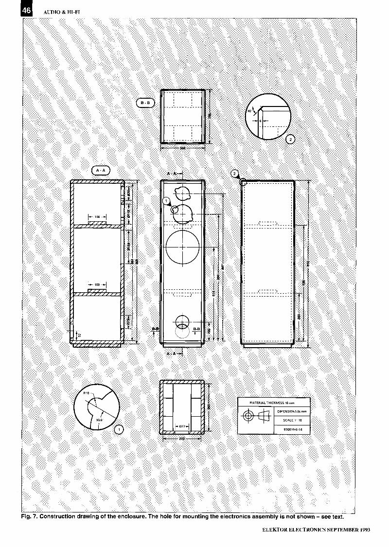
I AUDIO & HI-FI
A - A
I.- 100
[..-- 100 -..i
J7/ z)/ /9/ z / A
Teri
WWWWWWWWWWWWWI A
,1101......1...,
R11)
r30,0
B - B
A - A 2
+1
r
13-151 B -B
A -A
21
I i
t
MATERIAL THICKNESS 18 mm
DIMENSIONS IN mmerSCALE 1 10
930016-11 14
Fig. 7. Construction drawing of the enclosure. The hole for mounting the electronics assembly is not shown - see text.
ELEKTOR ELECTRONICS SEPTEMBER 1993

Please mention ELEKTOR ELECTRONICS when contacting advertisers47
YOUR PERSONAL
UNIVERSAL PROGRAMMER
Superpro is a low cost programmer which can easily
be attached to your PC for use in R & D. It comes with
its own half card for high speed communication so you
can still use your parallel port.
Superpro comes from California so you can be sure the
latest devices will be supported. In fact the software is
updated on an almost monthly basis. The extensive
device list covers most popular logic and memoryfamilies such as Amd's Mach series as well as thepopular Altera range EP310 to EP1810. Support is
also included for popular gals such as 1 6V8 and
20V8 from a variety of manufacturers. Standard 24,
28, 32 and 40 pin e (el proms are also catered for in
the 40 pin universal ZIF socket. An added bonus is the
ability to program a range of microcontrollers. PLCC
devices can be programmed with special adaptors.
....AI Buffer __nu ac urer
Load
Save
A Binary file
1 Intel (Extended)
C Motorola SI
D Motorola SZ
E Motorola S3
F. Tektronix
Running'
I._
File Marne
Buffer start address
snit$
r")
40. ON
N. if
0
Enter Save size11E*0
_JI
-Help F5 -Function select F6-tdit
7.0319:t.icTird?
So before spending thousands of pounds on a new stand alone programmer why not have a look at Superpro for a ten
day trial period?
LLOYD RESEARCH LTD Tel: 0489 574040 for a device list
PARTS LIST(Additional to that in Part 1)
Mains transformer, 80 VA, secondary2x18 V
Mains transformer, 160 VA.secondary 2x25 V
2 off bridge rectifier B100C250004 off capacitor 210,000 µF, 40 VMains entry with integral fuse holder
and 1 A slow fuse, and on/offswitch
Fuse holder with 500 mA slow fuse
ENCLOSURE
100 W, 200 mm (8 in), 4 0, woofer50 W, 50 mm (2 in), 8 0, mid -range
drive unit30 W, 25 mm (1 in), 8 0, tweeter18 mm thick medium density fibre boardor high -density chip board:
2 off 864x210 mm2 off 900x260 mm2 off 210x296 mm2 off 210x100 mm2 off 260x100 mm1 off 210x260 mm
Bass reflex duct, 145 mm (511/16 in) long3 metres mains cable2 bags polyester wadding
rent source is used here). In that case,the value of R26 must be increased tothe next or second higher El2 value.The value is correct when, a few sec-onds after the mains has been switchedon, the potential across Rei is 24 V.
For safety's sake, measure all rele-vant supply voltages on the board andcheck that the direct voltage levels atthe amplifier outputs are zero or verynearly so.
Finally, set P2 and P3 so that theresistance between wiper and groundis 55% of the total in the case of P2and 70% in the case of P3.
The enclosureThe box is made from 18 mm thickmedium density fibre board (MDF) orhigh -density chip board. The constructiondetails are shown in Fig. 7. Basically,it is a rectangular box provided withtwo reinforcing cross members thatprevent panel vibrations.
The one hole not shown in the draw-ing is that for the electronics assem-bly. It is best to fit this at the bottomof the enclosure, so that the boardrests on spacers on the bottom panel.Saw a rectangular hole in the rearpanel (see Fig. 2) whose width and
height are 20 mm smaller than thealuminium sheet. On completion, thesheet is fixed across the hole with 10or 12 suitable wood screws and sealedwith draught -proofing tape.
Before that, however, fill the enclo-sure above the lower cross memberevenly with the polyster wadding. Thebottom third of the box, where thebass reflex duct and electronics as-sembly will be located, remains freeof wadding.
Next, fit the drive units, providethem with cables and connect theseto the board. Make sure that the po-larity is as shown in Fig. 6.
Then, screw the electronics assem-bly across the rectangular hole at therear as already discussed.
Next, push the bass reflex duct intothe port on the front panel.
Finally, where deemed desirable, itis, of course, possible to use normal po-tentiometers for P2 and P3 and fit theseto the aluminium sheet, so that theycan be readjusted, when required, with-out the need of removing the entireassembly from the box. In that case,the connections between these controlsand the board should be by screenedaudio cable. END
ELEKTOR ELECTRONICS SEPTEMBER 1993

48 Please mention ELEKTOR ELECTRONICS when contacting advertisers
Low cost data acquisition for IBM PCs & compatibles...A unique range of low cost data acquisition products for IBM PCs and compatibles. Installed inseconds they simply plug directly into either the serial or parallel port. They are completely selfcontained, require no external power supply and take up no expansion slots.
Each device comes with an easy to use software package (PicoScope, PicoLog or both). C, Pascal,and Basic drivers are supplied for those who want to develop their own software, as is a manual giving
full details of the hardware and software. All software supplied on 3.5" disk.
Up to 24kHz sampling rate froma 386/33MHz machine0-5V Input rangeBNC input connector allowsuse of standard scope probes30V overload protectionParallel port connectionIncludes PicoScope software
Single Channel 8 bit ADC
ADC -1 1 15K samples per second0-2.5V Input rangeDigital outputD25 input connector30V overload protectionParallel port connectionIncludes both PicoScope andPicoLog software
11 Channel 10 bit ADC
Up to 18kHz sampling rate0-5V Input rangeBNC input connector allowsuse of standard scope probes30V overload protectionParallel port connectionIncludes both PicoScope andPicoLog software
Single Channel 12 bit ADC £85Typical applicationOscilloscopeVoltmeterSpectrum analyserAudio samplingChart recorder emulationTemperature measurementPressure measurementChromatographyAutomotive monitoringMedical researchEducation
vim TEL: 0954-21171° g g 8 . . d.
ADC -10 ADC -11
Software selectable singleended or differential inputsResolution programmablebetween 8 and 16 bits + sign±2.5V input range5V reference outputConnects to serial portIncludes PicoLog software
8 Channel 16 bit + sign ADC £99PicoScope 'Virtual instrument' software
package forthe ADC -10, ADC-
-H-4 11 and ADC -12.
i ; I ; 1 i
ii I
11'4-A 4fH
111111c-car,,,va,
Scope, voltmeter,spectrum analyser
PicoLog
Advanced datalogging software
ADC -12
Pico Technology Ltd. Broadway House, 149 -
ADC -16
Storage oscilloscope withtrigger and timebase. Tracescan be printed and savedMultiple meters onscreen Real
time spectrum analysis
Collect samples from 1 per ms to
one per day. Scale sampleslinearly, by equation or by table
look -up. Graphical (againsttime or XY) and text reports can
be displayed, printed orexported.
Picolog is also available for theADC -10: call for details.
PICO BENEFITS
30 day no quibblemoney back policy
Full 1 year guarantee
1 year's free softwareupgrades
Free technical support
Free user newsletter
Same day dispatch a
151 St Neots Road, Hardwick, Cambridge. CB3 70J.
6 FAX: 0954-211880-; t
ELEKTOR ELECTRONICS SEPTEMBER 1993

Please mention ELEKTOR ELECTRONICS when contacting advertisers 49
SPECIAL OFFERS WHILE STOCKS LASTCOMPONENTS80C31 44pm SMD CPU L1.25 82C55 PIA C1.45LM358 OpArep C1.00 for 5 6264 RAM L2.0024pin Zif L1.25 24pin Dil IDC header L1.00 for 37 Seg display CA RED (FND500)
8749 Eprom CPU 45.00UAA2050T UHF pager 46.00
Submin MicroSwitch 3 Amp [100 for 6..... C1.00 fee 4
Rotary Switch I Pole 12way or 3 pole 4way . L1.50 for 5 (either type)
PC SCOPE Turn your IBM PC into a powerful Storage Oscilloscope. Digital Voltmeter or Sound Sampler.Converter plugs into printer port with no power required. The ND converter with software (VGA required) readyto plug in and go Only L29.95
ASM51 SIMS! Complete Text Editor /Assembler plus Simulator for Microcontrollers 8051/52. Runs on IBM PCFull control Registers & memory. Label generated disassembly, program trace, single-step. go with break many morefeatures .[19.95
ASM48 t 5IM48 N above but for 8048/49 controllers L19 95
EPROM/ROM EMULATOft Works with ANY computer with centronics printer port. Emulates all ROMs from16(2758) to 32k127256) over 50 types supported. Any file sent to printer port appears as ROM on target machine.Fast download Ideal for MICRO development L39.95
Ef!I
PLEASE ADD £1.50 POST & PACKING
JOHN MORRISON (MICROS) DEPT ET4 REIN GARDENS,TINGLEY,WEST YORKSHIRE,
WF3 I JR. TELEPHONE 0532 537 507MEM
BADGER kS\ BOARDSPrinted Circuit Boards for Amateur Radio Schools CollegesShort Wave Listeners Clubs Hobbyists & Industry
A range of Printed Circuit Boards in stock from many of the Projects in MagazinesPRACTICAL WIRELESS U SIIORT WAVE MAGAZINE U ELEKTORLI IIRT
RADIO COMMUNICATIONKits Projects and Materials for manufacturing your own boards. Artwork and Plotting fromyour own Schematic drawings and also C A D facilities. We supply ONE OFF PrototypesPhone between 9.00am and 5.30pm Monday to Friday for helpful advice and assistanceClub talks and demonstrations of Printed Circuit Board manufacture ()RP involvement etc
021-353 932687, Blackberry Lane, Four Oaks, Sutton Coldfield. 1374 4JF
(Please mention where you spotted this advertisement)
IF AN
->ADVERT IS IN
PRINT, IS IT PROPER?Most advertisements are perfectly proper.A few are not.
The Advertising Standards Authority not onlymonitors over 850 advertisements every month, it ensurescompliance with the rules in the strict Code of AdvertisingPractice.
So when you question an advertiser, they hake toanswer to us.
To find out more about the role of theASA, please write to the address below.
Advertising Standards Authority,Department X, Brook House. TorringtonPlace, London WC1E 711N.
ASAThis space Is donated In the Interests of high standards In advertisements.
J
J
PROGRAMMER & EMULATORA combined eprom programmer and emulator in one case.
Programs and emulates all commonly used eproms 27(C)64 to 27(C)512.
A 2764 programmed and verified in 50 secs (seven different algorithms).
Fast 38400 Baud serial comms, download/upload approx. 3kbytes/second.
PC based software includes, basic editor, saving to disk, offset setting,directory & drive setting and controlling programming & emulation.
Auto reset of target option at start of emulation.
File conversion utilities and command line version included.
5v. supply only, programming voltages generated by internal SMPSU.
The PROGULATOR: £180 inc.Further details from:
White House Systems Tel: 091-373-460548 South Terrace, Esh Winning, Durham DH7 9PS
MACRO CROSS ASSEMBLERSfor 8051, 6800, 6809, Z80, 6502, ...
with linker and library manager £70
DemonstrationDisc £5.00
B. A. JonesFreepost (G R 1863)CheltenhamGLOS. GL50 3BR
Features: -Conditional assembly,File inclusion,Repeated blocks,Binary/Hex output,Map files,Full expression evaluation,and much more.
EPROM EMULATOR32K x 8 Non Vol (EEPROM)
27256271282764
MicroControlled
PC SoftwareIncluded (Com1/2). Int/Mot
Hex Download. Modify Memory.Powered from Target SKT
£1150 +Car. + VAT
Tel: 0280 850521 Fax: 0280 850434
ELEKTOR ELECTRONICS SEPTEMBER 1993

50
FIGURING IT OUTPART 8 - COMPLEX NUMBERS
By Owen Bishop
This series is intended to help you with the quantitative aspects of electronic design:predicting currents, voltage, waveforms, and other aspects of the behaviour of circuits.
Our aim is to provide more than just a collection of rule -of -thumb formulas.We will explain the underlying electronic theory and, whenever
appropriate, render some insights into the mathematics involved.
We begin this month's dis- 7, ...; the points between these that the term is imaginary.cussion with a simple and represent real numbers of vari- Note that we can have nega-
apparently innocuous equation: ous other kinds, including spe- tive imaginary numbers as wellcial numbers such as R. To rep- as positive ones. For example:
x2+ 1 = 0 [Eq. 47] resent imaginary numbers, weconstruct an imaginary num- j = -4-25.
The first stage of finding the ber line which is perpendicu-value of x is easy: lar to the real number line (see The perpendicular lines of
Fig. 68). The points marked on Fig. 68 take us a stage further,
x2 = -1, this represent the integral mul- since they can be taken to be thetiples of j. For example, the point axes by which any point in the
but now comes the ostensibly j3 is three times j: whole area of the figure can be
impossible part: defined. Points that are on thej3 = 3x \I-1 = I(9x-1) = \I-9. horizontal axis (known as the
x real axis) are real numbers.By convention, we write j3 in Points which are on the vertical
It is a fact of elementary arith- preference to 3j to make it clear axis (the imaginary axis) aremetic that two positive numbersmultiplied together give a posi-tive product. Further, two neg-ative numbers when multipliedtogether also yield a positiveproduct. There is no way of mul-tiplying two numbers with the Fig. 67.
same sign to obtain a negativeproduct. Yet, here we are ex- A
pected to multiply two identicalnumbers together and obtain-1. The way out of this impasse 15
is to recognize that the value ofx does not belong to the set of real
X j4
numbers. It is an imaginary 'a13
number. Mathematicians give A
it the symbol i, but, since this is iz
likely to be confused with thesymbol for electric current, elec- i I
trical and electronics engineersuse the symbol j instead. Thus, 11
we define j by the equation: -6 -5 -4 -3 -2 -1 0 1 2 3 4 5 6
j = q-1. [Eq. 48]
Although j belongs to the realmsof the imagination, it helps to un-derstand it and to work with itif we represent it in diagrammaticform. All real numbers can berepresented as points on a con-tinuous line, the number line(see Fig. 67). We have markedthe positions of the points thatrepresent integers -5, -2, 0, 4,
-6-ia
-5 -4 -3 -2 -1II I
0 1 2 3 4
j6 -
-j2 E
-13D
-j4B
-j5
-j6
Fig. 68.
F
REAL AXIS
5 6
930010 - 8 - 11
G
930010 - 8 - 12
imaginary numbers. Points withinthe four quadrants are definedby quoting their two coordinates,just as we would on an ordinarygraph. Each point in the figureis defined by two numbers, oneof which is real and the other ofwhich is imaginary. A number sodefined is known as a complexnumber. The area of the figureis the complex number plane.Sometimes it is referred to as theArgand plane, and the figure isknown as an Argand diagram.
Working with complexnumbersConsider the point A in Fig. 68.If this were a point on a graph,we would say that its coordi-nates are (2, 3). Since this is anArgand diagram, we say thatthis point represents the complexnumber (2 +j3). We can never ac-tually add 2 to j3, because thesenumbers represent distance inperpendicular directions. Becausethese distances are both positive,we know that the point is in thefirst quadrant. Values representedby other points in Fig. 68 are:
B=2-j4 E=0-j2C=-3 +j2 F.3 +JO
-j3 G=4.6 +j5.2
Each complex number has a realpart and an imaginary part. Eitherpart may sometimes be zero, inwhich event the number is rep-resented by a point on one of theaxes.
Addition of complex numbersfollows the rules of algebra in thatwe are allowed to add a's to a'sand b's to b's, but not a's to b's.With complex numbers, we mayadd the real parts and may addthe imaginary parts, but the twoparts must be kept separate.For example, add (4 +j6) and
ELEKTOR ELECTRONICS SEPTEMBER 1993

FIGURING IT OUT 8
(5 + j2):
Answer
4 + j65 + j29 + j8
Another example, add (3 + j2)and (2 -j4):
3 + j2+ 2 - j4
Answer 5 -j2
Subtraction is similar: for ex-ample, subtract (3 + j5) from(7 + j9):
7 + j9- 3 + j5
Answer 4 + j4
Addition and subtraction ofcomplex numbers presents nosurprises and it might be won-dered how these operations couldbe relevant to electronics. Figure69 helps to show the connection.
Vector additionIn Fig. 69, there are two points,P and Q, representing the twocomplex numbers added in thefirst of the three examples inthe previous section. The sumof these two numbers is repre-sented by point R. In Fig. 70,we have the same three points,but now these are seen to be thefinishing points of three vec-tors, all of which begin at the ori-gin. Not only can complex num-bers be drawn as vectors, but itis clear that the vector R is thesum of the vectors P and Q.Complex numbers are a way ofrepresenting vectors and addingcomplex numbers is a way ofadding vectors. Now we are re-ally connecting with electron-ics. In Parts 6 and 7 we usedvectors (or phasors) to showthe relationships between vari-ous currents, pds or impedancesin circuits that have sinusoidalcurrents or pds applied to them.It was often necessary to sum twoor more vectors. Application ofPythagoras' Theorem makes thisrelatively easy when the vectorsare perpendicular. When theyare not, the calculations may in-volve some elaborate trigonom-etry. To help us keep the trigunder control, we make use of theconventions of imaginary num-bers and the Argand diagram.Using imaginary numbers by nomeans implies that the currents,pds or impedances themselvesare imaginary. It is just that thegraphical representation ofimag-inary numbers is a useful tool fordealing with vector quantitiessuch as current, voltage and im-
4
Aj10 -
j9
j8
j7
j6
j5
j4
j3
j2
P
-jiV
A110-
-1 0
A
R=P+Q
Q
I $ I -4-
1 2 3 4 5 6 7 8 9 10
REAL AXIS
930010. 8. 13
Fig. 69.
1 2 3 4 5 6 7 8 9
REAL AXIS
Fig. 70.
4 + j3)a,
10
930010 - 8 - 14
0
40 I
11-1rNik 0:tart REAL AXIS
this way
0
Fig. 71
930010 - 8 - IS
pedance (and with other vectorquantities besides).
The meaning of jBefore we go on to use complexnumbers to analyse practicalcircuits, let us look again at thatsymbol j. We have given it avalue (Eq. 48), though this isnot a value like the value of a realn umber. There is another wayof thinking of j, particularly inthe context of the Argand dia-gram. We may think of j as theimaginary operator. An op-erator symbolizes an operation.For example, the symbol .1 sym-bolizes the operation of integra-tion. In logic and in digital elec-tronics, the operator + symbol-izes the OR operation. In theArgand diagram, j symbolizesthe operation of a quarter turn(90°) in the anticlockwise direc-tion. The convention of writingj first in an imaginary numberreinforces the idea that it is anoperator.
Given the complex number(4 + j3), for example, we inter-pret this as the following se-quence of instructions, illustratedin Fig. 71:1. Start at the origin facing along
the real axis in the positive di-rection.
2. Move 4 units forward.3. Turn 90° anticlockwise.4. Move 3 units forward.This take us to the point in thecomplex number plane whichrepresents (4 + j3).
A negative value of j is inter-preted as a 90° clockwise turn.For example, (5 - j2) means:1. As above.2. Move 5 units forward.3. Turn 90° clockwise.4. Move 2 units forward.
A 90° turn anticlockwise fol-lowed by another 90° turn anti-clockwise equals a turn of 180°.We are facing in the opposite di-rection, along the real axis, butin the negative direction. Thiscorresponds to the value of j2:
j2=jxj=-V-1 x =-1.Similarly, j3= -j ( a three quar-ters turn) and j4= 1 (a completeturn).
Using j
Figure 72 shows an LCR par-allel circuit to which a sinusoidalvoltage is applied. This figure isthe same as Fig. 60, discussed inPart 7. At any instant, equalvoltage is applied across eachbranch of the circuit. For each
ELEKTOR ELECTRONICS SEPTEMBER 1993

GENERAL INTEREST
branch of the circuit, the cur-rent at any instant is calculatedby dividing the voltage by theresistance or impedance of thatbranch. We consider each branchin turn.
IR
U=Uosin,,,t
930010.8-16
Fig. 72.
The current through the re-sistor is
IR = U/R.The current is in phase with thevoltage, so we represent it in anArgand diagram by a vector lyingalong the real axis in the posi-tive direction (Fig. 73).
The current through the ca-pacitor is
/re = U/Xc. [Eq. 49]
Owing to the properties of ca-pacitors, this current leads theresistor current by 90°. There aretwo ways of taking this phase dif-ference into account. One wayis to state that fact, as we havejust done, and then draw the vec-tor in the appropriate directionas we did in Fig. 61 ofPart 7. Theother way is to say that the re-actance of a capacitor is
Xe = -j/coC. [Eq. 50]
Eq. 50 is the same as Eq. 34Part 6), except that we have in-corporated the phase differenceinto it. Eq. 50 expresses Xc asan imaginary quantity, lagging90° behind the applied voltage.This hypothetical quality of theimpedance is related only to itsrepresentation in an Argand di-agram. The current passing intoor out of the capacitor contin-ues to be subjected to a substantialopposition to its flow!
Similarly, Eq. 33 (Part 6) cannow be modified to take phaseinto account:
XL = j coL. [Eq. 51]
Inductive impedance leads theapplied voltage.
If we substitute the new ex-pression for capacitive impedance(Eq. 50) into the equation for
calculating current (Eq. 49), weare in the position of dividing areal number by an imaginarynumber:
Ic = u/xc = ucoo-j. [Eq. 52]
As mentioned earlier, real num-bers and imaginary numbers donot mix. If we are to solve Eq. 49,we must discuss how to performmultiplication and division withcomplex numbers.
MultiplicationMultiplication follows the usualroutines of algebra. For example,multiply (4 + j3) by (3 + j2). Setthis out in the usual format formultiplication:
4 + j3x 3 + j2
12 + j9j8 +j26
12 +j17 - 6.
The third term has become real
A
Ic
81
because of squaring j. Subtractingthis, we obtain the answer: (6 +j17).
Division
This is rather more difficult, buta simple trick helps. This sub-terfuge involves what is knownas the conjugate complex num-ber. In Fig. 74, there is a pointA in the first quadrant. Its con-jugate is A', in the fourth quad-rant. It is clear that if, for ex-ample, A is (4 + j2), then A' is(4 -j2). The conjugate is formedby inverting the sign of the imag-inary part.Now consider the problem of di-viding (4 + j5) by (3 + j2):
4 + j5
nominator:
(4 + j5)(3 -j2)(3 + j2)(3 - j2)
22+j7- 13
= 1.69 + j0.54.
ReciprocalsIn circuit calculations, we oftenarrive at the expressions 1/j and1/-j. It is useful to know whatto substitute for these. Followingthe rules of division give above,we first note that the j and -jare conjugates of each other, andso:
3 + j2 1/j = (lx-j)/(jx-j) = -j/1=-j.[Eq. 53]
The trick is to multiply both nu-merator and denominator by theconjugate of the denominator.This does not affect the resultof division, but gets rid of theimaginary component of the de -
0
B =-4 + j3
REAL AXIS
Fig. 73.
Aj3
j2
j1
930010 -8.17
A=4 -1-j2
-5 -4 -3 -2 -1 0
B' =-4-j3
-j2
-i3
Fig. 74.
1 2 3 4 5
A' = 4-j2
930010 - 8 - 18
Similarly,
1/-j = (lxj)/(-jxj) =j/1 =j.[Eq. 54]
Continuing theanalysisSubstituting the result of Eq. 53into Eq. 52:
Ic = UNCI-j = j(UcoC).
The result has no real part andits imaginary part is positive. Thecurrent vector of the capacitorlies along the imaginary axisand leads the applied voltage by90°, as shown in Fig. 73. Drawingvector diagrams helps us to un-derstand what is happening (itis usually worthwhile to draw asketch at least), but the magni-tude and direction of the cur-rent vector has been obtainedsolely by calculation using com-plex numbers.
Similarly, we calculate thecurrent vector for /L:
IL=UlkoL = -jUlcoL.
This calculation by-passes whathappens to the factors w and Lin the denominator. The conju-gate of jcoL is -jcoL, so w and Lappear temporarily in the nu-merator and appear squared inthe denominator; these cancelout to leave w and L in the de-nominator, as at the beginningof the calculation. The overall ef-fect is that j disappears fromthe denominator and -j appearsin the numerator, as in Eq. 54.
The outcome of this calcula-tion is that the current vectorfor the inductor lies along the
ELEKTOR ELECTRONICS SEPTEMBER 1993

FIGURING IT OUT 8
imaginary axis and lags the ap-plied voltage by 90°, as shown inFig. 73.
Resulting vectorsIf we give some numeric valuesto L, C and R, and consider oneparticular frequency and a par-ticular instant in time, the ex-pressions become simpler. Supposethat R = 250 Q, C = 1.211F andL = 0.2 H. Also suppose thatf = 500 Hz, and that we evalu-ate the currents when U = 2 V.
The value of w is
= 2Tcf = 3142 rad s-1.
Now calculate the currents:
IR = 2/250 = 0.0080 A;
/c = jUcoC = j0.0075 A;
IL = -j UkoL = -j2/628.4
= -j0.0032 A.
Express currents in milliampsfor convenience: IR = 8.0 mA;/c = j7.5 mA and /L, = -j3.2 mA.
Finding the resultant of /cand IL is straightforward as theyare both complex numbers withonly imaginary parts:
/c+/L, = j(7.5-3.2) = j4.3.
The resultant has magnitude4.3 mA and leads IR by 90°. Addingthe resultant to IR gives:
I = 8.0+j4.3 fmAl
Figure 75 is an Argand dia-gram of these results. The mag-nitude of the total current I isobtained by Pythagoras' Theorem:
I = -N1(8.02+4.32) = 9.1 mA.
The phase angle is
Ip = tan -1(4.3/8.0) = 28.3°.
Analysing LCR circuitsAsa final example, we run throughthe analysis of a typical LCR cir-cuit. Figure 76 sets the prob-lem, which is to calculate themagnitude and phase angle ofthe total current I when the fre-quency is 100 Hz at time t= 0.001 s.In Fig. 76b, the impedancesare written in the form which in-corporates the information aboutphase, that is to say, in the formof complex numbers. Given thatf = 100 Hz, we calculate that:
= arcf = 628 rad s-1.Using w to evaluate the im-pedances at the given frequency,we arrive at Fig. 76c.
At time t = 0.001 s,U= 5sin(628x0.001) = 2.938 V,
remembering to work in radi-ans.
IR = 2.938/200 = 14.7 mA;/c = 2.938/-j72.4 = j40.7 mA;/L, = 2.938/j157 = -j18.7 mA.
I =i7°5
+ I =j4°3
The resultant of IC and IL isj21.9 mA. The resultant of thisand /R is (14.7+j21.9) mA. Themagnitude of the resultant isN/(14.72+21.92) = 26.4 mA. Thephase angle is ip = tan -1(21.9/14.7)= 56.1°.
If we are not interested in cal-culating IR, IC and IL individu-ally, we can simply find the totalimpedance by applying the rulesfor impedances in parallel:
I = + j4°3
,L= -j3.2
V
00
U = Ssinwt
f = 100Hz
1= 0.001s
0
REAL AXIS
Fig. 75.
930010 - 8 - 20
IR=8.0
930010 .8 - 19
22pF
,.(22x106)
1/X= 1/200+1/j157+1/ -j72.4= 0.005-j0.00637+j0.0381= 0.005+j0.00744.
Then:
I= U/X=2.938/(0.005+j0.00744)=0.0147+j0.0219.
In milliamps, I = 14.7+j21.9, asabove.
The complex impedances canbe used in any of the network re-duction techniques describedin Parts 1, 3 and 4.
In the foregoing examples,the final stages rely on trigonom-etry. Next month we shall showhow to calculate the magnitudeand direction of the resultant di-rectly from the complex num-bers. TO BE CONTINUED
Test yourself1. Add (3+j2) to (6+j3).2. Add (7+j) to (3-j4).3. Add (5.2-j0.3) to (-3.6-j2.3).4. Subtract (4-j2) from (5+j6).5. Multiply (3+j4) by (7+j3).6. Multiply (5-j3) by (3+j).7. What is the complex conju-
gate of (4+j5)?8. Divide (3+j2) by (7+j3).9. In an LCR circuit (Fig. 74),
R=120 I, L=0.1 H; C=471.1F,f=50 Hz and U=2sinwt. Cal-culate the current vectorsand their resultants.
10. Recalculate the current vec-tors and resultants in thecircuit of question 9 when thefrequency is increased to150 Hz. What are the mag-nitudes of Uand/ when t=2 s?
Answers toTest yourself (Part 7)1. UA = 3.074 V
UB = -2.272 VUp = 1.185 VIAC=0.741AIAD = 1.259 A'DC = 0.395 A/DB = 0.864 A/CB = 1.136 A
2. IN = -1.262 AGN = 0.4309 SI = -0.463 A
3. Perform nodal analysis at Band C; calculate UB and Uc;
-j72.411UB = 232.1x10⁻⁹ VUC = -0.172 Vvoltage gain = -0.172/0.01= 17.2
ELEKTOR ELECTRONICS SEPTEMBER 1993
Fig. 76.

54
PC -AIDED TRANSISTOR TESTER
os.`"` kid i1,,#,I o 1,,t
1 I 1 I I
$ 1 I, 1 1'IFs re, I r I 1
The advantage of having a computer run gain tests ontransistors is that you do not need an oscilloscope to view thecharacteristics. The circuit presented here is based on anearlier design, published about three years ago. This has beenenhanced with a p -n -p test function, an on -board power supply,and a control program for IBM PCs and compatibles.
Design by S. Aaltonen
THE sheer simplicity of the n -p -ntransistor tester described in Ref. 1
made it a wonderful little instrument.However, the circuit had two impor-tant disadvantages: firstly, it was un-able to test p -n -p transistors, and,secondly, it could not be used on IBMPCs and compatibles for lack of appro-priate software, which was only avail-able for monochrome Atari ST
computers. In retrospect, it was not sodifficult to add the p -n -p test function.All that had to be added were threetransistors, nine resistors and a smallnegative supply that provides the basecurrent for the p -n -p transistor. Thesecomponents may be found back in theblock diagram (Fig. 1), where they formthe DAC (digital -to -analogue con-verter) that supplies the base current
to the p -n -p transistor. The remainingparts were already contained in theoriginal design.
The curve tracer is controlled by thePC via the Centronics (printer) inter-face. Six data lines on the interface areused to control a counter and an A -Dconverter, while one of the handshakelines serves as an input via which thePC reads the ADC output data. In ef-fect, the direction of the data on theCentronics interface is the same asthat when a printer is connected.
The counter controls the measure-ment process. Eleven bits are underthe control of two lines (clock andcounter reset) on the Centronics inter-face. These 11 bits eventually controlthe measurement. During one com-plete measurement cycle, the counteris allowed to count from 0 to 4,095.The first eight bits control the DACthat supplies the collector -emitter volt-age (UCE) for the transistors undertest. The remaining three (MS) bits de-termine the base current. During ameasurement cycle, the base currentis increased from 0µA to 175 [tA insteps of 25 ?IA. At each step of the basecurrent, UCE is increased from 0 V to9 V in 256 steps.
As shown in the block diagram, thecollector current, Ic, of the transistorunder test causes a voltage dropacross a series resistor. This voltage isfirst amplified and then applied to anA -D converter. Note, however, that thesystem actually measures the emittercurrent, IE, when an n -p -n transistoris connected. Fortunately, that is not aproblem because the computer is per-fectly capable of calculating the collec-tor current with the simple formula
k=1E-IB.
Circuit descriptionAfter the discussion of the block dia-gram, the circuit diagram (Fig. 2) hasfew surprises. In fact, we need onlylook at the operation of the DACs andthe power supply, since not much elsehas changed with respect to the earlierdesign (Ref. 1).
The DAC that generates UCE con-sists of an integrated 8 -bit D -A con-verter (IC2), an opamp-based amplifier(IC3a) and a driver (T1). The DACs thatsupply the base current are built fromdiscrete components. The base currentgenerator for n -p -n transistors is thesimplest. Resistors R8 -R11 convert thevoltage represented by three bits oncounter IC i into a current. Diodes D 1,D2 and D3 ensure that this current can
ELEKTOR ELECTRONICS SEPTEMBER 1993

COMPUTER -AIDED TRANSISTOR TESTER
only flow via the base of the transistorunder test, and not via an output bitthat is at 0.
The base current (/b) generator forp -n -p transistors is a little more com-plex. This is because the emitter volt-age 'tracks' UcE, and is not at (nearly)ground potential as with n -p -n tran-sistors. To make sure that the transis-tor can be driven into conduction at alow UcE value (the emitter is then vir-tually at ground potential), the basehas to be made at least 0.6 V negativewith respect to ground. This isachieved with the aid of a small auxil-iary negative supply voltage, plus R12 -R20, T2, T3 and T4. These componentstogether form three small currentsources that can be switched on andoff by the three most significant bits ofcounter ICI. In this way, the base cur-rent for the p -n -p transistor is deter-mined by the sum of the currentsthrough the actuated current sources.The minimum level of the negativesupply voltage is easily establishedfrom the base -emitter voltage of thep -n -p transistor (approx. 0.6 V), andthe minimum voltage drop across thecurrent sources (approx. 1 V). Thus,the minimum negative voltage requiredis -1.6 V, which leaves some headroomfor the -1.8-V supply actually used.
Resistor R23 is the current sensingdevice. Since for reliable measurementresults its value must remain compar-atively low, it supplies a relativelysmall voltage. Whence the use of anamplifier, IC3b, which provides a gainof x48 before the signal reaches the AOinput of the A -D converter (IC4). Theshape of this signal is shown in Fig. 3.In fact, you already see the seven suc-cessive lines of the characteristic (notincluding /B=0). The peak value of thissignal depends on the current gain ofthe transistor under test, and may notexceed 5 V (the supply voltage of IC4).Simple reverse calculation then tellsus that the circuit can only handletransistors with a current gain smallerthan 595, which corresponds to amaximum measurable lc of 100 mA.
The collector voltage, UcE, has to bereduced instead of amplified. This isdone by R21 and R22, which halve themeasured voltage to keep it within safelimits for the input of IC4.
The original design of the transistorcurve tracer has two supply voltages:+5 V and +15 V. To these, one of -1.8 Vis added for the present design. Also,the +15 V is increased to +16.3 V toobtain a slightly higher drive margin.These changes have led to a revisedpower supply section. The positivevoltages are made in the conventionalway: a mains transformer, a bridgerectifier, an adjustable voltage regula-tor for 16.3 V (IC5), and another volt-age regulator that steps down the
MAIN SPECIFICATIONS
Plots gain curves of n -p -n and p -n -p transistors Connects to Centronics port, using standard parallel printer cable Gain curves displayed on PC monitor On -board power supply Software for IBM PCs and Atari STs (monochrome) Collector -emitter voltage range: 0-9 V Max. collector current: 100 mA Collector current measured at 7 base currents between 0 and 175µA Max. transistor gain: 595
Fig. 1. Block diagram of the n-p-n/p-n-p transistor curve tracer.
ELEKTOR ELECTRONICS SEPTEMBER 1993

56 TEST AND MEASUREMENT
Most components used in this project are available from Viewcom Electronics (see advert on pages 18 and 19).
R1
lc) 5V
K1
3L-0 0-18
30 17
3L0
-0 0=ERROR 32 014
310 13
210 JL.11
ii_2L.43 0_9.4L3 8
.2,Lc. 6
.2005.2L0 4
SELECT
1
BUSY
D4
D3
4003 D1
el Lo c1-1
BD139
E B
BC547B
B
D2
18
CTR12
ff >+
IC1
CT
74HCT4040
CT -0
4
5
6
7
8
7 6
7
9
3 10
2 11
4 12
3 13
12
14
17
19
15j
IC3 = LM358
5V
?I4
REF +AS
IC4 Al
DATA A2
A310 CLK
ADDR
SYS CLK
CS TLC1541
A10REF -
13
15
(f) 5V
3
AN OUT01
D2 REF OUT
D3 REF IN
D4 IC205 ZN42506 SEL
D7 CLK
5V7805
41 IC7 (,/
110 (5 11 (5 11319 CO .1.
lel IC2 IC49 TOOn TOOn700n76Y00700n1
14
16
15
2
4
R8 2% 01
R9 2%
5V
R10 24
ErillR11
EMIR122%
1N4148D2
IC3a
R6
3 R4 R5
1N4148D3
H1N4148
0NPN
O 0
r
016V3
C7 112IC3
700n
16V3 5V
R7 R26 7805
T1
(74
Ol)0
R21
1W
BD139
PNP
D10
POWER
BC547B
R13
100k
BC547B
R14
100
BC547B
4 R24
A4
A5 A5 LA6 LA7 8
A8 -8
A911
12
IC3b
R25 R23 R22
T4
R19 I R20 R17 R18 R15 R16
Ag.
2% 12i I 120
1V8 920144 - 12a
Fig. 2a. Circuit diagram of the computer -controlled transistor tester.
Fig. 2b. Three -voltage power supply for the transistor tester.
16.3 V to 5 V.The negative voltage is supplied by
C3, Ds, D9 and ICs. Of the alternatingcurrent that flows through capacitorC3 (one half via D8, and the other, viaD9), one half period is used to chargeC4. C3 also ensures that no short-cir-cuit is created for direct voltages. Next,
II MEME EMAINMMATIMN M
MOINTAMI
MENEMI==MIM MM.=ME
ME MEMO W-
Fig. 3 The output signal of amplifier IC3b al-ready describes the transistor gain charac-teristic, but the curves are arrangedhorizontally instead of vertically.
ELEKTOR ELECTRONICS SEPTEMBER 1993

COMPUTER -AIDED TRANSISTOR TESTER im
Fig. 4. Track layout and component mounting plan of the (single -sided) printed circuit boarddesigned for the transistor tester.
'' Resistors:3 1kr26 271(52
1 33k01 100 1W3 1501d2 2%1 371(04 2%3 100k01 34k118 2%1 171624 2%1 81(1266 2%
2 270k.Q1 101 47kCI1 27001 15001 1 kg'18
1 1500 2%1 3300 2%
Capacitors:1 220µF 25V radial1 100uF 63V radial3 100pf 35V radial2 100µF 16V radial6 100nF
Semiconductors:3 1N41486 1N40011 LED, red, 3mm1 BD1393 BC547B1 74HCT40401 ZN4251 LM3581 TLC15411 LM3171 LM3371 7805
R1,R2;R25R3;R4;R6;R15;R17.1419R5R7R8;R9;R10R11R12;R13;R14R16R18R20R21;R22R23R24R26R27R28R29R30
ClC2C3;C4;C5C6,C9C7;C8;C10-C13
D1,D2,D3D4 -D9D10T1
T2,T3,T4IC1
IC2IC31C4
IC5IC6IC7
Miscellaneous:1 36 -way PCB mount
Centronics socket K1
1 2 -way PCB terminal block7.5mm pitch K2
1 Mains socket(optionally inclusive of S1) K3
1 Mains -rated double -poleswitch 2A S1
1 Mains transformer2x9V/3.3VA, e.g.Monacor/MonarchVTR3209 TR1
1 Heat -sink for IC7, 6 5K/W, see text2 2 -mm dia banana socket, blue (C)2 2 -mm dia banana socket, black (B)2 2 -mm dia banana sockets, red (E)1 Enclosure, dim. 115x50x135mm
(e.g., ESM EB11/05)1 Control software on diskette
(for Atari and MSDOS); order code1781 (see page 78)
1 Printed circuit board 920144 (seepage 78)
ELEKTOR ELECTRONICS SEPTEMBER 1993

58 TEST AND MEASUREMENT
the voltage across C4 is stepped downto -1.8 V by an LM337 regulator, ICs.The regulator output voltage is deter-mined by resistors R29 and R30.
Printed circuit board andsoftwareAll components, except the mainsswitch, the mains socket, the transis-tor test sockets and the on/off LED(Dio) are accommodated on the printedcircuit board (Fig. 4). Apart from thecomponents, there are quite a few wirelinks to be fitted on to the board. Themains socket and mains switch haveto be wired with due respect to electri-cal safety. The specified transformer isa short-circuit proof type, which obvi-ates a fuse. A heat -sink is not requiredon IC7 if you use the metal enclosurementioned in the parts list. All threeregulators may be bolted on to the sidepanel with insulation sets (consistingof a mica washer, a plastic bush, a nutand a bolt). The bolts in these sets arebest replaced by types with a counter-sunk head. This allows the case coverto be fitted without problems. If youuse an enclosure without a metal sidepanel, a small heat -sink (approx. 6.5 KW-1 or better) is sufficient for IC7 to bekept reasonably cool. The two otherregulators can make do without heat -sinks.
If necessary, the operation of thecircuit (and that of the DACs in partic-ular) may be checked with the aid ofan oscilloscope. Connect a squarewave signal generator to the clockinput of IC 1, and hard -wire the resetinput of this IC to ground. This causesthe circuit to run the measurementcycle continuously, which makes test-ing, analysing and fault finding a loteasier. Be sure, however, to preventthe test transistor running too hot.
Fig. 6. Suggested front panel design.
Alternatively, write a program thatgenerates a square wave on Centronicsline D1, while keeping D3 low all thetime. If you find that the Centronicslines fail to reach the proper '1' level,fit them with pull-up resistors (1-10 MI).
The floppy disk contains the filesNP3ENG.TOS, NP3ENG.EXE andHERC.BGI. The TOS file is intended forAtari ST computers with a mono-chrome screen, while the EXE file isfor IBM PCs and compatibles.Although it produces a black -and -white picture only, the program workswith EGA and VGA display adaptors.Compatibility with a Hercules card isensured by the HERC.BGI file.
The program gives reports to signala number of fault conditions, includ-ing: curve tracer not connected; curvetracer switched off; and no transistorconnected. For the rest, the operationof the program is self-evident, and re-quires no detailed descriptions. After
writing the transistor curves on to thescreen, the program halts until a keyis pressed, and has to be started againfor a new test to be run. This may bedone automatically by an appropriatebatch file.
Reference:1. Transistor characteristic plotting.Elektor Electronics May 1990.
eznil IIIU
90
80
70
GU
50
40
30
20
10
n 1,1E 129
2 5
17541
I hi"
2541
10Vce/V
920144 - 13*
l/ceill 10 -9
2501
113h
-17541
7 -6 5
hFE 329 Ja 690 920144. 13b
- to
-20
-30
-40
-60
-70
-80
-90
-100I e/nil
Fig. 4. Examples of gain curves plotted on the PC screen for an n -p -n (left) and a p -n -p (right) transistor.
ELEKTOR ELECTRONICS SEPTEMBER 1993

Please mention ELEKTOR ELECTRONICS when contacting advertisers
-t.i7)1
. -Ora Ic IAdo 0 -fins
, Con se 0 rtg1 Ext lye r.npo trt-ba
aa
0 a
a
l'-'d I, 1, .,.
' . a a . a ,
, i ,,
.
' I r rI
\kb
r
'
I
a
are
0
0
a
s. '"
0 a
0
r - IrT
37444. .3. b
0: 4-.
-
G
r rol
kl
1.7 -
-4- I ireI Itoilip-a
::""I
F
0
0 0
a 0
-
0 4 0
.ts 54 tii
k R,
0 - (ir. e
- icuryfili,
r ip fight: clearancel ch;
oar Make - dva level fflose res a r +
Full etfist Support - BoardC re,0 d, Schema, Ta ; C Star an of
a
t
'-r- A.e4r4;
.1 V
tio -'ill to use
met niltcome
bot mechanical and el ctricatTop own modifi Lion fr the
Re rt genrator Data aseThe i polder pl ne su rt
I
schematic
CII, BOM'th full DRC I
rid! ss re-entr nt a torou erSimultaneous mutt -layer outingSMD: and analogu sup rt
'I, Full interrupt, res e, p nand zoom while uting
PI/tP t drivers - Incl ded s standarPrint rs - 9 & 24 pin DOt matrk,HP serjet and PostScript
Pen totters - HP, Graphtec & HoustonPhot plotters - All Gerber 3X00 and 4X00
t Exce Ion NC Drill and1 An tated drill drawings (BM2)
Z.... L.. ....... ...a'
or a free evaluatIon k'tMiran (I IKI I irhitari
Cambridge Research Labs181A Huntingdon RoadCambridge CB 0D1
Pone : (0223) 7777ax : (0223) 74
.
90
e4
3
ELEKTOR ELECTRONICS SEPTEMBER 1993

60 Please mention ELEKTOR ELECTRONICS when contacting advertisers
LAST MONTHSOFFS
AMSTRAD MP3 £19.00
VHF/UHF TV Receiver, converts RGB orcomposite monitor into colour TV. Brand newand cased.Our Price: £19.00Our Ref :EL19P1
INDUCTIVE AMPS £5.00
Made for amplifying a telephone handset for thehard of hearing. However if you hold one againsta piece of wire carrying a telephone conversa-tion you can hear both sides of the conversation!It can also be used for tracing live wires in a wallor detecting cables carrying mains etc.Fully cased complete with battery and fixingstrap.Aprox 2.5" diameter 1" thick.Our Price: £5.00Our Ref :EL5P1
THIS AUTUMNS FASTESTGROWING MEDIA!
- CD ROM DRIVE100W DOOR/SHELF SPEAKERS
quality 3 -way co -axial flush mounting speaker system.Unique design gunmetal and blackgrille. 100W max. powerhandling per speaker. Frequency repsonce -=60-200000HzSpeaker size =6.5"woofer, 2"mid, l"tweeterImpedance = 4 OhmMounting Depth -=39mm
OurSpecial Price: £23.99Our Ref : EL24P1
3 BUTTON LOGITECH MOUSE
Originally made for the Acorn Archimedies but could beeasily adapted for other machines. Pin details are supplied.NO SOFTWARE.
Our Price: £4.99Our Ref : EL5P2
CORDLESS PHONES (non working)£30.00 for 3
These are BT Curlews. They are not new andhave been stored in sunlight so the plastic casesare discoloured. They also have the hansetaerial missing. This is a standard telescopicaerial - a piece of wire will do!These are NON RETURNABLE!!Our Price: £30.00 for 3Our Ref :EL30P1
5 VOLT 4.4 AMP PSU
Acompact switch mode PSU with on/off switch,selectablevoltage input 110/240. NEW. 0/P via fly leads.GOOD STOCKS AVAILABLE
Our Price : £4.99Our Ref : EL5P3
XENON STROBE (ALARM BEACON)
12V stobe, clear lens, ideal for alarm box idicator or inmultiples as a display array. Great for special effects and
other leisure applications. Could be used as a vehicletamper indicator.
Our Price: £5.00Our Ref :EL5P4
DISC DRIVES BBC MOD £9.00
JVC 3.5" drive supplied with well explainedmodification details to enable use with a BBCcomputer. Price includes drive and data.Our Price: £9.00Our Ref :EL9P1
AA NICADS AND CHARGER PCB
150x8Ornm board includes 5 x AA, fast and tricklechargefacility change over relay, connector strip.NO CONECTION DETAILS.
Our Price :£2.99Our Ref : EL3P1
The Mitsumi CD ROM DRIVE willrealise the true potential of yourcomputer. Once installed throughMicrosoft Windows 3.1 over 500Mbyteof data can be stored on a single disk,but it is a read only medium. A vastlibrary of CD ROM disks are availablefrom a huge numbers of suppliers andtitles include whole encyclopedias. Thisunit can also reproduce HiFi qualitymusic CDs and delivers high resolutiondigital pictures. The Mitsumi drive isKodak CD compatible enabling you totransfer 35mm film onto a CD, a processundertaken in the chemist or with aKodak CD lab. View your holiday photoson your computer monitor using theROM DRIVE.
OUR PRICE: £169.00OUR REF : EL169P1
We also stock the following titlesat £29.00 each:Wing commander REF:EL29P1,Guinness Disk of RecordsREF:EL29P2World Atlas REF:EL29P3and Sherlock Holmes REF:EL29P4
MANY MORE SPECIAL OFFERSIN OUR REGULAR NEWSLETTERS
RABBIT VIDEO SYSTEM £29.00
Enables video/audio signal to be received onany TV in the house. Use VCR remote with anyTV (even non-remote)to control VCR functionsdowstairs etc. Transmits via 2 wire system.Retails at £60.00.Our Price: £29.00Our Ref : EL29P1
PIR MOVEMENT DETECTOR
Once again we have aquired stocks of this popular line andare able to offer you a very high quality and professionaldetector at only "115.00". Range: 20 Mtrs with a 90 arc.Day and Night mode. Diamensions: 15cm x 9cm x 1 lcm.New and boxed complete with installation guide.
Our Price: £15.00Our Ref :EL15P1
CTM644 COLOUR MONITOR £79
Refurbished monitor suitable for many homecomputers standard RGB input.Our Price: £79.00Our Ref : EL79P1
MINIMUM GOODS ORDER £5.00. TRADE ORDERSFROM GOVERNMENT, SCHOOLS, UNIVERSITIES& LOCAL AUTHORITIES WELCOME. ALL GOODSSUPPLIED SUBJECT TO OUR CONDITIONS OF SALEAND UNLESS OTHERWISE STATED GUARANTEEEFOR 30 DAYS.RIGHTS RESERVED TO CHANGE PRICES & SPECIFICATIONS WITHOUT PRIOR NOTICE. ORDEIR5,SUBJECT TO STOCK. QUOTATIONS WILLINGLYGIVEN FOR QUANTITIES HIGHER THAN THOSESTATED.
ACORN ELECTRON AC PSU
19V AC 14W very easily adaptable simply add a smallbridge rectifier, 3 pin plug in.
Our Price: £2.99 eachOur Ref :EL3P2
SOME OF OUR PRODUCTS MAY BE UNLICENSABLE IN THE UK
BULL ELECTRICAL250 PORTLAND ROAD HOVE SUSSEX
BN3 5QTMAIL ORDER TERMS: CASH PO OR CHEQUEWITH ORDER PLUS £3.00 POST PLUS VAT.
PLEASE ALLOW 7 -10 DAYS FOR DELIVERYTELEPHONE ORDERS WELCOME)...
TEL: 0273 203500 vimFAX: 0273 323077
HAVE HUNDREDS AND HUNDREDSMORE STOCK LINES - TOO MANY TOLIST IN ONE ADVERT CHOOSE FROM . .
AERIAL AMPLIFIERS FANSAEROSOLS FUSESALARMS GLUEGUN AND GLUEAMPLIFIED SPEAKERS HEADPHONESANALOUGUE MULTIMETERS HEATSHRINK SLEEVINGAPPLIANCE LEADS HI FI SPEAKERSBATTERIES AND HOLDERS IONISERSBATTERY CHARGERS LED'sBOOKS LASERS AND LASER PSU'sBOXES AND CASES LOGIC PROBESCAMCORDER BITS LOUD AND MARINE SPKRSCAPACITORS MICROPHONESCAR AMPS. RADIOS & SPKRS PIR LIGHTS AND DETECTORCB SPEAKERS AND PSU's POWER SUPPLIESCOMPUTER BITSCONNECTORSDESOLDER PUMPDIGITAL MULTIMETERSDISCO LIGHTINGDISPLAYSDUBBING KIT
RILLS
POWER AMPLIFIERSRADIOSSERVICE AIDSSOLDERING EQUIPMENTSTEAM ENGINESTRANSEIVERSTRANSFORMERSWIRELESS MICROPHONES
IN SUSSEX?CALL IN AND SEE US!!
TURN YOUR SURPLUS STOCK INTOCASH. IMMEDIATE SETTLEMENT. WEWILL ALSO QUOTE FORCOMPLETE FACTORY CLEARANCE.
MUCH MUCH MORE IN OUR 1993CATALOGUE. PLEASE SEND 4IP, A4 SIZEDSAE FOR YOUR FREE COPY.
ELEKTOR ELECTRONICS SEPTEMBER 1993

DIGITAL OUTPUT FOR CD PLAYERS61
Design by T. Giesberts
Nof only older, but also many modern(inexpensive), compact disc players
have no digital output. Interestingly,some of the latter ones have an opticaloutput, but as we have shown in an ear-lier issue', such outputs are not alwaysideal either: in fact, often a coaxial linkis to be preferred. If your CD player hasan optical output, the circuit describedhere will enable you to add a coaxial out-put in a straightforward manner. If not,it depends on the chip set used in theplayer whether a digital output can beadded or not.
Biphase modulationSince the early 1980s, standard datatransmissions in consumer equipmentmake use ofbiphase modulation that ren-ders the digital signals, which contain thebits to be transmitted, into S/PDIF(Sony/Philips DIgital Format). This for-mat has become the basis of internationalstandards IEAJ CP-340 and IEC 958 forall digital outputs, be they CD, DAT,DSR ore DCC.
The signals are modulated by a clock,which results in the biphase mark sig-nal-see Fig. 1. In this signal, a logic 1is represented by a high -low, or a low -high,transition halfway through the bit to besent, and a logic 0 by the absence ofsuch a transition. In this way, the 1 sand Os are represented not by levels butby the distances between individual tran-sitions. The advantage of such a signalis that it contains not only the data, butalso the clock rate at which the data aretransmitted. Knowing this rate is essen-tial for the processing of the data afterreception.
The bandwidth of the signal rangesfrom 0.7 MHz to 3 MHz at data rates of2048, 2822 and 3072 bits (clock fre-quency times 2 samples of every 32 bitsin, respectively, CD, DSR and DAT sig-nals).
The output level has been standard-ized at 0.5 Vpp ( terminated output), andthe input and output impedances at75 Q.
In an audio DAC (digital -to -analogueconverter), the S/PDIF signal is con-verted back to the usual logic (1, 0) lev-els, which are then processed in a tradi-tional manner. The reconversion is car-ried out by a special chip, called an ADIC(audio digital integrated circuit). Exam-ples of this are Yamaha's YM3623B, theSAA7274 and TDA1315H from Philips,and Sony's CX23053
It depends on the ADIC used in a CDplayer whether a coaxial output can be
Not all CD players have a digitalplayer is to be connected to
recorder. Since in many of themavailable, this article describes
digital coaxial output to be a
added. Some of these ICs provide a stan-dard output at which the S/PDIF signalis available. The addition of a buffer andan isolation transformer enables the sig-nal to be output at the correct level and
output, which is a must if thean external DAC or digitalthe digital signal is internallyhow a small circuit enables added in a simple manner.
electrically isolated from the electronicsin the CD player. A number of such ADICsare listed in Table 1.
Yamaha produces several types, mostof which are based on their signal pro -
Clock0
Data signal0-
Biphase-Mark-
Signal 0
0 0 0 0 1 0
Cell sequence 1 0 0 0 1 0 1 0 1 1 0 1 0 0 1 1 0 1 0 0880078 - 1
Fig. 1. In signals of the S/PDIF format, the data are biphase modulated.
Type Manufacturer Enclosure DOBM/Ground
YDC1 01 (B)YM347CYM7121BSAA7220SAA7340SAA7341SAA7345
CXD1165QCXD2500(A)Q
YamahaYamahaYamahaPhilipsPhilipsPhilipsPhilipsSonySony
80 -pin flatpack16 -pin DIP
80 -pin flatpack24 -pin DIP
80 -pin flatpack80 -pin flatpack44 -pin flatpack80 -pin flatpack80 -pin flatpack
pins 23, 29pins 16, 1pins 23, 29pins 14, 12pins 32, 33pins 32, 33pins 2, 15pins 27, 12pins 60, 52
Table 1. Pin numbers of the digital output of various ADICs.
ELEKTOR ELECTRONICS SEPTEMBER 1993

62 AUDIO & HI-FI
cessor/controller/RAM ICs Type YDC101and YM7121. Both these types have anoutput for a standard format digital audiosignal. Audio processor YM7402, usedin a number of multi -disc units, alsohas a digital output. The YM3437C is aconverter IC for digital audio data: it canconvert several formats into the standardformat. The resulting signal is availableat pin 16 of the chip.
Most Philips' ADICs, from the 2ndgeneration SAA7220 to the latest TypeSAA7345, have a digital output biphasemark (DOBM) output. An exception is theSAA7310, to which an audio digital out-put circuit (ADOC), normally a TypePCF3523, must be added before a bufferand isolation transformer can be con-nected.
Sony's processor Type CXD1165Q,used in older equipment (providing adigital outlet), has a digital output. Theoutput signal is synchronized via a bi-stable with a 4 MHz oscillator. In newerequipment, which uses processor TypeCXD2500(A)Q, the output of the chip istaken to an output socket without thissynchronization. In modern players, theprocessor arranges the muting of theaudio signal, but in older equipment thisis often done via an additional gate atthe relevant output. In such equipmentit may, therefore, be necessary to derivethe muting from a source outside the pro-cessor.
Whatever type of CD player you have,a service manual is required to inspectthe electronics meaningfully. The man-ual will tell you how the muting signalis generated. All we can tell you is thatin players that use the Type CXD1124Sfilter the muting signal is available atpin 23 of this filter.
Output bufferThe digital output of an IC cannot be usedwithout some precautions since, owingto the standard low impedance (75 Q) ofdigital inputs and outputs, it is easily over-loaded. Moreover, electrical isolation anda correct voltage level are needed. Theserequirements are met by the circuit inFig. 2, which consists of a buffer stagefollowed by an isolating transformer.The circuit can be connected directly tothe DOBM or DIF (digital interface for-mat) output of any of the ICs mentioned.
Buffering is provided by six -fold in-verter Type 74HC04. One gate invertsthe signal, which is then used to drivethe other five gates. These gates are con-nected in parallel and invert the signalanew. This arrangement makes it possi-ble for an output current of up to 100 mAto be drawn.
Capacitor C1 and the primary of trans-former Tr1 form a high-pass filter to pre-vent low -frequency constituents of thesignal getting on to the digital link. Thedata signal (0.7-3.0 MHz), is thus free oflow frequencies.
Fig. 2. Circuit diagram.
AO Tr1
Kt
3
4
2
Fig. 3. Printed -circuit board.
The isolation transformer reduces thesignal level from 5 Vpp at the primary toabout 1 V across the secondary. ResistorR2 ensures that the output impedanceis 75 f2. A 75 -ohm output cable and R2form a 1:1 voltage divider so that thevoltage across the load is 0.5 Vpp.
Resistor R1 prevents any tendency to
PARTS UST(All SMD components, except III)
Resistors:R=22052R2=750R3 = 10 SI
Capacitors:C2, C3 =100 nF, ceramic
C4 = 1 µF
Semiconductors:IC1 = 74HC04
Miscellaneous:K1 = Coaxial socket for PCB mountTri = 25 & 5 turns of 0.5 mm dia.
enamelled copper wire on aG2-3FT12 core
high -frequency oscillating when the out-put is not loaded.
Capacitor C2 links the ground of thecircuit to the screen of the output cable,so that, as far as a.c.is concerned, thecable does not float although there isproper electrical isolation.
Resistor R3 and capacitors C3 and C4
ELEKTOR ELECTRONICS SEPTEMBER 1993

Please mention ELEKTOR ELECTRONICS when contacting advertisers63
Call us now! We have the widest range ofcomp vents available - At competitive prices!
CABLES CAPACITORS
IFAN ADVERT
IS WRONG,WHO PUTSIT RIGHT?
We do.
The ,Advertising Standards
Authority ensures advertise-ments meet with the strictCode of Advertising Practice.
So it you question anadvertiser. Lhe have toanswer to us.
To find out more about the
ASA. please write toAdvertising Standards Authority,Dept .5, Brook nous(
Torrington Place,London WCIE 7115.
ASAThis span, isdonaind in lhr interests
high st:indards In afivert isements
decouple the supply line.
Construction and fitting
VIDEO HEADS SPEAKERS CONNECTORS SEMICONDUCTORS
I ,1i; I i;
MI6
VISA
SYSTEM 200 DEVICE PROGRAMMERSYSTEM: Programs 24, 28, 32 pin EPROMS, EEPROMS, FLASH and Emulators
as standard, quickly, reliably and at low cost.
Expandable to cover virtually any programmable part including serialE2, PALS, GALS, EPLD's and microcontrollers from all manufacturers.
DESIGN: Not a plug in card butconnecting to the PCserial or parallel port; itcomes complete withpowerful yet easy tocontrol software, cableand manual.
SUPPORT: UK design, manufactureand support. Same daydispatch, 12 month war-renty. 10 day moneyback guarantee.
mASK FOR FREE INFORMATION PACK
MQP ELECTRONICS Ltd.Unit 2, Park Road Centre
Malmesbury, Wiltshire. SN16 OBX. UKTEL. 0666 825146 FAX. 0666 825141
E2IMZIM
GERMANY 089 / 4602071NORWAY 071-17890ITALY 02 92 10 35 54FRANCE (1)69 41 28 01Also horn VEROSPEED UK
The circuit is best built on the PCB shownin Fig. 3. To keep it as small as possi-
Fig. 4. Transformer on G2-3FT12 toroid.
ble, and thus ensure straightforward fit-ting into an existing apparatus, all com-ponents, except the transformer, aresurface -mount devices (SMDs).
The transformer is made by close -winding 25 turns of 0.5 mm dia. enam-elled copper wire on to the toroidal core(see Fig. 4). Then wind five turns of thesame type of copper wire over a width ofabout 5 mm (3/16 in) over one end of theprimary. The numbers at the terminalscorrespond with numbers on the PCB.It is essential that the specified core isused to ensure the transformer performscorrectly.
Populating the board is best startedwith the coaxial socket, followed by thetransformer. Do not use too much heatwhen soldering the nut of the socket toprevent melting of the insulation in thesocket.
Solder the SMDs with a fine -tipped iron
at a temperature not exceeding 275 °C.This work is not difficult, but requiresprecision and patience.
Where to fit the circuit in an existingequipment depends on the type of CDplayer. The best position is undoubtedlyat the inside rear panel so that the coax-ial socket can be made accessible througha hole in this panel.
The board must be linked to the dig-ital output of the relevant IC (DOBM orDIF) by a short length of thin coaxialcable.
The supply for the circuit can normallybe taken from the supply to the playerelectronics via two lengths of insulatedcircuit wire. END
l`Digital-audio enhancer', Elektor Electro-nics, February 1993.
ELEKTOR ELECTRONICS SEPTEMBER 1993

64
THE ANALOGUESUBSYSTEM PART 2
INTERFACING SENSORS AND OTHER
SIGNAL SOURCES TO ELECTRONIC
CIRCUITS
By Joseph J. Carr, M.Sc.
Sensors are used to measure physical pa-rameters by producing an output currentor voltage signal that represents that pa-rameter. For example, a thermocoupleproduces a voltage that is proportional tothe temperature at the junction of twodissimilar metals. Similarly, a piezo-re-sistive strain gauge produces an outputvoltage that is proportional to strain on aresistance element, which in turn is pro-portional to an applied displacement,force or pressure. While the number ofdifferent sensors is large and varied,there are only a few different forms ofsensor output circuit configuration.These forms must be properly matched tothe input of the circuit that follows thesensor, or trouble will result.
Sensor output circuit forms
Figure 8 shows an array of several differ-ent forms of sensor circuit. In each cir-cuit, a current source, source resistance(R), and (in some) a voltage source areshown. Figure 8a shows the standardsingle -ended grounded sensor.' Theterm 'single -ended' means that one sideof the sensor circuit is grounded. If nei-ther side is grounded, then the sensor issaid to be a single -ended floating sen-sor (Fig. 8b). In the single -ended sensor,the output signal is referenced either toground or a single common, non -grounded, point. This form is sometimessubject to massive interference from ex-ternal fields, especially in the presence ofstrong audio frequency (AF), radio fre-quency (RF) or 50 or 60 -Hz power linefields. A variant of the single -endedfloating sensor is the single -endedfloating driven off ground sensorshown in Fig. 8c.
If a sensor drives the output throughequal resistances, it is said to be bal-anced. Figure 8d shows an example of abalanced grounded sensor. In thisform of output circuit, the sensor is refer-enced to ground through two equal resis-tances (both designated R). The version
shown in Fig. 8e is an example of a bal-anced floating sensor. That is, the sen-sor is connected to a non -groundedcommon point (`A'), and outputs throughtwo equal resistances (R). The importantpoint in the balanced floating sensor isthat it is both balanced and ungrounded.Finally, in Fig. 8f we see the balanceddriven off ground sensor.
Amplifier input circuittypesThe output circuit of the sensor is usu-ally connected to a signal processing cir-cuit, most frequently an amplifier ofsome sort (although certain other circuitsare also used occasionally). Unfortu-nately, there are several types of ampli-fier input circuit, and not all sensors canbe easily interfaced with all types of am -
a) singleended grounded sensor; b) single -endedfloating sensor; c) single -ended floatingdriven off -ground; d) balanced groundedsensor; e) balanced floating sensor; f)balanced driven off -ground.
Fig. 8. Types of sensor circuit:
plifier input circuit. Figure 9 shows fourbasic types of input circuit. Figure 9ashows the Type I circuit, i.e., one that isa single -ended input amplifier. Theinput circuit is modelled as a resistanceto ground. Figure 9b shows the Type IIcircuit, which is modelled as a pair of dif-ferential inputs that each sees equalresistances to ground. In both cases, theoutput circuit is a voltage source in se-ries with an output resistance. Figure 9cshows the Type III input circuit, which issingle -ended floating and shielded.The input resembles the regular single -ended input (Fig. 9a), but the input isgrounded and protected from interfer-ence by a shield. Finally, in Fig. 9d wesee the Type IV input circuit. This circuitresembles the Type II, except that theinput circuit is protected by a shield, isfloating, and is guarded (of which, morelater).
Matching sensors andamplifiersOne cannot simply connect the variousforms of sensor to the various types ofamplifier input circuit willy-nilly with-out some thought about the matter.Figure 10 shows a general table relatingthe sensor and amplifier circuits. A 'yes'in a block means the combination (rowvs. column) is recommended. A 'no'means that there are problems in thatparticular combination, so it is not rec-ommended.
There are two combinations where itmay or may not work, depending on thecircumstances, so some degree of cautionis required. For example, mixing a Type Iinput circuit with a Form A sensor out-put circuit requires consideration of sig-nal levels. Do not use it when the outputof the sensor is in the microvolt or milli-volt range. Also, it is not a good idea tomix two grounds, i.e., one each on theamplifier and the sensor. Either elimi-nate one of the grounds, or join them to-gether in a 'single point' (also called`star') ground. A similar problem occurswhen interfacing a Form A sensor and aType II amplifier input. Some differen-tial amplifiers can be converted into asingle -ended amplifier, but one must becertain in each case.
Practical sensor amplifiersSensor amplifiers can easily be con-structed from operational amplifier ICs,or certain other linear amplifier IC de-vices. There are three basic forms of am-plifier that are useful for sensorinterfacing: single -ended (Fig. 11), dif-ferential (Fig. 12), and isolated(Fig. 13).
Single -ended amplifiersFigure 11 shows three variations on thesingle -ended amplifier. The circuit ofFig. 1 la is an op -amp inverting fol-
ELEKTOR ELECTRONICS SEPTEMBER 1993

THE ANALOGUE SUBSYSTEM -2 65
Fig. 9. Four basic types of amplifier input circuit: a) Type I (single -ended input amplifier; bType II (differential inputs); c) Type Ill (single -ended floating and shielded); d) Type IV (singleended, floating, shielded and guarded).
lower. The voltage gain is -R2/R1, andthe input impedance is basically the re-sistance of Ri. As with all op -amp voltageamplifier circuits, the output impedanceis low. A non -inverting unity gain fol-lower is shown in Fig. 11b. This circuithas a very high input impedance, a lowoutput impedance (which means that im-pedance transformation takes place be-tween input and output), and a voltagegain of one. The power (P) gain, however,is larger than one because Um and U0 areequal, yet R,»Ro (note: P=U2/R).Finally, is the non -inverting followerwith gain circuit. This circuit has thesame attributes as the unity gain non -in-verting follower, except that the voltagegain is (R2/R1)+1.
Differential amplifiersA differential amplifier is one that hasbalanced inputs such that one input isinverting (-) and the other input is non -inverting (+). The inverting input pro-duces an output signal that is out ofphase with the input signal. The non -in-verting input produces an output signal
that is in phase with the input signal.The main reason to use a differential
amplifier is for interference suppression.In many systems, the input leads pick up50 -Hz signals from the power line fieldsthat permeate all electrified buildings. Insingle -ended amplifiers, the 50 -Hz inter-fering signal is treated as a valid inputsignal, just like the desired sensor signal.But in differential amplifiers, the twoleads are affected equally by the field, sopresent equal input signals to the (-) and(+) inputs. This type of signal is called acommon mode signal because it affectsboth inputs equally. Because these in-puts perform opposite each other, the netresult is that the two output signal com-ponents due to the common mode signal,cancel each other. The degree to whichcommon mode signals are suppressed bythis mechanism in differential amplifiersis called the common mode rejectionratio (CMRR), which is usually ex-pressed in decibels.
There are two basic configurations fordifferential amplifiers. The dc differen-tial amplifier circuit, using one opamp
Inputcircuittype
Sensor signal form
A B C D E F
I see text yes no no yes no
II see text yes no yes yes no
III see text yes yes no yes no
IV see text yes yes yes yes yes
Fig. 10. Table of compatibility between input and output types (see Figs. 8 and 9). A 'yes'denotes a recommended combination, a "no" denotes a combination that is notrecommended.
device, is shown in Fig. 12a. The inputresistors are balanced (R1=R2), as are thefeedback resistors (R3=R4). The differen-tial voltage gain of this circuit is R3/111.
If the resistors of the d.c. differential am-plifier are perfectly matched, the CMRRwill be very high - of the order of the in-herent CMRR of the op -amp device itself(70 to 120 dB). But any mismatch, evenwhen due to resistor tolerances, willupset the balance and force the CMRRlower. This problem can be overcome byreplacing R4 in Fig. 12a with a seriescombination of a fixed resistor (R4A inthe inset) and a potentiometer (Pi) con-nected as a rheostat. This network is ad-justed by shorting the two inputstogether, applying a signal (1 Vac is goodin most cases), and adjusting Pi for mini-mum output signal.
Limitations of the d.c. differential am-plifier of Fig. 12a include a relatively lowmaximum gain, and a low input imped-ance (set by R1 and R2). But these prob-lems are overcome in an advanced formof differential amplifier called the in-strumentation amplifier (Fig. 12b).Several semiconductor companies makeintegrated circuit versions of this circuitin which all three amplifiers are in onepackage (often called `ICIAs' for inte-grated circuit instrumentation am-plifiers).
The instrumentation amplifier circuithas a very high input impedance, espe-cially when the input amplifiers (Al andA2) are either BiMOS or BiFET types(which use field effect transistor inputstages). The two input amplifiers shouldbe identical types, or (preferably) twosections of a dual or triple op -amp device.
In this amplifier, the assumption isthat R2=R3, R4=R5, and R6=R7. As in thecase of the d.c. differential amplifier,CMRR adjustment can be provided bymaking R7 a series combination of a fixedresistor and a potentiometer. The gain ofthe circuit is:
Av -2 R2
+ 1r -R0 (1)
RI ) \ R4 )
It is common to use Ri as a gain con-trol, but it is important to not allow thevalue of R1 to get too low. When R1=0,the gain tries to go to infinity and theamplifier will saturate. The input signalsU1 and U2 are referenced to ground, sothe differential input signal Ud=U2-U,.The common mode signal (if any) isshown as U,m.
Isolation amplifiersThe isolation amplifier is one in whichthe input circuits (section 'A' in Fig. 13)are isolated from the output circuits(Section 'B') by an extremely high imped-ance (n012 ohms). These devices are usu-ally variants of differential amplifiers,but their purpose is to isolate the sensorcircuit from the following electronics.
ELEKTOR ELECTRONICS SEPTEMBER 1993
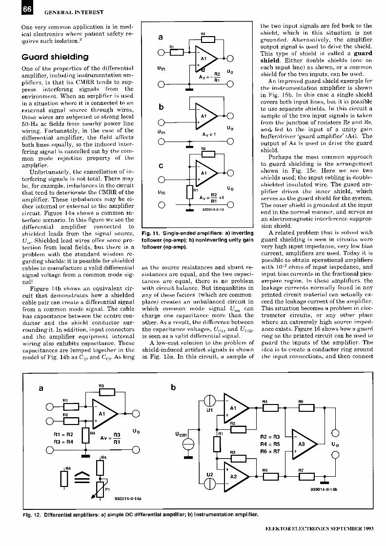
66 GENERAL INTEREST
One very common application is in med-ical electronics where patient safety re-quires such isolation.2
Guard shieldingOne of the properties of the differentialamplifier, including instrumentation am-plifiers, is that its CMRR tends to sup-press interfering signals from theenvironment. When an amplifier is usedin a situation where it is connected to anexternal signal source through wires,those wires are subjected to strong local50 -Hz ac fields from nearby power linewiring. Fortunately, in the case of thedifferential amplifier, the field affectsboth lines equally, so the induced inter-fering signal is cancelled out by the com-mon mode rejection property of theamplifier.
Unfortunately, the cancellation of in-terfering signals is not total. There maybe, for example, imbalances in the circuitthat tend to deteriorate the CMRR of theamplifier. These imbalances may be ei-ther internal or external to the amplifiercircuit. Figure 14a shows a common in-terface scenario. In this figure we see thedifferential amplifier connected toshielded leads from the signal source,U. Shielded lead wires offer some pro-tection from local fields, but there is aproblem with the standard wisdom re-garding shields: it is possible for shieldedcables to manufacture a valid differentialsignal voltage from a common mode sig-nal!
Figure 14b shows an equivalent cir-cuit that demonstrates how a shieldedcable pair can create a differential signalfrom a common mode signal. The cablehas capacitance between the centre con-ductor and the shield conductor sur-rounding it. In addition, input connectorsand the amplifier equipment internalwiring also exhibits capacitance. Thesecapacitances are lumped together in themodel of Fig. 14b as Cs, and Cc,. As long
Fig. 11. Single -ended amplifiers: a) Invertingfollower (op -amp); b) noninverting unity gainfollower (op -amp).
as the source resistances and shunt re-sistances are equal, and the two capaci-tances are equal, there is no problemwith circuit balance. But inequalities inany of these factors (which are common-place) creates an unbalanced circuit inwhich common mode signal U,,, cancharge one capacitance more than theother. As a result, the difference betweenthe capacitance voltages, Ucs, and Uc,is seen as a valid differential signal.
A low-cost solution to the problem ofshield -induced artifact signals is shownin Fig. 15a. In this circuit, a sample of
the two input signals are fed back to theshield, which in this situation is notgrounded. Alternatively, the amplifieroutput signal is used to drive the shield.This type of shield is called a guardshield. Either double shields (one oneach input line) as shown, or a commonshield for the two inputs, can be used.
An improved guard shield example forthe instrumentation amplifier is shownin Fig. 15b. In this case a single shieldcovers both input lines, but it is possibleto use separate shields. In this circuit asample of the two input signals is takenfrom the junction of resistors R8 and R9,and. fed to the input of a unity gainbuffer/driver 'guard amplifier' (A4). Theoutput of A4 is used to drive the guardshield.
Perhaps the most common approachto guard shielding is the arrangementshown in Fig. 15c. Here we see twoshields used; the input cabling is double -shielded insulated wire. The guard am-plifier drives the inner shield, whichserves as the guard shield for the system.The outer shield is grounded at the inputend in the normal manner, and serves asan electromagnetic interference suppres-sion shield.
A related problem that is solved withguard shielding is seen in circuits werevery high input impedance, very low biascurrent, amplifiers are used. Today it ispossible to obtain operational amplifierswith 1012 ohms of input impedance, andinput bias currents in the fractional pico-ampere region. In these amplifiers, theleakage currents normally found in anyprinted circuit material can actually ex-ceed the leakage current of the amplifier.This situation becomes a problem in elec-trometer circuits, or any other placewhere an extremely high source imped-ance exists. Figure 16 shows how a guardring on the printed circuit can be used toguard the inputs of the amplifier. Theidea is to create a conductor ring aroundthe input connections, and then connect
Fig. 12. Differential amplifiers: a) simple DC differential amplifier; b) instrumentation amplifier.
ELEKTOR ELECTRONICS SEPTEMBER 1993

THE ANALOGUE SUBSYSTEM -2 67
this guard ring to a low impedance pointthat is at signal potential levels.Figure 16a shows the connection of theguard ring to inverting amplifiers. Thering is connected to the grounded non -in-verting input. Figures 16b and 16c showmethods for use with non -inverting am-plifiers. In both cases, the guard ring isconnected to the inverting input of theop -amp.
AC -coupled differentialamplifiersThere are some cases where instrumen-tation amplifiers need to be AC -coupled.Perhaps the most common problem iswhere a small amplitude AC signal isriding on a large DC component. An ex-ample is found in medical electronic de-vices such as the electrocardiograph(ECG). These instruments record thebiopotentials waveforms generated bythe heart activity. These signals tend tohave peak amplitudes in the 1 -mV re-gion. But there is a real problem. Thebiopotentials are picked up with metalelectrodes, usually made of silver -silverchloride (Ag-AgC1) material, that inter-face to electrolytic skin. In other words,the junction forms a battery. The half -cell potential of medical electrodes can be500 to 1,000 mV, which is seen by theamplifier as a DC component creating anoffset. Given that the weak signal needsto be amplified 1,000 times, the amplifierwill quickly saturate when faced with theDC offset. Another example exists in op-
= NONISOLATED (CHASSIS) GROUND
= ISOLATED (FLOATING) GROUND930014-11-15
Fig. 13. Isolated amplifier.
toelectronics. The usual situation forphotodiodes and phototransistors is tohave a weak light generated signal rid-ing on a large static level.
There are a couple methods for strip-ping off the signal component, leavingbehind the offset, so that it can be ampli-fied and otherwise processed. Figure 17ashows an AC -coupled instrumentationamplifier, such as shown previously inFig. 12b and 15b. Each non -invertinginput (+IN) is coupled through a capaci-tor (Ca and Cb). If the amplifier is a verylow bias current type, only the capacitorsare needed. But most practical op -ampshave an input bias current that cannotbe ignored, and this current will chargethe capacitors creating a second DC off -
Fig. 14. a) Standard input configuration inwhich the differential amplifier inputs areconnected to shielded leads from signalsource; b) equivalent circuit showingdistributed capacitances.
set source. For most practical circuits,therefore, bleeder resistors (Ra and Rb)are needed. These resistors set the inputimpedance of the amplifier, so dependingon the application should have values inthe 100 ki2 to 10 MS2 region.
Maintaining the common mode rejec-tion ratio (CMRR) of the differential in-
Fig.15. a) Simple guard shield solution to problem of Fig. 14a; b) improved version that uses a guard amplifier (A4); c) double shielded guardshield circuit.
ELEKTOR ELECTRONICS SEPTEMBER 1993

68 GENERAL INTEREST
Fig. 16. Use of a printed circuit guard ringfeature: a) inverting amplifier version; b) & c)noninverting amplifier versions.
Fig. 17. a) AC coupled instrumentationamplifier input; b) use of a CMRR ADJUSTcontrol.
strumentation amplifier requires thatRa=Rb, but that requires high precisionresistors. If ordinary five percent toler-ance resistors are used, a CMRR adjustpotentiometer (resistor R, in Fig. 17b)may be needed.
Another way to handle the DC offsetproblem is to use a d.c. restoration cir-cuit, such as Fig. 18.4 This circuit uses aBurr -Brown INA-117 difference ampli-fier (Al). This device features unity gain,but has a very common mode input range(±200 V), with ±500-V input protectioncircuitry. A second amplifier (A2) is usedto provide a low-pass filter response inthe feedback loop, which translates to ahigh-pass response for the circuit overall.The -3 -dB frequency response for thisamplifier is given by:
Avret-F-3dB =
2 TC Ri Ci(2)
where:Avref is the voltage gain seen from the ref-erence pins on the amplifier;Cl is the capacitance of Cl in farads;Ri is the resistance of R1 in ohms.
For the component values of Fig. 18, the-3 dB frequency is of the order of 6.1 Hz,so only signals having a frequency wellremoved from d.c. will pass the circuit.
Auto -zero circuitA very useful circuit for amplifiers thatmust maintain a very low internal driftis shown in Fig. 19. This circuit uses amethod similar to the d.c. restorationmethod of Fig. 18. Amplifier AlA is themain amplifier, and it has a forward gainof -R2/R1, or about 100 for the compo-nent values shown. The d.c. restorationcircuit (amplifier A1B) is used to bias thenon -inverting input of AlA. Switch Si isused to auto -zero the circuit. Switch Si isshown in the zero position in Fig. 19.The signal input is grounded throughS1A, setting the effective Um to zero. Atthe same time, S1B connects the input of
Fig. 18. DC restoration circuit.
OPERATE
IIZERO
Sib
Fig. 19. Auto -zero circuit.
A1B to the output. When Um=0, the out-put voltage U0 is due to the inherent off-set of the amplifier circuit. This voltageis used to charge capacitor Ci. When Siis returned to the operate position, thisvoltage is used to counter itself throughthe non -inverting input. In order to pre-vent capacitor leakage from degradingthe offset cancellation, Ci should be apolypropylene type.
ConclusionSensor interfacing can be a dicey processbecause of these pitfalls on the pathway,but with due regard for signal source out-put circuit form, amplifier input type,and the other factors in the interfacer'sbasket of tricks, the job is a lot easier.
In next month's concluding instalmentwe will be looking at a universal multi -gain analogue amplifier.
Notes and recommended reading1. Definitions derived in part fromGeorge Klier (Gould, Inc.), 'SignalConditioners: A Brief Outline', Sensors:The Journal of Machine Perception, Jan.1990, Vol.7, No.1, pp.44-48. Some of thedefinitions used in this article were orig-inated in the Klier article cited above.For additional information see: Daniel H.Sheingold (ed.), Transducer InterfacingHandbook, Analog Devices, Inc.,(Norwood, MA 1981).2. John M. Brown and Joseph J. Carr,Introduction to biomedical EquipmentTechnology. Formerly published by JohnWiley & Sons, Inc., but now withPrentice -Hall.3. Joseph J. Carr, Integrated Electronics,Technology Publications - Division ofHarcourt, Brace, Jovanovich (1990).4. 'AC Coupling Instrumentation andDifference Amplifiers'. R. Mark Stitt,Burr -Brown Corporation ApplicationsBulletin No. 8 (Tucson, AZ, USA, 1990).
ELEKTOR ELECTRONICS SEPTEMBER 1993

Please mention ELEKTOR ELECTRONICS when contacting advertisers69
SURVEILLANCEPIHWESSNMIL 011Aur1'Y KITS
Whether your requirement for surveillance equipment is amateur, professional or you are just fascinated by this unique area ofelectronics SUMA DESIGNS has a kit to fit the bill. We have been designing electronic surveillance equipment for over 12 yearsand you can be sure that all of our kits are very well tried, tested and proven and come complete with full instructions, circuitdiagrams, assembly details and all high quality components including fibreglass PCB. Unless otherwise stated all transmittersare tuneable and can be received on an ordinary VHF FM radio. Note that certain products are for Overseas use only.
UTX Ultra -miniature Room TransmitterSmallest room transmitter kit in the word! Incredible 10mm x 20mm including mic3-12V operation. 500m range £16.45
MTX Micro -miniature Room TransmitterBest-selling micro -miniature Room TransmitterJust 17mm x 17mm including mic. 3-12V operation. 1000m range £13.45
STX High-performance Room TransmitterHi performance transmitter with a buffered output stage for greater stability and range.Measures 22mm x 22mm including mic. 6-12V operation, 1500m range £15.45
VT500 High -power Room TransmitterPowerful 250mW output providing excellent range and performance. Size 20mm x40mm. 9-12V operation. 3000m range £16.45
VXT Voice Activated TransmitterTriggers only when sounds are detected. Very low standby current. Variable sensitivityand delay with LED indicator. Size 20mm x 67mm. 9V operation. 1000m range £19.45
HVX400 Mains Powered Room TransmitterConnects directly to 240V AC supply for long-term monitoring. Size 30mm x 35mm.500m range £19.45
SCRX Subcarrier Scrambled Room Transmitter
Scrambled output from this transmitter cannot be monitored without the SCDM decoderconnected to the receiver. Size 20mm x 67mm. 9V operation. 1000m range £22.95
SCLX Subcarrier Telephone TransmitterConnects to telephone line anywhere, requires no batteries. Output scrambled sorequires SCDM connected to receiver. Size 32mm x 37mm. 1000m range £23.95
SCDM Subcarrier Decoder Unit for SCRXConnects to receiver earphone socket and provides decoded audio output toheadphones. Size 32mm x 70mm. 9-12V operation £22.95
ATR2 Micro Size Telephone Recording InterfaceConnects between telephone line (anywhere) and cassette recorder. Switches tapeautomatically as phone is used. All conversations recorded. Size 16mm x 32mm.Powered from line £13.45
*** Specials ***DLTX/DLIIX Radio Control SwitchRemote control anything around your home or garden, outside lights, alarms, pagingsystem etc. System consists of a small VHF transmitter with digital encoder and receiverunit with decoder and relay output, momentary or alternate, 8 -way dil switches on bothboards set your own unique security code. TX size 45mm x 45mm. RX size 35mm x90mm. Both 9V operation. Range up to 200m.Complete System (2 kits) £50.95Individual Transmitter DLT)( £19.95
Individual Receiver OLRX £37.95
MIX -1 Ni-FtMIcrollreadeasterNot technically a surveillance device but a great idea! Connects to the headphone outputof your Hi-Fi, tape or CD and transmits Hi-Fi quality to a nearby radio. Listen to yourfavourite music anywhere around the house, garden, in the bath or in the garage andyou don't have to put up with the DJ's choice and boring waffle. Size 27mm x 60mm.9V operation. 250m range £20.95
0
UTLX Ultra -miniature Telephone TransmitterSmallest telephone transmitter kit available. Incredible size of 10mm x 20mm!Connects to line (anywhere) and switches on and off with phone use.All conversation transmitted. Powered from line. 500m range £15.95
TLXTOO Micro -miniature Telephone TransmitterBest-selling telephone transmitter. Being 20mm x 20mm it is easier to assemble thanUTLX. Connects to line (anywhere) and switches on and off with phone use. Allconversations transmitted. Powered from line. 1000m range £13.45
snx High-performance Telephone TransmitterHigh performance transmitter with buffered output stage providing excellent stabilityand performance. Connects to line (anywhere) and switches on and off with phone use.All conversations transmitted. Powered from line. Size 22mm x 22mm.1500m range £16.45
TKX900 Signalling/Tracking TransmitterTransmits a continous stream of audio pulses with variable tone and rate. Ideal forsignalling or tracking purposes. High power output giving range up to 3000m. Size25mm x 63mm. 9V operation £22.95
CD400 Pocket Bug Detector/LocatorLED and piezo bleeper pulse slowly, rate of pulse and pitch of tome increase as youapproach signal. Gain control allows pinpointing of source. Size 45mm x 54mm. 9Voperation £30.95
CD600 Professional Bug Detector/LocatorMulticolour readout of signal strength with variable rate bleeper and variable sensitivityused to detect and locate hidden transmitters. Switch to AUDIO CONFORM mode todistinguish between localised bug transmission and normal legitimate signals such aspagers, cellular, taxis etc. Size 70mm x 100mm. 9V operation £50.95
QT)(180 Crystal Controlled Room TransmitterNarrow band FM transmitter for the ultimate in privacy. Operates on 180 MHz andrequires the use of a scanner receiver or our ORX180 kit (see catlogue). Size 20mm x67mm. 9V operation. 1000m range £40.95
QU(180 Crystal Colntrolled Telephone TransmitterAs per OTX180 but connects to telephone line to monitor both sides of conversations20mm x 67mm. 9V operation. 1000m range £40.95
QSX18O Line Powered Crystal Controlled Phone TransmitterAs per OLX180 but draws power requirements from line. No batteries required. Size32mm x 37mm. Range 500m £35.95
QRX180 Crystal Controlled FM ReceiverFor monitoring any of the '0' range transmitters. High sensitivity unit. All RF sectionsupplied as a pre -built and aligned module ready to connect on board so no difficultysetting up. Outpt to headphones. 60mm x 75mm. 9V operation £60.95
A build-up service is available on all our kits if required.UK customers please send cheques, POs or registered cash. Please add£1.50 per order for P&P. Goods despatched ASAP allowing for chequeclearance. Overseas customers send sterling bank draft and add £5.00 perorder for shipment. Credit card orders welcomed on 0827 714476.
OUR LATEST CATALOGUE CONTAINING MANY MORE NEWSURVEILLANCE KITS NOW AVAILABLE. SEND TWO FIRSTCLASS STAMPS OR OVERSEAS SEND TWO IRCS.
- 1 :
. I:
ELEKTOR ELECTRONICS SEPTEMBER 1993

70
MINI MICRO CLOCKThis is the 'little brother' of the Maxi Micro Clock published inthe previous issue of Elektor Electronics. A true miniaturedesign, the Mini Micro Clock has nevertheless the samefunctions as the 'maxi' version. This makes it ideal for use in alarger unit, or on a car dashboard.
Design by A. Rietjens
THIS time the circuit is based on theST6215 microcontroller from ST
(SGS/Thomson). The ST6215 is sup-plied in a 28 -pin plastic DIL enclosure,and has sufficient I/O lines to imple-ment the clock function without a sin-gle additional logic IC. Despite the factthat the ST6215 is larger than theST6210 used in the Maxi Micro Clock(Ref. 1), the Mini Micro Clock is a verycompact unit, with four LED displayssqueezed in between the microcon-trollers's two rows of pins.
The circuitFigure 1 shows the complete circuit di-agram of the Mini Micro Clock. To theright you see the four displays, LD 1-LD4, with their transistor drivers. Thedrivers are switched by the microcon-troller via outputs DigitO-Digit3. A lowlevel at one of these outputs actuatesthe associated transistor driver,which, in turn, causes the LED displayto be supplied. The four digital outputsallow the displays to be multiplexedunder software control. The selectionof active (lit) segments in the displaysis determined by the levels at outputsA -G, which are also found on the mi-crocontroller. Like the display enablelines, the segment selection lines are`active low'. The same goes for the dec-imal point, which is controlled by thelevel on output DP. A clear differencewith the Maxi Micro Clock is that aBCD decoder and separate bufferswith open -collector outputs are not re-quired.
The ADJ (adjust) input of theprocessor is connected to a preset po-tentiometer, Pi, which serves to adjustthe clock. Although the adjustmentrange of this preset is relatively small(approx. 60 s per week), it is, fortu-nately, ample to ensure good synchro-nization of the clock. An 8 -MHz quartzcrystal is used as a reference in theclock, and connected to the oscillatorbonded out to pins 3 and 4 of the mi-crocontroller. The two 22-pF capaci-tors ensure that the crystal resonatesat the correct frequency. An additional
trimmer is not required, since theclock is adjusted with the aid of Pi.
The three switches used to set andoperate the clock are connected di-rectly to I/O lines. Their functions aredescribed further on.
The communication of the clockwith the outside world is not limited tothe four displays. If desired, a buzzermay be actuated via transistor T6, or arelay energized via transistor T5. If youobject to the sound of the buzzer, si-lence it by removing jumper 'A'.Alternatively, replace the jumper by aminiature switch to make the buzzeron/off selection easier.
The last two components aroundthe microcontroller that need to be dis-cussed are resistor R9 and capacitorC - these parts serve to decouple themicrocontroller's power supply.
The power supply, shown at the topof the circuit diagram, has an addi-tional switching transistor that is ac-tuated when the mains supply isswitched off, or disappears otherwise.As long as the mains supply is present,diode D7 is cut off, so that the batteryconnected to the terminals marked`BO' is not loaded. Also, transistor T7is driven into conduction via resistorR14, and the output voltage of IC2 isconnected to the circuit. In case themains voltage disappears, diode D6 iscut off, and D7 conducts. Next, regula-tor IC2 reduces the battery voltage to5 V. Since D6 is cut off, transistor T7does not receive base current, so thatthe displays remain off. The microcon-troller, however, is still powered, andcontinues to operate in this condition.Switching off the displays causes thecurrent consumption of the clock todrop from 100 mA to about 8 mA, al-lowing a 9-V battery to keep the clockticking for several hours in the ab-sence of mains power.
Although a 4.5-V battery would ap-pear the first choice as a backup de-vice, a 9-V (PP3) type is used becauseof its much smaller size. A 4.5-V bat-tery is about two times as large as theentire clock, and is, therefore, not agood choice when compactness is a
prime requirement.If the clock is used in a car, the
switched battery voltage is connectedto diode Ds, and the unswitched bat-tery voltage to diode D7. With the igni-tion switched off, the clock continuesto work with the displays switched off.The displays are switched on againwhen the car is started.
ConstructionHaving described the circuit diagramof the mini clock we now turn to thepractical construction of the device.Figure 2 shows the compact, double -sided and through -plated, printed cir-cuit board (PCB) designed for the MiniMicro Clock. The PCB and the 9-V bat-tery are fitted into a compact ABS en-closure, which makes the clocksmaller than a packet of cigarettes.
The cover of the enclosure is cutand drilled to make the necessaryclearances for the LEDs, displays andpress -keys. The Conrad enclosurementioned in the parts list requires asmall (35x5 mm) piece of the PCB to becut out of the PCB, to allow for amoulded support. When the Diptal boxis used, the PCB edges are cut off tothe extra corner points printed on theoverlay. Next, file the PCB until it canbe clamped into the box. The connec-tion to the mains supply may be madein one of the side panels.
After this preparatory work, you areready to start soldering. As indicatedby the photograph of the prototype,components are fitted at both sides of
ELEKTOR ELECTRONICS SEPTEMBER 1993

MINI MICRO CLOCK em
D7
Bt1
8mAH
1N4001 IC2
D6 7805
im +0 1N40019V
10...15V300mA
5V
0
C5
720m16V
- -0-11
T5
Bz1
1N4148
6
BC547B
R10
10k
R11
BC547B P1
10k
11:00n
A 70-8
B012
50k
S1
SETT0
S3
UP
°ILS2
DOWN0 ()
C4MIM
TOOn
BUZ
RELAY
ADJ
P
R14 BC547B470L1
R15 IR12
5 11
NMI
IC1
RST
DIG3
DIG2
DIG1
DIGO
ST62T15T
DOWN
INSC
OUT
LED
A
B
C
E
G
DP
-L
R8
3k3
3k3
R13
Most components used in this pro-ject are available from ViewcomElectronics (see advert on pages 18and 19).
JR1
T1
BC557B
3k3
R2
T2
BC557B
R3
T3
BC557B
R5
15
##
D1
LD13 8
8 10
9 9
2
23
0
a
7C
4
2
7
16
X18MHz
C2
227
4 28
C3
111.212 p
CA CA
O
O updp
6 HD1105
10
7
4
LD23 8
a
C
CA CA
O
f
dp
0
10
7
5
4
6 HD1105
LD33
R4
T4
BC557B
LD48 3
CA CA
O 09 dp
10
9
6 HD1105
CA CA
b O
O 110dp
930055 - 11
6 HD1105
Fig. 1. Circuit diagram of the Mini Micro Clock. The heart of the circuit is formed by a microcontroller Type ST62T15 from SGS/Thomson. Thecontroller is supplied ready -programmed, in three different versions, through our Readers Services.
the PCB. Apart from the microcon-troller, all components are fitted di-rectly on to the board. Start by fittingall passive parts. Initially, you mayhave problems getting the SMT partsfitted, but rest assured that with pa-tience the technique will be masteredafter a little while. Next, fit the dis-plays, followed by the IC socket for themicrocontroller. It is important to keepto this order because a number of dis-play connections are difficult to reachonce the IC socket is on the board.Mount two pins for jumper 'A', so thatthe jumper is readily fitted, or a minia-ture switch connected via short wires.Small pins may also be fitted to con-nect the relay and the supply voltage.Next, mount the diodes, LEDs andtransistors (all upright). The length ofthe LED terminals depends on thearrangement of the other componentsat this side of the PCB. The top of eachLED, the displays and the switches
must all be at the same height, as wellas level with the cover of the enclosureused. To assist in its cooling, voltageregulator IC2 is best fitted above theboard surface using a 5 -mm long PCBspacer. Finally, fit the crystal. The cir-cuit is then ready for use.
Three versionsJust as with the Maxi Micro Clock, theMini Micro Clock may be built for threedifferent applications: clock; darkroomclock/long-period timer; or cookingtimer. Each of these applications re-quires its own microcontroller, whichis supplied ready -programmedthrough our Readers Services. As withthe Maxi Micro Clock, the cookingtimer requires only two of the four dis-plays (LDI and LD4 may be omitted).The operation of each of the three ver-sions of the Mini Micro Clock is dis-cussed below.
ClockThis function is realized by fitting amicrocontroller with software ordercode 7111. The SET press -key selectsbetween clock setting and alarm timesetting. Depending on the selection,LED D i or D2 lights. The desired timeis set by pressing the UP and DOWNkeys. If neither of the two functions isselected (both LEDs off) the UP andDOWN keys enable you to select be-tween an 'hours:minutes' or a 'min-utes:seconds' display, both with thealarm enabled or disabled.One of these four options remains se-lected until the user selects anothersetting. Consequently, the clock willnot automatically return to the pre-ferred settings.When the alarm is enabled (jumper 'A'fitted), and the time equals the alarmtime, the buzzer will sound. The alarmmay be turned off by pressing Si or S2.
ELEKTOR ELECTRONICS SEPTEMBER 1993

el GENERAL INTEREST
Fig. 2. Track layouts and component mounting plans of the double -sided, through -plated, printed circuit board designed for the clockATTENTION: pin 10 of the microcontroller (TEST) should be connected to ground via a short piece of wire.
Resistors (all SMT):4 1k.(1
4 31(513
1 101)4 10k0
1
1
1
33k)47052501d2 preset H
Capacitors:2 100nF SMT2 22pF1 220µF 16V
Semiconductors:2 LED, red, 3mm2 LED, green, 3mm1 1N41482 1N40014 BC557B3 BC547B1 ST62T1511 7805
R1 -R4R5 -R8R9R10;R11;R12;R15R13PI14P1
Cl ;C4C2,C3C5
D1,D2D3;D40506;D7T1 -T4T5;T6;T7IC 1
IC2
' Miscellaneous:1 9-V PP3 battery Bt11 5-V buzzer Bzl4 HD11050 (Siemens)2 LD1-LD43 3CTL3 press -key (MEC)3 S1 -S31 8MHz quartz crystal X1
1 Plastic enclosure dim.61x22x80mm e gConrad4 523950, orDipta1557x30x86mm
1 Printed circuit board 930055 (seepage 78)
1 supplied ready -programmed throughthe Readers Services (see page 78).Three different versions are available7111 mini clock7121 mini darkroom clock7131 mini cooking timer
2 ElectroValue, Unit 3, Central TradingEstate, Staines, Middx TW18 4UX.Telephone. (0784) 442253. Fax: (0784)4603203 C-1 Electronics, P.O. Box 22089,
6360 AB Nuth, Holland Fax: (+31) 452418774 Conrad Electronic Nederland By, P.O.Box 12, 7500 AA Enschede, Holland Tel(+31) 53 282000. Fax* (+31) 53 283075.
6 Diptal, France. Tel +33 50 569497, fax.+33 50 569517.
We are advised that nearly all compo-nents for this project are available fromViewcom Electronics For address andtelephone number, see advert on pages18 and 19 in this issue.
ELEKTOR ELECTRONICS SEPTEMBER 1993

MINI MICRO CLOCK
Fig. 3. Prdtotype, showing the displays,switches and LEDs fitted at the front side ofthe PCB.
.
4i
Fig. 4. The rear side of the PCB holds therest of the parts, which are densely packed.
Transistor T5 is controlled togetherwith the buzzer, and actuates the (op-tional) 5-V relay.
Darkroom clock
The darkroom clock or long -periodtimer function (software order code7121) allows a programmed timing in-terval to be signalled. Both repetitiveand single signalling are possible. Indarkroom clock mode, the `min:sec'display function is not used, and re-placed by a 'repetitive alarm' function.The maximum time between two shortalarm signals is 99 minutes and59 seconds (99:59). The darkroomclock function is selected with theDOWN key, which also serves to selectbetween alarm (buzzer) on and off.
The SET key allows the alarm timeonly to be programmed - there is nopoint in setting the actual time. Thecounter is reset when the UP key ispressed after setting the desired alarmtime. Depending on your selection, thebuzzer will sound once, or repetitively,after a set period has elapsed. The lat-ter function is particularly useful totime the film developer.
The optional relay is actuated viatransistor T5 during the first period(after resetting). This allows an electri-cal apparatus, for instance, an en-larger, to be switched on for amaximum period of 99 minutes and59 seconds.
Cooking timerThis function requires the microcon-troller with order code 7131. The UPand DOWN keys are used to set the de-sired time, which is counted down tozero. A short beep is produced whenthe programmed time has elapsed.
The cooking timer does not use dis-plays LD i and LD4, so that only theminutes and/or tens of seconds read-outs are visible. Before programmingthe cooking time, the SET key must beused to select between cooking times
0
Fig. 6. Suggestion for a front panel layout.
longer or shorter than 10 minutes.Next, the desired time is set with theUP and DOWN keys. When the cookingtime is shorter than 10 minutes, thefirst display shows the remaining min-utes, and the second display the re-maining tens of seconds. For instance,if the displays read '8.3', the remainingtime is 8 minutes and 30 seconds.With cooking times longer than10 minutes, the display shows thenumber of minutes only. The point be-tween the two displays flashes at arate of 1 Hz.Reference:Maxi Micro Clock. Elektor ElectronicsJuly/August 1993.
I2C interface for PCsFebruary 1992The PCD8584 iused in this project isno longer manufactured by PhilipsSemiconductors, and replaced by thePCF8584. This is a fully compatible ICand only improved as regards the 4 -wire long-distance mode, which didnot work correctly on the PCD8584.
Real-time clock for 80C32computerJune 1993Contrary to what is implied by the de-scription of the parallel connection ofthe SmartWatch IC pins with theEPROM pins, pin 1 of the SmartWatch
CORRECTIONSAND UPDATES
should be connected separately to+5V, for instance, to EPROM pin 28,via a short wire. This is necessary be-cause pin 1 on the SmartWatch is`reset', while on the EPROM it is ad-dress line A14, which may be madehigh by 'high' addressing or glitches,causing the clock to be reset.
VHF -low converterJune 1993The parts list should be corrected to
read:1 4tH21 OjtH1
L3L5
The circuit diagram is correct.The sub- ljt H chokes used in this pro-ject are available from, among others,Cricklewood Electronics.
1.2 GHz multifunctionfrequency meterDecember 1992The recommended LCD module TypeLTN211-F10 is no longer manufac-tured by Philips Components, and maybe replaced by the compatible typesLM016L from Hitachi, or the LM16A21from Sharp.
ELEKTOR ELECTRONICS SEPTEMBER 1993

74
DX TELEVISI N
A two -monthly column by Keith Hamer and Garry Smith
After a sluggish start, the long-awaited1993 sporadic -E season finally estab-lished itself. The first signs of receptionoccurred on May 2nd with an opening al-ready in progress at 0600h UTC. Astrong and stable signal from the CIS 1stnetwork was present on channel R2 and,at times, the SECAM colour locked.
The most intense and busiest openingoccurred on May 12th with strong sig-nals throughout the day from South,South-east and Central Europe. Amongthe countries identified were Spain,Portugal, Italy, Germany, Hungary, theCzech Republic, Switzerland, Poland,Slovenia, Serbia and Croatia. Three sep-arate openings on the 15th brought inCentral European stations, although theexact source of the transmissions couldnot be determined. A variety of test pat-terns were resolved by several enthusi-asts on May 21st from Norway, Swedenand the CIS.
Tropospheric reception had its mo-ments - in fact it has been prevalentthis year. April 27th was extremely pro-ductive with various Benelux,Scandinavian and German catches, someof which fell into the 'exotic' category.
Reception reportsPeter Chalkley of Luton has notched upseveral countries already this seasonusing a D-100 DX -TV converter fed intoan elderly Philips TV-ette portable.During an opening to Scandinavia andthe East on May 14th, Peter discovered6 -metre amateur radio activity fromEstonia.
The same opening produced test cardsfrom Norway, Sweden and Finland forAndrew Jackson at his QTH inBirkenhead. Of particular interest was amodified Norwegian PM5534 test cardwith the initials `NRK' at the top withthe date and time across the centre.There was no identification in the lowerblack rectangle.
Bob Brooks of South Wirral andStephen Michie of Bristol have also no-ticed the modified NRK test pattern withthe date display on two occasions, but inbetween these sightings the normal ver-sion with transmitter identification hasbeen seen. Both Bob and Stephen werefortunate enough to identify Iceland onMay 14th. The PM5544 test card carriedthe identification `RUV' at the top, and`ISLAND' in the lower black rectangle.
Neil Purling of Hull has noted a slow
start to the sporadic -E season. Even so,he has successfully managed to identifyPortuguese, Spanish and Italian signalsin Band I.
Simon Hamer of New Radnor inPowys did well with tropospheric recep-tion at the end of April when signalsfrom the new Norwegian TV -2 networkwere discovered on channel E12. Duringthe same opening programmes from theSwedish TV -4 service were seen.
Stephen Michie has reported strongcolour reception from the Dutch Lopiktransmitter using a wideband UHF gridindoors. A second (stacked) grid is beingadded to the system to reduce the cap-ture angle in the hope of reducing prob-lems from local UHF relays.
The sporadic -E season (November toMarch in the Southern hemisphere) pro-duced some spectacular long -haul highMUF signals 'down -under' according toAnthony Mann of Perth in WesternAustralia. Double -skip FM receptionfrom Victoria was identified onDecember 24th of last year, and again onJanuary 24th. TV signals from the Northon channels E2 and R1 were also noted.These were thought to have originated inThailand and China, respectively.
The highlight of the Australian seasonwas the reception of several channel A2vision carriers from Hawaii and Mexicoon January 16th from 0530-0600h UTC,possibly via a combination of F2 -layerand sporadic -E propagation.
Meanwhile, Todd Emslie of Sydney isstill trying to trace a mystery Pacific FMstation on 93.25 MHz during an intenseSporadic -E opening to New Caledonia onFebruary 6th. The early afternoon recep-tion lasted for around 30 minutes duringwhich the US Top 40 and adverts wereheard but there were no clues as to theirorigin.
Log for April13.04.93: Unidentified meteor -scatter`pings' on channels E3 and R2 at1315h UTC.15.04.93: Tropospheric reception fromSweden and Denmark in Band III and atUHF.27.04.93: Excellent tropospheric recep-tion from France, Eire, Belgium, theNetherlands, Luxembourg, Norway,Sweden and Denmark. In addition, atleast nine German services were identi-fied on various Band III and UHF chan-nels.28.04.93: Similar reception to the 27th.
-a,
Fig. 1. A typical UEIT test card as used bymost ex -USSR stations for all networks.There are many subtle identificationvariations, some with letters and others withnumbers, thus making positive identificationdifficult.
Log for May02.05.93: Sporadic -E signals from anunidentified CIS transmitter on channelR2 at 0600 UTC in SECAM colour.05.05.93: A late afternoon sporadic -Eopening with Italian signals on channelsIA and IB.12.05.93: Intense and active sporadic -Ereception throughout the day fromSouthern and Central European on vari-ous Band I channels. At least elevencountries were identified.13.05.93: Sporadic -E signals fromFinland, Norway, Sweden, Iceland andEstonia.15.05.93: Sporadic -E openings at earlymorning, midday and late afternoon withvarious unidentified signals fromEastern Europe on channels R1 and R2.At 1645h UTC, a clock two hours aheadof UTC was noted.21.05.93: Sporadic -E signals between1100h and 1300h UTC from Norway(Steigen on channel E2 and Hemnes E3),followed by signals from Sweden, includ-ing the PM5534 test card. At 1225h UTCa UEIT test pattern from an unidentifiedCIS transmitter appeared.24.05.93: Sporadic -E reception fromScandinavia in Band I and good -qualitytropospheric signals from the Nether-lands at UHF.25.05.93: Denmark (DR) on channel E7,and TV -2 on E27 from Abenraa with thePM5534 test card, tone and music at0630h UTC. Towards midnight, severalBenelux stations were noted, plus aGerman ZDF station on channel E24.26.05.93: Strong tropospheric receptionfrom the NED-3 Lopik outlet on channelE30.27.05.93: Sporadic -E reception fromSpain, Portugal, Hungary, Austria,Sweden, Denmark and the CzechRepublic.29.05.93: Early evening sporadic -E re-ception from Spain, Portugal andCorsica.
The DX -TV logs were kindly supplied byAndrew Jackson, Stephen Michie, Simon
ELEKTOR ELECTRONICS SEPTEMBER 1993

DX -TELEVISION ElHamer, Garry Smith, Bob Brooks andPeter Chalkley.
DX -TV informationThere have been several requests fromElektor Electronics readers for publica-tions covering the DX -TV hobby. Thereare in fact various books available writ-ten by DX -TV enthusiasts. There is alsoa range of videos covering test cards,propagation, equipment, etc.
`DX -TV For Beginners' by SimonHamer (£4.80, UK) covers the basics ofTV DX-ing with practical ideas for get-ting into the hobby with the minimumoutlay. 'A TV-DXers Handbook' by RogerBunney (new edition to be publishedsoon), covers the subject in greater tech-nical depth, while 'Guide to DX -TV'(£4.80, UK) by Keith Hamer and GarrySmith provides ideas for improving anexisting set, with the emphasis on choos-ing the correct type of aerial and pre -am-plifier, and ways of preventing or curingcommon forms of interference. A freecopy of the latest HS Publications cata-logue covering DX -TV books, videos andequipment is available by sending alarge stamped and addressed envelope(or two IRCs) to: HS Publications, 7Epping Close, Derby DE3 4HR.(Telephone: 0332 381699).
Channel allocationsSome explanation may be necessary con-cerning the channel numbering systemused by TV stations overseas. In general,countries in Western Europe use an `E'prefix, while those in the East use an 'R'prefix, but the channels do not coincide.There are three `E' channels allocated inBand I, and these are used by countriessuch as Norway and Spain. The channelsare referred to as E2, E3 and E4.Channels E5 to E12 are located inBand III.
There are only two channels allo-cated to Band I: R1 and R2. Countriessuch as Poland or Hungary use 'R' chan-nels. Channels R3, R4 and R5 are locatedwithin a special band (TV Band II) justbelow the FM radio band. Channels R6 toR12 are to be found in Band III.
There are exceptions. Italy uses let-ters instead of numbers to identify chan-nels; also an 'I' prefix is used. These areIA and IB in Band I, IC just below theFM band, and ID to IH in Band III.France is another exception: an `L' prefixis used. In Band I the channels are L2,L3 and L4, although the frequencies useddo not coincide with those of other coun-tries. In Band III, the French channelsrange from L5 to L10.
UHF allocations are little more civi-lized, and UK channel 30, for example,has the same vision frequency as E30 inSweden, L30 in France or R30 in Poland.
Recognizing the various channel num-bers and their relative positions on each
band comes with experience, and oftenthe reception can be identified by thesefactors. It is best to imagine a band asbeing a horizontal tuning scale on aradio. TV sets with VHF tuners fittedusually have a scale inscribed only with`E' channels 2-4 in Band I, and 5-12 inBand III. Specialized converters such asthe D-100 also have the Italian and 'R'channels marked around the Band I dial.
Band I channels, in ascending order,are: E2 (Western Europe), R1/E2a(Eastern Europe and Austria), IA(Italy), E3, L2 (France), R2, L3, E4/IBand L4.
European DAB planFurther information has come to handregarding the proposed Digital AudioBroadcasting plan for Europe. In Europe,the proposed allocations will mean theloss of Band III channel E12; existingtransmissions will be move to UHF.
It seems likely that the UnitedKingdom will have approximately12.5 MHz of spectrum centred around230 MHz, producing seven blocks of1.5 MHz bandwidth. Each block will sup-port up to twelve national radio channels.One block will be reserved for the BBCwith a second for independent radio. Theremaining five blocks will be used foraround the UK, and each area should haveenough space for six local stations, with asmany as twelve in large cities.
Service informationFrance: Experiments using the Ceefaxteletext system are continuing, and theexisting Antiope system will be phasedout next year. Teletext subtitles onCeefax page 888 are already availablevia the France -3 network. TF1, France -2and France -3 are the only networks witha Teletext service.Belgium: The French-speaking RTBFnetwork has abandoned their ownTeletext system, known as Percival, infavour of the Ceefax system. Other im-portant changes to the network includethe conversion of the existing service intoFrench -based ones, such as Canal Plusand ARTE. The Tele21 service fromTornai (channel E63, 20 kW, vertical)and Wavre (channel 28, 500 kW) is nowcalled `Sport21', while the Ander'tiestransmitter on channel 61 (200 kW hori-zontal) broadcasts ARTE21, which isidentical to ARTE in France. TheARTE21 transmissions have 'normal'sound, but the picture is encrypted.
The PM5544 test pattern for theFlemish-speaking network has changedits top identification from 'BRT' to`BRTN'. The lower identification remainsas before, namely TV1 or TV2.Switzerland: A fourth network called`S Plus' will be launched at the end ofAugust. Competing with German sta-tions such as RTL, SAT -1, PRO -7, etc.,
N
Fig. 2. An elaborate DX -TV installation usingseparate yagi arrays for each band. Forsporadic -E reception, a simple loft -mounteddipole can be used if aerials cannot be fittedoutdoors.
the network will broadcast initiallythroughout the North of Switzerland,covering 70% of the population via cabledistribution and terrestrial transmittersoperating around channel E36. RTL inthe meantime have opened an office inZurich in an attempt to attract local ad-vertising. Special news and programmefeeds for Switzerland have also been pro-posed.Estonia: the first PAL transmitters areplanned for 1994/1995.Russia: At station opening, the RTV(Russian TV) network now identifies it-self as 'Telekanal Rossija'. Most of theprogrammes aired via the TKR channelare produced by independent TV produc-tion companies, and the trend is for themto display their own identification in thecorner of the picture during the pro-gramme. Thus, there are dozens of differ-ent logos to be seen via the TKR channel,so caution is needed when trying to iden-tify this channel.Germany: in the North of the country,regional magazine programmes shownbetween 1830-1900h UTC have beentransferred from the ARD-1 service tothe N3 network.
In the Berlin area, ORB -1 and SFB-1have merged, producing a common pro-gramme on channel E7. This means thatchannel E5, which was used by SFB-1, isno longer in use. N -TV (the news chan-nel) has been assigned channel E51(5 kW ERP), while channel E44 has beenallocated to VOX -TV.
Due to interference problems, the SSVC(British Forces) transmitter at Mtilheimhas moved from channel E41 to E54.
This month's service information waskindly supplied by Gosta van der Lindenand the Benelux DX Club; BerndTrutenau, Lithuania; Pertti Salonen,Finland; Reflexion Club, Germany;Roger Bunney, UK; Jurgen Klassen,Germany; Simon Hamer, UK; AndreGille, France. Please send any newsabout DX -TV in your part of the world to:Keith Hamer, 7 Epping Close, DerbyDE3 4HR, England.
ELEKTOR ELECTRONICS SEPTEMBER 1993

76
Project
PRODUCT OVERVIE2E7'71g ][BMEA number of projects carried in Elektor Electronics are supported by ready-made printed -circuit boards (PCBs), self-adhesive front panel foils, ROMs, EPROMs, PALs, GALs,microcontrollers and diskettes, which may be ordered through our Readers Services using theorder form printed every month opposite the Readers Services page.The list printed here is complementary to the shorter one opposite the Readers Services pageelsewhere in this issue. This two -page overview of all currently available products is regularlyupdated and appears in the March, June, September and December issues of ElektorElectronics.Items marked with a dot (o) following the product number are in limited supply only, and theiravailability can not be guaranteed by the time your order is received.Items not listed here or on this month's Readers Services page are not available.The artwork for making PCBs which are not available ready-made through the ReadersServices may be found in the relevant article (from March 1990 onwards).Prices and item descriptions subject to change. Prices can be confirmed on request at the timeof ordering. Sterling (£) prices are inclusive of VAT at 17.5%.
Project NO- Pilo*(US$)
1987
:
JANUARY 1987Top -of -the -rangepreamplifier 86111-2 26.45 52.90
FEBRUARY 1987Electron ROM card 86089 6.70 13.40
MARCH 1987MSX EPROMmer 87002 11.15 22.30
APRIL 1987Facsimile interface 87038 10.40 20.80
MAY 1987MIDI signal distribution 87012
OCTOBER 1987Low -noise microphonepreamplifier
NOVEMBER 1987SSB receiver for 80mand 20mBASIC computerDimmer for inductiveloads
1988
87058
8.70 17.40
4.05 8.10
87051 17.35 34.7087192 23.80 47.60
87181 7.05 1410
JANUARY 1988Stereo limiter 87168 8.50 17.00
FEBRUARY 1988Infra -red headphones 87640 7.20 14.40
MARCH 1988Computer -controlledslide faderLow -noise preamplifierfor FM receiversSignal divider forsatellite TV receivers
APRIL 1988Fuzz unit for guitarsActive loudspeakersystem
MAY 1988Plotter
87259
880041
880067
18.80
7.65
5.90
37.60
15.30
11.80
87255 7.65 15.30880030 8.80 17.60
87167 13.50 27.00
JUNE 1988Wideband active aerial 880043-1 for SW receivers 880043-2
JULY/AUGUST 1988I/O extension card forIBM PCsFrequency read-out forSW receivers
OCTOBER 1988Centronics interfacefor slide faderPreamplifier forpuristsPeripheral modulesfor BASIC computer
7.05 14.105.60 11.20
880038 33.60 67.20
880039 21.60 43.20
880111 9.10880132-1 6.95880132-2 14.40
18.2013.9028.80
880159 el 5.90 11.80
ProJed NO - PropIasi)
NOVEMBER 1988Bus interface for hi-resLCD screens 880074 19.70LFA-t50 -a fast 880092-1 9.95power amplifier 880092-2 9.20Harmonic enhancer 880167 7.40Portable MIDI keyboard 880168 9.20
DECEMBER 1988LFA-150 -a fastpower amplifierCVBS-to-TTL adaptorColour test patterngeneratorAutonomous I/Ocontroller
1989
880092-3 880092-4
880098
7.507.605.70
39.4019.9018.4014.8018.40
15.0015.2011.40
880130 15.65 31.30
880184e 18.00 36.00
JANUARY 1989Fax interface for AtariST and ArchimedesMIDI control unit
880109880178-1880178-2
8.6510.65
7.80
17.3021.3015.60
Low -budget capaci-tance meter UPBS-1 2.30 4.60
FEBRUARY 1989Digital Model TrainTouch key organVHF receiver
MARCH 1989Power line modemCentronics buffer
APRIL 1989Digital Model TrainFunction generatorTriplet
Multi -point IR control
87291-1 4.95 9.90886077 11.80 23.60886127 8.75 17.50
880189 7.15 14.30890007-1 23.05 461 0890007-2 2.55 5.10890007-3 9.80 19.60
87291-2/3UPBS-1
890013-1890013-2890019-1890019-2
5.05 10.102.30 4.607.80 15.608.00 16.004.05 8104.75 9.50
Video recording amplifier ELV project
MAY 1989RDS decoder 880209 5.30 10.60Digital Model Train (4) 87291-4 615 12.30Analogue multimeter 890035 14.70 29.40DTMF system decoder 890060 7.65 15.30Sine -wave converter UPBS-1 2.30 4.60S-VHS-to-RGB converter ELV project
JUNE 19898 -digit frequency meter 880128 13.50 27.00Echo unit ELV project
JULY/AUGUST 1989MIDI keyboard interfacedecoder board 890105-1controller boardTracking testerFloppy disk monitor 890078Function generator UPBS-1
SEPTEMBER 1989Digital Model TrainStereo viewerResonance meter
OCTOBER 1989Logic analyser withAtari ST
87291-6890044886071
8.25 16.50
ELV project5.00 10.002.30 4.60
7.85 15.706.55 13 1 04.60 9.20
890126 6.15 12.30
Proloct No
CD error detector 890131RGB-to-CVBS converter
NOVEMBER 1989Digital Model Train (8) 87291-5
DECEMBER 1989Digital Model TrainEPROM simulatorHard disk monitorIC testerLF/HF signal tracerSolid-state preamp
1990
Price(e) (US$)
7.05 14.10ELV project
51.10 102.20
87291-7 10.30 20.60890166 11.75 23.50890186 12.95 25.90
ELV project890183 9.40 18.80
890170-1' 13.80 27.60890170-3* 10.60 21.20
JANUARY 1990Video mixer (1)Mini EPROMprogrammerAll solid-statepreamplifierSimple AC milli -voltmeter
87304-1
890164
890170-2'
32.00 64.00
8.25 16.50
18.50 37.00
900004 7.65 15.30
*The four PCBs required for the preamplifier (2 x890170-1; lx 890170-2 and 1x 890170-3) areavailable as a package, ref. 890170-9, at adiscounted price of £48.15 (US$96.30).
FEBRUARY 1990Initialisation aid forprinters
900007 16.75 33.50
Digital Model Train (11) 87291-8 5.30 10.60Reflex MW AM receiver UPBS-1 2.30 4.60Video mixer (2) 87304-2 19.10 38.20Capacitance meter 900012 8.50 17.00
MARCH 1990Audio/video modulator ELV projectDigital model train (12) 87291-9 4.10 8.20IC monitor 896140 8.80 17.60Power line monitor 900025 5.60 11.20Video mixer (3) 87304-3 41.70 83.40
APRIL 1990Digital model train (13) 87291-10 4.70 9.40Q meter 900031 7.05 14.10RS -232 splitter 900017-1 8.50 17.00
900017-2 5.30 10.60Wiring allocation tester ELV project
MAY 1990Acoustic temperaturemonitor UPBS-1 2.30 4.60Budget sweep/functiongenerator 900040 8.25 16.50Centronics ADC/DAC 900037D 17.90 35.80PC servicing card ELV projectTransistor characteristicplotting 900058 5.60 11.20
JUNE 1990Electronic load simulator 900042 1410 28.20MIDI master keyboard Doepfer ElektronikMini EPROM viewer 900030 21 15 42.30Power zener diode UPBS-1 2.30 4.60Remotely controlledstroboscope ELV project
JULY/AUGUST 1990Battery testerCompact 10A powersupply
ELV project
900045 13.50 27.00
Mooin (u2S)
Intermediate projects UPBS-1 2.30 4.60Mini FM transmitter* 896118 5.00 10.00Sound demodulator forsatellite -TV receivers 900057 4.40 8.80Audio power indicator 904004 4.40 8.80Four -monitor driverfor PCs 904067 6.15 12.30can not be supplied to readers in the UK
SEPTEMBER 1990High -current hFE tester 900078 6.45 12.90Infra -red remotecontrol 904085/86 7.95 15.90Sound generator ELV project
OCTOBER 1990pP-controlled telephoneexchangeS-VHS/CVBS-to-RGBconverter
900081 21.15 42.30
900055 14.40 28.80
NOVEMBER 1990400 -watt laboratory PSU 900082 12.95 25.90Dubbing mixer EV7000 ELV projectMedium -power audio 900098 10.60 21.20amplifierProgrammer for the 8751 900100 8.25 16.50PT100 thermometer 900106 5.90 11.80
DECEMBER 1990Active mini subwoofer 900122-2 6.15 12.30Milliohmmeter 910004 5.90 11.80Phase check foraudio systems 900114-1/2 9.40 18.80PC -controlled Video-text decoder (1) ELV projectSignal suppressor forall -solid state preamp 904024 4.40 8.80
1991JANUARY 1991Logic analyser (1):- BusboardPC controlled Video-text decoder (2)SWR meter
900094-4 10.60 21.20
ELV project900013 3.55 710
FEBRUARY 1991Logic analyser (2):- RAM board 900094-2 18.50 37.00- Probe board 900094-3 5.00 10.00Multifunction measure-ment card for PCs 900124-1 28.20 56.40MIDI -to -CV interface Doepfer ElektronikRDS decoder:- demodulator board 880209 5.30 10.60- processor board 900060 7.65 15.30
MARCH 1991The complete preamplifier:- input board 890169-1 26.10 52.20- main board 890169-2 39.35 78.70Electronic exposuretimer 900041 10.85 21.70PC -controlled weatherstation (1) 900124-3 4.40 8.802-m band converter 900006-1 5.00 10.00
APRIL 1991Logic analyser (3):- control board 900094-5 18.50 37.00MIDI programmechanger 900138 6.75 13.508 -bit I/O for Atari 910005 12.35 24.706-m band transverter 910010 11.45 22.90Wattmeter:- meter board 910011-1 6.45 12.90- display board 910011-2 4.10 8.20Moving -coil (MC)preamplifier 910016 10.60 21.20Dimmer for halogen lights:- transmitter 910032-1 4.10 8.20- receiver 910032-2 4.40 8.80PC -controlled semi-conductor tester ELV project
MAY 199180C32/8052 Computer 910042 12.05 24.10Battery tester 906056 4.10 8.20Laser (1) ELV projectMoving -magnet (MM)preamplifier 900111 6.75 13.50Universal I/O interfacefor IBM PCs 910046 10.85 21.70
JUNE 1991Universal battery charger 900134 9.40 18.80Logic analyser - 4- power supply board 900094-7 8.80 17.60- Atari interface 900094-6 12.65 25.30- IBM interface 900094-1 14.40 28.80Digital phase meter(set of 3 PCBs) 910045-1/2/3 26.15 52.30Light transceiver UPBS-1 2.30 4.60Variable AC PSU 900104 6.15 12.30Light switch w. TV IR r/c 910048 5.60 11.20RTC for Atari ST 910006 6.15 12.30
JULY/AUGUST 1991Multifunction I/O for PCs 910029 24.40 48.80B/W video digitizer 910053 22.60 45.20Stepper motor board -- power driver board 910054-2 28.50 57.00
ELEKTOR ELECTRONICS SEPTEMBER 1993

Printed circuit boards whose number is followed by a + sign are only available in combination with theassociated software item, and can not be supplied separately. The indicated price includes the software.
Laser - 3LED voltmeterWien bridgeAngled bus extensioncard for PCsSync separator
Pries* Project(£) (US$)
ELV project914005 5.60 11.20914007 4.10 8.20
914030 12.05 24.10914077 4.40 8.80
SEPTEMBER 1991Peak indicator for loud-speakers ELV projectTimecode interface for slide control:- main board 910055 24.40 48.80- display board 87291-9a 4.10 8.20Asymm-symm converter 910072 5.60 11.20
OCTOBER 1991PC -controlled weatherstation (2) 900124-2Digital function generator- main board 910077-1- display board 910077-2Audio spectrum shiftencoder/decoder 910105
NOVEMBER 1991Relay card for uni-versal I/O interface 910038Dissipation limiter 910071Digital function generator- sine converter 910077-3- R/T converter 910077-4Class -A power amplifier (1):
880092-1880092-2
Timer for CH systems UPBS-2
DECEMBER 1991Class -A power amplifier (2):
880092-3880092-4
Economy power supply 910111 pP programmable filters 910125Amiga mouse/joystickswitch 914078Safe solid-state relay 914008 Slave mains on/offcontrol Mark -2 914072 Wideband antennaamplifier
1992
- main board 920039-1- power board 920039-2Audio DAC - 1 920063-1Optocard for universalPC I/O bus 910040Audio -video processor - 3FM tuner - 5:- keyboard/display 920005-4- S -meter 920005-6RS232 quick tester 920037Small projects:Water pump control forsolar power system 924007Simple power supply 924024Wideband active teles-copic antenna 924102
3.80 7.60 SEPTEMBER 1992EPROM emulator - II 910082
21.75 43.50 Audio/video processor - 412.65 25.30 Audio DAC - 2 920063-2
(US$
11.15 22.306.45 12.908.50 17.00
12.95 25.90ELV project
14.40 28.803.80 7.605.00 10.00
7.35 14.705.00 10.00
3.25 6.50
10.00 20.00ELV project
18.80 37.60
10.35 20.70 OCTOBER 1992Audio DAC - 3 920063-3 26.45Mains sequencer 920013 17.35Wideband active antenna 924101 3.25
12.95 25.90 RDS demodulator 880209 5.304.40 8.80
NOVEMBER 199215.00 30.00 Printer sharing unit 92001112.35 24.70 Sound sampler for Amiga 920074
Difference thermometer 920078Low -power TTL-to-RS232 interface
9.959.053.80
19.9018.10
7.60
ELV project
14.706.755.30
52.9034.70
6.5010.60
29.4013.5010.60
920127 3.55 7.10
DECEMBER 1992Digital audio/visual system(incl. EPROM 6171) 920022+ 34.10 68.20
7.50 15.00 1.2 GHz multifunction7,60 15.20 frequency meter9.40 18.80 (incl. EPROM 6141) 920095+ 29,40 58.806.75 13.50 Output amplifier for ribbon
loudspeakers 920135-1 19.40 38.804.10 8.20 920135-2 7.95 15.903.80 7.60 Peak -delta NiCd charger 920147 4.10 8.20
IDC-to-box header adaptor924049 6.45 12.906.45 12.90 Mini keyboard for Z80 924047 12.35 24.70
800552 pP system 924071 20.00 40.00Mains power -on delay 924055 6.45 12.90
JANUARY 1992CD player 910146Fast precise thermometer 910081Low -frequency counter- input board 910149-1- display board 910149-2Mini Z80 system 910060Prototyping board forIBM PCs 910049PC -controlled weather 900124-5station (3)
FEBRUARY 1992Audio/video switchingunit 910130I2C interface for PCs 910131-1Measurement amplifier 910144Mini square wavegenerator 910151RAM extension for miniZ80 systemSwitch -mode powersupply 920001
MARCH 19928751 emulator 920019A-D/D-A and I/O forI2C bus 910131-2AF drive indicator 920016Centronics line boosterFM tuner (tuner board)LC meterMIDI optical link
APRIL 199280C32 SBC extension2 -metre FM receiverComb generatorAD232 converterAutomatic NiCd chargerLCD for L -C meterMilli -ohm meter adaptor
910133920005920012920014
910109910134920003920010
UPBS-1920018920020
MAY 19921.3-GHz prescaler 914059Compact mains supply 920021FM tuner - 3 (PSU) 920005-2GAL programmer 920030NICAM decoder 920035
JUNE 19924 -Megabyte printer buffer 910110Audio -video processor - 212C display 920004FM tuner - 4:- mode control board 920005-3- synthesizer board 920005-5Guitar tuner 920033Multi -purpose Z80 card 920002
JULY 199212VDC to 240VAC Inverter
1993JANUARY 1993
8.25 16.50 PAL test pattern generator8.50 17.00 (incl. GAL 6211) 920129+ 15.30 30.60
Multi -core cable tester5.00 10.00 - matrix board 926079 17.05 34.106.45 12.90 - slave unit 926084 6.20 12.40
10.60 21.20 - master unit 926085 8.25 16.50
21.15 42.30 FEBRUARY 199310.00 20.00 U2400B NiCd battery
charger 920098 8.75 17.50Digital -audio enhancer 920169 14.25 28.50I2C opto/relay card 930004 11.00 22.00Watt-hour meter (PCBs -1and -2, and EPROM 6241)920148+ 37.25 74.5011 75
14.4013.50
23.5028.8027.00
5.30 10.60 930006 7.00 14.00
910073 2.35 4.70 920138 10.25 20.50
4.40 8.80 APRIL 1993Audio power meter 930018 10.25 20.5027MHz AM/FM transmitter920121 Not available
12.05 24.10 Video digitizer for PCs(incl. disk 1831) 930007 37.00 74.00Infrared receiver for 80C32single -board computer(incl. disk 1791) 920149 ; 14.50 29.004MB printer buffer card 920009 27.50 55.00
6.155.605.90
21.158.806.15
13.5010.308.50
12.352.304.704.40
5.007.358.80
11.1515.00
12.3011.2011.8042.3017.6012.30
27.0020.6017.0024,70
4.609.408.80
10.0014.7017.6022.3030.00
18.80 37.60ELV project
4.70 9.40
5.60 11.2010.85 21.7010.00 20.0020.25 40.50
MARCH 1993Linear sound pressuremeterElectrically isolatedRS232 interface
MAY 1993FM stereo signal generator920155VHF/UHF receiver 926001Philips preamplifier 930003Workbench PSU 930033
920075-1
23.0019.00
7.5021.50
4.70
46.0038.0015.0043.00
9.40
JUNE 1993Spectrum VU meter 920151 13.00 26.00GAL programmer upgrade930060 4.50 9.00Digital frequency readoutfor VHF/UHF receiver 926001-2 11.50 23.00Inexpensive phase meter- main board 930046 9.00 18.00- meter board 920018 4.75 9.50
For Juty/August and September 1993 items seepage 78 of this issue
ROMS - EPROMS - PALS - GALS - MICROCONTROLLERSArticle/Project Issue Order Description Price
(£) (US$)code
For pre -1989 project EPROMs see the December 1992 Product Overview or contact our Dorchester officeMultifunction measurement card for PCsMIDI control unitThe digital model trainDarkroom clockVideo mixerFour -sensor sunshine recorderpP-controlled telephone exchangeRDS decoderMIDI programme changerLogic analyserLogic analyser (IBM interface)MIDI -to -CV interlaceMultifunction I/O card for PCsAmiga mouse/joystick switchStepper motor board4-MByte printer buffer (6/92 and 4/93)8751 emulator (incl. system disk 525 in.)EMON51 (incl. course disk 1661)Connect 4EMON51 (incl. course disk 1681)FM tunerMulti -purpose Z80 card: GAL setMulti -purpose Z80 card: BIOSTV test pattern generator (80C32 SBC)1.2 GHz multifunction frequency meterDigital audio/visual systemDigital audio/visual system (software package)PAL test pattern generatorWatt-hour meter8751 programmer
2/91 561 1 x 16L8 10.301/89 570 1 x 27C64 11.75series 572 1 x 27642/90 583 1 x 271283/90 5861 1 x 27646/90 5921 1 x 2712810/90 5941 1 x 271282/91 5951 1 x 27644/91 5961 1 x 2764(Series) see under DISKETTES below
6/91 5971 1 x PAL 16L8 8.252/91 5981 1 x 2764 15.307-8/91 5991 1 x PAL 16L8 8.2512/91 6001 1 x GAL 16V8 8.256/91 6011 1 x PAL 16L8 8.25
6041 1 x 27C64 15.303/92 6051 1 x 27C64 29.40(series) 6061 1 x 27256 20.0012/91 6081 1 x 2764 15.30(series) 6091 1 x 27256 20.007/92 6101 1 x 27C256 20.006/92 6111 2 x GAL 16V8 11.156/92 6121 1 x 27128 15.303/93 6151 1 x 27256 15.3012/92 6141 1 x 27C256 11.4512/92 6171 1 x 27C256 10.302/93 6181 EPROM, GALe and disk 30.501/93 6211 1 x GAL 20V8 9.402193 6241 1 x 27256 10.0011/90 7061 1 x 8751 46.40
11.7510.8511.7511.7515.3015.3015.30
20.6023.5023.5021.7023.5023.5030.6030.6030.60
16.5030.6016.5016.5016.5030.6058.8040.0030.6040.0040.0022.3030.6030.6022.9020.6061.0018.8020.0092.80
DISKETTES
Article/Project Issue Ordercode
Disk size Price(£) (US$)
For pre -1990 project diskettes see the December 1992 Product Overview or contact our Dorchester officeFAX interface for IBM PCs 6/90 119 5.25 -inch (2 5) 8.25 16.50EPROM emulator II 9/91 129 5.25 -inch 6.75 13.50RS -232 splitter 4/90 1411 5.25 -inch 6.75 13.50Centronics ADC/DAC 5/90 1421 5.25 -inch 6.75 13.50Transistor characteristic plotting (Atari ST)(for monochrome systems only)
5/90 1431 3.5 -inch 7.65 15.30
ROM -copy for BASIC computer 9/90 1441 5.25 -inch 7.65 15.30Multifunction measurement card (MMC) for PCs 2/91 1461 5.25 -inch 7.65 15.308751 programmer 11/90 1471 5.25 -inch 7.65 15.30PT100 thermometer 11/90 1481 5.25 -inch 7.65 15.30Logic analyser: IBM software & GAL IC 7-8/91 1491 5.25 -inch 19.40 38.80Logic analyser: Atari software & GAL IC 7-8/91 1501 3.5 -inch 19.40 38.80Plotter driver (D. Sijtsma) 9/91 1541 5.25 -inch 11.15 22.30PC -controlled weather station (3) 1641 5.25 -inch 7.65 15.308 -bit I/O interface for Atari ST 41/9921 1571 3.5 -inch 7.65 15.30Tektronix/Intel file converter 4/91 1581 5.25 -inch 7.65 15.30B/W video digitizer for Archimedes 7-8/91 1591 3.5 -inch 11.15 22.30Timecode interface for slide controller 9/911611 5.25 -inch 7.65 15.30Real-time clock for Atari ST 6/91 1621 3.5 -inch 7.65 15.3024 -bit colour extension for video digitizer 11/91 1631 3.5 -inch 11.15 22.308051/8032 assembler course (IBM version) (series) 1661 5.25 -inch 7.65 15.30A-D/D-A and I/O for I2C bus 3/92 1671 order as 1821 (see below)8051/8032 assembler course (Atari version)AD232 converter 4/92
168116911691
3.5 -inch 7.65 15.305.25 -inch 7.65 15.30
GAL programmer (upgrade: June 1993) 5/92 & 6/93 1701 5.25 -inch (3 x) 11.15 22.30Multi -purpose Z80 card 6/92 1711 5.25 -inch 7.65 15.30Pascal routines for MMC for PCs 10/92 1751 5.25 inch 9.70 19.40Speech/sound memory 12/92 1771 5.25 inch 7.65 15.30Infra -red receiver and DTMF decoder for80C32 single -board computer 3 & 4/93 1791 5.35 -inch 7.50 15.0012C opto/relay card 2/93 1821 5.25 inch 7.65 15.30Video digitizer for PCs 4/93 1823 5.25 inch 14.50 29.00GAL programmer for Amiga 6/93 1841 3.5 inch 11.00 22.00Philips preamplifier 5/93 1861 5.25 inch 8.50 17.00GAL programmer (excl. Opal Jr. disks) 6/93 1881 5.25 inch 10.75 21.50X2404 -to -8751 interfacing 6/93 1891 5.25 inch 8.50 17.00
SELF-ADHESIVE FRONT PANEL FOILSArticle/Project Issue Order code Price
(E) (US$)
All -solid state preamplifier 1/90 890170-F1 19.70 39.40Video mixer 3/90 87304-F 19.40 38.80O meter 4/90 900031-F 13.50 27.00Budget sweep/function generator 5/90 900040-F 11.75 23.50High -current hFE tester 9/90 900078-F 16.45 32.90400 -watt laboratory PSU 11/90 900082-F 20.55 41.10Milliohm meter 12/90 910004-F 16.45 32.90Wattmeter 4/91 910011-F 9.70 19.40Universal NiCd battery charger 6/91 900134-F 6.45 12.90Logic analyser (series) 900094-F 10.30 20.60Digital phase meter 6/91 910045-F 11.75 23.50Variable AC power supply 6/91 900104-F 16.45 32.90Timecode interface for slide controller 9/91 910055-F 8.80 17.60Digital function generator 10/91 910077-F 10.60 21.204 -Megabyte printer buffer 6/92 910110-F 11.45 22.90Economy power supply 12/91 910111-F 10.60 21.20Measurement amplifier 2/92 910144-F 8.80 17.60CD player 1/92 910146-F 12.05 24.10FM tuner (series) 920005-F 13.20 26.404-mByte printer buffer 3/93 920009-F 8.25 16.50LC meter 3/92 920012-F 11.45 22.90Digital audio/visual system (series) 920022-F1 10.00 20.00
920022-F2 19.40 38.80920022-F3 28.80 57.60
Guitar tuner 6/92 920033-F 8.80 17.60NICAM decoder 5/92 920035-F 8.25 16.5012VDC-to-240VAC inverter 7/92 920038-F 16.15 32.30Audio DAC 10/92 920063-F 10.00 20.001.2GHz multifunction frequency meter 12/92 920095-F 13.80 27.60U2400B NiCd battery charger 2/93 920098-F 8.75 17.50Workbench PSU 4/93 930033-F 17.00 34.00Inexpensive phase meter 6/93 930046-F 17.25 34.50
ELEKTOR ELECTRONICS SEPTEMBER 1993

78
READERS SERVICESExcept in the USA and Canada, all orders, except forsubscriptions and past issues (for which see below),must be sent BY POST to our Dorchester office usingthe appropriate form opposite. Please note that wecan not deal with PERSONAL CALLERS, as no stockis carried at the editorial and administrative office.Readers in the USA and Canada should send orders,except for subscriptions (for which see below), to OldColony Sound Lab, Peterborough, whose full addressis given on the order form opposite. All US$ prices arepostpaid to customers in the fifty states except forbooks. Please add $2.00 for the first book and 750 foreach additional book ordered. Canadians please addUS$4.50 for the first book, and 750 for each additionalone. Canadians may expect Canadian duty chargeson shipments of any items except books.All other customers must add postage and packingcharges for orders up to £25.00 as follows: UK andEire £1.95; surface mail outside UK £2.45; Europe(airmail) £2.95; outside Europe (airmail) £3.70. For or-ders over £25.00, but not exceeding £100.00, thesep&p charges should be doubled. For orders over£100.00 in value, p&p charges will be advised.
SUBSCRIPTIONS & PAST ISSUES
Subscriptions and past issues, if available, should beordered from Worldwide Subscription Service Ltd,Unit 4, Gibbs Reed Farm, Pashley Road, TICE-HURST TN5 7HE, England. For subscriptions, usethe order form on the opposite page. Prices of past is-sues (except July/August and December), includingpostage for single copies, are £2.70 (UK and Eire);£3.00 (surface mail outside UK); £3.20 (air mailEurope); £3.95 (airmail outside Europe). Prices of pastJuly/August and December issues, including postagefor single copies, are £3.75 (UK); £4.00 (surface mailoutside UK); £4.25 (airmail Europe); and £5.00 (air-mail outside Europe).
PAST ARTICLES
Photocopies of articles from January 1978 onwardscan be provided, postage paid, at £1.95 (UK and Eire),£2.10 (surface mail outside UK), £2.45 (airmailEurope), or £2.70 (airmail outside Europe). In case anarticle is split into instalments, these prices are applic-able per instalment. Photocopies may be orderedfrom our editorial and administrative offices.
COMPONENTS
Components for projects appearing in Elektor Elec-tronics are usually available from appropriate advertis-ers in this magazine. If difficulties in the supply ofcomponents are envisaged, a source will normally beadvised in the article. It should be noted that thesource(s) given is (are) not exclusive - other suppli-ers may also be able to help.
BOOKSFor book availability, see advertisement on page 7.
SHELF BOXElektor Electronics shelf box £2.95 $6.00
FRONT PANELSPROJECT No. Price Price
(£) (US$)Timecode interface 910055-F 8.80 17.60Digital functiongenerator 910077-F 10.60 21.20
4 -Megabyte printerbuffer 910110-F 11.45 22.90Economy PSU 910111-F 10.60 21.20CD Player 910146-F 12.05 24.10Measurement amplifier 910144-F 8.80 17.60FM tuner 920005-F 13.20 26.404MB printer buffer card 920009-F 8.25 16.50LC meter 920012-F 11.45 22.90Guitar tuner 920033-F 8.80 17.60NICAM decoder 920035-F 8.25 16.5012VDC to 240VACinverter 920038-F 16.15 32.30
Audio DAC 920063-F 10.00 20.00Dig. audio/visual system 920022-F1 10.00 20.00
920022-F2 19.40 38.80920022-F3 28.80 57.60
1.2 GHz multifunction
PROJECT No. Price Price(e)
frequency meter 920095-F 13.80 27.60U2400B NiCd batterycharger 920098-F 8.75 17.50Workbench PSU 930033-F 17.00 34.00Inexpensive phase meter 930046-F 17.25 34.50
EPROMS / PALS / MICROCONTROLLERSMultifunction measurementcard for PCs (1 x PALI 6L8) 561 10.30 20.60Video mixer (1 x 2764) 5861 11.75 23.50RDS decoder (1 x 2764) 5951 15.30 30.60MIDI programme changer(1 x 2764) 5961 15.30 30.60Logic analyser (IBM inter-face) (1 x PAL 16L8) 5971 8.25 16.50MIDI -to -CV interface 5981 15.30 30.60Multifunction I/O for PCs(1 x PAL 16L8) 5991 8.25 16.50Amiga mouse/joystickswitch (1 x GAL 16V8) 6001 8.25 16.50Stepper motor board - 1
(1 x PAL 16L8) 6011 8.25 16.504 -Megabyte printer buffer(1 x 2764) 6041 15.30 30.608751 emulatorincl. system disk (MSDOS) 6051 29.40 58.80Connect 4 (1 x 27C64) 6081 15.30 30.60EMON51 (8051 assemblercourse) (1 x 27256 +disk 1661) 6061 20.00 40.00EMON51 (8051 assemblercourse) (1 x 27256 +disk 1681) 6091 20.00 40.00Multi -purpose Z80 card:FM tuner (1 x 27C256) 6101 20.00 40.00Multi -purpose Z80 card:GAL set (2 x GAL 16V8) 6111 11.15 22.30Multi -purpose Z80 card:BIOS (1 x EPROM 27128) 6121 15.30 30.601.2 GHz multifunctionfrequency meter(1 x 27C256) 6141 11.45 22.90Digital audio/visual system(1 x 27C256) 6171 10.30 20.60TV test pattern generator(1 x 27256) 6151 13.00 26.00DiAV system. Package:1 x 27512; 2 x GAL; 1 xfloppy disk (MSDOS) 6181 30.50 61.00PAL test pattern generator(1 x GAL 20V8-25) 6211 9.40 18.60Watt-hour meter (1 x 27256) 6241 10.00 20.00Four fold DAC (1 x GAL) 6251 10.75 21.50Multipurpose display decoder(1 x 2764) 6261 11.50 23.008751 programmer (1 x 8751) 7061 46.40 92.80Maxi micro clock (clock) 7081 11.50 23.00Maxi micro clock (darkroom timer) 7091 11.50 23.00Maxi micro clock (cooking timer) 7101 11.50 23.00Mini micro clock (clock) 7111 11.50 23.00Mini micro clock (darkroom timer) 7121 11.50 23.00Mini micro clock (cooking timer) 7131 11.50 23.00
DISKETTES
Multifunction measurementcard (MMC) for PCs 1461 7.65 15.308751 programmer 1471 7.65 15.30PT100 thermometer 1481 7.65 15.30Logic analyser: IBM softwareon disk, incl. GAL 1491 19.40 38.80Logic analyser: Atari softwareon disk (3.5"), incl. GAL 1501 19.40 38.80Plotter driver (D. Sijtsma) 1541 11.15 22.30I/O interface for Atari 1571 7.65 15.30Tek/Intel file converter 1581 7.65 15.30B/W video digitizer 1591 11.15 22.30Timecode interface 1611 7.65 15.30RTC for Atari ST 1621 7.65 15.3024 -bit colour extensionfor video digitizer 1631 11.15 22.30PC controlled weatherstation - 3 (supersedesdisks 1551 and 1561) 1641 7.65 15.308051/8032 Assembler course(IBM version) 1661 7.65 15.308051/8032 Assemblercourse (Atari version) (3.5") 1681 7.65 15.30AD232 converter 1691 7 65 15.30
PROJECT
GAL programmer (3 disks;
. Price Price(E) (ASS)
upgrade: June 1993) 1701 11.15 22.30Multi -purpose Z80 card 1711 7.65 15.30EPROM emulator II 129 6.75 13.50Pascal library for MMC 1751 9.70 19.40Speech/sound memory 1771 7.65 15.30PC -aided transistor tester 1781 7.50 15.00IR receiver and DTMF decoderfor 80C32 SBC 1791 9.00 18.00I2C opto/relay card 1821 7.65 15.30Video digitizer for PCs 1831 14.50 29.00GAL programmer for Amiga 1841 11.00 22.00I2C alphanumerical display 1851 8.50 17.00Philips preamplifier 1861 8.50 17.00GAL programmer (excl. OpalJr. disks) 1881 10.75 21.50X2404 -to -8751 interfacing 1891 8.50 17.00
PRINTED CIRCUIT BOARDS
Printed circuit boards whose number is followed by a+ sign are only available in combination with the as-sociated software item, and can not be supplied sepa-rately. The indicated price includes the software.
APRIL 1993Audio power meter27MHz AM/FM transmitterVideo digitizer for PCs(incl. disk 1831)Infrared receiver for 80C32single -board computer(incl. disk 1791)4MB printer buffer card
MAY 1993FM stereo signal generatorVHF/UHF receiverPhilips preamplifierWorkbench PSU
930018920121
930007+
10.25 20.50Not available
37.00 74.00
920149+ 14.50 29.00920009 27.50 55.00
920155926001930003930033
920075-1
JUNE 1993Spectrum VU meter 920151GAL programmer upgrade 930060Digital frequency readoutfor VHF/UHF receiver 926001-2Inexpensive phase meter- main board- meter board
JULY/AUGUST 1993Active 3 -way loudspeakersystemMaxi micro clockFour -fold DAC for PCsSMD soldering stationVHF -low converterUHF remote control trans-mitterUHF remote controlreceiver 934118Lead -acid battery charger 934033I2C bus fuse (5 on 1 PCB) 934016SCSI active bus termination 934038Car battery voltage monitor 934018Speed indication for PCs 934017Audible continuity tester 934034Multipurpose display decoder934029Voice operated recording 934039Low -noise microphone amp 934044Joystick converter for PCs 934006General transformer PCB 934004Plant humidity monitor 934031Plant humidity monitor (supply) 934032
SEPTEMBER 1993Fuzzy logic multimeter - 1 920049-2Linear temperature gauge 920150Digital output for CD players 920171PC -aided transistor tester 920144Harmonic enhancer 930025I2C alphanumerical display(incl. disk 1851)Mini micro clock
23.00 46.0019.00 38.007.50 15.00
21.50 43.004.70 9.40
13.00 26.004.50 9.00
11 50 23.00
930046 9.00 18.00920018 4.75 9.50
930016 21.50 43.00930020 15.50 31.00930040 Kolter Electronic930065 9.50 19.00926087 15.50 31.00
914064 Not available
Not availableNot available
8.00 16.00Not availableNot availableNot availableNot availableNot available6.00 12.00
Not availableNot available6.50 13.004.50 9.004.00 8.00
20.00 40.007.05 14.10
Not available9.75 19.50
13.50 27.00
930044+ 14.25 28.50930055 7.50 15.00
950-1750 MHz converter UPBS-1 1.95 3.90
IA list of all PCBs, software products and front panels available through the Readers Services ispublished in the March, June, September and December issues of Elektor Electronics
ELEKTOR ELECTRONICS SEPTEMBER 1993

79
r9-93
Send this order form to *Elektor Electronics (Publishing)P.O. Box 1414Dorchester DT2 8YHENGLAND
*USA and Canada residents only: use $ prices,and send order form to:Old Colony Sound Lab,P.O. Box 243, Peterborough, NH 03458.Tel. (603) 924-6371, 924-6526Fax: (603) 924-9467
ORDER FORMVAT No, 454 135 463
NameAddress
Post code
Telephone Date
Please supply the following. For PCBs, front panel foils, EPROMs, PALs, GALs, microcontrollers anddiskettes, state the part number and description; for books, state the full title; for photocopies of articles,state full name of article and month and year of publication. Please use block capitals.
Qty. Order code Description Price Total
Method of payment (see overleaf before ticking as appropriate)Note: cheques not made out in sterling must be increased by the equivalent of £15.00
Bank draft Cheque (payable to Elektor Electronics Publishing)
Giro transfer (our account no. 34 152 3801)
1_1 Postal/money order
vis.4 E
Sub -totalP&P
Total paid
Expiry date. Signature:
L J
VISA
International Subscription ServicePlease enter my subscription to Elektor Electronics
for 0 one year Cl two years (tick as required)by 0 surface mail 0 airmail (tick as required).
Method of payment (see overleaf before ticking as appropriate)0 Cheque enclosed (payable to Elektor Electronics Publishing)
CI Giro transfer to a/c 34 152 38010 Credit card Expiry date Signature
Name
Address
Postal codeTelephone Date
Send this form toElektor Electronics, World Wide Subscription Service Ltd, Unit 4, Gibbs Reed Farm,
Pashley Road, Ticehurst TN5 7HE, England9.93 (Registered in the UK under the Data Protection Act, 1984)
ELEKTOR ELECTRONICS SEPTEMBER 1993

80
TERMS OF BUSINESSHOW TO PAYUnless you have an approved credit accountwith us, all orders must be accompanied bythe full payment, including postage and pack-ing charges as stated on page 70, section 1.
Payment may be made by cheque drawnon a London clearing bank (but see para. 4below), postal order, VISA, ACCESS, MAS-TERCARD or EUROCARD (when paying bycredit card, the order must go to the card-holder's address). Do not send cash throughthe mail. Cheques and postal orders should becrossed and made payable to `Elektor Electronics(Publishing)'.
Payment may also be made by direct trans-fer from a private or business Giro account toour Giro Account No. 34 152 3801 by com-pleting and sending to the National Giro Centre,in a National Giro postage paid envelope, aNational Giro transter/deposit form. Do not sendGiro transfers direct to us, as this will delay yourorder.
If you live outside the UK, payment mayalso be made by Bankers' sterling draft drawnon a London clearing bank, Eurocheque madeout in pounds sterling (with holder's guaran-tee card number written on the back), or US orCanadian dollar cheque, but such cheques, ac-cepted at the exchange rate prevailing at thetime your order is received, must be increasedby the equivalent of £15.00 to cover our bankers'negotiating fee.
If you pay by Bankers' sterling draft, makeclear to the issuing bank that your full nameand address MUST be communicated to theLondon clearing bank.
Our bankers are National WestminsterBank PLC, 100 High Street, BRENTFORD
r
TW8 8AY, England. Our account number is4285 0134.
DELIVERYAlthough every effort will be made to dispatchyour order within 2-3 weeks from receipt of yourinstructions, we can not guarantee this time scalefor all orders.
RETURNSFaulty goods or goods sent in error may be re-turned for replacement or correction, but notbefore obtaining our consent. All goods re-turned should be packed securely in a paddedbag or box, enclosing a covering letter statingthe dispatch note number. If the goods are re-turned because of a mistake on our part, wewill refund the return postage. Goods returnedfor refund must be in resaleable condition andwill be subject to a 10% handling charge witha minimum charge of £2.50.
DAMAGED GOODSClaims for damaged goods must be received atour Dorchester office within 10 days (UK); 14days (Europe) or 21 days (all other countries)from the date on our "Recorded Delivery" slip.
CANCELLED ORDERSAll cancelled orders will be subject to a 10%handling charge with a minimum charge of£2.50.
PATENTSPatent protection may exist i n respect of circuits,devices, components, and soon, described in ourbooks or magazines. Elektor Electronics (Publishing)do not accept responsibility or liability for fail -
ing to identify such patent or other protection.
COPYRIGHTAll drawings, photographs, articles, printed -cir-cuit boards, EPROMS, and cassettes published inour books or magazines (other than in third -partyadvertisements) are copyright and may not bereproduced or transmitted in any form or byany means, including photocopying and record-ing, in whole or in part, without the prior per-mission of Elektor Electronics (Publishing) inwriting. Such written permission must also beobtained before any part of these publicationsis stored in a retrieval system of any nature.
Nothwithstanding the above, printed -circuitboards may be produced for private and personaluse without prior permission.
LIMITATION OF LIABILITYElektor Electronics (Publishing) shall not beliable in contract, tort, or otherwise, for anyloss or damage suffered by the purchaser what-soever or howsoever arising out of, or in con-nexion with, the supply of goods or services byElektor Electronics (Publishing) other than tosupply goods as described or, at the option ofElektor Electronics (Publishing), to refund thepurchaser any money paid in respect of thegoods.
LAWAny question relating to the supply of goodsand services by Elektor Electronics (Publishing)shall be determined in all respects by the lawsof England.
April 1993
Annual subscription rates (1994)
United Kingdom £ 27.00Rest of the world (surface mail) £33.00AIRMAILEurope & Eire £34.00USA & Canada $57.00Middle East & North Africa £43.00Central & southern Africa £43.00Central & South America £ 43.00Australia & New Zealand £45.00Far East & South Pacific regions £45.00
Payment may be made by cheque in sterling drawnon a London clearing bank (but see below), postalorder, VISA, ACCESS, MASTERCARD or EUROCARD (in whichcase the subscription must be sent to the cardholder's ad-dress) or by direct transfer to our Giro Account no. 34152 3801. Do not send cash through the mail. Chequesand postal orders should be made payable to `ElektorElectronics Publishing'. Giro transfers should be made bycompleting and sending the appropriate transfer/depositform to the National Giro Centre (UK) or to your nationalGiro Centre.
If you live outside the United Kingdom, payment mayalso be made by Bankers' sterling draft drawn on a Londonclearing bank or Eurocheque. Eurocheques should bemade out in pounds sterling and have the holder's guaranteecard number written on the back.
US dollar cheques. Subscribers in the USA and Canada
only may pay in $US cheques.
The standard subscription order period is twelve months.If a permanent change of address during your subscrip-tion period means that copies have to be dispatched by amore expensive service, no extra charge will be made.Similarly, no refund will be made, nor expiry date extended,if a change of address allows the use of a cheaper service.
Student applications, which qualify for a 10% (ten percent) reduction in current rates, must be supported by ev-idence of studentship signed by the head of the college,school or university faculty.
Please note that new subscriptions take about four weeksfrom receipt of order to become effective.
Cancelled subscriptions will be subject to a charge of25% (twenty-five per cent) of the full subscription price or£7.50, whichever is the higher, plus the cost of any issuesalready dispatched. Subscriptions cannot be cancelled afterthey have run for six months or more.
Our bankers are National Westminster Bank PLC, SortingCode 60-03-23, 100 High Street, Brentford TW8 8AY,England. Our account number is 4285 0134.
June 1993
L
ELEKTOR ELECTRONICS SEPTEMBER 1993

ELEKTOR ELECTRONICS is available from, among others:CRICKLEWOOD
ELECTRONICS LIMITED40 Cricklewood Broadway,
London NW2 3ETTelephone 081 450 0995
Fax 081 208 1441
L.F. HANNEYYour electronic componentspecialist for Avon, Wilts &
Somerset.77 Lower Bristol Road, Bath,
Avon, Telephone 0225424811
AAGE NIELSEN1 Sortedam DosseringenDK-2200 Copenhagen,
Denmark,Telephone 01 39 30 10
Fax 031 39 05 02
TABACCARIA BRITANICAPraea do Duque da
Terceira 191107 Lisboa, PortugalTelephone 932 4752
MK KNJIGARNASlovenska 29
LjubljanaSlovenia
Telephone 061 150 196
THE ELECTRONIC SHOPElectronic components, test
equipment, telephoneaccessories, computer
accessories, microphones,disco lighting, speakers, turntables, mixers, meters, stylus.
29 Hanging Ditch,Manchester M4 3ES,
Telephone 061 834 1185
HELMHOLT ELEKTRONIKFarvevej 2
DK-7600 Struer, DenmarkTelephone 97 85 26 11
--
D.P. HOBBS (NORWICH)LTD
Electronic componentspecialists. Amateur radio
equipment.13 St. Benedict Street,
Norwich NR2 4PE,Telephone 0603 615786
RCE ELECTRONICCENTRE
Boulevarden 34DK-9000 Aalborg, Denmark
Telephone 98 16 07 10
TECHNICAL BOOKS &MAGAZINES
289-299 Swanston StreetMelbourne, Australia 3000
Telephone 663 3951MANCOMP
240 Platt LaneManchester M14 7BS
EnglandTelephone 061 224 1888
ELEY ELECTRONICS100-104 Beatrice Road
Leicester LE3 9FFTelephone (0533) 515 944
VEJLE RC ELEKTRONIKSdr Brogade 42
P 0 Box 332DK-7100 Vejle, DenmarkTelephone 75 83 25 33
INEL Co.P.O. Box 1397
JL. Hariang Banga No. 3Bandung 40116
IndonesiaGREENWELD27 Park Road
Southampton SOl 3TBEngland
Telephone (0703) 236 363Fax (0703) 236 307
OMNI ELECTRONICSStock a wide range of
electronic components.174 Dalkeith Road,
Edinburgh EH16 5DX,Telephone 031 667 2611
BEBEK ELECTRONICSHirsimetsantie 26SF -15200 Lahti 11
FinlandTelephone (18) 33 99 46
ADVERTISING INElektor Electronics
The closing date for copy is five weeks beforepublication date (four weeks for camera-ready copy).Colour advertisements should be submitted on film
separations. Elektor Electronics is published on the thirdThursday of the month preceding cover date.
Elektor Electronics (Publishing) will not be liable forany loss caused by the failure of any advertisement toappear for any reason, and they do not accept liability
for printers' errors, although every care is taken to avoidmistakes.
Copy instructions, artwork and all correspondencepertaining to advertisements should be addressed to
Elektor Electronics (Publishing)Advertisement Office
3 Crescent TerraceCHELTENHAM GL50 3PE
EnglandTelephone (0242) 510 760
FAX (0242) 226 626
INDEX OF ADVERTISERS
Advertising Standards AuthorityBadger BoardsBaylin PublicationsB K ElectronicsBull ElectricalCricklewood ElectronicsDisplay ElectronicsElectromailElektor ElectronicsICE TechnologyJ P DistributionLabcenter ElectronicsLloyd Research LtdMacro Cross AssemblersMaplin Electronic SuppliesJohn Morrison (Micros)MQP Electronics LtdNumber One Systems LtdPico Technology LtdPOWERwareSmart CommunicationsStewart of ReadingSuma DesignsTsien (UK) LtdUltimate TechnologyViewcom ElectronicsWhite House SystemsZE Systems
49, 63494313
606328
Inside back cover7, 42, 82
3543274749
Back cover4963
44817
437
6959
Inside front cover18, 19
4949
ELEKTOR ELECTRONICS SEPTEMBER 1993

81
EVENTSIEE AND IEEIE PROGRAMME
30 Aug -3 Sep Software engineering stan-dards. Symposium in Brighton. Detailsfrom T. Denvir, Lloyd's Register of Shipping.Lloyd's Register House, 29 WellesleyRoad, Croydon CR0 2AJ, England.
30 Aug -2 Sep-Quantum electronics.Eleventh national conference in Belfast.Details from S. Swain, David Bates Building,Queen's University, Belfast BT7 INN,Northern Ireland.
2 Sep-Software problems and their solutionfor the Channel Tunnel.
6-10 Sep-Networks and information engi-neering (Singapore). Details from SICON/ICIE '93 Secretariat, IEEE Singapore Section,PO Box 1066, Kent Ridge Post Office,Singapore 9111.
6-9 Sep-European Microwave Conference(Madrid). Details from MEP, 90 CalverleyRoad, Tunbridge Wells, Kent TN1 2UN,England. Telephone (0892) 544 027.
6-8 Sep-Virtual reality in engineering(University of Reading).
8-10 Sep-Modelling and simulation forthe modelling industry (Glasgow). Detailsfrom Institution of Nuclear Engineers,1 Penerley Road, London SE6 2LQ.
9-11 Sep-Personal, indoor and mobile radiocommunications (Yokohama). Details fromDr S Kato, ITT Radio Communications,Systems Labs, 1-2356 Take Yokosuka,
SWITCHBOARDI Switchboard allows all PRIVATE READERS
of Elektor Electronics one FREE advertise-ment of up to 108 characters, includingspaces, commas, numerals, etc., per month
Write the advertisement, which MUSTrelate to electronics, In the coupon on thispage; it MUST INCLUDE a private telephonenumber or name and address; post officeboxes are NOT acceptable
Elektor Electronics (Publishing) can notaccept responsibility for any correspondenceor transaction as a result of a free advertise-ment or of any inaccuracy in the text of suchan advertisement
Advertisements will be placed in the orderin which they are received.
Elektor Electronics (Publishing) reservethe right to refuse advertisements withoutgiving reasons or without returning them
FREE to good home oscilloscope tube 20thCentury Type S6G. Ring John on 091 373 4605.
FOR SALE. Valve amplifier, 15 W, unboxedwith separate boxed mains transformer. Also90CG Pec. Ring Mr Jarvis on 031 336 4502.
WANTED. Eddystone receivers, any model;must be in nice order and condition. for cash.Collection possible. Phone Mr P. Lepino on0374 128170
WANTED. Music synthesizers & kits wanted.Elektor Formant, Digisound, EMS. Any state.Plans, etc. Phone Mr M Orphan on 071 2374007.
238-03, Japan.12-15 Sep-Sensors and their applications
(Manchester). Details from Institute ofPhysics, 47 Belgrave Square, LondonSWIX 8QX, England.
13-15 Sep-Systems engineering for realtime applications (Cirencester).
13-15 Sep-Holographic systems, compo-nents and applications (University ofNeuchatel, Switzerland).
13-16 Sep-Power electronics and applica-tions (Brighton).
13-17 Sep Adaptive signal processing(University of Birmingham).
13-17 Sep Communication network design(University of Warwick).
14 Sep Oversampling and sigma delta tech-niques (Imperial College, London).
19-24 Sep-Communication theory and ap-plications (University of Warwick).
20 Sep-Synthesis and optimization of logicsystems (Napier University, Edinburgh).
20-21 Sep Remote sensing for engineersand potential users (University of Surrey).
20-24 Sep-Railway signalling and controlsystems (University of Birmingham).
28-30 Sep-Partial discharge (Canterbury).27 Sep -1 Oct Subscriber loop and services
(Vancouver). Details from ISSLS '93Secretariat, 645-375 Water Street, Vancouver,BC, Canada V6B 5C6.
Further information on these, and many other,events may be obtained from the IEE, SavoyPlace, London WC2R OBL; Telephone
FOR SALE. Components to construct an 12C PCcard, including PCB and disk. Ring Richard on(0684) 573 948.
WANTED. Any computer bits and pieces, alsodatabooks (ICs). Will pay. Phone Robin on(0268) 524 968.
FOR SALE. 8 -inch floppy disks DSDD; 5 for£5.00post paid. Write to N. Thorley, `Stokeleigh',Wyson Lane, Brimfield, Ludlow SY8 4NW.
FOR SALE. IBM industrial PC -AT in rack mountcase, £250 o.n.o. Call Stephen on 071 431 1204evenings or weekends.
WANTED. HP or Tek spectrum analyser, 1.5 GHz.Write to Francisco Barros, I. Hurtado Mendoza,13-28036 Madrid, Spain or phone 341 34510 99.
WANTED. CRT for Tektronix oscilloscope Model2215A. Make me an offer! Phone Austin on(0483) 222 253.
SURPLUS TO REQUIREMENTS EPROMs,4000 & 74HC logic, DRAMs, opamps and dis-crete devices. Phone Tim on (0377) 88476.
HELP. Need catalogue data for 3BGP7 andG3TP7 CRTs. Please write to Elia Mady, PO Box46370, Aubu Dhabi, U.A.E.
WANTED. Elektor Electronics 1988-89; 1990-91;1992. Please write to Henrik Brodersen, Skovvej317, DK-7000 Fredericia, Denmark.
WANTED. Assembler for NEC UCOM 87AD fam-ily micros. UPD78C10, etc. Phone Trevor on(0705) 454 696.
071 240 1871, or from the IEEIE, Savoy HillHouse, Savoy Hill, London WC2R OBS;Telephone 071 836 3357.
Whether you're 7 or 77, there will be some-thing for you at the British Association'sAn-nual Science Festival, which this year willbe held at Keele University from 29 Augusttill 3 September. This festival will once againbring you a jam-packed week of science, whereyou'll be spoilt for choice. Each day will becrammed with different opportunities: choosefrom hands-on science activities, debates, vis-its, exhibitions, talks, and many more.
The exhibition at this year's festival is`Science for Life', which is all about biomed-ical science. It is the focus of the WellcomeCentre for Medical Science, a major newinitiative of the Wellcome Trust. The exhi-bition provides an exciting opportunity to learnabout the past, present and future of biomed-ical science, and to appreciate its impact oneveryday life. Entrance is free.
Details from the British Association forthe Advancement of Science, Fortress House,23 Savile Row, London W1X 1 AB. Telephone071 494 3326.
FOR SALE. PSpice circuit simulator, hobbyversion, disk and guide, £35. Phone Gary on(0602) 220 188 evenings for details.
WANTED. Micro doctorMFG, Dataman designsand in -circuit IC tester. Phone (0202) 530 161.
Send this coupon toElektor Electronics (Publishing)
P.O. Box 1414Dorchester DT2 8YH
England
Block capitals p ease - one character to each box
ELEKTOR ELECTRONICS 09/93
Name and address MUST be given
ELEKTOR ELECTRONICS SEPTEMBER 1993

Please mention ELEKTOR ELECTRONICS when contacting advertisers 83
Electromail offers youover 38,000 products you could
read all about them, FREE.A't
flJJElectromail is Europe's biggest electronic. electrical and mechanical components and
equipment catalogue, with information on over 38,000 top quality products and tools
In fact. there's so much information that it comes in 3 parts. Normally it would cost £6.50.
but when you spend £5000 on your next order, we'll provide a full refund,
The Electromail catalogue gives you access to the full RS Components range of
carefully selected products, together with full specifications. With over 2.000 full colour
pages. it is the industry's premier reference work - no professional engineer would be
without it
Send for your copy now - it can be yours FREE Either 'phone or fax us direct quoting
your AccessNisa number and this code 89/3
Or complete the coupon The otter closes on 31st October 1993
THE INDUSTRY'S TOP REFERENCE GUIDEElectromail, PO Box 33, Corby, Northants, NN17 9EL
Tel 0536 204555 Fax. 0536 405555
infifiTgefliNt4 CATALOGUE OFFER -1Electionisil, PO Box 33. Cabe. Nortnenit. NN I i 9EL Tel 0536 204555Please pond me Me contaael Etoctrornae catalogue lot Worn I *Mkt. payment I end...14nd nay paymentwill be refunded should my rosAt pun:nese De .8,830 00 Ma one, closes 31110193 Please anew28 days lot &Wel, 011al Opt.. On UK only Use Mot coupon to oualrly la IT,. one, - phOto..41 coonsere ocCePtable
Nam.
Position
Company
AcIditOSS
Pool Coda:
Tel, Furendow. eMouo/P.O. be 0.90
I I Mob W ;my by AownWVIsir. MY Dodd Card No.*
in 1 1 1 1 1 11H1111111L_.
Expiry Dew
ewe. eerie a. a...Mr
ELEKTOR ELECTRONICS SEPTEMBER 1993

4
0 CV .70, 0,, j,),^.e,/ te0 14 '41'
00° 0/0 o.0 cf:0
' /0..r
-Pi 0..)4'; or'44 0
isaD % oj.'0 45 S 0 1,
00,
0_iy60 ,re o,> 41, sfjs('>, ')ce '4)e
cbeq °04.. (90° ^0'.) .5' 4)460/ ,P, 00,/ 6>,/
4.0 ,
BS 5750Part 2 1987
Level B:Quality Assurance
RS12750
Over 700 colour packed pages with hundredsof brand New Products at Super Low Prices,
on sale from 3rd Se tember onl £2.95.Available from all branches of WHSMITH, selected branches of
R S P.1!c in Scotland ONLY, and Maplin stores nationwide.4, The Maplin Electronics 1994 Catalogue - UNIQUELY DIFFERENT!

![Elektor[nonlinear.ir] 1976-03.pdf](https://static.fdokumen.com/doc/165x107/63255337cedd78c2b50c8927/elektornonlinearir-1976-03pdf.jpg)