
Elektor Electronics UK - November 2012
88
[ Microcontrollers & Embedded • Analogue • Audio• Digital • Test & Measurement ] www.elektor.com www.elektor.com www.elektor.com Nixie VU meter Glowing columns span 40 years of electronics history Electricity Meter on the Web It’s openEnergy, S0-compatible, openSource A Library for the ElektorBus Your collection of instant code chunks ✚ ✚ ✚ Web Server DIY Style Farewell 7805 & 7905 with the Elektor Linux Board Switch-mode replacements do a much better job November 2012 AUS$ 14.90 - NZ$ 17.90 - SAR 105.95 - NOK 102 £ 4.90 74874
-
Upload
khangminh22 -
Category
Documents
-
view
0 -
download
0
Transcript of Elektor Electronics UK - November 2012

[Microcontrollers & Embedded • Analogue • Audio• Digital • Test & Measurement]
www.elektor.comwww.elektor.comwww.elektor.comwww.elektor.com
Nixie VU meterGlowing columns span 40 years of electronics history
Electricity Meter on the WebIt’s openEnergy, S0-compatible, openSource
A Library for the ElektorBusYour collection of instant code chunks
Web Server DIY Style
Farewell 7805 & 7905
with the Elektor Linux Board
Switch-mode replacements do a much better job
November 2012 AUS$ 14.90 - NZ$ 17.90 - SAR 105.95 - NOK 102 £ 4.90
74874

COMING SOON A NEW ENGINEERING
ECO-SYSTEMwww.designspark.com
DESIGNSPARKDESIGNDESIGNUNIQUE
RESOURCES FROM
Naamloos-10 1 24-09-12 14:21
74874

Naamloos-10 1 24-09-12 13:53
74874

4 11-2012 elektor
Close encounters of the RFID kindWhile engrossed in the making of an e-product it’s easy to fall prey to electro-technotunnel vision (ETTV), which, although possibly harmful, also greatly augments the experience of an eye opener every now and then, coming from unexpected corners — from kind non-technical people. The product in this case is a book on RFID (radio frequency identification – device) I am post-editing now for publication in November (I hope). The book goes way beyond the vast body of work already published on practical RFID in Elektor maga-zine. You may remember our worldwide RFID card giveaway and Scan-and-Win lot-tery from a few years ago. The book is the most exhaustive yet comprehensible work on the technology I’ve seen thus far, and the authors discuss these wonderful cards and their readers down to the last bit of the checksum system. The book almost ready editorially, I thought I’d suggest to our book production crew to once again approach NXP for a supply of a few K of sponsored RFID cards to glue in the books, say two with every copy, for customers to experiment with. Although they liked my suggestion, I wasn’t able to return to my ETTV desk without answering questions like “What’s all this stuff good for then?” I failed to trigger any enthusiasm about RFID technology and bit masking until I mentioned the system’s vulnerability to hacking by digital pickpockets. Like “so if I stand close enough to Donald Trump I can read all of his personal data?” Scam or not, this gave my fellow workers an immediate warm connec-tion to the book and its scope. RFID was no longer nerd stuff or Boys Toys, and the book “great if only I understood the third chapter”. A few days later while on my way to Boston to celebrate Circuit Cellar magazine’s 25th anniversary I experienced my coat being confiscated by Customs at Amsterdam airport. It produced an odd blip on their Xray (I think) machines, and a kind but strict officer told me “Sir it’s an anoma-lous sub-frequency response that needs investigation” and I could collect my coat after the return flight. As it turned out, an active “quality control” RFID tag got sewn into the coat lining; no harm done except I was without a coat in New England early October weather. Vulnerable, for sure, but not to hacking.
Happy reading,
Jan Buiting, Managing Editor
6 ColophonWho’s who at Elektor.
8 IndustryA monthly roundup of all the latest in electronics land.
10 Electrical Storm Proximity MeasurementDesign considerations behind a lightning detector IC recently introduced by ams.
12 Welcome in elektor-dot-labsJoin the welcome tour of the Elektor laboratories. Who’s doing what there, why, and how?
16 Farewell 7805 & 7905Grateful for their accomplishment, we now institutionalise the 7805 and 7905, and welcome their switch-mode replacements.
22 Embedded Linux Made Easy (5)This month we set about doing A-D conversion, I/O and generally getting our Linux board onto the Internet highway.
30 Nixie VU MeterYour high end tube amplifier really deserves this warm & retro power indicator built with two IN-9 bargraph Nixie tubes.
36 Arduino on Course (3a)We’re now ready to use the Arduino Mega ADK board to connect the real world to your Android smartphone — or is it the other way around?
42 USB Weather Logger Time-SynchedOur highly successful weather logger gets over-air timekeeping added with atomic precision, from Germany.
44 E-Labs Inside: Budget Rigol Spectrum AnalyserThis spectrum analyser with built-in tracking analyser caught our attention mainly because of its stunning price/performance ratio.
74874
5elektor 11-2012
45 E-Labs Inside: Beep-beep-beep who’s there?Meanwhile in the labs, trying hard to identify a mysterious source of signals in the 433 MHz ISM band.
46 Electricity on the WebBig chance your electricity meter is S0-compatible, which is reason enough to build this openSource gateway for the openEnergy platform.
50 A Library for the ElektorBusThe ElektorBus being a platform it can benefit from a library of code pieces for everyone to set up his own comms methods.
60 SDN — Software Defined NICDirt cheap! A NIC and any old webcam, add a microcontroller and you have an IP network camera.
66 Electronics for Starters (9)Here we introduce oscillators and their basic design methods using transistors of course.
70 ICL78M6610+PSU & ADE7953 AFE ICsRaymond’s pick of the month in terms of components.
72 Retronics: HP-35: A Pocket Revolution (1972)It’s hard to contend that this product was every engineer’s delight when it hit the market 40 years ago. Series Editor: Jan Buiting
76 Gerard’s Columns: Fighting AuthoritiesA column or two from our US columnist Gerard Fonte.
78 HexadokuElektor’s monthly puzzle with an electronics touch.
84 Coming AttractionsNext month in Elektor magazine.
CONTENTSVolume 38November 2012no. 431
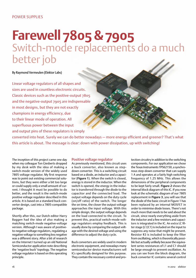
16 Farewell 7805 & 7905Linear voltage regulators of all shapes and sizes are used in countless electronic circuits. The classic 7805 and 7905 devices are not exactly champions in en-ergy efficiency, due to their linear mode of operation. All superfluous power between the input and output pins of these regulators is simply converted into heat. Surely we can do better nowadays — more energy efficient and greener? That’s what this article is about. The message is clear: down with power dis-sipation, up with switching!
46 Electricity on the WebReducing each individual’s carbon footprint has been high on the Global Agen-da for the last couple of years. There are many ways to achieve that, but first and foremost you need to know how much electricity is passing through your meter and emptying your wallet 24/7/365. Why not let the worldwide web and some clever technology help you keep tabs on your electricity consumption?
30 Nixie VU MeterThis circuit is designed to embellish a (tube) amplifier. It supplies delightful light effects rather than a calibrated readout for output power or decibels. At the heart of the circuit is a PSoC from California that’s busy all the time driving two Nixie tubes… from the Ukraine.
22 Embedded Linux Made Easy (5)The Elektor Linux board is proving to be a big hit. The board’s versatility makes it an ideal learning tool and platform for Linux application development. In this instalment we set about reading digital and analogue signals then we hook up a network adapter and build a small web server which generates dynamic HTML pages. Using this we can read the status of remote LEDs amongst other things and display the information in a browser.
74874

Our international teams
6 11-2012 elektor
elektor
The Network
The TeamManaging Editor: Jan Buiting ([email protected])
International Editorial Staff: Harry Baggen, Thijs Beckers, Eduardo Corral, Wisse Hettinga, Denis Meyer, Jens Nickel, Clemens Valens
Design staff: Thijs Beckers, Ton Giesberts, Luc Lemmens, Raymond Vermeulen, Jan Visser
Membership Manager: Raoul Morreau
Graphic Design & Prepress: Giel Dols, Mart Schroijen
Online Manager: Daniëlle Mertens
Managing Director: Don Akkermans
Volume 38, Number 431, November 2012 ISSN 1757-0875
Publishers: Elektor International Media, 78 York Street, London W1H 1DP, United Kingdom. Tel. +44 (0)20 7692 8344 www.elektor.com
the magazine is available from newsagents, bookshops and electronics retail outlets, or on subscription.
elektor is published 11 times a year with a double issue for July & August.
Subscriptions: Elektor International Media, 78 York Street, London W1H 1DP, United Kingdom. Tel. +44 (0)20 7692 8344 , fax: +31 (0)46 43 70 161Internet: www.elektor.com/subsEmail: [email protected]
Rates and terms are given on the Subscription Order Form.
Head Office: Elektor International Media b.v. P.O. Box 11 NL-6114-ZG Susteren The Netherlands.Telephone: +31 (0)46 4389444, Fax: (+31) 46 4370161
Distribution: Seymour, 2 East Poultry Street, London EC1A, England. Telephone:+44 (0)20 7429 4073
UK Advertising: Elektor International Media b.v. P.O. Box 11 NL-6114-ZG Susteren The Netherlands.
Tech the Future explores the solutions for a sustainable future provided by technology,
creativity and science.
United KingdomWisse Hettinga+31 (0)46 [email protected]
USAHugo Vanhaecke+1 [email protected]
GermanyFerdinand te Walvaart+31 46 [email protected]
FranceDenis Meyer+31 46 [email protected]
NetherlandsHarry Baggen+31 46 [email protected]
Spaineduardo Corral+34 91 101 93 [email protected]
ItalyMaurizio del Corso+39 [email protected]
SwedenWisse Hettinga+31 46 [email protected]
BrazilJoão Martins+55 11 4195 [email protected]
PortugalJoão Martins+351 [email protected]
IndiaSunil D. Malekar+91 [email protected]
RussiaNataliya Melnikova+7 (965) 395 33 [email protected]
TurkeyZeynep köksal+90 532 277 48 [email protected]
South AfricaJohan Dijk+27 78 2330 694 / +31 6 109 31 926j.dijk @elektor.com
ChinaCees Baay+86 21 6445 [email protected]
74874

Membership Counter
Partners
AudioXpress www.audioamateur.com . . . . . . . . . . . . . . . . 79
Beta Layout www.pcb-pool.com . . . . . . . . . . . . . . . . . . . 29
Cadsoft www.element14.com . . . . . . . . . . . . . . . . . . 21
DesignSpark www.designspark.com. . . . . . . . . . . . . . . . . . . 2
Eurocircuits www.elektorpcbservice.com . . . . . . . . . . . . . . 75
EzPCB www.siliconray.com . . . . . . . . . . . . . . . . . . . 29
Jackaltac www.jackaltac.com . . . . . . . . . . . . . . . . . . . . 9
Labcenter www.labcenter.com . . . . . . . . . . . . . . . . . . . 88
MikroElektronika www.mikroe.com. . . . . . . . . . . . . . . . . . . . . . 3
Pico Technology www.picotech.com/CM124 . . . . . . . . . . . . . . . 69
Reichelt www.reichelt.co.uk . . . . . . . . . . . . . . . . . . . . 35
7elektor 11-2012
elektor
Contact Johan Dijk ([email protected], +27 78 23 30 694) to reserve your own space for the next edition of our members' magazine
Not a member yet?Sign up at www.elektor.com/member
Telephone: +31 (0)46 43 89 444, Fax: +31 (0)46 43 70 161Email: [email protected]: www.elektor.comAdvertising rates and terms available on request.
Copyright Noticethe circuits described in this magazine are for domestic use only. All drawings, photographs, printed circuit board layouts, programmed integrated circuits, disks, CD-roMs, software carriers and article texts published in our books and magazines
(other than third-party advertisements) are copyright elektor International Media b.v. and may not be reproduced or transmit-ted in any form or by any means, including photocopying, scan-ning and recording, in whole or in part without prior written per-mission from the Publisher. Such written permission must also be obtained before any part of this publication is stored in a retrieval system of any nature. Patent protection may exist in respect of circuits, devices, components etc. described in this magazine. the Publisher does not accept responsibility for failing to identify such patent(s) or other protection. the submission of designs or
articles implies permission to the Publisher to alter the text and design, and to use the contents in other elektor International Media publications and activities. the Publishers cannot guaran-tee to return any material submitted to them.
DisclaimerPrices and descriptions of publication-related items subject to change. errors and omissions excluded.
© Elektor International Media b.v. 2012 Printed in the Netherlands
We now have
members in countries.
• The latest on electronics and information technology
• Hints, tips and interesting offers• In your own mailbox each Friday
• The latest on electronics and • The latest on electronics and information technologyinformation technology
• Hints, tips and interesting offers• Hints, tips and interesting offers• In your own mailbox each Friday • In your own mailbox each Friday
Take out a FREE membership to Elektor Weekly
Register today at www.elektor.com/newsletter
JOIN THE WORLD’S LEADING PLATFORM FOR ELECTRONICS ENGINEERSJOIN THE WORLD’S LEADING PLATFORM FOR ELECTRONICS ENGINEERSJOIN THE WORLD’S LEADING PLATFORM FOR ELECTRONICS ENGINEERS
membersmembersinin countries.countries.83membersmembers
now havenow have 264660
74874
8 11-2012 elektor
INDUSTRY
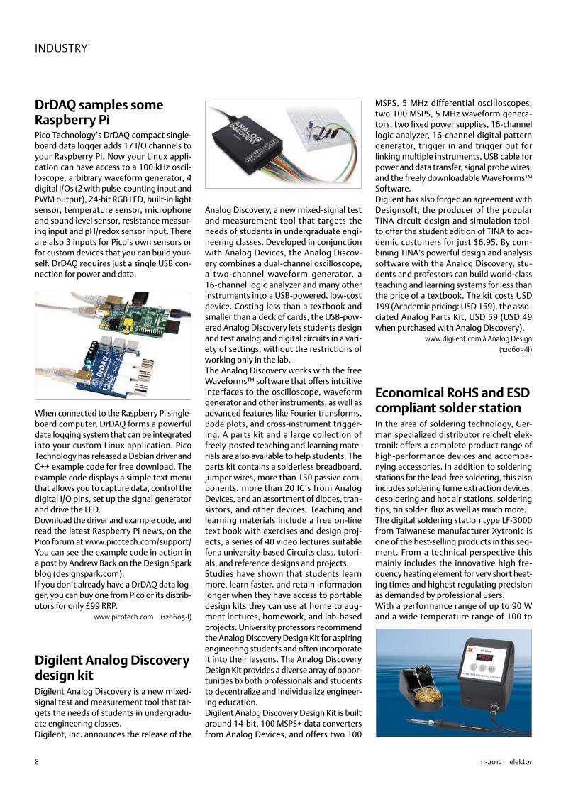
DrDAQ samples some Raspberry PiPico Technology’s DrDAQ compact single-board data logger adds 17 I/O channels to your Raspberry Pi. Now your Linux appli-cation can have access to a 100 kHz oscil-loscope, arbitrary waveform generator, 4 digital I/Os (2 with pulse-counting input and PWM output), 24-bit RGB LED, built-in light sensor, temperature sensor, microphone and sound level sensor, resistance measur-ing input and pH/redox sensor input. There are also 3 inputs for Pico’s own sensors or for custom devices that you can build your-self. DrDAQ requires just a single USB con-nection for power and data.
When connected to the Raspberry Pi single-board computer, DrDAQ forms a powerful data logging system that can be integrated into your custom Linux application. Pico Technology has released a Debian driver and C++ example code for free download. The example code displays a simple text menu that allows you to capture data, control the digital I/O pins, set up the signal generator and drive the LED.Download the driver and example code, and read the latest Raspberry Pi news, on the Pico forum at www.picotech.com/support/You can see the example code in action in a post by Andrew Back on the Design Spark blog (designspark.com).If you don’t already have a DrDAQ data log-ger, you can buy one from Pico or its distrib-utors for only £99 RRP.
www.picotech.com (120605-I)
Digilent Analog Discovery design kitDigilent Analog Discovery is a new mixed-signal test and measurement tool that tar-gets the needs of students in undergradu-ate engineering classes.Digilent, Inc. announces the release of the
Analog Discovery, a new mixed-signal test and measurement tool that targets the needs of students in undergraduate engi-neering classes. Developed in conjunction with Analog Devices, the Analog Discov-ery combines a dual-channel oscilloscope, a two-channel waveform generator, a 16-channel logic analyzer and many other instruments into a USB-powered, low-cost device. Costing less than a textbook and smaller than a deck of cards, the USB-pow-ered Analog Discovery lets students design and test analog and digital circuits in a vari-ety of settings, without the restrictions of working only in the lab. The Analog Discovery works with the free Waveforms™ software that offers intuitive interfaces to the oscilloscope, waveform generator and other instruments, as well as advanced features like Fourier transforms, Bode plots, and cross-instrument trigger-ing. A parts kit and a large collection of freely-posted teaching and learning mate-rials are also available to help students. The parts kit contains a solderless breadboard, jumper wires, more than 150 passive com-ponents, more than 20 IC’s from Analog Devices, and an assortment of diodes, tran-sistors, and other devices. Teaching and learning materials include a free on-line text book with exercises and design proj-ects, a series of 40 video lectures suitable for a university-based Circuits class, tutori-als, and reference designs and projects. Studies have shown that students learn more, learn faster, and retain information longer when they have access to portable design kits they can use at home to aug-ment lectures, homework, and lab-based projects. University professors recommend the Analog Discovery Design Kit for aspiring engineering students and often incorporate it into their lessons. The Analog Discovery Design Kit provides a diverse array of oppor-tunities to both professionals and students to decentralize and individualize engineer-ing education. Digilent Analog Discovery Design Kit is built around 14-bit, 100 MSPS+ data converters from Analog Devices, and offers two 100
MSPS, 5 MHz differential oscilloscopes, two 100 MSPS, 5 MHz waveform genera-tors, two fixed power supplies, 16-channel logic analyzer, 16-channel digital pattern generator, trigger in and trigger out for linking multiple instruments, USB cable for power and data transfer, signal probe wires, and the freely downloadable WaveForms™ Software.Digilent has also forged an agreement with Designsoft, the producer of the popular TINA circuit design and simulation tool, to offer the student edition of TINA to aca-demic customers for just $6.95. By com-bining TINA’s powerful design and analysis software with the Analog Discovery, stu-dents and professors can build world-class teaching and learning systems for less than the price of a textbook. The kit costs USD 199 (Academic pricing: USD 159), the asso-ciated Analog Parts Kit, USD 59 (USD 49 when purchased with Analog Discovery).
www.digilent.com à Analog Design(120605-II)
Economical RoHS and ESD compliant solder stationIn the area of soldering technology, Ger-man specialized distributor reichelt elek-tronik offers a complete product range of high-performance devices and accompa-nying accessories. In addition to soldering stations for the lead-free soldering, this also includes soldering fume extraction devices, desoldering and hot air stations, soldering tips, tin solder, flux as well as much more.The digital soldering station type LF-3000 from Taiwanese manufacturer Xytronic is one of the best-selling products in this seg-ment. From a technical perspective this mainly includes the innovative high fre-quency heating element for very short heat-ing times and highest regulating precision as demanded by professional users.With a performance range of up to 90 W and a wide temperature range of 100 to
74874
9elektor 11-2012
INDUSTRY
520°C, the Xytronic soldering station is ideal for a lead-free soldering in accordance with RoHS standards. Due to a zero-voltage control circuit that is electrically isolated from the Ac power line, even electrostati-cally sensitive components can be soldered safely and damage free. An equipotential bonding socket furthermore enables ESD compliant operation. The soldering iron that is supplied as standards works with 36 V low voltage and is equipped with an internally heated soldering tip with inte-grated temperature sensor for a high regu-lating precision of ± 3°C.
www.reichelt.de (120605-III)
HiPer SimulationTM AFS and enhanced T-Spice HiPer SiliconTM v15.23
Tanner EDA has released version 15.23 of its full-flow analog and mixed-signal design suite: HiPer SiliconTM. The addition of HiPer SimulationTM AFS to version 15.23 gives designers added capabilities for front-end design flow, including schematic capture, dual circuit simulators and waveform probing.HiPer Silicon version 15.23 includes Tanner Analog FastSPICE (T-AFS), which integrates the Berkeley Design Automation Analog Fast-SPICE Platform with Tanner EDA’s S-EditTM schematic capture an≠d W-EditTM wave-form analyzer. With HiPer Simulation AFS, two Spice simulators deliver the ultimate in performance and productivity, even for large netlists. T-Spice provides fast, accurate anal-ysis while T-AFS delivers accuracy with run-times 5x to 10x faster than traditional Spice
Advertisement
simulators, on a single core. Users can drive the T-AFS simulator directly from S-Edit, get-ting the speeds and accuracy necessary for nanometer design. Simulation results are displayed automatically in W-Edit for view-ing, measuring, and analyzing interactively.For additional information on T-AFS or a product datasheet, please see the website
below. As always, Tanner EDA offers a free 30-day evaluation.Version 15.23 also adds new TCL commands to S-Edit, supporting greater functionality. And T-Spice now supports the HiSIM-HV model. Integration with Berkeley Design Automation transient noise analysis capability allows users to simulate realistic device noise effects for all circuits, especially non-periodic circuits such as sigma-delta ADCs and frac-N PLLs.
www.tannereda.com/tafs (120605-VI)
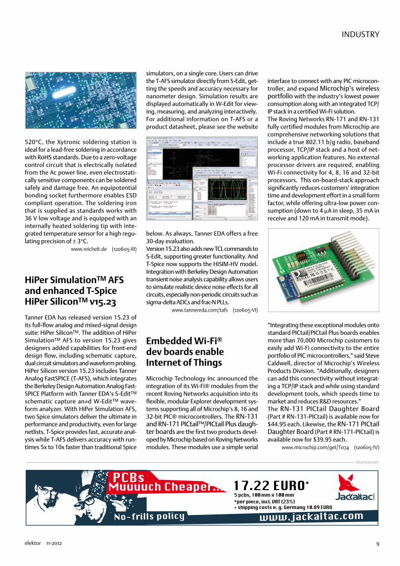
Embedded Wi-Fi® dev boards enable Internet of Things
Microchip Technology Inc announced the integration of its Wi-Fi® modules from the recent Roving Networks acquisition into its flexible, modular Explorer development sys-tems supporting all of Microchip’s 8, 16 and 32-bit PIC® microcontrollers. The RN-131 and RN-171 PICtail™/PICtail Plus daugh-ter boards are the first two products devel-oped by Microchip based on Roving Networks modules. These modules use a simple serial
interface to connect with any PIC microcon-troller, and expand Microchip’s wireless portfolio with the industry’s lowest power consumption along with an integrated TCP/IP stack in a certified Wi-Fi solution.The Roving Networks RN-171 and RN-131 fully certified modules from Microchip are comprehensive networking solutions that include a true 802.11 b/g radio, baseband processor, TCP/IP stack and a host of net-working application features. No external processor drivers are required, enabling Wi-Fi connectivity for 4, 8, 16 and 32-bit processors. This on-board-stack approach significantly reduces customers’ integration time and development effort in a small form factor, while offering ultra-low power con-sumption (down to 4 µA in sleep, 35 mA in receive and 120 mA in transmit mode).
“Integrating these exceptional modules onto standard PICtail/PICtail Plus boards enables more than 70,000 Microchip customers to easily add Wi-Fi connectivity to the entire portfolio of PIC microcontrollers,” said Steve Caldwell, director of Microchip’s Wireless Products Division. “Additionally, designers can add this connectivity without integrat-ing a TCP/IP stack and while using standard development tools, which speeds time to market and reduces R&D resources.”The RN-131 PICtail Daughter Board (Part # RN-131-PICtail) is available now for $44.95 each. Likewise, the RN-171 PICtail Daughter Board (Part # RN-171-PICtail) is available now for $39.95 each.
www.microchip.com/get/T074 (120605-IV)
74874

10 11-2012 elektor
INDUSTRY
Electrical Storm Proximity Measurement
The US maintains detailed weather and accident reports that provide a long-term record of the risk to human life posed by lightning. Since 1940, approximately 30% more people have been killed by lightning than by hurricanes (according to the US’s NOAA National Weather Service). Accurate weather forecasts nowadays help people to take precautions when there is a high risk of storms, and fatalities number fewer than 50 per year in the US on average. But every death is one too many, and in addi-tion the injuries and equipment losses caused by lightning strikes (detailed at www.struckbylightning.org) exact a con-siderable toll on those unlucky enough to live in a region prone to violent storms. In addition, Chinese scientists have warned that global warming is likely to intensify extreme weather patterns, and severe storms in recent years may be a prelude to this (China Meteorological Administration, July 30, 2007).
Yet the death and damage attributable to lightning is largely avoidable, if people have sufficient warning of an approaching light-ning storm. According to the so called “30-30 rule”, if the time between the lightning and the thunder is less than 30 seconds, people should get under cover for at least 30 minutes. And if you hear thunder, you are probably already in danger. The human senses are not well equipped to perceive the onset of a lightning storm. A delay of 30 seconds between lightning and thunder corresponds to a distance of about 10 km (6 miles) from the strike (since the speed of sound in air is about 300m/s); this is about the furthest distance at which humans can hear thunder in a quiet environment with-out any physical obstacles baffling the sound. In case of physical obstacles and/or a high level of ambient noise (such as traffic, crowds) this distance can be reduced to just a few kilometres.
Exacerbating the problem, it is typical for lightning to strike the ground not vertically but on a diagonal, over a horizontal span
which can stretch as far as 10 km; this is the biggest limitation of the 30-30 rule. Since people can only hear thunder at a maximum distance of 10 km, it is clear that reliance on unaided human senses poses a considerable risk to both life and property.
Electromagnetic propagation (EMP) in lightningAs early as the 19th century, Alexander Stepanovic Popov noticed that it was pos-sible to detect lightning using a simple AM radio receiver; this was the first electrical system capable of predicting a storm.In fact, lightning emits electromagnetic energy from very low frequencies up to X-ray bands. The intensity of the EMP phe-nomenon displays 1/f behaviour: the emis-sions are at their strongest at low kHz fre-quencies, and weaken as frequency rises. Using a simple system with an amplifier, down-mixer and a low-pass filter, Popov was able to hear the signal produced by lightning.Similar technology is still in use today in personal lightning detectors (or ‘lightning counters’) sold to consumers. Although the American Meteorological Society does not recognise the reliability or value of these portable devices, lightning counters can, in the right conditions, detect lightning within a small area. But these rudimentary devices are of limited use, since they can-
not estimate the distance from the head of the storm, nor can they reliably differentiate lightning from sources of interference such as microwave ovens, fluorescent ballasts, motors, car engines and camera flashes. Furthermore, as those systems are based on discrete solutions they are not optimized for current consumption and the battery life is limited to a couple of weeks.What is needed to provide consumers with a reliable and timely warning to protect themselves is a personal device that accu-rately estimates the distance from a storm over a distance of 30 km (19 miles) or more, and that reliably distinguishes lightning sig-nals from other sources of EMP.
Use of narrowband systems in lightning detectionThere are two kinds of lightning: cloud-to-ground and intra-cloud. In terms of electro-magnetic analysis, the huge currents gen-erated in storms produce wideband signals across a large spectrum. Monitoring such a wide frequency range is next to impossi-ble with a portable, consumer device. For-tunately, since Popov’s experiments it has been known that a narrowband system can pick up signals from lightning. But how accurate is this narrowband signal?In fact, lightning is a complex combina-tion of several different events: break-down, return strike, in-cloud activity, and
By Ruggero Leoncavallo, System Engineer, ams AG
Figure 1. Comparison of broadband and narrowband signals
74874

11elektor 11-2012
ElEcTRIcal SToRm PRoxImITY mEaSUREmENT
Using simple narrowband RF technique
subsequent strike. The scientific literature (Le Vine, D.M., ‘Review of Measurements of the RF Spectrum of Radiation from Light-ning’, 1987) establishes that it is possible to detect lightning with a narrowband system, even if some detail in the shape of the signal is lost. As Figure 1 shows, there is a close match between the broadband electric field and the signal picked up with a narrowband receiver at 500kHz.Le Vine’s paper also shows that lightning’s emissions peak at around 5kHz and drop as a function of 1/f. So if the centre fre-quency of a narrowband receiver is set too high, the received signal strength falls to the point at which it is hard to distinguish it from other, interfering sources of EMP. Signal strength is much greater at a low frequency; at very low frequencies, how-ever, the antenna becomes too bulky to be accommodated in a portable device. There is therefore a trade-off between sig-nal strength and device size, with the most suitable frequencies being between a few hundred kHz up to a few MHz.
Pattern matching software produces reliable distance measurementsIn line with Popov’s findings, then, a low frequency receiver can sense the emissions from lightning strikes. But the bigger chal-lenge in producing a reliable and useful
lightning detector is:•to reject signals from other emitters;•to estimate accurately the distance from
a storm.
Now, ams (formerly: ‘austriamicrosystems’) have developed suitable technology which is implemented in its AS3935 Storm Detec-tor IC. This technology, which is effective for both cloud-to-ground and intra-cloud light-ning, uses algorithms which analyse incom-ing signals and compare their shape to the typical shape of a lightning strike’s wave-form. Exhaustive effort has gone into tuning the algorithm so that it provides an excel-lent balance between rejection of interfer-ence from other emitters, and recognition of genuine signals emitted by lightning.A dedicated hardwired algorithm imple-mented in the AS3935 is also able to derive accurate distance estimations from analysis of the energy of the signal detected by the IC’s RF front end.
Figure 2 shows a block diagram of the AS3935. Like the Popov system, it moni-tors the LF bands (500 kHz – 2 MHz) to detect the strong 1/f signature characteris-tic of lightning. The system includes an Ana-logue Front-End (AFE), which amplifies the input signal picked up by the antenna and transfers it to the baseband, while filtering it for back-end numerical elaboration. The
lightning algorithm block consists of three stages: signal validation, energy calculation and statistical distance estimation.The first block checks the pattern of the incoming signal and rejects manmade noise. As shown in Figure 1, a typical light-ning signal goes high very fast and declines smoothly after the peak. The flexible algo-rithm in the AS3935 allows optimisation by the end user of the trade-off between lightning detection effectiveness on the one hand and disturber rejection on the other.If the received signal is judged to be light-ning, the second block performs an energy calculation. This calculation is then ana-lysed in the last block, which makes an assessment of the distance to the head of the storm based on data collected during the whole storm. The distance estimation is provided in kilometres with a variable resolution between 1 km (0.8 miles) and 4 km (2.5 miles). (The estimate becomes more accurate as the storm draws closer to the instrument.)
The performance of the AS3935 has been tested by the Florida Institute of Technology at Melbourne, US and compared to the offi-cial lightning data provided by the National Lightning Detection Network (NLDN) in the US, which is regarded as the gold standard for lightning monitoring (see Figure 3).
(120541)
Voltage Regulator
POR
Register
I2CSPI
Bias Block
Noise Floor Level
GenerationNoise Floor Evaluation
Signal ValidationWatch dog
Statistical Distance Estimation
LC-oscillator
Calibration
TRCO SRCO
I2C_ADD
VDD VREG
ACG
IRQ
GND
EN_VREGI2CD/
MISO
MISOI2CL/
SCL
SS
Lightning Algorithm
Energy Calculation
ADD0 ADD1SINT
INPINN
AFETEST
Clock Generators
Figure 3. Comparison of lightning monitoring outputs from the AS3935 and the gold-standard NLDN data. This shows that the output from the AS3935 closely matches that of the NLDN’s sophisticated radar-based systems. The horizontal axis represents the number
of lightning strikes.
Figure 2. Block diagram of AS3935 Storm Detector.
74874

12 11-2012 elektor
By the Elektor Editorial Team: Jan Buiting (Elektor UK & USA), Jens Nickel (Elektor Germany), Harry Baggen (Elektor Netherlands) and Denis Meyer (Elektor France)
Elektor is poised for the future and ready to rejuvenate itself, starting next month. Our rock
solid foundation will remain the level of respect for what the joint team has achieved over the
past years. Our readers, website visitors and clients can continue to expect service, reliability
and expertise. Elektor holds its position as one of the leading portals, platforms and forums
for electronic engineers all over the globe. The means to reach our readers, as well as the
accessibility of our services, are upped to match today’s requirements and beyond.
Elektor today is much more than a just these printed pages. Still, staples and ink is where we started from. Many members of the Elektor community consider themselves a subscriber first and foremost. Some have been with us for 25+ years, others for just a few months. Many of you buy the magazine occasionally from bookstores if a project or article is announced that matches your particular interest. Others may remember Elektor magazine as their vehicle to a professional career in electronics many years ago. We are equally happy to guide readers if they are students, or inform and support them in their professional capacity.
Along the way Elektor’s services have expanded vastly, by popular request or simply prompted by time. We are sure you have seen our website at least once, or bought a PCB or kit from our shop. We would not be surprised to see one of our 30x Circuit editions on your bookshelf, or find your name on the list of participants to one of our webinars or international design contests. We may even have published one of your projects for all & sundry to enjoy and learn from.
Meanwhile the electronics industry has discovered what’s cooking at Elektor. Manufacturers are actively seeking to contact you by way of us, for beta testing, sampling, competitions and information exchange. In some case, even for job opportunities.
Increasingly electronics enthusiasts get to know Elektor by way of media other than the magazine that has built our name and fame.
You may not realise it, but you are part of a 300 Kpeople network spanning 80 countries. Our websites welcome visitors from 243 countries.
Summarising, Elektor has developed into an international community of electronics aficionados. Indeed, way beyond the limits of printed paper. Consequently we will no longer use the terms ‘reader” or “subscriber” and switch to “member” instead. To underscore that the times are well past when we reached our members with a printed-only product, and that the Internet offers fantastic opportunities for us to employ for our services, we are introducing the ELEKTOR.COMMUNITY.
Here’s the bill of materials and the schematic!
elektor labsA new dedicated website is available where you can leave proposals for projects, present your own projects to peers, follow its progress, as well as reel in finished and tried & tested stuff. Elektor.LABS. A beta version of this website has been online for some time already under the name Projects. Elektor.LABS is Elektor’s throbbing heart, where projects are being proposed to, and get developed by, you and the community — where knowledge is shared, enjoyed and acquired.
elektor communityAt www.elektor.com a single portal, homepage, central website, exists called Elektor.COMMUNITY from which you can access our
74874

13elektor 11-2012
(WAY) BEYOND PRINTED PAPER
shop Elektor.STORE, our archive Elektor.FILES and a number of FORUMS. The structure offers all of Elektor’s traditional ‘counters’ like for tracing old articles and components, ordering books or kits, extending your membership, and so on.As before, you can access all sections directly too.
elektor magazineAs of now the printed magazine will be called Elektor.MAGAZINE, appearing 8 times per year. Although it has a restyled layout, a new logo and new sections, Elektor.MAGAZINE continues to bring you the best-of-market number of circuits and projects. In addition to the extra thick Projects Generator edition to cover the summer months, you will receive another ‘jumbo’ magazine at the start of the year. In green fashion the magazine is also downloadable in its entirety. In total you receive 10 editions per year.
elektor postThe scope of our new mail service called Elektor.POST is beyond that of the current E-weekly newsletter, which remains in place to deliver newsletters on a regular basis, videos, offers and invitations to webinars and competitions. To that, Elektor.POST adds an exclusive two-weekly project that will automatically reach you by email.
That’s 25 extra projects per year, delivered by email.
For whom?The traditional subscription is replaced by a membership, comprising:
•Eight editions per year of the restyled and restructured magazine with the traditional number of circuits and projects enhanced and extended with new sections and elements.
•Two editions per year of the ‘jumbo’ version of Elektor.
•Elektor Year Volume stored on your membership card.
•A minimum of 10 per cent discount on all products and services in Elektor.STORE.
•Printed circuit board availability for every Elektor project; with a discount of 10 per cent minimum for members.
•Direct access to Elektor.LABS
•Elektor.POST sent to your email account
•A GOLDCARD membership card that comes as a USB card loaded with a solid amount of goodies.
Alternatively, we offer the all-paperless GREENCARD membership card, which delivers all products and services, including Elektor.MAGAZINE, online only.
If your current subscription is about to expire, you will receive a personal message in which all changes and options are explained in detail. With that message comes an offer for your new membership that’s hard to refuse.
74874

14
ELEKTOR
Welcome in !Hello! Nice to see so many of you here for this tour of Elektor.LABS. Today .LABS is open to
everyone, but if you want to come back later, you will need a membership card or an invitation.
Then you can visit Elektor.LABS whenever you like. My name is CPV and I will be your guide.
Please follow me.
Elektor LABS is the place where the real electronics action is. Forget accounting or management, .LABS, or dot-labs as we pronounce it, is the throbbing heart of your favourite electronics community bet-ter known as Elektor. The people who work in .LABS are not only as attractive as our secretaries, but they also know way more about electronics.
Here on my right for instance (your left) we have Ton G. as in “Gee Ton, that sounds amazing!” Although he doesn’t like to brag about it, Ton is a highly gifted audio ampli-
fier designer and he literally overflows with knowledge and expe-rience. If you have a question, ask Ton. We do too.
Over there in the far corner we have Luc or Lucky Luc. Please all say hi to Luc. [Hi Luc!] We call him Lucky Luc because he always gets his projects working. Don’t ask me how he does it, he just does it. Luc is a kind of quiet guy full of hidden depths littered with electronics nuggets. If you talk to him gently he will give you some of them.
Then we have Raymond or Raving Ray as we like to say. Contrary to Ton and Luc, Raymond is always raving about new tech-
nologies and chips. He sucks up product information like a sponge and spills wild ideas like a regular BP oil well in the Gulf of Mexico. Looking for a new field-program-mable doohicky?
Ask Raving Ray.
elektor labs
74874
15elektor 11-2012
Welcome in elektor lABS!
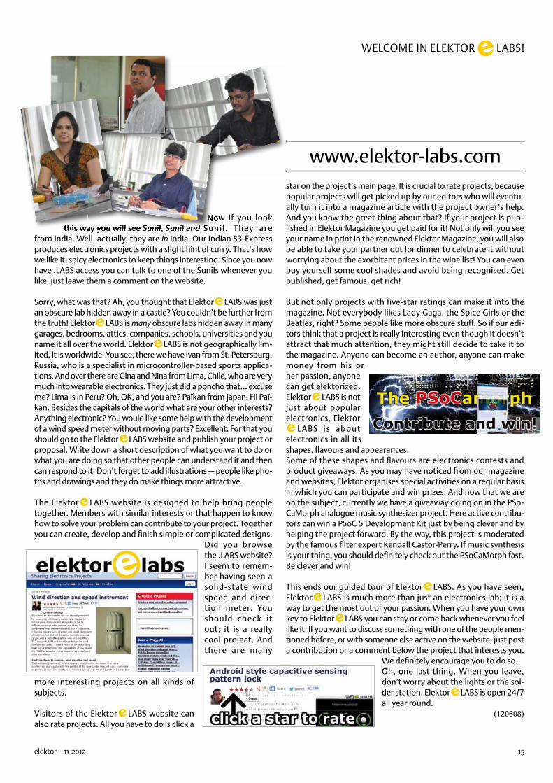
Now if you look this way you will see Sunil, Sunil and Sunil . They are
from India. Well, actually, they are in India. Our Indian S3-Express produces electronics projects with a slight hint of curry. That’s how we like it, spicy electronics to keep things interesting. Since you now have .LABS access you can talk to one of the Sunils whenever you like, just leave them a comment on the website.
Sorry, what was that? Ah, you thought that Elektor LABS was just an obscure lab hidden away in a castle? You couldn’t be further from the truth! Elektor LABS is many obscure labs hidden away in many garages, bedrooms, attics, companies, schools, universities and you name it all over the world. Elektor LABS is not geographically lim-ited, it is worldwide. You see, there we have Ivan from St. Petersburg, Russia, who is a specialist in microcontroller-based sports applica-tions. And over there are Gina and Nina from Lima, Chile, who are very much into wearable electronics. They just did a poncho that… excuse me? Lima is in Peru? Oh, OK, and you are? Païkan from Japan. Hi Paï-kan. Besides the capitals of the world what are your other interests? Anything electronic? You would like some help with the development of a wind speed meter without moving parts? Excellent. For that you should go to the Elektor LABS website and publish your project or proposal. Write down a short description of what you want to do or what you are doing so that other people can understand it and then can respond to it. Don’t forget to add illustrations — people like pho-tos and drawings and they do make things more attractive.
The Elektor LABS website is designed to help bring people together. Members with similar interests or that happen to know how to solve your problem can contribute to your project. Together you can create, develop and finish simple or complicated designs.
Did you browse the .LABS website? I seem to remem-ber having seen a solid-state wind speed and direc-tion meter. You should check it out; it is a really cool project. And there are many
more interesting projects on all kinds of subjects.
Visitors of the Elektor LABS website can also rate projects. All you have to do is click a
star on the project’s main page. It is crucial to rate projects, because popular projects will get picked up by our editors who will eventu-ally turn it into a magazine article with the project owner’s help. And you know the great thing about that? If your project is pub-lished in Elektor Magazine you get paid for it! Not only will you see your name in print in the renowned Elektor Magazine, you will also be able to take your partner out for dinner to celebrate it without worrying about the exorbitant prices in the wine list! You can even buy yourself some cool shades and avoid being recognised. Get published, get famous, get rich!
But not only projects with five-star ratings can make it into the magazine. Not everybody likes Lady Gaga, the Spice Girls or the Beatles, right? Some people like more obscure stuff. So if our edi-tors think that a project is really interesting even though it doesn’t attract that much attention, they might still decide to take it to the magazine. Anyone can become an author, anyone can make money from his or her passion, anyone can get elektorized. Elektor LABS is not just about popular electronics, Elektor
LABS is about electronics in all its shapes, flavours and appearances.Some of these shapes and flavours are electronics contests and product giveaways. As you may have noticed from our magazine and websites, Elektor organises special activities on a regular basis in which you can participate and win prizes. And now that we are on the subject, currently we have a giveaway going on in the PSo-CaMorph analogue music synthesizer project. Here active contribu-tors can win a PSoC 5 Development Kit just by being clever and by helping the project forward. By the way, this project is moderated by the famous filter expert Kendall Castor-Perry. If music synthesis is your thing, you should definitely check out the PSoCaMorph fast. Be clever and win!
This ends our guided tour of Elektor LABS. As you have seen, Elektor LABS is much more than just an electronics lab; it is a way to get the most out of your passion. When you have your own key to Elektor LABS you can stay or come back whenever you feel like it. If you want to discuss something with one of the people men-tioned before, or with someone else active on the website, just post a contribution or a comment below the project that interests you.
We definitely encourage you to do so.Oh, one last thing. When you leave, don’t worry about the lights or the sol-der station. Elektor LABS is open 24/7 all year round.
(120608)
www.elektor-labs.com
Now if you look Now if you look this way you will see Sunil, Sunil and this way you will see Sunil, Sunil and Sunil . They are Sunil . They are this way you will see Sunil, Sunil and this way you will see Sunil, Sunil and this way you will see Sunil, Sunil and this way you will see Sunil, Sunil and
74874
16 11-2012 elektor
POWER SUPPLIES
Farewell 7805 & 7905 Switch-mode replacements do a much better job
The inception of this project came one day when my colleague Ton Giesberts dropped by my desk with the idea of making a switch-mode version of the widely used 7805 voltage regulator. My first response was to point out existing commercial solu-tions, but they were either a bit too large or could supply only a small amount of cur-rent. I thought it must be possible to do better, and the result is the switch-mode positive voltage regulator described in this article. It is based on a standard buck con-verter design, cast into a 7805-compatible package.
Shortly after this, our Dutch editor Harry Baggen had the idea of also making a matching switch-mode negative-voltage version. Although I was aware of positive-to-negative voltage regulators, regulating a negative voltage to something less negative was a different story. After a bit of research on the Internet I turned up an old National Semiconductor application note describing the ‘negative buck’ topology. The negative voltage regulator is based on this operating principle.
Positive voltage regulatorAs previously mentioned, this circuit uses a buck converter, also known as step-down converter. This is a switching circuit based on a diode, an inductor and a capaci-tor (Figure 1). When the switch is closed, energy is stored in the inductor. When the switch is opened, the energy in the induc-tor is transferred through the diode to the capacitor and the connected load. The output voltage depends on the duty cycle (on/off ratio) of the switch. The longer the on time, the closer the output voltage approaches the input voltage. With this simple design, the output voltage depends on the load connected to the circuit. To prevent this, practical switch-mode volt-age regulators employ feedback. This is usually done by comparing the output volt-age with the desired voltage and using the difference to adjust the duty cycle.
Buck converters are widely used in modern electronic equipment, and nowadays many semiconductor device manufacturers sell ICs specifically designed for this purpose. They contain the necessary control and pro-
tection circuitry in addition to the switching components. For our application we chose the Texas Instruments TPS62150, a synchro-nous step-down converter that can supply 1 A and operates at a fairly high switching frequency of 1.25 MHz. This allows the dimensions of the peripheral components to be kept fairly small. Figure 2 shows the internal block diagram of this IC. If you now look at the schematic diagram of our 7805 replacement in Figure 3, you will see that the diode of the basic circuit in Figure 1 has been replaced by an internal MOSFET in order to minimise diode losses. There’s not much more that needs to be said about the circuit, since nearly everything aside from the inductor and a few resistors and capaci-tors is integrated in the IC. An extra LC fil-ter stage (L1/C1) is included on the input to suppress any noise that might be present. Resistor R3 is included to keep the filter from oscillating, which is theoretically possi-ble but actually unlikely because the equiva-lent series resistances of L1 and C1 should be large enough to prevent oscillation. As you can see from the block diagram, the buck converter IC contains several control
By Raymond Vermeulen (Elektor Labs)
Linear voltage regulators of all shapes and
sizes are used in countless electronic circuits.
Classic devices such as the positive-output 7805
and the negative-output 7905 are indispensable
in most designs, but they are not exactly
champions in energy efficiency, due
to their linear mode of operation. All
superfluous power between the input
and output pins of these regulators is simply
converted into heat. Surely we can do better nowadays — more energy efficient and greener? That’s what
this article is about. The message is clear: down with power dissipation, up with switching!
74874

17elektor 11-2012
SWITCH-MODE 7805/7905
circuits that precisely regulate the output voltage, so that only minimal undershoots or overshoots occur in response to fast load changes (‘load steps’).
The components have been specifically cho-sen with an eye to the size of the overall cir-cuit. The dimensions of the TO-220 package are rather loosely specified and vary from one make to the next. We chose values roughly in the middle for our design, with a package size of 15.5 × 10.1 × 4.75 mm. Here the space normally occupied by the metal tab is part of the circuit board. This means that the device cannot be screwed to a heat sink like a normal 7805, but that is not nec-essary due to the low power dissipation of the switch-mode voltage regulator. Alterna-tive resistor values for output voltages other than 5 V are listed in Table 1.
The PCB layout is an important factor for switch-mode voltage regulators. Figure 4 shows the PCB layout for the positive volt-age regulator. The basic rules generally applicable to PCBs of this sort are that cir-cuit loops with large current variations should be kept as small as possible, while circuit loops with large voltage variations should have as little copper area as pos-sible. Since our device must anyhow be made small, these rules fit nicely with our mechanical constraints.
In terms of performance, the switch-mode regulator can hold its own against a normal 7805: the maximum input voltage is 17 V
Technical specificationsPositive voltage regulator
•Output voltage +5 V (adjustable with two resistors)
• Input voltage range 6 to 17 V•Maximum output current 1 A•Maximum output ripple 80 mVpp at 17 V
in and 1 A out•Dimensions and pinout identical to
standard 7805
Negative voltage regulator
•Output voltage –5 V (adjustable with two resistors)
• Input voltage range –6 to –17 V•Maximum output current 0.85 A•Maximum output ripple 36 mVpp at –17 V
in and 0.85 A out•Dimensions and pinout identical to
standard 7905
Off
On
120212 - 13
Figure 1. Block diagram of the buck converter topology.
control logic
Softstart
ThermalShtdwn
UVLO PG control
powercontrol
erroramplifier
gatedrive
HS lim
LS lim
PVINPVINAVINPG
PGNDPGNDAGND
comp
comp
+
_timer t ON
DCS - Control TM
direct control&
compensation
comparator
ramp
SW
SW
SW
EN*
SS/TR
DEF*
FSW*
VOS
FB
* This pin is connected to a pull down resistor internally(see Detailed Description section).
EXPO
SED
PAD
TPS62150
SS/TR
AGND
IC1
PVINPVIN
PGND
PGND
AVINVOSFSW
DEF
SW1112 SW
SW
17 15 16
14
PGFB
10
13 EN
6
123
7
45
9
8
L2
3uH3
L1
100nH
C3
3n325V
C4
100n25V
C1
10u25V
R1
430k
R3
100m
R2
82k
C2
22u6V3
1
2
3K1
120212 - 11
VIN VOUT
GND
Figure 2. Internal block diagram of the TPS62150.
Figure 3. Schematic diagram of the positive voltage regulator.
74874

18 11-2012 elektor
POWER SUPPLIES
and the output can certainly deliver 1 A. The standard capacitors usually present with a 7805 configuration can be left as they are with an existing PCB design. However, you can omit them in new designs without any problems.Figure 5 shows the efficiency of the switch-mode positive voltage regulator at various
input voltages and output currents. At low input voltages the efficiency is around 95% for output currents up to 250 mA. It drops to around 85% at the maximum allowable input voltage. At the maximum output cur-rent level, the efficiency is roughly 90% over virtually the entire input voltage range.The response of this circuit to a sudden change in load, or load step, is especially interesting. For this we put together a test setup that switches between 10% and 85% of the maximum load at a rate of 50 kHz with 50% duty cycle. The measured output voltage is shown in Figure 6. The large spike is mainly due to the location of the test probe and the leads. The test setup does not represent a realistic load situation, but instead a sort of worst case. In normal use the spike at the output will be much smaller.
Negative voltage regulatorWith the positive voltage regulator the circuit design and the component values are fairly close to the description in the
Table 1. Resistance values for various output voltages (positive voltage regulator).
Uuit R1 R2
5.0 V 430 k 82 k
3.3 V 256 k 82 k
2.5 V 174 k 82 k
1.8 V 102 k 82 k
1.5 V 72 k 82 k
1.2 V 41 k 82 k
Figure 5. Measured efficiency of the positive voltage regulator at 250 mA (a) and 1 A (b) output current. Blue = switch-mode voltage regulator; red = standard 7805.
COMPONENT LISTpositive voltage regulator
ResistorsR1 = 430kΩ 1%/0.1 W, SMD 0402R2 = 82kΩ 1%/0.1 W, SMD 0402R3 = 0.1Ω 1%/0.1 W, SMD 0402
CapacitorsC1 = 10µF 25 V, X5R, SMD 0805 (e.g.
TMK212BBJ106KG-T)C2 = 22µF 6.3 V, X5R, SMD 0805 (e.g.
JMK212BJ226MG-T)C3 = 3.3nF 25V, X7R, SMD 0402C4 = 100nF 25V, X5R, SMD 0402
InductorsL1 = 100nH, SMD 0805 (e.g.
MLZ2012DR10D)L2 = 3.3µH, 4x4 mm (e.g.
NRS4018T3R3MDGJ)
Figure 4. Double-sided PCB layout for the positive voltage regulator.
(200%)
0.00%5.00%
10.00%15.00%20.00%25.00%30.00%35.00%40.00%45.00%50.00%55.00%60.00%65.00%70.00%75.00%80.00%85.00%90.00%95.00%
100.00%
0 2 4 6 8 10 12 14 16 18
eff (%
)
Uin(V)
Rload = 20.3Ω
0.00%5.00%
10.00%15.00%20.00%25.00%30.00%35.00%40.00%45.00%50.00%55.00%60.00%65.00%70.00%75.00%80.00%85.00%90.00%95.00%
100.00%
0 2 4 6 8 10 12 14 16 18
eff(%
)
Uin(V)
Rload = 4.727Ω
Figure 6. Response to pulsed load.
74874

19elektor 11-2012
SWITCH-MODE 7805/7905
data sheet for the IC used in the circuit, but things are distinctly different with the negative voltage regulator. There are lots of ICs available for switch-mode power supplies that boost or buck the input volt-age or invert the polarity, but there are no switch-mode regulator ICs available that convert a negative voltage to a lower nega-tive voltage. However, as mentioned earlier we found a description on the Internet for a circuit that can handle this task.
It is based on a boost converter connected ‘the wrong way round’, in what is called a negative buck converter topology. If you take a close look at the circuit diagram of the negative voltage regulator in Figure 8, you may think that the pin designations are mixed up, since circuit ground is con-nected to the Vin pin of the IC and the nega-tive input voltage is connected to the GND pin. This allows a negative input voltage to be converted to a less negative regulated output voltage.
However, we have a problem here with the feedback circuit, since we have to reference the feedback signal to the GND pin of the IC in this unusual configuration. If we used a normal voltage divider for this, the resis-tor ratio would depend on the input voltage relative to the VCC pin. This means that the circuit would only work properly at a spe-cific input voltage. We solved this problem by using a MAX4073 current shunt monitor IC for the feedback signal. it converts the output voltage level relative to GND to a voltage referenced to Vin.
For the boost converter IC we looked for a device that could handle a high input volt-age but was nevertheless small enough for this application. We ultimately chose the Texas Instruments TPS61170 (Figure 7). In can handle up to 20 V between Vin and GND.Despite the unusual arrangement, virtually the same formulas can be used here as for a standard buck converter. The input and output LC filters from the positive voltage regulator design can also be reused for the negative voltage regulator.
All in all, this yields a design that is small enough to fit on a PCB with the same
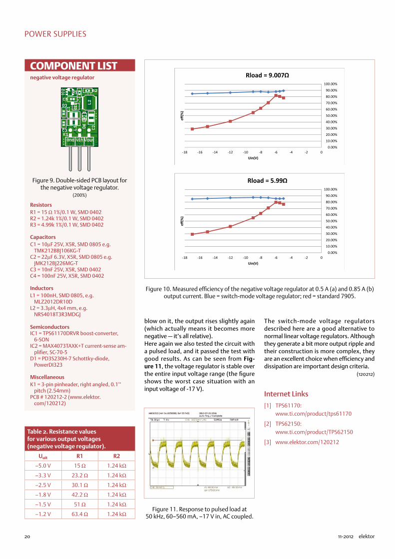
dimensions as a standard 7905 IC (see Fig-ure 9). Here as well, other output voltages can be obtained by adjusting the resistor values for the voltage divider (see Table 2).
The performance of this unusual arrange-ment is very good. As can be seen from Figure 10, the efficiency is a good deal
better than with a normal 7905. However, the maximum output current is lower than with the positive voltage regulator. This is due to the built-in current limiting of the TPS61170. In practice, it turns out that the current limit of the negative voltage regu-lator is somewhat temperature dependent. When it’s on the edge of limiting and you
SW
RampGenerator
Oscillator
CurrentSensor
CTRL
GND
+
FB
ErrorAmplifer
2
1
Vin
4
6
SoftStart-up
5
3
COMP
L2
3uH3
D1
PD3S230H-7
C4
100n25V
C3
10n
TPS61170
EXPO
SED
IC1
CTRL
COMP VIN
GND PAD
FB
SW
1
6
5
43
2R34k99
C1
10u25V
C2
10u25V
R2
1k24
R1
15R
L1
100nH
1
2
3
K1VIN
VOUT
GND
MAX4073T
IC2
VCC
OUT
RS–GND
RS+
1
3
5
2
4
120212 - 12
Figure 7. Internal block diagram of the TPS61170.
Figure 8. Schematic diagram of the negative voltage regulator.
74874
20 11-2012 elektor
POWER SUPPLIES
blow on it, the output rises slightly again (which actually means it becomes more negative — it’s all relative).Here again we also tested the circuit with a pulsed load, and it passed the test with good results. As can be seen from Fig-ure 11, the voltage regulator is stable over the entire input voltage range (the figure shows the worst case situation with an input voltage of -17 V).
The switch-mode voltage regulators described here are a good alternative to normal linear voltage regulators. Although they generate a bit more output ripple and their construction is more complex, they are an excellent choice when efficiency and dissipation are important design criteria.
(120212)
Internet Links
[1] TPS61170: www.ti.com/product/tps61170
[2] TPS62150: www.ti.com/product/TPS62150
[3] www.elektor.com/120212
Table 2. Resistance values for various output voltages (negative voltage regulator).
Uuit R1 R2
–5.0 V 15 Ω 1.24 kΩ
–3.3 V 23.2 Ω 1.24 kΩ
–2.5 V 30.1 Ω 1.24 kΩ
–1.8 V 42.2 Ω 1.24 kΩ
–1.5 V 51 Ω 1.24 kΩ
–1.2 V 63.4 Ω 1.24 kΩ
COMPONENT LISTnegative voltage regulator
ResistorsR1 = 15 Ω 1%/0.1 W, SMD 0402R2 = 1.24k 1%/0.1 W, SMD 0402R3 = 4.99k 1%/0.1 W, SMD 0402
CapacitorsC1 = 10µF 25V, X5R, SMD 0805 e.g.
TMK212BBJ106KG-TC2 = 22µF 6.3V, X5R, SMD 0805 e.g.
JMK212BJ226MG-TC3 = 10nF 25V, X5R, SMD 0402C4 = 100nF 25V, X5R, SMD 0402
InductorsL1 = 100nH, SMD 0805, e.g.
MLZ2012DR10DL2 = 3.3µH, 4x4 mm, e.g.
NRS4018T3R3MDGJ
SemiconductorsIC1 = TPS61170DRVR boost-converter,
6-SONIC2 = MAX4073TAXK+T current-sense am-
plifier, SC-70-5D1 = PD3S230H-7 Schottky-diode,
PowerDI323
MiscellaneousK1 = 3-pin pinheader, right angled, 0.1’’
pitch (2.54mm)PCB # 120212-2 (www.elektor.
com/120212)
Figure 9. Double-sided PCB layout for the negative voltage regulator.
(200%)
Figure 10. Measured efficiency of the negative voltage regulator at 0.5 A (a) and 0.85 A (b) output current. Blue = switch-mode voltage regulator; red = standard 7905.
0.00%
10.00%
20.00%
30.00%
40.00%
50.00%
60.00%
70.00%
80.00%
90.00%
100.00%
-18 -16 -14 -12 -10 -8 -6 -4 -2 0
eff(%
)
Uin(V)
Rload = 9.007Ω
0.00%
10.00%
20.00%
30.00%
40.00%
50.00%
60.00%
70.00%
80.00%
90.00%
100.00%
-18 -16 -14 -12 -10 -8 -6 -4 -2 0
eff(%
)
Uin(V)
Rload = 5.99Ω
Figure 11. Response to pulsed load at 50 kHz, 60–560 mA, –17 V in, AC coupled.
74874

WIRELESS POWER: CHARGING INNOVATION
element14.com/wireless-power-solution
Wireless power integration made easy with TI’s Qi Compliant Wireless Power bqTESLA evaluation modules and solution portfolio from TI & Würth enable design engineers to easily accelerate the integration of wireless power technology in consumer electronics, such as smart phones, digital cameras, MP3 players, along with infrastructure applications such as furniture and cars. We’ll help you cross the design finish line in record time
with a wide range of evaluation modules both on the transmitter and receiver side to help reduce the design cycle of wireless power solutions. Whether implementing wireless charging within an existing design, or adding it to a new one, we’ve got the tools, support and expertise to help you – cut the cord! Make your own kit by selecting a TI transmitter and receiver module with corresponding Charging-Coils provided by Würth Elektronik.
Naamloos-10 1 24-09-12 13:55
74874

22 11-2012 elektor
MicrocontrollerS
Embedded Linux Made Easy (5)i/o, ADc, PWM, lAn & Web server
By Benedikt Sauter [1]
The Elektor Linux board is proving to be a big hit. The board’s versatility makes it an ideal learning tool
and platform for Linux application development. In this instalment we set about reading digital and
analogue signals then we hook up a network adapter and build a small web server which generates
dynamic HTML pages. Using this we can read the status of remote LEDs amongst other things and
display the information in a browser.
We’ve already spoken of boot loaders and Kernels and many read-ers have already taken their first steps with the file system and SD cards (check out the text box ‘SD card image’). In this instalment we move onto the first ‘real world’ task. Embedded Linux solutions are
often found in applications such as process control and data collec-tion. We start by showing how to input and output both analogue and digital values. Next we set up a network connection to allow remote access of the board and remote control from a web page.
Digital I/O pinsIn the second instalment of this series we have already managed to turn LED1 on and off. The LED is connected to the GPIO3 pin of the processor. These GPIO-Pins can be configured as either input or out-put and also as an interrupt input. The procedure for initialising the I/O pins should be familiar to the majority of Elektor readers by now:
•activate the pins as GPIO;•initialise the data direction;•output a value or read in the signal level on the pin.
Under Embedded Linux we can talk to the GPIO-Pins via the device driver from the console.First we go to the communications folder with the GPIO driver:
cd /sys/class/gpio
Next we activate any pins connected to LEDs as GPIO (see circuit diagram in [2]):
echo 3 > export
Now we must activate the pin connected to the pushbutton as a GPIO:
echo 15 > export
Next configure the pins as either output or input:
cd gpio3echo “out” > direction
cd ../gpio15
P1
+3V3
GPA1
Figure 1. Use a pot to test the A/D converters
Figure 2. The analogue inputs are connected via a connector block
74874
23elektor 11-2012
eMbeDDeD linux MADe eASy
echo “in” > direction
Now we can control the LED (as already shown) using the following command to turn the LED on and off:cd ../gpio3echo 1 > value
echo 0 > value
The pushbutton status is contained in a (virtual) file called ‘value’. The value of which can be read using the cat command:
cd ../gpio15cat value
Now you can send commands to control the relay on the board. It is connected to GPIO18 and the pin can be configured as an output in the same way as above.
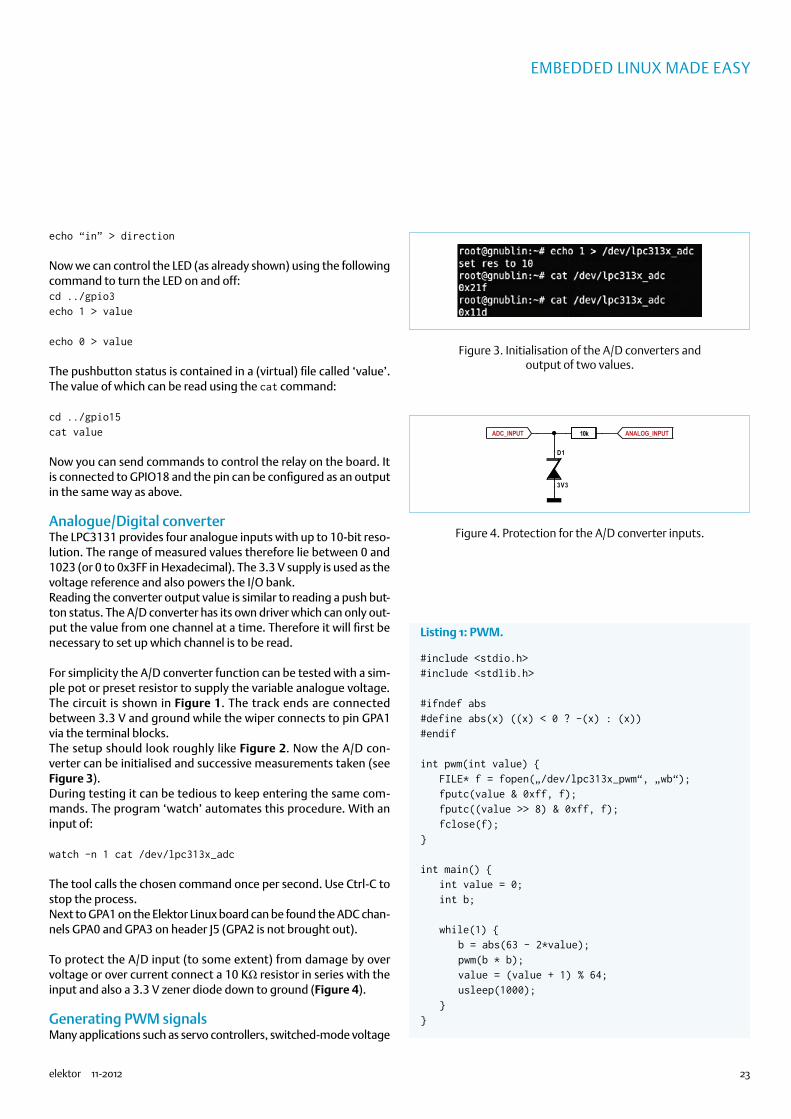
Analogue/Digital converterThe LPC3131 provides four analogue inputs with up to 10-bit reso-lution. The range of measured values therefore lie between 0 and 1023 (or 0 to 0x3FF in Hexadecimal). The 3.3 V supply is used as the voltage reference and also powers the I/O bank.Reading the converter output value is similar to reading a push but-ton status. The A/D converter has its own driver which can only out-put the value from one channel at a time. Therefore it will first be necessary to set up which channel is to be read.
For simplicity the A/D converter function can be tested with a sim-ple pot or preset resistor to supply the variable analogue voltage. The circuit is shown in Figure 1. The track ends are connected between 3.3 V and ground while the wiper connects to pin GPA1 via the terminal blocks.The setup should look roughly like Figure 2. Now the A/D con-verter can be initialised and successive measurements taken (see Figure 3).During testing it can be tedious to keep entering the same com-mands. The program ‘watch’ automates this procedure. With an input of:
watch -n 1 cat /dev/lpc313x_adc
The tool calls the chosen command once per second. Use Ctrl-C to stop the process.Next to GPA1 on the Elektor Linux board can be found the ADC chan-nels GPA0 and GPA3 on header J5 (GPA2 is not brought out).
To protect the A/D input (to some extent) from damage by over voltage or over current connect a 10 KΩ resistor in series with the input and also a 3.3 V zener diode down to ground (Figure 4).
Generating PWM signalsMany applications such as servo controllers, switched-mode voltage
ADC_INPUT ANALOG_INPUT
D1
3V3
10k
Figure 3. Initialisation of the A/D converters and output of two values.
Figure 4. Protection for the A/D converter inputs.
Listing 1: PWM.
#include <stdio.h>#include <stdlib.h>
#ifndef abs#define abs(x) ((x) < 0 ? -(x) : (x))#endif
int pwm(int value) FILE* f = fopen(„/dev/lpc313x_pwm“, „wb“); fputc(value & 0xff, f); fputc((value >> 8) & 0xff, f); fclose(f);
int main() int value = 0; int b;
while(1) b = abs(63 - 2*value); pwm(b * b); value = (value + 1) % 64; usleep(1000);
74874

24 11-2012 elektor
MicrocontrollerS
generators and digital audio (and much more [3]) need a generator of pulse width modulated signals. The Elektor Linux board outputs PWM signals from header J5. For test purposes use an oscilloscope to view the generated signals.In PWM mode the controller increments a 12-bit counter on each clock pulse. When the counter value reaches a predetermined value it switches state of the PWM pin from high to low (when the counter overflows it is reset and the bit goes high) The pre-determined value can be any 12-bit value i.e. in the range from 0 to 4095. When the value of 0 is specified the PWM output will go low immediately. A value of 2000 gives a square wave with a mark-space ratio of around 50 %.In contrast to both the I/O and ADC drivers the PWM driver expects a binary input value so it is not simple to use echo or cat because the value supplied will be interpreted as a character (ASCII). We need the assistance of a small help program.We were able to quickly write this on board using C. We have included a copy of this program (Listing 1). In the Home folder, where you will always find yourself after logging in, you will find the file ‘pwm.c’. In the code it is necessary to change the name of a device file.
First open the file using an editor on the board:
nano pwm.c
Navigate along the following line using the arrow keys…
FILE* f = fopen(“/dev/pwm”, “wb”);
… change the line to read:
FILE* f = fopen(“/dev/lpc313x_pwm”, “wb”);
Now save the edited version using Ctrl-o and end the editing session with Ctrl-x. The code can be compiled on the PC or directly on the Linux board which also contains its own compiler:
gcc -o pwm pwm.c
Once compiled (this takes a few moments) it can be directly executed:
./pwm
The oscilloscope display shows how the mark/space ratio changes.
When a signal with a fixed mark/space ratio is required this can be achieved for example with a small script written in the program-ming language Python. The file ‘pwm.py’ can be found in the home folder.First it is necessary to start the Python interpreter:
python
Figure 5. PWM output when a value of 1000 is used as a comparison value.
Figure 6. PWM with 50 % mark/space ratio.
Figure 7. PWM with 1 % mark/space ratio.
Figure 8. PWM with 99 % mark/space ratio.
74874

25elektor 11-2012
eMbeDDeD linux MADe eASy
In the interpreter (already we are in interactive mode) we can load the PWM module (a library of Python functions):
import pwm
Now it is possible to call the module functions. One of these func-tions allows direct input of the counter compare value:pwm.pwm_raw(1000)
The signal on the oscilloscope should now look like Figure 5.
Alternatively the mark-space ratio can be given as a percentage:
pwm.pwm(50)the waveform on the screen now looks like Figure 6.
Using the command
pwm.pwm(1)pwm.pwm(99)
is interpreted as mark then space so produces 1 to 99 % (Figure 7 / Figure 8).Use Ctrl-d to close the Python-Interpreter.Be aware that at the start Python takes a little while to fully initialise but once running it responds quite smoothly.
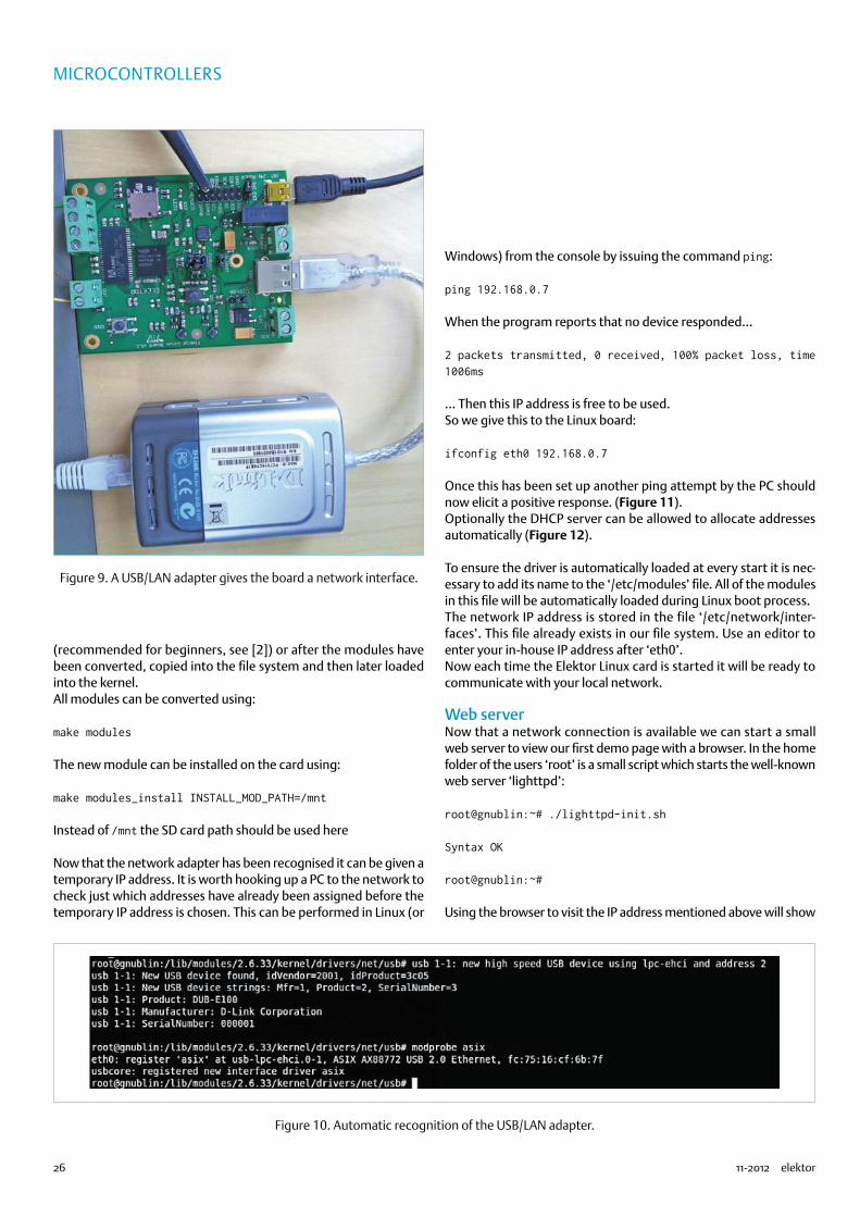
Network interfacingIn the last instalment of this series we have already shown how to interface a USB/UART adapter. Now we install another USB adapter to the Linux board which can connect to an Ethernet network. We will be using an off-the–shelf USB/LAN adapter (Figure 9). There
are many different models on the market but they mostly use the same or similar chipsets. The one we are using here is the ‘D-Link DUB-E100’ [4].In the last instalment of this series we integrated the driver for the USB/UART adapter in the kernel. As we have already shown in this series the kernel can also load a device driver as a module during run time. We will use this approach for the network adapter. The file system already contains many different drivers.
In the case of D-Link adapters it is necessary to give the following command:
modprobe asix
Now we should see an output as shown in Figure 10.There are three drivers in the file system:
asix pegasusnet1080
When a different adapter is used try loading different drivers one after the other. To check if the correct one has been found we should see this response to the input:
ifconfig -a
A response of ‘eth0’ indicates the driver has been correctly loaded and the network is ready to transfer data.When all of the drivers fail it is possible to go to ‘Device Drivers’ -> ‘Network device support’ -> ‘USB Network Adapters’ and load the drivers by hand. The drivers can either be compiled into the kernel
SD card imageWhen experimenting — which we like to encourage! — you can sometimes find yourself backed down a one-way street with no way out. In this situation there may be no alternative but to take a fresh version of the original SD card. For this reason we are offering the SD card contents as an extra download. First download the image from the Elektor web [8] (Download ‘SD Card Image’, 120180-12.zip).
When the download is complete, unpack the archived files:
unzip 120180-12.zip
This takes a while before the following message appears:
Archive: ../120180-12.zip inflating: Elektor_Linux_Board - Build_New_SD_Card.txt inflating: gnublin.img
Now take the SD to be written to and plug it into the PC or card read-er. The system will read the card but we are not interested in this, we just need a 1:1 image of the downloaded file on the memory card. For this it will be necessary to manually configure the card.
The best way is to plug the card in the reader and give the command dmesg via the console to find out what the card has been mapped to. The response to this command will be something like the following:
[ 1069.427374] sdf: sdf1 sdf2 [ 1069.430857] sd 5:0:0:0: [sdf] No Caching mode page present [ 1069.430863] sd 5:0:0:0: [sdf] Assuming drive cache: write through [ 1069.430868] sd 5:0:0:0: [sdf] Attached SCSI removable disk [ 1070.002620] EXT2-fs (sdf1): warning: mounting unchecked fs, running e2fsck is recommended
In the last line there is an indication of the device name that the ker-nel has given to the SD card (sdf1 in this case).
Now it is necessary to manually unmount all partitions by using…
umount /dev/sdf1
… replace sdf1 with the device name assigned to your card (exactly as the name assigned to the first partition).
Now the downloaded image can be written to the SD card:
sudo dd if=gnublin.img of=/dev/sdf
sdf is the description of the whole card as a block device.
NB: The process of writing can take up to 10 minutes.
74874
26 11-2012 elektor
MicrocontrollerS
(recommended for beginners, see [2]) or after the modules have been converted, copied into the file system and then later loaded into the kernel.All modules can be converted using:
make modules
The new module can be installed on the card using:
make modules_install INSTALL_MOD_PATH=/mnt
Instead of /mnt the SD card path should be used here
Now that the network adapter has been recognised it can be given a temporary IP address. It is worth hooking up a PC to the network to check just which addresses have already been assigned before the temporary IP address is chosen. This can be performed in Linux (or
Windows) from the console by issuing the command ping:
ping 192.168.0.7
When the program reports that no device responded…
2 packets transmitted, 0 received, 100% packet loss, time 1006ms
… Then this IP address is free to be used.So we give this to the Linux board:
ifconfig eth0 192.168.0.7
Once this has been set up another ping attempt by the PC should now elicit a positive response. (Figure 11).Optionally the DHCP server can be allowed to allocate addresses automatically (Figure 12).
To ensure the driver is automatically loaded at every start it is nec-essary to add its name to the ‘/etc/modules’ file. All of the modules in this file will be automatically loaded during Linux boot process.The network IP address is stored in the file ‘/etc/network/inter-faces’. This file already exists in our file system. Use an editor to enter your in-house IP address after ‘eth0’.Now each time the Elektor Linux card is started it will be ready to communicate with your local network.
Web serverNow that a network connection is available we can start a small web server to view our first demo page with a browser. In the home folder of the users ‘root’ is a small script which starts the well-known web server ‘lighttpd’:
root@gnublin:~# ./lighttpd-init.sh
Syntax OK
root@gnublin:~#
Using the browser to visit the IP address mentioned above will show
Figure 9. A USB/LAN adapter gives the board a network interface.
Figure 10. Automatic recognition of the USB/LAN adapter.
74874

27elektor 11-2012
eMbeDDeD linux MADe eASy
the web site in Figure 13.
A web server typically generates static HTML web pages. When we show the status of an LED in a browser for example, the web server must output a dynamically assembled HTML page (depending on the LED status). We require an interface between the web server and an external program that is capable of detecting whether the LED is on or off and can generate a corresponding web page.The simplest link is called CGI. This ‘Common Gateway Interface’ is an interface which enables the web server to access almost any program. One condition is that it is command-line orientated, and can also be started (with any parameters) from the console. CGI scripts also most commonly return an HTML page. As a CGI program you can use a simple Linux shell script, a PHP or Python program or even a C program.
Switching an LED from the browserThis simple application will show how it is possible to change the state of an LED from a browser. We create a simple script file that the shell (console) can directly execute. First it is necessary to setup the CGI interface on the web server.In the file ‘/etc/lighttpd/modules.conf’ identify the entry…
#include “conf.d/cgi.conf”
… Using an editor (e.g. nano or vi) change it to:
include “conf.d/cgi.conf”
Next, in the file ‘/etc/lighttpd/conf.d/cgi.conf’ it is necessary to edit the entry
#alias.url += ( “/cgi-bin” => server_root + “/cgi-bin” )
To…
alias.url += ( “/cgi-bin” => var.server_root + “/cgi-bin” )
Now the web server knows that the files in the ‘/cgi-bin’ folder can be treated as programs (and not as HTML pages to be sent to the browser)
Next for us to finally use a simple shell script as a CGI program it is necessary to identify the region in the file …
cgi.assign = ( “.pl” => “/usr/bin/perl”, “.cgi” => “/usr/bin/perl”, “.rb” => “/usr/bin/ruby”, “.erb” => “/usr/bin/eruby”, “.py” => “/usr/bin/python” )
… And add the line ‘.sh’ => ‘/bin/sh’
cgi.assign = ( “.pl” => “/usr/bin/perl”, “.cgi” => “/usr/bin/perl”, “.rb” => “/usr/bin/ruby”, “.sh” => “/bin/sh”, “.erb” => “/usr/bin/eruby”, „.py“ => „/usr/bin/python“ )
The next step is to create a directory for the CGI programs:
mkdir -p /srv/www/htdocs/cgi-bin
And lastly to add the program in Listing 2, after that the editor can
Figure 11. A reply following a ping.
Figure 12. The DHCP server automatically assigns the address.
Figure 13. Test page of the web server.
74874
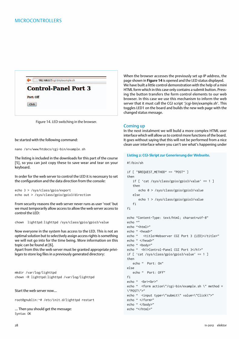
28 11-2012 elektor
MicrocontrollerS
be started with the following command:
nano /srv/www/htdocs/cgi-bin/example.sh
The listing is included in the downloads for this part of the course [5], so you can just copy these to save wear and tear on your keyboard.
In order for the web server to control the LED it is necessary to set the configuration and the data direction from the console:
echo 3 > /sys/class/gpio/exportecho out > /sys/class/gpio/gpio3/direction
From security reasons the web server never runs as user ‘root’ but we must temporarily allow access to allow the web server access to control the LED:
chown lighttpd:lighttpd /sys/class/gpio/gpio3/value
Now everyone in the system has access to the LED. This is not an optimal solution but to selectively assign access rights is something we will not go into for the time being. More information on this topic can be found at [6].Apart from this the web server must be granted appropriate privi-leges to store log files in a previously generated directory:
mkdir /var/log/lighttpdchown -R lighttpd:lighttpd /var/log/lighttpd
Start the web server now…
root@gnublin:~# /etc/init.d/lighttpd restart
… Then you should get the message:Syntax OK
When the browser accesses the previously set up IP address, the page shown in Figure 14 is opened and the LED status displayed.We have built a little control demonstration with the help of a mini HTML form which in this case only contains a submit button. Press-ing the button transfers the form control elements to our web browser. In this case we use this mechanism to inform the web server that it must call the CGI script ‘/cgi-bin/example.sh’. This toggles LED1 on the board and builds the new web page with the changed status message.
Coming upIn the next instalment we will build a more complex HTML user interface which will allow us to control more functions of the board. It goes without saying that this will not be performed from a nice clean user interface where you can’t see what’s happening under
Listing 2: CGI-Skript zur Generierung der Webseite.
#!/bin/sh
if [ "$REQUEST_METHOD“ == "POST“ ]then if [ ‘cat /sys/class/gpio/gpio3/value’ == 1 ] then echo 0 > /sys/class/gpio/gpio3/value else echo 1 > /sys/class/gpio/gpio3/value fifi
echo “Content-Type: text/html; charset=utf-8”echo “”echo “<html>”echo “ <head>”echo “ <title>Webserver CGI Port 3 (LED)</title>”echo “ </head>”echo “ <body>”echo “ <h1>Control-Panel CGI Port 3</h1>”if [ ‘cat /sys/class/gpio/gpio3/value’ == 1 ]then echo “ Port: On”else echo “ Port: Off”fiecho “ <br><br>”echo “ <form action\”/cgi-bin/example.sh \” method = \”POST\”>”echo “ <input type=\”submit\” value=\”Click\”>”echo “ </form>”echo “ </body>”echo “</html>”
Figure 14. LED switching in the browser.
74874

29elektor 11-2012
eMbeDDeD linux MADe eASy
the surface; our control requires a little more intelligence. This can be achieved by a small program running in the background.For the edition after that and then for the final instalment of this series (the first edition of the year 2013) we have planned some-thing special: The subjects we intend to cover will be entirely up to you. Go to our special web site [7] and tell us what you would like to see! A good deal of user talk on the project may also be found on our forum [9].
(120182)
Internet Links
[2] www.elektor.com/120181
[3] http://en.wikipedia.org/wiki/Pulse-width_modulation
[4] http://shop.embedded-projects.net/gnublin
[5] www.elektor.com/120182
[6] http://en.gnublin.org/index.php/Permissions_GPIO
[7] www.elektor.com/linux-feedback
[8] www.elektor.com/120180
[9] www.elektor.com/forum/elektor-forums/fields-of-interest/micro-controllers-embedded.1543738.lynkx
$136$136CNC enclosure, hifi sound quality, easy to buildCNC enclosure, hifi sound quality, easy to build6P3P 7.5Wx2 Tube Amp Kit6P3P 7.5Wx2 Tube Amp Kit
$25$25“Must have” tool for ARM developers“Must have” tool for ARM developersUSB AMR JTAG Simulation J-Link v8USB AMR JTAG Simulation J-Link v8
$50$50Small,Low Cost,Easy To DevelopeSmall,Low Cost,Easy To DevelopeSEN1060 GPS Module With AntennaSEN1060 GPS Module With Antenna
$0$0Free, Portable, MultifunctionFree, Portable, MultifunctionMini multimeter DT-830BMini multimeter DT-830B
www.pcb-pool.com
Free Phone UK: 0800 389 [email protected] A
ll re
gist
ered
bra
nds
rem
ain
the
regist
ered
tra
dem
arks
of t
he res
pect
ive m
anuf
actu
rer !
PCB-
POOL®
is a
reg
iste
red
trade
mar
k of
Bet
a LA
YOUT
Gm
bH
FREE Stencilwith every PCB Prototype order
PCB-
POOL®
is a
reg
iste
red
trade
mar
k of
Bet
a LA
YOUT
Gm
bHPC
B-PO
OL®
is a
reg
iste
red
trade
mar
k of
Bet
a LA
YOUT
Gm
bH
EAGLE order button pcb-pool.com/download-button
on your first PCB order 20% off
Advertisement
74874

30 11-2012 elektor
audio
Nixie VU Metera warm & retro power indicator for the tube amp
Distance is meaningless these days it seems, and borders non-existent. The same with e-age, in a way, considering the PSoC (pro-grammable system on chip) and the IN-9 Nixie tube differ about 45 years in years yet get along really well in an Elektor circuit published in 2012. Let’s see how a 1960s ‘Sovjet-elektronisjk’ device and a ‘Silicon Valley’ bit of technology from the Internet Age can be coaxed to work together in a synergetic manner — hosted by Elektor.
Why the IN-9?The IN-9 seems to be the ideal tube for this circuit, being a linear gas discharge tube emitting an orange/pink-ish glowing light. The height of the ‘glowing column’ is proportional to the current flowing and the anode voltage is around 150 VDC. For sticklers: ‘linear’ applies to most of the device’s range, not all of it, see Figure 1. Between 0 and 8 mA everything seems all right at about 10.3 mm per mA but beyond that expect borsj, or “nothing meaning-ful” in Oxford English. These tubes can be obtained as NOS (new old stock) devices on the Internet, specifically on a certain auc-
By Harald W. Cintra (Brazil)
This circuit is designed to embellish a (tube)
amplifier. It supplies delightful light effects
rather than a calibrated readout for output
power or decibels. At the heart of the
circuit is a PSoC from California that’s busy
all the time driving two Nixie tubes… from
the Ukraine.
100
50
0
0 10Current [mA]
20 30110744 - 12
Leng
th [m
m]
Figure 1. Measured (nope, not “manufacturer specified”) relation between IN-9 illuminated column (bar) height and tube current. Stay in the 0-8 mA range and you’re
fine. Illustration redrawn, permission granted, from an original by Jeff Malins (2004).
Features•Column type stereo VU meter•2 x IN-9 linear gas discharge (Nixie) tube•Column colour: warm orange/pink•Net column height: 85 mm (approx.)•Audio ‘Line’ drive level (approx. 0.7 V)•Cypress PSoC CY8C27443 based
•PSoC device available ready-programmed
•Software lin/log converter•Onboard 150 VDC supply•Compact board (65 x 65 mm)
74874
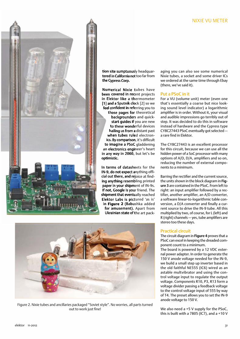
31elektor 11-2012
nixie vu meter
tion site sumptuously headquar-tered in California not too far from the Cypress Corp.
Numerical Nixie tubes have been covered in recent projects in Elektor like a thermometer [1] and a Sputnik clock [2] so we feel confident in referring you to
those pages for theoretical backgrounders and quick-start guides if you are new
to these wonderful devices hailing us from a distant past
when tubes ruled electron-ics. By comparison, it’s difficult
to imagine a PSoC gladdening an electronics engineer’s heart
in any way in 2060, but let’s be optimistic.
In terms of datasheets for the IN-9, do not expect anything offi-cial out there, and rejoice at find-ing anything resembling printed paper in your shipment of IN-9s. If not, Google is your friend. The
shipment that eventually reached Elektor Labs is pictured ‘as is’ in Figure 2 (Babushka added
for amusement). Apart from Ukrainian state of the art pack-
aging you can also see some numerical Nixie tubes, a socket and some driver ICs we ordered at the same time through Ebay (there, we’ve said it).
Put a PSoC in itFor a VU (volume unit) meter (even one that’s essentially a coarse but nice look-ing sound level indicator) a logarithmic amplifier is in order. Without it, your visual and audible impressions go terribly out of step. It was decided to do this in software instead of hardware and the Cypress type CY8C27443 PSoC eventually got selected — a rare find in Elektor.
The CY8C27443 is an excellent processor for this circuit, because we can use all the hidden power of a SoC processor with many options of A/D, D/A, amplifiers and so on, reducing the number of external compo-nents to a minimum.
Barring the rectifier and the current source, the units shown in the block diagram in Fig-ure 3 are contained in the PSoC. From left to right: an input amplifier followed by a rec-tifier, another amplifier, an A/D converter, a software linear-to-logarithmic table con-version, a D/A converter and finally a cur-rent source to drive the IN-9 tube. All this multiplied by two, of course, for L (left) and R (right) channels — yes, tube amplifiers are stereo too these days.
Practical circuitThe circuit diagram in Figure 4 proves that a PSoC can excel in keeping the dreaded com-ponent count to a minimum.The board is powered by a 12 VDC exter-nal power adapter. In order to generate the 150 V anode voltage needed for the IN-9, we build a small step up inverter based in the old faithful NE555 (IC6) wired as an astable multvibrator and using the con-trol voltage input to regulate the output voltage. Components R10, P3, R13 form a voltage divider passing a feedback voltage to the control voltage input of 555 by way of T4. The preset allows you to set the IN-9 anode voltage to 150 V.
We also need a +5 V supply for the PSoC, this is built with a 7805 (IC7), and a +10 V
Figure 2. Nixie tubes and ancillaries packaged “Soviet style”. No worries, all parts turned out to work just fine!
tion site sumptuously headquartion site sumptuously headquartion site sumptuously headquartion site sumptuously headquartered in California not too far from tered in California not too far from tered in California not too far from tered in California not too far from the Cypress Corp.the Cypress Corp.the Cypress Corp.the Cypress Corp.
Numerical Nixie tubes have Numerical Nixie tubes have Numerical Nixie tubes have Numerical Nixie tubes have been covered in recent projects been covered in recent projects been covered in recent projects been covered in recent projects in Elektor like a thermometer in Elektor like a thermometer in Elektor like a thermometer in Elektor like a thermometer [1] and a Sputnik clock [2] so we [1] and a Sputnik clock [2] so we [1] and a Sputnik clock [2] so we [1] and a Sputnik clock [2] so we feel confident in referring you to feel confident in referring you to feel confident in referring you to feel confident in referring you to
those pages for theoretical those pages for theoretical those pages for theoretical those pages for theoretical backgrounders and quick-backgrounders and quick-start guides if you are new start guides if you are new
to these wonderful devices to these wonderful devices to these wonderful devices to these wonderful devices hailing us from a distant past hailing us from a distant past hailing us from a distant past hailing us from a distant past
when tubes ruled electronwhen tubes ruled electronwhen tubes ruled electronwhen tubes ruled electronics. By comparison, it’s difficult ics. By comparison, it’s difficult ics. By comparison, it’s difficult ics. By comparison, it’s difficult
to imagine a PSoC gladdening to imagine a PSoC gladdening to imagine a PSoC gladdening to imagine a PSoC gladdening an electronics engineer’s heart an electronics engineer’s heart an electronics engineer’s heart an electronics engineer’s heart
in any way in 2060, but let’s be in any way in 2060, but let’s be in any way in 2060, but let’s be in any way in 2060, but let’s be optimistic.optimistic.optimistic.optimistic.
In terms of datasheets for the In terms of datasheets for the IN-9, do not expect anything offiIN-9, do not expect anything official out there, and rejoice at findcial out there, and rejoice at finding anything resembling printed ing anything resembling printed paper in your shipment of IN-9s. paper in your shipment of IN-9s. If not, Google is your friend. The If not, Google is your friend. The
shipment that eventually reached shipment that eventually reached Elektor Labs is pictured ‘as is’ Elektor Labs is pictured ‘as is’ in in FigureFigure 2 2 (Babushka added (Babushka added
for amusement). Apart from for amusement). Apart from Ukrainian state of the art packUkrainian state of the art pack
74874
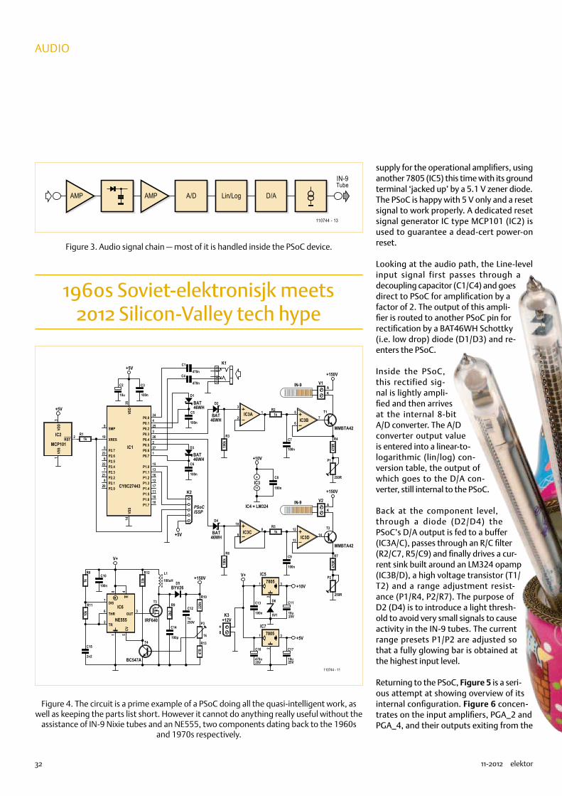
32 11-2012 elektor
audio
supply for the operational amplifiers, using another 7805 (IC5) this time with its ground terminal ‘jacked up’ by a 5.1 V zener diode.The PSoC is happy with 5 V only and a reset signal to work properly. A dedicated reset signal generator IC type MCP101 (IC2) is used to guarantee a dead-cert power-on reset.
Looking at the audio path, the Line-level input signal first passes through a decoupling capacitor (C1/C4) and goes direct to PSoC for amplification by a factor of 2. The output of this ampli-fier is routed to another PSoC pin for rectification by a BAT46WH Schottky (i.e. low drop) diode (D1/D3) and re-enters the PSoC.
Inside the PSoC, this rectified sig-nal is lightly ampli-fied and then arrives at the internal 8-bit A/D converter. The A/D converter output value is entered into a linear-to-logarithmic (lin/log) con-version table, the output of which goes to the D/A con-verter, still internal to the PSoC.
Back at the component level, through a diode (D2/D4) the PSoC’s D/A output is fed to a buffer (IC3A/C), passes through an R/C filter (R2/C7, R5/C9) and finally drives a cur-rent sink built around an LM324 opamp (IC3B/D), a high voltage transistor (T1/T2) and a range adjustment resist-ance (P1/R4, P2/R7). The purpose of D2 (D4) is to introduce a light thresh-old to avoid very small signals to cause activity in the IN-9 tubes. The current range presets P1/P2 are adjusted so that a fully glowing bar is obtained at the highest input level.
Returning to the PSoC, Figure 5 is a seri-ous attempt at showing overview of its internal configuration. Figure 6 concen-trates on the input amplifiers, PGA_2 and PGA_4, and their outputs exiting from the
1960s Soviet-elektronisjk meets 2012 Silicon-Valley tech hype
AMP A/D D/A
IN-9Tube
110744 - 13
Lin/LogAMP
R3
100k
R21k
3
21IC3A 5
67IC3B
C7
100n
T1
AK
AK
MMBTA42
R4
470R
P1
250R
V1IN-9
+150V
R6
100k
R51k
10
98IC3C 12
1314IC3D
C9
100n
T2
MMBTA42
R7
470R
P2
250R
V2IN-9
+150V
+10V
C8
100n
C5
100n
C6
100n
C1
470nC4
470nC3
100n
C2
10u
+5V
K2
+5V
R11k
ISSPPSoC
VSS
1
RST 2
VDD
3
IC2
MCP101
+5V
OUT3
THR6
DIS7
TR2
R4
CV5
81
IC6
NE555
C10
100n
V+
R8
1k
R11
10k
C15
2n2
T3
IRF640
T4
BC547A
R12
33k
L1
100uH
R9
2k2
C14
100p
D5BYV26
250V
C12
1u
R10
220k
R13
47R
+150V1 3
2
IC57805
1 3
2
IC77805
D6
5V1
C13
100n
0+
25V
C11
10u
25V
C16
470u25V
C17
10u
+5V
+10V
K3+12V
K1
4
11
P0.71
P0.52
P0.33
P0.14
P2.75
P2.56
P2.37
P2.18
SMP9
P1.710
P1.511
P1.312
P1.113
VSS
14
P1.015
P1.216
P1.417
P1.618
XRES19
P2.020
P2.221
P2.422
P2.623
P0.024
P0.225
P0.426
P0.627
VDD
28
IC1
CY8C27443
P3
1k
D3
BAT46WH
D1
BAT46WH
D2
BAT46WH
D4
BAT46WH
110744 - 11
IC3
IC4 = LM324
V+
Figure 3. Audio signal chain — most of it is handled inside the PSoC device.
Figure 4. The circuit is a prime example of a PSoC doing all the quasi-intelligent work, as well as keeping the parts list short. However it cannot do anything really useful without the
assistance of IN-9 Nixie tubes and an NE555, two components dating back to the 1960s and 1970s respectively.
74874

33elektor 11-2012
nixie vu meter
chip and returning via PGA_1 and PGA_3 for buffering and subsequent routing to DUALADC8 were they get digitized. With some effort you can also see the output of D/A converters routed to output pins.The PSoC design files are available free of charge from the Elektor website [3]. Cypress offer a number of great software tools to design and configure the innards of their PSoC devices. For those of you less concerned about the way a PSoC works or gets programmed, Elektor are offering ready-pro-grammed ICs [3].
ConstructionThe project is built on the circuit board pictured in Figure 7. It’s
a h y b r i d , i.e. a mix of
through-hole and SMD. The
SMDs have to b e m o u nte d
first. The PSoC and the LM324
do not have an unmanageable pin
pitch, hence can be soldered by hand
with good care and precision using a sol-der iron with a very
fine tip. Various meth-ods exist and these have
been described many times in Elektor.
T h e e l e c t r o l y t i c capacitors are al l
radial through-hole types — be sure to
mount them with the correct polarisation.
The IN-9 tubes should sit in sockets to prevent
any risk of their lead wires breaking off at the ‘Mur-
phy Spot’, i.e. where they exit from the glass envelope.
However, if the tubes are secured properly in their final position, their 40-mm long lead wires can simply be extended for connect-ing to the screw terminals on the board marked V1 and V2, where ‘K’ is the cathode, and ‘A’ the anode. Remember, these wires
carry a high voltage and should be rated, secured and protected accordingly.
A short movie showing the Nixie VU Meter in action on a tube amplifier is available on Elektor’s very own Youtube channel called
Figure 5. A PSoC is like a sophisticated incarnation of a box of Lego: you get the modules — you decide what’s built today — you test — you modify — you show off the finished
construction. This image shows the structure programmed to obtain the Nixie VU Meter.
Figure 6. A closer, yet virtual, look at the amplifier blocks inside the PSoC.
74874

34 11-2012 elektor
audio
‘ElektorIM’ (no typo) [4].Finally, some friendly yet cautionary advice:
Do not build this circuit unless you under-stand the dangers of working with high direct voltages. This includes any connec-tion to audio signals in a tube amplifier.
(110744)
[1] Nixie Thermometer/Hygrometer, Elektor June 2012, www.elektor.com/110321
[2] Sputnik Time Machine, Elektor January 2007, www.elektor.com/050018
[3] www.elektor.com/110744
[4] www.youtube.com/user/elektorim?feature=results_main
COMPONENT LISTResistors(all fixed Rs SMA shape 0805)R1,R2,R5,R8 = 1kΩR3,R6 = 100kΩR4,R7 = 470ΩR9 = 2.2kΩR10 = 220kΩR11 = 10kΩR12 = 33kΩR13 = 47ΩP1,P2 = 220Ω preset, top adjustP3 = 1kΩ preset, top adjust
CapacitorsC1,C4 = 470nF (SMD 0805)C2,C11,C17 = 10µF 16V radialC3,C5,C6,C7,C8,C9,C10,C13,C14 = 100nF
(SMD 0805)
C12 = 1µF 250V (SMD shape 1825)C15 = 2.2nF (SMD shape 0805)C16 = 470µF 25V radial
InductorsL1 = 100µH, 860mA, Multicomp
MCSDRH73B-101MHF
SemiconductorsD1,D2,D3,D4 = BAT46WHD5 = BYV26D6 = BZD27C5V1P 5.1V zener diodeT1,T2 = MMBTA42T3 = IRF640NSPBFT4 = BC847IC1 = CY8C27443-24SXI, Elektor #
110744-41*IC2 = MCP101-475HI/TO
IC3 = LM324ADT (SOIC-14)IC4 = NE555DT (SOIC-8)IC5,IC6 = 78L05
MiscellaneousK1 = 3.5mm stereo jack, PCB mount (Lumberg
1503 09)K2 = 5-pin SIL pinheader, 0.1’’ pitch (2.54mm)K3 = 2-way PCB screw terminal block, 5mm
pitchV1,V2 = 2-way PCB screw terminal block,
5mm pitch2 pcs IN-9 Nixie tubePCB # 110744-1*
* ordering details at www.elektor.com/110744
Figure 7. The circuit board designed by Elektor Labs takes a mix of SMA devices (also called SMDs) and through-hole components.
74874

international payment via
+49 (0)4422 955-333
+49 (0)4422 955-360
Professional quality @ discount prices!
more than 40 years experience
more than 40000 products in stock
no minimum order charge
fast 24 hour shipment
Daily rates! - Price level: 17.9.2012
.co.uk
Patented MagLev fan system 12 VA magnetic fi eld is used to keep the rotors suspended. This enables the operation of the fans in any position.
FAN-ML 4010-12
Cooling element for multiple screw mounting
Temperature dependent fan control
• out of aluminium profi le• for T0220, 218, TOP3 • M3 screw channel• Rth cooling element: 3.6 K/W• H x W x D: 94 x 55 x 28 mm
For fans of up to max. 2.5W Operating voltage: 12V-Engine speed optimisation depending on the temperature for minimum noise development.
Bestellnummer:FAN-ML 4010-12 40x40x10 8500 39 16.2
Dimensions (mm) Rpm dB m³/h
FAN-ML 4020-12 40x40x20 8200 27 18.4FAN-ML 5010-12 50x50x10 6100 35 25.9FAN-ML 6010-12 60x60x10 4000 28 27.2FAN-ML 8020-12 80x80x20 3200 38 61.1
6 K/W V 6716Z
endenntt
LÜFTER-REGLER
Heat conducting paste
Ensure highest heat conductivity between semiconductor and cooling element.
paste
LEITPASTE 5GR SyringeLEITPASTE 35GR Tube
All cooling elements under: http://rch.lt/5L
Made in Germany!!!!
Immediately functional 4.3” TFT displayBesides a diverse range of fonts, powerful graphic functions have already been integrated and can be used immediately.• TFT-Graphic display with graphic function• 480 x 272 pixel / 4.3 (320 x 240 pixel / 3.2 ), 16bit colour (65,536 colours) with white LED illumination• Supply +5V / 180mA
iiniininininninninininiiininininininiiiiininaaanyanyanyny!any!y!y!a !any!aanyy!aanany!nanyny!y!anyy!y!y!a !!an !
MMMMMMMaMaMaaMadMadMadeMadeaddedadeadeMaadeMa eedeea ea eeedeeM ddeMMMaMMaMaMadaaadeMadMadMadeadedeeMaadadeaddeeM edeeadea eeeeddeeMGerGeGGGGeerGerermermermermrmrmGe mG mermermme mG maaaaaaGGGeGGeGeGermGermGermGermmermrmrmGerGeerermGGerGeG aaaaa
EA EDIP-TFT43AEA EDIP-TFT43ATP with TOUCH PANEL
Bestellnummer: nm / colour UF / IF (V / mA)
LED 5-16000 RT 630nm super red 2LED 5-08000 GN 520nm pure green 3.2LED 5-14000 GE 592nm super yellow 2LED 5-12000 BL 466nm blue 3.2LED 5-05000 WS 6000K white 3.3LED 5-25000 WS 5500 K white 3.3LED 5-16000 WW 4000K warm white 3.3
LED‘s 5mm, ultra bright, Lucky LightHousing: colourless, transparent
The highlight of LED technology CAUTION! Module temperature over 150°C.Ensure suffi cient cooling.
High Power 10W LED-Module
High temperatures
LED H10WG PWS 6000K pure whiteLED H10WG NWS 4000K natural white
EA EDIP-TFT43A
TMPM 04105 5VDC / 800mA
TMPM 04112 12VDC / 333mA
All TRACO products: http://rch.lt/5M
72%
76 %
TSR-1 Series, 1APowerful switching regulatorsReplace all ineffective 78xx linear regulators with 1-Step-down switching regulators of the TSR-1 series!
• Operating temperature: -40°C to +85°C• continuous short-circuit-proof
TMPM seriesSwitching power supply, module• Output power: 4 Watt• Universal power inlet: 85-264VAC, 47-440Hz• cUL/UL 60950-1, IEC/EN 60950-1, CB-Report• Operating temperature range: -25°C to +60°C• Short circuit and overload protection, protection class II
TIW SeriesSwitching power supply, 5-12W• Installation in fl ush mounted sockets• Dirt/water protected , IP 67• Universal power inlet: 93-264VAC, 47-63 Hz• Security accreditation acc. to IEC/EN 60950-1, EN 60335-1 and EN 50178• Short circuit / overload protection
Output Effi ciency
TMPM 04124 24VDC / 167mA 77%
TIW 06-105 5.0VDC 1000 mA
Outputperformance
Output current,
maxOutput
voltage5W
TIW 12-112TIW 12-115TIW 12-124
12W
12W
12W
12.0VDC
15.0VDC
24.0VDC
1000 mA
800 mA
500 mA
TSR 1-2433 3.3VDC
TSR 1-2450 5.0VDC
1000 mA
1000 mA
Inputvoltage
Output current,
maxOutput
voltage4.75-36 VDC
6.50-36 VDC
TSR 1-2490TSR 1-24120
12.00-36 VDC
15.00-36 VDC
9.0VDC
12.0VDC
1000 mA
1000 mA
TSR 1-2433
Workshop Supply
Power SupplyComponents
Network & PC Technology
Sat and TV Technology
Cooling Technology Optoelectronics Power Supply
nted MagLev fan system mm t dd M L f t
etic fi eld is used to keep the rotors suspenpspen
FAN-ML
etsets
Ot
(~ £2,16)
(~ £2,80)(~ £3,16)(~ £2,16)(~ £3,08)
(~ £146,75)
(~ £7,17)
(~ £2,60)
(~ £2,16)
(~ £1,00)(~ £2,24)
(~ £146,75)(~ £154,51)
(~ £0,26)(~ £0,26)(~ £0,23)(~ £0,18)(~ £0,24)(~ £0,24)(~ £0,34)
(~ £11,17)(~ £11,97)
(~ £7,17)(~ £7,17)(~ £7,17)(~ £7,17)
(~ £13,13)(~ £13,13)(~ £13,13)
(~ £22,26)(~ £23,98)(~ £23,98)(~ £23,98)
(~ £2,16)
For consumers: The statutory right of withdrawal for consumers shall apply. All stated prices in € include the legal value added tax, ex works Sande, plus forwarding charges for the entire shopping cart. Our general terms and conditions shall apply exclusively (under www.reichelt.de/agb in the catalogue or on request). Subject to prior sale. All product names and logos are property of the respective manufacturers. Images can be similar. Subject to misprint, errors and changes in prices.reichelt elektronik GmbH & Co. KG, Elektronikring 1, 26452 Sande (HRA 200654 Oldenburg)
2,703,852,703,953,50
2,70 €
3,25 €
2,70
1,252,80
183,25192,95
0,330,330,290,230,300,300,42
13,9514,95
183,25 €
16,4016,4016,40
27,8029,9529,9529,95
8,958,958,958,95
8,95 €
Elektor 2012-11.indd 1 13.09.2012 12:57:52Naamloos-10 1 24-09-12 13:51
74874

36 11-2012 elektor
Microprocessors
Arduino on Course (3a)part 3a: connect the physical world to your Android phone
The Android OS allows anyone to create physical add-ons for smart-phones. This article provides an introduction into setting up your system for developing add-ons and Apps connected to them.
Hardware list-o-maniaHere’s a shopping list for our experiments:•Arduino Mega ADK board (pictured above) or Arduino Uno
board with USB Host Shield;•Android smartphone with Android OS 2.3.4 or newer;•USB cable and microUSB cable.
Note: in this article we will concentrate in how to prepare your sys-tem to start developing Arduino applications that will connect to your smartphone. We will give you some pre-made Apps (source included) for you to read/write data from/to the board and for use by, or supplied by, the smartphone.
Tip: before continuing reading the article, we strongly recom-mend you download all the code used in it, as we are only showing excerpts, due to the length of each one of the examples.
Introduction to Android OSAndroid is an operating system (OS) meant for mobile and embed-ded devices. It is based on Linux and runs a Java-like virtual machine called Dalvik. As in other OSs used in the market of mobile tele-phony, Android presents a number of differences when compared to Linux.First of all, as this OS is meant to be used in cellphones, the typical phone operations will have a high priority in the system. For exam-ple, unless configured otherwise, a phone call from the missus will stop your device from doing anything else.Also, all the devices sport a series of pre-assembled sensors like accelerometers, temperature sensors, light sensors, etc.
By David Cuartielles (Spain) and Andreas Goransson (Sweden)
This month you will start experimenting with
the Arduino Mega ADK board, exploring its
capability to connect to Android phones
and tablets. Android is an Operating
System (OS) for mobile and
embedded devices
that aims at reaching
almost every
device in the
connected world.
According to
independent sources
[1], Android reached
about 50% of the market
share during 2011.
Personal Download for I © Elektor
74874

37elektor 11-2012
Arduino on course
They offer multiple ways to access the Internet or other devices. Android offers multiple possibilities to do so: GPRS/3G/4G, Wi-Fi, Bluetooth, USB cable, etc.Finally, by default you will not program native applications, but programs that will run on top of the Dalvik virtual machine. In this way, in terms of syntax your programs will be equivalent to Java. In many cases you can import Java libraries (from source) straight into your phone apps. Android assures a certain degree of portability between ‘terminals’ from different manufacturers. In other words, the same app, once compiled, will most likely work fine for all the different phones as long as they run the same version of the OS.
Android h/w add-onsAndroid development team introduced in 2011 the possibility of creating accessory devices (add-on devices) using a series of open source tools. The famous Accessory Development Kit [2] consists of a series of hardware reference designs and the Android Open Acces-sory Protocol (AOAP).
The hardware designs are derivatives of different Arduino boards. For this article, we’ll focus on using an Arduino Mega ADK, which is compatible with the first version of the AOAP. The code presented in this article should work with later ADK compatible boards (like Arduino Due and the like). It should also be possible to replicate the experiments shown in here using an Arduino Uno and a USB Host Shield for Arduino like the one in Figure 1.One of the main features the AOAP brings into play is ‘App Wakeup’ upon accessory detection. When an accessory is plugged to the phone or tablet, it triggers a call to an application whose name is determined by the accessory. In case the App wasn’t installed in the device, the accessory would also inform about a URL from where to download and install the application.
At the time of writing this article, there were a whole series of boards compatible with the Google ADK besides the Arduino Mega ADK. On the other hand there were no compatible boards with Google ADK2 besides the Arduino Due.
Experimental setup @ the Arduino sideFor the sake of simplicity, let’s start by configuring our experimental setup preparing the Arduino IDE enable it to compile AOAP com-patible source for the Arduino Mega ADK. Besides having the right hardware, you will need to install:
•Arduino 1.0.1 or newer•The UsbHost library for Arduino (includes the AndroidAccessory
class). If you never installed a library for Arduino before, a how-to follows in the next section.
Thanks to the way AOAP works, once you have the right code run-ning on the Arduino Mega ADK, even if you have no applications in your phone ready to take advantage of the accessory, your Android
device will connect to the Internet and offer you a website where it will be possible for you to download the App used in this example, as is being done in Figure 2.
Note: For this automatic App installation to work, you need to acti-vate the option that allows your phone to install applications from outside the official Google Play Market. Follow Settings à Applica-tions and make sure the option “Unknown sources” is active. Also make sure your phone has a data connection either over Wi-Fi or the phone network to download the App from our servers.
Installing the USB Host library for ArduinoAt the time of writing this article the Arduino IDE did not include the USB Host library we are presenting. Therefore when you examine the “Sketch / Import Library” menu you don’t see the library named ‘USB Host’ in the list — you will have to download the library from the official Arduino website hosting this project [3] and install it.
Figure 1. : Arduino Uno connected to a USB Host Shield.
Figure 2. Arduino Mega ADK connected to a PC and to a phone.
74874

38 11-2012 elektor
Microprocessors
Essentially, adding a new library to the IDE is done by creating a folder called ‘libraries’ inside your sketchbook and uncompressing the file you got from the website [3] directly there. After that, you should restart the Arduino IDE and the library will then show up in the above-mentioned menu.If you had a previous version of this library or one obtained from a different website than the Arduino one, we strongly recommend you uninstall it before bringing in this new version, as they might be incompatible.With the library you will be installing not only the code to execute different com-mands on the modem, but also a series of examples that will allow you to:
•test whether the ADK mode is working properly;
•send digital/analogue values from the board to the phone;•receive values from the phone into the board;•debug the different types of USB devices connected to the
Arduino Mega ADK board.
The way to access the examples is very simple, just use the menu to navigate through: “File / Examples / USB Host”.
Boot an App — prep workTo check whether things are working fine for you, let’s make the easiest example pos-sible. You are going to upload a program to your Arduino board that will make your phone download a very simple App called Elektor_MIAU, as well as show something on the screen. (code listing 1)
Once you load this code into your Arduino Mega ADK, you should open the Serial Port Monitor in your IDE to monitor what is hap-pening. When connecting your phone via the micro USB cable to the Arduino board, the Serial port will register something simi-lar to what is shown in Figure 3.
At the same time, the phone will detect it has a compatible accessory hooked up and, since you will have no application installed in it for it to handle the data, you will get a message indicating where you can get the proper App from the Internet. You should get something similar to Figure 4.
You will notice the URL mentioned in the
phone’s screenshot is the same one as in code listing 1. In other words, you deter-mine in your Arduino code, where the App is located on the Internet. In this case, we have set up a website for you to check all the examples from your phone. You should open the browser in your Android device and see the site as in Figure 5.You will have to download it and install the App by clicking the link underneath the image It will first get downloaded and then effectively loaded into your device. Next you need to click on the file (called “Elektor_MIAU.apk”) which will install it. If the App is already in your phone, you will instead get an invitation to load the right applica-tion when plugging in the accessory again (Figure 6).
Once you have given permission for the App to boot, it will present a GIF image as part of a loop (Figure 7). We thought it would be fun to show that you can actually use some graphic capabilities on your Android terminal and stay clear of the corny “Hello World” text on the screen. However, this App is not using any information from the Arduino board, nor is it sending anything back to it — all it does
is allow you to check whether your phone/tablet supports Accessory Mode.
Note: It should be mentioned here that it is possible to have more than one App to handle the data produced by an accessory. In that case, the dialogue window will offer more than one option to choose from.
Experimental setup @ the Android sideBuilding Android Apps can be complex. It requires installing a long list of different software packages coming from different locations. We wrote a Getting Started Guide revising all the different packages you need for getting the easiest experimental setup possible [3].Probably the easiest way to develop a simple Android application implies using the open source software tool called Processing [4] by C. Reas and B. Fry. This software offers a sim-plified IDE that allows Java applications to be compiled. The latest version also compiles code for Android phones, and Javascript for websites. We have developed an Add-on tool for the Processing IDE that compiles and uploads code to your Android device for controlling accessories.
Figure 3. Screenshot from the Serial Port Monitor when linking an Android device to
your Arduino Mega ADK.
Figure 4. Screenshot taken from an Android phone showing the warning about missing
an App to handle an accessory.
74874
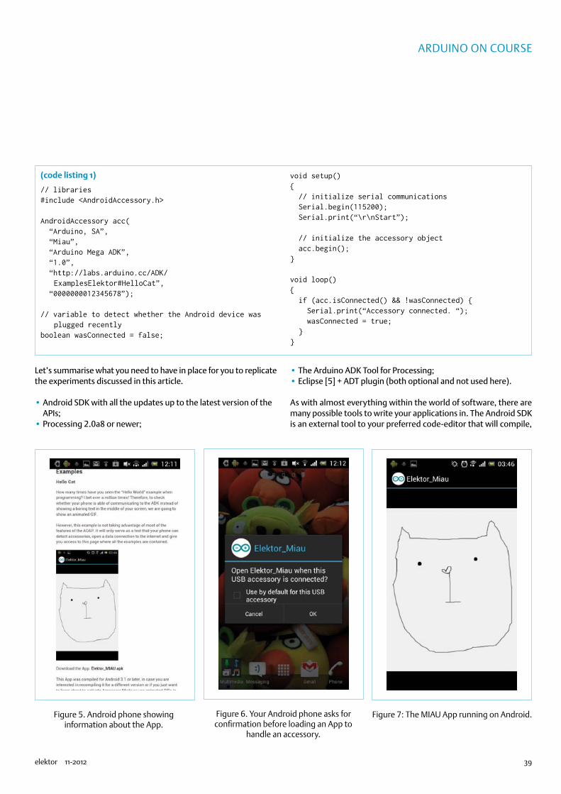
39elektor 11-2012
Arduino on course
Let’s summarise what you need to have in place for you to replicate the experiments discussed in this article.
•Android SDK with all the updates up to the latest version of the APIs;
•Processing 2.0a8 or newer;
•The Arduino ADK Tool for Processing;•Eclipse [5] + ADT plugin (both optional and not used here).
As with almost everything within the world of software, there are many possible tools to write your applications in. The Android SDK is an external tool to your preferred code-editor that will compile,
(code listing 1)
// libraries#include <AndroidAccessory.h>
AndroidAccessory acc( “Arduino, SA”, “Miau”, “Arduino Mega ADK”, “1.0”, “http://labs.arduino.cc/ADK/
ExamplesElektor#HelloCat”, “0000000012345678”);
// variable to detect whether the Android device was plugged recently
boolean wasConnected = false;
void setup() // initialize serial communications Serial.begin(115200); Serial.print(“\r\nStart”);
// initialize the accessory object acc.begin();
void loop() if (acc.isConnected() && !wasConnected) Serial.print(“Accessory connected. “); wasConnected = true;
Figure 5. Android phone showing information about the App.
Figure 6. Your Android phone asks for confirmation before loading an App to
handle an accessory.
Figure 7: The MIAU App running on Android.
74874

40 11-2012 elektor
Microprocessors
link libraries, simulate, compress and sign your Android applications for a specific ver-sion of the OS.On the other hand, Processing is a really good tool if you are starting to program, and therefore we created an Add-on for it as explained in the Getting Started Guide [3]. But if you really want to use a professional set of tools to write Android Apps on, you should consider Eclipse [5], the open source IDE, and the associated tools. Android’s developer site [6] explains how to install the whole Eclipse-based toolchain step by step.I will assume you managed to install Pro-cessing and all the other tools without much trouble. All of them are cross platform and should work for virtually any version of your OS. So now we will write the code for Android using Processing.
Your first AppBefore even thinking of making an App to control your accessory, let’s make a very simple App using Processing to show some-thing on the phone’s screen. For you to start writing Android Apps you will need to have the Android SDK installed and the Process-ing software configured to compile Android applications (Figure 8). Your IDE should have a green colour scheme.
Let’s start by making an App and running it on the device straight away. The following bit of code will show a square in the centre of the screen. We will later add the code for the square to change depending on sensor
data captured by the Arduino Accessory. (code listing 2)Processing is a tool aimed at graphic art-ists and therefore it uses a paradigm where instead of having a ‘loop’, the main function in the program happens to be called ‘draw’. The code you write inside Processing’s IDE is Java, but it hides all the complex operations behind it. To check whether you have eve-rything installed properly, follow the menu Sketch à Run on Device, as in Figure 9, this should compile the code and upload it auto-matically to the phone.Once the App boots, you should see an image like Figure 10 on your phone’s screen. The App will boot directly and it will remain there. You will be able to look for it on your App menu and run it as many times as you want to.
Note: At the time of writing, Processing didn’t allow signing Apps. The process of signing an App is what validates it for dis-tribution to other devices. Any Apps cre-ated with Processing will only work on the devices you upload them to directly. If you wanted to send your Apps to a friend, you should compile them using Eclipse, which is much more complicated at this point and will not be explained here. For example, the “Elektor_MIAU” application is signed, allow-ing anyone to download it from the Internet.
Make your App boot upon accessory connectionNow you made a very simple application
Figure 8. Screenshot of Processing running Android mode; note the Mode button in the
upper right corner.
Figure 9. Running the App directly on your phone.
(code listing 2)
void setup() // make sure the screen will have // fixed orientation orientation(PORTRAIT);
void draw() // draw from the center of the shape rectMode(CENTER); // make a 50x50 pix square using the // default color scheme rect(width/2, height/2, 50, 50);
(code listing 3)
AndroidAccessory acc( “Arduino, SA”, “Elektor_Rectangle”,
“Arduino Mega ADK”, “1.0”, “http://labs.arduino.cc/ADK/
ExamplesElektor#Rectangle”, “0000000012345678”);
74874
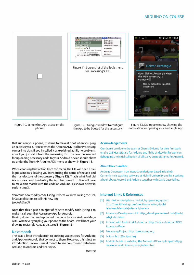
41elektor 11-2012
Arduino on course
that runs on your phone, it’s time to make it boot when you plug an accessory to it. Here is when the Arduino ADK Tool for Processing comes into play. If you installed it as explained at [3], no problems arise if you just call it from the Processing IDE. The new tool needed for uploading accessory code to your Android device should show up under the Tools à Arduino ADK menu as shown in Figure 11.
When choosing that option from the menu, the IDE will open a dia-logue window allowing you introducing the name of the app and the manufacturer of the accessory (Figure 12). That is what Android Accessories need to identify the App to connect to. You will have to make this match with the code on Arduino, as shown below in code listing 3.
You could now modify code listing 1 where we were calling the Hel-loCat application to call this new one.(code listing 3)
Note that this is just a snippet of code to modify code listing 1 to make it call your first Accessory App for Android.Having done that and uploaded the code to your Arduino Mega ADK, whenever you plug your phone to the board, it will boot your drawing rectangle App, as pictured in Figure 13.
Next monthThis was a brief introduction to creating accessories for Arduino and Apps on Android that connect to them. However, this is just an introduction. Follow us next month to see how to send data from Arduino to Android and vice-versa.
(120539)
Acknowledgements
Our thanks are due to the team at Circuits@Home for their first work on the USB Host Library for Arduino and Philip Lindsay for his work on debugging the initial collection of official Arduino Libraries for Android.
About the co-author
Andreas Goransson is an interaction designer based in Malmö. Currently he is teaching software at Malmö University and he is writing a book about Android and Arduino together with David Cuartiellies.
Internet Links & References
[1] Worldwide smartphone market, by operating system: http://mobithinking.com/mobile-marketing-tools/latest-mobile-stats/a#smartphoneos
[2] Accessory Development Kit: http://developer.android.com/tools/adk/index.html
[3] Arduino with Android at Arduino.cc: http://labs.arduino.cc/ADK/AccessoryMode
[4] Processing Project: http://processing.org
[5] Eclipse: http://eclipse.org
[6] Android Guide to installing the Android SDK using Eclipse: http://developer.android.com/tools/index.html
Figure 11. Screenshot of the Tools menu for Processing’s IDE.
Figure 12. Dialogue window to configure the App to be booted for the accessory.
Figure 10. Screenshot App active on the phone.
Figure 13. Dialogue window showing the notification for opening your Rectangle App.
74874

42 11-2012 elektor
TEST & MEASUREMENT
USB Weather Logger Time-synched
DCF77 is a German time signal and stand-ard-frequency radio station operating on the long wave. Its 77.5 kHz carrier signal has the relatively high power of 50 kW, meaning that the station can be received within a guaranteed range of 2000 km (1250 miles) from Frankfurt am Main under normal conditions.
The standalone data logger from Septem-ber 2011 [1] records data for atmospheric pressure, temperature and humidity pro-vided by I2C sensors and indicates this on a liquid crystal display (LCD). The results can also be read over a USB link and displayed graphically on a PC using GNUplot. As the sensor modules used are digital, the hard-ware overheads are minimal and no align-ment is required. The measurements are sampled at regular time intervals and saved to a serial EEPROM that requires no supply voltage to retain the readings. The meas-urement instrument runs for six to eight weeks on three AA batteries. A serial USB module enables data to be transferred to a PC for evaluation.
Since the first article was published in September 2011 a large number of read-ers have built this weather logger (a kit is available from Elektor comprising PCB, pro-
to the software. These alterations gave the designer the convenient opportunity to add some extra functions to the software.Fortunately the original Elektor PCB can still be used following this enhancement. The only alteration required is at Pin 23 of the microcontroller (Figure 1), where we
by Wilfried Wätzig (Germany)
Following requests from numerous Elektor readers, the author of the USB Weather Logger with Long-term
Storage (Elektor September 2011) has created an enhanced version with a DCF radio time signal module.
VDD
26
D431
D332
D233
D134
D035
E36
RS39
RESE
T40
LCD1DOGM162W-AA0
1
VCC
8
VCC
C5
100n
1 23 45 6
K1
C4
100n
X1
32.768kHz
S3S2S1
R4
10k
VCC
63V
C1
4u7
RESET1
PD02
PD13
PD24
PD35
PD46
PD511
PD612
PD713
VCC
7
GND
8
XTAL19
XTAL210
PB014
PB115
PB216
PB317
PB418
PB519
AVCC
20
AREF21
AGND
22
PC023
PC124
PC225
PC326
PC427
PC528
IC2
ATmega168
VCC
VCC
120113 - 11
100n
DCF
Figure 1. Update: New microcontroller with DCF module.
grammed controller, humidity
and atmospheric pressure sensor). Many readers asked the
author for means to retrofit a DCF77 mod-ule, which would also require modifications
74874

43elektor 11-2012
USB WEATHER loggER
now connect the signal output from the DCF module.A DCF module from Pollin (PON contact connected to ground) and one from Conrad Electronics were both tested with this new hook-up. Both modules proved sensitive to interference from switchmode power sup-plies, low-energy lamp bulbs and suchlike. You need to reckon with a delay of several minutes before the module ‘acquires’ a solid signal, enabling the program to decode the DCF data. Alternatively the microcontroller can also use the built-in real–time clock (RTC).
Enhanced functionsBecause the program code has been expanded (now nearly 12 KB), the ATmega88 must be replaced by the pin-compatible ATmega168. The new program (version 1.1) for the microcontroller can be downloaded from the Elektor project page [2]. A pre-programmed ATmega168 is also available (order code 120113-41 [2]). The fuses of the ATmega168 remain the same as in the ATmega88 (see Table 1).After switch-on the weather logger samples in Time Mode:
DCF clock:The 1-second pulse from the real-time clock is used during synchronisation to the DCF signal.Output to the display:
+++ xx hh:mm:ss x x = D C F - c o u n t e r, hh:mm:ss = clock timeerr c b DD:MM:YY c = DCF-Error-Counter, b = DCF-Bit, DD:MM:YY = DateOnce the DCF clock is synchronised the symbol “DCF” appears in place of “+++”.Pressing switch S1 takes us back to the main program.Table 2 gives an overview of all settings and
functions (accessible with the press buttons S1 to S3).With the interactive commands for data sampling there is an additional output format for outputting month/day/hour/minute (Table 3).
(120113)
Internet Links
[1] www.elektor.com/100888
[2] www.elektor.com/120113
Table 3. Interactive commands for data sampling
Command Function
h =helpPrints the commands available, i.e.
# h=help/a=show-p/p#=print#/m#=set-fm#/c=clear/x=exit
a =show-p Prints the number of readings
p# =print#
p0 prints readings with their unit of measurement, e.g.123 12:30:00 T= 25.6 degC H=43% P= 987.6 hPap1 prints the figures alone, e.g.123 12:30:00 256 43 9876p2 prints the time axis in hours and the other values without units in the input format for GNUplot, e.g.68.50 256 43 9876p3 prints date (Month/Day) and clock time (Hours/Minutes) along with the values (for Excel), e.g.10 23 12 30 256 43 9876
m# =set-fm#
Sets the number of readings per hour #=0 to 6 (60/30/20/15/12/10 minutes)
m0 no readings
m6 6 readings per hour, i.e. every 10 minutes
c =clear Clears the number of readings N
x =exit Terminates the serial connection
Table 1. Fuse settings for the ATmega168
Fuses:
EXT. 0xF9 8 MHz internal oscillator : 8 => CPU-CLOCK = 1 MHz
HIGH 0xDF CKDIV8 enabled, brown-out disabled
LOW 0x62 65 ms startup
Table 2. Settings and functions (keys S1, S2, S3)
S1 function menu S2 function S3 function
DCF clock menu Real-time clock menu
0: normal display indicate pressure reading indicate humidity reading
1: set time advance hours advance minutes
2: set M/N raise M: 0 to 6 clear N
3: UART control next exit
4: display readings next exit
M = samples per hour; N = number of samples
74874

E-LA
Bs IN
SID
E
44 11-2012 elektor
By Harry Baggen (Editor, Elektor Netherlands)
“I have this great analyser, you will have to try it some time. It has an amazing number of features for just over a thousand euro.” This is pretty much the beginning of a telephone conversation I had a while ago with AR Benelux, distributor of, among others, the Chinese brand Rigol. Yes, that did indeed sound very promising: a spectrum analyser with a range of up to 1.5 GHz and with a built-in tracking-generator and priced around the €/£1,000 mark (ex VAT) (USA: $16xx). Of course would I like the opportunity to examine this instrument thoroughly, as the former “Elektor benchtest” editor I do have a weak spot for test equipment!
An appointment was quickly made and after the production of the September 2012 edition I would have a few spare days to ‘play’ with this instrument, or so I thought. Now, before I realised it I was smack in the middle of the production of the next magazine and the evaluation period for the test instrument was about to expire. On top of it all it happened that Jan Buiting, our only in-house radio amateur, who was keen to take part in the evaluation of the instrument, would be going on holiday.Now, there we were, Elektor Labs engineer Ton Giesberts and the undersigned. How would we deal with this? We are both ‘DC-boys’, which is what radio amateurs would call us; the circuits we normally work on don’t operate above 100 kHz. Nevertheless I wanted to make a serious attempt at evaluating the capabilities of this analyser. So, we collected several RF circuits that were being worked on in the lab and sat down for the task at hand. We simply started measuring things!
Solid impressionThe Rigol DSA815-TG is a spectrum analyser with a frequency range from 9 kHz to 1.5 GHz. Normally you could easily pay double that for an analyser with these specifications and that wouldn’t include a tracking generator, while this instrument has that built in as standard. Radio amateurs in particular will drool when looking at all the possibilities that this analyser has to offer. For its price the instrument can really be considered
a bargain — finally an affordable analyser for hobbyists with a slightly longer purse!
The first thing you notice when unpacking the analyser is its weight. This is, at over 4 kilos (9 lbs), quite heavy, certainly in comparison with a digital oscilloscope at a similar price point. The finish is good, and the appearance is fortunately (unlike many other Chinese manufacturers) very modest with few bright colours. The instrument has both USB-host and USB device connections, so it is possible to plug in a USB memory stick as well as connect the analyser to a computer. There is even an Ethernet connection which allows you to control of the analyser remotely over a network.
After switching on, the 8” wide-screen display with a resolution of 800 x 480 pixels turns out to offer an excellent picture quality, it is still clearly readable at large viewing angles. The operating panel is adjacent to the display and has a large number of buttons and a rotary dial. All kinds of settings are indicated on the display around the measuring window. On the right are the menu entries which correspond to an adjacent column of buttons. This design has many similarities with those of other makes of scopes and analysers. However, every now and then there is the tendency to push on the screen, instead of the adjacent button, but perhaps one day there will be a version with a touch screen. In that respect we are spoilt with the present day mobile phones and tablets. Hopefully AR Benelux will be able to clean the greasy fingerprints off the screen!
Initial measurementsIn the beginning you will likely have to struggle through all the menus in order to find what you are looking for. It is not that the menu layout is bad, far from it, but because the instrument has so many features and settings that it is sometimes hard to see the forest for the trees. Though amounting to some 220 pages the accompanying manual on the CD doesn’t offer a great deal of help with this either. Although every setting and function is described in detail, it is still very easy to become lost. However, after working with the analyser for a few weeks you will be able
Budget Rigol Spectrum Analyser
74874

45elektor 11-2012
to find your way around the menus, this is from experience with the newer scopes in our lab.As a test, a prototype of a circuit with a small 433-MHz (ISM band)transmitter, for tracking down model aeroplanes, was connected. The 433-MHz carrier was easily found, the auto-button on the analyser then resulted in a zoomed-in version of the carrier, positioned in the centre of the screen. Switching back to the full analyser range of 1.5 GHz shows that the second harmonic is only about 12 dB smaller than the base frequency. Hmm, does that meet the standards? We’ll have to follow that up.In particular when measuring the characteristics of filters, is the combination of analyser and built-in generator ideal. The behaviour of a circuit can be quickly established without the need for any other equipment. A normalising function is very handy here, which lets you compensate for any small deviations in the generator/analyser combination, before characterising a filter.The analyser offers many settings and measuring options when looking at the test results on the screen, such as resolution-bandwidth, sweep time, scale divisions, etc. The display shows a copious amount of information without interfering with the measurements. You can, of course, place various markers for making measurements, and measurement results and settings can be stored and exported. We could continue some more with listing all the features, but we’ll leave it at this.
Considering the absence of our resident radio amateur we didn’t do any further experiments with the analyser, but even after this short introduction we have a very positive impression of the DSA815. The comparatively low price, in combination with the many features and built-in tracking generator means that this instrument deserves a prominent place on the wish list of many a radio amateur or RF enthusiast.
p.s. Have a look at the top photo, where the Rigol is next to our own Advantest analyser. This instrument is at least 20 years old, but the design of the control panel is remarkably similar!
(120560)
Further information:
http://eu.rigol.com/or national distributor
By Thijs Beckers (Elektor Editorial & Labs)
In our Elektor Labs designer Ton Giesberts has been working on a circuit capable of helping to find your lost RC model plane after it made an unfortunate landing somewhere into a corn field or undergrowth. The prototype is built up and running smoothly. But I wouldn’t be writing this piece if it wasn’t for something strange happening while testing the circuit in our labs. Apart from the receiver functioning correctly in conjunc-tion with the transmitter module, the receiver also picks up a repetitive signal that sounds like three short beeps, with an interval of about a minute or so. When hooked up to a scope, we see the three beeps look like they are Manchester-coded communication signals. Although the receiver is tuned to the 433 MHz ISM band, frankly we are clueless about the origins of these beeps. We surmised it could be the fire alarm sensor installation or the burglar alarm system.Apart from this, we noticed the receiver picked up the signal generated by car alarm keys as well. When combined with an oscilloscope, this could be ‘helpful’ when eavesdropping on car alarm systems. Of course the system should be of the older type, where only one-way communication was used (I recently heard of car thieves using a transmitter-equipped RC helicopter they hover over huge parking lots while transmitting bursts of codes from up in the air. A small Wi-Fi camera attached under-neath the helicopter provides a nice overview and when there’s a car alarm system deactivated by the randomly generated code, the scoundrels simply walk/drive up to the car, open the door and drive away, without having to smash any windows).Another thing we noticed was the noise radiated by TFT screens triggering the LED signal VU meter. It seemed to be originat-ing from the (switching) power supply. Both the screen from the oscillo-scope and the computer screen are susceptible. Perhaps a proper metal shielding of the receiver circuit wouldn’t be such a bad idea.In the mean time, our three-beep-per-minute source of interference remained elusive. Perhaps if I could find some time and walk around with a TAPIR [1]...
(120452)
Internet Link:
[1] www.elektor.com/ 120354
Beep-beep-beep, who’s there?
74874
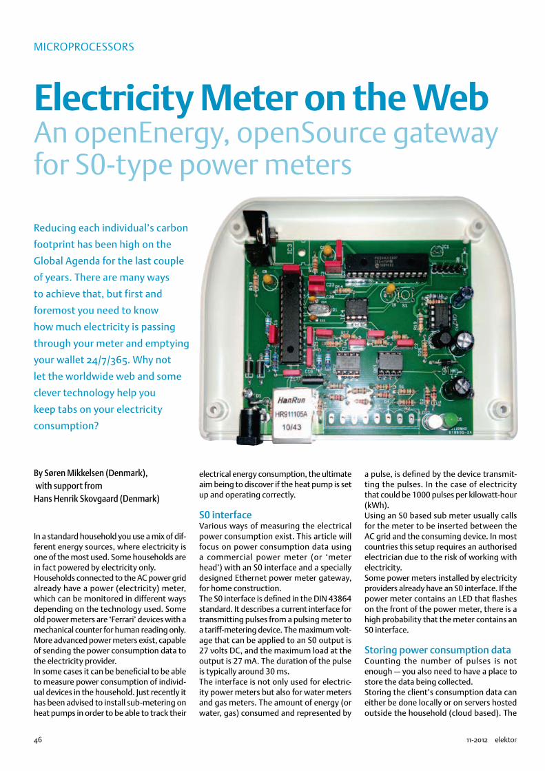
46 11-2012 elektor
Microprocessors
Electricity Meter on the WebAn openEnergy, openSource gateway for S0-type power meters
In a standard household you use a mix of dif-ferent energy sources, where electricity is one of the most used. Some households are in fact powered by electricity only.Households connected to the AC power grid already have a power (electricity) meter, which can be monitored in different ways depending on the technology used. Some old power meters are ‘Ferrari’ devices with a mechanical counter for human reading only. More advanced power meters exist, capable of sending the power consumption data to the electricity provider.In some cases it can be beneficial to be able to measure power consumption of individ-ual devices in the household. Just recently it has been advised to install sub-metering on heat pumps in order to be able to track their
electrical energy consumption, the ultimate aim being to discover if the heat pump is set up and operating correctly.
S0 interfaceVarious ways of measuring the electrical power consumption exist. This article will focus on power consumption data using a commercial power meter (or ‘meter head’) with an S0 interface and a specially designed Ethernet power meter gateway, for home construction.The S0 interface is defined in the DIN 43864 standard. It describes a current interface for transmitting pulses from a pulsing meter to a tariff-metering device. The maximum volt-age that can be applied to an S0 output is 27 volts DC, and the maximum load at the output is 27 mA. The duration of the pulse is typically around 30 ms.The interface is not only used for electric-ity power meters but also for water meters and gas meters. The amount of energy (or water, gas) consumed and represented by
a pulse, is defined by the device transmit-ting the pulses. In the case of electricity that could be 1000 pulses per kilowatt-hour (kWh).Using an S0 based sub meter usually calls for the meter to be inserted between the AC grid and the consuming device. In most countries this setup requires an authorised electrician due to the risk of working with electricity.Some power meters installed by electricity providers already have an S0 interface. If the power meter contains an LED that flashes on the front of the power meter, there is a high probability that the meter contains an S0 interface.
Storing power consumption dataCounting the number of pulses is not enough — you also need to have a place to store the data being collected.Storing the client’s consumption data can either be done locally or on servers hosted outside the household (cloud based). The
By Søren Mikkelsen (Denmark), with support from Hans Henrik Skovgaard (Denmark)
Reducing each individual’s carbon
footprint has been high on the
Global Agenda for the last couple
of years. There are many ways
to achieve that, but first and
foremost you need to know
how much electricity is passing
through your meter and emptying
your wallet 24/7/365. Why not
let the worldwide web and some
clever technology help you
keep tabs on your electricity
consumption?
74874

47elektor 11-2012
electricity Meter on the Web
amount of data and the bandwidth required for storing power consumption are not a big deal by today’s standards. Here we’ve elected to use an open source solution to store and present power con-sumption data. The solution originates
from the openenergymonitor project [1]. That project has created a system based on PHP and the MySql database. In terms of availability, you are unlikely to find a bet-ter solution. It’s open source, so you have full access to the source. But you don’t need
be a web-tool expert to use it. You can also use it from a hosted service for a modest fee (www.emoncms.org). But you can also host it on your own server or at any ‘web hotel’ provider that supports PHP and MySql.
X2 9
1112
13
14
12345678
10
Q1
25MHz
C14
22p
C13
22p
+3V3
C18
100n
C17
100n
C21
100n
C20
100n
C23
100n
C9
10u
R26
2k32
R27330R
R24330R
R29
49k9
R28
49k9
C15
100n
1% 1%
R23
49k9
R20
49k9
1% 1%
+3V3
L3
100MHz
C11
100n
HR911105A
C4
100n
C3
100n
+3V3
C5
10u16V16V
ENC28J60SP
TPOUT+
VDDO
SCVD
DPLL
VSSP
LLVS
SOSC
TPOUT–
CLKOUT
VDDR
XVD
DTX
VSST
XVS
SRX
RESETTPIN+TPIN–
RBIAS
OSC2OSC1
IC5
LEDALEDB
VCAP
INT
VDD
VSS
WOL
SCK
23
25
24
28
17
201915
18 11 21 22
10
SOSICS
16
1312
2726
14
4
2
5
67
8
9
31
R8
1k
+3V3
R5
2k
+3V3
S1
RESET
JP112345
+3V3 FLASH-CS
ETH-MOSIETH-MISOETH-CLK
ETH-MOSIETH-MISOETH-MISO
OPTO-1OPTO-2OPTO-4OPTO-3
PGD3/EMUD3/ASDA1/RP5/CN27/PMD7/RB5PGC3/EMUC3/ASCL1/RP6/CN24/PMD6/RB6
PGC2/EMUC2/TMS/RP11/CN15/PMD1/RB11PGD2/EMUD2/TDI/RP10/CN16/PMD2/RB10
PGD1/EMUD1/AN2/C2IN–/RP0/CN4/RB0PGC1/EMUC1/AN3/C2IN+/RP1/CN5/RB1
AN10/RTCC/RP14/CN12/PMWR/RB14
TCK/SCL1/RP8/CN22/PMD4/RB8TDO/SDA1/RP9/CN21/PMD3/RB9
AN9/RP15/CN11/PMCS1/RB15
AN11/RP13/CN13/PMRD/RB13AN12/RP12/CN14/PMD0/RB12
OSCO/CLKO/CN29/PMA0/RA3
SOSCO/T1CK/CN0/PMA1/RA4SOSCI/RP4/CN1/PMBE/RB4 INT0/RP7/CN23/PMD5/RB7
AN4/C1IN–/RP2/CN6/RB2AN5/C1IN+/RP3/CN7/RB3OSCI/CLKI/CN30/RA2
AN0/VREF+/CN2/RA0AN1/VREF–/CN3/RA1
PIC24HJ128GP202VCAP/VDDCORE
IC2MCLR
AVDD
AVSS
VDD
VSS VSS
13
26
28
19
10111214
27
15
2524232221
20
181716
8
1
23
45679
R2
1k
LED2
R1
1k
LED1
DS2502IC1
DATA
GND
NC3 2
1
PGDPGC
R11330R
R16
150R
+24V
C8
100n
R12330R
R15
150R
C7
100n
OK2.A8
7
1
2
OK2.B6
5
3
4
+24V
+3V3
+3V3
R181k2
R171k2
R9330R
R7
150R
+24V
C2
100n
R10330R
R6
150R
C1
100n
OK1.B6
5
3
4
OK1.A8
7
1
2
+24V
+3V3
+3V3
R41k2
R31k2
OPTO-1
OPTO-2
OPTO-3
OPTO-4
+V
R21
1R
R19
180R
C16
420p
R22
1k2
C12
100u 16VL
DR125100uH
C19
100u
C22
100u
L4
1uH
R25
22k
+24V
MC34063
IC6
SWEDRC
SWCCII
IPK
GND
VCC
TC
6
3 28
4
175
110462 - 11
J1
LM1086TO263IC3
L1
L1, L2 = EMI filter bead
MICC10
C6
10u
C10
10u16V 16V
D1
L2
MICC10
+V
+3V3
25LC1024
EEPR
OMAr
ray
IC4
GNDHLDSCK
VCC
SI SO
WP
CS
8
4
5 2
7
3
6
1
R14
10k
+3V3
ETH-MOSIETH-CLK
ETH-CS ETH-CS
FLASH-CS
ETH-MISO
1WIR
E-MA
C
POWER-STATUSPOWER-S0
LED-LINKLED-STATUS
TD+TD–RD+CCT
RD–
X1
12345678
OK1 = PS2501-2OK2 = PS2501-2
MCLR
R31180RR32180R
R30180R
S2
D2
1N5818
R13
10k
50V50V
JP2
123
TX RX G
S0 POWER
SAC45-E3/54
Figure 1. Circuit diagram of the Puls0 gateway for S0-compatible electricity meter modules. Four S0 inputs are provided.
74874

48 11-2012 elektor
Microprocessors
The Puls0 Powermeter GatewayThe initial requirements for the Puls0 gate-way were:
•four S0 inputs;•5 volt supply;•Ethernet connectivity;•OpenEnergyMonitor EmonCMS support;•Visual indication on received pulses.
The schematic of the gateway appears in Figure 1. First off, unlike many other cir-cuits designed today this design is made with leaded components only. This makes it possible for people with big thumbs and weak eyes (the author included) to solder the circuit without significant problems. All the prototypes of this circuit have been manufactured using PCBs from a profes-sional board factory.
The Puls0 gateway consists of the following hardware blocks. Power supply, local stor-age, microcontroller, S0 interface and Eth-ernet interface. Let’s have a look at each of these.
The power supply around IC3 converts the input voltage to the required 3.3 volts used by the local storage, microcontroller and Ethernet interface block. The Ethernet circuit by itself requires up to 500 mA. An
LM1086-3.3 regulator handles the conver-sion. A heatsink is also required since the regulator gets rather hot.
The local storage block consists of a Micro-chip SPI based serial EEPROM, IC4. It handles the local software settings, but also con-tains the web pages used for the user inter-face. A 1024-Kbit EEPROM is big enough to handle the web pages including graph-ics. This of course doesn’t have room for fancy flash based configuration pages. But a decent JavaScript /CSS/HTML based UI should be okay too.
The microcontroller is a Microchip PIC24HJ128GP202 16-bit, 40-MIPS device (IC2). It has 128 KBytes Flash memory and 8 KBytes RAM. In terms of speed this micro-controller is more than capable of handling the web server and other TCP/IP client functionality.
The S0 interface around OK2A/B and OK1A requires a higher voltage (approx. 24 V) to operate. This is provided by a step-up DC-DC converter (IC6). The input volt-age to this converter is taken directly from the power adapter supplying the gate-way. The DC-DC converter is based on the widely used MC34063 chip used in a billion devices on the globe. Each S0 interface port
is isolated from the microcontroller with an optocoupler.
The Ethernet interface is based on the Microchip ENC28j60 Ethernet controller (IC5). The gateway uses an Ethernet con-nector with built in magnetics. It’s crucial to stick to the one shown here (X2). The ENC28J60 chip is very picky with the type of Ethernet connector used. Not all Ether-net connectors with built in magnetics can be used. The various connectors out there on the market are also not pin-compatible.
Construction and testingThe circuit board design for the Puls0 gate-way appears in Figure 2. There is no special procedure for assembling the board. It is however a good idea to solder the different function blocks in steps, starting with the power supply. Then verify that the chips in each function block get the right voltage, and that there are no short circuits.Pay special attention to the voltage regu-lator and the heatsink. The pair have to be mounted carefully to prevent any risk of short circuits.
Once you’re sure the chips get the right voltage, do verify that the Ethernet control-ler has the right Vcap (pin 14) voltage. This voltage should be around 2.5 volts. If that is the case, plug in an Ethernet cable that’s connected to an active network through a switch. Now the LEDs in the connector should start to flash.Assuming that there is no short circuit, the circuit is ready for programming.
Adding software to the Puls0 gatewayWithout software the Puls0 gateway wouldn’t be of much use. The software is applied to the box in two steps. First, the microcontroller firmware is down-loaded. Next the web pages are put into the EEPROM. All software components for the project and the Eagle board design data are available free of charge from the Elektor website [2].
The PIC24HJ128GP202 microcontroller can be programmed using a Microchip PICKIT3 or similar. Remember to keep the circuit
Figure 2. Printed circuit board design for the ‘electricity meter’s gateway to the web’. Remarkably (happily?) there are through-hole components only on the board.
74874
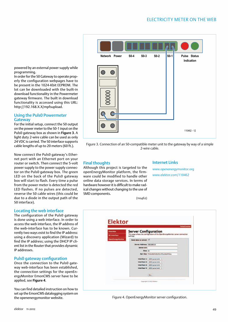
49elektor 11-2012
electricity Meter on the Web
powered by an external power supply while programming.In order for the S0 Gateway to operate prop-erly the configuration webpages have to be present in the 1024-Kbit EEPROM. The lot can be downloaded with the built-in download functionality in the Powermeter gateway firmware. The built in download functionality is accessed using this URL: http://192.168.X.X/mpfsupload.
Using the Puls0 Powermeter GatewayFor the initial setup, connect the S0 output on the power meter to the S0-1 input on the Puls0 gateway box as shown in Figure 3. A light duty 2-wire cable can be used as only 24 VDC is carried. The S0 interface supports cable lengths of up to 20 meters (60 ft.).
Now connect the Puls0 gateway’s Ether-net port with an Ethernet port on your router or switch. Then connect the 5-volt power supply to the power supply connec-tor on the Puls0 gateway box. The green LED on the back of the Puls0 gateway box will start to flash. Every time a pulse from the power meter is detected the red LED flashes. If no pulses are detected, reverse the S0 cable wires (this could be due to a diode in the output path of the S0 interface).
Locating the web interfaceThe configuration of the Puls0 gateway is done using a web interface. In order to access the web interface, the IP address of the web-interface has to be known. Cur-rently two ways exist to find the IP address:using a discovery application (Wizard) to find the IP address; using the DHCP IP cli-ent list in the Router that provides dynamic IP addresses.
Puls0 gateway configurationOnce the connection to the Puls0 gate-way web-interface has been established, the connection settings for the openEn-ergyMonitor EmonCMS server have to be applied, see Figure 4.
You can find detailed instruction on how to set up the EmonCMS datalogging system on the openenergymonitor website.
Final thoughtsAlthough this project is targeted to the openEnergyMonitor platform, the firm-ware could be modified to handle other online data storage services. In terms of hardware however it is difficult to make rad-ical changes without changing to the use of SMD components.
(110462)
Internet Links
www.openenergymonitor.org
www.elektor.com/110462
110462 - 12
Network Power S0-4 S0-3 S0-2 S0-1 StatusPulseIndication
00000
Figure 3. Connection of an S0-compatible meter unit to the gateway by way of a simple 2-wire cable.
Figure 4. OpenEnergyMonitor server configuration.
74874

50 11-2012 elektor
MICROCONTROLLERS
A Library for the ElektorBusThe fast track to your own bus firmware
By Jens Nickel
Exactly one year ago we presented
software that lets you implement a
PC-based controller for your own bus
applications quickly and conveniently. Now
we are extending this rapid development
concept to include the firmware for the
microcontroller nodes. The ElektorBus C
library relieves developers of the tedious
task of dealing with the bus protocol at the
bit level. The library even includes its own
hardware layer, which makes it independent
of your choice of microcontroller. This
creates attractive perspectives extending
beyond the bus itself.
With tricky projects, simply coming up with a bit of software that actually does what it’s supposed to do can sometimes be a major triumph. That’s how it was with the ElektorBus. In the course of our series of articles on the bus [1], we first had to develop the pro-tocol functions. For that we usually downloaded firmware to the microcontrollers and used it to test the new functions.
However, in the course of time our expectations grew. For vari-ous types of bus nodes, such as experimental nodes with photo-sensors or relays or operational boards, we had to develop spe-cific firmware each time. Although the basic structure was always the same, we first had to laboriously figure out where the code had to be modified in order to do something different, such as transmitting a numerical value instead of receiving one. There was also no getting round an detailed study of the protocol specs when we had to hard-code the bytes of a message to do some-thing like energise or release a relay.
Many advantagesA library can be a real help in such situations. It hides the unchang-ing basic structure of the bus firmware behind a few function calls, allowing the actual application code to be short and relatively easy to understand. It independently computes the bytes that have to be transmitted on the bus, relieving application developers of the onerous task of bashing individual protocol bits. Finally, it makes the application code independent of the hardware, which means it is independent of the actual bus node boards and microcontrollers. This is important because we keep receiving questions about the possibility of using other microcontrollers, such as PIC devices. For-tunately, the C language has a standardised syntax and the compil-ers for a wide variety of microcontroller types observe the syntax rules. This makes it possible to write platform-independent appli-cation code (Figure 1) that can be ported from one type of board to another.
We call the libraryNow it’s time to leave the theory behind and turn to practical mat-ters. The following lines of code:
Elektor products and support•Experimental node board (PCB 110258-1 or set of three boards
110258-1C3)•RS485/USB converter, fully assembled and tested (110258-91)•Stepper motor driver (PCB 110018-1)
•Free software download
All products and downloads are available via the web page for this article: www.elektor.com/120582
74874
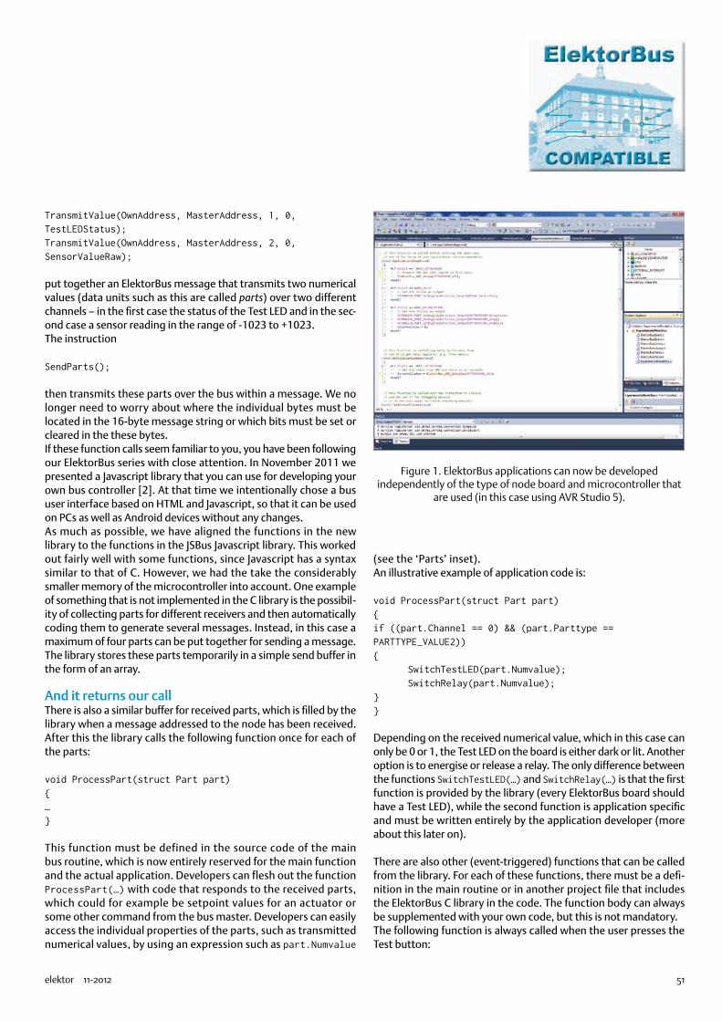
51elektor 11-2012
TransmitValue(OwnAddress, MasterAddress, 1, 0, TestLEDStatus);TransmitValue(OwnAddress, MasterAddress, 2, 0, SensorValueRaw);
put together an ElektorBus message that transmits two numerical values (data units such as this are called parts) over two different channels – in the first case the status of the Test LED and in the sec-ond case a sensor reading in the range of -1023 to +1023.The instruction
SendParts();
then transmits these parts over the bus within a message. We no longer need to worry about where the individual bytes must be located in the 16-byte message string or which bits must be set or cleared in the these bytes.If these function calls seem familiar to you, you have been following our ElektorBus series with close attention. In November 2011 we presented a Javascript library that you can use for developing your own bus controller [2]. At that time we intentionally chose a bus user interface based on HTML and Javascript, so that it can be used on PCs as well as Android devices without any changes.As much as possible, we have aligned the functions in the new library to the functions in the JSBus Javascript library. This worked out fairly well with some functions, since Javascript has a syntax similar to that of C. However, we had the take the considerably smaller memory of the microcontroller into account. One example of something that is not implemented in the C library is the possibil-ity of collecting parts for different receivers and then automatically coding them to generate several messages. Instead, in this case a maximum of four parts can be put together for sending a message. The library stores these parts temporarily in a simple send buffer in the form of an array.
And it returns our callThere is also a similar buffer for received parts, which is filled by the library when a message addressed to the node has been received. After this the library calls the following function once for each of the parts:
void ProcessPart(struct Part part)…
This function must be defined in the source code of the main bus routine, which is now entirely reserved for the main function and the actual application. Developers can flesh out the function ProcessPart(…) with code that responds to the received parts, which could for example be setpoint values for an actuator or some other command from the bus master. Developers can easily access the individual properties of the parts, such as transmitted numerical values, by using an expression such as part.Numvalue
(see the ‘Parts’ inset).An illustrative example of application code is:
void ProcessPart(struct Part part)if ((part.Channel == 0) && (part.Parttype == PARTTYPE_VALUE2)) SwitchTestLED(part.Numvalue); SwitchRelay(part.Numvalue);
Depending on the received numerical value, which in this case can only be 0 or 1, the Test LED on the board is either dark or lit. Another option is to energise or release a relay. The only difference between the functions SwitchTestLED(…) and SwitchRelay(…) is that the first function is provided by the library (every ElektorBus board should have a Test LED), while the second function is application specific and must be written entirely by the application developer (more about this later on).
There are also other (event-triggered) functions that can be called from the library. For each of these functions, there must be a defi-nition in the main routine or in another project file that includes the ElektorBus C library in the code. The function body can always be supplemented with your own code, but this is not mandatory.The following function is always called when the user presses the Test button:
Figure 1. ElektorBus applications can now be developed independently of the type of node board and microcontroller that
are used (in this case using AVR Studio 5).
74874

52 11-2012 elektor
MICROCONTROLLERS
void TestButtonClicked(void) ToggleTestLED();
This example implements a simple debugging feature that can be used to determine whether or not the software is actually running on the node.The functions presently implemented in the library are listed and briefly described in the ‘Major Functions’ inset.
The bus machineNothing has changed in the basic execution of the firmware. First the hardware and the node parameters (such as the address) are ini-tialised, and then the code enters an infinite loop. Only after enter-ing the loop can the node start performing application-specific tasks, such as reading sensor values via the ADC. Next comes the actual bus engine. It initially responds to any messages that have
been received, including messages from the bus scheduler. If the node is a scheduled node and the scheduler asks it to send a mes-sage, SendFlag is set to initiate immediate transmission of a mes-sage. Otherwise the node, operating as a FreeBus node, transmits only in the FreeBus phase and only if it has something to transmit (SendEventFlag == TRUE). The algorithm that waits for the mes-sage confirmation from the receiver and repeats the transmission if necessary (since collisions can occur in the FreeBus phase) is also unchanged (see [3] for the relevant terminology).
All of this is now encapsulated in the library, and the application developer does not need to be concerned with the code for these functions. The developer only needs to know that SendEventFlag is set when the function SendParts(); is called, and that in this situ-ation the message is not sent immediately, but only when the next FreeBus phase occurs. A different mechanism is incorporated for periodically queried (scheduled) nodes. When such a node receives a message from the scheduler advising that it’s at the head of the queue, the library first calls the function
void PreparePartsForScheduledMessage()…
The definition of this function must also be present in the applica-tion code. Now the node can collect the current values of the appro-priate parts (e.g. sensor values):
void PreparePartsForScheduledMessage() TransmitValue(OwnAddress, MasterAddress, 0, 0, SensorValueRaw);
In this case it is not necessary to call SendParts().
As the library contains the recurrent portions of the firmware, the main loop can be kept nice and short, as illustrated in Listing 1. The names of the function calls are self-explanatory. The functions ApplicationSetup() and GetApplicationData() must be imple-mented by the application developer. For example, you could ini-tialise an ADC and then periodically read in sensor values.
Hardware functionsYou can use the following code to initialise the ADC:
void ApplicationSetup() ElektorBus_ADC_Setup(0);
The function ElektorBus_ADC_Setup(0) initialises the ADC (ADC channel 0). The underlying instructions (specific values must be writ-
USER APPLICATION
APPLICATION PROTOCOLJSBUS
HOST
REC
AA MODE REC SEND DATA CRC
SEND PART PART PART
HYBRID MODE/SCHEDULER
ELEKTOR MESSAGE PROTOCOL
USB / VCP/ HARDWARE UART HARDWARE
ELEKTORBUSBOARD.H /.C
ELEKTORBUSNODE.H /.C
ELEKTORBUSLIBRARY.H /.C
USER APPLICATION
120582 - 13
ELEKTOR BUS
PC
µC
Figure 2. Software for rapid application development. The ElektorBus C library is simultaneously responsible for both protocol
layers ( message and application protocols). There is also a hardware layer.
Listing 1: The main loop of all ElektorBus firmware.
int main(void) ElektorBusLibrarySetup(); ApplicationSetup(); while(1) GetApplicationData(); ElektorBusEngine();
74874
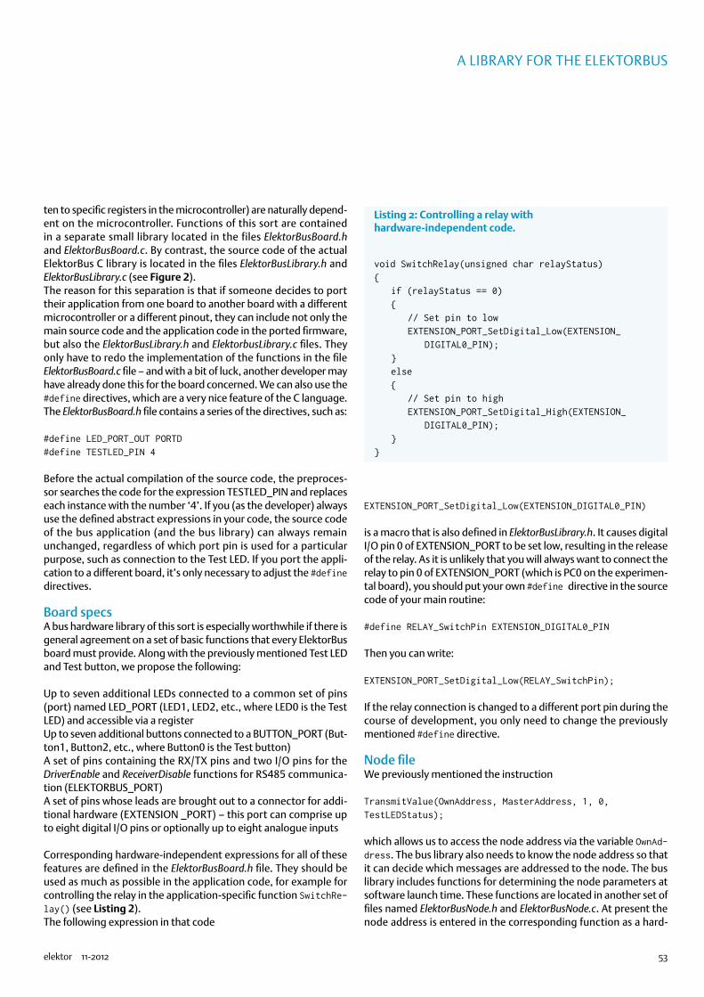
53elektor 11-2012
A LIbRARy fOR ThE ELEkTORbuS
ten to specific registers in the microcontroller) are naturally depend-ent on the microcontroller. Functions of this sort are contained in a separate small library located in the files ElektorBusBoard.h and ElektorBusBoard.c. By contrast, the source code of the actual ElektorBus C library is located in the files ElektorBusLibrary.h and ElektorBusLibrary.c (see Figure 2).The reason for this separation is that if someone decides to port their application from one board to another board with a different microcontroller or a different pinout, they can include not only the main source code and the application code in the ported firmware, but also the ElektorBusLibrary.h and ElektorbusLibrary.c files. They only have to redo the implementation of the functions in the file ElektorBusBoard.c file – and with a bit of luck, another developer may have already done this for the board concerned. We can also use the #define directives, which are a very nice feature of the C language. The ElektorBusBoard.h file contains a series of the directives, such as:
#define LED_PORT_OUT PORTD#define TESTLED_PIN 4
Before the actual compilation of the source code, the preproces-sor searches the code for the expression TESTLED_PIN and replaces each instance with the number ‘4’. If you (as the developer) always use the defined abstract expressions in your code, the source code of the bus application (and the bus library) can always remain unchanged, regardless of which port pin is used for a particular purpose, such as connection to the Test LED. If you port the appli-cation to a different board, it’s only necessary to adjust the #define directives.
Board specsA bus hardware library of this sort is especially worthwhile if there is general agreement on a set of basic functions that every ElektorBus board must provide. Along with the previously mentioned Test LED and Test button, we propose the following:
Up to seven additional LEDs connected to a common set of pins (port) named LED_PORT (LED1, LED2, etc., where LED0 is the Test LED) and accessible via a registerUp to seven additional buttons connected to a BUTTON_PORT (But-ton1, Button2, etc., where Button0 is the Test button)A set of pins containing the RX/TX pins and two I/O pins for the DriverEnable and ReceiverDisable functions for RS485 communica-tion (ELEKTORBUS_PORT)A set of pins whose leads are brought out to a connector for addi-tional hardware (EXTENSION _PORT) – this port can comprise up to eight digital I/O pins or optionally up to eight analogue inputs
Corresponding hardware-independent expressions for all of these features are defined in the ElektorBusBoard.h file. They should be used as much as possible in the application code, for example for controlling the relay in the application-specific function SwitchRe-lay() (see Listing 2).The following expression in that code
EXTENSION_PORT_SetDigital_Low(EXTENSION_DIGITAL0_PIN)
is a macro that is also defined in ElektorBusLibrary.h. It causes digital I/O pin 0 of EXTENSION_PORT to be set low, resulting in the release of the relay. As it is unlikely that you will always want to connect the relay to pin 0 of EXTENSION_PORT (which is PC0 on the experimen-tal board), you should put your own #define directive in the source code of your main routine:
#define RELAY_SwitchPin EXTENSION_DIGITAL0_PIN
Then you can write:
EXTENSION_PORT_SetDigital_Low(RELAY_SwitchPin);
If the relay connection is changed to a different port pin during the course of development, you only need to change the previously mentioned #define directive.
Node fileWe previously mentioned the instruction
TransmitValue(OwnAddress, MasterAddress, 1, 0, TestLEDStatus);
which allows us to access the node address via the variable OwnAd-dress. The bus library also needs to know the node address so that it can decide which messages are addressed to the node. The bus library includes functions for determining the node parameters at software launch time. These functions are located in another set of files named ElektorBusNode.h and ElektorBusNode.c. At present the node address is entered in the corresponding function as a hard-
Listing 2: Controlling a relay with hardware-independent code.
void SwitchRelay(unsigned char relayStatus) if (relayStatus == 0) // Set pin to low EXTENSION_PORT_SetDigital_Low(EXTENSION_ DIGITAL0_PIN); else // Set pin to high EXTENSION_PORT_SetDigital_High(EXTENSION_ DIGITAL0_PIN);
74874

54 11-2012 elektor
MICROCONTROLLERS
coded value:
unsigned char GetNodeAddress() return 5;
However, we intend to implement dynamic node addressing at a later date in this project.
Example softwareAs you might expect, we again have example software [4] for this instalment of the ElektorBus series. The project for AVR Studio 5 includes all the files mentioned above, along with an example appli-cation. Actually there are three example applications, which you can select as desired by means of a directive at the beginning of the ElektorBusNode.h file:
#define DEVICE NODE_PHOTOSENSOR
The node is then assigned the corresponding address (5, 6 or 7) when the software starts up, and the firmware determines whether the node is scheduled or not. Of course, you can adapt the addresses in the ElektorBusNode.c file to suit your own requirements.The hardware -dependent f i les ElektorBusBoard.h and ElektorBusBoard.c are tailored to the small experimental node board. However, the hex file is too big for the flash memory of an ATmega88, which must be replaced by the pin-compatible (and not significantly more expensive) ATmega328. As the bus library is intended to form the basis for further development, an additional requirement for ElektorBus boards is at least 32 KB of flash memory in the microcontroller; 64 KB or more is preferable. For the example
120582 - 12
USBRS485
CONVERTERNODE
PC DOMOTICS MASTERSCHEDULER
USB
8
ELEKTOR BUS
5
100
M
+VIN
+V GND
GND
+5VDIR
STEPENABLE
POWER SUPPLYMOTOR
ELEKTORBUS
120582 - 11
Figure 3. All you need to run the example application is an RS485 to USB converter and an experimental node board, which must be
fitted with an ATmega328.
Figure 4. For the third example application, the experimental node board is connected to the stepper motor driver described in the June 2012 issue of Elektor. We used a small stepper motor from Ming Jong [9].
74874

55elektor 11-2012
A LIbRARy fOR ThE ELEkTORbuS
software you need only one experimental node board, along with an RS485 to USB converter (see Figure 3).
Motor control liteIn order to try out the software, you must connect a photoresistor or a relay to the EXTENSION_PORT of the experimental node board (on pin header K4 with 5 V, GND, and PC0–PC6). The circuitry for the photosensor (you can use a potentiometer instead) and the relay extension is described in instalment 8 of the ElektorBus series [5]. As a special treat, we have included a third application: a simple con-troller for a stepper motor. For this you need to connect the Elektor stepper motor driver board [6][7] to the experimental node board as shown in Figure 4. Incidentally, this is a sort of sneak preview of an upcoming ElektorBus article in which we will describe a bus-compatible stepper motor driver board.The download [4] also includes a UIBus folder with a very simple HTML file for controlling all of this from a PC. Simply drag it onto the desktop and run ElektorBusBrowser.exe [8]. Start by launching the scheduler by means of the corresponding HTML button (Fig-
ure 5). After the original firmware has been downloaded to the ATmega328, you should see sensor readings. In addition, the red Test LED on the board should toggle when you press the Test but-ton on the board. The LED status is also shown in the radio button on the PC.If NODE_RELAY is selected in the firmware and a relay is connected, you can energise and release the relay. You can also do this manu-ally on the board with the Test button.If instead you include #define DEVICE NODE_MOTORCONTROL in the firmware, you can cause the stepper motor to move 1,000 steps forward or backward from the PC.
OutlookThere’s still a lot to be done, since the bus library is presently only available in an initial version and contains only the most essential functions. Among other things, we should also implement interval functions (for periodic transmission of sensor values from nodes) and in connection with these, functions for the initialisation of tim-ers, etc.
PartsThe ElektorBus protocol specifies that up to four parts (data units) can be transmitted in the eight application data bytes of an ElektorBus message. For example, these parts can be meas-ured values, setpoint values, limit indications or commands for changing the unit or scale. A part is represented in the ElektorBus C library by a data structure identified by the keyword struct. For each received part, the library calls the function void ProcessPart(struct Part part) and passes the data structure corresponding to part to the function. The application de-veloper can use an expression such as part.Numvalue to access all the properties of a received part:
Valid Checksum OK? (not yet implemented)
Sender Transmitter address
Receiver Receiver address
Channel Channel number
Setflag Setpoint or reading?
Ackflag Acknowledgement message or original message (flag at application level)
Mode Mode byte of the message (with acknowledge flags at the message level)
Parttype Type of part, for which the following constants are defined: PARTTYPE_VALUE2, PARTTYPE_VALUE4, PARTTYPE_VALUEFLOAT, PARTTYPE_LIMIT, PARTTYPE_SCALE, PARTTYPE_INTERVAL
Numvalue Transmitted numerical value (e.g. -1023–1023 for PARTTYPE_VALUE2)
Limit 0 = All OK; 1 = Below lower limit; 2 = Above upper limit
Quantity Physical quantity (0–127; see [3])
Unit Unit (0–3; see [3])
Scale Exponent for scaling (-15 t +15)
Interval Interval scaling unit for sensor messages (see [3])
Preset Reserved
0 1 0 1 0 1 0 1 0
BYTE 7BIT
6 5 4 3 2 1 0
1
ID
MODE0 0 0 0 0 0 0
120582 - 16
023456789ABCDEF
ADDRESS RECEIVER
ADDRESS SENDER
PART
PART
PART
CRC
74874

56 11-2012 elektor
MICROCONTROLLERS
This will give us a nice little library that allows us to control a vari-ety of microcontroller functions quite independently of the type of IC that is used. We have already checked the basic feasibility of this approach with an ATxmega 256, which will be fitted on an upcom-ing Elektor board. This creates possibilities for developing a sort of
Elektor firmware library that can also be used for other projects (not just the ElektorBus). It‘s a very attractive idea to think that Elektor projects from other electronics enthusiasts could be ported very easily to your favourite microcontroller.
We will keep you posted on this and more at www.elektor-projects.com.
(120582-I)
Internet Links
[1] www.elektor.com/elektorbus
[2] www.elektor.com/110517
[3] www.elektor.com/Uploads/2012/2/ElektorBusReference.pdf
[4] www.elektor.com/120582
[5] www.elektor.com/110428
[6] www.elektor.com/110018
[7] http://rch.lt/schrittmotor
[8] www.elektor.com/110708
[9] www.mingjong.net/index.php?action=prod_detail&p_id=88&lang=en
Figure 5. A very simple HTML user interface for trying out the three example applications.
Major functions in the ElektorBus C library
Functions and variables implemented in ElektorBusLibrary.c
void SetValue(sender, receiver, channel, mode, setvalue)
Puts an additional part in the send buffer that sets a target value for an actuator.
void TransmitValue(sender, receiver, channel, mode, currentvalue)
Puts an additional part in the send buffer that represents the actual value of a sensor/actuator.
void SendParts()
Encodes all parts stored in the send buffer into a message and trans-mits the message.
void SwitchTestLED(unsigned char ledStatus)
Switches the Test LED on (ledStatus = 1) or off (ledStatus = 0).
void ToggleTestLED()
Toggles the Test LED.
74874
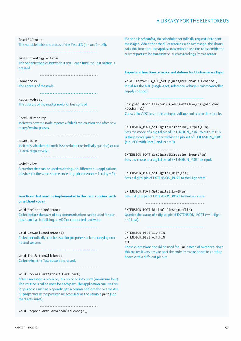
57elektor 11-2012
A LIbRARy fOR ThE ELEkTORbuS
TestLEDStatus
This variable holds the status of the Test LED (1 = on; 0 = off).
TestButtonToggleStatus
This variable toggles between 0 and 1 each time the Test button is pressed.
OwnAddress
The address of the node.
MasterAddress
The address of the master node for bus control.
FreeBusPriority
Indicates how the node repeats a failed transmission and after how many FreeBus phases.
IsScheduled
Indicates whether the node is scheduled (periodically queried) or not (1 or 0, respectively).
NodeDevice
A number that can be used to distinguish different bus applications (devices) in the same source code (e.g. photosensor = 1; relay = 2).
Functions that must be implemented in the main routine (with or without code)
void ApplicationSetup()
Called before the start of bus communication; can be used for pur-poses such as initialising an ADC or connected hardware.
void GetApplicationData()
Called periodically; can be used for purposes such as querying con-nected sensors.
void TestButtonClicked()
Called when the Test button is pressed.
void ProcessPart(struct Part part)
After a message is received, it is decoded into parts (maximum four). This routine is called once for each part. The application can use this for purposes such as responding to a command from the bus master. All properties of the part can be accessed via the variable part (see the ‘Parts’ inset).
void PreparePartsForScheduledMessage()
If a node is scheduled, the scheduler periodically requests it to sent messages. When the scheduler receives such a message, the library calls this function. The application code can use this to assemble the current parts to be transmitted, such as readings from a sensor.
Important functions, macros and defines for the hardware layer
void ElektorBus_ADC_Setup(unsigned char ADCchannel)
Initialises the ADC (single-shot, reference voltage = microcontroller supply voltage).
unsigned short ElektorBus_ADC_GetValue(unsigned char ADCchannel)
Causes the ADC to sample an input voltage and return the sample.
EXTENSION_PORT_SetDigitalDirection_Output(Pin)
Sets the mode of a digital pin of EXTENSION_PORT to output. Pin is the physical pin number within the pin set of EXTENSION_PORT (e.g. PCO with Port C and Pin = 0)
EXTENSION_PORT_SetDigitalDirection_Input(Pin)
Sets the mode of a digital pin of EXTENSION_PORT to input.
EXTENSION_PORT_SetDigital_High(Pin)
Sets a digital pin of EXTENSION_PORT to the High state.
EXTENSION_PORT_SetDigital_Low(Pin)
Sets a digital pin of EXTENSION_PORT to the Low state.
EXTENSION_PORT_Digital_PinStatus(Pin)
Queries the status of a digital pin of EXTENSION_PORT (==1 High; ==0 Low).
EXTENSION_DIGITAL0_PINEXTENSION_DIGITAL1_PINetc.These expressions should be used for Pin instead of numbers, since this makes it very easy to port the code from one board to another board with a different pinout.
74874

Flowcode 5 is one of the world’s most advanced graphical programming languages for microcontrollers (PIC, AVR, ARM and dsPIC/PIC24). The great advantage of Flowcode is that it allows those with little to no programming experience to create complex electronic systems in minutes.
www.elektor.com/fl owcode
E-Blocks are small circuit boards each of which contains a block of electronics that you would typically fi nd in an electronic or embedded system. There are more than 40 separate circuit boards in the range; from simple LED boards to more complex boards like device program-mers, Bluetooth and TCP/IP. E-blocks can be snapped together to form a wide variety of systems that can be used for teaching/learning electronics and for the rapid prototyping of complex electronic systems. Separate ranges of complementary software, curriculum, sensors and applications information are available.
MIAC (Matrix Industrial Automotive Controller) is an industrial grade control unit which can be used to control a wide range of different electronic systems including sensing, monitoring and automotive. Internally the MIAC is powered by a powerful 18 series PICmicro device which connects directly to the USB port and can be programmed with Flowcode, C or assembly. Flowcode is supplied with the unit. MIAC is supplied with an industrial standard CAN bus interface which allows MIACs to be networked together.
Flowkit provides In Circuit Debugging for a range of Flowcode applications for PIC and AVR projects:• Start, stop, pause and step your Flowcode programs in real time• Monitor state of variables in your program• Alter variable values• In circuit debug your Formula Flowcode, ECIO and MIAC projects
E-Blocks are small circuit boards each of which contains E-Blocks are small circuit boards each of which contains a block of electronics that you would typically fi nd in an a block of electronics that you would typically fi nd in an
Flowkit provides In Circuit Debugging for a range of Flowcode applications for PIC and Flowkit provides In Circuit Debugging for a range of Flowcode applications for PIC and AVR projects:AVR projects:
… for electronics
Flowkit
Developing and learning with Flowcode 5
MIAC (Matrix Industrial Automotive Controller) is an industrial grade control unit which MIAC (Matrix Industrial Automotive Controller) is an industrial grade control unit which can be used to control a wide range of different electronic systems including sensing, can be used to control a wide range of different electronic systems including sensing,
… for industrial control
Anzeige Flowcode UK 120222.indd 2-3Naamloos-2 58 05-10-12 08:33
74874

Flowcode 5 is one of the world’s most advanced graphical programming languages for microcontrollers (PIC, AVR, ARM and dsPIC/PIC24). The great advantage of Flowcode is that it allows those with little to no programming experience to create complex electronic systems in minutes.
New features in Flowcode 5Flowcode 5 is packed with new features that make development easier including:
More information and products at:
www.elektor.com/eblocks
• New C code views and customization• Simulation improvements• Search and replace function• New variable types and features, constants
and port variables• Automatic project documentation• New project explorer makes coding easier• Implementation of code bookmarks for
program navigation
• Complete redesign of interrupts system allows developers access to more chip features
• Compilation errors and warnings navigate to icons
• Disable icons feature• Improved annotations• Improved links to support media• Support for MIAC expansion modules and
MIACbus
Formula Flowcode is a low cost robot vehicle which is used to teach and learn robotics, and to provide a platform for competing in robotics events. The specifi cation of the Formula Flowcode buggy is high with direct USB program-ming, line following sensors, distance sensors, 8 onboard LEDs, sound sensor, speaker and an E-blocks expansion port. The buggy is suitable for a wide range of robotics exercises from simple line following through to complete maze solving. E-blocks expansion allows you to add displays, connection with Bluetooth or Zigbee, and GPS.
ECIO devices are powerful USB programmable microcontrollers with either 28 or 40 pin standard DIL (0.6”) footprints. They are based on the PIC 18 series and ARM 7 series microcontrollers. ECIO is perfect for student use at home, project work and building fully integrated embedded systems. ECIO can be programmed with Flowcode, C or Assembly and new USB routines in Flowcode allow ultra rapid development of USB projects inclu-ding USB HID, USB slave, and USB serial bus (PIC only). ECIO can be incorporated into your own circuit boards to give your projects USB reprogrammability.
Formula Flowcode is a low cost robot vehicle which is Formula Flowcode is a low cost robot vehicle which is used to teach and learn robotics, and to provide a platform used to teach and learn robotics, and to provide a platform
… for robotics
ECIO devices are powerful USB programmable microcontrollers with either 28 or 40 pin ECIO devices are powerful USB programmable microcontrollers with either 28 or 40 pin standard DIL (0.6”) footprints. They are based on the PIC 18 series and ARM 7 series standard DIL (0.6”) footprints. They are based on the PIC 18 series and ARM 7 series
… for USB projects
Developing and learning with Flowcode 5
maze solving. E-blocks expansion allows you to add displays, maze solving. E-blocks expansion allows you to add displays,
23-02-12 10:48:52Naamloos-2 59 05-10-12 08:33
74874

60 11-2012 elektor
MicrocontrollerS
SDN – Software Defined NICMicrocontroller ethernet card
Our series of articles on the SDR AVR fea-tured in the last few editions of Elektor was a good illustration of just what can be achieved with a modest 8-bit AVR micro-controller. You may find it difficult to believe but when clocked at 20 MHz and with the help of very few peripheral components it is also possible to use just such a microcon-troller to send Ethernet packets onto a net-work! To show how this ‘Software Defined Network Interface Card (SDN)’ can be built it will first be necessary to resort to a little bit of theory.
The TCP ModelWorking with networks it is not long before you come across the standard OSI reference model for network communication. In this article however we use the TCP/IP model because it comes closer to reality.From the diagram in Figure 1 it can be seen that the model consists of four layers which build on one another. The lowest layer is the network access layer, here the network
packets are sent onto the Ethernet cable. Next up is the network layer which ensures that the network packets find their way through the Internet. This network layer establishes a communication link between two computers connected together via the Internet. On top of this is the trans-port layer which provides communication between processes on the computers. The best known of these protocols is the TCP (Transmission Control Protocol), which establishes point to point communication between two processes. In contrast to IP (Internet Protocol), TCP guarantees that the packets arrived intact and in the cor-rect order. This is achieved by the receiver sending an acknowledgement onto the net-work to indicate correct packet reception or otherwise. There are also other protocols that are less well known at this level: The UDP (User Datagram Protocol) differs from the TCP protocol in that it is not secure, it doesn’t guarantee arrival or in fact in which order the packets are received. This how-ever gives the opportunity to broadcast data which the TCP does not allow. Broad-
casting refers to the sending of a message to multiple recipients on the network. The uncertainty in the data transfer should never the less be put into perspective and packets can be resent if it is determined they were lost.
The highest layer of the TCP/IP model is the application layer, which uses the underly-ing transport layer protocols to build a host to host connection. The most well know example of a TCP protocol is the HTTP which takes care of communication between a web server and a web browser. Some appli-cations use UDP despite the possibility of unreliable transfer. One of these is NFS (Net File System) from Sun microsystems, which allows access of files over a network on UDP.
Packing the packetsEach layer takes the data it is passed by the layer above and embeds it in its own frame. Contained in the frame is informa-tion to ensure that the packet arrives at the receiver processor. Some protocols place a header before the data, other append
By Dr. Merten Joost (Germany)
Many off-the-shelf network interface cards (NICs) have the disadvantage of
using expensive hardware and often require
substantial investment of time and software
development before success is achieved. We
show here just how little hardware you can get
away with if you only need to send data
onto a network. To demonstrate we build
a dirt-cheap IP network camera from an
old web cam.
74874
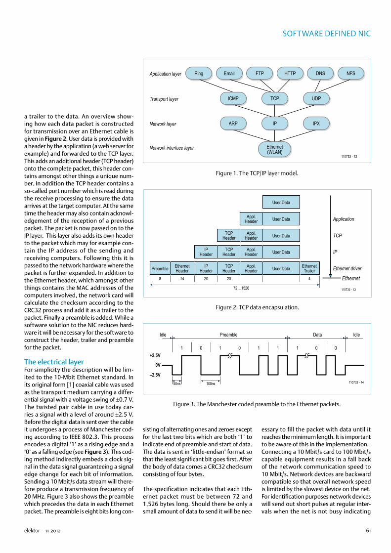
61elektor 11-2012
Software DefineD nic
a trailer to the data. An overview show-ing how each data packet is constructed for transmission over an Ethernet cable is given in Figure 2. User data is provided with a header by the application (a web server for example) and forwarded to the TCP layer. This adds an additional header (TCP header) onto the complete packet, this header con-tains amongst other things a unique num-ber. In addition the TCP header contains a so-called port number which is read during the receive processing to ensure the data arrives at the target computer. At the same time the header may also contain acknowl-edgement of the reception of a previous packet. The packet is now passed on to the IP layer. This layer also adds its own header to the packet which may for example con-tain the IP address of the sending and receiving computers. Following this it is passed to the network hardware where the packet is further expanded. In addition to the Ethernet header, which amongst other things contains the MAC addresses of the computers involved, the network card will calculate the checksum according to the CRC32 process and add it as a trailer to the packet. Finally a preamble is added. While a software solution to the NIC reduces hard-ware it will be necessary for the software to construct the header, trailer and preamble for the packet.
The electrical layerFor simplicity the description will be lim-ited to the 10-Mbit Ethernet standard. In its original form [1] coaxial cable was used as the transport medium carrying a differ-ential signal with a voltage swing of ±0.7 V. The twisted pair cable in use today car-ries a signal with a level of around ±2.5 V. Before the digital data is sent over the cable it undergoes a process of Manchester cod-ing according to IEEE 802.3. This process encodes a digital ‘1’ as a rising edge and a ‘0’ as a falling edge (see Figure 3). This cod-ing method indirectly embeds a clock sig-nal in the data signal guaranteeing a signal edge change for each bit of information. Sending a 10 Mbit/s data stream will there-fore produce a transmission frequency of 20 MHz. Figure 3 also shows the preamble which precedes the data in each Ethernet packet. The preamble is eight bits long con-
sisting of alternating ones and zeroes except for the last two bits which are both ‘1’ to indicate end of preamble and start of data. The data is sent in ‘little-endian’ format so that the least significant bit goes first. After the body of data comes a CRC32 checksum consisting of four bytes.
The specification indicates that each Eth-ernet packet must be between 72 and 1,526 bytes long. Should there be only a small amount of data to send it will be nec-
essary to fill the packet with data until it reaches the minimum length. It is important to be aware of this in the implementation.Connecting a 10 Mbit/s card to 100 Mbit/s capable equipment results in a fall back of the network communication speed to 10 Mbit/s. Network devices are backward compatible so that overall network speed is limited by the slowest device on the net. For identification purposes network devices will send out short pulses at regular inter-vals when the net is not busy indicating
PingApplication layer
Transport layer
Network layer
Network interface layer
Email FTP HTTP
ICMP TCP UDP
ARP IP
Ethernet(WLAN)
110733 - 12
DNS NFS
IPX
Figure 1. The TCP/IP layer model.
User Data
User DataAppl.Header
User DataAppl.Header
TCPHeader
User DataAppl.Header
TCPHeader
IPHeader
User Data
Application
TCP
IP
Ethernet driver
Ethernet
Preamble
8 14 20 20 4
110733 - 1372 ...1526
Appl.Header
TCPHeader
IPHeader
EthernetHeader
EthernetTrailer
Figure 2. TCP data encapsulation.
110733 - 14
1
50ns
Idle Preamble Data Idle
100ns
0 1
0V
+2.5V
–2.5V
0 1 1 1 0 0
Figure 3. The Manchester coded preamble to the Ethernet packets.
74874

62 11-2012 elektor
MicrocontrollerS
its transmission capability to a partner. At 10 Mbit/s this NLP (Normal Link Pulse) con-sists of a 100 ns pulse transmitted every 16 ms (±8 ms). For our purposes this pulse will be generated in software.
AVR NICComparing the data rate with the proces-sor clock raises the question of how it is possible to send and receive a 20 MHz sig-nal with a processor clocked at 20 MHz? The short answer is that it is not possible. The simple process of receiving the data stream
and storing it to memory requires a faster processor clock. Any attempt to interpret the data at the same time is just out of the question.
Without the possibility to receive data, communication according to TCP is also not possible. It specifies that received pack-ets must be acknowledged, implying the need for a bidirectional capability. The UPD communication protocol however specifies no acknowledge. This introduces a degree of uncertainty in the transmission path
because no handshake is implemented but for the same reason achieves a higher com-munication bandwidth. This allows trans-mission of streamed video and audio which can then be received by any computer con-nected to this local network.
Just sending the data clocked at 20 MHz is quite an achievement in itself; as well as reading the data from memory in real time it must be Manchester encoded, sent out at the correct time. In addition it is neces-sary to check the data length and append
+VCC
X4
10111213
141516171819202122232425
123456789
SV1
10
123456789
+VCC
PB2(INT2/AIN0)PB3(OC0/AIN1)
PB0(XCK/T0)
ATMega644-20PU
PC6(TOSC1)PC7(TOSC2)
PB5(MOSI)PB6(MISO)
PD2(INT0)PD3(INT1)
PD4(OC1B)PD5(OC1A)
PD6(ICP1)
PA7(ADC7)PA6(ADC6)PA5(ADC5)PA4(ADC4)PA3(ADC3)PA2(ADC2)PA1(ADC1)PA0(ADC0)
PB7(SCK)
PD0(RXD)PD1(TXD)
PD7(OC2)
PC0(SCL)PC1(SDA)PC2(TCK)PC3(TMS)PC4(TDO)
PC5(TDI)
PB1(T1)
PB4(SS)
XTAL1 XTAL2
IC1
AVCCAREF
RST
GND
VCC
GND1211
10
13 31
3032
1415161718192021
222324252627282933
34353637383940
12345678
9
G2
G1
R5
100R
R1
100R
R2
100R
R3
100R
R4
100R
+VCC
OG1
20MHz
8
5
4
+VCC
X3
4 3
12
6 5
+VCC
X2
B1
C1
470u16V
7805
IC4
C5
100n
R6
220R
LED1
+VCC
C2
100n
74HC240N
IC2
1A11A21A31A4
2A12A22A32A4
1Y11Y21Y31Y4
2Y12Y22Y32Y4
VCC
GND
131517
12141618
11
1G
192G
20
10
246
3579
81
+VCC
C3
100n
74HC299
H/QHG/QGF/QFE/QE
D/QDC/QCB/QBA/QA
QH* CLRVCC
GNDQA*
CLK
20
10
1716
15
14
13
SL 18
SR 11
G2G1
12
S1 19
S0
9
4
5
6
78
32
1
IC3
+VCC
C4
100n
110733 - 11
ISPSCKMISOMOSI
RST
(OG2) (14)
(8)
(7)
SELECTPE
BUSYACK
D0D1D2D3D4D5D6D7
SELECTPE
BUSYACK
D7D6D5D4D3D2D1D0
STROBE
SLCT INRESETERRORAUTOLF
STROBEAUTOLFERRORRESETSLCT IN
J212345678
PS/2
9V...16V
B40C1500
RJ45
Figure 4. The circuit diagram.
74874
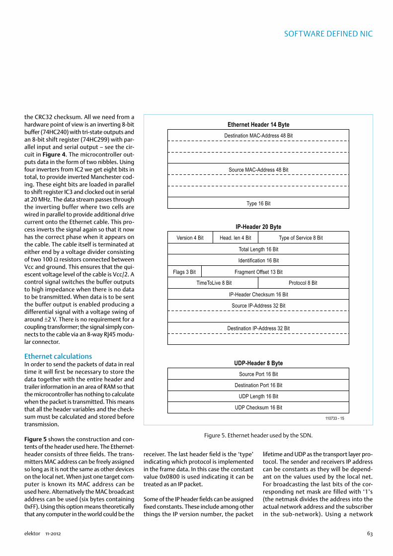
63elektor 11-2012
Software DefineD nic
the CRC32 checksum. All we need from a hardware point of view is an inverting 8-bit buffer (74HC240) with tri-state outputs and an 8-bit shift register (74HC299) with par-allel input and serial output – see the cir-cuit in Figure 4. The microcontroller out-puts data in the form of two nibbles. Using four inverters from IC2 we get eight bits in total, to provide inverted Manchester cod-ing. These eight bits are loaded in parallel to shift register IC3 and clocked out in serial at 20 MHz. The data stream passes through the inverting buffer where two cells are wired in parallel to provide additional drive current onto the Ethernet cable. This pro-cess inverts the signal again so that it now has the correct phase when it appears on the cable. The cable itself is terminated at either end by a voltage divider consisting of two 100 Ω resistors connected between Vcc and ground. This ensures that the qui-escent voltage level of the cable is Vcc/2. A control signal switches the buffer outputs to high impedance when there is no data to be transmitted. When data is to be sent the buffer output is enabled producing a differential signal with a voltage swing of around ±2 V. There is no requirement for a coupling transformer; the signal simply con-nects to the cable via an 8-way RJ45 modu-lar connector.
Ethernet calculationsIn order to send the packets of data in real time it will first be necessary to store the data together with the entire header and trailer information in an area of RAM so that the microcontroller has nothing to calculate when the packet is transmitted. This means that all the header variables and the check-sum must be calculated and stored before transmission.
Figure 5 shows the construction and con-tents of the header used here. The Ethernet-header consists of three fields. The trans-mitters MAC address can be freely assigned so long as it is not the same as other devices on the local net. When just one target com-puter is known its MAC address can be used here. Alternatively the MAC broadcast address can be used (six bytes containing 0xFF). Using this option means theoretically that any computer in the world could be the
receiver. The last header field is the ‘type’ indicating which protocol is implemented in the frame data. In this case the constant value 0x0800 is used indicating it can be treated as an IP packet.
Some of the IP header fields can be assigned fixed constants. These include among other things the IP version number, the packet
lifetime and UDP as the transport layer pro-tocol. The sender and receivers IP address can be constants as they will be depend-ant on the values used by the local net. For broadcasting the last bits of the cor-responding net mask are filled with ‘1’s (the netmask divides the address into the actual network address and the subscriber in the sub-network). Using a network
Destination MAC-Address 48 Bit
Source MAC-Address 48 Bit
Type 16 Bit
Total Length 16 Bit
Identification 16 Bit
Ethernet Header 14 Byte
Source Port 16 Bit
Destination Port 16 Bit
UDP Length 16 Bit
UDP Checksum 16 Bit
UDP-Header 8 Byte
Version 4 Bit Head. len 4 Bit Type of Service 8 Bit
Fragment Offset 13 Bit
IP-Header Checksum 16 Bit
Destination IP-Address 32 Bit
Flags 3 Bit
Protocol 8 Bit
110733 - 15
TimeToLive 8 Bit
Source IP-Address 32 Bit
IP-Header 20 Byte
Figure 5. Ethernet header used by the SDN.
74874

64 11-2012 elektor
MicrocontrollerS
address of 192.168.1.0 and a net mask of 255.255.255.0 gives the broadcast address 192.168.1.255. There are also fields which need to be calculated for each packet: The ‘total length’ field for example contains the length of the IP packets (header plus data). The packet length information can be dif-ferent every time to allow the transmission of different amounts of data. In addition a checksum of the IP header is calculated and contained in the ‘IP Header Checksum’ field. An option allows each packet to be identi-fied by a consecutive value written to the ‘Identification’ field.
The ports of the sending and receiving pro-cesses are registered in the UDP header. This will generally be a constant value and must correspond with the port of the receiving processes. Port numbers below 1,000 should be avoided because this range includes the so-called ‘well know ports’ where processes would require special
privileges to bind a network socket to an IP address. The ‘UDP length’ field is similar to the ‘IP length’ field, its value is dependant on the packet size so must be calculated for each packet. The UDP checksum is fortu-nately optional and is not calculated in this version.
Next the total packet length is checked to make sure it complies with the minimum packet length restriction. When the packet length is found to be too short its size is padded out with additional ‘padding bytes’ to increase its length. The actual value of the padding bytes is arbitrary. Once this is completed the checksum on the complete data packet can be calculated. The Ethernet preamble is not included in the checksum calculation but the data and padding bytes will be. The resulting CRC32 checksum value is now added to the end of the packet. The source code for the CRC32 calculation routine has been borrowed from the Linux
kernel; it was compiled, disassembled and heavily optimised by hand to improve the routine’s efficiency.
A library for the GNU-Assembler has been produced which contains routines to per-form all the tasks outlined above and is C compatible. It can be used with the AVR-GCC (in AVR studio 5 for example) to pro-gram all the applications. The library has two functions that are useful here; UDPInit() expects a pointer value as a parameter which points to an area in memory where the complete Ethernet packet will be stored. The routine stores all the static header information starting at this mem-ory location. It then goes on to initialise the 8-bit timer0 so that every 13 ms an inter-rupt routine is called which sends the NLP. The data is placed 50 Bytes after the start of the packet storage location. The second function UDPSend() calculates the header information from the data packets, cor-rects the packet length when necessary, calculates the CRC32 checksum and sends the packet to the net. This function expects two pointer values as parameters; the first points to the beginning of the packets in memory while the second points to the end location of the actual data.
Up and runningThe SDN needs just six LSBs from any free port of an AVR microcontroller. Four of these are used to transfer the data value while the other two control the shift reg-ister and the tri-state inverter bus driver. The controller is clocked from an exter-nal 20 MHz oscillator which also clocks the shift register. The sparse component
Figure 6. The author’s finished prototype.
IP CamFor test purposes an old parallel port camera was connected to free pins of the microcontroller. The driver code ‘cam.c’ and header ‘cam.h’ for the camera was inspired by an old GPL DOS driver which was ported to the microcontroller. The microcontroller reads the camera data line by line and creates a UDP packet for each line, prefixing the corresponding line
number. The PC software ‘canvas.exe’ takes the UDP packets and displays the image line by line. It achieves a frame rate of approximately two frames per second which is often sufficient for surveillance applications. This is a good demonstration of the capability of the software defined NIC to make an IP capable camera with a hardware cost of just 10 Euro.
Those of you interested in this demonstration should note that the camera used is a ‘Creative Labs Video Blaster WebCam II, Model 1100001424’ for parallel port operation, which can be found for sale at on-line auction sites.
74874

65elektor 11-2012
Software DefineD nic
count with just IC2 and IC3 means that the entire circuit can be laid out on a small sin-gle sided PCB. The PCB layout files along with the firmware source files for this pro-ject are available to download for free from the Elektor web page for this article [2]. Figure 6 shows the prototype board devel-oped by the author.
In the AVR Studio environment it is neces-sary to add the file ‘udp.S’ in the source files for the project. The listing ‘udp_avr.c’ is a simple test program which reserves a 54 byte area of memory for the payload. The first 50 bytes are reserved for the header while the last four bytes contain the check-sum. In order to send small packets without the need to reallocate memory area every time the send function provides a second parameter which points to end of the trans-mit data area. When the circuit is connected to a network and a (free) copy of the packet capture software Wireshark [3] is running on the PC, incoming data packets can be viewed in great detail.
PC SourceIn order to be able to read data sent by the SDN it is necessary to run software on a PC which can receive the UDP formatted pack-ets. The listing ‘udp_pc.c’ demonstrates in C (GCC under Cygwin) that you need very lit-tle code to be able to receive data via a UDP socket. Once the socket has been set up it is only necessary to call the function ‘recv()’. On the PC side you are not confined to the use of the C language, sockets are also used in some other high level languages such as Java or Delphi.
Data throughputA 10 Mbit Ethernet achieves a data rate of 1 MB/s maximum. Figure 7 shows the achievable data throughput in relation to the packet length. It can be seen that a data rate of ‘only’ 400 KB/s can be achieved. This is a result of the additional computa-tional overheads needed to calculate the CRC32 checksum. Measurements indicate that the checksum calculation takes a little more time than is actually required to send the data.
(110733)
Internet Links
[1] http://research.microsoft.com/en-us/um/people/gbell/Ethernet_Blue_Book_1980.pdf
[2] www.elektor.com/110730
[3] www.wireshark.org
[4] http://userpages.uni-koblenz.de/~physik/informatik/techC.pdf
450
400
350
300
250
200
150
100
50
00 200 400 600
Packet size in bytes
KB/s
800
110733 - 16
1000
Figure 7. Data throughput is dependant on packet size.
Listing „udp_pc.c“
#define BUFLEN 800#define PORT 6668
main() SOCKET s; struct sockaddr_in adresse; unsigned char buf[BUFLEN]; int num;
if((s = socket(AF_INET,SOCK_DGRAM, 0))<0) printf(„no socket %d\n“,s),exit(0); adresse.sin_family = AF_INET; adresse.sin_port = htons(PORT); adresse.sin_addr.s_addr = htonl(INADDR_ANY);
if(bind(s, (struct sockaddr*) &adresse, sizeof(adresse)) != 0) printf(„bind failed\n“),exit(0); num=recv(s,buf,BUFLEN,0); // do something
The AuthorDr. Merten Joost is a lecturer at the university of Koblenz, Germany, and lectures on the subjects of digital electronics, Microcontrollers and Robotics. The contents of this article are the basis of his lecture on microcontrollers [4], he also specialises on the basics of computer networks and efficient microcontroller programming.
74874

66 11-2012 elektor
BASICS
Electronics for Starters (9)Sine-wave oscillators
RC oscillatorsEveryone knows the unpleasant whistling that can occur with a public address system. It results from acoustic feedback between the loudspeaker and the microphone. The pitch of the tone varies from one situation to the next, and the effect can only be pre-vented by increasing the distance between the system components or reducing the gain.In theory, any circuit or system with suffi-cient feedback can oscillate. The feedback path may be purely electronic, such as feed-back from a signal output to an input. A necessary condition is the right phase rela-tionship, which is present with a two-stage amplifier.
The circuit in Figure 1 is similar to that of a multivibrator, but with adjustable feedback. A multivibrator always generates square-wave signals, but the circuit shown here can also generate sine waves or other wave-
forms. The feedback can be adjusted with the volume control to the point where weak oscillation just starts to occur. The wave-form in this situation is usually sinusoidal.
It is also possible to generate an oscillat-ing signal with a single transistor, even though it has a 180-degree phase shift. The required additional 180-degree phase shift can be achieved by connecting several RC networks in series. The phase-shift oscilla-tor shown in Figure 2 generates a sine-wave signal at approximately 800 kHz, which is ideal for purposes such as practicing your Morse code or providing a test signal for checking out audio amplifiers.A working phase-shift oscillator can also be built using a BS170 field effect transistor. The circuit in Figure 3 is designed with very high resistance values and oscillates at a fre-quency of 10 Hz. It draws a very low operat-ing current of approximately 30 µA.
Ring oscillatorsUp to now we have used one-stage or two-stage amplifiers to build oscillators. What
happens if you have a circuit with three common-emitter stages? You would actu-ally expect the feedback to be negative, since the overall phase shift is 180 degrees. However, in practice the circuit oscillates (Figure 4). The oscillating frequency rises with increasing supply voltage and can rise as high as 1 MHz.What is happening here? We basically have a three-stage amplifier with nega-tive feedback and very high voltage gain. However, each of the stages also causes a small time delay in addition to its gain. At a very specific frequency, the combination of these three delays results in an additional 180-degree phase shift. The negative feed-back therefore turns into positive feedback at this frequency, and the result is oscilla-tion. If you want to use a circuit of this sort as an amplifier for very low input signal lev-els rather than an oscillator, you must do everything possible to prevent any form of positive feedback. With such high gain it is not especially easy to prevent parasitic oscillations.It’s easier to build a three-stage oscillator
By Burkhard Kainka (Germany)
If we only used electronics to process existing signals, we would be missing an important aspect of
electronics: generating oscillating signals, as if by magic. Oscillators are important parts of many devices
and are used for a wide variety of purposes. For example, they can be used to generate audible signals or
test signals for checking out circuits and modules.
BC547B BC547B
100k
1k
100k
1k
1u 10u
47k100n
+9V
BC547C
100k
10k
+9V
100k
10n10n 100n
Figure 1. Oscillation caused by positive feedback. Figure 2. A phase-shift oscillator.
74874
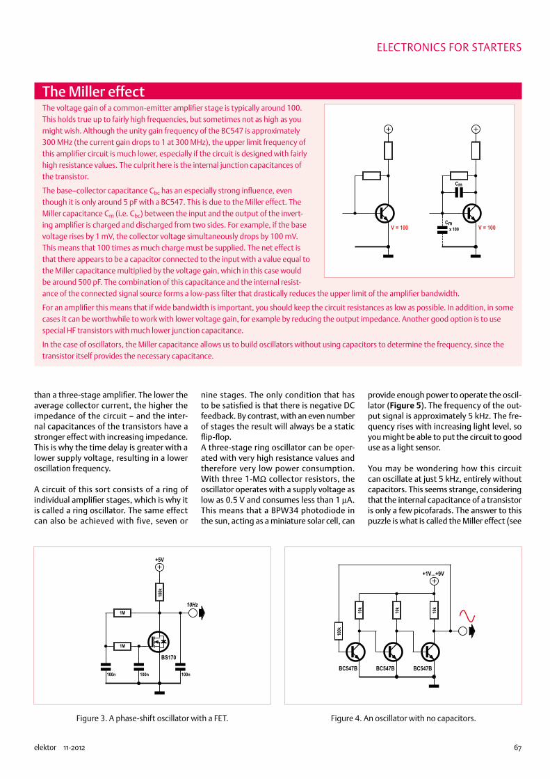
67elektor 11-2012
ElECtronICS for StArtErS
than a three-stage amplifier. The lower the average collector current, the higher the impedance of the circuit – and the inter-nal capacitances of the transistors have a stronger effect with increasing impedance. This is why the time delay is greater with a lower supply voltage, resulting in a lower oscillation frequency.
A circuit of this sort consists of a ring of individual amplifier stages, which is why it is called a ring oscillator. The same effect can also be achieved with five, seven or
nine stages. The only condition that has to be satisfied is that there is negative DC feedback. By contrast, with an even number of stages the result will always be a static flip-flop.A three-stage ring oscillator can be oper-ated with very high resistance values and therefore very low power consumption. With three 1-MΩ collector resistors, the oscillator operates with a supply voltage as low as 0.5 V and consumes less than 1 µA. This means that a BPW34 photodiode in the sun, acting as a miniature solar cell, can
provide enough power to operate the oscil-lator (Figure 5). The frequency of the out-put signal is approximately 5 kHz. The fre-quency rises with increasing light level, so you might be able to put the circuit to good use as a light sensor.
You may be wondering how this circuit can oscillate at just 5 kHz, entirely without capacitors. This seems strange, considering that the internal capacitance of a transistor is only a few picofarads. The answer to this puzzle is what is called the Miller effect (see
1M
100k
+5V
1M
100n100n 100n
BS170
10Hz
BC547B
10k
+1V...+9V
BC547B
10k
BC547B
10k
100k
Figure 3. A phase-shift oscillator with a FET. Figure 4. An oscillator with no capacitors.
The Miller effectThe voltage gain of a common-emitter amplifier stage is typically around 100. This holds true up to fairly high frequencies, but sometimes not as high as you might wish. Although the unity gain frequency of the BC547 is approximately 300 MHz (the current gain drops to 1 at 300 MHz), the upper limit frequency of this amplifier circuit is much lower, especially if the circuit is designed with fairly high resistance values. The culprit here is the internal junction capacitances of the transistor.
The base–collector capacitance Cbc has an especially strong influence, even though it is only around 5 pF with a BC547. This is due to the Miller effect. The Miller capacitance Cm (i.e. Cbc) between the input and the output of the invert-ing amplifier is charged and discharged from two sides. For example, if the base voltage rises by 1 mV, the collector voltage simultaneously drops by 100 mV. This means that 100 times as much charge must be supplied. The net effect is that there appears to be a capacitor connected to the input with a value equal to the Miller capacitance multiplied by the voltage gain, which in this case would be around 500 pF. The combination of this capacitance and the internal resist-ance of the connected signal source forms a low-pass filter that drastically reduces the upper limit of the amplifier bandwidth.
For an amplifier this means that if wide bandwidth is important, you should keep the circuit resistances as low as possible. In addition, in some cases it can be worthwhile to work with lower voltage gain, for example by reducing the output impedance. Another good option is to use special HF transistors with much lower junction capacitance.
In the case of oscillators, the Miller capacitance allows us to build oscillators without using capacitors to determine the frequency, since the transistor itself provides the necessary capacitance.
Cm
Cmx 100 V = 100V = 100
74874

68 11-2012 elektor
BASICS
inset), which causes the capacitance seen at the input to be the product of the collec-tor–base capacitance and the voltage gain. Once you know this, you can easily connect additional capacitors between the collec-tor and base leads to generate very low frequencies (Figure 6). With three 100-nF
capacitors, the output frequency is approxi-mately 1 Hz.
Three-phase LED blinkerAttractive lighting effects can be gener-ated with such low frequencies. The aim of the circuit shown in Figure 7 is to use three
LEDs to generate a pleasant flickering effect. This is a three-phase oscillator in which each of the three LEDs lights up in a differ-ent phase. The LED current is approximately sinusoidal, resulting in gentle transitions.Depending on whether you connect the cir-cuit directly to the 9 V supply voltage or use
Three-phase blinker
Three-phase signals can also be generated very easily with a microcontroller. This re-quires a total of six switching points with the same time spacing. The result with three LEDs is similar to that with a three-phase
ring oscillator, but distinctly more digital.
A special feature of this circuit is that the three LEDs share a single series resistor. As a result, each LED operates at two brightness levels. There are three On states for each individual LED. In the first state its lights up together with the LED to its left and shares the operating current with the other LED. In the third state it does the same, but with the LED to its right. By contrast, in the mid-dle state it lights up by itself and therefore receives the full current. Each LED accord-ingly passes through the following sequence of states: half on, full on, half on, off, off, off, and in each case with a phase difference of 120 degrees relative to its neighbour LED.
If you are new to AVR Basic, get a copy of Elementary Course BASCOM-AVR, see the online book store at www.elektor.com
‘Three-phase blinker 1500 mA, 0.67 Hz
$regfile = “attiny13.dat”
$crystal = 1200000
Config Portb = Output
Do
Portb.0 = 1
Waitms 250
Portb.3 = 0
Waitms 250
Portb.4 = 1
Waitms 250
Portb.0 = 0
Waitms 250
Portb.3 = 1
Waitms 250
Portb.4 = 0
Waitms 250
Loop
End
100n
+5V
ATtiny13
VCC PB2 PB1 PB0
RES PB3 PB4
2 3 1
1
GND
470R
2
3
BC547C
1M
BC547C
1M
BC547C
1M
BPW34
5kHz
+0V5
BC547C
1M
BC547C
1M
BC547C
1M
BPW34
+0V5
1Hz100n 100n 100n
Figure 5. A ring oscillator powered by a solar cell. Figure 6. A lower-frequency ring oscillator with less power consumption.
74874

69elektor 11-2012
the potentiometer to reduce the operating current, the light is bright and flickers quickly or is less bright and flickers more slowly. Here again the frequency is highly dependent on the operating current.
(120009)
BC547B
1k
BC547B
1k
BC547B
1k
27k
27k
27k
100u 100u 100u
9V
10k
Figure 7. A three-phase lighting effect generator.
Solution to the quizin the September 2012 editionThe correct solution code is ‘CFG’. Here are the explanations:
Answer 1:
The duration of a full period is T = 2 x 0.65 ms = 1.3 ms, so f = 1/T = 1/1.3 ms = 0.769 kHz, or approximately 770 Hz (answer C is correct).
Answer 2:
The base voltage does not drop as much and returns to +0.6 V more quickly, so the frequency rises (answer F).
Answer 3:
The emitter current should be greater, so the emitter resistance needs to be reduced (answer G). This also causes the current through the loudspeaker to rise.
PicoScope 3406B200 MHz bandwidth
128 MS deep memory1 GS/s real-time sampling
Advanced digital triggering200 MHz spectrum analyzer
Function generator and AWG
Spectrum analyzer. Full SDK and advanced triggers
Serial decoding(CAN, FlexRay, LIN, SPI, I2C, UART)
Mask limit testing,measurements and math channels
Colour persistence modes,all as standard and free updates
ENTER ONLINE ATwww.picotech.com/CM124
CLOSING DATE 30.11.2012
ALL MODELS INCLUDE PROBES, FULL SOFTWARE AND 5 YEAR WARRANTY.
PC Oscilloscope
PicoScope®
4-CHANNEL
Adve
rtise
men
t
74874

70 11-2012 elektor
Component tips
ICL78M6610+PSU & ADE7953 AFE ICs By Raymond Vermeulen (Elektor Labs)
ICs for energy measurementsPerhaps you would like to know what the AC line voltage looks like at home, or how much power a particular load is consuming. This load could be any kind of appliance: an ordinary light bulb, a big electric motor, a DC/AC inverter or even a solar panel that delivers energy back to the grid. In all these cases you would like to know as much as possible about the applied voltage, the current consumption (or generation) and the phase rela-tionship, just to mention a few important measurements. There are so called AFEs (Analogue Front Ends) ICs available, which have been especially designed for these types of tasks. A lot of functionality is integrated in these chips, so you as the designer only need to connect a microcontroller to the serial interface of the AFE and subsequently read the “ready-to-eat” values from the registers. In this article I describe a couple of these ICs.
(120530)
Maxim 78M6610+PSUThis IC can time the switching-on of connected systems with re-spect to the zero-crossing with an adjustable offset, so that the inherent delay of switching a relay can be taken into account. The switching-on and -off can be triggered when certain voltage thresholds are exceeded, with adjustable hysteresis. Another striking feature is that the energy of the harmonics can be read out separately. There are also connections for temperature sen-sors. Voltage and current spikes are also registered. All of this in-dicates that this IC is mainly intended to be used for data centres or other large consumers.
• Internal and external temperature sensors•The current is measured in one conductor•Relay-control-output for downstream circuits•Real, apparent and reactive power, and RMS-current and -volt-
age can be read out•These can also be read out separated into fundamental and
harmonics•Lowest and highest RMS-current and -voltage since since last reset•Highest current- and voltage-spike since a certain time•Power factor•AC line frequency
Separate pins for configurable alarm outputs.
Analog Devices ADE7953This IC is used in, among other things, ‘smart’ energy meters for domestic use. Consequently such as energy use, direction of cur-rent flow and tamper detection feature prominently. The com-munication interfaces also have protection features, such as write protection, communication verification and CRC. People who are suspicious towards smart energy meters can perhaps sleep a little easier after looking at the block diagram.
•Separate measurement of phase and neutral conductors•Actual voltage•Actual current through phase and neutral conductors•RMS voltage•RMS current through phase and neutral conductors.•Phase angle between the currents in the conductors• Real, apparent and reactive power, and energy•No-load detection•Peak detection.•Adjustable voltage dip threshold•Period time
Separate pins for zero-crossing detection (can also be configured for other purposes) and direction of power flow (for example to be able to detect reverse power flow to the grid).
Datasheet 78M6610+PSU: http://datasheets.maxim-ic.com/en/ds/78M6610+PSU.pdf
Figure 1. Block diagram of the design of the 78M6610+PSU.
Datasheet ADE7953: www.analog.com/static/imported-files/data_sheets/ADE7953.pdf
Figure 2. Block diagram of the ADE7953.
IAP
IAN
VP
VN
IBP
IBN
ADE7953
AGND
DGND
CS SCLKCLKIN
REF RESET VDD VINTA VINTD
CLKOUT
REVP
ZX
CF2
CF1
ZX_I
IRQ
PGA
PGA
PGA
1.2V REFX2 AIRMS
LPF
AIRMSOS
X2 AVRMSLPF
LPF
VRMSOS
AVAGAIN
AWGAIN AWATTOS
AVARGAIN AVAROS
DFC
CF1DEN
:
DFC
CF2DEN
:
VGAINAPHCAL
HPF
AIGAIN
DIGITALINTEGRATOR
HPFADC
ADC
ADC
ACTIVE, REACTIVE ANDAPPARENT ENERGIES ANDVOLTAGE/CURRENT RMS
CALCULATION FOR PHASE B(SEE PHASE A FOR DETAILED
DATA PATH).
COMPUTATIONALBLOCK FOR TOTALREACTIVE POWER
CONFIGURATIONAND CONTROL
UART SPI INTERFACE I2C
REVP
ZXZX_I
PEAK
ANGLE
POWER FACTOR
SAG
LOWNOISE
PRE-AMP
PHASEA AND B
DATA
MISO/SDA/Tx
MOSI/SCL/Rx
XTALOSC
MUX
AIN
AT
EM
P2
AV
N
AIP
XIN
XOUT
V3P3D
VREFVBIASGEN
IBIASGEN
MUXCONTROL
INFO.BLOCK
FLASH4Kx16
PROGRAMMEMORY
EMPEnergy Measurement
Processor
CLOCKGEN
GNDD
UART
TEMPSENSE
SDI/RX/SDAo
SDO/TX/SDAi
ACFAULT
SSB/DIR/SCL
ADDR1
SPCK/ADDR0
CE DATARAM
512x24
I2C
RESET
ADC
16
CK20M
SPI
RCOSC
CKSEL
24b data bus
RELAYCTRL
TIM
ER
SW
AT
CH
DO
G
program bus
IOM
UX
TRIMBITS
V3P3A
2.5vREG.
2.5vV3P3
DIV
SQRT
MPY
TEMPLOG.
IFCONFIG
MP0
ACCRIT
GNDA
MP1
AV
P
AT
EM
P1
FIR
74874

MaxSonar Ultrasonic Ranging is EZ
www.maxbotix.com
New
LV-ProxSonar-EZ - People sensing made easy - Multi-sensor operation - Low power requirements - Fast measurement cycle - MSRP $29.95
I2CXL-MaxSonar-EZ - Incredible noise immunity - I2C interface - Automatic calibration - Great for UAV’s or Robotics - Starting at $39.95 New
Further information at
www.elektor.com/rf-appm////rf
The RF & Microwave Toolbox contains 43 calculation and conversion tools for RF, microwave and electronics in general. Whether you are an RF professional, radio-amateur, astronomer or hobbyist, this app puts some of the most impor -tant tools right at your fi ngertips. Literally!
Highlights:• Amplifi er cascade (NF, Gain, P1db,
OIP2, OIP3)• Field intensity and power density
converter (W/m2, V/m, A/m, Tesla, Gauss,dBm, W)
• PCB Trace calculator (impedance/dimensions)
• PI and T attenuator• Antenna temperature (Kelvin)• EMC (EIRP, ERP, dBμV/m)• Filter Design (Butterworth, Chebyshev, prototype)• And much more
Elektor RF & MicrowaveToolbox
Download
your app now!
for Android
See your project in print!
Elektor magazine is looking for
Technical Authors/Design Engineers
If you haveaan innovative or original project you’d
like to share with Elektor’s 140 k+ readership and the electronics community
aabove average skills in designing electronic circuits
aexperience in writing electronics-related software
abasic skills in complementing your hardware or software with explanatory text
aa PC, email and Internet access for efficient communications with Elektor’s centrally located team of editors and technicians
then don’t hesitate to contact us for exciting opportunities to get your project or feature article published. Our Author Guidelines are at: www.elektor.com/authors.
Elektor USAJan Buiting MA, Editor4 Park Street, Vernon, CT 06066, USAEmail: [email protected]
Naamloos-3 1 05-10-12 08:41
74874
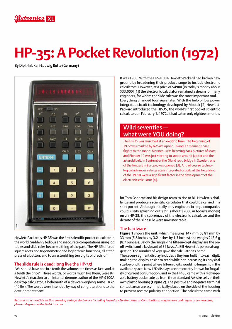
72 11-2012 elektor
XL
HP-35: A Pocket Revolution (1972)By Dipl.-Inf. Karl-Ludwig Butte (Germany)
Hewlett-Packard’s HP-35 was the first scientific pocket calculator in the world. Suddenly tedious and inaccurate computations using log tables and slide rules became a thing of the past. The HP-35 offered square roots and trigonometric and logarithmic functions, all at the press of a button, and to an astonishing ten digits of precision.
The slide rule is dead: long live the HP-35!‘We should have one in a tenth the volume, ten times as fast, and at a tenth the price”. These words, or words much like them, were Bill Hewlett’s reaction to an internal demonstration of the HP-9100A desktop calculator, a behemoth of a device weighing some 18 kg (40 lbs). The words were intended by way of congratulations to the development team!
It was 1968. With the HP-9100A Hewlett-Packard had broken new ground by broadening their product range to include electronic calculators. However, at a price of $4900 (in today’s money about $33,000! [1]) the electronic calculator remained a dream for many engineers, for whom the slide rule was the most important tool.Everything changed four years later. With the help of low power integrated circuit technology developed by Mostek [2] Hewlett-Packard introduced the HP-35, the world’s first pocket scientific calculator, on February 1, 1972. It had taken only eighteen months
for Tom Osborne and his design team to rise to Bill Hewlett’s chal-lenge and produce a scientific calculator that could be carried in a shirt pocket. Although initially only engineers in large companies could justify splashing out $395 (about $2600 in today’s money) on an HP-35, the supremacy of the electronic calculator and the demise of the slide rule were now inevitable.
The hardwareFigure 1 shows the unit, which measures 147 mm by 81 mm by 33 mm (5.8 inches by 3.2 inches by 1.3 inches) and weighs 246.6 g (8.7 ounces). Below the single-line fifteen-digit display are the on-off switch and a keyboard of 35 keys. At Bill Hewlett’s personal sug-gestion, the number of keys gave the calculator its name.The seven-segment display includes a tiny lens built into each digit, making the display easier to read while not increasing its physical size beyond the point where fifteen digits would no longer fit in the available space. Now LED displays are not exactly known for frugal-ity of current consumption, and so the HP-35 came with a recharge-able battery pack made up from three standard AA-size cells in their own plastic housing (Figure 2). The positive and negative terminal contact areas are asymmetrically placed on the side of the housing to prevent reverse polarity connection. The calculator came with
Retronics is a monthly section covering vintage electronics including legendary Elektor designs. Contributions, suggestions and requests are welcome; please telegraph [email protected]
1
Wild seventies — what were YOU doing?The HP-35 was launched at an exciting time. The beginning of 1972 was marked by NASA’s Apollo 16 and 17 manned space flights to the moon; Mariner 9 was beaming back pictures of Mars; and Pioneer 10 was just starting to snoop around Jupiter and the asteroid belt. In September the Öland road bridge in Sweden, one of the longest in Europe, was opened [3]. And of course techno-logical advances in large scale integrated circuits at the beginning of the 1970s were a significant factor in the development of the electronic calculator [4].
74874
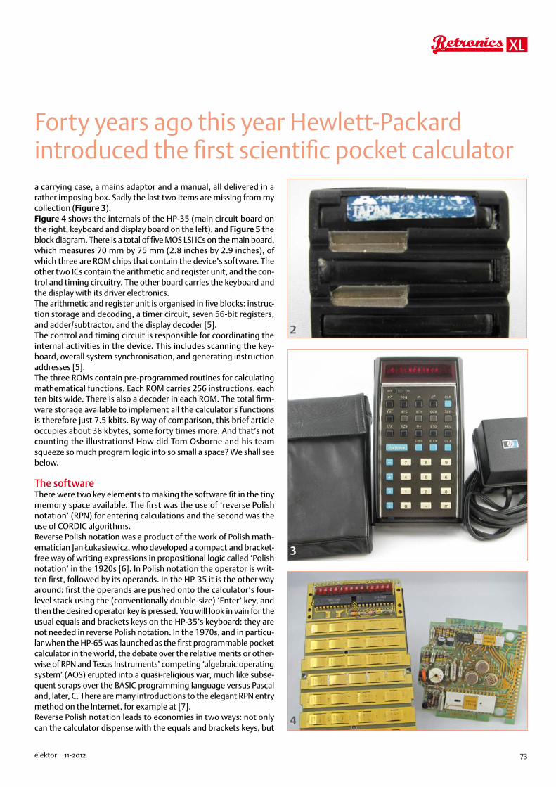
73elektor 11-2012
XL
Forty years ago this year Hewlett-Packard introduced the first scientific pocket calculatora carrying case, a mains adaptor and a manual, all delivered in a rather imposing box. Sadly the last two items are missing from my collection (Figure 3).Figure 4 shows the internals of the HP-35 (main circuit board on the right, keyboard and display board on the left), and Figure 5 the block diagram. There is a total of five MOS LSI ICs on the main board, which measures 70 mm by 75 mm (2.8 inches by 2.9 inches), of which three are ROM chips that contain the device’s software. The other two ICs contain the arithmetic and register unit, and the con-trol and timing circuitry. The other board carries the keyboard and the display with its driver electronics.The arithmetic and register unit is organised in five blocks: instruc-tion storage and decoding, a timer circuit, seven 56-bit registers, and adder/subtractor, and the display decoder [5].The control and timing circuit is responsible for coordinating the internal activities in the device. This includes scanning the key-board, overall system synchronisation, and generating instruction addresses [5].The three ROMs contain pre-programmed routines for calculating mathematical functions. Each ROM carries 256 instructions, each ten bits wide. There is also a decoder in each ROM. The total firm-ware storage available to implement all the calculator’s functions is therefore just 7.5 kbits. By way of comparison, this brief article occupies about 38 kbytes, some forty times more. And that’s not counting the illustrations! How did Tom Osborne and his team squeeze so much program logic into so small a space? We shall see below.
The softwareThere were two key elements to making the software fit in the tiny memory space available. The first was the use of ‘reverse Polish notation’ (RPN) for entering calculations and the second was the use of CORDIC algorithms.Reverse Polish notation was a product of the work of Polish math-ematician Jan Łukasiewicz, who developed a compact and bracket-free way of writing expressions in propositional logic called ‘Polish notation’ in the 1920s [6]. In Polish notation the operator is writ-ten first, followed by its operands. In the HP-35 it is the other way around: first the operands are pushed onto the calculator’s four-level stack using the (conventionally double-size) ‘Enter’ key, and then the desired operator key is pressed. You will look in vain for the usual equals and brackets keys on the HP-35’s keyboard: they are not needed in reverse Polish notation. In the 1970s, and in particu-lar when the HP-65 was launched as the first programmable pocket calculator in the world, the debate over the relative merits or other-wise of RPN and Texas Instruments’ competing ‘algebraic operating system’ (AOS) erupted into a quasi-religious war, much like subse-quent scraps over the BASIC programming language versus Pascal and, later, C. There are many introductions to the elegant RPN entry method on the Internet, for example at [7].Reverse Polish notation leads to economies in two ways: not only can the calculator dispense with the equals and brackets keys, but
2
3
4
74874

74 11-2012 elektor
XL
also it simplifies the software required to implement expression evaluation. The user is also no longer constrained by a limit on the nesting of brackets, although it is necessary to keep in mind the finite depth of the stack.The second key aspect of the HP-35’s firmware design was the use of CORDIC algorithms. CORDIC is an abbreviation for ‘COordinate Rotation Digital Computer’ and it is a class of efficient iterative algo-rithms for calculating trigonometric and other mathematical func-tions developed by Jack E. Volder in 1958 [8]. Volder succeeded in designing a digital replacement for the unreliable navigation com-puter in the Convair B-58 bomber that could compute its position in real time. The ‘real time’ aspect can be seen as particularly sig-nificant when one considers that the B-58 was a supersonic aircraft.Tom Osborne had already made successful use of CORDIC algo-rithms in the HP9100A desktop calculator and so already knew how to implement multiplication and division, as well as trigonometric functions, using just addition and shift operations. The accuracy of the results bears comparison with that of any modern calcula-tor, although there are sometimes small errors in the last digit. For example, the HP-35 gives 43 = 63. 99999997 rather than exactly 64.
BugsDespite the care that went into the development of the software a couple of bugs did remain, first discovered after more than 25,000 units had been sold [9]. For example, eln 2.02 gave 2 rather than 2.02, and tan–1 0.0002 gave 5.729577893×10⁻³ instead of 0.01145916 [10]. It was a difficult situation, and, these being the days before flash memory and the Internet, Hewlett-Packard did not have the option of publishing a software update for users to down-load as is now the norm for high-end graphical calculators. A crisis meeting was held, and Dave Packard got straight to the point: what were they going to do about all the units they had already sold? The now-famous suggestion of one colleague “Don’t tell?” was of course not accepted [9]. Instead all customers were sent a notice inform-ing them of the bug and offering a free repair (see [11] page 6, fig-ures 5 and 6). It transpired that only about a quarter of the affected machines were sent back for repair: most customers kept their machines, often along with the notification letter describing the bug; many even ordered a new HP-35 with the corrected software.
The inexorable march of the pocket calculatorThe HP-35 was one of Hewlett-Packard’s most successful products ever, and on April 14, 2009 HP received the coveted ‘IEEE Milestone in Electrical Engineering and Computing’ award for the device [12]. One year after the HP-35 was launched its successor, the HP-45, appeared on the market and in 1974 HP introduced the HP-65, the first programmable pocket calculator in the world, which could store programs on tiny magnetic cards. In total HP has developed over a hundred different calculator models, and their machines have been used by many Nobel Prize winners. Although the hype surrounding electronic calculators has waned with the widespread use of personal computers, development continues with new, more sophisticated units offering graphics facilities and symbolic manipulation. Beyond the world of science, users in finance have also benefited from cal-culators specially designed for their needs: for example, in 1973 HP launched its HP-80 ‘business’ calculator. The HP-12C financial calcula-tor set another record for Hewlett-Packard, the device having been in continuous production since its introduction in 1981: over 30 years!
(120454)
Sources and references
[1] ‘What is a dollar worth?’ www.minneapolisfed.org/
[2] Malone, Michael S.: ‘Bill & Dave’, Portfolio (Penguin Group) New York, 2007
[3] http://en.wikipedia.org/wiki/1972
[4] http://en.wikipedia.org/wiki/Integrated_circuit
[5] HP Journal June 1971, page 2 onwards: www.hpl.hp.com/hpjournal/pdfs/IssuePDFs/1972-06.pdf
[6] http://en.wikipedia.org/wiki/Polish_notation
[7] http://h41111.www4.hp.com/calculators/uk/en/articles/rpn.html
[8] http://en.wikipedia.org/wiki/CORDIC
[9] http://www.hpmuseum.org/hp35.htm
[10] http://www.jacques-laporte.org/HP35%20ROM.htm
[11] http://hhuc.us/2007/Remembering%20The%20HP35A.pdf
[12] http://www.ieee.org/about/news/2009/14april_1.html
AddressRegister
InstructionDecoder
DisplayDecoder
7Registers
Adder
Adder
TimingTiming12 Status Bits
Return Address
Pointer Register
Word Select Circuitry
Control Circuitry
ROM 22560Bits
ROM 12560Bits
+7.5V
+6V3.75V
KEYBOARD
MOS/LSIIsWS
IsWS
2
1
Is
Is
WS
Step
15Lines
Start
SYNC
SYNC
Carry
Control And Timing Circuit (MOS/LSI)Arithmetic And Register
Circuit (MOS/LSI)
MOS/LSI
-12V
Power OnCircuit
PowerSupply
ROM 02560Bits
ClockDriver
(bipolar)
Cathode Driver(bipolar)
LED Display
Cathode Driver(bipolar)
5Illustration reproduced courtesy Hewlett-Packard
74874

Brought to you by Eurocircuits
Easy-access online pooling services cut your board costs• No tooling charges
• No minimum order charge - order from 1 PCB
• Instant online ordering without pre-payment
New added-value PCB services get your designs into production faster• PCB Visualizer immediate online data check
• Online advice and tips on design for manufacture
PCB proto – dedicated engineering prototype service, fast and low-cost• 1 or 2 PCBs in 2, 3, 5 or 7 working days
• DRC-checked and fully fi nished with 2 soldermasks and 1 legend, 150µm technology
• 1 x 100 x 80mm in 7WD - 2 layer 47,03 € - 4 layer 95,52 €
• 2 x 100 x 80mm in 7WD - 2 layer 36,89 € each - 4 layer 74,76 € each
STANDARD pool – the widest range of pooling options in Europe• 1-8 layers 150µm technology PCBs
• from 2 working days
TECH pool – all the benefi ts of pooling for high-density PCBs• 2-8 layers 100µm technology PCBs
• from 4 working days
IMS pool – aluminium-backed PCBs for high heat-dissipation (LED) applications• Single layer Insulated Metal Substrate PCBs
• from 3 working days
On demand – multi-option non-pooling service for specialist needs• 1-16 layers down to 90µm technology
• from 2 working days
www.elektorPCBservice.com
Prices quoted include 21% Belgian VAT but exclude transport costs
The European reference for PCB prototypes and small series
See us live at electronica 2012Messe München – 13-16 November hall A5 – stand 314
Naamloos-10 1 24-09-12 14:30
74874

76 11-2012 elektor
gerard’s columns
By Gerard Fonte (USA)
“Everybody’s lost but me!” (Indiana Jones and the Last Crusade). It feels that way when you’re disputing a widely held belief. All the books say you’re wrong. All your superiors say you’re wrong. Your mother thinks you’re right, but she doesn’t understand a word you utter. But you know you’re correct. Should you give up, give in or fight on?
The Price is RightProbably the first thing to determine is if the fight is worth the effort. There are some contests that are a Pyrrhic victory at best. For example, suppose you are with your boss and a lot of executives and they’re talking about suicidal ‘Lemming Behavior’. It’s probably not the best time to lecture all of them that this is just a myth cre-ated a long time ago by a Walt Disney movie.You can see why it’s important to look past the immediate situ-ation to see what is accomplished by swimming upstream. Being right for the simple sake of inflating your ego is generally a bad idea. It irritates people and generates bad feelings towards you. On the other hand, there’s the fairly common situation when some aspect of safety is being ignored or overlooked. In this case, it’s important to say something. It’s important to the person at risk (which may be you). It’s important to your self respect. And it’s important to your wallet, when the lawyers file their personal injury lawsuit.
Father Knows BestOkay, that’s pretty straightforward. But what do you do when you have an idea that contradicts the textbook? How do you contest a well-known author or engineer or expert? After all, you’re not an author or expert. You may not even be an engineer. Everybody believes what is in the book. Why should they believe you?The first thing to do is to be absolutely sure you fully understand your own idea as well as the one you disagree with. You have to become an expert in this area. How was the original idea developed, what are its assumptions, its implications, its predictions? Compare that to your concept. Determine what the important differences between them are and figure out why they are different. This ‘what’ and ‘why’ will be the focus of your argument.A classic example of this is a Master’s Thesis from 1939. Oscilla-tors of the time were either very expensive or had high distortion. Everybody knew that. The fundamental reason was the difficulty in maintaining precise amplitude control in the feedback loop. This 23 year old student thought he had a better method. He identified the reason for the distortion problem and created a simple method to overcome it. It was literally an eureka ‘light bulb’ moment. The ‘what’ was an incandescent lamp used in the feedback loop. The ‘why’ was that the lamp had a large positive temperature coefficient and stabilized the amplitude. The result was a very pure sine wave oscillator with a very low manufacturing cost. The student’s name was Bill Hewlett who co-founded Hewlett/Packard.
Aligning Your DucksExtraordinary claims require extraordinary evidence. The simplest solution is to actually do what you say that can be done. It’s difficult
to argue with success. If you place your widget on your boss’s desk and demonstrate to him that it costs half of the current design while out-performing it, how can he deny it works?However, it is important to realize that there are political consider-ations that may trump technical ones. If your boss was the original designer, you may have a hard sell. Some institutions have an aver-sion to evolution. I remember the classic line, “I don’t care if your idea can save the company a million dollars a year. We aren’t going to change.” (They aren’t doing so well.)If you can’t build your idea then you have to seriously collect and develop a lot of supporting evidence. Let’s be realistic, the first thing someone will do is pull out their old textbook and say Dr. No says is can’t be done that way. You have to be able to counter that argu-ment with hard facts and figures. Again the ‘what’ and ‘why’ are important. Being enthusiastic and waving your arms a lot, will not convince many people.Simulations are useful. But a simulation in isolation is probably not enough. People know that simulations are not the real world and that they can be adjusted to support any idea. A good simulation is one that properly illustrates the conventional idea and then shows how your idea is superior.Yes, this is a lot of work. But swimming upstream takes energy. People rarely see the benefit of any new idea immediately. People are doubters. And for good reason. We’ve all been bombarded with fantastic and revolutionary concepts that just aren’t. Everybody has ideas that don’t pan out. What makes your idea any different? And why should anyone listen? There is a tremendous amount of social inertia that must be overcome when you challenge authority. It’s absolutely critical that this is understood. You can have a cure for cancer. But until it’s tested and verified, and re-tested and re-veri-fied, it won’t be accepted.That doesn’t mean that you should give up or that your idea isn’t a good one. Being tenacious is one mark successful people share. What it means is that the world is not a happy place for unconventional ideas.
The Impossible TruthSimply because someone in authority says something, does not make it true. Although, it’s probably true. And, as the authority grows, the likelihood of it being true increases. But, if you think you can do better, then give it a try. Innovation comes from challenging authority. Everyone in authority started out as a student or hobby-ist. Somebody just like you. They achieved their status with hard work, attention to detail and a proper skepticism of the status quo. As Arthur Clarke said: “The only way of finding the limits of the pos-sible is by going beyond them into the impossible.”
Or as I put it, nothing is impossible unless you believe it is.(120498)
Fighting Authority
74874

77elektor 11-2012
Computing power and global interconnectivity are pushing tech innovation into overdrive. Pioneering technologies and creative workarounds affect even the couch potato 24/7. Tech the Future reports on technology strides that shape the future — yours included.
Follow Tech the Future
www.techthefuture.com
Fascinated by technology’s impact on the future?Check out Tech the Future!
Now on www.elektor.com:
Elektor Partners showcasing hot and relevant information to all Elektor members.
Including:• Coast Electronics • CS Technology • Easysync • Elnec • FTDI Chip • FTT First Technology Transfer • Robot Electronics • Robotiq
Get Elektorized …..
You are just one click away from reaching more than 500,000 visitors per month and 2 million monthly pageviews by Elektor members.
For more information of how to become an Elektor Preferred Supplier, contact Johan Dijk by [email protected]
1211_elektor_adv_UK.indd 77 04-10-2012 13:46
74874

78 11-2012 elektor
INFOTAINMENT
Hexadoku Puzzle with an electronics touchHere’s another Hexadokunut to crack for those having had enough of all them schematics and software
listings but still wanting a light mental challenge.
Enter the right numbers or letters A-F in the open boxes, find the solution in the grey boxes, send it to us
and you automatically enter the prize draw for one of four Elektor Shop vouchers.
The instructions for this puzzle are straightforward. Fully geared to electronics fans and programmers, the Hexadoku puzzle employs the hexadecimal range 0 through F. In the diagram composed of 16 × 16 boxes, enter numbers such that all hexadecimal numbers 0 through F (that’s 0-9 and A-F) occur once only in each row, once
in each column and in each of the 4×4 boxes (marked by the thicker black lines). A number of clues are given in the puzzle and these determine the start situation. Correct entries received enter a draw for a main prize and three lesser prizes. All you need to do is send us the numbers in the grey boxes.
Solve Hexadoku and win!Correct solutions received from the entire Elektor readership automati-cally enter a prize draw for one Elektor Shop voucher worth £80.00 and three Elektor Shop Vouchers worth £40.00 each, which should encour-age all Elektor readers to participate.
Participate!Before December 1, 2012, send your solution (the numbers in the grey boxes) by email to:
Prize winnersThe solution of theSeptember 2012 Hexadoku is: 3F126.
The Elektor £80.00 voucher has been awarded to William Neumann (Canada).The Elektor £40.00 vouchers have been awarded to Yves Printems (France),
Jean-Louis Vidaud (France) and Eugene Stemple (USA).Congratulations everyone!
The competition is not open to employees of Elektor International Media, its business partners and/or associated publishing houses.
1 4 C 8 9 3 B A 2 5 7 E 0 6 D F7 9 2 B C 0 D E 6 4 A F 3 8 1 5A 6 D 3 1 F 4 5 8 0 9 B 2 E 7 CE F 0 5 2 6 8 7 1 3 C D 4 9 A B0 7 3 C B 2 9 F 4 8 E 1 D A 5 69 1 8 F 3 4 0 D 5 6 B A E 7 C 22 5 E D 6 7 A 1 C 9 0 3 8 F B 44 A B 6 E C 5 8 D 7 F 2 1 0 9 3C 8 A 4 D 9 E 3 F 1 2 6 5 B 0 7F 2 7 9 0 A C 4 3 B 8 5 6 1 E D6 D 1 E 5 8 2 B 7 A 4 0 F C 3 93 B 5 0 F 1 7 6 9 E D C A 2 4 85 C 9 7 8 D 6 0 A F 1 4 B 3 2 EB 0 F A 4 5 3 C E 2 6 9 7 D 8 18 3 6 2 A E 1 9 B D 5 7 C 4 F 0D E 4 1 7 B F 2 0 C 3 8 9 5 6 A
74874

Naamloos-2 1 20-04-12 08:46
74874

1
2
3
4
5
ELEKTOR STORE
80 11-2012 elektor
Sound Secrets and technologyElectric GuitarWhat would today’s rock and pop music be without
electric lead and bass guitars? These instruments
have been setting the tone for more than forty years.
Their underlying sound is determined largely by their
electrical components. But, how do they actually
work? This book answers many questions simply, in
an easily-understandable manner. For the interested
musician (and others), this book unveils, in a simple
and well-grounded way, what have, until now, been
regarded as manufacturer secrets. The examination
explores deep within the guitar, including pickups and
electrical environment, so that guitar electronics are
no longer considered highly secret. With a few deft
interventions, many instruments can be rendered
more versatile and made to sound a lot better – in
the most cost-effective manner.
Approx. 280 pages • ISBN 978-1-907920-13-4
£29.50 • US $47.60
More than 75,000 componentsCD Elektor’s Components Database 7This CD-ROM gives you easy access to design data
for over 11,100 ICs, 37,000 transistors, FETs, thy-
ristors and triacs, 25,100 diodes and 2,000 opto-
couplers. The program package consists of eight
Elektor Linux BoardEmbedded Linux Made EasyToday Linux can be found running on all sorts of de-
vices, even coffee machines. Many electronics enthu-
siasts will be keen to use Linux as the basis of a new
microcontroller project, but the apparent complexity
of the operating system and the high price of de-
velopment boards has been a hurdle. Here Elektor
solves both these problems, with a beginners’ course
accompanied by a compact and inexpensive popula-
ted and tested circuit board. This board includes eve-
rything necessary for a modern embedded project:
a USB interface, an SD card connection and various
other expansion options. It is also easy to hook the
board up to an Ethernet network.
Populated and tested Elektor Linux Board
Art.# 120026-91 • £57.80 • US $93.30
A comprehensive and practicalhow-to guide
Design your own PC Visual Processing and Recognition System in C#
This book is aimed at Engineers, Scientists and en-
thusiasts with developed programming skills or with
a strong interest in image processing technology on
databanks covering ICs, transistors, diodes and op-
tocouplers. A further eleven applications cover the
calculation of, for example, zener diode series resis-
tors, voltage regulators, voltage dividers and AMV’s.
A colour band decoder is included for determining
resistor and inductor values. All databank applica-
tions are fully interactive, allowing the user to add,
edit and complete component data.
ISBN 978-90-5381-298-3 • £24.90 • US $40.20
LabWorX 2Mastering Surface Mount TechnologyThis book takes you on a crash course in techniques,
tips and know-how to successfully introduce sur-
face mount technology in your workfl ow. Even if you
are on a budget you too can jumpstart your designs
with advanced fi ne pitch parts. Besides explaining
methodology and equipment, attention is given to
SMT parts technologies and soldering methods. Many
practical tips and tricks are disclosed that bring sur-
face mount technology into everyone’s reach with-
out breaking the bank. A comprehensive kit of parts
comprising all SMT components, circuit boards and
solder stencils is available for readers wishing to rep-
licate three projects described in this book.
282 pages • ISBN 978-1-907920-12-7
£29.50 • US $47.60
22
33
11
Limited Time Offer for Elektor Magazine Members!
15% DISCOUNTwww.elektor.com/guitar
Elektor Store UK 11-2012.indd 80 05-10-12 08:48
74874
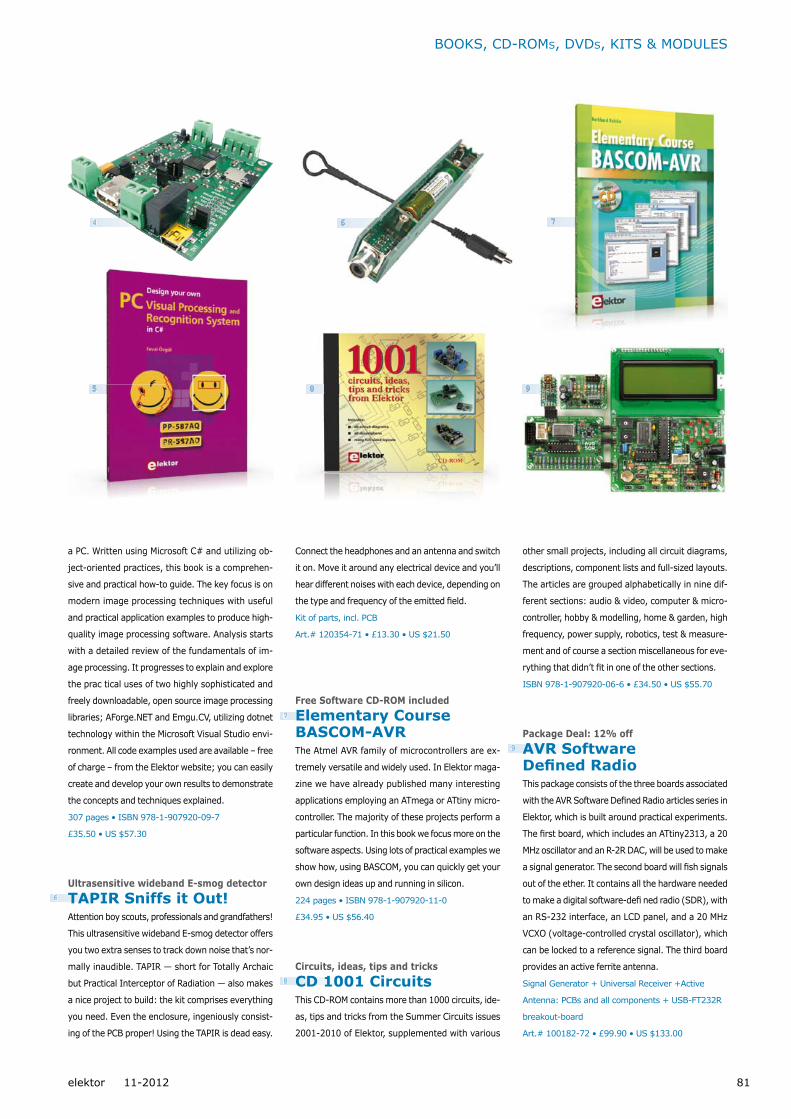
4
6
8
7
9
BOOKS, CD-ROMS, DVDS, KITS & MODULES
81elektor 11-2012
99
a PC. Written using Microsoft C# and utilizing ob-
ject-oriented practices, this book is a comprehen-
sive and practical how-to guide. The key focus is on
modern image processing techniques with useful
and practical application examples to produce high-
quality image processing software. Analysis starts
with a detailed review of the fundamentals of im-
age processing. It progresses to explain and explore
the prac tical uses of two highly sophisticated and
freely downloadable, open source image processing
libraries; AForge.NET and Emgu.CV, utilizing dotnet
technology within the Microsoft Visual Studio envi-
ronment. All code examples used are available – free
of charge – from the Elektor website; you can easily
create and develop your own results to demonstrate
the concepts and techniques explained.
307 pages • ISBN 978-1-907920-09-7
£35.50 • US $57.30
Ultrasensitive wideband E-smog detectorTAPIR Sniffs it Out!Attention boy scouts, professionals and grandfathers!
This ultrasensitive wideband E-smog detector offers
you two extra senses to track down noise that’s nor-
mally inaudible. TAPIR — short for Totally Archaic
but Practical Interceptor of Radiation — also makes
a nice project to build: the kit comprises everything
you need. Even the enclosure, ingeniously consist-
ing of the PCB proper! Using the TAPIR is dead easy.
Connect the headphones and an antenna and switch
it on. Move it around any electrical device and you’ll
hear different noises with each device, depending on
the type and frequency of the emitted fi eld.
Kit of parts, incl. PCB
Art.# 120354-71 • £13.30 • US $21.50
Free Software CD-ROM includedElementary Course BASCOM-AVRThe Atmel AVR family of microcontrollers are ex-
tremely versatile and widely used. In Elektor maga-
zine we have already published many interesting
applications employing an ATmega or ATtiny micro-
controller. The majority of these projects perform a
particular function. In this book we focus more on the
software aspects. Using lots of practical examples we
show how, using BASCOM, you can quickly get your
own design ideas up and running in silicon.
224 pages • ISBN 978-1-907920-11-0
£34.95 • US $56.40
Circuits, ideas, tips and tricksCD 1001 CircuitsThis CD-ROM contains more than 1000 circuits, ide-
as, tips and tricks from the Summer Circuits issues
2001-2010 of Elektor, supplemented with various
other small projects, including all circuit diagrams,
des criptions, component lists and full-sized layouts.
The articles are grouped alphabeti cally in nine dif-
ferent sections: audio & video, computer & micro-
controller, hobby & modelling, home & garden, high
frequency, power supply, robotics, test & measure-
ment and of course a section miscellaneous for eve-
rything that didn’t fi t in one of the other sections.
ISBN 978-1-907920-06-6 • £34.50 • US $55.70
Package Deal: 12% offAVR Software Defined RadioThis package consists of the three boards associated
with the AVR Software Defined Radio articles series in
Elektor, which is built around practical experiments.
The first board, which includes an ATtiny2313, a 20
MHz oscillator and an R-2R DAC, will be used to make
a signal generator. The second board will fi sh signals
out of the ether. It contains all the hardware needed
to make a digital software-defi ned radio (SDR), with
an RS-232 interface, an LCD panel, and a 20 MHz
VCXO (voltage-controlled crystal oscillator), which
can be locked to a reference signal. The third board
provides an active ferrite antenna.
Signal Generator + Universal Receiver +Active
Antenna: PCBs and all components + USB-FT232R
breakout-board
Art.# 100182-72 • £99.90 • US $133.00
8855
7766
Elektor Store UK 11-2012.indd 81 05-10-12 08:48
74874

11
10
12
13
13
14
15
ELEKTOR STORE
82 11-2012 elektor
Avoid interference and earth loopsUSB IsolatorIf your USB device ever suffers from noise caused
by an earth loop or if you want to protect your PC
against external voltages then you need a USB iso-
lator. The circuit described in Elektor’s October 2012
edition offers an optimal electrical isolation of both
the data lines as well as the supply lines between the
PC and the USB device.
Populated and tested Board
Art.# 120291-91 • £62.30 • US $101.40
Associated 60-piece Starter Kit availableFun with LEDsThis booklet presents more than twenty exciting
projects covering LEDs, aimed at young & old. From
an Air Writer, a Party Light, Running Lights, a LED
Fader right up to a Christmas Tree. Use this book to
replicate various projects and then put them into
practice. To give you a head start each project is
supported by a brief explanation, schematics and
photos. In addition, the free support page on the
Elektor website has a few inspiring video links avail-
able that elaborate on the projects. A couple of pro-
jects employ the popular Arduino microcontroller
board that’s graced by a galaxy of open source ap-
plications. The optional 60-piece Starter Kit avail-
able with this book is a great way to get circuits
built up and tested on a breadboard, i.e. without
soldering.
96 pages • ISBN 978-1-907920-05-9
£16.95 • US $38.00
Free mikroC compiler CD-ROM includedController Area Network ProjectsThe aim of the book is to teach you the basic prin-
ciples of CAN networks and in addition the develop-
ment of microcontroller based projects using the
CAN bus. You will learn how to design microcontroller
based CAN bus nodes, build a CAN bus, develop high-
level programs, and then exchange data in real-time
over the bus. You will also learn how to build micro-
controller hardware and interface it to LEDs, LCDs,
and A/D converters.
260 pages • ISBN 978-1-907920-04-2
£29.50 • US $47.60
Bridging Android and your electronics projectsAndroPodWith their high-resolution touchscreens, ample com-
puting power, WLAN support and telephone func-
tions, Android smartphones and tablets are ideal for
use as control centres in your own projects. However,
up to now it has been rather diffi cult to connect them
to exter-nal circuitry. Our AndroPod interface board,
which adds a serial TTL port and an RS485 port to the
picture, changes this situation.
Andropod module with RS485 Extension
Art.# 110405-91 • £53.35 • US $74.70
Meet BOBFT232R USB/Serial Bridge/BOBYou’ll be surprised fi rst and foremost by the size of this
USB/serial converter – no larger than the moulded plug
on a USB cable! And you’re also bound to appreciate
that fact that it’s practical, quick to implement, reus-
able, and multi-platform – and yet for all that, not too
expensive! Maybe you don’t think much of the various
commercially-available FT232R-based modules. Too ex-
pensive, too bulky, badly designed, That’s why this pro-
ject got designed in the form of a breakout board (BOB).
PCB, assembled and tested
Art.# 110553-91 • £12.90 • US $20.90
110 issues, more than 2,100 articlesDVD Elektor 1990 through 1999This DVD-ROM contains the full range of 1990-1999
volumes (all 110 issues) of Elek tor Electronics maga-
zine (PDF). The more than 2,100 separate articles
have been classifi ed chronologically by their dates of
publication (month/year), but are also listed alpha-
1212
1010
1414
1111
Elektor Store UK 11-2012.indd 82 05-10-12 08:48
74874

16
18
18
17
19
BOOKS, CD-ROMS, DVDS, KITS & MODULES
83elektor 11-2012
betically by topic. A comprehensive index enables
you to search the entire DVD. What’s more, this DVD
also con tains the entire ‘The Elektor Datasheet Col-
lection 1...5’ CD-ROM series.
ISBN 978-0-905705-76-7 • £69.00 • US $111.30
Enhanced second editionDesign your own Embedded Linux Control Centre on a PCThe main system described in this book reuses an
old PC, a wireless mains outlet with three switches
and one controller, and a USB webcam. All this is
linked together by Linux. This book will serve up the
basics of setting up a Linux environment – including
a software development environment – so it can be
used as a control centre. The book will also guide
you through the necessary setup and confi guration
of a webserver. New edition enhancements include
details of extending the capabilities of your control
center with ports for a mobile phone (for SMS mes-
saging) and the Elektor “thermo snake” for lowcost
networked real-time thermal monitoring of your
house and outbuildings. Now you can additionally
also send all kinds of useful temperature and sensor
warnings to a mobile phone. All software needed will
be available at the Elektor website.
416 pages • ISBN 978-1-907920-02-8
£34.50 • US $55.70
Processor design in the real worldMicroprocessor Design using Verilog HDLIf you have the right tools, designing a microproces-
sor shouldn’t be complicated. The Verilog hardware
description language (HDL) is one such tool. This
book is a practical guide to processor design in the
real world. It presents the Verilog HDL in an easily digest-
ible fashion. You’re led through the microprocessor de-
sign process from the start to fi nish, and essential topics
ranging from writing in Verilog to debugging and tes-
ting are laid bare.
340 pages • ISBN 978-0-9630133-5-4
£27.90 • US $45.00
Counter for alpha, beta and gamma radiationImproved Radiation MeterThis device can be used with different sensors to meas-
ure gamma and alpha radiation. It is particularly suit-
able for long-term measurements and for examining
weakly radio-active samples. The photodiode has a
smaller sensitive area than a Geiger-Müller tube and so
has a lower background count rate, which in turn means
that the radiation from a small sample is easier to de-
tect against the background. A further advantage of a
semiconductor sensor is that is offers the possibility of
measuring the energy of each particle.
Kit of parts incl. display and programmed controller
Art.# 110538-71 • £35.50 • $57.30
Dual-layer DVD: 165 mins. videoDVD Modern Valve ElectronicsThis fi lmed seminar (presented by Menno van der
Veen) starts with a short discussion of the classic ap-
proach using valve load line graphs, followed by cur-
rent sources and current foldback techniques. Next,
the negative effect of cathode electrolytics is covered
as well as reducing supply voltage interference. With
the help of state of the art measurement techniques
the (in)correctness of feedback is proven, while also
clarifying what’s happening deep within the core of
the output transformer.
ISBN 978-1-907920-10-3 • £24.90 • US $40.20
More information on theElektor Website: www.elektor.com/storeElektor78 York StreetLondon - W1H 1DPUnited KingdomTel.: +44 20 7692 8344Email: [email protected]
1616
1919
1515 1717
Elektor Store UK 11-2012.indd 83 05-10-12 08:48
74874

84 11-2012 e lektor
COMING ATTRACTIONS next month in elektor
Article titles and magazine contents subject to change; please check the magazine tab on www.elektor.com
elektor Uk/european December 2102 edition on sale november 29, 2012. elektor USA December 2012 edition on publication november 26, 2012.
Elektor on the webwww.elektor.com www.elektor.com www.elektor.com www.elektor.com www.elektor.com www.
All magazine articles back to volume 2000 are available individually in pdf format against e-credits. Article summaries and compo-
nent lists (if applicable) can be instantly viewed to help you positively identify an article. Article related items and resources are also
shown, including software downloads, hyperlinks, circuit boards, programmed ICs and corrections and updates if applicable.
In the Elektor Shop you’ll find all other products sold by the
publishers, like CD-ROMs, DVDs, kits, modules, equipment,
tools and books. A powerful search function allows you to
search for items and references across the entire website.
Also on the Elektor website:
• Electronics news and Elektor announcements
• Readers Forum
• PCB, software and e-magazine downloads
• Time limited offers
• FAQ, Author Guidelines and Contact
The 7-Up Alarm ClockHow many people are really satisfied about the digital alarm clock on the nightstand? A few, maybe. It’s high time for someone to design a comprehensive alarm clock that really has all the features you’d want it to have. These requirements have resulted in this design based on an Atmel AT89C5131 USB microcontroller that distinguishes itself clearly in terms of functionality from the usual digital alarm clocks in the shops. The device is even equipped with a USB socket for communication with a PC.
Arduino AC Powerline AnalyserA simple Arduino-board should not be underestimated in terms of performance. With this project we demonstrate the power of a small 8-bit microcontroller, not forgetting of course to pinpoint its limitations. The spectrum analyser discussed in this article uses FFT to analyse and quantify the harmonics of the mains frequency and shows the results on a display. We also explain how the components of the microcontroller can be used in an efficient way and what free development tools are necessary to set up this type of project.
USB I/O Interface CableNowadays most computers only have USB connections for communication with the out-side world. Surely it’s useful to employ that interface for your own measurements and control purposes. We developed an interface cable based on a USB-TTL cable from FTDI, to which a small PCB with an R8C microcontroller is added for fitting into a DB25-plug housing. The controller handles the communication with the PC, and at the output side offers 24 pins for the user to configure and do a variety of measuring and switching tasks.
74874

If you’ve ever wanted to design and program with the ADuC841 microcontroller, or other microcontrollers in the 8051 family, this is the book
for you. With introductory and advanced labs, you’ll soon master the many ways to use a microcontroller. Perfect for academics!
Now Just $35.00
If you’ve ever wanted to design and program with the ADuC841 If you’ve ever wanted to design and program with the ADuC841
ADuC841 Microcontroller Design Manual:From Microcontroller Theory to Design Projects
www.cc-webshop.com Buy it today!
Naamloos-1 1 18-04-12 09:02
74874

www.elektor-projects.com
Sharing Electronics Projects
Get elektorized too! Check www.elektor-projects.com
Sharing Electronics Projects Sharing Electronics Projects
Get ElektorizedElektor Projects is an online community for people passionate about electronics. Here you can share your projects and participate in those created by others. It’s a place where you can discuss project development and electronics.
Elektor’s team of editors and engineers assist you to bring your projects to a good end. They can help you write an article to be published in Elektor maga-zine or even develop a complete product that you can sell in the Elektor Shop!
Sharing Electronics Projects Sharing Electronics Projects Sharing Electronics Projects Sharing Electronics Projects Sharing Electronics Projects Sharing Electronics Projects
Get elektorized too! Check Get elektorized too! Check www.elektor-projects.comwww.elektor-projects.com
that you can sell in the Elektor Shop!that you can sell in the Elektor Shop!
Get elektorized too! Check Get elektorized too! Check
JOINNOW!
Adv Elektor Projects 120913 UK.indd 1 13-09-12 16:36:03
74874

$25 Print or Digital :: $50 ComboCelebrate Circuit Cellar’s 25th year of bringing
readers insightful analysis of embedded electronics technology.
Visit www.circuitcellar.com/el912to take advantage of these great deals.
Celebrate Circuit Cellar’s25th Anniversary
Sign up today and you’ll also receive the Special 25th Anniversary Edition with your subscription!
of bringing of bringing
SPECIAL: SAVE 50% SPECIAL: SAVE 50% SPECIAL: SAVE 50%
BONUS OFFER! BONUS OFFER! BONUS OFFER! BONUS OFFER!
Naamloos-4 1 24-07-12 12:39
74874

PROTEUS DESIGN SUITE Features:
Our completely new manual router makes placing tracks quick and intuitive. During track placement the route will follow the mouse wherever possible and will intelligently move around obstacles while obeying the design rules.
All versions of Proteus also include an integrated world class shape based auto-router as standard.
< Board Autoplacement & Gateswap Optimiser.
< Direct CADCAM, ODB++, IDF & PDF Output.
< Integrated 3D Viewer with 3DS and DXF export.
< Mixed Mode SPICE Simulation Engine.
< Co-Simulation of PIC, AVR, 8051 and ARM7.
< Direct Technical Support at no additional cost.
<
<
<
<
<
<
Hardware Accelerated Performance.
Unique Thru-View™ Board Transparency.
Over 35k Schematic & PCB library parts.
Integrated Shape Based Auto-router.
Flexible Design Rule Management.
Polygonal and Split Power Plane Support.
Labcenter Electronics Ltd. 53-55 Main Street, Grassington, North Yorks. BD23 5AA. Registered in England 4692454 Tel: +44 (0)1756 753440, Email: [email protected]
Visit our website or phone 01756 753440
for more details
Prices start from just £150 exc. VAT & delivery
ROUTE FASTER !
WITH PROTEUS PCB DESIGN
Naamloos-3 1 10-10-11 09:24
74874