Electromagnetic generator for harvesting energy from human motion
6
Sensors and Actuators A 147 (2008) 248–253 Contents lists available at ScienceDirect Sensors and Actuators A: Physical journal homepage: www.elsevier.com/locate/sna Electromagnetic generator for harvesting energy from human motion C.R. Saha ∗ , T. O’Donnell, N. Wang, P. McCloskey Tyndall National Institute, University College Cork, Cork, Ireland article info Article history: Received 9 November 2007 Received in revised form 28 January 2008 Accepted 3 March 2008 Available online 15 March 2008 Keywords: Magnetic spring generator Energy harvesting Self-powered sensors Electromechanical conversion abstract This paper presents an electromagnetic based generator which is suitable for supplying generating power from human body motion and has application in providing energy for body worn sensors or electronics devices. A prototype generator has been built and tested both by a shaker at resonance condition and also by human body motion during walking and slow running. The experimental results will show that the prototype could generate 300 W to 2.5mW power from human body motion. The measured results are analyzed and compared with the theoretical model. © 2008 Elsevier B.V. All rights reserved. 1. Introduction There has been growing interest over the last few years in vibra- tional energy scavenging as a means to provide power to wireless sensor nodes. All the reported works [1–13] make use of a vibrat- ing mass which is attached to housing with a mechanical beam or spring. To-date most of the devices have been tested by a force con- trolled vibration shaker in the laboratory without considering the real applications. An exception to this is the work of Glynne-Jones et al. [4] who tested their electromagnetic generator in a car engine compartment. There have also been several attempts to imple- ment generators which can harvest energy from human motion. Most work has focused on the integration into the shoe as this has the potential for significant energy harvesting [7,8]. For example, Kymissis et al. [7] in MIT showed that PVDT and PZT piezoelectric materials placed in the sole of the shoe were capable of generating 1 and 2 mW average power during walking. Similarly Duffy and Car- roll [8] tested an electromagnetic generator integrated into a shoe which could generate 500 mV (rms) at a 5 Hz frequency. Buren et al. [11] discussed the potential for generation of power from human motion from generators placed on locations other than the shoe. For example they predicted that a generator (1000 mm 3 electromag- netic generator with 10 mg moving mass and 5 mm displacement) could generate 134 W and 2.1mW from human walking when the generator was placed in head and feet, respectively. These pre- dictions were based on the assumption that a generator with a ∗ Corresponding author. Tel.: +353 21 4904165. E-mail addresses: [email protected] (C.R. Saha), [email protected] (T. O’Donnell). resonant frequency matched to the frequency of walking could be used. However because of the low frequency and irregular nature of human movement a resonant generator may not be the most suit- able approach. Since the vibration signal in human motion tends to be non-sinusoidal random vibration, a suitable generator structure is necessary which can vibrate easily at off resonance conditions. In this paper we present such a generator and measure the power generated from human motion when the generator is placed in a rucksack. The generator makes use of a “magnetic spring” as opposed to a mechanical spring, which could give advantages such as ease of construction, ease of tunability and less prone to fatigue. In Section 2 the structure of the magnetic spring electromag- netic generator is described. The modeling concept of this generator structure will be discussed in Section 3. A mm scale prototype gen- erator has been built and tested by a force control electromagnetic shaker and for real human body vibration. These results are pre- sented and analyzed in Section 4. Finally in Section 5 the measured results of the magnetic spring generator are compared with the existing energy harvesting devices. 2. Structure of the magnetic spring generator Fig. 1 shows different possible configurations for the magnetic spring generator structure. The basic idea is that axially magnetized permanent magnets are placed vertically inside a tube so that fac- ing surfaces have the same polarization. Thus the magnets repel one another. Two magnets are fixed at both ends of the generator tube housing. A middle magnet or magnets is free to move but is sus- pended between both fixed end magnets in the generator housing due to the repulsive force. A coil is wrapped around the outside of 0924-4247/$ – see front matter © 2008 Elsevier B.V. All rights reserved. doi:10.1016/j.sna.2008.03.008
-
Upload
independent -
Category
Documents
-
view
3 -
download
0
Transcript of Electromagnetic generator for harvesting energy from human motion
Sensors and Actuators A 147 (2008) 248–253
Contents lists available at ScienceDirect
Sensors and Actuators A: Physical
journa l homepage: www.e lsev ier .com/ locate /sna
g e
ctromand
ratoruring300 �ith th
Electromagnetic generator for harvestin
C.R. Saha ∗, T. O’Donnell, N. Wang, P. McCloskeyTyndall National Institute, University College Cork, Cork, Ireland
a r t i c l e i n f o
Article history:Received 9 November 2007Received in revised form 28 January 2008Accepted 3 March 2008Available online 15 March 2008
Keywords:Magnetic spring generatorEnergy harvestingSelf-powered sensorsElectromechanical conversion
a b s t r a c t
This paper presents an elefrom human body motiondevices. A prototype geneby human body motion dprototype could generateanalyzed and compared w
1. Introduction
There has been growing interest over the last few years in vibra-tional energy scavenging as a means to provide power to wirelesssensor nodes. All the reported works [1–13] make use of a vibrat-ing mass which is attached to housing with a mechanical beam or
spring. To-date most of the devices have been tested by a force con-trolled vibration shaker in the laboratory without considering thereal applications. An exception to this is the work of Glynne-Joneset al. [4] who tested their electromagnetic generator in a car enginecompartment. There have also been several attempts to imple-ment generators which can harvest energy from human motion.Most work has focused on the integration into the shoe as this hasthe potential for significant energy harvesting [7,8]. For example,Kymissis et al. [7] in MIT showed that PVDT and PZT piezoelectricmaterials placed in the sole of the shoe were capable of generating1 and 2 mW average power during walking. Similarly Duffy and Car-roll [8] tested an electromagnetic generator integrated into a shoewhich could generate 500 mV (rms) at a 5 Hz frequency. Buren et al.[11] discussed the potential for generation of power from humanmotion from generators placed on locations other than the shoe. Forexample they predicted that a generator (1000 mm3 electromag-netic generator with 10 mg moving mass and 5 mm displacement)could generate 134 �W and 2.1 mW from human walking whenthe generator was placed in head and feet, respectively. These pre-dictions were based on the assumption that a generator with a∗ Corresponding author. Tel.: +353 21 4904165.E-mail addresses: [email protected] (C.R. Saha), [email protected]
(T. O’Donnell).
0924-4247/$ – see front matter © 2008 Elsevier B.V. All rights reserved.doi:10.1016/j.sna.2008.03.008
nergy from human motion
agnetic based generator which is suitable for supplying generating powerhas application in providing energy for body worn sensors or electronicshas been built and tested both by a shaker at resonance condition and alsowalking and slow running. The experimental results will show that theW to 2.5 mW power from human body motion. The measured results aree theoretical model.
© 2008 Elsevier B.V. All rights reserved.
resonant frequency matched to the frequency of walking could beused.
However because of the low frequency and irregular nature ofhuman movement a resonant generator may not be the most suit-able approach. Since the vibration signal in human motion tends tobe non-sinusoidal random vibration, a suitable generator structureis necessary which can vibrate easily at off resonance conditions.In this paper we present such a generator and measure the powergenerated from human motion when the generator is placed ina rucksack. The generator makes use of a “magnetic spring” as
opposed to a mechanical spring, which could give advantages suchas ease of construction, ease of tunability and less prone to fatigue.In Section 2 the structure of the magnetic spring electromag-netic generator is described. The modeling concept of this generatorstructure will be discussed in Section 3. A mm scale prototype gen-erator has been built and tested by a force control electromagneticshaker and for real human body vibration. These results are pre-sented and analyzed in Section 4. Finally in Section 5 the measuredresults of the magnetic spring generator are compared with theexisting energy harvesting devices.
2. Structure of the magnetic spring generator
Fig. 1 shows different possible configurations for the magneticspring generator structure. The basic idea is that axially magnetizedpermanent magnets are placed vertically inside a tube so that fac-ing surfaces have the same polarization. Thus the magnets repel oneanother. Two magnets are fixed at both ends of the generator tubehousing. A middle magnet or magnets is free to move but is sus-pended between both fixed end magnets in the generator housingdue to the repulsive force. A coil is wrapped around the outside of

C.R. Saha et al. / Sensors and Actua
Fig. 1. Magnetic spring generator structure (a) single moving magnet, (b) singlemoving magnet replaced two magnets + pole and (c) one fixed magnet.
the tube. When the tube is vibrated the middle magnet vibrates upand down, and a voltage will be induced in the coil. This structurecan be easily built since the generator simply consists of magnetsand coil without the need for any mechanical beam. Essentially thesuspended moving magnet works as magnetic spring constant. Thisconstruction is similar to the inductively powered torch [14], exceptwith the addition of a magnetic spring. The voltage induced in thecoil (assuming motion in the z-direction) is given by;
Vcoil = nd�
dt= n
(d�
dz
)(dz
dt
)(1)
where n is the number of turns in the coil, � is the average turn fluxlinkage and (dz/dt) is the velocity of movement in the z-direction.From this we can see that the important parameter for the gener-ation of voltage is the flux linkage gradient and displacement orvelocity. In order to increase the flux linkage, the single movingmagnet can be replaced by two magnets separated by a soft mag-netic “pole” piece, where magnets and pole piece are glued together
tors A 147 (2008) 248–253 249
so that they move as a single object as shown in Fig. 1b. The differ-ence in flux linkage between the single moving magnet and doublemoving magnet plus pole will be shown in the next section.
In order to increase the displacement, instead of using two fixedmagnet, the generator could be built using only one fixed end mag-net and a single moving object as shown in Fig. 1c. In this case,the resonance frequency would be lower and the displacement ofthe moving magnet would be higher compared to both fixed endmagnets. Any system always oscillates at maximum amplitude ata certain frequency which is known as resonance frequency. Thisconcept can be explained by considering the response of a springdamper system to an impulse excitation. The response of a springdamper system to an impulse excitation of F0 for time t0 is governedby [15];
x(t) = F0
k, for [0 < t < t0] and x(t)
= exp(−�ωnt)X sin(ωdt + �), for [t > t0] (2)
where ωd = ωn(1 − �2)1/2, � is the damping ratio is given by� = D/2mωn and � is the phase angle which depends on displace-ment and velocity at t0. It can be seen from the above equationthat this response consists of an initial displacement followed bya decaying, sinusoidal transient response. The initial displacementis controlled by the spring constant, and the force applied (masstimes acceleration). The decay is controlled by the damping ratio,� = D/2m, and the natural frequency of the system. Thus if the damp-ing constant or the natural frequency is high the response will decayquickly.
When the top magnet is removed from the generator, the effec-tive spring constant is decreased and hence the resonant frequencyis decreased. Thus according to Eq. (2) the initial displacement willbe greater and the decay rate slower, which explains the increasedvoltage and larger average power. This concept will be verified withthe measured results of the real prototype which has been built andtested.
3. Analysis of generator structure
The generator structure has been modeled using finite elementanalysis (FEA) in order to understand the spring forces which existbetween the fixed and moving magnets and to understand theflux linkage with the coil. Fig. 2a and b shows the results of anaxi-symmetric finite element simulation of the corresponding gen-
erator structure of Fig. 1a and b, respectively, showing magneticfield lines. In this simulation a 15 mm × 19 mm single moving mag-net is replaced by two 15 mm × 8 mm moving magnets separatedby a 15 mm × 3 mm soft magnetic pole piece. 3 mm thickness ischosen as approximately the minimum thickness which ensuresthat flux density in the pole piece is less than 1.8 T. Thinner polepieces would result in saturation of the pole and hence no increasein flux density. The overall generator dimension is given in Section4. Fig. 3 shows a plot of the radial component of B field along a lineextending from the top to the bottom of the generator for both ofthe generator structures. It can be seen from these field plots thatthe peak flux density for the double moving magnets with the polepiece is almost twice as high as for the single moving magnet gen-erator structure. Thus the flux gradient is higher, which translatesinto higher voltages and higher electromagnetic damping.It is also of interest to investigate the dependence of the forcebetween the magnets poles, which can be expressed analytically[16];
Fm = �0Qm1Qm2
4�r2(3)

250 C.R. Saha et al. / Sensors and Actuators A 147 (2008) 248–253
Fig. 2. Finite element simulation showing fluxlines for (a) single moving
where Qm = HcA where Hc is the coercive force, A is the pole surfacearea and r is the distance between the poles. The spring constant,k, over small displacements, x, can be calculated from the linearapproximation of the balanced forces equation;
kx = F (4)
where the total force, F, acting on the centre magnet is given byF = Fm1 − Fm2, where Fm1 and Fm2 are the repulsive force magnitudeon the middle magnet due to top and bottom magnet, respectively.
The electromagnetic force and spring constant can be calculatedfrom a FE transient simulation using the force versus displacementgraph for the double moving magnets plus pole structure generatorwhich is shown in Fig. 4. The resting position of the moving magnets
Fig. 3. Plot of radial component of flux density along a coil surface line extendingfrom the top of the magnet tube to the bottom.
magnet and (b) double moving magnets + pole generator structure.
Fig. 4. Electromagnetic force vs. displacement of the double moving magnets + polegenerator.
is 4 mm away from the middle position due to the gravitationalforce. It can be seen from this graph that the electromagnetic forceon the moving magnets is almost linear with displacement. Thespring constant between 4 and 8 mm region can be estimated fromthe graph as 61.5 N/m.
4. Generator prototype and test results
The generator prototype consists of two opposite polarity cir-cular magnets tightly glued to a 3 mm thick magnetic pole piece.This combination was inserted into a hollow Teflon tube so that itcan move freely. After inserting, the two opposite polarity magnetswere fixed on the both ends of the Teflon tube and 40 �m copperwire with 1000 turns coil was wrapped around the tube at a point

C.R. Saha et al. / Sensors and Actua
tor can be estimated from the frequency response to be 18 whichcorresponds to a parasitic damping ratio of 0.0277. The electricaldamping depends on load resistance, magnet and coil parame-ters [12]. The maximum load power measured was 14.55 �W on7.3 k� load resistance. At this optimum load resistance the electri-cal damping ratio and parasitic damping ratio are equal.
4.2. Measured results of the generator for human body vibration
Next the generator was placed inside a rucksack as shownin Fig. 7 and the voltage and power output was measured dur-ing walking and slow running conditions. An ADXL321 bi-axialaccelerometer was mounted on the generator body and connectedto an XR440 pocket data logger. The pocket data logger was usedto measure the generator load voltage and the acceleration lev-els experienced by the generator. Fig. 8 shows the measuredacceleration level for 2 s of data for walking and slow runningconditions, respectively. The data shows peak acceleration levelsof approximately 0.5 g with a frequency of 2 Hz for walking andpeak acceleration levels of approximately 1 g with a frequency of
Fig. 5. Tube generator-1.
Table 1Generator parameters
Parameters Dimension
Tube (mm) 17 × 55Middle magnets (mm) 15 × 8End magnets (mm) 10 × 1Moving mass (kg) 0.027Coil outer diameter (mm) 18Coil inner diameter (mm) 17Coil thickness (mm) 6
Coil resistance (�) 800midway between the ends of the tube. Fig. 5 shows the prototypewhich has been built, pictured beside a standard AA size battery.The complete dimensions and parameters of the generator are givenin Table 1.
4.1. Measured results for sinusoidal acceleration
For the first tests the generator was tested by mounting it ver-tically on a force controlled electromagnetic shaker. The vibrationfrequency of the shaker was swept in order to determine the res-onant frequency of the moving magnet combination. Any systemalways generates maximum vibration at the resonance conditionand resonance occurs when the system natural frequency matcheswith the vibration frequency.
Fig. 6 shows the no-load voltage versus frequency curve for0.38259 m/s2 accelerations level. It can be seen that the resonantfrequency of the generator is at approximately 8 Hz. The theoret-
Fig. 6. Measured no-load peak voltage for half power bandwidth frequency.
tors A 147 (2008) 248–253 251
ical resonant frequency, calculated from ωn =√
k/m, where thespring constant, k, was estimated from the previous simulation,is 7.6 Hz. The measured open circuit quality factor of the genera-
Fig. 7. Placement of generator in rucksack.
Fig. 8. Measured acceleration level for generator placed in rucksack during walkingand slow running.

252 C.R. Saha et al. / Sensors and Actuators A 147 (2008) 248–253
Fig. 9. Measured no-load voltage during walking and slow running for generatorwith fixed magnets at both ends.
approximately 2.75 Hz for slow running. Fig. 9 shows the measured
generated voltage graph during walking and slow running condi-tion. It can be seen that the generated voltage for the slow runningcase is more than two times higher than for the walking case. Theaverage load powers of the generator was measured to be 0.30 mWfor walking and 1.86 mW for slow running when the coil resistanceand load resistance are matched.A second version of this generator, without a top fixed magnetwas also tested in order to compare the system frequency, gener-ated voltage and power level difference. Fig. 10 shows the measuredgenerated voltage graph during walking and slow running condi-tion. The average measured maximum load powers of the generatorwithout top fixed magnets were 0.95 and 2.46 mW during walkingand slow running condition, respectively. Comparing this to thepower levels obtained from the generator with both fixed magnets,it can be seen that power level is increased three times during walk-ing but the power level during slow running condition is increasedonly by 32%. During slow running condition, the magnet displace-ment is large and it moves outside the coil where it does notgenerate any more voltage and power. In this case the dimensionsof the coil should be optimized for the expected displacement.
Fig. 10. Measured no-load voltage during walking and slow running for generatorwith only one fixed magnet.
Fig. 11. Pulse response of generator with both fixed end magnets and only one fixedend magnet.
In order to verify the generator voltage obtained from a singleshock excitation of both generators was grabbed in an oscilloscopeand is shown in Fig. 11. It can be seen that the natural frequency,and decay rate is higher in the case of the top and bottom fixedend magnet generator than the generator without top fixed magnetgenerator. Due to the lower spring constant the generator with-out the top end magnet gives higher displacement of the movingmagnet as well as higher voltage. This is consistent with Eq. (2)discussed earlier.
Ultimately the electrical energy generated will have to be storedin either a rechargeable battery or a capacitor. Thus it is of interest toinvestigate how much energy the generator can store over a certainperiod of time. The generator was placed inside a rucksack andthe output was connected to a rechargeable Li-MnO2 Varta coincell (Maxwell-ML1220) through a simple diode capacitor rectifiercircuit. The battery was initially discharged to a voltage of 1.09 V.After 1 h walking the battery voltage was increased from 1.09 to1.27 V. In order to calculate the energy transfer during this time,the discharged characteristic curve of the battery was measured on5.5 k� load using the pocket logger. The measured results show that3.54 J energy is transferred to the battery from the generator. Thisenergy level is consistent with the powering of low power sensormodules without battery. For example, the power consumption of awearable autonomous Microsystem which consists of a light sensor,
a microphone, accelerometer, microprocessor and a RF transceiveris 700 �W which is equivalent to 2.5 J [17].5. Discussion of results
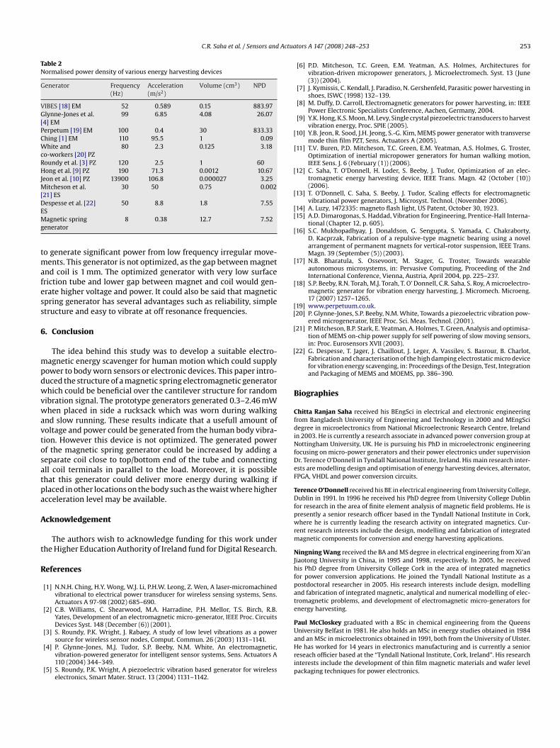
Many of the energy harvesting devices reported to-date are res-onant devices. These resonant devices are commonly comparedusing a normalized power density (NPD). The NPD figure for severalgenerators was presented in ref. [18]. Table 2 below compares theNPD of the magnetic spring generator when driven at resonanceto those given in ref. [18]. This shows that the normalized powerdensity of the magnetic spring generator does not show the bestperformance compared to other generators which is partially due tohigher damping loss. The moving magnet directly touches the tubesurface which obviously increases the damping loss. On the otherhand the majority of reported generators have resonant frequenciesof tens of Hz whereas the generators reported here have resonantfrequencies of 8 and 6.5 Hz. The average generated electrical powerof the vibrational generator is related to cube of the frequency [2]and the frequency of the all reported prototype generators are morethan 30 Hz. The generator presented here has been demonstrated
Actua
[
[
[
[[
[
[
[[
[
[
ests are modelling design and optimisation of energy harvesting devices, alternator,
C.R. Saha et al. / Sensors and
Table 2Normalised power density of various energy harvesting devices
Generator Frequency(Hz)
Acceleration(m/s2)
Volume (cm3) NPD
VIBES [18] EM 52 0.589 0.15 883.97Glynne-Jones et al.[4] EM
99 6.85 4.08 26.07
Perpetum [19] EM 100 0.4 30 833.33Ching [1] EM 110 95.5 1 0.09White andco-workers [20] PZ
80 2.3 0.125 3.18
Roundy et al. [3] PZ 120 2.5 1 60Hong et al. [9] PZ 190 71.3 0.0012 10.67Jeon et al. [10] PZ 13900 106.8 0.000027 3.25Mitcheson et al.[21] ES
30 50 0.75 0.002
Despesse et al. [22]ES
50 8.8 1.8 7.55
Magnetic springgenerator
8 0.38 12.7 7.52
to generate significant power from low frequency irregular move-ments. This generator is not optimized, as the gap between magnetand coil is 1 mm. The optimized generator with very low surfacefriction tube and lower gap between magnet and coil would gen-erate higher voltage and power. It could also be said that magneticspring generator has several advantages such as reliability, simplestructure and easy to vibrate at off resonance frequencies.
6. Conclusion
The idea behind this study was to develop a suitable electro-magnetic energy scavenger for human motion which could supplypower to body worn sensors or electronic devices. This paper intro-duced the structure of a magnetic spring electromagnetic generatorwhich could be beneficial over the cantilever structure for randomvibration signal. The prototype generators generated 0.3–2.46 mWwhen placed in side a rucksack which was worn during walkingand slow running. These results indicate that a usefull amount ofvoltage and power could be generated from the human body vibra-tion. However this device is not optimized. The generated powerof the magnetic spring generator could be increased by adding aseparate coil close to top/bottom end of the tube and connectingall coil terminals in parallel to the load. Moreover, it is possible
that this generator could deliver more energy during walking ifplaced in other locations on the body such as the waist where higheracceleration level may be available.Acknowledgement
The authors wish to acknowledge funding for this work underthe Higher Education Authority of Ireland fund for Digital Research.
References
[1] N.N.H. Ching, H.Y. Wong, W.J. Li, P.H.W. Leong, Z. Wen, A laser-micromachinedvibrational to electrical power transducer for wireless sensing systems, Sens.Actuators A 97-98 (2002) 685–690.
[2] C.B. Williams, C. Shearwood, M.A. Harradine, P.H. Mellor, T.S. Birch, R.B.Yates, Development of an electromagnetic micro-generator, IEEE Proc. CircuitsDevices Syst. 148 (December (6)) (2001).
[3] S. Roundy, P.K. Wright, J. Rabaey, A study of low level vibrations as a powersource for wireless sensor nodes, Comput. Commun. 26 (2003) 1131–1141.
[4] P. Glynne-Jones, M.J. Tudor, S.P. Beeby, N.M. White, An electromagnetic,vibration-powered generator for intelligent sensor systems, Sens. Actuators A110 (2004) 344–349.
[5] S. Roundy, P.K. Wright, A piezoelectric vibration based generator for wirelesselectronics, Smart Mater. Struct. 13 (2004) 1131–1142.
tors A 147 (2008) 248–253 253
[6] P.D. Mitcheson, T.C. Green, E.M. Yeatman, A.S. Holmes, Architectures forvibration-driven micropower generators, J. Microelectromech. Syst. 13 (June(3)) (2004).
[7] J. Kymissis, C. Kendall, J. Paradiso, N. Gershenfeld, Parasitic power harvesting inshoes, ISWC (1998) 132–139.
[8] M. Duffy, D. Carroll, Electromagnetic generators for power harvesting, in: IEEEPower Electronic Specialists Conference, Aachen, Germany, 2004.
[9] Y.K. Hong, K.S. Moon, M. Levy, Single crystal piezoelectric transducers to harvestvibration energy, Proc. SPIE (2005).
10] Y.B. Jeon, R. Sood, J.H. Jeong, S.-G. Kim, MEMS power generator with transversemode thin film PZT, Sens. Actuators A (2005).
[11] T.V. Buren, P.D. Mitcheson, T.C. Green, E.M. Yeatman, A.S. Holmes, G. Troster,Optimization of inertial micropower generators for human walking motion,IEEE Sens. J. 6 (February (1)) (2006).
12] C. Saha, T. O’Donnell, H. Loder, S. Beeby, J. Tudor, Optimization of an elec-tromagnetic energy harvesting device, IEEE Trans. Magn. 42 (October (10))(2006).
13] T. O’Donnell, C. Saha, S. Beeby, J. Tudor, Scaling effects for electromagneticvibrational power generators, J. Microsyst. Technol. (November 2006).
14] A. Luzy, 1472335: magneto flash light, US Patent, October 30, 1923.15] A.D. Dimarogonas, S. Haddad, Vibration for Engineering, Prentice-Hall Interna-
tional (Chapter 12, p. 605).16] S.C. Mukhopadhyay, J. Donaldson, G. Sengupta, S. Yamada, C. Chakraborty,
D. Kacprzak, Fabrication of a repulsive-type magnetic bearing using a novelarrangement of permanent magnets for vertical-rotor suspension, IEEE Trans.Magn. 39 (September (5)) (2003).
[17] N.B. Bharatula, S. Ossevoort, M. Stager, G. Troster, Towards wearableautonomous microsystems, in: Pervasive Computing, Proceeding of the 2ndInternational Conference, Vienna, Austria, April 2004, pp. 225–237.
18] S.P. Beeby, R.N. Torah, M.J. Torah, T. O’ Donnell, C.R. Saha, S. Roy, A microelectro-magnetic generator for vibration energy harvesting, J. Micromech. Microeng.17 (2007) 1257–1265.
19] www.perpetuum.co.uk.20] P. Glynne-Jones, S.P. Beeby, N.M. White, Towards a piezoelectric vibration pow-
ered microgenerator, IEEE Proc. Sci. Meas. Technol. (2001).21] P. Mitcheson, B.P. Stark, E. Yeatman, A. Holmes, T. Green, Analysis and optimisa-
tion of MEMS on-chip power supply for self powering of slow moving sensors,in: Proc. Eurosensors XVII (2003).
22] G. Despesse, T. Jager, J. Chaillout, J. Leger, A. Vassilev, S. Basrour, B. Charlot,Fabrication and characterisation of the high damping electrostatic micro devicefor vibration energy scavenging, in: Proceedings of the Design, Test, Integrationand Packaging of MEMS and MOEMS, pp. 386–390.
Biographies
Chitta Ranjan Saha received his BEngSci in electrical and electronic engineeringfrom Bangladesh University of Engineering and Technology in 2000 and MEngScidegree in microelectronics from National Microelectronic Research Centre, Irelandin 2003. He is currently a research associate in advanced power conversion group atNottingham University, UK. He is pursuing his PhD in microelectronic engineeringfocusing on micro-power generators and their power electronics under supervisionDr. Terence O’Donnell in Tyndall National Institute, Ireland. His main research inter-
FPGA, VHDL and power conversion circuits.
Terence O’Donnell received his BE in electrical engineering from University College,Dublin in 1991. In 1996 he received his PhD degree from University College Dublinfor research in the area of finite element analysis of magnetic field problems. He ispresently a senior research officer based in the Tyndall National Institute in Cork,where he is currently leading the research activity on integrated magnetics. Cur-rent research interests include the design, modelling and fabrication of integratedmagnetic components for conversion and energy harvesting applications.
Ningning Wang received the BA and MS degree in electrical engineering from Xi’anJiaotong University in China, in 1995 and 1998, respectively. In 2005, he receivedhis PhD degree from University College Cork in the area of integrated magneticsfor power conversion applications. He joined the Tyndall National Institute as apostdoctoral researcher in 2005. His research interests include design, modellingand fabrication of integrated magnetic, analytical and numerical modelling of elec-tromagnetic problems, and development of electromagnetic micro-generators forenergy harvesting.
Paul McCloskey graduated with a BSc in chemical engineering from the QueensUniversity Belfast in 1981. He also holds an MSc in energy studies obtained in 1984and an MSc in microelectronics obtained in 1991, both from the University of Ulster.He has worked for 14 years in electronics manufacturing and is currently a seniorreseach officier based at the “Tyndall National Institute, Cork, Ireland”. His researchinterests include the development of thin film magnetic materials and wafer levelpackaging techniques for power electronics.