Modal Verification and Strength Analysis of Rotor Bladed ...
© JVE INTERNATIONAL LTD. JOURNAL OF VIBROENGINEERING. SEP 2014, VOLUME 16, ISSUE 6. ISSN 1392-8716 2983
1391. Nonlinear response of the generator rotor under the unbalanced electromagnetic force
Guoyuan Zhang1, Yanni Tian2, Haizhou Huang3, Miao Zhou4 1, 2School of Electromechanical Engineering, Xidian University, Xi’an, 710071, China 3, 4Hubei Electric Testing & Research Institute, Wuhan, 430077, China 1Corresponding author E-mail: [email protected], [email protected], [email protected], [email protected] (Received 4 February 2014; received in revised form 25 May 2014; accepted 6 June 2014)
Abstract. The vibration response characteristics based on the unbalanced electromagnetic force and the oil film force coupling model for the generator rotor are calculated and analyzed. The nonlinear vibration for the 300 MW turbo-generator rotor under the different situation and different level (normal turns points) excitation winding inter-turn short circuit cases are carried out, and the typical parameters of the vibration response (such as the amplitude, frequency, and vibration component) are obtained. Meanwhile, as a comparative study, the linear and nonlinear dynamics results under the normal working condition are also studied. The results show that the fault of inter-turn short circuit may easily excite the low-frequency vibration, and the frequency is close to the rotor’s first critical speed; and the inter-turn short circuit fault located at the certain situation may induce the rotor’s 1/3 order subharmonic resonance or synchronous whirl. Keywords: nonlinear vibration, inter-turn short circuit, electromagnetic force, oil film force.
1. Introduction
The excitation winding inter-turn short circuit is one of the most common faults for turbo-generator rotors. Once faults as such occur, unusual large current would flow through the fault point, which would, in turn, ruin the rotor itself and break the equilibrium state of the air-gap magnetic field. And the consequent generator vibration and magnetized rotor would put the generator in severe danger [1, 2]. The indirect test is often used in on-spot diagnoses of such faults. That is, judgment is made based on the variation of relevant electric parameters. Nonetheless, this method demands the use of additional equipment to obtain relevant electric parameters, which is not helpful for direct or online diagnoses [3, 4]. Field observation has indicated that the inter-turn short circuit co-occurs with rotors’ unusual vibration behavior such that the latter might be the external manifestation of the fault. And this possibility has been acknowledged by many researchers [5-12]. The easy access to the vibration data of the generator rotor, contributed to the advancement of the idea that the rotor’s vibration behavior can be utilized to diagnose the fault of inter-turn short circuit. For example, Li et al. studied the influence of the rotor winding inter-turn short circuit fault on the vibration characteristics of the turbo-generator rotor [7, 8], putting forward one on-line diagnosis method of the short circuit fault, namely, monitoring the fundamental frequency of the stator iron core vibration [9]. The finding from Fang et al. showed that the stator winding inter-turn short circuit resulted in considerable variation of the vibration acceleration of the two-time fundamental frequency, lending support to the diagnosis method of vibration monitoring [10]. The vibration analysis of a real generator by Liu, also suggested that the rotor winding inter-turn short circuit led rotor vibration to exceed the limit when rotor was at the critical rate [11]. Hao et al. pointed out that the inter-turn short circuit could accelerate generator vibration, in their study of the steady-state mathematical model of excitation winding short fault [12]. Huang et al. found the link between the inter-turn short circuit and rotor vibration through monitoring the running generator [14]. However, those studies did not examine the mechanism of the non-linear vibration resulting from the coupling of the nonlinear oil film force and the electromagnetic force due to the inter-turn short circuit. In addition, the vibration data were mostly obtained during simulation experiments. Therefore, there is a clear need to conduct a study on the vibration mechanism from the perspective of numerical simulation. The present AU
THOR
'S P
ERSO
NAL
COPY
1391. NONLINEAR RESPONSE OF THE GENERATOR ROTOR UNDER THE UNBALANCED ELECTROMAGNETIC FORCE. GUOYUAN ZHANG, YANNI TIAN, HAIZHOU HUANG, MIAO ZHOU
2984 © JVE INTERNATIONAL LTD. JOURNAL OF VIBROENGINEERING. SEP 2014, VOLUME 16, ISSUE 6. ISSN 1392-8716
study intends to analyze the rotor’s vibration behavior under different circumstances of inter-turn short circuit and obtain detailed vibration data through the vibration component analysis, on the basis of the rotor non-linear vibration model of the coupling of the unbalanced electromagnetic force and nonlinear oil film force [15]. The findings could lend theoretical and technical support to early prediction and on-site diagnoses of such faults.
2. Research target and calculation
2.1. Research target
The research target is the bearing rotor system of one Dongfang generator of 300 MW. Table 1 presents the main parameters of the bearing and its working condition.
Table 1. Main parameters of the bearing and its working condition Parameter Value Parameter Value
Width / mm 380 Load / kg 26405 Diameter / mm 450 Ellipticity 0.566 Lubricant viscosity / (Pa·S) 0.0126 Lubricant 32# Inlet pressure / MPa 0.08 Radius clearance / mm 0.675
For an actual generator rotor, it has been common practice that its physical model is so modeled that the contiguous rotor system can be reduced to a limited number of discrete systems with multiple degrees of freedom. Several methods can be employed in the modeling, including the lumped masses method, the FEM, the Rayleigh-Ritz method, and the Tomoshenko method, among which, the lumped masses method stands out as the best candidate because, in reality, additional factors related to the couple parts of the rotor, such as bearing, unbalance force, and unexpected shock, needs to reckoned with, and the lumped masses method can cater for this need better as against the other methods and can improve the convergence speed and accuracy.
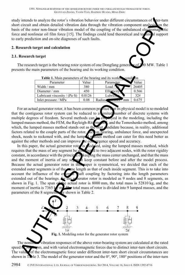
In this paper, the actual generator rotor is modeled, using the lumped masses method, which requires that the mass of any segment be distributed to two adjacent nodes, with the rotor rigidity constant, in accordance with the principle of keeping the mass center unchanged, and that the mass and the moment of inertia of any segment keep constant before and after the model process. Because the actual generator rotor in this paper is symmetrical, we decided that each of the extended outer segments is of the same length as that of each inside segment. This is to take into account the influence of the external shaft coupling by factoring into the length parameters extended out of the bearings. So the generator rotor is modeled as 9 nodes and 8 segments, as shown in Fig. 1. The span of the actual rotor is 8000 mm, the total mass is 52810 kg, and the moment of inertia is 7365 kg·m2. The total mass of rotor is divided into 9 lumped masses, and the parameters of the 8 segments are shown in Table 2.
Fig. 1. Modeling rotor for the generator rotor system
The nonlinear vibration responses of the above rotor-bearing system are calculated at the rated speed of 3000 rpm, and with varied electromagnetic forces due to distinct inter-turn short circuits. The values of the electromagnetic force under different inter-turn short circuit circumstances are shown in Table 3. The model of the generator rotor and the 0°, 90°, 180° positions of the inter-turn
AUTH
OR'S
PER
SONA
L CO
PY
1391. NONLINEAR RESPONSE OF THE GENERATOR ROTOR UNDER THE UNBALANCED ELECTROMAGNETIC FORCE. GUOYUAN ZHANG, YANNI TIAN, HAIZHOU HUANG, MIAO ZHOU
© JVE INTERNATIONAL LTD. JOURNAL OF VIBROENGINEERING. SEP 2014, VOLUME 16, ISSUE 6. ISSN 1392-8716 2985
short circuit faults were shown in Fig. 4, [15].
Table 2. Parameters for the 8 segments of modeling rotor Segment number Length / m External
diameter / m Internal
diameter / m Equivalent moment of
inertia diameter / m 1 1.300 0.520 0.00 0.37678 2 0.905 0.520 0.00 0.37678 3 0.690 0.980 0.00 0.71008 4 2.405 1.120 0.00 0.81152 5 2.405 1.120 0.00 0.81152 6 0.690 0.980 0.00 0.71008 7 0.905 0.520 0.00 0.37678 8 1.550 0.520 0.00 0.37678
Due to the symmetric rotor, a certain length of rotor segment is extended to the outer end of the bearing in order to make the stability threshold speed of generator rotor-bearing system approximate that of the modeling rotor. The bearings are installed in both ends, and have the same type and equivalent load. The dynamic oil film force can be obtained by solving the Reynolds equation with the finite-element method. The turbulence working condition with the Pan-Ng recommended turbulence factor is considered in the calculation process.
2.2. Calculation description
The vibration responses under the balanced and unbalanced conditions are studied in the paper. Under the balanced condition, the responses of the all nodes in the rotor system are caculated at the rated speed of 3000 rpm. Under the unbalanced condition, the responses of the all nodes and the nonlinear oil film force in different cases are calculated respectively, including the different situations, slight and serious short circuit faults. In this study, the slight and serious short circuit faults are defined by the ratio of short circuit winding turns to the total excitation turns. For slight short circuit, the ratio is low to 10 %, while for serious short circuit, the ratio is high to 25 %. The influences of the two distributed force mode on the vibration responses are studied. The electromagnetic force has two mode acted on the rotor, that is, the concentrated force acted on node 5 and distributed force acted on the node 3-7.
Table 3 presents the theoretical values of the electromagnetic forces under the rated speed in the 90° fault positions.
Table 3. The electromagnetic force list
Items Value / N
Normal condition 0 0 Under 90° position slight short circuit 1.3253e+003 7.3642e+003 Under 90° position serious short circuit 1.3702e+003 1.2711e+003
With the values of the electromagnetic force, the unbalanced eccentricity can be expressed as: = = × 3000 × 2 × 60 , (1)
where, is unbalanced eccentricity (m), is the mass (kg), is electromagnetic force (N), = , . Then, the equivalent unbalance eccentricity can be defined as: AU
THOR
'S P
ERSO
NAL
COPY
1391. NONLINEAR RESPONSE OF THE GENERATOR ROTOR UNDER THE UNBALANCED ELECTROMAGNETIC FORCE. GUOYUAN ZHANG, YANNI TIAN, HAIZHOU HUANG, MIAO ZHOU
2986 © JVE INTERNATIONAL LTD. JOURNAL OF VIBROENGINEERING. SEP 2014, VOLUME 16, ISSUE 6. ISSN 1392-8716
= , (2)
where, is the equivalent unbalance eccentricity ( = , ), is the radius clearance of bearings (mm).
Table 4 presents the equivalent unbalance eccentricity when the rated speed is 3000 rpm in the 90° fault positions, and distinct fault seriousness (slight and serious short circuit). The numerical values of and in Table 4 are the results of theoretical calculation.
Table 4. Calculation list and unbalanced parameters
Number Calculation condition (3000 rpm) Force mode Unbalanced eccentricity
1 Normal condition null 0.00 0.00 2 Under 90° position slight short circuit At node 5 0.00075 0.00419 3 Under 90° position serious short circuit At node 5 0.00078 0.00723 4 Under 90° position slight short circuit At node 3-7 0.000125 0.000698 5 Under 90° position serious short circuit At node 3-7 0.000130 0.001205
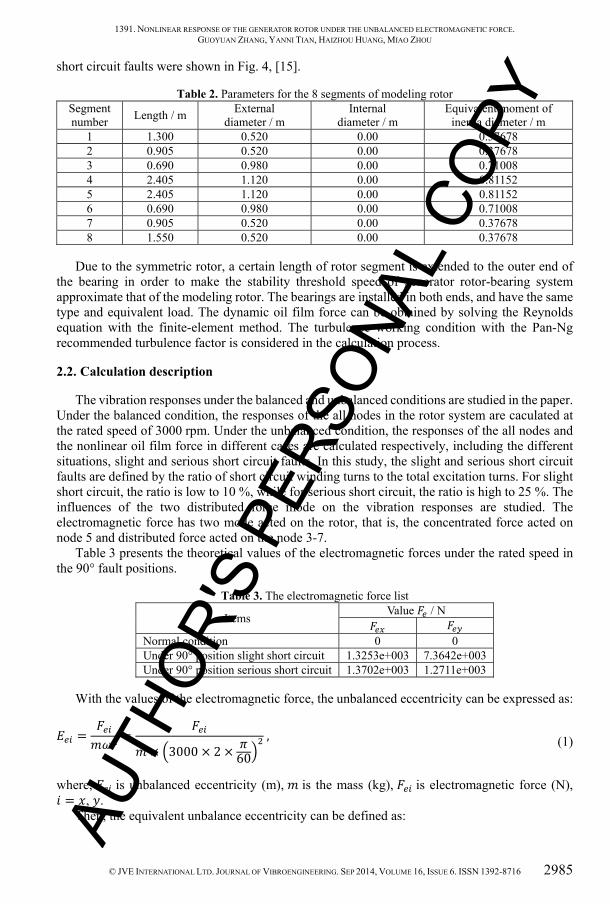
Table 4 depicts the calculation list for the response analysis and the special unbalanced results. and are the unbalanced eccentricity originated from the electromagnetic force. The coordinate system of the horizontal and vertical displacement , as well as bearing oil
film force ( , ) involved in the caculation and analysis process is shown in Fig. 2. In Fig. 2, denotes the bearing load. , , , are dimensionless value, and the relative unit of , is bearing side clearance (C) while that of , is . The computing results of response include the displacement of periodic solutions , , , , , , , (corresponding to nodes 2, 3, 4, 5 respectively in Fig. 1) and the waveform of , . The -coordinate of the response is dimensionless time priod , whose unit is radian. While the unit of time is second, = Ω 30⁄ . The maximum of -coordinate is dimensionless priod for periodic solution. The
-coordinate presents the nonlinear vibration response and corresponding rotor centerline orbit, the amplitude of response displayed by the -coordinate is the ratio of relative vibration response values which are relative to the static equilibium point (obtained by the calculation of bearing static point) to the bearing side clearance. The vertical axis presents the waveform of transient oil film force, -coordinate shows the ratio of the transient oil film force to bearing load.
Fig. 2. Coordinate system ( – center of bearing)
3. Linear and nonlinear dynamics results under the normal condition
3.1. Linear dynamics results
Tables 5 and 6 show the results of the static and dynamic characteristics for the sliding bearing at different rotational speed (800-4300 rpm).
Tables 5 and 6 present the theoretical values of the static and dynamic characteristics of the AUTH
OR'S
PER
SONA
L CO
PY

1391. NONLINEAR RESPONSE OF THE GENERATOR ROTOR UNDER THE UNBALANCED ELECTROMAGNETIC FORCE. GUOYUAN ZHANG, YANNI TIAN, HAIZHOU HUANG, MIAO ZHOU
© JVE INTERNATIONAL LTD. JOURNAL OF VIBROENGINEERING. SEP 2014, VOLUME 16, ISSUE 6. ISSN 1392-8716 2987
rotor when it is at different speeds. The dynamic characteristics of rotor are considered linear, and indexed by the 8 linear stiffness and damping coefficients ( , , , , , , ,
). And in this case, the bearing load consists of only the rotor mass, and there is no added load and no unbalanced electromagnetic force. The first critical speed and the linear instability speed (expressed as the logarithmic decrement), shown in Figs. 3 and 4, are thus obtained by solving the following equation, which has taken into consideration of the system’s inherent vibration problems due to the multi-DOF bearing rotor system adopted: [ ] + [ ] + [ ] = 0 , (3)
where, = [ , , . . . , , ] ( is number of the nodes), and the coefficients matrix [ ], [ ], [ ] is 2 ×2 matrix.
Table 5. Static characteristics of the bearing for the generator rotor Rotational
speed Attitude
angle Eccentricity Oil film thickness Flow Temperature
rise Power
consumption rpm / o ℎ / μm / l min-1 / °C / kW 800 59.5 0.4491 39.49 81.00 5.7 13.2
1300 68.65 0.438 56.70 135.60 8.3 31.8 1800 73.58 0.4177 69.86 186.60 11.1 58.2 2300 77.19 0.3988 80.66 234.00 14.2 93.7 2800 79.58 0.3794 89.10 278.40 17.8 140.0 3000 80.38 0.372 92.14 295.20 19.3 161.0 3300 81.53 0.3621 96.19 321.00 21.7 197.0 3800 82.68 0.3445 101.59 360.60 25.8 263.0 4300 83.8 0.3271 106.65 397.80 30.4 342.0
Table 6. Dynamic characteristics of the bearing for the generator rotor Rotational speed Stiffness coefficients (×107 kgf/m) Damping coefficients (×105 kgf·s/m)
rpm 800 5.71 3.25 18.00 40.20 3.97 6.62 6.62 38.90 1300 5.42 0.80 15.90 29.80 3.52 3.65 3.65 22.70 1800 5.11 –1.18 14.50 26.20 3.02 1.93 1.93 16.20 2300 4.64 –2.94 13.80 25.50 2.83 0.56 0.56 12.90 2800 4.63 –4.74 13.70 25.40 2.73 0.03 0.03 11.40 3000 4.55 –5.40 13.70 25.60 2.68 –0.20 –0.20 10.90 3300 4.51 –6.34 13.60 26.00 2.62 –0.46 –0.46 10.20 3800 4.20 –7.77 13.60 27.20 2.47 –0.90 –0.90 9.36 4300 4.23 –9.20 13.60 28.00 2.35 –1.07 –1.07 8.73
The 8 eigenvalues, which are always the complex conjugate pairs, can be obtained by solving the corresponding eigenvectors of the above equations. Once whether the forward or reverse whirl occurs is determined, the eigenvalues = − + under different speed conditions are obtained. The Ω − (speed – whirl speed) curve is made accordingly, and the intersection of the curve and the straight line = Ω is the critical speed.
For the multi-DOF bearing rotor system, set the value of the -order eigenvalue as = − + , the corresponding logarithmic decrement can be noted as: = −2 . (4)
The minimum logarithmic decrement is defined as = min( ) under the different speed conditions. The linear instability speed can be defined as the one when = 0. AU
THOR
'S P
ERSO
NAL
COPY
1391. NONLINEAR RESPONSE OF THE GENERATOR ROTOR UNDER THE UNBALANCED ELECTROMAGNETIC FORCE. GUOYUAN ZHANG, YANNI TIAN, HAIZHOU HUANG, MIAO ZHOU
2988 © JVE INTERNATIONAL LTD. JOURNAL OF VIBROENGINEERING. SEP 2014, VOLUME 16, ISSUE 6. ISSN 1392-8716
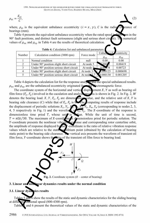
The whirl speed is shown as Fig. 3, while the Fig. 4 details the logarithmic decrement. As shown in the Fig. 4, the stability threshold of the generator rotor supported by the silding bearing is about 3430 rpm. The logarithmic decremen speed of shafting is 0.0695 at the working speed (3000 rpm). The error between the real first critical speed which is about 1280 rpm and the designed one provided by the Company is approximately 5 %.
Fig. 3. Whirl speed vs. speed
Fig. 4. Logarithmic decrement vs. speed
3.2. Nonlinear vibration response analysis for the generator rotor at the rated speed
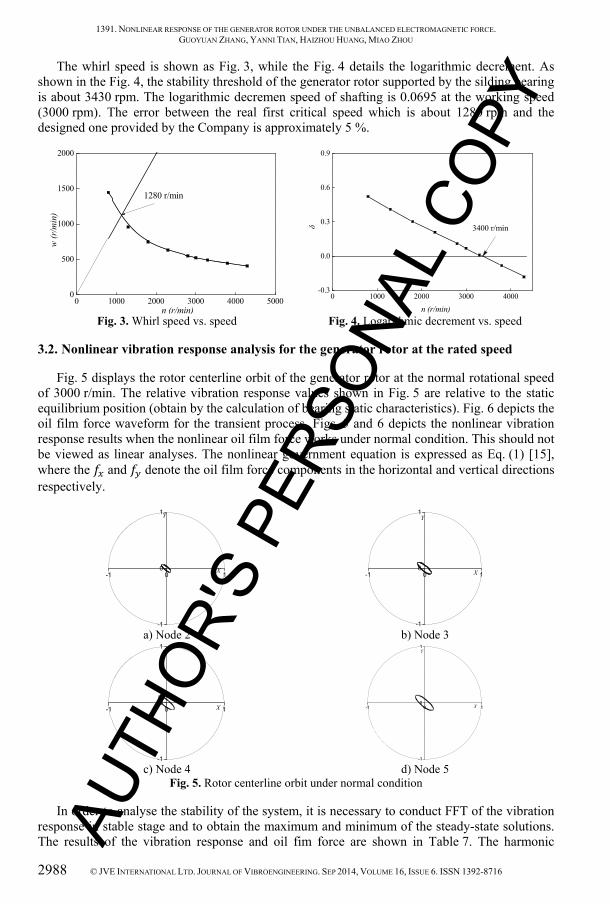
Fig. 5 displays the rotor centerline orbit of the generator rotor at the normal rotational speed of 3000 r/min. The relative vibration response values shown in Fig. 5 are relative to the static equilibrium position (obtain by the calculation of bearing static characteristics). Fig. 6 depicts the oil film force waveform for the transient process. Figs. 5 and 6 depicts the nonlinear vibration response results when the nonlinear oil film force works under normal condition. This should not be viewed as linear analyses. The nonlinear government equation is expressed as Eq. (1) [15], where the and denote the oil film force components in the horizontal and vertical directions respectively.
a) Node 2
b) Node 3
c) Node 4
d) Node 5
Fig. 5. Rotor centerline orbit under normal condition
In order to analyse the stability of the system, it is necessary to conduct FFT of the vibration response in stable stage and to obtain the maximum and minimum of the steady-state solutions. The results of the vibration response and oil fim force are shown in Table 7. The harmonic
0 1000 2000 3000 4000 50000
500
1000
1500
2000
w (r
/min
)
n (r/min)
1280 r/min
0 1000 2000 3000 4000-0.3
0.0
0.3
0.6
0.9
δn (r/min)
3400 r/min
-1 0 1
-1
0
1
Y
X -1 0 1
-1
0
1Y
X
-1 0 1
-1
0
1Y
X -1 0 1
-1
0
1Y
X
AUTH
OR'S
PER
SONA
L CO
PY
1391. NONLINEAR RESPONSE OF THE GENERATOR ROTOR UNDER THE UNBALANCED ELECTROMAGNETIC FORCE. GUOYUAN ZHANG, YANNI TIAN, HAIZHOU HUANG, MIAO ZHOU
© JVE INTERNATIONAL LTD. JOURNAL OF VIBROENGINEERING. SEP 2014, VOLUME 16, ISSUE 6. ISSN 1392-8716 2989
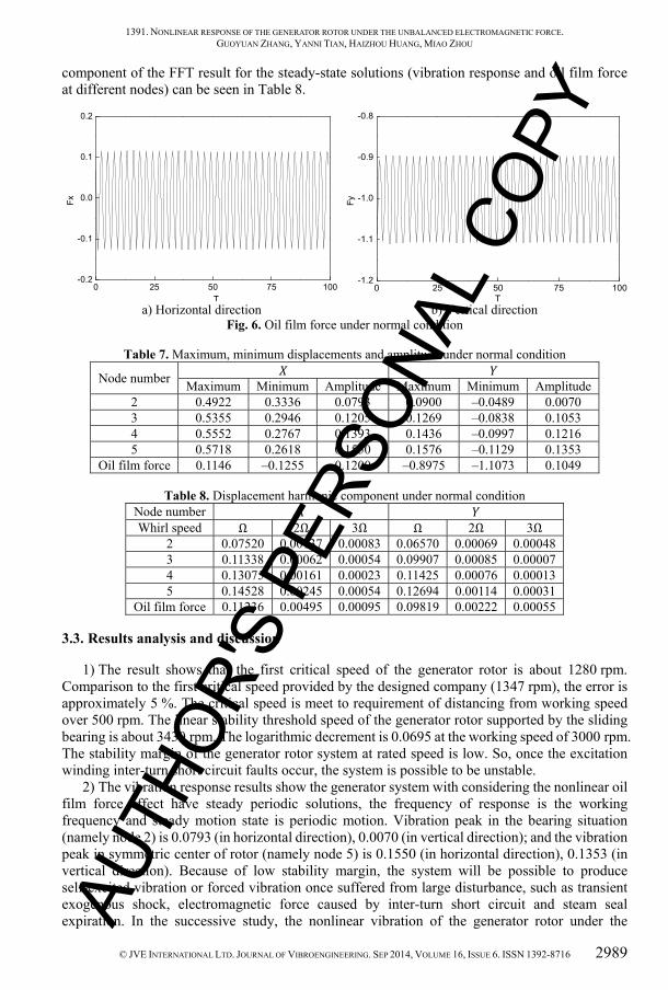
component of the FFT result for the steady-state solutions (vibration response and oil film force at different nodes) can be seen in Table 8.
a) Horizontal direction b) Vertical direction Fig. 6. Oil film force under normal condition
Table 7. Maximum, minimum displacements and amplitude under normal condition
Node number Maximum Minimum Amplitude Maximum Minimum Amplitude 2 0.4922 0.3336 0.0793 0.0900 –0.0489 0.0070 3 0.5355 0.2946 0.1205 0.1269 –0.0838 0.1053 4 0.5552 0.2767 0.1393 0.1436 –0.0997 0.1216 5 0.5718 0.2618 0.1550 0.1576 –0.1129 0.1353
Oil film force 0.1146 –0.1255 0.1200 –0.8975 –1.1073 0.1049
Table 8. Displacement harmonic component under normal condition Node number Whirl speed Ω 2Ω 3Ω Ω 2Ω 3Ω
2 0.07520 0.00137 0.00083 0.06570 0.00069 0.00048 3 0.11338 0.00062 0.00054 0.09907 0.00085 0.00007 4 0.13075 0.00161 0.00023 0.11425 0.00076 0.00013 5 0.14528 0.00245 0.00054 0.12694 0.00114 0.00031
Oil film force 0.11236 0.00495 0.00095 0.09819 0.00222 0.00055
3.3. Results analysis and discussion
1) The result shows that the first critical speed of the generator rotor is about 1280 rpm. Comparison to the first critical speed provided by the designed company (1347 rpm), the error is approximately 5 %. The critical speed is meet to requirement of distancing from working speed over 500 rpm. The linear stability threshold speed of the generator rotor supported by the sliding bearing is about 3430 rpm. The logarithmic decrement is 0.0695 at the working speed of 3000 rpm. The stability margin of the generator rotor system at rated speed is low. So, once the excitation winding inter-turn short circuit faults occur, the system is possible to be unstable.
2) The vibration response results show the generator system with considering the nonlinear oil film force effect have steady periodic solutions, the frequency of response is the working frequency and steady motion state is periodic motion. Vibration peak in the bearing situation (namely node 2) is 0.0793 (in horizontal direction), 0.0070 (in vertical direction); and the vibration peak in symmetric center of rotor (namely node 5) is 0.1550 (in horizontal direction), 0.1353 (in vertical direction). Because of low stability margin, the system will be possible to produce self-excited vibration or forced vibration once suffered from large disturbance, such as transient exogenous shock, electromagnetic force caused by inter-turn short circuit and steam seal expiration. In the successive study, the nonlinear vibration of the generator rotor under the
0 25 50 75 100-0.2
-0.1
0.0
0.1
0.2
Fx
T0 25 50 75 100
-1.2
-1.1
-1.0
-0.9
-0.8
Fy
T
AUTH
OR'S
PER
SONA
L CO
PY
1391. NONLINEAR RESPONSE OF THE GENERATOR ROTOR UNDER THE UNBALANCED ELECTROMAGNETIC FORCE. GUOYUAN ZHANG, YANNI TIAN, HAIZHOU HUANG, MIAO ZHOU
2990 © JVE INTERNATIONAL LTD. JOURNAL OF VIBROENGINEERING. SEP 2014, VOLUME 16, ISSUE 6. ISSN 1392-8716
different inter-turn short circuit cases will be analyzed in detail, the vibration characteristics under the different short circuit faults will be obtained.
4. Nonlinear vibration with the different electromagnetic force mode (under 90° position serious fault)
4.1. Concentrated force mode
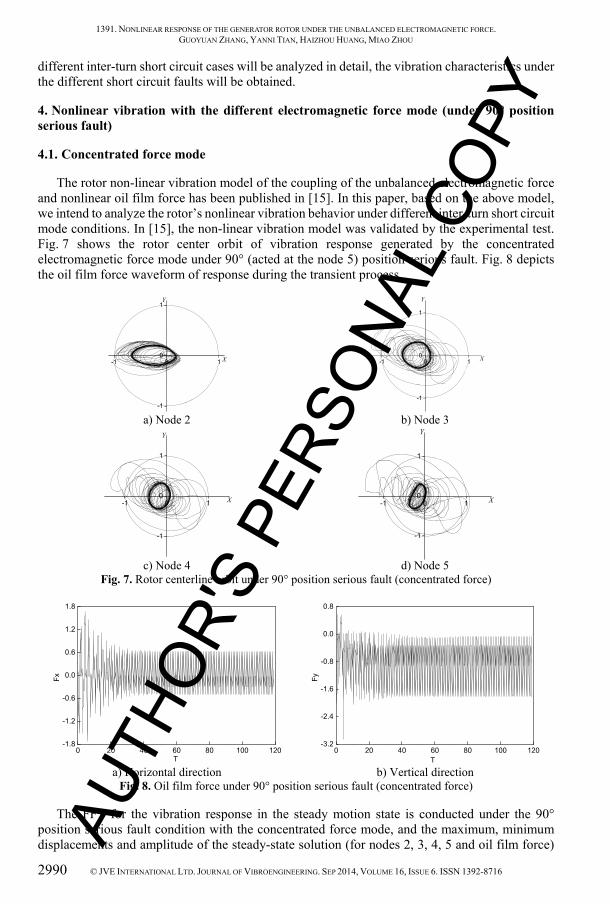
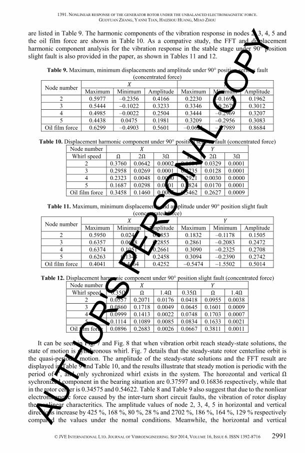
The rotor non-linear vibration model of the coupling of the unbalanced electromagnetic force and nonlinear oil film force has been published in [15]. In this paper, based on the above model, we intend to analyze the rotor’s nonlinear vibration behavior under different inter-turn short circuit mode conditions. In [15], the non-linear vibration model was validated by the experimental test. Fig. 7 shows the rotor center orbit of vibration response generated by the concentrated electromagnetic force mode under 90° (acted at the node 5) position serious fault. Fig. 8 depicts the oil film force waveform of response during the transient process.
a) Node 2
b) Node 3
c) Node 4
d) Node 5
Fig. 7. Rotor centerline orbit under 90° position serious fault (concentrated force)
a) Horizontal direction
b) Vertical direction
Fig. 8. Oil film force under 90° position serious fault (concentrated force)
The FFT for the vibration response in the steady motion state is conducted under the 90° position serious fault condition with the concentrated force mode, and the maximum, minimum displacements and amplitude of the steady-state solution (for nodes 2, 3, 4, 5 and oil film force)
-1 0 1
-1
0
1Y
X -1 0 1
-1
0
1
Y
X
-1 0 1
-1
0
1
Y
X -1 0 1
-1
0
1
Y
X
0 20 40 60 80 100 120-1.8
-1.2
-0.6
0.0
0.6
1.2
1.8
Fx
T0 20 40 60 80 100 120
-3.2
-2.4
-1.6
-0.8
0.0
0.8
Fy
T
AUTH
OR'S
PER
SONA
L CO
PY
1391. NONLINEAR RESPONSE OF THE GENERATOR ROTOR UNDER THE UNBALANCED ELECTROMAGNETIC FORCE. GUOYUAN ZHANG, YANNI TIAN, HAIZHOU HUANG, MIAO ZHOU
© JVE INTERNATIONAL LTD. JOURNAL OF VIBROENGINEERING. SEP 2014, VOLUME 16, ISSUE 6. ISSN 1392-8716 2991
are listed in Table 9. The harmonic components of the vibration response in nodes 2, 3, 4, 5 and the oil film force are shown in Table 10. As a compative study, the FFT and displacement harmonic component analysis for the vibration response in the stable stage under 90° position slight fault is also provided in the paper, as shown in Tables 11 and 12.
Table 9. Maximum, minimum displacements and amplitude under 90° position serious fault (concentrated force)
Node number Maximum Minimum Amplitude Maximum Minimum Amplitude 2 0.5977 –0.2356 0.4166 0.2230 –0.1693 0.1962 3 0.5444 –0.1022 0.3233 0.3346 –0.2679 0.3012 4 0.4985 –0.0022 0.2504 0.3444 –0.2969 0.3207 5 0.4438 0.0475 0.1981 0.3209 –0.2956 0.3083
Oil film force 0.6299 –0.4903 0.5601 –0.0621 –1.7989 0.8684
Table 10. Displacement harmonic component under 90° position serious fault (concentrated force) Node number Whirl speed Ω 2Ω 3Ω Ω 2Ω 3Ω
2 0.3760 0.0642 0.0002 0.1684 0.0329 0.0001 3 0.2958 0.0269 0.0001 0.2735 0.0128 0.0001 4 0.2323 0.0048 0.0000 0.2921 0.0030 0.0000 5 0.1687 0.0298 0.0001 0.2824 0.0170 0.0001
Oil film force 0.3458 0.1460 0.0005 0.5462 0.2627 0.0009
Table 11. Maximum, minimum displacements and amplitude under 90° position slight fault (concentrated force)
Node number Maximum Minimum Amplitude Maximum Minimum Amplitude 2 0.5950 0.0244 0.2853 0.1832 –0.1178 0.1505 3 0.6357 0.0648 0.2855 0.2861 –0.2083 0.2472 4 0.6374 0.1051 0.2661 0.3090 –0.2325 0.2708 5 0.6263 0.1348 0.2458 0.3094 –0.2390 0.2742
Oil film force 0.4041 –0.4464 0.4252 –0.5474 –1.5502 0.5014
Table 12. Displacement harmonic component under 90° position slight fault (concentrated force) Node number Whirl speed 0.35Ω Ω 1.4Ω 0.35Ω Ω 1.4Ω
2 0.0557 0.2071 0.0176 0.0418 0.0955 0.0038 3 0.0860 0.1718 0.0049 0.0645 0.1601 0.0009 4 0.0999 0.1413 0.0022 0.0748 0.1703 0.0007 5 0.1114 0.1089 0.0085 0.0834 0.1633 0.0021
Oil film force 0.0896 0.2683 0.0026 0.0667 0.3811 0.0011
It can be seen in Fig. 7 and Fig. 8 that when vibration orbit reach steady-state solutions, the state of motion is synchronous whirl. Fig. 7 details that the steady-state rotor centerline orbit is the quasi-periodic motion. The amplitude of the steady-state solutions and the FFT result are displayed in Table 9 and Table 10, and the results illustrate that steady motion is periodic with the period of , and only sychronized whirl exists in the system. The horozontal and vertical Ω sychronized component in the bearing situation are 0.37597 and 0.16836 respectively, while that in the rotor center is 0.34575 and 0.54622. Table 8 and Table 9 also suggest that due to the nonliear electromagnetic force caused by the inter-turn short circuit faults, the vibration of rotor display the nonlinear characteritics. The amplitude values of node 2, 3, 4, 5 in horizontal and vertical directions increase by 425 %, 168 %, 80 %, 28 % and 2702 %, 186 %, 164 %, 129 % respectively compared the values under the nomal conditions. Meanwhile, the horizontal and vertical AU
THOR
'S P
ERSO
NAL
COPY
1391. NONLINEAR RESPONSE OF THE GENERATOR ROTOR UNDER THE UNBALANCED ELECTROMAGNETIC FORCE. GUOYUAN ZHANG, YANNI TIAN, HAIZHOU HUANG, MIAO ZHOU
2992 © JVE INTERNATIONAL LTD. JOURNAL OF VIBROENGINEERING. SEP 2014, VOLUME 16, ISSUE 6. ISSN 1392-8716
amplitude of oil film force increase by 367 %, 728 % respectively because of the electromagnetic force.
Comparing the slight short circuit fault cases with the serious cases (shown in Tables 11 and 12) under 90° position, the state of motion transforms from the quasi-periodic motion to the synchronous whirl. The motion state whose main and secondary composition of vibration response is the response of the self-excited vibration and the forced vibration respectively converts into the sychronized whirl. As the unbalanced force caused by the short circuit increases, the vibration amplitude of the bearing situation rises by 46 % (in horizontal direction) and 30 % (in vertical direction). While there is a decrease of 19 % (in horizontal direction) and a increase of 12 % (in vertical direction) in the vibration amplitude of rotor center where the centrated force acting on (namely node 5). The oil film force amplitude increased by 32 % (in horizontal direction) and 73 % (in vertical direction). Although the variation law of vibration amplitude is complicated, sychronized whirl aroused by the self-excited vibration increases all the time as the severity of short circuit fault rises. In contrast with the slight short circuit case, under serious fault, the self-excited vibration amplitude of the bearing situation rise by 82 % (in horizontal direction) and 76 % (in vertical direction). While there is an increase of 55 % (in horizontal direction) and 73 % (in vertical direction) in the self-excited vibration amplitude of the rotor center (namely node 5) where the centrated force is acting on. And the oil film force amplitude increased by 29 % (in horizontal direction) and 43 % (in vertical direction).
4.2. Uniform force mode
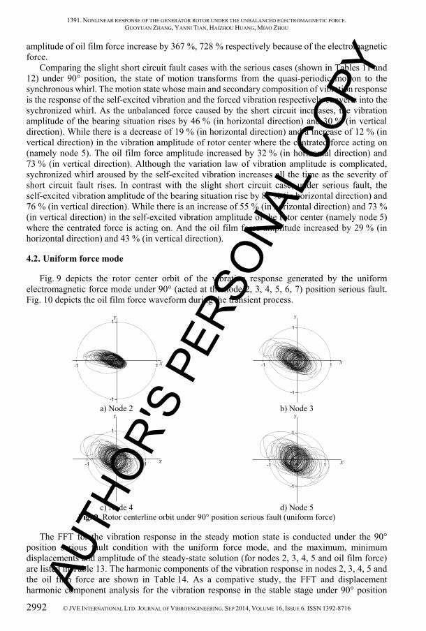
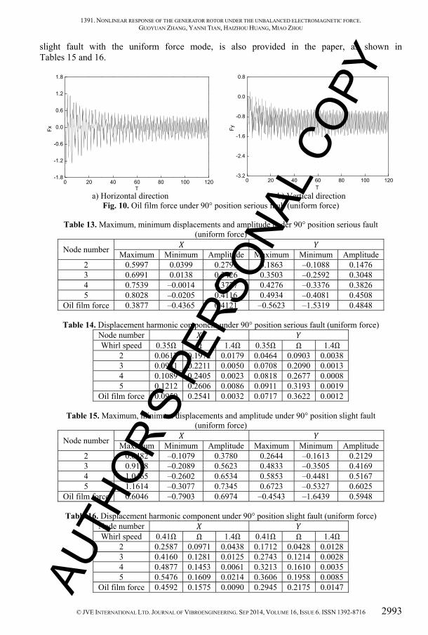
Fig. 9 depicts the rotor center orbit of the vibration response generated by the uniform electromagnetic force mode under 90° (acted at the node 2, 3, 4, 5, 6, 7) position serious fault. Fig. 10 depicts the oil film force waveform during the transient process.
a) Node 2
b) Node 3
c) Node 4
d) Node 5
Fig. 9. Rotor centerline orbit under 90° position serious fault (uniform force)
The FFT for the vibration response in the steady motion state is conducted under the 90° position serious fault condition with the uniform force mode, and the maximum, minimum displacements and amplitude of the steady-state solution (for nodes 2, 3, 4, 5 and oil film force) are listed in Table 13. The harmonic components of the vibration response in nodes 2, 3, 4, 5 and the oil film force are shown in Table 14. As a compative study, the FFT and displacement harmonic component analysis for the vibration response in the stable stage under 90° position
-1 0 1
-1
0
1Y
X -1 0 1
-1
0
1
Y
X
-1 0 1
-1
0
1
Y
X -1 0 1
-1
0
1
Y
X
AUTH
OR'S
PER
SONA
L CO
PY
1391. NONLINEAR RESPONSE OF THE GENERATOR ROTOR UNDER THE UNBALANCED ELECTROMAGNETIC FORCE. GUOYUAN ZHANG, YANNI TIAN, HAIZHOU HUANG, MIAO ZHOU
© JVE INTERNATIONAL LTD. JOURNAL OF VIBROENGINEERING. SEP 2014, VOLUME 16, ISSUE 6. ISSN 1392-8716 2993
slight fault with the uniform force mode, is also provided in the paper, as shown in Tables 15 and 16.
a) Horizontal direction
b) Vertical direction
Fig. 10. Oil film force under 90° position serious fault (uniform force)
Table 13. Maximum, minimum displacements and amplitude under 90° position serious fault (uniform force)
Node number Maximum Minimum Amplitude Maximum Minimum Amplitude 2 0.5997 0.0399 0.2799 0.1863 –0.1088 0.1476 3 0.6991 0.0138 0.3426 0.3503 –0.2592 0.3048 4 0.7539 –0.0014 0.3777 0.4276 –0.3376 0.3826 5 0.8028 –0.0205 0.4116 0.4934 –0.4081 0.4508
Oil film force 0.3877 –0.4365 0.4121 –0.5623 –1.5319 0.4848
Table 14. Displacement harmonic component under 90° position serious fault (uniform force) Node number Whirl speed 0.35Ω Ω 1.4Ω 0.35Ω Ω 1.4Ω
2 0.0617 0.1972 0.0179 0.0464 0.0903 0.0038 3 0.0941 0.2211 0.0050 0.0708 0.2090 0.0013 4 0.1089 0.2405 0.0023 0.0818 0.2677 0.0008 5 0.1212 0.2606 0.0086 0.0911 0.3193 0.0019
Oil film force 0.0959 0.2541 0.0032 0.0717 0.3622 0.0012
Table 15. Maximum, minimum displacements and amplitude under 90° position slight fault (uniform force)
Node number Maximum Minimum Amplitude Maximum Minimum Amplitude 2 0.6482 –0.1079 0.3780 0.2644 –0.1613 0.2129 3 0.9158 –0.2089 0.5623 0.4833 –0.3505 0.4169 4 1.0465 –0.2602 0.6534 0.5853 –0.4481 0.5167 5 1.1614 –0.3077 0.7345 0.6723 –0.5327 0.6025
Oil film force 0.6046 –0.7903 0.6974 –0.4543 –1.6439 0.5948
Table 16. Displacement harmonic component under 90° position slight fault (uniform force) Node number Whirl speed 0.41Ω Ω 1.4Ω 0.41Ω Ω 1.4Ω
2 0.2587 0.0971 0.0438 0.1712 0.0428 0.0128 3 0.4160 0.1281 0.0125 0.2743 0.1214 0.0028 4 0.4877 0.1453 0.0061 0.3213 0.1610 0.0035 5 0.5476 0.1609 0.0214 0.3606 0.1958 0.0085
Oil film force 0.4592 0.1575 0.0090 0.2945 0.2175 0.0147
0 20 40 60 80 100 120-1.8
-1.2
-0.6
0.0
0.6
1.2
1.8
Fx
T0 20 40 60 80 100 120
-3.2
-2.4
-1.6
-0.8
0.0
0.8
Fy
T
AUTH
OR'S
PER
SONA
L CO
PY
1391. NONLINEAR RESPONSE OF THE GENERATOR ROTOR UNDER THE UNBALANCED ELECTROMAGNETIC FORCE. GUOYUAN ZHANG, YANNI TIAN, HAIZHOU HUANG, MIAO ZHOU
2994 © JVE INTERNATIONAL LTD. JOURNAL OF VIBROENGINEERING. SEP 2014, VOLUME 16, ISSUE 6. ISSN 1392-8716
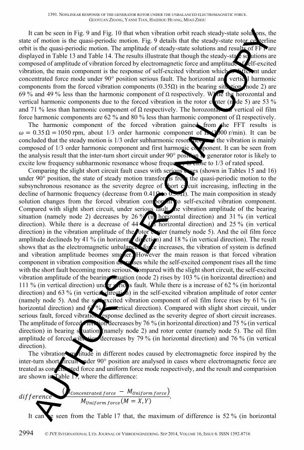
It can be seen in Fig. 9 and Fig. 10 that when vibration orbit reach steady-state solutions, the state of motion is the quasi-periodic motion. Fig. 9 details that the steady-state rotor centerline orbit is the quasi-periodic motion. The amplitude of steady-state solutions and results of FFT are displayed in Table 13 and Table 14. The results illustrate that though the steady-state solutions are composed of amplitude of vibration forced by electromagnetic force and amplitude of self-excited vibration, the main component is the response of self-excited vibration which is different under concentrated force mode under 90° position serious fault. The horizontal and vertical harmonic components from the forced vibration components (0.35Ω) in the bearing situation (node 2) are 69 % and 49 % less than the harmonic component of Ω respectively. While the horozontal and vertical harmonic components due to the forced vibration in the rotor center (node 5) are 53 % and 71 % less than harmonic component of Ω respectively. The horozontal and vertical oil film force harmonic components are 62 % and 80 % less than harmonic component of Ω respectively.
The harmonic component of the forced vibration gained from the FFT results is = 0.35 Ω = 1050 rpm, about 1/3 order harmonic component of Ω (1000 r/min). It can be concluded that the steady motion is 1/3 order subharmonic resonance, and the vibration is mainly composed of 1/3 order harmonic component and first harmonic component. It can be seen from the analysis result that the inter-turn short circuit under 90° position in generator rotor is likely to excite low frequency subharmonic resonance whose frequency is close to 1/3 of rated speed.
Comparing the slight short circuit fault cases with serious cases (shown in Tables 15 and 16) under 90° position, the state of steady motion transforms from the quasi-periodic motion to the subsynchronous resonance as the severity degree of short circuit increasing, inflecting in the decline of harmonic frequency (decrease from 0.41Ω to 0.35Ω). The main composition in steady solution changes from the forced vibration component to self-excited vibration component. Compared with slight short circuit, under serious fault, the vibration amplitude of the bearing situation (namely node 2) decreases by 26 % (in horizontal direction) and 31 % (in vertical direction). While there is a decrease of 44 % (in horizontal direction) and 25 % (in vertical direction) in the vibration amplitude of the rotor center (namely node 5). And the oil film force amplitude declineds by 41 % (in horizontal direction) and 18 % (in vertical direction). The result shows that as the electromagnetic unbalanced force increases, the vibration of system is defined and vibration amplitude beomes smaller. However the main reason is that forced vibration component in vibration composition decreases while the self-excited component rises all the time with the short fault becoming more serious. Compared with the slight short circuit, the self-excited vibration amplitude of the bearing situation (node 2) rises by 103 % (in horizontal direction) and 111 % (in vertical direction) under serious fault. While there is a increase of 62 % (in horizontal direction) and 63 % (in vertical direction) in the self-excited vibration amplitude of rotor center (namely node 5). And the self-excited vibration component of oil film force rises by 61 % (in horizontal direction) and 67 % (in vertical direction). Compared with slight short circuit, under serious fault, forced vibration response declined as the severity degree of short circuit increases. The amplitude of forced vibration decreases by 76 % (in horizontal direction) and 75 % (in vertical direction) in bearing situation (namely node 2) and rotor center (namely node 5). The oil film amplitude of forced vibration decreases by 79 % (in horizontal direction) and 76 % (in vertical direction).
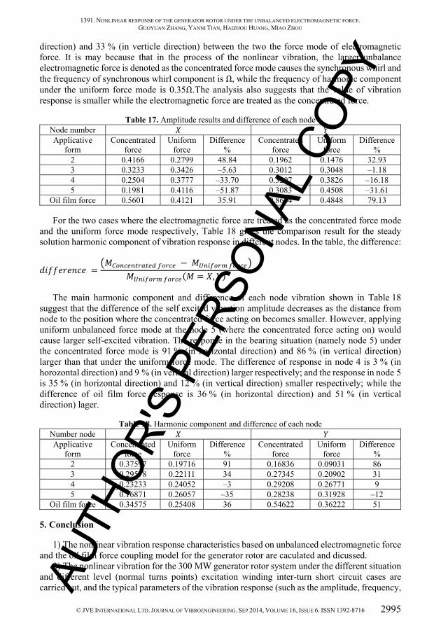
The vibration amplitude in different nodes caused by electromagnetic force inspired by the inter-turn short circuit under 90° position are analysed in cases where electromagnetic force are treated as concentrated force and uniform force mode respectively, and the result and comparision are shown in Table 17, where the difference:
= −( = , ) .It can be seen from the Table 17 that, the maximum of difference is 52 % (in horizontal AU
THOR
'S P
ERSO
NAL
COPY
1391. NONLINEAR RESPONSE OF THE GENERATOR ROTOR UNDER THE UNBALANCED ELECTROMAGNETIC FORCE. GUOYUAN ZHANG, YANNI TIAN, HAIZHOU HUANG, MIAO ZHOU
© JVE INTERNATIONAL LTD. JOURNAL OF VIBROENGINEERING. SEP 2014, VOLUME 16, ISSUE 6. ISSN 1392-8716 2995
direction) and 33 % (in verticle direction) between the two the force mode of electromagnetic force. It is may because that in the process of the nonlinear vibration, the larger unbalance electromagnetic force is denoted as the concentrated force mode causes the synchronous whirl and the frequency of synchronous whirl component is Ω, while the frequency of harmonic component under the uniform force mode is 0.35Ω.The analysis also suggests that the value of vibration response is smaller while the electromagnetic force are treated as the concentrated force.
Table 17. Amplitude results and difference of each node Node number Applicative
form Concentrated
force Uniform
force Difference
% Concentrated
force Uniform
force Difference
% 2 0.4166 0.2799 48.84 0.1962 0.1476 32.93 3 0.3233 0.3426 –5.63 0.3012 0.3048 –1.18 4 0.2504 0.3777 –33.70 0.3207 0.3826 –16.18 5 0.1981 0.4116 –51.87 0.3083 0.4508 –31.61
Oil film force 0.5601 0.4121 35.91 0.8684 0.4848 79.13
For the two cases where the electromagnetic force are treated as the concentrated force mode and the uniform force mode respectively, Table 18 gives the comparison result for the steady solution harmonic component of vibration response in different nodes. In the table, the difference:
= − ( = , ) .The main harmonic component and difference of each node vibration shown in Table 18
suggest that the difference of the self excited vibartion amplitude decreases as the distance from node to the position where the concentrated force acting on becomes smaller. However, applying uniform unbalanced force mode at the node 5 (where the concentrated force acting on) would cause larger self-excited vibration. The response in the bearing situation (namely node 5) under the concentrated force mode is 91 % (in horizontal direction) and 86 % (in vertical direction) larger than that under the uniform force mode. The difference of response in node 4 is 3 % (in horozontal direction) and 9 % (in vertical direction) larger respectively; and the response in node 5 is 35 % (in horizontal direction) and 12 % (in vertical direction) smaller respectively; while the difference of oil film force response is 36 % (in horizontal direction) and 51 % (in vertical direction) lager.
Table 18. Harmonic component and difference of each node Number node Applicative
form Concentrated
force Uniform
force Difference
% Concentrated
force Uniform
force Difference
% 2 0.37597 0.19716 91 0.16836 0.09031 86 3 0.29578 0.22111 34 0.27345 0.20902 31 4 0.23233 0.24052 –3 0.29208 0.26771 9 5 0.16871 0.26057 –35 0.28238 0.31928 –12
Oil film force 0.34575 0.25408 36 0.54622 0.36222 51
5. Conclusion
1) The nonlinear vibration response characteristics based on unbalanced electromagnetic force and the oil film force coupling model for the generator rotor are caculated and dicussed.
2) The nonlinear vibration for the 300 MW generator rotor system under the different situation and different level (normal turns points) excitation winding inter-turn short circuit cases are carried out, and the typical parameters of the vibration response (such as the amplitude, frequency, AU
THOR
'S P
ERSO
NAL
COPY
1391. NONLINEAR RESPONSE OF THE GENERATOR ROTOR UNDER THE UNBALANCED ELECTROMAGNETIC FORCE. GUOYUAN ZHANG, YANNI TIAN, HAIZHOU HUANG, MIAO ZHOU
2996 © JVE INTERNATIONAL LTD. JOURNAL OF VIBROENGINEERING. SEP 2014, VOLUME 16, ISSUE 6. ISSN 1392-8716
and vibration component) are obtained. Meanwhile, as a comparative study, the linear and nonlinear dynamics results under the normal working condition are also studied.
3) The results show that the fault of inter-turn short circuit may easily excite the low-frequency vibration, and the frequency is close to the rotor’s first critical speed; and the inter-turn short circuit fault located at the certain situation may induce the rotor’s 1/3 order subharmonic resonance or synchronous whirl.
Acknowledgements
This work was supported by National Natural Science Foundation of China (Project No. 51205314), Natural Science Foundation of Shaanxi Province of China (No. 2014JQ7252) and the Fundamental Research Funds for the Central Universities with No. JB140414.
References
[1] Zhang Z. P., Liu S., Yao S. J., et al. Fault Analysis and Diagnosis for the Large Generator Rotor. Beijing, China Electric Power Press, 2011, (in Chinese).
[2] Bai H. Y., Jing J. P., Meng G. Survey and outlook on the research of the unbalanced magnetic pull in the motors. Noise and Vibration Control, Vol. 29, Issue 6, 2009, p. 5-7, (in Chinese).
[3] Wolbank T. M., Macheiner P. E. Detection of air gap eccentricity in the presence of stator inter-turn fault of inverter fed induction machines. 39th IEEE Annual Power Electronics Specialists Conference, 2008, p. 2633-2638.
[4] Peng F. D., Zhang Z. P., Chen J. H., et al. Analysis and diagnosis of large turbogenerator rotor inter-turn short-circuit fault. Large Electric Machine and Hydraulic Turbine, Vol. 13, Issue 6, 2010, p. 16-19, (in Chinese).
[5] Pennacchi P., Frosini L. Dynamical behaviour of a three-phase generator due to unbalanced magnetic pull. IEE Proceedings on Electric Power Applications, Vol. 152, Issue 6, 2005, p. 1389-1400.
[6] Pennacchi P. Computational model for calculating the dynamical behaviour of generators caused by unbalanced magnetic pull and experimental validation. Journal of Sound and Vibration, Vol. 312, Issue 1-2, 2008, p. 332-353.
[7] Wan S. T., Li H. M., Li Y. G. Analysis of generator vibration characteristic on rotor winding inter-turn short circuit fault. Proceedings of the CSEE, Vol. 25, Issue 10, 2005, p. 122-126, (in Chinese).
[8] Zhao Y. J., Li Y. G., Wu Y. C., et al. Analysis of rotor vibration characteristic for turbine generator rotor winding inter-turn short circuit fault. Journal of North China Electric Power University, Vol. 35, Issue 9, 2008, p. 16-21, (in Chinese).
[9] Fang H. W., Xia C. L., Li G. P. Analysis of synchronous generator electro-magnetic torque and vibration with armature winding fault. Journal of Tianjin University, Vol. 42, Issue 4, 2009, p. 322-326, (in Chinese).
[10] Wu Y. C., Li H. M., Li Y. G., et al. New on-line diagnosis method for generator rotor winding inter-turn short circuit. High Voltage Engineering, Vol. 35, Issue 11, 2009, p. 2698-2703, (in Chinese).
[11] Liu X. Analysis and treatment of over-standard of over-critical velocity vibration caused by turn-to-turn shortage of rotor. Guangxi Electric Power, Vol. 34, Issue 1, 2011, p. 32-58, (in Chinese).
[12] Hao L. L., Sun Y. G., Qiu A. R., et al. Steady-state calculation and online monitoring of interturn short circuit of field windings in synchronous machines. Transactions on Energy Conversion, Vol. 27, Issue 1, 2012, p. 128-138, (in Chinese).
[13] Bachschmid N., Pennacchi P., Chatterton S., et al. On model updating of turbo-generator set. Journal of Vibroengineering, Vol. 11, Issue 3, 2009, p. 379-391.
[14] Huang H. Z., Zhang K. J., Zhang Y. Detection of turbine generator field winding serious inter-turn short circuit based on the vibration feature. The 44th International Universities Power Engineering Conference, Glasgow, Scotland, 2009.
[15] Zhang G. Y., Wei J. C., Huang H. Z., Zhou M. A study on the nonlinear vibration of the generator rotor based on the unbalanced electromagnetic force and the oil film force coupling model. Journal of Vibroengineering, Vol. 15, Issue 1, 2013, p. 23-36.
AUTH
OR'S
PER
SONA
L CO
PY
1391. NONLINEAR RESPONSE OF THE GENERATOR ROTOR UNDER THE UNBALANCED ELECTROMAGNETIC FORCE. GUOYUAN ZHANG, YANNI TIAN, HAIZHOU HUANG, MIAO ZHOU
© JVE INTERNATIONAL LTD. JOURNAL OF VIBROENGINEERING. SEP 2014, VOLUME 16, ISSUE 6. ISSN 1392-8716 2997
Zhang Guoyuan, PhD. He received the MS degree in mechanical engineering in 2004 from Northwestern Polytechnical University (NPU), China. He received the PhD degree in mechanical engineering in 2009 from Xian Jiaotong University, China. He worked at NPU as a postdoctoral fellow from 2010 to 2013. He has joined School of Electromechanical Engineering of Xidian University from 2013 and has been working on theoretical and experimental research and development on bearing and seal, mechanical system dynamics and mechanical design.
Tian Yanni received the BS degree in mechanical engineering in 2014 from Xidian University, China. In college, she has won the National Scholarship twice and Special Scholarship. She took part in the National Undergraduate Training Programs for Innovation and Entrepreneurship. She was admitted to Shanghai Jiao Tong University (STU) in June, 2014.
Huang Haizhou received the BS degree in mechanical engineering in 1984 from China Three Gorges University (GTGU), China. He received the MS degree and the PhD degree in mechanical engineering from Xian Jiaotong University, China, in 1991 and 2012 respectively. Presently he works at Hubei Electric Testing & Research Institute as a senior engineer and has been working on research on operation of steam turbine, fault vibration and unit testing and vibration test.
Zhou Miao received the BS degree in mechanical engineering in 2002 from Xi’an University of Technology, China, and MS degree in mechanical engineering in 2005 from Xian Jiaotong University. Presently he works at Hubei Electric Testing & Research Institute as a senior engineer and has been working on research on operation of steam turbine, fault vibration and design of bearings.
AUTH
OR'S
PER
SONA
L CO
PY
Copyright © 2022 FDOKUMEN