Electrohydrodynamic Convective Heat Transfer in a Square Duct
11
INTERDISCIPLINARY TRANSPORT PHENOMENA Electrohydrodynamic Convective Heat Transfer in a Square Duct Walter Grassi and Daniele Testi LOTHAR (Low Gravity and Thermal Advanced Research Laboratory), Department of Energetics “L. Poggi,” University of Pisa, Pisa, Italy Laminar to weakly turbulent forced convection in a square duct heated from the bot- tom is strengthened by ion injection from an array of high-voltage points opposite the heated strip. Both positive and negative ion injection are activated within the working liquid HFE-7100 (C 4 F 9 OCH 3 ), with transiting electrical currents on the order of 0.1 mA. Local temperatures on the heated wall are measured by liquid crystal thermography. The tests are conducted in a Reynolds number range from 510 to 12,100. In any case, heat transfer is dramatically augmented, almost independently from the flow rate. The pressure drop increase caused by the electrohydrodynamically induced flow is also measured. A profitable implementation of the technique in the design of heat sinks and heat exchangers is foreseen; possible benefits are pumping power reduction, size reduction, and heat exchange capability augmentation. Key words: EHD; ion injection; heat transfer enhancement; liquid crystals; forced convection Nomenclature c fluid specific heat [J·kg −1 K −1 ] D h hydraulic diameter [m] er F i relative error on the generic derived parameter F j er X i relative accuracy of the generic directly-measured parameter X i f Darcy–Weisbach friction factor g acceleration due to gravity [m·s −2 ] G V volume flow rate [m 3 ·s −1 ] Gr Grashof number based on the wall superheat Gr h Grashof number based on the wall heat flux Gz Graetz number HV applied voltage [V] I electrical current passing through the fluid [A] k e friction factor corrective coefficient in Eq. (5), accounting for entry-zone ef- fects in laminar flow Address for correspondence: Dr. Daniele Testi, Via Diotisalvi 2, I- 56126, Pisa, Italy. Vocie: +39-050-2217-109; fax: +39-050-2217-150. [email protected] L heated strip length [m] L p distance between the two cross sec- tions at which the differential pressure measurement takes place [m] Nu local Nusselt number <Nu> mean Nusselt number on a cross sec- tion Nu mean Nusselt number on the entire heated surface p d pressure drop along the distance L p [Pa] Pr Prandtl number q wall heat flux [W·m −2 ] Re Reynolds number Ri Richardson number s square duct side [m] T temperature [K] u mean fluid velocity [m·s −1 ] x longitudinal distance from the ther- mal inlet [m] x ∗ dimensionless distance from the ther- mal inlet y cross distance from the heated strip axis [m] Interdisciplinary Transport Phenomena: Ann. N.Y. Acad. Sci. 1161: 452–462 (2009). doi: 10.1111/j.1749-6632.2008.04330.x C 2009 New York Academy of Sciences. 452
Transcript of Electrohydrodynamic Convective Heat Transfer in a Square Duct
INTERDISCIPLINARY TRANSPORT PHENOMENA
Electrohydrodynamic Convective HeatTransfer in a Square Duct
Walter Grassi and Daniele Testi
LOTHAR (Low Gravity and Thermal Advanced Research Laboratory), Department ofEnergetics “L. Poggi,” University of Pisa, Pisa, Italy
Laminar to weakly turbulent forced convection in a square duct heated from the bot-tom is strengthened by ion injection from an array of high-voltage points opposite theheated strip. Both positive and negative ion injection are activated within the workingliquid HFE-7100 (C4F9OCH3), with transiting electrical currents on the order of 0.1 mA.Local temperatures on the heated wall are measured by liquid crystal thermography.The tests are conducted in a Reynolds number range from 510 to 12,100. In any case,heat transfer is dramatically augmented, almost independently from the flow rate. Thepressure drop increase caused by the electrohydrodynamically induced flow is alsomeasured. A profitable implementation of the technique in the design of heat sinksand heat exchangers is foreseen; possible benefits are pumping power reduction, sizereduction, and heat exchange capability augmentation.
Key words: EHD; ion injection; heat transfer enhancement; liquid crystals; forcedconvection
Nomenclaturec fluid specific heat [J·kg−1 K−1]Dh hydraulic diameter [m]erFi
relative error on the generic derivedparameter Fj
erX irelative accuracy of the genericdirectly-measured parameter Xi
f Darcy–Weisbach friction factorg acceleration due to gravity [m·s−2]GV volume flow rate [m3·s−1]Gr Grashof number based on the wall
superheatGrh Grashof number based on the wall
heat fluxGz Graetz numberHV applied voltage [V]I electrical current passing through the
fluid [A]ke friction factor corrective coefficient in
Eq. (5), accounting for entry-zone ef-fects in laminar flow
Address for correspondence: Dr. Daniele Testi, Via Diotisalvi 2, I-56126, Pisa, Italy. Vocie: +39-050-2217-109; fax: [email protected]
L heated strip length [m]Lp distance between the two cross sec-
tions at which the differential pressuremeasurement takes place [m]
Nu local Nusselt number<Nu> mean Nusselt number on a cross sec-
tion〈〈Nu〉〉 mean Nusselt number on the entire
heated surfacepd pressure drop along the distance Lp
[Pa]Pr Prandtl numberq wall heat flux [W·m−2]Re Reynolds numberRi Richardson numbers square duct side [m]T temperature [K]u mean fluid velocity [m·s−1]x longitudinal distance from the ther-
mal inlet [m]x∗ dimensionless distance from the ther-
mal inlety cross distance from the heated strip
axis [m]
Interdisciplinary Transport Phenomena: Ann. N.Y. Acad. Sci. 1161: 452–462 (2009).doi: 10.1111/j.1749-6632.2008.04330.x C© 2009 New York Academy of Sciences.
452
Grassi & Testi: EHD Convective Heat Transfer in a Square Duct 453
Greek letters
α convective heat transfer coefficient[W·m−2 K−1]
β fluid thermal expansion coefficient[K−1]
ηp efficiency of the pumpλ fluid thermal conductivity [W·m−1
K−1]μ dynamic viscosity [Pa·s]ν kinematic viscosity [m2·s−1]�e electrically-generated heat within the
fluid [W]�h wall heat flow [W]�p pumping power [W]ρ fluid mass density [kg·m−3]
Subscripts
b bulkin inletlam laminarout outletturb turbulentw wall
Introduction
Chronologically, this work represents the lat-est outcome of a very broad and still ongo-ing research project being carried out at theLOTHAR laboratory of the University of Pisafor two decades, supported by the EuropeanSpace Agency (ESA), that is exploring the roleof electrical and gravitational force fields inboth single-phase and two-phase thermofluiddynamics. In the present experimental cam-paign, the heat transfer enhancement tech-nique of ion injection is employed to increaseforced convection of a dielectric liquid in asquare duct heated from below. The laminar,transitional, and weakly turbulent flow regimesare examined (510 < Re < 12,100).
When a high-enough electric field is imposedon a sharp electrode immersed in a dielec-tric liquid, ions are created in the proximityof the electrode by electrochemical reactions.The charged particles have the same polarityas their emitter and are bounded to accelerate
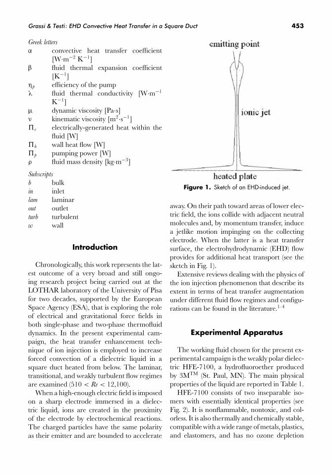
Figure 1. Sketch of an EHD-induced jet.
away. On their path toward areas of lower elec-tric field, the ions collide with adjacent neutralmolecules and, by momentum transfer, inducea jetlike motion impinging on the collectingelectrode. When the latter is a heat transfersurface, the electrohydrodynamic (EHD) flowprovides for additional heat transport (see thesketch in Fig. 1).
Extensive reviews dealing with the physics ofthe ion injection phenomenon that describe itsextent in terms of heat transfer augmentationunder different fluid flow regimes and configu-rations can be found in the literature.1–4
Experimental Apparatus
The working fluid chosen for the present ex-perimental campaign is the weakly polar dielec-tric HFE-7100, a hydrofluoroether producedby 3MTM (St. Paul, MN). The main physicalproperties of the liquid are reported in Table 1.
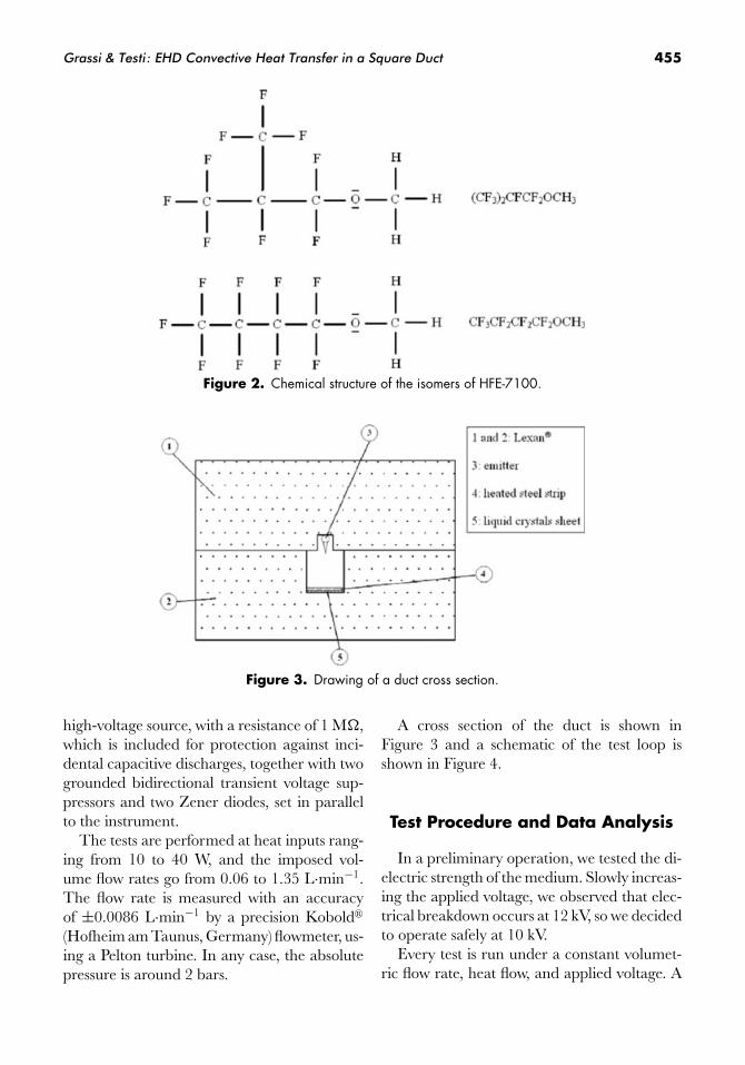
HFE-7100 consists of two inseparable iso-mers with essentially identical properties (seeFig. 2). It is nonflammable, nontoxic, and col-orless. It is also thermally and chemically stable,compatible with a wide range of metals, plastics,and elastomers, and has no ozone depletion
454 Annals of the New York Academy of Sciences
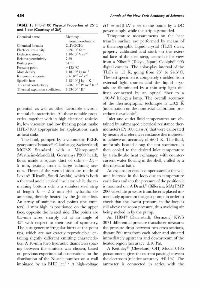
TABLE 1. HFE-7100 Physical Properties at 25◦Cand 1 bar (Courtesy of 3M)
Chemical name Methoxy-nonafluorobutane
Chemical formula C4F9OCH3
Electrical resistivity 3.29·107 � mDielectric strength 1.10·107 V m−1
Relative permittivity 7.39Boiling point 61 ◦CFreezing point −135 ◦CMass density 1.48·103 kg m−3
Kinematic viscosity 3.7·10−7 m2 s−1
Specific heat 1.18·103 J kg−1 K−1
Thermal conductivity 6.88·10−2 W m−1 K−1
Thermal expansion coefficient 1.53·10−3 K−1
potential, as well as other favorable environ-mental characteristics. All these notable prop-erties, together with its high electrical resistiv-ity, low viscosity, and low freezing point, makeHFE-7100 appropriate for applications, suchas heat sinks.
The fluid, pumped by a volumetric PEEKgear pump (Ismatec� (Glattbrugg, Switzerland)MCP-Z Standard, with a Micropump�
(Wertheim-Mondfeld, Germany) P200 head),flows inside a square duct of side s = Dh =5 mm, exiting from a large calming sec-tion. Three of the wetted sides are made ofLexan� (Riyadh, Saudi Arabia), which is botha thermal and electrical insulator, while the re-maining bottom side is a stainless steel stripof length L = 215 mm (43 hydraulic di-ameters), directly heated by the Joule effect.An array of stainless steel points (the emit-ters), 1 mm high, is positioned on the upperface, opposite the heated side. The points are0.5-mm wires, sharply cut at an angle of45◦ with respect to their axis of symmetry.The cuts generate irregular burrs at the pointtips, which are not exactly reproducible, en-tailing slightly different emitting characteris-tics. A 10-mm (two hydraulic diameters) spac-ing between the emitters was chosen, basedon previous experimental observations on thedistribution of the Nusselt number on a wallimpinged by an EHD jet.5–7 A high-voltage
HV = ±10 kV is set to the points by a DCpower supply, while the strip is grounded.
Temperature measurements on the heattransfer surface are performed by means ofa thermographic liquid crystal (TLC) sheet,properly calibrated and stuck on the exter-nal face of the steel strip, accessible for viewfrom a Nikon� (Tokyo, Japan) Coolpix� 995digital camera. The color-play interval of theTLCs is 1.5 K, going from 23◦ to 24.5◦C.The test specimen is completely shielded fromexternal light sources and the liquid crys-tals are illuminated by a thin-strip light dif-fuser connected by an optical fiber to a150-W halogen lamp. The overall accuracyof the thermographic technique is ±0.2 K(information on the nontrivial calibration pro-cedure is available8).
Inlet and outlet fluid temperatures are ob-tained by submerged electrical resistance ther-mometers (Pt 100, class A) that were calibratedby means of a reference resistance thermometerto achieve an accuracy of ±0.1 K. The fluid,uniformly heated along the test specimen, isthen cooled to the desired inlet temperatureby a shell-tube heat exchanger, with counter-current water flowing in the shell, chilled by athermostatic bath.
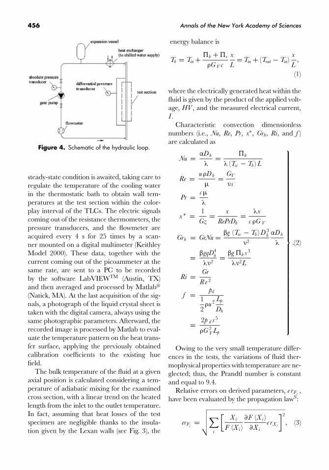
An expansion vessel compensates for the vol-ume increase in the loop due to temperaturevariations and sets the pressure of the position itis mounted on. A Druck� (Billerica, MA) PMP2060 absolute pressure transducer is placed im-mediately upstream the gear pump, in order tocheck that the lowest pressure in the loop isstill above the room pressure, thus avoiding airbeing sucked in by the pump.
An HBM� (Darmstadt, Germany) KWS3071 differential pressure transducer measuresthe pressure drop between two cross sections,distant 260 mm from each other and situatedimmediately upstream and downstream of theheated region (accuracy: ±10 Pa).
A Keithley� (Cleveland, OH) Model 6485picoammeter gives the current passing betweenthe electrodes (relative accuracy: ±0.4%). Theammeter is connected in series with the
Grassi & Testi: EHD Convective Heat Transfer in a Square Duct 455
Figure 2. Chemical structure of the isomers of HFE-7100.
Figure 3. Drawing of a duct cross section.
high-voltage source, with a resistance of 1 M�,which is included for protection against inci-dental capacitive discharges, together with twogrounded bidirectional transient voltage sup-pressors and two Zener diodes, set in parallelto the instrument.
The tests are performed at heat inputs rang-ing from 10 to 40 W, and the imposed vol-ume flow rates go from 0.06 to 1.35 L·min−1.The flow rate is measured with an accuracyof ±0.0086 L·min−1 by a precision Kobold�
(Hofheim am Taunus, Germany) flowmeter, us-ing a Pelton turbine. In any case, the absolutepressure is around 2 bars.
A cross section of the duct is shown inFigure 3 and a schematic of the test loop isshown in Figure 4.
Test Procedure and Data Analysis
In a preliminary operation, we tested the di-electric strength of the medium. Slowly increas-ing the applied voltage, we observed that elec-trical breakdown occurs at 12 kV, so we decidedto operate safely at 10 kV.
Every test is run under a constant volumet-ric flow rate, heat flow, and applied voltage. A
456 Annals of the New York Academy of Sciences
Figure 4. Schematic of the hydraulic loop.
steady-state condition is awaited, taking care toregulate the temperature of the cooling waterin the thermostatic bath to obtain wall tem-peratures at the test section within the color-play interval of the TLCs. The electric signalscoming out of the resistance thermometers, thepressure transducers, and the flowmeter areacquired every 4 s for 25 times by a scan-ner mounted on a digital multimeter (KeithleyModel 2000). These data, together with thecurrent coming out of the picoammeter at thesame rate, are sent to a PC to be recordedby the software LabVIEWTM (Austin, TX)and then averaged and processed by Matlab�
(Natick, MA). At the last acquisition of the sig-nals, a photograph of the liquid crystal sheet istaken with the digital camera, always using thesame photographic parameters. Afterward, therecorded image is processed by Matlab to eval-uate the temperature pattern on the heat trans-fer surface, applying the previously obtainedcalibration coefficients to the existing huefield.
The bulk temperature of the fluid at a givenaxial position is calculated considering a tem-perature of adiabatic mixing for the examinedcross section, with a linear trend on the heatedlength from the inlet to the outlet temperature.In fact, assuming that heat losses of the testspecimen are negligible thanks to the insula-tion given by the Lexan walls (see Fig. 3), the
energy balance is
Tb = Tin + �h + �e
ρG V c
x
L= Tin + (Tout − Tin)
x
L,
(1)
where the electrically generated heat within thefluid is given by the product of the applied volt-age, HV , and the measured electrical current,I .
Characteristic convection dimensionlessnumbers (i.e., Nu, Re, Pr, x∗, Grh, Ri, and f )are calculated as
Nu = αD h
λ= �h
λ (Tw − Tb ) L
Re = uρD h
μ= GV
νs
Pr = cμ
λ
x ∗ = 1Gz
= x
RePrDh
= λx
cρG V
Grh = GrNu = βg (Tw − Tb ) D 3h
ν2
αD h
λ
= βgqD4h
λν2= βg �h s 3
λν2L
Ri = Gr
Re 2
f = pd
12ρu 2 Lp
Dh
= 2p d s 5
ρG 2V Lp
⎫⎪⎪⎪⎪⎪⎪⎪⎪⎪⎪⎪⎪⎪⎪⎪⎪⎪⎪⎪⎪⎪⎪⎪⎪⎪⎪⎪⎪⎪⎪⎪⎪⎪⎪⎪⎪⎪⎬⎪⎪⎪⎪⎪⎪⎪⎪⎪⎪⎪⎪⎪⎪⎪⎪⎪⎪⎪⎪⎪⎪⎪⎪⎪⎪⎪⎪⎪⎪⎪⎪⎪⎪⎪⎪⎪⎭
.(2)
Owing to the very small temperature differ-ences in the tests, the variations of fluid ther-mophysical properties with temperature are ne-glected; thus, the Prandtl number is constantand equal to 9.4.
Relative errors on derived parameters, e rFj,
have been evaluated by the propagation law9:
erFj=
√√√√∑i
[X i
F (X i )∂F (X i )
∂X i
e rX i
]2
, (3)
Grassi & Testi: EHD Convective Heat Transfer in a Square Duct 457
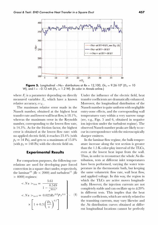
Figure 5. Longitudinal <Nu> distributions at Re = 12,100, Grh = 9.26·106 (�h = 10W), and I = −0.12 mA (�e = 1.2 W). (In color in Annals online.)
where Fj is a parameter depending on directlymeasured variables Xi, which have a knownrelative accuracy, e rX i
.The maximum relative error made in the
Nusselt number, obtained at the highest heattransfer rate and lowest wall heat flow, is 18.1%,whereas the maximum error in the Reynoldsnumber, corresponding to the lowest flow rate,is 14.3%. As for the friction factor, the highesterror is obtained at the lowest flow rate: withno applied electric field, it reaches 23.4% (withpd = 54 Pa), and gets to a maximum of 15.8%(with pd = 148 Pa) with the electric field on.
Experimental Results
For comparison purposes, the following cor-relations are used for developing pure forcedconvection in a square duct under, respectively,the laminar10 (Re < 2000) and turbulent11 (Re
> 4000) regimes:
< N u >la m = 3.61
1 − 0.549
e 38.6x ∗
< N u >t u r b = 0.023Re 0.8P r 0.4
×[
1 + 0.3(
D h
x
)0.7]
⎫⎪⎪⎪⎪⎪⎪⎪⎪⎬⎪⎪⎪⎪⎪⎪⎪⎪⎭
. (4)
Under the influence of the electric field, heattransfer coefficients are dramatically enhanced.Moreover, the longitudinal distribution of theNusselt number is quite uniform with negligibleentry-zone effects, and the corresponding walltemperatures vary within a very narrow range(see, e.g., Figs. 5 and 6, obtained in negativeion injection under the turbulent regime). Theobserved Nusselt number peaks are likely to oc-cur in correspondence with the microscopicallysharper emitters.
In the laminar flow regime, the bulk temper-ature increase along the test section is greaterthan the 1.5 K color-play interval of the TLCs,even at the lowest heat input from the wall.Thus, in order to reconstruct the whole Nu dis-tribution, tests at different inlet temperatureshave been performed, varying the water tem-perature in the thermostatic bath, but keepingthe same volumetric flow rate, wall heat flow,and applied voltage. In this way, the region inwhich the TLCs are active moves longitudi-nally. However, the injection currents are notcompletely stable and can oscillate up to ±20%in different tests. This implies that the heattransfer coefficients, which are strictly related tothe transiting currents, may vary likewise andthe Nu distribution curves obtained at differ-ent longitudinal locations cannot be perfectly
458 Annals of the New York Academy of Sciences
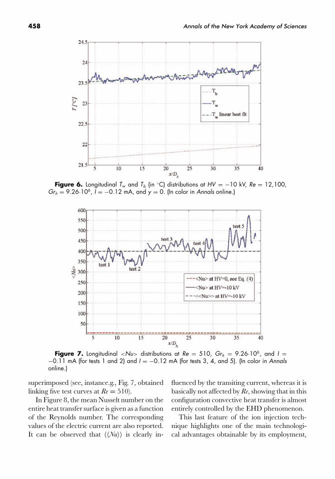
Figure 6. Longitudinal Tw and Tb (in ◦C) distributions at HV = −10 kV, Re = 12,100,Grh = 9.26·106, I = −0.12 mA, and y = 0. (In color in Annals online.)
Figure 7. Longitudinal <Nu> distributions at Re = 510, Grh = 9.26·106, and I =−0.11 mA (for tests 1 and 2) and I = −0.12 mA (for tests 3, 4, and 5). (In color in Annalsonline.)
superimposed (see, instance.g., Fig. 7, obtainedlinking five test curves at Re = 510).
In Figure 8, the mean Nusselt number on theentire heat transfer surface is given as a functionof the Reynolds number. The correspondingvalues of the electric current are also reported.It can be observed that 〈〈Nu〉〉 is clearly in-
fluenced by the transiting current, whereas it isbasically not affected by Re, showing that in thisconfiguration convective heat transfer is almostentirely controlled by the EHD phenomenon.
This last feature of the ion injection tech-nique highlights one of the main technologi-cal advantages obtainable by its employment,

Grassi & Testi: EHD Convective Heat Transfer in a Square Duct 459
Figure 8. 〈〈Nu〉〉 and I (in μA) versus Re at Grh = 9.26·106. (In color in Annals online.)
Figure 9. pd (in Pa) versus Re. (In color in Annals online.)
since the use of large pumps to obtain high heattransfer rates can be avoided, virtually at no ex-pense of energy. In fact, according to Eq. (4),in the absence of an electric field, a Reynoldsnumber of 60,000 would be necessary to reacha mean Nusselt number of 400, as obtained atRe = 510 and HV = −10 kV (see Fig. 7) withelectrical currents around 0.1 mA, thus with aJoule heating on the order of only 1 W.
In terms of pressure drops along the test sec-tion, the values measured at HV = −10 kV arecompared in Figure 9 with the data taken atHV = 0 and with the values calculated by
means of the following correlations, availablefor the friction factor in laminar12 and turbu-lent11 forced convection:
f lam = 57Re
ke
f turb = 0.184Re 0.2
[1 +
(D h
L p
)0.7]
⎫⎪⎪⎪⎬⎪⎪⎪⎭
, (5)
with ke decreasing from 1.11 to 1 as Re increases.The pressure drops obtained via Eq. (5) are
accurate for smooth tubes. In fact, even atHV = 0 kV, they are lower than the ones
460 Annals of the New York Academy of Sciences
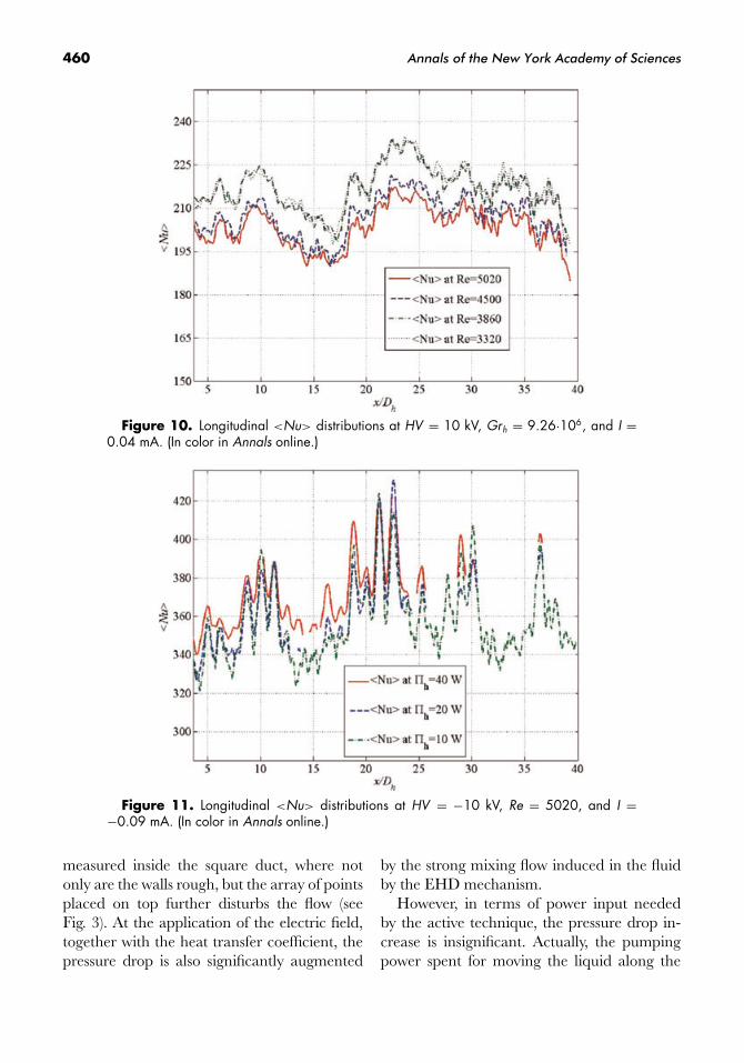
Figure 10. Longitudinal <Nu> distributions at HV = 10 kV, Grh = 9.26·106, and I =0.04 mA. (In color in Annals online.)
Figure 11. Longitudinal <Nu> distributions at HV = −10 kV, Re = 5020, and I =−0.09 mA. (In color in Annals online.)
measured inside the square duct, where notonly are the walls rough, but the array of pointsplaced on top further disturbs the flow (seeFig. 3). At the application of the electric field,together with the heat transfer coefficient, thepressure drop is also significantly augmented
by the strong mixing flow induced in the fluidby the EHD mechanism.
However, in terms of power input neededby the active technique, the pressure drop in-crease is insignificant. Actually, the pumpingpower spent for moving the liquid along the

Grassi & Testi: EHD Convective Heat Transfer in a Square Duct 461
test section is given by
�p = GV pd
ηp
. (6)
Therefore, even if the pump has a low effi-ciency, �p is still on the order of 0.1 W at thehighest flow rate, well below the power dissi-pated by the ionic current.
In Figure 10, the longitudinal distribution ofthe Nusselt number is shown at the applicationof a 10-kV high voltage in positive polarity. TheNusselt number enhancement is significantlylower than the one obtained in negative polarity(compare Figs. 8 and 10); in fact, the transitingcurrents are more than halved, indicating thatthe liquid molecules, or the neutral impuritiesdissolved in the fluid, are more easily reducedthan oxidized.
In the tests, the Richardson number did notexceed 0.1, suggesting that buoyancy effectson the existing forced convection are negligi-ble. Experimental evidence for this is given inFigure 11, where Nusselt numbers obtained atGrh = 9.26·106, 2.32·107, and 3.71·107 (�h =10, 25, and 40 W) are compared, showing noappreciable variations.
Conclusions
In the present research, forced convectionof a dielectric liquid in a square duct heatedfrom below is strongly enhanced by the EHDtechnique of ion injection. The experimentalcampaign includes tests in the laminar, transi-tional, and weakly turbulent flow regimes (510< Re < 12,100).
In the presence of the electric field, heattransfer was shown to depend solely on the ioniccurrent passing through the liquid, with noentry-zone effects and, most of all, with negligi-ble influence of the flow rate. Thus, under thelaminar regime, the Nusselt numbers with neg-ative ion injection are around 60 times higherthan those obtainable in developing pure forcedconvection, whereas the pressure drops are only
increased about threefold, as shown, respec-tively, in Figures 8 and 9.
Local Nusselt number gradients occur due topossible differences in the emitting characteris-tics of the points and to fluid dynamic interfer-ence between the impinging jets of the array.The power utilized for maintaining the ionicdrift between the electrodes is on the order of1 W. Implementation of the technique for high-efficiency compact heat exchangers and heatsinks is at hand.
Acknowledgments
The authors are particularly indebted to Mr.Roberto Manetti and Mr. Davide Della Vistafor their skillful technical assistance throughoutthe entire experimental campaign.
Conflicts of Interest
The authors declare no conflicts of interest.
References
1. Ohadi, M.M., J. Darabi & B. Roget. 2000. Electrodedesign, fabrication, and material science for EHD-enhanced heat and mass transport. Ann. Rev. Heat
Trans. 11: 563–632.2. Grassi, W. & D. Testi. 2006. Heat transfer en-
hancement by electric fields in several heat ex-change regimes. Ann. N. Y. Acad. Sci. 1077: 527–569.
3. Grassi, W., D. Testi & D. Della Vista. 2007. Optimalworking fluid and electrode configuration for EHD-enhanced single-phase heat transfer. J. Enhanced Heat
Trans. 14: 161–173.4. Testi, D. 2006. Single-phase thermo-fluid dynamics
under electric fields: phenomenology and technolog-ical potential. Ph.D. thesis, University of Pisa, Italy.
5. Grassi, W., D. Testi & M. Saputelli. 2005. EHD en-hanced heat transfer in a vertical annulus. Int. Com-
mun. Heat Mass Transfer 32: 748–757.6. Grassi W. & D. Testi. 2006. Heat transfer augmen-
tation by ion injection in an annular duct. J. Heat
Transfer-Trans. ASME 128: 283–289.7. Testi, D. 2007. Ion injection as an effective technique
of heat transfer enhancement in space. J. Thermophys.
Heat Trans. 21: 431–436.

462 Annals of the New York Academy of Sciences
8. Grassi, W. et al. 2007. Calibration of a sheet of ther-mosensitive liquid crystals viewed non-orthogonally.Measurement 40: 898–903.
9. Moffat, R.J. 1988. Describing the uncertainties inexperimental results. Exp. Fluid Thermal Sci. 1: 3–17.
10. Shah, R.K. & A.L. London. 1978. Laminar Flow Forced
Convection in Ducts. Academic Press. New York.11. McAdams, W.H. 1958. Heat Transmission. McGraw-
Hill. New York.12. Fried, E. & I.E. Idelchik. 1989. Flow Resistance: A Design
Guide for Engineers. Hemisphere. New York.