Electrochemical characterization of a bioceramic material: The shell of the Eastern oyster...
8
Electrochemical characterization of a bioceramic material: The shell of the Eastern oyster Crassostrea virginica Yuhchae Yoon a , Andrew S. Mount b , Karolyn M. Hansen c , Douglas C. Hansen a, ⁎ a Nonstructural Materials Division, University of Dayton Research Institute, University of Dayton, Dayton, OH 45469, USA b Department of Biological Sciences, Clemson University, Clemson, South Carolina 29634, USA c Department of Biology, University of Dayton, Dayton, OH 45469, USA abstract article info Article history: Received 30 December 2010 Received in revised form 6 April 2011 Accepted 6 April 2011 Available online 16 April 2011 Keywords: Crassostrea virginica Electrochemical impedance spectroscopy Prismatic layer Ionic conductivity The shell of the Eastern oyster (Crassostrea virginica) is composed of multiple incongruent mineralized layers. This bioceramic composite material was investigated to determine the effects of shell thickness, orientation and layer composition on its electrochemical behavior using electrochemical impedance spectroscopy, potentiodynamic polarization and scanning electron microscopy-energy dispersive spectroscopy. SEM-EDS analysis of the oyster shell revealed that the multilayered biocomposite material is composed of calcium carbonate (CaCO 3 ). EIS measurements in 3.5 wt.% NaCl indicated that the impedance of the whole oyster shell in the low frequency region exhibited high impedance values which exhibited a decreasing trend with increasing immersion time. In terms of overall shell thickness, limiting currents measured by potentiody- namic techniques through the shell were observed to increase when the outer layers of the shell were sequentially removed by grinding, thus decreasing the shell thickness. These limiting current values remained relatively constant when the inner layers of the shell were removed. The impedance values of the oyster shell material as measured by EIS were shown to decrease with decreasing shell thickness. These findings suggest that the prismatic (outermost) shell layer in combination with the soluble organic matrix between all shell layers may influence the ionic conductivity through the oyster shell. © 2011 Elsevier B.V. All rights reserved. 1. Introduction The process of biomineralization by a living organism provides inspiration for the development of new and novel materials [1–3]. One such organism is the Eastern oyster, Crassostrea virginica,a bivalve mollusc composed of a soft body protected by two hard shell sections that are jointed at one end by a hinge ligament. Oyster shell valves are composed primarily of calcite, a calcium carbonate polymorph; calcite crystals are integrated within an organic protein matrix in a layer-by-layer arrangement to form the bioceramic [4–7]. An understanding of the shell formation process is essential for eventual development of bioceramic coatings for applications such as: adaptive surface coatings, corrosion inhibition, and hybrid composite materials. There are two proposed models for shell formation: the matrix-mediated model (organic matrix as a site for crystal nucleation) and the cellular-mediated model (crystal nuclei trans- ported to mineralization front via blood cells). There is evidence for both [8–10]. The matrix mediated model assumes that a pre-formed organic matrix is present in an extracellular compartment prior to mineralization of the shell. It further assumes that all subsequent mineralization events including crystal nucleation, crystal growth, and crystal termination are mediated via its extracellular control [10–12]. We have observed the cellular-mediated formation of a layered, highly-ordered organic/mineral bioceramic, and that both organic matrix and mineral deposition occurs simultaneously [13]. This process of crystal formation and layer organization influences the structural, mechanical, and electrochemical properties of the shell material. The unique mechanical properties of bioceramic calcified tissues are derived from this layer-by-layer arrangement of a soft organic (lipid and protein) phase and a hard mineral phase composed of calcium carbonate, calcium phosphate, and/or silica [1,11,14]. Crassostrea species shells consist of an initial quinone tanned periostracal layer which originates from the periostracal gland of the outer mantle epithelia tissues. Beneath this outermost layer are columnar polycrystalline calcite crystals which form the prismatic layer (Fig. 1) [10]. The polycrystalline prisms that form this columnar layer are delineated by organic membranes which are secreted from outer mantle epithelial cells. The prisms may also contain intracrystal- line organic material. After maturation of the prismatic layer, subsequent shell layers are deposited as foliated (lath-like) calcite and form the remainder of the oyster shell. Foliated layers exist as two structurally different phases: dense foliated and chalky foliated. The complex assembly of organic membranes with prismatic, dense Bioelectrochemistry 81 (2011) 91–98 ⁎ Corresponding author. Tel./fax: + 1 937 229 4380/229 2503. E-mail address: [email protected] (D.C. Hansen). 1567-5394/$ – see front matter © 2011 Elsevier B.V. All rights reserved. doi:10.1016/j.bioelechem.2011.04.002 Contents lists available at ScienceDirect Bioelectrochemistry journal homepage: www.elsevier.com/locate/bioelechem
-
Upload
independent -
Category
Documents
-
view
1 -
download
0
Transcript of Electrochemical characterization of a bioceramic material: The shell of the Eastern oyster...
Bioelectrochemistry 81 (2011) 91–98
Contents lists available at ScienceDirect
Bioelectrochemistry
j ourna l homepage: www.e lsev ie r.com/ locate /b ioe lechem
Electrochemical characterization of a bioceramic material: The shell of the Easternoyster Crassostrea virginica
Yuhchae Yoon a, Andrew S. Mount b, Karolyn M. Hansen c, Douglas C. Hansen a,⁎a Nonstructural Materials Division, University of Dayton Research Institute, University of Dayton, Dayton, OH 45469, USAb Department of Biological Sciences, Clemson University, Clemson, South Carolina 29634, USAc Department of Biology, University of Dayton, Dayton, OH 45469, USA
⁎ Corresponding author. Tel./fax: +1 937 229 4380/2E-mail address: [email protected] (
1567-5394/$ – see front matter © 2011 Elsevier B.V. Aldoi:10.1016/j.bioelechem.2011.04.002
a b s t r a c t
a r t i c l e i n f oArticle history:Received 30 December 2010Received in revised form 6 April 2011Accepted 6 April 2011Available online 16 April 2011
Keywords:Crassostrea virginicaElectrochemical impedance spectroscopyPrismatic layerIonic conductivity
The shell of the Eastern oyster (Crassostrea virginica) is composed of multiple incongruent mineralized layers.This bioceramic composite material was investigated to determine the effects of shell thickness, orientationand layer composition on its electrochemical behavior using electrochemical impedance spectroscopy,potentiodynamic polarization and scanning electron microscopy-energy dispersive spectroscopy. SEM-EDSanalysis of the oyster shell revealed that the multilayered biocomposite material is composed of calciumcarbonate (CaCO3). EIS measurements in 3.5 wt.% NaCl indicated that the impedance of the whole oyster shellin the low frequency region exhibited high impedance values which exhibited a decreasing trend withincreasing immersion time. In terms of overall shell thickness, limiting currents measured by potentiody-namic techniques through the shell were observed to increase when the outer layers of the shell weresequentially removed by grinding, thus decreasing the shell thickness. These limiting current values remainedrelatively constant when the inner layers of the shell were removed. The impedance values of the oyster shellmaterial as measured by EIS were shown to decrease with decreasing shell thickness. These findings suggestthat the prismatic (outermost) shell layer in combination with the soluble organic matrix between all shelllayers may influence the ionic conductivity through the oyster shell.
29 2503.D.C. Hansen).
l rights reserved.
© 2011 Elsevier B.V. All rights reserved.
1. Introduction
The process of biomineralization by a living organism providesinspiration for the development of new and novel materials [1–3].One such organism is the Eastern oyster, Crassostrea virginica, abivalve mollusc composed of a soft body protected by two hard shellsections that are jointed at one end by a hinge ligament. Oyster shellvalves are composed primarily of calcite, a calcium carbonatepolymorph; calcite crystals are integrated within an organic proteinmatrix in a layer-by-layer arrangement to form the bioceramic [4–7].
An understanding of the shell formation process is essential foreventual development of bioceramic coatings for applications such as:adaptive surface coatings, corrosion inhibition, and hybrid compositematerials. There are two proposed models for shell formation:the matrix-mediated model (organic matrix as a site for crystalnucleation) and the cellular-mediated model (crystal nuclei trans-ported to mineralization front via blood cells). There is evidence forboth [8–10]. The matrix mediated model assumes that a pre-formedorganic matrix is present in an extracellular compartment prior tomineralization of the shell. It further assumes that all subsequent
mineralization events including crystal nucleation, crystal growth, andcrystal termination are mediated via its extracellular control [10–12].We have observed the cellular-mediated formation of a layered,highly-ordered organic/mineral bioceramic, and that both organicmatrix and mineral deposition occurs simultaneously [13]. Thisprocess of crystal formation and layer organization influences thestructural, mechanical, and electrochemical properties of the shellmaterial.
The unique mechanical properties of bioceramic calcified tissuesare derived from this layer-by-layer arrangement of a soft organic(lipid and protein) phase and a hard mineral phase composed ofcalcium carbonate, calcium phosphate, and/or silica [1,11,14].Crassostrea species shells consist of an initial quinone tannedperiostracal layer which originates from the periostracal gland ofthe outer mantle epithelia tissues. Beneath this outermost layer arecolumnar polycrystalline calcite crystals which form the prismaticlayer (Fig. 1) [10]. The polycrystalline prisms that form this columnarlayer are delineated by organic membranes which are secreted fromoutermantle epithelial cells. The prismsmay also contain intracrystal-line organic material. After maturation of the prismatic layer,subsequent shell layers are deposited as foliated (lath-like) calciteand form the remainder of the oyster shell. Foliated layers exist as twostructurally different phases: dense foliated and chalky foliated. Thecomplex assembly of organic membranes with prismatic, dense
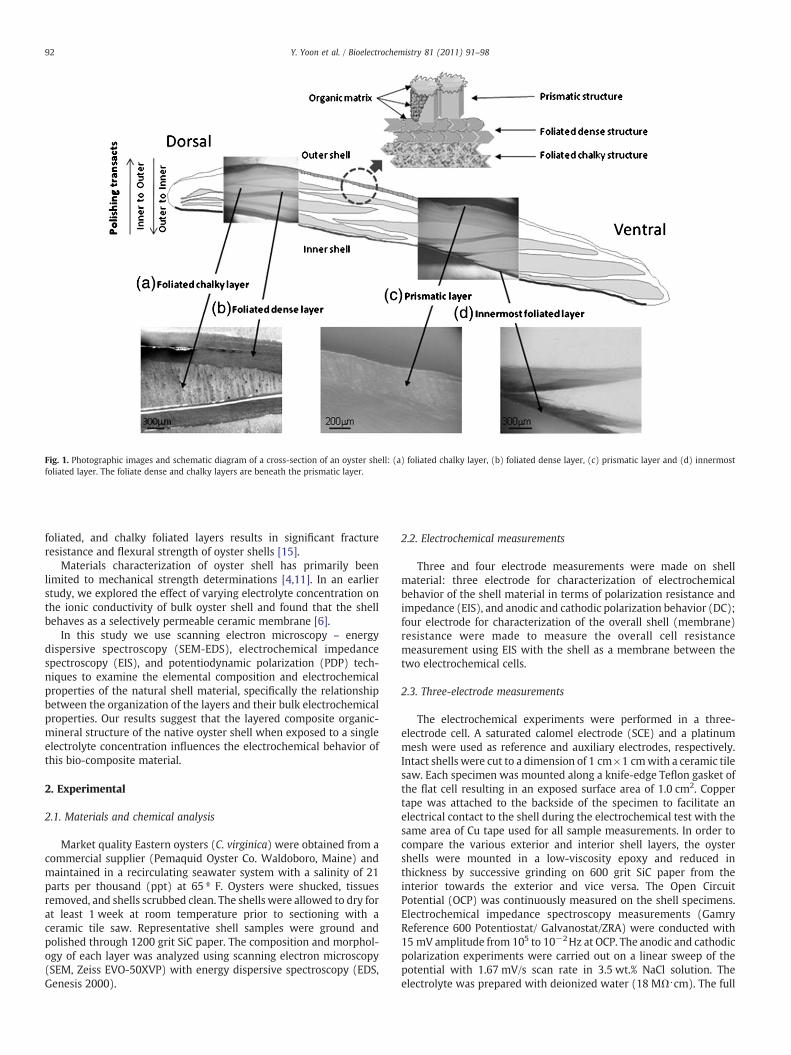
Fig. 1. Photographic images and schematic diagram of a cross-section of an oyster shell: (a) foliated chalky layer, (b) foliated dense layer, (c) prismatic layer and (d) innermostfoliated layer. The foliate dense and chalky layers are beneath the prismatic layer.
92 Y. Yoon et al. / Bioelectrochemistry 81 (2011) 91–98
foliated, and chalky foliated layers results in significant fractureresistance and flexural strength of oyster shells [15].
Materials characterization of oyster shell has primarily beenlimited to mechanical strength determinations [4,11]. In an earlierstudy, we explored the effect of varying electrolyte concentration onthe ionic conductivity of bulk oyster shell and found that the shellbehaves as a selectively permeable ceramic membrane [6].
In this study we use scanning electron microscopy – energydispersive spectroscopy (SEM-EDS), electrochemical impedancespectroscopy (EIS), and potentiodynamic polarization (PDP) tech-niques to examine the elemental composition and electrochemicalproperties of the natural shell material, specifically the relationshipbetween the organization of the layers and their bulk electrochemicalproperties. Our results suggest that the layered composite organic-mineral structure of the native oyster shell when exposed to a singleelectrolyte concentration influences the electrochemical behavior ofthis bio-composite material.
2. Experimental
2.1. Materials and chemical analysis
Market quality Eastern oysters (C. virginica) were obtained from acommercial supplier (Pemaquid Oyster Co. Waldoboro, Maine) andmaintained in a recirculating seawater system with a salinity of 21parts per thousand (ppt) at 65 º F. Oysters were shucked, tissuesremoved, and shells scrubbed clean. The shells were allowed to dry forat least 1 week at room temperature prior to sectioning with aceramic tile saw. Representative shell samples were ground andpolished through 1200 grit SiC paper. The composition and morphol-ogy of each layer was analyzed using scanning electron microscopy(SEM, Zeiss EVO-50XVP) with energy dispersive spectroscopy (EDS,Genesis 2000).
2.2. Electrochemical measurements
Three and four electrode measurements were made on shellmaterial: three electrode for characterization of electrochemicalbehavior of the shell material in terms of polarization resistance andimpedance (EIS), and anodic and cathodic polarization behavior (DC);four electrode for characterization of the overall shell (membrane)resistance were made to measure the overall cell resistancemeasurement using EIS with the shell as a membrane between thetwo electrochemical cells.
2.3. Three-electrode measurements
The electrochemical experiments were performed in a three-electrode cell. A saturated calomel electrode (SCE) and a platinummesh were used as reference and auxiliary electrodes, respectively.Intact shells were cut to a dimension of 1 cm×1 cmwith a ceramic tilesaw. Each specimen was mounted along a knife-edge Teflon gasket ofthe flat cell resulting in an exposed surface area of 1.0 cm2. Coppertape was attached to the backside of the specimen to facilitate anelectrical contact to the shell during the electrochemical test with thesame area of Cu tape used for all sample measurements. In order tocompare the various exterior and interior shell layers, the oystershells were mounted in a low-viscosity epoxy and reduced inthickness by successive grinding on 600 grit SiC paper from theinterior towards the exterior and vice versa. The Open CircuitPotential (OCP) was continuously measured on the shell specimens.Electrochemical impedance spectroscopy measurements (GamryReference 600 Potentiostat/ Galvanostat/ZRA) were conducted with15 mV amplitude from 105 to 10−2Hz at OCP. The anodic and cathodicpolarization experiments were carried out on a linear sweep of thepotential with 1.67 mV/s scan rate in 3.5 wt.% NaCl solution. Theelectrolyte was prepared with deionized water (18 MΩ⋅cm). The full
a
93Y. Yoon et al. / Bioelectrochemistry 81 (2011) 91–98
frequency EIS scans were made to determine the impedance behaviorof the shell specimen as a function of time and specimen thickness.Since the limiting impedance at low frequencies is the sum of the poreresistance (Rpore), the solution resistance (Rs) and the polarizationresistance (Rp), the absolute impedance measured at 10 mHz wasused to represent the total impedance of the cell (Rcell) for comparisonbetween the various shell thickness used in 3.5 wt.% NaCl solution [6].
2.4. Four-electrode measurement
The resistancemeasurement using EIS to obtain information about thestructure of porousmaterials has beendescribedpreviously [6,16–18] Theresistance of the oyster shells was measured using a four electrodeconfiguration using both EIS andDC polarization in 3.5 wt.%NaCl solution[6]. The whole intact oyster shell was positioned between twoindependent flat cells on either side of the shell. Two saturated calomelreference electrodes were positioned in each cell with one connected tothe sense electrode and the other connected to the reference electrode toprecisely control voltage across the shell. A pair of platinum meshelectrodes were used to apply and measure the current, i.e. working andcounter electrodes, respectively.
3. Results
3.1. Multilayer structure of the Eastern oyster shell
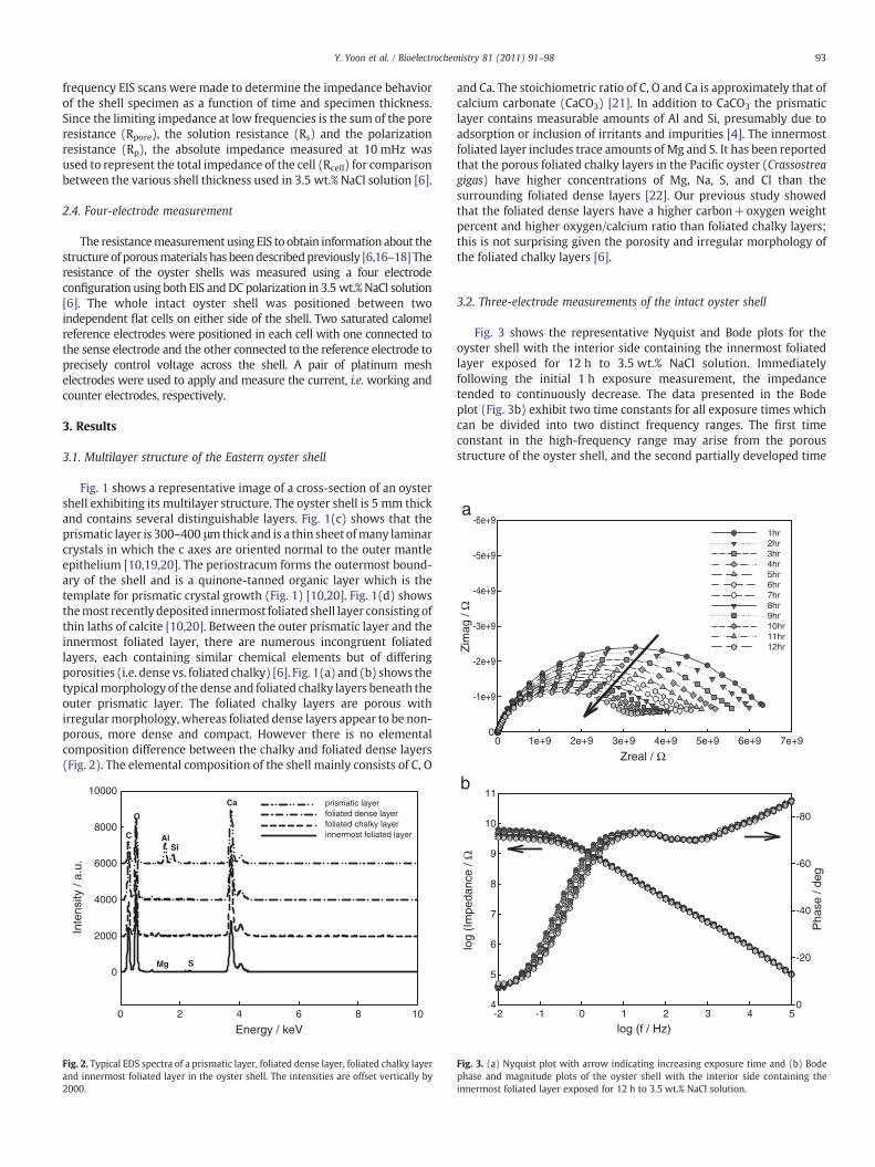
Fig. 1 shows a representative image of a cross-section of an oystershell exhibiting its multilayer structure. The oyster shell is 5 mm thickand contains several distinguishable layers. Fig. 1(c) shows that theprismatic layer is 300–400 μmthick and is a thin sheet ofmany laminarcrystals in which the c axes are oriented normal to the outer mantleepithelium [10,19,20]. The periostracum forms the outermost bound-ary of the shell and is a quinone-tanned organic layer which is thetemplate for prismatic crystal growth (Fig. 1) [10,20]. Fig. 1(d) showsthemost recently deposited innermost foliated shell layer consisting ofthin laths of calcite [10,20]. Between the outer prismatic layer and theinnermost foliated layer, there are numerous incongruent foliatedlayers, each containing similar chemical elements but of differingporosities (i.e. dense vs. foliated chalky) [6]. Fig. 1(a) and (b) shows thetypicalmorphology of the dense and foliated chalky layers beneath theouter prismatic layer. The foliated chalky layers are porous withirregularmorphology,whereas foliated dense layers appear to be non-porous, more dense and compact. However there is no elementalcomposition difference between the chalky and foliated dense layers(Fig. 2). The elemental composition of the shell mainly consists of C, O
Energy / keV0 2 4 6 8 10
Inte
nsity
/ a.
u.
0
2000
4000
6000
8000
10000prismatic layerfoliated dense layerfoliated chalky layerinnermost foliated layerC
O
Ca
Mg S
AlSi
Fig. 2. Typical EDS spectra of a prismatic layer, foliated dense layer, foliated chalky layerand innermost foliated layer in the oyster shell. The intensities are offset vertically by2000.
and Ca. The stoichiometric ratio of C, O and Ca is approximately that ofcalcium carbonate (CaCO3) [21]. In addition to CaCO3 the prismaticlayer contains measurable amounts of Al and Si, presumably due toadsorption or inclusion of irritants and impurities [4]. The innermostfoliated layer includes trace amounts of Mg and S. It has been reportedthat the porous foliated chalky layers in the Pacific oyster (Crassostreagigas) have higher concentrations of Mg, Na, S, and Cl than thesurrounding foliated dense layers [22]. Our previous study showedthat the foliated dense layers have a higher carbon+oxygen weightpercent and higher oxygen/calcium ratio than foliated chalky layers;this is not surprising given the porosity and irregular morphology ofthe foliated chalky layers [6].
3.2. Three-electrode measurements of the intact oyster shell
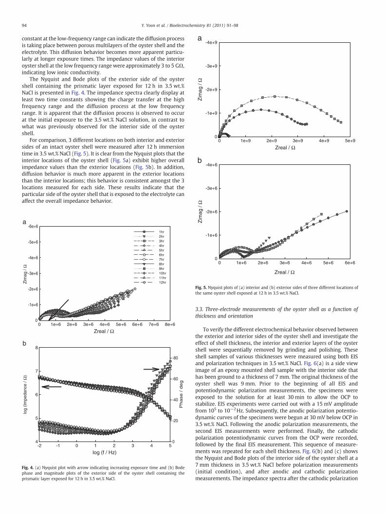
Fig. 3 shows the representative Nyquist and Bode plots for theoyster shell with the interior side containing the innermost foliatedlayer exposed for 12 h to 3.5 wt.% NaCl solution. Immediatelyfollowing the initial 1 h exposure measurement, the impedancetended to continuously decrease. The data presented in the Bodeplot (Fig. 3b) exhibit two time constants for all exposure times whichcan be divided into two distinct frequency ranges. The first timeconstant in the high-frequency range may arise from the porousstructure of the oyster shell, and the second partially developed time
b
Fig. 3. (a) Nyquist plot with arrow indicating increasing exposure time and (b) Bodephase and magnitude plots of the oyster shell with the interior side containing theinnermost foliated layer exposed for 12 h to 3.5 wt.% NaCl solution.
Ω
-4e+6
-3e+6
Zreal / Ω0 1e+9 2e+9 3e+9 4e+9 5e+9
Zim
ag /
Ω
-4e+9
-3e+9
-2e+9
-1e+9
0
a
b
94 Y. Yoon et al. / Bioelectrochemistry 81 (2011) 91–98
constant at the low-frequency range can indicate the diffusion processis taking place between porous multilayers of the oyster shell and theelectrolyte. This diffusion behavior becomes more apparent particu-larly at longer exposure times. The impedance values of the interioroyster shell at the low frequency rangewere approximately 3 to 5 GΩ,indicating low ionic conductivity.
The Nyquist and Bode plots of the exterior side of the oystershell containing the prismatic layer exposed for 12 h in 3.5 wt.%NaCl is presented in Fig. 4. The impedance spectra clearly display atleast two time constants showing the charge transfer at the highfrequency range and the diffusion process at the low frequencyrange. It is apparent that the diffusion process is observed to occurat the initial exposure to the 3.5 wt.% NaCl solution, in contrast towhat was previously observed for the interior side of the oystershell.
For comparison, 3 different locations on both interior and exteriorsides of an intact oyster shell were measured after 12 h immersiontime in 3.5 wt.% NaCl (Fig. 5). It is clear from the Nyquist plots that theinterior locations of the oyster shell (Fig. 5a) exhibit higher overallimpedance values than the exterior locations (Fig. 5b). In addition,diffusion behavior is much more apparent in the exterior locationsthan the interior locations; this behavior is consistent amongst the 3locations measured for each side. These results indicate that theparticular side of the oyster shell that is exposed to the electrolyte canaffect the overall impedance behavior.
log (f / Hz)-2 -1 0 1 2 3 4 5
log
(Im
peda
nce
/ Ω)
4
5
6
7
8
Ph
ase
/ d
eg
-80
-60
-40
-20
0
Zreal / Ω 0 1e+6 2e+6 3e+6 4e+6 5e+6 6e+6 7e+6 8e+6
Zim
ag /
Ω
-6e+6
-5e+6
-4e+6
-3e+6
-2e+6
-1e+6
0
1hr2hr3hr4hr5hr6hr7hr8hr9hr10hr11hr12hr
b
Fig. 4. (a) Nyquist plot with arrow indicating increasing exposure time and (b) Bodephase and magnitude plots of the exterior side of the oyster shell containing theprismatic layer exposed for 12 h in 3.5 wt.% NaCl.
Zreal / Ω
0 1e+6 2e+6 3e+6 4e+6 5e+6 6e+6
Zim
ag /
-2e+6
-1e+6
0
Fig. 5. Nyquist plots of (a) interior and (b) exterior sides of three different locations ofthe same oyster shell exposed at 12 h in 3.5 wt.% NaCl.
3.3. Three-electrode measurements of the oyster shell as a function ofthickness and orientation
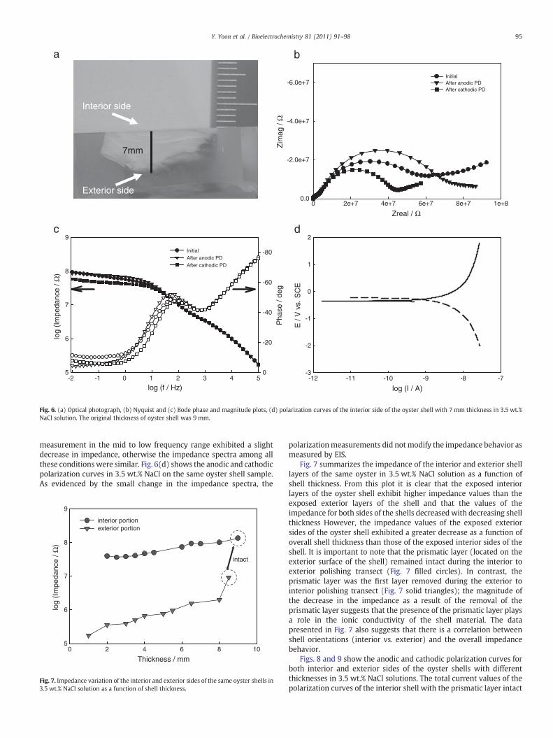
To verify the different electrochemical behavior observed betweenthe exterior and interior sides of the oyster shell and investigate theeffect of shell thickness, the interior and exterior layers of the oystershell were sequentially removed by grinding and polishing. Theseshell samples of various thicknesses were measured using both EISand polarization techniques in 3.5 wt.% NaCl. Fig. 6(a) is a side viewimage of an epoxy mounted shell sample with the interior side thathas been ground to a thickness of 7 mm. The original thickness of theoyster shell was 9 mm. Prior to the beginning of all EIS andpotentiodynamic polarization measurements, the specimens wereexposed to the solution for at least 30 min to allow the OCP tostabilize. EIS experiments were carried out with a 15 mV amplitudefrom 105 to 10−2Hz. Subsequently, the anodic polarization potentio-dynamic curves of the specimens were begun at 30 mV below OCP in3.5 wt.% NaCl. Following the anodic polarization measurements, thesecond EIS measurements were performed. Finally, the cathodicpolarization potentiodynamic curves from the OCP were recorded,followed by the final EIS measurement. This sequence of measure-ments was repeated for each shell thickness. Fig. 6(b) and (c) showsthe Nyquist and Bode plots of the interior side of the oyster shell at a7 mm thickness in 3.5 wt.% NaCl before polarization measurements(initial condition), and after anodic and cathodic polarizationmeasurements. The impedance spectra after the cathodic polarization
log (I / A)-12 -11 -10 -9 -8 -7
E /
V v
s. S
CE
-3
-2
-1
0
1
2
log (f / Hz)-2 -1 0 1 2 3 4 5
log
(Im
peda
nce
/ Ω)
5
6
7
8
9
Pha
se /
deg
-80
-60
-40
-20
0
Initial After anodic PD After cathodic PD
Zreal / Ω 0 2e+7 4e+7 6e+7 8e+7 1e+8
Zim
ag /
Ω
-6.0e+7
-4.0e+7
-2.0e+7
0.0
Initial After anodic PD After cathodic PD
7mm
Exterior side
Interior side
dc
Fig. 6. (a) Optical photograph, (b) Nyquist and (c) Bode phase and magnitude plots, (d) polarization curves of the interior side of the oyster shell with 7 mm thickness in 3.5 wt.%NaCl solution. The original thickness of oyster shell was 9 mm.
95Y. Yoon et al. / Bioelectrochemistry 81 (2011) 91–98
measurement in the mid to low frequency range exhibited a slightdecrease in impedance, otherwise the impedance spectra among allthese conditions were similar. Fig. 6(d) shows the anodic and cathodicpolarization curves in 3.5 wt.% NaCl on the same oyster shell sample.As evidenced by the small change in the impedance spectra, the
Thickness / mm0 2 4 6 8 10
log
(Im
peda
nce
/ Ω)
5
6
7
8
9
interior portion exterior portion
intact
Fig. 7. Impedance variation of the interior and exterior sides of the same oyster shells in3.5 wt.% NaCl solution as a function of shell thickness.
polarizationmeasurements did notmodify the impedance behavior asmeasured by EIS.
Fig. 7 summarizes the impedance of the interior and exterior shelllayers of the same oyster in 3.5 wt.% NaCl solution as a function ofshell thickness. From this plot it is clear that the exposed interiorlayers of the oyster shell exhibit higher impedance values than theexposed exterior layers of the shell and that the values of theimpedance for both sides of the shells decreased with decreasing shellthickness However, the impedance values of the exposed exteriorsides of the oyster shell exhibited a greater decrease as a function ofoverall shell thickness than those of the exposed interior sides of theshell. It is important to note that the prismatic layer (located on theexterior surface of the shell) remained intact during the interior toexterior polishing transect (Fig. 7 filled circles). In contrast, theprismatic layer was the first layer removed during the exterior tointerior polishing transect (Fig. 7 solid triangles); the magnitude ofthe decrease in the impedance as a result of the removal of theprismatic layer suggests that the presence of the prismatic layer playsa role in the ionic conductivity of the shell material. The datapresented in Fig. 7 also suggests that there is a correlation betweenshell orientations (interior vs. exterior) and the overall impedancebehavior.
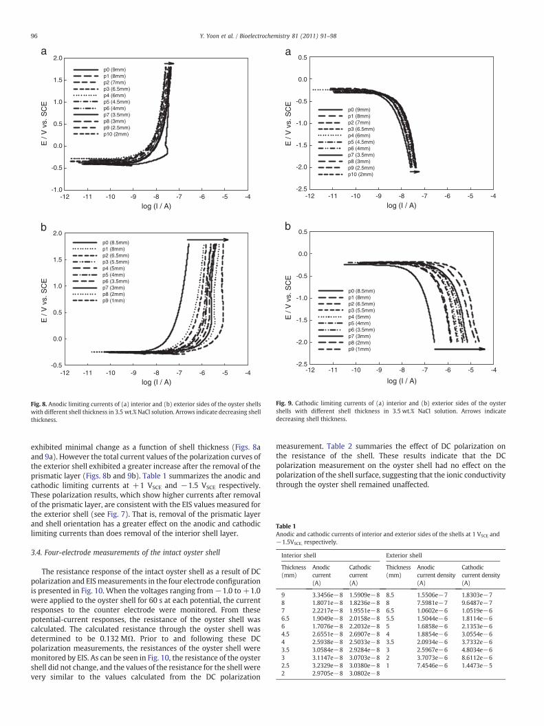
Figs. 8 and 9 show the anodic and cathodic polarization curves forboth interior and exterior sides of the oyster shells with differentthicknesses in 3.5 wt.% NaCl solutions. The total current values of thepolarization curves of the interior shell with the prismatic layer intact
log (I / A)
E /
V v
s. S
CE
-1.0
-0.5
0.0
0.5
1.0
1.5
2.0
p0 (9mm)p1 (8mm)p2 (7mm)p3 (6.5mm)p4 (6mm)p5 (4.5mm)p6 (4mm)p7 (3.5mm)p8 (3mm)p9 (2.5mm)p10 (2mm)
log (I / A)
-12 -11 -10 -9 -8 -7 -6 -5 -4
-12 -11 -10 -9 -8 -7 -6 -5 -4
E /
V v
s. S
CE
-0.5
0.0
0.5
1.0
1.5
2.0p0 (8.5mm)p1 (8mm)p2 (6.5mm)p3 (5.5mm)p4 (5mm)p5 (4mm)p6 (3.5mm)p7 (3mm)p8 (2mm)p9 (1mm)
b
a
Fig. 8. Anodic limiting currents of (a) interior and (b) exterior sides of the oyster shellswith different shell thickness in 3.5 wt.% NaCl solution. Arrows indicate decreasing shellthickness.
log (I / A)
E /
V v
s. S
CE
-2.5
-2.0
-1.5
-1.0
-0.5
0.0
0.5
p0 (9mm)p1 (8mm)p2 (7mm)p3 (6.5mm)p4 (6mm)p5 (4.5mm)p6 (4mm)p7 (3.5mm)p8 (3mm)p9 (2.5mm)p10 (2mm)
log (I / A)
E /
V v
s. S
CE
-12 -11 -10 -9 -8 -7 -6 -5 -4
-12 -11 -10 -9 -8 -7 -6 -5 -4-2.5
-2.0
-1.5
-1.0
-0.5
0.0
0.5
p0 (8.5mm)p1 (8mm)p2 (6.5mm)p3 (5.5mm)p4 (5mm)p5 (4mm)p6 (3.5mm)p7 (3mm)p8 (2mm)p9 (1mm)
b
a
Fig. 9. Cathodic limiting currents of (a) interior and (b) exterior sides of the oystershells with different shell thickness in 3.5 wt.% NaCl solution. Arrows indicatedecreasing shell thickness.
Table 1Anodic and cathodic currents of interior and exterior sides of the shells at 1 VSCE and−1.5VSCE, respectively.
Interior shell Exterior shell
Thickness(mm)
Anodiccurrent(A)
Cathodiccurrent(A)
Thickness(mm)
Anodiccurrent density(A)
Cathodiccurrent density(A)
9 3.3456e−8 1.5909e−8 8.5 1.5506e−7 1.8303e−78 1.8071e−8 1.8236e−8 8 7.5981e−7 9.6487e−77 2.2217e−8 1.9551e−8 6.5 1.0602e−6 1.0519e−66.5 1.9049e−8 2.0158e−8 5.5 1.5044e−6 1.8114e−66 1.7076e−8 2.2032e−8 5 1.6858e−6 2.1353e−64.5 2.6551e−8 2.6907e−8 4 1.8854e−6 3.0554e−64 2.5938e−8 2.5033e−8 3.5 2.0934e−6 3.7332e−63.5 3.0584e−8 2.9284e−8 3 2.5967e−6 4.8034e−63 3.1147e−8 3.0703e−8 2 3.7073e−6 8.6112e−62.5 3.2329e−8 3.0380e−8 1 7.4546e−6 1.4473e−52 2.9705e−8 3.0802e−8
96 Y. Yoon et al. / Bioelectrochemistry 81 (2011) 91–98
exhibited minimal change as a function of shell thickness (Figs. 8aand 9a). However the total current values of the polarization curves ofthe exterior shell exhibited a greater increase after the removal of theprismatic layer (Figs. 8b and 9b). Table 1 summarizes the anodic andcathodic limiting currents at +1 VSCE and −1.5 VSCE respectively.These polarization results, which show higher currents after removalof the prismatic layer, are consistent with the EIS values measured forthe exterior shell (see Fig. 7). That is, removal of the prismatic layerand shell orientation has a greater effect on the anodic and cathodiclimiting currents than does removal of the interior shell layer.
3.4. Four-electrode measurements of the intact oyster shell
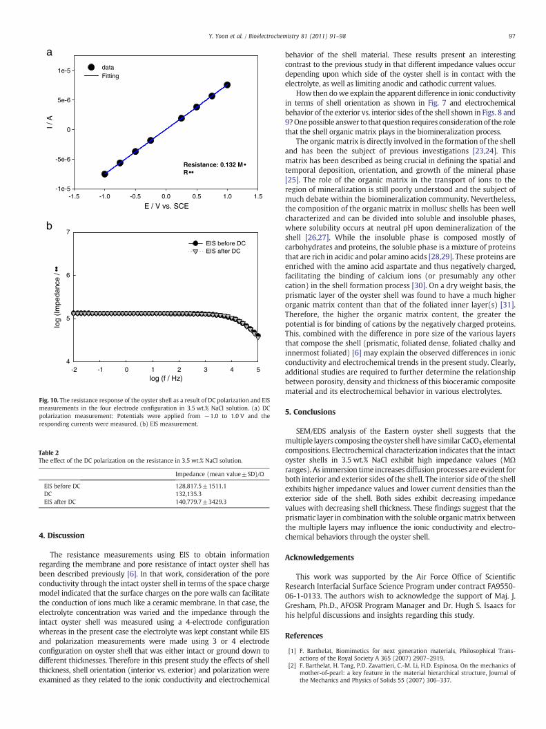
The resistance response of the intact oyster shell as a result of DCpolarization and EISmeasurements in the four electrode configurationis presented in Fig. 10. When the voltages ranging from−1.0 to +1.0were applied to the oyster shell for 60 s at each potential, the currentresponses to the counter electrode were monitored. From thesepotential-current responses, the resistance of the oyster shell wascalculated. The calculated resistance through the oyster shell wasdetermined to be 0.132 MΩ. Prior to and following these DCpolarization measurements, the resistances of the oyster shell weremonitored by EIS. As can be seen in Fig. 10, the resistance of the oystershell did not change, and the values of the resistance for the shell werevery similar to the values calculated from the DC polarization
measurement. Table 2 summaries the effect of DC polarization onthe resistance of the shell. These results indicate that the DCpolarization measurement on the oyster shell had no effect on thepolarization of the shell surface, suggesting that the ionic conductivitythrough the oyster shell remained unaffected.
E / V vs. SCE-1.5 -1.0 -0.5 0.0 0.5 1.0 1.5
I / A
-1e-5
-5e-6
0
5e-6
1e-5 dataFitting
Resistance: 0.132 MR
log (f / Hz)-2 -1 0 1 2 3 4 5
log
(Im
peda
nce
/
4
5
6
7
EIS before DCEIS after DC
b
a
Fig. 10. The resistance response of the oyster shell as a result of DC polarization and EISmeasurements in the four electrode configuration in 3.5 wt.% NaCl solution. (a) DCpolarization measurement: Potentials were applied from −1.0 to 1.0 V and theresponding currents were measured, (b) EIS measurement.
Table 2The effect of the DC polarization on the resistance in 3.5 wt.% NaCl solution.
Impedance (mean value±SD)/Ω
EIS before DC 128,817.5±1511.1DC 132,135.3EIS after DC 140,779.7±3429.3
97Y. Yoon et al. / Bioelectrochemistry 81 (2011) 91–98
4. Discussion
The resistance measurements using EIS to obtain informationregarding the membrane and pore resistance of intact oyster shell hasbeen described previously [6]. In that work, consideration of the poreconductivity through the intact oyster shell in terms of the space chargemodel indicated that the surface charges on the pore walls can facilitatethe conduction of ions much like a ceramic membrane. In that case, theelectrolyte concentration was varied and the impedance through theintact oyster shell was measured using a 4-electrode configurationwhereas in the present case the electrolyte was kept constant while EISand polarization measurements were made using 3 or 4 electrodeconfiguration on oyster shell that was either intact or ground down todifferent thicknesses. Therefore in this present study the effects of shellthickness, shell orientation (interior vs. exterior) and polarization wereexamined as they related to the ionic conductivity and electrochemical
behavior of the shell material. These results present an interestingcontrast to the previous study in that different impedance values occurdepending upon which side of the oyster shell is in contact with theelectrolyte, as well as limiting anodic and cathodic current values.
How then dowe explain the apparent difference in ionic conductivityin terms of shell orientation as shown in Fig. 7 and electrochemicalbehavior of the exterior vs. interior sides of the shell shown in Figs. 8 and9?Onepossible answer to that question requires considerationof the rolethat the shell organic matrix plays in the biomineralization process.
The organic matrix is directly involved in the formation of the shelland has been the subject of previous investigations [23,24]. Thismatrix has been described as being crucial in defining the spatial andtemporal deposition, orientation, and growth of the mineral phase[25]. The role of the organic matrix in the transport of ions to theregion of mineralization is still poorly understood and the subject ofmuch debate within the biomineralization community. Nevertheless,the composition of the organic matrix in mollusc shells has been wellcharacterized and can be divided into soluble and insoluble phases,where solubility occurs at neutral pH upon demineralization of theshell [26,27]. While the insoluble phase is composed mostly ofcarbohydrates and proteins, the soluble phase is a mixture of proteinsthat are rich in acidic and polar amino acids [28,29]. These proteins areenriched with the amino acid aspartate and thus negatively charged,facilitating the binding of calcium ions (or presumably any othercation) in the shell formation process [30]. On a dry weight basis, theprismatic layer of the oyster shell was found to have a much higherorganic matrix content than that of the foliated inner layer(s) [31].Therefore, the higher the organic matrix content, the greater thepotential is for binding of cations by the negatively charged proteins.This, combined with the difference in pore size of the various layersthat compose the shell (prismatic, foliated dense, foliated chalky andinnermost foliated) [6] may explain the observed differences in ionicconductivity and electrochemical trends in the present study. Clearly,additional studies are required to further determine the relationshipbetween porosity, density and thickness of this bioceramic compositematerial and its electrochemical behavior in various electrolytes.
5. Conclusions
SEM/EDS analysis of the Eastern oyster shell suggests that themultiple layers composing theoyster shell have similar CaCO3 elementalcompositions. Electrochemical characterization indicates that the intactoyster shells in 3.5 wt.% NaCl exhibit high impedance values (MΩranges). As immersion time increases diffusion processes are evident forboth interior and exterior sides of the shell. The interior side of the shellexhibits higher impedance values and lower current densities than theexterior side of the shell. Both sides exhibit decreasing impedancevalues with decreasing shell thickness. These findings suggest that theprismatic layer in combinationwith the soluble organicmatrix betweenthe multiple layers may influence the ionic conductivity and electro-chemical behaviors through the oyster shell.
Acknowledgements
This work was supported by the Air Force Office of ScientificResearch Interfacial Surface Science Program under contract FA9550-06-1-0133. The authors wish to acknowledge the support of Maj. J.Gresham, Ph.D., AFOSR Program Manager and Dr. Hugh S. Isaacs forhis helpful discussions and insights regarding this study.
References
[1] F. Barthelat, Biomimetics for next generation materials, Philosophical Trans-actions of the Royal Society A 365 (2007) 2907–2919.
[2] F. Barthelat, H. Tang, P.D. Zavattieri, C.-M. Li, H.D. Espinosa, On the mechanics ofmother-of-pearl: a key feature in the material hierarchical structure, Journal ofthe Mechanics and Physics of Solids 55 (2007) 306–337.

98 Y. Yoon et al. / Bioelectroche
[3] N. Nassif, N. Pinna, N. Gehrke, M. Antonietti, C. Jager, H. Colfen, Amorphous layeraround aragonite platelets in nacre, Proceedings of the National Academy ofSciences 102 (2005) 12653–12655.
[4] F. Wheaton, Review of the properties of Eastern oysters, Crassostrea virginica PartI. Physical properties, Aquacultural Engineering 37 (2007) 3–13.
[5] F. Wheaton, Review of oyster shell properties Part II. Thermal properties,Aquacultural Engineering 37 (2007) 14–23.
[6] Y. Yoon, A.S. Mount, K.M. Hansen, D.C. Hansen, Electrolyte conductivity throughthe shell of the Eastern Oyster using a four-electrode measurement, Journal of TheElectrochemical Society 156 (2009) 169–176.
[7] S.W. Lee, Y.M. Kim, H.S. Choi, J.M. Yang, C.S. Choi, Primary structure of myostracalprism soluble protein (MPSP) in oyster shell, Crassostrea gigas, The Protein Journal25 (2006) 288–294.
[8] G. Falini, S. Albeck, S. Weiner, L. Addadi, Control of aragonite or calcitepolymorphism by mollusk shell macromolecules, Science 271 (1996) 67–69.
[9] S. Mann, B.R. Heywood, S. Rajam, J.D. Birchall, Controlled crystallization of CaCO3
under stearic acid monolayers, Nature 334 (1988) 692–695.[10] A.S. Mount, A.P. Wheeler, R.P. Paradkar, D. Snider, Hemocyte-mediated shell
mineralization in the Eastern Oyster, Science 304 (2004) 297–300.[11] J.D. Currey, The design of mineralised hard tissues for their mechanical functions,
The Journal of Experimental Biology 202 (1999) 3285–3294.[12] R. Narayanan, S. Dutta, S.K. Seshadri, Hydroxy apatite coatings on Ti-6Al-4 V from
seashell, Surface & Coatings Technology 200 (2006) 4720.[13] M.B. Johnstone, K.M. Hansen, N.V. Gohad, D.C. Hansen, A.S. Mount, Cellular
Orchestrated Biomineralization of Nanocrystalline Composites on ImplantSurfaces, Journal of Experimental Marine Biology and Ecology (submitted forpublication).
[14] S. Weiner, H.D. Wagner, The material bone: structure-mechanical functionrelations, Annual Review of Materials Science 28 (1998) 271–298.
[15] E. Munch, M.E. Launey, D.H. Alsem, E. Saiz, A.P. Tomsia, R.O. Ritchie, Tough, bio-inspired hybrid materials, Science 322 (2008) 1516–1520.
[16] P. Fievet, A. Szymczyk, B. Aoubiza, J. Pagetti, Journal of Membrane Science 168(2000) 87–100.
[17] E. Mueller, C.S. Sikes, B.J. Little, Peptide interactions with steel surfaces: inhibitionof corrosion and calcium carbonate precipitation, Corrosion 49 (1993) 829–835(Houston, TX, United States).
[18] A. Szymczyk, P. Fievet, B. Aoubiza, C. Simon, J. Pagetti, An application of the spacecharge model to the electrolyte conductivity inside a charged microporousmembrane, Journal of Membrane Science 161 (1999) 275–286.
[19] A.G. Checa, A.B. Rodriguez-Navarro, F.J. Esteban-Delgado, The nature andformation of calcitic columnar prismatic shell layers in pteriomorphian bivalves,Biomaterials 26 (2005) 6404–6414.
[20] C.S. Sikes, A.P. Wheeler, A. Wierzbicki, A.S. Mount, R.M. Dillaman, Nucleation andgrowth of calcite on native versus pyrolyzed oyster shell folia, The BiologicalBulletin 198 (2000) 50–66.
[21] B. Pokroy, E. Zolotoyabko, Microstructure of natural plywood-like ceramics: astudy by high resolution electron microscopy and energy-variable X-raydiffraction, Journal of Materials Chemistry 13 (2003) 682–688.
[22] K. Wada, S. Suga, The distribution of some elements in the shell of freshwater andmarine bivalves by electron microprobe analysis, Bulletin of the National PearlResearch Laboratory 20 (1976) 2219–2240.
[23] K.Wada, Crystal growth of molluscan shell, Bulletin of the National Pearl ResearchLaboratory 7 (1961) 703–828.
[24] K.M.Wilbur, Shell formation and regeneration, in: K.M.Wilbur, C.M. Yonge (Eds.),Physiology of Mollusca, Academic Press, New York, 1964, pp. 243–282.
[25] A.H. Heuer, D.J. Fink, V.J. Laraia, J.L. Arias, P.D. Calvert, K. Kendall, G.L. Messing, J.Blackwell, P.C. Rieke, D.H. Thompson, A.P. Wheeler, A. Veis, A.I. Caplan, Innovativematerials processing strategies: a biomimetic approach, Science 255 (1992)1098–1105.
[26] K.M. Wilbur, K. Simkiss, Calcified shells, in: M. Florkin, E. Stotz (Eds.),Comprehensive Biochemistry, Elsevier, Amsterdam, 1968, pp. 229–295.
[27] S. Weiner, L. Hood, Soluble protein of the organic matrix of mollusk shells: apotential template for shell formation, Science 190 (1975) 987–989.
[28] S. Tanaka, H. Hatano, G. Suzue, Biochemical studies on pearl VII. Fractionation andterminal amino acids of conchiolin, Journal of Biochemistry 47 (1960) 117–123.
[29] V.R. Meenakashi, P.E. Hare, K.M. Wilbur, Amino acids of the organic matrix ofneogastropod shells, Comparative Biochemistry and Physiology 40B (1971)1037–1043.
[30] S. Weiner, Aspartic acid-rich proteins: major components of the soluble organicmatrix of mollusc shells, Calcified Tissue International 29 (1979) 163–167.
[31] A.S. Mount, PhD Dissertation "Nucleation of Calcite in the Eastern Oyster,Crassostrea virginica: Biochemical and Functional Studies of the Organic Matrixfrom Foliated Shell". Clemson SC, Clemson University, 1999.
Yuhchae Yoon received a Ph.D. in Materials Science andEngineering in 2004 from the Ohio State University. He iscurrently a research scientist at the University of DaytonResearch Institute. His main research areas include determi-nistic methods for predicting the accumulation of corrosiondamage on aircraft alloys, including corrosion sensor
mistry 81 (2011) 91–98
technology, and the development of novel-experimentalmethods and equipment in the study of corrosion inhibitors,coatings and aluminum alloys.
AndrewS.Mount received a Ph.D. inMarineZoology in 1999from Clemson University. He is currently a ResearchAssociate Professor in the Department of Biological Sciencesand theSchool ofMaterials Science&Engineering at ClemsonUniversity. His research interests include marine cellularbiomineralization and signal transduction mechanisms of
biofouling in marine invertebrates.Karolyn M. Hansen received a Ph.D. in Marine Biology/Biochemistry in 1990 from the University of Delaware.She is currently an Assistant Professor of Biology with theUniversity of Dayton where she teaches at the under-graduate and graduate level and conducts research in theareas of Biomaterials, Biosensing, and Sensor Development.
Douglas C. Hansen received a Ph.D. in Marine Biochemistryin 1993 from the University of Delaware. He currently is anAssociate Professor of Chemical and Material Engineering atthe University of Dayton and conducts research through theUniversity of Dayton Research Institute (UDRI) as a SeniorResearch Scientist andGroup Leader, anddirects the research
of undergraduate and graduate students in areas of electro-chemistry, corrosion, biomaterials and biochemistry.