electric measurement devices with digital indication
124
-
Upload
khangminh22 -
Category
Documents
-
view
1 -
download
0
Transcript of electric measurement devices with digital indication


ELECTRIC MEASUREMENT DEVICES WITH DIGITAL INDICATION

MULTIFUNCTUAL MEASURING INSTRUMENTS WITH ELECTRIC POWER QUALITY CONTROL AND COMMERCIAL ACCOUNTING FUNCTIONS
POWER QUALITY ANALYZERS WITH TECHNICAL AND COMMERCIAL ACCOUNTING
MULTIFUNCTIONAL POWER QUALITY ANALYZERS WITH TECHNICAL AND COMMERCIAL ACCOUNTING
ЩМК96
ЩМК120C
only forЩМК120C
ЩМК96 and ЩМК120 devices are intended for control of class A power energy quality parameters in accordance with GOST 30804.4.30-2013, GOST 32144-2013. They are designed for measurement of all power energetic pa-rameters at the connection point and power energy technical record-keeping.
ЩМК120C devices are intended for commercial accounting of the power en-ergy in accordance with the GOST 31819.22-2012 (0,2 S class), GOST 31819.23-2012 (1 class) and quality control of the class A power energy parameters in accordance with GOST 30804.4.30-2013, GOST 32144-2013, electrical current parameters, voltage, power, active and reactive energy in the three-phase electric mains and AC systems. The devices satisfy all the requirements for the commercial accountings devices.
Also these devices can integrate into the telemetry systems, they can simul-taneously transfer data for several directions independently.
Scopes of application:
• power energy quality parameters monitoring at the power energy distri-bution systems;
• electric power quality parameters control in Automated measuring and information system for electric power commercial accounting, at produc-tion areas and Housing and public utilities;
• 8-tariff electric power iscal metering (ЩМК120С);
• measuring of the circuits parameters and its transmission to the telemetry control systems and ACS;
• emergency registration;
• measuring of energy loss in power line.
ЩМК96, ЩМК120 (ЩМК120C) is put on the State Register of the Measuring Devices RF №60431-15, the validity period is to April 14, 2020.
Quality of electric power
Class AGOST 30804.4.30-2013GOST 32144-2013GOST 30804.4.15-2013GOST 30804.4.7-2013GOST R8.655-2009
• RMS of voltage
• frequency
• Duration and depth of voltage fail and voltages swell
• Temporary voltages swell duration
• Long and short flicker batch
• Temporary voltage swell coefficient
• n-harmonical voltage component coefficient
• voltage waveform distortion factor
• voltage unbalance factor for inverted sequence
• voltage unbalance factor for null sequence
Electric power
commercial accounting
GOST 31819.22-2012(0,2S class)GOST 31819.23-2012(1 class)
• metering of the consumed active electric energy in increment total in summarily and severally as per tariff
• eight tariffs
• active and reactive energy
• active and reactive loss energy
• flags of energy metering misconduct
Measurement and display of electricsystem parameters
GOST 22261-94GOST R52931-2008GOST 29322-2014
• electric current, tollerance not above ±0,1%
• voltage, tollerance not above ±0,1%
• electric power, tollerance not above ±0,5%
• electric energy, tollerance not above ±0,5%
ELEC
TRIC
MEA
SURE
MEN
T D
EVIC
ES W
ITH
DIG
ITA
L IN
DIC
ATIO
N
2

ELEC
TRIC
MEA
SURE
MEN
T D
EVIC
ES W
ITH
DIG
ITA
L IN
DIC
ATIO
N
ЩМК96, ЩМК120, ЩМК120C
Device Type
ЩМК96
ЩМК120, ЩМК120С
Data display
LED indication
(single or seven-segment dispalys)
Additional Features
Telemetry
Input signal
Measuring time
Galvanic isolation of the inputand output circuits, supply circuitsMinimum input resistanca inCurrent circuits:Voltage circuits:
- 3 blocks of the seven-segment displays (4 indicators in each block)- single LED displays for displaying of the measurement units, different indexes, signs of the di displayed parametersHeight of character: 20 mm and 14 mm (ЩМК96, ЩМК120), 20 mm (ЩМК120С)For ЩМК120С there is a row of seven-segment indicators in the bottom part of the front panel, they are used for displaying of the current values and sum results for every tariff and total for all tariffs, current tariff number, date and time.To display telemetry at the optional device:Connection of the indication modules (МИ120, МИ80) or indication panel T44, T54, T74 on the RS485 inter-face or Ethernet (for МИ120.5)To communicate with telemetry control unit:Connection of the telemetry controller ЭЛКТ on the RS485 interface for data transferring to the upper level as per IEC6 1850-8-1 protocol (Ethernet interface)
Current:1А,5АVoltage:100V, 400 VNominal effective voltage:57.7/230V – phase, 100/400 V – phase-to-phase Measurement frequency of the current/voltage input signal:42,5-57,5Hz Maximum wire section 4mm2
0,2sec.(current and voltage),1 sec (frequency)
Yes
0,02 Оm (1А, 5А)0,4 МОm (100V), 1,6 МOm (400V)
Electric energy quality parameters
RMS of voltage(U), V
Overdeviation(δU(+)), %**
Underdeviation( δU(-)), %**
Frequency (f ), HzFrequency deviation(∆f ), Hz
Short flicker batch(Рst), rel. un.
Long flicker batch(Рlt), rel. un.
n-harmonical voltage component coefficient to the 50 degree (КU(n)), %***
Aggregate harmonical voltage component coefficient (voltage waveform distortion factor)(КU), %
Voltage unbalance factor for inverted sequence (К2U), %
Voltage unbalance factor for null sequence (К0U), %
Duration of the voltage fail (∆tn), sec
Depth of the voltage fail ( δ Un), %
Duration of the voltage interruption (∆tint), sec
Duration of the temporary over-voltage (∆tov), sec
Temporary over-voltage factor (Кov), rel. un.
Rangeof measurement
(0...200) % Unom
(0...100) %
(0...90) %
(42,5...57,5) Hz(-7,5...7,5)Hz
(0,2...10)
(0,2...10)
(0,05...30)
(0,1...30)
(0...20)
(0...20)
(0,02...60) s
(10...99) %
(0,02...60) s
(0,02...60) s
(1,1...2,0)
Measurement error limit*
у=±0,1%
∆=±0,1
∆=±0,1
∆ =±0,01
∆ =±0,01
δ =±5%
δ =±5%
∆ =±0,05(КU(N)<1%)
δ =±5,0%(1%<КU(N)<30%)
∆ =±0,05(0,1%<KU<1%)
δ =±5,0%(1%<КU<30%)
∆ =±0,15
∆ =±0,15
∆ =±0,02
∆ =±0,2
∆ =±0,02
∆ =±0,02
∆ =±0,002
Overall dimensions, mm96х96х93 (without safety cover)96х96х103 (with safety cover)
120х120х93 (without safety cover)120х120х103 (with safety cover)
Character height, mm
20,14
20,14
Weight, kg
0,7
0,7
* error identifications: Δ – absolute; δ, % – fractional; у, % – reduced** relatively to the Un which is equal to the nominal Un or approved Uapp value of voltage as per GOST32144*** the harmonic subgroup number n is from 2 to 50 as per GOST 30804.4.7
3

Communication interfaces
RS485
Ethernet
Remote human-computerinterfaceIntegration with Electric EnergyQuality Control ParametersSystem
Device time synchronization
Integration into the systems
Power supply
Voltage
Power from the supply circuit (not above)
Device reprogramming (trim)
Reprogramming
Operational ConditionsWorking temperature rangeDust/moisture protectionResistance to mechanical stressElectromagnetic capabilityMountingCalibration periodGuaranteeperiodAverage lifetime, not lessMean time between errors
Protocols: Modbus RTU, IEC 60870-5-101Note: It is possible to have one RS485 port for ЩМК96, ЩМК120, two RS485 ports – for ЩМК120СEthernet 10/100 BASE TX (socket RJ45) or Ethernet 100 BASE FX (socket ST)Protocols: IEC 60870-5-104, IEC 61850-8-1Note: It is possible to have one Ethernet port for ЩМК96, ЩМК120, two Ethernet ports – for ЩМК120С
HTTP(Embedded WEB-server)
HTTP(integration in to the software package for visualization and monitor ingofindicators of the quali-ty of electricity supplied with the device)
NTP (RFC5905)/РТР (IEEE’1588)
IEC 60870-5-101/104, IEC 61850-8-1
- main: 220 V (90-264V of AC with frequency of (50 ± 0,5) Hz or 130-370V of DC)- stand-by: «STAND-BY» (for ЩМК120С)
10V-A (full power) when powered by a single-phase alternating current source 50 Hz,10W when powered from the direct current source
-via the Configurator software (RS485 interface, Ethernet),-via WEB-interface,-via control buttons on the front panel.The reprogramming parameters are described in the Device Manual
-40 - +55°CIP51Group 4 as per GOST22261Immunity: GOSTR51317.6.5, Electromagnetic emission: International special committee on radio interference 22 for A classAt the panel10 years36 months30 years250000 hours
MULTIFUNCTUAL MEASURING INSTRUMENTS WITH ELECTRIC POWER QUALITY CONTROL AND COMMERCIAL ACCOUNTING FUNCTIONS
ELEC
TRIC
MEA
SURE
MEN
T D
EVIC
ES W
ITH
DIG
ITA
L IN
DIC
ATIO
N
For ЩМК120С: optic “optoport” interface (IEC 61107), impulse output interface
ORDERING FORM
ЩМК а - b - c - d - e - f - g - h - i
а – device performance depending on the overall dimensions– ЩМК96 – overall dimensions 96х96 mm– ЩМК120 – overall dimensions 120х120 mm – ЩМК120С – overall dimensions 120х120 mm, fiscal electric energy metering function
b – rated voltage:– electric line voltage – 100 V, 400 V;– U/100 – voltage ratio (rated voltage of the seconadry winding 100 V);
c – rated current:– phase current, -1 A, 5 A,– I/1, I/5 – current ratio (rated current of the secondary winding 1 A, 5A);
d – main Ethernet interface indication– 1REO – Ethernet interface (optics), except ЩМК120С– 1REC – Ethernet interface (copper), except ЩМК120С – 2REO – 2 Ethernet interfaces (optics), only for ЩМК120С – 2REC – 2 Ethernet interface (copper), only for ЩМК120С
e – main RS485 interface indication (only for REC devices)– x – no RS485 interface, except ЩМК120С– RS – additional RS485 interface, except ЩМК120С– 2RS – two RS485 interfaces, always for ЩМК120С
f – metering scheme designation– 3П – three-wire connection scheme– 4П – four-wire connection scheme
g – indicator color:– К – red color;– З – green color;– Ж – yellow color;
h – ambient class– УХЛЗ.1 –for operation conditons of -40 – +55°C, ralative humidity not above 90%, +30°C
i – Special design:– if no, do not complete;– IEC 61850-8-1 – digital substations protocol support
4

ЩМК96, ЩМК120, ЩМК120C
ЩМК96, ЩМК120, ЩМК120C
ЩМК device type
ЩМК96
ЩМК120
ЩМК120С
Rated value or transformation ratio
Ethernet interface
RS485 interface
Metering scheme
Color of indication
Ambient class
Special design
Code parameter of the full designation
Notes:“+” sign shows presence of all possible options in the order formula.“х” sign means, that this parameter is absent.The unused i parameter is not stated
As for ЩМК96 device with the following parameters – rated voltage – 100 V, rated current – 1A, Ethernet interface (copper), three-wire connection scheme, red color of indicators, for working temperature -40.. +55°C, ralative humidity not above 90%, +30°C.ЩМК96 - 100 В - 1 A - REC- x - ЗП-К-УХЛЗ.1 TУ 25-7504.227-2014
As for ЩМК120 device with the following parameters – rated voltage – 400 V, rated current – 5A, Ethernet interface (copper),RS485 interface, four-wire connection scheme, green color of indicators, for working temperature -40.. +55°C, ralative humidity not above 90%, +30°C.ЩМК120 - 400 В - 5 A - REC- RS - 4П-З-УХЛЗ.1 TУ 25-7504.227-2014
As for ЩМК120С device with the following parameters – rated voltage – 400 V, rated current – 5A, 2 Ethernet interfaces (optics), 2 RS485 interfaces, four-wire connection scheme, red color of indicators, for working temperature -40.. +55°C, ralative humidity not above 90%, +30°C, IEC 6 1850-8-1 protocolЩМК120С - 400 В - 5 A - 2REO - 2RS - 4П-К-УХЛЗ.1 - IEC 61850-8-1 TУ 25-7504.227-2014
ORDERING EXAMPLE
OVERALL AND INSTALLATION DIMENSIONS
Device type H, mm L, mm L1, mm A, mm B, mm
ЩМК96ЩМК120, ЩМК120С
ELEC
TRIC
MEA
SURE
MEN
T D
EVIC
ES W
ITH
DIG
ITA
L IN
DIC
ATIO
N
5

MULTIFUNCTUAL MEASURING INSTRUMENTS WITH ELECTRIC POWER QUALITY CONTROL AND COMMERCIAL ACCOUNTING FUNCTIONS
ELEC
TRIC
MEA
SURE
MEN
T D
EVIC
ES W
ITH
DIG
ITA
L IN
DIC
ATIO
N
CONNECTION DIAGRAMS
ЩМК96, ЩМК120 connection diagram(three-phase, four-wire, tree-element)
Connection with 3 CT and 3 VT
ЩМК120С connection diagram(three-phase,three-wire, two-element)
Connection with 2CT and 2 VT
Notes:Usup1 –voltage on the main power supplyUsup2 –voltage on the additional power supply
ЩМК96, ЩМК120 connection diagram(three-phase,three-wire, two-element)
Connection with 2CT and 2 VT
supsup
sup sup
Line
VT1
VT1
CT1
CT2
VT2
VT1 VT2
CT1CT1
CT2
CT2
CT3
VT2 VT3
Supply Supply
Load
Load
Line
Line
Load
RESERVE
6

COMMERCIAL ACCOUNTING DEVICE WITH FUNСTIONS OF POWER QUALITY CONTROL
ЩМК120СП is intended for electric power commercial accounting in ac-cordance with the GOST 31819.22-2012 (0,2 S class), GOST 31819.23-2012 (1 class), A class quality parameters measurement in accordance with the GOST 30804.4.30-2013 GOST 32144-2013, electric current parameters, voltage, power, active and reactive energy in the three-phase electrical circuits and AC systems. They are also intended for metering in the connection points and keeping the metering results, displaying of the metered energy values and power quality parameters, and forwarding data via the communication inter-faces.
The devices satisfy all the requirements for the commercial accounting de-vices.
ЩМК120СП is put on the State Register of the Measuring Devices RF №68977-17, the validity period is to October 23, 2022.
Quality of electric power
Class AGOST 30804.4.30-2013GOST 32144-2013GOST 30804.4.15-2013GOST 30804.4.7-2013GOST R 8.655-2009
• RMS of voltage
• frequency
• Duration and depth of voltage fail and voltage swell
• Temporary voltage swell duration
• Long and short flicker batch
• Temporary voltage swell coefficient
• n-harmonical voltage component coefficient
• voltage waveform distortion factor
• voltage unbalance factor for inverted sequence
• voltage unbalance factor for null sequence
Electric power commercial accounting
GOST 31819.22-2012 (0,2S class)GOST 31819.23-2012 (1 class)
• metering of the consumed active electric energy in increment total in summarily and severally as per tariff
• eight tariffs
• active and reactive energy
• active and reactive loss energy
• energy malmetering flags
Measurement and display of electric system parameters
GOST 22261-94GOST R 52931-2008GOST 29322-2014
• electric current, tollerance not above ±0,1 %
• voltage, tollerance not above ±0,1 %
• electric power,tollerance not above ±0,5 %
• electric energy, tollerance not above ±0,5 %
ELEC
TRIC
MEA
SURE
MEN
T D
EVIC
ES W
ITH
DIG
ITA
L IN
DIC
ATIO
N
7

COMMERCIAL ACCOUNTING DEVICE WITH FUNСTIONS OF POWER QULITY CONTROL
ELEC
TRIC
MEA
SURE
MEN
T D
EVIC
ES W
ITH
DIG
ITA
L IN
DIC
ATIO
N
Device Type
Electric energy metering parameters
Received active energy (А+) as per n-tariff (n = 1,2,…,8,0 – summarily as per tariffs)
Transferred active energy (А-) as per n-tariff (n = 1,2,…,8,0 - summarily as per tariffs)
Total active energy ((А+)+(А-)) as per n-tariff(n = 1,2,…,8, 0 - summarily as per tariffs)
Reactive energy as per r-quadrant (Qr) (r = 1, 2, 3 or 4) as per n-tariff (n = 1,2,…,8,0 - summarily as per tariffs) Received reactive energy (R+ = Q1+Q2) as per n-tariff (n = 1, 2,…, 8, 0 - summarily as per tariffs)Transferred reactive energy (R- = Q3+Q4) as per n-tariff (n = 1, 2,…,8, 0 - summarily as per tariffs)
Total reactive energy ((R+)+(R-)) as per n-tariff (n = 1, 2,..., 8, 0 - summarily as per tariffsAveraging time of energy differential measurement (metering interval), min
Preoscillation current (sensitiveness) for active energy metering, А
Preoscillation current (sensitiveness) for reactive energy metering, А
Quantity of the impulse-number meterng interfaces (terminals)
Electric energy quality parameters
RMS of voltage (U), V
Overdeviation (δU(+)), % **
Underdeviation ( δU(-)), %**
Frequency (f ), HzFrequency deviation (∆f ), Hz
Short flicker batch (РSt), rel. un.
Long flicker batch (Рlt), rel. un.
n-harmonical voltage component coefficient to the 50 degree (КU(N)), %***
Agreegate harmonical voltage component coefficient (voltage waveform distortion factor) (КU), %
Voltage unbalance factor for the inverted sequence (К2U), %
Voltage unbalance factor for the sequence (К0U), %
Duration of the voltage fail (∆tn), sec
Depth of the voltage fail (δUn), %
Duration of the voltage interruption (∆tint), sec
Duration of the temporary over-voltage (∆tov), sec
Temporary over-voltage factor (Кov ), rel. un
Measurement error
In accordance with the accuracy class 0,2S as per GOST 31819.22
In accordance with the accuracy class 0,2S as per GOST 31819.22
In accordance with the accuracy class 0,2S as per GOST 31819.22
In accordance with the accuracy class 1 as per GOST 31819.23
In accordance with the accuracy class 1 as per GOST 31819.23
In accordance with the accuracy class 1 as per GOST 31819.23
In accordance with the accuracy class 1 as per GOST 31819.23
1, 2, 3, 4, 5, 6, 10, 12, 15, 20, 30, 60
0,001 . lnom
0,002 . lnom
4 congigurable terminals
Overall dimensions, mm Character height, mm Weight, kg
* error identifications: Δ - absolute; δ,% - fractional; у,% - reduced** relatively to the Un which is equal to the nominal Un or approved Uapp value of voltage as per GOST 32144*** the harmonic subgroup number n is from 2 to 50 as per GOST 30804.4.7
nom
Range of measurement
Measurement error limit*
HzHz
s
s
s
8

Data display
LED indication(single or seven-segment dispalys)
Additional Features
Telemetry
Input signal
Measuring time
Galvanic isolation of the input andoutput circuits, supply circuitsInput resistanceCurrent circuits:Voltage circuits:
Communication intefacesRS485
Ethernet
Remote human-computer interface
Integration with Electric EnergyQuality Control Parameters System
Device time synchronization
Integration into the systems
Power supply
Voltage
Power from the supply circuit (not above)
Device reprogramming (trim)
Reprogramming
Operational ConditionsWorking temperature rangeDust/moisture protectionResistance to mechanical stressElectromagnetic capabilityMountingCalibration periodGuarantee periodAverage lifetime, not lessMean time between errors
-1 row of the seven-segment displays (8 displays, character height is 14 mm)- single seven-segment display for displaying the number of the selected tariff- single LED displays for displaying of the different operational factors
To display telemetry at the optional device:Connection of the indication modules (МИ120, МИ80) or indication panel T44, T54, T74 on the RS485 inter-face or Ethernet (for МИ120.5)To communicate with telemetry control unit:Connection of the telemetry controller ЭЛКТ on the RS485 interface for data transferring to the upper level as per IEC 61850-8-1 protocol (Ethernet interface)
Current: 1 А, 5 АVoltage: 100 V, 400 VNominal effective voltage: 57.7/230 V - phase,100/400 V – line-to-lineMeasurement frequency of the current/voltage input signal: 42,5 - 57,5 HzMaximum wire section 4 mm2
0,2 sec. (current and voltage), 1 sec (frequency)
Yes
0,02 Om (1 A, 5 A) 0,4 MOm (100 V), 1,6 MOm (400 V)
Quantity: 2; Protocols: Modbus RTU, IEC 60870-5-101
Ethernet 10/100 BASETX (socket RJ45) or Ethernet 100 BASE FX (socket ST)Quantity: 2; Protocols: IEC 60870-5-104, IEC 61850-8-1
HTTP (Embedded WEB-server)
HTTP (integration into the software package for visualization and monitoring of indicators of the quality of electricity supplied with the device)
NTP (RFC 5905)/РТР (IEEE’ 1588)
RS485 (Modbus RTU, IEC 60870-5-101),Ethernet (IEC 60870-5-104, IEC 61850-8-1),Optical interface «optoport» (IEC 61107), impulse output interface
- main: 220 V (90-264 V of AC with frequency of (50 ± 0,5) Hz or 130-370 V of DC)- stand-by: «STAND-BY» (90-264 V of AC with frequency of (50 ± 0,5) Hz or 130-370 V of DC)
10 V-A (full power) when powered by a single-phase alternating current source 50 Hz,10 W when powered from the direct current source
- via the Configurator software (RS485 interface, Ethernet),- via control buttons on the front panel,- via WEB-interfaceThe reprogramming parameters are described in the Device Manual
-40 - +55 °CIP51Group 4 as per GOST 22261Immunity: GOST R 51317.6.5, Electromagneict emission: International special committee on radio interference 22 for A class
At the panel12 years36 months25 years250000 hours
ELEC
TRIC
MEA
SURE
MEN
T D
EVIC
ES W
ITH
DIG
ITA
L IN
DIC
ATIO
N
9

COMMERCIAL ACCOUNTING DEVICE WITH FUNСTIONS OF POWER QULITY CONTROL
ELEC
TRIC
MEA
SURE
MEN
T D
EVIC
ES W
ITH
DIG
ITA
L IN
DIC
ATIO
N
ORDERING FORM
ЩМК
ORDERING EXAMPLE
CONNECTION DIAGRAMS
а – rated voltage:– electric line voltage - 100 V, 400 V;– U/100 – voltage ratio (rated voltage of the secondary winding 100 V);
b – rated current:– phase current - 1 А; 5 A;– I/1; I/5 – current ratio (rated current of the secondary winding 1 А and 5 А);
c – indicator color:– К – red color;– З – green color;– Ж – yellow color;
d – special design:– if no, do not complete;
Notes:“+” sign shows presence of all possible options in the order formula.The unused “d” parameter is not stated.
Notes:Usup1 –voltage on the main power supplyUsup2 –voltage on the additional power supply
As for ЩМК120СП with the following parameters: rated voltage – 400 V, rated current – 5A, red color of indicator:ЩМК120СП – 400 В -5 A – К TУ 26.51.43-233-05763903-2017
As for ЩМК120СП with the following parameters: rated voltage – 100 V, rated current – 1A, red color of indicator:ЩМК120СП – 100 В -1 A – К TУ 26.51.43-233-05763903-2017
Measurement device design
Code parameter of the full designationRated value or transformation ratio Color of indication
Meter connection diagram(three-phase, four-wire, tree-element)
Connection with 3 CT and 3 VT
Meter connection diagram(three-phase, four-wire, two-element)
Connection with 2 CT and 2 VT
sup sup
Output relay Trial terminals Trial terminalsOutput relayRESERVE RESERVE
Line
Load
Load
Line
VT1 VT1 VT2VT2 VT3
CT1 CT1
CT2
CT2
CT3
10

OVERALL DIMENSIONS
ELEC
TRIC
MEA
SURE
MEN
T D
EVIC
ES W
ITH
DIG
ITA
L IN
DIC
ATIO
N
11

PORTABLE POWER QUALITY CONTROL DEVICE
ELEC
TRIC
MEA
SURE
MEN
T D
EVIC
ES W
ITH
DIG
ITA
L IN
DIC
ATIO
N
PORTABLE POWER QUALITY CONTROL DEVICE
Portable МПК1 devices are intended for electric power quality parameters metering for current and voltage in the three-pase circuits and alternative current systems, МПК2 are intended for electric power quality parameters metering for voltage at the connection points of the metering devices for sub-station, monitoring systems and quality control systems, it is provided to keep results as for defined algorithms for time periods, which are measured by re-al-time clocks.
Quality parameters calculation is performed as for A class in accordance with GOST 30804.4.30-2013, GOST 32144-2013.
МПК1, МПК2 are put on the State Register of the Measuring Devices RF №71684-18, the validity period is to June 28, 2023.
Quality of electric power
Class AGOST 30804.4.30-2013GOST 32144-2013GOST 30804.4.15-2013GOST 30804.4.7-2013GOST R 8.655-2009
• RMS of voltage• frequency• Duration and depth of voltage fail and voltage swell • Temporary voltage swell duration• Long and short flicker batch• Temporary voltage swell coefficient• n-harmonical voltage component coefficient• voltage waveform distortion factor• voltage unbalance factor for inverted sequence• voltage unbalance factor for null sequence
Device Type Weight, kg, no more (not including case, wires and clips)Case
Overall dimensions, mmDevice
Comes standard with:
• МПК device
• Case
• Wires with clips for input signals connection
• Сlamp meters or Rogowski coils (for МПК1, optional)
• Supply cable
• Operation manual and calibration procedure for 10 pcs.
• Logbook
12

nom
Electric energy quality parameters
RMS of voltage (U), V
Overdeviation (δU(+)), % **
Underdeviation ( δU(-)), %**
Frequency (f), HzFrequency deviation (∆f ), Hz
Short flicker batch (РSt), rel. un.
Long flicker batch (Рlt), rel. un.
n-harmonical voltage component coefficient to the 50 degree (КU(N)), %***
Agreegate harmonical voltage component coefficient (voltage waveform distortion factor) (КU), %
Voltage unbalance factor for the inverted sequence (К2U), %
Voltage unbalance factor for the sequence (К0U), %
Duration of the voltage fail (∆tn), sec
Depth of the voltage fail (δUn), %
Duration of the voltage interruption (∆tint), sec
Duration of the temporary over-voltage (∆tov), sec
Temporary over-voltage factor (Кov ), rel. un.
Data display
LED indication(single or seven-segment dispalys)
Telemetry
Input signal
Measuring time
Galvanic isolation of the input andoutput circuits, supply circuitsInput Resistance, not lessCurrent circuits:Voltage circuits:
Communication intefaces
RS485
Ethernet
Remote human-computer interface
Integration with Electric EnergyQuality Control Parameters System
Device time synchronization
-3 blocks of the seven-segment displays (4 indicators in the block, character height is 14 mm)- single LED indicators for displaying of the different operational factors – depending on the orderIt is possible to choose the displayed parameters by the control button on the device front panel.
Voltage: 100 V, 400 V; U/100Current: 1 А, 5 А, 250 A (KT), 800 A (KT), 3000 A (KT), 3000 A (KP); I/1; I/5Measurement frequency of the current/voltage input signal: 42,5 - 57,5 HzNote: KT – clamp meters, KP – Rogowski coil
0,2 sec. (current and voltage), 1 sec (frequency)
Yes
0,02 Om (1A, 5 A)0,42 MOm (100 V), 1,66 MOm (400 V)
Quantity: 0,1;Protocols: Modbus RTU, IEC 60870-5-101
Ethernet 10/100 BASETX (socket RJ45) or Ethernet 100 BASE FXQuantity: 1;Protocols: IEC 60870-5-104, IEC 61850-8-1
HTTP (Embedded WEB-server)
HTTP ( integration into the software package for visualization and monitoring of indicators of thequality of electricity supplied with the device)
NTP (RFC 5905)/РТР (IEEE’ 1588)
Range of measurement
Measurement error limit*
The parameters depend on the device design* error identifications: Δ - absolute; δ,% - fractional; у,% - reduced** relatively to the Un which is equal to the nominal Un or approved Uapp value of voltage as per GOST 32144*** the harmonic subgroup number n is from 2 to 50 as per GOST 30804.4.7
ELEC
TRIC
MEA
SURE
MEN
T D
EVIC
ES W
ITH
DIG
ITA
L IN
DIC
ATIO
N
13

PORTABLE POWER QUALITY CONTROL DEVICE
ELEC
TRIC
MEA
SURE
MEN
T D
EVIC
ES W
ITH
DIG
ITA
L IN
DIC
ATIO
N
220 V (90-264 V of AC with frequency of (50 ± 0,5) Hz or 130-370 V of DC)
10 V-A (full power) when powered by a single-phase alternating current source 50 Hz,10 W when powered from the direct current source
- via the Configurator software (RS485 interface, Ethernet),-changing of the lightnening intensity of the indicators (if applicable) ( via the Configurator soft-ware for RS485 interface, Ethernet) or via control buttons on the front panel-selection of current parameters displaying (if applicable) (via control buttons on the front panel)The reprogramming parameters are described in the Device Manual
-40 - +55 °CIP41Group М7 as per GOST 30631-99In accordance with the requirements established in CISPR-22 for class A equipment
At the panel10 years24 months
25 years
250000 hours
Power supply
Voltage
Power from the supply circuit (not above)Device reprogramming (trim)
Reprogramming
Operational ConditionsWorking temperature range
Dust/moisture protectionResistance to mechanical stressElectromagnetic capabilityMountingCalibration periodGuarantee period
Average lifetime, not less
Mean time between errors
ORDERING FORM
МПК a - b - c - d - e - f - g
а – device performance depending on the overall dimensions1 – overall dimensions 175х86х280 mm2 – overall dimensions 95х53х175 mm
b – nominal rates of the metering input parameters (depending on the device performance)Performance options:b1 – one metering parameter (voltage) (for МПК2 only)– electric line voltage - 100 V, 400 V; - U/100 – voltage ratio (rated voltage of the secondary winding 100 V);
b1, b2 – two metering parameters (voltage, current) (for МПК1 only)– electric line voltage - 100 V, 400 V; - U/100 – voltage ratio (rated voltage of the secondary winding 100 V); – 1,0A, 5,0A, 250 A(KT), 800 A(KT), 3000 A(KP) – phase current, or I/1, I/5 – current ratio (rated current of the secondary winding 1 A, 5A);Note: KT – clamp meters, KP – Rogowski coil
c – main Ethernet interface indicationREO – Ethernet interface (optics) REC – Ethernet interface (copper)
d – main RS485 interface indication (only for REC devices)x – no RS485 interface RS – RS485 interface
e – indicator color:x – device without indicators (for МПК2 only)К – red color (МПК1);З – green color(МПК1);Ж – yellow color(МПК1);
f – clips optionsA – 1 option of clips (pic.1);B– 2 option of clips(pic.2);C– 3 option of clips(pic.3);
14

Clip A (clip 1) – alligator clip, length 92 mm, diameter – 32 mm;Clip B (clip 2) – alligator clip, length 155 mm, diameter – 11,5 mm;Clip C (clip 3) – tweezer clip, length 159 mm, diameter – 4 mm;
g – special design:- if no, do not complete;- IEC 61850-8-1 – digital substations protocol support (for МПК1 only)
KT – clamp meters; KP – Rogowski coil Notes:Sign “х” means that the parameter is absentThe unused g paramer is not statedThe design with IEC 61850-8-1 protocol support is possible for МПК1.
As for МПК device with the following parameters: overal dimension: 175х86х280 mm, input parameters - rated voltage – 100 V, rated current – 1A, Ethernet interface (optics), green color of indicators, 1 clips optionМПК1-100 В, 1A-REO-x-З-A TУ25-7504.231-2016
As for МПК device with the following parameters: overal dimension: 175х86х280 mm, input parameters - rated voltage – 400 V, rated current – 5A, Ethernet interface (copper), red color of indicators, 2 clips option, digital substations IEC 61850-8-1 protocol supportМПК1-400 В, 5A-REC-RS-К-B-IEC 61850-8-1 TУ25-7504.231-2016
As for МПК device with the following parameters: overal dimension: 95х53х175 mm, input parameters - rated voltage – 100 V, Ethernet interface (copper),RS485 interface 3 clips optionМПК2-100 В-REC-RS-х-С TУ25-7504.231-2016
Fig. 1 Fig. 2 Fig. 3
Measurement device design
Code parameter of the full designation
Rated value or transformation ratio Ethernet interface
RS485 interface Color of indication
Clips options
ORDERING EXAMPLE
R, Y, G
ELEC
TRIC
MEA
SURE
MEN
T D
EVIC
ES W
ITH
DIG
ITA
L IN
DIC
ATIO
N
100V, 400V
100V, 400V
15

CONNECTION DIAGRAMS
OVERALL AND INSTALLATION DIMENSIONS
PORTABLE POWER QUALITY CONTROL DEVICE
ELEC
TRIC
MEA
SURE
MEN
T D
EVIC
ES W
ITH
DIG
ITA
L IN
DIC
ATIO
N
three-phase, four-wire, tree-elementConnection with 3 СT and 3 VT
Note: Current circuits are not used for МПК2 device connetion
МПК1 device connection diagram with Rogowski coil (KP) and clamp meters
three-phase, three-wire, two-elementConnection with 2 CT and 2 VT
sup sup
Line
Load
Power Supply Power Supply
Line
Load
VT1 VT2 VT3 VT1 VT2
СT1 СT1
СT2
СT2
СT3
16

ELEC
TRIC
MEA
SURE
MEN
T D
EVIC
ES W
ITH
DIG
ITA
L IN
DIC
ATIO
N
17

ONE-PHASE POWER QUALITY CONTROL DEVICE
ELEC
TRIC
MEA
SURE
MEN
T D
EVIC
ES W
ITH
DIG
ITA
L IN
DIC
ATIO
N
ONE-PHASE POWER QUALITY CONTROL DEVICE
Power quality control devices “ПРОТЕКТ” are intended for:
• Measurement of the Electric power quality control parameters as for S class
• Measurement of the voltage parameters in the AC one-phase circuits, with keeping the results in the defined time intervals, determined by the inter-nal real-time clocks;
• Match-making of the power quality parameters and norms of the utility power supply circuits with standard voltage as per GOST R8.655
These devices can be used at the energetic venues for electric parameters control, for complex automatization and for the automated control systems for all industrial fields.
ПРОТЕКТ
Device Type
ПРОТЕКТ
Data display
Indication
General parameters
Metering input signals range
Communication interface
Operation temperature range
Power supply
Memory
MountingWarranty operating lifeElectric energy quality parameters
Power quality parameters metering
Metrological characteristics
Overall dimensions, mm
55х90х63
- LED indication (single indication)- Monochrome OLED display (by order)
Unom= 230 V
USB (for measured and calculated parameters transfer to the external devices and internalparameters adjusting)
-40 - +70 °C- from the measuring circuit with voltage range of 20 -276 V- from the internal accunulator (if no external power supply) – not less then 15 minutes
Nonvolatile:Fixed (128 Mb)Portable (max 32 Gb, MicroSD type) for the following work at PC
On DIN-molding24 months
- Root-mean-square voltage (U);- Frequency (f )- Voltage fall duration (∆tn)- Duration of the voltage fail (δUn )- Depth of the voltage fail (∆tint)- Duration of the voltage interruption (∆tint U)- Duration of the temporary over-voltage (∆tov)- Temporary over-voltage factor (Кov)
As per GOST 30804.4.30 for S class metering
18

ORDERING FORM
ПРОТЕКТ a - b
ORDERING EXAMPLE
а – device type depending on the complement100 – device with input signal rated voltage – 230 V101 – device with input signal rated voltage – 230 V and monochrome display OLED
b – special designSD – with removable MicroSD memory card- if no, do not complete;
As for one phase power quality parameters control metering device for S class with the rated voltage of the input signal – 230 V ПРОТЕКТ 100 TУ 26.51.43-237-05763903-2017
As for one phase power quality parameters control metering device for S class with the rated voltage of the input signal – 230 V and OLED monochrome displayПРОТЕКТ 101 TУ 26.51.43-237-05763903-2017
ELEC
TRIC
MEA
SURE
MEN
T D
EVIC
ES W
ITH
DIG
ITA
L IN
DIC
ATIO
N
19

MULTIFUNCTIONAL ELECTRIC MEASURING DEVICES
ELEC
TRIC
MEA
SURE
MEN
T D
EVIC
ES W
ITH
DIG
ITA
L IN
DIC
ATIO
N MULTIFUNCTIONAL ELECTRIC MEASURING DEVICES
ЩМ120, ЩМ96 devices are intended for the measuring the parameters of the three-wire and four-wire three-phase AC circuits with frequency of 45-55 Hz with symmetrical and asymmetrical load.
The devices are used in the data collection systems for transferring to the up-per level systems or as a universal metering device instead of several metering devices: amperemeter, voltagemeter, wattmeter, varmeter, frequency meter.
The device has the following options: Reprogramming of the displayed ranges; Min and max set points adjustment in the metering range; Indication brightness adjustments; Connection of the external indication modules;
Application fields:
• Energetics;
• Gas and oil industry
ЩМ120, ЩМ96 devices have a certificate of type approval of the Russian Mar-itime Registry of Shipping (Ambient class OM2)
DEVICES FOR ELECTRICAL CIRCUIT PARAMETERS
Device Type
Metering and calculating parameters
Actual value of the phase voltage
Average actual value of the phase voltage
Actual value of the phase-to-phase voltage
Average actual value of the phase-to-phase voltage
Actual value of the phase current
Аverage actual phase current
Actual power of the load phase***
Overall dimensions, mm
96х96х75,6 (without safety cover)96х96х103 (with safety cover)
120х120х75,6 (without safety cover)120х120х103 (with safety cover)
Character height, mm
Designation Intrinsic error
Displayed on the indica-tor**
Interface transferring**
Measurement in accordance with measurement scheme
(parameter g*)
Weight, kg
ЩМ120, ЩМ96 are put on theState Register of the Measuring Devices RF №63217-16, the validity period is to February 17, 2021.ЩМ120 matches the requirements of PJSC ROSSETI and PJSC FGC UES and are recommended for PJSC ROSSETI and PJSC FGC UES venues.
Note: the rare safety cover is supplied in the complete
20

Metering and calculating parameters
Sum actual power***
Reactive power of the load phase***
Sum reactive power***
Total power of the load phase
Sum total power
Every phase power ratio
Total power ratio
Circuit frequency
Data display
LED indication(single or seven-segment dispalys)
Additional Features
Telemetry
Input signal
Measuring timeInput analog signal transition time,not above
Intrinsic error limit
Galvanic isolation unit of input andoutput circuits, supply circits
Short-time input signal (with multiplicit, maximum valuey) overload
Input resistance, not less:For current circuitsFor voltage circuits
Communication intefaces/Analog outputs
RS485
Ethernet (100BASETX)
Analog outputs
Remote signal system
Discrete inputs
Remote control
Discrete inputs
-3 blocks of the seven-segment displays (4 indicators in the block); character height: 25 mm and 20mm (ЩМ120), 20 mm and 14 mm (ЩМ96)- single LED displays for displaying of the measurement units, identification indexes and signs of the dispayed parametersConnection of the indication modules (МИ120, МИ80) or indication panel on the RS485 interface or Ethernet (for МИ120.5)
A:0,5; 1, 2,5; 5V: 100, 400Hz: 45…55
0,1 sec.
0,5 sec.
- For current and voltage:±0,2%;- For power::±0,5%;- For frequency: ±0,01 Hz;- For analog output::±0,5%;
Yes
Multiplicity: 20, number of overloads:2; time of the each overload, sec: 0,5; time interval between two overloads, sec: 0,5.
0,02 Om2 Mom
Quantity: 1,2; Protocols: Modbus RTUData transferring speed: 9600, 19200, 38400, 57600 bit/sec.
Quantity: 0,1; Protocols: Modbus RTU, IEC 60870-5-104,Quantity: 0,1,2,3Reprogramming ranges: 0…5 mA, 4..20 mA, 0..20 mA, 0…2,5…5 mA, 4…12..20 mA, 0..10..20 mA, -5..0..±5 mA
Quantity: 0,4, 6, 8; input signal type “clean contact”, volatage at the opened device terminals=24 V, current 10mA (do not required external dampening)
Quantity: 0,1,2,3 (modes: on, off, block etc) = 300V, ~200V, 100mA
* Indication parameter code ЩМ a - b - c - d - e - f - g - h - i - j** Possibility of the special parameters indication display and value transferring via interfaces depending on the metering schemes. ***ЩМ device metering parameters with special design P, Q, PQ (depending on the order)Note: Average actual value of the phase current (phase and phase-to-phase voltage) is arithmetic average sum of the actual phase current values (phase and phase-to-phase voltage).
Designation Intrinsic error
Displayed on the indica-tor**
Interface transferring**
Measurement in accordance with measurement scheme
(parameter g*)
ELEC
TRIC
MEA
SURE
MEN
T D
EVIC
ES W
ITH
DIG
ITA
L IN
DIC
ATIO
N
21

MULTIFUNCTIONAL ELECTRIC MEASURING DEVICES
ELEC
TRIC
MEA
SURE
MEN
T D
EVIC
ES W
ITH
DIG
ITA
L IN
DIC
ATIO
N
Power supply
Voltage
Power consumption from the supply circuit(not above)
Device reprogramming (trim)
Reprogramming
Reprogramming parameters
Operational Conditions
Working temperature range
Protection class
MountingWire cross-section
Maximum overload for internal signal(duration)Calibration periodWarranty operating lifetimeAverage lifetime, not lessAverage mean time to failure
- 220 VU – universal power supply; power supply voltage 85-270 V of AC with frequency of 50 Hz or for 100-265 V of DC-24 VN (24+12/-6) V of DC
15 VA
- via the Configurator software (RS485 interface, Ethernet),- via control buttons on the front panel (if applicable)
• Scale range• Password assignment• Indication refreshmЩМent period: 0,1 – 10 sec• Decimal point position• Set point for every electric value (for discrete inputs)• RS485, Ethernet interfaces parameters• Output signals parameters• Indication brightness• Modbus RTU, Modbus TCP, IEC 60870-5-104 (via the Configurator software)• Output and input signals calibration
-40 - +70 °C-40 - +55 °C(for devices with Maritime register acceptance)
IP50;IP52 (for devices with Maritime register acceptance)On the shield2,5 mm2
150% (2 hours)
10 years60 months30 years
250 000 hours
ORDERING FORM
ЩМ a - b - c - d - e - f - g - h - i - j
а – device performance depending on the overall dimensionsЩМ96 overall dimensions 96х96mmЩМ120 overall dimensions 120х120mm
b – nominal voltage:- linear voltage-100 V, 400 V- transformer voltage ratio (nominal voltage of the secondary winding 100 V);
c – nominal current:- phase current: 0,5 A; 1,0 A;2,5A; 5,0A- transformer current ratio (nominal current of the secondary winding – 1 A and 5 A);
d – supply voltage designation:220В–universal supply: supply voltage 85-270 V of AC, frequency 50 Hz, or 100-265 V of DC24В–DC current supply, voltage (24+12/-6) V
e- Designation for aditional interface RS485 interface and discrete outputs)x – no additional interface and discrete outputs;RSX – RS485 additional interface and no discrete outputs;RS04 - RS485 additional interface and 4 discrete outputs;RS06 - RS485 additional interface and 6 discrete outputs (only for ЩМ120);X08 - no additional interface and 8 discrete outputs
Note: If there are no discrete outputs (e=x, e=RSX) the device can have output signals design (analog or discrete)
22

f – Designation for Ethernet interface and real-time clocks-x – device without Ethernet inteface and real-time clocks-RE - device with Ethernet inteface
g – metering scheme designation- 3П-three-wire connection scheme- 4П-four-wire connection scheme
h – indicators color designationК – red color (MPK1);З – green color(MPK1);Ж – yellow color(MPK1);
i - existence of output signals: - x - there is no such parameter; - 01-one discrete output signal;- 02- two discrete output signals; - 03- three discrete output signals; - 10(a) - one analog output signal;- 20(a,b) - two analog output signals;-30(a,b,c) - three analog output signals;where - a,b,c - designations of output analog signals measuring ranges(A=0...5mA; B=4...20mA; C=0...20mA; AP=0...2,5...5mA; BP=4...12...20mA; CP=0...10...20mA; EP=-5...0...+5mA) (Example: (30(C,A,B);30(B,B,C);20(C,B);20(A,A);10(A));
j- Special design:- if no, do not complete;- P – design for actual power metering;- Q – design for reactive power metering;-PQ – dedign for actual and reactive power metering;
Note: For device with the digital indicators, which are intended for marine vehicles it is neccesary to state the ambient class OM2 at the end of the ordering form.
Measure-ment devicetype
Rated value ortransformationratio
Supplyvoltage
Additional interfaceand discreteoutputs
Ethernetinterface
Meteringschemedesignation
Color ofindication
Outputsignals
Specialdesign
Note
Code parameter of the full designation
Notes:“+” sign shows presence of all possible options in the order formula.“х” sign means, that this parameter is absent.
As for ЩМ120 device with the following characteristics: nominal voltage 400 V, nominal current 5A, supply voltage 85 – 270 V of AC, Frequency 50 Hz or 100 – 265 V of DC, addiional RS485 interface, four-wire metering scheme, yellow color of indicator, 3 analog outputs (0…5)mA; (4…20)mA; (0…10…20)mA;ЩМ120-400 В-5A-220ВУ-RSX-x-4П-Ж-30 (A, B, CP) TУ 25-7504.211.1-2010
ORDERING EXAMPLE
ELEC
TRIC
MEA
SURE
MEN
T D
EVIC
ES W
ITH
DIG
ITA
L IN
DIC
ATIO
N
R, G, Y
R, G, Y
23

MULTIFUNCTIONAL ELECTRIC MEASURING DEVICES
ELEC
TRIC
MEA
SURE
MEN
T D
EVIC
ES W
ITH
DIG
ITA
L IN
DIC
ATIO
N
CONNECTION DIAGRAMSConnection schemes for three-phase three-wire circuits
to Personal computer
Additional interface
Additional interface
Additional interface
Additional interface
to Personal computer
to Personal computerto Personal computer
to Personal computer
Supply Supply
SupplySupply Discrete outputs
Discrete outputs
Discrete outputs
Analog outputsDiscrete outputs
Supply
For device with discrete outputs design (e=RSX)
For device with discrete outputs and additional interface Design RS485 (e=RS04)
For device with discrete outputs and withoutadditional interface Design RS485 (e=x08)
For device with discrete outputs and additional interface Design RS485 (e=RS06)
For device with analog outputs design (e=RSX)
sup
sup
sup
sup
sup
Notes:1. Additional interface RS485 (terminals 17-19) depends on the device design2. Resistor R=430 Om3. PA- milli amperemeter
Notes:1. Additional interface RS485 (terminals 17-19) depends on the device design2. Resistor R=430 Om
IC IC
IC IC
IC
24

Connection schemes for three-phase four-wire circuits
to Personal computer
to Personal computer
to Personal computer
to Personal computer
to Personal computer
Additional interface
Additional interface
Additional interface
Additional interface
Supply
Supply
Supply
Supply
SupplyDiscrete outputs
Discrete outputs
Discrete outputs
Discrete outputs
For device with discrete outputs design (e=RSX)
For device with discrete outputs and additional interface Design RS485 (e=RS04)
For device with analog outputs design (e=RSX)
For device with discrete outputs and additional interface Design RS485 (e=RS06)
Notes:1. Additional interface RS485 (terminals 17-19) depends on the device design2. Resistor R=430 Om
Notes:1. Additional interface RS485 (terminals 17-19) depends on the device design2. Resistor R=430 Om3. PA- milli amperemeter
Analog outputs
For device with discrete outputs and withoutadditional interface Design RS485 (e=x08)
sup
sup
sup sup
sup
ELEC
TRIC
MEA
SURE
MEN
T D
EVIC
ES W
ITH
DIG
ITA
L IN
DIC
ATIO
N
For more detailed connection diagrams, see the Devices Operation Manual on the website www.elpribor.ru
IC IC
ICIC
IC
25

MULTIFUNCTIONAL ELECTRIC MEASURING DEVICES
ELEC
TRIC
MEA
SURE
MEN
T D
EVIC
ES W
ITH
DIG
ITA
L IN
DIC
ATIO
N
OVERALL AND INSTALLATION DIMENSIONS
Device type H, mm L, mm L1, mm A, mm B, mm
Neck
26

INDICATION MODULES
Indication modules are intended for displaying the results of metering de-vices and transformers and can be used at the electro stations, substations and distribution units of energetic and industrial companies.
Modules depending on the modification or the model can display the param-eters of three-wire or four-wire alternating current circuits (measured or calcu-lated parameters), display parameters of direct current circuits, discrete output status via RS495 or Ethernet interfaces.
Several modules can be connected to one metering device or transforming device.
One measuring device or converter can be connected to one of the МИ120.1, МИ120.2, МИ120.3, МИ80.3 modules; up to 4 measuring devices and converters can be connected to the 120.5 module.
Module type
МИ120.1МИ120.2МИ120.3
МИ120.5
МИ80.3
Displayed parameters
Actual value of the phase voltage
Actual value of the phase-to-phase voltage
Average actual value of the phase-to-phase voltage
Actual value of the phase current
Average actual value of the phase current
Actual power of the load phase
Sum actual power
Reactive power of the load phase
Sum reactive power
Total power of the load phase
Sum total power
Phase power ratio
Average power ratio
Circuit frequencyDiscrete inputs status
Designation
Overall dimensions, mm
120х120х102,1 (with safety cover)Note: Device is supplied with the safety cover
80х80х85 (with safety cover)Note: Device is supplied with thesafety cover
Display type
LED
LCD color(sensor)
LED
Displayed parameters
All parameters of the following devices: ЩМ120, ЩМ96, E849ЭЛ, E900ЭЛ, E3854ЭЛ, E854ЭЛ, E856ЭЛ, E1845ЭЛ, E1856ЭЛ, E1858ЭЛ, ЩК96, ЩК120, ЩП02, ЩП72, ЩП96, ЩП120, ЩЧ02, ЩЧ72, ЩЧ96, ЩЧ120, Щ00П, Щ01П, Щ02.01П, ЩП00П, ЩП01П, ЩП02.01П, ЩЧ00П, ЩЧ02.01 П etc.
Climate conditions
-40..+70oC, relativehumidity not above 95%,t=35 oC
+1..+50oC, relativehumidity not above 80%,t=35 oC-40..+70 oC, relativehumidity not above 95%,t=35 oC
Note: Sign + means, that this parameter can be displayed, sign-means, that this parameter cannot be displayed.* Displayed parameters (phase and phase-to-phase values) depend on the type of connected metering device or transformer.
ELEC
TRIC
MEA
SURE
MEN
T D
EVIC
ES W
ITH
DIG
ITA
L IN
DIC
ATIO
N
Note: For МИ120.5 indication of all parameters of any devices and converters is possible
27

INDICATION MODULES
ELEC
TRIC
MEA
SURE
MEN
T D
EVIC
ES W
ITH
DIG
ITA
L IN
DIC
ATIO
N
LED indication
Sevensegmented indicators (LCD for МИ120.5)
Interface
Additional options (for МИ120.5 only)
Power supply parameters
Power consumption, not above
Reprogramming parameters
Weight, kg, not above
Warranty operating lifetime
Average lifetime, not less
Average mean time to failure
Displaying measured data from the external devices (metering devices, transformers)
МИ120.1, МИ120.2, МИ120.3 – three four digit seven segmented LED indicators; МИ80.3 - one four digit seven segmented LED indicator RS485 (Modbus RTU protocol), data rate: 9600, 19200, 38400, 57600 bit/secFor МИ120.5 only:-Ethernet(IEC 60870-5-104 protocol), data rate 100 Mbit/sec- RS485 (IEC 60870-5-101 protocol),
It is possible to connect external SD card (data backup), real-time clocks. Event logging
5 VN-(5+4/-0,5) V DC (besides МИ120.5);12VN –(12+6/3) V DC;24VN- (24+12/-6) V DC;220 VU – universal power supply: power voltage 85-253 V AC, frequency 50 Hz or 120-256 V DC
МИ80.3 – 2 V-AМИ120.1, МИ120.2, МИ120.3 – 4 V-AМИ120.5 – 10 V-A
Configuration via Configurator software:- Connected address of the metering device and transformer- Connected address of the digital interfaces- Data rate for RS485 interface- Separate parameters of the digital interfaces- Set points for values, displayed on the indicators (besides МИ120.5)- Indicators brightness It is possible to configure МИ120.5 via Settings menu of the module (sensor panel)
0,4 kg (МИ80.3 – 0,2 kg)24 monthsМИ80.3, МИ120.1, МИ120.2, МИ120.3 – 25 yearsМИ120.5 – 20 years200000 hours
ORDERING FORM
МИ a - b - c - d - e - f - g - h
а – module typeМИ80 – 80х80 mm (only for universal led module)МИ120 - 120х120 mm
b – design according to the displayed parameters and indicator panels1 – load indication module (P, Q, I), LED – displayes actual and reactive power, average load current2 – voltage indication module(U), LED – displayes phase and linear voltage3 – universal indication module, LED – displayes the main measured and calculated parameters;5 – universal indication module, LCD – displayes the main measured and calculated parameters;
c – supply voltage designation:5ВН-(5+4/-0,5) V DC (besides МИ120.5);12ВН –(12+6/3) V DC;24ВН– (24+12/-6) V DC;220ВУ – universal power supply: power voltage 85-253 V AC, frequency 50 Hz or 120-256 V DC
d - Designation for aditional interface RS485 interface and discrete outputs)x – this parameter is absent (only for МИ120.5 with RE design)RS – RS485 additional interface
e – Designation for Ethernet interface (this parameter is only for МИ120.5)x – device without Ethernet inteface (only for МИ120.5 with RE design)RE – device with Ethernet inteface
28

f – SD card connection, real-time clocks(this parameter is only for МИ120.5 with possbilty of event-logging)x – this parameter is absentSD- it is possible to connect SD card
g – indicator colorК – red color;З – green color;Ж – yellow color;TS – colored touch screen (only for МИ120.5)
h- Special design:x - this parameter is absent
As for the module with the following characteristics: frst frame size is 120х120 mm, base load indication module, LED, supply voltage – 85-253 V AC, Frequency (50 ±0,5 Hz) or 120 – 265 V DC; RS485 digital interface, green indication color.МИ120.1-220BУ-RS-x-x-x-З-х TУ25-7504.213-2011
As for the module with the following characteristics: frst frame size is 120х120 mm, universal indication module, LCD, supply voltage – 24V DC; RS485 digital interface..МИ120.5-24BH-RS-X-X-TS-X TУ25-7504.213-2011
As for the module with the following characteristics: frst frame size is 120х120 mm, universal indication module, LCD sensor colored, supply voltage – 12V DC; Ethernet digital interface, SD-card, real-time clocks.МИ120.5-12BH-x-RE-SD-TS-X TУ25-7504.213-2011
As for the module with the following characteristics: frst frame size is 120х120 mm, universal indication module, LCD sensor colored, supply voltage – 12V DC; RS485, Ethernet digital interface, SD-card, real-time clocks.МИ120.5-12BH-RS-RE-SD-TS-X TУ25-7504.213-2011
As for the module with the following characteristics: frst frame size is 80х80 mm, universal indication module, LED, supply voltage – 5V DC; RS485 digital interface, yellow indication color.МИ80.3-5BH-RS-х-х-Ж-х TУ25-7504.213-2011
Mia moduletype
Supply voltage Interfaces
Designation code parameters
SD-card Indication color Special design
Notes:“+” sign shows presence of all possible options in the order formula.“х” sign means, that this parameter is absent.
ORDERING EXAMPLE
R, G, YR, G, YR, G, YR, G, Y
ELEC
TRIC
MEA
SURE
MEN
T D
EVIC
ES W
ITH
DIG
ITA
L IN
DIC
ATIO
N
12ВН, 24 ВН, 220ВУ
29

INDICATION MODULES
ELEC
TRIC
MEA
SURE
MEN
T D
EVIC
ES W
ITH
DIG
ITA
L IN
DIC
ATIO
N
CONNECTION DIAGRAMS Connetion to the PC
Моdule
Моdule
Моdule
To PC or metering device
To PC or metering device
Моdule
Моdule
To PCTo PC
Power supply
Power supply
Power supply
Power supply
Power supply
Voltage supply
Voltage supply metering devicemetering device
Voltage supply
Power supply
Моdule
sup
sup
sup
For modules with voltage of 5VN, 12VN, 24 VN
For modules with voltage of 5VN, 12VN, 24 VN
For modules with voltage of 12VN, 24 VN
Note: If one МИ120.5 module is used for displaying the parameters of several devices it is necessary to connect all metering devices on one RS485 bus.
For modules with voltage of 220VU
For modules with voltage of 220VU
For modules with voltage of 220VU
Connetion to metering device or transformer
Connetion of МИ120.5 to metering device, transformer, PC by Ethernet interface
ICIC
30

Connetion of МИ120.5 to metering device, transformer, PC by Ethernet interface via computer
For modules with voltage of 12VN, 24 VN For modules with voltage of 220VU
Моdule
commutator commutator
to metering device
to metering device
to PC to PC
Моdule
Power supply Power supply
Voltage supply
sup
OVERALL DIMENSIONS
Neck
NeckEL
ECTR
IC M
EASU
REM
ENT
DEV
ICES
WIT
H D
IGIT
AL
IND
ICAT
ION
31

ELEC
TRIC
MEA
SURE
MEN
T D
EVIC
ES W
ITH
DIG
ITA
L IN
DIC
ATIO
N
METERING DEVICES FOR ALTERNATIVE CURRENT, VOLTAGE AND FREQUENCY
METERING DEVICES FOR ALTERNATIVE CURRENT, VOLTAGE AND FREQUENCY
The ЩП120, ЩП96, ЩП72, ЩП02 devices are intended for metering and transformation of the actual current, voltage and frequency parameters in the one-phase circuits and other AC circuits into unified output signals of DC and transferring the results data via RS485 digital interface.
The devices can be used in three-phase electric circuits for measuring and transforming the parameters of one phase.
The ЩП120, ЩП96, ЩП72, ЩП02 devices have a certificate of type approval of the Russian Maritime Registry of Shipping (Ambient class OM2)
Device Type
Data display
LED indication(single or seven-segment dispalys)
Additional Indication
Additional Features
Telemetry
Input signal
Registration of the Maximum measured value
Measuring time
- 4 digit seven-segment LED indicator (for current and voltage parameters)- 4 digit seven-segment LED indicator (for frequency parameter – by the order)- single seven-segment indicators for displaying the RS485 interface, signalization of discrete outputs.Height of character:ЩП02 – 20 mmЩП72 – 14,2 mmЩП96 – 20 mmЩП120 – red, green, yellow – 26 mmЩП120 – with colored indicators – 20 mm
Colored barographic (dicrete-analog) scale (31 segment) – for ЩП120 only, with colored combined indicators.Connection of the indication modules or indication panel on the RS485 interface
mV: 100,150, 200, 250, 500, 1000, 2000V: 1,2,5,10, 20, 50, 100, 150, 200, 250, 380, 500, 600, 750mA: 2,5,10,20,50,100,200, 500, 1000, 2000A: 1,2,5,10,20Hz:15…100, 100…850
Yes
0,2 sec.
Overall dimensions, mm
96х48х148 (with safety cover)96х48х121,5 (without safety cover)72х72х103 (with safety cover)72х72х75,6 (without safety cover)96х96х103 (with safety cover)96х96х75,6 (without safety cover)120х120х103 (with safety cover)120х120х75,6 (without safety cover)
Weight, kg, not above
ЩП120, ЩП96, ЩП72, ЩП02 devices are included into the State Register of the Measuring Devices RF №68259-17, the validity period is to August 22, 2022
Note: The device is supplied with the rare safety cover
32

Input analog signal transition time,not above
Intrinsic error limit
Galvanic isolation unit of input andoutput circuits, supply circits
Short-time input signal (with multiplicit, maxi-mum valuey) overload
Input resistance for alternative current voltage metering
Electric energy quality parameters
Electric energy quality parameters control
Communication intefaces/Analog outputs
RS485
Analog outputs
Remote control
Discrete inputs
Power supply
Voltage
Power consumption from the supply circuit(not above)
Device reprogramming (trim)
Reprogramming
Reprogramming parameters
Operational ConditionsWorking temperature rangeProtection classMountingWire cross-sectionMaximum overload for internal signal(duration)Calibration periodWarranty operating lifetimeAverage lifetime, not lessAverage mean time to failure
1,0 sec.
- For current and voltage:±0,2%;:±0,5%;- For frequency: ±0,01 Hz (from 15 to 100 Hz);±0,1 Hz (from 100 to 850 Hz);- For analog output::±0,5%;
Yes
Current:Multiplicity: 20, number of overloads:2; time of the each overload, sec: 0,5; time intervalbetween two overloads, sec: 0,5.Voltage:Multiplicity: 1,5, number of overloads:9; time of the each overload, sec: 0,5; time intervalbetween two overloads, sec: 15
(1+0,012/-0,005) Mom
- Frequency deviation- Voltage fail duration- Voltage fail depth- Voltage interruption duration- Duration of temporary overload(the energy quality parameters are stored at PC via Configurator software)
Quantity: 0,1,2; Protocols: Modbus RTU, IEC 60870-5-101Data transferring speed: 4800, 9600, 19200, 38400, 57600, 115200 bit/sQuantity: 0,1,2 Reprogramming ranges: 0…5 mA, 4..20 mA, 0..20 mA
Quantity:0,1,2DC voltage 350 V, 200mA, or AC voltage 250 V, 200mA
5 VN - (5+4/-0,5) V DC12 VN –(12+6/3) V DC;24 VN - (24+12/-6) V DC;220 VU – 85-264 V AC, frequency (50± 3) Hz or 100-370 V DC230 V – 85-264 V AC, frequency (50± 3) Hz
2,5 VA – for ЩП02, ЩП72 supply voltage 5VN, 12VN, 24 VN;3,0 VA – for ЩП96, ЩП120 supply voltage 5VN, 12VN, 24 VN;5(4*) VA – for ЩП02, ЩП72, ЩП96, ЩП120 supply voltafe 220VU, 230V* for devices without RS485 interface
- via the Configurator software (RS485 interface),- via control buttons on the front panel (if applicable)
- Scale range- Indication parameters setting- Trigger levels of the discrete outputs (set points)- Analog outputs parameters- Interfaces parameters- Selection of the scale type for displaying of the results- Calibration
-40 - +70 °CIP54On the shield2,5 mm2
150% (2 hours)
10 years60 months20 years200 000 hours
ELEC
TRIC
MEA
SURE
MEN
T D
EVIC
ES W
ITH
DIG
ITA
L IN
DIC
ATIO
N
33

ELEC
TRIC
MEA
SURE
MEN
T D
EVIC
ES W
ITH
DIG
ITA
L IN
DIC
ATIO
N
METERING DEVICES FOR ALTERNATIVE CURRENT, VOLTAGE AND FREQUENCY
ORDERING FORM
ЩП a - b - c - d - e - f - g - h - i
а – device performance depending on the overall dimensionsЩП02 - 96х48 mm, ЩП72 - 72х72 mmЩП96 - 96х96 mm, ЩП120 - 120х120 mm
b1– input signal range designation for direct connection, transformation ratio for connection via external current or voltage transformer :mV: 100,150, 200, 250, 500, 1000, 2000V: 1,2,5,10, 20, 50, 100, 150, 200, 250, 380, 500, 600, 750mA: 2,5,10,20,50,100,200, 500, 1000, 2000A: 1,2,5,10,20Hz:15…100, 100…850Default frequency range for the input signal is 15..100 Hz for frequency designation of 50 Hz (it is not stated in the order).In the case of order the device with frequency range of 100..850 Hz with the main indicator only it is necessary to specify the fre-quency designation of b1 – 400 Hz in brackets.Note: If scale range is different to the direct metering range of the input signal, please additionally specify the ordered scale range in the ordering formula.
b2 – frequency scale range designation of the input signal of the additional indicator (except ЩП02)50 Hz for 15..100 Hz400 Hz for 100..850 Hz- it is not specified, if there is no such parameter, or d=x
c – supply voltage5ВН – (5+4/-0,5)V of DC12ВН – (12+6/-3)V of DC24ВН – (24+12/-6)V of DC230В – supply voltage 85-264 V AC, frequency 50 Hz220ВУ – universal supply: supply voltage 85-264 V AC, frequency 50 Hz or 100 – 370 V DC.
d – RS485 interface1RS – one interface2RS – two interfaces (for ЩП96 and ЩП120 only)x - when parameter is absent
e – analog and discrete outputs 02 – two discrete outputs, no analog outputs11 – one analog output and one discrete output12 – one analog output and two discrete outputs20 – two analog outputs, no discrete outputs22 – two analog outputs and two discrete outputsWithout analog and discrete ouputs. After the numbers please specify analog output signals A=0..5mA, B=4..20 mA, C=0..20mA in bracketsif ordering two analog outputs, designations should be separated by the comma
f – indicator color К – red color;З – green color;Ж – yellow color;Ц – colored combined (only for ЩП120)
g – accuracy class 0,2 – for all designs (except the devices wihout RS485 interface, and/or with operational design)0,5 – for all designs
h – operatonal design OM2 – for Marine VehiclesA – for NPP (safety class 4)X – in other cases
i – special design (only for ЩП120 with colored combined indicators) 1Б- one barographic (discrete-analog) scale2Б- two barographic (discrete-analog) scales, only if b2 parameter was selected- do not stated, if there is no such parameter
34

ЩПa device design
Range scale Supply voltage
Interface Analog and discrete outputs
Indication color
Designation code parameters
Аccuracy class
Operational design
Special design
Notes:“+” sign shows presence of all possible options in the order formula.“х” sign means, that this parameter is absent in the order formula.“-” sign means, that there is no this parameter.
*Usup – supply voltage 85-264 V of AC with frequency of 50 Hz or 100-370 V of DC (220V), supply voltage 85-264 V of AC with frequency of 50 Hz (230V)
ЩП120 device, main indicator – output signal scale range – 0-500 V, additional indicator – frequency range – 15-100 Hz, supply voltage 85-264 V AC, Frequency 50Hz, or 100-370 V DC, two RS485 interfaces, two analog outputs 0..5 mA and 0..20 mA, two discrete outputs, red indicator, Аccuracy class – 0,5, operation at Marine vehicles.ЩП120-500 В, 50Гц-220ВУ-2RS-22(A,C)-К-0,5-OM2- TУ26.51.43-235-05763903-2017
ЩП120 device, main indicator – output signal scale range – 0-500 V, additional indicator – frequency range – 100-850 Hz, supply voltage 85-264 V AC, Frequency 50Hz, or 100-370 V DC, two RS485 interfaces, two analog outputs 0..5 mA and 0..20 mA, two discrete outputs, colored combined indicator, Аccuracy class – 0,5, operation at NPP, two barographic(discrete-analog) scales.ЩП120-500 В, 400Гц-220ВУ-2RS-22(A,C)-Ц-0,5-A-2B- TУ26.51.43-235-05763903-2017
ORDERING EXAMPLE
CONNECTION DIAGRAMS
Design with RS485 interface
For ЩП02 with voltage of 5VN, 12VN, 24 VN For ЩП02 with voltage of 220VU, 230 V*
to Personal computer
To metering and control devices
Input Input
To metering and control devices
to Personal computer
Supply Supply
Voltagesupply
Input signal supply
Input signal supply sup
R, G, Y
R, G, Y
R, G, Y
R, G, Y
ELEC
TRIC
MEA
SURE
MEN
T D
EVIC
ES W
ITH
DIG
ITA
L IN
DIC
ATIO
N
12VN, 24VN,220VU, 230V
12VN, 24VN,220VU, 230V
12VN, 24VN,220VU, 230V
12VN, 24VN,220VU, 230V
IC IC
35

ELEC
TRIC
MEA
SURE
MEN
T D
EVIC
ES W
ITH
DIG
ITA
L IN
DIC
ATIO
N
METERING DEVICES FOR ALTERNATIVE CURRENT, VOLTAGE AND FREQUENCY
to Personal computer
to Personal computer
to Personal computer
to Personal computer
to Personal computer
to Personal computer
to Personal computer
to Personal computer
to Personal computer
to Personal computer
To metering and control devices
To metering and control devices
To metering and control devices
To metering and control devices
To metering and control devices
To metering and control devices
Input
Input
Input Input
Input
InputSupply
Supply
Supply
Supply
Supply
Supply
Voltagesupply
Voltagesupply
Voltagesupply
Input signal supply
Input signal supply
Input signal supply
Input signal supply
Input signal supply
Input signal supply sup
sup
sup
For ЩП72 with voltage of 5VN, 12VN, 24 VN
For ЩП96 with voltage of 5VN, 12VN, 24 VN
For ЩП120 with voltage of 5VN, 12VN, 24 VN
For ЩП72 with voltage of 220VU, 230 VU*
For ЩП96 with voltage of 220VU, 230 V*
For ЩП120 with voltage of 220VU, 230 V*
*Usup – supply voltage 85-264 V of AC with frequency of 50 Hz or 100-370 V of DC (220V), supply voltage 85-264 V of AC with frequency of 50 Hz (230V)
IC IC
IC IC IC IC
ICIC
ICIC
36

OVERALL AND INSTALLATION DIMENSIONS
Design without RS485 interface
For designs with voltage of 12VN, 24 VN For designs with voltage of 220VU, 230 V*
*Usup – supply voltage 85-264 V of AC with frequency of 50 Hz or 100-370 V of DC (220V), supply voltage 85-264 V of AC with frequency of 50 Hz (230V)
Input InputSupply Supply
Voltagesupply
Input signal supply
Input signal supply sup
Neck
Device type HхH, mm L1, mm L, mm A, mm B, mm
ELEC
TRIC
MEA
SURE
MEN
T D
EVIC
ES W
ITH
DIG
ITA
L IN
DIC
ATIO
N
37

ELEC
TRIC
MEA
SURE
MEN
T D
EVIC
ES W
ITH
DIG
ITA
L IN
DIC
ATIO
N
SMALL SIZE METERING DEVICES FOR ALTERNATIVE CURRENT, VOLTAGE AND FREQUENCY
SMALL SIZE METERING DEVICES FOR ALTERNATIVE CURRENT, VOLTAGE AND FREQUENCY
The small size digital devices ЩП00П, ЩП01П, ЩП02.01П are intended for metering and transformation of the actual current, voltage and frequency pa-rameters in the one-phase circuits and other AC circuits into unified output signals of DC and transferring the results data via RS485 digital interface.
The devices one-channel, one-limit and have designs according to the over-all dimensions, measuring ranges, scale ranges, supply voltage, interfaces, discrete and analog outputs, accuracy class and special design.
One-phase devices can be used in three-phase electric circuits for measur-ing and transforming the parameters of one phase.
The devices are used in energy industry and other industrial spheres for electric parameters control.
Device Type
Data display
LED indication(single or seven-segment dispalys)
Additional Features
Telemetry
Input signal
Measured/transformed frequency scale
Accuracy class
Maximum scale range
Measuring time
Input analog signal transition time,not above
Intrinsic error limit
Galvanic isolation unit of input andoutput circuits, supply circits
Short-time input signal (with multiplicit, maxi-mum valuey) overload
-4-digit seven-segment LED indicators (for voltage and current parameters display)- single LED indicators for displaying work of interface, discrete outputs status, lighten-ing of the measurement units prefix
Connection of the indication modules or indication panel on the RS485 interface
For direct connection:mV: 100, 150, 200, 250, 500, 1000, 2000V:1;2;5;10;20;50;100;150;200;250;380 (except ЩП00П); 500 (except ЩП00П);750 (except ЩП00П; ЩП01П);mA: 2;5;10;20;50; 100; 200;500; 1000;2000A:1;2Note: It is possible to connect devices via voltage transformator 100V or current trans-formator 1
45-65 Hz (by default)100-300 Hz (by the order)
- For measuring of current and voltage of AC – 0,2 or 0,5;- For measuring of the input signal frequency–0,5;- For transforming–0,5;
0-99990,1 sec.
0,5 sec.
- For current and voltage:±0,2%;±0,5%;- For frequency: ±0,01 Hz; ±0,1 Hz;- For analog output::±0,5%;
Yes (ЩП00П devices don’t have Galvanic isolation unit for RS interface circuit)
Current:Multiplicity: 2, number of overloads:10; time of the each overload, sec: 10; time interval between two overloads, sec: 10
Overall dimensions, mm Height of character, mm Weight, kg, not above
ЩП00П, ЩП01П, ЩП02.01П devices are included into the State Register of the Measuring Devices RF №64095-16, the validity period is to June 02, 2021
38

Input resistance for voltage AC circuits
Communication intefaces/Analog outputs
RS485
Analog outputs
Remote control
Discrete outputs
Power supply
Voltage
Power consumption from the supply circuit(not above)
Device reprogramming (trim)Reprogramming
Reprogramming parameters
Operational Conditions
Working temperature rangeProtection classMountingWire cross-section
Maximum overload for internal signal (duration)
Calibration periodWarranty operating lifetimeAverage lifetime, not lessAverage mean time to failure
(1±0,005) MOm
Quantity: 0 or 1; Protocols: Modbus RTUData transferring speed: 9600, 19200, 38400, 57600 bit/sec
Quantity: 0,1,2; Reprogramming ranges: 0…5 mA, 4..20 mA, 0..20 mA, 0…2,5…5 mA,4…12..20 mA, 0..10..20 mA
Quantity:0,1,2;Direct voltage 300 V, 100 mA, or alternative voltage 200 V, 100 mA
-5V-(5±0,25) V of DC-12V-(12±0,6) V of DC-24V-(24±1,2) V of DC-5VN-(5±4/-0,5) V of DC-12VN-(12±6/-3) V of DC (there is a safety function to prevent wrong pole connection)-24VN-(24±12/-6) V of DC (there is a safety function to prevent wrong pole connection)-external block of stabilized supply 5 V (for ЩП00П).Devices ЩП02.01П provide reserve supply for designs with supply voltage (12+6/-3) V and (24+12/-6)V
ЩП00П -1,7 VAЩП01П -2,7 VAЩП02.01П -3,2 VA
- via the Configurator software (RS485 interface),
- Indication parameters: Indication refreshment period; decimal point position; scale type and parameters selection, display parameters;
- Interface parameters: device address, data rate, paritet, stop-bit;- Metering part parameters: metering type, input signal calibration, metering time, unsensitive zone value- Discrete output parameters;- Analog output parameters;
-40 - +50 °CIP50On the shield2,5 mm2
150% (2 hours)
10 years36 months20 years200 000 hours
ELEC
TRIC
MEA
SURE
MEN
T D
EVIC
ES W
ITH
DIG
ITA
L IN
DIC
ATIO
N
39

ELEC
TRIC
MEA
SURE
MEN
T D
EVIC
ES W
ITH
DIG
ITA
L IN
DIC
ATIO
N
SMALL SIZE METERING DEVICES FOR ALTERNATIVE CURRENT, VOLTAGE AND FREQUENCY
ORDERING FORM
ЩП
ЩПа – device performance depending on the front frame sizeЩП00П - 48х24,ЩП01П - 96х24,ЩП02.01П - 96х48,
b – input signal metering scale range:For direct connection:mV: 100, 150, 200, 250, 500, 1000, 2000V:1;2;5;10;20;50;100;150;200;250;380 (except Щ00П); 500 (except Щ00П);750 (except Щ00П; Щ01П);mA: 2;5;10;20;50; 100; 200;500; 1000;2000A:1;2It is possible to connect devices via voltage transformator 100V or current transformator 1 A.Default frequency range: 45-65 Hz (it is not stated in the order)If order the device with frequency range of 300 – 500 Hz, please, specify in b parameter 400 Hz (in brackets).Note: If scale range is different to the direct metering range of the input signal, please additionally specify the ordered scale range in the ordering formula.
c – nominal voltage:-5В-(5±0,25) V of DC-12В-(12±0,6) V of DC-24В-(24±1,2) V of DC-5ВН-(5±4/-0,5) V of DC-12ВН-(12±6/-3) V of DC-24ВН-(24±12/-6) V of DC X – wth external stabilized voltage block 5 V (for ЩП00П)
d – RS485 interface:- 1RS – one interface;x – without interface
e - Designation for analog and discrete outputs:01 - one discrete outputs, no analog outputs10 – one analog output and no discrete outputs11 – one analog output and one discrete output12 – one analog output and two discrete outputs20 – two analog outputs, no discrete outputs22 – two analog outputs and two discrete outputs х - Without analog and discrete ouputs.AP=0...2.5...5 mA, BP=4...12...20 mA, CP=0...10...20 mAif ordering two analog outputs, designations should be separated by the comma
f – indicator color- К – red color ;- З – green color;- Ж – yellow color;
g – accuracy class0,2 or 0,5
h – special design A – for NPP (safety class 4)The parameter is not stated if there is no special design
Measurementdevice type Scale range Supply
voltageInterface
Analog and discrete outputs
Designation code parameters
Color ofindication
Аccuracy class Special design
Notes:“+” sign shows presence of all possible options in the order formula.“х” sign means, that this parameter is absent.The unused h parameter is not stated.For ЩП00П device interface RS485 is without galvanic isolation unit.
x, 5V, 12V, 24V5V, 12V, 24V
5VN, 12VN, 24VN
40

ORDERING EXAMPLE
CONNECTION DIAGRAMS
ЩП00П device with transformation ratio – 10kV/100V, with external block of stabilized power supply 5 V, without interface, with-out discrete and analog outputs, red indicator color, accuracy class – 0,5ЩП00П-10кВ/100В-x-x-x-К-0,5 – TУ25-75.04.228-2015
ЩП01П device with output signal scale range of 0-100mA, voltage supply of 24 V DC, stabilized, one RS485 interface, without discrete and analog outputs, red indicator color, accuracy class – 0,5, special design A, indication range – 0..50 mЩП01П-100мA-24В-1RS-X-К-0,5-A – TУ25-75.04.228-2015 Note indication range – 0..50 m
to Personal computer
to Personal computer
to Personal computer
To metering and control device
To metering and control device
Voltagesupply
Voltagesupply
SupplySupply
Supply
Input
Input
Input
Voltagesupply
Input signal supply
Input signal supply
Input signal supply
ELEC
TRIC
MEA
SURE
MEN
T D
EVIC
ES W
ITH
DIG
ITA
L IN
DIC
ATIO
N
IC IC
IC
41

OVERALL AND INSTALLATION DIMENSIONS
ELEC
TRIC
MEA
SURE
MEN
T D
EVIC
ES W
ITH
DIG
ITA
L IN
DIC
ATIO
N
Neck
Neck
Neck
SMALL SIZE METERING DEVICES FOR ALTERNATIVE CURRENT, VOLTAGE AND FREQUENCY
42

METERING DEVICES FOR ALTERNATIVE CURRENT, VOLTAGE AND FREQUENCY
The ЩК120, ЩК96, devices are intended for metering of the actual current, voltage and frequency parameters in the one-phase and three-phase AC cir-cuits.
Devices provide possibility of transferring the results data via RS485 digital interface (Modbus RTU protocol) and unified output signals of DC. That is why these devices can be used in different automated control systems.
The devices are multichannel and multilimit, they have designs for output signals, scale ranges, number of channels, supply voltage, interfaces, discrete and analog outputs, indication color, accuracy class and overall dimensions.
The devices have a possibility to program the scale range (channel rated current – 1 A, 5 A, voltage 100 V) and level of the controlled values of input signals (set points), fast changing of the indicators brightness.
Device Type Overall dimensions, mm
96х96х103 (with safety cover)96х96х75,6 (without safety cover)
120х120х103 (with safety cover)120х120х75,6 (without safety cover)
Height of character, mm Weight, kg, not above
ЩК120, ЩК96 devices are included into the State Register of the Measuring Devices RF №42450-11, the validity period is to July 6, 2021
Note: The device is supplied with the rare safety cover
Data display
LED indication(single or seven-segment dispalys)
Additional Features
Telemetry
Input signal
Measured/transformed frequency scaleaccuracy class
Maximum scale range
Measuring timeInput analog signal transition time, not above
Registration of the Maximum measured value
Intrinsic error limit
Galvanic isolation unit of input andoutput circuits, supply circits
Short-time input signal (with multiplicit, maximum valuey) overload
- 4 digit seven-segment LED indicator (forfrequency, current and voltageparameters)- single LED indicators for displaying work of interface, discrete outputs status,lightening of the measurement units prefix
Connection of the indication modules or indication panel on the RS485 interface
V: 50, 100,250, 500mA:500A:1,2,5Examples of the scale ranges (connection via voltage transformer or currenttransformer)(scale range can be any in the range of 2-120 V for connection via voltagetransformer of 100 V,From 0,020 – 1,000 A for connection via current transformer 1 A or 0,10 – 5,000 A forconnection via current transformer 5 A)V: 380, 660kV: 3,6,10,11,15, 20,35,100, 150,220,330, 400,500, 750A: 1, 5,10,15, 20,30,40, 50, 75, 80, 100, 150, 200, 300, 400, 500, 600, 750, 800kA: 1; 1,2; 1,5; 2; 3;4;5;6;7;8;10; 12;14;16;18; 20;25; 28; 30; 32; 35; 40Hz: 45..65
45-65 Hz (by default)
0,5 or 1,00-99991,0 sec.
1,0 sec.
±0,5%; ±1,0%;
Yes
Current:Multiplicity: 20, number of overloads:2; time of the each overload, sec: 0,5; time intervalbetween two overloads, sec: 0,5.Voltage:Multiplicity: 1,5, number of overloads:9; time of the each overload, sec: 0,5; time intervalbetween two overloads, sec: 15
ELEC
TRIC
MEA
SURE
MEN
T D
EVIC
ES W
ITH
DIG
ITA
L IN
DIC
ATIO
N
43

ELEC
TRIC
MEA
SURE
MEN
T D
EVIC
ES W
ITH
DIG
ITA
L IN
DIC
ATIO
N
METERING DEVICES FOR ALTERNATIVE CURRENT, VOLTAGE AND FREQUENCY
Input resistance for alternative current voltage metering
Voltage drop at the input for current metering (not above): for scale range 500mA, 1000mA, 2000mA, 1A, 2A, 5 A
Communication intefaces/Analog outputs
RS485
Analog outputs
Remote controlDiscrete outputsPower supply
Voltage
Power consumption from the supply circuit(not above)
Device reprogramming (trim)
Reprogramming
Reprogramming parameters
Operational ConditionsWorking temperature rangeProtection classMountingWire cross-section
Maximum overload for internal signal (duration)
Calibration periodWarranty operating lifetimeAverage lifetime, not lessAverage mean time to failure
- 50 kOm – for devices with the effective range of 50 V- 100 kOm – for devices with the effective range of 100 V- 250 kOm – for devices with the effective range of 250 V- 450 kOm – for devices with the effective range of 500 V
30 mV
Quantity: 1; Protocols: Modbus RTUData transferring speed: 9600, 19200, 38400, 57600 bit/s
Ranges: 0…5 mA, 0..20 mA, 4..20 mA (for each parameter)
DC voltage 300 V, 100mA, or AC voltage 200 V, 100mA
- 12VN – (12+6/3) V DC;- 24VN – (24+12/-6) V DC;- 220 VU – 85-253 V AC, frequency (50± 0,5) Hz or 120-265 V DC- 230 V – 85-253 V AC, frequency (50± 0,5) Hz
12 VA
- via the Configurator software (RS485 interface),- via control buttons on the front panel
• Scale range selection and adjustment• Trigger levels of the discrete outputs (set points)• Interfaces parameters adjustment• Calibration of metering channels and analog outputs
-40 - +55 °CIP40On the shieldSolid wires with cross-section 4 mm2, multipair wires – with cross-section to 2,5 mm2
150% (2 hours)
3 years24 months15 years100 000 hours
ORDERING FORM
ЩК a - b1, b2, b3 - c - d - e - f - g - h - i
а – Device type (as for overall dimensions, mm)ЩК96 - 96х96 mm, ЩК120 - 120х120 mm
b1, b2, b3 – range scale :V: 50, 100,250, 500mA:500A:1,2,5Examples of the scale ranges (connection via voltage transformer or current transformer)(scale range can be any in the range of 2-120 V for connection via voltage transformer of 100 V, From 0,020 – 1,000 A for connection via current transformer 1 A or 0,10 – 5,000 A for connection via current transformer 5 A)V: 380, 660kV: 3,6,10,11,15, 20,35,100, 150,220,330, 400,500, 750A: 1, 5,10,15, 20,30,40, 50, 75, 80, 100, 150, 200, 300, 400, 500, 600, 750, 800kA: 1; 1,2; 1,5; 2; 3;4;5;6;7;8;10; 12;14;16;18; 20;25; 28; 30; 32; 35; 40Hz**: 45..65 *Range scale should be completed for every channel** Frequency of the frst channel voltage
c – number of digits4,0
44

d – supply voltage12ВН – (12+6/-3)V of DC24ВН – (24+12/-6)V of DC220ВУ – supply voltage 85-253 V AC, frequency (50±0,5) Hz or 120-265 V DC.230В – supply voltage 85-253 V AC, frequency (50±0,5) Hz;
e – RS485 interfaceRS – RS485 (necessary to be stated)
f – discrete outputs 21 – discrete output for every chanel00 – no discrete outputs, no analog outputs
g – analog outputs A=0..5mA – for every chanelB=4..20 mA – for every chanelC=0..20mA – for every chanel- if this parameter is absent, do not complete
h – indicator color - К – red color;- З – green color;- Ж – yellow color;
i – accuracy class 0,5;1,0.
*Usup – supply voltage 85-253 V of AC with frequency of 50 Hz or 120-265 V of DC (220V), supply voltage 85-265 V of AC with frequency of 50 Hz (230V)
ORDERING EXAMPLE
CONNECTION DIAGRAMS
ЩК120 device, first channel range scale 0-500 V, the second and the third channels – 0-250 V with the direct connection, supply voltage 24 V DC, RS485 interface, discrete outputs, analog outputs 0..5 mA, red indicator, accuracy class 0,5;ЩК120-500 В, 250 В, 250 В -4,0 – 24ВН-RS-21-A-К- 0,5 TУ25-7504.206-2009
For designs with supply voltage of 12VN, 24 VN For designs with supply voltage of 220VU, 230 V
to Personal computer
to Personal computer
To metering and control device
To metering and control device
To metering and control device
To metering and control device
Channel 1 Channel 2 Channel 3
sup
Channel 1 Channel 2 Channel 3
Voltagesupply
SupplySupply
Input signal supply
Input signal supply
Input signal supply
Input signal supply
Input signal supply
Input signal supply
ELEC
TRIC
MEA
SURE
MEN
T D
EVIC
ES W
ITH
DIG
ITA
L IN
DIC
ATIO
N
IC IC
45

ELEC
TRIC
MEA
SURE
MEN
T D
EVIC
ES W
ITH
DIG
ITA
L IN
DIC
ATIO
N
METERING DEVICES FOR ALTERNATIVE CURRENT, VOLTAGE AND FREQUENCY
OVERALL AND INSTALLATION DIMENSIONS
Neck
Device type HхH, mm L1, mm L, mm A, mm B, mm
46

ALTERNATIVE CURRENT FREQUENCY MEASURING DEVICES
The ЩЧ120, ЩЧ96, ЩЧ72, ЩЧ02 devices are intended for metering and transformation of the AC frequency parameter in the one-phase circuits and other AC circuits into unified output signals of DC and transferring the results data via RS485 digital interface.
These devices are used in energy industry and other industrial spheres for control of electric parameters.
The possibility of information exchange via RS485 interface (Modbus RTU protocol) and unified output signals of direct current allow to use the devices in the automated systems.
The devices are one-channel, one-limit and have designs according to their overall dimensions, scale ranges, metering ranges, supply voltage, interfac-es, discrete and analog outputs, indication color, accuracy class and special design.
Device Type Overall dimensions, mm96х48х148 (with safety cover)96х48х121,5 (without safety cover)
72х72х103 (with safety cover)72х72х75,6 (without safety cover)
96х96х103 (with safety cover)96х96х75,6 (without safety cover)
120х120х103 (with safety cover)120х120х75,6 (without safety cover)
Weight, kg, not above
ЩЧ120, ЩЧ96, ЩЧ72, ЩЧ02 devices are included into the State Register of the Measuring Devices RF №67465-17, the validity period is to May 10, 2022
Note: The device is supplied with the rare safety cover
Data display
LED indication(single or seven-segment dispalys)
Additional Indication
Additional Features
TelemetryIndication range
Input voltage range
Аccuracy class
Maximum scale range
Measuring time
- 4 digit seven-segment LED indicator (for current and voltage parameters)- single LED indicators for displaying work of interface, discrete outputs.Height of character:ЩЧ02 – 14,2 mm (for 5-digit device) and 20 mm (for 4-digit device)ЩЧ72 – 10 mm (for 5-digit device) and 14,2 mm (for 4-digit device)ЩЧ96 – 14,2 mm (for 5-digit device) and 20 mm (for 4-digit device)ЩЧ120 – 20 mm (for 5-digit device) and 26 mm (for 4-digit device)ЩЧ120 – with colored combined character indicator – 20 mm
Colored barographic (dicrete-analog) scale (31 segment) – for ЩЧ120 only,with colored combined indicators.
Connection of the indication modules or indication panel on the RS485 interface
10…9999 Hz, 10…15000 Hz
Unom=150 V (22,5…180V)Unom=500 V (75…600 V)
0,01; 0,05 – for measuring0,5 – for transforming
4-digits: 0 – 99995-digits: 0 - 999990,1 sec.
ELEC
TRIC
MEA
SURE
MEN
T D
EVIC
ES W
ITH
DIG
ITA
L IN
DIC
ATIO
N
47

ELEC
TRIC
MEA
SURE
MEN
T D
EVIC
ES W
ITH
DIG
ITA
L IN
DIC
ATIO
N
ALTERNATIVE CURRENT FREQUENCY MEASURING DEVICES
Input analog signal transition time,not above
Intrinsic error limit
Galvanic isolation unit of input andoutput circuits, supply circits
Input resistance for alternative current voltage metering
Communication intefaces/Analog outputs
RS485
Analog outputs
Remote control
Discrete inputs
Power supply
Voltage
Power consumption from the supply circuit (not above)
Device reprogramming (trim)
Reprogramming
Reprogramming parameters
Operational ConditionsWorking temperature rangeProtection classMountingWire cross-section
Maximum overload for internal signal(duration)Calibration periodWarranty operating lifetimeAverage lifetime, not lessAverage mean time to failure
0,5 sec.
Measuring:±0,05% (4—digit);±0,01% (5—digit);Transforming: ±0,5%
Yes
(1+-0,005) Mom
Quantity: 0,1,2; Protocols: Modbus RTUData transferring speed: 9600, 19200, 38400, 57600 bit/sQuantity:0,1,2Ranges: 0…5 mA, 4..20 mA, 0..20 mA, 0..2,5..5 mA, 4..12..20 mA,0…10..20 mANote: can be different combinations of outputs depending on the design.
Quantity:0,1,2DC voltage 350 V, 200mA, or AC voltage 250 V, 200mANote: can be different combinations of outputs depending on the design.
- 12VN –(12+6/3) V DC;- 24VN - (24+12/-6) V DC;- 220 VU – 85-264 V AC, frequency (50± 0,5) Hz or 120-370 V DC- 230 V – 85-264 V AC, frequency (50± 0,5) Hz
3,5 VA – for devices with supply voltage 12VN, 24 VN;6,0 VA – for devices with supply voltage 220VU, 24 230 V;
- via the Configurator software (RS485 interface),- via control buttons on the front panel (if applicable)
• Indication operation parameters• Decimal point position• Frequency to output signal transforming range• Parameters of Outputs changing• Trigger levels of the discrete outputs (set points)• Interface parameters• Calibration
-40 - +70 °CIP50On the shield2,5 mm2
150% (2 hours)
10 years24 months20 years200 000 hours
48

ORDERING FORM
ЩЧ
а – device performance depending on the overall dimensions of the front panelЩЧP02 - 96х48 mm, ЩЧ72 - 72х72 mmЩЧ96 - 96х96 mm, ЩЧ120 - 120х120 mm
b – input voltage designation:150 V, 500 V
c – supply voltage12ВН –(12+6/3) V DC;24ВН - (24+12/-6) V DC;220ВУ – 85-264 V AC, frequency (50± 0,5) Hz or 120-370 V DC230В – 85-264 V AC, frequency (50± 0,5) Hz
d – RS485 interfacex – if there is no such parameter1RS – main interface2RS –main and additional interfaces (for ЩЧ96 and ЩЧ120 only) Note: if there is no such parameter (d=x) devices can have limited functions
e – analog and discrete outputs x – without discrete and analog outputs02 – two discrete outputs, no analog outputs11(a) – one analog output and one discrete output12(a) – one analog output and two discrete outputs22(a,b) – two analog outputs and two discrete outputs 20 (a,b)– two analog outputs, no discrete outputsWhere a,b – designations of the output analog signals changing: A=0..5mA, B=4..20 mA, C=0..20mA AP=0...2.5...5 mA, BP=4...12...20 mA, CP=0...10...20 mA
f – indicator color К – red color;З – green color;Ж – yellow color;Ц – colored combined (only for ЩЧ120)
g – digits -4,0 (scale range 10…9999 Hz, accuracy class – 0,05);-5,0 (scale range 10…15000 Hz, accuracy class – 0,01); (except the devices without RS485 interface)
h – special design -b- barographic (discrete-analog) scale only for ЩЧ120 with colored combined indicators- do not stated, if there is no such parameter
ЩЧa device design Input voltage Supply
voltageInterface Analog and
discrete outputs
Designation code parameters
Color ofindication
Аccuracy class
Special design
* Only for devices with colored combined indicatorsNotes:“+” sign shows presence of all possible options in the order formula. “-” sign means that this parameter shall not be stated“х” sign means, that this parameter is absent in the order formula.Analog output ranges shall be stated in the brackets after number of outputs.Do not specify h parameter, if it is not stated.
R, G, Y
R, G, Y
R, G, Y
R, G, Y
ELEC
TRIC
MEA
SURE
MEN
T D
EVIC
ES W
ITH
DIG
ITA
L IN
DIC
ATIO
N
49

ELEC
TRIC
MEA
SURE
MEN
T D
EVIC
ES W
ITH
DIG
ITA
L IN
DIC
ATIO
N
ALTERNATIVE CURRENT FREQUENCY MEASURING DEVICES
ORDERING EXAMPLE
CONNECTION DIAGRAMS
*Usup – supply voltage 85-264 V of AC with frequency of 50 Hz or 100-370 V of DC (220V), supply voltage 85-264 V of AC with frequency of 50 Hz (230V)
ЩЧ120 device, input voltage 150 V, supply voltage 85-264 V AC, frequency 50 Hz or 120-370 V DC, 2 interfaces, 2 analog outputs, 4..20 mA, two discrete outputs, red indicator, 5 digits.ЩЧ120-150 В-220В-2RS-22(B,B)-К-0,5 TУ25-7504.224-2014
ЩЧ120 device, input voltage 500 V, supply voltage 85-264 V AC, frequency 50 Hz or 120-370 V DC, 2 interfaces, 2 analog outputs, 4..20 mA, two discrete outputs, red indicator, 5 digits.ЩЧ120-150 В-220В-2RS-22(B,B)-К-0,5 TУ25-7504.224-2014
For ЩЧ02 with voltage of 12VN, 24 VN
For ЩЧ72 with voltage of 12VN, 24 VN
For ЩЧ02 with voltage of 220VU, 230 V*
For ЩЧ72 with voltage of 220VU, 230 V*
to Personal computer
to Personal computer
to Personal computer
to Personal computer
To metering and control device To metering
and control device
To metering and control device To metering and control device
sup
sup
Input Input
Input Input
SupplySupply
Supply Supply
Input signal supply Voltage
supply
Voltage supply
Input signal supply
Input signal supply
Input signal supply
IC IC
IC IC
50

For ЩЧ96 with voltage of 12VN, 24 VN
For ЩЧ120 with voltage of 12VN, 24 VN
For ЩЧ96 with voltage of 220VU, 230 V*
For ЩЧ120 with voltage of 220VU, 230 V*
to Personal computer
to Personal computer
to Personal computer
to Personal computer
to Personal computer
to Personal computer
to Personal computer
to Personal computer
To metering and control device
To metering and control device
To metering and control device
To metering and control device
sup
sup
Input
Input
Input
Input
Supply
Supply
Supply
Supply
Input signal supply
Input signal supply
Voltage supply
Voltage supply
Input signal supply
Input signal supply
*Usup – supply voltage 85-264 V of AC with frequency of 50 Hz or 200-370 V of DC (220V), supply voltage 85-264 V of AC with frequency of 50 Hz (230V)
Neck
Device type HхH, mm L1, mm L, mm A, mm B, mm
ELEC
TRIC
MEA
SURE
MEN
T D
EVIC
ES W
ITH
DIG
ITA
L IN
DIC
ATIO
N
IC IC IC IC
IC IC IC IC
51

SMALL SIZE METERING DEVICES FOR ALTERNATIVE CURRENT FREQUENCY
The small size digital devices ЩЧ00П, ЩЧ01П, ЩЧ02.01П are intended for metering and transformation of the alternative current frequency parameter in the one-phase circuits and other AC circuits into unified output signals of DC and transferring the results data via RS485 digital interface.
The devices one-channel, one-limit and have designs according to the over-all dimensions, measuring ranges, scale ranges, supply voltage, interfaces, discrete and analog outputs, accuracy class and special design. The devices have a frequency range scale (normal frequency metering range) from 10 to 9999 Hz, 4 digits.
Frequency transforming range can be different depending on the scale range. It is possible to change transforming range by the client duration op-eration.
Device TypeЩЧ00ПЩЧ01ПЩЧ02.01П
Overall dimensions, mm48х24х8696х24х8696х48х95
Height of character, mm9,99,920
Weight, kg, not above0,20,20,3
ЩЧ00П, ЩЧ01П, ЩЧ02.01П devices are included into the State Register of the Measuring Devices RF №64095-16, the validity period is to June 02, 2021
Data display
LED indication(single or seven-segment dispalys)
Additional FeaturesTelemetry
Input voltage range
Frequency transforming range
Accuracy class
Maximum scale rangeMeasuring time
Output analog signal setting time, not above
Intrinsic error limit
Galvanic isolation unit of input andoutput circuits, supply circits
Short-time input signal (with multiplicit, maximum valuey) overload
Input resistance for alternative current voltage metering
Communication intefaces/Analog outputs
RS485
Analog outputs
- 4-digit seven-segment LED indicators for frequency current parameters display- single LED indicators for displaying work of interface, discrete outputs status, lightening of the measurement units prefix
Connection of the indication modules or indication panel on the RS485 interface
150 V, 250V, 500 V
45-55 Hz (by default)Frequency transforming range can be different in the frequency metering range of 10-9999 HzFor input signal frequency metering: 0,05For transforming – 0,50-99990,1 sec.
0,5 sec.
- For frequency meterng : ±0,05%;- For frequency transforming : ±0,5%;
Yes (ЩЧ00П devices don’t have Galvanic isolation unit for RS interface circuit)
Current: Multiplicity: 2, number of overloads:10; time of the each overload, sec: 10; time interval between two overloads, sec: 10
(1±0,005) MОm
Quantity: 0 or 1 ; Protocols: Modbus RTUData transferring speed: 9600, 19200, 38400, 57600 bit/sec
Quantity: 0,1,2Ranges: 0…5 mA, 4..20 mA, 0..20 mA, 0..2,5..5 mA, 4..12..20 mA, 0…10..20 mA
SMALL SIZE METERING DEVICES FOR ALTERNATIVE CURRENT FREQUENCY
ELEC
TRIC
MEA
SURE
MEN
T D
EVIC
ES W
ITH
DIG
ITA
L IN
DIC
ATIO
N
52

Quantity: 0,1,2;Direct voltage 300 V, 100 mA, or alternative voltage 200 V, 100 mA
-5V-(5±0,25) V of DC-12V-(12±0,6) V of DC-24V-(24±1,2) V of DC-5VN-(5±4/-0,5) V of DC-12VN-(12+6/-3) V of DC (there is a safety function to prevent wrong pole connection)-24VN-(24+12/-6) V of DC (there is a safety function to prevent wrong pole connection)-external block of stabilized supply 5 V (for ЩЧ00П).Devices ЩЧ02.01П provide reserve supply for designs with supply voltage (12+6/-3) V and (24+12/-6)V
ЩЧ00П -1,7 VA; ЩЧ01П -2,7 VA; ЩЧ02.01П -3,2 VA
- via the Configurator software (RS485 interface),
- Indication parameters: Indication refreshment period; decimal point position; scale typeand parameters selection, display parameters;- Interface parameters: device address, data rate, paritet, stop-bit;- Metering part parameters: metering type, input signal calibration, metering time,unsensitive zone value- Discrete output parameters;- Analog output parameters;
-40 - +50 °CIP50On the shield2,5 mm2
150% (2 hours)
10 years36 months20 years200 000 hours
ORDERING FORM
ЩЧ a - b - c- d - e - f - g
а – device performance depending on the front frame size, mmЩЧ00П - 48х24,ЩЧ01П - 96х24,ЩЧ02.01П - 96х48,
b – Input voltage range designation:250 V- for ЩЧ00П, ЩЧ01П150 V, 500 V- for ЩЧ02.01П
c – Designation of supply voltage:-5В-(5±0,25) V of DC-12В-(12±0,6) V of DC-24В-(24±1,2) V of DC-5ВН-(5±4/-0,5) V of DC-12ВН-(12±6/-3) V of DC - 24ВН-(24+12/-6)V of DCX – with external stabilized voltage block 5 V (for ЩЧ00П)
d – RS485 interface:- 1RS – one interface;x – without interface
Remote control
Discrete outputs
Power supply
Voltage
Power consumption from the supply circuit(not above)
Device reprogramming (trim)Reprogramming
Reprogramming parameters
Operational ConditionsWorking temperature rangeProtection classMountingWire cross-sectionMaximum overload for internal signal(duration)Calibration periodWarranty operating lifetimeAverage lifetime, not lessAverage mean time to failure
ELEC
TRIC
MEA
SURE
MEN
T D
EVIC
ES W
ITH
DIG
ITA
L IN
DIC
ATIO
N
53

SMALL SIZE METERING DEVICES FOR ALTERNATIVE CURRENT FREQUENCY
ELEC
TRIC
MEA
SURE
MEN
T D
EVIC
ES W
ITH
DIG
ITA
L IN
DIC
ATIO
N
e - Designation for analog and discrete outputs01 - one discrete output, no analog outputs10 – one analog output and no discrete outputs11 – one analog output and one discrete output12 – one analog output and two discrete outputs20 – two analog outputs, no discrete outputs22 – two analog outputs and two discrete outputs X – without analog and discrete outputsAfter the numbers please specify analog output signals A=0..5mA, B=4..20 mA, C=0..20 mA, AР=0..2,5..5mA, BР=4..12..20 mA, CР=0..10..20 mA in brackets,For two analog outputs in order, please separate them by comma.
f – indicator color- К – red color ;- З – green color;- Ж – yellow color;
g - digits4,0 (range scale – 10….9999 Hz, accuracy class – 0,05)
Notes:“+” sign shows presence of all possible options in the order formula.“х” sign means, that this parameter is absent.For ЩЧ00П device interface RS485 is without galvanic isolation unit.
ORDERING EXAMPLE
CONNECTION DIAGRAMS
ЩЧ00П device with supply voltage 250 V, with external block of stabilized power supply 5 V, without interface, withoutdiscrete and analog outputs, green indicator color, 4 digitsЩЧ00П -250 В-x-x-x-З-4,0 – TУ25-7504.228-2015
ЩЧ01П device with supply voltage 250 V, Stabilized power supply 12 V DC, one RS485 interface, without discrete andanalog outputs, green indicator color, 4 digitsЩЧ01П-250 В-12В-1RS-x-З-4,0 – TУ25-7504.228-2015
Measurementdevice type
Code parameter of the full designation
to Personal computer
to Personal computer
To metering and control device
Input Input Supply Supply
Input signal supply
Input signal supplyVoltage
supplyVoltage supply
x, 5V, 12V, 24V5V, 12V, 24V
5VN, 12VN, 24VN
IC IC
54

to Personal computer
To metering and control device
Input Supply
Input signal supply Voltage
supply
Neck
Neck
OVERALL AND INSTALLATION DIMENSIONS
ELEC
TRIC
MEA
SURE
MEN
T D
EVIC
ES W
ITH
DIG
ITA
L IN
DIC
ATIO
N
IC
55

SMALL SIZE METERING DEVICES FOR ALTERNATIVE CURRENT FREQUENCY
ELEC
TRIC
MEA
SURE
MEN
T D
EVIC
ES W
ITH
DIG
ITA
L IN
DIC
ATIO
N
Neck
56

METERING DEVICES FOR POWER METERING OF THE ONE-PHASE CIRCUITS
The ЩВ120.1, ЩВ96.1, ЩВ72.1, ЩВ02.1 devices are intended for metering and transformation of the actual and reactive power of one-phase circuits into unified output signals of DC and transferring the results data via RS485 digital interface.
The possibility of information exchange via RS485 interface (Modbus RTU protocol) and unified output signals of direct current allow to use the devices in the automated systems.
It is possible to program the following parameters of device by using inte-grated buttons and interface:
• Scale range and decimal point position• Set points level• Changing of digital indicators brightness• Interface parameters
Device Type Overall dimensions, mm96х48х148 (with safety cover)96х48х121,5 (without safety cover)
72х72х103 (with safety cover)72х72х75,6 (without safety cover)
96х96х103 (with safety cover)96х96х75,6 (without safety cover)
120х120х103 (with safety cover)120х120х75,6 (without safety cover)
Height of character, mm Weight, kg, not above
ЩВ120.1, ЩВ96.1, ЩВ72.1, ЩВ02.1 devices are included into the State Register of the Measuring Devices RF №64916-16, the validity period is to September 7,2021.
Data display
LED indication(single or seven-segment dispalys)
Additional Features
Telemetry
Input signal
Measurement unitRated power ratioNominal frequency value of measuring signalsAccuracy classMaximum scale rangeMeasuring time
Input analog signal transition time, not above
Voltage drop for current of 5 A, not above
Intrinsic error limit
- 4 digit seven-segment LED indicator (for displaying of different parameters,depending on the order)- single LED indicators for displaying work of interface, discrete outputs, lighten-ing of the measurement units prefix
Connection of the indication modules or indication panel on the RS485 interface
A: 0,5; 1; 2,5; 5I/1;I/5 – through the current tranformator with secondary winding 1 A and 5 AV: 100, 380 (400)U/100 through a voltage transformer with a rated secondary winding voltage of 100 V.
W, kW, MW, ±VAr, ±kVAr, ±MVAr, W/±VAr, kW/±kVAr, MW/±MVAr,For wattmetre cosφ=1, for varmetre - sinφ=150 Hz0,5-9999 to+99990,1 sec.
0,5 sec.
30 mV
±0,5%
Note: The device is supplied with the rare safety cover
ELEC
TRIC
MEA
SURE
MEN
T D
EVIC
ES W
ITH
DIG
ITA
L IN
DIC
ATIO
N
57

METERING DEVICES FOR POWER METERING OF THE ONE-PHASE CIRCUITS
ELEC
TRIC
MEA
SURE
MEN
T D
EVIC
ES W
ITH
DIG
ITA
L IN
DIC
ATIO
N
Galvanic isolation unit of input andoutput circuits, supply circits
Short-time input signal (with multiplicit, maximum valuey) overload
Input resistance for alternative current voltage metering
Communication intefaces/Analog outputs
RS485
Analog outputs
Remote control
Discrete inputs
Power supply
Voltage
Power consumption from the supply circuit (not above)
Device reprogramming (trim)
Reprogramming
Reprogramming parameters
Operational ConditionsWorking temperature rangeProtection classMountingWire cross-sectionMaximum overload for internal signal(duration)Calibration periodWarranty operating lifetimeAverage lifetime, not lessAverage mean time to failure
Yes
Current:Multiplicity: 20, number of overloads:2; time of the each overload, sec: 0,5; time interval between two overloads, sec: 0,5.Voltage:Multiplicity: 1,5, number of overloads:9; time of the each overload, sec: 0,5; timeinterval between two overloads, sec: 15
- Not above 0,02 Om for series circuit- Not less 500 kOm for parallel circuit
Quantity: 1,2; Protocols: Modbus RTUData transferring speed: 4800, 9600, 19200, 38400 bit/s
Quantity: 0,1,2Ranges: 0…5 mA,4..20 mA,.0..20 mA, , 0..2,5..5 mA,4..12..20 mA,.0…10..20 mA.
Quantity: 0,1,2DC voltage 300 V, 100mA, or AC voltage 200 V, 100mA
- 5VN –((5+4/-0,5) V DC- 12VN –((12+6/3) V DC;- 24VN- (24+12/-6) V DC;- 220 VU – 85-253 V AC, frequency (50± 0,5) Hz or 120-265 V DC
6,0 VA
-via the Configurator software (RS485 interface),-via control buttons on the front panel (if applicable)
- Range scale, Decimal point position- Set points level- Changing of digital indicators brightness- Interface parameters
-40 - +50°CIP50On the shield2,5 mm2
150% (2 hours)
10 years2 years25 years200 000 hours
ORDERING FORM
ЩВ a - b - c- d - e - f - g - h - i
а – device type depending on the overall dimensions ЩВ02.1 - 96х48 mm, ЩВ72.1 - 72х72 mmЩВ96 .1 - 96х96 mm, ЩВ120.1 - 120х120mm
b – nominal voltage or voltage transformation ratio100 V, 380 V, 400 V – nominal voltageU/100 – U – nominal voltage of the primary winding of the voltage transformer, nominal voltage of the secondary winding is 100V.
c – nominal current or сurrent ratio0,5 A, 1 A, 2,5A, 5 A – nominal currentI/1, I/5 – I – nominal current of the primary winding of the voltage transformer, nominal current of the secondary winding is 1A or 5 A.
d – Measurement unitW, kW, MW, ±VAr, ±kVAr, ±MVAr, W/±VAr, kW/±kVAr, MW/±MVAr,
58

e – power supply220ВУ – universal voltage; supply voltage - 85-253 V AC, frequency 50 Hz or 120-265 V DC5ВН –(5+4/-0,5) V DC12ВН –(12+6/3) V DC;24ВН- (24+12/-6) V DC;
f – interface1RS – main interface2RS –main and additional interfaces Note: ЩВ02.1 and ЩВ72.1 devices are produced on;y with onle interface (f=1RS).
g – output analog signal changing rangex – the parameter is absentX – one output analog signal (for example: A, B,C,BP)X/Y - two output analog signals (for example: A/A, A/B, C/BP) (A=0..5mA, B=4..20 mA, C=0..20Ma, AP=0..2,5..5 mA, BP=4..12..20 mA, CP=0..10..20mA);
h – analog and discrete outputs (depends on the number of output signals)x – without discrete and analog outputssignals20,02,11 – ЩВ72.112,20,22 – ЩВ02.1, ЩВ96.1, ЩВ120.1, where11– one analog output and one discrete output12 – one analog output and two discrete outputs02 – two discrete outputs, no analog outputs20 - two analog outputs, no discrete outputs (this parameter shall be stated for the device, where the measurement unit is xW/xVar)22– two analog outputs and two discrete outputs (this parameter shall be stated for ЩВ120.1, SV96.1, ЩВ02.1 devices, where the measurement unit is xW/xVar)
i – indicator color К – red color;З – green color;Ж – yellow color;
Notes:“+”sign shows presence of all possible options in the order formula.“-”sign means, that this parameter is absent in the order formula.
ORDERING EXAMPLE
For device, which has the following characteristics: ЩВ02.1 device, nominal voltage – 100 V, nominal current – 5A, power measurement unit – MW, supply voltage – 85-253 V AC, frequency 50 Hz, or 120-265 V DC, one RS485 interface, analog output changing range – 0..10..20 mA, two discrete outputs, green color of indicationЩВ02.1-100 В-5A-МВт-220ВУ-1RS-CP-12-3 TУ25-7504.217-2015
ЩВa device design
Nominal value or transformation
ratio
Measure-ment unit
Supply voltage
Number of interfaces
Designation code parameters
Analog syn-gnal changing
range
Analog and discrete outputs
Indication color
W, Var, ±Var W, Var, ±Var
W, Var, ±Var
W, Var, ±Var
W/Var, W/±Var
W/Var, W/±Var
W/Var, W/±Var
ELEC
TRIC
MEA
SURE
MEN
T D
EVIC
ES W
ITH
DIG
ITA
L IN
DIC
ATIO
N
59

METERING DEVICES FOR POWER METERING OF THE ONE-PHASE CIRCUITS
ELEC
TRIC
MEA
SURE
MEN
T D
EVIC
ES W
ITH
DIG
ITA
L IN
DIC
ATIO
N
CONNECTION DIAGRAMS
To PC
Power supply Power supply
Power supply
Power supply
Power supply
Power supply Power supply
Power supply
Power supply
Power supply
To PCTo PC
To PC To PC
To PC
IC IC IC IC
ICIC
IC
60

Neck
Device type HхH1, mm L, mm L1, mm A, mm B, mm
OVERALL AND INSTALLATION DIMENSIONS
ELEC
TRIC
MEA
SURE
MEN
T D
EVIC
ES W
ITH
DIG
ITA
L IN
DIC
ATIO
N
61
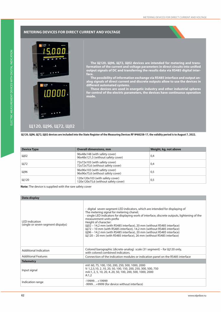
METERING DEVICES FOR DIRECT CURRENT AND VOLTAGE
The Щ120, Щ96, Щ72, Щ02 devices are intended for metering and trans-formation of the current and voltage parameters in direct circuits into unified output signals of DC and transferring the results data via RS485 digital inter-face.
The possibility of information exchange via RS485 interface and output an-alog signals of direct current and discrete outputs allow to use the devices in different automated systems.
These devices are used in energetic industry and other industrial spheres for control of the electric parameters, the devices have continuous operation mode.
Device Type Weight, kg, not aboveOverall dimensions, mm96х48х148 (with safety cover)96х48х121,5 (without safety cover)
72х72х103 (with safety cover)72х72х75,6 (without safety cover)96х96х103 (with safety cover)96х96х75,6 (without safety cover)
120х120х103 (with safety cover)120х120х75,6 (without safety cover)
Щ120, Щ96, Щ72, Щ02 devices are included into the State Register of the Measuring Devices RF №68258-17, the validity period is to August 7, 2022.
Data display
LED indication(single or seven-segment dispalys)
Additional Indication
Additional Features
Telemetry
Input signal
Indication range
- digital seven-segment LED indicators, which are intended for displaying ofThe metering signal for metering chanel;- single LED indicators for displaying work of interface, discrete outputs, lightening of the measurement units prefixHeight of character:Щ02 – 14,2 mm (with RS485 interface), 20 mm (without RS485 interface)Щ72 – 10 mm (with RS485 interface), 14,2 mm (without RS485 interface)Щ96 – 14,2 mm (with RS485 interface), 20 mm (without RS485 interface)Щ120 – 20 mm (with RS485 interface), 26 mm (without RS485 interface)
Colored barographic (dicrete-analog) scale (31 segment) – for Щ120 only, with colored combined indicators.Connection of the indication modules or indication panel on the RS485 interface
mV: 60, 75, 100, 150, 200, 250, 500, 1000, 2000V: 1,2,5,10, 2..10, 20, 50, 100, 150, 200, 250, 300, 500, 750mA:1, 2, 5, 10, 20, 4..20, 50, 100, 200, 500, 1000, 2000A:1,2
-19999…+19999-9999…+9999 (for device without interface)
METERING DEVICES FOR DIRECT CURRENT AND VOLTAGE
ELEC
TRIC
MEA
SURE
MEN
T D
EVIC
ES W
ITH
DIG
ITA
L IN
DIC
ATIO
N
Note: The device is supplied with the rare safety cover
62

Maximum measured value registrtion
Measuring time
Input analog signal transition time,not above
Intrinsic error limit
Galvanic isolation unit of input andoutput circuits, supply circits
Short-time input signal (with multiplicit, maximum valuey) overload
Input resistance for alternative current voltage metering
Communication intefaces/Analog outputs
RS485
Analog outputs
Remote control
Discrete inputs
Powersupply
Voltage
Power consumption from the supply circuit(not above)
Device reprogramming (trim)
Reprogramming
Reprogramming parameters
Operational ConditionsWorking temperature rangeProtection classMountingWire cross-sectionMaximum overload for internal signal(duration)Calibration periodWarranty operating lifetimeAverage lifetime, not lessAverage mean time to failure
YES
0,2 sec.
1,0 sec.
Measuring of current and voltage of DC: ±0,1%, ±0,2%Transforming: of current and voltage of DC: ±0,5%
Yes
Current:Multiplicity: 2, number of overloads:10; time of the each overload, sec:10 ; time intervalbetween two overloads, sec: 10Voltage:Multiplicity: 1,5, number of overloads:9; time of the each overload, sec: 0,5; timeinterval between two overloads, sec: 15
(1+0,012/-0,005) MОm
Quantity: 0,1,2; Protocols: ModbusRTUData transferring speed: 4800, 9600, 19200, 38400, 57600, 115200 bit/s
Quantity: 0,1,2Ranges: 0…5 mA,4..20 mA,.0..20 mA, , 0..2,5..5 mA,4..12..20 mA, 0…10..20 mA.
Quantity: 0,1,2DC voltage 350 V, 200mA, or AC voltage 250 V, 200mA
5VN –(5+4/-0,5) V DC;12VN –(12+6/3) V DC;24VN- (24+12/-6) V DC;220 VU – 85-264 V AC, frequency (50± 3) Hz or 120-370 V DC230 V – 85-264 V AC, frequency (50± 3) Hz
2,5 VA – for Щ02, Щ72 – with supply voltage of 5 VN, 12VN, 24VN3,0 VA – for Щ96, Щ120 – with supply voltage of 5 VN, 12VN, 24VN5(4*) VA – for Щ02, Щ72, Щ96, Щ120 – with supply voltage of 220VU, 230V*for devices without RS485 interface
-via the Configurator software (RS485 interface),-via control buttons on the front panel (if applicable)
- Range scale- Indication parameters setting- Trigger levels of the discrete outputs (set points)- Interface parameters- Scale type selection for displaying of the results- Calibration
-40 - +70°CIP54On the shield2,5 mm2
150% (2 hours)
10 years60 months20 years200 000 hours
ELEC
TRIC
MEA
SURE
MEN
T D
EVIC
ES W
ITH
DIG
ITA
L IN
DIC
ATIO
N
63

METERING DEVICES FOR DIRECT CURRENT AND VOLTAGE
ELEC
TRIC
MEA
SURE
MEN
T D
EVIC
ES W
ITH
DIG
ITA
L IN
DIC
ATIO
N
ORDERING FORM
Щ a - b - c- d - e - f - g - h - i
а – device performance depending on the overall dimensions Щ02 - 96х48 mm, Щ72 - 72х72 mmЩ96 - 96х96 mm, Щ120 - 120х120mm
b – designation of the range scale for direct connection and transformation ratio for connection via the external bypass.mV: 60, 75, 100, 150, 200, 250, 500, 1000, 2000V: 1,2,5,10, 2..10, 20, 50, 100, 150, 200, 250, 300, 500, 750mA:1, 2, 5, 10, 20, 4..20, 50, 100, 200, 500, 1000, 2000A:1,2Note: If the range of indications differs from the range of direct measurement of the input signal, additionally indicate the ordered range of indications in the note to the order formula.
c – supply voltage5ВН –(5+4/-0,5) V DC;12ВН –(12+6/3) V DC;24ВН- (24+12/-6) V DC;220В – 85-264 V AC, frequency (50± 3) Hz or 120-370 V DC230ВУ – 85-264 V AC, frequency (50± 3) Hz
d – RS485 interface1RS – main interface2RS –two interfaces (for Щ96 and Щ120 only) x – if there is no such parameterNote: if there is no such parameter (d=x) devices can have limited functions
e – analog and discrete outputs 02 – two discrete outputs, no analog outputs11 – one analog output and one discrete output12 – one analog output and two discrete outputs20– two analog outputs, no discrete outputs22 – two analog outputs and two discrete outputs x – without discrete and analog outputsAfter the numbers please specify analog output signals A=0..5mA, B=4..20 mA, C=0..20mA, A=0..2,5..5mA, B=4..12..20 mA, C=0..10..20mA in brackets. For two analog outputs in order, please separate them by comma.
f – indicator color К – red color;З – green color;Ж – yellow color;Ц – colored touch screen (only for Щ120)
g – accuracy class0,1 – for all designs (except devices without RS485 interface or/and with operational design)0,2 – for all designs
h – operatonal design A – for NPP (safety class 4)X – in other cases
i – special design -Б- barographic (discrete-analog) scale only for Щ120 with colored combined indicators- do not stated, if there is no such parameter
64

Щa device design Range scale Supply
voltageInterface
Analog and discrete outputs
Designation code parameters
Indication color
Аccuracy class Operational
designSpecial design
Notes:“+”sign shows presence of all possible options in the order formula.“х”sign means, that this parameter is absent in the order formula.“-”sign means, that this parameteis not indicated
ORDERING EXAMPLE
Щ120 device, scale range (– 100..+100V), supply voltage 85-264 V of AC, frequency 50 Hz or 100-370 V DC, two RS485 interfaces, two analog outputs 0..5mA and 0..20 mA, two discrete outputs, red indication color, accuracy class – 0,2; operation at NPP, indica-tion range – fro, -20 to +50OCЩ120-100В-220ВУ-2RS-22 (A,C)-К-0,2-A- TУ 26.51.43-236-05763903-2017Note: indication range – 20…+50 OC
Щ120 device, scale range (– 100..+100V), supply voltage 85-264 V of AC, frequency 50 Hz or 100-370 V DC, two RS485 interfaces, two analog outputs 0..5mA and 0..20 mA, two discrete outputs, colored combined indicator, accuracy class – 0,2; barographic (discrete-analog) indicators scaleЩ120-100В-220ВУ-2RS-22 (A,C)-Ц-0,2-x- TУ 26.51.43-236-05763903-2017
CONNECTION DIAGRAMS Design of device with RS485 interface
For Щ02 with voltage of 5VN, 12VN, 24 VN For Щ02 with voltage of 220VU, 230 V*
to Personal computer
to Personal computer
To metering and control deviceTo metering and control device
Input Input Supply Supply
Input signal supply
Input signal supply Voltage
supplysup
*Usup – supply voltage 85-264 V of AC with frequency of 50 Hz or 100-370 V of DC (220V), supply voltage 85-264 V of AC with frequency of 50 Hz (230V)
R, G, Y
R, G, Y
R, G, Y
R, G, Y
ELEC
TRIC
MEA
SURE
MEN
T D
EVIC
ES W
ITH
DIG
ITA
L IN
DIC
ATIO
N
12VN, 24VN220VU, 130V
12VN, 24VN220VU, 130V
12VN, 24VN220VU, 130V
12VN, 24VN220VU, 130V
IC IC
65

METERING DEVICES FOR DIRECT CURRENT AND VOLTAGE
ELEC
TRIC
MEA
SURE
MEN
T D
EVIC
ES W
ITH
DIG
ITA
L IN
DIC
ATIO
N
to Personal computer
to Personal computer
to Personal computer
to Personal computer
to Personal computer
to Personal computer
to Personal computer
to Personal computer
to Personal computer
to Personal computer
To metering and control device
To metering and control device
To metering and control device
To metering and control device
To metering and control device
To metering and control device
Input Input
Input
Input Input
Input
Supply
Supply
Supply Supply
Supply
Supply
Input signal supply
Input signal supply
Input signal supply
Input signal supply Input
signal supply
Input signal supply
Voltage supply
Voltage supply
Voltage supply
sup
sup
sup
For Щ72 with voltage of 5VN, 12VN, 24 VN
For Щ96 with voltage of 5VN, 12VN, 24 VN
For Щ120 with voltage of 5VN, 12VN, 24 VN
For Щ72 with voltage of 220VU, 230 V*
For Щ96 with voltage of 220VU, 230 V*
For Щ120 with voltage of 220VU, 230 V*
*Usup – supply voltage 85-264 V of AC with frequency of 50 Hz or 100-370 V of DC (220V), supply voltage 85-264 V of AC with frequency of 50 Hz (230V)
IC IC
ICIC
ICIC
ICIC
ICIC
66

Design of device without RS485 interface
OVERALL AND INSTALLATION DIMENSIONS
Input Input SupplySupply
Input signal supply
Input signal supply sup
Voltage supply
*Usup – supply voltage 85-264 V of AC with frequency of 50 Hz or 100-370 V of DC (220V), supply voltage 85-264 V of AC with frequency of 50 Hz (230V)
For device with voltage of 12VN, 24 VN For device with voltage of 220VU, 230 V*
Neck
Device type HхH1, mm L, mm L1, mm A, mm B, mmEL
ECTR
IC M
EASU
REM
ENT
DEV
ICES
WIT
H D
IGIT
AL
IND
ICAT
ION
67

SMALL SIZE METERING DEVICES FOR ALTERNATIVE CURRENT, VOLTAGE AND FREQUENCY
ELEC
TRIC
MEA
SURE
MEN
T D
EVIC
ES W
ITH
DIG
ITA
L IN
DIC
ATIO
N
SMALL SIZE METERING DEVICES FOR ALTERNATIVE CURRENT, VOLTAGE AND FREQUENCY
The small size digital devices Щ00П, Щ01П, Щ02.01П, Щ02.00 are intend-ed for metering and transformation of the current and voltage parameters in direct circuits into unified output signals of DC and transferring the results data via RS485 digital interface (if applicable).
The devices one-channel,one-limit and have designs according to the over-all dimensions, measuring ranges, scale ranges, supply voltage, interfaces, discrete and analog outputs, accuracy class and special design.
Device Type Weight, kg, not aboveOverall dimensions, mm Height of character, mm
Щ00П, Щ01П, Щ02.01П, Щ02.00 devices are included into the State Register of the Measuring Devices RF №64095-16, the validity period is to June 02, 2021
Data display
LED indication(single or seven-segment dispalys)
Additional Features
Telemetry
Input signal
Аccuracy class
Maximum scale range
Measuring time
Input analog signal transition time,not above
Intrinsic error limit
Galvanic isolation unit of input andoutput circuits, supply circits
Short-time input signal (with multi-plicit, maximum valuey) overload
- 4-digit seven-segment LED indicators (for voltage and current parameters display)- single LED indicators for displaying work of interface, discrete outputs status, lightening of the measurement units prefix
Connection of the indication modules or indication panel on the RS485 interface
mV: 60,75, 100, 150, 200, 250, 500, 1000, 2000V:1;2;5;10;2..10; 20;50;100;150;200;250;300 (except Щ00П); 500 (except Щ00П);750 (except Щ00П; Щ01П);mA: 2;5;10;20; 4..20; 50; 100; 200;500; 1000;2000A:1;2
For measuring of current and voltage of DC – 0,1 or 0,2; For transforming–05;
Щ01П, Щ02.01П: -9999 …+9999Щ00П: -1999 …+9999Щ02.00: -1999 …+19990,1 sec.
0,5 sec.
Щ00П, Щ01П, Щ02.01П:For current and voltage measuring :±0,1%;±0,2%;For current and voltage transforming :±0,5%;Щ02.00:For current and voltage measuring :±0,2%;
Yes (Щ00П devices don’t have galvanic isolation unit for RS interface circuit)
Current: Multiplicity: 2, number of overloads:10; time of the each overload, sec: 10; time interval between two overloads, sec: 10
68

Input resistance for voltage AC circuits
Communication intefaces/Analog outputs
RS485
Analog outputs
Remote control
Discrete outputs
Powersupply
Voltage
Power consumption from the supply circuit (not above)
Device reprogramming (trim)Reprogramming
Reprogramming parameters
Operational ConditionsWorking temperature rangeProtection classMountingWire cross-sectionMaximum overload for internal signal(duration)Calibration periodWarranty operating lifetimeAverage lifetime, not lessAverage mean time to failure
(1±0,005) MOm
Quantity: 0 or 1; Protocols: ModbusRTUData transferring speed: 9600, 19200, 38400, 57600 bit/secQuantity: 0,1,2Ranges: 0…5 mA, 4..20 mA, 0..20 mA, 0…2,5…5 mA, 4…12..20 mA, 0..10..20 mA.
Quantity: 0,1,2;Direct voltage 300 V, 100 mA, or alternative voltage 200 V, 100 mA
-5V-(5±0,25) V of DC-12V-(12±0,6) V of DC-24V-(24±1,2) V of DC-5VN-(5±4/-0,5) V of DC-12VN-(12±6/-3) V of DC (there is a safety function to prevent wrong pole connection)-24VN-(24±12/-6) V of DC (there is a safety function to prevent wrong pole connection)-external block of stabilized supply 5 V (for Щ00П).Devices Щ02.01П provide reserve supply for designs with supply voltage (12+6/-3) V and (24+12/-6)V
Щ00П -1,7 VAЩ01П -2,7 VAЩ02.01П -3,2 VAЩ02.00 -2,5 VA
-via the Configurator software (RS485 interface),- Indication parameters: Indication refreshment period; decimal point position; scale type and
parameters selection, display parameters;- Interface parameters: device address, data rate, paritet, stop-bit;- Metering part parameters: metering type, input signal calibration, metering time, unsensitive
zone value- Discrete output parameters;- Analog output parameters;
-40 - +50°C
IP50On the shield2,5 mm2
150% (2 hours)
10 years36 months20 years200 000 hours
ELEC
TRIC
MEA
SURE
MEN
T D
EVIC
ES W
ITH
DIG
ITA
L IN
DIC
ATIO
N
69

ORDERING FORM
Щ
а – device performance depending on the front frame size, mmЩ00П - 48х24,Щ01П - 96х24,Щ02.01П - 96х48,Щ02.00 - 96х48,
b – designation of the range scale for direct connection and transformation ratio for connection via the external bypass.mV: 60, 75, 100, 150, 200, 250, 500, 1000, 2000V: 1,2,5,10, 2..10, 20, 50, 100, 150, 200, 250, 300 (except Щ00П), 500 (except Щ00П), 750(except Щ00П, Щ01П),mA:1, 2, 5, 10, 20, 4..20, 50, 100, 200, 500, 1000, 2000A:1,2Note: If scale range is different to the direct metering range of the input signal, please additionally specify the ordered scale range in the ordering formula.
c – nominal voltage:-5В-(5±0,25) V of DC-12В-(12±0,6) V of DC-24В-(24±1,2) V of DC-5ВН-(5±4/-0,5) V of DC-12ВН-(12±6/-3) V of DC -24ВН-(24+12/-6)V of DCX – with external stabilized voltage block 5 V (for Щ00П)
d – RS485 interface:-1RS – one interface;x – without interface
e - Designation for analog and discrete outputs01 - one discrete outputs, no analog outputs10 – one analog output and no discrete outputs11 – one analog output and one discrete output12 – one analog output and two discrete outputs20 – two analog outputs, no discreteoutputs22 – two analog outputs and two discrete outputs x – without discrete and analog outputsAfter the numbers please specify analog output signals A=0..5mA, B=4..20 mA, C=0..20mA, A=0..2,5..5mA, B=4..12..20 mA, C=0..10..20mA in brackets. For two analog outputs in order, please separate them by comma. f – indicator colorК – red color ;З – green color;Ж – yellow color (except Щ02.00);
g - accuracy class0,1 or 0,2 Note: For Щ02.00 device instrument rating is 0,2
h – special design A – for NPP (safety class 4)The parameter is not stated if there is no special design
Measurementdevice type
Code parameter of the full designation
SMALL SIZE METERING DEVICES FOR ALTERNATIVE CURRENT, VOLTAGE AND FREQUENCY
ELEC
TRIC
MEA
SURE
MEN
T D
EVIC
ES W
ITH
DIG
ITA
L IN
DIC
ATIO
N
x, 5V, 12V, 24V5V, 12V, 24V
5V, 12V, 24V
5VN, 12VN, 24VN
70
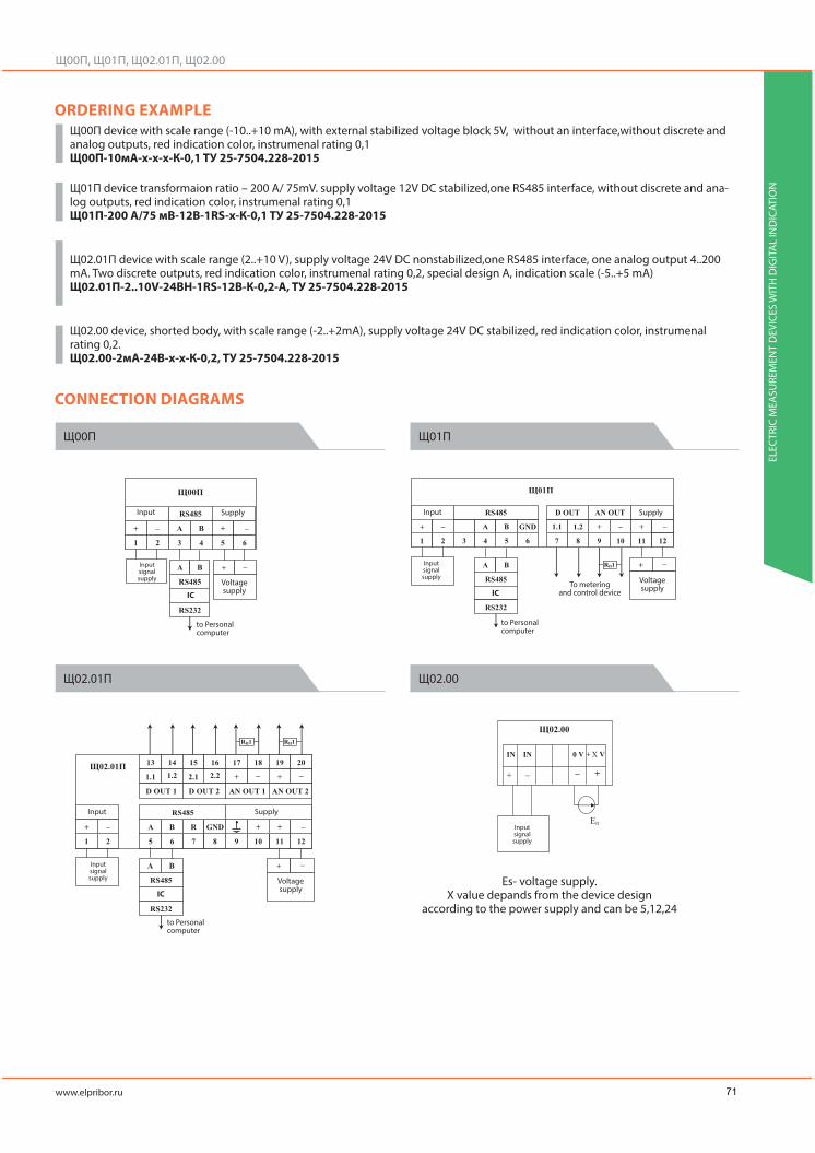
ORDERING EXAMPLEЩ00П device with scale range (-10..+10 mA), with external stabilized voltage block 5V, without an interface,without discrete and analog outputs, red indication color, instrumenal rating 0,1 Щ00П-10мA-x-x-x-К-0,1 TУ 25-7504.228-2015
Щ01П device transformaion ratio – 200 A/ 75mV. supply voltage 12V DC stabilized,one RS485 interface, without discrete and ana-log outputs, red indication color, instrumenal rating 0,1 Щ01П-200 A/75 мВ-12В-1RS-x-К-0,1 TУ 25-7504.228-2015
Щ02.01П device with scale range (2..+10 V), supply voltage 24V DC nonstabilized,one RS485 interface, one analog output 4..200 mA. Two discrete outputs, red indication color, instrumenal rating 0,2, special design A, indication scale (-5..+5 mA) Щ02.01П-2..10V-24ВH-1RS-12В-К-0,2-A, TУ 25-7504.228-2015
Щ02.00 device, shorted body, with scale range (-2..+2mA), supply voltage 24V DC stabilized, red indication color, instrumenal rating 0,2.Щ02.00-2мA-24В-x-x-К-0,2, TУ 25-7504.228-2015
CONNECTION DIAGRAMS
to Personal computer
to Personal computer
to Personal computer
To metering and control device
Input
Input
Input Supply
Supply
Supply
Input signal supply
Input signal supply
Input signal supply
Input signal supply
Voltage supply
Voltage supply
Voltage supply
Es- voltage supply. X value depands from the device design
according to the power supply and can be 5,12,24
ELEC
TRIC
MEA
SURE
MEN
T D
EVIC
ES W
ITH
DIG
ITA
L IN
DIC
ATIO
N
IC IC
IC
71

SMALL SIZE METERING DEVICES FOR ALTERNATIVE CURRENT, VOLTAGE AND FREQUENCY
ELEC
TRIC
MEA
SURE
MEN
T D
EVIC
ES W
ITH
DIG
ITA
L IN
DIC
ATIO
N
OVERALL AND INSTALLATION DIMENSIONS
Neck
Neck
72

Neck
NeckEL
ECTR
IC M
EASU
REM
ENT
DEV
ICES
WIT
H D
IGIT
AL
IND
ICAT
ION
73

POSITION INDICATORS ECP OF POWER TRANSFORMERS
ELEC
TRIC
MEA
SURE
MEN
T D
EVIC
ES W
ITH
DIG
ITA
L IN
DIC
ATIO
N
POSITION INDICATORS ECP OF POWER TRANSFORMERS
The ЩУП96, ЩУП120 indicators are intended for transformation of sensors signals of the transforming switching devices under the load into the digital signal for displaying the position number at the digital indicator.
Indicators are mounted at the control shield and are used for installation on the MZ-2, MZ-4 drivers (Bulgaria) and at the other drivers with resistive sensor.
These devices can be used as a resistor gauge. 4-wire connection.
Device Type Weight, kg, not aboveOverall dimensions, mm96х96х100 (with safety cover)120х120х102,1 (with safety cover)
Height of character, mm
Data display
LED indication(single or seven-segment dispalys)
Signal transforming parametersNumber of stepsStep resistanceMaximum measured resistanceMaximum relay current
Maximum allowable voltage at the relay outputterminals
Intrinsic error limit
Communication intefaces/Analog outputs
RS485
Powersupply
Voltage
Power consumption from the supply circuit (not above)Device reprogramming (trim)
Reprogramming
Reprogramming parameters
Operational Conditions
Working temperature range
Protection class
MountingWire cross-sectionWarranty operating lifetimeAverage lifetime, not lessAverage mean time to failure
- 4-digit seven-segment digital indicator (for display of the determined signal value)- additional single indicators P, K1, K2, showing the indicators operation mode.
2-99
5-20 Om (1 Om step)1000 Om (999,9)
100 mA
300 V (as for amplitude)
±0,5%
Quantity: 0,1; Protocols: ModbusRTUData transferring speed: 4800, 9600, 19200, 38400, 57600 bit/s
85-242 V AC, frequency (50±0,5) Hz or 100 -265 V DC
7 VA
-via tuning panel, connected through connector pin-via RS485 interface,
- Trigger levels of the discrete outputs (set points) with indication at the discrete-an-alog indicator
- Indicators brightening- Calibration values- Interface parameters
+5 - +50°C (O4.1 ambient class)-40- +55°C (УХЛ3.1 ambient class)
IP2XOn the shieldNot above 1,5 mm2
2 years
10 years10 000 hours
Note: Indicators are supplied with a safety cover.
74

ORDERING FORM
а – device performance depending on the overall dimensionsЩУП96 - 96х96 mm,ЩУП120 - 120х120 mm,
b – step resistance value5-20 (if it is not specified in the order, the default value is 6 Om)
c – interface:-RS – RS485 interface (Modbus RTU);x – without interface, do not complete
d – indicator colorК – red color ;З – green color;Ж – yellow color
e – ambient class +5 - +50°C (O4.1 ambient class) -40- +55°C (УХЛ3.1 ambient class)
ORDERING EXAMPLE
ЩУП120 device, step resistance 6 Om, RS485 interface, red indicator color, temperature range 40- +55°C.ЩУП120-6-RS-К-УХЛЗ 3.1 TУ 25-7504.205-2008
CONNECTION DIAGRAMS
Input Output 1 Output 2
Discrete outputs
To PC
sup
indicators
OVERALL AND INSTALLATION DIMENSIONS
Neck
ELEC
TRIC
MEA
SURE
MEN
T D
EVIC
ES W
ITH
DIG
ITA
L IN
DIC
ATIO
N
IC
75

POSITION INDICATORS ECP OF POWER TRANSFORMERS
ELEC
TRIC
MEA
SURE
MEN
T D
EVIC
ES W
ITH
DIG
ITA
L IN
DIC
ATIO
N
Neck
76

POSITION INDICATORS ECP OF POWER TRANSFORMERS
The ЩУП120У indicator is a modification of ЩУП120 indicator. It can be mounted at the control shield and it is compatible with UP30 indicating cross-coil instrument.
This indicator is used for installation on the MZ-2, MZ-4 drivers (Bulgaria) instead of LKM step pointer and at the drivers MR, EM, ED-S type (Germany) and also at the other drivers with resistive sensor, with output signal of cur-rent loop type. The indicator works together with rotating selsyn BD404 type or BD1404 type and can be installed at the all drivers (RNT13, PDP-1, PDP-4 and others)
It is possible to determine maximum allowable drivers position. Digital and analog outputs allow to transfer driver step information into
automated control and mechanics systems.
Device Type Weight, kg, not aboveOverall dimensions, mm
120х120х102,1 (with safety cover)
Height of character, mm
Data display
LED indication(single or seven-segment dispalys)
Indicator brightnessSignal transforming parametersMaximum number of steps
Minimal impedance of the resistor gaugeSelsyn gauge voltage
Resistor gauge voltage
Input resistance of the indicator for work with currentloop type sensor, not aboveMaximum allowable voltage of DC at the control relayterminals, relay output
Maximum allowable current at the control block relayCommunication intefaces/Analog outputs
RS485
Analog output
Remote controlRelay outputsPower supplyVoltagePower consumption from the supply circuit (not above)Device reprogramming (trim)
Reprogramming
Reprogramming parameters
- 2-digit digital indicator (for display of the determined signal value)- additional single indicators
1000 mkd
9925 Om
24..27 V5 V
820 Om
400 V
120 mA
Quantity: 1; Protocols: Modbus RTUInterface data rate:9600 baud – by default;4800, 19200, 38400 baud – can be reprogrammed by the user.
4..20 mA – by default;0..20 mA; 0..5 mA– can be reprogrammed by the user.
300 V, 100 mA
220 V, 50 Hz15 VA
-via RS485 interface,-via control buttons on the front panel
- Step value- One step adjustment- Initial ange of the selsyn-sensor setting- Connection wires compensation (from sensor to the indicator)- Changing of device internal registers values- Password setting
Note: Indicators are supplied with a safety cover.
ELEC
TRIC
MEA
SURE
MEN
T D
EVIC
ES W
ITH
DIG
ITA
L IN
DIC
ATIO
N
77

Operational ConditionsWorking temperature rangeProtection classMountingWire cross-sectionWarranty operating lifetime
Average lifetime, not lessAverage mean time to failure
-40- +55°CIP20On the shieldNot above 2,5 mm2
2 years10 years10 000 hours
POSITION INDICATORS ECP OF POWER TRANSFORMERS
ELEC
TRIC
MEA
SURE
MEN
T D
EVIC
ES W
ITH
DIG
ITA
L IN
DIC
ATIO
N
ORDERING FORM
ЩУП120U a - b - c - d
а – designation for the output parametersx – this parameter is absentTP(X), Bl, RV – sensor:TP (X) – current loop output signal sensor, whereX- output analog signalA=0..5 mA, B=4..20 mA , C=0..20 mA;Bl – blocking relay;RB – relay output;
b – indicator colorК – red color ;З – green color;
c – number of drivers positions:from 1 to 99, selected by the client.
d – the angle between step or step resistance value:X°C – step value for drivers with the selsyn-sensor;YR- step value (Om) for drivers with resistor sensors.
Note! If you need a BCD-code output, please specify in the order additionally, by the comma “BCD-output”
ORDERING EXAMPLEFor ЩУП120U indicator with the following characterictics: current loop outpuit signal, 0..20 mA. Blocking output, relay output, number of drivers positions – 10, step resistance – 5 Om, red indicator color, BCD-output.ЩУП120У-ТП(С), Бл,РВ-К-10-5R, ВСD-выход, TУ 25.7504.214-201
78

CONNECTION DIAGRAMS
OVERALL AND INSTALLATION DIMENSIONS
Not used
Tx transfer
Rx receive
Not used
General RS232
Not used
General RS485
Not used
Power supply +24V
Power supply ТП
Output ТП
General ТП
General Control
Switching “Turn down”
Switching “Turn up”
Last step
First step
Blocking “Increase”
Blocking “Decrease”
General Control
To the contact Р1/-ТП
To the contact Р2/+ТП
To the contact Р3
To the contact С1
To the contact Р1
To the contact Р2
To the contact Р3
To the contact С2
Power supply ~220V
Power supply ~220V
Not used
To the contact Р1/-ТП
To the contact Р2/+ТП
To the contact Р3
To the contact С1
To the contact Р1
To the contact Р2
To the contact Р3
To the contact С2
Neck
ELEC
TRIC
MEA
SURE
MEN
T D
EVIC
ES W
ITH
DIG
ITA
L IN
DIC
ATIO
N
~220
V
79

METERING INDICATOR PANEL
ELEC
TRIC
MEA
SURE
MEN
T D
EVIC
ES W
ITH
DIG
ITA
L IN
DIC
ATIO
N
METERING INDICATOR PANEL
Digital information panels T44, T54, T74 are intended for metering and displaying all electric and physics parameters (alternative and direct current, voltage, pressure, temperature, frequency, etc.) and digital values of RS485 interface, Modbus RTU protocol.
Advantages:• Maximum scale range – 1999…+9999• Change mode settings by remote control or by RS485 interface• Brightness adjustment (12 steps)• Prorgamming of input signal parameters, change of display scale• Min and max set points setting• Forming of discrete signal for control of commutation equipment• If the limit value is achieved, Indicator flashes• Indicator color selection: red, green, yellow
Type
Data display
LED indication
Parameters display
General parameters
Input signal
Maximum scale rangeTransforming timeIntrinsic error limit
Galvanic isolation unit of input andoutput circuits, supply circitsCommunication intefaces
RS485
Remote control
Discrete outputs
Power supply
Voltage
Power consumption from the supply circuit (not above)Panel reprogramming (trim)
Reprogramming
Reprogramming parameters
Height of character, mm
-metering of input signals values (any electric or physical);- data from RS485 interface- value of temperature (by the order)
Direct current and voltage:mV:60, 75, 100, -75..0..75V: 5, 10, 20, 50, 100, 200, 250, 500mA: 2;5;10;20; 4..20;-5..0..5Alternative current and voltage:mV:100V: 5, 10, 20, 50, 100, 200, 250, 380, 500mA: 2;5;10;20; 50, 100, 20085..253 V for 10-5000 Hz frequency displaying
-1999 …+9999
0,5 sec±0,5%
Yes
Quantity: 1; Protocol: Modbus RTUData rate: 9600, 19200, 38400, 57600 baud
Quantity:1;Direct voltage 300 V, 100 mA, or alternative voltage 200 V, 100 mA
85-253 V AC (50±0,5) frequency, 120 – 265 V DC
- via remote control board- via RS485 interface
- Output signal parameters- displaying scale changing- Indicators brightness changing
15 VA 17 VA 20VA
80
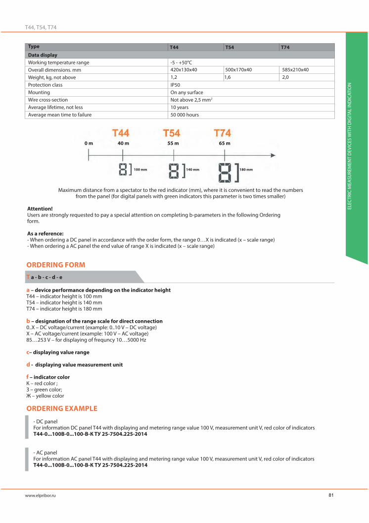
Type
Data displayWorking temperature rangeOverall dimensions. mmWeight, kg, not aboveProtection classMountingWire cross-sectionAverage lifetime, not lessAverage mean time to failure
-5 - +50°C
IP50On any surfaceNot above 2,5 mm2
10 years50 000 hours
420х130х40 500х170х40 585х210х401,2 1,6 2,0
ORDERING FORM
T a - b - c - d - e
а – device performance depending on the indicator heightT44 – indicator height is 100 mmT54 – indicator height is 140 mmT74 – indicator height is 180 mm
b – designation of the range scale for direct connection 0..X – DC voltage/current (example: 0..10 V – DC voltage)X – AC voltage/current (example: 100 V – AC voltage)85…253 V – for displaying of frequncy 10…5000 Hz
c– displaying value range
d - displaying value measurement unit
f – indicator color К – red color ;З – green color;Ж – yellow color
ORDERING EXAMPLE
- DC panelFor information DC panel T44 with displaying and metering range value 100 V, measurement unit V, red color of indicatorsТ44-0...100В-0...100-В-К TУ 25-7504.225-2014
- AC panelFor information AC panel T44 with displaying and metering range value 100 V, measurement unit V, red color of indicatorsТ44-0...100В-0...100-В-К ТУ 25-7504.225-2014
Maximum distance from a spectator to the red indicator (mm), where it is convenient to read the numbers from the panel (for digital panels with green indicators this parameter is two times smaller)
Attention!Users are strongly requested to pay a special attention on completing b-parameters in the following Orderingform.
As a reference:- When ordering a DC panel in accordance with the order form, the range 0…X is indicated (x – scale range)- When ordering a AC panel the end value of range X is indicated (x – scale range)
ELEC
TRIC
MEA
SURE
MEN
T D
EVIC
ES W
ITH
DIG
ITA
L IN
DIC
ATIO
N
0 m 40 m
100 mm 140 mm 180 mm
55 m 65 m
81

METERING INDICATOR PANEL
ELEC
TRIC
MEA
SURE
MEN
T D
EVIC
ES W
ITH
DIG
ITA
L IN
DIC
ATIO
N
For information panel T54 with metering range value 85…253 V and displaying range value 45..65 Hz , measurement unit Hz, green color of indicatorsТ54-85...253В-45...65 - Гц - З TУ 25-7504.225-2014
OVERALL AND INSTALLATION DIMENSIONS
Panel design L, mm H, mm B, mm
2 openinngs
82

METERING INDICATOR PANEL-CLOCKS
Electronic panel-clocks ТЧ44, ТЧ54, ТЧ74 are intended for displaying the current time, date and temperature. These panels have a huge potential for using at different companies and organizations. Besides, functionality of the electronic panel allows to control microclimate (temperature) of the offices, that is why this panel can be used at education facilities.
Line-up of the electric panel-clocks includes the following models: ТЧ44, ТЧ54, ТЧ74 (indicators height – 100 mm, 140 mm, 180 m allows to read all information from 40 m, 55 m and 65 m).
All digital panels are produced according to the modern requirements – thin metal body, thickness- 40 m. The designed construction allows to pro-duce the devices of different overall dimension in short terms. According to the client requirements.
Ultra bright LEDs and sensors are used for electronic panels-clocks, that is why the clocks are reliable and stable. The bright indicators allow to read the actual information even on sunny days. Observation angle is 120o.
It is possible to program the clocks by remote control (RC-5) and RS485 in-terface.
Type
Data display
LED indication
Parameters display
Range scale
Intrinsic error limit
Communication interface
RS485
Remote control
Discrete outputs
Power supply
Voltage
Power consumption from the supply circuit (not above)Panel reprogramming (trim)
Reprogramming
Reprogramming parameters
Operational Conditions
Working temperature rangeOverall dimensions. mmWeight, kg, not aboveProtection classMountingWire cross-sectionAverage lifetime, not lessAverage mean time to failure
Height of character, mm
- date and time- temperatureTemperature: -50..+50°CTime: 0 – 23.590,1 sec/dat (accuracy movement)±2°C for -50…-20 °C scale range±2°C for -20…+50 °C scale range
Quantity: 1; Protocol:ModbusRTUData rate: 9600, 19200, 38400, 57600 baud
Quantity:1;Direct voltage 300 V, 100 mA, or alternative voltage 200 V, 100 mA
85-253 V AC (50±0,5) frequency, 120 – 265 V DC
-via remote control board-via RS485 interface- Indicators brightness changing- Indicators flashing adjustment-interval and time value of the sound signal;- date and time adjustment
-5 - +50°C
IP50On any surfaceNot above 2,5 mm2
10 years50 000 hours
15 VA 17 VA 20VA
ELEC
TRIC
MEA
SURE
MEN
T D
EVIC
ES W
ITH
DIG
ITA
L IN
DIC
ATIO
N
83

Maximum distance from a spectator to the red indicator (mm), where it is convenient to read the numbers from the panel (for digital panels with green indicators this parameter is two times smaller)
ORDERING FORM
а – device performance depending on the indicator heightТЧ44 – indicator height is 100 mmТЧ54 – indicator height is 140 mmТЧ74 – indicator height is 180 mm
b – indicator color К – red color ;З – green color;Ж – yellow color
ORDERING EXAMPLEPanel-clocks with red indicationТЧ44-К TУ 25-7504.225-2014
METERING INDICATOR PANEL-CLOCKS
ELEC
TRIC
MEA
SURE
MEN
T D
EVIC
ES W
ITH
DIG
ITA
L IN
DIC
ATIO
N
OVERALL AND INSTALLATION DIMENSIONS
Panel design L, mm H, mm B, mm
2 openinngs
0 m 40 m
100 mm 140 mm 180 mm
55 m 65 m
84

METAL-ENCLOSED DIGITAL ELECTRIC METERING DEVICES Щ20, Щ21. Щ22, Щ23 FOR NPP
Panel-mounted digital electric metering devices Щ20, Щ21, Щ22. Щ23 are intended for metering of current or voltage values in DC circuits (for operation at NPP and other industrial spheres).
If electric output signal ranges of the primary transducers satisfy the in-put signal range of the device, the devices can be used together with primary transducers for metering of the nonelectric values.
Input signal metering ranges: 0..5 mA, 0..20 mA, 4..20 mA, 0..75 mV, 0..200mV, 0..1 V, 0..10 V, 2..10 V.
The devices meet the requirements of electromagnetic capability in accor-dance with GOST R 50746-2000 for 4 class of NPP(technical equipment for NPP and radiation-hazardous facilities). Communication interface - RS485 (Protocols: Modbus RTU, ASCII).
Industrial noise level does not exceed the values determined by the GOST 30805.22-2013 for B class equipment. As for solid bodies’ effect resistance, the devices have IP20 code as per GOST 14254-2015.
Average mean time to failure – not less than 150000 hours.Average lifetime – not less than 15 years.All devices are metal-enclosed, they are fireproof, don’t have any moving
parts, they are stable to the mechanical effects in accordance with M40 group, seismic resistance is 9 points for the installation level under 0 point – 10 m, 8 points for the installation level under 0 point – 25 m, as for GOST 17516.1-90, the devices fall into the first category of seismic resistance, according to the NP 031-01.
The mounting construction is designed for mounting on the 50mm panel. According to the client requirements it is possible to install the device at the panel of another thickness.
The devices are intended for NPP, they can be used in the safety systems and normal operation systems, the devices fit into a 2,3,4 safety class (de-pending on the order) and have the classified designation 2NU, 3NU in accor-dance with NP-001-2015.
Operation conditions:- Ambient temperature -10 ..+50°C;- Relative humidity – not above 98%, 35°C;- Atmospheric pressure – 84..106,7 kPa;- Supply voltage – (24±4)V DCIt is possible to choose output signal metering range, change the scale
range and measurement units.As for devices Щ21.3, Щ22.4, Щ22.6, Щ23.3, Щ23.4, Щ23.6 there is a pos-
sibility to program indicator color changing limits of discrete-analog device.As for devices Щ20.3, Щ21.7, Щ23.7, Щ23.8.6 there is a possibility to de-
termine color signalization zones of the discrete-analog device, which are formed by the number of single color indicators by the order.
Щ20, Щ21, Щ22, Щ23 devices are put on the State Register of the Measuring Devices RF №61450-15, the validity period is to September 1, 2020.
ELEC
TRIC
MEA
SURE
MEN
T D
EVIC
ES W
ITH
DIG
ITA
L IN
DIC
ATIO
N
85

METAL-ENCLOSED DIGITAL ELECTRIC METERING DEVICES Щ20, Щ21. Щ22, Щ23 FOR NPP
ELEC
TRIC
MEA
SURE
MEN
T D
EVIC
ES W
ITH
DIG
ITA
L IN
DIC
ATIO
N
Metering value
DC Voltage
DC Current
Design 1 (one pole)
0-75 mV0-200 mV
0-1 V0-10 V2-10 V0-5 mA
0-20 mA4-20 mA
-1999…9999-1999…9999
-19999…19999-9999..9999
-1999…9999-19999…19999
-9999..9999
-1999…9999-9999..9999
-1999…9999-9999..9999-9999..9999
4 and “-” sign
4 and “-” sign
4 and “-” sign
4 and “-” sign4 and “-” sign
30, pellet31, pellet (trick)45, trick (pellet)61, pellet (trick)91, trick (pellet)
25, pellet (trick)25, pellet (trick)61, pellet (trick)61, pellet (trick)91, trick (pellet)
lineLineLine
curvecurve
LineLine
curvecurvecurve
Design 2 (two poles)
-75..0..75 mV-200..0..200 mV
-1..0..1 V-10..0..10 V-6..2..10 V-5..0..5 mA
-20..0..20 mA-12…4…20 mA
Group of output signals ranges (for Щ20)
Device type
Devices with digital indicating device
Devices with discrete-analog indicating device
Devices with discrete-analog and digital indicating devices
* The scale range can be changed by the Client via remote control panel.** Factory setting is stated without brackets.
Maximum range ofdigital indicating
device indications*
Number ofindicators for thedigital indicating
device
Number of thesingle indicators of
the digital indicating device, type of the indicator**
Discrete-analogindicating device
type
Output signal range
86

Device type
Devices with digital indicating device
Devices with discrete-analog indicating device
Devices with discrete-analog and digital indicating devices
Output signalmetering range
Programming parameters
Digital indicatingdevice range
scale
Indicatorsbrightness
Limits of indicatorscolor changing for
discrete-analogindicating device
Type of the pointer forthe discrete-analog
indicating device
Note: sign + means, that this parameter is programmablesign - means, that this parameter is not programmable
ORDERING FORM
а – device type (according to the front frame overall dimensions, mm)Щ20 -50х25Щ21 -100х25Щ22 -100х50Щ23 -100х100
b –design according to the type of the indicating device, scale range, of the digital indicating device and number of the single indicators of the discrete-analog indicating device:1 – digital indicating device, range scale -1999…9999;2 – digital indicating device, range scale ±19999;3 – discrete-analog indicating device, number of single indicators – to 61;4 – digital indicating device, range scale -1999…9999 and dis-crete-analog indicating device, number of single indicators – to 61;5 – digital indicating device, range scale ±9999;6 – digital indicating device, range scale ±9999 and discrete-ana-log indicating device, number of single indicators – to 61;7 - discrete-analog indicating device, number of single indicators – more than 61;8 - digital indicating device, range scale ±9999 anf discrete-ana-log indicating device, number of single indicators – more than 61;
c – construction designГ- horizontalВ - vertical
d – output signal range
e – scale range
f – measurement unit of the physical value;
g – color of the front panelБ – whiteС – greyЧ – black
h – color of the front frameБ – whiteС – greyЧ – black
i – color of the indicator of the digital indicating deviceК – red ;З – green;Ж – yellow;
j – discrete-analog indicating device parameters- color changing limits and indication color (К - red, Ж - yellow, З - green) for Щ21.3, Щ22.4,Щ22.6, Щ23.3, Щ23.4, Щ23.6 (from the start of the scale range), - number and color(К - red, Ж - yellow, З - green) for single indicators of each signaliza-tion zone for Щ20.3, Щ21.7,Щ23.7, Щ23.8 (from the start of the scale range).
The unused parameter j shаll be replaced by x sign in the ordering formula. Do not specify the unused parameters c and j.
Should be stated addiionally:1) Safety class,class designation as for NP-001-2015 (2NU, 3NU or 4)2) Installation panel thickness, if it is differ from 50 mm;3) language, if you need Marks, Operation Manual and Calibration Methods in English, the default language is Russian.4) Number or copies for Operation Manual and Calibration Methods
ELEC
TRIC
MEA
SURE
MEN
T D
EVIC
ES W
ITH
DIG
ITA
L IN
DIC
ATIO
N
87

METAL-ENCLOSED DIGITAL ELECTRIC METERING DEVICES Щ20, Щ21. Щ22, Щ23 FOR NPP
ELEC
TRIC
MEA
SURE
MEN
T D
EVIC
ES W
ITH
DIG
ITA
L IN
DIC
ATIO
N
Щааdevicetype
Code of Designation parameter
H(V)
H(V)
H(V)
H(V)
H(V)
Note: sign + means, that this parameter is in the ordering formulasign - means, that this parameter is not in the ordering formula
ORDERING EXAMPLEЩ22.2, front frame size is 100х50 mm, digital indicating device, the maximum scale range of 19999, output signal range is 0..5 mA, indication range -20…+50, measurement unit oC, front panel color – white, front frame color - black, indication color – green, safety class – 2 N.Щ22.2-0...5мА-минус 20.00...плюс 50.00-оС-Б-Ч-З, ТУ 25-7504.210-2010, класс безопасности - 2Н
Щ22.4, front frame size is 100х50 mm, digital and discrete-analog indicating device, construction design – horizontal, output signal range is 0..5 mA, indication range -20…+50, measurement unit oC, front panel color – white front frame color - black, indication color – red, limit of color change – minus 20 – red, minus 10 – yellow, 0 – green, plus 30 – yellow, plus 40 - red, safety class – 4.Щ22.4.H-0..5 mA - минус 20.00..плюс 50.00 - оС-Б-Ч-З-минус 20(К), минус 10 (Ж), 0 (З), плюс 30 (Ж), плюс 40 (К) , TУ 25-7504.210-2010, класс безопасности - 4
CONNECTION DIAGRAMS
Device
Tuning panel ПН-2
Input signal source
Power block
Device
General connection diagram for output signal metering Connection diagram for calibration and
programming (except Щ20.3 device)*
*K- calibrator, БП – power block, PV1- combined digital device
88

OVERALL AND INSTALLATION DIMENSIONS
For more detailed information about overall and installation dimensions see Operation Manual at www.elpribor.ry
ELEC
TRIC
MEA
SURE
MEN
T D
EVIC
ES W
ITH
DIG
ITA
L IN
DIC
ATIO
N
89

POWER UNITS FOR DIGITAL DEVICES
POWER UNITS FOR DIGITAL DEVICES
БПИ-5 power units are intended for power supply of the digital devices with power voltage +5 V.Overall dimensions – 96х48х90 mm.Weight – 0,3 kg.
Are intended for panel digital device agjustment for changing the parameters for RS485 interface.
Adjustment tool set 1:- Interface convector (USB into RS485 ЭЛПИ-1);- Software- Operation Manual
Adjustment tool set 2:- Laptop- Interface convector (USB into RS485 ЭЛПИ-1);- Software- Operation Manual
POWER UNITS FOR DIGITAL DEVICES / ADJUSTMENT TOOLS SETS
ELEC
TRIC
MEA
SURE
MEN
T D
EVIC
ES W
ITH
DIG
ITA
L IN
DIC
ATIO
N
Power unit type
БПИ5-1, 1 AБПИ5-1, 3 A
Power voltage, V
220 VU – 85-253 V AC, 50 Hz frequency, 100 -265 V DC
Output voltage, V Load current Output power, VA
БПИ5-1 power unit for group power supply for devices with galvanic power separation.Warranty life – 2 years.Average lifetime, not less – 10 years. Mean time between errors – 10000 hours
ORDERING EXAMPLEFor impulse one-chanel power unit, load current 3 A, Uout=5 VБПИ5-1, 3 A TУ 25-7504.166-2003
90

INSTRUMENT CONVERTERSAND TELEMETRY CONTROL DEVICES

MULTIFUNCTUONAL INSTRUMENT CONVERTERS
INSTRUMENT CONVERTERS
E900ЭЛ, E894ЭЛ converters are intended for metering and converting of electric parameters in three-phase three-wire AC circuits and three-phase four-wire AC circuits into output signals of DC and digital signal sequence for transferring data via RS485 interface (Modbus RTU, IEC 60870-5-101) and Eth-ernet interface (TCP, IEC 60870-5-104 protocols).
The converters can be used for:
- Three-phase circuits parameters control (E900ЭЛ) and metering of actual/reactive or actual and reactive power (E849ЭЛ);
- Electric energy quality control (E900ЭЛ).
E900ЭЛ, E894ЭЛ converters have a certificate of type approval of the Rus-sian Maritime Registry of Shipping (Ambient class OM2).
E900ЭЛ, E894ЭЛ converters are included into the State Register of the Measuring Devices RF №66759-17, the validity period is to February 27, 2022
INST
RUM
ENT
CON
VERT
ERS
AN
D T
ELEM
ETRY
CO
NTR
OL
DEV
ICES
MULTIFUNCTUONAL INSTRUMENT CONVERTERS
Converter Type Overall dimensions, mm Weight, kg, not above
Three-phase circuit parameters
Actual phase voltage
Average actual phase voltage
Actual phase-to-phase voltage
Average actual phase-to-phase voltage
Actual zero-sequence voltage
Actual phase current
Average actual phase current
Actual zero-sequence current
Actual power of the load phase
Sum actual power
Reactive power of the load phase
Sum reactive power
Total power of the load phase
Sum total power
Power ratio in the each phase
Total power ratioCircuit frequency
Designation
92

Electric quality parameters
Frequency deviation, HZ (-5..5Hz)Voltage fail duration, c (0,02..60 sec)Voltage fail depth, % (10..95%)
Voltage interruption duration, sec (0,02..60 sec)Duration of temporary overload, sec (0,02..60 sec)
Data display
LED indication(single indicators)
LCD (by the order)
Additional Features
Telemetry
Input signals
Measuring time
Intrinsic error limit
Galvanic isolation unit of input andoutput circuits, supply circits
Short-time input signal (with multiplicit, maximum valuey) overload
Input resistance
Communication intefaces/Analog outputs
RS485
Ethernet
Analog outputs
Output analog signal setting time, not above
Remote signal system
Discrete inputs
Remote controlDiscrete inputs
Power supply
Voltage
Power consumption from the supply circuit(not above)
Device reprogramming (trim)
Reprogramming
-Power supply voltage;- RS485 interface operation;-discrete output status;-analog output status;- event indicator;-phase sequence error
Color, LCD size: 46,7х35,4 mm (2,2”)Connection of the indication modules (МИ120, МИ80) or indication panel on the RS485 interface or Ethernet (for МИ120.5). For communication with telemetry control point the ЭЛКТ telemetry controller can be connected via RS485 Interface for data transferring to the upper level via IEC 61850-8-1 protocol (Ethernet interface)
A: 1,0; 5,0 range from 0 to 2,0 InomB: 100, 380, 400 (range – 0-1,2 Unom)Hz: 45..550,1 sec.
- For current and voltage:±0,2%;- For power::±0,5%;- For frequency: ±0,01 Hz;- For analog output::±0,5%;
Yes
Multiplicity: 20, number of overloads:2; time of the each overload, sec: 0,5; time interval between two overloads, sec: 0,5.
For current circuits – not less 0,02 OmFor voltage current circuits – not less 1 MOm
Quantity: 1,2; Protocols: Modbus RTU, IEC 60870-5-101Data transferring speed: 4800, 9600, 19200, 38400, 57600 baud
Quantity:0,1, 2; 100BASETX Protocols: Modbus RTU, IEC 60870-5-104,Quantity:0,1,2,3Reprogramming ranges: 0…5 mA,4..20 mA,.0..20 mA,.0…2,5…5 mA,.4…12..20 mA,.0..10..20 mA,
0,5 sec
Quantity: 8; input signal type “clean contact”, volatage at the opened device terminals=24 V,current 10mA (do not required external dampening)
Quantity:0,1,2,3 (modes: on, off, block etc)~250 V,=30V, current 5 A
-24 VN –(24+12/-6) V DC220 VU –90-264 V of AC with frequency of 50 Hz or for 130-270 V of DC;Measuring circuit
7 VA
- via the Configurator software (RS485 interface, Ethernet),- via Web-Interface, via control buttons on the front panel- via the control buttons on the front panel (if applicable)
Notes:Signs “+” and “-” show if this parameter is measured or not for this type of the converter or connection scheme.Average actual value of the phase current (phase and phase-to-phase voltage) is arithmetic average sum of the actual phase current values(phase and phase-to-phase voltage).
INST
RUM
ENT
CON
VERT
ERS
AN
D T
ELEM
ETRY
CO
NTR
OL
DEV
ICES
93

Reprogramming parameters
Operational ConditionsWorking temperature rangeProtection classMountingWire cross-sectionMaximum overload for internal signal(duration)Calibration periodWarranty operating lifetimeAverage lifetime, not lessAverage mean time to failure
- Connection scheme (three or four wires)- Scale range (devices with rated current of 1A, 5A and voltage of 100 V)- Password assignment- Indication refreshment period: 0,1 – 10 sec- Decimal point position- Set point for every electric value (for discrete outputs – to three control signals forcommutation equipment)- RS485, Ethernet interfaces parameters- Output signals parameters- Indication brightness- Modbus RTU, Modbus TCP, IEC 60870-5-104, IEC 60870-5-101- Output and input signals calibration
-40 - +70 °C
IP20DIN-bar, 35 mm2,5 mm2
150% (2 hours)
11 years (with LCD – 8 years)24 months20 years (with LCD – 15 years)250 000 hours (with LCD – 150 000 hours )
MULTIFUNCTUONAL INSTRUMENT CONVERTERS
INST
RUM
ENT
CON
VERT
ERS
AN
D T
ELEM
ETRY
CO
NTR
OL
DEV
ICES
ORDERING FORM
а – converter type according to the functionality849ЭЛ – measuring power converter;900ЭЛ – multifunctional instrument converter;
b – nominal voltage:- 100 V, 380V, 400 V -linear voltage-- U/100 - transformer voltage ratio (rated voltage of the secondary winding 100 v);
c – nominal current:-1 A, 5 A - phase current- I/1, I/5 - transformer current ratio (nominal current of the second-ary winding – 1 A and 5 A);
d – supply voltage designation:24ВН –DC current supply, voltage (24+12/-6) V220ВУ–universal supply: supply voltage 90-264 V of AC, frequen-cy 50 Hz, or 130-270 V of DC;From measuring circuit - 90-264 V
e- Designation for RS485 interfaces1RS – one main RS485 interface;2RS – one main and one additional RS485 interfaces;
f – Designation for Ethernet interfacesx – device without Ethernet inteface 1RЕ - device with one Ethernet inteface2RЕ - device with two Ethernet inteface
g – Designation for 8 discrete outputs:x – device without discrete outputs;DI – 8 discrete outputs
h - Designation for analog and discrete outputsx – no discrete outputs, no analog outputs01 - one discrete output, no analog outputs02 - two discrete outputs, no analog outputs03 - three discrete outputs, no analog outputs10(a) – one analog output and no discrete outputs11(a)– one analog output and one discrete output12 (a)– one analog output and two discrete outputs13 (a)– one analog output and three discrete outputs20(a,b) – two analog outputs, no discrete outputs21(a,b) – two analog outputs, one discrete output22(a,b) – two analog outputs and two discrete outputs 23(a,b) – two analog outputs and three discrete outputs30(a,b,c) – three analog outputs, no discrete outputs31(a,b,c)– three analog output and one discrete output32(a,b,c)– three analog output and two discrete outputs33(a,b,c)– three analog output and three discrete outputsWhere a,b,c – designations of the analog output signals scale ranges(A=0..5mA, B=4..20 mA, C=0..20mA, AP=0..2,5..5 mA, BP=4..12..20 mA, CP=0..10..20mA, EP=-5...0..5 mA)(Example: (12(A); 21(B,B); 33 (C,A,B); 30 (C,B,C));
i - Indication typex- null parameter (base design)LCD – color LCD
j - operation designx – for general purpose industrial device (base design)OM2 – for Marine vehicles (except design with LCD)
k - Special design:- if no, do not complete;- P – design for actual power metering;- Q – design for reactive power metering;-PQ – dedign for actual and reactive power metering;
94

Measurementdevice type
Notes:“+” sign shows presence of all possible options in the order formula.“х” sign means, that this parameter is absent.For E900ЭЛ do not comlete K parameter.
Rated value ortransformation
ratio
Supplyvoltage
RS485interface
Ethernetinterface
Discreteinputs
Outputsignals
Operationdesign
Specialdesign
IndicationCode parameter of the full designation
ORDERING EXAMPLEFor power converter with the following parameters: rated voltage – 100 V, rated current 1 A, supply voltage – 90-264 V AC, frequen-cy 50 Hz or 130-370 V DC, main RS485 interface, Ethernet interface, discrete inputs, analog output 0..5 mA, two discrete outputs, operation at marine vehicles,metering of actual and reactive power.E849ЭЛ-100В-1 A-220ВУ-1RS-1RE-DI-12(A)-x-OM2-PQ TУ 25-7504.232-2016
For power converter with the following parameters: transformer voltage ratio – 10000/100, transformer current ratio 600/5, supply voltage – (24+12/-6) V DC, main and additional RS485 interfaces, one discrete output, LCD, metering of actual power.E849ЭЛ-10000/100-600/5-24ВН-2RS-x-x-01-LCD-x-P TУ 25-7504.232-2016
For power converter with the following parameters: rated voltage – 400 V, rated current 5 A, supply voltage – 90-264 V AC, frequen-cy 50 Hz or 130-370 V DC, main RS485 interface, two Ethernet interfaces, discrete inputs, three analog output 0..5 mA, 4..20 mA, 0…5 mA, three discrete outputs.E900ЭЛ-400В-5A-220ВУ-1RS-2RE-DI-33(A,B,A)-x-x TУ 25-7504.232-2016
CONNECTION SCHEMES
Notes:1. Supply voltage Usup depends on the converters design.2. Number of analog outputs (connectors 11-16) depends on the converters design.3. Number of discrete inputs (connectors 26-34) depends on the converters design.4. Number of discrete outputs (connectors 35-40) depends on the converters design.5. Additional RS485 interface (connectors 41-43) depends on the converters design.6. Connection of the converters with one or two Ethernet interfaces is showed by dotted line.
Signalization circuits
To PC
To PC To PCadditional interface
Discrete inputs
Discrete outputs
Analog outputs
Suply
sup
INST
RUM
ENT
CON
VERT
ERS
AN
D T
ELEM
ETRY
CO
NTR
OL
DEV
ICES
220VU 24VN
220VU 24VN
IC
95

MULTIFUNCTUONAL INSTRUMENT CONVERTERS
INST
RUM
ENT
CON
VERT
ERS
AN
D T
ELEM
ETRY
CO
NTR
OL
DEV
ICES
OVERALL AND INSTALLATION DIMENSIONS
96

E856ЭЛ converters are intended for metering of electric current and volt-age in DC circuits.
The converters can be used for control of current and voltage of the electric systems, installation and automation of different electric energy facilities, de-fense facilities, safety and industry.
RS485 interface allows to use the converters for data transferring in the digital code of ACS. The converters can be designed without RS485 interface.
Converters have a certificate of type approval of the Russian Maritime Reg-istry of Shipping (Ambient class OM2).
E856ЭЛ converter is included into the State Register of the Measuring Devices RF №68159-17, the validity period is to Огдн 26, 2022
INSTRUMENT CONVERTERS OF DIRECT CURRENT AND VOLTAGE
Converter Type Design Overall dimensions, mm Weight, kg, not above
Data displayAdditional FeaturesTelemetry
Input signals
Intrinsic error limit
Galvanic isolation unit of input andoutput circuits, supply circits
Short-time input signal (with multiplicit, maximum valuey) overload
Input resistanceCommunication intefaces/Analog outputs
RS485
Analog outputs
Input analog signal transition time, not above
Connection of the indication modules or indication panel on the RS485 interface
mA: 0..5, 4..20, 0..20, -5...0..5mV: 0..75, -75..0..75V:0..60, 0..100, 0..150, 0..250, 0..500, 0..1000±0,5%
Yes
Current:Multiplicity: 20, number of overloads:2; time of the each overload, sec: 0,5; time interval between two overloads, sec: 0,5.Voltage:Multiplicity: 1,5, number of overloads:9; time of the each overload, sec: 0,5; time interval between two overloads, sec: 15.
(1-0,005) MОm
Quantity: 0,1,2; Protocol: Modbus RTUData transferring speed: 4800, 9600, 19200, 38400 baud
Quantity:0,1,2Ranges: 0…5 mA, 4..20 mA, 0..20 mA, 0…2,5…5 mA, 4…12..20 mA,0..10..20 mA0,5 sec.
with RS485without RS485
Design with RS485
Design without RS485
Input signal
0..5 mA, 4..20 mA, 0..20 mA,-5..0..5 mA, 0..75mV, -75..0,,75mV, 0..60 V, 0..100 V, 0..150 V,0..250 V. 0..500 V, 0…1000 V
Output signalOutput 1
0..5 mA, 4..20 mA, 0..20 mA, 0..2,5..4 mA, -5..0..+5 mA, 4..12..20 mA, 0..10..20 mA
Output 2
0..5 mA, 4..20 mA, 0..20 mA,0..2,5..5 mA, -5..0..+5 mA,4..12..20 mA, 0..10..20 mA
Load resistance, not above
For analog output2,5 kOm (0..5 mA, 0..2,5..5 mA);2,0 kOm (-5..0..5 mA, 0..20 mA,
4..20 mA, 4..12..20 mA, 0..10..20 mA)
INST
RUM
ENT
CON
VERT
ERS
AN
D T
ELEM
ETRY
CO
NTR
OL
DEV
ICES
97

Power supply
Voltage
Power consumption from the supply circuit(not above)
Operational ConditionsWorking temperature rangeProtection classMountingWire cross-sectionMaximum overload for internal signal(duration)Calibration periodWarranty operating lifetimeAverage lifetime, not lessAverage mean time to failure
-12 VN –(12+6/-3) V DC-24 VN –(24+12/-6) V DC230 VU –85-264 V of AC with frequency of 50 Hz;220 V –85-264 V of AC with frequency of 50 Hz or for 130-370 V of DC;
1 W from the circuit of input signal (for parallel circuit)0,01 W from the circuit of input signal (for series circuit)6 VA – from the supply circuit
-40 - +50 °CIP50DIN-bar4 mm2 (solid wires)2,5 mm2 (multicore wires)120% (2 hours)10 years2 years
20 years200 000 hours
INSTRUMENT CONVERTERS OF DIRECT CURRENT AND VOLTAGE
INST
RUM
ENT
CON
VERT
ERS
AN
D T
ELEM
ETRY
CO
NTR
OL
DEV
ICES
ORDERING FORM
а – input signal metering (converting) rangemA: 0..5, 4..20, 0..20, -5...0..5mV: 0..75, -75..0..75V:0..60, 0..100, 0..150, 0..250, 0..500, 0..1000
b – voltage supply:- 220ВУ – universal supply: supply voltage – 85-264 V AC, fre-quency 50 Hz or 100-370 V DC 230 V- supply voltage 85-264 V AC, frequency 50 Hz-12ВН–(12+6/-3) V DC-24ВН –(24+12/-6) V DC
c – designation for analog output signal changing rangeA=0..5mA, B=4..20 mA, C=0..20mA,AP=0..2,5..5 mA, BP=4..12..20 mA, CP=0..10..20mA,EP=-5...0..5 mAX – no such parameter (only for converters with RS485)
d – designation for additional analog output signal changing range (there is no such parameter for converter without interfaces)A=0..5mA, B=4..20 mA, C=0..20mA,AP=0..2,5..5 mA, BP=4..12..20 mA, CP=0..10..20mA,EP=-5...0..5 mAX – no such parameter
e - Designation of interfaces1RS – one main RS485 interface;2RS – one main and one additional RS485 interfaces;X – no interfaces
f - Special designOM2 – for Marine vehiclesA – for NPP (safety class 4)- Do not complete, if there is not such parameter
ORDERING EXAMPLEFor power converter with the following parameters:converter type – E856ЭЛ, input signal metering (converting) range 0-250V, supply voltage – 85-264 V AC, frequency 50 Hz, or 100-370 V DC, output analog signal changing range 0..10..20 mA, one RS485 interface, operation at marine vehicles.E856ЭЛ-0..250 В - 220 ВУ-CP-x-1RS-OM2 TУ 25-7504.216 – 2011
For power converter with the following parameters:converter type – E856ЭЛ, input signal metering (converting) range 0-75V, supply voltage – 85-364 V AC, frequency 50 Hz, output analog signal changing range 0..5 mA, no RS485 interface.E856ЭЛ-0..75 В -230 В-A-x-x- TУ 25-7504.216 - 2011
98

CONNECTION SCHEMES
OVERALL AND INSTALLATION DIMENSIONS
A1, A2 – standard milliampermetersV- standard voltmeter* contacts for connection to the direct current power supply (12VN, 24VN)
Laboratory transformer
Additionalinterface
To PC
Input signal source
Input signal source
Output analog signals
Output analog signals
sup
SuplyInput
Output 1 Output 2
INST
RUM
ENT
CON
VERT
ERS
AN
D T
ELEM
ETRY
CO
NTR
OL
DEV
ICES
Е856ЭЛ (with RS485)
Е856ЭЛ (with RS485)
Е856ЭЛ (without RS485)
Е856ЭЛ (without RS485)
99

INSTRUMENT CONVERTERS OF DIRECT CURRENT AND VOLTAGE
INST
RUM
ENT
CON
VERT
ERS
AN
D T
ELEM
ETRY
CO
NTR
OL
DEV
ICES
E1856ЭЛ converters are intended for metering of electric current and volt-age in DC circuits. The converters can be used for control of current and volt-age of the electric systems, installation and automation of different electric energy and industrial facilities.
RS485 interface allows to use the converters for data transferring in the digital code of ACS. The converters can be designed without RS485 interface.
Converters have the following options:
- Program selection of the analog input signal;
- Program selection of the analog output signal;
- Forming of the discrete output signal for achievement of the set limit value;
- Displaying of the input signal (percentagewise from the rated value) at the indicator;
- Data transferring by RS485 interface (Modbus RTU protocol);
- It is possible to produce converters without interface and analog outputs.
Possibility of the program selection of output and input signals range al-lows to quickly solve issues with usage of converters with different ranges and types of input signals.
Converters parameters can be changed via Configurator software or con-trol buttons at the front panels.
E1856ЭЛ converter is included into the State Register of the Measuring Devices RF №59809-15, the validity period is to February 6, 2020
INSTRUMENT CONVERTERS OF DIRECT CURRENT AND VOLTAGE
Converter Type Overall dimensions, mm Weight, kg, not above
Data display
LED indication(single or seven-segment dispalys)
Additional Features
Telemetry
Input signals
Intrinsic error limit
Galvanic isolation unit of input andoutput circuits, supply circits
Short-time input signal (with multiplicit, maximum valuey) overload
Input resistance
Communication intefaces/Analog outputs
RS485
Analog outputs
Input analog signal transition time,not above
-2-digit seven-segment LED indicators for input percentage scale display- two single LED indicators for displaying work of interface and supply voltage
Connection of the indication modules or indication panel on the RS485 interface
Programmable ranges:mA: 0..5, 4..20, 0..20, -5...0..5mV: 0..75, -75..0..75V:0..60, 0..100, 0..150, 0..250, 0..500±0,5%
Yes
Current:Multiplicity: 20, number of overloads:2; time of the each overload, sec: 0,5; time interval between two overloads, sec: 0,5.Voltage:Multiplicity: 1,5, number of overloads:9; time of the each overload, sec: 0,5; time interval between two overloads, sec: 15.
For each series circuits (current) – not less 0,02 OmFor parallel circuits(voltage) for converters with power supply from AC circuit – not less 1 MOm
Quantity: 0,1; Protocol: Modbus RTUData transferring speed: 4800, 9600, 19200, 38400 bit/sec
Quantity:0,1Programmable Ranges: 0…5 mA, 4..20 mA, 0..20 mA, 0…2,5…5 mA,4…12..20 mA, 0..10..20 mA
0,5 sec.
100

Discrete output
Discrete output
Power supply
Voltage
Power consumption from the supply circuit(not above)
Device reprogramming (trim)
Reprogramming
Reprogramming parameters
Operational ConditionsWorking temperature rangeProtection classMountingWire cross-sectionMaximum overload for internal signal(duration)Calibration periodWarranty operating lifetimeAverage lifetime, not lessAverage mean time to failure
Quantity:0,1Direct voltage: 300 V, 100 mA;Alternative voltage: 200 V, 100 mA
-12 VN –(12+6/-3) V DC-24 VN –(24+12/-6) V DC230 V –85-253 V of AC with frequency of 50 Hz;220 VU –85-253 V of AC with frequency of 50 Hz or for 120-265 V of DC;
0,5 W from the circuit of input signal (for parallel circuit)0,01 W from the circuit of input signal (for series circuit)6 VA – from the supply circuit
- via the Configurator software (RS485 interface),- via the control buttons on the front panel- Range and type of input signal;- Range of changing of analog output signals;- Discrete input triggering parameters- RS485 interface parameters
-40 - +50 °CIP50DIN-bar0,08 - 2,5 mm2
150% (2 hours)
8 years2 years20 years
200 000 hours
ORDERING FORM
а – input signal metering (converting) rangemA: 0..5, 4..20, 0..20, -5...0..5mV: 0..75, -75..0..75V:0..60, 0..100, 0..150, 0..250, 0..500
b – voltage supply:220ВУ – universal supply: supply voltage – 85-253 V AC, frequency 50 Hz or 120-265 V DC230В- supply voltage 85-253 V AC,frequency 50 Hz-12ВН–(12+6/-3) V DC-24ВН –(24+12/-6) V DC
c – designation for analog output signal changing range (reprogramming of output analog signal is made under the selected option)X – no such optionsOption 1: A1;B1;C1; AP1;BP1; CP1;Option 2: A2;B2;C2; AP2;BP2; CP2;EP2;Where:A1(A2)=0..5mA, B1(B2)=4..20 mA, C1(C2)=0..20mA, AP1(AP2)=0..2,5..5 mA, BP1(BP2)=4..12..20 mA, CP1(CP2)=0..10..20mA,EP1(EP2)=-5...0..5 mANote: If there is no output signal (c=x), the converters have a design with the digital interface RS485 (f=RS)
d – discrete inputX – no discrete input01 – one discrete input
f - Special design (digital interface)x-no interface;RS- there is an interface
INST
RUM
ENT
CON
VERT
ERS
AN
D T
ELEM
ETRY
CO
NTR
OL
DEV
ICES
101

INSTRUMENT CONVERTERS OF DIRECT CURRENT AND VOLTAGE
INST
RUM
ENT
CON
VERT
ERS
AN
D T
ELEM
ETRY
CO
NTR
OL
DEV
ICES
Converterdesign
Metering(converting)
range of inputsignal
Supplyvoltage
Range ofoutput analog
signalchanging
Discreteinputs
Specialdesign
Code parameter of the full designation
ORDERING EXAMPLEFor converter with the following parameters:converter type – E1856ЭЛ, input signal metering range 0-20 mA, supply voltage – 85-253 V AC, frequency 50 Hz , output signal changing range 0..10..20 mA (option 1), discrete output, no interface.E1856ЭЛ-0..20 мA-220ВУ CP1-01-x TУ 25-7504.226 – 2014
For power converter with the following parameters:converter type – E1856ЭЛ, input signal metering range (-75..+75)V, supply volt-age – 85-253 V AC, frequency 50 Hz, output analog signal changing range 4..20 mA(option 2), no discrete output, RS485 interface,operation at NPP (safety class 4)E1856ЭЛ- -75..0..75мВ-230 В-B2-x-RS, A- TУ 25-7504.226 – 2014
Notes:1 Existance of interface (XT4 block) depends on the converters design2 The possible output signals connections depending on the converters design are shown by the dotted line.A– standard milliampermeterV- standard voltmeter
CONNECTION SCHEMES
OVERALL AND INSTALLATION DIMENSIONS
Input signal source
InputO
utput
To PC
Output analog signal Su
pply
sup
Laboratory transformer
12VN 24VN 220VU, 230V
102

E3854ЭЛ converters are intended for metering and converting of electric parameters in one-phase, three-phase AC circuits and other circuits into out-put discrete and analog signals, transferring the results by the continuous dig-ital RS485 interface.
One-phase converters can be used in three-phase circuits for metering and converting parameters of the one phase.
Three-phase converters can be used for metering and converting electric parameters in three-phase three-wire circuits and three-phase four-wire AC circuits.
Data exchange via RS485 interface and existence of analog and discrete output signals allows to use these converters in different systems of automa-tion control.
THREE-CHANNEL INSTRUMENT CONVERTERS OF ALTERNATIVE CURRENT AND VOLTAGE
Converter Type Overall dimensions, mm Weight, kg, not above
Data display
LED indication(single or seven-segment dispalys)
Additional Features
Telemetry
Input signals
Instrument rating
Intrinsic error limit
Galvanic isolation unit of input andoutput circuits, supply circits
Short-time input signal (with multiplicit, maximum valuey) overload
Input resistance
Communication intefaces/Analog outputs
RS485
Analog outputs
Input analog signal transition time,not above
Discrete outputDiscrete outputs
- RS485 interface operation;-discrete output status;-supply voltageConnection of the indication modules or indication panel on the RS485 interface
For one-phase converter:V: 50, 100, 75..125, 125, 150..250, 250, 500(U/100- via voltage transformer 100V)A: 1, 5 (I/5, I/1 – via current transformer 1 A, 5A)Hz:45..65For three-phase converter:U/100, 100 V -57,7 (100)V (phase (linear) voltage),400 V- 230 (400) V (phase (linear) voltage),
for measuring - 0.2; for conversion - 0.5
Alternative voltage and current metering: ±0,2%;Frequency metering in the range 45-65 Hz:±0,01%;Converting of Alternative voltage and current, frequency (45-55 Hz):±0,5%;
Yes
Current:Multiplicity: 20, number of overloads:2; time of the each overload, sec: 0,5; time interval between two overloads, sec: 0,5.Voltage:Multiplicity: 1,5, number of overloads:9; time of the each overload, sec: 0,5; time interval between two overloads, sec: 15.
-50 kOm – for converter with measurement limit 50 V-100 kOm – for converter with measurement limit 100 V-125 kOm – for converter with measurement limit 125 V-250 kOm – for converter with measurement limit 250 V-450 kOm – for converter with measurement limit 450 V
Quantity: 0,1; Protocol: Modbus RTUData transferring speed: 4800, 9600, 19200, 38400, 57600 baud
Quantity: 0,1,2,3 Ranges: 0…5 mA,4..20 mA,.0..20 mA
0,2 sec.
Quantity: 0,1,2,3 (relay or opto-coupler)
E3854ЭЛ converter is included into the State Register of the Measuring Devices RF №70318-18, the validity period is to January,31 2023.
INST
RUM
ENT
CON
VERT
ERS
AN
D T
ELEM
ETRY
CO
NTR
OL
DEV
ICES
103

Power supply
Voltage
Power consumption from the supply circuit(not above)
Device reprogramming (trim)Reprogramming
Reprogramming parameters
Operational ConditionsWorking temperature rangeProtection classMounting
Wire cross-section
Maximum overload for internal signal(duration)Calibration periodWarranty operating lifetimeAverage lifetime, not lessAverage mean time to failure
-12 VN –(12+6/-3) V DC-24 VN –(24+12/-6) V DC220 VN –90-264 V of AC with frequency of (50±3) Hz or for 130-370 V of DC;230 V –90-264 V of AC with frequency of (50±3) Hz230(MC) V – supply from metering circuit -90-264 V of AC with frequency of (50±3) Hz or for 130-370 V of DC
-3(o VnAly (fforor mon peo-pwhears seu cpopnlyv ecrirtceursit) for rated values of output signals with maximum set of analog anddiscrete outputs)-0,6 VA –(from voltage metering circuits)-0,1 VA –(from current metering circuits)3 VA ( from voltage metering circuits with power supply from metering circuit)
- via the Configurator software (RS485 interface)
- Converter connection mode (1,2,3-chanel)- Metering chanel adjustment- Frequncy to analog output signal convertion range adjustment- Operation mode and analog outputs binding;- Discrete inputs (set points) triggering parameters- Main and additional nterfaces parameters- Calibration of input metering chanels
-40 - +70 °CIP30DIN-barTo 4 mm2 – solid wiresTo 2,5 mm2 – multicore wires
150% (2 hours)
10 years3 years20 years200 000 hours
THREE-CHANNEL INSTRUMENT CONVERTERS OF ALTERNATIVE CURRENT AND VOLTAGE
INST
RUM
ENT
CON
VERT
ERS
AN
D T
ELEM
ETRY
CO
NTR
OL
DEV
ICES
ORDERING FORM
a1, a2, a3 – scale rangesDesign options:1) One-phase, two-, three-chanel converter- two metering/converting parameters(do not specify a3 parameter)a1, a2 – rated value or voltage(current) ratio of the first and the second chanels- three metering/converting parameters:a1, a2, a3 – rated value or voltage(current) ratio of the first, the second and the third chanels2) Three-phase convertera1- rated input voltage;U/100. 100 V- 57,7 (100)V (phase (linear) voltage),400 V-230 (400)V (phase (linear) voltage),
b – voltage supply:12ВН – direct current supply, voltage (12+6/-3) V24ВН – direct current supply, voltage (24+12/-6) V230В supply voltage 90-264 V AC, frequency (50±3) Hz;230В (ИЦ)- supply voltage from metering circuit, 90-264 V AC, frequency (50±3) Hz or 130 -370 V DC (only for one-phase convererts);220В –supply voltage – 85-253 V AC, frequency 50 Hz or 120-264 V DC230В supply voltage 90-264 V AC (50±3) Hz, or 130 – 370 V DC.Note: Power supply from metering circuit ia applied only for converters with the first-chanel 0-100 V or 0-250 V.
104

c - additional RS485 interfacex-no interface;RS- onde additional RS485 interface
d - Designation for analog outputs and analog signal changing rangesnumber of analog outputs (first digit – number of analog outputs)x –no analog outputs10(x) – one analog output;20(x,y) – two analog outputs;30(x,y,z) – three analog outputs;Where x,y,z – designations of the analog output signals scale ranges A, B, CWhere A=0..5mA, B=4..20 mA, C=0..20mA(Example: (10(A); 20(B,B); 30(C,A,B); 30 (C,B,C));
e - Designation for discrete outputs number of discrete outputs (second digit – number of discrete outputs)current in signalization circuits (is specified in brackets after the number of outputs, depending on the order)x – no discrete outputs01(x) - one discrete output, no analog outputs02(x) - two discrete outputs, no analog outputs03(x) - three discrete outputs, no analog outputsX – maximum current in signalization circuits: 0,2 A; 0,5 A.(Example: 01(0,2A); 0,3(5A)
f - Special design:- if no, do not complete;
Converterdesign
Rated value oftransformer ratio
Supplyvoltage
Additionalinterface*
Discreteoutputs
Analogoutputs
Specialdesign
Code parameter of the full designation
* main RS485 interface is defaultNotes:“+” sign shows presence of all possible options in the order formula.“х” sign means, that this parameter is absent.Number of analog and discrete outputs – one analog and(or) one discrete output for every displayed parameter.The ranges of the analog outputs should be specified in brackets after number of outputs.The maximum current of discrete outputs should be specified in brackets after number of outputs.Do not specify unused a2, a3, f parameters.
ORDERING EXAMPLEE3854ЭЛ converter,three-phase, linear(phase-to-phase) voltage 400 V, universal supply voltage, additional interface, three analog outputs 4..20 mA, three discrete outputs with maximum current of 5A.E3854ЭЛ-400 В-220ВУ-RS-30(B,B,B)-03(5A) TУ 26.51.43-234-05763903-2017
E3854ЭЛ converter, one-phase,two-chanel, first chanel changing range – 0-500 V with direct connection (rated value 500 V), for the second chanel – 0-1,5 A with the direct connectio (rated value 1A), supply voltage 24 V DC, additional interface, two analog outputs 0..5 mA, 0..20 mA, two discrete outputs with maximum current of 0,2 A.E3854ЭЛ-500 В, 1A-24ВН-RS-20(A,C)-02(0,2 A) TУ 26.51.43-234-05763903-2017
E3854ЭЛ converter, one-phase,three-chanel, changing range for the first, the second and the third chanels – 0-10 kV with connec-tion through voltage transformer (rated value 100 V),universal power supply, additional interface, no analog and discrte outputs E3854ЭЛ-10кВ/100В, 10кВ/100В, 10кВ/100В -220V0-RS-X-X TУ 26.51.43-234-05763903-2017
INST
RUM
ENT
CON
VERT
ERS
AN
D T
ELEM
ETRY
CO
NTR
OL
DEV
ICES
12VN, 24VN, 230V, 220VU
230V (ИЦ)
12VN, 24VN, 230V, 220VU
230V (ИЦ)
12VN, 24VN, 230V, 220VU
105

THREE-CHANNEL INSTRUMENT CONVERTERS OF ALTERNATIVE CURRENT AND VOLTAGE
INST
RUM
ENT
CON
VERT
ERS
AN
D T
ELEM
ETRY
CO
NTR
OL
DEV
ICES
CONNECTION SCHEMES
E3854ЭЛ, one-phase design E3854ЭЛ, three-phase design
E3854ЭЛ, three-phase design via three voltage transformers
E3854EL4ЭЛ, three-phase design via two voltage transformers
Notes:1. Supply voltage Usup depends on the converters design.2. Number of analog outputs (connectors 1-6) depends on the
converters design.3. Number of discrete outputs (connectors 16-21) depends on the
converters design.4. Additional RS485 interface (connectors 22-24) depends on the
converters design.5. Depending on the converters design L and N parameters can have
the following values: L=In*/ULn; N=In*/UNn, where n – channel number (n=1,2,3)
Notes:1. Supply voltage Usup depends on the converters design.2. Number of analog outputs (connectors 1-6) depends on the
converters design.3. Number of discrete outputs (connectors 16-21) depends on the
converters design.4. Additional RS485 interface (connectors 22-24) depends on the
converters design.
Notes:1. Supply voltage Usup depends on the converters design.2. Number of analog outputs (connectors 1-6) depends on the
converters design.3. Number of discrete outputs (connectors 16-21) depends on the
converters design.4. Additional RS485 interface (connectors 22-24) depends on the
converters design.5. A phase is connected to the contact 10, B phase – to the contact
11, c phase – to the contact 12, neutral phase is connected to the contact 13.
Inputsignal source
Inputsignal source
Inputsignal source
InputChannel 1 Channel 2 Channel 3
To PC
To PC
Analog outputs
Additional Interface Additional Interface
Analog outputs Input Input
SupplySupply
Additionalinterface
Additionalinterface
Analog outputs
Discrete outputs
Discrete outputs Discrete outputs
Discrete outputs
Analog outputs
To PC
To PC
Supply Supply
supsup
sup sup
IC IC
IC IC
106

OVERALL AND INSTALLATION DIMENSIONS
INST
RUM
ENT
CON
VERT
ERS
AN
D T
ELEM
ETRY
CO
NTR
OL
DEV
ICES
PowerSupply
107

E854ЭЛ converters are intended for linear converting of input signal of al-ternative current and voltage, frequency 50 Hz into one or two potential free output DC signals.
The converters can be used for control of current and voltage of the electric systems, installation and automation of different electric energy facilities, de-fense facilities, safety and industry.
RS485 interface allows to use the converters for data transferring in the digital code of ACS.
E854ЭЛ converters have a certificate of type approval of the Russian Mari-time Registry of Shipping (Ambient class OM2).
INSTRUMENT CONVERTERS OF ALTERNATIVE CURRENT AND VOLTAGE
Converter Type Design Overall dimensions, mm Weight, kg, not above
Data displayAdditional Features
Telemetry
Input signals
Intrinsic error limit
Galvanic isolation unit of input andoutput circuits, supply circits
Short-time input signal (with multiplicit, maximum valuey) overload
Input resistance
Connection of the indication modules or indication panel on the RS485 interface
A: 0..0,5; 0..1; 0..2,5; 0..5.V:0..125, 0..250, 75..125, 150..250, 0..100, 0..400, 0..500
±0,5%;
Yes
Current:Multiplicity: 20, number of overloads: 2; time of the each overload, sec: 0,5; time interval between two overloads, sec: 0,5.Voltage:Multiplicity: 1,5, number of overloads: 9; time of the each overload, sec: 0,5; time interval between two overloads, sec: 15.
(1-0,005) MОm
E854ЭЛ converter is included into the State Register of the Measuring Devices RF №68159-17, the validity period is to July 26, 2022
INSTRUMENT CONVERTERS OF ALTERNATIVE CURRENT AND VOLTAGE
INST
RUM
ENT
CON
VERT
ERS
AN
D T
ELEM
ETRY
CO
NTR
OL
DEV
ICES
with RS485without RS485
Design with RS485
Design without RS485
Input signal Output signal
Output 1Alternative voltage, VAlternative current, A Output 2
Load resistance, not above, Om
108

Communication intefaces / Analog outputs
RS485
Analog outputs
Input analog signal transition time, not above
Power supply
Voltage
Power consumption from the supply circuit(not above)
Operational ConditionsWorking temperature rangeProtection classMountingWire cross-sectionMaximum overload for internal signal(duration)Calibration periodWarranty operating lifetimeAverage lifetime, not lessAverage mean time to failure
Quantity: 0,1,2; Protocol: Modbus RTUData transferring speed: 4800, 9600, 19200, 38400 baud
Quantity:0,1,2Ranges: 0…5 mA,4..20 mA,.0..20 mA0,5 sec.
220 VU –85-264 V of AC with frequency of 50 Hz or for 100-370 V of DC;230 V –85-264 V of AC with frequency of 50 Hz;-12 VN –(12+6/-3) V DC-24 VN –(24+12/-6) V DC
1 W from the circuit of input signal (for parallel circuit)0,01 W from the circuit of input signal (for series circuit)6 VA – from the supply circuit
-40 - +50 °CIP50DIN-bar
4 mm2 (solid wires)2,5 mm2 (multicore wires)120% (2 hours)10 years2 years20 years200 000 hours
ORDERING FORM
a – input signal metering (converting) range;b – voltage supply:220ВУ – universal supply: supply voltage – 85-264 V AC, frequency 50 Hz or 100-370 V DC230В- supply voltage 85-264 V AC, frequency 50 Hz-12ВН –(12+6/-3) V DC-24ВН –(24+12/-6) V DC
c – designation for analog output signal changing rangeA=0..5mA, B=4..20 mA, C=0..20mA,X – no such parameter (only for converters with RS485)
d – designation for additional analog output signal changing range (there is no such parameter for converter without interfaces)A=0..5mA, B=4..20 mA, C=0..20mA,X – no such parameter (only for converters with RS485)
e - Designation of interfacesх - no interface1RS – one main RS485 interface;2RS – one main and one additional RS485 interfaces;
f - Special designOM2 – for Marine vehiclesA – for NPP (safety class 4)- Do not complete, if there is not such parameter
ORDERING EXAMPLEFor power converter with the following parameters:converter type – E854ЭЛ, input signal metering (converting) range 0-2,5 A, supply voltage –(12+6/-3), , output signal changing range 4..20 mA, one RS485 interface.E854ЭЛ-0..2,5 A-12 ВН - В -x-1RS TУ 25-7504.216 – 2011
For power converter with the following parameters:converter type – E854ЭЛ, input signal metering (converting) range 75-125 V, supply voltage 85-264 V AC, frequency 50 Hz, output signal changing range 0..5 mA, additional output signal changing range 4..20 mA, two RS485 interfaces, opertation at marine vehicles.E854ЭЛ-75..125 В-230 В-A-В-2RS-OM2 TУ 25-7504.216 – 2011
INST
RUM
ENT
CON
VERT
ERS
AN
D T
ELEM
ETRY
CO
NTR
OL
DEV
ICES
109
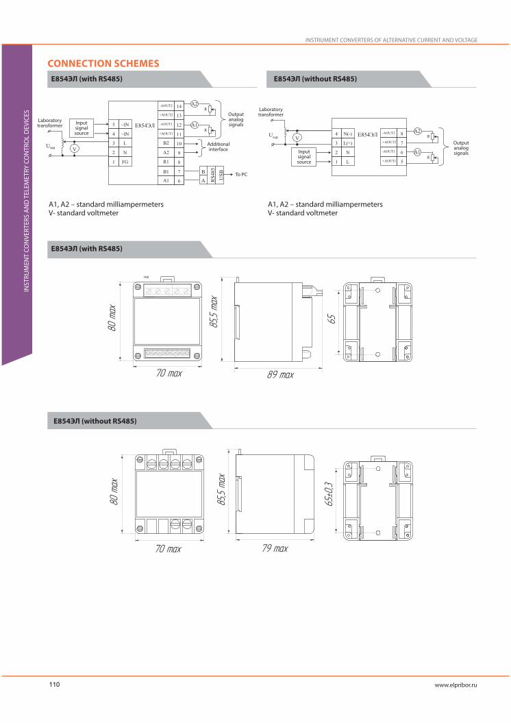
INSTRUMENT CONVERTERS OF ALTERNATIVE CURRENT AND VOLTAGE
INST
RUM
ENT
CON
VERT
ERS
AN
D T
ELEM
ETRY
CO
NTR
OL
DEV
ICES
CONNECTION SCHEMESE854ЭЛ (with RS485) E854ЭЛ (without RS485)
E854ЭЛ (with RS485)
A1, A2 – standard milliampermetersV- standard voltmeter
A1, A2 – standard milliampermetersV- standard voltmeter
sup
Laboratory transformer
Laboratory transformer
Input signal source
Input signal source
Output analog signals
Output analog signals
Additional interface
To PC
sup
sup
E854ЭЛ (without RS485)
110

E1854ЭЛ converters are intended for metering of electric current and volt-age in one-phase AC circuits. The converters can be used for control of current and voltage of the electric systems, installation and automation of different electric energy and industrial facilities.
Converters have the following options:
- Program selection of the analog input signal;
- Program selection of the analog output signal;
- orming of the discrete output signal for achievement of the set limit value;
- Displaying of the input signal (percentagewise from the rated value) at the indicator;
- Data transferring by RS485 interface (Modbus RTU protocol);
- It is possible to produce converters without interface and analog outputs.
Possibility of the program selection of output and input signals range al-lows to quickly solve issues with usage of converters with different ranges and types of input signals.
Converters parameters can be changed via Configurator software or con-trol buttons at the front panels.
INSTRUMENT CONVERTERS OF ALTERNATIVE CURRENT AND VOLTAGE
Converter Type Overall dimensions, mm Weight, kg, not above
Data display
LED indication(single or seven-segment dispalys)
Additional Features
Telemetry
Input signals
Intrinsic error limit
Galvanic isolation unit of input andoutput circuits, supply circits
Short-time input signal (with multiplicit, maximum valuey) overload
Input resistance
Communication intefaces/Analog outputs
RS485
Analog outputs
Input analog signal transition time, not above
- 2-digit seven-segment LED indicators for input percentage scale display- two single LED indicators for displaying work of interface and supply voltage
Connection of the indication modules or indication panel on the RS485 interface
Programmable ranges:A: 0..0,5, 0…1; 0..2,5; 0..5V: 0..125, 0..250, 0..500, 75..125, 150..200
±0,5%
Yes
Current:Multiplicity: 20, number of overloads:2; time of the each overload, sec: 0,5; time interval between two overloads, sec: 0,5.Voltage:Multiplicity: 1,5, number of overloads:9; time of the each overload, sec: 0,5; time interval between two overloads, sec: 15.For each series circuits (current) – not above 0,02 OmFor parallel circuits(voltage) for converters with power supply from AC circuit – not less 1 MOm
Quantity: 0,1; Protocol: Modbus RTUData transferring speed: 4800, 9600, 19200, 38400 bit/sec
Quantity: 0,1Programmable Ranges: 0…5 mA,4..20 mA,.0..20 mA
0,5 sec.
E1854ЭЛ converter is included into the State Register of the Measuring Devices RF №59809-15, the validity period is to February 6, 2020
INST
RUM
ENT
CON
VERT
ERS
AN
D T
ELEM
ETRY
CO
NTR
OL
DEV
ICES
111

Discrete output
Discrete output
Power supply
Voltage
Power consumption from the supply circuit(not above)
Device reprogramming (trim)
Reprogramming
Reprogramming parameters
Operational ConditionsWorking temperature rangeProtection classMountingWire cross-sectionMaximum overload for internal signal(duration)Calibration periodWarranty operating lifetimeAverage lifetime, not lessAverage mean time to failure
Quantity:0,1Direct voltage: 300 V, 100 mA;Alternative voltage: 200 V, 100 mA
12 VN –(12+6/-3) V DC24 VN –(24+12/-6) V DC230 V –85-253 V of AC with frequency of 50 Hz;220 VU –85-253 V of AC with frequency of 50 Hz or for 120-265 V of DC;
- 0,5 W from the circuit of input signal (for parallel circuit)- 0,01 W from the circuit of input signal (for series circuit)- 6 VA – from the supply circuit
- via the Configurator software (RS485 interface),- via the control buttons on the front panel- Range and type of input signal;- Range of changing of analog output signals;- Discrete input triggering parameters- RS485 interface parameters
-40 - +50 °CIP50DIN-bar0,08 - 2,5 mm2
150% (2 hours)
8 years2 years20 years200 000 hours
INSTRUMENT CONVERTERS OF ALTERNATIVE CURRENT AND VOLTAGE
INST
RUM
ENT
CON
VERT
ERS
AN
D T
ELEM
ETRY
CO
NTR
OL
DEV
ICES
ORDERING FORM
a – input signal metering (converting) rangeA: 0..0,5, 0…1; 0..2,5; 0..5V: 0..125, 0..250, 0..500, 75..125, 150..200
b – voltage supply:- 220ВУ – universal supply: supply voltage – 85-253 V AC,frequency 50 Hz or 120-265 V DC-230В - supply voltage 85-253 V AC, frequency 50 Hz-12ВН –(12+6/-3) V DC-24ВН –(24+12/-6) V DC
c – designation for analog output signal changing range (reprogramming of outputanalog signal is made under the selected option)X – no outputs.A1;B1;C1Where:A1=0..5mA, B1=4..20 mA, C1=0..20mA,Note: If there is no output signal (c=x) the converters have design with RS485 digitalinterface (f=RS)
d – discrete inputX – no discrete input01 – one discrete input
f - Special design (digital interface)x- no interface;RS- there is an interface
112

Converterdesign
Metering(converting)
range of inputsignal
Supplyvoltage
Range of outputanalog signal
changing
Discreteinputs
Specialdesign
Code parameter of the full designation
ORDERING EXAMPLEFor converter with the following parameters:converter type – E1854ЭЛ, input signal metering range 0-2,5 A, supply voltage – (12+6/-3) V DC, output signal changing range 4..20 mA, RS485 interface, operation NPP (safety class 4)E1854ЭЛ-0..2,5 A-12 ВН-B1-01-RS-A TУ 25-7504.226 – 2014
For power converter with the following parameters:converter type – E1854ЭЛ, input signal metering range 0-125 V, supply voltage – 85-253 V AC, frequency 50 Hz, output analog signal changing range 0..5 mA, no discrete output, no interface.E1854ЭЛ-0..125 В-230 В-A1-x-x TУ 25-7504.226 – 2014
CONNECTION SCHEMES
OVERALL AND INSTALLATION DIMENSIONS
Notes:“+” sign shows presence of all possible options in the order formula.“х” sign means, that this parameter is absent.For converters which will be used at NPP (safety class 4), please specify A design in the end of the ordering formula (separated by a comma)
Laboratory transformer
Output
Input
Supp
ly
Input signal source
Output analog signals
To PC
sup
Notes:Existance of interface (XT4 block) depends on the converters designA– standard milliampermeterV- standard voltmeter
INST
RUM
ENT
CON
VERT
ERS
AN
D T
ELEM
ETRY
CO
NTR
OL
DEV
ICES
12VN, 24VN,220VU, 230V
113

INSTRUMENT CONVERTERS OF ALTERNATIVE CURRENT
INST
RUM
ENT
CON
VERT
ERS
AN
D T
ELEM
ETRY
CO
NTR
OL
DEV
ICES
ЭП34С converters are intended for linear conversion of alternative current in electric circuits with the rated value to 660 V into unified output signal of direct current. The converters can be used for electric current control systems and installations and for automation of energetic facilities and other industri-al spheres.
Converters are one-phase devices. Converters are mounted at the DIN-bar 35 mm.
INSTRUMENT CONVERTERS OF ALTERNATIVE CURRENT
Converter Type Overall dimensions, mm Weight, kg, not above
Output current range, mA Load resistance, Om Power supplyInput signal range
Alternative current, A
A: 0..0,5, 0…1; 0..2,5; 0..5, 0..25; 0...50; 0..100
±0,5%Yes
Current:Multiplicity: 20, number of overloads:2; time of the each overload, sec: 0,5; time interval between two overloads, sec: 0,5.Voltage:Multiplicity: 1,5, number of overloads:9; time of the each overload, sec: 0,5; time interval between two overloads, sec: 15.
Quantity: 1Ranges: 0…5 mA, 0..20 mA0,5 sec.
From metering circuit
From power supply circuit, not above: 4,0 VAFrom input signal circuit, not above: 1,2 VA
-30 - +50 °CIP00
DIN-barto 2,5 mm2
120% (2 hours)24 months (8 hours per day)4 years10 years20 000 hours
TelemetryInput signalsIntrinsic error limitGalvanic isolation unit of input and output circuits, supply circits
Short-time input signal (with multiplicit, maximum valuey) overload
Analog output
Analog output
Input analog signal transition time, not above
Power supplyVoltage
Power consumption from the supply circuit (not above)
Operational ConditionsWorking temperature rangeProtection classMountingWire cross-sectionMaximum overload for internal signal (duration)
Calibration periodWarranty operating lifetimeAverage lifetime, not lessAverage mean time to failure
From metering circuit
ЭП34С converter is included into the State Register of the Measuring Devices RF №32200-06, the validity period is to April 14, 2022.
114

ORDERING EXAMPLEFor converter ЭП34С, input signal range 0-0,5 A, output current range 0..5 mAЭП34С-0..0,5 A – 0..5 мA TУ 25-7504-189-2005
CONNECTION SCHEMES
OVERALL AND INSTALLATION DIMENSIONS
Transmission bus
Output Output
Input
Input signal source
Output analog signals
Output analog signals
To PC
INST
RUM
ENT
CON
VERT
ERS
AN
D T
ELEM
ETRY
CO
NTR
OL
DEV
ICES
115

INSTRUMENT CONVERTERS OF DIRECT CURRENT FREQUENCY
INST
RUM
ENT
CON
VERT
ERS
AN
D T
ELEM
ETRY
CO
NTR
OL
DEV
ICES
E1858ЭЛ converters are intended for metering of alternative current fre-quency on the base of analog-digit conversion of inputs signals. .
Converters have the following options:
- Program selection of the analog input signal, scale range;
- Program selection of the analog output signal;
- Forming of the discrete output signal for achievement of the set limit value;
- Displaying of the input signal (percentagewise from the rated value) at the indicator;
- Data transferring by RS485 interface (Modbus RTU protocol);
- It is possible to produce converters without interface and analog outputs.
Possibility of the program selection of output and input signals range al-lows to quickly solve issues with usage of converters with different ranges and types of input signals.
Converters parameters can be changed via Configurator software or con-trol buttons at the front panels.
INSTRUMENT CONVERTERS OF DIRECT CURRENT FREQUENCY
Converter Type Overall dimensions, mm Weight, kg, not above
- 2-digit seven-segment LED indicators for input percentage scale display- two single LED indicators for displaying work of interface and supply voltage
Connection of the indication modules or indication panel on the RS485 interface
Programmable ranges:Hz: 45..65, 300..500
50 – 500 V
±0,5%;
Yes
Current:Multiplicity: 20, number of overloads: 2; time of the each overload, sec: 0,5; time interval between two overloads, sec: 0,5.Voltage:Multiplicity: 1,5, number of overloads:9; time of the each overload, sec: 0,5; time interval between two overloads, sec: 15.
- For each series circuit (current) – not above 0,02 Om- For parallel circuits(voltage) for converters with power supply from AC circuit – not less 1 MOm
Quantity: 0,1; Protocol: Modbus RTUData transferring speed: 4800, 9600, 19200, 38400 bit/sec
Quantity: 0,1Programmable Ranges: 0…5 mA, 4..20 mA, .0..20 mA, .0…2,5…5 mA, .4…12..20 mA, .0..10..20 mA,
0,5 sec.
Data display
LED indication(single or seven-segment dispalys)
Additional FeaturesTelemetry
Input signals
Rated input voltage
Intrinsic error limit
Galvanic isolation unit of input andoutput circuits, supply circits
Short-time input signal (with multiplicit, maximum valuey) overload
Input resistance
Communication intefaces/Analog outputs
RS485
Analog outputs
Input analog signal transition time,not above
E1854ЭЛ converter is included into the State Register of the Measuring Devices RF №59809-15, the validity period is to February 6, 2020
116

Quantity:0,1Direct voltage: 300 V, 100 mA;Alternative voltage: 200 V, 100 mA
12 V –(12+6/-3) V DC24 V –(24+12/-6) V DC230 V –85-253 V of AC with frequency of 50 Hz;220 V –85-253 V of AC with frequency of 50 Hz or for 120-265 V of DC;
- 0,5 W from the circuit of input signal (for parallel circuit)- 0,01 W from the circuit of input signal (for series circuit)- 6 VA – from the supply circuit
- via the Configurator software (RS485 interface),- via the control buttons on the front panel
- Range of input signal;- Range of changing of analog output signals;- Discrete output triggering parameters- RS485 interface parameters
-40 - +50 °CIP50DIN-bar0,08 - 2,5 mm2
150% (2 hours)
8 years2 years
20 years200 000 hours
Discrete output
Discrete output
Power supply
Voltage
Power consumption from the supply circuit(not above)
Device reprogramming (trim)
Reprogramming
Reprogramming parameters
Operational ConditionsWorking temperature rangeProtection classMountingWire cross-sectionMaximum overload for internal signal(duration)Calibration periodWarranty operating lifetimeAverage lifetime, not lessAverage mean time to failure
ORDERING FORM
a – input signal metering range: 45..65 Hz, 300..500 Hz;
b – voltage supply:- 220В – universal supply: supply voltage – 85-253 V AC,frequency 50 Hz or 120-265 V DC230В supply voltage 85-253 V AC,frequency 50 Hz-12В –(12+6/-3) V DC-24В –(24+12/-6) V DC
c – designation for analog output signal changing range (reprogramming of output analog signal is made under the selected option)X – no such optionsOption 1: A1;B1;C1; AP1;BP1; CP1;Option 2: A2;B2;C2; AP2;BP2; CP2;EP2;Where:A1(A2)=0..5mA, B1(B2)=4..20 mA, C1(C2)=0..20mA,AP1(AP2)=0..2,5..5 mA, BP1(BP2)=4..12..20 mA, CP1(CP2)=0..10..20mA,EP1(EP2)=-5...0..5 mANote: If there is no output signal (c=x) the converters have design with RS485 digitalinterface (f=RS)
d – discrete inputX – no discrete input01 – one discrete input
f - Special design (digital interface)x-no interface;RS- there is an interface
INST
RUM
ENT
CON
VERT
ERS
AN
D T
ELEM
ETRY
CO
NTR
OL
DEV
ICES
117

Converterdesign
Metering(converting)
range of inputsignal
Supplyvoltage
Range of outputanalog signal
changing
Discreteinputs
Specialdesign
Code parameter of the full designation
INSTRUMENT CONVERTERS OF DIRECT CURRENT FREQUENCY
INST
RUM
ENT
CON
VERT
ERS
AN
D T
ELEM
ETRY
CO
NTR
OL
DEV
ICES
ORDERING EXAMPLEFor power converter with the following parameters:converter type – E1854ЭЛ, input signal metering range 45-65 Hz, supply volt-age – 85-253 V AC, frequency 50 Hz, output analog signal changing range 0..5 mA(option 1), discrete output, no interface.E1858ЭЛ-45..65 Гц-230 В-A1-01-x- TУ 25-7504.226 – 2014
CONNECTION SCHEMES
OVERALL AND INSTALLATION DIMENSIONS
Notes:“+” sign shows presence of all possible options in the order formula.“х” sign means, that this parameter is absent.For converters which will be used at NPP (safety class 4), please specify A design in the end of the ordering formula (separated by a comma)
Notes:1. Existance of interface (XT4 block) depends on the converters design2. The possible output signals connections depending on the converters design are shown by the dotted line.A – standard milliampermeterV - standard voltmeter
Laboratory transformer
Output
Input
Supp
ly
Input signal source
Output analog signals
To PC
sup
12VN, 24VN,220VU, 230V
118

ЭЛКТ controller can be used as a main telemetry control device of con-trolled point and provide data exchange with telemetry control point via Eth-ernet interface.
Its functions include polling of discrete input/output modules, metering devices and converter for 6 independent RS485 interfaces, local data ar-chiving, interfaces/protocols conversion and data transmission to the upper level of telemetry control systems.
ЭЛКТ telemetry controller provides ability to program of local logics (PLC) on JavaScript (ECMAScript 5/5.1).
TELEMETRY CONTROLLER
Converter Type Overall dimensions, mm Weight, kg, not above
- Power supply;- Current status of data exchange via Ethernet interface and RS485 data interfaces (RS1-RS6)
- Change of the internal configurated discrete outputs and controller outputs staus;- Controllers selfdiagnostics result, particulary incuding events of wrong cotrollers settings made by the user.- Fact of controllers configuration parameters change;- Events of turning on/off of power supply and controllers reset.- Web-interface connections with controller, particulary including wrong authorization event;- All data changes are saved on SD-card.
RS485Quantity: 6Protocols: IEC 60870-5-101, Modbus RTU(Support of other data exchange (including data from power energy meters) protocols is possible upon the request)
Ethernet 100 BASE-TXQuantity: 2Protocols: IEC 60870-5-104, IEC 60850-8-1 (MMS), Modbus TCP
Direct tunneling of RS485 channels through IP-interfaces
Data display
LED indication (single indicators)
Event log
Event log (in the internal memory of -controller)
Communication iterfaces
Communication interface for pollingof terminal devices
Communication interface forintegratiion into telemetry orautomated control systems
Additional features
TELEMETRY CONTROL DEVICES
Facilities:• 2000 channels at the controlled point:
- 500 channels of remote signaling (“discrete inputs”) “two-way switch” type;- 500 channels of remote control (“discrete outputs”) “two-way switch” type;- 500 channels of telemetry of the current analog value (“analog inputs”);- 500 channels of remote adjusting of the current analog value (“analog outputs”);
• Connection of 200 external devices for:- Remote signaling with time mark (discrete input/output module ELMV OAO Electropribor or other modules, compatible with IEC 60870-5-
101, Modbus RTU protocols);- Telemetry with time mark (devices and converters of Щ, ЩП, ЩМ, ЩМК, E series and other devices of OAO Electropribor or other digital
devices, electric energy fiscal meters of other manufactures);- Remote control with time mark (discrete input/output module ELMV OAO Electropribor or other modules, compatible with IEC 60870-5-
101, Modbus RTU protocols);• Direct traffic pass-through between RS485 and Ethernet interfaces (interface conversion function).• Data conversion and data transmission with mark time from the external devices to the upper level using IEC 61850-8-1 (MMS) protocol of Ethernet interface.• Local data back-up depending on the input parameters.
INST
RUM
ENT
CON
VERT
ERS
AN
D T
ELEM
ETRY
CO
NTR
OL
DEV
ICES
119

Error of run – not above ±1 sec.per day (if there is no external power supply the controller an provide operation of the real-time clocks for at least 30 days)
Protocol: NTP (RFC 5905)
Protocol: IEC 60870-5-101
220 VU – 90-264 V AC, frequency 50 Hz or 130-370 V DC
-5VA (total power) – power supply from one-phase AC source, 50 Hz;- 5 W – power supply from DC source
-via Web-iterface;-via Configurator software
- Functional parameters of several RS485 traffic interfaces;- Controller connection parameters via RS485 interfaces of the external devices (discrete input/output modules, telemetry gauges, etc);- Parameters of analog and discrete outputs/inputs (several channels or remote signaling, remote control, telemetry and remote adjusting);- Parameters of IP-profile of Etherner interfaces- Parameters of communiction protocols (Modbus RTU, IEC 60870-5-104 and IEC 60850-8-1 (MMS)) support in device- Date and time (internal controllers real-time clocks data) and time sinchronisation param-eters;- Setting authorization parameters for access to the controller via digital Ethernet interfaces
-40 - +70 °CIP20DIN-bar1,5 mm2
24 months20 years200 000 hours
Time synchronisation
Real-time clocks
Sinchronisation of telemetrycontrollers time
Sinchronisation of terminal devicestimePower supply
Power supply voltage
Power consumption from the powerline, not above
Reprogramming of the device (trim)
Reprogramming
Parameters of reprogramming
Operational ConditionsWorking temperature rangeProtection classMountingWire cross-sectionWarranty operating lifetimeAverage lifetime, not lessAverage mean time to failure
TELEMETRY CONTROLLER
INST
RUM
ENT
CON
VERT
ERS
AN
D T
ELEM
ETRY
CO
NTR
OL
DEV
ICES
ORDERING EXAMPLEЭЛКТ TУ 26.51.43-239-05763903-2017
OVERALL AND INSTALLATION DIMENSIONS
The connection diagrams are listed in the Operation Manual of the Controller at www.elpribor.ru
120

The distributed complex of telemetry devices is intended for using as a part of automated process control systems and telemetry at power energy facili-ties and other automated industrial venues.
- Discrete input-output module ЭЛМВ can provide the following functions as a part of telemetry complex:
- Collection and conversion of discrete signals into digital format and their transmission with time mark by the RS485 interface into different hardware and software complexes for industrial facilities control;
- Conversion of signals and control commands of industrial equipment, which were got from different hardware and software complexes through RS485 interface with time mark into output discrete signals for transmitting them to the equipment on facilities.
- Function of group remote signaling gauge (to 12 physical and 32 logical channels of remote signaling of “position of two-way switch” for one module) and function of remote control module for forming of discrete output signals for control of two-way objects (to 4 physical channels of discrete output of “two-way switch control” type).
ЭЛМВ discrete input-output module provides ability to program of local logics (PLC) on JavaScript (ECMAScript 5/5.1).
DISCRETE INPUT-OUTPUT MODULE
Converter Type Overall dimensions, mm Weight, kg, not above
- Power supply;- Status of data exchange via RS485 data interface- Excistance of possible internal software-hardware errors of the device
Quantity:1, protocols:IEC 60870-5-101, Modbus RTUData rate:1200, 2400, 4800, 9600, 19200, 38400, 57600 and 115200 bit/sec
Error of run – not above ±1 sec.per day (if there is no external power supply the controller an provide operation of the real-time clocks for at least 30 days)IEC 60870-5-101, Modbus RTU (RS485)
Quantity:12 or 6 (depending on the order)
2 designs:1) 220 V DC (30 mA for a short moment in the case of short-circuit, then 1,15 mA)Guaranteed response threshold, V - 163± 5%;Guaranteed shut-off threshold, V - 144± 5%;Input type – “Clean contact” (requires for external wet-out)2) 24 V DC (10 mA)Guaranteed response threshold, V - 15± 5%;Guaranteed shut-off threshold, V - 13± 5%;Input type – “Clean contact”,”wet contact”Debouncing time-out:Adjusting, 0-20 ms, step -1 msInterference offset:Adjusting, 0-7 ms, step -1 msClip – “for screw”, max. wire cross-section – 4 mm2
Quantity: 4 or 2 (depending on the order)Modes: “Normal closed”, “Normal opened”220 V AC; 10A (15 A max, 4 sec)250 V DC; 0,35 AClip – “for screw”, max. wire cross-section – 4 mm2
Data display
LED indication (single indicators)
Communication iterfaces
RS485
Time synchronisation
Real-time clocks
Time sinchronisation
Remote signaling
Discrete inputs
Relay output
Relay discrete outputs
INST
RUM
ENT
CON
VERT
ERS
AN
D T
ELEM
ETRY
CO
NTR
OL
DEV
ICES
121

220 VU – 90-264 V AC, frequency 50 Hz or 130-370 V DC
- 5VA (total power) – power supply from one-phase AC source, 50 Hz;- 5 W – power supply from DC source
-via Configurator software
Functional parameters of RS485 interface;Parameters of communiction protocols (Modbus RTU, IEC 60870-5-104 and IEC 60850-8-1 (MMS)) support in deviceDate and time (internal controllers real-time clocks data) and time sinchronisation parame-ters;Functional parameters of analog and discrete outputs/inputs;Setting authorization parameters for access (passwords) to prevent unauthorised parame-ters modification
-40 - +70 °CIP20DIN-bar
Screwed terminals of the external interfaces – to 4 mm2
Terminals of RS485 interface - to 1,5 mm2
24 months20 years200 000 hours
Power supply
Power supply voltage
Power consumption from the powerline, not above
Reprogramming of the device (trim)Reprogramming
Parameters of reprogramming
Operational ConditionsWorking temperature rangeProtection classMounting
Wire cross-section
Warranty operating lifetimeAverage lifetime, not lessAverage mean time to failure
DISCRETE INPUT-OUTPUT MODULE
INST
RUM
ENT
CON
VERT
ERS
AN
D T
ELEM
ETRY
CO
NTR
OL
DEV
ICES
ORDERING EXAMPLEFor module cell controller with the following characteristics:6 discrete inputs, 2 discrete outputs, 24 V voltage (“Clean” contact)ЭЛМВ-6/2-24 В TУ 26.51.43-238-05763903-2017
OVERALL AND INSTALLATION DIMENSIONS
ORDERING FORM
a – number of discrete inputs/outputs:6/2 - 6 discrete inputs, 2 discrete outputs;12/4 - 12 discrete inputs, 4 discrete outputs;
b – voltage supply of discrete inputs:24 V –24 V voltage (“Clean contact”,”wet contact”);220 V -- 220 V voltage “Clean contact” (requires for external wet-out)
The connection diagrams are listed in the Operation Manual of the Module at www.elpribor.ru
122