Effective thickness of laminated glass beams: New expression via a variational approach
15
Effective thickness of laminated glass beams: New expression via a variational approach Laura Galuppi, Gianni F. Royer-Carfagni ⇑ Department of Civil-Environmental Engineering and Architecture, University of Parma, Parco Area delle Scienze 181/A, I 43100 Parma, Italy article info Article history: Received 30 October 2011 Revised 22 December 2011 Accepted 23 December 2011 Available online 15 February 2012 Keywords: Structural glass Laminated glass Composite structures Bending strength Effective thickness Variational approach abstract The performance of laminated glass, which consists of two or more glass plies bonded together by poly- meric interlayers, depends upon shear coupling between the plies through the polymer. This is com- monly considered by defining the effective thickness, i.e., the thickness of a monolithic beam with equivalent bending properties in terms of stress and deflection. General expressions have been proposed on the basis of simplified models by Newmark and Wölfel–Bennison, but they are either difficult to apply or inaccurate. Here, a variational approach to the problem is presented. By choosing appropriate shape functions for the laminated-beam deformation, minimization of the strain energy functional gives new expressions for the effective thickness under any constraint- and load-conditions, embracing the classical formulations as particular cases. Comparisons with numerical experiments confirm the better accuracy of the proposed approach with respect to the previous ones. Ó 2012 Elsevier Ltd. All rights reserved. 1. Introduction In order to reduce the risk of catastrophic collapse of structures made of glass, the brittle material par excellence, an effective tech- nique is to bond two or more glass plies with thermoplastic poly- meric interlayers with a treatment in autoclave at high pressure and temperature. This bond is quite strong because it is chemical in type, being due to the union between hydroxyl groups along the polymer and silanol groups on the glass surface. The resulting laminated glass is a safety glass because, after breakage, the frag- ments remain attached to the interlayer: risk of injuries is reduced and the element maintains a certain consistency that prevents detachment from fixings. But the interlayer affects also the pre glass-breakage response because it allows the transfer of shear stresses among glass plies, at the price of a relative sliding due to the deformation of the polymer. The assessment of the degree of connection offered by the polymer is crucial for the design of glass structures in the serviceability limit state and this is why a great number of studies, including this one, have considered the response of the composite laminated package before first cracking occurs. Indeed, the polymeric interlayers are too soft to present flexural stiffness per se, but they can provide shear stresses that play an important role for the glass-layer interaction [7]. In general, the degree of coupling of two glass layers depends upon the shear stiffness of the polymeric interlayer, as first mentioned by Hooper [3] while studying the bending of simply supported laminated- glass beams. Since then, the problem has been considered by many authors [15], one of the most recent contribution being the careful finite element analysis of [14], which includes an updated list of the most relevant literature. In the pre glass-breakage modeling no distinction has to be made for what the type of glass is concerned, because all treatments (annealing, heat strengthening, heat or chemical tempering) affect the ultimate strength and the type of rupture (size of resulting shards) but not the elastic moduli (Young’s modulus E ’ 70 GPa and Poisson ratio m ’ 0.2). If the response of glass is linear elastic up to failure, the response of the polymeric interlayer is highly non-linear, temperature-dependent and viscoelastic. There are three main commercial polymeric films, each one showing peculiar characteristics: Polyvinyl Butyral (PVB), Ethylene Vinyl Acetate (EVA), and Sentry Glass (SG) [16,10]. Pure PVB, a polyvinyl acetate, is stiff and brittle, but addition of softeners imparts plasticity and toughness, though influencing adhesion-strength, elasticity, water-absorbing and dependence on temperature (glass transition temperature T g of the order of 20–25 °C). Depending on the compo- sition, the properties of EVA, a polyolefine, vary from partial crystal- line and thermoplastic to amorphous and rubber-like, but an increased quantity of vinyl acetate improves strength and ultimate elongation, though decreasing melting temperature: when used as interlayers in laminated glass, modified EVAs are employed with mechanical properties similar to PVB. A somehow innovative material is SG, a ionoplast polymer that, when compared with 0141-0296/$ - see front matter Ó 2012 Elsevier Ltd. All rights reserved. doi:10.1016/j.engstruct.2011.12.039 ⇑ Corresponding author. E-mail address: [email protected] (G.F. Royer-Carfagni). Engineering Structures 38 (2012) 53–67 Contents lists available at SciVerse ScienceDirect Engineering Structures journal homepage: www.elsevier.com/locate/engstruct
Transcript of Effective thickness of laminated glass beams: New expression via a variational approach

Engineering Structures 38 (2012) 53–67
Contents lists available at SciVerse ScienceDirect
Engineering Structures
journal homepage: www.elsevier .com/ locate /engstruct
Effective thickness of laminated glass beams: New expressionvia a variational approach
Laura Galuppi, Gianni F. Royer-Carfagni ⇑Department of Civil-Environmental Engineering and Architecture, University of Parma, Parco Area delle Scienze 181/A, I 43100 Parma, Italy
a r t i c l e i n f o
Article history:Received 30 October 2011Revised 22 December 2011Accepted 23 December 2011Available online 15 February 2012
Keywords:Structural glassLaminated glassComposite structuresBending strengthEffective thicknessVariational approach
0141-0296/$ - see front matter � 2012 Elsevier Ltd. Adoi:10.1016/j.engstruct.2011.12.039
⇑ Corresponding author.E-mail address: [email protected] (G.F. Royer-C
a b s t r a c t
The performance of laminated glass, which consists of two or more glass plies bonded together by poly-meric interlayers, depends upon shear coupling between the plies through the polymer. This is com-monly considered by defining the effective thickness, i.e., the thickness of a monolithic beam withequivalent bending properties in terms of stress and deflection. General expressions have been proposedon the basis of simplified models by Newmark and Wölfel–Bennison, but they are either difficult to applyor inaccurate. Here, a variational approach to the problem is presented. By choosing appropriate shapefunctions for the laminated-beam deformation, minimization of the strain energy functional gives newexpressions for the effective thickness under any constraint- and load-conditions, embracing the classicalformulations as particular cases. Comparisons with numerical experiments confirm the better accuracy ofthe proposed approach with respect to the previous ones.
� 2012 Elsevier Ltd. All rights reserved.
1. Introduction
In order to reduce the risk of catastrophic collapse of structuresmade of glass, the brittle material par excellence, an effective tech-nique is to bond two or more glass plies with thermoplastic poly-meric interlayers with a treatment in autoclave at high pressureand temperature. This bond is quite strong because it is chemicalin type, being due to the union between hydroxyl groups alongthe polymer and silanol groups on the glass surface. The resultinglaminated glass is a safety glass because, after breakage, the frag-ments remain attached to the interlayer: risk of injuries is reducedand the element maintains a certain consistency that preventsdetachment from fixings. But the interlayer affects also the preglass-breakage response because it allows the transfer of shearstresses among glass plies, at the price of a relative sliding due tothe deformation of the polymer. The assessment of the degree ofconnection offered by the polymer is crucial for the design of glassstructures in the serviceability limit state and this is why a greatnumber of studies, including this one, have considered theresponse of the composite laminated package before first crackingoccurs.
Indeed, the polymeric interlayers are too soft to present flexuralstiffness per se, but they can provide shear stresses that play animportant role for the glass-layer interaction [7]. In general, thedegree of coupling of two glass layers depends upon the shear
ll rights reserved.
arfagni).
stiffness of the polymeric interlayer, as first mentioned by Hooper[3] while studying the bending of simply supported laminated-glass beams. Since then, the problem has been considered by manyauthors [15], one of the most recent contribution being the carefulfinite element analysis of [14], which includes an updated list ofthe most relevant literature.
In the pre glass-breakage modeling no distinction has to bemade for what the type of glass is concerned, because all treatments(annealing, heat strengthening, heat or chemical tempering) affectthe ultimate strength and the type of rupture (size of resultingshards) but not the elastic moduli (Young’s modulus E ’ 70 GPaand Poisson ratio m ’ 0.2). If the response of glass is linear elasticup to failure, the response of the polymeric interlayer is highlynon-linear, temperature-dependent and viscoelastic. There arethree main commercial polymeric films, each one showing peculiarcharacteristics: Polyvinyl Butyral (PVB), Ethylene Vinyl Acetate(EVA), and Sentry Glass (SG) [16,10]. Pure PVB, a polyvinyl acetate,is stiff and brittle, but addition of softeners imparts plasticity andtoughness, though influencing adhesion-strength, elasticity,water-absorbing and dependence on temperature (glass transitiontemperature Tg of the order of 20–25 �C). Depending on the compo-sition, the properties of EVA, a polyolefine, vary from partial crystal-line and thermoplastic to amorphous and rubber-like, but anincreased quantity of vinyl acetate improves strength and ultimateelongation, though decreasing melting temperature: when used asinterlayers in laminated glass, modified EVAs are employed withmechanical properties similar to PVB. A somehow innovativematerial is SG, a ionoplast polymer that, when compared with

54 L. Galuppi, G.F. Royer-Carfagni / Engineering Structures 38 (2012) 53–67
PVB, presents higher stiffness (>100 � PVB), strength (>5 � PVB),resistance to temperature (Tg � 60 �C). Depending upon polymertype, room-temperature T and characteristic load-duration t0, thesecant shear modulus of the interlayer may vary from 0.01 MPa(PVB at T = +60 �C under permanent load) up to 300 MPa (SG atT = 0 �C and t0 = 1 s).
As pointed out by Norville [8], the response of the laminatedglass beams may vary between two borderline cases: (i) the layeredlimit, when the beam is composed of free-sliding glass plies; (ii)the monolithic limit, where no relative slippage occurs and the clas-sical Euler–Bernoulli assumption that ‘‘plane sections remainplane’’ does hold. In the layered limit, the various plies equilibrate,in parallel, an aliquot of the applied load proportional to theirbending stiffness; in the monolithic limit, the response of the com-posite beam approaches that of a homogeneous beam with equalcross-section. It must be mentioned that in most models the inter-layer thickness is not explicitly considered: ignoring the spacingprovided by the polymeric layers, the equivalent monolith is oftentaken to be one whose thickness equals the sum of that of the glassplies. Experimental tests, however, show [9] that the laminate canbe stronger than this. Indeed, the monolithic limit has to be asso-ciated with the case of a beam for which the cross-sectional inertiaequals that of the cross sections of the composing glass layers,properly spaced of the interlayer gaps.
The capability of the interlayer to transfer shear stress betweeneach pair of connected glass surfaces is affected by load-level, load-duration, temperature, adhesion properties. This dependence hasbeen investigated in several studies [7,13,19], but considerationof all these effects in modeling would be very complicated. Aquite-effective technical solution, widely employed in the designpractice, consists in assuming perfect glass–polymer adhesionand in considering the polymer as a linear elastic material, charac-terized by proper secant elastic moduli calibrated according toroom temperature and load duration. Geometric non-linearitiesare usually important because of the slenderness of the laminatedpanel [11], but can be neglected, at least as a first order approxima-tion, when the loads are mainly orthogonal to the panel surfaceand no in-plane forces are present.
Numerical 3D models are used for the most important worksonly, while 2D or 1D models are usually preferred because of theirsimplicity. These are based upon the definition of an ‘‘equivalent’’beam or plate whose effective thickness is properly downgradedwhen compared with the monolithic limit. In simple words, theeffective thickness of a laminated glass plate is the (constant) thick-ness of the homogeneous plate that, under the same boundary andload conditions of the problem under consideration, presents thesame maximal stress or maximal deflection. This definition is verypractical, but in the technical literature and in the national stan-dards various formulations that lead to diverse expressions forthe equivalent thickness have been proposed. In substance, thetwo most common types of models are the one derived from thetheory by Newmark et al. [1] for layered composite beams withdeformable connectors and that proposed by Bennison et al.[17,10] based upon the original approach for sandwich beams byWölfel [4]. Both formulations furnish a one-dimensional analysisof the laminated-glass beam under the hypothesis that the inter-layer adhesion is sufficient to keep constant the relative distancebetween the bonded glass surfaces, although their relative slippagemay be allowed by the relatively-low shear stiffness of the polymer.
The aim of this paper is to revise the classical problem of a com-posite laminated glass beam under flexure, assuming linear elasticresponse for the components (glass + polymer) and ruling outdelamination and geometric non-linearities. A variational ap-proach to this problem is presented that automatically furnishesthe governing differential equations and boundary conditions. Tothis respect, the approach is substantially similar to that proposed
in [12] for numerical purposes, but here it is specialized towardstwo major goals: (i) the comparison of the various existing modelsunder a common variation framework; (ii) the definition of moreaccurate expressions for the effective thickness that may apply toa large number of constraint and load conditions. In particular,using convenient shape functions that fulfills general requirementsof the solution, we find a simplified formulation, original to ourknowledge, that can be used to define new expressions of theequivalent thickness for the laminated package. Comparisons withthe traditional formulations and with numerical experimentsbased upon refined FEM models, highlight the accuracy of the pro-posed approach with respect to previous ones, especially underboundary and load conditions that are different from the com-monly considered case of simply-supported beams under uniformloading.
2. Review of simple models for laminated glass
The classical expressions for the effective thickness of lami-nated glass rely upon simplifying assumptions in modeling thatare hardly mentioned in the literature. A brief review that will beuseful for the forthcoming considerations is here provided.
2.1. Newmark’s model
A simple analytical model for a structure made of two beamswith elastic interaction was proposed in 1951 by Newmark [1].This theory was originally conceived of for a typical steel-concretecomposite bridge deck, formed by a concrete slab and a steel beambonded by shear connectors. The assumptions of the model are thefollowing: (i) the shear connection is continuous; (ii) the amount ofslip permitted by the shear connection is directly proportional tothe load transmitted; (iii) the strain distribution in the slab andin the beam is linear; (iv) the slab and the beam deflect equalamounts at all points along their length. The model is applicableto any composite beam consisting of two elements with bendingstiffness, connected by an interface with negligible thickness thattransfers shear forces. Therefore, it can be conveniently used forlaminated glass.
Consider, as indicated in Fig. 1, a laminated beam of length l andwidth b composed of two glass plies of thickness h1 and h2 andYoung’s modulus E, connected by a polymeric interlayer of thick-ness t and shear modulus G. Let
Ai ¼ hib; Ii ¼bh3
i
12ði ¼ 1;2Þ; H ¼ t þ h1 þ h2
2; A�
¼ A1A2
A1 þ A2; Itot ¼ I1 þ I2 þ A�H2; A ¼ bt ð2:1Þ
and observe, in particular, that Itot represents the moment of inertiaof the full composite section (monolithic limit) that takes into ac-count the spacing provided by the interlayer gap. Introduced aright-handed orthogonal reference frame (x,y) with x parallel tothe beam axis, supposed horizontal, and y directed upwards, thetransversal displacement v(x) is positive if in the same directionof increasing y, the transversal load p(x) > 0 if directed downwards,while the bending moment M(x) is such that M00(x) > 0 whenv00(x) > 0. Then, as shown in [6], v(x) has to satisfy the differentialequation
v 0000 ðxÞ � a2v 00ðxÞ þ a2 MðxÞEItot
þ pðxÞEðI1 þ I2Þ
¼ 0; ð2:2Þ
where
K ¼ Gbt; a2 ¼ K
EA�Itot
I1 þ I2: ð2:3Þ
p(x)
x
y
Fig. 1. Beam composed of two glass plies bonded by a polymeric interlayer. Longitudinal and cross sectional view (not in the same scale).
L. Galuppi, G.F. Royer-Carfagni / Engineering Structures 38 (2012) 53–67 55
The model is accurate, but the solution of the differential Eq.(2.2) is relatively simple only if the bending moment M(x) isknown, i.e., the beam is statically determinate. Moreover, the mod-el is clearly one-dimensional and cannot be extrapolated to thecase of plates or shells under general boundary conditions.
2.2. The approach by Wölfel–Bennison
The modeling that relies upon the original approach by Wölfelfor composite sandwich structures is attractive because of itssimplicity; this is why it is mentioned in many structural stan-dards. In fact, it provides a direct method to calculate the ‘‘effectivethickness’’ of a monolithic beam with equivalent bending proper-ties to a laminated beam. However, this approach relies uponseveral simplifying assumptions that it is necessary to recall here,because they are useful to understand the limits of the theory but,to our knowledge, they are never mentioned in the technical liter-ature, apart from the original work by Wölfel [4] that is difficult tofind and written in German.
The model was primarily conceived of for a sandwich structurecomposed of three layers, the external ones with considerable axialstiffness but negligible bending stiffness, while the intermediatelayer can only bear shear stress with zero axial and flexuralstrength. Therefore, it well applies to sandwich panels composedof, e.g., a soft core and external metallic coating layers. With thesame notation of (2.1), let M(x) and MðxÞ, represent the bendingmoments in the beam under, respectively, the external service loadq(x) and a concentrated unit force at midspan, while Q(x) and QðxÞdenote the corresponding shear forces. If v is the shear coefficientof the intermediate (soft) layer, from the principle of virtual workthe sag d at midspan turns out to be:
d¼ 1Bs
Z l
0MðxÞMðxÞdxþ v
GA
Z l
0QðxÞQðxÞdx¼ð1þKÞ
Bs
Z l
0MðxÞMðxÞdx;
K¼bBsv
GAl2 ; b¼l2 R l
0 QðxÞQðxÞdxR l0 MðxÞMðxÞdx
; ð2:4Þ
where Bs = EA⁄H2 represents the bending stiffness of the two areas A1
and A2, supposed to be concentrated in the corresponding centroidand thus neglecting their individual bending stiffness. The coeffi-cient b in (2.4)3 depends upon the load condition and, for the mostcommon cases, the corresponding values are recorded in [4]. In par-ticular: b = 9.6 when the load is uniformly distributed; b = 12 for aconcentrated force at midspan; b = p2 for a sinusoidal load.
When the external layers presents considerable bending stiff-ness, Wölfel proposed an approximate solution according to whichthe bending stiffness Bs in (2.4) should be substituted by B�s definedas
d ¼ 1B�s
Z l
0MðxÞMðxÞdx; B�s ¼ EI1 þ EI2 þ
11þKBs; ð2:5Þ
that assumes that the individual bending stiffness of the externallayers has no influence on the bonding offered by the central layer:
the less the bending stiffness of the external layers, the more accu-rate is this hypothesis. Notice from (2.4) that K 2 ð0;þ1Þ. In partic-ular, G!1) K! 0, so that from (2.5) also B�s ! EItot (monolithiclimit); moreover, G! 0) K!1 and B�s ! EðI1 þ I2Þ (layered lim-it). Henceforth, the coefficient ð1þKÞ indicates the degradation ofthe bending stiffness due to the incomplete interaction betweenthe external layers.
Bennison et al. [17,18] have developed Wölfel’s approach spe-cifically for the case of laminated glass, by proposing to use (2.5)to calculate the deflection of a laminated glass beam. More pre-cisely, the authors call C ¼ 1=ð1þKÞ, C 2 ð0;1Þ, and introducethe equivalent moment of inertia of the cross section in the form
Ieq ¼ I1 þ I2 þ CA1A2
A1 þ A2H2: ð2:6Þ
In order to evaluate the shear coefficient v that takes part in thedefinition of K and, consequently, of C, it is necessary to estimatethe shear stresses s and �s, associated with the shear forces Q(x) andQðxÞ, respectively. Under the same simplifying hypotheses that hadled to (2.4), i.e., neglecting the flexural inertia of each one of theexternal plies, one finds that sb = Q/H and �sb ¼ Q=H. Then theshear coefficient, which is defined by
vGA
Z l
0QQdx¼ 1
G
Z l
0
ZAs�sdAdx¼ 1
G
Z l
0
ZA
ðHbÞ2dAdx¼ A
GðHbÞ2Z l
0QQ dx
ð2:7Þ
turns out to be
v ¼ A2
ðHbÞ2¼ t2
H2 : ð2:8Þ
The proposal by Bennison et al. is to consider for C the universalexpression
C ¼ 11þ b vBs
GAl2
¼ 11þ 9:6 tBs
GbH2 l2; ð2:9Þ
with b = 9.6 as in the case of uniformly distributed loading. Moreprecisely, the authors define the nominal values hs;1 and hs;2 ofthe thickness and the ‘‘bonding inertia’’ Is
hs;1 ¼Hh1
h1 þ h2; hs;2 ¼
Hh2
h1 þ h2; Is ¼
Bs
Eb¼ h1h2
h1 þ h2H2
¼ h1h2s;2 þ h2h2
s;1; ð2:10Þ
so that C of (2.9) can be written as
C ¼ 11þ 9:6 EIst
GH2 l2: ð2:11Þ
Consequently, recalling (2.6), for calculating the laminate deflectionone can consider a monolithic beam with deflection-effectivethickness hef;w given by
hef ;w ¼ffiffiffiffiffiffiffiffiffiffiffiffiffiffiffiffiffiffiffiffiffiffiffiffiffiffiffiffiffiffiffiffiffiffih3
1 þ h32 þ 12CIs
3q
: ð2:12Þ

56 L. Galuppi, G.F. Royer-Carfagni / Engineering Structures 38 (2012) 53–67
Once the effective stiffness of the laminate is established, the max-imum stress in the glass can be easily estimated. Eventually, onefinds that the maximum bending stress in each glass plies is thesame of that in a fictitious monolithic beam loaded by the serviceload q(x) with respectively stress-effective thickness
h1;ef ;r ¼
ffiffiffiffiffiffiffiffiffiffiffiffiffiffiffiffiffiffiffiffiffiffiffiffih3
ef ;w
h1 þ 2Chs;2
s; h2;ef ;r ¼
ffiffiffiffiffiffiffiffiffiffiffiffiffiffiffiffiffiffiffiffiffiffiffiffih3
ef ;w
h2 þ 2Chs;1
s: ð2:13Þ
It is important to notice that the method of the effective thick-ness relies upon the assumed form of C given by (2.9) and (2.11),which contains the coefficient b = 9.6, i.e., the one proposed byWölfel for the unique case of simply supported beams under uniformlydistributed loading. For other kind of loading and boundary con-straint, other values for b should be chosen. Moreover, accordingto Wölfel himself [4], the validity of the method is limited becauseits simplifying assumptions are valid for statically-determinedcomposite beams, for which the bending stiffness of the compositeplies is negligible.
3. The energetic approach
With respect to a reference system (x,y) as in Fig. 1, consider thelaminated beam �l/2 6 x 6 l/2 composed of two glass plies bondedby a thin polymeric interlayer, whose geometric sizes are definedby the same parameters of (2.1). Again, E and G represent theYoung’s modulus of the glass and the shear modulus of the inter-layer, and the beam is loaded under a generic load per unit lengthp(x), not necessarily uniformly distributed.
3.1. The variational formulation
The glass–polymer bond is supposed to be perfect and the inter-layer strain in direction y is negligible. Under the hypothesis thatstrains are small and the rotations moderate, the kinematics iscompletely described by the vertical displacement v(x), the samefor the two glass components, and the horizontal displacementsu1(x) and u2(x) of the centroid of the upper and lower glass ele-ment, respectively. As shown in detail in Fig. 2, let usup(x) and uinf(x)denote the horizontal displacement at the intrados of the upperglass element and the extrados of the lower glass element, i.e., atthe interface with the interlayer. Then, the shear strain in the inter-layer is then given by
c ¼ 1t½usupðxÞ � uinf ðxÞ þ v 0ðxÞt� ¼ 1
t½u1ðxÞ � u2ðxÞ þ v 0ðxÞH�: ð3:1Þ
The corresponding energy of the system [2] may be written asfollows:
E½u1ðxÞ;u2ðxÞ;vðxÞ� ¼Z l=2
�l=2
(12
EðI1 þ I2Þ½v 00ðxÞ�2 þ EA1½u01ðxÞ�2
hþ EA2½u02ðxÞ�
2 þ Gbtðu1ðxÞ � u2ðxÞ þ v 0ðxÞHÞ2
�þ vðxÞ
)dx; ð3:2Þ
u1
u2
usup
uinf
v’(x)
y
xv
u
Fig. 2. Relevant displacement components and corresponding deformation in thecomposite beam.
where the first term represents the flexional contributions, the sec-ond and the third terms are the extensional strain energy of theupper and lower glass plies, respectively, whereas the fourth termcorresponds to the interfacial strain energy due to the shear elasticstrain of the polymer; the last term expresses the contribution ofthe loading p(x). The zeroing of the first variation with respect tov(x), u1(x) and u2(x) gives respectively the Euler’s equilibriumequations
EðI1 þ I2Þv0000 ðxÞ � Gb
tðu1ðxÞ � u2ðxÞ þ v 0ðxÞHÞ0H þ p ¼ 0; ð3:3Þ
EA1u001ðxÞ ¼Gbtðu1ðxÞ � u2ðxÞ þ v 0ðxÞHÞ; ð3:4Þ
EA2u002ðxÞ ¼ �Gbtðu1ðxÞ � u2ðxÞ þ v 0ðxÞHÞ: ð3:5Þ
Observe, in passing, that Eqs. (3.4) and (3.5) can be rearrangedas
A1u001ðxÞ ¼ �A2u002ðxÞ; ð3:6ÞGbtðu1ðxÞ � u2ðxÞ þ v 0ðxÞHÞ ¼ E
2A1u001ðxÞ � A2u002ðxÞ� �
: ð3:7Þ
Recalling that EAiu00i ðxÞ is the derivative of the axial force Ni inthe ith glass layer, conditions (3.6) and (3.7) represent the axialequilibrium of the two glass plies under the mutual shear forceper unit length s, transmitted by the polymeric interlayer(Fig. 3a), i.e., A1u001ðxÞ ¼ �A2u002ðxÞ ¼ s ¼ Gcb. Such shear contribu-tions are statically equipollent to a distributed torque per unitlength equal to �s(h1/2 + t⁄) (t⁄ is arbitrary as shown in Fig. 3) inthe upper glass beam, �s(h2/2 + t � t⁄) in the lower glass beamand �st in the interlayer. Then, as represented in Fig. 3b, condition(3.3) represents the equilibrium under bending of the packageglass+polymer, which is of the form EIv
0000(x) + p(x) + m0(x) = 0, with
I = I1 + I2 and mðxÞ ¼ �sðxÞ h1þh22 þ t
� �¼ �sðxÞH.
Standard arguments in the calculus of variation [5] furnish theboundary conditions
�ðEðI1 þ I2Þv 000ðxÞ þGbt
cðxÞHÞdvðxÞ� �l=2
�l=2¼ 0;
½EðI1 þ I2Þv 00ðxÞdv 0ðxÞ�l=2�l=2 ¼ 0;
½EA1u01ðxÞdu1ðxÞ�l=2�l=2 ¼ 0;
½EA2u02ðxÞdu2ðxÞ�l=2�l=2 ¼ 0;
ð3:8Þ
where dv(x), du1(x) and du2(x) denote the variations of v(x), u1(x)and u2(x). Such variations are null at the boundary where the dis-placement is prescribed, and arbitrary otherwise.
It should be also observed that whenever G ? 0, the Euler’sequations give
EðI1 þ I2Þv0000 ðxÞ þ p ¼ 0;
EA1u001ðxÞ ¼ 0;EA2u002ðxÞ ¼ 0;
8><>: ð3:9Þ
that correspond to the equilibrium of two frictionless sliding glassbeams (layered limit).
In order to recover the equilibrium equation for the case of per-fect bonding, a relationship between the horizontal displacementof the upper and lower glass plies can be found from Eq. (3.6).Observe that such an equation can be rearranged in the form:
ðEA1u01ðxÞ þ EA2u02ðxÞÞ0 ¼ 0 ) EA1u01ðxÞ þ EA2u02ðxÞ ¼ const;
ð3:10Þ
where EA1u01ðxÞ ¼ N1ðxÞ and EA2u02ðxÞ ¼ N2ðxÞ represent the axialforces in the glass layers at x. If the beam is not constrained atone of its ends, so that du1(l/2) – 0 and du2(l/2) – 0 (or du1(�l/2) – 0 and du2(�l/2) – 0), then EA1u01ðl=2Þ ¼ EA2u02ðl=2Þ ¼ 0 (or

N2 N +d2 N2
N +dN11N1
dx dx
h1
h2
H
(a) (b)
t*
t-t*
Fig. 3. Interpretation of the Euler’s equations in terms of equilibrium of an infinitesimal voussoir.
L. Galuppi, G.F. Royer-Carfagni / Engineering Structures 38 (2012) 53–67 57
EA1u01ð�l=2Þ ¼ EA2u02ð�l=2Þ ¼ 0) and, consequently, EA1u01ðl=2ÞþEA2u02ðl=2Þ ¼ 0 (or EA1u01ð�l=2Þ þ EA2u02ð�l=2Þ ¼ 0). From (3.10), thisleads to N1(x) + N2(x) = 0, "x 2 (�l/2, l/2).
In the most general case in which the beam is constrained atboth its ends so that du1(±l/2) = du2(±l/2) = 0, we may suppose thatno axial elongation is given to each glass ply, i.e.,Z l=2
�l=2u01ðxÞdx ¼
Z l=2
�l=2u02ðxÞdx ¼ 0: ð3:11Þ
Then, if one assumed that N1(x) + N2(x) = N – 0, where N repre-sents the resultant axial force in the composite beam, one wouldfind
0 ¼Z l=2
�l=2EA1u01ðxÞ þ EA2u02ðxÞ
dx ¼ Nl ) N ¼ 0: ð3:12Þ
In conclusion, if one of the bar ends is not constrained, or if the barends are not displaced apart, the axial resultant force is null, leadingto:
ðEA1u1ðxÞ þ EA2u2ðxÞÞ0 ¼ 0 ) A1u1ðxÞ þ A2u2ðxÞ ¼ const: ð3:13Þ
In order to prevent the rigid body motion in x direction, at least onepoint of the structure may be rigidly fixed in space. This conditionmay be imposed not only on the displacement of the upper or lowerglass ply, but also on the (weighted) average displacement fieldA1u1(x) + A2u2(x), leading to
A1u1ðxÞ þ A2u2ðxÞ ¼ 0 ) u2ðxÞ ¼ �A1
A2u1ðxÞ: ð3:14Þ
Eq. (3.14) in the case of perfect bonding, i.e. G ?1, c = 0, leads tothe following relationship between vertical and horizontaldisplacement:
c¼u1ðxÞ�u2ðxÞþv 0ðxÞH¼0) u1ðxÞ¼�v 0ðxÞH A2
A1þA2; ð3:15Þ
leading to
Gbc ¼ EA1u1ðxÞ ¼ �EHA�v 000ðxÞ; ð3:16Þ
where A⁄ is defined by Eq. (2.1). Hence, the governing Eqs. (3.3),(3.4) and (3.5) may be rearranged as follows:
EðI1 þ I2Þv0000 ðxÞ � Gbcþ p ¼ EItotv
0000 ðxÞ þ p ¼ 0;A1u001ðxÞ ¼ �A2u002ðxÞ;Gbc ¼ EA1u001ðxÞ;
8><>: ð3:17Þ
where Itot has been defined by Eq. (2.1) and corresponds to themoment of inertia of the monolithic beam.
3.2. Comparison with Newmark’s model
Remarkably, the first of Euler’s Eq. (3.3) can be related to theNewmark’s forth-order differential Eq. (2.2), as shown in thesequel.
In the previous section, we have shown that the axial resultantforce N(x) = N1(x) + N2(x) is null. Observe now that the bending mo-ment at x in the ith glass layer, i = 1,2, is Mi(x) = EIiv00(x). Conse-quently, if N1(x) = �N2(x) the resulting bending moment in thewhole cross-section of the composite beam is M(x) = M1(x) +M2(x) + N2(x)H = M1(x) + M2(x) � N1(x)H, that is
MðxÞ¼EðI1þ I2Þv 00ðxÞþEAu02ðxÞH¼EðI1þ I2Þv 00ðxÞ�EAu01ðxÞH: ð3:18Þ
From this, one finds
HA1u01ðxÞ ¼ ðI1 þ I2Þv 00ðxÞ �MðxÞ=E;
HA2u02ðxÞ ¼ �ðI1 þ I2Þv 00ðxÞ þMðxÞ=E:
�ð3:19Þ
By substituting (3.19), Eq. (3.3) can be rewritten as follows:
EðI1 þ I2Þv0000 ðxÞ � Gb
tA1 þ A2
A1A2Itotv 00ðxÞ þ
GbtE
A1 þ A2
A1A2MðxÞ þ p ¼ 0:
ð3:20Þ
After setting, as in (2.3) and (2.1), K:¼Gb/t and A⁄ = A1A2/(A1 + A2),Eq. (3.20) can be rearranged in the form
v 0000 ðxÞ� KEA�
Itot
I1þ I2v 00ðxÞþ K
E2A�Itot
I1þ I2MðxÞþ pðxÞ
EðI1þ I2Þ¼0; ð3:21Þ
which represents Newmark’s Eq. (2.2).
4. Approximate simple models
4.1. Generalized Newmark (GN) approach
Newmark’s model represents an accurate elegant re-formula-tion of the governing differential equations for the compositebeam, based upon the association through equilibrium consider-ation of relevant terms with the bending-moment resultant. How-ever, it presents two major drawbacks. On the one hand, thefunction M(x) must be known a priori, which is, in general, possibleonly if the structure is statically determined. On the other hand,the definition of an effective thickness as done in (2.12) or (2.13)is not as straightforward as in Wölfel’s approach. Whenever thestatic constraints render the beam statically undetermined, anapproximate solution can be found by considering for M(x) in(3.20) the expression corresponding to the bending moment in abeam of constant thickness under the same static scheme, i.e., withthe same constraints of the considered problem. Observe that un-der this hypothesis M(x) can be easily calculated and does not de-pend upon the (supposed constant) thickness of the beam. Thisprocedure, as will be shown in Section 5, gives in general accurate

58 L. Galuppi, G.F. Royer-Carfagni / Engineering Structures 38 (2012) 53–67
solutions even if, rigorously speaking, the coupling effect offeredby the shear stiffness of the interlayer is variable along the lengthof the beam; consequently, the effective form of M(x) would coin-cide with that for a hyperstatic beam with variable cross-sectionalheight, but cannot be determined a-priori because the cross sec-tional height would depend upon M(x) itself.
Once M(x) is given, the fields v(x), u1(x) and u2(x) can be deter-mined by integrating the differential system (3.21), (3.4) and (3.5),with boundary conditions (3.8). The system can be easily solvednumerically. Eqs. (3.18) and (3.19) allow then to determine thebending moment and the axial force in both glass layers and, con-sequently, to calculate the maximum stress jr(i)jmaxj in the ith layerthrough
jrðiÞjmax ¼maxx
NiðxÞAi�MiðxÞ
Ii
hi
2
���� ����: ð4:1Þ
For any particular considered case, once the system of differen-tial equations has been solved, a deflection-effective thickness can bedefined by imposing that the maximum sag of a beam with thatconstant thickness, under the same constraint and load conditions,coincides with that for the problem solved according to Newmark’stheory. This can be easily done by recalling that the maximum sagof a beam of constant thickness h�wN is inversely proportional to themoment of inertia I⁄ of the beam itself; for example, for a simply
supported beam the maximum sag is wmax ¼ 5384
ql4
EI� ¼ 5384
ql4
Ebh�3
wN12
.
Analogously, one can define the stress-effective thickness as the(constant) thickness h�rN of that beam for which the maximumstress rmax ¼ 6Mmax
bh�rN2 is equal to the corresponding stress defined by
(4.1). The values of the deflection- or stress-effective thickness de-pend upon the case under consideration and, in general, no simpleexplicit expressions of the same type of (2.12) and (2.13) can befound for Newmark’s theory. However, the effective thicknessesmay serve as parameters of comparison for various theories andso will be considered for the particular cases analyzed in Section 5.
4.2. Enhanced effective-thickness (EET) approach
The definition of an ‘‘effective thickness’’ for laminated glassrepresents an efficient method to solve the most various problems,but since Newmark’s approach is not able to provide simple expli-cit expressions, an attempt is now made to consider enhancedapproximated solutions through the choice of appropriate and con-venient shape functions for the unknown fields v(x), u1(x) andu2(x), whose explicit expression will be found through energeticminimization.
In order to achieve a sufficient approximation, the shape func-tions for the horizontal and vertical displacements must be compat-ible with the qualitative properties of the solution. In particular, theproposed approximation must converge to the monolithic limitwhen G ?1, and to the layered limit when G ? 0. Such limitscorrespond to the solutions of Eqs. (4.2) and (4.3), respectively
EItotv0000 ðxÞ þ pðxÞ ¼ 0 ) vðxÞ ¼ vMðxÞ � �
gðxÞEItot
; ð4:2Þ
EðI1 þ I2Þv0000 ðxÞ þ pðxÞ ¼ 0 ) vðxÞ ¼ vLðxÞ � �
gðxÞEðI1 þ I2Þ
: ð4:3Þ
Henceforth, the general solution can be sought of the form
vðxÞ ¼ � gðxÞEIR
; ð4:4Þ
where IR is the equivalent (reduced) moment of inertia defined by
1IR¼ g
Itotþ 1� g
I1 þ I2: ð4:5Þ
Here, the parameter g is a non-dimensional quantity, tuningthe behavior from the layered limit (g = 0) to the monolithiclimit (g = 1), while g(x) is the assumed shape function for the verticaldisplacement, that in general must be selected according to the formof the external load p(x) and the geometric boundary conditions.
Requiring in (3.1) that c = 0 for the monolithic borderline case,recalling condition (3.6), the horizontal displacements u1(x) andu2(x) can be chosen of the form
u1ðxÞ¼ b1
EItot
A2
A1þA2Hg0ðxÞ; u2ðxÞ¼�b
1EItot
A1
A1þA2Hg0ðxÞ; ð4:6Þ
where b is another non-dimensional parameter, again tuning the re-sponse from the layered limit (b = 0, leading to null horizontal forcein the glass layers) to the monolithic limit (b = 1, leading to c = 0).
The corresponding energy (3.2) can thus be re-written as a func-tion of the parameters g and b to give
E½u1ðxÞ;u2ðxÞ;vðxÞ� ¼ bE½g;b; gðxÞ�¼Z l=2
�l=2
12½ðI1 þ I2Þ
Eg
Itotþ 1� g
I1 þ I2
� �2
½g00ðxÞ�2(
þ b2
EI2tot
A1A2
A1 þ A2H2½g00ðxÞ�2
þ Gbt
H2
E2Itot
bItot� g
Itot� 1� g
I1 þ I2
� �2
½g0ðxÞ�2
� pðxÞE2
gItotþ 1� g
I1 þ I2
� �gðxÞ
dx; ð4:7Þ
in which the shape function g(x) is a priori given.Consequently, the minimization of the energy is associated with
the minimization with respect to the only free parameters g and b,leading to
bItot
A1A2A1þA2
R l=2�l=2½g00ðxÞ�
2dxþ GbtE
bItot� g
Itot� 1�g
I1þI2
h i R l=2�l=2½g0ðxÞ�
2dx ¼ 0;
ðI1 þ I2Þ gItotþ 1�g
I1þI2
h i R l=2�l=2½g00ðxÞ�
2dx
þ GbtE H2 b
Itot� g
Itot� 1�g
I1þI2
h i R l=2�l=2½g0ðxÞ�
2dx�R l=2�l=2 pðxÞgðxÞdx ¼ 0:
8>>>><>>>>:ð4:8Þ
The system (4.8) can be substantially simplified provided that aparticular shape function g(x) is chosen. To illustrate, suppose thatg(x) is such that vðxÞ ¼ � gðxÞ
EIRrepresent the solution of the elastic
bending of a beam with constant moment of inertia IR under theload p(x), with the same boundary condition of the problem athand. Consider the virtual work equality for this system in whichthe aforementioned v(x) is selected as the strain/displacementfield, whereas the bending moment in equilibrium with p(x) isgiven by M(x) = v00(x) EIR. The external and internal virtual workcan be written as
Lve¼Z l=2
�l=2pðxÞgðxÞ
EIRdx; Lv i¼
Z l=2
�l=2MðxÞv 00ðxÞdx¼
Z l=2
�l=2g00ðxÞg
00ðxÞEIR
dx; ð4:9Þ
so that the equality between external and internal virtual workleads toZ l=2
�l=2pðxÞgðxÞdx ¼
Z l=2
�l=2½g00ðxÞ�2dx: ð4:10Þ
This condition can be used to simplify (4.8), yielding the followingnoteworthy expression for b and g that in this particular case coin-cide, i.e.,
g ¼ b ¼ 11þ I1þI2
lItot
A1A2A1þA2
W; ð4:11Þ
where the coefficient
W ¼R l=2�l=2½g00ðxÞ�
2dxR l=2�l=2½g0ðxÞ�
2dxð4:12Þ

L. Galuppi, G.F. Royer-Carfagni / Engineering Structures 38 (2012) 53–67 59
depends upon the geometry of the beam and on its boundary andloading condition, whereas the non-dimensional coefficient l, de-fined through
l ¼ GbEt; ð4:13Þ
represents a measure of the elastic stiffness of glass with respect tothe stiffness of the interlayer.
It should also be noticed that the coefficient g (or b) that ap-pears in the definition of IR as per (4.5), is somehow similar tothe parameter C of (2.6). In fact, the layered limit corresponds toC = g = 0 and the monolithic limit to C = g = 1, but comparing(4.5) and (2.6) one can realize that the values of both parameterscoincide only on the borderline cases. More precisely, C and gare associated with the weighted arithmetic and geometric meanof Itot and I1 + I2, respectively. In any case, analogously to theexpression (2.12) for C, also the parameter g can be used to definethe deflection-effective thickness hef ;w that, from (4.5), turns out tobe
hw ¼ffiffiffiffiffiffiffiffiffiffiffiffiffiffiffiffiffiffiffiffiffiffiffiffiffiffiffiffiffiffiffiffiffiffiffiffiffiffiffiffiffi
1g
h31þh3
2þ12Isð Þ þð1�gÞh3
1þh32ð Þ
3
vuut ; ð4:14Þ
Is having been defined in (2.10).For the calculation of the maximum (in absolute value) bending
stress jr(i)jmax in the ith glass layer, i = 1,2, it is possible to use thestress-effective thickness hi;ef ;r, analogous to that defined in (2.13)for Wölfel’s model, defined through
jrðiÞjmax ¼max
xjMðxÞj
16 bh2
i;ef ;r
¼maxx
NiðxÞAi�MiðxÞ
Ii
hi
2
���� ����; ð4:15Þ
where recalling (4.4), (4.6) and (4.11),
NiðxÞ ¼ EAiu0iðxÞ ¼ �ð�1Þi gItot
A�Hg00ðxÞ; MiðxÞ ¼ EIiv 00ðxÞ
¼ � Ii
IRg00ðxÞ: ð4:16Þ
Recalling the definitions of hs;1 and hs;2 of (2.10), one finds from(4.15) the following expression for the stress-effective thickness:
h1;r ¼ffiffiffiffiffiffiffiffiffiffiffiffiffiffiffiffiffiffiffiffiffiffiffiffiffiffiffiffi
12ghs;2
h31þh3
2þ12Isþ h1
h3w
vuut ; h2;r ¼ffiffiffiffiffiffiffiffiffiffiffiffiffiffiffiffiffiffiffiffiffiffiffiffiffiffiffiffi
12ghs;1
h31þh3
2þ12Isþ h2
h3w
vuut : ð4:17Þ
Clearly, the expressions for the equivalent thickness for deflec-tion and stress are different from those of (2.12) and (2.13), definedby Bennison et al. [18]. A detailed comparison will be made in thefollowing section.
5. Examples
The results obtainable with the approximate approaches of Sec-tions 4.1 and 4.2 are now compared with those proposed by Benn-ison et al. [17], that relies upon Wölfel’s theory of Section 2, andwith the numerical solutions of a FEM model, which considersthe effective stiffness of the interlayer in the composite package.Numerical simulations have been made with the program Abaqus,using a 3-D mesh with solid 20-node quadratic bricks with reducedintegration, available in the program library [20].
As shown in Fig. 5, the structured mesh has been crated bydividing the length of the beam in 100 elements, the width in 50elements and the thickness of each glass ply in 5 elements;whereas the thickness of the interlayer has been divided in 3 ele-ments. The four paradigmatic cases represented in Fig. 4 have beenconsidered for the sake of comparison because they representbeams under different boundary and loading conditions. Assumed
structural parameters for all cases are l = 3150 mm, b = 1000 mm,h1 = h2 = 10 mm, t = 0.76 mm, E = 70 GPa, while the modulus G ofthe polymeric interlayer is varied to evaluate its influence on theshear-coupling of the glass plies and it is nearly incompressible(m = 0.49). The distributed pressure on the beam is taken equal to0.75 kN/m2 so that, with b = 1000 mm, the distributed load per unitlength becomes p = 0.75 N/mm. For the concentrated force inFig. 4b, we take F = 1 kN.
For each case, first the analysis is numerically performed on amonolithic glass beam, with the same size, boundary and loadingconditions of the laminated glass beam under consideration, andthickness hM = h1 + h2 + t. This furnishes the value of the maximum
stress rMmax ¼ 6Mmax
bh2M
(where Mmax denotes the maximum bending
stress) and the maximum sag wMmax, that is inversely proportional
to the moment of inertia IM ¼ bh3M
12 of the beam itself. The finite ele-
ment analysis allows to evaluate the maximum sag ~wmax for thelaminated glass beam, and, consequently, the ‘‘experimental’’deflection-effective thickness ~hw may be easily evaluated throughthe relation
wMmax
~wmax¼
~h3w
h3M
: ð5:1Þ
Furthermore, the F.E. analysis allows to calculate the maximumstress in the laminated glass beam ~rmax, which allows to evaluatethe ‘‘experimental’’ stress-effective thickness ~hr through therelation
rMmax
~rmax¼
~h2r
h2M
: ð5:2Þ
The mesh employed in the numerical simulations can be recog-nized in Fig. 5, which shows the stress state for the double-clamped beam of Fig. 4c. The fine meshing allows to accuratelydetermine the stress and strain fields.
It should be mentioned that the numerical model of Fig. 5 cor-responds to a plate rather than a beam and, consequently, theremay be a difference with the 1-D beam theory for what the deflec-tion is concerned. When the width of the plate is comparable withits length, this can be up to a multiplier of the order of 1 � m2,where m is the Poisson’s ratio of glass, i.e., m = 0.2. Here, the lengthof the plate is about 3.5 times its width and consequently the dif-ference with beam theory is expected to be considerably smallerthan that. In any case, since the effective thickness approach isused to calculate plates of laminated glass, here the comparisonhas been made on purpose with a geometry that can be found inthe design practice. The differences with the borderline casesm = 0 are found to be less than 2%.
5.1. Simply supported beam under uniformly distributed load
For the case of the simply supported beam shown in Fig. 4a, theboundary conditions (3.8) give v(±l/2) = 0, v00(±l/2) = 0, u01ð�l=2Þ ¼u02ð�l=2Þ ¼ 0. Consider as a shape function in (4.4) the functiong(x) associated with the elastic deflection of a monolithic simplysupported beam under uniformly distributed load p, i.e.,
gðxÞ ¼ �p1
24x4 � 1
16l2x2 þ 5
384l4
� �: ð5:3Þ
Such choice, through (4.4) and (4.6), leads to expressions forv(x), u1(x) and u2(x) that satisfy the aforementioned boundary con-ditions. Moreover, it is compatible with (4.10), so that (4.11) holdsand g = b.
By substituting the shape function (5.3) into Eq. (4.12), thefollowing simple expression for coefficient W may be obtained:

p
(a)
(d)(b)
(c)
p
ll
F
l
p
l ll/2
x
y
x
y
x
y
x
y
Fig. 4. Representative examples of laminated glass beams under different boundary and load conditions.
Fig. 5. Axial stress of a double-clamped beam under uniformly distributed load, plotted on the deformed shape.
60 L. Galuppi, G.F. Royer-Carfagni / Engineering Structures 38 (2012) 53–67
W ¼ 168
17l2; ð5:4Þ
allowing to simply evaluate the coefficient g through (4.11).For a shear modulus of the polymeric interlayer G varying
from 0.01 MPa to 10 MPa, the graphs of Fig. 6 compare thedeflection- and stress-effective thickness, calculated accordingto the proposed enhanced effective thickness (EET) approachof Section 4.2, as per Eqs. (4.17) and (4.14), with the effectivethickness according to Wölfel–Bennison (WB) of (2.13) and(2.12), as well as with the effective thickness evaluated byadopting the revised generalized Newmark (GN) model of Sec-tion 4.1, that for this statically determinate case coincides withthe classical Newmark formulation of [1]. Observe that here allthe models give results that in practice coincide, a finding thatis not surprising because this is the simplest case upon whichall the approaches have been calibrated. The good approxima-tion achieved by the simplified approaches is evidenced by acomparison with the numerical results, also reported in thesame figure.
Fig. 7 shows the values of the maximum sag of the beam as afunction of the interlayer shear modulus G. Again, the numericaloutput confirms the accuracy of all the simplified approaches.
5.2. Simply supported beam under concentrated load
Consider the same beam, but now under a concentrate load F atmidspan (Fig. 4b). The boundary conditions are the same as beforeand the function g(x) to be considered in (4.4) is now
gðxÞ ¼�F � 1
12 x3 � 18 lx2 þ 1
48 l3� �
for � l=2 6 x 6 0;
�F 112 x3 � 1
8 lx2 þ 148 l3
� �for 0 < x 6 l=2:
8><>: ð5:5Þ
Thus, after substitution into (4.12), one finds
W ¼ 10
l2: ð5:6Þ
Fig. 8 shows, as a function of G, comparisons of the enhancedeffective thicknesses (EET) calculated with Eqs. (4.17) and (4.14),with the effective thicknesses calculated through expressions(2.13) and (2.12) for the Wölfel–Bennison (WB) model [18]. Noticethat, also for this load condition, both approaches give results thatpractically coincide. As a matter of fact, it was observed in Section2 that Wölfel’s theory prescribes for this case a coefficient b = 12 in(2.4), instead of 9.6 as indicated by the formulation of Wölfel–Bennison [18]. However, at least for the case at hand, the differenceis not substantial and the values of the effective thicknesses thatwould be obtained using either 12 or 9.6 are almost the same, atleast when G varies in the aforementioned range.
Further comparing these results with those obtainable with therevised generalized Newmark (GN) model (coinciding also in thiscase with the classical formulation [1]), it is evident from Fig. 8 thatthe deflection-effective thickness coincides with those of bothaforementioned formulations, whereas the stress-effective thick-ness is qualitatively different, especially in those branches tendingto the monolithic limit. The numerical simulations, whose resultsare also reported in the same figure, are in good agreement withNewmark theory. This is not surprising because, as already noticed

10-2
10-1
100
101
12
13
14
15
16
17
18
19
20
21
22
G[MPa]
[mm]
EETWBGNNumerical
10-2
10-1
100
101
12
13
14
15
16
17
18
19
20
21
22
G[MPa]
[mm]
EETWBGNNumerical
(a) (b)
Fig. 6. Simply supported beam under uniform load. Comparison of the effective thicknesses obtained with: Wölfel–Bennison approach (WB); generalized Newmark’sapproach (GN); enhanced effective-thickness approach (EET). Results from the numerical experiments are also reported for the sake of comparison.
10-2
10-1
100
101
-90
-80
-70
-60
-50
-40
-30
-20
-10
maximum
sag[mm]
EETWBGNNumerical
Fig. 7. Simply supported beam under uniform load. Comparison of the maximum sag obtained with the proposed simplified approaches, generalized Newmark (GN) andenhanced effective thickness (EET), and with the model by Wölfel–Bennison (WB). The results from numerical experiments are also indicated.
L. Galuppi, G.F. Royer-Carfagni / Engineering Structures 38 (2012) 53–67 61
in Section 4.1, Newmark theory is very accurate when the diagramof bending moment is a priori known, as it is the case in a staticallydetermined structure.
The maximum deflexion of the beam, calculated with the threeformulations, is recorded as a function of G in Fig. 9. One may observethat the enhanced effective-thickness method predicts a slightly-stiffer beam than Wölfel–Bennison formulation, but the differenceis very very small. The numerical experiments, also reported in thesame figure, confirm the prediction of the approximate models.
5.3. Double clamped beam under uniform load
What distinguishes the case of the double clamped beam(Fig. 4c) from the previous ones is that now the structure is
statically undetermined. The boundary conditions (3.8) for v(x)are of the form v(±l/2) = 0, v0(±l/2) = 0, while for what the horizon-tal displacement is concerned, we set u01ð�l=2Þ ¼ u02ð�l=2Þ ¼ 0.These conditions imply that the beam ends cannot rotate but theborder is stress free. As the shape function in (4.4) consider thenthe function g(x) defined as
gðxÞ ¼ �p1
24x4 � 1
48l2x2 þ 1
384l4
� �; ð5:7Þ
associated with the elastic curve of a monolithic beam under thesame load. This choice is compatible with (4.10) and leads in (4.4)and (4.6) to expressions for v(x), u1(x) and u2(x) that respect allthe boundary conditions (3.8). Then, substituting into (4.12), thenon-dimensional coefficient W turns out to be

10-2
10-1
100
101
12
13
14
15
16
17
18
19
20
21
22
G[MPa]
[mm]
EETWBGNNumerical
10-2
10-1
100
101
12
13
14
15
16
17
18
19
20
21
22
G[MPa]
[mm]
EETWBGNNumerical
(a) (b)
Fig. 8. Simply supported beam under concentrated load. Comparison of the effective thicknesses obtained with: Wölfel–Bennison (WB) approach; the generalized Newmarkmodel (GN); the enhanced effective thickness (EET) approach; the numerical simulations.
10-2
10-1
100
101
-60
-55
-50
-45
-40
-35
-30
-25
-20
-15
-10
maximum
sag[mm]
EETWBGNNumerical
Fig. 9. Simply supported beam under concentrated load. Maximum sag obtained with: Wölfel–Bennison (WB) approach; the revised Newmark (GN) model; the enhancedeffective thickness (EET) approach; the numerical simulations.
62 L. Galuppi, G.F. Royer-Carfagni / Engineering Structures 38 (2012) 53–67
W ¼ 42
l2 : ð5:8Þ
Fig. 10 shows in particular the comparison of the enhanced effec-tive thicknesses (EET), calculated through Eqs. (4.17) and (4.14),with the Wölfel–Bennison (WB) effective thicknesses defined in(2.13) and (2.12) as per [18]. What is evident here is that the pro-posed EET approach and the WB formulation give different resultsat the qualitative level, especially for low values of G. Most of all,WB is not on the side of safeness, because it predicts deflectionand stress values much lower than those predicted by ourformulation.
The aforementioned approaches rely upon simplifying assump-tions that provide a correspondence between the laminated beamand a monolithic beam of constant thickness. However, if one con-sidered the actual response of the laminated beam through, e.g., anaccurate numerical model, one would find that the bonding effectoffered by the interlayer varies from section to section. Since theeffective thickness depends upon the bonding offered by the inter-layer, the correct correspondence would be with a monolithicbeam with variable cross section. This correspondence, however,is difficult to determine because the effective cross-sectional iner-tia depends upon the form of the diagram of the bending moment,but the distribution of bending moments in a hyperstatic beam

10-2
10-1
100
101
12
13
14
15
16
17
18
19
20
21
22
G[MPa]
[mm]
EETWBGNNumerical
10-2
10-1
100
101
12
13
14
15
16
17
18
19
20
21
22
G[MPa]
[mm]
EETWB
(a) (b)
Fig. 10. Double clamped beam under uniform load. Comparison of the effective thicknesses obtained with: Wölfel–Bennison (WB) approach; the generalized Newmark (GN)model (at two cross sections); the enhanced effective thickness (EET) approach; the numerical simulations (at two cross sections).
L. Galuppi, G.F. Royer-Carfagni / Engineering Structures 38 (2012) 53–67 63
depends upon the cross-sectional inertia. In any case, once thelaminated beam problem has been accurately solved, one may de-fine for each cross section a stress-effective thickness as the thick-ness of a hyperstatic monolithic beam with constant cross sectionthat exhibits, at the section under consideration, the same maximalstress of the laminated beam.
For the sake of comparison, the stress-effective thickness de-fined as above has been derived from the numerical experimentsin two representative cross sections, i.e., in proximity of theclamped edges and at the midspan of the beam. Remarkably,as shown in Fig. 10, our EET formulation furnishes an averagevalue of the stress-effective thickness. Notice as well that theformulation WB does not provide accurate results. This is notsurprising because, as already observed in Section 2 when thestructure is not statically determined Wölfel’s hypotheses donot hold. The inaccuracy of the approach WB is also confirmedby the graphs of the maximum deflexion of the beam, recordedin Fig. 11.
It is interesting for this case to discuss the results obtainablewith the revised Newmark model (GN) of Section 4.1 that, werecall, relies upon the simplifying assumption that M(x) has thesame form of the bending moments in a hyperstatic beam withconstant thickness. Observing first Figs. 10a and 11, it is clearthat GN well captures the deflection of the beam. For what thestress is concerned, this approach can account for the variabilityof the bonding effect of the interlayer along the beam axis and,consequently, the stress effective thickness is sectional-depen-dent as mentioned above. It is then evident from Fig. 10b thatGN is able to accurately provide the stress at the beam midspan,but it is not so precise when stress is evaluated at the clampedends.
The revision of Newmark’s approach may be perhaps betterunderstood from Fig. 12, where the deflection curve is comparedwith that of the enhanced effective-thickness approach of Section4.2 for the case G = 1 MPa. Indeed, the latter one is determinedby the choice (5.7) for the shape function g(x) that, for the caseat hand, is derived from the elastic curve of a double clamped beamwith uniform cross section. On the other hand, the GN modelassumes the distribution of the bending moment of the doubleclamped beam with uniform cross section but not the correspond-ing deformation and, indeed its deflection curve differs from that of
the constant-thickness beam, though the sag at midspan is thesame. This is another evidence of how the variability of thebonding stiffness offered by the interlayer in a hyperstatic beammay effect its deformation, that would correspond to that of ahyperstatic beam with variable cross section. In the same figurethe results of the numerical simulation, which are in excellentagreement with the GN predictions.
5.4. Beam with three supports under uniform load
The case of the beam with three supports under uniformly dis-tributed load, shown in Fig. 4d, represents an intermediate case be-tween those of Fig. 4a and c. In fact, using the symmetry, only halfof the system, say 0 6 x 6 l, can be considered with boundary con-ditions in (3.8) of the type v(0) = v(l) = 0, v0(0) = 0, v00(l) = 0. For thiscase, we set as a shape function in (4.4) the expression
gðxÞ ¼�p 1
24 x4 þ 548 lx3 þ 1
16 l2x2� �
for � l 6 x 6 0;
�p 124 x4 � 5
48 lx3 þ 116 l2x2
� �for 0 < x 6 l:
8><>: ð5:9Þ
This choice implies through (4.6) that u01ð0Þ ¼ u02ð0Þ ¼ 0, whichis not completely consistent because at the symmetry sectionx = 0 one should assume u1(0) = u2(0) = 0. In fact, in general,u01ð0Þ–0 and u02ð0Þ–0 because the resultant axial force in each glassply is not necessarily null at the symmetry section. However, wewill verify later on that this approximation does not considerablyaffect the results.
Again, the assumed shape functions corresponds to the deflec-tion curve of the corresponding statically indeterminate problem,implying g = b. Substituting in the relevant expressions, one thusobtains the value of coefficient
W ¼ 21
l2: ð5:10Þ
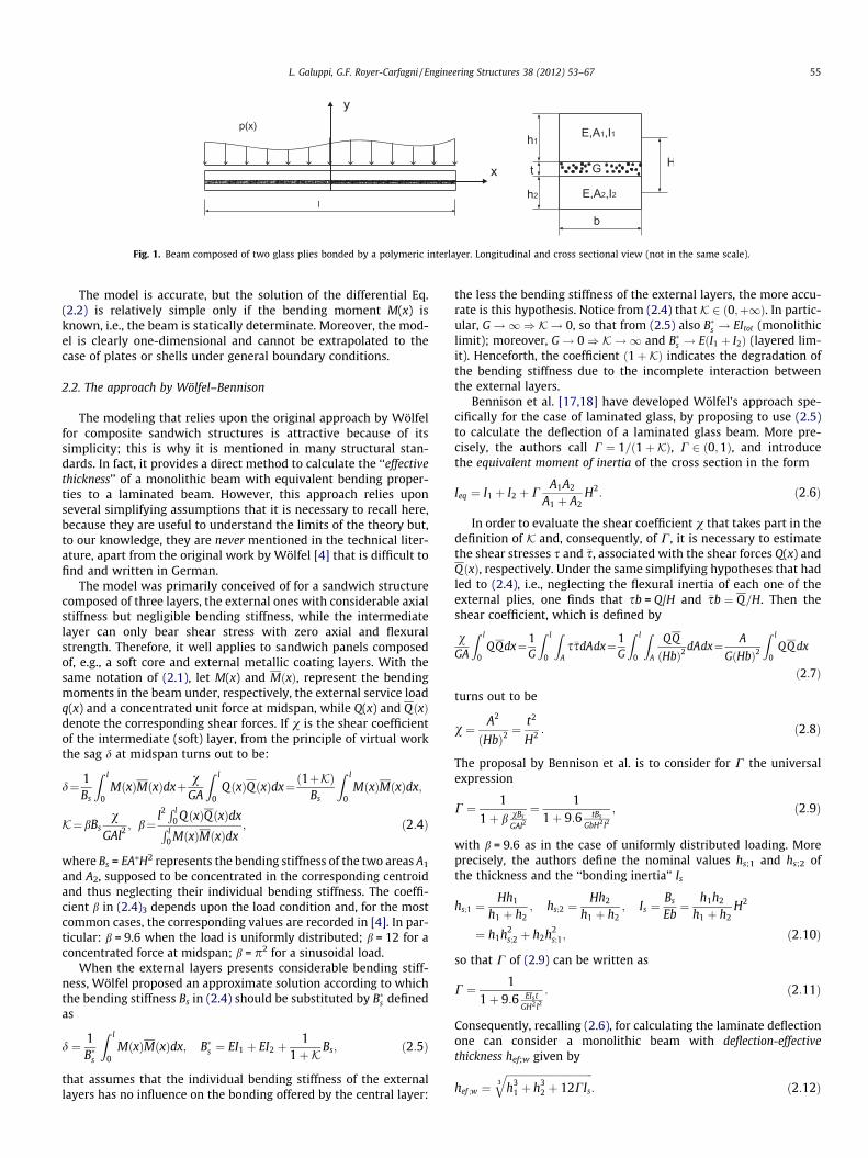
The comparison between the deflection-effective thicknessescalculated with the three approaches is represented in Fig. 13a to-gether with numerical experiments. Here, we can notice a substan-tial deviation of Wölfel–Bennison approach especially for thelowest values of G, but the numerical experiments are in favor ofthe enhanced effective-thickness approach, which gives results

10-2
10-1
100
101
-18
-16
-14
-12
-10
-8
-6
-4
-2
maximum
sag[mm]
EETWBGNNumerical
Fig. 11. Double clamped beam under uniform load. Maximum sag obtained with: Wölfel–Bennison (WB) approach; the generalized Newmark (GN) model; the enhancedeffective thickness (EET) approach; the numerical simulations.
-1500 -1000 -500 0 500 1000 1500-7
-6
-5
-4
-3
-2
-1
0
1ETTGNNumerical
Fig. 12. Deformed shape of double clamped beam under uniform load. Comparison of results obtained with the enhanced effective-thickness (EET) approach, the generalizedNewmark (GN) approach and the numerical experiments.
64 L. Galuppi, G.F. Royer-Carfagni / Engineering Structures 38 (2012) 53–67
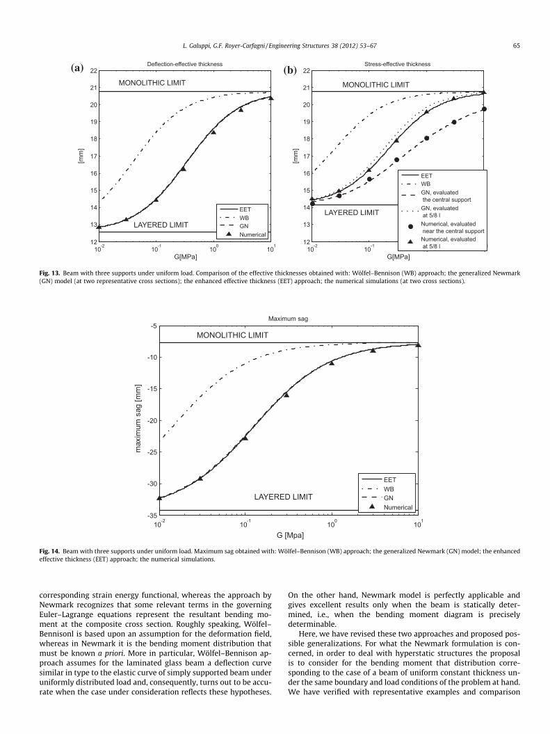
that in practice coincide with the revised Newmark (GN) theory.This finding is confirmed by the graphs of the maximum deflexionof the beam, recorded in Fig. 14.
For what the stress-effective thickness is concerned, since thesystem is not statically determined, from the results of the numer-ical simulations, as well as from the GN approach, we have consid-ered two representative cross sections, one in the neighborhood ofthe central support x = 0, the other one at x = 5l/8, where the bend-ing moment should be extremal. For this case, the enhanced effec-tive-thickness (EET) approach gives results that well capture thestress in the middle of the beam, but are not so accurate at thesymmetry section. On the other hand, the revised Newmark (GN)model gives excellent results at both cross sections.
The results that are obtained with the enhanced effective-thick-ness (EET) approach are summarized, for the sake of comparison, inFig. 15 that shows the deflection of the beam in the four configura-tions of Fig. 4 for different values of G. The bonding performance ofthe interlayer is clearly recognizable by the comparison with themonolithic and layered limits. Even small values of G (of the order
of 1 MPa) are sufficient to provide a considerable bonding strengththat is sufficient to produce a response remarkably close to that ofthe monolithic limit. This is why an accurate definition of the effec-tive thickness, especially in the case of soft interlayers, is crucial toachieve a good design on the side of slenderness, lightness andeconomy.
6. Discussion and conclusions
The two major simple approaches to the structural design oflaminated glass are essentially Newmark model [1] and the ap-proach by Bennison et al. [17,18], which is based upon the originalwork by Wölfel [4]. These two formulations have been reconsid-ered here and a common denominator to them, traditionally re-puted completely different, has been found by considering theproblem within a variational framework. In particular, it has beenshown that the model by Wölfel–Bennison derives from assuminga proper shape function for the beam deformation in the
10-2
10-1
100
101
12
13
14
15
16
17
18
19
20
21
22
G[MPa]
[mm]
EETWBGNNumerical
10-2
10-1
100
101
12
13
14
15
16
17
18
19
20
21
22
G[MPa]
[mm]
EETWB
(a) (b)
Fig. 13. Beam with three supports under uniform load. Comparison of the effective thicknesses obtained with: Wölfel–Bennison (WB) approach; the generalized Newmark(GN) model (at two representative cross sections); the enhanced effective thickness (EET) approach; the numerical simulations (at two cross sections).
10-2
10-1
100
101
-35
-30
-25
-20
-15
-10
-5
maximum
sag[mm]
EETWBGNNumerical
Fig. 14. Beam with three supports under uniform load. Maximum sag obtained with: Wölfel–Bennison (WB) approach; the generalized Newmark (GN) model; the enhancedeffective thickness (EET) approach; the numerical simulations.
L. Galuppi, G.F. Royer-Carfagni / Engineering Structures 38 (2012) 53–67 65
corresponding strain energy functional, whereas the approach byNewmark recognizes that some relevant terms in the governingEuler–Lagrange equations represent the resultant bending mo-ment at the composite cross section. Roughly speaking, Wölfel–Bennisonl is based upon an assumption for the deformation field,whereas in Newmark it is the bending moment distribution thatmust be known a priori. More in particular, Wölfel–Bennison ap-proach assumes for the laminated glass beam a deflection curvesimilar in type to the elastic curve of simply supported beam underuniformly distributed load and, consequently, turns out to be accu-rate when the case under consideration reflects these hypotheses.
On the other hand, Newmark model is perfectly applicable andgives excellent results only when the beam is statically deter-mined, i.e., when the bending moment diagram is preciselydeterminable.
Here, we have revised these two approaches and proposed pos-sible generalizations. For what the Newmark formulation is con-cerned, in order to deal with hyperstatic structures the proposalis to consider for the bending moment that distribution corre-sponding to the case of a beam of uniform constant thickness un-der the same boundary and load conditions of the problem at hand.We have verified with representative examples and comparison

-1500 -1000 -500 0 500 1000 1500-45
-40
-35
-30
-25
-20
-15
-10
-5
0
MONOLITHIC
LIMIT
LAYEREDLIMIT
-1500 -1000 -500 0 500 1000 1500-9
-8
-7
-6
-5
-4
-3
-2
-1
0
MONOLIT
HIC LIMIT
LA
-1500 -1000 -500 0 500 1000 1500-1.4
-1.2
-1
-0.8
-0.6
-0.4
-0.2
0MONOLITHIC LIMIT
LAYEREDL IMIT
-1500 -1000 -500 0 500 1000 1500-50
-45
-40
-35
-30
-25
-20
-15
-10
-5
0
MONOLITHIC LIMIT
LAYEREDLIMIT
(a)
(b)
(c)
(d)
Fig. 15. Deformed shape of the laminated glass beam calculated with the enhanced effective-thickness (EET) approach. Case h1 = h2 = 10 mm, t = 0.76 mm, l = 3150 mm,b = 10,000 mm, E = 70 GPa, p = 0.75 N/mm F = 1000 N.
66 L. Galuppi, G.F. Royer-Carfagni / Engineering Structures 38 (2012) 53–67
with accurate numerical experiments that this position usuallyprovides excellent results, both for the deflection and the stresscalculation. On the other side, to extend Wölfel–Bennison calcula-tions we have proposed to assume various shape function for thelaminated beam deflection, which should reflect the effectiveboundary and load conditions of the structure under consideration.This formulation results particularly simple if one consider as theshape function the form of the elastic curve of a monolithic beamwith constant cross section under the same conditions. With thisposition, the proposed approach gives excellent results and rela-tively compact formulas.
We have also verified that the approach à la Wölfel–Bennisonallows to naturally define a deflection- and stress-effective thick-ness as per Eqs. (2.12) and (2.13), which is very convenient forthe structural design. Here, we have extended such formulas tothe case of more elaborated boundary and load conditions, reach-ing simple expressions for the effective thickness, recorded in(4.14) and (4.17), that can be easily adapted to shape functionsof any form through the introduction of the coupling parameterg, defined in (4.11), that varies between the threshold value 0(layered limit) and 1 (monolithic limit). The calculation of theeffective thickness according to the enhanced proposed approachthus presents no additional difficulty with respect to the tradi-tional Wölfel–Bennison formulation, but gives much better resultswhen the beam is not simply supported and the load is not uni-form, especially when the interlayer is soft and the laminatedbeam approaches the layered limit. The enhanced effective-thick-ness approach here proposed in Section 4.2 thus seems to repre-sent a powerful tool for the calculation of laminated glass. Inparticular, it is much simpler than the models à la Newmark, forwhich it is necessary to calculate a priori the bending moment inthe beam and, most of all, the evaluation of an effective thickness
is not so natural and does not lead to compact expression. In par-ticular, the stress-effective thickness depends upon the particularsection at which the stress needs to be evaluated.
Last but not least, all the models here considered are valid onlyfor the 1-D scheme of a laminated glass beam under flexure, i.e.,when the glass panel is constrained at two borders and the defor-mation is cylindrical. On the other hand, it is customary in the de-sign practice to use the effective thickness calculated according toWölfel–Bennison, using the expression (2.12) and (2.13), to esti-mate the state of stress and the deformation of a laminated plate,under the most various boundary and load conditions. This proce-dure needs to be questioned since we have demonstrated here thatthe aforementioned formulation does not give in general accurateresults, except for the case of a simply supported 1-D beams. Theextension of the effective-thickness notion to the case of platesand shells under bending is the subject of presently ongoing work.
Acknowledgement
The authors acknowledge the Italian MURST for partial supportunder the PRIN2008 program.
References
[1] Newmark NM, Siess CP, Viest IM. Test and analysis of composite beams withincomplete interaction. Proc Soc Exp Stress Anal 1951;9:75–92.
[2] Timoshenko S, Woinowsky K. Theory of plates and shells. New York: McGraw-Hill; 1959.
[3] Hooper JA. On the bending of architectural laminated glass. Int J Mech Sci1973;15:309–23.
[4] Wölfel E. Nachgiebiger Verbund – Eine Näherungslösung und derenAnwendungsmöglichkeiten. Stahlbau 1987;6:173–80.
[5] Sagan H. Introduction to the calculus of variations. New York: Dover; 1992.

L. Galuppi, G.F. Royer-Carfagni / Engineering Structures 38 (2012) 53–67 67
[6] Girhammar UA, Gopu VKA. Composite beam-columns with interlayer slip –exact analysis. J Struct Eng – ASCE 1993;119:1265–82.
[7] Beher RA, Minor JE, Norville HS. Structural behavior of architectural laminatedglass. J Struct Eng – ASCE 1993;119:202–22.
[8] Norville HS, King KW, Swofford JL. Behavior and strength of laminated glass. JEng Mech – ASCE 1998;124:46–53.
[9] Bennison SJ, Jagota A, Smith CA. Fracture of glass/polyvinyl butyral laminatesin biaxial flexure. J Am Ceram Soc 1999;82:1761–70.
[10] Bennison SJ, Davies PS, Van Duser A, Jagota A. Structural performance oflaminated safety glass made with ‘‘stiff’’ interlayers. In: Proceedings of glassperformance days, Tampere (Finland); 2001.
[11] As�ik MZ. Laminated glass plates: revealing of nonlinear behavior. ComposStruct 2003;81:2659–71.
[12] As�ik MZ, Tezcan S. A mathematical model for the behavior of laminated glassbeams. Comput Struct 2005;83:1742–53.
[13] Stephen JB, Sloan JG, Kristunas DF, Buehler PJ, Amos T, Smith CA. Laminatedglass for blast mitigation: role of interlayer properties. In: Proceedings of glassperformance days, Tampere (Finland); 2005.
[14] Ivanov IV. Analysis, modelling, and optimization of laminated glasses as planebeam. Int J Sol Struct 2006;43:6887–907.
[15] Foraboschi P. Behavior and failure strength of laminated glass beams. J EngMech - ASCE 2007;133:1290–301.
[16] Bennison SJ, Qin MHX, Davies PS. High-performance laminated glass forstructurally efficient glazing. Innovative light-weight structures andsustainable Façades, Honk Hong; 2008.
[17] Bennison SJ. Structural properties of laminated glass. Short course, glassperformance days, Tampere (Finland); 2009.
[18] Calderone I, Davies PS, Bennison SJ, Huang X, Gang L. Effective laminatethickness for the design of laminated glass. In: Proceedings of glassperformance days, Tampere (Finland); 2009.
[19] Louter C, Belis J, Bos F, Callewaert D, Veer F. Experimental investigation of thetemperature effect on the structural response of SG-laminated reinforced glassbeams. Eng Struct 2010;32:1590–9.
[20] ABAQUS. Analysis users manual, version 6.10, Simulia.