
Effective October 1, 2020
399
Effective October 1, 2020
-
Upload
khangminh22 -
Category
Documents
-
view
3 -
download
0
Transcript of Effective October 1, 2020
Effective October 1, 2020

WYOMING DEPARTMENT OF TRANSPORTATION MATERIALS TESTING MANUAL
TABLE OF CONTENTS
Technicians testing must meet the requirements in Standard Section 414.4.4.
Print Pages
WYDOT No.
Last Revised Section Title
i
MTM TOC (Rev. 10-19)
100 Section – General
6 – 15 100.0 10-18 Definitions 16 – 21 101.0 10-17 Soils Tests and Their Indications 22 – 25 102.0 01-15 Soil Classification System
26 – 29 107.0 10-18 Materials Acceptance - Construction Test and Certification Requirements
30 – 33 108.0 10-19 Materials Acceptance - Manufactured Products: Materials Certifications, Form T-168 - Certification of Materials
34 – 35 120.0 09-16 Field Laboratory Testing Equipment: Standard Soils Kit 36 - 37 121.0 09-16 Field Laboratory Testing Equipment: Standard Surfacing Kit 38 – 39 122.0 09-16 Field Laboratory Testing Equipment: Standard Concrete Kit 40 – 43 123.0 Investigation of Gravel Deposits
44 – 45 124.0 Correlation between an Automatic Sampler and a Conveyor Belt Cut
46 – 55 126.0 10-20 Correlation of Aggregate Gradation Test Results
56 – 57 127.0 02-12 Assessment of Field Labs Performing Mix Volumetric Quality Acceptance Testing
58 – 59 130.0 10-17 Miscellaneous Items - Sample Size
200 Section – Earthwork
60 – 61 201.0 02-12 Soil Behavior 62 – 67 210.0 Moisture - Density Method Selection and Borrow Moisture Test 68 – 71 211.0 Standardization of Sand 72 – 75 212.0 10-20 Sand Cone Method Field Density Test 76 – 83 213.0 10-20 Moisture - Density Relations of Soils Method “A” 84 – 87 216.0 09-16 Check Curve - Embankment (CC - E) 88 – 91 217.0 10-20 Family of Curves 92 – 95 218.0 Reference Test 96 – 97 220.0 Control of Embankment during Construction
98 – 99 221.0 10-19 Final Embankment 100 – 109 230.0 10-19 Determination of Macrotexture of Pavement Surface
300 Section – Aggregate Materials
110 – 113 301.0 10-20 In - Place Density Test (Subbases and Bases) 114 – 119 390.0 10-17 Mix Design for Stabilized Base (FDR)
09-16
10-20
10-1910-20
02-1210-20
WYOMING DEPARTMENT OF TRANSPORTATION MATERIALS TESTING MANUAL
TABLE OF CONTENTS
Technicians testing must meet the requirements in Standard Section 414.4.4.
Print Pages
WYDOT No.
Last Revised Section Title
ii
MTM TOC (Rev. 10-19)
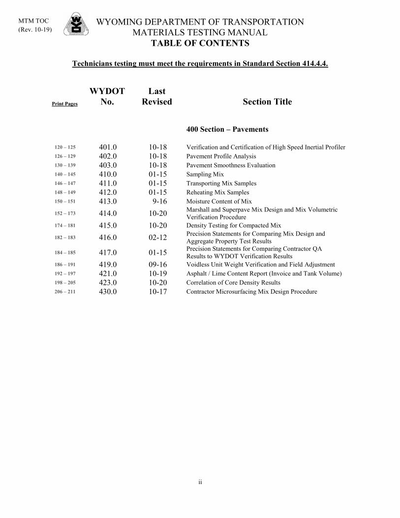
400 Section – Pavements
120 – 125 401.0 10-18 Verification and Certification of High Speed Inertial Profiler 126 – 129 402.0 10-18 Pavement Profile Analysis 130 – 139 403.0 10-18 Pavement Smoothness Evaluation 140 – 145 410.0 01-15 Sampling Mix 146 – 147 411.0 01-15 Transporting Mix Samples 148 – 149 412.0 01-15 Reheating Mix Samples 150 – 151 413.0 Moisture Content of Mix
152 – 173 414.0
9-16
10-20 Marshall and Superpave Mix Design and Mix Volumetric Verification Procedure
174 – 181 415.0 10-20 Density Testing for Compacted Mix
182 – 183 416.0 02-12 Precision Statements for Comparing Mix Design and Aggregate Property Test Results
184 – 185 417.0 01-15 Precision Statements for Comparing Contractor QA Results to WYDOT Verification Results
186 – 191 419.0 09-16 Voidless Unit Weight Verification and Field Adjustment 192 – 197 421.0 10-19 Asphalt / Lime Content Report (Invoice and Tank Volume) 198 – 205 423.0 10-20 Correlation of Core Density Results 206 – 211 430.0 10-17 Contractor Microsurfacing Mix Design Procedure
WYOMING DEPARTMENT OF TRANSPORTATION MATERIALS TESTING MANUAL
TABLE OF CONTENTS
Technicians testing must meet the requirements in Standard Section 414.4.4.
Print Pages
WYDOT No.
Last Revised Section Title
iii
MTM TOC (Rev. 10-19)
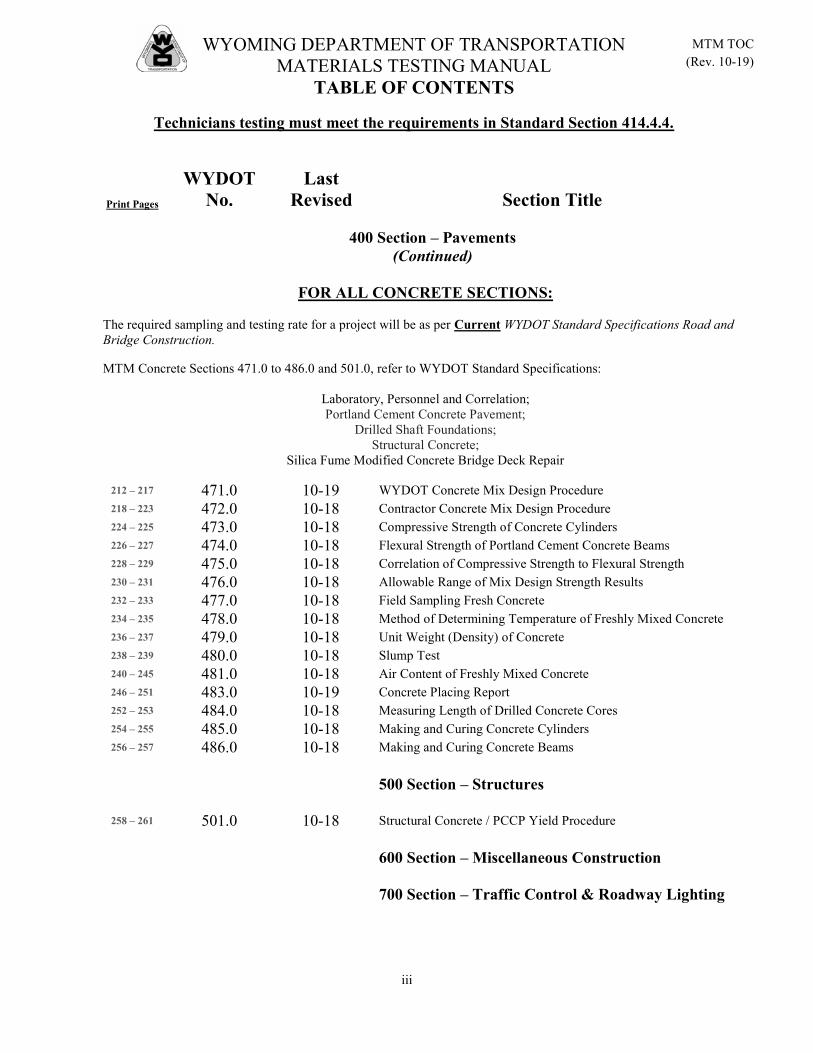
400 Section – Pavements (Continued)
FOR ALL CONCRETE SECTIONS:
The required sampling and testing rate for a project will be as per Current WYDOT Standard Specifications Road and Bridge Construction.
MTM Concrete Sections 471.0 to 486.0 and 501.0, refer to WYDOT Standard Specifications:
Laboratory, Personnel and Correlation; Portland Cement Concrete Pavement;
Drilled Shaft Foundations; Structural Concrete;
Silica Fume Modified Concrete Bridge Deck Repair
212 – 217 471.0 10-19 WYDOT Concrete Mix Design Procedure 218 – 223 472.0 10-18 Contractor Concrete Mix Design Procedure 224 – 225 473.0 10-18 Compressive Strength of Concrete Cylinders 226 – 227 474.0 10-18 Flexural Strength of Portland Cement Concrete Beams 228 – 229 475.0 10-18 Correlation of Compressive Strength to Flexural Strength 230 – 231 476.0 10-18 Allowable Range of Mix Design Strength Results 232 – 233 477.0 10-18 Field Sampling Fresh Concrete 234 – 235 478.0 10-18 Method of Determining Temperature of Freshly Mixed Concrete 236 – 237 479.0 10-18 Unit Weight (Density) of Concrete 238 – 239 480.0 10-18 Slump Test 240 – 245 481.0 10-18 Air Content of Freshly Mixed Concrete 246 – 251 483.0 10-19 Concrete Placing Report 252 – 253 484.0 10-18 Measuring Length of Drilled Concrete Cores 254 – 255 485.0 10-18 Making and Curing Concrete Cylinders 256 – 257 486.0 10-18 Making and Curing Concrete Beams
500 Section – Structures
258 – 261 501.0 10-18 Structural Concrete / PCCP Yield Procedure
600 Section – Miscellaneous Construction
700 Section – Traffic Control & Roadway Lighting
WYOMING DEPARTMENT OF TRANSPORTATION MATERIALS TESTING MANUAL
TABLE OF CONTENTS
Technicians testing must meet the requirements in Standard Section 414.4.4.
Print Pages
WYDOT No.
Last Revised Section Title
iv
MTM TOC (Rev. 10-19)
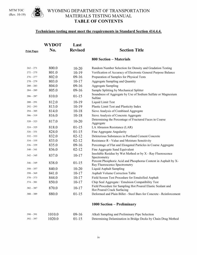
800 Section – Materials
262 – 271 800.0 Random Number Selection for Density and Gradation Testing 272 – 275 801.0 Verification of Accuracy of Electronic General Purpose Balance 276 – 277 802.0 09-16 Preparation of Samples for Physical Tests 278 – 279 803.0 10-17 Aggregate Sampling and Quantity 280 – 283 804.0 09-16 Aggregate Sampling 284 – 285 805.0 09-16 Sample Splitting by Mechanical Splitter
286 – 287 810.0 01-15 Soundness of Aggregate by Use of Sodium Sulfate or Magnesium Sulfate
288 – 291 812.0 10-19 Liquid Limit Test 292 – 293 813.0 10-19 Plastic Limit Test and Plasticity Index 294 – 305 814.0 10-18 Sieve Analysis of Combined Aggregate 306 – 319 816.0 10-18 Sieve Analysis of Concrete Aggregate
320 – 323 817.0 10-20 Determining the Percentage of Fractured Faces in Coarse Aggregate
324 – 325 818.0 01-15 LA Abrasion Resistance (LAR) 326 – 331 824.0 01-15 Fine Aggregate Angularity 332 – 333 832.0 02-12 Deleterious Substances in Portland Cement Concrete 334 – 335 833.0 02-12 Resistance R - Value and Moisture Sensitivity 336 – 339 835.0 09-16 Percentage of Flat and Elongated Particles in Coarse Aggregate 340 – 341 836.0 02-12 Fine Aggregate Sand Equivalent
342 – 345 837.0 10-17 Insoluble Residue by Wet Method or by X - Ray Fluorescence Spectrometry
346 – 349 838.0 01-15 Percent Phosphoric Acid and Phosphorus Content in Asphalt by X-Ray Fluorescence Spectrometry
350 – 357 840.0 10-20 Liquid Asphalt Sampling 358 – 369 841.0 10-17 Asphalt Volume Correction Table 370 – 373 844.0 10-17 Field Screen Test Procedure for Emulsified Asphalt 374 – 381 850.0 10-17 Chip Seal Aggregate / Emulsion Compatibility Test
382 – 387 870.0 10-17 Field Procedure for Sampling Hot Poured Elastic Sealant and Hot Poured Crack Surfacing
388 – 389 880.0 01-15 Deformed and Plain Billet - Steel Bars for Concrete - Reinforcement
1000 Section – Preliminary
390 – 391 1010.0 09-16 Alkali Sampling and Preliminary Pipe Selection 392 – 397 1020.0 01-15 Determining Delamination in Bridge Decks by Chain Drag Method
10-1910-20

WYDOT 100.0 (Rev. 10-18)
1
DEFINITIONS
Admixtures - Materials other than cement, aggregate and water in concrete used to entrain air, retard setting, or accelerate setting.
Anchorage - That portion of a reinforcing bar and any attachment thereto, designed to resist pulling out or slipping of the bar when subjected to stress.
Asphalt Cement (AC), Asphalt Binder, PGAB, etc – Asphalt Binder is considered to be practically pure bitumen which is in a semi-solid state at ordinary temperatures. Selection of the asphalt binder to be used in the HPM is based on environmental and traffic loadings.
Base, Base Course (CB, CTB, PMB) - Intermediate layer between subgrade and surfacing (concrete pavement or plant mix pavement) and contributes to the load bearing capacity of the surfacing section. This material is usually a granular material with the material above the No. 4 being at least partially crushed and may be stabilized using Portland cement, asphalt, emulsion, lime, etc. In the case of a gravel road, the base material will be the top layer and has similar material properties, although retain the natural cohesiveness to deter wash-boarding and rutting, which may mean higher PI.
Batch (Concrete) - The quantity of mix discharged from the mixer in one complete operation of the plant before additional materials are introduced.
Bedrock/Pit Floor - Unusable material, such as shale or native consolidate rock, that underlies the construction material and delineates the depth of rock deposit or vertical limit.
Bleeding (HPM & Chip Seals) - Characterized by the presence of an excessive amount of asphalt on the surface. Typically due to either an excessive amount of prime coat or tack coat or excessive asphalt in the mix.
Bleeding (Concrete) - The escape of water from freshly placed concrete commonly observed as an accumulation upon a horizontal surface.
Blow-Up (Concrete) - Localized buckling or shattering of rigid pavement caused by excessive longitudinal pressure.
Borrow Special Excavation (BSE) - This may be the same material as used in the sub-base, but is usually considered to be subgrade material that replaces inferior or problematic soil. This material may be of the same type as the sub-base, however a non-granular soil may be specified. This layer is not to be included as part of the surfacing section as determined during the pavement structural design; it is included as subgrade if the depth is 24 inches or greater.
California Bearing Ratio (CBR) - A test to determine the bearing capacity of a soil compared to a standard, well-graded, crushed stone.
Carry-over - Deposition of finer material into a bin that should contain larger size aggregate.
WYDOT 100.0 (Rev. 10-18)
2
Cement Treated Base (CTB) - Crushed aggregate that incorporates pit run material meeting a specified gradation treated with cement and placed above the subgrade, sub-base, or fill as a foundation for the pavement or surface course. The strength capacity of the CTB is greater than CB, so a thinner surfacing section is the result. Cementation Value (CV) - This test is used primarily for gravel roads with typically Crushed Base as the surfacing material. It is a test of the fines, minus No. 4 material, and is an indication of the cohesiveness of the material. The test consists of loading a 1 inch square compacted sample and recording the maximum strength achieved. A low strength is an indicator of a loss of cohesiveness that may result in wash-boarding and an extremely high strength is an indicator of excess clay and may result in rutting and slickness. Coarse Material - Crushed rock retained on a No. 4 sieve. This material is crushed after all the undersize pit run material or fines are removed, so all of the rock is crushed. Consistency (Concrete) - Designates the relative mobility of freshly mixed concrete commonly defined as slump. Construction Joint - Vertical or notched plane of separation in pavement. Contraction Joint - Joint of either full depth or weakened plane-type designed to establish position of any crack caused by contraction while providing no space for expansion of pavement beyond original length. Corrugations - Regular transverse undulations in surface of pavement consisting of alternate valleys and crests. Crack(s) - Vertical cleavage due to natural causes or traffic action. Crazing (Concrete) - Pattern cracking. Extending only through surface layer: A result of more drying shrinkage in surface than interior of plastic concrete. Crushed Base (CB) - Crushed aggregate that incorporates pit run material meeting a specified gradation placed above the subgrade, sub-base, or fill as a foundation for the pavement or surface course. Crusher Run Material - The natural granular material run through a crusher to a specified maximum top size. Some of this material would not be subjected to any crushing so pit run fines are still present. Curing Period - A period provided to prevent formation of surface cracks due to rapid loss of water while concrete is plastic and to assure attainment of specified strength. Cutback Asphalt - Asphalt cement which has been rendered liquid by fluxing with a petroleum distillate. (Includes: RC's - rapid curing; MC's - medium curing; SC's - slow curing)
WYDOT 100.0 (Rev. 10-18)
3
"D" lines - Disintegration characterized by successive formation of series of fine cracks at rather close intervals paralleling edges, joints, and cracks and usually curving across slab corners, initial cracks forming very close to slab edge and additional cracks progressively developing, ordinarily filled with calcareous deposit. Density - The mass of a material per unit volume. Commonly called “unit weight". In other words, the "weight" of a unit volume of material. Usually expressed in terms of lbs/ft3. Refer to AASHTO M 132 for additional information.
a. Apparent - The weight in air of a unit volume of a material at a specified temperature and pressure. If the material is a solid, the volume will be that of the impermeable portion.
b. Bulk - The weight in air of a unit volume of a permeable material (including both permeable and impermeable voids normal to the material) at a specified temperature and pressure.
Directional Bias –
Gradation- “Directional bias” is considered to exist when all five tests are higher for one laboratory than for the other and the average difference on at least one sieve exceeds the Allowable Gradation Difference in Table 3 of WYDOT 126.0 Density- “Directional bias” is considered to exist when all, or all but one of the tests are higher for one laboratory than the other and the average difference exceeds 0.5 lb/ft3.
Disintegration - Deterioration into small fragments from any cause. Distortion - Any deviation of pavement surface from original shape. Emulsion - Asphalt mixed with water with the aid of a small amount of emulsifying agent (usually a detergent). The object is to make a stable dispersion of the asphalt cement in water; stable enough for pumping, prolonged storage, and mixing. Further, the emulsion should “break” quickly after contact with aggregate in a mixer or after spraying on the roadbed. “Breaking” is the separation of the water from the asphalt. Expansion Joint - Joint designed to allow for the pavement to expand in length. Faulting - Differential vertical displacement of slabs adjacent to joint or crack. Filler - Natural material passing a No. 4 sieve that may be either granular (sand) or dirt. Fine Material - Crushed rock passing a No. 4 sieve. Generally, when specified as a Type I plant mix pavement aggregate, no pit run material is allowed unless a filler is specified and the fine material is crushed. In a Type III plant mix pavement aggregate, pit run material is allowed and the fines are usually a combination of crushed and pit run.

WYDOT 100.0 (Rev. 10-18)
4
Fineness Modulus - An index of the fineness or coarseness of an aggregate. It is the summation of the cumulative percentages of the material retained on the standard sieves divided by 100; the size opening in consecutive sieves being related by a constant ratio. Coarse aggregate sieves: 6 inch, 3 inch, 1½ inch, ¾ inch, ⅜ inch, and No. 4. Fine aggregate sieves: No. 4, No. 8, No. 16, No. 30, No. 50, and No. 100. Flecking - Dislodgement of thin mortar film from outermost portion of occasional particles of coarse aggregate on concrete surface, generally attributable to lack of bond between mortar and aggregate. Flexible Base and Pavements - The term flexible indicates Hot Plant Mix Pavement (PMP, HPM, PMB, etc.), also referred to as asphalt pavement or asphalt base, which is granular material, at least partially crushed, with added Asphalt Cement and lime. Mix design testing is completed on material from a specified source to determine the properties required, including component rates, to provide the necessary structural strength. A flexible course is intended to provide adequate aggregate interlock to provide vertical strength and also Aflexibility@ to allow adequate elasticity to accommodate the seasonal effects. Frost Heave - Differential upward displacement due to frost; seasonal displacement. Gradation - A term used to describe the range and the relative distribution of particle sizes in a material.
Example: Well graded soils: Soils that having an even distribution of particle sizes but usually have a low percentage of fines (material passing the No. 4 sieve).
Poorly graded soils: Soils that have the majority of particles retained on a certain sieve and may be either fine or coarse.
Grizzly - Instead of the square or round openings used in a screen, a grizzly has parallel bars spaced at a fixed distance and set at angles of 20o to 50o of horizontal. Hair Checking - Small irregular cracks extending to appreciable depth and occurring before concrete takes final set. Honeycomb - A surface or interior defect in a concrete mass characterized by the lack of mortar between the coarse aggregate particles. Joint(s) - Constructed junctions between adjacent sections of pavement or between pavement and structures. Laitance - Extremely fine material of little or no hardness which may collect on the surface of freshly placed concrete resulting from the use of excess mixing water. Leveling Course (Hot Plant Mix Leveling, Microsurfacing) - Course of variable thickness constructed immediately on top of base or existing pavement to remove large irregularities prior to overlying treatment or construction. This treatment restores the existing pavement surface and will have a variable thickness when placed.
WYDOT 100.0 (Rev. 10-18)
5
Liquid Limit - That moisture content which is the boundary between the liquid and plastic states for the minus No. 40 fraction of a soil. For laboratory-purposes, it may be defined as the moisture content as which that soil fraction will close a standard groove for a length of ½ inch when subjected to 25 blows in a liquid limit device. Longitudinal Joint - Joint of either full-depth or weakened-plane type constructed parallel to or along center line to control longitudinal cracking. Map Cracking - Disintegration in which cracking of slab surface develops in random pattern; may develop over entire surface or localized areas; may or may not be associated with abnormal growth of concrete. Marshall Mix Design - A test procedure that determines the optimum asphalt content for a specified PMP aggregate gradation that optimizes the properties required. The objective is to provide sufficient asphalt for a durable pavement, sufficient mix stability, sufficient voids to allow for a slight amount of additional compaction yet low enough to keep out air and moisture, and sufficient workability to permit efficient placement without segregation. On high traffic roads, try to minimize the asphalt content so the mix resists rutting, but keep enough to provide a durable surface that is still flexible and resists cracking. On lower traffic roads, try to allow enough asphalt to provide a flexible and durable pavement, yet not so high that rutting or shoving results. Compaction in this procedure utilizes a drop-hammer. Maximum Size – The smallest sieve listed in the applicable specification through which 100 percent of the aggregate sample particles pass. Superpave Maximum Size – One sieve larger than the nominal maximum size. Mechanical Analysis - The mechanical analysis of a soil/aggregate is the determination of the percentage of individual grain sizes present in the sample. The results of the tests are of value when used for classification purposes. The analysis consists of two parts, the determination of the amount of coarse material using a nest of sieves or screens and the analysis for the fine grained fraction using a hydrometer analysis. Moisture Content - The weight of water in a given soil mass divided by the oven dry weight of the soil; is expressed in percent. Nominal Maximum Size – One size larger than the first specification sieve to retain more than 10 percent. Optimum Moisture - Moisture content which will permit maximum dry density to be obtained for a given compactive effort. Overburden - Surface soil or granular material which may or may not be suitable for construction purposes and overlies material that may be suitable for road or bridge construction. Oversize Material - Particles that exceed the maximum size specified for a material type. For example, a ¾ inch nominal maximum size plant mix pavement has a top size of ¾ inch, so any material retained on a 1 inch screen or larger is considered to be oversize.
WYDOT 100.0 (Rev. 10-18)
6
Pavement Course or Surfacing Course (HPM or RHPM or Concrete Pavement) - This is the uppermost layer of the surfacing section that may have a surface treatment, PMWC, and is placed on the base course. This layer is comprised of a treated granular material that is either flexible or rigid. Permeability - A measure of the facility of a soil mass to transmit liquids largely dependent upon grain size distribution. PG Binders - As part of the SHRP recommendations, the asphalt cement testing and classification system were developed to better characterize the design environmental conditions to improve performance by controlling rutting, low temperature cracking and fatigue cracking. Typically use PG 58-28, PG 64-22, PG 64-28. Also PG 70-28 and PG 76-28. Pit Run Filler - The natural granular material passing a No. 4 screen before processing, such as crushing. Pitting - Displacement of particles of aggregates from pavement surface due to action of traffic or disintegration, without major displacement of cementing material. Plant Mix Base (PMB) - Crushed aggregate that may incorporate pit run material meeting a specified gradation treated with asphalt cement and placed above the subgrade, sub-base, or fill as a foundation for the pavement or surface course. The strength capacity of the PMB is greater than CB and CTB so a thinner surfacing section is the result. Plant Mix Pavement (PMP or HPM) - Crushed aggregate that may incorporate pit run fines, minus No. 4 material, mixed with lime and asphalt cement meeting specified material requirements that is placed above the base course. Plastic Index - The numerical difference between the liquid limit and the plastic limit. In other words, the difference between the percent of moisture at the liquid limit and the percent of moisture at the plastic limit (LL-PL). Plastic Limit - The moisture content which is the boundary between the plastic and semi-solid states for the minus No. 40 fraction of a soil. For laboratory purposes, it may be defined as the minimum moisture content at which the soil fraction can be rolled into a thread ⅛ inch in diameter without crumbling. Prime Coat - The initial application of low viscosity liquid asphalt to an absorbent base prior to placing an asphalt concrete. Progressive Scale - Concrete disintegration which at first appears as surface scaling but gradually progresses deeper. Pumping - Displacement and ejection of water and suspended fine particles at joint, cracks and edges.
WYDOT 100.0 (Rev. 10-18)
7
R-Value - The R-Value is determined on a soil sample using the stabilometer test. R-Value is a ratio of the lateral force and the vertical pressure. The stabilometer test also is an indicator of the moisture sensitivity of the soil that may affect the strength. Raveling - Progressive disintegration from surface downward or edges inward by dislodgement of aggregate particles. Resilient Modulus (MR) - Resilient Modulus is another method of classifying the bearing capacity of a soil. This test procedure allows varying moisture and lateral forces to mimic confined and unconfined conditions. Resurfacing - Supplemental surface placed on existing pavement to improve surface conformation or increase strength. Rigid Base and Rigid Pavement (Concrete Pavement, PCCP, or CTB) – The term rigid indicates concrete, which is granular material, at least partially crushed, that has added Portland cement, such as concrete pavement or Cement Treated Base (CTB). Mix design testing is completed on material from a specified source to determine the mixture properties required to provide the necessary structural strength. Rutting - Formation of longitudinal depressions by wheel tracking. Sand Equivalent (SE) - A ratio representing the sand to fines and is used to indicate the quality of granular materials for surfacing. Saturated Surface Dry - A term used to describe the condition of an aggregate in which the pores of all the particles are completely filled with water, but their surfaces are free from moisture. Scaling - Peeling away of surface of concrete pavement. Screened Material - Pit run or crusher run material that is separated into two or more size fractions and is often referred to as scalped on a certain sieve size. Screenings or Chats - Screened material passing a 1inch screen. Seal Coat - An application of liquid asphalt to an existing or new pavement to secure the necessary bond between the bituminous pavement and the plant mix wearing course to be placed over it. Settlement - Reduction in elevation of short sections of pavement or structures. Shaker - A vibratory or rotational device used to sieve undersize material out of the crushed material. Shoving - Displacement of bituminous paving material due to action of traffic, generally resulting in bulging of surface.
WYDOT 100.0 (Rev. 10-18)
8
Strategic Highway Research Program, SHRP. Due to the high costs of surfacing materials, SHRP was established by Congress to improve the performance and durability of US roads. All aspects of highway construction were considered for study and recommendations and many areas were considered including traffic control, rigid and flexible surfacing, maintenance and all aspects such as testing, field correlation and specifications. Slump - A measure of the consistency of concrete. Soil Classification - A soil classification system is an arrangement of different soils into groups having similar properties. The purpose is to make it possible to estimate the soil properties or strength capabilities by association with soils of the same class whose properties are known, and to provide the engineer with an accurate method of soil description. Spalling - Breaking or chipping of pavement at joints, cracks or edges usually resulting in fragments with feather edges. Specific Gravity -
a. Absolute - The ratio of the density of a solid to the density of water at a stated temperature and pressure. In other words, the ratio of the weight of a unit volume of a solid to the weight of an equal volume of water at a stated temperature.
b. Apparent - The ratio of the density of a permeable or impermeable material to the density of water at a stated temperature and pressure. In other words, the ratio of the weight in air of a unit volume of a material at a stated temperature to the weight in air of equal density of an equal volume of gas-free distilled water at a stated temperature. If the material is a solid, the volume shall be that of the impermeable portion.
c. Bulk - The ratio of the density of a permeable material to the density of water at a stated temperature and pressure. In other words, the ratio of the weight in air of a unit volume of a permeable material (including both permeable and impermeable voids normal to the material) at a stated temperature to the weight in air of equal density of an equal volume of gas-free distilled water at a stated temperature.
Stripping - Separation of bituminous films from aggregate particles due to presence of moisture. Sub-base - Specified surfacing material of planned thickness placed as foundation for a pavement. Sub-base (SB or PRSB or CRSB) - A specified surfacing course, usually granular, that overlies the subgrade and acts as the foundation for the overlying base and surface courses. The sub-base may be pit run or crusher run material from a designated source, borrow, pit, or quarry, or reused surfacing, and has a specified or implied minimum R-Value strength. This layer is typically included as part of the surfacing section as determined during the pavement structural design, but may be included as a drainage layer.
WYDOT 100.0 (Rev. 10-18)
9
Subgrade (Basement Soil) - The upper limits of embankments or in-place soils upon which the pavement structure is built. Material in cuts, fills, and fill foundations immediately below the first layer of sub-base. For design purposes, the subgrade is the top two feet of soil below the dirt grade. Sub-sealing or Under-sealing - Placing of waterproof material under existing pavement to arrest vertical flow of water or suspended solids and fill voids under pavement. Superpave (Superior Performing Asphalt Pavements) - A test procedure developed under SHRP to replace the Marshall mix design to determine the optimum asphalt content and aggregate gradation based on the traffic level. This procedure utilizes a gyratory compactor that is intended to more closely mimic field compaction. Surface Scale - Peeling away of surface mortar of Portland Cement Concrete exposing sound concrete, even though scale extends into mortar surrounding coarse aggregate. Surface Texture - Character of surface of pavement which depends on size, shape, arrangement and distribution of aggregates and cement or binder. Surface Treatment or Surface Seal (PMWC or Chip Seal) - This is the uppermost surfacing course that is not considered to provide structural strength, but does provide a friction layer to prevent skidding and also to seal the surface to prevent the infiltration of water. This layer is usually a chip seal or plant mix wearing course (PMWC) but could be microsurfacing or similar product. Tack Coat - An application of liquid asphalt to an existing or new pavement or primed surface to secure the necessary bond between the concrete or plant mix pavement and the plant mix pavement to be placed over it. Thrust - Pressure exerted by rigid pavement against other pavements or bridges. Topsoil - Surface soil suitable for germination of seeds and the support of vegetative growth. Undersize Material (Reject) - Material passing a specified screen size are considered to be undersized. Usually this term is used to describe the rejects or material passing the maximum size to produce the crushed material. Unit Weight - The commonly used term for DENSITY. Even though its usage has been widespread over the years, it is not standardized nor desirable terminology. For more detailed information, see AASHTO M 132, Appendix paragraph X1.5. Warping - Deviation of pavement surface from original shape caused by temperature and moisture differentials within slab. Warping Joint - Joint permitting warping of pavement slabs when moisture and temperature differentials occur in pavement, i.e., longitudinal or transverse joints with bonded steel or tie bars passing through them.

WYDOT 100.0 (Rev. 10-18)
10
Washing - Method utilized to remove the soils that are attached to the rock that would otherwise be knocked off the rock during crushing resulting in a high No. 200 fraction. Water to Cement Ratio (W/C or W/(CM)) - Ratio of the weight of water to the weight of cement used in a concrete mix design; an indicator of quality. (CM) indicates the total cementicious material in the mix including portland cement, silica fume, fly ash and slag. Water Table – Temperature/Density of Water referenced in WYDOT 213.0 and WYDOT 479.0
Temperature °F
Calibration of Measure lb/ft³
45 62.421 46 62.419 47 62.417 48 62.415 49 62.412 50 62.409 51 62.406 52 62.402 53 62.399 54 62.395 55 62.391 56 62.387 57 62.382 58 62.377 59 62.372 60 62.367 61 62.361 62 62.355 63 62.349 64 62.343 65 62.337 66 62.330 67 62.323 68 62.316 69 62.309 70 62.301 71 62.294 72 62.286 73 62.278 74 62.270 75 62.261 76 62.252 77 62.244 78 62.235 79 62.226 80 62.216 81 62.207 82 62.197 83 62.187 84 62.177 85 62.167
WYDOT 101.0 (Rev. 10-17)
1
SOILS TESTS AND THEIR INDICATIONS Reference Documents: AASHTO T 99 Standard Method of Test for Moisture-Density Relations of
Soils Using a 2.5-kg (5.5-lb) Rammer and a 305-mm (12- in.) Drop
Field Density Test
1. Purpose of the field density test: a. A test procedure for assuring compliance with the density specification
and moisture. b. Preliminary investigation - to obtain the natural density of the soil in
place. 1. As an indication of its bearing value as foundation.
2. To aid in computing the shrinkage or swell of a soil.
2. WYDOT methods for determining field density: a. Sand cone method. b. Nuclear density method.
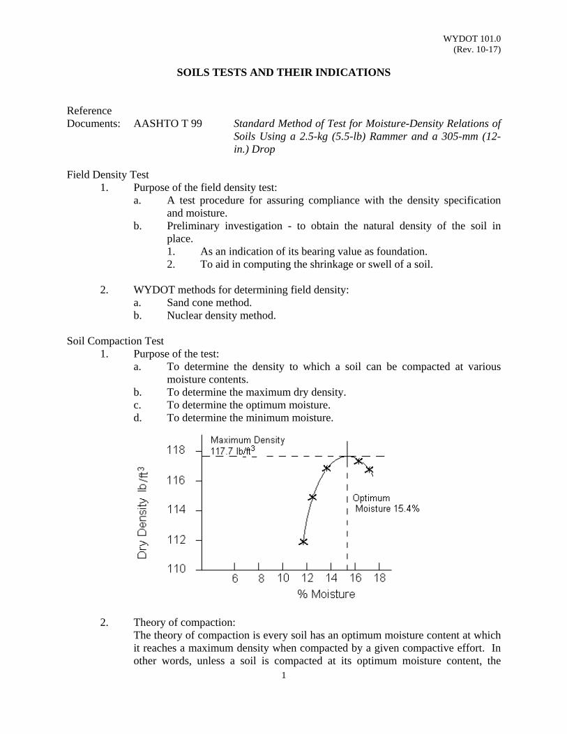
Soil Compaction Test
1. Purpose of the test: a. To determine the density to which a soil can be compacted at various
moisture contents. b. To determine the maximum dry density. c. To determine the optimum moisture. d. To determine the minimum moisture.
2. Theory of compaction: The theory of compaction is every soil has an optimum moisture content at which
it reaches a maximum density when compacted by a given compactive effort. In other words, unless a soil is compacted at its optimum moisture content, the

WYDOT 101.0 (Rev. 10-17)
2
maximum density cannot be obtained with this compactive effort. Experience has shown it is necessary to compact sub-grades, sub-bases and bases to high densities to obtain a foundation which will stand the effects of the traffic. Compaction increases the bearing value of soils and decreases compressibility minimizing settlements. Furthermore, it reduces the ability of some soils to absorb water; thus eliminating excessive expansion and softening of the subgrade lift. Since it influences so many properties of a road, it is necessary to control the compaction.
a. Density - Optimum Moisture Content:
The optimum moisture content for a soil may be defined as that amount of water which will, either partially or totally, fill the voids between the soil particles. This moisture will act as a lubricant which will allow the soil particles to slide over each other and form a denser mass. Since the water content at which the soil reaches its maximum density for any given compactive effort must completely or partially fill the voids between the particles, gradation of the soil is one of the major considerations. The finer the grains of the soil, the greater the surface area of the particles and therefore, more water must be added to reach its maximum density.
Consequently, using a specified compactive effort, the density of a soil increases with an incremental increase in moisture content until the optimum moisture content is reached. At this point the soil contains sufficient moisture to lubricate its particles as well as partially satisfy its affinity for water. If the moisture content is increased beyond this point, the soil particles will be displaced by water resulting in a decrease in the density.
Regarding the tolerances in the control of moisture content, it can be stated that granular soils have a sharp peak in their compaction (moisture-density) curves; hence the tolerance in moisture content cannot be as large as in a case of a clayey soil that has a considerably flatter curve. Generally, 4 percentage points under or 2 percentage points over optimum moisture content are accepted as to produce the M - D curve.
In the laboratory or on-site, the density and the optimum moisture content of soils are determined by use of "Standard Method of Test for Moisture-Density Relations of Soils Using a 2.5-kg (5.5-lb) Rammer and a 305-mm (12- in.) Drop", AASHTO Designation T 99. In this method, the soil is compacted in a 1/30 ft3 mold which is 4 inches in diameter. The soil is placed in three equal layers and compacted by 25 blows of a standard rammer on each of the three layers. The rammer has a striking face 2 inches in diameter, a weight of 5.5 lb, and a free fall of 12 inches.
WYDOT 101.0 (Rev. 10-17)
3
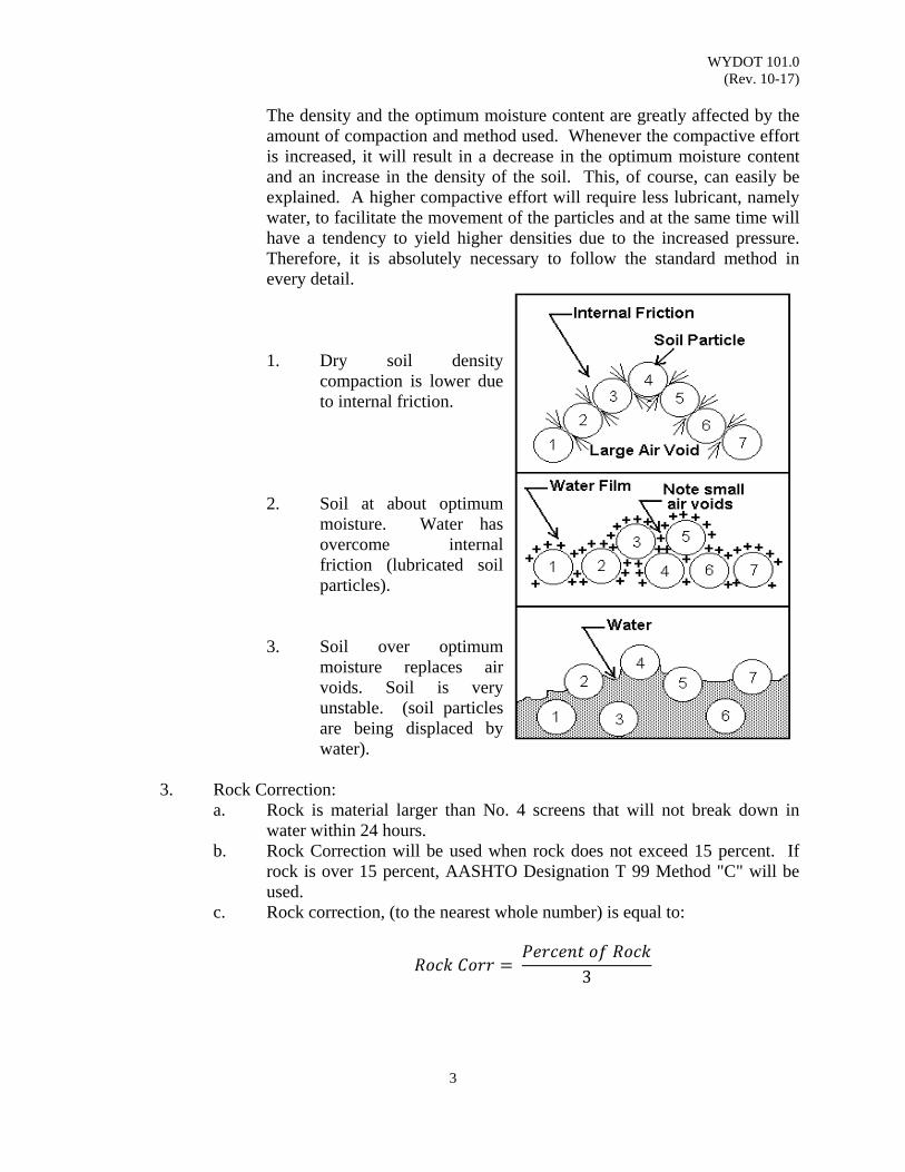
The density and the optimum moisture content are greatly affected by the amount of compaction and method used. Whenever the compactive effort is increased, it will result in a decrease in the optimum moisture content and an increase in the density of the soil. This, of course, can easily be explained. A higher compactive effort will require less lubricant, namely water, to facilitate the movement of the particles and at the same time will have a tendency to yield higher densities due to the increased pressure. Therefore, it is absolutely necessary to follow the standard method in every detail. 1. Dry soil density
compaction is lower due to internal friction.
2. Soil at about optimum moisture. Water has overcome internal friction (lubricated soil particles).
3. Soil over optimum moisture replaces air voids. Soil is very unstable. (soil particles are being displaced by water).
3. Rock Correction:
a. Rock is material larger than No. 4 screens that will not break down in water within 24 hours.
b. Rock Correction will be used when rock does not exceed 15 percent. If rock is over 15 percent, AASHTO Designation T 99 Method "C" will be used.
c. Rock correction, (to the nearest whole number) is equal to:
3
WYDOT 101.0 (Rev. 10-17)
4
Mechanical Analysis 1. Purpose:
a. Helps to analyze soils (soil classification). b. Determine frost heave potentialities (10 percent or less minus No. 200
material generally resists frost). c. Determine percent of soil components (gravel, sand, etc.).
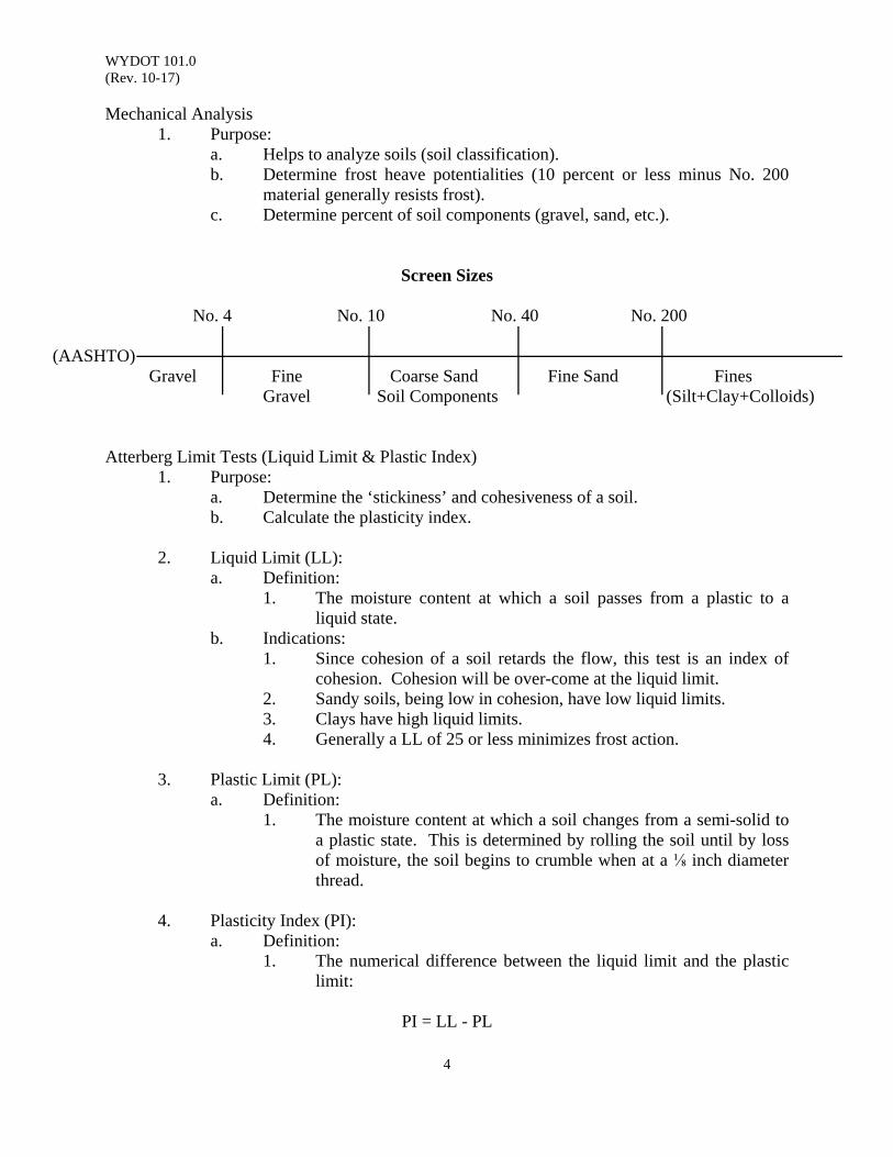
Screen Sizes No. 4 No. 10 No. 40 No. 200
(AASHTO) Gravel Fine Coarse Sand Fine Sand Fines Gravel Soil Components (Silt+Clay+Colloids)
Atterberg Limit Tests (Liquid Limit & Plastic Index)
1. Purpose: a. Determine the ‘stickiness’ and cohesiveness of a soil. b. Calculate the plasticity index.
2. Liquid Limit (LL):
a. Definition: 1. The moisture content at which a soil passes from a plastic to a
liquid state. b. Indications:
1. Since cohesion of a soil retards the flow, this test is an index of cohesion. Cohesion will be over-come at the liquid limit.
2. Sandy soils, being low in cohesion, have low liquid limits. 3. Clays have high liquid limits. 4. Generally a LL of 25 or less minimizes frost action.
3. Plastic Limit (PL):
a. Definition: 1. The moisture content at which a soil changes from a semi-solid to
a plastic state. This is determined by rolling the soil until by loss of moisture, the soil begins to crumble when at a ⅛ inch diameter thread.
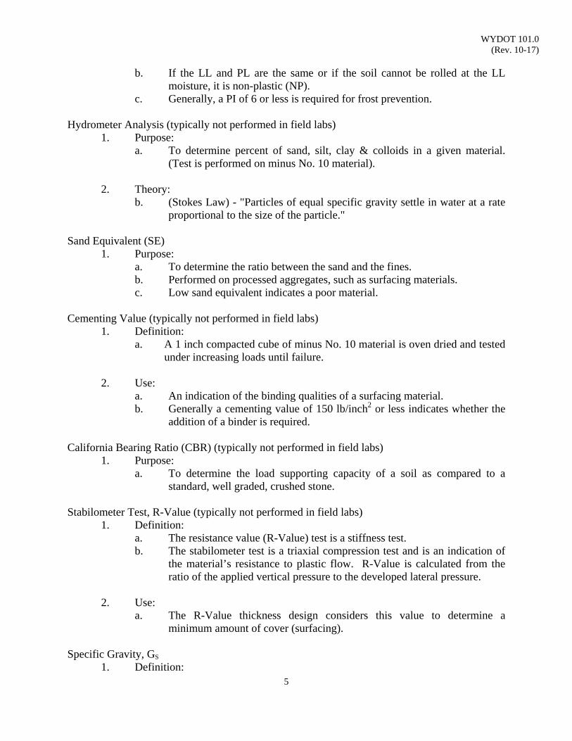
4. Plasticity Index (PI):
a. Definition: 1. The numerical difference between the liquid limit and the plastic
limit: PI = LL - PL
WYDOT 101.0 (Rev. 10-17)
5
b. If the LL and PL are the same or if the soil cannot be rolled at the LL moisture, it is non-plastic (NP).
c. Generally, a PI of 6 or less is required for frost prevention. Hydrometer Analysis (typically not performed in field labs)
1. Purpose: a. To determine percent of sand, silt, clay & colloids in a given material.
(Test is performed on minus No. 10 material).
2. Theory: b. (Stokes Law) - "Particles of equal specific gravity settle in water at a rate
proportional to the size of the particle." Sand Equivalent (SE)
1. Purpose: a. To determine the ratio between the sand and the fines. b. Performed on processed aggregates, such as surfacing materials. c. Low sand equivalent indicates a poor material.
Cementing Value (typically not performed in field labs)
1. Definition: a. A 1 inch compacted cube of minus No. 10 material is oven dried and tested
under increasing loads until failure. 2. Use:
a. An indication of the binding qualities of a surfacing material. b. Generally a cementing value of 150 lb/inch2 or less indicates whether the
addition of a binder is required. California Bearing Ratio (CBR) (typically not performed in field labs)
1. Purpose: a. To determine the load supporting capacity of a soil as compared to a
standard, well graded, crushed stone. Stabilometer Test, R-Value (typically not performed in field labs)
1. Definition: a. The resistance value (R-Value) test is a stiffness test. b. The stabilometer test is a triaxial compression test and is an indication of
the material’s resistance to plastic flow. R-Value is calculated from the ratio of the applied vertical pressure to the developed lateral pressure.
2. Use:
a. The R-Value thickness design considers this value to determine a minimum amount of cover (surfacing).
Specific Gravity, GS
1. Definition:

WYDOT 101.0 (Rev. 10-17)
6
a. The ratio of the density of a material to the density of water at the same temperature:
A = weight of oven dry sample in air B = weight of saturated, surface dry sample in air E = weight of saturated sample in water
Note: Use the same unit of weight for A, B & E. (GS is unitless)
WYDOT 102.0 (Rev. 01-15)
1
SOIL CLASSIFICATION SYSTEM
Scope: This practice describes classifying soils into seven groups based on laboratory determination of particle size distribution, liquid limit, and plasticity index. Evaluation of soils within each group is made by means of a “group index,” which is a value calculated from an empirical formula.
Use: The group classification, including group index, is useful in determining the relative quality of the soil material for use in earthwork structures, particularly embankments, subgrades, subbases, and bases. However, for the detailed design of important structures, additional data concerning strength or performance characteristics of the soil under field conditions will usually be required.
Reference Documents: AASHTO M 145 Standard Specification for Classification of Soils and Soil -
Aggregate Mixtures for Highway Construction Purposes
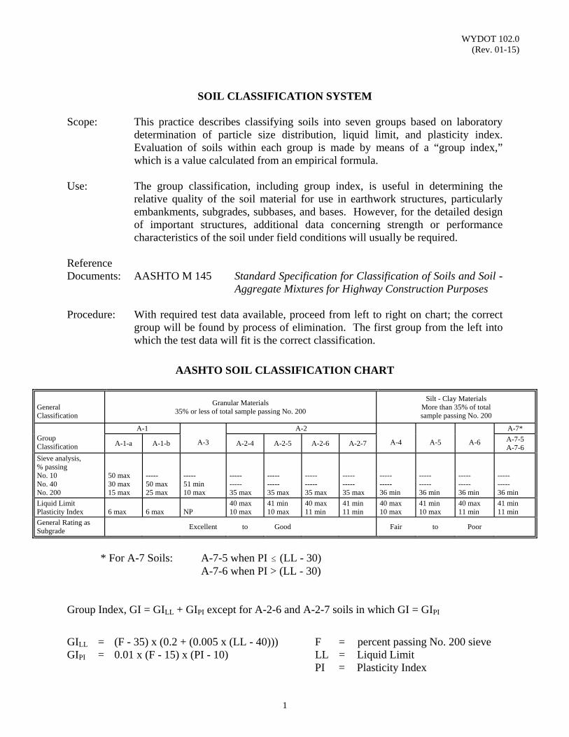
Procedure: With required test data available, proceed from left to right on chart; the correct group will be found by process of elimination. The first group from the left into which the test data will fit is the correct classification.
AASHTO SOIL CLASSIFICATION CHART
General Classification
Granular Materials 35% or less of total sample passing No. 200
Silt - Clay Materials More than 35% of total sample passing No. 200
Group Classification
A-1
A-3
A-2
A-4 A-5 A-6
A-7*
A-1-a A-1-b A-2-4 A-2-5 A-2-6 A-2-7
A-7-5A-7-6
Sieve analysis, % passing No. 10 No. 40 No. 200
50 max 30 max 15 max
----- 50 max 25 max
----- 51 min 10 max
----- ----- 35 max
----- ----- 35 max
----- ----- 35 max
----- ----- 35 max
----- ----- 36 min
----- ----- 36 min
----- ----- 36 min
----- ----- 36 min
Liquid Limit Plasticity Index
6 max
6 max
NP
40 max 10 max
41 min 10 max
40 max 11 min
41 min 11 min
40 max 10 max
41 min 10 max
40 max 11 min
41 min 11 min
General Rating as Subgrade
Excellent to Good Fair to Poor
* For A-7 Soils: A-7-5 when PI # (LL - 30)A-7-6 when PI > (LL - 30)
Group Index, GI = GILL + GIPI except for A-2-6 and A-2-7 soils in which GI = GIPI
GILL = (F - 35) x (0.2 + (0.005 x (LL - 40))) F = percent passing No. 200 sieve GIPI = 0.01 x (F - 15) x (PI - 10) LL = Liquid Limit
PI = Plasticity Index
WYDOT 102.0 (Rev. 01-15)
2
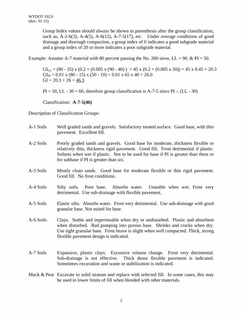
Group Index values should always be shown in parenthesis after the group classification, such as, A-2-6(3), A-4(5), A-6(12), A-7-5(17), etc. Under average conditions of good drainage and thorough compaction, a group index of 0 indicates a good subgrade material and a group index of 20 or more indicates a poor subgrade material.
Example: Assume A-7 material with 80 percent passing the No. 200 sieve, LL = 90, & PI = 50.
GILL = (80 - 35) x (0.2 + (0.005 x (90 - 40) ) = 45 x (0.2 + (0.005 x 50)) = 45 x 0.45 = 20.3 GIPI = 0.01 x (80 - 15) x (50 - 10) = 0.01 x 65 x 40 = 26.0 GI = 20.3 + 26 = 46.3
PI = 50, LL - 30 = 60, therefore group classification is A-7-5 since PI # (LL - 30)
Classification: A-7-5(46)
Description of Classification Groups: A-1 Soils Well graded sands and gravels. Satisfactory treated surface. Good base, with thin
pavement. Excellent fill. A-2 Soils Poorly graded sands and gravels. Good base for moderate, thickness flexible or
relatively thin, thickness rigid pavement. Good fill. Frost detrimental if plastic. Softens when wet if plastic. Not to be used for base if PI is greater than three or for subbase if PI is greater than six.
A-3 Soils Mostly clean sands. Good base for moderate flexible or thin rigid pavement.
Good fill. No frost conditions. A-4 Soils Silty soils. Poor base. Absorbs water. Unstable when wet. Frost very
detrimental. Use sub-drainage with flexible pavement. A-5 Soils Elastic silts. Absorbs water. Frost very detrimental. Use sub-drainage with good
granular base. Not suited for base. A-6 Soils Clays. Stable and impermeable when dry or undisturbed. Plastic and absorbent
when disturbed. Bad pumping into porous base. Shrinks and cracks when dry. Use tight granular base. Frost heave is slight when well compacted. Thick, strong flexible pavement design is indicated.
A-7 Soils Expansive, plastic clays. Excessive volume change. Frost very detrimental.
Sub-drainage is not effective. Thick dense flexible pavement is indicated. Sometimes excavation and waste or stabilization is indicated.
Muck & Peat Excavate to solid stratum and replace with selected fill. In some cases, this may
be used in lower limits of fill when blended with other materials.
WYDOT 102.0 (Rev. 01-15)
3
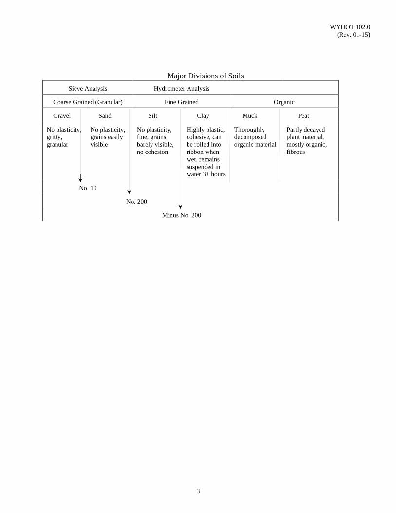
Major Divisions of Soils
Sieve Analysis
Hydrometer Analysis
Coarse Grained (Granular)
Fine Grained
Organic
Gravel
Sand
Silt
Clay
Muck
Peat
No plasticity, gritty, granular
No plasticity, grains easily visible
No plasticity, fine, grains barely visible, no cohesion
Highly plastic, cohesive, can be rolled into ribbon when wet, remains suspended in water 3+ hours
Thoroughly decomposed organic material
Partly decayed plant material, mostly organic, fibrous
No. 10
No. 200
Minus No. 200

WYDOT 102.0 (Rev. 01-15)
4
(This page intentionally left blank.)
WYDOT 107.0 (Rev. 10-18)
1
MATERIALS ACCEPTANCE
CONSTRUCTION TEST AND CERTIFICATION REQUIREMENTS
Scope: WYDOT uses a combination of sampling, testing, manufactured product
documentation (certification), and inspection to establish conformance of materials to project plans and specifications. Generally, three forms are developed for each construction project by the WYDOT Materials Program to provide guidelines for materials acceptance testing and documentation requirements. They are WYDOT Forms: T-128 Construction Test Requirements, T-131 Manufactured Products Received, and T-132 Engineer’s Verification of Specification Compliance.
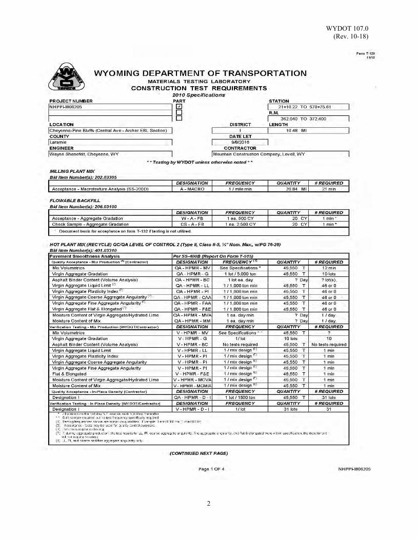
Use: Form T-128 Construction Test Requirements, lists the specified sampling and
testing frequencies for construction materials. Included in Form T-128 are sections for each construction material, identified from the project plans and specifications, where testing by the contractor or WYDOT is required to determine compliance to the applicable specification. A Form T-128 is generated and sent to the Resident Engineer for each project.
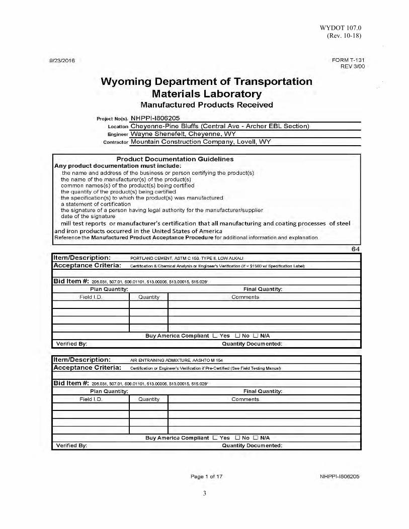
Form T-131 Manufactured Products Received, lists the documentation
requirements (Acceptance Criteria) for manufactured goods and products where documentation provided by the manufacturer or supplier is required to verify compliance to the applicable specification. Included in Form T-131 are sections for each manufactured product identified from the project plans and specifications. Within each section are fields containing the material / product name, acceptance criteria, bid item number(s), and, if available, the plan quantity. Field identification, quantity, and comment fields are provided for field personnel to list certification documents received and the quantity being certified or received. Fields are provided for the total quantity documented, final quantity and the identification of the person preparing the final. Manufactured products added to the project must be documented as well. Form T-131 is generated and sent to the Resident Engineer and Prime Contractor for each project. This form is available in MS Excel in the Falcon project directory.
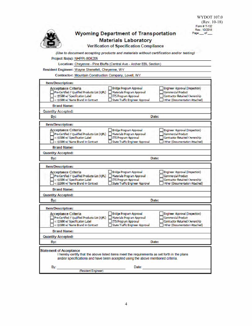
Form T-132 Engineer’s Verification of Specification Compliance, may be used to
document acceptance of certain construction materials and manufactured goods when exceptions exist to verify specification compliance. This method of acceptance may be used only when specifically noted in Forms T-128 or T-131.
Reference Documents: WYDOT T-128 Construction Test Requirements WYDOT T-131 Manufactured Products Received WYDOT T-132 Engineer’s Verification of Specification Compliance
WYDOT 107.0 (Rev. 10-18)
2
WYDOT 107.0 (Rev. 10-18)
3
WYDOT 107.0 (Rev. 10-18)
4
WYDOT 108.0 (Rev. 10-19)
1
MATERIALS ACCEPTANCE - MANUFACTURED PRODUCTS
MATERIALS CERTIFICATIONS FORM T-168, Certification of Materials
Scope: To ensure manufactured products meet applicable specifications, WYDOT
requires certification documents be provided for products delivered to the project site.
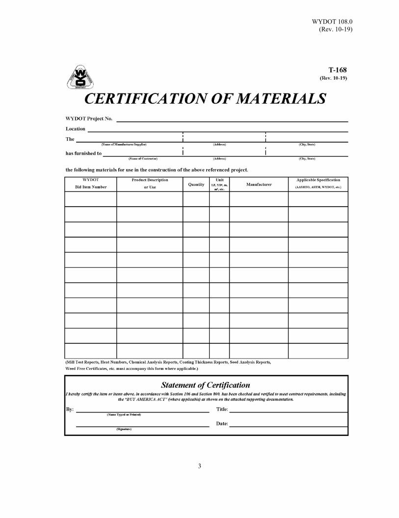
Use: Generally, the materials certification for manufactured products on WYDOT
projects is the Form T-168, Certification of Materials. Form T-168, Certification of Materials, is available for download on the department’s website. The contractor is to provide this form to sub-contractors, material suppliers, and manufacturers. The manufacturer or supplier will complete Form T-168, Certification of Materials, along with any required supporting documents, and return them to the prime contractor to upload into the ICX Construction Management System (CMS).
WYDOT accepts forms of certification other than Form T-168, Certification of
Materials, including statements of compliance on test reports, letters-of-certification, etc., although in order to be considered valid, all certification documents must provide the information shown below:
PRODUCT DOCUMENTATION GUIDELINES Product documentation must include: WYDOT PROJECT NUMBER WYDOT Project Name (Location)
Vendor / Supplier Contractor Bid Item Number (or Bid Item work is subsidiary to)
Description (Common (trade) name of the product) Quantity Unit of Measure Manufacturer / Fabricator Specifications to which the product was manufactured Statement of certification
Signature of a person having legal authority for the vendor, supplier or manufacturer
Printed or typed name corresponding to the signature Title of person signing the document Date

WYDOT 108.0 (Rev. 10-19)
2
SUPPORTING DOCUMENTS For many products, supporting documentation must also accompany the certification in order for the certification to be complete and valid. In most cases, the required supporting documents are listed in the “Acceptance Criteria” field on Form T-131, Manufactured Products Received. Examples of supporting documents include Seed Analysis Reports for each lot of seed, Weed Free Certificates for Dry Mulch and Typical Chemical Analysis Reports for Portland Cement & Fly Ash. Iron and Steel Products: Supporting documentation attesting that all manufacturing processes including melting/smelting, coating application, fabrication and assembly have been performed in the United States or its territories in accordance with the “BUY AMERICA ACT” must be provided by the entity who performed the work. Examples are Steel Mills, foundries and galvanizing plants. INSPECTION It is important for the WYDOT inspector to verify that material delivered to the project site is undamaged and that the certification documents uploaded into CMS represent the materials delivered to the project. Compare the description and quantity to the product delivered and verify that the specification designation, lot, batch and heat number match up with the markings on the product and the specification listed in the project contract documents.
Reference Documents: WYDOT T-131 Manufactured Products Received WYDOT T-168 Certification of Materials
WYDOT 108.0 (Rev. 10-19)
3

WYDOT 108.0 (Rev. 10-19)
4
(This page intentionally left blank.)
WYDOT 120.0 (Rev. 09-16)
1
FIELD LABORATORY TESTING EQUIPMENT:
STANDARD SOILS KIT 1. Chisel and hammer 2. Moisture tins, 3 oz 3. Moisture tins, 8 oz 4. Moisture tins, 16 oz 5. Graduated cylinder, 100 ml 6. Straightedge, 15 inch 7. Measure, 0.1 ft3 8. Compaction mold, 0.03 ft3 (base plate optional) 9. Compaction rammer and guide, 5½ lb 10. No. 4 Screen, round, 16 inch diameter (WYDOT Catalog # FT6440) 11. Pan, 16 inch diameter (WYDOT Catalog # FT5420) 12. Compaction block, 300 lb minimum (Standard Plan 106-1A) 13. Removal press and plug for samples 14. Stove for drying or infra-red heater 15. Balance (high capacity), sensitive to 0.1 lb [50 g] 16. Balance (low capacity), sensitive to 0.0002 lb [0.1 g] 17. Trowel, 5 inch 18. Wood block, 2 inch x 4 inch 19. Sample splitter: one large mechanical splitter 20. Sand cone apparatus, 1 gal [4 L] (jar and funnel) 21. Standard calibration sand (not less than 100 lb) 22. Containers with lids; suggest concrete cylinder cans and lids 23. Rammer with guide, 5 ½ lb 24. Spoon (large) 25. Shovel (and pick, if required) 26. Brass brush 27. Canvas sample bags 28. Mortar 29. Pestle (rubber tipped) 30. Liquid limit device 31. Grooving tool 32. Porcelain casserole 33. Spatula 34. Ground glass plate 35. Suitable pans 36. U.S. Standard Sieves, 8 inch diameter:
2 inch [50 mm] ¾ inch [19 mm] No. 4 [4.75 mm] No. 10 [2.00 mm] No. 20 [850 µm] No. 40 [425 µm]
No. 200 [75 µm]

WYDOT 120.0 (Rev. 09-16)
2
37. Kit box 38. Shipping envelopes 39. WYDOT Forms: T-112 Soil Compaction Worksheet *T-113 Weekly Report for Compaction of Embankment/Crushed Base/Other T-140 Plotting Worksheet *Weekly report no longer mandatory but optional
WYDOT 121.0 (Rev. 09-16)
1
FIELD LABORATORY TESTING EQUIPMENT:
STANDARD SURFACING KIT
1. Moisture tins, 3 oz 2. Moisture tins, 16 oz 3. Graduated cylinder, 100 ml 4. Straightedge, 15 inch 5. Measure, 0.1 ft3 6. Compaction mold, 0.03 ft3 (base plate optional) 7. Compaction rammer and guide, 5½ lb 8. No. 4 screen, round, 16 inch diameter (WYDOT Catalog # FT6440) 9. Pan, 16 inch diameter (WYDOT Catalog # FT5420) 10. Compaction block, 300 lb minimum (Standard Plan 106-1A) 11. Removal press and plug for samples 12. Stove for drying or infra-red heater 13. Balance, high capacity, sensitive to 0.1 lb [5 g] 14. Balance, low capacity, sensitive to 0.0002 lb [0.1 g] 15. Trowel, 5 inch 16. Sample splitter: one large mechanical splitter 17. Sand cone apparatus, 1 gal [4 l] (jar and funnel) 18. Standard calibration sand (not less than 100 lb) 19. Chisel and hammer 20. Containers with lids; suggest concrete cylinder cans and lids 21. Rammer with guide, 5 ½ lb 22. Spoon (large) 23. Shovel (flat square nose) 24. Wood block, 2 inch x 4 inch 25. Canvas sample bags 26. Container, 5 gal for sampling 27. Mortar 28. Pestle (rubber tipped) 29. Liquid limit device 30. Grooving tool 31. Porcelain casserole 32. Spatula, 4 inch long x 1 inch wide (with straight edge) 33. Ground glass plate 34. Suitable wash pans 35. Scoop (flat square nose) 36. Thermometers, 50 °F to 500 °F and 0 °F to 120 °F 37. Coring machine 38. Wire basket and chain 39. Container, 5 gal (with overflow) 40. Asbestos gloves 41. Brush sweeping 42. Brush brass 43. Large mechanical shaker with screens 44. Sieve shaker for 8 inch diameter sieves
WYDOT 121.0 (Rev. 09-16)
2
45. No. 8 sieve for washing 46. No. 200 sieve for washing 47. U.S. Standard Sieves, 8 inch diameter and / or large shaker:
2 ½ inch [53 mm] 2 inch [50 mm] 1 ½ inch [37.5 mm] 1 inch [25.0 mm] ¾ inch [19.0 mm] ½ inch [12.5 mm] ⅜ inch [9.5 mm] No. 4 [4.75 mm] (for large shaker) Pan (for large shaker)
48. U.S. Standard Sieves, 8 inch diameter: No. 4 [4.75 mm] No. 8 [2.36 mm] No. 10 [2.00 mm] No. 20 [850 µm] No. 30 [600 µm] No. 40 [425 µm] No. 50 [300 µm] No. 100 [150 µm] No. 200 [75 µm] Pan Lid (snug fitting)
49. Funnel stand with funnel, 1¼ inch ±, above cylinder 50. Jar (cylinder) and funnel bottom opening of ½ inch ± ⅛ diameter 51. Proportional caliper device 52. WYDOT Forms: *T-102 Report of Field Tests on Surfacing Materials T-120 Sample Transmittal T-166 Aggregate Analysis *Weekly report no longer mandatory but optional

WYDOT 122.0 (Rev. 09-16)
1
FIELD LABORATORY TESTING EQUIPMENT: STANDARD CONCRETE KIT
1. Rubber tired wheel borrow 2. Balance, high capacity (sensitive to 0.1 lb [50 g]) 3. Balance, low capacity (sensitive to 0.0002 lb [0.1 g]) 4. Slump cone 5. Pan, 15 inch x 15 inch 6. Tamping rod (bullet-point), ⅝ inch 7. Tamping rod (bullet-point), ⅜ inch 7. Rubber or rawhide mallet, 1.25 ± 0.50 lb 8. Trowel, 5 inch 9. Scoop (large) 10. Straightedge, 15 inch 11. Stove for drying or infra-red heater 12. Ruler, incremented in millimeters and inches 13. Air meter apparatus: including 12 inch x 12 inch x 0.5 inch plexiglass plate and water bulbs 14. Shovel 15. Concrete cylinder cans with lids (cases available, any number of cylinders can be taken) 16. Suitable wash pans 17. Sample splitters, one large field splitter or quartering canvas 18. Beam molds, 6 inch x 6 inch x 20 inch 19. Wood float 20. Brass brush 21. Large mechanical shaker with screens 22. Sieve shaker for 8 inch diameter sieves 23. No. 8 sieve for washing 24. No. 200 sieve for washing 25. U.S. Standard Sieves 8 inch diameter and / or large shaker:
2 ½ inch [53 mm] 2 inch [50 mm] 1 ½ inch [37.5 mm] 1 inch [25.0 mm] ¾ inch [19.0 mm] ½ inch [12.5 mm] ⅜ inch [9.5 mm] No. 4 [4.75 mm] (for large shaker) Pan (for large shaker)
26. U.S. Standard Sieves 8 inch diameter: No. 4 [4.75 mm] No. 8 [2.36 mm] No. 16 [1.18 mm] No. 30 [600 µm] No. 50 [300 µm] No. 100 [150 µm] No. 200 [75μm] Pan Lid (snug fitting)

WYDOT 122.0 (Rev. 09-16)
2
27. Kit box 28. Transmittal envelopes 29. WYDOT Forms: *T-101 Report of Field Tests on Concrete Aggregate T-109 Concrete Placing Report T-120 Sample Transmittal T-166 Aggregate Analysis *Weekly report no longer mandatory but optional
WYDOT 123.0 (Rev. 09-16)
1
INVESTIGATION OF GRAVEL DEPOSITS
Scope: The intent of a preliminary investigation is to assess the available quantity of suitable material available and determine whether the material meets the minimum aggregate requirements for the products to be produced; reference Section 106.3.3.3.
Apparatus: 1. Backhoe capable of digging a minimum of 15 feet 2. Shovel with a flat square nose3. Clean canvas sample sacks4. Form T-120, Sample Transmittal with transmittal envelopes5. Log forms for recording test hole information
(Geology Program will provide forms upon request)6. Stakes / lathe for marking the test holes7. Weighted tape for measuring test hole depth / thicknesses
Reference Documents: WYDOT 106.3.3.3 WYDOT Standard Specifications
WYDOT 106.3.3.3.1 WYDOT Standard Specifications WYDOT T-120 Sample Transmittal
Use: This procedure is intended to facilitate the requirements of 106.3.3.3.1, and intended to assist with the preparation of a sampling layout and the associated field investigation.
Procedure: Preliminary Work
Prior to field work, several preparatory steps are recommended to ensure an efficient and thorough preliminary investigation of the proposed pit site.
1. Obtain an estimate of the desired quantities of material for the proposedproject including what the material will be used for, for example hot plantmix (HPM), crushed base, subbase, borrow special excavation, etc.
2. Prepare a preliminary site map along with planned field test holes for theinvestigation. Any information collected regarding the geology of thearea, landmarks, etc., should be included on the site map.
Field Investigation
1. Conduct a surface inspection of the area to be investigated prior to anyphysical digging. This allows for an approximation of the total surfacearea and will also aid in determining the location, number of holes, andspacing between test holes. The number of test holes required will varydepending on the size of the area investigated and the amount of productto be produced.
As a guideline, between five and fifteen holes with spacing between 250and 500 feet is adequate for a preliminary investigation. If possible, the
WYDOT 123.0 (Rev. 09-16)
2
holes should be evenly spaced along the dimensions (length by width) of the site. However, if the thickness and quality of the gravel varies significantly, additional holes may be necessary.
2. There are several important factors to consider while digging and
sampling the test hole:
a. Every effort should be made to keep the topsoil and overburden separate from the gravel in order to avoid contamination of the gravel. This is accomplished by placing the topsoil and overburden on one side of the backhoe hole while placing the gravel on the other. It is not necessary to collect topsoil, overburden or pit floor samples during the preliminary investigation. It is good practice to note the depth of these layers.
b. When the gravel layer is reached and sampling begins, it is
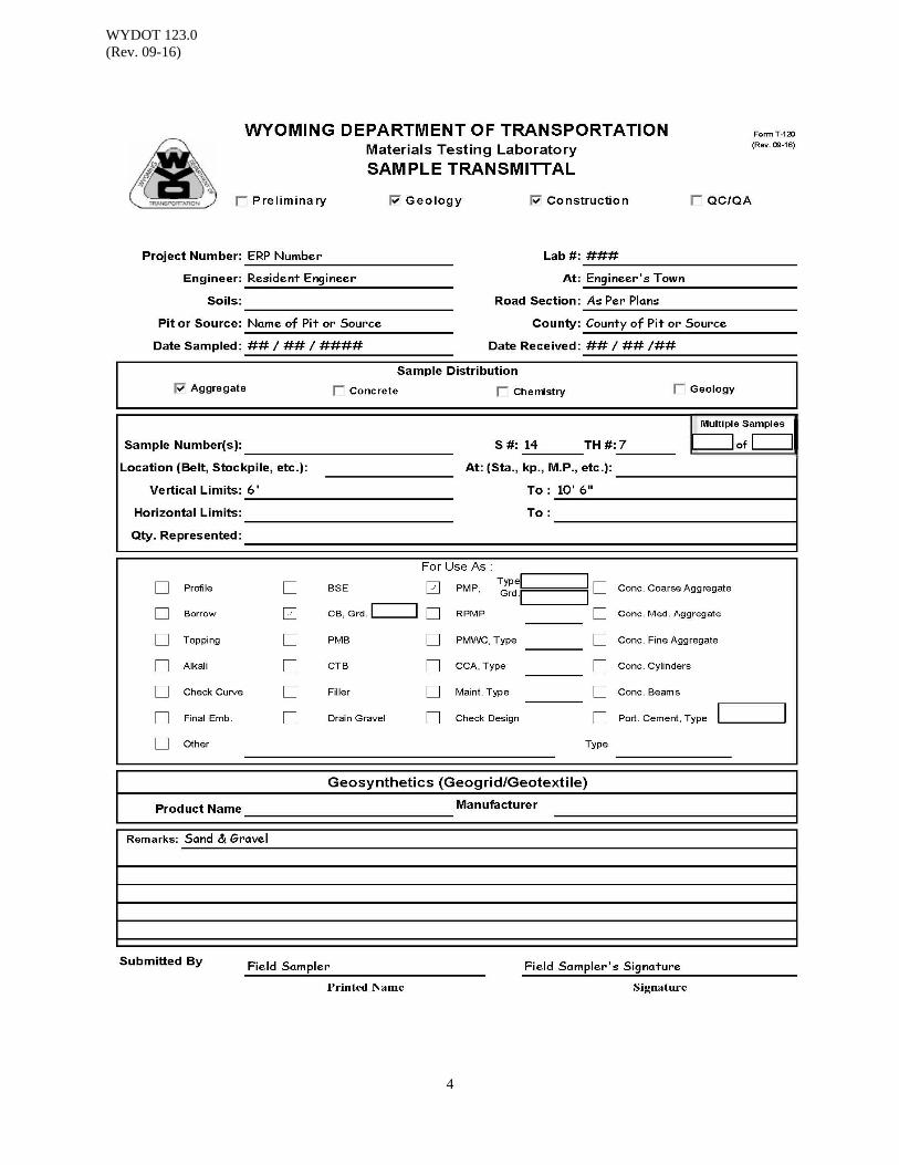
important to obtain a sample(s) that is as representative as possible of the material being dug. Do not collect the sample from one specific depth of the hole but instead, obtain a sample representing the entire thickness of the gravel layer. The sample should include, if present, a representative percentage of any deleterious material present within the gravel layer such as silt/sand seams, caliche-coated rock, clay balls, etc. At least one gravel sample per hole, or 8-10 samples minimum for the entire investigation, is required to obtain an adequate amount of material for wear grade testing by the consultant. Referencing of gravel samples from one hole to the next is not recommended. A Sample Transmittal, Form T-120 and envelope, or similar, for the consultant should be filled out completely. Test hole and sample number along with vertical limits and proposed use for the material, should be considered as required minimums for submittal to consultant.
c. While digging and sampling the test hole, it is important to keep an accurate record or log of the material being dug. Precisely record the thickness of the topsoil, overburden, sand and gravel, and if encountered, depth to the pit floor. A brief description of topsoil, overburden and pit floor (for example sandy topsoil, clayey silt overburden, red shale pit floor) should be recorded, however a more complete description of the gravel layer is recommended. Information to be noted would include:
1. Lenses or coatings of sand, silt, caliche, or clay within the
gravel, and their thickness. 2. The durability of the rock; is it a soft sandstone, or hard
competent rock? 3. Any cemented layers and the degree of cementation (slight,
moderate, well). 4. Depth to groundwater, if present.
WYDOT 123.0 (Rev. 09-16)
3
5. Maximum size of rock and visual estimation of the percentages of plus 3 inch (oversize) and plus 1 inch rock.
d. If and when the pit floor is reached, its depth should be recorded.
At this point the test hole should be abandoned and backfilling begun.
3. Backfilling of the hole should be accomplished only after all the necessary
samples have been collected and material thicknesses recorded. It is important to backfill the hole with the gravel first, and the topsoil and overburden last, to help reestablish vegetation. After backfilling is complete, the test hole should be marked with a lathe or stake (preferably both) labeled with the appropriate test hole number for surveying purposes, if necessary.
4. As the test holes are being dug, a rough sketch map should be drawn
indicating approximate test hole locations and other prominent features of the site such as terrace edges, fence lines, roads, old depleted pit limits, utilities, etc. A hand held GPS unit is useful in creating these field maps, test holes and other recorded features can be easily transferred to topographic maps to create fairly accurate map of a pit site.
5. When the preliminary investigation has been completed, check to ensure
that all of the samples have been completely and accurately identified and labeled, and then submit them to the Consultant for analysis with the suggested Form T-120. Estimate the total quantity of aggregate based on the dimensions of the pit and average gravel thickness to determine if adequate quantities are available for the project.
WYDOT 123.0 (Rev. 09-16)
4
WYDOT 124.0 (Rev. 10-20)
1
CORRELATION BETWEEN AN AUTOMATIC SAMPLER AND A CONVEYOR BELT CUT
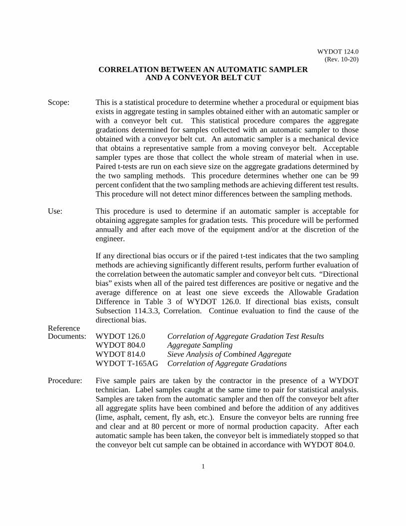
Scope: This is a statistical procedure to determine whether a procedural or equipment bias
exists in aggregate testing in samples obtained either with an automatic sampler or with a conveyor belt cut. This statistical procedure compares the aggregate gradations determined for samples collected with an automatic sampler to those obtained with a conveyor belt cut. An automatic sampler is a mechanical device that obtains a representative sample from a moving conveyor belt. Acceptable sampler types are those that collect the whole stream of material when in use. Paired t-tests are run on each sieve size on the aggregate gradations determined by the two sampling methods. This procedure determines whether one can be 99 percent confident that the two sampling methods are achieving different test results. This procedure will not detect minor differences between the sampling methods.
Use: This procedure is used to determine if an automatic sampler is acceptable for
obtaining aggregate samples for gradation tests. This procedure will be performed annually and after each move of the equipment and/or at the discretion of the engineer.
If any directional bias occurs or if the paired t-test indicates that the two sampling
methods are achieving significantly different results, perform further evaluation of the correlation between the automatic sampler and conveyor belt cuts. “Directional bias” exists when all of the paired test differences are positive or negative and the average difference on at least one sieve exceeds the Allowable Gradation Difference in Table 3 of WYDOT 126.0. If directional bias exists, consult Subsection 114.3.3, Correlation. Continue evaluation to find the cause of the directional bias.
Reference Documents: WYDOT 126.0 Correlation of Aggregate Gradation Test Results WYDOT 804.0 Aggregate Sampling WYDOT 814.0 Sieve Analysis of Combined Aggregate
WYDOT T-165AG Correlation of Aggregate Gradations Procedure: Five sample pairs are taken by the contractor in the presence of a WYDOT
technician. Label samples caught at the same time to pair for statistical analysis. Samples are taken from the automatic sampler and then off the conveyor belt after all aggregate splits have been combined and before the addition of any additives (lime, asphalt, cement, fly ash, etc.). Ensure the conveyor belts are running free and clear and at 80 percent or more of normal production capacity. After each automatic sample has been taken, the conveyor belt is immediately stopped so that the conveyor belt cut sample can be obtained in accordance with WYDOT 804.0.
WYDOT 124.0 (Rev. 10-20)
2
Gradation tests are run on both samples by the contractor in accordance with procedure WYDOT 814.0. Gradation test will be performed by the same contractor technician using the same equipment since this procedure is used to detect differences due only to the different sampling methods. Paired two tailed t-tests are performed separately for each sieve using an ∀ (alpha) with the level of significance of 0.01. The statistical method is the same as the one presented in WYDOT 126.0.
Calculations: Perform calculations in the same manner as in WYDOT 126.0. Report: Report results on Form T-165AG.
WYDOT 126.0 (Rev. 10-20)
1
CORRELATION OF AGGREGATE GRADATION TEST RESULTS
Scope: This statistical procedure compares the aggregate gradations determined by two
different laboratories. Paired t-tests are run on the aggregate gradations for each sieve size determined by the two laboratories. This procedure determines whether one can be 99 percent confident that the two laboratories are achieving different test results. Additional tests determine whether excessively large or small variability has caused a t-test to produce results that, though they are statistically correct, are practically wrong in the current situation. These tests combine to determine whether the two laboratories achieve results that are significantly different. This procedure will not detect minor differences between the two laboratories.
Use: This procedure determines whether there is any substantial systematic bias between
the aggregate gradations determined by the WYDOT field laboratory and by the contractor’s laboratory. If the data generated by the WYDOT field laboratory and by the contractor’s laboratory are found to be significantly different, then the dispute resolution procedure will be followed.
This procedure may be used for concrete aggregate or other aggregate sources. When the procedure is different for concrete aggregate, the differences are noted in this procedure.
The paired t-test determines if the differences in aggregate gradations are significantly different for each sieve size.
If any directional bias occurs or if the t-test indicates that the two laboratories are
achieving significantly different results, further evaluation of the correlation between the laboratories will be performed.
If there is any change in testing personnel or equipment, the correlation process is repeated using production test results.
Reference Documents: AASHTO T 27 Standard Method of Test for Sieve Analysis of Fine and
Coarse Aggregate WYDOT 114.3.3 WYDOT Standard Specifications WYDOT 401 WYDOT Standard Specifications WYDOT 803 WYDOT Standard Specifications
WYDOT 417.0 Precision Statements for Comparing Contractor QA Results to WYDOT Verification Results
WYDOT 804.0 Aggregate Sampling WYDOT 814.0 Sieve Analysis of Combined Aggregate
WYDOT 816.0 Sieve Analysis of Concrete Aggregate WYDOT E-119 Pay Adjustment for Density CMS FORM Correlation of Aggregate Gradations WYDOT T-166 Aggregate Analysis
WYDOT 126.0 (Rev. 10-20)
2
Procedure: Fifteen aggregate samples are collected in groups of three according to WYDOT 405.0. During each of the five sampling events, the contractor will obtain three samples; one to be tested by the contractor, one by WYDOT, and one retained as a referee sample. The middle sample will be the referee sample when cutting samples from the conveyor belt. Label samples obtained at the same time to compare during statistical analysis. The WYDOT field laboratory will test five samples, the contractor’s laboratory will test five samples, and five samples will be retained by WYDOT as referee samples.
Determine the percentage passing each sieve size for each aggregate sample according to WYDOT 814.0 (or WYDOT 816.0 for concrete aggregate). Report the test result pairs (percentages) on CMS Form Correlation of Aggregate Gradations passing each sieve to the nearest 0.1 percent as previously recorded on Form T-166 (Aggregate Analysis), Combined Aggregate, % Passing column item “to 0.1%”. Enter specification sieves per the WYDOT Standard Specifications, Section 803 for which the minimum percent passing is less than 90 percent.
Perform two-tailed paired t-tests separately for each sieve using an “𝛼𝛼” (alpha) level of significance of 0.01. If the standard deviation of the differences is less than the 1S standard deviation for multilaboratory precision in Table 1 of this section (adapted from AASHTO T 27, Table 2), use the 1S standard deviation for multilaboratory precision instead of the calculated standard deviation. Similarly, if the calculated standard deviation is greater than the D2S value in Table 1 of this section, use the D2S percent for multilaboratory precision instead of the calculated standard deviation. When the sample is a Coarse Aggregate Test sample (only retained No. 4) use Coarse column of Table 1 of this section, when a Fine Aggregate Test sample (has only minus No. 4) use Fine column Table 1 of this section (adapted from AASHTO T 27, Table 3).
Note: When evaluating gradation for acceptance in the CMS application, enter the gradation test result to the nearest tenth (0.1). This will allow the acceptance to be calculated with the correct significance level (whole number) and also allow verification comparisons. Results produced from CMS on form E-120 (Pay Adjustment for Aggregate Gradation).
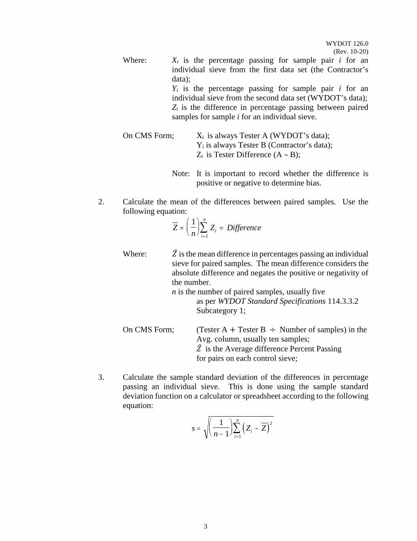
Calculations: 1. Calculate the difference between the percent passing each sieve for each
pair of samples. Use the following equation:
Xi - Yi = Zi
Difference = Ai - Bi
WYDOT 126.0 (Rev. 10-20)
3
Where: Xi is the percentage passing for sample pair i for an individual sieve from the first data set (the Contractor’s data); Yi is the percentage passing for sample pair i for an individual sieve from the second data set (WYDOT’s data); Zi is the difference in percentage passing between paired samples for sample i for an individual sieve.
On CMS Form; Xi is always Tester A (WYDOT’s data);
Yi is always Tester B (Contractor’s data); Zi is Tester Difference (A – B); Note: It is important to record whether the difference is
positive or negative to determine bias.
2. Calculate the mean of the differences between paired samples. Use the following equation:
Zn
Z Differenceii
n
=
=
=∑1
1
Where: �̅�𝑍 is the mean difference in percentages passing an individual
sieve for paired samples. The mean difference considers the absolute difference and negates the positive or negativity of the number. n is the number of paired samples, usually five
as per WYDOT Standard Specifications 114.3.3.2 Subcategory 1;
On CMS Form; (Tester A + Tester B ÷ Number of samples) in the Avg. column, usually ten samples; �̅�𝑍 is the Average difference Percent Passing for pairs on each control sieve;
3. Calculate the sample standard deviation of the differences in percentage
passing an individual sieve. This is done using the sample standard deviation function on a calculator or spreadsheet according to the following equation:
( )sn
Z Zii
n
=−
−
=∑1
1
2
1
WYDOT 126.0 (Rev. 10-20)
4
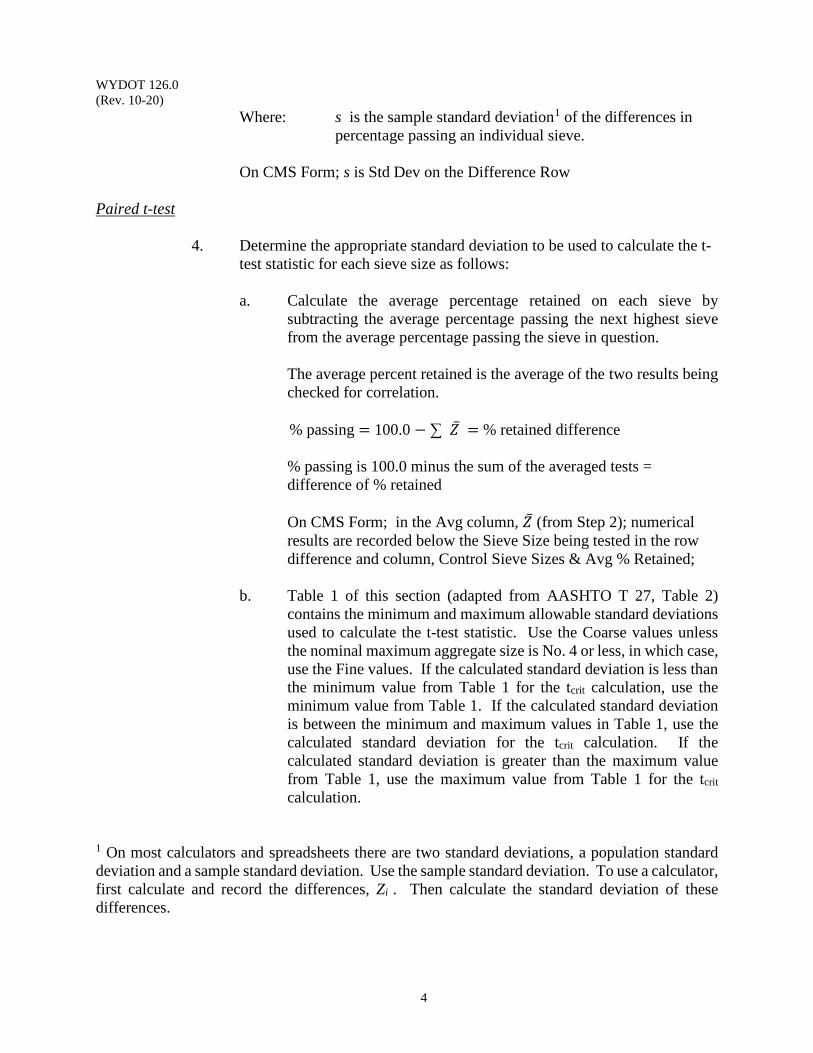
Where: s is the sample standard deviation1 of the differences in percentage passing an individual sieve.
On CMS Form; s is Std Dev on the Difference Row
Paired t-test
4. Determine the appropriate standard deviation to be used to calculate the t-
test statistic for each sieve size as follows: a. Calculate the average percentage retained on each sieve by
subtracting the average percentage passing the next highest sieve from the average percentage passing the sieve in question.
The average percent retained is the average of the two results being checked for correlation.
% passing = 100.0 − ∑ �̅�𝑍 = % retained difference
% passing is 100.0 minus the sum of the averaged tests = difference of % retained
On CMS Form; in the Avg column, �̅�𝑍 (from Step 2); numerical results are recorded below the Sieve Size being tested in the row difference and column, Control Sieve Sizes & Avg % Retained;
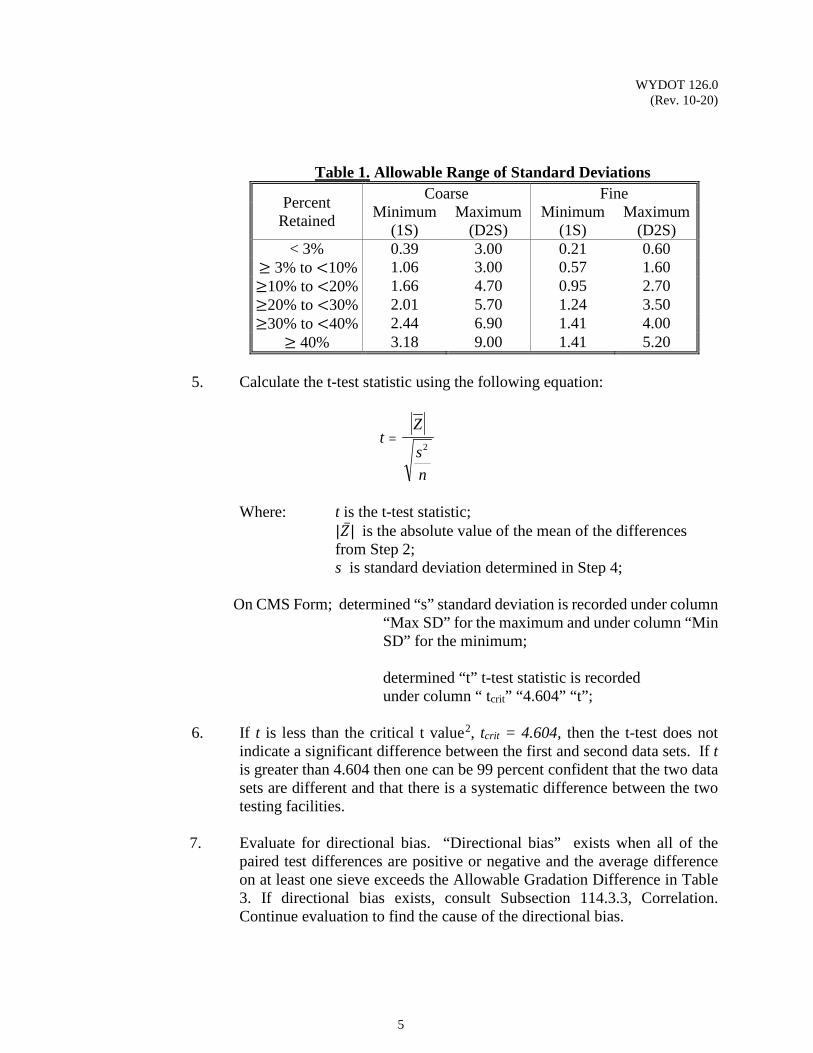
b. Table 1 of this section (adapted from AASHTO T 27, Table 2) contains the minimum and maximum allowable standard deviations used to calculate the t-test statistic. Use the Coarse values unless the nominal maximum aggregate size is No. 4 or less, in which case, use the Fine values. If the calculated standard deviation is less than the minimum value from Table 1 for the tcrit calculation, use the minimum value from Table 1. If the calculated standard deviation is between the minimum and maximum values in Table 1, use the calculated standard deviation for the tcrit calculation. If the calculated standard deviation is greater than the maximum value from Table 1, use the maximum value from Table 1 for the tcrit calculation.
1 On most calculators and spreadsheets there are two standard deviations, a population standard deviation and a sample standard deviation. Use the sample standard deviation. To use a calculator, first calculate and record the differences, Zi . Then calculate the standard deviation of these differences.
WYDOT 126.0 (Rev. 10-20)
5
Table 1. Allowable Range of Standard Deviations
Percent Retained
Coarse Fine Minimum
(1S) Maximum
(D2S) Minimum
(1S) Maximum
(D2S) < 3% 0.39 3.00 0.21 0.60
≥ 3% to <10% 1.06 3.00 0.57 1.60 ≥10% to <20% 1.66 4.70 0.95 2.70 ≥20% to <30% 2.01 5.70 1.24 3.50 ≥30% to <40% 2.44 6.90 1.41 4.00
≥ 40% 3.18 9.00 1.41 5.20 5. Calculate the t-test statistic using the following equation:
tZ
sn
=2
Where: t is the t-test statistic;
|�̅�𝑍| is the absolute value of the mean of the differences from Step 2;
s is standard deviation determined in Step 4;
On CMS Form; determined “s” standard deviation is recorded under column “Max SD” for the maximum and under column “Min SD” for the minimum;
determined “t” t-test statistic is recorded
under column “ tcrit” “4.604” “t”;
6. If t is less than the critical t value2, tcrit = 4.604, then the t-test does not indicate a significant difference between the first and second data sets. If t is greater than 4.604 then one can be 99 percent confident that the two data sets are different and that there is a systematic difference between the two testing facilities.
7. Evaluate for directional bias. “Directional bias” exists when all of the
paired test differences are positive or negative and the average difference on at least one sieve exceeds the Allowable Gradation Difference in Table 3. If directional bias exists, consult Subsection 114.3.3, Correlation. Continue evaluation to find the cause of the directional bias.
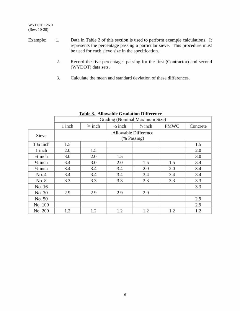
WYDOT 126.0 (Rev. 10-20)
6
Example: 1. Data in Table 2 of this section is used to perform example calculations. It
represents the percentage passing a particular sieve. This procedure must be used for each sieve size in the specification.
2. Record the five percentages passing for the first (Contractor) and second
(WYDOT) data sets. 3. Calculate the mean and standard deviation of these differences.
Table 3. Allowable Gradation Difference Grading (Nominal Maximum Size)
1 inch ¾ inch ½ inch ⅜ inch PMWC Concrete
Sieve Allowable Difference
(% Passing) 1 ¼ inch 1.5 1.5 1 inch 2.0 1.5 2.0 ¾ inch 3.0 2.0 1.5 3.0 ½ inch 3.4 3.0 2.0 1.5 1.5 3.4 ⅜ inch 3.4 3.4 3.4 2.0 2.0 3.4 No. 4 3.4 3.4 3.4 3.4 3.4 3.4 No. 8 3.3 3.3 3.3 3.3 3.3 3.3 No. 16 3.3 No. 30 2.9 2.9 2.9 2.9 No. 50 2.9 No. 100 2.9 No. 200 1.2 1.2 1.2 1.2 1.2 1.2
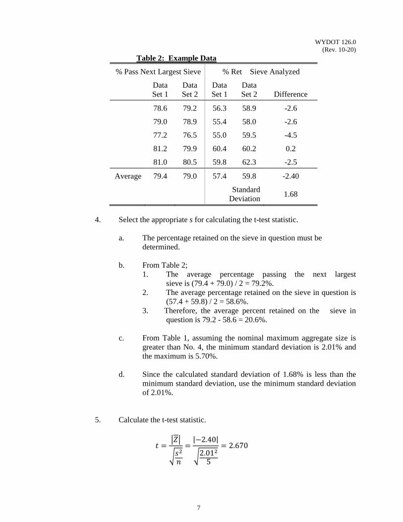
WYDOT 126.0 (Rev. 10-20)
7
Table 2: Example Data
% Pass Next Largest Sieve % Ret Sieve Analyzed
Data Set 1
Data Set 2
Data Set 1
Data Set 2
Difference
78.6 79.2 56.3 58.9 -2.6
79.0 78.9 55.4 58.0 -2.6
77.2 76.5 55.0 59.5 -4.5
81.2 79.9 60.4 60.2 0.2
81.0 80.5 59.8 62.3 -2.5
Average 79.4 79.0 57.4 59.8 -2.40
Standard Deviation
1.68
4. Select the appropriate s for calculating the t-test statistic.
a. The percentage retained on the sieve in question must be determined.
b. From Table 2;
1. The average percentage passing the next largest sieve is (79.4 + 79.0) / 2 = 79.2%.
2. The average percentage retained on the sieve in question is (57.4 + 59.8) / 2 = 58.6%.
3. Therefore, the average percent retained on the sieve in question is 79.2 - 58.6 = 20.6%.
c. From Table 1, assuming the nominal maximum aggregate size is
greater than No. 4, the minimum standard deviation is 2.01% and the maximum is 5.70%.
d. Since the calculated standard deviation of 1.68% is less than the
minimum standard deviation, use the minimum standard deviation of 2.01%.
5. Calculate the t-test statistic.
𝑡𝑡 =�𝑍𝑍�
�𝑠𝑠2
𝑛𝑛
=|−2.40|
�2.0125
= 2.670
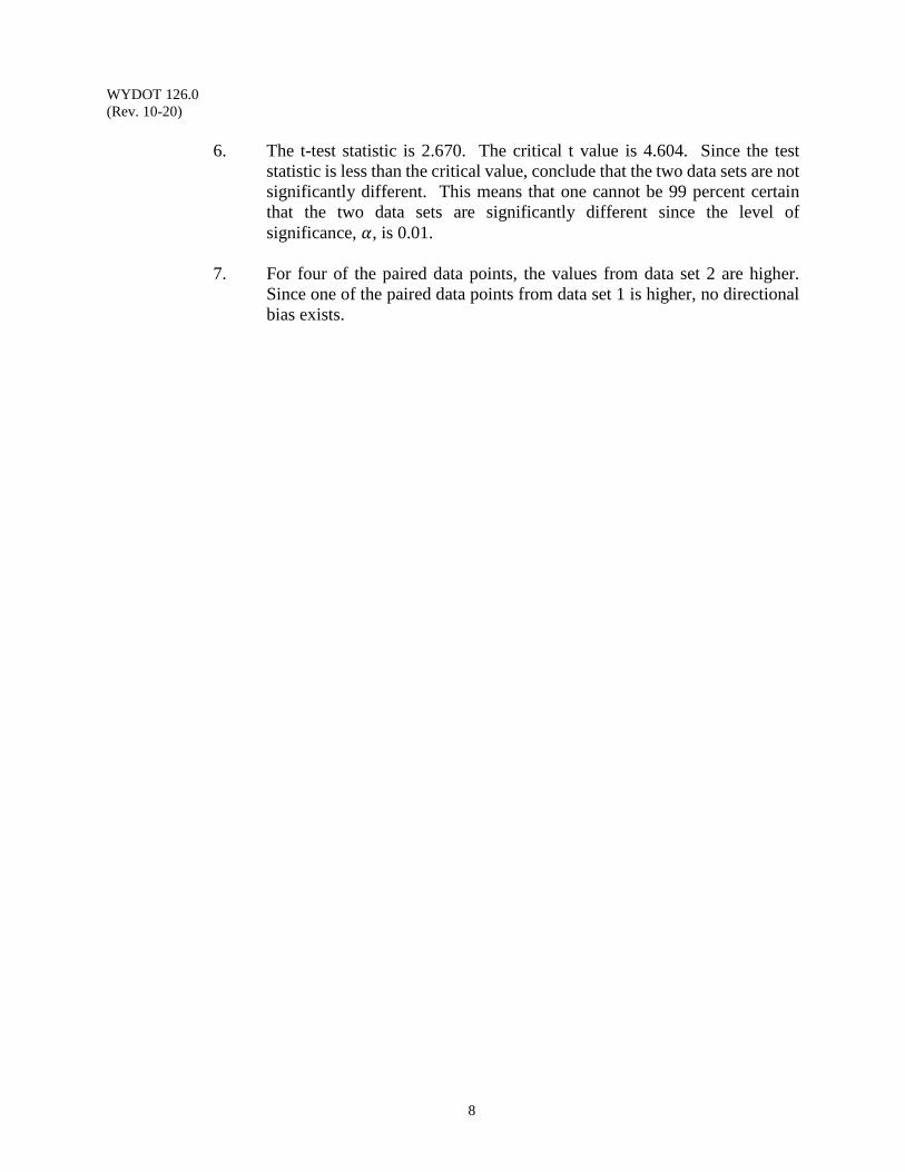
WYDOT 126.0 (Rev. 10-20)
8
6. The t-test statistic is 2.670. The critical t value is 4.604. Since the test
statistic is less than the critical value, conclude that the two data sets are not significantly different. This means that one cannot be 99 percent certain that the two data sets are significantly different since the level of significance, 𝛼𝛼, is 0.01.
7. For four of the paired data points, the values from data set 2 are higher.
Since one of the paired data points from data set 1 is higher, no directional bias exists.
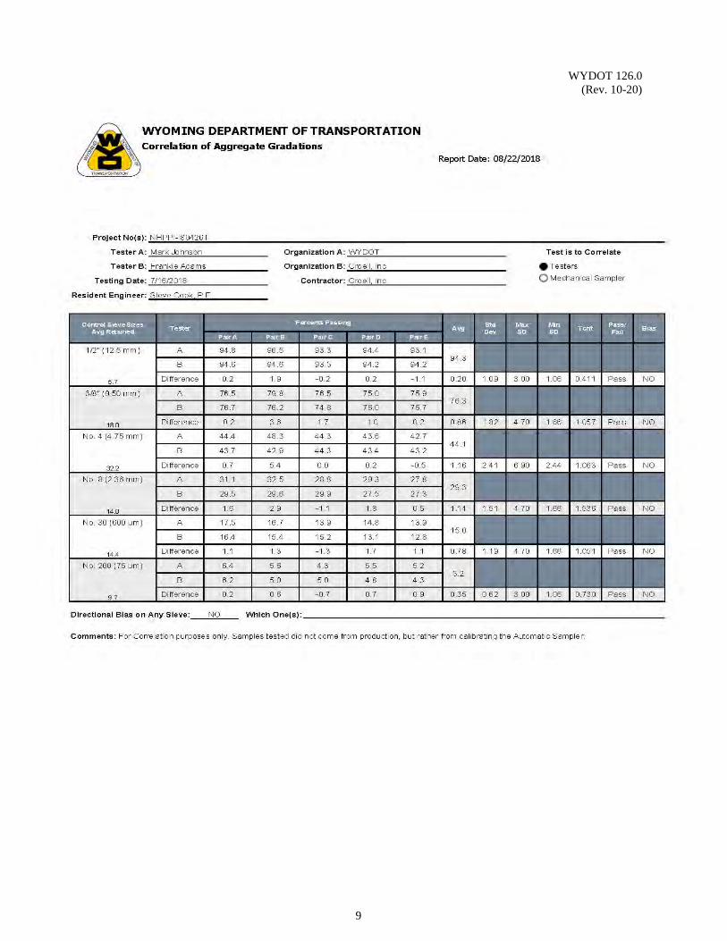
WYDOT 126.0 (Rev. 10-20)
9

WYDOT 126.0 (Rev. 10-20)
10
(This page intentionally left blank.)
WYDOT 127.0 (Rev. 02-12)
1
ASSESSMENT OF FIELD LABS PERFORMING MIX VOLUMETRIC QUALITY ACCEPTANCE TESTING
Scope: This procedure is intended to provide general guidance for assessing the competency of non-AASHTO accredited laboratories and personnel performing field testing of production mix volumetrics for quality acceptance.
Use: This procedure should be used to assess competencies of field laboratories and personnel
engaged in volumetric testing of production samples of mix for quality acceptance purposes and establish correlation of the field laboratory to the AASHTO accredited mix design facility. Assessment of field laboratories and personnel will be performed at the frequency stated in the contract documents or once per construction season, whichever is greater.
Reference Documents: WYDOT Current Edition WYDOT Standard Specifications
WYDOT 416.0 Precision Statements for Comparing Mix Design and Aggregate Property Test Results
WYDOT 417.0 Precision Statements for Comparing Contractor QA Results to WYDOT Verification Results
Procedure: The engineer may visit the field laboratory to verify the following is maintained and
available on-site:
1. Copies of relevant contract documents, including contract plans and associated specifications, JMF, mix design, etc.
2. Safety equipment is in good condition 3. Copies of current WYDOT Standard Specifications and WYDOT Materials
Testing Manual 4. Copies of the current applicable test procedures 5. The appropriate equipment to perform the required tests 6. The equipment is serviced and calibrated as required, documentation of such is on
file, and calibration/service decals are affixed to all testing equipment Obtain a sample of plant produced mix, mix from the project where the field laboratory is intended to be used is preferred, of sufficient size. The quantity must be large enough that when the sample is split in half, there is enough quantity of mix in each half to determine the following: air voids, voids in mineral aggregate, voids filled with asphalt (for Superpave mixes only), voidless unit weight, stability & flow (Marshall mixes only), extracted asphalt content, extracted gradation, dust-to-effective asphalt content, and film thickness.
WYDOT 127.0 (Rev. 02-12)
2
One half of the original sample will be tested by the field laboratory and the other half will be tested by an AASHTO accredited laboratory for the fore-mentioned properties. The results from each laboratory will be compared by the engineer using the criteria in WYDOT 416.0 and WYDOT 417.0. If the results are within the allowable limits (ie, correlate), the field laboratory and associated personnel are approved to perform field mix volumetric acceptance testing for the remainder of the construction season on WYDOT projects. If any of the results are not within the allowable limits, the field laboratory and the accredited laboratory must resolve the discrepancy(s) (additional mix testing may be necessary) and document the resolution of the discrepancy(s). If the resolution is acceptable to the engineer, the field laboratory and associated personnel are approved to perform field mix volumetric acceptance testing for the remainder of the construction season on WYDOT projects.
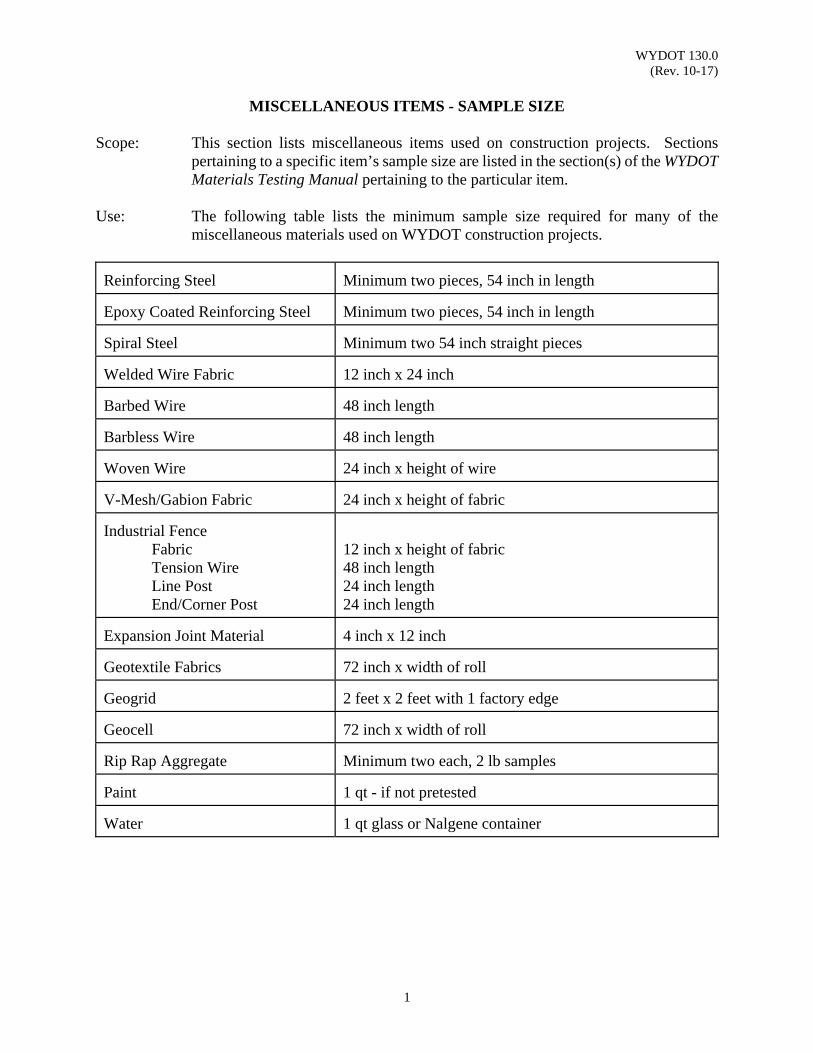
WYDOT 130.0 (Rev. 10-17)
1
MISCELLANEOUS ITEMS - SAMPLE SIZE
Scope: This section lists miscellaneous items used on construction projects. Sections
pertaining to a specific item’s sample size are listed in the section(s) of the WYDOT Materials Testing Manual pertaining to the particular item.
Use: The following table lists the minimum sample size required for many of the
miscellaneous materials used on WYDOT construction projects. Reinforcing Steel
Minimum two pieces, 54 inch in length
Epoxy Coated Reinforcing Steel
Minimum two pieces, 54 inch in length
Spiral Steel
Minimum two 54 inch straight pieces
Welded Wire Fabric
12 inch x 24 inch
Barbed Wire
48 inch length
Barbless Wire
48 inch length
Woven Wire
24 inch x height of wire
V-Mesh/Gabion Fabric
24 inch x height of fabric
Industrial Fence
Fabric Tension Wire Line Post End/Corner Post
12 inch x height of fabric 48 inch length 24 inch length 24 inch length
Expansion Joint Material
4 inch x 12 inch
Geotextile Fabrics
72 inch x width of roll
Geogrid
2 feet x 2 feet with 1 factory edge
Geocell
72 inch x width of roll
Rip Rap Aggregate
Minimum two each, 2 lb samples
Paint
1 qt - if not pretested
Water
1 qt glass or Nalgene container

WYDOT 130.0 (Rev. 10-17)
2
(This page intentionally left blank.)
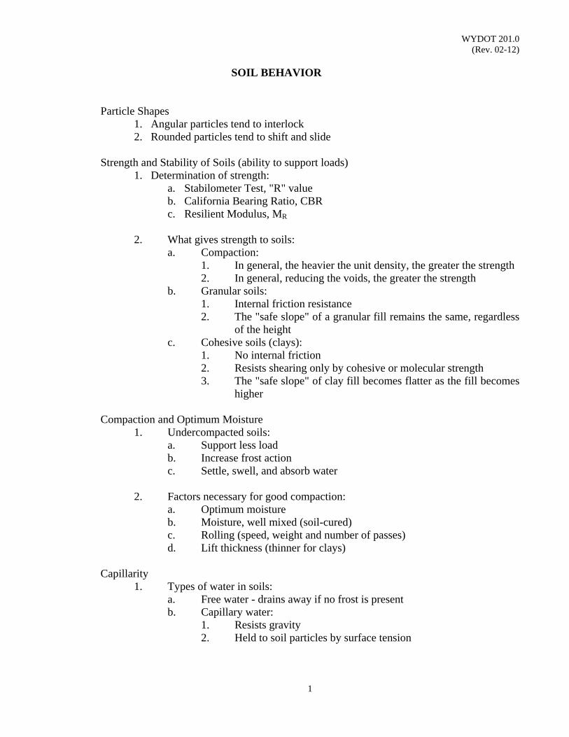
WYDOT 201.0 (Rev. 02-12)
1
SOIL BEHAVIOR Particle Shapes
1. Angular particles tend to interlock 2. Rounded particles tend to shift and slide
Strength and Stability of Soils (ability to support loads)
1. Determination of strength: a. Stabilometer Test, "R" value b. California Bearing Ratio, CBR c. Resilient Modulus, MR
2. What gives strength to soils:
a. Compaction: 1. In general, the heavier the unit density, the greater the strength 2. In general, reducing the voids, the greater the strength
b. Granular soils: 1. Internal friction resistance 2. The "safe slope" of a granular fill remains the same, regardless
of the height c. Cohesive soils (clays):
1. No internal friction 2. Resists shearing only by cohesive or molecular strength 3. The "safe slope" of clay fill becomes flatter as the fill becomes
higher Compaction and Optimum Moisture
1. Undercompacted soils: a. Support less load b. Increase frost action c. Settle, swell, and absorb water
2. Factors necessary for good compaction:
a. Optimum moisture b. Moisture, well mixed (soil-cured) c. Rolling (speed, weight and number of passes) d. Lift thickness (thinner for clays)
Capillarity
1. Types of water in soils: a. Free water - drains away if no frost is present b. Capillary water:
1. Resists gravity 2. Held to soil particles by surface tension
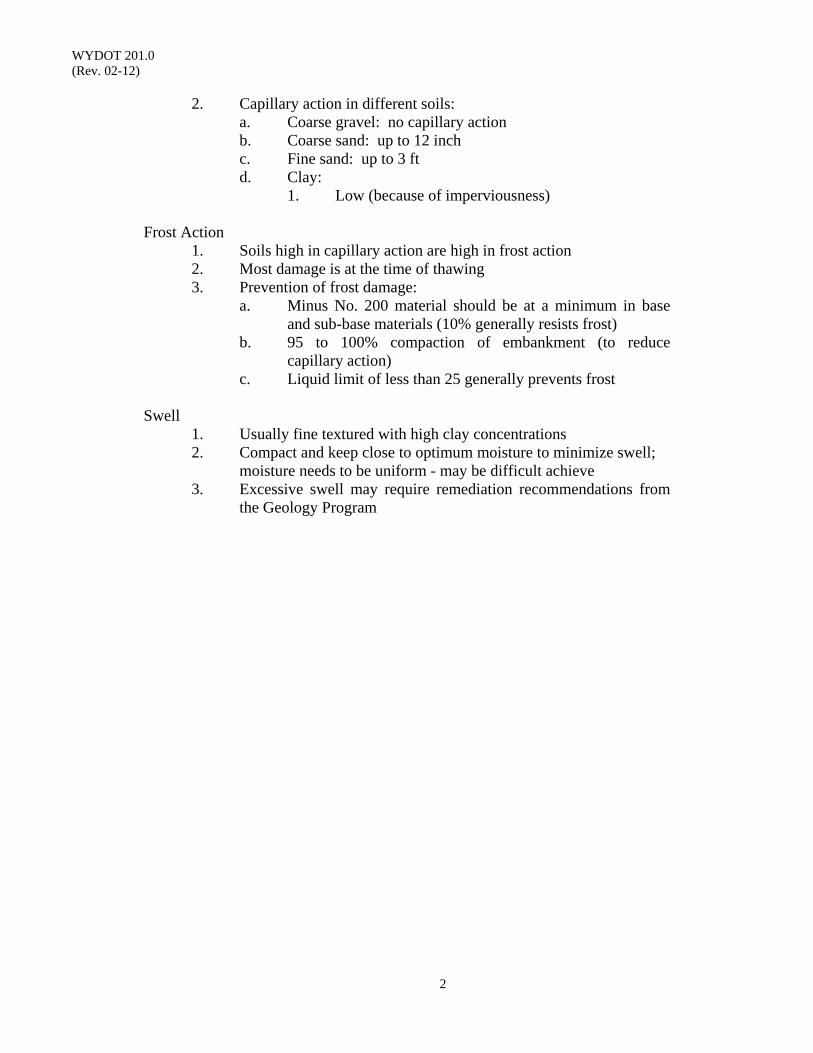
WYDOT 201.0 (Rev. 02-12)
2
2. Capillary action in different soils: a. Coarse gravel: no capillary action b. Coarse sand: up to 12 inch c. Fine sand: up to 3 ft d. Clay: 1. Low (because of imperviousness)
Frost Action
1. Soils high in capillary action are high in frost action 2. Most damage is at the time of thawing 3. Prevention of frost damage:
a. Minus No. 200 material should be at a minimum in base and sub-base materials (10% generally resists frost)
b. 95 to 100% compaction of embankment (to reduce capillary action)
c. Liquid limit of less than 25 generally prevents frost
Swell 1. Usually fine textured with high clay concentrations 2. Compact and keep close to optimum moisture to minimize swell; moisture needs to be uniform - may be difficult achieve 3. Excessive swell may require remediation recommendations from
the Geology Program
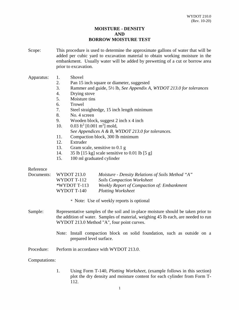
WYDOT 210.0 (Rev. 10-20)
1
MOISTURE - DENSITY AND
BORROW MOISTURE TEST
Scope: This procedure is used to determine the approximate gallons of water that will be added per cubic yard to excavation material to obtain working moisture in the embankment. Usually water will be added by prewetting of a cut or borrow area prior to excavation.
Apparatus: 1. Shovel
2. Pan 15 inch square or diameter, suggested 3. Rammer and guide, 5½ lb, See Appendix A, WYDOT 213.0 for tolerances 4. Drying stove 5. Moisture tins 6. Trowel 7. Steel straightedge, 15 inch length minimum 8. No. 4 screen 9. Wooden block, suggest 2 inch x 4 inch 10. 0.03 ft3 [0.001 m3] mold, See Appendices A & B, WYDOT 213.0 for tolerances. 11. Compaction block, 300 lb minimum 12. Extruder 13. Gram scale, sensitive to 0.1 g 14. 35 lb [15 kg] scale sensitive to 0.01 lb [5 g] 15. 100 ml graduated cylinder
Reference Documents: WYDOT 213.0 Moisture - Density Relations of Soils Method “A” WYDOT T-112 Soils Compaction Worksheet *WYDOT T-113 Weekly Report of Compaction of: Embankment WYDOT T-140 Plotting Worksheet * Note: Use of weekly reports is optional Sample: Representative samples of the soil and in-place moisture should be taken prior to
the addition of water. Samples of material, weighing 45 lb each, are needed to run WYDOT 213.0 Method "A", four point curves.
Note: Install compaction block on solid foundation, such as outside on a
prepared level surface. Procedure: Perform in accordance with WYDOT 213.0. Computations:
1. Using Form T-140, Plotting Worksheet, (example follows in this section) plot the dry density and moisture content for each cylinder from Form T-112.
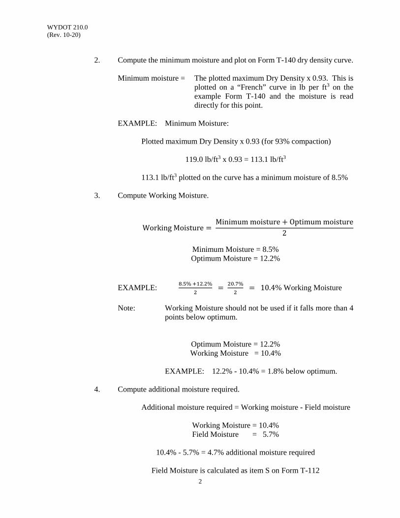
WYDOT 210.0 (Rev. 10-20)
2
2. Compute the minimum moisture and plot on Form T-140 dry density curve.
Minimum moisture = The plotted maximum Dry Density x 0.93. This is
plotted on a “French” curve in lb per ft3 on the example Form T-140 and the moisture is read directly for this point.
EXAMPLE: Minimum Moisture:
Plotted maximum Dry Density x 0.93 (for 93% compaction)
119.0 lb/ft3 x 0.93 = 113.1 lb/ft3
113.1 lb/ft3 plotted on the curve has a minimum moisture of 8.5%
3. Compute Working Moisture.
Working Moisture = Minimum moisture + Optimum moisture
2
Minimum Moisture = 8.5% Optimum Moisture = 12.2%
EXAMPLE: 8.5% +12.2%
2 = 20.7%
2 = 10.4% Working Moisture
Note: Working Moisture should not be used if it falls more than 4
points below optimum.
Optimum Moisture = 12.2% Working Moisture = 10.4%
EXAMPLE: 12.2% - 10.4% = 1.8% below optimum.
4. Compute additional moisture required.
Additional moisture required = Working moisture - Field moisture
Working Moisture = 10.4% Field Moisture = 5.7%
10.4% - 5.7% = 4.7% additional moisture required
Field Moisture is calculated as item S on Form T-112
WYDOT 210.0 (Rev. 10-20)
3
On Form T-112 the plotted Optimum Moisture % is item “GG”, plotted Max Dry Density is item “HH” and Roadway Moisture % ± Optimum is recorded directly above the remarks section.
5. Convert "Additional Moisture Required" from percent to gallons, using the
“Embankment Moisture Conversion Table” of this section. For 119.0 lb/ft3, with 4.7% additional moisture required is 18.1 gal/yd3, interpolating between 4% and 5%.
Report: Report weekly result on optional Form T-113 Weekly Report for Compaction of: Embankment. See example Form T-113 in WYDOT 213.0.
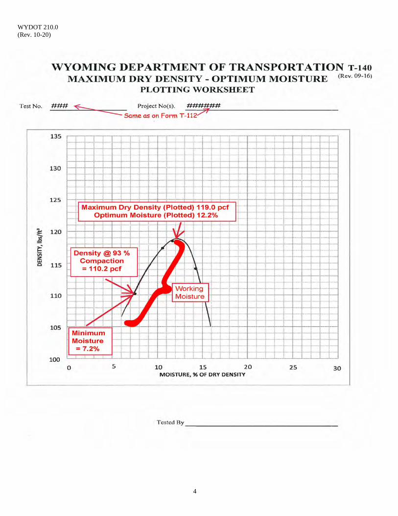
WYDOT 210.0 (Rev. 10-20)
4
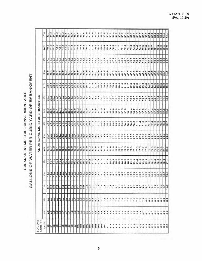
WYDOT 210.0 (Rev. 10-20)
5

WYDOT 210.0 (Rev. 10-20)
6
Example of French Curve
Must be made of solid material, i.e., plexiglass or cardboard
Can be acquired from a WYDOT IA Inspector or the WYDOT Materials Program
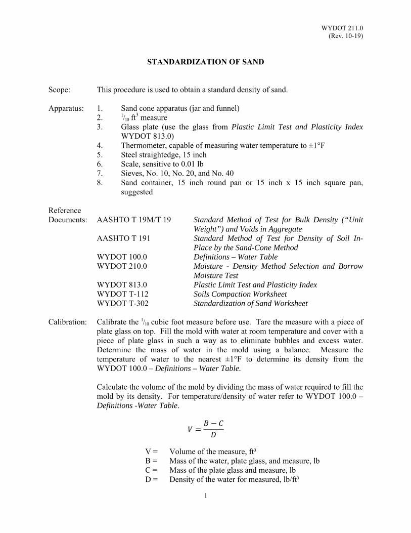
WYDOT 211.0 (Rev. 10-19)
1
STANDARDIZATION OF SAND
Scope: This procedure is used to obtain a standard density of sand.
Apparatus: 1. Sand cone apparatus (jar and funnel) 2. 1/10 ft
3 measure 3. Glass plate (use the glass from Plastic Limit Test and Plasticity Index
WYDOT 813.0) 4. Thermometer, capable of measuring water temperature to ±1°F 5. Steel straightedge, 15 inch 6. Scale, sensitive to 0.01 lb 7. Sieves, No. 10, No. 20, and No. 40
8. Sand container, 15 inch round pan or 15 inch x 15 inch square pan, suggested
Reference Documents: AASHTO T 19M/T 19 Standard Method of Test for Bulk Density (“Unit
Weight”) and Voids in Aggregate AASHTO T 191 Standard Method of Test for Density of Soil In-
Place by the Sand-Cone Method WYDOT 100.0 Definitions – Water Table WYDOT 210.0 Moisture - Density Method Selection and Borrow
Moisture Test WYDOT 813.0 Plastic Limit Test and Plasticity Index WYDOT T-112 Soils Compaction Worksheet WYDOT T-302 Standardization of Sand Worksheet Calibration: Calibrate the 1/10 cubic foot measure before use. Tare the measure with a piece of
plate glass on top. Fill the mold with water at room temperature and cover with a piece of plate glass in such a way as to eliminate bubbles and excess water. Determine the mass of water in the mold using a balance. Measure the temperature of water to the nearest ±1°F to determine its density from the WYDOT 100.0 – Definitions – Water Table.
Calculate the volume of the mold by dividing the mass of water required to fill the mold by its density. For temperature/density of water refer to WYDOT 100.0 – Definitions -Water Table.
𝑉𝐵 𝐶
𝐷
V = Volume of the measure, ft³ B = Mass of the water, plate glass, and measure, lb C = Mass of the plate glass and measure, lb D = Density of the water for measured, lb/ft³
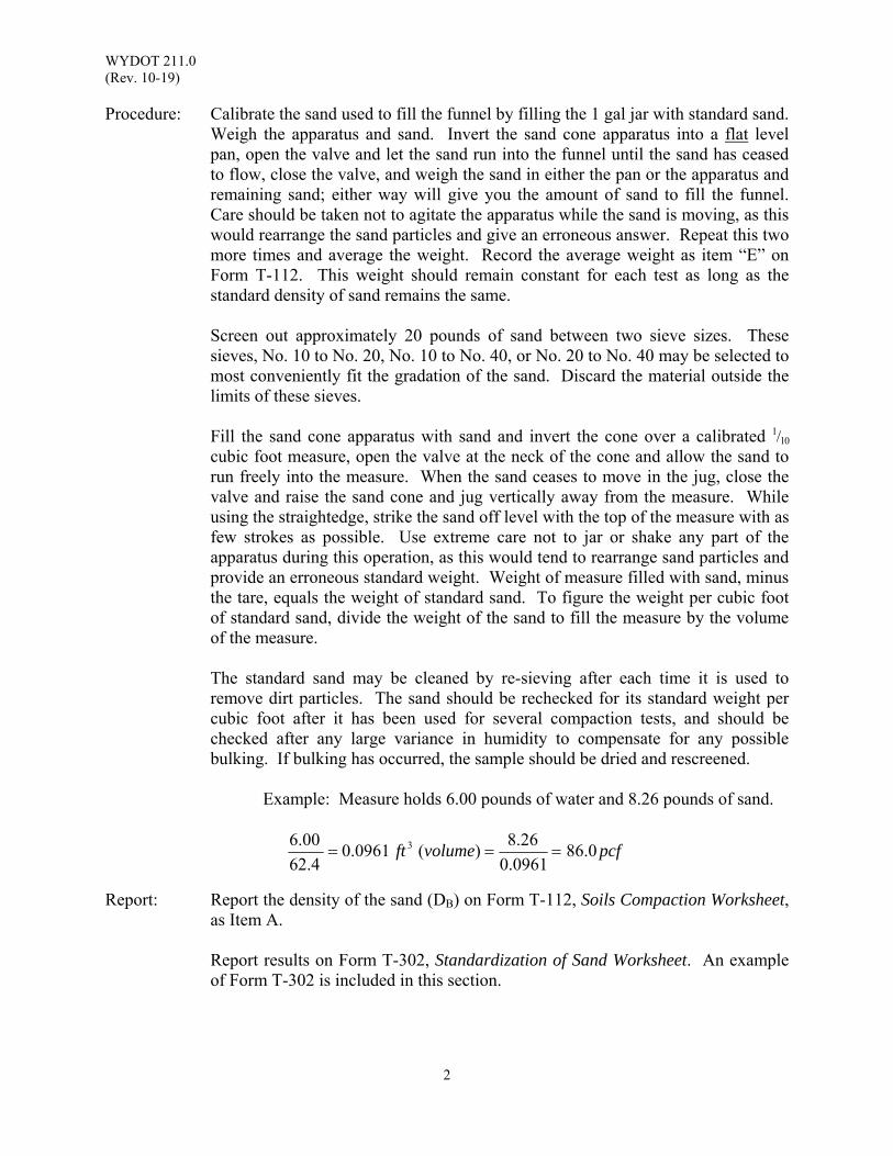
WYDOT 211.0 (Rev. 10-19)
2
Procedure: Calibrate the sand used to fill the funnel by filling the 1 gal jar with standard sand. Weigh the apparatus and sand. Invert the sand cone apparatus into a flat level pan, open the valve and let the sand run into the funnel until the sand has ceased to flow, close the valve, and weigh the sand in either the pan or the apparatus and remaining sand; either way will give you the amount of sand to fill the funnel. Care should be taken not to agitate the apparatus while the sand is moving, as this would rearrange the sand particles and give an erroneous answer. Repeat this two more times and average the weight. Record the average weight as item “E” on Form T-112. This weight should remain constant for each test as long as the standard density of sand remains the same. Screen out approximately 20 pounds of sand between two sieve sizes. These
sieves, No. 10 to No. 20, No. 10 to No. 40, or No. 20 to No. 40 may be selected to most conveniently fit the gradation of the sand. Discard the material outside the limits of these sieves.
Fill the sand cone apparatus with sand and invert the cone over a calibrated 1/10
cubic foot measure, open the valve at the neck of the cone and allow the sand to run freely into the measure. When the sand ceases to move in the jug, close the valve and raise the sand cone and jug vertically away from the measure. While using the straightedge, strike the sand off level with the top of the measure with as few strokes as possible. Use extreme care not to jar or shake any part of the apparatus during this operation, as this would tend to rearrange sand particles and provide an erroneous standard weight. Weight of measure filled with sand, minus the tare, equals the weight of standard sand. To figure the weight per cubic foot of standard sand, divide the weight of the sand to fill the measure by the volume of the measure.
The standard sand may be cleaned by re-sieving after each time it is used to
remove dirt particles. The sand should be rechecked for its standard weight per cubic foot after it has been used for several compaction tests, and should be checked after any large variance in humidity to compensate for any possible bulking. If bulking has occurred, the sample should be dried and rescreened.
Example: Measure holds 6.00 pounds of water and 8.26 pounds of sand.
Report: Report the density of the sand (DB) on Form T-112, Soils Compaction Worksheet,
as Item A.
Report results on Form T-302, Standardization of Sand Worksheet. An example of Form T-302 is included in this section.
pcfvolumeft 0.860961.0
26.8)(0961.0
4.62
00.6 3
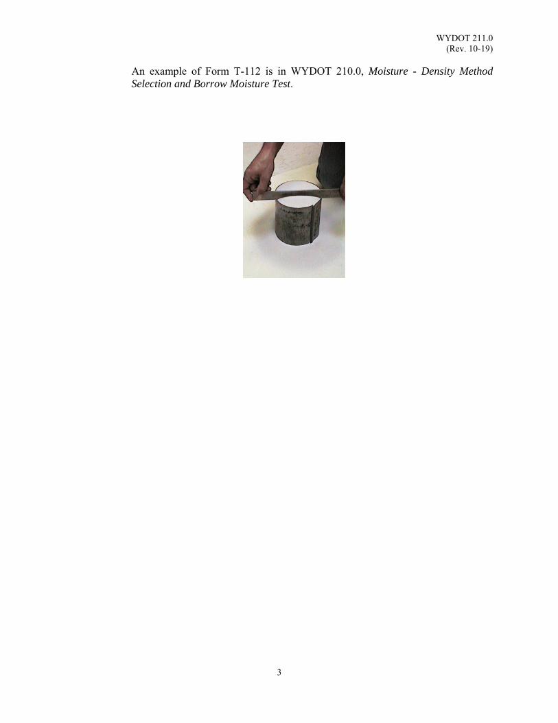
WYDOT 211.0 (Rev. 10-19)
3
An example of Form T-112 is in WYDOT 210.0, Moisture - Density Method Selection and Borrow Moisture Test.
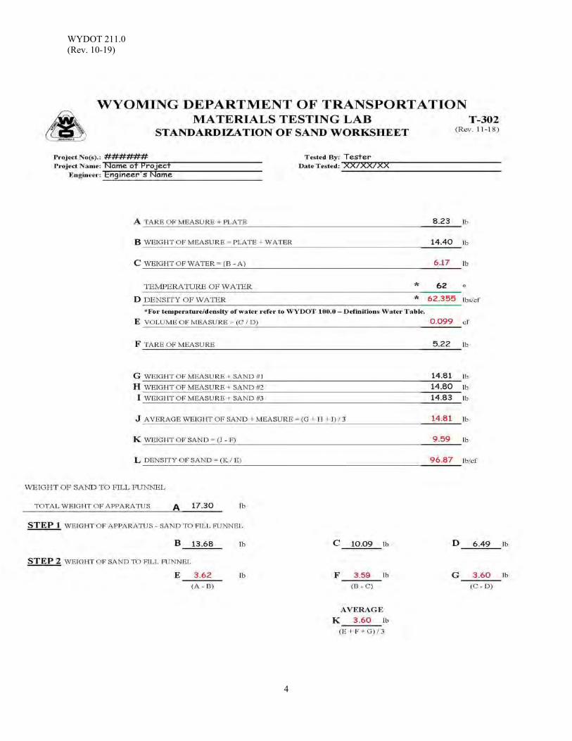
WYDOT 211.0 (Rev. 10-19)
4

WYDOT 212.0 (Rev. 10-20)
1
SAND CONE METHOD FIELD DENSITY TEST
Scope: This procedure is intended to determine the density of a soil, either in its natural state or
after being compacted. The procedure described below is intended to test soils containing particles not larger than 2 inches in diameter.
Apparatus: 1. Sand cone apparatus, 1 gal jar and funnel 2. Containers with lids, suggest two concrete cylinder cans 3. Chisel and hammer 4. Rammer with guide, 5½ lb 5. Spoon or half round dish 6. Shovel 7. Square pans 15 inch, suggested 8. Drying stove
9. Moisture tins 10. No. 4 screen 11. Wooden block, suggest 2 inch x 4 inch 12. Gram scale, sensitive to 0.1 g 13. 35 lb [15 kg] scale sensitive to 0.01 lb [5 g] 14. Base plate - optional 15. 2 inch [50 mm] screen 16. Standard Sand 17. Clean canvas sample sacks
Note: For WYDOT personnel, contact the WYDOT Materials Program (Field
Services) for information or sources for standard sand. Reference Documents: AASHTO T 191 Standard Method of Test for Density of Soil In-Place by the Sand-
Cone Method WYDOT 211.0 Standardization of Sand WYDOT 213.0 Moisture - Density Relations of Soils Method “A” WYDOT T-112 Soils Compaction Worksheet *WYDOT T-113 Weekly Report of Compaction of: Embankment * Note: Use of weekly reports is optional Procedure: Laboratory Preparations
1. Record the standard sand density as item “A” on Form T-112, Soil Compaction Worksheet, see WYDOT 211.0, Standardization of Sand.
2. Fill the sand cone; 1 gal jar with standard sand, weigh the apparatus and sand. Record as item “B” on Form T-112.
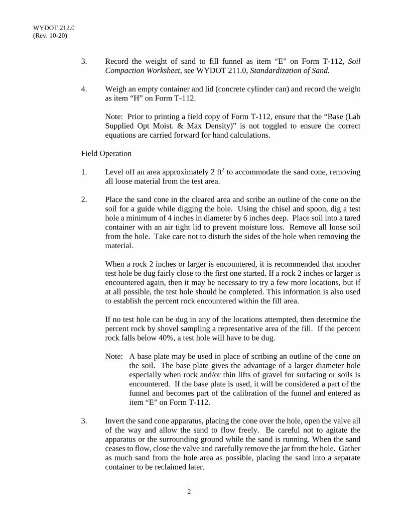
WYDOT 212.0 (Rev. 10-20)
2
3. Record the weight of sand to fill funnel as item “E” on Form T-112, Soil
Compaction Worksheet, see WYDOT 211.0, Standardization of Sand.
4. Weigh an empty container and lid (concrete cylinder can) and record the weight as item “H” on Form T-112.
Note: Prior to printing a field copy of Form T-112, ensure that the “Base (Lab Supplied Opt Moist. & Max Density)” is not toggled to ensure the correct equations are carried forward for hand calculations.
Field Operation
1. Level off an area approximately 2 ft2 to accommodate the sand cone, removing
all loose material from the test area.
2. Place the sand cone in the cleared area and scribe an outline of the cone on the soil for a guide while digging the hole. Using the chisel and spoon, dig a test hole a minimum of 4 inches in diameter by 6 inches deep. Place soil into a tared container with an air tight lid to prevent moisture loss. Remove all loose soil from the hole. Take care not to disturb the sides of the hole when removing the material.
When a rock 2 inches or larger is encountered, it is recommended that another
test hole be dug fairly close to the first one started. If a rock 2 inches or larger is encountered again, then it may be necessary to try a few more locations, but if at all possible, the test hole should be completed. This information is also used to establish the percent rock encountered within the fill area.
If no test hole can be dug in any of the locations attempted, then determine the
percent rock by shovel sampling a representative area of the fill. If the percent rock falls below 40%, a test hole will have to be dug.
Note: A base plate may be used in place of scribing an outline of the cone on
the soil. The base plate gives the advantage of a larger diameter hole especially when rock and/or thin lifts of gravel for surfacing or soils is encountered. If the base plate is used, it will be considered a part of the funnel and becomes part of the calibration of the funnel and entered as item “E” on Form T-112.
3. Invert the sand cone apparatus, placing the cone over the hole, open the valve all
of the way and allow the sand to flow freely. Be careful not to agitate the apparatus or the surrounding ground while the sand is running. When the sand ceases to flow, close the valve and carefully remove the jar from the hole. Gather as much sand from the hole area as possible, placing the sand into a separate container to be reclaimed later.
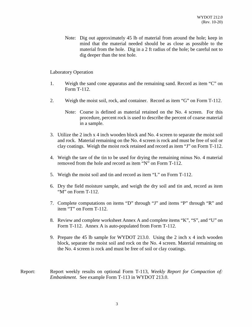
WYDOT 212.0 (Rev. 10-20)
3
Note: Dig out approximately 45 lb of material from around the hole; keep in
mind that the material needed should be as close as possible to the material from the hole. Dig in a 2 ft radius of the hole; be careful not to dig deeper than the test hole.
Laboratory Operation
1. Weigh the sand cone apparatus and the remaining sand. Record as item “C” on
Form T-112.
2. Weigh the moist soil, rock, and container. Record as item “G” on Form T-112.
Note: Coarse is defined as material retained on the No. 4 screen. For this procedure, percent rock is used to describe the percent of coarse material in a sample.
3. Utilize the 2 inch x 4 inch wooden block and No. 4 screen to separate the moist soil
and rock. Material remaining on the No. 4 screen is rock and must be free of soil or clay coatings. Weigh the moist rock retained and record as item “J” on Form T-112.
4. Weigh the tare of the tin to be used for drying the remaining minus No. 4 material
removed from the hole and record as item “N” on Form T-112.
5. Weigh the moist soil and tin and record as item “L” on Form T-112.
6. Dry the field moisture sample, and weigh the dry soil and tin and, record as item “M” on Form T-112.
7. Complete computations on items “D” through “J” and items “P” through “R” and
item “T” on Form T-112.
8. Review and complete worksheet Annex A and complete items “K”, “S”, and “U” on Form T-112. Annex A is auto-populated from Form T-112.
9. Prepare the 45 lb sample for WYDOT 213.0. Using the 2 inch x 4 inch wooden
block, separate the moist soil and rock on the No. 4 screen. Material remaining on the No. 4 screen is rock and must be free of soil or clay coatings.
Report: Report weekly results on optional Form T-113, Weekly Report for Compaction of:
Embankment. See example Form T-113 in WYDOT 213.0.
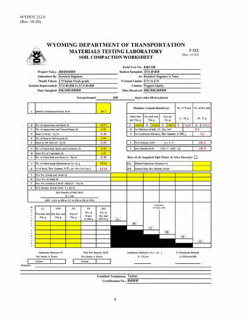
WYDOT 212.0 (Rev. 10-20)
4
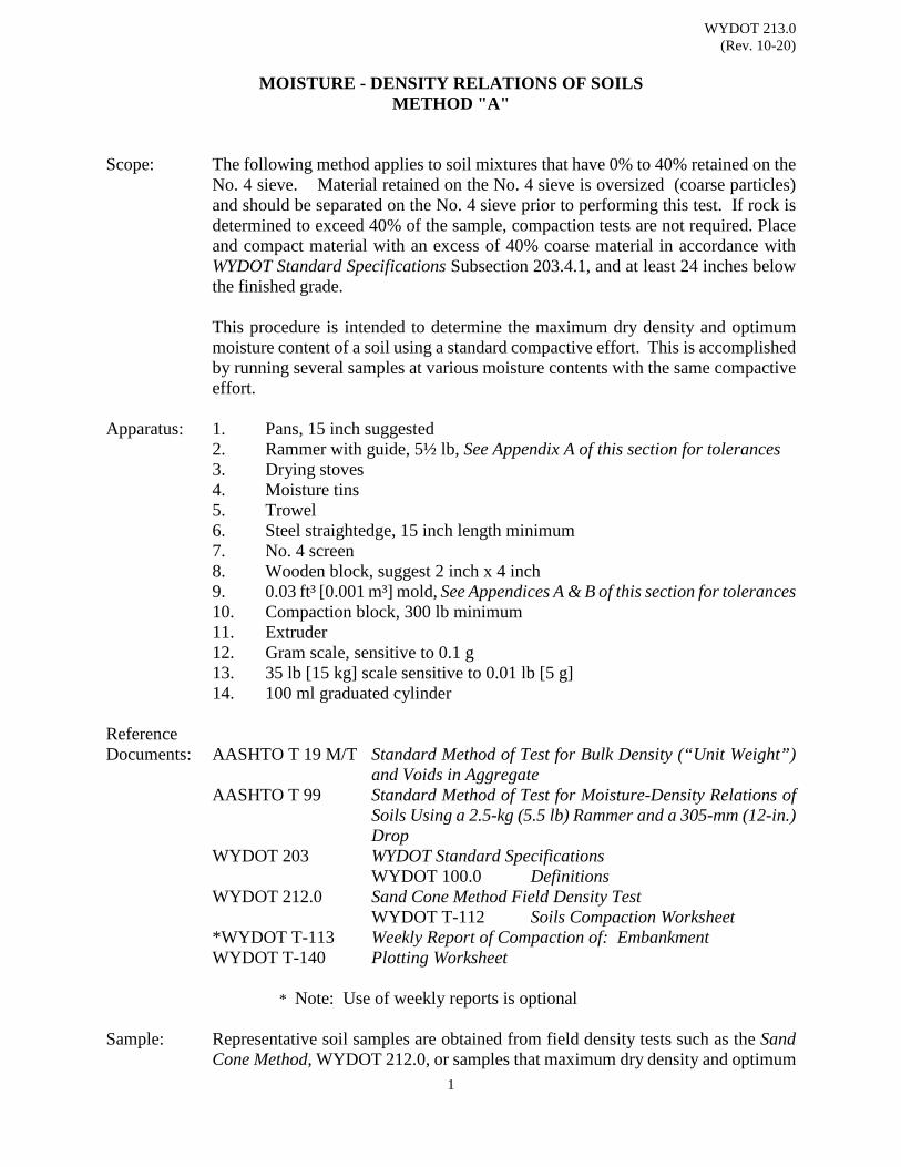
WYDOT 213.0 (Rev. 10-20)
1
MOISTURE - DENSITY RELATIONS OF SOILS METHOD "A" Scope: The following method applies to soil mixtures that have 0% to 40% retained on the
No. 4 sieve. Material retained on the No. 4 sieve is oversized (coarse particles) and should be separated on the No. 4 sieve prior to performing this test. If rock is determined to exceed 40% of the sample, compaction tests are not required. Place and compact material with an excess of 40% coarse material in accordance with WYDOT Standard Specifications Subsection 203.4.1, and at least 24 inches below the finished grade.
This procedure is intended to determine the maximum dry density and optimum
moisture content of a soil using a standard compactive effort. This is accomplished by running several samples at various moisture contents with the same compactive effort.
Apparatus: 1. Pans, 15 inch suggested 2. Rammer with guide, 5½ lb, See Appendix A of this section for tolerances 3. Drying stoves 4. Moisture tins 5. Trowel 6. Steel straightedge, 15 inch length minimum 7. No. 4 screen
8. Wooden block, suggest 2 inch x 4 inch 9. 0.03 ft³ [0.001 m³] mold, See Appendices A & B of this section for tolerances
10. Compaction block, 300 lb minimum 11. Extruder 12. Gram scale, sensitive to 0.1 g 13. 35 lb [15 kg] scale sensitive to 0.01 lb [5 g] 14. 100 ml graduated cylinder
Reference Documents: AASHTO T 19 M/T Standard Method of Test for Bulk Density (“Unit Weight”)
and Voids in Aggregate AASHTO T 99 Standard Method of Test for Moisture-Density Relations of
Soils Using a 2.5-kg (5.5 lb) Rammer and a 305-mm (12-in.) Drop
WYDOT 203 WYDOT Standard Specifications WYDOT 100.0 Definitions WYDOT 212.0 Sand Cone Method Field Density Test WYDOT T-112 Soils Compaction Worksheet
*WYDOT T-113 Weekly Report of Compaction of: Embankment WYDOT T-140 Plotting Worksheet
* Note: Use of weekly reports is optional Sample: Representative soil samples are obtained from field density tests such as the Sand
Cone Method, WYDOT 212.0, or samples that maximum dry density and optimum
WYDOT 213.0 (Rev. 10-20)
2
moisture content are requested. Separate oversized particles in the soil before any cylinders are compacted. To find the percent of oversized particles in any soil sample, separate the moist minus 2 in material over the No. 4 screen and weigh the rock retained on the screen; perform Annex A and Form T-112 calculations to determine the percent retained.
Note: Generally, four cylinders are required to plot a curve; screen enough
material on the No. 4 screen to have four separate and new samples for each cylinder; three cylinders under optimum moisture and one cylinder over optimum.
Procedure: 1. Use material passing the No. 4 screen. Thoroughly mix a 7 lb sample of
material, air-dried or stove-dried at 140 °F, to approximately 4% below optimum moisture.
2. Weigh the mold and base plate and record as “Tare Weight of Mold”, item
“W” on Form T-112.
3. Fill the 0.03 ft³ mold, fit with collar attached, to ⅓ of its depth and place on a 300 lb minimum compaction block or on a rigid, uniform foundation. Using the 5½ lb rammer with a free fall of 12 inches, distribute 25 blows over the entire surface of the soil within the mold. Add more soil to approximately ⅔ of the mold depth, compact this layer with 25 blows of the rammer. Add the last layer to the mold, compact this layer with 25 blows of the rammer to a total compacted depth of approximately 5 in.
4. After the soil has been compacted, remove the mold collar from the mold
assembly and carefully trim the compacted soil evenly with the top of the mold cylinder using the 15 in straightedge. Weigh the 0.03 ft³ mold, base plate and the compacted soil, record as “Wet Weight of Soil and Mold”, item “V” on Form T-112.
5. Weigh the tare of the tin to be used for drying the moisture sample and
record as item “NN” on Form T-112. 6. Remove the base plate and extract the compacted soil from the mold. Use
an extruder and plug if necessary. Slice the compacted soil vertically through the center. Cut a representative moisture sample from the center of one of the faces, which includes all three lifts. Ensure the weight of the moisture sample is no less than 100 g. Record the weight of the moisture sample and container as item “LL”, Wet Soil and Tin, on Form T-112.
7. Dry and weigh the moisture sample and tin, record as item “MM” on Form
T-112. 8. Calculate respective values for items “Y”, “Z”, “PP”, “QQ” and respective
percent moisture and dry densities on Form T-112.
9. Repeat steps 2 through 8 using the same procedure for the remaining
WYDOT 213.0 (Rev. 10-20)
3
samples. Each additional 7 lb sample used for compacting cylinders should have moisture increases in increments of 2%. As water is added, give the moisture time to work into the soil before the sample is compacted.
Note: Use a separate and new sample in each compaction test in instances
where the soil material is fragile in character (A-4 Soils) and will reduce significantly in grain size due to repeated compaction and in cases where the soil is a heavy-textured clay material that is difficult to incorporate water. If for some reason there is not enough material to reach the ‘break-over’ point, it is permissible to reuse one sample of 7 lb.
10. Continue compacting cylinders at 2% moisture increases until the soil
becomes saturated or there is a decrease or leveling off of item “V”, on Form T-112.
11. Using the graph on the Plotting Worksheet, Form T-140, plot the dry density
and moisture content for each cylinder run. Connect these points, using a French curve.
Note: Individual points may be plotted with the assistance of a computer program. The maximum dry density is the highest point on the curve and is recorded
as item “HH” on Form T-112. The moisture content corresponding to the peak of the curve will be the optimum moisture and is recorded as item “GG” on Form T-112. Complete the calculations on Form T-112.
12. Form T-112 and Annex A correct the maximum dry density and optimum
moisture content in accordance with AASHTO T99 Annex A1 for material containing more than 5 percent by weight of oversized material (material retained on the No. 4 sieve). The bulk specific gravity (Gsb) of the oversized particles is assumed to be 2.600. The moisture content of the oversized particles is assumed to be 2%. The percentage of oversized particles is based upon the field moisture sample in accordance with WYDOT 212.0.
Report: Report weekly results on optional Form T-113, Weekly Report for Compaction of:
Embankment.
WYDOT 213.0 (Rev. 10-20)
4
WYDOT 213.0 APPENDIX A
MOLD & RAM TOLERANCES
This appendix adopted from AASHTO T 99.
1. A 4 inch mold having a capacity of 1/30 ± 0.0005 ft³ with an internal diameter of 4.000 ± 0.016 inch and a height of 4.584 ± 0.018 inch.
2. Rammer - Manually Operated. Metal rammer with a mass of 5½ ± 0.02 lb, and having a
flat circular face of 2.000 inch diameter with a manufacturing tolerance of ± 0.01 inch. The in-service diameter of the flat circular face will be not less than 1.985 inch. The rammers will be equipped with a suitable guide-sleeve to control the height of drop to a free fall of 12.00 ± 0.06 inch above the elevation of the soil. The guide-sleeve will have at least 4 vent holes, no smaller than ⅜ inch diameter spaced approximately 90 degrees apart and approximately ¾ inch from each end and provide sufficient clearance so the free fall of the rammer shaft and head is unrestricted.
4. Calibration Equipment - A piece of the plate glass, preferably at least ¼ inch thick and at
least 1 inch larger than the diameter of the measure to be calibrated. Water pump or chassis grease can be placed on the rim of the container to prevent leakage.
WYDOT 213.0 (Rev. 10-20)
5
WYDOT 213.0 APPENDIX B
VOLUME OF MOLD
This Appendix adopted from AASHTO T 19M/T. Calibrate measures (molds) once a year or whenever there is reason to questions the accuracy. 1. Fill the mold with water at room temperature and cover with a piece of plate glass in such
a way as to eliminate bubbles and excess water. 2. Determine the mass of water in the mold using a balance. 3. Measure the temperature of water to determine its density from Table 1, interpolating if
necessary. 4. Calculate the volume of the mold by dividing the mass of water required to fill the mold
by its density. For temperature/density of water refer to WYDOT 100.0 – Definitions -Water Table.
𝑉𝑉 =𝐵𝐵 − 𝐶𝐶𝐷𝐷
V = Volume of the measure, ft³ B = Mass of the water, plate glass, and measure, 1 lb C = Mass of the plate glass and measure, 1 lb D = Density of the water for measured, lb/ft³
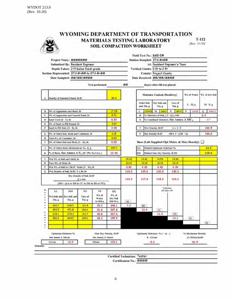
WYDOT 213.0 (Rev. 10-20)
6

WYDOT 213.0 (Rev. 10-20)
7
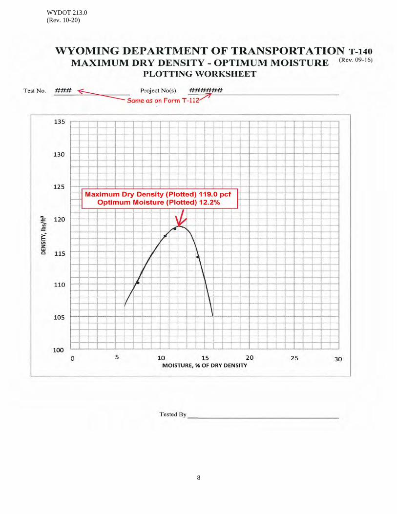
WYDOT 213.0 (Rev. 10-20)
8
WYDOT 216.0 (Rev. 10-19)
1
CHECK CURVE - EMBANKMENT (CC - E)
Scope: This procedure is used to compare field calculated results of Method "A",
maximum dry density and optimum moisture, with the results as determined by the Materials Program.
Apparatus: 1. Pans 15 inch, suggested
2. Rammer and guide, 5½ lb, See Appendix A, WYDOT 213.0 for tolerances 3. Drying stove 4. Moisture tins 5. Trowel 6. Steel straightedge, 15 inch length minimum 7. No. 4 screen 8. Wooden block, suggest 2 inch x 4 inch 9. 0.03 ft3 mold, See Appendices A & B, WYDOT 213.0 for tolerances. 10. Compaction block, 300 lb minimum 11. Extruder 12. Gram scale, sensitive to 0.1 g 13. 35 lb [15 kg] scale sensitive to 0.01 lb [5 g] 14. 100 ml graduated cylinder
Reference Documents: WYDOT 213.0 Moisture – Density Relations of Soils Method “A” WYDOT T-112 Soils Compaction Worksheet
WYDOT T-120 Sample Transmittal WYDOT T-140 Plotting Worksheet Sample: Sometime during the first few weeks of construction, coordinate with Field
Services Inspector, then secure a representative soil sample, enough material for two compaction tests. Thoroughly mix the material and split. Run a compaction test using Method "A", on one half of the material and send the other half to the Materials Program. Ensure there is enough material sent to the Materials Program to run at least four of these 7 lb samples. At least 90 lb of material should be sent to the Materials Program if there is a large amount of material above the 2 inch sieve.
Submit a completed Form T-120, Sample Transmittal, with each sack. Additionally, complete a Form T-112, Soil Compaction Worksheet, and the corresponding Form T-140, Maximum Dry Density – Optimum Moisture Plotting Worksheet, to accompany each sample sack. See Example T-112 and T-140 of this section.

WYDOT 216.0 (Rev. 10-19)
2
Procedure: Method "A" will be used for samples with less than 40% rock (WYDOT 213.0).
Additional compaction curves may be sent to the Materials Program as desired or needed. At least one check curve (CC) should be sent in by each field tester during construction, usually at the start of the project.
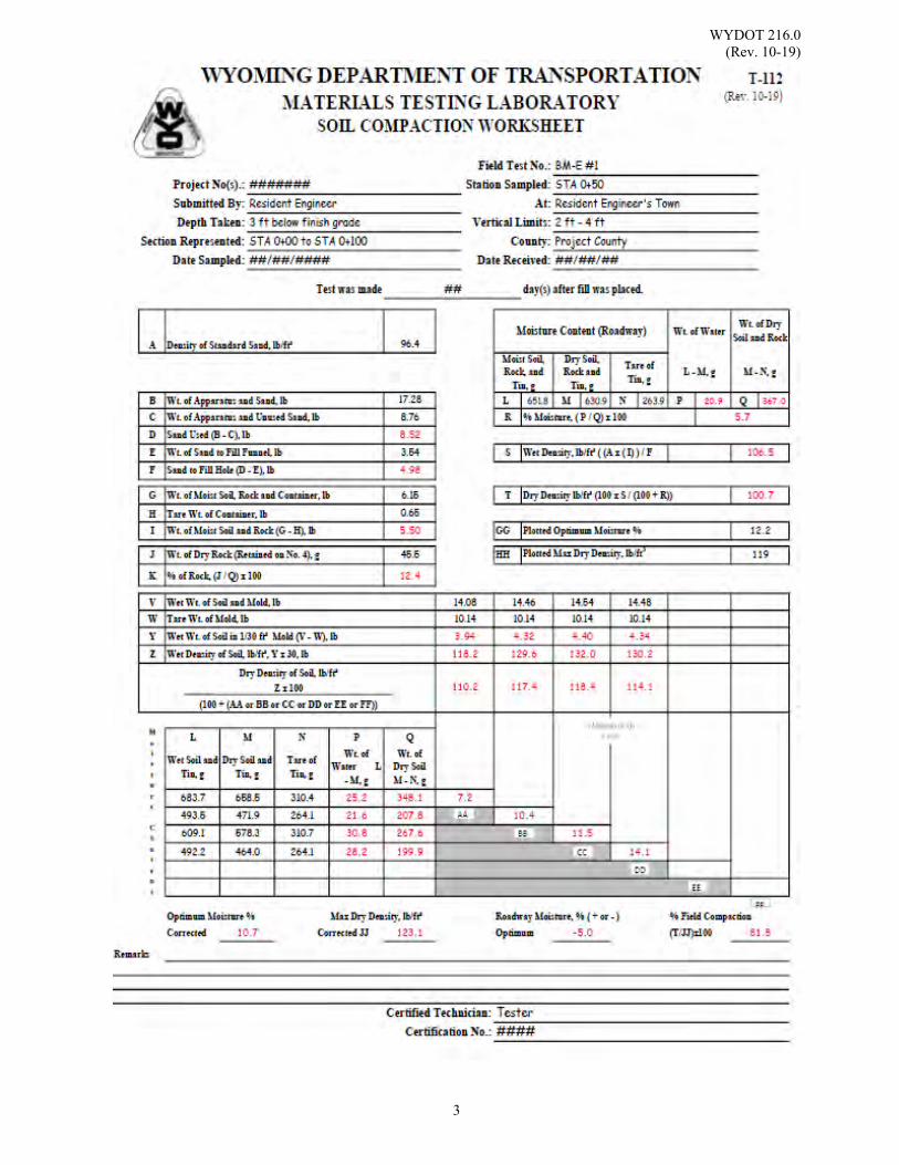
WYDOT 216.0 (Rev. 10-19)
3

WYDOT 216.0 (Rev. 10-19)
4
WYDOT 217.0 (Rev. 10-20)
1
FAMILY OF CURVES
Scope: This procedure is used to develop a series of several four point maximum dry density and optimum moisture curves of similar soils. A family of curves is a group of typical soil moisture-density relationships determined using WYDOT 213.0, which reveal certain similarities and trends characteristics of the soil type and source. Soils sampled from one source will have many different moisture-density curves, but if a group of these curves are plotted together certain relationships usually become apparent.
Intent For Use: Repeating the compaction process for several different types of cohesive-soils will
result in curves of similar shape and geometry. By plotting these curves on one sheet, a family of curves may be used to estimate the maximum dry density and optimum moisture content of a similar cohesive-soil sample in the field based on one point. To use the “one point” method based on the family of curves, the “one point” must fall on one of the established curves.
Apparatus: 1. Pans 15 inch, suggested
2. Rammer and guide, 5½ lb, See Appendix A, WYDOT 213.0 for tolerances 3. Drying stoves 4. Moisture tins 5. Trowel 6. Steel straightedge, 15 inch length minimum 7. Wooden block, suggest 2 inch x 4 inch 8. 0.03 ft3 mold, See Appendices A & B, WYDOT 213.0 for tolerances. 9. Compaction block, 300 lb minimum 10. Extruder 11. Gram scale, sensitive to 0.1 g 12. 35 lb [15 kg] scale sensitive to 0.01 lb [5 g] 13. 100 ml graduated cylinder
Reference Documents: AASHTO T 272 Standard Method of Test for Family of Curves - One Point
Method WYDOT 213.0 Moisture – Density Relations of Soils Method “A” WYDOT T-140 Plotting Worksheet Sample: Take representative soil samples large enough to be used in the compaction of four
point curves. When you encounter large amounts of 2 inch material, then at least 90 lb will be needed to get enough material.

WYDOT 217.0 (Rev. 10-20)
2
Procedure: After the completion of several Method "A" (WYDOT 213.0) Moisture-Density
tests, plot as many of the completed four point maximum dry density and optimum moisture curves as possible onto Form T-140, Plotting Worksheet.
The curves used to make a family will be curves of similar soils typically cohesive, which when plotted will have a tendency to peak in somewhat of a straight line. Curves that do not fall onto this alignment perfectly could still be in the same family if, in the judgment of the technician, the deviation from alignment is not too great. Any curves which obviously do not fit the alignment could possibly be used in the development of other families. A family of curves should consist of at least five curves so that a maximum range can be utilized.
When a family of curves has been developed and is being used, forward a copy to the Materials Program. As additional curves are added to the family or other families developed, send copies of these to the Materials Program.
A family of curves can be developed gradually while taking construction density tests on a regular basis.
Example: On the Form T-140 of this section, "A" through "F" were taken from a set of ten curves. The six curves used to make up this family all have the same dry density slope as compared to curves numbers one through three. The dry density slope is as important as the peaks in developing a family. Curves one through three can be used as the beginning of another family which can be developed as other curves are compacted.

WYDOT 217.0 (Rev. 10-20)
3
% Moisture
% Moisture

WYDOT 217.0 (Rev. 10-20)
4
(This page intentionally left blank.)
WYDOT 218.0 (Rev. 10-20)
1
REFERENCE TEST Scope: The following method is intended to reduce the number of compacted cylinders
needed in calculating maximum dry density and optimum moisture of soils from four cylinders to two cylinders. See Family of Curves (WYDOT 217.0).
Apparatus: 1. Pans 15 inch, suggested
2. Rammer and guide, 5½ lb, See Appendix A, WYDOT 213.0 for tolerances 3. Drying stoves 4. Moisture tins 5. Trowel 6. Steel straightedge, 15 inch length minimum 7. No. 4 screen 8. Wooden block, suggest 2 inch x 4 inch 9. 0.03 ft3 mold, See Appendices A & B, WYDOT 213.0 for tolerances. 10. Compaction block, 300 lb minimum 11. Extruder 12. Gram scale, sensitive to 0.1 g 13. 35 lb [15 kg] scale sensitive to 0.01 lb [5 g] 14. 100 ml graduated cylinder
Reference Documents: WYDOT 212.0 Sand Cone Method Field Density Test WYDOT 213.0 Moisture – Density Relations of Soils Method “A” WYDOT 217.0 Family of Curves WYDOT T-112 Soil Compaction Worksheet WYDOT T-140 Plotting Worksheet Sample: Representative soil samples for this type of test are usually taken as part of a Sand
Cone Method Field Density Test, (WYDOT 212.0).
Note: Always take large enough samples so that four cylinder maximum dry density and optimum moisture curves can be tested if needed.
Procedure: Determine the moisture content of the entire sample of the material removed from
the hole if a field density is performed. Dry the field moisture sample, calculate the percent moisture, record as item “R” and then compute dry density of fill, item “U” on Form T-112.
The percent of oversized particles in the soil should be determined before any
cylinders are compacted. If a field density test is performed, the percent of oversized particles is taken from Form T-112, item “K”. To find the percent of oversized particles in any soil sample, separate the minus 2 in material over the No. 4 screen and weigh the rock retained on the screen; perform calculations in accordance with Form T-112.
WYDOT 218.0 (Rev. 10-20)
2
With the percent rock determined, determine the percent of moisture in the sample. Mix enough material for two separate 7 lb samples, one usually at field moisture and the other at plus or minus 2% from field moisture. If the sample is taken as part of a "Field Density Test" sand cone method, then one of the two samples will be material from the test hole, and the other 7 lb sample will be material taken from around the test hole.
Enough material should always be taken and mixed to run four compaction cylinders if necessary.
If the percent rock falls between 0% to 40%, then Method "A", (WYDOT 213.0) procedure is followed for the compaction of two cylinders.
After the two cylinders have been compacted, plot the dry density and the moisture for each cylinder onto Form T-140, Plotting Worksheet, a maximum dry density and optimum moisture curve. The curve selected should be of similar soil and from the same general area. If the dry density and moisture for each cylinder does not plot very close to the curve you select, and you are not using a Family of Curves, it may be necessary to choose from other curves of similar soil already compacted. If none of the curves available come very close, then a new curve should be compacted using the remaining two, 7 lb samples.
When the proper curve is selected, use the maximum dry density and optimum moisture from that curve as item “HH” and “GG” on Form T-112. Under "Remarks" on Form T-112, the test number that the maximum dry density and optimum moisture were taken from should be indicated.
When referencing two cylinders to a Family of Curves, and the two cylinders fall between two plotted curves of the same family, one of two procedures can be followed: 1. Use either interpolation of the data between the two curves or, 2. Completion of the compaction test. Completion of the compaction test is the preferred procedure as this will add another curve to the family, thereby furnishing more accurate data for future referencing of tests.
Example: Dry Density #1, 104.1 pcf @ 12.5% moisture Dry Density #2, 105.9 pcf @ 15.3% moisture From family of curve (C), Dry Density 108.0 pcf @ 16.2% moisture
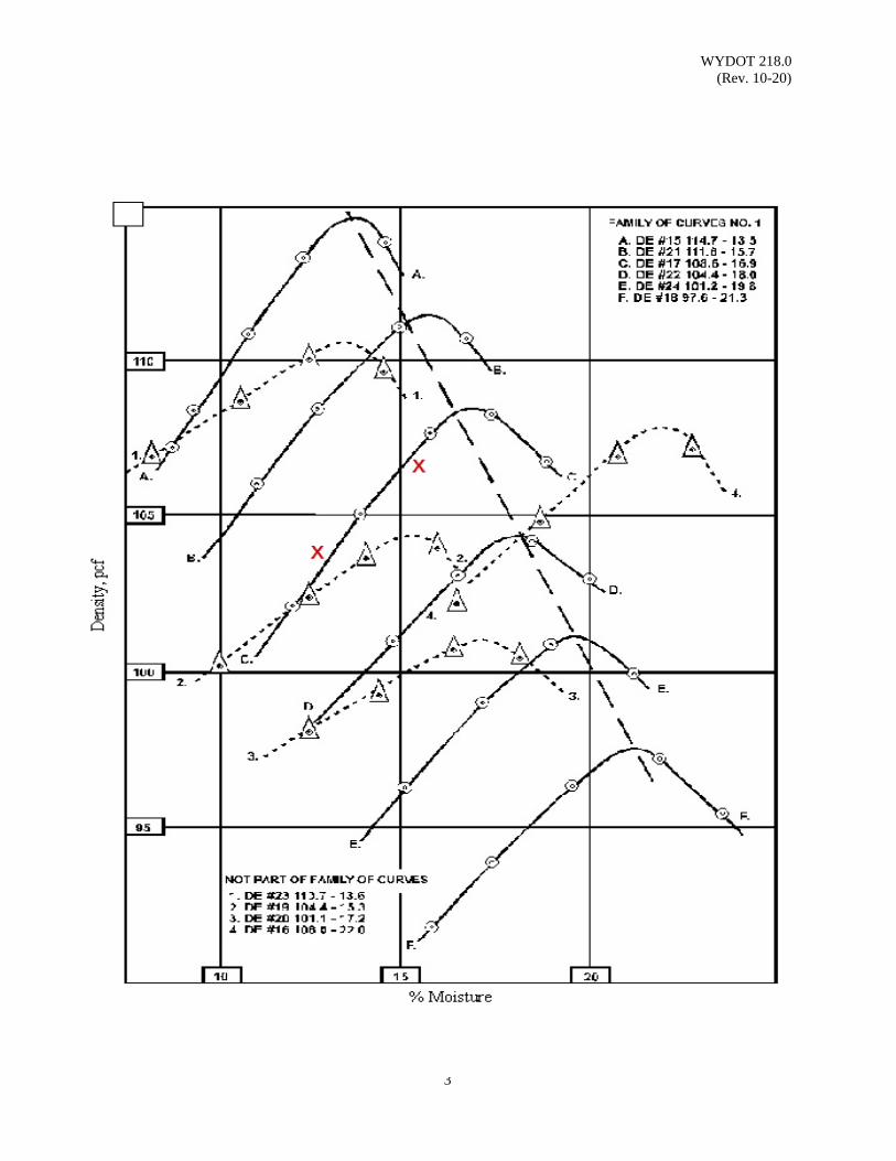
WYDOT 218.0 (Rev. 10-20)
3

WYDOT 218.0 (Rev. 10-20)
4
(This page intentionally left blank.)
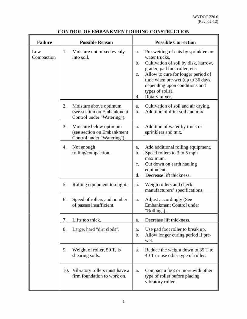
WYDOT 220.0 (Rev. 02-12)
1
CONTROL OF EMBANKMENT DURING CONSTRUCTION Failure
Possible Reason
Possible Correction
Low Compaction
1. Moisture not mixed evenly
into soil.
a. Pre-wetting of cuts by sprinklers or
water trucks. b. Cultivation of soil by disk, harrow,
grader, pad foot roller, etc. c. Allow to cure for longer period of
time when pre-wet (up to 36 days, depending upon conditions and types of soils).
d. Rotary mixer.
2. Moisture above optimum
(see section on Embankment Control under "Watering").
a. Cultivation of soil and air drying. b. Addition of drier soil and mix.
3. Moisture below optimum
(see section on Embankment Control under "Watering").
a. Addition of water by truck or
sprinklers and mix.
4. Not enough
rolling/compaction.
a. Add additional rolling equipment. b. Speed rollers to 3 to 5 mph
maximum. c. Cut down on earth hauling
equipment. d. Decrease lift thickness.
5. Rolling equipment too light.
a. Weigh rollers and check
manufacturers’ specifications.
6. Speed of rollers and number
of passes insufficient.
a. Adjust accordingly (See
Embankment Control under "Rolling").
7. Lifts too thick.
a. Decrease lift thickness.
8. Large, hard "dirt clods".
a. Use pad foot roller to break up. b. Allow longer curing period if pre-
wet.
9. Weight of roller, 50 T, is
shearing soils.
a. Reduce the weight down to 35 T to
40 T or use other type of roller.
10. Vibratory rollers must have a
firm foundation to work on.
a. Compact a foot or more with other
type of roller before placing vibratory roller.

WYDOT 220.0 (Rev. 02-12)
2
Failure
Possible Reason
Possible Correction
Spongy Surface, Ravelling
1. Excessively wet condition
below grade.
a. Sub-excavate and backfill with
suitable bridging material and provide adequate drainage.
b. For example: Lower water table with the use of drain pipes or by cutting borrow ditches deeper.
2. Expansive or non-
compactable soils.
a. Sub-excavate and backfill with
suitable material. NOTE: In the above two conditions the use of coarse graded material (gravel) should not be
used because of the ponding or "bathtub" condition which may be created. Layering (Wet & Dry)
1. Improper mixing or mixing
equipment not mixing deep enough.
a. Use additional mixing equipment.
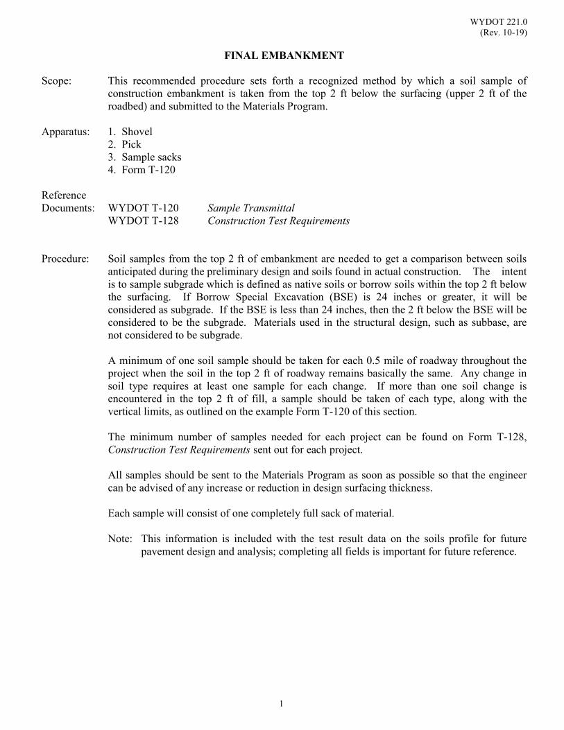
WYDOT 221.0 (Rev. 10-19)
1
FINAL EMBANKMENT
Scope: This recommended procedure sets forth a recognized method by which a soil sample of construction embankment is taken from the top 2 ft below the surfacing (upper 2 ft of the roadbed) and submitted to the Materials Program.
Apparatus: 1. Shovel
2. Pick 3. Sample sacks 4. Form T-120
Reference Documents: WYDOT T-120 Sample Transmittal WYDOT T-128 Construction Test Requirements Procedure: Soil samples from the top 2 ft of embankment are needed to get a comparison between soils
anticipated during the preliminary design and soils found in actual construction. The intent is to sample subgrade which is defined as native soils or borrow soils within the top 2 ft below the surfacing. If Borrow Special Excavation (BSE) is 24 inches or greater, it will be considered as subgrade. If the BSE is less than 24 inches, then the 2 ft below the BSE will be considered to be the subgrade. Materials used in the structural design, such as subbase, are not considered to be subgrade.
A minimum of one soil sample should be taken for each 0.5 mile of roadway throughout the project when the soil in the top 2 ft of roadway remains basically the same. Any change in soil type requires at least one sample for each change. If more than one soil change is encountered in the top 2 ft of fill, a sample should be taken of each type, along with the vertical limits, as outlined on the example Form T-120 of this section. The minimum number of samples needed for each project can be found on Form T-128, Construction Test Requirements sent out for each project.
All samples should be sent to the Materials Program as soon as possible so that the engineer can be advised of any increase or reduction in design surfacing thickness.
Each sample will consist of one completely full sack of material. Note: This information is included with the test result data on the soils profile for future
pavement design and analysis; completing all fields is important for future reference.
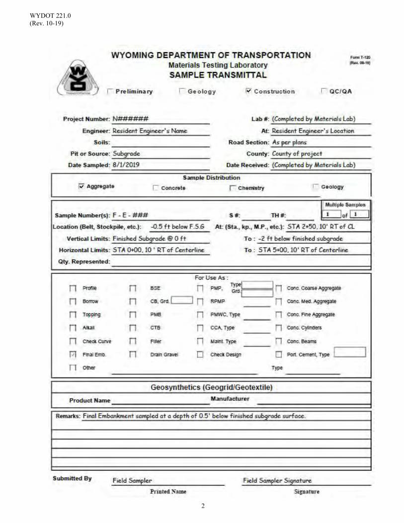
WYDOT 221.0 (Rev. 10-19)
2
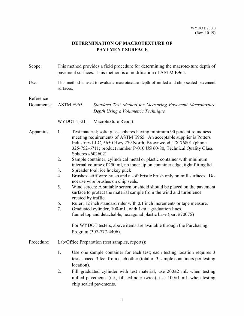
WYDOT 230.0 (Rev. 10-19)
1
DETERMINATION OF MACROTEXTURE OF PAVEMENT SURFACE
Scope: This method provides a field procedure for determining the macrotexture depth of pavement surfaces. This method is a modification of ASTM E965.
Use: This method is used to evaluate macrotexture depth of milled and chip sealed pavement surfaces.
Reference Documents: ASTM E965 Standard Test Method for Measuring Pavement Macrotexture Depth Using a Volumetric Technique
WYDOT T-211 Macrotexture Report
Apparatus: 1. Test material; solid glass spheres having minimum 90 percent roundness meeting requirements of ASTM E965. An acceptable supplier is Potters Industries LLC, 5650 Hwy 279 North, Brownwood, TX 76801 (phone 325-752-6711; product number P-010 US 60-80, Technical Quality Glass Spheres #602602) 2. Sample container; cylindrical metal or plastic container with minimum internal volume of 250 ml, no inner lip on container edge, tight fitting lid 3. Spreader tool; ice hockey puck 4. Brushes; stiff wire brush and a soft bristle brush only on mill surfaces. Do not use wire brushes on chip seals. 5. Wind screen; A suitable screen or shield should be placed on the pavement surface to protect the material sample from the wind and turbulence created by traffic.
6. Ruler; 12 inch standard ruler with 0.1 inch increments or tape measure. 7. Graduated cylinder, 100-mL, with 1-mL graduation lines, funnel top and detachable, hexagonal plastic base (part #70075)
For WYDOT testers, above items are available through the Purchasing Program (307-777-4406).
Procedure: Lab/Office Preparation (test samples, reports):
1. Use one sample container for each test; each testing location requires 3 tests spaced 3 feet from each other (total of 3 sample containers per testing location).
2. Fill graduated cylinder with test material; use 200±2 mL when testing milled pavements (i.e., fill cylinder twice), use 100±1 mL when testing chip sealed pavements.

WYDOT 230.0 (Rev. 10-19)
2
3. Gently tap the side of the graduated cylinder to level the top surface of the test material; visually verify quantity; add or empty material as necessary.
4. Pour applicable volume of test material, either 100 mL or 200 mL, in the sample container; close/seal with lid; label quantity on lid with marker pen
5. Repeat Steps 1 through 4 to prepare a sufficient quantity of samples for testing all surfacing location(s).
6. Prepare necessary test report(s) for recording measurements prior to field testing. Use Form T-211, and at the top of each report mark an ('X') in the appropriate box to select each of the following criteria:
a. Surfacing Type, either 'Milled Pavement' or 'Chip Sealing'; b. If chip sealing, then Aggregate Size, either ⅜ inch or ½ inch;
c. Sample Size, either 100 mL or 200 mL; The report form automatically generates the appropriate cross reference table based on surfacing type, aggregate size, and sample size.
Field Testing/Measurements:
1. Test finished pavement surface(s) as follows: a. One test per mile for milled surfaces receiving pavement overlay b. One test per frequency as specified for chip sealed surfaces
2. Determine a random, representative testing location on pavement surface to measure macrotexture depth.
3. Inspect testing location to ensure it is dry and homogeneous, free of unique or localized features such as cracks, joints, striping, and patching.
4. If localized features are present, move up-station at the same transverse offset until a suitable testing location is found.
5. Gently clean an area of about 1 foot square for sample location using the stiff-wire brush to remove and residue, debris or loosely bonded material. Be careful not to dislodge bonded material. After using the stiff wire brush, gently brush sample location with the soft bristle brush to remove any remaining debris.
6. Place the wind screen on the pavement surface to protect the sample location from air turbulence.
7. Hold the sample container with test material above pavement at sample location at a height not greater than 4 inches.
8. Pour appropriate, measured volume of test material from the container onto pavement surface forming a conical pile.
9. Place the spreader tool (ice hockey puck) lightly on top of conical pile of test material being careful not to compact the test material.
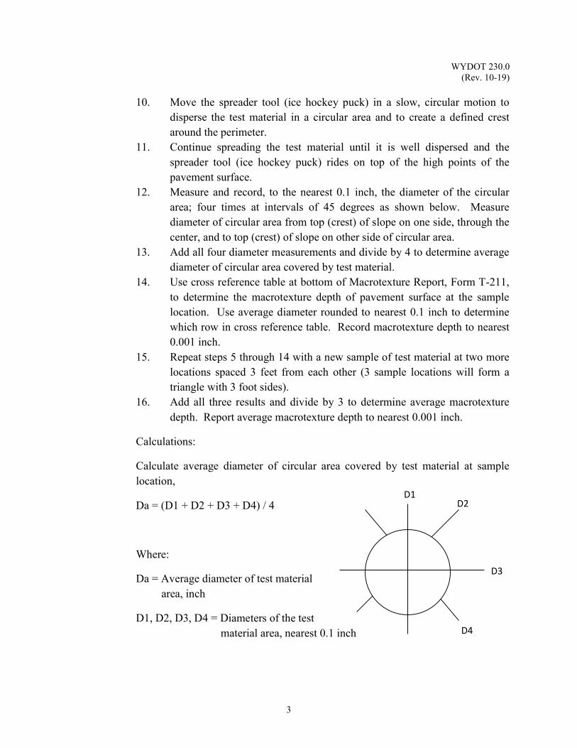
WYDOT 230.0 (Rev. 10-19)
3
10. Move the spreader tool (ice hockey puck) in a slow, circular motion to disperse the test material in a circular area and to create a defined crest around the perimeter.
11. Continue spreading the test material until it is well dispersed and the spreader tool (ice hockey puck) rides on top of the high points of the pavement surface.
12. Measure and record, to the nearest 0.1 inch, the diameter of the circular area; four times at intervals of 45 degrees as shown below. Measure diameter of circular area from top (crest) of slope on one side, through the center, and to top (crest) of slope on other side of circular area.
13. Add all four diameter measurements and divide by 4 to determine average diameter of circular area covered by test material.
14. Use cross reference table at bottom of Macrotexture Report, Form T-211, to determine the macrotexture depth of pavement surface at the sample location. Use average diameter rounded to nearest 0.1 inch to determine which row in cross reference table. Record macrotexture depth to nearest 0.001 inch.
15. Repeat steps 5 through 14 with a new sample of test material at two more locations spaced 3 feet from each other (3 sample locations will form a triangle with 3 foot sides).
16. Add all three results and divide by 3 to determine average macrotexture depth. Report average macrotexture depth to nearest 0.001 inch.
Calculations:
Calculate average diameter of circular area covered by test material at sample location,
Da = (D1 + D2 + D3 + D4) / 4
Where:
Da = Average diameter of test material area, inch
D1, D2, D3, D4 = Diameters of the test material area, nearest 0.1 inch
D1 D2
D3
D4

WYDOT 230.0 (Rev. 10-19)
4
Report: Record macrotexture depth of pavement surface on Form T-211, Macrotexture Report. Report macrotexture depth to nearest 0.001 inch. For chip sealed surfaces, also record percent embedment depth on Form T-211, Macrotexture Report. Report percent embedment depth to nearest 1 percent.

WYDOT 230.0 (Rev. 10-19)
5

WYDOT 230.0 (Rev. 10-19)
6
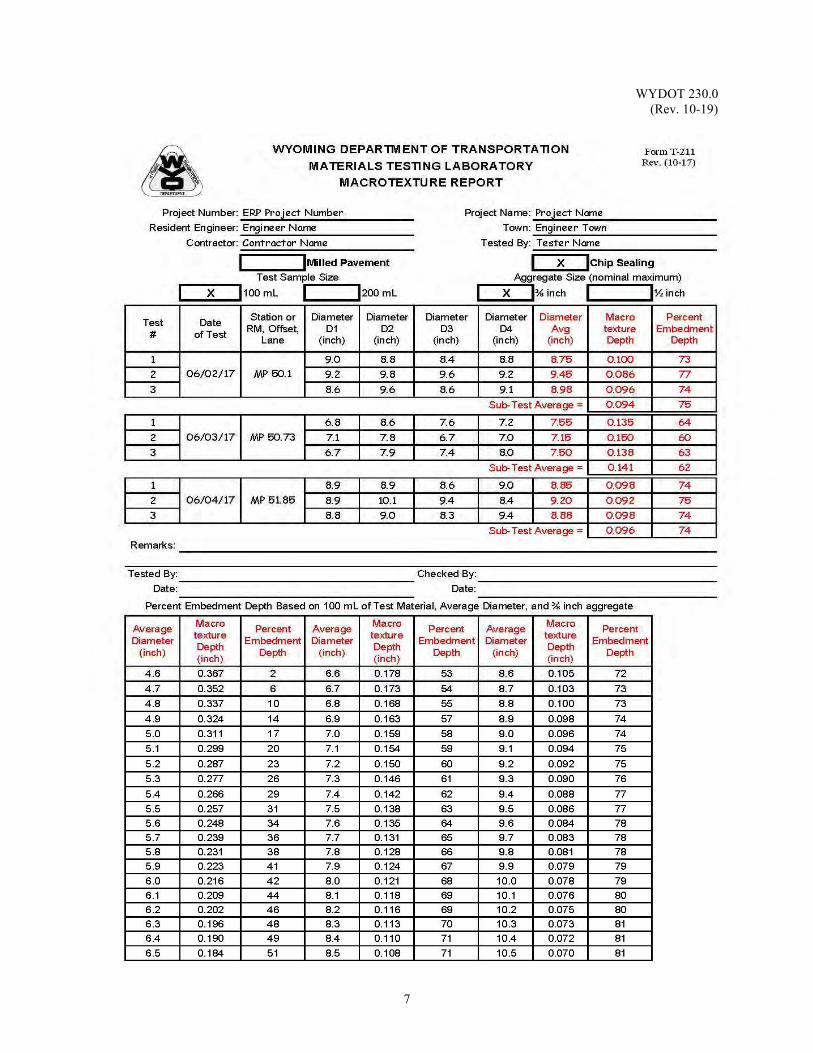
WYDOT 230.0 (Rev. 10-19)
7
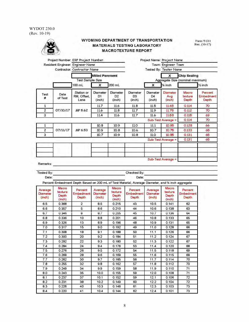
WYDOT 230.0 (Rev. 10-19)
8
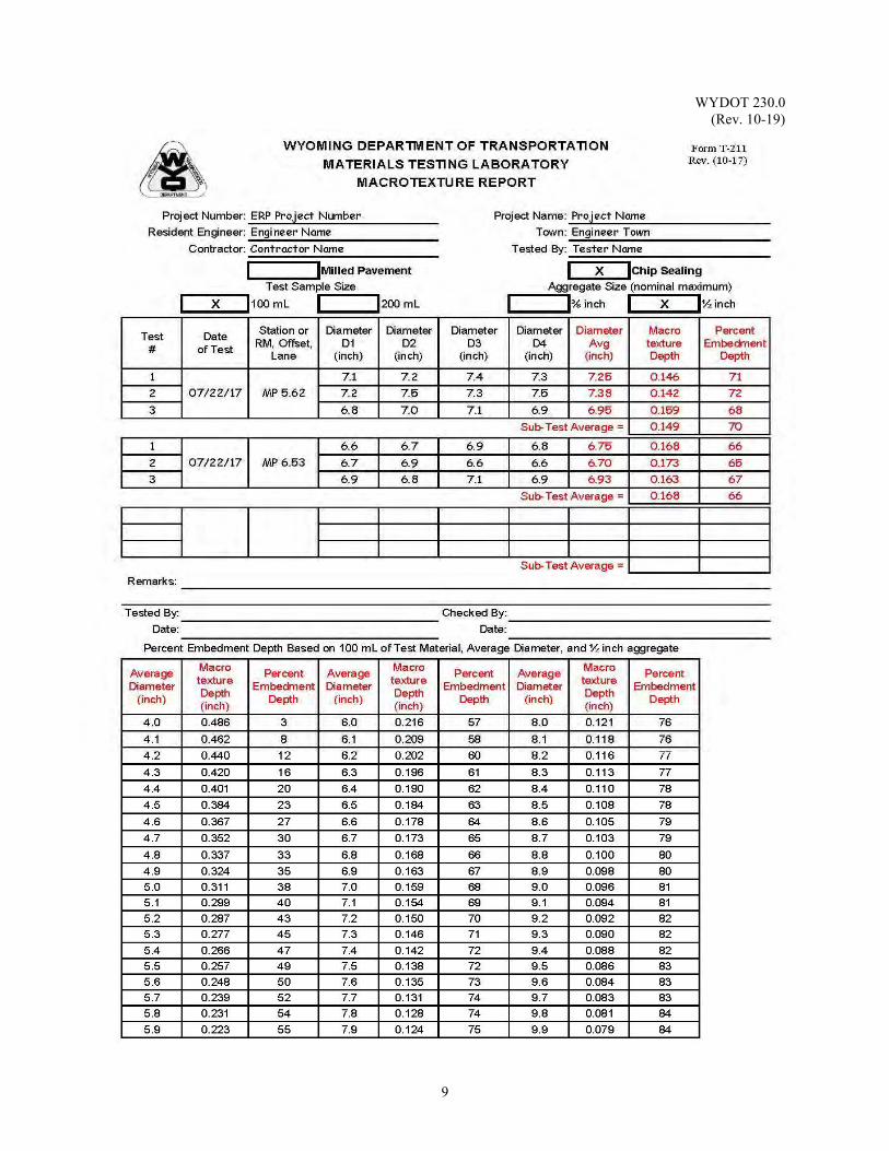
WYDOT 230.0 (Rev. 10-19)
9
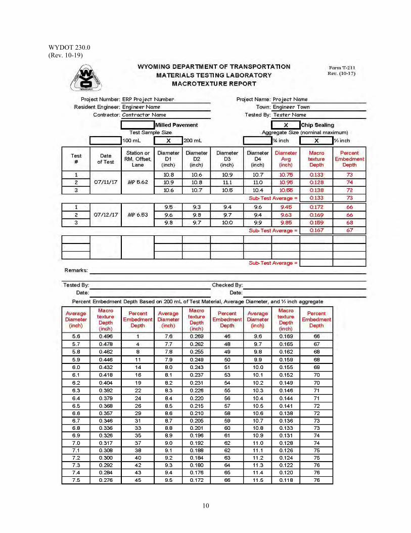
WYDOT 230.0 (Rev. 10-19)
10
WYDOT 301.0 (Rev. 10-20)
1
IN - PLACE DENSITY TEST (SUBBASES AND BASES)
Scope: This method is used in determining the in-place density of granular material without
the need to compact a moisture-density curve in the field. Apparatus: 1. Sand cone apparatus, 1 gal jar and funnel 2. Containers with lids, suggest two concrete cylinder cans 3. Chisel and hammer 4. Rammer with guide, 5 ½ lb 5. Spoon or half round dish 6. Shovel 7. Square pans 15 inch, suggested 8. Drying stoves
9. Moisture tins 10. No. 4 screen 11. Wooden block, suggest 2 inch x 4 inch 12. Gram scale, sensitive to 0.1 g 13. 35 lb [15 kg] scale sensitive to 0.01 lb [5 kg] 14. Base plate - optional 15. 2 inch screen 16. Standard sand 17. Clean canvas sample sacks
Note: For WYDOT personnel, contact WYDOT Field Services for
information or sources for standard sand. Reference Documents: AASHTO T 180 Standard Method of Test for Moisture-Density Relations of Soils Using a 4.54-kg (10-lb) Rammer and a 457-mm (18-in.) Drop WYDOT 212.0 Sand Cone Method Field Density Test
WYDOT T-112 Soil Compaction Worksheet *WYDOT T-113 Weekly Report of Compaction of: Embankment WYDOT T-166 Aggregate Analysis * Note: Use of weekly reports is optional Sample: A representative sample of granular material is taken during a Sand Cone Method
Field Density Test, WYDOT 212.0.
Note: Send at least 150 lb of aggregate to the Materials Program as soon as a representative sample can be obtained, but not less than two weeks before
WYDOT 301.0 (Rev. 10-20)
2
the aggregate is placed on the roadway. The Materials Program will then establish the maximum dry density and optimum moisture to be used in the field.
Sample sacks will be made of canvas weighing 30 to 50 lb, not to exceed 50
lb. Submit a completed Form T-166, Aggregate Analysis with each sack.
a. The maximum dry density needed for this test procedure is determined by AASHTO T 180, Moisture – Density Relations of Soils Using a 10 lb. (4.54 Kg) Rammer and 18 inch (457 mm) Drop.
b. Toggle the checkbox on Form T-112 indicating that the material is
Base (Lab Supplied Opt Moist. & Max Density). Record the maximum dry density and optimum moisture as item “HH” and “GG” on Form T-112 as previously established by the Materials Program.
Procedure: Laboratory Preparations
1. Record the standard sand density as item “A” on Form T-112, Soil Compaction Worksheet, see WYDOT 211.0, Standardization of Sand. Also see example Form T-112 of this section.
2. Fill the sand cone; 1 gal jar with standard sand, weigh the apparatus
and sand. Record as item “B” on Form T-112.
3. Record the weight of sand to fill funnel as item “E” on Form T-112, Soil Compaction Worksheet, see WYDOT 211.0, Standardization of Sand.
4. Weigh an empty container and lid (concrete cylinder can) and record the
weight as item “H” on Form T-112. Note: Prior to printing a field copy of Form T-112, be sure to toggle “Base
(Lab Supplied Opt Moist. & Max Density)” to ensure the correct equations are carried forward for hand calculations.
Field Operation
1. Level off an area approximately 2 ft2 to accommodate the sand cone,
removing all loose material from the test area.
2. Place the sand cone in the cleared area and scribe an outline of the cone on the soil for a guide while digging the hole. Using the chisel and spoon, dig a test hole a minimum of 4 inches in diameter and deep enough to remove one lift of base material. Place base into a tared container with an air tight lid to prevent moisture loss. Remove all loose base from the hole. Take care not to disturb the sides of the hole when removing the material.
WYDOT 301.0 (Rev. 10-20)
3
Note: A base plate may be used in place of scribing an outline of the cone on the soil. The base plate gives the advantage of a larger diameter hole especially when rock and/or thin lifts of gravel for surfacing or soils is encountered. If the base plate is used, it will be considered a part of the funnel and becomes part of the calibration of the funnel and entered as item “E” on Form T-112.
3. Invert the sand cone apparatus, placing the cone over the hole, open the valve
all of the way and allow the sand to flow freely. Be careful not to agitate the apparatus or the surrounding ground while the sand is running. When the sand ceases to flow, close the valve and carefully remove the jar from the hole. Gather as much sand from the hole area as possible, placing the sand into a separate container to be reclaimed later.
Laboratory Operation
1. Weigh the sand cone apparatus and the remaining sand. Record as item “C”
on Form T-112. 2. Weigh the soil, rock, and container. Record as item “G” on Form T-112.
Note: Coarse is defined as material retained on the No. 4 screen. For this
procedure, percent rock is used to describe the percent of coarse material in a sample.
3. Determine the moisture content of the entire sample of the material removed,
from the hole. Record as item “R”.
4. Utilize the 2 inch x 4 inch wooden block and No. 4 screen to separate the dry soil and rock of the field moisture sample. Material remaining on the No. 4 screen is rock and must be free of soil or clay coatings. Weigh the dry rock retained and record as item “J” on Form T-112. Determine the percent rock as outlined on Form T-112, item “K”.
5. Complete all computations up to and including item “U” on Form T-112.
Report: Report weekly results on optional Form T-113, Weekly Report for Compaction of
Crushed Base.
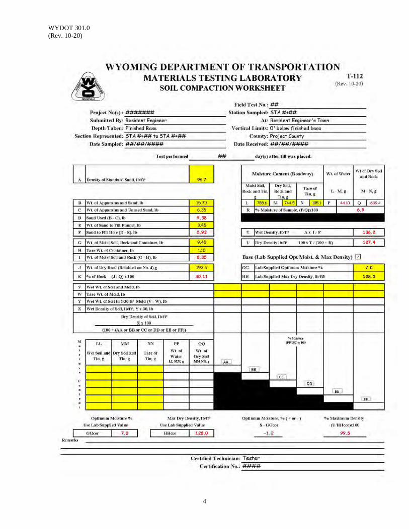
WYDOT 301.0 (Rev. 10-20)
4
WYDOT 390.0 (Rev. 10-18)
1
MIX DESIGN FOR STABILIZED BASE (FDR) Scope: This procedure describes the mix design procedure used to determine the
optimum additive content for each blend of aggregate materials available. Use: This procedure is used to determine the optimum emulsion and lime and/or other
additives for stabilized bases, most commonly for full depth reclamation operations.
Apparatus: 1. Jaw Crusher able to produce material passing the No. 4 sieve
requirements. A sledge may be used to reduce oversize particles to permit the material to be fed into the crusher
2. Gyratory Compactor calibrated for 6 inch diameter mold, including molds and ancillary equipment
3. Marshall Stability/Flow Equipment calibrated, including ancillary equipment
4. Mechanical Mixer equipped with bowls 10 inch to 12 inch in diameter 5. Two ovens; one forced draft oven capable of maintaining a temperature of
104 ± 5 °F and another capable of maintaining a temperature of 300 ± 9 °F 6. Balance, 5 kg capacity, accurate to 1 g 7. Sieves, U.S. Standard sizes, as specified 8. Sample Splitter suitable for splitting aggregates up to 1.25 inches 9. Pans approximately 10 inch diameter by 3 inch deep 10. Trowels and other small tools Reference Documents: AASHTO T 166 Standard Method of Test for Bulk Specific Gravity of
Compacted Hot Mix (HMA) Using Saturated Surface-Dry Specimens AASHTO T 180 Standard Method of Test for Moisture-Density Relations of
Soils Using a 4.54-kg (10-lb) Rammer and a 457-mm (18- in.) Drop
AASHTO T 209 Standard Method of Test for Theoretical Maximum Specific Gravity and Density of Hot Mix Asphalt (HMA)
AASHTO T 283 Standard Method of Test for Resistance of Compacted Hot Mix Asphalt (HMA) to Moisture-Induced Damage
ASTM D1452 Standard Practice for Soil Exploration and Sampling by
Auger Borings ASTM D2950 Standard Test Method for Density of Bituminous Concrete
in Place by Nuclear Methods ASTM D4867 Standard Test Method for Effect of Moisture on Asphalt
Concrete Paving Mixtures WYDOT 214.0 Moisture - Density Relations of Soils Method “C”
WYDOT 414.0 Marshall and Superpave Mix Design and Mix Volumetric Verification Procedure
WYDOT 415.0 Density Testing for Compacted Mix WYDOT 836.0 Fine Aggregate Sand Equivalent
WYDOT 390.0 (Rev. 10-18)
2
Sampling and Processing: Based on data from auger borings (ASTM D1452), cores (WYDOT 415.0), and/or
other determinations (i.e. plans, core records, pavement records, FWD deflection data, etc.), determine if more than one mix design will be performed. In addition, FDR projects with more than a 2 inch difference in bituminous surface between sections, with varying base types, or significant addition of crushed base will require the necessity of separate mix designs.
Obtain uncontaminated materials of uniform quality that meet the requirements of
the plans and specifications. 1. Emulsion. Provide a CSS-FDR emulsion sample, approximately 4 gallons
per mix design, that meets the project requirements. 2 Crushed Base. Furnish crushed base, 60 pounds if specified, that meets
the project requirements. 3. Additive. Determine the amount and type of additive, if any during the
mix design. When an additive is required, the total amount in the mix will not exceed 1.5 percent by weight of material.
a. Lime. When lime is required, furnish 1 pound of lime that meets
the project requirements. Use hydrated lime or commercial lime slurry, as shown in the plans.
Note: Usually addition of 1 percent lime is sufficient. b. Cement. When cement is required, furnish 1 pound of hydraulic
cement that meets the project requirements. Note: Usually addition of 1 percent cement is sufficient. c. Fly Ash. When fly ash is required, furnish 1 pound of fly ash that
meets the project requirements. If cores or slabs are received, determine the individual and average thickness
values. Crush the existing pavement (RAP) and any stabilized base materials to the
gradation below before blending with the aggregate. Determine the washed gradation on the composite material. The composite material will include any or all of the existing base, the RAP, and/or virgin aggregates. Combine the materials in the proportions that are representative of the project depth and cross-section.
Sieve Size Gradation
1¼ inch 100
1 inch 90 to 100
WYDOT 390.0 (Rev. 10-18)
3
Specimens prepared for mix design must have a maximum size passing the 1¼
inch screen for all material components. Material Evaluation: Determine the composite material washed gradation and
sand equivalent and report. Determine the RAP dry and washed gradation and sand equivalent. Report the washed gradation and sand equivalent on the blend.
Perform Modified Proctor compaction according to WYDOT 214.0 to determine
optimum moisture content (OMC) at peak dry density. Define OMC by a best-fit curve using a minimum of four points. Material containing 20 percent or more passing the No. 200 be mixed with the target moisture, sealed, and set aside a minimum of 12 hours. All other material be set aside a minimum of 3 hours. If a material contains less than 4 percent passing No. 200, then the additional curing is not required.
1. Selection of Water Content for Mix Design
a. Determine the water content of the composite material, not including water in the emulsion in accordance with AASHTO T 180, WYDOT 214.0. Mix water at the target water content for material containing 20 percent or more passing the No. 200 sieve, seal and set aside for a minimum of 12 hours. All other material will be set aside for a minimum of 3 hours. For material having a significant amount of RAP or coarse material that does not produce a well-defined moisture density curve, establish the optimum moisture content (OMC) at 3 percent.
b. Select the water content of specimens for the mix design, not including water in
the emulsion, based on the following:
* If SE ≤ 30 60 to 75 percent of OMC * If SE > 30 45 to 65 percent of OMC * No. 200 < 4.0 percent OMC = 2.5 percent * OMC established at 3.0 percent OMC = 2.5 percent
Sand equivalent is based on SE from the composite sample
2. Preparation of Test Specimens a. Obtain an appropriate amount of composite material before the addition of water
and emulsion to produce compacted samples at least 70 ± 5 mm in height and 150 mm diameter or 100 mm diameter for AASHTO T 283, see Table 2 in the Special Provision for Stabilized Full Depth Reclamation.
b. Mix the composite material specimens with the required amount of water for 60
seconds before the addition of emulsion. Allow the specimens sit sealed according to the same guidelines as used for the OMC specimens in Step 1.
c. Samples have a weight before addition of water and emulsion to produce 70 ± 5
mm tall compacted specimens (except for IDT testing).

WYDOT 390.0 (Rev. 10-18)
4
d. Select four emulsion contents that will bracket the design emulsion content. Typically 3 percent, 4 percent, 5 percent, and 6 percent are used, but other ranges or narrower bands (0.5 percent) may be designated.
e. Produce the number of specimens for each test method in the laboratory according
to the following table:
Test Number of Specimens per Emulsion Content Maximum Specific Gravity * 2 Gyratory Compacted Stability 3 Initial Gyratory Compacted Stability 3 Indirect Tensile Strength 6
* Uncompacted
f. Mix the composite material and emulsion in a mechanical mixer at room temperature for 60 seconds.
g. Cure mixed specimens individually at 104 °F for 27 to 33 minutes. Cover
loosely. h. If other materials are to be added, such as lime or cement, introduce them in a
similar manner as they will be on the project. For example, if lime is incorporated a day or more before emulsion addition, then add it to the wet aggregate a day or more before mixing with emulsion. If lime is incorporated as a slurry, then add it as a slurry in the laboratory.
3. Compaction and Curing
a. Compact emulsion stabilized specimens in a Superpave gyratory compactor (SGC) at a vertical pressure of 600 kPa, an external angle of 1.25° ± 0.02° (internal angle of 1.16° ± 0.02°), a mold of 6 inches diameter for 30 gyrations, and at room temperature. After the last gyration, apply 600 kPa pressure for 10 seconds. Do not heat the mold.
b. Cure compacted emulsion stabilized specimens, in a forced draft oven at 104 °F
for 40 to 48 hours (20 to 24 hours for ITS) and to a constant weight ( constant weight equals weight of core that does not change more than 0.05 percent when weighed at 2 hour intervals). After curing, allow the specimens to cool at room temperature for a minimum of 24 hours and a maximum of 30 hours.
c. Cure specimens for initial stability at room temperature (76 ± 10) for 20 to 24
hours.
d. Leave specimens for maximum specific gravity in loose form, not compacted, and test after cooling at room temperature for a minimum of 12 hours and a maximum of 24 hours.4. Volumetric Measurements
a. Determine and average the maximum specific gravities (AASHTO T 209) of two specimens at each emulsion content.
WYDOT 390.0 (Rev. 10-18)
5
Note: Use the supplemental dry-back procedure. b. Determine and average the bulk specific gravities (AASHTO T 166) of all
specimens at each emulsion content. c. Stability and flow. Once completed, the gyratory compacted stability and flow
test results are used to calculate the Gyratory Quotient value (GQ). The GQ indicates mixture stiffness. (While stiff mixtures are desirable to resist permanent deformation, it is not desirable to have mixtures so stiff that they are likely to crack under heavy, repeated loads.)
1. Prepare three specimens at each emulsion content in accordance with
Sections 2 and 3. 2. Test the dry samples for stability and flow using a 6 inch diameter stability
breaking head. 3. Calculate GQ by dividing the peak stability value by the flow value
reached at the point of peak stability. 4. For stability, report the average value of the three specimens for stability,
flow, and GQ. 5. Repeat Steps 4.c.1 through 4.c.4 for initial stability, reporting only the
stability.
d. Indirect Tensile Strength (ITS)
1. Prepare six specimens according to Sections 2 and 3 at the selected emulsion content, half to be tested dry and the other half to be tested after moisture conditioning.
2. Dry Subset. Test according to AASHTO T 283.
3. Conditioned Subset. Test according to AASHTO T 283 excluding the
vacuum saturation and freeze cycle. Place samples in a 104 ± 2 °F water bath for 24 ± 1 h. Remove and place specimens in a 77 ± 1 °F water bath for 2 h ± 10 min.
Continue testing according to AASHTO T 283 Section 11.
WYDOT 390.0 (Rev. 10-18)
6
5. Emulsion Content Selection
a. Select a design emulsion content to produce a stabilized base mixture meeting the requirements of Table 1 in the Special Provision for Stabilized Full Depth Reclamation. If more than one emulsion content produces mixtures that meet the criteria, then select the emulsion content that produces a mixture with the highest cured stability that meets all other criteria.
6. Report
a. Submit the mix design with a minimum of the following information on a modified Form E-46
1. Project Information (Project Number, Project Name, Project,
Resident Engineer, etc.) 2. Penetration of the Emulsion Residue used in the Mix Design
3. A general description of the materials received, their locations, and sampling procedure.
4. Average thickness of bituminous materials (RAP), existing base, etc.
5. Thickness to be reclaimed 6. Washed gradation of the separate and blended material(s). If RAP
was crushed in the laboratory, then report the gradation of the RAP and the combined washed gradation of the blend
7. Sand equivalent value of the separate and blended materials 8. Density and OMC of composite materials, un-stabilized, from
Proctor compaction 9. Moisture content used in mix design and the recommended
Moisture Content for field control 10. Range of emulsion contents tested 11. Density, Gmm, and air voids at each emulsion content (average
values) 12. Initial Stability after 24 hours (average values) 13. Indirect tensile strength (ITS), dry (control sample), and wet
(conditioned sample), at each emulsion content (average values) 14. Criteria values for each emulsion content tested 15. Design emulsion content as a percent, in gallons per square yard,
and in gallons per foot (with assumed width reported) 16. Initial Stability 17. Final Cured Stability 18. Final Cured Flow 19. Gyratory Quotient
WYDOT 401.0 (Rev. 10-18)
1
VERIFICATION AND CERTIFICATION OF HIGH SPEED INERTIAL PROFILER
Scope: This procedure describes verification and certification of high speed inertial profiler (HSIP) before use on plant mix and concrete pavements. Each HSIP requires periodic verification and annual certification prior to construction season. Each HSIP operator must be certified.
Use: This section describes verification and certification procedures for HSIP prior to
measuring surface variation, analyzing profile, and evaluating pavement smoothness.
Apparatus: 1. HSIP 2. Distance Measuring Instrument (DMI) Reference Documents: AASHTO M 328 Standard Specification for Inertial Profiler AASHTO R 56 Standard Practice for Certification of Inertial Profiling
Systems AASHTO R 57 Standard Practice for Operating Inertial Profiling Systems ASTM E 867 Standard Terminology Relating to Vehicle-Pavement
Systems ASTM E 950 Standard Test Method for Measuring the Longitudinal
Profile of Traveled Surfaces with an Accelerometer Established Internal Profiling Reference
ASTM E 1926 Standard Practice for Computing International Roughness Index of Roads from Longitudinal Profile Measurements
ASTM E 2560 Standard Specification for Data Format for Pavement Profile
WYDOT 414 WYDOT Standard Specifications WYDOT 415 WYDOT Standard Specifications WYDOT 402.0 Pavement Profile Analysis WYDOT 403.0 Pavement Smoothness Evaluation WYDOT SS-400A Supplementary Specification for Amendments to Division
400 WYDOT SS-400B Supplementary Specification for Plant Mix Pavement
Surface Variation, Profile and Smoothness WYDOT T-515 IPV High Speed Inertial Profiler Worksheet
WYDOT 401.0 (Rev. 10-18)
2
Procedure: 1. Verification - minimum frequency; weekly and once prior to certification,
a. verify DMI accuracy according to AASHTO R 56, Section
8.4, b. perform AASHTO R 57, including:
1. block test (height sensor check), 2. bounce test (vehicle suspension rebound),
c. accelerometer; per manufacturer's recommendations prior to each project; report settings/adjustments to WYDOT,
d. maintaining log (test results, software changes, etc); at minimum, must include data shown on WYDOT Form T-515 IPV (example included in this section),
e. having necessary repairs/adjustments/upgrades. 2. Certification -
Perform according to AASHTO R 56; comply with following:
a. Equipment: 1. calibration - comply with verification requirements above (Step 1);
for concrete pavement, profiler must use approved line lasers, minimum three (3) inch wide footprint,
2. have current (valid) annual certification from Wyoming Materials Technician Certification (WMTC) Program
b. Operator -must:
1. be proficient in operation of profiler, and 2. have current (valid) 3-year certification from Wyoming
Materials Technician Certification (WMTC) Program.
c. Test Section (reference profile) -WYDOT selects site(s) for certification testing; includes the following: 1. Roughness test section, typically smooth, 30-75, ),
a. relatively straight and level (no significant grade, grade change, horizontal curvature nor superelevation),
b. perform three (3) closed loop data collection runs using reference profiler; each wheel path in the intended direction of travel.
2. DMI test section, minimum length (0.1 mile + proper
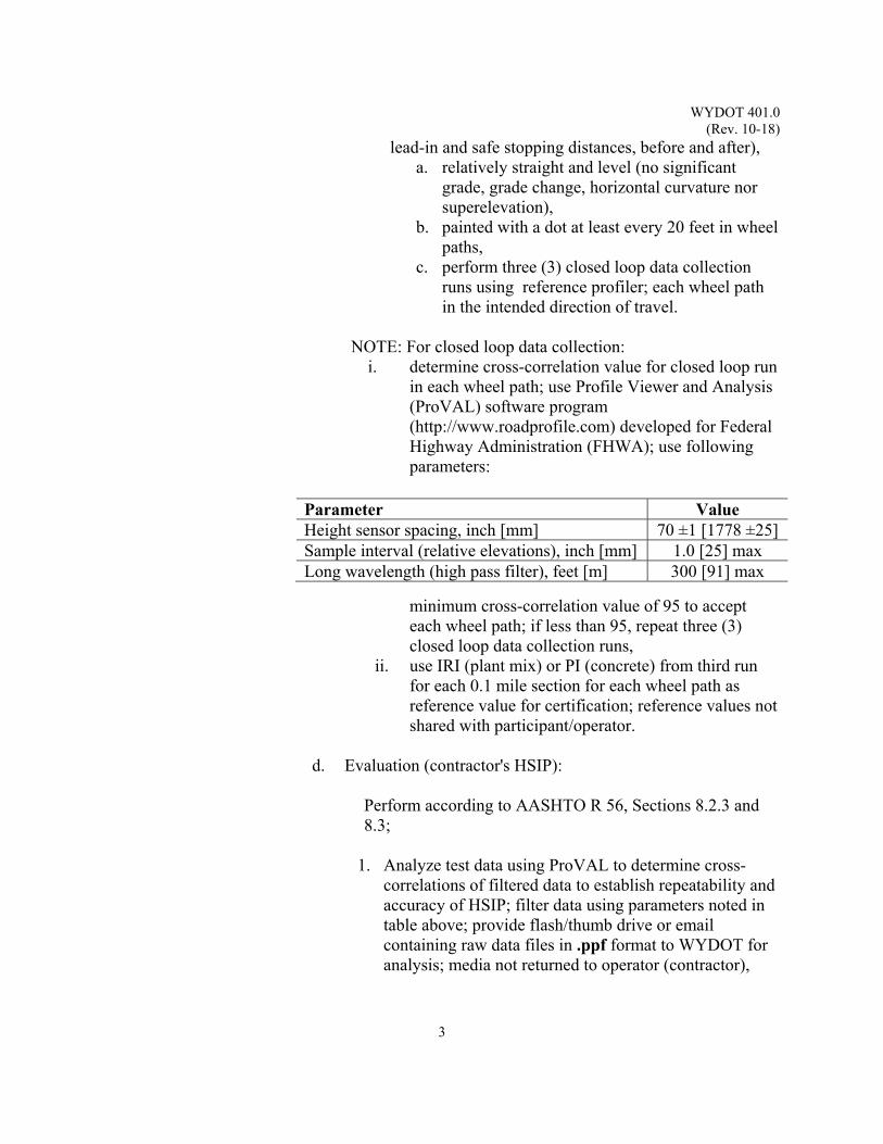
WYDOT 401.0 (Rev. 10-18)
3
lead-in and safe stopping distances, before and after), a. relatively straight and level (no significant
grade, grade change, horizontal curvature nor superelevation),
b. painted with a dot at least every 20 feet in wheel paths,
c. perform three (3) closed loop data collection runs using reference profiler; each wheel path in the intended direction of travel.
NOTE: For closed loop data collection: i. determine cross-correlation value for closed loop run
in each wheel path; use Profile Viewer and Analysis (ProVAL) software program (http://www.roadprofile.com) developed for Federal Highway Administration (FHWA); use following parameters:
minimum cross-correlation value of 95 to accept each wheel path; if less than 95, repeat three (3) closed loop data collection runs,
ii. use IRI (plant mix) or PI (concrete) from third run for each 0.1 mile section for each wheel path as reference value for certification; reference values not shared with participant/operator.
d. Evaluation (contractor's HSIP):
Perform according to AASHTO R 56, Sections 8.2.3 and 8.3;
1. Analyze test data using ProVAL to determine cross-correlations of filtered data to establish repeatability and accuracy of HSIP; filter data using parameters noted in table above; provide flash/thumb drive or email containing raw data files in .ppf format to WYDOT for analysis; media not returned to operator (contractor),
Parameter Value Height sensor spacing, inch [mm] 70 ±1 [1778 ±25] Sample interval (relative elevations), inch [mm] 1.0 [25] max Long wavelength (high pass filter), feet [m] 300 [91] max
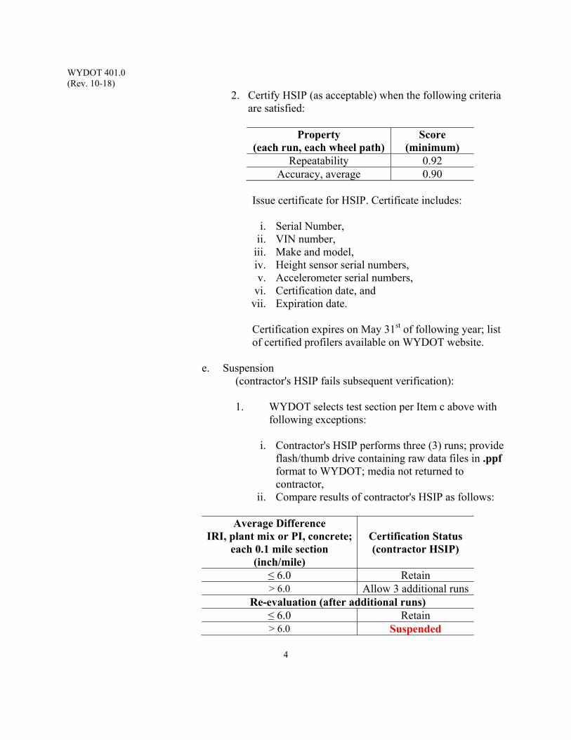
WYDOT 401.0 (Rev. 10-18)
4
2. Certify HSIP (as acceptable) when the following criteria are satisfied:
Property
(each run, each wheel path) Score
(minimum) Repeatability 0.92
Accuracy, average 0.90
Issue certificate for HSIP. Certificate includes:
i. Serial Number, ii. VIN number,
iii. Make and model, iv. Height sensor serial numbers, v. Accelerometer serial numbers,
vi. Certification date, and vii. Expiration date.
Certification expires on May 31st of following year; list of certified profilers available on WYDOT website.
e. Suspension
(contractor's HSIP fails subsequent verification): 1. WYDOT selects test section per Item c above with
following exceptions:
i. Contractor's HSIP performs three (3) runs; provide flash/thumb drive containing raw data files in .ppf format to WYDOT; media not returned to contractor,
ii. Compare results of contractor's HSIP as follows:
Average Difference IRI, plant mix or PI, concrete;
each 0.1 mile section (inch/mile)
Certification Status (contractor HSIP)
≤ 6.0 Retain > 6.0 Allow 3 additional runs
Re-evaluation (after additional runs) ≤ 6.0 Retain > 6.0 Suspended

WYDOT 401.0 (Rev. 10-18)
5
iii. Repair and/or adjust/calibrate HSIP by the manufacturer,
iv. At contractor's option, recertify HSIP after repairs, etc, prior to next annual certification; contractor pays all costs associated with recertification.
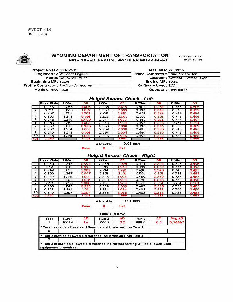
WYDOT 401.0 (Rev. 10-18)
6
WYDOT 402.0 (Rev. 10-18)
1
PAVEMENT PROFILE ANALYSIS
Scope: This procedure explains profile analysis of concrete and plant mix pavement surfaces (i.e., reduction or processing of raw elevation profile data). Pavement surfaces are measured from a moving plane of reference and elevation data is processed to provide a filtered or adjusted profile. Profile measurements agree with actual elevations within predetermined precision and accuracy.
Use: Use procedure to locate surface defects (e.g., bumps, dips, etc) on new or
rehabilitated pavement. Distance between inertial plane of reference of profiler and traveled pavement surface is measured to detect changes in elevation of pavement surface. Procedure is based upon ASTM E 950 which allows profile measurements at different longitudinal distance intervals (Classes 1, 2, 3, or 4) with associated vertical resolution. WYDOT requires Class 1 for longitudinal sampling and vertical measurement resolution (≤ 1 inch [25 mm], ≤ 0.005 inch [0.1 mm], respectively).
Apparatus: 1. High Speed Inertial Profiler (HSIP) 2. Computer, integral or external to profiler 3. Software program (ProVAL) Reference Documents: AASHTO M 328 Standard Specification for Inertial Profiler AASHTO R 56 Standard Practice for Certification of Inertial Profiling
Systems AASHTO R 57 Standard Practice for Operating Inertial Profiling Systems
ASTM E 867 Standard Terminology Relating to Vehicle-Pavement Systems
ASTM E 950 Standard Test Method for Measuring the Longitudinal Profile of Traveled Surfaces with an Accelerometer Established Internal Profiling Reference
ASTM E 1170 Standard Practices for Simulating Vehicular Response to Longitudinal Profiles of Traveled Surfaces
ASTM E 1926 Standard Practice for Computing International Roughness Index of Roads from Longitudinal Profile Measurements
ASTM E 2560 Standard Specification for Data Format for Pavement Profile
WYDOT 414 WYDOT Standard Specifications WYDOT 415 WYDOT Standard Specifications WYDOT 401.0 Verification and Certification of High Speed Inertial
Profiler
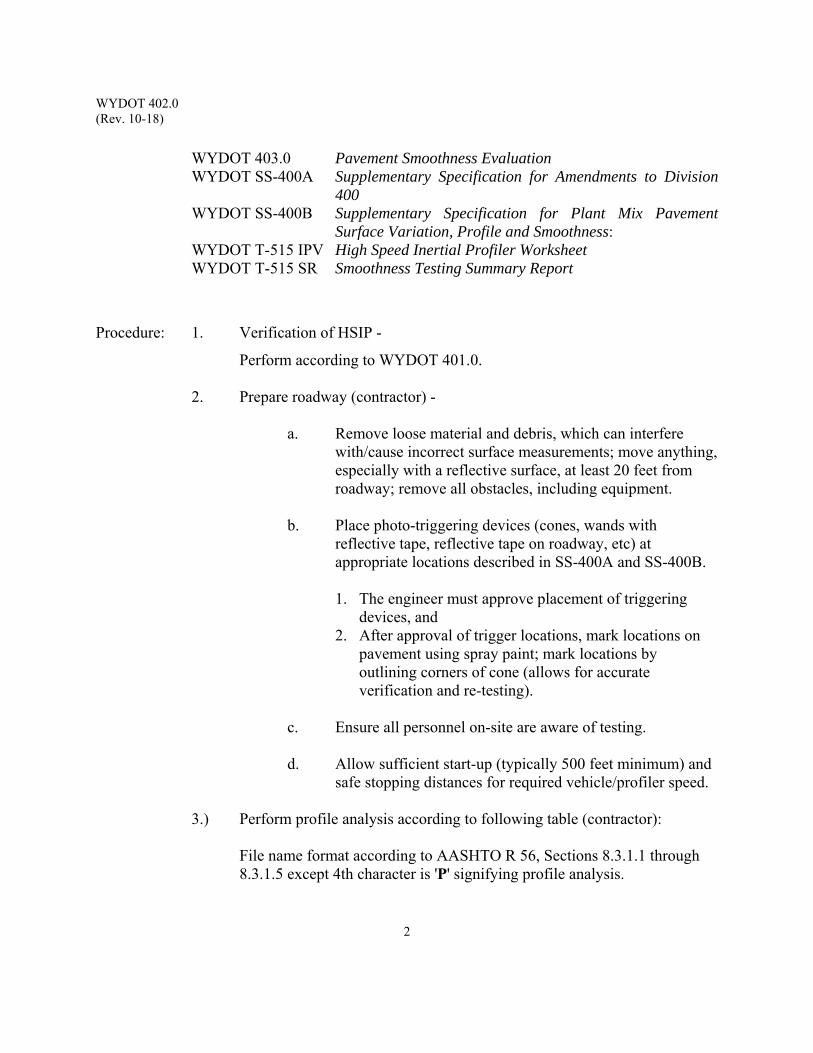
WYDOT 402.0 (Rev. 10-18)
2
WYDOT 403.0 Pavement Smoothness Evaluation WYDOT SS-400A Supplementary Specification for Amendments to Division
400 WYDOT SS-400B Supplementary Specification for Plant Mix Pavement
Surface Variation, Profile and Smoothness: WYDOT T-515 IPV High Speed Inertial Profiler Worksheet
WYDOT T-515 SR Smoothness Testing Summary Report
Procedure: 1. Verification of HSIP -
Perform according to WYDOT 401.0.
2. Prepare roadway (contractor) -
a. Remove loose material and debris, which can interfere with/cause incorrect surface measurements; move anything, especially with a reflective surface, at least 20 feet from roadway; remove all obstacles, including equipment.
b. Place photo-triggering devices (cones, wands with reflective tape, reflective tape on roadway, etc) at appropriate locations described in SS-400A and SS-400B. 1. The engineer must approve placement of triggering
devices, and 2. After approval of trigger locations, mark locations on
pavement using spray paint; mark locations by outlining corners of cone (allows for accurate verification and re-testing).
c. Ensure all personnel on-site are aware of testing.
d. Allow sufficient start-up (typically 500 feet minimum) and
safe stopping distances for required vehicle/profiler speed.
3.) Perform profile analysis according to following table (contractor): File name format according to AASHTO R 56, Sections 8.3.1.1 through 8.3.1.5 except 4th character is 'P' signifying profile analysis.
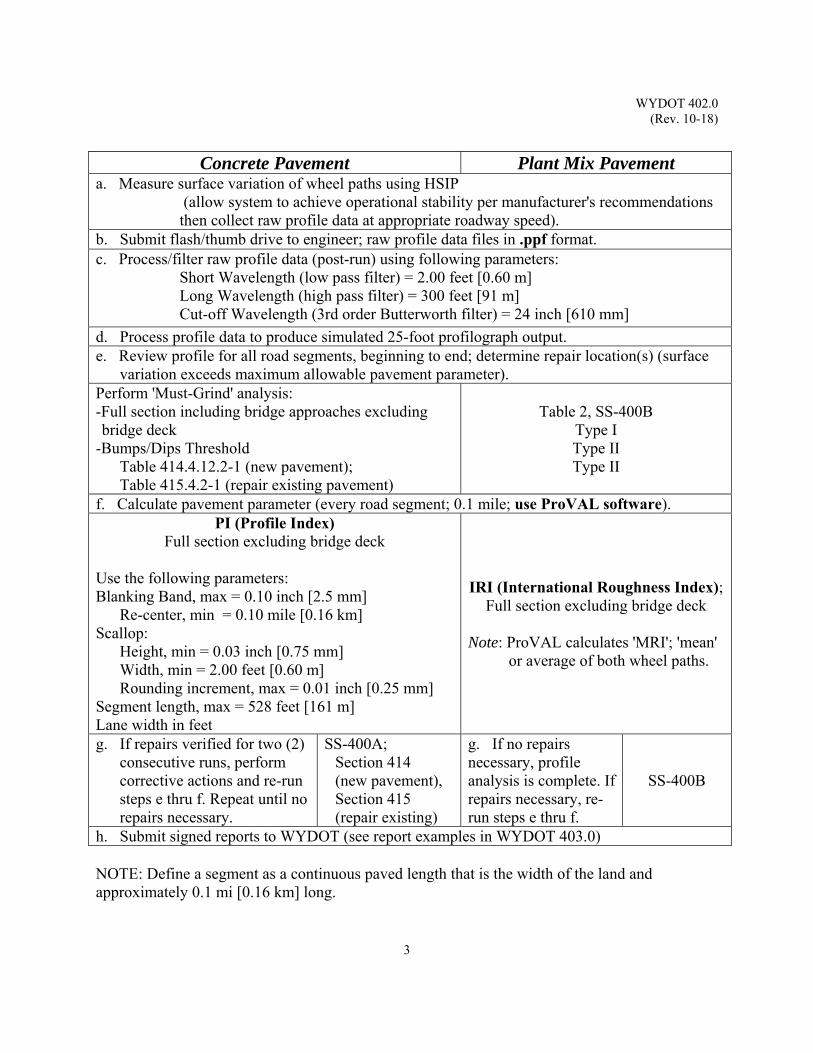
WYDOT 402.0 (Rev. 10-18)
3
Concrete Pavement Plant Mix Pavement a. Measure surface variation of wheel paths using HSIP
(allow system to achieve operational stability per manufacturer's recommendations then collect raw profile data at appropriate roadway speed).
b. Submit flash/thumb drive to engineer; raw profile data files in .ppf format. c. Process/filter raw profile data (post-run) using following parameters:
Short Wavelength (low pass filter) = 2.00 feet [0.60 m] Long Wavelength (high pass filter) = 300 feet [91 m] Cut-off Wavelength (3rd order Butterworth filter) = 24 inch [610 mm]
d. Process profile data to produce simulated 25-foot profilograph output. e. Review profile for all road segments, beginning to end; determine repair location(s) (surface
variation exceeds maximum allowable pavement parameter). Perform 'Must-Grind' analysis: -Full section including bridge approaches excluding bridge deck
-Bumps/Dips Threshold Table 414.4.12.2-1 (new pavement); Table 415.4.2-1 (repair existing pavement)
Table 2, SS-400B Type I Type II Type II
f. Calculate pavement parameter (every road segment; 0.1 mile; use ProVAL software). PI (Profile Index)
Full section excluding bridge deck
Use the following parameters: Blanking Band, max = 0.10 inch [2.5 mm]
Re-center, min = 0.10 mile [0.16 km] Scallop:
Height, min = 0.03 inch [0.75 mm] Width, min = 2.00 feet [0.60 m] Rounding increment, max = 0.01 inch [0.25 mm]
Segment length, max = 528 feet [161 m] Lane width in feet
IRI (International Roughness Index); Full section excluding bridge deck
Note: ProVAL calculates 'MRI'; 'mean'
or average of both wheel paths.
g. If repairs verified for two (2) consecutive runs, perform corrective actions and re-run steps e thru f. Repeat until no repairs necessary.
SS-400A; Section 414 (new pavement), Section 415 (repair existing)
g. If no repairs necessary, profile analysis is complete. If repairs necessary, re-run steps e thru f.
SS-400B
h. Submit signed reports to WYDOT (see report examples in WYDOT 403.0) NOTE: Define a segment as a continuous paved length that is the width of the land and approximately 0.1 mi [0.16 km] long.
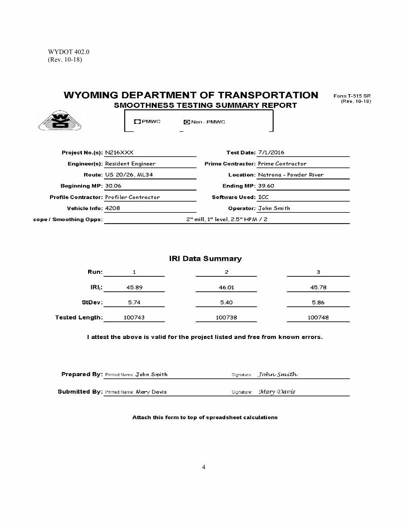
WYDOT 402.0 (Rev. 10-18)
4
WYDOT 403.0 (Rev. 10-18)
1
PAVEMENT SMOOTHNESS EVALUATION
Scope: This procedure explains smoothness evaluation of concrete and plant mix pavement surfaces. Pavement surfaces are measured using a high speed inertial profiler (HSIP). Surface profile is reported as Profile Index, PI, for concrete pavement and International Roughness Index, IRI, for plant mix pavement. Example forms and reports, with explanatory notes, are included.
Use: Use procedure to determine smoothness pay adjustments for new or rehabilitated
pavement surfaces after profile analysis is completed (contractor corrective actions).
Apparatus: 1. High Speed Inertial Profiler (HSIP) 2. Computer, integral or external to profiler 3. Software program (ProVAL) Reference Documents: AASHTO M 328 Standard Specification for Inertial Profiler AASHTO R 56 Standard Practice for Certification of Inertial Profiling
Systems AASHTO R 57 Standard Practice for Operating Inertial Profiling Systems ASTM E 867 Standard Terminology Relating to Vehicle-Pavement Systems ASTM E 950 Standard Test Method for Measuring the Longitudinal
Profile of Traveled Surfaces with an Accelerometer Established Internal Profiling Reference
ASTM E 1170 Standard Practices for Simulating Vehicular Response to Longitudinal Profiles of Traveled Surfaces
ASTM E 1926 Standard Practice for Computing International Roughness Index of Roads from Longitudinal Profile Measurements
ASTM E 2560 Standard Specification for Data Format for Pavement Profile WYDOT 414 WYDOT Standard Specifications WYDOT 415 WYDOT Standard Specifications WYDOT 401.0 Verification and Certification of High Speed Inertial Profiler WYDOT 402.0 Pavement Profile Analysis WYDOT SS-400A Supplementary Specification for Amendments to Division 400 WYDOT SS-400B Supplementary Specification for Plant Mix Pavement Surface
Variation, Profile and Smoothness WYDOT T-515 IPV High Speed Inertial Profiler Worksheet WYDOT T-515 M Smoothness Assessment Report WYDOT T-515 SR Smoothness Testing Summary Report
WYDOT 403.0 (Rev. 10-18)
2
Procedure: 1. Ensure profile analysis is completed according to
WYDOT 402.0.
2. Perform smoothness evaluation according to following table (contractor): File name format according to AASHTO R 56, Sections 8.3.1.1 through 8.3.1.5 except 4th character is 'E' signifying smoothness evaluation.
Note (for Plant Mix Pavement):
Upon receipt of Form T-515 SR, Smoothness Testing Summary Report, and original Spreadsheet Summary as prepared by the HSIP operator and submitted by the contractor, the engineer will check for discrepancies in data; examples of Form T-515 SR and Spreadsheet Summary are included in this section. If the engineer has any questions, submit data to WYDOT Materials Program for review.
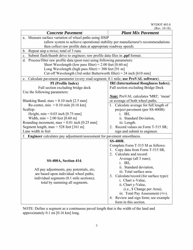
WYDOT 403.0 (Rev. 10-18)
3
Concrete Pavement Plant Mix Pavement a. Measure surface variation of wheel paths using HSIP
(allow system to achieve operational stability per manufacturer's recommendations then collect raw profile data at appropriate roadway speed).
b. Repeat step a twice; total of 3 runs c. Submit flash/thumb drive to engineer; raw profile data files in .ppf format. d. Process/filter raw profile data (post-run) using following parameters:
Short Wavelength (low pass filter) = 2.00 feet [0.60 m] Long Wavelength (high pass filter) = 300 feet [91 m] Cut-off Wavelength (3rd order Butterworth filter) = 24 inch [610 mm]
e. Calculate pavement parameter (every road segment; 0.1 mile; use ProVAL software). PI (Profile Index)
Full section excluding bridge deck Use the following parameters: Blanking Band, max = 0.10 inch [2.5 mm]
Re-center, min = 0.10 mile [0.16 km] Scallop:
Height, min = 0.03 inch [0.75 mm] Width, min = 2.00 feet [0.60 m]
Rounding increment, max = 0.01 inch [0.25 mm] Segment length, max = 528 feet [161 m] Lane width in feet
IRI (International Roughness Index); Full section excluding Bridge Deck Note: ProVAL calculates 'MRI'; 'mean' or average of both wheel paths. 1. Calculate average for full length of
project pavement (per SS-400B): i. IRI, ii. Standard Deviation, iii. Length.
2. Record values on Form T-515 SR; sign and submit to engineer.
f. Engineer calculates pay adjustment/assessment for pavement smoothness.
SS-400A, Section 414;
All pay adjustments, pay potentials, etc, are based upon individual wheel paths; individual segments (0.1 mile sections);
total by summing all segments.
SS-400B; Complete Form T-515 M as follows: 1. Copy data from Form T-515 SR, 2. Calculate and record:
Average (all 3 runs); i. IRI, ii. Standard deviation, iii. Total surface area.
3. Calculate/record (for surface type): i. Chart x-Value, ii. Chart y-Value,
(i.e., $ Change per Area), iii. Total Pay Assessment (+/-).
4. Review and sign form; see example form in this section.
NOTE: Define a segment as a continuous paved length that is the width of the land and approximately 0.1 mi [0.16 km] long.
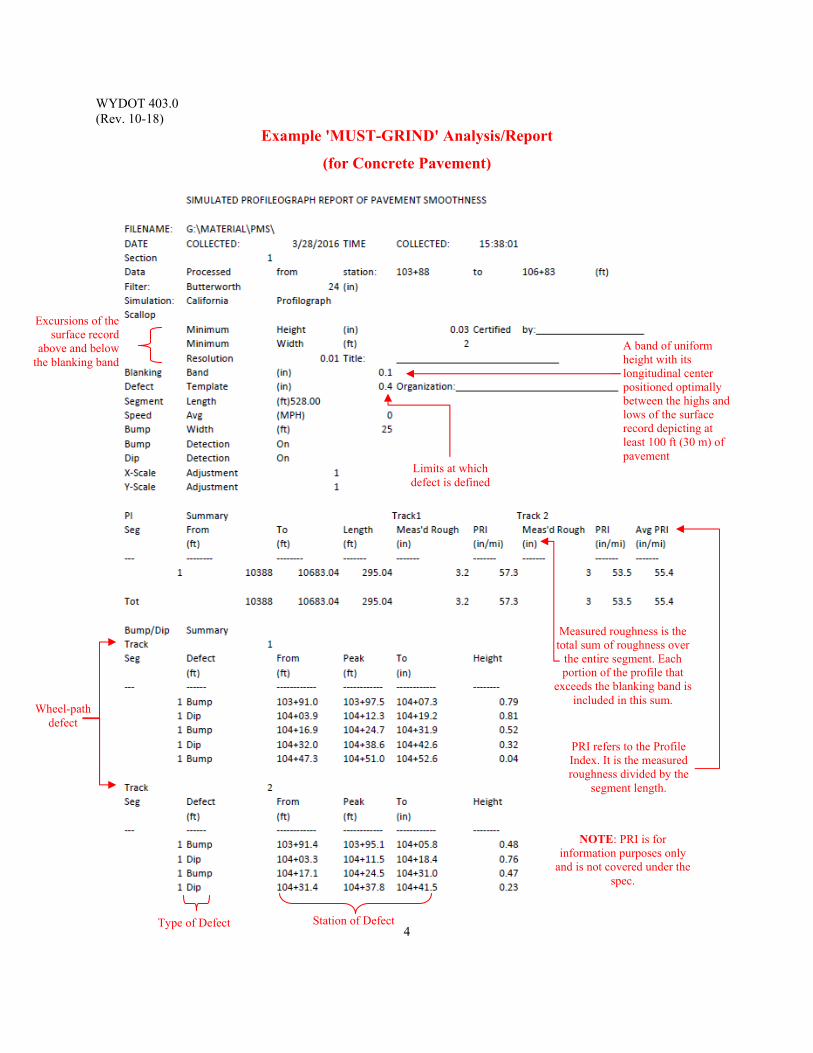
WYDOT 403.0 (Rev. 10-18)
4
Example 'MUST-GRIND' Analysis/Report
(for Concrete Pavement)
A band of uniform height with its longitudinal center positioned optimally between the highs and lows of the surface record depicting at least 100 ft (30 m) of pavement
Excursions of the surface record
above and below the blanking band
Limits at which defect is defined
Station of Defect Type of Defect
Wheel-path defect
Measured roughness is the total sum of roughness over
the entire segment. Each portion of the profile that
exceeds the blanking band is included in this sum.
PRI refers to the Profile Index. It is the measured roughness divided by the
segment length.
NOTE: PRI is for information purposes only
and is not covered under the spec.
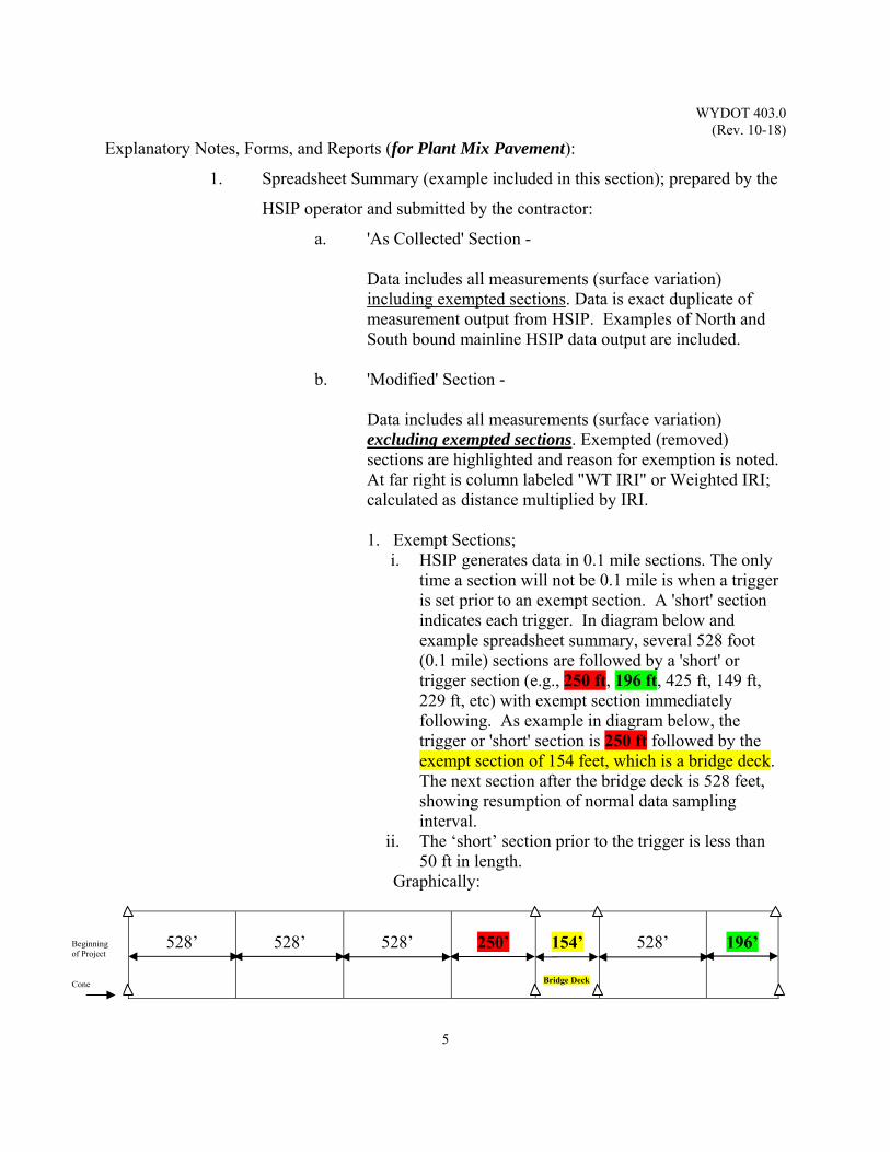
WYDOT 403.0 (Rev. 10-18)
5
Explanatory Notes, Forms, and Reports (for Plant Mix Pavement):
1. Spreadsheet Summary (example included in this section); prepared by the
HSIP operator and submitted by the contractor:
a. 'As Collected' Section - Data includes all measurements (surface variation) including exempted sections. Data is exact duplicate of measurement output from HSIP. Examples of North and South bound mainline HSIP data output are included.
b. 'Modified' Section - Data includes all measurements (surface variation) excluding exempted sections. Exempted (removed) sections are highlighted and reason for exemption is noted. At far right is column labeled "WT IRI" or Weighted IRI; calculated as distance multiplied by IRI. 1. Exempt Sections;
i. HSIP generates data in 0.1 mile sections. The only time a section will not be 0.1 mile is when a trigger is set prior to an exempt section. A 'short' section indicates each trigger. In diagram below and example spreadsheet summary, several 528 foot (0.1 mile) sections are followed by a 'short' or trigger section (e.g., 250 ft, 196 ft, 425 ft, 149 ft, 229 ft, etc) with exempt section immediately following. As example in diagram below, the trigger or 'short' section is 250 ft followed by the exempt section of 154 feet, which is a bridge deck. The next section after the bridge deck is 528 feet, showing resumption of normal data sampling interval.
ii. The ‘short’ section prior to the trigger is less than 50 ft in length.
Graphically:
528’ 528’
528’
250’ 154’
528’
196’
Bridge Deck
Beginning of Project Cone
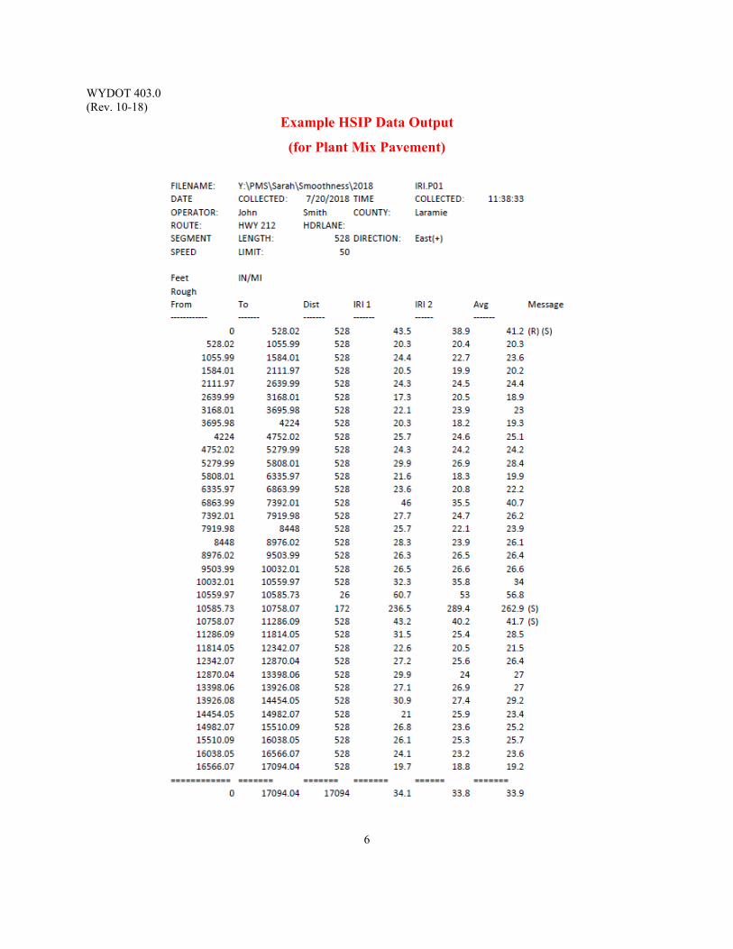
WYDOT 403.0 (Rev. 10-18)
6
Example HSIP Data Output
(for Plant Mix Pavement)
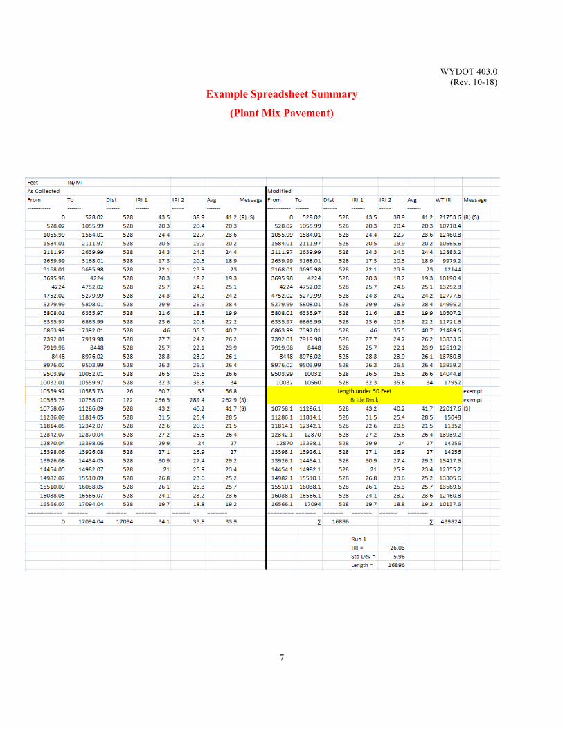
WYDOT 403.0 (Rev. 10-18)
7
Example Spreadsheet Summary
(Plant Mix Pavement)

WYDOT 403.0 (Rev. 10-18)
8
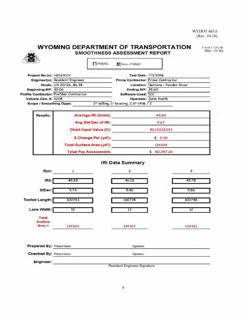
WYDOT 403.0 (Rev. 10-18)
9

WYDOT 403.0 (Rev. 10-18)
10
(This page intentionally left blank.)
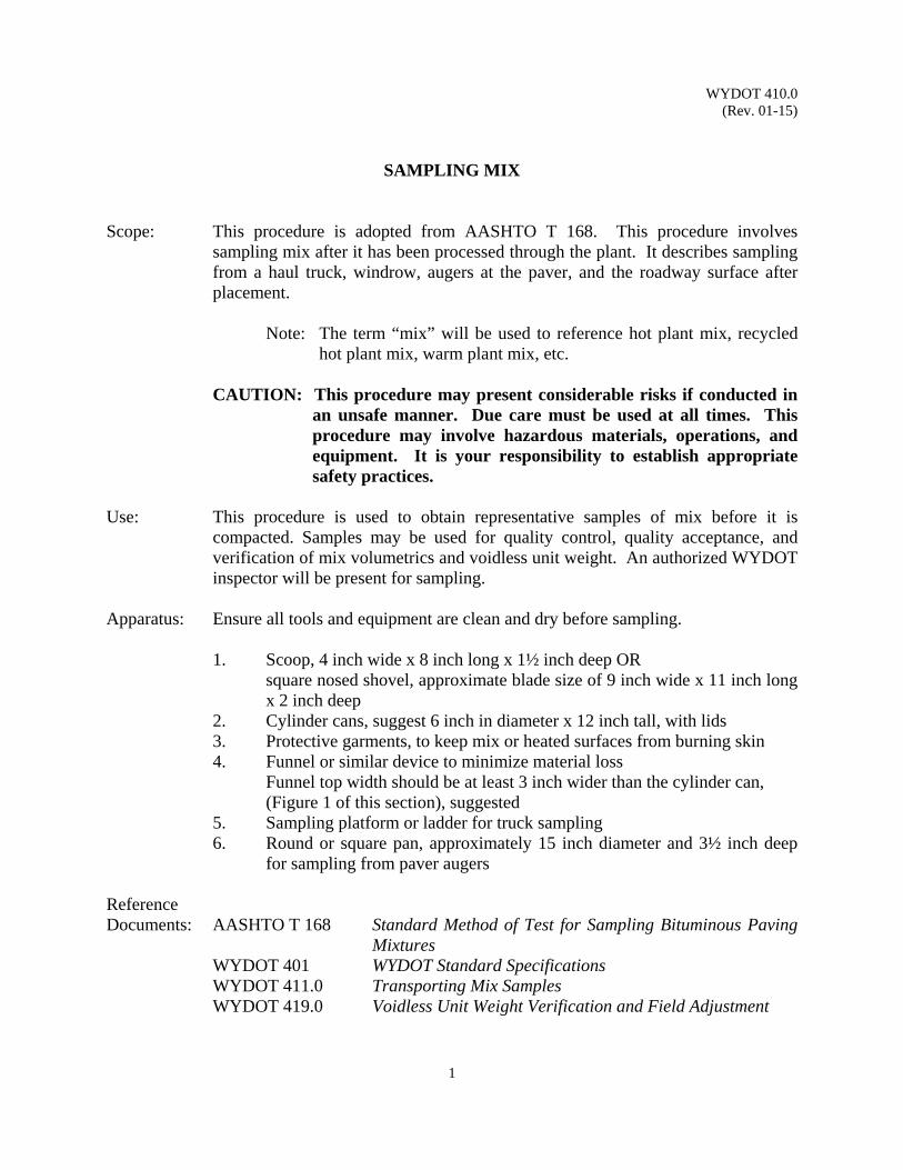
WYDOT 410.0 (Rev. 01-15)
1
SAMPLING MIX
Scope: This procedure is adopted from AASHTO T 168. This procedure involves
sampling mix after it has been processed through the plant. It describes sampling from a haul truck, windrow, augers at the paver, and the roadway surface after placement.
Note: The term “mix” will be used to reference hot plant mix, recycled
hot plant mix, warm plant mix, etc.
CAUTION: This procedure may present considerable risks if conducted in an unsafe manner. Due care must be used at all times. This procedure may involve hazardous materials, operations, and equipment. It is your responsibility to establish appropriate safety practices.
Use: This procedure is used to obtain representative samples of mix before it is
compacted. Samples may be used for quality control, quality acceptance, and verification of mix volumetrics and voidless unit weight. An authorized WYDOT inspector will be present for sampling.
Apparatus: Ensure all tools and equipment are clean and dry before sampling.
1. Scoop, 4 inch wide x 8 inch long x 1½ inch deep OR square nosed shovel, approximate blade size of 9 inch wide x 11 inch long
x 2 inch deep 2. Cylinder cans, suggest 6 inch in diameter x 12 inch tall, with lids 3. Protective garments, to keep mix or heated surfaces from burning skin 4. Funnel or similar device to minimize material loss Funnel top width should be at least 3 inch wider than the cylinder can, (Figure 1 of this section), suggested 5. Sampling platform or ladder for truck sampling 6. Round or square pan, approximately 15 inch diameter and 3½ inch deep
for sampling from paver augers
Reference Documents: AASHTO T 168 Standard Method of Test for Sampling Bituminous Paving
Mixtures WYDOT 401 WYDOT Standard Specifications WYDOT 411.0 Transporting Mix Samples WYDOT 419.0 Voidless Unit Weight Verification and Field Adjustment
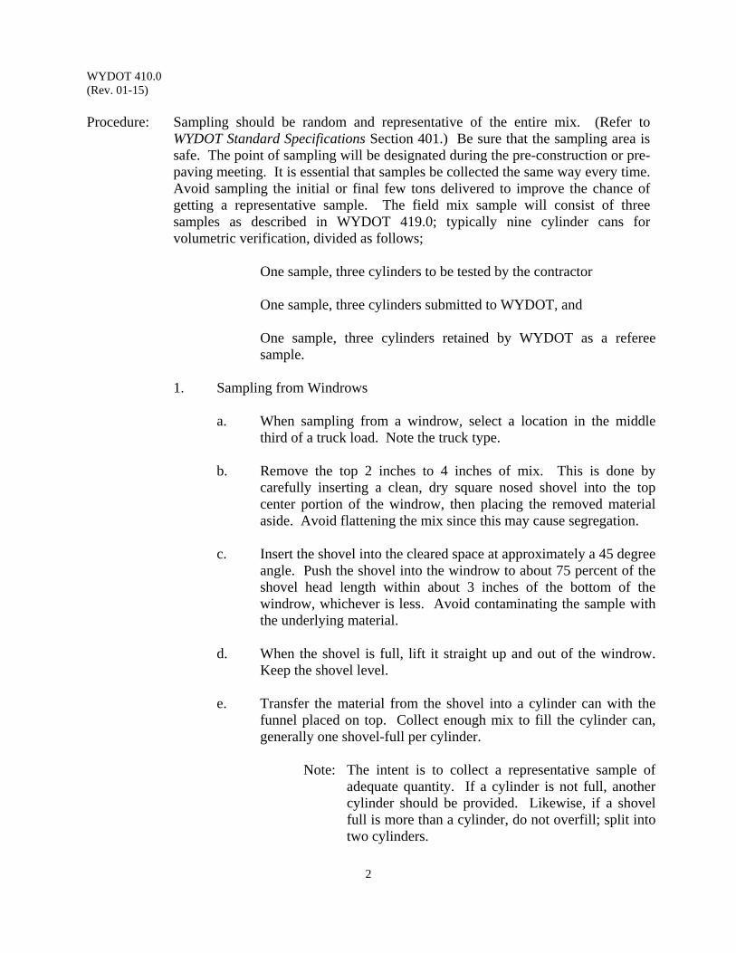
WYDOT 410.0 (Rev. 01-15)
2
Procedure: Sampling should be random and representative of the entire mix. (Refer to
WYDOT Standard Specifications Section 401.) Be sure that the sampling area is safe. The point of sampling will be designated during the pre-construction or pre-paving meeting. It is essential that samples be collected the same way every time. Avoid sampling the initial or final few tons delivered to improve the chance of getting a representative sample. The field mix sample will consist of three samples as described in WYDOT 419.0; typically nine cylinder cans for volumetric verification, divided as follows;
One sample, three cylinders to be tested by the contractor
One sample, three cylinders submitted to WYDOT, and
One sample, three cylinders retained by WYDOT as a referee sample.
1. Sampling from Windrows
a. When sampling from a windrow, select a location in the middle
third of a truck load. Note the truck type. b. Remove the top 2 inches to 4 inches of mix. This is done by
carefully inserting a clean, dry square nosed shovel into the top center portion of the windrow, then placing the removed material aside. Avoid flattening the mix since this may cause segregation.
c. Insert the shovel into the cleared space at approximately a 45 degree
angle. Push the shovel into the windrow to about 75 percent of the shovel head length within about 3 inches of the bottom of the windrow, whichever is less. Avoid contaminating the sample with the underlying material.
d. When the shovel is full, lift it straight up and out of the windrow.
Keep the shovel level. e. Transfer the material from the shovel into a cylinder can with the
funnel placed on top. Collect enough mix to fill the cylinder can, generally one shovel-full per cylinder.
Note: The intent is to collect a representative sample of
adequate quantity. If a cylinder is not full, another cylinder should be provided. Likewise, if a shovel full is more than a cylinder, do not overfill; split into two cylinders.
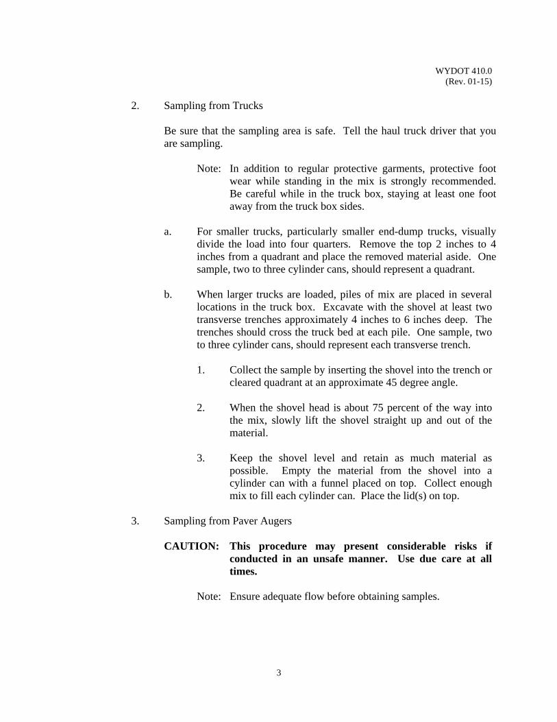
WYDOT 410.0 (Rev. 01-15)
3
2. Sampling from Trucks
Be sure that the sampling area is safe. Tell the haul truck driver that you are sampling.
Note: In addition to regular protective garments, protective foot
wear while standing in the mix is strongly recommended. Be careful while in the truck box, staying at least one foot away from the truck box sides.
a. For smaller trucks, particularly smaller end-dump trucks, visually
divide the load into four quarters. Remove the top 2 inches to 4 inches from a quadrant and place the removed material aside. One sample, two to three cylinder cans, should represent a quadrant.
b. When larger trucks are loaded, piles of mix are placed in several
locations in the truck box. Excavate with the shovel at least two transverse trenches approximately 4 inches to 6 inches deep. The trenches should cross the truck bed at each pile. One sample, two to three cylinder cans, should represent each transverse trench.
1. Collect the sample by inserting the shovel into the trench or
cleared quadrant at an approximate 45 degree angle. 2. When the shovel head is about 75 percent of the way into
the mix, slowly lift the shovel straight up and out of the material.
3. Keep the shovel level and retain as much material as
possible. Empty the material from the shovel into a cylinder can with a funnel placed on top. Collect enough mix to fill each cylinder can. Place the lid(s) on top.
3. Sampling from Paver Augers
CAUTION: This procedure may present considerable risks if conducted in an unsafe manner. Use due care at all times.
Note: Ensure adequate flow before obtaining samples.
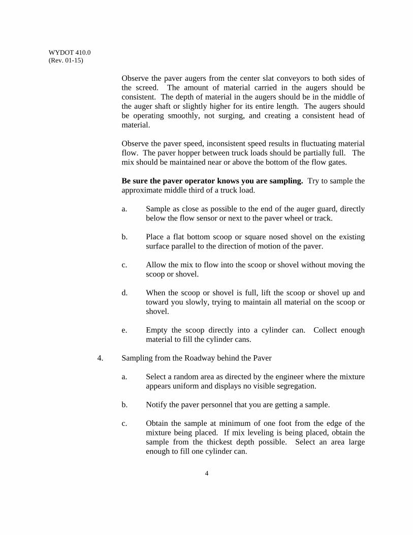
WYDOT 410.0 (Rev. 01-15)
4
Observe the paver augers from the center slat conveyors to both sides of the screed. The amount of material carried in the augers should be consistent. The depth of material in the augers should be in the middle of the auger shaft or slightly higher for its entire length. The augers should be operating smoothly, not surging, and creating a consistent head of material.
Observe the paver speed, inconsistent speed results in fluctuating material flow. The paver hopper between truck loads should be partially full. The mix should be maintained near or above the bottom of the flow gates.
Be sure the paver operator knows you are sampling. Try to sample the approximate middle third of a truck load.
a. Sample as close as possible to the end of the auger guard, directly
below the flow sensor or next to the paver wheel or track. b. Place a flat bottom scoop or square nosed shovel on the existing
surface parallel to the direction of motion of the paver. c. Allow the mix to flow into the scoop or shovel without moving the
scoop or shovel. d. When the scoop or shovel is full, lift the scoop or shovel up and
toward you slowly, trying to maintain all material on the scoop or shovel.
e. Empty the scoop directly into a cylinder can. Collect enough
material to fill the cylinder cans.
4. Sampling from the Roadway behind the Paver
a. Select a random area as directed by the engineer where the mixture appears uniform and displays no visible segregation.
b. Notify the paver personnel that you are getting a sample. c. Obtain the sample at minimum of one foot from the edge of the
mixture being placed. If mix leveling is being placed, obtain the sample from the thickest depth possible. Select an area large enough to fill one cylinder can.
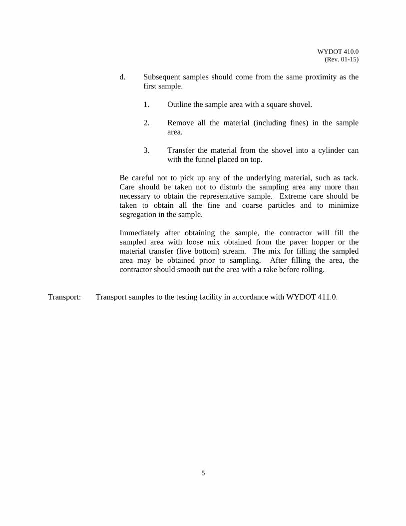
WYDOT 410.0 (Rev. 01-15)
5
d. Subsequent samples should come from the same proximity as the
first sample. 1. Outline the sample area with a square shovel. 2. Remove all the material (including fines) in the sample
area. 3. Transfer the material from the shovel into a cylinder can
with the funnel placed on top.
Be careful not to pick up any of the underlying material, such as tack. Care should be taken not to disturb the sampling area any more than necessary to obtain the representative sample. Extreme care should be taken to obtain all the fine and coarse particles and to minimize segregation in the sample.
Immediately after obtaining the sample, the contractor will fill the sampled area with loose mix obtained from the paver hopper or the material transfer (live bottom) stream. The mix for filling the sampled area may be obtained prior to sampling. After filling the area, the contractor should smooth out the area with a rake before rolling.
Transport: Transport samples to the testing facility in accordance with WYDOT 411.0.

WYDOT 410.0 (Rev. 01-15)
6
Figure 1. Funnel Diagram
WYDOT 411.0 (Rev. 01-15)
1
TRANSPORTING MIX SAMPLES
Scope: This procedure describes transporting mix (hot plant mix, recycled hot plant mix,
warm plant mix) samples from the sampling site to a testing facility. It is intended to minimize temperature loss from mix sampled in the field according to WYDOT 410.0. Temperature loss of approximately 1 °F per minute can be expected when following this procedure.
Use: This procedure is to be used for handling times less than 45 minutes. For travel
times greater than 45 minutes, reheating will be required according to WYDOT 412.0. Mix samples will be in a workable state until subsequent testing is done in accordance with WYDOT 414.0. This procedure reduces reheating time for mix samples.
Apparatus: 1. Five gallon buckets with lids, lined on the sides, bottom, and top with
loosely placed, paper backed fiberglass or semi-ridged 6 inch ID insulation
2. Insulated safety gloves 3. Cylinder cans, 6 inch in diameter x 12 inch, with lids
Reference Documents: WYDOT 410.0 Sampling Mix WYDOT 412.0 Reheating Mix Samples WYDOT 413.0 Moisture Content of Mix WYDOT 414.0 Marshall and Superpave Mix Design and Mix Volumetric
Verification Procedure Procedure: Obtain the sample following procedure WYDOT 410.0. The lid should be on the
cylinder can. Carefully put the cylinder can with lid into the insulated five gallon bucket. Place the top piece of insulation on top of the cylinder lid. Secure the insulated lid on the five gallon bucket.
Note: To reduce handling of the hot cylinder can, place the cylinder inside the
insulated bucket prior to sampling.
At the testing facility, determine the sample temperature. If the temperature loss is less than 50 °F, immediately obtain a sample for the moisture content of the mixture. Determine the moisture content of the mix in accordance with WYDOT 413.0. The moisture content of the mix cannot be obtained from a sample that has cooled more than 50 °F.

WYDOT 411.0 (Rev. 01-15)
2
(This page intentionally left blank)
WYDOT 412.0 (Rev. 01-15)
1
REHEATING MIX SAMPLES
Scope: This procedure describes reheating (hot plant mix, recycled hot plant mix, warm
plant mix) mix samples in a testing facility. Use: This procedure is used to attain appropriate temperatures of field sampled mix
prior to volumetric verification testing or voidless unit weight verification testing. Apparatus: Ventilated oven capable of maintaining temperature for tests to be performed. Reference Documents: AASHTO T 308 Standard Method of Test for Determining the Asphalt
Binder Content of Hot Mix Asphalt (HMA) by the Ignition Method
WYDOT 401 WYDOT Standard Specifications WYDOT 414.0 Marshall and Superpave Mix Design and Mix Volumetric
Verification Procedure Procedure: Place the appropriate quantity of the sample into a preheated oven that is set at the
appropriate reheating temperature.
The reheating temperatures should be determined from the following table according to the asphalt binder grade used in the sample being reheated. PG 58-28 280 °F PG 64-22 285 °F PG 64-28 290 °F PG 70-28 300 °F PG 76-28 310 °F Warm Plant Mix CONTACT MATERIALS PROGRAM
The Materials Program will provide the appropriate reheating temperatures for asphalt binder not included in the table above or for warm plant mix.
Heat the sample until the sample reaches a uniform temperature throughout. For ignition oven sample temperatures, reference AASHTO T 308.

WYDOT 412.0 (Rev. 01-15)
2
(This page intentionally left blank)
WYDOT 413.0 (Rev. 09-16)
1
MOISTURE CONTENT OF MIX
Scope: This procedure determines the moisture content of a sample of mix (hot plant mix, recycled hot plant mix, warm plant mix) by evaporation.
Use: This is a procedure to determine whether the amount of water in the mix exceeds
the specified amount. Apparatus: 1. Scale capable of 0.0001 lb [0.1 g] accuracy
2. Heat source, such as an electric or gas hot plate, electric heat lamps, or a ventilated convection oven capable of maintaining the temperature surrounding the sample at 230 ± 9 °F 3. Insulated safety gloves 4. Cylinder cans, 6 inch in diameter x 12 inch tall, with lids 5. Round or square batch pan, approximately 15 inch diameter or square x
3½ inch deep 6. Round sample pan for use in oven, 12 inch diameter x 3 inch deep 7. Flat bottomed scoop, approximately 4 inch wide x 8 inch long 1½ inch
deep Reference Documents: AASHTO T 168 Standard Method of Test for Sampling Bituminous Paving
Mixtures WYDOT 410.0 Sampling Mix WYDOT 411.0 Transporting Mix Samples WYDOT T-158F Mix Verification of Plant Produced Bituminous Plant Mix
Pavement Procedure: Perform this before substantial heat loss occurs
1. Obtain sample of the mix.
Note: Follow AASHTO T 168 or WYDOT 410.0 for sampling locations. 2. Transport samples according to WYDOT 411.0.
3. Empty the sample into the batch pan. a. Weigh the sample pan.
b. Using a hot scoop, place 1 to 3 lb in the sample pan. Weigh the pan and sample.
c. Place the sample in the heat source and dry thoroughly. Reweigh the pan and sample. The sample is dry when 5 minutes of additional heating causes less than 0.1% additional weight loss.
WYDOT 413.0 (Rev. 09-16)
2
Very rapid heating may cause some particles to explode, resulting in some particle loss. If a source of heat other than the temperature controlled oven is used, stir the sample during drying to accelerate the operation and prevent localized overheating.
Calculations: Calculate the total moisture content as follows:
Example:
Report: Report the results on Form T-158F.
Sample pan weight A 1.8682 lb Sample pan and wet mixture weight B 3.4320 lb Sample pan and dried mixture weight C 3.3991 lb Mixture dry weight C - A = D 1.5309 lb Moisture Weight B - C = E 0.0329 lb Moisture Content F = E / D * 100 2.15%
WYDOT 414.0 (Rev. 10-20)
1
MARSHALL AND SUPERPAVE MIX DESIGN AND MIX VOLUMETRIC VERIFICATION PROCEDURE
Scope: This procedure describes the use of the Marshall or the Superpave apparatus and
techniques for two purposes. It describes the mix design procedure including the batching calculations needed to prepare a job mix formula (JMF). In addition, it describes how the Marshall or the Superpave apparatus and mix design procedures are used to verify that construction mixes conform to the volumetric specifications. Included are the mix design volumetric calculations and examples.
Use: This procedure will be used either to generate mix designs or to check the
conformance of construction mixes to the job mix formula and mix volumetric control limits. This method is applicable only to asphalt paving mixtures containing aggregates with nominal maximum sizes of 1 inch or less.
In general, the contractor is responsible for submitting a construction mix. The laboratory and personnel performing mix design testing must be accredited. After the contractor has submitted the mix design and split samples, if required, to the engineer, the engineer will review the mix design for completeness and compliance. Once the engineer has ensured that the mix design meets the contract requirements, the mix design and any associated samples will be submitted to the Materials Program.
Reference Documents:
Asphalt Institute MS-2 Mix Design Methods for Asphalt Concrete and Other Hot Mix Types
AASHTO M 320 Standard Specification for Performance-Graded Asphalt Binder
AASHTO M 323 Standard Specification for Superpave Volumetric Mix Design AASHTO R 30 Standard Practice for Mixture Conditioning of Hot Mix
Asphalt (HMA) AASHTO R 35 Standard Practice for Superpave Volumetric Design for Hot
Mix Asphalt (HMA) AASHTO T 11 Standard Method of Test for Materials Finer than 75-µm (No.
200) Sieve in Mineral Aggregates by Washing AASHTO T 27 Standard Method of Test for Sieve Analysis of Fine and
Coarse Aggregates AASHTO T 84 Standard Method of Test for Specific Gravity and Absorption
of Fine Aggregate AASHTO T 85 Standard Method of Test for Specific Gravity and Absorption
of Coarse Aggregate AASHTO T 100 Standard Method of Test for Specific Gravity of Soils
WYDOT 414.0 (Rev. 10-20)
2
AASHTO T 164 Standard Method of Test for Quantitative Extraction of Asphalt Binder from Hot Mix Asphalt (HMA)
AASHTO T 166 Standard Method of Test for Bulk Specific Gravity of Compacted Hot Mix Asphalt (HMA) Using Saturated Surface-Dry Specimens
AASHTO T 209 Standard Method of Test for Theoretical Maximum Specific Gravity and Density of Hot Mix Asphalt (HMA)
AASHTO T 228 Standard Method of Test for Specific Gravity of Semi-Solid Asphalt Materials
AASHTO T 245 Standard Method of Test for Resistance to Plastic Flow of Bituminous Mixtures Using Marshall Apparatus
AASHTO T 248 Standard Method of Test for Reducing Samples of Aggregate to Testing Size
AASHTO T 269 Standard Method of Test for Percent Air Voids in Compacted Dense and Open Asphalt Mixtures
AASHTO T 283 Standard Method of Test for Resistance of Compacted Hot Mix Asphalt (HMA) Mixtures to Moisture-Induced Damage
AASHTO T 304 Standard Method of Test for Uncompacted Void Content of Fine Aggregate
AASHTO T 308 Standard Method of Test for Determining the Asphalt Binder Content of Hot Mix Asphalt (HMA) by the Ignition Method
AASHTO T 312 Standard Method of Test for Preparing and Determining the Density of Hot Mix Asphalt (HMA) by Means of the Superpave Gyratory Compactor
ASTM D5821 Standard Test Method for Determining the Percentage of Fractured Particles in Coarse Aggregate
AI SP-2 Superpave Mix Design WYDOT 114.2 WYDOT Standard Specifications WYDOT 401 WYDOT Standard Specifications WYDOT 803 WYDOT Standard Specifications WYDOT 410.0 Sampling Mix WYDOT 411.0 Transporting Mix Samples WYDOT 417.0 Precision Statements for Comparing Contractor QA Results
to WYDOT Verification Results WYDOT 419.0 Voidless Unit Weight Verification and Field Adjustment WYDOT 803.0 Aggregate Sampling and Quantity WYDOT 804.0 Aggregate Sampling WYDOT 805.0 Sample Splitting by Mechanical Splitter WYDOT 810.0
Soundness of Aggregate by Use of Sodium Sulfate or Magnesium Sulfate
WYDOT 812.0 Liquid Limit Test WYDOT 813.0 Plastic Limit Test & Plasticity Index WYDOT 814.0 Sieve Analysis of Combined Aggregate WYDOT 817.0 Determining the Percentage of Fractured Faces in Coarse
Aggregate WYDOT 818.0 LA Abrasion Resistance (LAR)
WYDOT 414.0 (Rev. 10-20)
3
WYDOT 824.0 Fine Aggregate Angularity WYDOT 835.0 Percentage of Flat and Elongated Particles in Coarse
Aggregate WYDOT 836.0 Fine Aggregate Sand Equivalent WYDOT E-46 Hot Plant Mix Job Mix Formula WYDOT E-46A Hot Plant Mix Job Mix Formula (Non-QAQC) WYDOT T-158 Bituminous Pavement Mix Design WYDOT T-158F Mix Verification of Plant Produced Bituminous Plant Mix
Pavement Mix Design Procedure 1. For Superpave mix designs, follow AASHTO R 35, AASHTO R 30, and AASHTO T 312,
except where the following procedure differs;
2. Sample the aggregate for mix designs according to WYDOT 803.0. Typically, aggregate samples for the mix design are obtained when aggregate production
hits the 25 percent mark. To ensure that the gradation used for the construction mix design is representative of the material produced, ensure that the samples are representative of the average gradation of the quality control samples. If the differences exceed the allowable difference in WYDOT 417.0, re-sample the stockpile and re-run the mix design. Submit the average quality control gradation from the stockpile, the mix design gradation, and the comparison results with the mix design. Ensure that the gradation samples submitted with the mix design for the mix design verification are split samples that were obtained at the same time as the samples for the mix design.
For recycled hot plant mix (RHPM) mix designs ensure that the samples are representative
of the materials to be used during construction, Section 803.5.3 WYDOT Standard Specifications. RAP is a variable material; the sampling program is critical to identifying the properties typical of the RAP. Sampling procedures used to produce the RAP samples for the mix design must accurately represent the RAP that will be utilized in the production mix. Examples of sampling procedures include various milling and coring operations. Take RAP samples from the pavement that is typical of the entire project. It is advisable to review core data that represents the length of the project before selecting sampling locations. RAP classification is necessary to prepare a representative mix design; a representative mix design is necessary to produce target gradation goals and achieve volumetric and density requirements. Careful sampling along with an informed selection of the target RAP gradation and asphalt content go a long way towards making construction consistent and producing a high-quality, durable pavement.
3. Determine the gradation of the coarse and fine aggregates used in the mix material according
to WYDOT 814.0. The coarse material is material that is retained on a No. 4 sieve, or above. These separated materials are used in the mix design. They are generally separated on the ¾ inch, ½ inch, ⅜ inch, and the No. 4 sieves. The fine material, material passing the
WYDOT 414.0 (Rev. 10-20)
4
No. 4 screen, is analyzed for gradation according to WYDOT 814.0, but further separation for mix design batching is not required. Do this for all the aggregates used in the mix design. Note: For some Superpave mix designs, batching the JMF gradation may be
necessary to produce repeatable results. When this is determined to be necessary, indicate this on form E-46.
For RHPM, split each sack of RAP to ensure that the sample is representative of the entire
sack. Split the material sampled from each sack according to WYDOT 805.0. Conduct an analysis of the sampled RAP’s gradations and asphalt content, the sampling procedures, and any other factors that may influence the properties of the production milled RAP. Information about sampling, sampling locations, sampling methods, the production milling process, and data from cores should be reviewed.
a. Determine the asphalt content and aggregate gradation of each of the RAP sacks
with a chemical extraction (AASHTO T 164). Calculate an average gradation and asphalt content for the RAP samples.
b. Average the extracted gradation samples from each sack to get an average RAP
gradation.
c. Select a target RAP gradation using the information described in the previous paragraph. Often this will be the same as the average of the RAP samples. It is important that the selected target gradation and asphalt content is close to the RAP gradation and asphalt content achieved during production. This selection is critical to the creation of a mix design that will work well in the field.
1. Select a target RAP gradation and asphalt content that is representative of
the anticipated production milled RAP based on information from the milled RAP samples, the cores, and any other factors that may influence the gradation or asphalt content of the production milled RAP.
4. Determine the Liquid Limit (LL), Plastic Limit (PL), and Plasticity Index (PI) of all fine
aggregate fractions and sources using WYDOT 812.0 and WYDOT 813.0. 5. Determine the Bulk Specific Gravity of the fine and coarse aggregate for all fractions and
sources using AASHTO T 84 and AASHTO T 85. 6. Determine the Los Angeles Abrasion Resistance (LAR) according to WYDOT 818.0.
7. Determine the aggregate soundness (MgSO4), if necessary, according to WYDOT 810.0. 8. Determine the Fractured Faces (WYDOT 817.0), the Fine Aggregate Angularity (WYDOT
824.0), and the Flat and Elongated Particles, 1:5 (WYDOT 835.0).

WYDOT 414.0 (Rev. 10-20)
5
9. Multiply the percentage of each aggregate type (bin split percentage) by the percentage passing for each sieve size. Add these values for each sieve size. These summed values must fall within the Wide Band Specifications for mix designs (Table 803.5.5-1 WYDOT Standard Specifications) and within the established Narrow Band Specifications (Table 401.4.13-1 and subsection 2.1 of 401.4.13.3.2 WYDOT Standard Specifications) or the Job Mix Formula and Control Limits for construction mixes.
For RHPM mix designs, the combined target RAP gradation multiplied by the RAP bin split
percentage from the plans when combined with the virgin JMF must fall within the Wide Band Specifications (Table 803.5.5-1 WYDOT Standard Specifications and plans). The Narrow Band Specifications are applied to the virgin aggregate gradation.
A. Batching Calculations & Examples 1. Combined Aggregate Gradations and Bin Splits
Combine the aggregate at the selected proportions (bin split percentages) for each individual sample to be compacted. In Table A1 that follows, three bin splits representing three stockpiles are to be used. Note: The percentage (%) of each split is a starting point when developing a
Job Mix Formula (JMF). Experience to achieve a gradation within specification limits is a matter of trial and error and reasoning. The No. 4 is a good starting point, normally.
Table Al. Combined Aggregate
Sieve Size
Wide Band
Specifications
Bin/Stockpile Coarse
Bin Splits
Fine
Filler
Min Max 55% 35% 10% Combined Gradation
1 inch 100 100 100 100 100
¾ inch 90 100 97 100 100 98
½ inch 55 90 41 99 100 67
No. 4 45 85 8 98 96 48
No. 8 30 65 2 70 72 33
No. 30 5 30 1 28 33 14
No. 200 2 7 0.8 8.8 16.2 5.1
WYDOT 414.0 (Rev. 10-20)
6
Table Al is an example of the calculations used to establish whether a particular combination of aggregates falls within the Wide Band Specifications. Nominal maximum and maximum size are controlled by the crushing operations and mix design specifications.
Table A1 from the percent passing gradation shown is a ¾ inch nominal maximum requirement, Table 803.5.5-1 WYDOT Standard Specifications.
Note: Aggregate gradation Wide Band is based on the nominal maximum size of the aggregate. The nominal maximum size is one size larger than the first sieve to retain more than 10 percent.
Maximum size is one sieve size larger than the nominal maximum size operations to provide an optimal mix design.
Combined gradations are calculated by multiplying the bin splits by the percentages passing each sieve. For example, on the No. 4 sieve, the combined gradation percentage passing is calculated as follows:
P = Aa + Bb + Cc …
Where:
Example, No. 4:
(8 x 55%) + (98 x 35%) + (96 x 10%) = 48%
Note: The combined gradation percentages are rounded to the nearest whole number.
Since all the combined gradation percentages passing are within the wide band
specifications, this is an acceptable bin split for these stockpile gradations.
P = Percent of combined aggregates passing a given sieve
A, B, C, . . . = Percent of material passing a given sieve for the individual aggregates
a, b, c, . . . = Proportion or Bin Split, of individual aggregates used in the combination, where the total = 100%
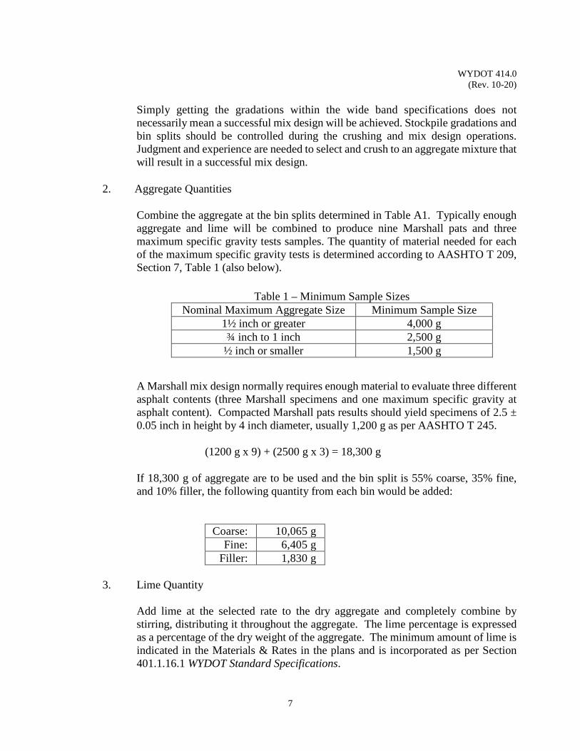
WYDOT 414.0 (Rev. 10-20)
7
Simply getting the gradations within the wide band specifications does not
necessarily mean a successful mix design will be achieved. Stockpile gradations and bin splits should be controlled during the crushing and mix design operations. Judgment and experience are needed to select and crush to an aggregate mixture that will result in a successful mix design.
2. Aggregate Quantities
Combine the aggregate at the bin splits determined in Table A1. Typically enough aggregate and lime will be combined to produce nine Marshall pats and three maximum specific gravity tests samples. The quantity of material needed for each of the maximum specific gravity tests is determined according to AASHTO T 209, Section 7, Table 1 (also below).
A Marshall mix design normally requires enough material to evaluate three different asphalt contents (three Marshall specimens and one maximum specific gravity at asphalt content). Compacted Marshall pats results should yield specimens of 2.5 ± 0.05 inch in height by 4 inch diameter, usually 1,200 g as per AASHTO T 245.
(1200 g x 9) + (2500 g x 3) = 18,300 g
If 18,300 g of aggregate are to be used and the bin split is 55% coarse, 35% fine, and 10% filler, the following quantity from each bin would be added:
Coarse: 10,065 g
Fine: 6,405 g Filler: 1,830 g
3. Lime Quantity
Add lime at the selected rate to the dry aggregate and completely combine by stirring, distributing it throughout the aggregate. The lime percentage is expressed as a percentage of the dry weight of the aggregate. The minimum amount of lime is indicated in the Materials & Rates in the plans and is incorporated as per Section 401.1.16.1 WYDOT Standard Specifications.
Table 1 – Minimum Sample Sizes Nominal Maximum Aggregate Size Minimum Sample Size
1½ inch or greater 4,000 g ¾ inch to 1 inch 2,500 g
½ inch or smaller 1,500 g

WYDOT 414.0 (Rev. 10-20)
8
Calculate the weight of lime to be added by multiplying the dry aggregate weight by the lime percentage addition rate. For example, with 1.0% lime and 19,000 g of dry aggregate, the lime addition of 190 g and is calculated as follows:
WL = WL x(WS)100 =
1.0 x (19,000)100 = 190 g
Where:
4. Water Quantity
Add water at a specified water to lime ratio, expressed by weight. Add the water to evenly coat the material.
Note: While doing a Job Mix Formula (JMF), a ratio of 3:1 (three parts water to
one part lime) is used. This is based on Section 401.4.13.2 WYDOT Standard Specifications.
Calculate the weight of water to add by multiplying the weight of lime by the water:lime ratio. For example, with 190 g of lime and a water:lime ratio of 3:1, the water addition rate of 570 g is calculated as follows:
WW = RW : Lx(WL) = 31 x (190) = 570 g
Where:
5. Asphalt Quantity
Oven dry the aggregate/lime mixture to drive off the water. Place the batched pans in the oven and heat to a temperature not to exceed 50 °F above the mixing temperature shown in Table 2 of this section. Add asphalt to the dry aggregate. The asphalt quantity is a percentage of the total mix weight, including the lime weight but not the water weight. Select at least three different trial asphalt contents, but none below 4.50% asphalt.
PL = Percentage of lime, % Ws = Dry aggregate weight, g WL = Lime weight, g
WW = Water weight, g RW:L = Water:lime ratio WL = Lime weight, g
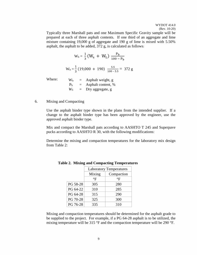
WYDOT 414.0 (Rev. 10-20)
9
Typically three Marshall pats and one Maximum Specific Gravity sample will be prepared at each of three asphalt contents. If one third of an aggregate and lime mixture containing 19,000 g of aggregate and 190 g of lime is mixed with 5.50% asphalt, the asphalt to be added, 372 g, is calculated as follows:
Wb = 13 (Ws + WL) Pb
100 − Pb
Wb = 13 (19,000 + 190) 5.5
100 – 5.5 = 372 g
Where:
6. Mixing and Compacting
Use the asphalt binder type shown in the plans from the intended supplier. If a change to the asphalt binder type has been approved by the engineer, use the approved asphalt binder type. Mix and compact the Marshall pats according to AASHTO T 245 and Superpave pucks according to AASHTO R 30, with the following modifications:
Determine the mixing and compaction temperatures for the laboratory mix design from Table 2:
Table 2. Mixing and Compacting Temperatures
Laboratory Temperatures Mixing Compaction
°F °F PG 58-28 305 280 PG 64-22 310 285 PG 64-28 315 290 PG 70-28 325 300 PG 76-28 335 310
Mixing and compaction temperatures should be determined for the asphalt grade to be supplied to the project. For example, if a PG 64-28 asphalt is to be utilized, the mixing temperature will be 315 °F and the compaction temperature will be 290 °F.
Wb = Asphalt weight, g Pb = Asphalt content, % WS = Dry aggregate, g
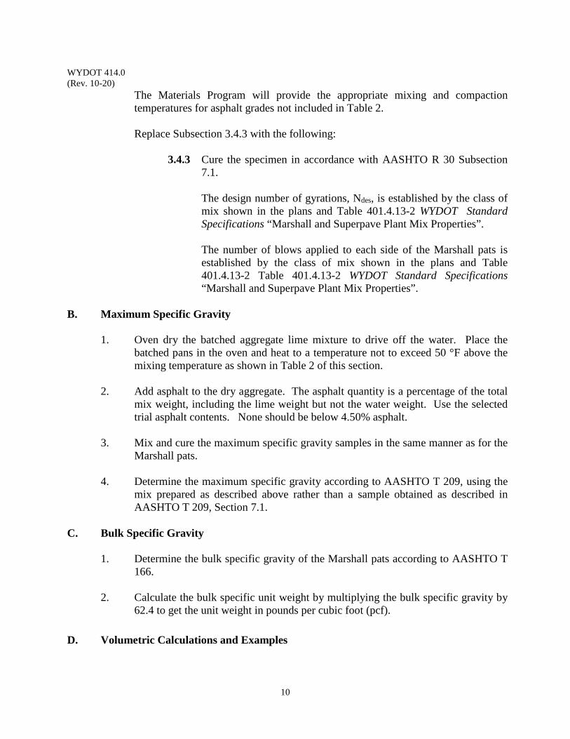
WYDOT 414.0 (Rev. 10-20)
10
The Materials Program will provide the appropriate mixing and compaction temperatures for asphalt grades not included in Table 2.
Replace Subsection 3.4.3 with the following:
3.4.3 Cure the specimen in accordance with AASHTO R 30 Subsection
7.1.
The design number of gyrations, Ndes, is established by the class of mix shown in the plans and Table 401.4.13-2 WYDOT Standard Specifications “Marshall and Superpave Plant Mix Properties”. The number of blows applied to each side of the Marshall pats is established by the class of mix shown in the plans and Table 401.4.13-2 Table 401.4.13-2 WYDOT Standard Specifications “Marshall and Superpave Plant Mix Properties”.
B. Maximum Specific Gravity
1. Oven dry the batched aggregate lime mixture to drive off the water. Place the batched pans in the oven and heat to a temperature not to exceed 50 °F above the mixing temperature as shown in Table 2 of this section.
2. Add asphalt to the dry aggregate. The asphalt quantity is a percentage of the total
mix weight, including the lime weight but not the water weight. Use the selected trial asphalt contents. None should be below 4.50% asphalt.
3. Mix and cure the maximum specific gravity samples in the same manner as for the
Marshall pats.
4. Determine the maximum specific gravity according to AASHTO T 209, using the mix prepared as described above rather than a sample obtained as described in AASHTO T 209, Section 7.1.
C. Bulk Specific Gravity
1. Determine the bulk specific gravity of the Marshall pats according to AASHTO T 166.
2. Calculate the bulk specific unit weight by multiplying the bulk specific gravity by 62.4 to get the unit weight in pounds per cubic foot (pcf).
D. Volumetric Calculations and Examples

WYDOT 414.0 (Rev. 10-20)
11
1. Perform the necessary calculations described as follows and report the derived values on Forms T-158 and E-46. Variables: The variables here generally follow those used in the Asphalt
Institute's publication MS-2, Mix Design Methods for Asphalt Concrete and Other Hot Mix Types.
P1, P2,…,Pn = Weight percentages of the individual aggregate portions, bin splits
Pmm = Total loose mixture percentage as percentage by total weight of mixture which equals 100%
Pb = Percentage asphalt (asphalt content) as a percentage of the total mixture weight including the lime weight but not the water weight
Pba = Absorbed asphalt by weight percentage of the dry aggregate Pbe = Effective asphalt content as a weight percentage of the total mixture not
including the water weight
Ps = Aggregate percentage by total weight of the mixture including the weight of the lime but not the water weight
Gsb = Bulk specific gravity of the total aggregate G1, G2,…,Gn = Bulk specific gravities of the individual aggregate portions as determined by
AASHTO T 84 & AASHTO T 85
Gmm = Maximum specific gravity of the total mix, sometimes referred to as the Voidless unit weight (VUW), or the Rice specific gravity, as determined by AASHTO T 209
Gmb = Bulk specific gravity of the compacted mixture as determined by AASHTO T 166
GSe = Effective specific gravity of the aggregate Gb = Specific gravity of the asphalt, obtained from the refinery invoice or loading
certificate Va = Air voids, percentage, in the compacted mixture by volume
VMA = Voids in mineral aggregate (Vma) VFA = Voids filled with asphalt (Vfa)
Vb = The volume percentage of the effective asphalt PPi = Percentage passing the individual sieve
SAFi = Surface area factor individual sieve SA = Surface area of the aggregate in ft²/lb
F.T. = Film thickness in µm D/A = Dust to asphalt ratio
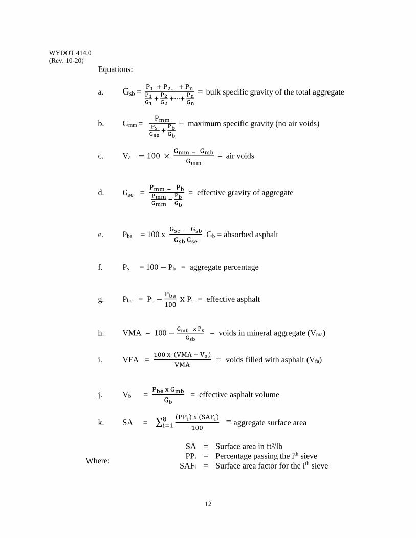
WYDOT 414.0 (Rev. 10-20)
12
Equations:
a. Gsb = P1 + P2… + PnP1G1
+ P2G2 +⋯+ PnGn
= bulk specific gravity of the total aggregate
b. Gmm = PmmPsGse
+ PbGb
= maximum specific gravity (no air voids)
c. Va = 100 × Gmm − Gmb
Gmm = air voids
d. Gse = Pmm − PbPmmGmm
− PbGb
= effective gravity of aggregate
e. Pba = 100 x Gse − GsbGsb Gse
Gb = absorbed asphalt
f. Ps = 100 − Pb = aggregate percentage
g. Pbe = Pb − Pba100
x Ps = effective asphalt
h. VMA = 100 − Gmb x Ps
Gsb = voids in mineral aggregate (Vma)
i. VFA = 100 x (VMA − Va)
VMA = voids filled with asphalt (Vfa)
j. Vb = Pbe x Gmb
Gb = effective asphalt volume
k. SA = ∑ (PPi) x (SAFi)100
8i=1 = aggregate surface area
Where:
SA = Surface area in ft²/lb PPi = Percentage passing the ith sieve
SAFi = Surface area factor for the ith sieve
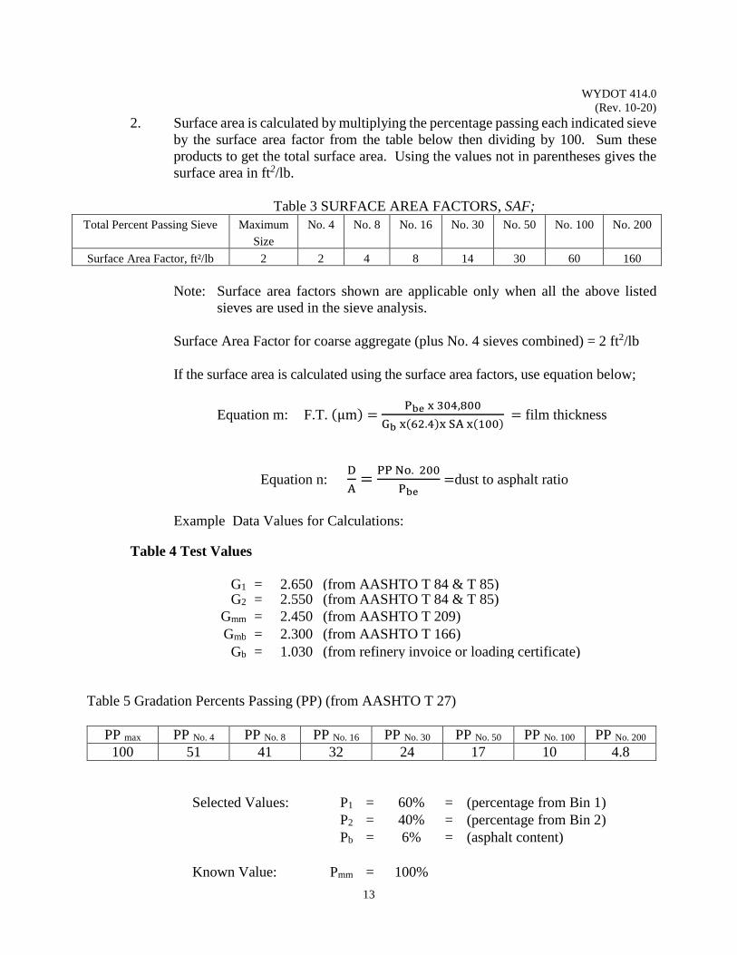
WYDOT 414.0 (Rev. 10-20)
13
2. Surface area is calculated by multiplying the percentage passing each indicated sieve by the surface area factor from the table below then dividing by 100. Sum these products to get the total surface area. Using the values not in parentheses gives the surface area in ft2/lb.
Table 3 SURFACE AREA FACTORS, SAF;
Total Percent Passing Sieve Maximum
Size
No. 4 No. 8 No. 16 No. 30 No. 50 No. 100 No. 200
Surface Area Factor, ft²/lb 2 2 4 8 14 30 60 160
Note: Surface area factors shown are applicable only when all the above listed
sieves are used in the sieve analysis. Surface Area Factor for coarse aggregate (plus No. 4 sieves combined) = 2 ft2/lb
If the surface area is calculated using the surface area factors, use equation below;
Equation m: F.T. (µm) = Pbe x 304,800
Gb x(62.4)x SA x(100) = film thickness
Equation n: DA
= PP No. 200
Pbe =dust to asphalt ratio
Example Data Values for Calculations:
Table 4 Test Values
G1 = 2.650 (from AASHTO T 84 & T 85) G2 = 2.550 (from AASHTO T 84 & T 85)
Gmm = 2.450 (from AASHTO T 209) Gmb = 2.300 (from AASHTO T 166)
Gb = 1.030 (from refinery invoice or loading certificate) Table 5 Gradation Percents Passing (PP) (from AASHTO T 27)
PP max PP No. 4 PP No. 8 PP No. 16 PP No. 30 PP No. 50 PP No. 100 PP No. 200
100 51 41 32 24 17 10 4.8
Selected Values: P1 = 60% = (percentage from Bin 1) P2 = 40% = (percentage from Bin 2) Pb = 6% = (asphalt content) Known Value: Pmm = 100%
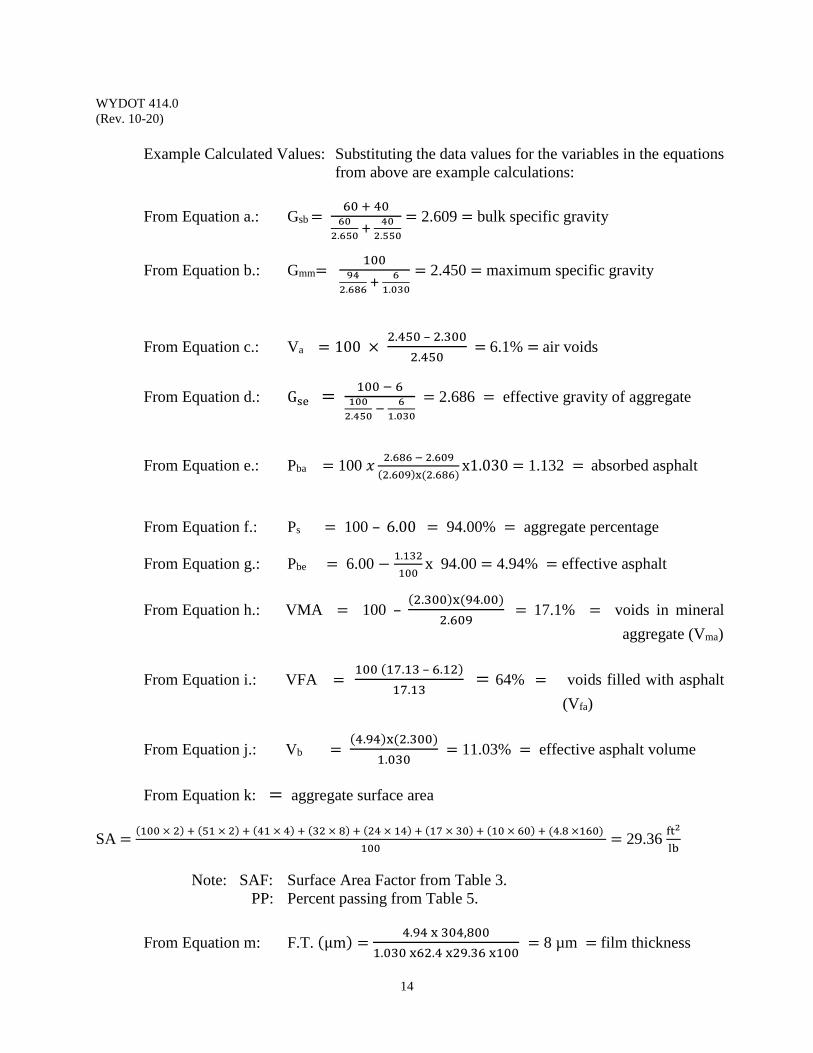
WYDOT 414.0 (Rev. 10-20)
14
Example Calculated Values: Substituting the data values for the variables in the equations
from above are example calculations:
From Equation a.: Gsb = 60 + 4060
2.650 + 402.550
= 2.609 = bulk specific gravity
From Equation b.: Gmm= 10094
2.686 + 61.030
= 2.450 = maximum specific gravity
From Equation c.: Va = 100 × 2.450 – 2.300
2.450 = 6.1% = air voids
From Equation d.: Gse = 100 − 6
1002.450 − 6
1.030 = 2.686 = effective gravity of aggregate
From Equation e.: Pba = 100 𝑥𝑥 2.686 − 2.609(2.609)x(2.686)
x1.030 = 1.132 = absorbed asphalt
From Equation f.: Ps = 100 – 6.00 = 94.00% = aggregate percentage
From Equation g.: Pbe = 6.00 − 1.132100
x 94.00 = 4.94% = effective asphalt
From Equation h.: VMA = 100 – (2.300)x(94.00)
2.609 = 17.1% = voids in mineral
aggregate (Vma)
From Equation i.: VFA = 100 (17.13 – 6.12)
17.13 = 64% = voids filled with asphalt
(Vfa)
From Equation j.: Vb = (4.94)x(2.300)
1.030 = 11.03% = effective asphalt volume
From Equation k: = aggregate surface area
SA = (100 × 2) + (51 × 2) + (41 × 4) + (32 × 8) + (24 × 14) + (17 × 30) + (10 × 60) + (4.8 ×160)
100= 29.36
ft2
lb
Note: SAF: Surface Area Factor from Table 3.
PP: Percent passing from Table 5.
From Equation m: F.T. (µm) = 4.94 x 304,800
1.030 x62.4 x29.36 x100 = 8 µm = film thickness
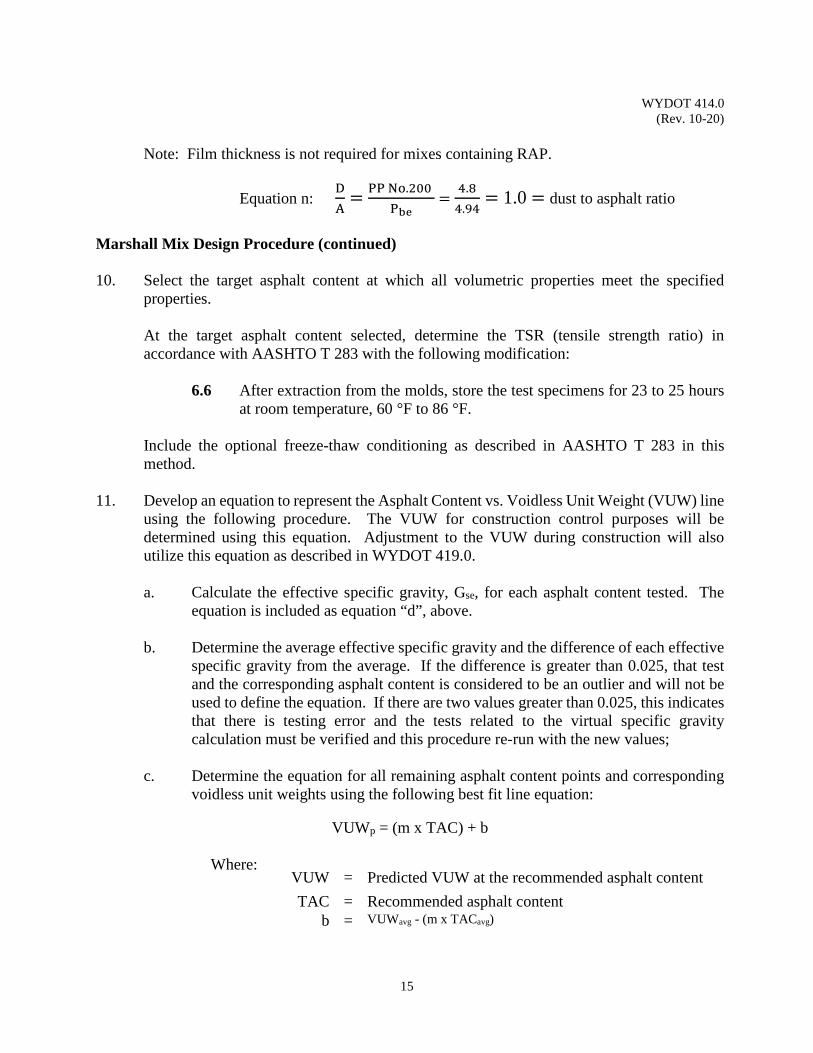
WYDOT 414.0 (Rev. 10-20)
15
Note: Film thickness is not required for mixes containing RAP.
Equation n: DA
= PP No.200
Pbe =
4.84.94
= 1.0 = dust to asphalt ratio
Marshall Mix Design Procedure (continued) 10. Select the target asphalt content at which all volumetric properties meet the specified
properties.
At the target asphalt content selected, determine the TSR (tensile strength ratio) in accordance with AASHTO T 283 with the following modification:
6.6 After extraction from the molds, store the test specimens for 23 to 25 hours at room temperature, 60 °F to 86 °F.
Include the optional freeze-thaw conditioning as described in AASHTO T 283 in this method.
11. Develop an equation to represent the Asphalt Content vs. Voidless Unit Weight (VUW) line
using the following procedure. The VUW for construction control purposes will be determined using this equation. Adjustment to the VUW during construction will also utilize this equation as described in WYDOT 419.0.
a. Calculate the effective specific gravity, Gse, for each asphalt content tested. The
equation is included as equation “d”, above.
b. Determine the average effective specific gravity and the difference of each effective specific gravity from the average. If the difference is greater than 0.025, that test and the corresponding asphalt content is considered to be an outlier and will not be used to define the equation. If there are two values greater than 0.025, this indicates that there is testing error and the tests related to the virtual specific gravity calculation must be verified and this procedure re-run with the new values;
c. Determine the equation for all remaining asphalt content points and corresponding
voidless unit weights using the following best fit line equation:
VUWp = (m x TAC) + b
Where:
VUW = Predicted VUW at the recommended asphalt content
TAC = Recommended asphalt content b = VUWavg - (m x TACavg)
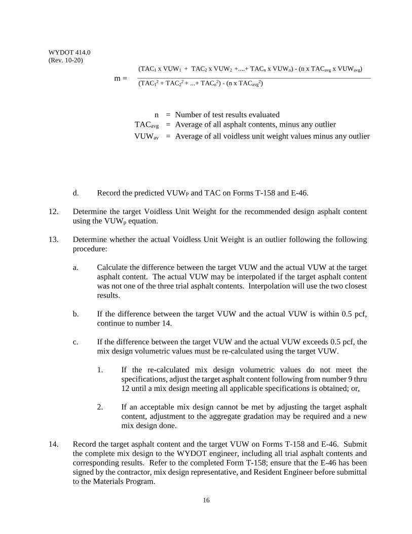
WYDOT 414.0 (Rev. 10-20)
16
m = (TAC1 x VUW1 + TAC2 x VUW2 +....+ TACn x VUWn) - (n x TACavg x VUWavg) (TAC1
2 + TAC22 + ...+ TACn
2) - (n x TACavg2)
d. Record the predicted VUWP and TAC on Forms T-158 and E-46. 12. Determine the target Voidless Unit Weight for the recommended design asphalt content
using the VUWp equation.
13. Determine whether the actual Voidless Unit Weight is an outlier following the following procedure:
a. Calculate the difference between the target VUW and the actual VUW at the target
asphalt content. The actual VUW may be interpolated if the target asphalt content was not one of the three trial asphalt contents. Interpolation will use the two closest results.
b. If the difference between the target VUW and the actual VUW is within 0.5 pcf,
continue to number 14.
c. If the difference between the target VUW and the actual VUW exceeds 0.5 pcf, the mix design volumetric values must be re-calculated using the target VUW. 1. If the re-calculated mix design volumetric values do not meet the
specifications, adjust the target asphalt content following from number 9 thru 12 until a mix design meeting all applicable specifications is obtained; or,
2. If an acceptable mix design cannot be met by adjusting the target asphalt
content, adjustment to the aggregate gradation may be required and a new mix design done.
14. Record the target asphalt content and the target VUW on Forms T-158 and E-46. Submit
the complete mix design to the WYDOT engineer, including all trial asphalt contents and corresponding results. Refer to the completed Form T-158; ensure that the E-46 has been signed by the contractor, mix design representative, and Resident Engineer before submittal to the Materials Program.
n = Number of test results evaluated TACavg = Average of all asphalt contents, minus any outlier
VUWav
= Average of all voidless unit weight values minus any outlier
WYDOT 414.0 (Rev. 10-20)
17
Construction Mix Volumetric Verification: 1. Sample the hot plant mix material according to WYDOT 410.0, to obtain three full cylinder
cans of material for Marshall mix verifications and five full cylinder cans of material for Superpave mix verifications. Transport the samples according to WYDOT 411.0.
2. Determine the maximum specific gravity according to AASHTO T 209, using the mix
obtained as described above rather than a lab-mixed sample as described in AASHTO T 209, Section 7.1.
3. Determine the total and effective asphalt contents and gradation. Determine and apply a
correction factor in accordance with AASHTO T 308 if the Ignition Method is utilized. Note: For recycle hot plant mix, chemical extractions may provide more reliable asphalt
content and gradation results.
4. Heat samples to the temperature at which the mix design specimens were compacted. (Table 2 of this section.)
5. Mix and compact the Superpave pucks with the Ndes gyrations used during design and
calculate density at Ndes and the Marshall pats according to AASHTO T 245 with the following modifications:
Replace Subsection 3.3.1 with the following: “3.3.1 The samples will be obtained according to WYDOT 410.0 and transported
according to WYDOT 411.0.”
After splitting, place specimens of the proper size to prepare a compacted specimen 2.5 inch ± 0.05 inch in height, about 2.6 lb, in appropriate pans for reheating. Reheat using the compaction temperature used during the mix design procedure. Replace Subsection 3.4.3 with the following: “3.4.3 No further curing is needed.”
The number of blows applied to each side of the Marshall pats is established by the class of mix shown in the plans and Section 401.4.13-2 WYDOT Standard Specifications “Marshall and Superpave Plant Mix Properties”.
6. Determine the bulk specific gravity of the Marshall pats or the Superpave pucks according
to AASHTO T 166. Calculate the VUW by multiplying the bulk specific gravity by 62.4 for pounds per cubic foot (pcf). Field adjustments to the VUW will be in accordance with WYDOT 419.0.
WYDOT 414.0 (Rev. 10-20)
18
7. Determine which calculations are needed for the current application, perform the necessary calculations, and report the results in accordance with Section Subsection 3 of 401.4.7.3 WYDOT Standard Specifications, on Form T-158F. At a minimum, report with the project information (project number, contractor, consultant, aggregate type, mix properties, level of control, aggregate source, asphalt type and source, extraction method, etc.) along with the following information: Sample number, date sampled, station sampled, total extracted asphalt content, effective asphalt content, compacted density, Voidless Unit Weight, Air Voids, VMA, Stability where applicable, Extracted Gradation, Dust to Effective Asphalt, Film Thickness when specified, and comments. Comments are intended to address action taken to address out-of-specification material, sampling issues, paired samples, etc.
8. Provide the engineer and the Materials Program with the volumetric results using Form T-
158F. The Materials Program will incorporate the volumetric results into the permanent project file. Form T-158F may be emailed to both the engineer and the Materials Program. Submit the proposed JMF on Form E-46.

WYDOT 414.0 (Rev. 10-20)
19
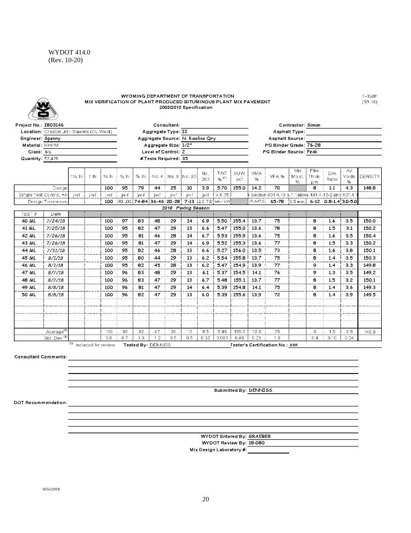
WYDOT 414.0 (Rev. 10-20)
20
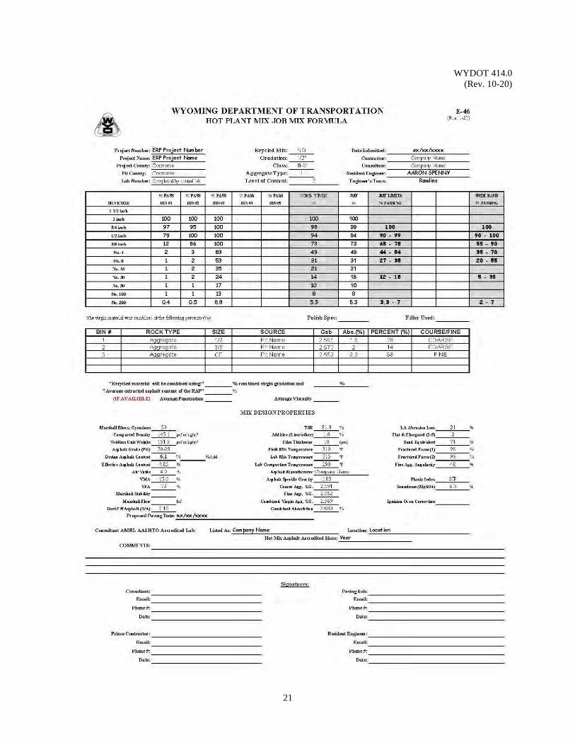
WYDOT 414.0 (Rev. 10-20)
21
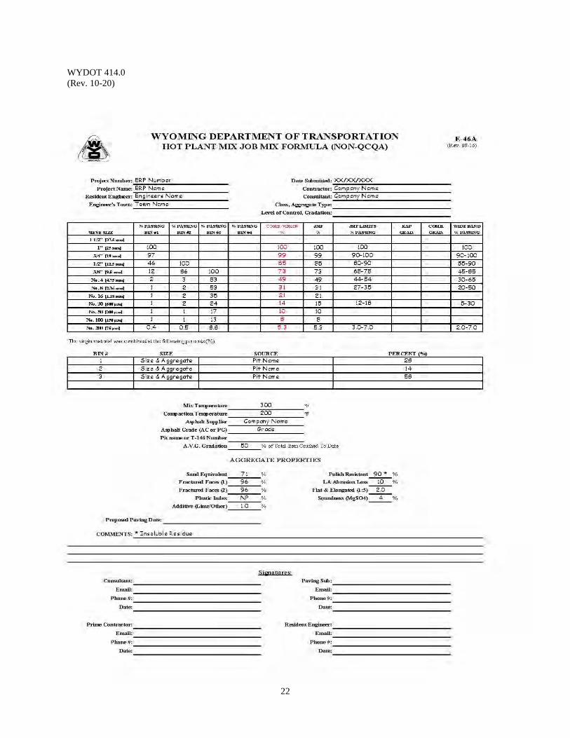
WYDOT 414.0 (Rev. 10-20)
22
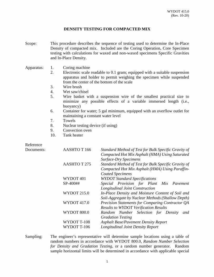
WYDOT 415.0 (Rev. 10-20)
1
DENSITY TESTING FOR COMPACTED MIX
Scope: This procedure describes the sequence of testing used to determine the In-Place
Density of compacted mix. Included are the Coring Operation, Core Specimen testing with calculations for waxed and non-waxed specimens Specific Gravities and In-Place Density.
Apparatus: 1. Coring machine
2. Electronic scale readable to 0.1 gram; equipped with a suitable suspension apparatus and holder to permit weighing the specimen while suspended from the center of the bottom of the scale
3. Wire brush 4. Wet saw/chisel 5. Wire basket with a suspension wire of the smallest practical size to
minimize any possible effects of a variable immersed length (i.e., buoyancy)
6. Container for water; 5 gal minimum, equipped with an overflow outlet for maintaining a constant water level
7. Towels 8. Nuclear testing device (if using) 9. Convection oven 10. Tank heater
Reference Documents: AASHTO T 166 Standard Method of Test for Bulk Specific Gravity of
Compacted Hot Mix Asphalt (HMA) Using Saturated Surface-Dry Specimens
AASHTO T 275 Standard Method of Test for Bulk Specific Gravity of Compacted Hot Mix Asphalt (HMA) Using Paraffin-Coated Specimens
WYDOT 401 WYDOT Standard Specifications SP-400## Special Provision for Plant Mix Pavement
Longitudinal Joint Construction WYDOT 215.0 In-Place Density and Moisture Content of Soil and
Soil-Aggregate by Nuclear Methods (Shallow Depth) WYDOT 417.0 Precision Statements for Comparing Contractor QA
Results to WYDOT Verification Results WYDOT 800.0 Random Number Selection for Density and
Gradation Testing WYDOT T-108 Asphalt Base/Pavement Density Report WYDOT T-106 Longitudinal Joint Density Report
Sampling: The engineer’s representative will determine sample locations using a table of
random numbers in accordance with WYDOT 800.0, Random Number Selection for Density and Gradation Testing, or a random number generator. Random sample horizontal limits will be determined in accordance with applicable special
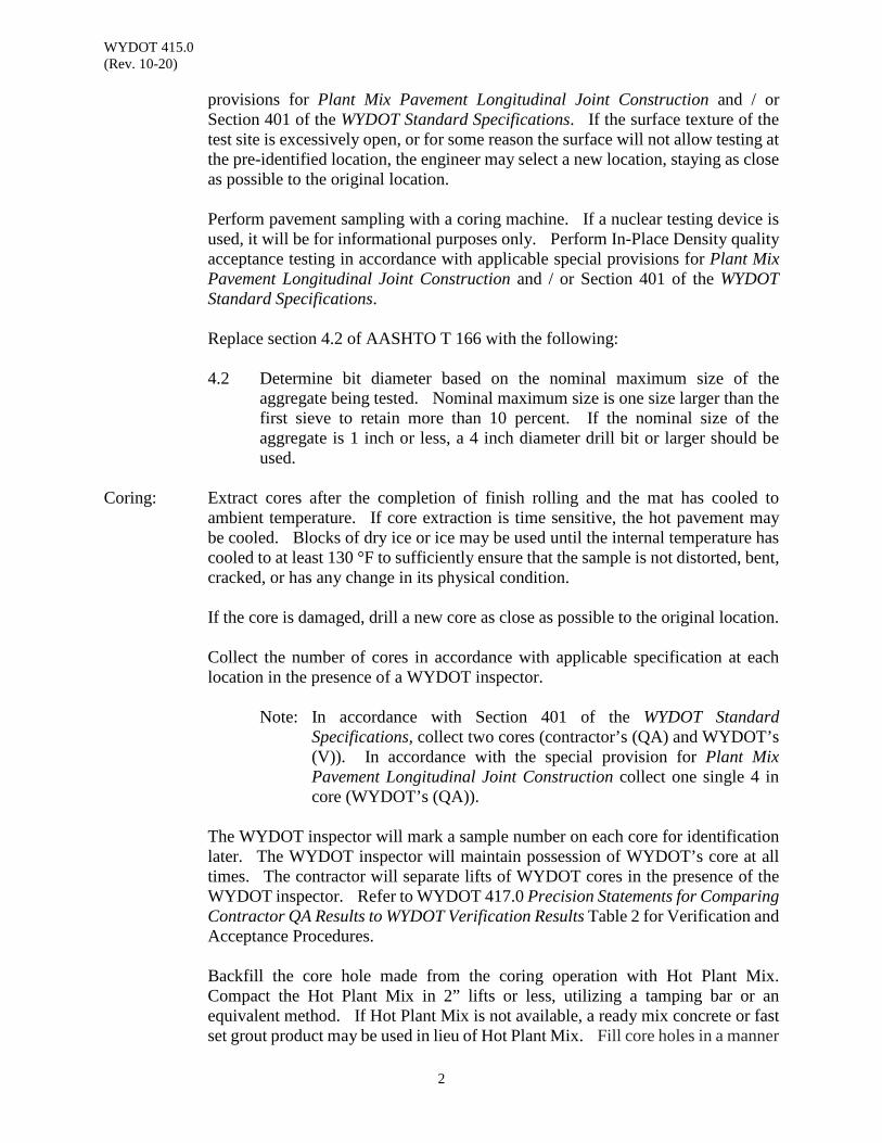
WYDOT 415.0 (Rev. 10-20)
2
provisions for Plant Mix Pavement Longitudinal Joint Construction and / or Section 401 of the WYDOT Standard Specifications. If the surface texture of the test site is excessively open, or for some reason the surface will not allow testing at the pre-identified location, the engineer may select a new location, staying as close as possible to the original location.
Perform pavement sampling with a coring machine. If a nuclear testing device is
used, it will be for informational purposes only. Perform In-Place Density quality acceptance testing in accordance with applicable special provisions for Plant Mix Pavement Longitudinal Joint Construction and / or Section 401 of the WYDOT Standard Specifications. Replace section 4.2 of AASHTO T 166 with the following: 4.2 Determine bit diameter based on the nominal maximum size of the
aggregate being tested. Nominal maximum size is one size larger than the first sieve to retain more than 10 percent. If the nominal size of the aggregate is 1 inch or less, a 4 inch diameter drill bit or larger should be used.
Coring: Extract cores after the completion of finish rolling and the mat has cooled to
ambient temperature. If core extraction is time sensitive, the hot pavement may be cooled. Blocks of dry ice or ice may be used until the internal temperature has cooled to at least 130 °F to sufficiently ensure that the sample is not distorted, bent, cracked, or has any change in its physical condition. If the core is damaged, drill a new core as close as possible to the original location.
Collect the number of cores in accordance with applicable specification at each location in the presence of a WYDOT inspector.
Note: In accordance with Section 401 of the WYDOT Standard Specifications, collect two cores (contractor’s (QA) and WYDOT’s (V)). In accordance with the special provision for Plant Mix Pavement Longitudinal Joint Construction collect one single 4 in core (WYDOT’s (QA)).
The WYDOT inspector will mark a sample number on each core for identification later. The WYDOT inspector will maintain possession of WYDOT’s core at all times. The contractor will separate lifts of WYDOT cores in the presence of the WYDOT inspector. Refer to WYDOT 417.0 Precision Statements for Comparing Contractor QA Results to WYDOT Verification Results Table 2 for Verification and Acceptance Procedures. Backfill the core hole made from the coring operation with Hot Plant Mix. Compact the Hot Plant Mix in 2” lifts or less, utilizing a tamping bar or an equivalent method. If Hot Plant Mix is not available, a ready mix concrete or fast set grout product may be used in lieu of Hot Plant Mix. Fill core holes in a manner
WYDOT 415.0 (Rev. 10-20)
3
resulting in a final surface that is level with the adjacent lift of plant mix. Fill the core holes prior to the next lift placement or prior to seasonal shutdown, whichever is sooner.
Preparation of Samples: Bring the core sample to room temperature at 77 ± 9 °F and clean off any foundation
material such as; prime coat, soil, crushed base, or cement treated base. A stiff wire brush may facilitate cleaning.
Separate any lifts from the compacted test lift during construction of multi-lift
pavements. Separation by the use of a wet saw is preferred. Take care to avoid damage to the core. Clean the top and/or bottom of each core of any material not part of the compacted test lift such as seal coat, tack coat, plant mix wearing course, or any foreign material such as striping tape, etc.
Insure the sample number is legible on each core for identification later. Record on the applicable form (Form T-108 (mainline) or Form T-106 (longitudinal joint)) the sample number for each test specimen taken. When correlating the nuclear tests, both cores and nuclear readings will have the same number, with the nuclear test number having a letter i.e. "N" added. When the nuclear testing device has been correlated, the continuous count will be with numbers only. Record on Form T-108 / T-106: date sampled, station sampled, section represented, lane taken, distance from centerline, and core thickness of the compacted test lift only. Refer to example Form T-108 of this section.
Note: Record test specimen thickness to the nearest ¼ in measured and an
average from three locations on the core.
Non-Waxed Procedure: Use only individual weights from the desired lift for density determination.
Record the core test sample weight (mass) to the nearest gram on Form T-108 / T-106. 1. Weigh the core after the core has been immersed in water at 77 ± 1.8 °F for
three to five minutes. Designate this weight as "E" on Form T-108 / T-106. Immerse and individually weigh each specimen.
To avoid error, use the same scale to obtain all weights. Note: Assure water level stays at optimum over flow level.
2. Weigh the Saturated Surface Dry core (SSD) in air. Designate this weight
(mass) as "B" on Form T-108 / T-106.
Remove the immersed core sample from the water. Use a damp towel to blot the core until saturated surface dry (SSD) condition exists (as quickly as possible and not to exceed 5 seconds). Weigh the core in air on the same
WYDOT 415.0 (Rev. 10-20)
4
scale as Step 1. A towel is considered damp when no water can be wrung from it. Note: Any water that seeps from the test specimen during
weighing is considered part of that saturated specimen (SSD).
If an individual core exceeds 2 percent absorption, test the individual specimen in accordance with the wax procedure without regard to other cores in the lot or the contractor’s cores. Note: Allow corelok with approved calibration. Corelok may be
used upon engineer’s acceptance of a method and calibration process.
3. Weigh the completely dried core sample in air. Designate this weight
(mass) as "A" on Form T-108 / T-106.
During testing, WYDOT and the contractor will dry the cores in a convection oven to a constant weight (mass) with a nondestructive method.
Note: If desired, the sequence of testing operation may be changed. For example, first the dry weight "A" can be obtained and then the weight in water "E" and then the saturated surface dry weight "B". If the sequence of testing is changed and the dried core weight "A" is taken first, the core must be carefully dried in an oven at a temperature not to exceed 125 ± 5 °F so as to not cause any distortion or disintegration of the core. Drying is not complete until a constant weight is obtained (constant weight equals weight of core and does not change more than 0.05 percent when weighed at 2 hour intervals). Drying the core rapidly using excessive heat will damage the core.
Cores with visible moisture on the surface will take at least several hours to
dry at 125 °F. Drying is not complete until a constant weight is obtained (i.e., weight of core changes by 0.05 percent or less between two hour intervals at this drying temperature). Turning and/or flipping the core specimen while drying may help to expose any trapped moisture.
Calculation: Calculating for dry weight;
(Wet Weight−Dry Weight)(Dry Weight)
x 100 = calculating for drying to 0.05 % or less.
WYDOT 415.0 (Rev. 10-20)
5
Calculating Specific Gravity;
SG = A (B –E)
= non-waxed core
Example Calculating unit weight, lb/ft3
Note: Form T-108 / T-106 is formulated for calculating lb/ft3, to compare to the Nuclear Unit Weight.
non-waxed core UW = A(B –E)
x Cd
Where: SG = Specific Gravity; round to three places past the decimal
A = Mass of sample in air after drying, g B = Mass of saturated surface dry (SSD) sample in air, g E = Mass of sample in water (wet weight), g Cd = 62.4 for English units lb/ft3 UW = Unit Weight in lb/ft3; round to 1 decimal place, tenth
Calculating for percent Density;
UWVUW
x 100 = Percent Density
Where: VUW = Voidless Unit Weight from the mix design, lb/ft3
Note: Find the volume of water absorbed by the core, in percent, to
determine if cores should be waxed. If more than two percent water is found, use the waxed procedure.
Calculating for percent of water absorbed;
𝐵𝐵 −𝐴𝐴𝐵𝐵 −𝐸𝐸
x 100 = Percent Water Absorbed
Where: A = Mass of sample in air after drying, g
B = Mass of saturated surface dry (SSD) sample in air, g E = Mass of sample in water (wet weight), g
Waxed Procedure: This method is performed on samples with open or interconnected voids or on
samples that have absorbed over 2 percent by volume as determined by steps 1 through 3 previously listed.
1. Weigh the completely dried core sample in air. Designate this weight
WYDOT 415.0 (Rev. 10-20)
6
(mass) as "A" on Form T-108 / T-106.
The only procedure that can be used in running a wax density tests is in the order shown.
2. Put wax into a pan to be melted, have another pan full of water being heated.
Place the pan with wax into the pan of hot water. To melt the wax, do not use direct heat from any kind of burner. The warm wax is ready when it is approximately 10° F above melting. Dip the core into the wax and cover all surfaces. It may be necessary to brush on melted wax to fill any pinholes left on the surface. Do not use too much wax. Allow 30 minutes to cool before weighing.
Weigh the waxed sample in air. Designate this weight (mass) as "F" on
Form T-108 / T-106.
3. Weigh the waxed sample immersed in water at 77 ± 1.8 °F. Designate the weight (mass) as "C" on Form T-108 / T-106.
Immerse and individually weigh each specimen.
Use the same scale as used to find the weight in air.
Note: Form T-108 / T-106 is formulated for calculating lb/ft3, to
compare to the Nuclear Unit Weight.
Calculation: Calculate Specific Gravity;
SG = A
(F – C) − (F – A)D
Example calculating unit weight, lb/ft3
Waxed Core UW = A
(F –C)− (F –A)D
x Cd
Where: SG = Specific Gravity; round to three places past the decimal
A = Mass of sample in air after drying, g F = Mass of waxed core sample (SSD) sample in air, g D = Specific gravity of the wax (SGwax = 0.9000); round to four
places past the decimal for weights C = Mass of waxed core sample in water (wet weight), g Cd = 62.4 for English units lb/ft3 UW = Unit Weight in lb/ft3; round to 1 decimal place, tenth

WYDOT 415.0 (Rev. 10-20)
7
Percent of Maximum Density;
UWVUW
x 100 = Percent Density; round to 2 decimal place
Where: VUW = Voidless Unit Weight from mix design JMF letter, lb/ft³
Report: Report the specific gravity, unit weight, voidless unit weight, and percent density
on Form T-108 / T-106.

WYDOT 415.0 (Rev. 10-20)
8
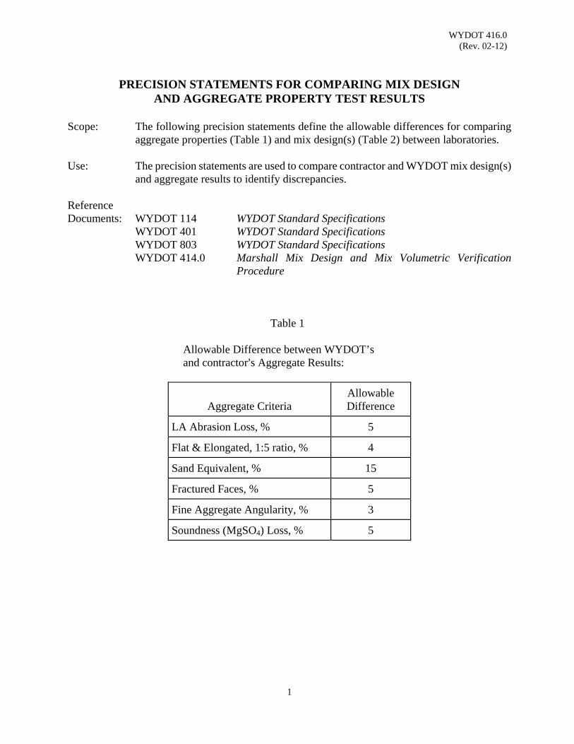
WYDOT 416.0 (Rev. 02-12)
1
PRECISION STATEMENTS FOR COMPARING MIX DESIGN
AND AGGREGATE PROPERTY TEST RESULTS
Scope: The following precision statements define the allowable differences for comparing aggregate properties (Table 1) and mix design(s) (Table 2) between laboratories.
Use: The precision statements are used to compare contractor and WYDOT mix design(s)
and aggregate results to identify discrepancies. Reference Documents: WYDOT 114 WYDOT Standard Specifications WYDOT 401 WYDOT Standard Specifications WYDOT 803 WYDOT Standard Specifications WYDOT 414.0 Marshall Mix Design and Mix Volumetric Verification
Procedure
Table 1 Allowable Difference between WYDOT’s and contractor=s Aggregate Results:
Aggregate Criteria
Allowable Difference
LA Abrasion Loss, %
5
Flat & Elongated, 1:5 ratio, %
4
Sand Equivalent, %
15
Fractured Faces, %
5
Fine Aggregate Angularity, %
3
Soundness (MgSO4) Loss, %
5

WYDOT 416.0 (Rev. 02-12)
2
Table 2 Allowable Difference between WYDOT’s and contractor=s Mix Design Results:
Mix Criteria
Allowable Difference
Marshall
Superpave
Bulk Specific Gravity (Gmb) (Coarse & Fine)
0.03
0.03
Air Voids (Va), %
1.2
1.2
Voids in Mineral Aggregate (VMA), %
1.2
1.2
Voids Filled with Asphalt Binder (VFA), %
8.0
Marshall Stability, lb
900
Marshall Flow, 0.01 in
3
Tensile Strength Retained (TSR), %
8
8
Film Thickness (F.T.), μm
2
2
Dust to Effective Asphalt Binder Ratio (D/A)
0.3
0.3
Voidless Unit Weight (VUW), lb/ft3
1.5
1.5
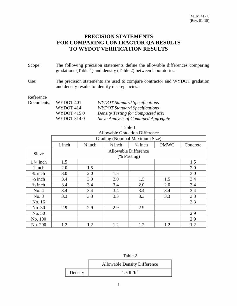
MTM 417.0 (Rev. 01-15)
1
PRECISION STATEMENTS FOR COMPARING CONTRACTOR QA RESULTS
TO WYDOT VERIFICATION RESULTS
Scope: The following precision statements define the allowable differences comparing gradations (Table 1) and density (Table 2) between laboratories.
Use: The precision statements are used to compare contractor and WYDOT gradation and density results to identify discrepancies.
Reference Documents: WYDOT 401 WYDOT Standard Specifications
WYDOT 414 WYDOT Standard Specifications WYDOT 415.0 Density Testing for Compacted Mix WYDOT 814.0 Sieve Analysis of Combined Aggregate
Table 1 Allowable Gradation Difference
Grading (Nominal Maximum Size) 1 inch ¾ inch ½ inch ⅜ inch PMWC Concrete
Sieve Allowable Difference
(% Passing) 1 ¼ inch 1.5 1.51 inch 2.0 1.5 2.0¾ inch 3.0 2.0 1.5 3.0½ inch 3.4 3.0 2.0 1.5 1.5 3.4⅜ inch 3.4 3.4 3.4 2.0 2.0 3.4No. 4 3.4 3.4 3.4 3.4 3.4 3.4No. 8 3.3 3.3 3.3 3.3 3.3 3.3No. 16 3.3No. 30 2.9 2.9 2.9 2.9No. 50 2.9No. 100 2.9No. 200 1.2 1.2 1.2 1.2 1.2 1.2
Table 2
Allowable Density Difference
Density 1.5 lb/ft3

MTM 417.0 (Rev. 01-15)
2
(This page intentionally left blank.)
WYDOT 419.0 (Rev. 09-16)
1
VOIDLESS UNIT WEIGHT VERIFICATION AND FIELD ADJUSTMENT
Scope: This procedure describes the verification and adjustment of the production mix Voidless Unit Weight (VUW). The VUW is sometimes referred to as maximum density, theoretical maximum weight, maximum specific gravity (Gmm), or Rice specific gravity.
Use: The VUW determined from the construction mix design is developed under controlled conditions. Construction introduces many variables which may result in variation between the VUW stated in the JMF letter from the construction mix design and the VUW determined during production of the mix. Therefore, adjustment of the VUW used for density control may be warranted. This adjustment is based on the VUW and extracted asphalt content test results. Submit VUW and extracted total asphalt content test results according to WYDOT Standard Specifications 401.4.11, to the engineer, which will be forwarded to the Materials Program.
The WYDOT Materials Program will analyze and adjust the VUW according to the procedures described below. In addition, the contractors test results may be verified by the WYDOT Materials Program as determined by the engineer and Materials Program. Adjustments to the VUW will apply to field control in accordance with WYDOT Standard Specifications 401.4.11.
Reference Documents: AASHTO T 164 Standard Method of Test for Quantitative Extraction of Asphalt
Binder from Hot Mix Asphalt (HMA) AASHTO T 209 Standard Method of Test for Theoretical Maximum Specific
Gravity and Density of Hot Mix Asphalt (HMA) AASHTO T 308 Standard Method of Test for Determining the Asphalt Binder
Content of Hot Mix Asphalt (HMA) by the Ignition Method WYDOT 114 WYDOT Standard Specifications WYDOT 401.4.11 WYDOT Standard Specifications WYDOT 410.0 Sampling Mix WYDOT 411.0 Transporting Mix Samples WYDOT 414.0 Marshall and Superpave Mix Design and Mix Volumetric
Verification Procedure
Procedure: Sample in the presence of a WYDOT representative, transport if necessary, and split if necessary, the mix in accordance with WYDOT 410.0 and WYDOT 411.0. WYDOT must maintain possession of the WYDOT cores at all times. Submit split
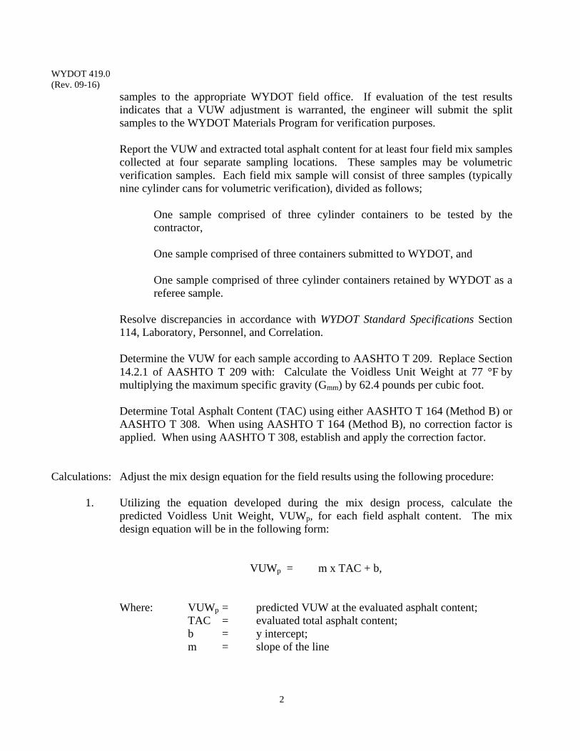
WYDOT 419.0 (Rev. 09-16)
2
samples to the appropriate WYDOT field office. If evaluation of the test results indicates that a VUW adjustment is warranted, the engineer will submit the split samples to the WYDOT Materials Program for verification purposes.
Report the VUW and extracted total asphalt content for at least four field mix samples collected at four separate sampling locations. These samples may be volumetric verification samples. Each field mix sample will consist of three samples (typically nine cylinder cans for volumetric verification), divided as follows;
One sample comprised of three cylinder containers to be tested by the contractor,
One sample comprised of three containers submitted to WYDOT, and
One sample comprised of three cylinder containers retained by WYDOT as a referee sample.
Resolve discrepancies in accordance with WYDOT Standard Specifications Section 114, Laboratory, Personnel, and Correlation.
Determine the VUW for each sample according to AASHTO T 209. Replace Section 14.2.1 of AASHTO T 209 with: Calculate the Voidless Unit Weight at 77 °Fby multiplying the maximum specific gravity (Gmm) by 62.4 pounds per cubic foot. Determine Total Asphalt Content (TAC) using either AASHTO T 164 (Method B) or AASHTO T 308. When using AASHTO T 164 (Method B), no correction factor is applied. When using AASHTO T 308, establish and apply the correction factor.
Calculations: Adjust the mix design equation for the field results using the following procedure:
1. Utilizing the equation developed during the mix design process, calculate the predicted Voidless Unit Weight, VUWp, for each field asphalt content. The mix design equation will be in the following form:
VUWp = m x TAC + b,
Where: VUWp = predicted VUW at the evaluated asphalt content;
TAC = evaluated total asphalt content; b = y intercept; m = slope of the line
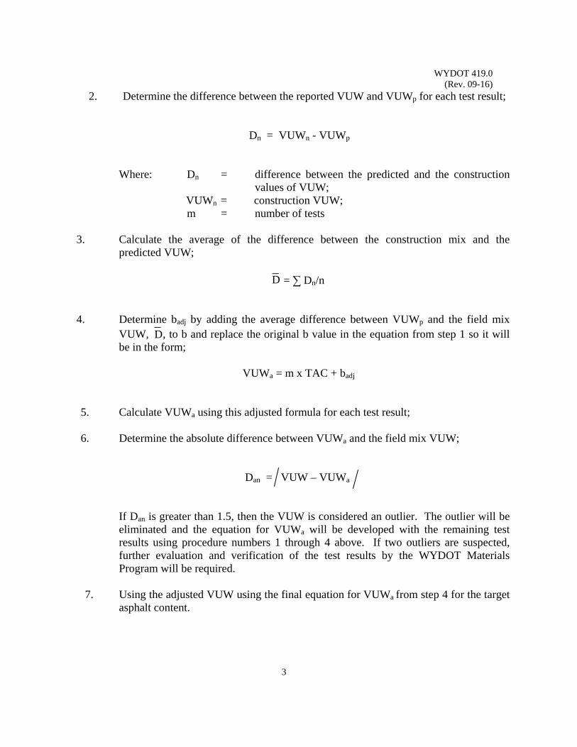
WYDOT 419.0 (Rev. 09-16)
3
D
D
2. Determine the difference between the reported VUW and VUWp for each test result;
Dn = VUWn - VUWp
Where: Dn = difference between the predicted and the construction values of VUW;
VUWn = construction VUW; m = number of tests
3. Calculate the average of the difference between the construction mix and the predicted VUW;
= ∑ Dn/n
4. Determine badj by adding the average difference between VUWp and the field mix VUW, , to b and replace the original b value in the equation from step 1 so it will be in the form;
VUWa = m x TAC + badj
5. Calculate VUWa using this adjusted formula for each test result;
6. Determine the absolute difference between VUWa and the field mix VUW;
Dan = VUW – VUWa
If Dan is greater than 1.5, then the VUW is considered an outlier. The outlier will be eliminated and the equation for VUWa will be developed with the remaining test results using procedure numbers 1 through 4 above. If two outliers are suspected, further evaluation and verification of the test results by the WYDOT Materials Program will be required.
7. Using the adjusted VUW using the final equation for VUWa from step 4 for the target
asphalt content.
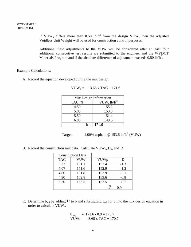
WYDOT 419.0 (Rev. 09-16)
4
D
D
D
If VUWa differs more than 0.50 lb/ft3 from the design VUW, then the adjusted
Voidless Unit Weight will be used for construction control purposes.
Additional field adjustments to the VUW will be considered after at least four additional consecutive test results are submitted to the engineer and the WYDOT Materials Program and if the absolute difference of adjustment exceeds 0.50 lb/ft3.
Example Calculations:
A. Record the equation developed during the mix design,
VUWP = 3.68 x TAC + 171.6
Mix Design Information TAC, % VUW, lb/ft3
4.50 155.2 5.00 153.0 5.50 151.4 6.00 149.6
b = 171.6 Target: 4.90% asphalt @ 153.6 lb/ft3 (VUW)
B. Record the construction mix data. Calculate VUWp, Dn, and . Construction Data TAC VUW VUWp D 5.23 151.1 152.4 -1.3 5.07 151.6 152.9 -1.3 4.80 151.8 153.9 -2.1 4.90 152.8 153.6 -0.8 5.20 153.5 152.5 1.0
-0.9
C. Determine badj by adding to b and substituting badj for b into the mix design equation in order to calculate VUWa.
b adj = 171.6 - 0.9 = 170.7 VUWa = - 3.68 xTAC + 170.7
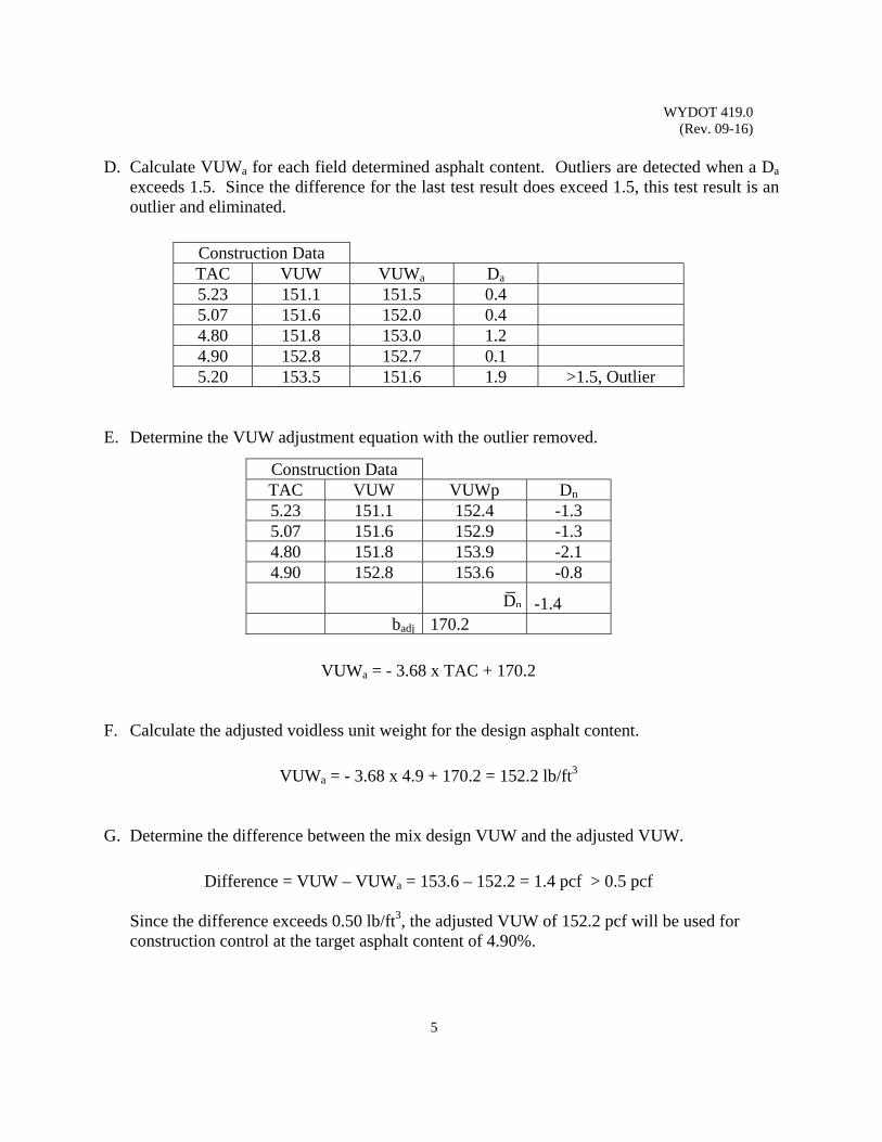
WYDOT 419.0 (Rev. 09-16)
5
Dn
D. Calculate VUWa for each field determined asphalt content. Outliers are detected when a Da
exceeds 1.5. Since the difference for the last test result does exceed 1.5, this test result is an outlier and eliminated.
Construction Data TAC VUW VUWa Da 5.23 151.1 151.5 0.4 5.07 151.6 152.0 0.4 4.80 151.8 153.0 1.2 4.90 152.8 152.7 0.1 5.20 153.5 151.6 1.9 >1.5, Outlier
E. Determine the VUW adjustment equation with the outlier removed. Construction Data TAC VUW VUWp Dn 5.23 151.1 152.4 -1.3 5.07 151.6 152.9 -1.3 4.80 151.8 153.9 -2.1 4.90 152.8 153.6 -0.8
-1.4 badj 170.2
VUWa = - 3.68 x TAC + 170.2
F. Calculate the adjusted voidless unit weight for the design asphalt content.
VUWa = - 3.68 x 4.9 + 170.2 = 152.2 lb/ft3
G. Determine the difference between the mix design VUW and the adjusted VUW.
Difference = VUW – VUWa = 153.6 – 152.2 = 1.4 pcf > 0.5 pcf
Since the difference exceeds 0.50 lb/ft3, the adjusted VUW of 152.2 pcf will be used for construction control at the target asphalt content of 4.90%.
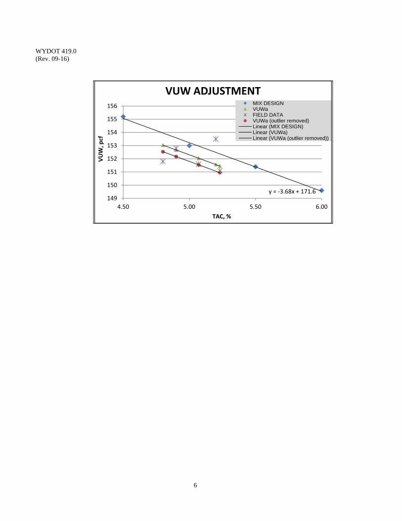
WYDOT 419.0 (Rev. 09-16)
6
y = ‐3.68x + 171.6149
150
151
152
153
154
155
156
4.50 5.00 5.50 6.00
VUW, pcf
TAC, %
VUW ADJUSTMENTMIX DESIGNVUWaFIELD DATAVUWa (outlier removed)Linear (MIX DESIGN)Linear (VUWa)Linear (VUWa (outlier removed))
WYDOT 421.0 (Rev. 10-19)
1
ASPHALT / LIME CONTENT REPORT
(INVOICE AND TANK VOLUME)
Scope: This form calculates the quantity of Performance Graded Asphalt Binder (PGAB) and Hydrated Lime incorporated into Hot Plant Mix (HPM) utilized on the project. This procedure describes the calculations involved in determining asphalt binder and lime content by percentage and as a tonnage from the levels in the storage tank(s), determined by “tank stabs” for Asphalt Binder, and the weight (mass) for Hydrated Lime. This procedure also describes instructions for calculations used on WYDOT Form E-56. Hydrated Lime is based on the percentage of asphalt binder and lime in the HPM.
Use: This procedure is used to report the daily Asphalt Binder Content and Lime Content
used in the production of mix, such as Hot Plant Mix (HPM) pavement and Plant Mix Wearing Course (PMWC). The amount of asphalt binder and lime used is determined on a daily basis, based on the amount of asphalt binder and lime delivered and the levels in the storage tank(s) for asphalt binder (PGAB). Refer to WYDOT Standard Specifications subsection 2.3 of 401.4.7.5, paragraph 2.3, for PGAB and WYDOT Standard Specifications 413.3 paragraph 4 for Hydrated Lime measurements.
Reference Documents: WYDOT 401 WYDOT Standard Specifications WYDOT 413 WYDOT Standard Specifications
WYDOT 841.0 Asphalt Volume Correction Table WYDOT E-56 Asphalt and Lime Report
Apparatus: 1. Calibrated measuring stick to measure (stab) the depth of asphalt binder in the storage tank.
2. WYDOT Form E-56, daily Asphalt and Lime Report of Asphalt Binder and Hydrated Lime Used (see example in this section). Form is available in CMS.
3. Copy of refinery invoices, Certificates of Compliance (COC), and loading certificates.
4. Storage tank volume tables (or dimensions of storage tanks).
Procedure: The following information is needed to perform these calculations:
1. Tons of asphalt received since previous report Obtained from refinery invoices, truck manifest, weigh ticket,
and/or Certificate of Compliance (COC) received at time of delivery
2. Tons of lime received since previous report
WYDOT 421.0 (Rev. 10-19)
2
Obtained from invoices, truck manifest, weigh ticket, and/or Certificate of Compliance (COC) received at time of delivery
3. Tons of asphalt in tanks, obtained from previous report 4. Temperature of each tank at time of tank stab Recorded from tank at time of tank stab 5. Specific Gravity at 60 F
Obtained from invoices, truck manifest, weigh ticket, and/or Certificate of Compliance (COC) received at time of delivery
6. Depth of asphalt in each tank; this is the tank stab depth 7. Storage tank volume tables
Maintained by contractor for each specific tank 8. Asphalt Conversion Table in WYDOT 841.0 9. Standard density of the asphalt, pounds per gallon at 60 F
Obtained from refinery invoices, truck manifest, weigh ticket, and/or Certificate of Compliance (COC) received at time of delivery
10. Total tons of plant mix produced Obtained from WYDOT Form E-78 11. Tons of RAP or % RAP
Tons of RAP is obtained from the contractors scales, or the % RAP is the value taken from the mix design (typically 15%)
12. Voided tons of plant mix Obtained from WYDOT Form E-78
Asphalt Quantities: The following describes the calculations performed on WYDOT Form E-56 (see
the example in this section). WYDOT Form E-56 is a dual use form. First described are instructions for WYDOT Form E-56, Asphalt Report section, followed by the Lime Report section.
All calculations in the Asphalt Report and Lime Report sections are rounded
to the nearest hundredth (0.01). Use these rounded values in all subsequent calculations.
Project Setup: The E-56 is located in CMS under the Tree Structure labeled Oil and Lime in the
left portion of the CMS window. Add an E-56 in CMS by right-clicking Oil and Lime and select Add Binder. From the Binder Type pull down menu, select the applicable Binder Type and select Save. Return to the Oil and Lime tree and right-click Add E-56. Select the Report Date for the corresponding date the material was placed. From the Asphalt Binder pull down menu, select the applicable binder bid item. From the Select Lime pull down menu, select the applicable Hydrated Lime bid item.
WYDOT 421.0 (Rev. 10-19)
3
Report: Oil Report This section will correspond to PG Binder located on the left hand side of the screen under OIL.
1. Right-click in the Invoice No. Box and select Add. 2. Enter the corresponding Invoice data (Invoice No. & Tons) 3. Populate the Balance Left On Last Report 4. Populate the S.G of P.G.A.B (Enter the Specific Gravity of the P.G.A.B. at 60 F
obtained from the Asphalt Invoice. Enter as many decimal places as are provided by the supplier.)
5. Populate the Inches In Tank (Use a calibrated measuring stick to measure (stab) the depth of asphalt binder in the storage tank. Measure the height of the asphalt in each tank using a tank stab reading and record in inches to the nearest half inch.)
6. Populate the Temperature (Enter the temperature of the asphalt in F at the time of the Tank Stab.)
7. Populate Gallons In Tank (Enter the volume of asphalt, in gallons, in each storage tank using the storage tank volume tables provided by the contractor.
8. Populate LBS of Oil / Gallon (Input the weight or standard density of the asphalt binder in lbs/gallon at 60 F as recorded on the Oil Invoice. Enter to as many decimal places as are provided by the supplier.)
9. Populate Design Oil % (This value is obtained from the approved mix design) 10. Populate % RAP or Tons RAP
Lime Report This section will correspond to the Hydrated Lime located on the right hand side of the screen under LIME.
1. Right-click in the Invoice No. Box and select Add. 2. Enter the corresponding Invoice data (Invoice No. & Tons) 3. Populate the Balance Left On Last Report 4. Populate the Ending Lime Reading in the Auxiliary storage in lbs (Auxiliary
storage is only to be used if lime is delivered onto the project and is stored in something other than the two storage silos that are available for use on Form E-56. Most mobile operations will not require auxiliary storage. The auxiliary storage is most applicable for locations that have stationary plants.)
5. Populate the Ending Lime Reading in Silo 1 in lbs (Input the ending LBS of lime for each storage used.)
6. Populate the Ending Lime Reading in Silo 2 in lbs (Input the ending LBS of lime for each storage used.)
7. Populate the % RAP (RAP used at the plant (if applicable)) 8. Populate Tons of Dry Aggregate Previous (This value will be taken from the
previous E-56 Report, or be 0 on the 1st report.)
WYDOT 421.0 (Rev. 10-19)
4
Material Produced This Date 1. Right-click in the Material Produced This Date Box and select Add. 2. From the Select Bid Item pull down menu, select the applicable Bid Item (Hot
Plant Mix, Hot Plant Mix Leveling, Hot Plant Mix Approaches, etc…) 3. Populate the Produced column with the tons of material produced (Input the total
tons of material Produced for each type of HPM) 4. Populate the Tons Voided with the tons of material voided (Input the total tons of
material Voided for each type of HPM.)
Note - Be sure to evaluate Subsection 401.5.1 of the Standard Specifications to ensure the approved mix design asphalt binder is within the Materials and Rates tolerance set.
Remarks
1. Populate Remarks (Enter relevant comments or observations such as voided load tickets, material remaining in tanks at beginning of project, samples taken, and any unusual events.)
Form Completion
1. Select the Approved Check Box 2. Select Post to Ledger Button 3. Select the E-56 Button
(A new warning has been implemented if the binder content pay factor is reject. The program defaults to a pay factor of 0.00 if the pay factor is reject. Please consult with the Materials Program for direction on how to handle the lot.)
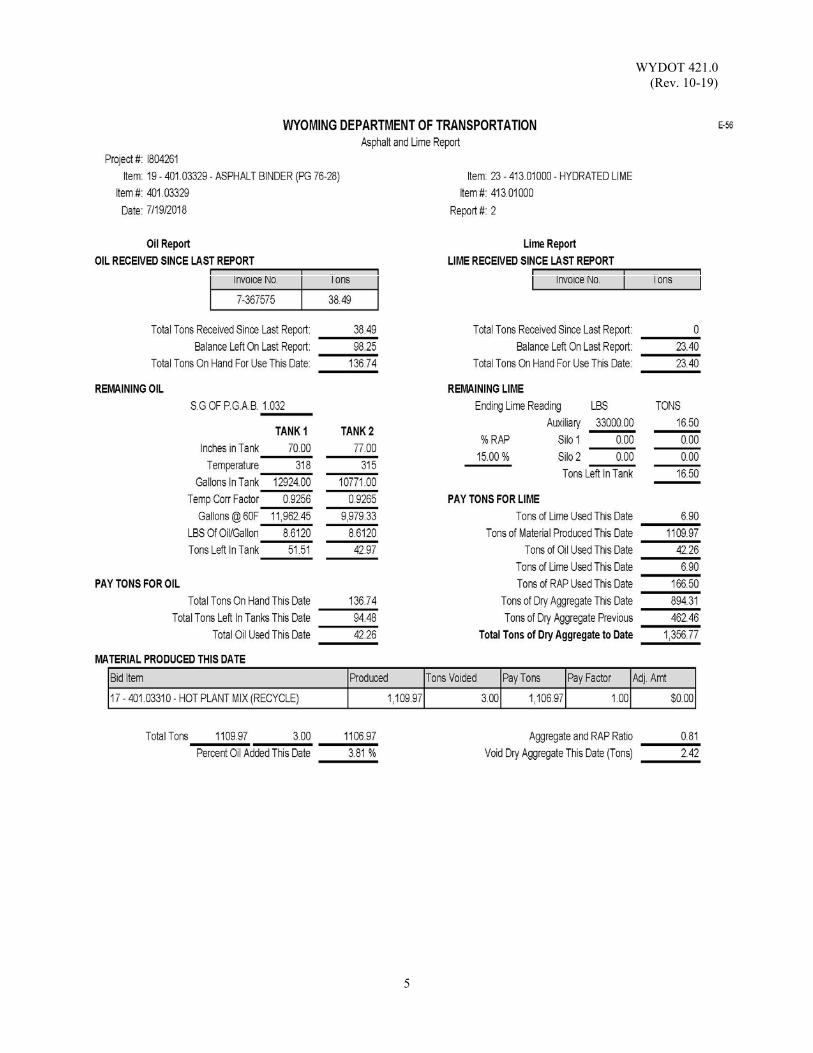
WYDOT 421.0 (Rev. 10-19)
5
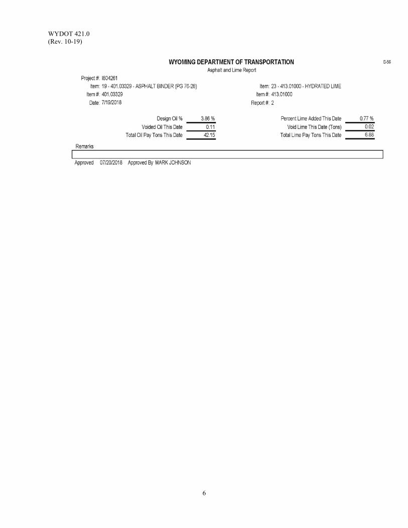
WYDOT 421.0 (Rev. 10-19)
6
WYDOT 423.0 (Rev. 10-20)
1
CORRELATION OF CORE DENSITY RESULTS
Scope: This statistical procedure compares the mix (hot plant mix, recycled hot plant mix,
warm plant mix) densities determined by WYDOT with those determined by the contractor. A two-tailed paired t-test is ran on the core densities determined by the two laboratories. This procedure determines whether one can be 99 percent confident that the two laboratories are achieving different test results. This procedure will not detect minor differences between the two laboratories.
Use: This procedure determines whether densities determined by WYDOT and the
contractor may be used interchangeably. If the data generated by WYDOT and the contractor are found to be significantly different, then the dispute resolution procedure will be followed.
The two-tailed paired t-test determines whether average the core densities are significantly different. The directional bias test indicates if one laboratory is getting consistently higher or lower results than the other.
If there is change in testing personnel or equipment, repeat the correlation process using production test results.
Reference Documents: WYDOT 114 WYDOT Standard Specifications WYDOT 401 WYDOT Standard Specifications WYDOT 415.0 Density Testing for Compacted Mix
WYDOT T-165CD Correlation of Core Densities Procedure: Collect seven sets of two cores, fourteen cores total, according to WYDOT 415.0.
Assign each pair a label in order to compare during the statistical analysis. WYDOT will test seven cores and the contractor will test the other seven.
Determine the density of each core using WYDOT 415.0. Report the core density value to the nearest 0.1 lb/ft3.
Eliminate outlier. Outliers are those pairs of core densities that are more than two standard deviations away from the mean of the differences.
Perform a two-tailed paired t-test on the density data as described in this section. Use the level of significance, 𝛼𝛼, of 0.01.
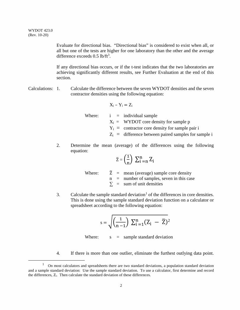
WYDOT 423.0 (Rev. 10-20)
2
Evaluate for directional bias. “Directional bias” is considered to exist when all, or all but one of the tests are higher for one laboratory than the other and the average difference exceeds 0.5 lb/ft3. If any directional bias occurs, or if the t-test indicates that the two laboratories are achieving significantly different results, see Further Evaluation at the end of this section.
Calculations: 1. Calculate the difference between the seven WYDOT densities and the seven contractor densities using the following equation:
Xi – Yi = Zi
Where: i = individual sample Xi = WYDOT core density for sample p Yi = contractor core density for sample pair i Zi = difference between paired samples for sample i
2. Determine the mean (average) of the differences using the following
equation:
Z� = �1n� ∑ Zin
i =n
Where: Z� = mean (average) sample core density n = number of samples, seven in this case
∑ = sum of unit densities
3. Calculate the sample standard deviation1 of the differences in core densities. This is done using the sample standard deviation function on a calculator or spreadsheet according to the following equation:
s = �� 1n −1
� ∑ (Zi − Z�)ni =1
2
Where: s = sample standard deviation
4. If there is more than one outlier, eliminate the furthest outlying data point.
1 On most calculators and spreadsheets there are two standard deviations, a population standard deviation
and a sample standard deviation: Use the sample standard deviation. To use a calculator, first determine and record the differences, Zi. Then calculate the standard deviation of these differences.
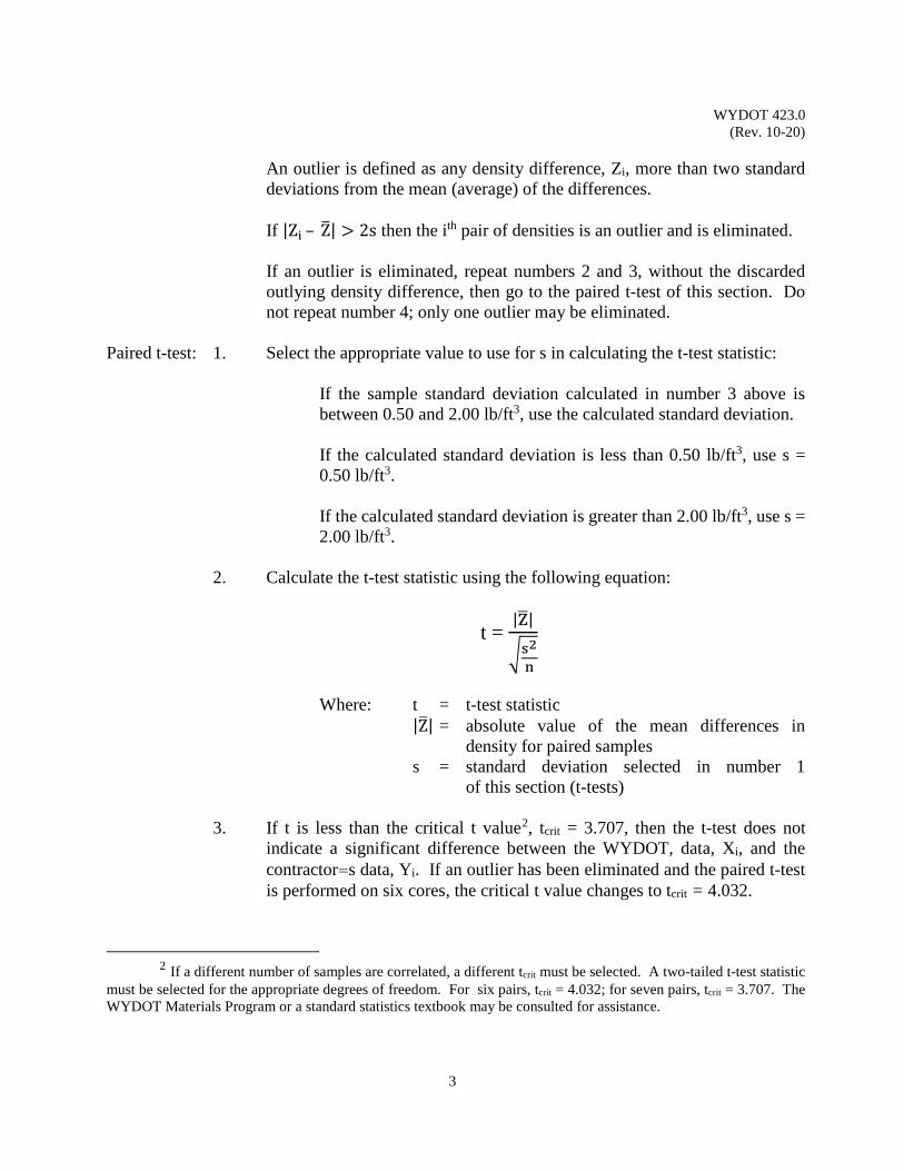
WYDOT 423.0 (Rev. 10-20)
3
An outlier is defined as any density difference, Zi, more than two standard deviations from the mean (average) of the differences.
If |Zi – Z�| > 2s then the ith pair of densities is an outlier and is eliminated. If an outlier is eliminated, repeat numbers 2 and 3, without the discarded outlying density difference, then go to the paired t-test of this section. Do not repeat number 4; only one outlier may be eliminated.
Paired t-test: 1. Select the appropriate value to use for s in calculating the t-test statistic:
If the sample standard deviation calculated in number 3 above is between 0.50 and 2.00 lb/ft3, use the calculated standard deviation.
If the calculated standard deviation is less than 0.50 lb/ft3, use s =
0.50 lb/ft3.
If the calculated standard deviation is greater than 2.00 lb/ft3, use s = 2.00 lb/ft3.
2. Calculate the t-test statistic using the following equation:
t = |Z�|
�s2n
Where: t = t-test statistic
|Z�| = absolute value of the mean differences in density for paired samples
s = standard deviation selected in number 1 of this section (t-tests)
3. If t is less than the critical t value2, tcrit = 3.707, then the t-test does not
indicate a significant difference between the WYDOT, data, Xi, and the contractor=s data, Yi. If an outlier has been eliminated and the paired t-test is performed on six cores, the critical t value changes to tcrit = 4.032.
2 If a different number of samples are correlated, a different tcrit must be selected. A two-tailed t-test statistic
must be selected for the appropriate degrees of freedom. For six pairs, tcrit = 4.032; for seven pairs, tcrit = 3.707. The WYDOT Materials Program or a standard statistics textbook may be consulted for assistance.
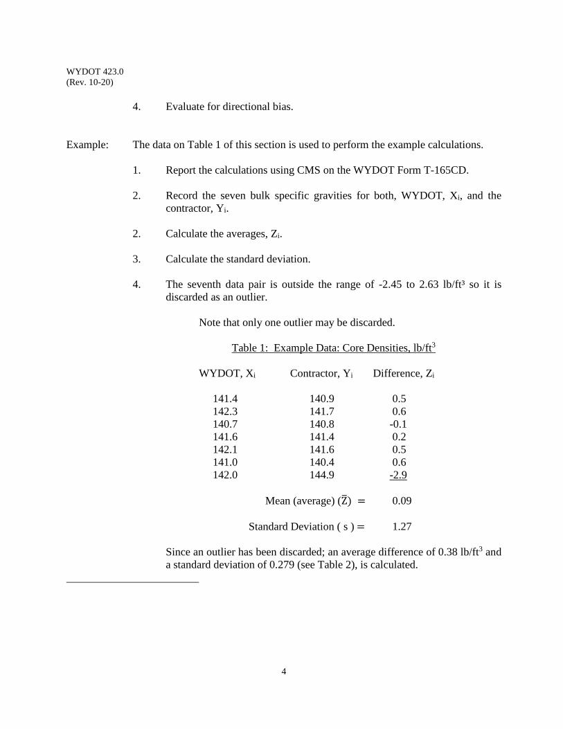
WYDOT 423.0 (Rev. 10-20)
4
4. Evaluate for directional bias.
Example: The data on Table 1 of this section is used to perform the example calculations.
1. Report the calculations using CMS on the WYDOT Form T-165CD. 2. Record the seven bulk specific gravities for both, WYDOT, Xi, and the
contractor, Yi. 2. Calculate the averages, Zi. 3. Calculate the standard deviation.
4. The seventh data pair is outside the range of -2.45 to 2.63 lb/ft³ so it is
discarded as an outlier. Note that only one outlier may be discarded.
Table 1: Example Data: Core Densities, lb/ft3
WYDOT, Xi Contractor, Yi Difference, Zi 141.4 140.9 0.5 142.3 141.7 0.6 140.7 140.8 -0.1 141.6 141.4 0.2 142.1 141.6 0.5 141.0 140.4 0.6 142.0 144.9 -2.9 Mean (average) (Z�) = 0.09 Standard Deviation ( s ) = 1.27 Since an outlier has been discarded; an average difference of 0.38 lb/ft3 and a standard deviation of 0.279 (see Table 2), is calculated.
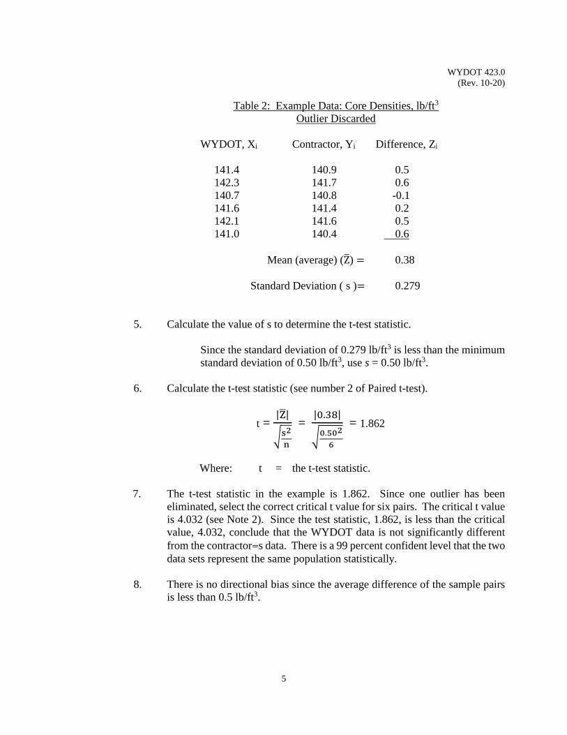
WYDOT 423.0 (Rev. 10-20)
5
Table 2: Example Data: Core Densities, lb/ft3 Outlier Discarded
WYDOT, Xi Contractor, Yi Difference, Zi 141.4 140.9 0.5 142.3 141.7 0.6 140.7 140.8 -0.1 141.6 141.4 0.2 142.1 141.6 0.5 141.0 140.4 0.6 Mean (average) (Z�) = 0.38 Standard Deviation ( s )= 0.279
5. Calculate the value of s to determine the t-test statistic.
Since the standard deviation of 0.279 lb/ft3 is less than the minimum standard deviation of 0.50 lb/ft3, use s = 0.50 lb/ft3.
6. Calculate the t-test statistic (see number 2 of Paired t-test).
t = |Z�|
�s2n
= |0.38|
�0.5026
= 1.862
Where: t = the t-test statistic.
7. The t-test statistic in the example is 1.862. Since one outlier has been
eliminated, select the correct critical t value for six pairs. The critical t value is 4.032 (see Note 2). Since the test statistic, 1.862, is less than the critical value, 4.032, conclude that the WYDOT data is not significantly different from the contractor=s data. There is a 99 percent confident level that the two data sets represent the same population statistically.
8. There is no directional bias since the average difference of the sample pairs
is less than 0.5 lb/ft3.
WYDOT 423.0 (Rev. 10-20)
6
Further Evaluation:
1. Resolve the discrepancy in accordance with Subsection 114.3.3,
“Correlation”.
2. For Informational Purposes Only:
WYDOT and Contractors swap cores and observe QC testing.
Report: Report the results on Form T-165CD (see examples in this section).
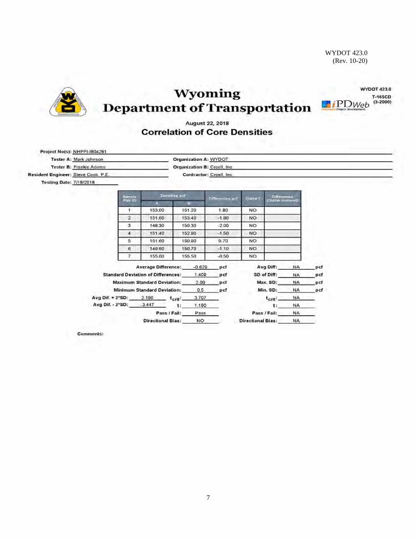
WYDOT 423.0 (Rev. 10-20)
7

WYDOT 423.0 (Rev. 10-20)
8
(This page intentionally left blank.)
WYDOT 430.0 (Rev. 10-17)
1
CONTRACTOR MICROSURFACING MIX DESIGN PROCEDURE
Scope: This procedure describes the method for independent microsurfacing mix designs
and establishes the information which is to be reported with a submitted mix design. This procedure applies to all projects which require the Contractor to submit microsurfacing mix designs. A microsurfacing mix design will recommend the “combination” of additives, aggregate, emulsion, mineral filler, and water to produce a mix that will perform under specific traffic (present and future) and environmental conditions (temperature, humidity).
Ensure laboratories performing mix designs meet the requirements of WYDOT
Standard Specifications Section 114.2 for all applicable AASHTO test methods. Use: This procedure is to be used for preparation of a mix design by the contractor and
for submission on WYDOT Form E-46M (see blank form in this section) to the WYDOT Materials Program for final approval.
Reference Documents: AASHTO M 85 Portland Cement
AASHTO M 208 Standard Specification for Cationic Emulsified Asphalt AASHTO M 303 Lime for Asphalt Mixtures AASHTO M 320 Performance-Graded Asphalt Binder AASHTO M 332 Performance-Graded Asphalt Binder Using Multiple Stress
Creep Recovery (MSCR) Test AASHTO R 66 Standard Practice for Sampling Asphalt Materials AASHTO T 2 Sampling of Aggregates AASHTO T 11 Materials Finer than 75 µm (No. 200) Sieve in Mineral
Aggregate AASHTO T 19 Bulk Density (“Unit Weight”) and Voids in Aggregate AASHTO T 27 Sieve Analysis of Fine and Coarse Aggregates AASHTO T 49 Penetration of Bituminous Materials AASHTO T 53 Softening Point of Bitumen AASHTO T 59 Testing Emulsified Asphalts AASHTO T 96 Resistance to Degradation of Small-Size Coarse Aggregate by Abrasion and Impact in the Los Angeles Machine AASHTO T 104 Soundness of Aggregate by Use of Sodium Sulfate or
Magnesium Sulfate AASHTO T 112 Clay Lumps and Friable Particles in Aggregate
AASHTO T 176 Plastic Fines in Graded Aggregates and Soils by Use of the Sand Equivalent Test
AASHTO T 313 Determining the Flexural Creep Stiffness of Asphalt Binder Using the Bending Beam Rheometer (BBR)
WYDOT 430.0 (Rev. 10-17)
2
AASHTO T 315 Determining the Rheological Properties of Asphalt Binder
Using a Dynamic Shear Rheometer (DSR) AASHTO T 316 Viscosity Determination of Asphalt Binder Using
Rotational Viscometer AASHTO T 350 Multiple Stress Creep Recovery (MSCR) Test of Asphalt
Binder Using a Dynamic Shear Rheometer (DSR) ASTM C 29 Standard Test Method for Bulk Density (“Unit Weight”)
and Voids in Aggregate ASTM D 6372 Standard Practice for Design, Testing and Construction of
Micro-Surfacing ISSA A143 Recommended Performance Guideline for Micro Surfacing ISSA TB147 Test Methods for Measurement of Stability and Resistance
to Compaction, Vertical and Lateral Displacement of Multi-layered Fine Aggregate Cold Mixes - Method A
WYDOT 114.2 WYDOT Standard Specifications WYDOT 410.2 WYDOT Standard Specifications WYDOT 410.4.5 WYDOT Standard Specifications WYDOT 801.1.1 WYDOT Standard Specifications WYDOT 803.6.2 WYDOT Standard Specifications WYDOT 803.7 WYDOT Standard Specifications WYDOT 804.1 WYDOT Standard Specifications WYDOT 804.3 WYDOT Standard Specifications WYDOT 814.1.1 WYDOT Standard Specifications WYDOT 820.1 WYDOT Standard Specifications WYDOT 832.0 Deleterious Substances In Portland Cement Concrete WYDOT E-46M Microsurfacing Mix Design Procedure: Optimize the following characteristics in the microsurfacing mix design: Mixability – Ensure the aggregate, control additives, emulsified asphalt,
mineral filler, and water mix together forming a homogeneous, free-flowing, uniformly coated surfacing material applied in a continuous fashion to roadway surface using the microsurfacing equipment.
Workability – Ensure the applied mixture sets to a rain-safe condition quickly
without segregation, raveling, displacement, or flushing. Ensure the mixture cures in a controlled manner within a reasonably defined time period providing sufficient coating on aggregate and allowing return of traffic.
WYDOT 430.0 (Rev. 10-17)
3
Performance – Ensure the mixture resists traffic-induced stresses, maintains
satisfactory friction resistance, does not ravel, de-bond, bleed, exhibit moisture damage, or lose cohesiveness over the life of the treatment.
Perform the mix design according to the standard industry practice.
Recommended method is described in International Slurry Surfacing Association (ISSA) Technical Bulletins (TB), “Recommended Performance Guideline For Micro Surfacing” A143 (Section 5.2), and ASTM D 6372, International Standard Practice for Design, Testing, and Construction of Micro-Surfacing.
For materials selection, provide quality components in the mixture as follows: Aggregate – Conform to requirements of Subsection 803.7, Aggregate for
Microsurfacing, and if applicable, Subsection 803.6.2, Polish Resistant Aggregate. Ensure compatibility of aggregate with emulsified asphalt and provide all criteria used to establish, and test data to verify, compatibility of aggregate and emulsified asphalt. Ensure job mix formula (JMF) complies with requirements of Subsection 410.4.5.
Emulsified Asphalt – Conform to requirements for CQS-1HP emulsified asphalt per
Subsections 410.2, Materials, and 804.3, Emulsified Asphalt, Table 804.3-1.
Mineral Filler - Conform to requirements of Subsection 801.1.1 for Portland
Cement, and Subsection 820.1 for hydrated lime. Water – Ensure use of potable water free of harmful salts and
contaminants conforming to requirements of Subsection 814.1.1.
Determine minimum emulsion content, determine minimum residual asphalt
content by total weight of dry aggregate, verify that mix and set times are appropriate for the climatic conditions expected during the project, and report quantitative effects of moisture content on the unit weight of the aggregate (bulking effect) according to AASHTO T 19 (ASTM C 29).
Ensure base asphalt binder for emulsified asphalt complies with requirements
specified in Subsection 804.1, Performance Graded Asphalt Binder, and has a Jnr3.2 of 4.0 kPa-1 or less per Table 1 in AASHTO M 332. To do so, determine the pavement climatic high temperature (per current LTPPBind software, >90% reliability, and no ‘grade-bumping’) and perform Multiple Stress Creep Recovery testing per AASHTO T 350 on distillation residue only, not RTFO residue.
WYDOT 430.0 (Rev. 10-17)
4
For the completed mix design, test every property at the minimum emulsion
content to ensure all properties in Table 410.4.5-2, Testing Requirements, meet specifications. Include in the mix design the aggregate proportions, the recommended minimum polymer-modified emulsified asphalt content, recommended mineral filler content, water rate, and other additives to control mix set times and cohesion properties.
For Test Procedure ISSA TB147 (ASTM D 6372), after compacting and
removing the specimen from the loaded wheel track machine, immediately re-measure the specimen both laterally and vertically in the wheel path and record the results. Calculate the lateral displacement as the percent increase of the original width. Calculate the vertical displacement as the percent decrease of the original net thickness. Ensure the vertical displacement is no greater than 15%.
General: Report the mix design information on WYDOT Form E-46M (see blank form in
this section) and include the following:
Aggregate Information, both coarse and fine;
Dry Weight and SSD Weight Aggregate Gradation and JMF with JMF units Specific Gravity (SSD) Absorption Magnesium Sulfate Loss per AASHTO T 104 Source Location
For Coarse Aggregate, also include;
Percentage of Wear per AASHTO T 96
For Fine Aggregate, also include;
Fineness Modulus Colorimetric (See WYDOT 832.0)
Emulsified Asphalt Information;
Minimum residual asphalt content by total weight of dry aggregate Residual asphalt PG grade (e.g., PG58-28) Residual asphalt Jnr3.2 at pavement climatic high temperature Minimum emulsion content Emulsion grade (e.g., CQS-1HP) Emulsion supplier
WYDOT 430.0 (Rev. 10-17)
5
Minimum polymer content by percent solids of residual asphalt
weight content Polymer type (i.e., SBS, etc)
Additives Information;
Percent content Type Supplier
Mineral Filler Information;
Percent by total weight of dry aggregate Type (i.e., Portland Cement, hydrated lime) Supplier
Water Information;
Moisture content, % Source
Mixture Properties;
Wet Track Abrasion, One Hour Loss, maximum Wet Track Abrasion, 6 Day Soak Loss, maximum Excess Asphalt by LWT Sand Adhesion, maximum Mix Time @ 77 °F, minimum Wet Stripping, minimum Wet Cohesion @ 30 minutes (set), minimum Wet Cohesion @ 60 minutes (traffic), minimum or Near Spin Classification Compatibility, minimum grade points Lateral Displacement, maximum Vertical Displacement, maximum Specific Gravity after 1,000 cycles of 125 lb, maximum
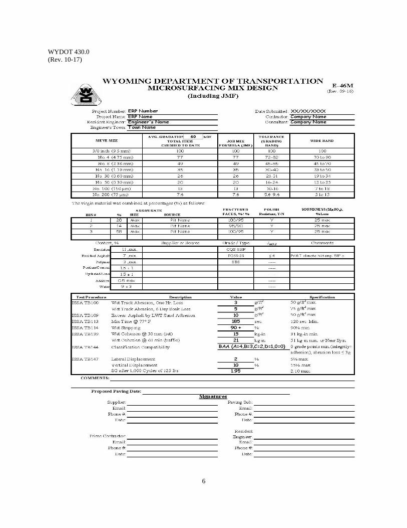
WYDOT 430.0 (Rev. 10-17)
6
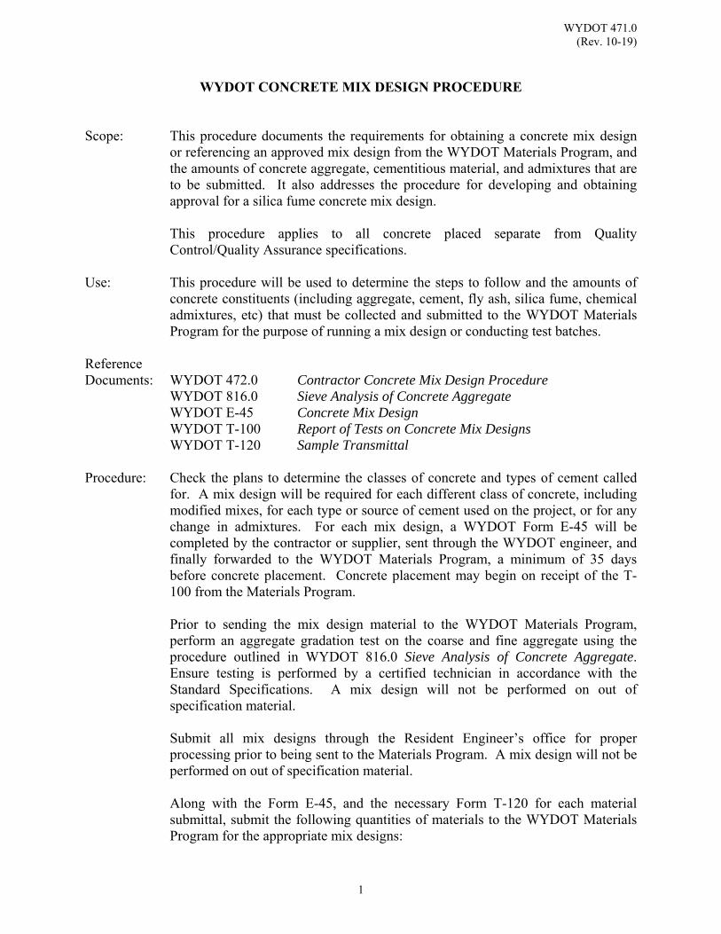
WYDOT 471.0 (Rev. 10-19)
1
WYDOT CONCRETE MIX DESIGN PROCEDURE
Scope: This procedure documents the requirements for obtaining a concrete mix design
or referencing an approved mix design from the WYDOT Materials Program, and the amounts of concrete aggregate, cementitious material, and admixtures that are to be submitted. It also addresses the procedure for developing and obtaining approval for a silica fume concrete mix design.
This procedure applies to all concrete placed separate from Quality
Control/Quality Assurance specifications. Use: This procedure will be used to determine the steps to follow and the amounts of
concrete constituents (including aggregate, cement, fly ash, silica fume, chemical admixtures, etc) that must be collected and submitted to the WYDOT Materials Program for the purpose of running a mix design or conducting test batches.
Reference Documents: WYDOT 472.0 Contractor Concrete Mix Design Procedure WYDOT 816.0 Sieve Analysis of Concrete Aggregate WYDOT E-45 Concrete Mix Design WYDOT T-100 Report of Tests on Concrete Mix Designs WYDOT T-120 Sample Transmittal Procedure: Check the plans to determine the classes of concrete and types of cement called
for. A mix design will be required for each different class of concrete, including modified mixes, for each type or source of cement used on the project, or for any change in admixtures. For each mix design, a WYDOT Form E-45 will be completed by the contractor or supplier, sent through the WYDOT engineer, and finally forwarded to the WYDOT Materials Program, a minimum of 35 days before concrete placement. Concrete placement may begin on receipt of the T-100 from the Materials Program. Prior to sending the mix design material to the WYDOT Materials Program, perform an aggregate gradation test on the coarse and fine aggregate using the procedure outlined in WYDOT 816.0 Sieve Analysis of Concrete Aggregate. Ensure testing is performed by a certified technician in accordance with the Standard Specifications. A mix design will not be performed on out of specification material.
Submit all mix designs through the Resident Engineer’s office for proper processing prior to being sent to the Materials Program. A mix design will not be performed on out of specification material. Along with the Form E-45, and the necessary Form T-120 for each material submittal, submit the following quantities of materials to the WYDOT Materials Program for the appropriate mix designs:
WYDOT 471.0 (Rev. 10-19)
2
Submit ALL aggregate samples in standard canvas bags, 30 lb - 50 lb in each bag. For liquid admixtures submit 1 quart of each type.
Structural Concrete Aggregate:
600 lb of coarse aggregate
400 lb of fine aggregate
For each additional mix design on the same project from the same source, send 270 lb of coarse aggregate and 200 lb of fine aggregate that will be needed for each mix design. Aggregate samples will be sent to the WYDOT Materials Program a minimum of 35 days prior to construction intended use.
P.C.C.P Aggregate:
775 lb of coarse aggregate
600 lb of fine aggregate
For each mix design on Portland Cement Concrete Pavement (PCCP) mix design.
Representative samples of coarse and fine aggregate should be sent
to the WYDOT Materials Program as soon as possible and a minimum of 35 days before the aggregate will be used in construction.
The samples sent in for mix designs are not check samples and cannot be used as such. Check samples are taken only during production.
Fly Ash and Slag Cement:
When fly ash or slag cement is to be used in the concrete mix design, a fly ash or slag cement sample should be taken for the project. Send 50 lb of fly ash and ship it in plastic bucket(s) or container(s).
Record on Form T-120 the class of fly ash used, the manufacturer's name, and the invoice number if possible. It will not be necessary to record the contractor's name or the name of the ready mix company.
WYDOT 471.0 (Rev. 10-19)
3
Portland Cement:
A Portland Cement sample should be taken for each source and type of cement used on the project. The sample must be free of any soil or rocks. Send 140 lb of cement and ship it in plastic bucket(s) or container(s). A Portland Cement sample should be taken for each source and type of cement used on the project. Record on Form T-120 the type of cement used, the manufacturer's name, and the invoice number if possible. It will not be necessary to record the contractor's name or the name of the ready mix company.
Silica Fume:
A silica fume concrete mix design must be developed by the contractor with the aid of an admixture manufacturer prior to requesting mix design approval from the WYDOT Materials Program. Batching proportions and batching sequence must be determined by this process. Results of this mix development will be submitted to the WYDOT Materials Program when requesting mix design approval. A Laboratory test mix will be conducted by the WYDOT Materials Program utilizing these instructions. If the proposed mix design does not provide a satisfactory mix, as determined by WYDOT Materials Program, the contractor must resubmit a revised mix design. The contractor will provide the following items to the WYDOT engineer at least 30 days prior to placement:
1. A completed Form E-45 indicating all materials to
be used, including the manufacturer and source for all materials.
2. A letter indicating proportions of all materials,
including water. The aggregate proportions will indicate whether they are saturated, surface dry condition or dry condition. Total or net water will also be indicated as appropriate based on aggregate condition.
3. An equipment letter indicating the mixing
equipment to be used.
4. A batch sequence letter indicating the sequence of material batching and mixing times.
5. Submit sufficient samples of all mix constituents so
that a test mix may be batched at the WYDOT Materials Program.
WYDOT 471.0 (Rev. 10-19)
4
Sufficient samples will be a minimum of:
100 lb of cement 400 lb of coarse aggregate 300 lb of fine aggregate 25 lb of silica fume 1 lb of fibers 1 quart each of all liquid or dry admixtures
(which includes normal and high-range water reducers and air-entraining admixture).
No more than two mix designs for each placement location will be batched by the WYDOT Materials Program at no cost to the contractor. The contractor will be charged a fee for each additional mix design confirmation.
The contractor must conduct a trial batch prior to placement to verify in-field conditions, utilizing stockpiled aggregate as proposed for the project and simulating proposed haul distance. Trial batch material may not be used in the resurfacing work.
Referencing Mix Designs:
If a proposed mix design is composed of identical components to a previous mix design, the previous mix may be referenced if less than two years old for PCCP mixes and three years for structural mixes. In such cases, aggregate analysis only will be required. Send 100 lb of coarse aggregate and 100 lb of fine aggregate along with Form E-45 showing all mix design components to the WYDOT Materials Program for testing.
For silica fume concrete, referencing to avoid the laboratory test mix will only be allowed within one year of use. The on-site trial batch will always be required.
Mix Design Approval:
The WYDOT Materials Program will determine acceptability of all mix designs and reference designs upon determination of mixture properties and strength development trends. Upon approval, a copy of Form T-100PE or Form T-100SE (see example forms in WYDOT 472.0), with the mix design proportions used, mix consistency results, and strength results, will be forwarded to the WYDOT engineer. Concrete placement may begin upon receipt of Form T-100PE, or Form T-100SE.
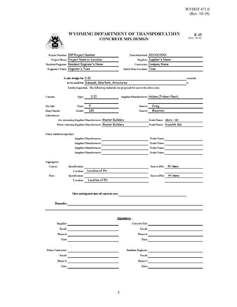
WYDOT 471.0 (Rev. 10-19)
5
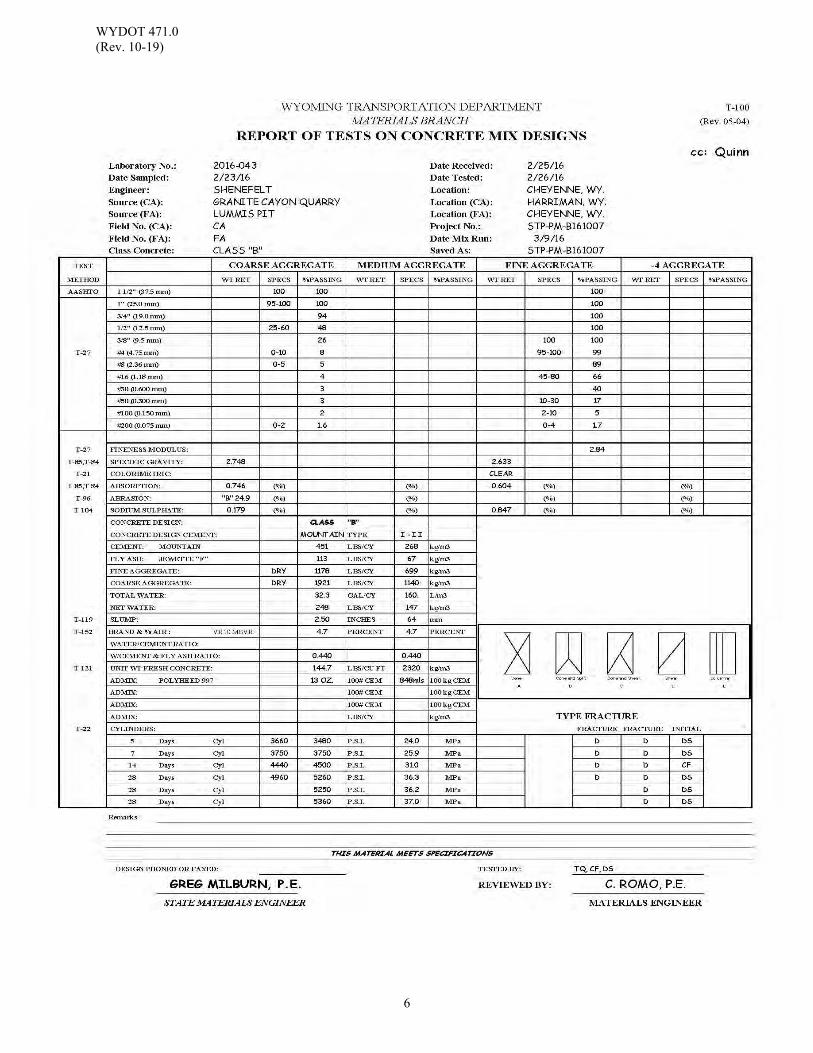
WYDOT 471.0 (Rev. 10-19)
6
WYDOT 472.0 (Rev. 10-18)
1
CONTRACTOR CONCRETE MIX DESIGN PROCEDURE
Scope: This procedure describes required mix design procedures for independent
concrete mix designs and establishes the information which is to be reported with a submitted mix design. This procedure applies to Quality Control / Quality Assurance (QC / QA) projects which require the Contractor to submit concrete mix designs.
Ensure laboratories performing mix designs meet the requirements of WYDOT
Standard Specifications. Use: This procedure is to be used for preparation of a mix design by the contractor and
for submission of a contractor’s mix design. Submit information on a WYDOT Form E-45 (see example form in WYDOT 471.0 section) to the WYDOT Materials Program for final approval.
Reference Documents: ASTM C39/C39M Standard Test Method for Compressive Strength of
Cylindrical Concrete Specimens ASTM C131/C131M Standard Test Method for Resistance to Degradation of
Small-Size Coarse Aggregate by Abrasion and Impact in the Los Angeles Machine
ASTM C88 Standard Test Method for Soundness of Aggregate by Use of Sodium Sulfate or Magnesium Sulfate
WYDOT Current WYDOT Standard Specifications WYDOT 471.0 WYDOT Concrete Mix Design Procedure WYDOT 475.0 Correlation of Compressive Strength to Flexural Strength WYDOT 476.0 Allowable Range of Mix Design Strength Results WYDOT 832.0 Deleterious Substances in Portland Cement Concrete WYDOT E-45 Concrete Mix Design WYDOT T-100SE Structural Concrete Pavement Mix Design
WYDOT T-100PE Portland Cement Concrete Pavement Mix Design
Refer to “For All Concrete Sections” notation in Table of Contents – 400 Pavements. Procedure: The concrete mix design will be conducted according to industry common
practice. The mix design process will include a trial batch. The trial batch may be done in either a laboratory mixer or a field production mixer.
WYDOT 472.0 (Rev. 10-18)
2
Structural Concrete:
The mix design will meet the requirements of WYDOT Standard Specifications and any additional requirements shown in the contract. The mix design information will be reported on WYDOT Form T-100SE. This procedure is to be used for preparation of a mix design by the contractor and for submission of a contractor’s mix design. Submit information on a WYDOT Form E-45 (see example form in WYDOT 471.0 section) to the WYDOT Materials Program for final approval.
The mix design results will include a minimum of three 28 day compressive strength results. The Alaboratory mix design strength@ will be defined as the mean of the 28 day compressive strength results.
Portland Cement Concrete Pavement:
The mix design will meet the requirements of WYDOT Standard Specifications and any additional requirements shown in the contract. The mix design information will be reported on WYDOT Form T-100PE (see example form in this section). The mix design results will include a minimum of three 28 day compressive strength results and three 28 day flexural strength. The design flexural strength will be defined as the average of the 28 day flexural strength results, unless modifications are indicated in the contract. The range of the mix design strength values will meet the limits as specified in WYDOT 476.0.
A compressive strength to flexural strength correlation constant will be calculated according to WYDOT 475.0 and reported on WYDOT Form T-100PE. This constant will be used for calculating flexural strength based on field collected compressive strength cylinders.
General: Suppliers should contact their admixture product sales representative for specific
mix design recommendations. Current WYDOT specifications allow a maximum of 0.45 water-to-cementitious materials (w/cm) ratio. In order to achieve workable mixes, normal range water reducers alone may not perform adequately. Water reducers are listed in WYDOT 111.0 as normal range (NRWR), mid-range (MRWR), and high-range (HRWR).
With the exception of accelerators, on-site admixtures are not required as part of the mix design trial batch. However, the mix design information will include the information listed following under Admixtures on the appropriate Form T-100PE or Form T-100SE.

WYDOT 472.0 (Rev. 10-18)
3
When stabilizers are to be used in the mix design, the stabilizer will be incorporated into the trial batch. The stabilizer will be added as indicated in the batching sequence. The transport time will be simulated prior to reactivating the stabilizer. The mix design information will include the information listed as follows under Stabilizer on the appropriate Form T-100PE or Form T-100SE.
Include the following:
Along with Form E-45 submit quantities of materials in accordance with
WYDOT 471.0 for a verification mix design.
Completed Form T-100PE or Form T-100SE. A batching sequence will be submitted with the Form T-100PE or Form T-
100SE. Class of Concrete and Specified Design Strength
Fine Aggregate Information;
Dry Weight and SSD Weight Aggregate Gradation Fineness Modulus Specific Gravity (SSD) Absorption Sodium Sulphate Loss per ASTM C88
Colorimetric (See WYDOT 832.0) Source Location
Coarse Aggregate Information;
Dry Weight and SSD Weight Aggregate Gradation Specific Gravity (SSD) Absorption Sodium Sulphate Loss per ASTM C88 Percentage of Wear per ASTM C131/C131M Source Location
WYDOT 472.0 (Rev. 10-18)
4
Additional Information;
Weight, Type, and Brand of Cement Weight, Class, and Source of Fly Ash Weight, Class, and Source of Other Pozzolans All Admixtures and Dosages (including any special handling or
mixing requirements for admixture introduction) Weight of Net or Mixing Water (total water minus absorbed water) Water/Cement Ratio Water/Cement+Pozzolan ratio Unit Weight, Slump and Air Content Early Strength Results (1, 2, 7 day, etc.), for high early strength
mixes Fracture Type of Cylinders per ASTM C39/C39M
(See Form T-100SE) A minimum of four 28-day Compressive Strength Results for structural concrete. A minimum of three 28-day Compressive Strength Results and a minimum of three 28-day Flexural Strength Results for Portland Cement Concrete Pavement.
On-Site Admixtures;
Type of admixtures which are anticipated on site Dosage rate (including maximum dosage rate) Mixing requirements
Stabilizers;
Type of stabilizer Dosage rate, not to exceed 4 oz per 100 lb cement Mixing requirements during transport Anticipated slump and air loss (if any) during transport Method of reactivation at the site Initial set time
Units: Weights: lb Volumes: gal/yd³ respectively Admixture: fluid oz/100 lb of cement or lb/yd³ Strength: psi
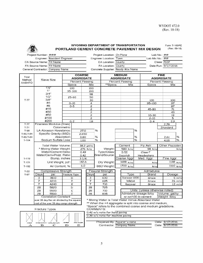
WYDOT 472.0 (Rev. 10-18)
5
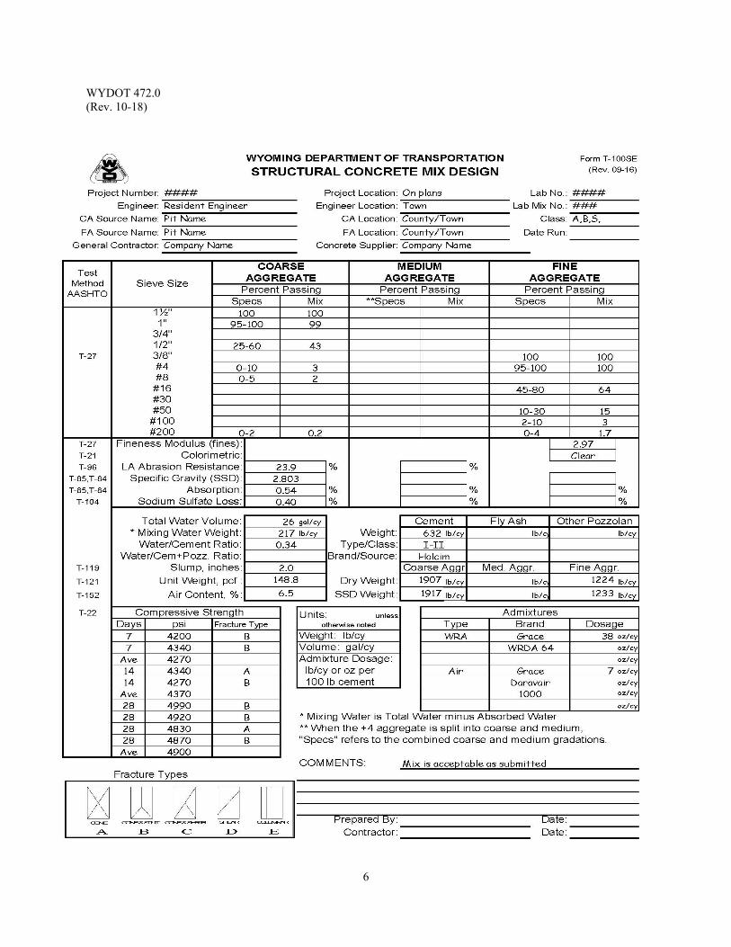
WYDOT 472.0 (Rev. 10-18)
6
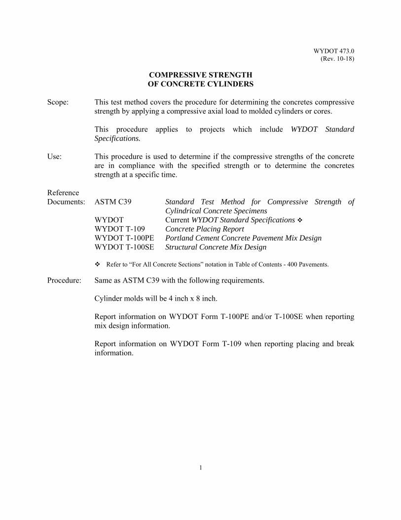
WYDOT 473.0 (Rev. 10-18)
1
COMPRESSIVE STRENGTH OF CONCRETE CYLINDERS
Scope: This test method covers the procedure for determining the concretes compressive
strength by applying a compressive axial load to molded cylinders or cores. This procedure applies to projects which include WYDOT Standard
Specifications. Use: This procedure is used to determine if the compressive strengths of the concrete
are in compliance with the specified strength or to determine the concretes strength at a specific time.
Reference Documents: ASTM C39 Standard Test Method for Compressive Strength of
Cylindrical Concrete Specimens WYDOT Current WYDOT Standard Specifications WYDOT T-109 Concrete Placing Report WYDOT T-100PE Portland Cement Concrete Pavement Mix Design WYDOT T-100SE Structural Concrete Mix Design
Refer to “For All Concrete Sections” notation in Table of Contents - 400 Pavements. Procedure: Same as ASTM C39 with the following requirements.
Cylinder molds will be 4 inch x 8 inch. Report information on WYDOT Form T-100PE and/or T-100SE when reporting mix design information.
Report information on WYDOT Form T-109 when reporting placing and break information.

WYDOT 473.0 (Rev. 10-18)
2
(This page intentionally left blank.)
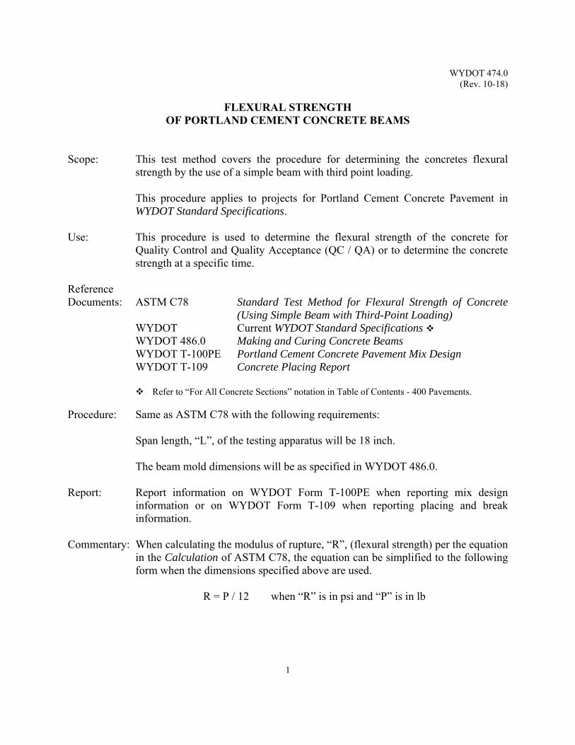
WYDOT 474.0 (Rev. 10-18)
1
FLEXURAL STRENGTH OF PORTLAND CEMENT CONCRETE BEAMS
Scope: This test method covers the procedure for determining the concretes flexural
strength by the use of a simple beam with third point loading. This procedure applies to projects for Portland Cement Concrete Pavement in
WYDOT Standard Specifications. Use: This procedure is used to determine the flexural strength of the concrete for
Quality Control and Quality Acceptance (QC / QA) or to determine the concrete strength at a specific time.
Reference Documents: ASTM C78 Standard Test Method for Flexural Strength of Concrete
(Using Simple Beam with Third-Point Loading) WYDOT Current WYDOT Standard Specifications WYDOT 486.0 Making and Curing Concrete Beams WYDOT T-100PE Portland Cement Concrete Pavement Mix Design WYDOT T-109 Concrete Placing Report
Refer to “For All Concrete Sections” notation in Table of Contents - 400 Pavements. Procedure: Same as ASTM C78 with the following requirements:
Span length, “L”, of the testing apparatus will be 18 inch.
The beam mold dimensions will be as specified in WYDOT 486.0. Report: Report information on WYDOT Form T-100PE when reporting mix design
information or on WYDOT Form T-109 when reporting placing and break information.
Commentary: When calculating the modulus of rupture, “R”, (flexural strength) per the equation
in the Calculation of ASTM C78, the equation can be simplified to the following form when the dimensions specified above are used.
R = P / 12 when “R” is in psi and “P” is in lb

WYDOT 474.0 (Rev. 10-18)
2
(This page intentionally left blank.)

WYDOT 475.0 (Rev. 10-18)
1
CORRELATION OF COMPRESSIVE STRENGTH TO FLEXURAL STRENGTH
Scope: This test method covers the procedure for determining and applying the correlation constant used for calculating flexural strength of Portland Cement Concrete Pavement (PCCP) based on compressive strength results.
This procedure applies to projects which include WYDOT Standard
Specifications. Use: This procedure is used for the determination of the compressive strength to
flexural strength correlation constant from the mix design information. The constant is then used to convert compressive strength field data to flexural strength.
Reference Documents: WYDOT Current WYDOT Standard Specifications WYDOT 476.0 Allowable Range of Mix Design Strength Results WYDOT T-100PE Portland Cement Concrete Pavement Mix Design
Refer to “For All Concrete Sections” notation in Table of Contents – 400 Pavements.
Procedure: The following equation will be utilized:
FS = CC x (CS)1/2 Where: FS is flexural strength;
CS is compressive strength; CC is the correlation constant.
Solving for CC yields: CC = FS / (CS)1/2
The values for flexural strength, “FS”, and compressive strength, “CS”, will be determined from the mix design results. Both the flexural strength values and the compressive strength values will come from the same batch. The flexural strength value will be the average of a minimum of three 28 day beam tests and the compressive strength value will be the average of a minimum of three 28 day cylinder tests.
Report: Report information on WYDOT Form T-100PE, Portland Cement Concrete Pavement Mix Design.

WYDOT 475.0 (Rev. 10-18)
2
The range of the mix design strength values will meet the limits as specified in WYDOT 476.0. The correlation constant, “CC”, will be recorded to (0.01). All strength values from the mix design will be reported.
If a new mix design is required, a new correlation constant will be calculated.
After review and approval from the WYDOT Materials Program, the correlation constant will be used to calculate the flexural strength from the 28-day Quality Control and Quality Acceptance (QC / QA) cylinders tests if the cylinder option is selected.
The number of samples required to evaluate a sublot will be in accordance with the WYDOT Standard Specifications. If the flexural strength is to be determined from the cylinder compressive strengths, the number of required samples will be based on the required number of cylinders.
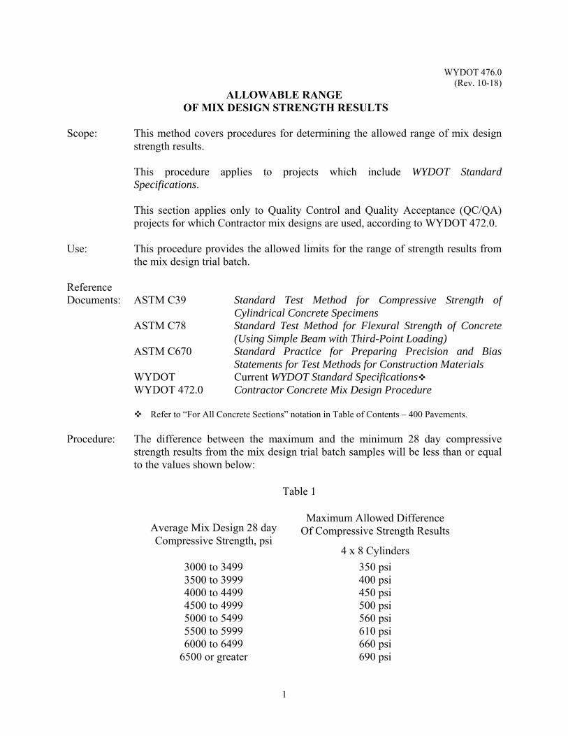
WYDOT 476.0 (Rev. 10-18)
1
ALLOWABLE RANGE OF MIX DESIGN STRENGTH RESULTS
Scope: This method covers procedures for determining the allowed range of mix design
strength results. This procedure applies to projects which include WYDOT Standard
Specifications. This section applies only to Quality Control and Quality Acceptance (QC/QA)
projects for which Contractor mix designs are used, according to WYDOT 472.0. Use: This procedure provides the allowed limits for the range of strength results from
the mix design trial batch. Reference Documents: ASTM C39 Standard Test Method for Compressive Strength of
Cylindrical Concrete Specimens ASTM C78 Standard Test Method for Flexural Strength of Concrete
(Using Simple Beam with Third-Point Loading) ASTM C670 Standard Practice for Preparing Precision and Bias
Statements for Test Methods for Construction Materials WYDOT Current WYDOT Standard Specifications WYDOT 472.0 Contractor Concrete Mix Design Procedure
Refer to “For All Concrete Sections” notation in Table of Contents – 400 Pavements. Procedure: The difference between the maximum and the minimum 28 day compressive
strength results from the mix design trial batch samples will be less than or equal to the values shown below:
Table 1
Average Mix Design 28 day Compressive Strength, psi
Maximum Allowed Difference Of Compressive Strength Results
4 x 8 Cylinders
3000 to 3499 350 psi 3500 to 3999 400 psi 4000 to 4499 450 psi 4500 to 4999 500 psi 5000 to 5499 560 psi 5500 to 5999 610 psi 6000 to 6499 660 psi
6500 or greater 690 psi
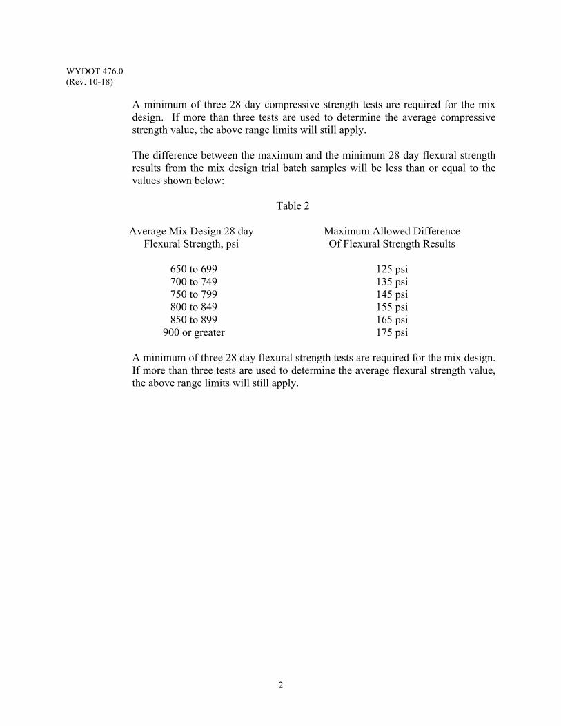
WYDOT 476.0 (Rev. 10-18)
2
A minimum of three 28 day compressive strength tests are required for the mix design. If more than three tests are used to determine the average compressive strength value, the above range limits will still apply.
The difference between the maximum and the minimum 28 day flexural strength results from the mix design trial batch samples will be less than or equal to the values shown below:
Table 2
Average Mix Design 28 day
Flexural Strength, psi Maximum Allowed Difference Of Flexural Strength Results
650 to 699 125 psi 700 to 749 135 psi 750 to 799 145 psi 800 to 849 155 psi 850 to 899 165 psi
900 or greater 175 psi
A minimum of three 28 day flexural strength tests are required for the mix design. If more than three tests are used to determine the average flexural strength value, the above range limits will still apply.
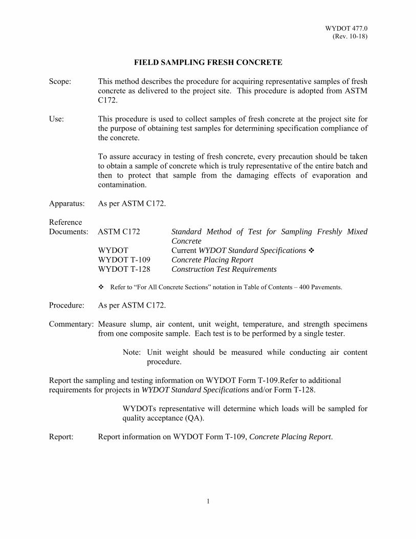
WYDOT 477.0 (Rev. 10-18)
1
FIELD SAMPLING FRESH CONCRETE
Scope: This method describes the procedure for acquiring representative samples of fresh
concrete as delivered to the project site. This procedure is adopted from ASTM C172.
Use: This procedure is used to collect samples of fresh concrete at the project site for
the purpose of obtaining test samples for determining specification compliance of the concrete.
To assure accuracy in testing of fresh concrete, every precaution should be taken
to obtain a sample of concrete which is truly representative of the entire batch and then to protect that sample from the damaging effects of evaporation and contamination.
Apparatus: As per ASTM C172. Reference Documents: ASTM C172 Standard Method of Test for Sampling Freshly Mixed
Concrete WYDOT Current WYDOT Standard Specifications WYDOT T-109 Concrete Placing Report WYDOT T-128 Construction Test Requirements
Refer to “For All Concrete Sections” notation in Table of Contents – 400 Pavements. Procedure: As per ASTM C172.
Commentary: Measure slump, air content, unit weight, temperature, and strength specimens
from one composite sample. Each test is to be performed by a single tester. Note: Unit weight should be measured while conducting air content
procedure. Report the sampling and testing information on WYDOT Form T-109.Refer to additional requirements for projects in WYDOT Standard Specifications and/or Form T-128.
WYDOTs representative will determine which loads will be sampled for quality acceptance (QA).
Report: Report information on WYDOT Form T-109, Concrete Placing Report.

WYDOT 477.0 (Rev. 10-18)
2
(This page intentionally left blank.)

WYDOT 478.0 (Rev. 10-18)
1
METHOD OF DETERMINING TEMPERATURE
OF FRESHLY MIXED CONCRETE Scope: This test method describes procedures for determining the temperature of freshly
mixed concrete. This procedure is adopted from ASTM C1064. Use: This procedure is used for determining the temperature of freshly mixed concrete. Apparatus: As per ASTM C1064.
Reference Documents: ASTM C1064 Standard Test Method for Temperature of Freshly Mixed
Hydraulic-Cement Concrete) WYDOT Current WYDOT Standard Specifications WYDOT 477.0 Field Sampling Fresh Concrete WYDOT T-109 Concrete Placing Report
Refer to “For All Concrete Sections” notation in Table of Contents – 400 Pavements. Procedure: As per ASTM C1064. Report: Report information on WYDOT Form T-109, Concrete Placing Report.

WYDOT 478.0 (Rev. 10-18)
2
(This page intentionally left blank.)
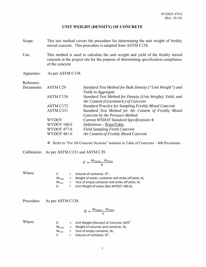
WYDOT 479.0 (Rev. 10-18)
1
UNIT WEIGHT (DENSITY) OF CONCRETE
Scope: This test method covers the procedure for determining the unit weight of freshly mixed concrete. This procedure is adopted from ASTM C138.
Use: This method is used to calculate the unit weight and yield of the freshly mixed
concrete at the project site for the purpose of determining specification compliance of the concrete
Apparatus: As per ASTM C138.
Reference Documents: ASTM C29 Standard Test Method for Bulk Density (“Unit Weight”) and
Voids in Aggregate ASTM C138 Standard Test Method for Density (Unit Weight), Yield, and
Air Content (Gravimetric) of Concrete ASTM C172 Standard Practice for Sampling Freshly Mixed Concrete ASTM C231 Standard Test Method for Air Content of Freshly Mixed
Concrete by the Pressure Method WYDOT Current WYDOT Standard Specifications WYDOT 100.0 Definitions - WaterTable WYDOT 477.0 Field Sampling Fresh Concrete WYDOT 481.0 Air Content of Freshly Mixed Concrete
Refer to “For All Concrete Sections” notation in Table of Concretes – 400 Pavements. Calibration: As per ASTM C231 and ASTM C29.
Where: Procedure: As per ASTM C138.
Where:
V = Volume of container, ft³. WTotal = Weight of water, container and strike‐off plate, lb; WTare = Tare of empty container and strike‐off plate, lb; D = Unit Weight of water (See WYDOT 100.0);
D WTotal
= =
Unit Weight (Density) of Concrete, lb/ft3 Weight of concrete and container, lb;
WTare = Tare of empty container, lb; V = Volume of container, ft³.

WYDOT 479.0 (Rev. 10-18)
2
Report: Report information on WYDOT Form T-109, Concrete Placing Report.
(This page intentionally left blank.)
WYDOT 480.0 (Rev. 10-18)
1
SLUMP TEST Scope: This test method describes the procedure for determining the concretes slump in
both the laboratory and the field. This procedure is adopted from ASTM C143. Use: This procedure is used to determine the consistency of the fresh concrete at the
project site for the purpose of determining specification compliance for structural concrete and is considered an applicable method for concrete having coarse aggregate up to 1½ inch in size.
The maximum slump specifications for the class of concrete are found in WYDOT
Standard Specifications. Apparatus: As per ASTM C143. Reference Documents: ASTM C143 Standard Test Method for Slump of Hydraulic-Cement
Concrete WYDOT Current WYDOT Standard Specifications WYDOT 477.0 Field Sampling Fresh Concrete WYDOT T-109 Concrete Placing Report
Refer to “For All Concrete Sections” notation in Table of Contents – 400 Pavements. Sampling: Sample in accordance with WYDOT Standard Specifications and WYDOT 477.0. Procedure: As per ASTM C143.
Report: Report the slump in terms of inches to the nearest ¼ inch of subsidence of the
specimen during the test on Form T-109. Precision and Bias: Reference WYDOT Standard Specifications for acceptable tolerances between two
testers from different laboratories, rather than Table 1 in ASTM C143.

WYDOT 480.0 (Rev. 10-18)
2
(This page intentionally left blank.)
WYDOT 481.0 (Rev. 10-18)
1
AIR CONTENT OF FRESHLY MIXED CONCRETE Scope: This test method describes the procedure for determining the air content of freshly
mixed concrete in both the laboratory and the field. This procedure is adopted from ASTM C231.
The procedure in ASTM C231 describes the use of two types of air meters, only
Type B air meters are allowed on WYDOT projects. The principle of the Type B meter consists of equalizing a known volume of air at a known pressure in a sealed air chamber with an unknown volume of air in the concrete sample. The dial on the pressure gauge is being calibrated in terms of percent air for the observed pressure at which equalization takes place.
Use: This method is used to determine the air content of the freshly mixed concrete in
the laboratory or at the project site for the purpose of determining specification compliance.
The percent of entrained air content, range specification for the class of concrete,
and air content values are found in WYDOT Standard Specifications. Apparatus: As per ASTM C231.
* Calibration cylinder (5% air puck) is an acceptable alternative to the
calibrating vessel. Reference Documents: ASTM C138 Standard Test Method for Density (Unit Weight), Yield, and
Air Content (Gravimetric) of Concrete ASTM C231 Standard Test Method for Air Content of Freshly Mixed
Concrete by the Pressure Method WYDOT Current WYDOT Standard Specifications WYDOT 477.0 Field Sampling Fresh Concrete WYDOT 479.0 Unit Weight (Density) of Concrete WYDOT T-109 Concrete Placing Report WYDOT T-480 Equipment Calibration, Verification, Maintenance and
Checking Form WYDOT T-481 Report of Calibration Verification
Refer to “For All Concrete Sections” notation in Table of Contents – 400 Pavements. Calibration: As per ASTM C231. Sampling: Obtain a representative sample of freshly mixed concrete in accordance with
WYDOT 477.0.

WYDOT 481.0 (Rev. 10-18)
2
This procedure must be started within five minutes of obtaining the composite sample and completed within fifteen minutes of obtaining the composite sample. There is a ten minute window for running the air content test. Procedure: As per ASTM C138. Report: Report calibration information on WYDOT T-480.0, Equipment Calibration,
Verification, Maintenance, and Checking Form and WYDOT T-481.0, Report of Calibration Verification. Report air content results on WYDOT Form T-109, Concrete Placing Report

WYDOT 481.0 (Rev. 10-18)
3
REPLACEMENT PARTS LIST FOR
PRESS-UR-METER Part No. 1. Pressure chamber 20. Cover "O" ring 2. Pressure chamber cap 21. Cover Pet cock 3. Pressure chamber elbow 22. Clamp 4. Pressure chamber gasket 23. Clamp nut 5. Pressure chamber air release stem 24. Clamp trunion 6. Pressure chamber air release cap 25. Clamp spring 7. Complete gauge 26. Clamp toggle 8. Pump assembly complete 27. Toggle set screw 9. Pump piston leather 28. Toggle lock nut 10. Pump air-check gasket 29. Base 11. Needle valve stem 30. Base handle 12. Needle valve nut 31. Calibrating vessel (not illustrated) 13. Need valve lever 32. Calibrating tube (outer) (not illustrated) 14. Need valve lever 33. Calibrating tube (inner) (not illustrated) 15. Needle valve "O" ring 34. Strike off bar (not illustrated) 16. Needle valve spring 35. Tamping Rod (not illustrated) 17. Needle valve spring retainer 36. Syringe (not illustrated) 18. Needle valve seat assembly 37. Gauge glass (not illustrated) 19. Cover 38. Carrying case (not illustrated)
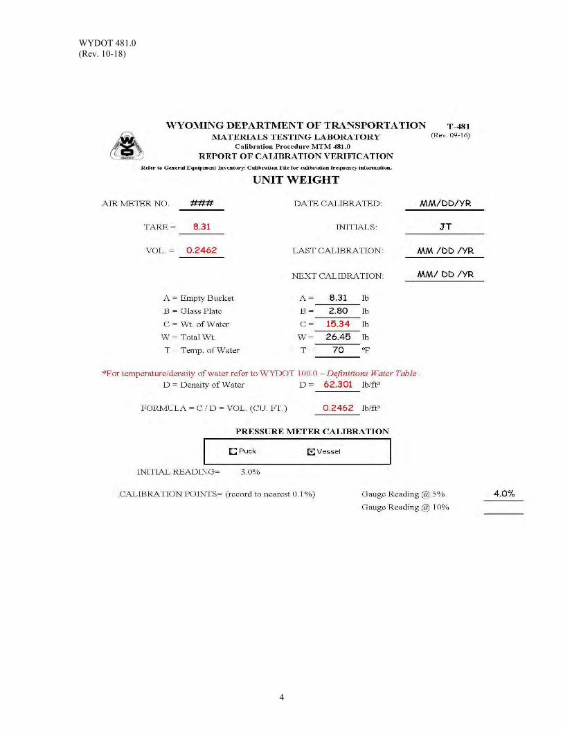
WYDOT 481.0 (Rev. 10-18)
4
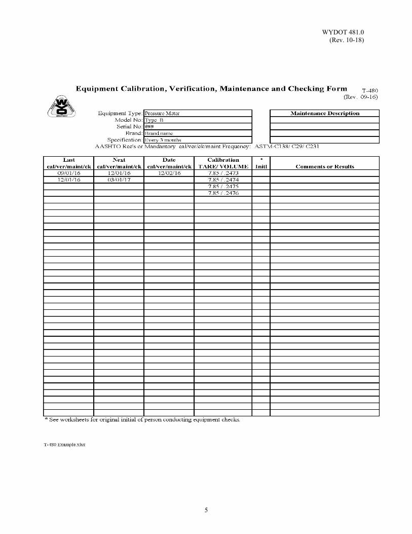
WYDOT 481.0 (Rev. 10-18)
5

WYDOT 481.0 (Rev. 10-18)
6
(This page intentionally left blank.)
WYDOT 483.0 (Rev. 10-19)
1
CONCRETE PLACING REPORT Scope: This procedure describes the method used in recording and reporting the
physical properties of the fresh concrete at the project site, water-cement ratios, placement conditions and cylinder and/or beam identification numbers.
Use: The Concrete Placing Report, WYDOT Form T-109, is used to record
the properties of the fresh concrete along with placement location and placement conditions. The WYDOT Form T-109 provides a permanent record and copies of the placing report accompany the concrete cylinders and/or beams when they are transported for testing.
Sampling: Representative samples of the fresh concrete will be taken as outlined in
WYDOT 477.0. Procedure: Use WYDOT Form T-109 (see example in this section) as a record and report
form, indicating as much information as possible about the concrete being delivered to the project. The sampling location will be in accordance with WYDOT 477.0.
Record the laboratory mix design data, which will be based on a 1 yd3 mix, the weather conditions, and all test results including temperature (WYDOT 478.0), density (WYDOT 479.0), slump (WYDOT 480.0), and air content (WYDOT 481.0), and, whether or not cylinders and/or beams are taken.
When cylinders are taken, a minimum of three cylinders will always be used for determining the ultimate 28 day strength. Any early breaks will require additional cylinders.
Record the number of days until cylinders are to be broken in the column Requested Testing Age (Days) and the location of each set of cylinders taken so that if necessary they can pinpoint the area of the placement at a later date.
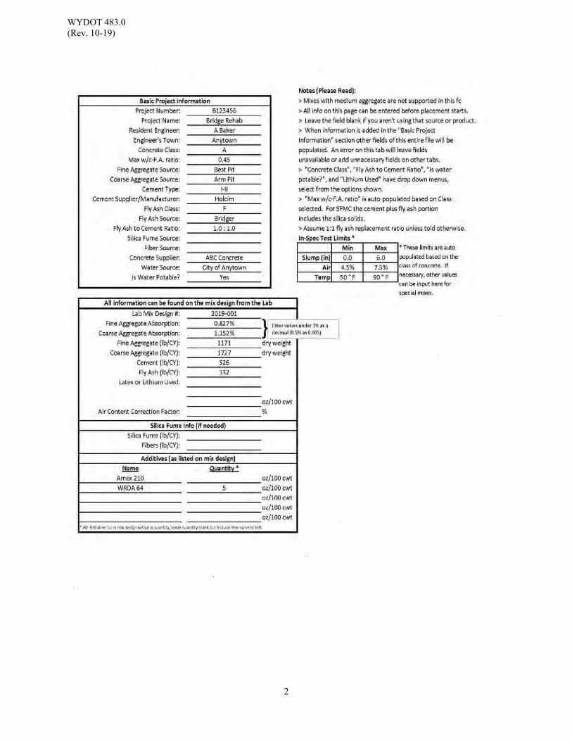
WYDOT 483.0 (Rev. 10-19)
2
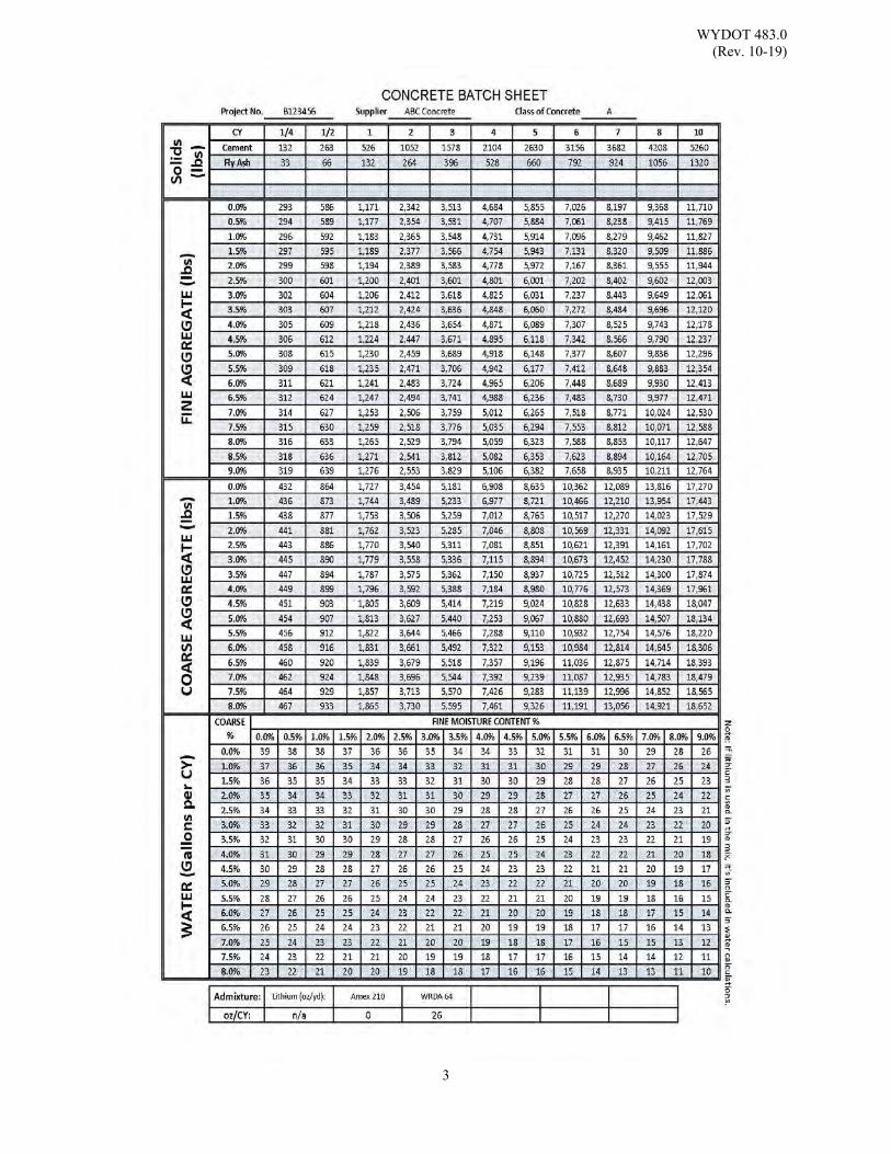
WYDOT 483.0 (Rev. 10-19)
3
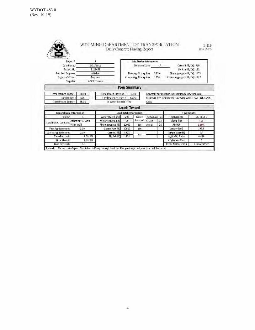
WYDOT 483.0 (Rev. 10-19)
4
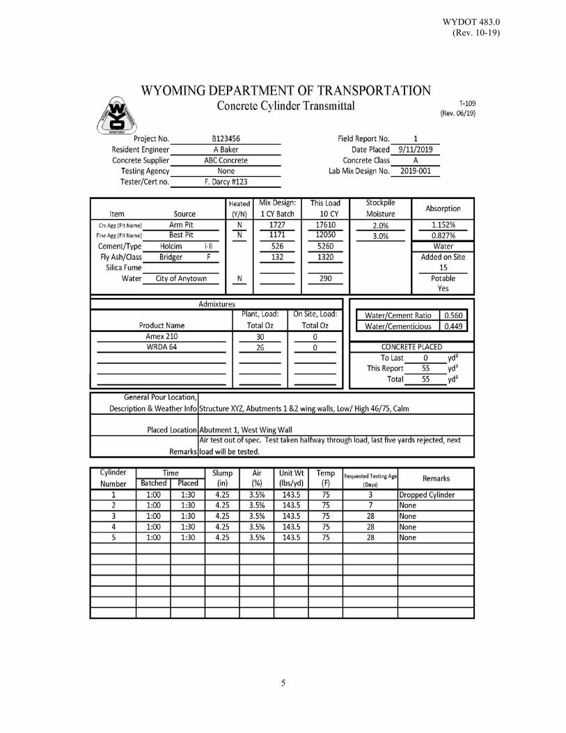
WYDOT 483.0 (Rev. 10-19)
5

WYDOT 483.0 (Rev. 10-19)
6
(This page intentionally left blank.)
WYDOT 484.0 (Rev. 10-18)
1
MEASURING LENGTH OF DRILLED CONCRETE CORES Scope: This method covers the procedure for determining the length of a core which is
drilled from concrete pavement. This procedure is identical to ASTM C174. Use: This method is used to determine the length of concrete cores taken at the project
site for the purpose of determining specification compliance for concrete thickness including quality acceptance and/or quality control samples when applicable.
Apparatus: As per ASTM C174. Reference Documents: ASTM C174 Standard Test Method for Measuring Thickness of
Concrete Elements Using Drilled Concrete Cores WYDOT Current WYDOT Standard Specifications WYDOT 800.0 Random Number Selections for Density and Gradation
Testing
Refer to “For All Concrete Sections” notation in Table of Contents – 400 Pavements. Sampling: As per ASTM C174. The WYDOT engineer will randomly select representative locations using a table
of random numbers in accordance with WYDOT 800.0. Do not attempt coring without water. Ensure the coring drill is perpendicular to
the surface during and after coring. Take the concrete core samples at least 2 feet away from all joints and edges of pavement to ensure drilling will not damage dowel bars or tie steel.
The contractor or his representative will core in the presence of the WYDOT
representative in accordance with WYDOT Standard Specifications. The WYDOT representative will measure the concrete core specimens.
Procedure: If the base material is bonded to the bottom surface of the concrete, remove the
bonded particles by wedging, by chisel and hammer, or by careful wire brushing. Do not use cores that show abnormal defects or that have been damaged appreciably in the drilling operation.
Measure the core in accordance with ASTM C174. Sum the individual sublot core values and round the lot mean thickness to the nearest 0.10 inch. Refer to WYDOT Standard Specifications.

WYDOT 484.0 (Rev. 10-18)
2
(This page intentionally left blank.)
WYDOT 485.0 (Rev. 10-18)
1
MAKING AND CURING CONCRETE CYLINDERS
Scope: This method covers procedures for molding and curing concrete cylinders at the
project site. This section applies to projects without Quality Control (QC) / Quality Acceptance (QA), for QC / QA projects which include WYDOT Standard Specifications. Included are references from ASTM C31.
Use: This procedure is used for molding and curing concrete cylinders for the purpose
of acquiring samples for acceptance testing and for determining form removal time or determining when a structure may be put into service.
Reference Documents: ASTM C31 Standard Practice for Making and Curing Concrete Test
Specimens in the Field ASTM C138 Standard Test Method for Density (Unit Weight), Yield, and
Air Content (Gravimetric) of Concrete ASTM C172 Standard Practice for Sampling Freshly Mixed Concrete WYDOT Current WYDOT Standard Specifications
WYDOT 477.0 Field Sampling Fresh Concrete WYDOT T-109 Concrete Placing Report WYDOT T-128 Construction Test Requirements Refer to “For All Concrete Sections” notation in Table of Contents – 400 Pavements.
Apparatus: As per ASTM C172. Sample: Representative composite samples will be as per ASTM C172. Sampling and
testing rate requirements will be itemized on the WYDOT Form T-128, Construction Test Requirements.
Make at least one set per sublot, a set is defined as three cylinders for 28 day QC /
QA and non QC / QA testing. Make a sufficient number of cylinders if early breaks are requested. Follow the procedure for sampling concrete as outlined in WYDOT 477.0.
Obtain the samples for compressive strength for structural concrete as per WYDOT Standard Specifications. Unit weight, slump, air content and temperature will be measured from the same composite sample of concrete when compressive strength test specimens are made. Sampling and testing information will be reported on WYDOT Form T-109.
WYDOT 485.0 (Rev. 10-18)
2
Procedure: After sampling the concrete place the cylinder can on a level rigid surface, free
from vibration or other disturbance, and as close as possible to the planned place of storage. The appropriate methods of consolidation are as per ASTM C31.
Rodding: As per ASTM C31. Vibrating: As per ASTM C31.
Finishing: As per ASTM C31. Curing: Non - QC / QA:
After molding, cylinders shall be immediately stored at the project site in an environment which provides a temperature range of 60 F to 80 F and in a moist environment which will prevent any loss of moisture. The 48 hour initial cure limit does not apply for QC / QA1. The cylinders shall remain in this environment until transport. After set WYDOT will transport the quality acceptance (QA) cylinders to the WYDOT Materials Program in Cheyenne for testing or to an alternate location as determined by the WYDOT engineer where the cylinders will be placed in a standard cure environment. The cylinders shall remain in their molds until they are received by the testing laboratory. The 4 hour maximum transportation time limit does not apply.
Cylinders which will be used for determining form removal time or determining when a structure may be put into service will remain in the same environment as the placed concrete until tested.
QC / QA Projects
The contractor will provide a location with the above conditions at the project site for storing the cylinders during initial curing.
1 WYDOT does not require that standard cure facilities be located at project sites. Therefore, it is understood that under some circumstances the contractor may not be capable of placing cylinders in standard cure within 48 hours.
WYDOT 486.0 (Rev. 10-18)
1
MAKING AND CURING CONCRETE BEAMS Scope: This method covers procedures for molding and curing concrete beams for mix
designs and the project site upon request. This section applies to projects with Quality Control (QC) / Quality Acceptance (QA) for Portland Cement Concrete Pavement (PCCP). Included are references from ASTM C31.
Use: This procedure is used for molding and curing concrete beams for the purpose of
acquiring samples for acceptance testing and for determining the 28 day flexural strength of the concrete pavement.
This procedure is typically used for Mix Design only as per WYDOT Standard
Specifications. If requested and approved by the WYDOT Materials Program to use concrete beams in the field throughout a project, and dependent on the Level of Control of the project, use the procedure approved and specified.
Reference Documents: ASTM C31 Standard Practice for Making and Curing Concrete Test
Specimens in the Field ASTM C138 Standard Test Method for Density (Unit Weight)‚ Yield‚
and Air Content (Gravimetric) of Concrete ASTM C172 Standard Practice for Sampling Freshly Mixed Concrete WYDOT Current WYDOT Standard Specifications
WYDOT 471.0 WYDOT Concrete Mix Design Procedure WYDOT 474.0 Flexural Strength of Portland Cement Concrete Beams WYDOT 475.0 Correlation of Compressive Strength to Flexural Strength WYDOT 477.0 Field Sampling Fresh Concrete WYDOT T-109 Concrete Placing Report WYDOT T-128 Construction Test Requirements Refer to “For All Concrete Sections” notation in Table of Contents – 400 Pavements.
Apparatus: As per ASTM C31.
Sampling: As per ASTM C172. Follow the Mix Design procedure as outlined in WYDOT 471.0.
Make at least one set per sublot, a set is defined as three beam molds for 28 day QC / QA testing and to make a sufficient number of beams for early breaks. Follow the procedure for sampling concrete as outlined in WYDOT 477.0.
Procedure: Follow procedures in ASTM C138.
Rodding: As per ASTM C31. Vibrating: As per ASTM C31.
WYDOT 486.0 (Rev. 10-18)
2
Finishing: As per ASTM C31.
Apply curing compound to the exposed surface immediately. If the curing compound is not readily available, protect the exposed surface from evaporation using wet burlap, plastic sheeting or an impervious material until the curing compound is applied.
Curing: After molding, beams will be immediately stored at the project site
in an environment which provides a temperature range of 60 °F to 80 °F and in an environment which will prevent any loss of moisture. The 48 hour initial cure limit does not apply1.
The contractor will provide a location with the above conditions at the project site for storing the beams during initial curing.
Beams will remain in the molds until received by the WYDOT Materials Program. Commentary: ASTM C31 states that for cylinders and beams
which are to be transported after 48 hours, a standard cure environment will be required at the project site in addition to the initial curing environment of 60 F to 80 F. A standard cure requires the beams to be removed from the molds and placed in an environment which provides free water on the cylinders at all times at a temperature of 73.4 F ± 3 F. However ASTM C31, allows for the cylinders and beams to remain in the 60 F to 80 F environment in the molds until transport, thereby eliminating the requirement for a standard cure facility on the project site.
According to ASTM C31, one possible method for preventing moisture loss from samples during initial curing, is to store the samples in heavyweight closed plastic bags. The 4 hour maximum transportation time limit does not apply.
Report: Sampling and testing information will be reported on Form T-109.
1 WYDOT does not require that standard cure facilities be located at project sites. Therefore, it is understood that under some circumstances the contractor may not be capable of placing cylinders in standard cure within 48 hours.
WYDOT 501.0 (Rev. 10-18)
1
STRUCTURAL CONCRETE / PCCP YIELD PROCEDURE
Scope: This procedure provides formulas for calculating yield and relative yield of
structural concrete and Portland Cement Concrete Pavement (PCCP). Yield is defined in ASTM C138 as the volume of concrete produced from the mixture of known quantities of the component materials.
Use: This procedure is used for Quality Control (QC) purposes with structural concrete
and for informational purposes on Portland Cement Concrete Pavement (PCCP). This procedure is used in conjunction with WYDOT 479.0 and WYDOT 481.0. Reference Documents: ASTM C138 Standard Test Method for Density (Unit Weight), Yield, and
Air Content (Gravimetric) of Concrete WYDOT Current WYDOT Standard Specifications WYDOT 479.0 Unit Weight (Density) of Concrete WYDOT 481.0 Air Content of Freshly Mixed Concrete WYDOT 816.0 Sieve Analysis of Concrete Aggregate WYDOT T-109 Concrete Placing Report
Refer to “For All Concrete Sections” notation in Table of Contents – 400 Pavements.
Procedure: Yield is the volume of concrete represented by the weight of concrete materials
batched:
YF =
Where: YF = Volume of field yield ft3;
WT = Total weight of constituent materials batched including aggregate, cement, fly ash and water expressed in lb;
UF = Fresh density (unit weight) of concrete lb/ft3.
Relative yield is the ratio of the actual volume of concrete obtained to the volume as designated for the batch; calculated as follows:
= Where: = Relative yield; YT = Volume of designated concrete batch.
Method: Yield will be calculated simultaneously with those batches on which routine consistency tests are performed.
Yield will only be determined on batches on which the delivered load is 75% or greater of the rated capacity of the truck mixer or agitator.
WYDOT 501.0 (Rev. 10-18)
2
Variation will be determined, from theoretical yield to field yield, on a percentage basis as follows:
x100
Where: V = Variation (%); YT = Theoretical yield (the intended amount batched ft3
from batch tickets). Example: 7 yd³ is batched;
Batch Ticket: Sand = 8,432.3 lb Rock = 12,634.1 lb Water / Batch = 1,714.3 lb Water / Site = 75.8 lb Cement = 4,166.0 lb Total = 27,022.5 lb (for 7 yd³ batch);
Total weight of the batch is 27,022.5 lb The measured density (unit wt.) is 144.5 lb/ft3; Density (unit weight) is reported to the nearest 0.1 lb/ft3; Theoretical yield: YT 7 yd³ x 27 ft3/yd³ 189.0 ft3
Theoretical yield is calculated from the products mix design specific
gravity multiplied by 62.4 lb/ft3;
Yield:
YF = = 187.0 = , .
.
Yield is reported to the nearest 0.1 ft3; Where: Relative Yield:
= = 0.99 = .
.
Relative yield is reported to the nearest 0.01. Where: Relative yield;
YF = 187.0 ft³ WT = 27,022.5 lb UF = 144.5 lb/ft³
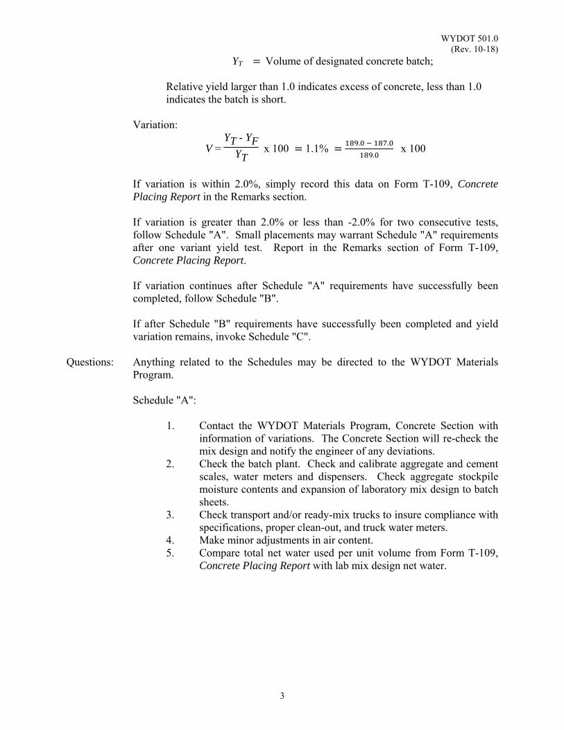
WYDOT 501.0 (Rev. 10-18)
3
YT Volume of designated concrete batch; Relative yield larger than 1.0 indicates excess of concrete, less than 1.0 indicates the batch is short.
Variation:
V = YT - YF
YT x 100 1.1%
. .
.x 100
If variation is within 2.0%, simply record this data on Form T-109, Concrete Placing Report in the Remarks section. If variation is greater than 2.0% or less than -2.0% for two consecutive tests, follow Schedule "A". Small placements may warrant Schedule "A" requirements after one variant yield test. Report in the Remarks section of Form T-109, Concrete Placing Report.
If variation continues after Schedule "A" requirements have successfully been completed, follow Schedule "B".
If after Schedule "B" requirements have successfully been completed and yield variation remains, invoke Schedule "C".
Questions: Anything related to the Schedules may be directed to the WYDOT Materials Program. Schedule "A": 1. Contact the WYDOT Materials Program, Concrete Section with
information of variations. The Concrete Section will re-check the mix design and notify the engineer of any deviations.
2. Check the batch plant. Check and calibrate aggregate and cement scales, water meters and dispensers. Check aggregate stockpile moisture contents and expansion of laboratory mix design to batch sheets.
3. Check transport and/or ready-mix trucks to insure compliance with specifications, proper clean-out, and truck water meters.
4. Make minor adjustments in air content. 5. Compare total net water used per unit volume from Form T-109,
Concrete Placing Report with lab mix design net water.
WYDOT 501.0 (Rev. 10-18)
4
Schedule "B": 1. Submit samples of project aggregate, cement, fly ash and
admixtures to the WYDOT Materials Program to check specific gravities, absorption and re-run mix design.
Schedule "C": 1. Adjust the mix design to reduce yield variation to within the 2%
variation limit. This will be done by proportionally adjusting all concrete components - fine aggregate, coarse aggregate, cement and fly ash. The adjustment would be of a temporary nature.
2. Re-adjustment may be necessary dependent on duration of the placement and variation in the batch plant.
Discussion: It should be noted that the following conditions will affect yield:
1. The difference between field air content and lab mix design air content will vary yield in direct proportion to the difference in air content (e.g. lab mix design air content of 5.5% vs. field air content of 4.0% will result in 1.5% variation in yield) as per WYDOT Standards.
2. A change of 1.0% moisture content of either the sand (FA) or rock (CA) will vary yield by approximately 1.0% if not accounted for (determine % moisture as per WYDOT 816.0).
3. Variations in aggregate (i.e. specific gravity, absorption) will result in variation in yield.
4. A change in the water/cement ratio of 0.01 will vary yield by approximately 0.5%.
5. Form errors or grade miscalculations may result in yield variation from contractor's viewpoint.
6. Allowable variations in batch plant scale accuracy will affect yield. All of these factors may have additive affects on yield and will vary constantly during the project. It is the WYDOT Materials Program intent to minimize yield variations and adjustments necessary to compensate for them. The 2% allowable variation and procedures in Schedule "A" should accomplish this. Performance of Schedule "A" items should not be limited only to periods of yield variation. These items should be performed routinely. The emphasis of this procedure will result in increased attention on the batch plant and more scale maintenance may be required.
WYDOT 800.0 (Rev. 10-20)
1
RANDOM NUMBER SELECTION FOR DENSITY AND GRADATION TESTING
Scope: This procedure describes the process for randomly selecting test locations for
density tests and the test tonnage for gradation tests. Use: Brief narratives and examples of the use of spreadsheet random number functions
and of random number tables are included. Reference Documents: WYDOT 401 WYDOT Standard Specifications SP-400## Special Provision for Plant Mix Pavement Longitudinal Joint Construction WYDOT T-312 Density Random Number Selection Procedure: Density Tests
1. Determine the total production of material for one day. This information
can be obtained from the daily weight tickets. 2. Determine the total linear distance paved and the total width paved. This
information can be obtained from the weight tickets or from the paving inspector.
3. Determine the number and size of lots needed for one day’s production.
Determine the number of sublots per lot. These are determined from WYDOT Standard Specifications Section 401, or Table 401.4.23-2, depending on which controls the plant mix production being evaluated.
4. Determine the lot size in linear feet and the length of section that is
represented by each test. a. Determine the length per lot by dividing the number of linear feet
paved by the number of lots represented. b. Determine the length represented by each test by dividing the feet
represented per lot by the number of sublots per lot. c. Determine the stations representing each lot and sublot based on the
section lengths and the beginning station.
5. Perform the following location selection separately for each test (sublot). An example of this procedure is provided below. a. Select a random number between 0 and 1 as described in the
“Random Number Selection” of this section. b. Determine a test station. Multiply the random number between 0
and 1 by the length represented per sublot and add it to the beginning station of the section represented.
c. Select another random number between 0 and 1 as described in the “Random Number Selection” of this section.

WYDOT 800.0 (Rev. 10-20)
2
d. Determine the transverse distance. Subtract 2 feet from the width of the ribbon and then multiply this width by the random number between 0 and 1. Add 1 foot to the result and measure in that distance from the outer edge of the ribbon to determine the test location at the test station selected in “5.b.” above.
Example: This demonstrates one possible spreadsheet layout for calculating the station and
distance from the outer edge of the ribbon for density core sampling.
The numbers generated above are generated by the formulas below:
Lot Number
Sublot Number
Begin Station
End Station
Net Length
Longitudinal Random Number
Length* Random Number
Station Tested
1 1 0+00 50+00 5,000 0.870 4,350 43+50 1 2 50+00 100+00 5,000 0.894 4,470 94+70 1 3 100+00 150+00 5,000 0.961 4,805 148+05 1 4 150+00 200+00 5,000 0.545 2,725 177+25 1 1 1
5 6 7
200+00 250+00 300+00
250+00 300+00 350+00
5,000 5,000 5,000
0.200 0.620 0.713
1,000 3,100 3,565
210+00 281+00 335+65
Lot Number
Sublot Number
Ribbon Width
1 ft
Ribbon Width
2 ft
Transverse Random Number
Width 2 ft
*Random Number
Distance From
Ribbon Edge, ft
1 1 12 10 0.261 2.61 3.61 1 2 12 10 0.064 0.64 1.64 1 3 12 10 0.766 7.66 8.66 1 4 12 10 0.500 5.00 6.00 1 1 1
5 6 7
12 12 12
10 10 10
0.873 0.731 0.956
8.73 7.31 9.56
9.73 8.31 10.56
Lot Number
Sublot Number
Begin Station
End Station
Net Length
Longitudinal Random Number
Length* Random Number
Station Tested
1 1 0 5000 =D2-C2 =Rand() =E2*F2 =G2+C2 1 2 5000 10000 =D3-C3 =Rand() =E3*F3 =G3+C3 1 3 10000 15000 =D4-D4 =Rand() =E4*F4 =G4+C4
Lot Number
Sublot Number
Ribbon Width
1 ft
Ribbon Width
2 ft
Transverse Random Number
Width 2 ft
*Random Number
Distance From
Ribbon Edge, ft
1 1 12 =C7-2 =Rand() =D7*E7 =1+F7 1 2 12 =C8-2 =Rand() =D8*E8 =1+F8 1 3 12 =C9-2 =Rand() =D9*E9 =1+F9

WYDOT 800.0 (Rev. 10-20)
3
An example worksheet T-312, Density Random Number Selection Worksheet is shown at the end of this section.
Longitudinal Joint Density Tests 1. Determine the length of the lot in accordance with SP-400##, Special
Provision for Plant Mix Pavement Longitudinal Joint Construction.
2. Determine the length represented by each test by dividing the feet represented per lot by the number of sublots (7) per lot.
3. Determine the stations representing each lot and sublot based on the section
lengths and the beginning station. 4. Perform the following location selection separately for each test (sublot).
a. Select a random number between 0 and 1 as described in the “Random Number Selection” of this section.
b. Determine a test station. Multiply the random number between 0 and 1 by the length represented per sublot and add it to the beginning station of the section represented.
c. Determine the transverse distance in accordance with SP-400##, Special Provision for Plant Mix Pavement Longitudinal Joint Construction.
Gradation Tests
1. Determine the number and size of lots and sublots needed. This is
determined according to WYDOT Standard Specifications Section 401 or Table 401.4.23-1 for Plant Mix Pavements, depending on which one controls the aggregate production being evaluated. The total amount of material used on the project may be taken from the Plans (TEQ) or from revised quantity estimates.
2. Determine a random number between 0 and 1 as described in the “Random
Number Selection” of this section for each sublot. 3. Determine the tonnage to sample. Multiply the random number by the tons
represented, per sublot, and add to the beginning tonnage for the sublot.
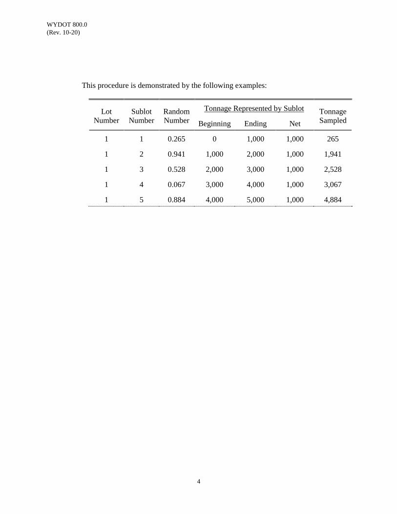
WYDOT 800.0 (Rev. 10-20)
4
This procedure is demonstrated by the following examples:
Lot
Number
Sublot
Number
Random Number
Tonnage Represented by Sublot
Tonnage Sampled
Beginning
Ending
Net
1
1
0.265
0
1,000
1,000
265
1
2
0.941
1,000
2,000
1,000
1,941
1
3
0.528
2,000
3,000
1,000
2,528
1
4
0.067
3,000
4,000
1,000
3,067
1
5
0.884
4,000
5,000
1,000
4,884
WYDOT 800.0 (Rev. 10-20)
5
Random Number Selection
One may use the random function of a spreadsheet, the random number on a calculator, or random number tables to generate random numbers. Use of a spreadsheet and of random number tables is described here.
Use a random function on a spreadsheet. Most spreadsheets have a random
number generator function. A spreadsheet may be set up that generates random numbers and calculates the tonnage to sample. An example of such a spreadsheet, with both numbers and formulas displayed, was used to calculate some of the above tonnages as follows:
Random Number Beginning Ending Net Sample 0.558 14,700 15,385 685 15,083 0.138 15,385 16,070 685 15,480 0.597 16,070 16,755 685 16,479 Random Number Beginning Ending Net Sample =Rand() 14,700 15,385 =C2-B2 =(C2-B2)*A2+B2 =Rand() 15,385 16,070 =C3-B3 =(C3-B3)*A3+B3 =Rand() 16,070 16,755 =C4-B4 =(C4-B4)*A4+B4
Use a random number table, such as the ones included in this procedure. The tables are set up with the columns and rows assembled in groups of either five or seven, since most lots are comprised of five or seven sublots. Enter the random number table at any point, but do not enter it in the same place twice. Once entering the table, arbitrarily choose random numbers from the table, one random number for each sublot. This may be accomplished by selecting the group of random numbers, either row or column, in which the entry number is included (see the provided example).
Avoid simply entering the table randomly five or seven times to get five or seven numbers.
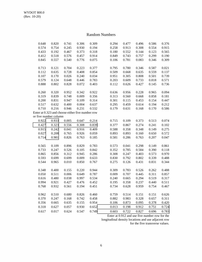
WYDOT 800.0 (Rev. 10-20)
6
Random Numbers
0.648 0.820 0.741 0.306 0.309 0.294 0.477 0.496 0.586 0.376 0.574 0.754 0.245 0.930 0.194 0.258 0.913 0.308 0.554 0.915 0.433 0.192 0.467 0.373 0.318 0.180 0.552 0.144 0.123 0.565 0.412 0.518 0.576 0.457 0.914 0.849 0.743 0.757 0.299 0.190 0.845 0.557 0.540 0.776 0.075 0.106 0.781 0.083 0.346 0.309
0.713 0.121 0.704 0.223 0.377 0.795 0.780 0.346 0.587 0.021 0.112 0.635 0.728 0.408 0.854 0.509 0.668 0.635 0.559 0.137 0.107 0.170 0.026 0.240 0.034 0.951 0.305 0.808 0.501 0.739 0.579 0.124 0.648 0.446 0.783 0.203 0.609 0.733 0.818 0.571 0.888 0.802 0.828 0.072 0.403 0.112 0.626 0.427 0.145 0.736
0.260 0.320 0.952 0.342 0.922 0.636 0.956 0.228 0.965 0.094 0.319 0.839 0.748 0.009 0.356 0.313 0.560 0.668 0.858 0.181 0.200 0.831 0.947 0.109 0.314 0.301 0.115 0.453 0.154 0.447 0.517 0.632 0.400 0.004 0.637 0.295 0.459 0.614 0.194 0.212 0.710 0.216 0.946 0.231 0.532 0.179 0.631 0.168 0.170 0.586
Enter at 0.323 and choose either five number row or five number column
0.922
0.933
0.005
0.647
0.214
0.715
0.109
0.373
0.513
0.074
0.427
0.323
0.556
0.308
0.839
0.377
0.867
0.274
0.241
0.102 0.915 0.242 0.041 0.916 0.409 0.588 0.358 0.348 0.149 0.275 0.027 0.208 0.765 0.926 0.059 0.893 0.893 0.160 0.650 0.572 0.714 0.981 0.826 0.763 0.185 0.581 0.286 0.763 0.207 0.047
0.565 0.109 0.896 0.829 0.783 0.573 0.041 0.298 0.149 0.861 0.733 0.247 0.526 0.105 0.842 0.352 0.785 0.584 0.390 0.118 0.865 0.856 0.312 0.945 0.286 0.308 0.247 0.403 0.573 0.970 0.593 0.699 0.699 0.009 0.633 0.830 0.792 0.802 0.339 0.488 0.544 0.965 0.010 0.850 0.767 0.275 0.126 0.431 0.831 0.344
0.348 0.400 0.155 0.220 0.944 0.309 0.783 0.526 0.262 0.488 0.050 0.511 0.006 0.649 0.787 0.009 0.707 0.445 0.311 0.857 0.616 0.480 0.038 0.997 0.534 0.240 0.665 0.294 0.519 0.317 0.994 0.921 0.427 0.476 0.452 0.195 0.358 0.237 0.440 0.511 0.768 0.932 0.561 0.194 0.451 0.734 0.628 0.959 0.754 0.467
0.962 0.510 0.680 0.826 0.460 0.759 0.514 0.151 0.151 0.626 0.370 0.247 0.168 0.742 0.458 0.882 0.983 0.328 0.657 0.311 0.356 0.665 0.635 0.155 0.954 0.106 0.873 0.095 0.378 0.420 0.318
0.627
0.057
0.930
0.652
0.013
0.198
0.912
0.751
0.724
0.617
0.017
0.624
0.547
0.749
0.603
0.722
0.827
0.696
0.783 Enter at 0.912 and use five number row for the
longitudinal density locations and use adjacent row for the five transverse values.
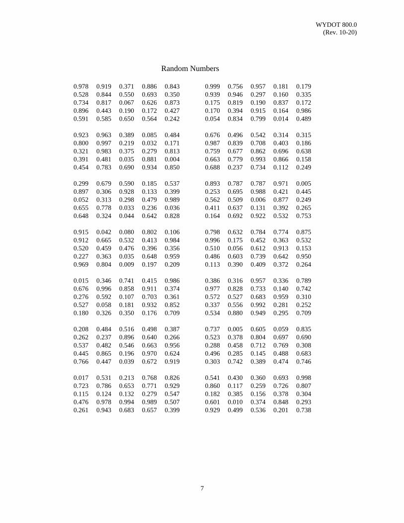
WYDOT 800.0 (Rev. 10-20)
7
Random Numbers
0.978 0.919 0.371 0.886 0.843 0.999 0.756 0.957 0.181 0.179 0.528 0.844 0.550 0.693 0.350 0.939 0.946 0.297 0.160 0.335 0.734 0.817 0.067 0.626 0.873 0.175 0.819 0.190 0.837 0.172 0.896 0.443 0.190 0.172 0.427 0.170 0.394 0.915 0.164 0.986 0.591 0.585 0.650 0.564 0.242 0.054 0.834 0.799 0.014 0.489
0.923 0.963 0.389 0.085 0.484 0.676 0.496 0.542 0.314 0.315 0.800 0.997 0.219 0.032 0.171 0.987 0.839 0.708 0.403 0.186 0.321 0.983 0.375 0.279 0.813 0.759 0.677 0.862 0.696 0.638 0.391 0.481 0.035 0.881 0.004 0.663 0.779 0.993 0.866 0.158 0.454 0.783 0.690 0.934 0.850 0.688 0.237 0.734 0.112 0.249
0.299 0.679 0.590 0.185 0.537 0.893 0.787 0.787 0.971 0.005 0.897 0.306 0.928 0.133 0.399 0.253 0.695 0.988 0.421 0.445 0.052 0.313 0.298 0.479 0.989 0.562 0.509 0.006 0.877 0.249 0.655 0.778 0.033 0.236 0.036 0.411 0.637 0.131 0.392 0.265 0.648 0.324 0.044 0.642 0.828 0.164 0.692 0.922 0.532 0.753
0.915 0.042 0.080 0.802 0.106 0.798 0.632 0.784 0.774 0.875 0.912 0.665 0.532 0.413 0.984 0.996 0.175 0.452 0.363 0.532 0.520 0.459 0.476 0.396 0.356 0.510 0.056 0.612 0.913 0.153 0.227 0.363 0.035 0.648 0.959 0.486 0.603 0.739 0.642 0.950 0.969 0.804 0.009 0.197 0.209 0.113 0.390 0.409 0.372 0.264
0.015 0.346 0.741 0.415 0.986 0.386 0.316 0.957 0.336 0.789 0.676 0.996 0.858 0.911 0.374 0.977 0.828 0.733 0.140 0.742 0.276 0.592 0.107 0.703 0.361 0.572 0.527 0.683 0.959 0.310 0.527 0.058 0.181 0.932 0.852 0.337 0.556 0.992 0.281 0.252 0.180 0.326 0.350 0.176 0.709 0.534 0.880 0.949 0.295 0.709
0.208 0.484 0.516 0.498 0.387 0.737 0.005 0.605 0.059 0.835 0.262 0.237 0.896 0.640 0.266 0.523 0.378 0.804 0.697 0.690 0.537 0.482 0.546 0.663 0.956 0.288 0.458 0.712 0.769 0.308 0.445 0.865 0.196 0.970 0.624 0.496 0.285 0.145 0.488 0.683 0.766 0.447 0.039 0.672 0.919 0.303 0.742 0.389 0.474 0.746
0.017 0.531 0.213 0.768 0.826 0.541 0.430 0.360 0.693 0.998 0.723 0.786 0.653 0.771 0.929 0.860 0.117 0.259 0.726 0.807 0.115 0.124 0.132 0.279 0.547 0.182 0.385 0.156 0.378 0.304 0.476 0.978 0.994 0.989 0.507 0.601 0.010 0.374 0.848 0.293 0.261 0.943 0.683 0.657 0.399 0.929 0.499 0.536 0.201 0.738
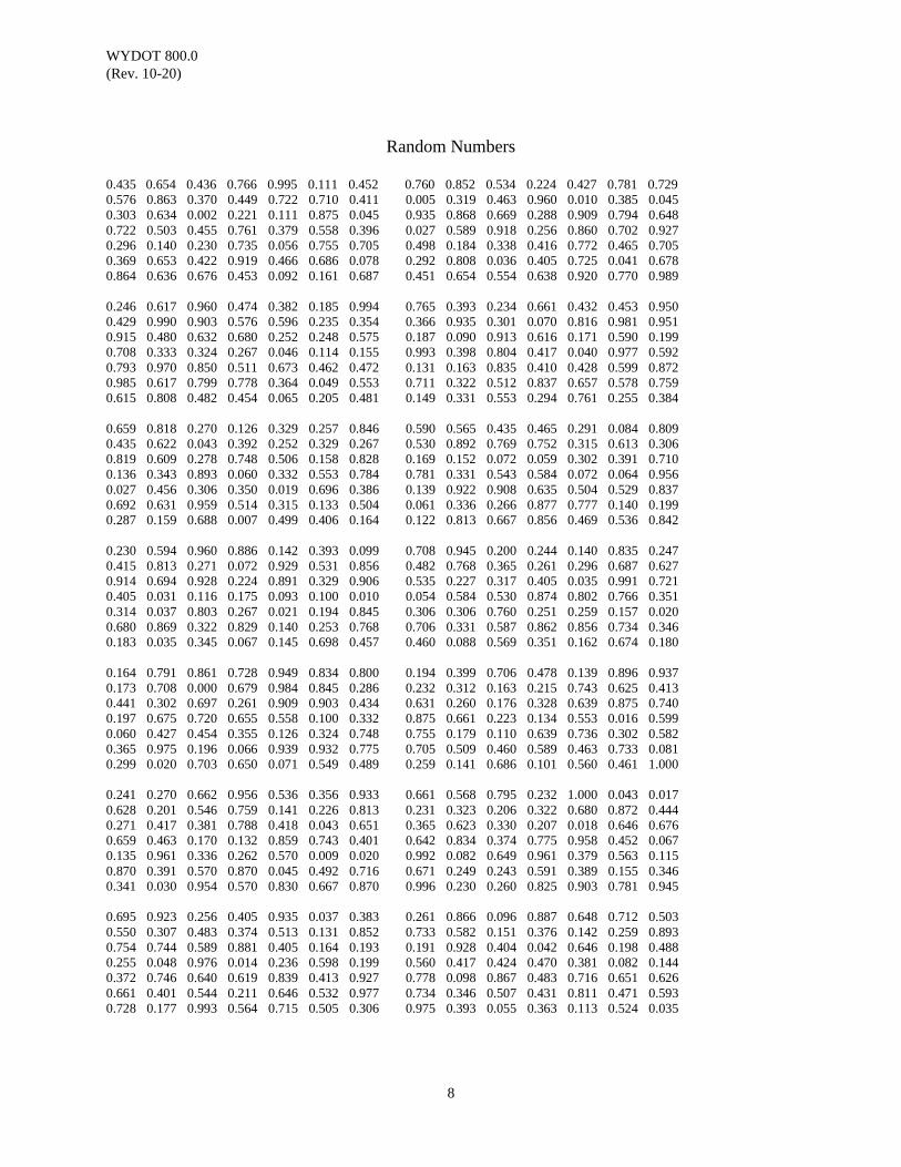
WYDOT 800.0 (Rev. 10-20)
8
Random Numbers
0.435 0.654 0.436 0.766 0.995 0.111 0.452 0.760 0.852 0.534 0.224 0.427 0.781 0.729 0.576 0.863 0.370 0.449 0.722 0.710 0.411 0.005 0.319 0.463 0.960 0.010 0.385 0.045 0.303 0.634 0.002 0.221 0.111 0.875 0.045 0.935 0.868 0.669 0.288 0.909 0.794 0.648 0.722 0.503 0.455 0.761 0.379 0.558 0.396 0.027 0.589 0.918 0.256 0.860 0.702 0.927 0.296 0.140 0.230 0.735 0.056 0.755 0.705 0.498 0.184 0.338 0.416 0.772 0.465 0.705 0.369 0.653 0.422 0.919 0.466 0.686 0.078 0.292 0.808 0.036 0.405 0.725 0.041 0.678 0.864 0.636 0.676 0.453 0.092 0.161 0.687 0.451 0.654 0.554 0.638 0.920 0.770 0.989 0.246 0.617 0.960 0.474 0.382 0.185 0.994 0.765 0.393 0.234 0.661 0.432 0.453 0.950 0.429 0.990 0.903 0.576 0.596 0.235 0.354 0.366 0.935 0.301 0.070 0.816 0.981 0.951 0.915 0.480 0.632 0.680 0.252 0.248 0.575 0.187 0.090 0.913 0.616 0.171 0.590 0.199 0.708 0.333 0.324 0.267 0.046 0.114 0.155 0.993 0.398 0.804 0.417 0.040 0.977 0.592 0.793 0.970 0.850 0.511 0.673 0.462 0.472 0.131 0.163 0.835 0.410 0.428 0.599 0.872 0.985 0.617 0.799 0.778 0.364 0.049 0.553 0.711 0.322 0.512 0.837 0.657 0.578 0.759 0.615 0.808 0.482 0.454 0.065 0.205 0.481 0.149 0.331 0.553 0.294 0.761 0.255 0.384 0.659 0.818 0.270 0.126 0.329 0.257 0.846 0.590 0.565 0.435 0.465 0.291 0.084 0.809 0.435 0.622 0.043 0.392 0.252 0.329 0.267 0.530 0.892 0.769 0.752 0.315 0.613 0.306 0.819 0.609 0.278 0.748 0.506 0.158 0.828 0.169 0.152 0.072 0.059 0.302 0.391 0.710 0.136 0.343 0.893 0.060 0.332 0.553 0.784 0.781 0.331 0.543 0.584 0.072 0.064 0.956 0.027 0.456 0.306 0.350 0.019 0.696 0.386 0.139 0.922 0.908 0.635 0.504 0.529 0.837 0.692 0.631 0.959 0.514 0.315 0.133 0.504 0.061 0.336 0.266 0.877 0.777 0.140 0.199 0.287 0.159 0.688 0.007 0.499 0.406 0.164 0.122 0.813 0.667 0.856 0.469 0.536 0.842 0.230 0.594 0.960 0.886 0.142 0.393 0.099 0.708 0.945 0.200 0.244 0.140 0.835 0.247 0.415 0.813 0.271 0.072 0.929 0.531 0.856 0.482 0.768 0.365 0.261 0.296 0.687 0.627 0.914 0.694 0.928 0.224 0.891 0.329 0.906 0.535 0.227 0.317 0.405 0.035 0.991 0.721 0.405 0.031 0.116 0.175 0.093 0.100 0.010 0.054 0.584 0.530 0.874 0.802 0.766 0.351 0.314 0.037 0.803 0.267 0.021 0.194 0.845 0.306 0.306 0.760 0.251 0.259 0.157 0.020 0.680 0.869 0.322 0.829 0.140 0.253 0.768 0.706 0.331 0.587 0.862 0.856 0.734 0.346 0.183 0.035 0.345 0.067 0.145 0.698 0.457 0.460 0.088 0.569 0.351 0.162 0.674 0.180 0.164 0.791 0.861 0.728 0.949 0.834 0.800 0.194 0.399 0.706 0.478 0.139 0.896 0.937 0.173 0.708 0.000 0.679 0.984 0.845 0.286 0.232 0.312 0.163 0.215 0.743 0.625 0.413 0.441 0.302 0.697 0.261 0.909 0.903 0.434 0.631 0.260 0.176 0.328 0.639 0.875 0.740 0.197 0.675 0.720 0.655 0.558 0.100 0.332 0.875 0.661 0.223 0.134 0.553 0.016 0.599 0.060 0.427 0.454 0.355 0.126 0.324 0.748 0.755 0.179 0.110 0.639 0.736 0.302 0.582 0.365 0.975 0.196 0.066 0.939 0.932 0.775 0.705 0.509 0.460 0.589 0.463 0.733 0.081 0.299 0.020 0.703 0.650 0.071 0.549 0.489 0.259 0.141 0.686 0.101 0.560 0.461 1.000 0.241 0.270 0.662 0.956 0.536 0.356 0.933 0.661 0.568 0.795 0.232 1.000 0.043 0.017 0.628 0.201 0.546 0.759 0.141 0.226 0.813 0.231 0.323 0.206 0.322 0.680 0.872 0.444 0.271 0.417 0.381 0.788 0.418 0.043 0.651 0.365 0.623 0.330 0.207 0.018 0.646 0.676 0.659 0.463 0.170 0.132 0.859 0.743 0.401 0.642 0.834 0.374 0.775 0.958 0.452 0.067 0.135 0.961 0.336 0.262 0.570 0.009 0.020 0.992 0.082 0.649 0.961 0.379 0.563 0.115 0.870 0.391 0.570 0.870 0.045 0.492 0.716 0.671 0.249 0.243 0.591 0.389 0.155 0.346 0.341 0.030 0.954 0.570 0.830 0.667 0.870 0.996 0.230 0.260 0.825 0.903 0.781 0.945 0.695 0.923 0.256 0.405 0.935 0.037 0.383 0.261 0.866 0.096 0.887 0.648 0.712 0.503 0.550 0.307 0.483 0.374 0.513 0.131 0.852 0.733 0.582 0.151 0.376 0.142 0.259 0.893 0.754 0.744 0.589 0.881 0.405 0.164 0.193 0.191 0.928 0.404 0.042 0.646 0.198 0.488 0.255 0.048 0.976 0.014 0.236 0.598 0.199 0.560 0.417 0.424 0.470 0.381 0.082 0.144 0.372 0.746 0.640 0.619 0.839 0.413 0.927 0.778 0.098 0.867 0.483 0.716 0.651 0.626 0.661 0.401 0.544 0.211 0.646 0.532 0.977 0.734 0.346 0.507 0.431 0.811 0.471 0.593 0.728 0.177 0.993 0.564 0.715 0.505 0.306 0.975 0.393 0.055 0.363 0.113 0.524 0.035
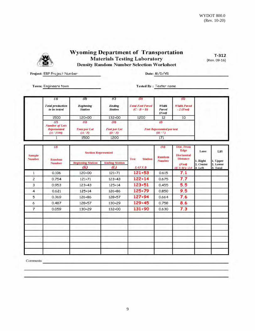
WYDOT 800.0 (Rev. 10-20)
9

WYDOT 800.0 (Rev. 10-20)
10
(This page intentionally left blank.)

WYDOT 801.0 (Rev. 10-19)
1
VERIFICATION OF ACCURACY OF ELECTRONIC GENERAL PURPOSE BALANCE
Scope: This method describes the verification procedure for balances used for WYDOT projects. Perform this verification in accordance with ASTM E617 annually, each time the scale is moved inside the lab or the lab trailer is moved, and when concerns of accuracy come into question.
Apparatus: A balance that has the capacity and readability for the test being performed per
WYDOT 814.0 Sieve Analysis of Combined Aggregate. Class 4 (AASHTO M231-95) or (ASTM E 617) weights
Reference Documents:
AASHTO M231-95 Standard Specification for Weighing Devices Used in the Testing of Materials
ASTM E617 Standard Specification for Laboratory Weights and Precision Mass Standards WYDOT 814.0 Sieve Analysis of Combined Aggregate WYDOT T-313 Balance Verification Worksheet Procedure: 1. Setup the balance in a location away from drafts or excessive air movement that might affect the read-out.
2. Level the balance and if weighing in water, observe that the suspension apparatus is free of any obstructions that might affect its movement.
3. For balances with anticipated usage up to and including 10,000 grams, the
verification weights will be 100 grams, 1,000 grams, 5,000 grams, and 10,000 grams.
4. Balances with anticipated usage over 10,000 grams, the verification weights
will be 5,000 grams, 10,000, and 15,000 grams.
5. If one balance is to be used for both of the listed ranges, verify using all weights.
6. Place the weight per verification in five locations of the balance (the center
and four corners) using the full range and record the actual weight obtained.
7. The allowable tolerance per verification is ± 0.1% of the weight used.

WYDOT 801.0 (Rev. 10-19)
2
8. If any recorded weight exceeds the allowable range, discontinue use of the balance until the balance is calibrated or repaired and a complete new verification is performed.
9. Copies of all worksheets will be signed by the individual performing the
verification and will be kept with the balance.
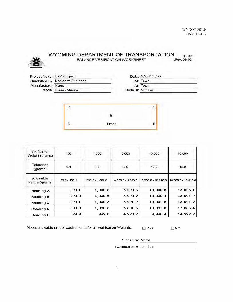
WYDOT 801.0 (Rev. 10-19)
3

WYDOT 801.0 (Rev. 10-19)
4
(This page intentionally left blank.)
WYDOT 802.0 (Rev. 09-16)
1
PREPARATION OF SAMPLES FOR PHYSICAL TESTS
Scope: This method describes the preparation of samples for physical tests which usually
include liquid limit (WYDOT 812.0) and plastic limit (WYDOT 813.0) tests. This procedure is technically equivalent, but not identical, to AASHTO T 87.
Apparatus: 1. Sieves; No. 10 and No. 40 [2.00 mm and 425 µm] 2. Mortar and pestle 3. Sample splitter 4. Drying stove 5. Square pan 15 inch, suggested 6. Trowel Reference Documents: AASHTO R 58 Standard Method of Test for Dry Preparation of Disturbed
Soil and Soil-Aggregate Samples for Test WYDOT 812.0 Liquid Limit Test WYDOT 813.0 Plastic Limit Test & Plasticity Index Procedure: 1. Air dry the sample thoroughly. Samples dried to a workable condition in
an oven or other drying apparatus at a temperature not exceeding 140° F are considered to be air dried. This can be accomplished by using a low flame and constant stirring with the trowel.
Note: For soils, the sample needs to be workable; not dried to a
constant mass.
2. Reduce the sample to a convenient size by use of the sample splitter, about 0.5 lb is sufficient.
3. Separate the soil and rock on the No. 10 sieve. Grind material remaining
on the No. 10 sieve in a mortar with a rubber covered pestle until the soil particles are broken into separate grains. Discard the fraction retained on the No. 10 sieve after the second sieving.
4. The remaining portion passing the No. 10 sieve will be separated into two
parts by means of the No. 40 sieve, grinding lightly, break up between each of the screenings with the rubber covered pestle. Care must be taken not to pulverize aggregate, only a rubbing action is needed to free clay particles from the coarser aggregate. Discard the material remaining on the No. 40 sieve when repeated grinding produces only small quantities passing the No. 40 sieve.

WYDOT 802.0 (Rev. 09-16)
2
5. Thoroughly mix the remaining material that passes the No. 40 sieve and set aside for testing.
6. Remove the sample for testing with a scoop or spoon. Do not pour as
pouring will cause segregation.
WYDOT 803.0 (Rev. 10-17)
AGGREGATE SAMPLING AND QUANTITY Scope: This procedure is used when samples of aggregate are taken either for mix design
or for maximum density/optimum moisture as used in density testing. Apparatus: 1. Shovel 2. Canvas sample sacks 3. Sample splitter Reference Documents: AASHTO T 180 Standard Method of Test for Moisture-Density Relations of
Soils Using a 4.54-kg (10-lb) Rammer and a 457-mm (18-in.) Drop
WYDOT 414.0 Marshall and Superpave Mix Design and Mix Volumetric Verification Procedure
WYDOT 804.0 Aggregate Sampling WYDOT T-120 Sample Transmittal WYDOT T-166 Aggregate Analysis Sampling: See Aggregate Sampling procedures in WYDOT 804.0.
A completed Form T-120, Sample Transmittal, Complete and submit Form T-166, Aggregate Analysis.
Note: The WYDOT Materials Program will furnish optimum moisture and maximum dry density when requested.
Use sample sacks made of canvas. The sample weight per canvas sack will be
30 lb to 50 lb. Do not exceed 50 lb per sample. Procedure: Examples of Form T-166 describing the information needed by the WYDOT
Materials Program to complete mix design or maximum density follow. Provide, at a minimum, the quantity of material according to the following: Subbase or Blended Subbase 150 lb each stockpile Crushed Base 150 lb (AASHTO T 180) Blended Crushed Base each stockpile Hot Plant Mix Aggregate 100 lb each stockpile – Non-Superpave 150 lb each stockpile – Superpave Reclaimed Asphalt Pavement 120 lb each stockpile* (RAP) * refer to WYDOT 414.0 for sampling guidelines

WYDOT 803.0 (Rev. 10-17)
2
Microsurfacing 100 lb each stockpile Plant Mix Wearing Course 100 lb when one stockpile is used 70 lb each additional stockpile Maintenance Stockpiles 180 lb each stockpile Concrete Mix Design - Silica Fume 100 lb cement 300 lb fines
400 lb coarse 25 lb silica fume 1 lb fiber 1 quart each admixture
- Structural Concrete 50 lb fly ash (A / B / S Class) 140 lb cement
400 lb fines 600 lb coarse 1 quart each admixture
- PCCP 50 lb fly ash 140 lb cement
600 lb fines 775 lb coarse 1 quart each admixture

WYDOT 804.0 (Rev. 09-16)
1
AGGREGATE SAMPLING
Scope: This procedure covers the methods of obtaining representative aggregate samples
of a finished gradation product taken at the end of the production line. Care must be taken to get samples that will provide test data that is truly representative of either the preliminary crushed or final accepted aggregate product. This procedure is similar but not technically equivalent to AASHTO T 2:
1. AASHTO T 2 requires a minimum three belt samples be collected and
combined to obtain a representative sample. This procedure requires only one sample be collected at approximately the middle one-third of the conveyor belt.
2. AASHTO T 2 requires the minimum weight of sample be determined
based on the nominal maximum size. This procedure requires a minimum 30 lb in every case.
3. AASHTO T 2 does not include a procedure on how to sample from a
windrow. Apparatus: 1. Flat square-nose shovel 2. Flat square-nose scoop or dust pan and brush 3. Conveyor belt template (furnished by the contractor to fit the shape of the
conveyor belt) 4. Canvas sample sack or container able to hold 30 lb to 50 lb of aggregate at
one time
Note: Samples submitted to WYDOT must be in a canvas sample sack. If sample is furnished in other type of container, it must be transferred to a canvas sample sack prior to submittal to WYDOT. Care must be taken not to segregate or lose any of the sample during the transfer.
Reference Documents: AASHTO T 2 Standard Method of Test for Sampling of Aggregates WYDOT 800.2 WYDOT Standard Specifications WYDOT 804.0 Correlation of Aggregate Gradation Test Results WYDOT T-165AG Correlation of Aggregate Gradations
WYDOT 804.0 (Rev. 09-16)
2
Procedure: Conveyor Belt
1. Obtain conveyor belt samples of the finished product before the addition of any additives (cement, fly-ash, lime, asphalt, and etc.).
2. Stop the conveyor belt while sampling. To prevent accidental startups, the
conveyor belt will be equipped with a keylock on/off switch or a switch in a lockout box which can either be key-locked or padlocked in the “off” position. The person doing the sampling will keep the key with them and return it after the conveyor belt is clear of any sampling equipment and/or personnel.
3. Scaffolding will be attached to the conveyor belt framework having a non-
slip walking surface, toe plate and safety hand rail.
4. Sample the conveyor belt approximately in the middle one-third. Take the sample when the belt is filled to approximately 80 percent or more of the normal production capacity. Sampling will not be taken over the rollers of the conveyor belt to avoid segregation. Note: In the presence of WYDOT personnel sampling of the conveyor
belt should be performed by the contractor’s representative.
5. Using the template furnished by the contractor, saw back and forth until the template is all the way through the aggregate stream and onto the conveyor belt. The material between the template will yield a minimum of 30 lb and be placed into a container which is of sufficient capacity that none of the material is lost during sampling or hauling. Any fines left on the belt must be cleaned off with a brush and flat square nose scoop or dust pan and added to the sample.
Note: The template shape conforms to the shape of the conveyor belt in
the aggregate stream on the conveyor belt.
6. When more than one sample is being taken, another cut into the stream of aggregate should be taken as close as possible to the first cut making sure that the stream was not disturbed by the first cut. This procedure may be repeated as many times as needed to obtain the necessary number of samples.
Windrow
1. Sampling of a windrow for final acceptance of gradation material is
allowable when there is no conveyor belt available.

WYDOT 804.0 (Rev. 09-16)
3
2. The windrow sampling location will be randomly selected by WYDOT personnel with notification given to the contractor's representative so that arrangements can be made for the proper equipment (blade, loader bucket, or jersey spreader).
3. Flatten the windrow to approximately an 8 inch depth for at least 6 feet in
length.
4. Divide the spread-out windrow into four quarters. Sample each quarter getting enough material from each quarter so that when combined, the sample will weigh at least 30 lb. Use a flat square nose shovel to dig into each quarter at a 45 degree angle, sampling the entire 8 inch depth while being careful not to contaminate any of the samples with material from beneath the flattened windrow.
Stockpile
1. It is recommended that every effort be made to get conveyor belt samples during preliminary production and stockpiling. In sampling material from stockpiles, it is difficult to ensure unbiased samples.
2. Stockpile samples which can be taken of a finished product for project
acceptance is limited as described per WYDOT Standard Specifications Section 800.2 (Point of Sampling).
Note: All other aggregates will be sampled from either the conveyor belt
or a windrow.
3. A representative sample of the aggregate is difficult to obtain when sampling a stockpile due to segregation of the material. A visual examination of stockpiles will show segregation along the outside slope and base of the pile, with the coarser material usually rolling along the outside slope. Shoveling to get a representative samples from the base or slope is not practical. Therefore, it will be necessary to use a loader to dig into the stockpile and transfer the material to a flat level surface. In some unusual cases depending on the variability of the material, it may be necessary to sample the pile at more than one location.
4. Spread the material and flatten to approximately an 8 inch depth.
5. Divide the flattened material into four quarters. Sample each quarter to get
enough material from each quarter so when combined the sample will weigh at least 30 lb. Use a flat square nose shovel to dig into at a 45 degree angle; sample the entire 8 inch depth being careful not to contaminate the samples with underlying material.
WYDOT 804.0 (Rev. 09-16)
4
Check Samples
1. When check samples are taken, approximately 30 lb of additional material will be needed. Combine both samples. Split out approximately a 30 lb field sample and send the remaining sample to the Materials Program in a canvas sack.
Note: Preliminary crushing tests are for informational purposes only and
are not to be used for final acceptance. During preliminary crushing, tests for correlation of testers can be performed and reported on Form T-165AG. Refer to WYDOT 126.0 for correlation procedure.
WYDOT 805.0 (Rev. 09-16)
1
SAMPLE SPLITTING BY MECHANICAL SPLITTER Scope: This method covers the procedure for reducing a representative sample of
aggregate to the appropriate size for testing. This technique is intended to minimize variation of sample characteristics between representative field sample and test samples. This method is intended to be conducted such that the smaller test sample portion is representative of the larger sample and thus, of the total supply.
This procedure is technically equivalent but not identical to AASHTO T 248
Standard Method of Test for Reducing Samples of Aggregate to Testing Size. Apparatus: Sample Splitter having
1. An even number of equal width chutes, but not less than a total of eight for coarse aggregate or twelve for fine aggregate which discharge alternately to each side of the splitter.
2. A minimum width of the individual chutes that are approximately 50 percent larger than the largest particle in the sample to be split for coarse aggregate and mixed aggregate. For dry fine aggregate, this minimum width must be at least 50 percent larger than the largest particle in the sample and the maximum width will be ¾ inch.
3. Two receptacles, metal pans of any type, to hold the split halves of the sample following the splitting process.
4. A hopper or straight-edged pan with a width equal to or slightly less than the overall width of the assembly chutes to feed a sample at a controlled rate to the chutes.
5. All splitter and accessory equipment should be designed so that the sample will flow smoothly without restriction or loss of material.
Reference Documents: AASHTO T 248 Standard Method of Test for Reducing Samples of
Aggregate to Testing Size Selection of Method: Fine Aggregate Reduce samples of the fine aggregate that are drier than the saturated-
surface-dry condition in size by use of a mechanical splitter. Samples having free moisture on the particle surfaces may be reduced in size by use of a mechanical splitter after drying to saturated-surface-dry conditions. To dry samples to saturated-surface-dry, use temperatures that do not exceed those specified for any tests contemplated. Alternatively, if the moist sample is very large, a preliminary split may be made using a

WYDOT 805.0 (Rev. 09-16)
2
mechanical splitter having wide chute openings of 1½ inch or more to reduce the sample to not less than 11 lb. As a quick approximation, if the fine aggregate will retain its shape when molded in the hand, it is considered wetter than saturated-surface-dry.
Coarse Aggregate and Mixtures of Coarse and Fine Aggregate Reduce the sample in accordance with this procedure. Avoid splitting samples when reducing the sample size will result in non-
representative split samples. Aggregate samples having relatively few large-sized particles in the sample dictates by the laws of chance that these few particles would not be equally distributed.
Procedure: Ensure that the splitter is placed on a level surface and is secure to the floor; the splitter should not rock or wobble. Uniformly place the sample to be split in the hopper so that when it is introduced into the chutes, approximately equal amounts will flow through each chute. Do not use your hands to redistribute the material.
Introduce the sample at a rate that allows free flow through the chutes and into the
receptacles below. Reintroduce the portion of the sample in one of the receptacles into the splitter as
many times as necessary to reduce the sample to the size specified for the intended test. The portion of the material collected in the other receptacle may be reserved for reduction in size for other tests.
WYDOT 810.0 (Rev. 01-15)
1
SOUNDNESS OF AGGREGATE BY USE OF SODIUM SULFATE
OR MAGNESIUM SULFATE
Scope: This test method describes the procedure to determine the resistance of aggregates to break down or disintegrate.
Use: This testing requires repeated immersions of the aggregate in saturated solutions
of sodium or magnesium sulfate. The procedure simulates weathering conditions. Reference Documents: AASHTO T 104 Standard Method of Test for Soundness of Aggregate by
Use of Sodium Sulfate or Magnesium Sulfate WYDOT E-46 Job Mix Formula WYDOT T-100PE Portland Cement Concrete Mix Design: Pavement WYDOT T-100SE Portland Cement Concrete Mix Design: Structural Procedure: Perform according to AASHTO T 104 Standard Method of Test for Soundness of
Aggregate by Use of Sodium Sulfate or Magnesium Sulfate.
Test results using the two salts (MgSO4 or NaSO4) differ considerably and care must be taken in using the appropriate salt solution. Use the salt solution specified; typically sodium sulfate is used on concrete aggregate and magnesium sulfate used on base and hot plant mix aggregate.
The required number of cycles is five, and the test will be performed on both Coarse (plus No. 4) and Fine (minus No. 4) material for concrete aggregate and the coarse aggregate for other surfacing aggregates.
Report test results on the appropriate Form:
E-46, Job Mix Formula (Contractor Furnished Sources) T-100PE, Portland Cement Concrete Pavement Mix Design
T-100SE, Structural Concrete Mix Design

WYDOT 810.0 (Rev. 01-15)
2
(This page intentionally left blank.)
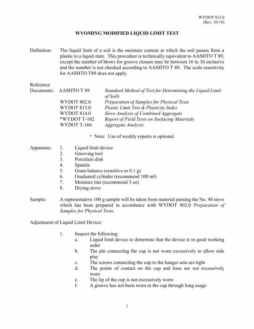
WYDOT 812.0 (Rev. 10-19)
1
WYOMING MODIFIED LIQUID LIMIT TEST
Definition: The liquid limit of a soil is the moisture content at which the soil passes from a
plastic to a liquid state. This procedure is technically equivalent to AASHTO T 89, except the number of blows for groove closure may be between 16 to 36 inclusive and the number is not checked according to AASHTO T 89. The scale sensitivity for AASHTO T89 does not apply.
Reference Documents: AASHTO T 89 Standard Method of Test for Determining the Liquid Limit
of Soils WYDOT 802.0 Preparation of Samples for Physical Tests WYDOT 813.0 Plastic Limit Test & Plasticity Index WYDOT 814.0 Sieve Analysis of Combined Aggregate *WYDOT T-102 Report of Field Tests on Surfacing Materials WYDOT T-166 Aggregate Analysis * Note: Use of weekly reports is optional
Apparatus: 1. Liquid limit device 2. Grooving tool
3. Porcelain dish 4. Spatula
5. Gram balance (sensitive to 0.1 g) 6. Graduated cylinder (recommend 100 ml) 7. Moisture tins (recommend 3 oz) 8. Drying stove Sample: A representative 100 g sample will be taken from material passing the No. 40 sieve
which has been prepared in accordance with WYDOT 802.0 Preparation of Samples for Physical Tests.
Adjustment of Liquid Limit Device:
1. Inspect the following: a. Liquid limit device to determine that the device is in good working
order b. The pin connecting the cup is not worn excessively to allow side
play c. The screws connecting the cup to the hanger arm are tight d. The points of contact on the cup and base are not excessively
worn e. The lip of the cup is not excessively worn f. A groove has not been worn in the cup through long usage
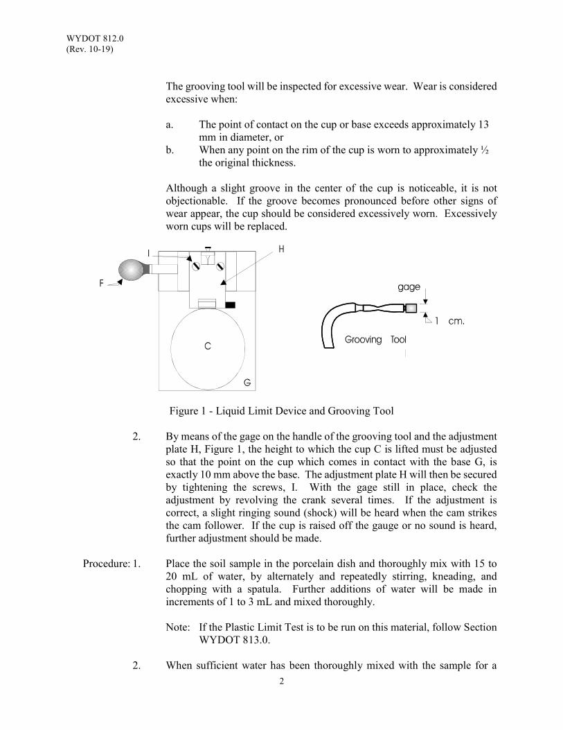
WYDOT 812.0 (Rev. 10-19)
2
The grooving tool will be inspected for excessive wear. Wear is considered
excessive when: a. The point of contact on the cup or base exceeds approximately 13 mm in diameter, or b. When any point on the rim of the cup is worn to approximately ½ the original thickness. Although a slight groove in the center of the cup is noticeable, it is not objectionable. If the groove becomes pronounced before other signs of wear appear, the cup should be considered excessively worn. Excessively worn cups will be replaced.
Figure 1 - Liquid Limit Device and Grooving Tool
2. By means of the gage on the handle of the grooving tool and the adjustment plate H, Figure 1, the height to which the cup C is lifted must be adjusted so that the point on the cup which comes in contact with the base G, is exactly 10 mm above the base. The adjustment plate H will then be secured by tightening the screws, I. With the gage still in place, check the adjustment by revolving the crank several times. If the adjustment is correct, a slight ringing sound (shock) will be heard when the cam strikes the cam follower. If the cup is raised off the gauge or no sound is heard, further adjustment should be made.
Procedure: 1. Place the soil sample in the porcelain dish and thoroughly mix with 15 to
20 mL of water, by alternately and repeatedly stirring, kneading, and chopping with a spatula. Further additions of water will be made in increments of 1 to 3 mL and mixed thoroughly.
Note: If the Plastic Limit Test is to be run on this material, follow Section
WYDOT 813.0.
2. When sufficient water has been thoroughly mixed with the sample for a
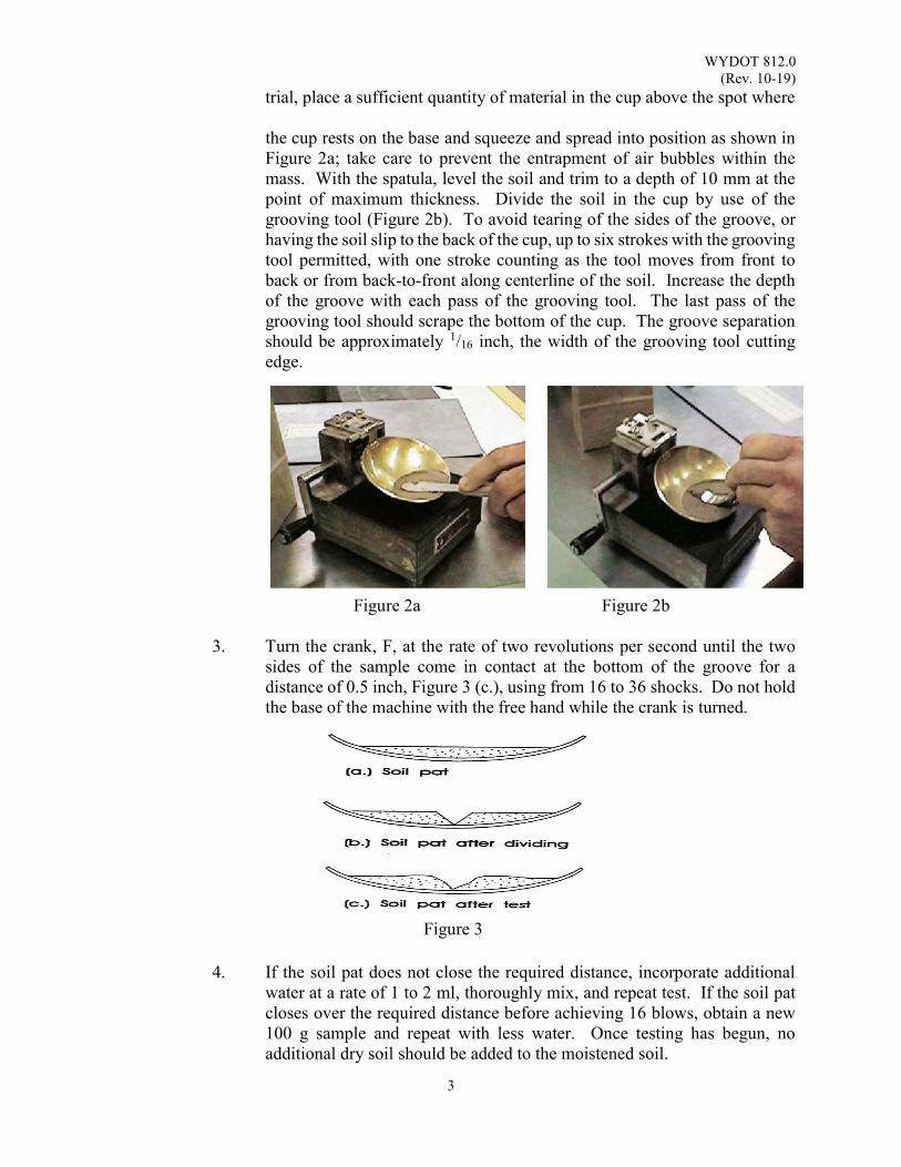
WYDOT 812.0 (Rev. 10-19)
3
trial, place a sufficient quantity of material in the cup above the spot where the cup rests on the base and squeeze and spread into position as shown in
Figure 2a; take care to prevent the entrapment of air bubbles within the mass. With the spatula, level the soil and trim to a depth of 10 mm at the point of maximum thickness. Divide the soil in the cup by use of the grooving tool (Figure 2b). To avoid tearing of the sides of the groove, or having the soil slip to the back of the cup, up to six strokes with the grooving tool permitted, with one stroke counting as the tool moves from front to back or from back-to-front along centerline of the soil. Increase the depth of the groove with each pass of the grooving tool. The last pass of the grooving tool should scrape the bottom of the cup. The groove separation should be approximately 1/16 inch, the width of the grooving tool cutting edge.
Figure 2a Figure 2b 3. Turn the crank, F, at the rate of two revolutions per second until the two
sides of the sample come in contact at the bottom of the groove for a distance of 0.5 inch, Figure 3 (c.), using from 16 to 36 shocks. Do not hold the base of the machine with the free hand while the crank is turned.
4. If the soil pat does not close the required distance, incorporate additional
water at a rate of 1 to 2 ml, thoroughly mix, and repeat test. If the soil pat closes over the required distance before achieving 16 blows, obtain a new 100 g sample and repeat with less water. Once testing has begun, no additional dry soil should be added to the moistened soil.
Figure 3
WYDOT 812.0 (Rev. 10-19)
4
5. When the soil pat closes the required distance within the 16 to 36 shocks, take a moisture sample as follows: Slice the soil, about 0.75 inch in width, extending from edge to edge of the soil pat at right angles to the groove and including that portion of the groove in which the soil flowed together.
6. Place the moisture sample in a moisture tin, weigh, dry over a stove, and
weigh again. Take care to avoid burning the moisture sample.
Calculation of Moisture: (Wet soil and tin, g) - (Dry soil and tin, g) = Weight of water, g (Dry soil and tin, g) - (Tare of tin, g) = Weight of Dry soil, g
% of Moisture = Weight of Water, g
Weight of Dry Soil, g × 100
% moisture in sample x correction factor = Liquid Limit
Note: Liquid Limit is rounded to the whole number.
7. On some sandy materials, the liquid limit cannot be determined. The material in the cup will slide or bounce together, rather than flow together. In this case, mark the liquid limit as no value (NV) and the plastic index as non-plastic (NP).
8. Record daily test results on Form T-166, Aggregate Analysis and weekly
test results on optional Form T-102, Report of Field Test on Surfacing Materials. For examples, see section WYDOT 814.0.
CORRECTION CHART
Number of Shocks Correction Factor Number of Shocks Correction Factor
16 0.947 27 1.009
17 0.954 28 1.014
18 0.961 29 1.018
19 0.967 30 1.022
20 0.973 31 1.026
21 0.979 32 1.030
22 0.985 33 1.034
23 0.985 34 1.038
24 0.995 35 1.042
25 1.000 36 1.045
26 1.005
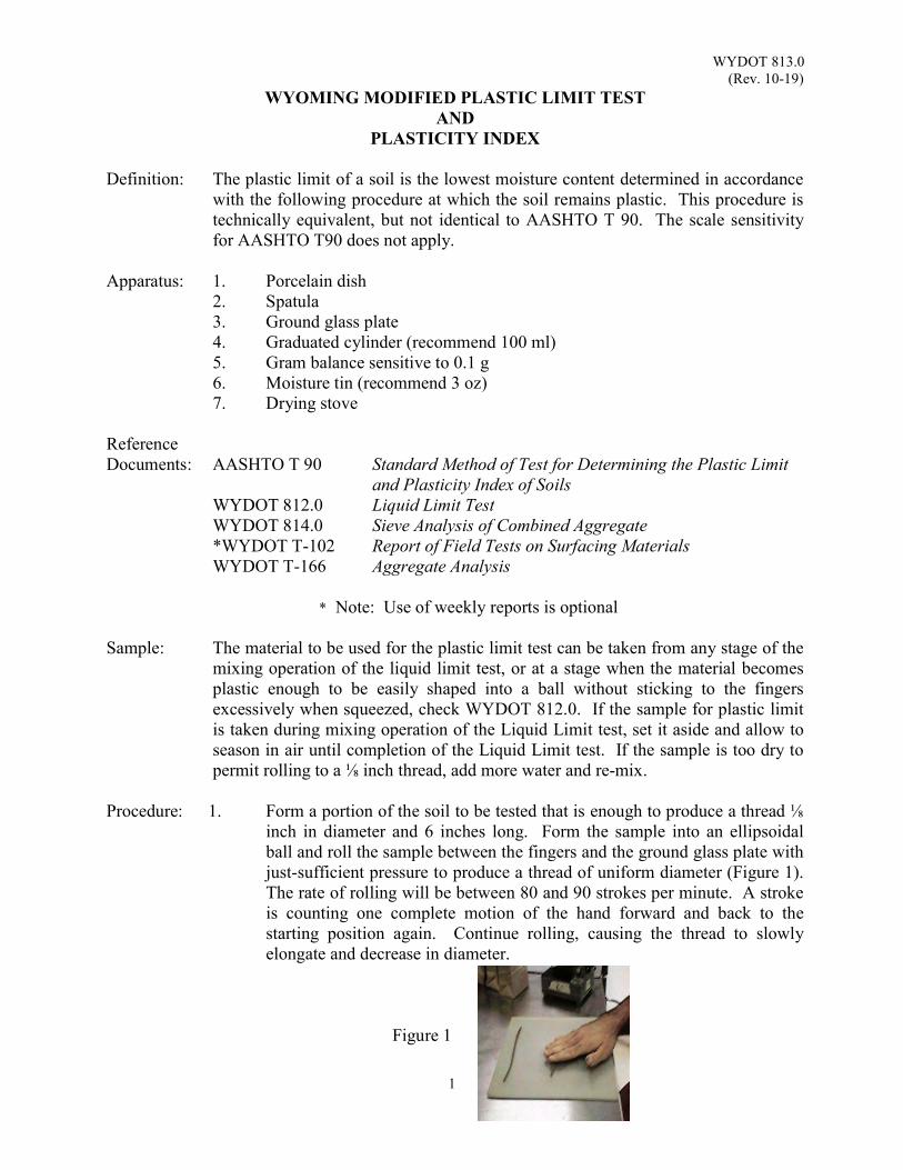
WYDOT 813.0 (Rev. 10-19)
1
WYOMING MODIFIED PLASTIC LIMIT TEST AND
PLASTICITY INDEX Definition: The plastic limit of a soil is the lowest moisture content determined in accordance
with the following procedure at which the soil remains plastic. This procedure is technically equivalent, but not identical to AASHTO T 90. The scale sensitivity for AASHTO T90 does not apply.
Apparatus: 1. Porcelain dish 2. Spatula 3. Ground glass plate
4. Graduated cylinder (recommend 100 ml) 5. Gram balance sensitive to 0.1 g 6. Moisture tin (recommend 3 oz) 7. Drying stove
Reference Documents: AASHTO T 90 Standard Method of Test for Determining the Plastic Limit
and Plasticity Index of Soils WYDOT 812.0 Liquid Limit Test WYDOT 814.0 Sieve Analysis of Combined Aggregate *WYDOT T-102 Report of Field Tests on Surfacing Materials WYDOT T-166 Aggregate Analysis
* Note: Use of weekly reports is optional Sample: The material to be used for the plastic limit test can be taken from any stage of the
mixing operation of the liquid limit test, or at a stage when the material becomes plastic enough to be easily shaped into a ball without sticking to the fingers excessively when squeezed, check WYDOT 812.0. If the sample for plastic limit is taken during mixing operation of the Liquid Limit test, set it aside and allow to season in air until completion of the Liquid Limit test. If the sample is too dry to permit rolling to a ⅛ inch thread, add more water and re-mix.
Procedure: 1. Form a portion of the soil to be tested that is enough to produce a thread ⅛
inch in diameter and 6 inches long. Form the sample into an ellipsoidal ball and roll the sample between the fingers and the ground glass plate with just-sufficient pressure to produce a thread of uniform diameter (Figure 1). The rate of rolling will be between 80 and 90 strokes per minute. A stroke is counting one complete motion of the hand forward and back to the starting position again. Continue rolling, causing the thread to slowly elongate and decrease in diameter.
Figure 1
WYDOT 813.0 (Rev. 10-19)
2
2. When the diameter of the thread becomes ⅛ inch, break and re-roll the thread: Continue this alternate rolling to a ⅛ inch diameter thread, gathering together, kneading and rolling, until the thread crumbles under the slight pressure required for rolling and the soil can no longer be rolled into a ⅛ inch thread. Crumbling may occur when the thread has a diameter greater than ⅛ inch. Consider this a satisfactory end point, provided the soil has previously rolled into a thread ⅛ inch in diameter.
3. As the soil crumbles, place the soil in a tared moisture tin with an air-tight
lid until you have approximately 15 to 20 g of material. To avoid moisture loss, keep tin covered until wet weight has been recorded. Thoroughly dry the sample, using extreme care not to burn the sample. Record the dry weight of the material and container.
Calculation of Moisture: (Wet soil and tin, g) - (Dry soil and tin, g) = Weight of water, g (Dry soil and tin, g) - (Tare of tin, g) = Weight of Dry soil, g
% of Moisture = ,
, × 100
The percent of moisture is the plastic limit.
Note: Plastic limit and plastic index is rounded to the whole number.
PLASTICITY INDEX Definition: The plasticity index (PI) of a soil is the numerical difference between liquid limit
and the plastic limit. It is the range in water content within which the material is in a plastic state.
Calculation to determine Plastic Index:
(Liquid Limit) - (Plastic Limit) = Plasticity Index Non-Plastic Soils (NP)
1. When the plastic limit is equal to or greater than the liquid limit, mark the
plasticity index as non-plastic (NP).
2. When soil cannot be rolled to a tread of ⅛ inch diameter in the first try when the moisture is equal to or slightly greater than the liquid limit, the soil is non-plastic (NP).
3. Record daily test results on Form T-166, Aggregate Analysis and weekly
test results on optional Form T-102, Report of Field Test on Surfacing Materials. For example, see section WYDOT 814.0. Refer to routing on form.
WYDOT 814.0 (Rev. 10-18)
1
SIEVE ANALYSIS OF COMBINED AGGREGATE
Scope: This procedure is technically equivalent, but not identical to AASHTO T 27 and
AASHTO T 11. This test method describes the procedure for determining particle size distribution of a combined aggregate using a large mechanical sieve shaker. A combined aggregate is defined as an aggregate containing both coarse and fine fractions. The results will primarily be used to determine compliance with specifications of product control of the following:
Hot Plant Mix Base Plant Mix Wearing Course Subbase Chip Seal Concrete Micro surfacing Blotter Maintenance Stockpile Aggregate Bed Course Material Gravel for Drains Class B Bedding Pervious Backfill Riprap Filter Gravel for Bedding Etc.
Apparatus: 1. Large mechanical shaker with appropriate sized testing screens. For
example: (Gilson model TS-1 or TS-2) Note: A large mechanical shaker must be able to handle a 30 lb sample
without overloading the screens. The stack of 8 inch or 12 inch sieves is not equivalent to a large mechanical shaker.
2. Washpan with sufficient capacity to allow enough water to completely
cover wash sample 3. Balance(s)
Scale Sensitivity * Sample Weight
0.1 g 4 lb or less 1.0 g 4 lb to 11 lb 5.0 g 11 lb to 44 lb
20.0 g 44 lb plus * Based off of nominal maximum size 4. Drying stove 5. Splitting device 6. 8 inch U.S. standard sieves with a snug-fitting nested cover 7. 8 inch sieve shaker with a minimum ¼ hp motor, combined back and forth
lateral motion and up-and-down tilting motion, and 15 minute electric reset timer switch with a hold feature for continuous operation
WYDOT 814.0 (Rev. 10-18)
2
Reference Documents: AASHTO T 11 Standard Method of Test for Material Finer Than 75-µm
(No. 200) Sieve in Mineral Aggregates by Washing AASHTO T 27 Standard Method of Test for Sieve Analysis of Fine and
Coarse Aggregates WYDOT 803 WYDOT Standard Specifications WYDOT 802.0 Preparation of Samples for Physical Tests WYDOT 804.0 Aggregate Sampling WYDOT 805.0 Sample Splitting by Mechanical Splitter WYDOT 812.0 Liquid Limit Test WYDOT 813.0 Plastic Limit Test and Plasticity Index *WYDOT T-102 Report of Field Tests on Surfacing Materials WYDOT T-120 Pay Adjustment for Aggregate Gradation WYDOT T-166 Aggregate Analysis * Note: Use of weekly reports is optional
Sampling: The sampling location and procedure is outlined in section WYDOT 804.0.
Aggregate to be tested for gradation acceptance should be free of any additives. Note: Before proceeding, check the equipment; (scale, sieves, etc.). Check for
condition, calibration, level and cleanliness. Nest the required sieves in the proper order.
Procedure: 1. Weigh the entire sample. Record the wet weight (mass) in the “%
Moisture” section on Form T-166, Aggregate Analysis.
Note: Weigh material to the nearest 0.1 percent of the total original dry sample mass. Requirement for 30 lb to 50 lb sample weight is to the nearest hundredth (0.01).
2. Dry the sample. Control the temperature so the heat used will allow steam
to escape without generating enough pressure to fracture any of the particles of the sample.
3. Allow the test sample to cool to room temperature, weigh the dried and
cooled test sample.
Record this weight (mass) as the Dry weight in the % Moisture Section.
The Dry weight (mass) is subtracted from the Wet weight (mass) to determine the amount of moisture. The amount of moisture is divided by the Dry weight times 100 to determine the percent of moisture in the sample.
Wet Dry Moisture
%Moisture MoistureDry
100
WYDOT 814.0 (Rev. 10-18)
3
Constant mass is when the weight does not change by more than 0.1 percent of the original dry sample mass.
OriginalDryWeightDryWeight
100 within0.1%
Note: Original Dry weight (mass) may change as sample becomes drier.
4. Determine test sample size. Generally it is not necessary to reduce the sample weight by splitting to less
than 30 lb when using the large mechanical sieve shaker. Take care not to overload an individual sieve when working with aggregates, which typically collect on the No. 4 sieve. If it is necessary to reduce the sample size, follow procedure WYDOT 805.0 Sample Splitting by Mechanical Splitter. A larger test sample should increase the accuracy of the results. In no case should the size of the test sample be less than: Note: Nominal maximum size aggregate is one size larger than the first
specification sieve to retain more than 10 percent.
5. Clamp down the sieve trays, start shaker, then slowly add sample. Follow the instructions outlined in the mechanical sieve shaker "Operating and Service Manual" for tightening the sieve trays. Shake until no material can be observed falling free from one sieve to another.
Note: Excessive time (more than approximately ten minutes) to achieve
adequate sieving may result in damage to the sample.
6. Continue sieving for a sufficient time period and in such manner that, after completion, not more than 0.5 percent by mass of the total sample passes any sieve during one minute of continuous hand sieving performed as follows:
Selecting the sieve with the most retained material, hold the
individual sieve, with a snug fitting pan and cover attached, in a slightly inclined position in one hand. Strike the side of the sieve sharply and with an upward motion against the heel of the other hand at the rate of about 150 times per minute, turn the sieve about
Nominal Maximum Size
Aggregate
Minimum Weight of Test Sample
⅜ inch 2 lb ½ inch 4 lb ¾ inch 11 lb 1 inch 22 lb
1½ inch 30 lb
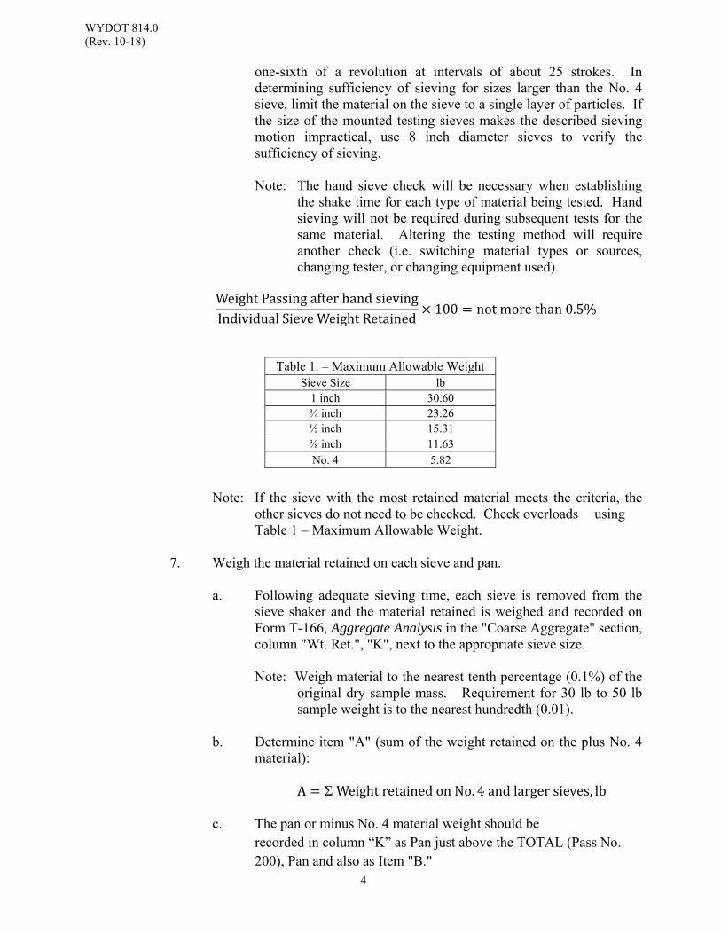
WYDOT 814.0 (Rev. 10-18)
4
one-sixth of a revolution at intervals of about 25 strokes. In determining sufficiency of sieving for sizes larger than the No. 4 sieve, limit the material on the sieve to a single layer of particles. If the size of the mounted testing sieves makes the described sieving motion impractical, use 8 inch diameter sieves to verify the sufficiency of sieving.
Note: The hand sieve check will be necessary when establishing
the shake time for each type of material being tested. Hand sieving will not be required during subsequent tests for the same material. Altering the testing method will require another check (i.e. switching material types or sources, changing tester, or changing equipment used).
WeightPassingafterhandsievingIndividualSieveWeightRetained
100 notmorethan0.5%
Note: If the sieve with the most retained material meets the criteria, the other sieves do not need to be checked. Check overloads using Table 1 – Maximum Allowable Weight.
7. Weigh the material retained on each sieve and pan.
a. Following adequate sieving time, each sieve is removed from the sieve shaker and the material retained is weighed and recorded on Form T-166, Aggregate Analysis in the "Coarse Aggregate" section, column "Wt. Ret.", "K", next to the appropriate sieve size.
Note: Weigh material to the nearest tenth percentage (0.1%) of the
original dry sample mass. Requirement for 30 lb to 50 lb sample weight is to the nearest hundredth (0.01).
b. Determine item "A" (sum of the weight retained on the plus No. 4
material):
A Σ WeightretainedonNo. 4andlargersieves, lb
c. The pan or minus No. 4 material weight should be recorded in column “K” as Pan just above the TOTAL (Pass No. 200), Pan and also as Item "B."
Table 1. – Maximum Allowable Weight Sieve Size lb
1 inch 30.60 ¾ inch 23.26 ½ inch 15.31 ⅜ inch 11.63 No. 4 5.82

WYDOT 814.0 (Rev. 10-18)
5
d. The total of column “K”, the material mass on sieves and in the pan will be within 0.3 percent, based on the original dry sample mass recorded as Dry Weight in the % Moisture Section in Step 4.
E DE
100 percentchange
Note: If the percent change differs by more than 0.3 percent, based on the original dry sample mass, the results should not be used for acceptance evaluation and another sample should be obtained.
e. Determine item "H" (percent retained plus No. 4 material):
HAD
100
f. Determine item "I" (percent passing the No. 4 sieve):
IBD
100
Note: On Form T-166, Aggregate Analysis items
Combined Aggregate items:
A = Sum of weight retained No. 4 material and above, lb B = Weight passing No. 4 sieve, lb D = Total dry sample weight measured after sieving, lb E = Total dry sample weight, lb H = Percent retained plus No. 4 material I = Percent passing minus No. 4 material K = Weight retained per sieve and Pan, lb
8. Split the fines (minus No. 4 material) to a minimum of 300 g.
Follow the procedure outlined in WYDOT 805.0 Sample Splitting by Mechanical Splitter.
9. After splitting, weigh the reduced fines (minus No. 4) sample.
Record the weight in "Fine Aggregate" section as "Sample Wt." item "F".
Note: Record fines (minus No. 4) to the nearest 0.10 of a g.

WYDOT 814.0 (Rev. 10-18)
6
10. Wash the fines (minus No. 4 material).
Add enough water to the sample container to cover the sample. Agitate with sufficient vigor to separate and suspend the minus No. 200 material. Pour off the dirty water into a nested No. 8 and No. 200 sieve (8 inch or 12 inch diameter). The No. 200 sieve should be placed in the sink with one side propped up about ½ inch so that the water will flow freely. Add more water, agitate, and pour off the dirty water. Repeat this operation until the wash water is clear. Fines retained on the No. 200 sieve after washing will need to be cleaned of any trapped minus No. 200 material. Use tool or spoon to agitate the material in the wash pan; do not use hand or any tool on the material within the No. 200 sieve or on the screen itself. Do not hit the screen. Wash the retained material into a pile on one side of the screen.
With the sieve held over the sink, use the heel of free hand to tap the outside edge to help dry and loosen the retained material. When the material starts moving around, empty the material into the washpan by tapping on the outside edge of the sieve. Any material still retained should be washed into the washpan using as little water as possible.
11. Dry the washed sample.
If direct heat is used, popping or sputtering can be controlled by covering the sample container. After enough steam has escaped, the sample can be uncovered. Make sure any material retained on the cover is returned to the sample.
If oven drying is used, “dry” is when the fines are a constant mass at a temperature of 230 ± 9 oF.
12. Weigh the dried wash sample.
Record the weight (mass) in the "Fine Aggregate" section as the "After Wash" weight just below item ”F”.
Note: The sample should be allowed to cool to room temperature before
recording the final “After Wash” weight (mass) and before placing into 8 inch sieves.
13. Sieve the sample through 8 inch U.S. Standard sieves.
Pour the washed, dried and weighed fine aggregate into a nest of U.S. Standard sieves from the No. 4 down to the No. 200 including the pan. The amount of material on any 8 inch sieve should not exceed 200 g. The amount of material on a screen may be reduced by sieving the sample in small portions or by the addition of a sieve above the screen which may be overloaded. See Step 6 for a discussion of shaking time.
WYDOT 814.0 (Rev. 10-18)
7
Note: Sieves required for specified testing are listed in the WYDOT
Standard Specifications Section 803 or provided by WYDOT Material Program Mix Design Letters.
14. Weigh the material retained on each sieve.
Record the weight of the retained material from each sieve in the “Fine Aggregate” section, column "Wt. Ret." Item "P."
The material in the pan should be weighed and recorded at the top in the "Fine Aggregate" section as weight passing No. 200 Pan.
Determine "Total Pass No. 200” by subtracting the "After Wash" weight from the "Sample Weight" and adding the "Weight Pass No. 200 Pan”.
TotalPassNo. 200 SampleWeight AfterWashWeight PanWeight
Note: Calculate the “Pass No. 200” as material washed out of the sample. The material washed out plus the material in the pan is the “Total Pass No. 200”.
The “Total Pass No. 200” in the “Coarse Aggregate” section, is the weight entered in ˝Coarse Aggregate˝ section, column “Wt. Ret., item “K” Pass No. 200, Pan.
The Total for “Coarse Aggregate” section, Weight Retained column, item "K" should equal item “E”
Note: Record “Fine Aggregate” weight to the nearest tenth (0.1) of a g
and the “Total Pass No. 200” weight to the nearest tenth (0.1).
15. Determine the percent retained for each sieve for both Coarse and Fine Aggregates sections, column % Ret. item "L" and item "R."
Note: Record calculated percent retained results to the nearest tenth (0.1).
Coarse Aggregate: "Percent Retained" column, item "L" is found by dividing the weight retained on each sieve in item "K" by the total sample weight item "E" and multiplying by 100.
L x100
Note: Report the weight for “Pass No. 200, Pan” before splitting in item
“K”.
WYDOT 814.0 (Rev. 10-18)
8
The total for “Coarse Aggregate” column, % Retained column item "L", should equal 100 percent. Fine Aggregate: "Percent Retained" column item "R", is calculated by dividing the weight retained on each sieve in item “P” by the “Fine Aggregate” sample weight item "F" (before wash).
R 100
The total for “Fine Aggregate” column, % Retained column item "R", should equal 100 percent.
16. Determine item "S":
“Fine Aggregate”, Percent Retained (% Ret) item “S”, is found by multiplying item “R” by item “I” (Total Sample Wt. Washed) and dividing by 100.
S
The total for “Fine Aggregate” column, % Retained item "S", should equal item “I”.
Coarse Aggregate items:
K = Weight retained per sieve, lb L = Percent retained per sieve based on total sample
weight item "E", %
Fine Aggregate items: F = Fine Aggregate total dry sample weight, lb P = Weight retained per sieve, lb R = Percent retained per sieve based on total sample
weight item "F", washed, % S = Percent retained per sieve based on total sample, %
17. Determine the percent retained for the Combined Sample for each sieve
size and record in the “Combined Aggregate” section, Percent Retained column item "Z."
Z L S
18. Find the “Combined Aggregate” column, % Passing column, “to 0.1%”. Begin subtracting from 100 at the Maximum Aggregate size, 100 minus the sum of item “Z”.
%passing 100.0 ΣZ
The percent passing the No. 200 should equal “Fine Aggregate”, Percent Retained (% Ret) column item “S”, Pass No. 200.
WYDOT 814.0 (Rev. 10-18)
9
Note: In the “to 1%” column, round each result to the nearest whole
number and record the result in the “Combined Aggregate” section, % Passing column item 1%. For the No. 200 sieve, round the result to the nearest tenth percent (0.1%) except when over 10 percent.
These are the results that should be used for analysis.
Note: For evaluating gradation for acceptance in the CMS, enter the gradation test result to the nearest tenth (0.1). This will allow the acceptance to be calculated with the correct significance level (whole number) and also allow verification comparisons. Results produced from CMS on E-120 (Pay Adjustment for Aggregate Gradation).
If calculating the acceptance outside of the CMS, round the
gradation test result to the nearest whole number except for the No. 200 sieve which is rounded to the nearest tenth (0.1). If determining verification comparisons outside of the CMS, round the gradation test result to the nearest tenth (0.1).
19. Atterberg limits should be determined in accordance with procedures
outlined in WYDOT 802.0, WYDOT 812.0, and WYDOT 813.0.
20. Record the weekly results on optional Form T-102, Report of Field Tests on Surfacing Materials. Refer to routing on the forms. For Example of Form T-102 see pages following in this section.
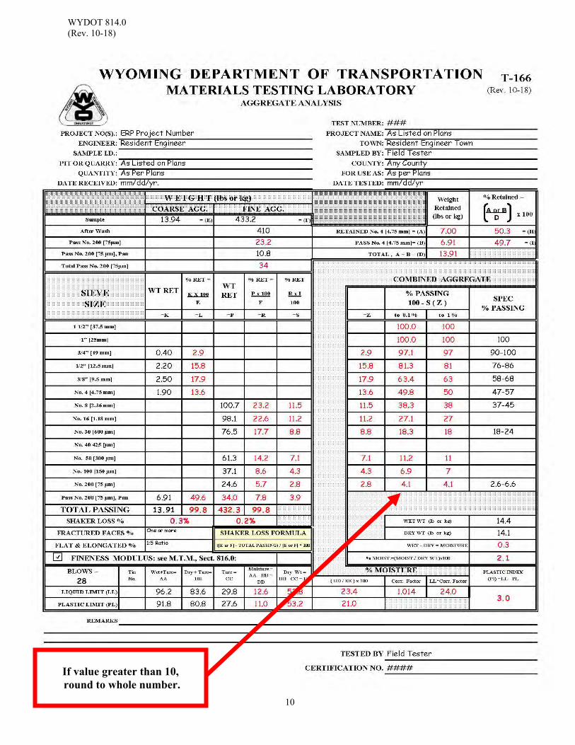
WYDOT 814.0 (Rev. 10-18)
10
If value greater than 10, round to whole number.
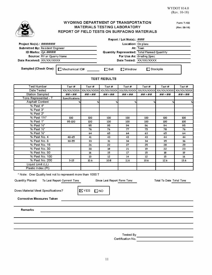
WYDOT 814.0 (Rev. 10-18)
11
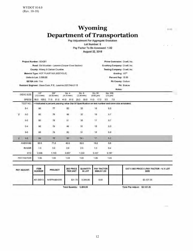
WYDOT 814.0 (Rev. 10-18)
12
WYDOT 816.0 (Rev. 10-18)
1
SIEVE ANALYSIS OF CONCRETE AGGREGATE
Scope: This method is used for determining the distribution of particle sizes in fine and coarse
aggregate including concrete or mortar. The determination of percent moisture and of the fineness modulus of concrete aggregate are also included.
Use: This method is used to determine the particle size distribution (gradation) for both fine
and coarse aggregate and the fineness modulus of fine aggregate in concrete aggregate for the purpose of determining specification compliance.
Apparatus: (For Fine Aggregate Sieve Analysis)
1. Standard 8 inch sieves 2. Wash pan 3. Sample splitter 4. Gram scale, sensitive to 0.1 g 5. 35 lb [15 kg] scale, sensitive to 0.01 lb [5 g] 6. Drying stove
(For Coarse Aggregate Sieve Analysis) 1. Large mechanical sieve shaker (Gilson model TS-1, TS-2, or equivalent)
2. Drying stove 3. Splitting device
4. Balance(s)
Scale Sensitivity Sample Weight 0.1 g 4 lb or less 1.0 g 4 lb to11 lb 5.0 g 11 lb to 44 lb 20.0 g 44 lb plus
Reference Documents: AASHTO M 45 Standard Specification for Aggregate for Masonry Mortar AASHTO T 11 Standard Method of Test for Materials Finer Than 75- m (No.
200) Sieve in Mineral Aggregates by Washing AASHTO T 27 Standard Method of Test for Sieve Analysis of Fine and Coarse
Aggregates WYDOT 414 WYDOT Standard Specifications WYDOT 471.0 WYDOT Concrete Mix Design Procedure WYDOT 472.0 Contractor Concrete Mix Design Procedure WYDOT 803 WYDOT Standard Specifications WYDOT SS-500G WYDOT Supplementary Specification - Structural Concrete with
Quality Control and Quality Acceptance WYDOT 804.0 Aggregate Sampling WYDOT 805.0 Sample Splitting by Mechanical Splitter WYDOT 814.0 Sieve Analysis of Combined Aggregate
WYDOT 816.0 (Rev. 10-18)
2
*WYDOT T-101 Report of Field Tests on Concrete Aggregate *WYDOT T-102 Report of Field Test of Surfacing Materials WYDOT T-166 Aggregate Analysis * Note: Use of weekly reports is optional Sampling: The sampling procedure is outlined in section WYDOT 804.0.
Sample frequency as per WYDOT Standard Specifications Subsection 414.4.2 and Table 414.4.2-1.
Note: Before Procedure 1. Below, check the equipment; (scale, sieves, etc.).
Check for condition, calibration, level and cleanliness. Nest the required sieves in the proper order.
Procedure: Moisture Determination for Fine and Coarse Concrete Aggregate Moisture determination for fine and coarse concrete aggregate should be performed for
each sample taken or as specified in WYDOT Standard Specifications Table 414.4.2-1. See Example Form T-166 in this section.
1. Weigh the entire sample. Record the wet weight (mass), % Moisture Area on
Form T-166.
Note: Weigh material to the nearest 0.1 percent of the total original sample mass. Requirement for 30 lb to 50 lb sample weight is to the nearest 0.01.
2. Dry the sample. Control the temperature so that the heat used will allow steam
to escape without generating enough pressure to fracture any of the particles of the sample.
Note: A sample is considered dry when it is a constant mass at a
temperature of 230 ± 9 °F.
Original Dry weight (mass) may change as the sample becomes drier.
3. Allow the test sample to cool to room temperature, weigh the dried sample, and
cool test sample. Record this weight (mass) as the Dry weight in the % Moisture Section on Form
T-166. The Dry weight (mass) is subtracted from the Wet weight (mass) to determine the amount of moisture. The amount of moisture is divided by the Dry weight times 100 to determine the percent of moisture in the sample.
WYDOT 816.0 (Rev. 10-18)
3
Wet Dry Moisture
%MoistureMoistureDry
100
Note: A sample is considered dry when it is a constant mass at a
temperature of 230 ± 9o F.
Constant mass is when the weight does not change by more than 0.1 percent of the original dry sample mass.
100 within0.1%
Procedure: Sieve Analysis for Fine Concrete Aggregate 1. Representative samples of fine aggregate are thoroughly dried to a constant
mass and reduced to test size by splitting (WYDOT 805.0). After splitting, weigh the reduced test size. For fine aggregate, the test size is a
minimum of 500 grams. (No less than 300 grams after drying). On Form T-166, record the weight in the “Fine Aggregate” section as “Sample
Wt.” Item “F”. Record the test sample weight to the nearest tenth (0.10) of a gram.
2. Wash the sample according to WYDOT 814.0, Steps 8 through 12. 3. Fine material which is washed into the No. 200 sieve from the aggregate should
be cleaned. With the sieve held over the sink, use the heel of your free hand to tap the outside edge to help dry and loosen the retained material. When the material starts moving around, empty the material back into the washpan by tapping on the outside edge of the sieve. Any material still retained should be washed into the washpan using as little water as possible.
4. Dry the washed sample.
Place the pan and sample either on a stove or in an oven for drying. If direct heat is used, popping and sputtering can be controlled by covering the sample container. After enough steam has escaped, the sample can be uncovered. Make sure any material retained on the cover is returned to the sample.
WYDOT 816.0 (Rev. 10-18)
4
Dry is when the fines are a constant mass at a temperature of 230 ± 9 °F.
Constant mass is when the weight does not change by more than 0.1 percent of the original dry sample mass.
100 within0.1%
Note: The sample should be allowed to cool to approximately room
temperature before recording the final “After Wash” weight (mass) and before putting into the 8 inch sieves.
5. Weigh the dried wash sample.
After the sample is thoroughly dry and cooled, weigh the sample. On Form T-166, record the weight (mass) in the “Fine Aggregate” section as the “After Wash Weight”, just below Item “F”.
6. Sieve the sample through 8 inch U.S. Standard sieves.
After the sample has been weighed, pour the material into the required nest of U.S. Standard sieves from the ⅜ inch on down to the No. 200 including the pan. Use a brush or a scraper to be sure you get all the sample fines out of the drying pan.
The amount of material retained on any one sieve must not weigh more than
about 200 grams for the usual 8 inch diameter sieve. Note: The amount of material on a sieve screen may be reduced by
sieving the sample in smaller portions and mathematically recombining or by the addition of a sieve above the sieve which maybe overloaded.
In no case will fragments in the sample be turned or manipulated
through the sieves by hand.
Continue sieving for a sufficient period and in such manner that, after completion, not more than 0.5 percent by mass of the total sample passes any sieve during one minute of continuous hand sieving performed as follows:
Selecting the sieve with the most retained material, hold the individual sieve, with a snug fitting pan and cover attached, in a slightly inclined position in one hand. Strike the side of the sieve sharply and with an upward motion against the heel of the other hand at the rate of about one-hundred-fifty times per minute, turn the sieve about one-sixth of a revolution at intervals of about twenty-five strokes.
Note: The hand sieve check will be necessary when establishing the
WYDOT 816.0 (Rev. 10-18)
5
shake time for each type of material being tested. Hand sieving will not be required during subsequent tests for the same material. Altering the testing method will require another check (i.e. switching material types or sources, changing tester, or changing equipment used).”
100 notmorethan0.5%
Note: If the sieve with the most retained material meets the criteria, the other
sieves do not need to be checked. 7. Weigh the material retained on each sieve and record the weight.
Note: Sieves required for specified testing are listed in the WYDOT Standard Specifications Section 803 or provided by WYDOT Material Program mix design letters.
Record the weight of the retained material from each sieve in the “Fine Aggregate” section, column "Wt. Ret." Item "P" on Form T-166.
The material in the pan should be weighed and recorded at the top of Form T-166 in the "Fine Aggregate" section as weight passing No. 200 Pan.
Determine "Total Pass No. 200 by subtracting the "After Wash" weight from the "Sample Weight" and adding the "Weight Pass No. 200 Pan”.
TotalPassNo. 200 SampleWT. AfterWashWT. PanWT.
Note: The Pass No. 200 is calculated material washed out of the sample. The material washed out plus the material in the pan is the Total Pass No. 200.
Record the weight (mass) of the minus No. 4 to the nearest tenth (0.10) of a gram.
8. Determine the percent retained for the “Fine Aggregates” section, column “%
Ret.” Item "R" on Form T-166.
Note: All calculated results should be recorded to the nearest 0.10 (tenth).
“Fine Aggregate” section, "Percent Retained" column, Item "R" is found by dividing the weight retained on each sieve in “Fine Aggregate” section, “Percent Retained” column, Item "P" by the before wash weight “Fine Aggregate” section, Item "F."
R 100
The “Total” for “Fine Aggregate” section, “% Retained” column, Item "R"
WYDOT 816.0 (Rev. 10-18)
6
should equal 100 percent. Fine Aggregate items:
F = Reduced dry sample weight; P = Wt. retained per sieve; R = Percent retained per sieve based on the before wash
sample weight item "F". 9. After determining the “Percent Retained” column, Item “R” for “Fine
Aggregate”, record the results in the “Combined Aggregate” section, “Percent Retained” column, Item "Z" on Form T-166 also.
10. On Form T-166, find the “Combined Aggregate” section, “% Passing” column,
Item “0.1%”. Begin subtracting from 100 at the Maximum Aggregate size; 100 minus the sum of Item “Z”.
%passing 100.0 ΣZ
The percent passing the No. 200 should equal “Fine Aggregate” section, “Percent Retained” column, Item “R”.
Round each result to the nearest whole number, except for the No. 200 sieve.
Record the result in the “Combined Aggregate” section, “% Passing” column, Item “1%”. For the No. 200 sieve, round the result to the nearest tenth (0.10) percent except when over 10 percent. These are the results that should be used for acceptance.
Report: Daily results must be filled out on Form T-166, while weekly results are recorded on
optional Form T-101. As per WYDOT Standard Specifications 414.4.7, the fine aggregate may be adjusted up
to two percent by weight, based on the total weight of aggregate without requiring a new mix design. Ensure the fine aggregate fraction does not exceed 44 percent of the total aggregate mass.
WYDOT 816.0 (Rev. 10-18)
7
Procedure: Fineness Modulus of Concrete Aggregate;
1. Determine the fineness modulus of the fine aggregate after the completion of all functions in section “Sieve Analysis for Fine Concrete Aggregate” (Calculating the percent retained and passing for each sieve). To determine the fineness modulus, use the percent retained for each sieve from the d inch through the No. 100. On Form T-166, calculate the fineness modulus in the “Fine Aggregates” section, column “% Ret.” Item "S" (see Example Form T-166 in this section).
Example:
320.8 = Cumulative Total Fineness Modulus: 320.8 / 100 = 3.21 If the fineness modulus varies by more than ± 0.20 from the fineness modulus used for the mix design, it will be necessary to contact the WYDOT Materials Program for a review of the mix design being used.
Note: WYDOT Supplementary Specification SS-500G Section 513.4.10.2.6 part;
A new mix design is required when:
A change in the fine aggregate fineness modulus of more than 0.3 from the initial mix.
Report: Record the fineness modulus result for each fine aggregate test on Form T-166 in the
fineness modulus section located below the data entry area (See Example Form T-166 in this section). Report the fineness modulus for each test result under remarks on Form T-101 (Weekly Report).
Retained on the: ⅜ inch = 0 % Retained on the: No. 4 = 2.9 % 2.9 = 0+2.9 Retained on the: No. 8 = 21.0 % 23.9 = 0+2.9+21.0 Retained on the: No. 16 = 16.3 % 40.2 = 0+2.9+21.0+16.3 Retained on the: No. 30 = 26.7 % 66.9 = 0+2.9+21.0+16.3+26.7 Retained on the: No. 50 = 23.2 % 90.1 = 0+2.9+21.0+16.3+26.7+23.2 Retained on the: No. 100 = 6.7 % 96.8 = 02.9+21.0+16.3+26.7+23.2+6.7 320.8
WYDOT 816.0 (Rev. 10-18)
8
Procedure: Sieve Analysis Coarse Concrete Aggregate The sampling location and procedure is outlined in section WYDOT 804.0. Aggregate
to be tested for gradation acceptance should be free of any additives.
Note: Before Procedure 1 below, check the equipment (scale, sieves, etc.). Check for condition, calibration, level and cleanliness. Nest the required sieves in the proper order.
See the procedure for “Moisture Determination for Fine and Coarse Concrete Aggregate” in this section.
1. Determine test sample size.
Generally it is not necessary to reduce the sample weight by splitting to less than 30 lb when using the large mechanical sieve shaker. Care should be taken not to overload an individual sieve when working with aggregates which could collect primarily on the No. 4 sieve. If it is necessary to reduce the sample size, follow procedure WYDOT 805.0, Splitting by Mechanical Splitter. A larger test sample should increase the accuracy of the results. In no case should the size of the test sample be less than:
Nominal Maximum Size Aggregate
Minimum Weight of Test Sample
⅜ inch 2 lb ½ inch 4 lb ¾ inch 11 lb 1 inch 22 lb
1½ inch 30 lb
Should the sample require splitting to reduce the sample size, the weight (mass) after splitting is entered in the “Coarse Aggregate” section, “Sample” Item “E” on Form T-166.
2. Clamp down the sieve trays, start shaker and add sample. Follow the
instructions outlined in the mechanical sieve shaker "Operating and Service Manual" for tightening sieve trays.
Note: Shake until no material can be observed falling from one sieve to
another. Excessive time (more than approximately 10 minutes) to achieve adequate sieving may result in damage to the sample.
3. Continue sieving for a sufficient period and such manner that, after completion,
not more than 0.5 percent by mass of the total sample passes any sieve during one minute of continuous hand sieving performed as follows.
Selecting the sieve with the most retained material, hold the individual
WYDOT 816.0 (Rev. 10-18)
9
sieve, with a snug fitting pan and cover attached, in a slightly inclined position in one hand. Strike the side of the sieve sharply and with an upward motion against the heel of the other hand at the rate of about one-hundred-fifty times per minute, turn the sieve about one-sixth of a revolution at intervals of about twenty-five strokes. In determining sufficiency of sieving for sizes larger than the No. 4 sieve, limit the material on the sieve to a single layer of particles. If the size of the mounted testing sieves makes the described sieving motion impractical, use 8 inch diameter sieves to verify the sufficiency of sieving.
100 not more than 0.5%
If the sieve with the most retained material meets the criteria, the other
sieves do not need to be checked.
4. Weigh the material retained on each sieve tray and pan.
Following adequate sieving time, each sieve tray is removed from the sieve shaker and the material retained is weighed and recorded on Form T-166 in the "Coarse Aggregate" section, column "Wt. Ret." Item "K", next to the appropriate sieve size. Weigh material to the nearest 0.1% of the original dry sample mass.
Requirement for 30 lb to 50 lb sample weight is to the nearest hundredth (0.01).
The “Total” of the sieve and pan weights (Item “K”) should be within 0.3 percent of the original total dry sample weight which was recorded as item "E@ if the sample was split, or the % Moisture Dry Weight when not split.
100 within 0.3%
If the amounts differ by more than 0.3 percent, based on the original dry
sample mass, the results should not be used for acceptance or rejection purposes and another sample should be obtained.
When amounts differ by less than 0.3 percent, based on the original dry sample mass, the “Total” determined material and pan sample weight should be used for calculations. Enter the Sample weight (mass) in the “Coarse Aggregate” section, Item “E”.
WYDOT 816.0 (Rev. 10-18)
10
5. Determine the percent retained for each screen for the “Coarse Aggregate” section, column “% Retained”, Item "L" on Form T-166.
“Coarse Aggregate” section, "Percent Retained" column, Item "L" is found by dividing the weight retained on each sieve tray in column "K" by the sample weight Item "E" and multiplying by 100.
L = KE x (100)
The “Total” for the “Coarse Aggregate” section, column “Percent Retained”, Item "L" should equal 100 percent.
6. After determining the percent retained for each sieve size, enter the results
recorded in the “Combined Aggregate” section, column “% Retained”, Item "Z" on Form T-166.
7. Find the percent passing for the coarse aggregate.
Find the “Combined Aggregate” section, “% Passing” column, Item “0.1%” on Form T-166. Begin subtracting from 100 at the Maximum Aggregate size; 100 minus the sum of Item “Z”.
% passing = 100.0 - Σ Z
8. On Form T-166, except for the No. 200 sieve, round each result to the nearest whole number. Record the result in the “Combined Aggregate” section, “% Passing” column, Item “1%”. For the No. 200 sieve, round the result to the nearest 0.1 percent (tenth). These are the results that should be used for acceptance.
A washed sieve analysis must be performed on all material passing the #4 screen, following the procedure previously described for fine concrete aggregate when:
1. There is a significant amount of material coating the aggregate OR 2. There is more than 5% passing the No. 4 sieve.
Report: Daily testing results are recorded on Form T-166, while weekly test results are recorded
on optional Form T-101. The results of surfacing material gradation tests for the week are recorded on optional
Form T-102. When several different surfacing materials are being tested at the same time, each will need a completely different report for the week.
See Example of Forms T-101, T-102, T-166 for fine aggregate, and T-166 for coarse
aggregate in this section.
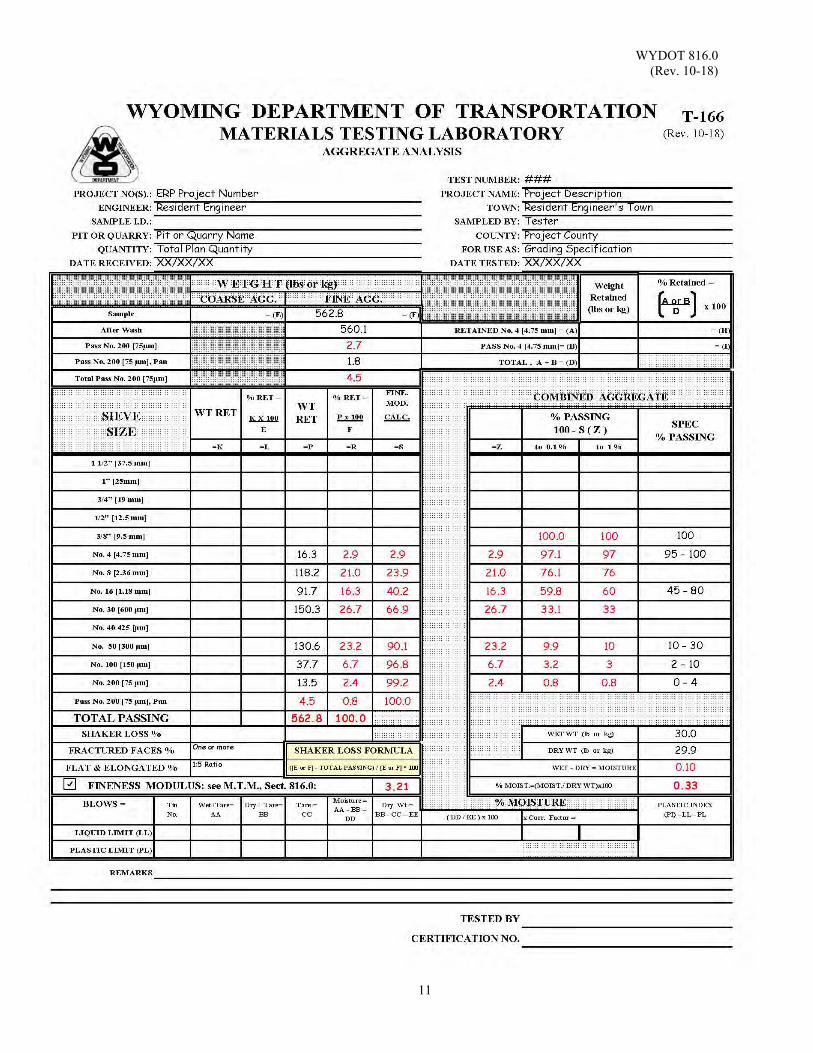
WYDOT 816.0 (Rev. 10-18)
11
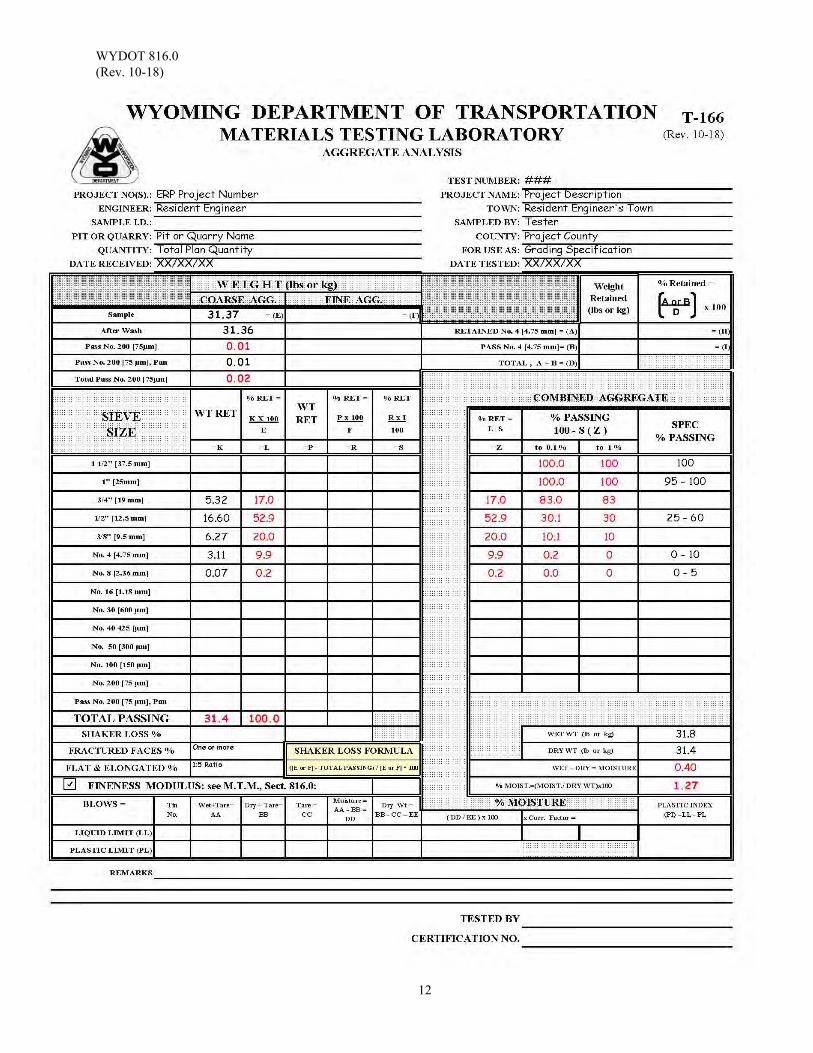
WYDOT 816.0 (Rev. 10-18)
12
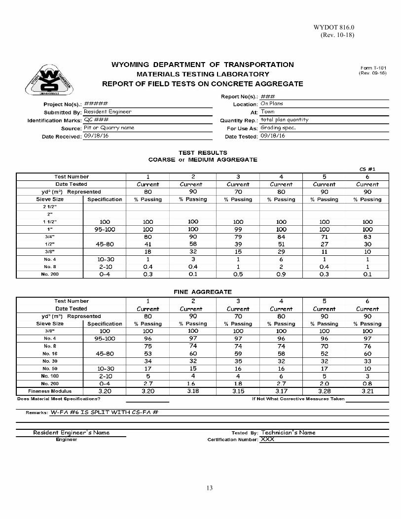
WYDOT 816.0 (Rev. 10-18)
13
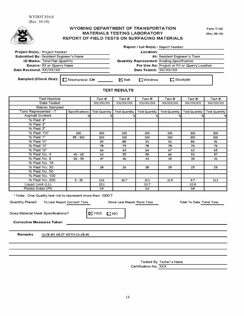
WYDOT 816.0 (Rev. 10-18)
14

WYDOT 817.0 (Rev. 10-20)
1
DETERMINING THE PERCENTAGE OF FRACTURED FACES IN COARSE AGGREGATE
Scope: This test method describes the procedure to determine the percentage of aggregate having one or more fractured faces. Procedure adopted from AASHTO T 335.
Use: The purpose of ensuring fractured face requirements is to provide aggregate that has adequate shear strength from inter-particle friction to improve stability and texture. A fractured face is an angular, rough, or broken surface of an aggregate particle created by crushing or other means. A face will be considered a “fractured face” whenever one-quarter or more of the maximum cross-section area, when viewed normal to that face, is fractured with sharp and well-defined edges (this excludes small nicks). Apparatus: 1. Drying Stove 2. Splitting device or quartering canvas 3. 8 inch U.S. standard sieves
4. 8 inch sieve shaker with a minimum ¼ hp motor, combined back and forth lateral motion and up-and-down tilting motion, and 15 minute electric reset timer switch with a hold feature for continuous operation 5. Balance(s)
Scale Sensitivity Sample Weight 0.1 g 4 lb or less 1.0 g 4 lb to 11 lb 5.0 g 11 lb to 44 lb 20.0 g 44 lb plus
Reference Documents: AASHTO T 335 Standard Method of Test for Determining the Percentage of Fracture in Coarse Aggregate, Method 1 WYDOT 803 WYDOT Standard Specifications WYDOT 804.0 Aggregate Sampling WYDOT 805.0 Sample Splitting by Mechanical Splitter WYDOT E-46 Job Mix Formula WYDOT T-159 Flat & Elongated and Fractured Faces Sampling: The sampling location and procedure is outlined in section WYDOT 804.0 Aggregate Sampling. Aggregate to be tested for gradation acceptance should be free of any additives. Test Sample: Dry the sample sufficiently to obtain clean separation of fine and coarse material. Control the temperature so the heat used will allow steam to escape without generating enough pressure to fracture any of the particles of the sample.
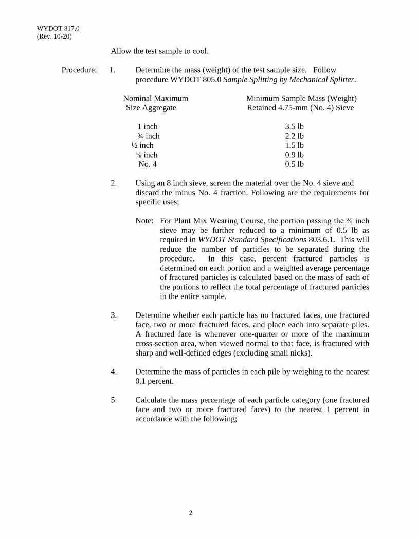
WYDOT 817.0 (Rev. 10-20)
2
Allow the test sample to cool. Procedure: 1. Determine the mass (weight) of the test sample size. Follow
procedure WYDOT 805.0 Sample Splitting by Mechanical Splitter.
Nominal Maximum Minimum Sample Mass (Weight) Size Aggregate Retained 4.75-mm (No. 4) Sieve
1 inch 3.5 lb ¾ inch 2.2 lb ½ inch 1.5 lb ⅜ inch 0.9 lb No. 4 0.5 lb
2. Using an 8 inch sieve, screen the material over the No. 4 sieve and discard the minus No. 4 fraction. Following are the requirements for specific uses;
Note: For Plant Mix Wearing Course, the portion passing the ⅜ inch
sieve may be further reduced to a minimum of 0.5 lb as required in WYDOT Standard Specifications 803.6.1. This will reduce the number of particles to be separated during the procedure. In this case, percent fractured particles is determined on each portion and a weighted average percentage of fractured particles is calculated based on the mass of each of the portions to reflect the total percentage of fractured particles in the entire sample.
3. Determine whether each particle has no fractured faces, one fractured
face, two or more fractured faces, and place each into separate piles. A fractured face is whenever one-quarter or more of the maximum cross-section area, when viewed normal to that face, is fractured with sharp and well-defined edges (excluding small nicks).
4. Determine the mass of particles in each pile by weighing to the nearest
0.1 percent. 5. Calculate the mass percentage of each particle category (one fractured
face and two or more fractured faces) to the nearest 1 percent in accordance with the following;

WYDOT 817.0 (Rev. 10-20)
3
Calculating for one or more fractured faces;
% 1 FF = 1 FF + 2 FF
mass × 100
Where: % 1 FF is the percent of particles with one or more fractured faces
1 FF is the mass (weight) of particles with one fractured face 2 FF is the mass (weight) of particles with two or more fractured faces mass is the total test sample mass (weight)
Calculating for two or more fractured faces;
% 2 FF = 2 FFmass
mass × 100
Where: % 2 FF is the percent of particles with two or more fractured faces
Using the equations in the worksheet T-159, correct the value so it is representative of the sample. Report the results on Form E-46.
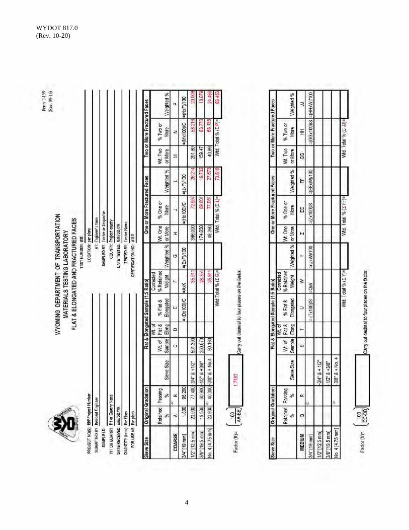
WYDOT 817.0 (Rev. 10-20)
4
WYDOT 818.0 (Rev. 01-15)
1
LA ABRASION RESISTANCE (LAR)
Scope: This test method, commonly referred to as the Los Angeles Rattler (LAR), is a
measure of the degradation of aggregates resulting from a combination of actions including impact and grinding.
Use: LAR is an aggregate source criteria for approval of Contractor Furnished Sources
in the appropriate WYDOT Standard Specifications book. A standard gradation of material is placed inside a rotating steel drum along with a specified number of steel spheres. The steel drum contains a steel shelf inside the drum to pick the material up and carry it to a point within the drum where the material and steel spheres drop to the opposite side of the drum, creating an impact crushing effect. This cycle is repeated for 500 revolutions. When the drum stops and the contents are removed, the aggregate portion is sieved to determine the percent degradation. A specification for LAR is typical for most surfacing aggregates.
Apparatus: 1. Los Angeles machine, according to AASHTO T 96
2. Sieves; No. 4 and No. 12 3. Balance (sensitive to 0.1 g) 4. Charge (steel spheres)
Reference Documents: AASHTO T 96 Standard Test Method for Resistance to Degradation of
Small-Size Coarse Aggregate by Abrasion and Impact in the Los Angeles Machine
WYDOT 414.0 Marshall and Superpave Mix Design and Mix Volumetric Verification Procedure
WYDOT 804.0 Aggregate Sampling WYDOT E-46 Job Mix Formula Sampling: Obtain and reduce field samples according to WYDOT 804.0. Procedure: Perform according to AASHTO T 96. Perform test procedure using charge
requirements on aggregate with at least one fractured face for grading “B”. Report: Report the results on Form E-46. See example in WYDOT 414.0.

WYDOT 818.0 (Rev. 01-15)
2
(This page intentionally left blank.)
WYDOT 824.0 (Rev. 01-15)
1
FINE AGGREGATE ANGULARITY
Scope: This test method covers the procedure to determine the fine aggregate angularity of an aggregate, also referred to as the uncompacted void content of a standard graded fine aggregate sample.
Use: This test method determines the void content under standardized conditions which
depends on the fine aggregate particle shape and texture. A higher void content indicates greater angularity, less sphericity, a rougher surface texture, or a combination of these. A lower void content indicates more spherical particles, smoother particles, or a combination of these. Fine Aggregate Angularity is typically a tool for aggregate classification of fines for use with mix designs for Hot Plant Mix. A specification for Fine Aggregate Angularity is typical for aggregate properties for Hot Plant Mix.
Apparatus: As defined in AASHTO T 304 1. Cylindrical measure (approximately 100 ml) 2. Jar and funnel with bottom opening of 12.7 ± 0.6 mm diameter 3. Funnel stand capable of holding funnel 115 ± 2 mm above the top of
cylinder 4. Glass plate approximately 2 inch x 2 inch minimum x ⅛ inch thick 5. Pan of sufficient size to contain the funnel stand and prevent loss of
material 6. Metal spatula with blade approximately 4 inch long x 1 inch wide, with
straight edge 7. Balance accurate and readable to ± 0.1 g, capable of weighing the
cylindrical measure and its contents
As defined in WYDOT 814.0
1. Wash pan with sufficient capacity to allow enough water to completely cover wash sample
2. Drying stove 3. Balance(s)
Scale Sensitivity Sample Weight 0.1 g 4 lb or less 1.0 g 4 lb to 11 lb
4. 8 inch or 12 inch diameter No. 100 wash sieve 5. 8 inch or 12 inch diameter U.S. standard sieves 6. 8 inch or 12 inch sieve shaker
WYDOT 824.0 (Rev. 01-15)
2
Reference Documents: AASHTO T 84 Standard Method of Test for Specific Gravity and
Absorption of Fine Aggregate AASHTO T 304 Standard Method of Test for Uncompacted Void Content of
Fine Aggregate, Method A WYDOT 414.0 Marshall and Superpave Mix Design and Mix Volumetric
Verification Procedure WYDOT 804.0 Aggregate Sampling WYDOT 805.0 Sample Splitting by Mechanical Splitter WYDOT 814.0 Sieve Analysis of Combined Aggregate WYDOT E-46 Job Mix Formula Sampling: The sampling location and procedure is outlined in WYDOT 804.0. Aggregate to
be tested for acceptance evaluation must be free of any additives.
Procedure: Calibrate the cylindrical measure to determine volume per AASHTO T 304. Determine the Specific Gravity of the minus No. 4 material per AASHTO T 84. Determine the mass (weight) of the test sample size. 1. Follow procedure WYDOT 805.0.
2. Follow WYDOT 814.0, use minus No. 4 to obtain about 3 lb.
3. Wash the minus No. 4 material.
Note: A wetting agent may or may not be necessary to add to the test sample. A wetting agent is any dispersing agent, such as Calgon, Joy, or other detergent that will promote separation of the fine materials.
When a wetting agent is used, a sufficient amount should be added
to assure a thorough separation of the material finer than the No. 100 sieve from the coarser particles. There should be enough wetting agent to produce a small amount of suds when the sample is agitated. The quantity will depend on the hardness of the water, the quality of the detergent, and the agitation process. Excessive foaming may cause material to overflow the sieves.
WYDOT 824.0 (Rev. 01-15)
3
Add enough water to the sample container to cover the test sample. Agitate with sufficient vigor to separate and suspend the minus No. 100 material. Pour off the dirty water into nested No. 8 and No. 100 sieve (8 inch or 12 inch diameter). The No. 100 sieve should be placed in the sink with one side propped up about ½ inch so that water will flow freely. Add more water, agitate, and pour off the dirty water. Repeat this operation until the wash water is clear. Fines retained on the No. 100 sieve after washing will need to be cleaned of any trapped minus No. 100 material.
You may use your hand or spoon to agitate the material in the wash pan, but do not use your hand or any tool on the material within the No. 100 sieve or on the screen itself. Do not hit the screen. Wash the retained material into a pile on one side of the screen.
Note: A spray nozzle or a piece of rubber tubing attached to a water
faucet may be used to rinse any of the material that may have fallen onto the sieves. The velocity of water, which may be increased by pinching the tubing or by use of a nozzle, should not be sufficient to cause any splashing of the sample over the sides of the sieve. With the sieve held over the sink use the heel of your free hand to tap the outside edge to help dry and loosen the retained material. When the material starts moving around, empty the material into the washpan by tapping on the outside edge of the sieve. Any material still retained should be washed into the washpan using as little water as possible.
4. Dry the washed sample.
If direct heat is used, popping or sputtering can be controlled by covering the sample container. After enough steam has escaped the sample can be uncovered. Make sure any material retained on the cover is returned to the sample.
If oven drying, consider the sample to be “dry” when the fines are at a constant mass at a temperature of 230 ± 9o F.
5. Determine the mass of a standard graded sample:
Pour the washed and dried fine aggregate into a nest of U.S. Standard sieves from the No. 8 down to the No. 100 including the pan. The amount of material on any 8 inch sieve should not exceed 200 g. The amount of material on a screen may be reduced by sieving the sample in small portions.
WYDOT 824.0 (Rev. 01-15)
4
Continue sieving for a sufficient period and in such a manner that, after completion, not more than 0.5 percent by mass of the total sample passes any sieve during one minute of continuous hand sieving as described in WYDOT 814.0.
Weigh out and combine the following quantities of fine aggregate, which has been dried and sieved.
Individual Size Fraction Mass, g
No. 8 to No. 16 44 No. 16 to No. 30 57
No. 30 to No. 50 72 No. 50 to No. 100 17 190 g The tolerance on each of these amounts is ± 0.2 g. 6. Mix the combined test sample with the spatula until it appears to be
homogeneous. Position the jar and funnel vertical in the stand and center the cylindrical measure beneath them in the level catch pan. Using a finger to block the opening of the funnel, pour the test sample into the funnel. Level the material in the funnel with the spatula. Remove the finger used as a block and allow the test sample to fall freely into the cylindrical measure.
7. After the funnel empties, strike-off excess heaped fine aggregate from the
cylindrical measure by a quick single pass of the spatula. The width of the blade should be vertical, keeping the straight part of its edge horizontal and in light contact with the top of the measure.
Until this operation is complete, exercise care to avoid vibration or any disturbance that could cause compaction of the fine aggregate in the cylindrical measure. Brush adhering grains from the outside of the container.
Note: After strike-off, the cylindrical measure may be tapped lightly to
compact the sample to make it easier to transfer the container of fine aggregate to the scale or balance without spilling any of the test sample.
Determine and record the mass of the cylindrical measure and fine aggregate to the nearest 0.1 g.

WYDOT 824.0 (Rev. 01-15)
5
Retain all fine aggregate particles for a second test run.
Recombine the sample from the retaining pan and cylindrical measure and repeat the procedure.
Average the results of the two test run.
a. Record the mass of the empty cylindrical measure. b. For each test run, record the mass of the cylindrical measure and
fine aggregate.
Calculations: Calculate the uncompacted voids for the each determination as follows;
U – ⁄ 100
Where: V = volume of cylindrical measure, mL; F = net mass of fine aggregate in cylindrical measure, g (gross mass minus the mass of the empty measure); G = bulk dry specific gravity of fine aggregate; U = uncompacted voids in the material, percent;
Calculate the average uncompacted voids for the two determinations. Report: Report the results on Form E-46. See example in WYDOT 414.0 Report the uncompacted voids in percent to the nearest 0.1 percent. Report the specific gravity value used in the calculation.

WYDOT 824.0 (Rev. 01-15)
6
(This page intentionally left blank.)
WYDOT 832.0 (Rev. 02-12)
1
DELETERIOUS SUBSTANCES IN PORTLAND CEMENT CONCRETE
Scope: This test method describes the procedure for an approximate determination of
injurious organic impurities in the fine aggregates for concrete. Use: This procedure is used to determine if the fine aggregate for concrete contains
organic impurities which could potentially be damaging to the concrete. Reference Documents: AASHTO T 21 Standard Method of Test for Organic Impurities in Fine
Aggregates for Concrete Procedure: Same as AASHTO T 21 Commentary: Section 9. Determination of Color Value; of AASHTO T 21, provides a standard
color solution procedure and a glass color standard alternate procedure. Either procedure is acceptable.
If 9.2 Glass Color Standard Procedure is used, matching organic plates 1, 2, or 3
is considered acceptable when evaluating organic impurities. If the color matches organic plates 4 or 5 or is darker than organic plate 5, then the fine aggregate is considered to possibly contain injurious organic compounds.

WYDOT 832.0 (Rev. 02-12)
2
(This page intentionally left blank.)
WYDOT 833.0 (Rev. 02-12)
1
RESISTANCE R - VALUE AND MOISTURE SENSITIVITY Scope: This method describes the testing for determination of the R-Value and moisture-
sensitivity of soils, subbases, and bases.
The Moisture Sensitivity procedure uses the results of AASHTO T 190, “Resistance R-Value and Expansion Pressure of Compacted Soils”, to determine if a soil, sub-base, base or other unbound material is moisture sensitive. Moisture sensitivity is a factor considered in the acceptance of Crushed Base.
Reference Documents: AASHTO T 190 Standard Method of Test for Resistance R-Value and
Expansion Pressure of Compacted Soils Procedure: This procedure is identical to AASHTO T 190 except as modified below: 4.4 Occasionally, material from very plastic, clay-test specimens will extrude
from under the mold and around the follower ram during the loading operation. If this occurs between 200 and 400 psi and fewer than five lights are lit, the soils will be reported as less than 5 R-Value (-5). Coarse granular materials and clean sands may require the use of paper baskets to permit testing.
Moisture Sensitivity of Unbound Materials
A graph of exudation pressure versus R-Value is developed for the material. The R-Value of the material at 300 psi exudation pressure is then compared to the R-Value at 200 psi exudation pressure. If the difference between the 300 psi R-Value and the 200 psi R-Value is less than or equal to 5, the material will be considered non-moisture sensitive.
Report: Report the gradation R-Value and the moisture-sensitivity.

WYDOT 833.0 (Rev. 02-12)
2
(This page intentionally left blank.)
WYDOT 835.0 (Rev. 09-16)
1
PERCENTAGE OF FLAT AND ELONGATED PARTICLES IN COARSE AGGREGATE
Scope: This test method describes the determination of the percentages of flat and
elongated particles in coarse aggregates at a 1:5 ratio. This procedure is adopted from ASTM D4791.
Use: Individual particles of aggregate of specific fractions sieve sizes are measured to
determine the ratios of length to thickness which can affect the workability of materials. Flat and Elongated Particles is an aggregate quality test that can vary based on the type and amount of crushing effort. A specification for Flat and Elongated Particles is typical for flexible pavements.
Apparatus: 1. Proportional Caliper Device
The proportional caliper device illustrated in Figure 1 of this section is an example of an apparatus suitable for this test method. It consists of a base plate with two fixed posts and a swinging arm mounted between them so that the openings between the arms and the posts maintain a constant ratio. The axis position can be adjusted to provide the desired ratio of opening dimensions. Figure 1 of this section illustrates a device on which ratios of 1:2, 1:3, and 1:5 may be set. For Hot Plant Mix aggregate, a 1:5 ratio is specified.
2. Balance
The balance or scales used be accurate to 0.5% of the mass of the sample.
Reference Documents: ASTM D4791 Standard Test Method for Flat Particles, Elongated
Particles, or Flat and Elongated Particles in Coarse Aggregate
WYDOT 414.0 Marshall and Superpave Mix Design and Mix Volumetric Verification Procedure
WYDOT 804.0 Aggregate Sampling WYDOT 805.0 Sample Splitting by Mechanical Splitter WYDOT 814.0 Sieve Analysis of Combined Aggregate WYDOT E-46 Job Mix Formula WYDOT T-159 Flat & Elongated and Fractured Faces WYDOT T-166 Aggregate Analysis
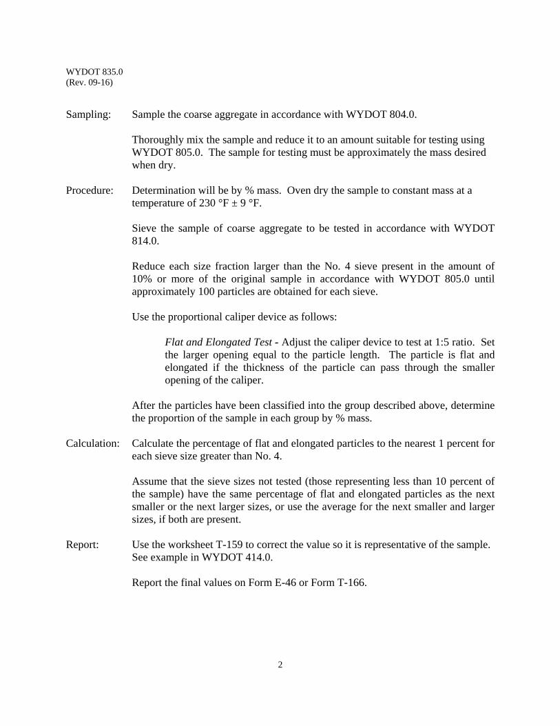
WYDOT 835.0 (Rev. 09-16)
2
Sampling: Sample the coarse aggregate in accordance with WYDOT 804.0.
Thoroughly mix the sample and reduce it to an amount suitable for testing using WYDOT 805.0. The sample for testing must be approximately the mass desired when dry.
Procedure: Determination will be by % mass. Oven dry the sample to constant mass at a temperature of 230 °F ± 9 °F.
Sieve the sample of coarse aggregate to be tested in accordance with WYDOT 814.0. Reduce each size fraction larger than the No. 4 sieve present in the amount of 10% or more of the original sample in accordance with WYDOT 805.0 until approximately 100 particles are obtained for each sieve.
Use the proportional caliper device as follows:
Flat and Elongated Test - Adjust the caliper device to test at 1:5 ratio. Set the larger opening equal to the particle length. The particle is flat and elongated if the thickness of the particle can pass through the smaller opening of the caliper.
After the particles have been classified into the group described above, determine the proportion of the sample in each group by % mass.
Calculation: Calculate the percentage of flat and elongated particles to the nearest 1 percent for
each sieve size greater than No. 4.
Assume that the sieve sizes not tested (those representing less than 10 percent of the sample) have the same percentage of flat and elongated particles as the next smaller or the next larger sizes, or use the average for the next smaller and larger sizes, if both are present.
Report: Use the worksheet T-159 to correct the value so it is representative of the sample. See example in WYDOT 414.0. Report the final values on Form E-46 or Form T-166.
WYDOT 835.0 (Rev. 09-16)
3
Figure 1 - Proportional Caliper

WYDOT 835.0 (Rev. 09-16)
4
(This page intentionally left blank.)
WYDOT 836.0 (Rev. 02-12)
1
FINE AGGREGATE SAND EQUIVALENT Scope: This test method covers the procedure for determining the sand equivalent (SE) of
fine aggregate samples. Use: This procedure is used to determine the relative proportion of fine dust or clay-like
material in fine aggregate. It uses settling rates in a calcium chloride flocculating solution to establish the relative amounts of slow and rapid settling material in a sample passing the No. 4 sieve. SE is an indicator of the quality of the minus No. 4 pit run filler. A specification for SE is typical for Hot Plant Mix aggregate.
Reference Documents: AASHTO T 176 Standard Method of Test for Plastic Fines in Graded
Aggregates and Soils by Use of the Sand Equivalent Test WYDOT 414.0 Marshall and Superpave Mix Design and Mix Volumetric
Verification Procedure WYDOT E-46 Job Mix Formula Procedure: Perform according to AASHTO T 176.
To be consistent with the procedure used in WYDOT Materials Program, a mechanized shaker is recommended.
Report: Report the results on Form E-46. See example in WYDOT 414.0.

WYDOT 836.0 (Rev. 02-12)
2
(This page intentionally left blank.)
WYDOT 837.0 (Rev. 10-17)
1
INSOLUBLE RESIDUE BY WET METHOD OR
BY X - RAY FLUORESCENCE SPECTROMETRY Scope: This method describes the quantitative determination of acid soluble and insoluble
compounds found in aggregates used for surfacing, typically chip seal or plant mix wearing course. The standard procedure is adopted from ASTM D3042 Standard Test Method for Insoluble Residue in Carbonate Aggregates. This method is limited to quantitative determinations of the following analytes: SiO2, Al2O3, CaCO3, Fe2O3, MgCO3, Na2O and K2O.
Use: Wyoming requires ASTM D3042 Section 7, “Procedure for Determining Only the
Plus 75 µm (No. 200) Size Fraction of Insoluble Residue”. Reference Documents: ASTM D3042 Standard Test Method for Insoluble Residue in Carbonate Aggregates, Section 7 WYDOT T-107W Report of Test on Aggregate Discussion: Acid solubility may be estimated by the quantities of certain compounds in an
aggregate source. Aggregates containing high percentages of SiO2 and Al2O3 will be more acid insoluble as compared to samples containing high percentages of CaCO3, Fe2O3, and MgCO3 (i.e., acid soluble).1 Numerous reports indicate a strong correlation between acid insolubility of aggregates and a resistance to polishing. The X-Ray Fluorescence Spectrometry (XRFS) method has the following limitations: 1. Inorganic, element analysis only (i.e., non-carbon);
2. Cannot determine molecular structure (conversion from element detection to compounds actually present is problematic); and
3. Limited subset of the most common 11 elements typically found in
aggregates analyzed. Because of the above limitations, and primarily because the molecular structure of compounds cannot be definitively determined (for example, is MgO, MgCO3 or both present), this method can produce erroneous results for acid insolubility of an aggregate source. However, the method can be used for quick, qualitative analysis of aggregates to determine if aluminum and/or silicon are of such high

WYDOT 837.0 (Rev. 10-17)
2
concentrations that it clearly identifies the aggregate as acid insoluble. For these reasons, the Materials Program does not recommend the XRFS method for aggregate acceptance testing. The XRFS may be utilized for preliminary evaluation of aggregate sources, although further evaluation with ASTM D3042 may be indicated.
Report: See attached example report Form T-107W. 1 CRC Handbook of Chemistry and Physics, Section B, The Elements and Inorganic Compounds -
Refer to Table of Physical Constants of Inorganic Compounds (acid solubility characteristics) for the following compounds; Al2O3, SiO2, CaCO3, Fe2O3, and MgCO3.
Refer to Table of Gravimetric Factors and their Logarithms for the following compounds; MgO, Al2O3, SiO2, P2O5, CaO, TiO2, MnO, Fe2O3, CaCO3, MgCO3.
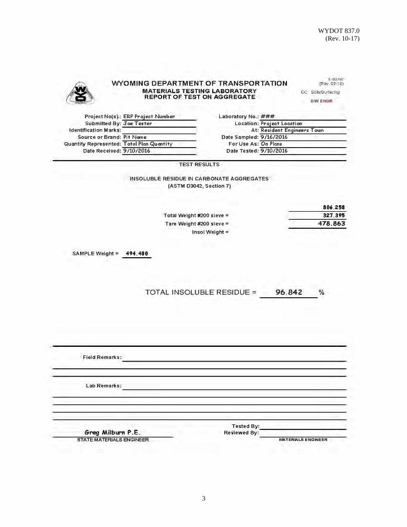
WYDOT 837.0 (Rev. 10-17)
3

WYDOT 837.0 (Rev. 10-17)
4
(This page intentionally left blank.)
WYDOT 838.0 (Rev. 01-15)
1
PERCENT PHOSPHORIC ACID and PHOSPHORUS CONTENT in ASPHALT
By X-RAY FLUORESCENCE SPECTROMETRY
Scope: This procedure describes how to quantitatively determine percent of phosphoric
acid (deca-acid oligomer form) and phosphorus content in asphalt binder. Use: This method is limited to x-ray fluorescence spectrometer (XRFS) using an
energy-dispersive detector measuring low levels (ppm accuracy) of elemental phosphorus under positive helium pressure instead of vacuum. To ensure accuracy of phosphorus measurement, by correcting for various masking and interference effects, detector will also measure energy levels for adjacent elements to phosphorus (including but not limited to silicon, sulfur, arsenic, etc).
Reference Documents: WRI Calculation of Phosphorous Content of Phosphoric Acid Oligomers (Western Research Institute, Laramie, WY; Michael Harnsberger,
February 28, 2007) WAL Phosphorus Content (ppm) of Asphalt Binder Samples (Wyoming Analytical Laboratories, Golden, CO; Chuck Wilson, March 28, 2007) Apparatus: 1. X-Ray fluorescence spectrometer, including:
a. X-ray detector; energy-dispersive (EDXRF), using helium gas background instead of vacuum.
b. Liquid sample cups using 6.0 micron poly carbonate or Mylar film for both standard (control) and test samples.
2. Helium gas, reagent grade, 99.5% minimum purity 3. Standard (control) samples of asphalt binder with known concentrations of
phosphoric acid and SBS polymer. Standard samples are as follows:
a. 0% phosphoric acid (PA), 0% SBS polymer b. 0% PA, 2.5% SBS c. 0.2% PA, 2.5% SBS d. 0.4% PA, 2.5% SBS e. 0.8% PA, 2.5% SBS f. 1.6% PA, 2.5% SBS
Procedure: 1. Obtain or prepare standard (control) samples of asphalt binder with known
concentrations of phosphoric acid and SBS polymer. If samples are prepared, use low shear mixer to blend phosphoric acid and SBS polymer at a temperature of 295 °F for 1 hour. When blending, measure mass of base asphalt and SBS polymer to 2 decimal places and mass of phosphoric acid to 4 decimal places.
WYDOT 838.0 (Rev. 01-15)
2
2. For each standard (control) sample, pour sample solution into liquid
sample cup to a level of ¼ to ⅜ inch (approx. 6 to 10 millimeters). Let sample cool to temperature of 72 °F before testing in XRFS. Make sure there are no wrinkles or bulges in the film of the windows.
3. Place standard (control) sample into test chamber of XRFS and measure
for elemental phosphorus. Repeat for each standard (control) sample. 4. Heat and liquefy asphalt binder test samples to pour into liquid sample cup
to a level of ¼ to ⅜ inch (approx. 6 to 10 millimeters). Let sample cool to temperature of 72 °F before testing in XRFS. Make sure there are no wrinkles or bulges in the film of the windows.
5. Place asphalt binder test sample into test chamber of XRFS and measure
for elemental phosphorus. Repeat for each test sample.
6. Determine percent weight phosphoric acid (%) and phosphorus content (ppm) using either Method A, Bracketing Standards, or Method B, Calibration/Regression Line -
Method A, Bracketing Standards - Calculate and record percent weight phosphoric acid (% PA), to the nearest 0.01, for each test sample according to the following
equation:
,
%
cps = counts per second, elemental phosphorus A = Low bracketing standard (control) sample, cps B = High bracketing standard (control) sample, cps C = Difference, in % PA, between bracketing standards D = % PA for low bracketing standard (control) sample
Calculate and record phosphorus content (ppm), to the nearest whole number, for each test sample according to the following equation:
3530.652 % 134.674 ,
WYDOT 838.0 (Rev. 01-15)
3
Method B, Calibration/Regression Line - Standard (control) samples can be measured for elemental phosphorus and a calibration/regression line generated based on intensity. Calibration/regression line must not exceed 0.006 standard deviation. Using the calibration/regression line, calculate and record percent weight phosphoric acid (%PA) and phosphorus content (ppm). NOTE: Difference(s) between Method A and Method B must not exceed 0.01% PA. If difference is greater than 0.01% PA, then Method A must be used (counts per second, cps, methodology). 7. Report test sample ID number, manufacturer/supplier, PGAB grade,
percent weight phosphoric acid (nearest 0.01, %), phosphorus content (nearest whole number, ppm), and date tested for each asphalt binder test sample.

WYDOT 838.0 (Rev. 01-15)
4
(This page intentionally left blank.)
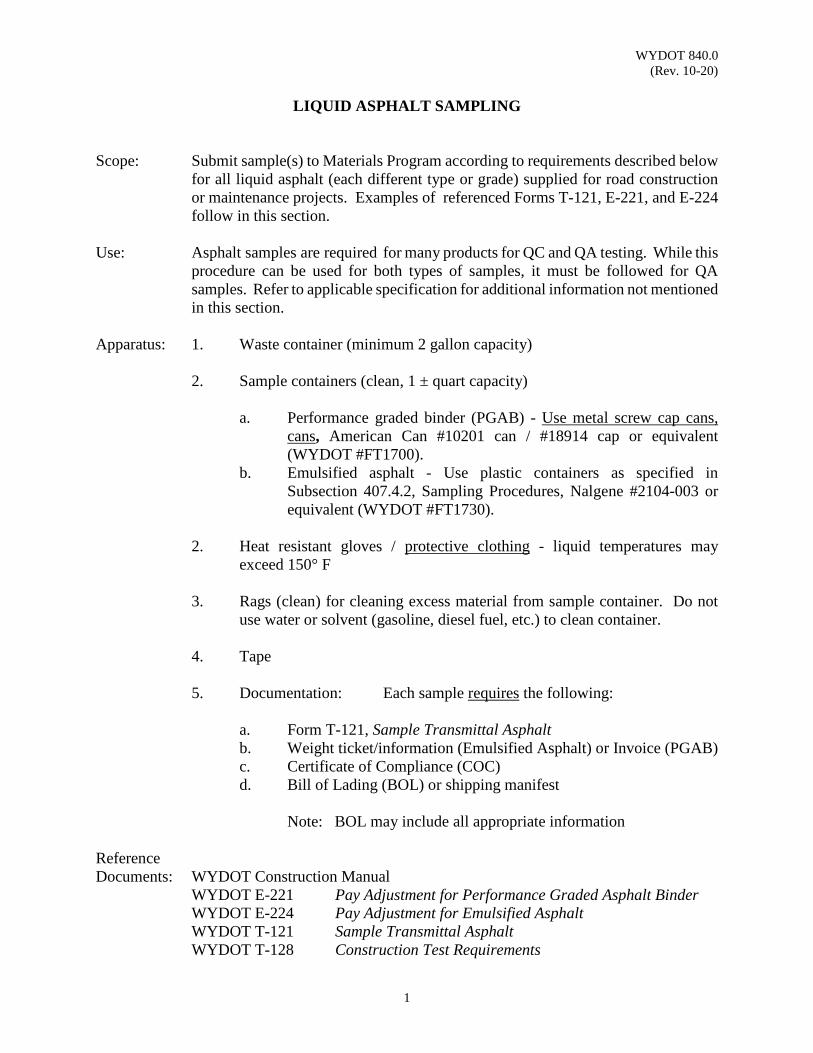
WYDOT 840.0 (Rev. 10-20)
1
LIQUID ASPHALT SAMPLING Scope: Submit sample(s) to Materials Program according to requirements described below
for all liquid asphalt (each different type or grade) supplied for road construction or maintenance projects. Examples of referenced Forms T-121, E-221, and E-224 follow in this section.
Use: Asphalt samples are required for many products for QC and QA testing. While this
procedure can be used for both types of samples, it must be followed for QA samples. Refer to applicable specification for additional information not mentioned in this section.
Apparatus: 1. Waste container (minimum 2 gallon capacity) 2. Sample containers (clean, 1 ± quart capacity)
a. Performance graded binder (PGAB) - Use metal screw cap cans, cans, American Can #10201 can / #18914 cap or equivalent (WYDOT #FT1700).
b. Emulsified asphalt - Use plastic containers as specified in Subsection 407.4.2, Sampling Procedures, Nalgene #2104-003 or equivalent (WYDOT #FT1730).
2. Heat resistant gloves / protective clothing - liquid temperatures may exceed 150° F 3. Rags (clean) for cleaning excess material from sample container. Do not use water or solvent (gasoline, diesel fuel, etc.) to clean container. 4. Tape
5. Documentation: Each sample requires the following:
a. Form T-121, Sample Transmittal Asphalt b. Weight ticket/information (Emulsified Asphalt) or Invoice (PGAB)
c. Certificate of Compliance (COC) d. Bill of Lading (BOL) or shipping manifest
Note: BOL may include all appropriate information Reference Documents: WYDOT Construction Manual WYDOT E-221 Pay Adjustment for Performance Graded Asphalt Binder WYDOT E-224 Pay Adjustment for Emulsified Asphalt WYDOT T-121 Sample Transmittal Asphalt WYDOT T-128 Construction Test Requirements
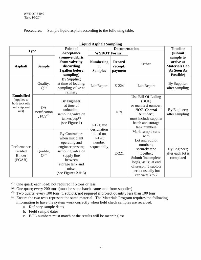
WYDOT 840.0 (Rev. 10-20)
2
Procedures: Sample liquid asphalt according to the following table:
Liquid Asphalt Sampling
Type Point of Acceptance
(remove debris from valve by
discarding 1 gallon before
sampling)
Documentation Timeline (submit
sample to arrive at
Materials Lab As Soon As
Possible)
WYDOT Forms
Other Asphalt Sample Numbering
of Samples
Record receipt,
payment
Emulsified (Applies to
both tack oils and chip seal
oils)
Quality, Q(1)
By Supplier; at time of loading; sampling valve at
refinery
Lab Report E-224 Lab Report By Supplier;
after sampling
QA Verification
, FCS(2)
By Engineer; at time of unloading;
sampling valve on tanker/pup(4)
(see Figure 1) T-121; use designation
noted on T-128; number
sequentially
N/A
Use Bill-Of-Lading (BOL)
or manifest number; NOT 'Control
Number'; must include supplier
batch and storage tank numbers
By Engineer; after sampling
Performance Graded Binder
(PGAB)
Quality, Q(3)
By Contractor; when mix plant operating and
engineer present; sampling valve on
supply line between
storage tank and mixer
(see Figures 2 & 3)
E-221
Mark sample cans with
Lot and Sublot numbers;
securely tape together;
Submit 'incomplete' lot(s), 'as is', at end of season; 5 sublots per lot usually but
can vary 3 to 7
By Engineer; after each lot is
completed
(1) One quart; each load; not required if 5 tons or less (2) One quart; every 200 tons (must be same batch, same tank from supplier) (3) Two quarts; every 100 tons (1 sublot); not required if project quantity less than 100 tons (4) Ensure the two tests represent the same material. The Materials Program requires the following information to have the system work correctly when field check samples are received:
a. Refinery sample dates b. Field sample dates c. BOL numbers must match or the results will be meaningless
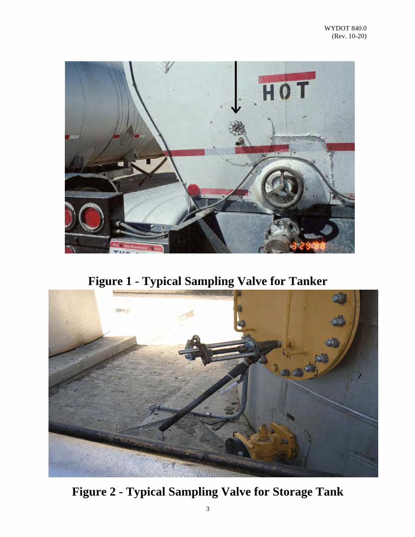
WYDOT 840.0 (Rev. 10-20)
3
Figure 1 - Typical Sampling Valve for Tanker
Figure 2 - Typical Sampling Valve for Storage Tank
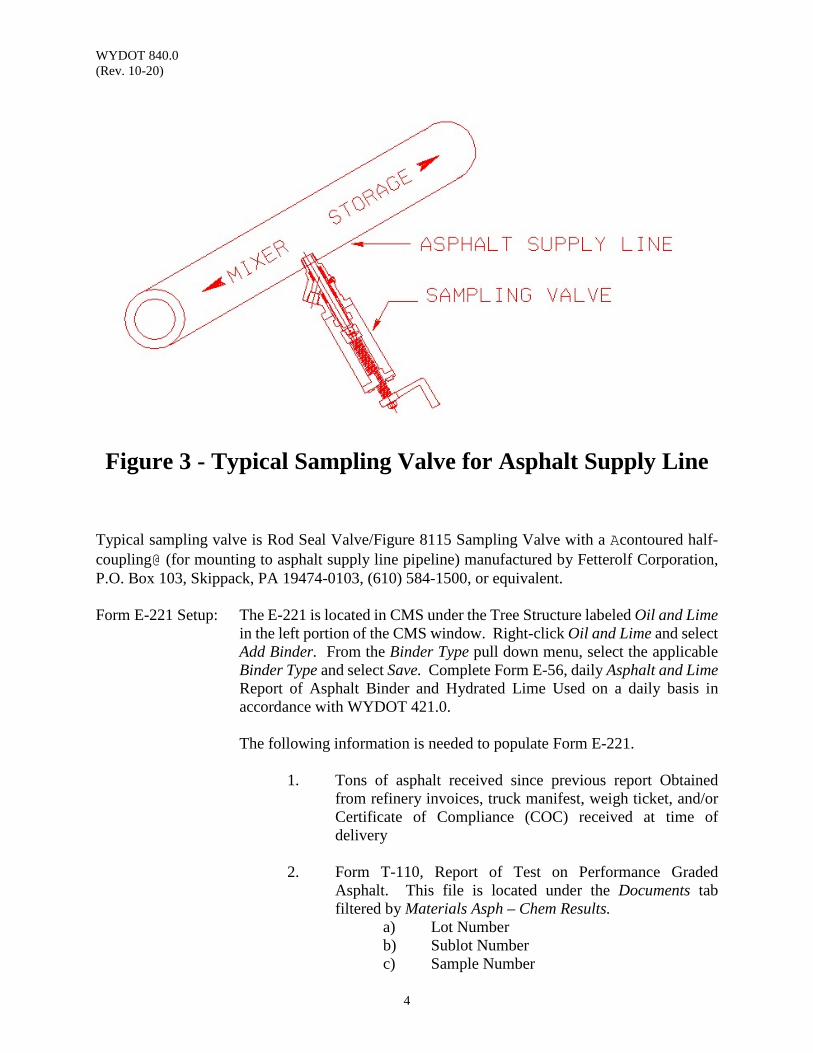
WYDOT 840.0 (Rev. 10-20)
4
Figure 3 - Typical Sampling Valve for Asphalt Supply Line
Typical sampling valve is Rod Seal Valve/Figure 8115 Sampling Valve with a Acontoured half-coupling@ (for mounting to asphalt supply line pipeline) manufactured by Fetterolf Corporation, P.O. Box 103, Skippack, PA 19474-0103, (610) 584-1500, or equivalent. Form E-221 Setup: The E-221 is located in CMS under the Tree Structure labeled Oil and Lime
in the left portion of the CMS window. Right-click Oil and Lime and select Add Binder. From the Binder Type pull down menu, select the applicable Binder Type and select Save. Complete Form E-56, daily Asphalt and Lime Report of Asphalt Binder and Hydrated Lime Used on a daily basis in accordance with WYDOT 421.0.
The following information is needed to populate Form E-221.
1. Tons of asphalt received since previous report Obtained from refinery invoices, truck manifest, weigh ticket, and/or Certificate of Compliance (COC) received at time of delivery
2. Form T-110, Report of Test on Performance Graded
Asphalt. This file is located under the Documents tab filtered by Materials Asph – Chem Results.
a) Lot Number b) Sublot Number c) Sample Number

WYDOT 840.0 (Rev. 10-20)
5
d) Lab Test Report e) Pay Factor
3. Voided Tons – this value is obtained from form E-56, daily Asphalt and Lime Report of Asphalt Binder and Hydrated Lime located in CMS.
4. Contractor’s Cost – this is included in the preconstruction
documents.
6. Remarks Completing E-221:
1. Form E-221 is automatically started as Invoice No.s are created in the E-56 module. Note: Create manual entries in the E-221 to account for oil in tank at startup, oil remaining at completion, and oil used on other projects.
2. The Report Date, Invoice No., and Received Tons are all automatically populated from the E-56 module.
3. Populate the Lot, Sublot, Sample Number, Lab Test Report,
and Pay Factor from the information provided on Form T-110.
4. Populate the Voided Tons from the corresponding E-56’s
Voided Oil This Date. If there are multiple Invoice No.’s received on the respective day, select one invoice and place the total voided tons for that particular day on the selected invoice. Reference the corresponding E-56 in the Remarks section.
5. The Net Tons is automatically calculated. 6. Enter the Contractor’s Cost from the confidential price
quotes received at the preconstruction meeting. 7. The Pay Adjustment is automatically calculated. 8. Select E221 and review the populated form. 9. If all information is accurate, toggle Approved and select
Post to Ledger.
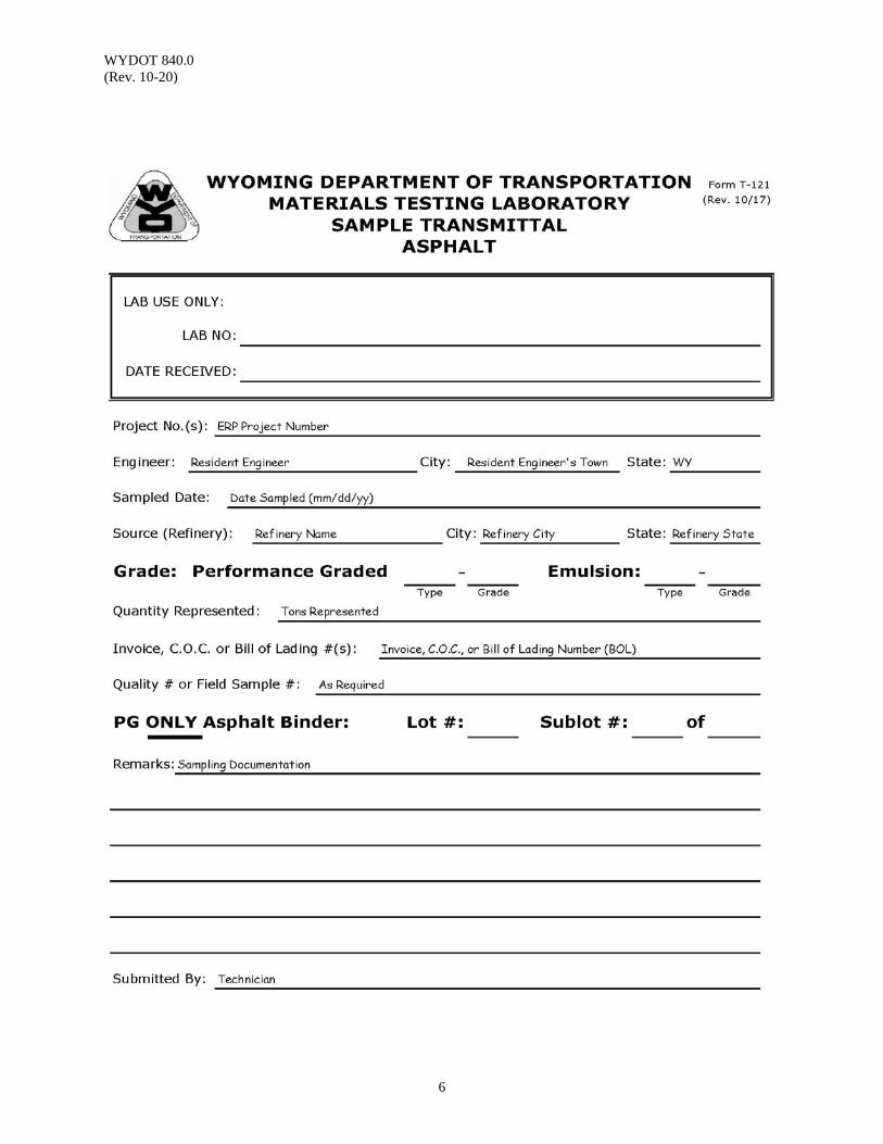
WYDOT 840.0 (Rev. 10-20)
6
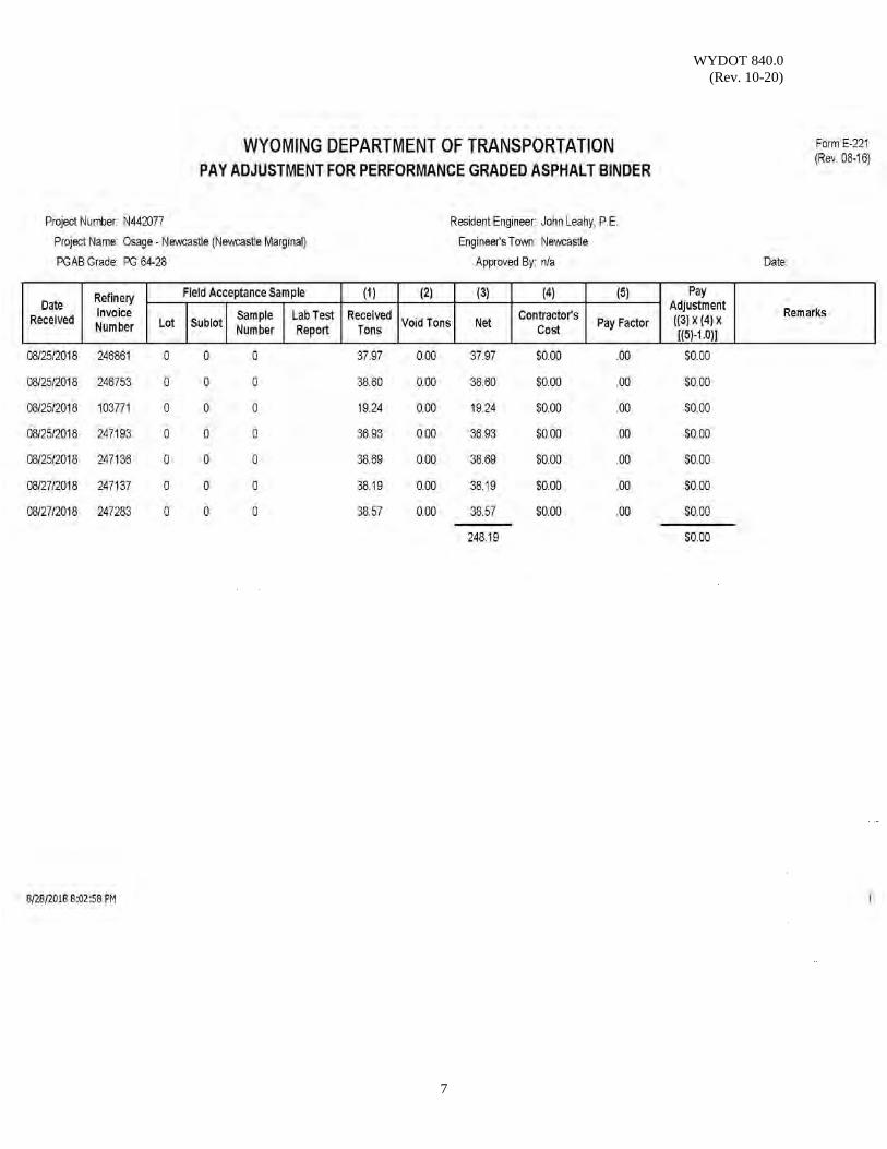
WYDOT 840.0 (Rev. 10-20)
7
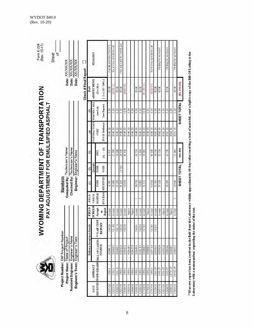
WYDOT 840.0 (Rev. 10-20)
8
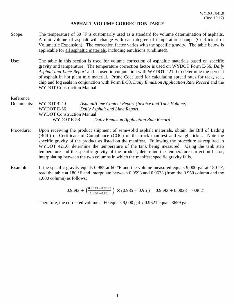
WYDOT 841.0 (Rev. 10-17)
1
ASPHALT VOLUME CORRECTION TABLE
Scope: The temperature of 60 °F is customarily used as a standard for volume determination of asphalts. A unit volume of asphalt will change with each degree of temperature change (Coefficient of Volumetric Expansion). The correction factor varies with the specific gravity. The table below is applicable for all asphaltic materials, including emulsions (undiluted).
Use: The table in this section is used for volume correction of asphaltic materials based on specific
gravity and temperature. The temperature correction factor is used on WYDOT Form E-56, Daily Asphalt and Lime Report and is used in conjunction with WYDOT 421.0 to determine the percent of asphalt in hot plant mix material. Prime Coat used for calculating spread rates for tack, seal, chip and fog seals in conjunction with Form E-58, Daily Emulsion Application Rate Record and the WYDOT Construction Manual.
Reference Documents: WYDOT 421.0 Asphalt/Lime Content Report (Invoice and Tank Volume) WYDOT E-56 Daily Asphalt and Lime Report WYDOT Construction Manual WYDOT E-58 Daily Emulsion Application Rate Record Procedure: Upon receiving the product shipment of semi-solid asphalt materials, obtain the Bill of Lading
(BOL) or Certificate of Compliance (COC) of the truck manifest and weigh ticket. Note the specific gravity of the product as listed on the manifest. Following the procedure as required in WYDOT 421.0, determine the temperature of the tank being measured. Using the tank stab temperature and the specific gravity of the product, determine the temperature correction factor, interpolating between the two columns in which the manifest specific gravity falls.
Example: If the specific gravity equals 0.985 at 60 °F and the volume measured equals 9,000 gal at 180 °F,
read the table at 180 °F and interpolate between 0.9593 and 0.9633 (from the 0.950 column and the 1.000 column) as follows:
0.9593 . .
. . (0.985 – 0.95 0.9593 0.0028 0.9621
Therefore, the corrected volume at 60 equals 9,000 gal x 0.9621 equals 8659 gal.
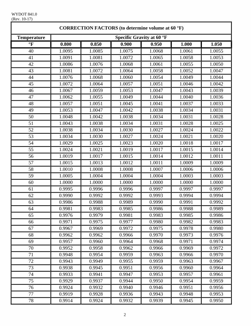
WYDOT 841.0 (Rev. 10-17)
2
CORRECTION FACTORS (to determine volume at 60 °F)
Temperature Specific Gravity at 60 °F °F 0.800 0.850 0.900 0.950 1.000 1.050 40 1.0095 1.0085 1.0075 1.0068 1.0061 1.0055 41 1.0091 1.0081 1.0072 1.0065 1.0058 1.0053 42 1.0086 1.0076 1.0068 1.0061 1.0055 1.0050 43 1.0081 1.0072 1.0064 1.0058 1.0052 1.0047 44 1.0076 1.0068 1.0060 1.0054 1.0049 1.0044 45 1.0072 1.0064 1.0057 1.0051 1.0046 1.0042 46 1.0067 1.0059 1.0053 1.0047 1.0043 1.0039 47 1.0062 1.0055 1.0049 1.0044 1.0040 1.0036 48 1.0057 1.0051 1.0045 1.0041 1.0037 1.0033 49 1.0053 1.0047 1.0042 1.0038 1.0034 1.0031 50 1.0048 1.0042 1.0038 1.0034 1.0031 1.0028 51 1.0043 1.0038 1.0034 1.0031 1.0028 1.0025 52 1.0038 1.0034 1.0030 1.0027 1.0024 1.0022 53 1.0034 1.0030 1.0027 1.0024 1.0021 1.0020 54 1.0029 1.0025 1.0023 1.0020 1.0018 1.0017 55 1.0024 1.0021 1.0019 1.0017 1.0015 1.0014 56 1.0019 1.0017 1.0015 1.0014 1.0012 1.0011 57 1.0015 1.0013 1.0012 1.0011 1.0009 1.0009 58 1.0010 1.0008 1.0008 1.0007 1.0006 1.0006 59 1.0005 1.0004 1.0004 1.0004 1.0003 1.0003 60 1.0000 1.0000 1.0000 1.0000 1.0000 1.0000 61 0.9995 0.9996 0.9996 0.9997 0.9997 0.9997 62 0.9990 0.9992 0.9992 0.9993 0.9994 0.9994 63 0.9986 0.9988 0.9989 0.9990 0.9991 0.9992 64 0.9981 0.9983 0.9985 0.9986 0.9988 0.9989 65 0.9976 0.9979 0.9981 0.9983 0.9985 0.9986 66 0.9971 0.9975 0.9977 0.9980 0.9982 0.9983 67 0.9967 0.9969 0.9972 0.9975 0.9978 0.9980 68 0.9962 0.9962 0.9966 0.9970 0.9973 0.9976 69 0.9957 0.9960 0.9964 0.9968 0.9971 0.9974 70 0.9952 0.9958 0.9962 0.9966 0.9969 0.9972 71 0.9948 0.9954 0.9959 0.9963 0.9966 0.9970 72 0.9943 0.9949 0.9955 0.9959 0.9963 0.9967 73 0.9938 0.9945 0.9951 0.9956 0.9960 0.9964 74 0.9933 0.9941 0.9947 0.9953 0.9957 0.9961 75 0.9929 0.9937 0.9944 0.9950 0.9954 0.9959 76 0.9924 0.9932 0.9940 0.9946 0.9951 0.9956 77 0.9919 0.9928 0.9936 0.9943 0.9948 0.9953 78 0.9914 0.9924 0.9932 0.9939 0.9945 0.9950
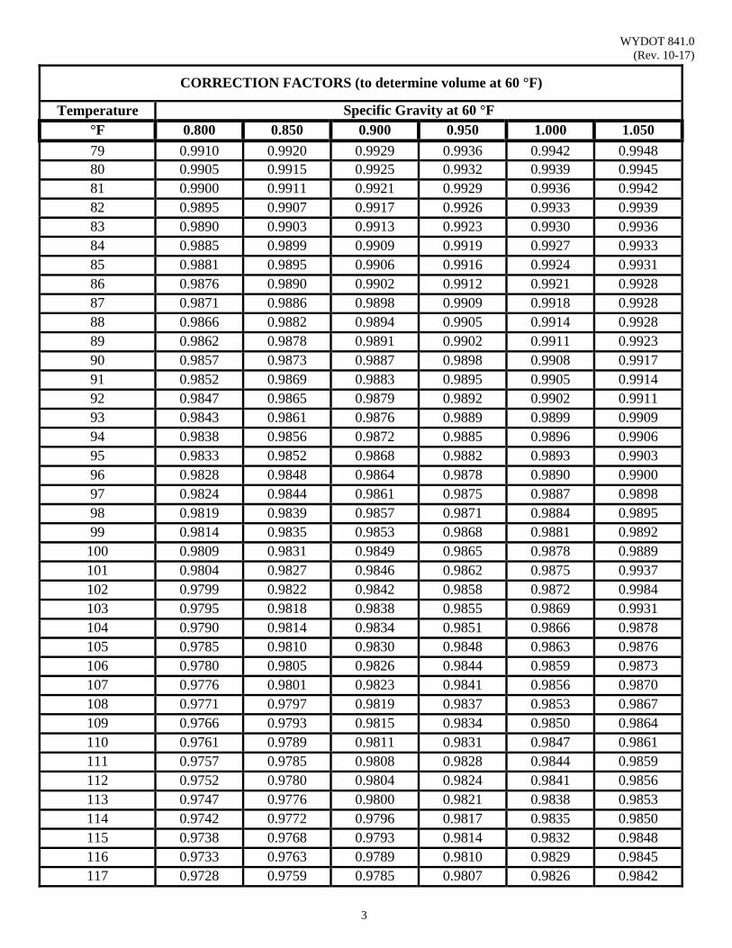
WYDOT 841.0 (Rev. 10-17)
3
CORRECTION FACTORS (to determine volume at 60 °F)
Temperature Specific Gravity at 60 °F °F 0.800 0.850 0.900 0.950 1.000 1.050 79 0.9910 0.9920 0.9929 0.9936 0.9942 0.9948 80 0.9905 0.9915 0.9925 0.9932 0.9939 0.9945 81 0.9900 0.9911 0.9921 0.9929 0.9936 0.9942 82 0.9895 0.9907 0.9917 0.9926 0.9933 0.9939 83 0.9890 0.9903 0.9913 0.9923 0.9930 0.9936 84 0.9885 0.9899 0.9909 0.9919 0.9927 0.9933 85 0.9881 0.9895 0.9906 0.9916 0.9924 0.9931 86 0.9876 0.9890 0.9902 0.9912 0.9921 0.9928 87 0.9871 0.9886 0.9898 0.9909 0.9918 0.9928 88 0.9866 0.9882 0.9894 0.9905 0.9914 0.9928 89 0.9862 0.9878 0.9891 0.9902 0.9911 0.9923 90 0.9857 0.9873 0.9887 0.9898 0.9908 0.9917 91 0.9852 0.9869 0.9883 0.9895 0.9905 0.9914 92 0.9847 0.9865 0.9879 0.9892 0.9902 0.9911 93 0.9843 0.9861 0.9876 0.9889 0.9899 0.9909 94 0.9838 0.9856 0.9872 0.9885 0.9896 0.9906 95 0.9833 0.9852 0.9868 0.9882 0.9893 0.9903 96 0.9828 0.9848 0.9864 0.9878 0.9890 0.9900 97 0.9824 0.9844 0.9861 0.9875 0.9887 0.9898 98 0.9819 0.9839 0.9857 0.9871 0.9884 0.9895 99 0.9814 0.9835 0.9853 0.9868 0.9881 0.9892 100 0.9809 0.9831 0.9849 0.9865 0.9878 0.9889 101 0.9804 0.9827 0.9846 0.9862 0.9875 0.9937 102 0.9799 0.9822 0.9842 0.9858 0.9872 0.9984 103 0.9795 0.9818 0.9838 0.9855 0.9869 0.9931 104 0.9790 0.9814 0.9834 0.9851 0.9866 0.9878 105 0.9785 0.9810 0.9830 0.9848 0.9863 0.9876 106 0.9780 0.9805 0.9826 0.9844 0.9859 0.9873 107 0.9776 0.9801 0.9823 0.9841 0.9856 0.9870 108 0.9771 0.9797 0.9819 0.9837 0.9853 0.9867 109 0.9766 0.9793 0.9815 0.9834 0.9850 0.9864 110 0.9761 0.9789 0.9811 0.9831 0.9847 0.9861 111 0.9757 0.9785 0.9808 0.9828 0.9844 0.9859 112 0.9752 0.9780 0.9804 0.9824 0.9841 0.9856 113 0.9747 0.9776 0.9800 0.9821 0.9838 0.9853 114 0.9742 0.9772 0.9796 0.9817 0.9835 0.9850 115 0.9738 0.9768 0.9793 0.9814 0.9832 0.9848 116 0.9733 0.9763 0.9789 0.9810 0.9829 0.9845 117 0.9728 0.9759 0.9785 0.9807 0.9826 0.9842
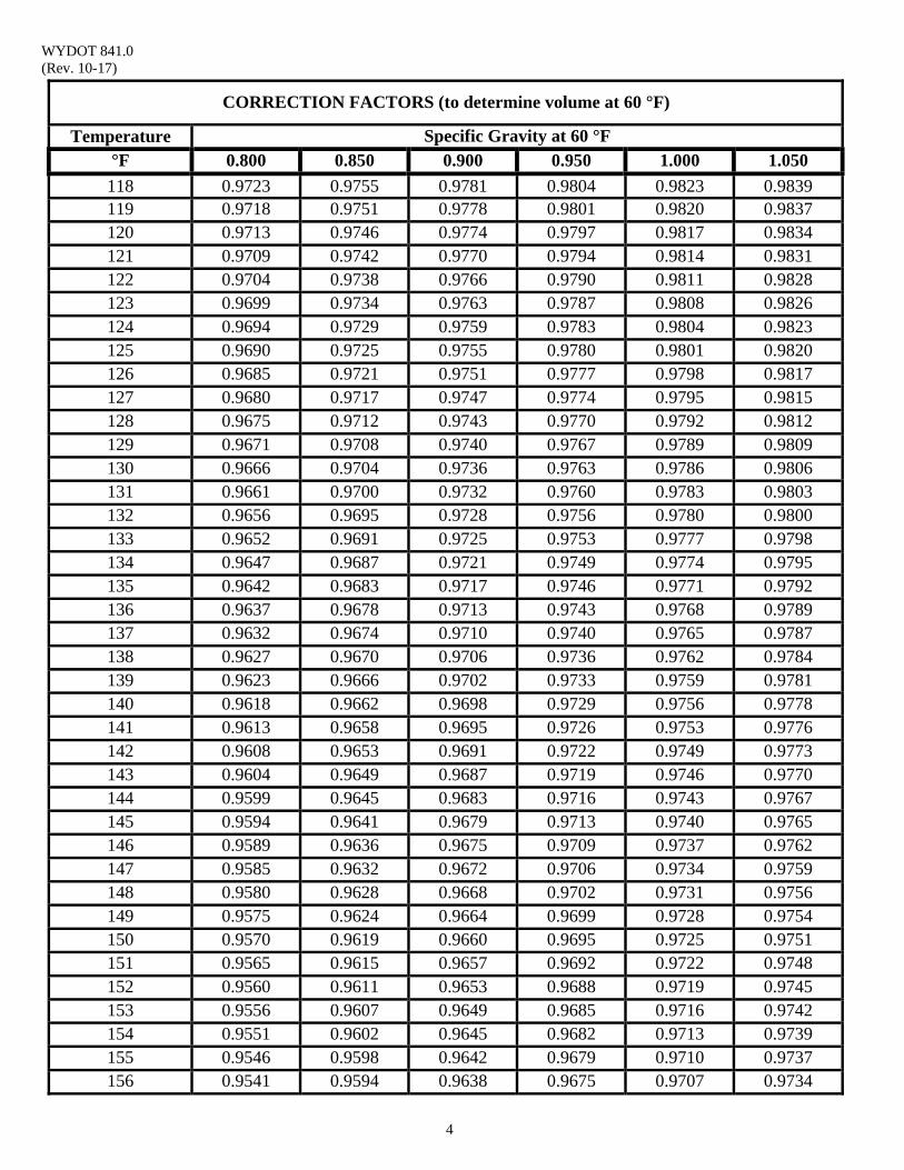
WYDOT 841.0 (Rev. 10-17)
4
CORRECTION FACTORS (to determine volume at 60 °F)
Temperature Specific Gravity at 60 °F °F 0.800 0.850 0.900 0.950 1.000 1.050 118 0.9723 0.9755 0.9781 0.9804 0.9823 0.9839 119 0.9718 0.9751 0.9778 0.9801 0.9820 0.9837 120 0.9713 0.9746 0.9774 0.9797 0.9817 0.9834 121 0.9709 0.9742 0.9770 0.9794 0.9814 0.9831 122 0.9704 0.9738 0.9766 0.9790 0.9811 0.9828 123 0.9699 0.9734 0.9763 0.9787 0.9808 0.9826 124 0.9694 0.9729 0.9759 0.9783 0.9804 0.9823 125 0.9690 0.9725 0.9755 0.9780 0.9801 0.9820 126 0.9685 0.9721 0.9751 0.9777 0.9798 0.9817 127 0.9680 0.9717 0.9747 0.9774 0.9795 0.9815 128 0.9675 0.9712 0.9743 0.9770 0.9792 0.9812 129 0.9671 0.9708 0.9740 0.9767 0.9789 0.9809 130 0.9666 0.9704 0.9736 0.9763 0.9786 0.9806 131 0.9661 0.9700 0.9732 0.9760 0.9783 0.9803 132 0.9656 0.9695 0.9728 0.9756 0.9780 0.9800 133 0.9652 0.9691 0.9725 0.9753 0.9777 0.9798 134 0.9647 0.9687 0.9721 0.9749 0.9774 0.9795 135 0.9642 0.9683 0.9717 0.9746 0.9771 0.9792 136 0.9637 0.9678 0.9713 0.9743 0.9768 0.9789 137 0.9632 0.9674 0.9710 0.9740 0.9765 0.9787 138 0.9627 0.9670 0.9706 0.9736 0.9762 0.9784 139 0.9623 0.9666 0.9702 0.9733 0.9759 0.9781 140 0.9618 0.9662 0.9698 0.9729 0.9756 0.9778 141 0.9613 0.9658 0.9695 0.9726 0.9753 0.9776 142 0.9608 0.9653 0.9691 0.9722 0.9749 0.9773 143 0.9604 0.9649 0.9687 0.9719 0.9746 0.9770 144 0.9599 0.9645 0.9683 0.9716 0.9743 0.9767 145 0.9594 0.9641 0.9679 0.9713 0.9740 0.9765 146 0.9589 0.9636 0.9675 0.9709 0.9737 0.9762 147 0.9585 0.9632 0.9672 0.9706 0.9734 0.9759 148 0.9580 0.9628 0.9668 0.9702 0.9731 0.9756 149 0.9575 0.9624 0.9664 0.9699 0.9728 0.9754 150 0.9570 0.9619 0.9660 0.9695 0.9725 0.9751 151 0.9565 0.9615 0.9657 0.9692 0.9722 0.9748 152 0.9560 0.9611 0.9653 0.9688 0.9719 0.9745 153 0.9556 0.9607 0.9649 0.9685 0.9716 0.9742 154 0.9551 0.9602 0.9645 0.9682 0.9713 0.9739 155 0.9546 0.9598 0.9642 0.9679 0.9710 0.9737 156 0.9541 0.9594 0.9638 0.9675 0.9707 0.9734
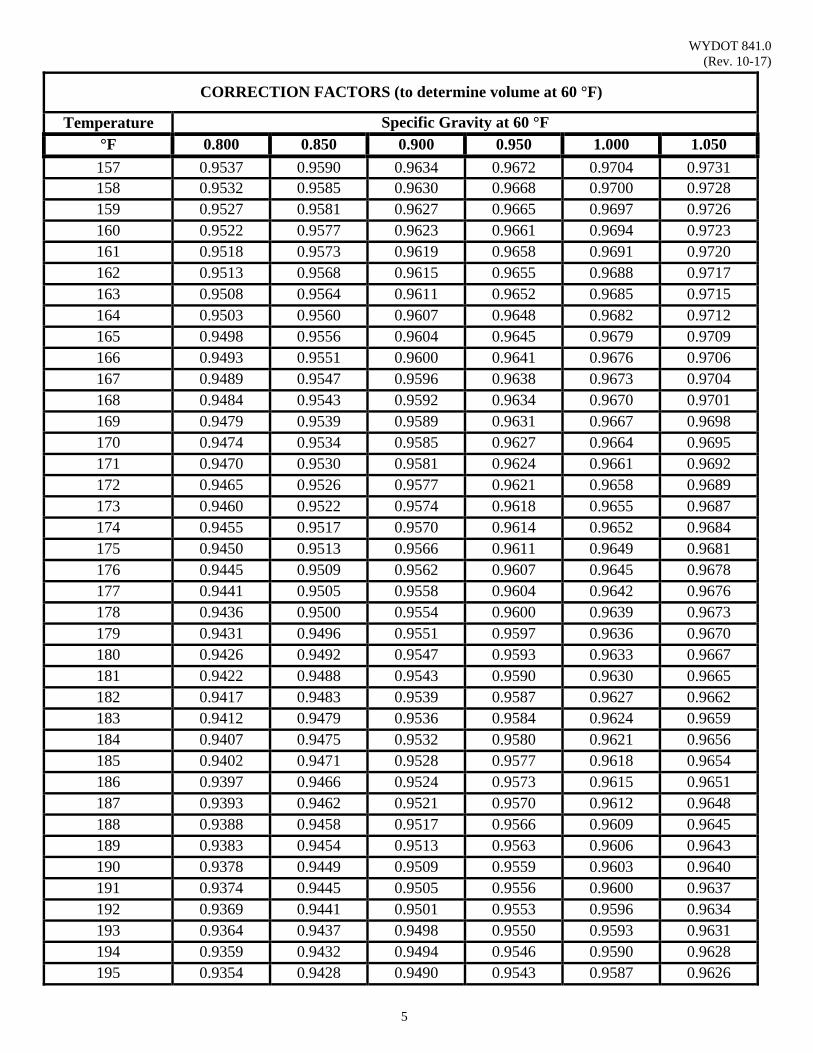
WYDOT 841.0 (Rev. 10-17)
5
CORRECTION FACTORS (to determine volume at 60 °F)
Temperature Specific Gravity at 60 °F °F 0.800 0.850 0.900 0.950 1.000 1.050 157 0.9537 0.9590 0.9634 0.9672 0.9704 0.9731 158 0.9532 0.9585 0.9630 0.9668 0.9700 0.9728 159 0.9527 0.9581 0.9627 0.9665 0.9697 0.9726 160 0.9522 0.9577 0.9623 0.9661 0.9694 0.9723 161 0.9518 0.9573 0.9619 0.9658 0.9691 0.9720 162 0.9513 0.9568 0.9615 0.9655 0.9688 0.9717 163 0.9508 0.9564 0.9611 0.9652 0.9685 0.9715 164 0.9503 0.9560 0.9607 0.9648 0.9682 0.9712 165 0.9498 0.9556 0.9604 0.9645 0.9679 0.9709 166 0.9493 0.9551 0.9600 0.9641 0.9676 0.9706 167 0.9489 0.9547 0.9596 0.9638 0.9673 0.9704 168 0.9484 0.9543 0.9592 0.9634 0.9670 0.9701 169 0.9479 0.9539 0.9589 0.9631 0.9667 0.9698 170 0.9474 0.9534 0.9585 0.9627 0.9664 0.9695 171 0.9470 0.9530 0.9581 0.9624 0.9661 0.9692 172 0.9465 0.9526 0.9577 0.9621 0.9658 0.9689 173 0.9460 0.9522 0.9574 0.9618 0.9655 0.9687 174 0.9455 0.9517 0.9570 0.9614 0.9652 0.9684 175 0.9450 0.9513 0.9566 0.9611 0.9649 0.9681 176 0.9445 0.9509 0.9562 0.9607 0.9645 0.9678 177 0.9441 0.9505 0.9558 0.9604 0.9642 0.9676 178 0.9436 0.9500 0.9554 0.9600 0.9639 0.9673 179 0.9431 0.9496 0.9551 0.9597 0.9636 0.9670 180 0.9426 0.9492 0.9547 0.9593 0.9633 0.9667 181 0.9422 0.9488 0.9543 0.9590 0.9630 0.9665 182 0.9417 0.9483 0.9539 0.9587 0.9627 0.9662 183 0.9412 0.9479 0.9536 0.9584 0.9624 0.9659 184 0.9407 0.9475 0.9532 0.9580 0.9621 0.9656 185 0.9402 0.9471 0.9528 0.9577 0.9618 0.9654 186 0.9397 0.9466 0.9524 0.9573 0.9615 0.9651 187 0.9393 0.9462 0.9521 0.9570 0.9612 0.9648 188 0.9388 0.9458 0.9517 0.9566 0.9609 0.9645 189 0.9383 0.9454 0.9513 0.9563 0.9606 0.9643 190 0.9378 0.9449 0.9509 0.9559 0.9603 0.9640 191 0.9374 0.9445 0.9505 0.9556 0.9600 0.9637 192 0.9369 0.9441 0.9501 0.9553 0.9596 0.9634 193 0.9364 0.9437 0.9498 0.9550 0.9593 0.9631 194 0.9359 0.9432 0.9494 0.9546 0.9590 0.9628 195 0.9354 0.9428 0.9490 0.9543 0.9587 0.9626
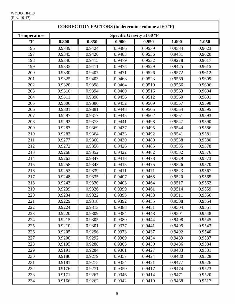
WYDOT 841.0 (Rev. 10-17)
6
CORRECTION FACTORS (to determine volume at 60 °F)
Temperature Specific Gravity at 60 °F °F 0.800 0.850 0.900 0.950 1.000 1.050 196 0.9349 0.9424 0.9486 0.9539 0.9584 0.9623 197 0.9345 0.9420 0.9483 0.9536 0.9431 0.9620 198 0.9340 0.9415 0.9479 0.9532 0.9278 0.9617 199 0.9335 0.9411 0.9475 0.9529 0.9425 0.9615 200 0.9330 0.9407 0.9471 0.9526 0.9572 0.9612 201 0.9325 0.9403 0.9468 0.9523 0.9569 0.9609 202 0.9320 0.9398 0.9464 0.9519 0.9566 0.9606 203 0.9316 0.9394 0.9460 0.9516 0.9563 0.9604 204 0.9311 0.9390 0.9456 0.9512 0.9560 0.9601 205 0.9306 0.9386 0.9452 0.9509 0.9557 0.9598 206 0.9301 0.9381 0.9448 0.9505 0.9554 0.9595 207 0.9297 0.9377 0.9445 0.9502 0.9551 0.9593 208 0.9292 0.9373 0.9441 0.9498 0.9547 0.9590 209 0.9287 0.9369 0.9437 0.9495 0.9544 0.9586 210 0.9282 0.9364 0.9433 0.9492 0.9541 0.9581 211 0.9277 0.9360 0.9430 0.9489 0.9538 0.9580 212 0.9272 0.9356 0.9426 0.9485 0.9535 0.9578 213 0.9268 0.9352 0.9422 0.9482 0.9532 0.9576 214 0.9263 0.9347 0.9418 0.9478 0.9529 0.9573 215 0.9258 0.9343 0.9415 0.9475 0.9526 0.9570 216 0.9253 0.9339 0.9411 0.9471 0.9523 0.9567 217 0.9248 0.9335 0.9407 0.9468 0.9520 0.9565 218 0.9243 0.9330 0.9403 0.9464 0.9517 0.9562 219 0.9239 0.9326 0.9399 0.9461 0.9514 0.9559 220 0.9234 0.9322 0.9395 0.9458 0.9511 0.9556 221 0.9229 0.9318 0.9392 0.9455 0.9508 0.9554 222 0.9224 0.9313 0.9388 0.9451 0.9504 0.9551 223 0.9220 0.9309 0.9384 0.9448 0.9501 0.9548 224 0.9215 0.9305 0.9380 0.9444 0.9498 0.9545 225 0.9210 0.9301 0.9377 0.9441 0.9495 0.9543 226 0.9205 0.9296 0.9373 0.9437 0.9492 0.9540 227 0.9200 0.9292 0.9369 0.9434 0.9489 0.9537 228 0.9195 0.9288 0.9365 0.9430 0.9486 0.9534 229 0.9191 0.9284 0.9361 0.9427 0.9483 0.9531 230 0.9186 0.9279 0.9357 0.9424 0.9480 0.9528 231 0.9181 0.9275 0.9354 0.9421 0.9477 0.9526 232 0.9176 0.9271 0.9350 0.9417 0.9474 0.9523 233 0.9171 0.9267 0.9346 0.9414 0.9471 0.9520 234 0.9166 0.9262 0.9342 0.9410 0.9468 0.9517
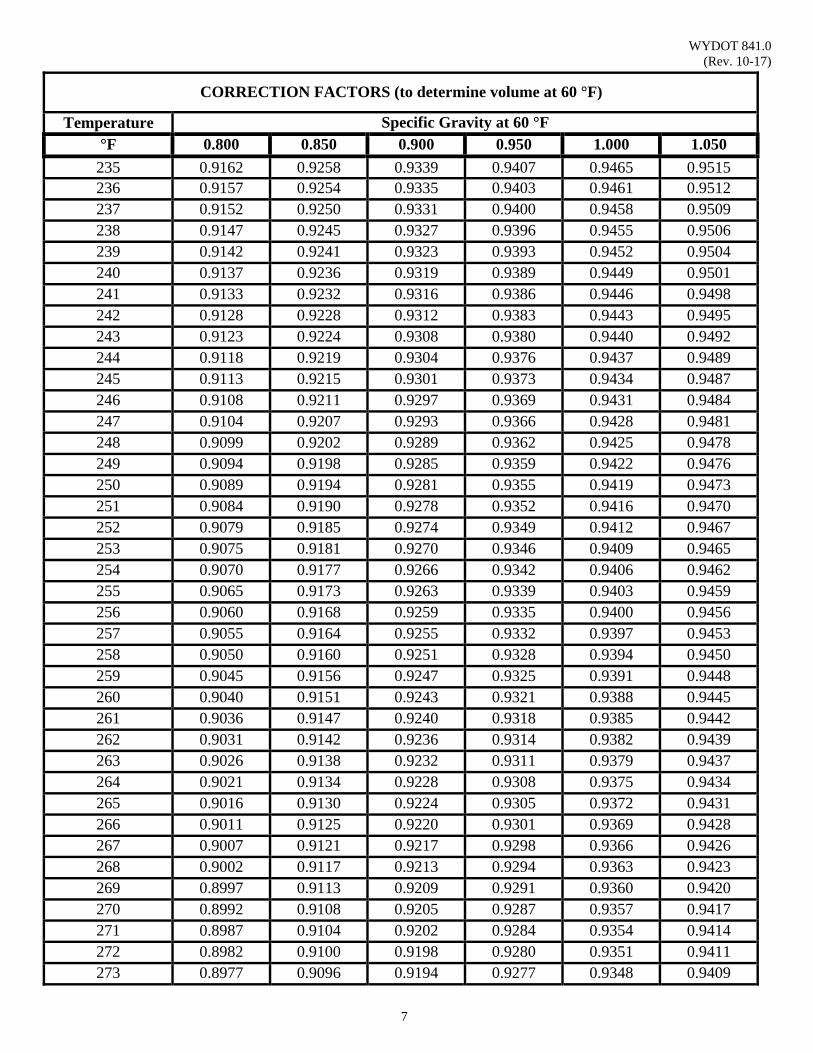
WYDOT 841.0 (Rev. 10-17)
7
CORRECTION FACTORS (to determine volume at 60 °F)
Temperature Specific Gravity at 60 °F °F 0.800 0.850 0.900 0.950 1.000 1.050 235 0.9162 0.9258 0.9339 0.9407 0.9465 0.9515 236 0.9157 0.9254 0.9335 0.9403 0.9461 0.9512 237 0.9152 0.9250 0.9331 0.9400 0.9458 0.9509 238 0.9147 0.9245 0.9327 0.9396 0.9455 0.9506 239 0.9142 0.9241 0.9323 0.9393 0.9452 0.9504 240 0.9137 0.9236 0.9319 0.9389 0.9449 0.9501 241 0.9133 0.9232 0.9316 0.9386 0.9446 0.9498 242 0.9128 0.9228 0.9312 0.9383 0.9443 0.9495 243 0.9123 0.9224 0.9308 0.9380 0.9440 0.9492 244 0.9118 0.9219 0.9304 0.9376 0.9437 0.9489 245 0.9113 0.9215 0.9301 0.9373 0.9434 0.9487 246 0.9108 0.9211 0.9297 0.9369 0.9431 0.9484 247 0.9104 0.9207 0.9293 0.9366 0.9428 0.9481 248 0.9099 0.9202 0.9289 0.9362 0.9425 0.9478 249 0.9094 0.9198 0.9285 0.9359 0.9422 0.9476 250 0.9089 0.9194 0.9281 0.9355 0.9419 0.9473 251 0.9084 0.9190 0.9278 0.9352 0.9416 0.9470 252 0.9079 0.9185 0.9274 0.9349 0.9412 0.9467 253 0.9075 0.9181 0.9270 0.9346 0.9409 0.9465 254 0.9070 0.9177 0.9266 0.9342 0.9406 0.9462 255 0.9065 0.9173 0.9263 0.9339 0.9403 0.9459 256 0.9060 0.9168 0.9259 0.9335 0.9400 0.9456 257 0.9055 0.9164 0.9255 0.9332 0.9397 0.9453 258 0.9050 0.9160 0.9251 0.9328 0.9394 0.9450 259 0.9045 0.9156 0.9247 0.9325 0.9391 0.9448 260 0.9040 0.9151 0.9243 0.9321 0.9388 0.9445 261 0.9036 0.9147 0.9240 0.9318 0.9385 0.9442 262 0.9031 0.9142 0.9236 0.9314 0.9382 0.9439 263 0.9026 0.9138 0.9232 0.9311 0.9379 0.9437 264 0.9021 0.9134 0.9228 0.9308 0.9375 0.9434 265 0.9016 0.9130 0.9224 0.9305 0.9372 0.9431 266 0.9011 0.9125 0.9220 0.9301 0.9369 0.9428 267 0.9007 0.9121 0.9217 0.9298 0.9366 0.9426 268 0.9002 0.9117 0.9213 0.9294 0.9363 0.9423 269 0.8997 0.9113 0.9209 0.9291 0.9360 0.9420 270 0.8992 0.9108 0.9205 0.9287 0.9357 0.9417 271 0.8987 0.9104 0.9202 0.9284 0.9354 0.9414 272 0.8982 0.9100 0.9198 0.9280 0.9351 0.9411 273 0.8977 0.9096 0.9194 0.9277 0.9348 0.9409
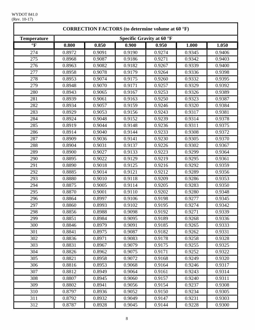
WYDOT 841.0 (Rev. 10-17)
8
CORRECTION FACTORS (to determine volume at 60 °F)
Temperature Specific Gravity at 60 °F °F 0.800 0.850 0.900 0.950 1.000 1.050 274 0.8972 0.9091 0.9190 0.9274 0.9345 0.9406 275 0.8968 0.9087 0.9186 0.9271 0.9342 0.9403 276 0.8963 0.9082 0.9182 0.9267 0.9339 0.9400 277 0.8958 0.9078 0.9179 0.9264 0.9336 0.9398 278 0.8953 0.9074 0.9175 0.9260 0.9332 0.9395 279 0.8948 0.9070 0.9171 0.9257 0.9329 0.9392 280 0.8943 0.9065 0.9167 0.9253 0.9326 0.9389 281 0.8939 0.9061 0.9163 0.9250 0.9323 0.9387 282 0.8934 0.9057 0.9159 0.9246 0.9320 0.9384 283 0.8929 0.9053 0.9156 0.9243 0.9317 0.9381 284 0.8924 0.9048 0.9152 0.9239 0.9314 0.9378 285 0.8919 0.9044 0.9148 0.9236 0.9311 0.9375 286 0.8914 0.9040 0.9144 0.9233 0.9308 0.9372 287 0.8909 0.9036 0.9141 0.9230 0.9305 0.9370 288 0.8904 0.9031 0.9137 0.9226 0.9302 0.9367 289 0.8900 0.9027 0.9133 0.9223 0.9299 0.9364 290 0.8895 0.9022 0.9129 0.9219 0.9295 0.9361 291 0.8890 0.9018 0.9125 0.9216 0.9292 0.9359 292 0.8885 0.9014 0.9121 0.9212 0.9289 0.9356 293 0.8880 0.9010 0.9118 0.9209 0.9286 0.9353 294 0.8875 0.9005 0.9114 0.9205 0.9283 0.9350 295 0.8870 0.9001 0.9110 0.9202 0.9280 0.9348 296 0.8864 0.8997 0.9106 0.9198 0.9277 0.9345 297 0.8860 0.8993 0.9102 0.9195 0.9274 0.9342 298 0.8856 0.8988 0.9098 0.9192 0.9271 0.9339 299 0.8851 0.8984 0.9095 0.9189 0.9268 0.9336 300 0.8846 0.8979 0.9091 0.9185 0.9265 0.9333 301 0.8841 0.8975 0.9087 0.9182 0.9262 0.9331 302 0.8836 0.8971 0.9083 0.9178 0.9258 0.9328 303 0.8831 0.8967 0.9079 0.9175 0.9255 0.9325 304 0.8826 0.8962 0.9075 0.9171 0.9252 0.9322 305 0.8821 0.8958 0.9072 0.9168 0.9249 0.9320 306 0.8816 0.8953 0.9068 0.9164 0.9246 0.9317 307 0.8812 0.8949 0.9064 0.9161 0.9243 0.9314 308 0.8807 0.8945 0.9060 0.9157 0.9240 0.9311 309 0.8802 0.8941 0.9056 0.9154 0.9237 0.9308 310 0.8797 0.8936 0.9052 0.9150 0.9234 0.9305 311 0.8792 0.8932 0.9049 0.9147 0.9231 0.9303 312 0.8787 0.8928 0.9045 0.9144 0.9228 0.9300
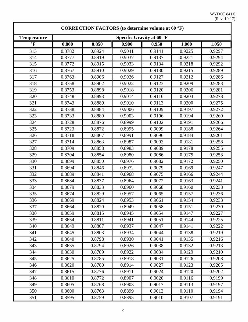
WYDOT 841.0 (Rev. 10-17)
9
CORRECTION FACTORS (to determine volume at 60 °F)
Temperature Specific Gravity at 60 °F °F 0.800 0.850 0.900 0.950 1.000 1.050 313 0.8782 0.8924 0.9041 0.9141 0.9225 0.9297 314 0.8777 0.8919 0.9037 0.9137 0.9221 0.9294 315 0.8772 0.8915 0.9033 0.9134 0.9218 0.9292 316 0.8767 0.8910 0.9029 0.9130 0.9215 0.9289 317 0.8763 0.8906 0.9026 0.9127 0.9212 0.9286 318 0.8758 0.8902 0.9022 0.9123 0.9209 0.9283 319 0.8753 0.8898 0.9018 0.9120 0.9206 0.9281 320 0.8748 0.8893 0.9014 0.9116 0.9203 0.9278 321 0.8743 0.8889 0.9010 0.9113 0.9200 0.9275 322 0.8738 0.8884 0.9006 0.9109 0.9197 0.9272 323 0.8733 0.8880 0.9003 0.9106 0.9194 0.9269 324 0.8728 0.8876 0.8999 0.9102 0.9191 0.9266 325 0.8723 0.8872 0.8995 0.9099 0.9188 0.9264 326 0.8718 0.8867 0.8991 0.9096 0.9184 0.9261 327 0.8714 0.8863 0.8987 0.9093 0.9181 0.9258 328 0.8709 0.8858 0.8983 0.9089 0.9178 0.9255 329 0.8704 0.8854 0.8980 0.9086 0.9175 0.9253 330 0.8699 0.8850 0.8976 0.9082 0.9172 0.9250 331 0.8694 0.8846 0.8972 0.9079 0.9169 0.9247 332 0.8689 0.8841 0.8968 0.9075 0.9166 0.9244 333 0.8684 0.8837 0.8964 0.9072 0.9163 0.9241 334 0.8679 0.8833 0.8960 0.9068 0.9160 0.9238 335 0.8674 0.8829 0.8957 0.9065 0.9157 0.9236 336 0.8669 0.8824 0.8953 0.9061 0.9154 0.9233 337 0.8664 0.8820 0.8949 0.9058 0.9151 0.9230 338 0.8659 0.8815 0.8945 0.9054 0.9147 0.9227 339 0.8654 0.8811 0.8941 0.9051 0.9144 0.9225 340 0.8649 0.8807 0.8937 0.9047 0.9141 0.9222 341 0.8645 0.8803 0.8934 0.9044 0.9138 0.9219 342 0.8640 0.8798 0.8930 0.9041 0.9135 0.9216 343 0.8635 0.8794 0.8926 0.9038 0.9132 0.9213 344 0.8630 0.8789 0.8922 0.9034 0.9129 0.9210 345 0.8625 0.8785 0.8918 0.9031 0.9126 0.9208 346 0.8620 0.8780 0.8914 0.9027 0.9123 0.9205 347 0.8615 0.8776 0.8911 0.9024 0.9120 0.9202 348 0.8610 0.8772 0.8907 0.9020 0.9116 0.9199 349 0.8605 0.8768 0.8903 0.9017 0.9113 0.9197 350 0.8600 0.8763 0.8899 0.9013 0.9110 0.9194 351 0.8595 0.8759 0.8895 0.9010 0.9107 0.9191
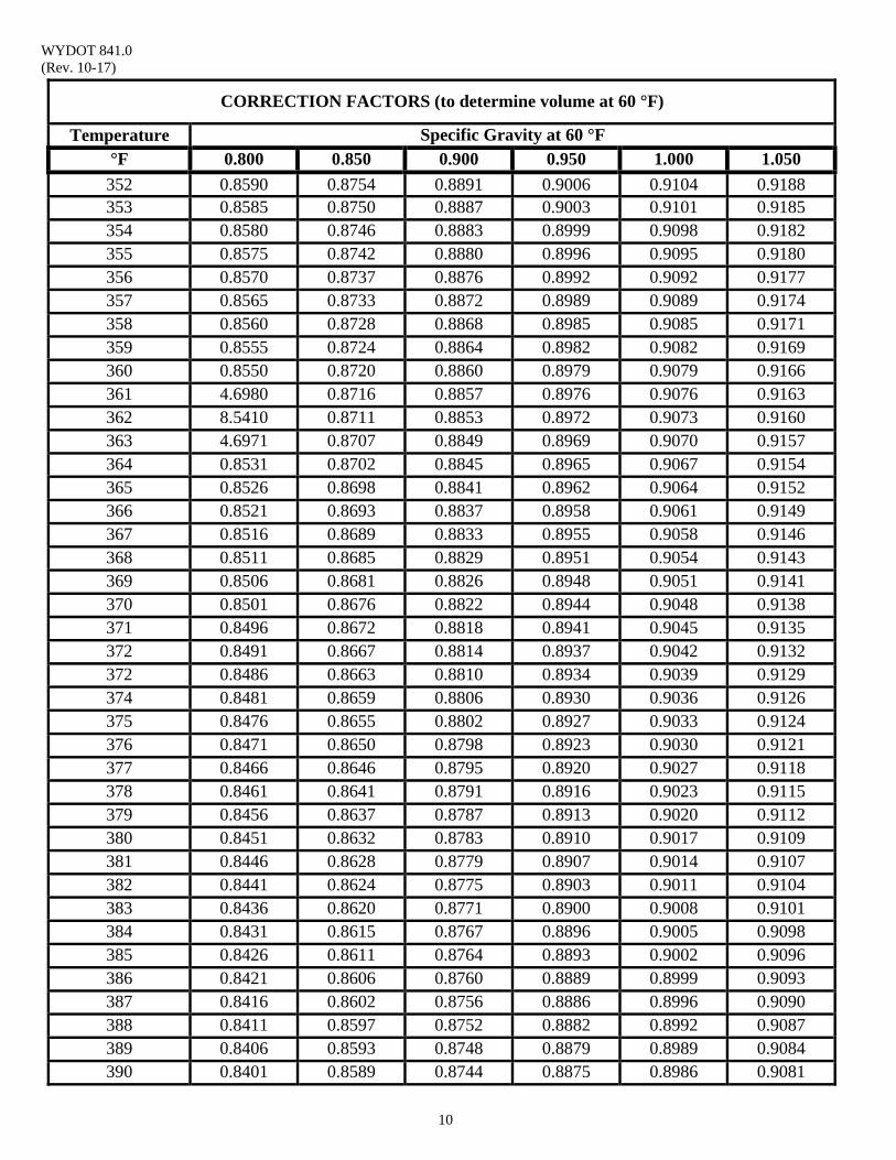
WYDOT 841.0 (Rev. 10-17)
10
CORRECTION FACTORS (to determine volume at 60 °F)
Temperature Specific Gravity at 60 °F °F 0.800 0.850 0.900 0.950 1.000 1.050 352 0.8590 0.8754 0.8891 0.9006 0.9104 0.9188 353 0.8585 0.8750 0.8887 0.9003 0.9101 0.9185 354 0.8580 0.8746 0.8883 0.8999 0.9098 0.9182 355 0.8575 0.8742 0.8880 0.8996 0.9095 0.9180 356 0.8570 0.8737 0.8876 0.8992 0.9092 0.9177 357 0.8565 0.8733 0.8872 0.8989 0.9089 0.9174 358 0.8560 0.8728 0.8868 0.8985 0.9085 0.9171 359 0.8555 0.8724 0.8864 0.8982 0.9082 0.9169 360 0.8550 0.8720 0.8860 0.8979 0.9079 0.9166 361 4.6980 0.8716 0.8857 0.8976 0.9076 0.9163 362 8.5410 0.8711 0.8853 0.8972 0.9073 0.9160 363 4.6971 0.8707 0.8849 0.8969 0.9070 0.9157 364 0.8531 0.8702 0.8845 0.8965 0.9067 0.9154 365 0.8526 0.8698 0.8841 0.8962 0.9064 0.9152 366 0.8521 0.8693 0.8837 0.8958 0.9061 0.9149 367 0.8516 0.8689 0.8833 0.8955 0.9058 0.9146 368 0.8511 0.8685 0.8829 0.8951 0.9054 0.9143 369 0.8506 0.8681 0.8826 0.8948 0.9051 0.9141 370 0.8501 0.8676 0.8822 0.8944 0.9048 0.9138 371 0.8496 0.8672 0.8818 0.8941 0.9045 0.9135 372 0.8491 0.8667 0.8814 0.8937 0.9042 0.9132 372 0.8486 0.8663 0.8810 0.8934 0.9039 0.9129 374 0.8481 0.8659 0.8806 0.8930 0.9036 0.9126 375 0.8476 0.8655 0.8802 0.8927 0.9033 0.9124 376 0.8471 0.8650 0.8798 0.8923 0.9030 0.9121 377 0.8466 0.8646 0.8795 0.8920 0.9027 0.9118 378 0.8461 0.8641 0.8791 0.8916 0.9023 0.9115 379 0.8456 0.8637 0.8787 0.8913 0.9020 0.9112 380 0.8451 0.8632 0.8783 0.8910 0.9017 0.9109 381 0.8446 0.8628 0.8779 0.8907 0.9014 0.9107 382 0.8441 0.8624 0.8775 0.8903 0.9011 0.9104 383 0.8436 0.8620 0.8771 0.8900 0.9008 0.9101 384 0.8431 0.8615 0.8767 0.8896 0.9005 0.9098 385 0.8426 0.8611 0.8764 0.8893 0.9002 0.9096 386 0.8421 0.8606 0.8760 0.8889 0.8999 0.9093 387 0.8416 0.8602 0.8756 0.8886 0.8996 0.9090 388 0.8411 0.8597 0.8752 0.8882 0.8992 0.9087 389 0.8406 0.8593 0.8748 0.8879 0.8989 0.9084 390 0.8401 0.8589 0.8744 0.8875 0.8986 0.9081
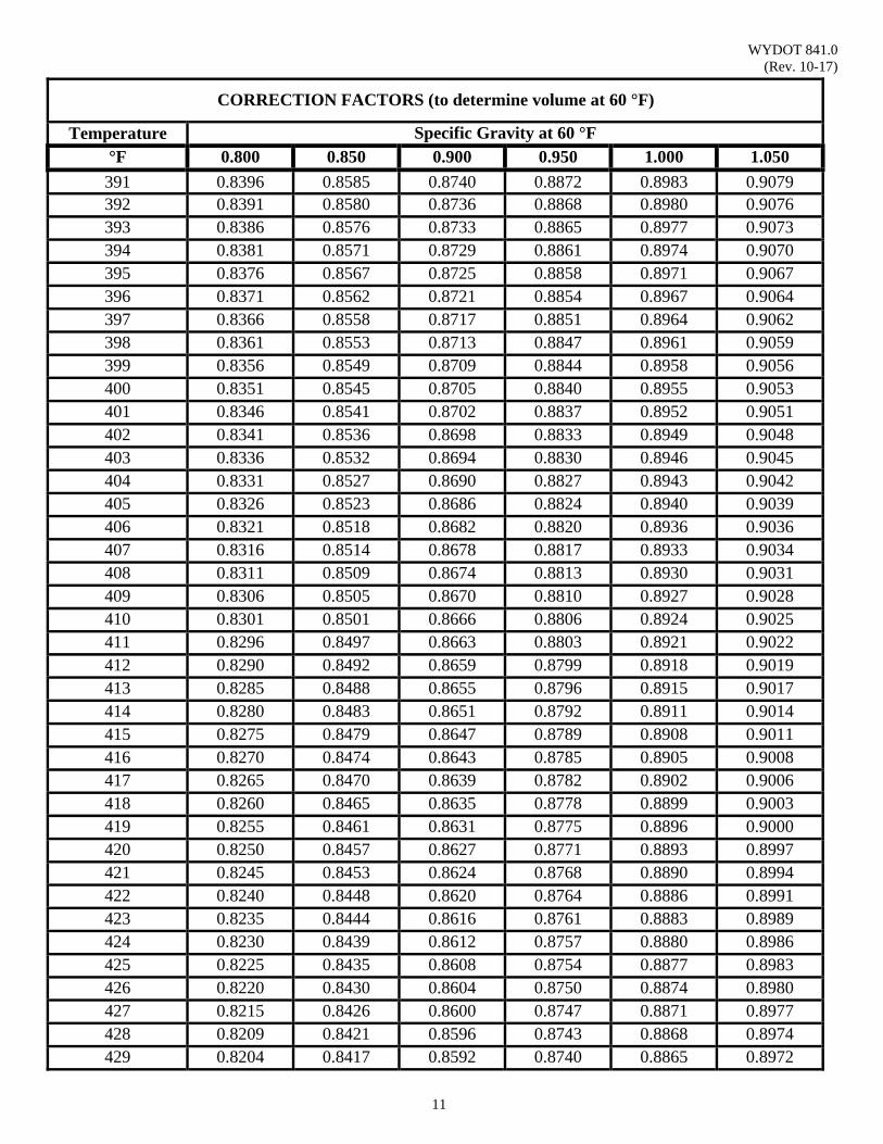
WYDOT 841.0 (Rev. 10-17)
11
CORRECTION FACTORS (to determine volume at 60 °F)
Temperature Specific Gravity at 60 °F °F 0.800 0.850 0.900 0.950 1.000 1.050 391 0.8396 0.8585 0.8740 0.8872 0.8983 0.9079 392 0.8391 0.8580 0.8736 0.8868 0.8980 0.9076 393 0.8386 0.8576 0.8733 0.8865 0.8977 0.9073 394 0.8381 0.8571 0.8729 0.8861 0.8974 0.9070 395 0.8376 0.8567 0.8725 0.8858 0.8971 0.9067 396 0.8371 0.8562 0.8721 0.8854 0.8967 0.9064 397 0.8366 0.8558 0.8717 0.8851 0.8964 0.9062 398 0.8361 0.8553 0.8713 0.8847 0.8961 0.9059 399 0.8356 0.8549 0.8709 0.8844 0.8958 0.9056 400 0.8351 0.8545 0.8705 0.8840 0.8955 0.9053 401 0.8346 0.8541 0.8702 0.8837 0.8952 0.9051 402 0.8341 0.8536 0.8698 0.8833 0.8949 0.9048 403 0.8336 0.8532 0.8694 0.8830 0.8946 0.9045 404 0.8331 0.8527 0.8690 0.8827 0.8943 0.9042 405 0.8326 0.8523 0.8686 0.8824 0.8940 0.9039 406 0.8321 0.8518 0.8682 0.8820 0.8936 0.9036 407 0.8316 0.8514 0.8678 0.8817 0.8933 0.9034 408 0.8311 0.8509 0.8674 0.8813 0.8930 0.9031 409 0.8306 0.8505 0.8670 0.8810 0.8927 0.9028 410 0.8301 0.8501 0.8666 0.8806 0.8924 0.9025 411 0.8296 0.8497 0.8663 0.8803 0.8921 0.9022 412 0.8290 0.8492 0.8659 0.8799 0.8918 0.9019 413 0.8285 0.8488 0.8655 0.8796 0.8915 0.9017 414 0.8280 0.8483 0.8651 0.8792 0.8911 0.9014 415 0.8275 0.8479 0.8647 0.8789 0.8908 0.9011 416 0.8270 0.8474 0.8643 0.8785 0.8905 0.9008 417 0.8265 0.8470 0.8639 0.8782 0.8902 0.9006 418 0.8260 0.8465 0.8635 0.8778 0.8899 0.9003 419 0.8255 0.8461 0.8631 0.8775 0.8896 0.9000 420 0.8250 0.8457 0.8627 0.8771 0.8893 0.8997 421 0.8245 0.8453 0.8624 0.8768 0.8890 0.8994 422 0.8240 0.8448 0.8620 0.8764 0.8886 0.8991 423 0.8235 0.8444 0.8616 0.8761 0.8883 0.8989 424 0.8230 0.8439 0.8612 0.8757 0.8880 0.8986 425 0.8225 0.8435 0.8608 0.8754 0.8877 0.8983 426 0.8220 0.8430 0.8604 0.8750 0.8874 0.8980 427 0.8215 0.8426 0.8600 0.8747 0.8871 0.8977 428 0.8209 0.8421 0.8596 0.8743 0.8868 0.8974 429 0.8204 0.8417 0.8592 0.8740 0.8865 0.8972

WYDOT 841.0 (Rev. 09-16)
12
CORRECTION FACTORS (to determine volume at 60 °F)
Temperature Specific Gravity at 60 °F °F 0.800 0.850 0.900 0.950 1.000 1.050
430 0.8199 0.8412 0.8588 0.8736 0.8861 0.8969 431 0.8194 0.8408 0.8585 0.8733 0.8858 0.8966 432 0.8189 0.8403 0.8581 0.8729 0.8855 0.8963 433 0.8184 0.8399 0.8577 0.8726 0.8852 0.8960 434 0.8179 0.8395 0.8573 0.8722 0.8849 0.8957 435 0.8174 0.8391 0.8569 0.8719 0.8846 0.8955 436 0.8169 0.8386 0.8565 0.8715 0.8843 0.8952 437 0.8164 0.8382 0.8561 0.8712 0.8840 0.8949 438 0.8159 0.8377 0.8557 0.8708 0.8836 0.8946
The following formulas are used to calculate the correction factors in the table above:
@60° @ °
– 0.000611 ° 60°
Reference: Perry’s Chemical Engineers’ Handbook, 6th edition, 1984, McGraw – Hill, R660.28P or 660.2
WYDOT 844.0 (Rev. 10-17)
1
FIELD SCREEN TEST PROCEDURE FOR EMULSIFIED ASPHALT
Scope: This method provides a field procedure for determining whether emulsified
asphalt has uniform particle size and distribution and does not have deleterious material large enough to plug and/or contaminate equipment (distributor filters, spray nozzles, etc). This procedure is adopted from AASHTO R 66. This procedure is NOT the Sieve Test included in AASHTO T 59.
Use: This procedure is used to evaluate emulsified asphalt in accordance with WYDOT
Standard Specifications Section 804.3, and upon delivery for acceptance or rejection of tanker(s) before use per WYDOT Standard Specifications Section 113.2.
This test is performed to ensure emulsions are “smooth and homogeneous
throughout.” The owner of the distributor is responsible for ensuring the emulsion is acceptable for each load of emulsion delivered.
Reference Documents: AASHTO M 140 Standard Specification for Emulsified Asphalt AASHTO M 208 Standard Specification for Cationic Emulsified Asphalt
AASHTO R 66 Standard Practice for Sampling Asphalt Materials WYDOT 113.2 WYDOT Standard Specifications Acceptance of Asphalt
Materials WYDOT 804.3 WYDOT Standard Specifications Section Emulsified
Asphalt WYDOT E-224 Pay Adjustment for Emulsified Asphalt Apparatus: 1. 11½ inch square screen mesh with ⅛ inch square openings
2. Large containers such as, 5 gallon capacity, etc., for testing and cleanup 3. Gloves, insulated, vinyl coated, 10 inch gauntlet 4. Aluminum 12 inch square pan, 2 inch deep with 8-inch diameter hole
centered in bottom of pan
Precautions: 1. Use gloves for handling the apparatus and hot emulsified asphalt.
2. Ensure the screen mesh is clean and dry before use.
WYDOT 844.0 (Rev. 10-17)
2
3. Do not re-use screen mesh. Emulsified asphalt hardens such that apparatus cannot be cleaned completely to avoid accumulation buildup affecting future testing.
Procedure: 1. Upon delivery of each load to project, check the temperature of the emulsified asphalt to ensure it complies with appropriate specifications. Place one large container under the sampling valve, open the valve and allow a minimum of two gallons of emulsified asphalt to pour into the five gallon container. This is to ensure that any possible residue is flushed out of the valve/port and only representative material is used during the test.
2. Momentarily close the valve and place another large container under the
valve port. Place a clean, unused piece of screen mesh with ⅛ inch openings into the square pan and position it under the valve/port. Reopen the valve/port and allow one gallon sample of emulsified asphalt to flow through the piece of screen mesh and hole in pan into the container below and close the valve.
Note: If the one gallon sample of emulsified asphalt is obtained through
the fill port on the top of the tanker, then the sampling cup/ladle, etc., must be dipped down far enough into the emulsified asphalt to avoid any contamination, such as foam floating at the top of the emulsified asphalt in the tanker.
3. Examine the piece of screen mesh. Emulsion may stick to the screen mesh
due to cooling effects. Determine if emulsion is acceptable as follows: a. Using a vinyl coated glove, press down lightly on each particle on
the screen mesh to distinguish between bubbles and 'true sieve particles' versus other solid contaminants (DO NOT force particles through the screen mesh).
'True sieve particles' appear as round beads (bb's) and are an
agglomeration of the dispersed phase of emulsion (see picture below showing emulsion particle size distribution viewed under a microscope). AASHTO specifications allow 0.1 percent by weight maximum of sieve particles (larger than 0.85 millimeter in size). Sieve particles, when pressed down lightly, will flatten out smoothly on the screen or push through because they are soft and pliable.
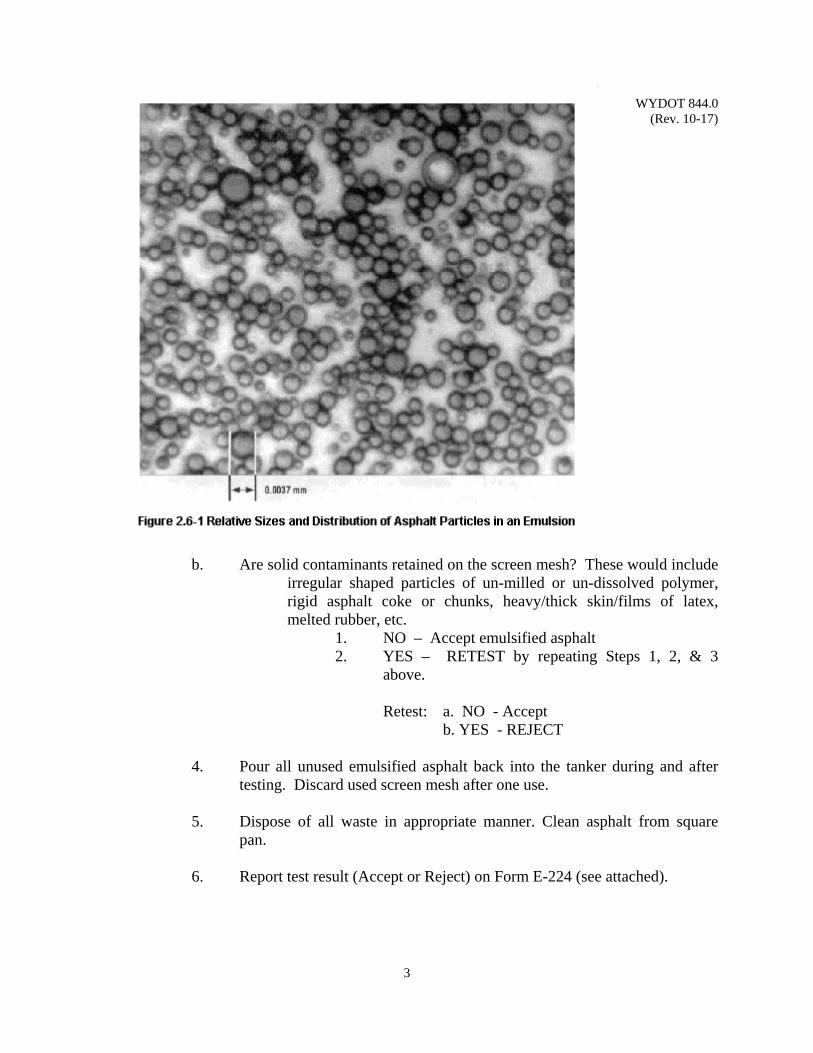
WYDOT 844.0 (Rev. 10-17)
3
b. Are solid contaminants retained on the screen mesh? These would include irregular shaped particles of un-milled or un-dissolved polymer, rigid asphalt coke or chunks, heavy/thick skin/films of latex, melted rubber, etc.
1. NO – Accept emulsified asphalt 2. YES – RETEST by repeating Steps 1, 2, & 3
above. Retest: a. NO - Accept b. YES - REJECT 4. Pour all unused emulsified asphalt back into the tanker during and after
testing. Discard used screen mesh after one use. 5. Dispose of all waste in appropriate manner. Clean asphalt from square
pan. 6. Report test result (Accept or Reject) on Form E-224 (see attached).

WYDOT 844.0 (Rev. 10-17)
4
WYDOT 850.0 (Rev. 10-17)
1
CHIP SEAL AGGREGATE / EMULSION COMPATIBILITY TEST
Scope: This procedure describes the method for determining compatibility of aggregate
and emulsified asphalt for chip seals and establishes information to report prior to sealing operations. Compatibility is defined as the ability of aggregate to allow sufficient coating by emulsion residue and resist coating loss from adverse water exposure.
Ensure laboratories performing compatibility testing meet requirements of
WYDOT Standard Specifications for applicable AASHTO test methods. Use: Contractor performs compatibility testing prior to sealing operations. Submit test
data on WYDOT Form T-180 to Resident Engineer (see blank form this section). Apparatus: 1. Containers for mixing, having rounded corners, such as seamless tin cans,
with capacity to easily hold 100 grams of aggregate. 2. Balance, with minimum capacity of 95 grams, accurate to 0.1 gram. 3. Spatula, steel, with stiff blade approximately 25 mm wide by 100 mm
long. 4. Beaker, glass, 800 milliliter (mL). 5. Piece of aluminum window screen, cut in circle to match bottom, inside
diameter of 800 mL beaker. 6. Heat source, either hot plate or Bunsen burner, capable of maintaining 200
°F ± 10 °F. 7. Thermometer, stem, range 180 °F to 220 °F. 8. Brown Kraft paper, 50 lb weight, square sheet; 12 inch x 12 inch, 18 inch
x 18 inch Reference Documents: AASHTO R 66 Standard Practice for Sampling Asphalt Materials
AASHTO T 2 Sampling of Aggregates AASHTO T 11 Materials Finer than 75 µm (No. 200) Sieve in Mineral
Aggregate AASHTO T 27 Sieve Analysis of Fine and Coarse Aggregates AASHTO T 59 Testing Emulsified Asphalts
WYDOT 409 WYDOT Standard Specifications WYDOT 803.1 WYDOT Standard Specifications WYDOT 803.8 WYDOT Standard Specifications WYDOT 803.9 WYDOT Standard Specifications WYDOT 804.1 WYDOT Standard Specifications WYDOT 804.3 WYDOT Standard Specifications WYDOT 814.1.1 WYDOT Standard Specifications WYDOT T-180 Chip Seal Aggregate / Emulsion Compatibility Test
WYDOT 850.0 (Rev. 10-17)
2
Procedure: 1. Obtain approximately 100 ± 5 grams of clean, oven-dried (no surface
moisture) aggregate as required by project specifications. For example, if project requires gradation Type B for chip seal aggregate, obtain aggregate sample from project source(s) that is well-graded from coarse to fine in accordance with Table 803.8-1, Gradation Requirements: Chip Seal, 2010 WYDOT Standard Specifications.
2. Obtain emulsion of same type as required by project specifications;
thoroughly heat emulsion to 140 ± 5 °F; stir for 5 minutes or until uniform in consistency.
3. Weigh 100 ± 5 grams of aggregate into a clean mixing container; record
weight as aggregate, A, in grams, on Form T-180. 4. Add 1% water to aggregate (by weight of dry aggregate); mix until water
is absorbed; record weight as water, W, in grams, on Form T-180. 5. Determine quantity of emulsion to add to aggregate to achieve blend of
7% emulsion with 93% aggregate using the following equation:
E7% = (A ÷ 0.93) - A Where: A = Aggregate dry weight, grams (Step 3) E7% = Emulsion weight (7% blend), grams
6. Add calculated quantity of emulsion (Step 5) to aggregate; thoroughly and vigorously mix/blend emulsion and aggregate to maximize coating of aggregate, but not more than 5 minutes ± 15 seconds.
7. After completely mixing aggregate and emulsion, empty container onto 18 inch x 18 inch square sheet of brown Kraft paper; spread out sample so all coated aggregate surfaces are clearly visible.
8. Let coated aggregate cure at room temperature (60 °F to 80 °F) for 24
hours.
9. Measure gross weight of coated aggregate & sheet (nearest gram); record as aggregate weight before boiling, AB, on Form T-180; visually estimate percent coating (nearest 5%).
10. Record as percent coating before boiling, PB(1), on Form T-180 (the digit
1 denotes 1% water added to aggregate before emulsion coating).
WYDOT 850.0 (Rev. 10-17)
3
11. If PB(1) ≥ 85%, proceed with boiling sample (Step 14); otherwise obtain new aggregate sample (per Step 1), repeat Steps 2 through 9 except add 2% water (Step 4).
12. Record percent coating before boiling as, PB(2), on Form T-180 (the digit 2 denotes 2% water added to aggregate before emulsion coating).
13. If PB(2) ≥ 85%, proceed with boiling sample (Step 14); otherwise record aggregate/emulsion combination as "Not Compatible" on Form T-180.
14. Place circular piece of aluminum window screen on bottom of 800 mL beaker to serve as a spacer to allow boiling water to contact full surface area of all coated aggregates (including surfaces at bottom of beaker).
15. Add 600 mL of water into beaker. 16. Determine “mild boil” temperature, TB, for water using the following
equation (elevation adjusted):
TB = (-0.002 x E) + 205.1 Where: TB = Temperature, nearest degree F E = Elevation of lab above sea level, nearest 10 feet
17. Heat water in beaker to temperature TB ± 5 °F (from Step 16); verify
temperature using stem thermometer inserted into water while heating. 18. Add entire coated aggregate sample (Step 9) to boiling water in beaker;
measure weight of used 18 inch x 18 inch sample sheet and residue (nearest gram); record as sample sheet & residue weight before boiling, SB, on Form T-180.
19. Adjust/add heat to achieve TB ± 5 °F again (verify using stem
thermometer); record as temperature of water, TW, on Form T-180; leave coated aggregate sample in boiling water for 5 minutes ± 15 seconds; record boiling time as, BT, on Form T-180.
20. Drain water from beaker; let coated aggregate cool to room temperature
(60 °F to 80 °F); measure weight of clean 12 inch x 12 inch square sheet of brown Kraft paper; record as sample sheet weight after boiling, SA, on Form T-180; empty beaker contents onto sample sheet; spread out sample so all coated aggregate surfaces are clearly visible.
WYDOT 850.0 (Rev. 10-17)
4
21. Measure gross weight of coated aggregate & sheet (nearest gram); record
as aggregate weight after boiling, AA, on Form T-180; visually estimate percent coating (nearest 5%).
22. Record as percent coating after boiling, PA(x), on Form T-180 (where digit
x denotes percent water added to aggregate before emulsion coating). 23. Determine percent coating retained after boiling, PR(x), using the
following equation:
PR(x) = (PA(x) ÷ PB(x) ) x 100% Where: x = percent water added to aggregate to achieve 85% minimum emulsion coating before boiling PR(x) = Percent coating retained after boiling, nearest 1% PA(x) = Percent coating after boiling, nearest 5% PB(x) = Percent coating before boiling, nearest 5%
24. Record percent coating retained after boiling as, PR(x), on Form T-180.
25. If PR(x) ≥ 80%, record aggregate/emulsion combination as
“Compatible” on Form T-180; if PR(x) < 80%, record aggregate/emulsion combination as “Not Compatible” on Form T-180.
General: Provide materials for aggregate/emulsion combination(s) as follows: Aggregate– Conform to requirements of Subsection 803.1, General; 803.8,
Aggregate for Chip Seal, and Subsection 803.9, Aggregate for Blotter.
Emulsified Asphalt– Conform to requirements of Subsection 804.3, Emulsified
Asphalt. Water – Conform to requirements of Subsection 814.1.1, General. Report: All test information on WYDOT Form T-180 (see blank form this section)
including the following:
WYDOT 850.0 (Rev. 10-17)
5
Aggregate;
Source location (e.g., Granite Canyon Quarry, Underpass Pit, etc) Gradation type (B, C, D, E, K, or S) Gradation data (% Passing, sieve size) Dry sample weight, A Weight (coated) before boiling, AB
Weight, sample sheet & residue, before boiling, SB
Weight, sample sheet, after boiling, SA Weight (coated) after boiling, AA
Coating (emulsion residue);
Percent before boiling, PB Percent after boiling, PA Percent retained after boiling, PR
Water; Source location (e.g., City of Cheyenne, etc) Weight added to aggregate (1%, 2%), W Temperature (boiling, elevation adjusted), TB
Temperature (boiling water), TW Boiling time, BT
Emulsified Asphalt;
Emulsion supplier Emulsion type/grade (e.g., CRS-2P) Modifier type (latex, solid) Blend sample weight, E7%
Aggregate/Emulsion Compatibility Aggregate moisture, % (to achieve 85% coating before boiling and 80% coating retained after boiling)
Contractor will: Provide all information required by Form T-180 to laboratory (e.g.,
emulsion supplier) performing compatibility testing. This information includes WYDOT project number, project location, name of WYDOT resident engineer, name of aggregate source, aggregate sample gradation type and data, date when aggregate was sampled, company that tested and graded the aggregate, contractor name, address, name of contact, and phone number.

WYDOT 850.0 (Rev. 10-17)
6
Testing Laboratory will: Perform compatibility testing, record all data on Form T-180, sign, print
name, and date the completed Form T-180 at bottom right, and submit to contractor for their review, signature, printed name and date (bottom left).
Contractor must submit completed, signed and dated Form T-180 to WYDOT
Resident Engineer at least three working days prior to chip sealing operations.
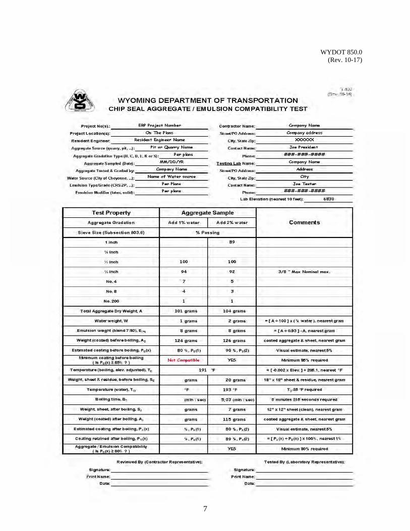
WYDOT 850.0 (Rev. 10-17)
7

WYDOT 850.0 (Rev. 10-17)
8
(This page intentionally left blank.)
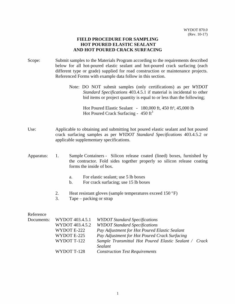
WYDOT 870.0 (Rev. 10-17)
1
FIELD PROCEDURE FOR SAMPLING HOT POURED ELASTIC SEALANT
AND HOT POURED CRACK SURFACING
Scope: Submit samples to the Materials Program according to the requirements described below for all hot-poured elastic sealant and hot-poured crack surfacing (each different type or grade) supplied for road construction or maintenance projects. Referenced Forms with example data follow in this section.
Note: DO NOT submit samples (only certifications) as per WYDOT
Standard Specifications 403.4.5.1 if material is incidental to other bid items or project quantity is equal to or less than the following;
Hot Poured Elastic Sealant - 180,000 ft, 450 ft³, 45,000 lb Hot Poured Crack Surfacing - 450 ft3
Use: Applicable to obtaining and submitting hot poured elastic sealant and hot poured
crack surfacing samples as per WYDOT Standard Specifications 403.4.5.2 or applicable supplementary specifications.
Apparatus: 1. Sample Containers - Silicon release coated (lined) boxes, furnished by
the contractor. Fold sides together properly so silicon release coating forms the inside of box.
a. For elastic sealant; use 5 lb boxes b. For crack surfacing; use 15 lb boxes
2. Heat resistant gloves (sample temperatures exceed 150 F) 3. Tape – packing or strap Reference Documents: WYDOT 403.4.5.1 WYDOT Standard Specifications WYDOT 403.4.5.2 WYDOT Standard Specifications WYDOT E-222 Pay Adjustment for Hot Poured Elastic Sealant WYDOT E-225 Pay Adjustment for Hot Poured Crack Surfacing
WYDOT T-122 Sample Transmittal Hot Poured Elastic Sealant / Crack Sealant
WYDOT T-128 Construction Test Requirements
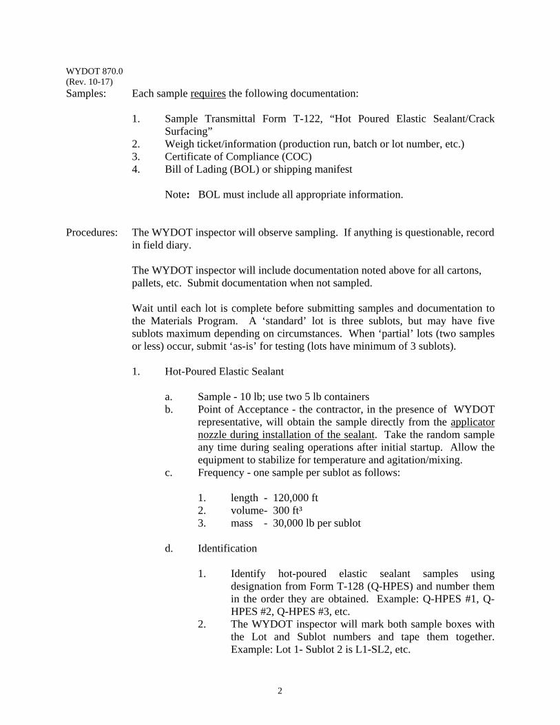
WYDOT 870.0 (Rev. 10-17)
2
Samples: Each sample requires the following documentation:
1. Sample Transmittal Form T-122, “Hot Poured Elastic Sealant/Crack Surfacing”
2. Weigh ticket/information (production run, batch or lot number, etc.) 3. Certificate of Compliance (COC) 4. Bill of Lading (BOL) or shipping manifest
Note: BOL must include all appropriate information.
Procedures: The WYDOT inspector will observe sampling. If anything is questionable, record in field diary. The WYDOT inspector will include documentation noted above for all cartons, pallets, etc. Submit documentation when not sampled.
Wait until each lot is complete before submitting samples and documentation to the Materials Program. A ‘standard’ lot is three sublots, but may have five sublots maximum depending on circumstances. When ‘partial’ lots (two samples or less) occur, submit ‘as-is’ for testing (lots have minimum of 3 sublots).
1. Hot-Poured Elastic Sealant
a. Sample - 10 lb; use two 5 lb containers b. Point of Acceptance - the contractor, in the presence of WYDOT
representative, will obtain the sample directly from the applicator nozzle during installation of the sealant. Take the random sample any time during sealing operations after initial startup. Allow the equipment to stabilize for temperature and agitation/mixing.
c. Frequency - one sample per sublot as follows: 1. length - 120,000 ft 2. volume- 300 ft³ 3. mass - 30,000 lb per sublot d. Identification
1. Identify hot-poured elastic sealant samples using designation from Form T-128 (Q-HPES) and number them in the order they are obtained. Example: Q-HPES #1, Q-HPES #2, Q-HPES #3, etc.
2. The WYDOT inspector will mark both sample boxes with the Lot and Sublot numbers and tape them together. Example: Lot 1- Sublot 2 is L1-SL2, etc.
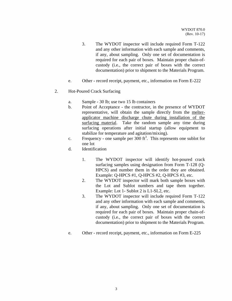
WYDOT 870.0 (Rev. 10-17)
3
3. The WYDOT inspector will include required Form T-122
and any other information with each sample and comments, if any, about sampling. Only one set of documentation is required for each pair of boxes. Maintain proper chain-of-custody (i.e., the correct pair of boxes with the correct documentation) prior to shipment to the Materials Program.
e. Other - record receipt, payment, etc., information on Form E-222
2. Hot-Poured Crack Surfacing
a. Sample - 30 lb; use two 15 lb containers b. Point of Acceptance - the contractor, in the presence of WYDOT
representative, will obtain the sample directly from the melter-applicator machine discharge chute during installation of the surfacing material. Take the random sample any time during surfacing operations after initial startup (allow equipment to stabilize for temperature and agitation/mixing).
c. Frequency - one sample per 300 ft3. This represents one sublot for one lot
d. Identification
1. The WYDOT inspector will identify hot-poured crack surfacing samples using designation from Form T-128 (Q-HPCS) and number them in the order they are obtained. Example: Q-HPCS #1, Q-HPCS #2, Q-HPCS #3, etc.
2. The WYDOT inspector will mark both sample boxes with the Lot and Sublot numbers and tape them together. Example: Lot 1- Sublot 2 is L1-SL2, etc.
3. The WYDOT inspector will include required Form T-122 and any other information with each sample and comments, if any, about sampling. Only one set of documentation is required for each pair of boxes. Maintain proper chain-of-custody (i.e., the correct pair of boxes with the correct documentation) prior to shipment to the Materials Program.
e. Other - record receipt, payment, etc., information on Form E-225
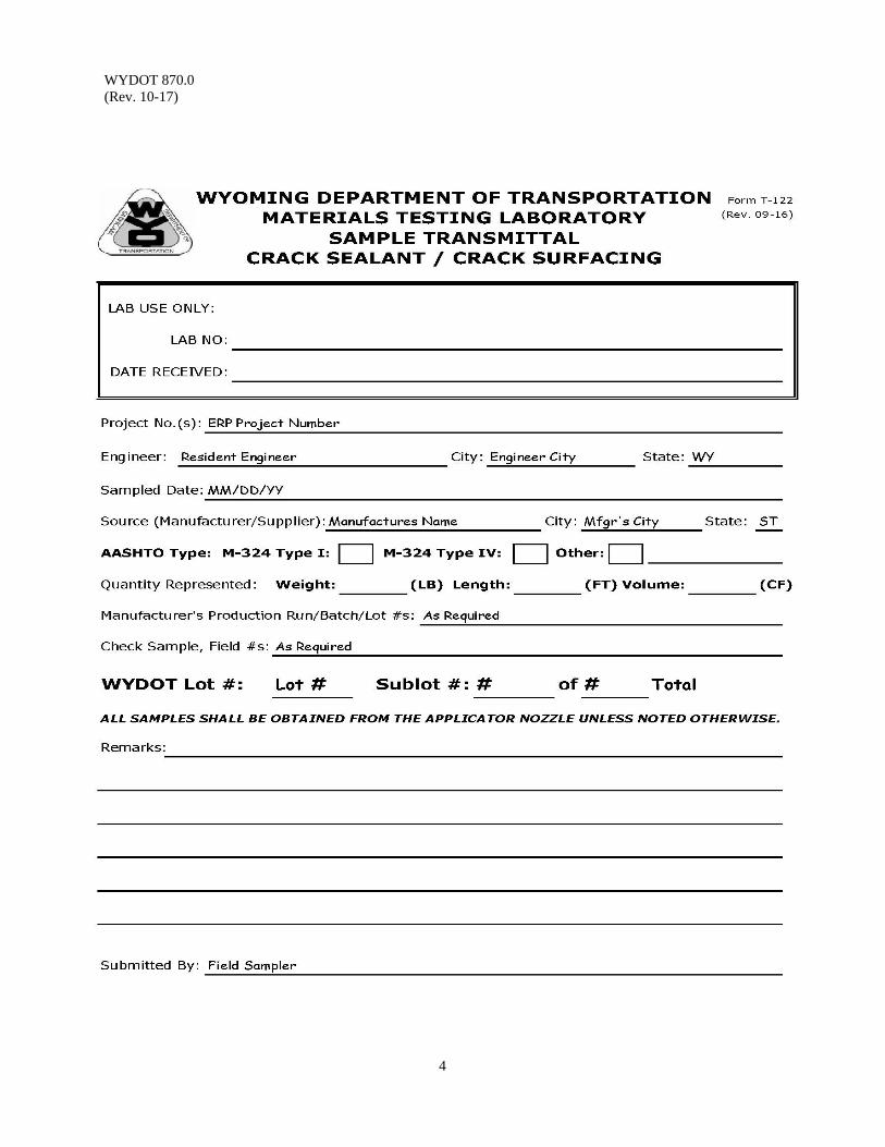
WYDOT 870.0 (Rev. 10-17)
4
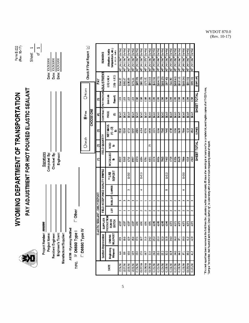
WYDOT 870.0 (Rev. 10-17)
5
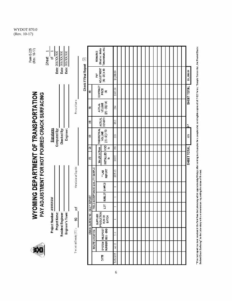
WYDOT 870.0 (Rev. 10-17)
6
WYDOT 880.0 (Rev. 01-15)
1
DEFORMED AND PLAIN BILLET-STEEL BARS FOR
CONCRETE REINFORCEMENT Scope: This section covers deformed and plain billet-steel concrete reinforcement bars in
cut lengths or coils, or deformed and plain carbon-steel bars; ASTM A615 Standard Specification for Deformed and Plain Carbon-Steel Bars for Concrete Reinforcement and AASHTO M 31 Deformed and Plain Carbon-Steel Bars for Concrete Reinforcement. The standard sizes and dimensions of deformed bars and their number designations are listed in a table in this section.
A deformed bar is a steel bar with protrusions; a bar that is intended for use as
reinforcement in reinforced concrete construction. The nominal dimensions of a deformed bar are equivalent to those of a plain round bar having the same weight per foot as the deformed bar.
Use: This section describes the designation numbers, grades, and nominal dimensions of
deformed and plain carbon-steel concrete reinforcement bars, and lists the minimum yield and tensile strength.
WYDOT Standard Specifications section 811.1.2 Reinforcing Steel Bars requires
reinforcing steel bars in accordance with ASTM A615 and for epoxy-coated steel bars in accordance with ASTM A775.
Reference Documents: AASHTO M 31 Standard Specification for Deformed and Plain
Carbon-Steel Bars for Concrete Reinforcement ASTM A615 Standard Specification for Deformed and Plain
Carbon-Steel Bars for Concrete Reinforcement WYDOT 811.1.2 WYDOT Standard Specifications WYDOT 130.0 Miscellaneous Items - Sample Size WYDOT T-128 Construction Test Requirements
Minimum Yield Strength:
40,000 lb/in² Grade 40 60,000 lb/in² Grade 60 75,000 lb/in² Grade 75
*80,000 lb/in² designated as Grade 80
Minimum Tensile Strength:
60,000 lb/in² Grade 40 90,000 lb/in² Grade 60
100,000 lb/in² Grade 75 *105,000 lb/in² designated as Grade 80
Bars are classified in three grades in AASHTO M 31. *Bars are classified in four grades in ASTM A615, adding Grade 80.
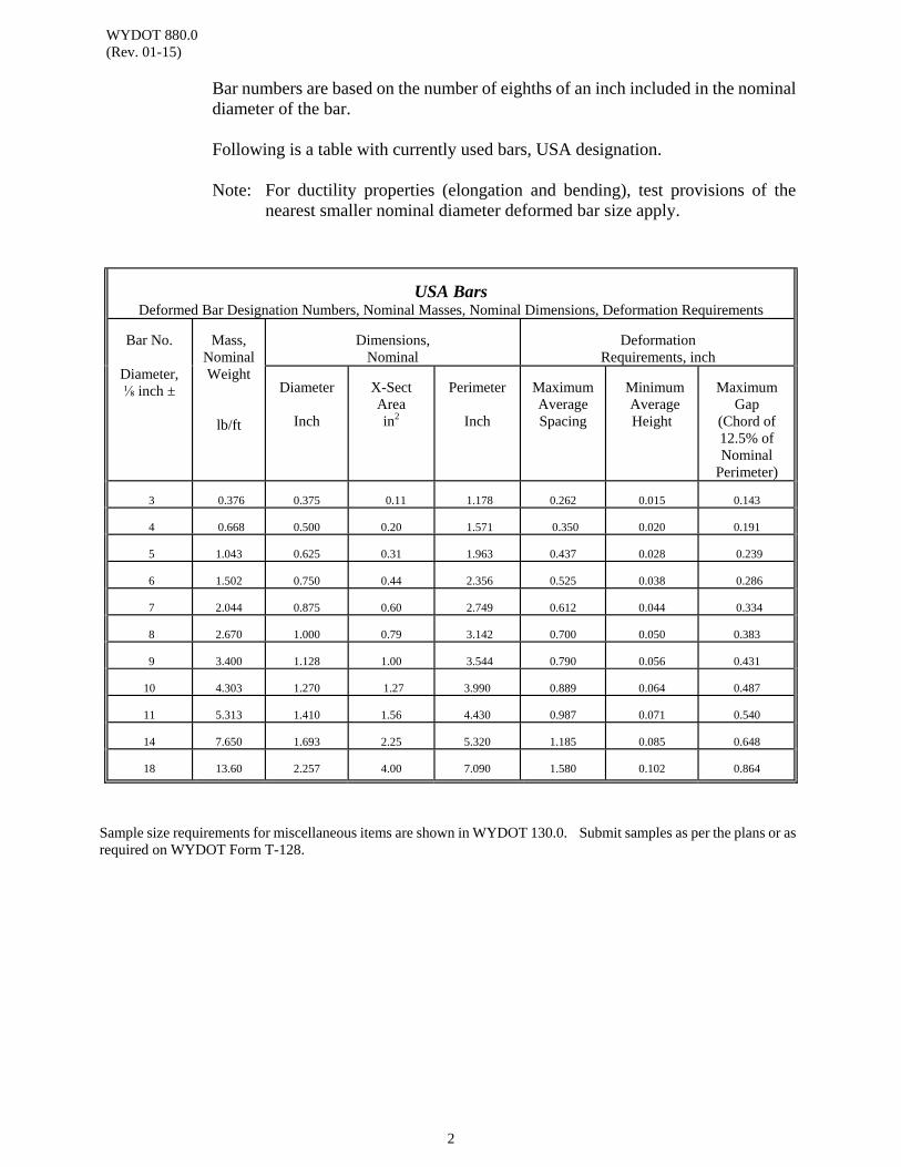
WYDOT 880.0 (Rev. 01-15)
2
Bar numbers are based on the number of eighths of an inch included in the nominal diameter of the bar.
Following is a table with currently used bars, USA designation. Note: For ductility properties (elongation and bending), test provisions of the
nearest smaller nominal diameter deformed bar size apply.
USA Bars Deformed Bar Designation Numbers, Nominal Masses, Nominal Dimensions, Deformation Requirements
Bar No. Diameter, ⅛ inch ±
Mass,
Nominal Weight
lb/ft
Dimensions,
Nominal
Deformation
Requirements, inch Diameter
Inch
X-Sect Area in2
Perimeter Inch
Maximum Average Spacing
Minimum Average Height
Maximum
Gap (Chord of 12.5% of Nominal
Perimeter) 3
0.376
0.375
0.11
1.178
0.262
0.015
0.143
4
0.668
0.500
0.20
1.571
0.350
0.020
0.191
5
1.043
0.625
0.31
1.963
0.437
0.028
0.239
6
1.502
0.750
0.44
2.356
0.525
0.038
0.286
7
2.044
0.875
0.60
2.749
0.612
0.044
0.334
8
2.670
1.000
0.79
3.142
0.700
0.050
0.383
9
3.400
1.128
1.00
3.544
0.790
0.056
0.431
10
4.303
1.270
1.27
3.990
0.889
0.064
0.487
11
5.313
1.410
1.56
4.430
0.987
0.071
0.540
14
7.650
1.693
2.25
5.320
1.185
0.085
0.648
18
13.60
2.257
4.00
7.090
1.580
0.102
0.864
Sample size requirements for miscellaneous items are shown in WYDOT 130.0. Submit samples as per the plans or as required on WYDOT Form T-128.
WYDOT 1010.0 (Rev. 09-16)
1
ALKALI SAMPLING AND PRELIMINARY PIPE SELECTION
Scope: Alkali samples are soil samples taken from drainage channels that are traversed
by an existing or proposed roadway.
Apparatus: 1. Clean canvas sample sacks 2. Shovel
3. Form T-120 Sample Transmittal with envelope Use: Alkali samples are tested to determine the potential of the soil to cause damage to
metallic and/or concrete drainage structures. Reference Documents: WYDOT T-120 Sample Transmittal Sampling Determination: A minimum of 25 lb of soil is required for each sample.
The sampling may be performed as a separate task or, the sampling may be done at the same time the AField Photo Annotation@ task is performed (this task includes the verification of drainage structure type, size and condition).
For reconstruction projects: Obtain a sample at every drainage channel that will be traversed by the proposed alignment.
For widen and overlay projects: Obtain samples only at those locations where the drainage structure is in fair/poor condition. If the drainage structure is in good condition extend it with the same level of corrosion resistance materials as the existing.
Procedure: Alkali samples are taken by the engineer at all existing or proposed drainage facilities that are less than 48 inches in diameter or width. The Geology Program will take the alkali samples at existing or proposed drainage facilities that are 48 inches or greater unless other arrangements are made by the Programs involved. Obtain sample at one drainage location only, unless required by the plans or the engineer. Obtain the sample at either the upstream or the downstream end of the existing or proposed drainage structure, whichever is more accessible. Take the sample from the site such that it will represent the soil that will be in contact with the drainage structure; typically taken from the upper 0.5 feet of the soil at the low point within the drainage channel.
Submitted alkali samples to the Materials Program with a Form T-120 that includes the milepost, the station, and the location of the sample as well as the condition of the existing drainage structure (if applicable).
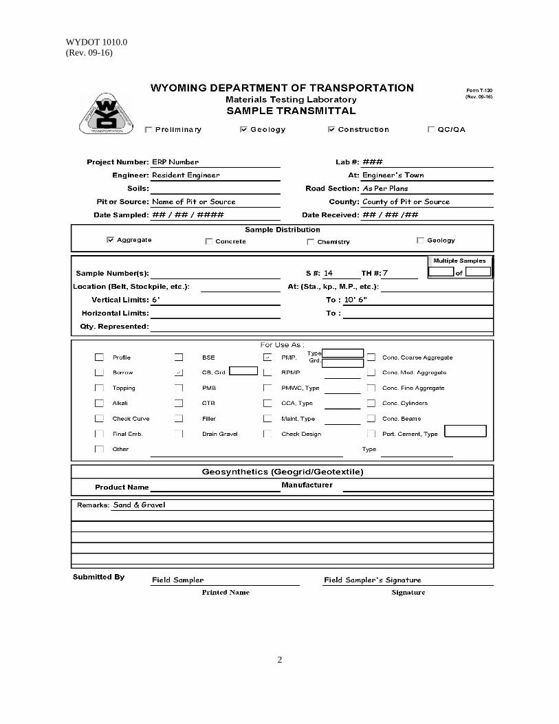
WYDOT 1010.0 (Rev. 09-16)
2

WYDOT 1020.0 (Rev. 01-15)
1
DETERMING DELAMINATION IN BRIDGE DECKS BY CHAIN DRAG METHOD
Scope: This procedure is technically equivalent, but not identical, to ASTM D 4580. This test method describes the procedure for surveying concrete bridge decks and other concrete pavements by chain drag method to locate delaminations in the concrete.
Use: This procedure is not intended for use on bridge decks that have been overlaid with bituminous mixtures or on frozen concrete. This procedure may be used on bridge decks that have been overlaid with concrete pavement, however, areas indicated to be delaminated may have a lack of bond between the overlay and the underlying bridge deck.
Apparatus: 1. The chain drag apparatus consists of four segments of 1 inch link chain of ¼ inch diameter steel approximately 18 inch long. These are attached to two 10 inch pieces of ¾ inch type L copper tubing (two segments of chain attached to each piece) which are joined together by a ¾ inch copper tee. A 3 ft piece of the same copper tubing is attached to the copper tee to form a handle with the completed apparatus forming a T.
See Figure 1. 2. Measuring tape and marking paint to establish a grid system on the bridge deck and to outline the delaminated areas. 3. A bridge deck layout/map. Field notes can be prepared in advance with
the dimensions of the deck, skew angles, and a 5 ft grid matching the grid on the deck.
Reference Documents: ASTM D 4580 Standard Practice for Measuring Delaminations in
Concrete Bridge Decks by Sounding Procedure: 1. Bridge Deck Layout Construct a grid system on the deck surface by establishing the center of
the bridge deck and placing a mark at 5 ft intervals from centerline to curb on each side of the deck at each abutment. Any distance less than 5 ft should be next to each curb. This forms the transverse part of the grid. Mark a scale down the centerline of the deck in 5 ft intervals to establish the longitudinal part of the grid.
2. Test Procedure Drag the chains over the deck surface either longitudinally or
transversely. Delaminated areas are those where a dull or hollow sound from the chain dragging operation is heard. When a delamination is
WYDOT 1020_0 (Rev. 01-15)
2
heard, mark the limit of the delamination with marking paint or a lumber crayon. Continue chain dragging and marking the delamination until the limits are found in all directions.
3. Plotting Transfer the outlines of the delaminations marked on the deck to the map
by drawing the outlines from the deck to the corresponding location on the map. A tape measure can be used to measure the lines that are between the 5 ft grid marks. Determine the total area contained in the individual delaminated areas. Divide the total delaminated area by the total bridge deck area and multiply by 100 to yield the percent of delaminated area.
DelaminatedArea
TotalBridgeDeckAreax100 %Delaminated
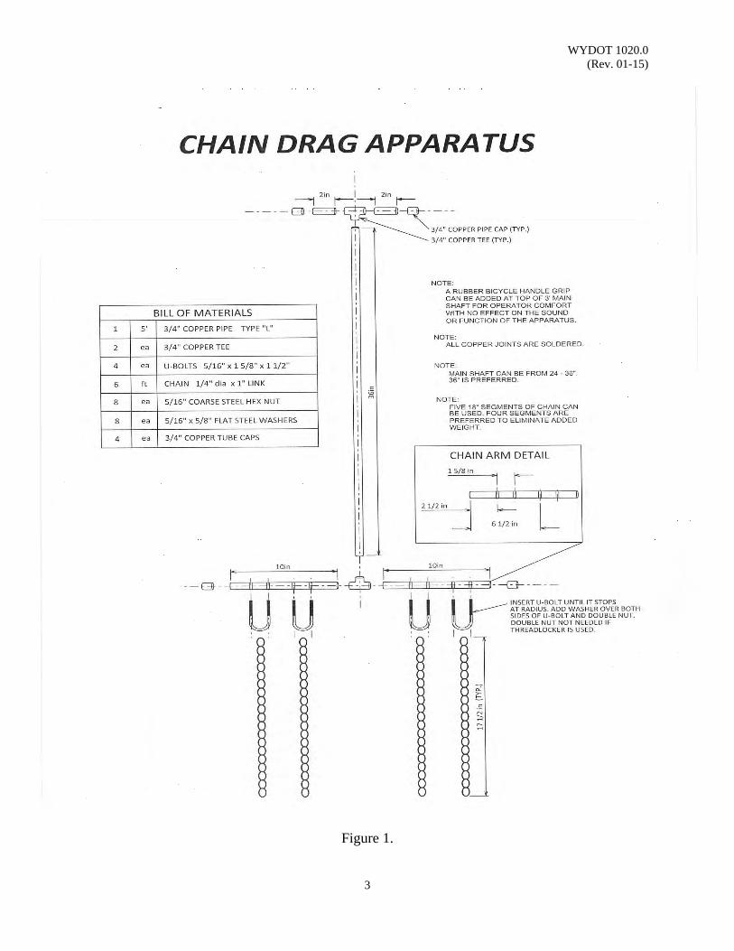
WYDOT 1020.0 (Rev. 01-15)
3
Figure 1.
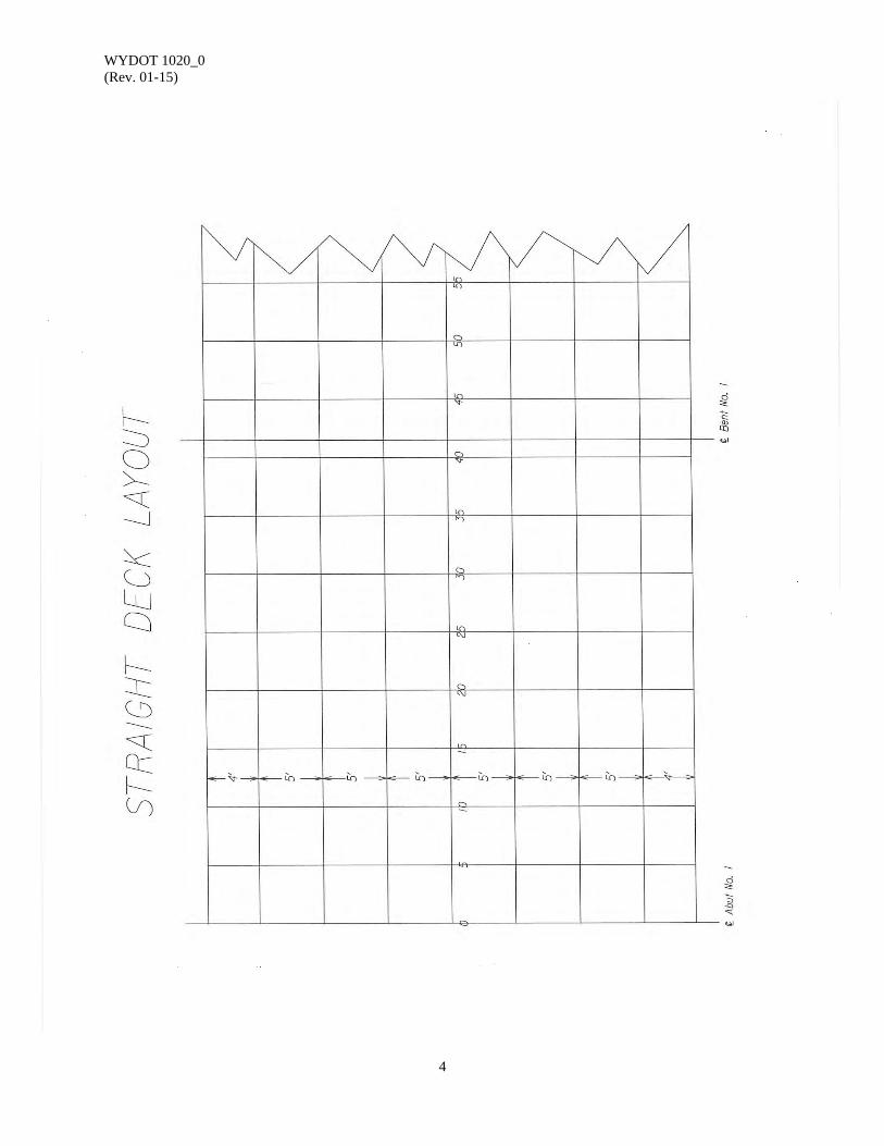
WYDOT 1020_0 (Rev. 01-15)
4
(This page intentionally left blank.)
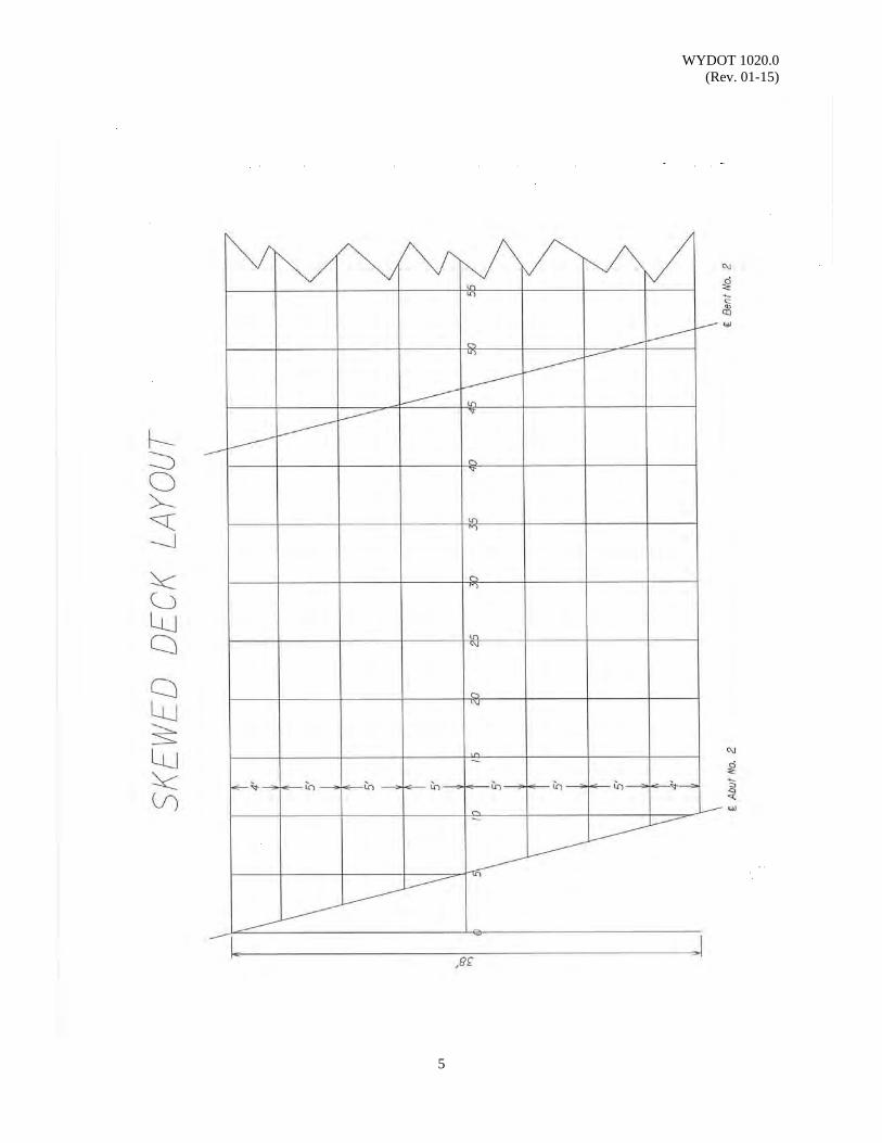
WYDOT 1020.0 (Rev. 01-15)
5

WYDOT 1020_0 (Rev. 01-15)
6
(This page intentionally left blank.)
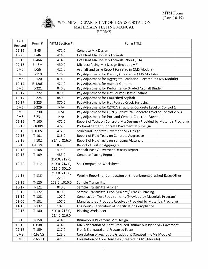
LaRev
09
1009
09
CM
CM
CM
10
CM
10
10
10
CM
CM
CM
09
09
09
09
09
09
10
10
10
09
09
10
09
11
03
11
09
09
10
09
CM
CM
ast vised
Form
‐16 E‐4
‐20 E‐4
‐16 E‐46
‐16 E‐46
MS E‐5
MS E‐11
MS E‐12
‐17 E‐12
MS E‐22
‐17 E‐22
‐17 E‐22
‐17 E‐22
MS E‐22
MS E‐23
MS E‐23
‐16 T‐10
‐16 T‐100
‐16 T‐100
‐16 T‐10
‐16 T‐10
‐16 T‐107
‐18 T‐10
‐18 T‐10
‐20 T‐11
‐16 T‐11
‐16 T‐12
‐17 T‐12
‐16 T‐12
‐12 T‐12
‐00 T‐13
‐16 T‐13
‐16 T‐14
‐16 T‐15
‐18 T‐15
‐16 T‐15
MS T‐165
MS T‐165
W
m # MTM
45 4
46 4
6A 4
6M 4
6 4
19 1
20 8
0E 4
21 8
22 8
24 8
25 8
29
30
31
00 4
0PE 4
0SE 4
01 8
02 814.
7W 8
08 4
09 4
12 210.0213.0216.
13 213.0
2
20 123.0
21 8
22 8
28 1
31 1
32 1
40 210.0214.
58 4
58F 4
59 8
5AG 1
5CD 4
WYOMINGMA
Section #
471.0 C
414.0 H
414.0 H
430.0 M
421.0 A
126.0 P
814.0 P
421.0 P
840.0 P
870.0 P
840.0 P
870.0 P
N/A P
N/A P
N/A P
471.0 R
472.0 P
472.0 S
816.0 R
0, 816.0 R
837.0 R
415.0 A
483.0 C
0, 212.0, 0, 214.0, 0, 301.0
S
0, 215.0, 221.0
W
0, 1010.0 S
840.0 S
870.0 S
107.0 C
107.0 M
107.0 E
0, 213.0, 0, 216.0
P
414.0 B
414.0 M
817.0 F
126.0 C
423.0 C
G DEPARTMATERIALS
F
Concrete Mix
Hot Plant Mix
Hot Plant Mix
Microsurfacin
Asphalt and L
Pay Adjustme
Pay Adjustme
Pay Adjustme
Pay Adjustme
Pay Adjustme
Pay Adjustme
Pay Adjustme
Pay Adjustme
Pay Adjustme
Pay Adjustme
Report of Test
Portland Cem
Structural Con
Report of Fiel
Report of Fiel
Report of Test
Asphalt Base /
Concrete Plac
Soil Compacti
Weekly Repor
Sample Trans
Sample Trans
Sample Trans
Construction
Manufactured
Engineer’s Ve
Plotting Work
Bituminous Pa
Mix Verificatio
Flat & Elongat
Correlation of
Correlation of
MENT OF TR TESTING MFORMS
i
Design
x Job Mix Form
x Job Mix Form
ng Mix Design
ime Report (C
ent for Densit
ent for Aggreg
ent for Asphal
ent for Perfor
ent for Hot Po
ent for Emulsi
ent for Hot Po
ent for QC/QA
ent for QC/QA
ent for Portlan
ts on Concret
ment Concrete
ncrete Pavem
d Tests on Co
d Tests on Su
t on Aggregat
/ Pavement D
cing Report
ion Workshee
rt for Compac
mittal
mittal Asphal
mittal Crack S
Test Requirem
d Products Re
erification of S
ksheet
avement Mix
on of Plant Pr
ted and Fract
f Aggregate G
f Core Densiti
RANSPORTMANUAL
Form TI
mula
mula (Non‐QC
n (Include JMF
Created in CM
y (Created in
gate Gradatio
lt Content
mance Grade
oured Elastic S
ified Asphalt
oured Crack S
A Structural C
A Structural C
nd Cement Co
te Mix Design
e Pavement M
ment Mix Desi
oncrete Aggre
urfacing Mate
te
Density Repor
et
ction of Emba
lt
Sealant / Crac
ments (Provid
eceived (Prov
Specification
x Design
roduced Bitu
tured Faces
Gradations (Cr
ies (Created i
TATION
TLE
CQA)
F)
MS Module)
CMS Module
on (Created in
ed Asphalt Bin
Sealant
urfacing
Concrete Leve
Concrete Leve
oncrete Pave
ns (Provided b
Mix Design
ign
egate
erials
rt
ankment/Cru
ck Surfacing
ded by Mater
vided by Mate
Compliance
minous Plant
reated in CM
n CMS Modu
MTM F(Rev. 10
e)
n CMS Module
nder
el of Control 1
el of Control 2
ment
by Materials P
shed Base/Ot
rials Program
erials Program
t Mix Paveme
S Module)
ule)
Forms 0-19)
e)
1
2 & 3
Program)
ther
)
m)
ent
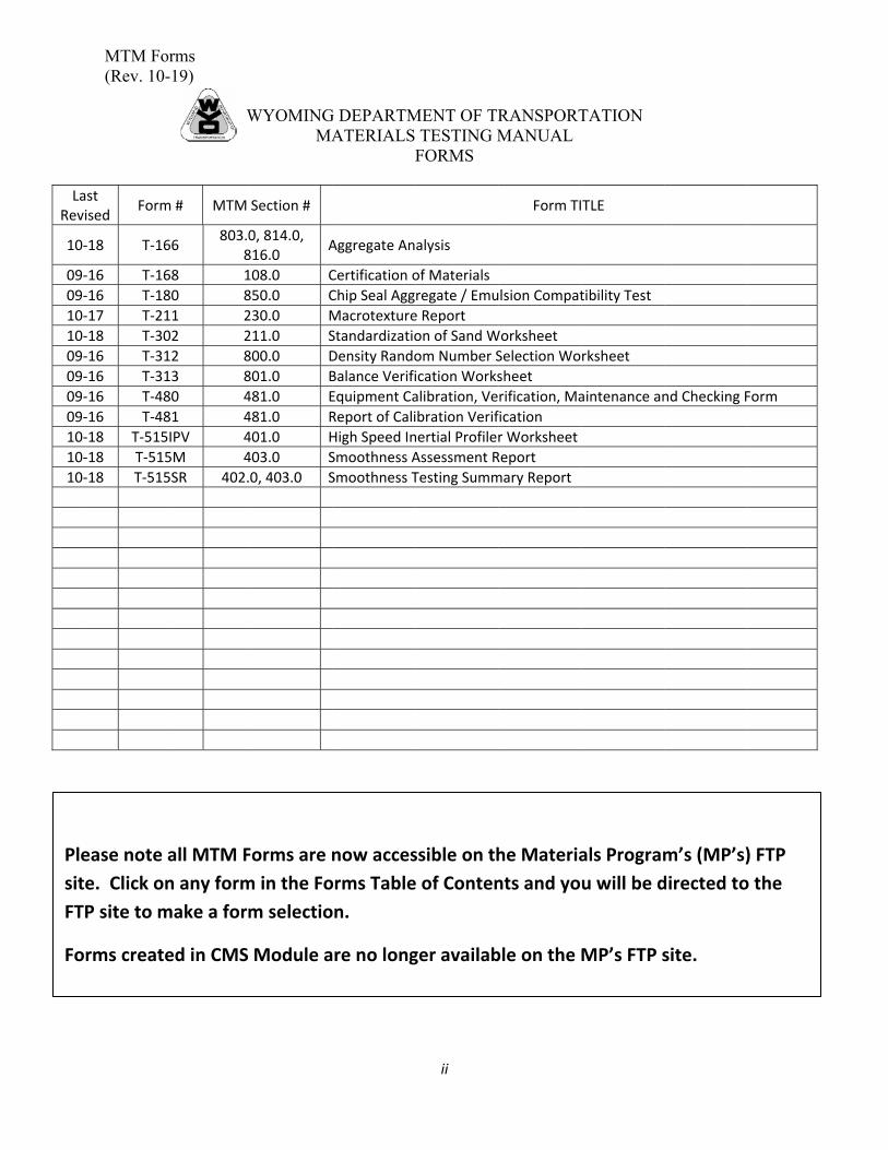
LaRev
10
09
09
10
10
09
09
09
09
10
10
10
Ple
sit
FT
Fo
MTM Fo(Rev. 10-
ast vised
Form
‐18 T‐16
‐16 T‐16
‐16 T‐18
‐17 T‐21
‐18 T‐30
‐16 T‐31
‐16 T‐31
‐16 T‐48
‐16 T‐48
‐18 T‐515
‐18 T‐515
‐18 T‐515
ease note
te. Click on
TP site to m
orms create
orms -19)
W
m # MTM
66 803.0
8
68 1
80 8
11 2
02 2
12 8
13 8
80 4
81 4
5IPV 4
5M 4
5SR 402.
all MTM F
n any form
make a form
ed in CMS
WYOMINGMA
Section #
0, 814.0, 816.0
A
108.0 C
850.0 C
230.0 M
211.0 S
800.0 D
801.0 B
481.0 E
481.0 R
401.0 H
403.0 S
0, 403.0 S
Forms are n
m in the Fo
m selectio
Module a
G DEPARTMATERIALS
F
Aggregate An
Certification o
Chip Seal Agg
Macrotexture
Standardizatio
Density Rando
Balance Verifi
Equipment Ca
Report of Cali
High Speed In
Smoothness A
Smoothness T
now acces
orms Table
on.
are no long
MENT OF TR TESTING MFORMS
ii
alysis
of Materials
regate / Emu
e Report
on of Sand W
om Number S
ication Works
alibration, Ve
ibration Verif
nertial Profile
Assessment R
Testing Summ
ssible on th
e of Conten
ger availab
RANSPORTMANUAL
Form TI
lsion Compat
Worksheet
Selection Wo
sheet
rification, Ma
fication
r Worksheet
Report
mary Report
he Materia
nts and yo
ble on the
TATION
TLE
tibility Test
rksheet
aintenance an
als Program
u will be d
MP’s FTP s
nd Checking F
m’s (MP’s)
directed to
site.
Form
) FTP
o the