
EFFECT OF OSCILLATION AMPLITUDE ON VELOCITY DISTRIBUTIONS IN AN OSCILLATORY BAFFLED COLUMN (OBC
7
chemical engineering research and design 9 0 ( 2 0 1 2 ) 1038–1044 Contents lists available at SciVerse ScienceDirect Chemical Engineering Research and Design journa l h o me pa ge: www.elsevier.com/locate/cherd Effect of oscillation amplitude on velocity distributions in an oscillatory baffled column (OBC) Ahmad Azahari Hamzah a , Nurul Hasan b,∗ , Mohd Sobri Takriff a , Siti Kartom Kamarudin a , Jaafar Abdullah c , Isa M Tan b , Wah Keng Sern a a Department of Chemical & Process Engineering, Faculty of Engineering & Built Environment, National University of Malaysia, 43600 Bangi, Malaysia b Department of Chemical Engineering, University Technology Petronas, Bandar Seri Iskandar, 31750 Tronoh, Malaysia c Centre of Computed Tomography and Industrial Imaging, Malaysia Nuclear Agency, Bangi, 43000 Kajang, Selangor, Malaysia a b s t r a c t This paper presents a numerical study of the effect of oscillation amplitude in oscillatory baffled column (OBC) using computational fluid dynamics. The numerical work was carried out for single phase liquid flow for an unsteady 3-D model using commercial software, Fluent (2006). This work was concentrated on the effect of oscillation amplitude. Three amplitudes of 5, 10 and 15 mm with constant frequency of 1 Hz are applied. Vortex and cycle average velocities at different points are analyzed. The studies show the maximum velocity for 5 mm, 10 mm and 15 mm in an OBC are 0.11 m/s, 0.25 m/s and 0.40 m/s respectively in the first cycle of oscillation. At a constant frequency, greater oscillation amplitude displaces the liquid to a further distance and builds a larger vortex. Vortex length was 1.5 times bigger when oscillation amplitude changes from 5 mm to 10 mm and 2 times when the amplitude is triple from 5 mm. The detailed validation is presented somewhere else; this research is focused on the effect of oscillation. © 2011 The Institution of Chemical Engineers. Published by Elsevier B.V. All rights reserved. Keywords: CFD; Flow pattern; Oscillatory baffled column; Oscillation amplitude; Vortex length; Velocity distributions 1. Introduction Mixing has great importance in chemical and biochemical industries. Basic phenomenon for mixing enhancement is the production of cyclic discrete vortices in the bulk fluid (Ni et al., 2003a). Oscillatory baffled column (OBC) is a device that can enhance the formation of vortices and increase the intensity of mixing process. Previous studies showed that OBC success- fully increases mass transfer (Stonestreet and Harvey, 2002), heat transfer (Mackley and Stonestreet, 1995), chaotic mixing (Reis et al., 2004) and residence time (Stephens and Mackley, 2002) compared to other mixing equipments. It can be oper- ated in batch or continuous mode depending on the process itself. The key feature of oscillating baffled flows is that mix- ing can be controlled to a very high degree of precision, giving a wide range of mixing conditions, from ‘soft’ mixing, exhibit- ing plug flow characteristics, to the most intense, approaching mixed flow conditions (Ni et al., 2003b). OBC is widely used in ∗ Corresponding author. Tel.: +60 5 368 7638; fax: +60 5 365 6176. E-mail address: nurul [email protected] (N. Hasan). Received 1 December 2010; Received in revised form 11 September 2011; Accepted 4 November 2011 laboratory scale to industrial applications such as photocat- alytic wet oxidation (Fabiyi and Skelton, 1999), polymerisation processes (Ni et al., 2002b) and heterogeneous photocatalytic oxidation (Gao et al., 2003). A typical experimental set is shown in Fig. 1 as performed in the current investigation. With the rapid advancement in computational fluid dynamics (CFD) modeling, studying local flow and transport phenomena in OBC has become feasible. Various aspects of the study were conducted on the OBC using the CFD such as effect of viscosity (Fitch et al., 2005), flow dynamics (Ni et al., 2002a), scale up behavior (Jian and Ni, 2005), effect of gap between baf- fle and wall (Ni et al., 2004) and shear rate distributions (Reis et al., 2004). These studies show that an OBC has capabilities to increase the intensity of mixing. The dynamics in an OBC is controlled by dimen- sionless parameters which are Reynolds number (Re n = uD/v = uD/), oscillatory Reynolds number (Re o = u o D/v = x o ωD/ = 2fx o D/), and the Strouhal number (S t = D/4x o ). 0263-8762/$ – see front matter © 2011 The Institution of Chemical Engineers. Published by Elsevier B.V. All rights reserved. doi:10.1016/j.cherd.2011.11.003
Transcript of EFFECT OF OSCILLATION AMPLITUDE ON VELOCITY DISTRIBUTIONS IN AN OSCILLATORY BAFFLED COLUMN (OBC
chemical engineering research and design 9 0 ( 2 0 1 2 ) 1038–1044
Contents lists available at SciVerse ScienceDirect
Chemical Engineering Research and Design
journa l h o me pa ge: www.elsev ier .com/ locate /cherd
Effect of oscillation amplitude on velocity distributions in anoscillatory baffled column (OBC)
Ahmad Azahari Hamzaha, Nurul Hasanb,∗, Mohd Sobri Takriffa,Siti Kartom Kamarudina, Jaafar Abdullahc, Isa M Tanb, Wah Keng Serna
a Department of Chemical & Process Engineering, Faculty of Engineering & Built Environment, National University of Malaysia,43600 Bangi, Malaysiab Department of Chemical Engineering, University Technology Petronas, Bandar Seri Iskandar, 31750 Tronoh, Malaysiac Centre of Computed Tomography and Industrial Imaging, Malaysia Nuclear Agency, Bangi, 43000 Kajang, Selangor, Malaysia
a b s t r a c t
This paper presents a numerical study of the effect of oscillation amplitude in oscillatory baffled column (OBC) using
computational fluid dynamics. The numerical work was carried out for single phase liquid flow for an unsteady 3-D
model using commercial software, Fluent (2006). This work was concentrated on the effect of oscillation amplitude.
Three amplitudes of 5, 10 and 15 mm with constant frequency of 1 Hz are applied. Vortex and cycle average velocities
at different points are analyzed. The studies show the maximum velocity for 5 mm, 10 mm and 15 mm in an OBC are
0.11 m/s, 0.25 m/s and 0.40 m/s respectively in the first cycle of oscillation. At a constant frequency, greater oscillation
amplitude displaces the liquid to a further distance and builds a larger vortex. Vortex length was 1.5 times bigger
when oscillation amplitude changes from 5 mm to 10 mm and 2 times when the amplitude is triple from 5 mm. The
detailed validation is presented somewhere else; this research is focused on the effect of oscillation.
© 2011 The Institution of Chemical Engineers. Published by Elsevier B.V. All rights reserved.
Keywords: CFD; Flow pattern; Oscillatory baffled column; Oscillation amplitude; Vortex length; Velocity distributions
uD/v = uD�/�), oscillatory Reynolds number (Reo = uoD/v =
1. Introduction
Mixing has great importance in chemical and biochemicalindustries. Basic phenomenon for mixing enhancement is theproduction of cyclic discrete vortices in the bulk fluid (Ni et al.,2003a). Oscillatory baffled column (OBC) is a device that canenhance the formation of vortices and increase the intensityof mixing process. Previous studies showed that OBC success-fully increases mass transfer (Stonestreet and Harvey, 2002),heat transfer (Mackley and Stonestreet, 1995), chaotic mixing(Reis et al., 2004) and residence time (Stephens and Mackley,2002) compared to other mixing equipments. It can be oper-ated in batch or continuous mode depending on the processitself. The key feature of oscillating baffled flows is that mix-ing can be controlled to a very high degree of precision, givinga wide range of mixing conditions, from ‘soft’ mixing, exhibit-ing plug flow characteristics, to the most intense, approaching
mixed flow conditions (Ni et al., 2003b). OBC is widely used in∗ Corresponding author. Tel.: +60 5 368 7638; fax: +60 5 365 6176.E-mail address: nurul [email protected] (N. Hasan).Received 1 December 2010; Received in revised form 11 September 20
0263-8762/$ – see front matter © 2011 The Institution of Chemical Engidoi:10.1016/j.cherd.2011.11.003
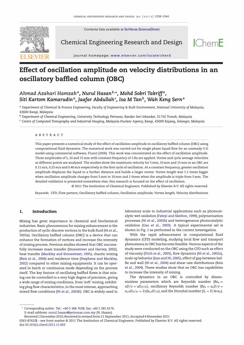
laboratory scale to industrial applications such as photocat-alytic wet oxidation (Fabiyi and Skelton, 1999), polymerisationprocesses (Ni et al., 2002b) and heterogeneous photocatalyticoxidation (Gao et al., 2003). A typical experimental set isshown in Fig. 1 as performed in the current investigation.
With the rapid advancement in computational fluiddynamics (CFD) modeling, studying local flow and transportphenomena in OBC has become feasible. Various aspects of thestudy were conducted on the OBC using the CFD such as effectof viscosity (Fitch et al., 2005), flow dynamics (Ni et al., 2002a),scale up behavior (Jian and Ni, 2005), effect of gap between baf-fle and wall (Ni et al., 2004) and shear rate distributions (Reiset al., 2004). These studies show that an OBC has capabilitiesto increase the intensity of mixing.
The dynamics in an OBC is controlled by dimen-sionless parameters which are Reynolds number (Ren =
11; Accepted 4 November 2011
xoωD�/� = 2�fxo�D/�), and the Strouhal number (St = D/4�xo).
neers. Published by Elsevier B.V. All rights reserved.
chemical engineering research and design 9 0 ( 2 0 1 2 ) 1038–1044 1039
Nomenclature
Ren = uD/v = uD�/� Reynolds numberReo = uoD/v = xoωD�/� = 2�fxo�D/� oscillatory
Reynolds numberSt = D/4�xo Strouhal numberD diameter of column, mf oscillation frequency, Hzp pressure drop, Pat time, su velocity, m/sVr,V� ,Vz laminar velocity velocities (m/s) at r, �v and z
coordinatesxo oscillation amplitude, mx co-ordinates in x direction, my co-ordinates in y direction, mz co-ordinates in z direction, m
Greek letters� fluid viscosity, kg/ms�o nominal laminar viscosity, kg/ms�t turbulent viscosity, kg/ms� fluid density, kg/m3
� shear stress, N/m2
� the kinematic viscosity of fluid, m2/s
Oiceior
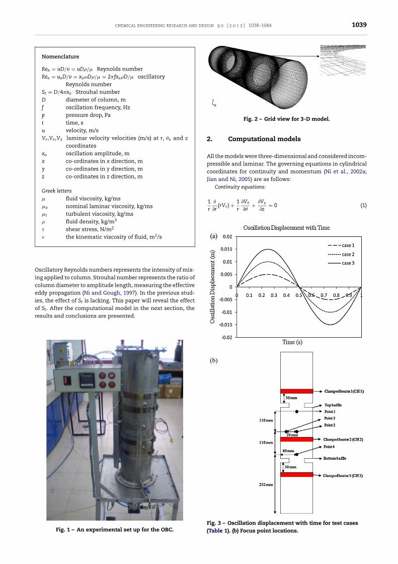
Fig. 2 – Grid view for 3-D model.
r ∂r(rVr) +
r ∂�+
∂z= 0 (1)
scillatory Reynolds numbers represents the intensity of mix-ng applied to column. Strouhal number represents the ratio ofolumn diameter to amplitude length, measuring the effectiveddy propagation (Ni and Gough, 1997). In the previous stud-es, the effect of St is lacking. This paper will reveal the effectf St. After the computational model in the next section, theesults and conclusions are presented.
Fig. 1 – An experimental set up for the OBC.
2. Computational models
All the models were three-dimensional and considered incom-pressible and laminar. The governing equations in cylindricalcoordinates for continuity and momentum (Ni et al., 2002a;Jian and Ni, 2005) are as follows:
Continuity equations:
1 ∂ 1 ∂V� ∂Vz
Fig. 3 – Oscillation displacement with time for test cases(Table 1). (b) Focus point locations.
1040 chemical engineering research and design 9 0 ( 2 0 1 2 ) 1038–1044
t (a)
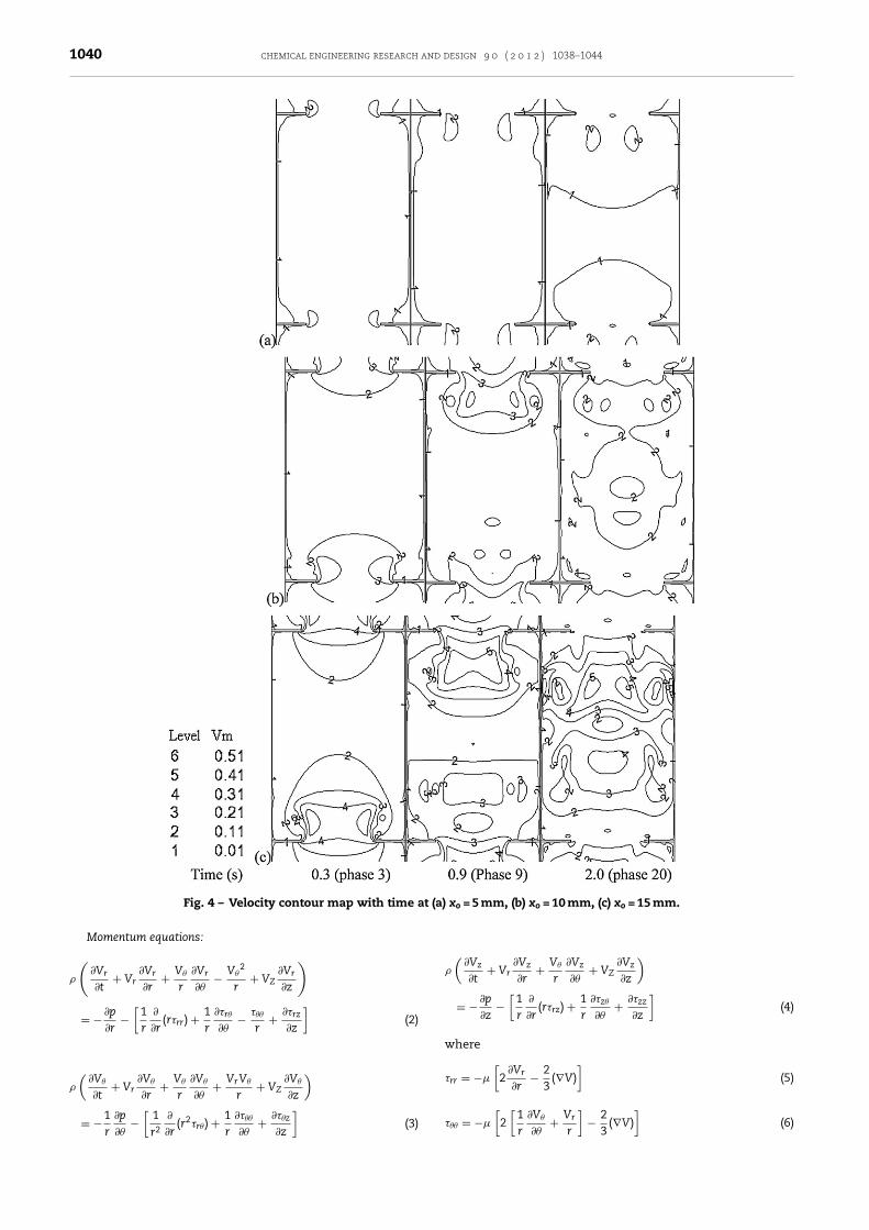
Fig. 4 – Velocity contour map with time aMomentum equations:
�
(∂Vr
∂t+ Vr
∂Vr
∂r+ V�
r
∂Vr
∂�− V�
2
r+ VZ
∂Vr
∂z
)
= − ∂p
∂r−
[1r
∂
∂r(r�rr) + 1
r
∂�r�
∂�− ���
r+ ∂�rz
∂z
](2)
�
(∂V�
∂t+ Vr
∂V�
∂r+ V�
r
∂V�
∂�+ VrV�
r+ VZ
∂V�
∂z
)
1 ∂p[
1 ∂ 2 1 ∂��� ∂��z]
= −r ∂�
−r2 ∂r
(r �r�) +r ∂�
+∂z
(3)
xo = 5 mm, (b) xo = 10 mm, (c) xo = 15 mm.
�
(∂Vz
∂t+ Vr
∂Vz
∂r+ V�
r
∂Vz
∂�+ VZ
∂Vz
∂z
)
= − ∂p
∂z−
[1r
∂
∂r(r�rz) + 1
r
∂�z�
∂�+ ∂�zz
∂z
](4)
where
�rr = −�
[2
∂Vr
∂r− 2
3(∇V)
](5)
[ [1 ∂V� Vr
]2
]
��� = −� 2r ∂�+
r−
3(∇V) (6)
chemical engineering research and design 9 0 ( 2 0 1 2 ) 1038–1044 1041
�
�
�
�
(
TowToivgdbA
guami
3
FaFsnioao
pusatdafm
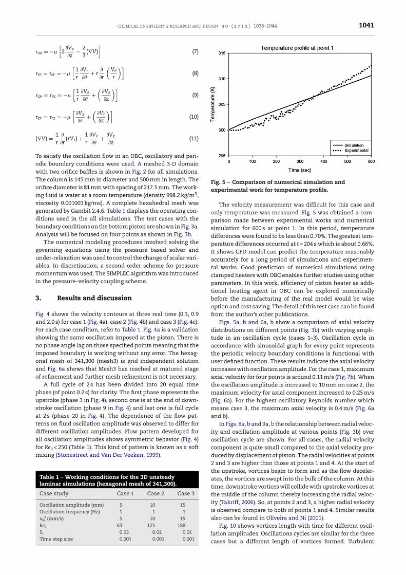
Fig. 5 – Comparison of numerical simulation and
zz = −�
[2
∂Vz
∂z− 2
3(∇V)
](7)
r� = ��r = −�
[1r
∂Vr
∂�+ r
∂
∂r
(V�
r
)](8)
z� = ��z = −�
[1r
∂Vz
∂�+
(∂Vz
∂z
)](9)
zr = �rz = −�
[∂Vz
∂r+
(∂Vr
∂z
)](10)
∇V) = 1r
∂
∂r(rVr) + 1
r
∂V�
∂�+ ∂Vz
∂z(11)
o satisfy the oscillation flow in an OBC, oscillatory and peri-dic boundary conditions were used. A meshed 3-D domainith two orifice baffles is shown in Fig. 2 for all simulations.he column is 145 mm in diameter and 500 mm in length. Therifice diameter is 81 mm with spacing of 217.5 mm. The work-
ng fluid is water at a room temperature (density 998.2 kg/m3,iscosity 0.001003 kg/ms). A complete hexahedral mesh wasenerated by Gambit 2.4.6. Table 1 displays the operating con-itions used in the all simulations. The test cases with theoundary conditions on the bottom piston are shown in Fig. 3a.nalysis will be focused on four points as shown in Fig. 3b.
The numerical modeling procedures involved solving theoverning equations using the pressure based solver andnder-relaxation was used to control the change of scalar vari-bles. In discretisation, a second order scheme for pressureomentum was used. The SIMPLEC algorithm was introduced
n the pressure–velocity coupling scheme.
. Results and discussion
ig. 4 shows the velocity contours at three real time (0.3, 0.9nd 2.0 s) for case 1 (Fig. 4a), case 2 (Fig. 4b) and case 3 (Fig. 4c).or each case condition, refer to Table 1. Fig. 4a is a validationhowing the same oscillation imposed at the piston. There iso phase angle lag on those specified points meaning that the
mposed boundary is working without any error. The hexag-nal mesh of 341,300 (mesh3) is grid independent solutionnd Fig. 6a shows that Mesh3 has reached at matured stagef refinement and further mesh refinement is not necessary.
A full cycle of 2 s has been divided into 20 equal timehase (of point 0.2 s) for clarity. The first phase represents thepstroke (phase 3 in Fig. 4), second one is at the end of down-troke oscillation (phase 9 in Fig. 4) and last one is full cyclet 2 s (phase 20 in Fig. 4). The dependence of the flow pat-erns on fluid oscillation amplitude was observed to differ forifferent oscillation amplitudes. Flow pattern developed forll oscillation amplitudes shows symmetric behavior (Fig. 4)
or Reo < 250 (Table 1). This kind of pattern is known as a softixing (Stonestreet and Van Der Veeken, 1999).
Table 1 – Working conditions for the 3D unsteadylaminar simulations (hexagonal mesh of 341,300).
Case study Case 1 Case 2 Case 3
Oscillation amplitude (mm) 5 10 15Oscillation frequency (Hz) 1 1 1xof (mm/s) 5 10 15Reo 63 125 188St 0.03 0.02 0.01Time step size 0.001 0.001 0.001
experimental work for temperature profile.
The velocity measurement was difficult for this case andonly temperature was measured. Fig. 5 was obtained a com-parison made between experimental works and numericalsimulation for 600 s at point 1. In this period, temperaturedifferences were found to be less than 0.70%. The greatest tem-perature differences occurred at t = 204 s which is about 0.66%.It shows CFD model can predict the temperature reasonablyaccurately for a long period of simulations and experimen-tal works. Good prediction of numerical simulations usingclamped heaters with OBC enables further studies using otherparameters. In this work, efficiency of piston heater as addi-tional heating agent in OBC can be explored numericallybefore the manufacturing of the real model would be wiseoption and cost saving. The detail of this test case can be foundfrom the author’s other publications.
Figs. 5a, b and 6a, b show a comparison of axial velocitydistributions on different points (Fig. 3b) with varying ampli-tude in an oscillation cycle (cases 1–3). Oscillation cycle inaccordance with sinusoidal graph for every point representsthe periodic velocity boundary conditions is functional withuser defined function. These results indicate the axial velocityincreases with oscillation amplitude. For the case 1, maximumaxial velocity for four points is around 0.11 m/s (Fig. 7b). Whenthe oscillation amplitude is increased to 10 mm on case 2, themaximum velocity for axial component increased to 0.25 m/s(Fig. 6a). For the highest oscillatory Reynolds number whichmeans case 3, the maximum axial velocity is 0.4 m/s (Fig. 6aand b).
In Figs. 8a, b and 9a, b the relationship between radial veloc-ity and oscillation amplitude at various points (Fig. 3b) overoscillation cycle are shown. For all cases, the radial velocitycomponent is quite small compared to the axial velocity pro-duced by displacement of piston. The radial velocities at points2 and 3 are higher than those at points 1 and 4. At the start ofthe upstroke, vortices begin to form and as the flow deceler-ates, the vortices are swept into the bulk of the column. At thistime, downstroke vortices will collide with upstroke vortices atthe middle of the column thereby increasing the radial veloc-ity (Takriff, 2006). So, at points 2 and 3, a higher radial velocityis observed compare to both of points 1 and 4. Similar resultsalso can be found in Oliveira and Ni (2001).
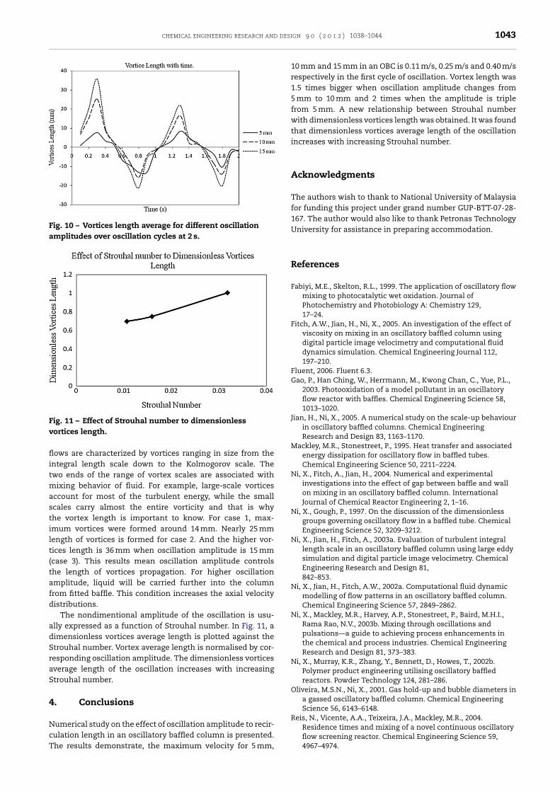
Fig. 10 shows vortices length with time for different oscil-
lation amplitudes. Oscillations cycles are similar for the threecases but a different length of vortices formed. Turbulent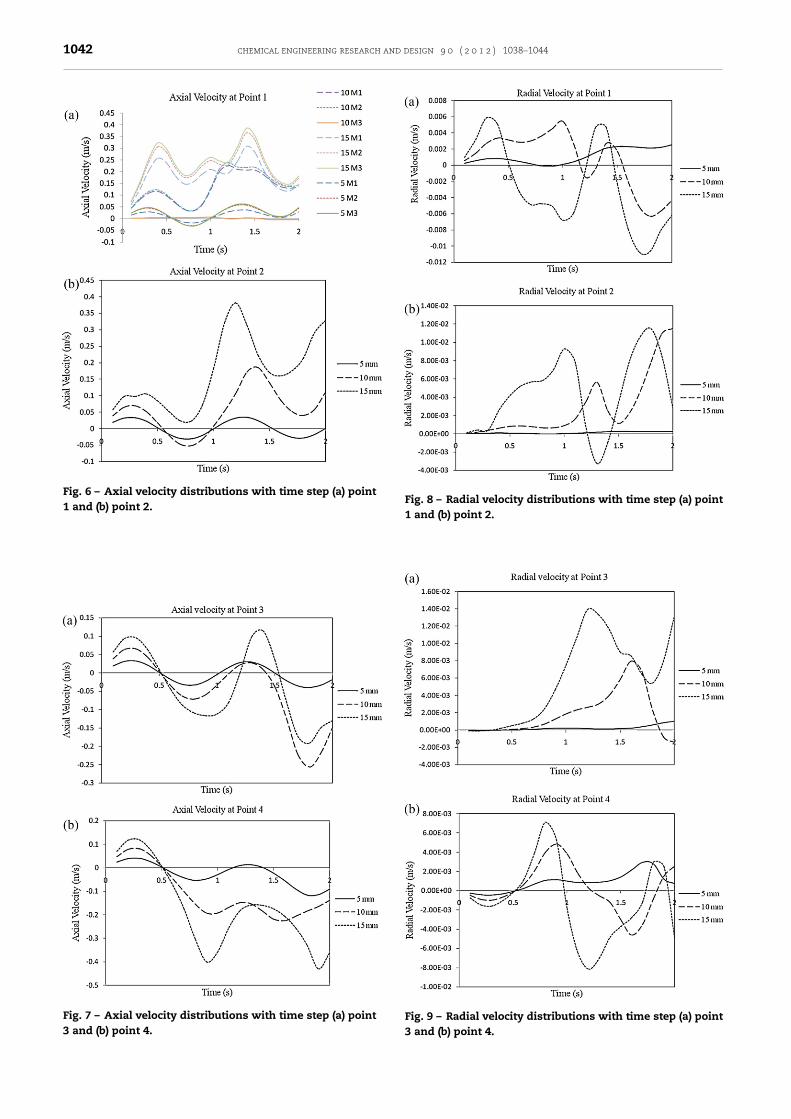
1042 chemical engineering research and design 9 0 ( 2 0 1 2 ) 1038–1044
Fig. 6 – Axial velocity distributions with time step (a) point1 and (b) point 2.
Fig. 7 – Axial velocity distributions with time step (a) point3 and (b) point 4.
Fig. 8 – Radial velocity distributions with time step (a) point1 and (b) point 2.
Fig. 9 – Radial velocity distributions with time step (a) point3 and (b) point 4.
chemical engineering research and design 9 0 ( 2 0 1 2 ) 1038–1044 1043
Fig. 10 – Vortices length average for different oscillationamplitudes over oscillation cycles at 2 s.
Fig. 11 – Effect of Strouhal number to dimensionlessv
flitmastilt(tafd
adSraS
4
NcT
ortices length.
ows are characterized by vortices ranging in size from thentegral length scale down to the Kolmogorov scale. Thewo ends of the range of vortex scales are associated with
ixing behavior of fluid. For example, large-scale vorticesccount for most of the turbulent energy, while the smallcales carry almost the entire vorticity and that is whyhe vortex length is important to know. For case 1, max-mum vortices were formed around 14 mm. Nearly 25 mmength of vortices is formed for case 2. And the higher vor-ices length is 36 mm when oscillation amplitude is 15 mmcase 3). This results mean oscillation amplitude controlshe length of vortices propagation. For higher oscillationmplitude, liquid will be carried further into the columnrom fitted baffle. This condition increases the axial velocityistributions.
The nondimentional amplitude of the oscillation is usu-lly expressed as a function of Strouhal number. In Fig. 11, aimensionless vortices average length is plotted against thetrouhal number. Vortex average length is normalised by cor-esponding oscillation amplitude. The dimensionless vorticesverage length of the oscillation increases with increasingtrouhal number.
. Conclusions
umerical study on the effect of oscillation amplitude to recir-
ulation length in an oscillatory baffled column is presented.he results demonstrate, the maximum velocity for 5 mm,10 mm and 15 mm in an OBC is 0.11 m/s, 0.25 m/s and 0.40 m/srespectively in the first cycle of oscillation. Vortex length was1.5 times bigger when oscillation amplitude changes from5 mm to 10 mm and 2 times when the amplitude is triplefrom 5 mm. A new relationship between Strouhal numberwith dimensionless vortices length was obtained. It was foundthat dimensionless vortices average length of the oscillationincreases with increasing Strouhal number.
Acknowledgments
The authors wish to thank to National University of Malaysiafor funding this project under grand number GUP-BTT-07-28-167. The author would also like to thank Petronas TechnologyUniversity for assistance in preparing accommodation.
References
Fabiyi, M.E., Skelton, R.L., 1999. The application of oscillatory flowmixing to photocatalytic wet oxidation. Journal ofPhotochemistry and Photobiology A: Chemistry 129,17–24.
Fitch, A.W., Jian, H., Ni, X., 2005. An investigation of the effect ofviscosity on mixing in an oscillatory baffled column usingdigital particle image velocimetry and computational fluiddynamics simulation. Chemical Engineering Journal 112,197–210.
Fluent, 2006. Fluent 6.3.Gao, P., Han Ching, W., Herrmann, M., Kwong Chan, C., Yue, P.L.,
2003. Photooxidation of a model pollutant in an oscillatoryflow reactor with baffles. Chemical Engineering Science 58,1013–1020.
Jian, H., Ni, X., 2005. A numerical study on the scale-up behaviourin oscillatory baffled columns. Chemical EngineeringResearch and Design 83, 1163–1170.
Mackley, M.R., Stonestreet, P., 1995. Heat transfer and associatedenergy dissipation for oscillatory flow in baffled tubes.Chemical Engineering Science 50, 2211–2224.
Ni, X., Fitch, A., Jian, H., 2004. Numerical and experimentalinvestigations into the effect of gap between baffle and wallon mixing in an oscillatory baffled column. InternationalJournal of Chemical Reactor Engineering 2, 1–16.
Ni, X., Gough, P., 1997. On the discussion of the dimensionlessgroups governing oscillatory flow in a baffled tube. ChemicalEngineering Science 52, 3209–3212.
Ni, X., Jian, H., Fitch, A., 2003a. Evaluation of turbulent integrallength scale in an oscillatory baffled column using large eddysimulation and digital particle image velocimetry. ChemicalEngineering Research and Design 81,842–853.
Ni, X., Jian, H., Fitch, A.W., 2002a. Computational fluid dynamicmodelling of flow patterns in an oscillatory baffled column.Chemical Engineering Science 57, 2849–2862.
Ni, X., Mackley, M.R., Harvey, A.P., Stonestreet, P., Baird, M.H.I.,Rama Rao, N.V., 2003b. Mixing through oscillations andpulsations—a guide to achieving process enhancements inthe chemical and process industries. Chemical EngineeringResearch and Design 81, 373–383.
Ni, X., Murray, K.R., Zhang, Y., Bennett, D., Howes, T., 2002b.Polymer product engineering utilising oscillatory baffledreactors. Powder Technology 124, 281–286.
Oliveira, M.S.N., Ni, X., 2001. Gas hold-up and bubble diameters ina gassed oscillatory baffled column. Chemical EngineeringScience 56, 6143–6148.
Reis, N., Vicente, A.A., Teixeira, J.A., Mackley, M.R., 2004.Residence times and mixing of a novel continuous oscillatory
flow screening reactor. Chemical Engineering Science 59,4967–4974.
1044 chemical engineering research and design 9 0 ( 2 0 1 2 ) 1038–1044
Stephens, G.G., Mackley, M.R., 2002. Heat transfer performancefor batch oscillatory flow mixing. Experimental Thermal andFluid Science 25, 583–594.
Stonestreet, P., Harvey, A.P., 2002. A mixing-based design
methodology for continuous oscillatory flow reactors.Chemical Engineering Research and Design 80, 31–44.Stonestreet, P., Van Der Veeken, P.M.J., 1999. The effects ofoscillatory flow and bulk flow components on residence timedistribution in baffled tube reactors. Chemical EngineeringResearch and Design 77, 671–684.
Takriff, M.S., 2006. Pencampuran Aliran Berayun. UniversitiKebangsaan Malaysia, Bangi.