Metallic Nanoparticle Integrated Ternary Polymer Blend of ...
Fuel 144 (2015) 264–273
Contents lists available at ScienceDirect
Fuel
journal homepage: www.elsevier .com/locate / fuel
Effect of iso-octane/methane blend on laminar burning velocity andflame instability
http://dx.doi.org/10.1016/j.fuel.2014.11.0430016-2361/� 2014 Published by Elsevier Ltd.
⇑ Corresponding author at: No. 424, Hafez Avenue, 15875-4413 Tehran, Iran. Tel.:+98 21 64543413; fax: +98 2166001164.
E-mail address: [email protected] (B.M. Dariani).
Mahdi Baloo a,b, Bijan Mollaei Dariani a,⇑, Mehdi Akhlaghi a, Iman Chitsaz a,b
a Mechanical Engineering Department, Amirkabir University of Technology, Iranb IPCO Engine Research Centre, 1398813711 Tehran, Iran
h i g h l i g h t s
�We did experiments for binary blends of methane/iso-octane and CNG/iso-octane.� Addition of methane to iso-octane increases the stretched burning velocity.� Blended fuel has higher laminar flame speed than base fuels in some regions.� Hydrodynamic instability would be more for 70% methane than the other fuels.� Methane has more Markstein length and number than the other blends in rich region.
a r t i c l e i n f o
Article history:Received 13 August 2014Received in revised form 7 November 2014Accepted 13 November 2014Available online 24 December 2014
Keywords:Laminar burning velocityMarkstein lengthBlended fuelSchlieren
a b s t r a c t
CNG–gasoline blended fuel has been considered as a potential choice of alternative fuel for spark ignition(SI) engines specially turbocharged one to utilize advantages of both fuels.
In this study methane (main component of CNG) is added in two volumetric fractions of 30% and 70% toiso-octane (representative fuel of gasoline). Spherical flames are experimentally investigated at initialtemperature of 363 K and pressure of 1 bar in constant volume chamber. Classical schlieren techniqueused to characterize the combustion of blended and base fuels. Unstretched flame propagation speedand Markstein lengths are obtained via nonlinear methodology in different equivalence ratio. The laminarburning velocities, Markstein number and burning flux of blended fuel are then extracted and comparedwith base fuels. The results show that addition of methane to iso-octane increases the unstretched prop-agation speed in lean region but decrease the unstretched propagation speed in rich region. Blended fuelsresponse to stretch is a linear combination of base fuels in lean region (Ø > 1); but methane has moreMarkstein length and Markstein number than the other fuels in rich region (Ø > 1). Laminar burningvelocity and flame stability of 30% methane blended fuel is close to iso-octane. Laminar burning velocityof 70% methane blended fuel is higher than base fuel at Ø = 0.9. The tests also repeated for CNG/iso-octane blended fuel and similar trend obtained for laminar burning velocities.
� 2014 Published by Elsevier Ltd.
1. Introduction the low ignitability and low flame speed of methane (the main
The use of alternative fuels in automotive engines has gainedmore attentions due to the increased conventional fuel pricesand enforcement of stringent emission limits. The use of CNG inmodern spark ignition turbocharged engine offers many advanta-ges such as high knocking resistance, low CO2 emissions and highspecific power outputs. On the other hand, compared to gasoline,the volumetric efficiency is significantly decreased when CNG isport-injected due to its low energy density. It is also notable that
component of natural gas) pose great challenges for its utilizationin combustion engines [1]. Therefore, a combination of gasolineand CNG has been proposed as an alternative fuel in SI enginesto utilize advantages of both fuels [2–6].
In order to understand the combustion properties of gasoline/methane mixture and to develop high-performance combustionengines utilizing gasoline and natural gas, fundamental investiga-tion on the ignition, flame propagation, flame stability, and extinc-tion of methane/iso-octane fuel is essential.
Laminar burning velocity is a physiochemical property thatinfluences on the performance and emissions of the combustionprocess in many combustion devices.
Nomenclature
A area (m2)ADI adiabatic model without radiative lossOF oxygen fuel ratioa stretch rate (1/s)f burning flux (kg/m2 s)Ø equivalence ratioLb Markstein length (mm)m volume fraction of methaneMF 2-methylfuranDMF 2,5-dimethylfurann number of moler flame radius (mm)
R relative reduction in unstretched laminar flame speedcaused by radiation
qu density of unburned gases (kg/m3)qb density of burned gases (kg/m3)sb stretched flame propagation speed (mm/s)
S0b unstretched flame propagation speed (mm/s)
S0u laminar burning velocity (cm/s)
st stoichiometrict time (s)d0
T unstretched laminar flame thickness (mm)X number of moles of oxygen per one mole of mixed fuel
M. Baloo et al. / Fuel 144 (2015) 264–273 265
Laminar burning velocity is also used in engine simulations topredict turbulent burning velocity which is related to burn duration[7], and directly affects the power output [8,9]. Laminar flame speedof fuel blends has been concerned in recent years. Chen et al. [10]performed theoretical analysis and presented a model for the lam-inar flame speed of binary fuel blends. Their model showed that thelaminar flame speed of binary fuel blends depends on the square ofthe laminar flame speed of each individual fuel component. Theperformance of their model as well as models reported in the liter-ature was assessed for methane/hydrogen mixtures. The effect ofadditives to the laminar flame speed of methane is investigatedby many researchers. Most effort has been confined to the hydrogenaddition to increase of methane (CNG) flame speed [11–15]. Someothers, focused on other additives like acetone but remarkable var-iation on the flame speed has not been observed [16]. Chen et al.[17] investigated the laminar flame speed of methane–dimethylether fuel blends. They also measured the flame stability, Marksteinlength, and Lewis number. The laminar flame speed of binary fuel isincreased but not as much as hydrogen addition.
Fuel additives to iso-octane have been considered as a potentialchoice of alternative fuel pathway for spark ignition (SI) engines. Itis notable that iso-octane is used to represent gasoline in funda-mental studies of gasoline blended fuels. Jerzembeck et al. [18]determined laminar burning velocities and Markstein lengths ofgasoline and some other fuels under engine-relevant conditionsby using the constant volume bomb method. Laminar flame speedof DMF (2,5-dimethylfuran) and its blend with iso-octane wasinvestigated by Tian et al. [19,20]. Ma et al. [21] also investigatedon the laminar burning characteristics of MF(2-methylfuran)–iso-octane blend. Hydrogen was also added to iso-octane to pro-pose a model by Tahtouh et al. [22]. The influences of pressure,equivalence ratio and ethanol mole fraction on iso-octane/air flamevelocity was investigated by Varea et al. [23].
In previous works, the laminar flame propagation characteris-tics of CNG and gasoline blended fuels have not been studied. Inthe present paper, the schlieren photography is used to investigatethe laminar burning velocity, flame instability and burning flux. Inthis research, we are providing a survey on equivalence ratio tounderstand the flame properties of CNG-gasoline blended fuel. Asgasoline is a mixture of many species and would be too complexfor detailed chemical reaction mechanism analyses, thereforeiso-octane is used in this study as a representative component ofgasoline, similarly to previous works [24].
2. Experimental approach
2.1. Facility
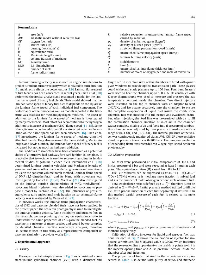
The experimental setup is shown in Fig. 1 and consists of a con-stant-volume cylindrical chamber (CVC) with a diameter and
length of 135 mm. Two sides of this chamber are fitted with quartzglass windows to provide optical transmission path. These glassescould withstand static pressure up to 100 bars. Four band heaterswere used to heat the chamber up to 500 K. A PID controller withK-type thermocouple was used to measure and preserve the gastemperature constant inside the chamber. Two direct injectorswere installed on the top of chamber with an adaptor to feedCNG/CH4 and iso-octane separately into the chamber. To ensurethe complete evaporation of liquid fuel inside the combustionchamber, fuel was injected into the heated and evacuated cham-ber. After injection, the feed line was pressurized with air to fillthe combustion chamber. Rotation of inlet air in the chambercauses complete mixing of air and fuels. Initial pressure of combus-tion chamber was adjusted by two pressure transducers with arange of (0–1 bar) and (0–30 bar). The internal pressure of the ves-sel was continuously monitored via an AVL, GU12P piezo-resistiveabsolute pressure transducer 0–200 bars. The temporal evolutionof expanding flame was recorded via Z-type high speed schlierenphotography.
2.2. Mixtures preparation
All tests were performed at initial temperature of 363 K andinitial pressure of 1 bar and were repeated at least 3 times at eachpoint. The equivalence ratios (Ø) varied from 0.8 to 1.2.
Fuel–air Mixtures can be expressed as mCH4 + (1 �m)C8H18 +X(O2 + 3.76N2) where m is methane mole fraction in mixed fueland X is the number of moles of oxygen per one mole of mixed fuel.
Total equivalence ratio is defined as ø ¼ ðOFÞstx , therefore X can be
derived as X ¼ 12:5�10:5mø . Partial pressure method utilized to fill the
CVC with precise injection of each fuel separately at desired Ø. Inthis method partial pressure of each fuel is related to its molefraction.
pmix ¼ pair þ pfuel ¼ pfuel 1þ pair
pfuel
!¼ pfuel 1þ nair
nfuel
� �
¼ pfuelð1þ 4:76XÞ ð1Þ
pfuel ¼ piso-octane þ pMethane ð2Þ
where piso-octane and pMethane are partial pressure of iso-octane andmethane respectively.
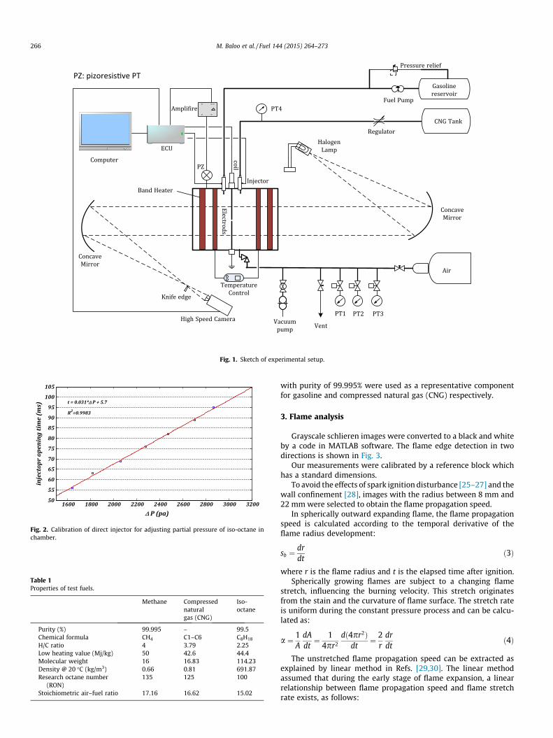
Calibration of direct injectors for liquid and gaseous fuel wasdone for each Ø. Fig. 2 shows the calibration of injector for iso-octane–air mixture. The R-squared value is 0.9983 which indicatesthat the regression line approximates the real data points well. t isthe injector opening time and DP is pressure increase inside thechamber after fuel injection.
The properties of fuels that used in the experiments are pre-sented in Table 1.Iso-octane with purity of 99.5% and methane
Air
Halogen
Lamp
CNG Tank
High Speed CameraPT1 PT2 PT3
Knife edge
VentVacuum
pump
Concave
Mirror
Band Heater
Ele
ctrod
s
ECU
Computer
Temperature
Control
Gasoline
reservoirFuel Pump00
00
0
Ampli�ire
Injector
Regulator
Pressure relief
PT4
PZ
Concave
Mirror
coil
PZ: pizoresis�ve PT
Fig. 1. Sketch of experimental setup.
1600 1800 2000 2200 2400 2600 2800 3000 320050
55
60
65
70
75
80
85
90
95
100
105
Δ P (pa)
inje
ctop
r op
enin
g tim
e (m
s) t = 0.031*Δ P + 5.7
R2=0.9983
Fig. 2. Calibration of direct injector for adjusting partial pressure of iso-octane inchamber.
Table 1Properties of test fuels.
Methane Compressednaturalgas (CNG)
Iso-octane
Purity (%) 99.995 – 99.5Chemical formula CH4 C1–C6 C8H18
H/C ratio 4 3.79 2.25Low heating value (Mj/kg) 50 42.6 44.4Molecular weight 16 16.83 114.23Density @ 20 �C (kg/m3) 0.66 0.81 691.87Research octane number
(RON)135 125 100
Stoichiometric air–fuel ratio 17.16 16.62 15.02
266 M. Baloo et al. / Fuel 144 (2015) 264–273
with purity of 99.995% were used as a representative componentfor gasoline and compressed natural gas (CNG) respectively.
3. Flame analysis
Grayscale schlieren images were converted to a black and whiteby a code in MATLAB software. The flame edge detection in twodirections is shown in Fig. 3.
Our measurements were calibrated by a reference block whichhas a standard dimensions.
To avoid the effects of spark ignition disturbance [25–27] and thewall confinement [28], images with the radius between 8 mm and22 mm were selected to obtain the flame propagation speed.
In spherically outward expanding flame, the flame propagationspeed is calculated according to the temporal derivative of theflame radius development:
sb ¼drdt
ð3Þ
where r is the flame radius and t is the elapsed time after ignition.Spherically growing flames are subject to a changing flame
stretch, influencing the burning velocity. This stretch originatesfrom the stain and the curvature of flame surface. The stretch rateis uniform during the constant pressure process and can be calcu-lated as:
a ¼ 1A
dAdt¼ 1
4pr2
dð4pr2Þdt
¼ 2r
drdt
ð4Þ
The unstretched flame propagation speed can be extracted asexplained by linear method in Refs. [29,30]. The linear methodassumed that during the early stage of flame expansion, a linearrelationship between flame propagation speed and flame stretchrate exists, as follows:
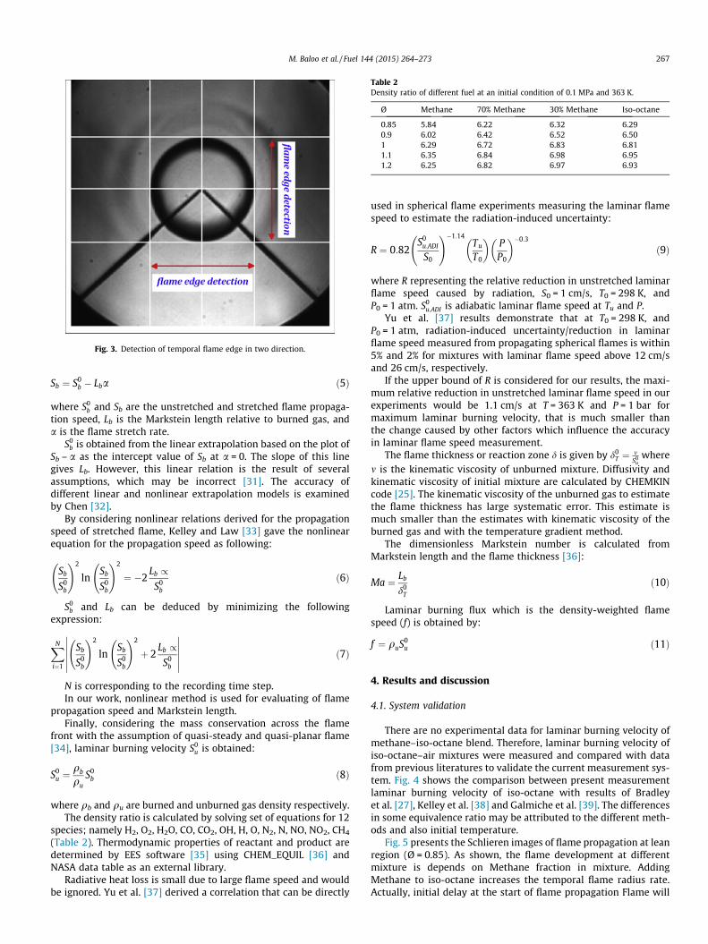
Fig. 3. Detection of temporal flame edge in two direction.
Table 2Density ratio of different fuel at an initial condition of 0.1 MPa and 363 K.
Ø Methane 70% Methane 30% Methane Iso-octane
0.85 5.84 6.22 6.32 6.290.9 6.02 6.42 6.52 6.501 6.29 6.72 6.83 6.811.1 6.35 6.84 6.98 6.951.2 6.25 6.82 6.97 6.93
M. Baloo et al. / Fuel 144 (2015) 264–273 267
Sb ¼ S0b � Lba ð5Þ
where S0b and Sb are the unstretched and stretched flame propaga-
tion speed, Lb is the Markstein length relative to burned gas, anda is the flame stretch rate.
S0b is obtained from the linear extrapolation based on the plot of
Sb – a as the intercept value of Sb at a = 0. The slope of this linegives Lb. However, this linear relation is the result of severalassumptions, which may be incorrect [31]. The accuracy ofdifferent linear and nonlinear extrapolation models is examinedby Chen [32].
By considering nonlinear relations derived for the propagationspeed of stretched flame, Kelley and Law [33] gave the nonlinearequation for the propagation speed as following:
Sb
S0b
!2
lnSb
S0b
!2
¼ �2Lb /
S0b
ð6Þ
S0b and Lb can be deduced by minimizing the following
expression:
XN
i¼1
Sb
S0b
!2
lnSb
S0b
!2
þ 2Lb /
S0b
������������ ð7Þ
N is corresponding to the recording time step.In our work, nonlinear method is used for evaluating of flame
propagation speed and Markstein length.Finally, considering the mass conservation across the flame
front with the assumption of quasi-steady and quasi-planar flame[34], laminar burning velocity S0
u is obtained:
S0u ¼
qb
quS0
b ð8Þ
where qb and qu are burned and unburned gas density respectively.The density ratio is calculated by solving set of equations for 12
species; namely H2, O2, H2O, CO, CO2, OH, H, O, N2, N, NO, NO2, CH4
(Table 2). Thermodynamic properties of reactant and product aredetermined by EES software [35] using CHEM_EQUIL [36] andNASA data table as an external library.
Radiative heat loss is small due to large flame speed and wouldbe ignored. Yu et al. [37] derived a correlation that can be directly
used in spherical flame experiments measuring the laminar flamespeed to estimate the radiation-induced uncertainty:
R ¼ 0:82S0
u;ADI
S0
!�1:14Tu
T0
� �PP0
� ��0:3
ð9Þ
where R representing the relative reduction in unstretched laminarflame speed caused by radiation, S0 = 1 cm/s, T0 = 298 K, andP0 = 1 atm. S0
u;ADI is adiabatic laminar flame speed at Tu and P.Yu et al. [37] results demonstrate that at T0 = 298 K, and
P0 = 1 atm, radiation-induced uncertainty/reduction in laminarflame speed measured from propagating spherical flames is within5% and 2% for mixtures with laminar flame speed above 12 cm/sand 26 cm/s, respectively.
If the upper bound of R is considered for our results, the maxi-mum relative reduction in unstretched laminar flame speed in ourexperiments would be 1.1 cm/s at T = 363 K and P = 1 bar formaximum laminar burning velocity, that is much smaller thanthe change caused by other factors which influence the accuracyin laminar flame speed measurement.
The flame thickness or reaction zone d is given by d0T ¼ m
S0u
wherem is the kinematic viscosity of unburned mixture. Diffusivity andkinematic viscosity of initial mixture are calculated by CHEMKINcode [25]. The kinematic viscosity of the unburned gas to estimatethe flame thickness has large systematic error. This estimate ismuch smaller than the estimates with kinematic viscosity of theburned gas and with the temperature gradient method.
The dimensionless Markstein number is calculated fromMarkstein length and the flame thickness [36]:
Ma ¼ Lb
d0T
ð10Þ
Laminar burning flux which is the density-weighted flamespeed (f) is obtained by:
f ¼ quS0u ð11Þ
4. Results and discussion
4.1. System validation
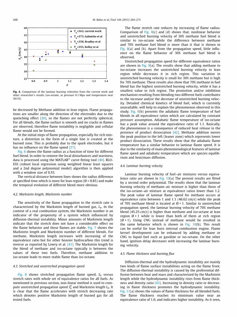
There are no experimental data for laminar burning velocity ofmethane–iso-octane blend. Therefore, laminar burning velocity ofiso-octane–air mixtures were measured and compared with datafrom previous literatures to validate the current measurement sys-tem. Fig. 4 shows the comparison between present measurementlaminar burning velocity of iso-octane with results of Bradleyet al. [27], Kelley et al. [38] and Galmiche et al. [39]. The differencesin some equivalence ratio may be attributed to the different meth-ods and also initial temperature.
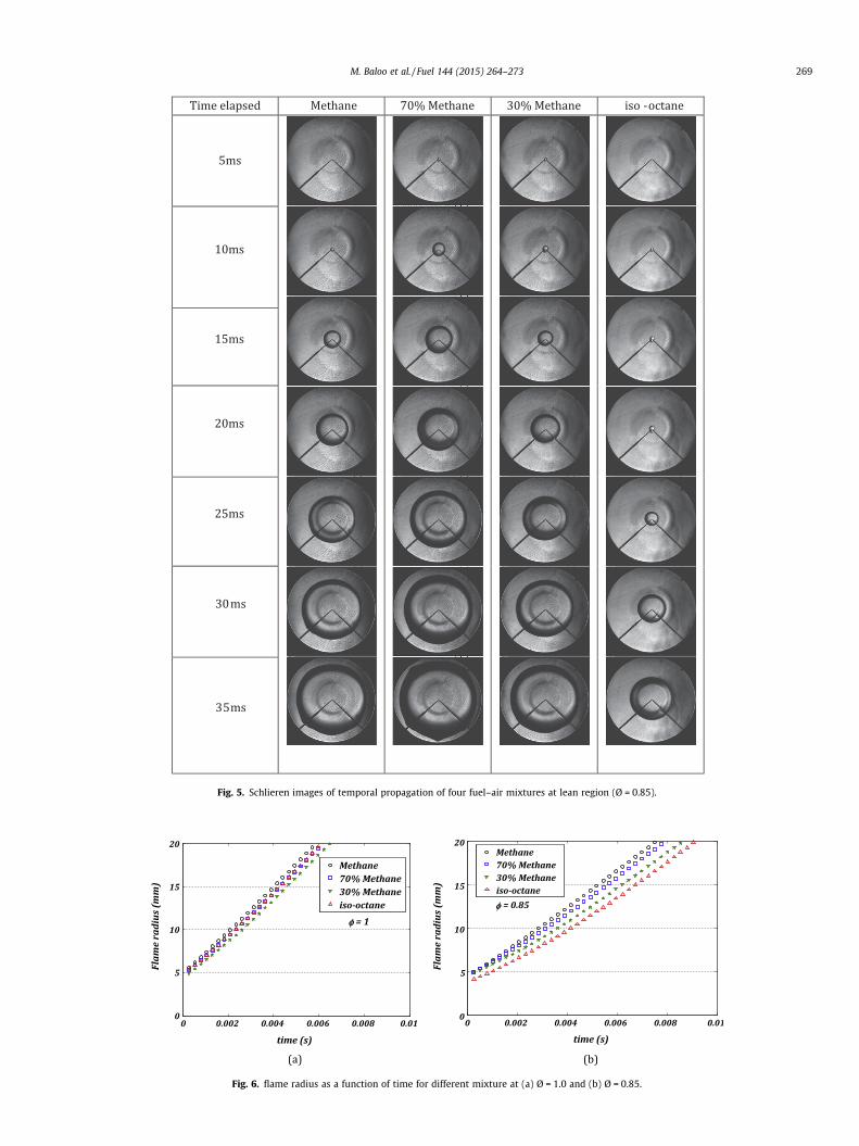
Fig. 5 presents the Schlieren images of flame propagation at leanregion (Ø = 0.85). As shown, the flame development at differentmixture is depends on Methane fraction in mixture. AddingMethane to iso-octane increases the temporal flame radius rate.Actually, initial delay at the start of flame propagation Flame will
0.8 0.9 1 1.1 1.2 1.3 1.425
30
35
40
45
50
55
60
φ
S L (cm
/s)
Tu=363, current work
Tu=373, Galmiche et al
Tu=358, Bradley et al
Tu=353, Kelley et al
Fig. 4. Comparison of the laminar burning velocities from the current work andother researcher’s results (iso-octane, at pressure 0.1 Mpa and temperature near363 K).
268 M. Baloo et al. / Fuel 144 (2015) 264–273
be decreased by Methane addition in lean region. Flame propaga-tions are smaller along the direction of the electrodes due to thequenching effect [20], so the flames are not perfectly spherical.For all blends, the flame surface is smooth and no cracks in flamesare observed, therefore flame instability is negligible and cellularflame would not be formed.
At the initial steps of flame propagation, especially for rich mix-ture, a distortion in the form of a single line is created at theburned zone. This is probably due to the spark electrodes, but ithas no influence on the flame speed [27].
Fig. 6 shows the flame radius as a function of time for differentfuel blend. In order to remove the local disturbances and waviness,data is processed using the MATLAB� curve fitting tool [40]. RLO-ESS (robust local regression using weighted linear least squaresand a 2nd degree polynomial model) algorithm is then appliedwith a window size of 0.55.
The vertical distance between lines shows the radius differenceat specified time which is more for lean region (Ø = 0.85) and makethe temporal evolution of different blend more obvious.
4.2. Markstein length, Markstein number
The sensitivity of the flame propagation to the stretch rate ischaracterized by the Markstein length of burned gas, Lb. In thecontext of a real combustion system, the Markstein number is anindicator of the propensity of a system which influenced bydiffusion-thermal instability. Minor amounts of Markstein lengthindicate that the stretch does not have a considerable effect onthe flame behavior and these flames are stable. Fig. 7 shows theMarkstein length and Markstein number of different blends. Formethane, Markstein length increases with increasing of theequivalence ratio but for other heavier hydrocarbon this trend isinverse as reported by Lowry et al. [41]. The Markstein length forthe blend of methane and iso-octane typically is between thevalues of these two fuels. Therefore, methane addition toiso-octane leads to more stable flame than iso-octane.
4.3. Stretched and unstretched propagation speed
Fig. 8 shows stretched propagation flame speed, Sb versusstretch rates with whole set of equivalence ratios for all fuels. Asmentioned in previous section, non-linear method is used to com-pute unstretched propagation speed S0
b and Markstein length Lb. Itis clear that the flame accelerates with stretch decreasing ratewhich denotes positive Markstein length of burned gas for alltested fuels.
The flame stretch rate reduces by increasing of flame radius.Comparison of Fig. 8(c) and (d) shows that, nonlinear behaviorand unstretched burning velocity of 30% methane fuel blend issimilar to iso-octane while the difference between methaneand 70% methane fuel blend is more than it that is shown inFig. 8(a) and (b). Apart from the propagation speed, little influ-ence on the flame behavior of 30% methane fuel blend isobserved.
Unstretched propagation speed for different equivalence ratiosare shown in Fig. 9(a). The results show that adding methane toiso-octane increases the unstretched burning velocity in leanregion while decreases it in rich region. This variation inunstretched burning velocity is small for 30% methane but is highfor 70% methane. These results also show that 70% methane in fuelblend has the highest unstretched burning velocity, while it has asmallest value in rich region. The promotion and/or inhibitionmechanism resulting from blending two different fuels contributesto the increase and/or the decrease of unstretched burning veloc-ity. Detailed chemical kinetics of blend fuel, which is currentlyunavailable, will help to explain the phenomenon observed in thisstudy. Fig. 9(b) presents the adiabatic flame temperature of fuelblends in all equivalence ratios which are calculated by constantpressure assumption. Adiabatic flame temperature of iso-octanehas a peak value around the equivalence ratio of 1.1. Basically,the phenomenon is a consequence of reduced heat release in thepresence of product dissociation [42]. Methane addition movesthe peak position to the left (leaner zone) which represents lowerproduct dissociation. These results show that the adiabatic flametemperature has a similar behavior to laminar flame speed. It isdue to the similarity of main phenomenological features of laminarflame speed and adiabatic temperature which are species equilib-rium and heat/mass diffusion.
4.4. Laminar burning velocity
Laminar burning velocity of fuel–air mixtures versus equiva-lence ratio are shown in Fig. 10(a) The present results are fittedby a second order polynomial. The results show that the laminarburning velocity of methane–air mixture is higher than those ofthe iso-octane–air mixture at equivalence ratios lower than 1.2.The peak value of laminar flame speed for methane occurs atequivalence ratio between 1 and 1.1 (46.62 cm/s) while the peakof 70% methane blend is located at Ø < 1. Similar to unstretchedpropagation speed, the laminar burning velocity of 70% methaneblend (45.25 cm/s) is higher than methane and iso-octane at leanregion Ø < 1 while is lower than both of them at rich region(Ø < 1). Using CNG instead of methane would be resulted inthe same behavior which is shown in Fig. 10(b). This resultcan be useful for lean burn internal combustion engine. Flamekernel development can be enhanced by adding methane orCNG to liquid fuel such as gasoline or iso-octane. On the otherhand, ignition delay decreases with increasing the laminar burn-ing velocity.
4.5. Flame thickness and burning flux
Diffusion-thermal and the hydrodynamic instability are mainlytwo kinds of flame surface instabilities acting on the flame front.The diffusion-thermal instability is caused by the preferential dif-fusion between heat and mass and characterized by the Marksteinlength while the hydrodynamic instability rises from flame thick-ness and density ratio [43]. Increasing in density ratio or decreas-ing in flame thickness promotes the hydrodynamic instability.Fig. 11(a) shows the values of flame thickness for all blended fuels.The flame thickness reaches its minimum value near anequivalence ratio of 1.0, and indicates higher instability. As it seen,
Time elapsed Methane 70% Methane 30% Methane iso -octane
5ms
10ms
15ms
20ms
25ms
30 ms
35ms
Fig. 5. Schlieren images of temporal propagation of four fuel–air mixtures at lean region (Ø = 0.85).
Fig. 6. flame radius as a function of time for different mixture at (a) Ø = 1.0 and (b) Ø = 0.85.
M. Baloo et al. / Fuel 144 (2015) 264–273 269
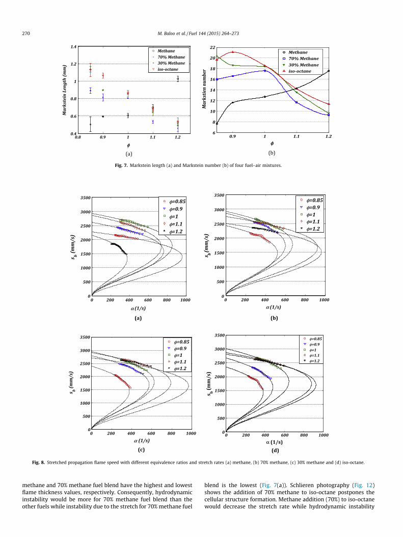
Fig. 7. Markstein length (a) and Markstein number (b) of four fuel–air mixtures.
(a) (b)
(c) (d)
0 200 400 600 800 10000
500
1000
1500
2000
2500
3000
3500
α (1/s)
s b (mm
/s)
φ=0.85φ=0.9φ=1φ=1.1φ=1.2
0 200 400 600 800 10000
500
1000
1500
2000
2500
3000
3500
α (1/s)
s b(mm
/s)
φ=0.85φ=0.9φ=1φ=1.1φ=1.2
0 200 400 600 800 10000
500
1000
1500
2000
2500
3000
3500
α (1/s)
s b(m
m/s
)
φ=0.85φ=0.9φ=1φ=1.1φ=1.2
0 200 400 600 800 10000
500
1000
1500
2000
2500
3000
3500
α (1/s)
s b (mm
/s)
φ=0.85φ=0.9φ=1φ=1.1φ=1.2
Fig. 8. Stretched propagation flame speed with different equivalence ratios and stretch rates (a) methane, (b) 70% methane, (c) 30% methane and (d) iso-octane.
270 M. Baloo et al. / Fuel 144 (2015) 264–273
methane and 70% methane fuel blend have the highest and lowestflame thickness values, respectively. Consequently, hydrodynamicinstability would be more for 70% methane fuel blend than theother fuels while instability due to the stretch for 70% methane fuel
blend is the lowest (Fig. 7(a)). Schlieren photography (Fig. 12)shows the addition of 70% methane to iso-octane postpones thecellular structure formation. Methane addition (70%) to iso-octanewould decrease the stretch rate while hydrodynamic instability

Fig. 9. (a) Unstretched propagation speed and (b) adiabatic flame temperature versus equivalence ratios.
Fig. 10. Laminar burning velocity of methane and iso-octane mixtures (a and b) CNG and iso-octane mixture versus equivalence ratio.
Fig. 11. Flame thickness (a) and burning flux (b) of mixtures versus equivalence ratio.
M. Baloo et al. / Fuel 144 (2015) 264–273 271
would be increased. Therefore, it can be concluded that the effectof stretch rate is more than hydrodynamic instability on the flamefront.
Fig. 11(b) presents the burning flux versus equivalence ratio forall fuels. The change of laminar burning flux values are in the orderof laminar burning velocities. 70% methane fuel blend has the peak
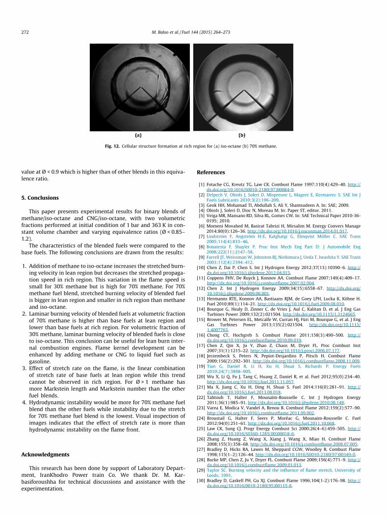
Fig. 12. Cellular structure formation at rich region for (a) iso-octane (b) 70% methane.
272 M. Baloo et al. / Fuel 144 (2015) 264–273
value at Ø < 0.9 which is higher than of other blends in this equiva-lence ratio.
5. Conclusions
This paper presents experimental results for binary blends ofmethane/iso-octane and CNG/iso-octane, with two volumetricfractions performed at initial condition of 1 bar and 363 K in con-stant volume chamber and varying equivalence ratios (Ø < 0.85–1.2).
The characteristics of the blended fuels were compared to thebase fuels. The following conclusions are drawn from the results:
1. Addition of methane to iso-octane increases the stretched burn-ing velocity in lean region but decreases the stretched propaga-tion speed in rich region. This variation in the flame speed issmall for 30% methane but is high for 70% methane. For 70%methane fuel blend, stretched burning velocity of blended fuelis bigger in lean region and smaller in rich region than methaneand iso-octane.
2. Laminar burning velocity of blended fuels at volumetric fractionof 70% methane is higher than base fuels at lean region andlower than base fuels at rich region. For volumetric fraction of30% methane, laminar burning velocity of blended fuels is closeto iso-octane. This conclusion can be useful for lean burn inter-nal combustion engines. Flame kernel development can beenhanced by adding methane or CNG to liquid fuel such asgasoline.
3. Effect of stretch rate on the flame, is the linear combinationof stretch rate of base fuels at lean region while this trendcannot be observed in rich region. For Ø > 1 methane hasmore Markstein length and Markstein number than the otherfuel blends.
4. Hydrodynamic instability would be more for 70% methane fuelblend than the other fuels while instability due to the stretchfor 70% methane fuel blend is the lowest. Visual inspection ofimages indicates that the effect of stretch rate is more thanhydrodynamic instability on the flame front.
Acknowledgments
This research has been done by support of Laboratory Depart-ment, IranKhodro Power train Co. We thank Dr. M. Kar-basiforoushha for technical discussions and assistance with theexperimentation.
References
[1] Fotache CG, Kreutz TG, Law CK. Combust Flame 1997;110(4):429–40. http://dx.doi.org/10.1016/S0010-2180(97)00084-9.
[2] Delpech V, Obiols J, Soleri D, Mispreuve L, Magere E, Kermarrec S. SAE Int JFuels Lubricants 2010;3(2):196–209.
[3] Geok HH, Mohamad TI, Abdullah S, Ali Y, Shamsudeen A. In: SAE; 2009.[4] Obiols J, Soleri D, Dioc N, Moreau M. In: Paper ST, editor. 2011.[5] Veiga MR, Mansano RD, Silva RL, Gomes CW. In: SAE Technical Paper 2010-36-
0195; 2010.[6] Momeni Movahed M, Basirat Tabrizi H, Mirsalim M. Energy Convers Manage
2014;80(0):126–36. http://dx.doi.org/10.1016/j.enconman.2014.01.017.[7] Lindström F, Angström H-E, Kalghatgi G, Elmqvist Möller C. SAE Trans
2005;114(4):833–46.[8] Bonatesta F, Shayler P. Proc Inst Mech Eng Part D: J Automobile Eng
2008;222(11):2147–58.[9] Farrell JT, Weissman W, Johnston RJ, Nishimura J, Ueda T, Iwashita Y. SAE Trans
2003;112(4):2394–412.[10] Chen Z, Dai P, Chen S. Int J Hydrogen Energy 2012;37(13):10390–6. http://
dx.doi.org/10.1016/j.ijhydene.2012.04.015.[11] Coppens FHV, De Ruyck J, Konnov AA. Combust Flame 2007;149(4):409–17.
http://dx.doi.org/10.1016/j.combustflame.2007.02.004.[12] Chen Z. Int J Hydrogen Energy 2009;34(15):6558–67. http://dx.doi.org/
10.1016/j.ijhydene.2009.06.001.[13] Hermanns RTE, Konnov AA, Bastiaans RJM, de Goey LPH, Lucka K, Köhne H.
Fuel 2010;89(1):114–21. http://dx.doi.org/10.1016/j.fuel.2009.08.010.[14] Bourque G, Healy D, Zinner C, de Vries J, Aul C, Kalitan D, et al. J Eng Gas
Turbines Power 2009;132(2):021504. http://dx.doi.org/10.1115/1.3124665.[15] Brower M, Petersen EL, Metcalfe W, Curran HJ, Füri M, Bourque G, et al. J Eng
Gas Turbines Power 2013;135(2):021504. http://dx.doi.org/10.1115/1.4007763.
[16] Chong CT, Hochgreb S. Combust Flame 2011;158(3):490–500. http://dx.doi.org/10.1016/j.combustflame.2010.09.019.
[17] Chen Z, Qin X, Ju Y, Zhao Z, Chaos M, Dryer FL. Proc Combust Inst2007;31(1):1215–22. http://dx.doi.org/10.1016/j.proci.2006.07.177.
[18] Jerzembeck S, Peters N, Pepiot-Desjardins P, Pitsch H. Combust Flame2009;156(2):292–301. http://dx.doi.org/10.1016/j.combustflame.2008.11.009.
[19] Tian G, Daniel R, Li H, Xu H, Shuai S, Richards P. Energy Fuels2010;24(7):3898–905.
[20] Wu X, Li Q, Fu J, Tang C, Huang Z, Daniel R, et al. Fuel 2012;95(0):234–40.http://dx.doi.org/10.1016/j.fuel.2011.11.057.
[21] Ma X, Jiang C, Xu H, Ding H, Shuai S. Fuel 2014;116(0):281–91. http://dx.doi.org/10.1016/j.fuel.2013.08.018.
[22] Tahtouh T, Halter F, Mounaïm-Rousselle C. Int J Hydrogen Energy2011;36(1):985–91. http://dx.doi.org/10.1016/j.ijhydene.2010.08.148.
[23] Varea E, Modica V, Vandel A, Renou B. Combust Flame 2012;159(2):577–90.http://dx.doi.org/10.1016/j.combustflame.2011.09.002.
[24] Broustail G, Halter F, Seers P, Moréac G, Mounaim-Rousselle C. Fuel2012;94(0):251–61. http://dx.doi.org/10.1016/j.fuel.2011.10.068.
[25] Law CK, Sung CJ. Progr Energy Combust Sci 2000;26(4–6):459–505. http://dx.doi.org/10.1016/S0360-1285(00)00018-6.
[26] Zhang Z, Huang Z, Wang X, Xiang J, Wang X, Miao H. Combust Flame2008;155(3):358–68. http://dx.doi.org/10.1016/j.combustflame.2008.07.005.
[27] Bradley D, Hicks RA, Lawes M, Sheppard CGW, Woolley R. Combust Flame1998;115(1–2):126–44. http://dx.doi.org/10.1016/S0010-2180(97)00349-0.
[28] Burke MP, Chen Z, Ju Y, Dryer FL. Combust Flame 2009;156(4):771–9. http://dx.doi.org/10.1016/j.combustflame.2009.01.013.
[29] Taylor SC. Burning velocity and the influence of flame stretch. University ofLeeds; 1991.
[30] Bradley D, Gaskell PH, Gu XJ. Combust Flame 1996;104(1-2):176–98. http://dx.doi.org/10.1016/0010-2180(95)00115-8.
M. Baloo et al. / Fuel 144 (2015) 264–273 273
[31] Halter F, Tahtouh T, Mounaïm-Rousselle C. Combust Flame2010;157(10):1825–32. http://dx.doi.org/10.1016/j.combustflame.2010.05.013.
[32] Chen Z. Combust Flame 2011;158(2):291–300. http://dx.doi.org/10.1016/j.combustflame.2010.09.001.
[33] Kelley AP, Law CK. Combust Flame 2009;156(9):1844–51. http://dx.doi.org/10.1016/j.combustflame.2009.04.004.
[34] Law CK. Combustion physics. Cambridge University Press; 2010.[35] Klein SA, Alvarado FL. In: F-Chart. Software: Middleton; 2000.[36] Strehlow RA. New York: McGraw-Hill; 1984.[37] Yu H, Han W, Santner J, Gou X, Sohn CH, Ju Y, et al. Combust Flame
2014;161(11):2815–24. http://dx.doi.org/10.1016/j.combustflame.2014.05.012.
[38] Kelley AP, Liu W, Xin YX, Smallbone AJ, Law CK. Proc Combust Inst2011;33(1):501–8. http://dx.doi.org/10.1016/j.proci.2010.05.058.
[39] Galmiche B, Halter F, Foucher F. Combust Flame 2012;159(11):3286–99.http://dx.doi.org/10.1016/j.combustflame.2012.06.008.
[40] Prathap C, Ray A, Ravi MR. Combust Flame 2008;155(1–2):145–60. http://dx.doi.org/10.1016/j.combustflame.2008.04.005.
[41] Lowry W, Serinyel Z, Bourque G, Metcalfe W, de Vries J, Krejci M, et al. J EngGas Turbines Power 2011;133(9):091501. http://dx.doi.org/10.1115/1.4002809.
[42] Law CK, Makino A, Lu TF. Combust Flame 2006;145(4):808–19. http://dx.doi.org/10.1016/j.combustflame.2006.01.009.
[43] Williams FA. Combustion theory. Menlo park, CA: Benjamin-Cummins; 1985.
Copyright © 2022 FDOKUMEN