Laminar dust flames in a reduced-gravity environment
12
This article appeared in a journal published by Elsevier. The attached copy is furnished to the author for internal non-commercial research and education use, including for instruction at the authors institution and sharing with colleagues. Other uses, including reproduction and distribution, or selling or licensing copies, or posting to personal, institutional or third party websites are prohibited. In most cases authors are permitted to post their version of the article (e.g. in Word or Tex form) to their personal website or institutional repository. Authors requiring further information regarding Elsevier’s archiving and manuscript policies are encouraged to visit: http://www.elsevier.com/copyright
Transcript of Laminar dust flames in a reduced-gravity environment

This article appeared in a journal published by Elsevier. The attachedcopy is furnished to the author for internal non-commercial researchand education use, including for instruction at the authors institution
and sharing with colleagues.
Other uses, including reproduction and distribution, or selling orlicensing copies, or posting to personal, institutional or third party
websites are prohibited.
In most cases authors are permitted to post their version of thearticle (e.g. in Word or Tex form) to their personal website orinstitutional repository. Authors requiring further information
regarding Elsevier’s archiving and manuscript policies areencouraged to visit:
http://www.elsevier.com/copyright

Author's personal copy
Laminar dust flames in a reduced-gravity environment$
Samuel Goroshin n, Francois-David Tang, Andrew J. Higgins, John H.S Lee
Department of Mechanical Engineering, Macdonald Engineering Building, McGill University, 817 Sherbrooke St. West, Montreal, Quebec, Canada H3A 2K6
a r t i c l e i n f o
Article history:
Received 1 February 2010
Received in revised form
4 July 2010
Accepted 28 August 2010
Keywords:
Reduced-gravity
Iron
Dust
Combustion
Discrete
Flame
a b s t r a c t
The propagation of laminar dust flames in suspensions of iron in gaseous oxidizers was
studied in a low-gravity environment onboard a parabolic flight aircraft. The reduction
of buoyancy-induced convective flows and particle settling permitted the measurement
of fundamental combustion parameters, such as the burning velocity and the flame
quenching distance over a wide range of particle sizes and in different gaseous
mixtures. Experimentally measured flame speeds and quenching distances were found
in good agreement with theoretical predictions of a simplified analytical model that
assumes particles burning in a diffusive mode. However, the comparison of flame
speeds in oxygen–argon and oxygen–helium iron suspensions indicates the possibility
that fine micron-sized particles burn in the kinetic mode. Furthermore, when the
particle spacing is large compared to the scale of the reaction zone, a theoretical
analysis suggests the existence of a new so-called discrete flame propagation regime.
Discrete flames are strongly dependent on particle density fluctuations and demon-
strate directed percolation behavior near flame propagation limits. The experimental
observation of discrete flames in particle suspensions will require low levels of gravity
over extended periods available only on orbital platforms.
& 2010 Elsevier Ltd. All rights reserved.
1. Introduction
The combustion of particulate suspensions in anoxidizing media (dust combustion) is a poorly developedbranch of combustion science, yet it is of great practicalimportance in a wide variety of industries and moderntechnologies (e.g., coal-fired power plants, fire safety inchemical, pharmaceutical, mining, and food industries,combustion material synthesis, propulsion, etc.). It is alsowell recognized that the reason this field is under-developed in comparison to other branches of combustionscience is rooted in the difficulties of performing combus-tion experiments, with particulate suspensions at normalgravity. Reduced-gravity is essential to the generation of auniform dust suspension of arbitrary particle size and
concentration. When particles with a characteristic sizeon the order of tens of microns are suspended, theyrapidly settle in a gravitational field. To maintain aparticulate in suspension for a time duration adequateto carry out combustion experiments invariably requirescontinuous convective flow in excess of the gravitationalsettling velocity, which is often comparable with and caneven exceed the laminar burning velocity. Even for smallparticle sizes on the order of microns, a stable laminardust flow can be maintained only for relatively low dustconcentrations at normal gravity conditions. Highdust loading leads to a gravitational instability of thedust cloud. In a confined volume, this instability ismanifested by the formation of recirculation cells in thedust suspension, or results in the rapid settling of thedense dust cloud, as a whole, in an unconfined volume [1].Many important solid fuels, such as carbon and boron,also have low laminar flame speeds of the order of severalcentimeters per second [2,3]. Convective flows that occurin combustion products due to buoyancy disrupt the low
Contents lists available at ScienceDirect
journal homepage: www.elsevier.com/locate/actaastro
Acta Astronautica
0094-5765/$ - see front matter & 2010 Elsevier Ltd. All rights reserved.
doi:10.1016/j.actaastro.2010.08.038
$ This paper was presented during the 60th IAC in Daejeon.n Corresponding author. Tel.: +1 514 398 6309; fax: +1 514 398 7365.
E-mail address: [email protected] (S. Goroshin).
Acta Astronautica 68 (2011) 656–666
Author's personal copy
speed flames and make observation of such flames atnormal gravity difficult.
The potential of a reduced-gravity environment tofacilitate the study of dust combustion was recognized bycombustion scientists prior to the establishment ofcurrent reduced-gravity research programs by variousnational space agencies. The pioneering work by Kumagai[4], dating back to the 1950s, employed a custom-builtdrop tower to study droplet combustion in a reduced-gravity environment. Ballal [5] investigated flames inorganic and metal particulate suspensions, using a 10 mdrop tower. Experimental observations of coal-dust/airflame structure under low-gravity conditions were carriedout by Wolanski et al. [6] with a similar 10 m drop tower.NASA-sponsored experiments in reduced-gravity dateback to the combustion of lycopodium dust clouds atthe drop tower at NASA Glenn Research Center [7] and onLearjet parabolic flights [8,9]. Experiments at the JapanMicrogravity Centre (JAMIC) 10 s drop tower investigatedflame propagation in PMMA particle clouds [10]. Morerecently, the combustion of metallic suspensions atreduced-gravity was studied in aluminum [11,12],magnesium [13,14], and iron [15].
McGill University, under sponsorship from the CanadianSpace Agency, has been active in metal dust combustionresearch, utilizing a reduced-gravity environment since1991 [11,12,15]. Due to the limited number of experimentsthat can be carried out in a reduced-gravity environment, itis essential that ground-based studies supplement reduced-gravity experiments, even if only in the narrow range of dustparameters that are not severely affected by particle settlingand natural convection. Thus, a comprehensive program hasalso included extensive experimentation in ground-basedfacilities and a multipronged theoretical effort [16–19].
The current paper presents the development of a dustcombustion apparatus built specifically for experimenta-tion onboard Falcon-20 parabolic flight aircraft operatedby the Flight Research Laboratory of the CanadianNational Research Council (Ottawa) and summarizesthe key experimental results obtained. One objective ofthe investigation was to obtain a reliable set of experi-mental data on basic combustion parameters of dustsuspensions, such as the laminar burning velocity, theflame structure, and the quenching distance for suspen-sions of nonvolatile fuels in the widest possible rangeof particle sizes, in order to validate theoretical modelsdeveloped by the authors.
Another objective of the current research effort is toidentify possible rationale for performing dust combus-tion experiments in a longer duration micro-gravityenvironment provided by orbital platforms, such assounding rockets, the International Space Station or otherautonomous satellites. Our recent theoretical works [19]have predicted a new and unusual flame propagationregime analogous to the Directed Percolation phenomen-on [20]. This regime would involve flames propagating atlow speeds in diluted mixtures and would require a high-quality, long-duration microgravity environment. A gen-eral outline of an experiment on an orbital platformpermitting the observation and the study of discrete,percolating flames is proposed.
2. Experimental equipment for parabolic flightexperiments
2.1. Apparatus
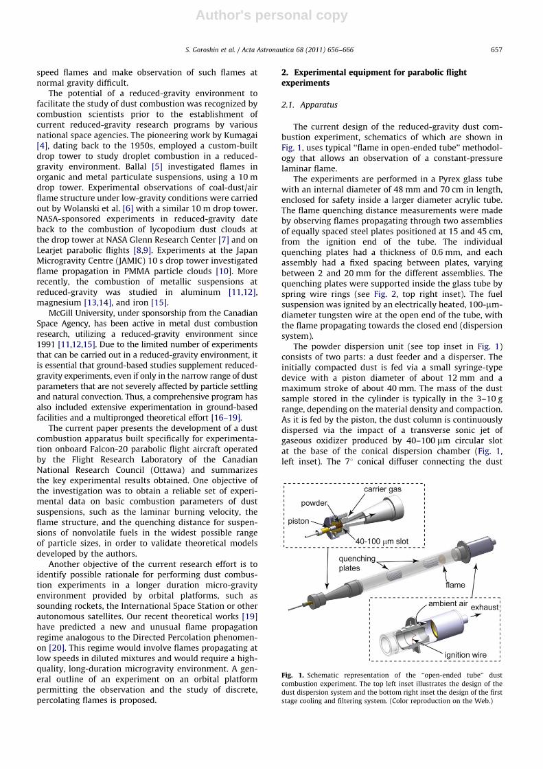
The current design of the reduced-gravity dust com-bustion experiment, schematics of which are shown inFig. 1, uses typical ‘‘flame in open-ended tube’’ methodol-ogy that allows an observation of a constant-pressurelaminar flame.
The experiments are performed in a Pyrex glass tubewith an internal diameter of 48 mm and 70 cm in length,enclosed for safety inside a larger diameter acrylic tube.The flame quenching distance measurements were madeby observing flames propagating through two assembliesof equally spaced steel plates positioned at 15 and 45 cm,from the ignition end of the tube. The individualquenching plates had a thickness of 0.6 mm, and eachassembly had a fixed spacing between plates, varyingbetween 2 and 20 mm for the different assemblies. Thequenching plates were supported inside the glass tube byspring wire rings (see Fig. 2, top right inset). The fuelsuspension was ignited by an electrically heated, 100-mm-diameter tungsten wire at the open end of the tube, withthe flame propagating towards the closed end (dispersionsystem).
The powder dispersion unit (see top inset in Fig. 1)consists of two parts: a dust feeder and a disperser. Theinitially compacted dust is fed via a small syringe-typedevice with a piston diameter of about 12 mm and amaximum stroke of about 40 mm. The mass of the dustsample stored in the cylinder is typically in the 3–10 grange, depending on the material density and compaction.As it is fed by the piston, the dust column is continuouslydispersed via the impact of a transverse sonic jet ofgaseous oxidizer produced by 40–100 mm circular slotat the base of the conical dispersion chamber (Fig. 1,left inset). The 71 conical diffuser connecting the dust
Fig. 1. Schematic representation of the ‘‘open-ended tube’’ dust
combustion experiment. The top left inset illustrates the design of the
dust dispersion system and the bottom right inset the design of the first
stage cooling and filtering system. (Color reproduction on the Web.)
S. Goroshin et al. / Acta Astronautica 68 (2011) 656–666 657

Author's personal copy
dispersion unit with the flame tube provides expansionand laminarization of the initially, highly turbulent dustflow. The resulting flow of metal powder in suspension inthe gaseous oxidizer fills the combustion tube at a flowvelocity on the order of 10 cm/s.
The fuel concentration in the suspension can bechanged by varying the piston speed, as controlled by anelectromechanical linear actuator. The fuel concentrationin the suspension can be calculated from the feeding rateof the piston, the packing density of the powder, and theknown flow rate of the dispersing gas. The concentrationcalculations were verified experimentally in ground-based trials with micron-size powders by collecting dustfrom the flow with a fine material filter for a prescribedperiod of time. The mass concentrations of iron suspen-sion in reduced-gravity experiments, presented in thecurrent paper, varied in a range 900–1200 g/m3.
The exhaust from the combustion tube is passedthrough a series of cooling and filtering systems andultimately discharged into the cabin to accommodate theabsence of overboard vents on the aircraft. The combus-tion products were drawn into the inlet of a multistagecooling and filtering system by a vacuum blower. A wideannular opening between the combustion tube and thefiltering system (see Fig. 1, right bottom inset) ensures anunobstructed access of the ambient air. The co-flow ofcabin air entering filtration system exceeds the flow ofcombustion products by an order of magnitude, providingfast cooling of hot products, while preventing any hotparticulates from escaping into the cabin. The condensedcombustion products are removed from the flow by aseries of three filters. The first filter assembly, integratedwith the combustion tube assembly (see Fig. 1, bottominset), contains a packed bed of steel beads and a ceramicfilter. The products were subsequently passed through asecond filter consisting of a packed bed of smaller copperbeads and a filter made from silica fibers. The remainingfine particulates were collected by a third stage filterof corrugated filter paper embedded with the blower.Cooled and cleaned from particulates, the gaseouscombustion products (comprised practically of purenitrogen, in the case of iron combustion) were expelledinto an aircraft cabin.
The combustion rack itself contains four replaceablecombustion tube assemblies. Each assembly is comprisedof a combustion tube integrated with an individualpowder dispersion unit and the first stage filter. Fourtube assemblies are mounted horizontally parallel to eachother on the combustion rack, providing an unobstructedview for the optical diagnostic (Figs. 2 and 3).
An additional eight spare combustion tube assemblieswere stored separately on a holding rack (Fig. 3(b))and were used as replacements for the combustion racktubes, following the completion of the first four experi-ments.
Flame propagation was recorded by a high-speeddigital camera viewing the entire length of the combus-tion tube at 300 frames per second. High resolutionpictures were obtained by a digital SLR camera. A fiberoptic miniature spectrometer (Ocean Optics USB 4000)was used to record the spectral emission of the flame inthe wavelength range 400–1000 nm at the rate of about20 spectra per second (see [21] for details). The spectro-meter resolution is about 1.5 nm and the field of view isabout 2 mm. The optical diagnostics devices weremounted on a frame across the isle facing the combustiontube rack.
Fig. 2. Photograph of the combustion rack with four combustion tube
assemblies. The inset shows quenching plate assembly mounted inside
the Pyrex flame tube. (Color reproduction on the Web.)
Fig. 3. Photographs of the dust combustion apparatus (a) and combus-
tion tube holding rack (b) onboard the Falcon-20 parabolic flight aircraft.
(Color reproduction on the Web.)
S. Goroshin et al. / Acta Astronautica 68 (2011) 656–666658

Author's personal copy
2.2. Iron powders
The properties of the dust fuels can range from highlyvolatile organic solids to refractory metals that hardlyproduce any gaseous products during combustion. Theselection of iron dusts for the current experiments wasmotivated by the desire to realize a ‘‘pure’’ heterogeneousflame, as reflected in our analytical models [16]. Thisrequirement excluded organic dusts such as PMMA, sincetheir volatility results in their burning being not thatdissimilar from liquid spray combustion, in which dropletevaporation and combustion of the gaseous fuel vaporsare the controlling mechanisms. Similarly, moderatelyvolatile metals, such as magnesium and aluminum, werealso excluded since their flame temperatures exceed theboiling point of the metal, a feature that may result in theformation of a metal vapor–air flame. Even the combus-tion of refractory elements with boiling points above theirflame temperatures such as carbon and boron, may stillpartially occur in the gas phase, due to the formation ofgaseous suboxides (BO, BO2, CO, etc.). Thermodynamiccalculations show that a few metals (iron, zirconium,hafnium) are good candidates to burn as a pure hetero-geneous flame uncontaminated by gas-phase combustion,since they form only condensed phase oxides. For safetyreasons, iron was selected for this study. Equilibriumthermodynamic calculations predict a stoichiometricadiabatic flame temperature in air of 2230 K well belowthe boiling point of iron at 3130 K and Fe3O4 and FeOoxides, which are the main products of combustion.
The iron powders used were characterized using theMie scattering technique with a Malvern Mastersizer2000E system. The arithmetic (d10) and Sauter (d32) meanparticle sizes of the powders used are given in Table 1.Scanning electron microscope photographs of the ironpowders used are shown in Fig. 4.
Experiments were performed in air and in gaseousmixtures of 21% oxygen balanced with argon and helium.The mixtures were prepared by a commercial gas supplierwith the certified accuracy of about 0.2%.
2.3. Experimental procedure
The Falcon-20 aircraft operated by the CanadianNational Research Council is capable of completing 12parabolas per flight. During a parabola, the aircraft interiorcabin undergoes 20–25 s of reduced-gravity. The accelera-tion level during this period averages around 10�2 g, asshown in Fig. 5. The smallest g levels were generallyobtained within 10 s into the parabola, but occasional g-jitters during the same period could be as high as 10�1 g.
The automated experimental sequence was initiatedmanually by a push-button switch 1–2 s after the onset ofreduced-gravity. The experimental sequence consisted of adust dispersion period terminated after 8–10 s by the cut-off of dispersion flow, a 0.5–2 s ignition delay, and a3–10 s flame propagation event through the quiescent dustsuspension. The ignition delay permits the gas-particlesmixture to decelerate to a quiescent state. In order toreduce the effect of dust dispersion transients, the volumeof dust suspension passed through the combus-tion tube before ignition exceeded twice the tube volume.
A total of 12 combustion experiments were performedduring a given flight. Upon landing the combustion tubesassemblies were cleaned, filters replaced, and dustcartridges recharged. On an average, two flights wereperformed each day during a four days flight campaign.The experimental results presented below were collectedduring three flight campaigns. Fig. 6 depicts flamepropagation events during parabolic flight experiments.
3. Experimental results
3.1. Qualitative observations
The propagating flames in most cases exhibitedparabolic-shaped fronts, as shown in Fig. 7, similar tothat observed in gas flames propagating in tubes. Theparabolic shape, usually developed after the flamepropagated a distance of about one to two tube diametersafter ignition. For the larger sized particles, the combus-tion front appears to be highly discrete, with individualburning particles clearly visible (Fig. 7(b)). A cellular flamestructure was often observed (see Fig. 8) for ironsuspensions in air and in the Ar–O2 mixtures with finerpowders, but absent in larger powders (D and E) and inHe–O2 mixtures. A typical cellular flame was comprised ofseveral cells ranging in size from about 0.5 to 1.5 cm. Thecellular structure was reminiscent of earlier observationsof acoustically excited dust flames in aluminum suspen-sions [16]. However, the analysis of the high-speed videosdid not reveal any measurable oscillations in flameposition or speed that would indicate acoustically coupledcombustion in the present case.
Upon encountering the quenching plate assembly,individual flamelets were formed inside the channels. Theflame propagation through the quenching channels wasdeemed successful if the flame was able to reinitiatedownstream of the quenching plates assembly. When theflame emerged from the quenching plate, the flame had ahighly corrugated structure, but quickly reestablished itsusual parabolic shape within 1–2 tube diameters (see Fig. 9).
3.2. Flame propagation speeds and quenching distances
The propagation velocity of the flame was measuredbetween the two quenching plate assemblies by analyzingthe high-speed video records of the flame. A summary ofthe flame speed measurements is shown in Fig. 10, whereeach symbol represents a separate experiment. Note thatdifferently shaped symbols denote the different gaseous
Table 1Characteristics of iron powders.
Powder Particle shape Purity, % d10 (lm) d32 (lm)
A Spherical 99.0 3.3 4.3
B Spherical 99.5 7.0 9.6
C Spherical 99.5 9.9 13.7
D Irregular 99.9 26.8 44.7
E Spheroidal 99.9 34.1 46.7
S. Goroshin et al. / Acta Astronautica 68 (2011) 656–666 659

Author's personal copy
mixtures used (air, Ar–O2, or He–O2). The flame speedincreased with decreasing particle size, with the He–O2
mixture always exhibiting the greatest flame speed for agiven powder. Experiments using the finest powder (A)were performed also at normal gravity. The flame speedsoutside quenching plates were found to be the same inreduced-gravity and ground-based experiments.
The propagation speeds of the individual flamelets,measured inside the quenching plate assemblies in airsuspensions, normalized by the average flame speed forthe same particle size in the open tube (outside thequenching plates), are shown in Fig. 11. These measure-ments were made from the analysis of the high-speedvideos by tracking the fastest flamelets inside thequenching plate assemblies (i.e., the first flamelet toemerge from the opposite side of the assembly). The insetin Fig. 11 shows the smallest observed flame speed insideplates for four different particle sizes.
The ‘‘quench/passed’’ results of the quenching plate testsare summarized in Fig. 12, where each symbol correspondsto a different gas mixture. The flame quenching results werealways unambiguous, with quenching occurring promptlyupon the flame encountering the quenching plates. Flamequenching with the finest particle size (A) in air and Ar–O2
was not observed even with the smallest quenching plateassembly used (Dq=2 mm). The large scatter of resultsobtained with the largest particle size used (D) is suspectedof being a consequence of the sensitivity to g-jitters on slowpropagating flames.
3.3. Flame temperature
A typical example of the iron flame spectra registeredby spectrometer is shown in Fig. 13. The total absence ofany atomic lines or molecular bands on the backgroundof a continuous spectral component, observed for all
Fig. 4. SEM picture of Fe particles with diameter (a) d10=3.3 mm, (b) d10=7.0 mm, (c) d10=9.9 mm, (d) d10=26.8 mm, and (e) d10=34.1 mm.
S. Goroshin et al. / Acta Astronautica 68 (2011) 656–666660

Author's personal copy
powders, confirms the pure heterogeneous character ofiron particle combustion predicted by equilibrium thermo-dynamic calculations. The temperature of emitters(i.e., particles) was found by linearly fitting the spectralintensity to Planck’s law. It shows that light emitters arepractically ‘‘grey,’’ i.e., their emissivity does not depend onwavelength in 500–850 nm range (see cutaway in Fig. 13).The results of the temperature measurements are given inTable 2 for powders B, C and D.
The measured flame temperatures show good agree-ment with temperatures predicted by equilibrium ther-modynamic calculations [22] for the larger particlesizes (powders C and D) in air (2230 K) and argon(2514 K). For powder B, the measured temperature inhelium and air is lower than the adiabatic flametemperature. The temperature difference could be attrib-uted to a possible transition from diffusive to kineticcombustion mode as the particle size decreases (seeSection 4.2).
0
Acc
eler
atio
n (g
)
Time (s)
0
0.5
1.0
1.5
2.0
2.5
10 20 30 40
15 17 19 21 23 250
0.01
0.02
0.03
0.04
0.05
dispersion combustion
Fig. 5. Typical vertical acceleration profile during a parabolic flight
maneuver. (Color reproduction on the Web.)
Fig. 6. Flame propagation events onboard the parabolic flight aircraft.
(Color reproduction on the Web.)
Fig. 7. Flames in suspension of iron powders (a) B and (b) D. (Color
reproduction on the Web.)
Fig. 8. Cellular flame structure in Ar–O2 and a dust suspension of iron
powder C. (Color reproduction on the Web.)
S. Goroshin et al. / Acta Astronautica 68 (2011) 656–666 661

Author's personal copy
4. Discussion
4.1. Comparisons to the theoretical model
In contrast to gaseous flames that are modeled as acontinuum, heterogeneous dust flames consist of indivi-dual burning particles that might be at much highertemperature than the surrounding gas. However, if thenon-dimensional parameter w1 is large in comparison tounity, then a dust flame can still be modeled as acontinuum, in which the heat release function is spatiallyuniform [19]. Estimations show that for an iron–airparameter w is larger than 5 (and even larger in heliummixtures), meaning the ‘‘classical’’ continuum approach tomodeling the dust flame structure can be used. Withinthis framework, a model that has been previouslydeveloped by the authors [16] is briefly outlined here.The model assumes mechanical equilibration between theparticles and the gas (no slip), and the particles are
assumed to burn in the diffusive mode after ignition withthe burning rate proportional to the local oxygenconcentration, which is variable due to oxygen consump-tion by burning particles and oxygen diffusion along theflame width. The calculated temperature of the gas at themoment of ignition takes into account the dependence ofthe particle ignition temperature on the local oxygenconcentration as well as the thermal inertia of theparticles in the preheat zone. Heat losses to the wallsare assumed to be due to molecular heat diffusivity only,and are written in a volumetric form, within the context
Fig. 9. Iron dust flame propagating through quenching plate assembly.
(Color reproduction on the Web.)
Flam
e S
peed
(cm
/s)
PowderE
0
30
60
90
120
DCBA
139.1 He-O2AirAr-O2
Fig. 10. Flame speed measurements for iron powders A, B, C, D, and E in
air; Ar–O2, and He–O2. Note that each symbol represents a separate
experiment, with the different shaped symbols corresponding to
different gaseous mixtures. (Color reproduction on the Web.)
Nor
mal
ized
Fla
me
Spe
ed v
in/ v
out
Channel Width (mm)0 6 10 12 14
0.5
0.6
0.7
0.8
0.9
1.0
1.1
1.2
Min
Rat
io v
min /v
out
0.4
0.6
0.8
0 10 20 30Particle Diameter (μm)
powder A, exp.powder A, theorypowder B, exp.powder B, theory
theoryexperiment
2 4 8
Fig. 11. Flame speed inside the quenching plate assemblies, normalized
by open tube results for iron A and B in air. The inset graph shows the
minimum flame speed observed in the quenching plate assemblies for
all four iron powders used. Curves are the predictions of the theoretical
model. (Color reproduction on the Web.)
Fig. 12. Summary of pass/quench results in the quenching plate
assemblies for iron powders A, B, C, D, and E in air; Ar–O2, and He–O2.
Solid symbols denote successful propagation; open symbols denote
quenching. (Color reproduction on the Web.)
1 w=tca/l2, where tc is the characteristic combustion time of the
particle, a[cm2/s] is the heat diffusivity of the gas, and l is the average
distance between particles in the suspension.
S. Goroshin et al. / Acta Astronautica 68 (2011) 656–666662

Author's personal copy
of the quasi-one-dimensional model. With these approx-imations, the governing heat and oxygen diffusionequations describing the preheat and combustion zonesbecome linear and can be solved in closed form. The flamespeed is then determined by matching the solution forthe thermal and oxygen fluxes at the boundary betweenthe preheat and combustion zones. The quenchingdistance emerges as a turning (i.e., bifurcation) point inthe solution for flame speed. The only inputs required tothe model (other than the thermodynamic and transportproperties of the gas and particulate fuel) are the ignitiontemperature and burning time of an individual particle.For the present study, the ignition temperature wasobtained from the literature [23] and the burning timewas calculated using a simple diffusion model of hetero-geneous combustion of particles.
The flame speed predicted by the model is the laminarburning velocity of a planar front. In order to compare thisprediction to the experimental results with a curvedflame propagating in a tube, the analytic results for theflame speed were multiplied by a factor of 2, following therelation between burning rate and flame speed forsimilarly shaped flames in gases [24]. The comparison ofexperimental results with theoretical predictions isshown in Fig. 14 and exhibit good correlation with thethe flame speed V�1/dp law predicted by the model.
The reduction of flame speeds predicted by the modelinside quenching plates also demonstrates good correla-tion with experimental data (Fig. 11). The predictedminimal flame speeds prior to quenching are comparedto the experimentally observed minimum flame speeds inair for powders A, B, C, and D, inside the quenching plates,in the inset of Fig. 11. It is interesting to note that theminimal normalized value of flame speed at quenchingdoes not depend on particle size.
In the analytic model of the dust flame describedabove, heat losses to the walls appear as the ratio of thecharacteristic combustion time, tc, to the characteristictime of heat diffusion across the channel, l2c/a (where lc isthe channel width and a is the average thermal diffusivityof the gas in the channel). Thus, it follows that thequenching distance, lq, is proportional to Otc. For particleswhich burn in the diffusive mode (tc�dp
2, where dp is theparticle diameter), the model therefore predicts a lineardependence of the quenching distance on the particle size.This linear prediction is shown as a straight line in Fig. 15,in satisfactory agreement with the data.
In comparison to gas flames such as stoichiometricmethane–air or propane–air, which exhibit quenchingdistances similar or even larger (in comparison to thefinest dust used) to the iron–air flames, it is interesting tonote that the estimated burning time of iron particles ismore than an order of magnitude greater than thecharacteristic combustion time in a gas flame. Themechanism of particle combustion in a heterogeneousdust flame provides an explanation for the remarkableability of the thicker dust flame to propagate through acomparatively smaller quenching distance. This is becausethe dust flame can tolerate a much larger decrease in bulkgas temperature before quenching, since all that isnecessary to sustain propagation is elevating the particlesto their ignition temperature (for iron dust, approximately850 K). Once ignited, the particles will burn in thediffusive mode as autonomous ‘‘micro-reactors,’’ inde-pendent of the surrounding gas temperature. A gas flame
Rel
ativ
e In
tens
ity
Wavelength λ (nm) 500 550 600 650 700 750 800 850
1/λ (nm-1)
ln (I
λ5 )
0.0012 0.0014 0.001630
31
32
33
34
R2 = 0.99934
y = -7287x + 41.93
Fig. 13. Flame emission spectra (for iron B in air) and fit to Planck’s law
for a grey-body emitter (inset). (Color reproduction on the Web.)
Table 2Flame temperatures for powder B, C, and D, in air, Ar–O2 and He–O2.
Powder TAir (K) TAr–O2 (K) THe–O2 (K)
B 1820 2370 2150
C 2140 2340 2380
D 2410 2550 2460
Particle Diameter (mm)
Flam
e S
peed
(cm
/s)
0 10 15 20 25 30 350
20
40
60
80
100
120 exp. theory
He-O2AirAr-O2
5
Fig. 14. Comparison of flame speed measurements with the predictions
of one-dimensional laminar flame model. (Color reproduction on the
Web.)
S. Goroshin et al. / Acta Astronautica 68 (2011) 656–666 663

Author's personal copy
governed by Arrhenius kinetics, in contrast, cannotcontinue to propagate if the flame temperature decreasesby one characteristic interval RTaf
2 /EA [25], (R is the gasconstant, Taf is the adiabatic flame temperature, and EA isthe activation energy of the fuel). For a gas flame, thecharacteristic interval is of the order of a few hundreddegrees, making it much more susceptible to quenching.
4.2. Ratio of flame speed between argon and helium and the
mode of particle combustion
The combustion of particles in suspension can occur intwo asymptotic modes: kinetic or diffusive. In kineticallycontrolled combustion, the burning rate of particles isdefined by the rate of heterogeneous reaction, whereas thediffusive combustion mode is defined by the rate of oxygendiffusion towards the particle surface. The diffusive modeof particle combustion is responsible for most peculiaritiesof dust flames in comparison to gaseous flames, and thusthe identification of the particle combustion mode and theset of dust combustion parameters, where an intermodaltransition occurs, are of primary importance. We proposeto use the ratio of flame speeds for iron suspensions in He–O2
and Ar–O2 gas mixtures, the so-called ‘‘argon/heliumtest,’’ to identify the mode of particle combustion.
For a flame propagating via molecular transport ofheat, a dimensional analysis suggests that the propagationspeed, v [cm/s], should depend on the thermal diffusivity,a [cm2/s], and the characteristic combustion time, tc [s],as follows: v2
�a/tc [26]. When argon in the mixture issubstituted for helium, only the thermal diffusivity a andthe oxygen diffusivity D are varied. All other flameproperties such as the adiabatic flame temperature andchemical kinetic rates remain constant. For a particleburning in the diffusive mode, the particle combustiontime, tc, varies inversely with the oxygen diffusivity, D.For diffusive particle combustion, we would expect theratio between the flame propagation speeds of the He–O2
and Ar–O2 mixtures to scale as follows:
vHe
vAr
� �2
diffusive
¼ðaDÞHe
ðaDÞAr
ð1Þ
Alternatively, for a particle burning in the kineticallycontrolled combustion mode, the reaction time dependsonly on the kinetic rates of the reaction, which do notchange as helium is substituted for argon. Thus, thescaling between flame propagation speeds in the He–O2
and Ar–O2 mixtures should be
vHe
vAr
� �2
kinetic
¼aHe
aArð2Þ
These two different ad hoc predictions can be used toestimate the predominant mode of particles combustionin flame. The predicted scaling between diffusive andkinetically controlled flames is shown in Table 3, ascompared to the experimental results for powders A–D.Note that powders B–D have an experimental ratio (vHe/
vAr)2 in the range 5.3–7.7, which is in a reasonable
agreement with the 6.9–7.7 prediction of diffusivelycontrolled combustion. For powder A, however, thesquared ratio of flame speeds in helium and argon basedmixtures decreases to approximately 2.7, which is evenless than the ad hoc predicted ratio for kineticallycontrolled combustion.
The significant departure in the scaling betweenhelium and argon diluted mixtures observed for powderA (the smallest powder used in the current experiments)is a strong indication of a transition from diffusive tokinetically controlled particles combustion mode. Thatthe change in flame speed ratio is even greater than thatpredicted by the models of diffusive and kineticallycontrolled combustion likely reflects the fact the actualreaction zone is in a transition process, at least in anargon–oxygen mixture or larger particle suspensions inhelium mixtures, in which both kinetics and oxygen diffu-sion play a comparable role. The lower flame tempera-tures measured in suspensions of finer particles in heliumas compared to larger particles suspensions (see Table 2)reinforce the likelihood that fine particles in He–O2 burnin a kinetic mode.
5. Discrete regime of the flame propagation andpercolating reactive waves in particulate suspensions
As was mentioned earlier, depending on combustionparameters of individual particles and the thermody-namic characteristics of the fuel, laminar flame fronts in
Cha
nnel
Wid
th (m
m)
Particle Diameter (μm)0 10 15 20 25 30
0
2
4
6
8
10
12
14 exp. theory
He-O2AirAr-O2
5
Fig. 15. Comparison of experimental measurements of quenching
distance with the predictions of one-dimensional laminar flame model,
including volumetric heat losses. (Color reproduction on the Web.)
Table 3Ratio of the experimentally measured flame speed in Ar–O2 and He–O2,
compared to predictions of scaling based on thermal and oxygen mass
diffusivity.
Powder (vAr/vHe)2 Kinetic scaling Diffusive scaling
aHe/aAr (aD)He/(aD)Ar
A 2.770.5
4.7–5.0 6.9–7.7B 6.770.7
C 5.370.6
D 7.771.2
S. Goroshin et al. / Acta Astronautica 68 (2011) 656–666664

Author's personal copy
nonvolatile solid suspensions can demonstrate either acontinuous or discrete behavior [27]. A theoretical modelof flame propagation accounting for the point-like natureof the heat sources predicts that the combustion front in asuspension will demonstrate unusual ‘‘discrete’’ proper-ties, when the value of the parameter w is below unity[19]. The behavior and properties of the ‘‘discrete’’ andconventional ‘‘continuum’’ reaction fronts are drasticallydifferent. Classical flame theories predict a relativelystrong dependence of flame speed on the combustiontime of individual particles. In contrast, for the discreteflame, the flame speed will be almost independent ofcombustion rate in fuel lean mixtures [27]. Even moreintriguing differences are predicted [19] in the physicalnature of flame propagation limits in the continuous anddiscrete systems. For example, the theory of flames ingaseous systems predicts that no flame propagation limitexists in the absence of heat losses. For a suspension ofsolid particles, the continuum flame theory that neglectsthe discrete nature of heat sources in a flame predicts theexistence of a ‘‘thermodynamic’’ limit that is derived froma simple thermal balance equation, demanding that theflame temperature must be greater than the ignitiontemperature of the particle as a condition of flamepropagation. This condition does not impose any restric-tion on the minimal flame speed, when the fuelconcentration approaches the flame propagation limit. Incontrast, even the simplest model of the discrete flamepropagating through a regular lattice of combustionparticles predicts the existence of a flame propagationlimit that is almost twice as high as the ‘‘thermodynamic’’limit and a non-zero value of the flame speed at the limitin the absence of heat losses [19].
The discrete mode of combustion also exhibits ele-ments of Directed Percolation similar to that observed inthe phase transition fronts in randomized media [21]. Wehave developed 2- and 3-dimensional models to simulatereactive waves propagating through localized heatsources. A sequence of still frames representing thetemperature field as a reaction front propagates throughthe mixture is shown in Fig. 16. The propagation ofthe front becomes highly dependent on the presenceof density fluctuations effectively lowering the flame
propagation limit compared to a regular particle distribu-tion. The shape of discrete flames resembles a percolatingfront, rather than smooth reaction wave.
Our estimation shows that for suspensions of iron insimulated air, where nitrogen is replaced by xenon, the valueof parameter w is below 0.1, and thus discrete properties ofthe flame should be quite apparent. The reduced-gravityexperiments with iron–oxygen–xenon mixtures on parabolicflight aircraft similar in scope to experiments described aboveare now in preparation. These experiments will be limited bythe necessity to use relatively large fuel concentrations farfrom the flame propagation limits, where the flame mightdemonstrate percolating behavior.
Our calculations predict that near-limit flames dominatedby discrete behavior will have propagation speeds on theorder of 1 cm/s or less. The reduced-gravity environment inparabolic flight aircraft with g-jitters on the order of 10�2 geffectively allows observation of flames with minimal speedsonly on the order of 3–5 cm/s. Higher quality reduced-gravityconditions are available in drop towers (10�5–10�6 g), butcurrent operations limit the duration of the experimentbelow 10 s, which is insufficient to observe a fully developeddiscrete flame. Ultimately, only space-based platforms suchas the International Space Station or autonomous satelliteswith their low frequency g-jitters in the range of tens ofmicro-g-s and practically unlimited duration do not impose arestriction on the minimal observable flame speed. Orbitalplatforms will permit the observation of near-limit discreteflames and multiple experiments for accumulation of thenecessary statistical data.
6. Conclusion
As the experimental results of this work have demon-strated, the reduced-gravity environment has proven tobe an invaluable tool in dust combustion research,permitting measurements of fundamental dust flameparameters over a wide range of particle sizes for thefirst time. One of the dominant mechanisms differentiat-ing dust flames from homogeneous combustion is that theignition of individual particles results in the appearance ofmicro-diffusion flames around each particle within the
τ = 0.5
0 10 20 300
5
10
15
20τ = 1.5
0 10 20 300
5
10
15
20τ = 2.5
0 10 20 300
5
10
15
20
0
0.5
1.0
1.5
2.0temperature θ
Fig. 16. Snapshots of the flame structure in a suspension of dust flame in discrete propagation regime generated by 2-D model [19]. The blue color
denotes the coldest regions and the hottest are dark red. The unburned particles are shown as large light brown dots and burned as small grey dots. A few
particles burning at the moment of the snapshot are shown in red. (Color reproduction on the Web.) (For interpretation of the references to colour in this
figure legend, the reader is referred to the web version of this article.)
S. Goroshin et al. / Acta Astronautica 68 (2011) 656–666 665

Author's personal copy
global reaction zone (i.e., ‘‘flames within the flame’’). Thisfeature, in the authors’ opinion, accounts for the majorityof characteristics that distinguish dust flames from thegas-phase combustion. The second feature distinguishingflames in heterogeneous media from homogeneouscombustion is the theoretically predicted existence of adiscrete regime of flame propagation, where the rando-mized structure of the media (e.g., density fluctuations)defines the flame speed and the propagation limits ratherthan the reaction rates. The theory also predicts that suchdiscrete flames will exhibit a behavior analogous to theDirected Percolation phenomenon. The experimentalrealization of discrete flames in dust suspensions wouldlikely require high-quality, long-duration reduced-gravityenvironment, available only on orbital platforms.
Acknowledgments
This work was supported under Canadian Space AgencyContract 9F007-052073/001/ST. The authors would like tothank the personnel of NRC Flight Research Laboratory fortheir support during parabolic flight campaigns.
References
[1] F.T. Green, J.E. O’Donnell, The quenching behavior of coal dust airmixtures, Final Report, US Bureau of Mines Contract J0166076(1981).
[2] J.T. Bryant, The combustion of premixed laminar graphite dustflames at atmospheric pressure, Combus. Sci. Technol. 2 (1971)389–399.
[3] L.V. Boickuk, V.G. Shevchuk, A.I. Shvets, Flame propagation in two-component aluminum–boron gas suspensions, Combus. Explos.Shock Waves 38 (2002) 651–654.
[4] S. Kumagai, H. Isoda, Combustion of fuel droplets in a free fallingchamber, Proc. Combus. Symp 6 (1957) 726–731.
[5] D.R. Ballal, Flame propagation through dust clouds of carbon, coal,aluminum and magnesium in an environment of zero gravity, Proc.R. Soc. Sci. A 385 (1983) 21–51.
[6] M. Gieras, R. Klemens, P. Wolanski, Ignition and combustion of coalparticles at zero gravity, Acta Astronaut. 12 (1985) 573–579.
[7] A. Berlad, Combustion of particle clouds, in: T.H. Cochran (Ed.),Combustion Experiments in a Zero-Gravity Laboratory, AIAAProgress in Astronautics and Aeronautics, New York, (1981)91–127.
[8] H.D. Ross, L.T. Facca, Feasibility of reduced gravity experimentsinvolving quiescent, uniform particle cloud combustion, NASA Tech.Memo. 101371 (1989).
[9] A.L. Berlad, H. Ross, L. Facca, V. Tangirala, Particle cloud flamesin acoustic fields, Combus. Flame 82 (1990) 448–450.
[10] H. Kobayashi, N. Ono, Y. Ukuyama, T. Niioka, Flame propagationexperiment in PMMA particle cloud in microgravity environment,Proc. Combus. Symp 25 (1994) 1693–1699.
[11] J.H.S. Lee, O. Peraldi, R. Knystautas, Microgravity combustionof dust suspensions, NASA CP-1992-10113 (1992) 189–195.
[12] S. Goroshin, M. Kolbe, J. Bellerose, J. Lee, Microgravity apparatusand ground-based study of the flame propagation, NASA CP-2003-212376 (2003) 341–344.
[13] E.L. Dreizen, V.K. Hoffmann, Constant pressure combustion ofaerosol of coarse magnesium particles in microgravity, Combus.Flame 118 (1999) 262–280.
[14] E.L. Dreizen, V.K. Hoffmann, Experiments on magnesium aerosolcombustion in microgravity, Combus. Flame 122 (2000) 20–29.
[15] F.D. Tang, S. Goroshin, A. Higgins, J. Lee, Flame propagation andquenching in iron dust clouds, Proc. Combus. Symp. 32 (2009)1905–1912.
[16] S. Goroshin, M. Bidabadi, J.H.S. Lee, Quenching distance of laminarflame in aluminum dust clouds, Combus. Flame 105 (1995) 147–160.
[17] S. Goroshin, I. Fomenko, J.H.S Lee, Burning velocity in fuel-richaluminum dust clouds, Proc. Combus. Symp. 26 (1996) 1961–1967.
[18] S. Goroshin, M. Kolbe, J.H.S. Lee, Flame speed in a binary suspensionof solid fuel particles, Proc. Comb. Symp. 28 (1998) 2811–2817.
[19] F.D. Tang, A.J. Higgins, S. Goroshin, Effect of discreteness onheterogeneous flames: propagation limits in regular and randomparticle arrays, Combus. Theory Model 2 (2009) 319–341.
[20] H. Hinrichsen, Nonequilibrium critical phenomena and phasetransitions into absorbing states, Adv. Phys. 49 (2000) 815–958.
[21] S. Goroshin, J. Mamen, A. Higgins, T. Bazyn, N. Glumac, H. Krier,Emission spectroscopy of flame fronts in aluminum suspensions,Proc. Combus. Symp. 31 (2007) 2011–2019.
[22] S. Gordon, B. McBride, Computer program for calculation ofcomplex chemical equilibrium compositions and applications,NASA RP 1271, Washington, DC, 1994.
[23] A.L. Breiter, V.M. Mal’tsev, E.I. Popov, Models of metal ignition,Combus. Explos. Shock Waves 13 (1977) 558–570.
[24] G.H. Markstein, Non-Steady Flame Propagation, Pergamon Press,New York, 1964 (page 72).
[25] L.A. Vulis, Thermal Regimes of Combustion, McGraw-Hill, NewYork, 1961 (Chap. 3).
[26] L.D. Laudau, E.M. Lifschitz, Fluid Mechanics, Pergamon Press, 1987(Chap. 16).
[27] S. Goroshin, J.H.S. Lee, Y. Shoshin, Effect of the discrete nature ofheat sources on flame propagation in particulate suspensions, Proc.Combus. Symp 27 (1998) 743–749.
Dr. Samuel Goroshin is a Senior ResearchScientist at the Department of MechanicalEngineering at McGill University, Montreal,Canada. His research interests include metalcombustion, flame propagation in particulatesuspensions, solid propellants, combustionmaterial synthesis, and optical diagnostics incombustion. Dr. Goroshin is active in theCanadian reduced gravity research programsince 1992 and has designed several combus-tion experiments performed on NASA andCanadian Space Agency parabolic flight aircraft.
Mr. Francois-David Tang is a GraduateStudent in the Department of MechanicalEngineering at McGill University. His disser-tation research topic is on the combustion ofiron dust suspensions.
Prof. Andrew J. Higgins is an AssociateProfessor in the Department of MechanicalEngineering at McGill University, Montreal,Canada. He conducts experimental and the-oretical research in detonation waves, shockwaves, and reactive waves in gaseous, multi-phase, and condensed phase media withapplications to aerospace propulsion, hyper-velocity accelerators, and material synthesis.
Prof. John Lee is a Professor at in theDepartment of Mechanical Engineering atMcGill University, Montreal, Canada. Hisresearch covers three main areas: shockwaves, detonation waves and heterogeneouscombustion (microgravity and SHS). Hismost important advances are in the field ofdetonation and include explosion lengthscaling, failure mechanism in detonations,non-ideal detonation, high-speed deflagra-tions, and quasi-detonations.
S. Goroshin et al. / Acta Astronautica 68 (2011) 656–666666