Effect of Center of Mass on Vibration-sensing Technology for ...
8
471 Sensors and Materials, Vol. 33, No. 1 (2021) 471–478 MYU Tokyo S & M 2468 * Corresponding author: e-mail: [email protected] ** Corresponding author: e-mail: [email protected] https://doi.org/10.18494/SAM.2021.3032 ISSN 0914-4935 © MYU K.K. https://myukk.org/ Effect of Center of Mass on Vibration-sensing Technology for Diesel Engine Jianbin Liao, 1,2 HongLiang Yu, 2* Yuchao Song, 1 Xueping Guo, 2 and Chih-Cheng Chen 3,4** 1 Marine Engineering College, Jimei University, 185 Yinjiang Road, Jimei District, Xiamen, 361021, China 2 Marine Engineering College, Dalian Maritime University, 1 Linghai Road, Dalian 116026, China 3 Department of Automatic Control Engineering, Feng Chia University, Taichung 40724, Taiwan 4 Department of Aeronautical Engineering, Chaoyang University of Technology, Taichung 413, Taiwan (Received July 20, 2020; accepted November 16, 2020) Keywords: diesel engine, isolation system, isolator, multibody dynamics Different centers of mass (CMs) of a diesel engine were set to find their effects on the vertical vibration of an engine. To understand the effects and reduce vibration during sensing, we changed the location of the CM of the engine and performed a simulation to obtain data such as the vertical movements, velocity, torque, and acceleration of the vertical springs of isolators. The data showed that a 0.1 mm higher CM than the original CM of the engine reduced the amplitude of the vertical vibration by 4.35% and the velocity of the vertical vibration by 45.7% at a fixed rotation speed of the engine of 1000 revolutions per minute (rpm). Different CMs did not significantly affect the torque and acceleration. Instead, the phase of the vertical movements, the velocity, and the acceleration significantly changed with the CM in the simulation. The results imply that the CM needs to be considered in the design of the vibration isolation system of a diesel engine to increase the accuracy and lifetime of sensors used in vehicles under severe vibration conditions. 1. Introduction Diesel engines are widely used for passenger cars, heavy-duty vehicles, locomotives, ships, aircraft, and other machines. A diesel engine is more fuel-efficient and performs better at lower revolutions per minute (rpm) than a gasoline engine. Even with thin air, a diesel engine operates better with a turbocharger. In addition, the development of technology has enabled diesel engines to emit much less or nearly zero pollutants. (1) However, the high compression ratio of air to fuel generates a high pressure and temperature inside the cylinders of a diesel engine, leading to considerable vibration. The vibration of a diesel engine causes physical discomfort to passengers in vehicles and ships. In ships, the vibration causes the malfunction of various sensors. (2,3) It also hinders the appropriate operation of sensors, resulting in unexpected data. (4–6) Sensors are usually small and light but require high reliability. Thus, the vibration of ships with diesel engines is a major problem to be solved. Marine diesel engines have vibration isolation
-
Upload
khangminh22 -
Category
Documents
-
view
0 -
download
0
Transcript of Effect of Center of Mass on Vibration-sensing Technology for ...
471Sensors and Materials, Vol. 33, No. 1 (2021) 471–478MYU Tokyo
S & M 2468
*Corresponding author: e-mail: [email protected] **Corresponding author: e-mail: [email protected]://doi.org/10.18494/SAM.2021.3032
ISSN 0914-4935 © MYU K.K.https://myukk.org/
Effect of Center of Mass on Vibration-sensing Technologyfor Diesel Engine
Jianbin Liao,1,2 HongLiang Yu,2* Yuchao Song,1 Xueping Guo,2 and Chih-Cheng Chen3,4**
1Marine Engineering College, Jimei University, 185 Yinjiang Road, Jimei District, Xiamen, 361021, China2Marine Engineering College, Dalian Maritime University, 1 Linghai Road, Dalian 116026, China
3Department of Automatic Control Engineering, Feng Chia University, Taichung 40724, Taiwan4Department of Aeronautical Engineering, Chaoyang University of Technology, Taichung 413, Taiwan
(Received July 20, 2020; accepted November 16, 2020)
Keywords: diesel engine, isolation system, isolator, multibody dynamics
Different centers of mass (CMs) of a diesel engine were set to find their effects on the vertical vibration of an engine. To understand the effects and reduce vibration during sensing, we changed the location of the CM of the engine and performed a simulation to obtain data such as the vertical movements, velocity, torque, and acceleration of the vertical springs of isolators. The data showed that a 0.1 mm higher CM than the original CM of the engine reduced the amplitude of the vertical vibration by 4.35% and the velocity of the vertical vibration by 45.7% at a fixed rotation speed of the engine of 1000 revolutions per minute (rpm). Different CMs did not significantly affect the torque and acceleration. Instead, the phase of the vertical movements, the velocity, and the acceleration significantly changed with the CM in the simulation. The results imply that the CM needs to be considered in the design of the vibration isolation system of a diesel engine to increase the accuracy and lifetime of sensors used in vehicles under severe vibration conditions.
1. Introduction
Diesel engines are widely used for passenger cars, heavy-duty vehicles, locomotives, ships, aircraft, and other machines. A diesel engine is more fuel-efficient and performs better at lower revolutions per minute (rpm) than a gasoline engine. Even with thin air, a diesel engine operates better with a turbocharger. In addition, the development of technology has enabled diesel engines to emit much less or nearly zero pollutants.(1) However, the high compression ratio of air to fuel generates a high pressure and temperature inside the cylinders of a diesel engine, leading to considerable vibration. The vibration of a diesel engine causes physical discomfort to passengers in vehicles and ships. In ships, the vibration causes the malfunction of various sensors.(2,3) It also hinders the appropriate operation of sensors, resulting in unexpected data.(4–6) Sensors are usually small and light but require high reliability. Thus, the vibration of ships with diesel engines is a major problem to be solved. Marine diesel engines have vibration isolation
472 Sensors and Materials, Vol. 33, No. 1 (2021)
systems to reduce vibration and noise, which are transferred to all parts of ships. The system must have vibration isolators at appropriate locations to obtain the best results. However, even with such a system, it is not easy to get rid of the vibration owing to the motion complexity in a diesel engine, although the development of electronics, sensors, and computer-aided measurement technology has led to improved vibration isolation systems in marine engineering. There have been many studies to find the vibration characteristics of diesel engines(1,7–12) and on how to reduce vibration with various vibration isolation systems.(13–16) However, there has been little research on how to precisely locate vibration isolators. To find the best locations of isolators, the effect of the center of mass (CM) of a diesel engine needs to be understood and assessed, which has not yet been reported. Thus, we investigate how the CM influences the vertical vibration of a diesel engine. As shown in this paper, the design and research of diesel engine vibration isolators can effectively reduce the overall vibration of the diesel engine, thereby improving the working conditions of sensors in vehicles. Our results provide basic information on how to study of the effect of the CM on multidirectional vibration. Then, a model can be established to find the best locations of vibration isolators for the vibration isolation systems of diesel engines.
2. Methods
2.1 Modeling of diesel engine for simulation
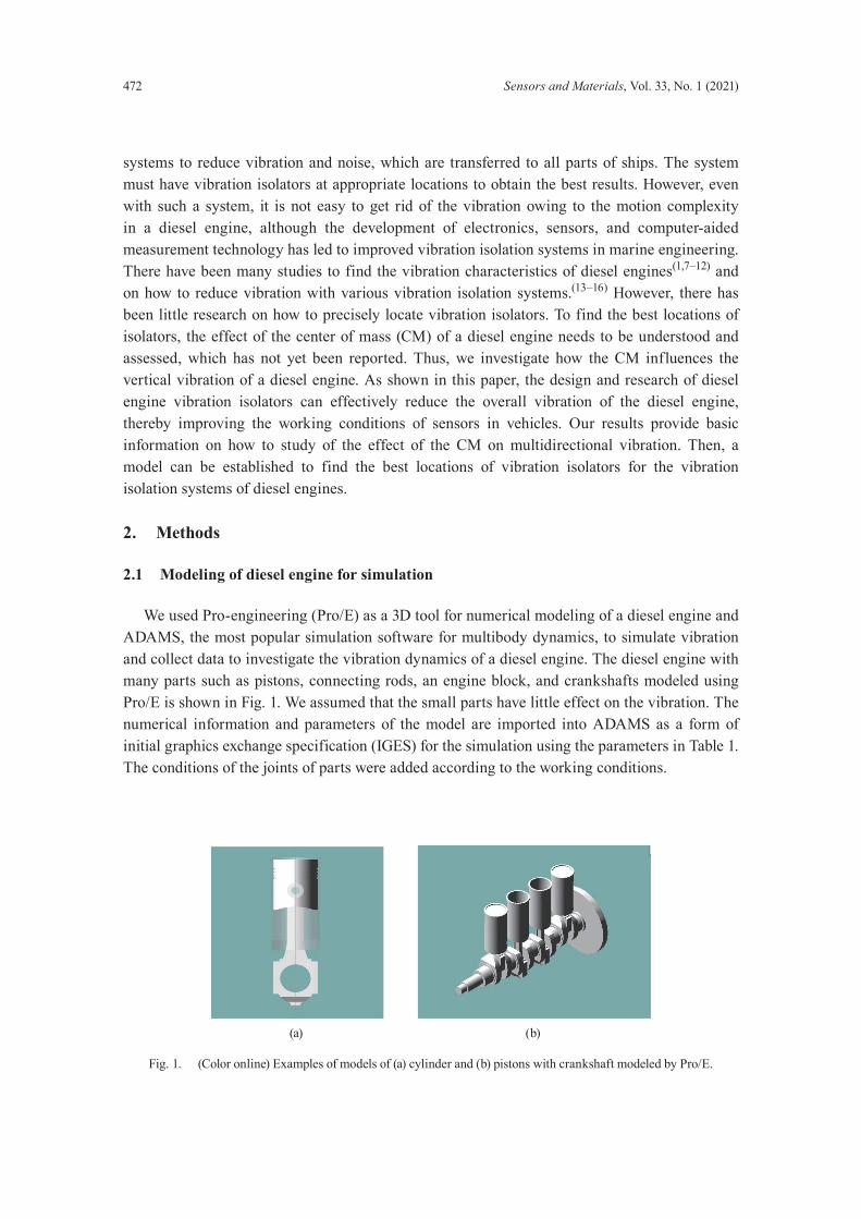
We used Pro-engineering (Pro/E) as a 3D tool for numerical modeling of a diesel engine and ADAMS, the most popular simulation software for multibody dynamics, to simulate vibration and collect data to investigate the vibration dynamics of a diesel engine. The diesel engine with many parts such as pistons, connecting rods, an engine block, and crankshafts modeled using Pro/E is shown in Fig. 1. We assumed that the small parts have little effect on the vibration. The numerical information and parameters of the model are imported into ADAMS as a form of initial graphics exchange specification (IGES) for the simulation using the parameters in Table 1. The conditions of the joints of parts were added according to the working conditions.
(a) (b)
Fig. 1. (Color online) Examples of models of (a) cylinder and (b) pistons with crankshaft modeled by Pro/E.
Sensors and Materials, Vol. 33, No. 1 (2021) 473
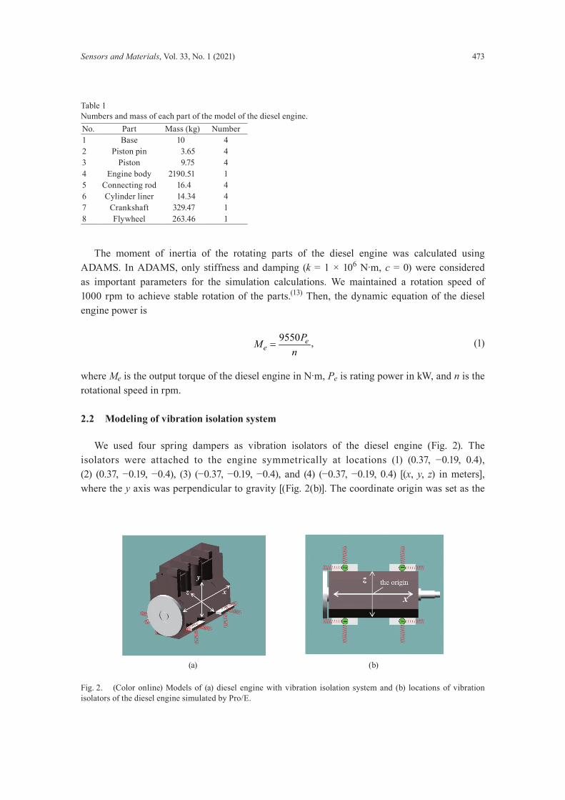
The moment of inertia of the rotating parts of the diesel engine was calculated using ADAMS. In ADAMS, only stiffness and damping (k = 1 × 10⁶ N·m, c = 0) were considered as important parameters for the simulation calculations. We maintained a rotation speed of 1000 rpm to achieve stable rotation of the parts.(13) Then, the dynamic equation of the diesel engine power is
9550 ee
PMn
= , (1)
where Me is the output torque of the diesel engine in N·m, Pe is rating power in kW, and n is the rotational speed in rpm.
2.2 Modeling of vibration isolation system
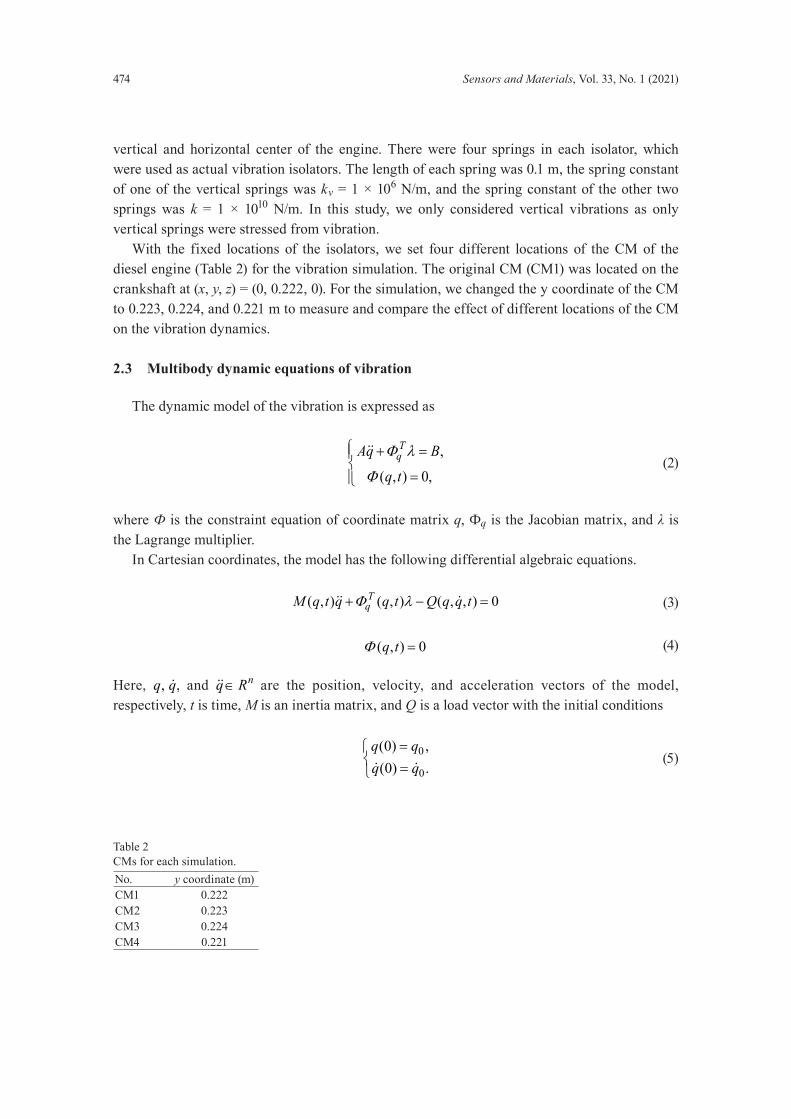
We used four spring dampers as vibration isolators of the diesel engine (Fig. 2). The isolators were attached to the engine symmetrically at locations (1) (0.37, −0.19, 0.4), (2) (0.37, −0.19, −0.4), (3) (−0.37, −0.19, −0.4), and (4) (−0.37, −0.19, 0.4) [(x, y, z) in meters], where the y axis was perpendicular to gravity [(Fig. 2(b)]. The coordinate origin was set as the
Table 1Numbers and mass of each part of the model of the diesel engine.No. Part Mass (kg) Number1 Base 10 42 Piston pin 3.65 43 Piston 9.75 44 Engine body 2190.51 15 Connecting rod 16.4 46 Cylinder liner 14.34 47 Crankshaft 329.47 18 Flywheel 263.46 1
(a) (b)
Fig. 2. (Color online) Models of (a) diesel engine with vibration isolation system and (b) locations of vibration isolators of the diesel engine simulated by Pro/E.
474 Sensors and Materials, Vol. 33, No. 1 (2021)
vertical and horizontal center of the engine. There were four springs in each isolator, which were used as actual vibration isolators. The length of each spring was 0.1 m, the spring constant of one of the vertical springs was kv = 1 × 10⁶ N/m, and the spring constant of the other two springs was k = 1 × 10¹⁰ N/m. In this study, we only considered vertical vibrations as only vertical springs were stressed from vibration. With the fixed locations of the isolators, we set four different locations of the CM of the diesel engine (Table 2) for the vibration simulation. The original CM (CM1) was located on the crankshaft at (x, y, z) = (0, 0.222, 0). For the simulation, we changed the y coordinate of the CM to 0.223, 0.224, and 0.221 m to measure and compare the effect of different locations of the CM on the vibration dynamics.
2.3 Multibody dynamic equations of vibration
The dynamic model of the vibration is expressed as
,
( , ) 0,
TqAq B
q t
Φ λ
Φ
+ =
=
(2)
where Ф is the constraint equation of coordinate matrix q, Фq is the Jacobian matrix, and λ is the Lagrange multiplier. In Cartesian coordinates, the model has the following differential algebraic equations.
( , ) ( , ) ( , , ) 0TqM q t q q t Q q q tΦ λ+ − = (3)
( , ) 0q tΦ = (4)
Here, , , nq q q R∈ and , , nq q q R∈ are the position, velocity, and acceleration vectors of the model, respectively, t is time, M is an inertia matrix, and Q is a load vector with the initial conditions
0
0
(0) ,(0) .
q qq q
= =
(5)
Table 2CMs for each simulation.No. y coordinate (m)CM1 0.222 CM2 0.223 CM3 0.224 CM4 0.221

Sensors and Materials, Vol. 33, No. 1 (2021) 475
3. Results and Discussion
3.1 Vertical movements of vibration isolators
To determine the effect of the CM of an engine body, we input the different CMs in Table 2 in the simulation and plotted periodic time-response curves with ADAMS. We repeated 1000 calculations for the first 2 s after the engine started. As shown in Fig. 3, different CMs of the engine body generated different vertical movements. The average vertical amplitudes of the engine were 0.788, 0.745, 0.787, and 0.746 mm for CM1, CM2, CM3, and CM4, respectively. CM2 had the least amplitude, which was 5.46% less than that of CM1, the original CM. The velocity of each of the four vertical springs in the isolators is shown in Fig. 4 and Table 3. The result showed that the velocity of each spring had periodicity but with different vibration patterns. In general, the velocities with CM2 were lower than those with the other CMs. CM4, the CM with the lowest vertical location, had springs with the highest velocities except for spring (2). The velocities of springs (1), (3), and (4) with CM2 were lower than those with the other CMs. Spring (2) with CM2 had a higher velocity than those with CM1, CM3, and CM4. Spring (3) with CM2 had the lowest velocity of 48.18 mm/s, only 54.3% of the velocity with CM4. Nevertheless, CM2, the CM at (0, 0.222, 0) (m) vibrated slower while CM4 at (0, 0.221, 0) (m) vibrated faster than the other CMs. It is not clear why spring (2) with CM2 and CM4 had higher and lower velocities, which is contrary to the results for the other springs with the other CMs.
3.2 Torque of vibration
Even though the amplitudes and velocities of the vertical movement of the springs are different in each location of the vibration isolators, the torques of the springs and their patterns are very similar. The calculated torques were ±206.71 N·m (CM1), ±207.27 N·m (CM2), ±207.68 N·m (CM3), and ±207.06 N·m (CM4). The difference among the torques was less than 0.47%. Figure 5 shows the torques of the diesel engine. The curves of the torques for each CM
Fig. 3. (Color online) Amplitudes of vertical movements of the engine with different CMs.

476 Sensors and Materials, Vol. 33, No. 1 (2021)
(a) (b)
(c) (d)
Fig. 4. (Color online) Velocity of vertical movements for each CM. (a) vertical spring of (1), (b) vertical spring of (2), (c) vertical spring of (3), and (d) vertical spring of (4).
Table 3Velocity of vertical springs (mm/s).Isolator CM1 CM2 CM3 CM4(1) 101.03 91.36 112.44 127.59(2) 89.66 99.20 95.57 74.04(3) 71.41 48.18 59.75 88.64(4) 124.57 113.42 126.93 133.05
Fig. 5. (Color online) Curves for torques for different CMs.
Sensors and Materials, Vol. 33, No. 1 (2021) 477
were periodic and similar to trigonometric curves. The torques for the different CMs showed almost identical patterns with slight differences at the top and bottom of the torque curves.
3.3 Acceleration of vibration in test
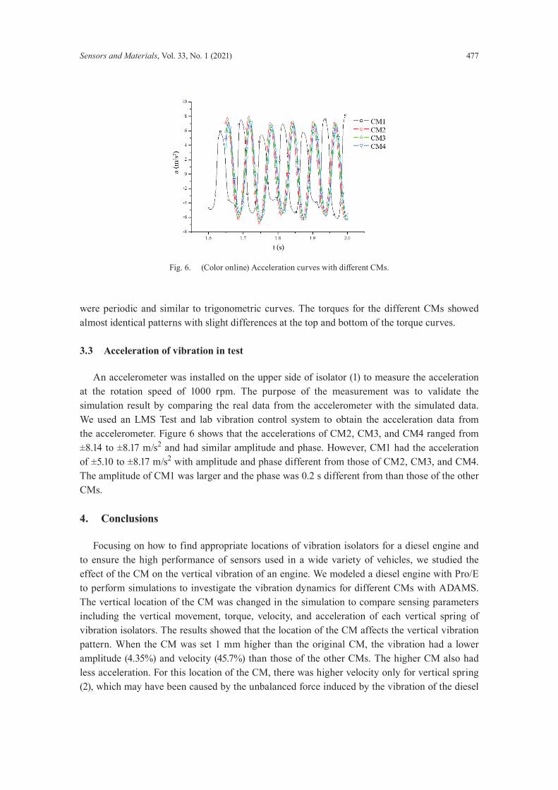
An accelerometer was installed on the upper side of isolator (1) to measure the acceleration at the rotation speed of 1000 rpm. The purpose of the measurement was to validate the simulation result by comparing the real data from the accelerometer with the simulated data. We used an LMS Test and lab vibration control system to obtain the acceleration data from the accelerometer. Figure 6 shows that the accelerations of CM2, CM3, and CM4 ranged from ±8.14 to ±8.17 m/s2 and had similar amplitude and phase. However, CM1 had the acceleration of ±5.10 to ±8.17 m/s2 with amplitude and phase different from those of CM2, CM3, and CM4. The amplitude of CM1 was larger and the phase was 0.2 s different from than those of the other CMs.
4. Conclusions
Focusing on how to find appropriate locations of vibration isolators for a diesel engine and to ensure the high performance of sensors used in a wide variety of vehicles, we studied the effect of the CM on the vertical vibration of an engine. We modeled a diesel engine with Pro/E to perform simulations to investigate the vibration dynamics for different CMs with ADAMS. The vertical location of the CM was changed in the simulation to compare sensing parameters including the vertical movement, torque, velocity, and acceleration of each vertical spring of vibration isolators. The results showed that the location of the CM affects the vertical vibration pattern. When the CM was set 1 mm higher than the original CM, the vibration had a lower amplitude (4.35%) and velocity (45.7%) than those of the other CMs. The higher CM also had less acceleration. For this location of the CM, there was higher velocity only for vertical spring (2), which may have been caused by the unbalanced force induced by the vibration of the diesel
Fig. 6. (Color online) Acceleration curves with different CMs.
478 Sensors and Materials, Vol. 33, No. 1 (2021)
engine. In this study, we considered the diesel engine vibration system as a whole. Although the location of the vibration isolator has been studied, the impact of the CM of the diesel engine and the vibration isolator on vibration is also an innovative feature of this study. The results of this study suggest that even though the original CM is considered in general, different locations of the CM must be simulated to find the best locations of isolators for diesel engines. Thus, to design the most appropriate vibration isolation system of a diesel engine, different locations of the CM must be considered. With the importance of the CM in vibration dynamics, it is necessary to study the multidirectional effect of the CM for the vibration isolation system and the causes of the unbalanced force induced by vibration. The results will improve the engineering model used to construct the vibration isolation systems of diesel engines and be beneficial for the operation of sensors in vehicles with diesel engines.
Acknowledgments
This research was carried out with the support of Fujian Province Key Laboratory of Ship and Ocean Engineering and Fujian Engineering Research Center of Marine Detecting and Remanufacturing. The authors gratefully acknowledge Fujian Science and Technology Projects (No. 2019H0020) and the National Fund Cultivation Program of Jimei University (No. 2P2020008).
References
1 Argonne National Laboratories: https://www.anl.gov/article/7-things-you-might-not-know-about-diesel (accessed May 2020).
2 X. Zhao, Y. Cheng, and S. Ji: Appl. Acoust. 116 (2017) 205. https://doi.org/10.1016/j.apacoust.2016.09.030 3 C. Xu, C. Wu, L. Liu, and Y. Wang: ICEP 1 (2019) 1. https://doi.org/10.19475/j.cnki.issn1674-957x.2019.01.004 4 J. Kambrath, Y. Wang, Y. Yoon, A. Alexander, X. Liu, C. Gajanayake, and A. Gupta: IEEE Trans. Transport.
Electrif. 4 (2018) 249. https://doi.org/10.1109/TTE.2017.2764324 5 S. Baek and D. Kim: IEEE Trans. Ind. Inf. 15 (2019) 922. https://doi.org/10.1109/TII.2018.2828856 6 A. Diez-Olivan, J. Pagan, N. Khoa, R. Sanz, and B. Sierra: Int. J. Adv. Manuf. Tech. 95 (2019) 327. https://doi.
org/10.1007/s00170-017-1204-2 7 J. Monieta: 2018 AIP Conf. Proc. (AIP, 2018) 1–11. https://doi.org/10.1063/1.5066506 8 E. Armentani, C. Francesco, E. Luca, G. Venanzio, and C. Roberto: Appl. Sci. 8 (2018) 1192. https://doi.
org/10.3390/app8071192 9 Z. Gao, Z. Jiang, and J. Zhang: Meas. Control 52 (2019) 1371. https://doi.org/10.1177/0020294019866851 10 X. Xie, X. Yu, and S. Zhu: J. Vib. Shock. 29 (2010). https://doi.org/10.13465/j.cnki.jvs.2010.03.008 11 X. Yang, H. Wu, B. Chen, S. Kang, and S. Cheng: J. Sound Vib. 439 (2019) 398. https://doi.org/10.1016/
j.jsv.2018.10.007 12 X. Du, Z. Li, F. Bi, J. Zhang, X. Wang, and K. Shao: J. Cent. South Univ. 19 (2012) 2238. https://doi.
org/10.1007/s11771-012-1268-y 13 A. Kovacs and R. Ibrahim: Nonlinear Dyn. 4 (1993) 635. https://doi.org/10.1007/BF00162235 14 J. Xi, Z. Feng, G. Wang, and F. Wang: J. Mech. Sci. Technol. 29 (2015) 181. https://doi.org/10.1007/s12206-014-
1225-9 15 R. Jin and W. Chen: Mach. Build. Auto. 41 (2012). https://doi.org/10.19344/j.cnki.issn1671-5276.2012.06.034 16 M. Milanese, M. Knauer, G. Colangelo, D. Laforgia, and A. DeRisi: Energy Proc. 126 (2017) 1075. https://doi.
org/10.1016/j.egypro.2017.08.238