Eddy-Current Array Probes for Steam Generator Tube Inspection
90
NUREGICR-6357 ORNL/TM-13213 Evaluation and Field Validation of Eddy-Current Array Probes for Steam Generator Tube Inspection Prepared by C. V. Dodd, J. R. Pate Oak Ridge National Laboratory Prepared for U. S . Nuclear Regulatory Commission
-
Upload
khangminh22 -
Category
Documents
-
view
1 -
download
0
Transcript of Eddy-Current Array Probes for Steam Generator Tube Inspection

NUREGICR-6357 ORNL/TM-13213
Evaluation and Field Validation of Eddy-Current Array Probes for Steam Generator Tube Inspection
Prepared by C. V. Dodd, J. R. Pate
Oak Ridge National Laboratory
Prepared for U. S . Nuclear Regula tory Commission

AVAILABILITY NOTICE
Availabilii of Reference Materials Cited in NRC Publications
Most documents cited In NRC publications will be available from one of the following sources: 1. The NRC Public Document Room, 2120 L Street, NW.. Lower Level. Washington, DC 20555-0001
2. The Superintendent of Documents, U S . Government Printing Office, P. 0. Box 37082, Washington. DC 20402-9328
3. The Natlonal Technical Information Service, Springfield, VA 221 61 -0002
Although the listing that follows represents the majority of documents cited in NRC publications, it is not in- tended to b e exhaustlve.
Referenced documents available for inspection and copying for a fee from the NRC Public Document Room include NRC correspondence and internal N R C memoranda: NRC bulletins, circulars. information notices, in- spection and investigation notices: licensee event reports; vendor reports and correspondence: Commission papers: and applicant and licensee documents and correspondence.
The following documents In the NUREG series a r e available for purchase from the Government Printing Office: formal NRC staff and contractor reports, NRC-sponsored conference proceedings, international agreement reports, grantee reports. and NRC booklets and brochures. Also available a r e regulatory guides, NRC regula- tions In the Code of Federal Regulations, and Nuclear Regulatory Commission Issuances.
Documents available from the National Technical Information Service include NUREG-series reports and tech- nlcal reports prepared by other Federal agencies and reports prepared by t h e Atomic Energy Commission, forerunner agency to the Nuclear Regulatory Commission.
Documents available from public and special technical libraries include all open literature items, such as books. journal articles. and transactions. Federal Register notices. Federal and Sta te legislation, and congressional reports can usually be obtained from these libraries.
Documents such as theses , dissertations. foreign reports and translations, and non-NRC conference pro- ceedings a r e available for purchase from the organization sponsoring the publication cited.
Single copies of NRC draft reports are available free. to the extent of supply. upon written request to the Office of Admlnlstratlon, Distribution and Mail Services Section, U.S. Nuclear Regulatory Commission, Washington. DC 20555-0001.
Coples of Industry codes and standards used in a substantive manner in the NRC regulatory process are maln- tained at the NRC Library. Two White Flint North. 11545 Rockville Pike. Rockville. MD 20852-2738, for use by the public. Codes and standards a re usually copyrighted and may be purchased from the originating organlza- t l O n or, if they are American National Standards. from the American National Standards Institute, 1430 Broad- way, New York, NY 10018-3308.
DISCLAIMER NOTICE
This report was prepared as an account of work sponsored by an agency of the United States Government. Neitherthe United States Government nor any agency thereof, norany of theiremployees, makes any warranty, expressed or implied, or assumes any legal liability or responsibility for any third party’s use, or the results of such use, of any information, apparatus, product, or process disclosed in this report, or represents that its use by such third party would not infringe privately owned rights.
. -- -- -

DISCLAlMER
Portions of this document may be illegible in electronic image products. Images are produced from the best available original document.


NUREGICR-6357 ORNL/TM-13213
Evaluation and Field Validation of Eddy-Current Array Probes for Steam Generator Tube Inspection
Manuscript Completed: October 1994 Date Published: July 1996
Prepared by C. V Dodd, J. R. Pate
Oak Ridge National Laboratory Managed by Lockheed Martin Energy Research Cnmoration
DISCLAIMER


Abstract
The objective of the Improved Eddy-Current IS1 for Steam Generator Tubing program is to upgrade and validate eddy-current inspections, including probes, instrumentation, and data processing techniques for inservice inspection of new, used, and repaired steam generator tubes; to improve defect detection, classification, and characterization as affected by diameter and thickness variations, denting, probe wobble, tube sheet, tube supports, copper and sludge deposits, even when defect types and other variables occur in combination; to transfer this advanced technology to NRC's mobile NDE laboratory and staff. This report describes the design of specialized high-speed 16-coil eddy-current array probes. Both pancake and reflection coils are considered. Test results from inspections using the probes in working steam generators are given. Computer programs developed for probe calculations are also supplied.


Contents
Abstract ............................................................................................................................................ Introduction ...................................................................................................................................... Array probe design ............................................................................................................................ Individual coil design ......................................................................................................................... Instrumentation ................................................................................................................................. Prairie Island test results for array probes . first test ............................................................................... Speed trial studies ............................................................................................................................ Prairie Island test results for array probes . second text ......................................................................... Appendix A: Computation of eddy-current signals for a pancake coil ................................................... Appendix B: Computation of eddy-current signals for a reflection coil .................................................. Appendix C: Least squares program ................................................................................................. Appendix D: Neural network program ................................................................................................
6
7
a
9
10
Figures
The 16-coil array probe ....................................................................................................... A cross section of the array probe ........................................................................................ Pancake coil and electrical connections ............................................................................... Reflection coil above a flat plate ........................................................................................... Variation in normalized coil impedance for different values of coil cross-section ............................................................................................................ Defect signal for a far-side defect ......................................................................................... Magnitude of defect signals for coils of different sizes ........................................................... ......................................................................................................................................... Field uniformity comparison ................................................................................................
Paae
iii
1
2
3
a
9
13
13
19
35
51
61
Paae
2
2
3
3
4
5
5
7
7
Shaped coils ...................................................................................................................... a V NUREG/CR-6357
...... ........... . . . . ~~~~ . . ~ ~~

11
12
13
14
15
Circumferential groove standard .......................................................................................... Bobbin probe scan of tube row 35 Column 30 using Zetec Eddynet software ............................................................................................................... Pancake array scan of tube Row 35 Column 30 showing three indications ................................................................................................................ The vertical component of the 260 kHz data from the reflection array probe at tube support 01 H in tube R43C59 in steam generator 12 ................................. The vertical component of the 260 kHz reflection array probe from tube support 01 H in tube R43C59 of steam generator 12 with the tube support suppression mix applied ...........................................................................
NUREG/CR-6357 vi
Paae
10
11
13
16
17
Evaluation and Field Validation of Eddy-Current Array Probes for Steam Generator Tube Inspection
C. V. Dodd and J. R. Pate
Introduction As the nation's steam generators have aged, new mechanisms for the degradation of steam
generator tubes have appeared, and the frequency of forced outages due to major tube leak events has increased. To ensure that tube degradation is detected before it leads to a forced outage, h will be necessary to inspect during each outage a large number of the tubes in each steam generator using a technique which is sensitive to all forms of degradation. The primary method for the inspection of steam generator tubing is eddy-current testing, and while eddy-current testing can be used to perform a fast and reliable inspection, the eddy-current techniques currently being used for steam generator inspection are no longer adequate for.the needs of the nuclear power industry.
generator tubing. The probe consists of a pair of circumferentially-wound coils which are pulled through the tube at speeds of up to 40 inches per second, acquiring data as they travel. The probe's high speed and complete coverage of the tube circumference have made it a favorite of utilities with a tight outage schedule. However, since the probe induces eddy-currents in the tube wall with components only in the circumferential direction, the bobbin probe is not sensitive to circumferential cracks because these will not interrupt the flow of the induced currents. Furthermore, since the probe looks at the entire tube circumference at one time, the ability to use bobbin probe data to distinguish between cracks and volumetric flaws is limited.
To overcome the sensitivity limitations of the bobbin probe, the rotating pancake probe (RPC) was introduced. The RPC consists of one or more small coils pressed against the inner surface of the tube wall. In order to inspect the entire circumference of the tube, it is necessary to rotate the coil as it is pulled through the tube. Unfortunately, this means that the RPC is quite slow, with an inspection speed of only 0.2 in per second. This is clearly too slow to inspect the large numbers of tubes that should be inspected, and utilities avoid this type of inspection when at all possible. The result has been forced outages for tube leaks. Plants such as Palo Verde 2, have had outages lasting several months while long sections of tubes were inspected using the RPC.
Clearly a new probe design which combines the speed of the bobbin probe with the sensitivity of the RPC is needed to ensure the detection of all types of defects and to improve the ability to characterize defects. Toward this end, ORNL has developed a 16-coil eddy-current array probe. This probe consists of 16 small coils pressed against the inner surface of the tube and distributed about its circumference. The data obtained with this probe are similar in nature to those from the RPC, allowing detection of cracks of any orientation, but since it is not necessary to rotate the probe to achieve full coverage of the tube circumference, inspection speeds approaching those of the bobbin coil are possible.
The bobbin probe has traditionally been the primary method for the inspection of steam

Array Probe Design
The eddy-current array probes developed by ORNL consist of 16 small coils pressed against the inner surface of the tube as shown in Figure 1. The coils are divided into two
I
Figure 1 The 16-coil array probe
groups of eight coils each with the two groups being separated by a distance of approximately 4.5 inches in the axial direction. Each coil is mounted in an individual spring-loaded shoe to keep the coil pressed against the inner surface of the tube, which has a diameter of 0.775 inches, but if necessary the shoe will retract, allowing the probe to pass through a tube of diameter 0.720 inches. This makes it possible to inspect tubes with a significant amount of denting.
of the groups of eight coils. Neighboring coils in the same group are separated by 45 degrees in the circumferential direction. The coils in one group are centered in the regions between the coils in the other, resulting in there being 22.5 degrees between adjacent coils.
Figure 2 shows a cross section of one
+
Figure 2 A cross section of the array probe
NUREG/CR-6357 2

While the array probe has been designed for and tested in only straight sections of tubes with an outer diameter of 7/8 inches, Zetec, the company which manufactured the probe, feels that the probe can be constructed to inspect the U-bends of the tubes and that it can be scaled to inspect tubes with an outer diameter of 3/4 inches.
Individual Coil Design
The individual coils which make up the 16-coil array probe were designed to maximize sensitivity to small defects on the outer diameter of the tube. Two array probes with different types of coils were designed and constructed; one probe contained the commonly used pancake coil, and the other contained reflection coils. Figure 3 shows a pancake coil and its electrical circuit. The pancake coil is used as the test coil in a typical bridge circuit, and a second identical coil placed is in a reference tube. The voltage measured is the difference between the test and reference signals, and since the probes will be nearly balanced, the signal can be amplified, increasing the sensitivity to small changes in the part being tested.
In Figure 4 we show a reflection coil and its electrical connections. The reflection coil consists of a driver coil which is used to induce eddy currents in the part being tested, and two smaller pickup coils in which a voltage is induced by the eddy currents in the part. The reflection coil can be designed in such a way to offer better discrimination to lift-off, the distance between the coil and the test part, than can be obtained with the pancake coil, and it therefore has a significant advantage over the pancake coil for steam generator inspection. The reflection coil circuit is similar to an induction bridge which is widely used for many types of highly accurate measurements.
the types of coils in order to maximize their Design studies were done for both of
n
Electrical Connections Figure 3 Pancake coil and electrical connect ions
Driver coil
Pickup coils
6 Pickup Coils >
Electrical circuit
Figure 4 Reflection coil above a flat plate
3 NUREG/CR-6357

sensitivity to small defects on the far side of the tube wall and to minimize the effects of other variables. For the purpose of the design study, we considered the tube wall to be a flat plate. The first consideration was to make the coils as flat as was practical. Figure 5 illustrates how the normalized coil impedance depends on the shape of the coil cross section. From the figure it is evident that for a given value of the quantity o p d , the product of the inspection frequency, tube conductivity, tube permeability, and coil mean radius squared, increasing coil flatness increases the coil impedance change from its air value. Therefore, the coil is more sensitive to the properties of the part being tested when its turns are as close to the part as possible. There is a limit on the coil flatness, however, since if the coil is made too thin, its dc resistance becomes too high. In addition, the small defects that we wish to measure are usually on the far side of the conductor, so that the absolute flatness is not critical. It is recognized that as coils become flatter, the sensitivity to lift-off, conductivity variations, and other conductor property variations will also increase, but
1 .o Lu- 0.9
t- 2 ' W 0.8
r H 0.7
r $ 0.6 a
0.5
0.4
0.3
ORNL-DWG 71- I1842
CROSS SECTION SYMBOLS
0.2 ' I I I I I I
RESISTIVE COMPONENT
Figure 5 Variation in normalized coil impedance for different values of coil cross-section
other methods will be used to reduce these effects. A number of different pancake and reflection coil designs were tested using both analytical
calculations and experimental measurements. The model used for most of the calculations was a point defect or a very small spherical defect. The reasoning was that if we could optimize for the smallest defects, detection of the larger ones would also be accomplished. Also, the mathematical model used for most of the calculations is only valid for small defects.
NU REG/CR-6357 4

In Figure 6 we show the calculations of the impedance change for the P90 pancake coil due to a point defect on the far side of a conducting plate as a function of the defect radial location for several different test fiequencies. Notice that there is an optimum fiequency for maximum sensitivity and an optimum radius. This gives an indication of the field spread of the coil.
We show in Figure 7 a plot of the defect signal for different size coils as a function of the distance fiom the center of the coil. The outer diameter of the coils was fixed at 0.240 inches by the size of the shoe in which the coil was mounted, and the inner radius was varied fiom Q.0 to 0.16 inches, causing the mean radius of the coil to vary fiom 0.06 to 0.1 inches. Both the maximum sensitivity and the radial distance at which the maximum sensitivity occurs vary with coil size. The maximum sensitivity occurs for the P75 at a radius of 0.080 inches, and for the P90 it occurs at 0.0875 inches. While the maximum sensitivity of the P90 is slightly less than that of the P75, the greater field spread of the P90 means that it is to be preferred for use in the array coil. Both the P75 and P90 coils were built and tested, and the results were similar to those expected.
A comparison study was performed between the reflection and pancake coils to measure the defect depth in the presence of other property variations. The signals fiom the pancake and reflection coils were computed using the programs IMPTST and MULRFD, respectively. Property variations (in the file NRCPRO.DAT) include a lift-off variation of 0.010 inches, tube wall thickness values of 0.050 inches, 0.040 inches, and 0.030 inches, and defect depth values of 0.000 inches, 0.005 inches, 0.010 inches, and 0.015 inches, with copper deposits, tube supports, and magnetite deposits on the outside of the tube at various locations. The copper was placed at 15 locations, the tube support at 12 locations, and the magnetite at 12 locations, for a total of 39 OD artifact property values. For each of these artifact property values there are four defect depth
- H 3.- $ 3 . m
3.1-
3.1004 L
3 3 . w
Dcfcct Signal at DHelcrrnt Frqucnckr for Coil WB
. . . .,....,....,.. n Figure 6 Defect signal for a far-side defect
Magnitude of Defect Signal for Different Coils
3.35e-54 0 .
P60E PIOB PIS HWB P90B PlOOB
f 0.070 0.075 0.080 0.085 0.090 0.085 0.100 O..-J
DlrturCClrolCCIl*otcdl(h)
Figure 7 Magnitude of defect signals for coils of different sizes
5 NUREG/CR-6357

values and five lift-off values, for a total of 780 property combinations. The frequencies were varied fiom 10 kHz to 1 MHz in a 1,2,5 sequence. The property variations for each of the three types of OD artifacts are summarized below.
Region
1
2
3
4
Material
Copper
Air
Inconel
Coil
I Region
1
2
3
4
Material
Tube Support
Air
Inconel
Coil
Thickness
Region
1
Infinite
Material Thickness
Magnetite Infinite
0.5, 0.005, 0.003, 0.001
0.050,0.040, 0.030
2
3
Thickness
Air 0.005, 0.003, 0.0001
Inconel 0.050, 0.040, 0.030
Infinite
0.005, 0.003, 0.0001
0.050, 0.040, 0.030
I I I
14 I Coil I
The best combination of three frequencies was chosen from the six frequencies used by running the program FINDFIT on the data for both coil types. Although this is only an approximation of the complexity of an actual problem, it does give an indication of how the multiple property fits can work without requiring an excessive amount of computer time. FINDFIT computes the best least squares fit of the property variations to the computed readings.
NUREG/CR-6357 6

In Figure 8 we show the results of the error in the measurement of defect depth for both the pancake and reflection coils. The defect depth measurement error is the R M S of the fit error and the drift error, and it is measured in percent of wall thickness. For both types of coils, the fit error dominates. The-neural net analysis techniques would probably give a better fit with no significant increase in the drift. From this comparison, the reflection coil seems to offer a significant advantage over the pancake coil.
Another important factor is the ability of the coils to cover the entire circumference of the tube. To measure this ability the probes were used to scan an axial EDM notch of
2 a ; 5
a 5 -
ur 6 -
2 c n
4 I 1 I 1 1 1
0
Relledi ind
P n $1 02 - 4 Y
a 0.1 - a - c M iij 0.0
0.02 0.03 0.0) 0.05 0.06 0.07 0.08 0.09
Coil Mean Radius (in.)
Reflection Coils
R60
1 I I I 1
depth 40% of wall thickness and length 0.25 inches. The scan was conducted once with the center of the coil passing directly over the notch, and then it was repeated with an angle of 12 degrees between the center of the coil and the notch. The ratio of the response to the defect when the probe is at 12 degrees to the response when the probe is at 0 degrees is plotted in Figure 9. The figure shows that the sensitivity of the P90 is much more uniform than that of the P7 or the P60, and that the pancake coils have greater field uniformity than the reflection coils.
The zero lift-off, or the distance between the coil and the inner surface of tube, will also have an effect on the sensitivity to. small defects on the far side of the tube wall. Both the sensitivity to and the resolution for small defects increases as the zero lift- off decreases. It is therefore best
Field Spread Plot
0.04 0.05 0.06 0.07 0.08 0.09 0.10
Average Coil Radius
Figure 9 Field uniformity comparison
NUREG/CR-6357 7

to get the coil as close to the tube wall as is practical. Ifthe coil is flat, the curvature of the tube increases the distance between the coil and the tube wall. One method of reducing this distance is to contour the coil to conform to the curvature of the tube, as shown in Figure 10. Coils of two different shapes were used, one with the coil cylindrically shaped to fit the tube wall, and another with the coil spherically shaped. The cylindrically shaped coil has smaller zero lift-off, but it appears
Side View End View Side View Spherically Shaped Both Coils Cylindrically Shaped
to be very slightly more I susceptible to lift-off effects than Figure 10 Shaped Coils the spherically shaped coil. The spherically shaped coil was also easier to fabricate. An attempt was made to build a cylindrically shaped reflection probe, but it was not successfbl.
turns is a compromise between the ratio of the dc coil impedance changes to the ac impedance changes and the effects of probe wire capacitance. It is desirable (but not always possible) to have a low cable capacitance between the instrument and the probe so that the probe operates well below its resonant frequency because near the coil resonance a 5 pF change in capacitance will lead to a signal change as large as that produced by a through-wall hole. For a 16-coil pancake array probe, 16 coaxial connections are needed, and for a 16-coil reflection array probe, 32 coaxial connections are needed. The initial reflection array probes were built using cable of capacitance 26 pF per foot. Since that time, cable with a capacitance of 20 pF per foot has been found for the reflection array, and cable with a capacitance of 17 pF per foot has been found for the pancake array probe. The inductance of the coils is about 50 to 90 microhenries so that with
above the highest test frequency we have used in the field validation of the probes. The number of layers in the coil, the number of turns per layer, and the wire gage are computed by the program AIRCO.
As a final consideration the number of turns in the coil was determined. The number of
' 110 feet of low-loss cable, the resonant frequency can be as high as 650 kHz, which is slightly
Instrumentation
The MIZ-30 eddy-current instrument was designed and constructed by Zetec specifically for array probe inspections. It is a high-speed multiple-frequency digital instrument that can drive 16 individual coils in either a bridge arrangement with a reference probe or in a transmit-receive mode for the reflection coils. It is capable of taking 500 readings per second for all 16 coils at four frequencies. The gain and hardware null are also software adjustable. A Hewlett Packard workstation is used to control the instrument over a local area network. The configuration of the instrument is set by the acquisition operator. The configuration can be entered manually or a data file containing the setup information can be transmitted over the LAN from any other workstation on the network and stored in the appropriate file. The configuration file can contain the setup
NU REG/CR-6357 8

information for up to 16 different types of inspections. The probe is positioned on the face of the tubesheet (a Zetec SM-22 was used for the Prairie Island tests), and the probe pushed into the tube and then the probe pulled as the data are acquired and recorded. Up to 16 channels can be displayed so that the acquisition operator can veri@ that all the channels of the probe are working and can tell where the probe is in the tube. However, with the amount of data to be processed when all 16 channels were displayed, the computer lagged too far behind the actual probe motion so that it was much better to display only one channel most ofthe time. The acquisition computer also controlled the probe positioning and insertion, which lagged too far behind when the 16 channels were displayed. This problem is considerable when using a 700 series workstation.
Prairie Island test results for array probes - first test
The array probes were first tested at the Prairie Island Unit 2 steam generators on November 14, 1993. The system wds assembled and tested on the Prairie Island mock-up the week before it was tested in the generators. The acquisition operators were not familiar with the MIZ-30, and some instructions were necessary before the acquisition programs could be successfilly run. The probe pusher-pullers were designed to drive 3/8 inch diameter polyurethane cable into the tubing, and since the array probes use 1/2 inch diameter cable, a modification had to be made to the pusher-puller before it would drive the array probe cable. A special part had to be machined and another part had to be removed. One of the twister cables was discovered to be bad, and personnel from Conam, the company which performed the acquisition and primary analysis of the eddy-current data at Prairie Island, repaired it. Conam also suggested that we add enough extension cable (10 feet) to allow the MIZ-30 to be moved to an area with lower contamination, which we did.
The MIZ-30 and the cables were installed in the generator on Sunday morning, November 14. The pusher-puller in the steam generator had to be modified in the same manner as the one in the mock-up. Unfortunately, due to the contamination and other problems, it was much more difficult to modi@, and the probe speed was limited to 15 inches per second by mechanical considerations.
current inspection which had been completed. The reflection array probe was tested first. The gain in the original design of the MIZ-30 was not as high as was needed to obtain the best results with this type of coil, and the signal-to-noise ratio for the reflection was thus about the same as that for the Zetec rotating pancake coil (RPC). The pancake array with spherically shaped P60 coils was then tested. The signal level for this probe was greater than that for the Zetec RPC by a factor of 5 to 10 for the same gain setting. The data fiom the various coils were reviewed by Gary Henry of EPRI, who determined that the signal-to-noise ratio of the pancake array probe was higher than that of the Zetec RPC by about a factor of 5.
A set of 48 tubes was selected for inspection based on the results of the regular eddy-
9 NU REG/CR-6357

In order to do improved signal analysis a circumferential groove standard had to be used to calibrate each coil in the probe. Figure 11 shows a drawing of the standard used. The grooves
7 0.008 in. /-Ferrite Ring Copper Ring
Figure 11 Circumferential groove standard
extend all the way around the circumference of the tube and have depths of 20%, 40%, 60%, 80% and 100% of wall thickness. In addition to the grooves the standard contained a ferrite ring (to simulate a magnetite deposit), a tube support ring, and a copper ring. Scanning the standard allowed us to perform mixes for the suppression of tube supports, magnetite, and copper. The data were analyzed at the site using the Zetec analysis software by analysts from Conam and Zetec. The data were also analyzed using the ORNL analysis software. Since the ORNL software was developed especially for array probe data, it is less cumbersome to use to perform mixes and other tasks. In general the array probes detected all indications that the bobbin coil detected. There were some calls made with the ORNL array probes that were not made with the bobbin coil, but these were all quite small and harmless. There were some indications at the tube supports, but none were judged to be serious. Figure 12 shows the bobbin coil scan of a section of tube R35C30 and Figure 13 shows a'plot of the pancake array probe data from the same section of the tube. There appear to be three small defects just above the tubesheet.
NUREG/CR-6357 10

Tube Comment 3 D I = Unkni Lancharks
TEH-
TSH-
OlH-
n Calr = SG2lH 1: 400 DIFF
P
lL00020 SRT 5 3: 400 RBSL
Vert
...................... r
4:02 NOV-13-93 SC 21 RW 35 COL 30 ID 246 Next-Last 1: 400 DIFF
0.25 u/d span 4 r o t 294
Refresh
ITzEl I 30 10 I L i z Chan
OlH
................ ). .......... Figure 12 Bobbin probe scan of tube row 35 column 30 using Zetec Eddynet software
NUREG/CR-6357

Figure 13 Pancake array scan of tube Row 35 Column 30 showing three indications
NUREG/CR-6357 12
Speed trial studies
Near the end of the test, a special production test was run. In order to simulate the production inspection conditions, two adjacent tubes from the test group were selected. The probe was inserted in one tube after the other, alternating between the tubes. This simulated the conditions that would obtain if the tubes were being tested by going in a straight line down a row of tubes. A total of 17 inspections were performed at a rate of 68 seconds per tube or 53 tubes per hour for inspection of 30 feet of tubing. In these tests the insertion speed was limited to 15 inches per second due to mechanical problems. An insertion speed of 40 inches per second would improve the inspection rate by 20 percent to 68 tubes per hour. The array probes were tested at a pull speed of 15 inches per second, which is about 75 times faster then the pull speed (0.2 inches per second) of the RPC. At this pull speed there was more than adequate resolution.
Prairie Island test results for array probes - second test
The second test at Prairie Island was conducted on the steam generators of Unit 1 on Saturday, May 29, 1994. The plan was to perform an eddy-current test on selected tubes using the contaminated pancake and reflection array probes that had been stored at the plant since they were used in the inspection of Unit 2 in November 1993. Uncontaminated probes and cables were sent directly to Prairie Island from Zetec (where our MIZ-30 had been upgraded). Upon its arrival, the instrument was checked out with both types of array probes. The reflection probe exhibited a "touch effect", in which the signal changed if the connectors were touched. This had been noticed during development and checkout at Zetec, and it was found that if the connectors were wrapped in bubble padding, the effect disappeared.
tested at Zetec and all of the channels had been working properly then. The problem was traced to one of the extension cables (two are required for the pancake array probes) and this cable was repaired. A Conam technician examined the connectors and said that one of them was not wired well. He repaired the lead and broke two more in the process and then fixed those. The probes were then tested, and it was found that all channels were working. The data obtained on standard runs looked very good for both probes, and the signal-to-noise ratio appeared to be about the same for the reflection and pancake array probes.
There was a delay of several days due to problems in getting access to the generators, problems in setting up for the production eddy-current inspections, and problems in data acquisition over the network used for these tests. The problems were finally resolved, but only after a delay of several days. The ORNL inspection, which came at the end of the other eddy- current tests, was delayed from Monday until 3:OO a.m. Saturday.
During this time extensive testing and mixing with both types of array probes were performed. One important discovery was that a better mix was obtained if the femte ring was placed directly against the tube support ring, to simulate magnetite adjacent to the support. The mixes obtained using this showed very little residual and very little distortion of the 20% defect. Preliminary results using the Zetec mix showed that scans of the actual tube had very little
One of the channels of the pancake array probe was not working. This probe had been
13 NU REG/CR-6357

residual, and that small defects at the tube supports could be easily detected. The ORNL analysis program would not run on the data due to an upgrade that Zetec had made in their software.
Our acquisition window was only 12 hours, which included the time necessary to make modifications to the pusher-puller and the time required to run the cable. We used a ten foot twister cable and a 50 foot extension cable for both probes. The data were evaluated at Prairie Island by the Conam analysts. The data fiom Unit 1, which is older than Unit 2, showed many more magnetite deposits. The pancake array probe had one channel missing. It was not possible to tell if the missing channel was due to another broken connection in the extension cable or if the contaminated array probe used in the previous inspection had a broken coil. Due to the fact that we already had problems with the extension cable we decided not to contaminate our spare probe. Therefore, the test of the pancake array probe was run with only 15 of the 16 coils working. In spite of the high cost of extension cables, fbture inspections should-be performed with at least one spare set of all cables and probes.
we had at the first inspection. In addition, the computer (a Hewlett Packard 700 series workstation) used was fast enough to take the data and send it to the analysis building in very near real time. While the program did abort twice at the start of the test, for the remainder of the test we had no problems. However, we experienced problems with the SM-22 positioner. It seemed to lose its location on the generator after about the first hour of testing. This required extensive time to locate plugs and other artifacts to veri@ the position of the tubes. It is possible that some of the tubes scanned were not the ones indicated, although the operators used every reasonable precaution.
The new MIZ-30 appears to give good, low-noise data. We were able to copy the setup file for the MIZ-30 acquisition which had been prepared earlier fiom an optical disk into the proper directory (named /miz3Od) on the acquisition computer and rename it so that it was used for the acquisition. It would have been faster to do this over the LAN, but the operator who knew how to do it was not on duty at the time. Copying the setup file saved a great deal of time that would have been required to type in the proper settings and also reduced the chances of making an error. However, the setup for the individual coils in the array probe did not match since we used the old, contaminated probes that were used in the last outage rather than the similar but not identical ones that were used for testing before the inspection. The setup for the individual channels is obtained from the acquisition header, and if the correct individual values are used, that data analyst does not have to reset these. With 16 coils for each of the four fiequencies, the setup time can be considerable using the Zetec software. Any mixes that are used require considerable time with the Zetec software. The scan of the tubing in the generator had a larger lift-off variation than we encountered in the scans of the standard, which made the data appear noisy at first. When the proper adjustments were made, the problem was corrected.
The ORNL analysis program was modified to match the new Zetec acquisition format and the data were analyzed at ORNL. In general, the array probes were able to detect all of the defects that the bobbin and RPC inspections showed. Figure 14 shows the vertical component of the reflection array probe data taken at 260 kHz at tube support 01H of tube R43C59 in steam
Fifty tubes were selected to be tested with both the reflection and pancake array probes.
-
We did not experience as much difficulty in getting the pusher-puller to drive the cable as
Several valuable lessons were obtained fiom the tests at a small cost to our programs.
,
NUREG/CR-6357 14

generator 12. The dark horizontal band across the plot is the tube support, and the bright spot near the center of the graph appears to be a defect. Figure 15 shows the same data with the tube support suppression mix applied. Here we see that the dark band representing the tube support has been eliminated while the bright spot has been amplified, indicating that it is indeed a defect.

2 4 6 8 10 12 14 16
Circumferential direction Figure 14 The vertical component of the 260 kHz data from the reflection array probe at tube support 01H in tube R43C59 in steam generator 12.
NUREG/CR-6357 16

40
20
10
2 4 6 8 10 12 14 16
Circumferential direct ion
' I . . , ' 7 - . ' . 1 ' ' I
Figure 15 The vertical component of the 260 lcHz reflection may probe data from tube support 01H in tube R43C59 of steam generator 12 with the tube support suppression mix applied.
17 NUREG/CR-6357


APPENDIX A


Appendix A: Computation of eddy-current signals for a pancake coil
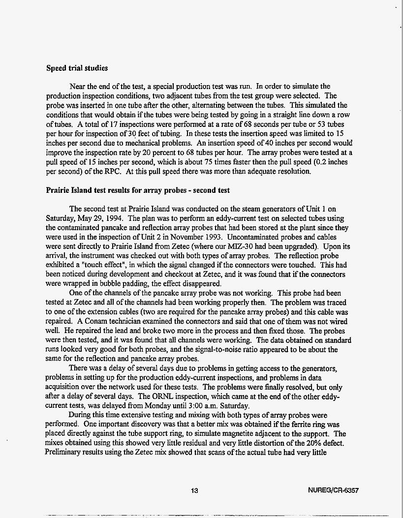
The program IMPTST.F calculates the impedance change of a pancake coil in response to a defect in a flat plate. The program is very similar to ones described in an earlier report. The program is listed below.
C C C C C C C C C C C C C C C C C C C C C C C C C C C C C C C C C C C C C C C C C
C C C C C C C C C C C C C
PROGRAM TSTIMP
August 9, 1994 VERSION, CALCULATES IMPEDANCE FOR A SINGLE COIL. CORRECTED FOR BURROWS DEFECT ERROR WLTI-LAYER PROGRAMS ORNL/TM-6858 AND IN ORNL-TM-4107, PP. 8-23. ALL COHPLEX OPERATIONS HAVE BEEN ELIMINATED, AND THE PROGRW NOU CALCULATES THE MAGNITUDES AND PHASES FOR ALL NPT SETS OF PROPERTIES. VARIATIONS IN THICKNESS,RESISTIVITY AND DEFECTS ARE ALLOWED. THE FREQUENCY CAN BE VARIED OVER NFT AND THE LIFT-OFF VARIED OVER NLT DIFFERENT VALUES. UHEN A DEFECT IS INCLUDED THE MAGNITUDE AHD PHASE UILL BE CALCULATED UITH AND WITHOUT THE DEFECT. NO ADDITIONAL SET OF PROPERTY VALUES (NPT) UITHOUT THE DEFECT IS NEEDED, BUT NPTT IS INCREASED. NUMERICAL VALUE OF THE SUBSCRIPT W S T BE SUBSTITUTED IN FOR THE SUBSCRIPT NAME IN THE DIMENSION STATEMENTS IN LINES 59-73. defect depths are modified for far side defects with small c a l l options have been removed. Program generates the data for pancake coils that are stored in pan.dat f i l e . The output can be run by the FINDF1T.F program.
DFDP=DISTANCE OF DEFECT FROH SURFACE OF LAYER (IN INCHES) DFLOC=DISTANCE OF DEFECT BELOW TOP OF THE REGION (IN INCHES) DFRAD=DISTANCE OF DEFECT FROH AXIS (IN INCHES) DFDIM=DEFECT DIAHETER(0F EQUIVALENT SPHERE, IN INCHES) DFVOL=NORMALIZED VOLUME OF DEFECT IRDPRM=MAXICKm NUMBER OF COEFFICIENTS IN EXPANSION LI=LOGICAL INPUT UNIT LOU=LOGICAL OUTPUT UNIT NCOIL=POSITION INDEX OF COIL DATA IN FILE 28 NDFLOC=NWBER OF DEFECT LOCATIONS IN A GIVEN SAMPLE NDFSIZ=NUMBER OF DEFECT SIZES AT A GIVEN LOCATION NDPS=NDFLOC*NDFSIZ=NUMBER OF DEFECTS PER SAMPLE NFT=NUHBER OF FREQUENCIES NLT=NUHBER OF LIFTOFF VALUES NWF=TOTAL NUMBER OF DEFECTS NPT=NUMBER OF SETS OF PROPERTIES NPTT=NPT+NWF=NUMBER OF PROPERTIES+NUnBER OF DEFECTS NPTT=NPT+NW F=NPT+NPT*NDPS=NPT*( l+NDFLOPNDSIZ) NRDF=NUMBER OF THE REGION UHERE DEFECT IS FOUND(=NRT IF NO DEFECT) NRT=NUMBER OF MATERIAL REGIONS, NO 1 IS FAREST, NRT IS COIL REG.
CHARACTER*6 NPROBE,COIL CHARACTER*4 PROPTY (7 ) ,CKTPAR(8) ,UNITS(7,2) ,UN(7) REAL LZ8L3,L6 DIMENSION CONVRT(2)
THE ACTUAL
DIMENSIONS THAT ARE CHANGED: DIMENSION RL1(WLT),RL2(NLT),WSR(NRT8NPTT,NFT) DIMENSION TMDFT(NFT) ,PHDFT(NFT) ,NWL(6,NFT) ,COEF( IRDPRM) DIMENSION BETAR(NRT),BETAI(NRT),COSF(NRT),SINF(NRT),XPOW(NRT) DIMENSION RES(NRT,NPT),PERM(NRT,NPT~,THICK(NRT,NPT) DIMENSION RHO(NRT,NPTT) ,U(NRT,NPTT) ,TH(NRT,NPTT) DIMENSION DFDP(NDFLOC),DFV(NPTT),DFSIZ(NPTT),PRO(NPROPM) DIMENSION NRDF(NPTT),DFRAD(NPTT),DFL~(NPTT),FREP(NFT),GAIN(NFT) DIMENSION GMARCNPTT) , W I (NPTT),GAMADR(NPTT) , G W I (NPTT) D IHENS ION TMAGCNLT , NPTT , NFT 1 , PHASECNLT , NPTT, NFT 1 D IMENSI ON TWTRE( NLT, NPTT , N FT) , T W T IM(NLT , NPTT , NFT 1 DIMENSION DRIVRE(NLT,NPTT,WFT),DRIVIU(NLT,NPTT,WFT)
21 NUREG/CR-6357

C C C
C
C
C C C
C C C
DIMENSION PICKRECNLT, NPTT,NFT ) I PI CKIH(NLT,NPTT,NFT) DIMENSION DRVDR( NLT, NPTT,NFT) ,DRVD I (NLT , NPTT,NFT) DIMENSION PICKDR(NLT,NPTT,NFT),PICKDI(NLT,NPTT,NFT)
THE APPROPRIATE NUMBERS SHOULD BE INSERTED IN THE FOLLOUING DlMElIS1ON STATEMENTS:
DIMENSION RLl(S),RL2(5),UUSR(4,156,6)
DIMENSION BETAR(4) ,BETA1 (4) ,COSF(4) ,sINF(4) ,xpw(4) DIMENSION RES(4,39),PERM(4,39),THICK(4,39) DIMENSION RH0(4,156) ,U(4,156) ,TH(4,156) DIMENSION DFDP(3) ,DFV(156) ,DFSIZ(156) ,PR0(7) DIMENSION NRDF(156),DFRAD(156),DFLOC(156),FREQ(6),GAIN(6) DIMENSION W R ( l 5 6 ) , W I (1561, W R ( 156) , M I (156) DIMENSION TiCIAG(5,156,6),PHASE(S,156,6) DIMENSION TCKITRE(5,156,6),TETIM(5,156,6) DIMENSION DRIVRE(5,156,6),DRIVIM(5,156,6) DIMENSION PICKRE(5,156,6),PICKIn(5,156,6) DIMENSION DRVDR(5,156,6),DRVDI (5,156,6) DIMENSION PICKDR(5,156,6),PICK1(5,156,6) COHMON /Bl/X,XX;XXXX COHMON /B2/Rl,RZ,L3,RBAR,VO,ZLDR,TNDR,RDCDR,RO,R9,CAPDR,CAPPU COMON /86/ L2,L6 DATA TUoP1/6.28318531/,RAD/57.2957795/, CONVRT/l . ,25.4/ DATA PROPTY/'REST' , 'PERM', 'THIK', 'L.0. ', 'DLOC' , 'DFSI ', 'DF %'/ DATA UNITS/'MOCCI','REL.','INCH','INCH','INCH','WIN',' ', DATA NUNIT/1/ DATA CKTPAR/'DR.T','PU.T','DR.R','PU.R','SE.R','SH.R', *'DR.C','PU.C'/ DATA NRT/4/,NPT/39/, NLT/5/, NFT/6/, NDFLOC/U, NDFSIZ/1/ ,NPROPW7/ DATA NPROBE/'P75 I/, IRDPRM/15/, ICOEF/l/ DATA NCOE/21/, NPR I NT/O/, LOU/9/, LO/O/, L I /5/, I R/1/, LOD/30/, I NPR/41/ DATA NRDF/156*3/ DATA DFDP/.005, -010, .015/ DATA DFRAD/156*1 .O/,DFD I AM/ - 125/
DIHENSION TIIDFT(6) ,PHDFT(6) ,NPOL(6,6) ,CwF( 15)
* @M0CM1,'REL.',' MM I , ' MM I , ' rCn ','CUH#',' '/
THE DIFFERENT FREQUENCIES AND GAINS ARE NOLl GIVEN.
DATA FREP/2.OE4,5 .E4 I l.OE5,2 .E5,5 .OE5,1 .E6/ DATA GAIU/1.,1.,1.,1.,1.,1./ OPEN PANCAKE COIL DATA FILE OPEN(28, FI LE='pan.dat , STATUS=IOLD ) OPEN OUTPUT FILE FOR READING DATA OPEN(LOD, FI LE='p75 irrp.dat ) IN GAIN(NF1 .EP.l.O GAIN WILL BE AUTOHATICALLY ADJUSTED FOR THAG(l,l,NF) = 4.5
NDPS=NDFLOCfND FS I2 NDPSl=NDPS+l NODF=NPT*NDPS NPTT=NPT+NODF MSET=NLT*NPTT
THIS SHOULD BE LARGEST HAG VALUE
THE HATERIAL PROPERTIES NOU FOLLOLl,STARTING UITH THE FIRST PROPERTY SET FOR THE L W R M O S T REGION. (RHO=RESISTIVITY IN MICROHM-M;U=RELATIVE PERMEABILITY;TH=THICKNESS IN INCHES)
OPEN(INPR,FILE=lnrcpro.dati,STATUS=lOLDi) READ RESISTIVITY, PERMEABILITY AND THICKNESS DATA FOR EACH REGION AND FOR EACH PROPERTY SET. RES(NR1,NPT) ,PERM(NRT,NPT) ,THICK(NRT,NPT) DO 4 NP=l,NPT DO 3 NR=l,NRT
READ(INPR,*)RES(NR,NP),PERM(NR,NP),THICK(NR,NP) 3 CONTINUE 4 CONTINUE
NUREG/CR-6357 22

C C
1 c 1 C C
2
C C C C C C
RESCNRT , NPT) , PERWNRT , NPT , TH I CKCNRT, NPT) TIUE AND DATE ARE PRINTED continue CALL GETTIH(IHR,IHN, ISE, IFR) CALL GETDAT(IYR, IHO, IDA) IYR=IYR-1900 FORMAT('TST1HP COIL I ,A61 URITE(LW82)NPROBE URITE(L082)NPROBE URITE(L0,865) NFT,HSET, NPROPH,NPTT TIHl=FLOAT( IHR)*3600.+FLOAT( IHH)*6O.+FLOAT( ISE)+FLOAT( I FRV100.
THE INPUT DATA FOR THE PARAMETERS OF THE COILS ARE READ FROM FILE 28. SEE FIG.2, P.4 AND FIG.4, P.7, ORHL-TH-4107, FOR DEFINITIONS.
10 READ(28,11)COIL,RBAR,Rl,R2,L3,L6,RDCDR,TNDR 1 1 FORCUT (A6,5F8.4 , F10.4, F8.1)
c 12 UR ITE(0,ll IC01 L , RBAR, R1 ,R2, L3, L6, RDCDR,TNDR
C
C C C C C C C C
C C C
C C C
C C
C C
C
C C C
IF(COIL.EP.'END ')URITE(O,*)' COIL NOT FOUND' IF(COIL.EP.'END ')GO TO 900 I F(CO1 L .NE .NPROBE)GO TO 10 LZ=NORWALIZED LIFTOFF INCREMENT. L2=. OOB/(RBAR*FLOAT(NLT- 1 1)
THE CIRCUIT PARAMETERS ARE NW GIVEN. RO=DRIVER SERIES RESISTANCE(0HH.S) R9=PICKUP SHUHT RESISTANCE(0HHS) CAPDR=DRIVER SHUNT CAPACITANCE(FARADS) CAPPU=PICKUP SHUNT CAPACITAHCE(FARADS) VO=DRIVER OUTPUT VOLTAGECRHS VOLTS)
RD40. R9=l .E6 CAPDR=8.0E-10 CAPPU=B.OE- 10 V0=3.535
SET UP PROPERTIES FOR THE INTEGRATION
CNVT=COHVRT(NUN I T) DIHORH=DFDIAM/RBAR VOLFAC=DINORH*DINORH*DINORH/8. DFVOL=TUOP I *VOL FAC/1.5 DO 15 NS=l,NPT DO 15 WD=l,NDPSl HP=(NS-1 )*NDPSl+ND DO 15 NR=l,NRT RHO(HR,NP)=RES(NR,NS) TH(NR,NP)=THICK(NR,NS) U(NR,NP)=PERH(NR,HS) IF(NR.NE.NRDF(HP)I GO TO 15 IF(ND.EP.l) DFV(NP)=O. IF(ND.EQ.1) GO TO 15 DFLOC(NP)=DFDP(ND-l)
DEFECT IS LOCATED FROM THE BACK SIDE OF REGION NRDF(NP) DFLOC(NP)=TH(NR,HP)-DFDP(ND-l)
DEFECT IS A 0.125 DIA HOLE UITH SEN FACT CALCULATED AT 1/2 DEPTH DFV(NP)=(2*DFDP(ND-l)'.012272)/(RBAR)**3
D FV(NP )=(2*D FLOC( HP )/RBAR )**3*TUOP I /12.
URITE(O,*)'DEFECT VOLUnE = I ,NP,DFV(NP) 15 CONTINUE
COMPUTE RECIPROCALS FOR LATER USE, TO AVOID DIVISIONS INSIDE LOOPS.
C 20 RRBAR = l./RBAR
C 23
.. . .
NUREG/CR-6357

C C C
C
C C C C C C C
C C C C
C C
C C
C C
THE PERUEABILITY IS CHANGED TO SQRT(.S)/U(N) AND THE THICKNESS IS CHANGED TO TH(N)*U(N)/RBAR.
DO 30 NP=l,NPTT IF(NPRINT.NE.0) URITE(LW,25)
DO 30 NR=l,NRT TH(NR,NP)=ll(NR,NP)*TH(NR,NP)*RRBAR U(NR,NP)=.707106781/U(NR,NP) IF(NR.NE.NRDF(NP)) GO TO 30 DFLOC(NP)=.707106781*DFLOC(NP)*RRBAR/U(NR,NP)
25 FORHAT(1X)
DFRAD(NP)=DFRAD(NP)*RRBAR DFRAD IS ALREADY NORMALIZED 30 CONTINUE
THE INTEGRATIOU IS PERFORMED BY THE HIDPOINT HETHOD, EVALUATING AT THE CENTER OF THE INTERVAL; FOR X LARGE THE INTEGRAL CONVERGES RAPIDLY,SO LARGER INTERVALS ARE TAKEN. IN THE INTEGRATION DRIVER IHPEDANCE AND AIR1 ARE CALCULATED.
s1 = 0.01 S2 = 5.0 61 = 0.0 82 = 52
INITIALIZE ALL SUHS TO ZERO AND CALCULATE THE VALUES OF WSR(NR,NP,NF).
DO 50 NF=l,NFT RCON=.360198724*RBAR*RBAR*FREQ(IF) DO 50 NP=l,NPTT DO 40 NL=l,NLT
THUTRE(NL,NP,NF)=O. THUTIU(NL,NP,NF)=O.
DRIVRE(NL,NP,NF)=O. DRIVIM(NL,NP,NF)=O. PICKRE(NL,NP,NF)=O. PICKIU(NL,NP,NF)=O.
PICKDR(NL,NP,NF)=O. PICKDI(NL,NP,NF)=O.
DRVDR(NL,NP,NF)=O. DRVDI(NL,NP,NF)=O.
40 CONTINUE DO 50 NR=l.NRT
WSR(N~(,NP,NF)=RCO/(RHO~NR,NP)*U(NR,NP)) 50 CONTINUE
AI R1 =O. c AIRZ=O. C
60 I1 = (82 - Bl)/S1 X = 81 - S1*0.5 DO 70 1=1,11
X = X + S l xx = x*x xxxx = XX*XX
CALL DCOIL(S1,NLT,NPTT,NRT,NFT,RL1,RL2,GAHAR,WI l ,GACW)R,WI,DRIVRE,DRIVIU,DRVDR,DRVDI ,BETAR 2, BETA1 , COSF, SI NF,XPON, WSR,U,TH , NRDF ,DFRAD ,DFLOC, FRE9,AIRl)
C 70 CONTINUE
81 = 82 82 = 82 + S2 s1 = 0.05 IF (X .LT. 9.) GO TO 60 s1 = 0.1 IF (X .LT. 29.) GO TO 60 s1 = 0.2 IF (X .LT. 39.) GO TO 60
NUREG/CR-6357 24

S1 = 0.5 IF (X .LT
C 79.) GO TO 60
C C C
THE INTEGRATION ENDS HERE.THE VALUES OF THICKNESS,U,DFLOC,DFRAO ARE RESTORED TO ORIGINAL VALUES,THEN CONVERTED TO DESIRED UNITS.
DO 80 NP=l,NPTT DFSIZ(NP)=DFV(NP)*((RBARfCNVT)**3) DO 80 NR=l,NRT U(NR8NP)=.707106781/U(NR,NP) TH(NR,NP)=CNVT*TH(NR,NP)/(U(NR,NPl*RRBAR) IF(NR.NE.NRDF(NP)) GO TO 80 DFLOC(NP)=CNVT*DFLOC(NPV(RRBAR*U(NR,NP) 1 DFRAD(NP)=CNVT+DFRAD(NP)/RRBAR
DO 85 NU=1,7 UN(NU)=UNITS(NU,NUNIT)
c CALL GETTIU(IHR,IUN,ISE,IFR) c TIUZ=FLOAT( IHR)*3600.+FLOAT( IUN)*60.+FLOAT( ISE)+FLOAT( I FR)/100. c TIUE=TIU2-TIUl c URITE(LW886)TIME c 86 FORMAT(' ELAPSED TIHE (SEC) ',F14.2) C C C
C C EACH SET OF PROPERTIES FOR EACH REGION IS NOU PRINTED OUT. C
80 CONTINUE
85 CONTINUE
THE COIL VALUES ARE NOU PRINTED OUT
CALL DVRCOL(LOU)
U R I T E ( L O U , 1 1 O ) U N ( 3 ) , U N ( l ) , U N ( 2 ) , U Y ( S ) , ( 6 )
DO 120 NS=l,NPT UR I TE( LOU, 25 1 DO 120 ND=l,NDPSl NP=(NS-l )*NDPSl+ND DO 115 NR=l,NRT I F(NR.EQ.l .AND.DFV(NPI .EQ.O)MITE(LOU,130)NP,NR,TH(NR,NP)
*,RHO(NR,NP),U(NR,NP) IF(NR.GT.l .AND.DFV(NP).EP.O.O)URITE(LW, 140)NR,TH(NR,NP)
*,RHO(NR,NP),U(NR,NP) I F( NR .GT .I .AND .DFV(NP) .GT . 0.0. AND . NR .EQ .NRDF(NP) )URITE(LW , 150)
* N P , N R , T H ~ N R , N P ) , R H O ~ N R , N P ) , U ~ N R , N P ) , D ~ N P ~ , D F S I Z ~ N P ~
110 FORMAT(' PROP REG LAY TH RESTW PERU DEFECT:Z LOCI, I RAD LOC SI ZE(V0L 1 , / , I SET I , 9X,A4 , 8X ,A4 , 6X, A4 , 9X, A4 , 2(5X, A4) 1
115 CONTINUE 120 CONTINUE 130 FORMAT (2( 14) , 2( 1 PE12.4) , OPF9.3 ) 140 FORMAT(4X,I4,2(1PE12.4),OPF9.3) 150 FORMAT(2(14),2(1PE12.4~,0PF9.3,3X82(F9.4~,1PE12.4)
CALL DCIRK(Tt4AG,PHASE,TWPI8RAD,DRIVRE8DRIVIU8DRVDR8DRVDI 1 , NRDF, FREP,U, WSR,GAIN, AI R1 , NLT , NRT,NPTT, NFT,NOD F,NPTT,DFV)
C C SET THE GAIN AT EACH FREQUENCY IF NEEDED C
DO 155 WF=l,NFT IF(GAIN(NF).EQ.l . O ) GAIN(WF)=4.5/THAG(l , 1 ,NF)
155 CONTINUE C C C
NEXT THE PROPERTIES OF THE COILS ARE DETERMINED AND PRINTED
160 CALL DCIRK(Tt4AG,PHASE,TWI,RAD,DRIVRE,DRIVIH,DRVDR,DRVDI 1 ,NRDF, FREQ,U, WSR, GAIN, AIR1 ,NLT,NRT,NPTT, NFT, No0 F, NPTT,DFV)
THE CIRCUIT PARAMETERS ARE PRINTED OUT FOR THE REFLECTION C C C COIL CIRCUIT. C
C CALL DVRCKT(L0U)
25 N UREG/CR-6357

C URITE INITIAL INFORHATION IN DIRECT ACCESS FILE LOO ON DISK C
URITE(LOO,855)NPROBE
URITE( LOO ,865 ) NFT, HSET, NPROPn,NPTT
URITE(LOD,870)(FREQ(NF),NF=l ,NFT) URITE(LOO,87O)(GAIN(NF),NF=l ,NFT)
URITE( LOO,875)(PROPTY (NPR) ,NPR=1 ,NPROPM) FORHAT (7( 1X ,A4) )
NREG=3 DO 830 NP=l,NPTT DO 820 NL=l,NLT H=(NP-l)*NLT+NL PRO(l)=RHO(NREG,NP) PRO(Z)=U(NREG,NP) PR0(3)=TH(NREG,NP) PR0(4)=( FLOAT(NL- 1 )*L2)*RBAR*CNVT
855 FORHAT(A6)
865 FORHATC4(1X,Is))
870 FORHAT(6(1PE12.4))
875 C SET REGION FOR UHICH UE UILL URITE PROPERTY VALUES
c PRO(S)=DFLOC(NP) C FIT DEFECT DEPTH FROn THE BACKSIDE
PRO(S)=TH(NREG,NP)-DFLOC(NP) IF(DFLOC(NP).EP.O.)PRO(5)=0. PR0(6)=DFSIZ(NP)
PR0(7)=100*(TH(NREG,NP)-DFLOC(NP))/TH(NREG,NP) I F(DFLOC(NP) .EP.O. )PR0(7)=0. URITE(LOO,840)(THAG(NL8NP,NF),PHASE(NL,NP,NF),NF=1 ,NFT),
c PR0(7)=100*DFLOC(NP)/TH(NREG,NP)
*(PRO(N),N=l ,NPROPM) 820 CONTINUE 830 CONTINUE
C 840 FORHAT(3(F7.4,1X,F8.2,1X),7(F8.4,1X))- 840 FORHAT(6(F7.4,1X, F8.2,1X),7(F8.4,1X)) 900 STOP
END
SUBROUTINE DCIRK(THAG,PHASE,TUOPI,RAD,DRIVRE,DRIVIH,DRVDR8DRVDI C
1, NRDF, FREP,U,UUSR, CAI N ,AI R1, NLT, NRT, NPT, NFT, NOOF, NPTT ,DFV) C C COHPUTES HAGNITUDES AND PHASES OF OUTPUT VOLTAGE C FOR VARIOUS PROPERTIES,FREQUENCIES AND LIFTOFFS. C
DIMENSION THAG(NLT,NPTT,NFT) ,PHASE(NLT,NPTT,NFT), *U( NRT, NPTT) , WSR(NRT ,NPTT, NFT 1, NRDF(NPTT1, FREWNFT 1 , CAIN(NFT), *DRIVRE(NLT,NPTT,NFT),DRIVIH(NLT,NPTT,NFT),DRVDR(NLT,NPTT,NFT), *DRVD I (NLT, NPTT, NFT) ,DFV(NPTT) COMMON /BZ/Rl ,RZ,RL3,RBAR,VO,ZLDR ,TNDR, RDCDR ,RO,R9, CAPDR, CAPPU Tl=TNDR/((RZ-Rl )*RL3)
COLFAC=1.0027518E-TRBAR DVRFAC=COLFAPTl*Tl
cc PICFAC=COLFAC*T2*T2 c U3UTFC=COLFAPTl*T2
ZLDR=DVRFAC*AI R1 c ZLPU=PICFAC*AIR2
DO 100 NF=l,NFT U=TUOPI*FREP(NF) DVRF=DVRFAC*U
c PICF=PICFAPU c i!HUTF=ZHUTFC*U
C T2=TNPU/( (R4-R3)*RL4)
PT=VO*RPGAIN(NF) Xl=IPRO*CAPDR X2=IPRPCAPPU 2122RE=Xl*X2-1. 21221H=-Xl -X2 DO 60 NP=l,NPTT DEF=-. 1193662*DFV(NP)*UUSR(NRDF(NP) ,NP,NF)*U(NRDF(NP) ,NP)
NUREG/CR-6357 26

DO 50 NL=l,NLT c MR=MTF*(T14UTRE(NL,NP,NF)+DEF*(DRVDR(NL8NP8NF)* c *PICKDI(NL,NP,NF)+PICKDR(NL,NP8NF~~RVDI(NL,NP,NF))) c ZHUI=ZHUTF*(TCUITIM(NL,NP,NF)-DEF*(DRVDR(NL,NP,NF)* c *PICKDR(NL,NP,NF)-DRYDI(NL,NP,NF)*PICKDI(NL,NP,NF)))
ZDRR=-DVRF*(DRIVIM(NL,NP,NF)-DEF*(DRVDR(NL,NP,NF)*
ZDRI=DVRF*(DRIVRE(NL,NP,NF)+AIRl+PDEF*
TMAGCNL ,NP,NF)=GAI N(NF)*SQRT(ZDRR*ZDRR+ZDRI*ZDRI ) PHASE(NL,NP,NF)=RAD*(ATAN2(ZDRI ,ZDRR))
*DRVDR(NL,NP,NF)-DRVDI (NL,NP,NF)*DRVDI(NL,NP,NF))I
*(DRVDR(NL,NP,NF)*DRVDI (NL,NP,NF)))
50 CONTINUE 60 CONTINUE 100 CONTINUE
RETURN END
SUBROUTINE PRFVLT( LOU , TMAG, PHASE, NRT, WPT,NFT,NLT,NrnF,NPTT,RLl, C
*NRDF, FREQ,GAIN) C C C SETS,FREQUENCIES AN0 DEFECTS. C
PRINTS OUT THE MAGNITUDES AND PHASES FOR THE DIFFERENT PROPERTY
REAL L2,L6 DIMENSION RLl(NLT),TMAG(NLT,NPTT,NFT),PHASE(NLT,NPTT,NFT) DIHENSION NRDF(NPTT) , FREQCNFT) ,GAIN(NFT) C W O N /B6/ L2,L6 RLl(1 )=L6 DO 10 NL=2,NLT RLl(NL)=RLI(NL-l )+L2
DO 110 NF=l,NFT WRITE(LOU, 190) WRITE(LW,150) FREQ(NF),GAIN(NF) URITE(LOU,160)(RLl(NL),HL=l ,NLT) WRITE( LOU , 165 ) DO 100 NP=l,NPTT WRITE( LOU , 170) NP , (TMAG(NL, NP, NF) , NL=1 ,NLT) WRITE(LOU,180)(PHASE(NL8NP8NF),NL=1 ,NLT) WRITE (LOU , 190 1
10 CONTINUE
100 CONTINUE 110 CONTINUE 150 FORMAT(' FREQUENCY ',lPE13.5,' 160 FORHAT(' PROP LFT OF ',9(F9.4)) 165 FORHAT(' SET') 170 FORMAT(1X815,' MAG ',9(F9.4)) 180 FORMAT(' PHA I ,9( F9.3)) 190 FORMAT(1X)
GAIN ',lPEl3.5)
C C C C C
C C C C C
C C
. . RETURN END
SUBROUTINES FOR THE W L T I LAYER DESIGN PROGRAMS FOR COIL IMPEDANCE
SUBROUTINE GA)IAwL (13 JULY 1977)
SUBROUTINE WL(NRT,NPT,WP,NFT,WF,BETAR,BETAI,COSF,SINF,XPON 1,MSR,U,TH,WR,WI,GAHADR,WUW)I,DFT,DFR,NRDF)
CALCULATES THE GAMMA FACTOR AND THE GAHAD FACTOR FOR ANY GIVEN SET OF MATERIAL PROPERTIES CONSISTING FOR PLANER LAYERS UITH ARBITRARY RESISTIVITIES,THICKNESSES,AND DEFECTS.
DIMENSION BETAR(NRT),BETAI(NRT),COSF(NRT),SINF(NRT),XPON~NRT) DIMENSION WSR(NRT,NPT,NFT) ,U(NRT,NPT) ,TH(NRT,NPT) DIMENSION WR(NPT),GACIAI(NPT),GAMADR(NPT),GAMADI(NPT),DFT(NPT) l,DFR(NPT), NRDFCNPT)
A MATERIAL UITHOUT A DEFECT IS CALCULATED 27 NUREG/CR-6357

C C C C C
C C C C C
C C C
C C
C C C
C C
C C
C
C C
C C
AT THE SAUE TIHE AS THE HATERIAL UITH DEFECTS.
CALCULATE THE BETA VALUES THAT UILL BE USED AND THE LOUERNST REGION THAT UILL BE SEEN BY THE COIL.
CALL BETAn(NSRT,NRT,NP,NPT,NF,NFT,BETAR,BETAI,COSF,SINF,XPOII l,WSR,U,TH,CUSD,SIND,XPOIID,DFT,NRDF)
CALCULATE THE INITIAL VALUES OF V l M ! MATRICES AND THE DEFECT HATRIX ,VD,IF THE DEFECT IS IN THE IUITIAL REGION.IT IS SET 70 0 OTHERYISE.
CALL VINITM(NSRT,NRT,NPT,NP,BETAR,BETAI ,V1R,V1 I ,V2R,V21
NSRT=NSRT+l IF(NSRT.GE.NRT) GO TO 40
TRANSFORM FROn THE INITIAL REGION +1 TO THE LAST REGION,NRT.
CALL ~TRM(NRT,NSRT,NRT,NPT,NP,BETAR,BETAI,COSF,SINF,XPON,
THE CAlUu FACTORS ARE CALCULATED FROH THE V-HATRICES.
l,VDR,VDI,NRDF,COSD,SIND,XPOND)
1V1R,VlI,V2R,V2I,VDR,VDI,NRDF,COSD,SIND,XPOND)
40 CALL CPXQOT(GAHAR(NP),GAHAI (NP),VlR,V1 I ,V2R,V2I 1 CALL CPXQOT( GAHADRCNP) , GAHAD I (NP) ,VDR , VD I , V2R , V2I ) RETURN END
VINITI SUBROUTINE (13 JULY 1977)
SUBROUTINE VINITH(NSRT,NRT,NPT,NP,BETAR,BETAI ,VlR,V1 I , MR,MI
SUBROUTINE TO CALCULATE THE INITIAL VIJ HATRIX AND TRANSFORM TO REGION NSRT+l. DIMENSION NRDF(NPT) ,BETAR(NRT) ,BETA1 (NRT) NR=NSRT NSC=NR+l VlR=BETAR(NSC)-BETAR(NR) V1 I=BETAI(NSC)-BETA1 (NR) K?R=BETAR(NSC)+BETAR(NR) V21=BETAI(NSC)+BETAI(NR) IF(NR.EQ.NRDF(NP)) GO TO 50 VDR=O.O VDI=O.O RETURN
50 VDR=(BETAR(NSC)*COSD+BETAI(NSC)*SIND)*2/XPOND VDI=(BETAI(NSC)*COSD-BETAR(NSC)*SIND)*2/XPOND RETURN END
l,VDR,VDI,NRDF,COSD,SIND,XPOND)
VHATRH SUBROUTINE (13 JULY 1977)
SUBROUTINE ~TRH(NSTP,NSRT,NRT,NPT,NP,BETAR,BETAI,COSF,SINF,XPON,
TRANSFORHATION FROH REGION NSRT TO REGION NSTP DIHENSION BETARCNRT) ,BETA1 (NRT) ,COSF(NRT) ,SINF(NRT) ,XPON(NRT) DIHENSION NRDFCNPT) NR=NSRT HAIN LOOP DEFINE OLD VALUES AS THE CURRENT VALUE OF VJ2(NP)
20 VlRO=VlR v1 IO=Vl I V2RO=V2R V21O=V21 NSC=NR+l DEFINE THE BETA FUNCTIONS AND EXPONENTIAL FUNCTIONS USED IN THE TRANSFORMTIOW CALCULATIONS BETUEEN NR AND NR+1. Bl=BETAR(NSC)+BETAR(NR) BZ=BETAI(NSC)+BETAI(NR)
1V1 R ,VI I, V2R, V2I ,VDR,VD I, NRD F, COSD , S I ND , XPOND )
NU REG/C R-6357 28

B3=BETAR( NSC) -BETAR(NR) B4=BETAI(NSC)-BETAI(NR) XPl=COSF(NR)/XPON(NR) XPZ=SI NF (NR)/XPON (NR) XP3=COSF(NR)*XPOII(NR) XP4=SINF(NR)*XPOII(NR) THE REAL 8 IM PARTS OF THE TRANSFORMATION MATRIX,TIJ,ARE NOW
TllR=Bl*XPl+B2*XPZ T l l I=B2*XP l -B l *XP2 Tl2R=B3*XP3-&*XP4 T121 =B4*XP3+B3*XP4 T21 R=B3*XPl+B4*XP2 T21 I=B4*XPI -B3*XP2 T22R=B1*XP3-BZfXP4 T 2 2 I =B2*XP3+81*XP4 TRANSFORM FROM VJZ(NR) TO VIZ(NR+1) V1R=T1 lR*V lRO-T l l I *V1 IO+T12R*V2RO-T12I*V2IO V1I=T11I*V1RO+T11R*V1IO+T121*V2RO+T12R*V210 VZR=TZlR*VlRO-TZl I * V l IO+T22R*V2RO-T22I*V2IO V2I=T21 I*VlRO+TZlR*Vl IO+T22I*V2RO+T22R*V210 IF(NR.LT.NRDF(NP)) GO TO 50 IF(NR.GT.NRDF(NP1) GO TO 40 I N I T I A L VDR,VDI CALCULATION I N THE DEFECT REGION TGFl=COSF( NR)*COSD+SINF(NR)*SIND TGF2=COSF(NR)*SIND-SINF(NR)*COSD XP1 =XPOND/XPON(NR) VDR=(VlRO*TGFl -V1 IO*TGF2)*XPl+(V2RO*TGFl+V2IO*TGF2)/XPl VD I=(VlRO*TGF2+Vl IO*TGFl )*XP1- (W?RO*TGF2-V210*TGFl )/XP1
C C CALCULATED.
C
C
C CALCULATIONS FOR REGIONS ABOVE THE DEFECT. 40 VDRO=VDR
VDIo=VDI VDR=Z*(BETARO.ISC)*VDRO-BETAI (NSC)*VDIO) VDI=2*(BETAI(NSC)*VDRO+BETAR(NSC)*VDIO)
C INCREMENT REGION COUNT &EXIT I F WE HAVE REACHED THE STOP (NSTP) REG. 5 0 NR=NR+l
I F (NR.LT.NSTP) GO TO 20 RETURN END
SUBROUTINE BETAM (13 JULY 1977)
SUBROUTINE BETAM(NR,NRT,NP,NPT,NF,NFT,BETAR,BETAI,COSF,SINF,XPON
DIMENSION BETARCNRT) ,BETA1 (NRT) ,COSF(NRT) ,SINF(NRT),XPON(NRT) D IHENSION WSR(NRT,NPT, NFT) ,U(NRT, NPT) , TH(NRT,NPT) D IMENSION DFT(NPT) ,NRDF(NPT) CoHnON /B1 /X , XX , XXXX START BETA CALCULATIONS AT UPPERMOST REGION AND W R K DOWN
NR=NRT BETAR(NR)=X BETAI (NR)=O. SET EXPONENT Wl TO ZERO AND START CALCULATING BETAS. SUMEXP=O.
BETAR(NR~=U(NR,NP~*SQRT(XX+SPRT~XXXX+WSR~NR,NP,NF~*WSR~NR,NP,NF
BETAI (NR)=U(NR,NP)*U(NR,NP)*WSR(NR,NP,NF)/BETAR(NR) I F (NR.EP.l) GO TO 50 XTH=BETAR(NR)*TH(NR,NP) SUMEXP=SUMEXP+XTH I F (SUMEXP.GT.20.) GO TO 40 XPON(NR)=EXP(XTH) COSF(NR)=COS(BETAI (NR)*TH(NR,NP)) SINF(NR)=SIN(BETAI (NR)*TH(HR,NP)) IF(NRDF(NP).NE.NR) GO TO 20
C C C
1,WSR,U,TH,COSD,SIND,XPOND,DFT,NRDF)
C C AWAY FROM COIL.
C
20 NR=HR-l
1)))
25 XPOND=EXP(BETAR(NR)*DFT(NP)) 29 NUREG/CR-6357
COSD=COS(BETAI (NR)*DFT(NP)) SIND=SIN(BETAI (NR)*DFT(NP)) IF(NR.NE.1) 60 TO 20
40 RETURN
50 IF(NRDF(NP).EO.1)GO TO 25 C CALCULATE THE DEFECT VALUES I F I T I S I N REGION 1.
RETURN END
C C C
C C
C C C
C
DCOIL ( J m 23, 1988)
SUBROUTINE DCOIL(S1,NLT,NPT,NRT,NFT,RL1,RL2,WR8GIUIAI l,WR,GAlUDI,DRIVRE,DRIVIM,DRVDR,DRVDI,BETAR 2,BETAI ,COSF,SINF,XPON,UUSR8U8TH,NRDF8DFR8DFT8 FRE0,AIRl)
DIMENSION BETAR(NRT) ,BETA1 (NRT) ,COSF(NRT) ,SINF(NRT) ,XW(NRT) DIMENSION WSR(NRT,NPT,NFT),U(NRT8NPT),TH(NRT8NPT) DIMENSION RL1 (NLT),RLZ(NLT) ,NRDF(NPT) ,DFR(NPT) ,DFT(NPT), FREWIIFT) DIMENSION GAHAR(NPT),WI(NPT),WR(NPT),GAHADI(NPT)
1 ,DRIVRE(NLT,NPT,NFT) ,DRIVIM(NLT,NPT,NFT),DRVDRVDR~NLT8NPT8NFT) 2,DRVDI (NLT,NPT,NFT)
REAL L3,L2,L6 C M O N /Bl/X,XX,XXXX COMON /B2/R1 , R2, L3, RBAR ,VO,ZLDR,TNDR,RDCDR,RO8R9,CAPDR8CAPPU ConnoW /B6/ L2,L6
CALCULATION OF THE COIL PART OF THE INTEGRAND. SUBPROGRAH FOR FOR PANCAKE TYPE COILS.
SUBROUTINE BESSEL EVALUATES THE INTEGRAL OF THE PRODUCT OF THE BESSEL FUNCTION J l ( X ) AND I T S ARGUMENT, X.
CALL BESSEL(XJRZ,X,RZ) CALL BESSEL(XJRl,X,Rl)
CALL BESSEL(XJR4,X8R4) CALL BESSEL(XJR3,X8R3)
D43 = XJR4 - XJR3 S6 = Sl fD43 S3 = S6*D2l
S7=S1 *D21 S4=S1*021*D21
S5 = S6*D43 EX3 = EXP(-X*L3) U1 = 1. - EX3
D21 = XJR2 - XJR l
EX4 = EXP(-X*L4) U2 = 1. - EX4 EX5 = EXP(-X*L5) U3 = EX3/(EX4*EX4*EX5*EX5)
UPDATE OF A IR VALUES
AIRl=AIRl+(S4+S4)*(X*L3-U1)
AIR2=AIR2+(S5+S5)*(03+Q3-U2*U3) 03=X*L4-U2
BYPASS THE UPDATE OF MUTUAL INDUCTANCE QUANTITIES FOR LARGE X.
I F (X .GT. 30.0) GO TO 200 EX1 = EXP(-X*L2) EX7 = EXP(-X*L6) EX2=EXl*EX1 E X B E X P E X 7
C U4 = 1. - EX4*U3 U6 = EX6W1
C U7 = EX5*U2*U4 NU REG/CR-6357 30

C
C
C C
C C
C C
W8=Wt*EX7 U9=Wl*EX7 U5 = W W 6 u6 = u6*Y1 W 7 = E X 6 * P U 7 RL1(1)=1.0 RL2(1) = 1.0 DO 50 NL=2,NLT LHINUS=NL-l RL1 (NL)=EXl*RLl (LHINUS) RL2(NL)=EX2*RL2(LHINUS)
THUT = S3*U5 DVR = S4*u6 PIC = S5*W DVRD=SPU9 PI CD=S6*U8
50 CONTINUE
LOOP OVER ALL NFT FREQUENCIES.
DO 160 NF=l,NFT
LOOP OVER ALL THE NPT DIFFERENT SETS OF PROPERTIES,CALCULATING THE VARIOUS GAMt!A AND DEFECT FACTORS AS UE GO.
DO 155 NP=l,NPT CALL GAHAHL(NRT,NPT,NP,NFT,NF,BETAR,BETAI,COSF,SINF,XPON
1 ,UUSR,U,TH,GAHAR,GAHAI,GAHADR,GAHADI ,DFT,DFR,NRDF) TMUR = THUT*GAMAR(NP) T M I = THUT*GAHAI(NP) DVRR = DVR*GAHAR(NP) DVRI = DVR*GAHAI(NP) PICR = PIC*WR(NP) PIC1 = PIC*GAHAI(NP)
IF(NRDF(NP).GT.NRT) GO TO 100 01 =X*D FR(NP) CALL BESELl ( Q l ,RJ1) DRDR=DVRD*RJl*GAHADR(NP) DRD I =DVRD*RJl*GAHAD I (NP) PICDR=PICD*RJl*GAHADR(NP) PICDI=PICD*RJl*GAHADI(NP)
C C
- - 100 CONTINUE
DO 150 NL=l,NLT C C
THUTRE(NL,NP,NF) = THUTRE(NL,NP,NF) + THUR*RL2(NL) THUTIH(NL,NP,NF) = TMUTIH(NL,NP,NF) + TMUI*RL2(NL) DRIVRE(NL,NP,NF) = DRIVRE(NL,NP,NF) + DVRR*RL2(NL) DRIVIH(NL,NP,NF) = DRIVIW(NL,NP,NF) + DVRI*RL2(NL) PICKRE(NL,NP,NF) = PICKRE(NL,NP,NF) + PICR*RL2(NL) PICKIH(NL,NP,NF) = PICKIH(NL,NP,NF) + PICI*RL2(NL)
DRVDR(NL,NP,NF)=DRVDR(NL,NP,NF)+DRDR*RL1 (NL) DRVDI (NL,NP,NF)=DRVDI(NL,NP,NF)+DRDI*RL1(NL)
C PICKDR(NL,NP,NF)=PICKDR(NL,NP,NF)+PICDR*RL1(NL) C PICKDI (NL,NP,NF)=PICKDI (NL,NP,NF)+PI CDI*RL1 (NL)
IF(NRDF(NP).GT.NRTI GO TO 150
150 CONTINUE 155 CONTINUE 160 CONTINUE
200 CONTINUE RETURN END
C
C C SUBROUTINE BESELI (19 JULY 1977) C
C C CALCULATES Jl(Q1) .
SUBROUTINE BESELI(Q1,RJl)
31 NU REG/CR-6357

C
20
C C C
C
IF(QI.GT.3) GO TO 20 QlS=Ql*Ql Q2S=((2.lE-ll*Q1S-5.38E-9~*QlS+6.75~-7)*Q1S-5.42443E-5 Q2S=((Q2VQlS+2.60415E-3)*QlS-6.25E-2)*QlS+.5 R J 1=Ql*Q2S RETURN Q3S=(((-. 14604057/Q1+.27617679)/Ql- .20210391 )/Q1+4.61835E-3)/Ql Q3S=((Q3S+. 14937)/Q1+4.68E-6)/Q1+.79788456 Q4S=( ( ( - .21262014/Ql+. 1939?232)/Q1+6.022188E-2)/Ql- . 1 R22733)/Q1 Q4S=( (Q4S+5.085E-4)/P1+.37498836)/Q1-2.35619449+Ql RJl=Q3VCOS(Q4S)/SQRT(Ql) RETURN END
SUBROUTINE DVRCOL (20 JULY 1977)
SUBROUTINE DVRCOL(LOU1
C C
SUBROUTINE TO PRINT OUT THE REFLECTION COIL PARAMETERS.(20 JULY 77) '
REAL L2,L3,L6 CGWlON /B2/R1 ,R2, L3,RBAR8VO,ZLDR, TNDR, RD CDR,RO, R9, CAPDR,CAPPU CwoIl /B6/ L2,L6 URI TE( L OU ,501RBAR URI TE( L OU , 60) UR1TE(LOU870)R1 ,R2,L3,TNDR8L6
UR I TE ( LOU , 90) C UR I TE (LOU , 80)R3 , R4 , L4 , TNPU, L5
50 FORMAT(WEAN RADIUS ',F12.5, 60 FORMAT(' COIL INN. RAD OUT. RAD LENGTH TURIJS EA
1 0 LIFT OFF') 70 FORHAT( DRIVER
90 FORMAT(1X) RETURN END
INCHES; NORMALIZED COIL DIHENSIONS1)
' ,3( F12.4 1 , F12.1 , F14.4) C 80 FORMAT(' PICK-UP ',3(F12.4),F12.1,F14.4)
C C SUBROUTINE DVRCKT (20 JULY 1977) C
SUBROUTINE DVRCKT(LOU) REAL L3 COWON /B2/Rl ,R2, L3,RBAR8VO, ZLDR, TNDR,RDCDR8RO,R9,CAPDR, CAPPU ULWR=1 ./SPRT(ZLDR*CAPDR)
c YLCPU=l ./SQRT(ZLPU*CAPW) VRITE(LW85O) URITE(LOU,60)RO,RDCDR8CAPDR,ZLDR,ULCDR,VO
URITE(LOU,80) c URITE(LOU,70)R9,RDCPU8CAPPU,ZLPU,ULCPU
50 FORMAT(' SER/SHT RES COIL DC RES SHUNT CAP. COIL INDUCT
60 FORHAT(' DVR CKT ',2(F12.3),3(1PEll .4),0PFll.4) c 70 FORMAT(: PICK CKT:,2(F12.3),3(1PE11.4),OPF11.4)
80 FORMAT(1X) RETURN END
1 RES.FREQ DRIV VOLT
C C CPXQOT SUBROUTINE (18 HAY 1977) C
C C FACTOR
SUBROUT I NE CPXQOT (GAHR , GAHI , V12R , V121 ,V22R ,V221) CALCULATES THE COMPLEX QUOTIENT OF V12/V22,UHICH IS THE GAHMA
Q4=V22I/V22R Q3=1 ./(V22R+V22I*Q4) a4=-a3*94 GAHR=VlZR*Q3-V12I*Q4 GAHI=V12R*Q4+V12I*Q3 RETURN
NUREG/CR-6357 32

END C C C C
C C C C C C
1000
C C C 1010
BESSEL.FOR (17 FEB. 1977)
SUBROUTINE BESSEL(XJl,X,R)
COHPUTES THE INTEGRAL OF THE BESSEL FUNCTION Jl(X) TIMES X FROH ZERO TO 2. USES POWER SERIES SUMATION FOR 2 .LE. 5, AND AN ASYMPTOTIC SERIES FOR Z .GT. 5. SEE ORNL-TM-3295, PP. 258-261.
DATA PI04 /.785398163/ Z=X*R IF (2 .GT. 5.0) GO TO 1010 K = Z + Z L = K + 3 F1 = 0.5*R*R*R XJl = F1/3.0
D1 = 2. D2 = 5. E = 4.
T = -.25*2*2
DO 1000 I=l,L F1 = Fl*T/D1 XJ1 = XJ1 + Fl/D2 D1 = D1 + E E = E + 2 . D2 = D2 + 2.
CONTINUE GO TO 1020
ASYMPTOTIC SERIES
T = l./Z X0=(((((-188.1357*T
FOR Z .GT. 5
+ 109.1142)*1 - 23.79333)*T + 2.050931)*1 + 0.7034845)*1 - 0.064109E-3 1 - 0.1730503)*1
1 - 0.187344E-2)*1 + 0.7979095 X1 = ((((-5.81751FT + 2.105874)'T - .6896196)*T +.4952024)*1 ARG = 2 - PI04 XJ1 = (1. - SPRT(t)*(Xl*COS(ARG) - XO*SIN(ARG)))/(X**3) END
1020 RETURN
33 NUREG/CR-6357

L
.

APPENDIX B


Appendix B: Computation of eddy-current signals for a reflection coil
Program MULRFD.F calculates the voltage change induced in a reflection coil by a defect in a flat plate. The program has been described in an earlier report. It is listed below.
C C C C C C C C C C C C C C C C C C C C C C C C C C C C C C C C C C C C C
C C C C C C C C
PROGRAM NRCRFDI
S e p t h r 21, 1994 VERSION, CORRECTED FOR BURRWS DEFECT ERROR M L T I -LAYER PROGRAMS ORNL/TM-6858 AND IN ORNL-TM-4107, PP. 8-23. ALL COMPLEX OPERATIONS HAVE BEEN ELIMINATED, AND THE PROGRAM NOW CALCULATES THE MAGNITUDES AND PHASES FOR ALL NPT SETS OF PROPERTIES. VARIATIONS IN THICKNESS,RESISTIVITY AND DEFECTS ARE ALLOUED. THE FREQUENCY CAN BE VARIED OVER NFT AND THE LIFT-OFF VARIED OVER NLT DIFFERENT VALUES. UHEN A DEFECT IS INCLUDED THE MAGNITUDE AND PHASE UILL BE CALCULATED WITH AND UITHOUT THE DEFECT. NO ADDITIONAL SET OF PROPERTY VALUES (NPT) WITHOUT THE DEFECT IS NEEDED, BUT UPTT IS INCREASED. NUMERICAL VALUE OF THE SUBSCRIPT MUST BE SUBSTITUTED IN FOR THE SUBSCRIPT NAME IN THE DIMENSION STATEMENTS IN LINES 59-73. defect depths are modified for far side defects u i th small c a l l options have been removed, and calculated data i s stored. properties are read from a data f i l e rather than put in program
DFDP=DISTANCE OF DEFECT FROM SURFACE OF LAYER (IN INCHES) DFLOC=DISTANCE OF DEFECT B E L W TOP OF THE REGION (IN INCHES) DFRAD=DISTANCE OF DEFECT FRDn AXIS (IN INCHES) DFDIAM=DEFECT DIAMETER(0F EQUIVALENT SPHERE, IN INCHES) DFVOL=NORMLIZED VOLUME OF DEFECT LI=LOGICAL INPUT UNIT LOU=LOGICAL OUTPUT UNIT NCOIL=POSITION INDEX OF COIL DATA IN FILE 28 NDFLOC=NUMBER OF DEFECT LOCATIONS IN A GIVEN SAMPLE NDFSIZ=NUHBER OF DEFECT SIZES AT A GIVEN LOCATION NDPS=NDFLOC*NDFSIZ=NUMBER OF DEFECTS PER SAMPLE NFT=NUHBER OF FREQUENCIES NLT=NWBER OF LIFTOFF VALUES NODF=TOTAL NWBER OF DEFECTS NPT=NUMBER OF SETS OF PROPERTIES NPTT=NPT+NODF=NWBER OF PROPERTIES+NUMBER OF DEFECTS NPTT=NPT+NOOF=NPT+NPT*NDPS=NPT*(l+NDFLOC*NDSIZ) NRDF=NUMBER OF THE REGION UHERE DEFECT IS FWND(=NRT IF NO DEFECT) NRT=NUMBER OF MATERIAL REGIONS, NO 1 IS FAREST, NRT IS COIL REG.
CHARACTER*6 NPROBE,COI L CHARACTER% PROPTY (7) , CKTPAR(8) ,UN ITS(7,2) ,UN(7) REAL L2,L3, L4, LS, L6 DIMENSION CONVRT(2)
THE ACTUAL
DIMENSIONS THAT ARE CHANGED: DIMENSION RL1(NLT),RL2(NLT),WSR(NRT,WPTT8NFT) DIMENSION THDFT(NFT),PHDFT(NFT),NPOL(6,NFT) DIMENSION BETAR(NRT),BETAI(NRT),COSF(NRT),SINF(NRT),XPON(NRT) DIMENSION RES(NRT,HPT),PERH(NRT,WPT),THICK(NRT,NPT) DIMENSION RHO(NRT,NPTT),U(NRT,NPTT),TH(NRT,NPTT) DIHENSION DFDP(NDFLOC),DFV(NPTT),DFSIZ(NPTT),PRO(NPROPM) DIMENSION NRDF(NPTT),DFRAD(NPTT),DFL~~NPTT),FREQ(~NFT) DIMENSION EAMAR(NPTT),WI(NPTT),GAMDR(NPTT),EAMADI(NPTT) DIMENSION TMG(NLT,NPTT,NFT),PHASE(NLT,NPTT,WFT) DIMENSION TWTRE(NLT, NPTT,NFT 1 ,TWTIM(NLT, NPTT,NFT) DIMENSION DRIVRE(WLT,NPTT,NFT),DRIVIM(NLT,NPTT,YFT) DIMENSION PICKRE(NLT,NPTT,NFT),PICKIM(NLT,NPTT,NFT) DIMENSION DRVDRCNLT, NPTT , N FT , P I CKDR(NLT, NPTT , NFT) D IMENSION DRVD I (NLT,NPTT ,NFT) , PICKD I (NLT, NPTT,NFT)
37 NUREG/CR-6357

C C
C
C C C
C
C C C
C C C C C C
C C C
C 1
THE APPROPRIATE NWBERS SHOULD BE INSERTED IN THE FOLLOWING DIUEIdSIW STATEMENTS:
DIUENSION RL1(5),RL2(5),HJSR(4,156,6) - DIUENSIW TIIDFT(6),PHDFT(6),NPOL(6,6)
DIMENSION BETAR(4),BETAI(4),WSf(4),sINF(4),xpON(4) DIUENSION RES(4,39),PERU(4,39),THICK(4,39) DIUENSION RH0(4,156),U(4,156),TH(4,156) DIUENSIOW DFDP(3) ,DFV(156) ,DFSIZ( 156) ,PR0(7) DIUENSIW NRDF(156),DFRAD(156),DFLOC(l56),FREQ(6),GAIN(6) DIUENSIW GAHAR(156),GAHAI(156),GIUIADR(156),GAIIADI(156) DIUENSIW TUAG(5,156,6),PHASE(5,156,6) DIUENSIW TWTRE(5,156,6),TWTIn(5,156,6) DIMENSION DRIVRE(5,156,6),DRIVIU(5,156,6) DIUENSIW PICKRE(5,156,6) ,PICKIU(5, 156,6) DIUENSIW DRVDR(5,156,6),PICKDR(5,156,6) D IUENSIW DRVDI (5 , 156,6) ,PI CKD IC5 , 156,6) COUUON /Bl/X,XX,XXXX COnnON /B2/R1 ,R2,R3,R4, L3, L4,RBAR,V08ZLDR, ZLPU,
C W O N /B6/ L2,L5,L6 DATA TvOp1/6.28318531/, RAD/57.2957795/, CONVRT/l., 25.4/ DATA PROPTY/'REST','PERM', 'THIK','L.O. ','DLOC', 'DFSI','DF %'/ DATA UNITS/'UOCU','REL.','INCH','INCH','INCH','CUIN',' ' DATA NUNIT/l/ DATA CKTPAR/'DR.T','PU.T','DR.R','PU.R','SE.R','SH.R',
*'DR.C','PU.C'/ DATA NRT/4/,NPT/39/, NLT/5/, NFT/6/, NDFLOC/3/,NDFSIZ/1/, NPROPM/7/ DATA NPROBE/'RW '/ DATA NPRI NT/O/, LOU/O/, LO/O/, LI/5/, I R/l/, LOD/30/, INPR/41/ DATA NROF/156*3/ DATA DFDP/.OO5, .010, .015/ DATA DFRAD/156*0.832/,DFD I An/. 125/
THE DIFFERENT FREQUENCIES AND GAINS ARE NOW GIVEN.
DATA FREQ/2.OE4,5 .E4,1 .OE5,2.OE5,5 .OE5,1 .OE6/ DATA GAIN/l.,l.,l.,l.,l.,l./ OPEN(28,FILE=1ref.dati,STATUS=iOLDi) OPEN OUTPUT FILE FOR WRITING DATA OPEN(LOD, FILE=' r83dref .dat' ) IN GAINCNF) .EQ.1.0 GAIN WILL BE AUTOUATICALLY ADJUSTED FOR TUAG(l,l,NF) = 4.5
NDPS=NDFLOC*NDFSIZ NDPSl=NDPS+l No0 F=NPT*NDPS NPTT=NPT+N OD F MSET=NLT*NPTT
*TNDR,TNPU,RD CDR,RDCPU,RO,R9, CAPDR, Y P P U
'WOUI','REL.',' UM 1 , ' H I,' UM ','CUUU',' ';
THIS SHOULD BE LARGEST UAG VALUE
THE UATERIAL PROPERTIES NOW FOLLOW,STARTING WITH THE FIRST PROPERTY SET FOR THE LOWERMOST REGION. (RHO=RESISTIVITY IN UICROHM-CM;U=RELATIVE PERMEABILITY;TH=THICKNESS IN INCHES)
OPEN(INPR,FILE='nrcpro.det',STATUS='OLDi,ERR=l) READ RESISTIVITY, PERMEABILITY AND THICKNESS DATA FOR EACH REGION AND FOR EACH PROPERTY SET. RES(NRT,NPT) ,PERU(NRT , NPT 1, THI CKCNRT, NPT) DO 4 NP=l,NPT DO 3 NR=l,NRT READ( INPR,*)RES(NR,NP),PERU(NR,NP),THICK(NR,NP) WRITE(LOU,*)NP,UR,RES(NR,NP),PERM(NR,NP),THICK(NR,NP)
3 CONTINUE 4 CONTINUE
PROGRAU NAUE AN0 COIL TYPE ARE PRINTED OUT . CONTINUE
2 FORUAT('NRCRFD1 COIL ',A61 NUREG/CR-6357 38

URITE(LOU,Z)NPROBE UR I TE( LO, 2)NPROBE URITE( L0,865) NFT,MSET , NPROPH, NPTT
C C THE I N W T DATA FOR THE PARAMETERS OF THE COILS C ARE READ FROM FILE 28. SEE FIG.2, P.4 C AHD FIG.4, P.7, ORNL-TM-4107, FOR DEFINITIONS. C
1 0 READ ( 28,ll )COI L ,REAR, R1, R2, L3, R3, R4, L4, L5, L6
11 FORl4AT(A6,9F8.4,F10.4,F11.4,2F8.1) *,RDCDR,RDCW,TNDR,THPU
C 12 UR I TE(O,11 IC01 L, RBAR, R1, R2, L3, R3, R4, L4, L5 , L6, RD CDR, RDCPU, TNDR, T N W IF(COIL.EP.'END ')URITE(O,*)' COIL NOT FOUND'
C
C C C
C C C
C C
C C C C
IF(COIL.EQ.'END ')GO TO 900 IF(COIL.NE.NPROBE)GO TO 10 LZ=HORMALIZED LIFTOFF INCREMENT. L2=. 01 OO/(RBAR*FLOAT(WLT-l))
THE CIRCUIT PARAMETERS ARE HW GIVEN. RO=DRIVER SERIES RESISTANCE(0HHS) R9=PICKUP SHUHT RESISTANCE(OHt4S) CAPDR=DRIVER SHUHT CAPACITANCE(FARADS) CAPPU=PICKUP SHUNT CAPACITANCE(FARADS) VO=DRIVER OUTPUT VOLTAGE(RMS VOLTS)
RO40. R9=1 .E6 CAPDRz2. 288E-9 CAPPU=Z. 288E-9 V0=3.535
SET UP PROPERTIES FOR THE INTEGRATION
CNVT=CONVRT(HUH IT) DINORH=DFDIACI/RBAR VOLFAC=DINORM*DINORM*DINORM/8. D F V O L = T W I *VOL FAC/1. 5 DO 15 NS=1,NPT DO 15 ND=l,NDPS1 NP=(HS-1 )*HDPSl+ND DO 15 NR=l,HRT RHO(NR,NP)=RES(HR,NS) TH(NR,NP)=THICK(NR,NS) U(HR,NP)=PERH(NR,NS) IF(HR.HE.NRDF(NP)) GO TO 15 IF(ND.EP.l) DFV(NP)=O. IF(HD.EQ.1) GO TO 15 DFLOC(NP)=DFDP(ND-l)
DEFECT IS LOCATED FROM THE BACK SIDE OF REGION NRDF(NP) DFLOC(HP)=TH(HR,NP)-DFDP(ND-l) DFV(NP)=(2*DFLOC(NP)/RBAR)**3*TUOPI/12.
DEFECT IS A 0.125 DIA HOLE UITH SEN FACT CALCULATED AT 1/2 DEPTH DFV(HP)=(2*DFDP(ND-l)*.0122R)/(RBAR)**3 WRITE(O,*)'DEFECT VOLUME =',NP,DFV(NP)
15 CONTINUE
20
25
COMPUTE RECIPROCALS FOR LATER USE, TO AVOID DIVISIONS INSIDE LOOPS.
RRBAR = 1JRBAR
THE PERMEABILITY IS CHANGED TO SQRT(.5)/U(N) AND THE THICKHESS IS CHANGED TO TH(N)*U(N)/RBAR.
DO 30 NP=l,NPTT IF(HPRINT.NE.0) URITE(LOU,Z5) FORUAT( 1X) DO 30 NR=l,NRT
39

C
C C C C C C C C
C C C C
C
m
TH(NR,NP)=LI(NR ,NP)*TH(NR ,NP)*RRBAR U(NR ,NP)=.707106781/U(NR ,NP) IF(NR.NE.NRDF(HP)) GO TO 30 DFLOC(NP)=.707106781*DFLOC(NP)*RRBAR/U(NR ,NP) DFRAD(NP)=DFRAD(NP)*RRBAR DFRAD IS ALREADY NORMALIZED
30 CONTINUE
THE 1NTEGRATI.W IS PERFORMED BY THE MIDPOINT METHOD, EVALUATING AT THE CENTER OF THE INTERVAL; FOR X LARGE THE INTEGRAL CONVERGES RAPIDLY,SO LARGER INTERVALS .ARE TAKEN.
IN THE INTEGRATION TWT, DRIVER, PICKUP, AIRl, AND AIR2 ARE CALCULATED.
s1 = 0.01 S2 = 5.0 61 = 0.0 E2 = S2
INITIALIZE ALL SUMS TO ZERO AND CALCULATE THE VALUES OF WSR(NR,NP,NF).
DO 50 NF=l,NFT RCON=.360198724*RBAR*RBAR*FRECl(NF) DO 50 NP=l,NPTT DO 40 NL=l,NLT
TMUTRECNL , I1P , NF)=O . TMUTIM(NL,HP,NF)=O. DRIVRE(NL,IIP , NF)=O. DRIVIM(NL,NP,NF)=O. PICKRE(NL,HP,NF)=O. PICKIM(NL ,HP,NF)=O. DRVDR(NL,NP,NF)=O. DRVDICNL ,NP,NF)=O. PICKDR(NL,HP,NF)=O. PICKDI(NL,NP,NF)=O.
WSR(NR,NP,NF)=RCON/(RHO(NR,NP)*U(NR,HP))
40 CONTINUE DO 50 NR=l,NRT
50 CONTINUE AIRl=O. AIR2=0.
60 I1 = (82 - Bl)/Sl X = E1 - Sl*0.5 DO 70 I=l,Il
x = x + s 1 xx = x*x xxxx = xx*xx
CALL RFCOLM(S1,NLT,HPTT,NRT,NFT,RLl,RL2,GAMAR,GAUAI
2 ,DRVDR ,DRVD I , PICKDR ,PI CKD I , BETAR, BETA1 , COSF, SI NF ,XPON 3,WSR,U,TH,NRDF,DFRADJDFLOC,AIR1 ,AIR21
~,GAHADR,GAIVU)I,TMUTRE,THUTIM,DRIVRE,DRIVIM,PICKRE,PICKIM
I.
70 CONTINUE 61 E2 s1 IF s1 IF s1 IF s1 IF
C
= 82 = 82 + S2 ='0.05 (X .LT. 9.) GO TO 60 = 0.1 (X .LT. 29.) GO TO 60 = 0.2 (X .LT. 39.) GO TO 60 = 0.5 (X .LT. 79.) GO TO 60
C C
THE INTEGRATION ENDS HERE-THE VALUES OF THICKNESS,U,DFLOC,DFRAD ARE RESTORED TO ORIGIONAL VALUES,THEN CONVERTED TO DESIRED UNITS.
NUREG/CR-6357 40

C DO 80 NP=l,NPTT DFSIZ(NP)=DFV(NP)*( (RBAR*CNVT)**3) DO 80 NR=l,NRT U(NR,NP)=.707106781/U(NR,NP) TH (NR, NP)=CNVT*TH (NR NP)/ ( W N R , NP)*RRBAR) IF(NR.NE.NRDF(NP)) GO TO 80 DFLOC(NP)=CNVTr)FLOC(NP)/(RRBAR*U(NR,NP) 1 DFRAD(NP)=CNVT*DFRAD(NP)/RRBAR
DO 85 NU=1,7 UN (NU)=UNI TS(NU, NUN I T)
80 CONTINUE
85 CONTIHUE C C THE COIL VALUES ARE NOU PRINTED OUT C
C C C
CALL PRFCOL(LOU)
EACH SET OF PROPERTIES FOR EACH REGION IS IOU PRINTED OUT.
WRITE( LOU, 1 1O)UN (3) ,UN ( 1 , UN (2), UN (5 1 ,UN (5 1, UN (6) 110 FORMAT(' PROP REG LAY TH RESTW PERM DEFECT9 LOCI,
* I RAD LOC SIZE(V0L) I ,/, I SET I ,9X8A4,8X,A4,6X,A4,9X,A4, 2(5X,A4) ) DO 120 NS=I,NPT UR I TE(LOU, 25 ) DO 120 ND=I,NDPSI NP=(NS-1 )*NDPSl+ND DO 115 NR=I,NRT IF(NR.EQ. 1 .AND.DFV(NP) .EQ.O)WRITE(LOU,130)NP8NR,TH(NR8NP)
*,RHO(NR,NP),U(NR,NP) IF(NR.GT.l .AND.DFV(NP).EQ.0.0)WRITE(LOU,140)NR8TH(NR,NP)
*,RHO(NR,NP),U(NR,NP) I F( NR.GT. 1 .AND .DFV( NP) .GT .O .O .AND. NR . E4 .NRDF(NP) )URITE(LW, 150)
*NP,NR,TH(NR,NP),RHO(NR,NP),U(HR,NP) ,DFLOC(NP),DFRAD(NP),DFSIZ(NP) 115 CONTINUE 120 CONTINUE 130 FORMAT(2(14),2(lPEl2.4),OPF9.3) 140 FORMAT(4X8 14,2(1PE12.41,OPF9.3) 150 FORMAT(2( 14) , 2( 1PE12.4) , 0PF9.3,3X8 2( F9.4) , 1 PE12.4)
CALL RFCIRK(TMG,PHASE,TVI,RAD,THUTRE,THUTIH,DRIVRE 1 ,DR IVIM,PI CKRE , PICKIM,DRVDR ,DRVD I I PI CKDR I PICKD I I NRDF , FREQ 2,U8UUSR,GAIN,AIR1 ,AIR2,NLT8NRT,NFT,NPTT,DFV)
C C SET THE GAIN AT EACH FREQUENCY IF NEEDED C
DO 155 NF=I,NFT IF(GAIN(NF) .EQ.1 .O) GAIN(NF)4.5/TMAG(1 ,I ,NF)
155 CONTINUE C C NEXT THE PROPERTIES OF THE COILS ARE DETERMINED AND PRINTED C 160 CALL RFCIRK(TMG, PHASE,TWI ,RAD,TMUTRE, TMUTIH,DRIVRE
I ,DRIVIR ,PI CKRE I PICKIM,DRVDR,DRVD I ,PICKDR,PICKDI ,NRDF , FREQ 2,U,WSR,GAIN,AIRI ,AIR2,NLT,NRT8NFT,NPTT,DFV)
C C THE CIRCUIT PARAMETERS ARE PRINTED OUT FOR THE REFLECTION C COIL CIRCUIT. C
C CALL PRFCKT(LOU)
C WRITE INITIAL INFORMATION IN DIRECT ACCESS FILE LOD ON DISK C
UR I TE CLOD, 855 INPROBE
MITE(LOD,865) NFT,MSET,NPRWM,NPTT
URITE(L00,87O)(FREQ(NF),NF=l ,NFT)
855 FORMAT(A6)
865 FORMAT(4(1X815))
41

WRITE( L a , 870 ( GAI NCNF 1, NF=1, N FT 1 870 FORUAT (6( 1 PE12.4 1 1
WRITE( LOD ,875)PROPTY (3) ,PROPTY(4) 875 FORUAT(7(1X,M)) C SET REGION FOR WHICH WE WILL URITE PROPERTY VALUES
NREG=3 DO 830 NP=l,NPTT DO 820 NL=l,NLT M=(NP-l)*NLT+NL PRO(l)=RHO(NREG,NP) PROCZ)=U(NREG,NP) PR0(3)=TH(NREG,NP) PR0(4)=( FLOATCNL-1 )*LZ)*RBAR*CNVT
c PR0(5)=DFLOC(NP) C FIT DEFECT DEPTH FROH THE BACKSIDE
PR0(5)=TH(NREG,NP)-DFLOC(WP) I F( DFLOCC NP) .Ea. 0. )PR0(5 )=0 . PR0(6)=DFSIZ(NP)
PR0(7)=100*(TH(NREG,NP)-DFLOC(NP) )/TH(NREG,NP) IF(DFLOC(NP) .EQ.O. )PR0(7)=0. URITE(LW ,840) (TUAG(NL,NP,NF) ,PHASE(NL,NP,NF) ,NF=1 ,NFT),
c PR0(7)=100*DFLOC(NP)/TH(NREG,NP)
*( PRO(N 1, N 4 , NPROPM 1 820 CONTINUE 830 CONTINUE 840 FORHAT(3 ( F7.4,1 X, F8.2,1X), 7( F8.4,1 X 1 840 FORHAT(6( F7.4,1X, F8.2,1X),7(F8.4,1X)) 900 STOP
C
END
SUBROUTINE RFCI RKCTMAG, PHASE ,TUOPI ,RAD, TMUTRE,TMUTIM,DRIVRE, C
*DRIVIM,PICKRE,PICKI~,DRVDR,DRVDI,PICKDR,PICKDI,NRDF,FREP, *U,WSR,GAIN,AIR1,AIR2,NLT,NRT,NFT,NPTT,DFV)
C C COnPUTES UAGNITUDES AND PHASES OF OUTPUT VOLTAGE C FOR VARIOUS PROPERTIES,FREQUENCIES AND LIFTOFFS. C
DIMENSION TUAG(NLT,NPTT,NFT) ,PHASE(NLT,NPTT,NFT), *U(NRT,NPTT) ,WSR(NRT,NPTT,NFT) ,NRDF(NPTT), FREP(NFT1 ,GAIN(NFI), *TMUTRE(NLT , NPTT,NFT) , TMUTIM(NLT,NPTT ,NFT) ,DRIVRE(NLT , NPTT,NFT) , *DRIVI~(NLT,NPTT,NFT),PICKRE(NLT,NPTT,NFT),PICKIM(NLT,NPTT,NFT) DIMENSION DRVDR(NLT,NPTT,NFT),PICKDR(NLT,NPTT,NFT),DFV(NPTT) DIMENSION DRVDI(NLT,NPTT,NFT),PICKDI(NLT,NPTT,NFT) COMMON /B2/R1,R2,R3,R4,RL3,RL4,RBAR8V0,ZLDR,ZLPU,
Tl=TNDR/((RZ-Rl )*RL3) TZ=TNPU/( (R4-R3)*RL4) COLFAC=1.0027518E-7*RBAR DVRFAC=COLFAC*Tl*Tl PI CFAC=COLFACfTZ*T2 UUITFC=COLFAFTl*T2 ZLDR=DVRFAC*AIRl ZLPU=P I CFAC*AI R2 DO 100 NF=l,NFT U=TUOPI*FREP(NF) DVR F=DVR FAC* W PICF=PICFAC*U MUTF=UIUTFFW PT=VO*RPGAIN(NF) Xl=Y*RO*CAPDR XZ=V*RPCAPPU ZlZ2RE=Xl*X2-1. ZlZZIM=-Xl -X2 DO 60 NP=l,NPTT DEF=- .1193662*DFV(NP)*UUSR(NRDF(NP) ,NP,NF)*U(NRDF(NP) ,NP) DO 50 NL=l,NLT UKIR=UUITF*(TWTRE(NL,WP,NF)+DEF*(DRVDR(NL,NP,NF)*
*PICKDI(NL,NP,NF)+PICKDR(NL,NP,NF)*DRVDI(NL,NP,NF)))
TNDR,TNPU,RDCDR,RDCPU,RO,R9,CAPDR,CAPPU
NU REG/CR-6357 42

U~UI=U~UTF*(TMTIM(NL,WP,NF)-DEF*(DRVDR(NL,NP,NF)*
ZDRR=-DVRF*(DRIVIM(NL,NP,NF)-DEF*(DRVDR(NL,NP,NF)* *PICKDR(NL,NP,NF)-DRVDI~NL8NP8NF~*PICKDI~NL8NP8~~~~~
*DRVDR(NL , NP , NF) -DRVD I (NL, NP , NF )*DRVD I (NL ,NP ,NF) 1) ZDRIrDVRF*(DRIVRE(NL,IP,WF)+AIRl+rDEF'
*(DRVDR(NL,NP,NF)*DRVDI(NL,NP,NF))) Z P U R = - P I C F * ( P I C K I M ( N L , W P , I F ) - D E F * ( P I C ~ R ~ N L 8 N P 8 N F ~ *
*PICKDR(NL, NP, NF) -PICK01 (NL,NP, NF)*PICKD I (NL,NP. NF) 1) ZPUI =PICF*(PI CKRE(NL, NP8NF)+AIR2+2*DEF*
*(PI CKDR(NL, NP, NF)*PI CKD I (NL, NP,NF) 1) ZPR=ZDRR+RDCDR Cl=ZPR*Xl+ZDRI C2=Xl*ZDRI -RO-ZPR ZPR=ZPUR+RDCPU C3=ZPR*X2+ZWI C4=X2*ZWI-R9-ZPR Z5SPRE=(ZIUlR+i!MUI )*(ZWR-ZnUI) ZPR=ZMUR*WI Z5SPIM=ZPR+ZPR DENRE=Z1Z2RE*Z5SPRE-Z1Z2IM*Z5SQIM+C1*C3-C2*C4 DEN IM=Z122RE*Z5SQ I H+Z1 Z2Ibl*Z5SPRE+C1 *C4+C2*C3 TNMRE=PT*WI TNMIM=-PT*ZnUR TUAG(NL,NP,NF)=SPRT((TNMRE**2+TNHIH**2)/(DENRE**2+DENIU**2) ) PHASE(NL,NP,NF)=RAD*(ATANZ(TNMIM*DENRE-TNHRE*DENI~, * TNHRE*DENRE+TNHIM*DENIM))
50 CONTINUE 60 CONTINUE 100 CONTINUE
RETURN END
C SUBROUTINE PRFVLT (LOU ,TUAG,PHASE, NFT, HLT,NPTT,RLl ,
*FREP, GAI N)
PRINTS CUT THE MAGNITUDES AND PHASES FOR THE DIFFERENT PROPERTY SETS,FREWENCIES AND DEFECTS.
REAL L2,L5,L6 DIMENSION RLl(NLT),TUAG(NLT,NPTT,NFT),PHASE(NLT,NPTT,NFT) DIMENSION FREP(NFT),GAIN(NFT) COCIHOIl /B6/ L2,L5,L6 RLl(l)=L6 DO 10 NL=2,NLT RLl(NL)=RLl(NL-I )+L2
DO 110 NF=l,NFT WRITE( LOU, 190) YRITE(LOU,150) FREQ(NF),GAIN(NF) URITE(LCU, 160)(RL1 (NL),NL=l ,NLT) UR I TE (LOU , 165) DO 100 NP=l,NPTT MITE(LOU, 170) NP, (TMAG(NL,NP,NF),NL=l ,NLT) URITE(LOU , 180) (PHASE(NL,NP,NF) ,NL=1 ,NLT) URITE(LOU, 190)
10 CONTINUE
100 CONTINUE 110 CONTINUE 150 FORMAT(' FREQUENCY ',lPE13.5,' GAIN ',lPE13.5) 160 FORMAT(' PROP LFT OF ',9(F9.4)) 165 FORMAT(' SET') 170 FORMAT(lX,15,' UAG ',9(F9.4)) 180 FORMAT(' PHA ' ,9( F9.3) ) 190 FORMAT(1X)
RETURN END
C C SUBROUTINES FOR THE MlLTI LAYER DESIGN PROGRAMS FOR REFLECTION C TYPE COILS.
43 NUREG/CR-6357

C C C
C C C
C C
C C C
C C
C C
SUBROUTINE GAMAHL (13 JULY 1977)
SUBROUTINE GAMAHL(NRT,NPT,NP,NFT,NF,BETAR,BETAI,COSF,SINF,XPOW l ,UUSR,U,TH,GAI IAR,GI ,GAWADR,WI ,DFT,YRDF)
CALCULATES THE EMMA FACTOR AND THE GMAD FACTOR FOR ANY GIVEN SET OF UATERIAL PROPERTIES CONSISTING FOR PLANER LAYERS UITH ARBITRARY RESISTIVITIES,THICKNESSES,AWD DEFECTS.
DIMENSION BETAR(NRT),BETAI(NRT),COSF(NRT),SINF(NRT),XPON(NRT) DIMENSION WSR(NRT,NPT,NFT),U(NRT,NPT),TH(NRT,YPT) DIMENSION GAHARCNPT) , W I (NPT) , W R ( NPT 1, GAHAD I (NPT) , D FTCNPT 1 1, NRDFCNPT)
A UATERIAL UITHOUT A DEFECT IS CALCULATED AT THE SAME TIME AS THE UATERIAL UITH DEFECTS.
CALCULATE THE BETA VALUES THAT UILL BE USED AND THE LOUERWST REGION THAT UILL BE SEEN BY THE COIL.
CALL BETAn(NSRT,NRT,NP,NPT,NF,NFT,BETAR,BETAI,COSF,SINF,XPON l,UUSR,U,TH,COSD,SIND,XPOND,DFT,NRDF)
CALCULATE THE INITIAL VALUES OF V 1 8 M UATRICES AND THE DEFECT UATRIX ,VD,IF THE DEFECT IS IN THE INITIAL REGION.IT IS SET TO 0 OTHERWISE.
CALL VINITM( NSRT, NRT, NPT,NP,BETAR ,BETA1 ,V1 R ,V1 I ,V2R ,V21
NSRT=NSRT+l IF(NSRT.GE.NRT) GO TO 40
l,VDR,VDI,NRDF,COSD,SIND,XPOND)
TRANSFORM FROM THE INITIAL REGION +1 TO THE LAST REGION,NRT.
CALL VHATRM(NRT,NSRT,NRT,NPT,NP,BETAR,BETAI,COSF,SINF,XPON,
THE GAHHA FACTORS ARE CALCULATED FROH THE V-MATRICES. 1V1R,V1I,V2R,V2I,VDR,VDI,NRDF,COSD,SIND,XPOND)
40 CALL CPXQOT(GAHAR(NP),GAMAI(NP),V1R,V1 I ,V2R,V21) CALL C P X Q O T ( W R ( N P ) , W I ( N P ) , V D R , V D I ,V2R,V2I 1 RETURN END
VINITM SUBROUTINE (13 JULY 1977)
SUBROUTINE VINITM(NSRT,NRT,NPT,NP,BETAR,BETAI,VlRIVlI,V2R,V2I
SUBROUTINE TO CALCULATE THE INITIAL VIJ HATRIX AND TRANSFORM TO REGION NSRT+l. D IMENSI ON NRDF (NPT) , BETARCNRT 1, BETA1 (NRT NR=NSRT NSC=NR+I VlR=BETAR(NSC)-BETAR(NR) V1 I=BETAI(NSC)-BETA1 (NR) V2R=BETAR(NSC)+BETAR(NR) VZI=BETAI (NSC)+BETAI (NR) IF(NR.EP.NRDF(NP)) GO TO 50 VDR=O.O VDI=O.O RETURN
VD I=(BETAI (NSC)*COSD-BETAR(NSC)*SI ND )*2/XPOND RETURN END
l,VDR,VDI,NRDF,COSD,SIND,XPOND)
50 VDR=(BETAR( NSC)*COSD+BETAI (NSC)*SI ND )*2/XPOND
VHATRM SUBROUTINE (13 JULY 1977)
SUBROUTINE VHATRM(NSTP,NSRT,NRT,NPT,NP,BETAR,BETAI,COSF,SINF,XPOH,
NUREG/CR-6357 44

C
C C
C C
C C
C
C
C C C
lVlR,VlI ,V2R8V2I,VDR,VDI ,NRDF,COSD,SIND,XPOND) TRANSFORMATION FROM REGION NSRT TO REGION NSTP D IMENSION BETAR( NRT) ,BETA1 (NRT) , COSF(NRT) , SI NF(NRT) ,XPON(NRT) DIMENSION NRDFCNPT) NR=NSRT WAIN LOOP DEFINE OLD VALUES AS THE WRRENT VALUE OF VJ2(NP)
20 VlRO=VlR v1 IO=V1 I V2RO=V2R v210=v2 I NSC=NR+1 DEFINE THE BETA FUNCTIONS AND EXPONENTIAL FUNCTIONS USED IN THE TRANSFORMATION CALCULATIONS BETWEEN NR AND NR+1. 81 =BET AR ( NSC )+BETAR ( NR ) B2=BETAI (NSC)+BETAI (NR) B3=BETAR(NSC)-BETAR(NR) B4=BETAI(NSC)-BETAI(NR) XPl=COSF(NR)/XPON(NR) XP2=SINF(NR)/XPON(NR) XP3=COSF(NR)*XPOH(NR) XP4=S I NF (NR)*XPON (NR) THE REAL & IM PARTS OF THE TRANSFORMATION WATRIX,TIJ,ARE NW CALCULATED. TI 1R=BlfXP1+B2*XP2 T 1 1 I =B2*XP1 -B1 *XP2 TI 2R=B3*XP3-MfXP4 T12I=B4*XP3+B3*XP4 T21 R=B3*XPl+B4*XP2 T21 I=B4*XPl-B3*XP2 T22R=Bl*XP3-B2*XP4 T22I =E2*XP3+Bl*XP4 TRANSFORM FROM VJ2(NR) TO VI2(HR+1) V1R=T1 lR*VlRO-T11 I*V1 IO+T12R*V2RO-T121*V210 V1 I=TllI*V1RO+TllR*VlIO+T12I*V2RO+T12R*V2IO V2R=T21R*VlRO-T21 I*V1 IO+T22R*V2RO-T221*VZIO V21 =T21 I*V1 RO+T21R*V1 IO+T22I*V2RO+T22R*V210 IF(NR.LT.NRDF(NP)) GO TO 50 IF(NR.GT.NRDF(NP)) GO TO 40 INITIAL VDR,VDI CALCULATION IN THE DEFECT REGION TGFl=COSF(NR)*COSD+SINF(NR)*SIND TGF2=COSF(NR)*SIND-SIHF(NR)*COSD XP1 =XPOND/XPON(NR) VDR=(VlRO*TGFl -V1 IO*TGF2)*XP1+(V2RO*TGFl+V21O*TGF2)/XPl VD I =(VlRO*TGF2+Vl IO*TGFl )*XPI - (V2RO*TGF2-V2IO*TGFl )/XPI
C CALCULATIONS FOR REGIONS ABOVE THE DEFECT. 40 VDRO=VDR
VDIO=VDI VDR=2*(EETAR(NSC)*VDRO-EETAI (NSC)*VDIO) VD I =2*(BETAI (NSC)*VDRO+BETAR(NSC)*VD IO)
C INCREMEHT REGION COUHT &EXIT IF WE HAVE REACHED THE STOP (NSTP) REG. 50 NR=NR+l
IF (NR.LT.NSTP) GO TO 20 RETURH END
C C
SUBROUTINE BETAM (13 JULY 1977)
SUBROUTINE BETAM( NR, NRT, NP,NPT ,NF, NFT,BETAR, BETA1 , COSF,SINF,XPON DIMENSION BETAR(NRT),BETAI(NRT),COSF(NRT),SINF(NRT~,XPON~NRT~ D IMENSION WSR( NRT, NPT, NFT) ,U(NRT,NPT) ,TH(NRT, NPT) DIMEHSION DFT(NPT),NRDF(NPT) COHMOH /B1/X8XX,XXXX START BETA CALCULATIONS AT UPPERMOST REGION AND WORK DOWN AWAY FROM COIL. NR=NRT BETAR(NR)=X
1 ,MJSR,U,TH , COSD ,SIND ,XPOND ,DFT ,NRDF)
45 NUREG/CR-6357

C
20
BETAI(NR)=O. SET EXPONENT SUM TO ZERO AND START CALCULATING BETAS. SU(EXP=O. NR=NR-1 BETAR( NR)=U(NR,NP)*SQRT(XX+SPRT(XXXX+WSR(NR, NP, NF )*WSR(NR, NP, NF 1))) BETAI (NR)=u(NR,NP)*u(NR,NP)*WSR(NR,NP,NF)/BETAR(NR) IF (NR.EP.1) GO TO 50 XTH=BETAR(NR)*TH(NR,NP) SUCIEXP=SUIIEXP+XTH . IF (SUCIEXP.GT.20.) GO TO 40 XPON( NR)=EXP(XTH) COSF(NR)=COS(BETAI (NR)*TH(NR,NP)) SINF(NR)=SIN(BETAI(NR)*TH(NR,NP)) IF(NRDF(NP).NE.NR) GO TO 20
COSD=COS(BETAI (NR )*D FT(NP) 1
IF(NR.NE.1) GO TO 20
25 XPOND=EXP(BETAR(NR)fDFT(NP))
SIND=SIN(BETA~ (NR)*DFT(NP))
40 RETURN
50 IF(NRDF(NP).EP.l)GO TO 25 C CALCULATE THE DEFECT VALUES IF IT IS IN REGION 1.
RETURN END
C C RFCOLM (13 JULY 1977) C
SUBRWTINE RFCOLM(S1,NLT,NPT,NRT,NFT8RL1,RL2,WR,GAHAI 1,G.AMADR,GAHADI,TMUTRE,TWTIM8DRIVRE,DRIVIM8PICKRE8PICKIM 2,DRVDR,DRVDI,PICKDR,PICKDI,BETAR,BETAI,COSF,SINF,XP~ 3,WSR,U,TH , NRDF,DFR,DFT, AIR1 ,AIR21 DIMENSION BETAR(NRT),BETAI(NRT),COSF(NRT),SINF(NRT),XPON(NRT) D IMENSI ON WSR( NRT, NPT, NFT 1, U(NRT , NPT 1 , TH (NRT , NPT 1 DIMENSION RLl(NLT),RL2(NLT),NRDF(HPT),DFR(NPT),DFT(NPT) DIMENSION WR(NPT),GAHAI(NPT),GAHADR(NPT),GAHADI(NPT) 1 , THUTRE( NLT , NPT , NFT ) , T W T IM(N LT , NPT , NFT ) , DRI VRE ( NLT , NPT , N FT 1 2,DRIVIM(NLT,NPT,NFT)8PICKRE~NLT8NPT,NFT~8PICKIM(NLT8NPT,NFT~ DIMENSION DRVDR(NLT,NPT,NFT),PICKDR(NLT,NPT,NFT) DIMENSION DRVD I (NLT,NPT, NFT) , PI CKD I (NLT NPT, NFT) REAL L3, L4,L2,L5,L6 COnHON /Bl/X,XX,XXXX COnnON /B2/R1 ,R2,R3,R4, L3, L4, RBAR,VO, ZLDR, ZLPU,
CocHlM /B6/ L2,L5,L6 1 TNDR,TNPU,RDCDR,RDCPU,R08R9,CAPDR,CAPPU
CALCULATION OF THE COIL PART OF THE INTEGRAND. SUBPROGRAM FOR FOR REFLECTION TYPE COILS.
C C C C C C SUBRWTINE BESSEL EVALUATES THE INTEGRAL OF C THE PRODUCT OF THE BESSEL FUNCTION Jl(X) AND ITS C ARGUUENT, X. C
CALL BESSEL(XJR2,X8R2) CALL BESSEL(XJRl,X,Rl) CALL BESSEL(XJR4,X8R4) CALL BESSEL(XJR3,X8R3) D21 = XJR2 - XJRl D43 = XJR4 - XJR3 S6 = SlfD43 S3 = S6*D21 S7=Sl*D21 S4=STD21 S5 = S6*D43 E X 3 = EXP(-X*L3) U1 = 1. - EX3 EX4 = EXP(-X*L4) V2 = 1. - EX4
NUREG/CR-6357 46

EX5 = EXP(-X*L5) U3 = EX3/(EX4*EXb*EX5*EX5)
C C UPDATE OF AIR VALUES C
AIRl=AIRl+(S4+S4)*(X*L3-U1) Q3=X*L4-U2 AI R2=AIRZ+(SS+S5 )*(Q3+Q3-Y2*Y2*U3)
C C BYPASS THE UPDATE OF MUTUAL INDUCTANCE QUANTITIES C FOR LARGE X. C
IF (X .GT. 30.0) GO TO 200 EX1 = EXP(-X*L2) EX7 = EXP(-X*L6) EX2=EXl*EX1 EX6=EXFEX7 U4 = 1. - EX4*U3 U6 = EX6*U1 U7 = EX5*U2*U4 U 8 = W E X 7 W = U 1 *EX7 U5 = W U 6 U6 = U6*U1 U 7 = EX6*UPU7 RL1(1)=1 .O RL2(1) = 1.0 DO 50 NL=2,NLT
RL1 (NL)=EX1*RL1(LHINUS) RL2<NL)=EX2*RL2(LHINUS)
TMUT = S3*W5 DVR = S4*U6 PIC = s5*u7 DVRD=SFW PICD=S6*U8
LMINUS=NL- 1
50 CONTINUE
C C C LOOP OVER ALL NFT FREQUENCIES. C
C C C THE VARIOUS GAMMA AND DEFECT FACTORS AS YE GO. C
DO 160 NF=l,NFT
LOOP OVER ALL THE NPT DIFFERENT SETS OF PROPERTIES,CALCULATING
DO 155 NP=l,NPT CALL G A H I U 1 L ( N R T , N P T , N P , N F T 8 N F 8 B E T A R , B E T A I , C 0
1 ,UUSR,U, TH, W R , G A M A I , GAMADR , GAMAD I ,DFT, NRDF) THUR = TIMT*GAMAR(NP) T W I = TCUIT*WI(NP) DVRR = DVR*WR(NP) DVRI = DVR*GAMAI(NP) PICR = PIC*WR(NP) PIC1 = PIC*WI(NP)
IF(NRDF(NP).GT.NRT) GO TO 100 Q1 =X*D FR(NP) CALL BESELl(Q1,RJl) DRDR=DVRD*RJ1*GAHADR(NP) DRDI=DVRD*RJ1*GAMADI(NP) PICDR=PICD*RJl*GAMADR(NP) PI CD I =PI CD*R J 1 *GAMAD I (NP)
100 CONTINUE DO 150 NL=l,NLT
TMUTRE(NL,NP,NF) = TMUTRE(NL,NP,NF) + TCUJR*RL2(NL) TMUTIM(NL,NP,NF) = TMUTIM(NL,NP,NF) + TMUI*RL2(NL) DRIVRE(NL,NP,NF) = DRIVRE(NL,NP,NF) + DVRR*RL2(NL) DRIVIM(NL,NP,NF) = DRIVIM(NL,NP,NF) + DVRI*RL2(NL)
47 NUREG/CR-6357

150 155 160
C 200
C C C
C C C
20
C C C
C
PICKRE( NL ,NP,NF) = PICKRE(NL, NP,NF) + PICR*RL2(NL) PICKIM(NL,NP,NF) = PICKIM(NL,NP,NF) + PICI*RL2(NL)
DRVDR(NL,NP,NF)=DRVDR(NL,NP,NF)+DRDR*RLl (NL) DRVDI (NL,NP,NF)=DRVDI(NL,NP,NF)+DRDI*RLl(NL) PICKDR(NL,NP,NF)=PICKDR(NL,NP,NF)+PICDR*RLl(NL) PICKDI (NL,NP,NF)=PICKDI (NL,NP,NF)+PI CDI*RLI(NL)
IF(NRDF(NP).GT.NRTI GO TO 150
CONTINUE CONTINUE CONTINUE
CONTINUE RETURN END
SUBROUTINE BESEL1 (19 JULY 1977)
SUBROUTINE BESELl(Q1 ,RJl)
CALCULATES Jl(Q1) . IF(Pl.GT.3) GO TO 20
Q2S~((2.1E-11*P1S-5.38E-9)*P1S+6.~~-7)*PlS-5.42443E-5 P2S=( (Q2S*QlS+2.60415E-3)*~11 S-6.25E-2)*Ql S+.5 RJl=Ql*P2S RETURN P3S=( ( (- .14604057/41+.27617679)/Pl- -2021 0391 )/P1+4.61835E-3)/PI P3S=( (Q3S+. 14937)/41+4.68E-6)/Pl+. 79788456 Q4S=((( - .21262014/Ql+. 19397232)/P1+6.02218E-2)/Pl- .17222733)/81
RJl=P3S*COS(Q4S)/SPRT(Pl) RETURN END
ai s=ai *ai
as=( (as+5.085~-4)/~1+ .37498836)/ai -2.35619449+~1
SUBROUTINE PRFCOL (20 JULY 1977)
SUBROUTINE PRFCOL(LOU)
C C
SUBROUTINE TO PRINT OUT THE REFLECTION COIL PARAHETERS.(20 JULY 77)
REAL L2, L3, L4, L5, L6 COMMON /B2/R1, R2, R3,R4, L3, L4,RBAR,VO,ZLOR, ZLPU,
COMMON /66/ L2,L5,L6 URITE(LOU,50)RBAR UR I TE( LOU, 60) URITE(LOU,'IO)Rl ,R2,L3,TNDR,L6 URITECLOU ,80)R3, R4, L4, TNPU, L5 URITECLOU ,901
50 FORMAT('MEAN RADIUS ',F12.5,# INCHES; NORMALIZE0 COIL DIMENSIOiIS1) 60 FORHAT(' COIL INN. RAD OUT. RAD LENGTH TURNS EA
1 TNDR,TNPU,RDCDR,RDCPU,RO,R9,CAPDR,CAPPU
1 0 L.O./RCES '> 70 80 90
C C C
SUBROUTINE PRFCKT (20 JULY 1977)
SUBROUTINE PRFCKT(LOU) REAL L3.L4 COMMON ;62/R1 ,R2,R3,R4, L3, L4, RBAR ,VO,ZLDR ,ZLPU,
ULCDR=l ./SPRT(ZLDR*CAPDR) ULCPU=1./SPRT(ZLPU*CAPPU) URITE(LOU,SO)
1 TNDR,TNPU,RDCDR,RDCPU,RO,R9,CAPDR,CAPPU
NU REG/C R-6357 48

WRITE( LOU,60)RO, ROCOR, CAPOR,ZLOR,WLCDR ,VO WRITE(LOU870)R9, ROCW, CAPW,ZLPU, WLCW UR I TE( LOU,80)
5 0 FORHAT(' SER/SHT RES COIL OC RES SHUNT CAP. COIL INDUCT
60 FORHAT(' DVR CKT ',2(F12.3),3(1PEl1.4),OPFll.4) 70 FORHAT( I PICK CKT',2(F12.3),3(1PE11.4),OPFll.4) 80 FORHAT(1X)
RETURN EN0
1 RES.FREP ORIV VOLT I)
CPXPOT SUBROUTINE (18 HAY 1977)
SUBROUTINE CPXPOT(WR,GAnI ,V12R8V121 ,V22R8V221) CALCULATES THE COMPLEX QUOTIENT OF V12/V22,WHICH IS THE WMA FACTOR P4=V22I/V22R P3=1 ./(V22R+V22I*P4)
WR=V12R*P3-V121*P4
RETURN EHO
a4=-~3*a4
WI =vi ~R*P~+v I~ I *P~
BESSEL.FOR (17 FEB. 1977)
SUBROUTINE BESSEL(XJ1 ,X,R)
COMPUTES THE INTEGRAL OF THE BESSEL FUNCTION J l ( X ) TIMES X FROM ZERO TO 2. USES POUER SERIES S U M T I O N FOR 2 .LE. 5, AND AN ASYMPTOTIC SERIES FOR 2 .GT. 5. SEE ORNL-TM-3295, PP. 258-261.
DATA P I 0 4 /.785398163/ Z=X*R IF (2 .GT. 5.0) GO TO 1010 K = Z + Z L = K + 3 F1 = 0.5*R*R*R XJ1 = F1/3.0 T = - .25*2*2 01 = 2. D2 = 5. E = 4. DO 1000 I=l,L
F1 = Fl*T/Dl XJ1 = XJ1 + F1/02 D1 = D1 + E E = E + 2 . D2 = 02 + 2.
1000 CONTINUE GO TO 1020
C C ASYMPTOTIC SERIES FOR 2 .GT. 5 C 1010 T = l . /Z
XO=(((((-188.1357*T + 109.1142)*T - 23.79333)*1 + 2.050931)*T
X1 = ((((-5.81751PT + 2.105874)*T - .6896196)*T +.49!32024)*T
ARG = 2 - PI04 XJ1 = (1. - SPRT(Z)*(Xl*COS(ARG) - XO*SIN(ARG)))/(X**3)
END
1
1 - 0.187344E-2)*T + 0.7979095
- 0.1730503)*1 + 0.7034845)*T - 0.064109E-3
1020 RETURN
49 NUREG/CR-6357


APPENDIX C

Appendix C: Least squares program
Program FINDF1T.F finds the best polynomial to use to perform a fit of eddy-current data to some property of the part being tested. The techniques used have been described in earlier reports. The program is listed below.
C C C C C C C C C C C C C C C C C C C C C C C C C C C C C
C C
PROGRAM FIHDFITN MRSIOH August 9, 1994 PROGRAM TO PERFORM A LEAST SWARES FIT TO DATA READ IHTO A DISK FILE BY NRCRFD, A M R S I W OF WLRFD. THIS PROGRAM WILL CYCLE THROUGH A SET OF FIT VALUES AHD PRINT THE BEST FIT AHD RHS ERROR AT EACH COUBIHATION OF FREQUEHCIES. FAST VERSION, STORES READIHGS AND PROPS IH BIG ARRAY RATHER THAN READ FROM FILE EACH TIME. COMPILE UITH FB (BIG ARRAY) OPTIOII.
IRDPRH=IUXIMUM NUMBER OF COEFFICIEHTS IN EXPANSION LITEK=LOGICAL INPUT UNIT LOTEK=OPERATOR OUTPUT UNIT FOR PROMPTING AND DISPLAY LPT=LOGICAL OUTPUT UNIT FOR PERMANENT RECORD NF=FREPUENCY INDEX HFT=NWBER OF FREQUENCIES USED IH FITTING EQUATIOH HFTT=TOTAL NUMBER OF FREQUEHCIES MEASURED IH RDEANA NP=PROPERTY INDEX HPROPM=MAXIHUM HUMBER OF PROPERTIES CALCULATED(=7 N W ) HPT=TOTAL HUMBER OF SETS OF PROPERTY VALUES USED FOR THE FIT HPTT=VALUE OF NPT READ FROM FILE 30, TOTAL POINTS FROM BIGRDG
NPRIHT=PRIHT AND TRANSFER INDEX. HSTOP=IHDEX TO STOP THE INSTRUMENT READIHGS VAR NAME HPOL(X,HF) FUNCTIOH IS NHFT 1 MAGHITUDE FUHCTIOH NUMBER HHPT 2 HAGHITUDE POLYHOMIAL DEGREE NPFT 4 PHASE FUNCTIOH HWBER HPPT 5 PHASE POLYHWIAL DEGREE NPCT 6 PHASE-MAG CROSS TERMS - 1
SOME SETS OF RDGS FROM FILE 30 HAY NOT BE USED; NPTT.GE.NPT
CHARACTER CCUD ITIOIIS*40, PROHAH(7)*4, HPROBE*6 CHARACTER*79 FIT1 ,FIT2,ERR1 ,ERR2
THE APPROPRIATE HUMBERS SHOULD BE IHSERTED IN THE FOLLWING C DIHENSIW STATEMENTS; C
DIHEHSIOH READNG(781,16) ,PR0(780) ,PROP(7) ,HBITF(61 DIMEHSIOH TMAG(780,6),PHASE(780,6),FREQ(6),GAIN(6) DIHENSIW T)U)FT(6),PHDFT(6),COEo DIHENSIOH RDGl(15) ,HPOL(6,6) DIMEHSIOH THAGl(6),PHASE1(6)
C C C DATA THAT HAY NEED TO BE CHANGED:
DATA HPT/780/,NPRINT/O/,LPT/8/,LOTEK/6/,HRDG/30/,LID/37/,L00/42/ DATA I RDPRM/l5/, I R/l/, HCHS/6/, NPROPH/7/, NPROPT/1/
DATA COHDITIOHS/iNRC TUBE W TUBE-SHT, MAG, CU, DEF, DATA N FTT/6/, HFT/3/, NPROP/S/ DATA NPCT, HPPT, HPFT,HMPT,NHFT/Z, 2,1,2,1/ DATA SD I FM/O. 1 O O / , SDRI FWO. 15/,ERMIN0/.2/,D I FMIHo/ .2/ DATA HFREQO/l/,HFIT/64/,D I FMIN/ .2/, ERMIN/.2/
C DATA COHDITIONS/'XXXXXXXXXXXXXXXXXXXXXXXXXXXXXXXXXXXXXXXXi/ THK'/
C C PRIHT TITLE AHD DATE C c CALL GETTIM(IHR,IMN,ISE,IFR) c CALL GETDAT(IYR,IMO,IDA) c IYR=IYR-1900
TIME AND DATE ARE PRINTED
53 NUREG/CR-6357

2 FORMAT( 'FINDFITN ' ~ 4 0 ) URITE(LPT,2)CONDITIOS
C
C C OPEN FILE FOR INPUT DATA FROM TSTIMP
30 FORMAT(1X)
OPEN(unit=LID,file=ar83dref.data) OPEN(unit=LPT,fiLe=ar83dc')
C C READ INITIAL INFORMATION IN DIRECT ACCESS FILE LID ON DISK C
55
65
70
7s
C C C
82
C C C
C 1297 85
READ( LID ,55 INPROBE FORMAT(A6) READ(LID,65) NDH,NPTT,NPROPM URITE(LOTEK,65) NFT,NPTT,NPROPM URITE(LOTEK,l4O)IHR,IMN,ISE,I~,IDA,IYR,NPTT,NPT FORMAT(3(1X,15)) READ(LID,70)(FREQ(NF),NF=l ,NFTT) READ ( LID ,70 (GAIN ( N F ) , N F=l , N FTT 1 FORMAT(6(1PE12.4)) READ(LID,75)(PRONM(NPR),WPR=1 ,NPROPH) FORMAT (7( 1 X , A4 1 1 URITE(LOTEK,E) (PRONAJNNPR) , NPR=1, NPROPH) THE SCREENING OF PROPERTIES IS BE DONE AT THIS POINT. OVERWRITE THE DATA STORED IN TMAG, PHASE AND PROP IF THE PROPERTY IS NOT ONE THAT UE SELECT. NP=1 DO 85 NPP=l,NPTT READ ( LID,*) (THAG(NP, NF) ,PHASE( NP, NFI ,NF=l , NFTT) ,
UE WILL
*(PROP(NPR) ,NPR=l ,NPROPH) JUMP ARWND IF YE DO NOT UANT THIS PROPERTY AND NEXT RDGS UILL OVERURITE THE DATA IN TMAG, PHASE AND PROP ARRAYS IF(PROP(3).NE.O.050) GO TO 85 PRO(NP)=PROP(NPROP) NP=NP+l
FORMAT( I3,15 ( F9 .3,1 X 1 1 CONTINUE NPZNP-1
URI TE( O81297)NP, (TMAGCNP, NF) ,PHASE(NP,NF 1, NF=l , NFTT) , PROCNP)
IF(NP.NE.NPT)WRITE(O,90)NP,NPT 90 FORMAT(' DATA SCREENING ERROR; ',16,l POINTS I ,
*'RATHER THAN ',16,' POINTS USED') C C END OF SECTION UHICH READS DIRECT ACCESS FILE C C THE DATE AND TIME THE DATA VAS TAKEN ARE PRINTED C
C URITE(LOD,140)IHR,IMN,ISE,I~,IDA,IYR,NPTT,NPT,NPROBE URITE( LPT, 140) I HR , IMN , I SE , IUO, IDA, IY R , NPTT,NPT,NPROBE
140 FORMATC'DATA COHPUTED
160 FORMAT(1X)
1,12,1:a,12,1:a,12,1 DATE a *,12,1/1,12, '/1,12, a POINTS:TOTAL=a,15,1 USED=*,I5, a PROBE I,A6)
URITECLPT, 170) (FREQCNF) ,NF=1 ,NFTT) URITE(LPT, 180)(GAIW(NF),NF=l ,NFTT) URITE(LPT,30)
C WRITE( LOD ,170) ( FREQCNF) ,NF=l ,NFTT ) 170 FORHAT('FREQS ',6(1PE12.4)) 180 FORMAT('GA1N ',6(1PE12.4))
C C LEAST SQUARES DESIGN SECTION. C C SET UP PROPERTY ARRAYS C EXPAND THE RAW READINGS IHTO IRDPR READINGS. C 200 NPTTl=NPT+l
NNFNT=(NPCT*NPPT*NPFT*NMPT*NHFT)*flFI-1 NNFFT=(P*NFTT)-l
C START NNFF AT A VALUE GREATER THAN 1 TO SKIP FREQUENCY SETS
NUREG/CR-6357 54

C
DO 1005 NNFF=NFREPO,NNFFT HFF=NNFF NSUI(=O DO 235 N=l,NFTT NBITF(N)=WXWFF,2) HFF3(FF/2 NSUM=NW+NB I TF (N 1
IF(NSUM.NE.NFT)GO TO 1005 I F(NB1 TF(NF) .Ea. 1 )NFF=NFF+l CYCLE OVER THE OFFSET COUNTER, NOFS=1,1 FOR NO OFFSET, NOFS=1,2 DO 1004 NOFS=1,2 IOFSET=NOFS-1 DO 250 NF=l,NFTT DO 250 NC=1,6 NPOL(NC,NF)=O
235 CONTINUE
250 CONTINUE C NNFN CAN BE STARTED AT THE LAST VALUE RUN TO FINISH AN C INTERUPTED RUN
DO 1000 NNFN=NFIT,NNFNT NF=O HNFN=NNFN
300 NF=NF+l
310
320
470
480
481 C
C 1298
485
IF(NBITF(NF).NE.I)GO TO 310 NPC=HOD(HNFN,NPCT) HNFN=HNFN/NPCT NPP=HOD(HNFN,NPPT)+l MNFN=HNFN/NPPT NPF=2*HOD(HNFW8NPFT)+1 MNFN=HNFN/NPFT NHP=HOD(HNFN,NMPT)+l HNFN=HNFN/NHPT NMF=MOD(HNFN,NUFT)+l HNFN=HNFN/NUFT NPOL(l,NF)=NHF NPOL(2, NF)=NHP NPOL(4,HF)=NPF NPOL(5 ,NF)=NPP NPOL(6,NF)=NPC IF(HNFN.GT.O)GO TO 300 IRDPR=IOFSET DO 320 NF=l,NFTT IRDPR=NPOL(2,NF)+NPOL(5,HF)+NPOL(6,HF)+IRDPR CONTINUE IF(IRDPRH.LT.IRDPR)GO TO 1000 IRDPRl=IRDPR+l DO 480 JF=l,NFTT THDFT(JF)=O. PHDFT( JF)=O. CONTINUE NR=l DO 490 NP=l,NPT DO 481 JF=l,NFTT TMAGl(JF)=TMAG(NP,JF) PHASEl(JF)=PHASE(NP, JF) CONTINUE
CALL RDGEXP(RDGl,TMAGl,PHASE1,NPOL,IOFSET,TUDFT,PHDFT,IRDPRH,NFTT)
FORMAT( I3 , 1% F9.3,lX) ) DO 485 IRD=1 , IRDPRH READNGCNR, IRD)=RDGl(IRD) CONTINUE NR=NR+l
UR I TE (0,1298)NP , (RDGlc I R 1 , I R=l , I RDPRH)
490 CONTINUE NRF=NR-l
DO THE LEAST SQUARES FIT OF THE READINGS TO THE PROPERTIES. C C
55

C
C C C 500
515 C
C
CALL ALSPS(READNG,PRO,COE,RSOS,NPT, IRDPR,NPTTl, IRDPRl)
CALCULATE THE DIFFERENCES IN THE FIT AND THE WIW DRIFTS
SSDRIF=O. SSDI FF=O. NR=1 DO 570 NP=l,NPT DRIFT=O. DO 515 JF=l,NFTT THAGl(JF)=TKAG(WP, JF) PHASEl(JF)=PHASE(NP,JF) CONTINUE
DO 540 JF=l,NFTT IF(NBITF(JF).EQ.O)M TO 540 DO 530 NC=1,2
C C TYPICAL ERROR IS 0.005 IN THE MAGNITUDE AND 0.01 IN THE PHASE
ONE HAGNITUDE OR PHASE DRIFT IS SET ON AT A TIHE.
C I F( NC.EQ. 1 )THDFT( JFPO. 005 I F( NC. EP.Z)PHDFT( JF)=.Ol CALL RDGEXP(RDG1 ,THAGl ,PHASE1 ,NPOL, IOFSET,THDFT,PHDFT, IRDPRH,NFTT)
C C THE POLYNOHIAL IS CALCULATED C
SUH=O . DO 520 IR=l,IRDPR SUH=SUH+COE( IR)*RDG1 (IR)
DRI FT=DRI FT+ABS(READNG(NR, IRDPRl )-SUH) 520 CONTINUE
THD FT( J F )=O. PHDFT( JF)=O .
530 CONTINUE 540 CONTINUE
DI FF=PRO(NR)-READNGCNR, IRDPRl 1 SSDI FF=SSDI FF+DI FF*DI FF SSDRIF=SSDRI F+DRI FT*DRIFT
565 NR=NR+l 570 CONTINUE
NRDZNR-1 IF(NPT.NE.NRF.OR.NPT.NE.NRD)URITE(LOTEK,*)1RE~ING ERROR:
SDRIF=SPRT(SSDRIF/FLOAT(NPT)) SDIFF=SPRT(SSDIFF/FLOAT(NPT)) ERROR=SPRT(SDRI F*SDRI F+SD I FF*SD I FF) I F( ERROR .GT .ERHIN .AND. SDI FF . GT .DI FWIN) GO TO 575 IF( ERROR.LT.ERHIN.AND.SD1 FF.LT.DI FWIN) GO TO 571 I F( SD I FF . LT .D I FHIN) WRITE( FIT1385 ) IOFSET, PRONAM(NPROP)
*,SDIFF,SDRIF,(NPOL(2, JF),NPOL(5, JF), JF=l ,NFTT) IF(SDIFF.GT.DIFHIN) URITE(ERR1,586)IOFSET,PRONAM(NPROP)
*, SD I FF, SDR I F, (NPOL (2, JF) , NPOL (5, J F) , J F=l , NFTT 1 IF(ERROR.LT.ERHIN) URITE(ERR2,587)NNFN,NNFF,
*ERROR,(NPOL(3,JF),NPOL(6,JF),JF=l,NFTT) IF(ERROR.GT.ERHIN) URITE(FIT2,588)NNFN,NNFF,
*ERR0R8(NPOL(3,JF),NPOL(6,JF), JF=l ,NFTT) GO TO 574
*, SD I FF, SDRI F, (NPOL(2, JF) ,NPOL(5, JF) , JF=l , NFTT) *,SDI FF,SDRIF, (NPOL(2, JF),NPOL(5, JF), JF=l ,NFTT)
*ERROR, (NPOL(3, JF) , NPOL(6, J F) , J F=l ,NFTT) *ERROR,(NPOL(3,JF),NPOL(6,JF),JF=l,NFTT)
* ASSUHED=I,NPT, I FIT =I,NRF,' DRIFT=I,NRD
571 URITE(FIT1,585)10FDSET,PRONAH(NPROP)
WRITE(ERR1,585)IOFSET,PRONAH(NPROP)
URITE(FIT2,587)NNFN,NNFF,
URITE(ERR2,587)NNFN,NNFF,
574 IF(ERROR.LT.ERHIN)ERHIN=ERROR
NUREG/CR-6357
IF(SDIFF.LT.DIFHIN)DIFHIN=SDIFF
URITE( LOTEK,586) IOFSET, PRONAH(HPR0P) ,SDI FF , SDRI F , 575 CONTINUE
c c *(NPOL(2,JF),NPOL(5,JF),JF=18NFTT) c URITE(LOTEK,588)NNFN8NNFF,ERROR8(NPOL(3,JF), c c UR ITE( LOTEKJO)
*NPOL(6, JF) , JF=l ,NFTT) 580 FORHAT( I RHS D I F IN ,A4, = I , F10.5 , W, 'DRI FT= ' , F10.5,3X 585 FORHAT(I2, I CONSTANT ',A4, '=1,F10.5, I** DRIFT=',F9.5,
586 FoRHAT(I2, I CONSTANT ',A4, 1=',F10.5, ' DRIFT=' ,F9.5,
587 FORHAT(' INDEX;FIT',16,1 FREP',I3,' ERROR=' ,F9.5,
588 FORHAT(' INDEX;FIT',I6,' FREP',13,' ERROR=',F9.5,
630 CONTINUE 1000 CONTINUE
*, 'FCTN' , 1212) *' POL ',12121
*' POL ',12121
*I** XTRH1,1212)
*I XTRH1,1212)
URITE(LPT810O6)ERR1 URITE(LPT, 1006IERR2 UR ITE(LPT 1006) FIT1 URITECLPT , 1006) FIT2 URITE(LPT,30) NFIT44 ERHIN=ERHINO DIFHIN=DIFHINO
1004 CONTINUE 1005 CONTINUE 1006 FORHAT(A79)
GO TO 900
GO TO 900
GO TO 900
991 URITE(LOTEK,*)IERROR IN OPENING INPUT DATA FILE'
996 URITE(LOTEK,*)'ERROR IN READING DATA FILE'
900 STOP
C
C C C C C C C C C C C
C C C
EN0 SUBROUTINE RDGEXP(READNG,THAG,PHASE,NPOL,IOFSET,THDFT,PHDFT
REAL*8 READNG,RDG DIHENSION READNG(IRDPRH),NPOL(6,NFT),THDFT(NFT),PHDFT(NFT) DIHENSION TMAG(NFT),PHASE(NFT)
NPOL CONTAINS A NUHBER FOR THE FUNCTION TYPE, THE POLYNOHIAL DEGREE, AND THE NUHBER OF CROSS TERHS FOR THE MAGNITUDE AND PHASE AT EACH FREQUENCY,STORED AS NPOL (NF;l-HAG FUN, 2-HAG P0L83-HAG #CROSS TERHS84-PH FUN85-PH POL, 6-PH # CROSS TERHS). UILL BE INCLUDED,=1 OFF-SET IS 1NCLUDED.THE VALUES OF THDFT(NF)& PHDFT(NF) GIVE THE MOUNT OF DRIFT IN THE HAGNITUDE AND PHASE.IF
FREQUENCY UILL BE SKIPPED.
READNG(l)=l. N=l I F(IOFSET.EP.1 )N=2 DO 210 NF=l,NFT DO 200 NC=l,Z NCC=Nc*3
1, IRDPRH,NFT)
IF IOFSETzO, NO OFF-SET
NPOL(NCP,NF) =O,THAT PARTICULAR MAGNITUDE AND PHASE FOR THAT
NCP=NCC-l NCF=NCP-1 ROLD=RDG IF(NPOL(NCP,NF).EP.O) GO TO 200 I F(NC.EQ. 1) RDG=TMAG(NF)+THDFT(NF) IF(NC.EP.2) RDG=PHASE(NF)+PHDFT(NF)
THE TYPE OF FUNCTION IS SELECTED

IF(WPOL(NCF,NF).EQ.l)RDG=RDG IF(NPOL(NCF,NF) .EQ.Z)RDG=ALOG(RDG) I F(NPOL(NCF,NF) .EQ.3)RDG=EXP(RDG) I F(NWL(NCF,NF) .EQ.4)RDG=1 JRDG
C C THE TYPE OF W L Y N W I A L IS SELECTED C AND THE POLYNOMIAL VALUES ARE CONSTRUCTED. C
READNG(N)=RDG N=N+l NDEG=NWL(NCP,NF)-l IF(NDEG.LT.1) GO TO 15 DO 10 I=l,NDEG READNGCN )=RDG*READNG(N- 1 ) N=N+1
10 CONTINUE C C CROSS TERMS ARE CONSTRUCTED C 15 IF(NPOL(NCC,NF).EQ.O) GO TO 200
RDY=ROLD NCTERM=NPOL(NCC,NF) DO 20 I=l,NCTERM RDY=ROLD*RDY
IF(RDY.NE.0) RINV=RDG/ROLD IF(RDY.EQ.0) RINV=O. DO 30 I=l,NCTERR RDY=RDY*RINV READNG(N)=RDY N=N+1
30 CONTINUE
ZOO CONTINUE 210 CONTINUE
20 CONTINUE
C
C C C C C C C C C C C C C C C C C C C
C C C
RETURN END SUEROUTINE ALSPS(A,Y,B,R2,NN,HM,NA,NB)
ALSPS IS A FORTRAN IV SUBROUTINE TO SOLVE THE LINEAR LEAST SQUARES PROBLEM NORMCAB - Y) = MIN. CALLING SEPUENCE IS
WHERE CALL ALSPS(A,Y, B, R2, N,M, NA)
A IS AN ARRAY CONTAINING THE LEAST SQUARES HATRIX. UPON RETURN THE (M+l)-TH COLUMN CONTAINS THE APPROXIHATING VECTOR AB.
CONTAINS UPON RETURN THE COEFFICIENTS OF THE FIT. CONTAINS UPON RETURN THE RESIDUAL SUM OF SQUARES. IS THE NUHBER OF ROUS IN THE LEAST SQUARES HATRIX.
MATRIX. IS THE FIRST DIMENSION OF THE ARRAY A.
CALL AL'S9S(READNG,PRO,COE,RSOS,NPT,IRDPR,NPTT1,IRDPRl) CALL ALSQS( A, Y, B, R2, NN, HM, NA, NE)
DIHENSION A(NA,NB),Y(NN),B(W) N = NN N1 = N+l
Ml = H+l HMl = M-1
Y IS THE VECTOR TO BE FIT B R2 N M IS THE NUHBER OF COLWNS IN THE LEAST SQUARES
NA
n = n n
REDUCE THE LEAST SPUARES HATRIX TO UPPER TRIANGULAR FORM
DO 60 L=l,M ss = 0.

DO 10 I=L,N SS = SS + A(I,L)**2
s2 = ss S =SPRT(SZ) IF (A(L,L).LT.O.) S=-S D = S2 + S*A(L,L) A(L,L) = A(L,L) + S IF (L.EP.H) GO TO 50 L1 = L+l DO 30 J=Ll,M
PP = 0. DO 20 I=L,N
10
20 30 A(N1,J) = PP/D
DO 40 J=Ll,M
40 50 A(N1,L) -S 60 CONTINUE
PP = PP + A(I,L)*A(I,J)
DO 40 I=L,N A(1,J) = A(1,J) - A(I,L)*A(Nl,J)
C C REDUCE THE VECTOR Y C
DO 80 I=l,N 80 A(1,HlI = Y(1)
DO 100 L=l,M PP = 0. DO 90 I=L,N
D = PP/(-A(L,L)*A(NI,L)) DO 100 I=L,N
90 PP = PP + A(I,L)*A(I,Hl)
100 A(1,Hl) = A(1,Hl) - D*A(I,L) C C CALCULATE THE COEFFICIENT VECTOR 6 C
B(H) = A(H,Hl )/A(N1 ,HI IF (H.EQ.1) GO TO 130 DO 120 LL=l,Wl L = H-LL L1 = L+l PP = A(L,Hl) DO 110 I=Ll,H
110 120 B(L) = PP/A(Nl,L)
PP = PP - A(L,I)*B(I) C C CALCULATE R2 C
130 SS = 0. MP1 = H+l DO 140 I=HP1,N SS = SS + A(I,Hl)**2
140 A(1,Hl) = 0. R2 = SS
C C PERFORH THE BACK CALCULATIONS C
DO 170 LL=l,H L = H-LL+l PP = 0. DO 150 I=L,N
D = PP/(-A(L,L)*A(Nl,L)) DO 160 I=L,N
150 PP = PP + A(I,Ll*A(I,Hl>
160 170 CONTINUE
RETURN END
A(I,H1) = A(1,Hl) - D*A(I,L)


APPENDIX D


Appendix D: Neural network program
This appendix describes the neural net program used for the automatic analysis of eddy- current data fiom the array probe. The program, when presented with training data taken on samples with known properties (such as defect depth or wall thickness), extracts the features of the data associated with the property of interest and learns the relationship between the data and the properties so that, when given an unfamiliar set of data, the program can respond by giving the value of the property most likely associated with that set of data. For the neural net program to be able to perform the analysis of data fiom hewn tubes adequately, the data in the training set must include examples of every type of signal that it is likely to be presented to the neural net. If, for example, the neural net is to be taught to recognize the defect depth in a tube, the training set must include scans of many types of defects such as notches and holes, and will also preferably include scans of tubes with more realistic degradation such as IGA and ODSCC. It is necessary in the training set for each type of degradation to be scanned in the presence of other artifacts which may occur near defects in the unknown tubes; therefore tube supports, magnetite deposits, and copper deposits must be placed at different locations relative to the defects in the training samples. The neural net can be expected to interpolate successfblly between data sets given it in training so that if it is trained on defects of depth 40% and 60% of wall thickness, it should be able to recognize defects of depth 50% of wall thickness, but the neural net cannot be expected, for example, to recognize or be able to characterize a defect in the presence of a deposit of a type not included in the training set. The algorithm used by the neural net is the backpropagation algorithm, which is described in many books.
The first step in training the neural net is to acquire data on the training samples using programs SCAN18.C or SCAN30.C described in an earlier report. The neural net program is designed to read files written in the format of these programs. The number of training data files must be entered in the program variable diles, and the names of these files must be assigned to the elements of the file array. The number of position coordinates in each file must be given in the naxes array and a number identifj4ng which tube was scanned to obtain the data should be entered in the standard array. Finally a set of positions for each axis at which a software null may be performed should be given in the nullpos array. In addition to the data which are contained in the file, it is necessary to spec@ the value of the property to be learned at each point in the tube at which data were taken. While this information can be, and in the past has been, included in the data file itself, it is usually more convenient to have a subroutine in the program which knows the value of the property at each point in each tube and which can thus calculate the actual value of the property based on the position and the tube identification.
After the modifications described above have been made in the neural net program, it can be compiled by executing a script with the following commands:
PROG=$l
LDOPTS= cc -Aa -L /usr/lib/XllR4 -1dld -0 $PROG SPR0G.o -1Xwindow -1sb cc -C -Aa +02 $PROG.c
-lXhpll 4x1 1 -1m -1curses

When the program is run it will first ask whether the user wants to restore a previously saved weights fle to begin training. This is useful if it is necessary to interrupt and then resume training at a later time. Ifthe user tells the program that he does not want to restore a file, the program will automatically assign small random numbers to all weights. The program then asks how many layers the user wishes to include in the neural net. The usual response is 3. The next question asked by the program is the number of elements for the input layer. The COK& response to enter here is one greater than the number of readings in each data point. For example, if the data used for training contains readings taken at four frequencies with two components at each fiequency, .there ark eight readings at each data point, so the correct resoponse to the question would be nine. The program next asks how many elements should be included in the hidden layer of the network. The usual response here is a number fiom four to nine. The program then asks how many elements should be in the output layer. If the user is training the network to output a single property value, the correct response here is two. The program will then ask for a value for the momentum parameter and for the learning rate. Any number less than one can be entered in response to these questions.
At this point the program will read the input data files and begin training. At the end of a number of training attempts determined by the program variable nna, the program will print out the average rms error over the last nna training passes. While the program is running it accepts the commands described below.
Command Action
e
1
m
9 S
At the end of each nna training attempts the program will, in addition to calculating the average rms error over the last training cycle, make a pass through the entire data set and calculate the true rms error with the weights in their state at that point. If the rms error has reached a new low, the weights are automatically saved in a disk file.
The program will prompt the user for a new value for the learning rate.
The program will prompt the user for a new value for the momentum parameter.
The program will halt execution.
The program will save the weights to a disk file.
M e r the training has been completed, the weight files stored in the format of the neural net program can be read by the analysis program SECORT described in an earlier report to apply the results of the training to eddy-current data not included in the training set.
The program is listed below.
/* * zgbpn-c * Version 20 October 1994 */
#include <stdio.h> #include <stdlib.h>
NUREG/CR-6357 64

Winc lude <str ing . h> #include <curses.hz #include *math.h>
f los t set_depth_zl1954(f loat *); f loat set_depth_z11956(f loat *); int f ind-nul l ( int ,FILE *); int n f i l e s = 11;
char f i l e t l t 8 0 1 = C 11. ./eddynet/vWaOl .dat1I, (1. ./eddynet/vWO02.dattI, 11. ./eWynet/vWa03.dat11, 11. ./eddynet/vWoo4.datI', 11. ./eddyrtet/~bdO05.dat~~, 11. ./eddynet/vW006.dat", 11. ./eddyrtet/vW007.datl1, 11. ./eddynet/vbe001 .datl1, 11. ./eddynet/vbeOOZ.dat", 81. ./eddynet/vbeOM.dat", 11. ./ed~tynet/vbe007.dat~~ 3;
int naxestl = C 1,1#1#1#1# 1#1#1#1#1# 1);
int standardtl = C 11956,11956,11956,11956,11956, 11956,11956,11~6,11956,11956, 11956);
f l oa t nullpost1 t33 = C C3.88,O. , 0. ), C4.63,0.,0.), C4.63,0.,0.), C3.13'0. , O J , (3.13 , 0. , 0. 1, (3.88,0.,0.), (3.88,O. ,OJ, C3.88,O. ,O.), C4.63,O. ,(I.), C3.88,O. ,O.) , C3.88,O. ,I).));
f l oa t nul lvalt43 t21;
void main(void) C
FILE *strdat, *strut, *strout; char wtsint801, utsoutt801; int faund_null; int eoftst; f l oa t xt31; int int int int int int int int int int int int
i s-nul L p s ;
n 1 ayers; ninput, nhidden, noutput; restore-f ran-f i le; pattern; ch; tmpdatr, tnpdati ; data 141 t23 ; printgeriod = 1; calculate-error = 0;
yt*= 0; 1, J I k, 1;

int udo-bad-step = 0; long m = 0; double uOC201 031, ulC21C201; double dOC203 033, dl 121 t203 ; double last-uOC203 031, last-ul C21 C201; double prev-epch-uOt201 033, prev-epoch-ul C211201; double prev-epch-&I 1201 033, prev-epoch-dl C21 E201 ; f l o a t input t1000003 031; f l o a t pos; f Loat *@-input, *pl-input; double hickienC201, output 121; f Loat actual~depthC1000001; double sscrr, sun, m e r r ; double prev-epoch-err = 1000.; double Lowest-error = 15.; int Lowest; double hidden-error C201, output-error C23 ; f loa t desired~valueC1000003 C21; double alpha, eta0; f l o a t caldep; f l o a t jog-amt; f l o a t datr,dati; f Loat rdatr,rdati; f l o a t datm,datp; int use;
/* Pancake c o i l */ f l o a t normfact41 = <602.,888.,877.,334.>; f l o a t phaseC41 = C-57.2,-18.2,-5.5,0.>; f l o a t rotationC41 = C116.,-18.,-91.,-133.>;
/* Reflection c o i l */ # i f (0)
f l o a t normfac 141 = C625. ,886. ,707. ,254.); f l o a t phase141 = C263.5,-30.2,-6.5,3.1);
#endi f
/* TEUPORARY */ normfacC13 *= 1.; normfacC21 *= 4.; normfact31 *= 8.; i n i tscr( 1; scrol lok(stdscr, TRUE); move(0, 0); c l r tobot0; erase(); refresh( 1;
for(i=O;i-%;i++) C phase t i l *= 3.1415927/180.; ro ta t ion C i 3 *= 3.1415927/180. ;
1
#if(O) i f ( (s t rda t = fopen(~~/users/jrp/bpn30/~11956.dat~~, Vl)) == NULL) C
printu(88Error: refresh( 1; exit(1);
f a i l u r e t o open input data f i le.\n1#);
3 #endi f
printu("Enter 1 t o restore from f i l e , 0 otherwise 9; refresh(); scanw(Wcl1', &restore-from-f i le);
NUREG/CR-6357

if(restore-from-file) C printw(I1Enter f i t e r n 18);
refresh( 1; scanu(~~xS~~, &utsinCOI); i f ( (strwt = fopen(&wtsinCOI , rV9) == NULL) C
printw(l#Error: f a i l u r e t o open input data f i le.\ns9; re f resh0; exi t ( 1 1;
1 fscanf(strwt, 8%ld11, 8m); fscanf(strwt, WP, Bnlayers); if(n1ayers I = 3) C
printw(l#Error: N h r o f layers in f i l e not equal t o 3.\n"); refresh( 1; exi t ( 1 1;
1 fscanf(strut, I%d xd xd", gninput, &&idden, Lnoutput); fscanf(strut, Wf X l f l ~ , &alpha, &eteo);
for(i=O; i<ninput; i*) C for(j=l; j<nhidden; j++) C
fscanf(strwt, Wf", 8uOtjl t i l 1; Last-yOtjI t i l = uOCj1 til; dOCjIti1 = 0.;
1 1 for(i=O; ienhidden; i++) C
fo r ( j=1; jenoutput; j++) C fscanf(strwt, ~ I X t f ~ ~ , 8wl t i l t i l 1; last-ul C j l t i l = wl C j l t i l ; dl C j l t i l = 0.;
1 1 fclose(strut);
printw("Enter nunber o f refresh(); scanu(Wi~~, Pninput); printw("Entcr nunber of refresh( 1; scanw(%i~~, Pnhidden); printw("Enter nunber o f refresh(); SCBnu("xd'~, h t p u t ) ;
printw("Enter momentun
1 else C
elements in input layer In);
elements in hidden layer ");
elements in output layer In);
refresh( );
printw("Enter learning ra te 8 t ) ;
refresh( ); scam(Wf", BetaO);
for(i=O; ie500; i++) C
1
for(i=O; icninput; i++) C
scanu("Xlf", &alpha);
printw(%lpha = X f , eta0 = %f\n", alpha, eta0);
j = rand();
for(j.1; jcnhidden; j++> C uOt j I t i 1 = 0.1 (1J32767.1 * rand0 - 0.5; Last_wOtjl t i l = uOtj1 til; d O C j 3 t i l = 0.;
1 1 for(i=O; ienhidden; i++) C
for( j=l; jenoutput; j++> C u l t j l t i l = (1A2767.1 * rand0 - 0.5;

last-ul tjl t i l = ul t i l til; dl t j l ti3 = 0.;
1 1
1
nodelay(stdscr, TRUE);
s t rout = fopen(Wxbpn.out11,W9; i f c s t r w t == NULL) C
printf(Wnab1e t o open output data f i Le.\nl'); exi t ( -1 1;
1
i = 0; for(k=O;k<nfi les;k++) C
printu(alReeding f i l e %d,%s\nt~,k,filetkl); refresh(); i f ( (s t rda t = fopen(filetk3, lJrll)) == NULL) C
printu("Error: f a i l u r e t o open input data f i l e %s.\nt',filetk3); refresh(); exit(1);
1
/* Read null v a l w s */ found-null = find-null(k,strdat);
if(!found-null) C printu(llNull posi t ion not found i n f i l e %s\nll,filetkl); printu(88Null posi t ion = (%f, Xf, %f)\n~1,nullpost03,
refresh(); exit(-1);
printu(18Found null in f i l e %d\ntt,k); refresh ( 1 ;
1 reuind(strdat);
eoftst = fscanf(strdat,l%d Xd1~,?datat03 101 ,?datal03 t13 1;
uhi le(eoftst != EOF) C fo r ( j=O; j4; j++) C
1
for( j=O; jcnaxes tk l ; j++) C
>
nul lpos tl3 ,nul lpos 121 1;
1 else C
fscanf(strdat,l%d %d",&data[j+ll to1 ,?data tj+13 111 1;
f s c a n f ( s t r & t , ~ ~ % f ~ ~ , & x t j l ~ ;
/* Discard data points we don't uant */ if(standardtk3 == 11954) C
i f( fabs(xt01 - 2.50) 0.005) C
1 else if(fabs(xC01 - 3.50) 0.005) C
1 else i f(xt03 < 2.5) C
1 else i f ( x t 0 l > 4.5) C
1 else C
use = 0;
use = 0;
use = 0;
use = 0;
NUREG/CR-6357 68

use = 1; >
1 else C
> ifcuse) C i++; inputti1 101 = 1.0; for( j=O; j4; j++) C
/normfecCjl;
/normfac t j l ;
use = 1;
datr = ((datat j I t01 - nu l l va l I j l IO l ) * cos(phesetj1)
dati = ((detet j ] 113 - nu l l va l I j3 113) * cos(phasetj1)
- (datat j ] 111 - nullvalCj3 111) * sin(pheseCj1))
+ (datet j l tO1 - nulLvalCjl101) * sin(phasetj1))
rdatr = datr*cos(rotationCjl ) - dat i*s in<rotat ionCj l~; rdet i = dat i*cos(rotet ionI j l ) + datr*sin(rotationCjl);
i f < j == 0) C rda t r = 0.; rda t i = 0.;
> i f ( j c4 ) C
rdatr = rdati*rdati; > inputti] fl*j+lI = rdatr; inputti] n*j+21 = rdeti; inputti] fl*j+31 = rdati*rdati*rdati ;
i f ( rde t r > 1.) C
> else C
> i f c r d a t i > 1.) C
> else C
> f pr i nt f ( s t rout , %f %f
> if(stendardIk1 == 11956) C
> else if(stendardtk1 == 11954) C
> else C
/*
inputti] [4*j+31 = rdetr;
, inputt i I t4*j+31 = rdatr;
inputti] [4*j+41 = rdati;
inputti] [4*j+41 = rdati;
*/ de t r , de t i 1 ;
actual-depth t i l = set-&pth_zl1956(x);
actual-depth t i l = set-depth-r11954(x);
pr i ntf ( Wnknoun standard.\n"); exi t ( - 1 I;
f pr int f ( s t rou t , "Xf \n" , act ua 1-dept h t i I 1;
desired-velwti l to1 = 0.; desired-valwti l C11 = 0.006 * actual-depthtil + 0.2;
> eoftst = fscanf(strdat,%l %d~~,&letaIOI to1 ,&dateC01 tll);
NUREG/CR-6357

3 fclose(strdat);
1
fclose(strout);
npt = i; printu(%pt = %d\ntl,npt); refresh( 1;
sserr = 0.; hiddent01 = 1.0;
Lbll:
for(L=O; L4000000; l++) C pattern = (int)(npt/32767. * rando); ifcpattern >= npt) C
1
@-input = &input tpatternl101;
for(j=l; jwhidden; j++) C pl-input = @-input; sun = 0.; for(k=O; k<ninput; k++) C
pattern = npt - 1;
sun += *(pl-input) * uOCj3 tkl; pl-i nput++;
1 hiddentj] = l.O/(l.O + exp(-sun));
1
for(i=l; iwoutput; i++) C sun = 0.; for(j=O; j<nhidden; j++) C
sun += hiddentjl wl til tjl; 1 outputtil = l.O/(l.O + exp(-sun)); output-errortil = outputtil * (1.0 - outputtil)
* (desired-valueIpattern3 til - outputtil 1; 1
for(j=O; j<nhidden; j++) C hidden-errortjl = 0.; for(i=l; ienoutput; i++) C
hidden-errortjl += output-errortil * ul til tjl; 1 hidden-errorCj1 *= hiddentjl (1.0 - hiddentjl);
1
for(j=l; jsnhidden; j++) C pl-input = @-input; for(k=O; kwinput; k++) C
u01jl [kl += *(pl-input) * etaO * hidden-errortjl dO[jl [kl = wOtj3 [kl - last-uOtj3 tkl; Last-uOIj1 Ckl = uOtj1 tkl; pl-i gut++;
+ alpha * d01jI [kl;
1 1
for(i=l; i<noutput; i++) C for(j=O; jenhien; j++) C
ul[i] [jl += hicklentjl * etaO * output-errorCi3 dl til tjl = ul til tjl - Last-wl til Cjl; Last-ul til Cjl = ul til tjl;
+ alpha * dl til tjl;
1
NUREG/CR-6357 70

1
caldep = (outputt13 - 0.2)/0.006;
sserr += (caldep - actual-depthcpatternl) (caldep - actual-depthcpatternl);
1 m e r r = sqrt(sserr/1000000.); nn += 1; if((nn X pr in tge r iod ) == 0) C
printu(Wd %8.5f\n1I, nn, m e r r ) ; refresh(); if(calcu1ate-error) C
rmserr = 0.; for(pattern = 0; patternenpt; pattern++) C
for( j= l ; jenhidden; j++) C sun = 0.; for(k=O; keninput; k++) C
1 hiddentj] = l.O/(l.O + exp(-sun));
sun = 0.; for(j=O; jenhidden; j++) C
1 outputt i ] = l.O/(l.O + exp(-sun));
sun += inputtpatternl t k l * uOCj3 Ckl;
1 for( i= l ; ienoutput; i++) C
sun += hiddent j l * ul t i l tj l;
1
m e r r += (desired-valuetpatternl E13 - output 113 1
3 * (desired-valuetpatternl 113 - output 113 1;
m e r r = sqrt(merr/npt)/0.006; i f(rmserr louest-error) C
lowest-error = m e r r ; lowest = 1; printu(I1Trw rms error = %f**\nlg, rmserr);
lowest = 0; printw(81True m error = Xf, best = Xf\nI1
1 else C
, m e r r , lowest-error); 1 if(uldo-bad-step) C if(rmserr prev-epoch-err) C
prev-epoch-err = m e r r ; for( i=l; ienoutput; i++) C
for(j=O; jenhidden; j++> C
1
prev-epoch-ul C i l t j l = w l t i l t j l ; prev-epoch-dl ti1 C j l = dl til tjl;
1 for( j=l; jenhidden; j++) C
for(k=O; keninput; k++) C
1
prev-epoch-wO I j l tk l = w0 Cjl tk l ; prev-epoch-do C j l t k l = do t j l tk l ;
1 1 else C
printw(l1Last epoch changes reversed.\nIl); for( i= l ; ienoutput; i++) C
for(j=O; jenhidden; j++) c wl I11 t j l = prev-epoch-wl t i l C j l ; last-ul t i l t j l = w l t i l tj l; dl t i l t j l = prev-epoch-dl t i l C j l ;
71 NUREG/CR-6357

> > for( j= l ; j<nhidden; j++> C
for(k=O; kainput; k++) C u0 j] [kl = prev-epoch-wO C j l Ckl ; Last-wOCj1 Ckl = uOCj1 Ckl; dO E j l Ckl = prev-epoch-dO C j l Ckl ;
/*printu(laj k u0 %d %d Xf", j, k, uOCj1 Ckl);*/ >
> > > refresh( );
> >
ch = getcho; i f ( (ch == lsl) 1 1 (lowest)) C
i f ( c h == Is1) C ncdelay(stdscr, FALSE); printu(l l\rdnter f i t e r n 18);
refresh( 1; scanw(%s", 8wtsout LO1 1;
> else C
> i f ( (s t rout = fopen(ButsoutC01, W1)) == NULL) C
strcpy(8utswt 101, % & e s t .uts");
printu(@lError: refresh(); exit(1);
f e i lure t o open output data f i le.\nY;
> fpr in t f (s t rout , Wd\n", nn); fpr int fcstrout, "3 It); fpr in t f (s t rout , W %d %d\n", ninput, nhidden, noutput); fpr int fcstrout, I1%f Xf\n", alpha, eta0); for(i=O; i<ninput; i++) C
for( j=1; j<nhidden; j++) fpr in t f (s t rout , "Xf 18,
> fpr int fcstrout, lf\nq;
> for(i=O; i<nhidden; i++) C
f o r ( j=1; j<noutput; j++) fpr in t f (s t rout , I IXf $1,
> f pr i nt f (s t rout, ll\nll) ;
> f c lose( s t rout); nodel ay( stdscr , TRUE 1; goto l b l l ;
> else i f (ch == a i l ) C
C uOCj3 [ill;
C u l C j l C i l 1;
- - - nodelay(stdscr, FALSE); pr intw("\enter amount t o jog weights 9; refresh( ); scanu(l%fl~, 8 jog-runt);
for( i= l ; ienoutput; i++) C for(j=O; j<nhidden; j++) C
u l t i l C j l += (jog-a& (rand0 - 16384))/16384.; dl C i l C j l = 0.; last-ul C i l C j l = ul C i l C j l ;
> 1
for( j= l ; j<nhidden; j++> C for(k=O; ksninput; k++) C
uO1jl[kl += (jog-runt (rand() - 16384))/16384;;
NUREG/CR-6357 72

dOtjl I k l = 0.; last-wOtj1 tk l = wOCj1 tkl;
1 1
node 1 aycstdscr TRUE); goto lbl l ;
goto lb12;
nodelay(stdscr, FALSE); printw("\ncurrent learning ra te = Xf\n", eta0); printw(t1Enter learning ra te 11); refresh(); scanu(Wf11, &etaO);
1 else i f (ch == I q l ) C
1 else i f ( ch == ' 1 8 ) C
for( i=l; i*noutput; i-) c for(j=O; jcnhidden; j++) C
1 dlIi3 t j l = 0.;
1
for( j=l; jcnhidden; j++) C for(k=O; k<ninput; k++) C
1 d 0 t j l I k l = 0.;
> nodelay(stdscr, TRUE); goto lb l l ;
node1 ay( stdscr FALSE ); printu("\nCurrent m n t u n = Xf\n", alpha); printw("Enter m n t m "1; refresh( 1; scanu(Wfll, &alpha); node 1 ay( stdscr TRUE 1; goto lbl l ;
1 else i f ( ch == * c ' l C
p r intw("\nConci se mode\n~~); refresh( 1; p r i n t g e r i o d = 5; goto lbl l ;
1 else i f ( ch == #VI) C
printw(ll\nVerbose mode\n"); refresh(); p r i n t g e r i o d = 1; goto lbl l ;
1 else i f ( ch == l e # ) C
ca lculate-error++; calculate-error = calculate-error X 2; printw(tl\ntl); goto lbl l ;
1 else i f (ch == C
undo-bad-s t e w ; undo-bad-step = undo-m-step %2; printw(ll\n9; goto lbll;
strout = fopen(~~bpntrrC).det",~~u~~);
1 else i f (ch == InP) C
1 else i f ( ch == Ipl) C
73 NUREG/CR-6357

if(strout == NULL) C printu(Wwble to open output data file.\n"); ref resh0; goto lbll;
1 for(k=O; kcnf i 1s; k++) C strdat = fopencf i LeCkl ,11rt9; iftstrdat r= NULL) C printu(1fUnable to open input data f i le %s\n1I,f i lelkl ); refresh(); goto lbll;
1 fclose(strdat);
1 fclosecstrout);
goto lbll;
1 else C
1
lb12: endwino;
1
f loat set_depth_zl1956(f loat *xp) C /* Set actual depths for standard 2-11956 */ float depth; float x,y,z;
x = xpCO1; y = xpc13; z = xpc21;
if(fabs(x - 3.5) c 0.15) C if(fabs(x - 3.5) c 0.10) C
1 else C
1
depth = 20.;
depth = (0.15 - fabs(3.5 - 1 else if(fabs(x - 4.25) c 0.15) if(fabs(x - 4.25) c 0.10) C
1 else C
depth = 40.;
XI) * 20J0.05;
C
depth = (0.15 - fabs(4.25 - x)) * 40J0.05; 1
1 else if(fabs(x - 5.00) c 0.15) C if(fabs(x - 5.00) c 0.10) C
1 else C
1
depth = 60.;
depth = (0.15 - fabs(5.00 - x)) * 60J0.05; 1 else if(fabs(x - 5.75) c 0.15) C if(fabs(x - 5.75) c 0.10) C
1 else C
1 1 else C
depth = 80.;
depth = (0.15 - fabs(5.75 - XI) 80J0.05;
depth = 0.;
NU REG/CR-6357

return depth; > f loat set-depth-z11%4(f loat *xp) c /* Set actual depths f o r standard 2-11954 */
f los t depth; f loat x,y,r; f loat dist; f l o a t xdist, zdist;
x = xpCOl; y = x p m ; 2 = xp121;
i f ( z 0.) C zd is t = 0.;
> else C
zd is t = z 0.4375 * 3.1415927/180.; > i f( fabs(x - 2.00) < 0.15) C
xdis t = fabs(x - 2.00); d i s t = sqrt(xdist*xdist + zdist*zdist); i f ( d i s t 0.10) C
depth = 20.; > else i f ( d i s t < 0.15) C
depth = (0.15 - d i s t ) 20J0.05; > else C
depth = 0.; >
> else i f( fabs(x - 3.00) < 0.15) C
xd is t = fabs(x - 3.00); d i s t = sqrt(xdist*xdist + zdist*zdist); i f ( d i s t < 0.10) C
depth = 40.; > else i f ( d i s t < 0.15) C
depth = (0.15 - d i s t ) 40J0.05; > else C
depth = 0.; > >
else i f( fabs(x - 4.00) xd is t = fabscx - 4.00); d i s t = sqrt(xdist*xdist + zdist*zdist); i f ( d i s t 0.10) C
depth = 60.; > else i f c d i s t < 0.15) C
depth = (0.15 - d i s t ) * 60J0.05; > else C
depth = 0.; >
0.15) C
> else i f( fabs(x - 5.00) < 0.15) C
xd is t = fabs(x - 5.00); d i s t = sqrt(xdist*xdist + zdist*zdist); i f t d i s t 0.10) C
depth = 80.; 75 NUREG/CR-6357
1 else if(dist 0.15) T
1 else C
1
depth = (0.15 - d i s t ) 80./0.05;
depth = 0.;
1 else i f( fabs(x - 6.00) < 0.15) C
xd is t = fabs(x - 6.00); d i s t = sqrt(xdist*xdist + zdist*zdist); i f (dist c 0.10) C
depth = 100.; 1 else i f ( d i s t < 0.15) C
depth = (0.15 - dist) * 100./0.05; 1 else C
1 1 else C
depth = 0.; 1
return depth;
depth = 0.;
1
int f ind-nul 1 (int k, FILE *strdat) c
int data141 121; f l o a t xn ] ; int found-null = 0; int is-nul lgos; int eoftst; int j;
eoftst = fscanf(strdat811%d %dXd",&dataIOl 101 ,?data101 C13 1;
uhi le((eoftst != EOFI && (!fownd_nulL)) C fo r ( j=O; j0; j++) C
1 fo r ( j=O; jcnaxesCk1; j++> C
1 i s - n u l l p s = 0; for( j=O; j<naxesIkI; j++) C
if(fabs(nullposCk1 Ijl - xCj1) c 0.005) C
1
fscanf(strdat,W %d~I,&dataCj+ll E01 ,&datalj+lI 111 1;
f scanf (strdat , %f Il,&x C j l ) ;
is-nul lgos++;
1
i f c i s -nu l lgos == naxestkl) C found-null = 1; for( j=O; j4; j++) C
n u l l v a l l j l I01 = dataCjICO3; nul Lval ljl t11 = d a t a l j l 111;
1 1 eoftst = fscanf(strdat,%d Xd~l,&dataCOl 101 ,tidataCOI E l l ) ;
1 return found-nul 1;
1
NU REG/C R-6357 76

NUREG/CR-6357 ORNVTM-13213
INTERNAL DISTRIBUTION
1. 2. 3. 4.
5-9. I O .
11-16. 17. 18.
W. R. Corwin L. D. Chitwood D. F. Craig S. A. David C. V. Dodd H. W. Hayden, Jr. D. J. McGuire R. K. Nanstad J. R. Pate
19. C. E. Pugh 20. W. A. Simpson
21-22. M&C Records Office 23. ORNL Patent Section 24. Central Research Library 25. Document Reference Section
26-27. Laboratory Records Department 28. Laboratory Records (RC) 29. Nuclear Safety Information Center
EXTERNAL DISTRIBUTION
30-31. NRC, OFFICE OF NUCLEAR REGULATORY RESEARCH, Washington, DC 20555
J. Craig M. E. Mayfield J. Muscara C. Z. Serpan
Charlotte, NC 28221 32.-33. ELECTRIC POWER RESEARCH INSTITUTE, P.O. BOX 21 7097,
M. Elmo K. Kryzwosz
Richland, WA 99352 34. BATELLE PACIFIC NORTHWEST LABORATORIES, P.O. Box 999,
B. Ferris
35.
36.
Steven D. Brown, 23 Greensburg Street, Delmont Borough, PA 15626
DOE, OAK RIDGE OPERATIONS OFFICE, Oak Ridge, TN 37831-8600
Office of Assistant Manager for Energy Research and Development
37.
38-286.
DOE, OFFICE OF SCIENTIFIC AND TECHNICAL INFORMATION,
Given distribution as shown in category RF (NTIS-IO)
P. 0. Box 62, Oak Ridge, TN 37831


IRC FORV 335 '.E91 RCM 1102,
U.S. NUCLEAR REGULATORY COMMISSION
101,2102 BIBLIOGRAPHIC DATA SHEET I s n insrrucrionr on the reversel
,TITLE AND SUBTITLE
Evaluation and Field Validation of Eddy-Current Array Probes for Steam Generator Tube Inspection
1. REPORT NUMBER ( b W d bv N R C *bd VoI.. Suoo.. R n . . md Cddrndum Numtara. If any.)
NUREG/CR-6357 ORNT /TM-13213
DATE REPORT PUBLISHED
July 1996 4. FIN OR GRANT kUM9ER
BO417 1
. AUTHORIS) 16. TYPE OF REPORT
C, V. Dodd and J. R. Pate
I . PERFORMING ORG&NlZ&TlON - NAME AND ADDRESS IMNRC. provide Division. OffceorRegion, US. Nuclear Rspularov Commiu,on.anomai/,ngKldre~. i/conrracror.proviae nrmc and mailing addred
Oak Ridge National Laboratory Oak Ridge, TN 37831-6285
.SPONSORING ORGANIZATION - NAME AND ADDRESS IIIWRC. wpe "'Sam JS abovc'lilcon:racror.provide NRCOwision. Officeor Region. U.S. Nuclear Rrgul~toly Commiumn. JI7d mr//hg JUdreS&/
Division of Engineering Technology Office of Nuclear Regulatory Research US. Nuclear Regulatory Commission Washington, DC 20555-0001
J. Muscara, NRC Project Manager 0. SUPPLEMENTARY NOTES
1. AESTRACT 1200 words or leur
The objective of the Improved Eddy-Current IS1 for Steam Generator Tubing program is to upgrade and validate eddy-current inspections, including probes, instrumentation, and data processing techniques for inservice inspection of new, used, and repaired steam generator tubes; to improve defect detection, classification and characterization as affected by diameter and thickness variations, denting, probe wobble, tube sheet, tube supports, copper and sludge deposits, even when defect types and other variables occur in combination; to transfer this advanced technology to NRC's mobile NDE laboratory and staff. This report descripes the design of specialized high-speed 16-coil eddy-current array probes. Both pancake and relection coils are considered. Test results from inspections using the probes in working steam generators are given. Computer programs developed for probe calculations are also supplied.
2. KEY W0RDSIDESCR:PTORS /Lis: words orphnses :ha: willnsbr mc8rcherr in locaring :he repor1.1 13. AVAlLABl LlTY STATEMENT
Array Probe Computer Programs Neural Networks Steam Generators Tubing Inspection
Unlimited 14. SECURITY CLASSIFICA710N
ITGS Pawl
Unclassified
Unclassified lThn Reporrl
15. NUMBER OF PAGES
16. PRICE 7 NRC FORM 335 12.891