
ecoTEC plus - Vaillant
56
en Installation and maintenance instructions ecoTEC plus VU ..6/6-5 OVZ (H-GB) 0020238195_07 - 12.10.2020
-
Upload
khangminh22 -
Category
Documents
-
view
2 -
download
0
Transcript of ecoTEC plus - Vaillant

en Installation and maintenance instructions
ecoTEC plusVU ..6/6-5 OVZ (H-GB)
0020
2381
95_0
7 -
12
.10.
2020

2 Installation and maintenance instructions ecoTEC plus 0020238195_07
Installation and maintenanceinstructions
Contents
1 Safety .................................................................... 3
1.1 Intended use.......................................................... 3
1.2 Qualification ........................................................... 3
1.3 General safety information .................................... 3
1.4 Regulations (directives, laws, standards) .............. 5
1.5 List of relevant standards for Great Britain andIreland.................................................................... 5
2 Guarantee and Customer Service...................... 6
3 Technical data...................................................... 7
4 Notes on the documentation .............................. 9
5 Product description............................................. 9
5.1 CE marking ............................................................ 9
5.2 Hot Water Association ........................................... 9
5.3 Serial number ........................................................ 9
5.4 Information on the data plate................................. 9
5.5 Functional elements............................................. 10
5.6 Safety Devices..................................................... 10
6 Set-up.................................................................. 11
6.1 Checking the scope of delivery............................ 11
6.2 Dimensions .......................................................... 11
6.3 Installation site ..................................................... 11
6.4 Minimum clearances............................................ 12
6.5 Compartment Ventilation ..................................... 12
6.6 Air/flue pipe.......................................................... 12
6.7 Using the mounting template............................... 16
6.8 Wall-mounting the product................................... 16
6.9 Removing/installing the front casing.................... 16
6.10 Removing/installing the side section ................... 16
7 Installation.......................................................... 18
7.1 Preparing for installation...................................... 18
7.2 Installing the heating pump.................................. 18
7.3 Heating water supply in the open heatingsystem ................................................................. 18
7.4 Heating water supply in the sealed heatingsystem ................................................................. 19
7.5 Connecting the heating flow and heatingreturn ................................................................... 19
7.6 Check compliance with the local gas group ........ 19
7.7 Gas connection.................................................... 20
7.8 Connecting the condensate discharge pipe ........ 20
7.9 Flue installation.................................................... 22
7.10 Electrical installation ............................................ 22
8 Operation............................................................ 25
8.1 Operating concept ............................................... 25
8.2 Calling up the installer level ................................. 25
8.3 Live Monitor (status codes) ................................. 25
9 Start-up ............................................................... 26
9.1 Carrying out the initial start-up............................. 26
9.2 Checking and treating the heating water/fillingand supplementary water .................................... 26
9.3 Filling the condensate trap .................................. 27
9.4 Flushing the heating installation for the firsttime ("cold") ......................................................... 27
9.5 Switching on the product ..................................... 27
9.6 Running the installation assistants ...................... 27
9.7 Restarting the installation assistants ................... 28
9.8 Test programmes................................................. 28
9.9 Filling the heating installation .............................. 28
9.10 Checking the gas setting ..................................... 28
9.11 Thoroughly flushing the heating installation("hot")................................................................... 30
9.12 Checking leak-tightness ...................................... 30
9.13 Checking the heating mode................................. 30
10 Adapting the unit to the heatinginstallation.......................................................... 30
10.1 Burner anti-cycling time ....................................... 30
11 Handing over to the end user........................... 31
12 Inspection and maintenance ............................ 32
12.1 Complete Service Interval Record section .......... 32
12.2 Using original seals.............................................. 32
12.3 Observing inspection and maintenanceintervals ............................................................... 32
12.4 Checking the CO₂ content ................................... 32
12.5 Setting the CO₂ content ....................................... 32
12.6 Removing the gas-air mixture unit ....................... 32
12.7 Cleaning the heat exchanger............................... 33
12.8 Checking the burner ............................................ 33
12.9 Checking the ignition electrode ........................... 33
12.10 Cleaning the condensate trap.............................. 34
12.11 Installing the gas-air mixture unit ......................... 34
12.12 Draining the product ............................................ 34
12.13 Completing inspection and maintenance work .... 34
13 Troubleshooting ................................................ 34
13.1 Rectifying faults ................................................... 34
13.2 Calling up the fault memory................................. 34
13.3 Deleting the fault memory.................................... 34
13.4 Resetting parameters to factory settings ............. 34
13.5 Preparing the repair work .................................... 35
13.6 Replacing defective components......................... 35
13.7 Checking the product for leak-tightness .............. 36
14 Decommissioning the product ......................... 36
15 Recycling and disposal..................................... 36
Appendix ............................................................................ 37
A Inspection and maintenance work................... 37
B Installer level – Overview .................................. 38
C Overview of diagnostics codes........................ 40
D Status codes – Overview .................................. 43
E Overview of fault codes .................................... 44
F Wiring diagram................................................... 46
G Wiring diagram, 30 kW ...................................... 47
H Commissioning Checklist................................. 48
I Commissioning Flow Chart .............................. 52
Index ................................................................................... 53
0020238195_07 ecoTEC plus Installation and maintenance instructions 3
1 Safety
1.1 Intended use
The product is intended as a heat generatorfor open and sealed heating installations andfor domestic hot water generation.
Improper use of any kind is prohibited.
Intended use also includes the following:
– use of the product only in mobile homesthat are made, transported once and per-manently situated in Great Britain and Ire-land. After the transportation of the mo-bile home to its destination the completeproduct must be checked for leak-tightnessagain
– validity of the product only for Great Britainand Ireland and for the gas types in GreatBritain and Ireland as listed on the dataplate
– Installing and operating the product onlyin conjunction with accessories for theair/flue pipe which are listed in the otherapplicable documents and comply with thetype of unit
– Using the product while observing the ac-companying operating, installation andmaintenance instructions for the productalong with all other components of the in-stallation
– Installing and setting up the product whileobserving the product and system ap-proval
– Observing all inspection and maintenanceconditions listed in the instructions
– Installing while observing the IP code
The following is classed as improper use:
– Using the product in vehicles, such as mo-bile homes or caravans. Units that are notclassed as vehicles are those that are in-stalled in a fixed and permanent location(known as "fixed installation").
– Any direct use in industrial or commercialprocesses
– Any use other than those described inthese instructions and any use that goesbeyond what is described here
1.2 Qualification
The person carrying out the work describedhere must have completed professional train-ing. The competent person must demon-strably have all of the knowledge, skills andcapabilities that are required in order to carryout the work mentioned below.
The following work must only be carried outby competent persons who are sufficientlyqualified to do so:
– Set-up– Dismantling– Installation– Start-up– Inspection and maintenance– Repair– Decommissioning
▶ Proceed in accordance with current tech-nology.
▶ Use the correct tool.
The above-mentioned work must always onlybe carried out by persons with sufficient qual-ifications.
This product can be used by children overeight years old and also by persons with lim-ited physical, sensory or mental capabilitiesor insufficient experience and/or knowledge ifthey are supervised or have been providedwith instructions on how to safely use theproduct, and they understand the risks res-ulting from using the product. Children mustnot play with the product. Cleaning and usermaintenance work must not be carried out bychildren unless they are supervised.
1.3 General safety information
The following sections convey importantsafety information. It is essential to read andobserve this information in order to preventrisk of death, risk of injury, material damageor environmental damage.
1.3.1 Gas
If you smell gas:
▶ Avoid rooms that smell of gas.▶ If possible, open doors and windows fully
and ensure adequate ventilation.▶ Do not use naked flames (e.g. lighters,
matches).▶ Do not smoke.
4 Installation and maintenance instructions ecoTEC plus 0020238195_07
▶ Do not use any electrical switches, mainsplugs, doorbells, telephones or other com-munication systems in the building.
▶ Close the emergency control valve or themain isolator.
▶ If possible, close the gas stopcock on theproduct.
▶ Warn other occupants in the building byyelling or banging on doors or walls.
▶ Leave the building immediately and ensurethat others do not enter the building.
▶ Notify the gas supply company orthe Emergency Service Provider+44 (0) 800 111999 by telephone once youare outside of the building.
1.3.2 Flue gas
Flue gases may cause poisoning, while hotflue gases may also cause burns. Flue gasesmust therefore never be allowed to escapeuncontrollably.
What to do if you smell flue gas in the prop-erty:
▶ Open all accessible doors and windowsfully to provide ventilation.
▶ Switch off the product.▶ Check the flue gas routes in the product
and the flue gas diversions.
To prevent flue gas exit:
▶ Only operate the product if the air/flue pipehas been completely installed.
▶ With the exception of short periods fortesting purposes, only operate the productwhen the front casing is installed andclosed.
▶ If you operate the product with an emptycondensate trap / siphon, then flue gasmay escape into the room air.
▶ In order to operate the product, ensure thatthe condensate trap / siphon is always full.
To ensure that the seals are not damaged:
▶ Instead of grease, use only water or com-mercially available soft soap to aid installa-tion.
1.3.3 Electricity
The power supply terminals L and N remainlive even if the unit main switch is switchedoff.
To prevent electric shocks, proceed as fol-lows before working on the product:
▶ Disconnect the product from the powersupply by switching off all power suppliesat all poles (electrical partition with a con-tact gap of at least 3 mm, e.g. fuse or cir-cuit breaker) or remove the mains plug (ifpresent).
▶ Secure against being switched back onagain.
▶ Wait at least three minutes until the con-densers have discharged.
▶ Check that there is no voltage.
1.3.4 Weight
To prevent injuries when transporting theproduct:
▶ Make sure that the product is transportedby at least two people.
1.3.5 Explosive and flammable substances
To prevent explosions and fire:
▶ Do not use the product in storage roomsthat contain explosive or flammable sub-stances (such as petrol, paper or paint).
1.3.6 High temperatures
To prevent burns:
▶ Only carry out work on components oncethey have cooled down.
To prevent material damage that is causedby heat transfer:
▶ Only solder connectors if the connectorsare not yet screwed to the service valves.
1.3.7 Heating water
Both unsuitable heating water and air in theheating water may cause material damage tothe product and in the heat generator circuit.
▶ Check the quality of the heating water.(→ Page 26)
▶ If you use non-diffusion-tight plastic pipesin the heating installation, ensure that noair gets into the heat generator circuit.
1.3.8 Neutralisation device
To prevent contamination of the waste water:
▶ Check whether a neutralising unit mustbe installed in accordance with nationalregulations.
0020238195_07 ecoTEC plus Installation and maintenance instructions 5
▶ Observe local regulations on neutralisingcondensate.
1.3.9 Frost
To prevent material damage:
▶ Do not install the product in rooms proneto frost.
1.3.10 Safety devices
▶ Install the necessary safety devices in theinstallation.
1.4 Regulations (directives, laws,standards)
▶ Observe the national regulations, stand-ards, directives, ordinances and laws.
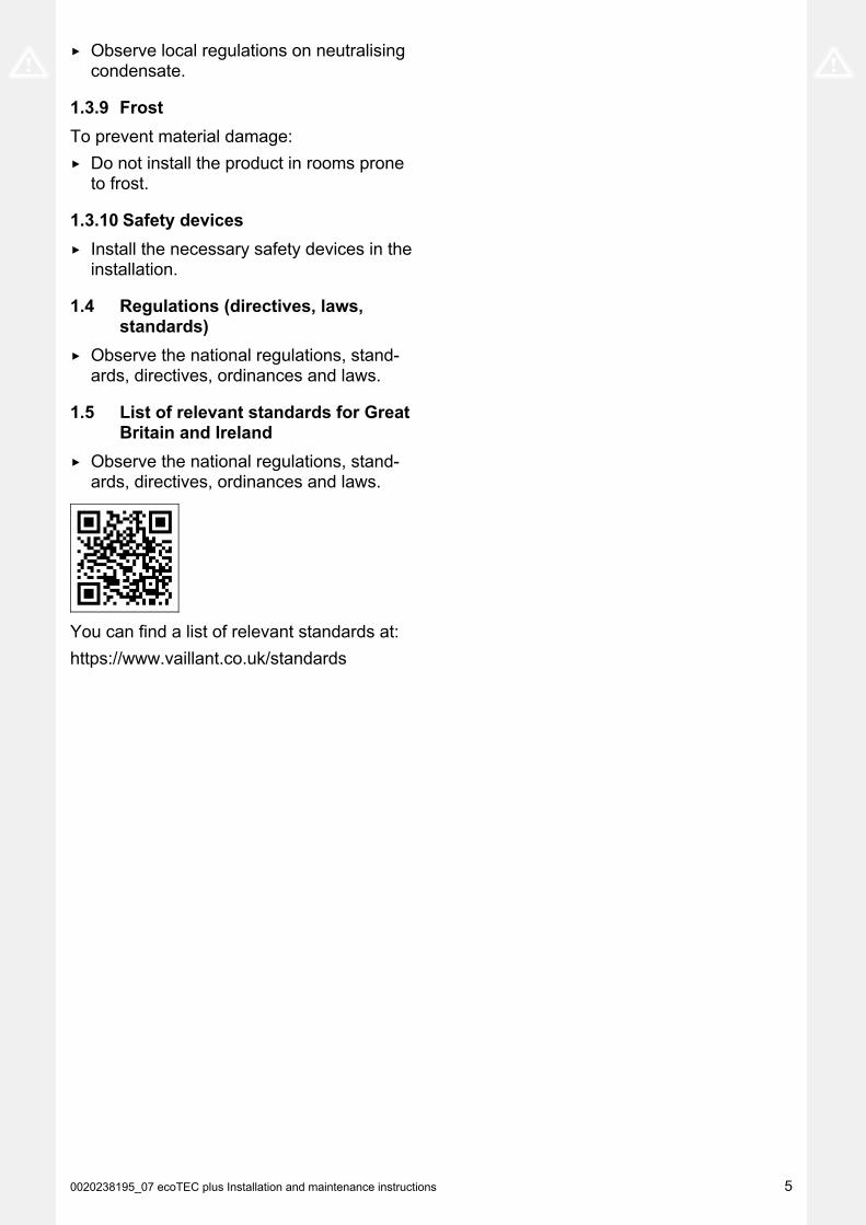
1.5 List of relevant standards for GreatBritain and Ireland
▶ Observe the national regulations, stand-ards, directives, ordinances and laws.
You can find a list of relevant standards at:
https://www.vaillant.co.uk/standards

6 Installation and maintenance instructions ecoTEC plus 0020238195_07
2 Guarantee and Customer Service
Thank you for installing a new Vaillant appliance in your home.Vaillant appliances are manufactured to the very highest standard so we are pleased to offer our
customers a comprehensive guarantee.To maintain your guarantee, the boiler must be serviced annually by a competent person who
holds the required qualifications in accordance with the rules in force of the country where the product is installed and in accordance with the manufactures recommendations.We recommend you complete your guarantee registration as soon as possible.
Guarantee Registration
Sales Support: Telephone: 0345 602 0262
Technical Enquiries: Telephone: 0344 693 3133
Email: [email protected] Enquiries:
Telephone: 0345 602 2922Training Enquiries:
Telephone: 0345 601 8885Email: [email protected]
Spares Enquiries: Telephone: 01773 596 615
To register your Vaillant appliance visit:https://self-service.vaillant.co.uk/warranty-registration
Vaillant is a licensed member of the Benchmark Scheme. Benchmark places responsibilities on both manufacturers and installers. The purpose is to ensure that customers are provided with the correct equipment for their needs, that it is installed, commissioned and serviced in accordance with the manufacturer’s instructions by a competent person approved at the time by the Health and Safety Executive and that it meets the requirements of the appropriate Building Regulations.The Benchmark Checklist can be used to demonstrate compliance with Building Regulations and should be provided to the customer for future reference.Installers are required to carry out installation, commissioning and servicing work in accordance with the Benchmark Code ofPractice which is available from the Heating and Hotwater Industry Council who manage and promote the Scheme.Benchmark is managed and promoted by the Heating and Hotwater Industry Council.
0020238195_07 ecoTEC plus Installation and maintenance instructions 7
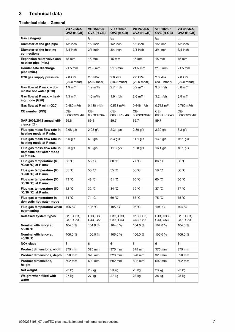
3 Technical data
Technical data – General
VU 126/6-5OVZ (H-GB)
VU 156/6-5OVZ (H-GB)
VU 186/6-5OVZ (H-GB)
VU 246/6-5OVZ (H-GB)
VU 306/6-5OVZ (H-GB)
VU 356/6-5OVZ (H-GB)
Gas category I2H I2H I2H I2H I2H I2H
Diameter of the gas pipe 1/2 inch 1/2 inch 1/2 inch 1/2 inch 1/2 inch 1/2 inch
Diameter of the heatingconnections
3/4 inch 3/4 inch 3/4 inch 3/4 inch 3/4 inch 3/4 inch
Expansion relief valve con-nection pipe (min.)
15 mm 15 mm 15 mm 15 mm 15 mm 15 mm
Condensate dischargepipe (min.)
21.5 mm 21.5 mm 21.5 mm 21.5 mm 21.5 mm 21.5 mm
G20 gas supply pressure 2.0 kPa
(20.0 mbar)
2.0 kPa
(20.0 mbar)
2.0 kPa
(20.0 mbar)
2.0 kPa
(20.0 mbar)
2.0 kPa
(20.0 mbar)
2.0 kPa
(20.0 mbar)
Gas flow at P max. – do-mestic hot water (G20)
1.9 m³/h 1.9 m³/h 2.7 m³/h 3.2 m³/h 3.8 m³/h 3.8 m³/h
Gas flow at P max. – heat-ing mode (G20)
1.3 m³/h 1.6 m³/h 1.9 m³/h 2.6 m³/h 3.2 m³/h 3.8 m³/h
Gas flow at P min. (G20) 0.480 m³/h 0.480 m³/h 0.533 m³/h 0.646 m³/h 0.762 m³/h 0.762 m³/h
CE number (PIN) CE-0063CP3646
CE-0063CP3646
CE-0063CP3646
CE-0063CP3646
CE-0063CP3646
CE-0063CP3646
SAP 2009/2012 annual effi-ciency (%)
89.8 89.8 89.7 89.7 89.7 –
Flue gas mass flow rate inheating mode at P min.
2.08 g/s 2.08 g/s 2.31 g/s 2.80 g/s 3.30 g/s 3.3 g/s
Flue gas mass flow rate inheating mode at P max.
5.5 g/s 6.9 g/s 8.3 g/s 11.1 g/s 13.8 g/s 16.1 g/s
Flue gas mass flow rate indomestic hot water modeat P max.
8.3 g/s 8.3 g/s 11.6 g/s 13.8 g/s 16.1 g/s 16.1 g/s
Flue gas temperature (80°C/60 °C) at P max.
55 ℃ 55 ℃ 60 ℃ 77 ℃ 86 ℃ 86 ℃
Flue gas temperature (80°C/60 °C) at P min.
55 ℃ 55 ℃ 55 ℃ 55 ℃ 56 ℃ 56 ℃
Flue gas temperature (50°C/30 °C) at P max.
43 ℃ 48 ℃ 51 ℃ 60 ℃ 60 ℃ 60 ℃
Flue gas temperature (50°C/30 °C) at P min.
32 ℃ 32 ℃ 34 ℃ 35 ℃ 37 ℃ 37 ℃
Flue gas temperature indomestic hot water mode
71 ℃ 71 ℃ 69 ℃ 68 ℃ 75 ℃ 75 ℃
Flue gas temperature whenoverheating
105 ℃ 105 ℃ 105 ℃ 95 ℃ 104 ℃ 104 ℃
Released system types C13, C33,C43, C53
C13, C33,C43, C53
C13, C33,C43, C53
C13, C33,C43, C53
C13, C33,C43, C53
C13, C33,C43, C53
Nominal efficiency at50/30 °C
104.0 % 104.0 % 104.0 % 104.0 % 104.0 % 104.0 %
Nominal efficiency at40/30 °C
106.0 % 106.0 % 106.0 % 106.0 % 106.0 % 106.0 %
NOx class 6 6 6 6 6 6
Product dimensions, width 375 mm 375 mm 375 mm 375 mm 375 mm 375 mm
Product dimensions, depth 320 mm 320 mm 320 mm 320 mm 320 mm 320 mm
Product dimensions,height
602 mm 602 mm 602 mm 602 mm 602 mm 602 mm
Net weight 23 kg 23 kg 23 kg 23 kg 23 kg 23 kg
Weight when filled withwater
27 kg 27 kg 27 kg 28 kg 28 kg 28 kg

8 Installation and maintenance instructions ecoTEC plus 0020238195_07
Technical data – G20 power/load G20
VU 126/6-5OVZ (H-GB)
VU 156/6-5OVZ (H-GB)
VU 186/6-5OVZ (H-GB)
VU 246/6-5OVZ (H-GB)
VU 306/6-5OVZ (H-GB)
VU 356/6-5OVZ (H-GB)
Maximum heat output 12 kW 15 kW 18 kW 24 kW 30 kW 35 kW
Effective output range (P)at 40/30 °C
4.8 to13.0 kW
4.8 to16.2 kW
5.3 to19.5 kW
6.5 to26.2 kW
7.6 to32.4 kW
7.6 to37.8 kW
Effective output range (P)at 50/30 °C
4.7 to12.8 kW
4.7 to15.9 kW
5.2 to19.1 kW
6.3 to25.7 kW
7.5 to31.8 kW
7.5 to37.1 kW
Effective output range (P)at 80/60 °C
4.5 to12.3 kW
4.5 to15.2 kW
5.0 to18.3 kW
6.1 to24.6 kW
7.2 to30.5 kW
7.1 to35.1 kW
Domestic hot water heatoutput (P)
4.4 to18.0 kW
4.4 to18.0 kW
5.0 to25.2 kW
6.0 to30.0 kW
7.1 to35.0 kW
7.1 to35.1 kW
Maximum heat input –heating (Q max.)
12.3 kW 15.3 kW 18.4 kW 24.7 kW 30.6 kW 35.7 kW
Minimum heat input – heat-ing (Q min.)
4.5 kW 4.5 kW 5.0 kW 6.1 kW 7.2 kW 7.1 kW
Maximum heat input – do-mestic hot water (Q max.)
18.4 kW 18.4 kW 25.7 kW 30.6 kW 35.7 kW 35.7 kW
Minimum heat input – do-mestic hot water (Q min.)
4.5 kW 4.5 kW 5.1 kW 6.1 kW 7.2 kW 7.1 kW
Technical data – Heating
VU 126/6-5OVZ (H-GB)
VU 156/6-5OVZ (H-GB)
VU 186/6-5OVZ (H-GB)
VU 246/6-5OVZ (H-GB)
VU 306/6-5OVZ (H-GB)
VU 356/6-5OVZ (H-GB)
Max. flow temperature ad-justment range (defaultsetting: 75 °C)
10 to 80 ℃ 10 to 80 ℃ 10 to 80 ℃ 10 to 80 ℃ 10 to 80 ℃ 10 to 80 ℃
Maximum permissiblepressure
0.3 MPa
(3.0 bar)
0.3 MPa
(3.0 bar)
0.3 MPa
(3.0 bar)
0.3 MPa
(3.0 bar)
0.3 MPa
(3.0 bar)
0.3 MPa
(3.0 bar)
Nominal water flow(ΔT = 20 K)
530 l/h 655 l/h 788 l/h 1,059 l/h 1,313 l/h 1,511 l/h
Nominal water flow atPmin (ΔT = 20 K)
195 l/h 195 l/h 215 l/h 260 l/h 300 l/h 345 l/h
Nominal water flow(ΔT = 30 K)
353 l/h 436 l/h 525 l/h 706 l/h 876 l/h 1,008 l/h
Nominal water flow atPmin (ΔT = 30 K)
130 l/h 130 l/h 145 l/h 170 l/h 200 l/h 230 l/h
Approximate value for thecondensate volume (pHvalue between 3.5 and 4.0)at 50/30 °C
1.23 l/h 1.53 l/h 1.84 l/h 2.47 l/h 3.06 l/h 3.57 l/h
Technical data – Electrics
VU 126/6-5OVZ (H-GB)
VU 156/6-5OVZ (H-GB)
VU 186/6-5OVZ (H-GB)
VU 246/6-5OVZ (H-GB)
VU 306/6-5OVZ (H-GB)
VU 356/6-5OVZ (H-GB)
Electrical connection 230 V /50 Hz
230 V /50 Hz
230 V /50 Hz
230 V /50 Hz
230 V /50 Hz
230 V /50 Hz
Built-in fuse (slow-blow) T2/2A, 250V T2/2A, 250V T2/2A, 250V T2/2A, 250V T2/2A, 250V T2/2A, 250V
Max. electrical power con-sumption
23 W 29 W 35 W 36 W 44 W 44 W
Standby electrical powerconsumption
2 W 2 W 2 W 2 W 2 W 2 W
IP rating IPX4D IPX4D IPX4D IPX4D IPX4D IPX4D
0020238195_07 ecoTEC plus Installation and maintenance instructions 9
4 Notes on the documentation
▶ Always observe all operating instructions enclosed withthe installation components.
▶ Store these instructions and all other applicable docu-ments for further use.
These instructions apply only to:
Product article number
Article numberGas CouncilNumber
VU 126/6-5 OVZ (H-GB)ecoTEC plus 412
0010021220 41-694-13
VU 156/6-5 OVZ (H-GB)ecoTEC plus 415
0010021221 41-694-14
VU 186/6-5 OVZ (H-GB)ecoTEC plus 418
0010021222 41-694-15
VU 246/6-5 OVZ (H-GB)ecoTEC plus 424
0010021223 41-694-16
VU 306/6-5 OVZ (H-GB)ecoTEC plus 430
0010021224 41-694-17
VU 356/6-5 OVZ (H-GB)ecoTEC plus 435
0010015674 41-044-76
5 Product description
5.1 CE marking
The CE marking shows that the products comply with thebasic requirements of the applicable directives as stated onthe declaration of conformity.
The declaration of conformity can be viewed at the manufac-turer's site.
5.2 Hot Water Association
Vaillant is a full member of the Hot Water Association andpromotes the scheme in association with its cylinder range.Details are available on the web site www.vaillant.co.uk
5.3 Serial number
The serial number is located on a plate behind the front flap.The plate is in a plastic strap. You can also display the serialnumber in the display.
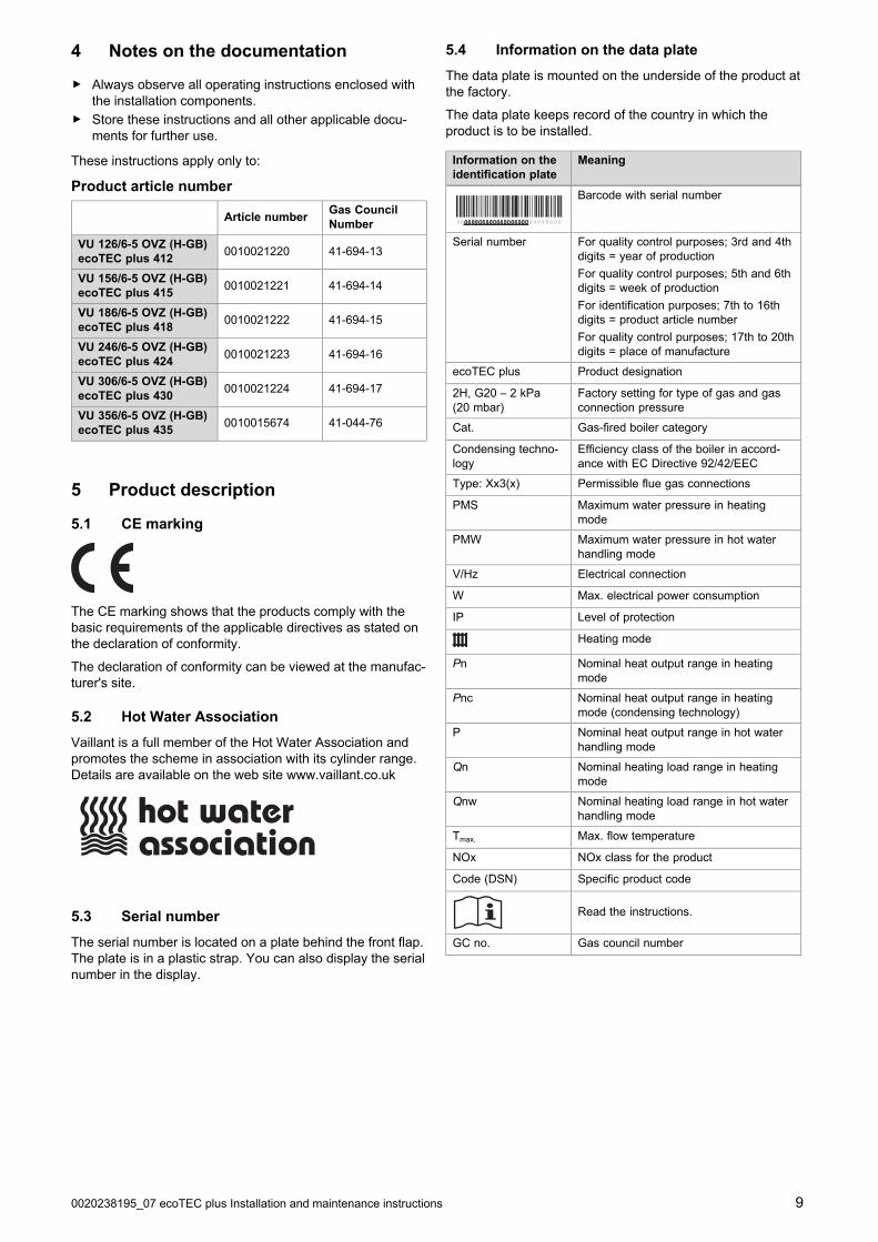
5.4 Information on the data plate
The data plate is mounted on the underside of the product atthe factory.
The data plate keeps record of the country in which theproduct is to be installed.
Information on theidentification plate
Meaning
Barcode with serial number
Serial number For quality control purposes; 3rd and 4thdigits = year of production
For quality control purposes; 5th and 6thdigits = week of production
For identification purposes; 7th to 16thdigits = product article number
For quality control purposes; 17th to 20thdigits = place of manufacture
ecoTEC plus Product designation
2H, G20 – 2 kPa(20 mbar)
Factory setting for type of gas and gasconnection pressure
Cat. Gas-fired boiler category
Condensing techno-logy
Efficiency class of the boiler in accord-ance with EC Directive 92/42/EEC
Type: Xx3(x) Permissible flue gas connections
PMS Maximum water pressure in heatingmode
PMW Maximum water pressure in hot waterhandling mode
V/Hz Electrical connection
W Max. electrical power consumption
IP Level of protection
Heating mode
Pn Nominal heat output range in heatingmode
Pnc Nominal heat output range in heatingmode (condensing technology)
P Nominal heat output range in hot waterhandling mode
Qn Nominal heating load range in heatingmode
Qnw Nominal heating load range in hot waterhandling mode
Tmax. Max. flow temperature
NOx NOx class for the product
Code (DSN) Specific product code
Read the instructions.
GC no. Gas council number

10 Installation and maintenance instructions ecoTEC plus 0020238195_07
5.5 Functional elements
4
5
6
3
11
10
9
7
8
1
2
1 Supply air test point(for the upper air/flueconnection)
2 Flue gas analysis point(for the upper air/flueconnection)
3 Fan/gas-air mixture
4 Flue pipe
5 Flue gas analysis point(for the rear air/flueconnection)
6 Gas valve assembly
7 Ignition transformer
8 Heat exchanger
9 Air intake pipe
10 Condensate trap
11 Electronics box
5.6 Safety Devices
5.6.1 Electrical Supply Failure
The boiler will not work without an electrical supply. Normaloperation of the boiler should resume when the electricalsupply is restored.
Reset any external controls, to resume normal operation ofthe central heating.
If the boiler does not resume normal operation press thereset button. If the boiler does not resume normal operationafter this call your Installation/Servicing company or Vaillantservice.
5.6.2 Overheating Safety
The boiler software is designed to recognise the potential foran overheat lockout and will shutdown before this happens.To restart the boiler, press the reset button on the boilerinterface.
If the boiler fails to resume normal operation and all externalcontrols are calling for heat, then call your Installation/ Servi-cing company or Vaillant service.
5.6.3 Frost protection
The appliance has a built in frost protection device that pro-tects the boiler from freezing. With the gas and electric sup-plies ON and irrespective of any room thermostat setting, thefrost protection device will operate the pump when the tem-perature of the boiler water falls below 12 °C.
A timer is used so that the temperature can be checked peri-odically. After 10 minutes the pump will be stopped if thetemperature is higher than 10 °C or has already reached35 °C. The burner will activate if the boiler temperature doesnot reach 10 °C after 30 minutes or at any time if the temper-ature drops to 5 °C.
The burner will switch off when the temperature reaches35 °C.
5.6.4 Condensate Drain Blockage
As a safety feature the boiler will stop working if the con-densate drain becomes blocked. During freezing conditionsthis may be due to the forming of ice in the condense drainexternal to the house. Release an ice blockage by the useof warm cloths on the pipe. After pressing reset the boilershould restart.
0020238195_07 ecoTEC plus Installation and maintenance instructions 11
6 Set-up
6.1 Checking the scope of delivery
▶ Check that the scope of delivery is complete and intact.
6.1.1 Scope of delivery
Number Designation
1 Heat generator
1 Unit mounting bracket
1 Flue adapter
1 Gas stopcock
1 Gas pipe
1 Condensate discharge hose
1 Mounting template
1 Enclosed documentation
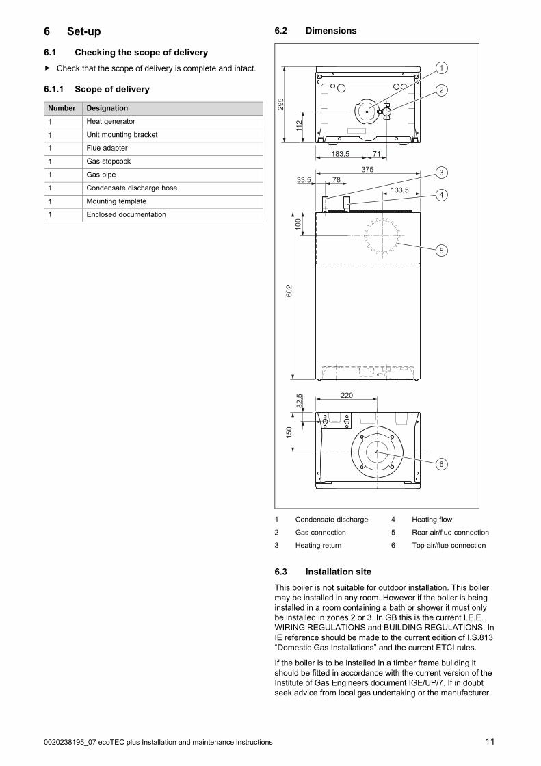
6.2 Dimensions
112
183,5 71
3757833,5
602
220
150
32,5
100
133,5
295
1
2
3
4
5
6
1 Condensate discharge
2 Gas connection
3 Heating return
4 Heating flow
5 Rear air/flue connection
6 Top air/flue connection
6.3 Installation site
This boiler is not suitable for outdoor installation. This boilermay be installed in any room. However if the boiler is beinginstalled in a room containing a bath or shower it must onlybe installed in zones 2 or 3. In GB this is the current I.E.E.WIRING REGULATIONS and BUILDING REGULATIONS. InIE reference should be made to the current edition of I.S.813“Domestic Gas Installations” and the current ETCI rules.
If the boiler is to be installed in a timber frame building itshould be fitted in accordance with the current version of theInstitute of Gas Engineers document IGE/UP/7. If in doubtseek advice from local gas undertaking or the manufacturer.

12 Installation and maintenance instructions ecoTEC plus 0020238195_07
6.4 Minimum clearances
CC
AB
D
Minimum clearance
A 150 mm (top air/flue connection)
75 mm (rear air/flue connection)
B 150 mm
C 5 mm
(70 mm if the side sec-tions ought to be removed)
D 500 mm
The boiler and flue are suitable for installation onto andthrough combustible materials provided that:
1. Minimum 5 mm clearance is maintained around thecircumference of the flue (air intake).
2. The combustible surface and fixings are suitable forsupporting the load.
3. The minimum clearances from the boiler case are main-tained.
6.5 Compartment Ventilation
The boilers are very high efficiency appliances.
As a consequence the heat loss from the appliance casingduring operation is very low.
Compartment ventilation is not required as the products areonly certified, and can only be fitted with a concentric fluesystem.
6.6 Air/flue pipe
6.6.1 Regulation
Different flue outlet configurations can be carried out.
– Consult the installation manual for air/flue gas systemsfor more information about the other possibilities andassociated accessories.
Minimum fall44 mm/m
– Standard flue terminal kits have an in-built fall back tothe boiler to drain the condensate. These can be fittedlevel between the appliance and the termination position.All other extended flues must have a fall of at least 44mm/m.
The maximum length of the flue outlet is defined according toits type (for example C13).
– Whatever the kind of flue system chosen, observe theminimum distances to position the flue terminals.
– To install the flue, refer to the separate flue instructionsupplied with your appliance.
– Explain these requirements to the user of the appliance.
In GB the minimum acceptable siting dimensions for theterminal from obstructions, other terminals and ventilationopenings are shown in diagram overleaf.
In IE the minimum distances for flue terminal positioningmust be those detailed in I.S. 813 “Domestic Gas Installa-tions”.
The terminal must be exposed to the external air, allowingfree passage of air across it at all times.
Being a condensing boiler some pluming may occur fromthe flue outlet. This should be taken into consideration whenselecting the position for the terminal.

0020238195_07 ecoTEC plus Installation and maintenance instructions 13
6.6.2 Position of the air/flue terminal
J
JN
QS
SP
UB
Boundary
G
D
JJ
R
V M
T
GC
W
E
F
LA
K
SP
S
F
X
A
Y
Boundary
Z
H
Aa
S
ZBa
6.6.2.1 Positioning the terminal of a fan-supported flue system
Installation site Dimensions
A Adjacent to a boundary. 300 mm
B1) The dimension below eaves, balconies and car ports can be reduced to this value, as long as the flue terminal is
extended to clear any overhang. External flue joints must be sealed with a suitable silicon sealant.25 mm
C Between a vertical flue terminal and a window or dormer window on a roof. 1,500 mm
D Between terminals facing each other. 1,200 mm
E Vertical flue clearance, adjacent to a boundary line. 300 mm
F2) Distance to a boundary line, unless it will cause a nuisance. BS 5440:Part 1 recommends that care is taken
when siting terminal in relation to boundary lines.600 mm
G Minimum clearance from a skylight to a vertical flue or to another vertical flue. Min. 300 mm
HVertical flue clearance, to noncombustible building material.
Vertical flue clearance to combustible building material.
500 mm
1,500 mm
J Above, below and either side of an opening door, air vent or opening window. 300 mm
K Diagonally to an opening door, air vent or opening window. 600 mm
L2) To an internal or external corner. 200 mm
MBelow a Velux window.
Above or to either side of the Velux window.
2,000 mm
600 mm
NFrom a pitched roof.
In regions with heavy snowfall.
400 mm
500 mm
P From vertical drain pipes and soil pipes. 25 mm
QBelow eaves.
Below gutters, pipe and drains.
200 mm
75 mm
1) There should be no ventilation/opening in the eaves within 300 mm distance of the terminal.
2) These dimensions comply with the building regulations, but they may need to be increased to avoid wallstaining and nuisance from pluming depending on site conditions.
– Terminals must be positioned so to avoid combustion products entering the building.
– Support the flue at approximately one metre intervals and at a change of direction, use suitable brackets andfixings.
– Installations in car ports are not recommended.
– The flue cannot be lower than 1 metre from the top of a lightwell due to the build up of combustion products.
– Dimensions from a flue terminal to a fanned air inlet to be determined by the ventilation equipment.

14 Installation and maintenance instructions ecoTEC plus 0020238195_07
Installation site Dimensions
RThe dimension below eaves, balconies and car ports can be reduced to this value, as long as the flue terminal isextended to clear any overhang. External flue joints must be sealed with suitable silicon sealant.
25 mm
S Above adjacent ground or balcony. 300 mm
T2) Distance to a surface facing a terminal, unless it will cause a nuisance. BS 5440: Part 1 recommends that care
is taken when siting terminals in relation to surfaces facing a terminal.600 mm
U Clearance alongside another terminal. 300 mm
V Above roof level. 300 mm
W Minimum to vertical structure on roof, roof vent. Min. 300 mm
X Minimum to opening in adjacent building. Min.2000 mm
Y Minimum at an angle to a boundary which is not less than 300 mm to the terminal Min. 600 mm
Z Minimum measured to the nearest corner of the OPEN window Min. 600 mm
Aa No more than this value above ridge. Max.300 mm
Ba Not less than this value below the opening window Min. 300 mm
1) There should be no ventilation/opening in the eaves within 300 mm distance of the terminal.
2) These dimensions comply with the building regulations, but they may need to be increased to avoid wallstaining and nuisance from pluming depending on site conditions.
– Terminals must be positioned so to avoid combustion products entering the building.
– Support the flue at approximately one metre intervals and at a change of direction, use suitable brackets andfixings.
– Installations in car ports are not recommended.
– The flue cannot be lower than 1 metre from the top of a lightwell due to the build up of combustion products.
– Dimensions from a flue terminal to a fanned air inlet to be determined by the ventilation equipment.
6.6.2.2 Horizontal terminal positioning
BS 5440-1 recommends that fanned flue chimney terminals should be positioned as follows:
a) at least 2 m from an opening in the building directly opposite, and
b) so that the products of combustion are not directed to discharge directly across a boundary if the products are likely tocause a nuisance to a neighbour or discharge over a walkway or patio.
For IE see current issue of IS 813.
For boilers covered within this manual.
Dimensions B and R:
These clearances may be reduced to 25 mm without affecting the performance of the boiler. In order to ensure that the con-densate plume does not affect adjacent surfaces the terminal should be extended as shown below.
Balcony/eaves
Gutter
Adequately secured air/flue gas pipe
The flue pipe mustprotrude beyond any overhang
You can use a plume management kit to enable the termination point to be positioned and directed away from the buildingfabric.

0020238195_07 ecoTEC plus Installation and maintenance instructions 15
6.6.3 Flue Configuration Description
6.6.3.1 Horizontal Concentric Flue ⌀ 60/100 mm or⌀ 80/125 mm (C13 type installation)
1
1 Gasket (fitted)
Note
If the terminal is at less than 1.80 m from theground, you must install a terminal protection kit.
Consult the separate installation manual for air/flue gas sys-tems supplied with your appliance for all possibilities and as-sociated accessories and how to install the flue system.
6.6.3.2 Terminal protection
A terminal guard is required if persons could come into con-tact with the terminal or the terminal could be subject to dam-age.
If a terminal guard is required, it must be positioned toprovide minimum of 50 mm clearance from any part of theterminal and be central over the terminal.
The guard should be similar to that shown in the figure.
6.6.3.3 Vertical Concentric Flue ⌀ 60/100 mm or⌀ 80/125 mm (C33 type installation)
Consult the separate installation manual for air/flue gas sys-tems supplied with your appliance for all possibilities and as-sociated accessories and how to install the flue system.
6.6.3.4 Multiple boiler chimney Flue ⌀ 60/100 mm(C43 type installation)
A
B
L
4
5
1
2
3
1 Pressure balancingsystem
2 Air-inlet pipe
3 Collector pipe

16 Installation and maintenance instructions ecoTEC plus 0020238195_07
4 Boiler
5 Inspection hatch
A Final storey
B Ground floor
Note
The flue connecting from the appliance to the fluesystem must be supplied from the manufacturer ofthe boiler.
C43 flue systems must not be a 'pressurised sys-tem' but act under natural draught principles.
C43 type flue systems must have their own con-densate drain fitted and not allow condensate tomix into other appliances.
The flue length must be calculated and installed according tothe relevant standards EN 13384-1 and 2 (C43 flue systemsonly) with reference to the manufacturer's instructions sup-plied. The appliance maximum flue length must be taken intoaccount when calculating the overall design of the flue sys-tem.
Consult the separate installation manual for air/flue gas sys-tems supplied with your appliance for all possibilities and as-sociated accessories and how to install the flue system.
6.7 Using the mounting template
▶ Use the mounting template to ascertain the locations atwhich you need to drill holes.
6.8 Wall-mounting the product
Note
If you are using the rear air/flue connection, in-stall the air/flue pipe before you wall-mount theproduct.
1. Only use fixing material that is permitted for the wall.
2. Check the load-bearing capacity of the wall.
3. Note the total weight of the product.
4. Only use fixing material that is permitted for the wall.
5. If required, ensure that mounting apparatus on-site hassufficient load-bearing capacity.
6. Wall-mount the product as described.
6.9 Removing/installing the front casing
6.9.1 Removing the front casing
B
D
C
A
6.9.2 Installing the front casing
▶ Refit the components in the reverse order.
6.10 Removing/installing the side section
6.10.1 Removing the side section
Caution.Risk of material damage caused by mech-anical deformation.
Removing both side sections may causemechanical distortion in the product, whichmay cause damage to the piping, for ex-ample, and potentially result in leaks.
▶ Always only remove one side section –never both side sections at the same time.
Note
If there is sufficient lateral clearance (at least70 mm), you can remove the side section to fa-cilitate maintenance or repair work.

0020238195_07 ecoTEC plus Installation and maintenance instructions 17
C
D
A
B
E
6.10.2 Installing the side section
▶ Refit the components in the reverse order.

18 Installation and maintenance instructions ecoTEC plus 0020238195_07
7 Installation
7.1 Preparing for installation
▶ Make sure that the existing gas meter and the pipelinesare capable of passing the rate of gas supply required.
▶ Consider the maximum heat output given in DHW mode.
▶ Install the following components:
– Draining cocks at the lowest points in the heatinginstallation (→ current version of "BS 2879")
– A bypass that is at least 1.5 m away from the product
– A stopcock in the gas pipe
– Where applicable, a flow regulator valve to adjust theflow rate
▶ Install the connection pipes such that they are free frommechanical stress.
▶ If you use non-diffusion-tight plastic pipes in the heatinginstallation, ensure that no air gets into the heat gener-ator circuit.
▶ Only solder connectors if the connectors are not yetscrewed to the service valves.
▶ Only bend connection pipes if they have not yet beenconnected to the product.
▶ Flush the heating installation thoroughly before installingthe product.
▶ Check the leak-tightness of the gas valve assembly usinga pressure of ≤ 11 kPa (110 mbar).
7.2 Installing the heating pump
Pressure loss in the productfrom the product
050100150200250300350400
0 200 400 600 800 1000 1200 1400 1600
430
424
418415412
435
A
B1
2
A Flow rate [l/h]
B Pressure loss [mbar]
1 Pressure loss 412 - 418
2 Pressure loss 424 - 435
The flow rate must not fall below the value in the diagram.
▶ Only use pumps that have an in-rush current ≤ 10/15 A.
▶ When designing/selecting the pump, note the pressureloss of the product.
▶ Install the pump in the heating flow.
▶ Install the pump upstream and downstream of the pumpisolation valves.
▶ Set the pump so that the temperature difference betweenthe flow and return is no more than 20 °C when the max-imum flow temperature is set.
– The flow rate specified in the technical data isreached.
7.3 Heating water supply in the open heatingsystem
▶ Connect the product to a supply/expansion tank asshown in the figure.
– The tank must not be more than 27 m (90 ft) abovethe product.
– The open vent pipe must be installed with an upwardgradient and must not be blocked.
– Supply pipe diameter: ≥ 15 mm
– The relative positions of the pump, supply and openvent pipe must be as shown in the figure.
Condition: Combined supply and open vent pipe
▶ Install the line in accordance with "BS 5449".
– Diameter: ≥ 22 mm
0020238195_07 ecoTEC plus Installation and maintenance instructions 19
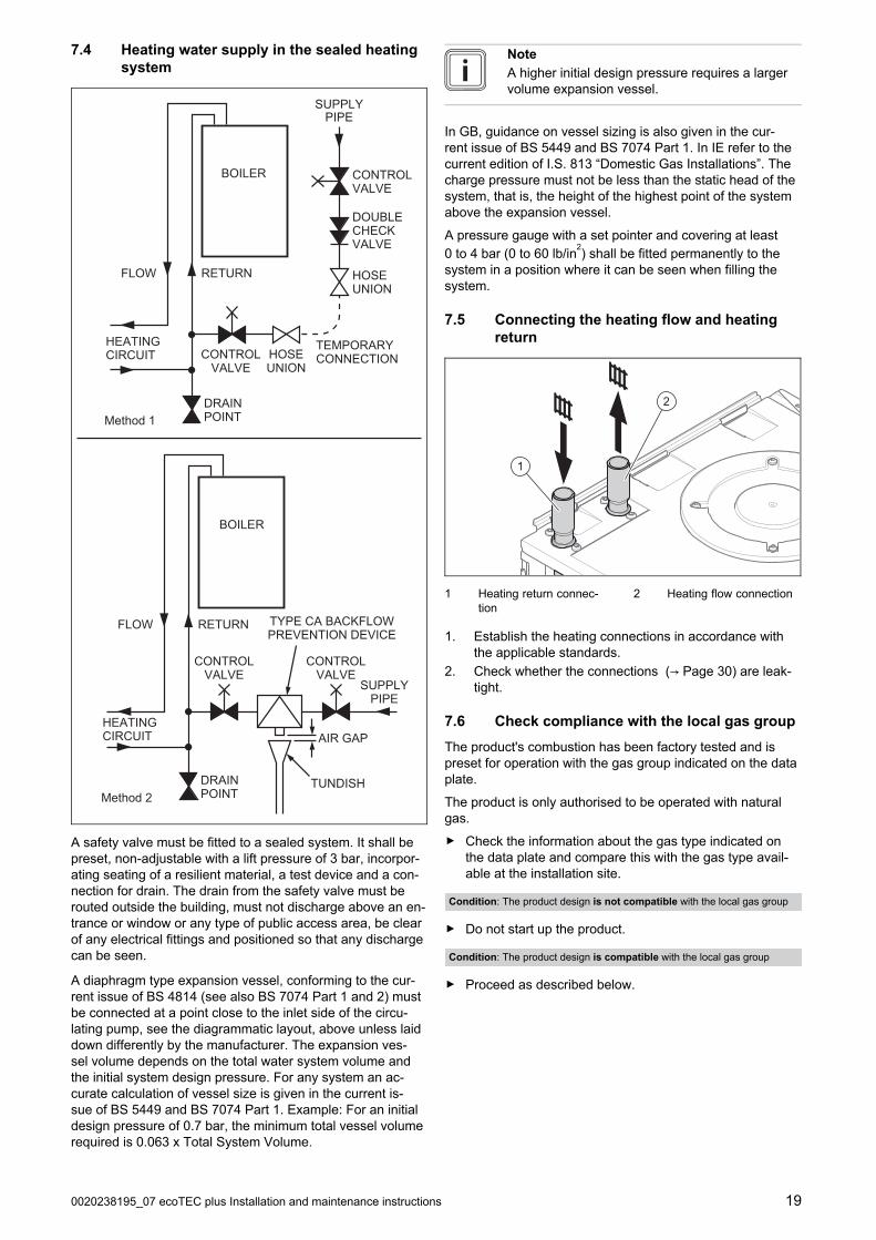
7.4 Heating water supply in the sealed heatingsystem
TEMPORARYCONNECTION
HOSEUNION
HOSEUNION
SUPPLYPIPE
CONTROLVALVE
CONTROLVALVE
DOUBLECHECKVALVE
HEATINGCIRCUIT
DRAINPOINT
BOILER
RETURNFLOW
Method 1
SUPPLYPIPE
AIR GAP
TUNDISH
CONTROLVALVE
CONTROLVALVE
TYPE CA BACKFLOWPREVENTION DEVICE
BOILER
RETURNFLOW
HEATINGCIRCUIT
DRAINPOINTMethod 2
A safety valve must be fitted to a sealed system. It shall bepreset, non-adjustable with a lift pressure of 3 bar, incorpor-ating seating of a resilient material, a test device and a con-nection for drain. The drain from the safety valve must berouted outside the building, must not discharge above an en-trance or window or any type of public access area, be clearof any electrical fittings and positioned so that any dischargecan be seen.
A diaphragm type expansion vessel, conforming to the cur-rent issue of BS 4814 (see also BS 7074 Part 1 and 2) mustbe connected at a point close to the inlet side of the circu-lating pump, see the diagrammatic layout, above unless laiddown differently by the manufacturer. The expansion ves-sel volume depends on the total water system volume andthe initial system design pressure. For any system an ac-curate calculation of vessel size is given in the current is-sue of BS 5449 and BS 7074 Part 1. Example: For an initialdesign pressure of 0.7 bar, the minimum total vessel volumerequired is 0.063 x Total System Volume.
Note
A higher initial design pressure requires a largervolume expansion vessel.
In GB, guidance on vessel sizing is also given in the cur-rent issue of BS 5449 and BS 7074 Part 1. In IE refer to thecurrent edition of I.S. 813 “Domestic Gas Installations”. Thecharge pressure must not be less than the static head of thesystem, that is, the height of the highest point of the systemabove the expansion vessel.
A pressure gauge with a set pointer and covering at least0 to 4 bar (0 to 60 lb/in
2) shall be fitted permanently to the
system in a position where it can be seen when filling thesystem.
7.5 Connecting the heating flow and heatingreturn
2
1
1 Heating return connec-tion
2 Heating flow connection
1. Establish the heating connections in accordance withthe applicable standards.
2. Check whether the connections (→ Page 30) are leak-tight.
7.6 Check compliance with the local gas group
The product's combustion has been factory tested and ispreset for operation with the gas group indicated on the dataplate.
The product is only authorised to be operated with naturalgas.
▶ Check the information about the gas type indicated onthe data plate and compare this with the gas type avail-able at the installation site.
Condition: The product design is not compatible with the local gas group
▶ Do not start up the product.
Condition: The product design is compatible with the local gas group
▶ Proceed as described below.

20 Installation and maintenance instructions ecoTEC plus 0020238195_07
7.7 Gas connection
1
1. Establish the gas connection (1) in accordance with theapplicable standards.
2. Purge the gas line before start-up.
3. Check the entire gas line properly for leak-tightness.
7.8 Connecting the condensate discharge pipe
1
2
▶ Follow the instructions listed here and observe directivesand local regulations on condensate discharge.
▶ Use PVC or another material that is suitable for drainingthe non-neutralised condensate.
▶ If it cannot be guaranteed that the materials the drainpipework is made from are suitable, install a system forneutralising the condensate.
Note
The condensate drain pipework must have acontinuous fall (45 mm per metre) and shouldwhenever possible terminate at a suitabledrain point within the heated envelope of thebuilding that will remain frost free under longperiods of low external temperatures.
▶ Connect the condensate trap (1). Use the supplied drainhose (2) for this.
Note
Ensure that the connection between the con-densate discharge pipe and the drain hose isnot air-tight.
▶ Connect a condensate discharge pipe (21.5 mm, notincluded in the scope of delivery) to the drain hose (2).
▶ During installation remove all burs from inside of cut pipework and avoid excessive adhesive which may trap smallpockets of water close to the pipe wall which can freezeand build into a larger ice plug.
▶ For any installation the condensate must be free flowingand not be possible for air back-pressure to prevent wa-ter flow.
▶ As with other pipe work insulate the condensate dis-charge pipe to minimise any risk of freezing and bewarewhen crossing cavities that the fall is maintained and thepipe sleeved.
You can find further information in the "BS 6798" specific-ation for installing and maintaining gas-fired boilers with anominal heat input of less than 70 kW.
7.8.1 Condensate discharge systems
It is not necessary to provide extra traps in the dischargepipe as there is already a trap inside the boiler. Fitting anextra trap may cause the boiler siphon to work incorrectly.Refer to BS5546 or BS6798 for further advice on disposal ofboiler condensate.
7.8.1.1 Direct Connection to internal soil and ventstack
Ø22mm
Preferred option
7.8.1.2 Direct connection to external soil and ventstack
Ø22mm
Ø 32mm
≤ 3 m

0020238195_07 ecoTEC plus Installation and maintenance instructions 21
7.8.1.3 External termination to gulley or hopper
Ø22mm
Ø 32mm
≤ 3 m
Best practice
7.8.1.4 Internal termination into combined sinkwaste
Ø32mm
Ø22mm≥ 3 m
100mm
Preferred option for external termination
7.8.1.5 External termination into soakaway
< 500 mm
100 mm
< 30
0 m
m
5025
25
< 25
25
Ø12
Ø32mm
≤ 3 m
1
2
3
4
5
6
1 Ground (either/or)
2 Seal
3 Plastic tube,100 mm diameter
4 Bottom of sealed tube
5 Limestone chippings
6 Hole depth 400 mmminimum
Least preferred option, must not terminate in rain water drain
7.8.1.6 Internal termination downstream of sinkwaste
100mm
Ø32mm
Ø22mm
≤ 3 m
Open end of pipe direct into gulley below ground level butabove water level
Susceptible to siphonage, must terminate in a gulley
7.8.1.7 External termination into rain water downpipe
≤ 3 mØ22mm
Ø 32mm
NB only combined foul/rainwater drain
7.8.1.8 Additional methods of introducing air breaks
1
2 3
1 Air break
2 Using a tundish
3 Using a pipe

22 Installation and maintenance instructions ecoTEC plus 0020238195_07
7.8.1.9 Connection of condensate pump
Ø32mm
Ø22mm
≥ 3 m
Preferred option for external connection
7.9 Flue installation
7.9.1 Installing and connecting the air/flue pipe
1. You can find out which air/flue pipes may be used byconsulting the enclosed set-up instructions for theair/flue system.
2. Observe the information on positioning the air/flue ter-minal.
Condition: Installation in damp rooms
▶ You must connect the product to a room-sealed air/fluesystem. The combustion air must not be taken from theinstallation site.
3. Install the air/flue pipe using the set-up instructions.
7.10 Electrical installation
Only qualified electricians may carry out the electrical install-ation.
The product must be earthed.
Danger!Risk of death from electric shock!
Continuous voltage is present at power sup-ply terminals L and N even when the unit isswitched off using the standby button.
▶ Switch off the power supply.▶ Secure the power supply against being
switched on again.
7.10.1 Opening the electronics box
B
B
A
7.10.2 Cable route
2
1230V
24V / eBus
1 230-V cable route 2 24-V cable or eBUScable route
7.10.3 General information about connectingcables
Caution.Risk of material damage caused by incor-rect installation.
Mains voltage at incorrect terminals and plugterminals may destroy the electronics.
▶ Do not connect any mains voltage to theeBUS (+/-) and RT 24 V terminals.
▶ Only connect the connection cable to theterminals marked for the purpose.
1. Route the connection cables of the components to beconnected through the grommet provided on the under-side of the product on the left.
2. Ensure that the grommet is plugged in correctly andthat the cables have been routed correctly.
3. Ensure that the grommets envelop the connectioncables tightly and with no visible gaps.

0020238195_07 ecoTEC plus Installation and maintenance instructions 23
4. Use strain reliefs.
5. If required, shorten the connection cables.
-+
NL
PE
30 mm≤
30 mm≤
40 mm≤
6. Strip the flexible cables as shown in the figure. In doingso, ensure that the insulation on the individual conduct-ors is not damaged.
7. Only strip inner conductors just enough to establishstable connections.
8. To avoid short circuits resulting from loose individualwires, fit conductor end sleeves on the stripped ends ofthe conductors.
9. Screw the respective plug to the connection cable.
10. Check whether all conductors are inserted mechanic-ally securely in the terminals of the plug. Remedy this ifnecessary.
11. Plug the plug into the associated PCB slot.
– In doing so, observe the wiring diagram in the ap-pendix.
7.10.4 Establishing the power supply
1
1. Observe all valid regulations.
2. Ensure that the nominal mains voltage is 230 V.
3. Do not interrupt the mains supply with a time switch orprogrammer.
4. Set up a fixed connection and install a partition witha contact gap of at least 3 mm (e.g. fuses or powerswitches).
5. Isolation should preferably be by a double poleswitched fused spur box having a minimum contactseparation of 3mm on each pole. The fused spur box
should be readily accessible and preferably adjacent tothe boiler. It should be identified as to its use.
6. Provide one common power supply for the boiler andfor the corresponding control:
– Power supply: Single-phase, 230 V, 50 Hz
– Fuse protection: ≤ 3 A
7. Open the electronics box. (→ Page 22)
8. Observe the routing of the power supply cable (1) in theelectronics box in order to guarantee that there is nostrain.
≤ 30
mm
NLX1230V~
RT
NLRT
1
9. Connect the cables. (→ Page 22)
10. Close the electronics box.
11. Make sure that access to the power supply is alwaysavailable and is not covered or blocked.
7.10.5 Connecting the heating pump
▶ Connect the heating pump to the boiler; see the wiringdiagram in the appendix.
24 Installation and maintenance instructions ecoTEC plus 0020238195_07
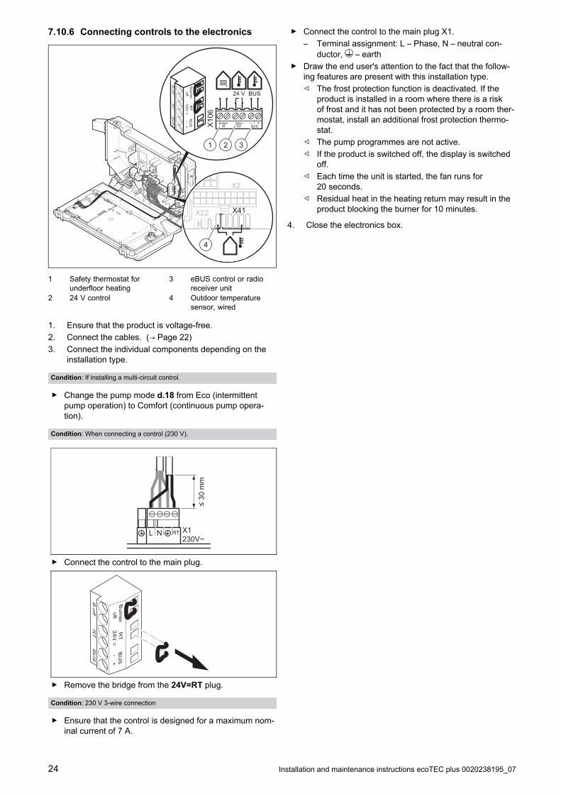
7.10.6 Connecting controls to the electronics
X2
X22 X41
– +24V=RT BUS
BurneroffX
106
BUS24 V
BU
SR
TB
.off
Burner
offR
T24V
=-
+B
US
1
4
32
1 Safety thermostat forunderfloor heating
2 24 V control
3 eBUS control or radioreceiver unit
4 Outdoor temperaturesensor, wired
1. Ensure that the product is voltage-free.
2. Connect the cables. (→ Page 22)
3. Connect the individual components depending on theinstallation type.
Condition: If installing a multi-circuit control.
▶ Change the pump mode d.18 from Eco (intermittentpump operation) to Comfort (continuous pump opera-tion).
Condition: When connecting a control (230 V).
≤ 30
mm
NL X1230V~
RT
▶ Connect the control to the main plug.
BU
SR
TB
.off
Burner
offR
T24V
=-
+B
US
▶ Remove the bridge from the 24V=RT plug.
Condition: 230 V 3-wire connection
▶ Ensure that the control is designed for a maximum nom-inal current of 7 A.
▶ Connect the control to the main plug X1.
– Terminal assignment: L – Phase, N – neutral con-ductor, – earth
▶ Draw the end user's attention to the fact that the follow-ing features are present with this installation type.
◁ The frost protection function is deactivated. If theproduct is installed in a room where there is a riskof frost and it has not been protected by a room ther-mostat, install an additional frost protection thermo-stat.
◁ The pump programmes are not active.
◁ If the product is switched off, the display is switchedoff.
◁ Each time the unit is started, the fan runs for20 seconds.
◁ Residual heat in the heating return may result in theproduct blocking the burner for 10 minutes.
4. Close the electronics box.

0020238195_07 ecoTEC plus Installation and maintenance instructions 25
8 Operation
8.1 Operating concept
The operating concept and the read-out and setting optionsof the end user level are described in the operating instruc-tions.
An overview of the read-out and setting options for the in-staller level is included in the table in the appendix.
Installer level – Overview (→ Page 38)
8.2 Calling up the installer level
1. Only call up the installer level if you are a competentperson.
2. Navigate to Menu → Installer level and confirm bypressing .
3. Set the value 17 (code) and confirm by pressing .
8.3 Live Monitor (status codes)
Menu → Live Monitor
Status codes in the display provide information on the pro-duct's current operating mode.
Status codes – Overview (→ Page 43)

26 Installation and maintenance instructions ecoTEC plus 0020238195_07
9 Start-up
9.1 Carrying out the initial start-up
Initial start-up must be carried out by a customer servicetechnician or an authorised competent person using thebenchmark checklist. The benchmark checklist in the ap-pendix (→ Page 48) of the installation instructions must befilled out and stored carefully along with the unit's document-ation.
▶ Carry out the initial start-up using the benchmark check-list in the appendix.
▶ Fill out and sign the benchmark checklist.
9.2 Checking and treating the heatingwater/filling and supplementary water
Caution.Risk of material damage due to poor-qual-ity heating water
▶ Ensure that the heating water is of suffi-cient quality.
▶ Before filling or topping up the installation, check thequality of the heating water.
Checking the quality of the heating water▶ Remove a little water from the heating circuit.
▶ Check the appearance of the heating water.
▶ If you ascertain that it contains sedimentary materials,you must desludge the installation.
▶ Use a magnetic rod to check whether it contains mag-netite (iron oxide).
▶ If you ascertain that it contains magnetite, clean the in-stallation and apply suitable corrosion-inhibition meas-ures, or fit a magnetic filter.
▶ Check the pH value of the removed water at 25 °C.
▶ If the value is below 6.5 or above 8.5, clean the installa-tion and treat the heating water.
▶ Ensure that oxygen cannot get into the heating water.
Checking the filling and supplementary water▶ Before filling the installation, measure the hardness of the
filling and supplementary water.
Treating the filling and supplementary water▶ Observe all applicable national regulations and technical
rules when treating the filling and supplementary water.
Provided the national regulations and technical rules do notstipulate more stringent requirements, the following applies:
You must treat the heating water in the following cases
– If the entire filling and supplementary water quantity dur-ing the operating life of the system exceeds three timesthe nominal volume of the heating installation, or
– If the guideline values listed in the following table are notmet, or
– If the pH value of the heating water is less than 6.5 ormore than 8.5.
Totalheatingoutput
Water hardness at specific system volume1)
≤ 20 l/kW> 20 l/kW≤ 50 l/kW
> 50 l/kW
kWppm
CaCO₃mol/m³
ppmCaCO₃
mol/m³
ppmCaCO₃
mol/m³
< 50 < 300 < 3 200 2 2 0.02
> 50to ≤ 200
200 2 150 1.5 2 0.02
> 200to ≤ 600
150 1.5 2 0.02 2 0.02
> 600 2 0.02 2 0.02 2 0.02
1) Nominal capacity in litres/heating output; in the case of multi-boiler systems, the smallest single heating output is to be used.
Caution.The use of unsuitable heating water maycause aluminium corrosion and a result-ing lack of leak-tightness.
In contrast to steel, grey cast iron or copper,for example, aluminium reacts with alkalineheating water (pH value > 8.5) to producesubstantial corrosion.
▶ When using aluminium, make sure thatthe pH value of the heating water isbetween 6.5 and a maximum of 8.5.
Caution.Risk of material damage if the heatingwater is treated with unsuitable additives.
Unsuitable additives may cause changes inthe components, noises in heating mode andpossibly subsequent damage.
▶ Do not use any unsuitable antifreeze andcorrosion inhibitors, biocides or sealants.
No incompatibility with our products has been detected todate with proper use of the following additives.
▶ When using additives, follow the manufacturer's instruc-tions without exception.
We accept no liability for the compatibility of any additive orits effectiveness in the rest of the heating system.
Additives for cleaning measures (subsequentflushing required)– Adey MC3+
– Adey MC5
– Fernox F3
– Sentinel X 300
– Sentinel X 400
Additives intended to remain permanently in theinstallation– Adey MC1+
– Fernox F1
– Fernox F2
– Sentinel X 100
– Sentinel X 200

0020238195_07 ecoTEC plus Installation and maintenance instructions 27
Additives for frost protection intended to remainpermanently in the installation– Adey MC ZERO
– Fernox Antifreeze Alphi 11
– Sentinel X 500
▶ If you have used the above-mentioned additives, informthe end user about the measures that are required.
▶ Inform the end user about the measures required for frostprotection.
9.3 Filling the condensate trap
C
2
3
1
A B
1. Unclip the lower section of the condensate trap (1) fromthe upper section of the condensate trap (2).
2. Remove the float (3).
3. Fill the lower section of the condensate trap with waterup to 10 mm below the upper edge of the condensatedischarge pipe.
4. Re-insert the float (3).
Note
Check whether the float is present in thecondensate trap.
5. Clip the lower section of the condensate trap (1) into theupper section of the condensate trap (2).
9.4 Flushing the heating installation for the firsttime ("cold")
Note
The complete heating system must be flushedat least twice: Once with cold water and oncewith hot water in accordance with the followinginstructions.
1. Check whether all thermostatic radiator valves and bothservice valves on the product are open.
2. Connect a hose to the drain valve that is located at thelowest position in the heating system.
3. Open the radiator valves and the drain valves so thatthe water can drain quickly. Start at the next point in the
installation and open the purging valves on the radiatorsso that the contaminated water can completely drain.
4. Close the drain cocks.
5. Refill the heating system with water.
6. Close the filling valve and the cold water tap.
9.5 Switching on the product
▶ Switch on the product via the main switch installed on-site.
9.6 Running the installation assistants
The installation assistant is displayed whenever the productis switched on until it has been successfully completed.It provides direct access to the most important checkprogrammes and configuration settings for starting up theproduct.
To recheck and reset the most important system parameters,call up the Unit configuration.
Menu → Installer level → Appliance config.
The setting options for more complex installations can befound in the Diagnostics menu.
Menu → Installer level → Diagnostics menu
▶ Press to confirm installation assistant start-up.
◁ All heating and domestic hot water demands areblocked whilst the installation assistant is active.
Note
If you do not confirm the launch of the install-ation assistant within 10 seconds of switchingthe system on, the basic display reappears.
▶ To access the next point, confirm by pressing in eachcase.
9.6.1 Language
▶ Set the required language.
▶ To confirm the set language and to avoid unintentionallychanging it, press twice to confirm this.
If you have unintentionally set a language that you do notunderstand, proceed as follows to change it:
▶ Press and hold and at the same time.
▶ Also briefly press .
▶ Press and hold and until the display shows thelanguage setting option.
▶ Select the required language.
▶ Press twice to confirm this change.
9.6.2 Filling mode
Filling mode (check programme P.06) is activated automatic-ally in the installation assistant for as long as the filling modeappears on the display.

28 Installation and maintenance instructions ecoTEC plus 0020238195_07
9.6.3 Purging
1. Unlike in the Check programmes menu, to purge thesystem, start check programme P.00 by pressing or
.
2. If you need to change the circuit that is to be purged,press .
9.6.4 Target flow temperature, domestic hot watertemperature
1. To set the target flow temperature and domestic hotwater temperature, use and .
2. Press to confirm this setting.
Condition: Water hardness: > 3.57 mol/m³, Product with connected cylinder
Danger!Risk of death from legionella.Legionella multiply at temperatures below60 °C.▶ Ensure that the end user is familiar with
all of the Anti-legionella measures in or-der to comply with the applicable regula-tions regarding legionella prevention.
▶ Set the domestic hot water temperature.
– Water temperature: ≤ 50 ℃
9.6.5 Partial heat load
The partial heat load of the product is set to Auto at the fact-ory. The product independently determines the optimum heatoutput depending on the current heat demand of the install-ation. You can retroactively change the setting in the Dia-gnostics menu under D.000.
9.6.6 Additional relay and multi-functional module
1. If you have connected additional components to theproduct, assign these components to the individual re-lays.
2. In each case, confirm by pressing .
Note
This setting can be retroactively changed inthe Diagnostics menu using D.026, D.027and D.028.
9.6.7 Contact details
▶ If required, store your telephone number in the Unit con-figuration (max. 16 digits/no blank spaces). The enduser can view the telephone number.
9.6.8 Ending the installation assistant
▶ Once you have run through the installation assistant suc-cessfully, confirm by pressing .
◁ The installation assistant will close and will not launchagain when the product is next switched on.
9.7 Restarting the installation assistants
Menu → Installer level → Start inst. assistant
You can restart the installation assistant at any time by call-ing it up in the menu.
9.8 Test programmes
Menu → Installer level → Test programs
As well as the installation assistants, you can also call upthe following test programmes for start-up, maintenance andtroubleshooting.
– Check programmes
– Function menu
– Electronics self-test
9.9 Filling the heating installation
▶ Fill the heating installation with the maximum possiblevolume flow.
9.10 Checking the gas setting
Only a qualified competent person is authorised to imple-ment the settings on the gas valve assembly.
Each destroyed seal must be replaced.
The CO₂ adjusting screw must be sealed.
Never modify the factory setting of the gas pressure regu-lator of the gas valve assembly.
9.10.1 Checking the air/flue pipe/flue gasrecirculation
1. Check the flue gas installation is intact in accordancewith the latest gas safe technical bulletin and informa-tion supplied in the installation instructions.
2. For extended flue gas installations check for flue gasrecirculation using the air analysis point.
3. Use a flue gas analyser.
4. If you discover unusual levels of CO or CO 2 in the sup-ply air, search for the leak in the flue system or for signsof flue gas recirculation.
5. Eliminate the damage properly.
6. Check again whether the supply air contains any un-usual levels of CO or CO 2.
7. If you cannot eliminate the damage, do not start up theproduct.
9.10.2 Checking the gas flow rate
The gas flow rate has been set during production and doesnot require adjustment. With the front casing fitted check thegas flow rate of the boiler as follows:
▶ Start up the product with the check programme P.01.
▶ In addition, ensure that maximum heat can be dissipatedinto the heating system by turning up the room thermo-stat.
▶ Wait at least 5 minutes until the boiler has reached itsoperating temperature.
▶ Ensure that all other gas appliances in the property areturned off.
▶ Measure the gas flow rate at the gas meter.
▶ Compare the measured values with the correspondingvalues in the table.

0020238195_07 ecoTEC plus Installation and maintenance instructions 29
Qnw from the dataplate
H gas in m³/h
Nom. +5% −10%
15.3 1.62 1.70 1.46
18.4 1.95 2.05 1.76
24.7 2.61 2.74 2.35
25.7 2.72 2.86 2.45
28.6 3.03 3.18 2.73
30.6 3.24 3.40 2.92
35.7 3.78 3.97 3.40
Condition: Gas flow rate not in the permissible range
▶ Check all of the piping and ensure that the gas flow ratesare correct.
▶ Only put the product into operation once the gas flowrates have been corrected.
Condition: Gas flow rate in the permissible range
▶ End the check programme P.01.
▶ Allow the boiler to cool down by allowing pump overrun tooperate for a minimum of 2 minutes.
▶ Record the boiler maximum gas flow rate onto theBenchmark gas boiler commissioning checklist.
9.10.3 Checking the gas connection pressure (gasflow pressure)
1
2
1. Ensure that the gas inlet working pressure can beobtained with all other gas appliances in the propertyworking.
2. Close the gas stopcock (1).
3. Undo the sealing screw on the test nipple (2).
4. Connect a manometer to the test nipple (2).
5. Open the gas stopcock (1).
6. Start up the product with check programme P.01 (sys-tem with eBUS control) or P.03 (installation withouteBUS control).
7. In addition, ensure that maximum heat can be dissip-ated into the heating system by turning up the roomthermostat.
8. With the boiler operating at full load check that the gasinlet working pressure at the reference test point (2)complies with the requirements.
Permissible gas flow pressure for operation with
Natural gas H 1.3 to 2.3 kPa
(13.0 to 23.0 mbar)
9. Should the pressure recorded at the reference test pointin the boiler be lower than indicated check if there isany blockage in the pipework or if the pipework is un-dersized.
Condition: Gas flow pressure not in the permissible range
Caution.Risk of material damage and operatingfaults caused by incorrect gas connec-tion pressure.If the gas connection pressure lies outsidethe permissible range, this can cause oper-ating faults in and damage to the product.▶ Do not make any adjustments to the
product.▶ Do not start up the product.
▶ If you cannot correct the failure, notify the gas supplycompany and proceed as follows:
▶ End check programme P.01.
▶ Allow the boiler to cool down by allowing pump overrunto operate for a minimum of two minutes.
▶ Close the gas stopcock.
▶ Remove the pressure gauge and retighten the sealingscrew (2) for the measuring nipple.
▶ Open the gas stopcock (1).
▶ Check the test nipple for gas tightness.
▶ Close the gas stopcock (1).
▶ Install the front casing.
▶ Disconnect the product from the electrical installation.
▶ You must not start up the boiler.
Condition: Gas flow pressure in the permissible range
▶ End the check programme P.01.
▶ Allow the boiler to cool down allowing pump overrun tooperate for a minimum of two minutes.
▶ Close the gas stopcock (1).
▶ Remove the pressure gauge and retighten the sealingscrew (2) for the measuring nipple.
▶ Open the gas stopcock (1).
▶ Check the test nipple for gas tightness.
▶ Remove the front casing.
▶ Reset boiler controls for normal operation.
▶ Record the appliance gas inlet working pressure (kParesp. mbar) in the Benchmark gas boiler commissioningchecklist.
9.10.4 Checking the CO₂ content
1. Start up the product with check programme (P.01).
Installer level – Overview (→ Page 38)
2. Wait until the value that is read is stable.
– Waiting period for reading a stable value: 5 min
30 Installation and maintenance instructions ecoTEC plus 0020238195_07
1
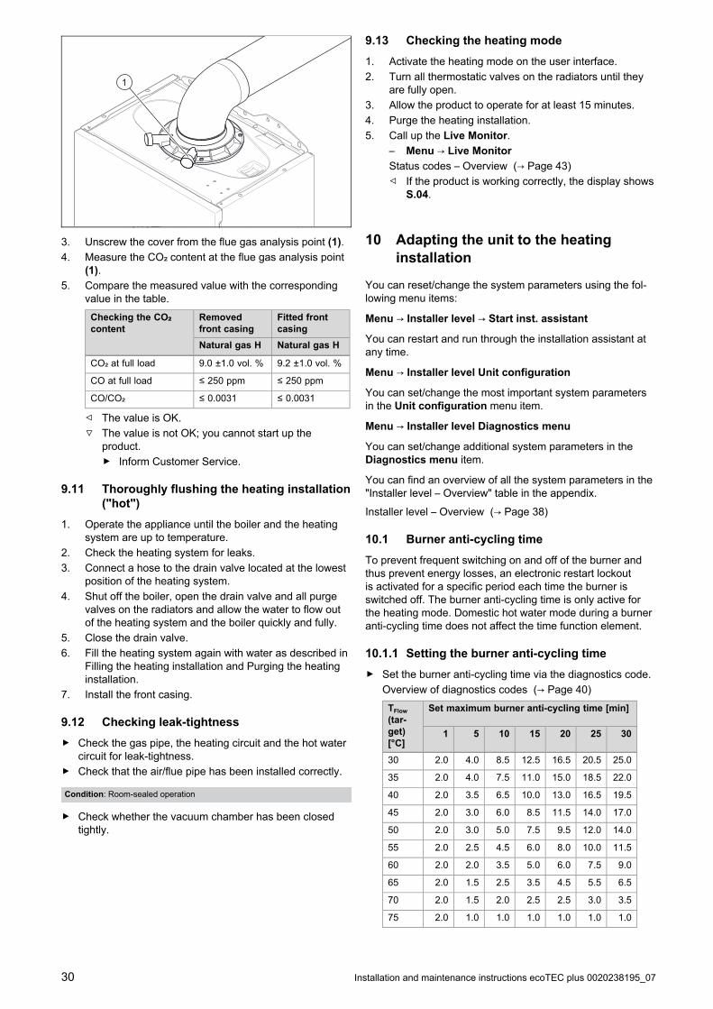
3. Unscrew the cover from the flue gas analysis point (1).
4. Measure the CO₂ content at the flue gas analysis point(1).
5. Compare the measured value with the correspondingvalue in the table.
Checking the CO₂content
Removedfront casing
Fitted frontcasing
Natural gas H Natural gas H
CO₂ at full load 9.0 ±1.0 vol. % 9.2 ±1.0 vol. %
CO at full load ≤ 250 ppm ≤ 250 ppm
CO/CO₂ ≤ 0.0031 ≤ 0.0031
◁ The value is OK.
▽ The value is not OK; you cannot start up theproduct.
▶ Inform Customer Service.
9.11 Thoroughly flushing the heating installation("hot")
1. Operate the appliance until the boiler and the heatingsystem are up to temperature.
2. Check the heating system for leaks.
3. Connect a hose to the drain valve located at the lowestposition of the heating system.
4. Shut off the boiler, open the drain valve and all purgevalves on the radiators and allow the water to flow outof the heating system and the boiler quickly and fully.
5. Close the drain valve.
6. Fill the heating system again with water as described inFilling the heating installation and Purging the heatinginstallation.
7. Install the front casing.
9.12 Checking leak-tightness
▶ Check the gas pipe, the heating circuit and the hot watercircuit for leak-tightness.
▶ Check that the air/flue pipe has been installed correctly.
Condition: Room-sealed operation
▶ Check whether the vacuum chamber has been closedtightly.
9.13 Checking the heating mode
1. Activate the heating mode on the user interface.
2. Turn all thermostatic valves on the radiators until theyare fully open.
3. Allow the product to operate for at least 15 minutes.
4. Purge the heating installation.
5. Call up the Live Monitor.
– Menu → Live Monitor
Status codes – Overview (→ Page 43)
◁ If the product is working correctly, the display showsS.04.
10 Adapting the unit to the heatinginstallation
You can reset/change the system parameters using the fol-lowing menu items:
Menu → Installer level → Start inst. assistant
You can restart and run through the installation assistant atany time.
Menu → Installer level Unit configuration
You can set/change the most important system parametersin the Unit configuration menu item.
Menu → Installer level Diagnostics menu
You can set/change additional system parameters in theDiagnostics menu item.
You can find an overview of all the system parameters in the"Installer level – Overview" table in the appendix.
Installer level – Overview (→ Page 38)
10.1 Burner anti-cycling time
To prevent frequent switching on and off of the burner andthus prevent energy losses, an electronic restart lockoutis activated for a specific period each time the burner isswitched off. The burner anti-cycling time is only active forthe heating mode. Domestic hot water mode during a burneranti-cycling time does not affect the time function element.
10.1.1 Setting the burner anti-cycling time
▶ Set the burner anti-cycling time via the diagnostics code.
Overview of diagnostics codes (→ Page 40)
TFlow
(tar-get)[°C]
Set maximum burner anti-cycling time [min]
1 5 10 15 20 25 30
30 2.0 4.0 8.5 12.5 16.5 20.5 25.0
35 2.0 4.0 7.5 11.0 15.0 18.5 22.0
40 2.0 3.5 6.5 10.0 13.0 16.5 19.5
45 2.0 3.0 6.0 8.5 11.5 14.0 17.0
50 2.0 3.0 5.0 7.5 9.5 12.0 14.0
55 2.0 2.5 4.5 6.0 8.0 10.0 11.5
60 2.0 2.0 3.5 5.0 6.0 7.5 9.0
65 2.0 1.5 2.5 3.5 4.5 5.5 6.5
70 2.0 1.5 2.0 2.5 2.5 3.0 3.5
75 2.0 1.0 1.0 1.0 1.0 1.0 1.0
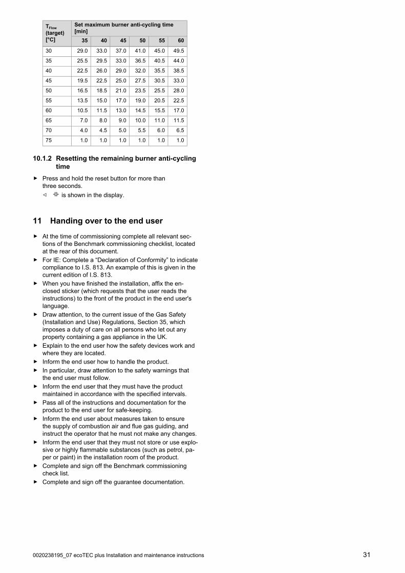
0020238195_07 ecoTEC plus Installation and maintenance instructions 31
TFlow
(target)[°C]
Set maximum burner anti-cycling time[min]
35 40 45 50 55 60
30 29.0 33.0 37.0 41.0 45.0 49.5
35 25.5 29.5 33.0 36.5 40.5 44.0
40 22.5 26.0 29.0 32.0 35.5 38.5
45 19.5 22.5 25.0 27.5 30.5 33.0
50 16.5 18.5 21.0 23.5 25.5 28.0
55 13.5 15.0 17.0 19.0 20.5 22.5
60 10.5 11.5 13.0 14.5 15.5 17.0
65 7.0 8.0 9.0 10.0 11.0 11.5
70 4.0 4.5 5.0 5.5 6.0 6.5
75 1.0 1.0 1.0 1.0 1.0 1.0
10.1.2 Resetting the remaining burner anti-cyclingtime
▶ Press and hold the reset button for more thanthree seconds.
◁ is shown in the display.
11 Handing over to the end user
▶ At the time of commissioning complete all relevant sec-tions of the Benchmark commissioning checklist, locatedat the rear of this document.
▶ For IE: Complete a “Declaration of Conformity” to indicatecompliance to I.S. 813. An example of this is given in thecurrent edition of I.S. 813.
▶ When you have finished the installation, affix the en-closed sticker (which requests that the user reads theinstructions) to the front of the product in the end user'slanguage.
▶ Draw attention, to the current issue of the Gas Safety(Installation and Use) Regulations, Section 35, whichimposes a duty of care on all persons who let out anyproperty containing a gas appliance in the UK.
▶ Explain to the end user how the safety devices work andwhere they are located.
▶ Inform the end user how to handle the product.
▶ In particular, draw attention to the safety warnings thatthe end user must follow.
▶ Inform the end user that they must have the productmaintained in accordance with the specified intervals.
▶ Pass all of the instructions and documentation for theproduct to the end user for safe-keeping.
▶ Inform the end user about measures taken to ensurethe supply of combustion air and flue gas guiding, andinstruct the operator that he must not make any changes.
▶ Inform the end user that they must not store or use explo-sive or highly flammable substances (such as petrol, pa-per or paint) in the installation room of the product.
▶ Complete and sign off the Benchmark commissioningcheck list.
▶ Complete and sign off the guarantee documentation.
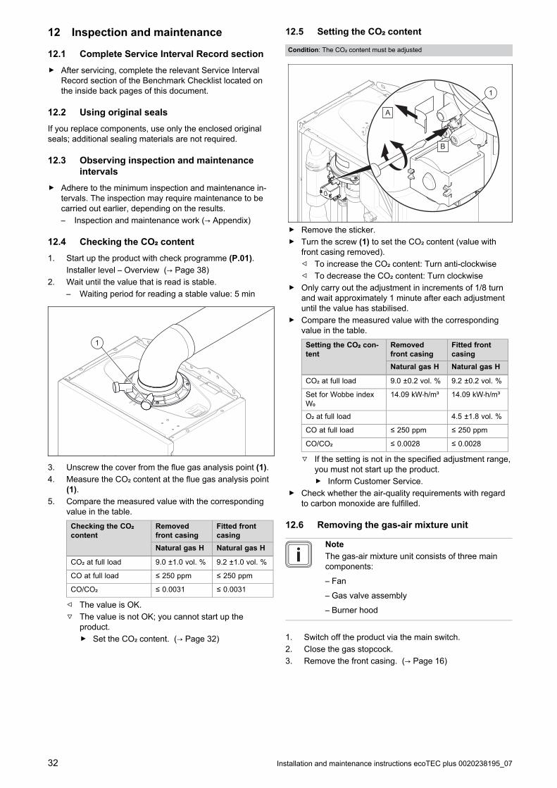
32 Installation and maintenance instructions ecoTEC plus 0020238195_07
12 Inspection and maintenance
12.1 Complete Service Interval Record section
▶ After servicing, complete the relevant Service IntervalRecord section of the Benchmark Checklist located onthe inside back pages of this document.
12.2 Using original seals
If you replace components, use only the enclosed originalseals; additional sealing materials are not required.
12.3 Observing inspection and maintenanceintervals
▶ Adhere to the minimum inspection and maintenance in-tervals. The inspection may require maintenance to becarried out earlier, depending on the results.
– Inspection and maintenance work (→ Appendix)
12.4 Checking the CO₂ content
1. Start up the product with check programme (P.01).
Installer level – Overview (→ Page 38)
2. Wait until the value that is read is stable.
– Waiting period for reading a stable value: 5 min
1
3. Unscrew the cover from the flue gas analysis point (1).
4. Measure the CO₂ content at the flue gas analysis point(1).
5. Compare the measured value with the correspondingvalue in the table.
Checking the CO₂content
Removedfront casing
Fitted frontcasing
Natural gas H Natural gas H
CO₂ at full load 9.0 ±1.0 vol. % 9.2 ±1.0 vol. %
CO at full load ≤ 250 ppm ≤ 250 ppm
CO/CO₂ ≤ 0.0031 ≤ 0.0031
◁ The value is OK.
▽ The value is not OK; you cannot start up theproduct.
▶ Set the CO₂ content. (→ Page 32)
12.5 Setting the CO₂ content
Condition: The CO₂ content must be adjusted
1
A
B
▶ Remove the sticker.
▶ Turn the screw (1) to set the CO₂ content (value withfront casing removed).
◁ To increase the CO₂ content: Turn anti-clockwise
◁ To decrease the CO₂ content: Turn clockwise
▶ Only carry out the adjustment in increments of 1/8 turnand wait approximately 1 minute after each adjustmentuntil the value has stabilised.
▶ Compare the measured value with the correspondingvalue in the table.
Setting the CO₂ con-tent
Removedfront casing
Fitted frontcasing
Natural gas H Natural gas H
CO₂ at full load 9.0 ±0.2 vol. % 9.2 ±0.2 vol. %
Set for Wobbe indexW₀
14.09 kW⋅h/m³ 14.09 kW⋅h/m³
O₂ at full load 4.5 ±1.8 vol. %
CO at full load ≤ 250 ppm ≤ 250 ppm
CO/CO₂ ≤ 0.0028 ≤ 0.0028
▽ If the setting is not in the specified adjustment range,you must not start up the product.
▶ Inform Customer Service.
▶ Check whether the air-quality requirements with regardto carbon monoxide are fulfilled.
12.6 Removing the gas-air mixture unit
Note
The gas-air mixture unit consists of three maincomponents:
– Fan
– Gas valve assembly
– Burner hood
1. Switch off the product via the main switch.
2. Close the gas stopcock.
3. Remove the front casing. (→ Page 16)
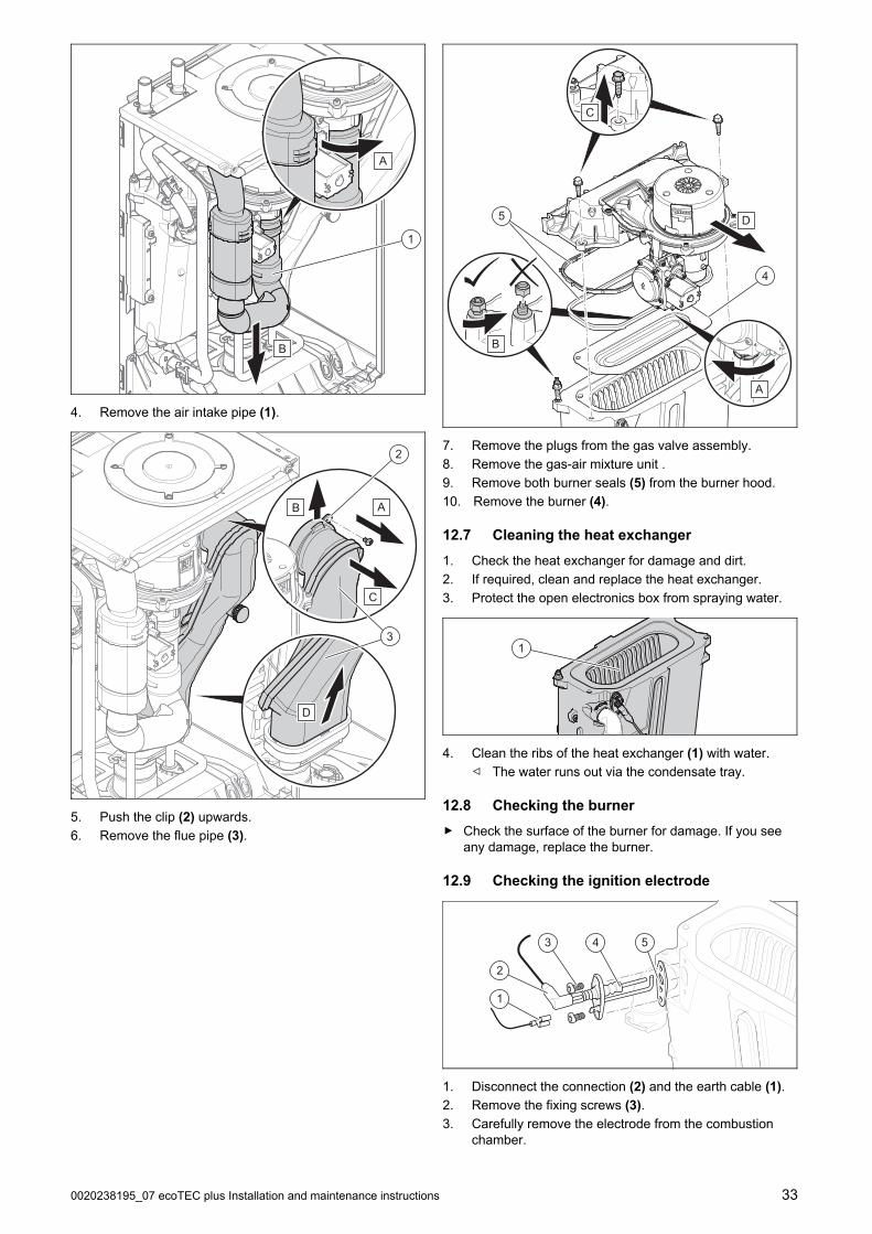
0020238195_07 ecoTEC plus Installation and maintenance instructions 33
A
B
1
4. Remove the air intake pipe (1).
D
C
B
2
3
A
5. Push the clip (2) upwards.
6. Remove the flue pipe (3).
B
A
D
C
4
5
7. Remove the plugs from the gas valve assembly.
8. Remove the gas-air mixture unit .
9. Remove both burner seals (5) from the burner hood.
10. Remove the burner (4).
12.7 Cleaning the heat exchanger
1. Check the heat exchanger for damage and dirt.
2. If required, clean and replace the heat exchanger.
3. Protect the open electronics box from spraying water.
1
4. Clean the ribs of the heat exchanger (1) with water.
◁ The water runs out via the condensate tray.
12.8 Checking the burner
▶ Check the surface of the burner for damage. If you seeany damage, replace the burner.
12.9 Checking the ignition electrode
1
2
3 4 5
1. Disconnect the connection (2) and the earth cable (1).
2. Remove the fixing screws (3).
3. Carefully remove the electrode from the combustionchamber.

34 Installation and maintenance instructions ecoTEC plus 0020238195_07
4. Check that the electrode ends (4) are undamaged.
5. Check the electrode distance.
– Clearance for the ignition electrodes: 3.5 to 4.5 mm
6. Make sure that the seal (5) is free from damage.
▽ If necessary, replace the seal.
12.10 Cleaning the condensate trap
2
3
1
A B
1. Unclip the lower section of the condensate trap (1) fromthe upper section of the condensate trap (2).
2. Remove the float (3).
3. Flush out the lower section of the condensate trap withwater.
4. Re-insert the float (3).
Note
Check whether the float is present in thecondensate trap.
5. Clip the lower section of the condensate trap (1) into theupper section of the condensate trap (2).
12.11 Installing the gas-air mixture unit
1. Install the burner.
2. Install two new burner seals in the burner hood.
3. Install the gas-air mixture unit.
4. Tighten the screws in a cross-wise pattern until theburner flange fits closely and uniformly onto the mat-ing surfaces.
– Tightening torque: 7 Nm, if a torque spanner isavailable
5. Install the flue pipe.
6. Install the air intake pipe.
12.12 Draining the product
1. Close the service valves of the product.
2. Start check programme P.06.
3. Open the drain valves.
12.13 Completing inspection and maintenancework
1. Check the gas connection pressure (gas flow pressure).(→ Page 29)
2. Check the CO₂ content. (→ Page 32)
3. If required, set the maintenance interval.
4. Check the product for tightness. (→ Page 30)
5. Install the front casing. (→ Page 16)
6. Fill out the relevant Service Record section in theBenchmark Checklist located at the rear of thisdocument.
13 Troubleshooting
13.1 Rectifying faults
▶ If fault codes (F.XX) are present, refer to the table in theappendix for advice or use the check programme(s).
Overview of fault codes (→ Page 44)
Installer level – Overview (→ Page 38)
If several faults occur at the same time, the display showsthe corresponding fault messages for two seconds each inalternation.
▶ Press and hold the reset button for more thanthree seconds.
▶ If you are unable to clear the fault code and it reappearsdespite several reset attempts, contact customer service.
13.2 Calling up the fault memory
The last 10 fault messages are stored in the fault memory.
▶ Navigate to the Fault list menu.
◁ The display shows the number of faults that haveoccurred, the fault numbers and the correspondingplain text display.
▶ Press or to call up individual fault messages.
13.3 Deleting the fault memory
1. Navigate to the Fault list menu.
2. Press twice to delete the fault list.
13.4 Resetting parameters to factory settings
1. Navigate to diagnostics code D.096 in the installer level.
2. Set the diagnostics code to 1, and confirm by pressing.

0020238195_07 ecoTEC plus Installation and maintenance instructions 35
13.5 Preparing the repair work
1. Decommission the product.
2. Disconnect the product from the electrical installation.
3. Remove the front casing.
4. Close the gas stopcock.
5. Close the service valves in the heating flow and in theheating return.
6. Close the service valve in the cold water pipe.
7. Drain the product if you want to replace water-carryingcomponents of the product.
8. Ensure that water does not drip on live components(e.g. the electronics box).
9. Use only new seals and O-rings. Do not use any addi-tional components.
13.5.1 Procuring spare parts
The original components of the product were also certifiedby the manufacturer as part of the declaration of conformity.If you use other, non-certified or unauthorised parts duringmaintenance or repair work, this may void the conformity ofthe product and it will therefore no longer comply with theapplicable standards.
We strongly recommend that you use original spare partsfrom the manufacturer as this guarantees fault-free and safeoperation of the product. To receive information about theavailable original spare parts, contact the contact addressprovided on the back page of these instructions.
▶ If you require spare parts for maintenance or repairwork, use only the spare parts that are permitted for theproduct.
13.6 Replacing defective components
13.6.1 Replacing the burner
1. Remove the gas-air mixture unit. (→ Page 32)
2. Remove the burner seal.
3. Remove the burner .
4. Install the new burner complete with new burner seal onthe heat exchanger.
5. Install the gas-air mixture unit. (→ Page 34)
13.6.2 Replacing the gas-air mixture unit
1. Remove the gas-air mixture unit. (→ Page 32)
2. Install the new gas-air mixture (→ Page 34).
13.6.3 Replacing the heat exchanger
1. Remove the side section. (→ Page 16)
2. Remove the gas-air mixture unit. (→ Page 32)
E
1
2
D
B
C
A
3. Remove the flow pipe (1).
4. Remove the return pipe (2).
B
A
5. Remove the gas pipe .
B3
4
A
6. Undo the clip underneath the condensate tray (4).
7. Undo the two screws (3).
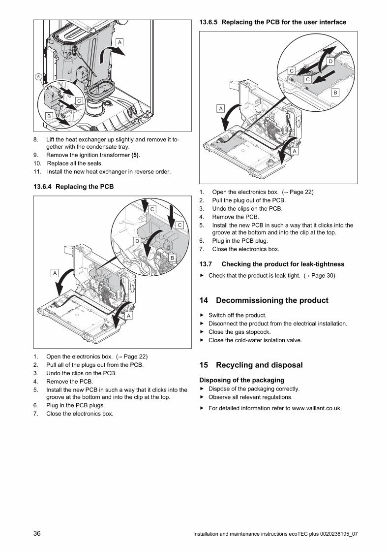
36 Installation and maintenance instructions ecoTEC plus 0020238195_07
A
5
C
B
8. Lift the heat exchanger up slightly and remove it to-gether with the condensate tray.
9. Remove the ignition transformer (5).
10. Replace all the seals.
11. Install the new heat exchanger in reverse order.
13.6.4 Replacing the PCB
C
C
D
B
A
A
1. Open the electronics box. (→ Page 22)
2. Pull all of the plugs out from the PCB.
3. Undo the clips on the PCB.
4. Remove the PCB.
5. Install the new PCB in such a way that it clicks into thegroove at the bottom and into the clip at the top.
6. Plug in the PCB plugs.
7. Close the electronics box.
13.6.5 Replacing the PCB for the user interface
B
CC
D
A
A
1. Open the electronics box. (→ Page 22)
2. Pull the plug out of the PCB.
3. Undo the clips on the PCB.
4. Remove the PCB.
5. Install the new PCB in such a way that it clicks into thegroove at the bottom and into the clip at the top.
6. Plug in the PCB plug.
7. Close the electronics box.
13.7 Checking the product for leak-tightness
▶ Check that the product is leak-tight. (→ Page 30)
14 Decommissioning the product
▶ Switch off the product.
▶ Disconnect the product from the electrical installation.
▶ Close the gas stopcock.
▶ Close the cold-water isolation valve.
15 Recycling and disposal
Disposing of the packaging▶ Dispose of the packaging correctly.
▶ Observe all relevant regulations.
▶ For detailed information refer to www.vaillant.co.uk.

0020238195_07 ecoTEC plus Installation and maintenance instructions 37
Appendix
A Inspection and maintenance work
The table below lists the manufacturer requirements with respect to minimum inspection and maintenance intervals. If na-tional regulations and directives require shorter inspection and maintenance intervals, you should observe these instead ofthe intervals listed. Each time inspection and maintenance work is carried out, carry out the required preparatory and com-pletion work.
Note
For those appliances which are not part of an annual service agreement/policy, maintenance must be carried outat least every 5 years.
# Maintenance work Interval
1 Record all of the analysis results in the Benchmark service record inthese instructions
Annually
2 Ask the end user whether any significant problems occur when operatingthe product
Annually
3 Use the diagnostics system to check the product's fault history Annually
4 Visually inspect whether the air/flue pipe and its opening have been in-stalled correctly in accordance with the set-up instructions
Annually
5 Check that the unit has been installed correctly and the connections havebeen secured
Annually
6 Check all of the connections for tightness Annually
7 Check that the condensate pipe is in good condition, that it is leak-tightand that the drain is correct
Annually
8 Check whether all of the externally routed condensate pipes are dimen-sioned correctly and have been insulated sufficiently (frost protection)
Annually
9 Check whether the gas flow rate corresponds with the specifications onthe data plate and lies within the tolerances specified in these instructions
Annually
10 If the gas flow rate lies outside of the tolerances specified in these in-structions, eliminate the fault in accordance with the regulations and thecurrent technology
Annually
11 Check the general condition of the product and, if required, eliminate anyfaults that are found
Annually
12 Carry out the combustion analysis: Measure the CO content, CO₂ contentand the CO/CO₂ ratio. For products with a rear air/flue connection: Thecombustion analysis can only be carried out when the unit casing hasbeen removed; it is not necessary to test these products for flue gas recir-culation
Annually
13 Check the product's recirculation at the supply air test point on the air/fluepipe. If required, inspect the entire air/flue system and, if necessary, cor-rect the fault
Annually
14 Disconnect the product from the electrical installation Annually
15 Check and, if required, correct the electrical installation Annually
16 Remove the unit casing, check the condition of all of the functional com-ponents, in particular for leaks, corrosion, rust, etc. and, if required, repairany damage
Annually
17 Visual inspection of the heat exchanger and burner seals Annually
18 Carefully clean the inside of the product: The air passages to the burnermust be clear and clean
Annually
19 Close the installation's gas stopcock and, if required, service valves Annually
20 Check the quality of the heating water: Clarity (clouding), correct inhibitorand pH value
Annually
21 Removing the gas-air mixture unit at regular intervals 32
22 Checking the burner at regular intervals 33
23 Cleaning the heat exchanger at regular intervals 33
24 Check and, if required, replace the insulating mat in the burner area at regular intervals
25 Installing the gas-air mixture unit at regular intervals 34
26 Cleaning the condensate trap Annually 34
27 Filling the condensate trap Annually 27

38 Installation and maintenance instructions ecoTEC plus 0020238195_07
# Maintenance work Interval
28 Reassemble the product After each time maintenancework is carried out
29 Open the service valves, carry out the required leak-tightness test Annually
30 Fill the product/heating installation to the filling pressure specified for thesystem
Annually
31 Connect the product to the electrical installation Annually
32 Run the test operation on the product/heating installation including hotwater generation (if available) and, if required, purge the product/heatinginstallation
Annually
33 Measure the CO content, CO₂ content and the CO/CO₂ ratio again Annually
B Installer level – Overview
Setting level ValuesUnit Increment, select, explanation
DefaultsettingMin. Max.
Installer level →
Enter code 00 99 – 1 (competent person code 17) –
Installer level → List of faults →
F.XX - F.XX¹ Current value – – –
Installer level → Test programs →
Gas type check Current value – Liquid gas, natural gas –
Installer level → Test programs → Check programs →
P.00 Purging – – – Yes, No –
P.01 Maximum load – – – Yes, No –
P.02 Minimum load – – – Yes, No –
P.06 Filling mode – – – Yes, No –
Installer level → Test programs → Function menu →
T.02 3-way valve – – – On, Off –
T.03 Fan – – – On, Off –
T.04 Cyl. charging pump – – – On, Off –
T.05 Circulation pump – – – On, Off –
T.06 External pump – – – On, Off –
T.08 Burner – – – On, Off –
Installer level → Test programs → Electronics self-test →
Self-test – – – Yes, No –
Installer level → Appliance config. →
Language – – – Deutsch, English, Français, Italiano, Dansk,Nederlands, Castellano, Türkce, Magyar,Pусский, Українськa, Svenska, Norsk, Pol-ski, Čeština, Hrvatski, Slovenčina, Română,Slovenščina, Português, Srpski
English
Flow temp. setpoint 30 75 ℃ 1 –
DHW temperature 30 60 ℃ 1
Product with connected domestic hot water cylin-der
–
¹Fault lists are only displayed, and can only be deleted, if faults have occurred.

0020238195_07 ecoTEC plus Installation and maintenance instructions 39
Setting level ValuesUnit Increment, select, explanation
DefaultsettingMin. Max.
Auxiliary relay 1 10 – 1 = Circulation pump
2 = External pump
3 = Cylinder charging pump
4 = Extractor hood
5 = External solenoid valve
6 = External fault message
7 = Solar pump (not active)
8 = eBUS remote control (not active)
9 = Legionella protection pump (not active)
10 = Solar valve (not active)
2
Accessory relay 1 1 10 – 1 = Circulation pump
2 = External pump
3 = Cylinder charging pump
4 = Extractor hood
5 = External solenoid valve
6 = External fault message
7 = Solar pump (not active)
8 = eBUS remote control (not active)
9 = Legionella protection pump (not active)
10 = Solar valve (not active)
2
Accessory relay 2 1 10 – 1 = Circulation pump
2 = External pump
3 = Cylinder charging pump
4 = Extractor hood
5 = External solenoid valve
6 = External fault message
7 = Solar pump (not active)
8 = eBUS remote control (not active)
9 = Legionella protection pump (not active)
10 = Solar valve (not active)
2
Heating partial load – – kW Partial load only, full load only, auto Auto
Contact data Phonenum-ber
– – 0 – 9 Auto
Default setting – – – On, Off –
Installer level → Diagnostics menu →
D.XXX - D.XXX Current value – – –
Installer level → Start ins. assistant →
Language – – – Deutsch, English, Français, Italiano, Dansk,Nederlands, Castellano, Türkce, Magyar,Pусский, Українськa, Svenska, Norsk, Pol-ski, Čeština, Hrvatski, Slovenčina, Română,Slovenščina, Português, Srpski
English
Filling mode: 3-way valve is in mid-position
0 2 – 0 = Normal operating mode
1 = Mid-position (parallel operation)
2 = Permanent heating mode position
–
Purge programme – – – Automatic adaptive purging of the heating circuitand hot water circuit
Not active
Active
–
Flow temp. setpoint 30 75 ℃ 1 –
DHW temperature 35 60 ℃ 1
Product with hot water generation
–
¹Fault lists are only displayed, and can only be deleted, if faults have occurred.

40 Installation and maintenance instructions ecoTEC plus 0020238195_07
Setting level ValuesUnit Increment, select, explanation
DefaultsettingMin. Max.
Auxiliary relay 1 10 – 1 = Circulation pump
2 = External pump
3 = Cylinder charging pump
4 = Extractor hood
5 = External solenoid valve
6 = External fault message
7 = Solar pump (not active)
8 = eBUS remote control (not active)
9 = Legionella protection pump (not active)
10 = Solar valve (not active)
2
Accessory relay 1 1 10 – 1 = Circulation pump
2 = External pump
3 = Cylinder charging pump
4 = Extractor hood
5 = External solenoid valve
6 = External fault message
7 = Solar pump (not active)
8 = eBUS remote control (not active)
9 = Legionella protection pump (not active)
10 = Solar valve (not active)
2
Accessory relay 2 1 10 – 1 = Circulation pump
2 = External pump
3 = Cylinder charging pump
4 = Extractor hood
5 = External solenoid valve
6 = External fault message
7 = Solar pump (not active)
8 = eBUS remote control (not active)
9 = Legionella protection pump (not active)
10 = Solar valve (not active)
2
Contact data Phone number – 0-9 –
End the installation assistant? – – – Yes, No –
¹Fault lists are only displayed, and can only be deleted, if faults have occurred.
C Overview of diagnostics codes
Setting level ValuesUnit Increment, select, explanation
Default set-ting
Own settingMin. Max.
d.00 Heating maximum output – – kW The maximum heating output variesdepending on the product.
→ Section "Technical data"
→ Section"Technical
data"
Adjustable
d.01 Pump overrun time inheating mode
1 60 min 1 5 Adjustable
d.02 Burner anti-cycling timein heating mode
2 60 min 1 20 Adjustable
d.04 Water temperature in thecylinder
Current value ℃ – – Notadjustable
d.05 Determined target heatingflow temperature
Current value℃ – – Not
adjustable
d.07 Target temperature forthe domestic hot water cylin-der
Current value ℃ – – Notadjustable
d.08 Status of the 230 V ther-mostat
Current value – 0 = Room thermostat open (no heatrequirement)
1 = Room thermostat closed (heatrequirement)
– Notadjustable
d.09 Target heating flow tem-perature that is set on theeBUS room thermostat
Current value – – – Notadjustable

0020238195_07 ecoTEC plus Installation and maintenance instructions 41
Setting level ValuesUnit Increment, select, explanation
Default set-ting
Own settingMin. Max.
d.10 Status of the internalpump in the heating circuit
Current value – off / on – Notadjustable
d.11 Status of the heating cir-cuit's shunt pump
Current value – off / on – Notadjustable
d.13 Status of the domestichot water circuit's circulationpump
Current value – off / on – Notadjustable
d.16 Status of the 24 V roomthermostat
Current value – off = Heating off
on = Heating on
– Notadjustable
d.17 Heating control – – – off = Flow temperature
on = Return temperature (adjustmentfor underfloor heating. If you have ac-tivated the return temperature control,the automatic heating output determ-ination function is not active.)
0 Adjustable
d.18 Pump overrun operatingmode
1 3 – 1 = Comfort (continuously operatingpump)
3 = Eco (intermittent pump operation– for the dissipation of the residualheat after domestic hot water gen-eration at an extremely low heat de-mand)
1 Adjustable
d.20 Maximum target domestichot water temperature
50 60 ℃ 1 50 Adjustable
d.23 Status of the heat de-mand
Current value – off = Heating off (Summer mode)
on = Heating on
– Notadjustable
d.24 Status of the pressureswitch
0 1 – off = Not switched
on = Switched
– Notadjustable
d.25 Status of the requirementto reheat the cylinder or forthe domestic hot water warmstart from the eBUS thermo-stat
Current value – off = Function deactivated
on = Function activated
– Notadjustable
d.27 Function of relay 1 (multi-functional module)
1 10 – 1 = Circulation pump
2 = External pump
3 = Cylinder charging pump
4 = Extraction hood
5 = External solenoid valve
6 = External fault message
7 = Solar pump (omitted)
8 = eBUS remote control
9 = Anti-legionella pump
10 = Solar valve
1 Adjustable
d.28 Function of relay 2 (multi-functional module)
1 10 – 1 = Circulation pump
2 = External pump
3 = Cylinder charging pump
4 = Extraction hood
5 = External solenoid valve
6 = External fault message
7 = Solar pump (omitted)
8 = eBUS remote control
9 = Anti-legionella pump
10 = Solar valve
2 Adjustable
d.31 Automatic filling device 0 2 – 0 = Manual
1 = Semi-automatic
2 = Automatic
0 Adjustable
d.33 Fan speed target value Current value rpm Fan speed = Display value x 100 – Notadjustable
d.34 Value for the fan speed Current value rpm Fan speed = Display value x 100 – Notadjustable
d.40 Heating flow temperature Current value ℃ – – Notadjustable
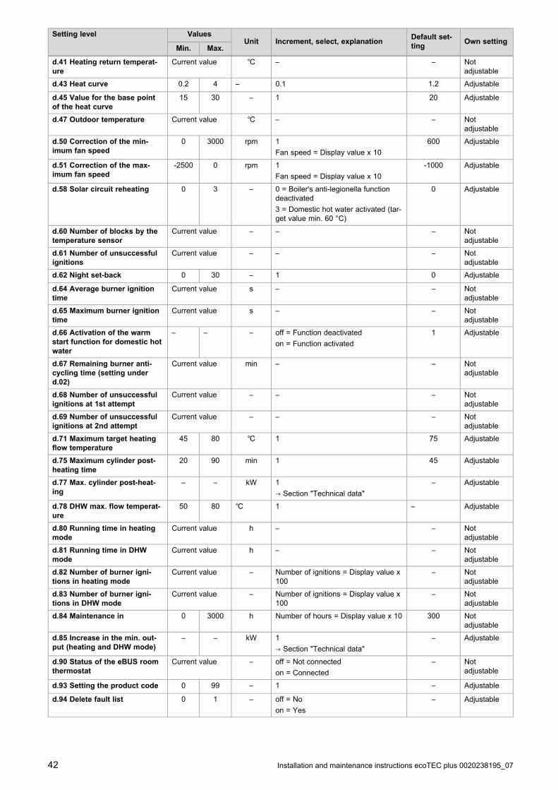
42 Installation and maintenance instructions ecoTEC plus 0020238195_07
Setting level ValuesUnit Increment, select, explanation
Default set-ting
Own settingMin. Max.
d.41 Heating return temperat-ure
Current value ℃ – – Notadjustable
d.43 Heat curve 0.2 4 – 0.1 1.2 Adjustable
d.45 Value for the base pointof the heat curve
15 30 – 1 20 Adjustable
d.47 Outdoor temperature Current value ℃ – – Notadjustable
d.50 Correction of the min-imum fan speed
0 3000 rpm 1
Fan speed = Display value x 10
600 Adjustable
d.51 Correction of the max-imum fan speed
-2500 0 rpm 1
Fan speed = Display value x 10
-1000 Adjustable
d.58 Solar circuit reheating 0 3 – 0 = Boiler's anti-legionella functiondeactivated
3 = Domestic hot water activated (tar-get value min. 60 °C)
0 Adjustable
d.60 Number of blocks by thetemperature sensor
Current value – – – Notadjustable
d.61 Number of unsuccessfulignitions
Current value – – – Notadjustable
d.62 Night set-back 0 30 – 1 0 Adjustable
d.64 Average burner ignitiontime
Current value s – – Notadjustable
d.65 Maximum burner ignitiontime
Current value s – – Notadjustable
d.66 Activation of the warmstart function for domestic hotwater
– – – off = Function deactivated
on = Function activated
1 Adjustable
d.67 Remaining burner anti-cycling time (setting underd.02)
Current value min – – Notadjustable
d.68 Number of unsuccessfulignitions at 1st attempt
Current value – – – Notadjustable
d.69 Number of unsuccessfulignitions at 2nd attempt
Current value – – – Notadjustable
d.71 Maximum target heatingflow temperature
45 80 ℃ 1 75 Adjustable
d.75 Maximum cylinder post-heating time
20 90 min 1 45 Adjustable
d.77 Max. cylinder post-heat-ing
– – kW 1
→ Section "Technical data"
– Adjustable
d.78 DHW max. flow temperat-ure
50 80 ℃ 1 – Adjustable
d.80 Running time in heatingmode
Current value h – – Notadjustable
d.81 Running time in DHWmode
Current value h – – Notadjustable
d.82 Number of burner igni-tions in heating mode
Current value – Number of ignitions = Display value x100
– Notadjustable
d.83 Number of burner igni-tions in DHW mode
Current value – Number of ignitions = Display value x100
– Notadjustable
d.84 Maintenance in 0 3000 h Number of hours = Display value x 10 300 Notadjustable
d.85 Increase in the min. out-put (heating and DHW mode)
– – kW 1
→ Section "Technical data"
– Adjustable
d.90 Status of the eBUS roomthermostat
Current value – off = Not connected
on = Connected
– Notadjustable
d.93 Setting the product code 0 99 – 1 – Adjustable
d.94 Delete fault list 0 1 – off = No
on = Yes
– Adjustable

0020238195_07 ecoTEC plus Installation and maintenance instructions 43
Setting level ValuesUnit Increment, select, explanation
Default set-ting
Own settingMin. Max.
d.95 Software versions – – – 1 = Main PCB
2 = Interface PCB
– Adjustable
d.96 Reset to factory settings – – – 0 = No
1 = Yes
– Adjustable
d.128 Heating minimum targetvalue
10 75 ℃ 1 10 Adjustable
d.129 Domestic hot water min-imum target value
35(combiboiler)
45(sys-tem
boiler)
60 ℃ 1 35 Adjustable
D Status codes – Overview
Status code Meaning
Displays in heating mode
S. 0 Heating mode: No requirement
S.01 Heating mode: Fan prerun
S.02 Heating mode: Pump prerun
S.03 Heating mode: Burner ignition
S.04 Heating mode: Burner on
S.05 Heating mode: Pump/fan overrun
S.06 Heating mode: Fan overrun
S.07 Heating mode: Pump overrun
S.08 Heating mode: Temporary shutdown after heating procedure
Display in domestic hot water mode with cylinder
S.20 Domestic hot water mode: Requirement
S.21 Domestic hot water mode: Fan prerun
S.22 Domestic hot water mode: Pump prerun
S.23 Domestic hot water mode: Burner ignition
S.24 DHW mode: Burner on
S.25 DHW mode: Pump/fan overrun
S.26 DHW mode: Fan overrun
S.27 DHW mode: Pump overrun
S.28 Domestic hot water mode: Temporary shutdown of the burner
Other displays
S.30 Room thermostat is blocking heating mode.
S.31 No heating demand: Summer mode, eBUS control, waiting period
S.32 Fan waiting time: Fan speed outside of the tolerance values
S.34 Frost protection active
S.39 Underfloor heating contact open
S.42 Flue non-return flap closed
S.46 Frost protection mode (Comfort): Minimum load
S.53 Product in waiting period/operating block function due to water deficiency (flow/return spread too large)
S.54 Waiting period: Water deficiency in the circuit (flow/return spread too large)
S.88 Product purging active
S.91 Maintenance: Demo mode
S.96 Automatic test programme: Return temperature sensor, heating demands blocked.
S.98 Automatic test programme: Return temperature sensor, heating demands blocked.
S.99 Internal automatic test programmes

44 Installation and maintenance instructions ecoTEC plus 0020238195_07
Status code Meaning
S.108 Purging the combustion chamber, fan in operation
S.109 Product's standby mode activated
E Overview of fault codes
Fault code Meaning Possible cause
F.00 Fault: Flow temperature sensor NTC plug not plugged in or has come loose, multiple plug on the PCB notplugged in correctly, interruption in cable harness, NTC sensor defective
F.01 Fault: Return temperature sensor NTC plug not plugged in or has come loose, multiple plug on the PCB notplugged in correctly, interruption in cable harness, NTC sensor defective
F.10 Short circuit: Flow temperature sensor NTC sensor defective, short circuit in the cable harness, cable/housing
F.11 Short circuit: Return temperature sensor NTC sensor defective, short circuit in the cable harness, cable/housing
F.12 andF.91
Short circuit: Cylinder temperaturesensor
NTC sensor defective, short circuit in the cable harness, cable/housing
F.13 Short circuit: Temperature sensor for thedomestic hot water cylinder
NTC sensor defective, short circuit in the cable harness, cable/housing
F.20 Safety shutdown: Overheating temperat-ure reached
Incorrect earth connection between cable harness and product, flow or returnNTC defective (loose connection), stray spark via ignition cable, ignition plugor ignition electrode
F.23 Safety shutdown: Temperature spreadtoo great (NTC1/NTC2)
Pump blocked, insufficient pump output, air in product, flow and return NTCsensors connected the wrong way round
F.24 Safety shutdown: Temperature rise toofast
Pump blocked, insufficient pump output, air in product, system pressure toolow, non-return valve blocked/incorrectly installed
F.25 Safety shutdown: Flue gas temperaturetoo high
Break in plug connection for optional flue gas safety cut-out (SCO), break incable harness
F.27 Safety shutdown: Fault in flame detec-tion
Moisture on the electronics, electronics (flame monitor) defective, gas solen-oid valve leaking
F.28 Fault: Ignition unsuccessful when startingup
Gas meter defective or gas pressure switch has triggered, air in gas, gasflow pressure too low, thermal cut-out has triggered, incorrect gas injector,incorrect spare gas valve assembly, fault on the gas valve assembly, mul-tiple plug on PCB incorrectly plugged in, break in cable harness, ignition sys-tem (ignition transformer, ignition cable, ignition plug, ignition electrode) de-fective, ionisation flow interrupted (cable, electrode), incorrect earthing ofproduct, electronics defective
F.29 Fault: Flame loss Gas supply temporarily stopped, flue gas recirculation, incorrect earthing ofproduct, ignition transformer has spark failure
F.32 Fan frost protection function active: Fanspeed outside the tolerance values
Plug on fan not correctly plugged in, multiple plug on PCB not correctlyplugged in, break in cable harness, fan blocked, Hall sensor defective, elec-tronics defective
F.49 eBUS fault: Voltage too low Short circuit on eBUS, eBUS overload or two power supplies with differentpolarities on the eBUS
F.61 Fault: Gas valve assembly control Short circuit/short-to-ground in cable harness to gas valve assembly, gasvalve assembly defective (coils shorted to earth), electronics defective
F.62 Fault: Gas valve switch-off control Delayed switch-off of gas valve assembly, delayed extinguishing of flamesignal, gas valve assembly leaking, electronics defective
F.63 Fault: EEPROM Electronics defective
F.64 Fault: Electronics / sensor / analogue-to-digital converter
Flow or return NTC short circuited, electronics defective
F.65 Fault: Electronics temperature too high Electronics overheating due to external influences, electronics defective
F.67 Value sent back by ASIC is incorrect(flame signal)
Implausible flame signal, electronics defective
F.68 Fault: Unstable flame (analogue input) Air in gas, gas flow pressure too low, incorrect air ratio, incorrect gas in-jector, ionisation flow interruption (cable, electrode)
F.70 Invalid product code (DSN) Display and PCB replaced at same time and Device Specific Number notreset, wrong or missing output coding resistor
F.71 Fault: Flow/return temperature sensor Flow temperature sensor signalling constant value: Flow temperature sensorincorrectly positioned on flow pipe, flow temperature sensor defective
F.72 Fault: Deviation in the water pressuresensor/return temperature sensor
Flow/return NTC temperature difference too great → flow and/or return tem-perature sensor defective
F.77 Fault: Condensate or smoke No response, flue non-return flap defective
F.78 Interruption to DHW outlet sensor atexternal control
UK link box is connected, but domestic hot water NTC not bridged

0020238195_07 ecoTEC plus Installation and maintenance instructions 45
Fault code Meaning Possible cause
F.83 Fault: Dry fire When the burner starts, the temperature change registered at the flow orreturn temperature sensor is non-existent or too small: Insufficient waterin the product, the flow or return temperature sensor is not in the correctposition on the pipe
F.84 Fault: Flow/return temperature sensor Values not consistent, difference < -6 K
Flow and return temperature sensors signalling implausible values: Flow andreturn temperature sensors have been inverted, flow and return temperaturesensors have not been correctly installed
F.85 Fault: Temperature sensor The flow and/or return temperature sensors have been installed on the samepipe/incorrect pipe
Temperature sensor not connected or is connected incorrectly
F.86 Fault: Underfloor heating contact Underfloor heating contact open, sensor disconnected or defective
F.87 Fault: Electrodes Electrodes not connected or they are connected incorrectly, short circuit inthe cable harness
F.88 Fault: Gas valve assembly Gas valve assembly not connected or it is connected incorrectly, short circuitin the cable harness
F.97 Fault: Main PCB self-test failed Main PCB defective
Connection No communication between the mainPCB and the user interface
Electronics defective

46 Installation and maintenance instructions ecoTEC plus 0020238195_07
F Wiring diagram
X14LN
X12
X51
X51
X20
16
19
3154
56
13
X51
X20
X40 X51
X30
X2
X21
X41
X22
X14L
N
– +24V=RT BUS
Burneroff
RT
X1
FUS
X106X32
X90
X12
X35
X1
RT
X21
LN
LN
15
eBUS
Burner off
X106
M
4321
NL
24V
230V~
24V
230V
~
123
2
7
9
143
5
6
10
11 12
8
1 Main PCB
2 Interface PCB
3 Control system
4 Temperature sensor on the heating flow
5 Temperature sensor on the heating return
6 Fan
7 Gas valve assembly
8 Heating pump
9 Monitoring electrode
10 Room thermostat
11 Main power supply and connection for 230 V control
12 Ignition electrode
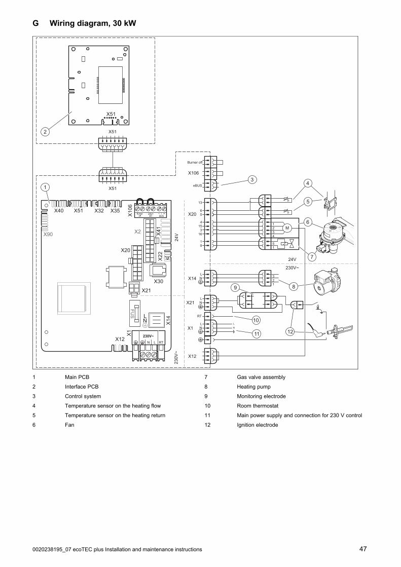
0020238195_07 ecoTEC plus Installation and maintenance instructions 47
G Wiring diagram, 30 kW
X14LN
X12
X51
X51
X20
16
19
3154
56
13
X51
X20
X40 X51
X30
X2
X21
X41
X22
X14L
N
– +24V=RT BUS
Burneroff
RT
X1
FUS
X106X32
X90
X12
X35
X1
RT
X21
LN
LN
15
eBUS
Burner off
X106
M
4321
NL
24V
230V~
24V
230V
~
123
2
7
9
143
5
6
10
11 12
8
1 Main PCB
2 Interface PCB
3 Control system
4 Temperature sensor on the heating flow
5 Temperature sensor on the heating return
6 Fan
7 Gas valve assembly
8 Heating pump
9 Monitoring electrode
10 Room thermostat
11 Main power supply and connection for 230 V control
12 Ignition electrode

48 Installation and maintenance instructions ecoTEC plus 0020238195_07
H Commissioning Checklist
© Heating and Hotwater Industry Council (HHIC)
www.centralheating.co.uk
* All installations in England and Wales must be notified to Local Authority Building Control (LABC) either directly or through aCompetent Persons Scheme. A Building Regulations Compliance Certificate will then be issued to the customer.
www.hhic.co.uk
Benchmark Commissioning & Warranty Validation Service Record
It is a requirement that the boiler is installed and commissioned to the manufacturers’ instructions and the data fields on the commissioning checklist completed in full.
To instigate the boiler warranty the boiler needs to be registered with the manufacturer within one month of the installation. The warranty rests with the end-user (consumer), and they should be made aware it is ultimately their responsibility to register with the manufacturer, within the allotted time period.
It is essential that the boiler is serviced in line with the manufacturers’ recommendations, at least annually. This must be carried out by a competent Gas Safe registered engineer. The service details should be recorded on the Benchmark Service and Interim Boiler Work Record and left with the householder. Failure to comply with the manufacturers’ servicing instructions and requirements will invalidate the warranty.
This Commissioning Checklist is to be completed in full by the competent person who commissioned the boiler as a means of demonstrating compliance with the appropriate Building Regulations and then handed to the customer to keep for future reference.
Failure to install and commission according to the manufacturers’ instructions and complete this Benchmark Commissioning Checklist will invalidate the warranty. This does not affect the customer’s statutory rights.

0020238195_07 ecoTEC plus Installation and maintenance instructions 49
© Heating and Hotwater Industry Council (HHIC)
www.centralheating.co.uk
GAS BOILER SYSTEM COMMISSIONING CHECKLIST & WARRANTY VALIDATION RECORDAddress:
Boiler make and model:
Boiler serial number:
Commissioned by (PRINT NAME): Gas Safe registration number:
Company name: Telephone number:
Company email: Company address:
Commissioning date:
Heating and hot water system complies with the appropriate Building Regulations? Yes
Boiler Plus requirements (tick the appropriate box(s))
Boiler Plus option chosen for combination boiler in ENGLANDWeather compensation Smart thermostat with automisation and optimisation
Load compensation Flue Gas Heat Recovery
Time and temperature control to hot water Cylinder thermostat and programmer/timer Combination boiler
Zone valves pre-existing Fitted Not required
Thermostatic radiator valves pre-existing Fitted Not required
Automatic bypass to system pre-existing Fitted Not required
pre-existing Fitted Not required
Water quality
instructions Yes
What system cleaner was used? Brand: Product:
What inhibitor was used? Brand: Product:
pre-existing Fitted Not required
CENTRAL HEATING MODE measure and record (as appropriate)
Gas rate (for combination boilers complete DHW mode gas rate) m3/hr or ft3/hr
Central heating output left at factory settings? Yes No
If no, what is the maximum central heating output selected? kW
Dynamic gas inlet pressure mbar
°C
Central heating return temperature °C
System correctly balanced/rebalanced? Yes
COMBINATION BOILERS ONLY
Is the installation in a hard water area (above 200ppm)? Yes No
Water scale reducer/softener pre-existing Fitted Not required
Brand: Product:
Yes No
If yes- DHW expansion vessel pre-existing Fitted Not required
Pressure reducing valve pre-existing Fitted Not required
DOMESTIC HOT WATER MODE Measure and record
Gas rate m3/hr or ft3/hr
Dynamic gas inlet pressure at maximum rate mbar
Cold water inlet temperature °C
Hot water has been checked at all outlets Yes Temperature °C
CONDENSATE DISPOSAL
The condensate drain has been installed in accordance with the manufacturers’ instructions and/or BS5546/BS6798 Yes
Point of termination Internal External (only where internal termination impractical)
Method of disposal Gravity Pumped
ALL INSTALLATIONS
Record the followingAt max rate: CO ppm CO2 % CO/CO2 Ratio
At min rate (where possible) CO ppm CO2 % CO/CO2 Ratio
instructions, and readings are correct? Yes
The operation of the boiler and system controls have been demonstrated to and understood by the customer Yes
The manufacturers’ literature, including Benchmark Checklist and Service Record, has been explained and left with the customer Yes
Commissioning Engineer’s signature
Customer’s signature
Time, temperature control and boiler interlock provided for central heating and hot water Yes
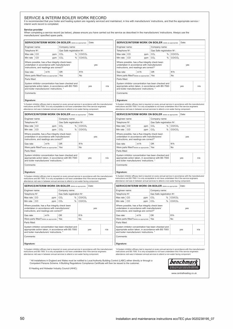
50 Installation and maintenance instructions ecoTEC plus 0020238195_07
© Heating and Hotwater Industry Council (HHIC)
www.centralheating.co.uk
SERVICE & INTERIM BOILER WORK RECORDIt is recommended that your boiler and heating system are regularly serviced and maintained, in line with manufacturers’ instructions, and that the appropriate service / interim work record is completed.
Service providerWhen completing a service record (as below), please ensure you have carried out the service as described in the manufacturers’ instructions. Always use the
SERVICE/INTERIM WORK ON BOILER delete as appropriate Date:
Engineer name: Company name:Telephone No: Gas Safe registration No: Max rate CO ppm CO² % CO/CO² Min rate CO ppm CO² % CO/CO²
undertaken in accordance with manufacturers’ instructions, and readings are correct?”
yes
Gas rate: m3/h OR ft3/hdelete as appropriate Yes No
System inhibitor concentration has been checked and appropriate action taken, in accordance with BS 7593 and boiler manufacturers’ instructions. *
yes n/a
Comments:
Signature:
instructions and BS 7593. It is only acceptable to not have undertaken this if the service engineers attendance visit was in between annual services to attend a non-water facing component.
instructions and BS 7593. It is only acceptable to not have undertaken this if the service engineers attendance visit was in between annual services to attend a non-water facing component.
instructions and BS 7593. It is only acceptable to not have undertaken this if the service engineers attendance visit was in between annual services to attend a non-water facing component.
instructions and BS 7593. It is only acceptable to not have undertaken this if the service engineers attendance visit was in between annual services to attend a non-water facing component.
instructions and BS 7593. It is only acceptable to not have undertaken this if the service engineers attendance visit was in between annual services to attend a non-water facing component.
instructions and BS 7593. It is only acceptable to not have undertaken this if the service engineers attendance visit was in between annual services to attend a non-water facing component.
SERVICE/INTERIM WORK ON BOILER delete as appropriate Date:
Engineer name: Company name:Telephone No: Gas Safe registration No: Max rate CO ppm CO² % CO/CO² Min rate CO ppm CO² % CO/CO²
undertaken in accordance with manufacturers’ instructions, and readings are correct?”
yes
Gas rate: m3/h OR ft3/hdelete as appropriate Yes No
System inhibitor concentration has been checked and appropriate action taken, in accordance with BS 7593 and boiler manufacturers’ instructions. *
yes n/a
Comments:
Signature:

0020238195_07 ecoTEC plus Installation and maintenance instructions 51
© Heating and Hotwater Industry Council (HHIC)
www.centralheating.co.uk
SERVICE & INTERIM BOILER WORK RECORDIt is recommended that your boiler and heating system are regularly serviced and maintained, in line with manufacturers’ instructions, and that the appropriate service / interim work record is completed.
Service providerWhen completing a service record (as below), please ensure you have carried out the service as described in the manufacturers’ instructions. Always use the
SERVICE/INTERIM WORK ON BOILER delete as appropriate Date:
Engineer name: Company name:Telephone No: Gas Safe registration No: Max rate CO ppm CO² % CO/CO² Min rate CO ppm CO² % CO/CO²
undertaken in accordance with manufacturers’ instructions, and readings are correct?”
yes
Gas rate: m3/h OR ft3/hdelete as appropriate Yes No
System inhibitor concentration has been checked and appropriate action taken, in accordance with BS 7593 and boiler manufacturers’ instructions. *
yes n/a
Comments:
Signature:
instructions and BS 7593. It is only acceptable to not have undertaken this if the service engineers attendance visit was in between annual services to attend a non-water facing component.
instructions and BS 7593. It is only acceptable to not have undertaken this if the service engineers attendance visit was in between annual services to attend a non-water facing component.
instructions and BS 7593. It is only acceptable to not have undertaken this if the service engineers attendance visit was in between annual services to attend a non-water facing component.
instructions and BS 7593. It is only acceptable to not have undertaken this if the service engineers attendance visit was in between annual services to attend a non-water facing component.
instructions and BS 7593. It is only acceptable to not have undertaken this if the service engineers attendance visit was in between annual services to attend a non-water facing component.
instructions and BS 7593. It is only acceptable to not have undertaken this if the service engineers attendance visit was in between annual services to attend a non-water facing component.
SERVICE/INTERIM WORK ON BOILER delete as appropriate Date:
Engineer name: Company name:Telephone No: Gas Safe registration No: Max rate CO ppm CO² % CO/CO² Min rate CO ppm CO² % CO/CO²
undertaken in accordance with manufacturers’ instructions, and readings are correct?”
yes
Gas rate: m3/h OR ft3/hdelete as appropriate Yes No
System inhibitor concentration has been checked and appropriate action taken, in accordance with BS 7593 and boiler manufacturers’ instructions. *
yes n/a
Comments:
Signature:
SERVICE/INTERIM WORK ON BOILER delete as appropriate Date:
Engineer name: Company name:Telephone No: Gas Safe registration No: Max rate CO ppm CO² % CO/CO² Min rate CO ppm CO² % CO/CO²
undertaken in accordance with manufacturers’ instructions, and readings are correct?”
yes
Gas rate: m3/h OR ft3/hdelete as appropriate Yes No
System inhibitor concentration has been checked and appropriate action taken, in accordance with BS 7593 and boiler manufacturers’ instructions. *
yes n/a
Comments:
Signature:
SERVICE/INTERIM WORK ON BOILER delete as appropriate Date:
Engineer name: Company name:Telephone No: Gas Safe registration No: Max rate CO ppm CO² % CO/CO² Min rate CO ppm CO² % CO/CO²
undertaken in accordance with manufacturers’ instructions, and readings are correct?”
yes
Gas rate: m3/h OR ft3/hdelete as appropriate Yes No
System inhibitor concentration has been checked and appropriate action taken, in accordance with BS 7593 and boiler manufacturers’ instructions. *
yes n/a
Comments:
Signature:
SERVICE/INTERIM WORK ON BOILER delete as appropriate Date:
Engineer name: Company name:Telephone No: Gas Safe registration No: Max rate CO ppm CO² % CO/CO² Min rate CO ppm CO² % CO/CO²
undertaken in accordance with manufacturers’ instructions, and readings are correct?”
yes
Gas rate: m3/h OR ft3/hdelete as appropriate Yes No
System inhibitor concentration has been checked and appropriate action taken, in accordance with BS 7593 and boiler manufacturers’ instructions. *
yes n/a
Comments:
Signature:
SERVICE/INTERIM WORK ON BOILER delete as appropriate Date:
Engineer name: Company name:Telephone No: Gas Safe registration No: Max rate CO ppm CO² % CO/CO² Min rate CO ppm CO² % CO/CO²
undertaken in accordance with manufacturers’ instructions, and readings are correct?”
yes
Gas rate: m3/h OR ft3/hdelete as appropriate Yes No
System inhibitor concentration has been checked and appropriate action taken, in accordance with BS 7593 and boiler manufacturers’ instructions. *
yes n/a
Comments:
Signature:
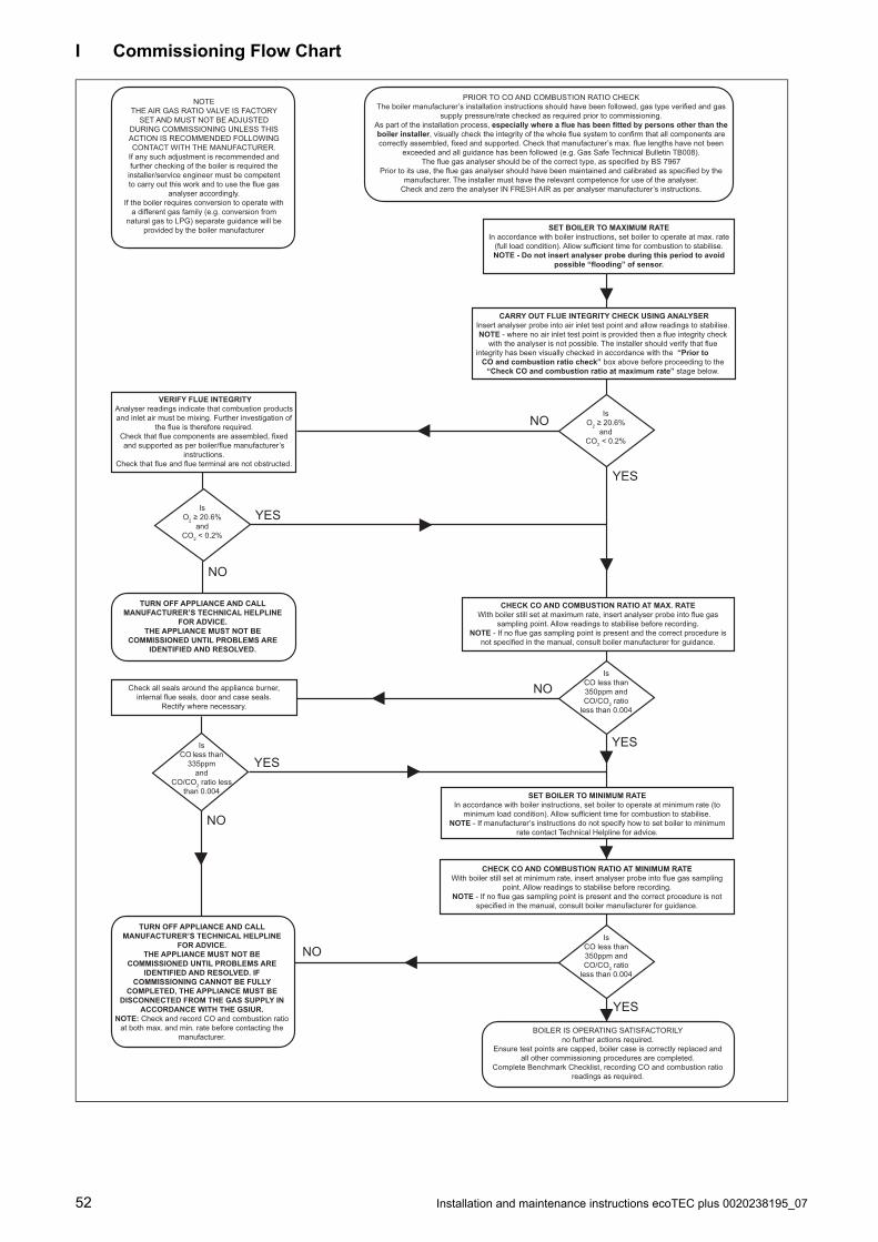
52 Installation and maintenance instructions ecoTEC plus 0020238195_07
I Commissioning Flow Chart
PRIOR TO CO AND COMBUSTION RATIO CHECKThe boiler manufacturer’s installation instructions should have been followed, gas type verified and gas
supply pressure/rate checked as required prior to commissioning.As part of the installation process, especially where a flue has been fitted by persons other than the boiler installer, visually check the integrity of the whole flue system to confirm that all components are correctly assembled, fixed and supported. Check that manufacturer’s max. flue lengths have not been
exceeded and all guidance has been followed (e.g. Gas Safe Technical Bulletin TB008).The flue gas analyser should be of the correct type, as specified by BS 7967
Prior to its use, the flue gas analyser should have been maintained and calibrated as specified by the manufacturer. The installer must have the relevant competence for use of the analyser.
Check and zero the analyser IN FRESH AIR as per analyser manufacturer’s instructions.
NOTETHE AIR GAS RATIO VALVE IS FACTORY
SET AND MUST NOT BE ADJUSTED DURING COMMISSIONING UNLESS THIS ACTION IS RECOMMENDED FOLLOWING CONTACT WITH THE MANUFACTURER.
If any such adjustment is recommended and further checking of the boiler is required the
installer/service engineer must be competent to carry out this work and to use the flue gas
analyser accordingly.If the boiler requires conversion to operate with
a different gas family (e.g. conversion from natural gas to LPG) separate guidance will be
provided by the boiler manufacturer
CARRY OUT FLUE INTEGRITY CHECK USING ANALYSERInsert analyser probe into air inlet test point and allow readings to stabilise.NOTE - where no air inlet test point is provided then a flue integrity check
with the analyser is not possible. The installer should verify that flue integrity has been visually checked in accordance with the “Prior to
CO and combustion ratio check” box above before proceeding to the “Check CO and combustion ratio at maximum rate” stage below.
SET BOILER TO MINIMUM RATEIn accordance with boiler instructions, set boiler to operate at minimum rate (to
minimum load condition). Allow sufficient time for combustion to stabilise.NOTE - If manufacturer’s instructions do not specify how to set boiler to minimum
rate contact Technical Helpline for advice.
CHECK CO AND COMBUSTION RATIO AT MINIMUM RATEWith boiler still set at minimum rate, insert analyser probe into flue gas sampling
point. Allow readings to stabilise before recording.NOTE - If no flue gas sampling point is present and the correct procedure is not
specified in the manual, consult boiler manufacturer for guidance.
CHECK CO AND COMBUSTION RATIO AT MAX. RATEWith boiler still set at maximum rate, insert analyser probe into flue gas
sampling point. Allow readings to stabilise before recording.NOTE - If no flue gas sampling point is present and the correct procedure is
not specified in the manual, consult boiler manufacturer for guidance.
SET BOILER TO MAXIMUM RATEIn accordance with boiler instructions, set boiler to operate at max. rate
(full load condition). Allow sufficient time for combustion to stabilise.NOTE - Do not insert analyser probe during this period to avoid
possible “flooding” of sensor.
IsCO less than 350ppm andCO/CO2 ratio
less than 0.004
IsO2 20.6%
andCO2 < 0.2%
IsCO less than 350ppm andCO/CO2 ratio
less than 0.004
BOILER IS OPERATING SATISFACTORILYno further actions required.
Ensure test points are capped, boiler case is correctly replaced and all other commissioning procedures are completed.
Complete Benchmark Checklist, recording CO and combustion ratio readings as required.
TURN OFF APPLIANCE AND CALL MANUFACTURER’S TECHNICAL HELPLINE
FOR ADVICE.THE APPLIANCE MUST NOT BE
COMMISSIONED UNTIL PROBLEMS ARE IDENTIFIED AND RESOLVED.
VERIFY FLUE INTEGRITYAnalyser readings indicate that combustion products and inlet air must be mixing. Further investigation of
the flue is therefore required.Check that flue components are assembled, fixed and supported as per boiler/flue manufacturer’s
instructions.Check that flue and flue terminal are not obstructed.
IsCO less than
335ppmand
CO/CO2 ratio less than 0.004
IsO2 20.6%
andCO2 < 0.2%
Check all seals around the appliance burner, internal flue seals, door and case seals.
Rectify where necessary.
TURN OFF APPLIANCE AND CALL MANUFACTURER’S TECHNICAL HELPLINE
FOR ADVICE.THE APPLIANCE MUST NOT BE
COMMISSIONED UNTIL PROBLEMS ARE IDENTIFIED AND RESOLVED. IF
COMMISSIONING CANNOT BE FULLY COMPLETED, THE APPLIANCE MUST BE
DISCONNECTED FROM THE GAS SUPPLY IN ACCORDANCE WITH THE GSIUR.
NOTE: Check and record CO and combustion ratio at both max. and min. rate before contacting the
manufacturer.
NO
NO
NO
NO
NO
YES
YES
YESYES
YES

0020238195_07 ecoTEC plus Installation and maintenance instructions 53
Index
AAdditional relay.................................................................... 28Air intake pipe, removing..................................................... 32Air/flue pipe, horizontal wall duct......................................... 15Air/flue pipe, installing ......................................................... 22Air/flue pipe, type C13 ......................................................... 15Air/flue pipe, type C33 ......................................................... 15Air/flue pipe, vertical roof duct ............................................. 15Article number ....................................................................... 9BBurner anti-cycling time....................................................... 30Burner anti-cycling time, resetting ....................................... 31Burner anti-cycling time, setting .......................................... 30Burner, checking ................................................................. 33Burner, removing................................................................. 32Burner, replacing ................................................................. 35CCE marking............................................................................ 9Check programmes ............................................................. 28CO₂ content
Checking........................................................................ 32CO₂ content, checking......................................................... 29Condensate discharge pipe................................................. 20Condensate trap, cleaning .................................................. 34Condensate trap, filling........................................................ 27Contact details..................................................................... 28Control ................................................................................. 24DData plate .............................................................................. 9Decommissioning ................................................................ 36Dimensions.......................................................................... 11Disposal, packaging ............................................................ 36Disposing of the packaging ................................................. 36Documents ............................................................................ 9Domestic hot water temperature ......................................... 28Draining the product ............................................................ 34EElectrical installation............................................................ 22Ending, installation assistant ............................................... 28FFactory settings, restoring ................................................... 34Fault codes.......................................................................... 34Fault memory, calling up ..................................................... 34Filling mode ......................................................................... 27Filling the heating installation .............................................. 28Flue pipe, removing............................................................. 32Front casing, installing......................................................... 16Frost protection ................................................................... 10GGas Council Number ............................................................. 9Gas flow rate ...................................................................... 28Gas group, checking ........................................................... 19Gas setting .......................................................................... 28Gas-air mixture, removing ................................................... 32Guarantee and Customer Service......................................... 6HHanding over to the end user .............................................. 31Heat exchanger, cleaning.................................................... 33Heat exchanger, replacing .................................................. 35Heating pump, connecting................................................... 23Heating system, open.......................................................... 18Heating water supply, open heating system........................ 18
IIgnition electrode, checking................................................. 33Inspection work ................................................................... 32Inspection work, completing ................................................ 34Installation assistant, ending ............................................... 28Installation assistants, restarting ......................................... 28Installation, preparations ..................................................... 18Installer level, calling up ...................................................... 25Intended use.......................................................................... 3KKammerbelüftung ................................................................ 12LLanguage ............................................................................ 27Leak-tightness ............................................................... 30, 36MMaintenance work ............................................................... 32Maintenance work, completing............................................ 34Minimum clearance ............................................................. 12Mounting template............................................................... 16Multi-functional module ....................................................... 28OOperating concept ............................................................... 25Overheating protection ........................................................ 10PPartial heat load .................................................................. 28PCB, replacing .................................................................... 36Power supply....................................................................... 23Power supply, establishing.................................................. 23Product, decommissioning .................................................. 36Product, mounting ............................................................... 16Product, switching on .......................................................... 27RRegulations ........................................................................... 5Repair work, preparing ........................................................ 35SSafety devices ..................................................................... 10Serial number ........................................................................ 9Side section, installing......................................................... 17Side section, removing ........................................................ 16Spare parts.......................................................................... 35Status codes........................................................................ 25Switching on ........................................................................ 27TTarget flow temperature ...................................................... 28Telephone number, competent person ............................... 28Test programmes ................................................................ 28Treating the heating water .................................................. 26UUser interface, replacing the PCB....................................... 36VValidity of the instructions...................................................... 9WWeight ................................................................................. 16


Supplier
Vaillant Ltd.
Nottingham Road Belper Derbyshire DE56 1JT
Telephone 0330 100 3461
[email protected] www.vaillant.co.uk
Publisher/manufacturer
Vaillant GmbH
Berghauser Str. 40 D-42859 Remscheid
Tel. +492191 18 0 Fax +492191 18 2810
[email protected] www.vaillant.de
© These instructions, or parts thereof, are protected by copyright and may be reproduced or distributed only withthe manufacturer's written consent.
Subject to technical modifications.
0020238195_07