ECE375 Lab 2 C -> Assembler -> Machine Code
16
ECE375 Lab 2 C - > Assembler - > Machine Code TA: Han Jang School of Electrical Engineering and Computer Science Oregon State University
-
Upload
khangminh22 -
Category
Documents
-
view
0 -
download
0
Transcript of ECE375 Lab 2 C -> Assembler -> Machine Code

ECE375 Lab 2C -> Assembler -> Machine Code
TA: Han JangSchool of Electrical Engineering and Computer ScienceOregon State University

Goal of this Lab� Understand bumpbot behaviors.
� Learn how to control with registers.
� Learn how to avoid switch debouncing.
� Understand the difference between C and Assmebly.

Bumpbot Behaviors� Forward
� Halt
� Backward
Bit 7
Bit6
Bit5
Bit 4
Bit 3
Bit2
Bit 1
Bit 0
On(1) Off(0)
Left MotorEnable
Left MotorForward
Right MotorForward
Right MotorEnable
Left MotorDisable
Left MotorForward
Right MotorForward
Right MotorDisable
Left MotorEnable
Left MotorBackward
Right MotorBackward
Right MotorEnable

Bumpbot Behaviors
� Turn Right
� Turn Left
Left MotorEnable
Left MotorForward
Right MotorBackward
Right MotorEnable
Right MotorForward
Left MotorBackward
Left MotorEnable
Right MotorEnable
On(1) Off(0)

Connection Guides

Controlling Registers� Three types of registers◦ DDRx is a data direction register for port x◦ PORTx is a port output register for port x◦ PINx is a port input register for port x
� Setting outputs◦ DDRB = 0b11111111 ; set 7-0 bits as outputs◦ PORTB = 0b11110000 ; turn on LEDs connected to 7-4
bits
� Setting inputs◦ DDRD = 0b00000000 ; set 7-0 bits as inputs◦ PORTD = 0b111111111 ; enable pull up resistor◦ IN mpr, PIND ; read input to mpr

AVR Ports
Atmega128 Datasheet 66p
Pull-upresistor
DDRx
PORTx
PINx

AVR Ports – Configure output
Atmega128 Datasheet 66p
Pull-upresistor
DDRx
PORTx
PINx
1
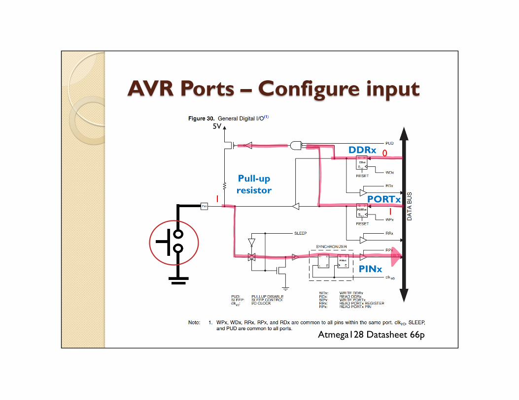
AVR Ports – Configure input
Atmega128 Datasheet 66p
Pull-upresistor
DDRx
PORTx
PINx
0
11
5V

AVR Ports – Configure input
Atmega128 Datasheet 66p
Pull-upresistor
DDRx
PORTx
PINx
0
10
5V

Switch Debouncing
5V
Pull-upresistor
Image from google
Delay

C vs Assembly� In C
DDRB = 0b11110000 // set 7-4bits as outputsPORTB = 0b01100000 // turn on LEDs connected to 5,6bits
� In AssemblyLDI mpr, 0b11110000OUT DDRB, mpr ; set 7-4bits as outputsLDI mpr, 0b01100000OUT PORTB, mpr ; turn on LEDs connected to 5,6bits

C vs Assembly� In C
If (PIND == 0b11110000) // check if the right whisker is hit{
BotAction(); // do something}
� In AssemblyIN mpr, PINDCPI mpr, 0b11111110 ; check if right whisker is hitBRNE NEXT ; if not, go to NEXTRCALL BotAction ; if yes, do somethingNEXT:

Check-off Lists
� Correct Bumpbot behaviors accordingly to different triggering whiskers.

Challenge
� “Push” function� The Bumpbot should go forward to push an object
if both whiskers got hit.

Questions?