ECblue - Baudiment Technology
39
ECblue Basic Version EC-fans with highest efciency Assembly instructions Software version: D1583...87A, D1680A from Version 1.00 L-BAL-F036-GB 1004 Index 003 Part.-No. 00295296-GB english
-
Upload
khangminh22 -
Category
Documents
-
view
1 -
download
0
Transcript of ECblue - Baudiment Technology

ECblueBasic Version
EC-fanswith highest efciency
Assembly instructions
Software version: D1583...87A, D1680A from Version 1.00
L-BAL-F036-GB 1004 Index 003 Part.-No. 00295296-GB
english
Content
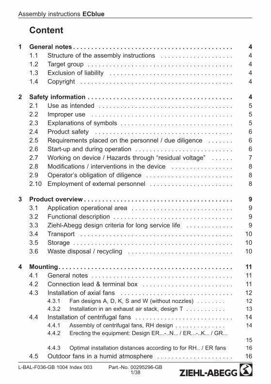
1 General notes . . . . . . . . . . . . . . . . . . . . . . . . . . . . . . . . . . . . . . . . . . . . 41.1 Structure of the assembly instructions . . . . . . . . . . . . . . . . . . . . 41.2 Target group . . . . . . . . . . . . . . . . . . . . . . . . . . . . . . . . . . . . . . . . 41.3 Exclusion of liability . . . . . . . . . . . . . . . . . . . . . . . . . . . . . . . . . . 41.4 Copyright . . . . . . . . . . . . . . . . . . . . . . . . . . . . . . . . . . . . . . . . . . 4
2 Safety information . . . . . . . . . . . . . . . . . . . . . . . . . . . . . . . . . . . . . . . . 42.1 Use as intended . . . . . . . . . . . . . . . . . . . . . . . . . . . . . . . . . . . . . 52.2 Improper use . . . . . . . . . . . . . . . . . . . . . . . . . . . . . . . . . . . . . . . 52.3 Explanations of symbols . . . . . . . . . . . . . . . . . . . . . . . . . . . . . . . 52.4 Product safety . . . . . . . . . . . . . . . . . . . . . . . . . . . . . . . . . . . . . . 62.5 Requirements placed on the personnel / due diligence . . . . . . . 62.6 Start-up and during operation . . . . . . . . . . . . . . . . . . . . . . . . . . . 62.7 Working on device / Hazards through “residual voltage” . . . . . . 72.8 Modications / interventions in the device . . . . . . . . . . . . . . . . . 82.9 Operator’s obligation of diligence . . . . . . . . . . . . . . . . . . . . . . . . 82.10 Employment of external personnel . . . . . . . . . . . . . . . . . . . . . . . 8
3 Product overview . . . . . . . . . . . . . . . . . . . . . . . . . . . . . . . . . . . . . . . . . 93.1 Application operational area . . . . . . . . . . . . . . . . . . . . . . . . . . . . 93.2 Functional description . . . . . . . . . . . . . . . . . . . . . . . . . . . . . . . . . 93.3 Ziehl-Abegg design criteria for long service life . . . . . . . . . . . . . 93.4 Transport . . . . . . . . . . . . . . . . . . . . . . . . . . . . . . . . . . . . . . . . . . 103.5 Storage . . . . . . . . . . . . . . . . . . . . . . . . . . . . . . . . . . . . . . . . . . . . 103.6 Waste disposal / recycling . . . . . . . . . . . . . . . . . . . . . . . . . . . . . 10
4 Mounting. . . . . . . . . . . . . . . . . . . . . . . . . . . . . . . . . . . . . . . . . . . . . . . . 114.1 General notes . . . . . . . . . . . . . . . . . . . . . . . . . . . . . . . . . . . . . . . 114.2 Connection lead & terminal box . . . . . . . . . . . . . . . . . . . . . . . . . 114.3 Installation of axial fans . . . . . . . . . . . . . . . . . . . . . . . . . . . . . . . 12
4.3.1 Fan designs A, D, K, S and W (without nozzles) . . . . . . . . 124.3.2 Installation in an exhaust air stack, design T . . . . . . . . . . . 13
4.4 Installation of centrifugal fans . . . . . . . . . . . . . . . . . . . . . . . . . . . 144.4.1 Assembly of centrifugal fans, RH design . . . . . . . . . . . . . . 144.4.2 Erecting the equipment: Design ER...-..N... / ER...-..K... / GR...
154.4.3 Optimal installation distances according to for RH.. / ER fans 16
4.5 Outdoor fans in a humid atmosphere . . . . . . . . . . . . . . . . . . . . . 16
Assembly instructions ECblue
L-BAL-F036-GB 1004 Index 003 Part.-No. 00295296-GB1/38
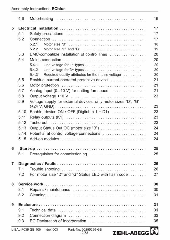
4.6 Motorheating . . . . . . . . . . . . . . . . . . . . . . . . . . . . . . . . . . . . . . . 16
5 Electrical installation . . . . . . . . . . . . . . . . . . . . . . . . . . . . . . . . . . . . . . 175.1 Safety precautions . . . . . . . . . . . . . . . . . . . . . . . . . . . . . . . . . . . 175.2 Connection . . . . . . . . . . . . . . . . . . . . . . . . . . . . . . . . . . . . . . . . . 17
5.2.1 Motor size “B” . . . . . . . . . . . . . . . . . . . . . . . . . . . . . . . . 185.2.2 Motor size “D” and “G” . . . . . . . . . . . . . . . . . . . . . . . . . . 19
5.3 EMC-compatible installation of control lines . . . . . . . . . . . . . . . . 205.4 Mains connection . . . . . . . . . . . . . . . . . . . . . . . . . . . . . . . . . . . . 20
5.4.1 Line voltage for 1~ types . . . . . . . . . . . . . . . . . . . . . . . . . 205.4.2 Line voltage for 3~ types . . . . . . . . . . . . . . . . . . . . . . . . . 205.4.3 Required quality attributes for the mains voltage . . . . . . . . . 20
5.5 Residual-current-operated protective device . . . . . . . . . . . . . . . . 215.6 Motor protection . . . . . . . . . . . . . . . . . . . . . . . . . . . . . . . . . . . . . 215.7 Analog input (0...10 V) for setting fan speed . . . . . . . . . . . . . . . 215.8 Output voltage +10 V . . . . . . . . . . . . . . . . . . . . . . . . . . . . . . . . . 235.9 Voltage supply for external devices, only motor sizes “D”, “G”
(+24 V, GND) . . . . . . . . . . . . . . . . . . . . . . . . . . . . . . . . . . . . . . 235.10 Enable, device ON / OFF (Digital In 1 = D1) . . . . . . . . . . . . . . . 235.11 Relay outputs (K1) . . . . . . . . . . . . . . . . . . . . . . . . . . . . . . . . . . . 235.12 Tacho out . . . . . . . . . . . . . . . . . . . . . . . . . . . . . . . . . . . . . . . . . . 235.13 Output Status Out OC (motor size “B”) . . . . . . . . . . . . . . . . . . . . 245.14 Potential at control voltage connections . . . . . . . . . . . . . . . . . . . 245.15 Add-on modules . . . . . . . . . . . . . . . . . . . . . . . . . . . . . . . . . . . . . 24
6 Start-up . . . . . . . . . . . . . . . . . . . . . . . . . . . . . . . . . . . . . . . . . . . . . . . . 256.1 Prerequisites for commissioning . . . . . . . . . . . . . . . . . . . . . . . . . 25
7 Diagnostics / Faults . . . . . . . . . . . . . . . . . . . . . . . . . . . . . . . . . . . . . . . 267.1 Trouble shooting . . . . . . . . . . . . . . . . . . . . . . . . . . . . . . . . . . . . . 267.2 For motor size “D” and “G” Status LED with ash code . . . . . . . 27
8 Service work. . . . . . . . . . . . . . . . . . . . . . . . . . . . . . . . . . . . . . . . . . . . . 308.1 Repairs / maintenance . . . . . . . . . . . . . . . . . . . . . . . . . . . . . . . . 308.2 Cleaning . . . . . . . . . . . . . . . . . . . . . . . . . . . . . . . . . . . . . . . . . . . 31
9 Enclosure . . . . . . . . . . . . . . . . . . . . . . . . . . . . . . . . . . . . . . . . . . . . . . . 319.1 Technical data . . . . . . . . . . . . . . . . . . . . . . . . . . . . . . . . . . . . . . 319.2 Connection diagram . . . . . . . . . . . . . . . . . . . . . . . . . . . . . . . . . . 339.3 EC Declaration of Incorporation . . . . . . . . . . . . . . . . . . . . . . . . . 35
Assembly instructions ECblue
L-BAL-F036-GB 1004 Index 003 Part.-No. 00295296-GB2/38

9.4 Index . . . . . . . . . . . . . . . . . . . . . . . . . . . . . . . . . . . . . . . . . . . . . 379.5 Manufacturer reference . . . . . . . . . . . . . . . . . . . . . . . . . . . . . . . 389.6 Service information . . . . . . . . . . . . . . . . . . . . . . . . . . . . . . . . . . . 38
Assembly instructions ECblue
L-BAL-F036-GB 1004 Index 003 Part.-No. 00295296-GB3/38

1 General notes1.1 Structure of the assembly instructions
Before installation and start-up, read this assembly instructions carefully to en-sure correct use!We emphasize that these assembly instructions apply to specic units only, andare in no way valid for the complete system!Use these assembly instructions to work safely with and on the device. They containsafety instructions that must be complied with as well as information that is required forfailure-free operation of the device.Keep these assembly instructions together with the device. It must be ensured that allpersons that are to work on the device can refer to the assembly instructions at any time.Keep the assembly instructions for continued use. They must be passed-on to allsuccessive owners, users and nal customers.
1.2 Target groupThe assembly instructions address persons entrusted with planning, installation, com-missioning and maintenance and servicing and who have the corresponding qualica-tions and skills for their job.
1.3 Exclusion of liabilityConcurrence between the contents of these assembly instructions and the describedhardware and software in the device has been examined. It is still possible that non-compliances exist; no guarantee is assumed for complete conformity. To allow for futuredevelopments, construction methods and technical data given are subject to alteration.We do not accept any liability for possible errors or omissions in the information con-tained in data, illustrations or drawings provided.Ziehl-Abegg AG is not liable for damage due to misuse, incorrect use, improper use oras a consequence of unauthorized repairs or modications.
1.4 CopyrightThese assembly instructions contain copyright protected information. The assemblyinstructions may be neither completely nor partially photocopied, reproduced, translatedor put on data medium without previous explicit consent from Ziehl-Abegg AG. Infringe-ments are liable for damages. All rights reserved, including those that arise throughpatent issue or registration on a utility model.
2 Safety informationThis chapter contains instructions to prevent personal injury and property damage.These instructions do not lay claim to completeness. In case of questions and problems,please consult our company technicians.
Assembly instructions ECblue General notes
L-BAL-F036-GB 1004 Index 003 Part.-No. 00295296-GB4/38

2.1 Use as intendedAttention!
• The fans are only intended for the conveyance of air or mixtures similar toair.
• Other uses which do not coincide with, or which exceed those specied willbe deemed unauthorised unless contractually agreed. Damages resultingfrom such unauthorised uses will not be the liability of the manufacturer.The user will assume sole liability.
• They must not be used in hazardous areas for the transfer of gas, mistvapours or mixtures. Nor must they be used for the transfer of solid compo-nents in the transfer medium.
• Reading these document and complying with all contained instructions -especiallythe safety notications contained therein -are considered part of intended use.
• To consider is also the documentation of attached components.
2.2 Improper useImproper use / reasonably foreseeable misuse
• Conveyance of aggressive and explosive gaseous media• Use in an explosive atmosphere• Operation with iced up fan wheels• Conveyance of abrasive or adhesive media• Conveyance of liquid media• Use of the fan and add-on parts (e.g. safety grille) as a resting surface or climbingaid
• Unauthorised constructional modications to the fan• Operation of the fan as a safety component or for the performance of safety-relevant functions in the sense of DIN EN ISO 13849-1.
• Blocking or braking of the fan by inserting objects• Loosening of the running wheel from the motor• All applications not listed in the intended use
Not the manufacturer, rather the operator of the frequency inverter is liable for anypersonal harm or material damage arising from non-intendeduse.
2.3 Explanations of symbolsSafety instructions are highlighted with warning triangles and are depicted according tothe degree of hazard as follows.Attention!Hazardous area. Death or severe injury or signicant property damage can occur ifthe corresponding precautions are not taken!
Danger owing to electric currentDanger owing to electric current or voltage.
Assembly instructions ECblue Safety information
L-BAL-F036-GB 1004 Index 003 Part.-No. 00295296-GB5/38

InformationImportant information and advice for user.
2.4 Product safetyThe device conforms to the state of the art at the time of delivery and is fundamentallyconsidered to be reliable. The device and its accessories must only be used in a awlesscondition and installed and operated in compliance with the assembly instructions and/oroperating instructions. Operating outside the device's technical specications (F ratingplate and attachment / technical data) can lead to a defect in the device and additionaldamage!A separate fault and performancemonitoring-systemwith an alarm signal functionis necessary in order to prevent personal injuries and material damages duringmalfunctions and in case the device fails. Substitute operation must be taken intoconsideration! The design and installation of the systemmust comply with localregulations and directives.
2.5 Requirements placed on the personnel / due diligencePersons entrusted with the planning, installation, commissioning and maintenance andservicing in connection with the frequency inverter must have the corresponding qual-ications and skills for these jobs.In addition, they must be knowledgeable about the safety regulations, EU directives,rules for the prevention of accidents and the corresponding national as well as regionaland in-house regulations. Personnel to be trained or instructed and apprentices are onlypermitted to work on the device under the supervision of an experienced person. Thisalso applies to personnel undergoing general training. Comply with the legal minimumage.
2.6 Start-up and during operationAttention!
• During commissioning, unexpected and hazardous conditions can arise in theentire installation due to defective adjustments, defective components or incorrectelectrical connections. Remove all persons and objects from the hazardous area.
• Danger of being sucked in: Do not wear loose or hanging clothing, long hair,jewellery, etc.
• Fuses must always be replaced only, never repaired or bridged. The specicationsfor maximum prefusing must always be adhered to (F Technical data). Only fusescited in the electrical circuit diagrammay be used.
• Any faults detected in the electric system/modules/operating equipment must becorrected immediately. If these faults are not corrected, the device/system ispotentially very dangerous. The device/systemmust therefore not be operatedwhen it is faulty.
Assembly instructions ECblue Safety information
L-BAL-F036-GB 1004 Index 003 Part.-No. 00295296-GB6/38

2.7 Working on device / Hazards through “residual voltage”InformationInstallation, electrical connection, and start-up operationmay only be carried outby an electrical specialist in accordance with electrotechnical regulations (e.g. DINEN 50110 or DIN EN 60204).
Danger owing to electric current• It is forbidden to carry out work on electrically live parts. Protection class of
the device when open is IP 00! It is possible to inadventently touch compo-nents carrying hazardous voltages!
• The rotor is not protected by insulation nor grounded to earth in accordancewith DIN EN 60204-1, and for this reason the system constructor mustprovide protection in the form of obstacles or a location outside the han-dling area in accordance with DIN VDE 0100-410 Attachment B, before themotor is connected to a power source. This protection can be achieved forexample by a protection grating (F Product overview: Application opera-tional area and Installation:General).
• The safe isolation from the supply must be checked using a two-pole voltagedetector.
• Even after disconnecting the mains voltage, life-threatening charges can appearbetween the protective ground “PE” and the mains connection.
• The protective conductor is routed over high discharge currents (irrespective of theclock frequency, current-source voltage and motor capacity). Earthing incompliance with VDE specications shall therefore be observed even for testingand trial conditions (EN 50 178, Art. 5.2.11). Without earthing, dangerous voltagescan be present on the motor housing.
• Maintenance work may only be carried out by suitably qualied personnel.
Waiting period at least 3 minutes!Through use of capacitors, danger of death exists even after switching off thedevice through directly touching the energized parts or due to parts that havebecome energized due to faults.The controller housingmay only be removed or opened when the power line hasbeen switched off and a period of three minutes has elapsed since switching it off.
Attention!• The fan may switch on and off automatically for functional reasons.• After power failure or mains disconnection an automatic restart of the fan
takes place after voltage return.• Temperatures of up to approx. 80 °C can arise on the controller housing!• Wait for the fan to come to a complete standstill before approaching it.
Assembly instructions ECblue Safety information
L-BAL-F036-GB 1004 Index 003 Part.-No. 00295296-GB7/38
2.8 Modications / interventions in the deviceAttention!For reasons of safety, no unauthorized interventions or modications may be made onthe device. All planned modications must be authorized by the manufacturer in writing.
Use only genuine spare parts / genuine wearing parts / genuine accessories from Ziehl-Abegg.These parts were specically designed for the device. There is no guarantee thatparts from non-original sources are designed and manufactured in correspondence withload and safety requirements.Parts and optional equipment not supplied by Ziehl-Abegg are not approved by Ziehl-Abegg for use.
2.9 Operator’s obligation of diligence• The contractor or owner must also ensure that the electric systems and equipmentare operated and maintained in accordance with electro-technical regulations.
• The owner is obliged to ensure that the device are operated in perfect workingorder only.
• The device may only be used as intended (F “Application”).• You must periodically examine the safety equipment for their properly functioningcondition.
• The assembly instructions and/or operating instructions are always readily avail-able at the location where the device is being used, are complete and are inlegible condition.
• These persons are regularly instructed in all applicable questions regarding occu-pational safety and environmental protection and are knowledgeable regardingthe assembly instructions and/or operating instructions and, especially, are famil-iar with the safety instructions contained therein.
• All safety and warning notices attached to the frequency inverter are neverremoved and remain legible.
2.10 Employment of external personnelMaintenance and service work are frequently carried out by external employees whooften do not recognize the specic situations and the thus resulting dangers.Thesepersons must be comprehensively informed about the hazards in their area of activity.You must monitor their working methods in order to intervene in good time if necessary.
Assembly instructions ECblue Safety information
L-BAL-F036-GB 1004 Index 003 Part.-No. 00295296-GB8/38

3 Product overview3.1 Application operational area
The fans / motors are not ready-for-use products, but conceived as components forventilation systems (type designationFtype label). The fans may only then be operatedwhen they are installed in accordance with their intended use, and safety has beensecured through protective devices in accordance with DIN EN ISO 13857 (DIN EN ISO12100) or other structural protective measures.
InformationThis assembly instructions describes the combination of motor and controller. Dependenton application and version of the fan absolutely the resuming specications are to beconsidered!
3.2 Functional description
ECblue stands for EC fans with maximum efciency. Highly efcient, electronicallyswitched external rotor motors with permanent magnets are used the speed of which iscontrolled by the integrated controller.The devices are constructed in accordance with the general requirement in DIN EN61800-2 for adjustable speed electrical power systems and is intended for one-quadrant-
ECblue fans in different models and sizes are described in this assembly manual.Connection, structure and technical details depend partly on the motor size.The three used motor sizes (B, D, G) are recognisable from the type designation.
Example for fans with motor size “B”Axial fans type:
• F _ _ _ _-_ I _. B _._ _ _ _Centrifugal fans type:
• RH _ _ _-_ I _. B _._ _• GR _ _ _-_ I _. B _._ _• ER _ _ _-_ I _. B _._ _
3.3 Ziehl-Abegg design criteria for long service lifeThe service life of devices with power electronics is decisively dependent on the ambienttemperatures. The longer electronic components are exposed to high ambient temper-atures, the faster the deterioration and the more probable the failures.The device is designed with a service life amounting to at least 40.000 h when S1operated at full power in the maximum permissible ambient-temperature environ-ment.In order to achieve this, the device protects itself by active temperature management.
Assembly instructions ECblue Product overview
L-BAL-F036-GB 1004 Index 003 Part.-No. 00295296-GB9/38

3.4 TransportAttention!
• Ziehl-Abegg fans are packed in the factory in accordance with the respective,agreed, form of transportation.
• Always observe the weight specications and the permissible carrying loads ofthe means of transport.
• Transport the fan(s) either in their original packing or larger fans on the transportdevices provided (axial fans: holes drilled in support arms, wall ring plates andmotor block ; radial fans: holes drilled in the motor block, fastening brackets andsupport plates) with suitable means of transport. Observe the weight specica-tions on the rating plate.
• Wear safety showes and gloves for handling!• Do not transport the fan by the connecting cable!• Avoid shocks and impacts to the device during the transport.• Avoid extreme heat or cold (temperature range for storage and transportF Techni-cal data).
• Be on the alert for any damage to the packaging or the fan.• Radial impellers or built-in fans type ER../GR.. are generally delivered on euro-pallets, and can be transported using lift trucks.
• Fix pallets during transport.• Only handle with suitable hoisting gear.• ConstructionER../ GR..: Fan unit may only be lifted and transported when usinga suitable hoisting device (load spreader). Ensure sufcient cable or chain length.
• Position the lifting beam transversely to the motor axis. Pay attention to adequatewidth of the lifting beam.
• Never stand underneath the suspended fan because defective transportequipment could cause death.
3.5 Storage• Store the fan in the original packaging in a dry area protected from the weatherand protect it from dirt and weather until nal installation.
• Do not stack pallets!• Avoid extreme heat or cold (temperature range for storage and transportF Techni-cal data).
• Inspect the motor bearings for proper operation prior to installation.• Avoid prolonged storage; we recommend a maximum of one year (consult themanufacturer before starting if stored for longer).
3.6 Waste disposal / recyclingDisposal must be carried out professionally and environmentally friendly in accordancewith the legal stipulations.
Assembly instructions ECblue Product overview
L-BAL-F036-GB 1004 Index 003 Part.-No. 00295296-GB10/38
4 Mounting4.1 General notes
Attention!• Installation, electrical connection and commissioning are only to be performed bytrained service personnel. The system manufacturer or the machine builder isresponsible that the inherent installation and security information are harmonizedwith the valid standard and guidelines (DIN EN ISO 12100 / 13857).
• Lift the fan out of the packing with a hoisting unit (lifting beam). Only use the holesin the motor block and the fastening brackets of the fan and the hook or fasteningbracket (depending on the design of the fan) as attachment points.
• The chain/rope may not touch the fan wheel when lifting with the lifting beam.Other damage is possible.
• Check the fan for damage, e.g. transport damage, cracks or dents or damage tothe electric cables, before assembly.
• At a weight greater than 25 kg for men / 10 kg for women, the fan should be liftedout by two persons (according to REFA). The values may differ from country tocountry.
• Do not allow drilling chips, screws and other foreign bodies to reach the deviceinterior!
• Prior to installing the fan, it is to be checked whether the safety zone as per DINEN ISO 13857 and in household appliances as per DIN EN 60335 are met. If theinstallation height (danger zone) above the reference level is greater than or equalto 2700 mm and is not reduced by auxiliary means such as chairs, ladders, workplatforms or bases on vehicles, a protection grating against accidental contact isnot necessary at the fan.
• If the fan is located in danger zone, then the manufacturer or operator shall ensurethat hazards shall be prevented by appropriare protective constuctions whichmeet the requirements to DIN EN ISO 13857.
• Custom designs must suit the prevailing conditions.• Tighten the fastenings with the specied torques.• Any use below -10 °C is dependent on not being subjected to unusual, sudden ormechanical loads or stresses on the material (min. ambient temperatureF Tech-nical data).
4.2 Connection lead & terminal boxInformationIn demanding environments (wet areas, open air installation) all connections mustincorporate water drainage curves. To ensure that water cannot penetrate through to thecontroller housing from the connections install a terminal box lower than ventilator.
Assembly instructions ECblue Mounting
L-BAL-F036-GB 1004 Index 003 Part.-No. 00295296-GB11/38
4.3 Installation of axial fans
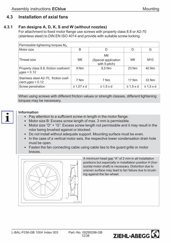
4.3.1 Fan designs A, D, K, S and W (without nozzles)For attachment to xed motor ange use screws with property class 8.8 or A2-70(stainless steel) to DIN EN ISO 4014 and provide with suitable screw locking.
Permissible tightening torques MAMotor size B D D G
Thread size M6M6
(Special applicationwith 5-pitch)
M8 M10
Property class 8.8, friction coefcientµges = 0.12
9 Nm 9,5 Nm 23 Nm 40 Nm
Stainless steel A2-70, friction coef-cient µges = 0.12 7 Nm 7 Nm 17 Nm 33 Nm
Screw penetration ≥ 1,07 x d ≥ 1,5 x d ≥ 1,5 x d ≥ 1,5 x d
When using screws with different friction values or strength classes, different tighteningtorques may be necessary.
Information• Pay attention to a sufcient screw-in length in the motor ange.• Motor size B: Excess screw length of max. 3 mm is permissible.• Motor size “D” + “G”: Excess screw length not permissible and it may result in therotor being brushed against or blocked.
• Do not install without adequate support. Mounting surface must be even.• In the case of a vertical motor axis, the respective lower condensation drain holemust be open.
• Fasten the fan connecting cable using cable ties to the guard grille or motorbraces.
A minimum head gap “A” of 2 mm in all installationpositions but especially in installation position H (hor-izontal motor shaft) is necessary. Distortion due touneven surface may lead to fan failure due to brush-ing against the fan wheel.
Assembly instructions ECblue Mounting
L-BAL-F036-GB 1004 Index 003 Part.-No. 00295296-GB12/38

4.3.2 Installation in an exhaust air stack, design T
gure 1
Mark the mounting bracket (4) in accordance with g. 1in the chimney (3) using a 4x90° template, drill holecenter distance “a” in accordance with the mountingbracket (4).
Fan sizeAdjustable diameter areamin. max.
F_063 640 660F_071 725 745F_080 815 835F_091 915 935
Tighten the mounting bracket (4) and the support bracket (5) g. 2 with screws (6) onlyso far that the mounting bracket and support bracket do not dig into the chimney wall (3).Self-locking nuts (7) are used for securing the screws. The enclosed protective caps (8)are to be pushed onto the ends of the fan supports (1), g. 2.
1819/104
57
6
3ai_kl_1905_1
gure 2
gure 3
Feed the fan (1) into the chimney in accordance with g. 3, and center it in the mountingbracket (4). In addition, the support is to be secured in accordance with g. 2 by usingbolts (9/10).
Assembly instructions ECblue Mounting
L-BAL-F036-GB 1004 Index 003 Part.-No. 00295296-GB13/38

The four support clamps (5) are used as support eyelets for additional xings (e.g. bystanding ropes) in order to relieve the chimney of the weight of greater fans.
Installation set (Part.-No. 00291545)
Pos. Naming Each1 Axial fan -3 Chimney -4 Mounting bracket 45 Support bracket 46 M8x70 screws DIN EN ISO 4014 87 M8 nuts DIN EN ISO 10511 self-locking 87a 8.4 washer DIN EN ISO 7089 88 Protective cap 49 M8x30 screws DIN EN ISO 4017 410 M8 nuts DIN EN ISO 10 511 self-locking 410a 8.4 washer DIN EN ISO 7089 4
All fastening elements made of stainless steel
4.4 Installation of centrifugal fans
4.4.1 Assembly of centrifugal fans, RH designFor attachment to xed motor ange use screws with property class 8.8 to DIN EN ISO4014 and provide with suitable screw locking.
Permissible tightening torques MAMotor size B D D G
Thread size M6M6
(Special applicationwith 5-pitch)
M8 M10
Property class 8.8, friction coefcientµges = 0.12
9 Nm 9,5 Nm 23 Nm 40 Nm
Screw penetration ≥ 1,07 x d ≥ 1,5 x d ≥ 1,5 x d ≥ 1,5 x d
When using screws with different friction values or strength classes, different tighteningtorques may be necessary.
Assembly instructions ECblue Mounting
L-BAL-F036-GB 1004 Index 003 Part.-No. 00295296-GB14/38
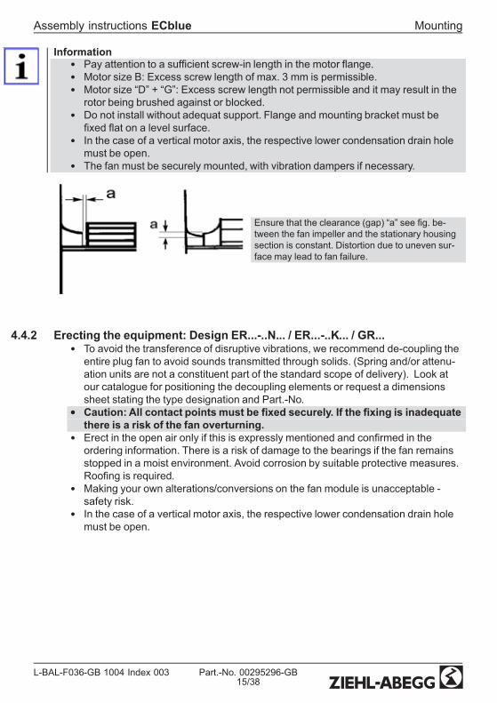
Information• Pay attention to a sufcient screw-in length in the motor ange.• Motor size B: Excess screw length of max. 3 mm is permissible.• Motor size “D” + “G”: Excess screw length not permissible and it may result in therotor being brushed against or blocked.
• Do not install without adequat support. Flange and mounting bracket must bexed at on a level surface.
• In the case of a vertical motor axis, the respective lower condensation drain holemust be open.
• The fan must be securely mounted, with vibration dampers if necessary.
Ensure that the clearance (gap) “a” see g. be-tween the fan impeller and the stationary housingsection is constant. Distortion due to uneven sur-face may lead to fan failure.
4.4.2 Erecting the equipment: Design ER...-..N... / ER...-..K... / GR...• To avoid the transference of disruptive vibrations, we recommend de-coupling theentire plug fan to avoid sounds transmitted through solids. (Spring and/or attenu-ation units are not a constituent part of the standard scope of delivery). Look atour catalogue for positioning the decoupling elements or request a dimensionssheet stating the type designation and Part.-No.
• Caution: All contact points must be xed securely. If the xing is inadequatethere is a risk of the fan overturning.
• Erect in the open air only if this is expressly mentioned and conrmed in theordering information. There is a risk of damage to the bearings if the fan remainsstopped in a moist environment. Avoid corrosion by suitable protective measures.Roong is required.
• Making your own alterations/conversions on the fan module is unacceptable -safety risk.
• In the case of a vertical motor axis, the respective lower condensation drain holemust be open.
Assembly instructions ECblue Mounting
L-BAL-F036-GB 1004 Index 003 Part.-No. 00295296-GB15/38

4.4.3 Optimal installation distances according to for RH.. / ER fans
• Distance on suction side: LA ≥ 0.5 x DSa*• Distance on the suction side: LD ≥ 1 x DSa• Impeller blade external-diameter : Ø DSa• Housing wall distances: A = 1,8 x DSa (A = B)
* In the case of disturbance ow (per example curved pipe at the suction side, aps etc.)LA ≥ 1 x DSa
4.5 Outdoor fans in a humid atmosphereInformationIf a fan is stationary for long periods in a humid atmosphere, it should be switchedON for minimum of two hours every month to remove any moisture that may havecondensedwithin the motor.
4.6 MotorheatingTo prevent a stationary ventilator in a cold environment from jamming or freezing, theMotorheating becomes automatically active at a controller interior temperature of -19 °C.
Assembly instructions ECblue Mounting
L-BAL-F036-GB 1004 Index 003 Part.-No. 00295296-GB16/38
5 Electrical installation5.1 Safety precautions
Danger owing to electric current• Work on electric componentsmay only be carried out by trained electricians
or by persons instructed in electricity under the supervision of an electricianin accordance with electrical engineering regulations.
• The 5 electrical safety rules must be observed!• Connect fan only to electrical circuits that can be disconnected with an all-
pole isolating switch.• The device owner is responsible for the EMC of the entire plant according to
the locally applicable standards.• It is forbidden to carry out work on electrically live parts. Even after discon-
nection, the dc-link is still live. Always wait at least 3 minutes.• A second person must always be present when working on energized parts
or lines who disconnects in case of emergency.• Inspect electrical equipment periodically: retighten loose connections –
immediately replace damaged lines and cables.
5.2 ConnectionInformationThe respective connections are represented in the enclosure of this assemblyinstructions (F Connection diagram)!
Assembly instructions ECblue Electrical installation
L-BAL-F036-GB 1004 Index 003 Part.-No. 00295296-GB17/38
5.2.1 Motor size “B”
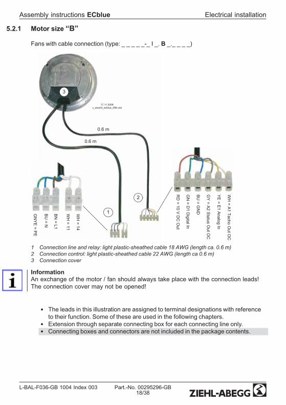
Fans with cable connection (type: _ _ _ _ _-_ I _. B _._ _ _ _)
GN
YE
= PE
BU
= N
BN
= L1
WH
= 11
WH
= 141
2
0.6 m
RD
= 10 V D
C O
ut
GN
= D1 D
igital In
BU
= GN
D
GY
= A2 Status O
ut OC
YE
= E1 A
nalog In
WH
= A1 Tacho O
ut OC
0.6 m
3
17.11.2009v_anschl_ecblue_096.vsd
1 Connection line and relay: light plastic-sheathed cable 18 AWG (length ca. 0.6 m)2 Connection control: light plastic-sheathed cable 22 AWG (length ca 0.6 m)3 Connection cover
InformationAn exchange of the motor / fan should always take place with the connection leads!The connection cover may not be opened!
• The leads in this illustration are assigned to terminal designations with referenceto their function. Some of these are used in the following chapters.
• Extension through separate connecting box for each connecting line only.• Connecting boxes and connectors are not included in the package contents.
Assembly instructions ECblue Electrical installation
L-BAL-F036-GB 1004 Index 003 Part.-No. 00295296-GB18/38

5.2.2 Motor size “D” and “G”
Fans with connection box (type: _ _ _ _ _-_ I _. D _._ _ _ _), (type: F _ _ _ _-_ I _. G _.__ _ _)
1
2
4 5 6
7
3
11 14
P E
P E
26 . 11 . 2009 v _ anchluss _ ecblue . vsd
L 1 L 2 L 3 L 1 N
1 3 6 0 - 3 6 0 V o r N ä s s e u n d S c h m u t z s c h ü t z e n K e e p d r y a n d p r o t e c t f r o m d i r t
3 ~ N a c h E N 5 0 1 7 8 i s t b e i V e r w e n d u n g e i n e s F I - S c h u t z s c h a l t e r s e i n a l l s t r o m s e n s i t i v e r z w i n g e n d v o r g e s c h r i e b e n 3 ~ f o r a n i n s t a l l a t i o n o f r . c . d p r o t e c t i o n i t s h a l l b e o b s e r v e d t h a t t h i s m u s t b e o f u n i v e r s a l - c o r r e n t s e n s i t i v i t y i n a c c o r d a n c e w i t h E N 5 0 1 7 8
2 4 V 1 0 V G N D D 1 E 1 1 1 1 4
K 1
L 1
L 1
L 2 L 3
N
D C
O u t
( I m
a x 7 0
m A )
D C
O u t
( I m
a x 1 0
m A )
A n a l
o g I n
( 0
. . . 1 0 V
/ P W
M )
D i g
i t a l I n
K o n t a k t b e l a s t u n g C o n t a c t r a t i n g
m a x . A C 2 5 0 V 2 A
N e t z s p a n n u n g L e i s t u n g s s c h i l d L i n e v o l t a g e R a t i n g - p l a t e
3 ~ T y p n i c h t f ü r I T - N e t z g e e i g n e t
3 ~ t y p e n o t s u i t a b l e f o r I T n e t w o r k
P E P E P E L 1 L 2 L 3 / N
+ 2 4
V
+ 1 0 V
G
N D
D
1 E
1
1 Cover of controller housing2 3 cable glands
(3 x M16 motor size “D”, 3 x M20 motor size “G”) included3 Cable entry points with plastic fastener4 Mains connection5 Connection alarm relay6 Connection contols7 Slot for add-on module
Procedure:1. Remove the cover from the controller housing for the connection.2. All 3 cable entry points are in a sealed condition at delivery. Remove plasticfastener if necessary, and insert cable gland, entry points that are not used mustremain sealed!
3. Insert and connect lines correctly.4. Attach cover of controller housing again carefully in correct position before start-up.
Attention!• Temperatures up to 85 °C can be present on the controller housing.• To connect, always use heat resistant wires or, as an alternative, silicon tubes.• Self-tapping screws are used for the “PE” conductor connection. These cannot beloosened and sufceintly retightened innitely.
• Remants from installation und foreign object may not remain on the inside!
Assembly instructions ECblue Electrical installation
L-BAL-F036-GB 1004 Index 003 Part.-No. 00295296-GB19/38

Cable glands and plastic fastener• Cable screw glands M16:sealing area for cable diameter 4...10 mm, torque = 2.5 Nm
• Cable screw glands M120:sealing area for cable diameter 6..12 mm, torque = 4 Nm
• Plastic cap M16 + M20: Torque with Phillips screwdriver = 1.25 Nm / with atscrewdriver = 2,5 Nm
Max. cross section of terminals• Mains connection L1, N and/or L1, L2, L3: max. 2,5 mm2 and/or AWG12• Connection control +24 V, +10 V, GND, D1, E1, K1: max. 1.5 mm2 and/or AWG16• Add-on modules: 1.5 mm2 (0.75 mm2 with wire end sleeve) and/or AWG16
5.3 EMC-compatible installation of control linesPay attention to sufcient distance from powerlines and motor wires to prevent interfer-ences. The control cable may not be longer than 30 m. Screened control cables must beused when the cable length is longer than 20 m. When using a shielded cable connectthe shielding to one side only, i.e. only to the device with the protective ground (keepcable short and with as little inductance as possible!).
5.4 Mains connection
5.4.1 Line voltage for 1~ typesMains connection: PE, L1, and N. Here, it must be strictly observed that the mainsvoltage lies within the allowable tolerance specications (F technical data).
Alternatively a supply of DC voltage is possible (F Technical data).The polarities on “L1” and “N” are irrelevant.
5.4.2 Line voltage for 3~ typesMains connection: PE, L1, L2 and L3. Here, it must be strictly observed that the mainsvoltage lies within the allowable tolerance specications (F technical data).
Alternatively a supply of DC voltage is possible (F Technical data).Connect to any two terminal clips for “L1”, “L2” and “L3”, the polarity is irrelevant.
Danger owing to electric currentNot suitabble for IT network!
5.4.3 Required quality attributes for the mains voltage
Danger owing to electric currentThe mains voltagemust comply with the DIN EN 50160 quality characteristics andthe dened standard voltages in IEC 60038!
Assembly instructions ECblue Electrical installation
L-BAL-F036-GB 1004 Index 003 Part.-No. 00295296-GB20/38

5.5 Residual-current-operated protective device
For 1 ~ fan types
Residual current circuit breaker (type A)
To ensure as high a degree of reliability as possible we recommend a release current of 300mA, where a residual current circuit breaker (type A) is used.
Danger owing to electric currentException: Mains connection between two phase conductors for supply networks 3 ~230 VFor an installation of r.c.d. protection, it shall be observed that this must be of“universalcurrent sensitivity”. In accordance with EN 50 178, Section. 5.2. other types ofcurrent-operated protective devices may not be used.
For 3 ~ fan types
Residual current circuit breaker (type B)
Danger owing to electric currentFor an installation of r.c.d. protection, it shall be observed that this must be of“universal-current sensitivity”. In accordance with EN 50 178, Section. 5.2. othertypes of current-operated protective devices may not be used. To ensure as high adegree of reliability as possible , we recommend a tripping current of 300 mA.
5.6 Motor protectionIntegrated overload protection, preceding motor protection device unnecessary (max.prefusingFTechnical details).
5.7 Analog input (0...10 V) for setting fan speedThe unit has an analog input 0...10 V for setting fan speed.Connection “GW E1 Viive” / “GND” (Analog In 1).Alternatively speed setting with a PWM-signal is possible.
Attention!Ensure correct polarity!Never apply line voltage to analog inputs!
Assembly instructions ECblue Electrical installation
L-BAL-F036-GB 1004 Index 003 Part.-No. 00295296-GB21/38

Possibilities for speed setting
0...10 V+
GND E1• Control via external setting signal 0...10 V• By external wiring with a resistor (499 Ω / 0,25 W) between theterminals “E1” and “GND” parallel to the input signal, activationwith a 0...20 mA signal is possible.
• The “AM-Modbus” communication module enables a invertedset-point signals to be programmed (10...0 V).
10V GND E1
10 kΩ
• Speed setting by 10 kΩ potentiometer at terminals “+10 V” and“GND” pick-off at terminals “E1”.
PWMf = 1...10 kHz
10 kΩ
12...30 V
10 V
GN
D E1
24 V E1
E1
GN
D
10V GND E124V
• Control by external setting signal PWM (connection “24 V” onlyfor motor sizes “D” and “G” available)
Diagram Setting signal and fan speed (Idealized principle diagram)nM
100 %
0 1 2 3 4 5 6 7 8 9 100 10 20 30 40 50 60 70 80 90 100
0 – 10 V0 – 100 % PWM
20.04.2009v_nmotor@0_10v_pwm.vsd
Si
nM Fan speedSi Speed setting signal 0...10 V / 0...100 % PWM
Assembly instructions ECblue Electrical installation
L-BAL-F036-GB 1004 Index 003 Part.-No. 00295296-GB22/38
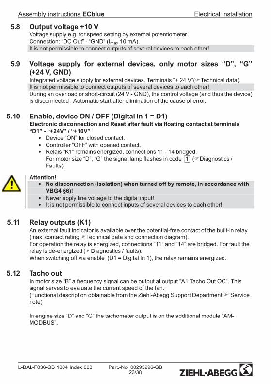
5.8 Output voltage +10 VVoltage supply e.g. for speed setting by external potentiometer.Connection: “DC Out” - “GND” (Imax 10 mA).It is not permissible to connect outputs of several devices to each other!
5.9 Voltage supply for external devices, only motor sizes “D”, “G”(+24 V, GND)Integrated voltage supply for external devices. Terminals “+ 24 V”(FTechnical data).It is not permissible to connect outputs of several devices to each other!During an overload or short-circuit (24 V - GND), the control voltage (and thus the device)is disconnected . Automatic start after elimination of the cause of error.
5.10 Enable, device ON / OFF (Digital In 1 = D1)Electronic disconnection and Reset after fault via oating contact at terminals“D1” - “+24V” / “+10V”
• Device “ON” for closed contact.• Controller “OFF” with opened contact.• Relais “K1” remains energized, connections 11 - 14 bridged.For motor size “D”, “G” the signal lamp ashes in code |1| (FDiagnostics /Faults).
Attention!• No disconnection (isolation)when turned off by remote, in accordance with
VBG4 §6)!• Never apply line voltage to the digital input!• It is not permissible to connect inputs of several devices to each other!
5.11 Relay outputs (K1)An external fault indicator is available over the potential-free contact of the built-in relay(max. contact ratingFTechnical data and connection diagram).For operation the relay is energized, connections “11” and “14” are bridged. For fault therelay is de-energized (FDiagnostics / faults).When switching off via enable (D1 = Digital In 1), the relay remains energized.
5.12 Tacho outIn motor size “B” a frequency signal can be output at output “A1 Tacho Out OC”. Thissignal serves to evaluate the current speed of the fan.(Functional description obtainable from the Ziehl-Abegg Support DepartmentF Servicenote)
In engine size “D” and “G” the tachometer output is on the additional module “AM-MODBUS”.
Assembly instructions ECblue Electrical installation
L-BAL-F036-GB 1004 Index 003 Part.-No. 00295296-GB23/38

5.13 Output Status Out OC (motor size “B”)Via the output “A2 Status Out OC” an additional operating message is possible inmotor size “B”.The OC (Open-Collector) output is on GND potential during operation. Whenusing the output voltage “+10 V” a LED can be controlled by a pull-up resistor (>4.7 kΩ).
26.11.2009v_ecblue_096_status_out_led.vsd
Pull Up> 4.7 k
10V
DC
Out
A2
Sta
tus
Out
OC
5.14 Potential at control voltage connectionsThe control voltage connections (< 50 V) relate to the joint GND potential (Exception:Relay contacts are potential free). There is a potential separation between the controlvoltage connections and the earthed conductor. It must be ensured that the maximumexternal voltage at the control voltage connections cannot exceed 50V (between “GND”terminals and “PE” earthed conductor). If necessary, a connection to the earthed con-ductor potential can be established, install bridge between “GND” terminal and the “PE”connection (terminal for screening).
5.15 Add-onmodulesThe assembly instructions available here describe the “basic version”.If required, an auxiliary module can be retrotted to the designated slot for motor size“D”, “G”. The auxiliary module is installed automatically. Manual installation or parameter-isation is not required!For fans of motor size “B” separate versions with integrated add-on modules areavailable.The extended scope of function is specied in the documentation for the auxiliarymodule.The range of additional modules is constantly being extended and adapted to marketrequirements. The currently available additional modules can be requested from Ziehl-Abegg.
Examples for currently available additional modules
Type Part.-No. FunctionAM-MODBUS(for motor size “D”and “G”)
349045 Communication moduleOver the “AM-MODBUS”module can be communicated withthe controller of the fan. The module can be put in temporarilyfor programming of desired functions during start-up or fordiagnostics. The connection to the control terminal is made bya connecting cable or wirelessly by means of radio.The module is left in the slot if it is to be integrated into amodule bus system or networked to several devices. Theaddressing of ECblue fans takes place automatically, i.e. it isnot necessary to manually enter individual network addressesfor each fan.
Assembly instructions ECblue Electrical installation
L-BAL-F036-GB 1004 Index 003 Part.-No. 00295296-GB24/38

AM-PREMIUM(for motor size “D”and “G”)
349046 Premium ModuleWhen the “AM-PREMIUM” is plugged in the controller in thefan is extended to become a full-grade multipurpose controller.The “Premium module” provides not only an integrated modulebus interface, it also enables sensors to be connected straightto the fan.The module also comes with two analogue inputs and oneanalogue output.
6 Start-up
6.1 Prerequisites for commissioningAttention!
• Before initial operation, check the following:1. Installation and electrical connection have been properly completed?2. Has any leftover installation material and other foreign material been removedfrom the fan area?
3. That safety devices -if necessary- are mounted (EN ISO 13857)?4. The impeller is out of reach?5. Installation position and the arrangement of condensation water drainscorrespond to each other?
6. Connection data complies with the specications on the type plate?
• Commissioningmay only take place if all safety instructions have beenchecked and danger can be excluded.– Check the direction of rotation (F rotation direction arrow on the fan blade,impeller base plate or on the fan housing).
– Check for quiet, low vibration operation. Strong vibrations due to erraticoperation (unbalanced), e.g. caused by transportation damage or improper use,can lead to failure.
– A-rated sound power levels of over 80 dB(A) are possible, see productcatalogue.
– Check for mechanical vibrations after installation into the system. If thetolerances according to DIN Iso 10816-1 are exceeded, it is possible toexclude certain speed ranges (add-on module for communication neccesary).
Assembly instructions ECblue Start-up
L-BAL-F036-GB 1004 Index 003 Part.-No. 00295296-GB25/38

7 Diagnostics / Faults7.1 Trouble shooting
Type of error Possible cause Remedial measuresFan no longer turns(any more)
Failure line voltageFailure of one phaseUnder - or overvoltage
check line voltage
Shortcut Earth Check motor connection and line voltageShort circuit winding Replace fanThermal motor protectionhas triggered (motor isoverheated)
Check for free air passages; remove foreign bodies ifnecessaryF "Impeller blocked or dirty"Check temperature of supply airchec voltage
Impeller blocked or dirty - Switch off power to the motor and secure againstswitching back on- heck safe isolation from supply- Remove safety grille- Remove foreign bodies or soiling- Remount the safety grille- Further procedure as in the chapter “Start-up”
fan will not start Temperature too low forbearing grease
Insert bearing with cold greasing
Air stream wrong direction(Motor turns in wrong direc-tion at high speed)
Check air stream
F "Fan does not turn"Fan turns too slowly Running wheel / blade
scrapes / brushesClear foreign bodies/dirt from the fan
Active temperature man-agement effective(Motor or electronics over-heated)
Check for free air passages; remove foreign bodies ifnecessaryF "Impeller blocked or dirty"Check temperature of supply airCheck installation space (air speed over heat sink)
Air ow to low Fan turns too slowly F
Airways blocked Check for free air passages (supply/exhaust air vents,lters)F "Impeller blocked or dirty"
Pressure loss different toplanned
Check fan selection
Vibrations Imbalance Check blades for damage, soiling or iceF "Runningwheel is blocked or soiled"
No or wrong vibrationdampers (only in radial)
Install correct vibration dampers
Unusual noises Bearing damaged / worn Change bearings
Assembly instructions ECblue Diagnostics / Faults
L-BAL-F036-GB 1004 Index 003 Part.-No. 00295296-GB26/38

Type of error Possible cause Remedial measuresRunning wheel / bladescrapes / brushes
Clear foreign bodies / dirt from the fanF "Runningwheel is blocked or soiled"
Operation beyond tear-offpoint(for axial fans)
Check for free air passages (supply/exhaust air vents,lters)
Wrong cover on nozzle(for centrifugal fans)
Observe the installation instructions
7.2 For motor size “D” and “G” Status LED with ash code
23.04.2009v_led_status_ecblue.vsd
11.02.2009v_flash_explain.VSD
3 x
2 x
ON
OFF
4 x
5 x
6 x
1 x
7 x
8 x
9 x
LED Code(only D, G)
Relays K1(for function fac-tory setting)
CauseExplanation
Reaction of ControllerAdjustment
OFF de-energized, 11- 14 interrupted no line voltage
Line voltage available?Unit switches OFF and automaticallyON when the voltage has been re-stored
ON energized, 11 - 14bridged Normal operation without fault
1 x energized, 11 - 14bridged
no enable = OFF
Terminals “D1” - “24 V / 10 V” (DigitalIn 1) not bridged.
Switch OFF by external contact (Fdigital input).
Assembly instructions ECblue Diagnostics / Faults
L-BAL-F036-GB 1004 Index 003 Part.-No. 00295296-GB27/38

LED Code(only D, G)
Relays K1(for function fac-tory setting)
CauseExplanation
Reaction of ControllerAdjustment
2 x energized, 11 - 14bridged
Active temperature managementThe device has an active tempera-ture managementto protect it fromdamage due to too high inside tem-peratures. In case of a temperaturerise above the xed limits, the modu-lation is reduced linearly. To preventthe complete system being switchedoff externally (in this operation per-missible for the controller) in case ofreduced operation due to too high aninternal temperature, no fault mes-sage is sent via the relay.
At sinking temperature the modula-tion rises again llinear.Check cooling of the controller
3 x de-energized, 11- 14 interrupted
HALL-ICIncorrect signal from the Hall-ICs,error in the commutation.
Controller turns the motor off. Auto-matic restart if no more fault is recon-gized.
4 x de-energized, 11- 14 interrupted
Line failure (only for 3 ~ types)The device is provided with a built-inphase-monitoring function for themains supply. In the event of a mainsinterruption (failure of a fuse ormains phase) the unit switches offafter a delay (approx. 200 ms).Function only when load for the con-troller is high enough.
Following a shutoff, a startup attemptis made after approximately 15 sec-onds, if the voltage supply is highenough. This keeps occurring untilall 3 supply phases are availableagain.Checking power supply
5 x de-energized, 11- 14 interrupted
Motor blockedIf after 8 seconds cummutation nospeed is measured > 0, the fault“Motor blocked” is released.
EC-Controller switches off, renewedattempt to start after about 2.5 sec.Final shutoff, when fourth startingtest fails. It is then necessary to havean enabling reset or to disconnectthe power supply.Check if motor is freely rotatable.
6 x de-energized, 11- 14 interrupted
IGBT FaultShortcut earth or shortcut of motorwinding.
EC-Controller switches off, renewedattempt to start after about 60 sec.FCode 9Final shutoff, if - following a secondstarting test – a second fault detec-tion is detected within a period of 60seconds.It is then necessary to have an ena-bling reset or to disconnect thepower supply.
Assembly instructions ECblue Diagnostics / Faults
L-BAL-F036-GB 1004 Index 003 Part.-No. 00295296-GB28/38
LED Code(only D, G)
Relays K1(for function fac-tory setting)
CauseExplanation
Reaction of ControllerAdjustment
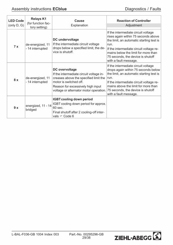
7 x de-energized, 11- 14 interrupted
DC undervoltageIf the intermediate circuit voltagedrops below a specied limit, the de-vice is shutoff.
If the intermediate circuit voltagerises again within 75 seconds abovethe limit, an automatic starting test isrun.If the intermediate circuit voltage re-mains below the limit for more than75 seconds, the device is shutoffwith a fault message.
8 x de-energized, 11- 14 interrupted
DC overvoltageIf the intermediate circuit voltage in-creases above the specied limit themotor is switched off.Reason for excessively high inputvoltage or alternator motor operation.
If the intermediate circuit voltagedrops again within 75 seconds belowthe limit, an automatic starting test isrun.If the intermediate circuit voltage re-mains above the limit for more than75 seconds, the device is shutoffwith a fault message.
9 x energized, 11 - 14bridged
IGBTcooling down periodIGBT cooling down period for approx.60 sec.Final shutoff after 2 cooling-off inter-valsF Code 6
Assembly instructions ECblue Diagnostics / Faults
L-BAL-F036-GB 1004 Index 003 Part.-No. 00295296-GB29/38
8 Service work8.1 Repairs / maintenance
Attention!• Allowmaintenancework to be carried out by trained specialists only.• Please observe the safety regulations and the worker´s protection rules by
all maintenance and service work (DIN EN 50 110, IEC 364).• Before working on the fan, this must be disconnected from the power supply
and secured against switching back on!• Keep the airways of the fan free - danger because of objects dropping out!• No maintenance work at running fan!• Watch out for vibration free motion!• Depending on the application and the transfer medium the impeller has a
natural wear. Deposits on the impeller can lead to imbalance and thus todamages (danger of endurance fracture). The impeller can disintegrate!
• Maintenance interval in accordance with the degree of contamination of theimpeller!
• In case of imbalance: Rebalancing the running wheel• Check the impeller, in particular the weld-seams, for possible cracks.• Repair, e.g. by welding is prohibited!• The fan or motor is maintenance free through the usage of ball bearings with “life-time lubrication”. After the end of the grease service-life (ca. 30-40,000 h duringstandard usage), an exchange of the bearing is necessary. For this as well as forall other defects (e.g. on the winding or in the electronics), please contact ourservice department.
• Bolted-on wheels and/or wings may only be replaced by authorised Ziehl-AbeggAG staff. The manufacturer shall not be liable for damage caused throughimproper repair work.
• Regular inspection, and cleaning is necessary to prevent imbalance due to ingressof dirt.
Danger owing to electric currentWhen the motor runs independently due to air owing through or if it continues torun down after being turned off, dangerous voltages of over 50 V can arise on themotor internal connections through operation of the generator.
Assembly instructions ECblue Service work
L-BAL-F036-GB 1004 Index 003 Part.-No. 00295296-GB30/38
8.2 CleaningDanger owing to electric currentVoltage supply for motor must be interrupted and secured against restoration!
Attention!• Do not use any aggressive, paint solvent cleaning agents when cleaning.• Cleaning with a water jet:
– Make sure that no water gets into the inside of the motor, note protection class(IP).
– Do not hold the jet spray directly on the motor openings and seals.– During cleaning work using a jet spray, no guarantee is assumed regardingcorrosion formation / paint adhesion for unpainted / painted fans.
– After the cleaning process, the fan must be operated for 30 minutes at 80 to100 % of maximum speed for drying purposes!
9 Enclosure
9.1 Technical data
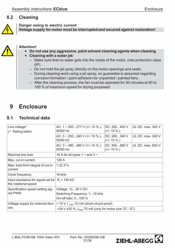
Line voltage*(F Rating-plate)
AC: 1 ~ 200...277 V (+/- 10 % ),50/60 Hz
DC: 280...400 V(+/- 10 % )
UL DC: max. 300 V
AC: 3 ~ 200...240 V (+/- 10 % ),50/60 Hz
DC: 280...340 V(+/- 10 % )
UL DC: max. 300 V
AC: 3 ~ 380...480 V (+/- 10 % ),50/60 Hz
DC: 500...680 V(+/- 10 % )
UL DC: max. 600 V
Maximal line fuse 16 A for all types 1 ~ and 3 ~Max. cut-in current 126 AMax. load limit integral of cut-incurrent
1.22 A2s
Clock frequency 16 kHzInput resistance for signal set forthe rotational speed
Ri > 100 kΩ
Specication speed setting sig-nal PWM
Voltage: 12...30 V DCSwitching Frequency: 1...10 kHzOn-off ratio: 0...100 %
Voltage supply for external devi-ces
+ 10 V, I max 10 mA (short-circuit-proof)+24 V ±20 %, Imax 70 mA (only for motor size “D”, “G”)
Assembly instructions ECblue Enclosure
L-BAL-F036-GB 1004 Index 003 Part.-No. 00295296-GB31/38

Permissible minimal and maxi-mal ambient temperature for op-eration
-25 °C...60 °C (up to 70 °C **)Please see the technical documentation of the product for the minimumand maximum ambient temperature valid for the respective fan; Thesemay deviate from the specied permissible ambient temperatures.To avoid condensation, the drive must be connected permanently to themains.
Max. permissible installationheight
height 1000 m amsl without derating
Permissible rel. humidity 85 % no condensationPermissible temperature rangefor storage and transport
-30...+80 °C
Electromagnetic compatibility forthe standard voltage 230 / 400V according to DIN IEC 60038
Interference emission EN 61000-6-3 (domestic household applications)Interference immunity EN 61000-6-2 (industrial applications)
Harmonics current according For 1 ~ typesActive power factor adjustment for sinusoidal input current (PFC = Power- Factor - controller), harmonic current in accordance with EN 61000-3-2are guaranteed.For 3 ~ typesEN 61000-3-2 for a “professional unit”.Please ask Ziehl-Abegg for the individual harmonic oscillation levels ofthe current as a percentage of the fundamental oscillation of the ratedcurrent.
Contact rating of the internalrelay
AC 250 V 2 A
Max. leakage current accordingto the dened networks of DINEN 60990
< 3,5 mA
dB(A) values F product catalogProtection class of motor ac-cording DIN EN 60529
IP 54
* Regarding the mains connection, the devices are to be classied as category “C2” devicesaccording to the relevant DIN EN 61800-2 The increased requirements placed on electricalinterference for category “C1” devices are complied with in addition.
** In case of a temperature increase above the predetermined threshold values modulation islinearly reduced by active temperature management.
Assembly instructions ECblue Enclosure
L-BAL-F036-GB 1004 Index 003 Part.-No. 00295296-GB32/38

9.2 Connection diagramMotor size “B” (type: _ _ _ _ _-_ I _. B _._ _ _ _)
ECblue (_ _ _ _ _-_I_.B_._ _ _ _)
N L1PENetzLine
1 ~ 200...277 V50/60 Hz
10 kΩ
+
2
KT00044A15.12.2009
PE N L1
1Externe Drehzahlvorgabe
External speed setting
3
10 V
DC
Out
(Im
ax =
10
mA
)
D1
Dig
ital I
n 1
GN
D
A2
Sta
tus
Out
OC
SignalanschlussSignal connection
GN
YE
BU
BN
RD
BU
GY
11 14
WH
WH
KontaktbelastungContact rating
max. AC 250 V 2 A
5
E1
Ana
log
In 1
A1
Tac
ho O
ut O
C
A ID B GN
D
A ID B GN
D
YE
WH
GN
11 14
10 kΩ
12...30 V
10 V
GN
D E1
E1
GN
D
PWMf = 1...10 kHz
4
EingangInput
0...10 V
K1
1 Line voltage 1 ~ 200...277 V, 50/50 Hz2 Signal connection3 Input 0...10 V4 PWM input, f = 1...10 kHz5 Contact rating max. AC 250 V 2 A
Assembly instructions ECblue Enclosure
L-BAL-F036-GB 1004 Index 003 Part.-No. 00295296-GB33/38
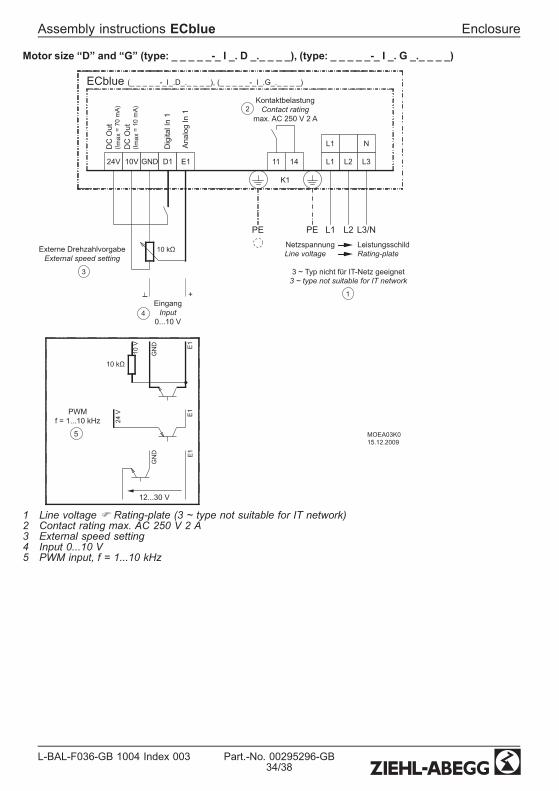
Motor size “D” and “G” (type: _ _ _ _ _-_ I _. D _._ _ _ _), (type: _ _ _ _ _-_ I _. G _._ _ _ _)
24V 10V GND D1 E1 11 14
DC
Out
(I max
= 7
0 m
A)D
C O
ut(I m
ax =
10
mA)
Dig
ital I
n 1
Ana
log
In 1
L3/NL2L1PE
L1
L2 L3
PE
L1
N
ECblue (_ _ _ _ _-_I_.D_._ _ _ _), (_ _ _ _ _-_I_.G_._ _ _ _)
MOEA03K015.12.2009
K1
KontaktbelastungContact rating
max. AC 250 V 2 A
Netzspannung LeistungsschildLine voltage Rating-plate
3 ~ Typ nicht für IT-Netz geeignet3 ~ type not suitable for IT network
EingangInput
0...10 V
+
PWMf = 1...10 kHz
Externe DrehzahlvorgabeExternal speed setting
5
3
4
1
2
10 kΩ
10 kΩ
12...30 V
10 V
GN
D E1
24 V E1
E1
GN
D
1 Line voltage F Rating-plate (3 ~ type not suitable for IT network)2 Contact rating max. AC 250 V 2 A3 External speed setting4 Input 0...10 V5 PWM input, f = 1...10 kHz
Assembly instructions ECblue Enclosure
L-BAL-F036-GB 1004 Index 003 Part.-No. 00295296-GB34/38
9.3 EC Declaration of Incorporationas dened by the EC Machinery Directive 2006/42/EC, Annex II B
The design of the incomplete machine:• Axial fan FA.., FB.., FC.., FE.., FS.., FT.., FH.., FL.., FN.., VR.., VN..• Centrifugal fan RA.., RD.., RE.., RF.., RG.., RH.., RK.., RM.., RR.., RZ.., GR..,ER..
• Cross ow fan QK.., QR.., QT.., QD.., QG..
Motor type:• Induction internal or external rotor motor (also with integrated frequency inverter)• Electronically commutated internal or external rotor motor (also with integrated ECcontroller)
complies with the requirements in Appendix I, Articles 1.1.2, 1.1.5, 1.4.1, 1.5.1 inEC Machinery Directive 2006/42/EC.
The manufacturer is theZiehl-Abegg AGHeinz-Ziehl-StraßeD-74653 Künzelsau
The following standards are applied:EN 60204-1:2006 Safety of machinery; electrical equipment of machines; Part 1: Gen-
eral requirementsEN ISO12100:2003
Safety of machinery; basic concepts, general principles for design
EN ISO13857:2008
Safety of machinery; safety distances to prevent danger zones beingreached by the upper limbs
Note: The maintenance of the EN ISO 13857:2008 relates only to theinstalled accidental contact protection, provided that it is part of thescope of delivery.
The specic technical documentation in accordance with Appendix VII B has beenwritten and is available in its entirety.
The person authorised for compiling the specic technical documentation is: Dr. O. Sadi,address see above.The specic documentation will be transmitted to the ofcial authorities on justiedrequest. The transmission can be electronic, on data carriers or on paper. All industrialproperty rights remain with the above-mentionedmanufacturer.
It is prohibited to commission this incomplete machine until it has been securedthat the machine into which it was incorporated complies with the stipulations ofthe EC Machinery Directive.
Assembly instructions ECblue EC Declaration of Incorporation
L-BAL-F036-GB 1004 Index 003 Part.-No. 00295296-GB35/38

Künzelsau, 29-Dec-2009Dr. O. Sadi - Technical Manager VentilationTechnologyTechnical Director Air Movement Divisioni.V.
Assembly instructions ECblue EC Declaration of Incorporation
L-BAL-F036-GB 1004 Index 003 Part.-No. 00295296-GB36/38
Assembly instructions ECblue
L-BAL-F036-GB 1004 Index 003 Part.-No. 00295296-GB37/38
9.4 Index
BBearing 26, 30
CChimney 14cleaning 31Clock frequency 31condensation drain hole 12, 15control cable 20current-operated protectivedevices 21
DDC voltage 20
EEnable 23
IImbalance 26Input resistance 31
Lleakage current 32
Mmotor size 9Motorheating 16
Oone-quadrant 9Outdoor fans 16
PPWM-signal 21
Rrelay 23Relay outputs 23Reset 23Residual current circuitbreaker 21
SSetting signal 22
TTechnical data 2, 31temperature management 28

9.5 Manufacturer referenceOur products are manufactured in accordance with the relevant international regulations.If you have any questions concerning the use of our products or plan special uses,please contact:
Ziehl-Abegg AGHeinz-Ziehl-Straße74653 KünzelsauTelephone: +49 (0) 7940 16-0Telefax: +49 (0) 7940 [email protected]://www.ziehl-abegg.de
9.6 Service informationIf you have any technical questions while commissioning or regarding malfunctions,please contact our V-STE support department for control systems - ventilation technol-ogy.Our worldwide contacts are available in our subsidiaries for deliveries outside of Ger-many.F www.ziehl-abegg.com.If you make returns for inspections or repairs we need certain information in order tofacilitate focused trouble shooting and fast repair. Please use our repair tickets for this. Itis provided to you after you have consulted our support department.In addition, you can download it from our homepage. Download - Ventilation Technology- Topic: Control Engineering - Document type: General documents.
Assembly instructions ECblue Index
L-BAL-F036-GB 1004 Index 003 Part.-No. 00295296-GB38/38