EC3-1820V2NA Version: C01 - 研祥
127
EC3-1820V2NA 3.5 寸主板带 VGA/HDMI/LVDS /2LAN/4COM 3.5-inch Motherboard with VGA /HDMI/LVDS/2LAN/4COM Version: C01
-
Upload
khangminh22 -
Category
Documents
-
view
0 -
download
0
Transcript of EC3-1820V2NA Version: C01 - 研祥

EC3-1820V2NA
3.5 寸主板带 VGA/HDMI/LVDS
/2LAN/4COM
3.5-inch Motherboard with VGA
/HDMI/LVDS/2LAN/4COM
Version: C01
法律资讯
警告提示
为了您的人身安全以及避免财产损失,必须注意本手册中的提示。人身安全
的提示用一个警告三角表示,仅与财产损失有关的提示不带警告三角。警告提示
根据危险等级由高到低如下表示。
危险
表示如果不采取相应的小心措施,将会导致死亡或者严重的人身伤害。
警告
表示如果不采取相应的小心措施,可能导致死亡或者严重的人身伤害。
小心
带有警告三角,表示如果不采取相应的小心措施,可能导致轻微的人身伤害。
注意
表示如果不注意相应的提示,可能会出现不希望的结果或状态。
合格的专业人员
本文件所属的产品/系统只允许由符合各项工作要求的合格人员进行操作。
其操作必须遵照各自附带的文件说明,特别是其中的安全及警告提示。 由于具
备相关培训及经验,合格人员可以察觉本产品/系统的风险,并避免可能的危险。
EVOC产品
请注意下列说明:
警告
EVOC产品只允许用于目录和相关技术文件中规定的使用情况。如果要使用其
他公司的产品和组件,必须得到EVOC推荐和允许。正确的运输、储存、组装、
装配、安装、调试、操作和维护是产品安全、正常运行的前提。必须保证允许
的环境条件。必须注意相关文件中的提示。
免责声明
本公司保留对此手册更改的权利,产品后续相关变更时,恕不另行通知。
对于任何因安装、使用不当、超规格使用而导致的直接、间接、有意或无意的损
坏及隐患概不负责。
订购产品前,请向经销商详细了解产品性能是否符合您的需求。
EVOC是研祥智能科技股份有限公司的注册商标。本手册所涉及到的其他商
标,其所有权为相应的产品厂家所拥有。
研祥智能科技股份有限公司©2015,版权所有,违者必究。未经许可,不得
以机械、电子或其它任何方式进行复制。
保修条款:
产品保修期两年。用户如另有要求,以双方签署的合同为准。
欲获更多信息请访问:
研祥网站:http://www.evoc.com
研祥技术支持邮箱:[email protected](国际)、[email protected](国内)
免费客服热线: 4008809666
文档说明
本文档适用范围
本文档适用于EVOC EC3-1820V2NA型号。
约定
在本文档中,术语“本板”或“产品”有时特指EVOC EC3-1820V2NA产
品。
说明
安全相关注意事项
为避免财产损失以及出于个人安全方面的原因,请注意本入门指南中关
于安全方面的信息。 文中使用警告三角来指示这些安全信息,警告三角的
出现取决于潜在危险的程度。
历史
本说明书发布版本:
版本 时间
B00 2015.4
C00 2015.7
C01 2015.7
安全须知
ESD 指令
可以通过下面的标签来识别含有静电敏感设备 (ESD, electrostatic
sensitive devices) 的模块:
在操作含有 ESD 的模块时,请严格遵守下面提到的准则:
在操作含有 ESD 的模块之前,请务必导去身体上的静电(例如,通过触摸
接地物体)。
所有设备和工具必须不能带有静电。
在安装或卸下含有 ESD 的模块之前,请务必要拔出电源插头并卸下电池。
只能通过其边缘来操作装配有 ESD 的模块。
请勿触摸含有 ESD 的模块上的任何连接器针脚或导体。
目 录
1.产品介绍 ...................................................................................................................1
1.1 概述 ...................................................................................................................1
1.2 机械尺寸、重量与环境 ...................................................................................1
1.3 典型功耗............................................................................................................1
1.4 电源选型参考功耗...........................................................................................2
1.5 微处理器...........................................................................................................3
1.6 芯片组...............................................................................................................3
1.7 系统内存...........................................................................................................3
1.8 显示功能...........................................................................................................3
1.9 网络功能...........................................................................................................4
1.10 音频功能.........................................................................................................4
1.11 电源特性.........................................................................................................4
1.12 Watchdog功能..................................................................................................4
1.13 操作系统.........................................................................................................4
1.14 I/O接口 ............................................................................................................4
2.安装说明 ...................................................................................................................6
2.1 产品外形尺寸图................................................................................................6
2.2 接口位置示意图...............................................................................................7
2.3 记录板卡的标识数据 ........................................................................................8
2.4 架构图...............................................................................................................8
2.5 跳线设置...........................................................................................................9
2.6 串口 ................................................................................................................10
2.7 LCD背光控制接口..........................................................................................11
2.8 显示接口.........................................................................................................11
2.9 USB接口..........................................................................................................14
2.10 网络接口.......................................................................................................15
2.11 音频接口.......................................................................................................16
2.12 鼠标键盘接口...............................................................................................16
2.13 SATA接口 ......................................................................................................16
2.14 GPIO接口 ......................................................................................................17
2.15 风扇接口........................................................................................................17
2.16 电源接口........................................................................................................18
2.17 状态指示控制接口.......................................................................................18
2.18 SIM接口 ........................................................................................................19
2.19 Mini-PCIe接口...............................................................................................19
2.20 mSATA接口 ...................................................................................................21
2.21 SATA硬盘热插拔 ..........................................................................................22
3.BIOS功能介绍 ........................................................................................................24
3.1 BIOS 信息提示界面.......................................................................................24
3.2 BIOS基本功能设置.........................................................................................25
3.3 x86 平台下BIOS所要管理的系统资源 ..........................................................33
4.驱动程序安装说明 .................................................................................................38
5.附录 .........................................................................................................................39
5.1 GPIO编程指引 ................................................................................................39
5.2 WDT看门狗编程指引.....................................................................................41
5.3 LVDS背光控制编程指引................................................................................43
5.4 常见故障分析与解决......................................................................................44
5.5 缩略语 .............................................................................................................45
产品介绍
EC3-1820V2NA · 1 ·
1.产品介绍
1.1 概述
EC3-1820V2NA 是一款基于 Intel®新一代凌动 Bay Trail SoC 平台的 3.5 寸
主板,CPU 选用 Future Intel® Celeron® processor for Intelligent Systems
(Based on 22nm Intel® Silvermont microarchitecture),主频为 4核 1.91GHz
和 2 核 1.33GHz,图形核心整合 INTEL 第七代图形引擎、两条显示管线,支持 DX11
及 3D 输出。
EC3-1820V2NA 拥有丰富的接口类型,可广泛应用于军工、自动化、电力等
领域。
1.2 机械尺寸、重量与环境
外形尺寸:146.1mm(长)×101.6mm(宽)×24.7mm(高)
净重:0.29Kg
工作环境:
温度:0℃~60℃;可扩展温度:-40℃~85℃
湿度:5%~95%(非凝结状态)
贮存环境:
温度:-40℃~85℃
湿度:5%~95%(非凝结状态)
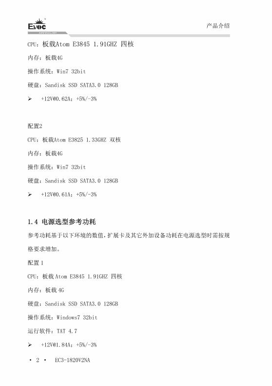
1.3 典型功耗
典型功耗是基于以下配置闲置状态的数值。
配置1
产品介绍
· 2 · EC3-1820V2NA
CPU:板载Atom E3845 1.91GHZ 四核
内存:板载4G
操作系统:Win7 32bit
硬盘:Sandisk SSD SATA3.0 128GB
[email protected];+5%/-3%
配置2
CPU:板载Atom E3825 1.33GHZ 双核
内存:板载4G
操作系统:Win7 32bit
硬盘:Sandisk SSD SATA3.0 128GB
[email protected];+5%/-3%
1.4 电源选型参考功耗
参考功耗基于以下环境的数值,扩展卡及其它外加设备功耗在电源选型时需按规
格要求增加。
配置 1
CPU:板载 Atom E3845 1.91GHZ 四核
内存:板载 4G
硬盘:Sandisk SSD SATA3.0 128GB
操作系统:Windows7 32bit
运行软件:TAT 4.7
[email protected];+5%/-3%
产品介绍
EC3-1820V2NA · 3 ·
配置 2
CPU: 板载 Atom E3825 1.33GHZ 双核
内存:板载 4G
硬盘:Sandisk SSD SATA3.0 128GB
操作系统:Windows 7 32bit
运行软件: TAT 4.7
[email protected];+5%/-3%
1.5 微处理器
板载Bay Trail-I SoC CPU,E3825 CPU主频为1.33GHz,为2核CPU;E3845 CPU
主频为1.91GHz,为4核CPU。
1.6 芯片组
单芯片处理器,芯片组集成在CPU里面。
1.7 系统内存
板载4G DDR3L内存颗粒,支持1333MT/s。
1.8 显示功能
支持VGA、HDMI和LVDS显示;LVDS不支持热插拔功能;
VGA+LVDS为异步输出;
VGA支持分辨率到2560×1600@60Hz;LVDS最高支持UXGA(1920×1080)。
产品介绍
· 4 · EC3-1820V2NA
1.9 网络功能
提供2个10/100/1000Mbps网络接口,其中LAN1为标准RJ45接口,支持网络
唤醒功能;LAN2采用2×7 2.0mm插针输出。
1.10 音频功能
采用HDA标准,支持MIC-IN/LINE-IN/LINE-OUT。
1.11 电源特性
+12V单电源供电,2×2供电接口。
1.12 Watchdog功能
支持 255 级,可编程按分或秒;
支持看门狗超时中断或复位系统。
1.13 操作系统
支持操作系统:Windows8.1、Windows8、windows7、Linux。
1.14 I/O接口
提供 4个串口,其中 COM1 和 COM2 支持 RS-232/RS-422/RS-485 模式,通过
BIOS 设置工作模式,COM3 和 COM4 仅支持 RS-232 模式;不支持 Modem 唤醒
功能;
提供 1个 SATA 接口和一个 mSATA(J2 可选)接口;
备注:建议使用以下 SATA 3.0 硬盘:
固态硬盘 Crucial 6Gb/s SATA3.0 2.5 128GB M4
机械硬盘 Seagate 6Gb/s SATA3.0 500GB ST500DM002
机械硬盘 Seagate 6Gb/s SATA3.0 3000GB
机械硬盘 WD 6Gb/s SATA3.0 4000GB
提供 5个 USB2.0 接口和 1 个 USB3.0 接口;
产品介绍
EC3-1820V2NA · 5 ·
备注:USB3.0接口默认关闭,没有安装Intel USB3.0驱动之前只能当USB2.0
接口使用,且开启 USB3.0 功能后没有安装 USB3.0 驱动之前在 Windows7 系
统所有 USB 接口(包括其他 USB2.0 接口)都不能使用,Windows8/8.1 会自
动加载驱动不需要安装驱动,下面为在 Windows7 系统启用 USB3.0 步骤:
1、 将主板 BIOS 设置为默认值,然后安装 Windows7,将附件驱动光盘放入
USB 光驱,进入驱动光盘将 Driver 目录下文件夹 USB3.0 拷贝到桌面;
2、 重启电脑,按 F2 进入 BIOS,选择“Advanced”-“EHCI Controller”
设置为“Disabled”,将“XHCI Controller”设置为“Enabled”,
按“F10”保存退出;
3、 重启后进入 Windows7 系统,用 PS2 鼠标双击桌面 USB3.0 文件夹,双
击“Setup.exe”进行安装 USB3.0 驱动,安装完成后所有 USB 都能正
常使用,此时 USB3.0 接口已达到 USB3.0 标准。
提供 1个 PS/2 键盘/鼠标接口;
提供 1个 16 路数字 I/O 接口;
提供 2个 Mini PCIE 接口(MPCIE1 和 J2,J2 可选),支持 WiFi;其中 MPCIE1
还支持 3G 模块;
提供 1个 Micro SD 卡接口;
提供 1个 HDMI 接口和 1个 VGA 接口;
提供 2个千兆网络接口。
提示:如何识别报警声
1、长鸣声为系统内存出错。
2、短“嘀”一声为开机声。
安装说明
· 6 · EC3-1820V2NA
2.安装说明
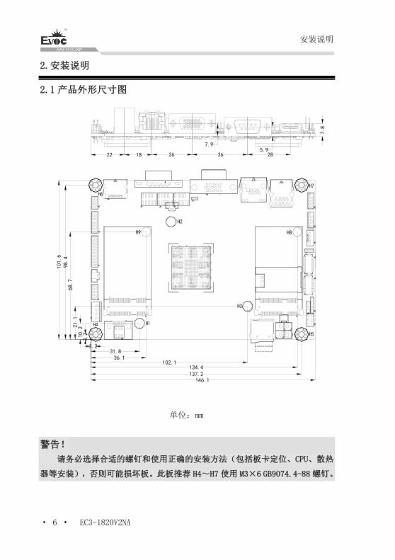
2.1 产品外形尺寸图
146.1
3.231.8
102.1
137.2
36.1
134.4
3.210.221.1
68.7
98.4
101.6
22 18 26 36 28
7.8
5.97.9
单位:mm
警告!
请务必选择合适的螺钉和使用正确的安装方法(包括板卡定位、CPU、散热
器等安装),否则可能损坏板。此板推荐 H4~H7 使用 M3×6 GB9074.4-88 螺钉。
安装说明
EC3-1820V2NA · 7 ·
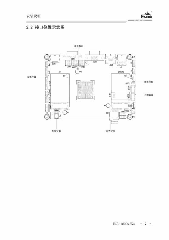
2.2 接口位置示意图
在板背面
在板背面
在板背面 在板背面
在板背面
在板背面
安装说明
· 8 · EC3-1820V2NA
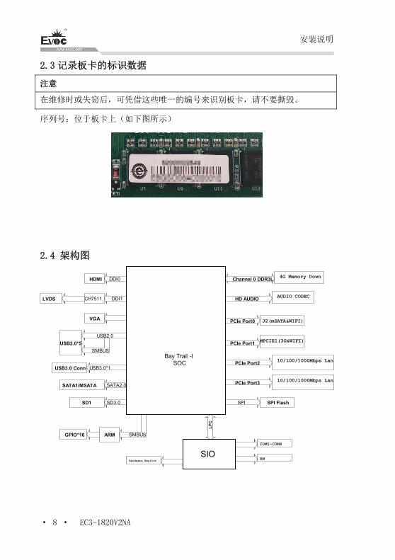
2.3 记录板卡的标识数据
注意
在维修时或失窃后,可凭借这些唯一的编号来识别板卡,请不要撕毁。
序列号:位于板卡上(如下图所示)
2.4 架构图
LP
C
SIOHardware Monitor
COM1~COM4
KM
USB3.0 Conn USB3.0*1
DDI1LVDS CH7511
VGA
Bay Trail -I SOC
4G Memory DownChannel 0 DDR3L
GPIO*16
USB2.0*5
USB2.0
SATA1/MSATA SATA2.0
SPISD1 SD3.0 SPI Flash
AUDIO CODEC HD AUDIO
HDMI DDI0
ARM
J2(mSATA&WIFI)PCIe Port0
10/100/1000Mbps LanPCIe Port2
PCIe Port310/100/1000Mbps Lan
MPCIE1(3G&WIFI)PCIe Port1
SMBUS
SMBUS
安装说明
EC3-1820V2NA · 9 ·
提示:如何识别跳线、接口第一脚
1、观察插头、插座旁边的文字标记,通常用“1”或加粗的线条或三角符号表示。
2、看看背面的焊盘,通常方型焊盘为第一脚。
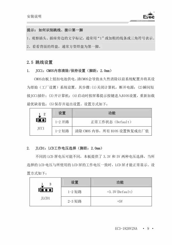
2.5 跳线设置
1. JCC1:CMOS内容清除/保持设置(脚距:2.0mm)
CMOS由板上钮扣电池供电。清CMOS会导致永久性消除以前系统配置并将其设
为原始(工厂设置)系统设置。其步骤:(1)关闭计算机,断开电源;(2)瞬间短
接JCC1插针;(3)开计算机;(4)启动时按屏幕提示按键进入BIOS设置,重新加载
最优缺省值;(5)保存并退出设置。设置方式如下:
设置 功能
1-2 开路 正常工作状态(Default)
JCC1 1-2 短路 清除 CMOS 内容,所有 BIOS 设置恢复成出厂值
2. JLCD1:LCD工作电压选择(脚距:2.0mm)
不同的 LCD 屏电压可能不同,本板提供了 3.3V 和 5V 两种电压选择,当所
选择的 LCD 电压与所使用的 LCD 屏的工作电压一致时,LCD 屏才能正常显示。设
置方式如下:
设置 功能
1-2 短路 +3.3V(Default)
JLCD1 2-3 短路 +5V
安装说明
· 10 · EC3-1820V2NA
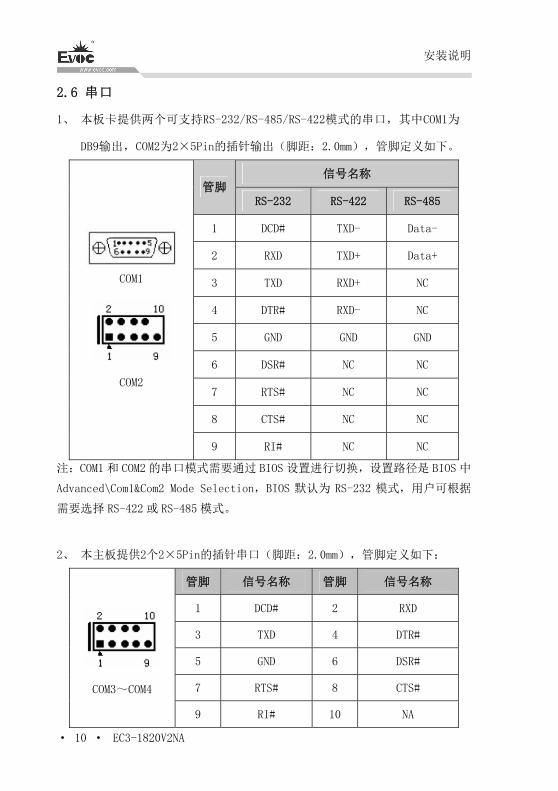
2.6 串口
1、 本板卡提供两个可支持RS-232/RS-485/RS-422模式的串口,其中COM1为
DB9输出,COM2为2×5Pin的插针输出(脚距:2.0mm),管脚定义如下。
信号名称 管脚
RS-232 RS-422 RS-485
1 DCD# TXD- Data-
2 RXD TXD+ Data+
3 TXD RXD+ NC
4 DTR# RXD- NC
5 GND GND GND
6 DSR# NC NC
7 RTS# NC NC
8 CTS# NC NC
COM1
COM2
9 RI# NC NC
注:COM1 和 COM2 的串口模式需要通过 BIOS 设置进行切换,设置路径是 BIOS 中
Advanced\Com1&Com2 Mode Selection,BIOS 默认为 RS-232 模式,用户可根据
需要选择 RS-422 或 RS-485 模式。
2、 本主板提供2个2×5Pin的插针串口(脚距:2.0mm),管脚定义如下:
管脚 信号名称 管脚 信号名称
1 DCD# 2 RXD
3 TXD 4 DTR#
5 GND 6 DSR#
7 RTS# 8 CTS#
COM3~COM4
9 RI# 10 NA
安装说明
EC3-1820V2NA · 11 ·
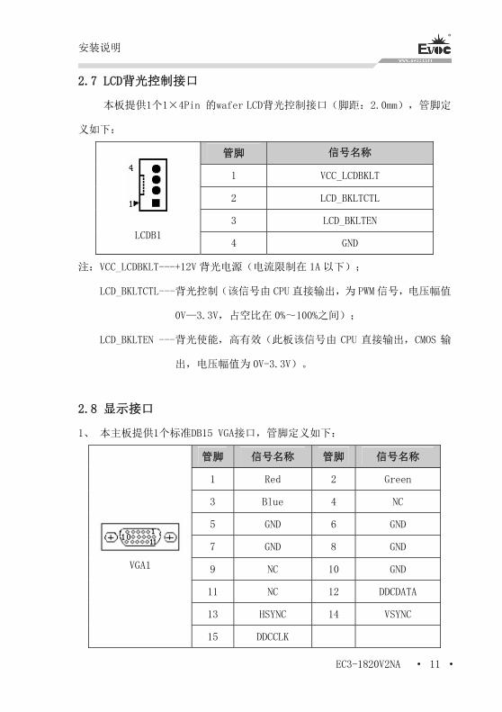
2.7 LCD背光控制接口
本板提供1个1×4Pin 的wafer LCD背光控制接口(脚距:2.0mm),管脚定
义如下:
管脚 信号名称
1 VCC_LCDBKLT
2 LCD_BKLTCTL
3 LCD_BKLTEN
LCDB1 4 GND
注:VCC_LCDBKLT---+12V 背光电源(电流限制在 1A 以下);
LCD_BKLTCTL---背光控制(该信号由 CPU 直接输出,为 PWM 信号,电压幅值
0V—3.3V,占空比在 0%~100%之间);
LCD_BKLTEN ---背光使能,高有效(此板该信号由 CPU 直接输出,CMOS 输
出,电压幅值为 0V-3.3V)。
2.8 显示接口
1、 本主板提供1个标准DB15 VGA接口,管脚定义如下:
管脚 信号名称 管脚 信号名称
1 Red 2 Green
3 Blue 4 NC
5 GND 6 GND
7 GND 8 GND
9 NC 10 GND
11 NC 12 DDCDATA
13 HSYNC 14 VSYNC
VGA1
15 DDCCLK
安装说明
· 12 · EC3-1820V2NA
注:由于Intel GMA驱动限制,在安装完显卡驱动后重启进入系统,CRT可能会成
为扩展模式或者CRT不显示(此时CRT为副显),此时可通过Ctrl+Alt+F1热键进
行切换,将CRT转换为主显示。
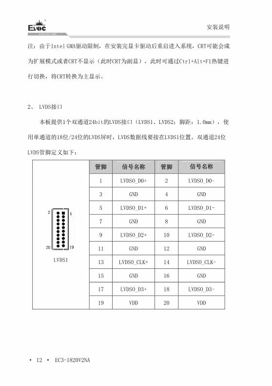
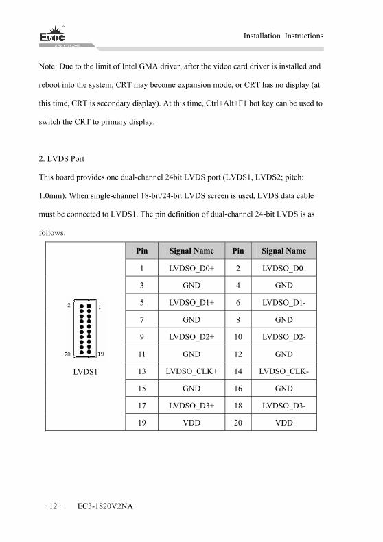
2、 LVDS接口
本板提供1个双通道24bit的LVDS接口(LVDS1、LVDS2;脚距:1.0mm),使
用单通道的18位/24位的LVDS屏时,LVDS数据线要接在LVDS1位置。双通道24位
LVDS管脚定义如下:
管脚 信号名称 管脚 信号名称
1 LVDSO_D0+ 2 LVDSO_D0-
3 GND 4 GND
5 LVDSO_D1+ 6 LVDSO_D1-
7 GND 8 GND
9 LVDSO_D2+ 10 LVDSO_D2-
11 GND 12 GND
13 LVDSO_CLK+ 14 LVDSO_CLK-
15 GND 16 GND
17 LVDSO_D3+ 18 LVDSO_D3-
LVDS1
19 VDD 20 VDD
安装说明
EC3-1820V2NA · 13 ·
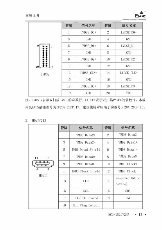
管脚 信号名称 管脚 信号名称
1 LVDSE_D0+ 2 LVDSE_D0-
3 GND 4 GND
5 LVDSE_D1+ 6 LVDSE_D1-
7 GND 8 GND
9 LVDSE_D2+ 10 LVDSE_D2-
11 GND 12 GND
13 LVDSE_CLK+ 14 LVDSE_CLK-
15 GND 16 GND
17 LVDSE_D3+ 18 LVDSE_D3-
LVDS2
19 VDD 20 VDD
注:LVDSOx表示双扫描PANEL的奇数行,LVDSEx表示双扫描PANEL的偶数行。本板
用到LVDS插座型号为DF20G-20DP-1V,建议使用对应端子的型号DF20A-20DF-1C。
3、 HDMI接口
管脚 信号名称 管脚 信号名称
1 TMDS Data2+ 2 TMDS Data2
3 TMDS Data2- 4 TMDS Data1+
5 TMDS Data1 Shield 6 TMDS Data1-
7 TMDS Data0+ 8 TMDS Data0
9 TMDS Data0- 10 TMDS Clock+
11 TMDS Clock Shield 12 TMDS Clock-
13 CEC 14 Reserved (NC on
device)
15 SCL 16 SDA
17 DDC/CEC Ground 18 +5V
HDMI1
19 Hot Plug Detect
安装说明
· 14 · EC3-1820V2NA
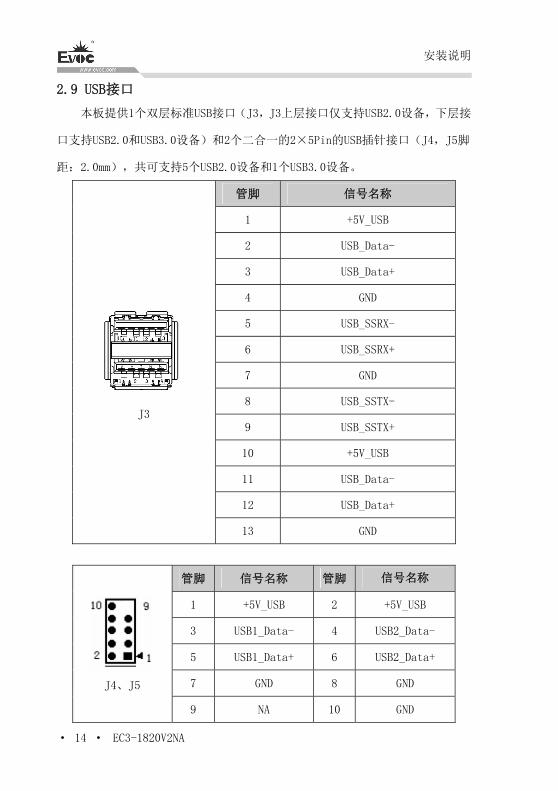
2.9 USB接口
本板提供1个双层标准USB接口(J3,J3上层接口仅支持USB2.0设备,下层接
口支持USB2.0和USB3.0设备)和2个二合一的2×5Pin的USB插针接口(J4,J5脚
距:2.0mm),共可支持5个USB2.0设备和1个USB3.0设备。
管脚 信号名称
1 +5V_USB
2 USB_Data-
3 USB_Data+
4 GND
5 USB_SSRX-
6 USB_SSRX+
7 GND
8 USB_SSTX-
9 USB_SSTX+
10 +5V_USB
11 USB_Data-
12 USB_Data+
J3
13 GND
管脚 信号名称 管脚 信号名称
1 +5V_USB 2 +5V_USB
3 USB1_Data- 4 USB2_Data-
5 USB1_Data+ 6 USB2_Data+
7 GND 8 GND
J4、J5
9 NA 10 GND
安装说明
EC3-1820V2NA · 15 ·
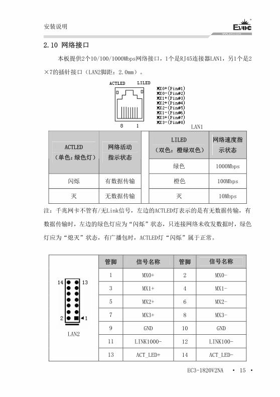
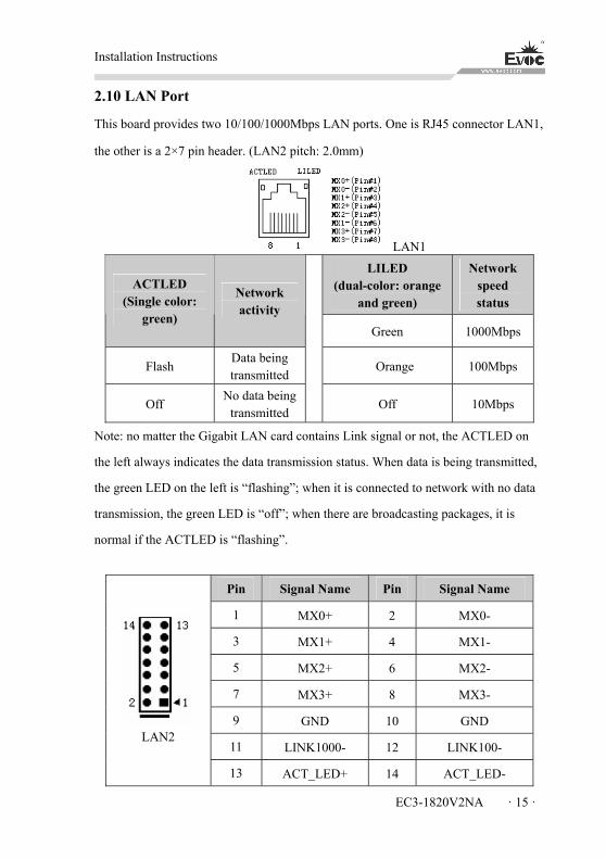
2.10 网络接口
本板提供2个10/100/1000Mbps网络接口,1个是RJ45连接器LAN1,另1个是2
×7的插针接口(LAN2脚距:2.0mm)。
LAN1
LILED
(双色:橙绿双色)
网络速度指
示状态 ACTLED
(单色:绿色灯)
网络活动
指示状态
绿色 1000Mbps
闪烁 有数据传输 橙色 100Mbps
灭 无数据传输 灭 10Mbps
注:千兆网卡不管有/无Link信号,左边的ACTLED灯表示的是有无数据传输,有
数据传输时,左边的绿色灯应为“闪烁”状态,只连接网络未收发数据时,绿色
灯应为“熄灭”状态,有广播包时,ACTLED灯“闪烁”属于正常。
管脚 信号名称 管脚 信号名称
1 MX0+ 2 MX0-
3 MX1+ 4 MX1-
5 MX2+ 6 MX2-
7 MX3+ 8 MX3-
9 GND 10 GND
11 LINK1000- 12 LINK100-
LAN2
13 ACT_LED+ 14 ACT_LED-
安装说明
· 16 · EC3-1820V2NA
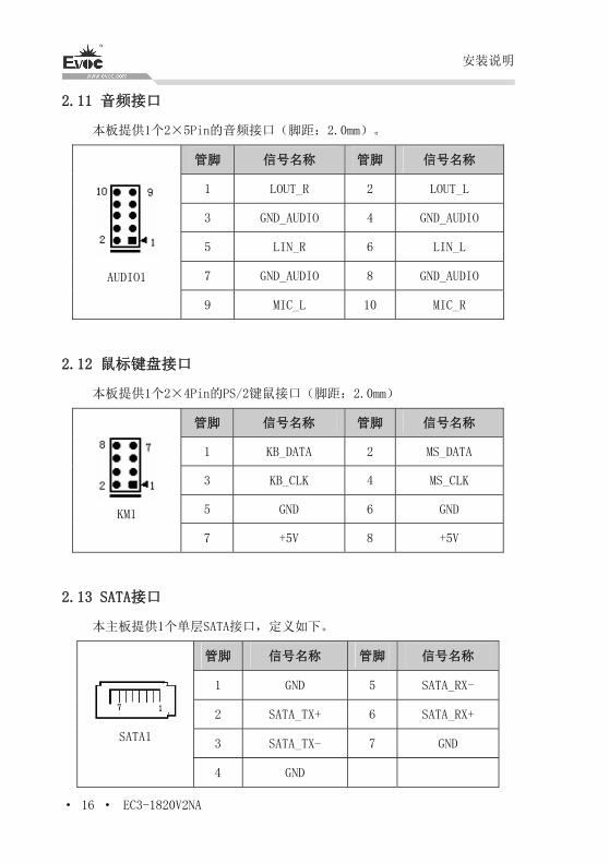
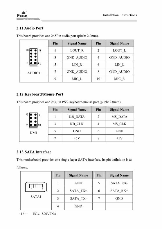
2.11 音频接口
本板提供1个2×5Pin的音频接口(脚距:2.0mm)。
管脚 信号名称 管脚 信号名称
1 LOUT_R 2 LOUT_L
3 GND_AUDIO 4 GND_AUDIO
5 LIN_R 6 LIN_L
7 GND_AUDIO 8 GND_AUDIO
AUDIO1
9 MIC_L 10 MIC_R
2.12 鼠标键盘接口
本板提供1个2×4Pin的PS/2键鼠接口(脚距:2.0mm)
管脚 信号名称 管脚 信号名称
1 KB_DATA 2 MS_DATA
3 KB_CLK 4 MS_CLK
5 GND 6 GND
KM1
7 +5V 8 +5V
2.13 SATA接口
本主板提供1个单层SATA接口,定义如下。
管脚 信号名称 管脚 信号名称
1 GND 5 SATA_RX-
2 SATA_TX+ 6 SATA_RX+
3 SATA_TX- 7 GND SATA1
4 GND

安装说明
EC3-1820V2NA · 17 ·
2.14 GPIO 接口
管脚 信号名称 管脚 信号名称
1 GPIO1 2 GPIO9
3 GPIO2 4 GPIO10
5 GPIO3 6 GPIO11
7 GPIO4 8 GPIO12
9 GPIO5 10 GPIO13
11 GPIO6 12 GPIO14
13 GPIO7 14 GPIO15
15 GPIO8 16 GPIO16
17 +5V 18 +5V
GPIO1
(脚距:2.0mm)
19 GND 20 GND
注:出厂Default值为连接器的第1、3、5、7、9、11、13、15脚为GPIO输入,第
2、4、6、8、10、12、14、16脚为GPIO输出,出厂默认状态为高电平,输入输出
信号的电压范围为0-5V。
2.15 风扇接口
本主板提供 1 个 1×2Pin 的 CPU 风扇接口(CPUFAN1,脚距:1.25mm)。使
用风扇插座时要注意以下三点:
风扇电流不大于 500 毫安(12 伏特)。
请确认风扇接线和本插座的接线是否相符。插座凹槽正对我们,从左
往右第一脚为地,第二脚为 12V 电源脚;请注意匹配装配。
将风扇气流调整成能将热量排出的方向。
安装说明
· 18 · EC3-1820V2NA
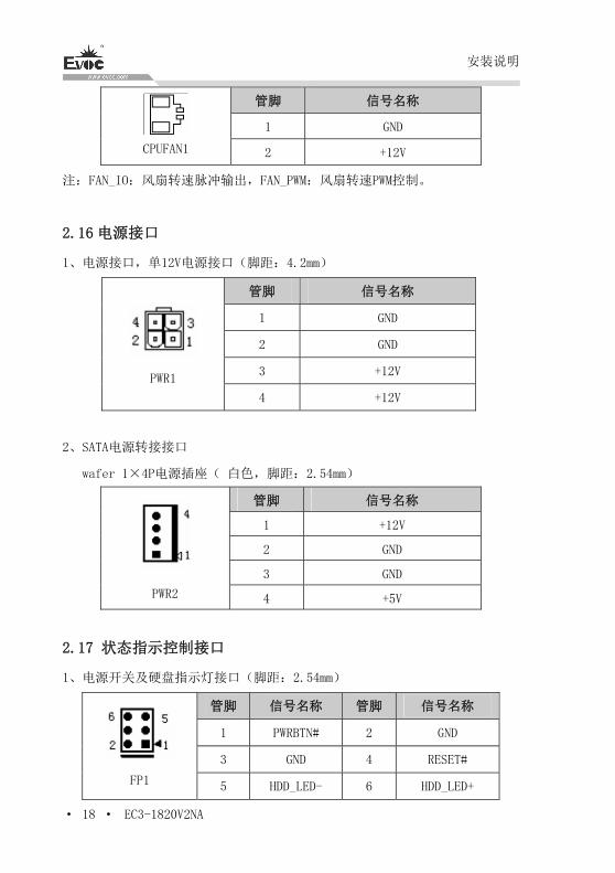
管脚 信号名称
1 GND
CPUFAN1 2 +12V
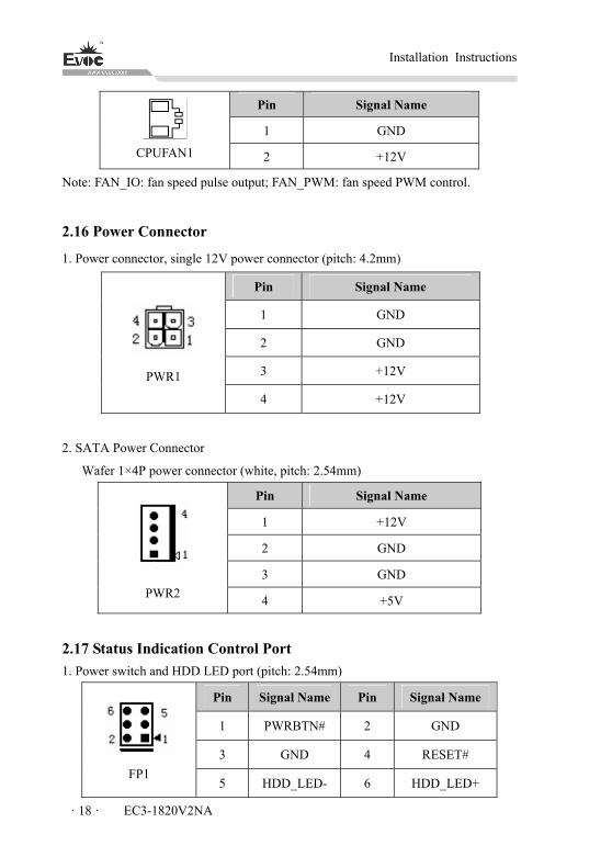
注:FAN_IO:风扇转速脉冲输出,FAN_PWM:风扇转速PWM控制。
2.16 电源接口
1、电源接口,单12V电源接口(脚距:4.2mm)
管脚 信号名称
1 GND
2 GND
3 +12V
PWR1
4 +12V
2、SATA电源转接接口
wafer 1×4P电源插座( 白色,脚距:2.54mm)
管脚 信号名称
1 +12V
2 GND
3 GND
PWR2 4 +5V
2.17 状态指示控制接口
1、电源开关及硬盘指示灯接口(脚距:2.54mm)
管脚 信号名称 管脚 信号名称
1 PWRBTN# 2 GND
3 GND 4 RESET#
FP1 5 HDD_LED- 6 HDD_LED+
安装说明
EC3-1820V2NA · 19 ·
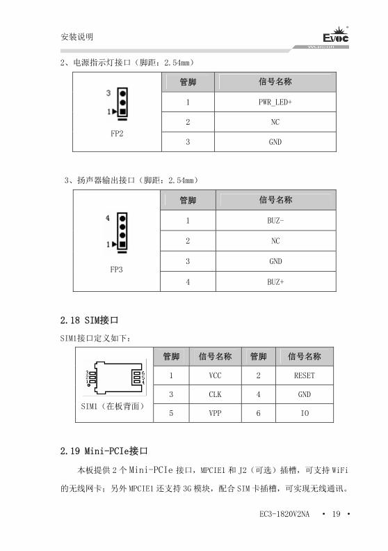
2、电源指示灯接口(脚距:2.54mm)
管脚 信号名称
1 PWR_LED+
2 NC
FP2 3 GND
3、扬声器输出接口(脚距:2.54mm)
管脚 信号名称
1 BUZ-
2 NC
3 GND
FP3 4 BUZ+
2.18 SIM接口
SIM1接口定义如下:
管脚 信号名称 管脚 信号名称
1 VCC 2 RESET
3 CLK 4 GND
SIM1(在板背面)5 VPP 6 IO
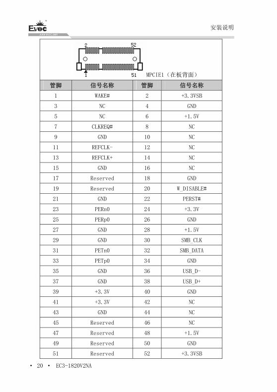
2.19 Mini-PCIe接口
本板提供 2 个 Mini-PCIe 接口,MPCIE1 和 J2(可选)插槽,可支持 WiFi
的无线网卡;另外 MPCIE1 还支持 3G 模块,配合 SIM 卡插槽,可实现无线通讯。
安装说明
· 20 · EC3-1820V2NA
MPCIE1(在板背面)
管脚 信号名称 管脚 信号名称
1 WAKE# 2 +3.3VSB
3 NC 4 GND
5 NC 6 +1.5V
7 CLKREQ# 8 NC
9 GND 10 NC
11 REFCLK- 12 NC
13 REFCLK+ 14 NC
15 GND 16 NC
17 Reserved 18 GND
19 Reserved 20 W_DISABLE#
21 GND 22 PERST#
23 PERn0 24 +3.3V
25 PERp0 26 GND
27 GND 28 +1.5V
29 GND 30 SMB_CLK
31 PETn0 32 SMB_DATA
33 PETp0 34 GND
35 GND 36 USB_D-
37 GND 38 USB_D+
39 +3.3V 40 GND
41 +3.3V 42 NC
43 GND 44 NC
45 Reserved 46 NC
47 Reserved 48 +1.5V
49 Reserved 50 GND
51 Reserved 52 +3.3VSB
安装说明
EC3-1820V2NA · 21 ·
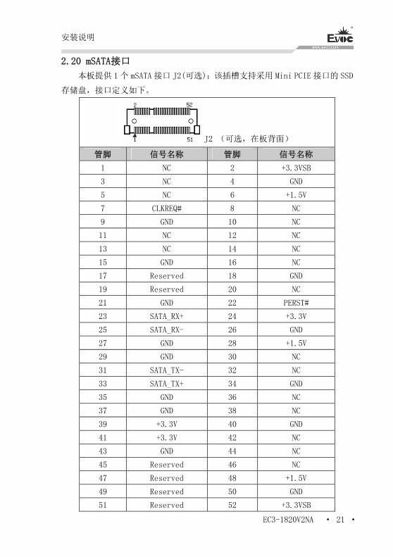
2.20 mSATA接口
本板提供 1个 mSATA 接口 J2(可选);该插槽支持采用 Mini PCIE 接口的 SSD
存储盘,接口定义如下。
J2 (可选,在板背面)
管脚 信号名称 管脚 信号名称
1 NC 2 +3.3VSB
3 NC 4 GND
5 NC 6 +1.5V
7 CLKREQ# 8 NC
9 GND 10 NC
11 NC 12 NC
13 NC 14 NC
15 GND 16 NC
17 Reserved 18 GND
19 Reserved 20 NC
21 GND 22 PERST#
23 SATA_RX+ 24 +3.3V
25 SATA_RX- 26 GND
27 GND 28 +1.5V
29 GND 30 NC
31 SATA_TX- 32 NC
33 SATA_TX+ 34 GND
35 GND 36 NC
37 GND 38 NC
39 +3.3V 40 GND
41 +3.3V 42 NC
43 GND 44 NC
45 Reserved 46 NC
47 Reserved 48 +1.5V
49 Reserved 50 GND
51 Reserved 52 +3.3VSB
安装说明
· 22 · EC3-1820V2NA
2.21 SATA硬盘热插拔
SATA 硬盘热插拔需注意:
(1) 硬盘必须支持:SATA2.0 接口以上,并且采用 15 芯 SATA 硬盘电源接口;
(2) SATA 硬盘仅工作在 AHCI 模式下且打开热拔插选项时支持热插拔功能;
(3) 芯片组驱动程序支持 SATA 硬盘的热插拔;
(4) 不能对操作系统所在的 SATA 硬盘进行带电热插拔。
注:请按照如下步骤进行 SATA 硬盘热插拔,否则,操作不当会导致硬盘损
坏和数据丢失。
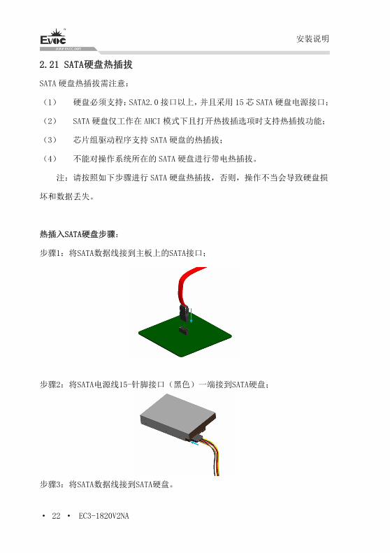
热插入SATA硬盘步骤:
步骤1:将SATA数据线接到主板上的SATA接口;
步骤2:将SATA电源线15-针脚接口(黑色)一端接到SATA硬盘;
步骤3:将SATA数据线接到SATA硬盘。
安装说明
EC3-1820V2NA · 23 ·
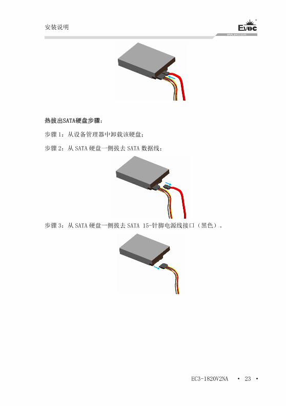
热拔出SATA硬盘步骤:
步骤 1:从设备管理器中卸载该硬盘;
步骤 2:从 SATA 硬盘一侧拔去 SATA 数据线;
步骤 3:从 SATA 硬盘一侧拔去 SATA 15-针脚电源线接口(黑色)。
BIOS 功能介绍
· 24 · EC3-1820V2NA
3.BIOS功能介绍
3.1 BIOS 信息提示界面
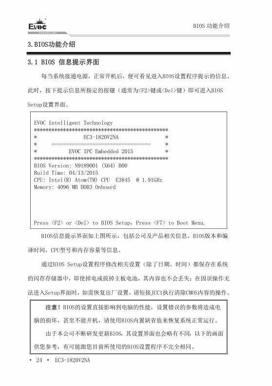
每当系统接通电源,正常开机后,便可看见进入BIOS设置程序提示的信息。
此时,按下提示信息所指定的按键(通常为<F2>键或<Del>键)即可进入BIOS
Setup设置界面。
EVOC Intelligent Technology ********************************************** * EC3-1820V2NA * * ================================== * * EVOC IPC Embedded 2015 * ********************************************** BIOS Version: N9189001 (X64) B00 Build Time: 04/13/2015 CPU: Intel(R) Atom(TM) CPU E3845 @ 1.91GHz Memory: 4096 MB DDR3 Onboard Press <F2> or <Del> to BIOS Setup,Press <F7> to Boot Menu.
BIOS信息提示界面如上图所示,包括公司及产品相关信息。BIOS版本和编
译时间,CPU型号和内存容量等信息。
通过BIOS Setup设置程序修改相关设置(除了日期、时间)都保存在系统
的闪存存储器中,即使掉电或拔掉主板电池,其内容也不会丢失;在因误操作无
法进入Setup界面时,如需恢复出厂设置,请短接JCC1执行清除CMOS内容的操作。
注意!BIOS的设置直接影响到电脑的性能,设置错误的参数将造成电
脑的损坏,甚至不能开机,请使用BIOS内置缺省值来恢复系统正常运行。
由于本公司不断研发更新BIOS,其设置界面也会略有不同,以下的画面
供您参考,有可能跟您目前所使用的BIOS设置程序不完全相同。
BIOS 功能介绍
EC3-1820V2NA · 25 ·
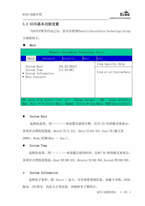
3.2 BIOS基本功能设置
当SETUP程序启动之后,您可以看到Phoenix SecureCore Technology Setup
主画面如下:
Main
Phoenix SecureCore Technology Setup
Main Advanced Security Boot Exit
Item Specific Help System Date System Time ▶ System Information ▶ Boot Features
[01/23/2015] [11:54:08]
View or set System Date
F1 Help ↑↓ Select Item +/- Change Values F9 Setup Defaults Esc Exit ←→ Select Menu Enter Select ▶ Sub-Menu F10 Save and Exit
System Date
选择此选项,用< + > / <->来设置目前的日期。以月/日/年的格式来表示。
各项目合理的范围是:Month/月(1-12), Date/日(01-31),Year/年(最大至
2099),Week/星期(Mon.~ Sun.)。
System Time
选择此选项,用< + > / <->来设置目前的时间。以时/分/秒的格式来表示。
各项目合理的范围是:Hour/时(00-23), Minute/分(00-59),Second/秒(00-59)。
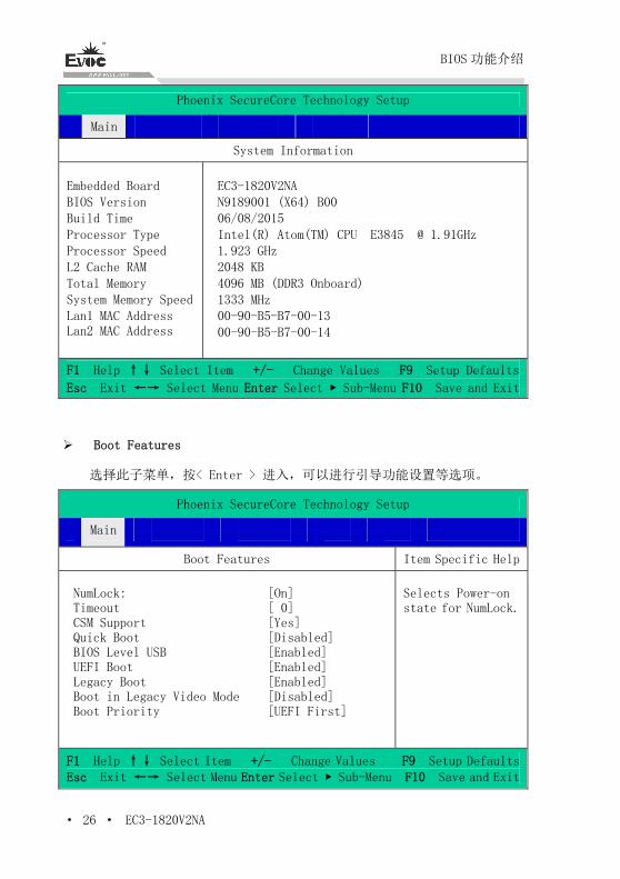
System Information
选择此子菜单,按< Enter > 进入,可以查看系统信息,如板卡名称,BIOS
版本,CPU型号,内存大小等信息,详细参考下图所示。
BIOS 功能介绍
· 26 · EC3-1820V2NA
Phoenix SecureCore Technology Setup
Main
System Information
Embedded Board BIOS Version Build Time Processor Type Processor Speed L2 Cache RAM Total Memory System Memory Speed Lan1 MAC Address Lan2 MAC Address
EC3-1820V2NA N9189001 (X64) B00 06/08/2015 Intel(R) Atom(TM) CPU E3845 @ 1.91GHz 1.923 GHz 2048 KB 4096 MB (DDR3 Onboard) 1333 MHz 00-90-B5-B7-00-13 00-90-B5-B7-00-14
F1 Help ↑↓ Select Item +/- Change Values F9 Setup Defaults
Esc Exit ←→ Select Menu Enter Select ▶ Sub-Menu F10 Save and Exit
Boot Features
选择此子菜单,按< Enter > 进入,可以进行引导功能设置等选项。
Phoenix SecureCore Technology Setup
Main
Boot Features Item Specific Help
NumLock: Timeout CSM Support Quick Boot BIOS Level USB UEFI Boot Legacy Boot Boot in Legacy Video Mode Boot Priority
[On] [ 0] [Yes] [Disabled] [Enabled] [Enabled] [Enabled] [Disabled] [UEFI First]
Selects Power-on state for NumLock.
F1 Help ↑↓ Select Item +/- Change Values F9 Setup DefaultsEsc Exit ←→ Select Menu Enter Select ▶ Sub-Menu F10 Save and Exit
BIOS 功能介绍
EC3-1820V2NA · 27 ·
NumLock
键盘NumLock状态设置,用于选择开机时NumLock的状态
Timeout
开机过程中等待时间设置,当主板接大容量存储设备时建议增加等待时间。
CSM Support
传统BIOS模块支持控制开关。
Quick Boot
快速开机选项开关,当开启时系统将省略开机提示信息。
BIOS Level USB
BIOS Legacy支持控制开关,当关闭时BIOS阶段及DOS系统无法使用USB设备。
UEFI Boot
UEFI 引导支持开关。
Legacy Boot
传统引导方式支持开关。
Boot in Leagcy Video Mode
引导时使用传统显示模式,以兼容个别系统或软件。
Boot Priority
引导方式优先级设置开关,用于调整UEFI和Legacy引导方式的先后顺序。
BIOS 功能介绍
· 28 · EC3-1820V2NA
Advanced
Phoenix SecureCore Technology Setup
Main Advanced Security Boot Exit
Item Specific Help Setup Warning: Setting items on this screen to incorrect values may cause system to malfunction!
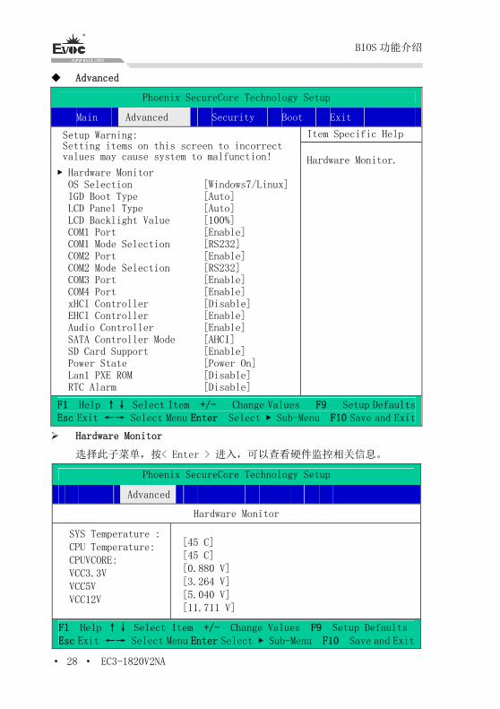
▶ Hardware Monitor OS Selection IGD Boot Type LCD Panel Type LCD Backlight Value COM1 Port COM1 Mode Selection COM2 Port COM2 Mode Selection COM3 Port COM4 Port xHCI Controller EHCI Controller Audio Controller SATA Controller Mode SD Card Support Power State Lan1 PXE ROM RTC Alarm
[Windows7/Linux] [Auto] [Auto] [100%] [Enable] [RS232] [Enable] [RS232] [Enable] [Enable] [Disable] [Enable] [Enable] [AHCI] [Enable] [Power On] [Disable] [Disable]
Hardware Monitor.
F1 Help ↑↓ Select Item +/- Change Values F9 Setup DefaultsEsc Exit ←→ Select Menu Enter Select ▶ Sub-Menu F10 Save and Exit
Hardware Monitor
选择此子菜单,按< Enter > 进入,可以查看硬件监控相关信息。
Phoenix SecureCore Technology Setup
Advanced
Hardware Monitor SYS Temperature : CPU Temperature: CPUVCORE: VCC3.3V VCC5V VCC12V
[45 C] [45 C] [0.880 V] [3.264 V] [5.040 V] [11.711 V]
F1 Help ↑↓ Select Item +/- Change Values F9 Setup Defaults Esc Exit ←→ Select Menu Enter Select ▶ Sub-Menu F10 Save and Exit
BIOS 功能介绍
EC3-1820V2NA · 29 ·
OS Selection
操作系统选择项,包括Windows 8.x, Android,和Windows7/Linux三个选
项。
IGD Boot Type
IGD引导显示设置选项,用于配置开机过程中显示输出端口,包括VGA,HDMI,
LVDS,Auto 选项是按照VBIOS默认输出。
LCD Panel Type
LCD 显示平板类型选择项,Auto选项是按照VBIOS默认输出分辨率,可以根
据所接的LVDS屏选择对应的集成显示分辨率输出,如所支持的LVDS屏分辨
率不在预备选项中,请联系EVOC客服寻求定制。
COM1~4 Port
串口1至4开关控制选项,关闭后系统下默认无法使用。
COM1~2 Mode Selection
串口1~2 模式选择项,用于配置COM1,2的工作模式,由RS-232,RS-485,
RS-422。
xHCI Controller / EHCI Controller
此两项用于选择USB控制器模式,选项xHCI Controller与EHCI Controller
不能同时设置成Enable。
SATA Controller Mode
集成SATA控制器工作模式选项,有AHCI,IDE 被选项。
SD Card Support
SD卡支持开关选项
Power State
用于选择系统上电行为, Power On,系统上电即开机,Power Off,系统
上电后,需要Power Button动作或通过其他方式唤醒系统。

BIOS 功能介绍
· 30 · EC3-1820V2NA
Lan1 PXE ROM
用于设置lan1网口,控制disable和enable。
RTC Alarm
用于设置定时启动,如果enable后会显示唤醒时间设置栏,设置时间小时、
分钟、秒,该时间到达后上电唤醒系统。
Security
Phoenix SecureCore Technology Setup
Main Advanced Security Boot Exit
Item Specific Help Secure Boot Activation ▶Secure Boot Configuration Supervisor Password is: User Password is: Set Supervisor Password Supervisor Hint String Set User Password User Hint String Min. Password length Authenticate User on Boot HDD Password Select No HDD detected
[Disabled] Cleared Cleared [Enter] [ ] [Enter] [ ] [ 1] [Disabled]
Set or clear the Supervisor account's password.
F1 Help ↑↓ Select Item +/- Change Values F9 Setup DefaultsEsc Exit ←→ Select Menu Enter Select ▶ Sub-Menu F10 Save and Exit
Secure Boot Activation
安全引导激活选项,该选项需设置 Supervisor Password 才能使用,该选
项一经设置 Enable,无法关闭。
Secure Boot Configuration
安全引导相关设置子菜单。该子菜单需设置 Supervisor Password 才能使用
Supervisor/User Password is:
此两项分别用于显示超级用户和普通用户的密码状态,当没有密码时显
Cleared,如有设置密码显示 Set。
Set Supervisor/User Password
此两项分别用于设置超级用户和普通用户的密码,按< Enter > 进入设置。
BIOS 功能介绍
EC3-1820V2NA · 31 ·
Supervisor/User Hint String
此两项分别用于设置超级用户和普通用户的提示信息,直接输入即可。
Min. Password length
最小密码长度设置项。
Authenticate User on Boot
验证用户开机选项,当Enable此项,每次开机需要输入用户密码。当Disable
时,进入Setup时需要输入用户密码,该项需要设置Supervisor Password
才能使用。
HDD Password Select
用于选择硬盘密码权限,有 User Only/User+Master被选项。该选项只有
接硬盘时才显示。
HDD Security Status
用于显示硬盘安全信息状态列表,如没有侦测到硬盘,会显示No HDD
Detected,如有侦测到硬盘会显示对应的 HDD Password State 状态,和
Set HDD User Password 选项,用于查看硬盘密码状态和设置硬盘密码功
能。
BIOS 功能介绍
· 32 · EC3-1820V2NA
Boot
Phoenix SecureCore Technology Setup
Main Advanced Security Boot Exit
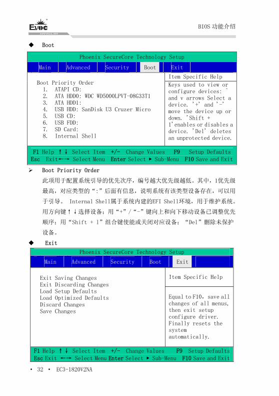
Item Specific Help Boot Priority Order 1. ATAPI CD: 2. ATA HDD0: WDC WD5000LPVT-08G33T1 3. ATA HDD1: 4. USB HDD: SanDisk U3 Cruzer Micro 5. USB CD: 6. USB FDD: 7. SD Card: 8. Internal Shell
Keys used to view or configure devices: ^ and v arrows Select a device. '+' and '-' move the device up or down. 'Shift + 1'enables or disables a device. 'Del' deletes an unprotected device.
F1 Help ↑↓ Select Item +/- Change Values F9 Setup DefaultsEsc Exit←→ Select Menu Enter Select ▶ Sub-Menu F10 Save and Exit
Boot Priority Order
此项用于配置系统引导的优先次序,编号越大优先级越低。其中,1优先级
最高,对应类型的“:”后面有信息,说明系统有该类型设备存在,可以用
于引导。 Internal Shell属于系统内建的EFI Shell环境,用于维护系统。
用方向键↑↓选择设备;用“+”/“-”键向上和向下移动设备已调整优先
顺序;用“Shift + l”组合键使能或关闭对应设备;“Del”删除未保护
设备。
Exit
Phoenix SecureCore Technology Setup
Main Advanced Security Boot Exit
Item Specific Help Exit Saving Changes Exit Discarding Changes Load Setup Defaults Load Optimized Defaults Discard Changes Save Changes
Equal to F10,save all changes of all menus, then exit setup configure driver. Finally resets the system automatically.
F1 Help ↑↓ Select Item +/- Change Values F9 Setup DefaultsEsc Exit ←→ Select Menu Enter Select ▶ Sub-Menu F10 Save and Exit
BIOS 功能介绍
EC3-1820V2NA · 33 ·
Exit Saving Changes
退出并保存变更。
Exit Discarding Changes
退出并放弃之前变更。
Load Setup Defaults
加载出厂默认设置。
Load Optimized Defaults
加载性能优化设置。
Discard Changes
放弃变更。
Save Changes
保存变更。
3.3 x86 平台下BIOS所要管理的系统资源
这里的系统资源我们定义三种:I/O端口地址,IRQ中断号和Memory地址。
IO端口地址
X86的I/O地址线只设计16条,从0~0FFFFh,I/O地址空间总共有64K,在传
统的ISA接口,只使用到前面的1024个(0000~03FFh),0400h以上的端口为PCI
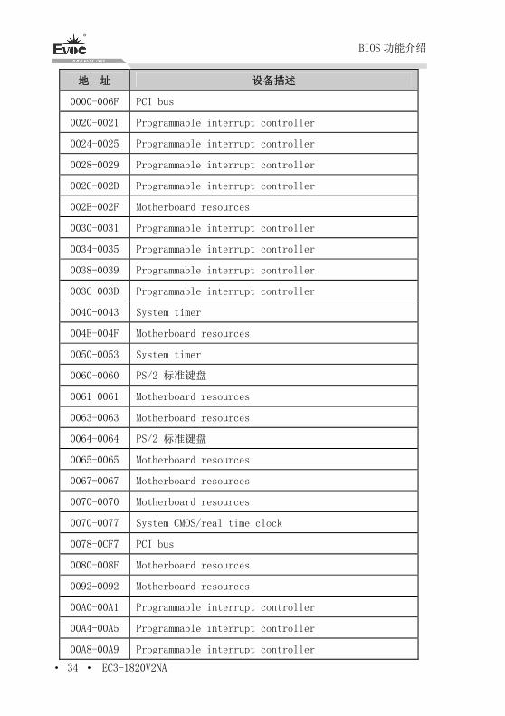
接口与EISA接口所使用。每一外围设备都会占用一段I/O地址空间。下表给出了
X86平台大致上所要用到的I/O接口列表。
BIOS 功能介绍
· 34 · EC3-1820V2NA
地 址 设备描述
0000-006F PCI bus
0020-0021 Programmable interrupt controller
0024-0025 Programmable interrupt controller
0028-0029 Programmable interrupt controller
002C-002D Programmable interrupt controller
002E-002F Motherboard resources
0030-0031 Programmable interrupt controller
0034-0035 Programmable interrupt controller
0038-0039 Programmable interrupt controller
003C-003D Programmable interrupt controller
0040-0043 System timer
004E-004F Motherboard resources
0050-0053 System timer
0060-0060 PS/2 标准键盘
0061-0061 Motherboard resources
0063-0063 Motherboard resources
0064-0064 PS/2 标准键盘
0065-0065 Motherboard resources
0067-0067 Motherboard resources
0070-0070 Motherboard resources
0070-0077 System CMOS/real time clock
0078-0CF7 PCI bus
0080-008F Motherboard resources
0092-0092 Motherboard resources
00A0-00A1 Programmable interrupt controller
00A4-00A5 Programmable interrupt controller
00A8-00A9 Programmable interrupt controller
BIOS 功能介绍
EC3-1820V2NA · 35 ·
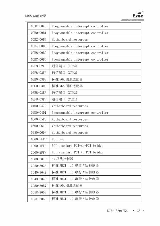
00AC-00AD Programmable interrupt controller
00B0-00B1 Programmable interrupt controller
00B2-00B3 Motherboard resources
00B4-00B5 Programmable interrupt controller
00B8-00B9 Programmable interrupt controller
00BC-00BD Programmable interrupt controller
02E8-02EF 通信端口 (COM4)
02F8-02FF 通信端口 (COM2)
03B0-03BB 标准 VGA 图形适配器
03C0-03DF 标准 VGA 图形适配器
03E8-03EF 通信端口 (COM3)
03F8-03FF 通信端口 (COM1)
0400-047F Motherboard resources
04D0-04D1 Programmable interrupt controller
0500-05FE Motherboard resources
0600-061F Motherboard resources
0680-069F Motherboard resources
0D00-FFFF PCI bus
1000-1FFF PCI standard PCI-to-PCI bridge
2000-2FFF PCI standard PCI-to-PCI bridge
3000-301F SM 总线控制器
3020-303F 标准 AHCI 1.0 串行 ATA 控制器
3040-3047 标准 AHCI 1.0 串行 ATA 控制器
3048-304F 标准 AHCI 1.0 串行 ATA 控制器
3050-3057 标准 VGA 图形适配器
3058-305B 标准 AHCI 1.0 串行 ATA 控制器
305C-305F 标准 AHCI 1.0 串行 ATA 控制器
BIOS 功能介绍
· 36 · EC3-1820V2NA
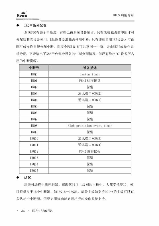
IRQ中断分配表
系统共0有15个中断源,有些已被系统设备独占。只有未被独占的中断才可
分配给其它设备使用。ISA设备要求独占使用中断;只有即插即用ISA设备才可由
UEFI或操作系统分配中断。而多个PCI设备可共享同一中断,并由UEFI或操作系
统分配。下表给出了X86平台部分设备的中断分配情况,但没有给出PCI设备所占
用的中断资源。
中断号 设备描述
IRQ0 System timer
IRQ1 PS/2 标准键盘
IRQ2 保留
IRQ3 通讯端口(COM2)
IRQ4 通讯端口(COM1)
IRQ5 保留
IRQ6 保留
IRQ7 保留
IRQ8 High precision event timer
IRQ9 保留
IRQ10 通讯端口(COM3)
IRQ11 通讯端口(COM4)
IRQ12 PS/2 兼容鼠标
IRQ13 保留
IRQ14 保留
IRQ15 保留
APIC
高级可编程中断控制器。在现代P4以上级别的主板中,大都支持APIC,可
以提供多于16个中断源,如IRQ16—IRQ23,部分主板如支持PCI-X的主板可以有
多达28个中断源。但要启用该功能必须相应的操作系统支持。
BIOS 功能介绍
EC3-1820V2NA · 37 ·
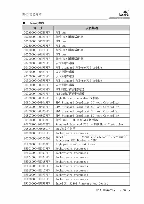
Memory地址
地 址 设备描述
000A0000-000BFFFF PCI bus
000A0000-000BFFFF 标准 VGA 图形适配器
000C0000-000DFFFF PCI bus
000E0000-000FFFFF PCI bus
80000000-8FFFFFFF 标准 VGA 图形适配器
80000000-908FFFFE PCI bus
90000000-903FFFFF 标准 VGA 图形适配器
90400000-9047FFFF 以太网控制器
90400000-904FFFFF PCI standard PCI-to-PCI bridge
90480000-90483FFF 以太网控制器
90500000-9057FFFF 以太网控制器
90500000-905FFFFF PCI standard PCI-to-PCI bridge
90580000-90583FFF 以太网控制器
90600000-906FFFFF PCI 加密/解密控制器
90700000-907FFFFF PCI 加密/解密控制器
90800000-90803FFF High Definition Audio 控制器
90804000-90804FFF SDA Standard Compliant SD Host Controller
90805000-90805FFF SDA Standard Compliant SD Host Controller
90806000-90806FFF SDA Standard Compliant SD Host Controller
90807000-90807FFF SDA Standard Compliant SD Host Controller
90808000-908087FF 标准 ACHI 1.0 串行 ATA 控制器
90808800-90808BFF Standard Enhanced PCI to USB Host Controller
90808C00-90808C1F SM 总线控制器
E0000000-EFFFFFFF Motherboard resources
E00000D0-E00000DB Intel(R) Atom(TM)/Celeron(R)/Pentium(R) Processor MBI Device - 33BD
FED00000-FED003FF High precision event timer
FED01000-FED01FFF Motherboard resources
FED03000-FED03FFF Motherboard resources
FED04000-FED04FFF Motherboard resources
FED08000-FED08FFF Motherboard resources
FED0C000-FED0FFFF Motherboard resources
FED1C000-FED1CFFF Motherboard resources
FEE00000-FEEFFFFF Motherboard resources
FEF00000-FEFFFFFF Motherboard resources
FF000000-FFFFFFFF Intel(R) 82802 Firmware Hub Device

驱动程序安装说明
· 38 · EC3-1820V2NA
4.驱动程序安装说明
本产品的驱动程序可依据配套光盘内容安装,在此不做介绍。
附录
EC3-1820V2NA · 39 ·
5.附录
5.1 GPIO编程指引
本板GPIO功能使用的是通过连接在SMBUS上的ARM芯片,芯片选用的是为
NUVOTON M054LDN,由M054LDN控制GPIO输入输出。
在OS层,基于SMBUS通信与M054LDN建立连接控制,用户可以设置GPIO输出
电平,读取GPIO输入电平。
M054LDN 与主板通过 SMBUS 通信,本产品设计主板为主设备,M054LDN 为从
设备。SMBUS 通信编程,用户可参考 ICH7 等相关文档规范。操作 SMBUS 底层接
口函数已实现,用户可以调用提供好的 API 来实现自己的相应需求。
以下是接口函数介绍,详细程序见光盘。
(1)、SMBWriteByteEx(UCHAR ucSlaveAddress,
UCHAR ucCommand,
UCHAR ucData,
BOOLEAN bPecCheck
);
功能描述:向SMBUS上写一字节(UCHAR)数据
参数: ucSlaveAddress——从设备地址
ucCommand——写操作命令
ucData——数据
bPecCheck——false:不校验,true:校验
返回值:
非0 --- 函数执行失败
0 --- 函数执行成功
(2)、SMBReadByteEx(UCHAR ucSlaveAddress,
附录
· 40 · EC3-1820V2NA
UCHAR ucCommand,
PUCHAR pData,
BOOLEAN bPecCheck
);
功能描述:向 SMBUS 上读一字节(UCHAR)数据
参数: ucSlaveAddress——从设备地址
ucCommand——读操作命令
pData——返回数据
bPecCheck——false:不校验,true:校验
返回值:
非 0 --- 函数执行失败
0 --- 函数执行成功
以上两API接口函数,也是根据SMBUS寄存器等协议规范进行编写的,用户
按照SMBUS规范和我们规定的相关协议命令,即可建立与M054LDN的正常通信。
本产品现规定M054LDN从设备地址为0x75,目前GPIO通信协议命令如下,
typedef enum
{
SMBUS_POST_INFO = 0,
SMBUS_INITGPIO = 0x01,//init gpio
SMBUS_DEINITGPIO = 0x02,//deinit gpio
SMBUS_GETARMINFO = 0x03,//get arm version
SMBUS_SETGPOHIGH=0x06,//set one gpo output high
SMBUS_SETGPOLOW=0x07,//set one gpo output low
SMBUS_GETGPILEVEL=0x08,//get one gpi input level
附录
EC3-1820V2NA · 41 ·
SMBUS_SETALLGPOLEVEL=0x0A,//set ALL gpo output LEVEL(0/1)
SMBUS_GETALLGPILEVEL=0x0B,//Get all gpi input LEVEL(0/1)
SMBUS_GPIOEND=0x5A
} SMBUS_GPIO_CMD;
函数参数值如下表:
地址 命令 参数 校验
slaveAddress command parameter false
parameter 表示 GPO/GPI 索引值,为 1-8。
则向 M054LDN 发送信息,调用 SMBWriteByteEx 函数即可以控制 GPO 的输出
电平;由于 M054LDN 为从设备,GPI 输入电平需主机主动读取,需先执行写函数
SMBWriteByteEx,再执行读函数 SMBReadByteEx,即可获取 GPI 的输入电平信息。
5.2 WDT看门狗编程指引
看门狗由 Super I/O NCT6106D 实现控制的。用户操作 WATCHDOG TIMER 寄
存器,即可实现控制看门狗。
操作看门狗底层接口函数已实现,用户可以调用提供好的 API 来实现自己
的相应需求。
以下是接口函数介绍,详细程序见光盘。
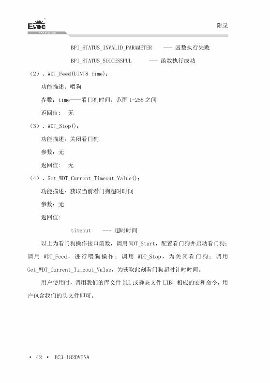
(1)、WDT_Start(UINT8 time,UINT8 count_mode);
功能描述:启动看门狗
参数: time——看门狗时间,范围 1-255 之间
count_mode——0:计时单位秒,1:计时单位分
返回值:
附录
· 42 · EC3-1820V2NA
BPI_STATUS_INVALID_PARAMETER --- 函数执行失败
BPI_STATUS_SUCCESSFUL --- 函数执行成功
(2)、WDT_Feed(UINT8 time);
功能描述:喂狗
参数:time——看门狗时间,范围 1-255 之间
返回值: 无
(3)、WDT_Stop();
功能描述:关闭看门狗
参数:无
返回值: 无
(4)、Get_WDT_Current_Timeout_Value();
功能描述:获取当前看门狗超时时间
参数:无
返回值:
timeout --- 超时时间
以上为看门狗操作接口函数,调用 WDT_Start,配置看门狗并启动看门狗;
调用 WDT_Feed,进行喂狗操作;调用 WDT_Stop,为关闭看门狗;调用
Get_WDT_Current_Timeout_Value,为获取此刻看门狗超时计时时间。
用户使用时,调用我们的库文件 DLL 或静态文件 LIB,相应的宏和命令,用
户包含我们的头文件即可。
附录
EC3-1820V2NA · 43 ·
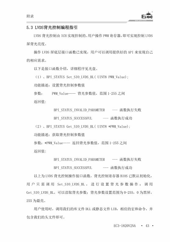
5.3 LVDS背光控制编程指引
LVDS 背光控制由 ICH 实现控制的。用户操作 PWM 寄存器,即可实现控制 LVDS
屏背光亮度。
操作 LVDS 屏底层接口函数已实现,用户可以调用提供好的 API 来实现自己
的相应需求。
以下是接口函数介绍,详细程序见光盘。
(1)、BPI_STATUS Set_SIO_LVDS_BL( UINT8 PWM_Value);
功能描述:设置背光控制参数值
参数: PWM_Value—— 背光参数值,范围 1-255 之间
返回值:
BPI_STATUS_INVALID_PARAMETER --- 函数执行失败
BPI_STATUS_SUCCESSFUL --- 函数执行成功
(2)、BPI_STATUS Get_SIO_LVDS_BL( UINT8 *PWM_Value);
功能描述:获取背光控制参数值
参数:*PWM_Value—— 返回背光参数值,范围 1-255 之间
返回值:
BPI_STATUS_INVALID_PARAMETER --- 函数执行失败
BPI_STATUS_SUCCESSFUL --- 函数执行成功
以上为 LVDS 背光控制操作接口函数,背光控制寄存器 BIOS 已默认初始化,
用 户 只 需 调 用 Set_SIO_LVDS_BL , 进 行 设 置 背 光 参 数 操 作 ; 调 用
Get_SIO_LVDS_BL,可以读取背光参数;背光参数设置范围为 0-255,0 为黑屏,
255 为最亮。
用户使用时,调用我们的库文件 DLL 或静态文件 LIB,相应的宏和命令,并
包含我们的头文件即可。
附录
· 44 · EC3-1820V2NA
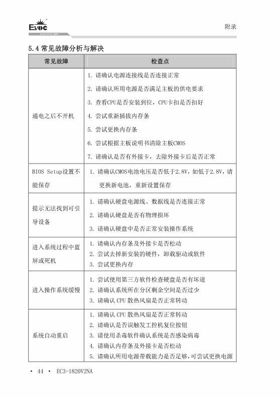
5.4 常见故障分析与解决
常见故障 检查点
通电之后不开机
1. 请确认电源连接线是否连接正常
2. 请确认所用电源是否满足主板的供电要求
3. 查看CPU是否安装到位,CPU卡扣是否扣好
4. 尝试重新插拔内存条
5. 尝试更换内存条
6. 尝试根据主板说明书清除主板CMOS
7. 请确认是否有外接卡,去除外接卡后是否正常
BIOS Setup设置不
能保存
1. 请确认CMOS电池电压是否低于2.8V,如低于2.8V,请
更换新电池,重新设置保存
提示无法找到可引
导设备
1. 请确认硬盘电源线、数据线是否连接正常
2. 请确认硬盘是否有物理损坏
3. 请确认硬盘中是否正常安装操作系统
进入系统过程中蓝
屏或死机
1. 请确认内存条及外接卡是否松动
2. 尝试去掉新安装的硬件,卸载驱动或软件
3. 尝试更换内存
进入操作系统缓慢
1. 尝试使用第三方软件检查硬盘是否有坏道
2. 请确认系统所在分区剩余空间是否过少
3. 请确认 CPU 散热风扇是否正常转动
系统自动重启
1. 请确认 CPU 散热风扇是否正常转动
2. 请确认是否误触发工控机复位按钮
3. 请使用杀毒软件确认系统是否感染病毒
4. 请确认内存条及外接卡是否松动
5. 请确认所用电源带载能力是否足够,可尝试更换电源
附录
EC3-1820V2NA · 45 ·
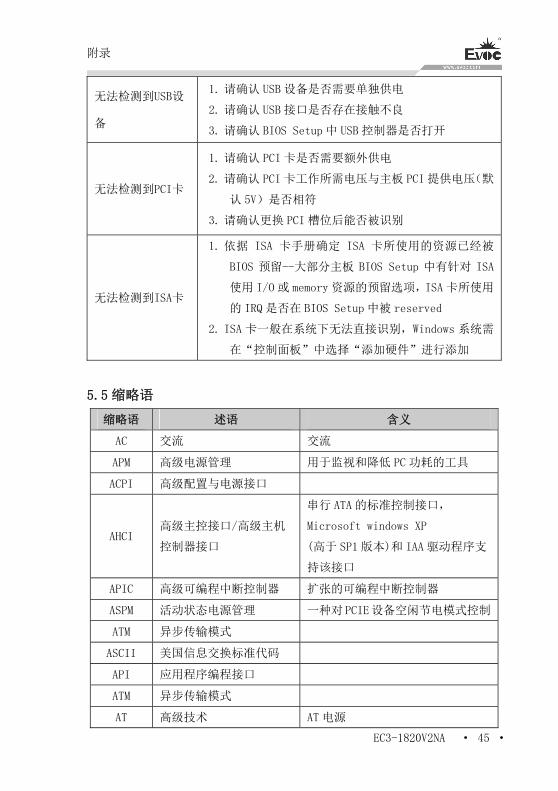
无法检测到USB设
备
1. 请确认 USB 设备是否需要单独供电
2. 请确认 USB 接口是否存在接触不良
3. 请确认 BIOS Setup 中 USB 控制器是否打开
无法检测到PCI卡
1. 请确认 PCI 卡是否需要额外供电
2. 请确认 PCI 卡工作所需电压与主板 PCI 提供电压(默
认 5V)是否相符
3. 请确认更换 PCI 槽位后能否被识别
无法检测到ISA卡
1. 依据 ISA 卡手册确定 ISA 卡所使用的资源已经被
BIOS 预留--大部分主板 BIOS Setup 中有针对 ISA
使用 I/O 或 memory 资源的预留选项,ISA 卡所使用
的 IRQ 是否在 BIOS Setup 中被 reserved
2. ISA 卡一般在系统下无法直接识别,Windows 系统需
在“控制面板”中选择“添加硬件”进行添加
5.5 缩略语
缩略语 述语 含义
AC 交流 交流
APM 高级电源管理 用于监视和降低 PC 功耗的工具
ACPI 高级配置与电源接口
AHCI 高级主控接口/高级主机
控制器接口
串行 ATA 的标准控制接口,
Microsoft windows XP
(高于 SP1 版本)和 IAA 驱动程序支
持该接口
APIC 高级可编程中断控制器 扩张的可编程中断控制器
ASPM 活动状态电源管理 一种对PCIE设备空闲节电模式控制
ATM 异步传输模式
ASCII 美国信息交换标准代码
API 应用程序编程接口
ATM 异步传输模式
AT 高级技术 AT 电源
附录
· 46 · EC3-1820V2NA
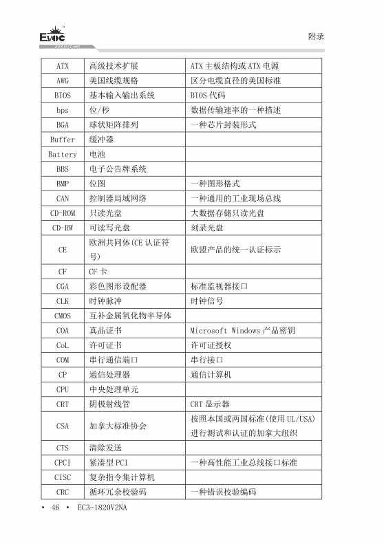
ATX 高级技术扩展 ATX 主板结构或 ATX 电源
AWG 美国线缆规格 区分电缆直径的美国标准
BIOS 基本输入输出系统 BIOS 代码
bps 位/秒 数据传输速率的一种描述
BGA 球状矩阵排列 一种芯片封装形式
Buffer 缓冲器
Battery 电池
BBS 电子公告牌系统
BMP 位图 一种图形格式
CAN 控制器局域网络 一种通用的工业现场总线
CD-ROM 只读光盘 大数据存储只读光盘
CD-RW 可读写光盘 刻录光盘
CE 欧洲共同体(CE 认证符
号) 欧盟产品的统一认证标示
CF CF 卡
CGA 彩色图形设配器 标准监视器接口
CLK 时钟脉冲 时钟信号
CMOS 互补金属氧化物半导体
COA 真品证书 Microsoft Windows 产品密钥
CoL 许可证书 许可证授权
COM 串行通信端口 串行接口
CP 通信处理器 通信计算机
CPU 中央处理单元
CRT 阴极射线管 CRT 显示器
CSA 加拿大标准协会 按照本国或两国标准(使用 UL/USA)
进行测试和认证的加拿大组织
CTS 清除发送
CPCI 紧凑型 PCI 一种高性能工业总线接口标准
CISC 复杂指令集计算机
CRC 循环冗余校验码 一种错误校验编码
附录
EC3-1820V2NA · 47 ·
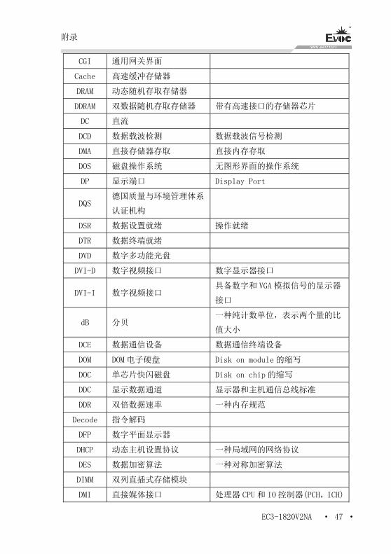
CGI 通用网关界面
Cache 高速缓冲存储器
DRAM 动态随机存取存储器
DDRAM 双数据随机存取存储器 带有高速接口的存储器芯片
DC 直流
DCD 数据载波检测 数据载波信号检测
DMA 直接存储器存取 直接内存存取
DOS 磁盘操作系统 无图形界面的操作系统
DP 显示端口 Display Port
DQS 德国质量与环境管理体系
认证机构
DSR 数据设置就绪 操作就绪
DTR 数据终端就绪
DVD 数字多功能光盘
DVI-D 数字视频接口 数字显示器接口
DVI-I 数字视频接口 具备数字和 VGA 模拟信号的显示器
接口
dB 分贝 一种纯计数单位,表示两个量的比
值大小
DCE 数据通信设备 数据通信终端设备
DOM DOM 电子硬盘 Disk on module 的缩写
DOC 单芯片快闪磁盘 Disk on chip 的缩写
DDC 显示数据通道 显示器和主机通信总线标准
DDR 双倍数据速率 一种内存规范
Decode 指令解码
DFP 数字平面显示器
DHCP 动态主机设置协议 一种局域网的网络协议
DES 数据加密算法 一种对称加密算法
DIMM 双列直插式存储模块
DMI 直接媒体接口 处理器 CPU 和 IO 控制器(PCH,ICH)
附录
· 48 · EC3-1820V2NA
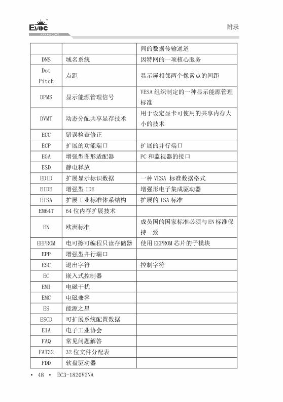
间的数据传输通道
DNS 域名系统 因特网的一项核心服务
Dot
Pitch 点距 显示屏相邻两个像素点的间距
DPMS 显示能源管理信号 VESA 组织制定的一种显示能源管理
标准
DVMT 动态分配共享显存技术 用于设定显卡可使用的共享内存大
小的技术
ECC 错误检查修正
ECP 扩展的功能端口 扩展的并行端口
EGA 增强型图形适配器 PC 和监视器的接口
ESD 静电释放
EDID 扩展显示标识数据 一种 VESA 标准数据格式
EIDE 增强型 IDE 增强形电子集成驱动器
EISA 扩展工业标准体系结构 扩展的 ISA 标准
EM64T 64 位内存扩展技术
EN 欧洲标准 成员国的国家标准必须与EN标准保
持一致
EEPROM 电可擦可编程只读存储器 使用 EEPROM 芯片的子模块
EPP 增强型并行端口
ESC 退出字符 控制字符
EC 嵌入式控制器
EMI 电磁干扰
EMC 电磁兼容
ES 能源之星
ESCD 可扩展系统配置数据
EIA 电子工业协会
FAQ 常见问题解答
FAT32 32 位文件分配表
FDD 软盘驱动器
附录
EC3-1820V2NA · 49 ·
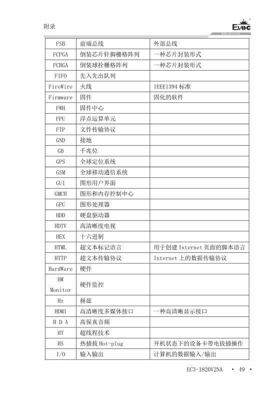
FSB 前端总线 外部总线
FCPGA 倒装芯片针脚栅格阵列 一种芯片封装形式
FCBGA 倒装球拴栅格阵列 一种芯片封装形式
FIFO 先入先出队列
FireWire 火线 IEEE1394 标准
Firmware 固件 固化的软件
FWH 固件中心
FPU 浮点运算单元
FTP 文件传输协议
GND 接地
GB 千兆位
GPS 全球定位系统
GSM 全球移动通信系统
GUI 图形用户界面
GMCH 图形和内存控制中心
GPU 图形处理器
HDD 硬盘驱动器
HDTV 高清晰度电视
HEX 十六进制
HTML 超文本标记语言 用于创建Internet页面的脚本语言
HTTP 超文本传输协议 Internet 上的数据传输协议
HardWare 硬件
HW
Monitor 硬件监控
Hz 赫兹
HDMI 高清晰度多媒体接口 一种高清晰显示接口
H D A 高保真音频
HT 超线程技术
HS 热插拔 Hot-plug 开机状态下的设备卡带电拔插操作
I/O 输入输出 计算机的数据输入/输出
附录
· 50 · EC3-1820V2NA
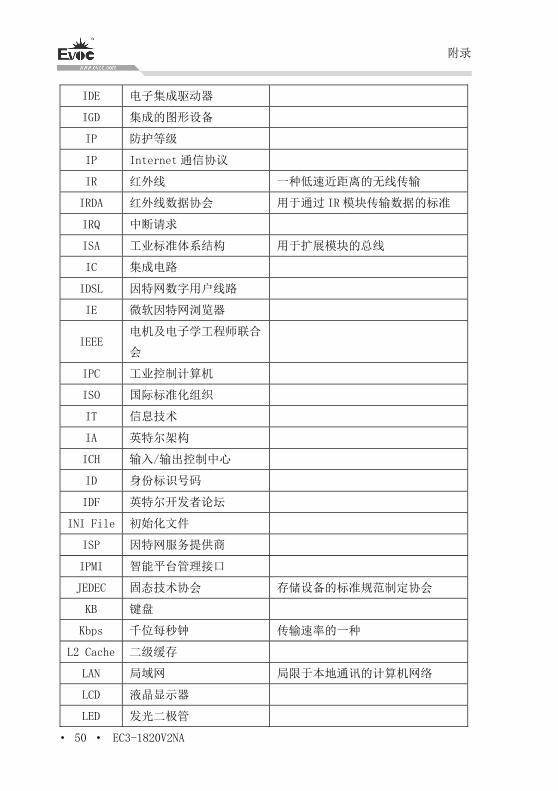
IDE 电子集成驱动器
IGD 集成的图形设备
IP 防护等级
IP Internet 通信协议
IR 红外线 一种低速近距离的无线传输
IRDA 红外线数据协会 用于通过 IR 模块传输数据的标准
IRQ 中断请求
ISA 工业标准体系结构 用于扩展模块的总线
IC 集成电路
IDSL 因特网数字用户线路
IE 微软因特网浏览器
IEEE 电机及电子学工程师联合
会
IPC 工业控制计算机
ISO 国际标准化组织
IT 信息技术
IA 英特尔架构
ICH 输入/输出控制中心
ID 身份标识号码
IDF 英特尔开发者论坛
INI File 初始化文件
ISP 因特网服务提供商
IPMI 智能平台管理接口
JEDEC 固态技术协会 存储设备的标准规范制定协会
KB 键盘
Kbps 千位每秒钟 传输速率的一种
L2 Cache 二级缓存
LAN 局域网 局限于本地通讯的计算机网络
LCD 液晶显示器
LED 发光二极管
附录
EC3-1820V2NA · 51 ·
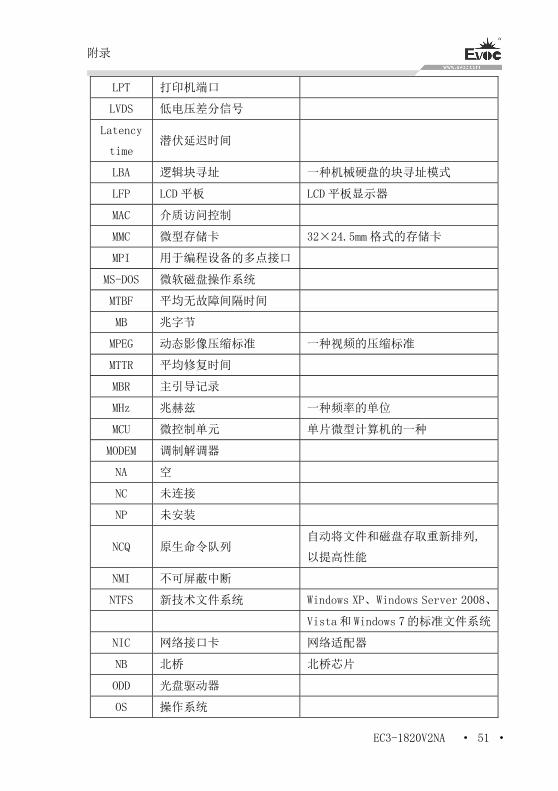
LPT 打印机端口
LVDS 低电压差分信号
Latency
time 潜伏延迟时间
LBA 逻辑块寻址 一种机械硬盘的块寻址模式
LFP LCD 平板 LCD 平板显示器
MAC 介质访问控制
MMC 微型存储卡 32×24.5mm 格式的存储卡
MPI 用于编程设备的多点接口
MS-DOS 微软磁盘操作系统
MTBF 平均无故障间隔时间
MB 兆字节
MPEG 动态影像压缩标准 一种视频的压缩标准
MTTR 平均修复时间
MBR 主引导记录
MHz 兆赫兹 一种频率的单位
MCU 微控制单元 单片微型计算机的一种
MODEM 调制解调器
NA 空
NC 未连接
NP 未安装
NCQ 原生命令队列 自动将文件和磁盘存取重新排列,
以提高性能
NMI 不可屏蔽中断
NTFS 新技术文件系统 Windows XP、Windows Server 2008、
Vista和 Windows 7的标准文件系统
NIC 网络接口卡 网络适配器
NB 北桥 北桥芯片
ODD 光盘驱动器
OS 操作系统
附录
· 52 · EC3-1820V2NA
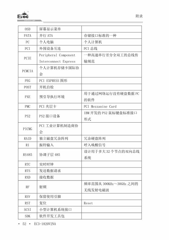
OSD 屏幕显示菜单
PATA 并行 ATA 存储接口标准的一种
PC 个人电脑 个人计算机
PCI 外围设备互连 PCI 总线
PCIE Peripheral Component
Interconnect Express
一种高速串行差分全双工的总线传
输规范
PCMCIA 个人计算机存储卡国际协
会
PEG PCI EXPRESS 图形
POST 开机自检
PXE 预引导执行环境 用于通过网络运行没有硬盘数据 PC
的软件
PMC PCI 夹层卡 PCI Mezzanine Card
PS2 PS2 接口设备 IBM 开发的 PS2 鼠标键盘标准接口
形式
PICMG PCI 工业计算机制造商协
会
RAID 独立磁盘冗余阵列 冗余硬盘阵列
RI 振铃输入 呼入唤醒信号
RS485 协调子层 485 设计用于多大32个节点的双向总线
系统
RTC 实时时钟
RTS 发送数据请求
RXD 接收数据
RF 射频 频率范围从 300KHz~30GHz 之间的
无线发射电磁波
RSV 保留使用引脚
RST 复位 Reset
SCSI 小型计算机系统接口
SDK 软件开发工具包
附录
EC3-1820V2NA · 53 ·
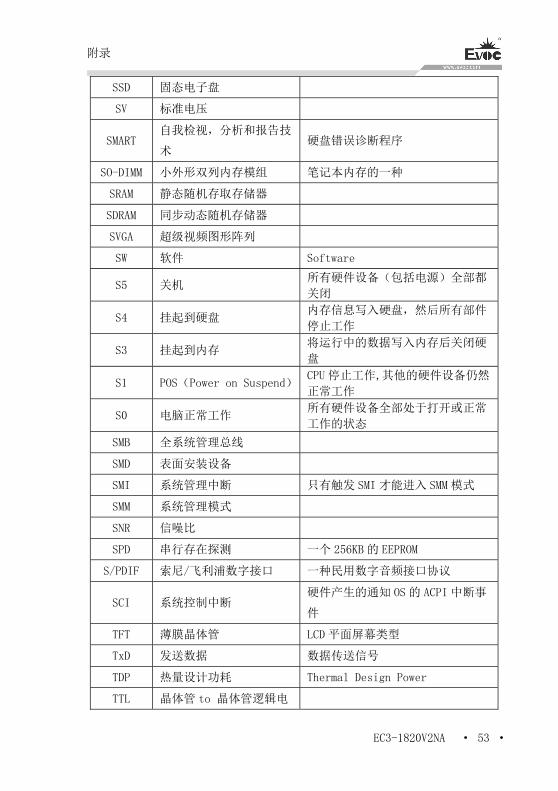
SSD 固态电子盘
SV 标准电压
SMART 自我检视,分析和报告技
术 硬盘错误诊断程序
SO-DIMM 小外形双列内存模组 笔记本内存的一种
SRAM 静态随机存取存储器
SDRAM 同步动态随机存储器
SVGA 超级视频图形阵列
SW 软件 Software
S5 关机 所有硬件设备(包括电源)全部都
关闭
S4 挂起到硬盘 内存信息写入硬盘,然后所有部件
停止工作
S3 挂起到内存 将运行中的数据写入内存后关闭硬
盘
S1 POS(Power on Suspend)CPU 停止工作,其他的硬件设备仍然
正常工作
S0 电脑正常工作 所有硬件设备全部处于打开或正常
工作的状态
SMB 全系统管理总线
SMD 表面安装设备
SMI 系统管理中断 只有触发 SMI 才能进入 SMM 模式
SMM 系统管理模式
SNR 信噪比
SPD 串行存在探测 一个 256KB 的 EEPROM
S/PDIF 索尼/飞利浦数字接口 一种民用数字音频接口协议
SCI 系统控制中断 硬件产生的通知 OS 的 ACPI 中断事
件
TFT 薄膜晶体管 LCD 平面屏幕类型
TxD 发送数据 数据传送信号
TDP 热量设计功耗 Thermal Design Power
TTL 晶体管 to 晶体管逻辑电
附录
· 54 · EC3-1820V2NA
路
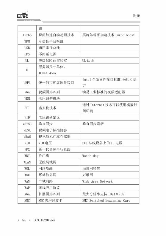
Turbo 瞬间加速自动超频技术 英特尔睿频加速技术 Turbo boost
TPM 可信任平台模组
USB 通用串行总线
UPS 不间断电源
UL 美国保险商实验室 UL 认证
U 服务器尺寸单位,
1U=44.45mm
UEFI 统一的可扩展固件接口 Intel 全新固件接口标准,采用 C语
言
VGA 视频图形阵列 满足工业标准的视频适配器
VRM 电压调整模块
VT 虚拟化技术 通过Internet技术可以使用模拟封
闭环境
VID 电压识别定义
VSYNC 垂直同步 垂直同步刷新
VESA 视频电子标准协会
VRAM 视讯随机存取存储器
VIO VIO 电压 PCI 总线设备上的 IO 电压
VPX 新一代高速串行总线
WDT 看门狗 Watch dog
WLAN 无线局域网
WOL 网络唤醒 局域网唤醒
WWW 环球信息网 万维网
WAN 广域网络 Wide Area Network
WAP 无线应用协议
XGA 扩展图形阵列 最大分辨率支持 1024×768
XMC XMC 夹层过渡卡 XMC Switched Mezzanine Card

Legal Information
Warnings
Please pay attention to the tips within the manual so as to avoid personal injury or
property losses. The tips for personal injury are indicated in warning triangles while
the tips only related to property losses have no warning triangles. The warning tips are
listed as follows with the hazardous scale from severe to slight.
Danger
If handled carelessly, death or severe human injury will occur.
Warning
If handled carelessly, death or severe human injury might occur.
Caution
Warning triangle indicates that slight human injury might occur if handled carelessly.
Note
Unexpected result or status might occur, if not handled according to the tips.
Professional Personnel
The product/system covered by the manual can only be handled by qualified and
professional personnel. During operation, please follow the respective instructive
manuals, especially the safety warnings. The professional personnel have been trained
and possess relevant experiences; therefore, he/she could be aware of the risks of the
product/system and avoid possible damages.
EVOC Product
Please pay attention to the following instructions:
Warning
EVOC product can only be used according to the descriptions within the manual,
including the contents and the relevant technical documents. If the products or
components from other companies are required, please get the recommendation and
grant from EVOC first. Proper transportation, storage, assembly, installation,
debugging, operation and maintenance are prerequisite to ensure product safety and
normal operation; therefore, please ensure permitted environment conditions and pay
attention to the tips within the manual.

Copyright Notice
Information offered in this manual is believed to be correct at the time of printing, and
is subject to change without prior notice in order to improve reliability, design and
function and does not represent a commitment on the part of the manufacturer. In no
event will the manufacturer be liable for direct, indirect, special, incidental, or
consequential damages arising out of improper installation and/or use, or inability to
use the product or documentation.
This user manual is protected by copyright. No part of this manual may be reproduced,
stored in any retrieval system, or transmitted, in any form or by any means,
mechanical, electronic, photocopied, recorded or otherwise, without the prior written
permission from the manufacturer.
Trademarks
EVOC is a registered trademark of EVOC Intelligent Technology Co., Ltd. Other
product names mentioned herein are used for identification purposes only and may be
trademark and/or registered trademarks of their respective companies.
Warranty Terms:
The warranty on the product lasts for two year. If the user has additional requirements,
the contract signed between the two sides shall prevail.
Please visit our website: http://www.evoc.com for more information,
or send an email to the Technical Support Mailbox [email protected]
(International) or [email protected] (Domestic) for consultation.
Hotline: 4008809666
About this manual
Scope of the Manual
The manual is appropriate for EVOC EC3-1820V2NA.
Convention
The term “the PC” or “the Product” within the manual usually stands for EVOC
EC3-1820V2NA.
Instructions
Safety instructions
To avoid property losses or individual injury, please pay attention to the safety
instructions within the manual. The warnings within the manual are marked with
warning triangle , whose existence is dependent upon the scale of the
potential hazard.
History
Version release of this manual:
Version Time
B00 2015.4
C00 2015.7
C01 2015.7
Safety Instructions
ESD Instructions
The following label can be used to identify the modules that contain electrostatic
sensitive devices:
When operating the modules that contain electrostatic sensitive devices, please follow
the instructions below:
When operating the modules that contain electrostatic sensitive devices, make
sure to release static electricity on your body (for example, by touching a
grounded object).
All the devices and tools should not contain ESD.
Before installing or removing modules that contain ESD, make sure to pull out
the power plug and remove the battery.
When assembling modules that contain ESD, always handle them by their edge.
Please do not touch any connector pin or conductive part on the modules that
contain ESD.
Contents
1. Product Introduction .................................................................................................1
1.1 Overview............................................................................................................1
1.2 Mechanical Dimensions, Weight and Environment............................................1
1.3 Typical Consumption .........................................................................................1
1.4 Reference Power Consumption for Power Supply Model Selection ..................2
1.5 Micro-processor .................................................................................................3
1.6 Chipset ...............................................................................................................3
1.7 System Memory .................................................................................................3
1.8 Display Function ................................................................................................3
1.9 Network Function...............................................................................................4
1.10 Audio................................................................................................................4
1.11 Power Supply Feature ......................................................................................4
1.12 Watchdog Function...........................................................................................4
1.13 Operating Systems ...........................................................................................4
1.14 I/O Ports ...........................................................................................................4
2. Installation Instructions ............................................................................................6
2.1 Product Dimensions Drawing ............................................................................6
2.2 Port Location......................................................................................................7
2.3 Data to Identify the Board..................................................................................8
2.4 Structure Diagram ..............................................................................................8
2.5 Jumper Setting....................................................................................................9
2.6 COM Port.........................................................................................................10
2.7 LCD Backlight Control Port.............................................................................11
2.8 Display Port......................................................................................................11
2.9 USB Port ..........................................................................................................14
2.10 LAN Port........................................................................................................15
2.11 Audio Port ......................................................................................................16
2.12 Keyboard/Mouse Port ....................................................................................16
2.13 SATA Interface ...............................................................................................16
2.14 GPIO Port.......................................................................................................17
2.15 Fan Connector ................................................................................................17
2.16 Power Connector............................................................................................18
2.17 Status Indication Control Port ........................................................................18
2.18 SIM Port.........................................................................................................19
2.19 Mini-PCIe Slot ...............................................................................................19
2.20 mSATA Interface ............................................................................................21
2.21 Hot-swap of SATA Hard Drive.......................................................................22
3. BIOS Setup.............................................................................................................24
3.1 BIOS Information Interface .............................................................................24
3.2 Basic Function Setting for BIOS......................................................................25
3.3 System Resource Managed by BIOS under X86 Platform...............................33
4. Installing the Drivers ..............................................................................................39
5. Appendix ................................................................................................................40
5.1 GPIO Programming Guide...............................................................................40
5.2 WDT Programming Guide ...............................................................................42
5.3 LVDS Backlight Control Programming Guide.................................................44
5.4 Troubleshooting and Solutions.........................................................................45
5.5 Abbreviations ...................................................................................................47
Product Introduction
EC3-1820V2NA · 1 ·
1. Product Introduction
1.1 Overview
EC3-1820V2NA is a 3.5-inch motherboard based on Intel® new-generation Atom
Bay Trail SoC platform. Its CPU is Future Intel® Celeron® processor for Intelligent
Systems (Based on 22nm Intel® Silvermont microarchitecture), clock frequency
Quad-core 1.91GHz and Dual-core 1.33GHz. Its graphics core integrates INTEL 7th
generation graphics engine, with two display tubes, supporting DX11 and 3D output.
EC3-1820V2NA has multiple types of interfaces, and can be widely used in military
industry, automation, electric power, and etc.
1.2 Mechanical Dimensions, Weight and Environment
Dimensions: 146.1mm(L) x 101.6mm(W) x 24.7mm(H)
Net Weight: 0.29Kg
Operating environment:
Temperature: 0℃~60℃; Extendable temperature range: -40℃~85℃
Humidity: 5 %~95% (non-condensing)
Storage environment:
Temperature: -40℃~85℃
Humidity: 5%~95% (non-condensing)
1.3 Typical Consumption
The typical consumption is calculated based on the following configuration under idle
status.
Configuration 1
Product Introduction
· 2 · EC3-1820V2NA
CPU: Onboard Atom E3845 1.91GHZ Quad-core
Memory: Onboard 4G
Operating system: Win7 32bit
Hard disk drive: SanDisk SSD SATA3.0 128GB
[email protected];+5%/-3%
Configuration 2
CPU: Onboard Atom E3825 1.33GHZ Dual-core
Memory: Onboard 4G
Operating system: Win7 32bit
Hard disk drive: SanDisk SSD SATA3.0 128GB
[email protected];+5%/-3%
1.4 Reference Power Consumption for Power Supply Model Selection
The reference power consumption is based on the data collected from the following
environments, expansion card and power consumption of other peripheral devices.
Power consumption needs to be added according to configuration requirements for
power supply model selection.
Configuration 1
CPU: Onboard Atom E3845 1.91GHZ Quad-core
Memory: Onboard 4G
HDD: SanDisk SSD SATA3.0 128GB
Operating system: Windows7 32bit
Product Introduction
EC3-1820V2NA · 3 ·
Operating software: TAT 4.7
[email protected];+5%/-3%
Configuration 2
CPU: Onboard Atom E3825 1.33GHZ Dual-core
Memory: Onboard 4G
HDD: SanDisk SSD SATA3.0 128GB
Operating system: Windows 7 32bit
Operating software: TAT 4.7
[email protected]; +5%/-3%
1.5 Micro-processor
Onboard Bay Trail-I SoC CPU,E3825 CPU with 1.33GHz clock frequency, dual-core
CPU; E3845 CPU with 1.91GHz clock frequency, quad-core CPU.
1.6 Chipset
Single-chip processor, chipset integrated in the CPU.
1.7 System Memory
Onboard 4G DDR3L memory chip, supporting 1333MT/s.
1.8 Display Function
Supports VGA, HDMI and LVDS; LVDS does not support hot swap;
VGA+LVDS are asynchronous output;
VGA supports resolution up to 2560×1600@60Hz; LVDS supports up to
UXGA(1920×1080).
Product Introduction
· 4 · EC3-1820V2NA
1.9 Network Function
Provides two 10/100/1000Mbps LAN ports; LAN1 is standard RJ45 port and supports
Wake-On-LAN; LAN2 uses 2×7 2.0mm pin header for output.
1.10 Audio
HDA standard, supporting MIC-IN/LINE-IN/LINE-OUT.
1.11 Power Supply Feature
+12V single power supply, 2×2 power connector.
1.12 Watchdog Function
255 levels, programmable by minute or second;
Supports Watchdog timeout interrupt or system reset.
1.13 Operating Systems
Supported operating systems: Windows8.1, Windows8, Windows7, Linux.
1.14 I/O Ports
Provides 4 COM ports. COM1 and COM2 support RS-232/RS-422/RS-485
modes, set by BIOS setup; COM3 and COM4 only support RS-232 mode;
Modem wakeup function is not supported;
1 x SATA interface and 1 x mSATA (optional J2) interface;
Note: It is recommended to use the following SATA 3.0 hard drives:
SSD Crucial 6Gb/s SATA3.0 2.5 128GB M4
HDD Seagate 6Gb/s SATA3.0 500GB ST500DM002
HDD Seagate 6Gb/s SATA3.0 3000GB
HDD WD 6Gb/s SATA3.0 4000GB
5 x USB2.0 port and 1 x USB3.0 port;
Product Introduction
EC3-1820V2NA · 5 ·
Note: USB3.0 is disabled by default. Before Intel USB3.0 driver is installed, it
can only be used as USB2.0 port. If USB3.0 driver is not installed after enabling
USB3.0 function, all the USB ports of Windows7 system (including other
USB2.0 ports) cannot be used. Windows8/8.1 will automatically load the driver.
The following steps are about enabling USB3.0 under Windows7 system:
1. Set the motherboard BIOS to default value, then install Windows7, place the
enclosed driver CD into the USB optical drive, and enter into the driver CD to
copy the folder USB3.0 under the Driver directory onto the desk;
2. Reboot the PC, press F2 to enter into BIOS, select “Advanced”- set “EHCI
Controller” to “Disabled”, and set “XHCI Controller” to “Enabled”, press “F10”
to save and exit;
3. Reboot and enter into Windows7 system, use PS2 mouse to double click
USB3.0 folder on the desk, double click “Setup.exe” to install the USB3.0 driver.
After the installation is finished, all the USB ports can be normally used. At this
time, USB3.0 ports have reached the USB3.0 standard.
1 x PS/2 keyboard/mouse port;
1 x 16-channel digital I/O port;
2 x Mini PCIE slot (MPCIE1 and J2, J2 optional), supporting WiFi; MPCIE1
supports 3G module;
1 x Micro SD card slot;
1 x HDMI port and 1 x VGA port;
2 x 1000Mbps LAN port.
Note: How to identify alarms
1. A long beep means a system memory error;
2. A short beep means bootup.
Installation Instructions
· 6 · EC3-1820V2NA
2. Installation Instructions
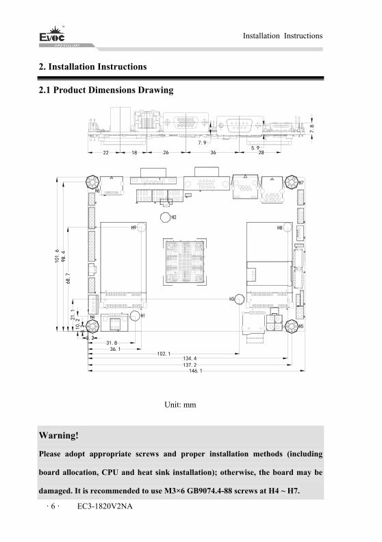
2.1 Product Dimensions Drawing
146.1
3.231.8
102.1
137.2
36.1
134.4
3.210.221
.168.7
98.4
101.6
22 18 26 36 28
7.8
5.97.9
Unit: mm
Warning!
Please adopt appropriate screws and proper installation methods (including
board allocation, CPU and heat sink installation); otherwise, the board may be
damaged. It is recommended to use M3×6 GB9074.4-88 screws at H4 ~ H7.
Installation Instructions
EC3-1820V2NA · 7 ·
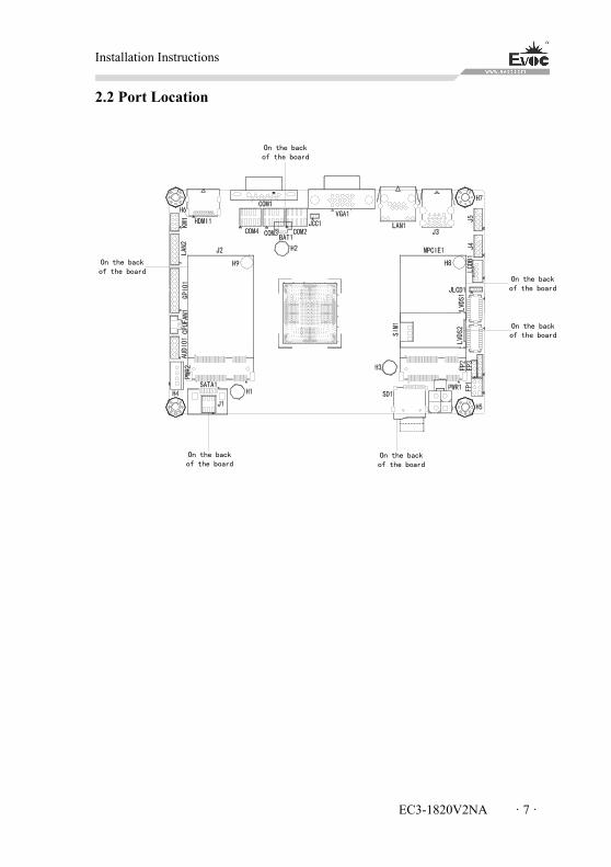
2.2 Port Location
On the backof the board
On the backof the board
On the backof the board
On the backof the board
On the backof the board
On the backof the board
Installation Instructions
· 8 · EC3-1820V2NA
2.3 Data to Identify the Board
Attention
During maintenance or after the product is stolen, this code can be used to identify
the PC. Please do not rip it off.
Serial No.: Located on the board (as shown below)
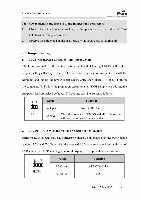
2.4 Structure Diagram
LP
C
SIOHardware Monitor
COM1~COM4
KM
USB3.0 Conn USB3.0*1
DDI1LVDS CH7511
VGA
Bay Trail -I SOC
4G Memory DownChannel 0 DDR3L
GPIO*16
USB2.0*5
USB2.0
SATA1/MSATA SATA2.0
SPISD1 SD3.0 SPI Flash
AUDIO CODEC HD AUDIO
HDMI DDI0
ARM
J2(mSATA&WIFI)PCIe Port0
10/100/1000Mbps LanPCIe Port2
PCIe Port310/100/1000Mbps Lan
MPCIE1(3G&WIFI)PCIe Port1
SMBUS
SMBUS
Installation Instructions
EC3-1820V2NA · 9 ·
Tip: How to identify the first pin of the jumpers and connectors
1. Observe the letter beside the socket, the first pin is usually marked with “1” or
bold lines or triangular symbols;
2. Observe the solder pad on the back: usually the square pad is the first pin.
2.5 Jumper Setting
1. JCC1: Clear/Keep CMOS Setting (Pitch: 2.0mm)
CMOS is powered by the button battery on board. Clearing CMOS will restore
original settings (factory default). The steps are listed as follows: (1) Turn off the
computer and unplug the power cable; (2) Instantly short circuit JCC1; (3) Turn on
the computer; (4) Follow the prompt on screen to enter BIOS setup when booting the
computer, load optimized defaults; (5) Save and exit. Please set as follows:
Setup Function
1-2 Open Normal (Default)
JCC1 1-2 Short
Clear the contents of CMOS and all BIOS settings will restore to factory default values.
2. JLCD1:LCD Working Voltage Selection (pitch: 2.0mm)
Different LCD screens may have different voltages. This board provides two voltage
options: 3.3V and 5V. Only when the selected LCD voltage is consistent with that of
LCD screen, can LCD screen give normal display. Its setup method is as follows:
Setup Function
1-2 Open +3.3V(Default)
JLCD1 2-3 Short +5V
Installation Instructions
· 10 · EC3-1820V2NA
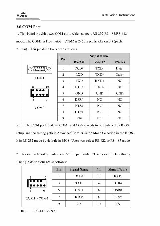
2.6 COM Port
1. This board provides two COM ports which support RS-232/RS-485/RS-422
mode. The COM1 is DB9 output; COM2 is 2×5Pin pin header output (pitch:
2.0mm). Their pin definitions are as follows:
Signal Name Pin
RS-232 RS-422 RS-485
1 DCD# TXD- Data-
2 RXD TXD+ Data+
3 TXD RXD+ NC
4 DTR# RXD- NC
5 GND GND GND
6 DSR# NC NC
7 RTS# NC NC
8 CTS# NC NC
COM1
COM2
9 RI# NC NC
Note: The COM port mode of COM1 and COM2 needs to be switched by BIOS
setup, and the setting path is Advanced\Com1&Com2 Mode Selection in the BIOS.
It is RS-232 mode by default in BIOS. Users can select RS-422 or RS-485 mode.
2. This motherboard provides two 2×5Pin pin header COM ports (pitch: 2.0mm).
Their pin definitions are as follows:
Pin Signal Name Pin Signal Name
1 DCD# 2 RXD
3 TXD 4 DTR#
5 GND 6 DSR#
7 RTS# 8 CTS#
COM3 COM4 ~
9 RI# 10 NA
Installation Instructions
EC3-1820V2NA · 11 ·
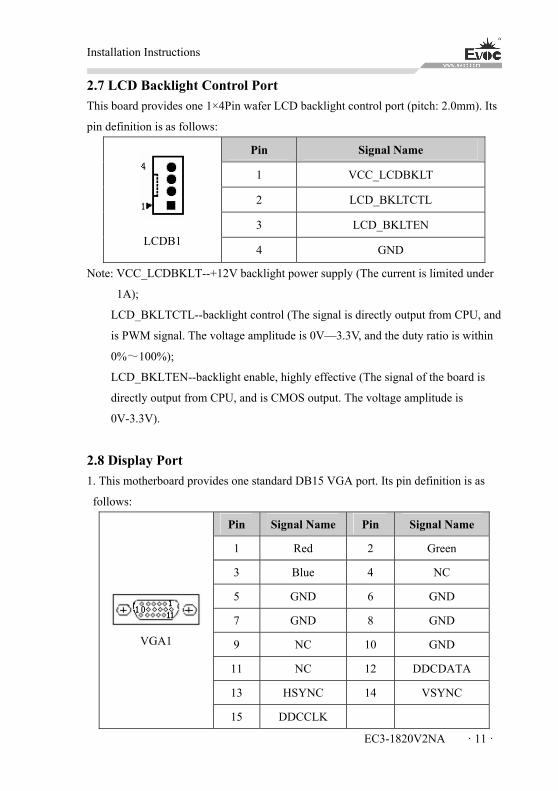
2.7 LCD Backlight Control Port
This board provides one 1×4Pin wafer LCD backlight control port (pitch: 2.0mm). Its
pin definition is as follows:
Pin Signal Name
1 VCC_LCDBKLT
2 LCD_BKLTCTL
3 LCD_BKLTEN
LCDB1 4 GND
Note: VCC_LCDBKLT--+12V backlight power supply (The current is limited under
1A);
LCD_BKLTCTL--backlight control (The signal is directly output from CPU, and
is PWM signal. The voltage amplitude is 0V—3.3V, and the duty ratio is within
0%~100%);
LCD_BKLTEN--backlight enable, highly effective (The signal of the board is
directly output from CPU, and is CMOS output. The voltage amplitude is
0V-3.3V).
2.8 Display Port
1. This motherboard provides one standard DB15 VGA port. Its pin definition is as
follows:
Pin Signal Name Pin Signal Name
1 Red 2 Green
3 Blue 4 NC
5 GND 6 GND
7 GND 8 GND
9 NC 10 GND
11 NC 12 DDCDATA
13 HSYNC 14 VSYNC
VGA1
15 DDCCLK
Installation Instructions
· 12 · EC3-1820V2NA
Note: Due to the limit of Intel GMA driver, after the video card driver is installed and
reboot into the system, CRT may become expansion mode, or CRT has no display (at
this time, CRT is secondary display). At this time, Ctrl+Alt+F1 hot key can be used to
switch the CRT to primary display.
2. LVDS Port
This board provides one dual-channel 24bit LVDS port (LVDS1, LVDS2; pitch:
1.0mm). When single-channel 18-bit/24-bit LVDS screen is used, LVDS data cable
must be connected to LVDS1. The pin definition of dual-channel 24-bit LVDS is as
follows:
Pin Signal Name Pin Signal Name
1 LVDSO_D0+ 2 LVDSO_D0-
3 GND 4 GND
5 LVDSO_D1+ 6 LVDSO_D1-
7 GND 8 GND
9 LVDSO_D2+ 10 LVDSO_D2-
11 GND 12 GND
13 LVDSO_CLK+ 14 LVDSO_CLK-
15 GND 16 GND
17 LVDSO_D3+ 18 LVDSO_D3-
LVDS1
19 VDD 20 VDD

Installation Instructions
EC3-1820V2NA · 13 ·
Pin Signal Name Pin Signal Name
1 LVDSE_D0+ 2 LVDSE_D0-
3 GND 4 GND
5 LVDSE_D1+ 6 LVDSE_D1-
7 GND 8 GND
9 LVDSE_D2+ 10 LVDSE_D2-
11 GND 12 GND
13 LVDSE_CLK 14 LVDSE_CLK-
15 GND 16 GND
17 LVDSE_D3+ 18 LVDSE_D3-
LVDS2
19 VDD 20 VDD
Note: LVDSOx means the odd line of dual-scan PANEL; LVDSEx means the even
line of dual-scan PANEL. The LVDS socket model used by this board is
DF20G-20DP-1V. It is recommended to use corresponding terminal of model
DF20A-20DF-1C.
2 HDMI Port
Pin Signal Name Pin Signal Name
1 TMDS Data2+ 2 TMDS Data2 Shield
3 TMDS Data2- 4 TMDS Data1+
5 TMDS Data1 6 TMDS Data1-
7 TMDS Data0+ 8 TMDS Data0 Shield
9 TMDS Data0- 10 TMDS Clock+
11 TMDS Clock 12 TMDS Clock-
13 CEC 14 Reserved (NC on device)
15 SCL 16 SDA
17 DDC/CEC 18 +5V
HDMI1
19 Hot Plug Detect

Installation Instructions
· 14 · EC3-1820V2NA
2.9 USB Port
This board provides one double-layer standard USB port (J3, J3 upper-layer ports
only support USB2.0 device; the lower-layer ports support both USB2.0 and USB3.0
devices) and two 2-in-1 2×5Pin USB pin header ports (J4, J5 pitch: 2.0mm). In total,
five USB2.0 devices and one USB3.0 device are supported.
Pin Signal Name
1 +5V_USB
2 USB_Data-
3 USB_Data+
4 GND
5 USB_SSRX-
6 USB_SSRX+
7 GND
8 USB_SSTX-
9 USB_SSTX+
10 +5V_USB
11 USB_Data-
12 USB_Data+
J3
13 GND
Pin Signal Name Pin Signal Name
1 +5V_USB 2 +5V_USB
3 USB1_Data- 4 USB2_Data-
5 USB1_Data+ 6 USB2_Data+
7 GND 8 GND
J4、J5
9 NA 10 GND
Installation Instructions
EC3-1820V2NA · 15 ·
2.10 LAN Port
This board provides two 10/100/1000Mbps LAN ports. One is RJ45 connector LAN1,
the other is a 2×7 pin header. (LAN2 pitch: 2.0mm)
LAN1
LILED (dual-color: orange
and green)
Network speed status
ACTLED (Single color:
green)
Network activity
Green 1000Mbps
Flash Data being transmitted
Orange 100Mbps
Off No data being
transmitted Off 10Mbps
Note: no matter the Gigabit LAN card contains Link signal or not, the ACTLED on
the left always indicates the data transmission status. When data is being transmitted,
the green LED on the left is “flashing”; when it is connected to network with no data
transmission, the green LED is “off”; when there are broadcasting packages, it is
normal if the ACTLED is “flashing”.
Pin Signal Name Pin Signal Name
1 MX0+ 2 MX0-
3 MX1+ 4 MX1-
5 MX2+ 6 MX2-
7 MX3+ 8 MX3-
9 GND 10 GND
11 LINK1000- 12 LINK100-
LAN2
13 ACT_LED+ 14 ACT_LED-
Installation Instructions
· 16 · EC3-1820V2NA
2.11 Audio Port
This board provides one 2×5Pin audio port (pitch: 2.0mm).
Pin Signal Name Pin Signal Name
1 LOUT_R 2 LOUT_L
3 GND_AUDIO 4 GND_AUDIO
5 LIN_R 6 LIN_L
7 GND_AUDIO 8 GND_AUDIO
AUDIO1
9 MIC_L 10 MIC_R
2.12 Keyboard/Mouse Port
This board provides one 2×4Pin PS/2 keyboard/mouse port (pitch: 2.0mm).
Pin Signal Name Pin Signal Name
1 KB_DATA 2 MS_DATA
3 KB_CLK 4 MS_CLK
5 GND 6 GND
KM1 7 +5V 8 +5V
2.13 SATA Interface
This motherboard provides one single-layer SATA interface. Its pin definition is as
follows:
Pin Signal Name Pin Signal Name
1 GND 5 SATA_RX-
2 SATA_TX+ 6 SATA_RX+
3 SATA_TX- 7 GND SATA1
4 GND

Installation Instructions
EC3-1820V2NA · 17 ·
2.14 GPIO Port
Pin Signal Name Pin Signal Name
1 GPIO1 2 GPIO9
3 GPIO2 4 GPIO10
5 GPIO3 6 GPIO11
7 GPIO4 8 GPIO12
9 GPIO5 10 GPIO13
11 GPIO6 12 GPIO14
13 GPIO7 14 GPIO15
15 GPIO8 16 GPIO16
17 +5V 18 +5V
GPIO1
(pitch: 2.0mm)
19 GND 20 GND
Note: The factory default is that the Pin1, Pin3, Pin5, Pin7, Pin9, Pin11, Pin13 and
P15 of the connector are GPIO input; Pin2, Pin4, Pin6, Pin8, Pin10, Pin12, Pin14 and
Pin16 are GPIO output. The factory default status is high level, and the voltage range
of input/output signals is 0-5V.
2.15 Fan Connector
This motherboard provides one 1×2Pin CPU fan connector (CPUFAN1, pitch:
1.25mm). Please pay attention to the following three points when using the fan
connector:
The fan current should not be larger than 500 mA (12V).
Please confirm that the fan cable complies with the socket cable. The
socket groove facing us, the first pin from left is the ground, and the
second pin is 12V power supply pin; Please note the matching when
assembling the product.
Adjust the fan’s airflow to the direction of heat venting.
Installation Instructions
· 18 · EC3-1820V2NA
Pin Signal Name
1 GND
CPUFAN1 2 +12V
Note: FAN_IO: fan speed pulse output; FAN_PWM: fan speed PWM control.
2.16 Power Connector
1. Power connector, single 12V power connector (pitch: 4.2mm)
Pin Signal Name
1 GND
2 GND
3 +12V
PWR1
4 +12V
2. SATA Power Connector
Wafer 1×4P power connector (white, pitch: 2.54mm)
Pin Signal Name
1 +12V
2 GND
3 GND
PWR2 4 +5V
2.17 Status Indication Control Port
1. Power switch and HDD LED port (pitch: 2.54mm)
Pin Signal Name Pin Signal Name
1 PWRBTN# 2 GND
3 GND 4 RESET#
FP1 5 HDD_LED- 6 HDD_LED+
Installation Instructions
EC3-1820V2NA · 19 ·
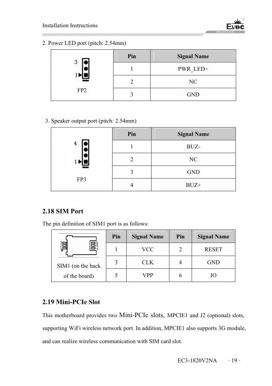
2. Power LED port (pitch: 2.54mm)
Pin Signal Name
1 PWR_LED+
2 NC
FP2 3 GND
3. Speaker output port (pitch: 2.54mm)
Pin Signal Name
1 BUZ-
2 NC
3 GND
FP3 4 BUZ+
2.18 SIM Port
The pin definition of SIM1 port is as follows:
Pin Signal Name Pin Signal Name
1 VCC 2 RESET
3 CLK 4 GND
SIM1 (on the back
of the board) 5 VPP 6 IO
2.19 Mini-PCIe Slot
This motherboard provides two Mini-PCIe slots, MPCIE1 and J2 (optional) slots,
supporting WiFi wireless network port. In addition, MPCIE1 also supports 3G module,
and can realize wireless communication with SIM card slot.
Installation Instructions
· 20 · EC3-1820V2NA
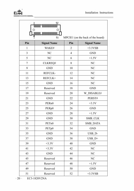
MPCIE1 (on the back of the board)
Pin Signal Name Pin Signal Name
1 WAKE# 2 +3.3VSB
3 NC 4 GND
5 NC 6 +1.5V
7 CLKREQ# 8 NC
9 GND 10 NC
11 REFCLK- 12 NC
13 REFCLK+ 14 NC
15 GND 16 NC
17 Reserved 18 GND
19 Reserved 20 W_DISABLE#
21 GND 22 PERST#
23 PERn0 24 +3.3V
25 PERp0 26 GND
27 GND 28 +1.5V
29 GND 30 SMB_CLK
31 PETn0 32 SMB_DATA
33 PETp0 34 GND
35 GND 36 USB_D-
37 GND 38 USB_D+
39 +3.3V 40 GND
41 +3.3V 42 NC
43 GND 44 NC
45 Reserved 46 NC
47 Reserved 48 +1.5V
49 Reserved 50 GND
51 Reserved 52 +3.3VSB
Installation Instructions
EC3-1820V2NA · 21 ·
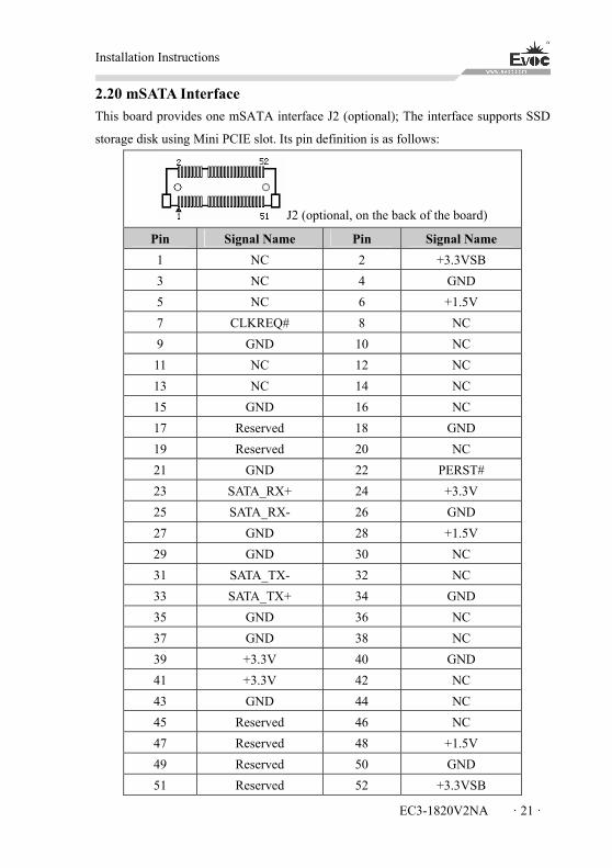
2.20 mSATA Interface
This board provides one mSATA interface J2 (optional); The interface supports SSD
storage disk using Mini PCIE slot. Its pin definition is as follows:
J2 (optional, on the back of the board)
Pin Signal Name Pin Signal Name
1 NC 2 +3.3VSB
3 NC 4 GND
5 NC 6 +1.5V
7 CLKREQ# 8 NC
9 GND 10 NC
11 NC 12 NC
13 NC 14 NC
15 GND 16 NC
17 Reserved 18 GND
19 Reserved 20 NC
21 GND 22 PERST#
23 SATA_RX+ 24 +3.3V
25 SATA_RX- 26 GND
27 GND 28 +1.5V
29 GND 30 NC
31 SATA_TX- 32 NC
33 SATA_TX+ 34 GND
35 GND 36 NC
37 GND 38 NC
39 +3.3V 40 GND
41 +3.3V 42 NC
43 GND 44 NC
45 Reserved 46 NC
47 Reserved 48 +1.5V
49 Reserved 50 GND
51 Reserved 52 +3.3VSB

Installation Instructions
· 22 · EC3-1820V2NA
2.21 Hot-swap of SATA Hard Drive
Notes for hot-swap of SATA hard drive:
1. The hard drive shall support SATA 2.0 and use 15-pin SATA hard drive power
connector.
2. SATA hard drive only works under AHCI mode, and supports hot swap function
when the hot swap option is enabled.
3. The driver of chipset shall support the hot-swap of SATA hard drive.
4. Hot-swap of SATA hard drive where the operating system is located is
forbidden when system is powered-on.
Note: Please carry out hot plugging by the following steps. Improper operation may
destroy the hard drive or result in data loss.
SATA hard drive hot plug steps:
Step 1: Connect the SATA data cable to the SATA interface on the motherboard;
Step 2: Connect the 15-pin connector (black) of SATA power cable to the SATA hard
drive;
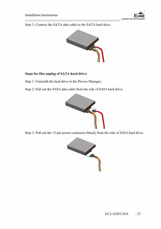
Installation Instructions
EC3-1820V2NA · 23 ·
Step 3: Connect the SATA data cable to the SATA hard drive.
Steps for Hot unplug of SATA hard drive:
Step 1: Uninstall the hard drive in the Device Manager;
Step 2; Pull out the SATA data cable from the side of SATA hard drive;
Step 3: Pull out the 15-pin power connector (black) from the side of SATA hard drive.
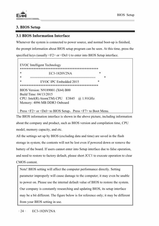
BIOS Setup
· 24 · EC3-1820V2NA
3. BIOS Setup
3.1 BIOS Information Interface
Whenever the system is connected to power source, and normal boot-up is finished,
the prompt information about BIOS setup program can be seen. At this time, press the
specified keys (usually <F2> or <Del>) to enter into BIOS Setup interface.
EVOC Intelligent Technology ********************************************** * EC3-1820V2NA * * ================================== * * EVOC IPC Embedded 2015 * ********************************************** BIOS Version: N9189001 (X64) B00 Build Time: 04/13/2015 CPU: Intel(R) Atom(TM) CPU E3845 @ 1.91GHz Memory: 4096 MB DDR3 Onboard Press <F2> or <Del> to BIOS Setup,Press <F7> to Boot Menu.
The BIOS information interface is shown in the above picture, including information
about the company and product, such as BIOS version and compilation time, CPU
model, memory capacity, and etc.
All the settings set up by BIOS (excluding data and time) are saved in the flash
storage in system; the contents will not be lost even if powered down or remove the
battery of the board. If users cannot enter into Setup interface due to false operation,
and need to restore to factory default, please short JCC1 to execute operation to clear
CMOS content.
Note! BIOS setting will affect the computer performance directly. Setting
parameter improperly will cause damage to the computer; it may even be unable
to power on. Please use the internal default value of BIOS to restore the system.
Our company is constantly researching and updating BIOS, its setup interface
may be a bit different. The figure below is for reference only; it may be different
from your BIOS setting in use.
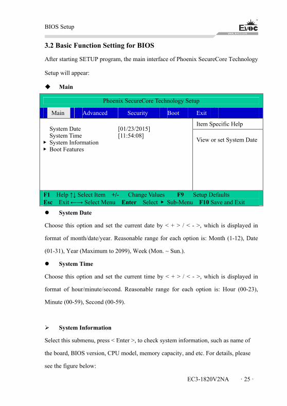
BIOS Setup
EC3-1820V2NA · 25 ·
3.2 Basic Function Setting for BIOS
After starting SETUP program, the main interface of Phoenix SecureCore Technology
Setup will appear:
Main
Phoenix SecureCore Technology Setup
Main Advanced Security Boot Exit
Item Specific Help System Date System Time ▶ System Information ▶ Boot Features
[01/23/2015] [11:54:08]
View or set System Date
F1 Help ↑↓ Select Item +/- Change Values F9 Setup Defaults Esc Exit ←→ Select Menu Enter Select ▶ Sub-Menu F10 Save and Exit
System Date
Choose this option and set the current date by < + > / < - >, which is displayed in
format of month/date/year. Reasonable range for each option is: Month (1-12), Date
(01-31), Year (Maximum to 2099), Week (Mon. ~ Sun.).
System Time
Choose this option and set the current time by < + > / < - >, which is displayed in
format of hour/minute/second. Reasonable range for each option is: Hour (00-23),
Minute (00-59), Second (00-59).
System Information
Select this submenu, press < Enter >, to check system information, such as name of
the board, BIOS version, CPU model, memory capacity, and etc. For details, please
see the figure below:
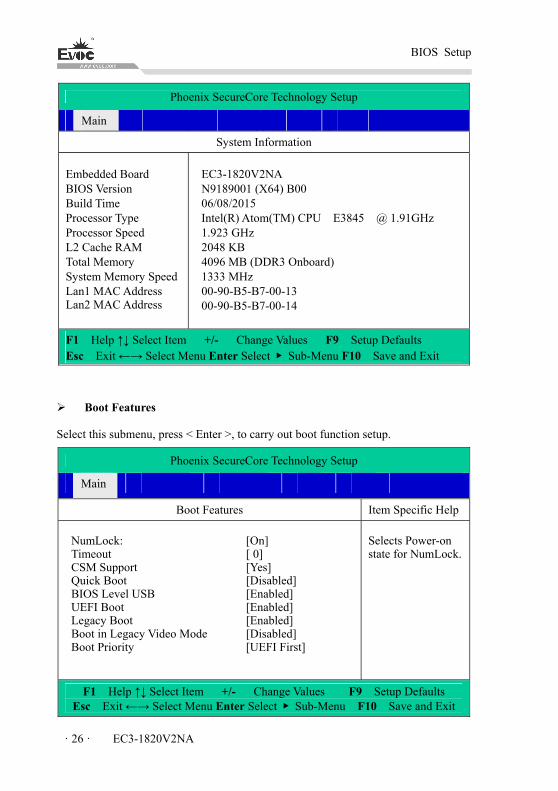
BIOS Setup
· 26 · EC3-1820V2NA
Phoenix SecureCore Technology Setup
Main
System Information
Embedded Board BIOS Version Build Time Processor Type Processor Speed L2 Cache RAM Total Memory System Memory Speed Lan1 MAC Address Lan2 MAC Address
EC3-1820V2NA N9189001 (X64) B00 06/08/2015 Intel(R) Atom(TM) CPU E3845 @ 1.91GHz 1.923 GHz 2048 KB 4096 MB (DDR3 Onboard) 1333 MHz 00-90-B5-B7-00-13 00-90-B5-B7-00-14
F1 Help ↑↓ Select Item +/- Change Values F9 Setup Defaults Esc Exit ←→ Select Menu Enter Select ▶ Sub-Menu F10 Save and Exit
Boot Features
Select this submenu, press < Enter >, to carry out boot function setup.
Phoenix SecureCore Technology Setup
Main
Boot Features Item Specific Help
NumLock: Timeout CSM Support Quick Boot BIOS Level USB UEFI Boot Legacy Boot Boot in Legacy Video Mode Boot Priority
[On] [ 0] [Yes] [Disabled] [Enabled] [Enabled] [Enabled] [Disabled] [UEFI First]
Selects Power-on state for NumLock.
F1 Help ↑↓ Select Item +/- Change Values F9 Setup Defaults Esc Exit ←→ Select Menu Enter Select ▶ Sub-Menu F10 Save and Exit
BIOS Setup
EC3-1820V2NA · 27 ·
NumLock
Keyboard NumLock status setup, used to select NumLock status during
boot-up.
Timeout
Wait time setup during boot-up. When the motherboard is connected to
large-capacity storage device, it is recommended to increase wait time.
CSM Support
Traditional BIOS module support control switch.
Quick Boot
Switch for quick boot option. When it is enabled, they system will skip the
boot-up prompt information.
BIOS Level USB
BIOS Legacy support control switch. When it is disabled, USB device cannot be
used in BIOS stage and DOS system.
UEFI Boot
UEFI boot support switch.
Legacy Boot
Switch for legacy boot.
Boot in Legacy Video Mode
Boot in legacy video mode, used to support specific system or software.
Boot Priority
Boot priority setup switch, used to adjust priority of UEFI and Legacy boot.

BIOS Setup
· 28 · EC3-1820V2NA
Advanced
Phoenix SecureCore Technology Setup
Main Advanced Security Boot Exit
Item Specific Help Setup Warning: Setting items on this screen to incorrect values may cause system to malfunction!
▶ Hardware Monitor OS Selection
IGD Boot Type LCD Panel Type LCD Backlight Value COM1 Port COM1 Mode Selection COM2 Port COM2 Mode Selection COM3 Port COM4 Port xHCI Controller EHCI Controller Audio Controller SATA Controller Mode SD Card Support Power State Lan1 PXE ROM RTC Alarm
[Windows7/Linux] [Auto] [Auto] [100%] [Enable] [RS232] [Enable] [RS232] [Enable] [Enable]
[Disable] [Enable] [Enable] [AHCI] [Enable] [Power On] [Disable]
[Disable]
Hardware Monitor.
F1 Help ↑↓ Select Item +/- Change Values F9 Setup Defaults Esc Exit ←→ Select Menu Enter Select ▶ Sub-Menu F10 Save and Exit
Hardware Monitor
Select this submenu, press < Enter >, to check information related to hardware
monitoring.
Phoenix SecureCore Technology Setup
AdvancedHardware Monitor
SYS Temperature : CPU Temperature: CPUVCORE: VCC3.3V VCC5V VCC12V
[45 C] [45 C] [0.880 V] [3.264 V] [5.040 V] [11.711 V]
F1 Help ↑↓ Select Item +/- Change Values F9 Setup Defaults Esc Exit ←→ Select Menu Enter Select ▶ Sub-Menu F10 Save and Exit
BIOS Setup
EC3-1820V2NA · 29 ·
OS Selection
Operating system options, including Windows 8.x, Android and Windows7
/Linux three options.
IGD Boot Type
IGD boot display setup options, used to configure display output ports during
boot-up, including VGA, HDMI, and LVDS. The Auto option is a default
output by VBIOS.
LCD Panel Type
LCD panel type option. The Auto option is a default output resolution by
VBIOS. Integrated display resolution output can be selected according to the
connected LVDS screen. If the supported LVDS screen resolution is not in the
options, please contact EVOC customer service for customization.
COM1~4 Port
COM1~4 switch control option. When it is disabled, they cannot be used under
the system by default.
COM1~2 Mode Selection
COM1~2 mode selection, used to configure working mode of COM1, 2. There
are RS-232, RS-485 and RS-422.
xHCI Controller / EHCI Controller
These two options are used to select USB controller mode. The options are
xHCI Controller and EHCI Controller. They cannot be set to Enable at the same
time.
SATA Controller Mode
SATA controller mode option. There are AHCI, IDE options.
SD Card Support
SD card support switch option.
Power State
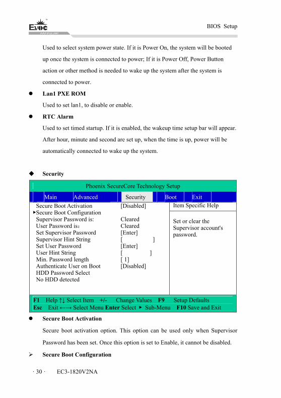
BIOS Setup
· 30 · EC3-1820V2NA
Used to select system power state. If it is Power On, the system will be booted
up once the system is connected to power; If it is Power Off, Power Button
action or other method is needed to wake up the system after the system is
connected to power.
Lan1 PXE ROM
Used to set lan1, to disable or enable.
RTC Alarm
Used to set timed startup. If it is enabled, the wakeup time setup bar will appear.
After hour, minute and second are set up, when the time is up, power will be
automatically connected to wake up the system.
Security
Phoenix SecureCore Technology Setup
Main Advanced Security Boot Exit Item Specific Help Secure Boot Activation
▶Secure Boot Configuration Supervisor Password is: User Password is:
Set Supervisor Password Supervisor Hint String Set User Password User Hint String Min. Password length Authenticate User on Boot HDD Password Select No HDD detected
[Disabled] Cleared Cleared [Enter] [ ] [Enter] [ ] [ 1]
[Disabled]
Set or clear the Supervisor account's password.
F1 Help ↑↓ Select Item +/- Change Values F9 Setup Defaults Esc Exit ←→ Select Menu Enter Select ▶ Sub-Menu F10 Save and Exit
Secure Boot Activation
Secure boot activation option. This option can be used only when Supervisor
Password has been set. Once this option is set to Enable, it cannot be disabled.
Secure Boot Configuration
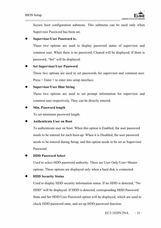
BIOS Setup
EC3-1820V2NA · 31 ·
Secure boot configuration submenu. This submenu can be used only when
Supervisor Password has been set.
Supervisor/User Password is:
These two options are used to display password status of supervisor and
common user. When there is no password, Cleared will be displayed; If there is
password, “Set” will be displayed.
Set Supervisor/User Password
These two options are used to set passwords for supervisor and common user.
Press < Enter > to enter into setup interface.
Supervisor/User Hint String
These two options are used to set prompt information for supervisor and
common user respectively. They can be directly entered.
Min. Password length
To set minimum password length.
Authenticate User on Boot
To authenticate user on boot. When this option is Enabled, the user password
needs to be entered for each boot-up. When it is Disabled, the user password
needs to be entered during Setup, and this option needs to be set as Supervisor
Password.
HDD Password Select
Used to select HDD password authority. There are User Only/User+Master
options. These options are displayed only when a hard disk is connected.
HDD Security Status
Used to display HDD security information status. If no HDD is detected, “No
HDD” will be displayed. If HDD is detected, corresponding HDD Password
State and Set HDD User Password option will be displayed, which are used to
check HDD password state, and set up HDD password function.
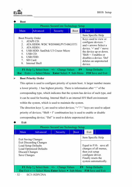
BIOS Setup
· 32 · EC3-1820V2NA
Boot
Phoenix SecureCore Technology Setup
Main Advanced Security Boot Exit
Item Specific Help Boot Priority Order
1. ATAPI CD: 2. ATA HDD0: WDC WD5000LPVT-08G33T1
3. ATA HDD1: 4. USB HDD: SanDisk U3 Cruzer Micro
5. USB CD: 6. USB FDD: 7. SD Card: 8. Internal Shell
Keys used to view or configure devices: ^ and v arrows Select a device. '+' and '-' move the device up or down. 'Shift + 1'enables or disables a device. 'Del' deletes an unprotected device.
F1 Help ↑↓ Select Item +/- Change Values F9 Setup Defaults Esc Exit←→ Select Menu Enter Select ▶ Sub-Menu F10 Save and Exit
Boot Priority Order
This option is used to configure priority of system boot. A larger number means
a lower priority. 1 has highest priority. There is information after “:” of the
corresponding type, which indicates that the system has device of such type, and
it can be used for booting. Internal Shell is an internal EFI Shell environment
within the system, which is used to maintain the system.
The direction keys ↑↓ are used to select devices; “+”/“-” keys are used to adjust
priority of devices; “Shift + l” combination key is used to enable or disable
corresponding device; “Del” is used to delete unprotected device.
Exit
Phoenix SecureCore Technology Setup
Main Advanced Security Boot Exit
Item Specific Help Exit Saving Changes Exit Discarding Changes Load Setup Defaults Load Optimized Defaults Discard Changes Save Changes
Equal to F10,save all changes of all menus, then exit setup configure driver. Finally resets the system automatically.
F1 Help ↑↓ Select Item +/- Change Values F9 Setup Defaults Esc Exit ←→ Select Menu Enter Select ▶ Sub-Menu F10 Save and Exit
BIOS Setup
EC3-1820V2NA · 33 ·
Exit Saving Changes
Exit and save changes.
Exit Discarding Changes
Exit and discard previous changes.
Load Setup Defaults
Load factory defaults.
Load Optimized Defaults
Load optimized defaults.
Discard Changes
To discard changes.
Save Changes
To save changes.
3.3 System Resource Managed by BIOS under X86 Platform
We define three kinds of system resources here: I/O port address, IRQ interrupt
number and DMA number.
IO Port Address
Only 16 I/O address cables of X86 are designed, 0~0FFFFh. I/O address space has
64K in total. For traditional ISA slot, only the 1024 (0000~03FFh) at the front are
used, and ports above 0400h are used by PCI slots and EISA slots. Each peripheral
device will occupy a section of I/O address space. The following table shows the list
of I/O ports to be used on the X86 platform.
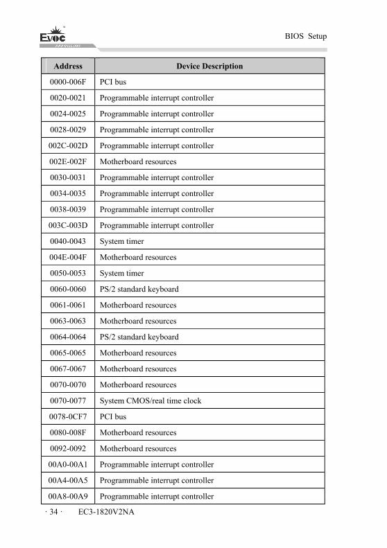
BIOS Setup
· 34 · EC3-1820V2NA
Address Device Description
0000-006F PCI bus
0020-0021 Programmable interrupt controller
0024-0025 Programmable interrupt controller
0028-0029 Programmable interrupt controller
002C-002D Programmable interrupt controller
002E-002F Motherboard resources
0030-0031 Programmable interrupt controller
0034-0035 Programmable interrupt controller
0038-0039 Programmable interrupt controller
003C-003D Programmable interrupt controller
0040-0043 System timer
004E-004F Motherboard resources
0050-0053 System timer
0060-0060 PS/2 standard keyboard
0061-0061 Motherboard resources
0063-0063 Motherboard resources
0064-0064 PS/2 standard keyboard
0065-0065 Motherboard resources
0067-0067 Motherboard resources
0070-0070 Motherboard resources
0070-0077 System CMOS/real time clock
0078-0CF7 PCI bus
0080-008F Motherboard resources
0092-0092 Motherboard resources
00A0-00A1 Programmable interrupt controller
00A4-00A5 Programmable interrupt controller
00A8-00A9 Programmable interrupt controller
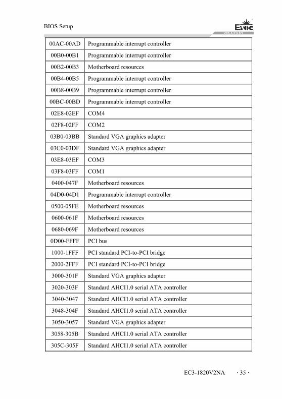
BIOS Setup
EC3-1820V2NA · 35 ·
00AC-00AD Programmable interrupt controller
00B0-00B1 Programmable interrupt controller
00B2-00B3 Motherboard resources
00B4-00B5 Programmable interrupt controller
00B8-00B9 Programmable interrupt controller
00BC-00BD Programmable interrupt controller
02E8-02EF COM4
02F8-02FF COM2
03B0-03BB Standard VGA graphics adapter
03C0-03DF Standard VGA graphics adapter
03E8-03EF COM3
03F8-03FF COM1
0400-047F Motherboard resources
04D0-04D1 Programmable interrupt controller
0500-05FE Motherboard resources
0600-061F Motherboard resources
0680-069F Motherboard resources
0D00-FFFF PCI bus
1000-1FFF PCI standard PCI-to-PCI bridge
2000-2FFF PCI standard PCI-to-PCI bridge
3000-301F Standard VGA graphics adapter
3020-303F Standard AHCI1.0 serial ATA controller
3040-3047 Standard AHCI1.0 serial ATA controller
3048-304F Standard AHCI1.0 serial ATA controller
3050-3057 Standard VGA graphics adapter
3058-305B Standard AHCI1.0 serial ATA controller
305C-305F Standard AHCI1.0 serial ATA controller
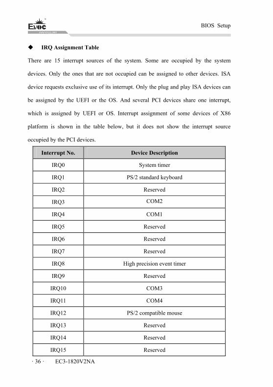
BIOS Setup
· 36 · EC3-1820V2NA
IRQ Assignment Table
There are 15 interrupt sources of the system. Some are occupied by the system
devices. Only the ones that are not occupied can be assigned to other devices. ISA
device requests exclusive use of its interrupt. Only the plug and play ISA devices can
be assigned by the UEFI or the OS. And several PCI devices share one interrupt,
which is assigned by UEFI or OS. Interrupt assignment of some devices of X86
platform is shown in the table below, but it does not show the interrupt source
occupied by the PCI devices.
Interrupt No. Device Description
IRQ0 System timer
IRQ1 PS/2 standard keyboard
IRQ2 Reserved
IRQ3 COM2
IRQ4 COM1
IRQ5 Reserved
IRQ6 Reserved
IRQ7 Reserved
IRQ8 High precision event timer
IRQ9 Reserved
IRQ10 COM3
IRQ11 COM4
IRQ12 PS/2 compatible mouse
IRQ13 Reserved
IRQ14 Reserved
IRQ15 Reserved
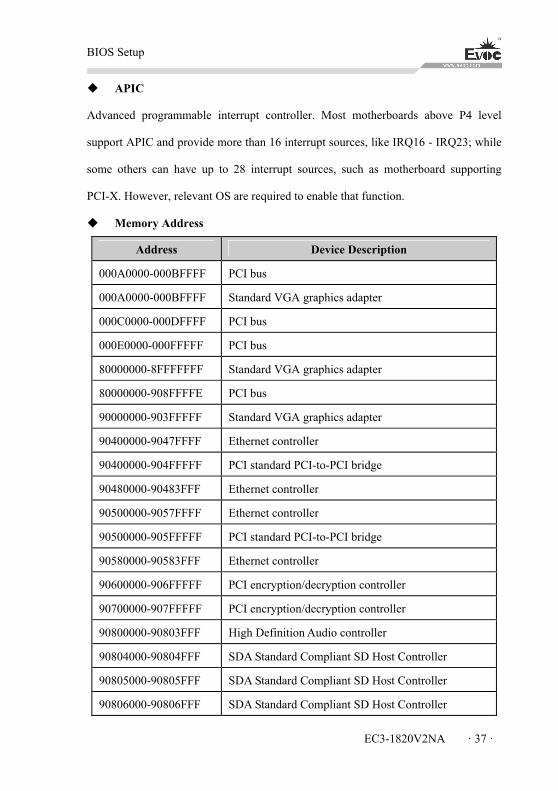
BIOS Setup
EC3-1820V2NA · 37 ·
APIC
Advanced programmable interrupt controller. Most motherboards above P4 level
support APIC and provide more than 16 interrupt sources, like IRQ16 - IRQ23; while
some others can have up to 28 interrupt sources, such as motherboard supporting
PCI-X. However, relevant OS are required to enable that function.
Memory Address
Address Device Description
000A0000-000BFFFF PCI bus
000A0000-000BFFFF Standard VGA graphics adapter
000C0000-000DFFFF PCI bus
000E0000-000FFFFF PCI bus
80000000-8FFFFFFF Standard VGA graphics adapter
80000000-908FFFFE PCI bus
90000000-903FFFFF Standard VGA graphics adapter
90400000-9047FFFF Ethernet controller
90400000-904FFFFF PCI standard PCI-to-PCI bridge
90480000-90483FFF Ethernet controller
90500000-9057FFFF Ethernet controller
90500000-905FFFFF PCI standard PCI-to-PCI bridge
90580000-90583FFF Ethernet controller
90600000-906FFFFF PCI encryption/decryption controller
90700000-907FFFFF PCI encryption/decryption controller
90800000-90803FFF High Definition Audio controller
90804000-90804FFF SDA Standard Compliant SD Host Controller
90805000-90805FFF SDA Standard Compliant SD Host Controller
90806000-90806FFF SDA Standard Compliant SD Host Controller

BIOS Setup
· 38 · EC3-1820V2NA
90807000-90807FFF SDA Standard Compliant SD Host Controller
90808000-908087FF Standard AHCI1.0 serial ATA controller
90808800-90808BFF Standard Enhanced PCI to USB Host Controller
90808C00-90808C1F SM bus controller
E0000000-EFFFFFFF Motherboard resources
E00000D0-E00000DB Intel(R) Atom(TM)/Celeron(R)/Pentium(R) Processor MBI Device - 33BD
FED00000-FED003FF High precision event timer
FED01000-FED01FFF Motherboard resources
FED03000-FED03FFF Motherboard resources
FED04000-FED04FFF Motherboard resources
FED08000-FED08FFF Motherboard resources
FED0C000-FED0FFFF Motherboard resources
FED1C000-FED1CFFF Motherboard resources
FEE00000-FEEFFFFF Motherboard resources
FEF00000-FEFFFFFF Motherboard resources
FF000000-FFFFFFFF Intel(R) 82802 Firmware Hub Device

Installing the Drivers
EC3-1820V2NA · 39 ·
4. Installing the Drivers
Regarding the driver program of this product, please refer to the enclosed CD.
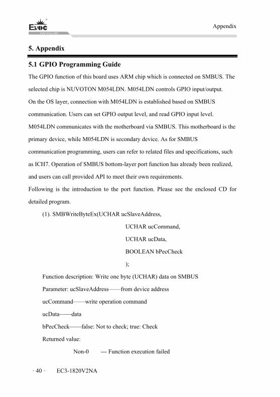
Appendix
· 40 · EC3-1820V2NA
5. Appendix
5.1 GPIO Programming Guide
The GPIO function of this board uses ARM chip which is connected on SMBUS. The
selected chip is NUVOTON M054LDN. M054LDN controls GPIO input/output.
On the OS layer, connection with M054LDN is established based on SMBUS
communication. Users can set GPIO output level, and read GPIO input level.
M054LDN communicates with the motherboard via SMBUS. This motherboard is the
primary device, while M054LDN is secondary device. As for SMBUS
communication programming, users can refer to related files and specifications, such
as ICH7. Operation of SMBUS bottom-layer port function has already been realized,
and users can call provided API to meet their own requirements.
Following is the introduction to the port function. Please see the enclosed CD for
detailed program.
(1). SMBWriteByteEx(UCHAR ucSlaveAddress,
UCHAR ucCommand,
UCHAR ucData,
BOOLEAN bPecCheck
);
Function description: Write one byte (UCHAR) data on SMBUS
Parameter: ucSlaveAddress——from device address
ucCommand——write operation command
ucData——data
bPecCheck——false: Not to check; true: Check
Returned value:
Non-0 --- Function execution failed
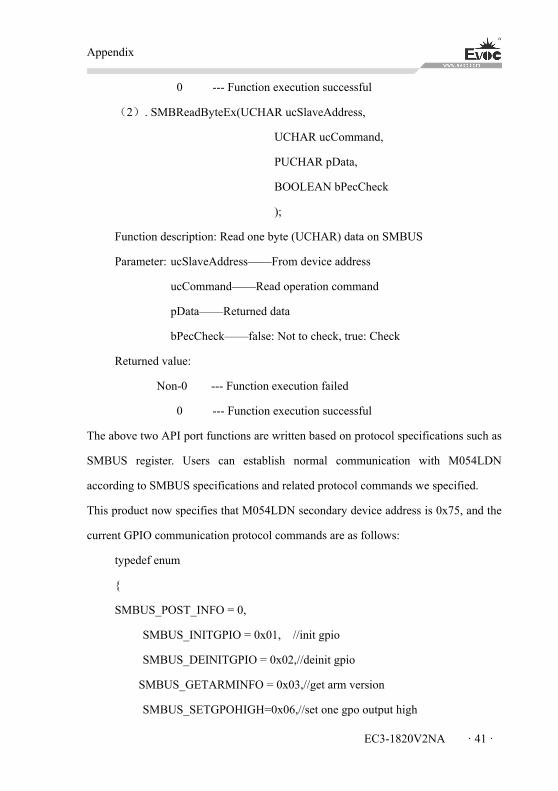
Appendix
EC3-1820V2NA · 41 ·
0 --- Function execution successful
(2). SMBReadByteEx(UCHAR ucSlaveAddress,
UCHAR ucCommand,
PUCHAR pData,
BOOLEAN bPecCheck
);
Function description: Read one byte (UCHAR) data on SMBUS
Parameter: ucSlaveAddress——From device address
ucCommand——Read operation command
pData——Returned data
bPecCheck——false: Not to check, true: Check
Returned value:
Non-0 --- Function execution failed
0 --- Function execution successful
The above two API port functions are written based on protocol specifications such as
SMBUS register. Users can establish normal communication with M054LDN
according to SMBUS specifications and related protocol commands we specified.
This product now specifies that M054LDN secondary device address is 0x75, and the
current GPIO communication protocol commands are as follows:
typedef enum
{
SMBUS_POST_INFO = 0,
SMBUS_INITGPIO = 0x01, //init gpio
SMBUS_DEINITGPIO = 0x02,//deinit gpio
SMBUS_GETARMINFO = 0x03,//get arm version
SMBUS_SETGPOHIGH=0x06,//set one gpo output high
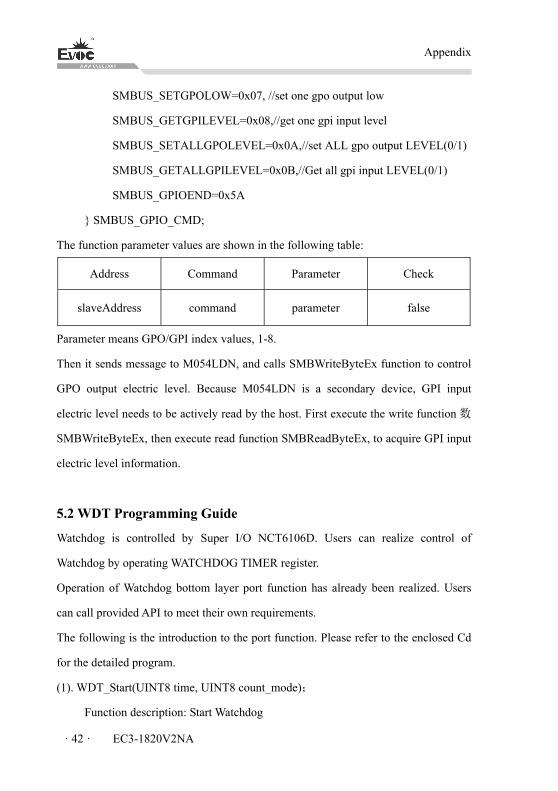
Appendix
· 42 · EC3-1820V2NA
SMBUS_SETGPOLOW=0x07, //set one gpo output low
SMBUS_GETGPILEVEL=0x08,//get one gpi input level
SMBUS_SETALLGPOLEVEL=0x0A,//set ALL gpo output LEVEL(0/1)
SMBUS_GETALLGPILEVEL=0x0B,//Get all gpi input LEVEL(0/1)
SMBUS_GPIOEND=0x5A
} SMBUS_GPIO_CMD;
The function parameter values are shown in the following table:
Address Command Parameter Check
slaveAddress command parameter false
Parameter means GPO/GPI index values, 1-8.
Then it sends message to M054LDN, and calls SMBWriteByteEx function to control
GPO output electric level. Because M054LDN is a secondary device, GPI input
electric level needs to be actively read by the host. First execute the write function 数
SMBWriteByteEx, then execute read function SMBReadByteEx, to acquire GPI input
electric level information.
5.2 WDT Programming Guide
Watchdog is controlled by Super I/O NCT6106D. Users can realize control of
Watchdog by operating WATCHDOG TIMER register.
Operation of Watchdog bottom layer port function has already been realized. Users
can call provided API to meet their own requirements.
The following is the introduction to the port function. Please refer to the enclosed Cd
for the detailed program.
(1). WDT_Start(UINT8 time, UINT8 count_mode);
Function description: Start Watchdog
Appendix
EC3-1820V2NA · 43 ·
Parameter: time——Watchdog time, within 1-255;
count_mode——0: counting unit second, 1: counting unit minute
Returned value:
BPI_STATUS_INVALID_PARAMETER --- Function execution failed;
BPI_STATUS_SUCCESSFUL --- Function execution successful
(2). WDT_Feed(UINT8 time);
Function description: Feed Watchdog;
Parameter: time——Watchdog time, within 1-255;
Returned value: None
(3). WDT_Stop();
Function description: Disable Watchdog
Parameter: None;
Returned value: None
(4). Get_WDT_Current_Timeout_Value();
Function description: Acquire current Watchdog timeout value;
Parameter: None;
Returned value:
timeout --- Timeout time
The above is the Watchdog operation port function. Call WDT_Start, to configure
Watchdog and start Watchdog; Call WDT_Feed to feed the Watchdog; Call
WDT_Stop to stop the Watchdog; Call Get_WDT_Current_Timeout_Value, to acquire
the Watchdog timeout value at the moment.
During the operation, users can call our library file DLL or static file LIB,
corresponding Macro and commands. Users only have to include our header file.

Appendix
· 44 · EC3-1820V2NA
5.3 LVDS Backlight Control Programming Guide
LVDS backlight control is realized by ICH. Users can operate PWM register to
realize control of LVDS screen backlight luminance.
After operation of LVDS screen bottom layer port functions has been realized, users
can call the provided API to realize their own requirements.
The following is the introduction of port functions. Please refer to the CD for detailed
program.
(1). BPI_STATUS Set_SIO_LVDS_BL( UINT8 PWM_Value);
Function description: to set backlight control parameter value
Parameter: PWM_Value—— backlight parameter. Ranging within 1-255
Returned value:
BPI_STATUS_INVALID_PARAMETER --- Function execution failed
BPI_STATUS_SUCCESSFUL --- Function execution successful
(2). BPI_STATUS Get_SIO_LVDS_BL( UINT8 *PWM_Value);
Function description: to acquire backlight control parameter value
Parameter: *PWM_Value—— return to backlight parameter value, ranging
within 1-255
Returned value:
BPI_STATUS_INVALID_PARAMETER --- Function execution failed
BPI_STATUS_SUCCESSFUL --- Function execution successful
The above is the port function for LVDS backlight control operation. The backlight
control register BIOS has been initialized by default, so users only need to call
Set_SIO_LVDS_BL, to carry out setup of backlight parameter operation; call
Get_SIO_LVDS_BL, to read backlight parameter; the backlight parameter setup
range is 0-255, 0 means black screen, and 255 means highest brightness.
During the operation, users can call our library file DLL or static file LIB,
corresponding Macro and commands, which include our header files.
Appendix
EC3-1820V2NA · 45 ·
5.4 Troubleshooting and Solutions
Common Fault Issues to be Checked
Unable to bootup
after powered on
1. Please make sure whether the power cord is well
connected;
2. Please make sure whether the adopted power supply
meets the power requirement of the motherboard;
3. Please check whether the CPU has been properly
installed and whether the CPU has been buckled properly;
4. Remove and install the memory module again;
5. Replace the memory module;
6. Please clear the CMOS according to the Manual;
7. Please make sure whether there are peripheral cards
connected, and whether it is normal after removing the
peripheral cards;
BIOS Setup cannot
be saved
Please check whether the CMOS battery voltage is lower
than 2.8V; if so, replace it with a new battery, set and save
the BIOS Setup again.
No bootable device
can be found
1. Please make sure the power cable or data cable of the
HDD is connected properly;
2. Please check whether there is physical damage to the
HDD;
3. Please make sure operating system has been normally
installed in the HDD.
Blue screen or
computer crush
occurred when
entering system
1. Please check whether the memory module or the
peripheral card is loose;
2. Try to remove the newly installed hardware, uninstall
the driver or software;
3. Try to replace the memory module.
Appendix
· 46 · EC3-1820V2NA
Slow to enter
operating system
1. Please check whether there are bad tracks on the hard
disk by third party software;
2. Please make sure the remaining space on the system
partition is enough;
3. Please check whether the CPU fan is operating normally.
System reboots
automatically
1. Please make sure the CPU fan is operating normally;
2. Please check whether the reset button has been triggered
by accident;
3. Please check whether the system is affected by virus
using anti-virus software;
4. Please check whether the memory module or the
peripheral card is loose;
5. Please make sure the load carrying capability of the
adopted power supply is enough; you may try to replace
the power.
No USB device can
be detected
1. Please confirm whether independent power supply is
required on the USB device;
2. Please check whether ill contact exists on the USB port;
3. Please make sure the USB controller in BIOS Setup has
been enabled.
No PCI card can be
detected
1. Please check whether additional power supply is needed
on the PCI card;
2. Please make sure whether the operating voltage of the
PCI card is in accord with that supplied by motherboard
(5V by default);
3. Please make sure whether the PCI slot can be identified
after replacement.
Appendix
EC3-1820V2NA · 47 ·
No ISA card can be
detected
1. Please make sure the resources used by ISA card have
been reserved by BIOS according to the ISA card manual
-- there are reserved options in BIOS Setup for ISA to use
I/O or memory resource on most of the motherboards; and
check whether the IRQ used by ISA card has been reserved
in BIOS Setup;
2. The ISA card usually cannot be identified directly under
the system; please choose “Add Hardware” in the “Control
Panel” in Windows system to set.
5.5 Abbreviations
Abbreviations Terminology Meaning
AC Alternate current Alternate current
APM Advanced Power
Management
A tool used to monitor and
lower PC power consumption.
ACPI Advanced Configuration and
Power Interface
AHCI Advanced Host Controller
Interface
Standard control interface of
serial ATA, Microsoft
windows XP
(above SP1 version) and IAA
driver program supports the
interface
APIC Advanced Programmable
Interrupt Controller
Extended programmable
interrupt controller
ASPM Active State Power
Management
A power saving mode control
for PCIE devices in idle status
ATM Asynchronous Transfer
Mode
ASCII American Standard Code for
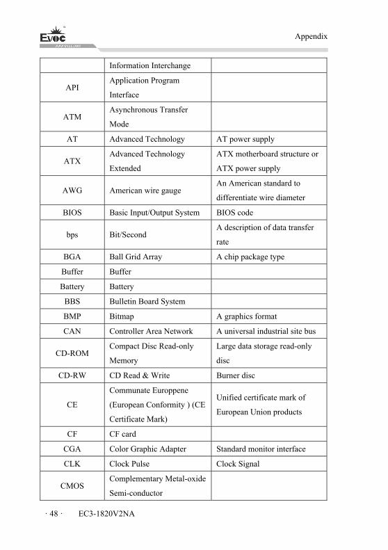
Appendix
· 48 · EC3-1820V2NA
Information Interchange
API Application Program
Interface
ATM Asynchronous Transfer
Mode
AT Advanced Technology AT power supply
ATX Advanced Technology
Extended
ATX motherboard structure or
ATX power supply
AWG American wire gauge An American standard to
differentiate wire diameter
BIOS Basic Input/Output System BIOS code
bps Bit/Second A description of data transfer
rate
BGA Ball Grid Array A chip package type
Buffer Buffer
Battery Battery
BBS Bulletin Board System
BMP Bitmap A graphics format
CAN Controller Area Network A universal industrial site bus
CD-ROM Compact Disc Read-only
Memory
Large data storage read-only
disc
CD-RW CD Read & Write Burner disc
CE
Communate Europpene
(European Conformity ) (CE
Certificate Mark)
Unified certificate mark of
European Union products
CF CF card
CGA Color Graphic Adapter Standard monitor interface
CLK Clock Pulse Clock Signal
CMOS Complementary Metal-oxide
Semi-conductor
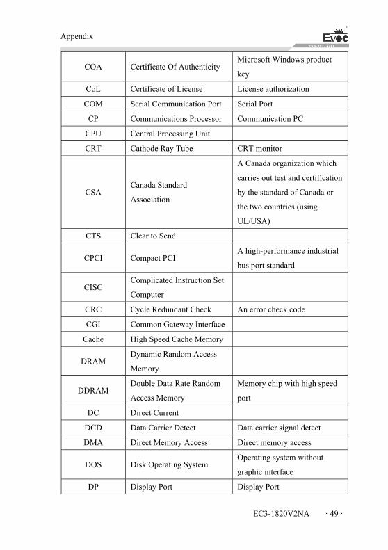
Appendix
EC3-1820V2NA · 49 ·
COA Certificate Of Authenticity Microsoft Windows product
key
CoL Certificate of License License authorization
COM Serial Communication Port Serial Port
CP Communications Processor Communication PC
CPU Central Processing Unit
CRT Cathode Ray Tube CRT monitor
CSA Canada Standard
Association
A Canada organization which
carries out test and certification
by the standard of Canada or
the two countries (using
UL/USA)
CTS Clear to Send
CPCI Compact PCI A high-performance industrial
bus port standard
CISC Complicated Instruction Set
Computer
CRC Cycle Redundant Check An error check code
CGI Common Gateway Interface
Cache High Speed Cache Memory
DRAM Dynamic Random Access
Memory
DDRAM Double Data Rate Random
Access Memory
Memory chip with high speed
port
DC Direct Current
DCD Data Carrier Detect Data carrier signal detect
DMA Direct Memory Access Direct memory access
DOS Disk Operating System Operating system without
graphic interface
DP Display Port Display Port
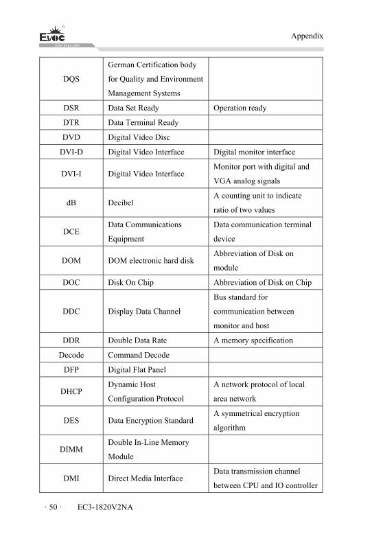
Appendix
· 50 · EC3-1820V2NA
DQS
German Certification body
for Quality and Environment
Management Systems
DSR Data Set Ready Operation ready
DTR Data Terminal Ready
DVD Digital Video Disc
DVI-D Digital Video Interface Digital monitor interface
DVI-I Digital Video Interface Monitor port with digital and
VGA analog signals
dB Decibel A counting unit to indicate
ratio of two values
DCE Data Communications
Equipment
Data communication terminal
device
DOM DOM electronic hard disk Abbreviation of Disk on
module
DOC Disk On Chip Abbreviation of Disk on Chip
DDC Display Data Channel
Bus standard for
communication between
monitor and host
DDR Double Data Rate A memory specification
Decode Command Decode
DFP Digital Flat Panel
DHCP Dynamic Host
Configuration Protocol
A network protocol of local
area network
DES Data Encryption Standard A symmetrical encryption
algorithm
DIMM Double In-Line Memory
Module
DMI Direct Media Interface Data transmission channel
between CPU and IO controller
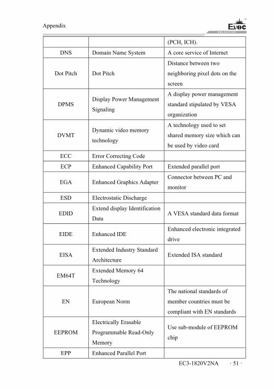
Appendix
EC3-1820V2NA · 51 ·
(PCH, ICH).
DNS Domain Name System A core service of Internet
Dot Pitch Dot Pitch
Distance between two
neighboring pixel dots on the
screen
DPMS Display Power Management
Signaling
A display power management
standard stipulated by VESA
organization
DVMT Dynamic video memory
technology
A technology used to set
shared memory size which can
be used by video card
ECC Error Correcting Code
ECP Enhanced Capability Port Extended parallel port
EGA Enhanced Graphics Adapter Connector between PC and
monitor
ESD Electrostatic Discharge
EDID Extend display Identification
Data A VESA standard data format
EIDE Enhanced IDE Enhanced electronic integrated
drive
EISA Extended Industry Standard
Architecture Extended ISA standard
EM64T Extended Memory 64
Technology
EN European Norm
The national standards of
member countries must be
compliant with EN standards
EEPROM
Electrically Erasable
Programmable Read-Only
Memory
Use sub-module of EEPROM
chip
EPP Enhanced Parallel Port
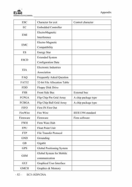
Appendix
· 52 · EC3-1820V2NA
ESC Character for exit Control character
EC Embedded Controller
EMI ElectroMagnetic
Interference
EMC Electro Magnetic
Compatibility
ES Energy Star
ESCD Extended System
Configuration Data
EIA Electronic Industries
Association
FAQ Frequently Asked Question
FAT32 32-bit File Allocation Table
FDD Floppy Disk Drive
FSB Front Side Bus External bus
FCPGA Flip Chip Pin Grid Array A chip package type
FCBGA Flip Chip Ball Grid Array A chip package type
FIFO First IN First Out
FireWire Fire Wire IEEE1394 standard
Firmware Firmware Firm software
FWH Firm Ware Hub
FPU Float Point Unit
FTP File Transfer Protocol
GND Grounding
GB Gigabit
GPS Global Positioning System
GSM Global System for Mobile
communication
GUI Graphical User Interface
GMCH Graphics & Memory
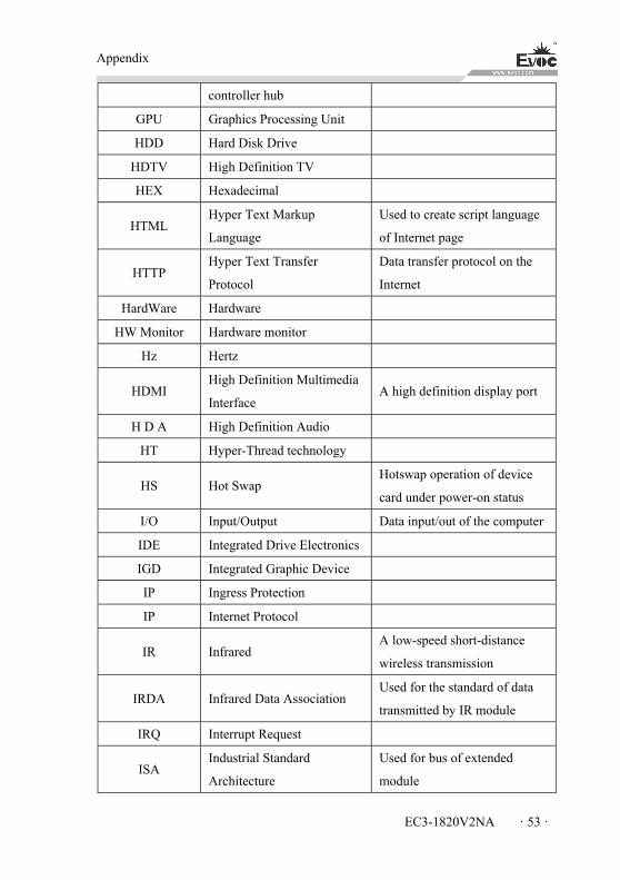
Appendix
EC3-1820V2NA · 53 ·
controller hub
GPU Graphics Processing Unit
HDD Hard Disk Drive
HDTV High Definition TV
HEX Hexadecimal
HTML Hyper Text Markup
Language
Used to create script language
of Internet page
HTTP Hyper Text Transfer
Protocol
Data transfer protocol on the
Internet
HardWare Hardware
HW Monitor Hardware monitor
Hz Hertz
HDMI High Definition Multimedia
Interface A high definition display port
H D A High Definition Audio
HT Hyper-Thread technology
HS Hot Swap Hotswap operation of device
card under power-on status
I/O Input/Output Data input/out of the computer
IDE Integrated Drive Electronics
IGD Integrated Graphic Device
IP Ingress Protection
IP Internet Protocol
IR Infrared A low-speed short-distance
wireless transmission
IRDA Infrared Data Association Used for the standard of data
transmitted by IR module
IRQ Interrupt Request
ISA Industrial Standard
Architecture
Used for bus of extended
module
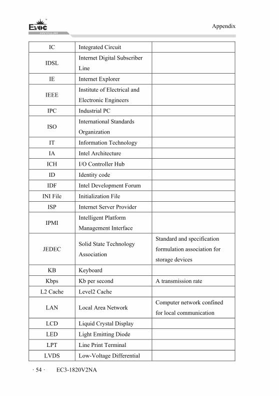
Appendix
· 54 · EC3-1820V2NA
IC Integrated Circuit
IDSL Internet Digital Subscriber
Line
IE Internet Explorer
IEEE Institute of Electrical and
Electronic Engineers
IPC Industrial PC
ISO International Standards
Organization
IT Information Technology
IA Intel Architecture
ICH I/O Controller Hub
ID Identity code
IDF Intel Development Forum
INI File Initialization File
ISP Internet Server Provider
IPMI Intelligent Platform
Management Interface
JEDEC Solid State Technology
Association
Standard and specification
formulation association for
storage devices
KB Keyboard
Kbps Kb per second A transmission rate
L2 Cache Level2 Cache
LAN Local Area Network Computer network confined
for local communication
LCD Liquid Crystal Display
LED Light Emitting Diode
LPT Line Print Terminal
LVDS Low-Voltage Differential
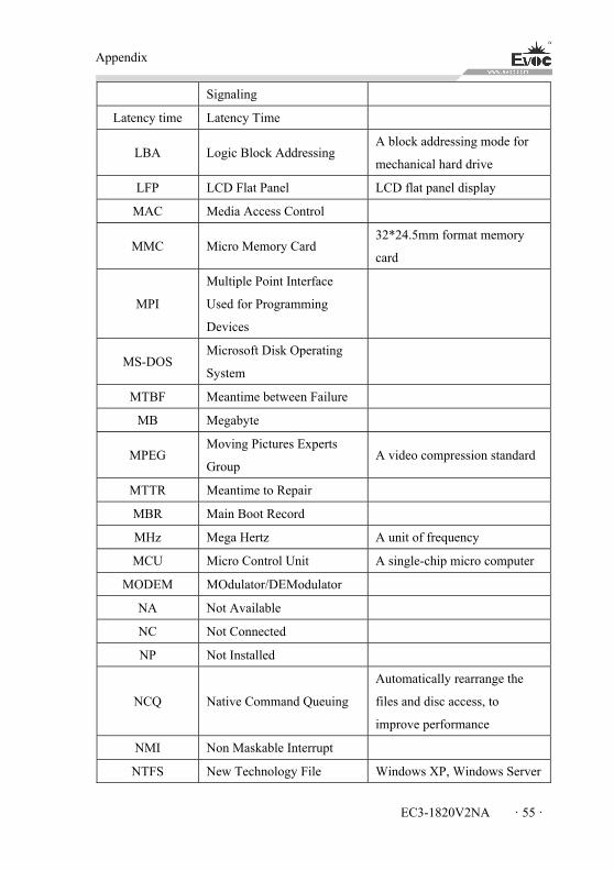
Appendix
EC3-1820V2NA · 55 ·
Signaling
Latency time Latency Time
LBA Logic Block Addressing A block addressing mode for
mechanical hard drive
LFP LCD Flat Panel LCD flat panel display
MAC Media Access Control
MMC Micro Memory Card 32*24.5mm format memory
card
MPI
Multiple Point Interface
Used for Programming
Devices
MS-DOS Microsoft Disk Operating
System
MTBF Meantime between Failure
MB Megabyte
MPEG Moving Pictures Experts
Group A video compression standard
MTTR Meantime to Repair
MBR Main Boot Record
MHz Mega Hertz A unit of frequency
MCU Micro Control Unit A single-chip micro computer
MODEM MOdulator/DEModulator
NA Not Available
NC Not Connected
NP Not Installed
NCQ Native Command Queuing
Automatically rearrange the
files and disc access, to
improve performance
NMI Non Maskable Interrupt
NTFS New Technology File Windows XP, Windows Server
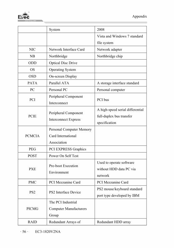
Appendix
· 56 · EC3-1820V2NA
System 2008
Vista and Windows 7 standard
file system
NIC Network Interface Card Network adapter
NB Northbridge Northbridge chip
ODD Optical Disc Drive
OS Operating System
OSD On-screen Display
PATA Parallel ATA A storage interface standard
PC Personal PC Personal computer
PCI Peripheral Component
Interconnect PCI bus
PCIE Peripheral Component
Interconnect Express
A high-speed serial differential
full-duplex bus transfer
specification
PCMCIA
Personal Computer Memory
Card International
Association
PEG PCI EXPRESS Graphics
POST Power On Self Test
PXE Pre-boot Execution
Environment
Used to operate software
without HDD data PC via
network
PMC PCI Mezzanine Card PCI Mezzanine Card
PS2 PS2 Interface Device PS2 mouse/keyboard standard
port type developed by IBM
PICMG
The PCI Industrial
Computer Manufacturers
Group
RAID Redundant Arrays of Redundant HDD array
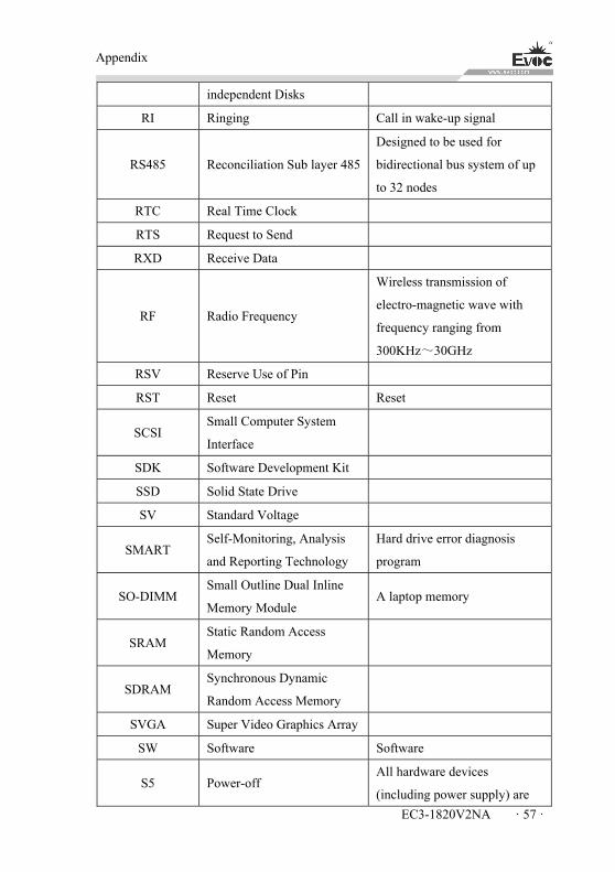
Appendix
EC3-1820V2NA · 57 ·
independent Disks
RI Ringing Call in wake-up signal
RS485 Reconciliation Sub layer 485
Designed to be used for
bidirectional bus system of up
to 32 nodes
RTC Real Time Clock
RTS Request to Send
RXD Receive Data
RF Radio Frequency
Wireless transmission of
electro-magnetic wave with
frequency ranging from
300KHz~30GHz
RSV Reserve Use of Pin
RST Reset Reset
SCSI Small Computer System
Interface
SDK Software Development Kit
SSD Solid State Drive
SV Standard Voltage
SMART Self-Monitoring, Analysis
and Reporting Technology
Hard drive error diagnosis
program
SO-DIMM Small Outline Dual Inline
Memory Module A laptop memory
SRAM Static Random Access
Memory
SDRAM Synchronous Dynamic
Random Access Memory
SVGA Super Video Graphics Array
SW Software Software
S5 Power-off All hardware devices
(including power supply) are
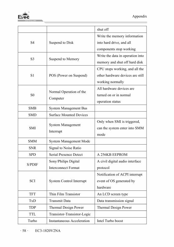
Appendix
· 58 · EC3-1820V2NA
shut off
S4 Suspend to Disk
Write the memory information
into hard drive, and all
components stop working
S3 Suspend to Memory Write the data in operation into
memory and shut off hard disk
S1 POS (Power on Suspend)
CPU stops working, and all the
other hardware devices are still
working normally
S0 Normal Operation of the
Computer
All hardware devices are
turned on or in normal
operation status
SMB System Management Bus
SMD Surface Mounted Devices
SMI System Management
Interrupt
Only when SMI is triggered,
can the system enter into SMM
mode
SMM System Management Mode
SNR Signal to Noise Ratio
SPD Serial Presence Detect A 256KB EEPROM
S/PDIF Sony/Philips Digital
Interconnect Format
A civil digital audio interface
protocol
SCI System Control Interrupt
Notification of ACPI interrupt
event of OS generated by
hardware
TFT Thin Film Transistor An LCD screen type
TxD Transmit Data Data transmission signal
TDP Thermal Design Power Thermal Design Power
TTL Transistor-Transistor-Logic
Turbo Instantaneous Acceleration Intel Turbo boost
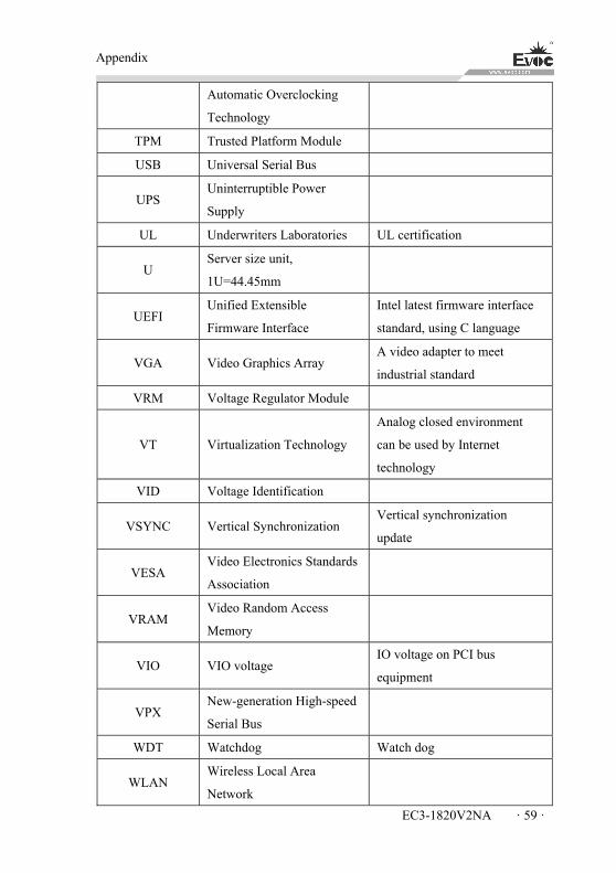
Appendix
EC3-1820V2NA · 59 ·
Automatic Overclocking
Technology
TPM Trusted Platform Module
USB Universal Serial Bus
UPS Uninterruptible Power
Supply
UL Underwriters Laboratories UL certification
U Server size unit,
1U=44.45mm
UEFI Unified Extensible
Firmware Interface
Intel latest firmware interface
standard, using C language
VGA Video Graphics Array A video adapter to meet
industrial standard
VRM Voltage Regulator Module
VT Virtualization Technology
Analog closed environment
can be used by Internet
technology
VID Voltage Identification
VSYNC Vertical Synchronization Vertical synchronization
update
VESA Video Electronics Standards
Association
VRAM Video Random Access
Memory
VIO VIO voltage IO voltage on PCI bus
equipment
VPX New-generation High-speed
Serial Bus
WDT Watchdog Watch dog
WLAN Wireless Local Area
Network
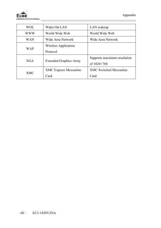
Appendix
· 60 · EC3-1820V2NA
WOL Wake-On-LAN LAN wakeup
WWW World Wide Web World Wide Web
WAN Wide Area Network Wide Area Network
WAP Wireless Application
Protocol
XGA Extended Graphics Array Supports maximum resolution
of 1024×768
XMC XMC Express Mezzanine
Card
XMC Switched Mezzanine
Card