EC2401 WIRELESS COMMUNICATION 16 MARK IMP ...
13
WWW.VIDYARTHIPLUS.COM WWW.VIDYARTHIPLUS.COM V+ TEAM EC2401 WIRELESS COMMUNICATION 16 MARK IMP QUESTION WITH KEY POINTS PART-B UNIT-I 1. Explain in detail the different types of services in wireless communication? (16 Marks) Ans. Explanation of the following services with diagram Types of Services 1. Broadcast 2. Paging 3. Cellular Telephony 4. Trunking Radio 5. Cordless Telephony 6. Wireless Local Area Networks 7. Personal Area Networks 8. Fixed Wireless Access 9. Ad hoc Networks and Sensor Networks 10. Satellite Cellular Communications 2. Discuss briefly about the requirements of services for a wireless system. (8 marks) Ans. Explanation of following requirement in detail 1. Data Rate 2. Range and Number of Users 3. Mobility 4. Energy Consumption 5. Use of Spectrum 6. Direction of Transmission 7. Service Quality 3. Compare and contrast wired and wireless communication (8 marks) Ans- Wired communications Wireless communications The communication takes place over a more or less stable medium like copper wires or optical fibers. The properties of the medium are well defined and time-invariant. Due to user mobility as well as multipath propagation, the transmission medium varies strongly with time. Increasing the transmission capacity can be achieved by using a different frequency on an existing cable,and/or by stringing new cables. Increasing the transmit capacity must be achieved bymore sophisticated transceiver concepts and smaller cell sizes (in cellular systems), as the amount of available spectrum is limited. The range over which communications can be performed without repeater stations is mostly The range that can be covered is limited both by the transmission medium
-
Upload
khangminh22 -
Category
Documents
-
view
0 -
download
0
Transcript of EC2401 WIRELESS COMMUNICATION 16 MARK IMP ...

WWW.VIDYARTHIPLUS.COM
WWW.VIDYARTHIPLUS.COM V+ TEAM
EC2401 WIRELESS COMMUNICATION 16 MARK IMP QUESTION WITH KEY POINTS
PART-B
UNIT-I
1. Explain in detail the different types of services in wireless communication? (16
Marks)
Ans. Explanation of the following services with diagram
Types of Services
1. Broadcast
2. Paging
3. Cellular Telephony
4. Trunking Radio
5. Cordless Telephony
6. Wireless Local Area Networks
7. Personal Area Networks
8. Fixed Wireless Access
9. Ad hoc Networks and Sensor Networks
10. Satellite Cellular Communications
2. Discuss briefly about the requirements of services for a wireless system. (8 marks)
Ans. Explanation of following requirement in detail
1. Data Rate
2. Range and Number of Users
3. Mobility
4. Energy Consumption
5. Use of Spectrum
6. Direction of Transmission
7. Service Quality
3. Compare and contrast wired and wireless communication (8 marks)
Ans-
Wired communications Wireless communications
The communication takes place over a more or
less stable medium like copper wires or optical
fibers. The properties of the medium are well
defined and time-invariant.
Due to user mobility as well as multipath
propagation, the transmission medium
varies strongly with time.
Increasing the transmission capacity can be
achieved by using a different frequency on an
existing cable,and/or by stringing new cables.
Increasing the transmit capacity must be
achieved bymore sophisticated transceiver
concepts and smaller cell sizes (in cellular
systems), as the amount of available
spectrum is limited.
The range over which communications can be
performed without repeater stations is mostly
The range that can be covered is limited
both by the transmission medium
WWW.VIDYARTHIPLUS.COM
WWW.VIDYARTHIPLUS.COM V+ TEAM
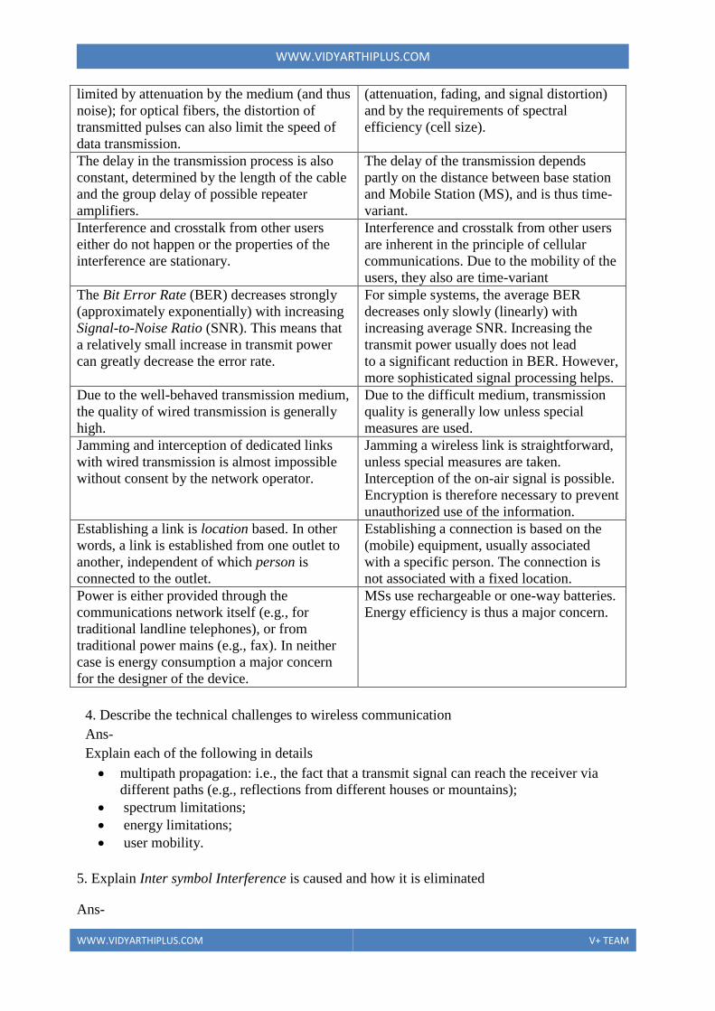
limited by attenuation by the medium (and thus
noise); for optical fibers, the distortion of
transmitted pulses can also limit the speed of
data transmission.
(attenuation, fading, and signal distortion)
and by the requirements of spectral
efficiency (cell size).
The delay in the transmission process is also
constant, determined by the length of the cable
and the group delay of possible repeater
amplifiers.
The delay of the transmission depends
partly on the distance between base station
and Mobile Station (MS), and is thus time-
variant.
Interference and crosstalk from other users
either do not happen or the properties of the
interference are stationary.
Interference and crosstalk from other users
are inherent in the principle of cellular
communications. Due to the mobility of the
users, they also are time-variant
The Bit Error Rate (BER) decreases strongly
(approximately exponentially) with increasing
Signal-to-Noise Ratio (SNR). This means that
a relatively small increase in transmit power
can greatly decrease the error rate.
For simple systems, the average BER
decreases only slowly (linearly) with
increasing average SNR. Increasing the
transmit power usually does not lead
to a significant reduction in BER. However,
more sophisticated signal processing helps.
Due to the well-behaved transmission medium,
the quality of wired transmission is generally
high.
Due to the difficult medium, transmission
quality is generally low unless special
measures are used.
Jamming and interception of dedicated links
with wired transmission is almost impossible
without consent by the network operator.
Jamming a wireless link is straightforward,
unless special measures are taken.
Interception of the on-air signal is possible.
Encryption is therefore necessary to prevent
unauthorized use of the information.
Establishing a link is location based. In other
words, a link is established from one outlet to
another, independent of which person is
connected to the outlet.
Establishing a connection is based on the
(mobile) equipment, usually associated
with a specific person. The connection is
not associated with a fixed location.
Power is either provided through the
communications network itself (e.g., for
traditional landline telephones), or from
traditional power mains (e.g., fax). In neither
case is energy consumption a major concern
for the designer of the device.
MSs use rechargeable or one-way batteries.
Energy efficiency is thus a major concern.
4. Describe the technical challenges to wireless communication
Ans-
Explain each of the following in details
multipath propagation: i.e., the fact that a transmit signal can reach the receiver via
different paths (e.g., reflections from different houses or mountains);
spectrum limitations;
energy limitations;
user mobility.
5. Explain Inter symbol Interference is caused and how it is eliminated
Ans-
WWW.VIDYARTHIPLUS.COM
WWW.VIDYARTHIPLUS.COM V+ TEAM
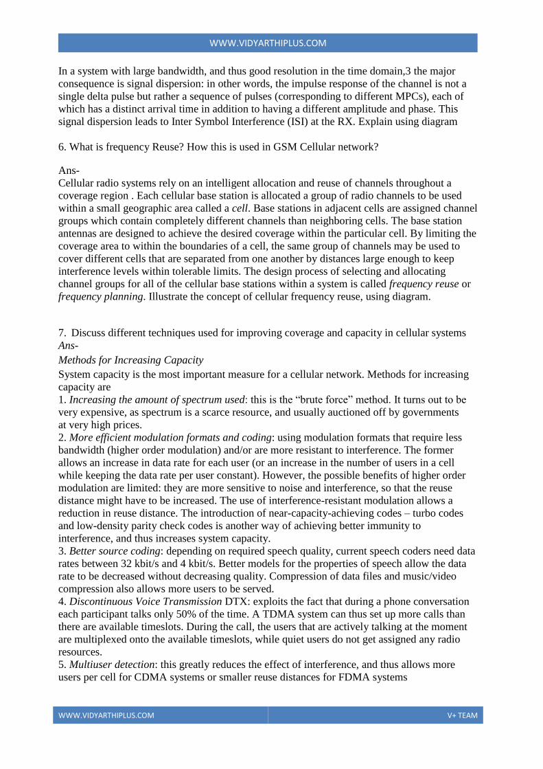
In a system with large bandwidth, and thus good resolution in the time domain,3 the major
consequence is signal dispersion: in other words, the impulse response of the channel is not a
single delta pulse but rather a sequence of pulses (corresponding to different MPCs), each of
which has a distinct arrival time in addition to having a different amplitude and phase. This
signal dispersion leads to Inter Symbol Interference (ISI) at the RX. Explain using diagram
6. What is frequency Reuse? How this is used in GSM Cellular network?
Ans-
Cellular radio systems rely on an intelligent allocation and reuse of channels throughout a
coverage region . Each cellular base station is allocated a group of radio channels to be used
within a small geographic area called a cell. Base stations in adjacent cells are assigned channel
groups which contain completely different channels than neighboring cells. The base station
antennas are designed to achieve the desired coverage within the particular cell. By limiting the
coverage area to within the boundaries of a cell, the same group of channels may be used to
cover different cells that are separated from one another by distances large enough to keep
interference levels within tolerable limits. The design process of selecting and allocating
channel groups for all of the cellular base stations within a system is called frequency reuse or
frequency planning. Illustrate the concept of cellular frequency reuse, using diagram.
7. Discuss different techniques used for improving coverage and capacity in cellular systems
Ans-
Methods for Increasing Capacity
System capacity is the most important measure for a cellular network. Methods for increasing
capacity are
1. Increasing the amount of spectrum used: this is the “brute force” method. It turns out to be
very expensive, as spectrum is a scarce resource, and usually auctioned off by governments
at very high prices.
2. More efficient modulation formats and coding: using modulation formats that require less
bandwidth (higher order modulation) and/or are more resistant to interference. The former
allows an increase in data rate for each user (or an increase in the number of users in a cell
while keeping the data rate per user constant). However, the possible benefits of higher order
modulation are limited: they are more sensitive to noise and interference, so that the reuse
distance might have to be increased. The use of interference-resistant modulation allows a
reduction in reuse distance. The introduction of near-capacity-achieving codes – turbo codes
and low-density parity check codes is another way of achieving better immunity to
interference, and thus increases system capacity.
3. Better source coding: depending on required speech quality, current speech coders need data
rates between 32 kbit/s and 4 kbit/s. Better models for the properties of speech allow the data
rate to be decreased without decreasing quality. Compression of data files and music/video
compression also allows more users to be served.
4. Discontinuous Voice Transmission DTX: exploits the fact that during a phone conversation
each participant talks only 50% of the time. A TDMA system can thus set up more calls than
there are available timeslots. During the call, the users that are actively talking at the moment
are multiplexed onto the available timeslots, while quiet users do not get assigned any radio
resources.
5. Multiuser detection: this greatly reduces the effect of interference, and thus allows more
users per cell for CDMA systems or smaller reuse distances for FDMA systems

WWW.VIDYARTHIPLUS.COM
WWW.VIDYARTHIPLUS.COM V+ TEAM
6. Adaptive modulation and coding: employs the knowledge at the TX of the transmission
channel, and chooses the modulation format and coding rate that are “just right” for the current
link situation. This approach makes better use of available power, and, among other effects,
reduces interference
7. Reduction of cell radius: this is an effective, but very expensive, way of increasing capacity,
as a new BS has to be built for each additional cell. For FDMA systems, it also means that the
frequency planning for a large area has to be redone.8 Furthermore, smaller cells also require
more handovers for moving users, which is complicated, and reduces spectral efficiency due to
the large amount of signaling information that has to be sent during a handover.
8. Use of sector cells: a hexagonal (or similarly shaped) cell can be divided into several
(typically three) sectors. Each sector is served by one sector antenna. Thus, the number of cells
has tripled, as has the number of BS antennas. However, the number of BS locations has
remained the same, because the three antennas are at the same
9. Use of an overlay structure: an overlay structure combines cells with different size and
different traffic density. Therefore, some locations may be served by several BSs
simultaneously.
10. Multiple antennas: these can be used to enhance capacity via different scenarios:
(a) diversity increases the quality of the received signal, which can be exploited
to increase capacity – e.g., by use of higher order modulation formats, or reduction of the
reuse distance;
(b) multiple-input multiple-output systems increase the capacity of each link;
(c) space division multiple access allows several users in the same frequency
channel in the same cell to be served.
11. Fractional loading: this system uses a small reuse distance, but uses only a small
percentage of the available timeslots in each cell. This leads to approximately the same average
capacity as the “conventional” scheme with large reuse distance and full loading of each cell.
12. Partial frequency reuse: in this scheme, the available spectrum is divided into N + 1
subbands. One subband is used in all the cell centers, while the other subbands are used at the
cell edges, employing a conventional frequency reuse (with cluster size N). The “cell edges”
must be large enough so that interference from one cell center to another is sufficiently weak.
8. With neat diagrams explain TDMA & FDMA
Ans-
Frequency Division Multiple Access (FDMA), where different frequencies are assigned
to different users. Explain the concept using diagram
The advantages are
The transmitter (TX) and receiver (RX) require little digital signal processing
(Temporal) synchronization is simple.
the disadvantages are
Frequency synchronization and stability are difficult
Sensitivity to fading:
Sensitivity to random Frequency Modulation (FM):
Intermodulation
Time Division Multiple Access (TDMA), where different timeslots are assigned to
different users.
Explain the concept using diagram and explain its ad, disadvantages.
o Users occupy a larger bandwidth
o Temporal guard intervals are required
Each timeslot might require a new synchronization and channel estimation, as transmission is
o not continuous
WWW.VIDYARTHIPLUS.COM
WWW.VIDYARTHIPLUS.COM V+ TEAM
o For interference-limited systems
9. Explain about noise and interference limited system
Ans
a. Noise limited system
When MS moves further away from the BS, the received signal power decreases, and at a
certain distance, the SNR does not achieve the required threshold for reliable communications.
Therefore, the range of the system is noise limited; equivalently, we can call it signal power
limited. Depending on the interpretation, it is too much noise or too little signal power that
leads to bad link quality.
Explain the following types of noise
Thermal noise
Man made noise
Receiver noise
And link budget
b. Interference-Limited Systems
The interference is so strong that it completely dominates the performance, so that the noise
can be neglected.
10. Write short notes channel assignment . (8 Marks)
Ans-
Fixed channel assignment
Dynamic channel assignment
11. Explain the different hand off strategies used in wireless communication (8 Marks)
Ans-
Concept of Handoff
Different types of handoff
UNIT-II
1. With neat diagrams explain the Free Space Propagation Model? (8 marks)
Derivation of the Friis’ law:
2. Derive the equation of the Path loss using Two-Ray Model with neat diagrams
Derivation of the following Equation, the power received at a distance d from a transmitter
is given by,
For derivation refer ( Rappaport Book)

WWW.VIDYARTHIPLUS.COM
WWW.VIDYARTHIPLUS.COM V+ TEAM
3. Explain knife Edge Diffraction Model
Explain diffraction and Fresnel zones for different knife edge Scenarios using diagrams and
derive diffraction gain exp and electric field due to diffraction
4. Derive the Impulse response model of a Multipath channel.
Explain
Impulse response of the mobile radio channels
Derive the expression for impulse response of mobile radio channels
Refer Rappaport book
5. What is small scale fading? What are the factors influencing small scale fading?
Definition
Effects of small scale fading
Factors influencing
o Multipath propagation
o Speed of the mobile
o Speed of surrounding objects
o Transmission bandwidth of the signal
6. Explain detail about type of small scale fading?
7. Explain Clarke’s model for flat fading?
It is used to find Doppler spread in Flat fading channels
Refer Rappopart book
8. Explain different propagation mechanism
In a more realistic scenario, there are dielectric and conducting obstacles (Interacting Objects
(IOs)).If these IOs have a smooth surface, waves are reflected and a part of the energy
penetrates the IO (transmission). If the surfaces are rough, the waves are diffusely scattered.
Finally, waves can also be diffracted at the edges of the IOs. Explain the following mechanism
Reflection and Transmission
Diffraction

WWW.VIDYARTHIPLUS.COM
WWW.VIDYARTHIPLUS.COM V+ TEAM
Scattering
9. Explain the wideband channel models 1. Frequency selective model 2. Time selective models 3. Gaussian models 4. WSSUS model 5. Non stationary channels
10. Explain different types of wide band and narrow band models
For a narrowband channel, the impulse response is a delta function with a time-varying
attenuation, so that for slowly time-varying channels: h(t, τ ) = α(t)δ(τ )
UNIT-III
1. Explain in detail the generation & detection of MSK technique? (16 Marks)
Principle of MSK
MSK transmitter block diagram &explanation
MSK receiver block diagram &explanation
2. Explain in detail the generation & detection of QPSK technique? (16 Marks)
Quadrature-Phase Shift Keying
A Quadrature-Phase Shift Keying (QPSK)-modulated signal is a PAM where the signal
carries bit per symbol interval on both the in-phase and quadrature-phase component.
When interpreting QPSK as a PAM, the band pass signal reads
SBP(t ) = EB/TB[p1D(t ) cos(2πfct) − p2D(t ) sin(2πfct)]
Explain the following for different types of QPSK and its comparison
Circuit diagram
Waveform
Constellation diagram
3. Explain in detail the generation & detection of GMSK modulation? (16 Marks)
Principle of GMSK
GMSK transmitter block diagram &explanation
GMSK receiver block diagram &explanation
4. Explain the performance of digital modulation in slow flat fading channel.(16 Marks)
Explanation & comparison of digital modulation
Performance results for ASK, FSK,QPSK,MSK
5. Explain error probability of coherent receivers
The modulation formats can be any of the form and explain error probability for the
following signal formats
1. Binary Phase Shift Keying (BPSK) signals are antipodal signals.
2. Binary Frequency Shift Keying (BFSK), and Binary Pulse Position Modulation
(BPPM), areorthogonal signals.
3. Quadrature-Phase Shift Keying (QPSK), π/4-DQPSK (Differential Quadrature-Phase
Shift Keying), and Offset Quadrature-Phase Shift Keying (OQPSK) are bi-orthogonal
signals
WWW.VIDYARTHIPLUS.COM
WWW.VIDYARTHIPLUS.COM V+ TEAM
6. Explain Error Probability in Flat-Fading Channels
7. Explain Error Probability in Delay- and Frequency-Dispersive Fading Channels
UNIT-IV
1. Explain the different methods of microdiversity in detail ((16 Marks)
Micro diversity can be used to combat small-scale fading, which are therefore called
“microdiversity.” The five most common methods are as follows:
1. Spatial diversity: several antenna elements separated in space.
2. Temporal diversity: transmission of the transmit signal at different times.
3. Frequency diversity: transmission of the signal on different frequencies.
4. Angular diversity: multiple antennas (with or without spatial separation) with different
antenna patterns.
5. Polarization diversity: multiple antennas with different polarizations (e.g., vertical and
horizontal).
Explain each types of diversity using diagrams (refer book Molisch)
2 .Explain several signal combining techniques in detail ((16 Marks)
Combining Signals - How to use diversity signals in a way that improves the total quality of
the signal that is to be detected. In general, we can distinguish two ways of exploiting signals
from the multiple diversity branches:
1. Selection diversity, where the “best” signal copy is selected and processed (demodulated and
decoded), while all other copies are discarded. There are different criteria for what constitutes
the “best” signal.
2. Combining diversity, where all copies of the signal are combined (before or after the
demodulator), and the combined signal is decoded. Again, there are different algorithms for
combination of the signals.
Combining diversity leads to better performance, as all available information is
exploited.
On the downside, it requires a more complex RX than selection diversity.
1. Selection Diversity
Received-Signal-Strength-Indication-Driven Diversity
Bit-Error-Rate-Driven Diversity
Switched Diversity
2. Combining Diversity
Principle Selection diversity wastes signal energy by discarding (Nr − 1) copies of the received
signal. This drawback is avoided by combining diversity, which exploits all available signal
copies. Each signal copy is multiplied by a (complex) weight and then added up.
Maximum Ratio Combining
Equal Gain Combining
Optimum Combining
Hybrid Selection – Maximum Ratio Combining
3. Explain the performance of diversity reception in Fading Channels a. Error Probability in Flat-Fading Channels

WWW.VIDYARTHIPLUS.COM
WWW.VIDYARTHIPLUS.COM V+ TEAM
b. Symbol Error Rate in Frequency-Selective Fading Channels
4. Explain linear feedback equalizers in detail ((16 Marks)
Linear equalizers are simple linear filter structures that try to invert the channel in the sense
that the product of the transfer functions of channel and equalizer fulfills a certain criterion.
- This criterion can be any one of the following
Achieving a completely flat transfer function of the channel–filter concatenation - Zero-
Forcing Equalizer
Minimizing the mean-squared error at the filter output - The Mean Square Error
Criterion
- Adaptation Algorithms for Mean Square Error Equalizers
5. Explain decision feedback equalizer in detail (8 Marks)
A decision feedback equalizer (DFE) has a simple underlying premise: once we have detected
a bit correctly, we can use this knowledge in conjunction with knowledge of the channel
impulse response to compute the ISI caused by this bit. In other words, we determine the effect
this bit will have on subsequent samples of the receive signal. The ISI caused by each bit can
then be subtracted from these later samples. Types are
MMSE Decision Feedback Equalizer
Zero-Forcing Decision Feedback Equalizer
6. Explain transmitter diversity with and without channel state information (8 Marks)
For the uplink transmission from the MS to BS, multiple antennas can act as receive
diversity branches. For the downlink, any possible diversity originates at the
transmitter.
Transmitter Diversity with Channel State Information
Transmitter Diversity Without Channel State Information
7. Explain the working principle of Linear predictive coder (16 Marks)
Block diagram of Linear predictive coder
Working principle
Advantages
8. Explain the working principle of GSM codec with neat block diagram. (16 Marks)
Block diagram of GSM codec
Working principle
Advantages
9. Explain the following codes in detail. (i) block code. (ii) convolutional code. (iii) turbo
codes
10. Explain in detail about the stochastic models for speech.
11. Explain LMS and Recursive Least Square algorithm
UNIT-V
WWW.VIDYARTHIPLUS.COM
WWW.VIDYARTHIPLUS.COM V+ TEAM
1. Explain in detail the CDMA multiple access technique. (16 Marks)
CDMA working principle
Advantages & comparison with other techniques.
2. Explain the principles of Frequency Hopping spread spectrum technique and direct
sequence spread spectrum technique. (16)
The principles of Frequency Hopping spread spectrum technique
The basic thought underlying FH is to change the carrier frequency of a narrowband
transmission system so that transmission is done in one frequency band only for a short while.
The ratio between the bandwidth over which the carrier frequency is hopped and the
narrowband transmission bandwidth is the spreading factor.
Basic Principle behind the Direct Sequence-Spread Spectrum
The DS-SS spreads the signal by multiplying the transmit signal by a second signal that has a
very large bandwidth. The bandwidth of this total signal is approximately the same as the
bandwidth of the wideband spreading signal. The ratio of the bandwidth of the new signal to
that of the original signal is again known as the spreading factor. As the bandwidth of the
spread signal is large, and the transmit power stays constant, the power-spectral density of the
transmitted signal is very small – depending on the spreading factor and the BS–MS distance, it
can lie below the noise power-spectral density. This is important in military applications,
because unauthorized listeners cannot determine whether a signal is being transmitted.
Authorized listeners, on the other hand, can invert the spreading operation and thus recover the
narrowband signal (whose power-spectral density lies considerably above the noise power).
3. Explain the principles of Code Division Multiple Access and compared with
TDMA
Each user is assigned a different spreading code, which determines the wideband signal that is
multiplied by the information symbols. Thus, many users can transmit simultaneously in a
wide band
4. Explain about Cellular Code-Division-Multiple-Access Systems and power control
Multiple Access In a TDMA/FDMA system, the answer is the limited number of available
timeslots/frequencies.
Users can occupy those slots, and not interfere with each other.
But when all possible timeslots have been assigned to users, there are no longer free
resources available, and no further users can be accepted into the system.
In a CDMA system, this mechanism is subtly different.
Different users are distinguished by different spreading codes; however, as user
separation is not perfect, each user in the cell contributes interference to all other users.
Thus, as the number of users increases, the interference for each user increases as well.
Consequently, transmission quality decreases gradually (graceful degradation), until
users find the quality too bad to place (or continue) calls.
Consequently, CDMA puts a soft limit on the number of users, not a hard limit like
TDMA.
Therefore, the number of users in a system depends critically on the Signal-to-
Interference-and-Noise Ratio (SINR) required by the receiver.

WWW.VIDYARTHIPLUS.COM
WWW.VIDYARTHIPLUS.COM V+ TEAM
It also implies that any increase in SINR at the receiver, or reduction in the required
SINR, can be immediately translated into higher capacity.
Power control
Distinguish between power control for the uplink and that for the downlink:
• Power control in the uplink : for the uplink, power control is vital for the proper operation of
CDMA.
Power control is done by a closed control loop: the MS first sends with a certain power,
the BS then tells the MS whether the power was too high or too low, and the MS
adjusts its power accordingly.
An open control loop (where the MS adjusts its transmit power based on its own
channel estimate) cannot be used to compensate for small-scale fading in a Frequency
Domain
However, an open loop can be used in conjunction with a closed loop. The open loop
compensates for large-scale variations in the channel (path loss and shadowing), which
are approximately the same at uplink and downlink frequencies. The closed loop is then
used to compensate for small-scale variations.
• Power control in the downlink: for the downlink, power control is not necessary for CDMA
to function: all signals from the BS arrive at one MS with the same power (the channel is the
same for all signals).
However, it can be advantageous to still use power control in order to keep the total
transmit power low. Decreasing the transmit power for all users within a cell by the
same amount leaves unchanged the ratio of desired signal power to intra-cell
interference – i.e., interference from signals destined for other users in the cell.
5. Effects of Multipath Propagation on Code Division
Block diagram of RAKE receiver
Working principle
6. Explain the operations of orthogonal frequency division multiplexing and define
and list the benefits of cyclic prefix cyclic prefix. (16 Marks)
Orthogonal Frequency Division Multiplexing (OFDM) is a modulation scheme that is
especially suited for high-data-rate transmission in delay-dispersive environments. It converts a
high-rate data stream into a number of low-rate streams that are transmitted over parallel,
narrowband channels that can be easily equalized.
Principle of Orthogonal Frequency Division Multiplexing
OFDM splits a high-rate data stream into N parallel streams, which are then transmitted by
modulating N distinct carriers (henceforth called subcarriers or tones). Symbol duration on
each subcarrier thus becomes larger by a factor of N. In order for the receiver to be able to
separate signals carried by different subcarriers, they have to be orthogonal.
Implementation of Transceivers
OFDM can be interpreted in two ways: one is an “analog” –Explain using diagram
Splitting original data stream into N parallel data streams, each of which has a lower data rate.
We furthermore have a number of local oscillators (LOs) available, each of which oscillates at
a frequency fn = nW/N, where n = 0, 1, . . .,N − 1. Each of the parallel data streams then
modulates one of the carriers.

WWW.VIDYARTHIPLUS.COM
WWW.VIDYARTHIPLUS.COM V+ TEAM
An alternative implementation is digital. It first divides the transmit data into blocks of
N symbols. Each block of data is subjected to an Inverse Fast Fourier Transformation
(IFFT), and then transmitted (see Figure 19.2b). This approach is much easier to
implement with integrated circuits. In the following, we will show that the two
approaches are equivalent.
Cyclic Prefix Concept
The delay dispersion will have only a small impact on the performance of OFDM we convert
the system into a parallel system of narrowband channels, so that the symbol duration on each
carrier is made much larger than the delay spread. Delay dispersion also leads to a loss of
orthogonality between the subcarriers, and thus to Inter Carrier Interference (ICI). Fortunately,
both these negative effects can be eliminated by a special type of guard interval, called the
cyclic prefix (CP).
7. Detail notes about GSM – system overview, physical and logical channels (16)
A GSM system consists essentially of three parts – namely, the Base Station Subsystem
(BSS), the Network and Switching Subsystem (NSS), and the Operation Support System
(OSS). Explain those using diagrams
In addition to the actual payload data, GSM also needs to transmit a large amount of signalling
information. These different types of data are transmitted via several logical channels. The
name stems from the fact that each of the data types is transmitted on specific timeslots that are
parts of physical channels.
Logical and Physical Channels
o Logical Channels
Traffic CHannels (TCHs) - Full-Rate Traffic Channels, Half-Rate Traffic CHannels o Conrol channels
Broadcast CHannels (BCHs)
Frequency Correction CHannels (FCCHs)
Synchronization CHannel (SCH)
Broadcast Control CHannel (BCCH) Common Control CHannels (CCCHs)
Paging CHannel (PCH)
Random Access CHannel (RACH)
Access Grant CHannel (AGCH) Dedicated Control CHannels (DCCHs)
Standalone Dedicated Control CHannel (SDCCH)
Slow Associated Control CHannel (SACCH)
Fast Associated Control CHannel (FACCH)
8. Explain about IS-95 used for wireless communication/ Explain forward & reverse
channel parameters of IS-95 CDMA (16) Interim Standard 95(IS-95).
This system became the first commercial Code Division Multiple Access (CDMA) system that achieved wide popularity.
System Overview
IS-95 is a CDMA system with an additional Frequency Division Multiple Access
(FDMA) component. The available frequency range is divided into frequency bands of
1.25 MHz; duplexing is done in the frequency domain. In the U.S.A., frequencies from
1850–1910MHz are used for the uplink, and 1930–1990MHz are used for the downlink
band.1 Within each band, traffic channels, control channels, and pilot channels are
separated by the different codes (chip sequences) with which they are spread.

WWW.VIDYARTHIPLUS.COM
WWW.VIDYARTHIPLUS.COM V+ TEAM
IS-95 specifies two possible speech coder rates: 13.3 or 8.6 kbit/s. In both cases, coding
increases the data rate to 28.8 kbit/s. The signal is then spread by a factor of 64,
resulting in a chip rate of 1.2288 Mchip/s. theoretically; each cell can sustain 64 speech
users. In practice, this numberis reduced to 12–18, due to imperfect power control, non
orthogonality of spreading codes, etc.
The downlink signals generated by one Base Station (BS) for different users are spread
by different Walsh–Hadamard sequences (see Section 18.2.6), and thus orthogonal to
each other. This puts an upper limit of 64 channels on each carrier. In the uplink,
different users are separated by spreading codes that are not strictly orthogonal.
Furthermore, interference from other cells reduces signal quality at the BS and Mobile
Station (MS).
Explain Spreading and Modulatio in the uplink and downlink
9. Discuss about 3G standards – WCDMA/UMTS for wireless network.
Explain the following
Physical-Layer Overview
Network Structure
Data Rates and Service Classes
Air Interface