EASY-Spray Series Ion Source User Guide - AnalyteGuru
74
Thermo EASY-Spray Series Ion Source User Guide 60053-97260 Revision C July 2015
-
Upload
khangminh22 -
Category
Documents
-
view
1 -
download
0
Transcript of EASY-Spray Series Ion Source User Guide - AnalyteGuru
Thermo
EASY-Spray Series Ion SourceUser Guide
60053-97260 Revision C July 2015
© 2015 Thermo Fisher Scientific Inc. All rights reserved.
Acclaim, Accucore, EASY-nLC, EASY-Spray, EASY-Spray NG, Endura MD, Foundation, nanoViper, Optima, PepMap, PepSwift, Q Exactive, TSQ Quantum Ultra, Velos Pro, and Viper are trademarks; Unity is a registered service mark; and Dionex, Exactive, LCQ, LTQ, Orbitrap, Orbitrap Fusion, Thermo Scientific, TSQ Endura, TSQ Quantiva, TSQ Quantum, UltiMate, and Xcalibur are registered trademarks of Thermo Fisher Scientific Inc. in the United States.
The following are registered trademarks in the United States and other countries: Dino-Lite is a registered trademark of AnMo Electronics Corporation. Fisher Scientific is a registered trademark of Fisher Scientific Co. IDEX is a registered trademark of IDEX Corporation. Microsoft and Windows are registered trademarks of Microsoft Corporation.
All other trademarks are the property of Thermo Fisher Scientific Inc. and its subsidiaries.
Thermo Fisher Scientific Inc. provides this document to its customers with a product purchase to use in the product operation. This document is copyright protected and any reproduction of the whole or any part of this document is strictly prohibited, except with the written authorization of Thermo Fisher Scientific Inc.
The contents of this document are subject to change without notice. All technical information in this document is for reference purposes only. System configurations and specifications in this document supersede all previous information received by the purchaser.
This document is not part of any sales contract between Thermo Fisher Scientific Inc. and a purchaser. This document shall in no way govern or modify any Terms and Conditions of Sale, which Terms and Conditions of Sale shall govern all conflicting information between the two documents.
Release history: Rev A, May 2012; Rev B, May 2013; Rev C, July 2015
For Research Use Only. Not for use in diagnostic procedures.

WEEE Directive2012/19/EU
Thermo Fisher Scientific is registered with B2B Compliance (B2Bcompliance.org.uk) in the UK and with the European Recycling Platform (ERP-recycling.org) in all other countries of the European Union and in Norway.
If this product is located in Europe and you want to participate in the Thermo Fisher Scientific Business-to-Business (B2B) Recycling Program, send an email request to [email protected] with the following information:
• WEEE product class
• Name of the manufacturer or distributor (where you purchased the product)
• Number of product pieces, and the estimated total weight and volume
• Pick-up address and contact person (include contact information)
• Appropriate pick-up time
• Declaration of decontamination, stating that all hazardous fluids or material have been removed from the product
For additional information about the Restriction on Hazardous Substances (RoHS) Directive for the European Union, search for RoHS on the Thermo Fisher Scientific European language websites.
IMPORTANT This recycling program is not for biological hazard products or for products that have been medically contaminated. You must treat these types of products as biohazard waste and dispose of them in accordance with your local regulations.

Directive DEEE2012/19/EU
Thermo Fisher Scientific s'est associé avec une ou plusieurs sociétés de recyclage dans chaque état membre de l’Union Européenne et ce produit devrait être collecté ou recyclé par celle(s)-ci. Pour davantage d'informations, rendez-vous sur la page www.thermoscientific.fr/rohs.
WEEE Direktive2012/19/EU
Thermo Fisher Scientific hat Vereinbarungen mit Verwertungs-/Entsorgungsfirmen in allen EU-Mitgliedsstaaten getroffen, damit dieses Produkt durch diese Firmen wiederverwertet oder entsorgt werden kann. Weitere Informationen finden Sie unter www.thermoscientific.de/rohs.
Thermo Scientific EASY-Spray Series Ion Source User Guide v
C
Preface . . . . . . . . . . . . . . . . . . . . . . . . . . . . . . . . . . . . . . . . . . . . . . . . . . . . . . . . . . . . . . ixRelated Documentation . . . . . . . . . . . . . . . . . . . . . . . . . . . . . . . . . . . . . . . . . . . xCompatible Mass Spectrometers . . . . . . . . . . . . . . . . . . . . . . . . . . . . . . . . . . . . .xiProduct Requirements . . . . . . . . . . . . . . . . . . . . . . . . . . . . . . . . . . . . . . . . . . . .xiContents of the EASY-Spray Series Ion Source Kits . . . . . . . . . . . . . . . . . . . . . xiiCautions and Special Notices . . . . . . . . . . . . . . . . . . . . . . . . . . . . . . . . . . . . . .xiiiContacting Us . . . . . . . . . . . . . . . . . . . . . . . . . . . . . . . . . . . . . . . . . . . . . . . . . xv
Chapter 1 Introduction . . . . . . . . . . . . . . . . . . . . . . . . . . . . . . . . . . . . . . . . . . . . . . . . . . . . . . . . . . .1Advantages of Nanoelectrospray . . . . . . . . . . . . . . . . . . . . . . . . . . . . . . . . . . . . . 2Functional Description . . . . . . . . . . . . . . . . . . . . . . . . . . . . . . . . . . . . . . . . . . . . 2
Source Housing . . . . . . . . . . . . . . . . . . . . . . . . . . . . . . . . . . . . . . . . . . . . . . . . 3Controller PCB . . . . . . . . . . . . . . . . . . . . . . . . . . . . . . . . . . . . . . . . . . . . . . . . 4Controller Power Supply . . . . . . . . . . . . . . . . . . . . . . . . . . . . . . . . . . . . . . . . . 5
Chapter 2 Installing the EASY-Spray Series Ion Source . . . . . . . . . . . . . . . . . . . . . . . . . . . . . .7Installing the Ion Source onto the Mass Spectrometer . . . . . . . . . . . . . . . . . . . . . 8Connecting the Controller Power Supply . . . . . . . . . . . . . . . . . . . . . . . . . . . . . 12Connecting the EASY-Spray P-Bus Temp Control Cable . . . . . . . . . . . . . . . . . 13Configuring the Venting Tee Holder . . . . . . . . . . . . . . . . . . . . . . . . . . . . . . . . 13Adjusting the Emitter Tip Position . . . . . . . . . . . . . . . . . . . . . . . . . . . . . . . . . . 15Removing the EASY-Spray Series Source. . . . . . . . . . . . . . . . . . . . . . . . . . . . . . 17
Chapter 3 Connecting the LCD Monitor and Video Camera. . . . . . . . . . . . . . . . . . . . . . . . . . .19Connecting the Monitor and Camera . . . . . . . . . . . . . . . . . . . . . . . . . . . . . . . . 19Adjusting the Video Picture. . . . . . . . . . . . . . . . . . . . . . . . . . . . . . . . . . . . . . . . 21
Chapter 4 Connecting the EASY-Spray Column Plumbing. . . . . . . . . . . . . . . . . . . . . . . . . . . .23Tools and Supplies . . . . . . . . . . . . . . . . . . . . . . . . . . . . . . . . . . . . . . . . . . . . . . 23Installing the EASY-Spray Column for the First Time. . . . . . . . . . . . . . . . . . . . 24Using the nanoViper Fitting . . . . . . . . . . . . . . . . . . . . . . . . . . . . . . . . . . . . . . . 26Connecting the LC to the EASY-Spray Column . . . . . . . . . . . . . . . . . . . . . . . . 27
Connecting an EASY-nLC 1000 Instrument to the EASY-Spray Column. . . 27Connecting an EASY-nLC II Instrument to the EASY-Spray Column . . . . . 30Connecting an RSLCnano System to the EASY-Spray Column. . . . . . . . . . . 33
Contents
Contents
vi EASY-Spray Series Ion Source User Guide Thermo Scientific
Chapter 5 Configuring the Mass Spectrometer for NSI Mode . . . . . . . . . . . . . . . . . . . . . . . .37Configuring the EASY-Spray NG Source’s NSI Parameters. . . . . . . . . . . . . . . . 37Configuring the EASY-Spray Source’s NSI Parameters . . . . . . . . . . . . . . . . . . . 38Selecting the Source for the LCQ Deca XP Max Mass Spectrometer . . . . . . . . . 40
Chapter 6 Maintenance . . . . . . . . . . . . . . . . . . . . . . . . . . . . . . . . . . . . . . . . . . . . . . . . . . . . . . . . .41Guidelines . . . . . . . . . . . . . . . . . . . . . . . . . . . . . . . . . . . . . . . . . . . . . . . . . . . . . 41Preparing the Work Area. . . . . . . . . . . . . . . . . . . . . . . . . . . . . . . . . . . . . . . . . . 41Tools and Supplies . . . . . . . . . . . . . . . . . . . . . . . . . . . . . . . . . . . . . . . . . . . . . . 42Cleaning the EASY-Spray Column Emitter Tip . . . . . . . . . . . . . . . . . . . . . . . . 43Replacing the Controller PCB . . . . . . . . . . . . . . . . . . . . . . . . . . . . . . . . . . . . . . 44
Chapter 7 Troubleshooting. . . . . . . . . . . . . . . . . . . . . . . . . . . . . . . . . . . . . . . . . . . . . . . . . . . . . . .47
Chapter 8 Replaceable Parts. . . . . . . . . . . . . . . . . . . . . . . . . . . . . . . . . . . . . . . . . . . . . . . . . . . . .51Spare Parts. . . . . . . . . . . . . . . . . . . . . . . . . . . . . . . . . . . . . . . . . . . . . . . . . . . . . 51Consumables . . . . . . . . . . . . . . . . . . . . . . . . . . . . . . . . . . . . . . . . . . . . . . . . . . . 51
Glossary . . . . . . . . . . . . . . . . . . . . . . . . . . . . . . . . . . . . . . . . . . . . . . . . . . . . . . . . . . . . .53
Index . . . . . . . . . . . . . . . . . . . . . . . . . . . . . . . . . . . . . . . . . . . . . . . . . . . . . . . . . . . . . . . .55
Thermo Scientific EASY-Spray Series Ion Source User Guide vii
F
Figure 1. nanoLC/MS system using the EASY-Spray ion source, camera, and monitor . . . . 1Figure 2. EASY-Spray NG source housing (P/N ES082) . . . . . . . . . . . . . . . . . . . . . . . . . . 3Figure 3. EASY-Spray source housing (P/N ES081) . . . . . . . . . . . . . . . . . . . . . . . . . . . . . . 3Figure 4. Controller PCB located on the bottom of the source (P/N ES082) . . . . . . . . . . . 4Figure 5. Controller power supply assembly (shown with a European input plug) . . . . . . . 5Figure 6. Examples of the mass spectrometer ion sweep cones . . . . . . . . . . . . . . . . . . . . . . 9Figure 7. EASY-Spray NG locking lever positions (top view) . . . . . . . . . . . . . . . . . . . . . . . 9Figure 8. EASY-Spray locking lever positions (top view) . . . . . . . . . . . . . . . . . . . . . . . . . . 10Figure 9. EASY-Spray NG source housing connection (ES082) . . . . . . . . . . . . . . . . . . . . 10Figure 10. EASY-Spray source housing connection (ES081) . . . . . . . . . . . . . . . . . . . . . . . . 11Figure 11. Power connection for the controller PCB (bottom view) . . . . . . . . . . . . . . . . . . 12Figure 12. Screw to remove before installing the Tee holder . . . . . . . . . . . . . . . . . . . . . . . 13Figure 13. Tee holder in the shipping configuration . . . . . . . . . . . . . . . . . . . . . . . . . . . . . 14Figure 14. Emitter positioning tool . . . . . . . . . . . . . . . . . . . . . . . . . . . . . . . . . . . . . . . . . . . 15Figure 15. Gap positions in front of the mass spectrometer’s ion transfer tube (side view) . 15Figure 16. X- and z-axes position controls on the source (P/N ES081) . . . . . . . . . . . . . . . 16Figure 17. Y-axis position control (P/N ES082). . . . . . . . . . . . . . . . . . . . . . . . . . . . . . . . . 17Figure 18. Camera and column installed on the EASY-Spray source (P/N ES081) . . . . . . . 20Figure 19. EASY-Spray column . . . . . . . . . . . . . . . . . . . . . . . . . . . . . . . . . . . . . . . . . . . . . 25Figure 20. nanoViper fitting . . . . . . . . . . . . . . . . . . . . . . . . . . . . . . . . . . . . . . . . . . . . . . . . 26Figure 21. Recommended plumbing locations on the venting tee (nanoViper example) . . 28Figure 22. Tee holder secured to the bottom of the column holder . . . . . . . . . . . . . . . . . . 28Figure 23. Example of a one-column setup with nanoViper fittings. . . . . . . . . . . . . . . . . . 29Figure 24. Example of a two-column setup with nanoViper fittings and a Viper union . . . 30Figure 25. LC line with sleeve, ferrule, and nut . . . . . . . . . . . . . . . . . . . . . . . . . . . . . . . . . . 31Figure 26. Column Out line with smaller fitting from the ZDV adapter union . . . . . . . . . 32Figure 27. Example of a two-column setup for the EASY-nLC II . . . . . . . . . . . . . . . . . . . 33Figure 28. Example of a one-column setup for an RSLCnano system (direct injection) . . . 34Figure 29. Example of a two-column setup for an RSLCnano system (preconcentration) . 35Figure 30. Ion Source page in the Tune window for the Orbitrap Fusion (example) . . . . . 38Figure 31. Tune Plus window for an NSI-configured Velos Pro (example) . . . . . . . . . . . . . 39Figure 32. NSI Source dialog box . . . . . . . . . . . . . . . . . . . . . . . . . . . . . . . . . . . . . . . . . . . 39Figure 33. Wash cap installed over the column emitter tip . . . . . . . . . . . . . . . . . . . . . . . . 43Figure 34. EASY-Spray with the new controller PCB and extra cover plate (bottom view). 44Figure 35. Controller PCB (P/N ES233) . . . . . . . . . . . . . . . . . . . . . . . . . . . . . . . . . . . . . . 44Figure 36. Bottom of the EASY-Spray source without the controller PCB. . . . . . . . . . . . . 45
Figures

Figures
viii EASY-Spray Series Ion Source User Guide Thermo Scientific
Thermo Scientific EASY-Spray Series Ion Source User Guide ix
P
Preface
The EASY-Spray Series Ion Source User Guide describes the hardware components, and provides installation and configuration procedures for the Thermo Scientific™ EASY-Spray™ Series ion sources.
To suggest changes to the documentation
Complete a brief survey about this document by clicking the button below.
If you have a printed copy of this document, fill out a reader survey online at www.surveymonkey.com/s/PQM6P62 or send an email message to the Technical Publications Editor at [email protected].
Thank you in advance for your help.
Contents
• Related Documentation
• Compatible Mass Spectrometers
• Product Requirements
• Contents of the EASY-Spray Series Ion Source Kits
• Cautions and Special Notices
• Contacting Us
Preface
x EASY-Spray Series Ion Source User Guide Thermo Scientific
Related DocumentationIn addition to this guide, you can also access the Preinstallation Requirements Guide, Getting Connected Guide, Getting Started Guide, and Hardware Manual for your specific Thermo Scientific mass spectrometer as PDF files from the data system computer.
To view the product manuals
From the Microsoft™ Windows™ taskbar, choose Start > All Programs > Thermo Instruments and so on.
To download user documentation from the Thermo Scientific website
1. Go to www.thermoscientific.com.
2. In the Search box, type the product name and press Enter.
3. In the left pane, select Documents & Videos, and then under Refine By Category, click Operations and Maintenance.
4. (Optional) Narrow the search results or modify the display as applicable:
• For all related user manuals and quick references, click Operator Manuals.
• For installation and preinstallation requirements guides, click Installation Instructions.
• For documents translated into a specific language, use the Refine By Language feature.
• Use the Sort By options or the Refine Your Search box (above the search results display).
5. Download the document as follows:
a. Click the document title or click Download to open the file.
b. Save the file.
Preface
Thermo Scientific EASY-Spray Series Ion Source User Guide xi
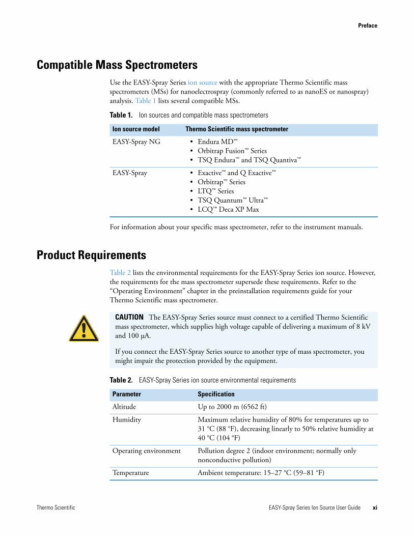
Compatible Mass SpectrometersUse the EASY-Spray Series ion source with the appropriate Thermo Scientific mass spectrometers (MSs) for nanoelectrospray (commonly referred to as nanoES or nanospray) analysis. Table 1 lists several compatible MSs.
For information about your specific mass spectrometer, refer to the instrument manuals.
Product RequirementsTable 2 lists the environmental requirements for the EASY-Spray Series ion source. However, the requirements for the mass spectrometer supersede these requirements. Refer to the “Operating Environment” chapter in the preinstallation requirements guide for your Thermo Scientific mass spectrometer.
Table 1. Ion sources and compatible mass spectrometers
Ion source model Thermo Scientific mass spectrometer
EASY-Spray NG • Endura MD™• Orbitrap Fusion™ Series • TSQ Endura™ and TSQ Quantiva™
EASY-Spray • Exactive™ and Q Exactive™ • Orbitrap™ Series • LTQ™ Series • TSQ Quantum™ Ultra™ • LCQ™ Deca XP Max
CAUTION The EASY-Spray Series source must connect to a certified Thermo Scientific mass spectrometer, which supplies high voltage capable of delivering a maximum of 8 kV and 100 μA.
If you connect the EASY-Spray Series source to another type of mass spectrometer, you might impair the protection provided by the equipment.
Table 2. EASY-Spray Series ion source environmental requirements
Parameter Specification
Altitude Up to 2000 m (6562 ft)
Humidity Maximum relative humidity of 80% for temperatures up to 31 °C (88 °F), decreasing linearly to 50% relative humidity at 40 °C (104 °F)
Operating environment Pollution degree 2 (indoor environment; normally only nonconductive pollution)
Temperature Ambient temperature: 15–27 °C (59–81 °F)
Preface
xii EASY-Spray Series Ion Source User Guide Thermo Scientific
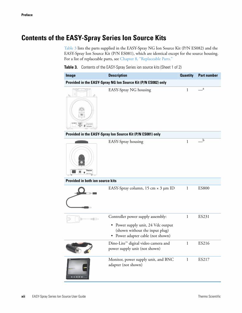
Contents of the EASY-Spray Series Ion Source KitsTable 3 lists the parts supplied in the EASY-Spray NG Ion Source Kit (P/N ES082) and the EASY-Spray Ion Source Kit (P/N ES081), which are identical except for the source housing. For a list of replaceable parts, see Chapter 8, “Replaceable Parts.”
Table 3. Contents of the EASY-Spray Series ion source kits (Sheet 1 of 2)
Image Description Quantity Part number
Provided in the EASY-Spray NG Ion Source Kit (P/N ES082) only
EASY-Spray NG housing 1 —a
Provided in the EASY-Spray Ion Source Kit (P/N ES081) only
EASY-Spray housing 1 —b
Provided in both ion source kits
EASY-Spray column, 15 cm × 3 μm ID 1 ES800
Controller power supply assembly:
• Power supply unit, 24 Vdc output (shown without the input plug)
• Power adapter cable (not shown)
1 ES231
Dino-Lite™ digital video camera and power supply unit (not shown)
1 ES216
Monitor, power supply unit, and BNC adapter (not shown)
1 ES217
EASY Spray
Actual temperature Set temperature
Heater
40 45
OFF C 60
35 50
30 55
C
Preface
Thermo Scientific EASY-Spray Series Ion Source User Guide xiii
Cautions and Special NoticesMake sure that you follow the cautions and special notices presented in this guide. Cautions and special notices appear in boxes; those concerning safety or possible damage also have corresponding caution symbols.
This guide uses the following types of cautions and special notices.
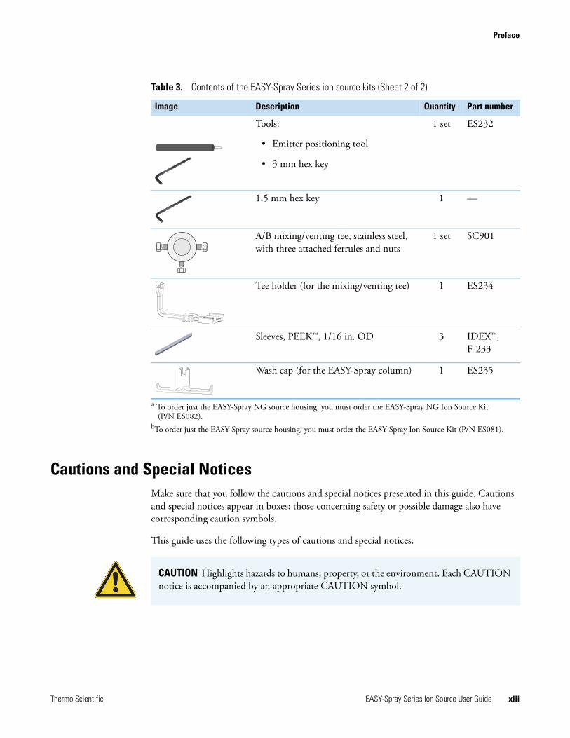
Tools:
• Emitter positioning tool
• 3 mm hex key
1 set ES232
1.5 mm hex key 1 —
A/B mixing/venting tee, stainless steel, with three attached ferrules and nuts
1 set SC901
Tee holder (for the mixing/venting tee) 1 ES234
Sleeves, PEEK™, 1/16 in. OD 3 IDEX™, F-233
Wash cap (for the EASY-Spray column) 1 ES235
a To order just the EASY-Spray NG source housing, you must order the EASY-Spray NG Ion Source Kit (P/N ES082).
bTo order just the EASY-Spray source housing, you must order the EASY-Spray Ion Source Kit (P/N ES081).
Table 3. Contents of the EASY-Spray Series ion source kits (Sheet 2 of 2)
Image Description Quantity Part number
CAUTION Highlights hazards to humans, property, or the environment. Each CAUTION notice is accompanied by an appropriate CAUTION symbol.
Preface
xiv EASY-Spray Series Ion Source User Guide Thermo Scientific
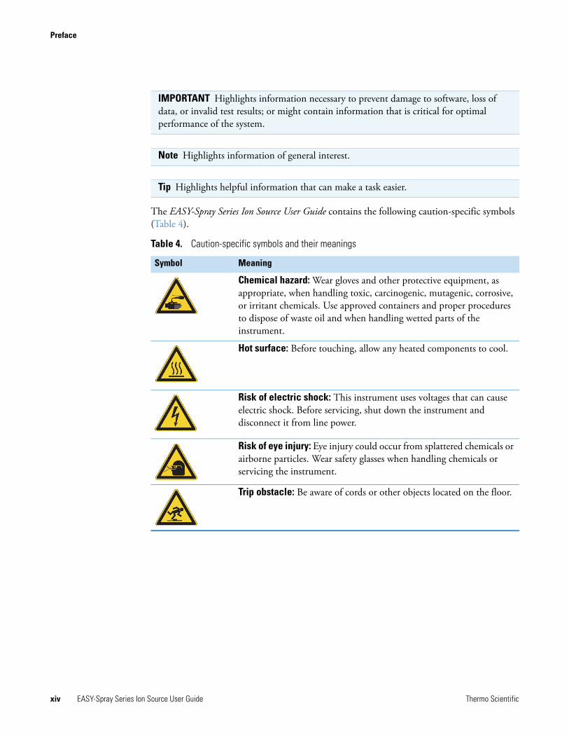
The EASY-Spray Series Ion Source User Guide contains the following caution-specific symbols (Table 4).
IMPORTANT Highlights information necessary to prevent damage to software, loss of data, or invalid test results; or might contain information that is critical for optimal performance of the system.
Note Highlights information of general interest.
Tip Highlights helpful information that can make a task easier.
Table 4. Caution-specific symbols and their meanings
Symbol Meaning
Chemical hazard: Wear gloves and other protective equipment, as appropriate, when handling toxic, carcinogenic, mutagenic, corrosive, or irritant chemicals. Use approved containers and proper procedures to dispose of waste oil and when handling wetted parts of the instrument.
Hot surface: Before touching, allow any heated components to cool.
Risk of electric shock: This instrument uses voltages that can cause electric shock. Before servicing, shut down the instrument and disconnect it from line power.
Risk of eye injury: Eye injury could occur from splattered chemicals or airborne particles. Wear safety glasses when handling chemicals or servicing the instrument.
Trip obstacle: Be aware of cords or other objects located on the floor.
Preface
Thermo Scientific EASY-Spray Series Ion Source User Guide xv
Contacting UsThere are several ways to contact Thermo Fisher Scientific for the information you need. You can use your smartphone to scan a QR code, which opens your email application or browser.
Contact us Customer Service and Sales Technical Support
(U.S.) 1 (800) 532-4752 (U.S.) 1 (800) 532-4752
(U.S.) 1 (561) 688-8731 (U.S.) 1 (561) 688-8736
To find global contact information or customize your request
1. Go to www.thermoscientific.com.
2. Click Contact Us, select the Using/Servicing a Product option, and then type the product name.
3. Use the phone number, email address, or online form.
To find product support, knowledge bases, and resources
Go to www.thermoscientific.com/support.
To find product information
Go to www.thermoscientific.com/lc-ms.
Note To provide feedback for this document:
• Send an email message to Technical Publications ([email protected]).
• Complete a survey at www.surveymonkey.com/s/PQM6P62.

Preface
xvi EASY-Spray Series Ion Source User Guide Thermo Scientific
Thermo Scientific EASY-Spray Series Ion Source User Guide 1
1
Introduction
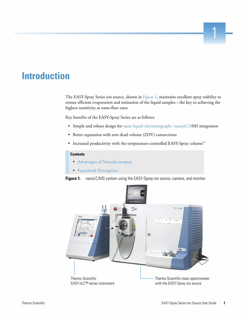
The EASY-Spray Series ion source, shown in Figure 1, maintains excellent spray stability to ensure efficient evaporation and ionization of the liquid samples—the key to achieving the highest sensitivity at nano-flow rates.
Key benefits of the EASY-Spray Series are as follows:
• Simple and robust design for nano liquid chromatography (nanoLC)/MS integration
• Better separation with zero dead volume (ZDV) connections
• Increased productivity with the temperature-controlled EASY-Spray column™
Figure 1. nanoLC/MS system using the EASY-Spray ion source, camera, and monitor
Contents
• Advantages of Nanoelectrospray
• Functional Description
Thermo Scientific EASY-nLC™ series instrument
Thermo Scientific mass spectrometer with the EASY-Spray ion source
1 IntroductionAdvantages of Nanoelectrospray
2 EASY-Spray Series Ion Source User Guide Thermo Scientific
Advantages of NanoelectrosprayThe use of electrospray (ESI) has evolved as a leading technique for generating intact, gas-phase ions from thermally labile, polar analytes in solution. In this technique, an emitter (a capillary tube or needle) induces ionization at a controlled distance from a counter electrode. Direct current (dc) voltage is applied, either to the needle or to the solvent, to produce a strong electrical field at the emitter tip. The electric field excites the ions in the solution as they leave the emitter tip. This interaction results in electrohydrodynamic disintegration of the fluid, generation of droplets, and formation of an aerosol jet.
Conventional ESI employs flow rates from 1 μL/min to 1 mL/min. Expediting desolvation and droplet shrinkage often requires a drying gas, thermal heating, or both, due to the high volume of liquid that exits the emitter. Nanospray ionization (NSI), also known as nanoelectrospray ionization (nanoESI or NSI), is a form of ESI that employs low rates of 10–1000 nL/min. NSI (or nanoESI) generally does not require a drying gas or thermal heating. Compared with ESI, NSI tolerates a wider range of liquid compositions including pure water.
As you lower the flow rate, a lower volume of mobile phase passes through the emitter, producing smaller aerosol droplets. This makes NSI more effective than conventional ESI at concentrating the analyte at the emitter tip, producing significant increases in sensitivity demonstrated by the signal response of the mass spectrometer.
Functional DescriptionThis section describes the following principal components of the EASY-Spray Series source and their functions:
• Source Housing
• Controller PCB
• Controller Power Supply
Note The mass spectrometer’s instrument control application uses the terms nanospray and NSI.
1 IntroductionFunctional Description
Thermo Scientific EASY-Spray Series Ion Source User Guide 3
Source Housing
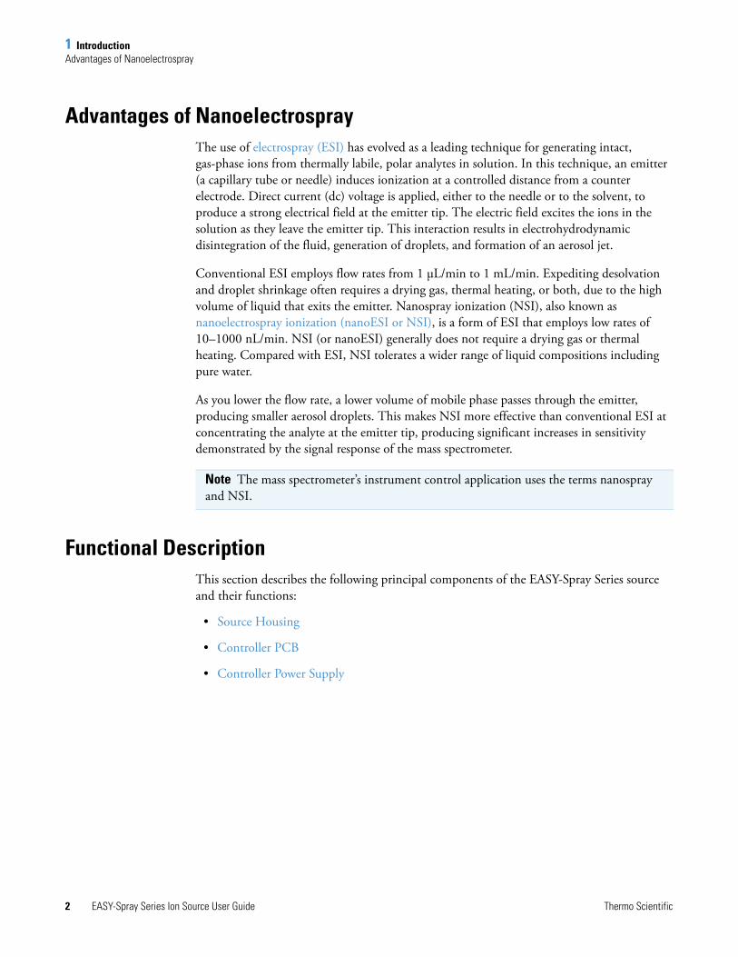
The EASY-Spray Series source housing (Figure 2 or Figure 3) arrives assembled and is easy to install on the appropriate mass spectrometer (see Table 1 on page xi). The source housing includes two locking levers, two observation windows, a position-adjustable column holder, and a controller printed circuit board (PCB). For installation instructions, see “Installing the Ion Source onto the Mass Spectrometer” on page 8.
Figure 2. EASY-Spray NG source housing (P/N ES082)
Figure 3. EASY-Spray source housing (P/N ES081)
Source housing
Column holder
Opening for the camera
Source housing
Column holder
Opening for the camera
1 IntroductionFunctional Description
4 EASY-Spray Series Ion Source User Guide Thermo Scientific
Using the top and front observation windows, you can view the tip of the emitter positioning tool while you move it into position. To enhance your view of the tool and then later of the emitter, connect the digital video camera and LCD monitor. For instructions, see Chapter 3, “Connecting the LCD Monitor and Video Camera.”
The column holder is mounted onto the front observation window and includes a position control knob. Use the control knob to align the z axis (front-to-back) of the emitter positioning tool (Figure 14 on page 15) with the mass spectrometer’s ion transfer tube. To align the tool’s x-axis (side-to-side) and y-axis position (up-and-down), use the controls that are built into the EASY-Spray Series housing. For instructions, see “Adjusting the Emitter Tip Position” on page 15.
Controller PCB
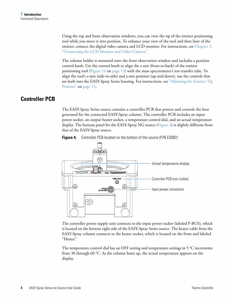
The EASY-Spray Series source contains a controller PCB that powers and controls the heat generated for the connected EASY-Spray column. The controller PCB includes an input power socket, an output heater socket, a temperature control dial, and an actual temperature display. The bottom panel for the EASY-Spray NG source (Figure 4) is slightly different from that of the EASY-Spray source.
Figure 4. Controller PCB located on the bottom of the source (P/N ES082)
The controller power supply unit connects to the input power socket (labeled P-BUS), which is located on the bottom right side of the EASY-Spray Series source. The heater cable from the EASY-Spray column connects to the heater socket, which is located on the front and labeled “Heater.”
The temperature control dial has an OFF setting and temperature settings in 5 °C increments from 30 through 60 °C. As the column heats up, the actual temperature appears on the display.
Input power connection
Actual temperature display
Controller PCB (not visible)
1 IntroductionFunctional Description
Thermo Scientific EASY-Spray Series Ion Source User Guide 5
Controller Power Supply
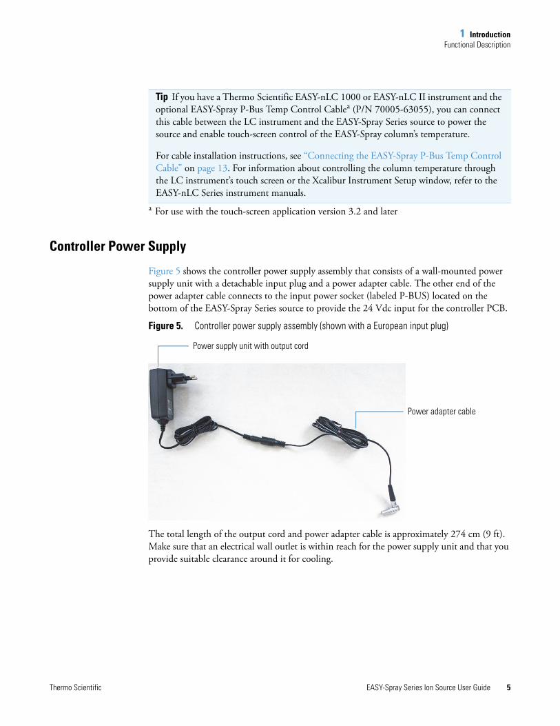
Figure 5 shows the controller power supply assembly that consists of a wall-mounted power supply unit with a detachable input plug and a power adapter cable. The other end of the power adapter cable connects to the input power socket (labeled P-BUS) located on the bottom of the EASY-Spray Series source to provide the 24 Vdc input for the controller PCB.
Figure 5. Controller power supply assembly (shown with a European input plug)
The total length of the output cord and power adapter cable is approximately 274 cm (9 ft). Make sure that an electrical wall outlet is within reach for the power supply unit and that you provide suitable clearance around it for cooling.
Tip If you have a Thermo Scientific EASY-nLC 1000 or EASY-nLC II instrument and the optional EASY-Spray P-Bus Temp Control Cablea (P/N 70005-63055), you can connect this cable between the LC instrument and the EASY-Spray Series source to power the source and enable touch-screen control of the EASY-Spray column’s temperature.
For cable installation instructions, see “Connecting the EASY-Spray P-Bus Temp Control Cable” on page 13. For information about controlling the column temperature through the LC instrument’s touch screen or the Xcalibur Instrument Setup window, refer to the EASY-nLC Series instrument manuals.
a For use with the touch-screen application version 3.2 and later
Power adapter cable
Power supply unit with output cord

1 IntroductionFunctional Description
6 EASY-Spray Series Ion Source User Guide Thermo Scientific
Thermo Scientific EASY-Spray Series Ion Source User Guide 7
2
Installing the EASY-Spray Series Ion Source
Follow these procedures to install or remove the EASY-Spray Series ion source. The only tool required is the 3 mm hex key.
Note The complete EASY-Spray Series source installation, including the digital camera and LCD monitor, requires three electrical wall outlets. Ensure that your lab has the appropriate outlets near the nanoLC/MS system.
Contents
• Installing the Ion Source onto the Mass Spectrometer
• Connecting the Controller Power Supply
• Configuring the Venting Tee Holder
• Adjusting the Emitter Tip Position
• Removing the EASY-Spray Series Source
2 Installing the EASY-Spray Series Ion SourceInstalling the Ion Source onto the Mass Spectrometer
8 EASY-Spray Series Ion Source User Guide Thermo Scientific
Installing the Ion Source onto the Mass SpectrometerBefore you install the EASY-Spray Series source, follow the procedure to prepare the mass spectrometer.
To prepare the mass spectrometer
1. If any other source is installed, remove it from the mass spectrometer after it has cooled to room temperature.
For instructions, refer to the mass spectrometer’s documentation.
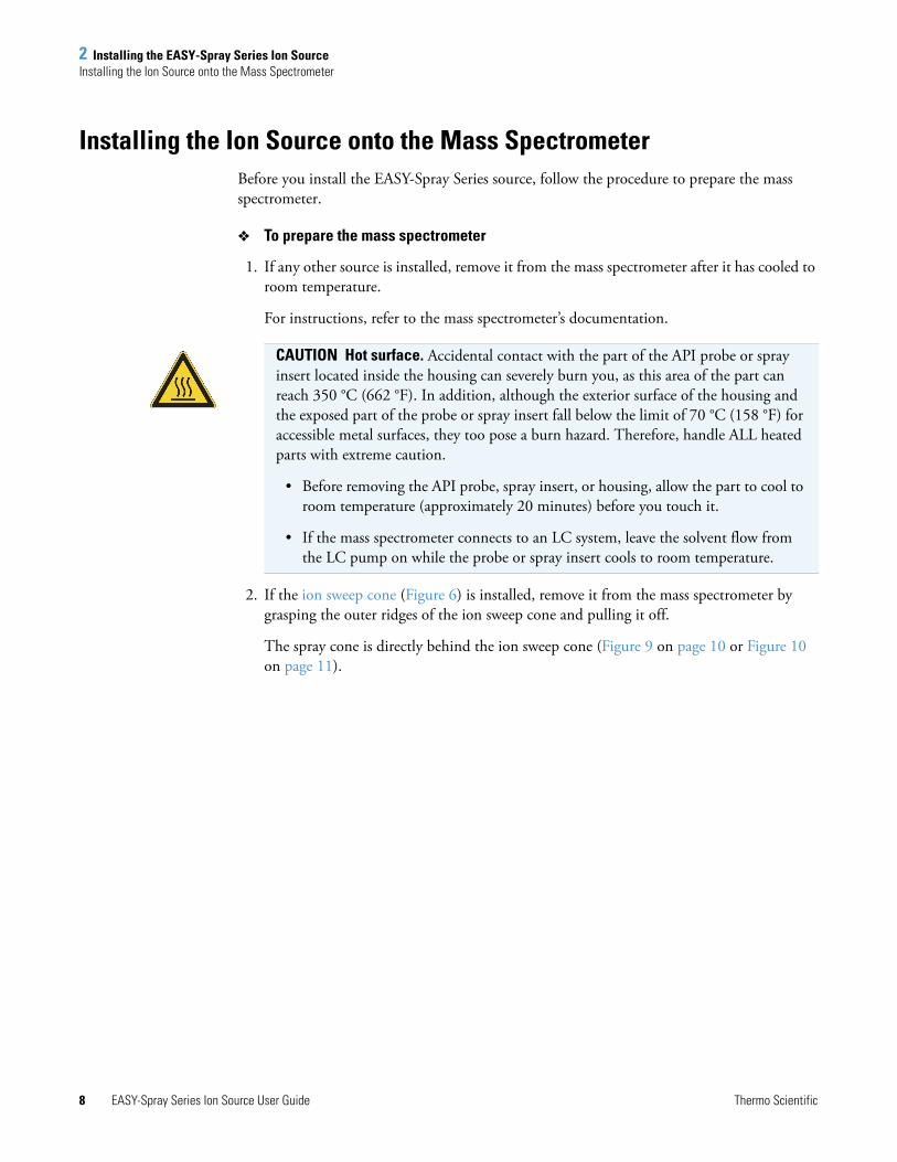
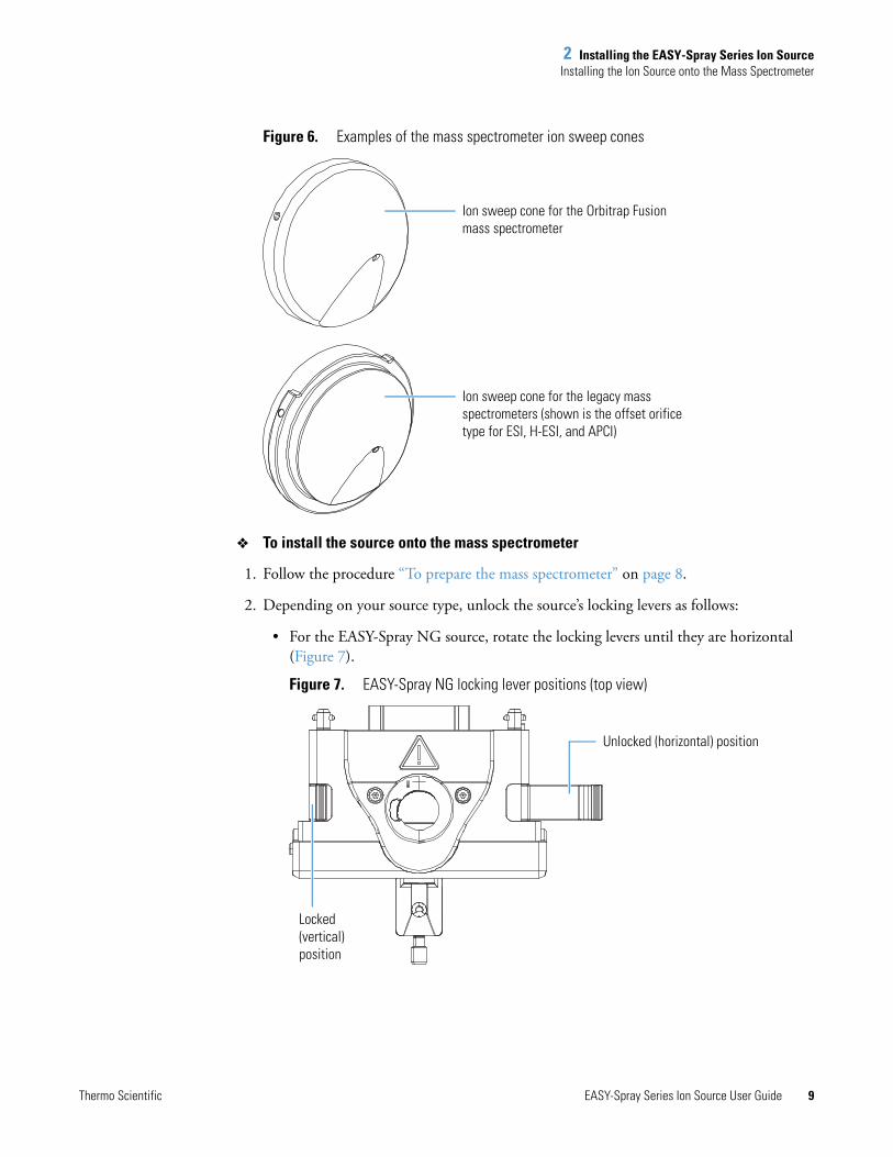
2. If the ion sweep cone (Figure 6) is installed, remove it from the mass spectrometer by grasping the outer ridges of the ion sweep cone and pulling it off.
The spray cone is directly behind the ion sweep cone (Figure 9 on page 10 or Figure 10 on page 11).
CAUTION Hot surface. Accidental contact with the part of the API probe or spray insert located inside the housing can severely burn you, as this area of the part can reach 350 °C (662 °F). In addition, although the exterior surface of the housing and the exposed part of the probe or spray insert fall below the limit of 70 °C (158 °F) for accessible metal surfaces, they too pose a burn hazard. Therefore, handle ALL heated parts with extreme caution.
• Before removing the API probe, spray insert, or housing, allow the part to cool to room temperature (approximately 20 minutes) before you touch it.
• If the mass spectrometer connects to an LC system, leave the solvent flow from the LC pump on while the probe or spray insert cools to room temperature.
2 Installing the EASY-Spray Series Ion SourceInstalling the Ion Source onto the Mass Spectrometer
Thermo Scientific EASY-Spray Series Ion Source User Guide 9
Figure 6. Examples of the mass spectrometer ion sweep cones
To install the source onto the mass spectrometer
1. Follow the procedure “To prepare the mass spectrometer” on page 8.
2. Depending on your source type, unlock the source’s locking levers as follows:
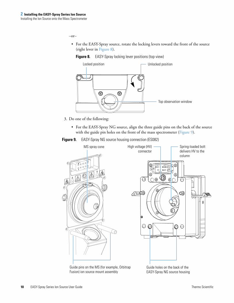
• For the EASY-Spray NG source, rotate the locking levers until they are horizontal (Figure 7).
Figure 7. EASY-Spray NG locking lever positions (top view)
Ion sweep cone for the Orbitrap Fusion mass spectrometer
Ion sweep cone for the legacy mass spectrometers (shown is the offset orifice type for ESI, H-ESI, and APCI)
Unlocked (horizontal) position
Locked (vertical) position
2 Installing the EASY-Spray Series Ion SourceInstalling the Ion Source onto the Mass Spectrometer
10 EASY-Spray Series Ion Source User Guide Thermo Scientific
–or–
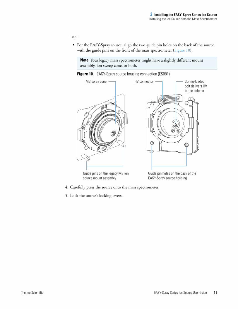
• For the EASY-Spray source, rotate the locking levers toward the front of the source (right lever in Figure 8).
Figure 8. EASY-Spray locking lever positions (top view)
3. Do one of the following:
• For the EASY-Spray NG source, align the three guide pins on the back of the source with the guide pin holes on the front of the mass spectrometer (Figure 9).
Figure 9. EASY-Spray NG source housing connection (ES082)
Unlocked positionLocked position
Top observation window
Guide holes on the back of the EASY-Spray NG source housing
Guide pins on the MS (for example, Orbitrap Fusion) ion source mount assembly
Spring-loaded bolt delivers HV to the column
MS spray cone High voltage (HV)connector
2 Installing the EASY-Spray Series Ion SourceInstalling the Ion Source onto the Mass Spectrometer
Thermo Scientific EASY-Spray Series Ion Source User Guide 11
–or–
• For the EASY-Spray source, align the two guide pin holes on the back of the source with the guide pins on the front of the mass spectrometer (Figure 10).
Figure 10. EASY-Spray source housing connection (ES081)
4. Carefully press the source onto the mass spectrometer.
5. Lock the source’s locking levers.
Note Your legacy mass spectrometer might have a slightly different mount assembly, ion sweep cone, or both.
Guide pins on the legacy MS ion source mount assembly
Guide pin holes on the back of the EASY-Spray source housing
MS spray cone Spring-loaded bolt delivers HV to the column
HV connector

2 Installing the EASY-Spray Series Ion SourceConnecting the Controller Power Supply
12 EASY-Spray Series Ion Source User Guide Thermo Scientific
Connecting the Controller Power SupplyIf the LC instrument includes the EASY-Spray P-Bus Temp Control Cable (P/N 70005-63055), you can skip this section and go to Connecting the EASY-Spray P-Bus Temp Control Cable.
To connect the controller power supply unit
1. Turn the temperature dial on the EASY-Spray Series source to the OFF position.
2. If not already connected, connect the detachable input plug and power adapter cable to the power supply unit (Figure 5 on page 5).
3. Plug the power supply unit into an electrical wall outlet.
4. Connect the power adapter cable to the P-BUS socket located on the bottom, right side of the source (Figure 17 on page 17) as follows:
a. Align the red dot on the plug with the red dot on the socket, which is on the right side of the socket (Figure 11).
Figure 11. Power connection for the controller PCB (bottom view)
b. Push the plug upward into the socket.
CAUTION To avoid an electric shock, always use the detachable input plug that is appropriate for your country or region and comes with the power supply unit.
Red dot on the socket
Red dot on the plug
CAUTION After completing the power supply connections, route the output cord so that it is not a trip hazard.
2 Installing the EASY-Spray Series Ion SourceConnecting the EASY-Spray P-Bus Temp Control Cable
Thermo Scientific EASY-Spray Series Ion Source User Guide 13
Connecting the EASY-Spray P-Bus Temp Control CableIf you have the optional EASY-Spray P-Bus Temp Control Cable (P/N 70005-63055) and an EASY-nLC 1000 or EASY-nLC II instrument, use this cable to control the EASY-Spray column temperature and provide power to the EASY-Spray Series source. This cable replaces the use of the controller power supply unit.
To connect the EASY-Spray P-Bus Temp Control Cable
1. Connect one end of the cable to the P-BUS socket on the back of the LC instrument.
2. Connect the other end of the cable to the P-BUS socket on the bottom of the source.
Configuring the Venting Tee Holder
Use this procedure to configure the (venting) Tee holder before inserting the emitter positioning tool or the EASY-Spray column.
Follow these procedures, as applicable:
• To install the optional Tee holder under the column holder
• To configure the Tee holder
To install the optional Tee holder under the column holder
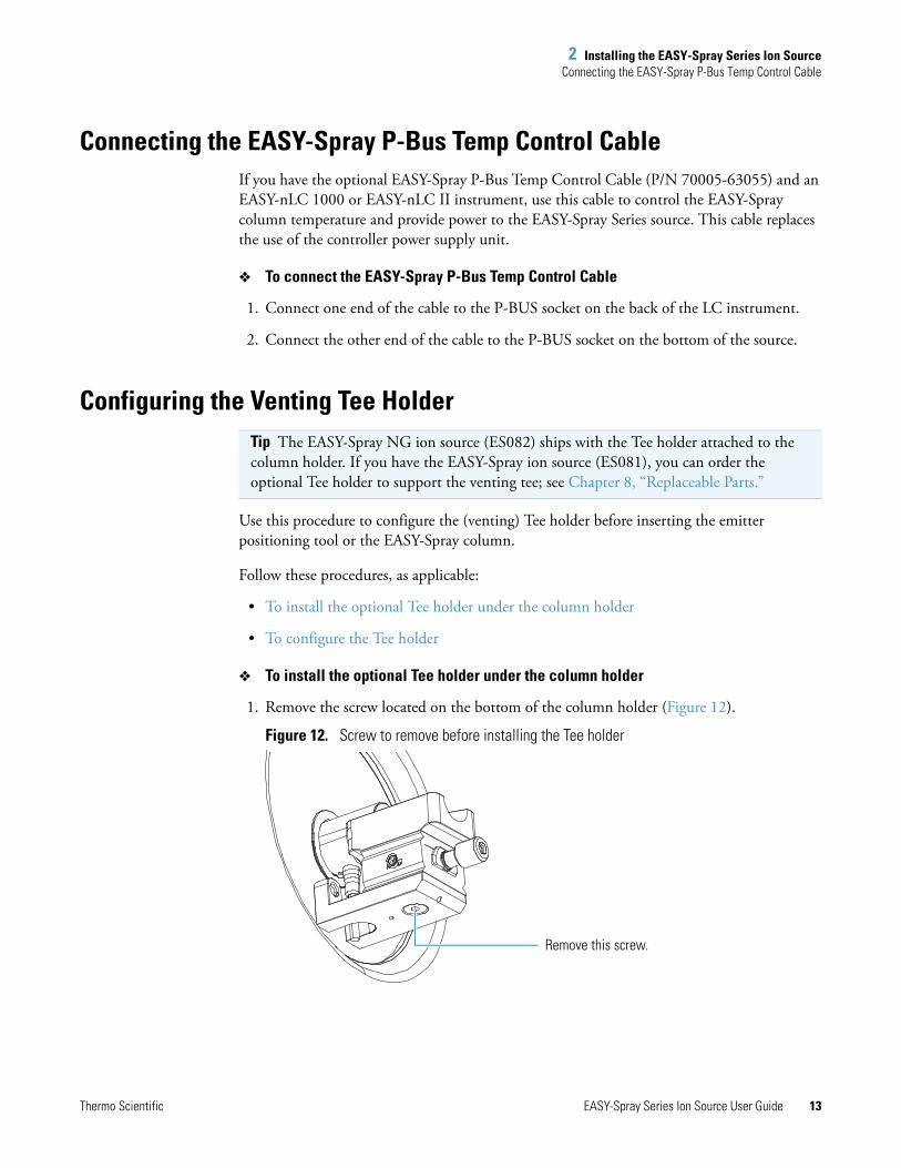
1. Remove the screw located on the bottom of the column holder (Figure 12).
Figure 12. Screw to remove before installing the Tee holder
Tip The EASY-Spray NG ion source (ES082) ships with the Tee holder attached to the column holder. If you have the EASY-Spray ion source (ES081), you can order the optional Tee holder to support the venting tee; see Chapter 8, “Replaceable Parts.”
Remove this screw.
2 Installing the EASY-Spray Series Ion SourceConfiguring the Venting Tee Holder
14 EASY-Spray Series Ion Source User Guide Thermo Scientific
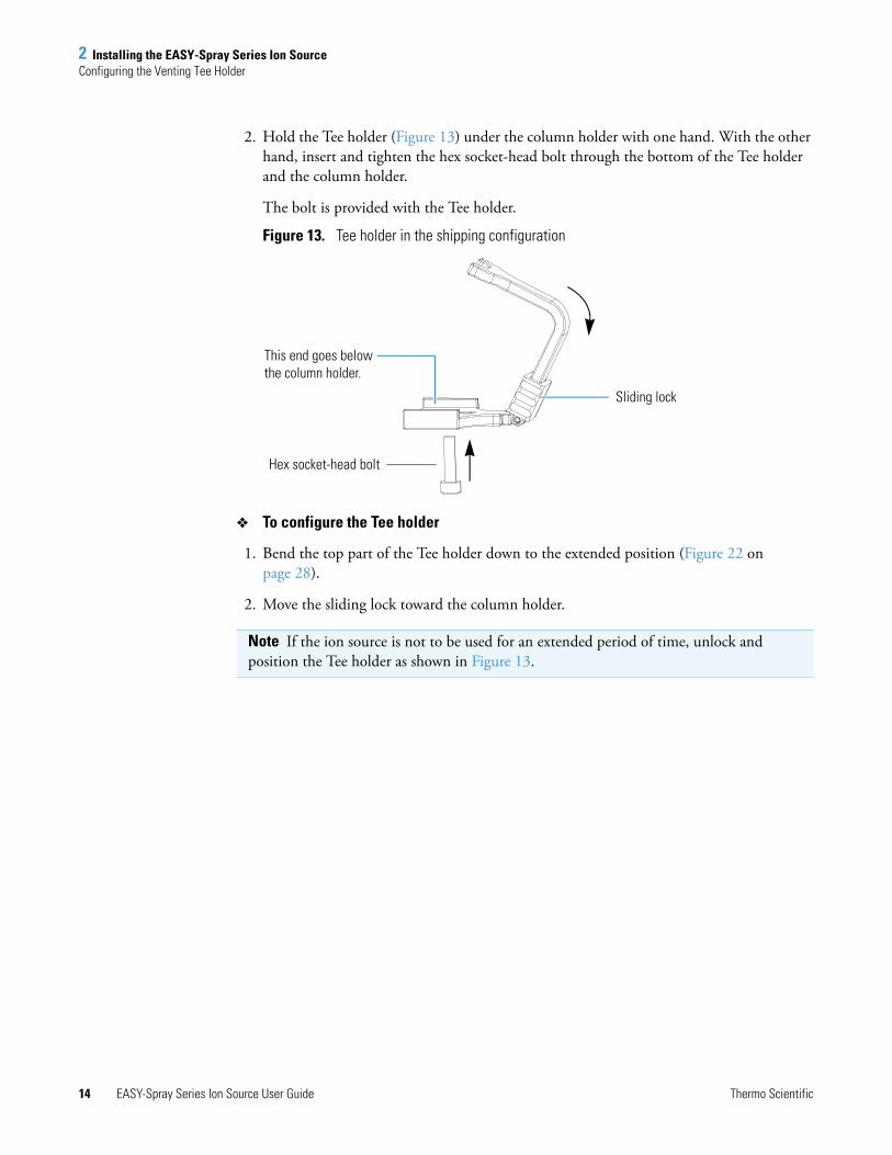
2. Hold the Tee holder (Figure 13) under the column holder with one hand. With the other hand, insert and tighten the hex socket-head bolt through the bottom of the Tee holder and the column holder.
The bolt is provided with the Tee holder.
Figure 13. Tee holder in the shipping configuration
To configure the Tee holder
1. Bend the top part of the Tee holder down to the extended position (Figure 22 on page 28).
2. Move the sliding lock toward the column holder.
Note If the ion source is not to be used for an extended period of time, unlock and position the Tee holder as shown in Figure 13.
This end goes below the column holder.
Hex socket-head bolt
Sliding lock
2 Installing the EASY-Spray Series Ion SourceAdjusting the Emitter Tip Position
Thermo Scientific EASY-Spray Series Ion Source User Guide 15
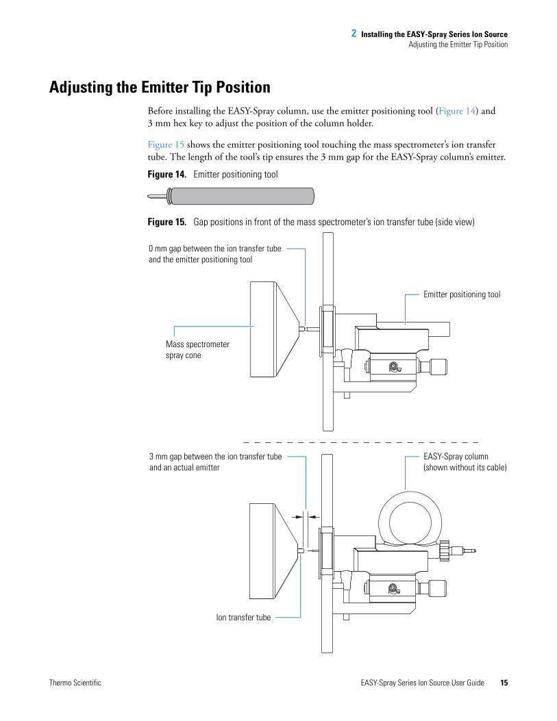
Adjusting the Emitter Tip PositionBefore installing the EASY-Spray column, use the emitter positioning tool (Figure 14) and 3 mm hex key to adjust the position of the column holder.
Figure 15 shows the emitter positioning tool touching the mass spectrometer’s ion transfer tube. The length of the tool’s tip ensures the 3 mm gap for the EASY-Spray column’s emitter.
Figure 14. Emitter positioning tool
Figure 15. Gap positions in front of the mass spectrometer’s ion transfer tube (side view)
0 mm gap between the ion transfer tube and the emitter positioning tool
3 mm gap between the ion transfer tube and an actual emitter
Mass spectrometer spray cone
Ion transfer tube
EASY-Spray column (shown without its cable)
Emitter positioning tool
2 Installing the EASY-Spray Series Ion SourceAdjusting the Emitter Tip Position
16 EASY-Spray Series Ion Source User Guide Thermo Scientific
To adjust the emitter tip position
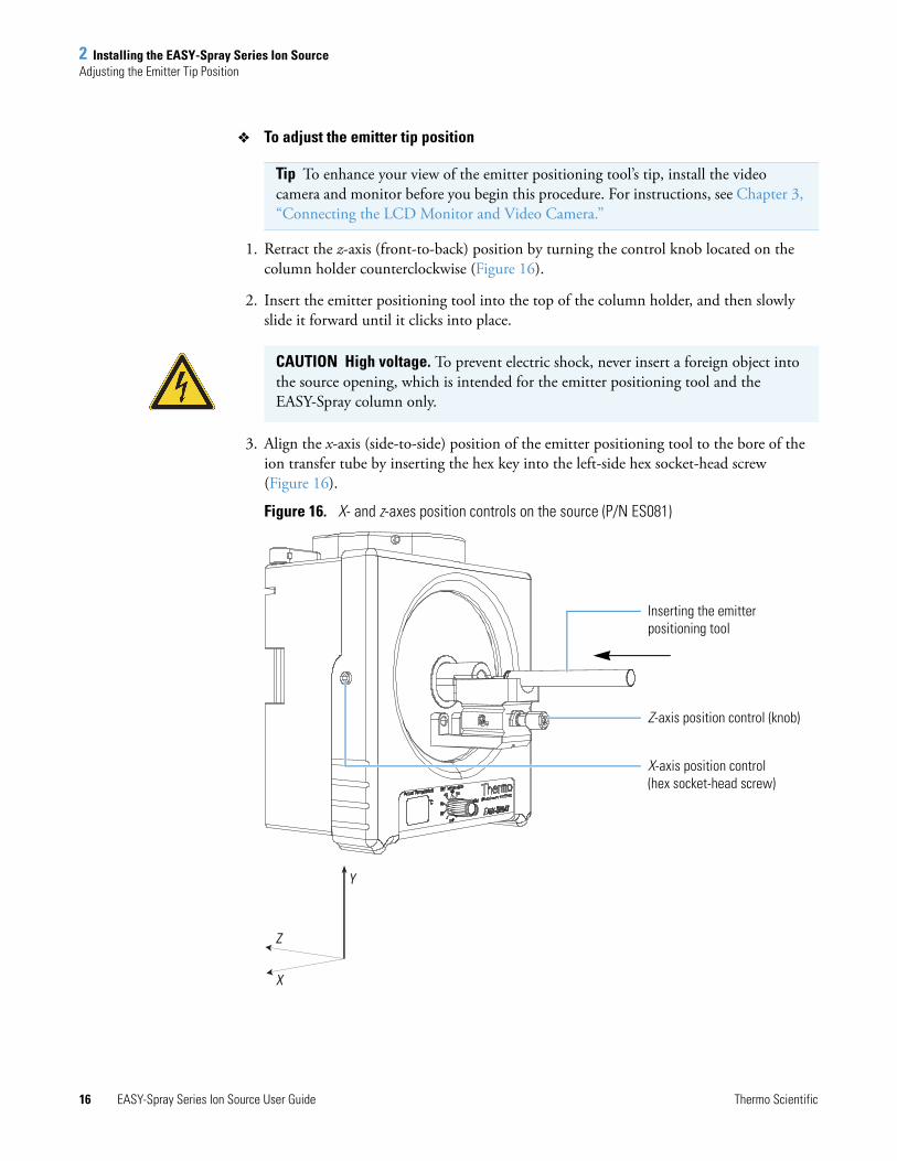
1. Retract the z-axis (front-to-back) position by turning the control knob located on the column holder counterclockwise (Figure 16).
2. Insert the emitter positioning tool into the top of the column holder, and then slowly slide it forward until it clicks into place.
3. Align the x-axis (side-to-side) position of the emitter positioning tool to the bore of the ion transfer tube by inserting the hex key into the left-side hex socket-head screw (Figure 16).
Figure 16. X- and z-axes position controls on the source (P/N ES081)
Tip To enhance your view of the emitter positioning tool’s tip, install the video camera and monitor before you begin this procedure. For instructions, see Chapter 3, “Connecting the LCD Monitor and Video Camera.”
CAUTION High voltage. To prevent electric shock, never insert a foreign object into the source opening, which is intended for the emitter positioning tool and the EASY-Spray column only.
Y
Z
X
X-axis position control (hex socket-head screw)
Z-axis position control (knob)
Inserting the emitter positioning tool
2 Installing the EASY-Spray Series Ion SourceRemoving the EASY-Spray Series Source
Thermo Scientific EASY-Spray Series Ion Source User Guide 17
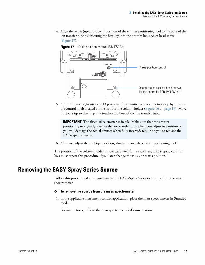
4. Align the y-axis (up-and-down) position of the emitter positioning tool to the bore of the ion transfer tube by inserting the hex key into the bottom hex socket-head screw (Figure 17).
Figure 17. Y-axis position control (P/N ES082)
5. Adjust the z-axis (front-to-back) position of the emitter positioning tool’s tip by turning the control knob located on the front of the column holder (Figure 16 on page 16). Move the tool’s tip so that it gently touches the bore of the ion transfer tube.
6. After you adjust the tool tip’s position, slowly remove the emitter positioning tool.
The position of the column holder is now calibrated for use with any EASY-Spray column. You must repeat this procedure if you later change the x-, y-, or z-axis position.
Removing the EASY-Spray Series SourceFollow this procedure if you must remove the EASY-Spray Series ion source from the mass spectrometer.
To remove the source from the mass spectrometer
1. In the applicable instrument control application, place the mass spectrometer in Standby mode.
For instructions, refer to the mass spectrometer’s documentation.
IMPORTANT The fused-silica emitter is fragile. Make sure that the emitter positioning tool gently touches the ion transfer tube when you adjust its position or you will damage the actual emitter when fully inserted, requiring you to replace the EASY-Spray column.
Y-axis position control
One of the hex socket-head screws for the controller PCB (P/N ES233)
2 Installing the EASY-Spray Series Ion SourceRemoving the EASY-Spray Series Source
18 EASY-Spray Series Ion Source User Guide Thermo Scientific
2. Turn the source’s temperature dial to the OFF position.
3. Turn off the LC instrument.
4. Disconnect the LC plumbing from the EASY-Spray column, and then remove the EASY-Spray column.
5. If the Tee holder is installed, move the sliding lock away from the column holder, and then bend the unattached end upward (Figure 13 on page 14).
6. Remove the camera as follows:
a. Unplug the camera power supply unit from the electrical wall outlet.
b. Disconnect the camera’s yellow video connector from the back of the monitor and the black power connector from the camera power supply unit.
c. Using the 1.5 mm hex key, loosen the hex socket-head screw securing the camera, and then remove the camera.
7. Do one of the following, as applicable:
• Disconnect the EASY-Spray P-Bus Temp Control Cable from the source.
• Unplug the controller power supply unit from the electrical wall outlet, and then disconnect the output cable from the source.
8. Unlock the source’s locking levers (Figure 7 on page 9 and Figure 8 on page 10).
9. Grasp the source housing with both hands and slowly pull it away from the mass spectrometer.
After you remove the EASY-Spray Series ion source from the mass spectrometer, place it in its original shipping box. The EASY-Spray Series source does not require cleaning.
CAUTION Hot surface. The maximum safety limit for heated surfaces is 70 °C (158 °F). Although the surface temperature of the EASY-Spray Series ion source falls below this maximum, it can still severely burn you, reaching approximately 50 °C (122 °F) with the heater unit turned on. Allow the source to cool to room temperature (approximately 20 minutes) before you touch it.
Tip Do not pull on the cable from the EASY-Spray column. Use the plug to disconnect the column from the heater socket.

Thermo Scientific EASY-Spray Series Ion Source User Guide 19
3
Connecting the LCD Monitor and Video Camera
Follow these procedures to connect the LCD monitor and digital video camera, and to adjust the video picture. The only tool required is the 1.5 mm hex key.
Connecting the Monitor and CameraTo enhance your view of the emitter tip, install the provided LCD monitor and digital video camera (see Table 3 on page xii).
To connect the monitor and camera
1. Follow the procedure “To install the source onto the mass spectrometer” on page 9.
2. Plug the two power supply units into electrical wall outlets.
3. Install the camera as follows:
a. Insert the camera into the opening above the top observation window with the focusing wheel facing toward you (Figure 18).
b. Using the 1.5 mm hex key, tighten the hex socket-head screw on the left side of the top observation window (Figure 16 on page 16) until it touches the camera—do not overtighten the screw.
c. Connect the camera’s black power connector to its power supply unit.
Contents
• Connecting the Monitor and Camera
• Adjusting the Video Picture
3 Connecting the LCD Monitor and Video CameraConnecting the Monitor and Camera
20 EASY-Spray Series Ion Source User Guide Thermo Scientific
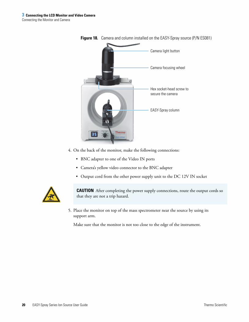
Figure 18. Camera and column installed on the EASY-Spray source (P/N ES081)
4. On the back of the monitor, make the following connections:
• BNC adapter to one of the Video IN ports
• Camera’s yellow video connector to the BNC adapter
• Output cord from the other power supply unit to the DC 12V IN socket
5. Place the monitor on top of the mass spectrometer near the source by using its support arm.
Make sure that the monitor is not too close to the edge of the instrument.
Camera focusing wheel
Camera light button
Hex socket-head screw to secure the camera
EASY-Spray column
CAUTION After completing the power supply connections, route the output cords so that they are not a trip hazard.
3 Connecting the LCD Monitor and Video CameraAdjusting the Video Picture
Thermo Scientific EASY-Spray Series Ion Source User Guide 21
Adjusting the Video PictureUse this procedure to focus the picture from the video camera. For additional information, refer to the manuals for the monitor and camera.
To adjust the video picture
1. Follow the procedure “To connect the monitor and camera” on page 19.
2. Turn on the monitor by pressing its POWER button.
The picture appears after a few seconds and is probably blurred. If there is no picture, press the monitor’s SOURCE button to change to the other video input channel.
3. If the picture is too dark, press the light button at the top of the camera (Figure 18 on page 20).
4. Adjust the picture by using the camera’s focusing wheel (Figure 18 on page 20).

3 Connecting the LCD Monitor and Video CameraAdjusting the Video Picture
22 EASY-Spray Series Ion Source User Guide Thermo Scientific
Thermo Scientific EASY-Spray Series Ion Source User Guide 23
4
Connecting the EASY-Spray Column Plumbing
Follow these procedures to connect the plumbing from the Thermo Scientific LC instrument to the EASY-Spray column.
Tools and SuppliesTable 5 lists the required tools and supplies for configuring the LC plumbing and EASY-Spray column connections. Not all parts are required.
Contents
• Tools and Supplies
• Installing the EASY-Spray Column for the First Time
• Using the nanoViper Fitting
• Connecting the LC to the EASY-Spray Column
Note The kit for the EASY-Spray Series ion source supplies the venting tee, fittings, and sleeves only. You are responsible for supplying the remaining parts and tools.
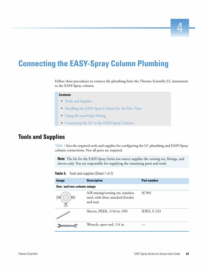
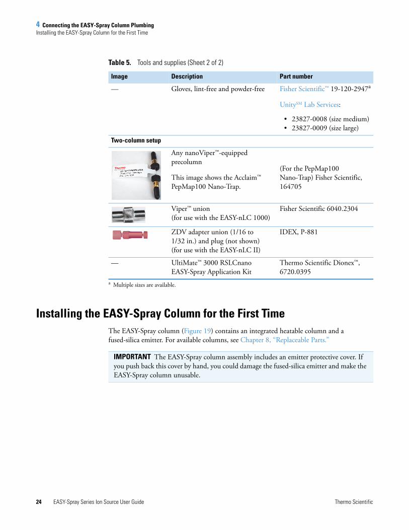
Table 5. Tools and supplies (Sheet 1 of 2)
Image Description Part number
One- and two-column setups
A/B mixing/venting tee, stainless steel, with three attached ferrules and nuts
SC901
Sleeves, PEEK, 1/16 in. OD IDEX, F-233
Wrench, open end, 1/4 in. —
4 Connecting the EASY-Spray Column PlumbingInstalling the EASY-Spray Column for the First Time
24 EASY-Spray Series Ion Source User Guide Thermo Scientific
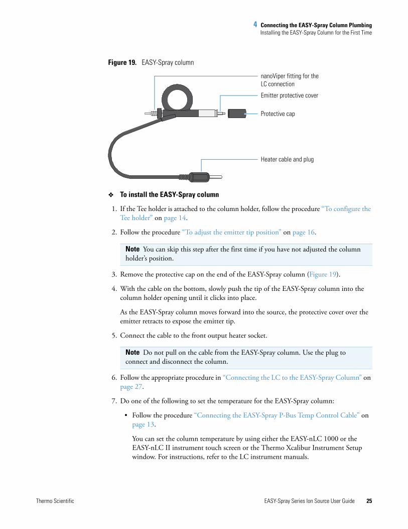
Installing the EASY-Spray Column for the First TimeThe EASY-Spray column (Figure 19) contains an integrated heatable column and a fused-silica emitter. For available columns, see Chapter 8, “Replaceable Parts.”
— Gloves, lint-free and powder-free Fisher Scientific™ 19-120-2947a
UnitySM Lab Services:
• 23827-0008 (size medium)• 23827-0009 (size large)
Two-column setup
Any nanoViper™-equipped precolumn
This image shows the Acclaim™ PepMap100 Nano-Trap.
(For the PepMap100 Nano-Trap) Fisher Scientific, 164705
Viper™ union (for use with the EASY-nLC 1000)
Fisher Scientific 6040.2304
ZDV adapter union (1/16 to 1/32 in.) and plug (not shown)(for use with the EASY-nLC II)
IDEX, P-881
— UltiMate™ 3000 RSLCnano EASY-Spray Application Kit
Thermo Scientific Dionex™, 6720.0395
a Multiple sizes are available.
Table 5. Tools and supplies (Sheet 2 of 2)
Image Description Part number
IMPORTANT The EASY-Spray column assembly includes an emitter protective cover. If you push back this cover by hand, you could damage the fused-silica emitter and make the EASY-Spray column unusable.
4 Connecting the EASY-Spray Column PlumbingInstalling the EASY-Spray Column for the First Time
Thermo Scientific EASY-Spray Series Ion Source User Guide 25
Figure 19. EASY-Spray column
To install the EASY-Spray column
1. If the Tee holder is attached to the column holder, follow the procedure “To configure the Tee holder” on page 14.
2. Follow the procedure “To adjust the emitter tip position” on page 16.
3. Remove the protective cap on the end of the EASY-Spray column (Figure 19).
4. With the cable on the bottom, slowly push the tip of the EASY-Spray column into the column holder opening until it clicks into place.
As the EASY-Spray column moves forward into the source, the protective cover over the emitter retracts to expose the emitter tip.
5. Connect the cable to the front output heater socket.
6. Follow the appropriate procedure in “Connecting the LC to the EASY-Spray Column” on page 27.
7. Do one of the following to set the temperature for the EASY-Spray column:
• Follow the procedure “Connecting the EASY-Spray P-Bus Temp Control Cable” on page 13.
You can set the column temperature by using either the EASY-nLC 1000 or the EASY-nLC II instrument touch screen or the Thermo Xcalibur Instrument Setup window. For instructions, refer to the LC instrument manuals.
Note You can skip this step after the first time if you have not adjusted the column holder’s position.
Note Do not pull on the cable from the EASY-Spray column. Use the plug to connect and disconnect the column.
Protective cap
Emitter protective cover
nanoViper fitting for the LC connection
Heater cable and plug
4 Connecting the EASY-Spray Column PlumbingUsing the nanoViper Fitting
26 EASY-Spray Series Ion Source User Guide Thermo Scientific
• Follow the procedure “Connecting the Controller Power Supply” on page 12, and use the temperature control dial on the front of the source.
Table 6 lists the display readings that can appear on the actual temperature display.
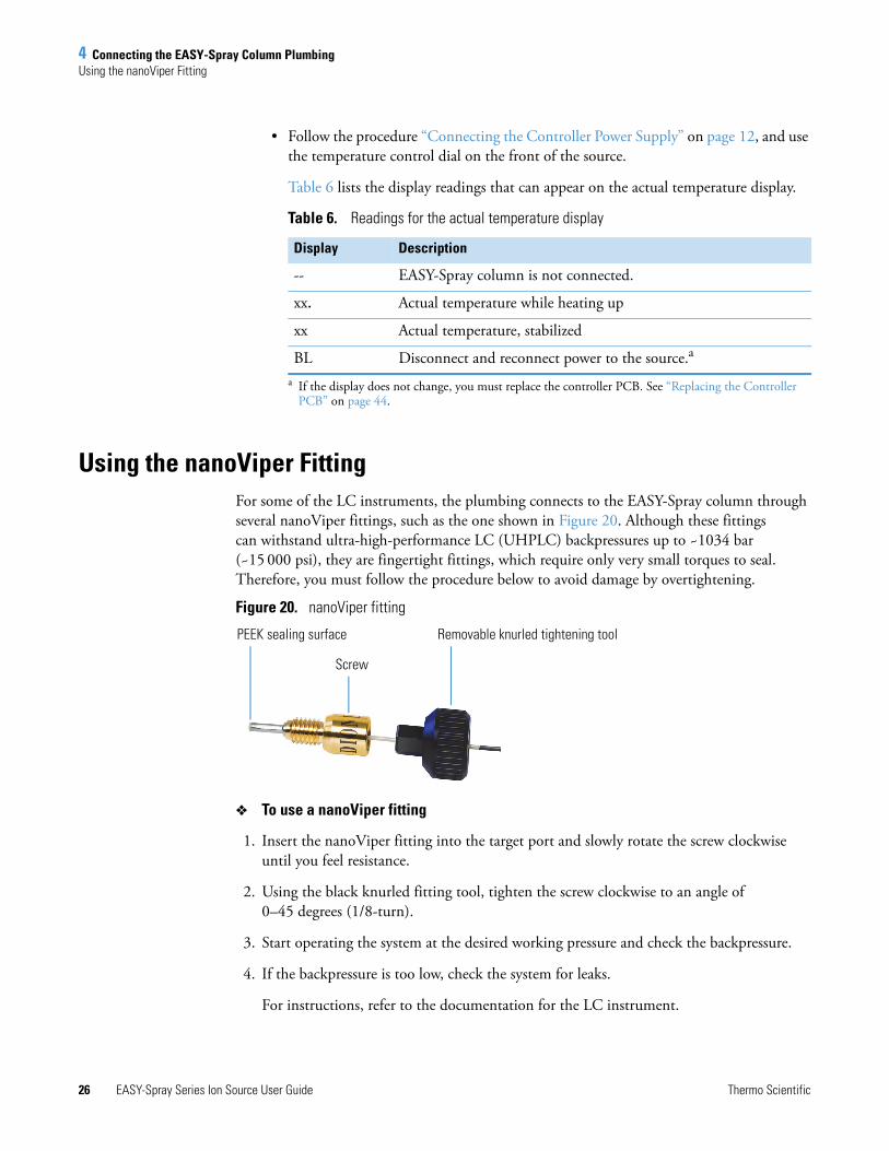
Using the nanoViper FittingFor some of the LC instruments, the plumbing connects to the EASY-Spray column through several nanoViper fittings, such as the one shown in Figure 20. Although these fittings can withstand ultra-high-performance LC (UHPLC) backpressures up to ~1034 bar (~15 000 psi), they are fingertight fittings, which require only very small torques to seal. Therefore, you must follow the procedure below to avoid damage by overtightening.
Figure 20. nanoViper fitting
To use a nanoViper fitting
1. Insert the nanoViper fitting into the target port and slowly rotate the screw clockwise until you feel resistance.
2. Using the black knurled fitting tool, tighten the screw clockwise to an angle of 0–45 degrees (1/8-turn).
3. Start operating the system at the desired working pressure and check the backpressure.
4. If the backpressure is too low, check the system for leaks.
For instructions, refer to the documentation for the LC instrument.
Table 6. Readings for the actual temperature display
Display Description
-- EASY-Spray column is not connected.
xx. Actual temperature while heating up
xx Actual temperature, stabilized
BL Disconnect and reconnect power to the source.a
a If the display does not change, you must replace the controller PCB. See “Replacing the Controller PCB” on page 44.
PEEK sealing surface Removable knurled tightening tool
Screw
4 Connecting the EASY-Spray Column PlumbingConnecting the LC to the EASY-Spray Column
Thermo Scientific EASY-Spray Series Ion Source User Guide 27
5. If the backpressure continues to be too low, return the system to atmospheric pressure.
6. Tighten the screw by as much as an additional 45 degrees. Do not turn the screw beyond an angle of 90 degrees from where you felt the initial resistance.
Connecting the LC to the EASY-Spray ColumnThis section describes how to connect the one or two plumbing lines from a nanoLC instrument to the EASY-Spray column in either a one- or two-column configuration. Table 5 on page 23 lists the required parts.
Follow the appropriate procedure:
• Connecting an EASY-nLC 1000 Instrument to the EASY-Spray Column
• Connecting an EASY-nLC II Instrument to the EASY-Spray Column, on page 30
• Connecting an RSLCnano System to the EASY-Spray Column, on page 33
Connecting an EASY-nLC 1000 Instrument to the EASY-Spray Column
Follow the appropriate procedure for a one- or two-column setup. The two-column setup includes a precolumn connected in the column-out flow path to the venting tee.
• To plumb a one-column setup from an EASY-nLC 1000 instrument
• To plumb a two-column setup from an EASY-nLC 1000 instrument, on page 29
IMPORTANT To extend the lifetime of the nanoViper fittings, open and close the connections at only atmospheric system pressures. Opening and closing connections at high system pressures can reduce the lifetime of the fittings.
IMPORTANT To prevent damage to the sealing surface of the nanoViper fitting, do not overtighten the fitting.
Note The EASY-nLC Series instruments identify the two solvent lines as “Column Out” and “Waste In.”
CAUTION Wear protective gloves and eye wear when handling the solvent lines.
Note Remove the nuts and ferrules from the venting tee.
4 Connecting the EASY-Spray Column PlumbingConnecting the LC to the EASY-Spray Column
28 EASY-Spray Series Ion Source User Guide Thermo Scientific
To plumb a one-column setup from an EASY-nLC 1000 instrument
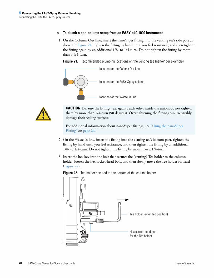
1. On the Column Out line, insert the nanoViper fitting into the venting tee’s side port as shown in Figure 21, tighten the fitting by hand until you feel resistance, and then tighten the fitting again by an additional 1/8- to 1/4-turn. Do not tighten the fitting by more than a 1/4-turn.
Figure 21. Recommended plumbing locations on the venting tee (nanoViper example)
2. On the Waste In line, insert the fitting into the venting tee’s bottom port, tighten the fitting by hand until you feel resistance, and then tighten the fitting by an additional 1/8- to 1/4-turn. Do not tighten the fitting by more than a 1/4-turn.
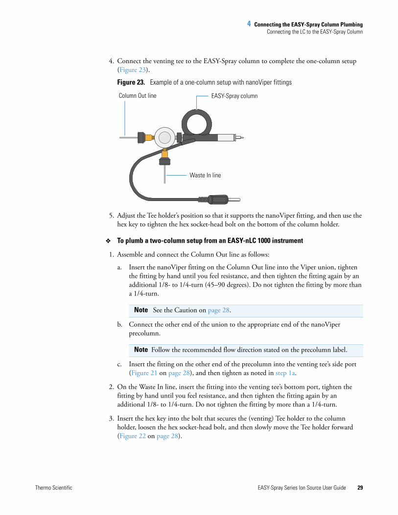
3. Insert the hex key into the bolt that secures the (venting) Tee holder to the column holder, loosen the hex socket-head bolt, and then slowly move the Tee holder forward (Figure 22).
Figure 22. Tee holder secured to the bottom of the column holder
Location for the Column Out line
Location for the EASY-Spray column
Location for the Waste In line
CAUTION Because the fittings seal against each other inside the union, do not tighten them by more than 1/4-turn (90 degrees). Overtightening the fittings can irreparably damage their sealing surfaces.
For additional information about nanoViper fittings, see “Using the nanoViper Fitting” on page 26.
Hex socket-head bolt for the Tee holder
Tee holder (extended position)
4 Connecting the EASY-Spray Column PlumbingConnecting the LC to the EASY-Spray Column
Thermo Scientific EASY-Spray Series Ion Source User Guide 29
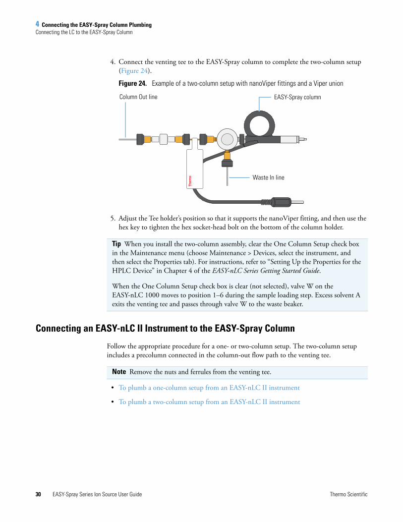
4. Connect the venting tee to the EASY-Spray column to complete the one-column setup (Figure 23).
Figure 23. Example of a one-column setup with nanoViper fittings
5. Adjust the Tee holder’s position so that it supports the nanoViper fitting, and then use the hex key to tighten the hex socket-head bolt on the bottom of the column holder.
To plumb a two-column setup from an EASY-nLC 1000 instrument
1. Assemble and connect the Column Out line as follows:
a. Insert the nanoViper fitting on the Column Out line into the Viper union, tighten the fitting by hand until you feel resistance, and then tighten the fitting again by an additional 1/8- to 1/4-turn (45–90 degrees). Do not tighten the fitting by more than a 1/4-turn.
b. Connect the other end of the union to the appropriate end of the nanoViper precolumn.
c. Insert the fitting on the other end of the precolumn into the venting tee’s side port (Figure 21 on page 28), and then tighten as noted in step 1a.
2. On the Waste In line, insert the fitting into the venting tee’s bottom port, tighten the fitting by hand until you feel resistance, and then tighten the fitting again by an additional 1/8- to 1/4-turn. Do not tighten the fitting by more than a 1/4-turn.
3. Insert the hex key into the bolt that secures the (venting) Tee holder to the column holder, loosen the hex socket-head bolt, and then slowly move the Tee holder forward (Figure 22 on page 28).
Note See the Caution on page 28.
Note Follow the recommended flow direction stated on the precolumn label.
Column Out line
Waste In line
EASY-Spray column
4 Connecting the EASY-Spray Column PlumbingConnecting the LC to the EASY-Spray Column
30 EASY-Spray Series Ion Source User Guide Thermo Scientific
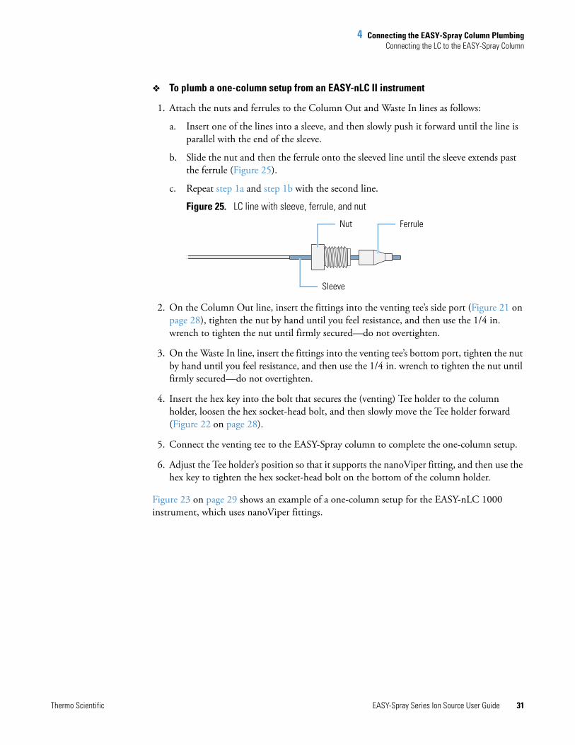
4. Connect the venting tee to the EASY-Spray column to complete the two-column setup (Figure 24).
Figure 24. Example of a two-column setup with nanoViper fittings and a Viper union
5. Adjust the Tee holder’s position so that it supports the nanoViper fitting, and then use the hex key to tighten the hex socket-head bolt on the bottom of the column holder.
Connecting an EASY-nLC II Instrument to the EASY-Spray Column
Follow the appropriate procedure for a one- or two-column setup. The two-column setup includes a precolumn connected in the column-out flow path to the venting tee.
• To plumb a one-column setup from an EASY-nLC II instrument
• To plumb a two-column setup from an EASY-nLC II instrument
Tip When you install the two-column assembly, clear the One Column Setup check box in the Maintenance menu (choose Maintenance > Devices, select the instrument, and then select the Properties tab). For instructions, refer to “Setting Up the Properties for the HPLC Device” in Chapter 4 of the EASY-nLC Series Getting Started Guide.
When the One Column Setup check box is clear (not selected), valve W on the EASY-nLC 1000 moves to position 1–6 during the sample loading step. Excess solvent A exits the venting tee and passes through valve W to the waste beaker.
Column Out line
Waste In line
EASY-Spray column
Note Remove the nuts and ferrules from the venting tee.
4 Connecting the EASY-Spray Column PlumbingConnecting the LC to the EASY-Spray Column
Thermo Scientific EASY-Spray Series Ion Source User Guide 31
To plumb a one-column setup from an EASY-nLC II instrument
1. Attach the nuts and ferrules to the Column Out and Waste In lines as follows:
a. Insert one of the lines into a sleeve, and then slowly push it forward until the line is parallel with the end of the sleeve.
b. Slide the nut and then the ferrule onto the sleeved line until the sleeve extends past the ferrule (Figure 25).
c. Repeat step 1a and step 1b with the second line.
Figure 25. LC line with sleeve, ferrule, and nut
2. On the Column Out line, insert the fittings into the venting tee’s side port (Figure 21 on page 28), tighten the nut by hand until you feel resistance, and then use the 1/4 in. wrench to tighten the nut until firmly secured—do not overtighten.
3. On the Waste In line, insert the fittings into the venting tee’s bottom port, tighten the nut by hand until you feel resistance, and then use the 1/4 in. wrench to tighten the nut until firmly secured—do not overtighten.
4. Insert the hex key into the bolt that secures the (venting) Tee holder to the column holder, loosen the hex socket-head bolt, and then slowly move the Tee holder forward (Figure 22 on page 28).
5. Connect the venting tee to the EASY-Spray column to complete the one-column setup.
6. Adjust the Tee holder’s position so that it supports the nanoViper fitting, and then use the hex key to tighten the hex socket-head bolt on the bottom of the column holder.
Figure 23 on page 29 shows an example of a one-column setup for the EASY-nLC 1000 instrument, which uses nanoViper fittings.
Nut Ferrule
Sleeve
4 Connecting the EASY-Spray Column PlumbingConnecting the LC to the EASY-Spray Column
32 EASY-Spray Series Ion Source User Guide Thermo Scientific
To plumb a two-column setup from an EASY-nLC II instrument
1. Assemble and connect the Column Out line as follows:
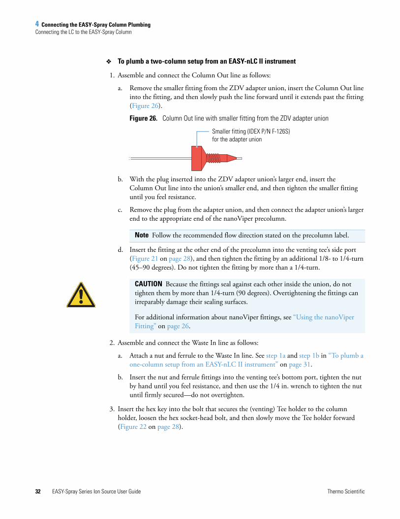
a. Remove the smaller fitting from the ZDV adapter union, insert the Column Out line into the fitting, and then slowly push the line forward until it extends past the fitting (Figure 26).
Figure 26. Column Out line with smaller fitting from the ZDV adapter union
b. With the plug inserted into the ZDV adapter union’s larger end, insert the Column Out line into the union’s smaller end, and then tighten the smaller fitting until you feel resistance.
c. Remove the plug from the adapter union, and then connect the adapter union’s larger end to the appropriate end of the nanoViper precolumn.
d. Insert the fitting at the other end of the precolumn into the venting tee’s side port (Figure 21 on page 28), and then tighten the fitting by an additional 1/8- to 1/4-turn (45–90 degrees). Do not tighten the fitting by more than a 1/4-turn.
2. Assemble and connect the Waste In line as follows:
a. Attach a nut and ferrule to the Waste In line. See step 1a and step 1b in “To plumb a one-column setup from an EASY-nLC II instrument” on page 31.
b. Insert the nut and ferrule fittings into the venting tee’s bottom port, tighten the nut by hand until you feel resistance, and then use the 1/4 in. wrench to tighten the nut until firmly secured—do not overtighten.
3. Insert the hex key into the bolt that secures the (venting) Tee holder to the column holder, loosen the hex socket-head bolt, and then slowly move the Tee holder forward (Figure 22 on page 28).
Note Follow the recommended flow direction stated on the precolumn label.
Smaller fitting (IDEX P/N F-126S) for the adapter union
CAUTION Because the fittings seal against each other inside the union, do not tighten them by more than 1/4-turn (90 degrees). Overtightening the fittings can irreparably damage their sealing surfaces.
For additional information about nanoViper fittings, see “Using the nanoViper Fitting” on page 26.
4 Connecting the EASY-Spray Column PlumbingConnecting the LC to the EASY-Spray Column
Thermo Scientific EASY-Spray Series Ion Source User Guide 33
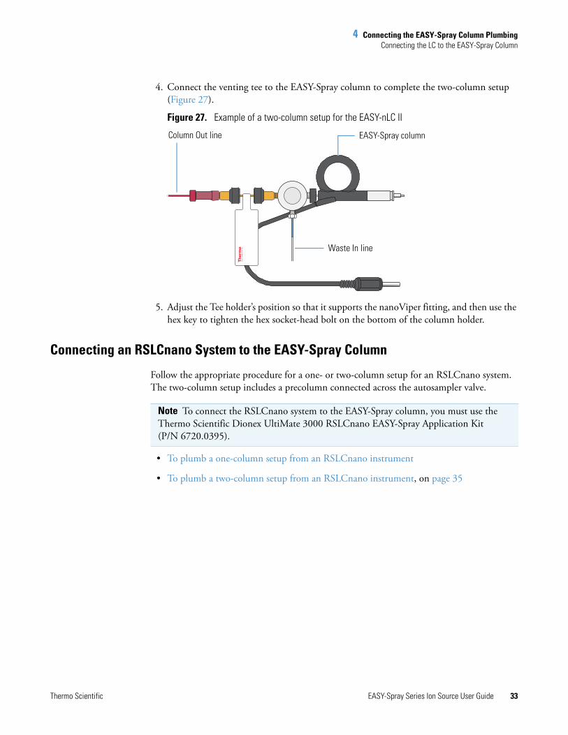
4. Connect the venting tee to the EASY-Spray column to complete the two-column setup (Figure 27).
Figure 27. Example of a two-column setup for the EASY-nLC II
5. Adjust the Tee holder’s position so that it supports the nanoViper fitting, and then use the hex key to tighten the hex socket-head bolt on the bottom of the column holder.
Connecting an RSLCnano System to the EASY-Spray Column
Follow the appropriate procedure for a one- or two-column setup for an RSLCnano system. The two-column setup includes a precolumn connected across the autosampler valve.
• To plumb a one-column setup from an RSLCnano instrument
• To plumb a two-column setup from an RSLCnano instrument, on page 35
Column Out line
Waste In line
EASY-Spray column
Note To connect the RSLCnano system to the EASY-Spray column, you must use the Thermo Scientific Dionex UltiMate 3000 RSLCnano EASY-Spray Application Kit (P/N 6720.0395).
4 Connecting the EASY-Spray Column PlumbingConnecting the LC to the EASY-Spray Column
34 EASY-Spray Series Ion Source User Guide Thermo Scientific
To plumb a one-column setup from an RSLCnano instrument
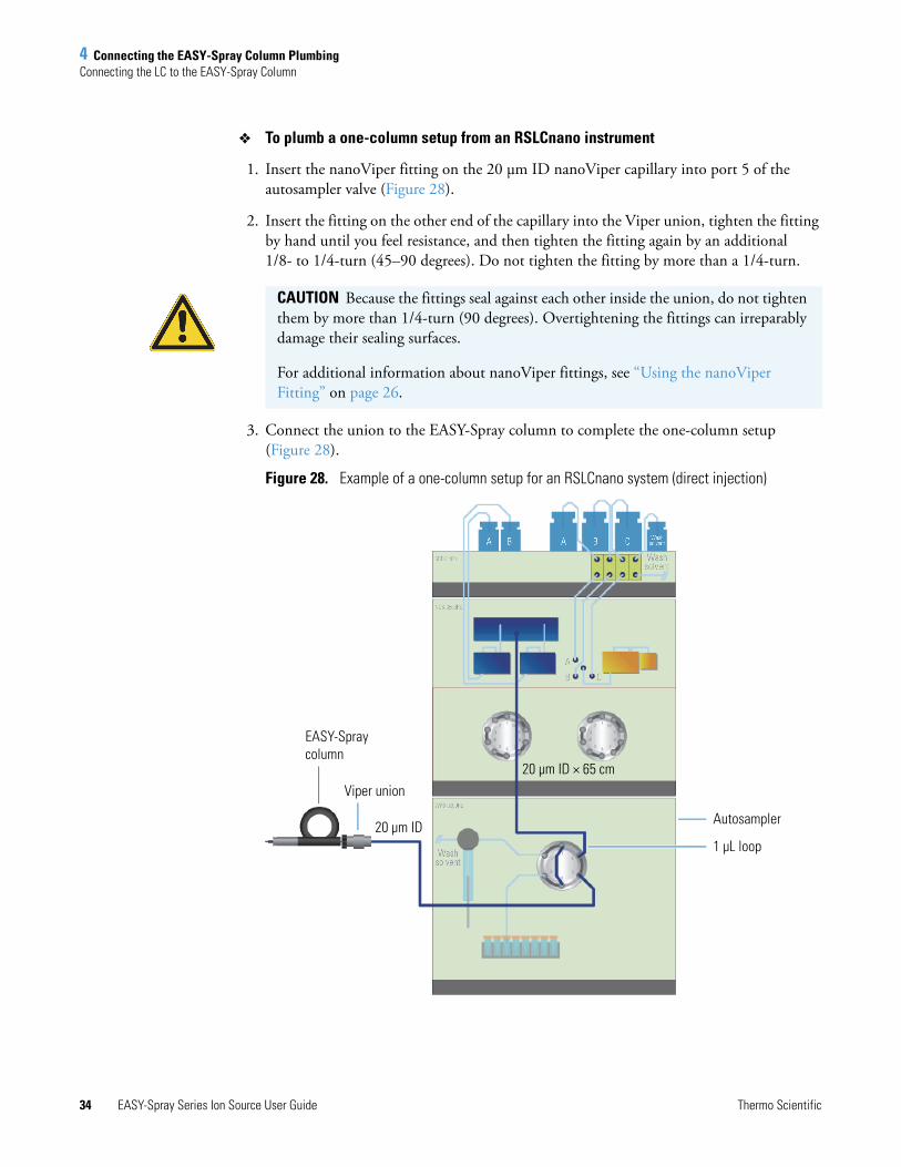
1. Insert the nanoViper fitting on the 20 μm ID nanoViper capillary into port 5 of the autosampler valve (Figure 28).
2. Insert the fitting on the other end of the capillary into the Viper union, tighten the fitting by hand until you feel resistance, and then tighten the fitting again by an additional 1/8- to 1/4-turn (45–90 degrees). Do not tighten the fitting by more than a 1/4-turn.
3. Connect the union to the EASY-Spray column to complete the one-column setup (Figure 28).
Figure 28. Example of a one-column setup for an RSLCnano system (direct injection)
CAUTION Because the fittings seal against each other inside the union, do not tighten them by more than 1/4-turn (90 degrees). Overtightening the fittings can irreparably damage their sealing surfaces.
For additional information about nanoViper fittings, see “Using the nanoViper Fitting” on page 26.
EASY-Spray column
Autosampler
Viper union 20 μm ID × 65 cm
20 μm ID1 μL loop
4 Connecting the EASY-Spray Column PlumbingConnecting the LC to the EASY-Spray Column
Thermo Scientific EASY-Spray Series Ion Source User Guide 35
To plumb a two-column setup from an RSLCnano instrument
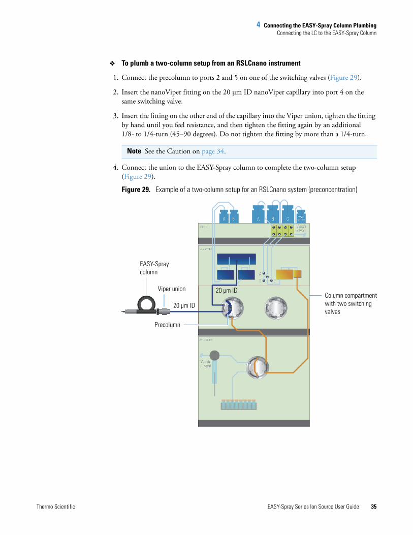
1. Connect the precolumn to ports 2 and 5 on one of the switching valves (Figure 29).
2. Insert the nanoViper fitting on the 20 μm ID nanoViper capillary into port 4 on the same switching valve.
3. Insert the fitting on the other end of the capillary into the Viper union, tighten the fitting by hand until you feel resistance, and then tighten the fitting again by an additional 1/8- to 1/4-turn (45–90 degrees). Do not tighten the fitting by more than a 1/4-turn.
4. Connect the union to the EASY-Spray column to complete the two-column setup (Figure 29).
Figure 29. Example of a two-column setup for an RSLCnano system (preconcentration)
Note See the Caution on page 34.
EASY-Spray column
Column compartment with two switching valves
Precolumn
Viper union 20 μm ID
20 μm ID

4 Connecting the EASY-Spray Column PlumbingConnecting the LC to the EASY-Spray Column
36 EASY-Spray Series Ion Source User Guide Thermo Scientific
Thermo Scientific EASY-Spray Series Ion Source User Guide 37
5
Configuring the Mass Spectrometer for NSI Mode
Follow the applicable procedures to configure the Thermo Scientific mass spectrometer for nanoelectrospray ionization (nanoESI or NSI) mode.
Configuring the EASY-Spray NG Source’s NSI ParametersAfter you complete the instrument configuration, use the Thermo Tune application to configure the NSI source parameters. For additional information, refer to the Tune Help.
To set the NSI source parameters
1. On the Microsoft™ Windows™ taskbar, choose Start > All Programs > Thermo Instruments > Thermo model > model Tune, where model is your specific mass spectrometer, to open the Tune window.
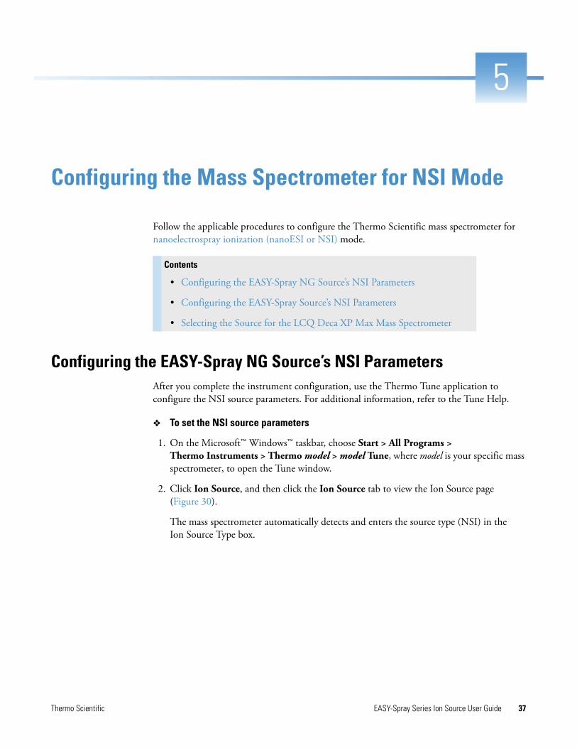
2. Click Ion Source, and then click the Ion Source tab to view the Ion Source page (Figure 30).
The mass spectrometer automatically detects and enters the source type (NSI) in the Ion Source Type box.
Contents
• Configuring the EASY-Spray NG Source’s NSI Parameters
• Configuring the EASY-Spray Source’s NSI Parameters
• Selecting the Source for the LCQ Deca XP Max Mass Spectrometer
5 Configuring the Mass Spectrometer for NSI ModeConfiguring the EASY-Spray Source’s NSI Parameters
38 EASY-Spray Series Ion Source User Guide Thermo Scientific
Figure 30. Ion Source page in the Tune window for the Orbitrap Fusion (example)
3. In the Pos Ion Spray Voltage (V) box, enter 1900.
Use 1900 V as the start value for the spray voltage. If the intensity of the full-scan spectrum is low, gradually increase the spray voltage to improve the spectrum. The recommended range for the spray voltage is 1400–2400 kV.
4. In the Sweep Gas (Arb) box, enter 0.
5. Click Apply.
Configuring the EASY-Spray Source’s NSI ParametersAfter you complete the instrument configuration, use the Thermo Tune Plus application to configure the NSI source parameters. For additional information, refer to the Tune Plus Help.
To set the NSI source parameters
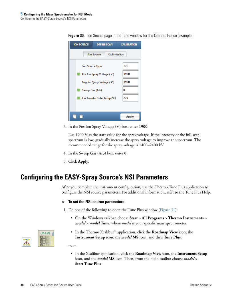
1. Do one of the following to open the Tune Plus window (Figure 31):
• On the Windows taskbar, choose Start > All Programs > Thermo Instruments > model > model Tune, where model is your specific mass spectrometer.
• In the Thermo Xcalibur™ application, click the Roadmap View icon, the Instrument Setup icon, the model MS icon, and then Tune Plus.
–or–
• In the Xcalibur application, click the Roadmap View icon, the Instrument Setup icon, and the model MS icon. Then, from the main toolbar choose model > Start Tune Plus.
5 Configuring the Mass Spectrometer for NSI ModeConfiguring the EASY-Spray Source’s NSI Parameters
Thermo Scientific EASY-Spray Series Ion Source User Guide 39
Figure 31. Tune Plus window for an NSI-configured Velos Pro (example)
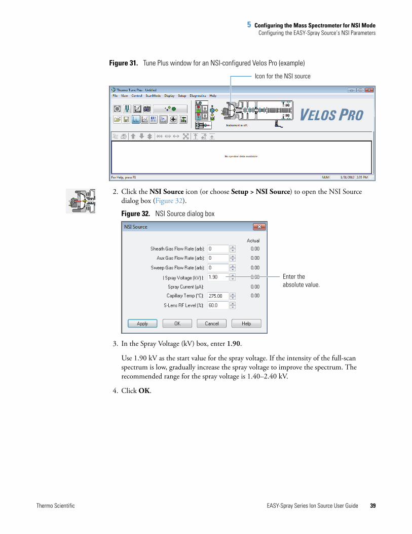
2. Click the NSI Source icon (or choose Setup > NSI Source) to open the NSI Source dialog box (Figure 32).
Figure 32. NSI Source dialog box
3. In the Spray Voltage (kV) box, enter 1.90.
Use 1.90 kV as the start value for the spray voltage. If the intensity of the full-scan spectrum is low, gradually increase the spray voltage to improve the spectrum. The recommended range for the spray voltage is 1.40–2.40 kV.
4. Click OK.
Icon for the NSI source
Enter the absolute value.
5 Configuring the Mass Spectrometer for NSI ModeSelecting the Source for the LCQ Deca XP Max Mass Spectrometer
40 EASY-Spray Series Ion Source User Guide Thermo Scientific
Selecting the Source for the LCQ Deca XP Max Mass Spectrometer
After you install the EASY-Spray source, use the Instrument Configuration window to configure the mass spectrometer for NSI mode.
To configure the mass spectrometer for NSI mode
1. If open, close the Xcalibur data system and Tune Plus application.
2. On the Windows taskbar, choose Start > All Programs > Xcalibur > Instrument Configuration to open the Instrument Configuration window.
3. Select the devices to control from the Xcalibur data system if not already selected:
a. In the Device Types list, select All.
b. Under Available Devices, double-click the icons for the mass spectrometer and nanoelectrospray LC instrument to add them to the Configured Devices list.
4. Double-click the mass spectrometer icon to open the Model Configuration dialog box.
5. In the left pane, select Ion Source to display the ion source configuration page, and then select Nanospray in the Default Source list.
6. Click OK, and then click OK again to close the message box.
7. Configure the LC device if you have not done so.
For instructions, refer to the LC instrument documentation.
8. In the Instrument Configuration window, click Done.
9. Restart the data system computer and the mass spectrometer.
Note This section is for the LCQ Deca XP Max mass spectrometer, which uses the Xcalibur data system version 2.0.7 or earlier.
Thermo Scientific EASY-Spray Series Ion Source User Guide 41
6
Maintenance
This chapter provides maintenance guidelines, a list of required tools and supplies, and instructions for replacing the controller PCB in the EASY-Spray Series source.
GuidelinesFor optimal results, follow these guidelines when performing the procedure in this chapter:
• Take precautions against electrostatic discharge (ESD), especially when the lab environment is at the lower end of the relative humidity specification (see page xi). For additional guidelines, refer to the “Operating Environment” chapter in the preinstallation requirements guide for your mass spectrometer.
• Proceed methodically.
• Always place the components on a clean, lint-free surface.
• Never overtighten a screw or use excessive force.
Preparing the Work Area To prepare the work area
Do the following:
• Cover the area with clean, lint-free paper or a large sheet of clean aluminum foil.
• Have nearby the necessary tools, supplies, and replacement parts (when applicable).
Contents
• Guidelines
• Preparing the Work Area
• Tools and Supplies
• Cleaning the EASY-Spray Column Emitter Tip
• Replacing the Controller PCB
6 MaintenanceTools and Supplies
42 EASY-Spray Series Ion Source User Guide Thermo Scientific
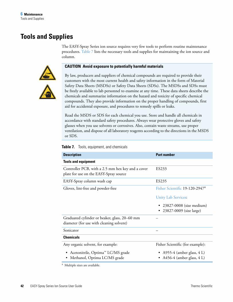
Tools and SuppliesThe EASY-Spray Series ion source requires very few tools to perform routine maintenance procedures. Table 7 lists the necessary tools and supplies for maintaining the ion source and column.
CAUTION Avoid exposure to potentially harmful materials
By law, producers and suppliers of chemical compounds are required to provide their customers with the most current health and safety information in the form of Material Safety Data Sheets (MSDSs) or Safety Data Sheets (SDSs). The MSDSs and SDSs must be freely available to lab personnel to examine at any time. These data sheets describe the chemicals and summarize information on the hazard and toxicity of specific chemical compounds. They also provide information on the proper handling of compounds, first aid for accidental exposure, and procedures to remedy spills or leaks.
Read the MSDS or SDS for each chemical you use. Store and handle all chemicals in accordance with standard safety procedures. Always wear protective gloves and safety glasses when you use solvents or corrosives. Also, contain waste streams, use proper ventilation, and dispose of all laboratory reagents according to the directions in the MSDS or SDS.
Table 7. Tools, equipment, and chemicals
Description Part number
Tools and equipment
Controller PCB, with a 2.5 mm hex key and a cover plate for use on the EASY-Spray source
ES233
EASY-Spray column wash cap ES235
Gloves, lint-free and powder-free Fisher Scientific 19-120-2947a
Unity Lab Services:
• 23827-0008 (size medium)• 23827-0009 (size large)
a Multiple sizes are available.
Graduated cylinder or beaker, glass, 20–60 mm diameter (for use with cleaning solvent)
–
Sonicator –
Chemicals
Any organic solvent, for example:
• Acetonitrile, Optima™ LC/MS grade • Methanol, Optima LC/MS grade
Fisher Scientific (for example):
• A955-4 (amber glass, 4 L)• A456-4 (amber glass, 4 L)
6 MaintenanceCleaning the EASY-Spray Column Emitter Tip
Thermo Scientific EASY-Spray Series Ion Source User Guide 43
Cleaning the EASY-Spray Column Emitter TipIf the video camera’s output shows dust particles on the EASY-Spray column’s emitter tip or if there are unresolved spray issues, follow the procedure in this section to clean the emitter.
To clean the EASY-Spray column emitter
1. Carefully remove the EASY-Spray column from the source.
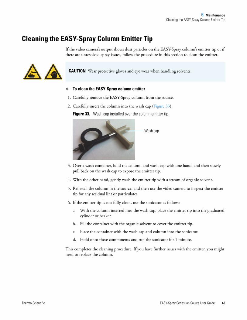
2. Carefully insert the column into the wash cap (Figure 33).
Figure 33. Wash cap installed over the column emitter tip
3. Over a wash container, hold the column and wash cap with one hand, and then slowly pull back on the wash cap to expose the emitter tip.
4. With the other hand, gently wash the emitter tip with a stream of organic solvent.
5. Reinstall the column in the source, and then use the video camera to inspect the emitter tip for any residual lint or particulates.
6. If the emitter tip is not fully clean, use the sonicator as follows:
a. With the column inserted into the wash cap, place the emitter tip into the graduated cylinder or beaker.
b. Fill the container with the organic solvent to cover the emitter tip.
c. Place the container with the wash cap and column into the sonicator.
d. Hold onto these components and run the sonicator for 1 minute.
This completes the cleaning procedure. If you have further issues with the emitter, you might need to replace the column.
CAUTION Wear protective gloves and eye wear when handling solvents.
Wash cap
6 MaintenanceReplacing the Controller PCB
44 EASY-Spray Series Ion Source User Guide Thermo Scientific
Replacing the Controller PCBIf the controller PCB becomes damaged, the actual temperature display might remain off and the EASY-Spray column might not heat. Follow this procedure to install a new controller PCB.
To replace the controller PCB
1. Follow the procedure “To remove the source from the mass spectrometer” on page 17.
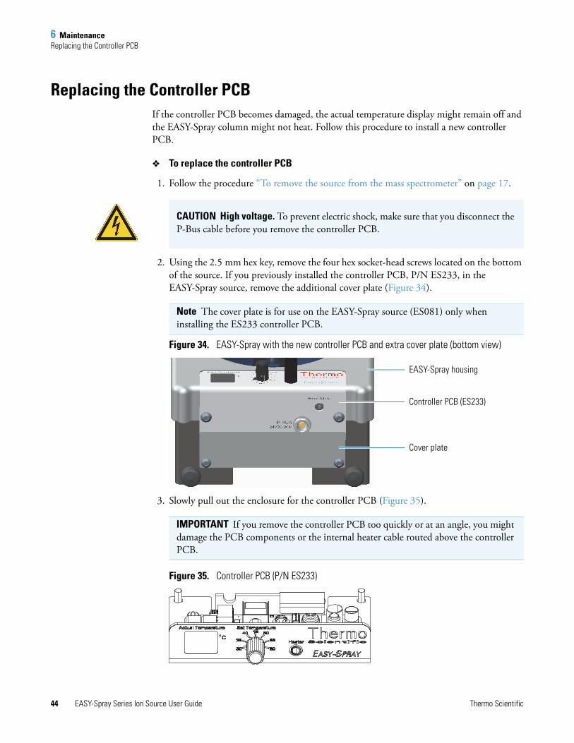
2. Using the 2.5 mm hex key, remove the four hex socket-head screws located on the bottom of the source. If you previously installed the controller PCB, P/N ES233, in the EASY-Spray source, remove the additional cover plate (Figure 34).
Figure 34. EASY-Spray with the new controller PCB and extra cover plate (bottom view)
3. Slowly pull out the enclosure for the controller PCB (Figure 35).
Figure 35. Controller PCB (P/N ES233)
CAUTION High voltage. To prevent electric shock, make sure that you disconnect the P-Bus cable before you remove the controller PCB.
Note The cover plate is for use on the EASY-Spray source (ES081) only when installing the ES233 controller PCB.
IMPORTANT If you remove the controller PCB too quickly or at an angle, you might damage the PCB components or the internal heater cable routed above the controller PCB.
EASY-Spray housing
Controller PCB (ES233)
Cover plate
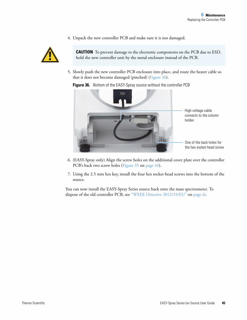
6 MaintenanceReplacing the Controller PCB
Thermo Scientific EASY-Spray Series Ion Source User Guide 45
4. Unpack the new controller PCB and make sure it is not damaged.
5. Slowly push the new controller PCB enclosure into place, and route the heater cable so that it does not become damaged (pinched) (Figure 36).
Figure 36. Bottom of the EASY-Spray source without the controller PCB
6. (EASY-Spray only) Align the screw holes on the additional cover plate over the controller PCB’s back two screw holes (Figure 35 on page 44).
7. Using the 2.5 mm hex key, install the four hex socket-head screws into the bottom of the source.
You can now install the EASY-Spray Series source back onto the mass spectrometer. To dispose of the old controller PCB, see “WEEE Directive 2012/19/EU” on page iii.
CAUTION To prevent damage to the electronic components on the PCB due to ESD, hold the new controller unit by the metal enclosure instead of the PCB.
One of the back holes for the hex socket-head screw
High voltage cable connects to the column holder.

6 MaintenanceReplacing the Controller PCB
46 EASY-Spray Series Ion Source User Guide Thermo Scientific
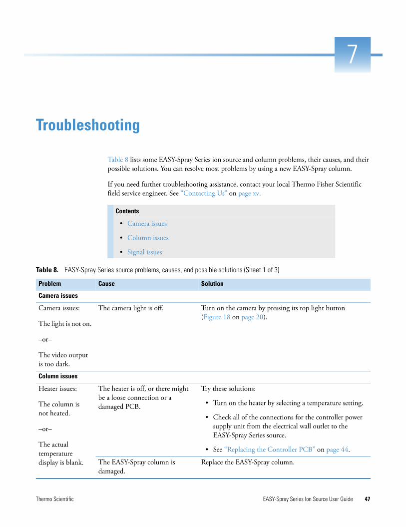
Thermo Scientific EASY-Spray Series Ion Source User Guide 47
7
Troubleshooting
Table 8 lists some EASY-Spray Series ion source and column problems, their causes, and their possible solutions. You can resolve most problems by using a new EASY-Spray column.
If you need further troubleshooting assistance, contact your local Thermo Fisher Scientific field service engineer. See “Contacting Us” on page xv.
Contents
• Camera issues
• Column issues
• Signal issues
Table 8. EASY-Spray Series source problems, causes, and possible solutions (Sheet 1 of 3)
Problem Cause Solution
Camera issues
Camera issues:
The light is not on.
–or–
The video output is too dark.
The camera light is off. Turn on the camera by pressing its top light button (Figure 18 on page 20).
Column issues
Heater issues:
The column is not heated.
–or–
The actual temperature display is blank.
The heater is off, or there might be a loose connection or a damaged PCB.
Try these solutions:
• Turn on the heater by selecting a temperature setting.
• Check all of the connections for the controller power supply unit from the electrical wall outlet to the EASY-Spray Series source.
• See “Replacing the Controller PCB” on page 44.
The EASY-Spray column is damaged.
Replace the EASY-Spray column.
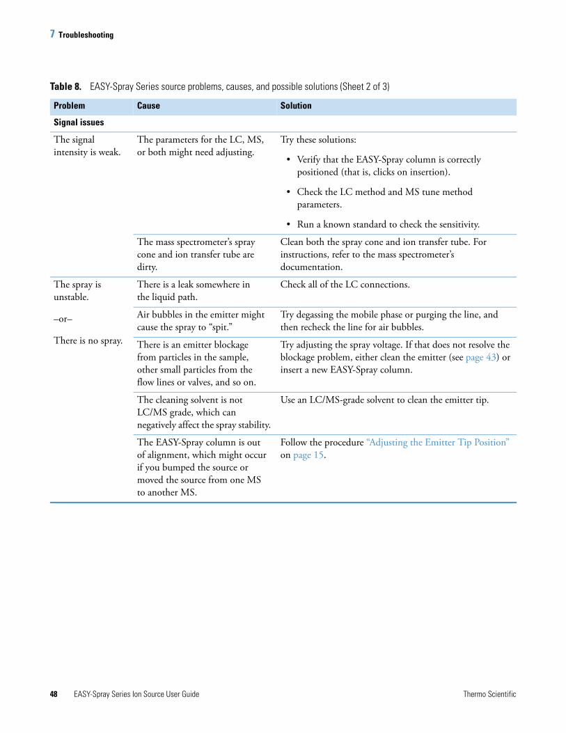
7 Troubleshooting
48 EASY-Spray Series Ion Source User Guide Thermo Scientific
Signal issues
The signal intensity is weak.
The parameters for the LC, MS, or both might need adjusting.
Try these solutions:
• Verify that the EASY-Spray column is correctly positioned (that is, clicks on insertion).
• Check the LC method and MS tune method parameters.
• Run a known standard to check the sensitivity.
The mass spectrometer’s spray cone and ion transfer tube are dirty.
Clean both the spray cone and ion transfer tube. For instructions, refer to the mass spectrometer’s documentation.
The spray is unstable.
–or–
There is no spray.
There is a leak somewhere in the liquid path.
Check all of the LC connections.
Air bubbles in the emitter might cause the spray to “spit.”
Try degassing the mobile phase or purging the line, and then recheck the line for air bubbles.
There is an emitter blockage from particles in the sample, other small particles from the flow lines or valves, and so on.
Try adjusting the spray voltage. If that does not resolve the blockage problem, either clean the emitter (see page 43) or insert a new EASY-Spray column.
The cleaning solvent is not LC/MS grade, which can negatively affect the spray stability.
Use an LC/MS-grade solvent to clean the emitter tip.
The EASY-Spray column is out of alignment, which might occur if you bumped the source or moved the source from one MS to another MS.
Follow the procedure “Adjusting the Emitter Tip Position” on page 15.
Table 8. EASY-Spray Series source problems, causes, and possible solutions (Sheet 2 of 3)
Problem Cause Solution
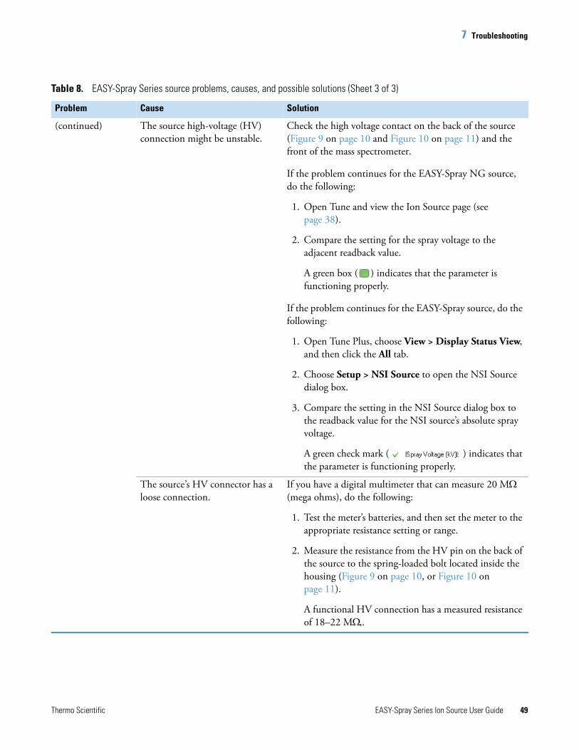
7 Troubleshooting
Thermo Scientific EASY-Spray Series Ion Source User Guide 49
(continued) The source high-voltage (HV) connection might be unstable.
Check the high voltage contact on the back of the source (Figure 9 on page 10 and Figure 10 on page 11) and the front of the mass spectrometer.
If the problem continues for the EASY-Spray NG source, do the following:
1. Open Tune and view the Ion Source page (see page 38).
2. Compare the setting for the spray voltage to the adjacent readback value.
A green box ( ) indicates that the parameter is functioning properly.
If the problem continues for the EASY-Spray source, do the following:
1. Open Tune Plus, choose View > Display Status View, and then click the All tab.
2. Choose Setup > NSI Source to open the NSI Source dialog box.
3. Compare the setting in the NSI Source dialog box to the readback value for the NSI source’s absolute spray voltage.
A green check mark ( ) indicates that the parameter is functioning properly.
The source’s HV connector has a loose connection.
If you have a digital multimeter that can measure 20 M (mega ohms), do the following:
1. Test the meter’s batteries, and then set the meter to the appropriate resistance setting or range.
2. Measure the resistance from the HV pin on the back of the source to the spring-loaded bolt located inside the housing (Figure 9 on page 10, or Figure 10 on page 11).
A functional HV connection has a measured resistance of 18–22 M,.
Table 8. EASY-Spray Series source problems, causes, and possible solutions (Sheet 3 of 3)
Problem Cause Solution

7 Troubleshooting
50 EASY-Spray Series Ion Source User Guide Thermo Scientific
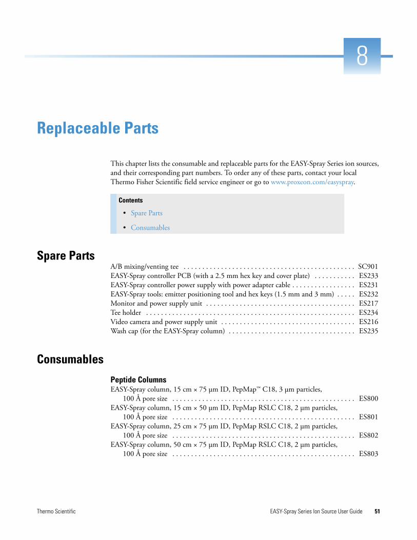
Thermo Scientific EASY-Spray Series Ion Source User Guide 51
8
Replaceable Parts
This chapter lists the consumable and replaceable parts for the EASY-Spray Series ion sources, and their corresponding part numbers. To order any of these parts, contact your local Thermo Fisher Scientific field service engineer or go to www.proxeon.com/easyspray.
Spare PartsA/B mixing/venting tee . . . . . . . . . . . . . . . . . . . . . . . . . . . . . . . . . . . . . . . . . . . . . . SC901EASY-Spray controller PCB (with a 2.5 mm hex key and cover plate) . . . . . . . . . . . ES233EASY-Spray controller power supply with power adapter cable . . . . . . . . . . . . . . . . . ES231EASY-Spray tools: emitter positioning tool and hex keys (1.5 mm and 3 mm) . . . . . ES232Monitor and power supply unit . . . . . . . . . . . . . . . . . . . . . . . . . . . . . . . . . . . . . . . . ES217Tee holder . . . . . . . . . . . . . . . . . . . . . . . . . . . . . . . . . . . . . . . . . . . . . . . . . . . . . . . . ES234Video camera and power supply unit . . . . . . . . . . . . . . . . . . . . . . . . . . . . . . . . . . . . ES216Wash cap (for the EASY-Spray column) . . . . . . . . . . . . . . . . . . . . . . . . . . . . . . . . . . ES235
Consumables
Peptide ColumnsEASY-Spray column, 15 cm × 75 μm ID, PepMap™ C18, 3 μm particles,
100 Å pore size . . . . . . . . . . . . . . . . . . . . . . . . . . . . . . . . . . . . . . . . . . . . . . . . . ES800EASY-Spray column, 15 cm × 50 μm ID, PepMap RSLC C18, 2 μm particles,
100 Å pore size . . . . . . . . . . . . . . . . . . . . . . . . . . . . . . . . . . . . . . . . . . . . . . . . . ES801EASY-Spray column, 25 cm × 75 μm ID, PepMap RSLC C18, 2 μm particles,
100 Å pore size . . . . . . . . . . . . . . . . . . . . . . . . . . . . . . . . . . . . . . . . . . . . . . . . . ES802EASY-Spray column, 50 cm × 75 μm ID, PepMap RSLC C18, 2 μm particles,
100 Å pore size . . . . . . . . . . . . . . . . . . . . . . . . . . . . . . . . . . . . . . . . . . . . . . . . . ES803
Contents
• Spare Parts
• Consumables

8 Replaceable PartsConsumables
52 EASY-Spray Series Ion Source User Guide Thermo Scientific
Intact Protein ColumnsEASY-Spray column, 25 cm × 200 μm ID, PepSwift™ Monolith . . . . . . . . . . . . . . . ES810EASY-Spray column, 15 cm × 75 μm ID, Accucore™ C4, 2.6 μm particles,
150 Å pore size . . . . . . . . . . . . . . . . . . . . . . . . . . . . . . . . . . . . . . . . . . . . . . . . . ES811EASY-Spray column, 15 cm × 75 μm ID, PepMap C18, 3 μm particles,
300 Å pore size . . . . . . . . . . . . . . . . . . . . . . . . . . . . . . . . . . . . . . . . . . . . . . . . . ES812
Thermo Scientific EASY-Spray Series Ion Source User Guide 53
G
Glossary
A
API ion transfer tube A tube assembly that assists in desolvating ions that are produced by the ESI, nanoESI (NSI), or APCI probe (or spray insert).
atmospheric pressure chemical ionization (APCI) A soft ionization technique done in an ion source operating at atmospheric pressure. Electrons from a corona discharge initiate the process by ionizing the mobile phase vapor molecules. A reagent gas forms, which efficiently produces positive and negative ions of the analyte through a complex series of chemical reactions.
atmospheric pressure ionization (API) Ionization performed at atmospheric pressure by using atmospheric pressure chemical ionization (APCI), electrospray (ESI), or nanoelectrospray ionization (nanoESI or NSI).
D
dynamic nanoelectrospray See nanoESI nanoLC gradient separation.
E
electrospray (ESI) A type of atmospheric pressure ionization that is currently the softest ionization technique available to transform ions in solution into ions in the gas phase.
electrospray ionization (ESI) See electrospray (ESI).
H
heated-electrospray (HESI) A type of atmospheric pressure ionization that converts ions in solution into ions in the gas phase by using electrospray (ESI) in combination with heated auxiliary gas.
heated-electrospray ionization (H-ESI) See heated-electrospray (HESI).
I
ion source A device that converts samples to gas-phase ions.
ion sweep cone A removable cone-shaped metal cover that fits on top of the API ion transfer tube and acts as a physical barrier to protect the entrance of the tube.
N
nano liquid chromatography (nanoLC) Liquid chromatography with typical flow rates of 10–1000 nL/min and 10–150 μm diameter columns.
A B C D E F G H I J K L M N O P Q R S T U V W X Y Z
Glossary: nanoelectrospray ionization (nanoESI or NSI)
54 EASY-Spray Series Ion Source User Guide Thermo Scientific
nanoelectrospray ionization (nanoESI or NSI) A type of electrospray (ESI) that accommodates very low flow rates of sample and solvent on the order of 1–20 nL/min (for static nanoelectrospray) or 100–1000 nL/min (for dynamic nanoelectrospray, which is also called nanoESI nanoLC gradient separation).
nanoESI nanoLC gradient separation Employs microscale capillary columns to separate the analytes in complex mixtures. The sample is loaded onto a column using an injection valve or a gas pressure vessel. The mixture components are then eluted by a solvent gradient and pumped through the emitter.
nanoESI (NSI) source The entire nanoelectrospray ion source.
nanoESI (NSI) spray current The flow of charged particles in the nanoESI (NSI) source. The voltage on the NSI spray needle supplies the potential required to ionize the particles.
nanoESI (NSI) spray voltage The high voltage that is applied to the spray needle in the nanoESI (NSI) source to produce the NSI spray current as liquid emerges from the nozzle. The NSI spray voltage is selected and set; the NSI spray current varies.
nanospray ionization (NSI) See nanoelectrospray ionization (nanoESI or NSI).
S
source See ion source.
static nanoelectrospray A device that performs continuous analysis of small analyte solution volumes over an extended period of time.
Thermo Scientific EASY-Spray Series Ion Source User Guide 55
I
Aaxes control
x- and z- 16y- 17
Ccamera
connecting 19light button and focusing wheel, locations 20removing 18troubleshooting 47
cleaning, emitter tip 43column
assembly 25cleaning 43installing 24–25part numbers for
intact protein 52peptide 51
setting the temperature 25consumables 51contacting us xvcontroller PCB
description 4power supply for 5replacing 44
Ddirective, WEEE iiidocumentation
accessing xadditional xdownloading x
EEASY-Spray column
See column
EASY-Spray P-Bus Temp Control Cableconnecting 13description 5
EASY-Spray Series ion sourceSee ion source
electrical wall outlets 7emitter
adjusting the tip position 16tip, cleaning 43troubleshooting 48
environmental requirements xi
Ffigures, list of vii
Hheater
cable 25troubleshooting 47
high voltageconnector, location 10–11internal cable, location 45troubleshooting 49
housingSee ion source
Iion source
axes controlx- and z- 16y- 17
benefits 1column, installing 25compatible mass spectrometers xiconnecting
controller power supply unit 12EASY-Spray P-Bus Temp Control Cable 13
Index
56 EASY-Spray Series Ion Source User Guide Thermo Scientific
Index: K
monitor and camera 19Tee holder 13
housingdescription 3installing 9
kits xiilocking levers, positions 10power connection 12removing 17
ion sweep cone 9
Kkits
EASY-Spray Ion Source xiiEASY-Spray NG Ion Source xiiUltiMate 3000 RSLCnano EASY-Spray Application 33
LLC connections
EASY-nLC 1000, connecting to 27EASY-nLC II, connecting to 30RSLCnano system, connecting to 33tools and supplies 23
locking levers, positions 9
Mmaintenance
controller PCB, replacing 44guidelines 41tools, equipment, and chemicals 42work area, preparing 41
mass spectrometerdiagnostics 49ion sweep cone 9NSI mode manually, LCQ Deca XP Max 40power requirements xipreparing for the source 8setting the NSI source parameters 37source, removing 17spray cone 10
monitorconnecting 19video picture, adjusting 21
MSDS 42
Nnanoelectrospray, advantages of 2nanoESI
See NSI modenanoViper fittings, using 26
NSI modemanual configuration, LCQ Deca XP Max 40setting the spray voltage 39
NSI Source dialog box 39
Oorganic solvents 42
Ppower connection, location 4power supply units, connecting
camera 19controller 12monitor 19
product requirements xi
Rreplaceable parts 51
SSDS 42signal intensity, troubleshooting 48source
See ion sourcespray
troubleshooting 48voltage
readback value 49setting the value, EASY-Spray 39setting the value, EASY-Spray NG 38
spray cone, MS 10
TTee holder
adjusting position 28configuring 14installing 13shipping configuration 14
temperaturecontrol dial, settings 4display codes 26display location 4
temperature control cable, connecting 13tools and supplies, connecting the LC 23troubleshooting 47Tune
application, opening 37legacy application, opening 38
Thermo Scientific EASY-Spray Series Ion Source User Guide 57
Index: V
Vventing tee, recommended LC connections 28
Wwash cap, installing 43WEEE directive iii
Xx, y, and z coordinates, column holder 16

58 EASY-Spray Series Ion Source User Guide Thermo Scientific
Index: X