![Extraordinary properties of nematic phases of bent-core liquid crystals (Invited Paper)[6911-05]](https://static.fdokumen.com/doc/165x107/6333b2707a687b71aa08555a/extraordinary-properties-of-nematic-phases-of-bent-core-liquid-crystals-invited.jpg)
Extraordinary properties of nematic phases of bent-core liquid crystals (Invited Paper)[6911-05]

Easy spectrally tunable highly efficient X-ray backlightingschemes based on spherically bent crystals
T. PIKUZ,1 A. FAENOV,1 I. SKOBELEV,1 A. MAGUNOV,1 L. LABATE,2 L.A. GIZZI,2
M. GALIMBERTI,2 A. ZIGLER,3 G. BALDACCHINI,4 F. FLORA,4 S. BOLLANTI,4 P. DI LAZZARO,4
D. MURRA,4 G. TOMASSETTI,5 A. RITUCCI,5 A. REALE,5 L. REALE,5 M. FRANCUCCI,6
S. MARTELLUCI,6 and G. PETROCELLI,61Multicharged Ions Spectra Data Center of National Research Institute of Physical Technical and Radiotechnical MeasurementsMendeleyev, Moscow, Russia
2Intense Laser Irradiation Laboratory, Istituto per i Processi Chimico-Fsisici, Consiglio Nazionale delle Recherché, Area dellaRicerca di Pisa, Pisa, Italy
3Racah Institute of Physics, The Hebrew University of Jerusalem, Jerusalem, Israel4Ente per le nuove technologie l’energia e l’ambiente, Unita’ Technico Scientifica Tecnologie Fisiche Avanzate, C.R. Frascati,Rome, Italy
5Istituto Nazionale per la Fisica della Materia, Dipartamento di Fisica dell’Aquila and Laboratory Nazionale del Gran Sasso,Istituto Nazionale di Fisica Nucleare, Assergi, Italy
6Istituto Nazionale per la Fisica della Materia, Universitó di Roma Tor Vergata, Roma, Italy
~Received 1 November 2003;Accepted 30 June 2004!
Abstract
New easy spectrally tunable backlighting schemes based on a spherically bent crystal are considered. Contrary totraditional backlighting scheme, in which the investigated objects should be placed between the backlighter and thecrystal, for the considered schemes an object is placed downstream of the crystal, before the tangential or after thesagittal focus and an image of the object is recorded at the distance from the object corresponding to the neededmagnification. The magnification is defined by the ratio of the distances from the sagittal focus to the detector and fromthe object to the sagittal focus. A ray-tracing modeling and experimental images of test meshes, obtained at incidenceangles of the backlighter radiation of 108 and 228, are presented. It is demonstrated that a simple linear transformationof the obtained astigmatic images allows reconstructing them as a stigmatic with an accuracy of 5–15%. For the spectralrange around 9 Å a spatial resolution about 10mm in a field of view of some square millimeters is achievedexperimentally and confirmed by ray-tracing simulations.
Keywords: Plasma diagnostics; X-ray backlighting; X-ray imaging; X-ray optics
1. INTRODUCTION
Experiments on using spherically bent crystals for X-raybacklighting imaging of plasma objects were started practi-cally 30 years ago~Belyaevet al., 1976! and nowadays theyare more and more widely applied for diagnostics of differ-ent plasma facilities~Pikuz et al., 1995a, 1995b, 1997;Aglitskiy et al., 1996, 1997, 1998, 1999, 2001a, 2001b;Brown et al., 1997; Sanchez del Rioet al., 1997, 1999;Holzeret al., 1998; Kochet al., 1998, 1999, 2003; Workmanet al., 1999, 2001; Sinarset al., 2003a, 2003b!. Despite ofthe fact that imaging of plasmas by spherically bent crystalshas many advantages~they have a very high luminositycompared with pinholes and can provide a high spatial
resolution over very large fields of view! it presents adisadvantage connected with the necessity to use them, inorder to minimize the astigmatism, only for angles of inci-dence within a few degrees of normal. Such a restriction onthe angle of incidenceu, along with the fixed interplanarspacing~2d! of the crystal itself, limits the wavelengthsrange used now for backlighting diagnostics.
One of the approaches for broadening the spectral rangefor backlighting diagnostics is to apply torroidally bentcrystals, which use different sagittal and meridional radii ofcurvature in order to eliminate the astigmatism for incidentangles far from normal~Vollbrecht et al., 1998; Missallaet al., 1999; Uschmannet al., 2000!. However, high-qualitytorroidal surfaces are more complicated to obtain comparedwith spherical ones. Another disadvantage of using suchcrystals for backlighting diagnostics is the very difficultalignment due to constraints on all the six degrees of posi-
Address correspondence and reprint requests to: A. Faenov, MISDCof VNIIFTRI Mendeleevo, Moscow region, 141570, Russia. E-mail:[email protected]
Laser and Particle Beams~2004!, 22, 289–300. Printed in the USA.Copyright © 2004 Cambridge University Press 0263-0346004 $16.00DOI: 10.10170S0263034604223138
289

tioning freedom. Furthermore, for an ideal torroidal surfaceand an ideal alignment~see, for more details, a theoreticalmodeling, which has been done by Uschmannet al., 2000!,reasonable spatial resolution in the range of 3–10mm couldbe reached only in a field of view around 100mm, which isnot appropriate for current Z-pinch plasma investigationsand for the future big scale laser plasma facilities.
Another approach to the broad the range of suitableimaging wavelengths is to increase the variations of pro-duced types of spherically bent crystals and their cuts.Unfortunately not so many types of crystals and their cutscould be bent along a spherical surface with a big enoughratio between the crystal sizes and their radius of curvature.
To avoid the restrictions on using spherically bent crys-tals with practically any angles of incidenceQ ~i.e., to avoidproblem with the apparent astigmatism aberrations! Fraenkelet al. ~1999!, Pikuzet al. ~1999, 2001!, Floraet al. ~2001!,and Sanchez del Rioet al. ~2001! have proposed the modi-fication of traditionally used monochromatic backlightingschemes—the so-called Shadow Monochromatic Backlight-ing ~SMB! scheme or X-ray crystal imaging microscope~XCIM !. The traditional X-ray monochromatic backlight-ing scheme with the spherically bent crystal is shown inFigure 1a. In this scheme the backlighter is placed on theRowland circle very close to the optical axis of the crystal
surface. The object and the detector are mounted at a dis-tances from the crystal according with the usual opticalequation
10a 1 10b 5 20R, ~1!
whereR is the crystal radius of curvature, andaandbare thedistance from the object to the crystal and from the crystal tothe detector, respectively. The magnification of the image isdefined by the valueM 5 b0a.
The modification of the monochromatic backlightingscheme, the SMB is shown in Figure 1b. A main advantageof the SMB scheme, compared with the usual backlightingscheme, is the possibility to work in a wide range of Braggangles far from 908, but still to receive a stigmatic image ofthe object. In the SMB scheme, the detector is placed at aspecial fixed position downstream from the crystal betweenthe tangential and sagittal foci. This position depends fromon the wavelength~Bragg angleQ! and the crystal curvatureand is defined by the equation~Sanchez del Rioet al., 2001!
d 5 ~ ft fs 2 fs2!0~ ft 1 fs!, ~2!
whereft andfs are the tangential and sagittal focuses, corre-spondingly. The magnification in this position is calculatedby Sanchez del Rioet al.~2001! asM 5d0x ~see Fig. 1b!. Toobtain different magnifications in such a scheme it is justsimply necessary to move the object along the source–crystal direction~to change distancex! and to keep fixed thebacklighter, the crystal, and the detector positions.
In Sanchez del Rioet al.~2001! and Pikuzet al.~2001! ithas been shown experimentally that the SMB scheme allowsus to obtain highly spatially resolved~;5 mm! monochro-matic~dl0l;1022–1024! images over a large field of view~some square millimeters! for Bragg anglesQ as small as;408. A ray-tracing modeling~Sanchez del Rioet al., 2001!confirmed that in such scheme the spatial resolution couldbe even better than the backlighter source size.
Unfortunately in the SMB scheme, spatial resolution isquite strongly dependent on the source size. Another disad-vantage of the SMB scheme, specifically if the crystal has asmall enough radius of curvature, is that the object should beplaced close enough to the backlighter and it can cause insome cases overheating of the investigated object by theradiation of the backlighter. Such a problem also is typicalfor the usual backlighting scheme with a Bragg angle closeto 908. Even more often in real experimental conditions thefollowing problem can occur: The object itself screens thebeam reflected from the crystal.
In this article we show how to avoid some of the above-mentioned problems. In the considered backlighting scheme,the position of the object has been changed and moveddownstream of the reflected beam. Experimental results arepresented, which were obtained in the case when a test meshwas placed either between the crystal and the tangentialfocus or after the sagittal focus. The obtained experimental
Fig. 1. Evolution of the monochromatic backlighting schemes with spher-ically bent crystals. a: Traditional scheme, where the distances object–crystal and crystal image are defined by optical equation; b: SMB~orXCIM ! scheme, which allows strongly decreased Bragg angle,,908; c:XMPI scheme proposed in this article with the object placed downstreamof the beam reflected from crystal.
290 T. Pikuz et al.

results are compared with the results of the ray-tracingcalculations, which were performed using the speciallydeveloped ray-tracing code ORTO~Labateet al., 2004!.
2. X-RAY MONOCHROMATIC PROJECTIONIMAGING (XMPI) SCHEME: GENERALDESCRIPTION AND RAY-TRACINGMODELING
As was mentioned above, the described new types of X-raymonochromatic projection imaging~XMPI ! schemes areplacedsomehowbetween the traditionaland theSMBschemes.Such considered schemes are still utilizing the properties ofthe shadow monochromatization, but for much bigger Braggangles, which are closer to normal incidence angles~Qaround 50–808 compared with the 20–608, which is moreusual for the SMB scheme, and compared with the 82–878,which is typical for the traditional backlighting scheme!.There are no strong restrictions in the new approaches,which are very important for the SMB scheme, for positionsof the backlighting source, the crystal, and the detector. Inthe SMB scheme, due to such fixed positions, the obtainedimages are stigmatic. In the new considered XMPI config-urations, the positions of the source, the crystal, and theobject are flexible, and in such cases the obtained images areastigmatic, but still the information about the space proper-ties of the object are kept with a high enough spatial reso-lution in both directions.
In XMPI schemes the magnifications are determined bythe following equations:
Mt 5 6~b 2 ft !0~ ft 2 a! ~3!
in the tangential direction and
Ms 5 6~b 2 fs!0~ fs 2 a! ~4!
in the sagittal direction.Here ft and fs are the tangential and the sagittal focus,
respectively~see eq.~2! and Fig. 1b!, a is the distancebetween the crystal and the object andb is the distancebetween the crystal and the image~see Fig. 1c!.
It is necessary to stress that, due to the big angle ofincidence, the reflected beam has an astigmatic structureand the image could be slightly deformed because of thedifferent magnification value in the sagittal and in the tan-gential directions. In such a case, to reach a geometricalsimilarity between the image and the object it is sufficient tomake a trivial linear geometrical transformation.
2.1. Ray-tracing modeling of the scheme
Ray-tracing simulations of the projection-imaging schemeillustrated above have been performed using the code ORTO~Labateet al., 2004!. The geometrical features of differentoptical setups based on bent Bragg crystals, as well as otheroptical elements, can be modeled by this code, which is also
able to consider the physical characteristics of the inter-action with the crystal by taking into account the crystalrocking curve. The code generates, using a Monte Carlomethod, a set of rays originating in a given region of thespace with a user-defined distribution and propagating towardanother region with a suitable angular distribution. Thespectral distribution of the source can also be considered~see more details in Labateet al., 2004!.
For the simulations described in the present article, aplanar source with a Gaussian shape has been used. Each raythus has its origin on a plane normal to the line joining thesource and the center of the crystal~see Fig. 2a! and theprobability for this origin to be at distancer from the sourcecenter is given by a Gaussian distribution~having its max-imum at r 5 0!. A white ~uniform! spectrum has beenassigned to this source. Because the rocking curve of thecrystal has been taken to be uniform in a given angle aroundthe Bragg angle, this means that only the geometrical fea-tures of the system have been modeled. Because an almostperfect mica crystal has been used for the experimentaltests, this approximation is suitable to provide an estimate ofthe attainable spatial resolution of the system as well as tostudy the distortion of the image.
Two different configurations, corresponding to differentvalues of the Bragg angle, have been considered for thefollowing simulations. In both cases, the point X-ray sourceas well as Gaussian sources, with a FWHM of 15, 30, and50mm, were considered. The imaged object was composedof two grids, rotated by 458 to each other, having, respec-tively, a period of 800 and 60mm and a wire thickness of 50and 14mm. For each simulation, 107 rays were sampled,whose direction was uniformly distributed in a solid angledefined by the source position and the four edges of thecrystal, whose size was selected as 83 8 mm2.
Figure 2b,c~left! shows the result of a simulation per-formed using a Bragg angleqB 5 80.58 and a crystal witha radius of curvatureRc 5 150 mm. The detector wasconsidered to be 123 12 mm2 wide ~this corresponds tothe whole image in the figure!. The source is placed at adistancec 5 148 mm from the crystal, and the object~position 1 in Fig. 2a! and detector, both oriented normalto the ray coming from the center of the crystal, lie atdistancesa 5 106 mm andb 5 410 mm downstream of thecrystal. The corresponding values of the tangential andsagittal magnification of the objects~at the position definedby the ray coming from the center of the crystal! areMt >6.25 andMs > 5.0, respectively. A more astigmatic con-figuration was also considered, using a Bragg angleqB 567.98. The result, using a detector 203 12 mm2 wide, isshown in Figure 2b,c~right!. The distances in the setupwerec 5 100 mm,a 5 62 mm, andb 5 360 mm. Since acrystal radius ofRc 5 100 mm was used, these led tomagnificationsMt > 11.25 andMs > 4.4.
From Figures 2b,c it is clearly seen that spatial resolutionis good enough for both angles that have been used in themodeling. What is interesting is that even in the case when
Easy spectrally tunable highly efficient X-ray backlighting schemes 291

the size of the backlighting source~30 mm! is two timeslarger than the size of the object~14 mm! the obtainedmodeling images clearly resolve the object. This means thateven for such a size of the backlighter source a spatialresolution is around 10mm. The effect of the astigmatismcan be clearly seen in the image, but these difficulties couldbe easily overcome by a simple geometrical transformationwithout losing spatial resolution of the system.
In some additional modeling the object and the detectorwere also oriented parallel to the crystal. Figure 3a showsthe tilting of the object and the detector to the anglew.
Results of this modeling are presented in Figure 3b,c. It canbe clearly seen from this figure that placing the object insuch a configuration reduce spatial resolution~compareresults presented in Figs. 2b,c~right! and 3b,c!. It means thatin experiments the object must be oriented as accurately aspossible perpendicular to the reflected beam from the centerof the crystal.
Finally, to explain a shift of the vertical wires, which wasobserved in the experimental tests, further simulations wereperformed with the objects~the meshes! tilted around anaxis defined by the plane of the object and the tangential
Fig. 2. Ray-tracing modeling of the XMPI scheme with spherically bent crystal in the case when the object~object 1! and detector areplaced downstream and perpendicular to the reflected beam. a: Sketch of the scheme used for modeling and experiments; b: simulatedimages of the double mesh~big mesh has a period 800mm and wire thickness of 50mm, small mesh has a period of 60mm and wirethickness of 14mm!, obtained under Bragg angle 80.58 ~left! and 67.98 ~right! with different sizes of the source; c: densitograms of thesmall mesh images for all considered cases.
292 T. Pikuz et al.

plane of the system. It corresponds that the object wasrotated to the angleb ~see Fig. 3a!. Figure 4 shows theresults of a simulation carried out using the same parametersas for the latter one, but now with the object rotated 58 and208 around this axis~also the source FWHM is in this case0.0 mm, corresponding to a point source!. Figure 4 obvi-ously shows the effect of a misalignment of the object withrespect to a perfectly vertical~i.e., normal to the tangentialplane! position.
In all the above considered cases, ray-tracing simulationsdemonstrate very clearly that sharp, well spatially resolvedimages with an acceptable degree of distortion can be obtainedusing the scheme illustrated above.
3. EXPERIMENTAL RESULTS ANDDISCUSSIONS
Experiments for X-ray monochromatic projection imagingof an object, placed downstream of the reflected beam,
were carried out at the “Hercules” laser facility at the“Ente per le Nuove Tecnologie, l’Energia e l’Ambiente”~ENEA! Institute in Frascati, Italy~Bollanti et al., 1996,1998!. This is a XeCl excimer laser with an active volumeof 9 3 4 3 100 cm3 and a wavelength of 0.308mm. Thelaser energy was 0.5–1 J, the pulse duration was 12 ns,and the repetition rate was 0.5 Hz. The laser radiation wasfocused onto a Fe target to form a backlighter source ofabout 15–25mm in diameter. Between 500 and 1000 lasershots were needed for obtaining good images on the film.Spherically bent mica crystals, with radius of curvatureR 5 100 mm ~working area 8 mm3 28 mm! and R 5150 mm~working area 14 mm3 48 mm!, were used forobtaining monochromatic images.
A couple of meshes~the same parameters as meshes usedin ray-tracing modeling!, were used as a test object: One meshwas with a period of 800mm and a diameter of the wires of5065mm and another mesh was with a period of 60mm anda diameter of the wires of 14mm. The obtained images were
Fig. 3. Ray-tracing modeling of the XMPI scheme with spher-ically bent crystal in the case when the object~object 1! anddetector are placed downstream and parallel to the crystalsurface: a: Sketch of the scheme used for modeling and exper-iments; b: simulated images of the double mesh~big mesh has aperiod of 800mm and wire thickness of 50mm, small mesh hasa period of 60mm and wire thickness of 14mm!, obtained underBragg angle 67.98 with different sizes of the source; c: densito-grams of the small mesh images for all considered cases.
Easy spectrally tunable highly efficient X-ray backlighting schemes 293

recorded on Kodak RAR 2492 film. The film holder was pro-tected by a 7-mm Be foil and by two layers of 1-mm poly-propylene filters coated with 0.2-mm layers of aluminum.Additional 2-mm polypropylene filters were used to stop theplasma debris from reaching the surface of the crystal.
Three types of experiments have been done. In all suchexperiments the test object was placed downstream of the
reflected beam, at various positions around the tangentialand the sagittal focusing points of the beam. The schemes ofthe setup correspond to the positions of Object 1 and Object 2in Figures 2a. The numerical parameters of the experimentalconfigurations are presented in the Table 1.
In the first type of experiment~Fig. 2a, object in position2, and Exp. No. 1 in Table 1!, a test mesh was placed after
Fig. 4. Ray-tracing modeling results obtained for different positions of meshes and detector. a: The meshes and the detector areperpendicular to the reflected beam; b: the meshes are rotated at the angleb; c: the meshes and the detector are placed parallel to thecrystal and after meshes were rotated at angleb.
294 T. Pikuz et al.

Table 1. Parameters of X-ray monochromatic projection imaging (XMPI) schemes used in experiments.
Exp. No.
Crystal radiusof curvature
~mm!
Braggangle
~8!
Distancesource–crystal p
~mm!
Tangentialfocus q'
~mm!
Sagittalfocus q~mm!
Distancecrystal–object a
~mm!
Distancecrystal–image b
~mm!
1 150 80.5 148 148 156.4 175 4102 150 80.5 148 148 156.4 106 4103 100 67.9 100 86.3 117.3 62 360
Fig. 5. a: Experimental monochromatic projection image for the double mesh~object 2 position in Fig. 2a!, placed downstream of thereflected beam after tangential and sagittal foci~big mesh: period 800mm; wires 506 5 mm; small mesh: period 60mm, wires 14mm!,obtained at the wavelengthl59.82 Å~Bragg angleQ580.58! by mica spherical crystal~R5150 mm! in second order of reflection; b:above image linearly transformed in the case of magnificationM 5 9.7x. Densitograms of the small mesh image are shown in layout~I ! and the big mesh image in layout~II !.
Easy spectrally tunable highly efficient X-ray backlighting schemes 295
the tangential and the sagittal foci of the reflected beam. Thetest mesh contained a big mesh and two small meshes, tiltedat 458 to one another. The resulting image obtained in thiscase, with a good spatial resolution in both the sagittal andthe tangential directions, is shown in Figure 5a. Due to thebig angle of incidence, the reflected beam has an astigmaticstructure and we could see that the image is also slightlydeformed because of the different magnification in thesagittal and in the tangential directions for astigmatic beam.In fact in the considered scheme the magnification in thesagittal direction was
Ms 5 2~b 2 fs!0~ fs 2 a! 5 13.7x,
whereas in the tangential direction it was
Mt 5 2~b 2 ft !0~ ft 2 a! 5 9.7x.
It is necessary to underline that, despite of the astigmaticdeformation of the illuminating beam, the image in Fig-ure 5a has a very good spatial resolution in the whole field ofview of 8.531.5 mm. In such a case, to reach a geometricalsimilarity between the image and the object it is sufficient to
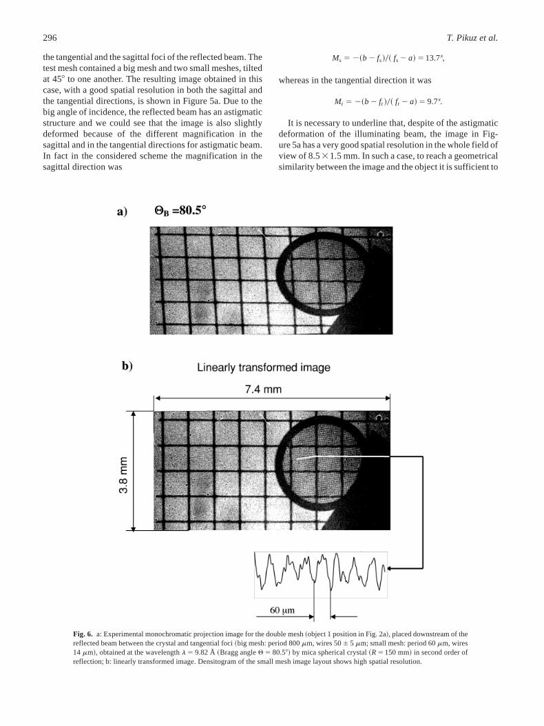
Fig. 6. a: Experimental monochromatic projection image for the double mesh~object 1 position in Fig. 2a!, placed downstream of thereflected beam between the crystal and tangential foci~big mesh: period 800mm, wires 506 5 mm; small mesh: period 60mm, wires14 mm!, obtained at the wavelengthl 5 9.82 Å ~Bragg angleQ 5 80.58! by mica spherical crystal~R5 150 mm! in second order ofreflection; b: linearly transformed image. Densitogram of the small mesh image layout shows high spatial resolution.
296 T. Pikuz et al.

do a linear geometrical transformation according with theratio Ms0Mt . The result of this linear transformation isshown in Figure 5b. It is clearly seen that after such atransformation the image is stigmatic, and it has a magnifi-cation 9.7x and a very good correspondence to the initialshape of the object.
For many plasma-backlighting applications it is veryimportant to distinguish the monochromatic backlightingradiation from the strong background radiation of the plasmaobject. To do it, usually some type of diaphragm is placedat the tangential foci at the Rowland circle. It means thatit is very important to consider the backlighting scheme
in which the object will stay after the crystal, but insidethe Rowland circle, before the tangential foci~the aboveray-tracing modeling has been done for this type ofscheme!. The scheme of such an experiment is presentedin Fig. 2a~Object 1 case; see also the description in Table 1,Exp. 2! and the results of this type of experiment is pre-sented in Figure 6a. For a better comparison with the pre-vious experimental scheme, the Bragg angle in this experimenthas been chosen the same~Q 5 80.58! as in the experimen-tal conditions of Figure 5. In experiment 2, which weconsidered now, the magnification in the sagittal directionwas
Fig. 7. a: Experimental monochromatic projection image for the double mesh~object 1 position in Fig. 2a!, placed downstream of thereflected beam between the crystal and tangential foci~big mesh: period 800mm, wires 506 5 mm; small mesh: period 60mm, wires14 mm!, obtained at the wavelengthl 5 9.22 Å ~Bragg angleQ 5 67.98! by spherical mica crystal~R5 100 mm! in second order ofreflection; b: linearly transformed image. Densitograms of the small mesh image in different directions shows high spatial resolution.
Easy spectrally tunable highly efficient X-ray backlighting schemes 297

Ms 5 ~b 2 fs!0~ fs 2 a! 5 5x
whereas in the tangential direction it was
Mt 5 ~b 2 ft !0~ ft 2 a! 5 6.2x.
We could see that still, despite the astigmatic deformationof the illuminating beam, the image in Figure 6a has a verygood spatial resolution in the whole field of view of 7.433.8 mm2. Again, like above, to reach the geometrical simi-larity between the image and the object it is sufficient to doa linear geometrical transformation, according with the ratioMs0Mt . The result of such a linear transformation is shownin Figure 6b. It is clearly seen that, after such transforma-tion, the image is stigmatic and it has a magnification 5x anda very good correspondence to the initial shape of the object.From comparison of the images from Figures 2 and 6 weclearly see a very good coincidence between experimentaland ray-tracing results.
As was demonstrated by ray-tracing modeling, it is pos-sible to obtain a very good spatial resolution also for biggerBragg angles. So, in this case it is interesting experimentallyto obtain images in such a scheme for bigger Bragg angles,which lay farther from the normal. The result of such anexperiment is presented in Figure 7a~see also the descrip-tion of the experimental conditions in Table 1, Exp. 3!. TheBragg angle in this experiment corresponds to ray-tracingmodeling and wasQ 5 67.98, so it was very far from thenormal. As can be seen from Figure 7a, the astigmatism ofthe obtained image is very big. But such strong astigmatismdoes not dramatically decrease the spatial resolution of theimage and still in both directions the spatial resolution isvery high. In Experiment 3 the magnification in the sagittaldirection was
Ms 5 ~b 2 fs!0~ fs 2 a! 5 5x
whereas in the tangential direction it was
Mt 5 ~b 2 ft !0~ ft 2 a! 5 12.3x.
Like above, to reach a geometrical similarity between theimage and the object it is sufficient to do a simple lineargeometrical transformation, according with the ratioMs0Mt .The result of such a linear transformation is shown inFigure 7b. It is clearly seen that, after such a transformation,the image is stigmatic and it has a magnification 5x and avery good correspondence to the initial shape of the object.
Thus, from the experiments carried out and from theray-tracing modeling, it is possible to conclude that whenthe angles of incidence of the backlighter beams on thecrystal were rather big~;10 and;228!, the beams reflectedby the crystal always had an astigmatic profile and theobtained images of the objects were astigmatic. Such adisadvantage is crucial in the case of working in the visi-ble spectral range with usual optical devices; but in the
case of the X-ray spectral range, where crystal optics haveunique properties~due to the Bragg conditions! to reflectonly very narrow beams, such a disadvantage is not reallyessential and it still allows us to obtain images with asufficiently high spatial resolution in both directions. Fur-thermore, a simple linear transformation of the images allowedus to reconstruct them with a high enough accuracy~adeformation in all directions not larger than 2% remainsfor images obtained under an angle of incidence of 108,and no more then 15% for an angle of incidence of 228!.Due to the small size of the X-ray backlighter source, thereconstructed images have a very high spatial resolution~better than 10mm for a Bragg angle around 808 andabout 15–20mm for a Bragg angle around 688! in a bigfield of view.
4. CONCLUSIONS
In summary, we proposed a new modification of the X-raybacklighting and self-emitting imaging technique~based onthe use of spherically bent crystal!, which can be efficientlyused under Bragg angles far from 908. The data presented inthis article demonstrate that such a technique allows us toobtain X-ray monochromatic backlighting images of inves-tigated objects in a big field of view~some square milli-meters!, with a spatial resolution up to 10mm. It gives thepossibility to strongly increase the spectral tunability ofbacklighting imaging systems based on spherically bentcrystals, which could be very useful for different plasmadiagnostic applications.
REFERENCES
Aglitskiy, Y., Lehechka, T., Deniz, A., Hardgrove, J., Seely,J., Brown, C., Feldman, U., Pawley, C., Gerber, K.,Bodner, S., Obenschain, S., Lehmberg, R., McLean, E.,Pronko, M., Sethian, J., Stamper, J., Schmitt, A., Sulli-van, C., Holland, G. & Laming, M. ~1996!. X-ray emissionfrom plasmas created by smoothed KrF laser irradiation.Phys.Plasmas3, 3438–3447.
Aglitskiy, Y., Lehechka, T., Deniz, A. Hardgrove, J., Seely,J., Brown, C., Feldman, U., Pawley, C., Gerber, K.,Bodner, S., Obenschain, S., Lehmberg, R., McLean, E.,Pronko, M., Sethian, J., Stamper, J., Schmitt, A., Sulli-van, C., Holland G. & Laming, M. ~1997!. X-ray spectros-copy of plasmas created by the Nike KrF laser.Rev. Sci.Instrum.68, 806–809.
Aglitskiy, Y., Lehechka, T., Obenschain, S., Bodner, S.,Pawley, C., Gerber, K., Sethian, J., Brown, C.M., Seely,J., Feldman, U. & Holland, G. ~1998!. High-resolutionmonochromatic X-ray imaging system based on sphericallybent crystals.Appl. Opt.37, 5253–5361.
Aglitskiy, Y., Lehechka, T., Obenschain, S., Pawley, C.,Brown, C.M. & Seely, J. ~1999!. X-ray crystal imagers forinertial confinement fusion experiments.Rev. Sci. Instrum.70,530–535.
Aglitskiy, Y., Velikovich, A.L., Karasik, M., Serlin, V.,Pawely, C.J., Schmitt A.J., Obenschain, S.P., Mostovych,
298 T. Pikuz et al.
A.N., Gardner, J.H. & Metzler, N. ~2001a!. Direct obser-vation of mass oscillations due to ablative Richtmyer–Meshkovinstability in plastic targets.Phys. Rev. Lett.87, 265001.
Aglitskiy, Y., Velikovich, A.L., Karasik, M., Serlin, V.,Pawely, C.J., Schmitt A.J., Obenschain, S.P., Mostovych,A.N., Gardner, J.H. & Metzler, N. ~2001b!. Direct obser-vation of feedout-related mass oscillations in plastic targets.Phys. Rev. Lett.87, 265002.
Belyaev, L.M., Gil’varg, A.B., Mikhailov, Yu.A., Pikuz,S.A., Sklizkov, G.V., Faenov, A.Ya. & Fedotov, S.I. ~1976!.X-ray photography of laser plasmas with the aid of analyzercrystals bent to form second-order surfaces.Sov. J. QuantumElectron.6, 1121–1122.
Bollanti, S., Cotton, R., Di Lazzaro, P., Flora, F., Letardi,T., Lisi, N., Batani, D., Conti, A., Mauri, A., Palladino,L., Reale, A., Belli, M., Ivanzini, F., Scafati, A., Reale,L., Tabocchini, A., Faenov, A.Ya., Pikuz, T.A. & Osterheld,A. ~1996!. The development and characterization of an XeClexcimer laser generated soft X-ray plasma source and its appli-cations.Il Nuovo Cimento18D, 1241–1255.
Bollanti, S., Albertano, P., Belli, M., Di Lazzaro, P.,Faenov, A.Ya., Flora, F., Giordano, G., Grilli, A., Ivanzini,F., Kukhlevsky, S.V., Letardi, T., Nottola, A., Pal-ladino, L., Pikuz, T., Reale, A., Reale, L., Scafati, A.,Tabocchini, A., Turcu, I.C.E., Vigli-Papadaki, K. & Schina,G. ~1998!. Soft X-ray plasma source for atmospheric pressuremicroscopy, radiobiologyandotherapplications.IlNuovoCimento20D, 1685–1701.
Brown, C., Seely, J., Feldman, U., Obenschain, S., Bodner,S., Pawley, C., Gerber, K., Serlin, V., Sethian, J., Aglitskiy,Y., Lehechka, T. & Holland, G. ~1997!. X-ray imaging oftargets irradiated by the Nike KrF laser.Rev. Sci. Instrum.68,1099–1102.
Flora, F., Bollanti, S., Lai, A., Di Lazzaro, P., Letardi, T.,Grilli, A., Palladino, L., Tomassetti, G., Reale, A.,Reale, L., Scafati, A., Bacchetta, L., Alianelli, L.,Sanchez del Rio, M., Pikuz, T.A. & Faenov, A.Ya. ~2001!.Anovel portable, high-luminosity monochromatically tuneableX-ray microscope.Proc. SPIE4504, 240–252.
Fraenkel, M., Zigler, A., Faenov, A.Ya. & Pikuz, T.A.~1999!. Large-field high-resolution X-ray monochromatic micro-scope, based on spherical crystal and high-repetition-rate femto-second laser-produced plasma.Physica Scripta59, 246–249.
Hölzer, G., Wehrhan, O., Heinisch, J., Foerster, E., Pikuz,T.A., Faenov, A.Ya., Pikuz, S.A., Romanova, V.M. &Shelkovenko, T.A. ~1998!. Flat and spherically bent musco-vite mica crystals for X-ray spectroscopy.Physica Scripta57,301–309.
Koch, J.A., Landen, O.L., Barbee, Jr., T.W., Celliers, P., DaSilva, L.B., Glendinning, S.G., Hammel, B.A., Kalantar,D.H., Brown, C., Seely, J., Bennett, G.R. & Hsing, W.~1998!. High-energy X-ray microscopy techniques for laser–fusion plasma research at the National Ignition Facility.Appl.Opt.37, 1784–1795.
Koch, J.A., Landen, O.L., Hammel, B.A., Brown, C.M.,Seely, J. & Aglitskiy, Y. ~1999!. Recent progress in high-energy, high-resolution X-ray imaging techniques for applica-tion to the National Ignition Facility.Rev. Sci. Instrum.70,525–529.
Koch, J.A., Aglitskiy, Y., Brown, C., Freeman, R., Hatchett,S., Holland, G., Key, M., MacKinnon, A., Seely, J.,
Snavely, R., Stephens, R. ~2003!. 4.5- and 8-keV emissionand absorption X-ray imaging using spherically bent quartz203 and 211 crystals.Rev. Sci. Instrum.74, 2130.
Labate, L., Galimberti, M., Giulietti, A., Giulietti, D.,Gizzi, L.A., Laville, P. & Tomassini, P. ~2004!. Ray-tracingsimulation of an X-ray optics based upon a bent crystal fordifferential absorption applications.Laser Part. Beams22,253–259.
Missalla, T., Uschmann, I., Förster, E., Jenke, G. & von derLinde, D. ~1999!. Monochromatic focusing of subpicosecondX-ray pulses in the keV range.Rev. Sci. Instrum.70, 1288–1299.
Pikuz, S.A., Shelkovenko, T.A., Hammer, D.A., Faenov,A.Ya., Pikuz, T.A., Dyakin, A.Ya. & Romanova, V.M.~1995a!. High luminosity monochromatic X-ray backlightingusing an incoherent plasma source to study extremely denseplasmas.J. Exp. Theor. Phys. Lett.61, 638–644.
Pikuz, T.A., Faenov, A.Ya., Pikuz, S.A., Romanova, V.M. &Shelkovenko, T.A. ~1995b!. Bragg X-ray optics for imagingspectroscopy of plasma microsources.J. X-ray Sci. Technol.5,323–340.
Pikuz, S.A., Shelkovenko, T.A., Romanova, V.M., Hammer,D.A., Faenov, A.Ya., Dyakin, V.M. & Pikuz, T.A. ~1997!.High luminosity monochromatic X-ray backlighting using anincoherent plasma source to study extremely dense plasmas.Rev. Sci. Instrum.68, 740–744.
Pikuz, T.A., Faenov, A.Ya., Fraenkel, M., Zigler, A., Flora,F., Bollanti, S., Di Lazzaro, P., Letardi, T., Grilli, A.,Palladino, L., Tomassetti, G., Reale,A., Reale, L., Limongi,T. & Bonfigli, F. ~1999!. Large-field high resolution X-ray mono-chromatic microscope, based on spherical crystal and high-repetition-rate laser-produced plasmas.Proc. SPIE3767, 67–79.
Pikuz, T.A., Faenov, A.Ya., Fraenkel, M., Zigler, A., Flora,F., Bollanti, S., Di Lazzaro, P., Letardi, T., Grilli, A.,Palladino, L., Tomassetti, G., Reale, A., Reale, L.,Scafati, A., Limongi, T., Bonfigli, F., Alianelli, L. &Sanchez del Rio, M. ~2001!. Shadow monochromatic back-lighting: Large-field high resolution X-ray shadowgraphy withimproved spectral tunability.Laser Part. Beams19, 285–293.
Sanchez del Rio, M., Faenov, A.Ya., Dyakin, V.M., Pikuz,T.A., Pikuz, S.A., Romanova, V.M. & Shelkovenko, T.A.~1997!. Ray-tracing for a monochromatic X-ray backlightingscheme, based on spherically bent crystal.Physica Scripta55,735.
Sanchez del Rio, M., Fraenkel, M., Zigler, A., Faenov,A.Ya. & Pikuz, T.A. ~1999!. Collimation of plasma producedX-rays by spherical crystals: Ray-tracing simulations and exper-imental results.Rev. Sci. Instrum.70, 1614–1620.
Sanchez del Rio, M., Alianelli, L., Pikuz, T.A., FaenovA.Ya. ~2001!. A novel imaging X-ray microscope based on aspherical crystal.Rev. Sci. Instrum.72, 3291–3303.
Sinars, D.B., Cuneo, M.E., Bennett, G.R., Wenger, D.F.,Ruggles, L.E., Vargas, M.F., Porter, J.L., Admas, R.G.,Johnson, D.W., Keller, K.L., Rambo, P.K., Rovang, D.C.,Seamen, H., Simpson, W.W., Smith, I.C. & Speas, S.C.~2003a!.MonochromaticX-raybacklightingofwire-arrayz-pinchplasmas using spherically bent quartz crystals.Rev. Sci. Instrum.74, 2202–2205.
Sinars, D.B., Bennett, G.R., Wenger, D.F., Cuneo, M.E. &Porter, J.L. ~2003b!. Evaluation of bent-crystal X-ray back-lighting and microscopy techniques for the Sandia Z-machine.Appl. Opt.42, 4059–4071.
Easy spectrally tunable highly efficient X-ray backlighting schemes 299

Uschmann, I., Fujita, K., Niki, I., Butzbach, R., Nishimura,H., Funakura, J., Nakai, M., Forster, E. & Mima, K.~2000!. Time-resolved ten-channel monochromatic imaging ofinertial confinement fusion plasmas.Appl. Opt.39, 5865–5871.
Vollbrecht, M., Treichel, O., Uschmann, I., Gabel, K.,Lebert, R. & Forster, E. ~1998!. Soft-x-ray imaging withtorroidally curved thallium acid phthalate crystals in the waterwindow.Appl. Opt.37, 1803–1807.
Workman, J., Tierney, T., Evans, S., Kyrala, G. & Benage,Jr., J. ~1999!. One-dimensional X-ray microscope for shockmeasurements in high-density aluminum plasmas.Rev. Sci.Instrum.70, 613–616.
Workman, J., Evans, S. & Kyrala, G.A. ~2001!. One-dimensional X-ray imaging using spherically bent mica crystalat 4.75 keV.Rev. Sci. Instrum.72, 674–677.
300 T. Pikuz et al.
Copyright © 2022 FDOKUMEN