Easergy P3M30 and P3M32 - Motor protection relay - GT ...
450
Easergy P3M30 and P3M32 Motor protection relay User Manual P3M/en M/G006 07/2020 www.schneider-electric.com
-
Upload
khangminh22 -
Category
Documents
-
view
0 -
download
0
Transcript of Easergy P3M30 and P3M32 - Motor protection relay - GT ...
Easergy P3M30 and P3M32Motor protection relay
User ManualP3M/en M/G00607/2020
www.schneider-electric.com

Table of Contents1 About this manual........................................................................ 131.1 Purpose...........................................................................................................131.2 Related documents......................................................................................... 131.3 Abbreviations and terms................................................................................. 14
2 Product introduction..................................................................... 202.1 Warranty..........................................................................................................202.2 Product overview............................................................................................ 202.3 Product selection guide...................................................................................212.4 Access to device configuration....................................................................... 29
2.4.1 User accounts.......................................................................................292.4.2 Logging on via the front panel.............................................................. 302.4.3 HTTP and FTP logon details................................................................ 312.4.4 Password management........................................................................ 312.4.5 Changing passwords for administrator and configurator accountsvia PuTTY...................................................................................................... 322.4.6 Password restoring............................................................................... 33
2.5 Front panel......................................................................................................342.5.1 Push-buttons.........................................................................................342.5.2 LED indicators...................................................................................... 352.5.3 Configuring the LED names via Easergy Pro....................................... 362.5.4 Controlling the alarm screen.................................................................372.5.5 Accessing operating levels................................................................... 372.5.6 Adjusting the LCD contrast................................................................... 372.5.7 Testing the LEDs and LCD screen........................................................372.5.8 Controlling an object with selective control...........................................372.5.9 Controlling an object with direct control................................................ 382.5.10 Menus................................................................................................. 38
2.5.10.1 Moving in the menus ............................................................ 402.5.10.2 Local panel messages...........................................................41
2.6 Easergy Pro setting and configuration tool..................................................... 412.7 Low-power instrument transformers............................................................... 42
3 Mechanical structure.................................................................... 433.1 Modularity....................................................................................................... 433.2 Slot info and order code..................................................................................45
4 Measurement functions................................................................464.1 Primary, secondary and per unit scaling......................................................... 53
4.1.1 Frequency adaptation mode................................................................. 594.1.2 Current scaling......................................................................................604.1.3 Voltage scaling for analog module E, F................................................ 62
4.2 Measurements for protection functions...........................................................654.3 Measurements for arc flash detection function............................................... 66
Table of Contents Motor protection relay
P3M/en M/G006 3
4.4 RMS values.....................................................................................................674.5 Harmonics and total harmonic distortion (THD)..............................................684.6 Demand values............................................................................................... 684.7 Minimum and maximum values...................................................................... 704.8 Maximum values of the last 31 days and 12 months...................................... 714.9 Memory management of measurements........................................................ 734.10 Power and current direction.......................................................................... 754.11 Symmetrical components..............................................................................76
5 Control functions.......................................................................... 785.1 Digital outputs................................................................................................. 785.2 Digital inputs................................................................................................... 815.3 Virtual inputs and outputs................................................................................875.4 Matrix.............................................................................................................. 93
5.4.1 Output matrix........................................................................................ 935.4.2 Blocking matrix..................................................................................... 945.4.3 LED matrix............................................................................................ 955.4.4 Object block matrix............................................................................... 98
5.5 Releasing latches............................................................................................985.5.1 Releasing latches using Easergy Pro................................................... 985.5.2 Releasing latches using buttons and local panel display......................995.5.3 Releasing latches using F1 or F2 buttons............................................ 99
5.6 Controllable objects...................................................................................... 1005.6.1 Object control with digital inputs......................................................... 1015.6.2 Local or remote selection....................................................................1025.6.3 Object control with I and O buttons.....................................................1025.6.4 Object control with F1 and F2.............................................................103
5.7 Logic functions.............................................................................................. 1045.8 Local panel....................................................................................................112
5.8.1 Mimic view...........................................................................................1125.8.2 Local panel configuration.................................................................... 115
6 Protection functions....................................................................1216.1 Current transformer requirements for overcurrent elements.........................121
6.1.1 CT requirements when settings are unknown.................................... 1226.1.2 Principle for calculating the saturation current in class P................... 1226.1.3 Examples of calculating the saturation current in class P...................1236.1.4 Principle for calculating the saturation current in class PX................. 1246.1.5 Examples of calculating the saturation current in class PX................ 124
6.2 Maximum number of protection stages in one application............................1246.3 General features of protection stages...........................................................1256.4 Dependent operate time............................................................................... 132
6.4.1 Standard dependent delays using IEC, IEEE, IEEE2 and RI curves..1346.4.2 Free parameterization using IEC, IEEE and IEEE2 curves................ 1556.4.3 Programmable dependent time curves...............................................156
6.5 Synchrocheck (ANSI 25)...............................................................................1576.6 Undervoltage (ANSI 27)................................................................................162
Motor protection relay Table of Contents
4 P3M/en M/G006
6.7 Directional power (ANSI 32) ........................................................................ 1656.8 Phase undercurrent (ANSI 37)......................................................................1666.9 Negative sequence overcurrent (ANSI 46) .................................................. 1676.10 Incorrect phase sequence (ANSI 47) .........................................................1696.11 Negative sequence overvoltage protection (ANSI 47)................................ 1706.12 Motor start-up supervision (ANSI 48) .........................................................1716.13 Thermal overload (ANSI 49 RMS).............................................................. 1766.14 Breaker failure (ANSI 50BF)....................................................................... 1806.15 Breaker failure 1 and 2 (ANSI 50BF).......................................................... 1826.16 Switch-on-to-fault (ANSI 50HS) ................................................................. 1886.17 Phase overcurrent (ANSI 50/51).................................................................1906.18 Earth fault overcurrent (ANSI 50N/51N) .................................................... 194
6.18.1 Earth fault faulty phase detection algorithm......................................1976.19 Capacitor bank unbalance (ANSI 51C) ......................................................198
6.19.1 Taking unbalance protection into use............................................... 2016.20 Locked rotor (ANSI 51LR)...........................................................................2056.21 Overvoltage (ANSI 59)................................................................................2086.22 Neutral voltage displacement (ANSI 59N).................................................. 2126.23 Motor restart inhibition (ANSI 66) ...............................................................2156.24 Directional phase overcurrent (ANSI 67) ................................................... 2176.25 Directional earth fault overcurrent (ANSI 67N)........................................... 221
6.25.1 Earth fault faulty phase detection algorithm......................................2276.26 Magnetizing inrush detection (ANSI 68F2)................................................. 2296.27 Fifth harmonic detection (ANSI 68H5)........................................................ 2316.28 Overfrequency and underfrequency (ANSI 81) ..........................................2326.29 Rate of change of frequency (ANSI 81R)................................................... 2346.30 Lockout (ANSI 86).......................................................................................2386.31 Differential overcurrent protection (ANSI 87M) .......................................... 2406.32 Arc flash detection (AFD)............................................................................249
6.32.1 Arc flash detection, general principle................................................2496.32.2 Arc flash detection menus................................................................ 2496.32.3 Configuration example of arc flash detection....................................2546.32.4 Arc flash detection characteristics.................................................... 258
6.33 Programmable stages (ANSI 99)................................................................ 259
7 Supporting functions.................................................................. 2627.1 Event log....................................................................................................... 2627.2 Disturbance recording...................................................................................264
7.2.1 Configuring the disturbance recorder................................................. 2697.3 Cold load start and magnetizing inrush.........................................................2707.4 System clock and synchronization................................................................2717.5 Voltage sags and swells................................................................................2787.6 Voltage interruptions..................................................................................... 2817.7 Current transformer supervision (ANSI 60)...................................................2837.8 Voltage transformer supervision (ANSI 60FL).............................................. 2857.9 Circuit breaker wear......................................................................................2877.10 Circuit breaker condition monitoring........................................................... 293
Table of Contents Motor protection relay
P3M/en M/G006 5
7.11 Energy pulse outputs...................................................................................2967.12 Running hour counter................................................................................. 2997.13 Timers......................................................................................................... 3007.14 Combined overcurrent status......................................................................3027.15 Trip circuit supervision (ANSI 74) ...............................................................307
7.15.1 Trip circuit supervision with one digital input.....................................3077.15.2 Trip circuit supervision with two digital inputs................................... 313
8 Communication and protocols....................................................3178.1 Cybersecurity................................................................................................ 3178.2 Communication ports.................................................................................... 317
8.2.1 Ethernet port....................................................................................... 3218.2.2 Disabling the Ethernet communication............................................... 321
8.3 Communication protocols............................................................................. 3238.3.1 Modbus RTU and Modbus TCP..........................................................3248.3.2 Profibus DP.........................................................................................3248.3.3 SPA-bus..............................................................................................3258.3.4 IEC 60870-5-103 (IEC-103)................................................................3258.3.5 DNP 3.0.............................................................................................. 3268.3.6 IEC 60870-5-101 (IEC-101)................................................................3268.3.7 IEC 61850...........................................................................................3278.3.8 HTTP server – Webset....................................................................... 327
8.4 IP filter...........................................................................................................3278.4.1 Configuring the IP filter....................................................................... 3288.4.2 Unexpected packets........................................................................... 3308.4.3 Alarms.................................................................................................331
9 Applications and configuration examples...................................3329.1 Industrial motor protection............................................................................ 3339.2 Rotor earth fault protection (ANSI 64R)........................................................ 3339.3 Arc flash detection........................................................................................ 3349.4 Using CSH120 and CSH200 with core balance CTs.................................... 337
10 Installation................................................................................ 33910.1 Checking the consignment..........................................................................33910.2 Product identification...................................................................................33910.3 Storage....................................................................................................... 34010.4 Mounting..................................................................................................... 34110.5 Connections................................................................................................ 345
10.5.1 Supply voltage cards........................................................................ 34610.5.2 Analog measurement cards..............................................................348
10.5.2.1 Analog measurement cards E and 1 (slot 8)....................... 34810.5.2.2 Analog measurement cards F and 2 (slot 8)....................... 35010.5.2.3 Low-power instrument transformer measurement card M(slot 8)............................................................................................... 35210.5.2.4 Analog measurement cards T and 1 (slot 4)....................... 353
10.5.3 I/O cards........................................................................................... 35510.5.3.1 I/O card “B = 3BIO+2Arc”.................................................... 355
Motor protection relay Table of Contents
6 P3M/en M/G006
10.5.3.2 I/O card “C = F2BIO+1Arc”..................................................35610.5.3.3 I/O card “D = 2IGBT”........................................................... 35710.5.3.4 I/O option card “D=4Arc”..................................................... 35810.5.3.5 I/O card “G = 6DI+4DO”...................................................... 35910.5.3.6 I/O card “H = 6DI + 4DO (NC)”............................................36110.5.3.7 I/O card “I = 10DI”................................................................363
10.5.4 Arc flash sensor................................................................................ 36410.5.4.1 Mounting the sensors to the switchgear..............................36510.5.4.2 Connecting the sensors to the device................................. 367
10.5.5 Communication cards....................................................................... 36810.5.5.1 COM 3 – COM 4 ports.........................................................374
10.5.6 Local port.......................................................................................... 38010.5.7 Connection data................................................................................38010.5.8 External option modules................................................................... 390
10.5.8.1 VSE-001 fiber-optic interface module..................................39010.5.8.2 VSE-002 RS-485 interface module..................................... 39110.5.8.3 VSE-009 DeviceNet interface module.................................39310.5.8.4 VPA-3CG Profibus interface module................................... 39410.5.8.5 VIO 12A RTD and analog input / output modules............... 395
10.5.9 Block diagrams................................................................................. 39510.5.10 Connection examples..................................................................... 399
10.6 Arc flash detection system setup and testing..............................................40310.6.1 Setting up the arc flash system.........................................................40310.6.2 Commissioning and testing...............................................................404
10.6.2.1 Checking zones...................................................................40510.6.2.2 Disconnecting trip circuits....................................................40510.6.2.3 Sensor testing..................................................................... 406
10.6.2.3.1 Testing the sensors.............................................40710.6.2.3.2 Testing the sensor supervision........................... 40710.6.2.3.3 Testing the binary I/O connectivity......................408
10.6.3 Test report ........................................................................................40810.6.3.1 Filling in the test report........................................................ 40810.6.3.2 Test report example.............................................................409
10.6.4 Troubleshooting................................................................................ 41010.7 Low-power instrument transformer testing..................................................410
10.7.1 Testing tools and equipment............................................................. 41110.7.2 Testing the low-power current transformer measurements...............41110.7.3 Testing the low-power voltage transformer measurements.............. 412
10.8 Voltage measurement modes..................................................................... 41210.8.1 Multiple channel voltage measurement – conventional VT.............. 41410.8.2 Multiple channel voltage measurement – LPVT............................... 423
10.9 CSH120 and CSH200 Core balance CTs................................................... 426
11 Test and environmental conditions........................................... 43111.1 Disturbance tests.........................................................................................43111.2 Electrical safety tests...................................................................................43211.3 Mechanical tests..........................................................................................433
Table of Contents Motor protection relay
P3M/en M/G006 7
11.4 Environmental tests.....................................................................................43311.5 Environmental conditions............................................................................ 43411.6 Casing......................................................................................................... 435
12 Maintenance.............................................................................43612.1 Preventive maintenance............................................................................. 43612.2 Periodic testing........................................................................................... 43712.3 Hardware cleaning...................................................................................... 43712.4 System status messages............................................................................ 43712.5 Spare parts................................................................................................. 43712.6 Self-supervision.......................................................................................... 437
12.6.1 Diagnostics....................................................................................... 44012.7 Arc flash detection system maintenance.................................................... 442
12.7.1 Visual inspection...............................................................................44312.7.2 Hardware cleaning............................................................................44312.7.3 Sensor condition and positioning check........................................... 443
13 Order codes and accessories.................................................. 44513.1 Order codes................................................................................................ 44513.2 Accessories.................................................................................................447
14 Firmware revision.....................................................................448
Motor protection relay Table of Contents
8 P3M/en M/G006
Legal informationThe Schneider Electric brand and any registered trademarks of Schneider ElectricIndustries SAS referred to in this guide are the sole property of Schneider ElectricSA and its subsidiaries. They may not be used for any purpose without theowner's permission, given in writing. This guide and its content are protected,within the meaning of the French intellectual property code (Code de la propriétéintellectuelle français, referred to hereafter as "the Code"), under the laws ofcopyright covering texts, drawings and models, as well as by trademark law. Youagree not to reproduce, other than for your own personal, noncommercial use asdefined in the Code, all or part of this guide on any medium whatsoever withoutSchneider Electric's permission, given in writing. You also agree not to establishany hypertext links to this guide or its content. Schneider Electric does not grantany right or license for the personal and noncommercial use of the guide or itscontent, except for a non-exclusive license to consult it on an "as is" basis, at yourown risk. All other rights are reserved.
Electrical equipment should be installed, operated, serviced and maintained onlyby qualified personnel. No responsibility is assumed by Schneider Electric for anyconsequences arising out of the use of this material.
As standards, specifications and designs change from time to time, please ask forconfirmation of the information given in this publication.
Legal information Motor protection relay
P3M/en M/G006 9
Safety informationImportant information
Read these instructions carefully and look at the equipment to become familiarwith the device before trying to install, operate, service or maintain it.
The following special messages may appear throughout this publication or on theequipment to warn of potential hazards or to call attention to information thatclarifies or simplifies a procedure.
This is the safety alert symbol. It is used toalert you to potential personal injuryhazards. Obey all safety messages thatfollow this symbol to avoid possible injury ordeath.
The addition of either symbol to a “Danger”or “Warning” safety label indicates that anelectrical hazard exists which will result inpersonal injury if the instructions are notfollowed.
DANGERDANGER indicates a hazardous situation which, if not avoided, will resultin death or serious injury.
WARNINGWARNING indicates a hazardous situation which, if not avoided, couldresult in death or serious injury.
CAUTIONCAUTION indicates a hazardous situation which, if not avoided, couldresult in minor or moderate injury.
NOTICENOTICE is used to address practices not related to physical injury.
Please note
Electrical equipment must only be installed, operated, serviced, and maintainedby qualified personnel. A qualified person is one who has skills and knowledgerelated to the construction, installation, and operation of electrical equipment andhas received safety training to recognize and avoid the hazards involved.
No responsibility is assumed by Schneider Electric for any consequences arisingout of the use of this material.
Motor protection relay Safety information
10 P3M/en M/G006

Protective grounding
The user is responsible for compliance with all the existing international andnational electrical codes concerning protective grounding of any device.
Safety information Motor protection relay
P3M/en M/G006 11

EU directive complianceEMC compliance
2014/30/EU
Compliance with the European Commission's EMC Directive. Product SpecificStandard was used to establish conformity:• EN 60255-26 2013
Product safety
2014/35/EU
Compliance with the European Commission's Low Voltage Directive. ProductSpecific Safety Standard was used to establish conformity:• EN 60255-27 2014
Motor protection relay EU directive compliance
12 P3M/en M/G006
1 About this manual
1.1 Purpose
This document contains instructions on the installation, commissioning andoperation of Easergy P3M30 and P3M32.
This document is intended for persons who are experts on electrical powerengineering, and it covers the relay models as described by the order code.
Related topics13.1 Order codes
1.2 Related documents
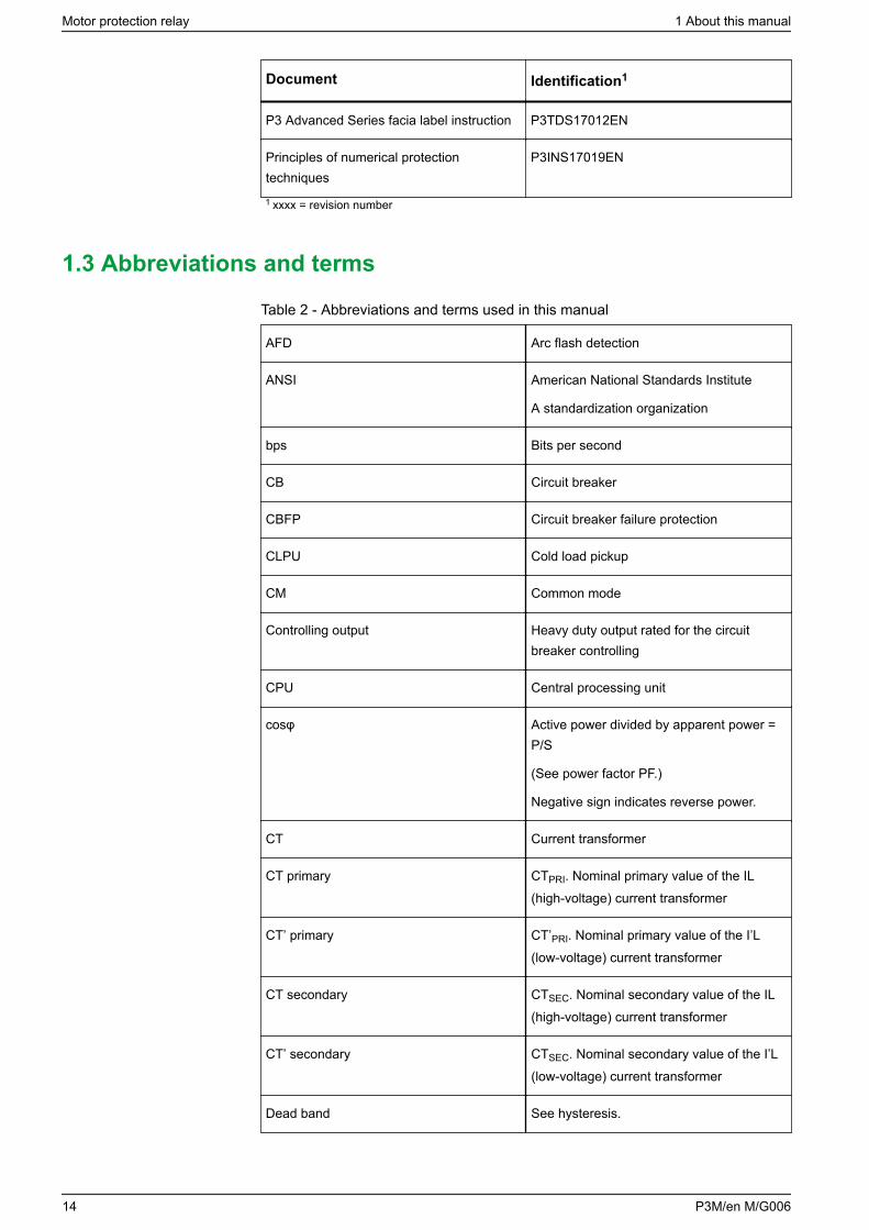
Table 1 - Related documents
Document Identification1
P3 Advanced Quick Start P3x3x/EN QS/xxxx
Easergy Pro Setting and Configuration ToolUser Manual
P3eSetup/EN M/xxxx
RTD and mA Output/Input Modules UserManual
P3VIO12A/EN M/A001
Profibus Interface Module User Manual P3VPA3CG/EN M/A001
IEC 61850 configuration instructions P3APS17001EN
Rapid Spanning Tree Protocol (RSTP) P3APS17002EN
Parallel Redundancy Protocol for EasergyP3 relays with dual-port 100 Mbps Ethernetinterface
P3APS17004EN
Communication parameter protocolmappings
P3TDS17005EN
Easergy P3 protection functions'parameters and recorded values
P3TDS17006EN
DeviceNet data model P3APS17008EN
IEC103 Interoperability List P3TDS17009EN
DNP 3.0 Device Profile Document P3TDS17010EN
1 About this manual Motor protection relay
P3M/en M/G006 13
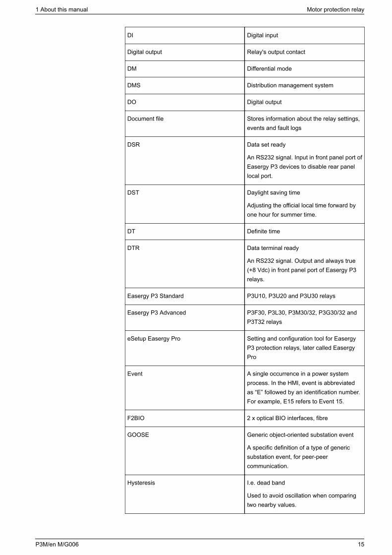
Document Identification1
P3 Advanced Series facia label instruction P3TDS17012EN
Principles of numerical protectiontechniques
P3INS17019EN
1 xxxx = revision number
1.3 Abbreviations and terms
Table 2 - Abbreviations and terms used in this manual
AFD Arc flash detection
ANSI American National Standards Institute
A standardization organization
bps Bits per second
CB Circuit breaker
CBFP Circuit breaker failure protection
CLPU Cold load pickup
CM Common mode
Controlling output Heavy duty output rated for the circuitbreaker controlling
CPU Central processing unit
cosφ Active power divided by apparent power =P/S
(See power factor PF.)
Negative sign indicates reverse power.
CT Current transformer
CT primary CTPRI. Nominal primary value of the IL(high-voltage) current transformer
CT’ primary CT’PRI. Nominal primary value of the I’L(low-voltage) current transformer
CT secondary CTSEC. Nominal secondary value of the IL(high-voltage) current transformer
CT’ secondary CTSEC. Nominal secondary value of the I’L(low-voltage) current transformer
Dead band See hysteresis.
Motor protection relay 1 About this manual
14 P3M/en M/G006
DI Digital input
Digital output Relay's output contact
DM Differential mode
DMS Distribution management system
DO Digital output
Document file Stores information about the relay settings,events and fault logs
DSR Data set ready
An RS232 signal. Input in front panel port ofEasergy P3 devices to disable rear panellocal port.
DST Daylight saving time
Adjusting the official local time forward byone hour for summer time.
DT Definite time
DTR Data terminal ready
An RS232 signal. Output and always true(+8 Vdc) in front panel port of Easergy P3relays.
Easergy P3 Standard P3U10, P3U20 and P3U30 relays
Easergy P3 Advanced P3F30, P3L30, P3M30/32, P3G30/32 andP3T32 relays
eSetup Easergy Pro Setting and configuration tool for EasergyP3 protection relays, later called EasergyPro
Event A single occurrence in a power systemprocess. In the HMI, event is abbreviatedas “E” followed by an identification number.For example, E15 refers to Event 15.
F2BIO 2 x optical BIO interfaces, fibre
GOOSE Generic object-oriented substation event
A specific definition of a type of genericsubstation event, for peer-peercommunication.
Hysteresis I.e. dead band
Used to avoid oscillation when comparingtwo nearby values.
1 About this manual Motor protection relay
P3M/en M/G006 15
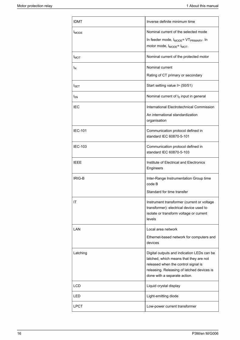
IDMT Inverse definite minimum time
IMODE Nominal current of the selected mode
In feeder mode, IMODE= VTPRIMARY. Inmotor mode, IMODE= IMOT.
IMOT Nominal current of the protected motor
IN Nominal current
Rating of CT primary or secondary
ISET Start setting value I> (50/51)
I0N Nominal current of I0 input in general
IEC International Electrotechnical Commission
An international standardizationorganisation
IEC-101 Communication protocol defined instandard IEC 60870-5-101
IEC-103 Communication protocol defined instandard IEC 60870-5-103
IEEE Institute of Electrical and ElectronicsEngineers
IRIG-B Inter-Range Instrumentation Group timecode B
Standard for time transfer
IT Instrument transformer (current or voltagetransformer): electrical device used toisolate or transform voltage or currentlevels
LAN Local area network
Ethernet-based network for computers anddevices
Latching Digital outputs and indication LEDs can belatched, which means that they are notreleased when the control signal isreleasing. Releasing of latched devices isdone with a separate action.
LCD Liquid crystal display
LED Light-emitting diode
LPCT Low-power current transformer
Motor protection relay 1 About this manual
16 P3M/en M/G006
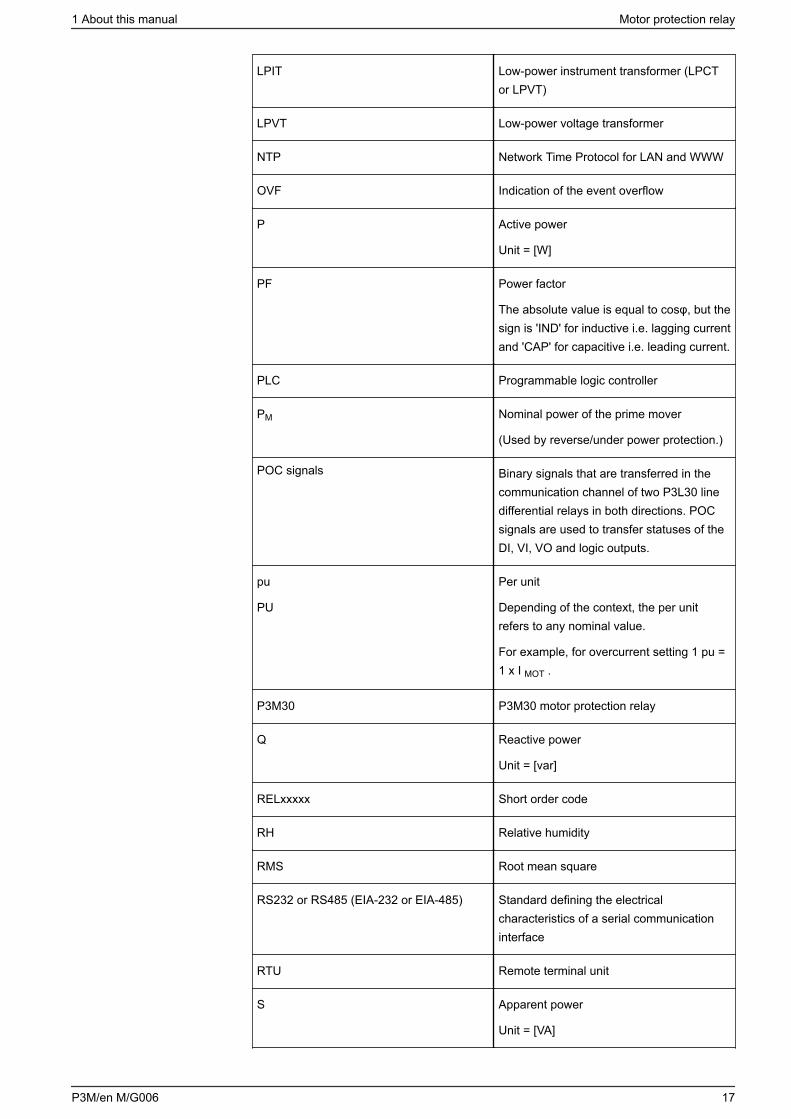
LPIT Low-power instrument transformer (LPCTor LPVT)
LPVT Low-power voltage transformer
NTP Network Time Protocol for LAN and WWW
OVF Indication of the event overflow
P Active power
Unit = [W]
PF Power factor
The absolute value is equal to cosφ, but thesign is 'IND' for inductive i.e. lagging currentand 'CAP' for capacitive i.e. leading current.
PLC Programmable logic controller
PM Nominal power of the prime mover
(Used by reverse/under power protection.)
POC signals Binary signals that are transferred in thecommunication channel of two P3L30 linedifferential relays in both directions. POCsignals are used to transfer statuses of theDI, VI, VO and logic outputs.
pu
PU
Per unit
Depending of the context, the per unitrefers to any nominal value.
For example, for overcurrent setting 1 pu =1 x I MOT .
P3M30 P3M30 motor protection relay
Q Reactive power
Unit = [var]
RELxxxxx Short order code
RH Relative humidity
RMS Root mean square
RS232 or RS485 (EIA-232 or EIA-485) Standard defining the electricalcharacteristics of a serial communicationinterface
RTU Remote terminal unit
S Apparent power
Unit = [VA]
1 About this manual Motor protection relay
P3M/en M/G006 17
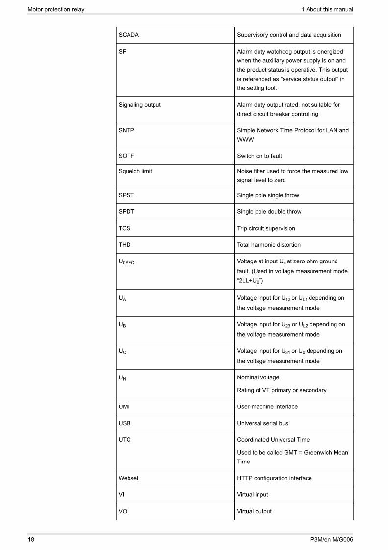
SCADA Supervisory control and data acquisition
SF Alarm duty watchdog output is energizedwhen the auxiliary power supply is on andthe product status is operative. This outputis referenced as "service status output" inthe setting tool.
Signaling output Alarm duty output rated, not suitable fordirect circuit breaker controlling
SNTP Simple Network Time Protocol for LAN andWWW
SOTF Switch on to fault
Squelch limit Noise filter used to force the measured lowsignal level to zero
SPST Single pole single throw
SPDT Single pole double throw
TCS Trip circuit supervision
THD Total harmonic distortion
U0SEC Voltage at input Uc at zero ohm groundfault. (Used in voltage measurement mode“2LL+U0”)
UA Voltage input for U12 or UL1 depending onthe voltage measurement mode
UB Voltage input for U23 or UL2 depending onthe voltage measurement mode
UC Voltage input for U31 or U0 depending onthe voltage measurement mode
UN Nominal voltage
Rating of VT primary or secondary
UMI User-machine interface
USB Universal serial bus
UTC Coordinated Universal Time
Used to be called GMT = Greenwich MeanTime
Webset HTTP configuration interface
VI Virtual input
VO Virtual output
Motor protection relay 1 About this manual
18 P3M/en M/G006
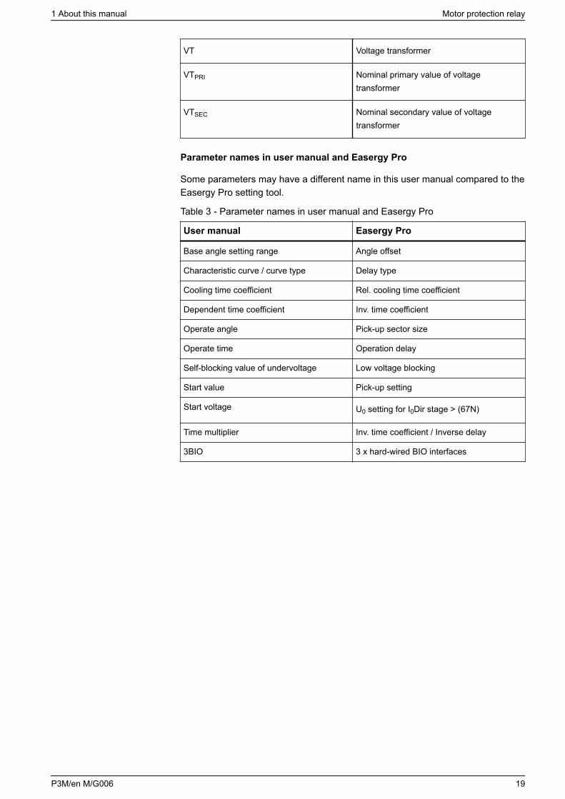
VT Voltage transformer
VTPRI Nominal primary value of voltagetransformer
VTSEC Nominal secondary value of voltagetransformer
Parameter names in user manual and Easergy Pro
Some parameters may have a different name in this user manual compared to theEasergy Pro setting tool.
Table 3 - Parameter names in user manual and Easergy Pro
User manual Easergy Pro
Base angle setting range Angle offset
Characteristic curve / curve type Delay type
Cooling time coefficient Rel. cooling time coefficient
Dependent time coefficient Inv. time coefficient
Operate angle Pick-up sector size
Operate time Operation delay
Self-blocking value of undervoltage Low voltage blocking
Start value Pick-up setting
Start voltage U0 setting for I0Dir stage > (67N)
Time multiplier Inv. time coefficient / Inverse delay
3BIO 3 x hard-wired BIO interfaces
1 About this manual Motor protection relay
P3M/en M/G006 19
2 Product introduction
2.1 Warranty
This product has a standard warranty of 2 years.
Ask your local Schneider Electric representative about our optional 10-yearwarranty. Local conditions and availability apply.
2.2 Product overview
The relay has a modular design and it can be optimized to almost all types ofmotor applications in low and medium voltage distribution systems.
Main characteristic and options
• The relay has all the necessary motor and feeder protection for industrialpower distribution networks.
• The relay has an optional interface for connecting four arc flash point sensors.• The relay has optional arc flash communications and high speed outputs to
allow for simple arc flash system configuration.• Two alternative display options
128 x 128 LCD matrix 128 x 128 LCD matrix detachable
• Power quality measurements and disturbance recorder enable capture oftransients
• Wide range of communication protocols, for example: Modbus TCP/IP Profibus IEC61850
The following options depend on the order code:
• power supply options• earth fault overcurrent input sensitivity• number of digital inputs• number of trip contacts• integrated arc-options (point sensors)• various possibilities with communication interfaces:
high-speed outputs simple arc flash system communications (BIO) fiber loop
• front panel protection of IP54
Motor protection relay 2 Product introduction
20 P3M/en M/G006
Protection functions
• Universal, adaptive protection functions for user-configurable applications likefeeder, motor and voltage protection from basic non-directional to directionalovercurrent protection, thermal overload, and auto-recloser
• Universal, adaptive protection functions for user-configurable applications likefeeder, motor and voltage protection from basic non-directional to directionalovercurrent protection and thermal overload
• Neutral voltage displacement, overvoltage and frequency protection includingsynchrocheck for two breakers
• Single-line diagram, measurements and alarms in the user-machine interface(UMI)
• User-configurable interlocking for primary object control• Optional arc flash detection utilizing point sensors and a fiber loop that can
provide system wide arc flash detection.
Virtual injection
• Current and voltage injection by manipulating the database of the product bysetting tool disturbance recorder file playback through the product's database
Robust hardware
• User-selectable Ethernet, RS485 or RS232 -based communication interfaces• Designed for demanding industrial conditions with conformal-coated printed
circuit boards• Standard USB connection (type B) for Easergy P3 setting software
Common technology for cost efficiency
• Powerful CPU supporting IEC 61850• Thanks to four setting groups, adaptation to various protection schemes is
convenient
User-machine interface (UMI)
• Clear LCD display for alarms and events• Single-line diagram mimic with control, indication and live measurements• Programmable function keys and LEDs• Circuit breaker ON/OFF control• Common firmware platform with other Easergy P3 range protection relays
2.3 Product selection guide
The selection guide provides information on the Easergy P3 platform to aid in therelay selection. It suggests Easergy P3 types suitable for your protectionrequirements, based on your application characteristics. The most typicalapplications are presented along with the associated Easergy P3 type.
2 Product introduction Motor protection relay
P3M/en M/G006 21
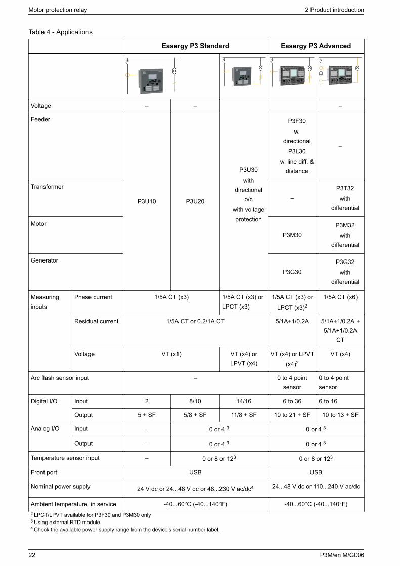
Table 4 - Applications
Easergy P3 Standard Easergy P3 Advanced
Voltage – –
P3U30
withdirectional
o/c
with voltageprotection
–
Feeder
P3U10 P3U20
P3F30
w.directional
P3L30
w. line diff. &distance
–
Transformer
–P3T32
withdifferential
Motor
P3M30P3M32
withdifferential
Generator
P3G30P3G32
withdifferential
Measuringinputs
Phase current 1/5A CT (x3) 1/5A CT (x3) orLPCT (x3)
1/5A CT (x3) orLPCT (x3)2
1/5A CT (x6)
Residual current 1/5A CT or 0.2/1A CT 5/1A+1/0.2A 5/1A+1/0.2A +5/1A+1/0.2A
CT
Voltage VT (x1) VT (x4) orLPVT (x4)
VT (x4) or LPVT(x4)2
VT (x4)
Arc flash sensor input – 0 to 4 pointsensor
0 to 4 pointsensor
Digital I/O Input 2 8/10 14/16 6 to 36 6 to 16
Output 5 + SF 5/8 + SF 11/8 + SF 10 to 21 + SF 10 to 13 + SF
Analog I/O Input – 0 or 4 3 0 or 4 3
Output – 0 or 4 3 0 or 4 3
Temperature sensor input – 0 or 8 or 123 0 or 8 or 123
Front port USB USB
Nominal power supply 24 V dc or 24...48 V dc or 48...230 V ac/dc4 24...48 V dc or 110...240 V ac/dc
Ambient temperature, in service -40...60°C (-40...140°F) -40...60°C (-40...140°F)2 LPCT/LPVT available for P3F30 and P3M30 only3 Using external RTD module4 Check the available power supply range from the device's serial number label.
Motor protection relay 2 Product introduction
22 P3M/en M/G006
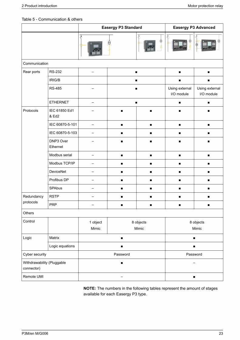
Table 5 - Communication & others
Easergy P3 Standard Easergy P3 Advanced
Communication
Rear ports RS-232 –
IRIG/B
RS-485 – Using externalI/O module
Using externalI/O module
ETHERNET –
Protocols IEC 61850 Ed1& Ed2
–
IEC 60870-5-101 –
IEC 60870-5-103 –
DNP3 OverEthernet
–
Modbus serial –
Modbus TCP/IP –
DeviceNet –
Profibus DP –
SPAbus –
Redundancyprotocols
RSTP –
PRP –
Others
Control 1 object
Mimic
8 objects
Mimic
8 objects
Mimic
Logic Matrix
Logic equations
Cyber security Password Password
Withdrawability (Pluggableconnector)
–
Remote UMI –
NOTE: The numbers in the following tables represent the amount of stagesavailable for each Easergy P3 type.
2 Product introduction Motor protection relay
P3M/en M/G006 23
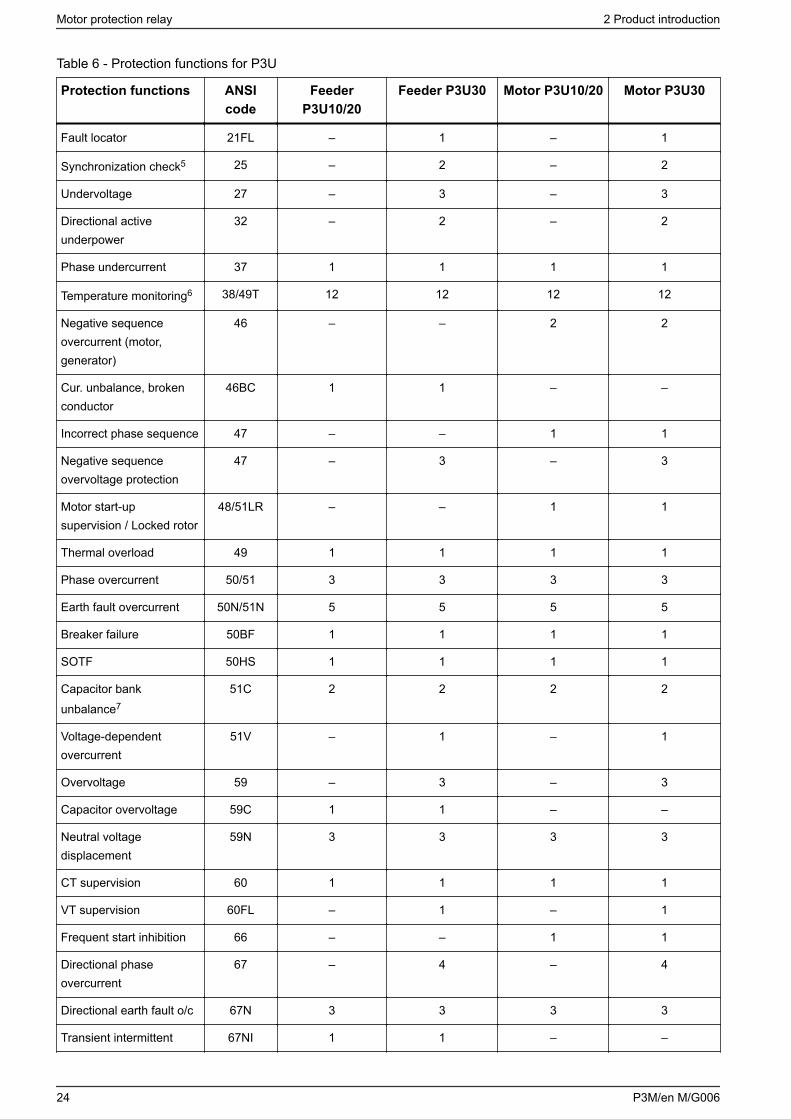
Table 6 - Protection functions for P3U
Protection functions ANSIcode
FeederP3U10/20
Feeder P3U30 Motor P3U10/20 Motor P3U30
Fault locator 21FL – 1 – 1
Synchronization check5 25 – 2 – 2
Undervoltage 27 – 3 – 3
Directional activeunderpower
32 – 2 – 2
Phase undercurrent 37 1 1 1 1
Temperature monitoring6 38/49T 12 12 12 12
Negative sequenceovercurrent (motor,generator)
46 – – 2 2
Cur. unbalance, brokenconductor
46BC 1 1 – –
Incorrect phase sequence 47 – – 1 1
Negative sequenceovervoltage protection
47 – 3 – 3
Motor start-upsupervision / Locked rotor
48/51LR – – 1 1
Thermal overload 49 1 1 1 1
Phase overcurrent 50/51 3 3 3 3
Earth fault overcurrent 50N/51N 5 5 5 5
Breaker failure 50BF 1 1 1 1
SOTF 50HS 1 1 1 1
Capacitor bankunbalance7
51C 2 2 2 2
Voltage-dependentovercurrent
51V – 1 – 1
Overvoltage 59 – 3 – 3
Capacitor overvoltage 59C 1 1 – –
Neutral voltagedisplacement
59N 3 3 3 3
CT supervision 60 1 1 1 1
VT supervision 60FL – 1 – 1
Frequent start inhibition 66 – – 1 1
Directional phaseovercurrent
67 – 4 – 4
Directional earth fault o/c 67N 3 3 3 3
Transient intermittent 67NI 1 1 – –
Motor protection relay 2 Product introduction
24 P3M/en M/G006
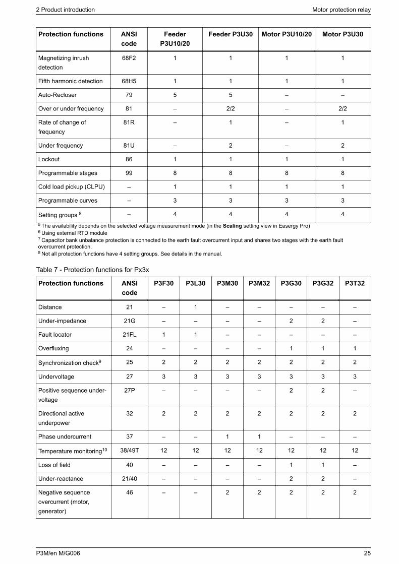
Protection functions ANSIcode
FeederP3U10/20
Feeder P3U30 Motor P3U10/20 Motor P3U30
Magnetizing inrushdetection
68F2 1 1 1 1
Fifth harmonic detection 68H5 1 1 1 1
Auto-Recloser 79 5 5 – –
Over or under frequency 81 – 2/2 – 2/2
Rate of change offrequency
81R – 1 – 1
Under frequency 81U – 2 – 2
Lockout 86 1 1 1 1
Programmable stages 99 8 8 8 8
Cold load pickup (CLPU) – 1 1 1 1
Programmable curves – 3 3 3 3
Setting groups 8 – 4 4 4 45 The availability depends on the selected voltage measurement mode (in the Scaling setting view in Easergy Pro)6 Using external RTD module7 Capacitor bank unbalance protection is connected to the earth fault overcurrent input and shares two stages with the earth faultovercurrent protection.8 Not all protection functions have 4 setting groups. See details in the manual.
Table 7 - Protection functions for Px3x
Protection functions ANSIcode
P3F30 P3L30 P3M30 P3M32 P3G30 P3G32 P3T32
Distance 21 – 1 – – – – –
Under-impedance 21G – – – – 2 2 –
Fault locator 21FL 1 1 – – – – –
Overfluxing 24 – – – – 1 1 1
Synchronization check9 25 2 2 2 2 2 2 2
Undervoltage 27 3 3 3 3 3 3 3
Positive sequence under-voltage
27P – – – – 2 2 –
Directional activeunderpower
32 2 2 2 2 2 2 2
Phase undercurrent 37 – – 1 1 – – –
Temperature monitoring10 38/49T 12 12 12 12 12 12 12
Loss of field 40 – – – – 1 1 –
Under-reactance 21/40 – – – – 2 2 –
Negative sequenceovercurrent (motor,generator)
46 – – 2 2 2 2 2
2 Product introduction Motor protection relay
P3M/en M/G006 25
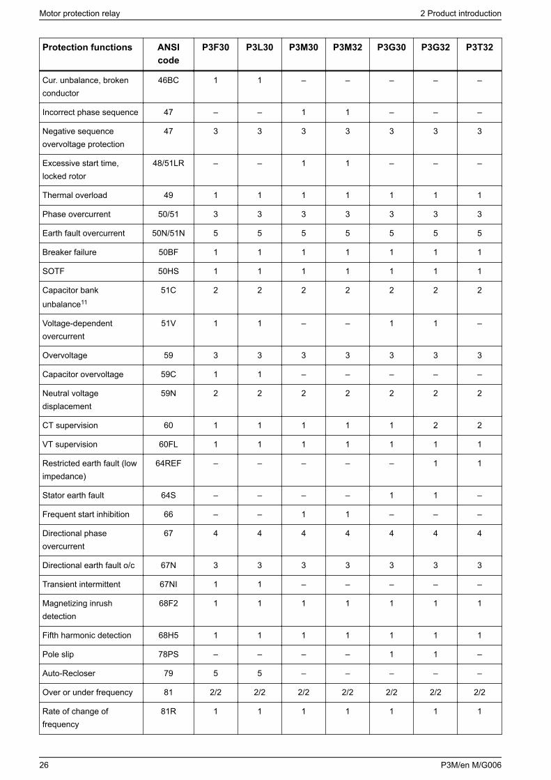
Protection functions ANSIcode
P3F30 P3L30 P3M30 P3M32 P3G30 P3G32 P3T32
Cur. unbalance, brokenconductor
46BC 1 1 – – – – –
Incorrect phase sequence 47 – – 1 1 – – –
Negative sequenceovervoltage protection
47 3 3 3 3 3 3 3
Excessive start time,locked rotor
48/51LR – – 1 1 – – –
Thermal overload 49 1 1 1 1 1 1 1
Phase overcurrent 50/51 3 3 3 3 3 3 3
Earth fault overcurrent 50N/51N 5 5 5 5 5 5 5
Breaker failure 50BF 1 1 1 1 1 1 1
SOTF 50HS 1 1 1 1 1 1 1
Capacitor bankunbalance11
51C 2 2 2 2 2 2 2
Voltage-dependentovercurrent
51V 1 1 – – 1 1 –
Overvoltage 59 3 3 3 3 3 3 3
Capacitor overvoltage 59C 1 1 – – – – –
Neutral voltagedisplacement
59N 2 2 2 2 2 2 2
CT supervision 60 1 1 1 1 1 2 2
VT supervision 60FL 1 1 1 1 1 1 1
Restricted earth fault (lowimpedance)
64REF – – – – – 1 1
Stator earth fault 64S – – – – 1 1 –
Frequent start inhibition 66 – – 1 1 – – –
Directional phaseovercurrent
67 4 4 4 4 4 4 4
Directional earth fault o/c 67N 3 3 3 3 3 3 3
Transient intermittent 67NI 1 1 – – – – –
Magnetizing inrushdetection
68F2 1 1 1 1 1 1 1
Fifth harmonic detection 68H5 1 1 1 1 1 1 1
Pole slip 78PS – – – – 1 1 –
Auto-Recloser 79 5 5 – – – – –
Over or under frequency 81 2/2 2/2 2/2 2/2 2/2 2/2 2/2
Rate of change offrequency
81R 1 1 1 1 1 1 1
Motor protection relay 2 Product introduction
26 P3M/en M/G006
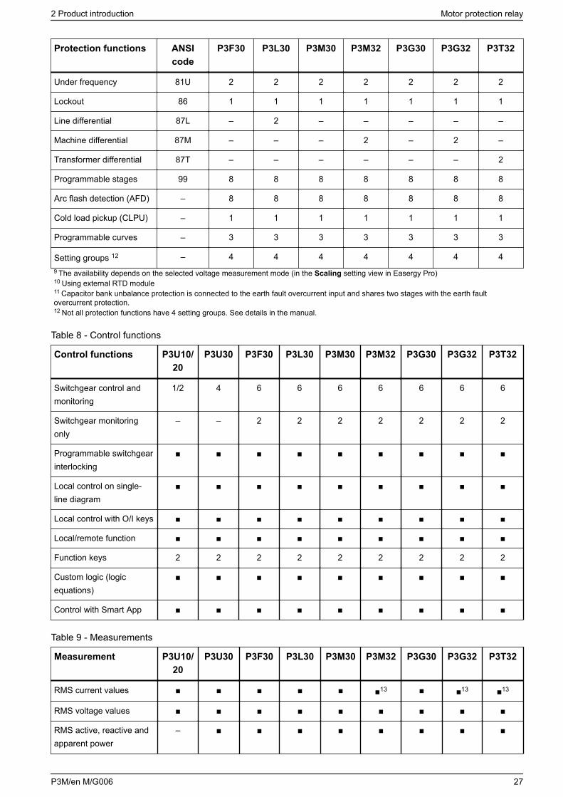
Protection functions ANSIcode
P3F30 P3L30 P3M30 P3M32 P3G30 P3G32 P3T32
Under frequency 81U 2 2 2 2 2 2 2
Lockout 86 1 1 1 1 1 1 1
Line differential 87L – 2 – – – – –
Machine differential 87M – – – 2 – 2 –
Transformer differential 87T – – – – – – 2
Programmable stages 99 8 8 8 8 8 8 8
Arc flash detection (AFD) – 8 8 8 8 8 8 8
Cold load pickup (CLPU) – 1 1 1 1 1 1 1
Programmable curves – 3 3 3 3 3 3 3
Setting groups 12 – 4 4 4 4 4 4 49 The availability depends on the selected voltage measurement mode (in the Scaling setting view in Easergy Pro)10 Using external RTD module11 Capacitor bank unbalance protection is connected to the earth fault overcurrent input and shares two stages with the earth faultovercurrent protection.12 Not all protection functions have 4 setting groups. See details in the manual.
Table 8 - Control functions
Control functions P3U10/20
P3U30 P3F30 P3L30 P3M30 P3M32 P3G30 P3G32 P3T32
Switchgear control andmonitoring
1/2 4 6 6 6 6 6 6 6
Switchgear monitoringonly
– – 2 2 2 2 2 2 2
Programmable switchgearinterlocking
Local control on single-line diagram
Local control with O/I keys
Local/remote function
Function keys 2 2 2 2 2 2 2 2 2
Custom logic (logicequations)
Control with Smart App
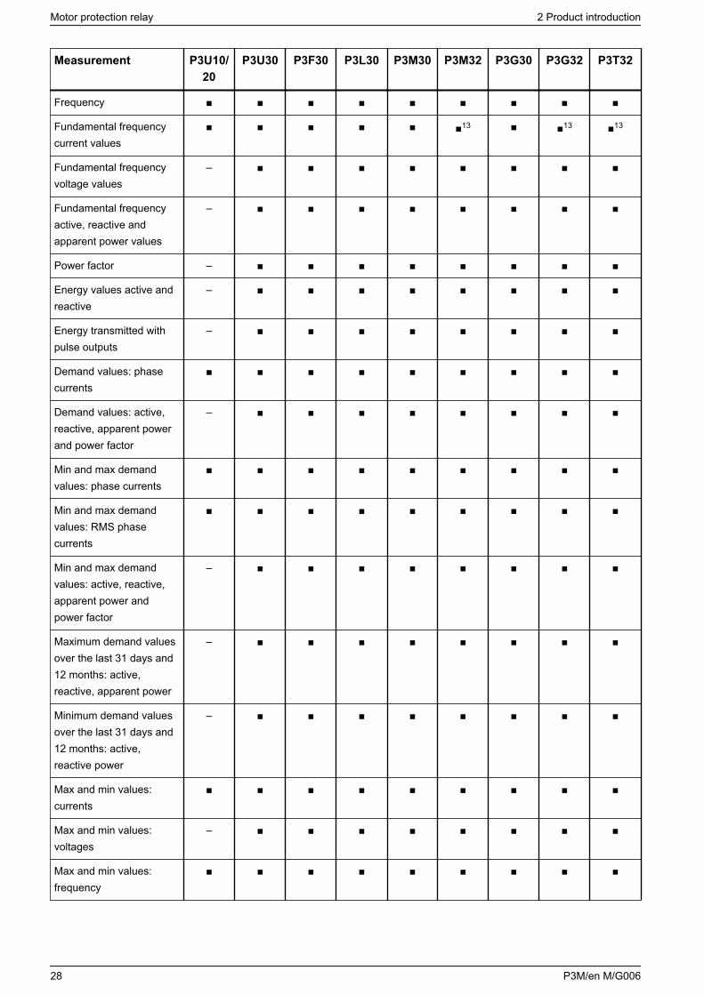
Table 9 - Measurements
Measurement P3U10/20
P3U30 P3F30 P3L30 P3M30 P3M32 P3G30 P3G32 P3T32
RMS current values 13 13 13
RMS voltage values
RMS active, reactive andapparent power
–
2 Product introduction Motor protection relay
P3M/en M/G006 27
Measurement P3U10/20
P3U30 P3F30 P3L30 P3M30 P3M32 P3G30 P3G32 P3T32
Frequency
Fundamental frequencycurrent values
13 13 13
Fundamental frequencyvoltage values
–
Fundamental frequencyactive, reactive andapparent power values
–
Power factor –
Energy values active andreactive
–
Energy transmitted withpulse outputs
–
Demand values: phasecurrents
Demand values: active,reactive, apparent powerand power factor
–
Min and max demandvalues: phase currents
Min and max demandvalues: RMS phasecurrents
Min and max demandvalues: active, reactive,apparent power andpower factor
–
Maximum demand valuesover the last 31 days and12 months: active,reactive, apparent power
–
Minimum demand valuesover the last 31 days and12 months: active,reactive power
–
Max and min values:currents
Max and min values:voltages
–
Max and min values:frequency
Motor protection relay 2 Product introduction
28 P3M/en M/G006
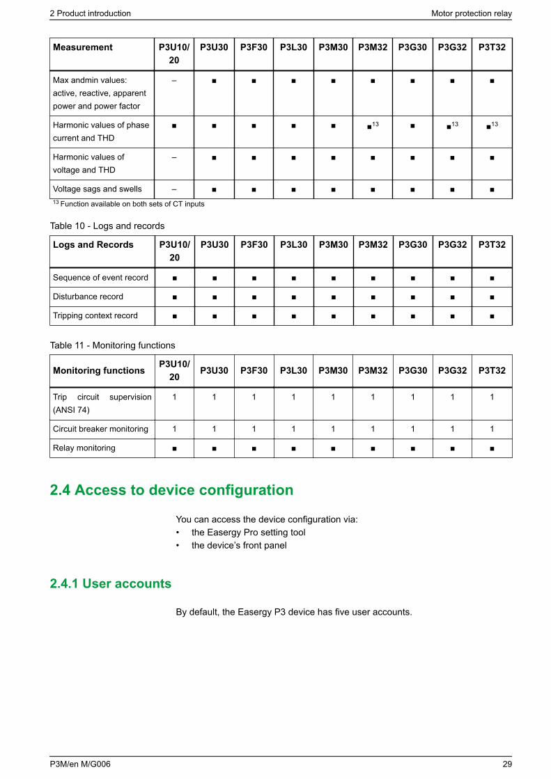
Measurement P3U10/20
P3U30 P3F30 P3L30 P3M30 P3M32 P3G30 P3G32 P3T32
Max andmin values:active, reactive, apparentpower and power factor
–
Harmonic values of phasecurrent and THD
13 13 13
Harmonic values ofvoltage and THD
–
Voltage sags and swells – 13 Function available on both sets of CT inputs
Table 10 - Logs and records
Logs and Records P3U10/20
P3U30 P3F30 P3L30 P3M30 P3M32 P3G30 P3G32 P3T32
Sequence of event record
Disturbance record
Tripping context record
Table 11 - Monitoring functions
Monitoring functions P3U10/20 P3U30 P3F30 P3L30 P3M30 P3M32 P3G30 P3G32 P3T32
Trip circuit supervision(ANSI 74)
1 1 1 1 1 1 1 1 1
Circuit breaker monitoring 1 1 1 1 1 1 1 1 1
Relay monitoring
2.4 Access to device configuration
You can access the device configuration via:• the Easergy Pro setting tool• the device’s front panel
2.4.1 User accounts
By default, the Easergy P3 device has five user accounts.
2 Product introduction Motor protection relay
P3M/en M/G006 29
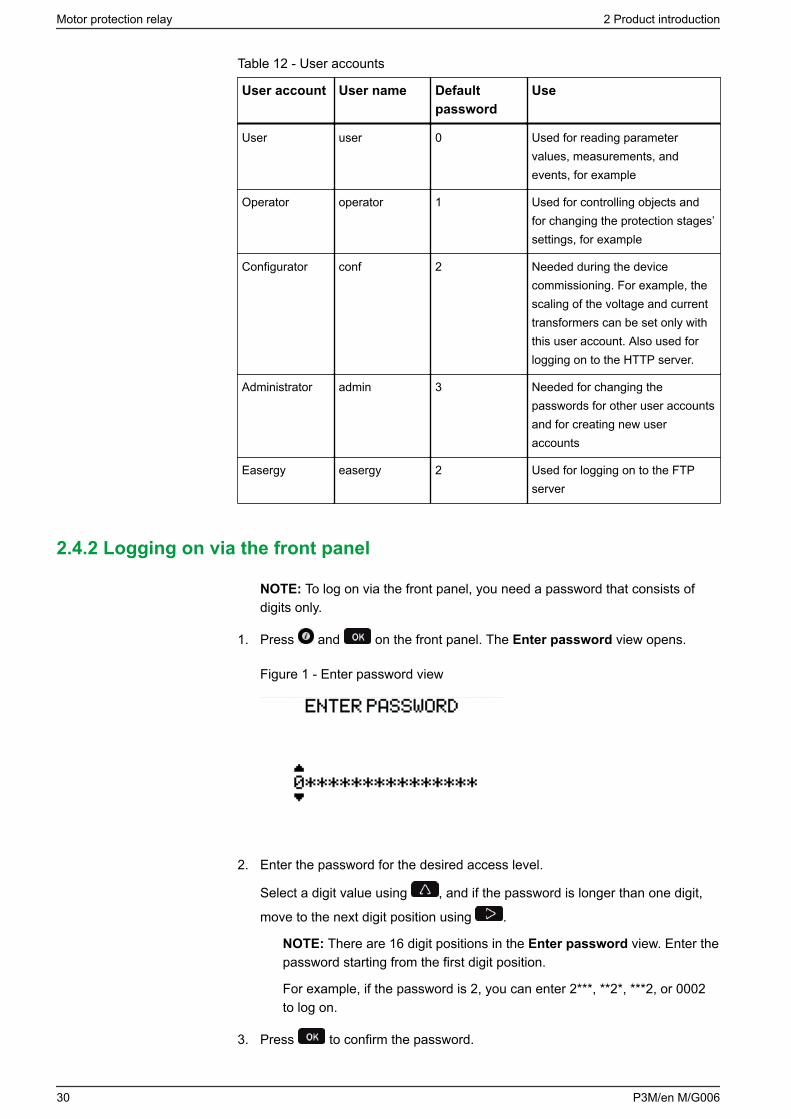
Table 12 - User accounts
User account User name Defaultpassword
Use
User user 0 Used for reading parametervalues, measurements, andevents, for example
Operator operator 1 Used for controlling objects andfor changing the protection stages’settings, for example
Configurator conf 2 Needed during the devicecommissioning. For example, thescaling of the voltage and currenttransformers can be set only withthis user account. Also used forlogging on to the HTTP server.
Administrator admin 3 Needed for changing thepasswords for other user accountsand for creating new useraccounts
Easergy easergy 2 Used for logging on to the FTPserver
2.4.2 Logging on via the front panel
NOTE: To log on via the front panel, you need a password that consists ofdigits only.
1. Press and on the front panel. The Enter password view opens.
Figure 1 - Enter password view
2. Enter the password for the desired access level.
Select a digit value using , and if the password is longer than one digit,
move to the next digit position using .
NOTE: There are 16 digit positions in the Enter password view. Enter thepassword starting from the first digit position.
For example, if the password is 2, you can enter 2***, **2*, ***2, or 0002to log on.
3. Press to confirm the password.
Motor protection relay 2 Product introduction
30 P3M/en M/G006
Related topics2.4.4 Password management
2.4.3 HTTP and FTP logon details
You can log on to the HTTP server and FTP using these user names andpasswords.
Table 13 - HTTP and FTP logon details
Protocol User name Password
HTTP conf 2
FTP easergy 2
2.4.4 Password management
NOTICECYBERSECURITY HAZARD
To improve cybersecurity:
• Change all passwords from their default values when taking the protectiondevice into use.
• Change all passwords regularly.• Ensure a minimum level of password complexity according to common
password guidelines.
Failure to follow these instructions can increase the risk of unauthorizedaccess.
You can change the password for the operator or configurator user accounts inthe General > Device info setting view in Easergy Pro.
The password can contain letters, digits or any other UTF-8 characters (total 1–32characters). However, the new password cannot be any of the default passwords(digits 0–4 or 9999).
Follow these guidelines to improve the password complexity and thus devicesecurity:• Use a password of minimum 8 characters.• Use alphabetic (uppercase and lowercase) and numeric characters in addition
to symbols.• Avoid character repetition, number or letter sequences and keyboard patterns.• Do not use any personal information, such as birthday, name, etc.• Do not use the same password for different user accounts.• Do not reuse old passwords.
Also, all users must be aware of the best practices concerning passwordsincluding:• not sharing personal passwords• not displaying passwords during password entry• not transmitting passwords in email or by other means
2 Product introduction Motor protection relay
P3M/en M/G006 31
• not saving the passwords on PCs or other devices• no written passwords on any supports• regularly reminding users about the best practices concerning passwords
NOTE: To log on via the front panel, you need a password that consists ofdigits only.
Related topics2.4.2 Logging on via the front panel
2.4.5 Changing passwords for administrator and configurator accounts viaPuTTY
Change the password for the administrator and configurator user accounts toreach an optimal cybersecurity level. To log on as the administrator user, youneed to use either serial terminal software or Telnet client software. Thisinstruction describes how to change the passwords using PuTTY which is freelyavailable at www.putty.org.
1. Download and install PuTTY.
2. Connect the Easergy P3 device to your PC via the USB port in the device'sfront panel.
3. Find the COM port number for the device (for example, with Easergy Pro).
4. Connect to the device’s COM port via PuTTY.
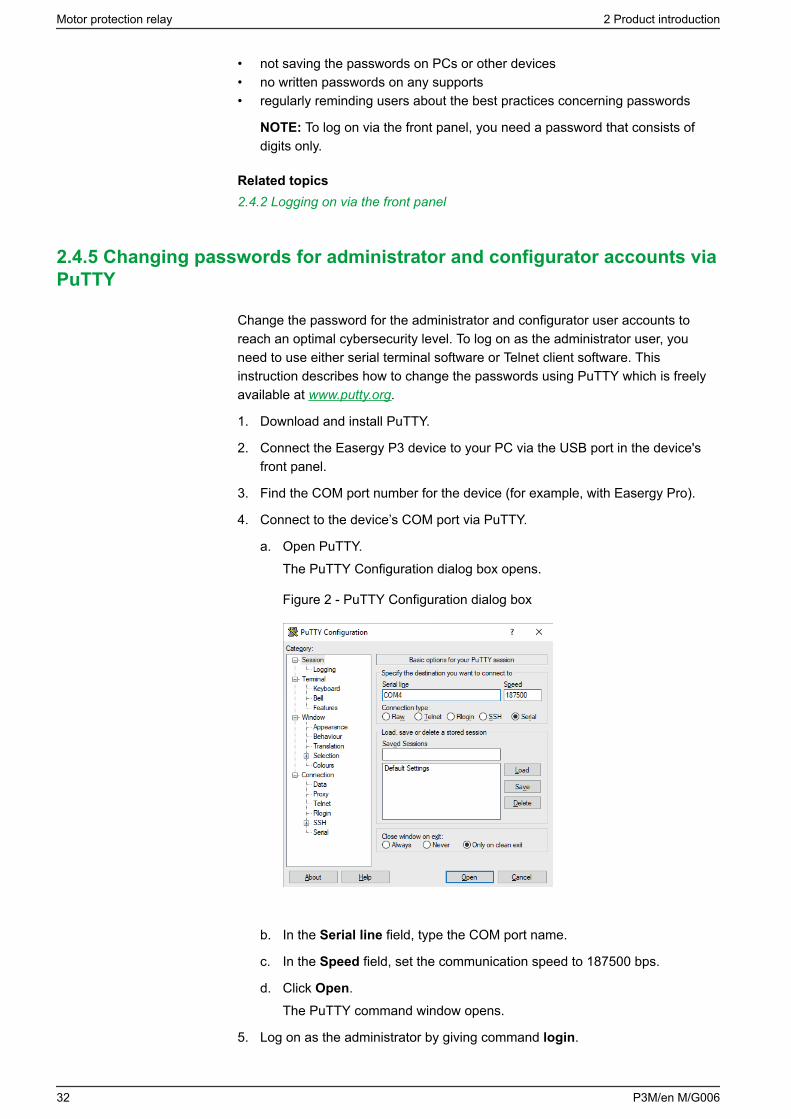
a. Open PuTTY.The PuTTY Configuration dialog box opens.
Figure 2 - PuTTY Configuration dialog box
b. In the Serial line field, type the COM port name.
c. In the Speed field, set the communication speed to 187500 bps.
d. Click Open.The PuTTY command window opens.
5. Log on as the administrator by giving command login.
Motor protection relay 2 Product introduction
32 P3M/en M/G006
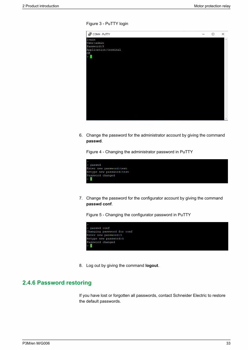
Figure 3 - PuTTY login
6. Change the password for the administrator account by giving the commandpasswd.
Figure 4 - Changing the administrator password in PuTTY
7. Change the password for the configurator account by giving the commandpasswd conf.
Figure 5 - Changing the configurator password in PuTTY
8. Log out by giving the command logout.
2.4.6 Password restoring
If you have lost or forgotten all passwords, contact Schneider Electric to restorethe default passwords.
2 Product introduction Motor protection relay
P3M/en M/G006 33
2.5 Front panel
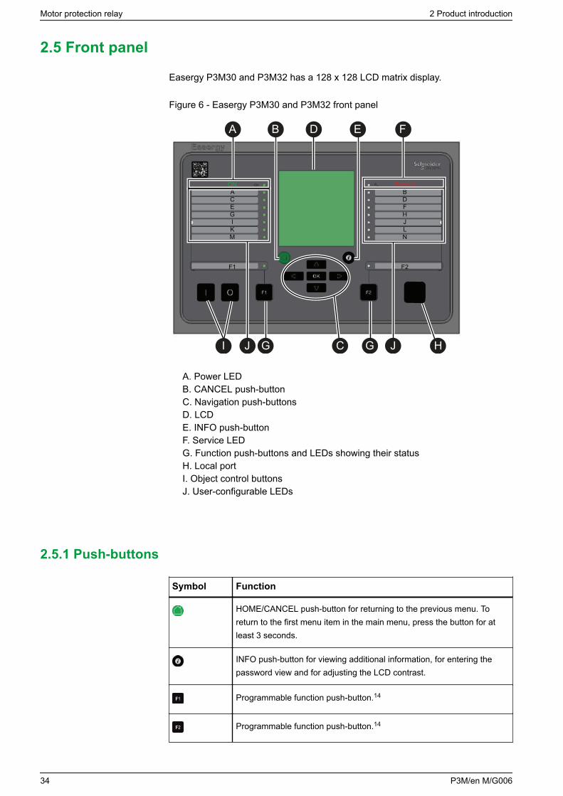
Easergy P3M30 and P3M32 has a 128 x 128 LCD matrix display.
Figure 6 - Easergy P3M30 and P3M32 front panel
ONACEGIKM
F1
ServiceBDFHJLN
F2
A B D E F
I J G C G J H
A. Power LEDB. CANCEL push-buttonC. Navigation push-buttonsD. LCDE. INFO push-buttonF. Service LEDG. Function push-buttons and LEDs showing their statusH. Local portI. Object control buttonsJ. User-configurable LEDs
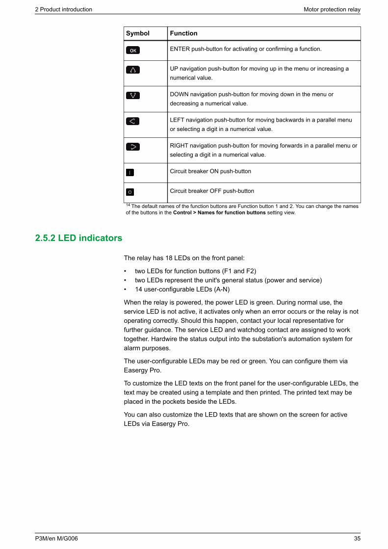
2.5.1 Push-buttons
Symbol Function
HOME/CANCEL push-button for returning to the previous menu. Toreturn to the first menu item in the main menu, press the button for atleast 3 seconds.
INFO push-button for viewing additional information, for entering thepassword view and for adjusting the LCD contrast.
Programmable function push-button.14
Programmable function push-button.14
Motor protection relay 2 Product introduction
34 P3M/en M/G006
Symbol Function
ENTER push-button for activating or confirming a function.
UP navigation push-button for moving up in the menu or increasing anumerical value.
DOWN navigation push-button for moving down in the menu ordecreasing a numerical value.
LEFT navigation push-button for moving backwards in a parallel menuor selecting a digit in a numerical value.
RIGHT navigation push-button for moving forwards in a parallel menu orselecting a digit in a numerical value.
Circuit breaker ON push-button
Circuit breaker OFF push-button
14 The default names of the function buttons are Function button 1 and 2. You can change the namesof the buttons in the Control > Names for function buttons setting view.
2.5.2 LED indicators
The relay has 18 LEDs on the front panel:
• two LEDs for function buttons (F1 and F2)• two LEDs represent the unit's general status (power and service)• 14 user-configurable LEDs (A-N)
When the relay is powered, the power LED is green. During normal use, theservice LED is not active, it activates only when an error occurs or the relay is notoperating correctly. Should this happen, contact your local representative forfurther guidance. The service LED and watchdog contact are assigned to worktogether. Hardwire the status output into the substation's automation system foralarm purposes.
The user-configurable LEDs may be red or green. You can configure them viaEasergy Pro.
To customize the LED texts on the front panel for the user-configurable LEDs, thetext may be created using a template and then printed. The printed text may beplaced in the pockets beside the LEDs.
You can also customize the LED texts that are shown on the screen for activeLEDs via Easergy Pro.
2 Product introduction Motor protection relay
P3M/en M/G006 35

Table 14 - LED indicators and their information
LED indicator LED color Meaning Measure /Remarks
Power LED lit Green The auxiliary powerhas been switchedon
Normal operationstate
Service LED lit Red Internal fault.Operates in parallelwith the self-supervision output
The relay attemptsto reboot. If theservice LED remainslit, call formaintenance.
A–H LED lit Green or red Application-relatedstatus indicators.
Configurable in theMatrix setting view
F1 or F2 LED lit Green Correspondingfunction keypressed / activated
Depending on thefunctionprogrammed to F1 /F2
2.5.3 Configuring the LED names via Easergy Pro
1. Go to General > LED names.
2. To change a LED name, click the LED Description text and type a newname. To save the new name, press Enter.
Figure 7 - LED NAMES menu in Easergy Pro for LED configuration
Motor protection relay 2 Product introduction
36 P3M/en M/G006
2.5.4 Controlling the alarm screen
You can enable or disable the alarm screen either via the relay's local display orusing Easergy Pro:
• On the local display, go to Events > Alarms.• In Easergy Pro, go to General > Local panel conf.
2.5.5 Accessing operating levels
1. On the front panel, press and .
2. Enter the password, and press .
2.5.6 Adjusting the LCD contrast
Prerequisite: You have entered the correct password.
1. Press , and adjust the contrast.
To increase the contrast, press .
To decrease the contrast, press .
2. To return to the main menu, press .
NOTE: By nature, the LCD display changes its contrast depending on theambient temperature. The display may become dark or unreadable at lowtemperatures. However, this condition does not affect the proper operation ofthe protection or other functions.
2.5.7 Testing the LEDs and LCD screen
You can start the test sequence in any main menu window.
To start the LED and LCD test:
1. Press .
2. Press .
The relay tests the LCD screen and the functionality of all LEDs.
2.5.8 Controlling an object with selective control
Prerequisite: You have logged in with the correct password and enabled selectivecontrol in the Objects setting view.
When selective control is enabled, the control operation needs confirmation(select before operate).
• Press to close an object.
– Press again to confirm.
2 Product introduction Motor protection relay
P3M/en M/G006 37
– Press to cancel.
• Press to open an object.
– Press again to confirm.
– Press to cancel.
2.5.9 Controlling an object with direct control
Prerequisite: You have logged in with the correct password and enabled directcontrol in the Objects setting view.
When direct control is enabled, the control operation is done without confirmation.
• Press to close an object.
• Press to open an object.
2.5.10 Menus
This section gives an overview of the menus that you can access via the device'sfront panel.
The main menu
Press the right arrow to access more measurements in the main menu.
Table 15 - Main menu
Menu name Description
Active LEDs User-configurable texts for active LEDs
Measurements User-configurable measurements
Single line Single line or Single line mimic,measurements and control view. This is adefault start view. To return to this viewfrom any location, press the HOME/CANCELL button for at least 3 seconds.
Info Information about the relay: relay's name,order code, date, time and firmware version
P Power: power factor and frequency valuescalculated by the relay. Press the rightarrow to view more measurements.
E Energy: the amount of energy that haspassed through the protected line,calculated by the relay from the currentsand voltages. Press the right arrow to viewmore energy measurements.
Motor protection relay 2 Product introduction
38 P3M/en M/G006
Menu name Description
I Current: phase currents and demandvalues of phase currents. Press the rightarrow to view more current measurements.
U Line-to-line voltages. Press the right arrowto view other voltage measurements.
Dema Minimum and maximum phase current andpower demand values
Umax Minimum and maximum values of voltageand frequency
Imax Minimum and maximum current values
Pmax Minimum and maximum power values
Month Monthly maximum current and powervalues
FL Short-circuit locator applied to incomer orfeeder
Evnt Event log: event codes and time stamps
DR Disturbance recorder configuration settings
Runh Running hour counter
TIMR Timers: programmable timers that you canuse to preset functions
DI Digital input statuses and settings
DO Digital output statuses and settings
Arc Arc flash detection settings
Prot Protection: settings and statuses for variousprotection functions
I>, I>>, etc. Protection stage settings and statuses. Theavailability of the menus are depends onthe activated protection stages.
AR Auto-reclosure settings, statuses andregisters
OBJ Objects: settings related to object statusdata and object control (open/closed)
Lgic Logic events and counters
2 Product introduction Motor protection relay
P3M/en M/G006 39
Menu name Description
CONF General device setup: CT and VT scalings,frequency adaptation, units, device info,date, time, clock, etc.
Bus Communication port settings
Slot Slot info: card ID (CID) that is the name ofthe card used by the relay firmware
Diag Diagnosis: various diagnostic information
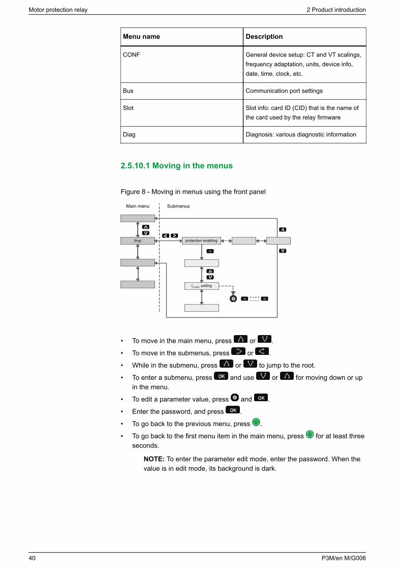
2.5.10.1 Moving in the menus
Figure 8 - Moving in menus using the front panel
Main menu Submenus
protection enabling
ISTART setting
Prot
OK
OK OK
• To move in the main menu, press or .
• To move in the submenus, press or .
• While in the submenu, press or to jump to the root.
• To enter a submenu, press and use or for moving down or upin the menu.
• To edit a parameter value, press and .
• Enter the password, and press .
• To go back to the previous menu, press .
• To go back to the first menu item in the main menu, press for at least threeseconds.
NOTE: To enter the parameter edit mode, enter the password. When thevalue is in edit mode, its background is dark.
Motor protection relay 2 Product introduction
40 P3M/en M/G006

2.5.10.2 Local panel messages
Table 16 - Local panel messages
Value is not editable: The value can not be edited or password isnot given
Control disabled: Object control disabled due to wrongoperating level
Change causes autoboot: Notification that if the parameter is changedthe relay boots itself
2.6 Easergy Pro setting and configuration tool
DANGERHAZARD OF ELECTRIC SHOCK, EXPLOSION, OR ARCFLASH
Only qualified personnel should operate this equipment.Such work should be performed only after reading thisentire set of instructions and checking the technicalcharacteristics of the device.
Failure to follow this instruction will result in death orserious injury.
Easergy Pro is a software tool for configuring Easergy P3 relays. It has agraphical interface where the relay settings and parameters are grouped underseven tabs:
• General• Measurements• Inputs/outputs• Protection• Matrix• Logs• Communication
The contents of the tabs depend on the relay type and the selected applicationmode.
Easergy Pro stores the relay configuration in a setting file. The configuration ofone physical relay is saved in one setting file. The configurations can be printedout and saved for later use.
For more information, see the Easergy Pro user manual.
NOTE: Download the latest version of the software from se.com/ww/en/product-range-download/64884-easergy-p3-protection-relays.
2 Product introduction Motor protection relay
P3M/en M/G006 41
NOTICEHAZARD OF EQUIPMENT DAMAGE
After writing new settings or configurations to a device, perform a test to verifythat the relay operates correctly with the new settings.
Failure to follow these instructions can result in unwanted shutdown ofthe electrical installation.
2.7 Low-power instrument transformers
Protection devices need current and voltage data from the equipment to beprotected. For technical, economic and safety reasons, this data cannot beobtained directly from the equipment’s medium-voltage (MV) power supply. Forthis purpose, low-power instrument transformers (LPITs) can be used. LPITs:• reduce the size of value to be measured• provide galvanic separation• supply the power needed to process the data or even for the protection device
to work
There are two types of LPITs:• low-power current transformers (LPCTs) that are connected on the MV
network primary circuit and supply a reduced current value to the secondarycircuit, proportional to the network current on which they are installed.
• low-power voltage transformers (LPVTs) that are connected to the MVnetwork primary and supply the secondary circuit with a reduced voltagevalue, proportional to the network voltage on which they are installed.
Using LPITs has many benefits compared to using tranditional CTs or VTs:• improved personal safety during testing and operation• one LPCT replaces the dedicated measurement CTs and protection CTs• the LPCT primary rating is no longer to be as close as possible to the nominal
current• time and money savings during project planning and execution• reduced environmental impact because of reduced instrument transformer
size
LPITs compliant with the standards IEC 60044 and IEC 61869 can be connectedto the LPIT inputs of Easergy P3 devices.
Motor protection relay 2 Product introduction
42 P3M/en M/G006
3 Mechanical structure
3.1 Modularity
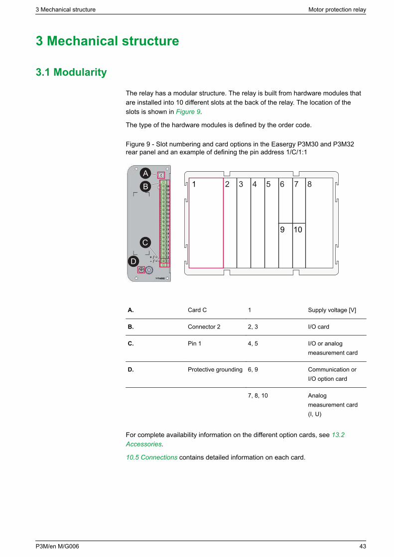
The relay has a modular structure. The relay is built from hardware modules thatare installed into 10 different slots at the back of the relay. The location of theslots is shown in Figure 9.
The type of the hardware modules is defined by the order code.
Figure 9 - Slot numbering and card options in the Easergy P3M30 and P3M32rear panel and an example of defining the pin address 1/C/1:1
1 2 3 4 5 6
9
7
10
8
D
C
BA
A. Card C 1 Supply voltage [V]
B. Connector 2 2, 3 I/O card
C. Pin 1 4, 5 I/O or analogmeasurement card
D. Protective grounding 6, 9 Communication orI/O option card
7, 8, 10 Analogmeasurement card(I, U)
For complete availability information on the different option cards, see 13.2Accessories.
10.5 Connections contains detailed information on each card.
3 Mechanical structure Motor protection relay
P3M/en M/G006 43
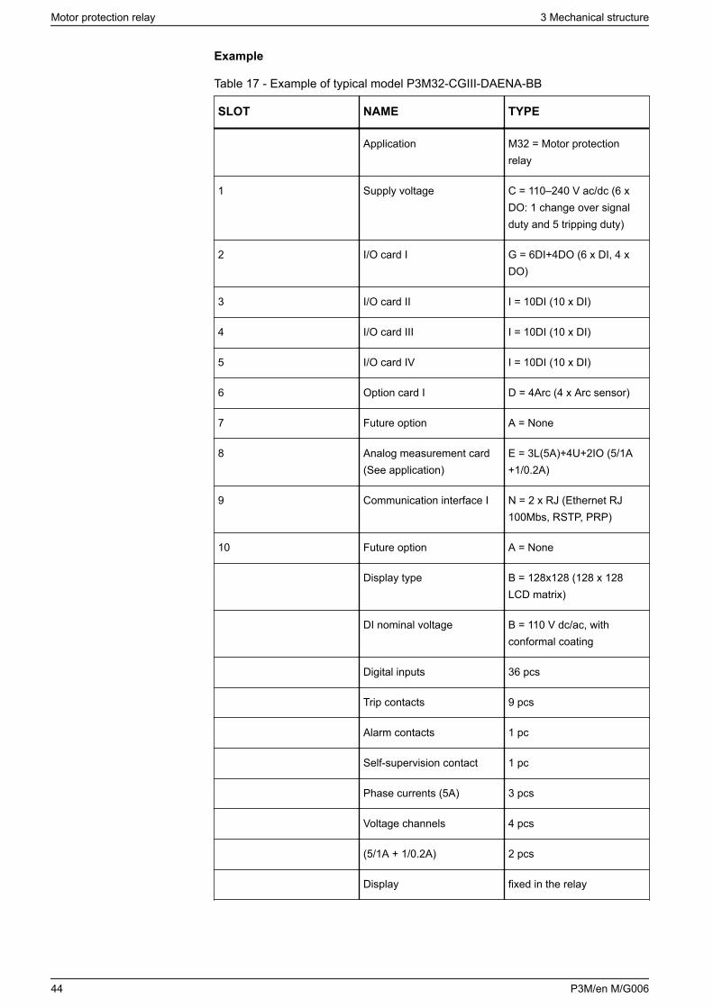
Example
Table 17 - Example of typical model P3M32-CGIII-DAENA-BB
SLOT NAME TYPE
Application M32 = Motor protectionrelay
1 Supply voltage C = 110–240 V ac/dc (6 xDO: 1 change over signalduty and 5 tripping duty)
2 I/O card I G = 6DI+4DO (6 x DI, 4 xDO)
3 I/O card II I = 10DI (10 x DI)
4 I/O card III I = 10DI (10 x DI)
5 I/O card IV I = 10DI (10 x DI)
6 Option card I D = 4Arc (4 x Arc sensor)
7 Future option A = None
8 Analog measurement card(See application)
E = 3L(5A)+4U+2IO (5/1A+1/0.2A)
9 Communication interface I N = 2 x RJ (Ethernet RJ100Mbs, RSTP, PRP)
10 Future option A = None
Display type B = 128x128 (128 x 128LCD matrix)
DI nominal voltage B = 110 V dc/ac, withconformal coating
Digital inputs 36 pcs
Trip contacts 9 pcs
Alarm contacts 1 pc
Self-supervision contact 1 pc
Phase currents (5A) 3 pcs
Voltage channels 4 pcs
(5/1A + 1/0.2A) 2 pcs
Display fixed in the relay
Motor protection relay 3 Mechanical structure
44 P3M/en M/G006
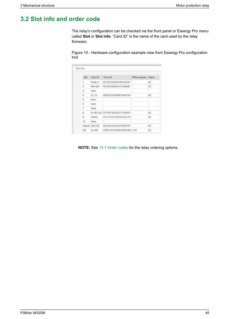
3.2 Slot info and order code
The relay's configuration can be checked via the front panel or Easergy Pro menucalled Slot or Slot info. “Card ID” is the name of the card used by the relayfirmware.
Figure 10 - Hardware configuration example view from Easergy Pro configurationtool
NOTE: See 13.1 Order codes for the relay ordering options.
3 Mechanical structure Motor protection relay
P3M/en M/G006 45
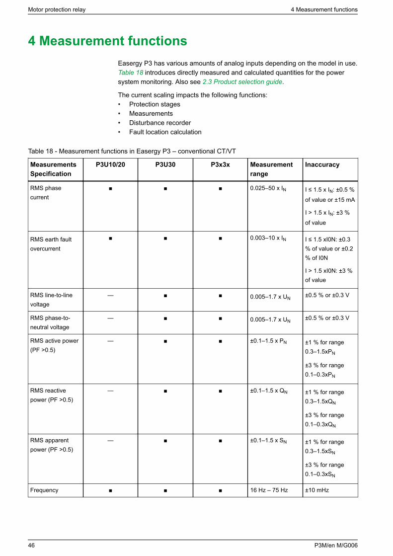
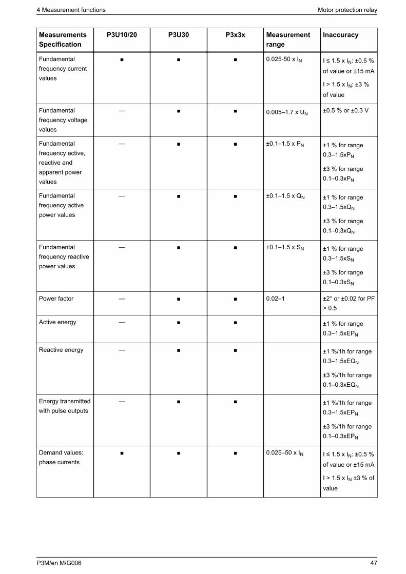
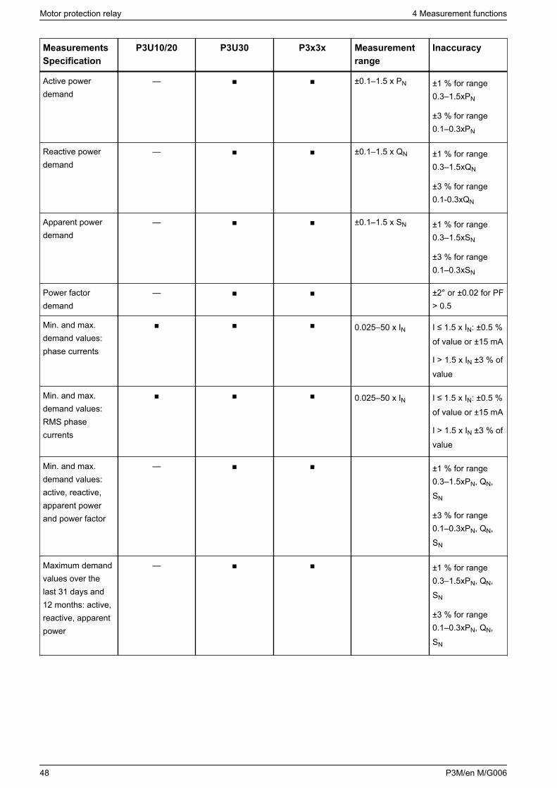
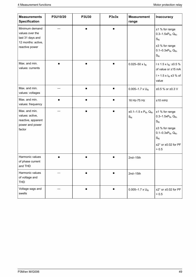
4 Measurement functionsEasergy P3 has various amounts of analog inputs depending on the model in use. Table 18 introduces directly measured and calculated quantities for the powersystem monitoring. Also see 2.3 Product selection guide.
The current scaling impacts the following functions:• Protection stages• Measurements• Disturbance recorder• Fault location calculation
Table 18 - Measurement functions in Easergy P3 – conventional CT/VT
MeasurementsSpecification
P3U10/20 P3U30 P3x3x Measurementrange
Inaccuracy
RMS phasecurrent
0.025–50 x IN I ≤ 1.5 x IN: ±0.5 %of value or ±15 mA
I > 1.5 x IN: ±3 %of value
RMS earth faultovercurrent
0.003–10 x IN I ≤ 1.5 xI0N: ±0.3% of value or ±0.2% of I0N
I > 1.5 xI0N: ±3 %of value
RMS line-to-linevoltage
— 0.005–1.7 x UN ±0.5 % or ±0.3 V
RMS phase-to-neutral voltage
— 0.005–1.7 x UN ±0.5 % or ±0.3 V
RMS active power(PF >0.5)
— ±0.1–1.5 x PN ±1 % for range0.3–1.5xPN
±3 % for range0.1–0.3xPN
RMS reactivepower (PF >0.5)
— ±0.1–1.5 x QN ±1 % for range0.3–1.5xQN
±3 % for range0.1–0.3xQN
RMS apparentpower (PF >0.5)
— ±0.1–1.5 x SN ±1 % for range0.3–1.5xSN
±3 % for range0.1–0.3xSN
Frequency 16 Hz – 75 Hz ±10 mHz
Motor protection relay 4 Measurement functions
46 P3M/en M/G006
MeasurementsSpecification
P3U10/20 P3U30 P3x3x Measurementrange
Inaccuracy
Fundamentalfrequency currentvalues
0.025-50 x IN I ≤ 1.5 x IN: ±0.5 %of value or ±15 mA
I > 1.5 x IN: ±3 %of value
Fundamentalfrequency voltagevalues
— 0.005–1.7 x UN ±0.5 % or ±0.3 V
Fundamentalfrequency active,reactive andapparent powervalues
— ±0.1–1.5 x PN ±1 % for range0.3–1.5xPN
±3 % for range0.1–0.3xPN
Fundamentalfrequency activepower values
— ±0.1–1.5 x QN ±1 % for range0.3–1.5xQN
±3 % for range0.1–0.3xQN
Fundamentalfrequency reactivepower values
— ±0.1–1.5 x SN ±1 % for range0.3–1.5xSN
±3 % for range0.1–0.3xSN
Power factor — 0.02–1 ±2° or ±0.02 for PF> 0.5
Active energy — ±1 % for range0.3–1.5xEPN
Reactive energy — ±1 %/1h for range0.3–1.5xEQN
±3 %/1h for range0.1–0.3xEQN
Energy transmittedwith pulse outputs
— ±1 %/1h for range0.3–1.5xEPN
±3 %/1h for range0.1–0.3xEPN
Demand values:phase currents
0.025–50 x IN I ≤ 1.5 x IN: ±0.5 %of value or ±15 mA
I > 1.5 x IN ±3 % ofvalue
4 Measurement functions Motor protection relay
P3M/en M/G006 47
MeasurementsSpecification
P3U10/20 P3U30 P3x3x Measurementrange
Inaccuracy
Active powerdemand
— ±0.1–1.5 x PN ±1 % for range0.3–1.5xPN
±3 % for range0.1–0.3xPN
Reactive powerdemand
— ±0.1–1.5 x QN ±1 % for range0.3–1.5xQN
±3 % for range0.1-0.3xQN
Apparent powerdemand
— ±0.1–1.5 x SN ±1 % for range0.3–1.5xSN
±3 % for range0.1–0.3xSN
Power factordemand
— ±2° or ±0.02 for PF> 0.5
Min. and max.demand values:phase currents
0.025–50 x IN I ≤ 1.5 x IN: ±0.5 %of value or ±15 mA
I > 1.5 x IN ±3 % ofvalue
Min. and max.demand values:RMS phasecurrents
0.025–50 x IN I ≤ 1.5 x IN: ±0.5 %of value or ±15 mA
I > 1.5 x IN ±3 % ofvalue
Min. and max.demand values:active, reactive,apparent powerand power factor
— ±1 % for range0.3–1.5xPN, QN,SN
±3 % for range0.1–0.3xPN, QN,SN
Maximum demandvalues over thelast 31 days and12 months: active,reactive, apparentpower
— ±1 % for range0.3–1.5xPN, QN,SN
±3 % for range0.1–0.3xPN, QN,SN
Motor protection relay 4 Measurement functions
48 P3M/en M/G006
MeasurementsSpecification
P3U10/20 P3U30 P3x3x Measurementrange
Inaccuracy
Minimum demandvalues over thelast 31 days and12 months: active,reactive power
— ±1 % for range0.3–1.5xPN, QN,SN
±3 % for range0.1–0.3xPN, QN,SN
Max. and min.values: currents
0.025–50 x IN I ≤ 1.5 x IN: ±0.5 %of value or ±15 mA
I > 1.5 x IN ±3 % ofvalue
Max. and min.values: voltages
— 0.005–1.7 x UN ±0.5 % or ±0.3 V
Max. and min.values: frequency
16 Hz-75 Hz ±10 mHz
Max. and min.values: active,reactive, apparentpower and powerfactor
— ±0.1–1.5 x PN, QN,SN
±1 % for range0.3–1.5xPN, QN,SN
±3 % for range0.1–0.3xPN, QN,SN
±2° or ±0.02 for PF> 0.5
Harmonic valuesof phase currentand THD
2nd–15th
Harmonic valuesof voltage andTHD
— 2nd–15th
Voltage sags andswells
— 0.005–1.7 x UN ±2° or ±0.02 for PF> 0.5
4 Measurement functions Motor protection relay
P3M/en M/G006 49
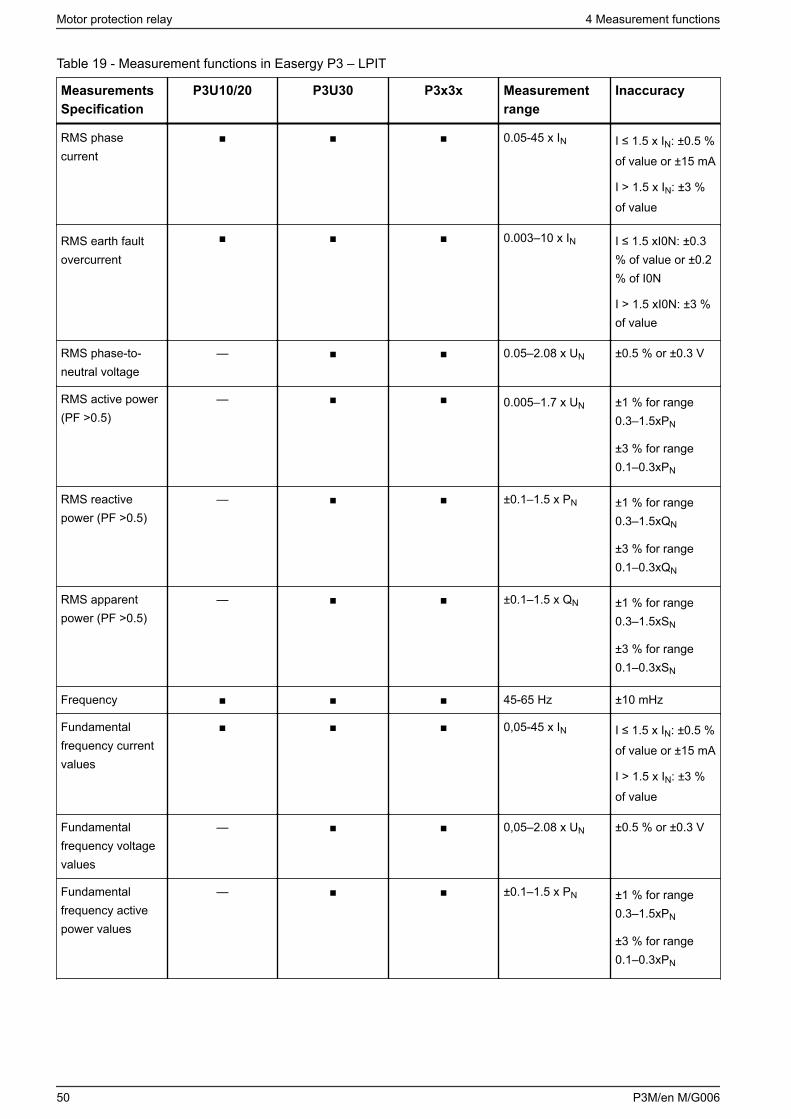
Table 19 - Measurement functions in Easergy P3 – LPIT
MeasurementsSpecification
P3U10/20 P3U30 P3x3x Measurementrange
Inaccuracy
RMS phasecurrent
0.05-45 x IN I ≤ 1.5 x IN: ±0.5 %of value or ±15 mA
I > 1.5 x IN: ±3 %of value
RMS earth faultovercurrent
0.003–10 x IN I ≤ 1.5 xI0N: ±0.3% of value or ±0.2% of I0N
I > 1.5 xI0N: ±3 %of value
RMS phase-to-neutral voltage
— 0.05–2.08 x UN ±0.5 % or ±0.3 V
RMS active power(PF >0.5)
— 0.005–1.7 x UN ±1 % for range0.3–1.5xPN
±3 % for range0.1–0.3xPN
RMS reactivepower (PF >0.5)
— ±0.1–1.5 x PN ±1 % for range0.3–1.5xQN
±3 % for range0.1–0.3xQN
RMS apparentpower (PF >0.5)
— ±0.1–1.5 x QN ±1 % for range0.3–1.5xSN
±3 % for range0.1–0.3xSN
Frequency 45-65 Hz ±10 mHz
Fundamentalfrequency currentvalues
0,05-45 x IN I ≤ 1.5 x IN: ±0.5 %of value or ±15 mA
I > 1.5 x IN: ±3 %of value
Fundamentalfrequency voltagevalues
— 0,05–2.08 x UN ±0.5 % or ±0.3 V
Fundamentalfrequency activepower values
— ±0.1–1.5 x PN ±1 % for range0.3–1.5xPN
±3 % for range0.1–0.3xPN
Motor protection relay 4 Measurement functions
50 P3M/en M/G006
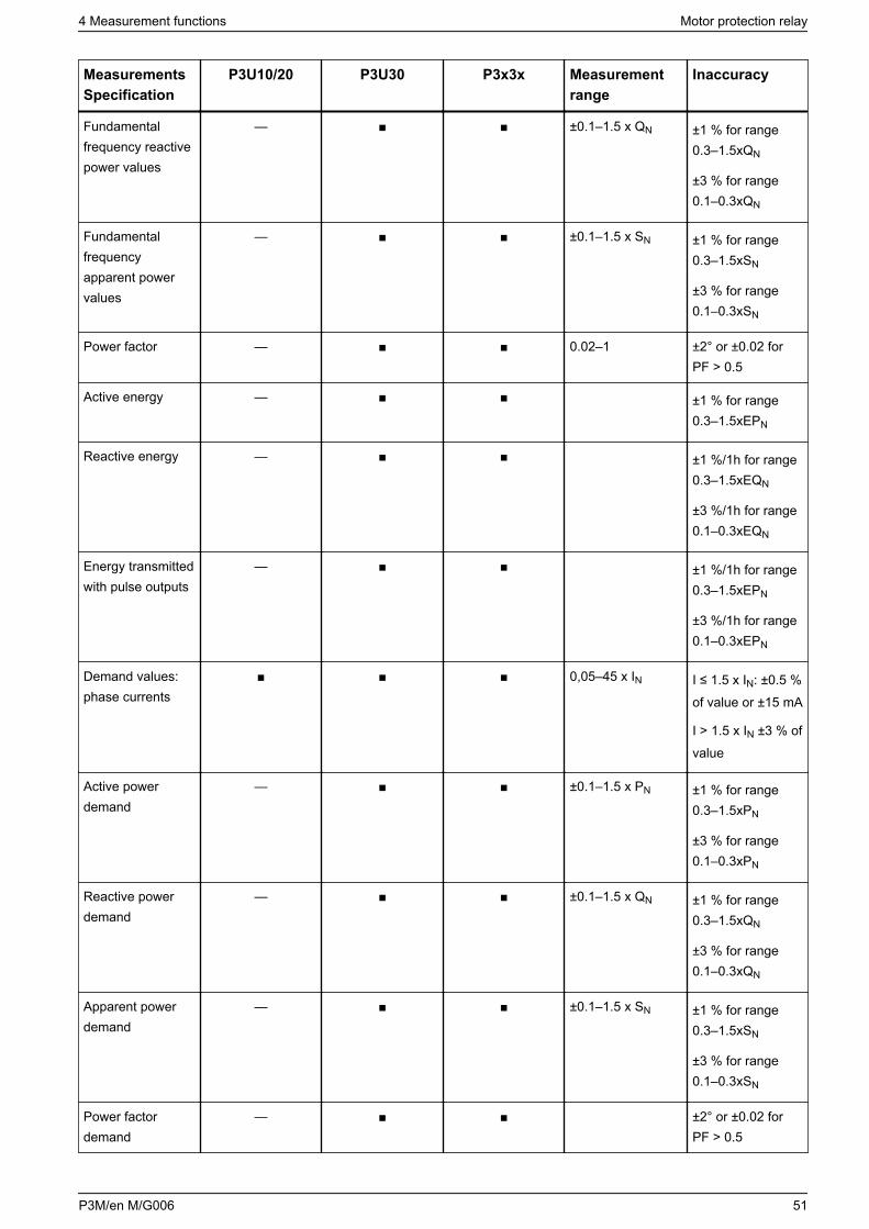
MeasurementsSpecification
P3U10/20 P3U30 P3x3x Measurementrange
Inaccuracy
Fundamentalfrequency reactivepower values
— ±0.1–1.5 x QN ±1 % for range0.3–1.5xQN
±3 % for range0.1–0.3xQN
Fundamentalfrequencyapparent powervalues
— ±0.1–1.5 x SN ±1 % for range0.3–1.5xSN
±3 % for range0.1–0.3xSN
Power factor — 0.02–1 ±2° or ±0.02 forPF > 0.5
Active energy — ±1 % for range0.3–1.5xEPN
Reactive energy — ±1 %/1h for range0.3–1.5xEQN
±3 %/1h for range0.1–0.3xEQN
Energy transmittedwith pulse outputs
— ±1 %/1h for range0.3–1.5xEPN
±3 %/1h for range0.1–0.3xEPN
Demand values:phase currents
0,05–45 x IN I ≤ 1.5 x IN: ±0.5 %of value or ±15 mA
I > 1.5 x IN ±3 % ofvalue
Active powerdemand
— ±0.1–1.5 x PN ±1 % for range0.3–1.5xPN
±3 % for range0.1–0.3xPN
Reactive powerdemand
— ±0.1–1.5 x QN ±1 % for range0.3–1.5xQN
±3 % for range0.1–0.3xQN
Apparent powerdemand
— ±0.1–1.5 x SN ±1 % for range0.3–1.5xSN
±3 % for range0.1–0.3xSN
Power factordemand
— ±2° or ±0.02 forPF > 0.5
4 Measurement functions Motor protection relay
P3M/en M/G006 51
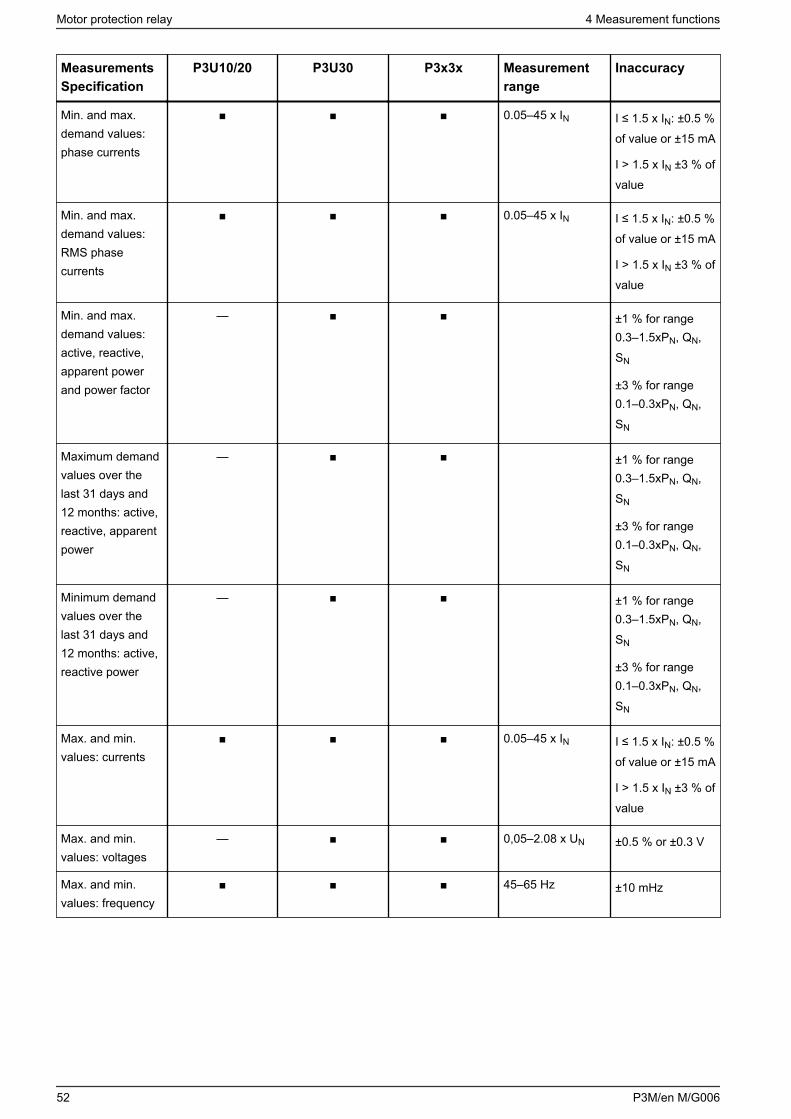
MeasurementsSpecification
P3U10/20 P3U30 P3x3x Measurementrange
Inaccuracy
Min. and max.demand values:phase currents
0.05–45 x IN I ≤ 1.5 x IN: ±0.5 %of value or ±15 mA
I > 1.5 x IN ±3 % ofvalue
Min. and max.demand values:RMS phasecurrents
0.05–45 x IN I ≤ 1.5 x IN: ±0.5 %of value or ±15 mA
I > 1.5 x IN ±3 % ofvalue
Min. and max.demand values:active, reactive,apparent powerand power factor
— ±1 % for range0.3–1.5xPN, QN,SN
±3 % for range0.1–0.3xPN, QN,SN
Maximum demandvalues over thelast 31 days and12 months: active,reactive, apparentpower
— ±1 % for range0.3–1.5xPN, QN,SN
±3 % for range0.1–0.3xPN, QN,SN
Minimum demandvalues over thelast 31 days and12 months: active,reactive power
— ±1 % for range0.3–1.5xPN, QN,SN
±3 % for range0.1–0.3xPN, QN,SN
Max. and min.values: currents
0.05–45 x IN I ≤ 1.5 x IN: ±0.5 %of value or ±15 mA
I > 1.5 x IN ±3 % ofvalue
Max. and min.values: voltages
— 0,05–2.08 x UN ±0.5 % or ±0.3 V
Max. and min.values: frequency
45–65 Hz ±10 mHz
Motor protection relay 4 Measurement functions
52 P3M/en M/G006
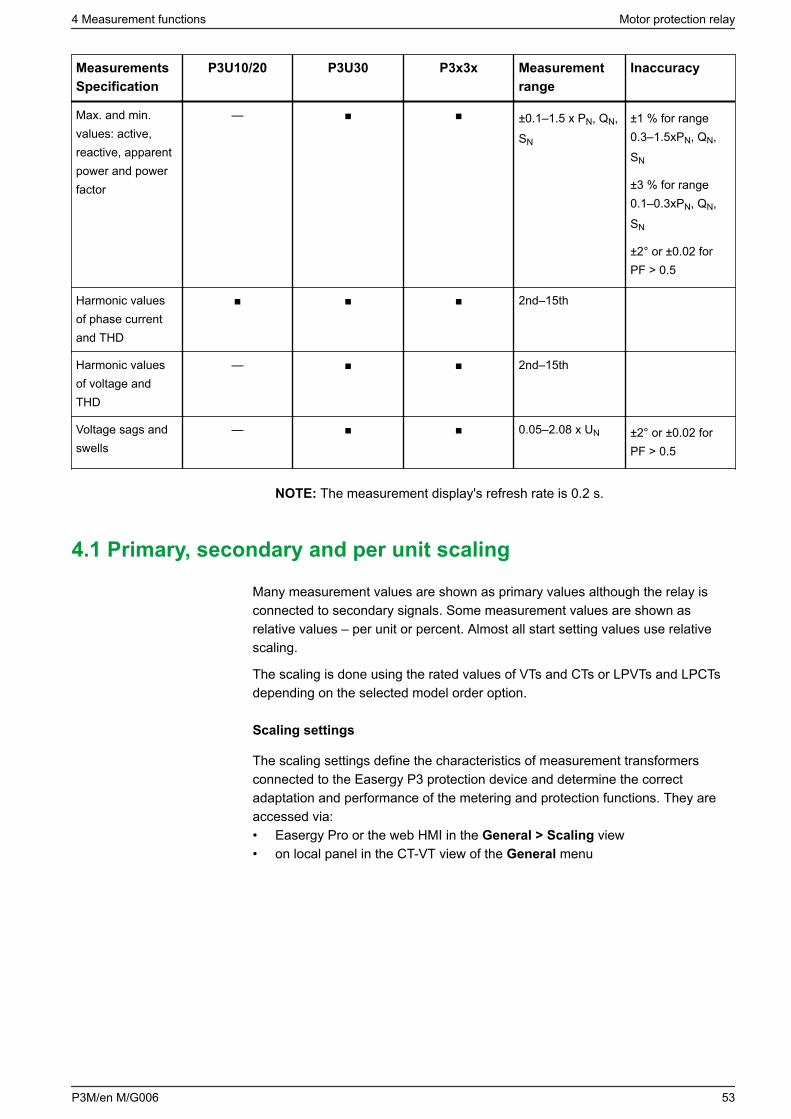
MeasurementsSpecification
P3U10/20 P3U30 P3x3x Measurementrange
Inaccuracy
Max. and min.values: active,reactive, apparentpower and powerfactor
— ±0.1–1.5 x PN, QN,SN
±1 % for range0.3–1.5xPN, QN,SN
±3 % for range0.1–0.3xPN, QN,SN
±2° or ±0.02 forPF > 0.5
Harmonic valuesof phase currentand THD
2nd–15th
Harmonic valuesof voltage andTHD
— 2nd–15th
Voltage sags andswells
— 0.05–2.08 x UN ±2° or ±0.02 forPF > 0.5
NOTE: The measurement display's refresh rate is 0.2 s.
4.1 Primary, secondary and per unit scaling
Many measurement values are shown as primary values although the relay isconnected to secondary signals. Some measurement values are shown asrelative values – per unit or percent. Almost all start setting values use relativescaling.
The scaling is done using the rated values of VTs and CTs or LPVTs and LPCTsdepending on the selected model order option.
Scaling settings
The scaling settings define the characteristics of measurement transformersconnected to the Easergy P3 protection device and determine the correctadaptation and performance of the metering and protection functions. They areaccessed via:• Easergy Pro or the web HMI in the General > Scaling view• on local panel in the CT-VT view of the General menu
4 Measurement functions Motor protection relay
P3M/en M/G006 53
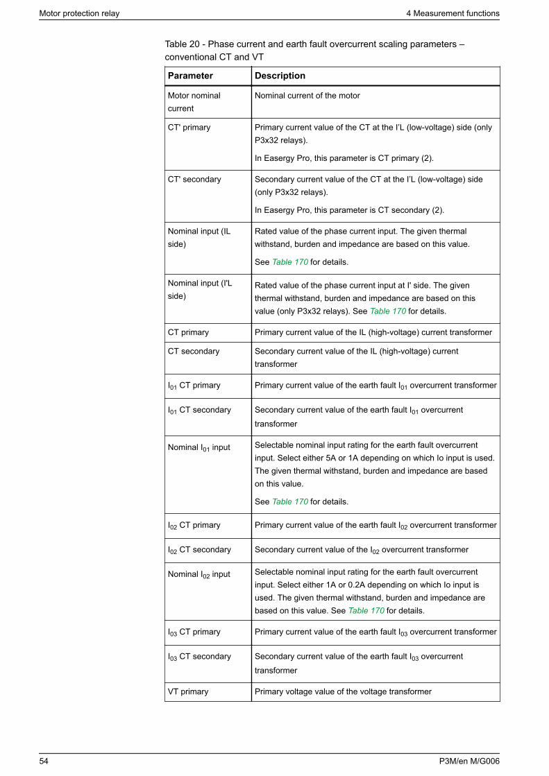
Table 20 - Phase current and earth fault overcurrent scaling parameters –conventional CT and VT
Parameter Description
Motor nominalcurrent
Nominal current of the motor
CT' primary Primary current value of the CT at the I’L (low-voltage) side (onlyP3x32 relays).
In Easergy Pro, this parameter is CT primary (2).
CT' secondary Secondary current value of the CT at the I’L (low-voltage) side(only P3x32 relays).
In Easergy Pro, this parameter is CT secondary (2).
Nominal input (ILside)
Rated value of the phase current input. The given thermalwithstand, burden and impedance are based on this value.
See Table 170 for details.
Nominal input (I'Lside)
Rated value of the phase current input at I' side. The giventhermal withstand, burden and impedance are based on thisvalue (only P3x32 relays). See Table 170 for details.
CT primary Primary current value of the IL (high-voltage) current transformer
CT secondary Secondary current value of the IL (high-voltage) currenttransformer
I01 CT primary Primary current value of the earth fault I01 overcurrent transformer
I01 CT secondary Secondary current value of the earth fault I01 overcurrenttransformer
Nominal I01 input Selectable nominal input rating for the earth fault overcurrentinput. Select either 5A or 1A depending on which Io input is used.The given thermal withstand, burden and impedance are basedon this value.
See Table 170 for details.
I02 CT primary Primary current value of the earth fault I02 overcurrent transformer
I02 CT secondary Secondary current value of the I02 overcurrent transformer
Nominal I02 input Selectable nominal input rating for the earth fault overcurrentinput. Select either 1A or 0.2A depending on which Io input isused. The given thermal withstand, burden and impedance arebased on this value. See Table 170 for details.
I03 CT primary Primary current value of the earth fault I03 overcurrent transformer
I03 CT secondary Secondary current value of the earth fault I03 overcurrenttransformer
VT primary Primary voltage value of the voltage transformer
Motor protection relay 4 Measurement functions
54 P3M/en M/G006
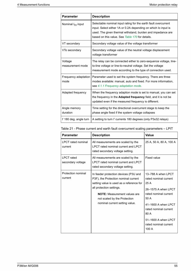
Parameter Description
Nominal I03 input Selectable nominal input rating for the earth fault overcurrentinput. Select either 1A or 0.2A depending on which Io input isused. The given thermal withstand, burden and impedance arebased on this value. See Table 170 for details.
VT secondary Secondary voltage value of the voltage transformer
VTo secondary Secondary voltage value of the neutral voltage displacementvoltage transformer
Voltagemeasurement mode
The relay can be connected either to zero-sequence voltage, line-to-line voltage or line-to-neutral voltage. Set the voltagemeasurement mode according to the type of connection used.
Frequency adaptationmode
Parameter used to set the system frequency. There are threemodes available: manual, auto and fixed. For more information,see 4.1.1 Frequency adaptation mode.
Adapted frequency When the frequency adaption mode is set to manual, you can setthe frequency in the Adapted frequency field, and it is not beupdated even if the measured frequency is different.
Angle memoryduration
Time setting for the directional overcurrent stage to keep thephase angle fixed if the system voltage collapses
I' 180 deg. angle turn A setting to turn I' currents 180 degrees (only P3x32 relays)
Table 21 - Phase current and earth fault overcurrent scaling parameters – LPIT
Parameter Description Value
LPCT rated nominalcurrent
All measurements are scaled by theLPCT rated nominal current and LPCTrated secondary voltage setting.
25 A, 50 A, 80 A, 100 A
LPCT ratedsecondary voltage
All measurements are scaled by theLPCT rated nominal current and LPCTrated secondary voltage setting.
Fixed value
Protection nominalcurrent
In feeder protection devices (P3U andP3F), the Protection nominal currentsetting value is used as a reference forall protection settings.
NOTE: Measurement values arenot scaled by the Protectionnominal current setting value.
13–788 A when LPCTrated nominal current25 A
26–1575 A when LPCTrated nominal current50 A
41–1600 A when LPCTrated nominal current80 A
51–1600 A when LPCTrated nominal current100 A
4 Measurement functions Motor protection relay
P3M/en M/G006 55
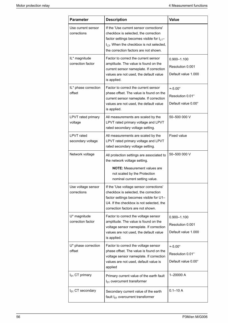
Parameter Description Value
Use current sensorcorrections
If the 'Use current sensor corrections'checkbox is selected, the correctionfactor settings becomes visible for IL1–IL3. When the checkbox is not selected,the correction factors are not shown.
IL* magnitudecorrection factor
Factor to correct the current sensoramplitude. The value is found on thecurrent sensor nameplate. If correctionvalues are not used, the default valueis applied.
0.900–1.100
Resolution 0.001
Default value 1.000
IL* phase correctionoffset
Factor to correct the current sensorphase offset. The value is found on thecurrent sensor nameplate. If correctionvalues are not used, the default valueis applied.
+-5.00°
Resolution 0.01°
Default value 0.00°
LPVT rated primaryvoltage
All measurements are scaled by theLPVT rated primary voltage and LPVTrated secondary voltage setting.
50–500 000 V
LPVT ratedsecondary voltage
All measurements are scaled by theLPVT rated primary voltage and LPVTrated secondary voltage setting.
Fixed value
Network voltage All protection settings are associated tothe network voltage setting.
NOTE: Measurement values arenot scaled by the Protectionnominal current setting value.
50–500 000 V
Use voltage sensorcorrections
If the 'Use voltage sensor corrections'checkbox is selected, the correctionfactor settings becomes visible for U1–U4. If the checkbox is not selected, thecorrection factors are not shown.
U* magnitudecorrection factor
Factor to correct the voltage sensoramplitude. The value is found on thevoltage sensor nameplate. If correctionvalues are not used, the default valueis applied.
0.900–1.100
Resolution 0.001
Default value 1.000
U* phase correctionoffset
Factor to correct the voltage sensorphase offset. The value is found on thevoltage sensor nameplate. If correctionvalues are not used, default value isapplied
+-5.00°
Resolution 0.01°
Default value 0.00°
I01 CT primary Primary current value of the earth faultI01 overcurrent transformer
1–20000 A
I01 CT secondary Secondary current value of the earthfault I01 overcurrent transformer
0.1–10 A
Motor protection relay 4 Measurement functions
56 P3M/en M/G006
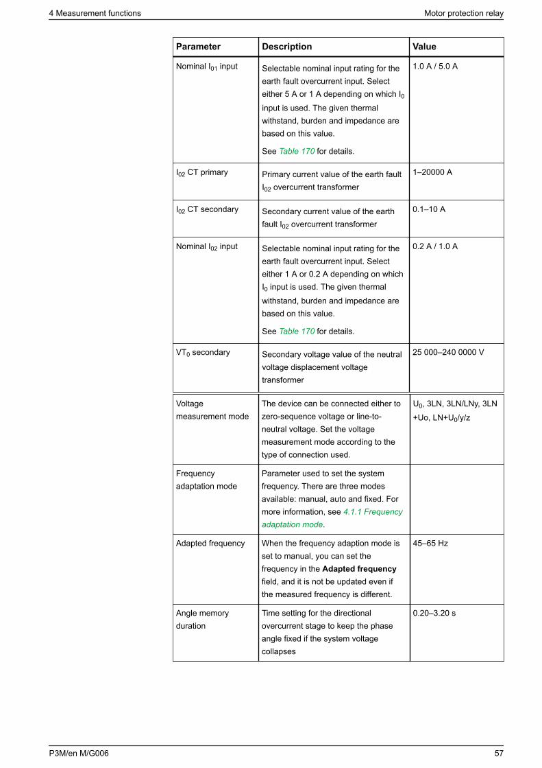
Parameter Description Value
Nominal I01 input Selectable nominal input rating for theearth fault overcurrent input. Selecteither 5 A or 1 A depending on which I0input is used. The given thermalwithstand, burden and impedance arebased on this value.
See Table 170 for details.
1.0 A / 5.0 A
I02 CT primary Primary current value of the earth faultI02 overcurrent transformer
1–20000 A
I02 CT secondary Secondary current value of the earthfault I02 overcurrent transformer
0.1–10 A
Nominal I02 input Selectable nominal input rating for theearth fault overcurrent input. Selecteither 1 A or 0.2 A depending on whichI0 input is used. The given thermalwithstand, burden and impedance arebased on this value.
See Table 170 for details.
0.2 A / 1.0 A
VT0 secondary Secondary voltage value of the neutralvoltage displacement voltagetransformer
25 000–240 0000 V
Voltagemeasurement mode
The device can be connected either tozero-sequence voltage or line-to-neutral voltage. Set the voltagemeasurement mode according to thetype of connection used.
U0, 3LN, 3LN/LNy, 3LN+Uo, LN+U0/y/z
Frequencyadaptation mode
Parameter used to set the systemfrequency. There are three modesavailable: manual, auto and fixed. Formore information, see 4.1.1 Frequencyadaptation mode.
Adapted frequency When the frequency adaption mode isset to manual, you can set thefrequency in the Adapted frequencyfield, and it is not be updated even ifthe measured frequency is different.
45–65 Hz
Angle memoryduration
Time setting for the directionalovercurrent stage to keep the phaseangle fixed if the system voltagecollapses
0.20–3.20 s
4 Measurement functions Motor protection relay
P3M/en M/G006 57
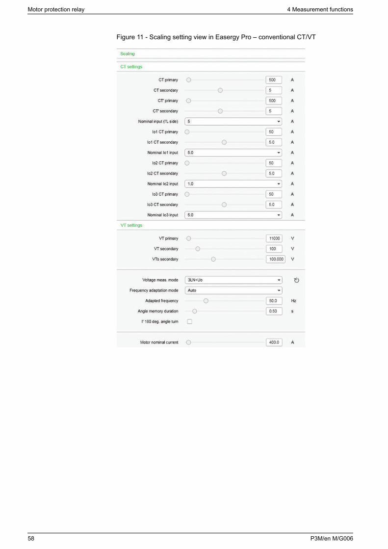
Figure 11 - Scaling setting view in Easergy Pro – conventional CT/VT
Motor protection relay 4 Measurement functions
58 P3M/en M/G006
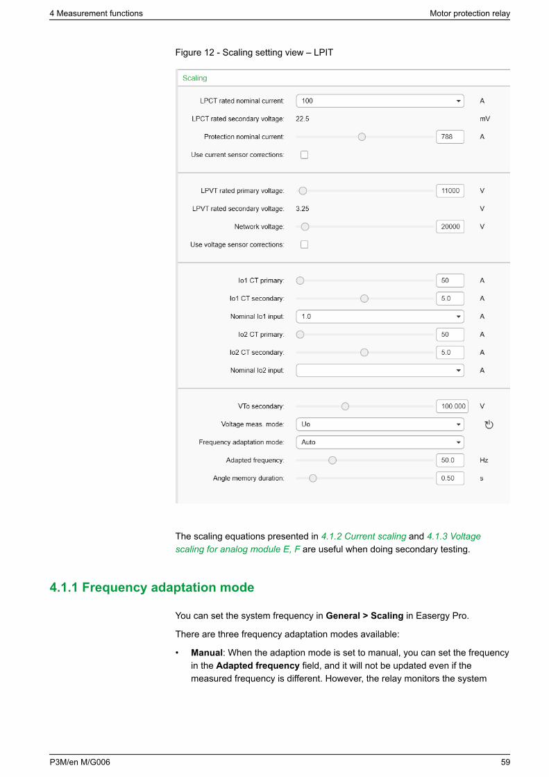
Figure 12 - Scaling setting view – LPIT
The scaling equations presented in 4.1.2 Current scaling and 4.1.3 Voltagescaling for analog module E, F are useful when doing secondary testing.
4.1.1 Frequency adaptation mode
You can set the system frequency in General > Scaling in Easergy Pro.
There are three frequency adaptation modes available:
• Manual: When the adaption mode is set to manual, you can set the frequencyin the Adapted frequency field, and it will not be updated even if themeasured frequency is different. However, the relay monitors the system
4 Measurement functions Motor protection relay
P3M/en M/G006 59
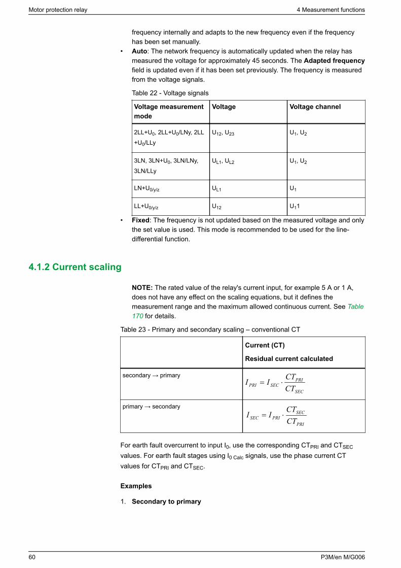
frequency internally and adapts to the new frequency even if the frequencyhas been set manually.
• Auto: The network frequency is automatically updated when the relay hasmeasured the voltage for approximately 45 seconds. The Adapted frequencyfield is updated even if it has been set previously. The frequency is measuredfrom the voltage signals.
Table 22 - Voltage signals
Voltage measurementmode
Voltage Voltage channel
2LL+U0, 2LL+U0/LNy, 2LL+U0/LLy
U12, U23 U1, U2
3LN, 3LN+U0, 3LN/LNy,3LN/LLy
UL1, UL2 U1, U2
LN+U0/y/z UL1 U1
LL+U0/y/z U12 U11
• Fixed: The frequency is not updated based on the measured voltage and onlythe set value is used. This mode is recommended to be used for the line-differential function.
4.1.2 Current scaling
NOTE: The rated value of the relay's current input, for example 5 A or 1 A,does not have any effect on the scaling equations, but it defines themeasurement range and the maximum allowed continuous current. See Table170 for details.
Table 23 - Primary and secondary scaling – conventional CT
Current (CT)
Residual current calculated
secondary → primary
SEC
PRISECPRI CT
CTII ⋅=
primary → secondary
PRI
SECPRISEC CT
CTII ⋅=
For earth fault overcurrent to input I0, use the corresponding CTPRI and CTSEC
values. For earth fault stages using I0 Calc signals, use the phase current CTvalues for CTPRI and CTSEC.
Examples
1. Secondary to primary
Motor protection relay 4 Measurement functions
60 P3M/en M/G006
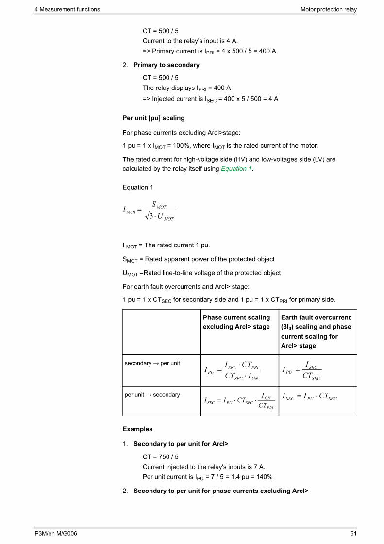
CT = 500 / 5Current to the relay's input is 4 A.=> Primary current is IPRI = 4 x 500 / 5 = 400 A
2. Primary to secondary
CT = 500 / 5The relay displays IPRI = 400 A=> Injected current is ISEC = 400 x 5 / 500 = 4 A
Per unit [pu] scaling
For phase currents excluding ArcI>stage:
1 pu = 1 x IMOT = 100%, where IMOT is the rated current of the motor.
The rated current for high-voltage side (HV) and low-voltages side (LV) arecalculated by the relay itself using Equation 1.
Equation 1
MOT
MOT
US
MOT⋅
=3
I
I MOT = The rated current 1 pu.
SMOT = Rated apparent power of the protected object
UMOT =Rated line-to-line voltage of the protected object
For earth fault overcurrents and ArcI> stage:
1 pu = 1 x CTSEC for secondary side and 1 pu = 1 x CTPRI for primary side.
Phase current scalingexcluding ArcI> stage
Earth fault overcurrent(3I0) scaling and phasecurrent scaling forArcI> stage
secondary → per unit
GNSEC
PRISECPU ICT
CTII
⋅⋅
=
SEC
SECPU CT
II =
per unit → secondary
PRI
GNSECPUSEC CT
ICTII ⋅⋅=
SECPUSEC CTII ⋅=
Examples
1. Secondary to per unit for ArcI>
CT = 750 / 5Current injected to the relay's inputs is 7 A.Per unit current is IPU = 7 / 5 = 1.4 pu = 140%
2. Secondary to per unit for phase currents excluding ArcI>
4 Measurement functions Motor protection relay
P3M/en M/G006 61

CT = 750/5IMOT = 525 ACurrent injected to the relay's inputs is 7 A.Per unit current is IPU = 7 x 750 / (5 x 525) = 2.00 pu = 2.00 x IMOT = 200%
3. Per unit to secondary for ArcI>
CT = 750 / 5The relay setting is 2 pu = 200%.Secondary current is ISEC = 2 x 5 = 10 A
4. Per unit to secondary for phase currents excluding ArcI>
CT = 750 / 5IMOT = 525 AThe relay setting is 2 x IMOT = 2 pu = 200%.Secondary current is ISEC = 2 x 5 x 525 / 750 = 7 A
5. Secondary to per unit for earth fault overcurrent
Input is I01.CT0 = 50 / 1Current injected to the relay's input is 30 mA.Per unit current is IPU = 0.03 / 1 = 0.03 pu = 3%
6. Secondary to per unit for earth fault overcurrent
Input is I01.CT0 = 50 / 1The relay setting is 0.03 pu = 3%.Secondary current is ISEC = 0.03 x 1 = 30 mA
7. Secondary to per unit for earth fault overcurrent
Input is I0 Calc.CT = 750 / 5Currents injected to the relay's IL1 input is 0.5 A.IL2 = IL3 = 0.Per unit current is IPU = 0.5 / 5 = 0.1 pu = 10%
8. Secondary to per unit for earth fault overcurrent
Input is I0 Calc.CT = 750 / 5The relay setting is 0.1 pu = 10%.If IL2 = IL3 = 0, then secondary current to IL1 is ISEC = 0.1 x 5 = 0.5 A
4.1.3 Voltage scaling for analog module E, F
NOTE: Voltage transformer scaling is based on the line-to-line voltages in allvoltage measurements modes.
Motor protection relay 4 Measurement functions
62 P3M/en M/G006
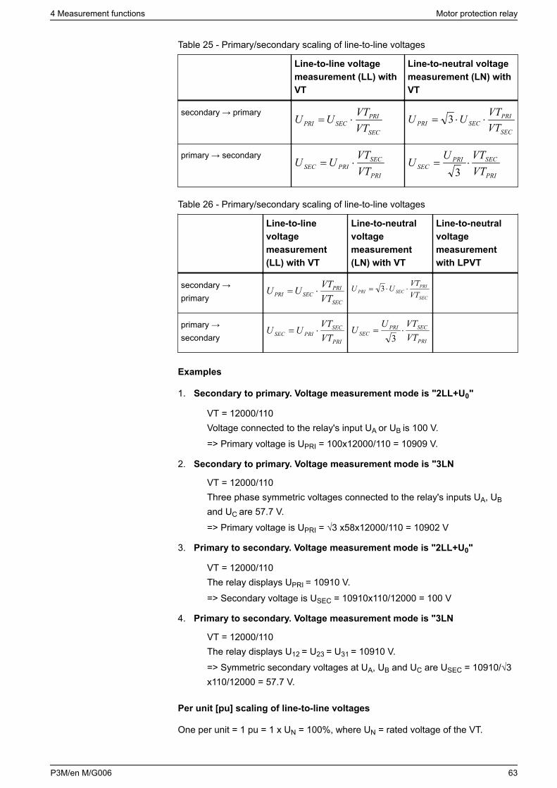
Table 25 - Primary/secondary scaling of line-to-line voltages
Line-to-line voltagemeasurement (LL) withVT
Line-to-neutral voltagemeasurement (LN) withVT
secondary → primary
SEC
PRISECPRI VT
VTUU ⋅=SEC
PRISECPRI VT
VTUU ⋅⋅= 3
primary → secondary
PRI
SECPRISEC VT
VTUU ⋅=
PRI
SECPRISEC VT
VTUU ⋅=3
Table 26 - Primary/secondary scaling of line-to-line voltages
Line-to-linevoltagemeasurement(LL) with VT
Line-to-neutralvoltagemeasurement(LN) with VT
Line-to-neutralvoltagemeasurementwith LPVT
secondary →primary SEC
PRISECPRI VT
VTUU ⋅=SEC
PRISECPRI VT
VTUU ⋅⋅= 3
primary →secondary PRI
SECPRISEC VT
VTUU ⋅=
PRI
SECPRISEC VT
VTUU ⋅=3
Examples
1. Secondary to primary. Voltage measurement mode is "2LL+U0"
VT = 12000/110Voltage connected to the relay's input UA or UB is 100 V.=> Primary voltage is UPRI = 100x12000/110 = 10909 V.
2. Secondary to primary. Voltage measurement mode is "3LN
VT = 12000/110Three phase symmetric voltages connected to the relay's inputs UA, UB
and UC are 57.7 V.=> Primary voltage is UPRI = √3 x58x12000/110 = 10902 V
3. Primary to secondary. Voltage measurement mode is "2LL+U0"
VT = 12000/110The relay displays UPRI = 10910 V.=> Secondary voltage is USEC = 10910x110/12000 = 100 V
4. Primary to secondary. Voltage measurement mode is "3LN
VT = 12000/110The relay displays U12 = U23 = U31 = 10910 V.=> Symmetric secondary voltages at UA, UB and UC are USEC = 10910/√3x110/12000 = 57.7 V.
Per unit [pu] scaling of line-to-line voltages
One per unit = 1 pu = 1 x UN = 100%, where UN = rated voltage of the VT.
4 Measurement functions Motor protection relay
P3M/en M/G006 63
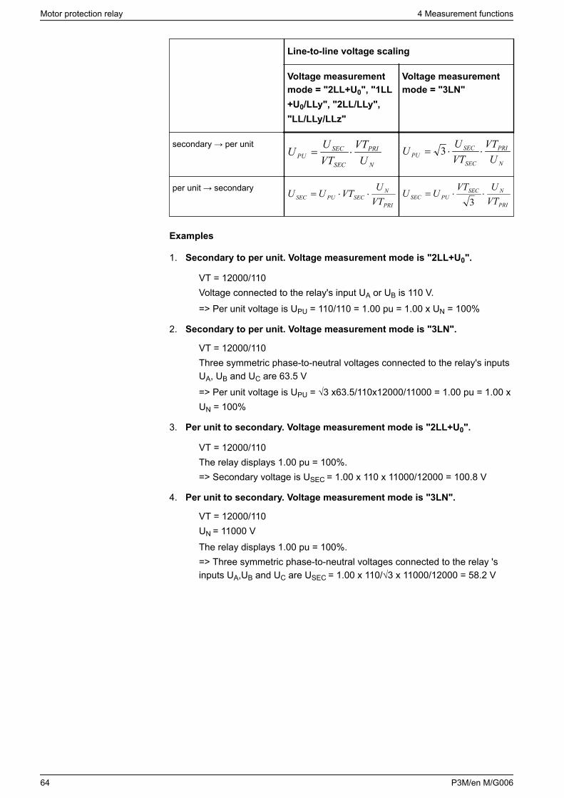
Line-to-line voltage scaling
Voltage measurementmode = "2LL+U0", "1LL+U0/LLy", "2LL/LLy","LL/LLy/LLz"
Voltage measurementmode = "3LN"
secondary → per unit
N
PRI
SEC
SECPU U
VTVTU
U ⋅=N
PRI
SEC
SECPU U
VTVTU
U ⋅⋅= 3
per unit → secondary
PRI
NSECPUSEC VT
UVTUU ⋅⋅=
PRI
NSECPUSEC VT
UVTUU ⋅⋅=
3
Examples
1. Secondary to per unit. Voltage measurement mode is "2LL+U0".
VT = 12000/110Voltage connected to the relay's input UA or UB is 110 V.=> Per unit voltage is UPU = 110/110 = 1.00 pu = 1.00 x UN = 100%
2. Secondary to per unit. Voltage measurement mode is "3LN".
VT = 12000/110Three symmetric phase-to-neutral voltages connected to the relay's inputsUA, UB and UC are 63.5 V=> Per unit voltage is UPU = √3 x63.5/110x12000/11000 = 1.00 pu = 1.00 xUN = 100%
3. Per unit to secondary. Voltage measurement mode is "2LL+U0".
VT = 12000/110The relay displays 1.00 pu = 100%.=> Secondary voltage is USEC = 1.00 x 110 x 11000/12000 = 100.8 V
4. Per unit to secondary. Voltage measurement mode is "3LN".
VT = 12000/110UN = 11000 VThe relay displays 1.00 pu = 100%.=> Three symmetric phase-to-neutral voltages connected to the relay 'sinputs UA,UB and UC are USEC = 1.00 x 110/√3 x 11000/12000 = 58.2 V
Motor protection relay 4 Measurement functions
64 P3M/en M/G006
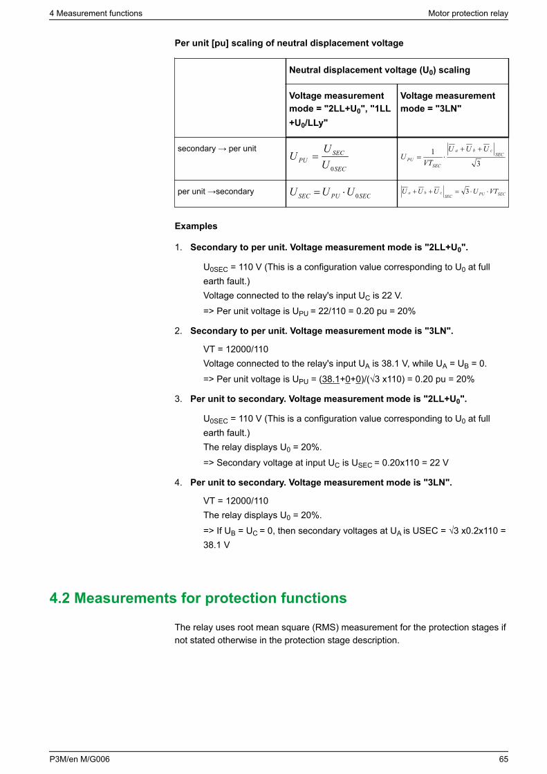
Per unit [pu] scaling of neutral displacement voltage
Neutral displacement voltage (U0) scaling
Voltage measurementmode = "2LL+U0", "1LL+U0/LLy"
Voltage measurementmode = "3LN"
secondary → per unit
SEC
SECPU U
UU
0
=3
1 SECcba
SECPU
UUU
VTU
++⋅=
per unit →secondary SECPUSEC UUU 0⋅= SECPUSEC
cba VTUUUU ⋅⋅=++ 3
Examples
1. Secondary to per unit. Voltage measurement mode is "2LL+U0".
U0SEC = 110 V (This is a configuration value corresponding to U0 at fullearth fault.)Voltage connected to the relay's input UC is 22 V.=> Per unit voltage is UPU = 22/110 = 0.20 pu = 20%
2. Secondary to per unit. Voltage measurement mode is "3LN".
VT = 12000/110Voltage connected to the relay's input UA is 38.1 V, while UA = UB = 0.=> Per unit voltage is UPU = (38.1+0+0)/(√3 x110) = 0.20 pu = 20%
3. Per unit to secondary. Voltage measurement mode is "2LL+U0".
U0SEC = 110 V (This is a configuration value corresponding to U0 at fullearth fault.)The relay displays U0 = 20%.=> Secondary voltage at input UC is USEC = 0.20x110 = 22 V
4. Per unit to secondary. Voltage measurement mode is "3LN".
VT = 12000/110The relay displays U0 = 20%.=> If UB = UC = 0, then secondary voltages at UA is USEC = √3 x0.2x110 =38.1 V
4.2 Measurements for protection functions
The relay uses root mean square (RMS) measurement for the protection stages ifnot stated otherwise in the protection stage description.
4 Measurement functions Motor protection relay
P3M/en M/G006 65
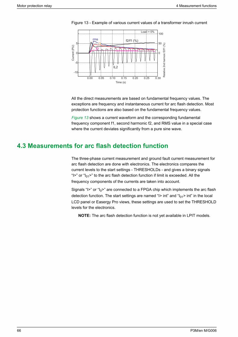
Figure 13 - Example of various current values of a transformer inrush current
0.00 0.05 0.10 0.15 0.20 0.25 0.30
-10
-5
0
5rms
IL2
f1f2
0
50
100
f2/f1 (%)
Cur
rent
(PU
)
Time (s)
Load = 0%
Rel
ativ
e 2n
d ha
rmoi
c f2
/f1 (%
)
All the direct measurements are based on fundamental frequency values. Theexceptions are frequency and instantaneous current for arc flash detection. Mostprotection functions are also based on the fundamental frequency values.
Figure 13 shows a current waveform and the corresponding fundamentalfrequency component f1, second harmonic f2, and RMS value in a special casewhere the current deviates significantly from a pure sine wave.
4.3 Measurements for arc flash detection function
The three-phase current measurement and ground fault current measurement forarc flash detection are done with electronics. The electronics compares thecurrent levels to the start settings - THRESHOLDs - and gives a binary signals“I>” or “I01>” to the arc flash detection function if limit is exceeded. All thefrequency components of the currents are taken into account.
Signals “I>” or “I0>” are connected to a FPGA chip which implements the arc flashdetection function. The start settings are named “I> int” and “I01> int” in the localLCD panel or Easergy Pro views, these settings are used to set the THRESHOLDlevels for the electronics.
NOTE: The arc flash detection function is not yet available in LPIT models.
Motor protection relay 4 Measurement functions
66 P3M/en M/G006
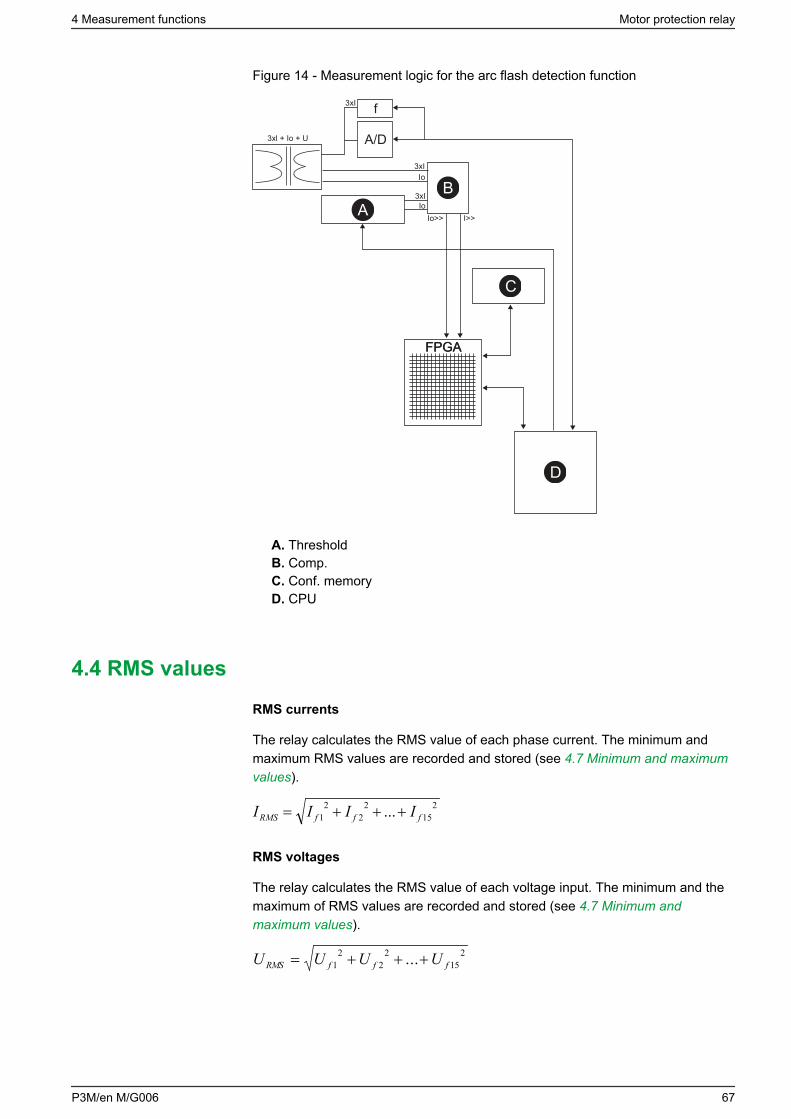
Figure 14 - Measurement logic for the arc flash detection function
FPGA
f
A/D
3xI
3xI
Io
IoIo>> I>>
3xI
3xl + Io + U
FPGA
AB
C
D
A. ThresholdB. Comp.C. Conf. memoryD. CPU
4.4 RMS values
RMS currents
The relay calculates the RMS value of each phase current. The minimum andmaximum RMS values are recorded and stored (see 4.7 Minimum and maximumvalues).
215
22
21 ... fffRMS IIII +++=
RMS voltages
The relay calculates the RMS value of each voltage input. The minimum and themaximum of RMS values are recorded and stored (see 4.7 Minimum andmaximum values).
215
22
21 ... fffRMS UUUU +++=
4 Measurement functions Motor protection relay
P3M/en M/G006 67
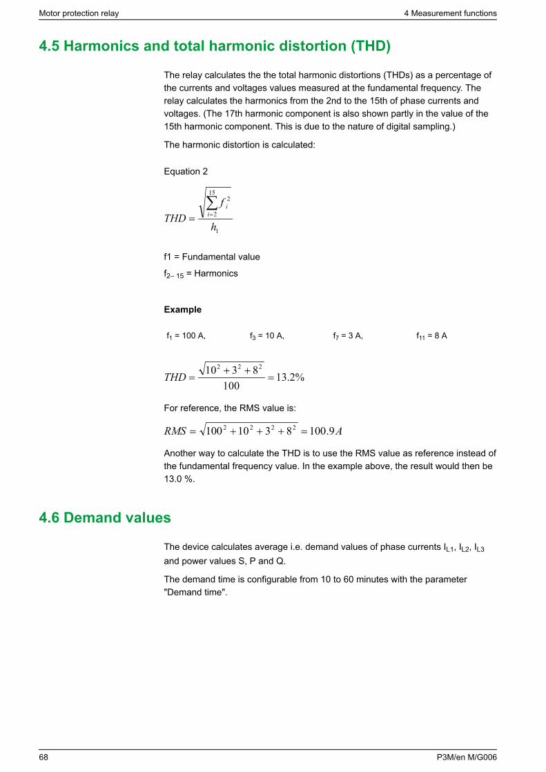
4.5 Harmonics and total harmonic distortion (THD)
The relay calculates the the total harmonic distortions (THDs) as a percentage ofthe currents and voltages values measured at the fundamental frequency. Therelay calculates the harmonics from the 2nd to the 15th of phase currents andvoltages. (The 17th harmonic component is also shown partly in the value of the15th harmonic component. This is due to the nature of digital sampling.)
The harmonic distortion is calculated:
Equation 2
1
15
2
hTHD i
2f i∑==
f1 = Fundamental value
f2– 15 = Harmonics
Example
f1 = 100 A, f3 = 10 A, f7 = 3 A, f11 = 8 A
%2.13100
8310 222
=++
=THD
For reference, the RMS value is:
ARMS 9.1008310100 2222 =+++=
Another way to calculate the THD is to use the RMS value as reference instead ofthe fundamental frequency value. In the example above, the result would then be13.0 %.
4.6 Demand values
The device calculates average i.e. demand values of phase currents IL1, IL2, IL3
and power values S, P and Q.
The demand time is configurable from 10 to 60 minutes with the parameter"Demand time".
Motor protection relay 4 Measurement functions
68 P3M/en M/G006
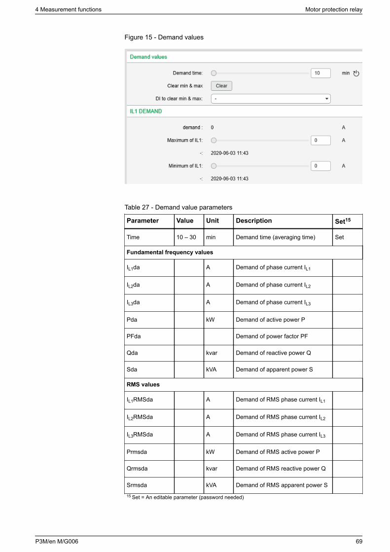
Figure 15 - Demand values
Table 27 - Demand value parameters
Parameter Value Unit Description Set15
Time 10 – 30 min Demand time (averaging time) Set
Fundamental frequency values
IL1da A Demand of phase current IL1
IL2da A Demand of phase current IL2
IL3da A Demand of phase current IL3
Pda kW Demand of active power P
PFda Demand of power factor PF
Qda kvar Demand of reactive power Q
Sda kVA Demand of apparent power S
RMS values
IL1RMSda A Demand of RMS phase current IL1
IL2RMSda A Demand of RMS phase current IL2
IL3RMSda A Demand of RMS phase current IL3
Prmsda kW Demand of RMS active power P
Qrmsda kvar Demand of RMS reactive power Q
Srmsda kVA Demand of RMS apparent power S
15 Set = An editable parameter (password needed)
4 Measurement functions Motor protection relay
P3M/en M/G006 69
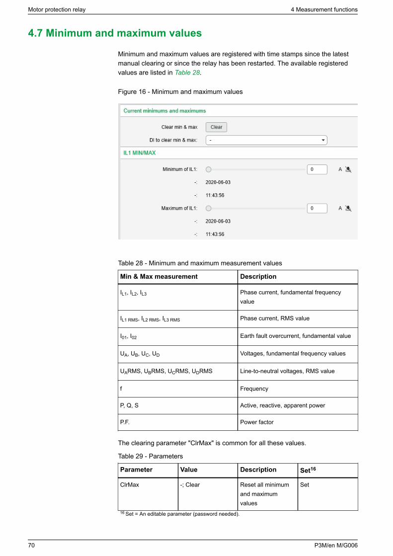
4.7 Minimum and maximum values
Minimum and maximum values are registered with time stamps since the latestmanual clearing or since the relay has been restarted. The available registeredvalues are listed in Table 28.
Figure 16 - Minimum and maximum values
Table 28 - Minimum and maximum measurement values
Min & Max measurement Description
IL1, IL2, IL3 Phase current, fundamental frequencyvalue
IL1 RMS, IL2 RMS, IL3 RMS Phase current, RMS value
I01, I02 Earth fault overcurrent, fundamental value
UA, UB, UC, UD Voltages, fundamental frequency values
UARMS, UBRMS, UCRMS, UDRMS Line-to-neutral voltages, RMS value
f Frequency
P, Q, S Active, reactive, apparent power
P.F. Power factor
The clearing parameter "ClrMax" is common for all these values.
Table 29 - Parameters
Parameter Value Description Set16
ClrMax -; Clear Reset all minimumand maximumvalues
Set
16 Set = An editable parameter (password needed).
Motor protection relay 4 Measurement functions
70 P3M/en M/G006
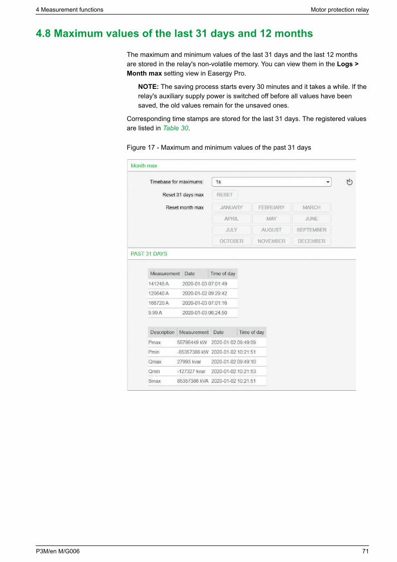
4.8 Maximum values of the last 31 days and 12 months
The maximum and minimum values of the last 31 days and the last 12 monthsare stored in the relay's non-volatile memory. You can view them in the Logs >Month max setting view in Easergy Pro.
NOTE: The saving process starts every 30 minutes and it takes a while. If therelay's auxiliary supply power is switched off before all values have beensaved, the old values remain for the unsaved ones.
Corresponding time stamps are stored for the last 31 days. The registered valuesare listed in Table 30.
Figure 17 - Maximum and minimum values of the past 31 days
4 Measurement functions Motor protection relay
P3M/en M/G006 71
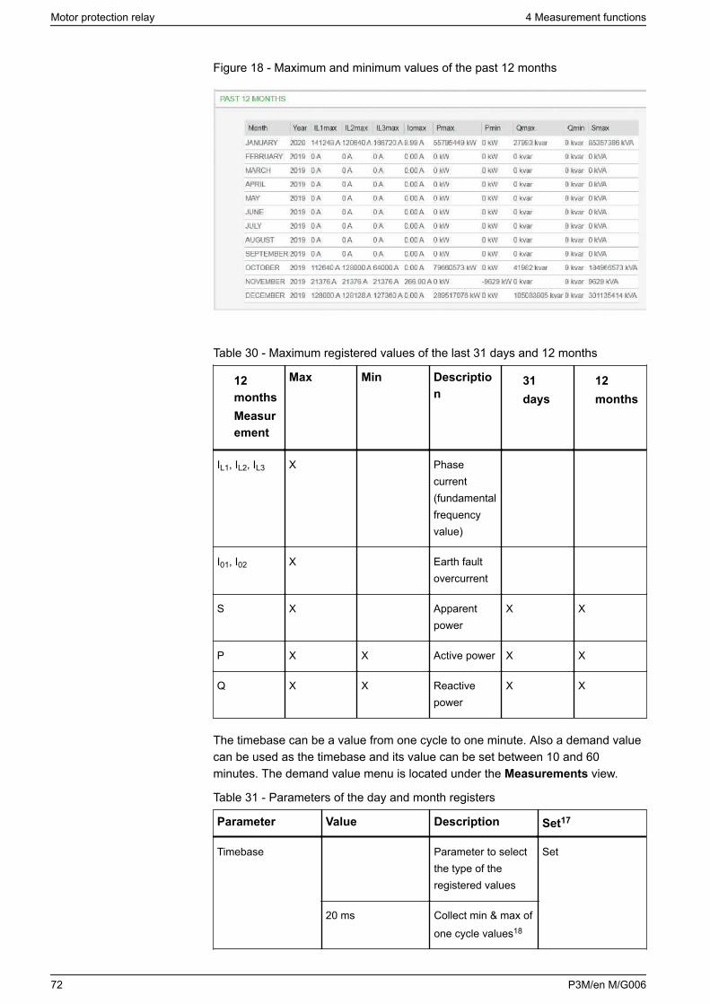
Figure 18 - Maximum and minimum values of the past 12 months
Table 30 - Maximum registered values of the last 31 days and 12 months
12monthsMeasurement
Max Min Description
31days
12months
IL1, IL2, IL3 X Phasecurrent(fundamentalfrequencyvalue)
I01, I02 X Earth faultovercurrent
S X Apparentpower
X X
P X X Active power X X
Q X X Reactivepower
X X
The timebase can be a value from one cycle to one minute. Also a demand valuecan be used as the timebase and its value can be set between 10 and 60minutes. The demand value menu is located under the Measurements view.
Table 31 - Parameters of the day and month registers
Parameter Value Description Set17
Timebase Parameter to selectthe type of theregistered values
Set
20 ms Collect min & max ofone cycle values18
Motor protection relay 4 Measurement functions
72 P3M/en M/G006
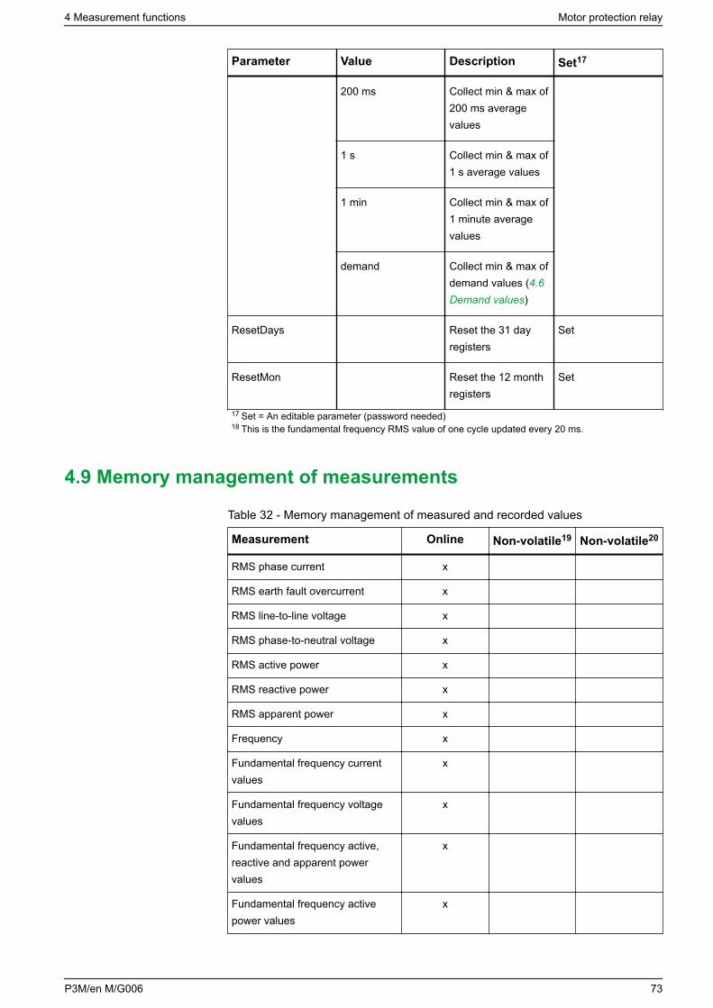
Parameter Value Description Set17
200 ms Collect min & max of200 ms averagevalues
1 s Collect min & max of1 s average values
1 min Collect min & max of1 minute averagevalues
demand Collect min & max ofdemand values (4.6Demand values)
ResetDays Reset the 31 dayregisters
Set
ResetMon Reset the 12 monthregisters
Set
17 Set = An editable parameter (password needed)18 This is the fundamental frequency RMS value of one cycle updated every 20 ms.
4.9 Memory management of measurements
Table 32 - Memory management of measured and recorded values
Measurement Online Non-volatile19 Non-volatile20
RMS phase current x
RMS earth fault overcurrent x
RMS line-to-line voltage x
RMS phase-to-neutral voltage x
RMS active power x
RMS reactive power x
RMS apparent power x
Frequency x
Fundamental frequency currentvalues
x
Fundamental frequency voltagevalues
x
Fundamental frequency active,reactive and apparent powervalues
x
Fundamental frequency activepower values
x
4 Measurement functions Motor protection relay
P3M/en M/G006 73
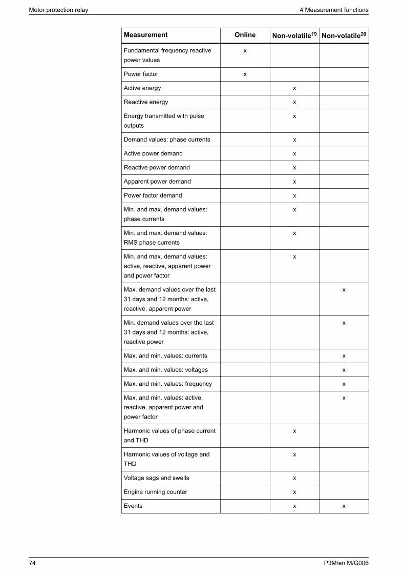
Measurement Online Non-volatile19 Non-volatile20
Fundamental frequency reactivepower values
x
Power factor x
Active energy x
Reactive energy x
Energy transmitted with pulseoutputs
x
Demand values: phase currents x
Active power demand x
Reactive power demand x
Apparent power demand x
Power factor demand x
Min. and max. demand values:phase currents
x
Min. and max. demand values:RMS phase currents
x
Min. and max. demand values:active, reactive, apparent powerand power factor
x
Max. demand values over the last31 days and 12 months: active,reactive, apparent power
x
Min. demand values over the last31 days and 12 months: active,reactive power
x
Max. and min. values: currents x
Max. and min. values: voltages x
Max. and min. values: frequency x
Max. and min. values: active,reactive, apparent power andpower factor
x
Harmonic values of phase currentand THD
x
Harmonic values of voltage andTHD
x
Voltage sags and swells x
Engine running counter x
Events x x
Motor protection relay 4 Measurement functions
74 P3M/en M/G006
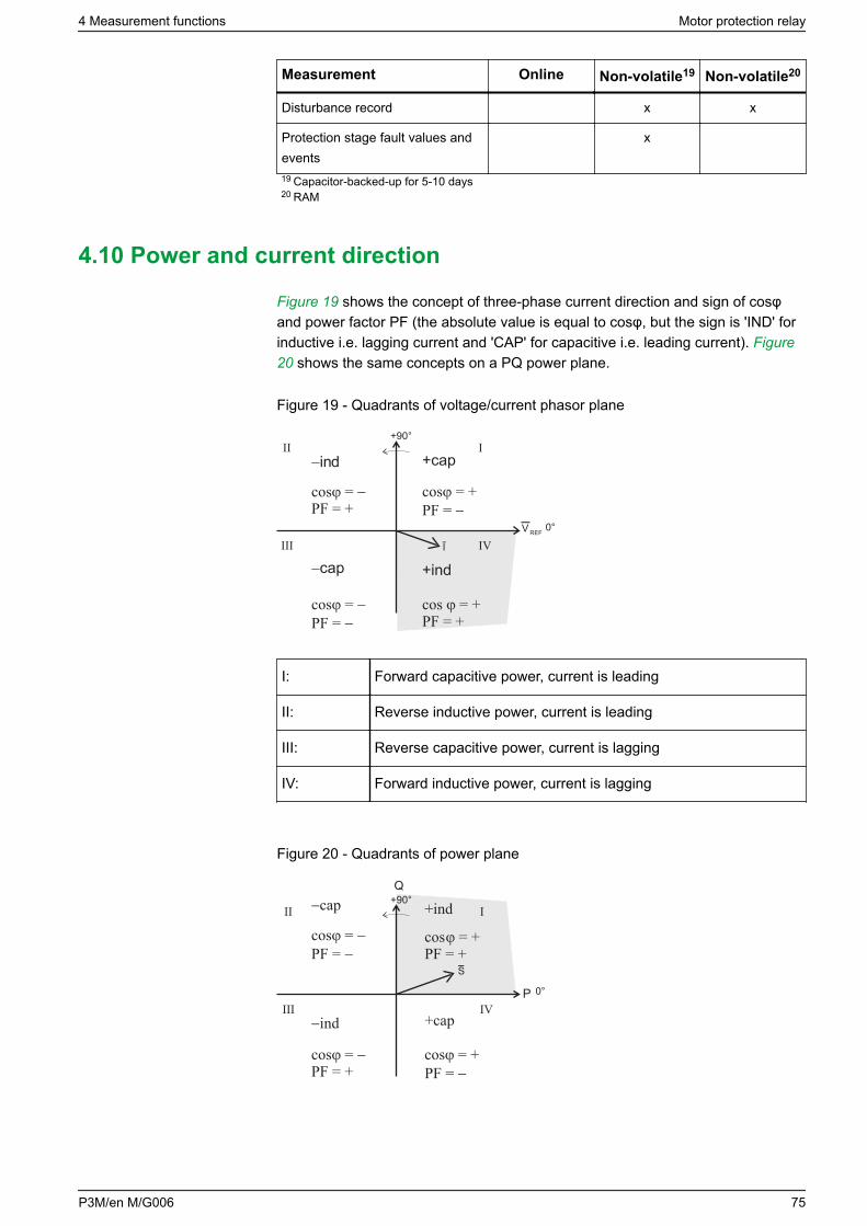
Measurement Online Non-volatile19 Non-volatile20
Disturbance record x x
Protection stage fault values andevents
x
19 Capacitor-backed-up for 5-10 days20 RAM
4.10 Power and current direction
Figure 19 shows the concept of three-phase current direction and sign of cosφand power factor PF (the absolute value is equal to cosφ, but the sign is 'IND' forinductive i.e. lagging current and 'CAP' for capacitive i.e. leading current). Figure20 shows the same concepts on a PQ power plane.
Figure 19 - Quadrants of voltage/current phasor plane
I
V REF
+ind
cos = +PF = +
+cap
cos = +PF =
ind
cos =PF = +
cap
cos =PF =
0°
+90°III
III IV
I: Forward capacitive power, current is leading
II: Reverse inductive power, current is leading
III: Reverse capacitive power, current is lagging
IV: Forward inductive power, current is lagging
Figure 20 - Quadrants of power plane
S
P
Q
+ind
cos = +PF = +
+cap
cos = +PF =
ind
cos =PF = +
cap
cos =PF =
0°
+90°III
III IV
4 Measurement functions Motor protection relay
P3M/en M/G006 75
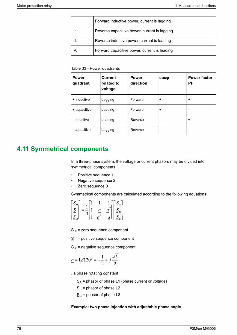
I: Forward inductive power, current is lagging
II: Reverse capacitive power, current is lagging
III: Reverse inductive power, current is leading
IV: Forward capacitive power, current is leading
Table 33 - Power quadrants
Powerquadrant
Currentrelated tovoltage
Powerdirection
cosφ Power factorPF
+ inductive Lagging Forward + +
+ capacitive Leading Forward + -
- inductive Leading Reverse - +
- capacitive Lagging Reverse - -
4.11 Symmetrical components
In a three-phase system, the voltage or current phasors may be divided intosymmetrical components.
• Positive sequence 1• Negative sequence 2• Zero sequence 0
Symmetrical components are calculated according to the following equations:
=
Saaaa
SSS
2
2
2 C
SB
SA
1
0
11
111
31
S 0 = zero sequence component
S 1 = positive sequence component
S 2 = negative sequence component
23
211201 ja +−=°∠=
, a phase rotating constant
SA = phasor of phase L1 (phase current or voltage)SB = phasor of phase L2SC = phasor of phase L3
Example: two phase injection with adjustable phase angle
Motor protection relay 4 Measurement functions
76 P3M/en M/G006
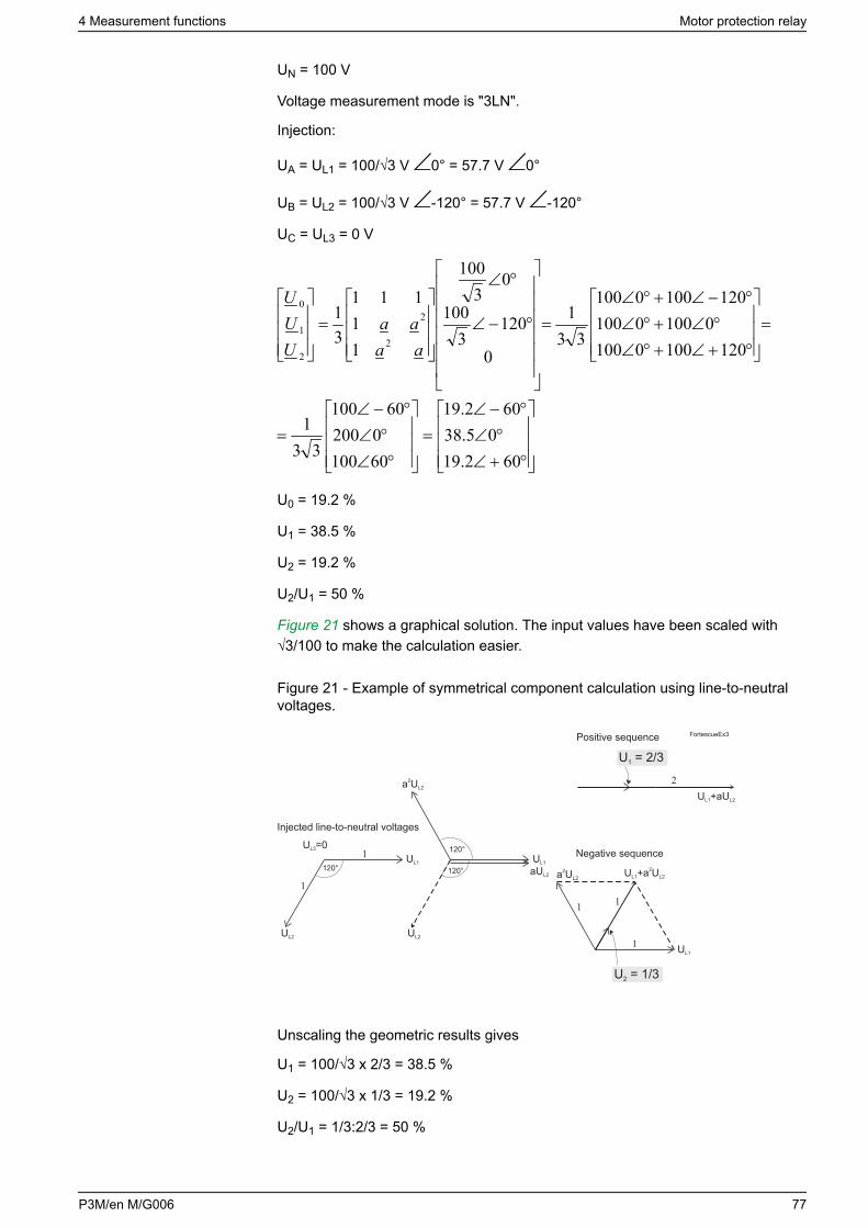
UN = 100 V
Voltage measurement mode is "3LN".
Injection:
UA = UL1 = 100/√3 V 0° = 57.7 V 0°
UB = UL2 = 100/√3 V -120° = 57.7 V -120°
UC = UL3 = 0 V
°+∠°∠
°−∠=
°∠°∠
°−∠=
=
°+∠+°∠°∠+°∠
°−∠+°∠=
°−∠
°∠
=
602.1905.38
602.19
601000200
60100
331
120100010001000100
1201000100
331
0
1203
100
03
100
11
111
31
2
2
2
1
0
aaaa
UUU
U0 = 19.2 %
U1 = 38.5 %
U2 = 19.2 %
U2/U1 = 50 %
Figure 21 shows a graphical solution. The input values have been scaled with√3/100 to make the calculation easier.
Figure 21 - Example of symmetrical component calculation using line-to-neutralvoltages.
U = 2/31
U = 1/32
120° 120°
120°UL1
UL1
UL1
U =0L3
UL2 UL2
a U2L2
a U2L2
aUL2
U +aUL1 L2
U +a UL1 L22
Positive sequence
Injected line-to-neutral voltages
Negative sequence
FortescueEx3
Unscaling the geometric results gives
U1 = 100/√3 x 2/3 = 38.5 %
U2 = 100/√3 x 1/3 = 19.2 %
U2/U1 = 1/3:2/3 = 50 %
4 Measurement functions Motor protection relay
P3M/en M/G006 77
5 Control functions
5.1 Digital outputs
The digital outputs are also called controlling outputs, signaling outputs and self-supervision outputs. Trip contacts can be controlled by using the relay outputmatrix or logic functions. Also forced control is possible. To use forced control,you must enable it in the Device/Test > Relays setting view.
Any internal signal can be connected to the digital outputs in the Matrix > Arcmatrix - output setting views.
The Output matrix and Relays setting views represent the state (de-energized /energized) of the digital output's coil. For example, a bright green vertical line inthe Output matrix and a logical "1" in the Relays view represent the energizedstate of the coil. The same principle applies for both NO and NC type digitaloutputs. The actual position (open / closed) of the digital outputs' contacts in coil'sde-energized and energized state depends on the type (NO / NC) of the digitaloutputs. De-energized state of the coil corresponds to the normal state of thecontacts. A digital output can be configured as latched or non-latched. 5.5Releasing latches describes releasing latches procedure.
The difference between trip contacts and signal contacts is the DC breakingcapacity. The contacts are single pole single throw (SPST) normal open (NO)type, except signal relay A1 which has a changeover contact single pole doublethrow (SPDT).
In addition to this, the relay has so called heavy duty outputs available in thepower supply modules C and D. For more details, see Table 170.
Programming matrix
1. Connected (single bullet)
2. Connected and latched (single bullet rounded with another circle)
3. Not connected (line crossing is empty)
Trip contacts can be connected to protection stages or other similar purpose inthe Output matrix setting view.
Motor protection relay 5 Control functions
78 P3M/en M/G006
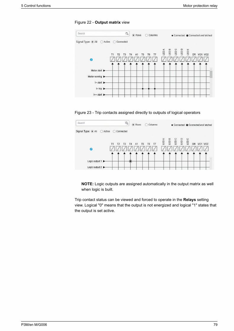
Figure 22 - Output matrix view
Figure 23 - Trip contacts assigned directly to outputs of logical operators
NOTE: Logic outputs are assigned automatically in the output matrix as wellwhen logic is built.
Trip contact status can be viewed and forced to operate in the Relays settingview. Logical "0" means that the output is not energized and logical "1" states thatthe output is set active.
5 Control functions Motor protection relay
P3M/en M/G006 79
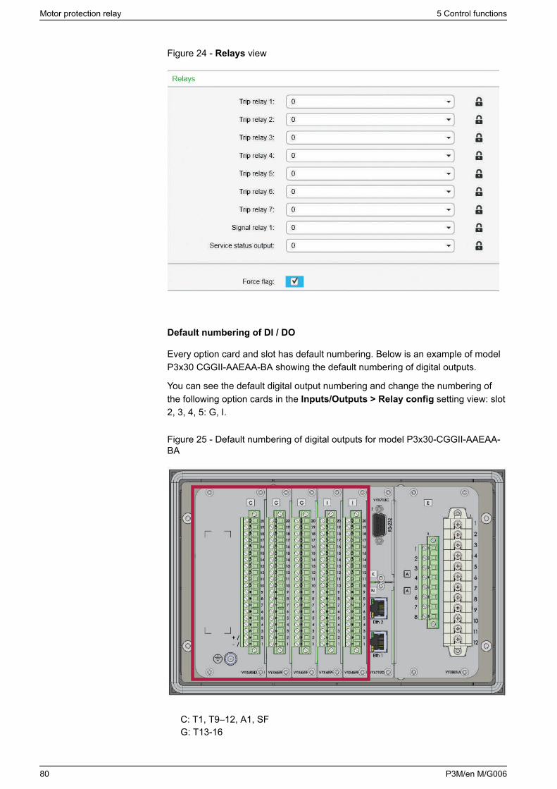
Figure 24 - Relays view
Default numbering of DI / DO
Every option card and slot has default numbering. Below is an example of modelP3x30 CGGII-AAEAA-BA showing the default numbering of digital outputs.
You can see the default digital output numbering and change the numbering ofthe following option cards in the Inputs/Outputs > Relay config setting view: slot2, 3, 4, 5: G, I.
Figure 25 - Default numbering of digital outputs for model P3x30-CGGII-AAEAA-BA
C: T1, T9–12, A1, SFG: T13-16
Motor protection relay 5 Control functions
80 P3M/en M/G006
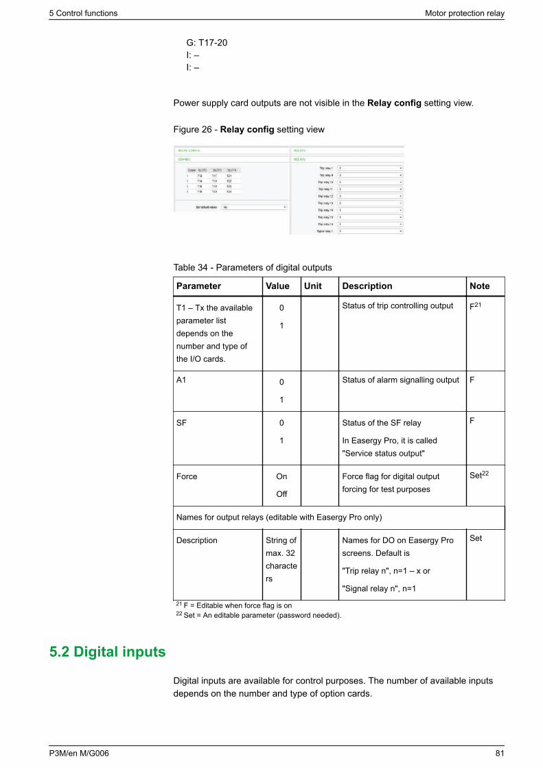
G: T17-20I: –I: –
Power supply card outputs are not visible in the Relay config setting view.
Figure 26 - Relay config setting view
Table 34 - Parameters of digital outputs
Parameter Value Unit Description Note
T1 – Tx the availableparameter listdepends on thenumber and type ofthe I/O cards.
0
1
Status of trip controlling output F21
A1 0
1
Status of alarm signalling output F
SF 0
1
Status of the SF relay
In Easergy Pro, it is called"Service status output"
F
Force On
Off
Force flag for digital outputforcing for test purposes
Set22
Names for output relays (editable with Easergy Pro only)
Description String ofmax. 32characters
Names for DO on Easergy Proscreens. Default is
"Trip relay n", n=1 – x or
"Signal relay n", n=1
Set
21 F = Editable when force flag is on22 Set = An editable parameter (password needed).
5.2 Digital inputs
Digital inputs are available for control purposes. The number of available inputsdepends on the number and type of option cards.
5 Control functions Motor protection relay
P3M/en M/G006 81
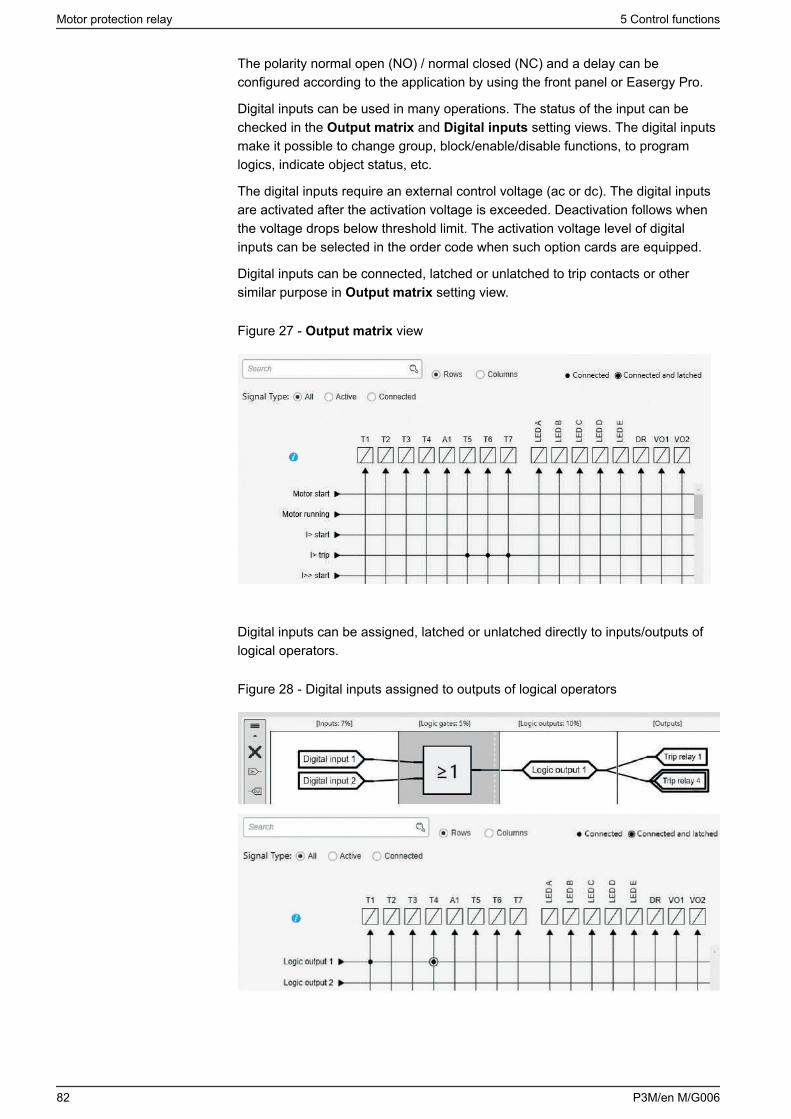
The polarity normal open (NO) / normal closed (NC) and a delay can beconfigured according to the application by using the front panel or Easergy Pro.
Digital inputs can be used in many operations. The status of the input can bechecked in the Output matrix and Digital inputs setting views. The digital inputsmake it possible to change group, block/enable/disable functions, to programlogics, indicate object status, etc.
The digital inputs require an external control voltage (ac or dc). The digital inputsare activated after the activation voltage is exceeded. Deactivation follows whenthe voltage drops below threshold limit. The activation voltage level of digitalinputs can be selected in the order code when such option cards are equipped.
Digital inputs can be connected, latched or unlatched to trip contacts or othersimilar purpose in Output matrix setting view.
Figure 27 - Output matrix view
Digital inputs can be assigned, latched or unlatched directly to inputs/outputs oflogical operators.
Figure 28 - Digital inputs assigned to outputs of logical operators
Motor protection relay 5 Control functions
82 P3M/en M/G006
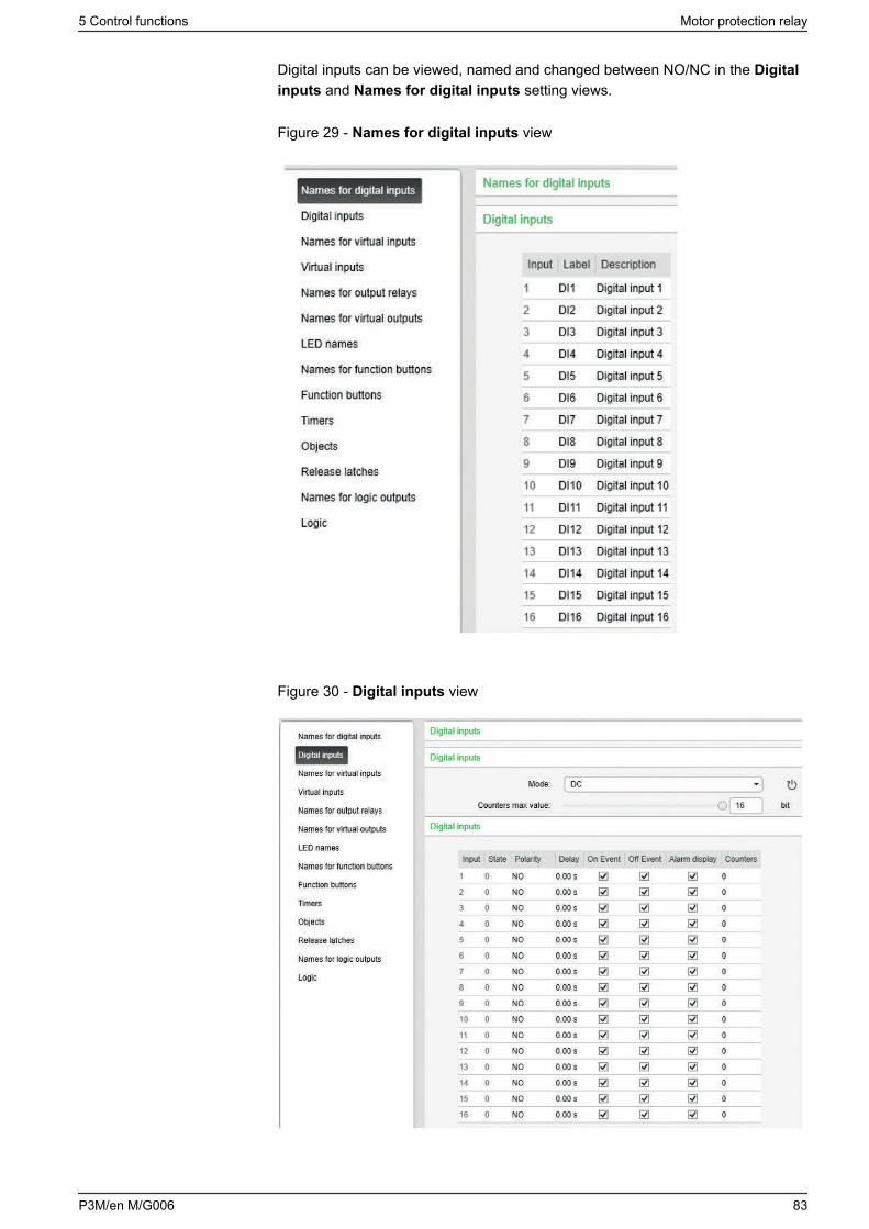
Digital inputs can be viewed, named and changed between NO/NC in the Digitalinputs and Names for digital inputs setting views.
Figure 29 - Names for digital inputs view
Figure 30 - Digital inputs view
5 Control functions Motor protection relay
P3M/en M/G006 83
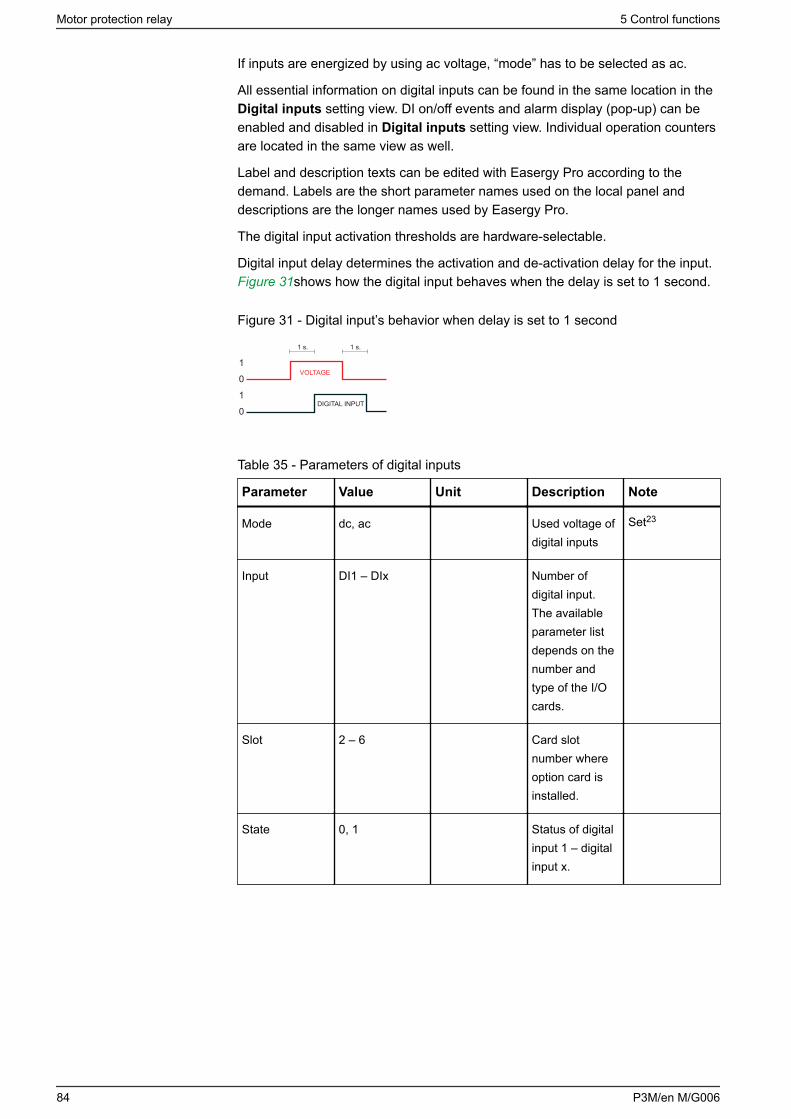
If inputs are energized by using ac voltage, “mode” has to be selected as ac.
All essential information on digital inputs can be found in the same location in theDigital inputs setting view. DI on/off events and alarm display (pop-up) can beenabled and disabled in Digital inputs setting view. Individual operation countersare located in the same view as well.
Label and description texts can be edited with Easergy Pro according to thedemand. Labels are the short parameter names used on the local panel anddescriptions are the longer names used by Easergy Pro.
The digital input activation thresholds are hardware-selectable.
Digital input delay determines the activation and de-activation delay for the input. Figure 31shows how the digital input behaves when the delay is set to 1 second.
Figure 31 - Digital input’s behavior when delay is set to 1 second
VOLTAGE
1 s.
DIGITAL INPUT
1 s.
1
0
1
0
Table 35 - Parameters of digital inputs
Parameter Value Unit Description Note
Mode dc, ac Used voltage ofdigital inputs
Set23
Input DI1 – DIx Number ofdigital input.The availableparameter listdepends on thenumber andtype of the I/Ocards.
Slot 2 – 6 Card slotnumber whereoption card isinstalled.
State 0, 1 Status of digitalinput 1 – digitalinput x.
Motor protection relay 5 Control functions
84 P3M/en M/G006
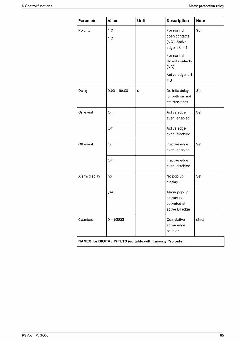
Parameter Value Unit Description Note
Polarity NO
NC
For normalopen contacts(NO). Activeedge is 0 > 1
For normalclosed contacts(NC)
Active edge is 1> 0
Set
Delay 0.00 – 60.00 s Definite delayfor both on andoff transitions
Set
On event On Active edgeevent enabled
Set
Off Active edgeevent disabled
Off event On Inactive edgeevent enabled
Set
Off Inactive edgeevent disabled
Alarm display no No pop-updisplay
Set
yes Alarm pop-updisplay isactivated atactive DI edge
Counters 0 – 65535 Cumulativeactive edgecounter
(Set)
NAMES for DIGITAL INPUTS (editable with Easergy Pro only)
5 Control functions Motor protection relay
P3M/en M/G006 85
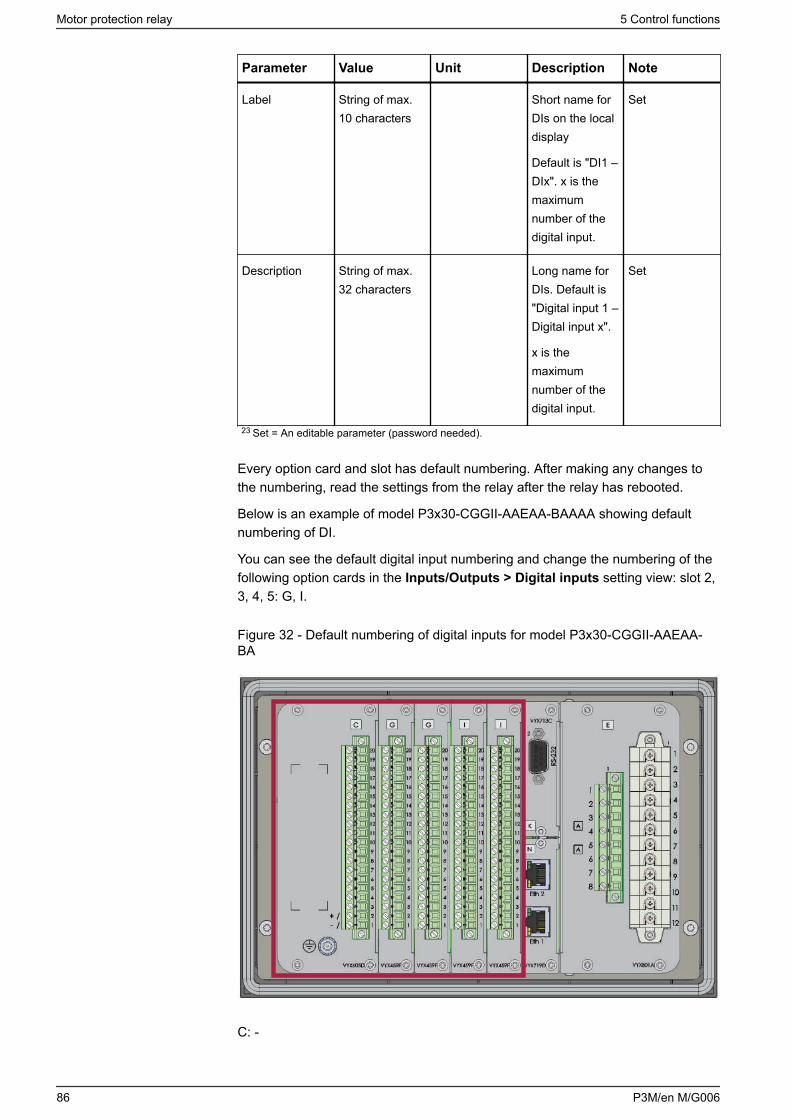
Parameter Value Unit Description Note
Label String of max.10 characters
Short name forDIs on the localdisplay
Default is "DI1 –DIx". x is themaximumnumber of thedigital input.
Set
Description String of max.32 characters
Long name forDIs. Default is"Digital input 1 –Digital input x".
x is themaximumnumber of thedigital input.
Set
23 Set = An editable parameter (password needed).
Every option card and slot has default numbering. After making any changes tothe numbering, read the settings from the relay after the relay has rebooted.
Below is an example of model P3x30-CGGII-AAEAA-BAAAA showing defaultnumbering of DI.
You can see the default digital input numbering and change the numbering of thefollowing option cards in the Inputs/Outputs > Digital inputs setting view: slot 2,3, 4, 5: G, I.
Figure 32 - Default numbering of digital inputs for model P3x30-CGGII-AAEAA-BA
C: -
Motor protection relay 5 Control functions
86 P3M/en M/G006
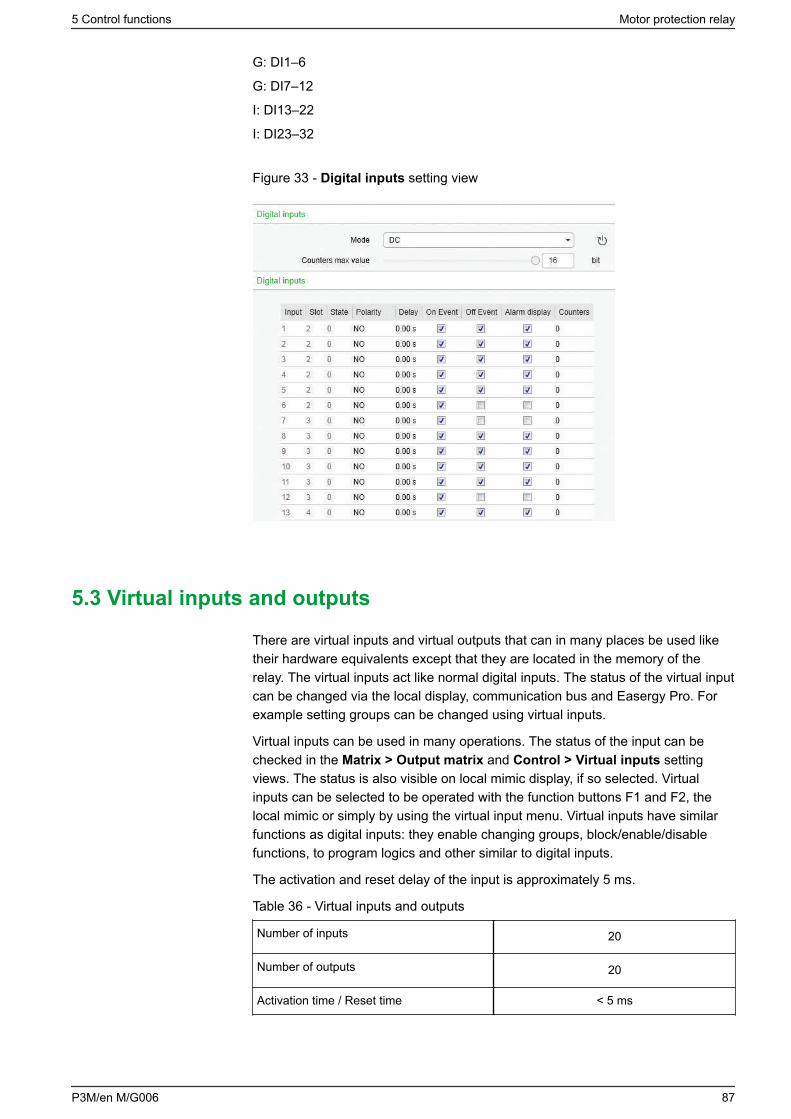
G: DI1–6
G: DI7–12
I: DI13–22
I: DI23–32
Figure 33 - Digital inputs setting view
5.3 Virtual inputs and outputs
There are virtual inputs and virtual outputs that can in many places be used liketheir hardware equivalents except that they are located in the memory of therelay. The virtual inputs act like normal digital inputs. The status of the virtual inputcan be changed via the local display, communication bus and Easergy Pro. Forexample setting groups can be changed using virtual inputs.
Virtual inputs can be used in many operations. The status of the input can bechecked in the Matrix > Output matrix and Control > Virtual inputs settingviews. The status is also visible on local mimic display, if so selected. Virtualinputs can be selected to be operated with the function buttons F1 and F2, thelocal mimic or simply by using the virtual input menu. Virtual inputs have similarfunctions as digital inputs: they enable changing groups, block/enable/disablefunctions, to program logics and other similar to digital inputs.
The activation and reset delay of the input is approximately 5 ms.
Table 36 - Virtual inputs and outputs
Number of inputs 20
Number of outputs 20
Activation time / Reset time < 5 ms
5 Control functions Motor protection relay
P3M/en M/G006 87
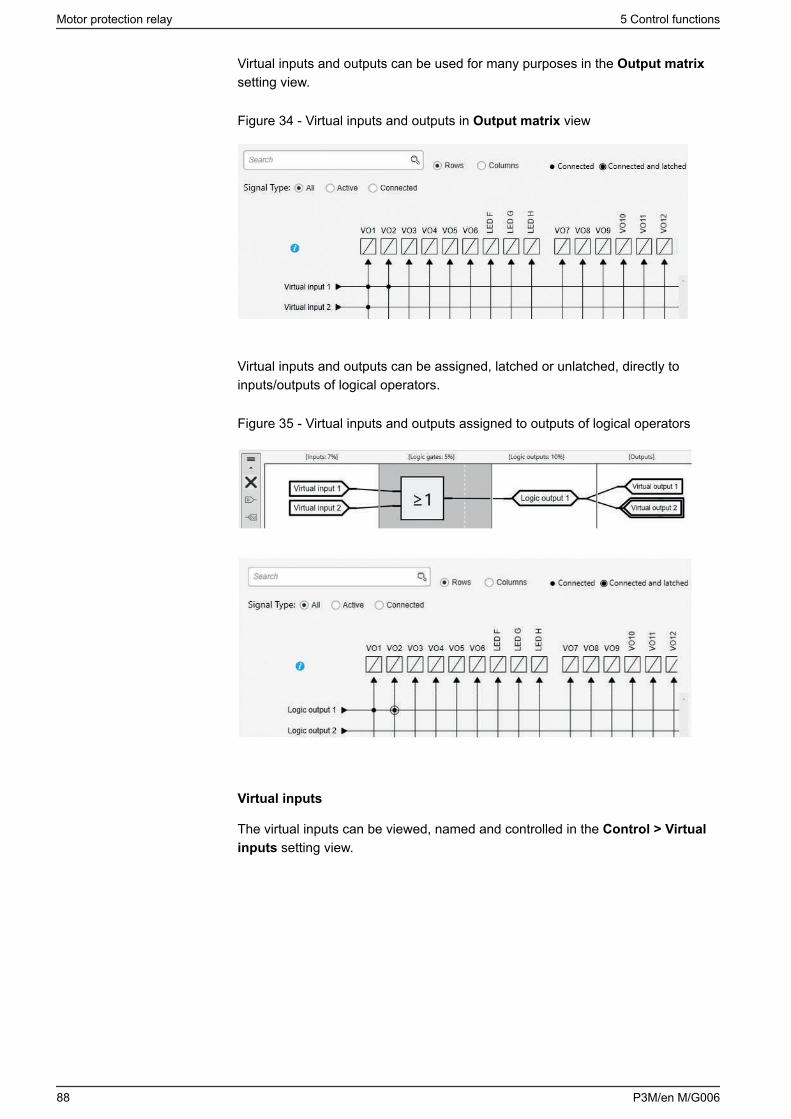
Virtual inputs and outputs can be used for many purposes in the Output matrixsetting view.
Figure 34 - Virtual inputs and outputs in Output matrix view
Virtual inputs and outputs can be assigned, latched or unlatched, directly toinputs/outputs of logical operators.
Figure 35 - Virtual inputs and outputs assigned to outputs of logical operators
Virtual inputs
The virtual inputs can be viewed, named and controlled in the Control > Virtualinputs setting view.
Motor protection relay 5 Control functions
88 P3M/en M/G006
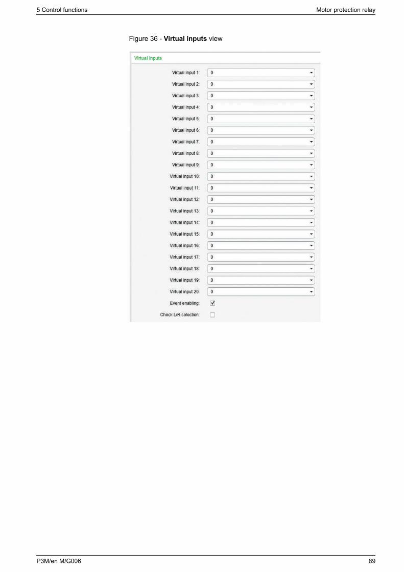
Figure 36 - Virtual inputs view
5 Control functions Motor protection relay
P3M/en M/G006 89
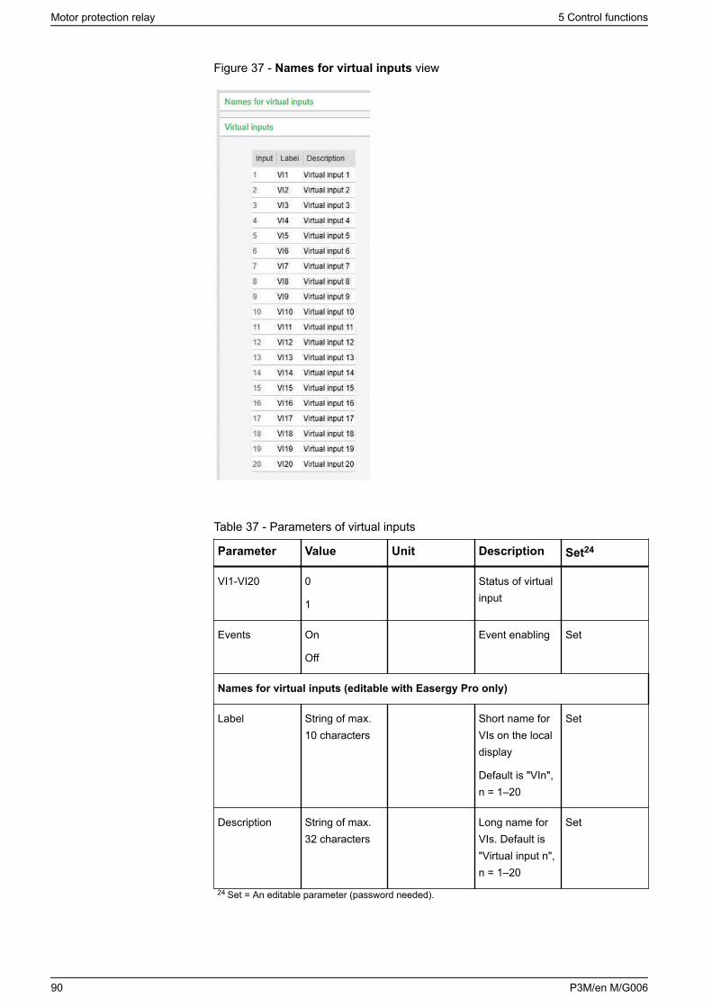
Figure 37 - Names for virtual inputs view
Table 37 - Parameters of virtual inputs
Parameter Value Unit Description Set24
VI1-VI20 0
1
Status of virtualinput
Events On
Off
Event enabling Set
Names for virtual inputs (editable with Easergy Pro only)
Label String of max.10 characters
Short name forVIs on the localdisplay
Default is "VIn",n = 1–20
Set
Description String of max.32 characters
Long name forVIs. Default is"Virtual input n",n = 1–20
Set
24 Set = An editable parameter (password needed).
Motor protection relay 5 Control functions
90 P3M/en M/G006
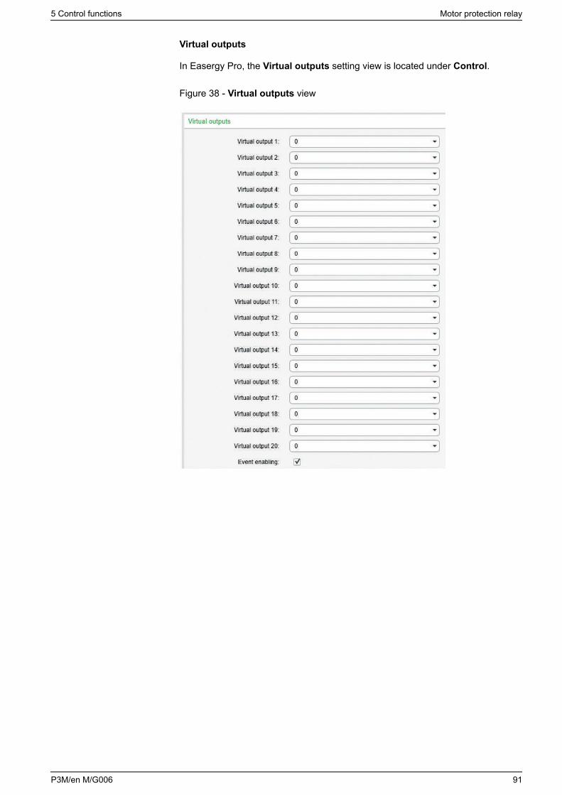
Virtual outputs
In Easergy Pro, the Virtual outputs setting view is located under Control.
Figure 38 - Virtual outputs view
5 Control functions Motor protection relay
P3M/en M/G006 91
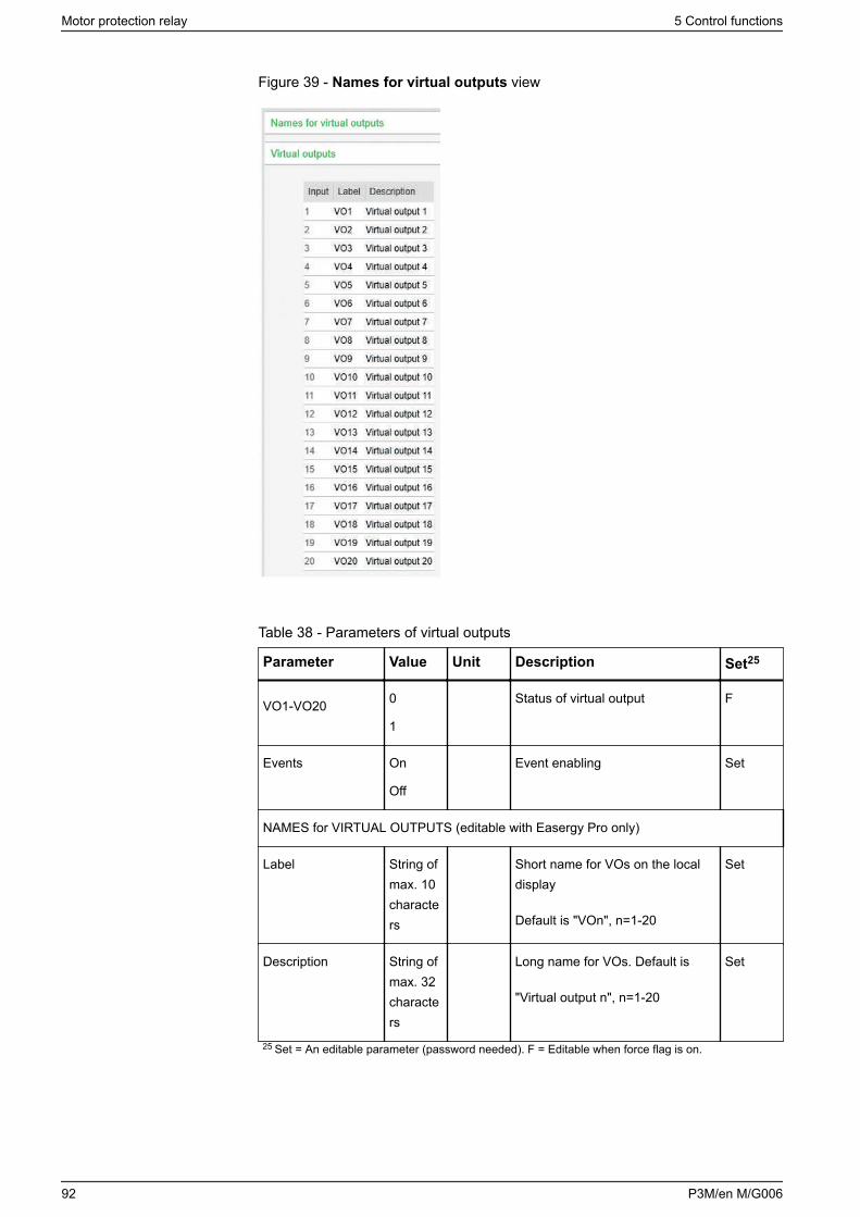
Figure 39 - Names for virtual outputs view
Table 38 - Parameters of virtual outputs
Parameter Value Unit Description Set25
VO1-VO20 0
1
Status of virtual output F
Events On
Off
Event enabling Set
NAMES for VIRTUAL OUTPUTS (editable with Easergy Pro only)
Label String ofmax. 10characters
Short name for VOs on the localdisplay
Default is "VOn", n=1-20
Set
Description String ofmax. 32characters
Long name for VOs. Default is
"Virtual output n", n=1-20
Set
25 Set = An editable parameter (password needed). F = Editable when force flag is on.
Motor protection relay 5 Control functions
92 P3M/en M/G006
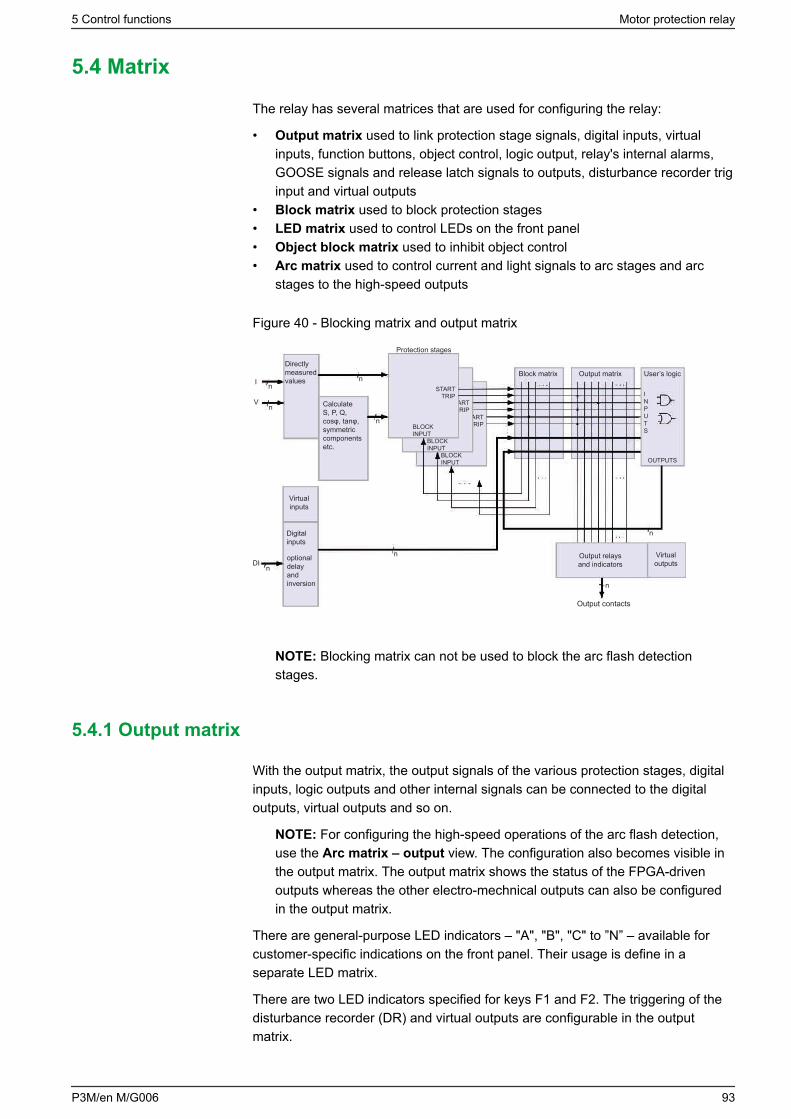
5.4 Matrix
The relay has several matrices that are used for configuring the relay:
• Output matrix used to link protection stage signals, digital inputs, virtualinputs, function buttons, object control, logic output, relay's internal alarms,GOOSE signals and release latch signals to outputs, disturbance recorder triginput and virtual outputs
• Block matrix used to block protection stages• LED matrix used to control LEDs on the front panel• Object block matrix used to inhibit object control• Arc matrix used to control current and light signals to arc stages and arc
stages to the high-speed outputs
Figure 40 - Blocking matrix and output matrix
Directly measured values
CalculateS, P, Q,cosφ, tanφ,symmetriccomponentsetc.
n
nn
n
n
n
n
n
Virtual inputs
Digital inputs
optional delayandinversion
I
V
DI
Protection stages
BLOCKINPUT
BLOCKINPUT
BLOCKINPUT
STARTTRIP
STARTTRIP
STARTTRIP
Block matrix Output matrix User’s logic
OUTPUTS
INPUTS
Output relaysand indicators
Output contacts
Virtualoutputs
NOTE: Blocking matrix can not be used to block the arc flash detectionstages.
5.4.1 Output matrix
With the output matrix, the output signals of the various protection stages, digitalinputs, logic outputs and other internal signals can be connected to the digitaloutputs, virtual outputs and so on.
NOTE: For configuring the high-speed operations of the arc flash detection,use the Arc matrix – output view. The configuration also becomes visible inthe output matrix. The output matrix shows the status of the FPGA-drivenoutputs whereas the other electro-mechnical outputs can also be configuredin the output matrix.
There are general-purpose LED indicators – "A", "B", "C" to ”N” – available forcustomer-specific indications on the front panel. Their usage is define in aseparate LED matrix.
There are two LED indicators specified for keys F1 and F2. The triggering of thedisturbance recorder (DR) and virtual outputs are configurable in the outputmatrix.
5 Control functions Motor protection relay
P3M/en M/G006 93
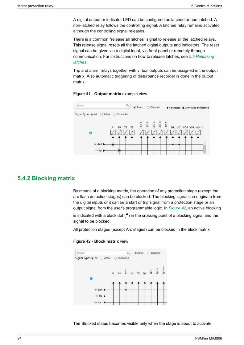
A digital output or indicator LED can be configured as latched or non-latched. Anon-latched relay follows the controlling signal. A latched relay remains activatedalthough the controlling signal releases.
There is a common "release all latches" signal to release all the latched relays.This release signal resets all the latched digital outputs and indicators. The resetsignal can be given via a digital input, via front panel or remotely throughcommunication. For instructions on how to release latches, see 5.5 Releasinglatches.
Trip and alarm relays together with virtual outputs can be assigned in the outputmatrix. Also automatic triggering of disturbance recorder is done in the outputmatrix.
Figure 41 - Output matrix example view
5.4.2 Blocking matrix
By means of a blocking matrix, the operation of any protection stage (except thearc flash detection stages) can be blocked. The blocking signal can originate fromthe digital inputs or it can be a start or trip signal from a protection stage or anoutput signal from the user's programmable logic. In Figure 42, an active blocking
is indicated with a black dot () in the crossing point of a blocking signal and thesignal to be blocked.
All protection stages (except Arc stages) can be blocked in the block matrix
Figure 42 - Block matrix view
The Blocked status becomes visible only when the stage is about to activate.
Motor protection relay 5 Control functions
94 P3M/en M/G006
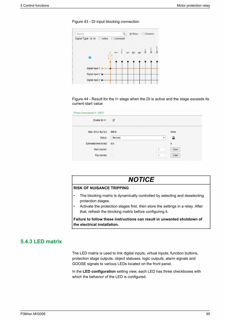
Figure 43 - DI input blocking connection
Figure 44 - Result for the I> stage when the DI is active and the stage exceeds itscurrent start value
NOTICERISK OF NUISANCE TRIPPING
• The blocking matrix is dynamically controlled by selecting and deselectingprotection stages.
• Activate the protection stages first, then store the settings in a relay. Afterthat, refresh the blocking matrix before configuring it.
Failure to follow these instructions can result in unwanted shutdown ofthe electrical installation.
5.4.3 LED matrix
The LED matrix is used to link digital inputs, virtual inputs, function buttons,protection stage outputs, object statuses, logic outputs, alarm signals andGOOSE signals to various LEDs located on the front panel.
In the LED configuration setting view, each LED has three checkboxes withwhich the behavior of the LED is configured.
5 Control functions Motor protection relay
P3M/en M/G006 95
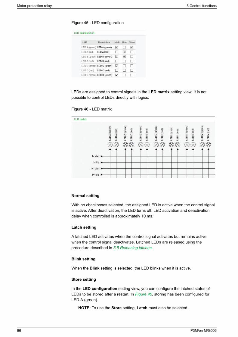
Figure 45 - LED configuration
LEDs are assigned to control signals in the LED matrix setting view. It is notpossible to control LEDs directly with logics.
Figure 46 - LED matrix
Normal setting
With no checkboxes selected, the assigned LED is active when the control signalis active. After deactivation, the LED turns off. LED activation and deactivationdelay when controlled is approximately 10 ms.
Latch setting
A latched LED activates when the control signal activates but remains activewhen the control signal deactivates. Latched LEDs are released using theprocedure described in 5.5 Releasing latches.
Blink setting
When the Blink setting is selected, the LED blinks when it is active.
Store setting
In the LED configuration setting view, you can configure the latched states ofLEDs to be stored after a restart. In Figure 45, storing has been configured forLED A (green).
NOTE: To use the Store setting, Latch must also be selected.
Motor protection relay 5 Control functions
96 P3M/en M/G006
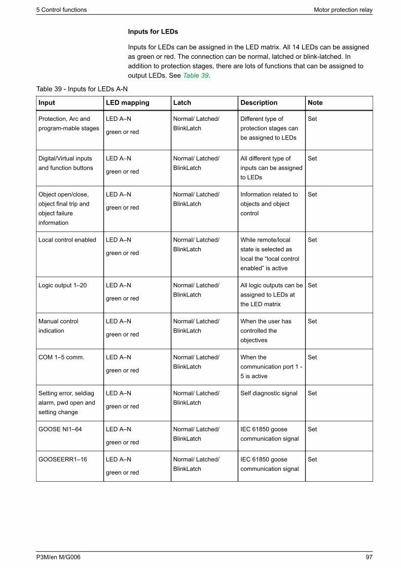
Inputs for LEDs
Inputs for LEDs can be assigned in the LED matrix. All 14 LEDs can be assignedas green or red. The connection can be normal, latched or blink-latched. Inaddition to protection stages, there are lots of functions that can be assigned tooutput LEDs. See Table 39.
Table 39 - Inputs for LEDs A-N
Input LED mapping Latch Description Note
Protection, Arc andprogram-mable stages
LED A–N
green or red
Normal/ Latched/BlinkLatch
Different type ofprotection stages canbe assigned to LEDs
Set
Digital/Virtual inputsand function buttons
LED A–N
green or red
Normal/ Latched/BlinkLatch
All different type ofinputs can be assignedto LEDs
Set
Object open/close,object final trip andobject failureinformation
LED A–N
green or red
Normal/ Latched/BlinkLatch
Information related toobjects and objectcontrol
Set
Local control enabled LED A–N
green or red
Normal/ Latched/BlinkLatch
While remote/localstate is selected aslocal the “local controlenabled” is active
Set
Logic output 1–20 LED A–N
green or red
Normal/ Latched/BlinkLatch
All logic outputs can beassigned to LEDs atthe LED matrix
Set
Manual controlindication
LED A–N
green or red
Normal/ Latched/BlinkLatch
When the user hascontrolled theobjectives
Set
COM 1–5 comm. LED A–N
green or red
Normal/ Latched/BlinkLatch
When thecommunication port 1 -5 is active
Set
Setting error, seldiagalarm, pwd open andsetting change
LED A–N
green or red
Normal/ Latched/BlinkLatch
Self diagnostic signal Set
GOOSE NI1–64 LED A–N
green or red
Normal/ Latched/BlinkLatch
IEC 61850 goosecommunication signal
Set
GOOSEERR1–16 LED A–N
green or red
Normal/ Latched/BlinkLatch
IEC 61850 goosecommunication signal
Set
5 Control functions Motor protection relay
P3M/en M/G006 97
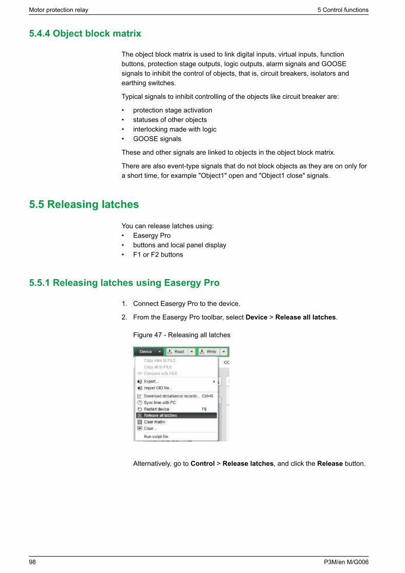
5.4.4 Object block matrix
The object block matrix is used to link digital inputs, virtual inputs, functionbuttons, protection stage outputs, logic outputs, alarm signals and GOOSEsignals to inhibit the control of objects, that is, circuit breakers, isolators andearthing switches.
Typical signals to inhibit controlling of the objects like circuit breaker are:
• protection stage activation• statuses of other objects• interlocking made with logic• GOOSE signals
These and other signals are linked to objects in the object block matrix.
There are also event-type signals that do not block objects as they are on only fora short time, for example "Object1" open and "Object1 close" signals.
5.5 Releasing latches
You can release latches using:• Easergy Pro• buttons and local panel display• F1 or F2 buttons
5.5.1 Releasing latches using Easergy Pro
1. Connect Easergy Pro to the device.
2. From the Easergy Pro toolbar, select Device > Release all latches.
Figure 47 - Releasing all latches
Alternatively, go to Control > Release latches, and click the Release button.
Motor protection relay 5 Control functions
98 P3M/en M/G006
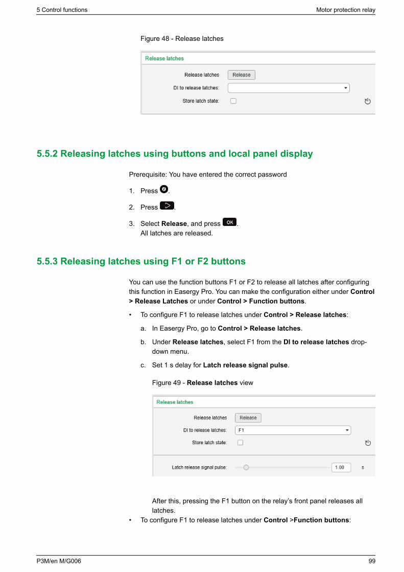
Figure 48 - Release latches
5.5.2 Releasing latches using buttons and local panel display
Prerequisite: You have entered the correct password
1. Press .
2. Press .
3. Select Release, and press .All latches are released.
5.5.3 Releasing latches using F1 or F2 buttons
You can use the function buttons F1 or F2 to release all latches after configuringthis function in Easergy Pro. You can make the configuration either under Control> Release Latches or under Control > Function buttons.
• To configure F1 to release latches under Control > Release latches:
a. In Easergy Pro, go to Control > Release latches.
b. Under Release latches, select F1 from the DI to release latches drop-down menu.
c. Set 1 s delay for Latch release signal pulse.
Figure 49 - Release latches view
After this, pressing the F1 button on the relay’s front panel releases alllatches.
• To configure F1 to release latches under Control >Function buttons:
5 Control functions Motor protection relay
P3M/en M/G006 99
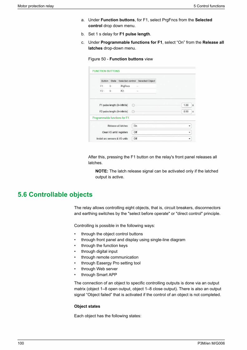
a. Under Function buttons, for F1, select PrgFncs from the Selectedcontrol drop down menu.
b. Set 1 s delay for F1 pulse length.
c. Under Programmable functions for F1, select “On” from the Release alllatches drop-down menu.
Figure 50 - Function buttons view
After this, pressing the F1 button on the relay's front panel releases alllatches.
NOTE: The latch release signal can be activated only if the latchedoutput is active.
5.6 Controllable objects
The relay allows controlling eight objects, that is, circuit breakers, disconnectorsand earthing switches by the "select before operate" or "direct control" principle.
Controlling is possible in the following ways:
• through the object control buttons• through front panel and display using single-line diagram• through the function keys• through digital input• through remote communication• through Easergy Pro setting tool• through Web server• through Smart APP
The connection of an object to specific controlling outputs is done via an outputmatrix (object 1–8 open output, object 1–8 close output). There is also an outputsignal “Object failed” that is activated if the control of an object is not completed.
Object states
Each object has the following states:
Motor protection relay 5 Control functions
100 P3M/en M/G006
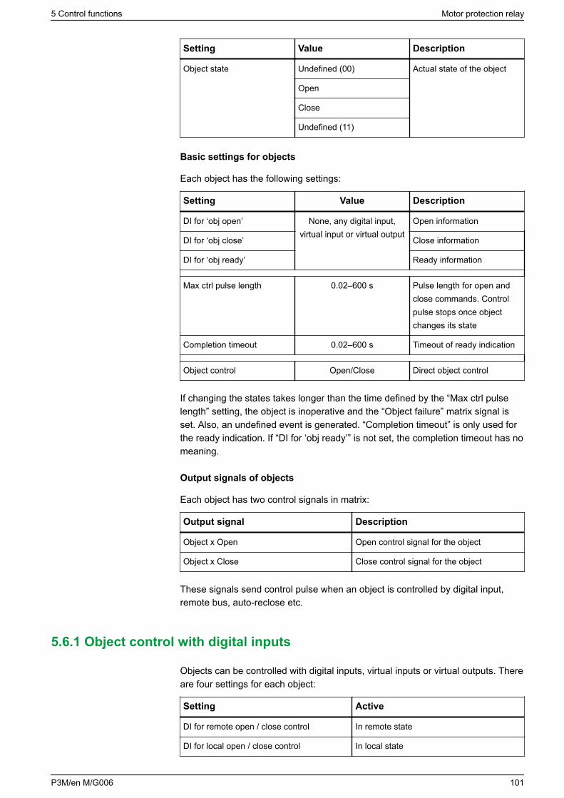
Setting Value Description
Object state Undefined (00) Actual state of the object
Open
Close
Undefined (11)
Basic settings for objects
Each object has the following settings:
Setting Value Description
DI for ‘obj open’ None, any digital input,virtual input or virtual output
Open information
DI for ‘obj close’ Close information
DI for ‘obj ready’ Ready information
Max ctrl pulse length 0.02–600 s Pulse length for open andclose commands. Controlpulse stops once objectchanges its state
Completion timeout 0.02–600 s Timeout of ready indication
Object control Open/Close Direct object control
If changing the states takes longer than the time defined by the “Max ctrl pulselength” setting, the object is inoperative and the “Object failure” matrix signal isset. Also, an undefined event is generated. “Completion timeout” is only used forthe ready indication. If “DI for ‘obj ready’” is not set, the completion timeout has nomeaning.
Output signals of objects
Each object has two control signals in matrix:
Output signal Description
Object x Open Open control signal for the object
Object x Close Close control signal for the object
These signals send control pulse when an object is controlled by digital input,remote bus, auto-reclose etc.
5.6.1 Object control with digital inputs
Objects can be controlled with digital inputs, virtual inputs or virtual outputs. Thereare four settings for each object:
Setting Active
DI for remote open / close control In remote state
DI for local open / close control In local state
5 Control functions Motor protection relay
P3M/en M/G006 101
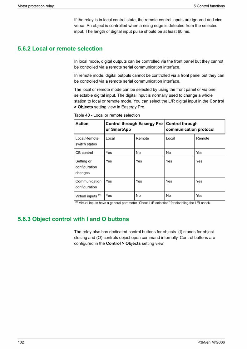
If the relay is in local control state, the remote control inputs are ignored and viceversa. An object is controlled when a rising edge is detected from the selectedinput. The length of digital input pulse should be at least 60 ms.
5.6.2 Local or remote selection
In local mode, digital outputs can be controlled via the front panel but they cannotbe controlled via a remote serial communication interface.
In remote mode, digital outputs cannot be controlled via a front panel but they canbe controlled via a remote serial communication interface.
The local or remote mode can be selected by using the front panel or via oneselectable digital input. The digital input is normally used to change a wholestation to local or remote mode. You can select the L/R digital input in the Control> Objects setting view in Easergy Pro.
Table 40 - Local or remote selection
Action Control through Easergy Proor SmartApp
Control throughcommunication protocol
Local/Remoteswitch status
Local Remote Local Remote
CB control Yes No No Yes
Setting orconfigurationchanges
Yes Yes Yes Yes
Communicationconfiguration
Yes Yes Yes Yes
Virtual inputs 26 Yes No No Yes26 Virtual inputs have a general parameter “Check L/R selection” for disabling the L/R check.
5.6.3 Object control with I and O buttons
The relay also has dedicated control buttons for objects. (I) stands for objectclosing and (O) controls object open command internally. Control buttons areconfigured in the Control > Objects setting view.
Motor protection relay 5 Control functions
102 P3M/en M/G006
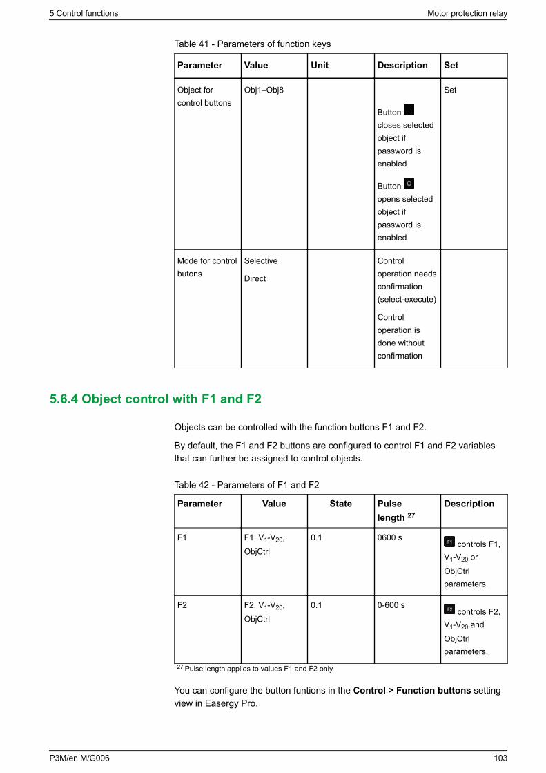
Table 41 - Parameters of function keys
Parameter Value Unit Description Set
Object forcontrol buttons
Obj1–Obj8
Button closes selectedobject ifpassword isenabled
Button opens selectedobject ifpassword isenabled
Set
Mode for controlbutons
Selective
Direct
Controloperation needsconfirmation(select-execute)
Controloperation isdone withoutconfirmation
5.6.4 Object control with F1 and F2
Objects can be controlled with the function buttons F1 and F2.
By default, the F1 and F2 buttons are configured to control F1 and F2 variablesthat can further be assigned to control objects.
Table 42 - Parameters of F1 and F2
Parameter Value State Pulselength 27
Description
F1 F1, V1-V20,ObjCtrl
0.1 0600 s controls F1,
V1-V20 orObjCtrlparameters.
F2 F2, V1-V20,ObjCtrl
0.1 0-600 s controls F2,
V1-V20 andObjCtrlparameters.
27 Pulse length applies to values F1 and F2 only
You can configure the button funtions in the Control > Function buttons settingview in Easergy Pro.
5 Control functions Motor protection relay
P3M/en M/G006 103
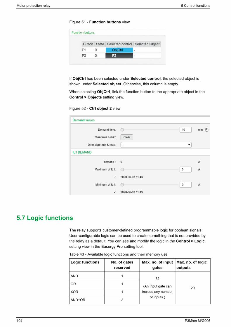
Figure 51 - Function buttons view
If ObjCtrl has been selected under Selected control, the selected object isshown under Selected object. Otherwise, this column is empty.
When selecting ObjCtrl, link the function button to the appropriate object in theControl > Objects setting view.
Figure 52 - Ctrl object 2 view
5.7 Logic functions
The relay supports customer-defined programmable logic for boolean signals.User-configurable logic can be used to create something that is not provided bythe relay as a default. You can see and modify the logic in the Control > Logicsetting view in the Easergy Pro setting tool.
Table 43 - Available logic functions and their memory use
Logic functions No. of gatesreserved
Max. no. of inputgates
Max. no. of logicoutputs
AND 132
(An input gate caninclude any number
of inputs.)
20OR 1
XOR 1
AND+OR 2
Motor protection relay 5 Control functions
104 P3M/en M/G006
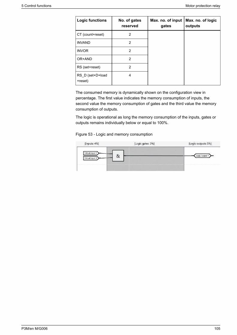
Logic functions No. of gatesreserved
Max. no. of inputgates
Max. no. of logicoutputs
CT (count+reset) 2
INVAND 2
INVOR 2
OR+AND 2
RS (set+reset) 2
RS_D (set+D+load+reset)
4
The consumed memory is dynamically shown on the configuration view inpercentage. The first value indicates the memory consumption of inputs, thesecond value the memory consumption of gates and the third value the memoryconsumption of outputs.
The logic is operational as long the memory consumption of the inputs, gates oroutputs remains individually below or equal to 100%.
Figure 53 - Logic and memory consumption
5 Control functions Motor protection relay
P3M/en M/G006 105
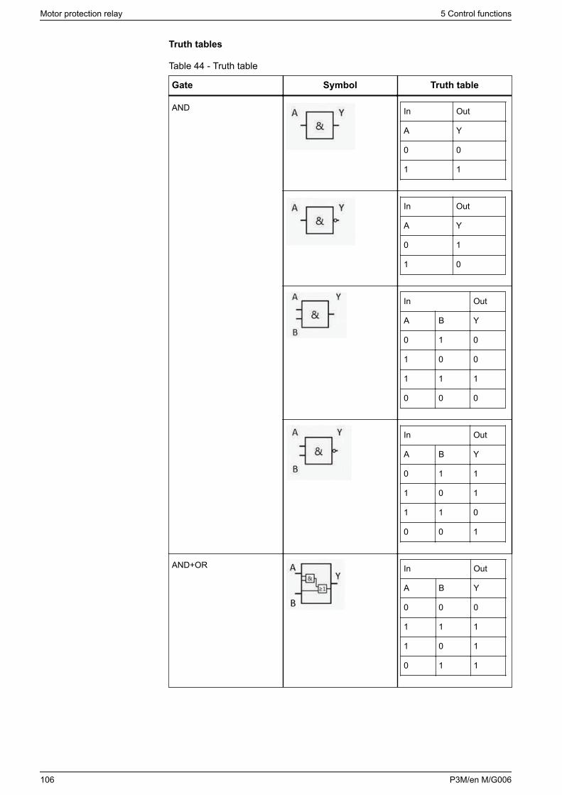
Truth tables
Table 44 - Truth table
Gate Symbol Truth table
AND In Out
A Y
0 0
1 1
In Out
A Y
0 1
1 0
In Out
A B Y
0 1 0
1 0 0
1 1 1
0 0 0
In Out
A B Y
0 1 1
1 0 1
1 1 0
0 0 1
AND+OR In Out
A B Y
0 0 0
1 1 1
1 0 1
0 1 1
Motor protection relay 5 Control functions
106 P3M/en M/G006
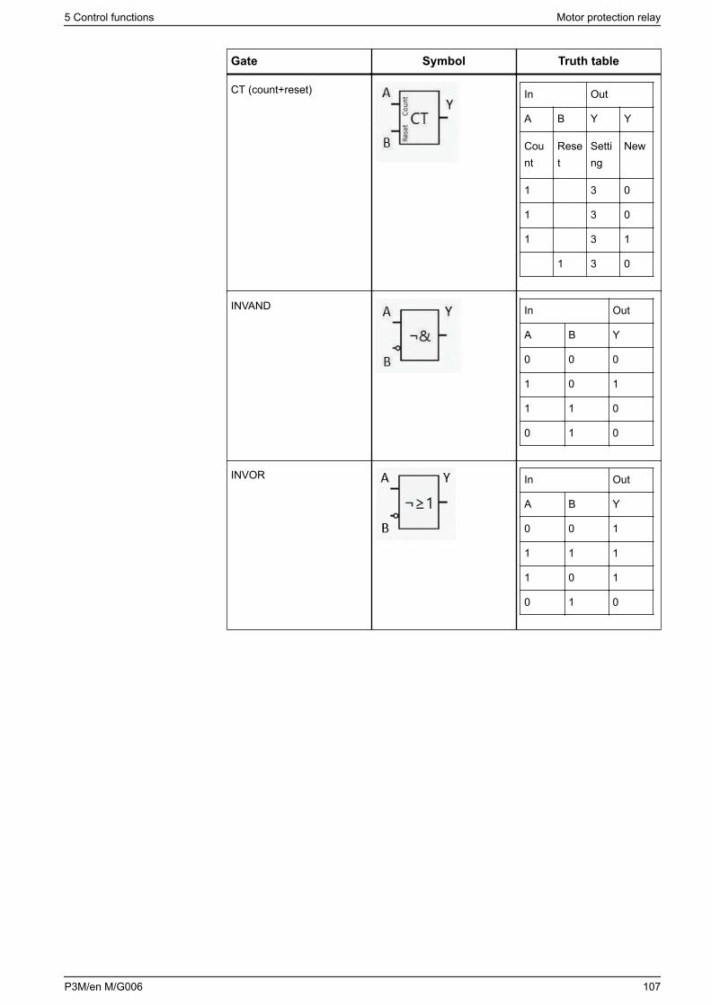
Gate Symbol Truth table
CT (count+reset) In Out
A B Y Y
Count
Reset
Setting
New
1 3 0
1 3 0
1 3 1
1 3 0
INVAND In Out
A B Y
0 0 0
1 0 1
1 1 0
0 1 0
INVOR In Out
A B Y
0 0 1
1 1 1
1 0 1
0 1 0
5 Control functions Motor protection relay
P3M/en M/G006 107
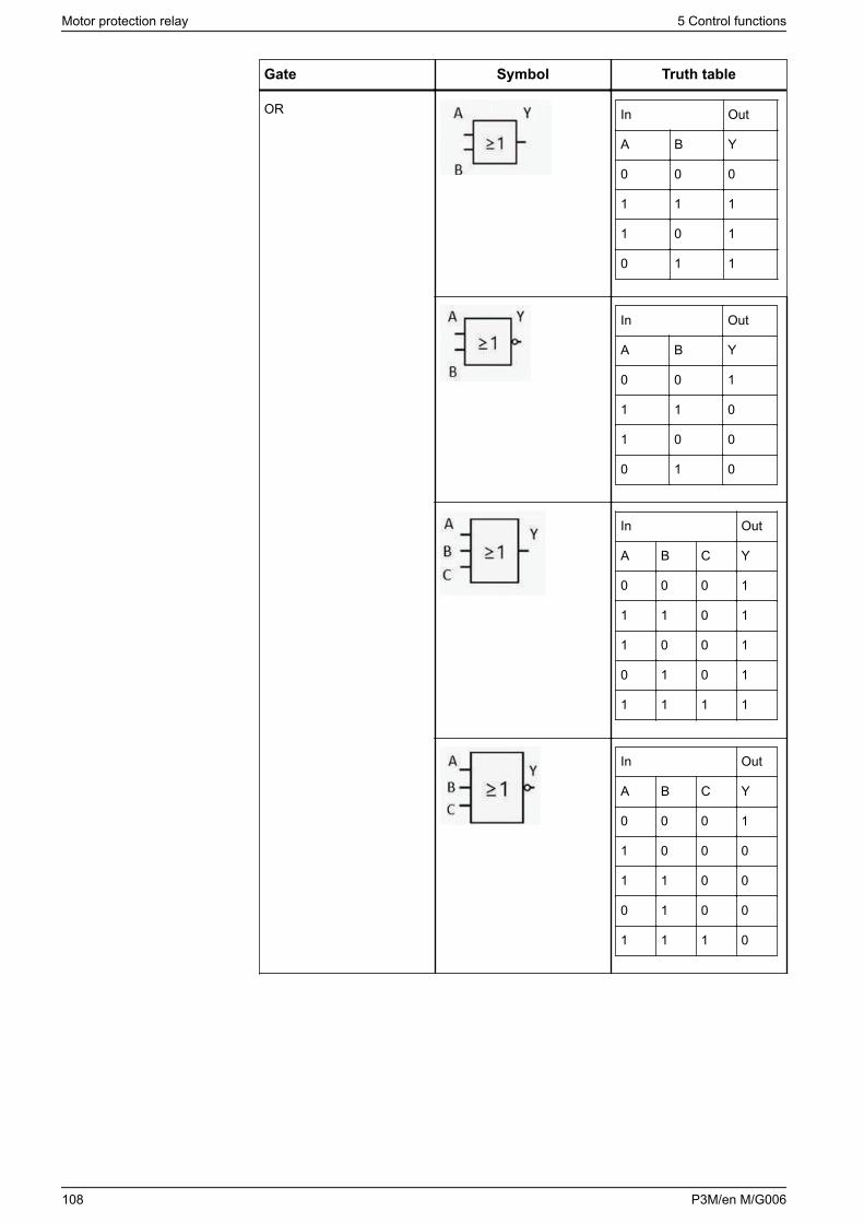
Gate Symbol Truth table
OR In Out
A B Y
0 0 0
1 1 1
1 0 1
0 1 1
In Out
A B Y
0 0 1
1 1 0
1 0 0
0 1 0
In Out
A B C Y
0 0 0 1
1 1 0 1
1 0 0 1
0 1 0 1
1 1 1 1
In Out
A B C Y
0 0 0 1
1 0 0 0
1 1 0 0
0 1 0 0
1 1 1 0
Motor protection relay 5 Control functions
108 P3M/en M/G006
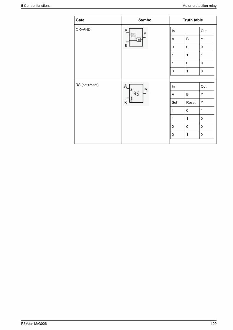
Gate Symbol Truth table
OR+AND In Out
A B Y
0 0 0
1 1 1
1 0 0
0 1 0
RS (set+reset) In Out
A B Y
Set Reset Y
1 0 1
1 1 0
0 0 0
0 1 0
5 Control functions Motor protection relay
P3M/en M/G006 109
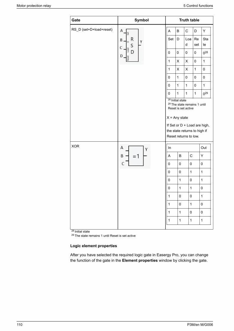
Gate Symbol Truth table
RS_D (set+D+load+reset) A B C D Y
Set D Load
Reset
State
0 0 0 0 028
1 X X 0 1
1 X X 1 0
0 1 0 0 0
0 1 1 0 1
0 1 1 1 029
28 Initial state29 The state remains 1 untilReset is set active
X = Any state
If Set or D + Load are high,the state returns to high ifReset returns to low.
XOR In Out
A B C Y
0 0 0 0
0 0 1 1
0 1 0 1
0 1 1 0
1 0 0 1
1 0 1 0
1 1 0 0
1 1 1 1
28 Initial state29 The state remains 1 until Reset is set active
Logic element properties
After you have selected the required logic gate in Easergy Pro, you can changethe function of the gate in the Element properties window by clicking the gate.
Motor protection relay 5 Control functions
110 P3M/en M/G006
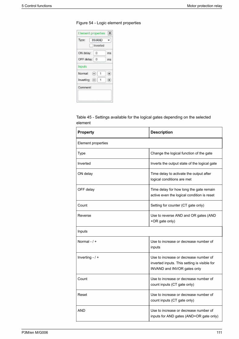
Figure 54 - Logic element properties
Table 45 - Settings available for the logical gates depending on the selectedelement
Property Description
Element properties
Type Change the logical function of the gate
Inverted Inverts the output state of the logical gate
ON delay Time delay to activate the output afterlogical conditions are met
OFF delay Time delay for how long the gate remainactive even the logical condition is reset
Count Setting for counter (CT gate only)
Reverse Use to reverse AND and OR gates (AND+OR gate only)
Inputs
Normal - / + Use to increase or decrease number ofinputs
Inverting - / + Use to increase or decrease number ofinverted inputs. This setting is visible forINVAND and INVOR gates only
Count Use to increase or decrease number ofcount inputs (CT gate only)
Reset Use to increase or decrease number ofcount inputs (CT gate only)
AND Use to increase or decrease number ofinputs for AND gates (AND+OR gate only)
5 Control functions Motor protection relay
P3M/en M/G006 111
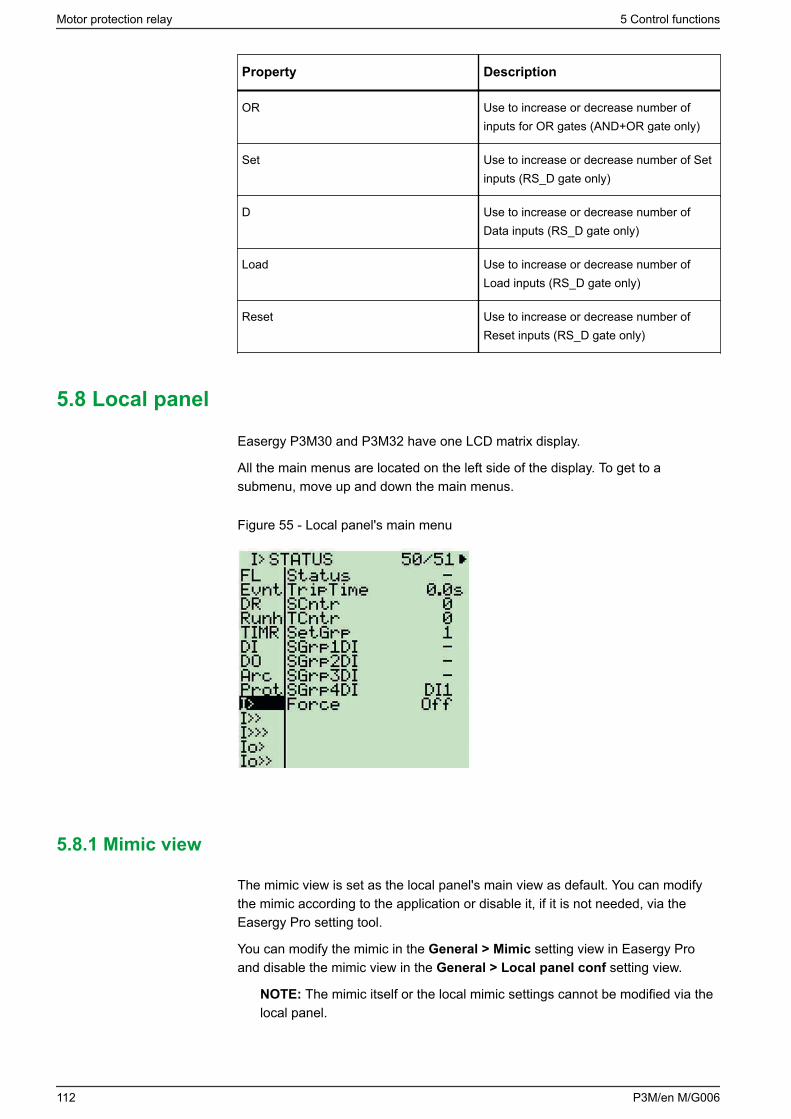
Property Description
OR Use to increase or decrease number ofinputs for OR gates (AND+OR gate only)
Set Use to increase or decrease number of Setinputs (RS_D gate only)
D Use to increase or decrease number ofData inputs (RS_D gate only)
Load Use to increase or decrease number ofLoad inputs (RS_D gate only)
Reset Use to increase or decrease number ofReset inputs (RS_D gate only)
5.8 Local panel
Easergy P3M30 and P3M32 have one LCD matrix display.
All the main menus are located on the left side of the display. To get to asubmenu, move up and down the main menus.
Figure 55 - Local panel's main menu
5.8.1 Mimic view
The mimic view is set as the local panel's main view as default. You can modifythe mimic according to the application or disable it, if it is not needed, via theEasergy Pro setting tool.
You can modify the mimic in the General > Mimic setting view in Easergy Proand disable the mimic view in the General > Local panel conf setting view.
NOTE: The mimic itself or the local mimic settings cannot be modified via thelocal panel.
Motor protection relay 5 Control functions
112 P3M/en M/G006
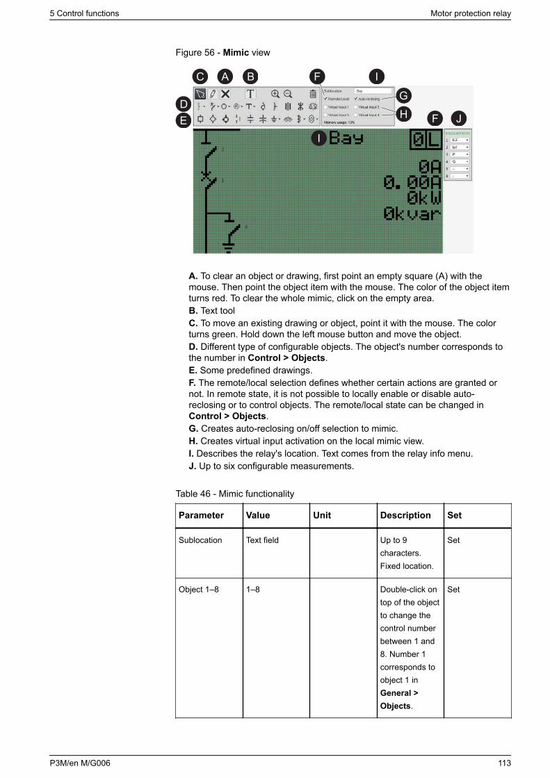
Figure 56 - Mimic view
C A B I
DE
F
I
F J
GH
A. To clear an object or drawing, first point an empty square (A) with themouse. Then point the object item with the mouse. The color of the object itemturns red. To clear the whole mimic, click on the empty area.B. Text toolC. To move an existing drawing or object, point it with the mouse. The colorturns green. Hold down the left mouse button and move the object.D. Different type of configurable objects. The object's number corresponds tothe number in Control > Objects.E. Some predefined drawings.F. The remote/local selection defines whether certain actions are granted ornot. In remote state, it is not possible to locally enable or disable auto-reclosing or to control objects. The remote/local state can be changed inControl > Objects.G. Creates auto-reclosing on/off selection to mimic.H. Creates virtual input activation on the local mimic view.I. Describes the relay's location. Text comes from the relay info menu.J. Up to six configurable measurements.
Table 46 - Mimic functionality
Parameter Value Unit Description Set
Sublocation Text field Up to 9characters.Fixed location.
Set
Object 1–8 1–8 Double-click ontop of the objectto change thecontrol numberbetween 1 and8. Number 1corresponds toobject 1 inGeneral >Objects.
Set
5 Control functions Motor protection relay
P3M/en M/G006 113
Parameter Value Unit Description Set
Remote/Localmode
L
R
Local / Remotecontrol. Rstands forremote. Remotelocal state canbe changed inGeneral >Objects as well.Position can bechanged.
Set
Auto reclosing 0
1
Possible toenable/disableauto-reclosurelocaly in localmode (L) orremotely inremote mode(R). Positioncan bechanged.
Set
Motor protection relay 5 Control functions
114 P3M/en M/G006
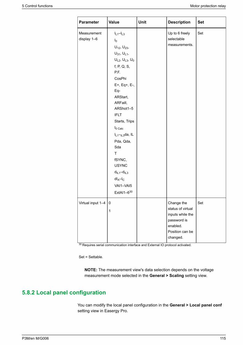
Parameter Value Unit Description Set
Measurementdisplay 1–6
IL1–IL3
I0U12, U23,U31, UL1,UL2, UL3, U0
f, P, Q, S,P.F.
CosPhi
E+, Eq+, E-,Eq-
ARStart,ARFaill,ARShot1–5
IFLT
Starts, Trips
I0 Calc
IL1–IL3da, IL
Pda, Qda,Sda
T
fSYNC,USYNC
dIL1–dIL3
dIA–ICVAI1–VAI5
ExtAI1–630
Up to 6 freelyselectablemeasurements.
Set
Virtual input 1–4 0
1
Change thestatus of virtualinputs while thepassword isenabled.Position can bechanged.
Set
30 Requires serial communication interface and External IO protocol activated.
Set = Settable.
NOTE: The measurement view's data selection depends on the voltagemeasurement mode selected in the General > Scaling setting view.
5.8.2 Local panel configuration
You can modify the local panel configuration in the General > Local panel confsetting view in Easergy Pro.
5 Control functions Motor protection relay
P3M/en M/G006 115
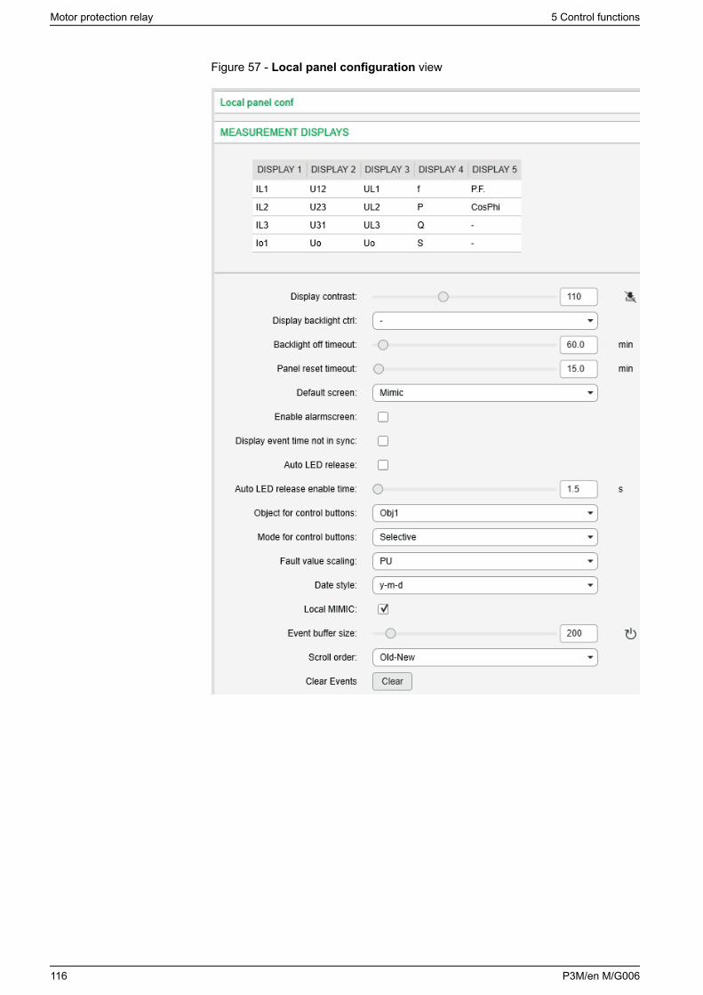
Figure 57 - Local panel configuration view
Motor protection relay 5 Control functions
116 P3M/en M/G006
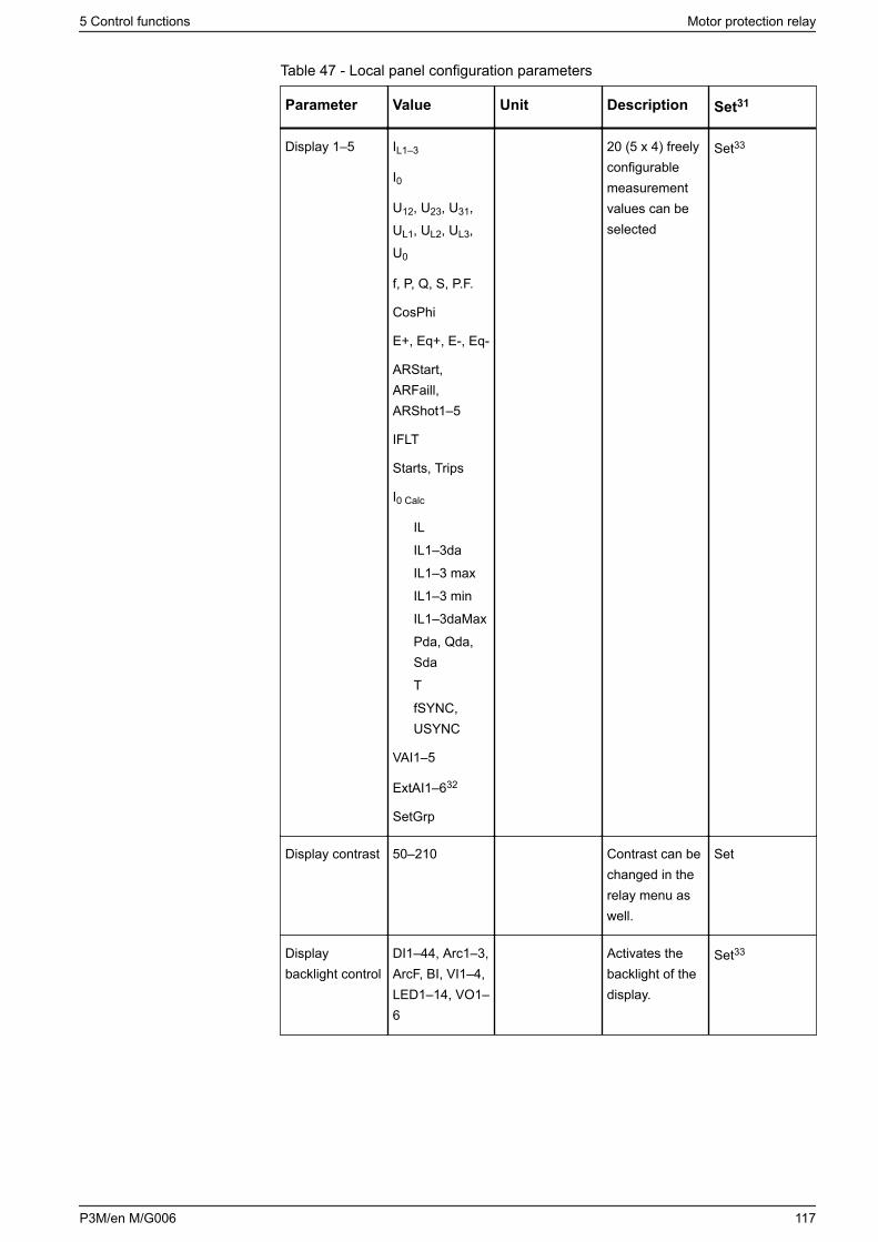
Table 47 - Local panel configuration parameters
Parameter Value Unit Description Set31
Display 1–5 IL1–3
I0
U12, U23, U31,UL1, UL2, UL3,U0
f, P, Q, S, P.F.
CosPhi
E+, Eq+, E-, Eq-
ARStart,ARFaill,ARShot1–5
IFLT
Starts, Trips
I0 Calc
IL
IL1–3da
IL1–3 max
IL1–3 min
IL1–3daMax
Pda, Qda,Sda
T
fSYNC,USYNC
VAI1–5
ExtAI1–632
SetGrp
20 (5 x 4) freelyconfigurablemeasurementvalues can beselected
Set33
Display contrast 50–210 Contrast can bechanged in therelay menu aswell.
Set
Displaybacklight control
DI1–44, Arc1–3,ArcF, BI, VI1–4,LED1–14, VO1–6
Activates thebacklight of thedisplay.
Set33
5 Control functions Motor protection relay
P3M/en M/G006 117
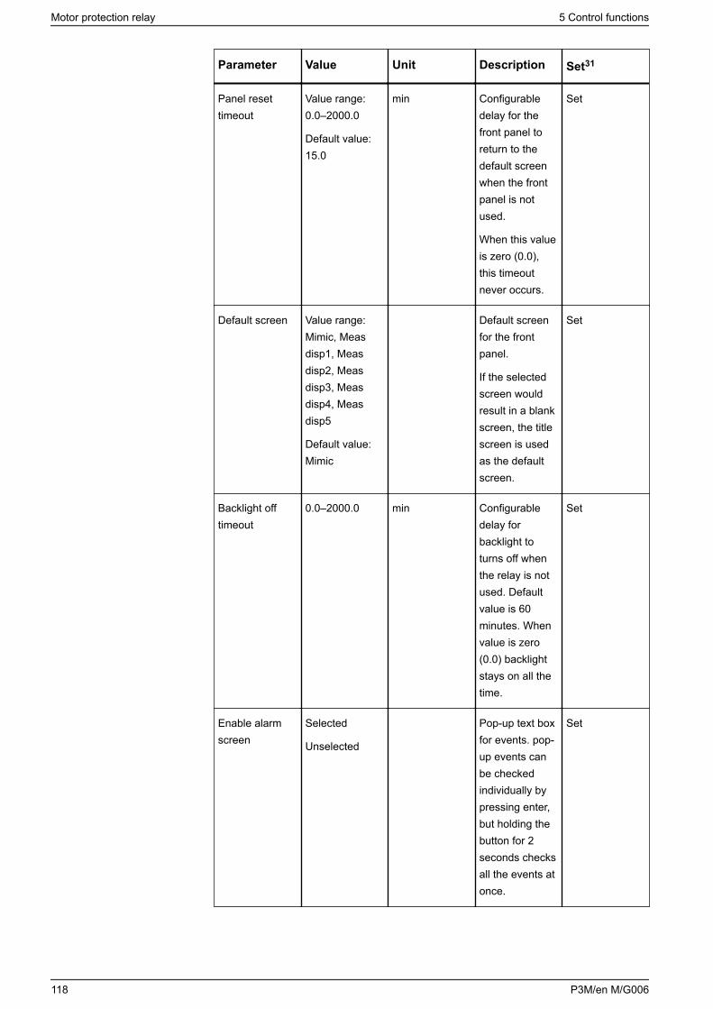
Parameter Value Unit Description Set31
Panel resettimeout
Value range:0.0–2000.0
Default value:15.0
min Configurabledelay for thefront panel toreturn to thedefault screenwhen the frontpanel is notused.
When this valueis zero (0.0),this timeoutnever occurs.
Set
Default screen Value range:Mimic, Measdisp1, Measdisp2, Measdisp3, Measdisp4, Measdisp5
Default value:Mimic
Default screenfor the frontpanel.
If the selectedscreen wouldresult in a blankscreen, the titlescreen is usedas the defaultscreen.
Set
Backlight offtimeout
0.0–2000.0 min Configurabledelay forbacklight toturns off whenthe relay is notused. Defaultvalue is 60minutes. Whenvalue is zero(0.0) backlightstays on all thetime.
Set
Enable alarmscreen
Selected
Unselected
Pop-up text boxfor events. pop-up events canbe checkedindividually bypressing enter,but holding thebutton for 2seconds checksall the events atonce.
Set
Motor protection relay 5 Control functions
118 P3M/en M/G006
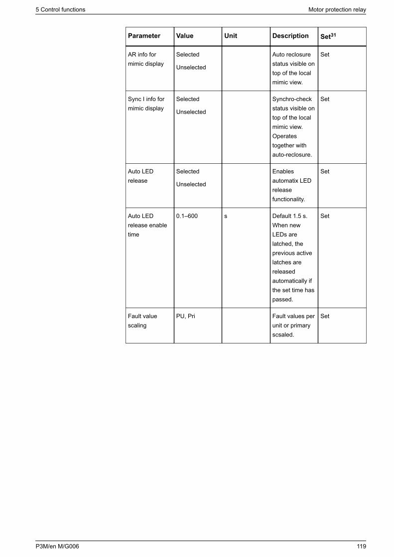
Parameter Value Unit Description Set31
AR info formimic display
Selected
Unselected
Auto reclosurestatus visible ontop of the localmimic view.
Set
Sync I info formimic display
Selected
Unselected
Synchro-checkstatus visible ontop of the localmimic view.Operatestogether withauto-reclosure.
Set
Auto LEDrelease
Selected
Unselected
Enablesautomatix LEDreleasefunctionality.
Set
Auto LEDrelease enabletime
0.1–600 s Default 1.5 s.When newLEDs arelatched, theprevious activelatches arereleasedautomatically ifthe set time haspassed.
Set
Fault valuescaling
PU, Pri Fault values perunit or primaryscsaled.
Set
5 Control functions Motor protection relay
P3M/en M/G006 119
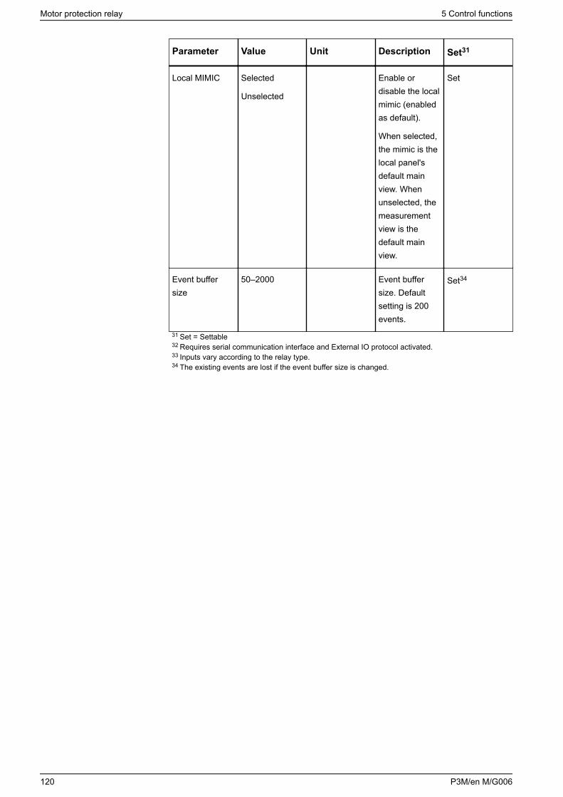
Parameter Value Unit Description Set31
Local MIMIC Selected
Unselected
Enable ordisable the localmimic (enabledas default).
When selected,the mimic is thelocal panel'sdefault mainview. Whenunselected, themeasurementview is thedefault mainview.
Set
Event buffersize
50–2000 Event buffersize. Defaultsetting is 200events.
Set34
31 Set = Settable32 Requires serial communication interface and External IO protocol activated.33 Inputs vary according to the relay type.34 The existing events are lost if the event buffer size is changed.
Motor protection relay 5 Control functions
120 P3M/en M/G006
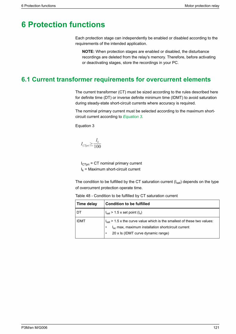
6 Protection functionsEach protection stage can independently be enabled or disabled according to therequirements of the intended application.
NOTE: When protection stages are enabled or disabled, the disturbancerecordings are deleted from the relay's memory. Therefore, before activatingor deactivating stages, store the recordings in your PC.
6.1 Current transformer requirements for overcurrent elements
The current transformer (CT) must be sized according to the rules described herefor definite time (DT) or inverse definite minimum time (IDMT) to avoid saturationduring steady-state short-circuit currents where accuracy is required.
The nominal primary current must be selected according to the maximum short-circuit current according to Equation 3.
Equation 3
IkICTpri >100
ICTpri = CT nominal primary currentIk = Maximum short-circuit current
The condition to be fulfilled by the CT saturation current (Isat) depends on the typeof overcurrent protection operate time.
Table 48 - Condition to be fulfilled by CT saturation current
Time delay Condition to be fulfilled
DT Isat > 1.5 x set point (Is)
IDMT Isat > 1.5 x the curve value which is the smallest of these two values:• Isc max, maximum installation shortcircuit current• 20 x Is (IDMT curve dynamic range)
6 Protection functions Motor protection relay
P3M/en M/G006 121
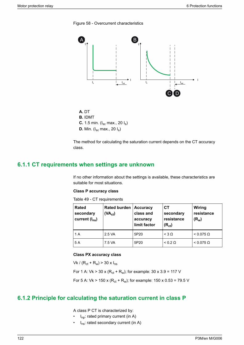
Figure 58 - Overcurrent characteristics
Is
t
Isat
IIs
t
Isat
I
C D
A B
A. DTB. IDMTC. 1.5 min. (Isc max., 20 Is)D. Min. (Isc max., 20 Is)
The method for calculating the saturation current depends on the CT accuracyclass.
6.1.1 CT requirements when settings are unknown
If no other information about the settings is available, these characteristics aresuitable for most situations.
Class P accuracy class
Table 49 - CT requirements
Ratedsecondarycurrent (Ins)
Rated burden(VAct)
Accuracyclass andaccuracylimit factor
CTsecondaryresistance(Rct)
Wiringresistance(Rw)
1 A 2.5 VA 5P20 < 3 Ω < 0.075 Ω
5 A 7.5 VA 5P20 < 0.2 Ω < 0.075 Ω
Class PX accuracy class
Vk / (Rct + Rw) > 30 x Ins
For 1 A: Vk > 30 x (Rct + Rw); for example: 30 x 3.9 = 117 V
For 5 A: Vk > 150 x (Rct + Rw); for example: 150 x 0.53 = 79.5 V
6.1.2 Principle for calculating the saturation current in class P
A class P CT is characterized by:• Inp: rated primary current (in A)• Ins: rated secondary current (in A)
Motor protection relay 6 Protection functions
122 P3M/en M/G006

• accuracy class, expressed by a percentage, 5P or 10P, followed by theaccuracy limit factor (ALF), whose usual values are 5, 10, 15, 20, 30
• VAct: rated burden, whose usual values are 2.5/5/7.5/10/15/30 VA• Rct: maximum resistance of the secondary winding (in Ω)
The installation is characterized by the load resistance Rw at the CT secondary(wiring + protection device). If the CT load complies with the rated burden, that is,Rw x Ins <= VAct, the saturation current is higher than ALF x Inp.
If the resistance Rct is known, it is possible to calculate the actual CT ALF whichtakes account of the actual CT load. The saturation current equals the actual ALFx Inp.
Equation 4
Rct × Ins2 + VActActual ALF = ALF × (Rct + Rw) × Ins2
6.1.3 Examples of calculating the saturation current in class P
The saturation current for a CT is calculated with:• transformation ratio: 100 A/5 A• rated burden: 2.5 VA• accuracy class and accuracy-limit factor: 5P20• resistance of the secondary winding: 0.1 Ω
To have an ALF of at least 20, that is, a saturation current of 20 x Inp = 2 kA, theload resistance Rw of the CT must be less than Equation 5.
Equation 5
VActRw, max = = = 0.1Ω Ins22.552
This represents 12 m (39 ft) of wire with cross-section 2.5 mm² (AWG 14) for aresistance per unit length of approximately 8 Ω/km (2.4 mΩ/ft). For an installationwith 50 m (164 ft) of wiring with section 2.5 mm² (AWG 14), Rw = 0.4 Ω.
As a result, the actual ALF is as presented in Equation 6.
Equation 6
Rct × Ins2 + VActActual ALF = ALF × = = 8(Rct + Rw) × Ins20.1 × 25 + 2.5
(0.1 + 0.4) × 25
Therefore, the saturation current Isat = 8 x Inp = 800 A.
6 Protection functions Motor protection relay
P3M/en M/G006 123
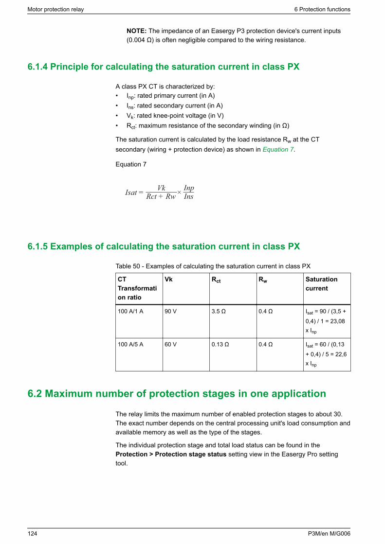
NOTE: The impedance of an Easergy P3 protection device's current inputs(0.004 Ω) is often negligible compared to the wiring resistance.
6.1.4 Principle for calculating the saturation current in class PX
A class PX CT is characterized by:• Inp: rated primary current (in A)• Ins: rated secondary current (in A)• Vk: rated knee-point voltage (in V)• Rct: maximum resistance of the secondary winding (in Ω)
The saturation current is calculated by the load resistance Rw at the CTsecondary (wiring + protection device) as shown in Equation 7.
Equation 7
VkIsat = ×Rct + RwInpIns
6.1.5 Examples of calculating the saturation current in class PX
Table 50 - Examples of calculating the saturation current in class PX
CTTransformation ratio
Vk Rct Rw Saturationcurrent
100 A/1 A 90 V 3.5 Ω 0.4 Ω Isat = 90 / (3,5 +0,4) / 1 = 23,08x Inp
100 A/5 A 60 V 0.13 Ω 0.4 Ω Isat = 60 / (0,13+ 0,4) / 5 = 22,6x Inp
6.2 Maximum number of protection stages in one application
The relay limits the maximum number of enabled protection stages to about 30.The exact number depends on the central processing unit's load consumption andavailable memory as well as the type of the stages.
The individual protection stage and total load status can be found in theProtection > Protection stage status setting view in the Easergy Pro settingtool.
Motor protection relay 6 Protection functions
124 P3M/en M/G006
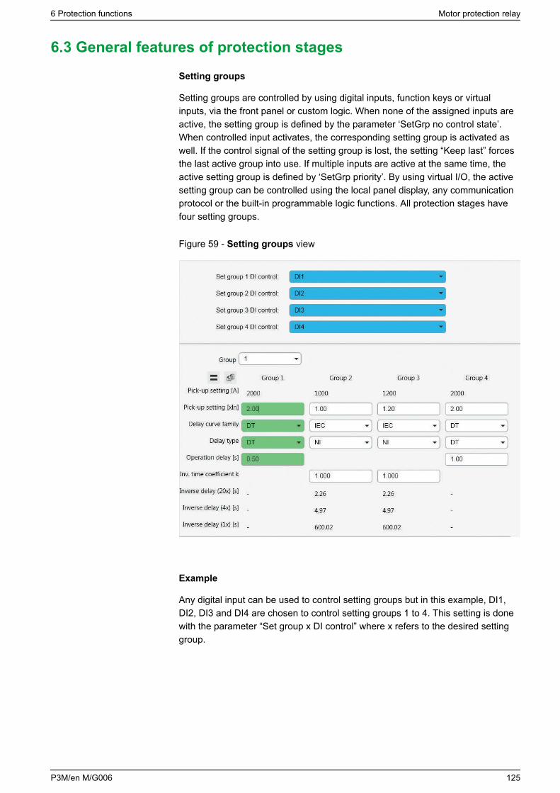
6.3 General features of protection stages
Setting groups
Setting groups are controlled by using digital inputs, function keys or virtualinputs, via the front panel or custom logic. When none of the assigned inputs areactive, the setting group is defined by the parameter ‘SetGrp no control state’.When controlled input activates, the corresponding setting group is activated aswell. If the control signal of the setting group is lost, the setting “Keep last” forcesthe last active group into use. If multiple inputs are active at the same time, theactive setting group is defined by ‘SetGrp priority’. By using virtual I/O, the activesetting group can be controlled using the local panel display, any communicationprotocol or the built-in programmable logic functions. All protection stages havefour setting groups.
Figure 59 - Setting groups view
Example
Any digital input can be used to control setting groups but in this example, DI1,DI2, DI3 and DI4 are chosen to control setting groups 1 to 4. This setting is donewith the parameter “Set group x DI control” where x refers to the desired settinggroup.
6 Protection functions Motor protection relay
P3M/en M/G006 125
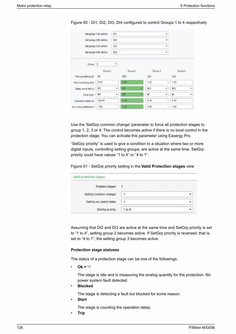
Figure 60 - DI1, DI2, DI3, DI4 configured to control Groups 1 to 4 respectively
Use the 'SetGrp common change' parameter to force all protection stages togroup 1, 2, 3 or 4. The control becomes active if there is no local control in theprotection stage. You can activate this parameter using Easergy Pro.
“SetGrp priority” is used to give a condition to a situation where two or moredigital inputs, controlling setting groups, are active at the same time. SetGrppriority could have values “1 to 4” or “4 to 1”.
Figure 61 - SetGrp priority setting in the Valid Protection stages view
Assuming that DI2 and DI3 are active at the same time and SetGrp priority is setto “1 to 4”, setting group 2 becomes active. If SetGrp priority is reversed, that is,set to “4 to 1”, the setting group 3 becomes active.
Protection stage statuses
The status of a protection stage can be one of the followings:
• Ok = ‘-‘
The stage is idle and is measuring the analog quantity for the protection. Nopower system fault detected.
• Blocked
The stage is detecting a fault but blocked for some reason.• Start
The stage is counting the operation delay.• Trip
Motor protection relay 6 Protection functions
126 P3M/en M/G006
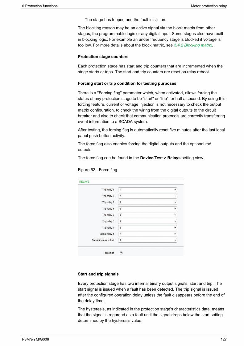
The stage has tripped and the fault is still on.
The blocking reason may be an active signal via the block matrix from otherstages, the programmable logic or any digital input. Some stages also have built-in blocking logic. For example an under frequency stage is blocked if voltage istoo low. For more details about the block matrix, see 5.4.2 Blocking matrix.
Protection stage counters
Each protection stage has start and trip counters that are incremented when thestage starts or trips. The start and trip counters are reset on relay reboot.
Forcing start or trip condition for testing purposes
There is a "Forcing flag" parameter which, when activated, allows forcing thestatus of any protection stage to be "start" or "trip" for half a second. By using thisforcing feature, current or voltage injection is not necessary to check the outputmatrix configuration, to check the wiring from the digital outputs to the circuitbreaker and also to check that communication protocols are correctly transferringevent information to a SCADA system.
After testing, the forcing flag is automatically reset five minutes after the last localpanel push button activity.
The force flag also enables forcing the digital outputs and the optional mAoutputs.
The force flag can be found in the Device/Test > Relays setting view.
Figure 62 - Force flag
Start and trip signals
Every protection stage has two internal binary output signals: start and trip. Thestart signal is issued when a fault has been detected. The trip signal is issuedafter the configured operation delay unless the fault disappears before the end ofthe delay time.
The hysteresis, as indicated in the protection stage's characteristics data, meansthat the signal is regarded as a fault until the signal drops below the start settingdetermined by the hysteresis value.
6 Protection functions Motor protection relay
P3M/en M/G006 127
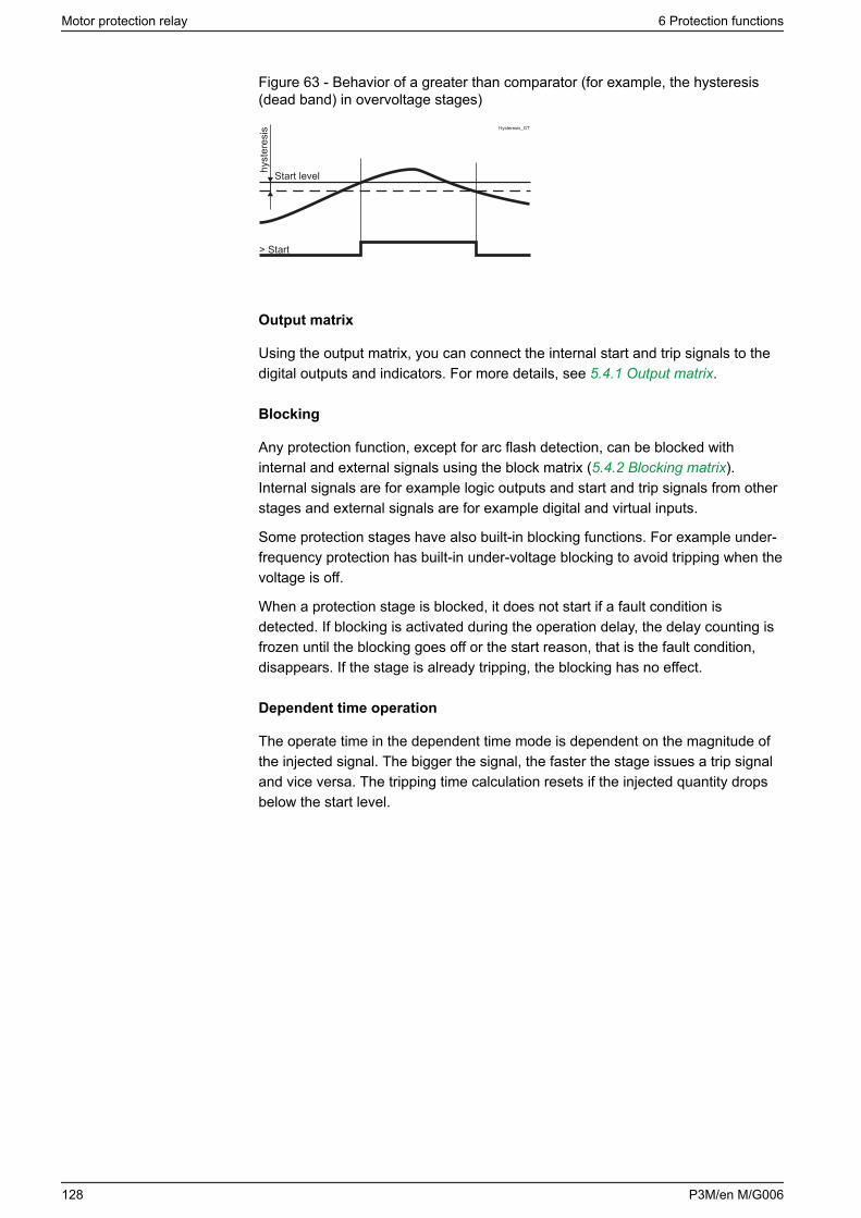
Figure 63 - Behavior of a greater than comparator (for example, the hysteresis(dead band) in overvoltage stages)
> Start
Start levelhyst
eres
is Hysteresis_GT
Output matrix
Using the output matrix, you can connect the internal start and trip signals to thedigital outputs and indicators. For more details, see 5.4.1 Output matrix.
Blocking
Any protection function, except for arc flash detection, can be blocked withinternal and external signals using the block matrix (5.4.2 Blocking matrix).Internal signals are for example logic outputs and start and trip signals from otherstages and external signals are for example digital and virtual inputs.
Some protection stages have also built-in blocking functions. For example under-frequency protection has built-in under-voltage blocking to avoid tripping when thevoltage is off.
When a protection stage is blocked, it does not start if a fault condition isdetected. If blocking is activated during the operation delay, the delay counting isfrozen until the blocking goes off or the start reason, that is the fault condition,disappears. If the stage is already tripping, the blocking has no effect.
Dependent time operation
The operate time in the dependent time mode is dependent on the magnitude ofthe injected signal. The bigger the signal, the faster the stage issues a trip signaland vice versa. The tripping time calculation resets if the injected quantity dropsbelow the start level.
Motor protection relay 6 Protection functions
128 P3M/en M/G006
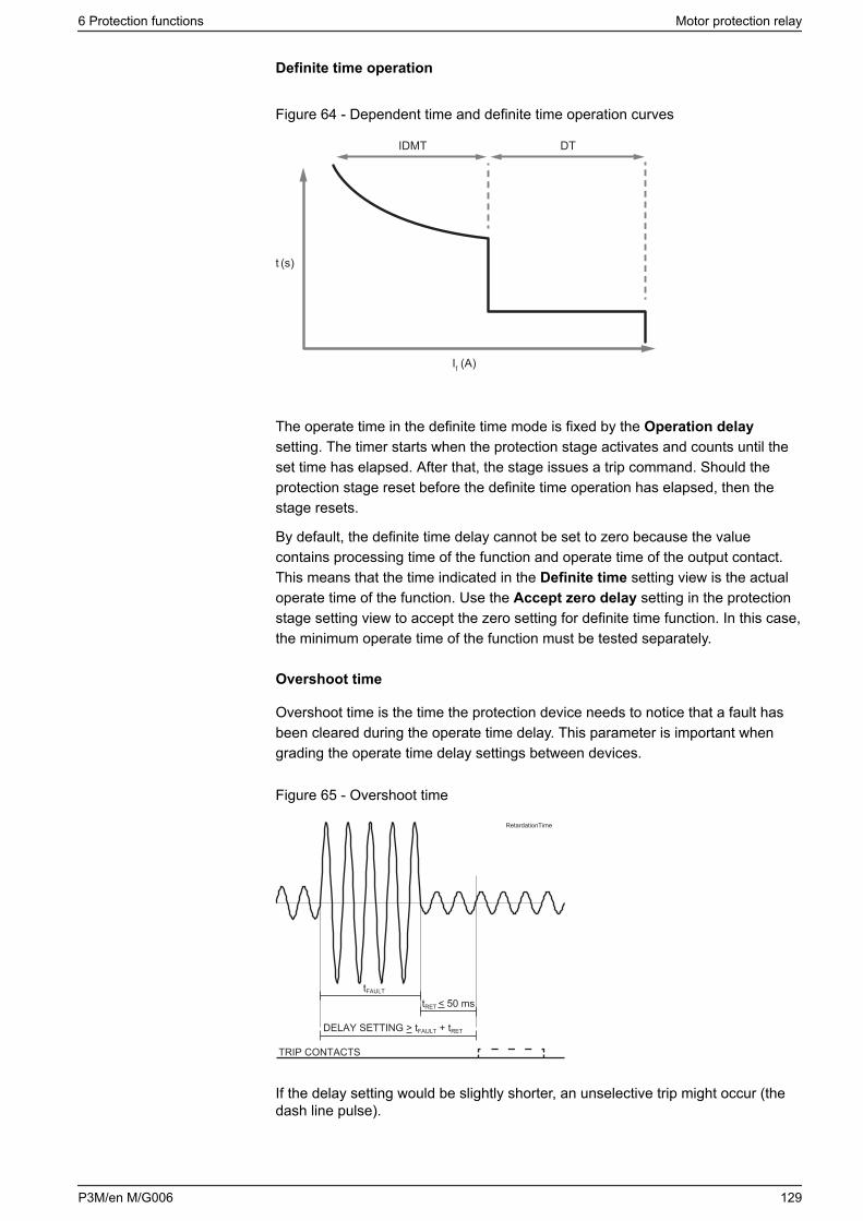
Definite time operation
Figure 64 - Dependent time and definite time operation curves
t (s)
If (A)
DTIDMT
The operate time in the definite time mode is fixed by the Operation delaysetting. The timer starts when the protection stage activates and counts until theset time has elapsed. After that, the stage issues a trip command. Should theprotection stage reset before the definite time operation has elapsed, then thestage resets.
By default, the definite time delay cannot be set to zero because the valuecontains processing time of the function and operate time of the output contact.This means that the time indicated in the Definite time setting view is the actualoperate time of the function. Use the Accept zero delay setting in the protectionstage setting view to accept the zero setting for definite time function. In this case,the minimum operate time of the function must be tested separately.
Overshoot time
Overshoot time is the time the protection device needs to notice that a fault hasbeen cleared during the operate time delay. This parameter is important whengrading the operate time delay settings between devices.
Figure 65 - Overshoot time
DELAY SETTING > tFAULT + tRET
TRIP CONTACTS
tRET < 50 mstFAULT
RetardationTime
If the delay setting would be slightly shorter, an unselective trip might occur (thedash line pulse).
6 Protection functions Motor protection relay
P3M/en M/G006 129
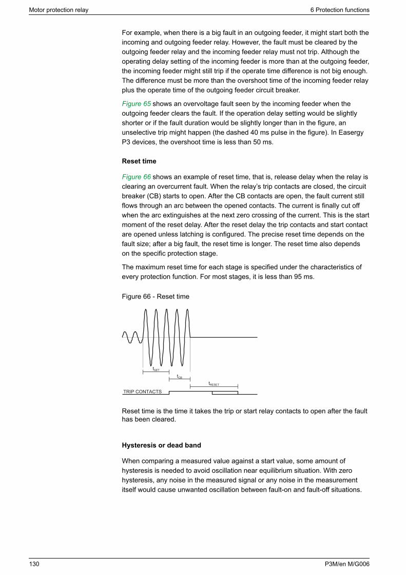
For example, when there is a big fault in an outgoing feeder, it might start both theincoming and outgoing feeder relay. However, the fault must be cleared by theoutgoing feeder relay and the incoming feeder relay must not trip. Although theoperating delay setting of the incoming feeder is more than at the outgoing feeder,the incoming feeder might still trip if the operate time difference is not big enough.The difference must be more than the overshoot time of the incoming feeder relayplus the operate time of the outgoing feeder circuit breaker.
Figure 65 shows an overvoltage fault seen by the incoming feeder when theoutgoing feeder clears the fault. If the operation delay setting would be slightlyshorter or if the fault duration would be slightly longer than in the figure, anunselective trip might happen (the dashed 40 ms pulse in the figure). In EasergyP3 devices, the overshoot time is less than 50 ms.
Reset time
Figure 66 shows an example of reset time, that is, release delay when the relay isclearing an overcurrent fault. When the relay’s trip contacts are closed, the circuitbreaker (CB) starts to open. After the CB contacts are open, the fault current stillflows through an arc between the opened contacts. The current is finally cut offwhen the arc extinguishes at the next zero crossing of the current. This is the startmoment of the reset delay. After the reset delay the trip contacts and start contactare opened unless latching is configured. The precise reset time depends on thefault size; after a big fault, the reset time is longer. The reset time also dependson the specific protection stage.
The maximum reset time for each stage is specified under the characteristics ofevery protection function. For most stages, it is less than 95 ms.
Figure 66 - Reset time
TRIP CONTACTS
tSET
tCB
tRESET
Reset time is the time it takes the trip or start relay contacts to open after the faulthas been cleared.
Hysteresis or dead band
When comparing a measured value against a start value, some amount ofhysteresis is needed to avoid oscillation near equilibrium situation. With zerohysteresis, any noise in the measured signal or any noise in the measurementitself would cause unwanted oscillation between fault-on and fault-off situations.
Motor protection relay 6 Protection functions
130 P3M/en M/G006
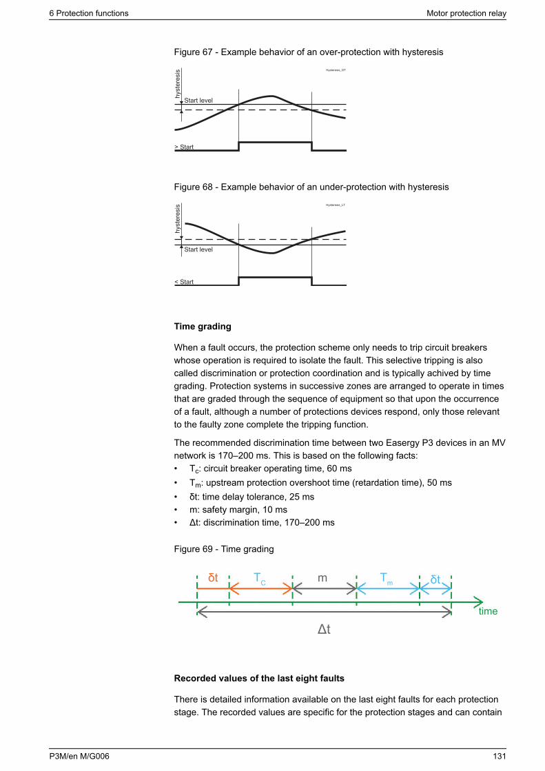
Figure 67 - Example behavior of an over-protection with hysteresis
> Start
Start levelhyst
eres
is Hysteresis_GT
Figure 68 - Example behavior of an under-protection with hysteresis
< Start
Start level
hyst
eres
is Hysteresis_LT
Time grading
When a fault occurs, the protection scheme only needs to trip circuit breakerswhose operation is required to isolate the fault. This selective tripping is alsocalled discrimination or protection coordination and is typically achived by timegrading. Protection systems in successive zones are arranged to operate in timesthat are graded through the sequence of equipment so that upon the occurrenceof a fault, although a number of protections devices respond, only those relevantto the faulty zone complete the tripping function.
The recommended discrimination time between two Easergy P3 devices in an MVnetwork is 170–200 ms. This is based on the following facts:• Tc: circuit breaker operating time, 60 ms• Tm: upstream protection overshoot time (retardation time), 50 ms• δt: time delay tolerance, 25 ms• m: safety margin, 10 ms• Δt: discrimination time, 170–200 ms
Figure 69 - Time grading
time
δtTmmTCδt
Δt
Recorded values of the last eight faults
There is detailed information available on the last eight faults for each protectionstage. The recorded values are specific for the protection stages and can contain
6 Protection functions Motor protection relay
P3M/en M/G006 131
information like time stamp, fault value, elapsed delay, fault current, fault voltage,phase angle and setting group.
NOTE: The recorded values are lost if the relay power is switched off.
Squelch limit
Current inputs have a squelch limit (noise filter) at 0.005 x IN. When themeasured signal goes below this threshold level, the signal is forced to zero.
NOTE: If ICALC is used to measure the residual current, the squelch limit forthe ICALC signal is same as for the phase currents. The I0 setting range beginsat the level of phase currents' squelch limit. This can cause instability if theminimum setting is used with the I0 CALC mode.
6.4 Dependent operate time
The dependent operate time – that is, the inverse definite minimum time (IDMT)type of operation – is available for several protection functions. The commonprinciple, formula and graphic representations of the available dependent delaytypes are described in this chapter.
Dependent delay means that the operate time depends on the measured realtime process values during a fault. For example, with an overcurrent stage usingdependent delay, a bigger a fault current gives faster operation. The alternative todependent delay is definite delay. With definite delay, a preset time is used andthe operate time does not depend on the size of a fault.
Stage-specific dependent delay
Some protection functions have their own specific type of dependent delay.Details of these dedicated dependent delays are described with the appropriateprotection function.
Operation modes
There are three operation modes to use the dependent time characteristics:
• Standard delays
Using standard delay characteristics by selecting a curve family (IEC, IEEE,IEEE2, RI) and a delay type (Normal inverse, Very inverse etc). See 6.4.1Standard dependent delays using IEC, IEEE, IEEE2 and RI curves.
• Standard delay formulae with free parameters
selecting a curve family (IEC, IEEE, IEEE2) and defining one's ownparameters for the selected delay formula. This mode is activated by settingdelay type to ‘Parameters’, and then editing the delay function parameters A –E. See 6.4.2 Free parameterization using IEC, IEEE and IEEE2 curves.
• Fully programmable dependent delay characteristics
Building the characteristics by setting 16 [current, time] points. The relayinterpolates the values between given points with second degree polynomials.This mode is activated by the setting curve family to ‘PrgN’'. There is amaximum of three different programmable curves available at the same time.Each programmed curve can be used by any number of protection stages.See 6.4.3 Programmable dependent time curves.
Motor protection relay 6 Protection functions
132 P3M/en M/G006
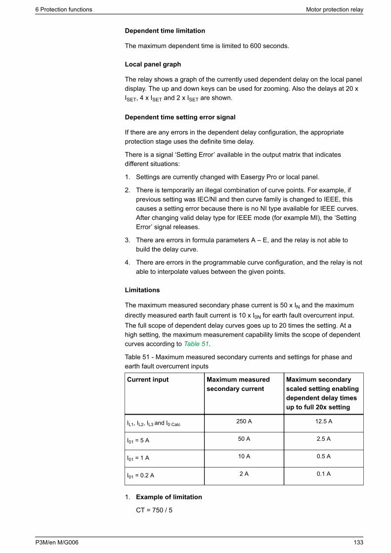
Dependent time limitation
The maximum dependent time is limited to 600 seconds.
Local panel graph
The relay shows a graph of the currently used dependent delay on the local paneldisplay. The up and down keys can be used for zooming. Also the delays at 20 xISET, 4 x ISET and 2 x ISET are shown.
Dependent time setting error signal
If there are any errors in the dependent delay configuration, the appropriateprotection stage uses the definite time delay.
There is a signal ‘Setting Error’ available in the output matrix that indicatesdifferent situations:
1. Settings are currently changed with Easergy Pro or local panel.
2. There is temporarily an illegal combination of curve points. For example, ifprevious setting was IEC/NI and then curve family is changed to IEEE, thiscauses a setting error because there is no NI type available for IEEE curves.After changing valid delay type for IEEE mode (for example MI), the ‘SettingError’ signal releases.
3. There are errors in formula parameters A – E, and the relay is not able tobuild the delay curve.
4. There are errors in the programmable curve configuration, and the relay is notable to interpolate values between the given points.
Limitations
The maximum measured secondary phase current is 50 x IN and the maximumdirectly measured earth fault current is 10 x I0N for earth fault overcurrent input.The full scope of dependent delay curves goes up to 20 times the setting. At ahigh setting, the maximum measurement capability limits the scope of dependentcurves according to Table 51.
Table 51 - Maximum measured secondary currents and settings for phase andearth fault overcurrent inputs
Current input Maximum measuredsecondary current
Maximum secondaryscaled setting enablingdependent delay timesup to full 20x setting
IL1, IL2, IL3 and I0 Calc 250 A 12.5 A
I01 = 5 A 50 A 2.5 A
I01 = 1 A 10 A 0.5 A
I01 = 0.2 A 2 A 0.1 A
1. Example of limitation
CT = 750 / 5
6 Protection functions Motor protection relay
P3M/en M/G006 133
CT0 = 100 / 1 (cable CT is used for earth fault overcurrent)
The CT0 is connected to a 1 A terminals of input I01.
For overcurrent stage I>, Table 51 gives 12.5 A. Thus, the maximum settingthe for I> stage giving full dependent delay range is 12.5 A / 5 A = 2.5 xIN =1875 APrimary.
For earth fault stage I0>, Table 51 gives 0.5 A. Thus, the maximum setting forthe I0> stage giving full dependent delay range is 0.5 A / 1 A = 0.5 xI0N = 50APrimary.
2. Example of limitation
CT = 750 / 5
Application mode is Motor
Rated current of the motor = 600 A
I0Calc = ( IL1 + IL2 + IL3) is used for earth fault overcurrent.
At secondary level, the rated motor current is 600 / 750*5 = 4 A
For overcurrent stage I>, Table 51 gives 12.5 A. Thus, the maximum settinggiving full dependent delay range is 12.5 A / 4 A = 3.13 x IMOT = 1875 APrimary.
For earth fault stage I0>, Table 51 gives 12.5 A. Thus, the maximum settingfor the I0> stage giving full dependent delay range is 12.5 A / 5 A = 2.5 x I0N =1875 APrimary.
6.4.1 Standard dependent delays using IEC, IEEE, IEEE2 and RI curves
The available standard dependent delays are divided in four categories calleddependent curve families: IEC, IEEE, IEEE2 and RI. Each category contains a setof different delay types according to Table 52.
Dependent time setting error signal
The dependent time setting error signal activates if the delay category is changedand the old delay type does not exist in the new category. See 6.4 Dependentoperate time for more details.
Limitations
The minimum definite time delay starts when the measured value is twenty timesthe setting, at the latest. However, there are limitations at high setting values dueto the measurement range. See 6.4 Dependent operate time for more details.
Motor protection relay 6 Protection functions
134 P3M/en M/G006
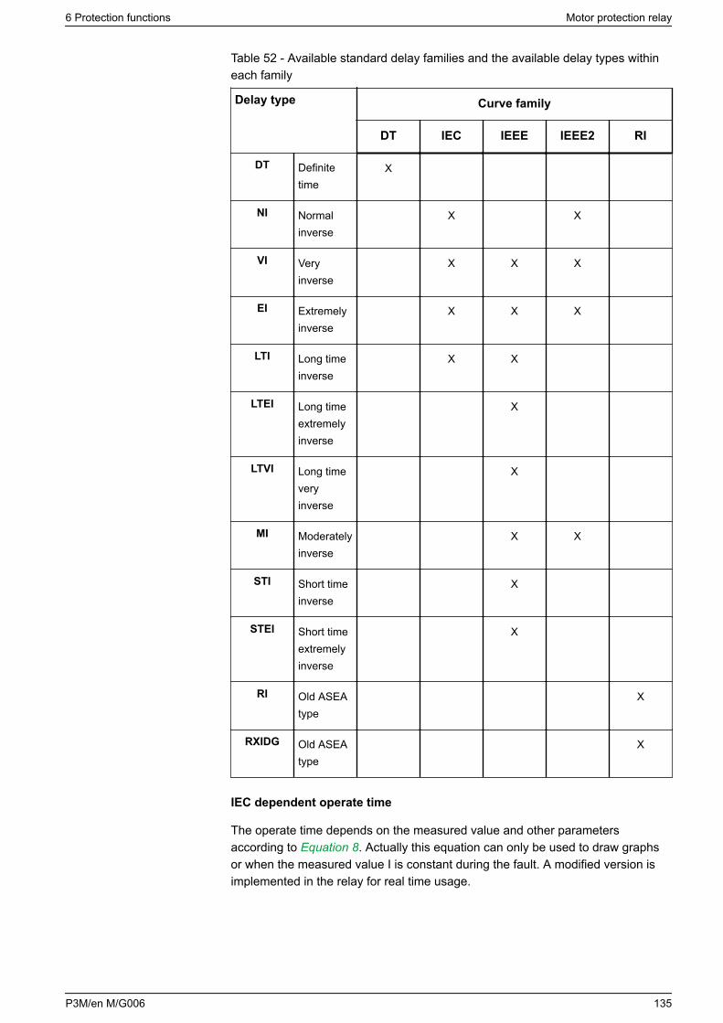
Table 52 - Available standard delay families and the available delay types withineach family
Delay type Curve family
DT IEC IEEE IEEE2 RI
DT Definitetime
X
NI Normalinverse
X X
VI Veryinverse
X X X
EI Extremelyinverse
X X X
LTI Long timeinverse
X X
LTEI Long timeextremelyinverse
X
LTVI Long timeveryinverse
X
MI Moderatelyinverse
X X
STI Short timeinverse
X
STEI Short timeextremelyinverse
X
RI Old ASEAtype
X
RXIDG Old ASEAtype
X
IEC dependent operate time
The operate time depends on the measured value and other parametersaccording to Equation 8. Actually this equation can only be used to draw graphsor when the measured value I is constant during the fault. A modified version isimplemented in the relay for real time usage.
6 Protection functions Motor protection relay
P3M/en M/G006 135
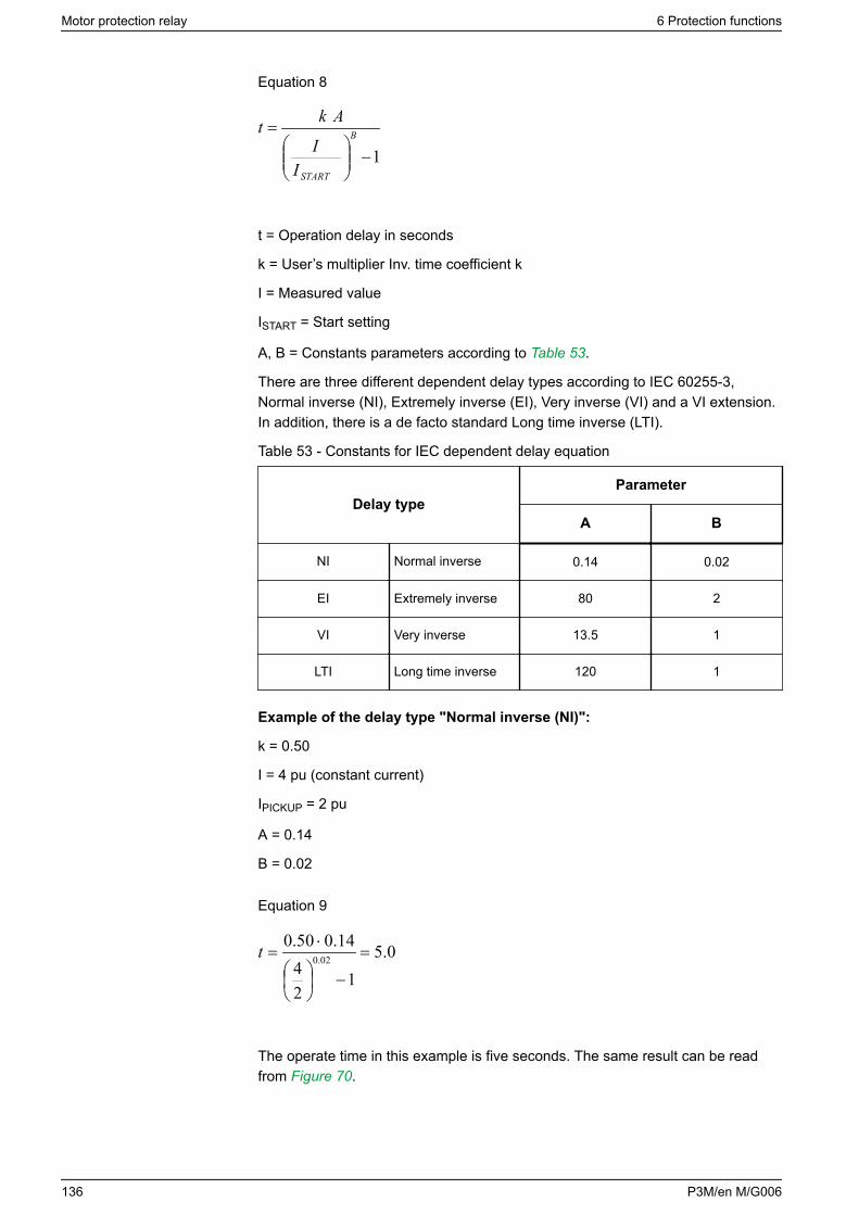
Equation 8
1−
= B
STARTII
Akt
t = Operation delay in seconds
k = User’s multiplier Inv. time coefficient k
I = Measured value
ISTART = Start setting
A, B = Constants parameters according to Table 53.
There are three different dependent delay types according to IEC 60255-3,Normal inverse (NI), Extremely inverse (EI), Very inverse (VI) and a VI extension.In addition, there is a de facto standard Long time inverse (LTI).
Table 53 - Constants for IEC dependent delay equation
Delay typeParameter
A B
NI Normal inverse 0.14 0.02
EI Extremely inverse 80 2
VI Very inverse 13.5 1
LTI Long time inverse 120 1
Example of the delay type "Normal inverse (NI)":
k = 0.50
I = 4 pu (constant current)
IPICKUP = 2 pu
A = 0.14
B = 0.02
Equation 9
0.51
24
14.050.002.0 =
−
⋅=t
The operate time in this example is five seconds. The same result can be readfrom Figure 70.
Motor protection relay 6 Protection functions
136 P3M/en M/G006
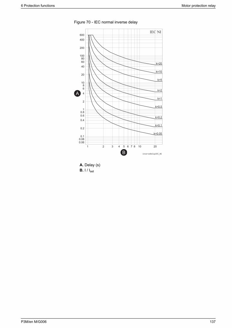
Figure 70 - IEC normal inverse delay
IEC NI
inverseDelayIEC_NI
A
B
A. Delay (s)B. I / Iset
6 Protection functions Motor protection relay
P3M/en M/G006 137
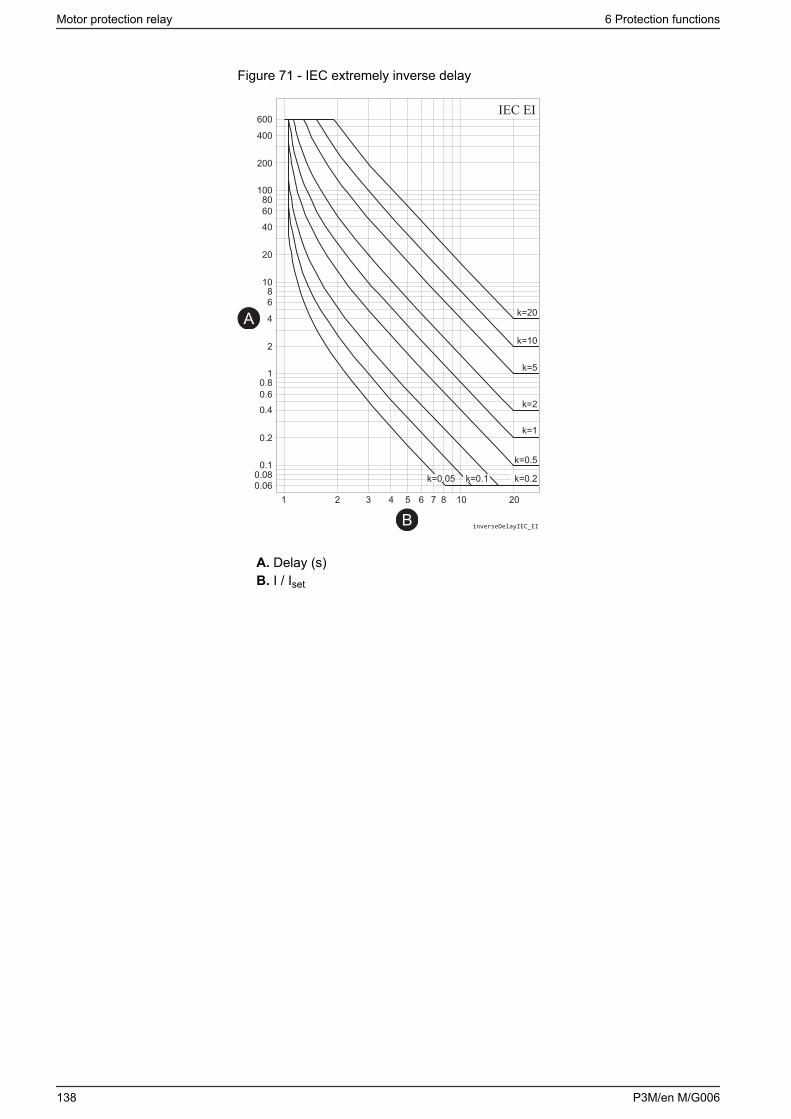
Figure 71 - IEC extremely inverse delay
IEC EI
inverseDelayIEC_EI
A
B
A. Delay (s)B. I / Iset
Motor protection relay 6 Protection functions
138 P3M/en M/G006
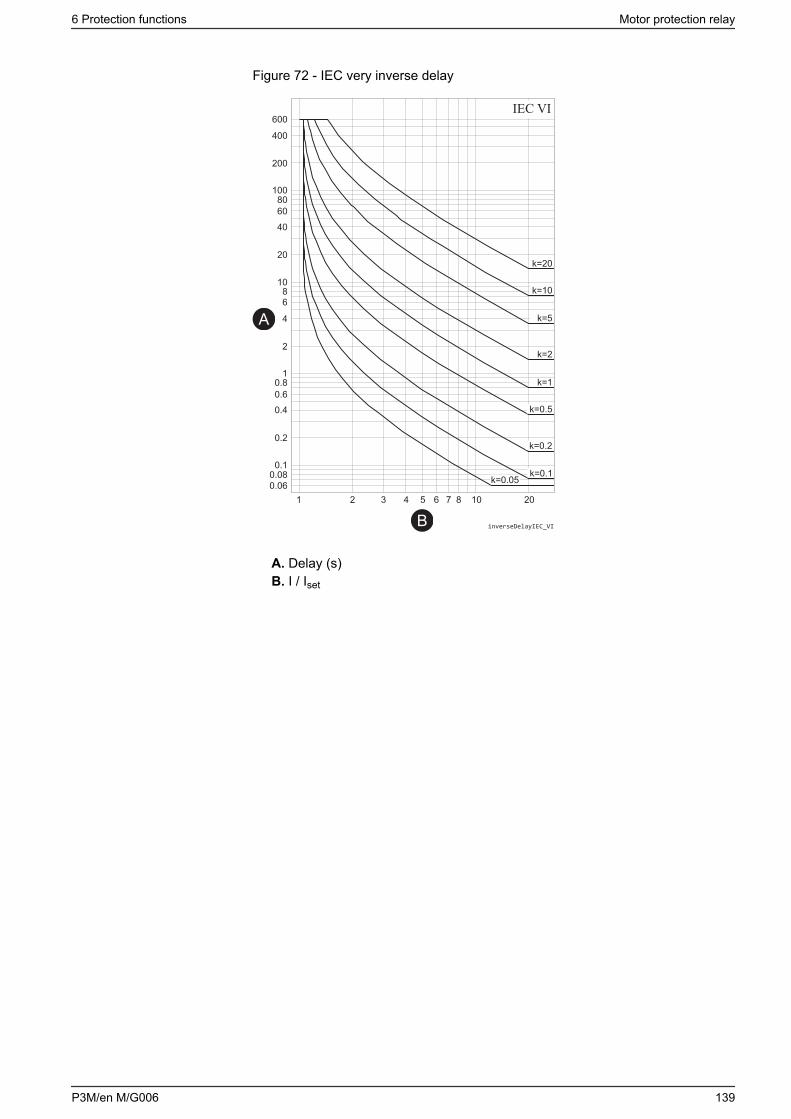
Figure 72 - IEC very inverse delay
IEC VI
inverseDelayIEC_VI
A
B
A. Delay (s)B. I / Iset
6 Protection functions Motor protection relay
P3M/en M/G006 139
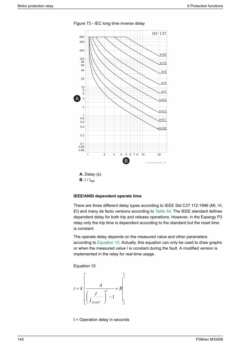
Figure 73 - IEC long time inverse delay
IEC LTI
inverseDelayIEC_LTI
A
B
A. Delay (s)B. I / Iset
IEEE/ANSI dependent operate time
There are three different delay types according to IEEE Std C37.112-1996 (MI, VI,EI) and many de facto versions according to Table 54. The IEEE standard definesdependent delay for both trip and release operations. However, in the Easergy P3relay only the trip time is dependent according to the standard but the reset timeis constant.
The operate delay depends on the measured value and other parametersaccording to Equation 10. Actually, this equation can only be used to draw graphsor when the measured value I is constant during the fault. A modified version isimplemented in the relay for real-time usage.
Equation 10
+
−
= B
II
Akt C
START
1
t = Operation delay in seconds
Motor protection relay 6 Protection functions
140 P3M/en M/G006
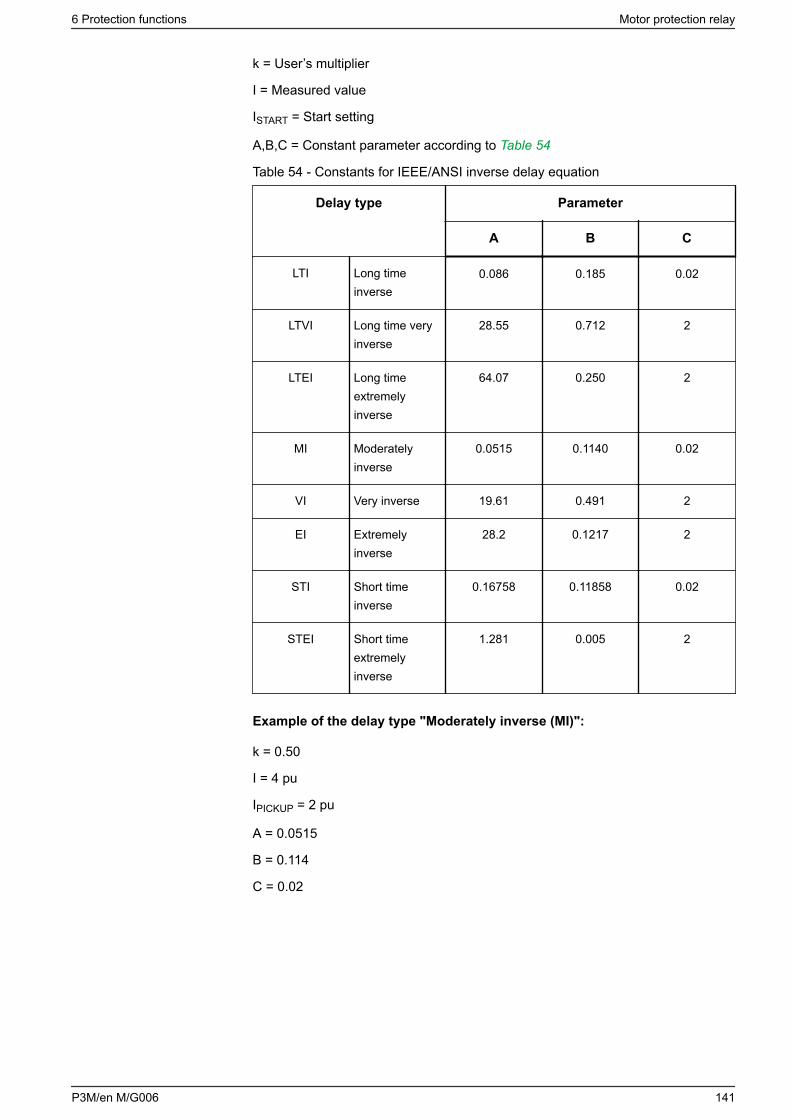
k = User’s multiplier
I = Measured value
ISTART = Start setting
A,B,C = Constant parameter according to Table 54
Table 54 - Constants for IEEE/ANSI inverse delay equation
Delay type Parameter
A B C
LTI Long timeinverse
0.086 0.185 0.02
LTVI Long time veryinverse
28.55 0.712 2
LTEI Long timeextremelyinverse
64.07 0.250 2
MI Moderatelyinverse
0.0515 0.1140 0.02
VI Very inverse 19.61 0.491 2
EI Extremelyinverse
28.2 0.1217 2
STI Short timeinverse
0.16758 0.11858 0.02
STEI Short timeextremelyinverse
1.281 0.005 2
Example of the delay type "Moderately inverse (MI)":
k = 0.50
I = 4 pu
IPICKUP = 2 pu
A = 0.0515
B = 0.114
C = 0.02
6 Protection functions Motor protection relay
P3M/en M/G006 141
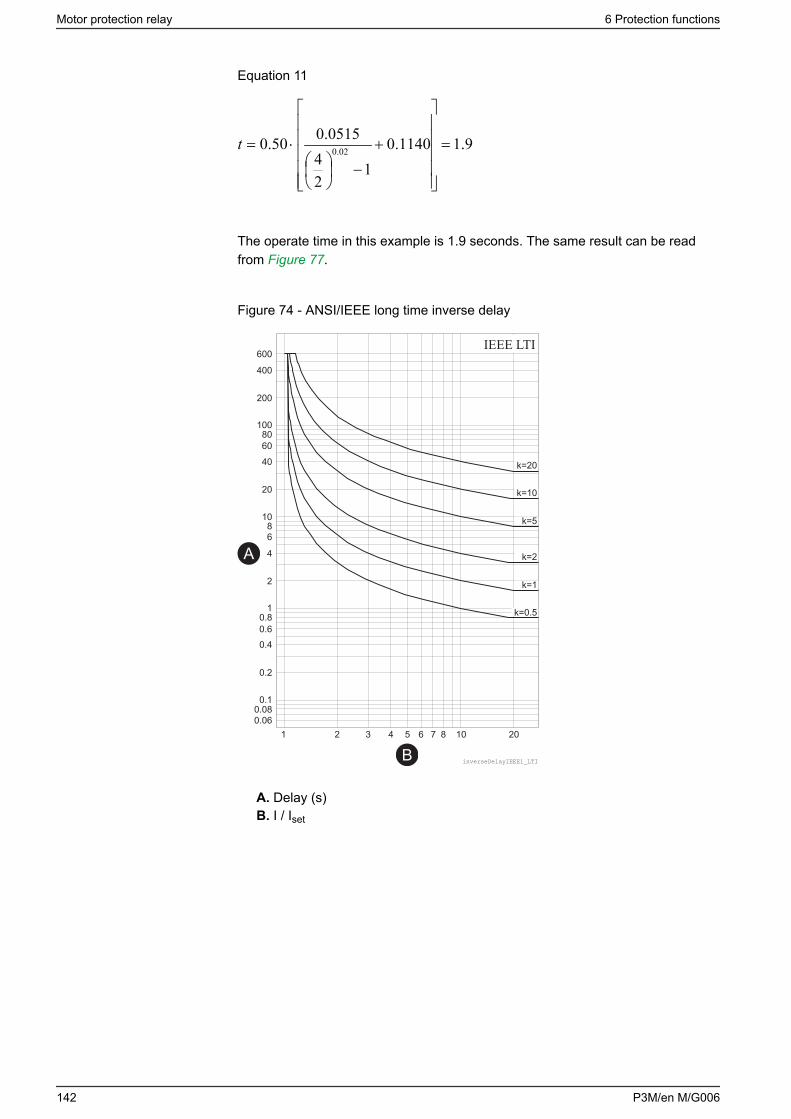
Equation 11
9.11140.01
24
0515.050.0 02.0 =
+
−
⋅=t
The operate time in this example is 1.9 seconds. The same result can be readfrom Figure 77.
Figure 74 - ANSI/IEEE long time inverse delay
IEEE LTI
inverseDelayIEEE1_LTI
A
B
A. Delay (s)B. I / Iset
Motor protection relay 6 Protection functions
142 P3M/en M/G006
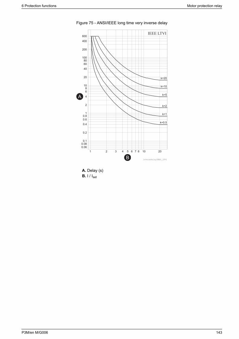
Figure 75 - ANSI/IEEE long time very inverse delay
IEEE LTVI
inverseDelayIEEE1_LTVI
A
B
A. Delay (s)B. I / Iset
6 Protection functions Motor protection relay
P3M/en M/G006 143
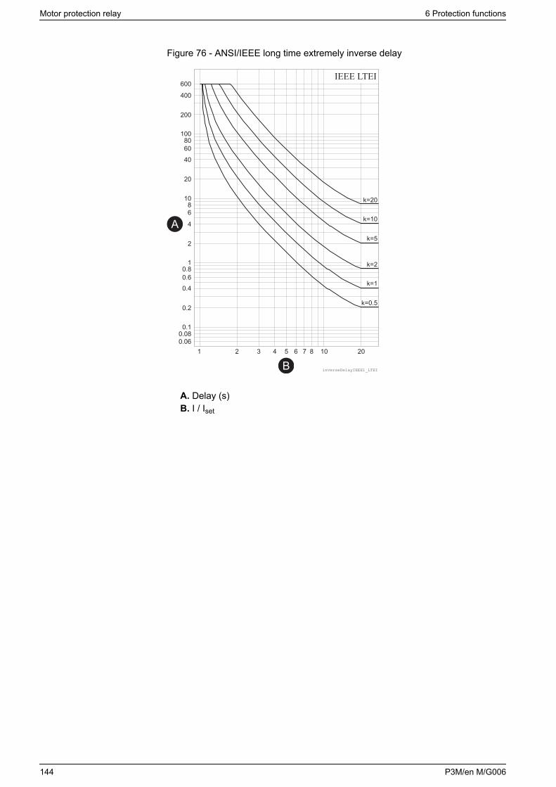
Figure 76 - ANSI/IEEE long time extremely inverse delay
IEEE LTEI
inverseDelayIEEE1_LTEI
A
B
A. Delay (s)B. I / Iset
Motor protection relay 6 Protection functions
144 P3M/en M/G006
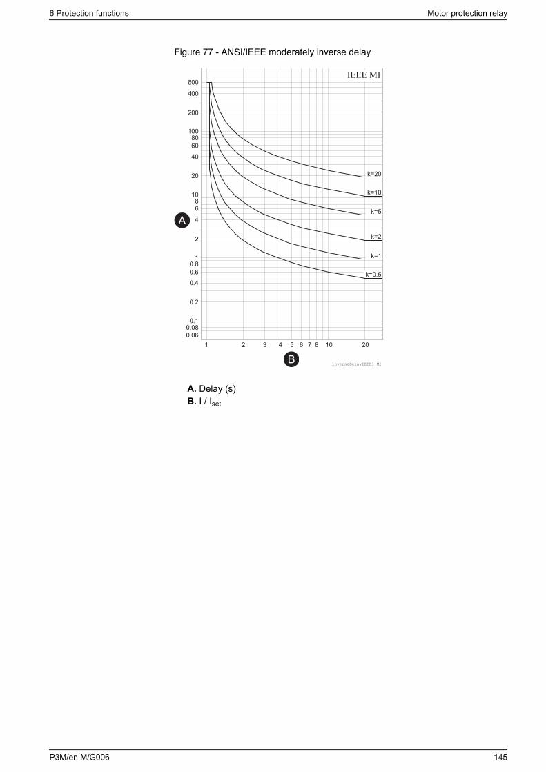
Figure 77 - ANSI/IEEE moderately inverse delay
IEEE MI
inverseDelayIEEE1_MI
A
B
A. Delay (s)B. I / Iset
6 Protection functions Motor protection relay
P3M/en M/G006 145
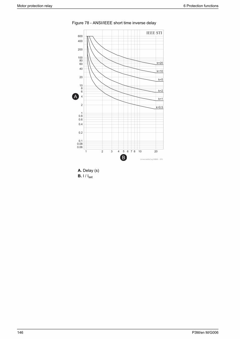
Figure 78 - ANSI/IEEE short time inverse delay
IEEE STI
inverseDelayIEEE1 STI
A
B
A. Delay (s)B. I / Iset
Motor protection relay 6 Protection functions
146 P3M/en M/G006
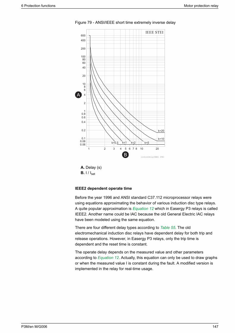
Figure 79 - ANSI/IEEE short time extremely inverse delay
IEEE STEI
inverseDelayIEEE1 STEI
A
B
A. Delay (s)B. I / Iset
IEEE2 dependent operate time
Before the year 1996 and ANSI standard C37.112 microprocessor relays wereusing equations approximating the behavior of various induction disc type relays.A quite popular approximation is Equation 12 which in Easergy P3 relays is calledIEEE2. Another name could be IAC because the old General Electric IAC relayshave been modeled using the same equation.
There are four different delay types according to Table 55. The oldelectromechanical induction disc relays have dependent delay for both trip andrelease operations. However, in Easergy P3 relays, only the trip time isdependent and the reset time is constant.
The operate delay depends on the measured value and other parametersaccording to Equation 12. Actually, this equation can only be used to draw graphsor when the measured value I is constant during the fault. A modified version isimplemented in the relay for real-time usage.
6 Protection functions Motor protection relay
P3M/en M/G006 147
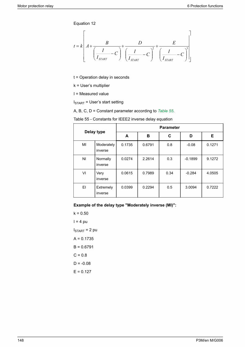
Equation 12
−
+
−
+
−
+= 32
CI
I
E
CI
I
D
CI
IBAkt
STARTSTARTSTART
t = Operation delay in seconds
k = User’s multiplier
I = Measured value
ISTART = User’s start setting
A, B, C, D = Constant parameter according to Table 55.
Table 55 - Constants for IEEE2 inverse delay equation
Delay typeParameter
A B C D E
MI Moderatelyinverse
0.1735 0.6791 0.8 -0.08 0.1271
NI Normallyinverse
0.0274 2.2614 0.3 -0.1899 9.1272
VI Veryinverse
0.0615 0.7989 0.34 -0.284 4.0505
EI Extremelyinverse
0.0399 0.2294 0.5 3.0094 0.7222
Example of the delay type "Moderately inverse (MI)":
k = 0.50
I = 4 pu
ISTART = 2 pu
A = 0.1735
B = 0.6791
C = 0.8
D = -0.08
E = 0.127
Motor protection relay 6 Protection functions
148 P3M/en M/G006
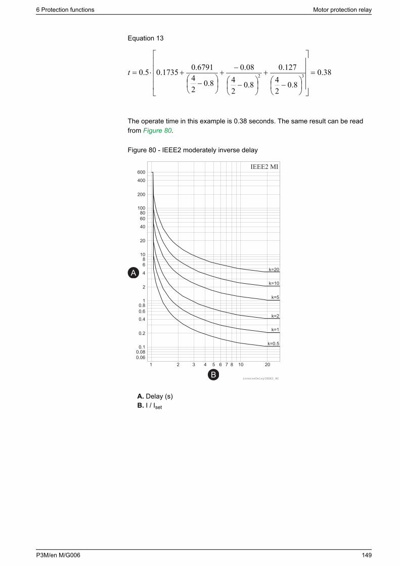
Equation 13
38.08.0
24
127.0
8.024
08.0
8.024
6791.01735.05.0 32 =
−
+
−
−+
−
+⋅=t
The operate time in this example is 0.38 seconds. The same result can be readfrom Figure 80.
Figure 80 - IEEE2 moderately inverse delay
IEEE2 MI
inverseDelayIEEE2_MI
A
B
A. Delay (s)B. I / Iset
6 Protection functions Motor protection relay
P3M/en M/G006 149
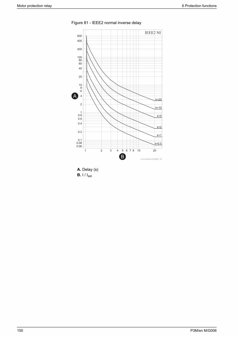
Figure 81 - IEEE2 normal inverse delay
IEEE2 NI
inverseDelayIEEE2_NI
A
B
A. Delay (s)B. I / Iset
Motor protection relay 6 Protection functions
150 P3M/en M/G006
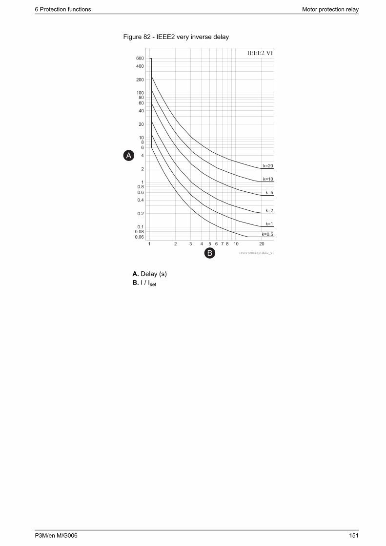
Figure 82 - IEEE2 very inverse delay
IEEE2 VI
inverseDelayIEEE2_VI
A
B
A. Delay (s)B. I / Iset
6 Protection functions Motor protection relay
P3M/en M/G006 151
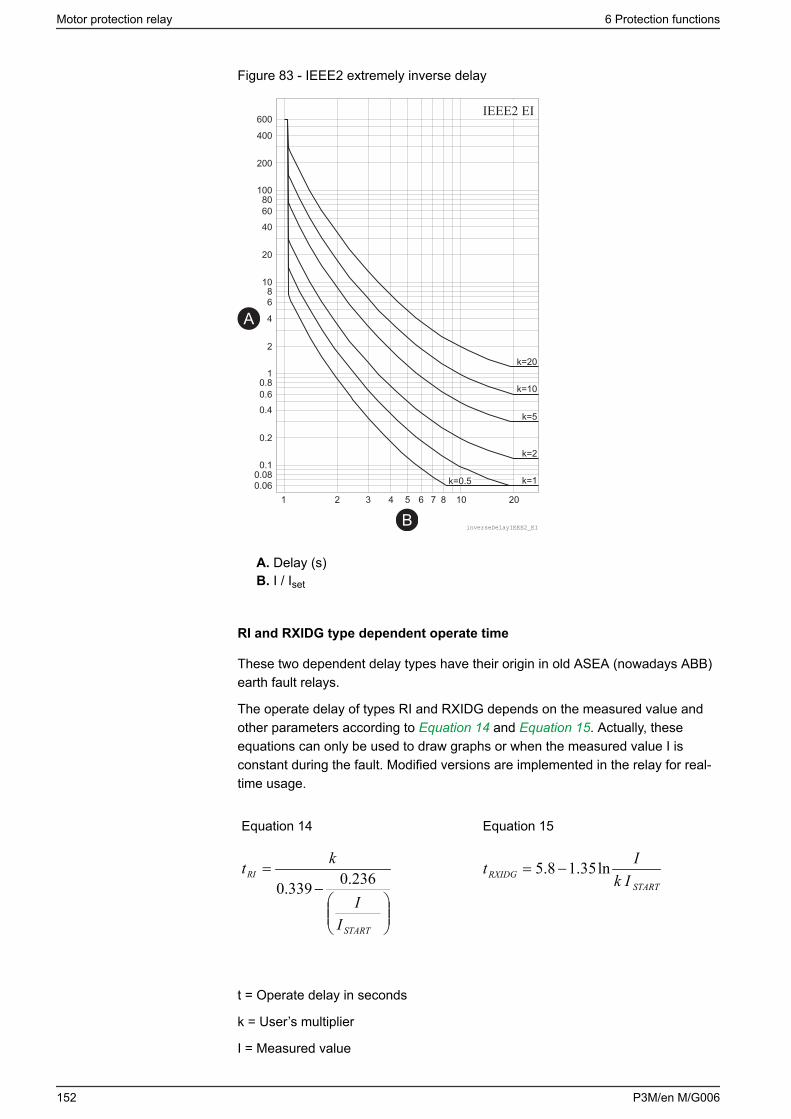
Figure 83 - IEEE2 extremely inverse delay
IEEE2 EI
inverseDelayIEEE2_EI
A
B
A. Delay (s)B. I / Iset
RI and RXIDG type dependent operate time
These two dependent delay types have their origin in old ASEA (nowadays ABB)earth fault relays.
The operate delay of types RI and RXIDG depends on the measured value andother parameters according to Equation 14 and Equation 15. Actually, theseequations can only be used to draw graphs or when the measured value I isconstant during the fault. Modified versions are implemented in the relay for real-time usage.
Equation 14
−
=
START
RI
II
kt 236.0339.0
Equation 15
STARTRXIDG Ik
It ln35.18.5 −=
t = Operate delay in seconds
k = User’s multiplier
I = Measured value
Motor protection relay 6 Protection functions
152 P3M/en M/G006

ISTART = Start setting
Example of the delay type RI
k = 0.50
I = 4 pu
ISTART = 2 pu
Equation 16
3.2
24236.0339.0
5.0=
−=RIt
The operate time in this example is 2.3 seconds. The same result can be readfrom Figure 84.
Example of the delay type RXIDG
k = 0.50
I = 4 pu
ISTART = 2 pu
Equation 17
9.325.0
4ln35.18.5 =⋅
−=RXIDGt
The operate time in this example is 3.9 seconds. The same result can be readfrom Figure 85.
6 Protection functions Motor protection relay
P3M/en M/G006 153
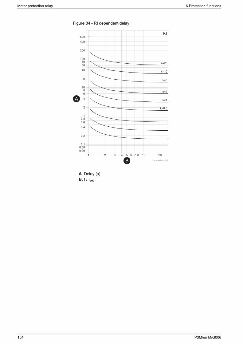
Figure 84 - RI dependent delay
RI
inverseDelayRI
A
B
A. Delay (s)B. I / Iset
Motor protection relay 6 Protection functions
154 P3M/en M/G006
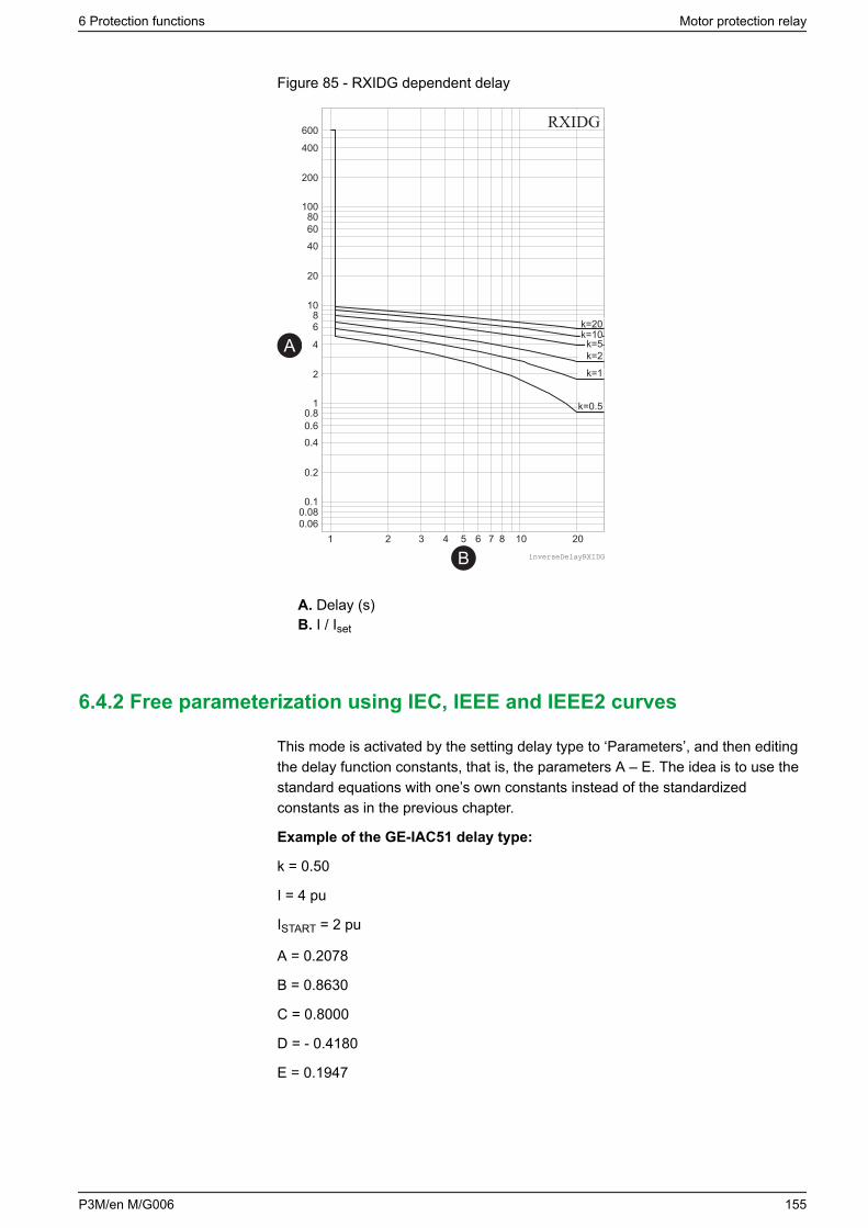
Figure 85 - RXIDG dependent delay
A
B
A. Delay (s)B. I / Iset
6.4.2 Free parameterization using IEC, IEEE and IEEE2 curves
This mode is activated by the setting delay type to ‘Parameters’, and then editingthe delay function constants, that is, the parameters A – E. The idea is to use thestandard equations with one’s own constants instead of the standardizedconstants as in the previous chapter.
Example of the GE-IAC51 delay type:
k = 0.50
I = 4 pu
ISTART = 2 pu
A = 0.2078
B = 0.8630
C = 0.8000
D = - 0.4180
E = 0.1947
6 Protection functions Motor protection relay
P3M/en M/G006 155
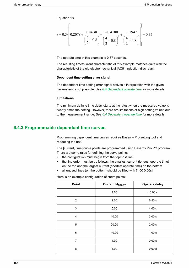
Equation 18
37.08.0
24
1947.0
8.024
4180.0
8.024
8630.02078.05.0 32 =
−
+
−
−+
−
+⋅=t
The operate time in this example is 0.37 seconds.
The resulting time/current characteristic of this example matches quite well thecharacteristic of the old electromechanical IAC51 induction disc relay.
Dependent time setting error signal
The dependent time setting error signal actives if interpolation with the givenparameters is not possible. See 6.4 Dependent operate time for more details.
Limitations
The minimum definite time delay starts at the latest when the measured value istwenty times the setting. However, there are limitations at high setting values dueto the measurement range. See 6.4 Dependent operate time for more details.
6.4.3 Programmable dependent time curves
Programming dependent time curves requires Easergy Pro setting tool andrebooting the unit.
The [current, time] curve points are programmed using Easergy Pro PC program.There are some rules for defining the curve points:• the configuration must begin from the topmost line• the line order must be as follows: the smallest current (longest operate time)
on the top and the largest current (shortest operate time) on the bottom• all unused lines (on the bottom) should be filled with [1.00 0.00s]
Here is an example configuration of curve points:
Point Current I/ISTART Operate delay
1 1.00 10.00 s
2 2.00 6.50 s
3 5.00 4.00 s
4 10.00 3.00 s
5 20.00 2.00 s
6 40.00 1.00 s
7 1.00 0.00 s
8 1.00 0.00 s
Motor protection relay 6 Protection functions
156 P3M/en M/G006
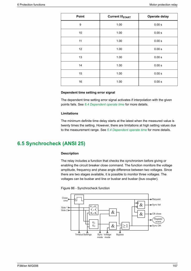
Point Current I/ISTART Operate delay
9 1.00 0.00 s
10 1.00 0.00 s
11 1.00 0.00 s
12 1.00 0.00 s
13 1.00 0.00 s
14 1.00 0.00 s
15 1.00 0.00 s
16 1.00 0.00 s
Dependent time setting error signal
The dependent time setting error signal activates if interpolation with the givenpoints fails. See 6.4 Dependent operate time for more details.
Limitations
The minimum definite time delay starts at the latest when the measured value istwenty times the setting. However, there are limitations at high setting values dueto the measurement range. See 6.4 Dependent operate time for more details.
6.5 Synchrocheck (ANSI 25)
Description
The relay includes a function that checks the synchronism before giving orenabling the circuit breaker close command. The function monitors the voltageamplitude, frequency and phase angle difference between two voltages. Sincethere are two stages available, it is possible to monitor three voltages. Thevoltages can be busbar and line or busbar and busbar (bus coupler).
Figure 86 - Synchrocheck function
&
U1U2 & 1
&
&
≥
Closecmd
Side 1Side 2
Timeout Settings Syncmode
Voltagemode
Bypass
Request
Register event
Sync fail
CB close
Sync OK
U1f1φ1
=U2f2φ2==
6 Protection functions Motor protection relay
P3M/en M/G006 157
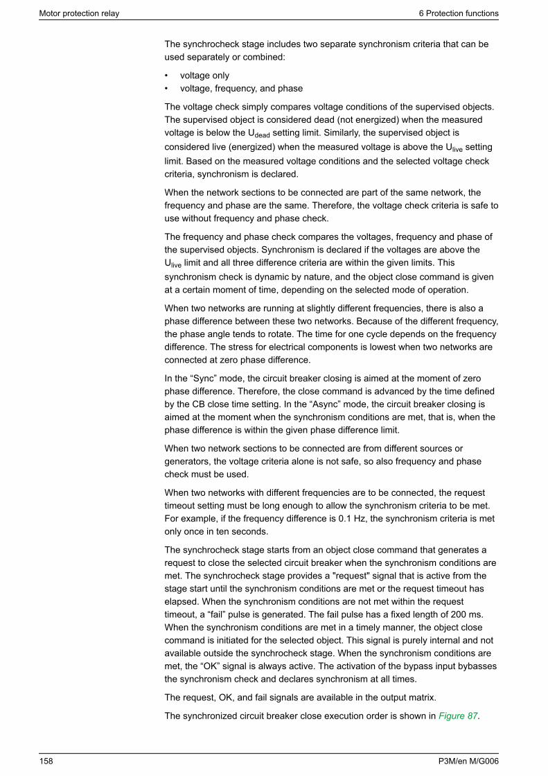
The synchrocheck stage includes two separate synchronism criteria that can beused separately or combined:
• voltage only• voltage, frequency, and phase
The voltage check simply compares voltage conditions of the supervised objects.The supervised object is considered dead (not energized) when the measuredvoltage is below the Udead setting limit. Similarly, the supervised object isconsidered live (energized) when the measured voltage is above the Ulive settinglimit. Based on the measured voltage conditions and the selected voltage checkcriteria, synchronism is declared.
When the network sections to be connected are part of the same network, thefrequency and phase are the same. Therefore, the voltage check criteria is safe touse without frequency and phase check.
The frequency and phase check compares the voltages, frequency and phase ofthe supervised objects. Synchronism is declared if the voltages are above theUlive limit and all three difference criteria are within the given limits. Thissynchronism check is dynamic by nature, and the object close command is givenat a certain moment of time, depending on the selected mode of operation.
When two networks are running at slightly different frequencies, there is also aphase difference between these two networks. Because of the different frequency,the phase angle tends to rotate. The time for one cycle depends on the frequencydifference. The stress for electrical components is lowest when two networks areconnected at zero phase difference.
In the “Sync” mode, the circuit breaker closing is aimed at the moment of zerophase difference. Therefore, the close command is advanced by the time definedby the CB close time setting. In the “Async” mode, the circuit breaker closing isaimed at the moment when the synchronism conditions are met, that is, when thephase difference is within the given phase difference limit.
When two network sections to be connected are from different sources orgenerators, the voltage criteria alone is not safe, so also frequency and phasecheck must be used.
When two networks with different frequencies are to be connected, the requesttimeout setting must be long enough to allow the synchronism criteria to be met.For example, if the frequency difference is 0.1 Hz, the synchronism criteria is metonly once in ten seconds.
The synchrocheck stage starts from an object close command that generates arequest to close the selected circuit breaker when the synchronism conditions aremet. The synchrocheck stage provides a "request" signal that is active from thestage start until the synchronism conditions are met or the request timeout haselapsed. When the synchronism conditions are not met within the requesttimeout, a “fail” pulse is generated. The fail pulse has a fixed length of 200 ms.When the synchronism conditions are met in a timely manner, the object closecommand is initiated for the selected object. This signal is purely internal and notavailable outside the synchrocheck stage. When the synchronism conditions aremet, the “OK” signal is always active. The activation of the bypass input bybassesthe synchronism check and declares synchronism at all times.
The request, OK, and fail signals are available in the output matrix.
The synchronized circuit breaker close execution order is shown in Figure 87.
Motor protection relay 6 Protection functions
158 P3M/en M/G006
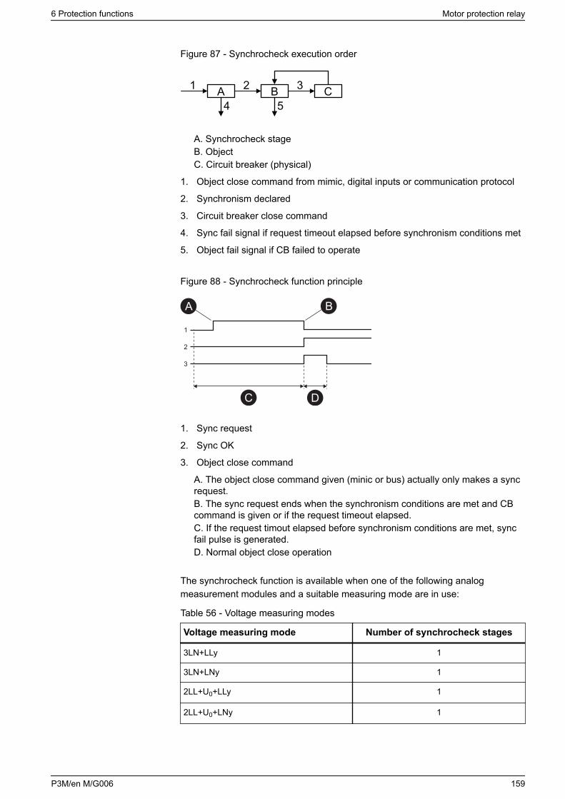
Figure 87 - Synchrocheck execution order
A B C1 2 3
4 5
A. Synchrocheck stageB. ObjectC. Circuit breaker (physical)
1. Object close command from mimic, digital inputs or communication protocol
2. Synchronism declared
3. Circuit breaker close command
4. Sync fail signal if request timeout elapsed before synchronism conditions met
5. Object fail signal if CB failed to operate
Figure 88 - Synchrocheck function principle
1
2
3
BA
C D
1. Sync request
2. Sync OK
3. Object close command
A. The object close command given (minic or bus) actually only makes a syncrequest.B. The sync request ends when the synchronism conditions are met and CBcommand is given or if the request timeout elapsed.C. If the request timout elapsed before synchronism conditions are met, syncfail pulse is generated.D. Normal object close operation
The synchrocheck function is available when one of the following analogmeasurement modules and a suitable measuring mode are in use:
Table 56 - Voltage measuring modes
Voltage measuring mode Number of synchrocheck stages
3LN+LLy 1
3LN+LNy 1
2LL+U0+LLy 1
2LL+U0+LNy 1
6 Protection functions Motor protection relay
P3M/en M/G006 159
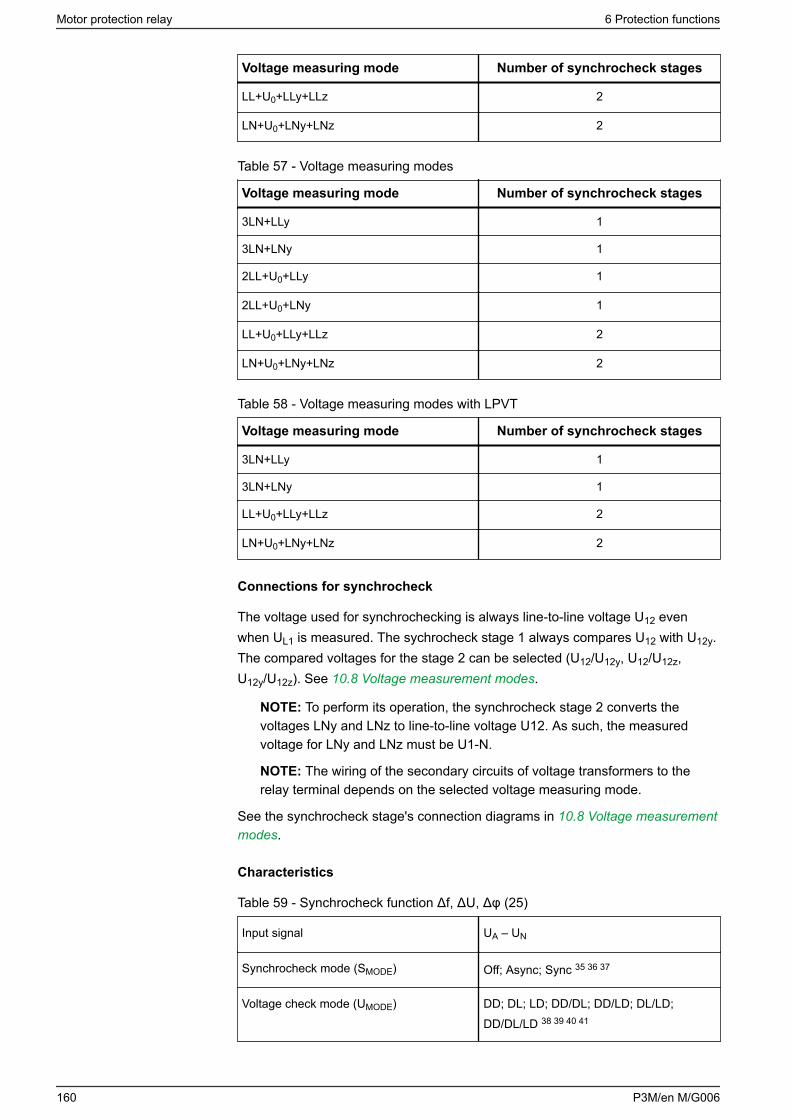
Voltage measuring mode Number of synchrocheck stages
LL+U0+LLy+LLz 2
LN+U0+LNy+LNz 2
Table 57 - Voltage measuring modes
Voltage measuring mode Number of synchrocheck stages
3LN+LLy 1
3LN+LNy 1
2LL+U0+LLy 1
2LL+U0+LNy 1
LL+U0+LLy+LLz 2
LN+U0+LNy+LNz 2
Table 58 - Voltage measuring modes with LPVT
Voltage measuring mode Number of synchrocheck stages
3LN+LLy 1
3LN+LNy 1
LL+U0+LLy+LLz 2
LN+U0+LNy+LNz 2
Connections for synchrocheck
The voltage used for synchrochecking is always line-to-line voltage U12 evenwhen UL1 is measured. The sychrocheck stage 1 always compares U12 with U12y.The compared voltages for the stage 2 can be selected (U12/U12y, U12/U12z,U12y/U12z). See 10.8 Voltage measurement modes.
NOTE: To perform its operation, the synchrocheck stage 2 converts thevoltages LNy and LNz to line-to-line voltage U12. As such, the measuredvoltage for LNy and LNz must be U1-N.
NOTE: The wiring of the secondary circuits of voltage transformers to therelay terminal depends on the selected voltage measuring mode.
See the synchrocheck stage's connection diagrams in 10.8 Voltage measurementmodes.
Characteristics
Table 59 - Synchrocheck function Δf, ΔU, Δφ (25)
Input signal UA – UN
Synchrocheck mode (SMODE) Off; Async; Sync 35 36 37
Voltage check mode (UMODE) DD; DL; LD; DD/DL; DD/LD; DL/LD;DD/DL/LD 38 39 40 41
Motor protection relay 6 Protection functions
160 P3M/en M/G006
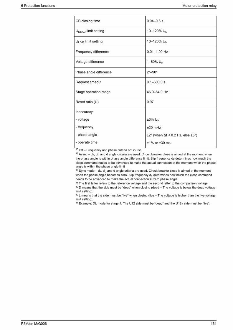
CB closing time 0.04–0.6 s
UDEAD limit setting 10–120% UN
ULIVE limit setting 10–120% UN
Frequency difference 0.01–1.00 Hz
Voltage difference 1–60% UN
Phase angle difference 2°–90°
Request timeout 0.1–600.0 s
Stage operation range 46.0–64.0 Hz
Reset ratio (U) 0.97
Inaccuracy:
- voltage
- frequency
- phase angle
- operate time
±3% UN
±20 mHz
±2° (when Δf < 0.2 Hz, else ±5°)
±1% or ±30 ms
35 Off – Frequency and phase criteria not in use36 Async – dF, dU and d angle criteria are used. Circuit breaker close is aimed at the moment whenthe phase angle is within phase angle difference limit. Slip frequency dF determines how much theclose command needs to be advanced to make the actual connection at the moment when the phaseangle is within the phase angle limit37 Sync mode – dF, dU and d angle criteria are used. Circuit breaker close is aimed at the momentwhen the phase angle becomes zero. Slip frequency dF determines how much the close commandneeds to be advanced to make the actual connection at zero phase angle.38 The first letter refers to the reference voltage and the second letter to the comparison voltage.39 D means that the side must be “dead” when closing (dead = The voltage is below the dead voltagelimit setting).40 L means that the side must be “live” when closing (live = The voltage is higher than the live voltagelimit setting).41 Example: DL mode for stage 1: The U12 side must be “dead” and the U12y side must be “live”.
6 Protection functions Motor protection relay
P3M/en M/G006 161
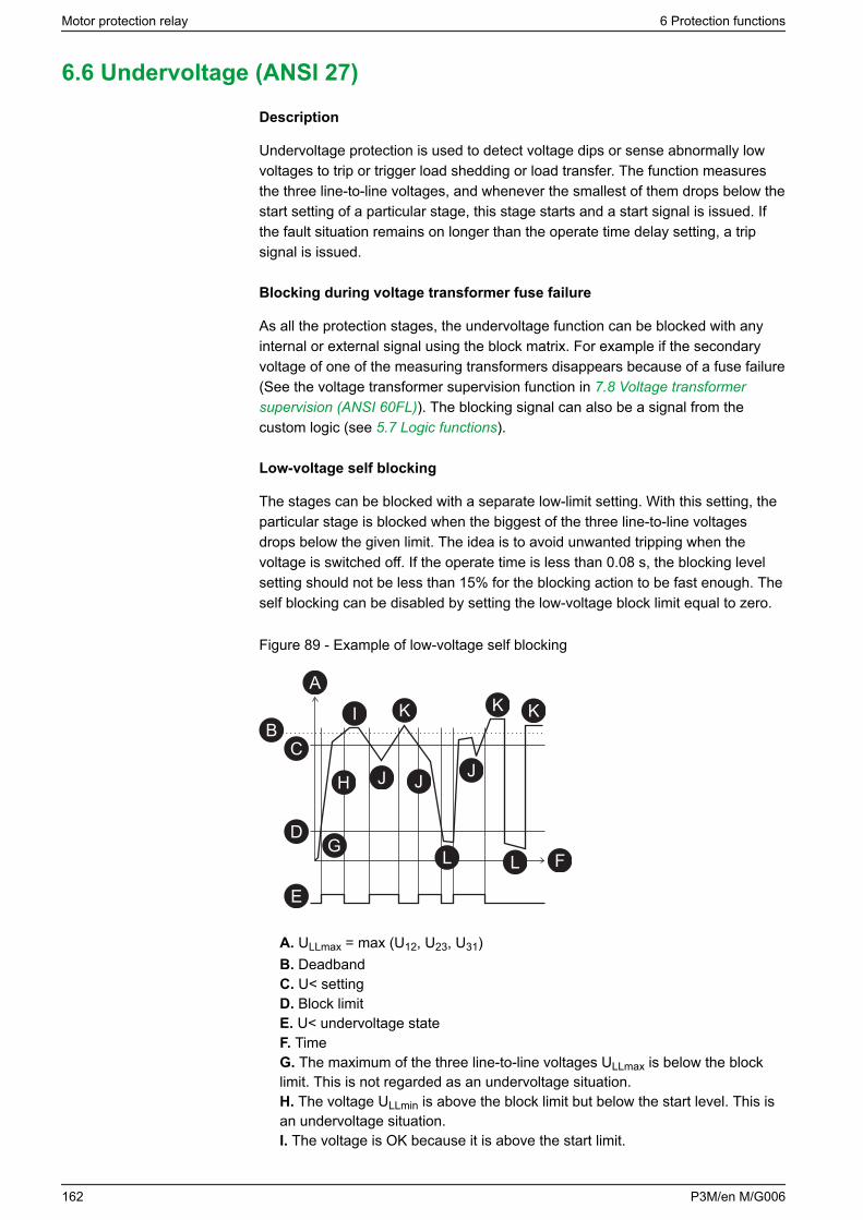
6.6 Undervoltage (ANSI 27)
Description
Undervoltage protection is used to detect voltage dips or sense abnormally lowvoltages to trip or trigger load shedding or load transfer. The function measuresthe three line-to-line voltages, and whenever the smallest of them drops below thestart setting of a particular stage, this stage starts and a start signal is issued. Ifthe fault situation remains on longer than the operate time delay setting, a tripsignal is issued.
Blocking during voltage transformer fuse failure
As all the protection stages, the undervoltage function can be blocked with anyinternal or external signal using the block matrix. For example if the secondaryvoltage of one of the measuring transformers disappears because of a fuse failure(See the voltage transformer supervision function in 7.8 Voltage transformersupervision (ANSI 60FL)). The blocking signal can also be a signal from thecustom logic (see 5.7 Logic functions).
Low-voltage self blocking
The stages can be blocked with a separate low-limit setting. With this setting, theparticular stage is blocked when the biggest of the three line-to-line voltagesdrops below the given limit. The idea is to avoid unwanted tripping when thevoltage is switched off. If the operate time is less than 0.08 s, the blocking levelsetting should not be less than 15% for the blocking action to be fast enough. Theself blocking can be disabled by setting the low-voltage block limit equal to zero.
Figure 89 - Example of low-voltage self blocking
I K K K
H J J J
LG
L
A
BC
D
E
F
A. ULLmax = max (U12, U23, U31)B. DeadbandC. U< settingD. Block limitE. U< undervoltage stateF. TimeG. The maximum of the three line-to-line voltages ULLmax is below the blocklimit. This is not regarded as an undervoltage situation.H. The voltage ULLmin is above the block limit but below the start level. This isan undervoltage situation.I. The voltage is OK because it is above the start limit.
Motor protection relay 6 Protection functions
162 P3M/en M/G006
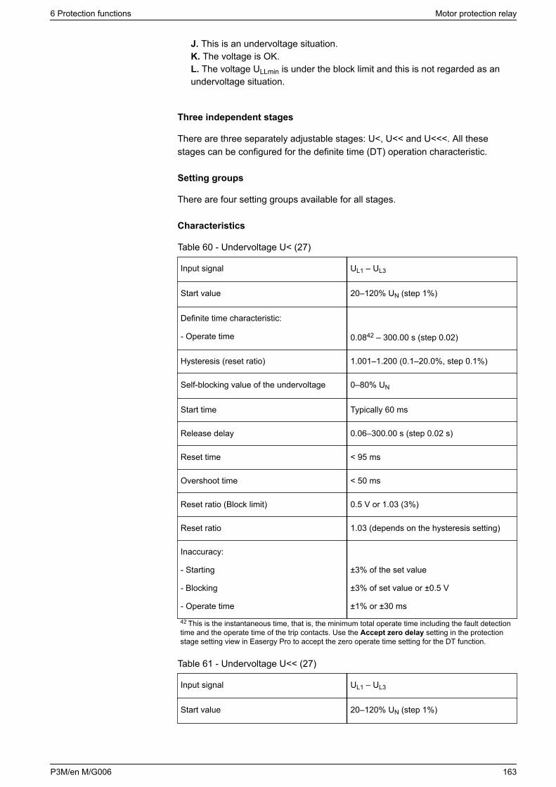
J. This is an undervoltage situation.K. The voltage is OK.L. The voltage ULLmin is under the block limit and this is not regarded as anundervoltage situation.
Three independent stages
There are three separately adjustable stages: U<, U<< and U<<<. All thesestages can be configured for the definite time (DT) operation characteristic.
Setting groups
There are four setting groups available for all stages.
Characteristics
Table 60 - Undervoltage U< (27)
Input signal UL1 – UL3
Start value 20–120% UN (step 1%)
Definite time characteristic:
- Operate time 0.0842 – 300.00 s (step 0.02)
Hysteresis (reset ratio) 1.001–1.200 (0.1–20.0%, step 0.1%)
Self-blocking value of the undervoltage 0–80% UN
Start time Typically 60 ms
Release delay 0.06–300.00 s (step 0.02 s)
Reset time < 95 ms
Overshoot time < 50 ms
Reset ratio (Block limit) 0.5 V or 1.03 (3%)
Reset ratio 1.03 (depends on the hysteresis setting)
Inaccuracy:
- Starting
- Blocking
- Operate time
±3% of the set value
±3% of set value or ±0.5 V
±1% or ±30 ms
42 This is the instantaneous time, that is, the minimum total operate time including the fault detectiontime and the operate time of the trip contacts. Use the Accept zero delay setting in the protectionstage setting view in Easergy Pro to accept the zero operate time setting for the DT function.
Table 61 - Undervoltage U<< (27)
Input signal UL1 – UL3
Start value 20–120% UN (step 1%)
6 Protection functions Motor protection relay
P3M/en M/G006 163
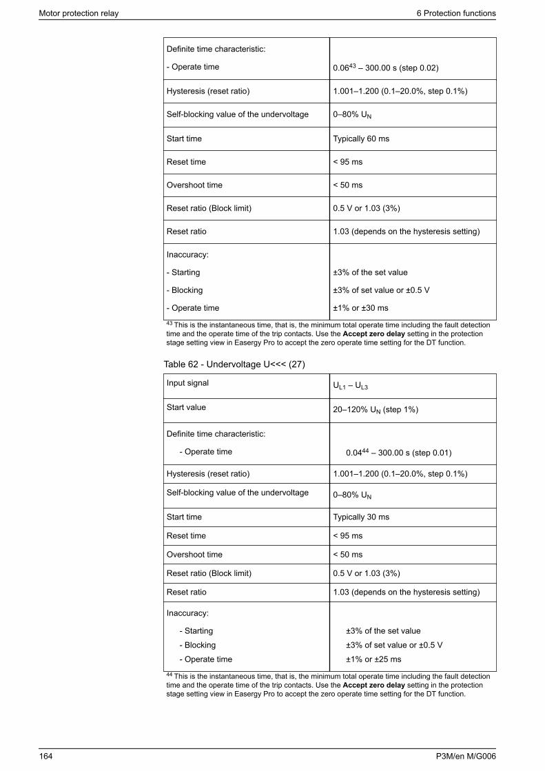
Definite time characteristic:
- Operate time 0.0643 – 300.00 s (step 0.02)
Hysteresis (reset ratio) 1.001–1.200 (0.1–20.0%, step 0.1%)
Self-blocking value of the undervoltage 0–80% UN
Start time Typically 60 ms
Reset time < 95 ms
Overshoot time < 50 ms
Reset ratio (Block limit) 0.5 V or 1.03 (3%)
Reset ratio 1.03 (depends on the hysteresis setting)
Inaccuracy:
- Starting
- Blocking
- Operate time
±3% of the set value
±3% of set value or ±0.5 V
±1% or ±30 ms
43 This is the instantaneous time, that is, the minimum total operate time including the fault detectiontime and the operate time of the trip contacts. Use the Accept zero delay setting in the protectionstage setting view in Easergy Pro to accept the zero operate time setting for the DT function.
Table 62 - Undervoltage U<<< (27)
Input signal UL1 – UL3
Start value 20–120% UN (step 1%)
Definite time characteristic:
- Operate time 0.0444 – 300.00 s (step 0.01)
Hysteresis (reset ratio) 1.001–1.200 (0.1–20.0%, step 0.1%)
Self-blocking value of the undervoltage 0–80% UN
Start time Typically 30 ms
Reset time < 95 ms
Overshoot time < 50 ms
Reset ratio (Block limit) 0.5 V or 1.03 (3%)
Reset ratio 1.03 (depends on the hysteresis setting)
Inaccuracy:
- Starting
- Blocking
- Operate time
±3% of the set value
±3% of set value or ±0.5 V
±1% or ±25 ms
44 This is the instantaneous time, that is, the minimum total operate time including the fault detectiontime and the operate time of the trip contacts. Use the Accept zero delay setting in the protectionstage setting view in Easergy Pro to accept the zero operate time setting for the DT function.
Motor protection relay 6 Protection functions
164 P3M/en M/G006
6.7 Directional power (ANSI 32)
Description
The directional power function can be used, for example, to disconnect a motor ifthe supply voltage is lost and thus prevent power generation by the motor. It canalso be used to detect loss of load of a motor.
The directional power function is sensitive to active power. For the directionalpower function, the start value is negative. For the underpower function, a positivestart value is used. Whenever the active power goes under the start value, thestage starts and issues a start signal. If the fault situation stays on longer than thedelay setting, a trip signal is issued.
The start setting range is from -200% to +200% of the nominal apparent powerSN. The nominal apparent power is determined by the configured voltage andcurrent transformer values.
Equation 19
3PrPr ⋅⋅= imaryRatedimaryRatedn CTVTS
There are two identical stages available with independent setting parameters.
Setting groups
There are four setting groups available for all stages.
Characteristics
Table 63 - Directional power stages P<, P<< (32)
Input signal IL1 – IL3
UL1 – UL3
Start value -200.0 to +200.0% SN (step 0.5)
Definite time function:
- Operate time 0.3–300.0 s (step 0.1)
Start time Typically 200 ms
Reset time < 500 ms
Reset ratio 1.05
Inaccuracy:
- Starting
- Operate time at definite time function
-
±3% of set value or ±0.5% of rated value
±1% or ±150 ms
NOTE: When the start setting is +1 to +200% , an internal block is activated ifthe maximum voltage of all phases drops below 5% of rated.
6 Protection functions Motor protection relay
P3M/en M/G006 165
6.8 Phase undercurrent (ANSI 37)
Description
The phase undercurrent stage measures the fundamental component of thephase currents.
The stage I< can be configured for definite time characteristic.
The undercurrent stage protects rather the relay driven by the motor, for examplea submersible pump, than the motor itself.
Setting groups
There are four setting groups available for each stage.
Characteristics
Table 64 - Phase undercurrent I< (37)
Input signal IL1 – IL3
Current setting range 20 – 70 %IN or %IMOT (step 1%)
Definite time characteristic:
- operate time
-
0.3 – 300.0 s (step 0.1)
Block limit 15 % (fixed)
Start time Typically 200 ms
Reset time < 450 ms
Reset ratio >1.05
Accuracy:
- Starting
- Operate time
-
±2% of set value or ±0.5% of the ratedvalue
±1 % or ±150 ms
NOTE: Stage Blocking is functional when all phase currents are below theblock limit.
Motor protection relay 6 Protection functions
166 P3M/en M/G006
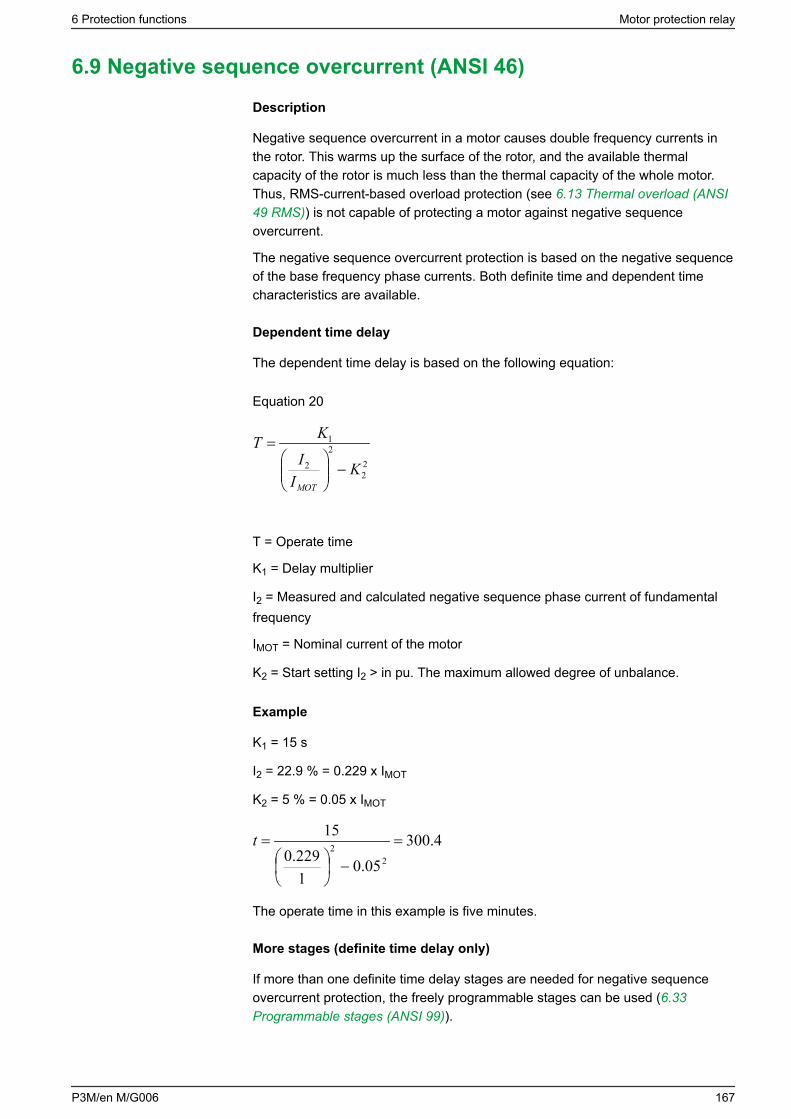
6.9 Negative sequence overcurrent (ANSI 46)
Description
Negative sequence overcurrent in a motor causes double frequency currents inthe rotor. This warms up the surface of the rotor, and the available thermalcapacity of the rotor is much less than the thermal capacity of the whole motor.Thus, RMS-current-based overload protection (see 6.13 Thermal overload (ANSI49 RMS)) is not capable of protecting a motor against negative sequenceovercurrent.
The negative sequence overcurrent protection is based on the negative sequenceof the base frequency phase currents. Both definite time and dependent timecharacteristics are available.
Dependent time delay
The dependent time delay is based on the following equation:
Equation 20
22
2
2
1
KI
I
KT
MOT
−
=
T = Operate time
K1 = Delay multiplier
I2 = Measured and calculated negative sequence phase current of fundamentalfrequency
IMOT = Nominal current of the motor
K2 = Start setting I2 > in pu. The maximum allowed degree of unbalance.
Example
K1 = 15 s
I2 = 22.9 % = 0.229 x IMOT
K2 = 5 % = 0.05 x IMOT
4.30005.0
1229.0
15
22 =
−
=t
The operate time in this example is five minutes.
More stages (definite time delay only)
If more than one definite time delay stages are needed for negative sequenceovercurrent protection, the freely programmable stages can be used (6.33Programmable stages (ANSI 99)).
6 Protection functions Motor protection relay
P3M/en M/G006 167
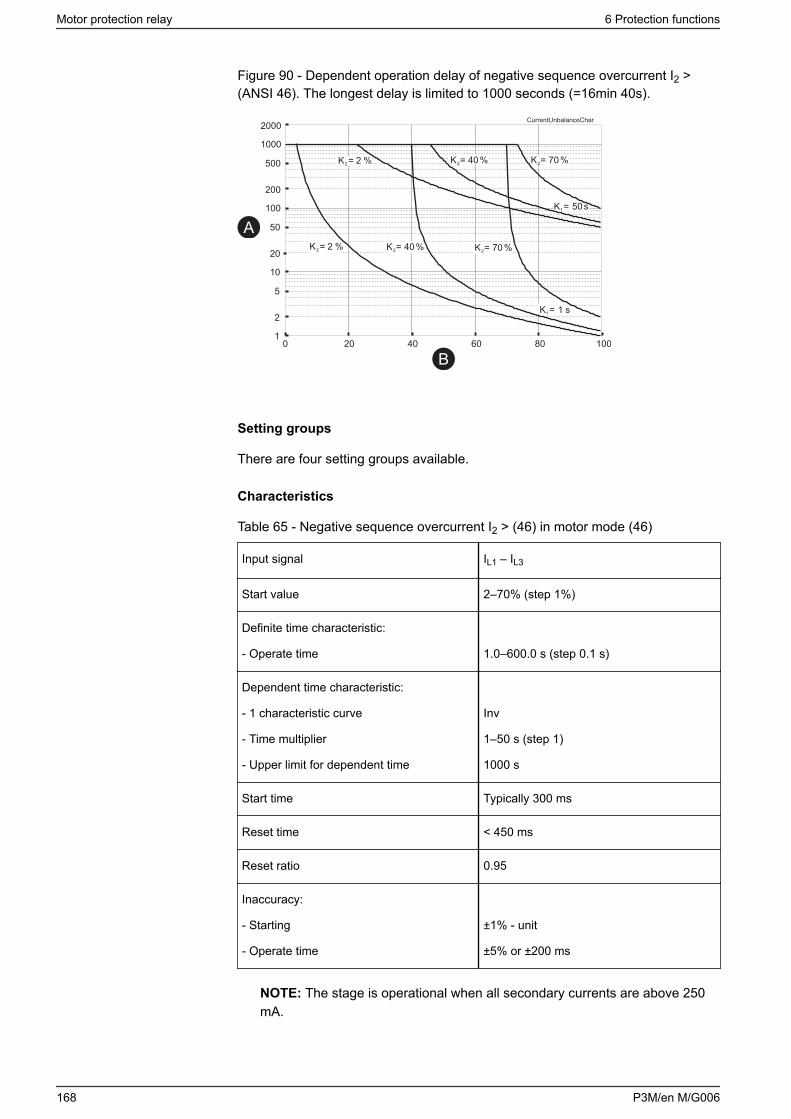
Figure 90 - Dependent operation delay of negative sequence overcurrent I2 >(ANSI 46). The longest delay is limited to 1000 seconds (=16min 40s).
01
10
100
1000
2
20
200
2000
5
50
500
20
CurrentUnbalanceChar
40 60 80 100
K = 1 s1
K = 50 s1
K = 2 %2
K = 2 %2
K = 40 %2
K = 40 %2
K = 70 %2
K = 70 %2
A
B
Setting groups
There are four setting groups available.
Characteristics
Table 65 - Negative sequence overcurrent I2 > (46) in motor mode (46)
Input signal IL1 – IL3
Start value 2–70% (step 1%)
Definite time characteristic:
- Operate time 1.0–600.0 s (step 0.1 s)
Dependent time characteristic:
- 1 characteristic curve
- Time multiplier
- Upper limit for dependent time
Inv
1–50 s (step 1)
1000 s
Start time Typically 300 ms
Reset time < 450 ms
Reset ratio 0.95
Inaccuracy:
- Starting
- Operate time
±1% - unit
±5% or ±200 ms
NOTE: The stage is operational when all secondary currents are above 250mA.
Motor protection relay 6 Protection functions
168 P3M/en M/G006
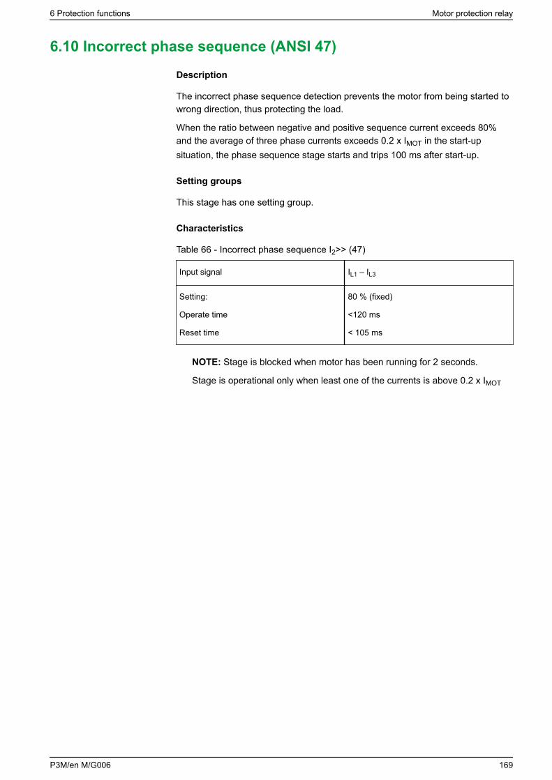
6.10 Incorrect phase sequence (ANSI 47)
Description
The incorrect phase sequence detection prevents the motor from being started towrong direction, thus protecting the load.
When the ratio between negative and positive sequence current exceeds 80%and the average of three phase currents exceeds 0.2 x IMOT in the start-upsituation, the phase sequence stage starts and trips 100 ms after start-up.
Setting groups
This stage has one setting group.
Characteristics
Table 66 - Incorrect phase sequence I2>> (47)
Input signal IL1 – IL3
Setting:
Operate time
Reset time
80 % (fixed)
<120 ms
< 105 ms
NOTE: Stage is blocked when motor has been running for 2 seconds.
Stage is operational only when least one of the currents is above 0.2 x IMOT
6 Protection functions Motor protection relay
P3M/en M/G006 169
6.11 Negative sequence overvoltage protection (ANSI 47)
Description
This protection stage can be used to detect voltage unbalance and phasereversal situations. It calculates the fundamental frequency value of the negativesequence component U2 based on the measured voltages (for calculation of U2,see 4.11 Symmetrical components).
Whenever the negative sequence voltage U2 raises above the user's start settingof a particular stage, this stage starts, and a start signal is issued. If the faultsituation remains on longer than the user's operate time delay setting, a trip signalis issued.
Blocking during VT fuse failure
Like all the protection stages, the negative sequence overvoltage can be blockedwith any internal or external signal using the block matrix, for example, if thesecondary voltage of one of the measuring transformers disappears because of afuse failure (See VT supervision function in 7.8 Voltage transformer supervision(ANSI 60FL)).
The blocking signal can also be a signal from the user's logic (see 5.7 Logicfunctions).
Three independent stages
There are three separately adjustable stages: U2>, U2>>, and U2>>>. Both stagescan be configured for the definite time (DT) operation characteristic.
Setting groups
There are four settings groups available for all stages. Switching between settinggroups can be controlled by digital inputs, virtual inputs (mimic display,communication, logic) and manually.
Characteristics
Table 67 - Negative sequence overvoltage protection U2> (47)
Start value: U2>, U2>>, U2>>> 2–120%
Operate time 0.08–300 s
Reset ratio 0.95
Inaccuracy:
- Starting
- Operate time
±1% - unit
±5% or ±200 ms
Motor protection relay 6 Protection functions
170 P3M/en M/G006
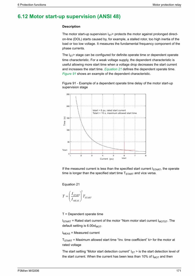
6.12 Motor start-up supervision (ANSI 48)
Description
The motor start-up supervision IST> protects the motor against prolonged direct-on-line (DOL) starts caused by, for example, a stalled rotor, too high inertia of theload or too low voltage. It measures the fundamental frequency component of thephase currents.
The IST> stage can be configured for definite operate time or dependent operatetime characteristic. For a weak voltage supply, the dependent characteristic isuseful allowing more start time when a voltage drop decreases the start currentand increases the start time. Equation 21 defines the dependent operate time. Figure 91 shows an example of the dependent characteristic.
Figure 91 - Example of a dependent operate time delay of the motor start-upsupervision stage
Tim
e (s
)
Tstart
Current (pu) Istart
Istart = 6 pu, rated start currentTstart = 15 s, maximum allowed start time
If the measured current is less than the specified start current ISTART, the operatetime is longer than the specified start time TSTART and vice versa.
Equation 21
STARTMEAS
START TIIT
2
=
T = Dependent operate time
ISTART = Rated start current of the motor “Nom motor start current IMOTST. Thedefault setting is 6.00xIMOT.
IMEAS = Measured current
TSTART = Maximum allowed start time “Inv. time coefficient” k> for the motor atrated voltage
The start setting “Motor start detection current” IST > is the start detection level ofthe start current. When the current has been less than 10% of IMOT and then
6 Protection functions Motor protection relay
P3M/en M/G006 171
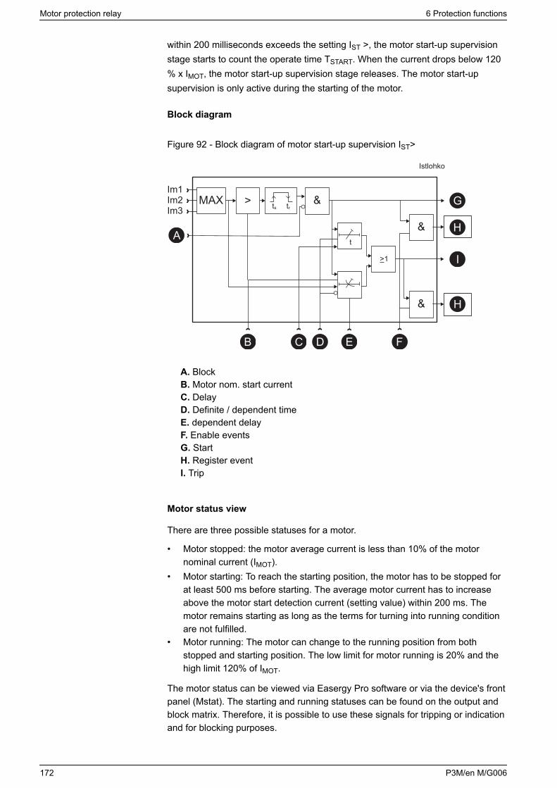
within 200 milliseconds exceeds the setting IST >, the motor start-up supervisionstage starts to count the operate time TSTART. When the current drops below 120% x IMOT, the motor start-up supervision stage releases. The motor start-upsupervision is only active during the starting of the motor.
Block diagram
Figure 92 - Block diagram of motor start-up supervision IST>
MAX &
t
&A
D F
G
H
I
H&
>1
B C E
>
Istlohko
Im1Im2Im3 ts tr
A. BlockB. Motor nom. start currentC. DelayD. Definite / dependent timeE. dependent delayF. Enable eventsG. StartH. Register eventI. Trip
Motor status view
There are three possible statuses for a motor.
• Motor stopped: the motor average current is less than 10% of the motornominal current (IMOT).
• Motor starting: To reach the starting position, the motor has to be stopped forat least 500 ms before starting. The average motor current has to increaseabove the motor start detection current (setting value) within 200 ms. Themotor remains starting as long as the terms for turning into running conditionare not fulfilled.
• Motor running: The motor can change to the running position from bothstopped and starting position. The low limit for motor running is 20% and thehigh limit 120% of IMOT.
The motor status can be viewed via Easergy Pro software or via the device's frontpanel (Mstat). The starting and running statuses can be found on the output andblock matrix. Therefore, it is possible to use these signals for tripping or indicationand for blocking purposes.
Motor protection relay 6 Protection functions
172 P3M/en M/G006
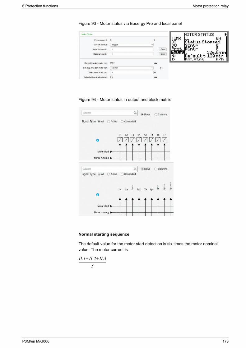
Figure 93 - Motor status via Easergy Pro and local panel
Figure 94 - Motor status in output and block matrix
Normal starting sequence
The default value for the motor start detection is six times the motor nominalvalue. The motor current is
3IL1+IL2+IL3
6 Protection functions Motor protection relay
P3M/en M/G006 173
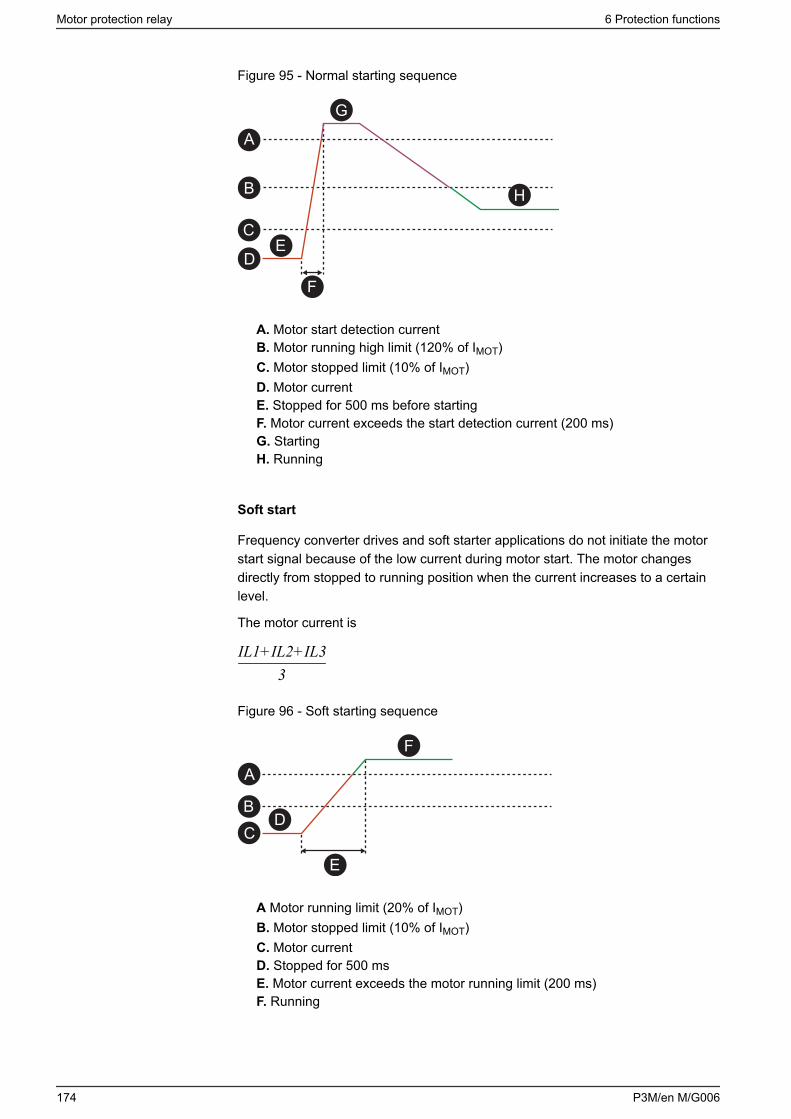
Figure 95 - Normal starting sequence
A
B
C
D
F
G
H
E
A. Motor start detection currentB. Motor running high limit (120% of IMOT)C. Motor stopped limit (10% of IMOT)D. Motor currentE. Stopped for 500 ms before startingF. Motor current exceeds the start detection current (200 ms)G. StartingH. Running
Soft start
Frequency converter drives and soft starter applications do not initiate the motorstart signal because of the low current during motor start. The motor changesdirectly from stopped to running position when the current increases to a certainlevel.
The motor current is
3IL1+IL2+IL3
Figure 96 - Soft starting sequence
E
A
BC
D
F
A Motor running limit (20% of IMOT)B. Motor stopped limit (10% of IMOT)C. Motor currentD. Stopped for 500 msE. Motor current exceeds the motor running limit (200 ms)F. Running
Motor protection relay 6 Protection functions
174 P3M/en M/G006
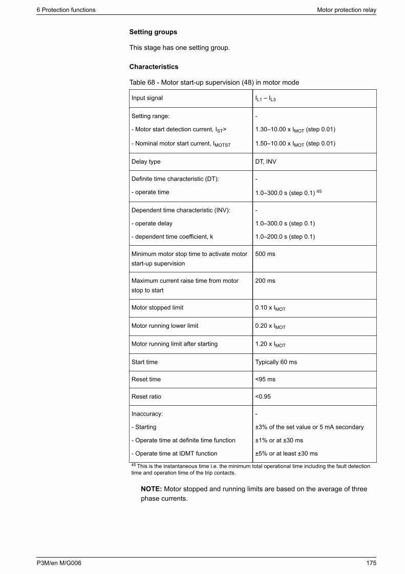
Setting groups
This stage has one setting group.
Characteristics
Table 68 - Motor start-up supervision (48) in motor mode
Input signal IL1 – IL3
Setting range:
- Motor start detection current, IST>
- Nominal motor start current, IMOTST
-
1.30–10.00 x IMOT (step 0.01)
1.50–10.00 x IMOT (step 0.01)
Delay type DT, INV
Definite time characteristic (DT):
- operate time
-
1.0–300.0 s (step 0.1) 45
Dependent time characteristic (INV):
- operate delay
- dependent time coefficient, k
-
1.0–300.0 s (step 0.1)
1.0–200.0 s (step 0.1)
Minimum motor stop time to activate motorstart-up supervision
500 ms
Maximum current raise time from motorstop to start
200 ms
Motor stopped limit 0.10 x IMOT
Motor running lower limit 0.20 x IMOT
Motor running limit after starting 1.20 x IMOT
Start time Typically 60 ms
Reset time <95 ms
Reset ratio <0.95
Inaccuracy:
- Starting
- Operate time at definite time function
- Operate time at IDMT function
-
±3% of the set value or 5 mA secondary
±1% or at ±30 ms
±5% or at least ±30 ms
45 This is the instantaneous time i.e. the minimum total operational time including the fault detectiontime and operation time of the trip contacts.
NOTE: Motor stopped and running limits are based on the average of threephase currents.
6 Protection functions Motor protection relay
P3M/en M/G006 175
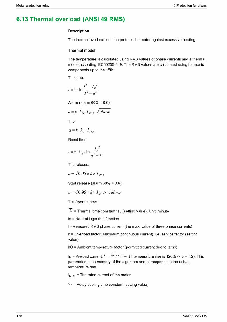
6.13 Thermal overload (ANSI 49 RMS)
Description
The thermal overload function protects the motor against excessive heating.
Thermal model
The temperature is calculated using RMS values of phase currents and a thermalmodel according IEC60255-149. The RMS values are calculated using harmoniccomponents up to the 15th.
Trip time:
22
22
lnaIIIt P
−−
⋅=τ
Alarm (alarm 60% = 0.6):
Ikka MOT alarm⋅⋅⋅= Θ
Trip:
MOTIkka ⋅⋅= Θ
Reset time:
22
2
lnIa
ICt P
−⋅⋅= ττ
Trip release:
MOTIka ××= 95.0
Start release (alarm 60% = 0.6):
Ika MOT alarm×××= 95.0
T = Operate time
= Thermal time constant tau (setting value). Unit: minute
ln = Natural logarithm function
I =Measured RMS phase current (the max. value of three phase currents)
k = Overload factor (Maximum continuous current), i.e. service factor (settingvalue).
kΘ = Ambient temperature factor (permitted current due to tamb).
Ip = Preload current, MOTP IkI ××= θ (If temperature rise is 120% -> θ = 1.2). Thisparameter is the memory of the algorithm and corresponds to the actualtemperature rise.
IMOT = The rated current of the motor
τC = Relay cooling time constant (setting value)
Motor protection relay 6 Protection functions
176 P3M/en M/G006
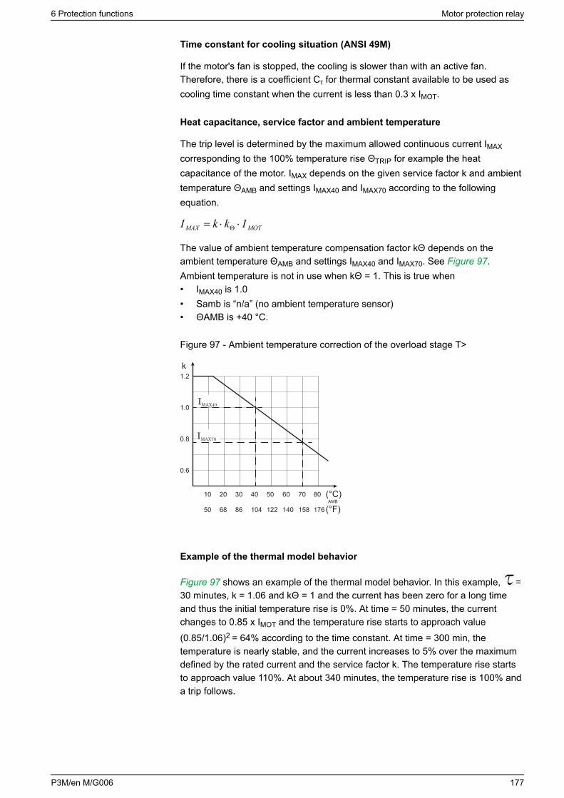
Time constant for cooling situation (ANSI 49M)
If the motor's fan is stopped, the cooling is slower than with an active fan.Therefore, there is a coefficient Cτ for thermal constant available to be used ascooling time constant when the current is less than 0.3 x IMOT.
Heat capacitance, service factor and ambient temperature
The trip level is determined by the maximum allowed continuous current IMAX
corresponding to the 100% temperature rise ΘTRIP for example the heatcapacitance of the motor. IMAX depends on the given service factor k and ambienttemperature ΘAMB and settings IMAX40 and IMAX70 according to the followingequation.
MOTMAX IkkI ⋅⋅= Θ
The value of ambient temperature compensation factor kΘ depends on theambient temperature ΘAMB and settings IMAX40 and IMAX70. See Figure 97.Ambient temperature is not in use when kΘ = 1. This is true when• IMAX40 is 1.0• Samb is “n/a” (no ambient temperature sensor)• ΘAMB is +40 °C.
Figure 97 - Ambient temperature correction of the overload stage T>
k
IMAX70
IMAX40
AMB(°C)
0.6
10 20 30 40 50 70 80
0.8
1.0
1.2
50 68 86 104 122 158 176 (°F)140
60
Example of the thermal model behavior
Figure 97 shows an example of the thermal model behavior. In this example, =30 minutes, k = 1.06 and kΘ = 1 and the current has been zero for a long timeand thus the initial temperature rise is 0%. At time = 50 minutes, the currentchanges to 0.85 x IMOT and the temperature rise starts to approach value(0.85/1.06)2 = 64% according to the time constant. At time = 300 min, thetemperature is nearly stable, and the current increases to 5% over the maximumdefined by the rated current and the service factor k. The temperature rise startsto approach value 110%. At about 340 minutes, the temperature rise is 100% anda trip follows.
6 Protection functions Motor protection relay
P3M/en M/G006 177
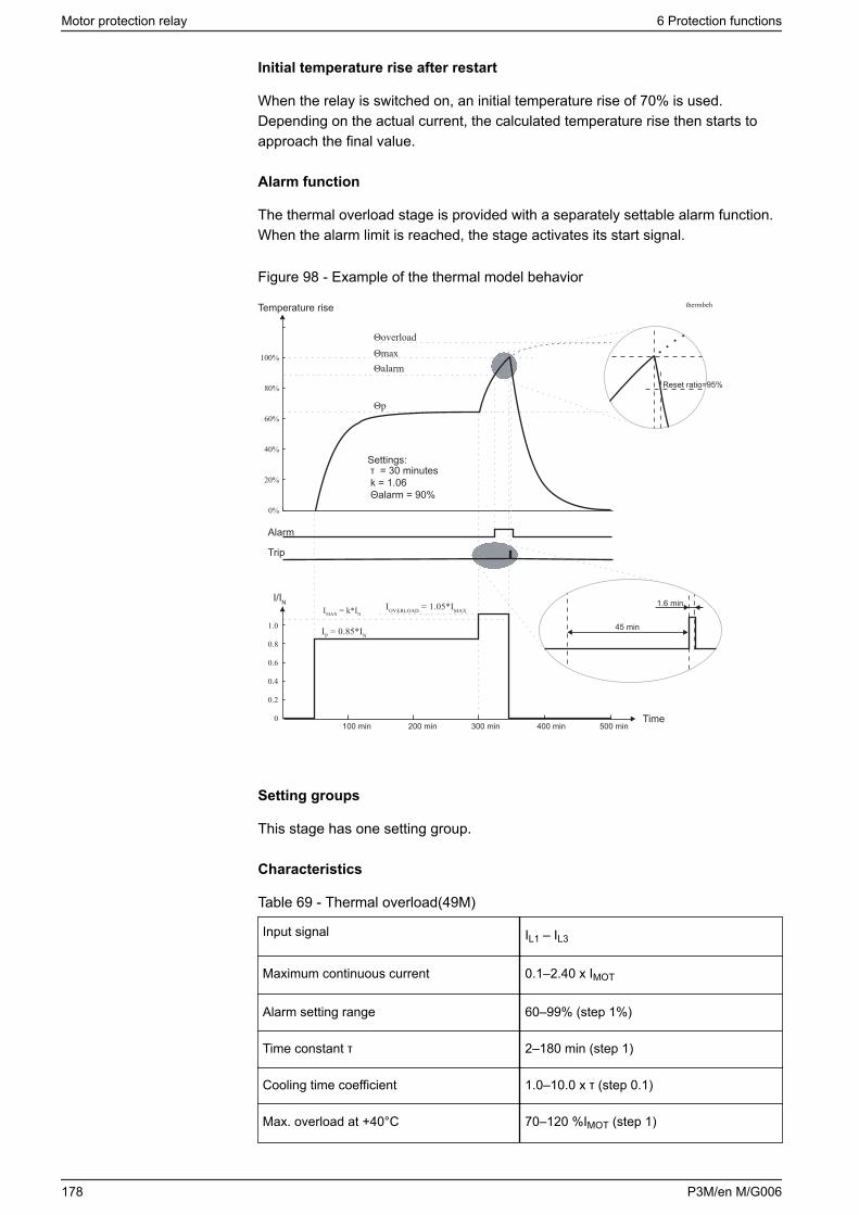
Initial temperature rise after restart
When the relay is switched on, an initial temperature rise of 70% is used.Depending on the actual current, the calculated temperature rise then starts toapproach the final value.
Alarm function
The thermal overload stage is provided with a separately settable alarm function.When the alarm limit is reached, the stage activates its start signal.
Figure 98 - Example of the thermal model behavior
Temperature rise
Alarm
Trip
I/IN
Settings:τ = 30 minutesk = 1.06Θalarm = 90%
Θp
ΘalarmΘmaxΘoverload
thermbeh
Reset ratio=95%
IMAX = k*INIOVERLOAD = 1.05*IMAX
IP = 0.85*IN
100 min 200 min 300 min 400 min 500 min
45 min
1.6 min
Time
Setting groups
This stage has one setting group.
Characteristics
Table 69 - Thermal overload(49M)
Input signal IL1 – IL3
Maximum continuous current 0.1–2.40 x IMOT
Alarm setting range 60–99% (step 1%)
Time constant τ 2–180 min (step 1)
Cooling time coefficient 1.0–10.0 x τ (step 0.1)
Max. overload at +40°C 70–120 %IMOT (step 1)
Motor protection relay 6 Protection functions
178 P3M/en M/G006

Max. overload at +70°C 50–100 %IMOT (step 1)
Ambient temperature -55 – 125°C (step 1°)
Reset ratio (Start & trip) 0.95
Operate time inaccuracy Relative inaccuracy ±5% or absoluteinaccuracy 1 s of the theoretical value
6 Protection functions Motor protection relay
P3M/en M/G006 179
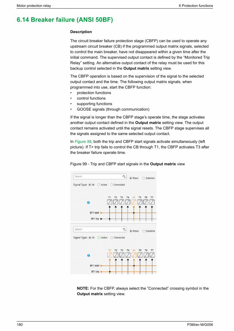
6.14 Breaker failure (ANSI 50BF)
Description
The circuit breaker failure protection stage (CBFP) can be used to operate anyupstream circuit breaker (CB) if the programmed output matrix signals, selectedto control the main breaker, have not disappeared within a given time after theinitial command. The supervised output contact is defined by the “Monitored TripRelay” setting. An alternative output contact of the relay must be used for thisbackup control selected in the Output matrix setting view.
The CBFP operation is based on the supervision of the signal to the selectedoutput contact and the time. The following output matrix signals, whenprogrammed into use, start the CBFP function:• protection functions• control functions• supporting functions• GOOSE signals (through communication)
If the signal is longer than the CBFP stage’s operate time, the stage activatesanother output contact defined in the Output matrix setting view. The outputcontact remains activated until the signal resets. The CBFP stage supervises allthe signals assigned to the same selected output contact.
In Figure 99, both the trip and CBFP start signals activate simultaneously (leftpicture). If T> trip fails to control the CB through T1, the CBFP activates T3 afterthe breaker failure operate time.
Figure 99 - Trip and CBFP start signals in the Output matrix view
NOTE: For the CBFP, always select the ”Connected” crossing symbol in theOutput matrix setting view.
Motor protection relay 6 Protection functions
180 P3M/en M/G006

Characteristics
Table 70 - Breaker failure (50BF)
Relay to be supervised T1–T4 (depending on the order code)
Definite time function:
- Operate time 0.1–10.0 s (step 0.1 s)
Inaccuracy:
- Operate time ±20 ms
6 Protection functions Motor protection relay
P3M/en M/G006 181
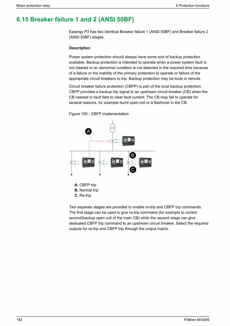
6.15 Breaker failure 1 and 2 (ANSI 50BF)
Easergy P3 has two identical Breaker failure 1 (ANSI 50BF) and Breaker failure 2(ANSI 50BF) stages.
Description
Power system protection should always have some sort of backup protectionavailable. Backup protection is intended to operate when a power system fault isnot cleared or an abnormal condition is not detected in the required time becauseof a failure or the inability of the primary protection to operate or failure of theappropriate circuit breakers to trip. Backup protection may be local or remote.
Circuit breaker failure protection (CBFP) is part of the local backup protection.CBFP provides a backup trip signal to an upstream circuit breaker (CB) when theCB nearest to fault fails to clear fault current. The CB may fail to operate forseveral reasons, for example burnt open coil or a flashover in the CB.
Figure 100 - CBFP implementation
A
B
C
A. CBFP tripB. Normal tripC. Re-trip
Two separate stages are provided to enable re-trip and CBFP trip commands.The first stage can be used to give re-trip command (for example to controlsecond/backup open coil of the main CB) while the second stage can givededicated CBFP trip command to an upstream circuit breaker. Select the requiredoutputs for re-trip and CBFP trip through the output matrix.
Motor protection relay 6 Protection functions
182 P3M/en M/G006
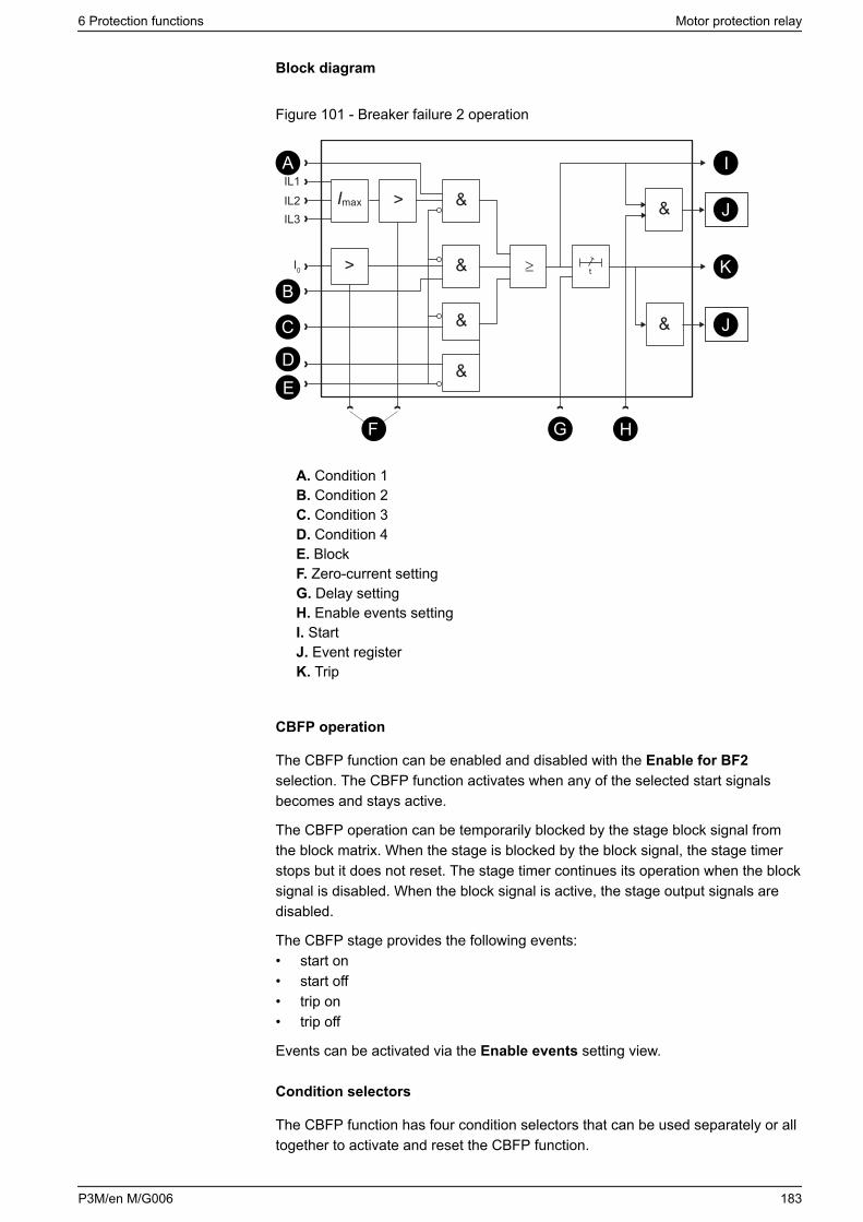
Block diagram
Figure 101 - Breaker failure 2 operation
&> &
≥> & t
&
&
&
Imax
IL1IL2IL3
I0
A
DE
C
F
B
G H
J
J
I
K
A. Condition 1B. Condition 2C. Condition 3D. Condition 4E. BlockF. Zero-current settingG. Delay settingH. Enable events settingI. StartJ. Event registerK. Trip
CBFP operation
The CBFP function can be enabled and disabled with the Enable for BF2selection. The CBFP function activates when any of the selected start signalsbecomes and stays active.
The CBFP operation can be temporarily blocked by the stage block signal fromthe block matrix. When the stage is blocked by the block signal, the stage timerstops but it does not reset. The stage timer continues its operation when the blocksignal is disabled. When the block signal is active, the stage output signals aredisabled.
The CBFP stage provides the following events:• start on• start off• trip on• trip off
Events can be activated via the Enable events setting view.
Condition selectors
The CBFP function has four condition selectors that can be used separately or alltogether to activate and reset the CBFP function.
6 Protection functions Motor protection relay
P3M/en M/G006 183
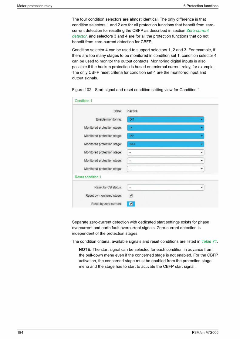
The four condition selectors are almost identical. The only difference is thatcondition selectors 1 and 2 are for all protection functions that benefit from zero-current detection for resetting the CBFP as described in section Zero-currentdetector, and selectors 3 and 4 are for all the protection functions that do notbenefit from zero-current detection for CBFP.
Condition selector 4 can be used to support selectors 1, 2 and 3. For example, ifthere are too many stages to be monitored in condition set 1, condition selector 4can be used to monitor the output contacts. Monitoring digital inputs is alsopossible if the backup protection is based on external current relay, for example.The only CBFP reset criteria for condition set 4 are the monitored input andoutput signals.
Figure 102 - Start signal and reset condition setting view for Condition 1
Separate zero-current detection with dedicated start settings exists for phaseovercurrent and earth fault overcurrent signals. Zero-current detection isindependent of the protection stages.
The condition criteria, available signals and reset conditions are listed in Table 71.
NOTE: The start signal can be selected for each condition in advance fromthe pull-down menu even if the concerned stage is not enabled. For the CBFPactivation, the concerned stage must be enabled from the protection stagemenu and the stage has to start to activate the CBFP start signal.
Motor protection relay 6 Protection functions
184 P3M/en M/G006
Table 71 - CBFP condition selectors
Criteria Start signal Reset condition
Condition 1 I>, I>>, I>>>, Iv>, I2>, dI>,dI>>, Iφ>, Iφ>>, Iφ>>>,Iφ>>>>, T>, If2>, X<, X<<,I’>, I’>>, If5, SOTF
Reset by CB status: DI1 –DIx (1, F1, F2, VI1-20,VO1–20, GOOSE_NI1–64,POC1–16, Obj1-8Op
Monitored stage: On/Off
Zero-current detection:On/Off
Condition 2 Io>, Io>>, Io>>>, Io>>>>,Io>>>>>, Ioφ>, Ioφ>>,Ioφ>>>, dIo>, dIo>>
Condition 3 Uof3<, U>, U>>, U>>>, U<,U<<, U<<<, U1<, U1<<,Uo>, Uo>>, P<, P<<, Q<,Z<, Z<<, Pgr1-8, f<, f<<, fx,fxx, df/dt, Uf>, Pslip
Reset by CB status: DI1 –DIx (1, F1, F2, VI1-20,VO1–20, GOOSE_NI1–64,POC1–16, Obj1-8Op
Monitored stage: On/Off
Condition 4 Outputs: A1, T1-Tx (1
Inputs: DI1 – DIx (1, F1, F2,VI1-20, VO1 – 20,GOOSE_NI1 – 64, POC1 –16
Arc sensor 3- 10, ArcStg1-8,I>int, Io>int
In addition to the selection of the start signal, the CBFP reset condition needs tobe selected.
If no reset conditions are selected, the stage uses Reset by monitored stage asthe reset condition. This prevents a situation where the stage never releases.
The reset condition Reset by CB status is useful if the current is already zerowhen the CB is opened (for example unloaded CB).
When more than one selection criteria are selected, AND condition is used, forexample “zero current detection” AND “object open”. See Figure 101 for details.
Stage timer
The operate delay timer is started by a signal activated by the monitored stages(condition selectors). The operate time delay is a settable parameter. When thegiven time delay has elapsed, the stage provides a trip signal through the outputmatrix and the event codes.
The timer delay can be set between 40 and 200 ms.
Zero-current detector
The zero-current detector is an undercurrent condition to reset the CBFP functionwhen all phase currents are below the start (pick-up) setting value. This separateundercurrent condition is needed to properly detect successful CB operation. Forexample, in a CB failure condition where one or more CB poles are partlyconducting when the CB is open, the fault current can be small enough to resetthe primary protection stage (for example overcurrent stage), in which case theCBFP does not operate. When a separate undercurrent limit is used, CBFP reset
6 Protection functions Motor protection relay
P3M/en M/G006 185
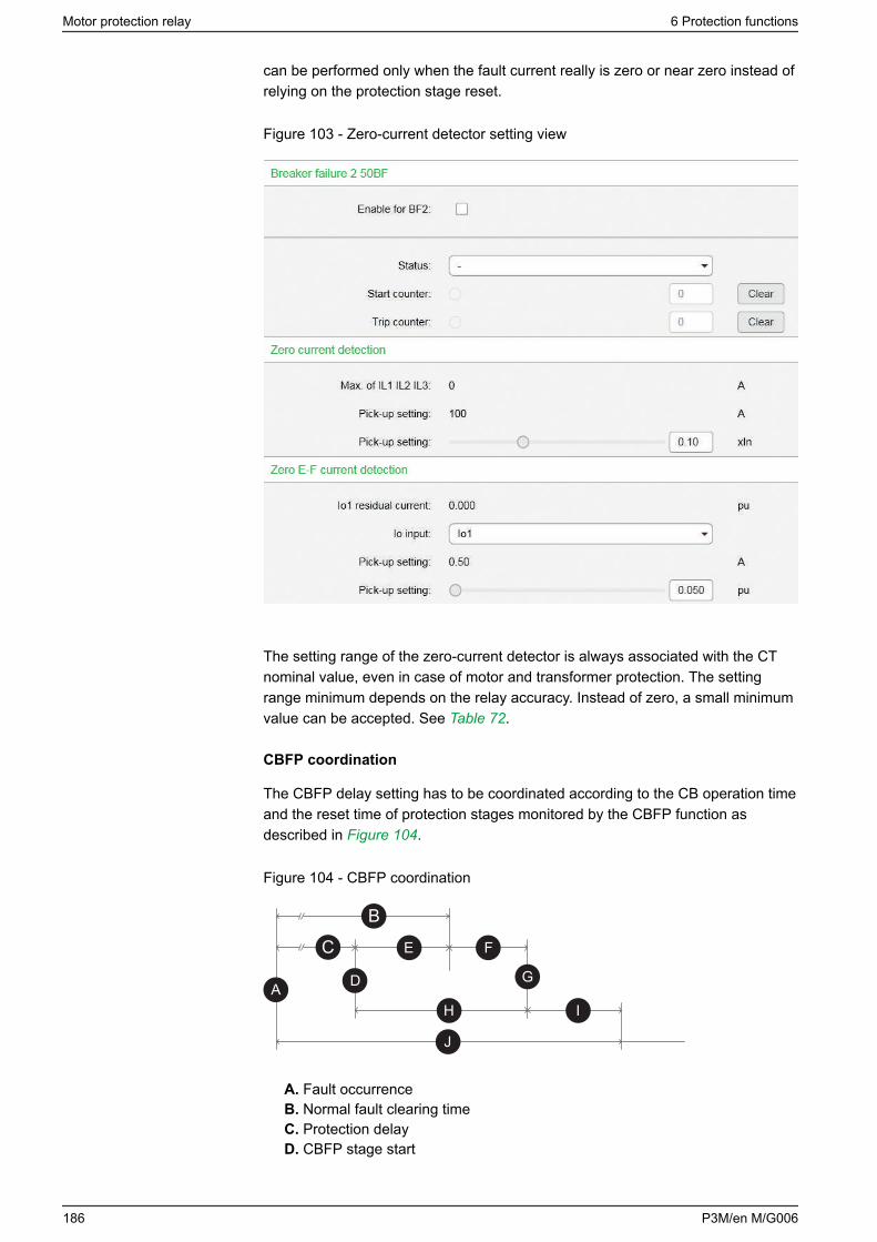
can be performed only when the fault current really is zero or near zero instead ofrelying on the protection stage reset.
Figure 103 - Zero-current detector setting view
The setting range of the zero-current detector is always associated with the CTnominal value, even in case of motor and transformer protection. The settingrange minimum depends on the relay accuracy. Instead of zero, a small minimumvalue can be accepted. See Table 72.
CBFP coordination
The CBFP delay setting has to be coordinated according to the CB operation timeand the reset time of protection stages monitored by the CBFP function asdescribed in Figure 104.
Figure 104 - CBFP coordination
B
C
A D
IH
J
E F
G
A. Fault occurrenceB. Normal fault clearing timeC. Protection delayD. CBFP stage start
Motor protection relay 6 Protection functions
186 P3M/en M/G006
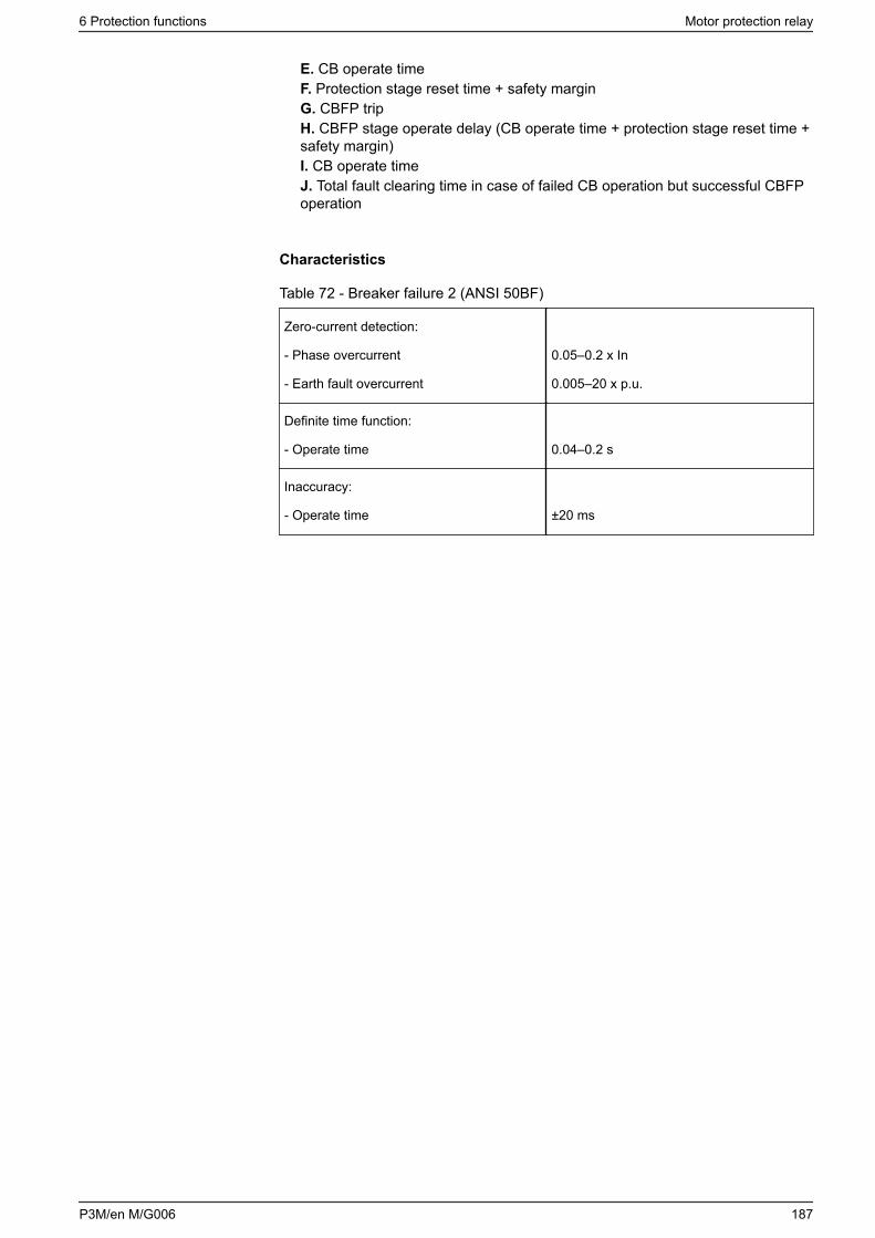
E. CB operate timeF. Protection stage reset time + safety marginG. CBFP tripH. CBFP stage operate delay (CB operate time + protection stage reset time +safety margin)I. CB operate timeJ. Total fault clearing time in case of failed CB operation but successful CBFPoperation
Characteristics
Table 72 - Breaker failure 2 (ANSI 50BF)
Zero-current detection:
- Phase overcurrent
- Earth fault overcurrent
0.05–0.2 x In
0.005–20 x p.u.
Definite time function:
- Operate time 0.04–0.2 s
Inaccuracy:
- Operate time ±20 ms
6 Protection functions Motor protection relay
P3M/en M/G006 187
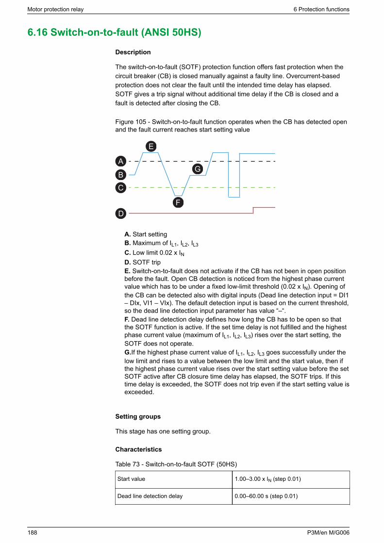
6.16 Switch-on-to-fault (ANSI 50HS)
Description
The switch-on-to-fault (SOTF) protection function offers fast protection when thecircuit breaker (CB) is closed manually against a faulty line. Overcurrent-basedprotection does not clear the fault until the intended time delay has elapsed.SOTF gives a trip signal without additional time delay if the CB is closed and afault is detected after closing the CB.
Figure 105 - Switch-on-to-fault function operates when the CB has detected openand the fault current reaches start setting value
E
F
GA
BC
D
A. Start settingB. Maximum of IL1, IL2, IL3
C. Low limit 0.02 x IND. SOTF tripE. Switch-on-to-fault does not activate if the CB has not been in open positionbefore the fault. Open CB detection is noticed from the highest phase currentvalue which has to be under a fixed low-limit threshold (0.02 x IN). Opening ofthe CB can be detected also with digital inputs (Dead line detection input = DI1– DIx, VI1 – VIx). The default detection input is based on the current threshold,so the dead line detection input parameter has value “–“.F. Dead line detection delay defines how long the CB has to be open so thatthe SOTF function is active. If the set time delay is not fulfilled and the highestphase current value (maximum of IL1, IL2, IL3) rises over the start setting, theSOTF does not operate.G.If the highest phase current value of IL1, IL2, IL3 goes successfully under thelow limit and rises to a value between the low limit and the start value, then ifthe highest phase current value rises over the start setting value before the setSOTF active after CB closure time delay has elapsed, the SOTF trips. If thistime delay is exceeded, the SOTF does not trip even if the start setting value isexceeded.
Setting groups
This stage has one setting group.
Characteristics
Table 73 - Switch-on-to-fault SOTF (50HS)
Start value 1.00–3.00 x IN (step 0.01)
Dead line detection delay 0.00–60.00 s (step 0.01)
Motor protection relay 6 Protection functions
188 P3M/en M/G006

SOTF active after CB closure 0.10–60.00 s (step 0.01)
Operate time < 30 ms (When IM/ISET ratio > 1.5)
Reset time < 95 ms
Reset ratio 0.97
Inaccuracy ±3% of the set value or 5 mA secondary
6 Protection functions Motor protection relay
P3M/en M/G006 189
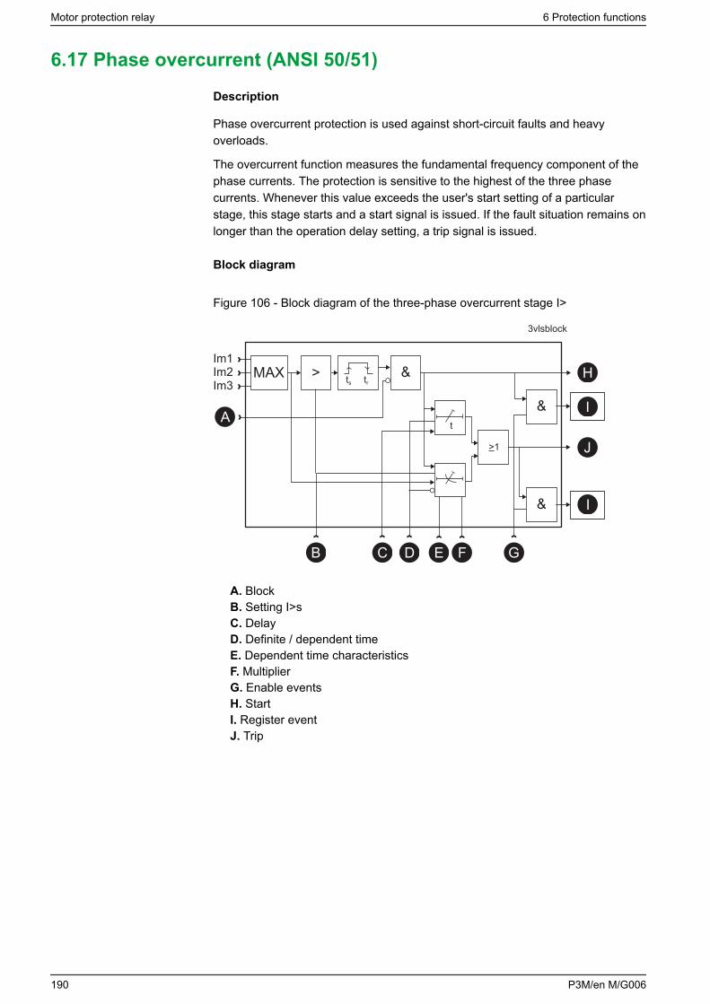
6.17 Phase overcurrent (ANSI 50/51)
Description
Phase overcurrent protection is used against short-circuit faults and heavyoverloads.
The overcurrent function measures the fundamental frequency component of thephase currents. The protection is sensitive to the highest of the three phasecurrents. Whenever this value exceeds the user's start setting of a particularstage, this stage starts and a start signal is issued. If the fault situation remains onlonger than the operation delay setting, a trip signal is issued.
Block diagram
Figure 106 - Block diagram of the three-phase overcurrent stage I>
&
t
&A
D G
H
I
J
I&
>1
B C E
> ts tr
F
3vlsblock
MAXIm1Im2Im3
A. BlockB. Setting I>sC. DelayD. Definite / dependent timeE. Dependent time characteristicsF. MultiplierG. Enable eventsH. StartI. Register eventJ. Trip
Motor protection relay 6 Protection functions
190 P3M/en M/G006
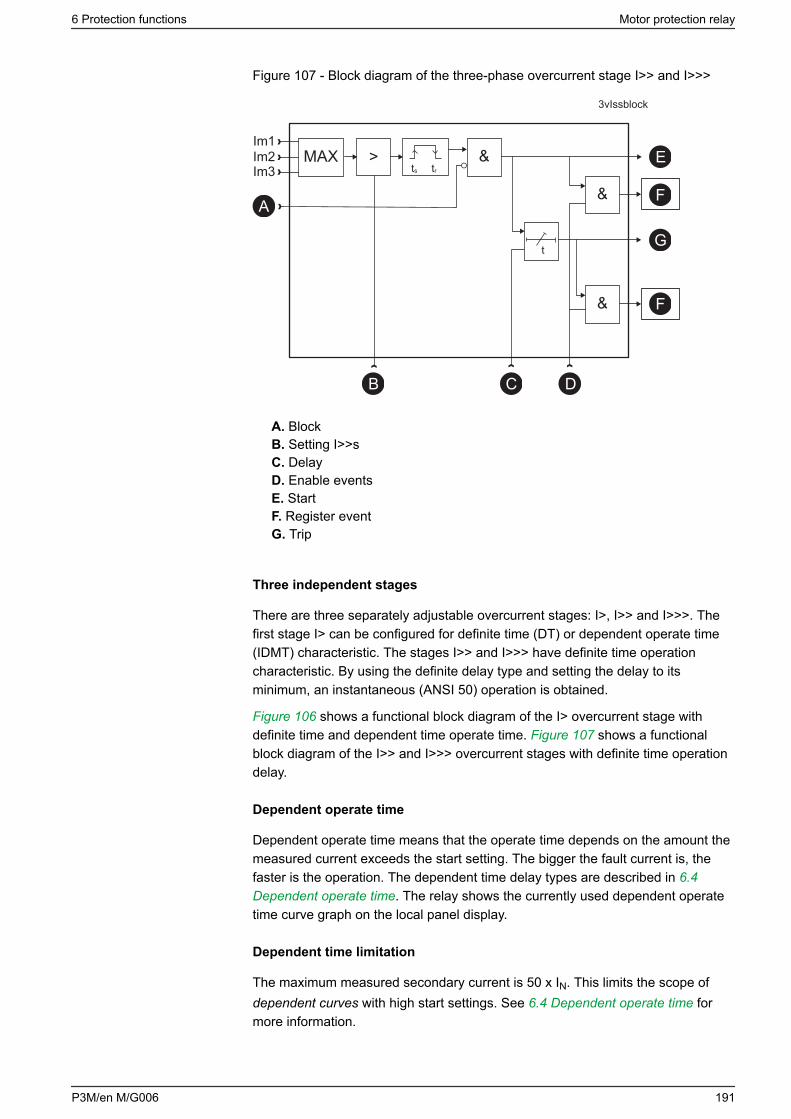
Figure 107 - Block diagram of the three-phase overcurrent stage I>> and I>>>
&
t
&
Im1Im2Im3
MAX
3vIssblock
ts tr
>
B C D
E
F
G
F&
A
A. BlockB. Setting I>>sC. DelayD. Enable eventsE. StartF. Register eventG. Trip
Three independent stages
There are three separately adjustable overcurrent stages: I>, I>> and I>>>. Thefirst stage I> can be configured for definite time (DT) or dependent operate time(IDMT) characteristic. The stages I>> and I>>> have definite time operationcharacteristic. By using the definite delay type and setting the delay to itsminimum, an instantaneous (ANSI 50) operation is obtained.
Figure 106 shows a functional block diagram of the I> overcurrent stage withdefinite time and dependent time operate time. Figure 107 shows a functionalblock diagram of the I>> and I>>> overcurrent stages with definite time operationdelay.
Dependent operate time
Dependent operate time means that the operate time depends on the amount themeasured current exceeds the start setting. The bigger the fault current is, thefaster is the operation. The dependent time delay types are described in 6.4Dependent operate time. The relay shows the currently used dependent operatetime curve graph on the local panel display.
Dependent time limitation
The maximum measured secondary current is 50 x IN. This limits the scope ofdependent curves with high start settings. See 6.4 Dependent operate time formore information.
6 Protection functions Motor protection relay
P3M/en M/G006 191
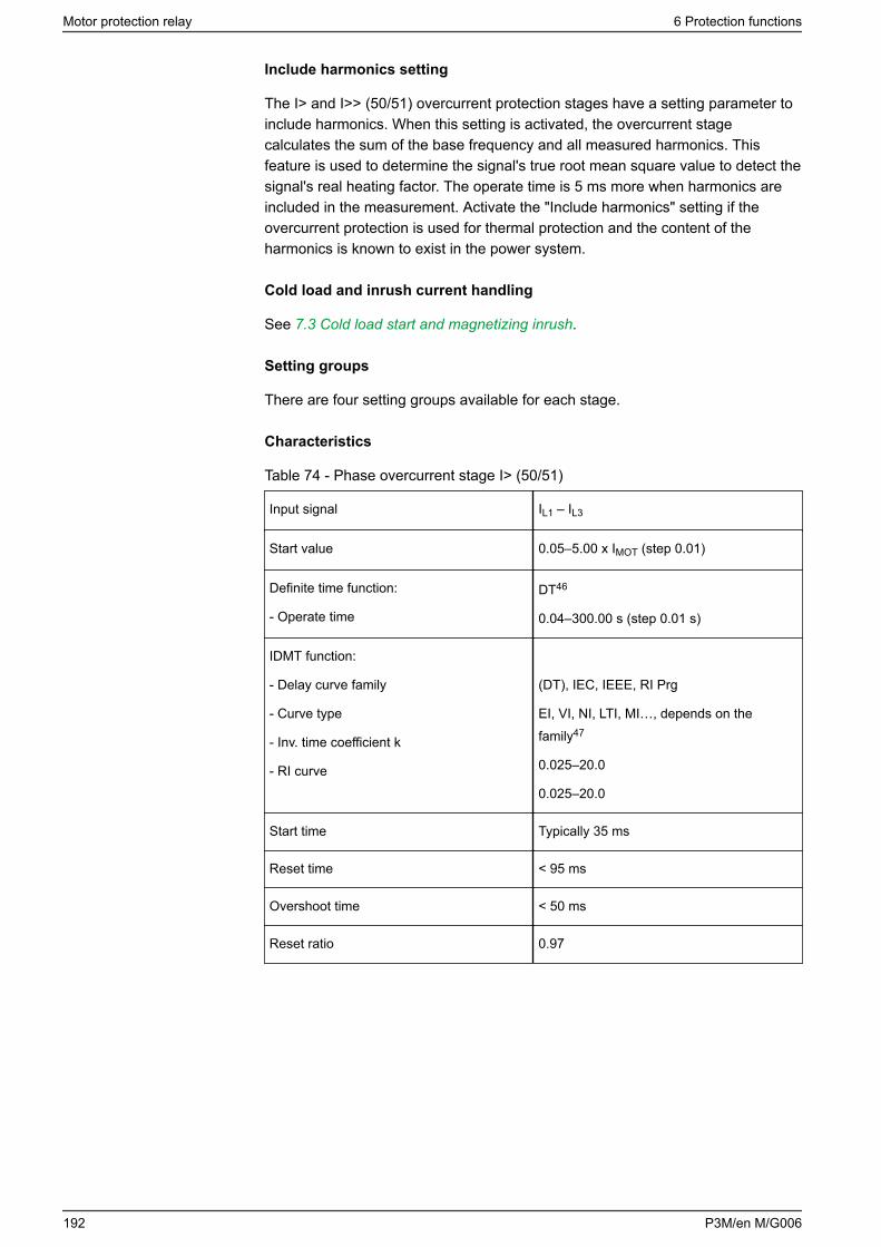
Include harmonics setting
The I> and I>> (50/51) overcurrent protection stages have a setting parameter toinclude harmonics. When this setting is activated, the overcurrent stagecalculates the sum of the base frequency and all measured harmonics. Thisfeature is used to determine the signal's true root mean square value to detect thesignal's real heating factor. The operate time is 5 ms more when harmonics areincluded in the measurement. Activate the "Include harmonics" setting if theovercurrent protection is used for thermal protection and the content of theharmonics is known to exist in the power system.
Cold load and inrush current handling
See 7.3 Cold load start and magnetizing inrush.
Setting groups
There are four setting groups available for each stage.
Characteristics
Table 74 - Phase overcurrent stage I> (50/51)
Input signal IL1 – IL3
Start value 0.05–5.00 x IMOT (step 0.01)
Definite time function:
- Operate time
DT46
0.04–300.00 s (step 0.01 s)
IDMT function:
- Delay curve family
- Curve type
- Inv. time coefficient k
- RI curve
(DT), IEC, IEEE, RI Prg
EI, VI, NI, LTI, MI…, depends on thefamily47
0.025–20.0
0.025–20.0
Start time Typically 35 ms
Reset time < 95 ms
Overshoot time < 50 ms
Reset ratio 0.97
Motor protection relay 6 Protection functions
192 P3M/en M/G006
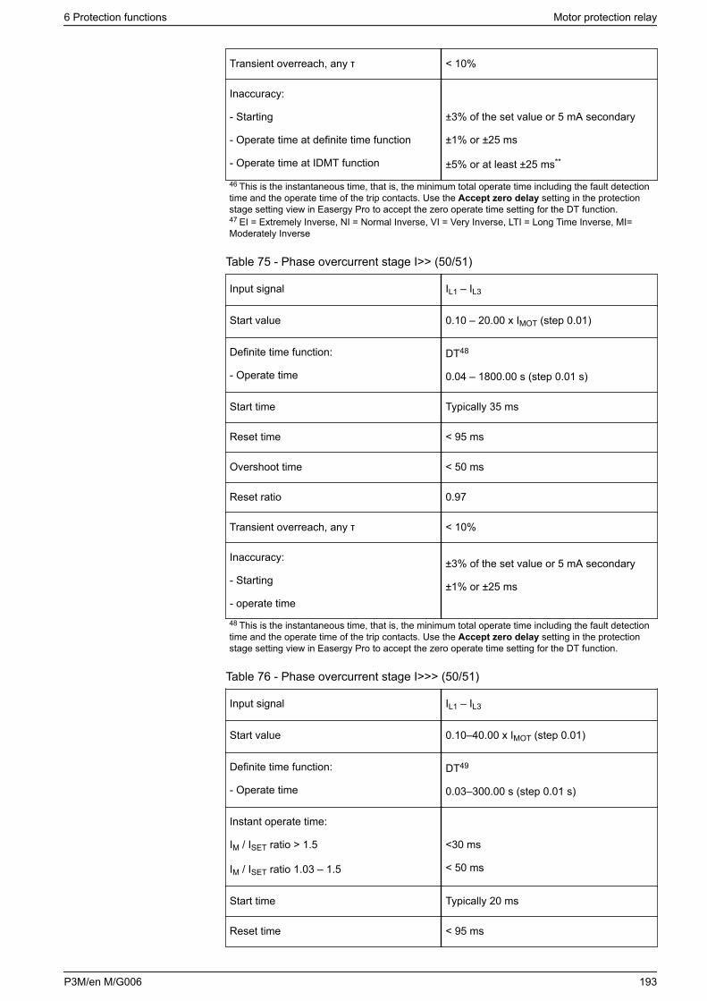
Transient overreach, any τ < 10%
Inaccuracy:
- Starting
- Operate time at definite time function
- Operate time at IDMT function
±3% of the set value or 5 mA secondary
±1% or ±25 ms
±5% or at least ±25 ms**
46 This is the instantaneous time, that is, the minimum total operate time including the fault detectiontime and the operate time of the trip contacts. Use the Accept zero delay setting in the protectionstage setting view in Easergy Pro to accept the zero operate time setting for the DT function.47 EI = Extremely Inverse, NI = Normal Inverse, VI = Very Inverse, LTI = Long Time Inverse, MI=Moderately Inverse
Table 75 - Phase overcurrent stage I>> (50/51)
Input signal IL1 – IL3
Start value 0.10 – 20.00 x IMOT (step 0.01)
Definite time function:
- Operate time
DT48
0.04 – 1800.00 s (step 0.01 s)
Start time Typically 35 ms
Reset time < 95 ms
Overshoot time < 50 ms
Reset ratio 0.97
Transient overreach, any τ < 10%
Inaccuracy:
- Starting
- operate time
±3% of the set value or 5 mA secondary
±1% or ±25 ms
48 This is the instantaneous time, that is, the minimum total operate time including the fault detectiontime and the operate time of the trip contacts. Use the Accept zero delay setting in the protectionstage setting view in Easergy Pro to accept the zero operate time setting for the DT function.
Table 76 - Phase overcurrent stage I>>> (50/51)
Input signal IL1 – IL3
Start value 0.10–40.00 x IMOT (step 0.01)
Definite time function:
- Operate time
DT49
0.03–300.00 s (step 0.01 s)
Instant operate time:
IM / ISET ratio > 1.5
IM / ISET ratio 1.03 – 1.5
<30 ms
< 50 ms
Start time Typically 20 ms
Reset time < 95 ms
6 Protection functions Motor protection relay
P3M/en M/G006 193
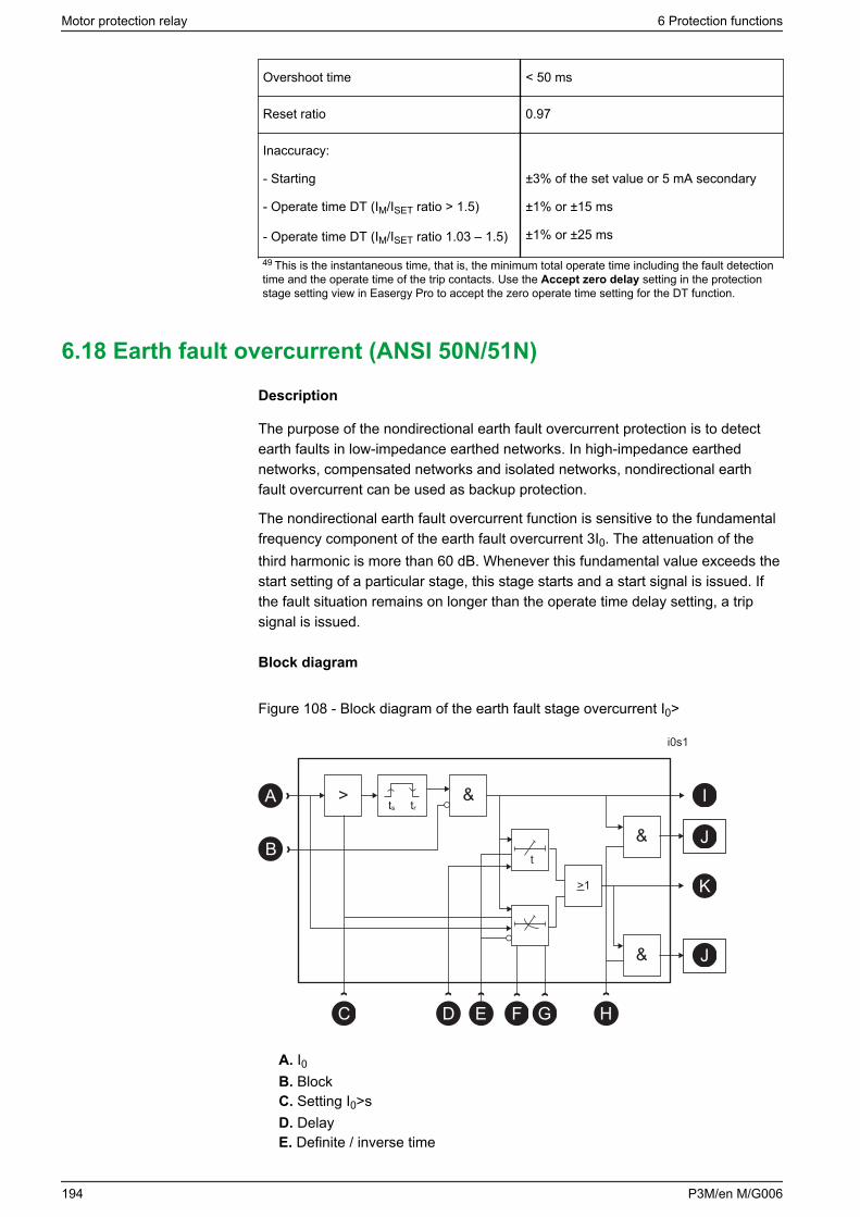
Overshoot time < 50 ms
Reset ratio 0.97
Inaccuracy:
- Starting
- Operate time DT (IM/ISET ratio > 1.5)
- Operate time DT (IM/ISET ratio 1.03 – 1.5)
±3% of the set value or 5 mA secondary
±1% or ±15 ms
±1% or ±25 ms
49 This is the instantaneous time, that is, the minimum total operate time including the fault detectiontime and the operate time of the trip contacts. Use the Accept zero delay setting in the protectionstage setting view in Easergy Pro to accept the zero operate time setting for the DT function.
6.18 Earth fault overcurrent (ANSI 50N/51N)
Description
The purpose of the nondirectional earth fault overcurrent protection is to detectearth faults in low-impedance earthed networks. In high-impedance earthednetworks, compensated networks and isolated networks, nondirectional earthfault overcurrent can be used as backup protection.
The nondirectional earth fault overcurrent function is sensitive to the fundamentalfrequency component of the earth fault overcurrent 3I0. The attenuation of thethird harmonic is more than 60 dB. Whenever this fundamental value exceeds thestart setting of a particular stage, this stage starts and a start signal is issued. Ifthe fault situation remains on longer than the operate time delay setting, a tripsignal is issued.
Block diagram
Figure 108 - Block diagram of the earth fault stage overcurrent I0>
&
t
&B
E H
I
J
K
J&
>1
C D F
>
G
i0s1
ts trA
A. I0B. BlockC. Setting I0>sD. DelayE. Definite / inverse time
Motor protection relay 6 Protection functions
194 P3M/en M/G006
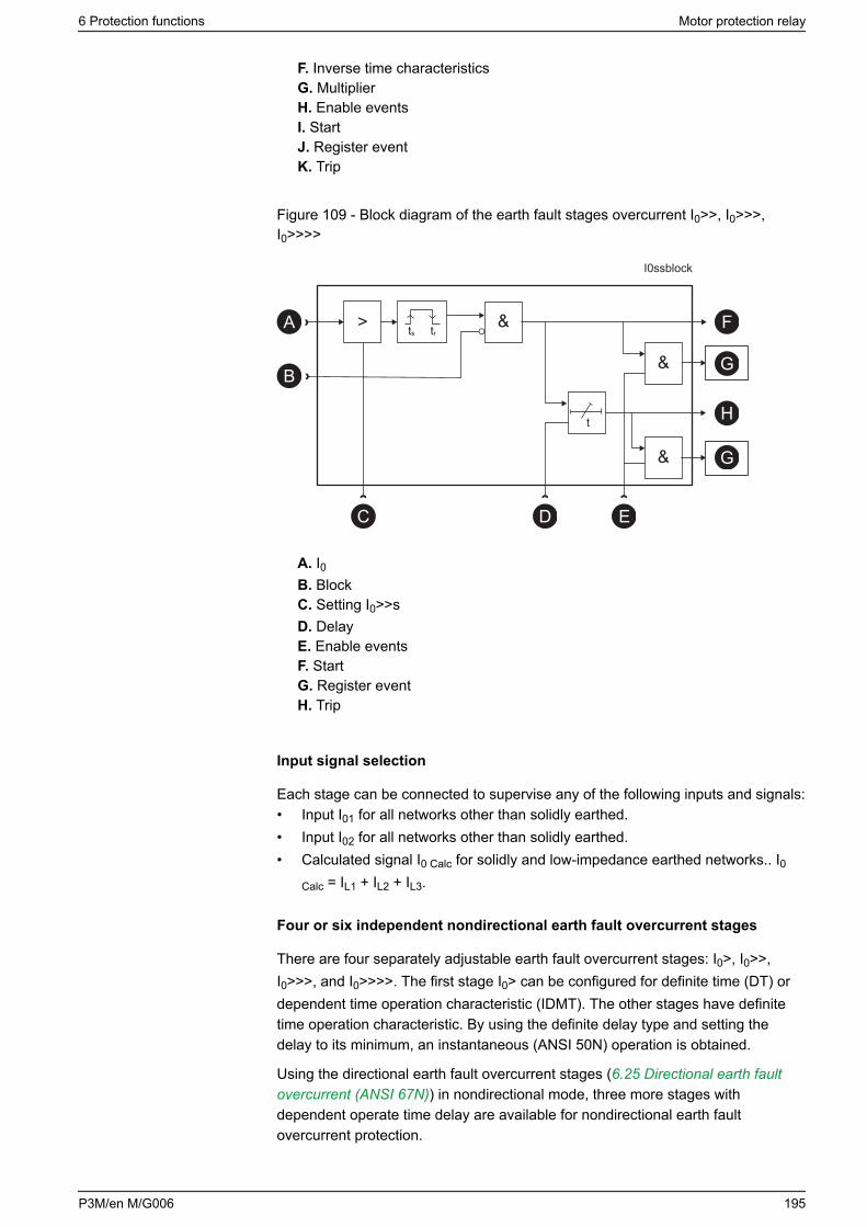
F. Inverse time characteristicsG. MultiplierH. Enable eventsI. StartJ. Register eventK. Trip
Figure 109 - Block diagram of the earth fault stages overcurrent I0>>, I0>>>,I0>>>>
&
t
&B
D E
F
G
H
G&
C
>
I0ssblock
ts trA
A. I0B. BlockC. Setting I0>>sD. DelayE. Enable eventsF. StartG. Register eventH. Trip
Input signal selection
Each stage can be connected to supervise any of the following inputs and signals:• Input I01 for all networks other than solidly earthed.• Input I02 for all networks other than solidly earthed.• Calculated signal I0 Calc for solidly and low-impedance earthed networks.. I0
Calc = IL1 + IL2 + IL3.
Four or six independent nondirectional earth fault overcurrent stages
There are four separately adjustable earth fault overcurrent stages: I0>, I0>>,I0>>>, and I0>>>>. The first stage I0> can be configured for definite time (DT) ordependent time operation characteristic (IDMT). The other stages have definitetime operation characteristic. By using the definite delay type and setting thedelay to its minimum, an instantaneous (ANSI 50N) operation is obtained.
Using the directional earth fault overcurrent stages (6.25 Directional earth faultovercurrent (ANSI 67N)) in nondirectional mode, three more stages withdependent operate time delay are available for nondirectional earth faultovercurrent protection.
6 Protection functions Motor protection relay
P3M/en M/G006 195
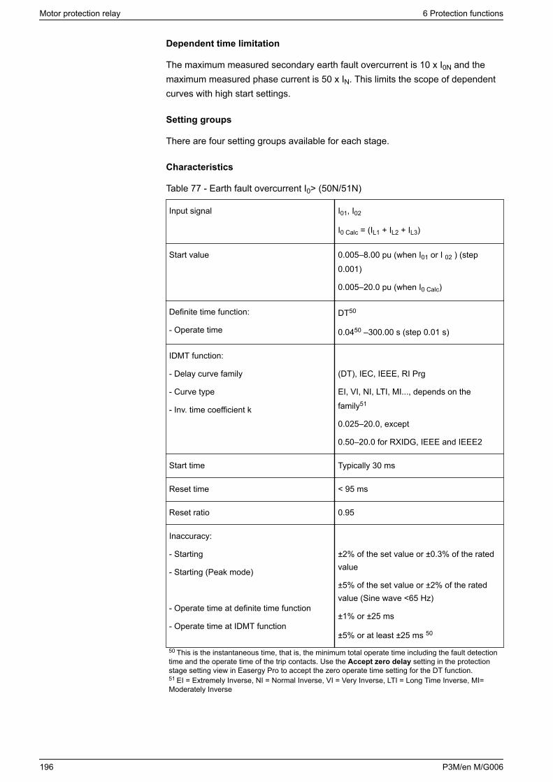
Dependent time limitation
The maximum measured secondary earth fault overcurrent is 10 x I0N and themaximum measured phase current is 50 x IN. This limits the scope of dependentcurves with high start settings.
Setting groups
There are four setting groups available for each stage.
Characteristics
Table 77 - Earth fault overcurrent I0> (50N/51N)
Input signal I01, I02
I0 Calc = (IL1 + IL2 + IL3)
Start value 0.005–8.00 pu (when I01 or I 02 ) (step0.001)
0.005–20.0 pu (when I0 Calc)
Definite time function:
- Operate time
DT50
0.0450 –300.00 s (step 0.01 s)
IDMT function:
- Delay curve family
- Curve type
- Inv. time coefficient k
(DT), IEC, IEEE, RI Prg
EI, VI, NI, LTI, MI..., depends on thefamily51
0.025–20.0, except
0.50–20.0 for RXIDG, IEEE and IEEE2
Start time Typically 30 ms
Reset time < 95 ms
Reset ratio 0.95
Inaccuracy:
- Starting
- Starting (Peak mode)
- Operate time at definite time function
- Operate time at IDMT function
±2% of the set value or ±0.3% of the ratedvalue
±5% of the set value or ±2% of the ratedvalue (Sine wave <65 Hz)
±1% or ±25 ms
±5% or at least ±25 ms 50
50 This is the instantaneous time, that is, the minimum total operate time including the fault detectiontime and the operate time of the trip contacts. Use the Accept zero delay setting in the protectionstage setting view in Easergy Pro to accept the zero operate time setting for the DT function.51 EI = Extremely Inverse, NI = Normal Inverse, VI = Very Inverse, LTI = Long Time Inverse, MI=Moderately Inverse
Motor protection relay 6 Protection functions
196 P3M/en M/G006
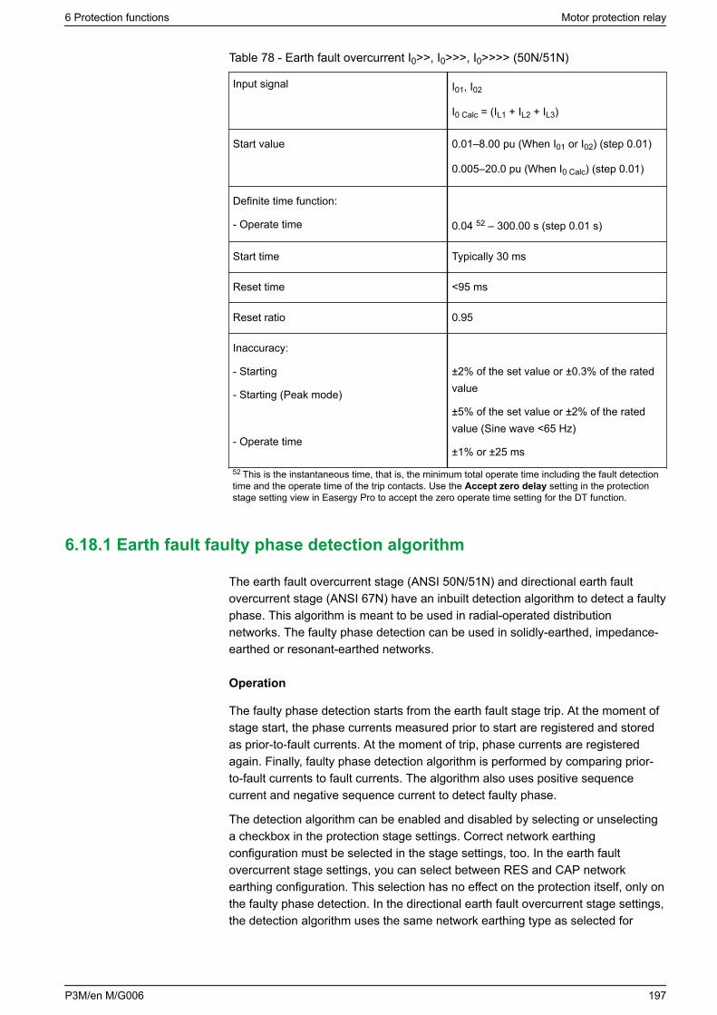
Table 78 - Earth fault overcurrent I0>>, I0>>>, I0>>>> (50N/51N)
Input signal I01, I02
I0 Calc = (IL1 + IL2 + IL3)
Start value 0.01–8.00 pu (When I01 or I02) (step 0.01)
0.005–20.0 pu (When I0 Calc) (step 0.01)
Definite time function:
- Operate time 0.04 52 – 300.00 s (step 0.01 s)
Start time Typically 30 ms
Reset time <95 ms
Reset ratio 0.95
Inaccuracy:
- Starting
- Starting (Peak mode)
- Operate time
±2% of the set value or ±0.3% of the ratedvalue
±5% of the set value or ±2% of the ratedvalue (Sine wave <65 Hz)
±1% or ±25 ms
52 This is the instantaneous time, that is, the minimum total operate time including the fault detectiontime and the operate time of the trip contacts. Use the Accept zero delay setting in the protectionstage setting view in Easergy Pro to accept the zero operate time setting for the DT function.
6.18.1 Earth fault faulty phase detection algorithm
The earth fault overcurrent stage (ANSI 50N/51N) and directional earth faultovercurrent stage (ANSI 67N) have an inbuilt detection algorithm to detect a faultyphase. This algorithm is meant to be used in radial-operated distributionnetworks. The faulty phase detection can be used in solidly-earthed, impedance-earthed or resonant-earthed networks.
Operation
The faulty phase detection starts from the earth fault stage trip. At the moment ofstage start, the phase currents measured prior to start are registered and storedas prior-to-fault currents. At the moment of trip, phase currents are registeredagain. Finally, faulty phase detection algorithm is performed by comparing prior-to-fault currents to fault currents. The algorithm also uses positive sequencecurrent and negative sequence current to detect faulty phase.
The detection algorithm can be enabled and disabled by selecting or unselectinga checkbox in the protection stage settings. Correct network earthingconfiguration must be selected in the stage settings, too. In the earth faultovercurrent stage settings, you can select between RES and CAP networkearthing configuration. This selection has no effect on the protection itself, only onthe faulty phase detection. In the directional earth fault overcurrent stage settings,the detection algorithm uses the same network earthing type as selected for
6 Protection functions Motor protection relay
P3M/en M/G006 197
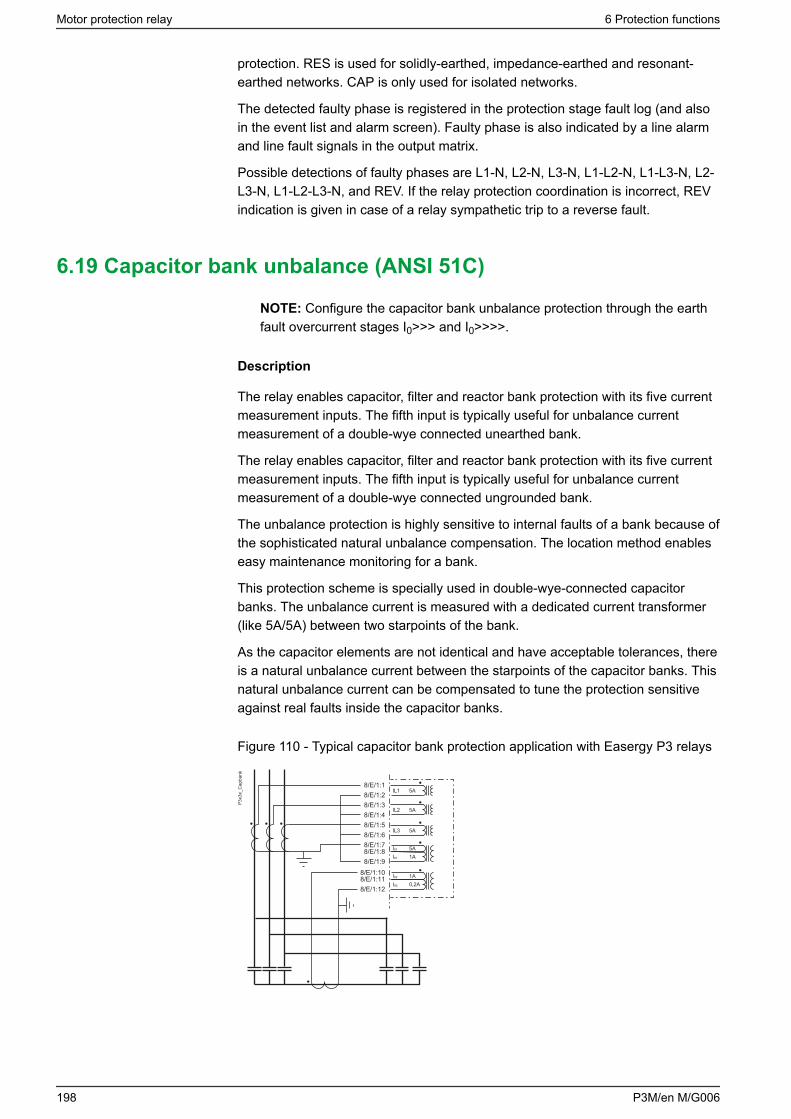
protection. RES is used for solidly-earthed, impedance-earthed and resonant-earthed networks. CAP is only used for isolated networks.
The detected faulty phase is registered in the protection stage fault log (and alsoin the event list and alarm screen). Faulty phase is also indicated by a line alarmand line fault signals in the output matrix.
Possible detections of faulty phases are L1-N, L2-N, L3-N, L1-L2-N, L1-L3-N, L2-L3-N, L1-L2-L3-N, and REV. If the relay protection coordination is incorrect, REVindication is given in case of a relay sympathetic trip to a reverse fault.
6.19 Capacitor bank unbalance (ANSI 51C)
NOTE: Configure the capacitor bank unbalance protection through the earthfault overcurrent stages I0>>> and I0>>>>.
Description
The relay enables capacitor, filter and reactor bank protection with its five currentmeasurement inputs. The fifth input is typically useful for unbalance currentmeasurement of a double-wye connected unearthed bank.
The relay enables capacitor, filter and reactor bank protection with its five currentmeasurement inputs. The fifth input is typically useful for unbalance currentmeasurement of a double-wye connected ungrounded bank.
The unbalance protection is highly sensitive to internal faults of a bank because ofthe sophisticated natural unbalance compensation. The location method enableseasy maintenance monitoring for a bank.
This protection scheme is specially used in double-wye-connected capacitorbanks. The unbalance current is measured with a dedicated current transformer(like 5A/5A) between two starpoints of the bank.
As the capacitor elements are not identical and have acceptable tolerances, thereis a natural unbalance current between the starpoints of the capacitor banks. Thisnatural unbalance current can be compensated to tune the protection sensitiveagainst real faults inside the capacitor banks.
Figure 110 - Typical capacitor bank protection application with Easergy P3 relays
255
8/E/1:3
IL1
IL2
IL3
I01
5A
5A
5A
5AI01 1A
I02 1AI02 0,2A
8/E/1:48/E/1:58/E/1:68/E/1:78/E/1:88/E/1:9
8/E/1:108/E/1:118/E/1:12
8/E/1:28/E/1:1
P3x3
x_C
apba
nk
Motor protection relay 6 Protection functions
198 P3M/en M/G006
Compensation method
The method of unbalance protection is to compensate for the natural unbalancecurrent. The compensation is triggered manually when commissioning. Thephasors of the unbalance current and one phase current are then recorded. Thisis because one polarizing measurement is needed. When the phasor of theunbalance current is always related to IL1, the frequency changes or deviationshave no effect on the protection. After the recording, the measured unbalancecurrent corresponds to the zero-level and therefore, the setting of the stage canbe very sensitive.
Compensation and location
The most sophisticated method is to use the compensation method describedabove with an add-on feature that locates the branch of each faulty element (thebroken fuse).
This feature is implemented to the stage I0>>>>, while the other stage I0>>> canstill function as normal unbalance protection stage with the compensationmethod. Normally, the I0>>>> could be set as an alarming stage while stage I0>>>trips the circuit breaker.
The stage I 0>>>> should be set based on the calculated unbalance currentchange of one faulty element. You can calculate this using the following formula:
Equation 22
3)2()2(31
21
10
−−
−−
⋅⋅⋅−
⋅⋅⋅=
CfU
CfU
I
NLNL
ππ
C1 = Capacitor unit capacitance (μF)
C2 = Capacitor unit capacitance, after one element fails (μF)
However, the setting must be 10% smaller than the calculated value, since thereare some tolerances in the primary equipment as well as in the relaymeasurement circuit. Then, the time setting of I0>>>> is not used for trippingpurposes. The time setting specifies, how long the relay must wait until it iscertain that there is a faulty element in the bank. After this time has elapsed, thestage I0>>>> makes a new compensation automatically, and the measuredunbalance current for this stage is now zero. Note, the automatic compensationdoes not affect the measured unbalance current of stage I0>>>.
6 Protection functions Motor protection relay
P3M/en M/G006 199
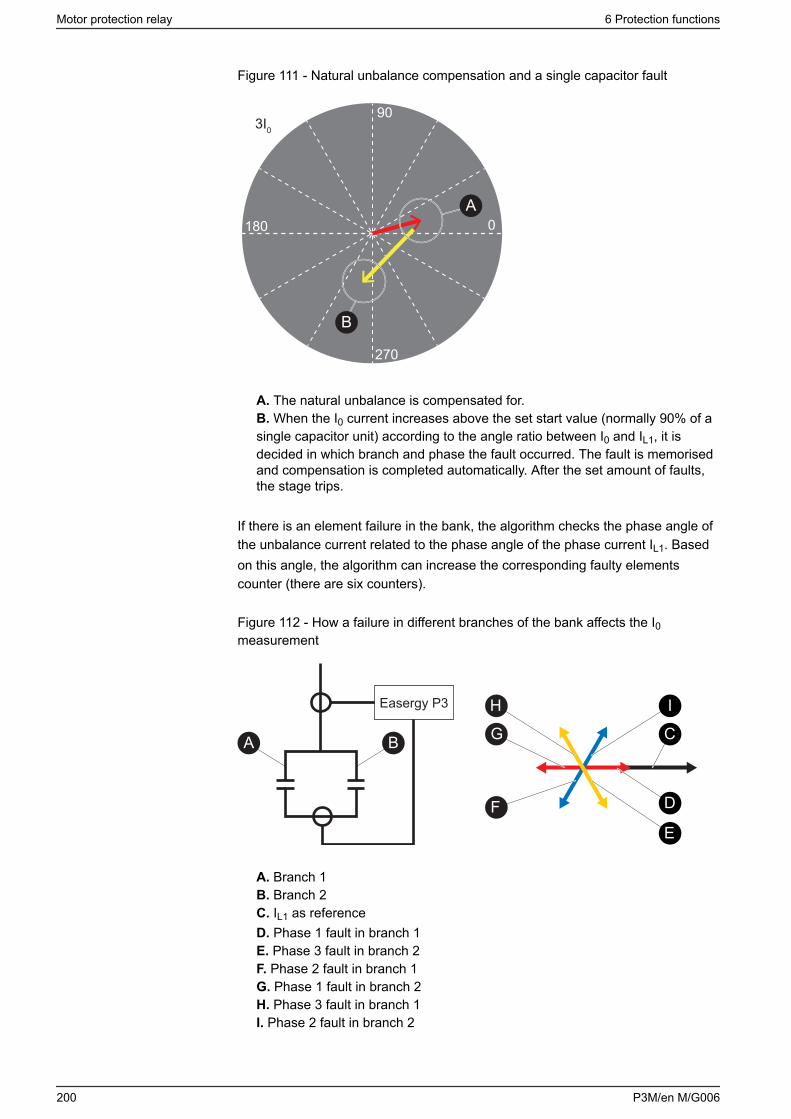
Figure 111 - Natural unbalance compensation and a single capacitor fault
90
0
270
180
3I0
A
B
A. The natural unbalance is compensated for.B. When the I0 current increases above the set start value (normally 90% of asingle capacitor unit) according to the angle ratio between I0 and IL1, it isdecided in which branch and phase the fault occurred. The fault is memorisedand compensation is completed automatically. After the set amount of faults,the stage trips.
If there is an element failure in the bank, the algorithm checks the phase angle ofthe unbalance current related to the phase angle of the phase current IL1. Basedon this angle, the algorithm can increase the corresponding faulty elementscounter (there are six counters).
Figure 112 - How a failure in different branches of the bank affects the I0measurement
H
A B
F
I
G C
E
Easergy P3
D
A. Branch 1B. Branch 2C. IL1 as referenceD. Phase 1 fault in branch 1E. Phase 3 fault in branch 2F. Phase 2 fault in branch 1G. Phase 1 fault in branch 2H. Phase 3 fault in branch 1I. Phase 2 fault in branch 2
Motor protection relay 6 Protection functions
200 P3M/en M/G006
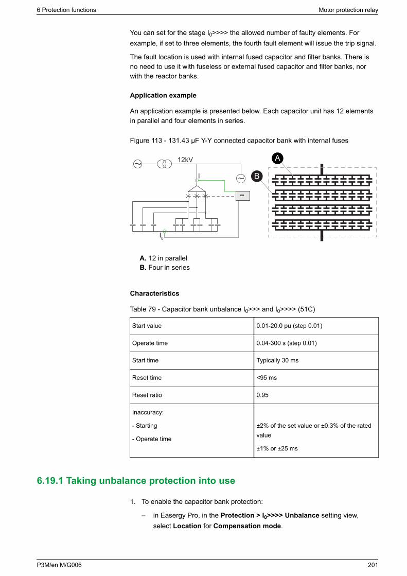
You can set for the stage I0>>>> the allowed number of faulty elements. Forexample, if set to three elements, the fourth fault element will issue the trip signal.
The fault location is used with internal fused capacitor and filter banks. There isno need to use it with fuseless or external fused capacitor and filter banks, norwith the reactor banks.
Application example
An application example is presented below. Each capacitor unit has 12 elementsin parallel and four elements in series.
Figure 113 - 131.43 μF Y-Y connected capacitor bank with internal fuses
A
B
12kV
I
I0
A. 12 in parallelB. Four in series
Characteristics
Table 79 - Capacitor bank unbalance I0>>> and I0>>>> (51C)
Start value 0.01‑20.0 pu (step 0.01)
Operate time 0.04‑300 s (step 0.01)
Start time Typically 30 ms
Reset time <95 ms
Reset ratio 0.95
Inaccuracy:
- Starting
- Operate time
±2% of the set value or ±0.3% of the ratedvalue
±1% or ±25 ms
6.19.1 Taking unbalance protection into use
1. To enable the capacitor bank protection:
– in Easergy Pro, in the Protection > I0>>>> Unbalance setting view,select Location for Compensation mode.
6 Protection functions Motor protection relay
P3M/en M/G006 201
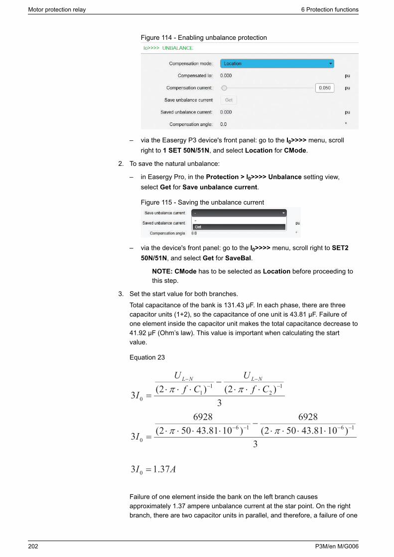
Figure 114 - Enabling unbalance protection
– via the Easergy P3 device's front panel: go to the I0>>>> menu, scrollright to 1 SET 50N/51N, and select Location for CMode.
2. To save the natural unbalance:
– in Easergy Pro, in the Protection > I0>>>> Unbalance setting view,select Get for Save unbalance current.
Figure 115 - Saving the unbalance current
– via the device's front panel: go to the I0>>>> menu, scroll right to SET250N/51N, and select Get for SaveBal.
NOTE: CMode has to be selected as Location before proceeding tothis step.
3. Set the start value for both branches.Total capacitance of the bank is 131.43 μF. In each phase, there are threecapacitor units (1+2), so the capacitance of one unit is 43.81 μF. Failure ofone element inside the capacitor unit makes the total capacitance decrease to41.92 μF (Ohm’s law). This value is important when calculating the startvalue.
Equation 23
3)2()2(31
21
10
−−
−−
⋅⋅⋅−
⋅⋅⋅=
CfU
CfU
I
NLNL
ππ
3)1081.43502(
6928)1081.43502(
6928
31616
0
−−−− ⋅⋅⋅⋅−
⋅⋅⋅⋅= ππI
AI 37.13 0 =
Failure of one element inside the bank on the left branch causesapproximately 1.37 ampere unbalance current at the star point. On the rightbranch, there are two capacitor units in parallel, and therefore, a failure of one
Motor protection relay 6 Protection functions
202 P3M/en M/G006
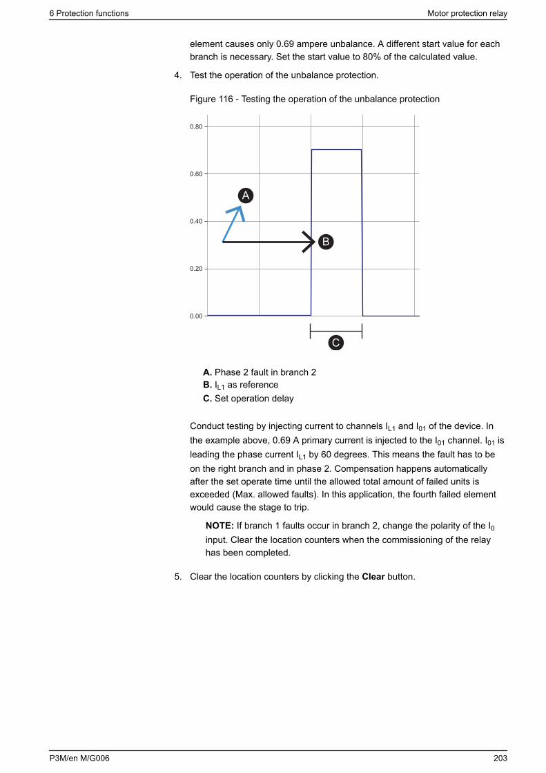
element causes only 0.69 ampere unbalance. A different start value for eachbranch is necessary. Set the start value to 80% of the calculated value.
4. Test the operation of the unbalance protection.
Figure 116 - Testing the operation of the unbalance protection
0.80
0.60
0.40
0.20
0.00
A
B
C
A. Phase 2 fault in branch 2B. IL1 as referenceC. Set operation delay
Conduct testing by injecting current to channels IL1 and I01 of the device. Inthe example above, 0.69 A primary current is injected to the I01 channel. I01 isleading the phase current IL1 by 60 degrees. This means the fault has to beon the right branch and in phase 2. Compensation happens automaticallyafter the set operate time until the allowed total amount of failed units isexceeded (Max. allowed faults). In this application, the fourth failed elementwould cause the stage to trip.
NOTE: If branch 1 faults occur in branch 2, change the polarity of the I0input. Clear the location counters when the commissioning of the relayhas been completed.
5. Clear the location counters by clicking the Clear button.
6 Protection functions Motor protection relay
P3M/en M/G006 203
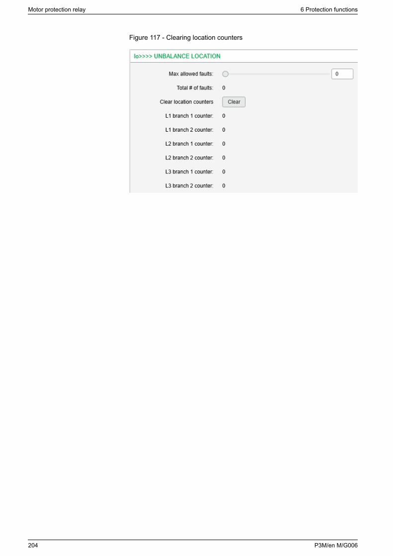
Figure 117 - Clearing location counters
Motor protection relay 6 Protection functions
204 P3M/en M/G006
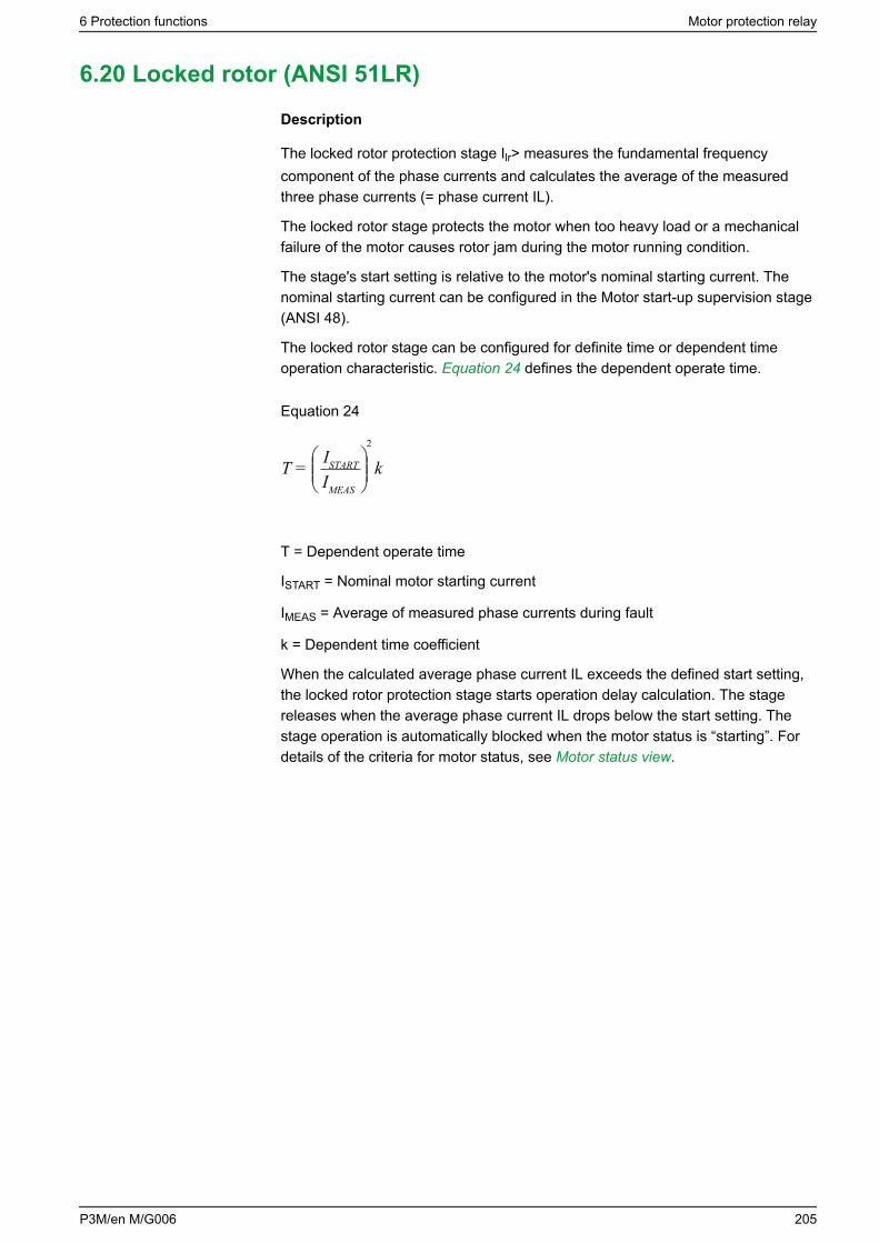
6.20 Locked rotor (ANSI 51LR)
Description
The locked rotor protection stage Ilr> measures the fundamental frequencycomponent of the phase currents and calculates the average of the measuredthree phase currents (= phase current IL).
The locked rotor stage protects the motor when too heavy load or a mechanicalfailure of the motor causes rotor jam during the motor running condition.
The stage's start setting is relative to the motor's nominal starting current. Thenominal starting current can be configured in the Motor start-up supervision stage(ANSI 48).
The locked rotor stage can be configured for definite time or dependent timeoperation characteristic. Equation 24 defines the dependent operate time.
Equation 24
kIMEAS
ISTARTT =
2
T = Dependent operate time
ISTART = Nominal motor starting current
IMEAS = Average of measured phase currents during fault
k = Dependent time coefficient
When the calculated average phase current IL exceeds the defined start setting,the locked rotor protection stage starts operation delay calculation. The stagereleases when the average phase current IL drops below the start setting. Thestage operation is automatically blocked when the motor status is “starting”. Fordetails of the criteria for motor status, see Motor status view.
6 Protection functions Motor protection relay
P3M/en M/G006 205
Block diagram
Figure 118 - Block diagram of the locked rotor protection stage Ilr>
&
t
&
Im1Im2Im3
AVG >
C F H
I
J
K
J&
D
>1
B E G
A
A. BlockB. Motor nominal start currentC. Start setting Ilr>D. Motor startingE. DelayF. Definite / inverse timeG. Inverse delayH. Enable eventsI. StartJ. Register eventK. Trip
Setting groups
This stage has one setting group.
Characteristics
Table 80 - Locked rotor (51LR) in motor mode
Start value 10 – 100 %IMOTSt (step 0.1%)
Delay type DT, INV
Definite time characteristic (DT):
- Operate time
-
1.0 – 300.0 s (step 0.1)53
Dependent time characteristic (INV):
- Dependent time coefficient, k
-
1.0 – 200.0 s (step 0.1)
Start time Typically 60 ms
Reset time <95 ms
Motor protection relay 6 Protection functions
206 P3M/en M/G006

Reset ratio <0.95
Inaccuracy:
- Starting
- Operate time at definite time function
- Operate time at IDMT function
-
±3% of the set value or 5 mA secondary
±1% or at ±30 ms
±5% or at least ±30 ms
53 This is the instantaneous time i.e. the minimum total operational time including the fault detectiontime and operation time of the trip contacts.
6 Protection functions Motor protection relay
P3M/en M/G006 207
6.21 Overvoltage (ANSI 59)
Description
Overvoltage protection is used to detect too high system voltages or to check thatthere is sufficient voltage to authorize a source transfer.
The overvoltage function measures the fundamental frequency component of theline-to-line voltages regardless of the voltage measurement mode (see 10.8Voltage measurement modes). By using line-to-line voltages any line-to-neutralover-voltages during earth faults have no effect. (The earth fault protectionfunctions take care of earth faults.) Whenever any of these three line-to-linevoltages exceeds the start setting of a particular stage, this stage starts and astart signal is issued. If the fault situation remains on longer than the operate timedelay setting, a trip signal is issued.
In solidly earthed, four-wire networks with loads between phase and neutralvoltages, overvoltage protection may be needed for line-to-neutral voltages, too.In such applications, the programmable stages can be used. 6.33 Programmablestages (ANSI 99).
Three independent stages
There are three separately adjustable stages: U>, U>> and U>>>. All the stagescan be configured for the definite time (DT) operation characteristic.
Configurable release delay
The U> stage has a settable reset delay that enables detecting intermittent faults.This means that the time counter of the protection function does not resetimmediately after the fault is cleared, but resets after the release delay haselapsed. If the fault appears again before the release delay time has elapsed, thedelay counter continues from the previous value. This means that the functioneventually trips if faults are occurring often enough.
Configurable hysteresis
The dead band is 3% by default. This means that an overvoltage fault is regardedas a fault until the voltage drops below 97% of the start setting. In a sensitivealarm application, a smaller hysteresis is needed. For example, if the start settingis about only 2% above the normal voltage level, the hysteresis must be less than2%. Otherwise, the stage does not release after fault.
Motor protection relay 6 Protection functions
208 P3M/en M/G006
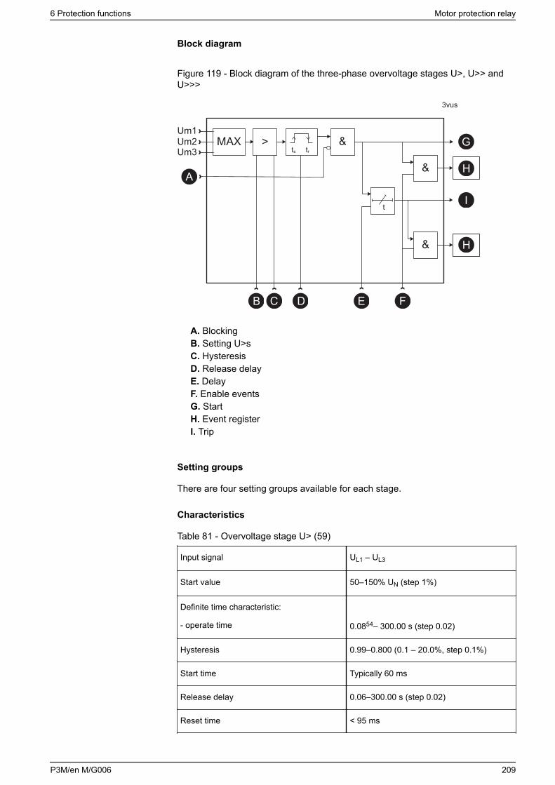
Block diagram
Figure 119 - Block diagram of the three-phase overvoltage stages U>, U>> andU>>>
&
t
&
Um1Um2Um3
MAX
3vus
ts tr
>
B E F
G
H
I
H&
C D
A
A. BlockingB. Setting U>sC. HysteresisD. Release delayE. DelayF. Enable eventsG. StartH. Event registerI. Trip
Setting groups
There are four setting groups available for each stage.
Characteristics
Table 81 - Overvoltage stage U> (59)
Input signal UL1 – UL3
Start value 50–150% UN (step 1%)
Definite time characteristic:
- operate time 0.0854– 300.00 s (step 0.02)
Hysteresis 0.99–0.800 (0.1 – 20.0%, step 0.1%)
Start time Typically 60 ms
Release delay 0.06–300.00 s (step 0.02)
Reset time < 95 ms
6 Protection functions Motor protection relay
P3M/en M/G006 209
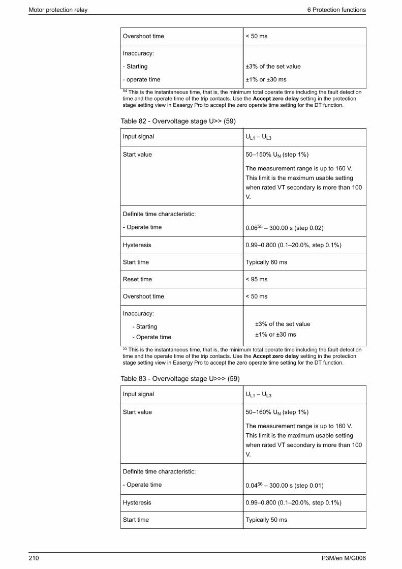
Overshoot time < 50 ms
Inaccuracy:
- Starting
- operate time
±3% of the set value
±1% or ±30 ms
54 This is the instantaneous time, that is, the minimum total operate time including the fault detectiontime and the operate time of the trip contacts. Use the Accept zero delay setting in the protectionstage setting view in Easergy Pro to accept the zero operate time setting for the DT function.
Table 82 - Overvoltage stage U>> (59)
Input signal UL1 – UL3
Start value 50–150% UN (step 1%)
The measurement range is up to 160 V.This limit is the maximum usable settingwhen rated VT secondary is more than 100V.
Definite time characteristic:
- Operate time 0.0655 – 300.00 s (step 0.02)
Hysteresis 0.99–0.800 (0.1–20.0%, step 0.1%)
Start time Typically 60 ms
Reset time < 95 ms
Overshoot time < 50 ms
Inaccuracy:
- Starting
- Operate time
±3% of the set value
±1% or ±30 ms
55 This is the instantaneous time, that is, the minimum total operate time including the fault detectiontime and the operate time of the trip contacts. Use the Accept zero delay setting in the protectionstage setting view in Easergy Pro to accept the zero operate time setting for the DT function.
Table 83 - Overvoltage stage U>>> (59)
Input signal UL1 – UL3
Start value 50–160% UN (step 1%)
The measurement range is up to 160 V.This limit is the maximum usable settingwhen rated VT secondary is more than 100V.
Definite time characteristic:
- Operate time 0.0456 – 300.00 s (step 0.01)
Hysteresis 0.99–0.800 (0.1–20.0%, step 0.1%)
Start time Typically 50 ms
Motor protection relay 6 Protection functions
210 P3M/en M/G006

Reset time < 95 ms
Overshoot time < 50 ms
Inaccuracy:
- Starting
- Operate time
±3% of the set value
±1% or ±25 ms
56 This is the instantaneous time, that is, the minimum total operate time including the fault detectiontime and the operate time of the trip contacts. Use the Accept zero delay setting in the protectionstage setting view in Easergy Pro to accept the zero operate time setting for the DT function.
6 Protection functions Motor protection relay
P3M/en M/G006 211
6.22 Neutral voltage displacement (ANSI 59N)
Description
The neutral voltage displacement protection is used as unselective backup forearth faults and also for selective earth fault protections for motors having a unittransformer between the motor and the busbar.
This function is sensitive to the fundamental frequency component of the neutralvoltage displacement voltage. The attenuation of the third harmonic is more than60 dB. This is essential because third harmonics exist between the neutral pointand earth also when there is no earth fault.
Whenever the measured value exceeds the start setting of a particular stage, thisstage starts and a start signal is issued. If the fault situation remains on longerthan the operate time delay setting, a trip signal is issued.
Measuring the neutral displacement voltage
The neutral displacement voltage is either measured with three voltagetransformers (for example broken delta connection), one voltage transformerbetween the motor's neutral point and earth or calculated from the measuredphase-to-neutral voltages according to the selected voltage measurement mode(see 10.8 Voltage measurement modes):
• When the voltage measurement mode is 3LN: the neutral displacementvoltage is calculated from the line-to-line voltages and therefore a separateneutral displacement voltage transformer is not needed. The setting valuesare relative to the configured voltage transformer (VT) voltage/√3
• When the voltage measurement mode contains "+U0": The neutraldisplacement voltage is measured with voltage transformer(s) for exampleusing a broken delta connection. The setting values are relative to the VT0
secondary voltage defined in configuration.• Connect the U0 signal according to the connection diagram to achieve correct
polarization.
Two independent stages
There are two separately adjustable stages: U0> and U0>>. Both stages can beconfigured for the definite time (DT) operation characteristic.
The neutral voltage displacement function comprises two separately adjustableneutral voltage displacement stages (stage U0> and U0>>).
Two independent stages
There are two separately adjustable stages: 59N-1 and 59N-2. Both stages canbe configured for the definite time (DT) operation characteristic.
Motor protection relay 6 Protection functions
212 P3M/en M/G006
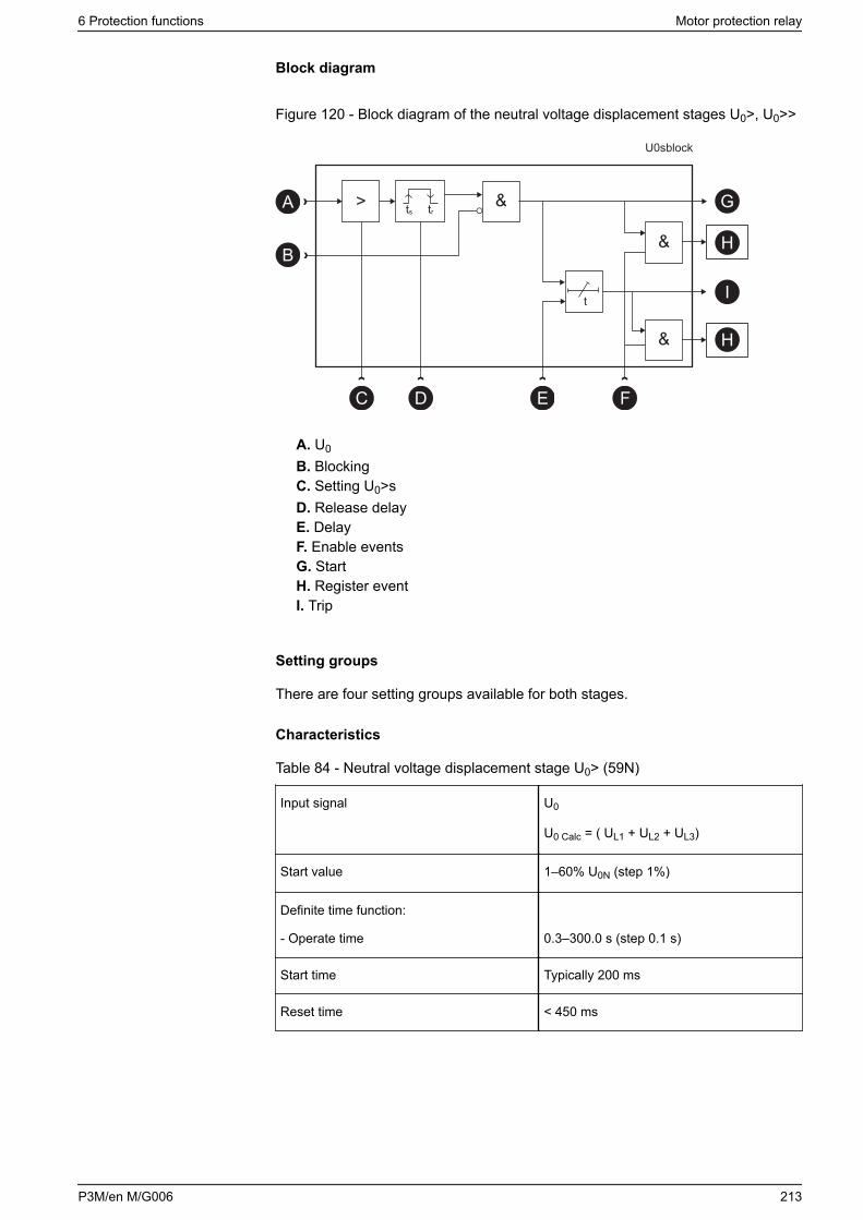
Block diagram
Figure 120 - Block diagram of the neutral voltage displacement stages U0>, U0>>
&
t
&B
E F
G
H
I
H&
C
>
U0sblock
A ts tr
D
A. U0
B. BlockingC. Setting U0>sD. Release delayE. DelayF. Enable eventsG. StartH. Register eventI. Trip
Setting groups
There are four setting groups available for both stages.
Characteristics
Table 84 - Neutral voltage displacement stage U0> (59N)
Input signal U0
U0 Calc = ( UL1 + UL2 + UL3)
Start value 1–60% U0N (step 1%)
Definite time function:
- Operate time 0.3–300.0 s (step 0.1 s)
Start time Typically 200 ms
Reset time < 450 ms
6 Protection functions Motor protection relay
P3M/en M/G006 213
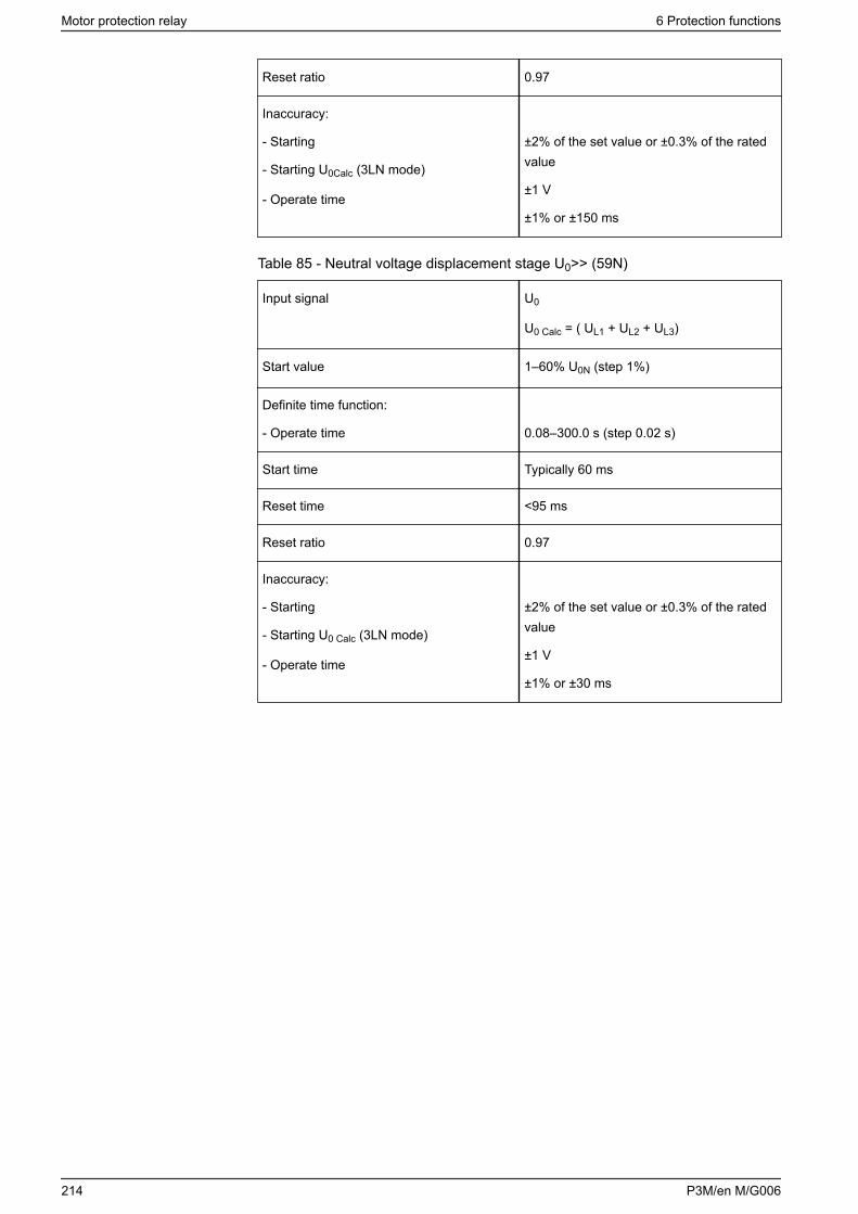
Reset ratio 0.97
Inaccuracy:
- Starting
- Starting U0Calc (3LN mode)
- Operate time
±2% of the set value or ±0.3% of the ratedvalue
±1 V
±1% or ±150 ms
Table 85 - Neutral voltage displacement stage U0>> (59N)
Input signal U0
U0 Calc = ( UL1 + UL2 + UL3)
Start value 1–60% U0N (step 1%)
Definite time function:
- Operate time 0.08–300.0 s (step 0.02 s)
Start time Typically 60 ms
Reset time <95 ms
Reset ratio 0.97
Inaccuracy:
- Starting
- Starting U0 Calc (3LN mode)
- Operate time
±2% of the set value or ±0.3% of the ratedvalue
±1 V
±1% or ±30 ms
Motor protection relay 6 Protection functions
214 P3M/en M/G006
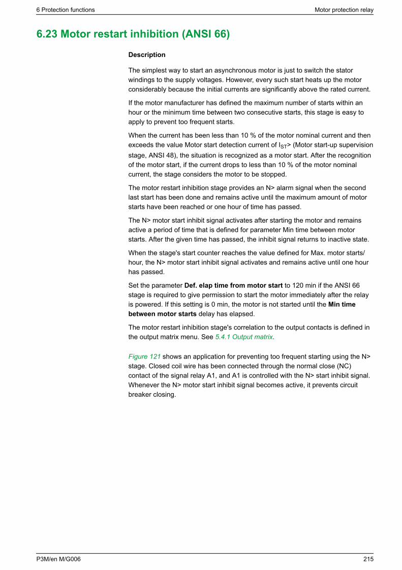
6.23 Motor restart inhibition (ANSI 66)
Description
The simplest way to start an asynchronous motor is just to switch the statorwindings to the supply voltages. However, every such start heats up the motorconsiderably because the initial currents are significantly above the rated current.
If the motor manufacturer has defined the maximum number of starts within anhour or the minimum time between two consecutive starts, this stage is easy toapply to prevent too frequent starts.
When the current has been less than 10 % of the motor nominal current and thenexceeds the value Motor start detection current of IST> (Motor start-up supervisionstage, ANSI 48), the situation is recognized as a motor start. After the recognitionof the motor start, if the current drops to less than 10 % of the motor nominalcurrent, the stage considers the motor to be stopped.
The motor restart inhibition stage provides an N> alarm signal when the secondlast start has been done and remains active until the maximum amount of motorstarts have been reached or one hour of time has passed.
The N> motor start inhibit signal activates after starting the motor and remainsactive a period of time that is defined for parameter Min time between motorstarts. After the given time has passed, the inhibit signal returns to inactive state.
When the stage's start counter reaches the value defined for Max. motor starts/hour, the N> motor start inhibit signal activates and remains active until one hourhas passed.
Set the parameter Def. elap time from motor start to 120 min if the ANSI 66stage is required to give permission to start the motor immediately after the relayis powered. If this setting is 0 min, the motor is not started until the Min timebetween motor starts delay has elapsed.
The motor restart inhibition stage's correlation to the output contacts is defined inthe output matrix menu. See 5.4.1 Output matrix.
Figure 121 shows an application for preventing too frequent starting using the N>stage. Closed coil wire has been connected through the normal close (NC)contact of the signal relay A1, and A1 is controlled with the N> start inhibit signal.Whenever the N> motor start inhibit signal becomes active, it prevents circuitbreaker closing.
6 Protection functions Motor protection relay
P3M/en M/G006 215
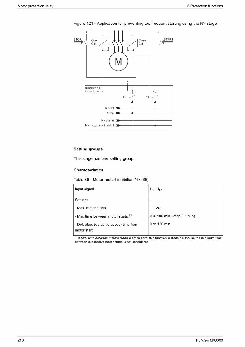
Figure 121 - Application for preventing too frequent starting using the N> stage
N> motor start inhibi t
I> trip
N> alar m
I> start
T1 A1
Easergy P3Output matrix
+
- -+ +
M
STOP STARTOpenCoil
CloseCoil
Setting groups
This stage has one setting group.
Characteristics
Table 86 - Motor restart inhibition N> (66)
Input signal IL1 – IL3
Settings:
- Max. motor starts
- Min. time between motor starts 57
- Def. elap. (default elapsed) time frommotor start
-
1 – 20
0.0–100 min. (step 0.1 min)
0 or 120 min
57 If Min. time between motors starts is set to zero, this function is disabled, that is, the minimum timebetween successive motor starts is not considered.
Motor protection relay 6 Protection functions
216 P3M/en M/G006
6.24 Directional phase overcurrent (ANSI 67)
Description
Directional overcurrent protection can be used for directional short circuitprotection. Typical applications are:• Short-circuit protection of two parallel cables or overhead lines in a radial
network.• Short-circuit protection of a looped network with single feeding point.• Short-circuit protection of a two-way feeder, which usually supplies loads but
is used in special cases as an incoming feeder.• Directional overcurrent protection in low impedance earthed networks. In this
case, the device has to connected to line-to-neutral voltages instead of line-to-line voltages. In other words, the voltage measurement mode has to be "3LN"(See chapter 10.8 Voltage measurement modes.
The stages are sensitive to the amplitude of the highest fundamental frequencycurrent of the three measured phase currents.
In line-to-line and in three-phase faults, the fault angle is determined by usingangles between positive sequence of currents and voltages. In line-to-neutralfaults, the fault angle is determined by using fault-phase current and the healthyline to line voltage. For details of power direction, see 4.10 Power and currentdirection.
A typical characteristic is shown in Figure 122. The base angle setting is -30°.The stage starts if the tip of the three phase current phasor gets into the greyarea.
NOTE: If the maximum possible earth fault current is greater than the usedmost sensitive directional overcurrent setting, connect the relay to the line-to-neutral voltages instead of line-to-line voltages to get the right direction forearth faults, too. For networks having the maximum possible earth faultcurrent less than the over current setting, use 67N, the directional earth faultstages.
Voltage memory
An adjustable 0.2–3.2 second cyclic buffer storing the phase-to-earth voltages isused as the voltage memory. The stored phase angle information is used asdirection reference if all the line-to-line voltages drop below 1% during a fault. Toadjust the voltage memory, set the Angele memory duration parameter in theScalings setting view in Easergy Pro.
6 Protection functions Motor protection relay
P3M/en M/G006 217
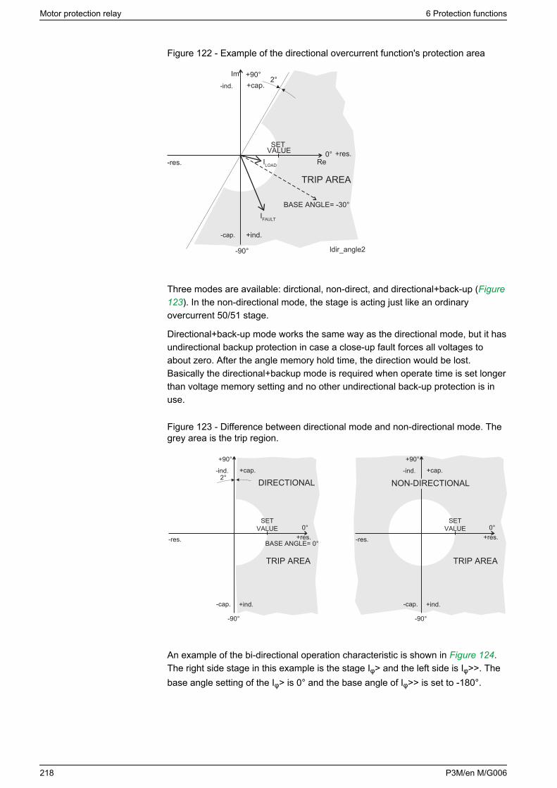
Figure 122 - Example of the directional overcurrent function's protection area
+90°
-res.
ldir_angle2
2°
Re
Im
0°
-90°
+ind.
-ind.
-cap.
+cap.
+res.
IFAULT
ILOAD
TRIP AREA
SETVALUE
BASE ANGLE= -30°
Three modes are available: dirctional, non-direct, and directional+back-up (Figure123). In the non-directional mode, the stage is acting just like an ordinaryovercurrent 50/51 stage.
Directional+back-up mode works the same way as the directional mode, but it hasundirectional backup protection in case a close-up fault forces all voltages toabout zero. After the angle memory hold time, the direction would be lost.Basically the directional+backup mode is required when operate time is set longerthan voltage memory setting and no other undirectional back-up protection is inuse.
Figure 123 - Difference between directional mode and non-directional mode. Thegrey area is the trip region.
+90° +90°
-res.
TRIP AREATRIP AREA
SETVALUE
SETVALUE
2°
BASE ANGLE= 0°
0° 0°
-90°
+ind. +ind.
-ind.
-cap.
-res.
-90°
-ind.
-cap.
+cap. +cap.
+res. +res.
NON-DIRECTIONALDIRECTIONAL
An example of the bi-directional operation characteristic is shown in Figure 124.The right side stage in this example is the stage Iφ> and the left side is Iφ>>. Thebase angle setting of the Iφ> is 0° and the base angle of Iφ>> is set to -180°.
Motor protection relay 6 Protection functions
218 P3M/en M/G006
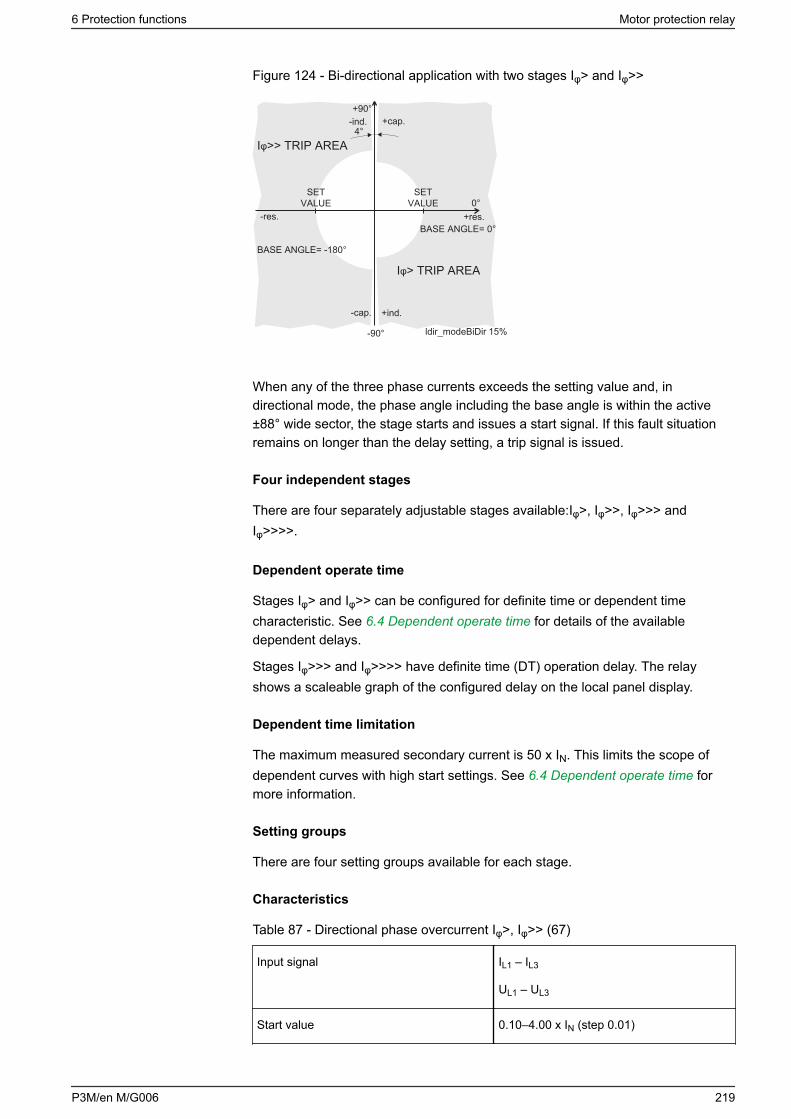
Figure 124 - Bi-directional application with two stages Iφ> and Iφ>>
+90°
-res.
ldir_modeBiDir 15%
Iφ> TRIP AREA
Iφ>> TRIP AREA
SETVALUE
SETVALUE
4°
0°
-90°
+ind.
-ind.
-cap.
+cap.
+res.
BASE ANGLE= -180°
BASE ANGLE= 0°
When any of the three phase currents exceeds the setting value and, indirectional mode, the phase angle including the base angle is within the active±88° wide sector, the stage starts and issues a start signal. If this fault situationremains on longer than the delay setting, a trip signal is issued.
Four independent stages
There are four separately adjustable stages available:Iφ>, Iφ>>, Iφ>>> andIφ>>>>.
Dependent operate time
Stages Iφ> and Iφ>> can be configured for definite time or dependent timecharacteristic. See 6.4 Dependent operate time for details of the availabledependent delays.
Stages Iφ>>> and Iφ>>>> have definite time (DT) operation delay. The relayshows a scaleable graph of the configured delay on the local panel display.
Dependent time limitation
The maximum measured secondary current is 50 x IN. This limits the scope ofdependent curves with high start settings. See 6.4 Dependent operate time formore information.
Setting groups
There are four setting groups available for each stage.
Characteristics
Table 87 - Directional phase overcurrent Iφ>, Iφ>> (67)
Input signal IL1 – IL3
UL1 – UL3
Start value 0.10–4.00 x IN (step 0.01)
6 Protection functions Motor protection relay
P3M/en M/G006 219
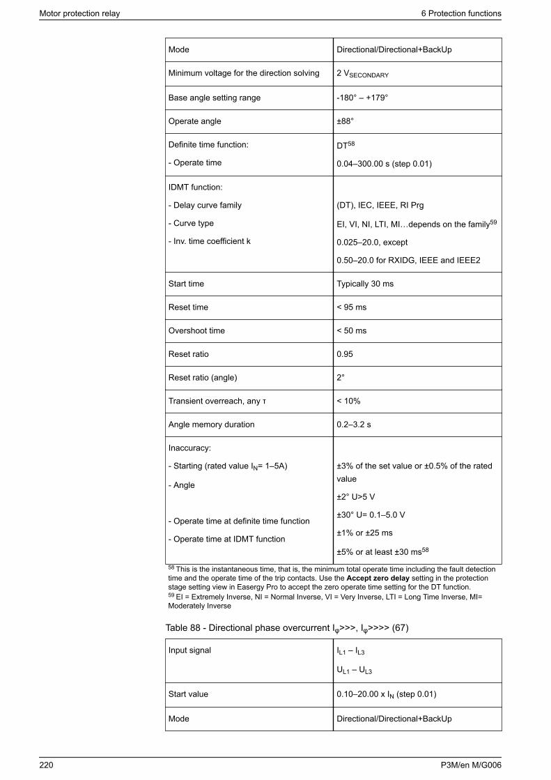
Mode Directional/Directional+BackUp
Minimum voltage for the direction solving 2 VSECONDARY
Base angle setting range -180° – +179°
Operate angle ±88°
Definite time function:
- Operate time
DT58
0.04–300.00 s (step 0.01)
IDMT function:
- Delay curve family
- Curve type
- Inv. time coefficient k
(DT), IEC, IEEE, RI Prg
EI, VI, NI, LTI, MI…depends on the family59
0.025–20.0, except
0.50–20.0 for RXIDG, IEEE and IEEE2
Start time Typically 30 ms
Reset time < 95 ms
Overshoot time < 50 ms
Reset ratio 0.95
Reset ratio (angle) 2°
Transient overreach, any τ < 10%
Angle memory duration 0.2–3.2 s
Inaccuracy:
- Starting (rated value IN= 1–5A)
- Angle
- Operate time at definite time function
- Operate time at IDMT function
±3% of the set value or ±0.5% of the ratedvalue
±2° U>5 V
±30° U= 0.1–5.0 V
±1% or ±25 ms
±5% or at least ±30 ms58
58 This is the instantaneous time, that is, the minimum total operate time including the fault detectiontime and the operate time of the trip contacts. Use the Accept zero delay setting in the protectionstage setting view in Easergy Pro to accept the zero operate time setting for the DT function.59 EI = Extremely Inverse, NI = Normal Inverse, VI = Very Inverse, LTI = Long Time Inverse, MI=Moderately Inverse
Table 88 - Directional phase overcurrent Iφ>>>, Iφ>>>> (67)
Input signal IL1 – IL3
UL1 – UL3
Start value 0.10–20.00 x IN (step 0.01)
Mode Directional/Directional+BackUp
Motor protection relay 6 Protection functions
220 P3M/en M/G006
Minimum voltage for the direction solving 2 VSECONDARY
Base angle setting range -180° – +179°
Operate angle ±88°
Definite time function:
- Operate time
DT60
0.04–300.00 s (step 0.01)
Start time Typically 30 ms
Reset time < 95 ms
Overshoot time < 50 ms
Reset ratio 0.95
Reset ratio (angle) 2°
Transient overreach, any τ < 10%
Angle memory duration 0.2–3.2 s
Inaccuracy:
- Starting (rated value IN= 1 – 5A)
- Angle
- Operate time at definite time function
±3% of the set value or ±0.5% of the ratedvalue
±2° U> 5 V
±30° U = 0.1–5.0 V
±1% or ±25 ms
60 This is the instantaneous time, that is, the minimum total operate time including the fault detectiontime and the operate time of the trip contacts. Use the Accept zero delay setting in the protectionstage setting view in Easergy Pro to accept the zero operate time setting for the DT function.
6.25 Directional earth fault overcurrent (ANSI 67N)
Description
The directional earth fault overcurrent is used in networks or motors where aselective and sensitive earth fault protection is needed and in applications withvarying network structure and length.
The earth fault protection is adapted for various network earth systems.
The function is sensitive to the fundamental frequency component of the earthfault overcurrent and neutral voltage displacement voltage and the phase anglebetween them. The attenuation of the third harmonic is more than 60 dB.Whenever the size of I0 and U0 and the phase angle between I0 and U0 fulfils thestart criteria, the stage starts and a start signal is issued. If the fault situationremains on longer than the operate time delay setting, a trip signal is issued.
Polarization
The neutral displacement voltage, used for polarization, is measured byenergizing input U0, that is, the angle reference for I0. Connect the U0 signal
6 Protection functions Motor protection relay
P3M/en M/G006 221
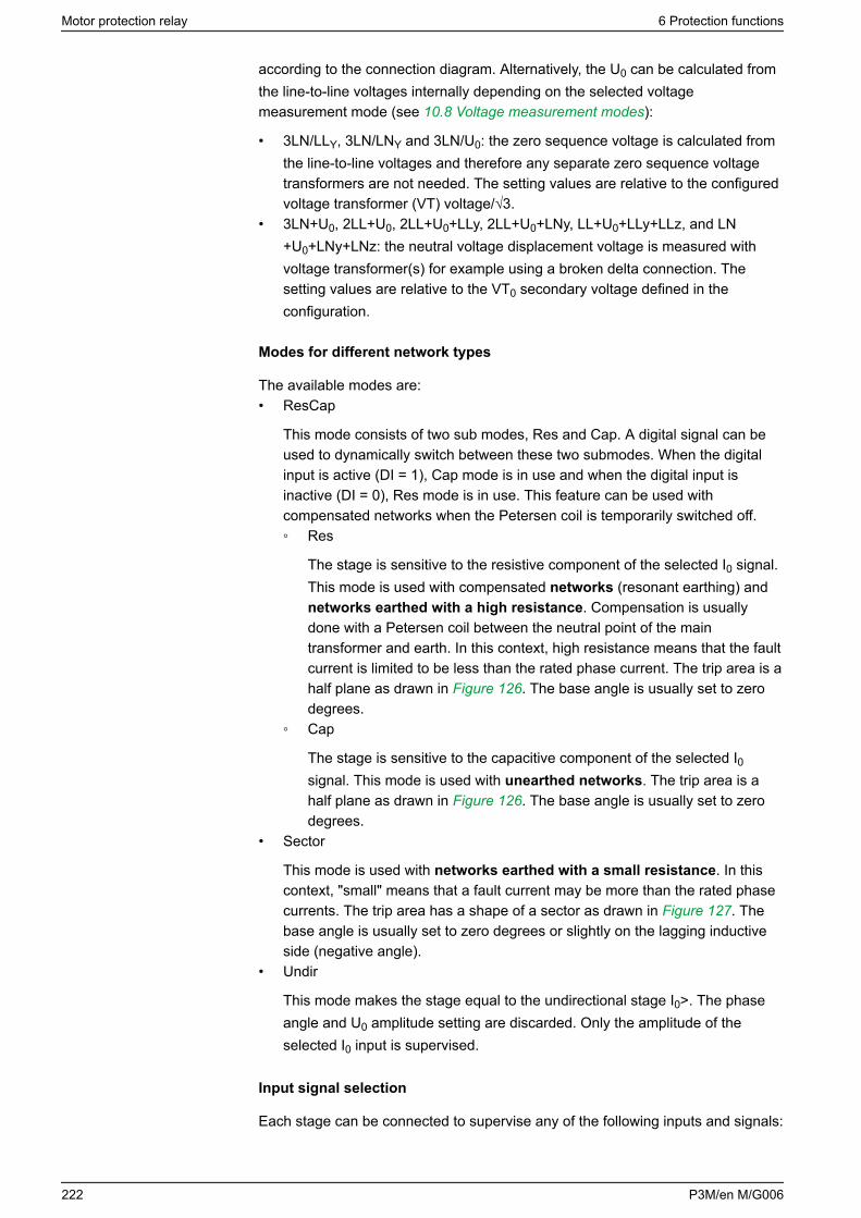
according to the connection diagram. Alternatively, the U0 can be calculated fromthe line-to-line voltages internally depending on the selected voltagemeasurement mode (see 10.8 Voltage measurement modes):
• 3LN/LLY, 3LN/LNY and 3LN/U0: the zero sequence voltage is calculated fromthe line-to-line voltages and therefore any separate zero sequence voltagetransformers are not needed. The setting values are relative to the configuredvoltage transformer (VT) voltage/√3.
• 3LN+U0, 2LL+U0, 2LL+U0+LLy, 2LL+U0+LNy, LL+U0+LLy+LLz, and LN+U0+LNy+LNz: the neutral voltage displacement voltage is measured withvoltage transformer(s) for example using a broken delta connection. Thesetting values are relative to the VT0 secondary voltage defined in theconfiguration.
Modes for different network types
The available modes are:• ResCap
This mode consists of two sub modes, Res and Cap. A digital signal can beused to dynamically switch between these two submodes. When the digitalinput is active (DI = 1), Cap mode is in use and when the digital input isinactive (DI = 0), Res mode is in use. This feature can be used withcompensated networks when the Petersen coil is temporarily switched off. Res
The stage is sensitive to the resistive component of the selected I0 signal.This mode is used with compensated networks (resonant earthing) andnetworks earthed with a high resistance. Compensation is usuallydone with a Petersen coil between the neutral point of the maintransformer and earth. In this context, high resistance means that the faultcurrent is limited to be less than the rated phase current. The trip area is ahalf plane as drawn in Figure 126. The base angle is usually set to zerodegrees.
Cap
The stage is sensitive to the capacitive component of the selected I0signal. This mode is used with unearthed networks. The trip area is ahalf plane as drawn in Figure 126. The base angle is usually set to zerodegrees.
• Sector
This mode is used with networks earthed with a small resistance. In thiscontext, "small" means that a fault current may be more than the rated phasecurrents. The trip area has a shape of a sector as drawn in Figure 127. Thebase angle is usually set to zero degrees or slightly on the lagging inductiveside (negative angle).
• Undir
This mode makes the stage equal to the undirectional stage I0>. The phaseangle and U0 amplitude setting are discarded. Only the amplitude of theselected I0 input is supervised.
Input signal selection
Each stage can be connected to supervise any of the following inputs and signals:
Motor protection relay 6 Protection functions
222 P3M/en M/G006
• Input I01 for all networks other than solidly earthed.• Input I02 for all networks other than solidly earthed.• Calculated signal I0 Calc for solidly and low-impedance earthed networks. I0
Calc = IL1 + IL2 + IL3 = 3I0.
Intermittent earth fault detection
Short earth faults make the protection start but does not cause a trip. A short faultmeans one cycle or more. For shorter than 1 ms transient type of intermittentearth faults in compensated networks, there is a dedicated stage I0INT> 67NI.When starting happens often enough, such intermittent faults can be clearedusing the intermittent time setting.
When a new start happens within the set intermittent time, the operation delaycounter is not cleared between adjacent faults and finally the stage trips.
Two independent stages
There are two separately adjustable stages: I0φ> and I0φ>>. Both stages can beconfigured for definite time delay (DT) or dependent time delay operate time.
Dependent operate time
Accomplished dependent delays are available for all stages INφ> and INφ >>.
The relay shows a scalable graph of the configured delay on the local paneldisplay.
Dependent time limitation
The maximum measured secondary earth fault overcurrent is 10 x I0N and themaximum measured phase current is 50 x IN. This limits the scope of dependentcurves with high start settings.
6 Protection functions Motor protection relay
P3M/en M/G006 223
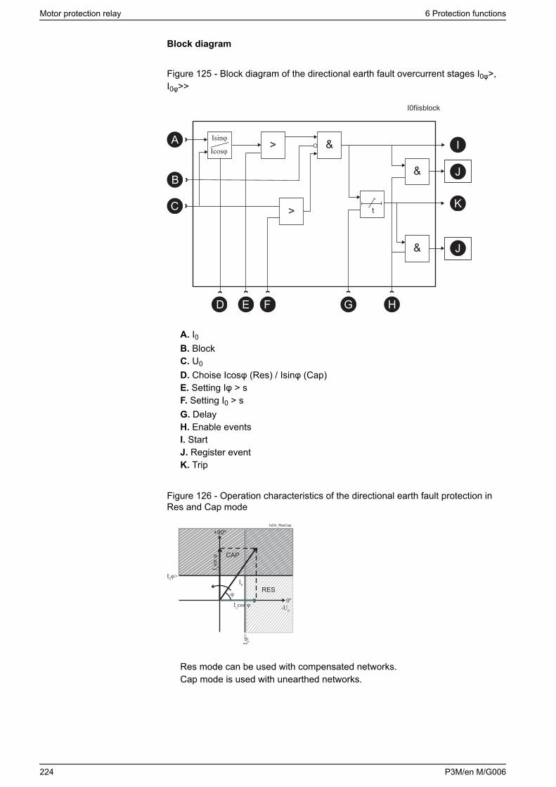
Block diagram
Figure 125 - Block diagram of the directional earth fault overcurrent stages I0φ>,I0φ>>
&
t
&
Isinφ
I0fiisblock
>
D G H
I
J
K
J&
Icosφ
B
C >
FE
A
A. I0B. BlockC. U0
D. Choise Icosφ (Res) / Isinφ (Cap)E. Setting Iφ > sF. Setting I0 > sG. DelayH. Enable eventsI. StartJ. Register eventK. Trip
Figure 126 - Operation characteristics of the directional earth fault protection inRes and Cap mode
I0φ>
I 0φ>
I osin
φ
φ
I0
-U0Iocos φ
+90º
CAP
RES0º
IoDir_ResCap
Res mode can be used with compensated networks.Cap mode is used with unearthed networks.
Motor protection relay 6 Protection functions
224 P3M/en M/G006
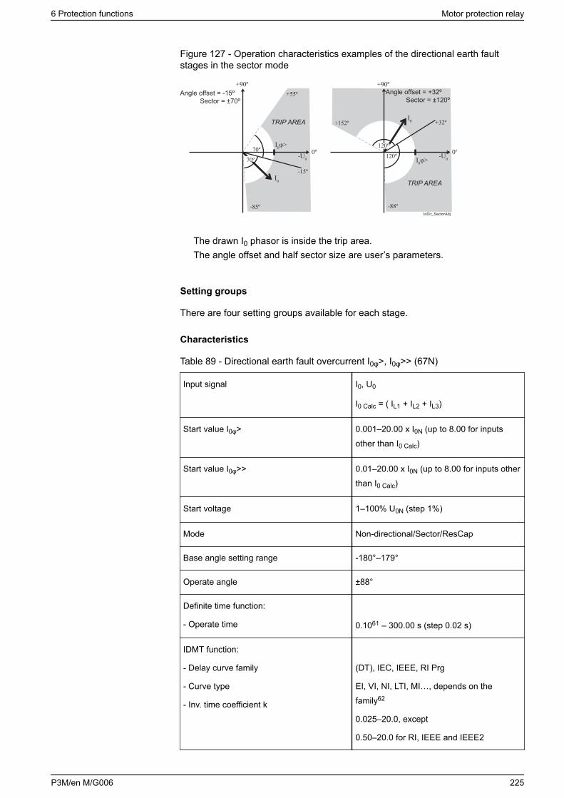
Figure 127 - Operation characteristics examples of the directional earth faultstages in the sector mode
Angle offset = -15ºSector = ±70º
TRIP AREA
TRIP AREA
+90º+55º
-85º
70º
70º
Angle offset = +32ºSector = ±120º
+90º
+152º
-88º
0º0º-U0
-15º
120º
-U0120º
IoDir_SectorAdj
I0
I0
I0φ>
I0φ>
+32º
The drawn I0 phasor is inside the trip area.The angle offset and half sector size are user’s parameters.
Setting groups
There are four setting groups available for each stage.
Characteristics
Table 89 - Directional earth fault overcurrent I0φ>, I0φ>> (67N)
Input signal I0, U0
I0 Calc = ( IL1 + IL2 + IL3)
Start value I0φ> 0.001–20.00 x I0N (up to 8.00 for inputsother than I0 Calc)
Start value I0φ>> 0.01–20.00 x I0N (up to 8.00 for inputs otherthan I0 Calc)
Start voltage 1–100% U0N (step 1%)
Mode Non-directional/Sector/ResCap
Base angle setting range -180°–179°
Operate angle ±88°
Definite time function:
- Operate time 0.1061 – 300.00 s (step 0.02 s)
IDMT function:
- Delay curve family
- Curve type
- Inv. time coefficient k
(DT), IEC, IEEE, RI Prg
EI, VI, NI, LTI, MI…, depends on thefamily62
0.025–20.0, except
0.50–20.0 for RI, IEEE and IEEE2
6 Protection functions Motor protection relay
P3M/en M/G006 225
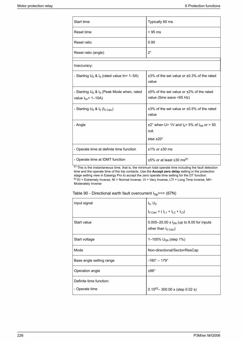
Start time Typically 60 ms
Reset time < 95 ms
Reset ratio 0.95
Reset ratio (angle) 2°
Inaccuracy:
- Starting U0 & I0 (rated value In= 1–5A) ±3% of the set value or ±0.3% of the ratedvalue
- Starting U0 & I0 (Peak Mode when, ratedvalue I0n= 1–10A)
±5% of the set value or ±2% of the ratedvalue (Sine wave <65 Hz)
- Starting U0 & I0 (I0 Calc) ±3% of the set value or ±0.5% of the ratedvalue
- Angle ±2° when U> 1V and I0> 5% of I0N or > 50mA
else ±20°
- Operate time at definite time function ±1% or ±30 ms
- Operate time at IDMT function ±5% or at least ±30 ms61
61 This is the instantaneous time, that is, the minimum total operate time including the fault detectiontime and the operate time of the trip contacts. Use the Accept zero delay setting in the protectionstage setting view in Easergy Pro to accept the zero operate time setting for the DT function.62 EI = Extremely Inverse, NI = Normal Inverse, VI = Very Inverse, LTI = Long Time Inverse, MI=Moderately Inverse
Table 90 - Directional earth fault overcurrent I0φ>>> (67N)
Input signal I0, U0
I0 Calc = ( IL1 + IL2 + IL3)
Start value 0.005–20.00 x I0N (up to 8.00 for inputsother than I0 Calc)
Start voltage 1–100% U0N (step 1%)
Mode Non-directional/Sector/ResCap
Base angle setting range -180° – 179°
Operation angle ±88°
Definite time function:
- Operate time 0.1063– 300.00 s (step 0.02 s)
Motor protection relay 6 Protection functions
226 P3M/en M/G006
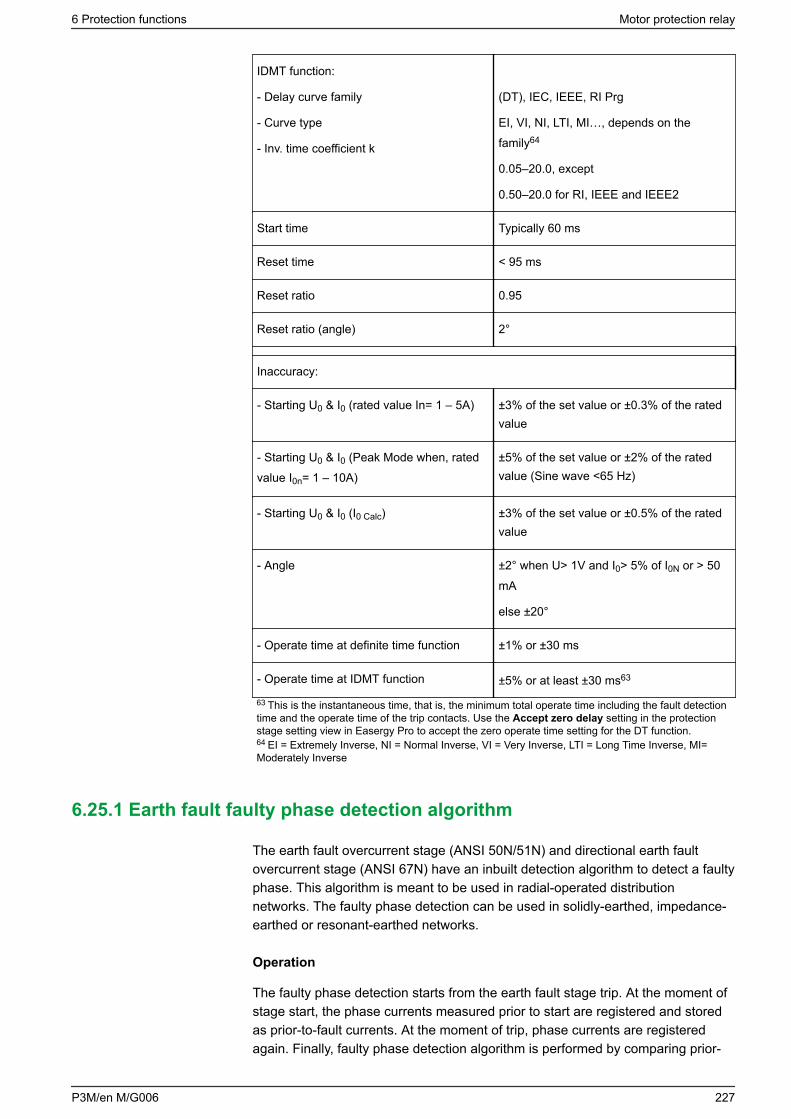
IDMT function:
- Delay curve family
- Curve type
- Inv. time coefficient k
(DT), IEC, IEEE, RI Prg
EI, VI, NI, LTI, MI…, depends on thefamily64
0.05–20.0, except
0.50–20.0 for RI, IEEE and IEEE2
Start time Typically 60 ms
Reset time < 95 ms
Reset ratio 0.95
Reset ratio (angle) 2°
Inaccuracy:
- Starting U0 & I0 (rated value In= 1 – 5A) ±3% of the set value or ±0.3% of the ratedvalue
- Starting U0 & I0 (Peak Mode when, ratedvalue I0n= 1 – 10A)
±5% of the set value or ±2% of the ratedvalue (Sine wave <65 Hz)
- Starting U0 & I0 (I0 Calc) ±3% of the set value or ±0.5% of the ratedvalue
- Angle ±2° when U> 1V and I0> 5% of I0N or > 50mA
else ±20°
- Operate time at definite time function ±1% or ±30 ms
- Operate time at IDMT function ±5% or at least ±30 ms63
63 This is the instantaneous time, that is, the minimum total operate time including the fault detectiontime and the operate time of the trip contacts. Use the Accept zero delay setting in the protectionstage setting view in Easergy Pro to accept the zero operate time setting for the DT function.64 EI = Extremely Inverse, NI = Normal Inverse, VI = Very Inverse, LTI = Long Time Inverse, MI=Moderately Inverse
6.25.1 Earth fault faulty phase detection algorithm
The earth fault overcurrent stage (ANSI 50N/51N) and directional earth faultovercurrent stage (ANSI 67N) have an inbuilt detection algorithm to detect a faultyphase. This algorithm is meant to be used in radial-operated distributionnetworks. The faulty phase detection can be used in solidly-earthed, impedance-earthed or resonant-earthed networks.
Operation
The faulty phase detection starts from the earth fault stage trip. At the moment ofstage start, the phase currents measured prior to start are registered and storedas prior-to-fault currents. At the moment of trip, phase currents are registeredagain. Finally, faulty phase detection algorithm is performed by comparing prior-
6 Protection functions Motor protection relay
P3M/en M/G006 227
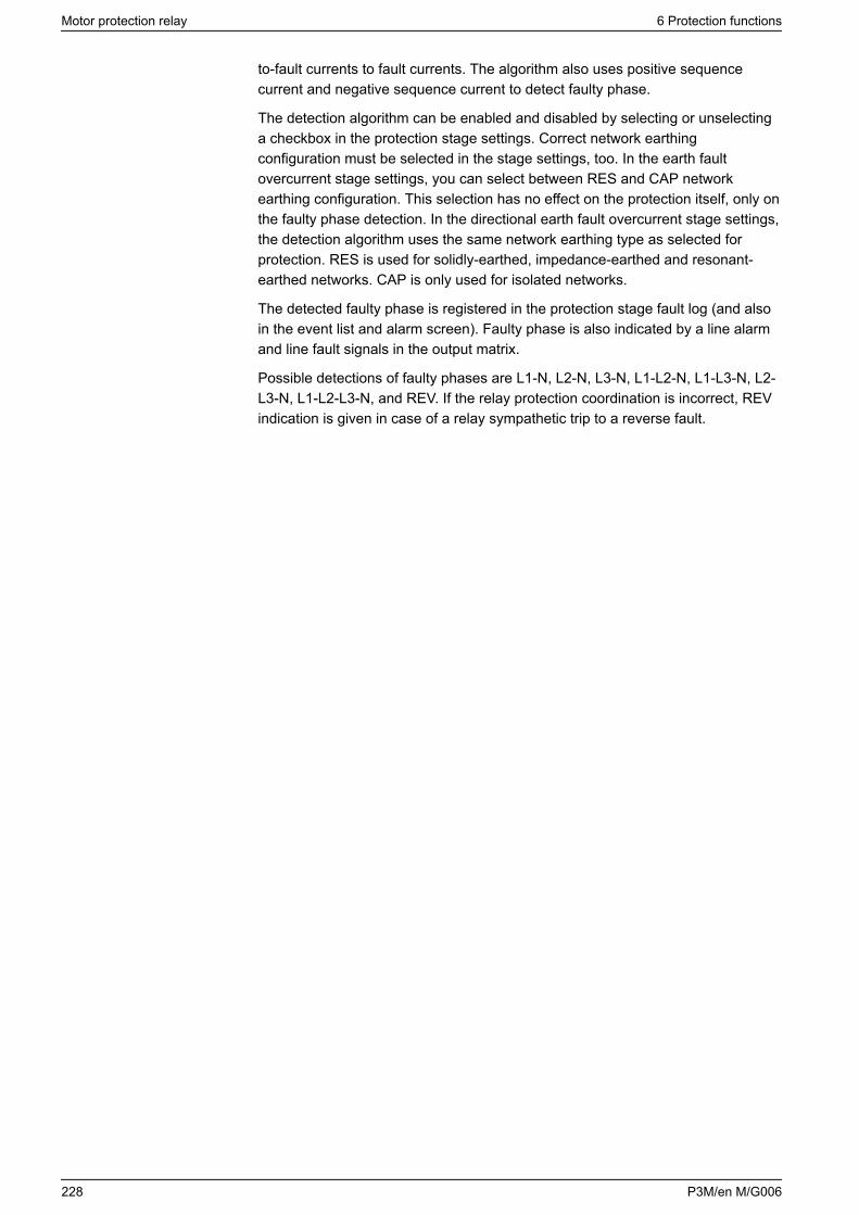
to-fault currents to fault currents. The algorithm also uses positive sequencecurrent and negative sequence current to detect faulty phase.
The detection algorithm can be enabled and disabled by selecting or unselectinga checkbox in the protection stage settings. Correct network earthingconfiguration must be selected in the stage settings, too. In the earth faultovercurrent stage settings, you can select between RES and CAP networkearthing configuration. This selection has no effect on the protection itself, only onthe faulty phase detection. In the directional earth fault overcurrent stage settings,the detection algorithm uses the same network earthing type as selected forprotection. RES is used for solidly-earthed, impedance-earthed and resonant-earthed networks. CAP is only used for isolated networks.
The detected faulty phase is registered in the protection stage fault log (and alsoin the event list and alarm screen). Faulty phase is also indicated by a line alarmand line fault signals in the output matrix.
Possible detections of faulty phases are L1-N, L2-N, L3-N, L1-L2-N, L1-L3-N, L2-L3-N, L1-L2-L3-N, and REV. If the relay protection coordination is incorrect, REVindication is given in case of a relay sympathetic trip to a reverse fault.
Motor protection relay 6 Protection functions
228 P3M/en M/G006
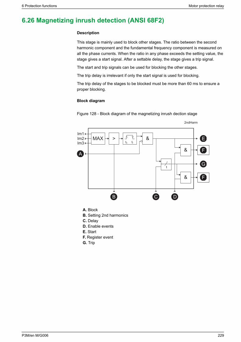
6.26 Magnetizing inrush detection (ANSI 68F2)
Description
This stage is mainly used to block other stages. The ratio between the secondharmonic component and the fundamental frequency component is measured onall the phase currents. When the ratio in any phase exceeds the setting value, thestage gives a start signal. After a settable delay, the stage gives a trip signal.
The start and trip signals can be used for blocking the other stages.
The trip delay is irrelevant if only the start signal is used for blocking.
The trip delay of the stages to be blocked must be more than 60 ms to ensure aproper blocking.
Block diagram
Figure 128 - Block diagram of the magnetizing inrush dection stage
&
t
&
Im1Im2Im3
MAX
2ndHarm
ts tr
>
B C D
E
F
G
F&
A
A. BlockB. Setting 2nd harmonicsC. DelayD. Enable eventsE. StartF. Register eventG. Trip
6 Protection functions Motor protection relay
P3M/en M/G006 229
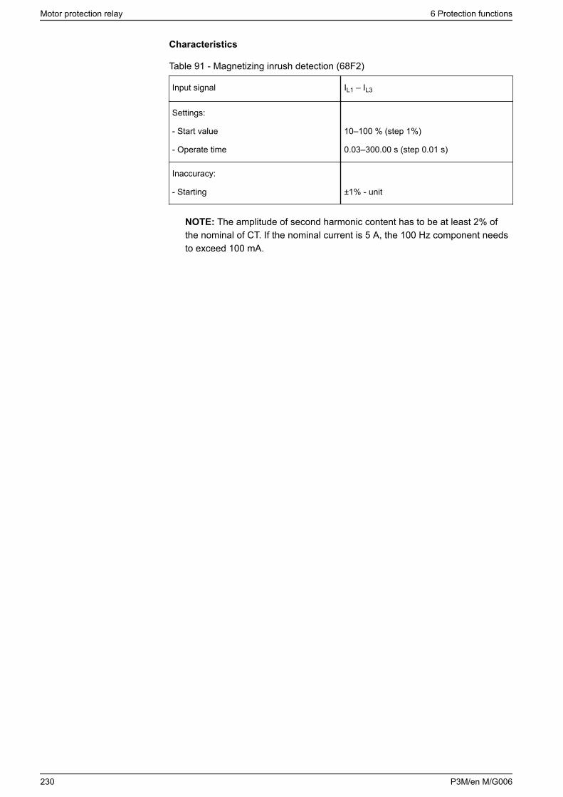
Characteristics
Table 91 - Magnetizing inrush detection (68F2)
Input signal IL1 – IL3
Settings:
- Start value
- Operate time
10–100 % (step 1%)
0.03–300.00 s (step 0.01 s)
Inaccuracy:
- Starting ±1% - unit
NOTE: The amplitude of second harmonic content has to be at least 2% ofthe nominal of CT. If the nominal current is 5 A, the 100 Hz component needsto exceed 100 mA.
Motor protection relay 6 Protection functions
230 P3M/en M/G006

6.27 Fifth harmonic detection (ANSI 68H5)
Description
Overexcitation of a transformer creates odd harmonics. The fifth harmonicdetection stage can be used detect overexcitation. This stage can also be used toblock some other stages.
The ratio between the fifth harmonic component and the fundamental frequencycomponent is measured on all the phase currents. When the ratio in any phaseexceeds the setting value, the stage activates a start signal. After a settable delay,the stage operates and activates a trip signal.
The trip delay of the stages to be blocked must be more than 60 ms to ensure aproper blocking.
Characteristics
Table 92 - Fifth harmonic detection (68H5)
Input signal IL1 – IL3
Settings:
- Setting range over exicitation
- Operate time
10–100% (step 1%)
0.03–300.00 s (step 0.01 s)
Inaccuracy:
- Starting ±2%- unit
6 Protection functions Motor protection relay
P3M/en M/G006 231

6.28 Overfrequency and underfrequency (ANSI 81)
Description
Frequency protection is used for load sharing, loss of power system detection andas a backup protection for overspeeding.
The frequency function measures the frequency from the two first voltage inputs.At least one of these two inputs must have a voltage connected to be able tomeasure the frequency. Whenever the frequency crosses the start setting of aparticular stage, this stage starts, and a start signal is issued. If the fault remainson longer than the operating delay setting, a trip signal is issued. For situationswhere no voltage is present, an adapted frequency is used.
Protection mode for f>< and f>><< stages
These two stages can be configured either for overfrequency or forunderfrequency.
Undervoltage self-blocking of underfrequency stages
The underfrequency stages are blocked when the biggest of the three line-to-linevoltages is below the low-voltage block limit setting. With this common setting,LVBlk, all stages in underfrequency mode are blocked when the voltage dropsbelow the given limit. The idea is to avoid purposeless alarms when the voltage isoff.
Initial self-blocking of underfrequency stages
When the biggest of the three line-to-line voltages has been below the block limit,the underfrequency stages are blocked until the start setting has been reached.
Four independent frequency stages
There are four separately adjustable frequency stages: f><, f>><<, f<, f<<. Thetwo first stages can be configured for either overfrequency or underfrequencyusage. So totally four underfrequency stages can be in use simultaneously. Usingthe programmable stages even more can be implemented (chapter 6.33Programmable stages (ANSI 99)). All the stages have definite operate time delay(DT).
Setting groups
There are four setting groups available for each stage.
Characteristics
Table 93 - Overfrequency and underfrequency f><, f>><< (81H/81L)
Input signal UL1 – UL3
Frequency measuring area 16.0–75.0 Hz
Current and voltage meas. range 45.0–65.0 Hz
Frequency stage setting range 40.0–70.0 Hz (step 0.01)
Motor protection relay 6 Protection functions
232 P3M/en M/G006
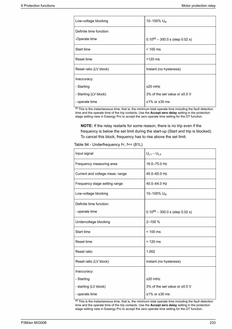
Low-voltage blocking 10–100% UN
Definite time function:
-Operate time 0.1065 – 300.0 s (step 0.02 s)
Start time < 100 ms
Reset time <120 ms
Reset ratio (LV block) Instant (no hysteresis)
Inaccuracy:
- Starting
- Starting (LV block)
- operate time
±20 mHz
3% of the set value or ±0.5 V
±1% or ±30 ms
65 This is the instantaneous time, that is, the minimum total operate time including the fault detectiontime and the operate time of the trip contacts. Use the Accept zero delay setting in the protectionstage setting view in Easergy Pro to accept the zero operate time setting for the DT function.
NOTE: If the relay restarts for some reason, there is no trip even if thefrequency is below the set limit during the start-up (Start and trip is blocked).To cancel this block, frequency has to rise above the set limit.
Table 94 - Underfrequency f<, f<< (81L)
Input signal UL1 – UL3
Frequency measuring area 16.0–75.0 Hz
Current and voltage meas. range 45.0–65.0 Hz
Frequency stage setting range 40.0–64.0 Hz
Low-voltage blocking 10–100% UN
Definite time function:
- operate time 0.1066 – 300.0 s (step 0.02 s)
Undervoltage blocking 2–100 %
Start time < 100 ms
Reset time < 120 ms
Reset ratio 1.002
Reset ratio (LV block) Instant (no hysteresis)
Inaccuracy:
- Starting
- starting (LV block)
- operate time
±20 mHz
3% of the set value or ±0.5 V
±1% or ±30 ms
66 This is the instantaneous time, that is, the minimum total operate time including the fault detectiontime and the operate time of the trip contacts. Use the Accept zero delay setting in the protectionstage setting view in Easergy Pro to accept the zero operate time setting for the DT function.
6 Protection functions Motor protection relay
P3M/en M/G006 233
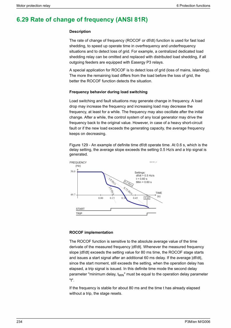
6.29 Rate of change of frequency (ANSI 81R)
Description
The rate of change of frequency (ROCOF or df/dt) function is used for fast loadshedding, to speed up operate time in overfrequency and underfrequencysituations and to detect loss of grid. For example, a centralized dedicated loadshedding relay can be omitted and replaced with distributed load shedding, if alloutgoing feeders are equipped with Easergy P3 relays.
A special application for ROCOF is to detect loss of grid (loss of mains, islanding).The more the remaining load differs from the load before the loss of grid, thebetter the ROCOF function detects the situation.
Frequency behavior during load switching
Load switching and fault situations may generate change in frequency. A loaddrop may increase the frequency and increasing load may decrease thefrequency, at least for a while. The frequency may also oscillate after the initialchange. After a while, the control system of any local generator may drive thefrequency back to the original value. However, in case of a heavy short-circuitfault or if the new load exceeds the generating capacity, the average frequencykeeps on decreasing.
Figure 129 - An example of definite time df/dt operate time. At 0.6 s, which is thedelay setting, the average slope exceeds the setting 0.5 Hz/s and a trip signal isgenerated.
FREQUENCY(Hz)
ROCOF1_v3
Settings:df/dt = 0.5 Hz/st = 0.60 stMin = 0.60 s
STARTTRIP
TIME(s)
0.5 Hz/s
1.0 Hz/s
2.0 Hz/s
0.75 Hz/s
ROCOF implementation
The ROCOF function is sensitive to the absolute average value of the timederivate of the measured frequency |df/dt|. Whenever the measured frequencyslope |df/dt| exceeds the setting value for 80 ms time, the ROCOF stage startsand issues a start signal after an additional 60 ms delay. If the average |df/dt|,since the start moment, still exceeds the setting, when the operation delay haselapsed, a trip signal is issued. In this definite time mode the second delayparameter "minimum delay, tMIN" must be equal to the operation delay parameter"t".
If the frequency is stable for about 80 ms and the time t has already elapsedwithout a trip, the stage resets.
Motor protection relay 6 Protection functions
234 P3M/en M/G006
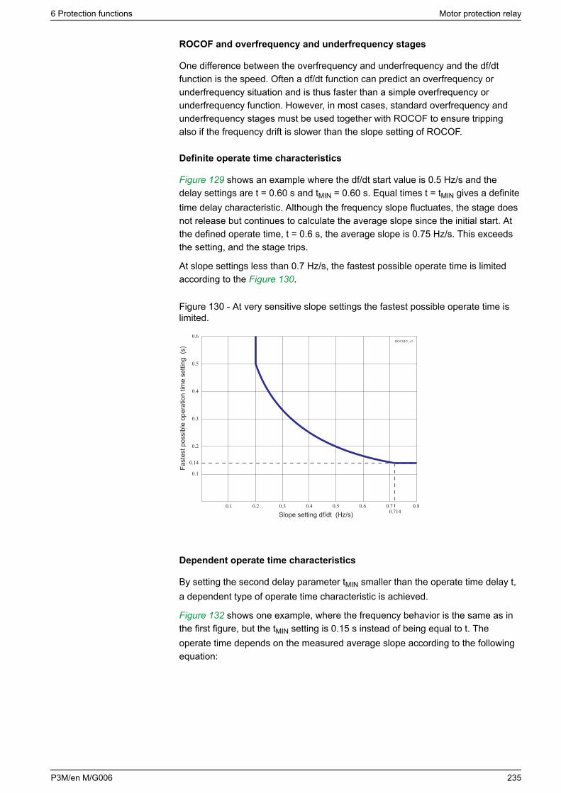
ROCOF and overfrequency and underfrequency stages
One difference between the overfrequency and underfrequency and the df/dtfunction is the speed. Often a df/dt function can predict an overfrequency orunderfrequency situation and is thus faster than a simple overfrequency orunderfrequency function. However, in most cases, standard overfrequency andunderfrequency stages must be used together with ROCOF to ensure trippingalso if the frequency drift is slower than the slope setting of ROCOF.
Definite operate time characteristics
Figure 129 shows an example where the df/dt start value is 0.5 Hz/s and thedelay settings are t = 0.60 s and tMIN = 0.60 s. Equal times t = tMIN gives a definitetime delay characteristic. Although the frequency slope fluctuates, the stage doesnot release but continues to calculate the average slope since the initial start. Atthe defined operate time, t = 0.6 s, the average slope is 0.75 Hz/s. This exceedsthe setting, and the stage trips.
At slope settings less than 0.7 Hz/s, the fastest possible operate time is limitedaccording to the Figure 130.
Figure 130 - At very sensitive slope settings the fastest possible operate time islimited.
Fast
est p
ossi
ble
oper
atio
n tim
e se
tting
(s)
ROCOF5_v3
Slope setting df/dt (Hz/s)
Dependent operate time characteristics
By setting the second delay parameter tMIN smaller than the operate time delay t,a dependent type of operate time characteristic is achieved.
Figure 132 shows one example, where the frequency behavior is the same as inthe first figure, but the tMIN setting is 0.15 s instead of being equal to t. Theoperate time depends on the measured average slope according to the followingequation:
6 Protection functions Motor protection relay
P3M/en M/G006 235
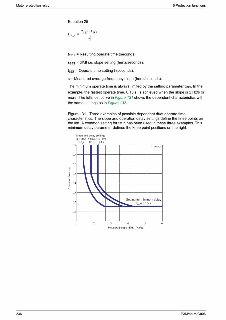
Equation 25
sts
t SETSETTRIP
⋅=
tTRIP = Resulting operate time (seconds).
sSET = df/dt i.e. slope setting (hertz/seconds).
tSET = Operate time setting t (seconds).
s = Measured average frequency slope (hertz/seconds).
The minimum operate time is always limited by the setting parameter tMIN. In theexample, the fastest operate time, 0.15 s, is achieved when the slope is 2 Hz/s ormore. The leftmost curve in Figure 131 shows the dependent characteristics withthe same settings as in Figure 132.
Figure 131 - Three examples of possible dependent df/dt operate timecharacteristics. The slope and operation delay settings define the knee points onthe left. A common setting for tMin has been used in these three examples. Thisminimum delay parameter defines the knee point positions on the right.
ROCOF6_v3
Ope
ratio
n tim
e (s
)
Measured slope |df/dt| (Hz/s)
Setting for minimum delaytMin= 0.15 s
Slope and delay settings0.5 Hz/s 1 Hz/s 1.5 Hz/s
Motor protection relay 6 Protection functions
236 P3M/en M/G006

Figure 132 - An example of dependent df/dt operate time. The time to trip will be0.3 s, although the setting is 0.6 s, because the average slope 1 Hz/s is steeperthan the setting value 0.5 Hz/s.
0.75 Hz/s
2.0Hz/s
FREQUENCY(Hz)
49.7
STARTTRIP
Settings:df/dt = 0.5 Hz/st = 0.60 st = 0.15sMin
0.00 0.450.30
50.0
TIME(s)
ROCOF3_v3
1.0 Hz/s0.5 Hz/s
0.15 0.60
Settings groups
There are four setting groups available.
Characteristics
Table 95 - Rate of change of frequency df/dt> (81R)
Start setting df/dt 0.2–10.0 Hz/s (step 0.1 Hz/s)
Definite time delay (t> and tMin> are equal):
- Operate time t> 0.1467 – 10.00 s (step 0.02 s)
Dependent time delay (t> is more thantMin>):
- Minimum operate time tMin>0.1467 – 10.00 s (step 0.02 s)
Start time Typically 140 ms
Reset time 150 ms
Overshoot time < 90 ms
Reset ratio 1
Inaccuracy:
- Starting
- Operate time(overshoot ≥ 0.2 Hz/s)
10% of set value or ±0.1 Hz/s
±35 ms, when area is 0.2 – 1.0 Hz/s
67 This is the instantaneous time, that is, the minimum total operate time including the fault detectiontime and the operate time of the trip contacts. Use the Accept zero delay setting in the protectionstage setting view in Easergy Pro to accept the zero operate time setting for the DT function.
NOTE: ROCOF stage is using the same low voltage blocking limit as thefrequency stages.
6 Protection functions Motor protection relay
P3M/en M/G006 237
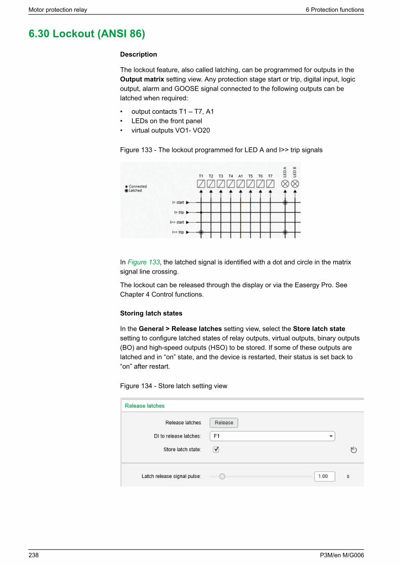
6.30 Lockout (ANSI 86)
Description
The lockout feature, also called latching, can be programmed for outputs in theOutput matrix setting view. Any protection stage start or trip, digital input, logicoutput, alarm and GOOSE signal connected to the following outputs can belatched when required:
• output contacts T1 – T7, A1• LEDs on the front panel• virtual outputs VO1- VO20
Figure 133 - The lockout programmed for LED A and I>> trip signals
In Figure 133, the latched signal is identified with a dot and circle in the matrixsignal line crossing.
The lockout can be released through the display or via the Easergy Pro. SeeChapter 4 Control functions.
Storing latch states
In the General > Release latches setting view, select the Store latch statesetting to configure latched states of relay outputs, virtual outputs, binary outputs(BO) and high-speed outputs (HSO) to be stored. If some of these outputs arelatched and in “on” state, and the device is restarted, their status is set back to“on” after restart.
Figure 134 - Store latch setting view
Motor protection relay 6 Protection functions
238 P3M/en M/G006
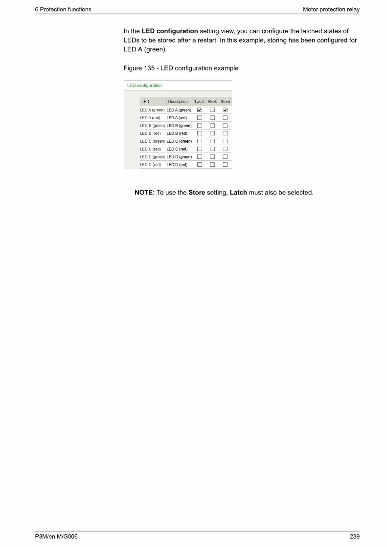
In the LED configuration setting view, you can configure the latched states ofLEDs to be stored after a restart. In this example, storing has been configured forLED A (green).
Figure 135 - LED configuration example
NOTE: To use the Store setting, Latch must also be selected.
6 Protection functions Motor protection relay
P3M/en M/G006 239
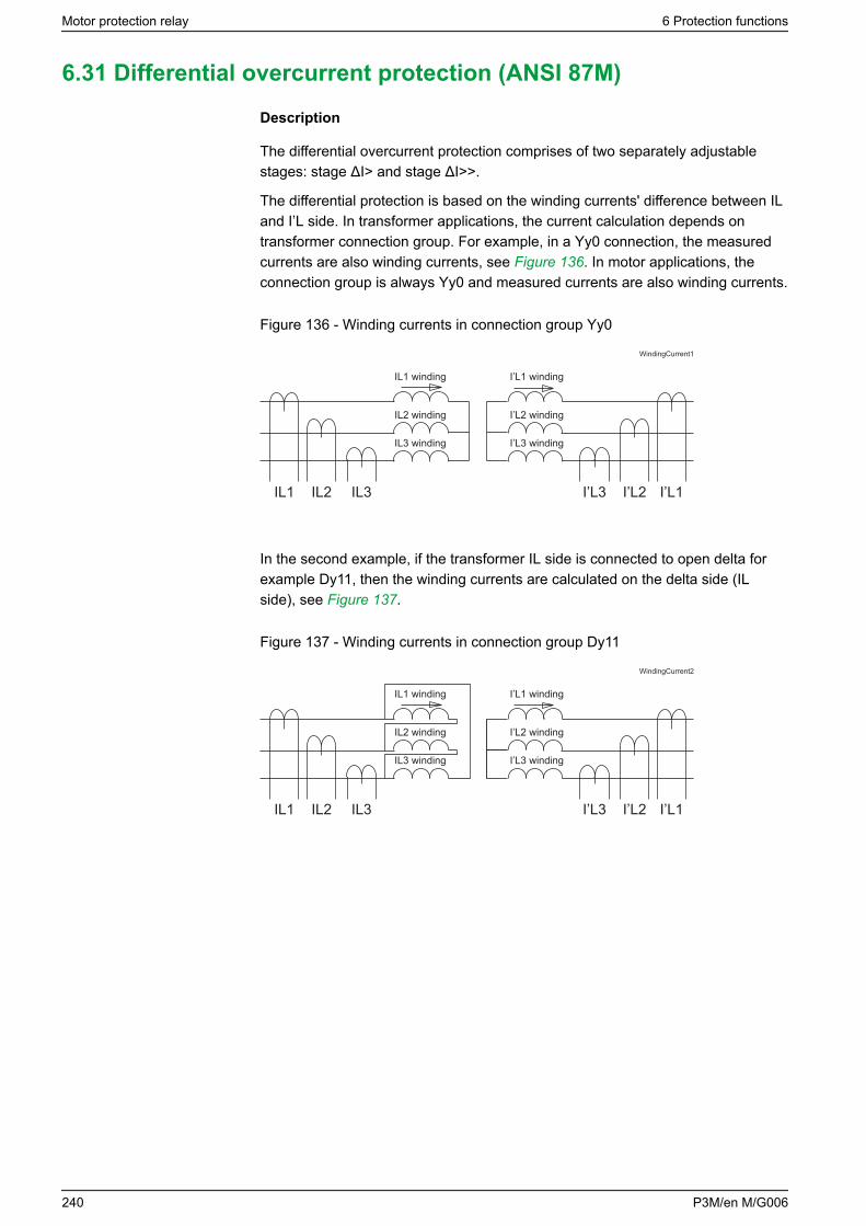
6.31 Differential overcurrent protection (ANSI 87M)
Description
The differential overcurrent protection comprises of two separately adjustablestages: stage ΔI> and stage ΔI>>.
The differential protection is based on the winding currents' difference between ILand I’L side. In transformer applications, the current calculation depends ontransformer connection group. For example, in a Yy0 connection, the measuredcurrents are also winding currents, see Figure 136. In motor applications, theconnection group is always Yy0 and measured currents are also winding currents.
Figure 136 - Winding currents in connection group Yy0
IL1 winding
IL2 winding
IL3 winding
WindingCurrent1
IL1 IL2 IL3 I’L3 I’L2 I’L1
I’L1 winding
I’L2 winding
I’L3 winding
In the second example, if the transformer IL side is connected to open delta forexample Dy11, then the winding currents are calculated on the delta side (ILside), see Figure 137.
Figure 137 - Winding currents in connection group Dy11
IL1 winding
IL2 winding
IL3 winding
WindingCurrent2
IL1 IL2 IL3 I’L3 I’L2 I’L1
I’L1 winding
I’L2 winding
I’L3 winding
Motor protection relay 6 Protection functions
240 P3M/en M/G006
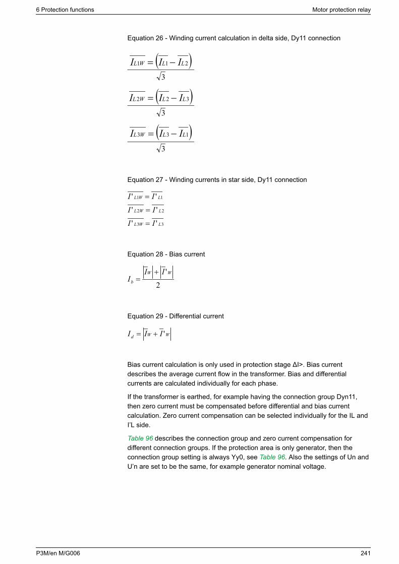
Equation 26 - Winding current calculation in delta side, Dy11 connection
( )211 LLWL III −=3
)( 322 LLWL III −=3
( )133 LLWL III −=3
Equation 27 - Winding currents in star side, Dy11 connection
33
22
11
''
''
''
LWL
LWL
LWL
II
II
II
=
=
=
Equation 28 - Bias current
2
'WW
b
III
+=
Equation 29 - Differential current
WWd III '+=
Bias current calculation is only used in protection stage ΔI>. Bias currentdescribes the average current flow in the transformer. Bias and differentialcurrents are calculated individually for each phase.
If the transformer is earthed, for example having the connection group Dyn11,then zero current must be compensated before differential and bias currentcalculation. Zero current compensation can be selected individually for the IL andI’L side.
Table 96 describes the connection group and zero current compensation fordifferent connection groups. If the protection area is only generator, then theconnection group setting is always Yy0, see Table 96. Also the settings of Un andU’n are set to be the same, for example generator nominal voltage.
6 Protection functions Motor protection relay
P3M/en M/G006 241
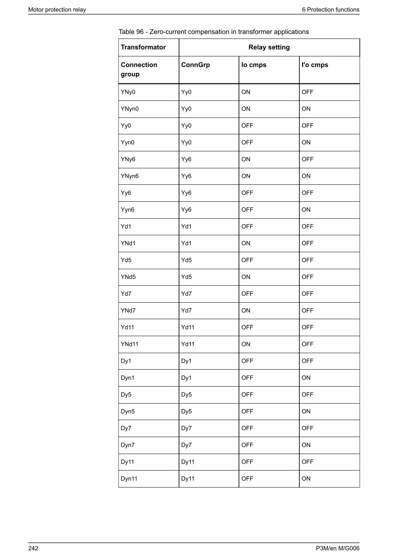
Table 96 - Zero-current compensation in transformer applications
Transformator Relay setting
Connectiongroup
ConnGrp Io cmps I'o cmps
YNy0 Yy0 ON OFF
YNyn0 Yy0 ON ON
Yy0 Yy0 OFF OFF
Yyn0 Yy0 OFF ON
YNy6 Yy6 ON OFF
YNyn6 Yy6 ON ON
Yy6 Yy6 OFF OFF
Yyn6 Yy6 OFF ON
Yd1 Yd1 OFF OFF
YNd1 Yd1 ON OFF
Yd5 Yd5 OFF OFF
YNd5 Yd5 ON OFF
Yd7 Yd7 OFF OFF
YNd7 Yd7 ON OFF
Yd11 Yd11 OFF OFF
YNd11 Yd11 ON OFF
Dy1 Dy1 OFF OFF
Dyn1 Dy1 OFF ON
Dy5 Dy5 OFF OFF
Dyn5 Dy5 OFF ON
Dy7 Dy7 OFF OFF
Dyn7 Dy7 OFF ON
Dy11 Dy11 OFF OFF
Dyn11 Dy11 OFF ON
Motor protection relay 6 Protection functions
242 P3M/en M/G006
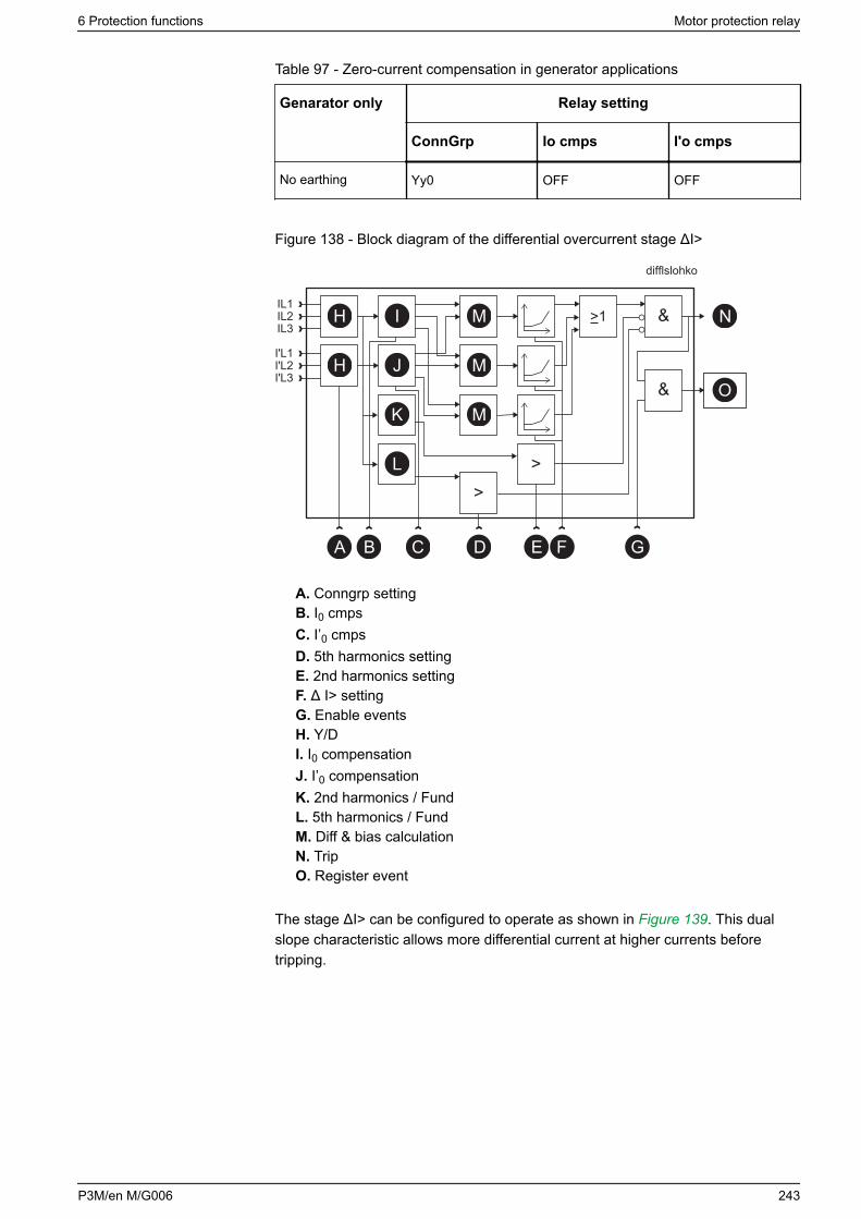
Table 97 - Zero-current compensation in generator applications
Genarator only Relay setting
ConnGrp Io cmps I'o cmps
No earthing Yy0 OFF OFF
Figure 138 - Block diagram of the differential overcurrent stage ΔI>
>1
B G
N
O
D F
M
&
>
M
M
&
>
H
H
I
J
K
L
IL1IL2IL3
I'L1I'L2I'L3
C EA
difflslohko
A. Conngrp settingB. I0 cmpsC. I’0 cmpsD. 5th harmonics settingE. 2nd harmonics settingF. Δ I> settingG. Enable eventsH. Y/DI. I0 compensationJ. I’0 compensationK. 2nd harmonics / FundL. 5th harmonics / FundM. Diff & bias calculationN. TripO. Register event
The stage ΔI> can be configured to operate as shown in Figure 139. This dualslope characteristic allows more differential current at higher currents beforetripping.
6 Protection functions Motor protection relay
P3M/en M/G006 243
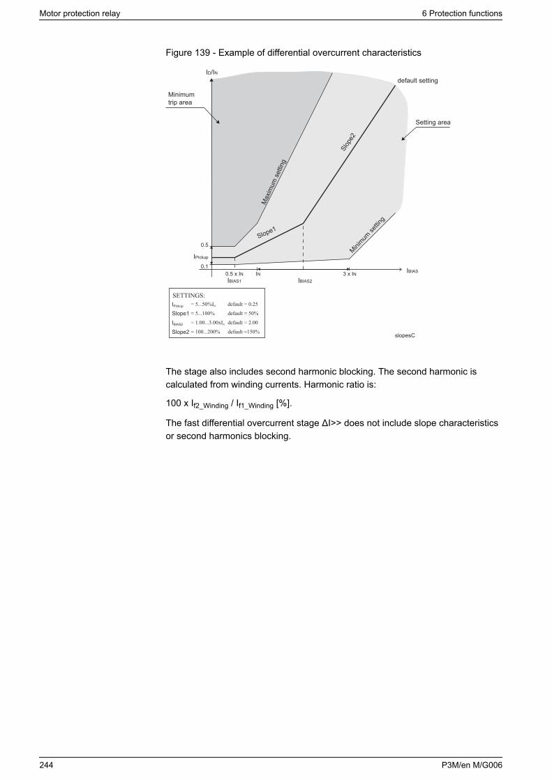
Figure 139 - Example of differential overcurrent characteristics
IPickup
slopesC
IBIAS2
Slope1
Slope2
Minimumtrip area
ID/IN
Max
imum
set
ting
Slope1
Slop
e2Mini
mum se
tting
IPickup
0.5
0.1
IBIAS1 IBIAS20.5 x IN IN 3 x IN IBIAS
Setting area
default setting
The stage also includes second harmonic blocking. The second harmonic iscalculated from winding currents. Harmonic ratio is:
100 x If2_Winding / If1_Winding [%].
The fast differential overcurrent stage ΔI>> does not include slope characteristicsor second harmonics blocking.
Motor protection relay 6 Protection functions
244 P3M/en M/G006

Differential protection using six CTs
Figure 140 - Easergy P3M30 and P3M32 connected as a motor differentialprotection device using six CTs
L1
L2L3
M
8E1:8F1:
123456
124578
4T1:
In this application mode, the settings in the device’s Scaling menu should be setas described in the following sections.
CT settings
Here, the motor high and low side primary and secondary CT ratings are setaccording to the actual CT ratios.
Set motor nominal current.
Settings of the differential protection
ΔI> 87 function shall be enabled for differential protection.
ΔI> pick-up setting range is user selectable from 5 % to 50 %.
Slope 1 can be set to 5 %.
IBIAS for start of slope 2 can be set to 3 x IN
Slope 2 can be set to 50 %.
If CTs are saturating at through faults, the Slope 2 settings must be changedaccordingly.
ΔI> 2nd harmonic block enable can be set OFF (disabled).
ΔI> 2nd harmonic block limit can be disregarded and the factory default settingcan be left intact.
6 Protection functions Motor protection relay
P3M/en M/G006 245
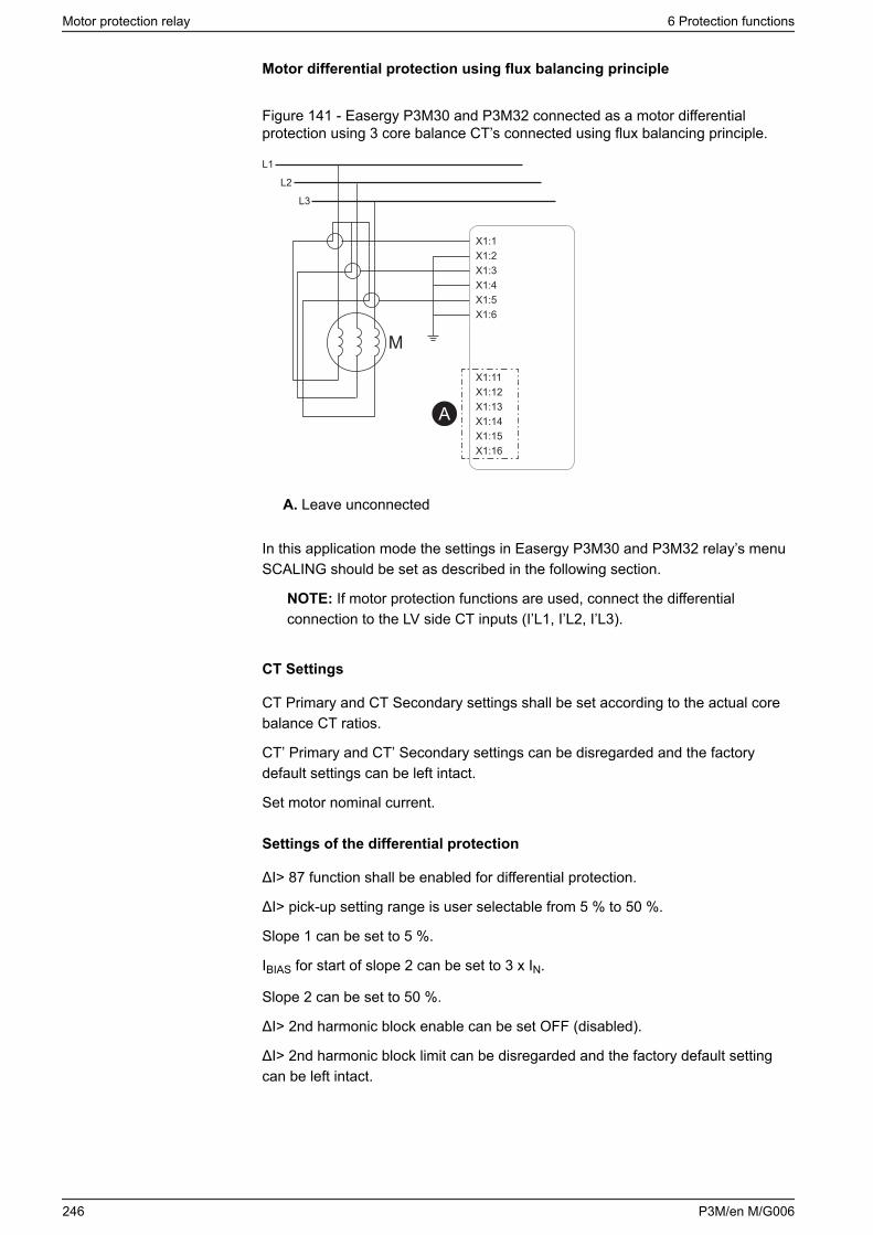
Motor differential protection using flux balancing principle
Figure 141 - Easergy P3M30 and P3M32 connected as a motor differentialprotection using 3 core balance CT’s connected using flux balancing principle.
A
X1:1X1:2X1:3X1:4X1:5X1:6
X1:11X1:12X1:13X1:14X1:15X1:16
L1
L2
L3
M
A. Leave unconnected
In this application mode the settings in Easergy P3M30 and P3M32 relay’s menuSCALING should be set as described in the following section.
NOTE: If motor protection functions are used, connect the differentialconnection to the LV side CT inputs (I’L1, I’L2, I’L3).
CT Settings
CT Primary and CT Secondary settings shall be set according to the actual corebalance CT ratios.
CT’ Primary and CT’ Secondary settings can be disregarded and the factorydefault settings can be left intact.
Set motor nominal current.
Settings of the differential protection
ΔI> 87 function shall be enabled for differential protection.
ΔI> pick-up setting range is user selectable from 5 % to 50 %.
Slope 1 can be set to 5 %.
IBIAS for start of slope 2 can be set to 3 x IN.
Slope 2 can be set to 50 %.
ΔI> 2nd harmonic block enable can be set OFF (disabled).
ΔI> 2nd harmonic block limit can be disregarded and the factory default settingcan be left intact.
Motor protection relay 6 Protection functions
246 P3M/en M/G006
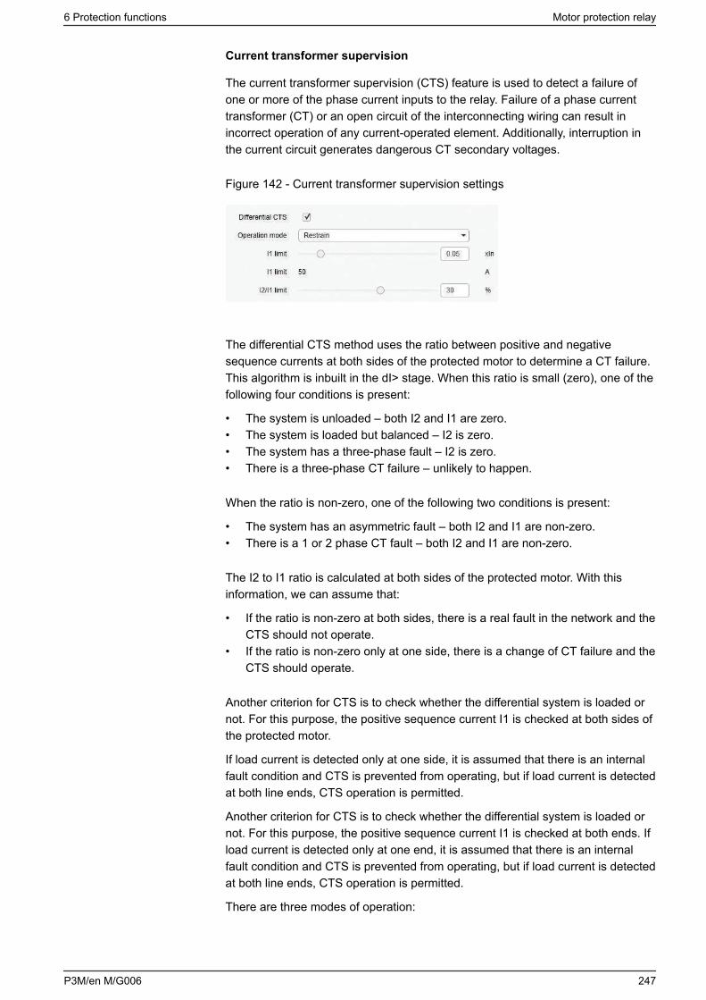
Current transformer supervision
The current transformer supervision (CTS) feature is used to detect a failure ofone or more of the phase current inputs to the relay. Failure of a phase currenttransformer (CT) or an open circuit of the interconnecting wiring can result inincorrect operation of any current-operated element. Additionally, interruption inthe current circuit generates dangerous CT secondary voltages.
Figure 142 - Current transformer supervision settings
The differential CTS method uses the ratio between positive and negativesequence currents at both sides of the protected motor to determine a CT failure.This algorithm is inbuilt in the dI> stage. When this ratio is small (zero), one of thefollowing four conditions is present:
• The system is unloaded – both I2 and I1 are zero.• The system is loaded but balanced – I2 is zero.• The system has a three-phase fault – I2 is zero.• There is a three-phase CT failure – unlikely to happen.
When the ratio is non-zero, one of the following two conditions is present:
• The system has an asymmetric fault – both I2 and I1 are non-zero.• There is a 1 or 2 phase CT fault – both I2 and I1 are non-zero.
The I2 to I1 ratio is calculated at both sides of the protected motor. With thisinformation, we can assume that:
• If the ratio is non-zero at both sides, there is a real fault in the network and theCTS should not operate.
• If the ratio is non-zero only at one side, there is a change of CT failure and theCTS should operate.
Another criterion for CTS is to check whether the differential system is loaded ornot. For this purpose, the positive sequence current I1 is checked at both sides ofthe protected motor.
If load current is detected only at one side, it is assumed that there is an internalfault condition and CTS is prevented from operating, but if load current is detectedat both line ends, CTS operation is permitted.
Another criterion for CTS is to check whether the differential system is loaded ornot. For this purpose, the positive sequence current I1 is checked at both ends. Ifload current is detected only at one end, it is assumed that there is an internalfault condition and CTS is prevented from operating, but if load current is detectedat both line ends, CTS operation is permitted.
There are three modes of operation:
6 Protection functions Motor protection relay
P3M/en M/G006 247
• indication mode: CTS alarm is raised but there is no effect on tripping• restrain mode: an alarm is raised and the differential current percentage
setting value increased by 100 (for example 30 % + 100 % = 130 %). The newvalue is theoretically the maximum amount of differential current that a CTfailure can produce in a normal full-load condition.
• block mode: an alarm is raised and differential protection is prevented fromtripping
The differential CTS block mode is not recommended for two reasons:
• If there is a real fault during a CT failure, the differential protection would notprotect the line at all.
• Blocking the protection could slow down the operate time of the differentialprotection because of transients in the beginning of the fault on the protectedline.
Setting groups
This stage has one setting group.
Characteristics
Table 98 - Differential overcurrent stage ΔI> (87)
Start value 5–50 % IN
Bias current for start of slope 1 0.50 x IN
Slope 1 5–100 %
Bias current for start of slope 2 1.00–3.00 x IN
Slope 2 100–200 %
Second harmonic blocking 5–30 %, or disable
Fifth harmonic blocking 20–50 %, or disable
Reset time
Reset ratio
< 95 ms
0.95
Inaccuracy:
- Second harmonic blocking ±2% - unit
- Fifth harmonic blocking ±3% - unit
- Starting ±3% of set value or 0.02 x IN when currentsare < 200 mA
- Operate time (ID > 1.2 x ISET) < 60 ms
- Operate time (ID > 3.5 x ISET) < 50 ms
Motor protection relay 6 Protection functions
248 P3M/en M/G006
Table 99 - Differential overcurrent stage ΔI>> (87)
Start value 5.0 – 40.0 x IN
Reset time
Reset ratio
< 95 ms
0.95
Inaccuracy:
- Starting ±3% of set value or ±0.5% of rated value
- Operate time (ID > 3.5 x ISET) < 40 ms
6.32 Arc flash detection (AFD)
DANGERHAZARD OF ELECTRIC SHOCK, EXPLOSION, OR ARC FLASH
Information on this product is offered as a tool for conducting arc flashhazard analysis. It is intended for use only by qualified persons who areknowledgeable about power system studies, power distribution equipment,and equipment installation practices. It is not intended as a substitute for theengineering judgement and adequate review necessary for such activities.
Failure to follow this instruction will result in death or serious injury.
6.32.1 Arc flash detection, general principle
The arc flash detection contains 8 arc stages that can be used to trip for examplethe circuit breakers. Arc stages are activated with overcurrent and light signals (orlight signals alone). The allocation of different current and light signals to arcstages is defined in arc flash detection matrices: current, light and output matrix.The matrices are programmed via the arc flash detection menus. Available matrixsignals depend on the order code (see 13.1 Order codes).
The available signal inputs and outputs for arc flash detection depend on therelay's hardware configuration.
NOTE: The arc flash detection function is not yet available in LPIT models.
6.32.2 Arc flash detection menus
The arc flash detection menus are located in the main menu under ARC. TheARC menu can be viewed either on the front panel or by using Easergy Pro.
6 Protection functions Motor protection relay
P3M/en M/G006 249
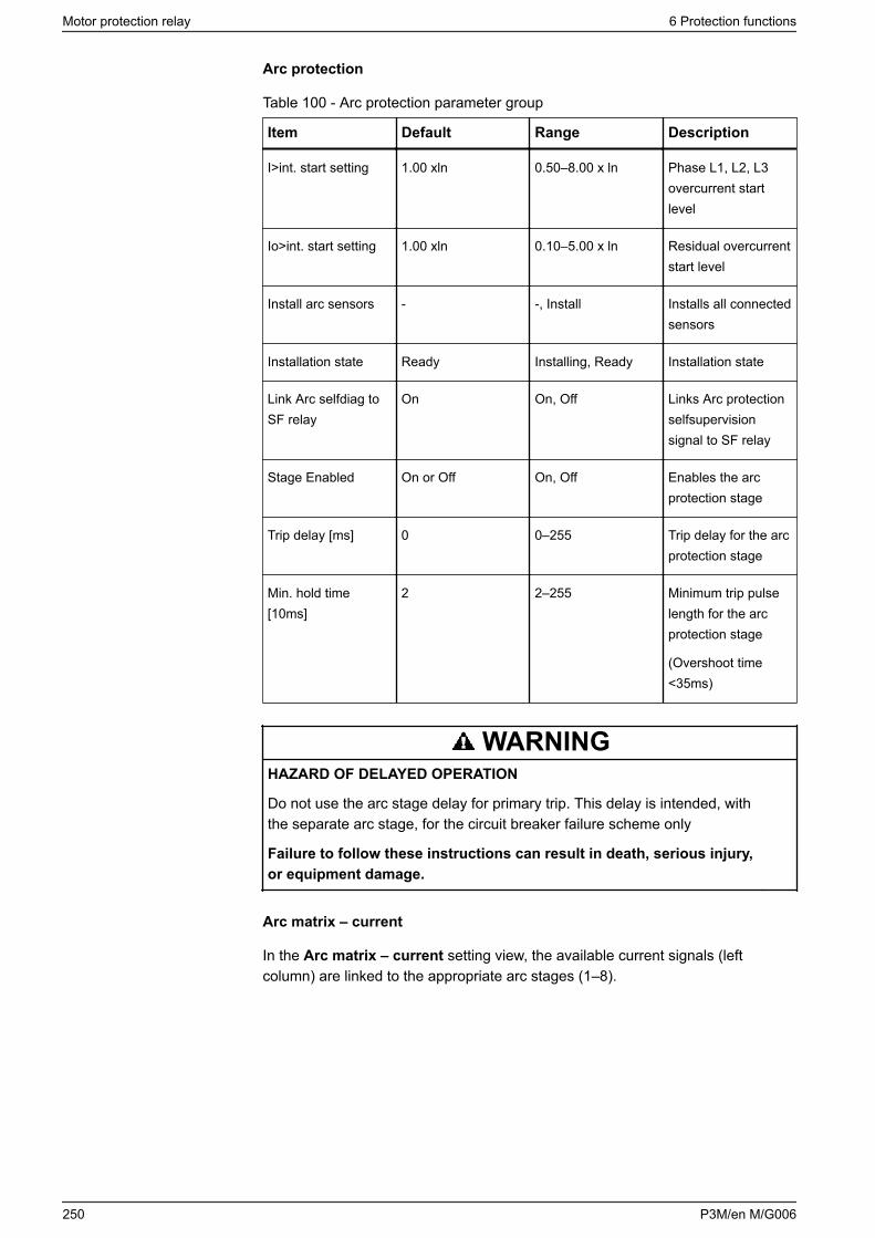
Arc protection
Table 100 - Arc protection parameter group
Item Default Range Description
I>int. start setting 1.00 xln 0.50–8.00 x ln Phase L1, L2, L3overcurrent startlevel
Io>int. start setting 1.00 xln 0.10–5.00 x ln Residual overcurrentstart level
Install arc sensors - -, Install Installs all connectedsensors
Installation state Ready Installing, Ready Installation state
Link Arc selfdiag toSF relay
On On, Off Links Arc protectionselfsupervisionsignal to SF relay
Stage Enabled On or Off On, Off Enables the arcprotection stage
Trip delay [ms] 0 0–255 Trip delay for the arcprotection stage
Min. hold time[10ms]
2 2–255 Minimum trip pulselength for the arcprotection stage
(Overshoot time<35ms)
WARNINGHAZARD OF DELAYED OPERATION
Do not use the arc stage delay for primary trip. This delay is intended, withthe separate arc stage, for the circuit breaker failure scheme only
Failure to follow these instructions can result in death, serious injury,or equipment damage.
Arc matrix – current
In the Arc matrix – current setting view, the available current signals (leftcolumn) are linked to the appropriate arc stages (1–8).
Motor protection relay 6 Protection functions
250 P3M/en M/G006
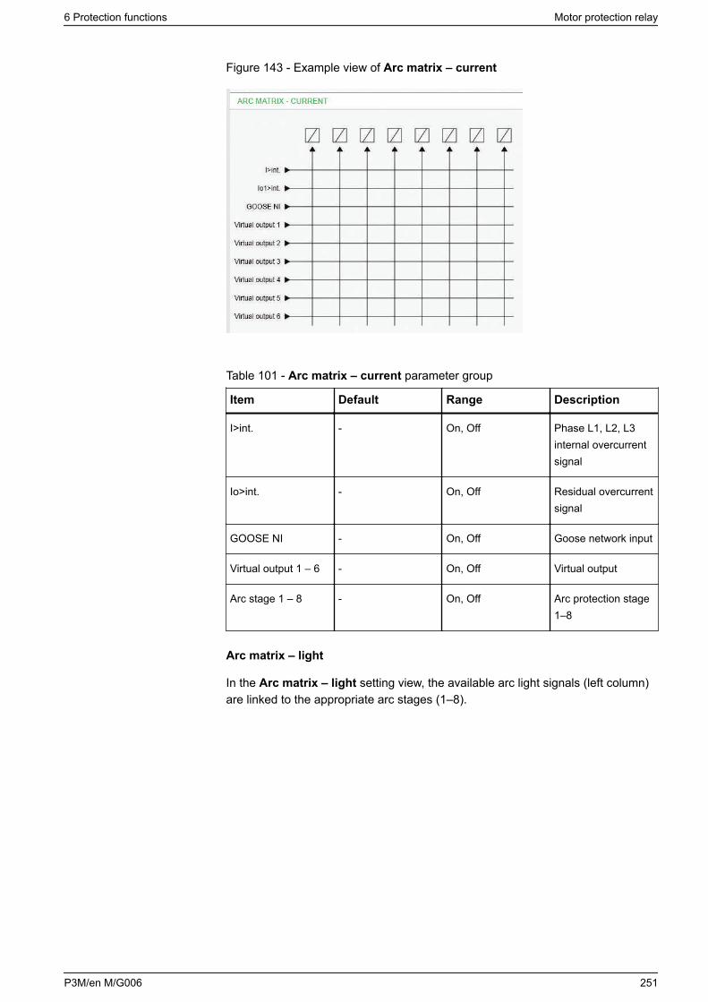
Figure 143 - Example view of Arc matrix – current
Table 101 - Arc matrix – current parameter group
Item Default Range Description
I>int. - On, Off Phase L1, L2, L3internal overcurrentsignal
Io>int. - On, Off Residual overcurrentsignal
GOOSE NI - On, Off Goose network input
Virtual output 1 – 6 - On, Off Virtual output
Arc stage 1 – 8 - On, Off Arc protection stage1–8
Arc matrix – light
In the Arc matrix – light setting view, the available arc light signals (left column)are linked to the appropriate arc stages (1–8).
6 Protection functions Motor protection relay
P3M/en M/G006 251
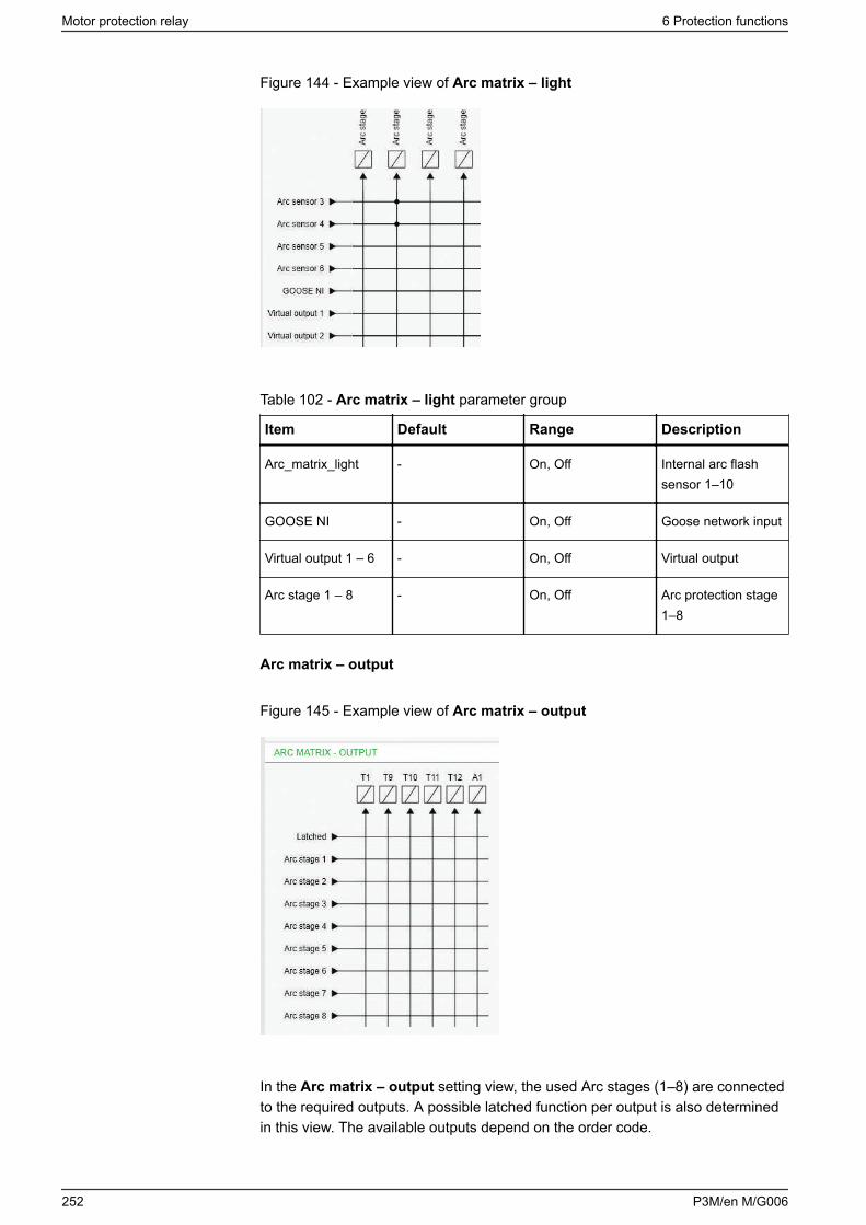
Figure 144 - Example view of Arc matrix – light
Table 102 - Arc matrix – light parameter group
Item Default Range Description
Arc_matrix_light - On, Off Internal arc flashsensor 1–10
GOOSE NI - On, Off Goose network input
Virtual output 1 – 6 - On, Off Virtual output
Arc stage 1 – 8 - On, Off Arc protection stage1–8
Arc matrix – output
Figure 145 - Example view of Arc matrix – output
In the Arc matrix – output setting view, the used Arc stages (1–8) are connectedto the required outputs. A possible latched function per output is also determinedin this view. The available outputs depend on the order code.
Motor protection relay 6 Protection functions
252 P3M/en M/G006
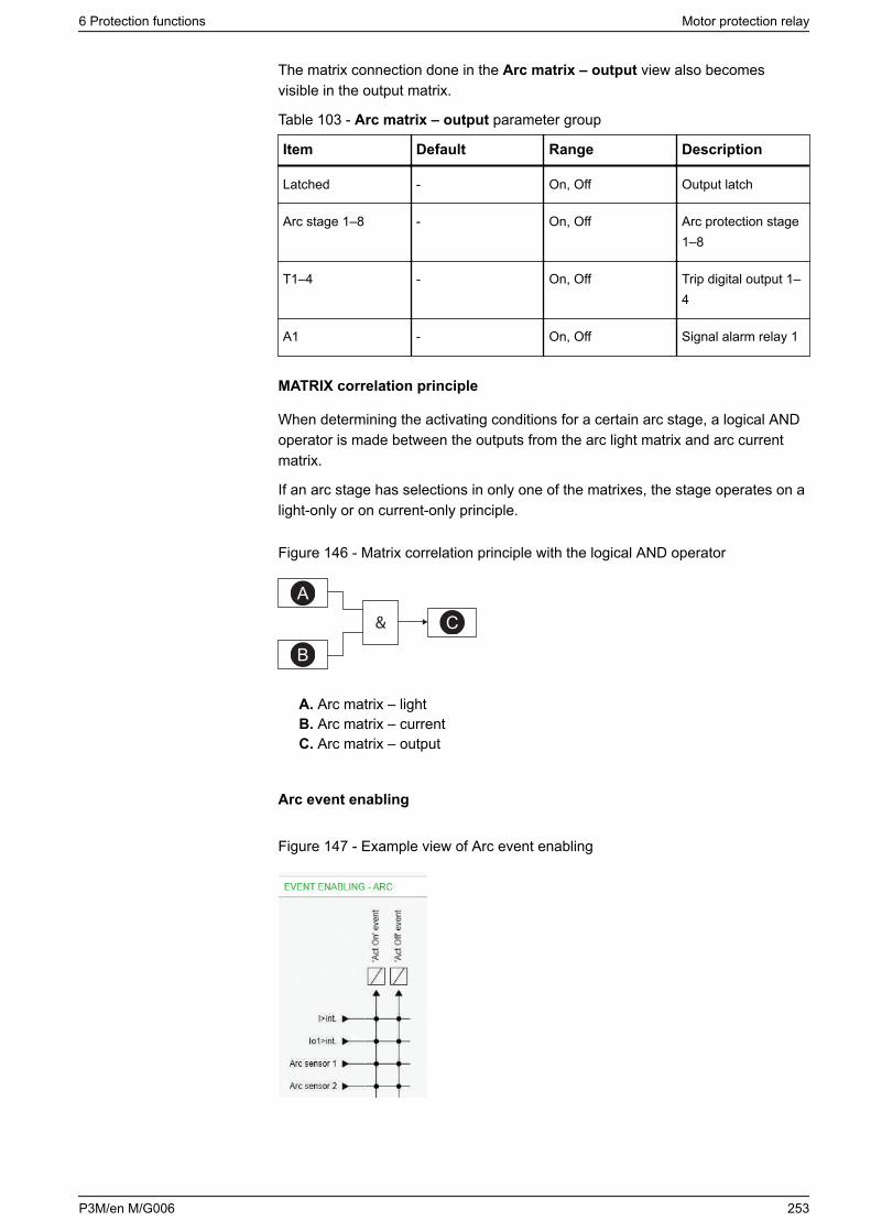
The matrix connection done in the Arc matrix – output view also becomesvisible in the output matrix.
Table 103 - Arc matrix – output parameter group
Item Default Range Description
Latched - On, Off Output latch
Arc stage 1–8 - On, Off Arc protection stage1–8
T1–4 - On, Off Trip digital output 1–4
A1 - On, Off Signal alarm relay 1
MATRIX correlation principle
When determining the activating conditions for a certain arc stage, a logical ANDoperator is made between the outputs from the arc light matrix and arc currentmatrix.
If an arc stage has selections in only one of the matrixes, the stage operates on alight-only or on current-only principle.
Figure 146 - Matrix correlation principle with the logical AND operator
A
B
C&
A. Arc matrix – lightB. Arc matrix – currentC. Arc matrix – output
Arc event enabling
Figure 147 - Example view of Arc event enabling
6 Protection functions Motor protection relay
P3M/en M/G006 253
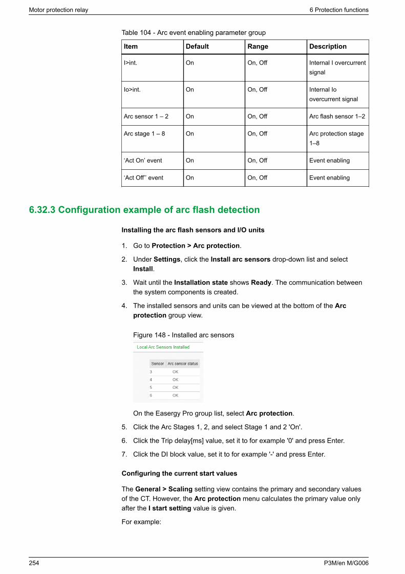
Table 104 - Arc event enabling parameter group
Item Default Range Description
I>int. On On, Off Internal I overcurrentsignal
Io>int. On On, Off Internal Ioovercurrent signal
Arc sensor 1 – 2 On On, Off Arc flash sensor 1–2
Arc stage 1 – 8 On On, Off Arc protection stage1–8
‘Act On’ event On On, Off Event enabling
‘Act Off’’ event On On, Off Event enabling
6.32.3 Configuration example of arc flash detection
Installing the arc flash sensors and I/O units
1. Go to Protection > Arc protection.
2. Under Settings, click the Install arc sensors drop-down list and selectInstall.
3. Wait until the Installation state shows Ready. The communication betweenthe system components is created.
4. The installed sensors and units can be viewed at the bottom of the Arcprotection group view.
Figure 148 - Installed arc sensors
On the Easergy Pro group list, select Arc protection.
5. Click the Arc Stages 1, 2, and select Stage 1 and 2 'On'.
6. Click the Trip delay[ms] value, set it to for example '0' and press Enter.
7. Click the DI block value, set it to for example '-' and press Enter.
Configuring the current start values
The General > Scaling setting view contains the primary and secondary valuesof the CT. However, the Arc protection menu calculates the primary value onlyafter the I start setting value is given.
For example:
Motor protection relay 6 Protection functions
254 P3M/en M/G006
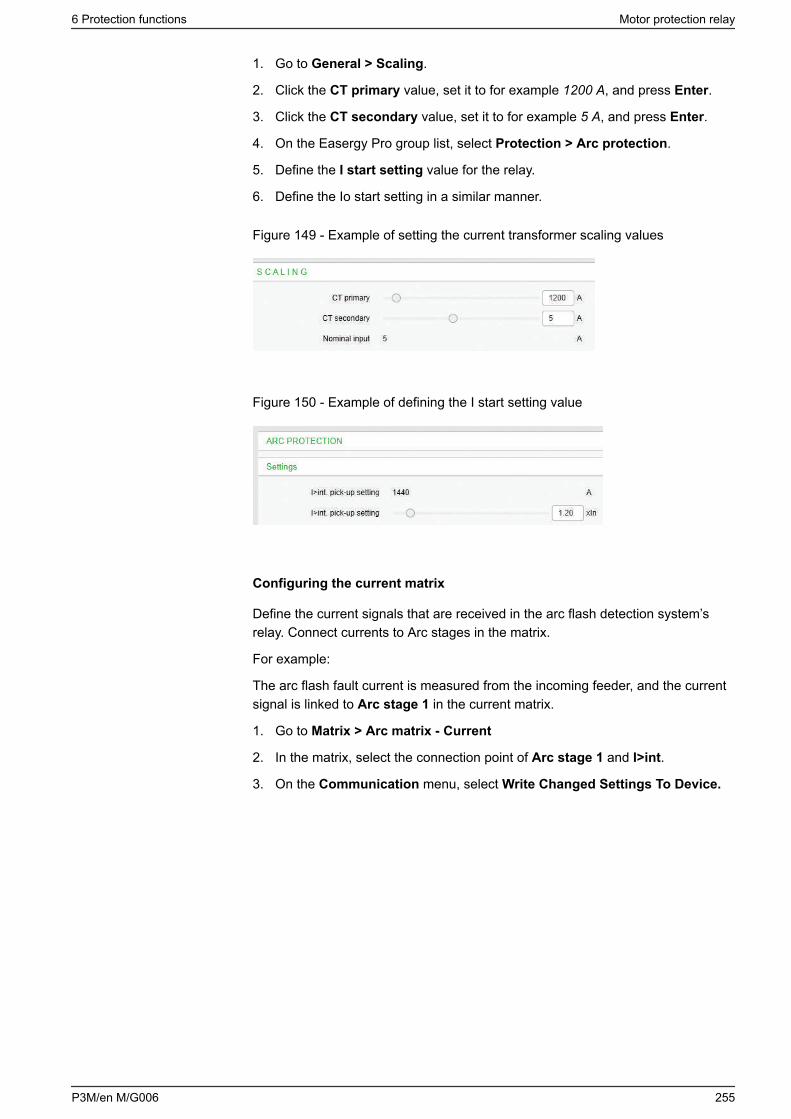
1. Go to General > Scaling.
2. Click the CT primary value, set it to for example 1200 A, and press Enter.
3. Click the CT secondary value, set it to for example 5 A, and press Enter.
4. On the Easergy Pro group list, select Protection > Arc protection.
5. Define the I start setting value for the relay.
6. Define the Io start setting in a similar manner.
Figure 149 - Example of setting the current transformer scaling values
Figure 150 - Example of defining the I start setting value
Configuring the current matrix
Define the current signals that are received in the arc flash detection system’srelay. Connect currents to Arc stages in the matrix.
For example:
The arc flash fault current is measured from the incoming feeder, and the currentsignal is linked to Arc stage 1 in the current matrix.
1. Go to Matrix > Arc matrix - Current
2. In the matrix, select the connection point of Arc stage 1 and I>int.
3. On the Communication menu, select Write Changed Settings To Device.
6 Protection functions Motor protection relay
P3M/en M/G006 255
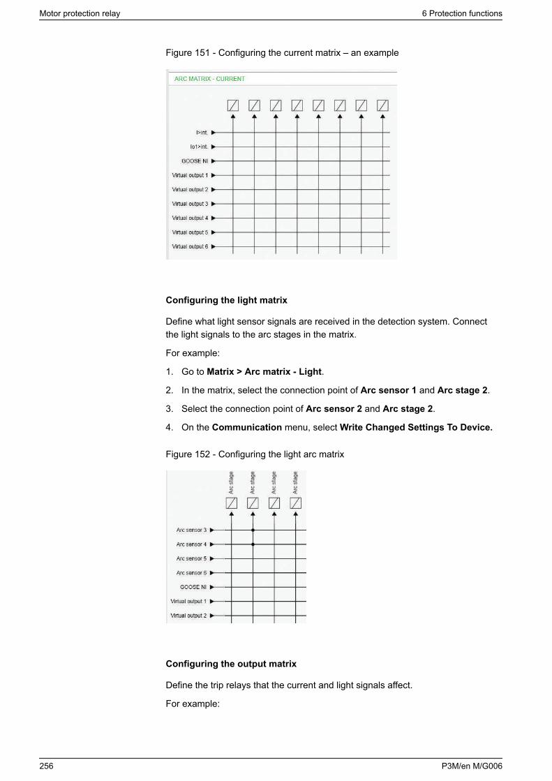
Figure 151 - Configuring the current matrix – an example
Configuring the light matrix
Define what light sensor signals are received in the detection system. Connectthe light signals to the arc stages in the matrix.
For example:
1. Go to Matrix > Arc matrix - Light.
2. In the matrix, select the connection point of Arc sensor 1 and Arc stage 2.
3. Select the connection point of Arc sensor 2 and Arc stage 2.
4. On the Communication menu, select Write Changed Settings To Device.
Figure 152 - Configuring the light arc matrix
Configuring the output matrix
Define the trip relays that the current and light signals affect.
For example:
Motor protection relay 6 Protection functions
256 P3M/en M/G006
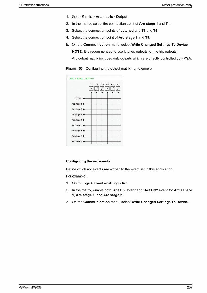
1. Go to Matrix > Arc matrix - Output.
2. In the matrix, select the connection point of Arc stage 1 and T1.
3. Select the connection points of Latched and T1 and T9.
4. Select the connection point of Arc stage 2 and T9.
5. On the Communication menu, select Write Changed Settings To Device.
NOTE: It is recommended to use latched outputs for the trip outputs.
Arc output matrix includes only outputs which are directly controlled by FPGA.
Figure 153 - Configuring the output matrix - an example
Configuring the arc events
Define which arc events are written to the event list in this application.
For example:
1. Go to Logs > Event enabling - Arc.
2. In the matrix, enable both ‘Act On’ event and ‘Act Off’’ event for Arc sensor1, Arc stage 1, and Arc stage 2.
3. On the Communication menu, select Write Changed Settings To Device.
6 Protection functions Motor protection relay
P3M/en M/G006 257
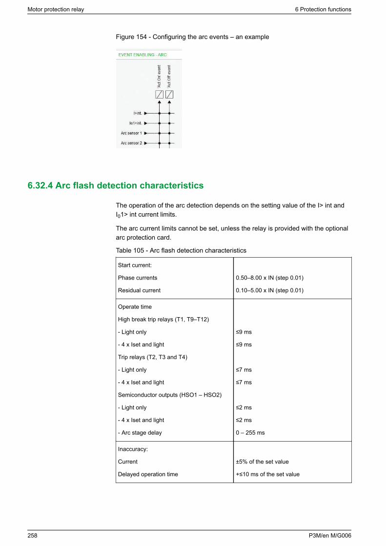
Figure 154 - Configuring the arc events – an example
6.32.4 Arc flash detection characteristics
The operation of the arc detection depends on the setting value of the I> int andI01> int current limits.
The arc current limits cannot be set, unless the relay is provided with the optionalarc protection card.
Table 105 - Arc flash detection characteristics
Start current:
Phase currents
Residual current
0.50–8.00 x IN (step 0.01)
0.10–5.00 x IN (step 0.01)
Operate time
High break trip relays (T1, T9–T12)
- Light only
- 4 x Iset and light
Trip relays (T2, T3 and T4)
- Light only
- 4 x Iset and light
Semiconductor outputs (HSO1 – HSO2)
- Light only
- 4 x Iset and light
- Arc stage delay
≤9 ms
≤9 ms
≤7 ms
≤7 ms
≤2 ms
≤2 ms
0 – 255 ms
Inaccuracy:
Current
Delayed operation time
±5% of the set value
+≤10 ms of the set value
Motor protection relay 6 Protection functions
258 P3M/en M/G006
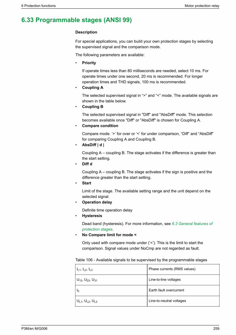
6.33 Programmable stages (ANSI 99)
Description
For special applications, you can build your own protection stages by selectingthe supervised signal and the comparison mode.
The following parameters are available:
• Priority
If operate times less than 80 milliseconds are needed, select 10 ms. Foroperate times under one second, 20 ms is recommended. For longeroperation times and THD signals, 100 ms is recommended.
• Coupling A
The selected supervised signal in “>” and “<” mode. The available signals areshown in the table below.
• Coupling B
The selected supervised signal in "Diff" and "AbsDiff" mode. This selectionbecomes available once "Diff" or "AbsDiff" is chosen for Coupling A.
• Compare condition
Compare mode. ‘>’ for over or ‘<’ for under comparison, “Diff” and “AbsDiff”for comparing Coupling A and Coupling B.
• AbsDiff | d |
Coupling A – coupling B. The stage activates if the difference is greater thanthe start setting.
• Diff d
Coupling A – coupling B. The stage activates if the sign is positive and thedifference greater than the start setting.
• Start
Limit of the stage. The available setting range and the unit depend on theselected signal.
• Operation delay
Definite time operation delay• Hysteresis
Dead band (hysteresis). For more information, see 6.3 General features ofprotection stages.
• No Compare limit for mode <
Only used with compare mode under (‘<’). This is the limit to start thecomparison. Signal values under NoCmp are not regarded as fault.
Table 106 - Available signals to be supervised by the programmable stages
IL1, IL2, IL3 Phase currents (RMS values)
U12, U23, U31 Line-to-line voltages
I0 Earth fault overcurrent
UL1, UL2, UL3 Line-to-neutral voltages
6 Protection functions Motor protection relay
P3M/en M/G006 259
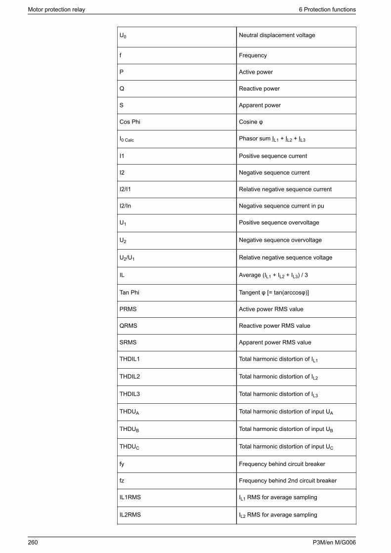
U0 Neutral displacement voltage
f Frequency
P Active power
Q Reactive power
S Apparent power
Cos Phi Cosine φ
I0 Calc Phasor sum IL1 + IL2 + IL3
I1 Positive sequence current
I2 Negative sequence current
I2/I1 Relative negative sequence current
I2/In Negative sequence current in pu
U1 Positive sequence overvoltage
U2 Negative sequence overvoltage
U2/U1 Relative negative sequence voltage
IL Average (IL1 + IL2 + IL3) / 3
Tan Phi Tangent φ [= tan(arccosφ)]
PRMS Active power RMS value
QRMS Reactive power RMS value
SRMS Apparent power RMS value
THDIL1 Total harmonic distortion of IL1
THDIL2 Total harmonic distortion of IL2
THDIL3 Total harmonic distortion of IL3
THDUA Total harmonic distortion of input UA
THDUB Total harmonic distortion of input UB
THDUC Total harmonic distortion of input UC
fy Frequency behind circuit breaker
fz Frequency behind 2nd circuit breaker
IL1RMS IL1 RMS for average sampling
IL2RMS IL2 RMS for average sampling
Motor protection relay 6 Protection functions
260 P3M/en M/G006
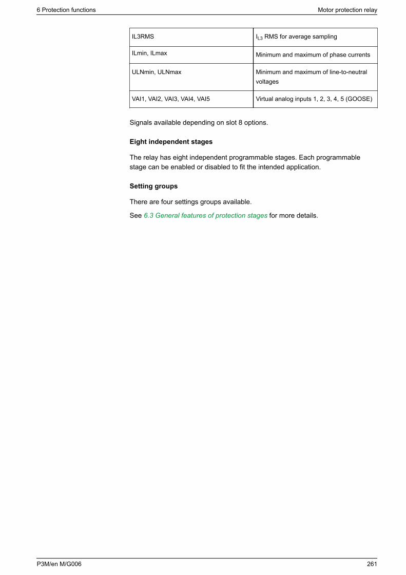
IL3RMS IL3 RMS for average sampling
ILmin, ILmax Minimum and maximum of phase currents
ULNmin, ULNmax Minimum and maximum of line-to-neutralvoltages
VAI1, VAI2, VAI3, VAI4, VAI5 Virtual analog inputs 1, 2, 3, 4, 5 (GOOSE)
Signals available depending on slot 8 options.
Eight independent stages
The relay has eight independent programmable stages. Each programmablestage can be enabled or disabled to fit the intended application.
Setting groups
There are four settings groups available.
See 6.3 General features of protection stages for more details.
6 Protection functions Motor protection relay
P3M/en M/G006 261
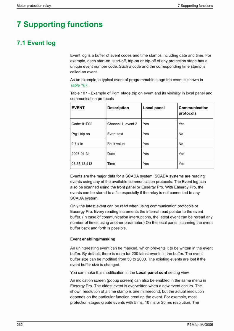
7 Supporting functions
7.1 Event log
Event log is a buffer of event codes and time stamps including date and time. Forexample, each start-on, start-off, trip-on or trip-off of any protection stage has aunique event number code. Such a code and the corresponding time stamp iscalled an event.
As an example, a typical event of programmable stage trip event is shown in Table 107.
Table 107 - Example of Pgr1 stage trip on event and its visibility in local panel andcommunication protocols
EVENT Description Local panel Communicationprotocols
Code: 01E02 Channel 1, event 2 Yes Yes
Prg1 trip on Event text Yes No
2.7 x In Fault value Yes No
2007-01-31 Date Yes Yes
08:35:13.413 Time Yes Yes
Events are the major data for a SCADA system. SCADA systems are readingevents using any of the available communication protocols. The Event log canalso be scanned using the front panel or Easergy Pro. With Easergy Pro, theevents can be stored to a file especially if the relay is not connected to anySCADA system.
Only the latest event can be read when using communication protocols orEasergy Pro. Every reading increments the internal read pointer to the eventbuffer. (In case of communication interruptions, the latest event can be reread anynumber of times using another parameter.) On the local panel, scanning the eventbuffer back and forth is possible.
Event enabling/masking
An uninteresting event can be masked, which prevents it to be written in the eventbuffer. By default, there is room for 200 latest events in the buffer. The eventbuffer size can be modified from 50 to 2000. The existing events are lost if theevent buffer size is changed.
You can make this modification in the Local panel conf setting view.
An indication screen (popup screen) can also be enabled in the same menu inEasergy Pro. The oldest event is overwritten when a new event occurs. Theshown resolution of a time stamp is one millisecond, but the actual resolutiondepends on the particular function creating the event. For example, mostprotection stages create events with 5 ms, 10 ms or 20 ms resolution. The
Motor protection relay 7 Supporting functions
262 P3M/en M/G006
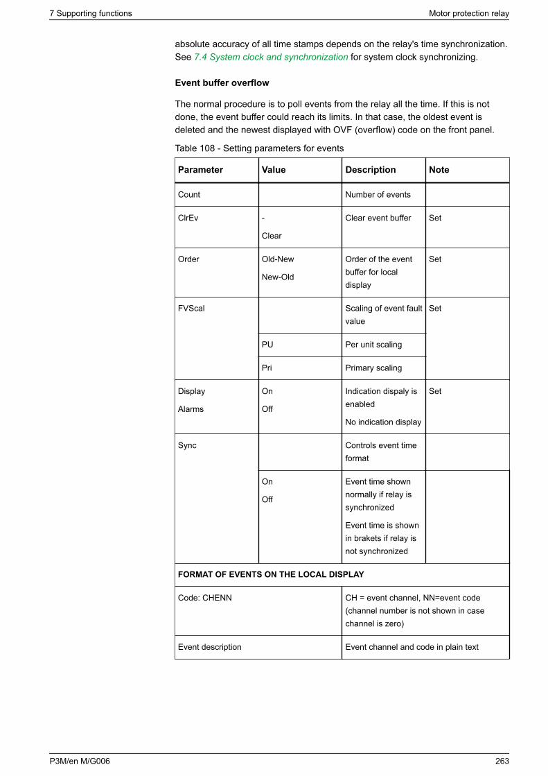
absolute accuracy of all time stamps depends on the relay's time synchronization.See 7.4 System clock and synchronization for system clock synchronizing.
Event buffer overflow
The normal procedure is to poll events from the relay all the time. If this is notdone, the event buffer could reach its limits. In that case, the oldest event isdeleted and the newest displayed with OVF (overflow) code on the front panel.
Table 108 - Setting parameters for events
Parameter Value Description Note
Count Number of events
ClrEv -
Clear
Clear event buffer Set
Order Old-New
New-Old
Order of the eventbuffer for localdisplay
Set
FVScal Scaling of event faultvalue
Set
PU Per unit scaling
Pri Primary scaling
Display
Alarms
On
Off
Indication dispaly isenabled
No indication display
Set
Sync Controls event timeformat
On
Off
Event time shownnormally if relay issynchronized
Event time is shownin brakets if relay isnot synchronized
FORMAT OF EVENTS ON THE LOCAL DISPLAY
Code: CHENN CH = event channel, NN=event code(channel number is not shown in casechannel is zero)
Event description Event channel and code in plain text
7 Supporting functions Motor protection relay
P3M/en M/G006 263
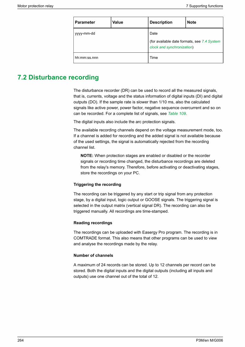
Parameter Value Description Note
yyyy-mm-dd Date
(for available date formats, see 7.4 Systemclock and synchronization)
hh:mm:ss.nnn Time
7.2 Disturbance recording
The disturbance recorder (DR) can be used to record all the measured signals,that is, currents, voltage and the status information of digital inputs (DI) and digitaloutputs (DO). If the sample rate is slower than 1/10 ms, also the calculatedsignals like active power, power factor, negative sequence overcurrent and so oncan be recorded. For a complete list of signals, see Table 109.
The digital inputs also include the arc protection signals.
The available recording channels depend on the voltage measurement mode, too.If a channel is added for recording and the added signal is not available becauseof the used settings, the signal is automatically rejected from the recordingchannel list.
NOTE: When protection stages are enabled or disabled or the recordersignals or recording time changed, the disturbance recordings are deletedfrom the relay's memory. Therefore, before activating or deactivating stages,store the recordings on your PC.
Triggering the recording
The recording can be triggered by any start or trip signal from any protectionstage, by a digital input, logic output or GOOSE signals. The triggering signal isselected in the output matrix (vertical signal DR). The recording can also betriggered manually. All recordings are time-stamped.
Reading recordings
The recordings can be uploaded with Easergy Pro program. The recording is inCOMTRADE format. This also means that other programs can be used to viewand analyse the recordings made by the relay.
Number of channels
A maximum of 24 records can be stored. Up to 12 channels per record can bestored. Both the digital inputs and the digital outputs (including all inputs andoutputs) use one channel out of the total of 12.
Motor protection relay 7 Supporting functions
264 P3M/en M/G006
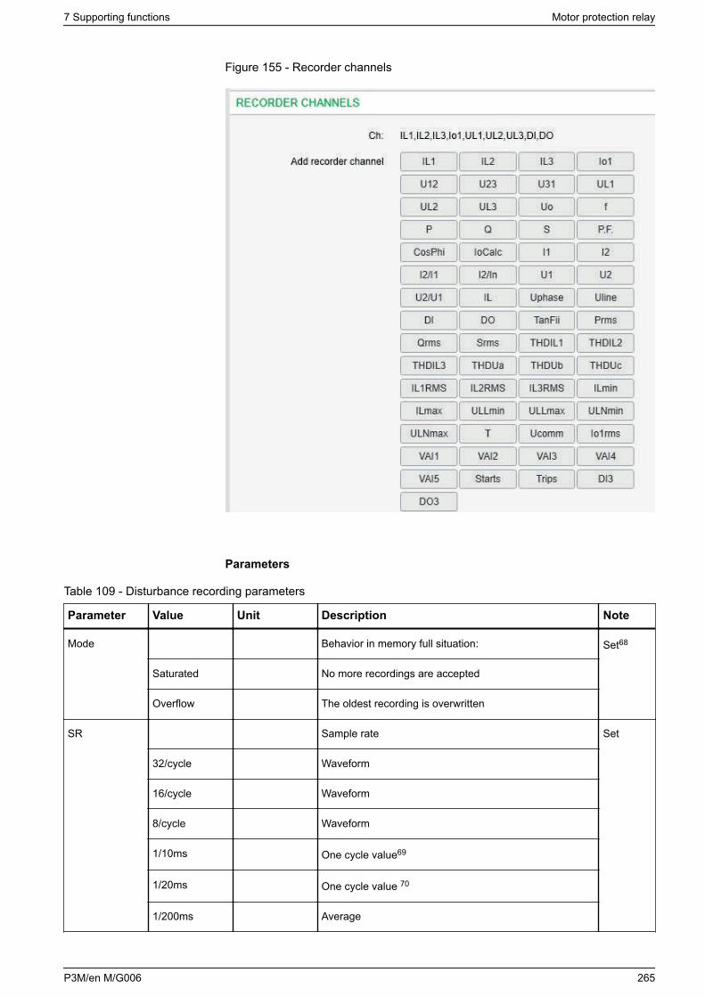
Figure 155 - Recorder channels
Parameters
Table 109 - Disturbance recording parameters
Parameter Value Unit Description Note
Mode Behavior in memory full situation: Set68
Saturated No more recordings are accepted
Overflow The oldest recording is overwritten
SR Sample rate Set
32/cycle Waveform
16/cycle Waveform
8/cycle Waveform
1/10ms One cycle value69
1/20ms One cycle value 70
1/200ms Average
7 Supporting functions Motor protection relay
P3M/en M/G006 265
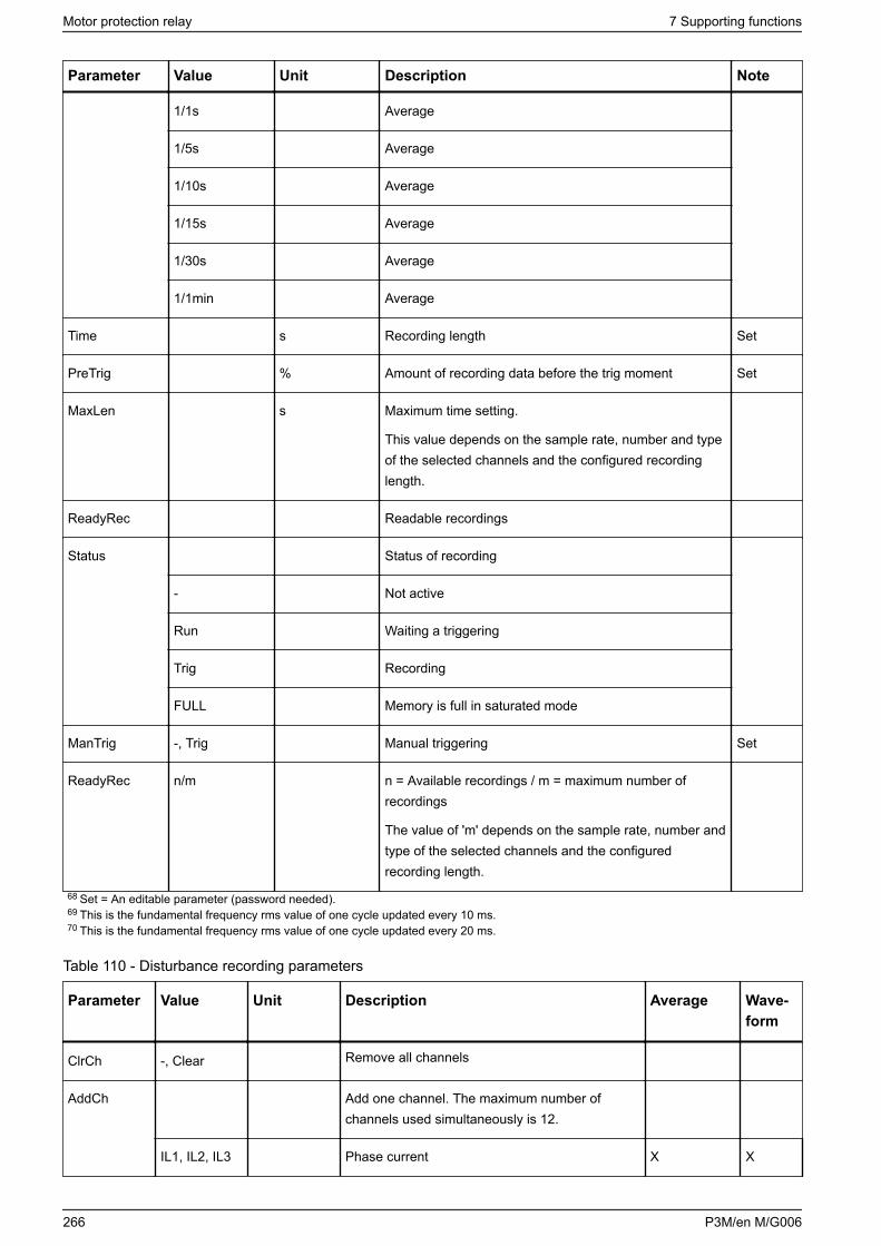
Parameter Value Unit Description Note
1/1s Average
1/5s Average
1/10s Average
1/15s Average
1/30s Average
1/1min Average
Time s Recording length Set
PreTrig % Amount of recording data before the trig moment Set
MaxLen s Maximum time setting.
This value depends on the sample rate, number and typeof the selected channels and the configured recordinglength.
ReadyRec Readable recordings
Status Status of recording
- Not active
Run Waiting a triggering
Trig Recording
FULL Memory is full in saturated mode
ManTrig -, Trig Manual triggering Set
ReadyRec n/m n = Available recordings / m = maximum number ofrecordings
The value of 'm' depends on the sample rate, number andtype of the selected channels and the configuredrecording length.
68 Set = An editable parameter (password needed).69 This is the fundamental frequency rms value of one cycle updated every 10 ms.70 This is the fundamental frequency rms value of one cycle updated every 20 ms.
Table 110 - Disturbance recording parameters
Parameter Value Unit Description Average Wave-form
ClrCh -, Clear Remove all channels
AddCh Add one channel. The maximum number ofchannels used simultaneously is 12.
IL1, IL2, IL3 Phase current X X
Motor protection relay 7 Supporting functions
266 P3M/en M/G006
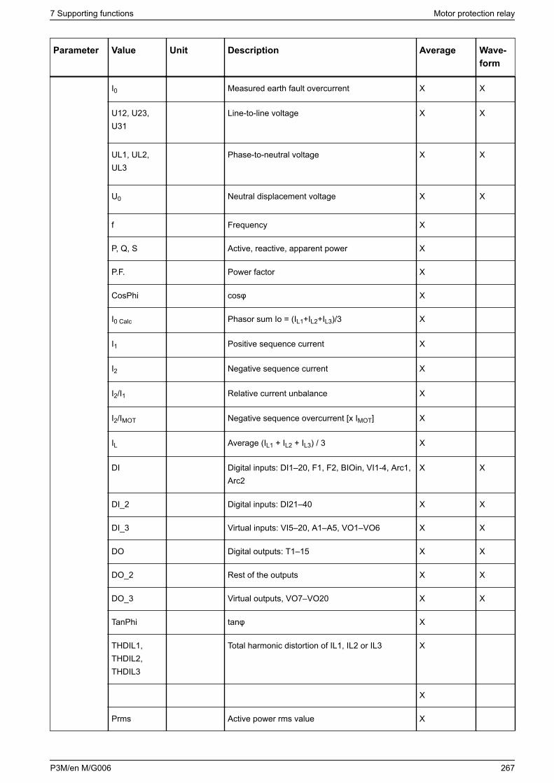
Parameter Value Unit Description Average Wave-form
I0 Measured earth fault overcurrent X X
U12, U23,U31
Line-to-line voltage X X
UL1, UL2,UL3
Phase-to-neutral voltage X X
U0 Neutral displacement voltage X X
f Frequency X
P, Q, S Active, reactive, apparent power X
P.F. Power factor X
CosPhi cosφ X
I0 Calc Phasor sum Io = (IL1+IL2+IL3)/3 X
I1 Positive sequence current X
I2 Negative sequence current X
I2/I1 Relative current unbalance X
I2/IMOT Negative sequence overcurrent [x IMOT] X
IL Average (IL1 + IL2 + IL3) / 3 X
DI Digital inputs: DI1–20, F1, F2, BIOin, VI1-4, Arc1,Arc2
X X
DI_2 Digital inputs: DI21–40 X X
DI_3 Virtual inputs: VI5–20, A1–A5, VO1–VO6 X X
DO Digital outputs: T1–15 X X
DO_2 Rest of the outputs X X
DO_3 Virtual outputs, VO7–VO20 X X
TanPhi tanφ X
THDIL1,THDIL2,THDIL3
Total harmonic distortion of IL1, IL2 or IL3 X
X
Prms Active power rms value X
7 Supporting functions Motor protection relay
P3M/en M/G006 267
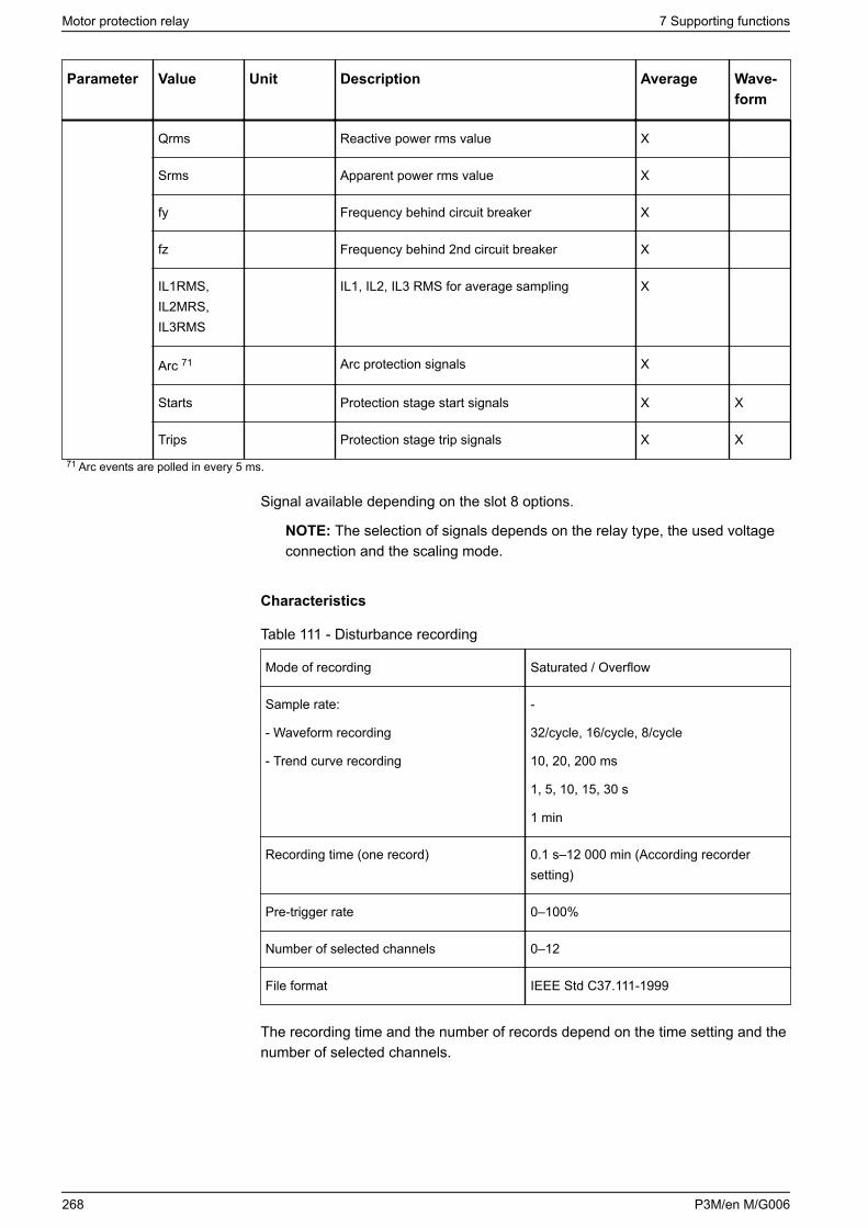
Parameter Value Unit Description Average Wave-form
Qrms Reactive power rms value X
Srms Apparent power rms value X
fy Frequency behind circuit breaker X
fz Frequency behind 2nd circuit breaker X
IL1RMS,IL2MRS,IL3RMS
IL1, IL2, IL3 RMS for average sampling X
Arc 71 Arc protection signals X
Starts Protection stage start signals X X
Trips Protection stage trip signals X X
71 Arc events are polled in every 5 ms.
Signal available depending on the slot 8 options.
NOTE: The selection of signals depends on the relay type, the used voltageconnection and the scaling mode.
Characteristics
Table 111 - Disturbance recording
Mode of recording Saturated / Overflow
Sample rate:
- Waveform recording
- Trend curve recording
-
32/cycle, 16/cycle, 8/cycle
10, 20, 200 ms
1, 5, 10, 15, 30 s
1 min
Recording time (one record) 0.1 s–12 000 min (According recordersetting)
Pre-trigger rate 0–100%
Number of selected channels 0–12
File format IEEE Std C37.111-1999
The recording time and the number of records depend on the time setting and thenumber of selected channels.
Motor protection relay 7 Supporting functions
268 P3M/en M/G006
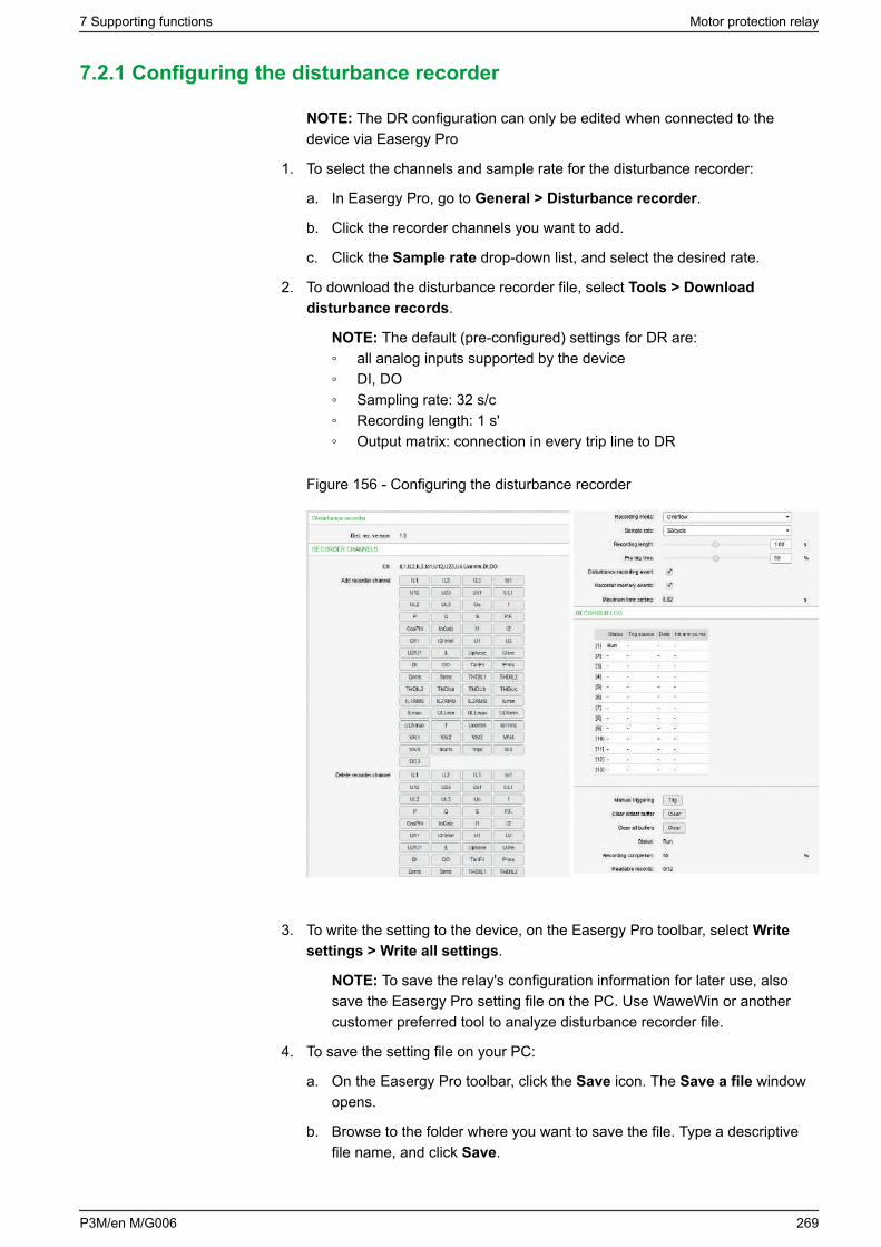
7.2.1 Configuring the disturbance recorder
NOTE: The DR configuration can only be edited when connected to thedevice via Easergy Pro
1. To select the channels and sample rate for the disturbance recorder:
a. In Easergy Pro, go to General > Disturbance recorder.
b. Click the recorder channels you want to add.
c. Click the Sample rate drop-down list, and select the desired rate.
2. To download the disturbance recorder file, select Tools > Downloaddisturbance records.
NOTE: The default (pre-configured) settings for DR are: all analog inputs supported by the device DI, DO Sampling rate: 32 s/c Recording length: 1 s' Output matrix: connection in every trip line to DR
Figure 156 - Configuring the disturbance recorder
3. To write the setting to the device, on the Easergy Pro toolbar, select Writesettings > Write all settings.
NOTE: To save the relay's configuration information for later use, alsosave the Easergy Pro setting file on the PC. Use WaweWin or anothercustomer preferred tool to analyze disturbance recorder file.
4. To save the setting file on your PC:
a. On the Easergy Pro toolbar, click the Save icon. The Save a file windowopens.
b. Browse to the folder where you want to save the file. Type a descriptivefile name, and click Save.
7 Supporting functions Motor protection relay
P3M/en M/G006 269
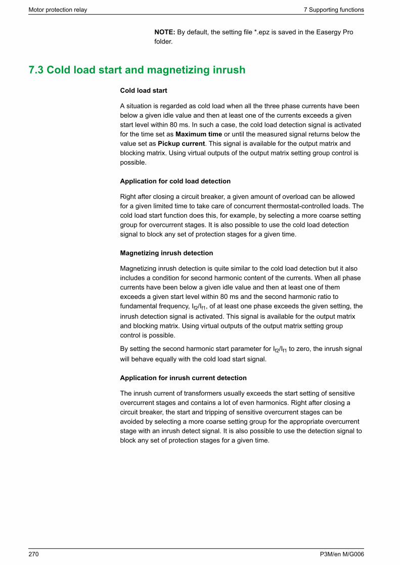
NOTE: By default, the setting file *.epz is saved in the Easergy Profolder.
7.3 Cold load start and magnetizing inrush
Cold load start
A situation is regarded as cold load when all the three phase currents have beenbelow a given idle value and then at least one of the currents exceeds a givenstart level within 80 ms. In such a case, the cold load detection signal is activatedfor the time set as Maximum time or until the measured signal returns below thevalue set as Pickup current. This signal is available for the output matrix andblocking matrix. Using virtual outputs of the output matrix setting group control ispossible.
Application for cold load detection
Right after closing a circuit breaker, a given amount of overload can be allowedfor a given limited time to take care of concurrent thermostat-controlled loads. Thecold load start function does this, for example, by selecting a more coarse settinggroup for overcurrent stages. It is also possible to use the cold load detectionsignal to block any set of protection stages for a given time.
Magnetizing inrush detection
Magnetizing inrush detection is quite similar to the cold load detection but it alsoincludes a condition for second harmonic content of the currents. When all phasecurrents have been below a given idle value and then at least one of themexceeds a given start level within 80 ms and the second harmonic ratio tofundamental frequency, If2/If1, of at least one phase exceeds the given setting, theinrush detection signal is activated. This signal is available for the output matrixand blocking matrix. Using virtual outputs of the output matrix setting groupcontrol is possible.
By setting the second harmonic start parameter for If2/If1 to zero, the inrush signalwill behave equally with the cold load start signal.
Application for inrush current detection
The inrush current of transformers usually exceeds the start setting of sensitiveovercurrent stages and contains a lot of even harmonics. Right after closing acircuit breaker, the start and tripping of sensitive overcurrent stages can beavoided by selecting a more coarse setting group for the appropriate overcurrentstage with an inrush detect signal. It is also possible to use the detection signal toblock any set of protection stages for a given time.
Motor protection relay 7 Supporting functions
270 P3M/en M/G006
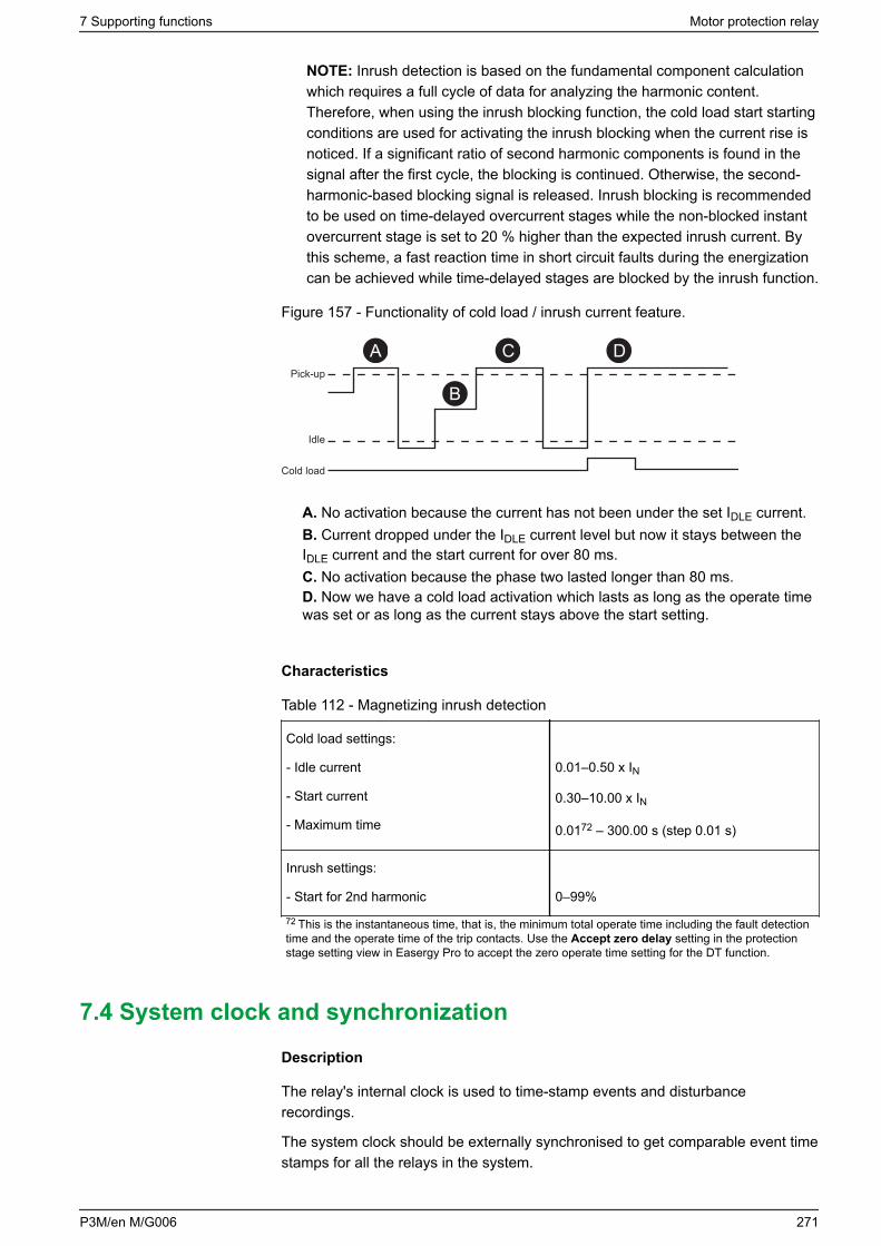
NOTE: Inrush detection is based on the fundamental component calculationwhich requires a full cycle of data for analyzing the harmonic content.Therefore, when using the inrush blocking function, the cold load start startingconditions are used for activating the inrush blocking when the current rise isnoticed. If a significant ratio of second harmonic components is found in thesignal after the first cycle, the blocking is continued. Otherwise, the second-harmonic-based blocking signal is released. Inrush blocking is recommendedto be used on time-delayed overcurrent stages while the non-blocked instantovercurrent stage is set to 20 % higher than the expected inrush current. Bythis scheme, a fast reaction time in short circuit faults during the energizationcan be achieved while time-delayed stages are blocked by the inrush function.
Figure 157 - Functionality of cold load / inrush current feature.
Pick-up
Idle
Cold load
A
B
C D
A. No activation because the current has not been under the set IDLE current.B. Current dropped under the IDLE current level but now it stays between theIDLE current and the start current for over 80 ms.C. No activation because the phase two lasted longer than 80 ms.D. Now we have a cold load activation which lasts as long as the operate timewas set or as long as the current stays above the start setting.
Characteristics
Table 112 - Magnetizing inrush detection
Cold load settings:
- Idle current
- Start current
- Maximum time
0.01–0.50 x IN
0.30–10.00 x IN
0.0172 – 300.00 s (step 0.01 s)
Inrush settings:
- Start for 2nd harmonic 0–99%
72 This is the instantaneous time, that is, the minimum total operate time including the fault detectiontime and the operate time of the trip contacts. Use the Accept zero delay setting in the protectionstage setting view in Easergy Pro to accept the zero operate time setting for the DT function.
7.4 System clock and synchronization
Description
The relay's internal clock is used to time-stamp events and disturbancerecordings.
The system clock should be externally synchronised to get comparable event timestamps for all the relays in the system.
7 Supporting functions Motor protection relay
P3M/en M/G006 271
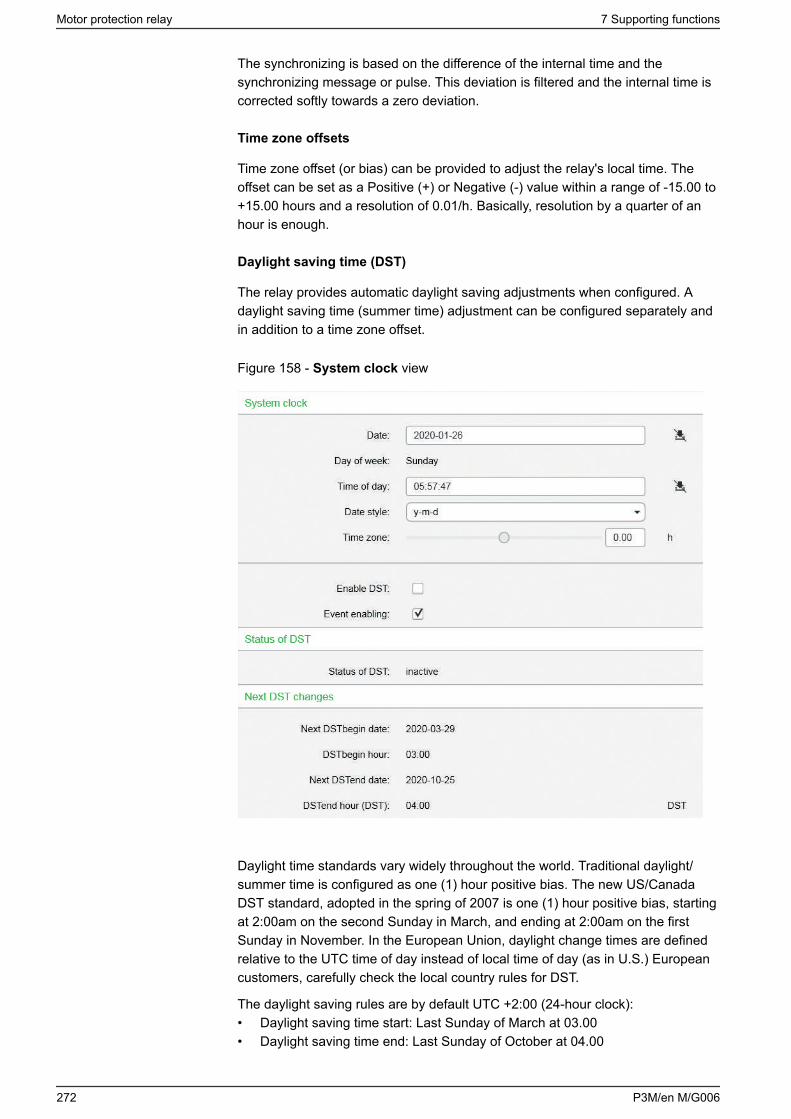
The synchronizing is based on the difference of the internal time and thesynchronizing message or pulse. This deviation is filtered and the internal time iscorrected softly towards a zero deviation.
Time zone offsets
Time zone offset (or bias) can be provided to adjust the relay's local time. Theoffset can be set as a Positive (+) or Negative (-) value within a range of -15.00 to+15.00 hours and a resolution of 0.01/h. Basically, resolution by a quarter of anhour is enough.
Daylight saving time (DST)
The relay provides automatic daylight saving adjustments when configured. Adaylight saving time (summer time) adjustment can be configured separately andin addition to a time zone offset.
Figure 158 - System clock view
Daylight time standards vary widely throughout the world. Traditional daylight/summer time is configured as one (1) hour positive bias. The new US/CanadaDST standard, adopted in the spring of 2007 is one (1) hour positive bias, startingat 2:00am on the second Sunday in March, and ending at 2:00am on the firstSunday in November. In the European Union, daylight change times are definedrelative to the UTC time of day instead of local time of day (as in U.S.) Europeancustomers, carefully check the local country rules for DST.
The daylight saving rules are by default UTC +2:00 (24-hour clock):• Daylight saving time start: Last Sunday of March at 03.00• Daylight saving time end: Last Sunday of October at 04.00
Motor protection relay 7 Supporting functions
272 P3M/en M/G006
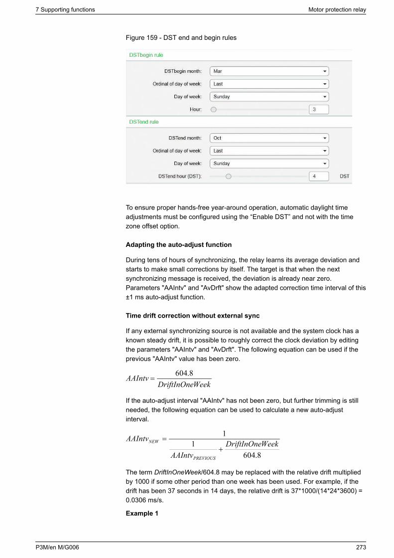
Figure 159 - DST end and begin rules
To ensure proper hands-free year-around operation, automatic daylight timeadjustments must be configured using the “Enable DST” and not with the timezone offset option.
Adapting the auto-adjust function
During tens of hours of synchronizing, the relay learns its average deviation andstarts to make small corrections by itself. The target is that when the nextsynchronizing message is received, the deviation is already near zero.Parameters "AAIntv" and "AvDrft" show the adapted correction time interval of this±1 ms auto-adjust function.
Time drift correction without external sync
If any external synchronizing source is not available and the system clock has aknown steady drift, it is possible to roughly correct the clock deviation by editingthe parameters "AAIntv" and "AvDrft". The following equation can be used if theprevious "AAIntv" value has been zero.
WeekDriftInOneAAIntv 8.604
=
If the auto-adjust interval "AAIntv" has not been zero, but further trimming is stillneeded, the following equation can be used to calculate a new auto-adjustinterval.
8.6041
1WeekDriftInOne
AAIntv
AAIntv
PREVIOUS
NEW
+=
The term DriftInOneWeek/604.8 may be replaced with the relative drift multipliedby 1000 if some other period than one week has been used. For example, if thedrift has been 37 seconds in 14 days, the relative drift is 37*1000/(14*24*3600) =0.0306 ms/s.
Example 1
7 Supporting functions Motor protection relay
P3M/en M/G006 273
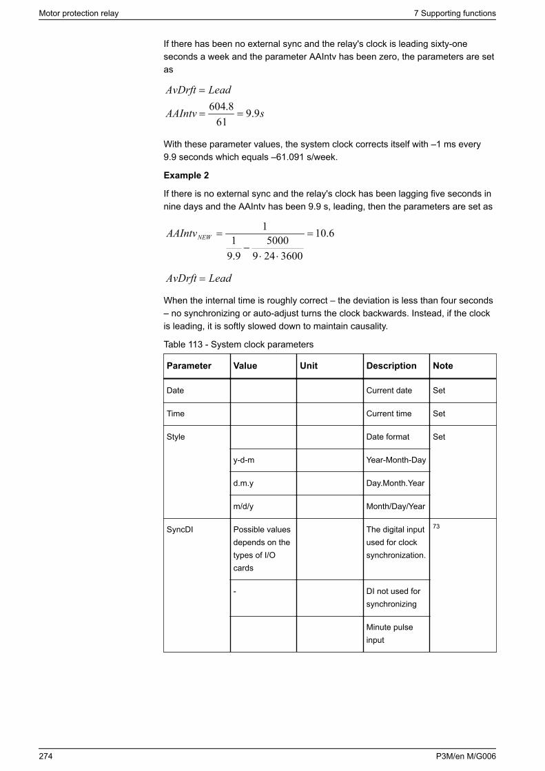
If there has been no external sync and the relay's clock is leading sixty-oneseconds a week and the parameter AAIntv has been zero, the parameters are setas
sAAIntv
LeadAvDrft
9.961
8.604==
=
With these parameter values, the system clock corrects itself with –1 ms every9.9 seconds which equals –61.091 s/week.
Example 2
If there is no external sync and the relay's clock has been lagging five seconds innine days and the AAIntv has been 9.9 s, leading, then the parameters are set as
6.10
36002495000
9.91
1=
⋅⋅−
=NEWAAIntv
LeadAvDrft =
When the internal time is roughly correct – the deviation is less than four seconds– no synchronizing or auto-adjust turns the clock backwards. Instead, if the clockis leading, it is softly slowed down to maintain causality.
Table 113 - System clock parameters
Parameter Value Unit Description Note
Date Current date Set
Time Current time Set
Style Date format Set
y-d-m Year-Month-Day
d.m.y Day.Month.Year
m/d/y Month/Day/Year
SyncDI Possible valuesdepends on thetypes of I/Ocards
The digital inputused for clocksynchronization.
73
- DI not used forsynchronizing
Minute pulseinput
Motor protection relay 7 Supporting functions
274 P3M/en M/G006
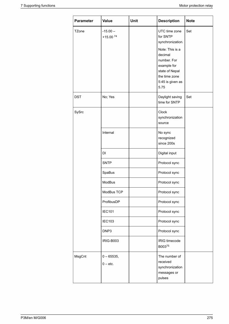
Parameter Value Unit Description Note
TZone -15.00 –+15.00 74
UTC time zonefor SNTPsynchronization.
Note: This is adecimalnumber. Forexample forstate of Nepalthe time zone5:45 is given as5.75
Set
DST No; Yes Daylight savingtime for SNTP
Set
SySrc Clocksynchronizationsource
Internal No syncrecognizedsince 200s
DI Digital input
SNTP Protocol sync
SpaBus Protocol sync
ModBus Protocol sync
ModBus TCP Protocol sync
ProfibusDP Protocol sync
IEC101 Protocol sync
IEC103 Protocol sync
DNP3 Protocol sync
IRIG-B003 IRIG timecodeB00375
MsgCnt 0 – 65535,
0 – etc.
The number ofreceivedsynchronizationmessages orpulses
7 Supporting functions Motor protection relay
P3M/en M/G006 275
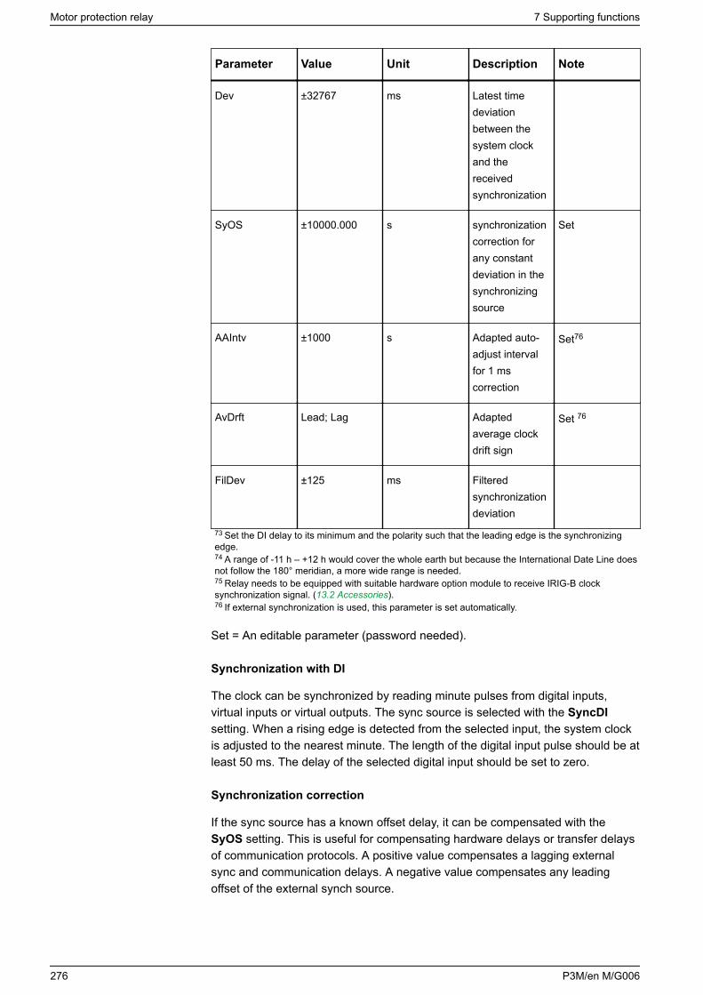
Parameter Value Unit Description Note
Dev ±32767 ms Latest timedeviationbetween thesystem clockand thereceivedsynchronization
SyOS ±10000.000 s synchronizationcorrection forany constantdeviation in thesynchronizingsource
Set
AAIntv ±1000 s Adapted auto-adjust intervalfor 1 mscorrection
Set76
AvDrft Lead; Lag Adaptedaverage clockdrift sign
Set 76
FilDev ±125 ms Filteredsynchronizationdeviation
73 Set the DI delay to its minimum and the polarity such that the leading edge is the synchronizingedge.74 A range of -11 h – +12 h would cover the whole earth but because the International Date Line doesnot follow the 180° meridian, a more wide range is needed.75 Relay needs to be equipped with suitable hardware option module to receive IRIG-B clocksynchronization signal. (13.2 Accessories).76 If external synchronization is used, this parameter is set automatically.
Set = An editable parameter (password needed).
Synchronization with DI
The clock can be synchronized by reading minute pulses from digital inputs,virtual inputs or virtual outputs. The sync source is selected with the SyncDIsetting. When a rising edge is detected from the selected input, the system clockis adjusted to the nearest minute. The length of the digital input pulse should be atleast 50 ms. The delay of the selected digital input should be set to zero.
Synchronization correction
If the sync source has a known offset delay, it can be compensated with theSyOS setting. This is useful for compensating hardware delays or transfer delaysof communication protocols. A positive value compensates a lagging externalsync and communication delays. A negative value compensates any leadingoffset of the external synch source.
Motor protection relay 7 Supporting functions
276 P3M/en M/G006
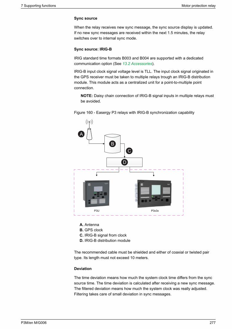
Sync source
When the relay receives new sync message, the sync source display is updated.If no new sync messages are received within the next 1.5 minutes, the relayswitches over to internal sync mode.
Sync source: IRIG-B
IRIG standard time formats B003 and B004 are supported with a dedicatedcommunication option (See 13.2 Accessories).
IRIG-B input clock signal voltage level is TLL. The input clock signal originated inthe GPS receiver must be taken to multiple relays trough an IRIG-B distributionmodule. This module acts as a centralized unit for a point-to-multiple pointconnection.
NOTE: Daisy chain connection of IRIG-B signal inputs in multiple relays mustbe avoided.
Figure 160 - Easergy P3 relays with IRIG-B synchronization capability
P3x3xP3U
A
BC
D
A. AntennaB. GPS clockC. IRIG-B signal from clockD. IRIG-B distribution module
The recommended cable must be shielded and either of coaxial or twisted pairtype. Its length must not exceed 10 meters.
Deviation
The time deviation means how much the system clock time differs from the syncsource time. The time deviation is calculated after receiving a new sync message.The filtered deviation means how much the system clock was really adjusted.Filtering takes care of small deviation in sync messages.
7 Supporting functions Motor protection relay
P3M/en M/G006 277
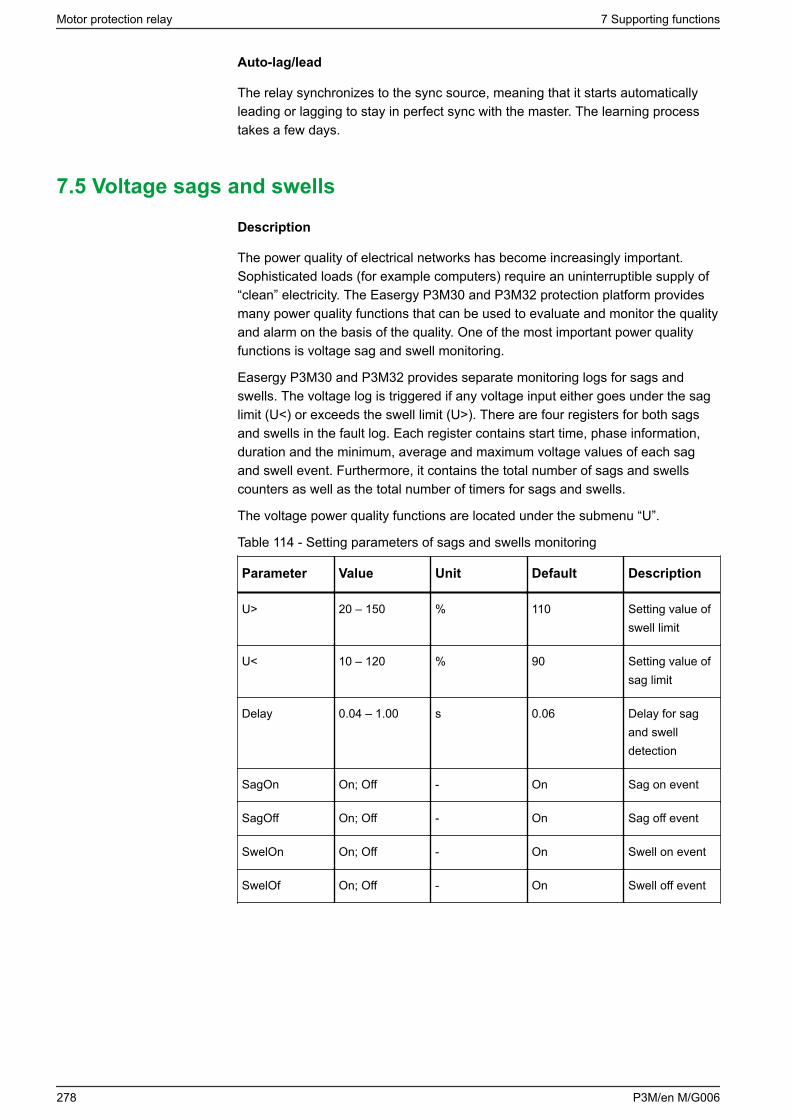
Auto-lag/lead
The relay synchronizes to the sync source, meaning that it starts automaticallyleading or lagging to stay in perfect sync with the master. The learning processtakes a few days.
7.5 Voltage sags and swells
Description
The power quality of electrical networks has become increasingly important.Sophisticated loads (for example computers) require an uninterruptible supply of“clean” electricity. The Easergy P3M30 and P3M32 protection platform providesmany power quality functions that can be used to evaluate and monitor the qualityand alarm on the basis of the quality. One of the most important power qualityfunctions is voltage sag and swell monitoring.
Easergy P3M30 and P3M32 provides separate monitoring logs for sags andswells. The voltage log is triggered if any voltage input either goes under the saglimit (U<) or exceeds the swell limit (U>). There are four registers for both sagsand swells in the fault log. Each register contains start time, phase information,duration and the minimum, average and maximum voltage values of each sagand swell event. Furthermore, it contains the total number of sags and swellscounters as well as the total number of timers for sags and swells.
The voltage power quality functions are located under the submenu “U”.
Table 114 - Setting parameters of sags and swells monitoring
Parameter Value Unit Default Description
U> 20 – 150 % 110 Setting value ofswell limit
U< 10 – 120 % 90 Setting value ofsag limit
Delay 0.04 – 1.00 s 0.06 Delay for sagand swelldetection
SagOn On; Off - On Sag on event
SagOff On; Off - On Sag off event
SwelOn On; Off - On Swell on event
SwelOf On; Off - On Swell off event
Motor protection relay 7 Supporting functions
278 P3M/en M/G006
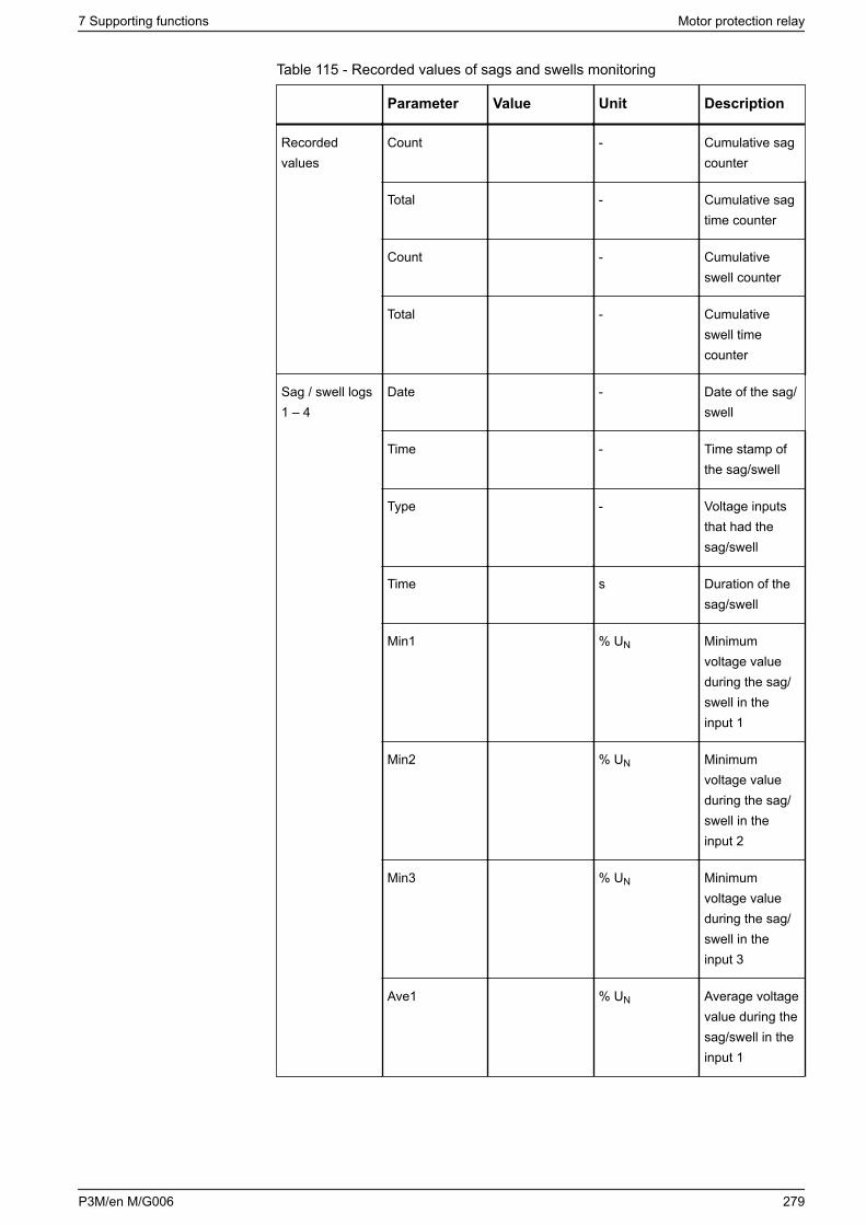
Table 115 - Recorded values of sags and swells monitoring
Parameter Value Unit Description
Recordedvalues
Count - Cumulative sagcounter
Total - Cumulative sagtime counter
Count - Cumulativeswell counter
Total - Cumulativeswell timecounter
Sag / swell logs1 – 4
Date - Date of the sag/swell
Time - Time stamp ofthe sag/swell
Type - Voltage inputsthat had thesag/swell
Time s Duration of thesag/swell
Min1 % UN Minimumvoltage valueduring the sag/swell in theinput 1
Min2 % UN Minimumvoltage valueduring the sag/swell in theinput 2
Min3 % UN Minimumvoltage valueduring the sag/swell in theinput 3
Ave1 % UN Average voltagevalue during thesag/swell in theinput 1
7 Supporting functions Motor protection relay
P3M/en M/G006 279
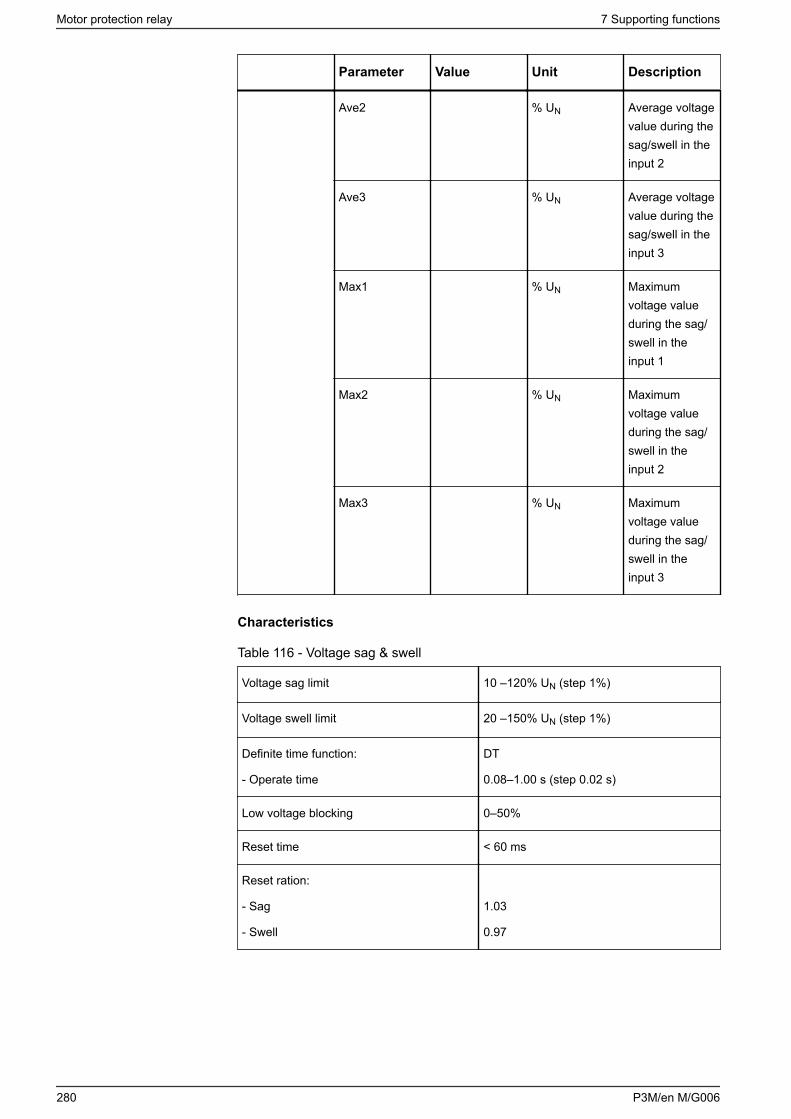
Parameter Value Unit Description
Ave2 % UN Average voltagevalue during thesag/swell in theinput 2
Ave3 % UN Average voltagevalue during thesag/swell in theinput 3
Max1 % UN Maximumvoltage valueduring the sag/swell in theinput 1
Max2 % UN Maximumvoltage valueduring the sag/swell in theinput 2
Max3 % UN Maximumvoltage valueduring the sag/swell in theinput 3
Characteristics
Table 116 - Voltage sag & swell
Voltage sag limit 10 –120% UN (step 1%)
Voltage swell limit 20 –150% UN (step 1%)
Definite time function:
- Operate time
DT
0.08–1.00 s (step 0.02 s)
Low voltage blocking 0–50%
Reset time < 60 ms
Reset ration:
- Sag
- Swell
1.03
0.97
Motor protection relay 7 Supporting functions
280 P3M/en M/G006
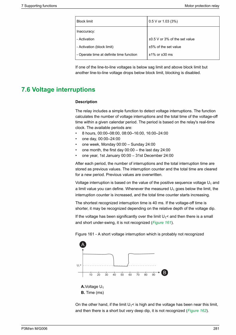
Block limit 0.5 V or 1.03 (3%)
Inaccuracy:
- Activation
- Activation (block limit)
- Operate time at definite time function
±0.5 V or 3% of the set value
±5% of the set value
±1% or ±30 ms
If one of the line-to-line voltages is below sag limit and above block limit butanother line-to-line voltage drops below block limit, blocking is disabled.
7.6 Voltage interruptions
Description
The relay includes a simple function to detect voltage interruptions. The functioncalculates the number of voltage interruptions and the total time of the voltage-offtime within a given calendar period. The period is based on the relay's real-timeclock. The available periods are:• 8 hours, 00:00–08:00, 08:00–16:00, 16:00–24:00• one day, 00:00–24:00• one week, Monday 00:00 – Sunday 24:00• one month, the first day 00:00 – the last day 24:00• one year, 1st January 00:00 – 31st December 24:00
After each period, the number of interruptions and the total interruption time arestored as previous values. The interruption counter and the total time are clearedfor a new period. Previous values are overwritten.
Voltage interruption is based on the value of the positive sequence voltage U1 anda limit value you can define. Whenever the measured U1 goes below the limit, theinterruption counter is increased, and the total time counter starts increasing.
The shortest recognized interruption time is 40 ms. If the voltage-off time isshorter, it may be recognized depending on the relative depth of the voltage dip.
If the voltage has been significantly over the limit U1< and then there is a smalland short under-swing, it is not recognized (Figure 161).
Figure 161 - A short voltage interruption which is probably not recognized
10
U1<
20 30 40 50 60 70 80 90
A
B
A.Voltage U1
B. Time (ms)
On the other hand, if the limit U1< is high and the voltage has been near this limit,and then there is a short but very deep dip, it is not recognized (Figure 162).
7 Supporting functions Motor protection relay
P3M/en M/G006 281
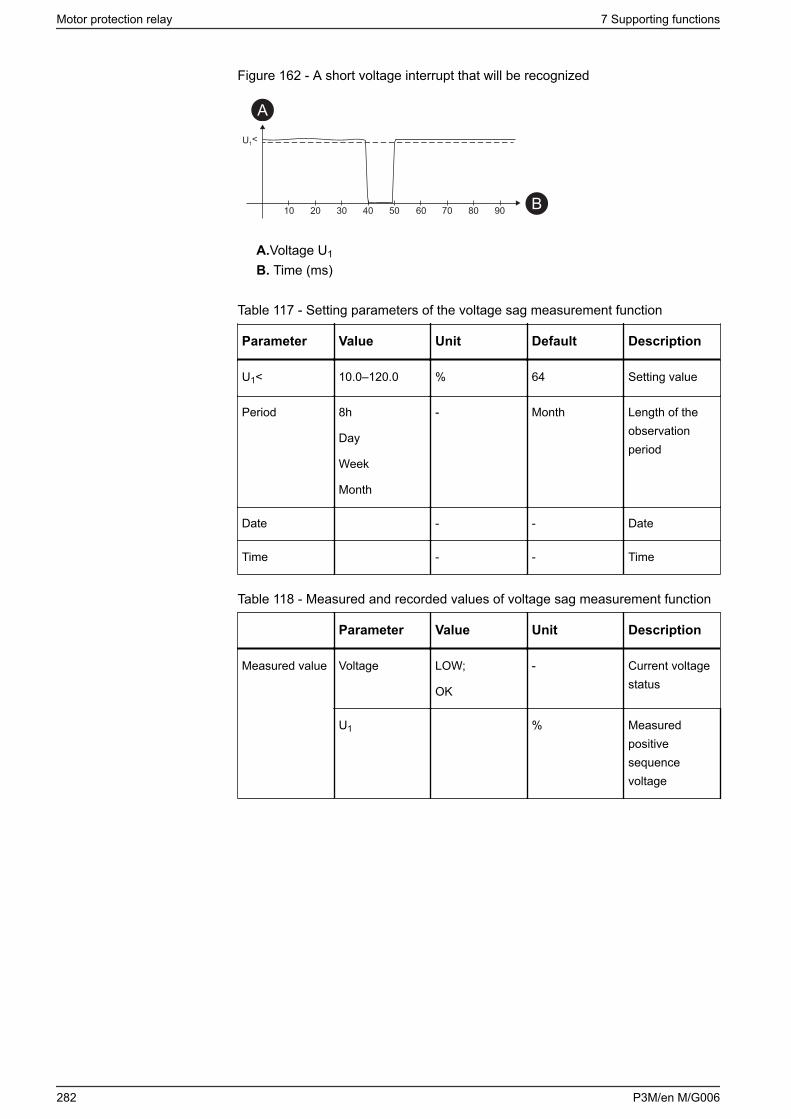
Figure 162 - A short voltage interrupt that will be recognized
10
U1<
20 30 40 50 60 70 80 90
A
B
A.Voltage U1
B. Time (ms)
Table 117 - Setting parameters of the voltage sag measurement function
Parameter Value Unit Default Description
U1< 10.0–120.0 % 64 Setting value
Period 8h
Day
Week
Month
- Month Length of theobservationperiod
Date - - Date
Time - - Time
Table 118 - Measured and recorded values of voltage sag measurement function
Parameter Value Unit Description
Measured value Voltage LOW;
OK
- Current voltagestatus
U1 % Measuredpositivesequencevoltage
Motor protection relay 7 Supporting functions
282 P3M/en M/G006
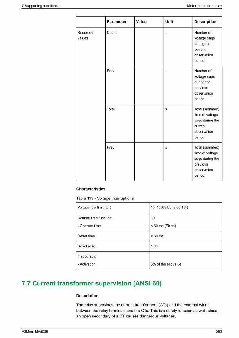
Parameter Value Unit Description
Recordedvalues
Count - Number ofvoltage sagsduring thecurrentobservationperiod
Prev - Number ofvoltage sagsduring thepreviousobservationperiod
Total s Total (summed)time of voltagesags during thecurrentobservationperiod
Prev s Total (summed)time of voltagesags during thepreviousobservationperiod
Characteristics
Table 119 - Voltage interruptions
Voltage low limit (U1) 10–120% UN (step 1%)
Definite time function:
- Operate time
DT
< 60 ms (Fixed)
Reset time < 60 ms
Reset ratio 1.03
Inaccuracy:
- Activation 3% of the set value
7.7 Current transformer supervision (ANSI 60)
Description
The relay supervises the current transformers (CTs) and the external wiringbetween the relay terminals and the CTs. This is a safety function as well, sincean open secondary of a CT causes dangerous voltages.
7 Supporting functions Motor protection relay
P3M/en M/G006 283
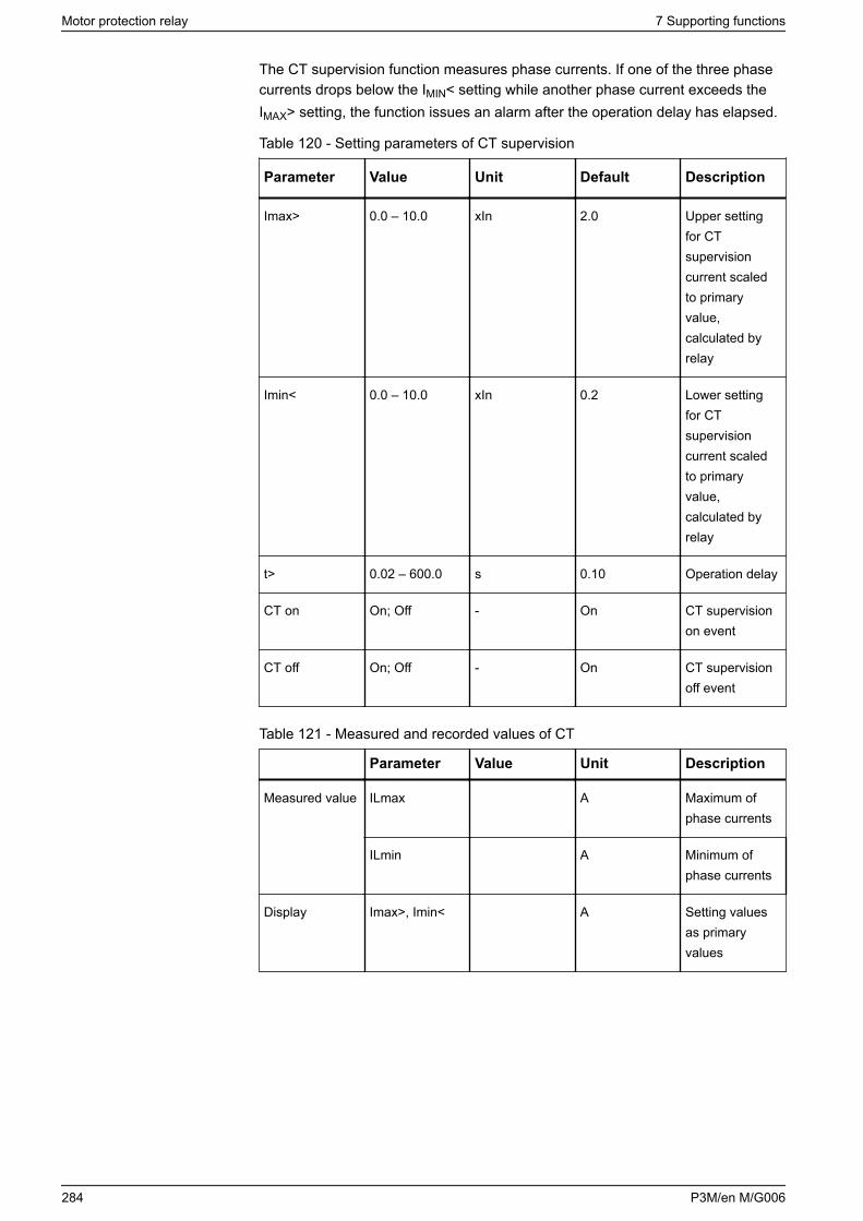
The CT supervision function measures phase currents. If one of the three phasecurrents drops below the IMIN< setting while another phase current exceeds theIMAX> setting, the function issues an alarm after the operation delay has elapsed.
Table 120 - Setting parameters of CT supervision
Parameter Value Unit Default Description
Imax> 0.0 – 10.0 xIn 2.0 Upper settingfor CTsupervisioncurrent scaledto primaryvalue,calculated byrelay
Imin< 0.0 – 10.0 xIn 0.2 Lower settingfor CTsupervisioncurrent scaledto primaryvalue,calculated byrelay
t> 0.02 – 600.0 s 0.10 Operation delay
CT on On; Off - On CT supervisionon event
CT off On; Off - On CT supervisionoff event
Table 121 - Measured and recorded values of CT
Parameter Value Unit Description
Measured value ILmax A Maximum ofphase currents
ILmin A Minimum ofphase currents
Display Imax>, Imin< A Setting valuesas primaryvalues
Motor protection relay 7 Supporting functions
284 P3M/en M/G006
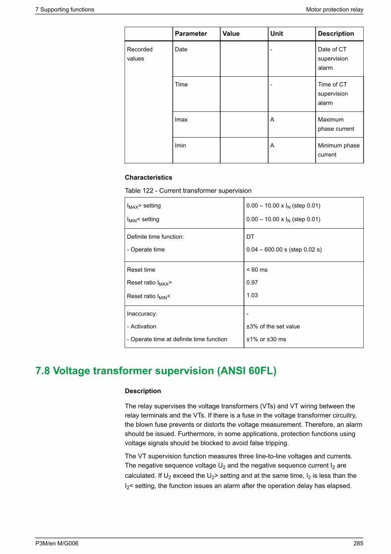
Parameter Value Unit Description
Recordedvalues
Date - Date of CTsupervisionalarm
Time - Time of CTsupervisionalarm
Imax A Maximumphase current
Imin A Minimum phasecurrent
Characteristics
Table 122 - Current transformer supervision
IMAX> setting
IMIN< setting
0.00 – 10.00 x IN (step 0.01)
0.00 – 10.00 x IN (step 0.01)
Definite time function:
- Operate time
DT
0.04 – 600.00 s (step 0.02 s)
Reset time
Reset ratio IMAX>
Reset ratio IMIN<
< 60 ms
0.97
1.03
Inaccuracy:
- Activation
- Operate time at definite time function
-
±3% of the set value
±1% or ±30 ms
7.8 Voltage transformer supervision (ANSI 60FL)
Description
The relay supervises the voltage transformers (VTs) and VT wiring between therelay terminals and the VTs. If there is a fuse in the voltage transformer circuitry,the blown fuse prevents or distorts the voltage measurement. Therefore, an alarmshould be issued. Furthermore, in some applications, protection functions usingvoltage signals should be blocked to avoid false tripping.
The VT supervision function measures three line-to-line voltages and currents.The negative sequence voltage U2 and the negative sequence current I2 arecalculated. If U2 exceed the U2> setting and at the same time, I2 is less than theI2< setting, the function issues an alarm after the operation delay has elapsed.
7 Supporting functions Motor protection relay
P3M/en M/G006 285
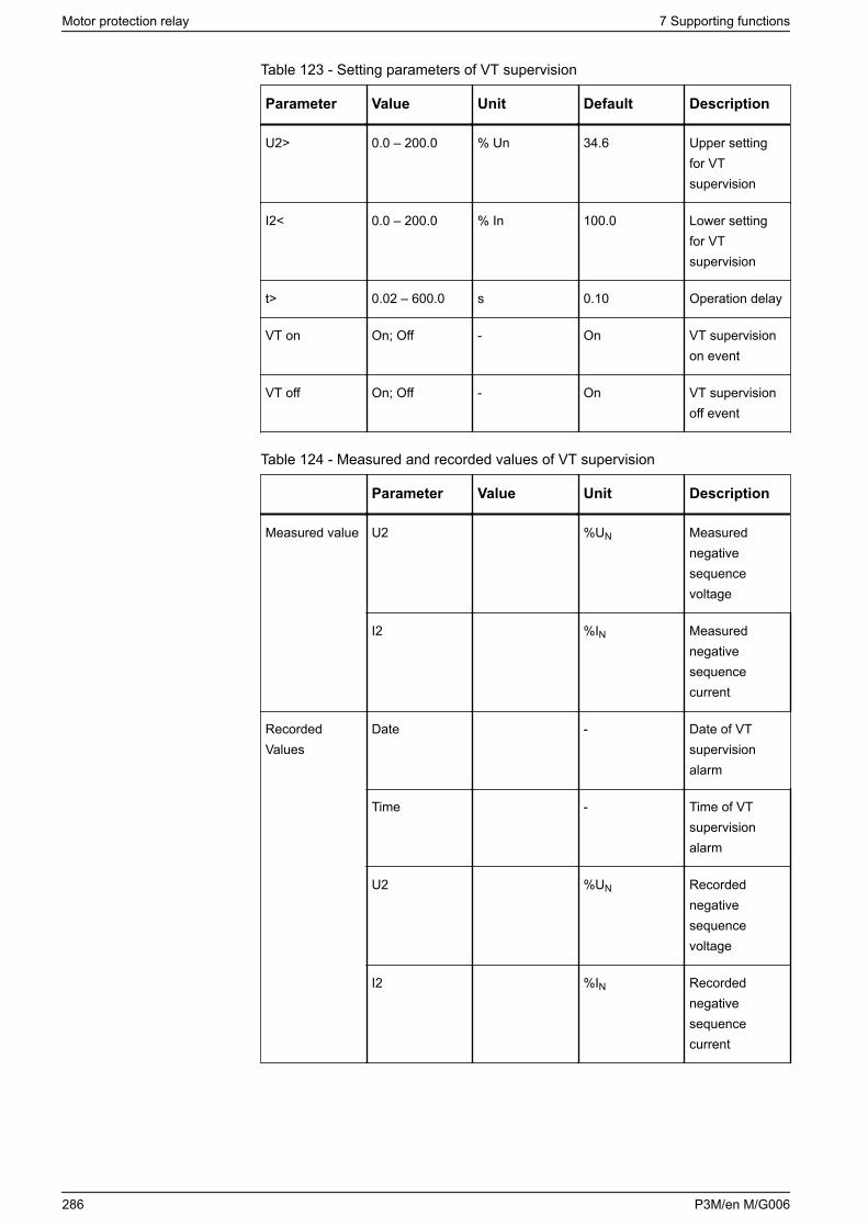
Table 123 - Setting parameters of VT supervision
Parameter Value Unit Default Description
U2> 0.0 – 200.0 % Un 34.6 Upper settingfor VTsupervision
I2< 0.0 – 200.0 % In 100.0 Lower settingfor VTsupervision
t> 0.02 – 600.0 s 0.10 Operation delay
VT on On; Off - On VT supervisionon event
VT off On; Off - On VT supervisionoff event
Table 124 - Measured and recorded values of VT supervision
Parameter Value Unit Description
Measured value U2 %UN Measurednegativesequencevoltage
I2 %IN Measurednegativesequencecurrent
RecordedValues
Date - Date of VTsupervisionalarm
Time - Time of VTsupervisionalarm
U2 %UN Recordednegativesequencevoltage
I2 %IN Recordednegativesequencecurrent
Motor protection relay 7 Supporting functions
286 P3M/en M/G006
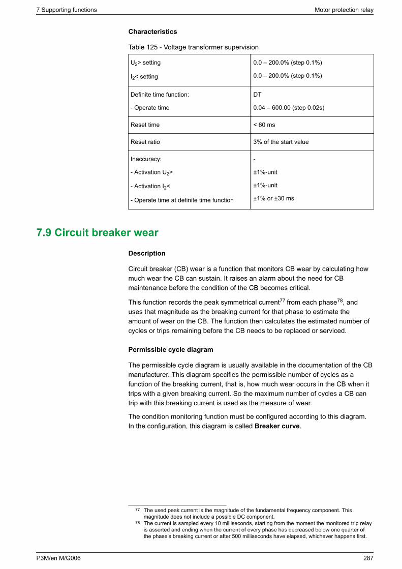
Characteristics
Table 125 - Voltage transformer supervision
U2> setting
I2< setting
0.0 – 200.0% (step 0.1%)
0.0 – 200.0% (step 0.1%)
Definite time function:
- Operate time
DT
0.04 – 600.00 (step 0.02s)
Reset time < 60 ms
Reset ratio 3% of the start value
Inaccuracy:
- Activation U2>
- Activation I2<
- Operate time at definite time function
-
±1%-unit
±1%-unit
±1% or ±30 ms
7.9 Circuit breaker wear
Description
Circuit breaker (CB) wear is a function that monitors CB wear by calculating howmuch wear the CB can sustain. It raises an alarm about the need for CBmaintenance before the condition of the CB becomes critical.
This function records the peak symmetrical current77 from each phase78, anduses that magnitude as the breaking current for that phase to estimate theamount of wear on the CB. The function then calculates the estimated number ofcycles or trips remaining before the CB needs to be replaced or serviced.
Permissible cycle diagram
The permissible cycle diagram is usually available in the documentation of the CBmanufacturer. This diagram specifies the permissible number of cycles as afunction of the breaking current, that is, how much wear occurs in the CB when ittrips with a given breaking current. So the maximum number of cycles a CB cantrip with this breaking current is used as the measure of wear.
The condition monitoring function must be configured according to this diagram.In the configuration, this diagram is called Breaker curve.
77 The used peak current is the magnitude of the fundamental frequency component. Thismagnitude does not include a possible DC component.
78 The current is sampled every 10 milliseconds, starting from the moment the monitored trip relayis asserted and ending when the current of every phase has decreased below one quarter ofthe phase’s breaking current or after 500 milliseconds have elapsed, whichever happens first.
7 Supporting functions Motor protection relay
P3M/en M/G006 287
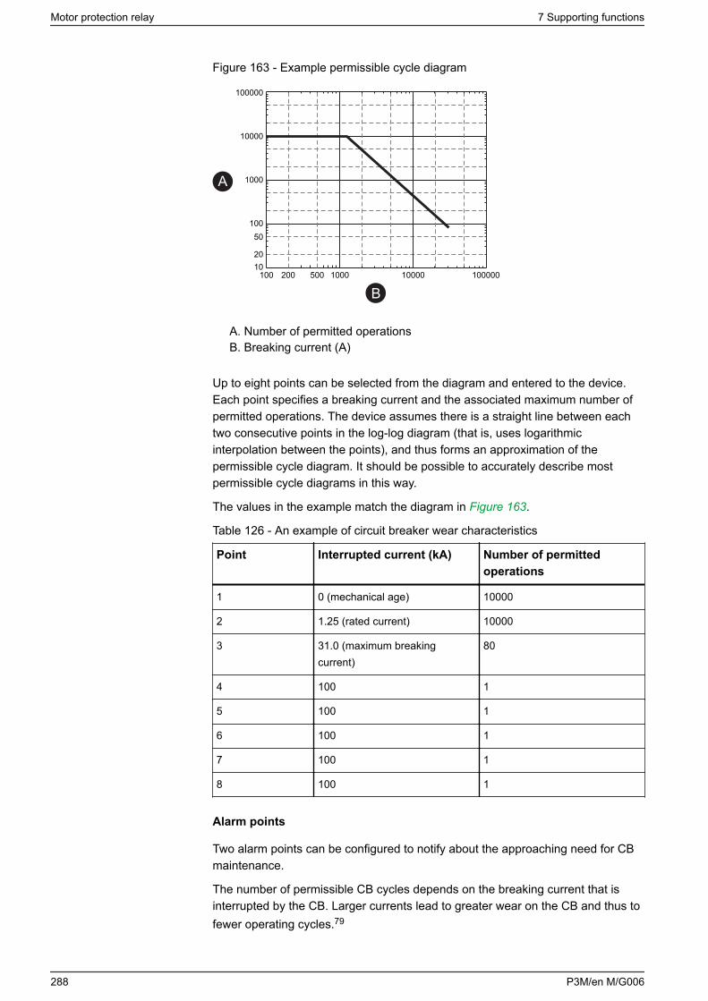
Figure 163 - Example permissible cycle diagram
1020
50100
1000
10000
100000
100 200 500 1000 10000 100000
A
B
A. Number of permitted operationsB. Breaking current (A)
Up to eight points can be selected from the diagram and entered to the device.Each point specifies a breaking current and the associated maximum number ofpermitted operations. The device assumes there is a straight line between eachtwo consecutive points in the log-log diagram (that is, uses logarithmicinterpolation between the points), and thus forms an approximation of thepermissible cycle diagram. It should be possible to accurately describe mostpermissible cycle diagrams in this way.
The values in the example match the diagram in Figure 163.
Table 126 - An example of circuit breaker wear characteristics
Point Interrupted current (kA) Number of permittedoperations
1 0 (mechanical age) 10000
2 1.25 (rated current) 10000
3 31.0 (maximum breakingcurrent)
80
4 100 1
5 100 1
6 100 1
7 100 1
8 100 1
Alarm points
Two alarm points can be configured to notify about the approaching need for CBmaintenance.
The number of permissible CB cycles depends on the breaking current that isinterrupted by the CB. Larger currents lead to greater wear on the CB and thus tofewer operating cycles.79
Motor protection relay 7 Supporting functions
288 P3M/en M/G006
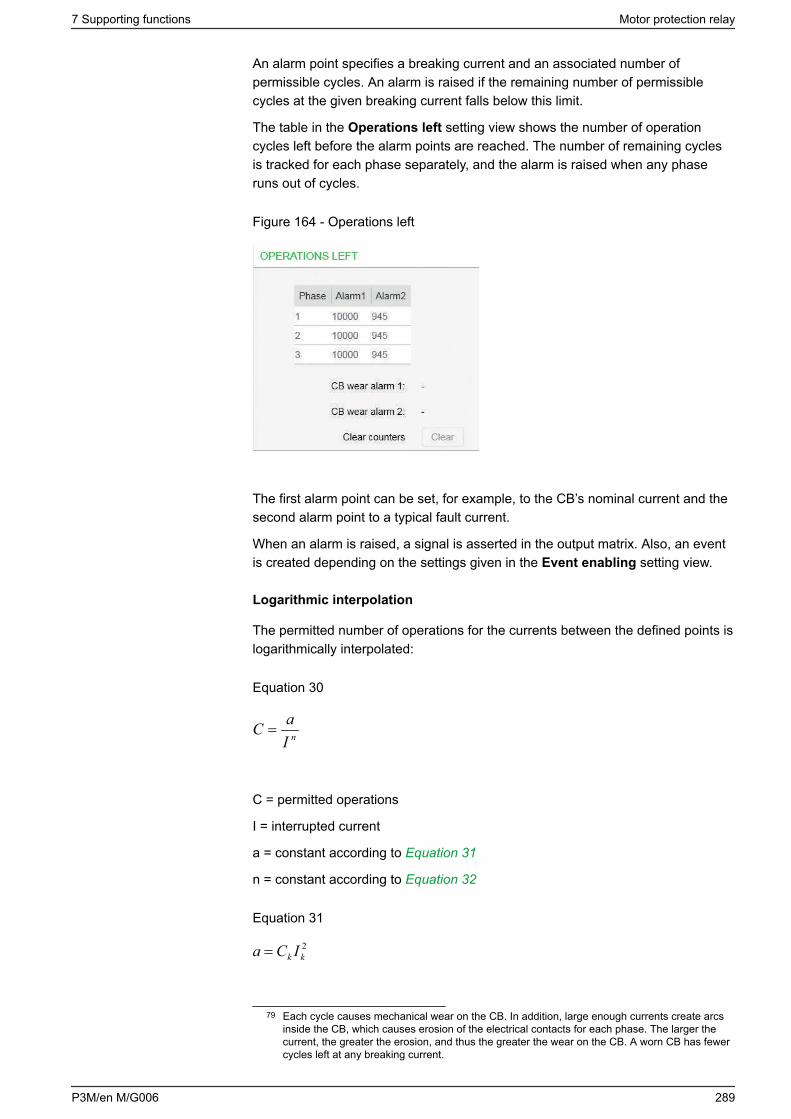
An alarm point specifies a breaking current and an associated number ofpermissible cycles. An alarm is raised if the remaining number of permissiblecycles at the given breaking current falls below this limit.
The table in the Operations left setting view shows the number of operationcycles left before the alarm points are reached. The number of remaining cyclesis tracked for each phase separately, and the alarm is raised when any phaseruns out of cycles.
Figure 164 - Operations left
The first alarm point can be set, for example, to the CB’s nominal current and thesecond alarm point to a typical fault current.
When an alarm is raised, a signal is asserted in the output matrix. Also, an eventis created depending on the settings given in the Event enabling setting view.
Logarithmic interpolation
The permitted number of operations for the currents between the defined points islogarithmically interpolated:
Equation 30
nIaC =
C = permitted operations
I = interrupted current
a = constant according to Equation 31
n = constant according to Equation 32
Equation 31
2kk ICa =
79 Each cycle causes mechanical wear on the CB. In addition, large enough currents create arcsinside the CB, which causes erosion of the electrical contacts for each phase. The larger thecurrent, the greater the erosion, and thus the greater the wear on the CB. A worn CB has fewercycles left at any breaking current.
7 Supporting functions Motor protection relay
P3M/en M/G006 289
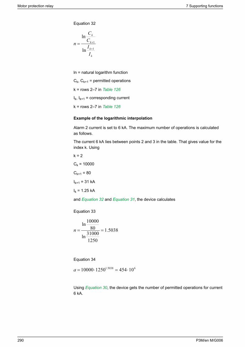
Equation 32
k
k
k
k
IICC
n1
1
ln
ln
+
+=
ln = natural logarithm function
Ck, Ck+1 = permitted operations
k = rows 2–7 in Table 126
Ik, Ik+1 = corresponding current
k = rows 2–7 in Table 126
Example of the logarithmic interpolation
Alarm 2 current is set to 6 kA. The maximum number of operations is calculatedas follows.
The current 6 kA lies between points 2 and 3 in the table. That gives value for theindex k. Using
k = 2
Ck = 10000
Ck+1 = 80
Ik+1 = 31 kA
Ik = 1.25 kA
and Equation 32 and Equation 31, the device calculates
Equation 33
5038.1
125031000ln
8010000ln
==n
Equation 34
65038.1 10454125010000 ⋅=⋅=a
Using Equation 30, the device gets the number of permitted operations for current6 kA.
Motor protection relay 7 Supporting functions
290 P3M/en M/G006
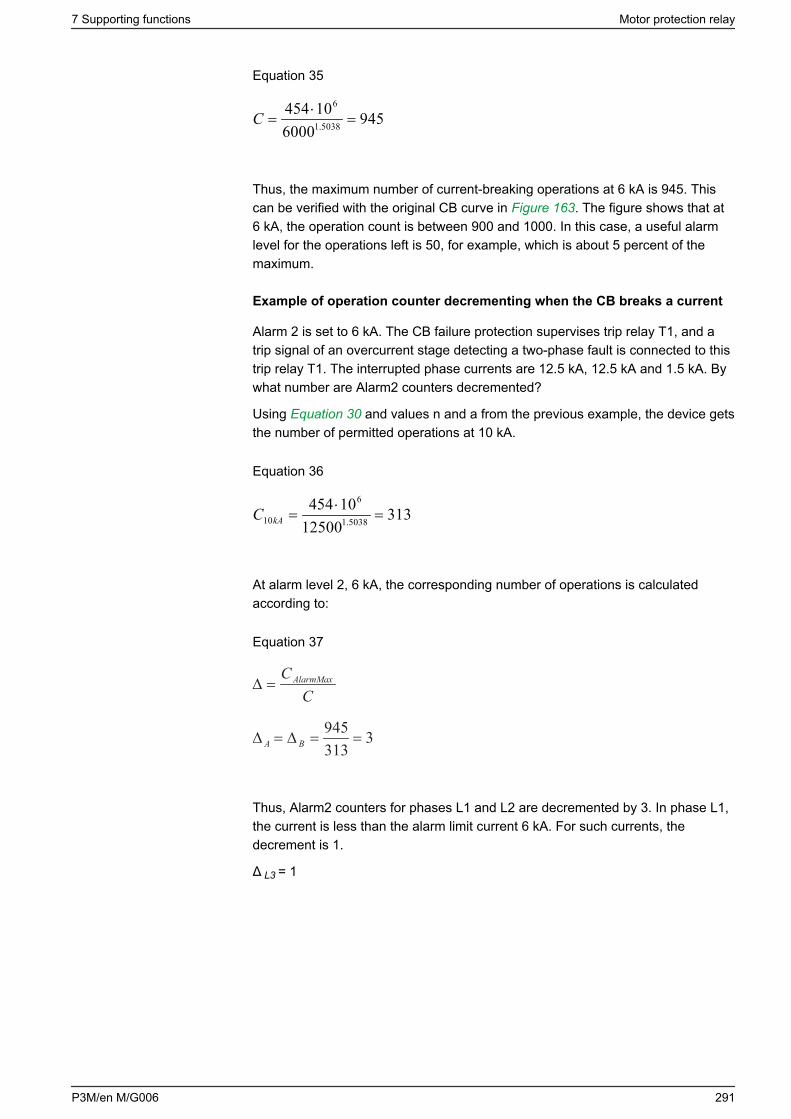
Equation 35
9456000
104545038.1
6
=⋅
=C
Thus, the maximum number of current-breaking operations at 6 kA is 945. Thiscan be verified with the original CB curve in Figure 163. The figure shows that at6 kA, the operation count is between 900 and 1000. In this case, a useful alarmlevel for the operations left is 50, for example, which is about 5 percent of themaximum.
Example of operation counter decrementing when the CB breaks a current
Alarm 2 is set to 6 kA. The CB failure protection supervises trip relay T1, and atrip signal of an overcurrent stage detecting a two-phase fault is connected to thistrip relay T1. The interrupted phase currents are 12.5 kA, 12.5 kA and 1.5 kA. Bywhat number are Alarm2 counters decremented?
Using Equation 30 and values n and a from the previous example, the device getsthe number of permitted operations at 10 kA.
Equation 36
31312500
104545038.1
6
10 =⋅
=kAC
At alarm level 2, 6 kA, the corresponding number of operations is calculatedaccording to:
Equation 37
CCAlarmMax=∆
3313945
==∆=∆ BA
Thus, Alarm2 counters for phases L1 and L2 are decremented by 3. In phase L1,the current is less than the alarm limit current 6 kA. For such currents, thedecrement is 1.
Δ L3 = 1
7 Supporting functions Motor protection relay
P3M/en M/G006 291
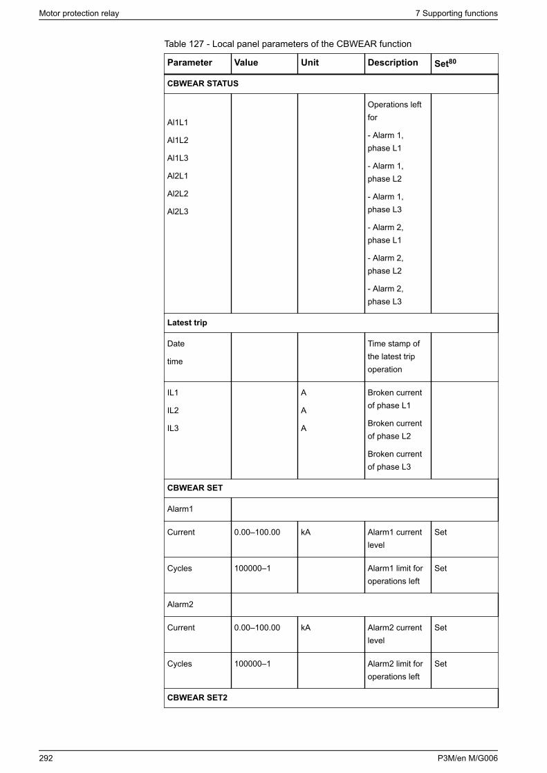
Table 127 - Local panel parameters of the CBWEAR function
Parameter Value Unit Description Set80
CBWEAR STATUS
Al1L1
Al1L2
Al1L3
Al2L1
Al2L2
Al2L3
Operations leftfor
- Alarm 1,phase L1
- Alarm 1,phase L2
- Alarm 1,phase L3
- Alarm 2,phase L1
- Alarm 2,phase L2
- Alarm 2,phase L3
Latest trip
Date
time
Time stamp ofthe latest tripoperation
IL1
IL2
IL3
A
A
A
Broken currentof phase L1
Broken currentof phase L2
Broken currentof phase L3
CBWEAR SET
Alarm1
Current 0.00–100.00 kA Alarm1 currentlevel
Set
Cycles 100000–1 Alarm1 limit foroperations left
Set
Alarm2
Current 0.00–100.00 kA Alarm2 currentlevel
Set
Cycles 100000–1 Alarm2 limit foroperations left
Set
CBWEAR SET2
Motor protection relay 7 Supporting functions
292 P3M/en M/G006
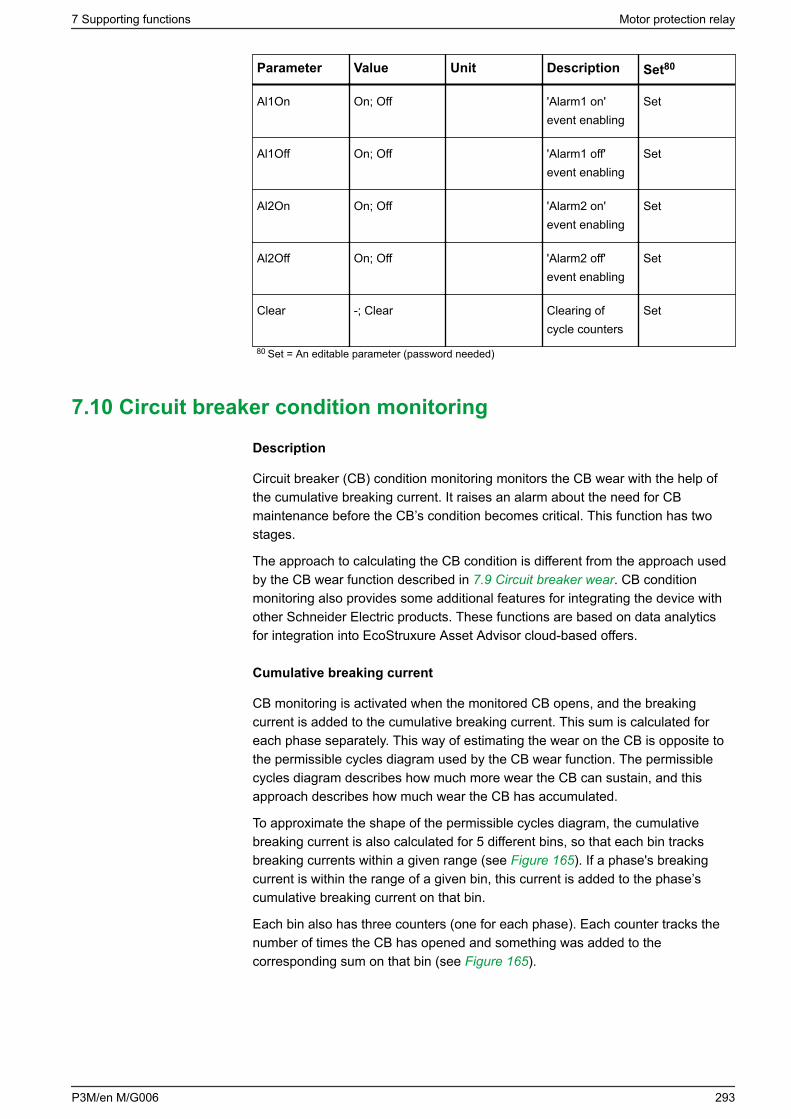
Parameter Value Unit Description Set80
Al1On On; Off 'Alarm1 on'event enabling
Set
Al1Off On; Off 'Alarm1 off'event enabling
Set
Al2On On; Off 'Alarm2 on'event enabling
Set
Al2Off On; Off 'Alarm2 off'event enabling
Set
Clear -; Clear Clearing ofcycle counters
Set
80 Set = An editable parameter (password needed)
7.10 Circuit breaker condition monitoring
Description
Circuit breaker (CB) condition monitoring monitors the CB wear with the help ofthe cumulative breaking current. It raises an alarm about the need for CBmaintenance before the CB’s condition becomes critical. This function has twostages.
The approach to calculating the CB condition is different from the approach usedby the CB wear function described in 7.9 Circuit breaker wear. CB conditionmonitoring also provides some additional features for integrating the device withother Schneider Electric products. These functions are based on data analyticsfor integration into EcoStruxure Asset Advisor cloud-based offers.
Cumulative breaking current
CB monitoring is activated when the monitored CB opens, and the breakingcurrent is added to the cumulative breaking current. This sum is calculated foreach phase separately. This way of estimating the wear on the CB is opposite tothe permissible cycles diagram used by the CB wear function. The permissiblecycles diagram describes how much more wear the CB can sustain, and thisapproach describes how much wear the CB has accumulated.
To approximate the shape of the permissible cycles diagram, the cumulativebreaking current is also calculated for 5 different bins, so that each bin tracksbreaking currents within a given range (see Figure 165). If a phase's breakingcurrent is within the range of a given bin, this current is added to the phase’scumulative breaking current on that bin.
Each bin also has three counters (one for each phase). Each counter tracks thenumber of times the CB has opened and something was added to thecorresponding sum on that bin (see Figure 165).
7 Supporting functions Motor protection relay
P3M/en M/G006 293
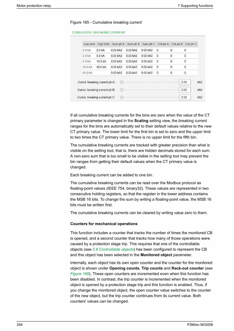
Figure 165 - Cumulative breaking current
If all cumulative breaking currents for the bins are zero when the value of the CTprimary parameter is changed in the Scaling setting view, the breaking currentranges for the bins are automatically set to their default values relative to the newCT primary value. The lower limit for the first bin is set to zero and the upper limitto two times the CT primary value. There is no upper limit for the fifth bin.
The cumulative breaking currents are tracked with greater precision than what isvisible on the setting tool, that is, there are hidden decimals stored for each sum.A non-zero sum that is too small to be visible in the setting tool may prevent thebin ranges from getting their default values when the CT primary value ischanged.
Each breaking current can be added to one bin.
The cumulative breaking currents can be read over the Modbus protocol asfloating-point values (IEEE 754, binary32). These values are represented in twoconsecutive holding registers, so that the register in the lower address containsthe MSB 16 bits. To change the sum by writing a floating-point value, the MSB 16bits must be written first.
The cumulative breaking currents can be cleared by writing value zero to them.
Counters for mechanical operations
This function includes a counter that tracks the number of times the monitored CBis opened, and a second counter that tracks how many of those operations werecaused by a protection stage trip. This requires that one of the controllableobjects (see 5.6 Controllable objects) has been configured to represent the CBand this object has been selected in the Monitored object parameter.
Internally, each object has its own open counter and the counter for the monitoredobject is shown under Opening counts, Trip counts and Rack-out counter (see Figure 166). These open counters are incremented even when this function hasbeen disabled. In contrast, the trip counter is incremented when the monitoredobject is opened by a protection stage trip and this function is enabled. Thus, ifyou change the monitored object, the open counter value switches to the counterof the new object, but the trip counter continues from its current value. Bothcounters' values can be changed.
Motor protection relay 7 Supporting functions
294 P3M/en M/G006
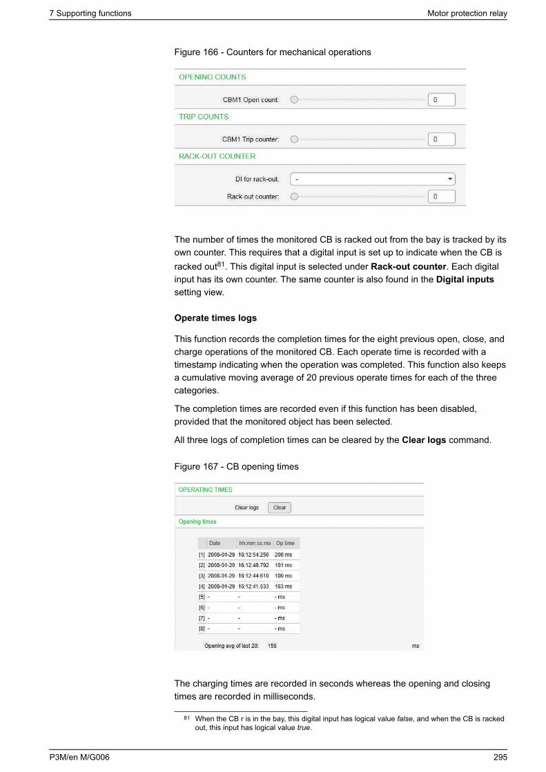
Figure 166 - Counters for mechanical operations
The number of times the monitored CB is racked out from the bay is tracked by itsown counter. This requires that a digital input is set up to indicate when the CB isracked out81. This digital input is selected under Rack-out counter. Each digitalinput has its own counter. The same counter is also found in the Digital inputssetting view.
Operate times logs
This function records the completion times for the eight previous open, close, andcharge operations of the monitored CB. Each operate time is recorded with atimestamp indicating when the operation was completed. This function also keepsa cumulative moving average of 20 previous operate times for each of the threecategories.
The completion times are recorded even if this function has been disabled,provided that the monitored object has been selected.
All three logs of completion times can be cleared by the Clear logs command.
Figure 167 - CB opening times
The charging times are recorded in seconds whereas the opening and closingtimes are recorded in milliseconds.
81 When the CB r is in the bay, this digital input has logical value false, and when the CB is rackedout, this input has logical value true.
7 Supporting functions Motor protection relay
P3M/en M/G006 295
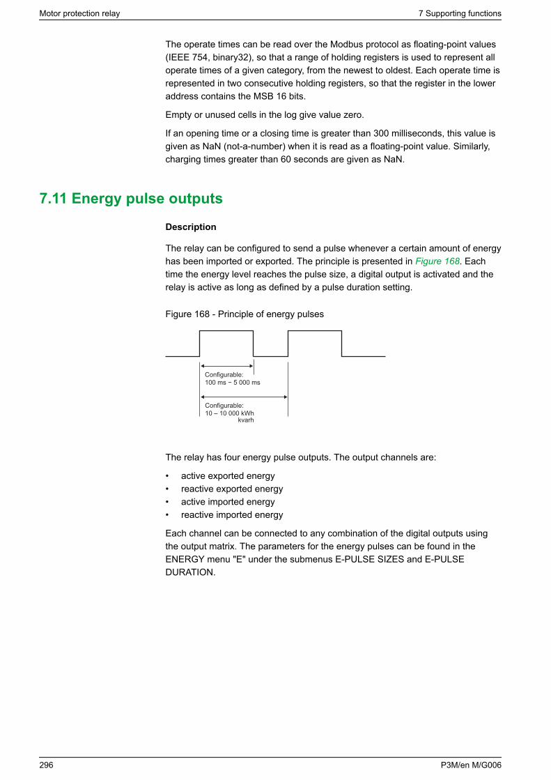
The operate times can be read over the Modbus protocol as floating-point values(IEEE 754, binary32), so that a range of holding registers is used to represent alloperate times of a given category, from the newest to oldest. Each operate time isrepresented in two consecutive holding registers, so that the register in the loweraddress contains the MSB 16 bits.
Empty or unused cells in the log give value zero.
If an opening time or a closing time is greater than 300 milliseconds, this value isgiven as NaN (not-a-number) when it is read as a floating-point value. Similarly,charging times greater than 60 seconds are given as NaN.
7.11 Energy pulse outputs
Description
The relay can be configured to send a pulse whenever a certain amount of energyhas been imported or exported. The principle is presented in Figure 168. Eachtime the energy level reaches the pulse size, a digital output is activated and therelay is active as long as defined by a pulse duration setting.
Figure 168 - Principle of energy pulses
Configurable:100 ms − 5 000 ms
Configurable:10 – 10 000 kWh
kvarh
The relay has four energy pulse outputs. The output channels are:
• active exported energy• reactive exported energy• active imported energy• reactive imported energy
Each channel can be connected to any combination of the digital outputs usingthe output matrix. The parameters for the energy pulses can be found in theENERGY menu "E" under the submenus E-PULSE SIZES and E-PULSEDURATION.
Motor protection relay 7 Supporting functions
296 P3M/en M/G006
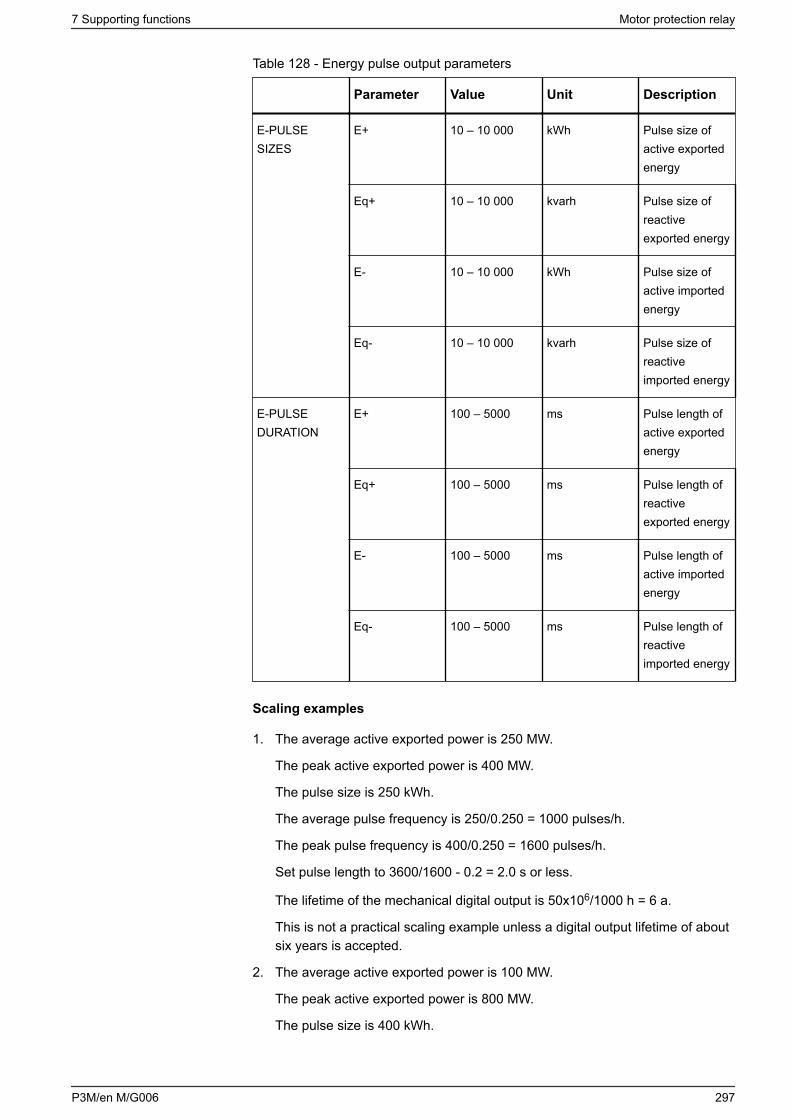
Table 128 - Energy pulse output parameters
Parameter Value Unit Description
E-PULSESIZES
E+ 10 – 10 000 kWh Pulse size ofactive exportedenergy
Eq+ 10 – 10 000 kvarh Pulse size ofreactiveexported energy
E- 10 – 10 000 kWh Pulse size ofactive importedenergy
Eq- 10 – 10 000 kvarh Pulse size ofreactiveimported energy
E-PULSEDURATION
E+ 100 – 5000 ms Pulse length ofactive exportedenergy
Eq+ 100 – 5000 ms Pulse length ofreactiveexported energy
E- 100 – 5000 ms Pulse length ofactive importedenergy
Eq- 100 – 5000 ms Pulse length ofreactiveimported energy
Scaling examples
1. The average active exported power is 250 MW.
The peak active exported power is 400 MW.
The pulse size is 250 kWh.
The average pulse frequency is 250/0.250 = 1000 pulses/h.
The peak pulse frequency is 400/0.250 = 1600 pulses/h.
Set pulse length to 3600/1600 - 0.2 = 2.0 s or less.
The lifetime of the mechanical digital output is 50x106/1000 h = 6 a.
This is not a practical scaling example unless a digital output lifetime of aboutsix years is accepted.
2. The average active exported power is 100 MW.
The peak active exported power is 800 MW.
The pulse size is 400 kWh.
7 Supporting functions Motor protection relay
P3M/en M/G006 297
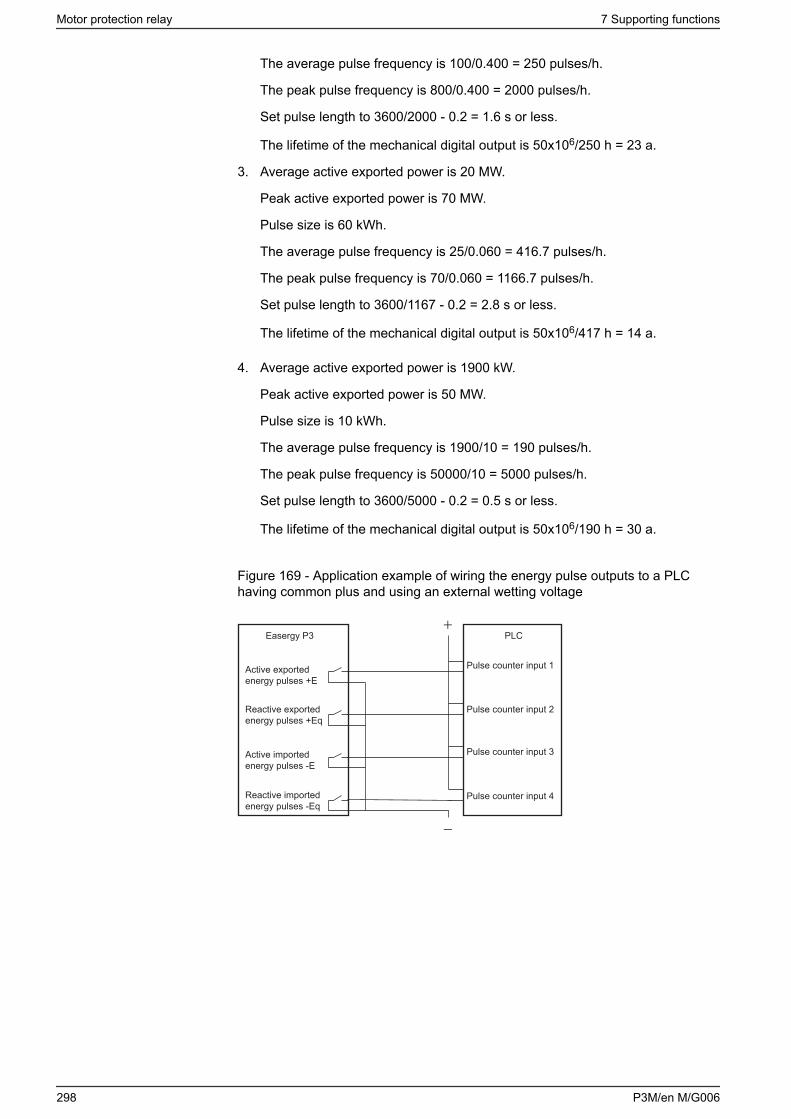
The average pulse frequency is 100/0.400 = 250 pulses/h.
The peak pulse frequency is 800/0.400 = 2000 pulses/h.
Set pulse length to 3600/2000 - 0.2 = 1.6 s or less.
The lifetime of the mechanical digital output is 50x106/250 h = 23 a.
3. Average active exported power is 20 MW.
Peak active exported power is 70 MW.
Pulse size is 60 kWh.
The average pulse frequency is 25/0.060 = 416.7 pulses/h.
The peak pulse frequency is 70/0.060 = 1166.7 pulses/h.
Set pulse length to 3600/1167 - 0.2 = 2.8 s or less.
The lifetime of the mechanical digital output is 50x106/417 h = 14 a.
4. Average active exported power is 1900 kW.
Peak active exported power is 50 MW.
Pulse size is 10 kWh.
The average pulse frequency is 1900/10 = 190 pulses/h.
The peak pulse frequency is 50000/10 = 5000 pulses/h.
Set pulse length to 3600/5000 - 0.2 = 0.5 s or less.
The lifetime of the mechanical digital output is 50x106/190 h = 30 a.
Figure 169 - Application example of wiring the energy pulse outputs to a PLChaving common plus and using an external wetting voltage
Easergy P3 PLC
−
+
Pulse counter input 1
Pulse counter input 2
Pulse counter input 3
Pulse counter input 4
Active importedenergy pulses -E
Reactive exportedenergy pulses +Eq
Active exportedenergy pulses +E
Reactive importedenergy pulses -Eq
Motor protection relay 7 Supporting functions
298 P3M/en M/G006
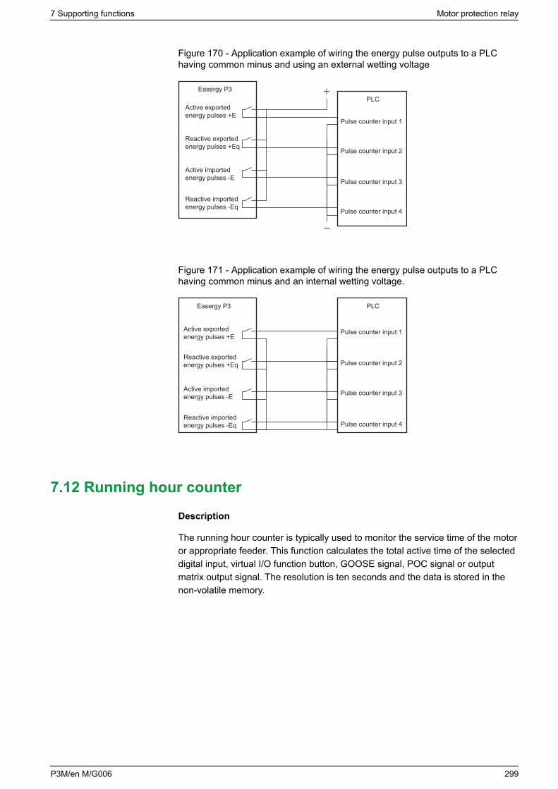
Figure 170 - Application example of wiring the energy pulse outputs to a PLChaving common minus and using an external wetting voltage
Easergy P3PLC
−
+
Pulse counter input 1
Pulse counter input 2
Pulse counter input 3
Pulse counter input 4
Active importedenergy pulses -E
Reactive exportedenergy pulses +Eq
Active exportedenergy pulses +E
Reactive importedenergy pulses -Eq
Figure 171 - Application example of wiring the energy pulse outputs to a PLChaving common minus and an internal wetting voltage.
PLC
Pulse counter input 1
Pulse counter input 2
Pulse counter input 3
Pulse counter input 4
Active importedenergy pulses -E
Reactive exportedenergy pulses +Eq
Active exportedenergy pulses +E
Reactive importedenergy pulses -Eq
Easergy P3
7.12 Running hour counter
Description
The running hour counter is typically used to monitor the service time of the motoror appropriate feeder. This function calculates the total active time of the selecteddigital input, virtual I/O function button, GOOSE signal, POC signal or outputmatrix output signal. The resolution is ten seconds and the data is stored in thenon-volatile memory.
7 Supporting functions Motor protection relay
P3M/en M/G006 299
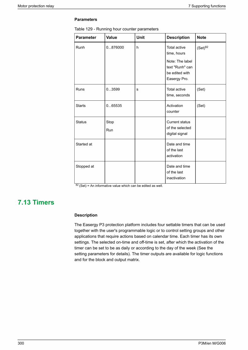
Parameters
Table 129 - Running hour counter parameters
Parameter Value Unit Description Note
Runh 0...876000 h Total activetime, hours
Note: The labeltext "Runh" canbe edited withEasergy Pro.
(Set)82
Runs 0...3599 s Total activetime, seconds
(Set)
Starts 0...65535 Activationcounter
(Set)
Status Stop
Run
Current statusof the selecteddigital signal
Started at Date and timeof the lastactivation
Stopped at Date and timeof the lastinactivation
82 (Set) = An informative value which can be edited as well.
7.13 Timers
Description
The Easergy P3 protection platform includes four settable timers that can be usedtogether with the user's programmable logic or to control setting groups and otherapplications that require actions based on calendar time. Each timer has its ownsettings. The selected on-time and off-time is set, after which the activation of thetimer can be set to be as daily or according to the day of the week (See thesetting parameters for details). The timer outputs are available for logic functionsand for the block and output matrix.
Motor protection relay 7 Supporting functions
300 P3M/en M/G006
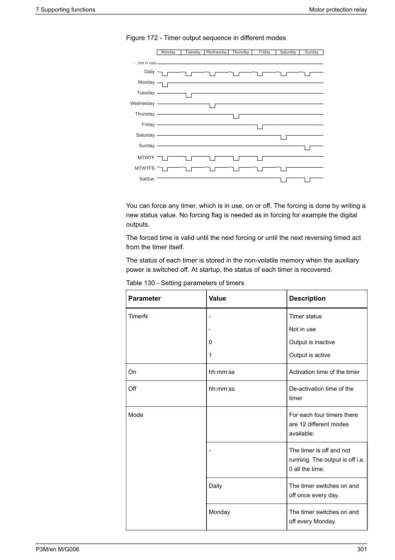
Figure 172 - Timer output sequence in different modes
Monday Tuesday Wednesday Thursday Friday Saturday Sunday
Monday
Tuesday
Wednesday
Thursday
Friday
Saturday
Sunday
Daily
(not in use)
MTWTF
MTWTFS
SatSun
You can force any timer, which is in use, on or off. The forcing is done by writing anew status value. No forcing flag is needed as in forcing for example the digitaloutputs.
The forced time is valid until the next forcing or until the next reversing timed actfrom the timer itself.
The status of each timer is stored in the non-volatile memory when the auxiliarypower is switched off. At startup, the status of each timer is recovered.
Table 130 - Setting parameters of timers
Parameter Value Description
TimerN -
-
0
1
Timer status
Not in use
Output is inactive
Output is active
On hh:mm:ss Activation time of the timer
Off hh:mm:ss De-activation time of thetimer
Mode For each four timers thereare 12 different modesavailable:
- The timer is off and notrunning. The output is off i.e.0 all the time.
Daily The timer switches on andoff once every day.
Monday The timer switches on andoff every Monday.
7 Supporting functions Motor protection relay
P3M/en M/G006 301
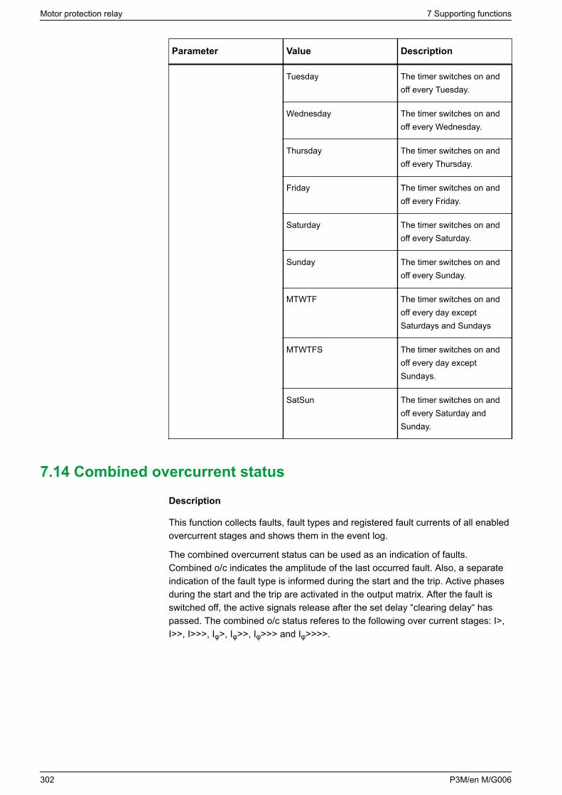
Parameter Value Description
Tuesday The timer switches on andoff every Tuesday.
Wednesday The timer switches on andoff every Wednesday.
Thursday The timer switches on andoff every Thursday.
Friday The timer switches on andoff every Friday.
Saturday The timer switches on andoff every Saturday.
Sunday The timer switches on andoff every Sunday.
MTWTF The timer switches on andoff every day exceptSaturdays and Sundays
MTWTFS The timer switches on andoff every day exceptSundays.
SatSun The timer switches on andoff every Saturday andSunday.
7.14 Combined overcurrent status
Description
This function collects faults, fault types and registered fault currents of all enabledovercurrent stages and shows them in the event log.
The combined overcurrent status can be used as an indication of faults.Combined o/c indicates the amplitude of the last occurred fault. Also, a separateindication of the fault type is informed during the start and the trip. Active phasesduring the start and the trip are activated in the output matrix. After the fault isswitched off, the active signals release after the set delay “clearing delay“ haspassed. The combined o/c status referes to the following over current stages: I>,I>>, I>>>, Iφ>, Iφ>>, Iφ>>> and Iφ>>>>.
Motor protection relay 7 Supporting functions
302 P3M/en M/G006
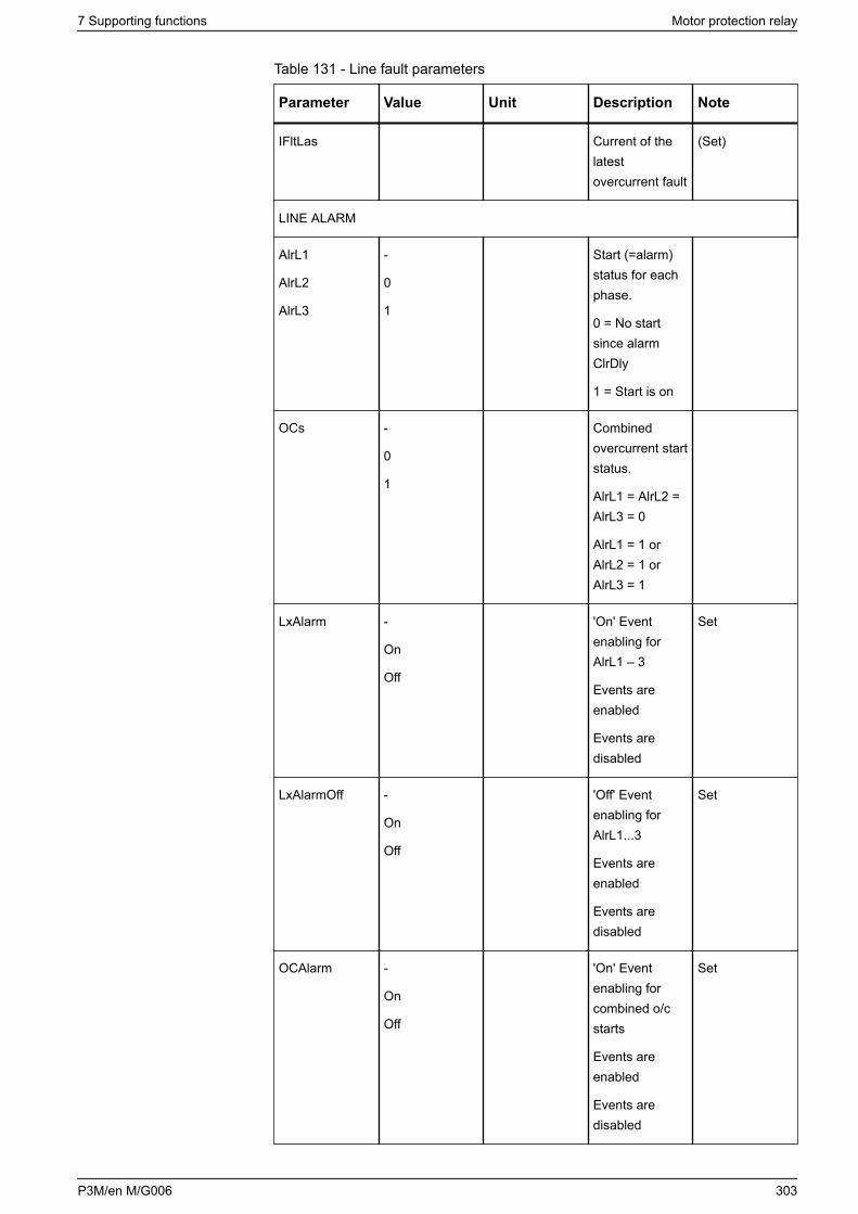
Table 131 - Line fault parameters
Parameter Value Unit Description Note
IFltLas Current of thelatestovercurrent fault
(Set)
LINE ALARM
AlrL1
AlrL2
AlrL3
-
0
1
Start (=alarm)status for eachphase.
0 = No startsince alarmClrDly
1 = Start is on
OCs -
0
1
Combinedovercurrent startstatus.
AlrL1 = AlrL2 =AlrL3 = 0
AlrL1 = 1 orAlrL2 = 1 orAlrL3 = 1
LxAlarm -
On
Off
'On' Eventenabling forAlrL1 – 3
Events areenabled
Events aredisabled
Set
LxAlarmOff -
On
Off
'Off' Eventenabling forAlrL1...3
Events areenabled
Events aredisabled
Set
OCAlarm -
On
Off
'On' Eventenabling forcombined o/cstarts
Events areenabled
Events aredisabled
Set
7 Supporting functions Motor protection relay
P3M/en M/G006 303
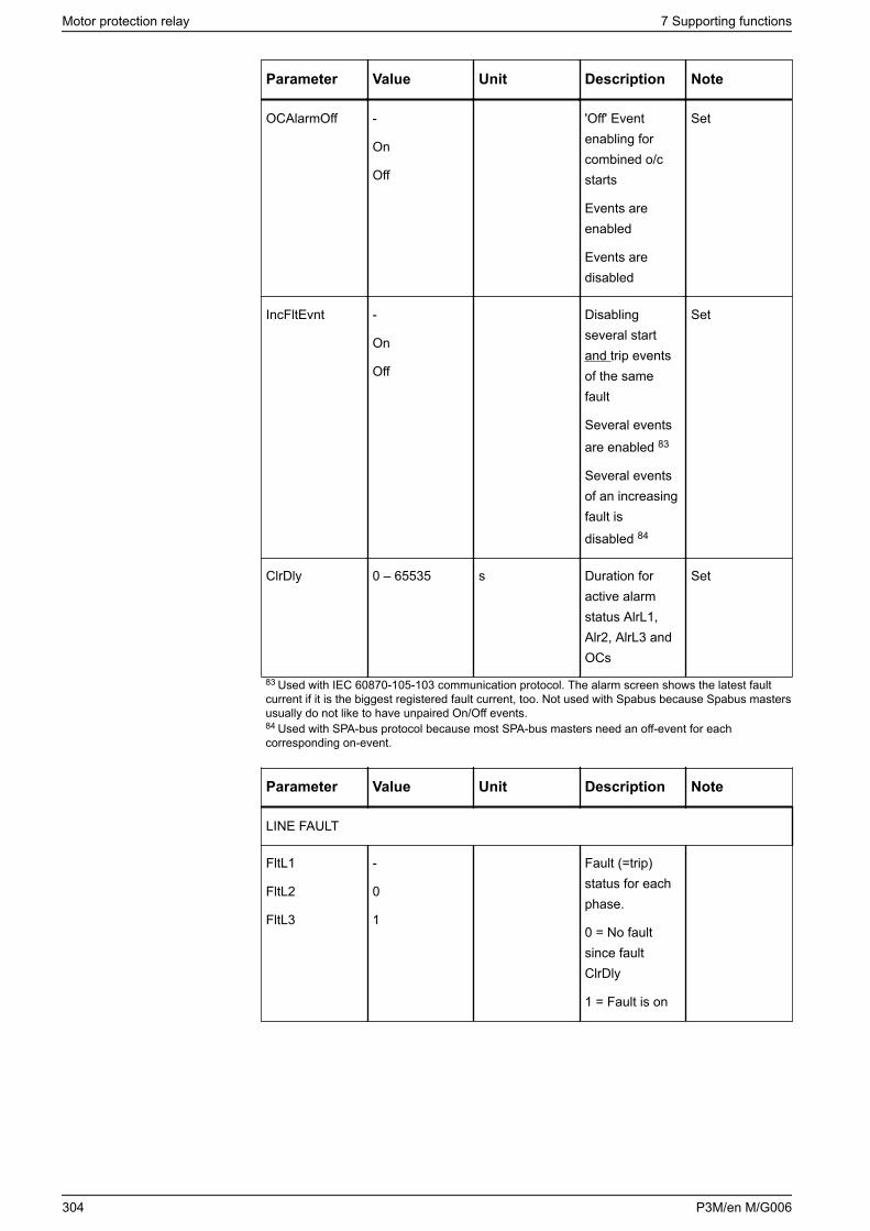
Parameter Value Unit Description Note
OCAlarmOff -
On
Off
'Off' Eventenabling forcombined o/cstarts
Events areenabled
Events aredisabled
Set
IncFltEvnt -
On
Off
Disablingseveral startand trip eventsof the samefault
Several eventsare enabled 83
Several eventsof an increasingfault isdisabled 84
Set
ClrDly 0 – 65535 s Duration foractive alarmstatus AlrL1,Alr2, AlrL3 andOCs
Set
83 Used with IEC 60870-105-103 communication protocol. The alarm screen shows the latest faultcurrent if it is the biggest registered fault current, too. Not used with Spabus because Spabus mastersusually do not like to have unpaired On/Off events.84 Used with SPA-bus protocol because most SPA-bus masters need an off-event for eachcorresponding on-event.
Parameter Value Unit Description Note
LINE FAULT
FltL1
FltL2
FltL3
-
0
1
Fault (=trip)status for eachphase.
0 = No faultsince faultClrDly
1 = Fault is on
Motor protection relay 7 Supporting functions
304 P3M/en M/G006
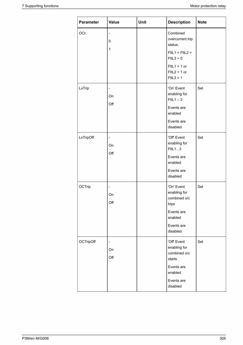
Parameter Value Unit Description Note
OCt -
0
1
Combinedovercurrent tripstatus.
FltL1 = FltL2 =FltL3 = 0
FltL1 = 1 orFltL2 = 1 orFltL3 = 1
LxTrip -
On
Off
'On' Eventenabling forFltL1 – 3
Events areenabled
Events aredisabled
Set
LxTripOff -
On
Off
'Off' Eventenabling forFltL1...3
Events areenabled
Events aredisabled
Set
OCTrip -
On
Off
'On' Eventenabling forcombined o/ctrips
Events areenabled
Events aredisabled
Set
OCTripOff -
On
Off
'Off' Eventenabling forcombined o/cstarts
Events areenabled
Events aredisabled
Set
7 Supporting functions Motor protection relay
P3M/en M/G006 305
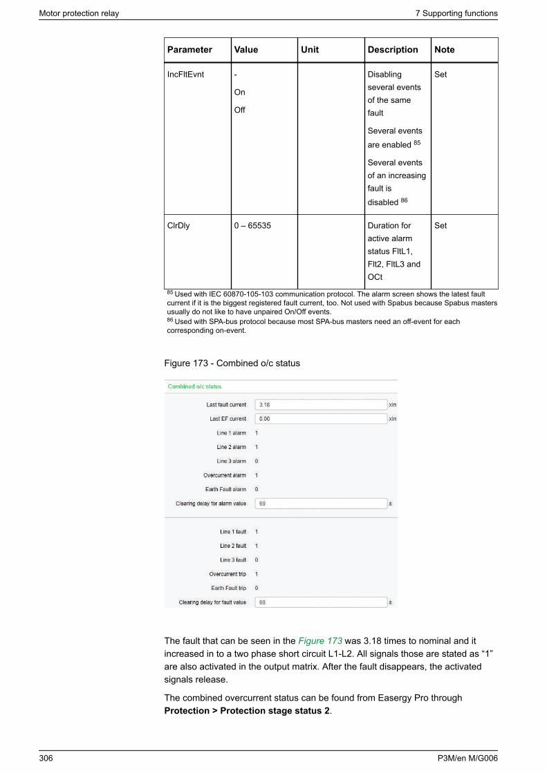
Parameter Value Unit Description Note
IncFltEvnt -
On
Off
Disablingseveral eventsof the samefault
Several eventsare enabled 85
Several eventsof an increasingfault isdisabled 86
Set
ClrDly 0 – 65535 Duration foractive alarmstatus FltL1,Flt2, FltL3 andOCt
Set
85 Used with IEC 60870-105-103 communication protocol. The alarm screen shows the latest faultcurrent if it is the biggest registered fault current, too. Not used with Spabus because Spabus mastersusually do not like to have unpaired On/Off events.86 Used with SPA-bus protocol because most SPA-bus masters need an off-event for eachcorresponding on-event.
Figure 173 - Combined o/c status
The fault that can be seen in the Figure 173 was 3.18 times to nominal and itincreased in to a two phase short circuit L1-L2. All signals those are stated as “1”are also activated in the output matrix. After the fault disappears, the activatedsignals release.
The combined overcurrent status can be found from Easergy Pro throughProtection > Protection stage status 2.
Motor protection relay 7 Supporting functions
306 P3M/en M/G006
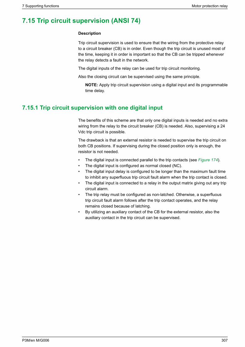
7.15 Trip circuit supervision (ANSI 74)
Description
Trip circuit supervision is used to ensure that the wiring from the protective relayto a circuit breaker (CB) is in order. Even though the trip circuit is unused most ofthe time, keeping it in order is important so that the CB can be tripped wheneverthe relay detects a fault in the network.
The digital inputs of the relay can be used for trip circuit monitoring.
Also the closing circuit can be supervised using the same principle.
NOTE: Apply trip circuit supervision using a digital input and its programmabletime delay.
7.15.1 Trip circuit supervision with one digital input
The benefits of this scheme are that only one digital inputs is needed and no extrawiring from the relay to the circuit breaker (CB) is needed. Also, supervising a 24Vdc trip circuit is possible.
The drawback is that an external resistor is needed to supervise the trip circuit onboth CB positions. If supervising during the closed position only is enough, theresistor is not needed.
• The digital input is connected parallel to the trip contacts (see Figure 174).• The digital input is configured as normal closed (NC).• The digital input delay is configured to be longer than the maximum fault time
to inhibit any superfluous trip circuit fault alarm when the trip contact is closed.• The digital input is connected to a relay in the output matrix giving out any trip
circuit alarm.• The trip relay must be configured as non-latched. Otherwise, a superfluous
trip circuit fault alarm follows after the trip contact operates, and the relayremains closed because of latching.
• By utilizing an auxiliary contact of the CB for the external resistor, also theauxiliary contact in the trip circuit can be supervised.
7 Supporting functions Motor protection relay
P3M/en M/G006 307
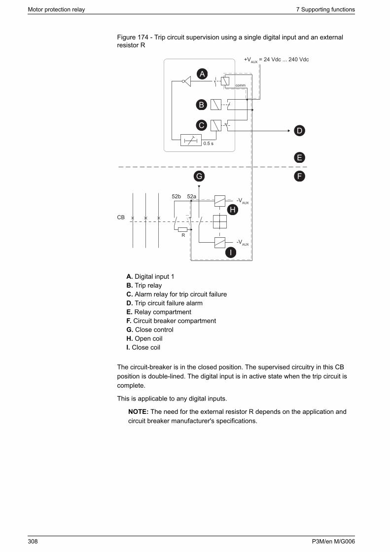
Figure 174 - Trip circuit supervision using a single digital input and an externalresistor R
+VAUX = 24 Vdc ... 240 Vdc
0.5 s
R
52b 52a
CB
-VAUX
-VAUX
comm
A
B
C D
E
FG
H
I
A. Digital input 1B. Trip relayC. Alarm relay for trip circuit failureD. Trip circuit failure alarmE. Relay compartmentF. Circuit breaker compartmentG. Close controlH. Open coilI. Close coil
The circuit-breaker is in the closed position. The supervised circuitry in this CBposition is double-lined. The digital input is in active state when the trip circuit iscomplete.
This is applicable to any digital inputs.
NOTE: The need for the external resistor R depends on the application andcircuit breaker manufacturer's specifications.
Motor protection relay 7 Supporting functions
308 P3M/en M/G006
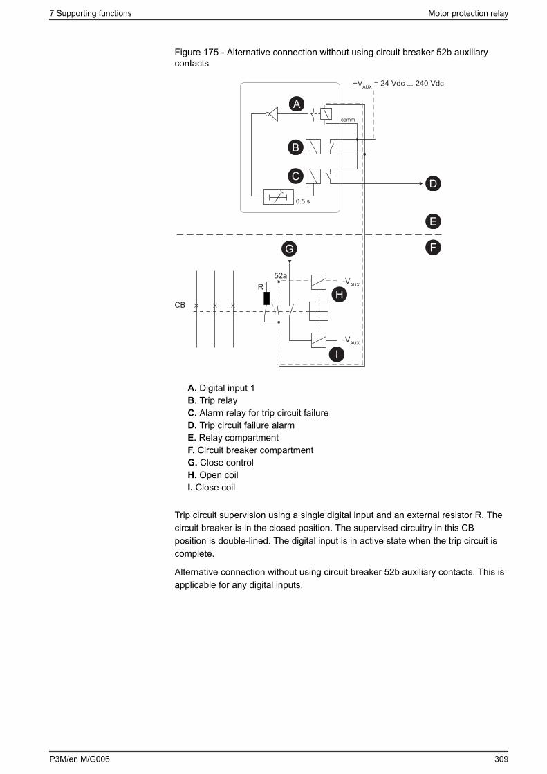
Figure 175 - Alternative connection without using circuit breaker 52b auxiliarycontacts
+VAUX = 24 Vdc ... 240 Vdc
0.5 s
R52a
CB
-VAUX
-VAUX
comm
A
B
C D
E
FG
H
I
A. Digital input 1B. Trip relayC. Alarm relay for trip circuit failureD. Trip circuit failure alarmE. Relay compartmentF. Circuit breaker compartmentG. Close controlH. Open coilI. Close coil
Trip circuit supervision using a single digital input and an external resistor R. Thecircuit breaker is in the closed position. The supervised circuitry in this CBposition is double-lined. The digital input is in active state when the trip circuit iscomplete.
Alternative connection without using circuit breaker 52b auxiliary contacts. This isapplicable for any digital inputs.
7 Supporting functions Motor protection relay
P3M/en M/G006 309
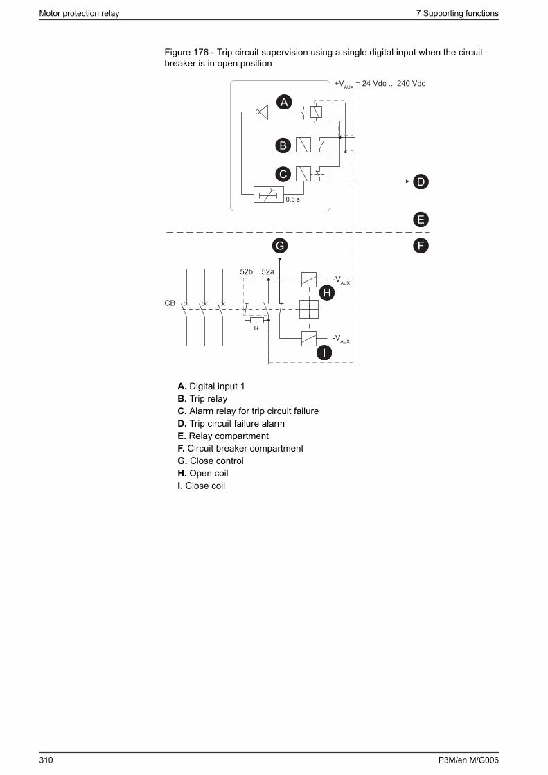
Figure 176 - Trip circuit supervision using a single digital input when the circuitbreaker is in open position
+VAUX = 24 Vdc ... 240 Vdc
0.5 s
R
52b 52a
CB
-VAUX
-VAUX
A
B
C D
E
FG
H
I
A. Digital input 1B. Trip relayC. Alarm relay for trip circuit failureD. Trip circuit failure alarmE. Relay compartmentF. Circuit breaker compartmentG. Close controlH. Open coilI. Close coil
Motor protection relay 7 Supporting functions
310 P3M/en M/G006
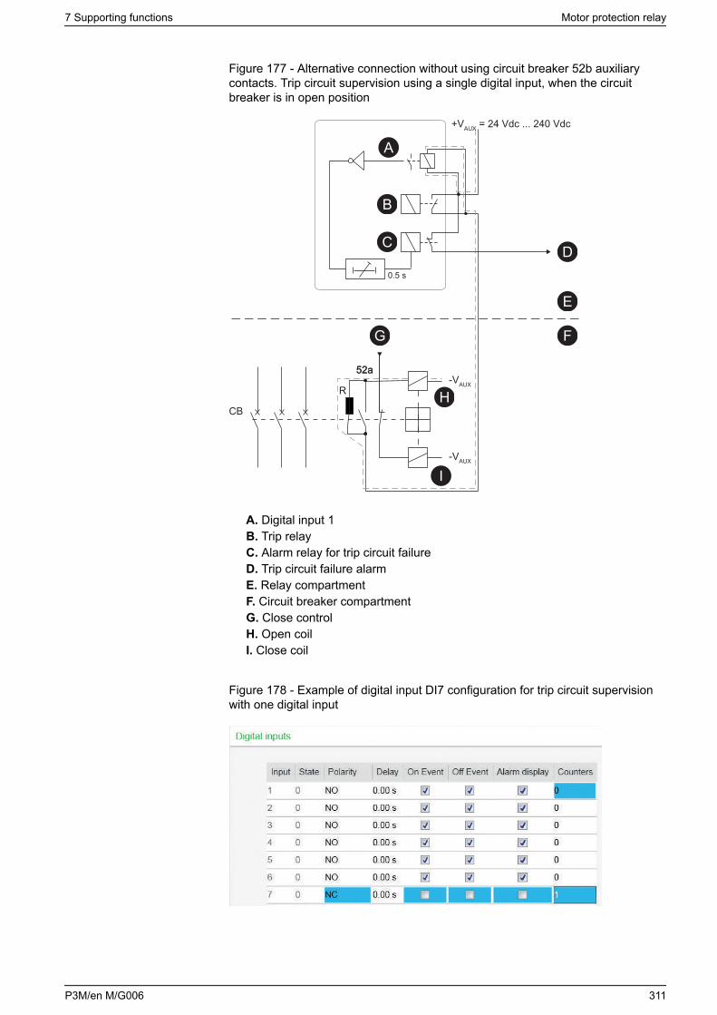
Figure 177 - Alternative connection without using circuit breaker 52b auxiliarycontacts. Trip circuit supervision using a single digital input, when the circuitbreaker is in open position
52a
+VAUX = 24 Vdc ... 240 Vdc
0.5 s
R
52a
CB
-VAUX
-VAUX
A
B
C D
E
FG
H
I
A. Digital input 1B. Trip relayC. Alarm relay for trip circuit failureD. Trip circuit failure alarmE. Relay compartmentF. Circuit breaker compartmentG. Close controlH. Open coilI. Close coil
Figure 178 - Example of digital input DI7 configuration for trip circuit supervisionwith one digital input
7 Supporting functions Motor protection relay
P3M/en M/G006 311
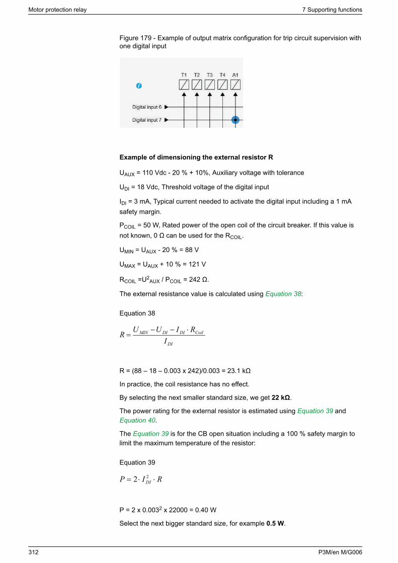
Figure 179 - Example of output matrix configuration for trip circuit supervision withone digital input
Example of dimensioning the external resistor R
UAUX = 110 Vdc - 20 % + 10%, Auxiliary voltage with tolerance
UDI = 18 Vdc, Threshold voltage of the digital input
IDI = 3 mA, Typical current needed to activate the digital input including a 1 mAsafety margin.
PCOIL = 50 W, Rated power of the open coil of the circuit breaker. If this value isnot known, 0 Ω can be used for the RCOIL.
UMIN = UAUX - 20 % = 88 V
UMAX = UAUX + 10 % = 121 V
RCOIL =U2AUX / PCOIL = 242 Ω.
The external resistance value is calculated using Equation 38:
Equation 38
DI
CoilDIDIMIN
IRIUUR ⋅−−
=
R = (88 – 18 – 0.003 x 242)/0.003 = 23.1 kΩ
In practice, the coil resistance has no effect.
By selecting the next smaller standard size, we get 22 kΩ.
The power rating for the external resistor is estimated using Equation 39 and Equation 40.
The Equation 39 is for the CB open situation including a 100 % safety margin tolimit the maximum temperature of the resistor:
Equation 39
RIP DI ⋅⋅= 22
P = 2 x 0.0032 x 22000 = 0.40 W
Select the next bigger standard size, for example 0.5 W.
Motor protection relay 7 Supporting functions
312 P3M/en M/G006
When the trip contacts are still closed and the CB is already open, the resistorhas to withstand much higher power (Equation 40) for this short time:
Equation 40
RUP MAX
2
=
P = 1212 / 22000 = 0.67 W
A 0.5 W resistor is enough for this short time peak power, too. However, if the triprelay is closed for longer than a few seconds, a 1 W resistor should be used.
7.15.2 Trip circuit supervision with two digital inputs
The benefit of this scheme is that no external resistor is needed.
The drawbacks are that two digital inputs (DIs) and two extra wires from the relayto the CB compartment are needed. Additionally, the minimum allowed auxiliaryvoltage is 48 V dc which is more than twice the threshold voltage of the digitalinput because when the CB is in open position, the two digital inputs are in series.
When two DIs are connected in a series, the switching threshold value used withone DI is too high. Therefore, a lower value must be selected: 24 V if the nominaloperation voltage for DI inputs is 110 V or 110 V if the nominal operation voltageis 220 V.
• The first digital input is connected parallel to the auxiliary contact of the circuitbreaker's open coil.
• Another auxiliary contact is connected in series with the circuitry of the firstdigital input. This makes it possible to supervise also the auxiliary contact inthe trip circuit.
• The second digital input is connected in parallel with the trip contacts.• Both inputs are configured as normal closed (NC).• The user’s programmable logic is used to combine the digital input signals
with an AND port. The delay is configured to be longer than the maximumfault time to inhibit any superfluous trip circuit fault alarm when the trip contactis closed.
• The output from the logic is connected to a relay in the output matrix givingout any trip circuit alarm.
In Figure 180, the supervised circuitry in this CB position is double-lined. Thedigital input is in active state when the trip circuit is complete. This is applicablefor all digital inputs.
7 Supporting functions Motor protection relay
P3M/en M/G006 313
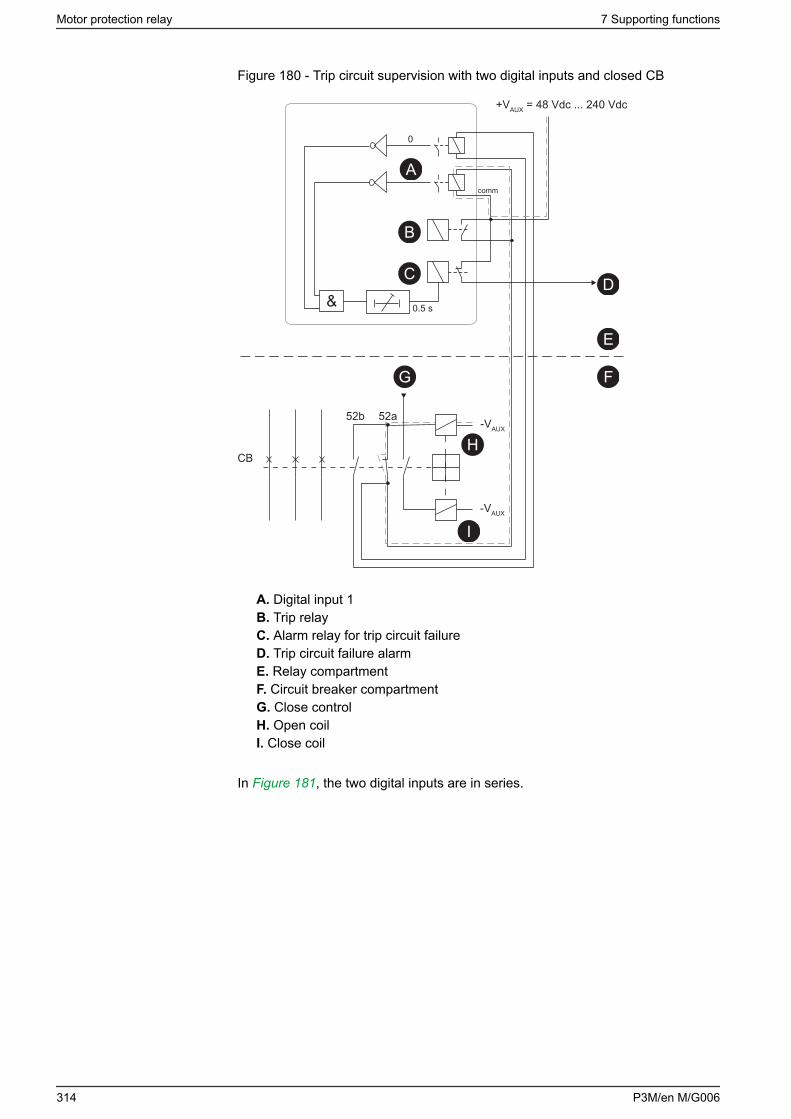
Figure 180 - Trip circuit supervision with two digital inputs and closed CB
52b 52a
+VAUX = 48 Vdc ... 240 Vdc
0.5 s
CB
-VAUX
-VAUX
comm
0
A
B
C D
E
FG
H
I
&
A. Digital input 1B. Trip relayC. Alarm relay for trip circuit failureD. Trip circuit failure alarmE. Relay compartmentF. Circuit breaker compartmentG. Close controlH. Open coilI. Close coil
In Figure 181, the two digital inputs are in series.
Motor protection relay 7 Supporting functions
314 P3M/en M/G006
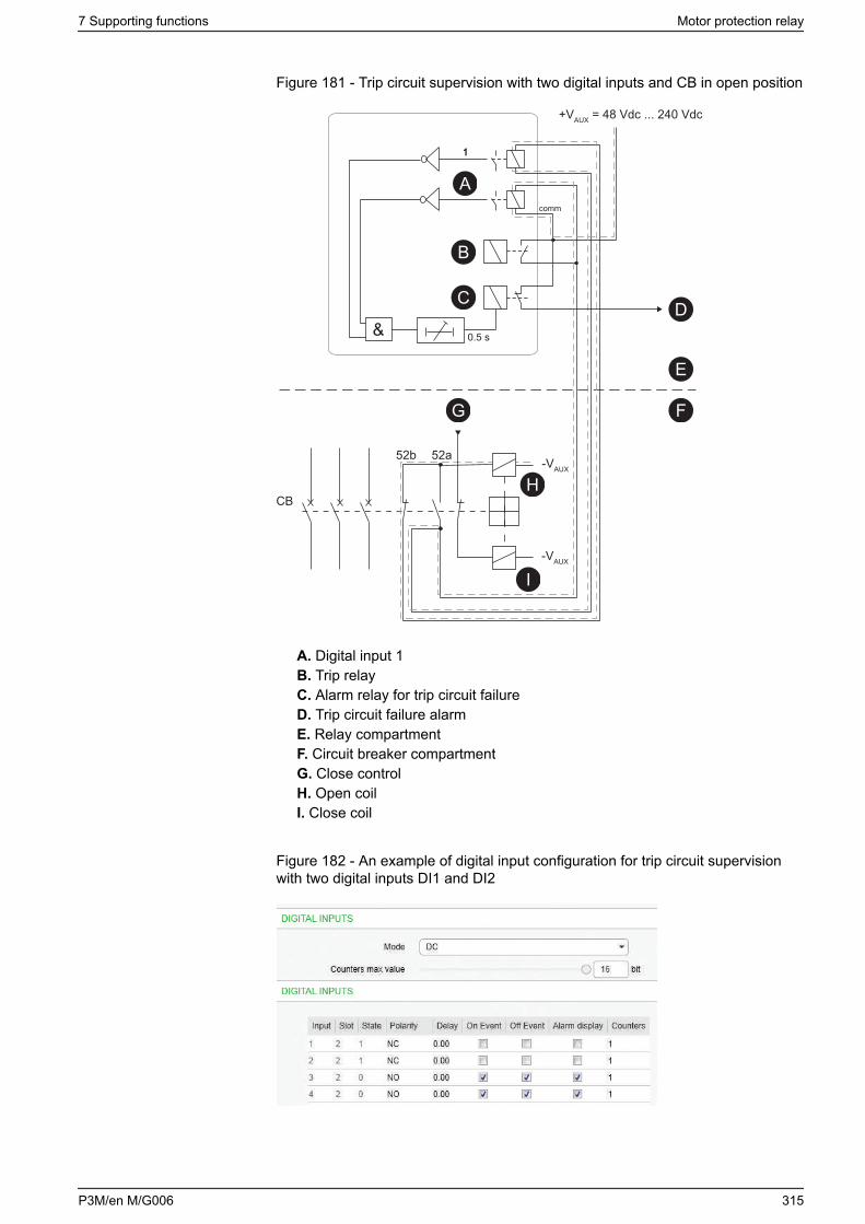
Figure 181 - Trip circuit supervision with two digital inputs and CB in open position
52b 52a
+VAUX = 48 Vdc ... 240 Vdc
0.5 s
CB
-VAUX
-VAUX
comm
1
&
A
B
C D
E
FG
H
I
1
A. Digital input 1B. Trip relayC. Alarm relay for trip circuit failureD. Trip circuit failure alarmE. Relay compartmentF. Circuit breaker compartmentG. Close controlH. Open coilI. Close coil
Figure 182 - An example of digital input configuration for trip circuit supervisionwith two digital inputs DI1 and DI2
7 Supporting functions Motor protection relay
P3M/en M/G006 315
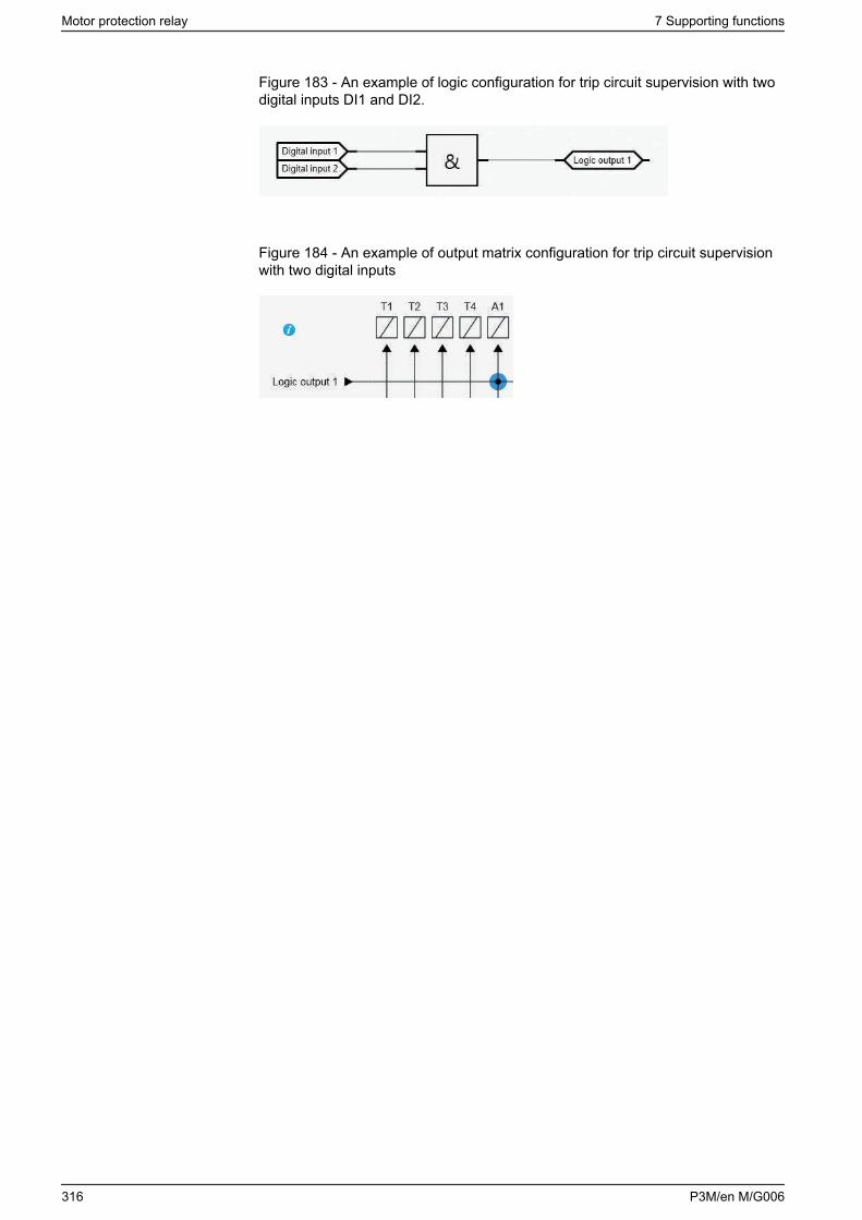
Figure 183 - An example of logic configuration for trip circuit supervision with twodigital inputs DI1 and DI2.
Figure 184 - An example of output matrix configuration for trip circuit supervisionwith two digital inputs
Motor protection relay 7 Supporting functions
316 P3M/en M/G006
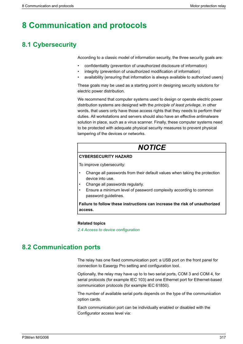
8 Communication and protocols
8.1 Cybersecurity
According to a classic model of information security, the three security goals are:
• confidentiality (prevention of unauthorized disclosure of information)• integrity (prevention of unauthorized modification of information)• availability (ensuring that information is always available to authorized users)
These goals may be used as a starting point in designing security solutions forelectric power distribution.
We recommend that computer systems used to design or operate electric powerdistribution systems are designed with the principle of least privilege, in otherwords, that users only have those access rights that they needs to perform theirduties. All workstations and servers should also have an effective antimalwaresolution in place, such as a virus scanner. Finally, these computer systems needto be protected with adequate physical security measures to prevent physicaltampering of the devices or networks.
NOTICECYBERSECURITY HAZARD
To improve cybersecurity:
• Change all passwords from their default values when taking the protectiondevice into use.
• Change all passwords regularly.• Ensure a minimum level of password complexity according to common
password guidelines.
Failure to follow these instructions can increase the risk of unauthorizedaccess.
Related topics2.4 Access to device configuration
8.2 Communication ports
The relay has one fixed communication port: a USB port on the front panel forconnection to Easergy Pro setting and configuration tool.
Optionally, the relay may have up to to two serial ports, COM 3 and COM 4, forserial protocols (for example IEC 103) and one Ethernet port for Ethernet-basedcommunication protocols (for example IEC 61850).
The number of available serial ports depends on the type of the communicationoption cards.
Each communication port can be individually enabled or disabled with theConfigurator access level via:
8 Communication and protocols Motor protection relay
P3M/en M/G006 317
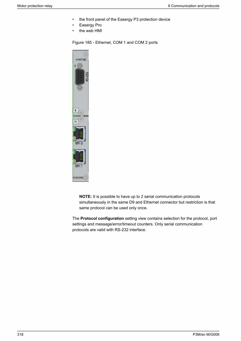
• the front panel of the Easergy P3 protection device• Easergy Pro• the web HMI
Figure 185 - Ethernet, COM 1 and COM 2 ports
NOTE: It is possible to have up to 2 serial communication protocolssimultaneously in the same D9 and Ethernet connector but restriction is thatsame protocol can be used only once.
The Protocol configuration setting view contains selection for the protocol, portsettings and message/error/timeout counters. Only serial communicationprotocols are valid with RS-232 interface.
Motor protection relay 8 Communication and protocols
318 P3M/en M/G006
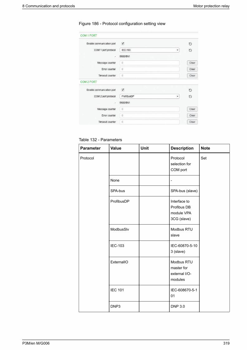
Figure 186 - Protocol configuration setting view
Table 132 - Parameters
Parameter Value Unit Description Note
Protocol Protocolselection forCOM port
Set
None -
SPA-bus SPA-bus (slave)
ProfibusDP Interface toProfibus DBmodule VPA3CG (slave)
ModbusSlv Modbus RTUslave
IEC-103 IEC-60870-5-103 (slave)
ExternalIO Modbus RTUmaster forexternal I/O-modules
IEC 101 IEC-608670-5-101
DNP3 DNP 3.0
8 Communication and protocols Motor protection relay
P3M/en M/G006 319
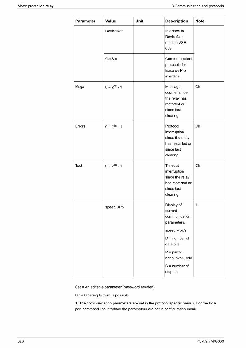
Parameter Value Unit Description Note
DeviceNet Interface toDeviceNetmodule VSE009
GetSet Communicationiprotocola forEasergy Prointerface
Msg# 0 – 232 - 1 Messagecounter sincethe relay hasrestarted orsince lastclearing
Clr
Errors 0 – 216 - 1 Protocolinterruptionsince the relayhas restarted orsince lastclearing
Clr
Tout 0 – 216 - 1 Timeoutinterruptionsince the relayhas restarted orsince lastclearing
Clr
speed/DPS Display ofcurrentcommunicationparameters.
speed = bit/s
D = number ofdata bits
P = parity:none, even, odd
S = number ofstop bits
1.
Set = An editable parameter (password needed)
Clr = Clearing to zero is possible
1. The communication parameters are set in the protocol specific menus. For the localport command line interface the parameters are set in configuration menu.
Motor protection relay 8 Communication and protocols
320 P3M/en M/G006
8.2.1 Ethernet port
The Ethernet port is used for Ethernet protocols like IEC61850 and Modbus TCP.
The physical interface is described in 10.5 Connections.
The parameters for the port can be set via the device's front panel or usingEasergy Pro. Two different protocols can be used simultaneously – both protocolsuse the same IP address and MAC address (but different port number).
8.2.2 Disabling the Ethernet communication
NOTICECYBERSECURITY HAZARD
• To improve cybersecurity, disable the Ethernet communication inenvironments where effective antimalware solutions have not been takeninto use.
• The device is not capable of transmitting data encrypted using Ethernetprotocols. If other users gain access to your network, transmitted informationcan be disclosed or subject to tampering.
• For transmitting data over an internal network, segment the networkphysically or logically and restrict access using standard controls such asfirewalls and other relevant features supported by your device such asIPTable whitelisting.
• For transmitting data over an external network, encrypt protocoltransmissions over all external connections using an encrypted tunnel, TLSwrapper or a similar solution.
Failure to follow these instructions can increase the risk of unauthorizedaccess.
1. To disable all Ethernet-based protocols:
a. In Easergy Pro, go to Communication > Protocol configuration.
b. Under Ethernet, disable the Ethernet port by unselecting the EnableEthernet communication checkbox.
8 Communication and protocols Motor protection relay
P3M/en M/G006 321
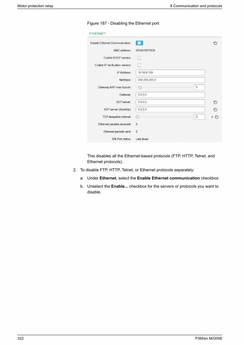
Figure 187 - Disabling the Ethernet port
This disables all the Ethernet-based protocols (FTP, HTTP, Telnet, andEthernet protocols).
2. To disable FTP, HTTP, Telnet, or Ethernet protocols separately:
a. Under Ethernet, select the Enable Ethernet communication checkbox.
b. Unselect the Enable... checkbox for the servers or protocols you want todisable.
Motor protection relay 8 Communication and protocols
322 P3M/en M/G006
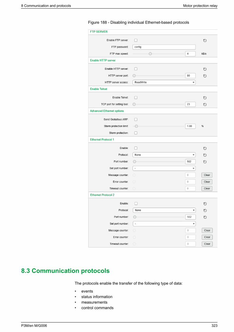
Figure 188 - Disabling individual Ethernet-based protocols
8.3 Communication protocols
The protocols enable the transfer of the following type of data:
• events• status information• measurements• control commands
8 Communication and protocols Motor protection relay
P3M/en M/G006 323

• clock synchronization• some settings through SPA bus, IEC-103, Modbus and IEC-61850 protocols• disturbance recordings through IEC-103, Modbus and IEC-61850 protocols
8.3.1 Modbus RTU and Modbus TCP
Modbus RTU and Modbus TCP protocols are often used in power plants andindustrial applications. The difference between these two protocols is the media.Modbus TCP uses Ethernet and Modbus RTU uses RS-485, optic fibre, orRS-232.
Easergy Pro shows a list of all available data items for Modbus. They are alsoavailable as a zip file ("Communication parameter protocol mappings.zip").
The information available via Modbus RTU and Modbus TCP includes:
• status values• control commands• measurement values• events• protection settings• disturbance recordings
The Modbus communication is activated via a menu selection with the parameter"Protocol". See 8.2 Communication ports.
For more information on Modbus configuration, see the documentP3APS18025EN Modbus configuration instructions.
For the Ethernet interface configuration, see 8.2.1 Ethernet port.
8.3.2 Profibus DP
The Profibus DP protocol is widely used in the industry. An external VPA 3CG andVX072 cables are required.
Device profile "continuous mode"
In this mode, the relay is sending a configured set of data parameterscontinuously to the Profibus DP master. The benefit of this mode is the speed andeasy access to the data in the Profibus master. The drawback is the maximumbuffer size of 128 bytes, which limits the number of data items transferred to themaster. Some PLCs have their own limitation for the Profibus buffer size, whichmay further limit the number of transferred data items.
Device profile "Request mode"
Using the request mode, it is possible to read all the available data from theEasergy P3 relay and still use only a very short buffer for Profibus data transfer.The drawback is the slower overall speed of the data transfer and the need ofincreased data processing at the Profibus master as every data item must beseparately requested by the master.
NOTE: In the request mode, it is not possible to read continuously only onesingle data item. At least two different data items must be read in turn to getupdated data from the relay.
Motor protection relay 8 Communication and protocols
324 P3M/en M/G006
There is a separate manual for VPA 3CG for the continuous mode and requestmode. The manual is available for downloading on our website.
Available data
Easergy Pro shows the list of all available data items for both modes. A separatedocument "Communication parameter protocol mappings.zip" is also available.
The Profibus DP communication is activated usually for remote port via a menuselection with parameter "Protocol". See 8.2 Communication ports.
8.3.3 SPA-bus
The relay has full support for the SPA-bus protocol including reading and writingthe setting values. Also, reading multiple consecutive status data bits,measurement values or setting values with one message is supported.
Several simultaneous instances of this protocol, using different physical ports, arepossible, but the events can be read by one single instance only.
There is a separate document "Communication parameter protocol mappings.zip"of SPA-bus data items available.
8.3.4 IEC 60870-5-103 (IEC-103)
The IEC standard 60870-5-103 "Companion standard for the informative interfaceof protection equipment" provides a standardized communication interface to aprimary system (master system).
The unbalanced transmission mode of the protocol is used, and the relayfunctions as a secondary station (slave) in the communication. Data is transferredto the primary system using the "data acquisition by polling" principle.
The IEC functionality includes application functions:• station initialization• general interrogation• clock synchronization• command transmission.
It is also possible to transfer parameter data and disturbance recordings via theIEC 103 protocol interface.
The following application service data unit (ASDU) types can be used:• ASDU 1: Time-tagged message• ASDU 3: Measurands I• ASDU 5: Identification message• ASDU 6: Time synchronization• ASDU 8: Termination of general interrogation• ASDU 10: Generic data
The relay accepts:• ASDU 6: Time synchronization• ASDU 7: Initiation of general interrogation• ASDU 10: Generic data• ASDU 20: General command
8 Communication and protocols Motor protection relay
P3M/en M/G006 325
• ASDU 21: Generic command• ASDU 23: Disturbance recorder file transfer
The data in a message frame is identified by:• type identification• function type• information number.
These are fixed for data items in the compatible range of the protocol, forexample, the trip of I> function is identified by:• type identification = 1• function type = 160• information number = 90
"Private range" function types are used for such data items that are not defined bythe standard (for example, the status of the digital inputs and the control of theobjects).
The function type and information number used in private range messages isconfigurable. This enables flexible interfacing to different master systems.
For more information on IEC 60870-5-103 in Easergy P3 relays, see the "IEC 103Interoperability List.pdf" and "Communication parameter protocol mappings.zip"documents.
8.3.5 DNP 3.0
The relay supports communication using the DNP 3.0 protocol. The followingDNP 3.0 data types are supported:• binary input• binary input change• double-bit input• binary output• analog input• counters
For more information, see the “DNP 3.0 Device Profile Document" and"Communication parameter protocol mappings.zip". DNP 3.0 communication isactivated via menu selection. RS-485 interface is often used but also RS-232 andfibre optic interfaces are possible.
8.3.6 IEC 60870-5-101 (IEC-101)
The IEC 60870-5-101 standard is derived from the IEC 60870-5 protocol standarddefinition. In Easergy P3 relays, the IEC 60870-5-101 communication protocol isavailable via menu selection. The relay works as a controlled outstation (slave)unit in unbalanced mode.
The supported application functions include process data transmission, eventtransmission, command transmission, general interrogation, clocksynchronization, transmission of integrated totals, and acquisition of transmissiondelay.
For more information on IEC 60870-5-101 in Easergy P3 relays, see the"Communication parameter protocol mappings.zip" document.
Motor protection relay 8 Communication and protocols
326 P3M/en M/G006
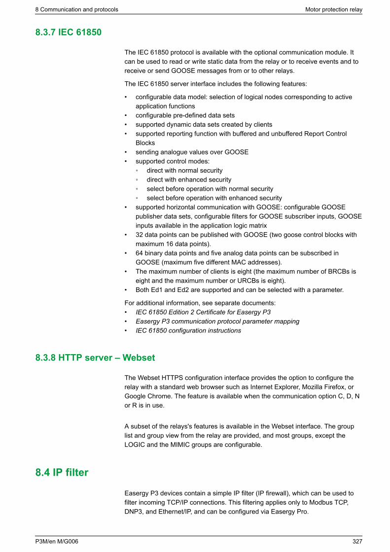
8.3.7 IEC 61850
The IEC 61850 protocol is available with the optional communication module. Itcan be used to read or write static data from the relay or to receive events and toreceive or send GOOSE messages from or to other relays.
The IEC 61850 server interface includes the following features:
• configurable data model: selection of logical nodes corresponding to activeapplication functions
• configurable pre-defined data sets• supported dynamic data sets created by clients• supported reporting function with buffered and unbuffered Report Control
Blocks• sending analogue values over GOOSE• supported control modes:
direct with normal security direct with enhanced security select before operation with normal security select before operation with enhanced security
• supported horizontal communication with GOOSE: configurable GOOSEpublisher data sets, configurable filters for GOOSE subscriber inputs, GOOSEinputs available in the application logic matrix
• 32 data points can be published with GOOSE (two goose control blocks withmaximum 16 data points).
• 64 binary data points and five analog data points can be subscribed inGOOSE (maximum five different MAC addresses).
• The maximum number of clients is eight (the maximum number of BRCBs iseight and the maximum number or URCBs is eight).
• Both Ed1 and Ed2 are supported and can be selected with a parameter.
For additional information, see separate documents:• IEC 61850 Edition 2 Certificate for Easergy P3• Easergy P3 communication protocol parameter mapping• IEC 61850 configuration instructions
8.3.8 HTTP server – Webset
The Webset HTTPS configuration interface provides the option to configure therelay with a standard web browser such as Internet Explorer, Mozilla Firefox, orGoogle Chrome. The feature is available when the communication option C, D, Nor R is in use.
A subset of the relays's features is available in the Webset interface. The grouplist and group view from the relay are provided, and most groups, except theLOGIC and the MIMIC groups are configurable.
8.4 IP filter
Easergy P3 devices contain a simple IP filter (IP firewall), which can be used tofilter incoming TCP/IP connections. This filtering applies only to Modbus TCP,DNP3, and Ethernet/IP, and can be configured via Easergy Pro.
8 Communication and protocols Motor protection relay
P3M/en M/G006 327
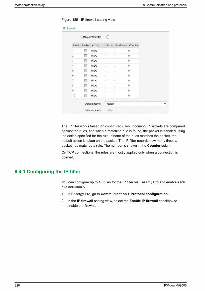
Figure 189 - IP firewall setting view
The IP filter works based on configured rules. Incoming IP packets are comparedagainst the rules, and when a matching rule is found, the packet is handled usingthe action specified for the rule. If none of the rules matches the packet, thedefault action is taken on the packet. The IP filter records how many times apacket has matched a rule. The number is shown in the Counter column.
On TCP connections, the rules are mostly applied only when a connection isopened.
8.4.1 Configuring the IP filter
You can configure up to 10 rules for the IP filter via Easergy Pro and enable eachrule individually.
1. In Easergy Pro, go to Communication > Protocol configuration.
2. In the IP firewall setting view, select the Enable IP firewall checkbox toenable the firewall.
Motor protection relay 8 Communication and protocols
328 P3M/en M/G006
Figure 190 - IP firewall setting view
3. In the IP firewall setting view, create a rule.
a. In the Name column, give the rule a name (maximum 32 characters) thatdescribes its purpose .
b. In the IP address column, specify an IP address.The IP address is used to filter the incoming IP packets based on the(apparent) IP address of the source device. There are four options.
Table 133 - IP address for the IP filter
IP address Description
Any By writing a dash or value zero in thiscolumn, the rule is set to match anysource IP address. The column showsa dash.
Single IP address If a single IP address (such as192.168.0.10) is written here, thepackets (or connections) must originatefrom this IP address to match the rule.
IP subnet If all IP addresses in a subnet shouldmatch this rule, write the subnet hereusing the CIDR notation. For example,notation 192.168.0.0/24 matches all IPaddresses in the range 192.168.0.0–192.168.0.255.
IP address range If a range of IP addresses (forexample, 192.168.0.20–192.168.0.30)is written here, packets from theseaddresses match the rule. Both endpoints of this range are inclusive.
8 Communication and protocols Motor protection relay
P3M/en M/G006 329
NOTE: If the matching range of IP addresses can be expressed usingthe CIDR notation, the range is expressed in this format, regardless ofhow the range was entered into the configuration. As a result, thepresentation format of the configuration as it is read from the devicemight not match the format in which it was entered. This may causeproblems with Easergy Pro because this tool expects the presentationformat to match exactly. To work around this issue, select the Resetand read current view command in Easergy Pro after writing theconfiguration. This is required to handle the large number of differentinput formats supported.
c. In the Action column, specify an action for the rule.There are four options.
Table 134 - Actions for IP filter
Action Description
Allow The packet is allowed to continuenormally. This means that the specifiedsource devices can use the specifiedservices on the P3 device.
Reject87 The packet is blocked and the remotepeer is informed about this decision.
Drop The packet is blocked without informingthe remote peer.
Cont. The processing of the other rulescontinues on this packet normally.
87 Because of the implementation details in the Easergy P3 TCP/IP stack, rules that aregiven the Reject action sometimes behave as if their action was Drop.
8.4.2 Unexpected packets
The IP filter also can also detect unexpected packets. For example, if a clientattempts to close a connection that does not exist, this is considered anunexpected packet.
Certain techniques used by hackers produce unexpected packets, but suchpackets may also appear on the network if some packets are lost or droppedbecause of a malfunctioning network device. Some devices may also haveprogramming errors or bugs produce unexpected packets in their TCP/IP stack.
The unexpected packets feature attempts to distinguish between these twosources based on the number of unexpected packets detected within aconfigurable “recent period”. If the number of these packets is greater than theconfigured limit, the selected alarm signal is triggered.
Motor protection relay 8 Communication and protocols
330 P3M/en M/G006
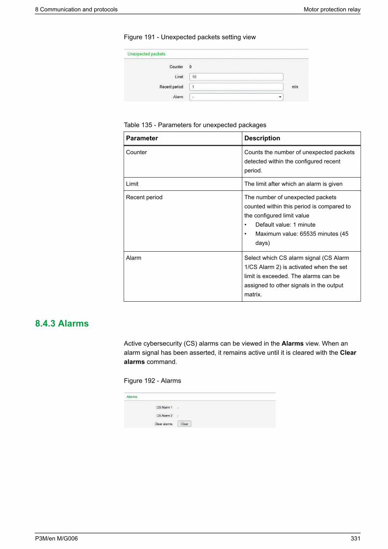
Figure 191 - Unexpected packets setting view
Table 135 - Parameters for unexpected packages
Parameter Description
Counter Counts the number of unexpected packetsdetected within the configured recentperiod.
Limit The limit after which an alarm is given
Recent period The number of unexpected packetscounted within this period is compared tothe configured limit value• Default value: 1 minute• Maximum value: 65535 minutes (45
days)
Alarm Select which CS alarm signal (CS Alarm1/CS Alarm 2) is activated when the setlimit is exceeded. The alarms can beassigned to other signals in the outputmatrix.
8.4.3 Alarms
Active cybersecurity (CS) alarms can be viewed in the Alarms view. When analarm signal has been asserted, it remains active until it is cleared with the Clearalarms command.
Figure 192 - Alarms
8 Communication and protocols Motor protection relay
P3M/en M/G006 331
9 Applications and configuration examplesThis chapter describes the protection functions in different protection applications.
The relay can be used for line/feeder protection of medium voltage networks witha grounded, low-resistance grounded, isolated or a compensated neutral point.The relays have all the required functions to be applied as a backup relay in high-voltage networks or to a transformer differential relay. In addition, the relayincludes all the required functions to be applied as a motor protection relay forrotating machines in industrial protection applications.
The relays provide a circuit breaker control function. Additional primary switchingrelays (earthing switches and disconnector switches) can also be controlled fromthe front panel or the control or SCADA/automation system. A programmablelogic function is also implemented in the relay for various applications, forexample interlockings schemes.
Motor protection relay 9 Applications and configuration examples
332 P3M/en M/G006
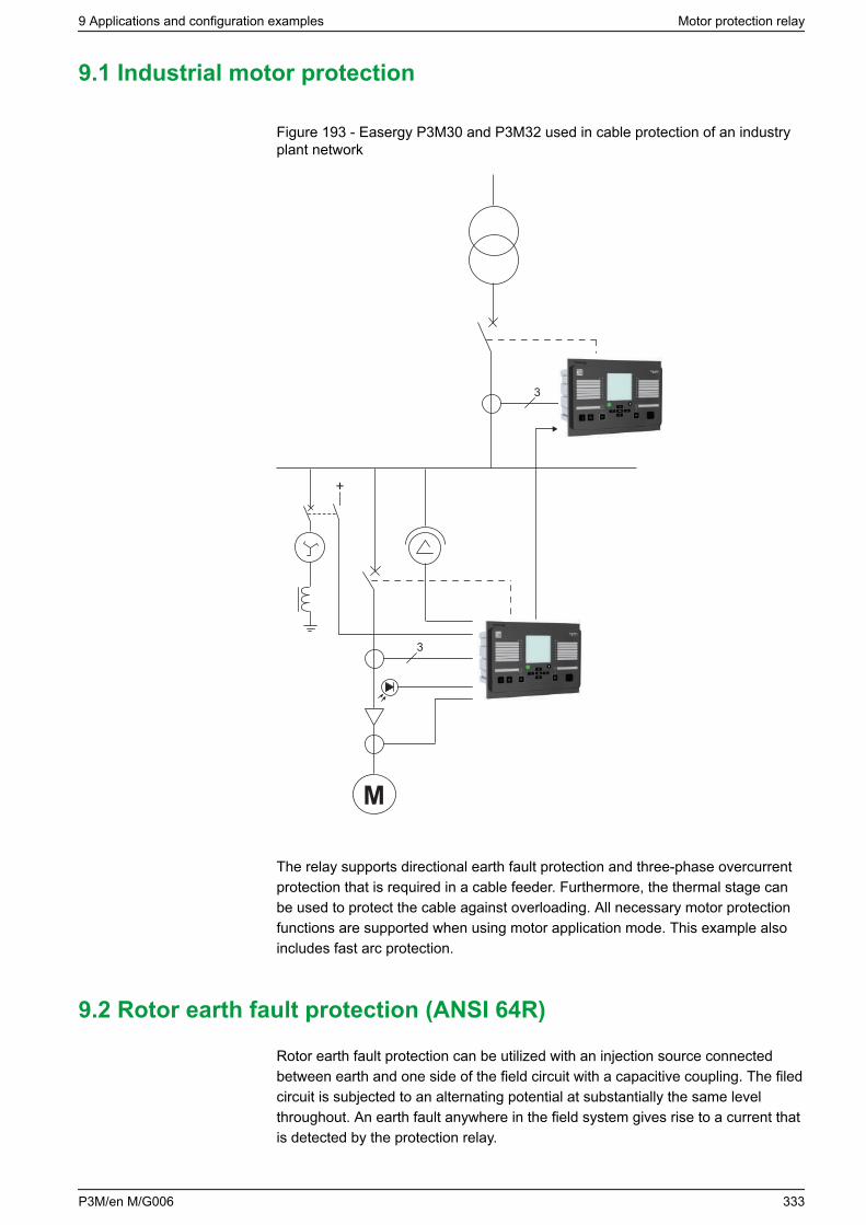
9.1 Industrial motor protection
Figure 193 - Easergy P3M30 and P3M32 used in cable protection of an industryplant network
3
3
+
M
The relay supports directional earth fault protection and three-phase overcurrentprotection that is required in a cable feeder. Furthermore, the thermal stage canbe used to protect the cable against overloading. All necessary motor protectionfunctions are supported when using motor application mode. This example alsoincludes fast arc protection.
9.2 Rotor earth fault protection (ANSI 64R)
Rotor earth fault protection can be utilized with an injection source connectedbetween earth and one side of the field circuit with a capacitive coupling. The filedcircuit is subjected to an alternating potential at substantially the same levelthroughout. An earth fault anywhere in the field system gives rise to a current thatis detected by the protection relay.
9 Applications and configuration examples Motor protection relay
P3M/en M/G006 333
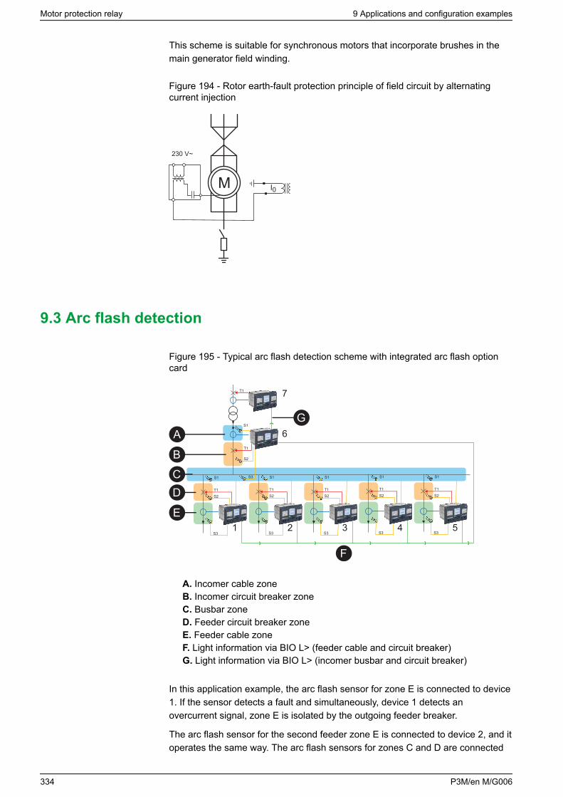
This scheme is suitable for synchronous motors that incorporate brushes in themain generator field winding.
Figure 194 - Rotor earth-fault protection principle of field circuit by alternatingcurrent injection
M I0
230 V~
9.3 Arc flash detection
Figure 195 - Typical arc flash detection scheme with integrated arc flash optioncard
S3
S2
S1
T1
S3
S2
S1
T1
S3
S2
S1
T1
S3
S2
S1
T1
S3
S2
S1
T1
S3
T1
T1
S2
S1
A
B
CD
E
F
G
1 2 3 4 5
6
7
A. Incomer cable zoneB. Incomer circuit breaker zoneC. Busbar zoneD. Feeder circuit breaker zoneE. Feeder cable zoneF. Light information via BIO L> (feeder cable and circuit breaker)G. Light information via BIO L> (incomer busbar and circuit breaker)
In this application example, the arc flash sensor for zone E is connected to device1. If the sensor detects a fault and simultaneously, device 1 detects anovercurrent signal, zone E is isolated by the outgoing feeder breaker.
The arc flash sensor for the second feeder zone E is connected to device 2, and itoperates the same way. The arc flash sensors for zones C and D are connected
Motor protection relay 9 Applications and configuration examples
334 P3M/en M/G006
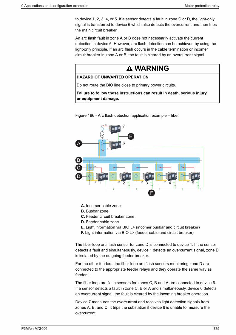
to device 1, 2, 3, 4, or 5. If a sensor detects a fault in zone C or D, the light-onlysignal is transferred to device 6 which also detects the overcurrent and then tripsthe main circuit breaker.
An arc flash fault in zone A or B does not necessarily activate the currentdetection in device 6. However, arc flash detection can be achieved by using thelight-only principle. If an arc flash occurs in the cable termination or incomercircuit breaker in zone A or B, the fault is cleared by an overcurrent signal.
WARNINGHAZARD OF UNWANTED OPERATION
Do not route the BIO line close to primary power circuits.
Failure to follow these instructions can result in death, serious injury,or equipment damage.
Figure 196 - Arc flash detection application example – fiber
S1
T1
S1
T1
S1
T1
S1
T1
S1
T1
T1
T1
S1
A
BC
D
E
F
1 2 3 4 5
6
7
A. Incomer cable zoneB. Busbar zoneC. Feeder circuit breaker zoneD. Feeder cable zoneE. Light information via BIO L> (incomer busbar and circuit breaker)F. Light information via BIO L> (feeder cable and circuit breaker)
The fiber-loop arc flash sensor for zone D is connected to device 1. If the sensordetects a fault and simultaneously, device 1 detects an overcurrent signal, zone Dis isolated by the outgoing feeder breaker.
For the other feeders, the fiber-loop arc flash sensors monitoring zone D areconnected to the appropriate feeder relays and they operate the same way asfeeder 1.
The fiber loop arc flash sensors for zones C, B and A are connected to device 6.If a sensor detects a fault in zone C, B or A and simultaneously, device 6 detectsan overcurrent signal, the fault is cleared by the incoming breaker operation.
Device 7 measures the overcurrent and receives light detection signals fromzones A, B, and C. It trips the substation if device 6 is unable to measure theovercurrent.
9 Applications and configuration examples Motor protection relay
P3M/en M/G006 335
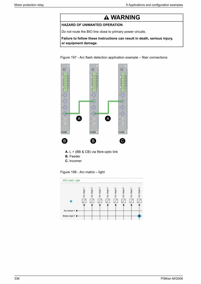
WARNINGHAZARD OF UNWANTED OPERATION
Do not route the BIO line close to primary power circuits.
Failure to follow these instructions can result in death, serious injury,or equipment damage.
Figure 197 - Arc flash detection application example – fiber connections
B B C
A A
A. L > (BB & CB) via fibre-optic linkB. FeederC. Incomer
Figure 198 - Arc matrix – light
Motor protection relay 9 Applications and configuration examples
336 P3M/en M/G006
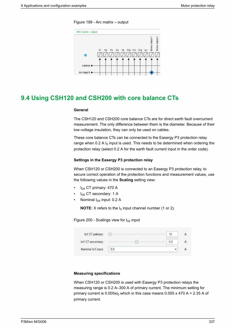
Figure 199 - Arc matrix – output
9.4 Using CSH120 and CSH200 with core balance CTs
General
The CSH120 and CSH200 core balance CTs are for direct earth fault overcurrentmeasurement. The only difference between them is the diameter. Because of theirlow-voltage insulation, they can only be used on cables.
These core balance CTs can be connected to the Easergy P3 protection relayrange when 0.2 A I0 input is used. This needs to be determined when ordering theprotection relay (select 0.2 A for the earth fault current input in the order code).
Settings in the Easergy P3 protection relay
When CSH120 or CSH200 is connected to an Easergy P3 protection relay, tosecure correct operation of the protection functions and measurement values, usethe following values in the Scaling setting view:
• I0X CT primary: 470 A• I0X CT secondary: 1 A• Nominal I0X input: 0.2 A
NOTE: X refers to the I0 input channel number (1 or 2).
Figure 200 - Scalings view for I02 input
Measuring specifications
When CSH120 or CSH200 is used with Easergy P3 protection relays themeasuring range is 0.2 A–300 A of primary current. The minimum setting forprimary current is 0.005xI0 which in this case means 0.005 x 470 A = 2.35 A ofprimary current.
9 Applications and configuration examples Motor protection relay
P3M/en M/G006 337
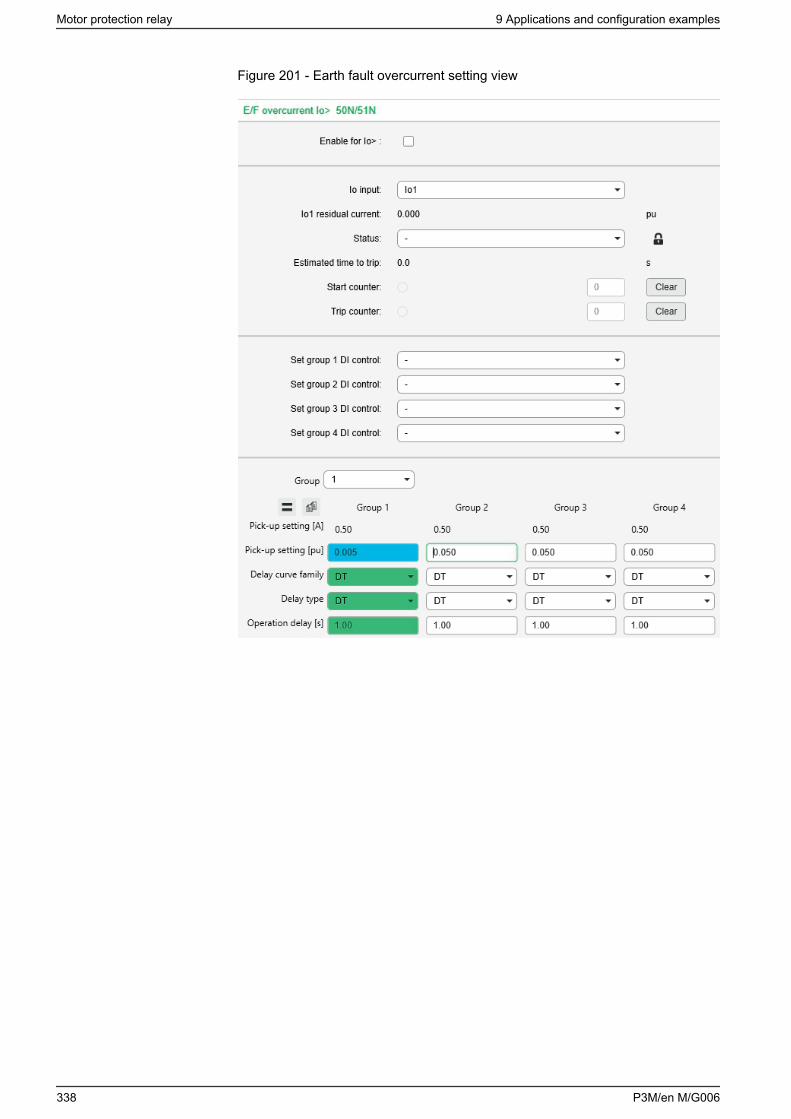
Figure 201 - Earth fault overcurrent setting view
Motor protection relay 9 Applications and configuration examples
338 P3M/en M/G006
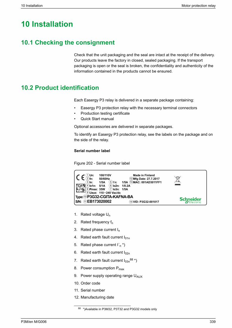
10 Installation
10.1 Checking the consignment
Check that the unit packaging and the seal are intact at the receipt of the delivery.Our products leave the factory in closed, sealed packaging. If the transportpackaging is open or the seal is broken, the confidentiality and authenticity of theinformation contained in the products cannot be ensured.
10.2 Product identification
Each Easergy P3 relay is delivered in a separate package containing:
• Easergy P3 protection relay with the necessary terminal connectors• Production testing certificate• Quick Start manual
Optional accessories are delivered in separate packages.
To identify an Easergy P3 protection relay, see the labels on the package and onthe side of the relay.
Serial number label
Figure 202 - Serial number label
Type: S/N:
P3G32-CGITA-KAFNA-BAEB173020002 VID: P3G32-001017
1
10
11
234 6
P:
5
78
Un:fn:In:Io1n:
100/110V50/60Hz1/5A5/1A
Uaux: 110 240 Vac/dcPmax: 35W
IIn:Io2n:
1/5A1/0.2A
Io3n: 1/5A
Made in FinlandMfg Date: 27.7.2017MAC: 001AD3011FF1
14
1213
9
1. Rated voltage Un
2. Rated frequency fn
3. Rated phase current In
4. Rated earth fault current I01n
5. Rated phase current I´n *)
6. Rated earth fault current I02n
7. Rated earth fault current I03n88 *)
8. Power consumption Pmax
9. Power supply operating range UAUX
10. Order code
11. Serial number
12. Manufacturing date
88 *)Available in P3M32, P3T32 and P3G32 models only
10 Installation Motor protection relay
P3M/en M/G006 339
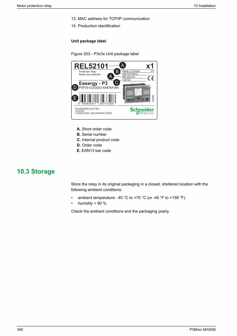
13. MAC address for TCP/IP communication
14. Production identification
Unit package label
Figure 203 - P3x3x Unit package label
REL52101 x1
Easergy - P3
Protection relayRelais de protection
Made in FinlandEB172730012REL522101135732
P3F30-CGGGG-AAENA-BA
SCHNEIDER ELECTRICCS30323F-92506 RUEIL MALMAISON CEDEX
4529
2
3576064813 28 3
Easergy
BA
CD
E
A
A. Short order codeB. Serial numberC. Internal product codeD. Order codeE. EAN13 bar code
10.3 Storage
Store the relay in its original packaging in a closed, sheltered location with thefollowing ambient conditions:
• ambient temperature: -40 °C to +70 °C (or -40 °F to +158 °F)• humidity < 90 %.
Check the ambient conditions and the packaging yearly.
Motor protection relay 10 Installation
340 P3M/en M/G006
10.4 Mounting
DANGERHAZARD OF ELECTRIC SHOCK, EXPLOSION, OR ARC FLASH
• Wear your personal protective equipment (PPE) and comply with the safeelectrical work practices. For clothing refer applicable local standards.
• Only qualified personnel should install this equipment. Such work shouldbe performed only after reading this entire set of instructions and checkingthe technical characteristics of the device.
• NEVER work alone.• Turn off all power supplying this equipment before working on or inside it.
Consider all sources of power, including the possibility of backfeeding.• Always use a properly rated voltage sensing relay to ensure that all power
is off.• Do not open the secondary circuit of a live current transformer.• Connect the device's protective ground to functional earth according to the
connection diagrams presented in this document.
Failure to follow this instruction will result in death or serious injury.
CAUTIONHAZARD OF CUTS
Trim the edges of the cut-out plates to remove any jagged edges.
Failure to follow these instructions can result in injury.
10 Installation Motor protection relay
P3M/en M/G006 341
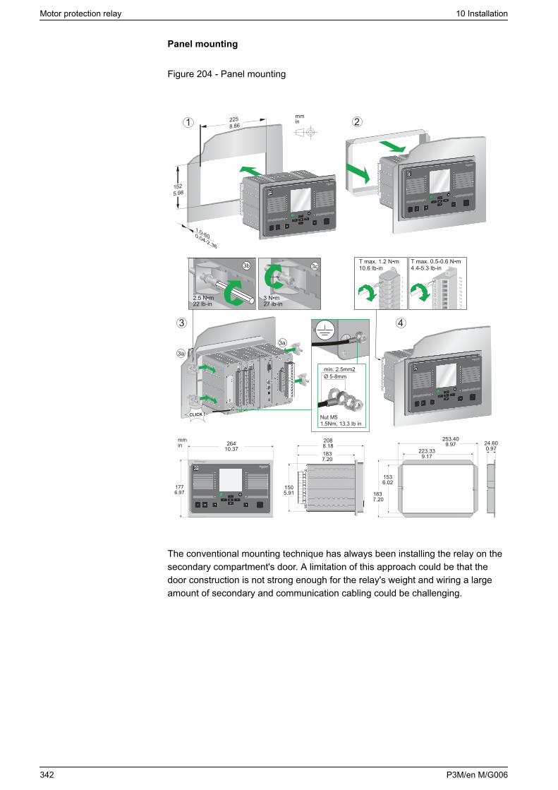
Panel mounting
Figure 204 - Panel mounting
Easergy
1.0-600.04-2.36
Easergy
225 8.86
152 5.98
1 2
4
24.600.97
253.409.97
223.339.17
183 7.20
1536.02
1505.91
2088.181837.20
3b
2.5 N•m22 lb-in
3c
3 N•m27 lb-in
mmin
mmin
T max. 1.2 N•m10.6 lb-in
T max. 0.5-0.6 N•m4.4-5.3 lb-in
1776.97
26410.37
EasergyEasergy
EasergyEasergy
CLICK !
3
3a
3a
min. 2.5mm2Ø 5-8mm
Nut M51.5Nm, 13.3 Ib in
The conventional mounting technique has always been installing the relay on thesecondary compartment's door. A limitation of this approach could be that thedoor construction is not strong enough for the relay's weight and wiring a largeamount of secondary and communication cabling could be challenging.
Motor protection relay 10 Installation
342 P3M/en M/G006
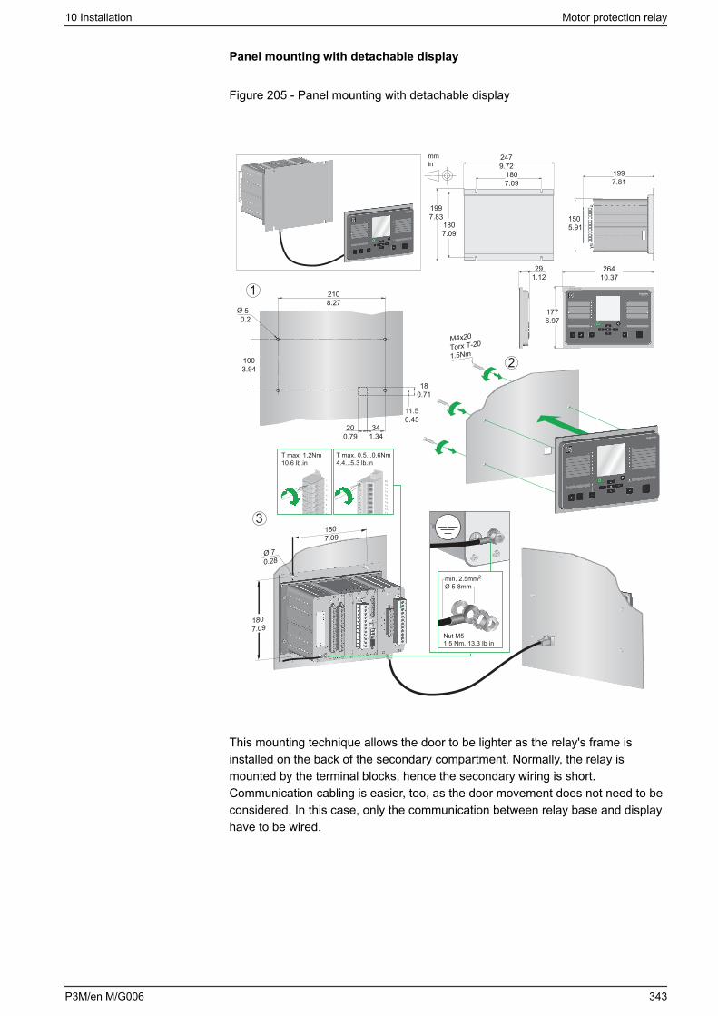
Panel mounting with detachable display
Figure 205 - Panel mounting with detachable display
mmin
T max. 1.2Nm10.6 lb.in
T max. 0.5...0.6Nm4.4...5.3 lb.in
M4x20Torx T-20
1.5Nm 2
1
31807.09
Ø 70.28
1997.83
1807.09
1807.09
2479.72
mmin
2108.27
1003.94
50.2
200.79
11.50.45
Ø
180.71
341.34
min. 2.5mm2
Ø 5-8mm
Nut M5
1807.09
1997.81
150 5.91
Easergy
1776.97
Easergy
291.12
Easergy
26410.37
1.5 Nm, 13.3 Ib in
This mounting technique allows the door to be lighter as the relay's frame isinstalled on the back of the secondary compartment. Normally, the relay ismounted by the terminal blocks, hence the secondary wiring is short.Communication cabling is easier, too, as the door movement does not need to beconsidered. In this case, only the communication between relay base and displayhave to be wired.
10 Installation Motor protection relay
P3M/en M/G006 343
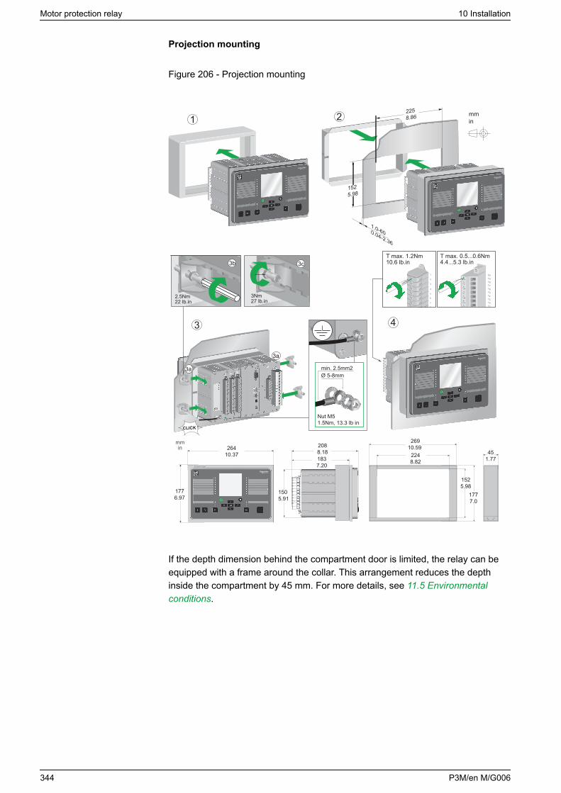
Projection mounting
Figure 206 - Projection mounting
ON
OK
Vamp 300
F1 F2OI
Easergy
EasergyEasergy
CLICK !
2225 8.86
152 5.98
1
4
3b
2.5Nm22 lb.in
3c
3Nm27 lb.in
mmin
T max. 1.2Nm10.6 lb.in
T max. 0.5...0.6Nm4.4...5.3 lb.in
1.0-600.04-2.36
269 10.59
152 5.98
177 7.0
224 8.82
45 1.77
1776.97
Easergy
3
3a
3aON
F1
F2
OK
Vamp 300
OI
EasergyEasergy
mmin 264
10.37
150 5.91
2088.181837.20
min. 2.5mm2Ø 5-8mm
Nut M51.5Nm, 13.3 Ib in
If the depth dimension behind the compartment door is limited, the relay can beequipped with a frame around the collar. This arrangement reduces the depthinside the compartment by 45 mm. For more details, see 11.5 Environmentalconditions.
Motor protection relay 10 Installation
344 P3M/en M/G006
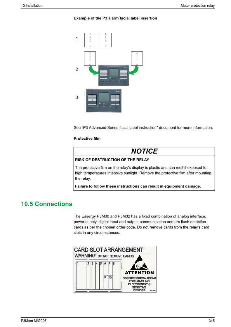
Example of the P3 alarm facial label insertion
ACEGIKM
F1
BDFHJLN
F2
ACEGIKM
F1
BDFHJLN
F2
BDFHJLN
F2
ACEGIKM
F1
1
2
3
See "P3 Advanced Series facial label instruction" document for more information.
Protective film
NOTICERISK OF DESTRUCTION OF THE RELAY
The protective film on the relay's display is plastic and can melt if exposed tohigh temperatures intensive sunlight. Remove the protective film after mountingthe relay.
Failure to follow these instructions can result in equipment damage.
10.5 Connections
The Easergy P3M30 and P3M32 has a fixed combination of analog interface,power supply, digital input and output, communication and arc flash detectioncards as per the chosen order code. Do not remove cards from the relay's cardslots in any circumstances.
1 2 3 4 5 6
9
7
10
8
CARD SLOT ARRANGEMENT
OBSERVE PRECAUTIONSFOR HANDLING
ELECTROSTATICSENSITIVEDEVICES
WARNING! DO NOT REMOVE CARDS!
VY197BVY197B
10 Installation Motor protection relay
P3M/en M/G006 345

10.5.1 Supply voltage cards
Auxiliary voltage
DANGERHAZARD OF ELECTRIC SHOCK
Before connecting the devices, disconnect the supply voltage to the unit.
Failure to follow these instructions will result in death or serious injury.
The external auxiliary voltage UAUX (110–240 V ac/dc, or optionally 24–48 V dc)of the relay is connected to the pins 1/C/1:1–2 or 1/D/1:1–2.
NOTE: When an optional 24–48 V dc power module is used, the polarity is asfollows: 1/D/2:2 positive (+), 1/D/2:1 negative (-).
NOTICELOSS OF PROTECTION OR RISK OF NUISANCE TRIPPING
• If the relay is no longer supplied with power or is in permanent fault state,the protection functions are no longer active and all the Easergy P3 digitaloutputs are dropped out.
• Check that the operating mode and SF relay wiring are compatible with theinstallation.
Failure to follow these instructions can result in equipment damage andunwanted shutdown of the electrical installation.
Figure 207 - Example of supply voltage card Power C 110-240
Motor protection relay 10 Installation
346 P3M/en M/G006
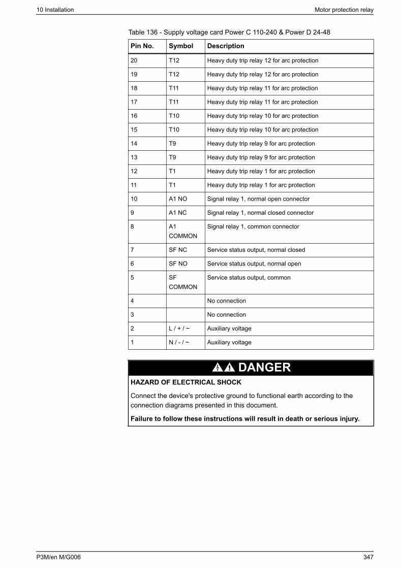
Table 136 - Supply voltage card Power C 110-240 & Power D 24-48
Pin No. Symbol Description
20 T12 Heavy duty trip relay 12 for arc protection
19 T12 Heavy duty trip relay 12 for arc protection
18 T11 Heavy duty trip relay 11 for arc protection
17 T11 Heavy duty trip relay 11 for arc protection
16 T10 Heavy duty trip relay 10 for arc protection
15 T10 Heavy duty trip relay 10 for arc protection
14 T9 Heavy duty trip relay 9 for arc protection
13 T9 Heavy duty trip relay 9 for arc protection
12 T1 Heavy duty trip relay 1 for arc protection
11 T1 Heavy duty trip relay 1 for arc protection
10 A1 NO Signal relay 1, normal open connector
9 A1 NC Signal relay 1, normal closed connector
8 A1COMMON
Signal relay 1, common connector
7 SF NC Service status output, normal closed
6 SF NO Service status output, normal open
5 SFCOMMON
Service status output, common
4 No connection
3 No connection
2 L / + / ~ Auxiliary voltage
1 N / - / ~ Auxiliary voltage
DANGERHAZARD OF ELECTRICAL SHOCK
Connect the device's protective ground to functional earth according to theconnection diagrams presented in this document.
Failure to follow these instructions will result in death or serious injury.
10 Installation Motor protection relay
P3M/en M/G006 347
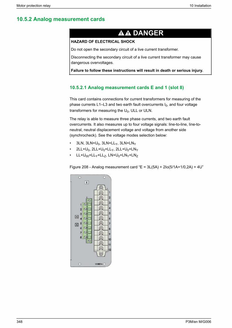
10.5.2 Analog measurement cards
DANGERHAZARD OF ELECTRICAL SHOCK
Do not open the secondary circuit of a live current transformer.
Disconnecting the secondary circuit of a live current transformer may causedangerous overvoltages.
Failure to follow these instructions will result in death or serious injury.
10.5.2.1 Analog measurement cards E and 1 (slot 8)
This card contains connections for current transformers for measuring of thephase currents L1–L3 and two earth fault overcurrents I0, and four voltagetransformers for measuring the U0, ULL or ULN.
The relay is able to measure three phase currents, and two earth faultovercurrents. It also measures up to four voltage signals: line-to-line, line-to-neutral, neutral displacement voltage and voltage from another side(synchrocheck). See the voltage modes selection below:
• 3LN, 3LN+U0, 3LN+LLY, 3LN+LNY
• 2LL+U0, 2LL+U0+LLY, 2LL+U0+LNY
• LL+U00+LLY+LLZ, LN+U0+LNY+LNZ
Figure 208 - Analog measurement card “E = 3L(5A) + 2Io(5/1A+1/0,2A) + 4U”
Motor protection relay 10 Installation
348 P3M/en M/G006
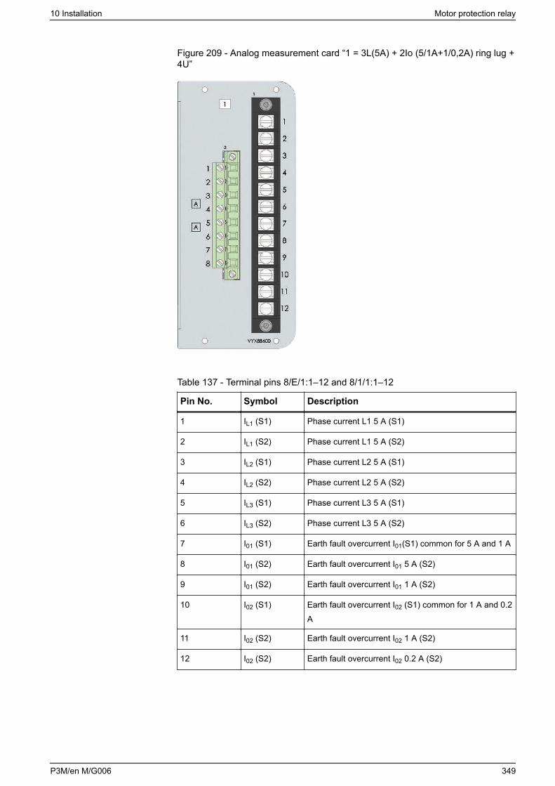
Figure 209 - Analog measurement card “1 = 3L(5A) + 2Io (5/1A+1/0,2A) ring lug +4U”
Table 137 - Terminal pins 8/E/1:1–12 and 8/1/1:1–12
Pin No. Symbol Description
1 IL1 (S1) Phase current L1 5 A (S1)
2 IL1 (S2) Phase current L1 5 A (S2)
3 IL2 (S1) Phase current L2 5 A (S1)
4 IL2 (S2) Phase current L2 5 A (S2)
5 IL3 (S1) Phase current L3 5 A (S1)
6 IL3 (S2) Phase current L3 5 A (S2)
7 I01 (S1) Earth fault overcurrent I01(S1) common for 5 A and 1 A
8 I01 (S2) Earth fault overcurrent I01 5 A (S2)
9 I01 (S2) Earth fault overcurrent I01 1 A (S2)
10 I02 (S1) Earth fault overcurrent I02 (S1) common for 1 A and 0.2A
11 I02 (S2) Earth fault overcurrent I02 1 A (S2)
12 I02 (S2) Earth fault overcurrent I02 0.2 A (S2)
10 Installation Motor protection relay
P3M/en M/G006 349
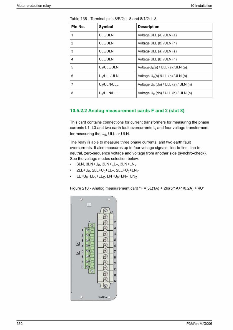
Table 138 - Terminal pins 8/E/2:1–8 and 8/1/2:1–8
Pin No. Symbol Description
1 ULL/ULN Voltage ULL (a) /ULN (a)
2 ULL/ULN Voltage ULL (b) /ULN (n)
3 ULL/ULN Voltage ULL (a) /ULN (a)
4 ULL/ULN Voltage ULL (b) /ULN (n)
5 U0/ULL/ULN VoltageU0(a) / ULL (a) /ULN (a)
6 U0/ULL/ULN Voltage U0(b) /ULL (b) /ULN (n)
7 U0/ULN/ULL Voltage U0 (da) / ULL (a) / ULN (n)
8 U0/ULN/ULL Voltage U0 (dn) / ULL (b) / ULN (n)
10.5.2.2 Analog measurement cards F and 2 (slot 8)
This card contains connections for current transformers for measuring the phasecurrents L1–L3 and two earth fault overcurrents I0 and four voltage transformersfor measuring the U0, ULL or ULN.
The relay is able to measure three phase currents, and two earth faultovercurrents. It also measures up to four voltage signals: line-to-line, line-to-neutral, zero-sequence voltage and voltage from another side (synchro-check).See the voltage modes selection below:• 3LN, 3LN+U0, 3LN+LLY, 3LN+LNY
• 2LL+U0, 2LL+U0+LLY, 2LL+U0+LNY
• LL+U0+LLY+LLZ, LN+U0+LNY+LNZ
Figure 210 - Analog measurement card "F = 3L(1A) + 2Io(5/1A+1/0.2A) + 4U"
Motor protection relay 10 Installation
350 P3M/en M/G006
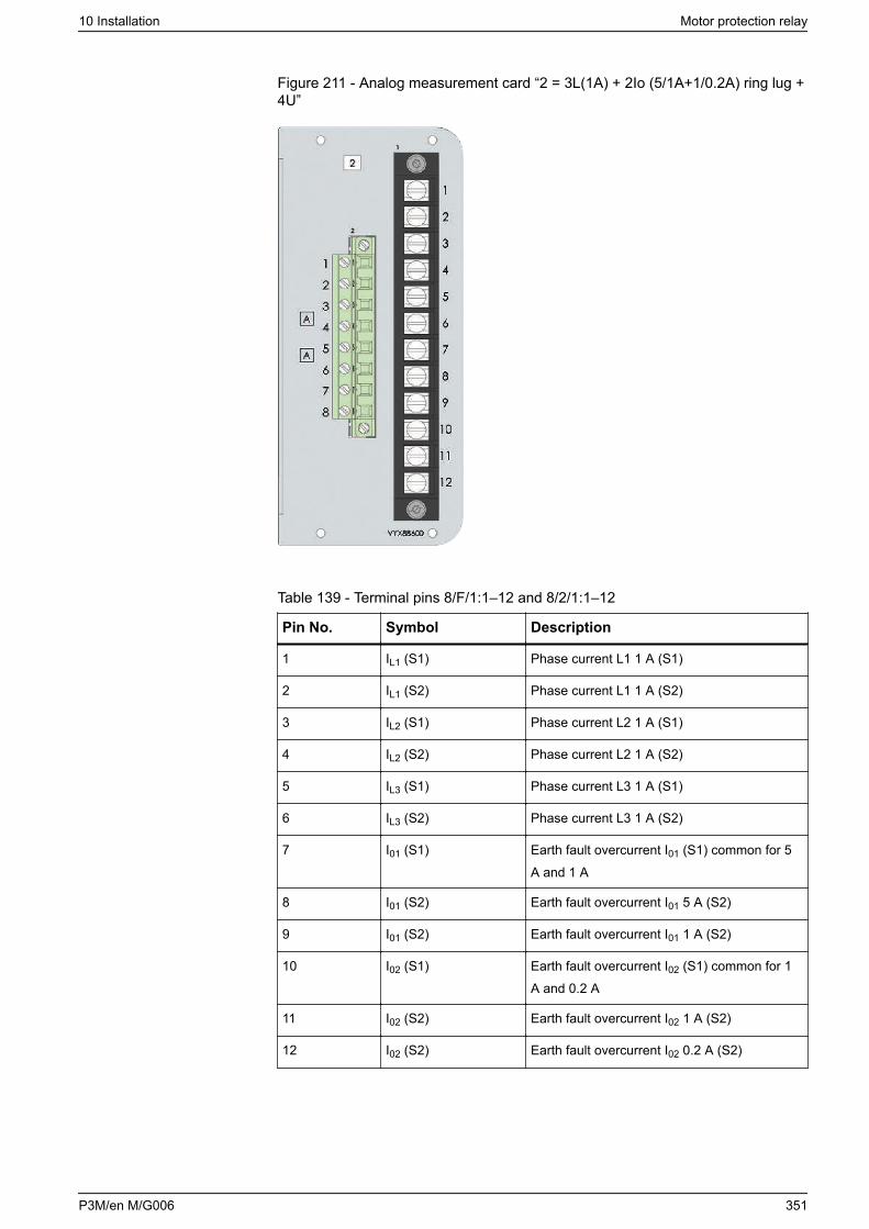
Figure 211 - Analog measurement card “2 = 3L(1A) + 2Io (5/1A+1/0.2A) ring lug +4U”
Table 139 - Terminal pins 8/F/1:1–12 and 8/2/1:1–12
Pin No. Symbol Description
1 IL1 (S1) Phase current L1 1 A (S1)
2 IL1 (S2) Phase current L1 1 A (S2)
3 IL2 (S1) Phase current L2 1 A (S1)
4 IL2 (S2) Phase current L2 1 A (S2)
5 IL3 (S1) Phase current L3 1 A (S1)
6 IL3 (S2) Phase current L3 1 A (S2)
7 I01 (S1) Earth fault overcurrent I01 (S1) common for 5A and 1 A
8 I01 (S2) Earth fault overcurrent I01 5 A (S2)
9 I01 (S2) Earth fault overcurrent I01 1 A (S2)
10 I02 (S1) Earth fault overcurrent I02 (S1) common for 1A and 0.2 A
11 I02 (S2) Earth fault overcurrent I02 1 A (S2)
12 I02 (S2) Earth fault overcurrent I02 0.2 A (S2)
10 Installation Motor protection relay
P3M/en M/G006 351
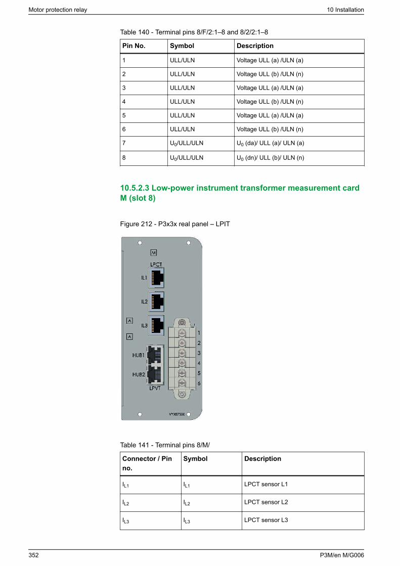
Table 140 - Terminal pins 8/F/2:1–8 and 8/2/2:1–8
Pin No. Symbol Description
1 ULL/ULN Voltage ULL (a) /ULN (a)
2 ULL/ULN Voltage ULL (b) /ULN (n)
3 ULL/ULN Voltage ULL (a) /ULN (a)
4 ULL/ULN Voltage ULL (b) /ULN (n)
5 ULL/ULN Voltage ULL (a) /ULN (a)
6 ULL/ULN Voltage ULL (b) /ULN (n)
7 U0/ULL/ULN U0 (da)/ ULL (a)/ ULN (a)
8 U0/ULL/ULN U0 (dn)/ ULL (b)/ ULN (n)
10.5.2.3 Low-power instrument transformer measurement cardM (slot 8)
Figure 212 - P3x3x real panel – LPIT
Table 141 - Terminal pins 8/M/
Connector / Pinno.
Symbol Description
IL1 IL1 LPCT sensor L1
IL2 IL2 LPCT sensor L2
IL3 IL3 LPCT sensor L3
Motor protection relay 10 Installation
352 P3M/en M/G006
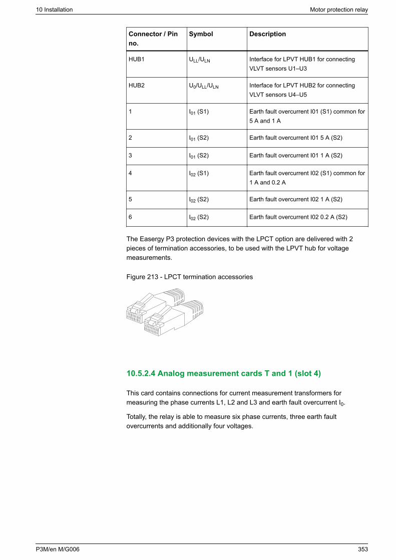
Connector / Pinno.
Symbol Description
HUB1 ULL/ULN Interface for LPVT HUB1 for connectingVLVT sensors U1–U3
HUB2 U0/ULL/ULN Interface for LPVT HUB2 for connectingVLVT sensors U4–U5
1 I01 (S1) Earth fault overcurrent I01 (S1) common for5 A and 1 A
2 I01 (S2) Earth fault overcurrent I01 5 A (S2)
3 I01 (S2) Earth fault overcurrent I01 1 A (S2)
4 I02 (S1) Earth fault overcurrent I02 (S1) common for1 A and 0.2 A
5 I02 (S2) Earth fault overcurrent I02 1 A (S2)
6 I02 (S2) Earth fault overcurrent I02 0.2 A (S2)
The Easergy P3 protection devices with the LPCT option are delivered with 2pieces of termination accessories, to be used with the LPVT hub for voltagemeasurements.
Figure 213 - LPCT termination accessories
10.5.2.4 Analog measurement cards T and 1 (slot 4)
This card contains connections for current measurement transformers formeasuring the phase currents L1, L2 and L3 and earth fault overcurrent I0.
Totally, the relay is able to measure six phase currents, three earth faultovercurrents and additionally four voltages.
10 Installation Motor protection relay
P3M/en M/G006 353
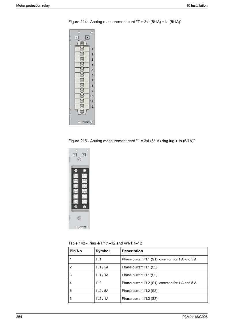
Figure 214 - Analog measurement card "T = 3xI (5/1A) + Io (5/1A)"
Figure 215 - Analog measurement card "1 = 3xI (5/1A) ring lug + Io (5/1A)”
Table 142 - Pins 4/T/1:1–12 and 4/1/1:1–12
Pin No. Symbol Description
1 I’L1 Phase current I’L1 (S1), common for 1 A and 5 A
2 I’L1 / 5A Phase current I’L1 (S2)
3 I’L1 / 1A Phase current I’L1 (S2)
4 I’L2 Phase current I’L2 (S1), common for 1 A and 5 A
5 I’L2 / 5A Phase current I’L2 (S2)
6 I’L2 / 1A Phase current I’L2 (S2)
Motor protection relay 10 Installation
354 P3M/en M/G006
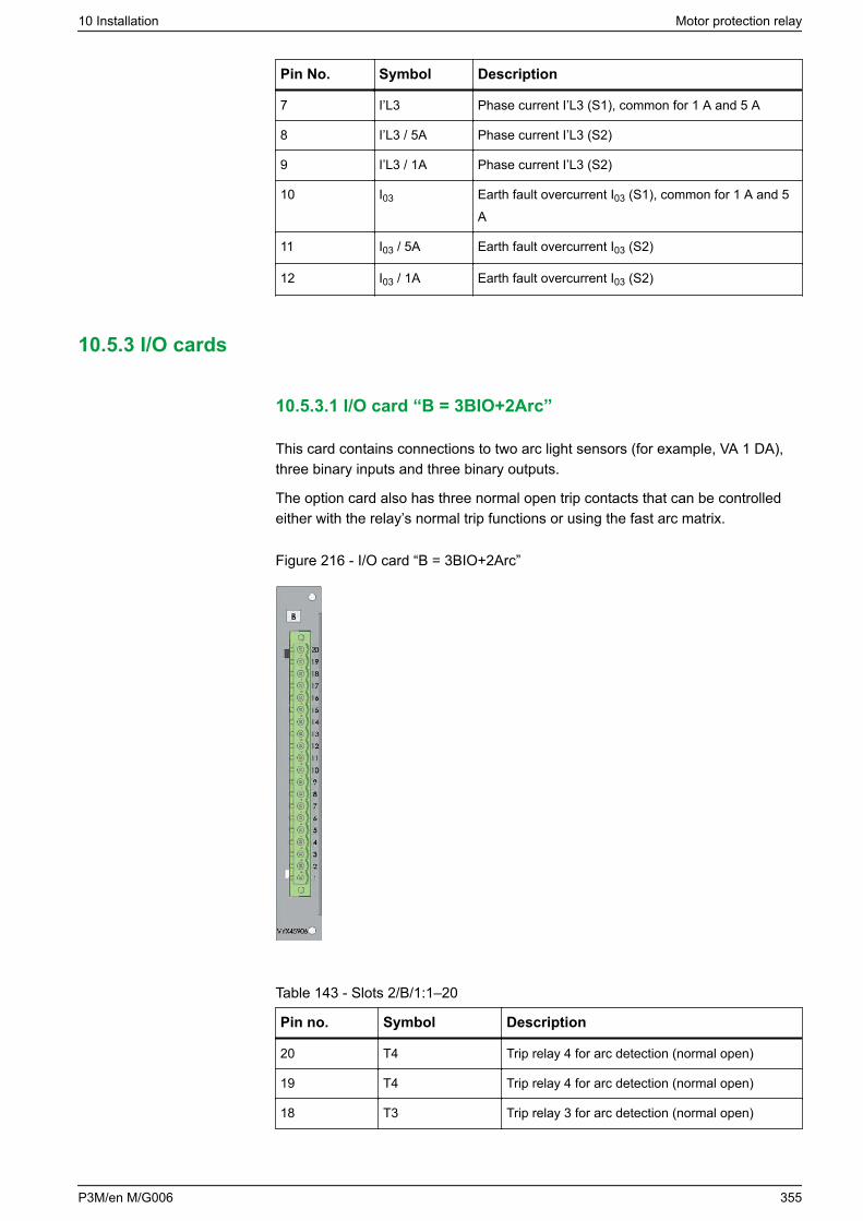
Pin No. Symbol Description
7 I’L3 Phase current I’L3 (S1), common for 1 A and 5 A
8 I’L3 / 5A Phase current I’L3 (S2)
9 I’L3 / 1A Phase current I’L3 (S2)
10 I03 Earth fault overcurrent I03 (S1), common for 1 A and 5A
11 I03 / 5A Earth fault overcurrent I03 (S2)
12 I03 / 1A Earth fault overcurrent I03 (S2)
10.5.3 I/O cards
10.5.3.1 I/O card “B = 3BIO+2Arc”
This card contains connections to two arc light sensors (for example, VA 1 DA),three binary inputs and three binary outputs.
The option card also has three normal open trip contacts that can be controlledeither with the relay’s normal trip functions or using the fast arc matrix.
Figure 216 - I/O card “B = 3BIO+2Arc”
Table 143 - Slots 2/B/1:1–20
Pin no. Symbol Description
20 T4 Trip relay 4 for arc detection (normal open)
19 T4 Trip relay 4 for arc detection (normal open)
18 T3 Trip relay 3 for arc detection (normal open)
10 Installation Motor protection relay
P3M/en M/G006 355

Pin no. Symbol Description
17 T3 Trip relay 3 for arc detection (normal open)
16 T2 Trip relay 2 for arc detection (normal open)
15 T2 Trip relay 2 for arc detection (normal open)
14 BI3 Binary input 3
13 BI3 Binary input 3
12 BI2 Binary input 2
11 BI2 Binary input 2
10 BI1 Binary input 1
9 BI1 Binary input 1
8 BO COMMON Binary output 1–3 common GND
7 BO3 Binary output 3, +30 V dc
6 BO2 Binary output 2, +30 V dc
5 BO1 Binary output 1, +30 V dc
4 Sen 2 - Arc sensor channel 2 negative terminal
3 Sen 2 + Arc sensor channel 2 positive terminal
2 Sen 1 - Arc sensor channel 1 negative terminal
1 Sen 1 - Arc sensor channel 1 positive terminal
10.5.3.2 I/O card “C = F2BIO+1Arc”
This card contains connections to one arc fiber sensor, two fiber binary inputs,two fiber binary outputs and three fast trip relays.
Arc loop sensor input is used with Arc-SLm sensor. The sensor’s sensitivity canbe set in the Arc protection setting view in Easergy Pro.
Binary inputs and outputs are designed to be used with 50/125 μm, 62.5/125 μm,100/140 μm, and 200 μm fiber sizes (Connector type: ST).
The option card also has three normal open trip contacts that can be controlledeither with the relay’s normal trip functions or using the fast arc matrix.
Motor protection relay 10 Installation
356 P3M/en M/G006
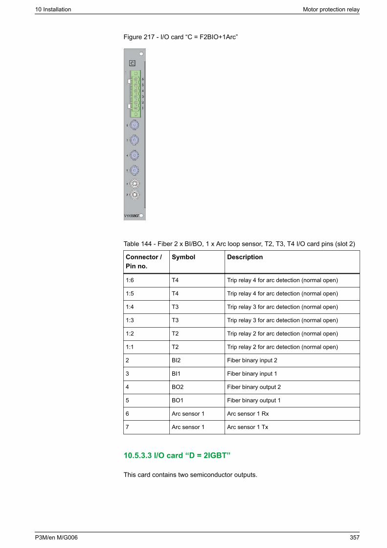
Figure 217 - I/O card “C = F2BIO+1Arc”
Table 144 - Fiber 2 x BI/BO, 1 x Arc loop sensor, T2, T3, T4 I/O card pins (slot 2)
Connector /Pin no.
Symbol Description
1:6 T4 Trip relay 4 for arc detection (normal open)
1:5 T4 Trip relay 4 for arc detection (normal open)
1:4 T3 Trip relay 3 for arc detection (normal open)
1:3 T3 Trip relay 3 for arc detection (normal open)
1:2 T2 Trip relay 2 for arc detection (normal open)
1:1 T2 Trip relay 2 for arc detection (normal open)
2 BI2 Fiber binary input 2
3 BI1 Fiber binary input 1
4 BO2 Fiber binary output 2
5 BO1 Fiber binary output 1
6 Arc sensor 1 Arc sensor 1 Rx
7 Arc sensor 1 Arc sensor 1 Tx
10.5.3.3 I/O card “D = 2IGBT”
This card contains two semiconductor outputs.
10 Installation Motor protection relay
P3M/en M/G006 357
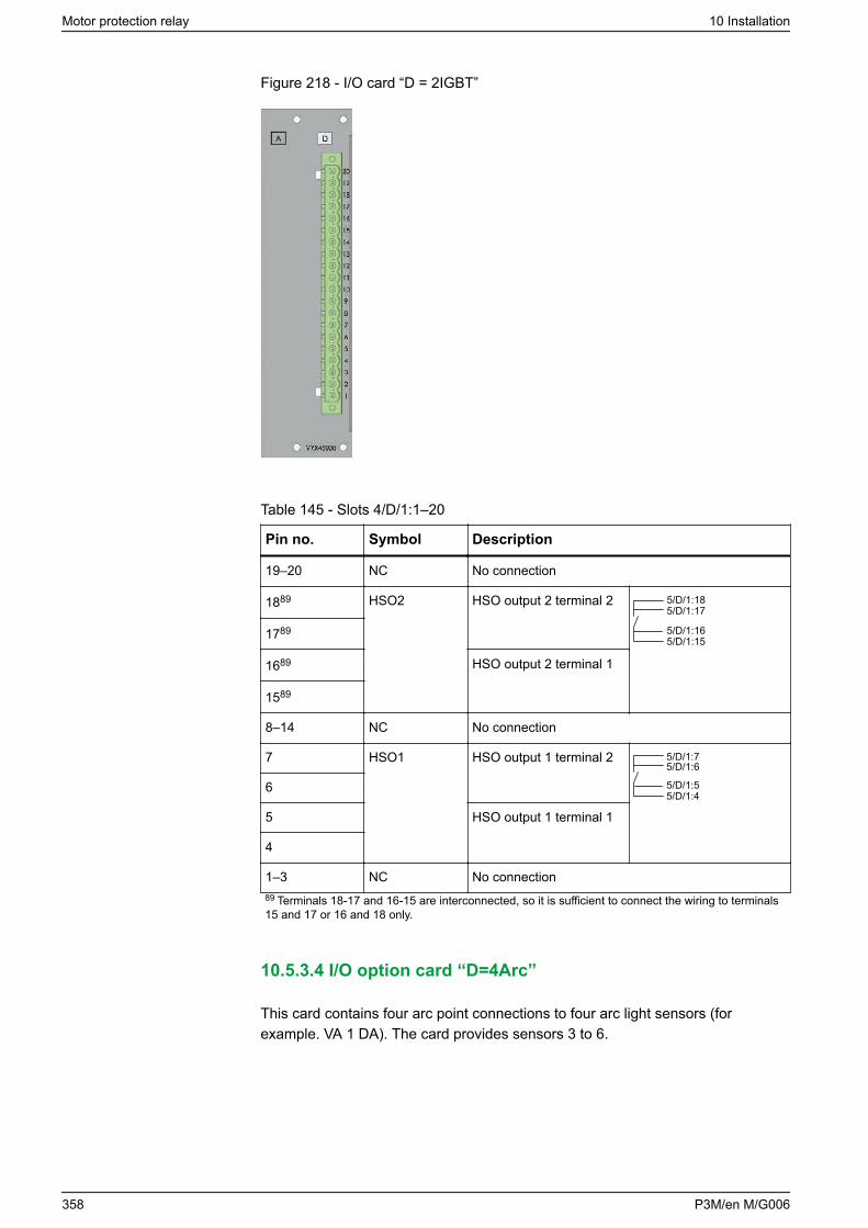
Figure 218 - I/O card “D = 2IGBT”
Table 145 - Slots 4/D/1:1–20
Pin no. Symbol Description
19–20 NC No connection
1889 HSO2 HSO output 2 terminal 2 5/D/1:185/D/1:17
5/D/1:165/D/1:151789
1689 HSO output 2 terminal 1
1589
8–14 NC No connection
7 HSO1 HSO output 1 terminal 2 5/D/1:75/D/1:6
5/D/1:55/D/1:4
6
5 HSO output 1 terminal 1
4
1–3 NC No connection89 Terminals 18-17 and 16-15 are interconnected, so it is sufficient to connect the wiring to terminals15 and 17 or 16 and 18 only.
10.5.3.4 I/O option card “D=4Arc”
This card contains four arc point connections to four arc light sensors (forexample. VA 1 DA). The card provides sensors 3 to 6.
Motor protection relay 10 Installation
358 P3M/en M/G006
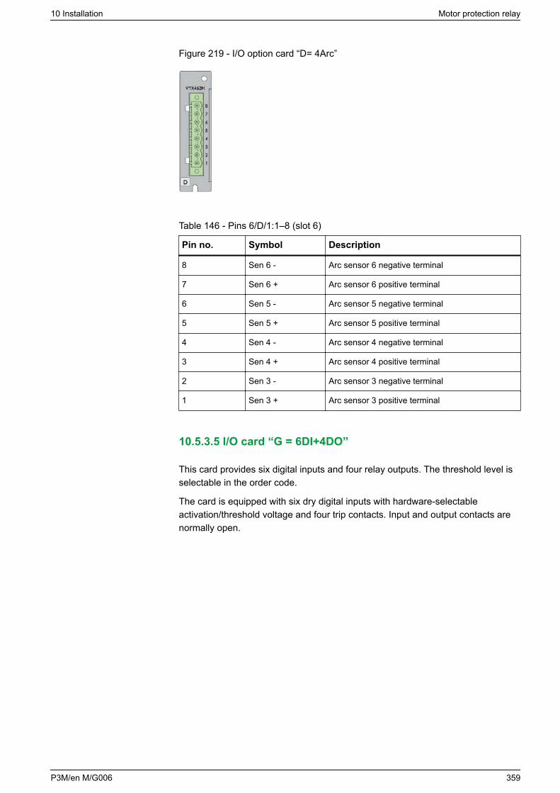
Figure 219 - I/O option card “D= 4Arc”
Table 146 - Pins 6/D/1:1–8 (slot 6)
Pin no. Symbol Description
8 Sen 6 - Arc sensor 6 negative terminal
7 Sen 6 + Arc sensor 6 positive terminal
6 Sen 5 - Arc sensor 5 negative terminal
5 Sen 5 + Arc sensor 5 positive terminal
4 Sen 4 - Arc sensor 4 negative terminal
3 Sen 4 + Arc sensor 4 positive terminal
2 Sen 3 - Arc sensor 3 negative terminal
1 Sen 3 + Arc sensor 3 positive terminal
10.5.3.5 I/O card “G = 6DI+4DO”
This card provides six digital inputs and four relay outputs. The threshold level isselectable in the order code.
The card is equipped with six dry digital inputs with hardware-selectableactivation/threshold voltage and four trip contacts. Input and output contacts arenormally open.
10 Installation Motor protection relay
P3M/en M/G006 359
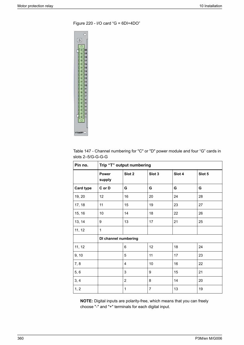
Figure 220 - I/O card “G = 6DI+4DO”
Table 147 - Channel numbering for "C" or "D" power module and four “G” cards inslots 2–5/G-G-G-G
Pin no. Trip “T” output numbering
Powersupply
Slot 2 Slot 3 Slot 4 Slot 5
Card type C or D G G G G
19, 20 12 16 20 24 28
17, 18 11 15 19 23 27
15, 16 10 14 18 22 26
13, 14 9 13 17 21 25
11, 12 1
DI channel numbering
11, 12 6 12 18 24
9, 10 5 11 17 23
7, 8 4 10 16 22
5, 6 3 9 15 21
3, 4 2 8 14 20
1, 2 1 7 13 19
NOTE: Digital inputs are polarity-free, which means that you can freelychoose "-" and "+" terminals for each digital input.
Motor protection relay 10 Installation
360 P3M/en M/G006
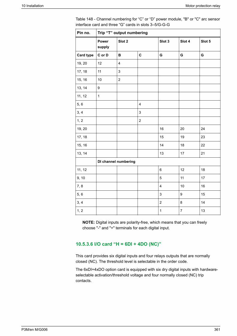
Table 148 - Channel numbering for “C” or “D” power module, "B" or "C" arc sensorinterface card and three “G” cards in slots 3–5/G-G-G
Pin no. Trip “T” output numbering
Powersupply
Slot 2 Slot 3 Slot 4 Slot 5
Card type C or D B C G G G
19, 20 12 4
17, 18 11 3
15, 16 10 2
13, 14 9
11, 12 1
5, 6 4
3, 4 3
1, 2 2
19, 20 16 20 24
17, 18 15 19 23
15, 16 14 18 22
13, 14 13 17 21
DI channel numbering
11, 12 6 12 18
9, 10 5 11 17
7, 8 4 10 16
5, 6 3 9 15
3, 4 2 8 14
1, 2 1 7 13
NOTE: Digital inputs are polarity-free, which means that you can freelychoose "-" and "+" terminals for each digital input.
10.5.3.6 I/O card “H = 6DI + 4DO (NC)”
This card provides six digital inputs and four relays outputs that are normallyclosed (NC). The threshold level is selectable in the order code.
The 6xDI+4xDO option card is equipped with six dry digital inputs with hardware-selectable activation/threshold voltage and four normally closed (NC) tripcontacts.
10 Installation Motor protection relay
P3M/en M/G006 361
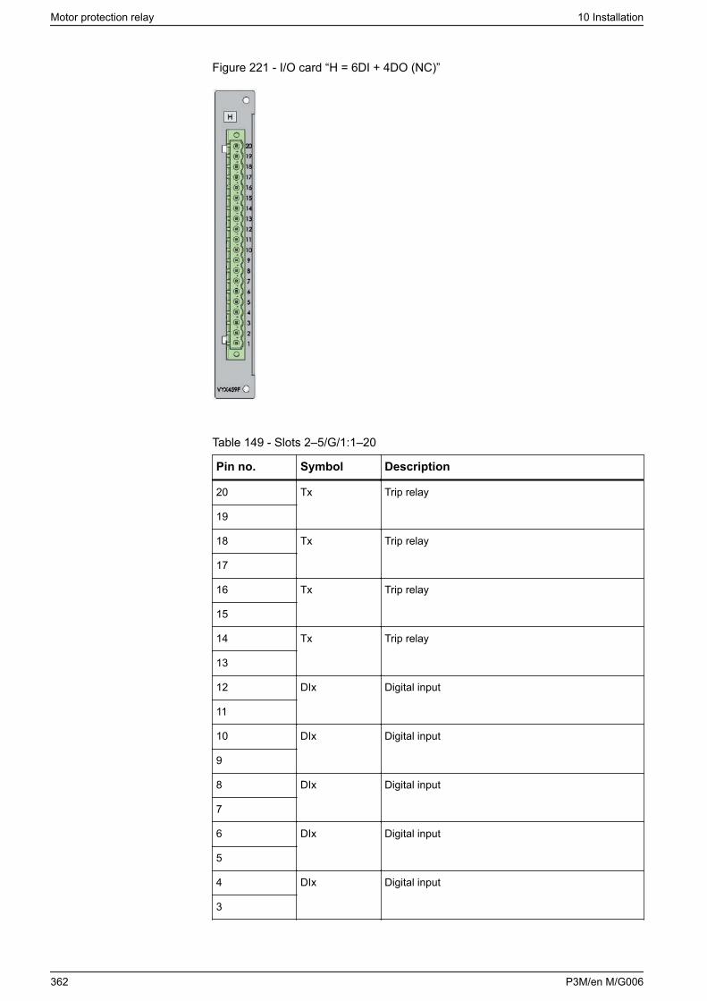
Figure 221 - I/O card “H = 6DI + 4DO (NC)”
Table 149 - Slots 2–5/G/1:1–20
Pin no. Symbol Description
20 Tx Trip relay
19
18 Tx Trip relay
17
16 Tx Trip relay
15
14 Tx Trip relay
13
12 DIx Digital input
11
10 DIx Digital input
9
8 DIx Digital input
7
6 DIx Digital input
5
4 DIx Digital input
3
Motor protection relay 10 Installation
362 P3M/en M/G006
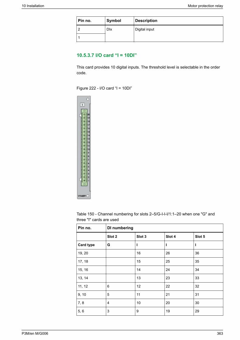
Pin no. Symbol Description
2 DIx Digital input
1
10.5.3.7 I/O card “I = 10DI”
This card provides 10 digital inputs. The threshold level is selectable in the ordercode.
Figure 222 - I/O card “I = 10DI”
Table 150 - Channel numbering for slots 2–5/G-I-I-I/1:1–20 when one "G" andthree "I" cards are used
Pin no. DI numbering
Slot 2 Slot 3 Slot 4 Slot 5
Card type G I I I
19, 20 16 26 36
17, 18 15 25 35
15, 16 14 24 34
13, 14 13 23 33
11, 12 6 12 22 32
9, 10 5 11 21 31
7, 8 4 10 20 30
5, 6 3 9 19 29
10 Installation Motor protection relay
P3M/en M/G006 363
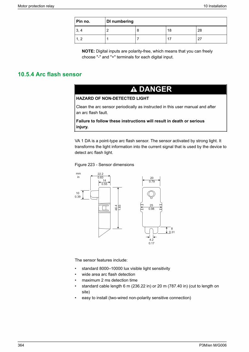
Pin no. DI numbering
3, 4 2 8 18 28
1, 2 1 7 17 27
NOTE: Digital inputs are polarity-free, which means that you can freelychoose "-" and "+" terminals for each digital input.
10.5.4 Arc flash sensor
DANGERHAZARD OF NON-DETECTED LIGHT
Clean the arc sensor periodically as instructed in this user manual and afteran arc flash fault.
Failure to follow these instructions will result in death or seriousinjury.
VA 1 DA is a point-type arc flash sensor. The sensor activated by strong light. Ittransforms the light information into the current signal that is used by the device todetect arc flash light.
Figure 223 - Sensor dimensions
140.55
22.20.83
mmin
100.39
46.4
1.83
200.79
250.98
80.31
4.20.17
The sensor features include:
• standard 8000–10000 lux visible light sensitivity• wide area arc flash detection• maximum 2 ms detection time• standard cable length 6 m (236.22 in) or 20 m (787.40 in) (cut to length on
site)• easy to install (two-wired non-polarity sensitive connection)
Motor protection relay 10 Installation
364 P3M/en M/G006
DANGERHAZARD OF NON-DETECTED LIGHT
Never attempt to extend the length of arc flash sensor cables.
Failure to follow these instructions will result in death or serious injury.
10.5.4.1 Mounting the sensors to the switchgear
DANGERHAZARD OF ELECTRIC SHOCK, EXPLOSION, OR ARC FLASH
• Apply appropriate personal protective equipment (PPE) and follow safeelectrical work practices. See NFPA 70E, NOM-029-STPS-2011, or CSAZ462.
• The arc fault detection system is not a substitute for proper PPE whenworking on or near equipment being monitored by the system.
• Information on this product is offered as a tool for conducting arc flashhazard analysis. It is intended for use only by qualified persons who areknowledgeable about power system studies, power distribution equipment,and equipment installation practices. It is not intended as a substitute forthe engineering judgement and adequate review necessary for suchactivities.
• Only qualified personnel should install and service this equipment. Readthis entire set of instructions and check the technical characteristics of thedevice before performing such work.
• Perform wiring according to national standards (NEC) and anyrequirements specified by the customer.
• Observe any separately marked notes and warnings.• NEVER work alone.• Before performing visual inspections, tests, or maintenance on this
equipment, disconnect all sources of electric power. Assume all circuits arelive until they are completely de-energized, tested, and tagged. Payparticular attention to the design of the power system. Consider all sourcesof power, including the possibility of backfeeding.
• Always use a properly rated voltage sensing relay to ensure that all poweris off.
• The equipment must be grounded.• Connect the device's protective ground to functional earth according to the
connection diagrams presented in this document.• Do not open the device. It contains no user-serviceable parts.• Install all devices, doors and covers before turning on the power to this
device.
Failure to follow these instructions will result in death or serious injury.
Install arc flash sensors inside the switchgear. There are two options for mountingthe sensors:• in customer-drilled holes on the switchgear• on VYX001 Z-shape or VYX002 L-shape mounting plates available from
Schneider Electric or locally fabricated from supplied drawings
10 Installation Motor protection relay
P3M/en M/G006 365
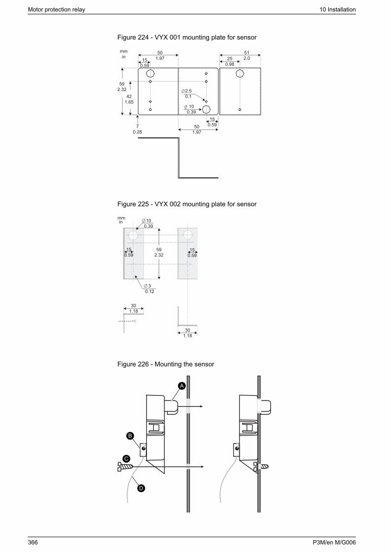
Figure 224 - VYX 001 mounting plate for sensor
mmin
501.9715
0.59
70.28
501.97
150.59
512.025
0.98
592.32
421.65
2.50.1
100.39
Figure 225 - VYX 002 mounting plate for sensor
301.18
150.59
150.59
mmin
301.18
100.39
592.32
30.12
Figure 226 - Mounting the sensor
A
B
D
C
Motor protection relay 10 Installation
366 P3M/en M/G006
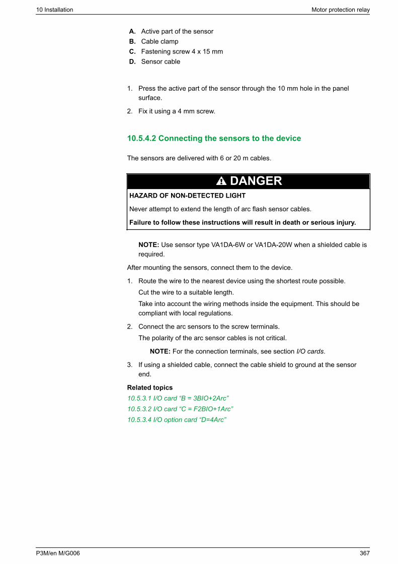
A. Active part of the sensorB. Cable clampC. Fastening screw 4 x 15 mmD. Sensor cable
1. Press the active part of the sensor through the 10 mm hole in the panelsurface.
2. Fix it using a 4 mm screw.
10.5.4.2 Connecting the sensors to the device
The sensors are delivered with 6 or 20 m cables.
DANGERHAZARD OF NON-DETECTED LIGHT
Never attempt to extend the length of arc flash sensor cables.
Failure to follow these instructions will result in death or serious injury.
NOTE: Use sensor type VA1DA-6W or VA1DA-20W when a shielded cable isrequired.
After mounting the sensors, connect them to the device.
1. Route the wire to the nearest device using the shortest route possible.Cut the wire to a suitable length.Take into account the wiring methods inside the equipment. This should becompliant with local regulations.
2. Connect the arc sensors to the screw terminals.The polarity of the arc sensor cables is not critical.
NOTE: For the connection terminals, see section I/O cards.
3. If using a shielded cable, connect the cable shield to ground at the sensorend.
Related topics10.5.3.1 I/O card “B = 3BIO+2Arc”10.5.3.2 I/O card “C = F2BIO+1Arc”10.5.3.4 I/O option card “D=4Arc”
10 Installation Motor protection relay
P3M/en M/G006 367
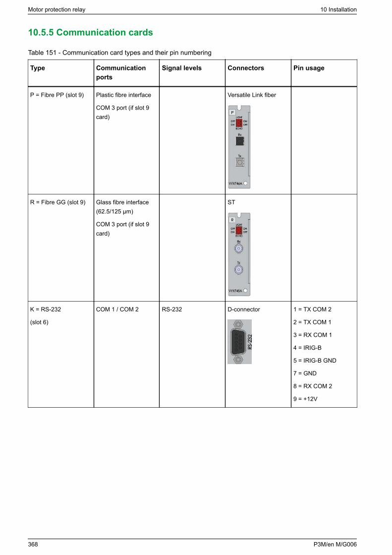
10.5.5 Communication cards
Table 151 - Communication card types and their pin numbering
Type Communicationports
Signal levels Connectors Pin usage
P = Fibre PP (slot 9) Plastic fibre interface
COM 3 port (if slot 9card)
Versatile Link fiber
R = Fibre GG (slot 9) Glass fibre interface(62.5/125 μm)
COM 3 port (if slot 9card)
ST
K = RS-232
(slot 6)
COM 1 / COM 2 RS-232 D-connector 1 = TX COM 2
2 = TX COM 1
3 = RX COM 1
4 = IRIG-B
5 = IRIG-B GND
7 = GND
8 = RX COM 2
9 = +12V
Motor protection relay 10 Installation
368 P3M/en M/G006
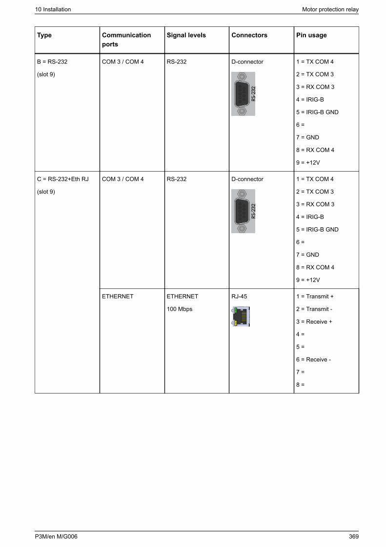
Type Communicationports
Signal levels Connectors Pin usage
B = RS-232
(slot 9)
COM 3 / COM 4 RS-232 D-connector 1 = TX COM 4
2 = TX COM 3
3 = RX COM 3
4 = IRIG-B
5 = IRIG-B GND
6 =
7 = GND
8 = RX COM 4
9 = +12V
C = RS-232+Eth RJ
(slot 9)
COM 3 / COM 4 RS-232 D-connector 1 = TX COM 4
2 = TX COM 3
3 = RX COM 3
4 = IRIG-B
5 = IRIG-B GND
6 =
7 = GND
8 = RX COM 4
9 = +12V
ETHERNET ETHERNET
100 Mbps
RJ-45 1 = Transmit +
2 = Transmit -
3 = Receive +
4 =
5 =
6 = Receive -
7 =
8 =
10 Installation Motor protection relay
P3M/en M/G006 369
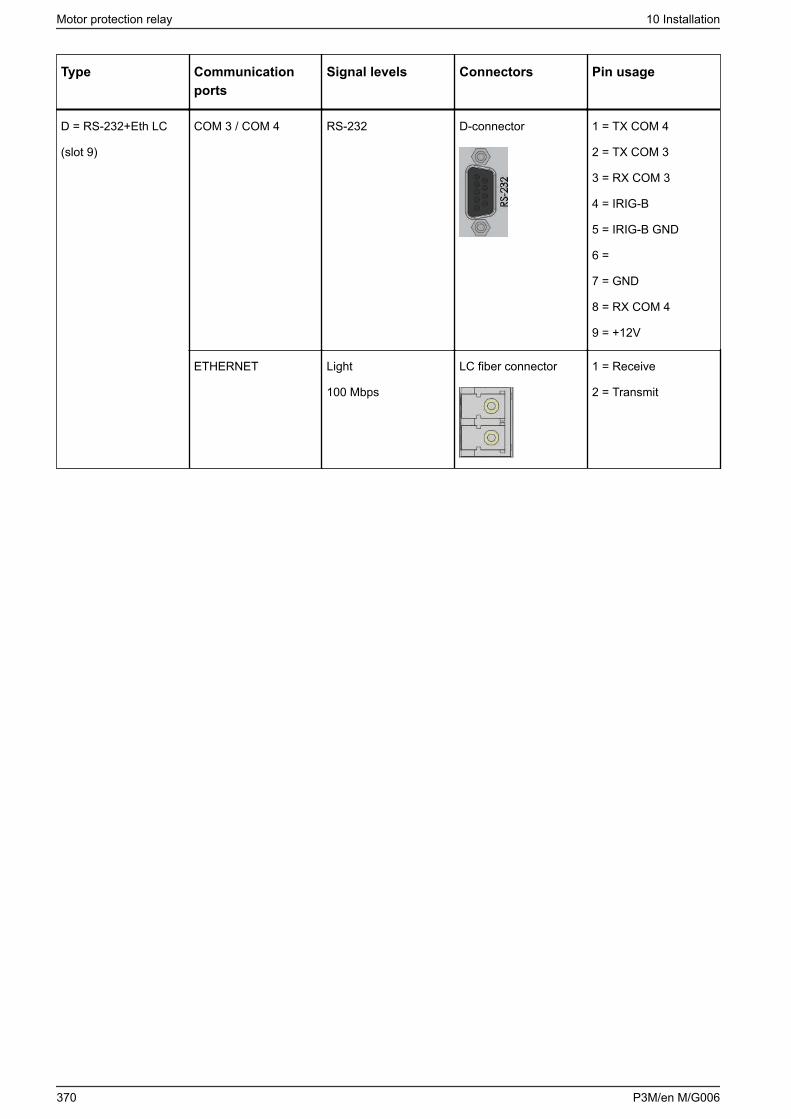
Type Communicationports
Signal levels Connectors Pin usage
D = RS-232+Eth LC
(slot 9)
COM 3 / COM 4 RS-232 D-connector 1 = TX COM 4
2 = TX COM 3
3 = RX COM 3
4 = IRIG-B
5 = IRIG-B GND
6 =
7 = GND
8 = RX COM 4
9 = +12V
ETHERNET Light
100 Mbps
LC fiber connector 1 = Receive
2 = Transmit
Motor protection relay 10 Installation
370 P3M/en M/G006
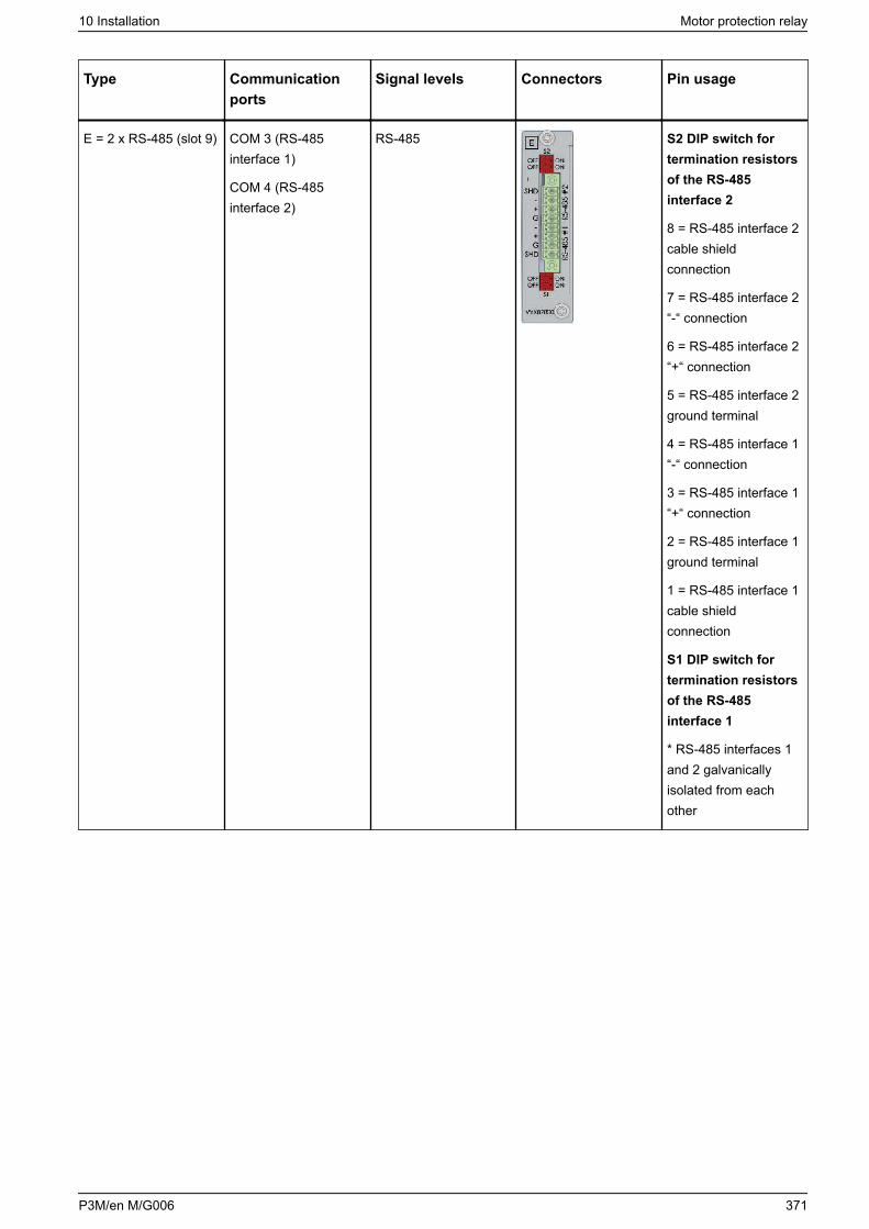
Type Communicationports
Signal levels Connectors Pin usage
E = 2 x RS-485 (slot 9) COM 3 (RS-485interface 1)
COM 4 (RS-485interface 2)
RS-485 S2 DIP switch fortermination resistorsof the RS-485interface 2
8 = RS-485 interface 2cable shieldconnection
7 = RS-485 interface 2“-“ connection
6 = RS-485 interface 2“+“ connection
5 = RS-485 interface 2ground terminal
4 = RS-485 interface 1“-“ connection
3 = RS-485 interface 1“+“ connection
2 = RS-485 interface 1ground terminal
1 = RS-485 interface 1cable shieldconnection
S1 DIP switch fortermination resistorsof the RS-485interface 1
* RS-485 interfaces 1and 2 galvanicallyisolated from eachother
10 Installation Motor protection relay
P3M/en M/G006 371
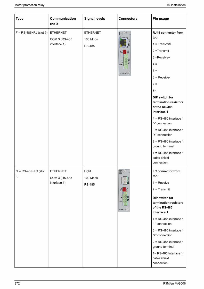
Type Communicationports
Signal levels Connectors Pin usage
F = RS-485+RJ (slot 9) ETHERNET
COM 3 (RS-485interface 1)
ETHERNET
100 Mbps
RS-485
RJ45 connector fromtop:
1 = Transmit+
2 =Transmit-
3 =Receive+
4 =
5 =
6 = Receive-
7 =
8=
DIP switch fortermination resistorsof the RS-485interface 1
4 = RS-485 interface 1“-“ connection
3 = RS-485 interface 1“+“ connection
2 = RS-485 interface 1ground terminal
1 = RS-485 interface 1cable shieldconnection
G = RS-485+LC (slot9)
ETHERNET
COM 3 (RS-485interface 1)
Light
100 Mbps
RS-485
LC connector fromtop:
1 = Receive
2 = Transmit
DIP switch fortermination resistorsof the RS-485interface 1
4 = RS-485 interface 1“-“ connection
3 = RS-485 interface 1“+“ connection
2 = RS-485 interface 1ground terminal
1= RS-485 interface 1cable shieldconnection
Motor protection relay 10 Installation
372 P3M/en M/G006
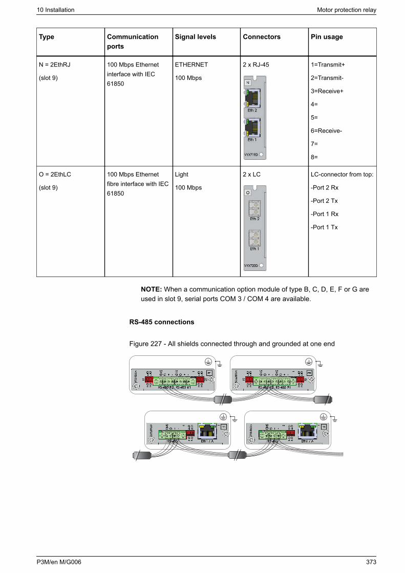
Type Communicationports
Signal levels Connectors Pin usage
N = 2EthRJ
(slot 9)
100 Mbps Ethernetinterface with IEC61850
ETHERNET
100 Mbps
2 x RJ-45 1=Transmit+
2=Transmit-
3=Receive+
4=
5=
6=Receive-
7=
8=
O = 2EthLC
(slot 9)
100 Mbps Ethernetfibre interface with IEC61850
Light
100 Mbps
2 x LC LC-connector from top:
-Port 2 Rx
-Port 2 Tx
-Port 1 Rx
-Port 1 Tx
NOTE: When a communication option module of type B, C, D, E, F or G areused in slot 9, serial ports COM 3 / COM 4 are available.
RS-485 connections
Figure 227 - All shields connected through and grounded at one end
10 Installation Motor protection relay
P3M/en M/G006 373
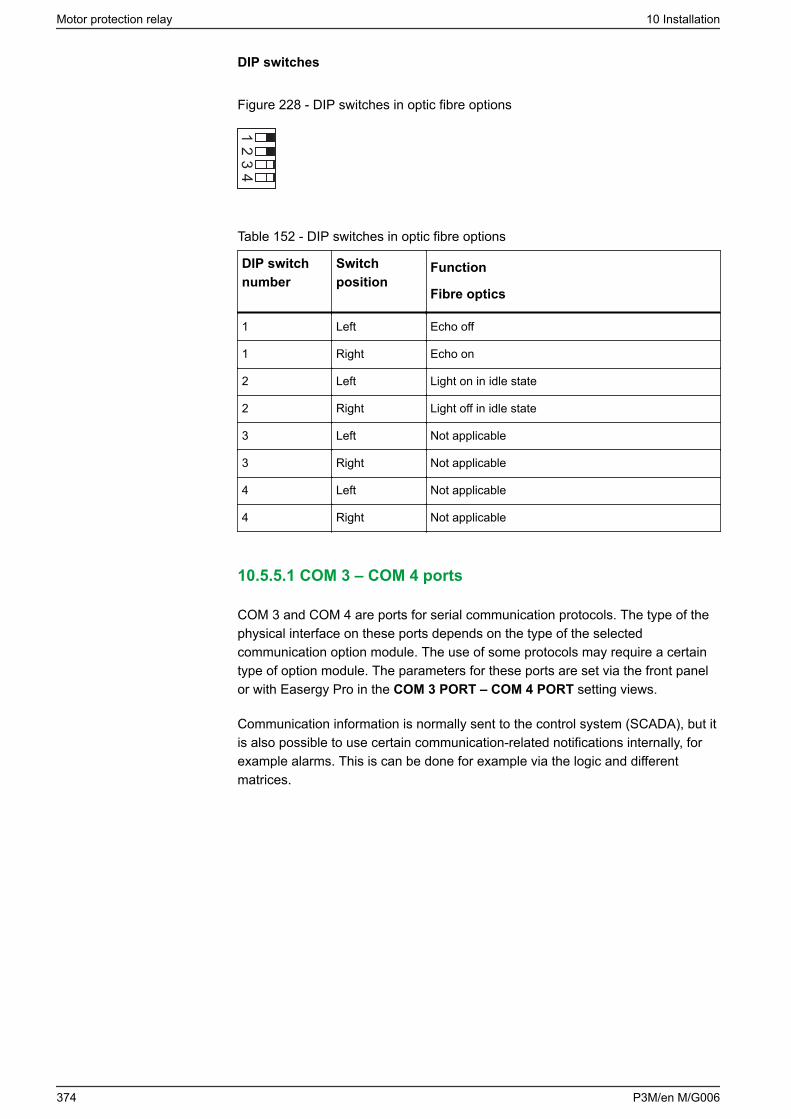
DIP switches
Figure 228 - DIP switches in optic fibre options
Table 152 - DIP switches in optic fibre options
DIP switchnumber
Switchposition
Function
Fibre optics
1 Left Echo off
1 Right Echo on
2 Left Light on in idle state
2 Right Light off in idle state
3 Left Not applicable
3 Right Not applicable
4 Left Not applicable
4 Right Not applicable
10.5.5.1 COM 3 – COM 4 ports
COM 3 and COM 4 are ports for serial communication protocols. The type of thephysical interface on these ports depends on the type of the selectedcommunication option module. The use of some protocols may require a certaintype of option module. The parameters for these ports are set via the front panelor with Easergy Pro in the COM 3 PORT – COM 4 PORT setting views.
Communication information is normally sent to the control system (SCADA), but itis also possible to use certain communication-related notifications internally, forexample alarms. This is can be done for example via the logic and differentmatrices.
Motor protection relay 10 Installation
374 P3M/en M/G006
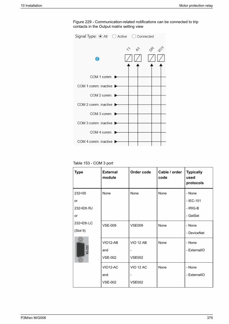
Figure 229 - Communication-related notifications can be connected to tripcontacts in the Output matrix setting view
Table 153 - COM 3 port
Type Externalmodule
Order code Cable / ordercode
Typicallyusedprotocols
232+00
or
232+Eth RJ
or
232+Eth LC
(Slot 9)
None None None - None
- IEC-101
- IRIG-B
- GetSet
VSE-009 VSE009 None - None
- DeviceNet
VIO12-AB
and
VSE-002
VIO 12 AB
-
VSE002
None - None
- ExternalIO
VIO12-AC
and
VSE-002
VIO 12 AC
-
VSE002
None - None
- ExternalIO
10 Installation Motor protection relay
P3M/en M/G006 375
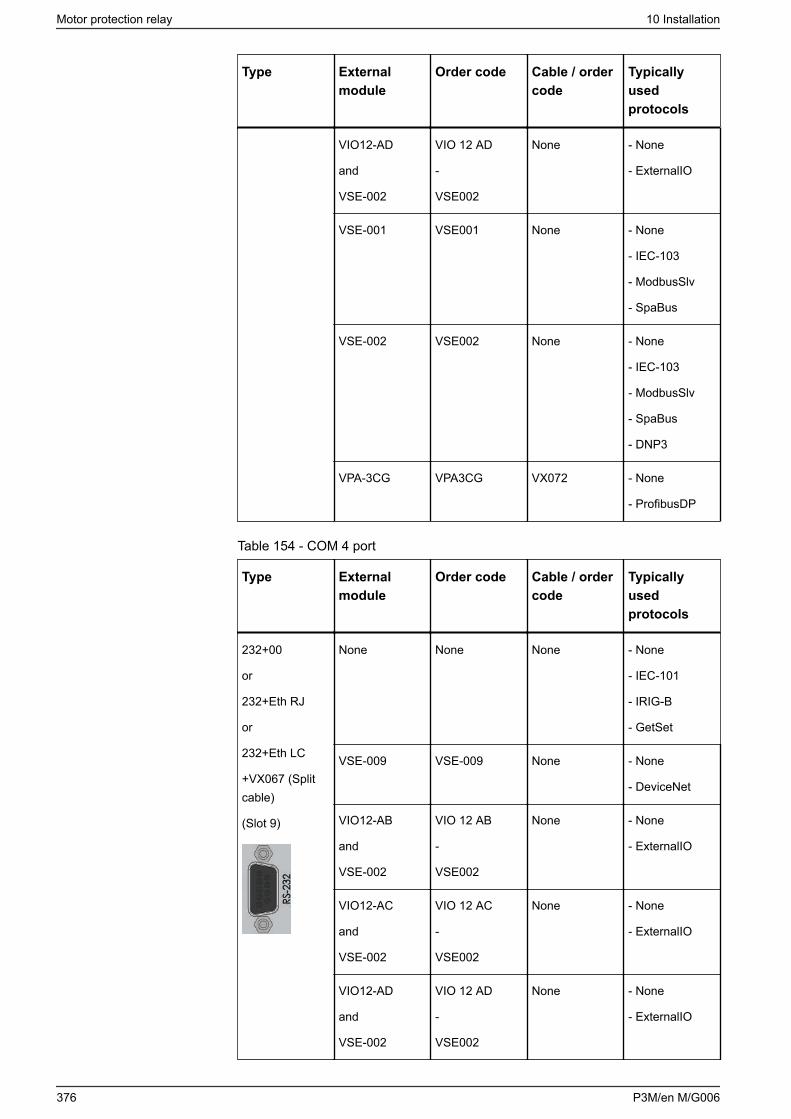
Type Externalmodule
Order code Cable / ordercode
Typicallyusedprotocols
VIO12-AD
and
VSE-002
VIO 12 AD
-
VSE002
None - None
- ExternalIO
VSE-001 VSE001 None - None
- IEC-103
- ModbusSlv
- SpaBus
VSE-002 VSE002 None - None
- IEC-103
- ModbusSlv
- SpaBus
- DNP3
VPA-3CG VPA3CG VX072 - None
- ProfibusDP
Table 154 - COM 4 port
Type Externalmodule
Order code Cable / ordercode
Typicallyusedprotocols
232+00
or
232+Eth RJ
or
232+Eth LC
+VX067 (Splitcable)
(Slot 9)
None None None - None
- IEC-101
- IRIG-B
- GetSet
VSE-009 VSE-009 None - None
- DeviceNet
VIO12-AB
and
VSE-002
VIO 12 AB
-
VSE002
None - None
- ExternalIO
VIO12-AC
and
VSE-002
VIO 12 AC
-
VSE002
None - None
- ExternalIO
VIO12-AD
and
VSE-002
VIO 12 AD
-
VSE002
None - None
- ExternalIO
Motor protection relay 10 Installation
376 P3M/en M/G006
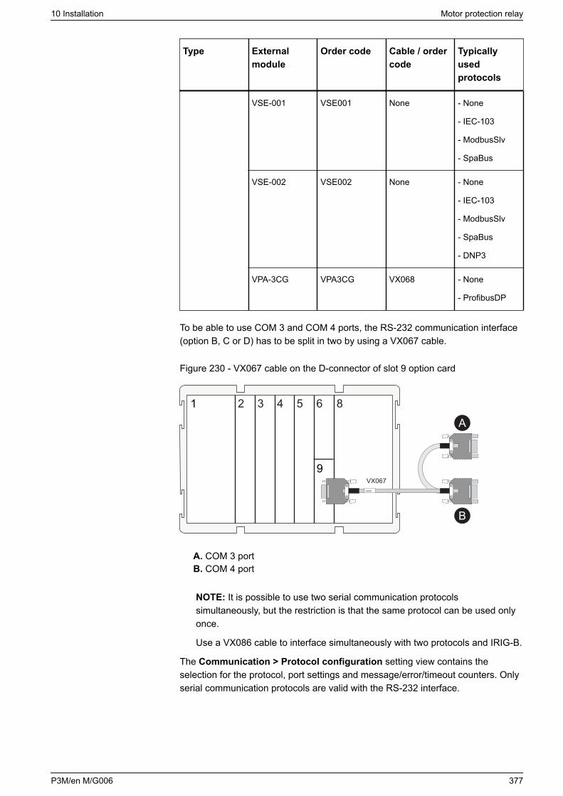
Type Externalmodule
Order code Cable / ordercode
Typicallyusedprotocols
VSE-001 VSE001 None - None
- IEC-103
- ModbusSlv
- SpaBus
VSE-002 VSE002 None - None
- IEC-103
- ModbusSlv
- SpaBus
- DNP3
VPA-3CG VPA3CG VX068 - None
- ProfibusDP
To be able to use COM 3 and COM 4 ports, the RS-232 communication interface(option B, C or D) has to be split in two by using a VX067 cable.
Figure 230 - VX067 cable on the D-connector of slot 9 option card
1 2 3 4 5 6
9
8
VX067
VX067
A
B
A. COM 3 portB. COM 4 port
NOTE: It is possible to use two serial communication protocolssimultaneously, but the restriction is that the same protocol can be used onlyonce.
Use a VX086 cable to interface simultaneously with two protocols and IRIG-B.
The Communication > Protocol configuration setting view contains theselection for the protocol, port settings and message/error/timeout counters. Onlyserial communication protocols are valid with the RS-232 interface.
10 Installation Motor protection relay
P3M/en M/G006 377
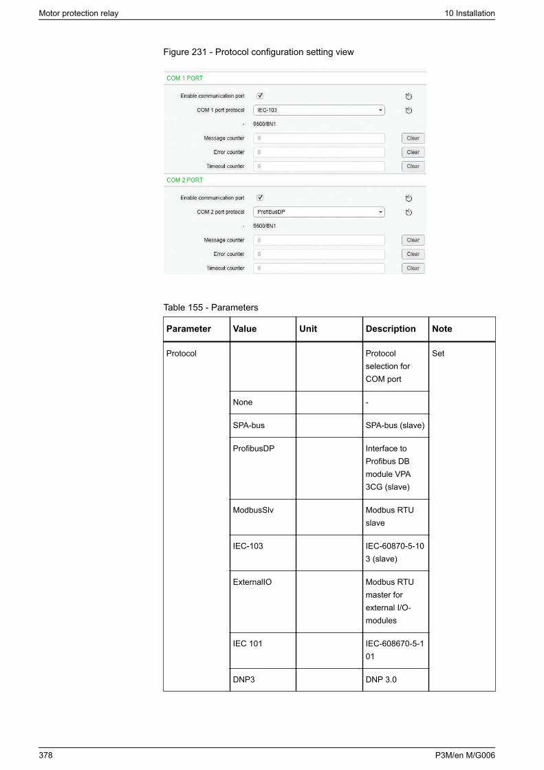
Figure 231 - Protocol configuration setting view
Table 155 - Parameters
Parameter Value Unit Description Note
Protocol Protocolselection forCOM port
Set
None -
SPA-bus SPA-bus (slave)
ProfibusDP Interface toProfibus DBmodule VPA3CG (slave)
ModbusSlv Modbus RTUslave
IEC-103 IEC-60870-5-103 (slave)
ExternalIO Modbus RTUmaster forexternal I/O-modules
IEC 101 IEC-608670-5-101
DNP3 DNP 3.0
Motor protection relay 10 Installation
378 P3M/en M/G006
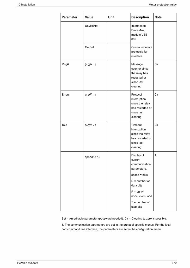
Parameter Value Unit Description Note
DeviceNet Interface toDeviceNetmodule VSE009
GetSet Communicationiprotocola for interface
Msg# 0–232 - 1 Messagecounter sincethe relay hasrestarted orsince lastclearing
Clr
Errors 0–216 - 1 Protocolinterruptionsince the relayhas restarted orsince lastclearing
Clr
Tout 0–216 - 1 Timeoutinterruptionsince the relayhas restarted orsince lastclearing
Clr
speed/DPS Display ofcurrentcommunicationparameters.
speed = bit/s
D = number ofdata bits
P = parity:none, even, odd
S = number ofstop bits
1.
Set = An editable parameter (password needed). Clr = Clearing to zero is possible.
1. The communication parameters are set in the protocol-specific menus. For the localport command line interface, the parameters are set in the configuration menu.
10 Installation Motor protection relay
P3M/en M/G006 379
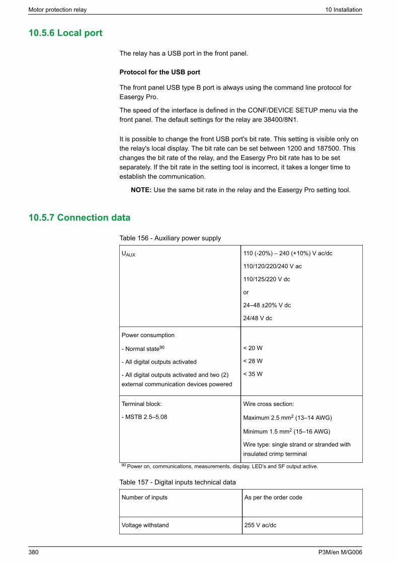
10.5.6 Local port
The relay has a USB port in the front panel.
Protocol for the USB port
The front panel USB type B port is always using the command line protocol forEasergy Pro.
The speed of the interface is defined in the CONF/DEVICE SETUP menu via thefront panel. The default settings for the relay are 38400/8N1.
It is possible to change the front USB port's bit rate. This setting is visible only onthe relay's local display. The bit rate can be set between 1200 and 187500. Thischanges the bit rate of the relay, and the Easergy Pro bit rate has to be setseparately. If the bit rate in the setting tool is incorrect, it takes a longer time toestablish the communication.
NOTE: Use the same bit rate in the relay and the Easergy Pro setting tool.
10.5.7 Connection data
Table 156 - Auxiliary power supply
UAUX 110 (-20%) – 240 (+10%) V ac/dc
110/120/220/240 V ac
110/125/220 V dc
or
24–48 ±20% V dc
24/48 V dc
Power consumption
- Normal state90
- All digital outputs activated
- All digital outputs activated and two (2)external communication devices powered
< 20 W
< 28 W
< 35 W
Terminal block:
- MSTB 2.5–5.08
Wire cross section:
Maximum 2.5 mm2 (13–14 AWG)
Minimum 1.5 mm2 (15–16 AWG)
Wire type: single strand or stranded withinsulated crimp terminal
90 Power on, communications, measurements, display, LED’s and SF output active.
Table 157 - Digital inputs technical data
Number of inputs As per the order code
Voltage withstand 255 V ac/dc
Motor protection relay 10 Installation
380 P3M/en M/G006
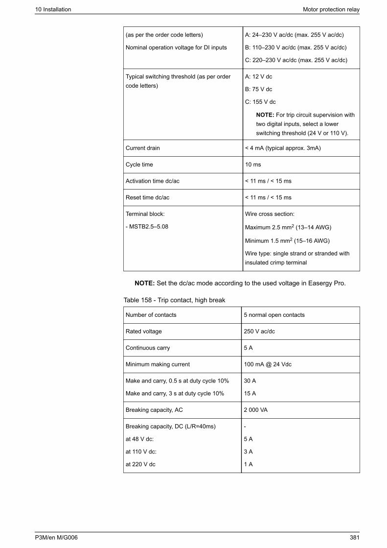
(as per the order code letters)
Nominal operation voltage for DI inputs
A: 24–230 V ac/dc (max. 255 V ac/dc)
B: 110–230 V ac/dc (max. 255 V ac/dc)
C: 220–230 V ac/dc (max. 255 V ac/dc)
Typical switching threshold (as per ordercode letters)
A: 12 V dc
B: 75 V dc
C: 155 V dc
NOTE: For trip circuit supervision withtwo digital inputs, select a lowerswitching threshold (24 V or 110 V).
Current drain < 4 mA (typical approx. 3mA)
Cycle time 10 ms
Activation time dc/ac < 11 ms / < 15 ms
Reset time dc/ac < 11 ms / < 15 ms
Terminal block:
- MSTB2.5–5.08
Wire cross section:
Maximum 2.5 mm2 (13–14 AWG)
Minimum 1.5 mm2 (15–16 AWG)
Wire type: single strand or stranded withinsulated crimp terminal
NOTE: Set the dc/ac mode according to the used voltage in Easergy Pro.
Table 158 - Trip contact, high break
Number of contacts 5 normal open contacts
Rated voltage 250 V ac/dc
Continuous carry 5 A
Minimum making current 100 mA @ 24 Vdc
Make and carry, 0.5 s at duty cycle 10%
Make and carry, 3 s at duty cycle 10%
30 A
15 A
Breaking capacity, AC 2 000 VA
Breaking capacity, DC (L/R=40ms)
at 48 V dc:
at 110 V dc:
at 220 V dc
-
5 A
3 A
1 A
10 Installation Motor protection relay
P3M/en M/G006 381
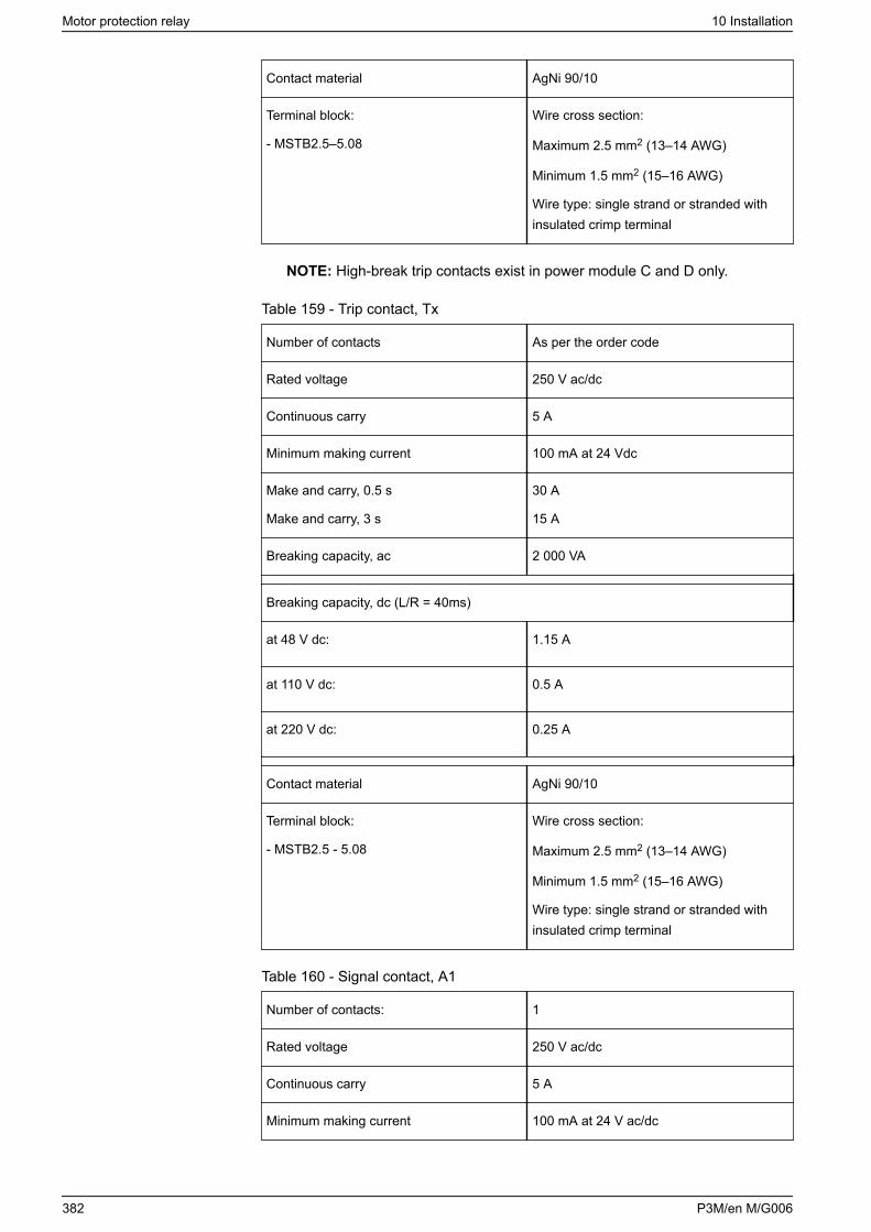
Contact material AgNi 90/10
Terminal block:
- MSTB2.5–5.08
Wire cross section:
Maximum 2.5 mm2 (13–14 AWG)
Minimum 1.5 mm2 (15–16 AWG)
Wire type: single strand or stranded withinsulated crimp terminal
NOTE: High-break trip contacts exist in power module C and D only.
Table 159 - Trip contact, Tx
Number of contacts As per the order code
Rated voltage 250 V ac/dc
Continuous carry 5 A
Minimum making current 100 mA at 24 Vdc
Make and carry, 0.5 s
Make and carry, 3 s
30 A
15 A
Breaking capacity, ac 2 000 VA
Breaking capacity, dc (L/R = 40ms)
at 48 V dc: 1.15 A
at 110 V dc: 0.5 A
at 220 V dc: 0.25 A
Contact material AgNi 90/10
Terminal block:
- MSTB2.5 - 5.08
Wire cross section:
Maximum 2.5 mm2 (13–14 AWG)
Minimum 1.5 mm2 (15–16 AWG)
Wire type: single strand or stranded withinsulated crimp terminal
Table 160 - Signal contact, A1
Number of contacts: 1
Rated voltage 250 V ac/dc
Continuous carry 5 A
Minimum making current 100 mA at 24 V ac/dc
Motor protection relay 10 Installation
382 P3M/en M/G006
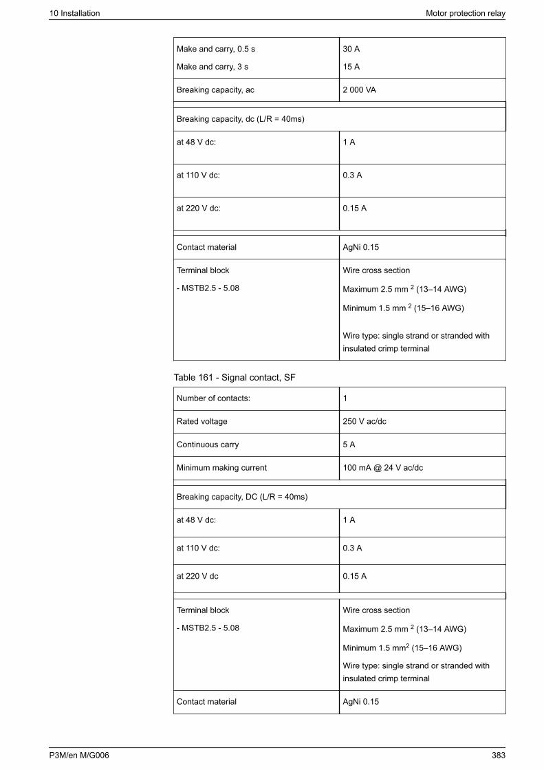
Make and carry, 0.5 s
Make and carry, 3 s
30 A
15 A
Breaking capacity, ac 2 000 VA
Breaking capacity, dc (L/R = 40ms)
at 48 V dc: 1 A
at 110 V dc: 0.3 A
at 220 V dc: 0.15 A
Contact material AgNi 0.15
Terminal block
- MSTB2.5 - 5.08
Wire cross section
Maximum 2.5 mm 2 (13–14 AWG)
Minimum 1.5 mm 2 (15–16 AWG)
Wire type: single strand or stranded withinsulated crimp terminal
Table 161 - Signal contact, SF
Number of contacts: 1
Rated voltage 250 V ac/dc
Continuous carry 5 A
Minimum making current 100 mA @ 24 V ac/dc
Breaking capacity, DC (L/R = 40ms)
at 48 V dc: 1 A
at 110 V dc: 0.3 A
at 220 V dc 0.15 A
Terminal block
- MSTB2.5 - 5.08
Wire cross section
Maximum 2.5 mm 2 (13–14 AWG)
Minimum 1.5 mm2 (15–16 AWG)
Wire type: single strand or stranded withinsulated crimp terminal
Contact material AgNi 0.15
10 Installation Motor protection relay
P3M/en M/G006 383
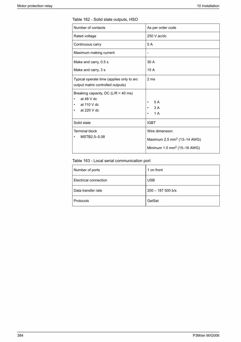
Table 162 - Solid state outputs, HSO
Number of contacts As per order code
Rated voltage 250 V ac/dc
Continuous carry 5 A
Maximum making current -
Make and carry, 0.5 s
Make and carry, 3 s
30 A
15 A
Typical operate time (applies only to arcoutput matrix controlled outputs)
2 ms
Breaking capacity, DC (L/R = 40 ms)• at 48 V dc• at 110 V dc• at 220 V dc
• 5 A• 3 A• 1 A
Solid state IGBT
Terminal block• MSTB2.5–5.08
Wire dimension:
Maximum 2.5 mm2 (13–14 AWG)
Minimum 1.5 mm2 (15–16 AWG)
Table 163 - Local serial communication port
Number of ports 1 on front
Electrical connection USB
Data transfer rate 200 – 187 500 b/s
Protocols GetSet
Motor protection relay 10 Installation
384 P3M/en M/G006
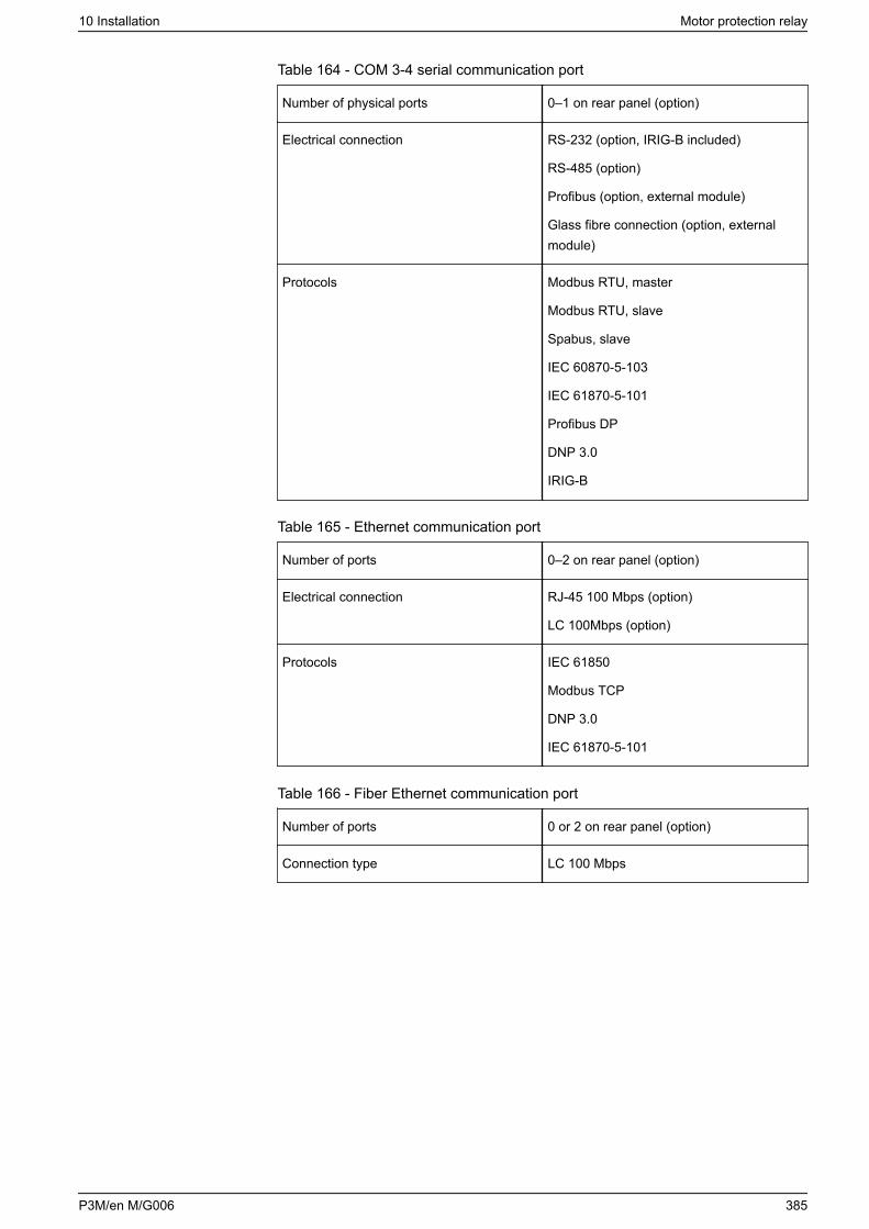
Table 164 - COM 3-4 serial communication port
Number of physical ports 0–1 on rear panel (option)
Electrical connection RS-232 (option, IRIG-B included)
RS-485 (option)
Profibus (option, external module)
Glass fibre connection (option, externalmodule)
Protocols Modbus RTU, master
Modbus RTU, slave
Spabus, slave
IEC 60870-5-103
IEC 61870-5-101
Profibus DP
DNP 3.0
IRIG-B
Table 165 - Ethernet communication port
Number of ports 0–2 on rear panel (option)
Electrical connection RJ-45 100 Mbps (option)
LC 100Mbps (option)
Protocols IEC 61850
Modbus TCP
DNP 3.0
IEC 61870-5-101
Table 166 - Fiber Ethernet communication port
Number of ports 0 or 2 on rear panel (option)
Connection type LC 100 Mbps
10 Installation Motor protection relay
P3M/en M/G006 385
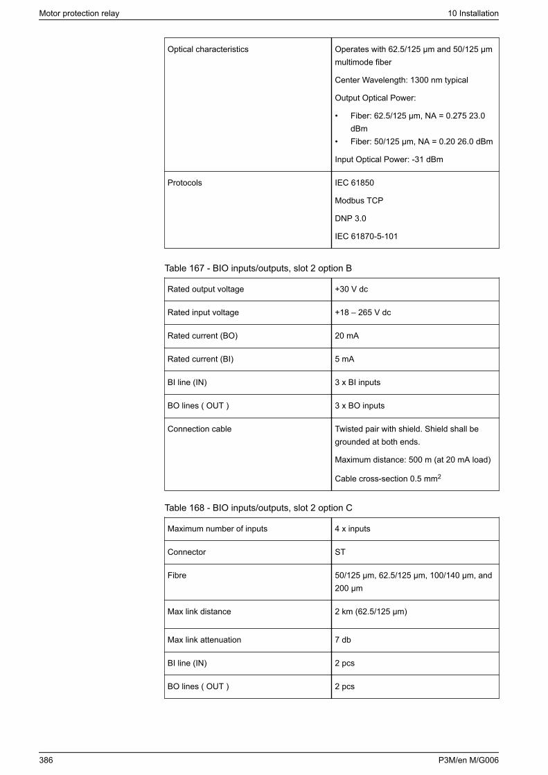
Optical characteristics Operates with 62.5/125 μm and 50/125 μmmultimode fiber
Center Wavelength: 1300 nm typical
Output Optical Power:
• Fiber: 62.5/125 μm, NA = 0.275 23.0dBm
• Fiber: 50/125 μm, NA = 0.20 26.0 dBm
Input Optical Power: -31 dBm
Protocols IEC 61850
Modbus TCP
DNP 3.0
IEC 61870-5-101
Table 167 - BIO inputs/outputs, slot 2 option B
Rated output voltage +30 V dc
Rated input voltage +18 – 265 V dc
Rated current (BO) 20 mA
Rated current (BI) 5 mA
BI line (IN) 3 x BI inputs
BO lines ( OUT ) 3 x BO inputs
Connection cable Twisted pair with shield. Shield shall begrounded at both ends.
Maximum distance: 500 m (at 20 mA load)
Cable cross-section 0.5 mm2
Table 168 - BIO inputs/outputs, slot 2 option C
Maximum number of inputs 4 x inputs
Connector ST
Fibre 50/125 μm, 62.5/125 μm, 100/140 μm, and200 μm
Max link distance 2 km (62.5/125 μm)
Max link attenuation 7 db
BI line (IN) 2 pcs
BO lines ( OUT ) 2 pcs
Motor protection relay 10 Installation
386 P3M/en M/G006
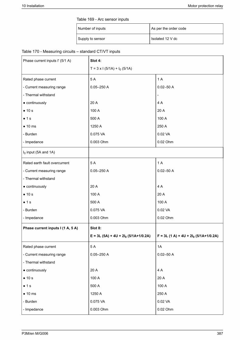
Table 169 - Arc sensor inputs
Number of inputs As per the order code
Supply to sensor Isolated 12 V dc
Table 170 - Measuring circuits – standard CT/VT inputs
Phase current inputs I' (5/1 A) Slot 4:
T = 3 x I (5/1A) + I0 (5/1A)
Rated phase current
- Current measuring range
- Thermal withstand
continuously
10 s
1 s
10 ms
- Burden
- Impedance
5 A
0.05–250 A
20 A
100 A
500 A
1250 A
0.075 VA
0.003 Ohm
1 A
0.02–50 A
-
4 A
20 A
100 A
250 A
0.02 VA
0.02 Ohm
I0 input (5A and 1A)
Rated earth fault overcurrent
- Current measuring range
- Thermal withstand
continuously
10 s
1 s
- Burden
- Impedance
5 A
0.05–250 A
20 A
100 A
500 A
0.075 VA
0.003 Ohm
1 A
0.02–50 A
4 A
20 A
100 A
0.02 VA
0.02 Ohm
Phase current inputs I (1 A, 5 A) Slot 8:
E = 3L (5A) + 4U + 2I0 (5/1A+1/0.2A) F = 3L (1 A) + 4U + 2I0 (5/1A+1/0.2A)
Rated phase current
- Current measuring range
- Thermal withstand
continuously
10 s
1 s
10 ms
- Burden
- Impedance
5 A
0.05–250 A
20 A
100 A
500 A
1250 A
0.075 VA
0.003 Ohm
1A
0.02–50 A
4 A
20 A
100 A
250 A
0.02 VA
0.02 Ohm
10 Installation Motor protection relay
P3M/en M/G006 387
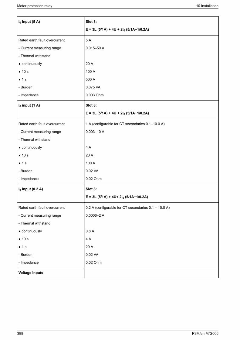
I0 input (5 A) Slot 8:
E = 3L (5/1A) + 4U + 2I0 (5/1A+1/0.2A)
Rated earth fault overcurrent
- Current measuring range
- Thermal withstand
continuously
10 s
1 s
- Burden
- Impedance
5 A
0.015–50 A
20 A
100 A
500 A
0.075 VA
0.003 Ohm
I0 input (1 A) Slot 8:
E = 3L (5/1A) + 4U + 2I0 (5/1A+1/0.2A)
Rated earth fault overcurrent
- Current measuring range
- Thermal withstand
continuously
10 s
1 s
- Burden
- Impedance
1 A (configurable for CT secondaries 0.1–10.0 A)
0.003–10 A
4 A
20 A
100 A
0.02 VA
0.02 Ohm
I0 input (0.2 A) Slot 8:
E = 3L (5/1A) + 4U+ 2I0 (5/1A+1/0.2A)
Rated earth fault overcurrent
- Current measuring range
- Thermal withstand
continuously
10 s
1 s
- Burden
- Impedance
0.2 A (configurable for CT secondaries 0.1 – 10.0 A)
0.0006–2 A
0.8 A
4 A
20 A
0.02 VA
0.02 Ohm
Voltage inputs
Motor protection relay 10 Installation
388 P3M/en M/G006
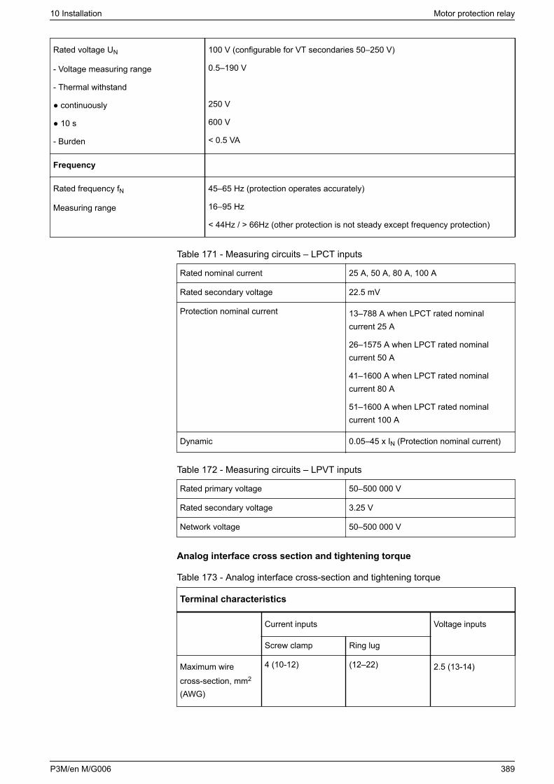
Rated voltage UN
- Voltage measuring range
- Thermal withstand
continuously
10 s
- Burden
100 V (configurable for VT secondaries 50–250 V)
0.5–190 V
250 V
600 V
< 0.5 VA
Frequency
Rated frequency fN
Measuring range
45–65 Hz (protection operates accurately)
16–95 Hz
< 44Hz / > 66Hz (other protection is not steady except frequency protection)
Table 171 - Measuring circuits – LPCT inputs
Rated nominal current 25 A, 50 A, 80 A, 100 A
Rated secondary voltage 22.5 mV
Protection nominal current 13–788 A when LPCT rated nominalcurrent 25 A
26–1575 A when LPCT rated nominalcurrent 50 A
41–1600 A when LPCT rated nominalcurrent 80 A
51–1600 A when LPCT rated nominalcurrent 100 A
Dynamic 0.05–45 x IN (Protection nominal current)
Table 172 - Measuring circuits – LPVT inputs
Rated primary voltage 50–500 000 V
Rated secondary voltage 3.25 V
Network voltage 50–500 000 V
Analog interface cross section and tightening torque
Table 173 - Analog interface cross-section and tightening torque
Terminal characteristics
Current inputs Voltage inputs
Screw clamp Ring lug
Maximum wirecross-section, mm2
(AWG)
4 (10-12) (12–22) 2.5 (13-14)
10 Installation Motor protection relay
P3M/en M/G006 389

Terminal characteristics
Maximum wiringscrew tighteningtorque Nm (Ib-in)
1.2 (10.6) 0.79 (7) 0.5-0.6 (4.4-5.3)
Maximum connectorretention tighteningtorgue Nm (Ib-in)
- 0.3-0.4 (2.7-3.5)
Wire type Single strand orstranded withinsulated crimpterminal
Ring lug width (mm)and screw size
- 8.0, M3.5
10.5.8 External option modules
10.5.8.1 VSE-001 fiber-optic interface module
DANGERHAZARD OF ELECTRIC SHOCK, EXPLOSION, OR ARC FLASH
• This equipment must only be installed or serviced by qualified electricalpersonnel.
• Turn off all power supplying this device and the equipment in which it isinstalled before working on the device or equipment.
• Connect protective earth before turning on any power supplying thisdevice.
Failure to follow these instructions will result in death or serious injury.
An external fiber-optic module VSE-001 is used to connect the device to a fiber-optic loop or a fiber-optic star. There are four different types of serial fiber-opticmodules:
• VSE001PP (Plastic-plastic)• VSE001GG (Glass-glass)
The modules provide a serial communication link up to 1 km (0.62 miles) withVSE 001 GG. With a serial-fibre interface module, it is possible to have thefollowing serial protocols in use:
• None• IEC-103• Modbus slave• SpaBus
The power for the module is taken from pin 9 of the D-connector or from anexternal power supply interface.
Motor protection relay 10 Installation
390 P3M/en M/G006
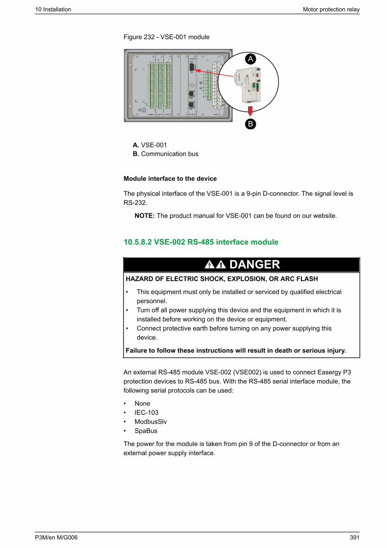
Figure 232 - VSE-001 module
A
B
A. VSE-001B. Communication bus
Module interface to the device
The physical interface of the VSE-001 is a 9-pin D-connector. The signal level isRS-232.
NOTE: The product manual for VSE-001 can be found on our website.
10.5.8.2 VSE-002 RS-485 interface module
DANGERHAZARD OF ELECTRIC SHOCK, EXPLOSION, OR ARC FLASH
• This equipment must only be installed or serviced by qualified electricalpersonnel.
• Turn off all power supplying this device and the equipment in which it isinstalled before working on the device or equipment.
• Connect protective earth before turning on any power supplying thisdevice.
Failure to follow these instructions will result in death or serious injury.
An external RS-485 module VSE-002 (VSE002) is used to connect Easergy P3protection devices to RS-485 bus. With the RS-485 serial interface module, thefollowing serial protocols can be used:
• None• IEC-103• ModbusSlv• SpaBus
The power for the module is taken from pin 9 of the D-connector or from anexternal power supply interface.
10 Installation Motor protection relay
P3M/en M/G006 391
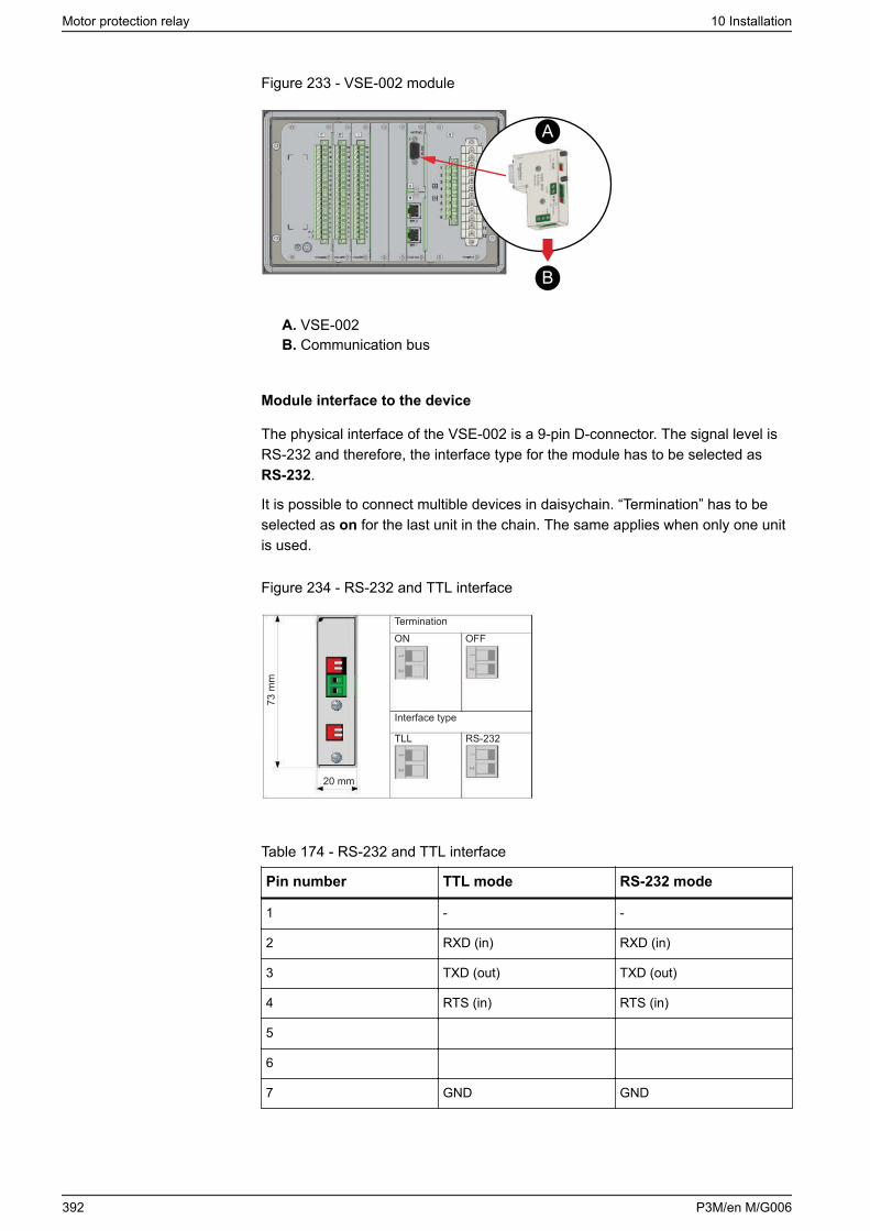
Figure 233 - VSE-002 module
A
B
A. VSE-002B. Communication bus
Module interface to the device
The physical interface of the VSE-002 is a 9-pin D-connector. The signal level isRS-232 and therefore, the interface type for the module has to be selected asRS-232.
It is possible to connect multible devices in daisychain. “Termination” has to beselected as on for the last unit in the chain. The same applies when only one unitis used.
Figure 234 - RS-232 and TTL interface
73 m
m
20 mm
TerminationON OFF
Interface type
TLL RS-232
Table 174 - RS-232 and TTL interface
Pin number TTL mode RS-232 mode
1 - -
2 RXD (in) RXD (in)
3 TXD (out) TXD (out)
4 RTS (in) RTS (in)
5
6
7 GND GND
Motor protection relay 10 Installation
392 P3M/en M/G006
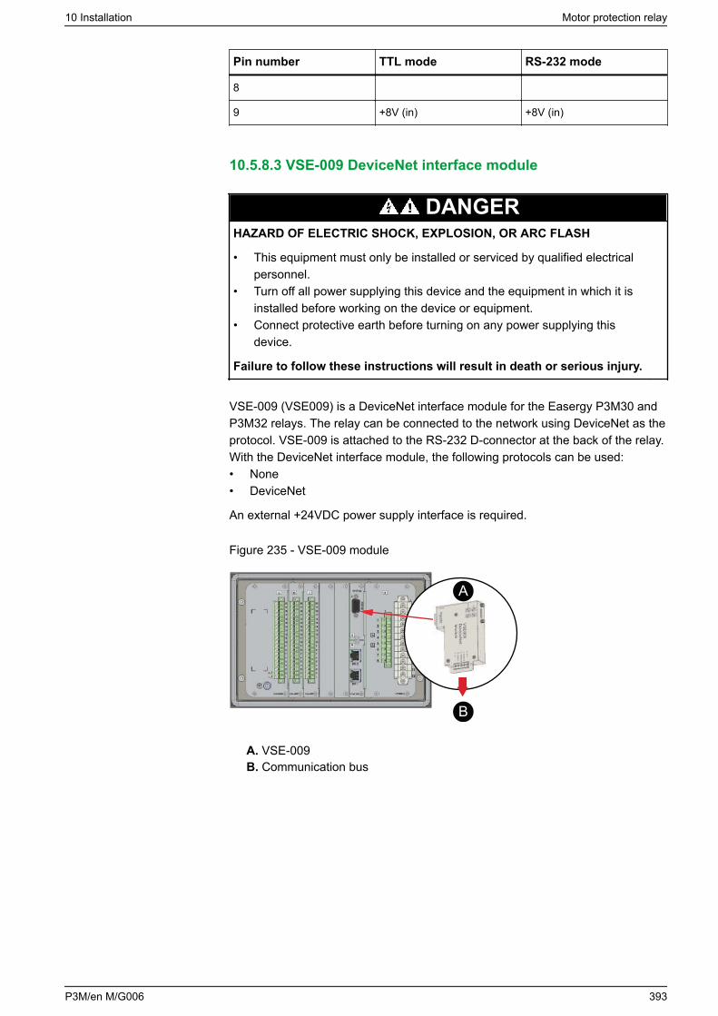
Pin number TTL mode RS-232 mode
8
9 +8V (in) +8V (in)
10.5.8.3 VSE-009 DeviceNet interface module
DANGERHAZARD OF ELECTRIC SHOCK, EXPLOSION, OR ARC FLASH
• This equipment must only be installed or serviced by qualified electricalpersonnel.
• Turn off all power supplying this device and the equipment in which it isinstalled before working on the device or equipment.
• Connect protective earth before turning on any power supplying thisdevice.
Failure to follow these instructions will result in death or serious injury.
VSE-009 (VSE009) is a DeviceNet interface module for the Easergy P3M30 andP3M32 relays. The relay can be connected to the network using DeviceNet as theprotocol. VSE-009 is attached to the RS-232 D-connector at the back of the relay.With the DeviceNet interface module, the following protocols can be used:• None• DeviceNet
An external +24VDC power supply interface is required.
Figure 235 - VSE-009 module
A
B
A. VSE-009B. Communication bus
10 Installation Motor protection relay
P3M/en M/G006 393
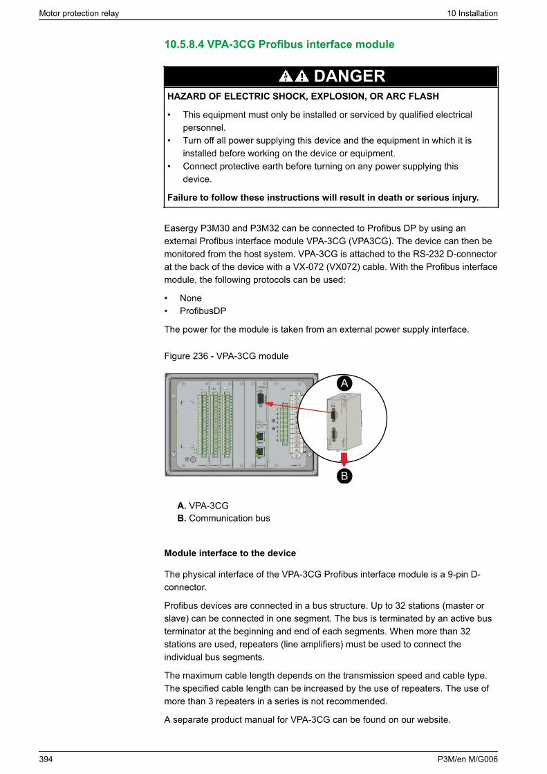
10.5.8.4 VPA-3CG Profibus interface module
DANGERHAZARD OF ELECTRIC SHOCK, EXPLOSION, OR ARC FLASH
• This equipment must only be installed or serviced by qualified electricalpersonnel.
• Turn off all power supplying this device and the equipment in which it isinstalled before working on the device or equipment.
• Connect protective earth before turning on any power supplying thisdevice.
Failure to follow these instructions will result in death or serious injury.
Easergy P3M30 and P3M32 can be connected to Profibus DP by using anexternal Profibus interface module VPA-3CG (VPA3CG). The device can then bemonitored from the host system. VPA-3CG is attached to the RS-232 D-connectorat the back of the device with a VX-072 (VX072) cable. With the Profibus interfacemodule, the following protocols can be used:
• None• ProfibusDP
The power for the module is taken from an external power supply interface.
Figure 236 - VPA-3CG module
A
B
A. VPA-3CGB. Communication bus
Module interface to the device
The physical interface of the VPA-3CG Profibus interface module is a 9-pin D-connector.
Profibus devices are connected in a bus structure. Up to 32 stations (master orslave) can be connected in one segment. The bus is terminated by an active busterminator at the beginning and end of each segments. When more than 32stations are used, repeaters (line amplifiers) must be used to connect theindividual bus segments.
The maximum cable length depends on the transmission speed and cable type.The specified cable length can be increased by the use of repeaters. The use ofmore than 3 repeaters in a series is not recommended.
A separate product manual for VPA-3CG can be found on our website.
Motor protection relay 10 Installation
394 P3M/en M/G006

10.5.8.5 VIO 12A RTD and analog input / output modules
VIO 12A I/O modules can be connected to Easergy P3M30 and P3M32 usingVSE 001 or VSE 002 interface modules.
VIO 12A I/O modules can be connected to Easergy P3U20 and P3U30 usingRS-485 connection in interface modules. Alternatively VIO 12A I/O modules canbe connected to Easergy P3U20 and P3U30 using RS-232 connection. If RS-232connection is used a separate VX082 or VX083 connection cable and VSE001 orVSE002 option module are needed.
A separate product manual for VIO 12A is available.
10.5.9 Block diagrams
The status of the output contacts is shown when the relay is energized but noneof the protection, controlling or self-supervision elements are activated.
10 Installation Motor protection relay
P3M/en M/G006 395
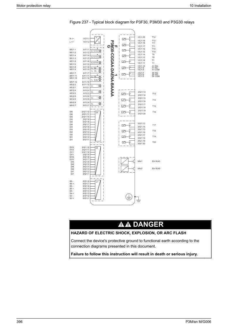
Figure 237 - Typical block diagram for P3F30, P3M30 and P3G30 relays
=~1/C/1:1
1/C/1:2N -/~L +/~
P3M30-CG
GAA-DAENA-BAAAA
FG
1/C/1:141/C/1:151/C/1:161/C/1:171/C/1:18
1/C/1:20
1/C/1:19
1/C/1:121/C/1:13
1/C/1:101/C/1:11
1/C/1:81/C/1:9
1/C/1:7
1/C/1:51/C/1:6
T9T10T10T11T11
T12
T12
T1T9
A1 NOT1
A1 COMA1 NC
SF NC
SF COMSF NO
3/G/1:193/G/1:183/G/1:173/G/1:163/G/1:15
3/G/1:133/G/1:14
3/G/1:20
9/N/1
9/N/2
Eth RJ45
Eth RJ45
DIDI12DI12DI11DI11DI10DI10
DI9DI9DI8DI8DI7DI7
3/G/1:123/G/1:113/G/1:103/G/1:93/G/1:83/G/1:73/G/1:63/G/1:53/G/1:43/G/1:33/G/1:23/G/1:1
2/G/1:132/G/1:142/G/1:152/G/1:162/G/1:172/G/1:18
T15
T14
T13
T162/G/1:192/G/1:20DI
IL1
IL2
IL3
5A
1A
U1
U2
U3
1A
0.2A
U4
5/1A
5/1A
5/1A
8/E/1:18/E/1:2
8/E/1:38/E/1:4
8/E/1:58/E/1:6
8/E/1:9
8/E/1:7
8/E/1:8
8/E/1:108/E/1:11
8/E/1:12
8/E/2:18/E/2:2
8/E/2:38/E/2:4
8/E/2:58/E/2:6
8/E/2:78/E/2:8
6/D/1:86/D/1:76/D/1:66/D/1:56/D/1:46/D/1:36/D/1:26/D/1:1
S5 -S5 +S4 -S4 +S3 -S3 +
S6 -S6 +
L>
T19
T18
T17
T20
2/G/1:122/G/1:112/G/1:102/G/1:92/G/1:82/G/1:72/G/1:62/G/1:52/G/1:42/G/1:32/G/1:22/G/1:1
DI6DI6DI5DI5DI4DI4DI3DI3DI2DI2DI1DI1
1
8/1/1:18/1/1:2
8/1/1:38/1/1:4
8/1/1:58/1/1:6
8/1/1:9
8/1/1:7
8/1/1:8
8/1/1:108/1/1:11
8/1/1:12
8/1/2:18/1/1:12
8/1/2:38/1/2:4
8/1/2:58/1/2:6
8/1/2:78/1/2:8
I01
I01
I02
I02
DANGERHAZARD OF ELECTRIC SHOCK, EXPLOSION, OR ARC FLASH
Connect the device's protective ground to functional earth according to theconnection diagrams presented in this document.
Failure to follow this instruction will result in death or serious injury.
Motor protection relay 10 Installation
396 P3M/en M/G006
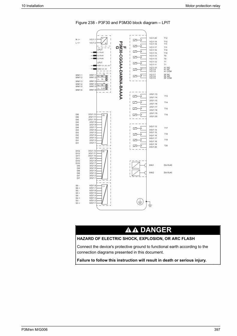
Figure 238 - P3F30 and P3M30 block diagram – LPIT
=~1/C/1:1
1/C/1:2N -/~L +/~
P3M30-CG
GAA-DAM
NA-BAAAAFG
1/C/1:141/C/1:151/C/1:161/C/1:171/C/1:18
1/C/1:20
1/C/1:19
1/C/1:121/C/1:13
1/C/1:101/C/1:11
1/C/1:81/C/1:9
1/C/1:7
1/C/1:51/C/1:6
T9T10T10T11T11
T12
T12
T1T9
A1 NOT1
A1 COMA1 NC
SF NC
SF COMSF NO
3/G/1:193/G/1:183/G/1:173/G/1:163/G/1:15
3/G/1:133/G/1:14
3/G/1:20
9/N/1
9/N/2
Eth RJ45
Eth RJ45
DI12DI12DI11DI11DI10DI10
DI9DI9DI8DI8DI7DI7
2/G/1:132/G/1:142/G/1:152/G/1:162/G/1:172/G/1:18
T15
T14
T13
T162/G/1:192/G/1:20
5A
1A
1A
0.2A
8/M/1:2
8/M/1:3
8/M/1:1
8/M/1:58/M/1:4
8/M/1:6
S5 -S5 +S4 -S4 +S3 -S3 +
S6 -S6 +
L>
T19
T18
T17
T20
DI6DI6DI5DI5DI4DI4DI3DI3DI2DI2DI1DI1
3/G/1:123/G/1:113/G/1:103/G/1:93/G/1:83/G/1:73/G/1:63/G/1:53/G/1:43/G/1:33/G/1:23/G/1:1
8/M/1:2
8/M/1:3
8/M/1:1
8/M/1:58/M/1:4
8/M/1:6
6/D/1:86/D/1:76/D/1:66/D/1:56/D/1:46/D/1:36/D/1:26/D/1:1
2/G/1:122/G/1:112/G/1:102/G/1:92/G/1:82/G/1:72/G/1:62/G/1:52/G/1:42/G/1:32/G/1:22/G/1:1
LPVT
LPCTIL1 RJ45
IL2 RJ45
IL3 RJ45
HUB1 U1, U2, U3
HUB2 U4, U5
DI
DI
I01
I01
I02
I02
DANGERHAZARD OF ELECTRIC SHOCK, EXPLOSION, OR ARC FLASH
Connect the device's protective ground to functional earth according to theconnection diagrams presented in this document.
Failure to follow this instruction will result in death or serious injury.
10 Installation Motor protection relay
P3M/en M/G006 397
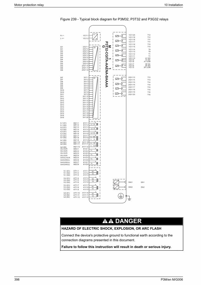
Figure 239 - Typical block diagram for P3M32, P3T32 and P3G32 relays
DI
DI
IL1 5A
IL2 5A
IL3 5A
5A
1A
1A
0.2A
I0
U1
U2
U3
U4
5A1A
5A1A
5A1A
5A1A
9/N/1
9/N/2
Eth1
Eth2
P3T32-CGITA-A
AEN
A-BA
AAAMG
=~
1/C/1:141/C/1:151/C/1:161/C/1:171/C/1:18
1/C/1:201/C/1:19
1/C/1:121/C/1:13
1/C/1:101/C/1:11
1/C/1:81/C/1:9
1/C/1:7
1/C/1:51/C/1:6
T9T10T10T11T11
T12T12
T1T9
A1 NOT1
A1 COMA1 NC
SF NC
SF COMSF NO
2/G/1:182/G/1:172/G/1:162/G/1:15
2/G/1:132/G/1:14
T15T15T14T14
T13T13
2/G/1:192/G/1:20
T16T16
1/C/1:1
1/C/1:2
N -/~
L +/~
DI1DI1DI2DI2DI3DI3DI4DI4DI5DI5DI6DI6
2/G/1:12/G/1:22/G/1:32/G/1:42/G/1:52/G/1:62/G/1:72/G/1:82/G/1:9
2/G/1:102/G/1:112/G/1:12
DI7DI7DI8DI8DI9DI9DI10DI10DI11DI11DI12DI12DI13DI13DI14DI14DI15DI15DI16DI16
3/I/1:13/I/1:23/I/1:33/I/1:43/I/1:53/I/1:63/I/1:73/I/1:83/I/1:9
3/I/1:103/I/1:113/I/1:123/I/1:133/I/1:143/I/1:153/I/1:163/I/1:173/I/1:183/I/1:193/I/1:20
IL1 (S1)IL1 (S2)IL2 (S1)IL2 (S2)IL3 (S1)IL3 (S2)Io1 (S1)Io1 (S2)Io1 (S2)Io2 (S1)Io2 (S2)
Io2 (S2)ULL/ULNULL/ULNULL/ULNULL/ULNUo/ULL/ULNUo/ULN/ULLUo/ULN/ULLUo/ULN/ULL
IꞌL1 (S2)IꞌL1 (S2)
IꞌL1 (S1)
IꞌL2 (S2)IꞌL2 (S2)
IꞌL2 (S1)
IꞌL3 (S2)IꞌL3 (S2)
IꞌL3 (S1)
Io3 (S2)Io3 (S2)
Io3 (S1)
4/1/1:2
I0
I0I0
11
8/E/1:18/E/1:2
8/E/1:48/E/1:3
8/E/1:68/E/1:5
8/E/1:88/E/1:9
8/E/1:7
8/E/1:118/E/1:10
8/E/1:12
8/E/2:28/E/2:1
8/E/2:48/E/2:3
8/E/2:68/E/2:5
8/E/2:88/E/2:7
8/1/1:18/1/1:2
8/1/1:48/1/1:3
8/1/1:68/1/1:5
8/1/1:88/1/1:9
8/1/1:7
8/1/1:118/1/1:10
8/1/1:12
8/1/2:28/1/2:1
8/1/2:48/1/2:3
8/1/2:68/1/2:5
8/1/2:88/1/2:7
4/T/1:24/T/1:3
4/T/1:44/T/1:54/T/1:6
4/T/1:74/T/1:84/T/1:9
4/T/1:104/T/1:114/T/1:12
4/T/1:1
4/1/1:3
4/1/1:44/1/1:54/1/1:6
4/1/1:74/1/1:84/1/1:9
4/1/1:104/1/1:11
4/1/1:12
4/1/1:1
DANGERHAZARD OF ELECTRIC SHOCK, EXPLOSION, OR ARC FLASH
Connect the device's protective ground to functional earth according to theconnection diagrams presented in this document.
Failure to follow this instruction will result in death or serious injury.
Motor protection relay 10 Installation
398 P3M/en M/G006
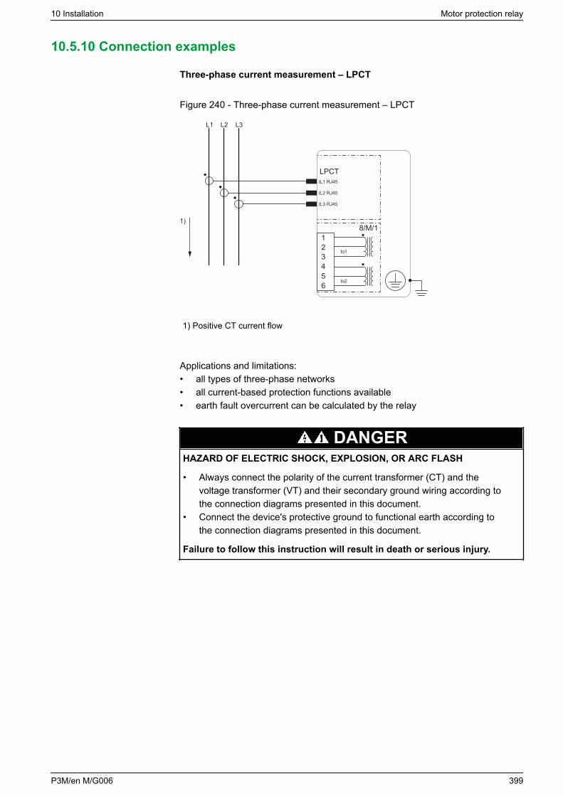
10.5.10 Connection examples
Three-phase current measurement – LPCT
Figure 240 - Three-phase current measurement – LPCT
L1 L2 L3
8/M/11)
LPCTIL1 RJ45
IL2 RJ45
IL3 RJ45
123456
Io1
Io2
1) Positive CT current flow
Applications and limitations:• all types of three-phase networks• all current-based protection functions available• earth fault overcurrent can be calculated by the relay
DANGERHAZARD OF ELECTRIC SHOCK, EXPLOSION, OR ARC FLASH
• Always connect the polarity of the current transformer (CT) and thevoltage transformer (VT) and their secondary ground wiring according tothe connection diagrams presented in this document.
• Connect the device's protective ground to functional earth according tothe connection diagrams presented in this document.
Failure to follow this instruction will result in death or serious injury.
10 Installation Motor protection relay
P3M/en M/G006 399
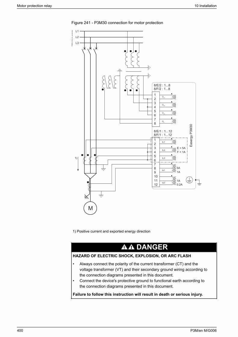
Figure 241 - P3M30 connection for motor protection
P3M
30_3
LN_U
o_co
nnec
tion
1)
L1
L2
L3
Ease
rgy
P3M
30
123456789101112
8/E/1 : 1...128/F/1 : 1...12
8/E/2 : 1...88/F/2 : 1...8
12345678
UL1
UL2
UL3
Uo
IL1
IL2
IL3
Io1
Io2
M
5A1A
E = 5AF = 1A
1A0.2A
1) Positive current and exported energy direction
DANGERHAZARD OF ELECTRIC SHOCK, EXPLOSION, OR ARC FLASH
• Always connect the polarity of the current transformer (CT) and thevoltage transformer (VT) and their secondary ground wiring according tothe connection diagrams presented in this document.
• Connect the device's protective ground to functional earth according tothe connection diagrams presented in this document.
Failure to follow this instruction will result in death or serious injury.
Motor protection relay 10 Installation
400 P3M/en M/G006
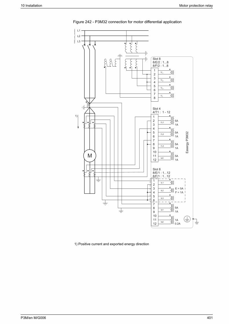
Figure 242 - P3M32 connection for motor differential application
M
L1
L2
L3
123456789101112
Slot 88/E/1 : 1...128/F/1 : 1...12
IL1
IL2
IL3
Io1
Io2
123456789101112
Slot 44/T1 : 1 - 12
Ease
rgy
P3M
32
5A1A
5A1A
5A1A
5A1A
5A1A
E = 5AF = 1A
1A0.2A
Io3
I’L3
I’L2
I’L1
Slot 88/E/2 : 1...88/F/2 : 1...812345678
UL1
UL2
UL3
Uo
P3M
32_m
otor
_con
nect
ion
1)
1) Positive current and exported energy direction
10 Installation Motor protection relay
P3M/en M/G006 401
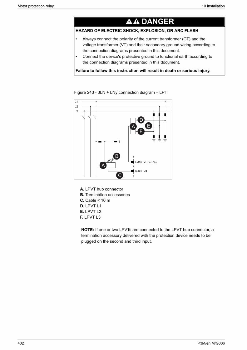
DANGERHAZARD OF ELECTRIC SHOCK, EXPLOSION, OR ARC FLASH
• Always connect the polarity of the current transformer (CT) and thevoltage transformer (VT) and their secondary ground wiring according tothe connection diagrams presented in this document.
• Connect the device's protective ground to functional earth according tothe connection diagrams presented in this document.
Failure to follow this instruction will result in death or serious injury.
Figure 243 - 3LN + LNy connection diagram – LPIT
RJ45 V4
RJ45 VL1, VL2, VL3
L1L2L3
A
A
B
C
DE
F
A. LPVT hub connectorB. Termination accessoriesC. Cable < 10 mD. LPVT L1E. LPVT L2F. LPVT L3
NOTE: If one or two LPVTs are connected to the LPVT hub connector, atermination accessory delivered with the protection device needs to beplugged on the second and third input.
Motor protection relay 10 Installation
402 P3M/en M/G006
10.6 Arc flash detection system setup and testing
10.6.1 Setting up the arc flash system
DANGERHAZARD OF ELECTRIC SHOCK, EXPLOSION, OR ARC FLASH
• Apply appropriate personal protective equipment (PPE) and follow safeelectrical work practices. See NFPA 70E, NOM-029-STPS-2011, or CSAZ462.
• The arc fault detection system is not a substitute for proper PPE whenworking on or near equipment being monitored by the system.
• Information on this product is offered as a tool for conducting arc flashhazard analysis. It is intended for use only by qualified persons who areknowledgeable about power system studies, power distribution equipment,and equipment installation practices. It is not intended as a substitute forthe engineering judgement and adequate review necessary for suchactivities.
• Only qualified personnel should install and service this equipment. Readthis entire set of instructions and check the technical characteristics of thedevice before performing such work.
• Perform wiring according to national standards (NEC) and anyrequirements specified by the customer.
• Observe any separately marked notes and warnings.• NEVER work alone.• Before performing visual inspections, tests, or maintenance on this
equipment, disconnect all sources of electric power. Assume all circuits arelive until they are completely de-energized, tested, and tagged. Payparticular attention to the design of the power system. Consider all sourcesof power, including the possibility of backfeeding.
• Always use a properly rated voltage sensing relay to ensure that all poweris off.
• The equipment must be grounded.• Connect the device's protective ground to functional earth according to the
connection diagrams presented in this document.• Do not open the device. It contains no user-serviceable parts.• Install all devices, doors and covers before turning on the power to this
device.
Failure to follow these instructions will result in death or serious injury.
Before setting up the arc flash system:• Mount and connect all components and sensors.• Make sure that you understand the customer application.
1. Identify the wiring connection of sensors to the device’s connectors.
2. Identify the wiring connection to breaking devices.
3. Identify binary I/O wiring connections.
4. Proceed with configuration in Easergy Pro with consideration of the customerapplication.
5. Power up the device.
10 Installation Motor protection relay
P3M/en M/G006 403
6. Reset the device by pushing the reset button.
7. Verify LED indication as described with consideration of the customerapplication.
8. If connecting two devices through MT in and MT out:
DANGERHAZARD OF LOSS OF SIGNAL
The MT in and MT out connections are not monitored. You must todetermine if external monitoring is required to detect broken ordisconnected wires.
Failure to follow these instructions will result in death or seriousinjury.
a. Verify the MT in MT out connections.
b. Set the related dip switch configuration.
c. Verify the LED indications.
10.6.2 Commissioning and testing
This section contains the commissioning testing instructions. The figure belowshows the testing sequence.
Motor protection relay 10 Installation
404 P3M/en M/G006
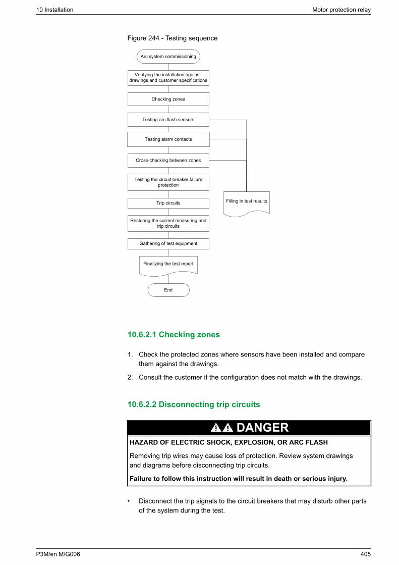
Figure 244 - Testing sequence
Arc system commissioning
Checking zones
Testing arc flash sensors
Restoring the current measuring and trip circuits
Filling in test results
Cross-checking between zones
End
Gathering of test equipment
Finalizing the test report
Testing alarm contacts
Testing the circuit breaker failure protection
Trip circuits
Verifying the installation against drawings and customer specifications
10.6.2.1 Checking zones
1. Check the protected zones where sensors have been installed and comparethem against the drawings.
2. Consult the customer if the configuration does not match with the drawings.
10.6.2.2 Disconnecting trip circuits
DANGERHAZARD OF ELECTRIC SHOCK, EXPLOSION, OR ARC FLASH
Removing trip wires may cause loss of protection. Review system drawingsand diagrams before disconnecting trip circuits.
Failure to follow this instruction will result in death or serious injury.
• Disconnect the trip signals to the circuit breakers that may disturb other partsof the system during the test.
10 Installation Motor protection relay
P3M/en M/G006 405
• Also disconnect trip signals routed to other parts of the system, such as thebreaker failure (ANSI 50BF) backup trip to upstream breakers and the transfertrip signals.
• Test the disconnected trip signals with a multimeter.
10.6.2.3 Sensor testing
DANGERHAZARD OF ELECTRIC SHOCK, EXPLOSION, OR ARC FLASH
• Apply appropriate personal protective equipment (PPE) and follow safeelectrical work practices. See NFPA 70E, NOM-029-STPS-2011, or CSAZ462.
• The arc fault detection system is not a substitute for proper PPE whenworking on or near equipment being monitored by the system.
• Information on this product is offered as a tool for conducting arc flashhazard analysis. It is intended for use only by qualified persons who areknowledgeable about power system studies, power distribution equipment,and equipment installation practices. It is not intended as a substitute forthe engineering judgement and adequate review necessary for suchactivities.
• Only qualified personnel should install and service this equipment. Readthis entire set of instructions and check the technical characteristics of thedevice before performing such work.
• Perform wiring according to national standards (NEC) and anyrequirements specified by the customer.
• Observe any separately marked notes and warnings.• NEVER work alone.• Before performing visual inspections, tests, or maintenance on this
equipment, disconnect all sources of electric power. Assume all circuits arelive until they are completely de-energized, tested, and tagged. Payparticular attention to the design of the power system. Consider all sourcesof power, including the possibility of backfeeding.
• Always use a properly rated voltage sensing relay to ensure that all poweris off.
• The equipment must be grounded.• Connect the device's protective ground to functional earth according to the
connection diagrams presented in this document.• Do not open the device. It contains no user-serviceable parts.• Install all devices, doors and covers before turning on the power to this
device.
Failure to follow these instructions will result in death or serious injury.
Testing the arc flash sensors with the light-only criteria operates the trip outputs ofthe device or the I/O units for the protected zone.
Testing the arc flash sensors with the light and current criteria, without an injectedcurrent, only generates an indication on the unit that protects the zone. Theindication of the arc fault is registered by the possible main unit and I/O unit.
NOTE: Testing the arc flash sensors using a light source can trip theneighboring zones.
Motor protection relay 10 Installation
406 P3M/en M/G006
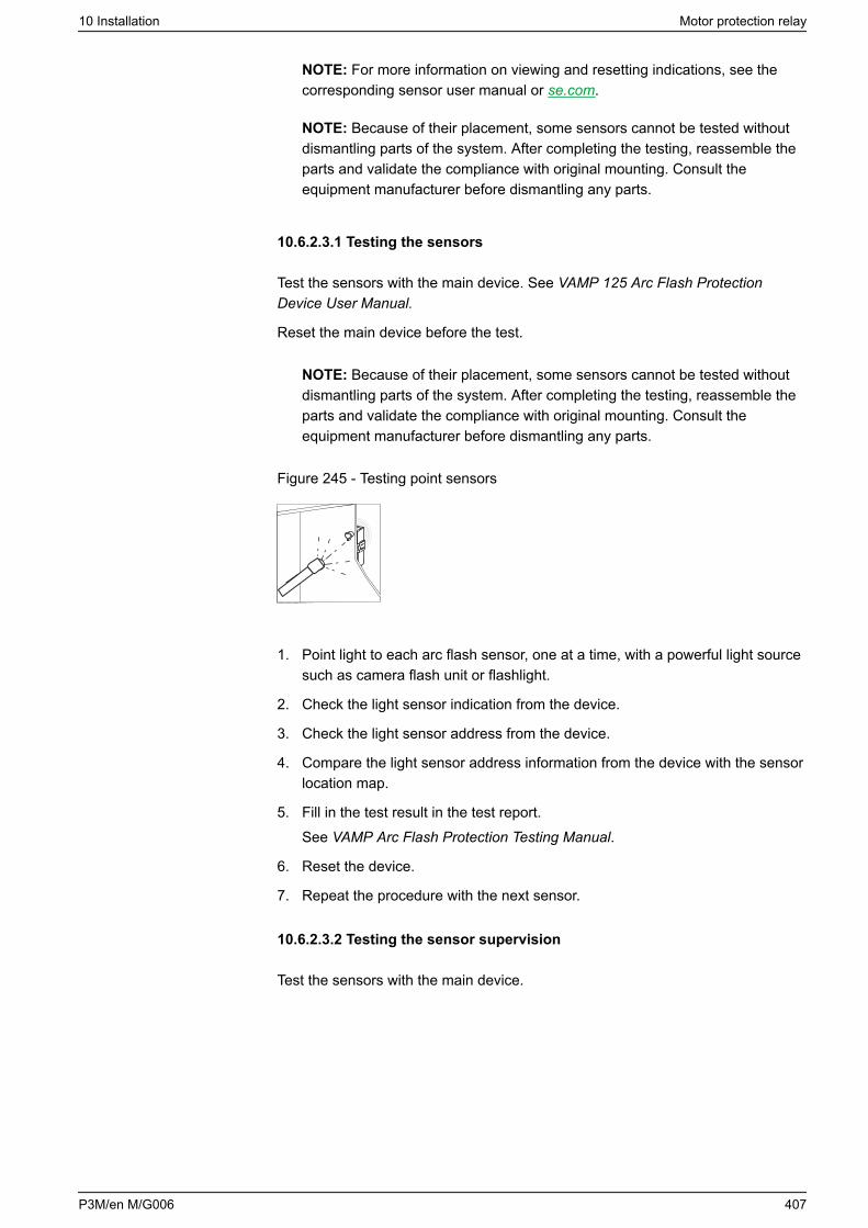
NOTE: For more information on viewing and resetting indications, see thecorresponding sensor user manual or se.com.
NOTE: Because of their placement, some sensors cannot be tested withoutdismantling parts of the system. After completing the testing, reassemble theparts and validate the compliance with original mounting. Consult theequipment manufacturer before dismantling any parts.
10.6.2.3.1 Testing the sensors
Test the sensors with the main device. See VAMP 125 Arc Flash ProtectionDevice User Manual.
Reset the main device before the test.
NOTE: Because of their placement, some sensors cannot be tested withoutdismantling parts of the system. After completing the testing, reassemble theparts and validate the compliance with original mounting. Consult theequipment manufacturer before dismantling any parts.
Figure 245 - Testing point sensors
1. Point light to each arc flash sensor, one at a time, with a powerful light sourcesuch as camera flash unit or flashlight.
2. Check the light sensor indication from the device.
3. Check the light sensor address from the device.
4. Compare the light sensor address information from the device with the sensorlocation map.
5. Fill in the test result in the test report.See VAMP Arc Flash Protection Testing Manual.
6. Reset the device.
7. Repeat the procedure with the next sensor.
10.6.2.3.2 Testing the sensor supervision
Test the sensors with the main device.
10 Installation Motor protection relay
P3M/en M/G006 407
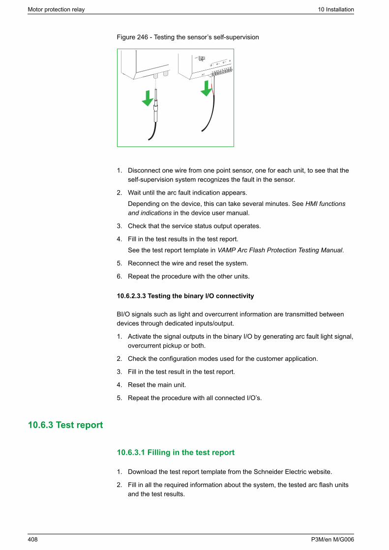
Figure 246 - Testing the sensor’s self-supervision
R1T1
T2R3
T3
R2
TRIP
X1
12
3
SENSOR INPUTS
ACT
TRIP
4
1 2 3 4 5 6 7 8ON
L>ext/int
LatchL+I/L
Zone
Addr.
X11 2 3 4 5 6 7 8 9 10 11
1. Disconnect one wire from one point sensor, one for each unit, to see that theself-supervision system recognizes the fault in the sensor.
2. Wait until the arc fault indication appears.Depending on the device, this can take several minutes. See HMI functionsand indications in the device user manual.
3. Check that the service status output operates.
4. Fill in the test results in the test report.See the test report template in VAMP Arc Flash Protection Testing Manual.
5. Reconnect the wire and reset the system.
6. Repeat the procedure with the other units.
10.6.2.3.3 Testing the binary I/O connectivity
BI/O signals such as light and overcurrent information are transmitted betweendevices through dedicated inputs/output.
1. Activate the signal outputs in the binary I/O by generating arc fault light signal,overcurrent pickup or both.
2. Check the configuration modes used for the customer application.
3. Fill in the test result in the test report.
4. Reset the main unit.
5. Repeat the procedure with all connected I/O’s.
10.6.3 Test report
10.6.3.1 Filling in the test report
1. Download the test report template from the Schneider Electric website.
2. Fill in all the required information about the system, the tested arc flash unitsand the test results.
Motor protection relay 10 Installation
408 P3M/en M/G006
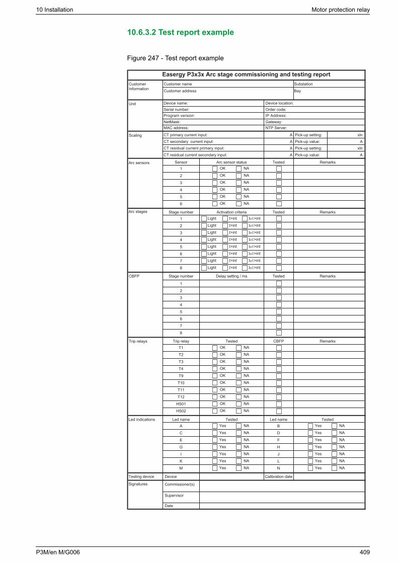
10.6.3.2 Test report example
Figure 247 - Test report example
Customer name
Easergy P3x3x Arc stage commissioning and testing report
Customer address
Device name:Serial number:Program version:NetMask:
Unit
CustomerInformation
Scaling
Arc sensors
Arc stages
CBFP
Trip relays
Led indications
Testing device
Signatures
MAC address:
Device location:Order code:IP Address:Gateway:NTP Server:
Substation
Bay
CT primary current input:CT secondary current input:CT residual current primary input:CT residual current secondary input:
Pick-up setting:Pick-up value:Pick-up setting:Pick-up value:
RemarksTestedArc sensor statusSensorOK1 NA
OK2 NA
OK3 NA
OK4 NA
OK5 NA
OK6 NA
RemarksTestedActivation criteriaStage numberLight1 I>int
2
3
4
5
6
7
8
RemarksTestedDelay setting / msStage number
1
2
3
4
5
6
7
8
Io1>int
Light I>int Io1>int
Light I>int Io1>int
Light I>int Io1>int
Light I>int Io1>int
Light I>int Io1>int
Light I>int Io1>int
Light I>int Io1>int
OK NARemarksCBFPTestedTrip relay
OK NA
OK NA
OK NA
OK NA
OK NA
OK NA
T1
T9
T10
T11
T12
HS01
HS02
Yes NALed nameTestedLed name
Yes NA
Yes NA
Yes NA
Yes NA
Yes NA
Yes NA
A
C
E
G
I
K
M
Yes NATested
Yes NA
Yes NA
Yes NA
Yes NA
Yes NA
Yes NA
Calibration dateDevice
Commissioner(s)
Supervisor
Date
B
D
F
H
J
L
N
AAAA
xlnA
xlnA
OK NAT2OK NAT3OK NAT4
10 Installation Motor protection relay
P3M/en M/G006 409

10.6.4 Troubleshooting
This table describes some common problems in the arc flash system and howthey can be solved.
Table 175 - Troubleshooting
Problem Possible cause Solution
The trip signal does notreach the circuit breaker.
Faulty trip circuit wiring Check that the wiring of thetrip circuit is not faulty.
The protection does not tripeven when a sufficient lightsignal is provided.
The protection needs bothlight and current informationto trip.
Check the dip switchconfiguration. The protectionmay be configured torequire both the light andcurrent condition to trip.
Faulty sensor wiringdetected by the self-supervision
Loose sensor wire Check the sensor wiring.The sensor wire may haveloosened in the terminalblocks.
Error message indicatingblocked sensor channel
Light pulse to the arc flashsensor is too long.
Check that the light pulse tothe arc flash sensor is nottoo long.
If light is supplied to the arcflash sensor for more thanthree seconds, the self-supervision functionactivates and switches thelight sensor channel todaylight blocking mode, andthe sensor channel isblocked. The sensorchannel indication activatesan error message indicationon the LED.
Remove the light source toreset the blocked channel.
10.7 Low-power instrument transformer testing
These tests verify that the accuracy of the low-power instrument transformer(LPIT) measurements are within acceptable tolerances.
Figure 248 shows the connection diagram that includes the Easergy P3 protectionrelay and a low-frequency generator as described in 10.7.1 Testing tools andequipment.
NOTE: To avoid any slow fluctuation of current measurements during testing,disconnect the signal generator earth/ground link or use an isolatortransformer.
Motor protection relay 10 Installation
410 P3M/en M/G006
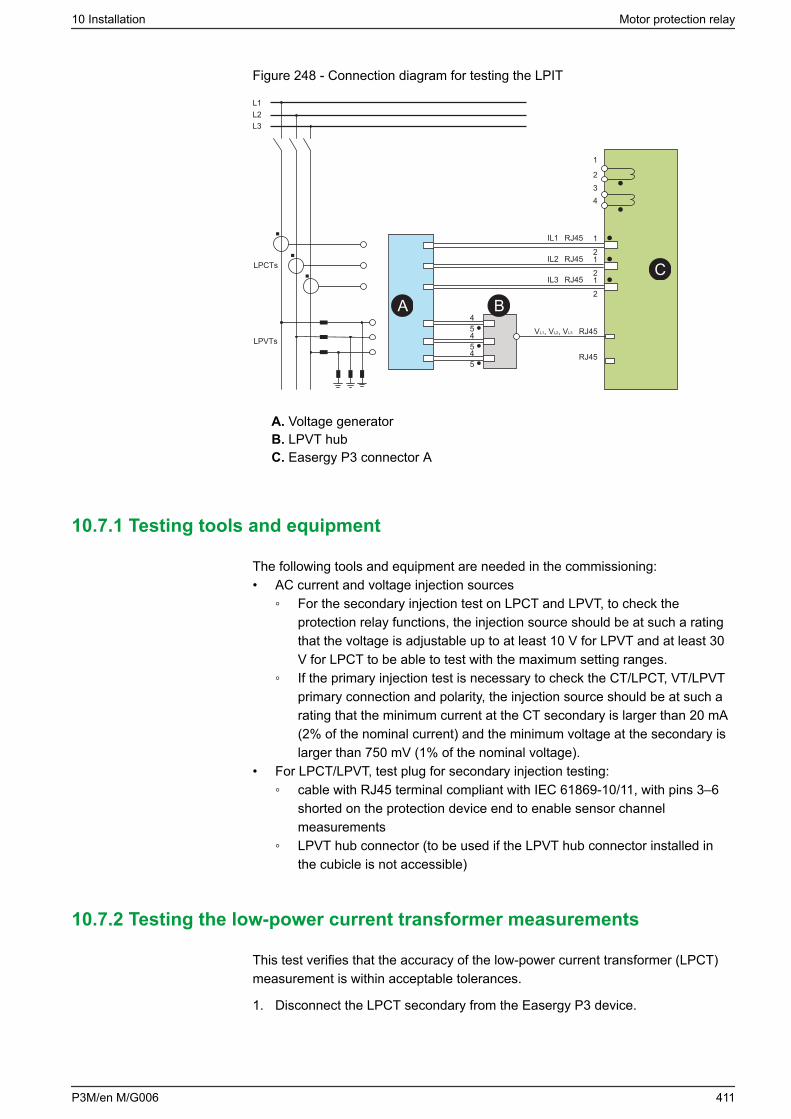
Figure 248 - Connection diagram for testing the LPIT
RJ45
1
2
12
454545
1212
34
RJ45LPCTs
LPVTs
IL3
IL2
IL1
L3L2L1
RJ45
RJ45
RJ45VL1, VL2, VL3
B
C
A
A. Voltage generatorB. LPVT hubC. Easergy P3 connector A
10.7.1 Testing tools and equipment
The following tools and equipment are needed in the commissioning:• AC current and voltage injection sources
For the secondary injection test on LPCT and LPVT, to check theprotection relay functions, the injection source should be at such a ratingthat the voltage is adjustable up to at least 10 V for LPVT and at least 30V for LPCT to be able to test with the maximum setting ranges.
If the primary injection test is necessary to check the CT/LPCT, VT/LPVTprimary connection and polarity, the injection source should be at such arating that the minimum current at the CT secondary is larger than 20 mA(2% of the nominal current) and the minimum voltage at the secondary islarger than 750 mV (1% of the nominal voltage).
• For LPCT/LPVT, test plug for secondary injection testing: cable with RJ45 terminal compliant with IEC 61869-10/11, with pins 3–6
shorted on the protection device end to enable sensor channelmeasurements
LPVT hub connector (to be used if the LPVT hub connector installed inthe cubicle is not accessible)
10.7.2 Testing the low-power current transformer measurements
This test verifies that the accuracy of the low-power current transformer (LPCT)measurement is within acceptable tolerances.
1. Disconnect the LPCT secondary from the Easergy P3 device.
10 Installation Motor protection relay
P3M/en M/G006 411
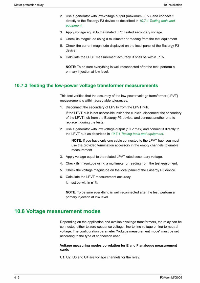
2. Use a generator with low-voltage output (maximum 30 V), and connect itdirectly to the Easergy P3 device as described in 10.7.1 Testing tools andequipment.
3. Apply voltage equal to the related LPCT rated secondary voltage.
4. Check its magnitude using a multimeter or reading from the test equipment.
5. Check the current magnitude displayed on the local panel of the Easergy P3device.
6. Calculate the LPCT measurement accuracy, it shall be within ±1%.
NOTE: To be sure everything is well reconnected after the test, perform aprimary injection at low level.
10.7.3 Testing the low-power voltage transformer measurements
This test verifies that the accuracy of the low-power voltage transformer (LPVT)measurement is within acceptable tolerances.
1. Disconnect the secondary of LPVTs from the LPVT hub.If the LPVT hub is not accessible inside the cubicle, disconnect the secondaryof the LPVT hub from the Easergy P3 device, and connect another one toreplace it during the tests.
2. Use a generator with low voltage output (10 V max) and connect it directly tothe LPVT hub as described in 10.7.1 Testing tools and equipment.
NOTE: If you have only one cable connected to the LPVT hub, you mustuse the provided termination accessory in the empty channels to enablemeasurement.
3. Apply voltage equal to the related LPVT rated secondary voltage.
4. Check its magnitude using a multimeter or reading from the test equipment.
5. Check the voltage magnitude on the local panel of the Easergy P3 device.
6. Calculate the LPVT measurement accuracy.It must be within ±1%.
NOTE: To be sure everything is well reconnected after the test, perform aprimary injection at low level.
10.8 Voltage measurement modes
Depending on the application and available voltage transformers, the relay can beconnected either to zero-sequence voltage, line-to-line voltage or line-to-neutralvoltage. The configuration parameter "Voltage measurement mode" must be setaccording to the type of connection used.
Voltage measuring modes correlation for E and F analogue measurementcards
U1, U2, U3 and U4 are voltage channels for the relay.
Motor protection relay 10 Installation
412 P3M/en M/G006
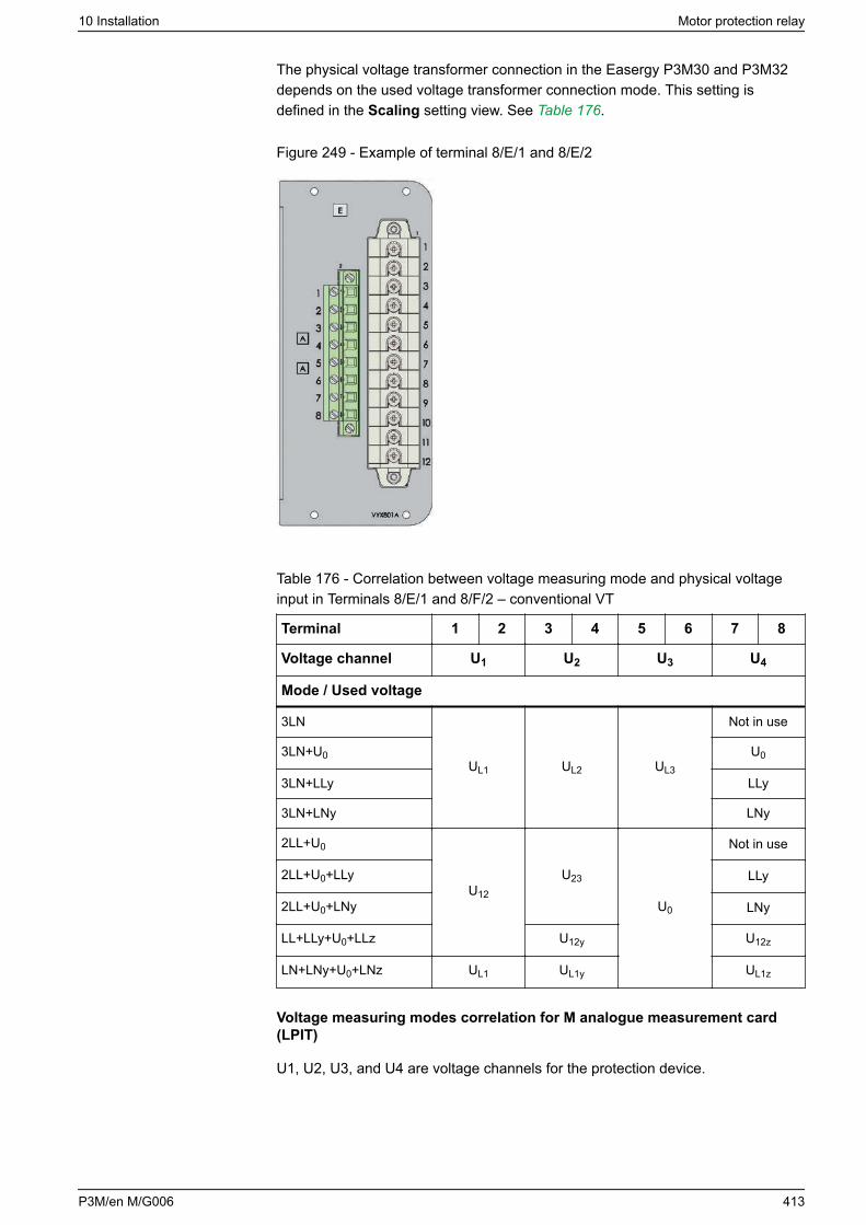
The physical voltage transformer connection in the Easergy P3M30 and P3M32depends on the used voltage transformer connection mode. This setting isdefined in the Scaling setting view. See Table 176.
Figure 249 - Example of terminal 8/E/1 and 8/E/2
Table 176 - Correlation between voltage measuring mode and physical voltageinput in Terminals 8/E/1 and 8/F/2 – conventional VT
Terminal 1 2 3 4 5 6 7 8
Voltage channel U1 U2 U3 U4
Mode / Used voltage
3LN
UL1 UL2 UL3
Not in use
3LN+U0 U0
3LN+LLy LLy
3LN+LNy LNy
2LL+U0
U12
U23
U0
Not in use
2LL+U0+LLy LLy
2LL+U0+LNy LNy
LL+LLy+U0+LLz U12y U12z
LN+LNy+U0+LNz UL1 UL1y UL1z
Voltage measuring modes correlation for M analogue measurement card(LPIT)
U1, U2, U3, and U4 are voltage channels for the protection device.
10 Installation Motor protection relay
P3M/en M/G006 413
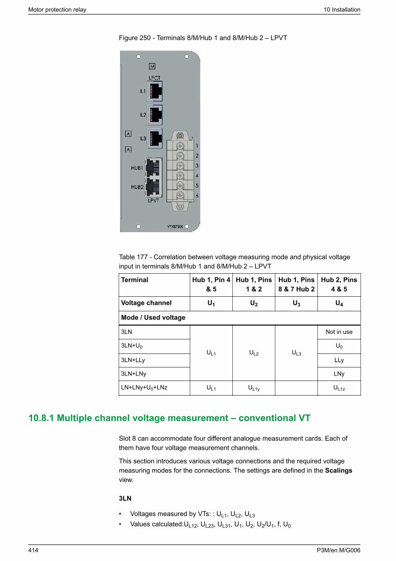
Figure 250 - Terminals 8/M/Hub 1 and 8/M/Hub 2 – LPVT
Table 177 - Correlation between voltage measuring mode and physical voltageinput in terminals 8/M/Hub 1 and 8/M/Hub 2 – LPVT
Terminal Hub 1, Pin 4& 5
Hub 1, Pins1 & 2
Hub 1, Pins8 & 7 Hub 2
Hub 2, Pins4 & 5
Voltage channel U1 U2 U3 U4
Mode / Used voltage
3LN
UL1 UL2 UL3
Not in use
3LN+U0 U0
3LN+LLy LLy
3LN+LNy LNy
LN+LNy+U0+LNz UL1 UL1y UL1z
10.8.1 Multiple channel voltage measurement – conventional VT
Slot 8 can accommodate four different analogue measurement cards. Each ofthem have four voltage measurement channels.
This section introduces various voltage connections and the required voltagemeasuring modes for the connections. The settings are defined in the Scalingsview.
3LN
• Voltages measured by VTs: : UL1, UL2, UL3
• Values calculated:UL12, UL23, UL31, U1, U2, U2/U1, f, U0
Motor protection relay 10 Installation
414 P3M/en M/G006
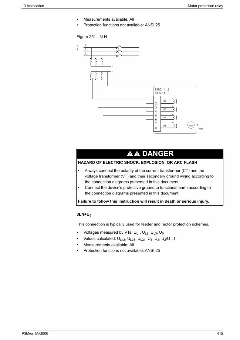
• Measurements available: All• Protection functions not available: ANSI 25
Figure 251 - 3LN
8/E/2 : 1...88/F/2 : 1...8
12345678
U1
U2
U3
U4
P3x3
x 3
LN
UL2
UL3
UL1
DANGERHAZARD OF ELECTRIC SHOCK, EXPLOSION, OR ARC FLASH
• Always connect the polarity of the current transformer (CT) and thevoltage transformer (VT) and their secondary ground wiring according tothe connection diagrams presented in this document.
• Connect the device's protective ground to functional earth according tothe connection diagrams presented in this document.
Failure to follow this instruction will result in death or serious injury.
3LN+U0
This connection is typically used for feeder and motor protection schemes.
• Voltages measured by VTs: UL1, UL2, UL3, U0
• Values calculated: UL12, UL23, UL31, U1, U2, U2/U1, f• Measurements available: All• Protection functions not available: ANSI 25
10 Installation Motor protection relay
P3M/en M/G006 415
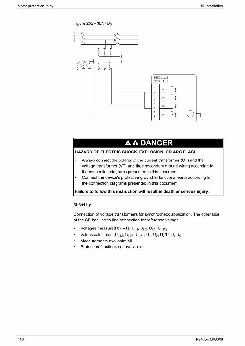
Figure 252 - 3LN+U0
8/E/2 : 1...88/F/2 : 1...8
12345678
U1
U2
U3
U4
P3x3
x 3
LN +
Uo
UL2
UL3
UL1
DANGERHAZARD OF ELECTRIC SHOCK, EXPLOSION, OR ARC FLASH
• Always connect the polarity of the current transformer (CT) and thevoltage transformer (VT) and their secondary ground wiring according tothe connection diagrams presented in this document.
• Connect the device's protective ground to functional earth according tothe connection diagrams presented in this document.
Failure to follow this instruction will result in death or serious injury.
3LN+LLy
Connection of voltage transformers for synchrocheck application. The other sideof the CB has line-to-line connection for reference voltage.
• Voltages measured by VTs: UL1, UL2, UL3, UL12y
• Values calculated: UL12, UL23, UL31, U1, U2, U2/U1, f, U0
• Measurements available: All• Protection functions not available: -
Motor protection relay 10 Installation
416 P3M/en M/G006
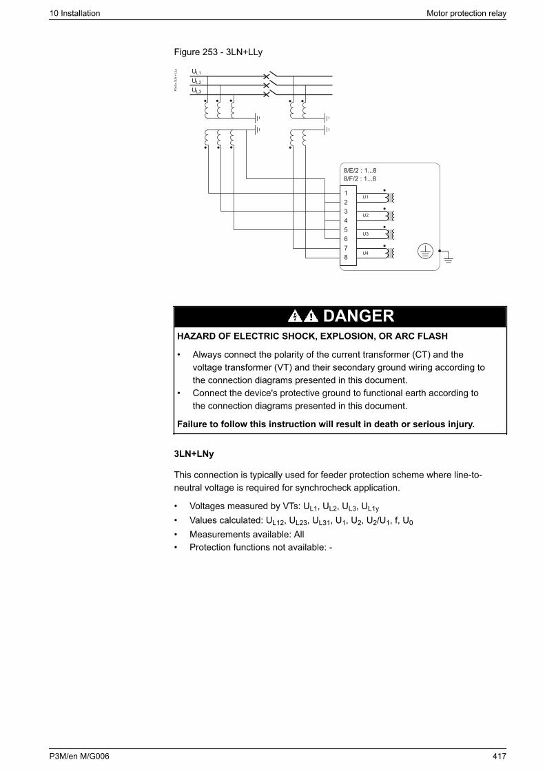
Figure 253 - 3LN+LLy
UL2
UL3
UL1
8/E/2 : 1...88/F/2 : 1...8
12345678
U1
U2
U3
U4
P3x3
x 3L
N +
LLy
DANGERHAZARD OF ELECTRIC SHOCK, EXPLOSION, OR ARC FLASH
• Always connect the polarity of the current transformer (CT) and thevoltage transformer (VT) and their secondary ground wiring according tothe connection diagrams presented in this document.
• Connect the device's protective ground to functional earth according tothe connection diagrams presented in this document.
Failure to follow this instruction will result in death or serious injury.
3LN+LNy
This connection is typically used for feeder protection scheme where line-to-neutral voltage is required for synchrocheck application.
• Voltages measured by VTs: UL1, UL2, UL3, UL1y
• Values calculated: UL12, UL23, UL31, U1, U2, U2/U1, f, U0
• Measurements available: All• Protection functions not available: -
10 Installation Motor protection relay
P3M/en M/G006 417
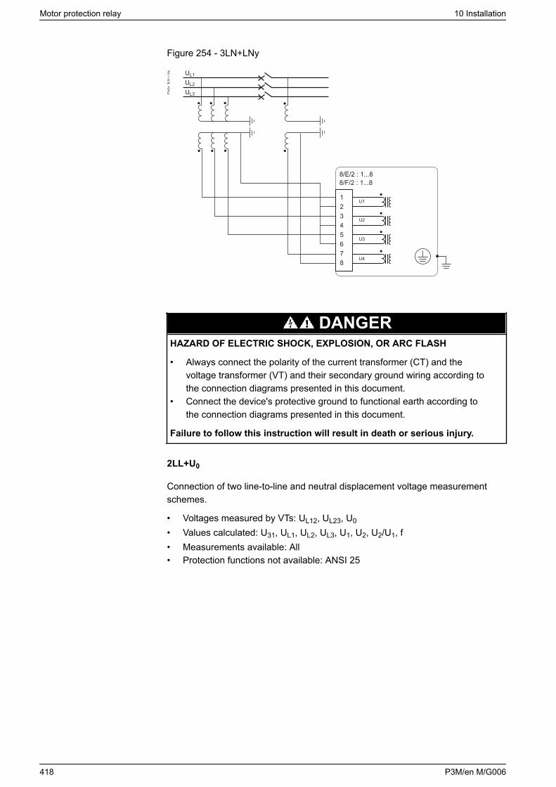
Figure 254 - 3LN+LNy
UL2
UL3
UL1
8/E/2 : 1...88/F/2 : 1...8
12345678
U1
U2
U3
U4
P3x3
x 3
LN +
LN
y
DANGERHAZARD OF ELECTRIC SHOCK, EXPLOSION, OR ARC FLASH
• Always connect the polarity of the current transformer (CT) and thevoltage transformer (VT) and their secondary ground wiring according tothe connection diagrams presented in this document.
• Connect the device's protective ground to functional earth according tothe connection diagrams presented in this document.
Failure to follow this instruction will result in death or serious injury.
2LL+U0
Connection of two line-to-line and neutral displacement voltage measurementschemes.
• Voltages measured by VTs: UL12, UL23, U0
• Values calculated: U31, UL1, UL2, UL3, U1, U2, U2/U1, f• Measurements available: All• Protection functions not available: ANSI 25
Motor protection relay 10 Installation
418 P3M/en M/G006
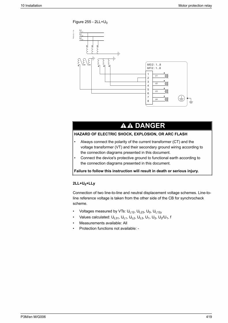
Figure 255 - 2LL+U0
UL2
UL3
UL1
P3x3
x 2L
L +
Uo
8/E/2 : 1...88/F/2 : 1...8
12345678
U1
U2
U3
U4
DANGERHAZARD OF ELECTRIC SHOCK, EXPLOSION, OR ARC FLASH
• Always connect the polarity of the current transformer (CT) and thevoltage transformer (VT) and their secondary ground wiring according tothe connection diagrams presented in this document.
• Connect the device's protective ground to functional earth according tothe connection diagrams presented in this document.
Failure to follow this instruction will result in death or serious injury.
2LL+U0+LLy
Connection of two line-to-line and neutral displacement voltage schemes. Line-to-line reference voltage is taken from the other side of the CB for synchrocheckscheme.
• Voltages measured by VTs: UL12, UL23, U0, UL12y
• Values calculated: UL31, UL1, UL2, UL3, U1, U2, U2/U1, f• Measurements available: All• Protection functions not available: -
10 Installation Motor protection relay
P3M/en M/G006 419
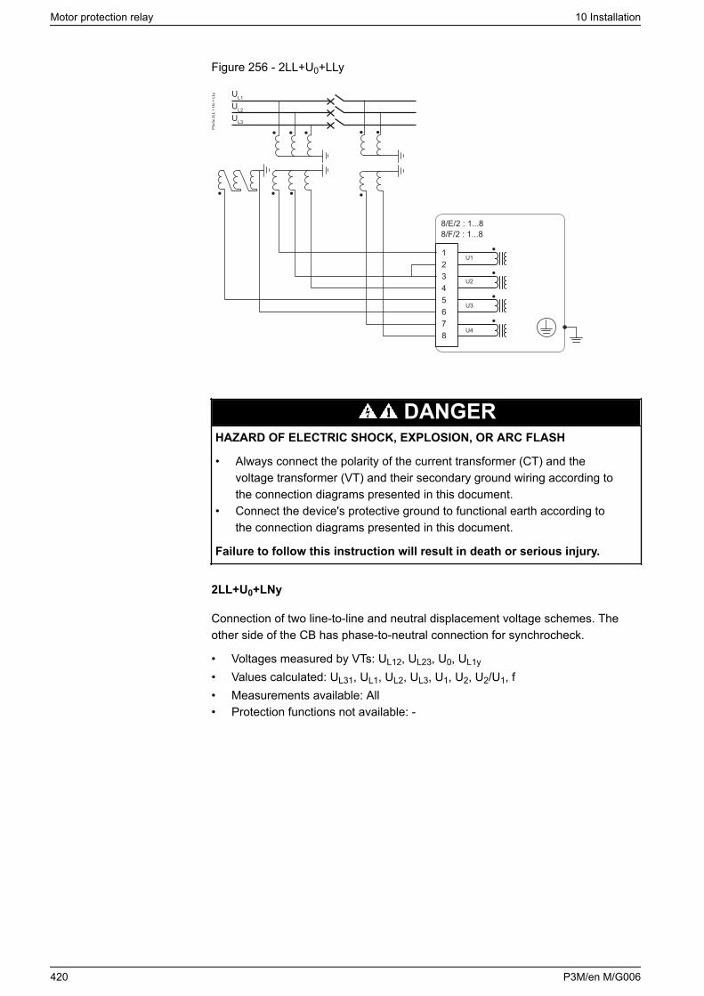
Figure 256 - 2LL+U0+LLy
8/E/2 : 1...88/F/2 : 1...8
12345678
U1
U2
U3
U4
P3x3
x 2L
L +
Uo
+ LL
y
UL2
UL3
UL1
DANGERHAZARD OF ELECTRIC SHOCK, EXPLOSION, OR ARC FLASH
• Always connect the polarity of the current transformer (CT) and thevoltage transformer (VT) and their secondary ground wiring according tothe connection diagrams presented in this document.
• Connect the device's protective ground to functional earth according tothe connection diagrams presented in this document.
Failure to follow this instruction will result in death or serious injury.
2LL+U0+LNy
Connection of two line-to-line and neutral displacement voltage schemes. Theother side of the CB has phase-to-neutral connection for synchrocheck.
• Voltages measured by VTs: UL12, UL23, U0, UL1y
• Values calculated: UL31, UL1, UL2, UL3, U1, U2, U2/U1, f• Measurements available: All• Protection functions not available: -
Motor protection relay 10 Installation
420 P3M/en M/G006
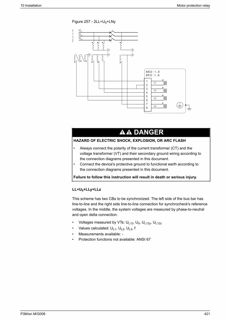
Figure 257 - 2LL+U0+LNy
8/E/2 : 1...88/F/2 : 1...8
12345678
U1
U2
U3
U4
P3x3
x 2
LL +
Uo
+ LN
y
UL2
UL3
UL1
DANGERHAZARD OF ELECTRIC SHOCK, EXPLOSION, OR ARC FLASH
• Always connect the polarity of the current transformer (CT) and thevoltage transformer (VT) and their secondary ground wiring according tothe connection diagrams presented in this document.
• Connect the device's protective ground to functional earth according tothe connection diagrams presented in this document.
Failure to follow this instruction will result in death or serious injury.
LL+U0+LLy+LLz
This scheme has two CBs to be synchronized. The left side of the bus bar hasline-to-line and the right side line-to-line connection for synchrocheck's referencevoltages. In the middle, the system voltages are measured by phase-to-neutraland open delta connection.
• Voltages measured by VTs: UL12, U0, UL12y, UL12z
• Values calculated: UL1, UL2, UL3, f• Measurements available: -• Protection functions not available: ANSI 67
10 Installation Motor protection relay
P3M/en M/G006 421
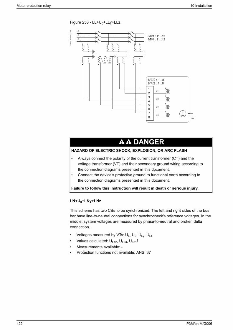
Figure 258 - LL+U0+LLy+LLz
P3x3
x LL
+ U
o +
LLy
+ LL
z
8/E/2 : 1...88/F/2 : 1...8
12345678
U1
U2
U3
U4
8/C/1 : 11...128/D/1 : 11...12
UL2
UL3
UL1
DANGERHAZARD OF ELECTRIC SHOCK, EXPLOSION, OR ARC FLASH
• Always connect the polarity of the current transformer (CT) and thevoltage transformer (VT) and their secondary ground wiring according tothe connection diagrams presented in this document.
• Connect the device's protective ground to functional earth according tothe connection diagrams presented in this document.
Failure to follow this instruction will result in death or serious injury.
LN+U0+LNy+LNz
This scheme has two CBs to be synchronized. The left and right sides of the busbar have line-to-neutral connections for synchrocheck's reference voltages. In themiddle, system voltages are measured by phase-to-neutral and broken deltaconnection.
• Voltages measured by VTs: UL, U0, ULy, ULz
• Values calculated: UL12, UL23, UL31f• Measurements available: -• Protection functions not available: ANSI 67
Motor protection relay 10 Installation
422 P3M/en M/G006
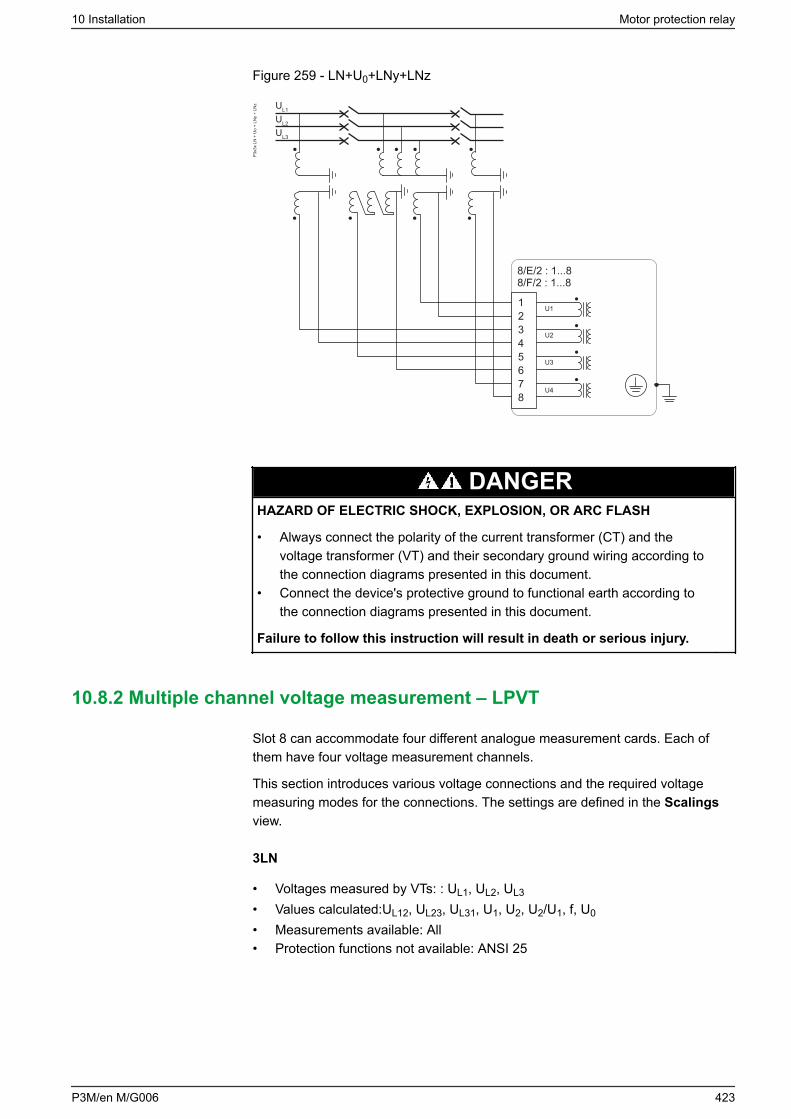
Figure 259 - LN+U0+LNy+LNz
P3x3
x LN
+ U
o +
LNy
+ LN
z
8/E/2 : 1...88/F/2 : 1...8
12345678
U1
U2
U3
U4
UL2
UL3
UL1
DANGERHAZARD OF ELECTRIC SHOCK, EXPLOSION, OR ARC FLASH
• Always connect the polarity of the current transformer (CT) and thevoltage transformer (VT) and their secondary ground wiring according tothe connection diagrams presented in this document.
• Connect the device's protective ground to functional earth according tothe connection diagrams presented in this document.
Failure to follow this instruction will result in death or serious injury.
10.8.2 Multiple channel voltage measurement – LPVT
Slot 8 can accommodate four different analogue measurement cards. Each ofthem have four voltage measurement channels.
This section introduces various voltage connections and the required voltagemeasuring modes for the connections. The settings are defined in the Scalingsview.
3LN
• Voltages measured by VTs: : UL1, UL2, UL3
• Values calculated:UL12, UL23, UL31, U1, U2, U2/U1, f, U0
• Measurements available: All• Protection functions not available: ANSI 25
10 Installation Motor protection relay
P3M/en M/G006 423

Figure 260 - 3LN
8/E/2 : 1...88/F/2 : 1...8
12345678
U1
U2
U3
U4
P3x3
x 3
LN
UL2
UL3
UL1
DANGERHAZARD OF ELECTRIC SHOCK, EXPLOSION, OR ARC FLASH
• Always connect the polarity of the current transformer (CT) and thevoltage transformer (VT) and their secondary ground wiring according tothe connection diagrams presented in this document.
• Connect the device's protective ground to functional earth according tothe connection diagrams presented in this document.
Failure to follow this instruction will result in death or serious injury.
3LN+U0
This connection is typically used for feeder and motor protection schemes.
• Voltages measured by VTs: UL1, UL2, UL3, U0
• Values calculated: UL12, UL23, UL31, U1, U2, U2/U1, f• Measurements available: All• Protection functions not available: ANSI 25
Motor protection relay 10 Installation
424 P3M/en M/G006
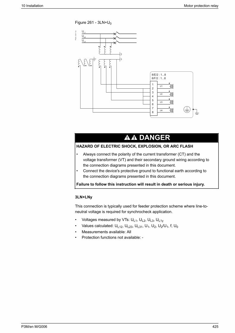
Figure 261 - 3LN+U0
8/E/2 : 1...88/F/2 : 1...8
12345678
U1
U2
U3
U4
P3x3
x 3
LN +
Uo
UL2
UL3
UL1
DANGERHAZARD OF ELECTRIC SHOCK, EXPLOSION, OR ARC FLASH
• Always connect the polarity of the current transformer (CT) and thevoltage transformer (VT) and their secondary ground wiring according tothe connection diagrams presented in this document.
• Connect the device's protective ground to functional earth according tothe connection diagrams presented in this document.
Failure to follow this instruction will result in death or serious injury.
3LN+LNy
This connection is typically used for feeder protection scheme where line-to-neutral voltage is required for synchrocheck application.
• Voltages measured by VTs: UL1, UL2, UL3, UL1y
• Values calculated: UL12, UL23, UL31, U1, U2, U2/U1, f, U0
• Measurements available: All• Protection functions not available: -
10 Installation Motor protection relay
P3M/en M/G006 425
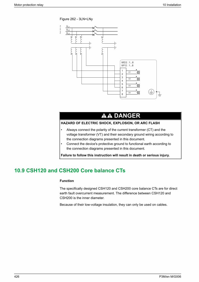
Figure 262 - 3LN+LNy
UL2
UL3
UL1
8/E/2 : 1...88/F/2 : 1...8
12345678
U1
U2
U3
U4
P3x3
x 3
LN +
LN
y
DANGERHAZARD OF ELECTRIC SHOCK, EXPLOSION, OR ARC FLASH
• Always connect the polarity of the current transformer (CT) and thevoltage transformer (VT) and their secondary ground wiring according tothe connection diagrams presented in this document.
• Connect the device's protective ground to functional earth according tothe connection diagrams presented in this document.
Failure to follow this instruction will result in death or serious injury.
10.9 CSH120 and CSH200 Core balance CTs
Function
The specifically designed CSH120 and CSH200 core balance CTs are for directearth fault overcurrent measurement. The difference between CSH120 andCSH200 is the inner diameter.
Because of their low-voltage insulation, they can only be used on cables.
Motor protection relay 10 Installation
426 P3M/en M/G006
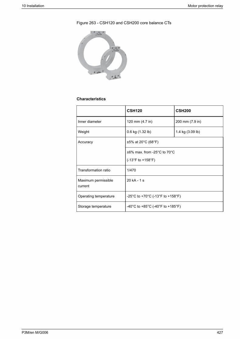
Figure 263 - CSH120 and CSH200 core balance CTs
Characteristics
CSH120 CSH200
Inner diameter 120 mm (4.7 in) 200 mm (7.9 in)
Weight 0.6 kg (1.32 lb) 1.4 kg (3.09 lb)
Accuracy ±5% at 20°C (68°F)
±6% max. from -25°C to 70°C
(-13°F to +158°F)
Transformation ratio 1/470
Maximum permissiblecurrent
20 kA - 1 s
Operating temperature -25°C to +70°C (-13°F to +158°F)
Storage temperature -40°C to +85°C (-40°F to +185°F)
10 Installation Motor protection relay
P3M/en M/G006 427
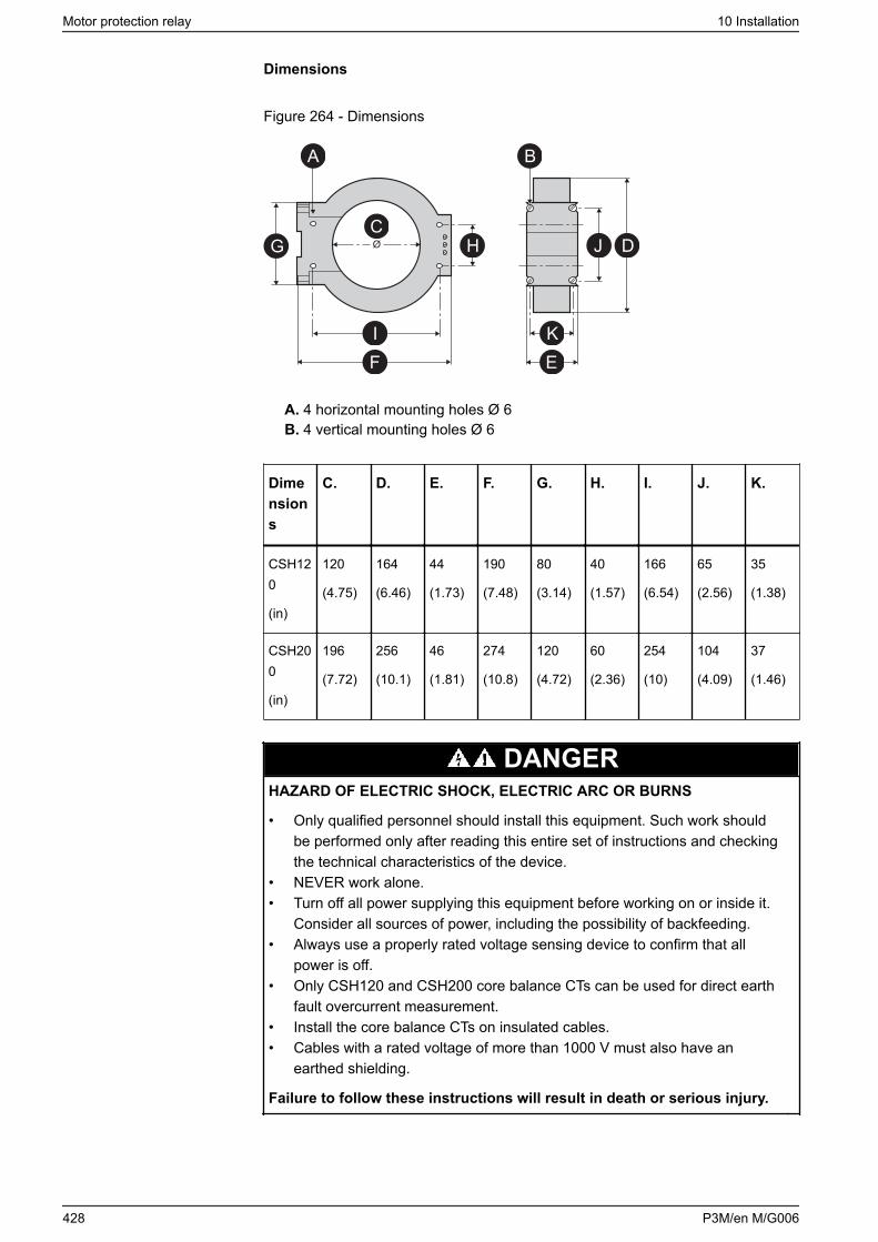
Dimensions
Figure 264 - Dimensions
CDJH
KE
IF
G
A B
A. 4 horizontal mounting holes Ø 6B. 4 vertical mounting holes Ø 6
Dimensions
C. D. E. F. G. H. I. J. K.
CSH120
(in)
120
(4.75)
164
(6.46)
44
(1.73)
190
(7.48)
80
(3.14)
40
(1.57)
166
(6.54)
65
(2.56)
35
(1.38)
CSH200
(in)
196
(7.72)
256
(10.1)
46
(1.81)
274
(10.8)
120
(4.72)
60
(2.36)
254
(10)
104
(4.09)
37
(1.46)
DANGERHAZARD OF ELECTRIC SHOCK, ELECTRIC ARC OR BURNS
• Only qualified personnel should install this equipment. Such work shouldbe performed only after reading this entire set of instructions and checkingthe technical characteristics of the device.
• NEVER work alone.• Turn off all power supplying this equipment before working on or inside it.
Consider all sources of power, including the possibility of backfeeding.• Always use a properly rated voltage sensing device to confirm that all
power is off.• Only CSH120 and CSH200 core balance CTs can be used for direct earth
fault overcurrent measurement.• Install the core balance CTs on insulated cables.• Cables with a rated voltage of more than 1000 V must also have an
earthed shielding.
Failure to follow these instructions will result in death or serious injury.
Motor protection relay 10 Installation
428 P3M/en M/G006
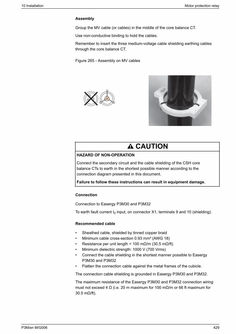
Assembly
Group the MV cable (or cables) in the middle of the core balance CT.
Use non-conductive binding to hold the cables.
Remember to insert the three medium-voltage cable shielding earthing cablesthrough the core balance CT.
Figure 265 - Assembly on MV cables
CAUTIONHAZARD OF NON-OPERATION
Connect the secondary circuit and the cable shielding of the CSH corebalance CTs to earth in the shortest possible manner according to theconnection diagram presented in this document.
Failure to follow these instructions can result in equipment damage.
Connection
Connection to Easergy P3M30 and P3M32
To earth fault current I0 input, on connector X1, terminals 9 and 10 (shielding).
Recommended cable
• Sheathed cable, shielded by tinned copper braid• Minimum cable cross-section 0.93 mm² (AWG 18)• Resistance per unit length < 100 mΩ/m (30.5 mΩ/ft)• Minimum dielectric strength: 1000 V (700 Vrms)• Connect the cable shielding in the shortest manner possible to Easergy
P3M30 and P3M32• Flatten the connection cable against the metal frames of the cubicle.
The connection cable shielding is grounded in Easergy P3M30 and P3M32.
The maximum resistance of the Easergy P3M30 and P3M32 connection wiringmust not exceed 4 Ω (i.e. 20 m maximum for 100 mΩ/m or 66 ft maximum for30.5 mΩ/ft).
10 Installation Motor protection relay
P3M/en M/G006 429
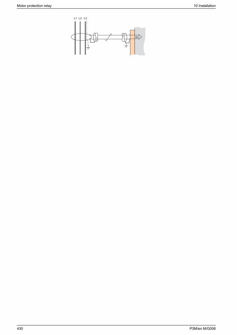
Motor protection relay 10 Installation
430 P3M/en M/G006
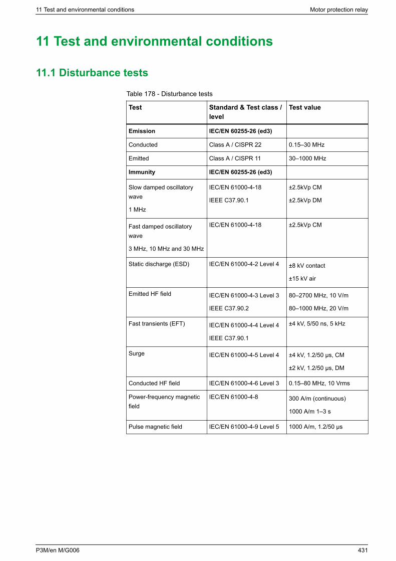
11 Test and environmental conditions
11.1 Disturbance tests
Table 178 - Disturbance tests
Test Standard & Test class /level
Test value
Emission IEC/EN 60255-26 (ed3)
Conducted Class A / CISPR 22 0.15–30 MHz
Emitted Class A / CISPR 11 30–1000 MHz
Immunity IEC/EN 60255-26 (ed3)
Slow damped oscillatorywave
1 MHz
IEC/EN 61000-4-18
IEEE C37.90.1
±2.5kVp CM
±2.5kVp DM
Fast damped oscillatorywave
3 MHz, 10 MHz and 30 MHz
IEC/EN 61000-4-18 ±2.5kVp CM
Static discharge (ESD) IEC/EN 61000-4-2 Level 4 ±8 kV contact
±15 kV air
Emitted HF field IEC/EN 61000-4-3 Level 3
IEEE C37.90.2
80–2700 MHz, 10 V/m
80–1000 MHz, 20 V/m
Fast transients (EFT) IEC/EN 61000-4-4 Level 4
IEEE C37.90.1
±4 kV, 5/50 ns, 5 kHz
Surge IEC/EN 61000-4-5 Level 4 ±4 kV, 1.2/50 μs, CM
±2 kV, 1.2/50 μs, DM
Conducted HF field IEC/EN 61000-4-6 Level 3 0.15–80 MHz, 10 Vrms
Power-frequency magneticfield
IEC/EN 61000-4-8 300 A/m (continuous)
1000 A/m 1–3 s
Pulse magnetic field IEC/EN 61000-4-9 Level 5 1000 A/m, 1.2/50 μs
11 Test and environmental conditions Motor protection relay
P3M/en M/G006 431
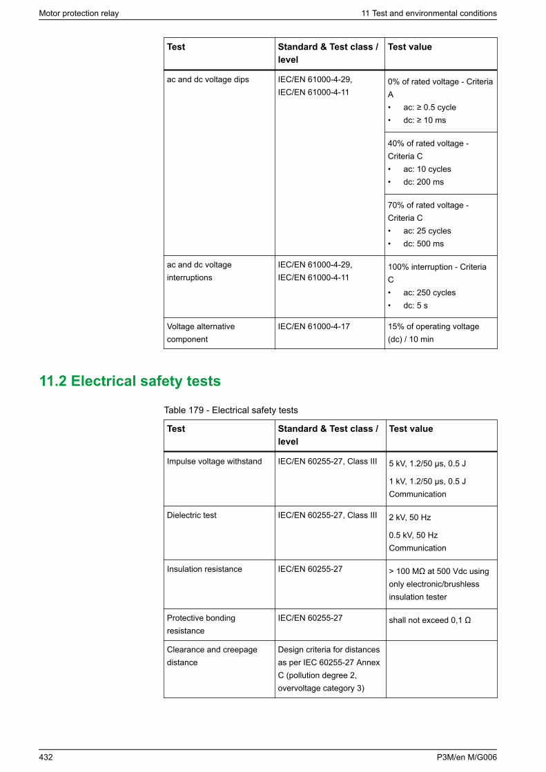
Test Standard & Test class /level
Test value
ac and dc voltage dips IEC/EN 61000-4-29,IEC/EN 61000-4-11
0% of rated voltage - CriteriaA• ac: ≥ 0.5 cycle• dc: ≥ 10 ms
40% of rated voltage -Criteria C• ac: 10 cycles• dc: 200 ms
70% of rated voltage -Criteria C• ac: 25 cycles• dc: 500 ms
ac and dc voltageinterruptions
IEC/EN 61000-4-29,IEC/EN 61000-4-11
100% interruption - CriteriaC• ac: 250 cycles• dc: 5 s
Voltage alternativecomponent
IEC/EN 61000-4-17 15% of operating voltage(dc) / 10 min
11.2 Electrical safety tests
Table 179 - Electrical safety tests
Test Standard & Test class /level
Test value
Impulse voltage withstand IEC/EN 60255-27, Class III 5 kV, 1.2/50 μs, 0.5 J
1 kV, 1.2/50 μs, 0.5 JCommunication
Dielectric test IEC/EN 60255-27, Class III 2 kV, 50 Hz
0.5 kV, 50 HzCommunication
Insulation resistance IEC/EN 60255-27 > 100 MΩ at 500 Vdc usingonly electronic/brushlessinsulation tester
Protective bondingresistance
IEC/EN 60255-27 shall not exceed 0,1 Ω
Clearance and creepagedistance
Design criteria for distancesas per IEC 60255-27 AnnexC (pollution degree 2,overvoltage category 3)
Motor protection relay 11 Test and environmental conditions
432 P3M/en M/G006

Test Standard & Test class /level
Test value
Burden IEC 60255-1
Contact performance IEC 60255-1
11.3 Mechanical tests
Table 180 - Mechanical tests
Test Standard & Test class /level
Test value
Device in operation
Vibrations IEC 60255-21-1, Class II /IEC 60068-2-6, Fc
1 Gn, 10 Hz – 150 Hz
Shocks IEC 60255-21-2, Class II /IEC 60068-2-27, Ea
10 Gn / 11 ms
Seismic IEC 60255-21-3 Method A,Class II
2 G horizontal / 1 G vertical ,1–35 Hz
Device de-energized
Vibrations IEC 60255-21-1, Class II /IEC 60068-2-6, Fc
2 Gn, 10 Hz – 150 Hz
Shocks IEC 60255-21-2, Class II /IEC 60068-2-27, Ea
30 Gn / 11 ms
Bump IEC 60255-21-2, Class II /IEC 60068-2-27, Ea
20 Gn / 16 ms
11.4 Environmental tests
Table 181 - Environmental tests
Test Standard & Test class /level
Test value
Device in operation
Dry heat EN / IEC 60068-2-2, Bd 70°C (158°F)
UL 50891 55°C (131°F)
Cold EN / IEC 60068-2-1, Ad -40°C (-40°F)
Damp heat, cyclic EN / IEC 60068-2-30, Db From 25°C (77°F) to 55°C(131°F)
From 93% RH to 98% RH
Testing duration: 6 days
11 Test and environmental conditions Motor protection relay
P3M/en M/G006 433
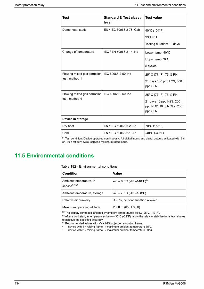
Test Standard & Test class /level
Test value
Damp heat, static EN / IEC 60068-2-78, Cab 40°C (104°F)
93% RH
Testing duration: 10 days
Change of temperature IEC / EN 60068-2-14, Nb Lower temp -40°C
Upper temp 70°C
5 cycles
Flowing mixed gas corrosiontest, method 1
IEC 60068-2-60, Ke 25° C (77° F), 75 % RH
21 days 100 ppb H2S, 500ppb SO2
Flowing mixed gas corrosiontest, method 4
IEC 60068-2-60, Ke 25° C (77° F), 75 % RH
21 days 10 ppb H2S, 200ppb NO2, 10 ppb CL2, 200ppb SO2
Device in storage
Dry heat EN / IEC 60068-2-2, Bb 70°C (158°F)
Cold EN / IEC 60068-2-1, Ab -40°C (-40°F)91 Test condition: Device operated continuously. All digital inputs and digital outputs activated with 5 son, 30 s off duty cycle, carrying maximum rated loads.
11.5 Environmental conditions
Table 182 - Environmental conditions
Condition Value
Ambient temperature, in-service92 93
-40 – 60°C (-40 –140°F)94
Ambient temperature, storage -40 – 70°C (-40 –158°F)
Relative air humidity < 95%, no condensation allowed
Maximum operating altitude 2000 m (6561.68 ft)92 The display contrast is affected by ambient temperatures below -25°C (-13°F).93 After a cold start, in temperatures below -30°C (-22°F), allow the relay to stabilize for a few minutesto achieve the specified accuracy.94 Recommended values with VYX 695 projection mounting frame:• device with 1 x raising frame → maximum ambient temperature 55°C• device with 2 x raising frame → maximum ambient temperature 50°C
Motor protection relay 11 Test and environmental conditions
434 P3M/en M/G006

11.6 Casing
Table 183 - Casing
Parameter Value
Degree of protection (IEC 60529) IP54 Front panel, IP20 rear side, IP10 rearside (if analog measurement card with ringlug connectors is used)
Dimensions (W x H x D) 270 x 176 x 230 mm / 10.63 x 6.93 x 9.06in
Weight 4.2 kg (9.272 lb) or higher (depends ofoptions)
11 Test and environmental conditions Motor protection relay
P3M/en M/G006 435

12 Maintenance
DANGERHAZARD OF ELECTRIC SHOCK, EXPLOSION, OR ARC FLASH
• Wear your personal protective equipment (PPE) and comply with the safeelectrical work practices. For clothing, see applicable local standards.
• Only qualified personnel should install this equipment. Such work shouldbe performed only after reading this entire set of instructions and checkingthe technical characteristics of the device.
• NEVER work alone.• Turn off all power supplying this equipment before working on or inside it.
Consider all sources of power, including the possibility of backfeeding.• Always use a properly rated voltage sensing device to ensure that all
power is off.• Do not open the secondary circuit of a live current transformer.• Always connect the polarity of the current transformer (CT) and the voltage
transformer (VT) and their secondary ground wiring according to theconnection diagrams presented in this document.
• Connect the device's protective ground to functional earth according to theconnection diagrams presented in this document.
Failure to follow this instruction will result in death or serious injury.
The Easergy P3 protection relays and arc flash detection products together withtheir extension units, communication accessories, arc flash detection sensors andcabling, later called “device”, require maintenance in work according to theirspecification. Keep a record of the maintenance actions. The maintenance caninclude, but is not limited to:• preventive maintenance• periodic testing• hardware cleaning• system status messages• spare parts• self-supervision
12.1 Preventive maintenance
Check the device visually when the switch gear is de-energized. During theinspection, pay attention to:
• dirty components• loose wire connections• damaged wiring• indicator lights• other mechanical connections
Perform visual inspection every three (3) years minimum.
Related topics2.5.7 Testing the LEDs and LCD screen
Motor protection relay 12 Maintenance
436 P3M/en M/G006

12.2 Periodic testing
Test the device periodically according to the end user's safety instructions andnational safety instructions or law. Carry out functional testing every five (5) yearsminimum.
Conduct the testing with a secondary injection principle for the protection stagesused in the device and its extension units.
In corrosive or offshore environments, carry out functional testing every three (3)years. For the testing procedures, see separate testing manuals.
12.3 Hardware cleaning
Special attention must be paid that the device do not become dirty. If cleaning isrequired, wipe out dirt from the units.
12.4 System status messages
If the device’s self checking detects an unindented system status, it will in mostcases provide an alarm by activating the service LED and indication statusnotification on the LCD screen. If this happens, store the possible message andcontact your local representative for further guidance.
12.5 Spare parts
Use an entire unit as a spare part for the device to be replaced. Always storespare parts in storage areas that meet the requirements stated in the userdocumentation.
12.6 Self-supervision
NOTICELOSS OF PROTECTION OR RISK OF NUISANCE TRIPPING
• If the relay is no longer supplied with power or is in permanent fault state,the protection functions are no longer active and all the Easergy P3 digitaloutputs are dropped out.
• Check that the operating mode and SF relay wiring are compatible with theinstallation.
Failure to follow these instructions can result in equipment damage andunwanted shutdown of the electrical installation.
Description
The electronic parts and the associated circuitry as well as the program executionare supervised by means of a separate watchdog circuit. Besides supervising thedevice, the watchdog circuit attempts to restart the microcontroller in an
12 Maintenance Motor protection relay
P3M/en M/G006 437
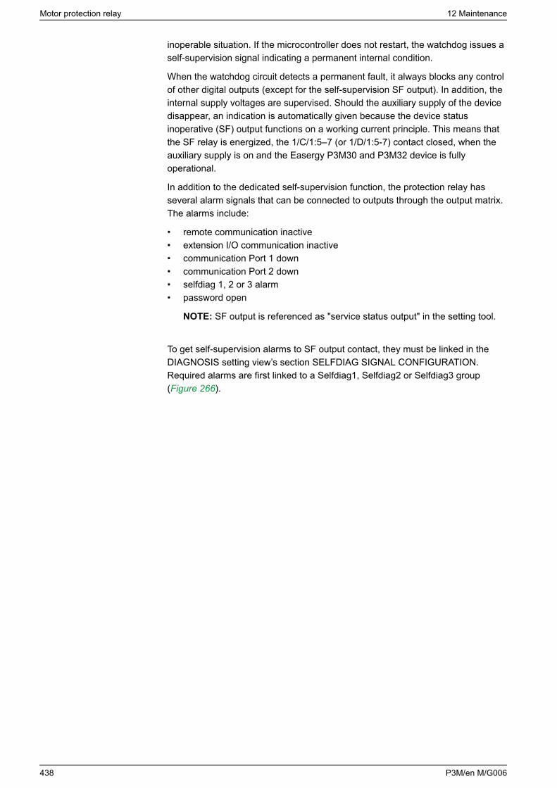
inoperable situation. If the microcontroller does not restart, the watchdog issues aself-supervision signal indicating a permanent internal condition.
When the watchdog circuit detects a permanent fault, it always blocks any controlof other digital outputs (except for the self-supervision SF output). In addition, theinternal supply voltages are supervised. Should the auxiliary supply of the devicedisappear, an indication is automatically given because the device statusinoperative (SF) output functions on a working current principle. This means thatthe SF relay is energized, the 1/C/1:5–7 (or 1/D/1:5-7) contact closed, when theauxiliary supply is on and the Easergy P3M30 and P3M32 device is fullyoperational.
In addition to the dedicated self-supervision function, the protection relay hasseveral alarm signals that can be connected to outputs through the output matrix.The alarms include:
• remote communication inactive• extension I/O communication inactive• communication Port 1 down• communication Port 2 down• selfdiag 1, 2 or 3 alarm• password open
NOTE: SF output is referenced as "service status output" in the setting tool.
To get self-supervision alarms to SF output contact, they must be linked in theDIAGNOSIS setting view’s section SELFDIAG SIGNAL CONFIGURATION.Required alarms are first linked to a Selfdiag1, Selfdiag2 or Selfdiag3 group(Figure 266).
Motor protection relay 12 Maintenance
438 P3M/en M/G006
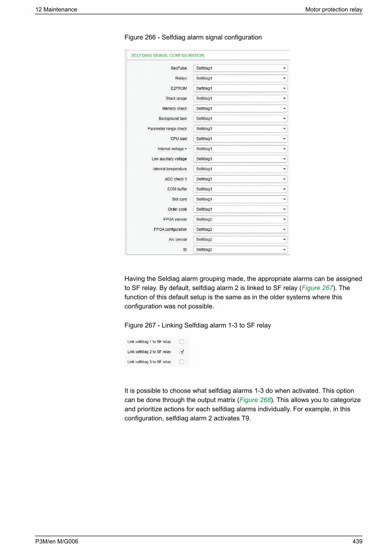
Figure 266 - Selfdiag alarm signal configuration
Having the Seldiag alarm grouping made, the appropriate alarms can be assignedto SF relay. By default, selfdiag alarm 2 is linked to SF relay (Figure 267). Thefunction of this default setup is the same as in the older systems where thisconfiguration was not possible.
Figure 267 - Linking Selfdiag alarm 1-3 to SF relay
It is possible to choose what selfdiag alarms 1-3 do when activated. This optioncan be done through the output matrix (Figure 268). This allows you to categorizeand prioritize actions for each selfdiag alarms individually. For example, in thisconfiguration, selfdiag alarm 2 activates T9.
12 Maintenance Motor protection relay
P3M/en M/G006 439
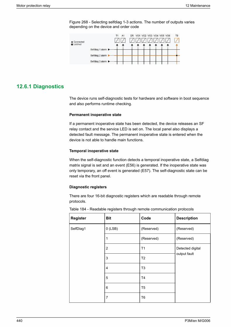
Figure 268 - Selecting selfdiag 1-3 actions. The number of outputs variesdepending on the device and order code
12.6.1 Diagnostics
The device runs self-diagnostic tests for hardware and software in boot sequenceand also performs runtime checking.
Permanent inoperative state
If a permanent inoperative state has been detected, the device releases an SFrelay contact and the service LED is set on. The local panel also displays adetected fault message. The permanent inoperative state is entered when thedevice is not able to handle main functions.
Temporal inoperative state
When the self-diagnostic function detects a temporal inoperative state, a Selfdiagmatrix signal is set and an event (E56) is generated. If the inoperative state wasonly temporary, an off event is generated (E57). The self-diagnostic state can bereset via the front panel.
Diagnostic registers
There are four 16-bit diagnostic registers which are readable through remoteprotocols.
Table 184 - Readable registers through remote communication protocols
Register Bit Code Description
SelfDiag1 0 (LSB) (Reserved) (Reserved)
1 (Reserved) (Reserved)
2 T1 Detected digitaloutput fault
3 T2
4 T3
5 T4
6 T5
7 T6
Motor protection relay 12 Maintenance
440 P3M/en M/G006
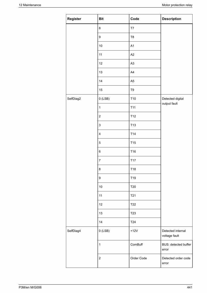
Register Bit Code Description
8 T7
9 T8
10 A1
11 A2
12 A3
13 A4
14 A5
15 T9
SelfDiag2 0 (LSB) T10 Detected digitaloutput fault
1 T11
2 T12
3 T13
4 T14
5 T15
6 T16
7 T17
8 T18
9 T19
10 T20
11 T21
12 T22
13 T23
14 T24
SelfDiag4 0 (LSB) +12V Detected internalvoltage fault
1 ComBuff BUS: detected buffererror
2 Order Code Detected order codeerror
12 Maintenance Motor protection relay
P3M/en M/G006 441

Register Bit Code Description
3 Slot card Detected option carderror
4 FPGA conf. Detected FPGAconfiguration error
5 I/O unit Detected ARC I/Ounit error
6 Arc sensor Detected faulty arcsensor
7 QD-card error Detected QD-carderror
8 BI Detected ARC BIerror
9 LowAux Low auxiliary supplyvoltage
The code is displayed in self-diagnostic events and on the diagnostic menu on thelocal panel and Easergy Pro.
NOTE: All signals are not necessarily available in every Easergy P3 product.
12.7 Arc flash detection system maintenance
The device requires maintenance to ensure that it works according to thespecification.
DANGERHAZARD OF UNEXPECTED SYSTEM OPERATION
Carry out periodic system testing as per the testing recommendation in thismanual or if the protection system scheme has been changed.
Failure to follow these instructions will result in death or serious injury.
DANGERHAZARD OF UNEXPECTED SYSTEM OPERATION
• If the arc flash detection unit is no longer supplied with power or is inpermanent non-operational state, the protection functions are no longeractive and all the output contacts are dropped out.
• To detect a power-off or a permanent fault state, connect the watchdog(SF) output contact to a monitoring device such as SCADA or DCS.
Failure to follow these instructions will result in death or serious injury.
Keep record of the maintenance actions performed for the system.
Motor protection relay 12 Maintenance
442 P3M/en M/G006

The maintenance can include but is not limited to:• visual inspection• periodic testing• hardware cleaning• sensor condition and positioning check• checking the obstruction of sensors
12.7.1 Visual inspection
Do visual inspection once every three (3) years minimum.
1. De-energize the switchgear.
2. Inspect the device, sensors and cabling.Pay attention to: possible dirty arc sensors loose wire connections damaged wiring indicator lights (device start-up) other mechanical connections
12.7.2 Hardware cleaning
Pay special attention to ensure that the device, its extension units and sensors donot become dirty.
DANGERHAZARD OF UNEXPECTED SYSTEM OPERATION
• Do not use any type of solvents or gasoline to clean the device, sensorsor cables.
• When cleaning the sensor, make sure that the cleaning solution does notcontact anything other than the sensor.
Failure to follow these instructions will result in death or serious injury.
• If cleaning is required, wipe out dirt from the device.• Use a dry cleaning cloth or equivalent together with mild soapy water to clean
any residues from the light sensor.
12.7.3 Sensor condition and positioning check
Always check that the sensor positioning remains as it was originally designedafter:• commissioning• sensor replacement• modification procedure• cleaning• arc flash fault• periodic testing
12 Maintenance Motor protection relay
P3M/en M/G006 443

Check for obstruction of the sensors.
Motor protection relay 12 Maintenance
444 P3M/en M/G006
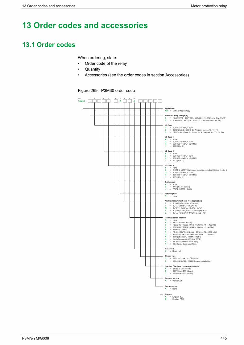
13 Order codes and accessories
13.1 Order codes
When ordering, state:• Order code of the relay• Quantity• Accessories (see the order codes in section Accessories)
Figure 269 - P3M30 order code
Slot 1 2 3 4 5 6 7 8 9 10
P3M30 - - A A -
ApplicationM30 = Motor protection relay
Nominal Supply voltage [V]C = Power C 110 - 230 V (80 .. 264Vac/dc, 5 x DO heavy duty, A1, SF)D = Power D 24 - 48 V (18 .. 60Vdc, 5 x DO heavy duty, A1, SF)
I/O Card IG = 6DI+4DO (6 x DI, 4 x DO)
I/O Card IIA = NoneG = 6DI+4DO (6 x DI, 4 x DO)H = 6DI+4DO (6 x DI, 4 x DO(NC))I = 10DI (10 x DI)
I/O Card IIIA = NoneG = 6DI+4DO (6 x DI, 4 x DO)H = 6DI+4DO (6 x DI, 4 x DO(NC))I = 10DI (10 x DI)
I/O Card IVA = None
G = 6DI+4DO (6 x DI, 4 x DO)H = 6DI+4DO (6 x DI, 4 x DO(NC))I = 10DI (10 x DI)
Option card IA = NoneD = 4Arc (4 x Arc sensor)K = RS232 (RS232, IRIG-B)
Future optionA = None
Analog measurement card (See application)
1 = 3L(5/1A) + 2Io (5/1A+1/0,2A) ringlug + 4U2 = 3L(1A) + 2Io (5/1A+1/0.2A) ringlug + 4U
Communication interface IA = NoneB = RS232 (RS232, IRIG-B)C = RS232+RJ (RS232, IRIG-B + Ethernet RJ-45 100 Mbs)D = RS232+LC (RS232, IRIG-B + Ethernet LC 100 Mbs)
N = 2xRJ (Ethernet RJ 100 Mbs, RSTP)O = 2xLC (Ethernet LC 100 Mbs, RSTP) P = PP (Plastic / Plastic serial fibre)R = GG (Glass / Glass serial fibre)
Display typeB = 128x128 (128 x 128 LCD matrix)C = 128x128Ext (128 x 128 LCD matrix, detachable) (1
Nominal DI voltage (voltage withstand)A = 24Vdc/ac (255 Vdc/ac)B = 110 Vdc/ac (255 Vdc/ac)C = 220 Vdc/ac (255 Vdc/ac)
ReservedA = Reserved
Product versionVersion 2.1A =
Future optionNoneA =
RegionEnglish, IECEnglish, ANSI
AB
==
E = 2xRS485 (2-wire)F = RS485+RJ (RS485 2-wire + Ethernet RJ-45 100 Mbs)G = RS485+LC (RS485 2-wire + Ethernet LC 100 Mbs)
B = 3BIO+2Arc (3 x BI/BO, 2 x Arc point sensor, T2, T3, T4)C = F2BIO+1Arc (Fibre 2 x BI/BO, 1 x Arc loop sensor, T2, T3, T4)
D = 2IGBT (2 x IGBT High speed outputs), excludes I/O Card III, slot 4
E = 3L(5/1A)+2Io (5/1A+1/0,2A)+4UF = 3L(1A)+2Io (5/1A+1/0.2A)+4UM = 3LPCT + 2Io(5/1A+1/0,2A) + 5LPVT (1
13 Order codes and accessories Motor protection relay
P3M/en M/G006 445
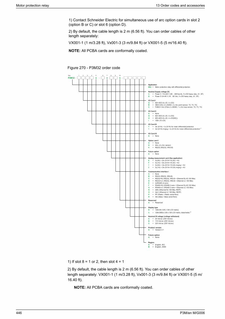
1) Contact Schneider Electric for simultaneous use of arc option cards in slot 2(option B or C) or slot 6 (option D).
2) By default, the cable length is 2 m (6.56 ft). You can order cables of otherlength separately:
VX001-1 (1 m/3.28 ft), Vx001-3 (3 m/9.84 ft) or VX001-5 (5 m/16.40 ft).
NOTE: All PCBA cards are conformally coated.
Figure 270 - P3M32 order code
Slot 1 2 3 4 5 6 7 8 9 10
P3M32 - - A A -A
ReservedA = Reserved
Product versionVersion 2.1A =
Future optionNoneA =
RegionEnglish, IECEnglish, ANSI
AB
==
ApplicationM32 = Motor protection relay with differential protection
Nominal Supply voltage [V]C = Power C 110-230 V (80 .. 264Vac/dc, 5 x DO heavy duty, A1, SF)D = Power D 24-48 V (18 .. 60 Vdc, 5 x DO heavy duty, A1, SF)
I/O Card IG = 6DI+4DO (6 x DI, 4 x DO)
I/O Card IIA = NoneG = 6DI+4DO (6 x DI, 4 x DO)H = 6DI+4DO (6 x DI, 4 x DO(NC))I = 10DI (10 x DI)
I/O Card III
1 = 3xI (5/1A) ringlug + Io (5/1A) for motor differential protection
I/O Card IVA = None
Option card IA = NoneD = 4Arc (4 x Arc sensor)K = RS232 (RS232, IRIG-B)
Future optionA = None
Analog measurement card (See application)
1 = 3L(5A) + 2Io (5/1A+1/0,2A) ringlug + 4U2 = 3L(1A) + 2Io (5/1A+1/0.2A) ringlug + 4U
Communication interface IA = NoneB = RS232 (RS232, IRIG-B)C = RS232+RJ (RS232, IRIG-B + Ethernet RJ-45 100 Mbs)D = RS232+LC (RS232, IRIG-B + Ethernet LC 100 Mbs)
N = 2xRJ (Ethernet RJ 100 Mbs, RSTP)O = 2xLC (Ethernet LC 100 Mbs, RSTP) P = PP (Plastic / Plastic serial fibre)R = GG (Glass / Glass serial fibre)
Display typeB = 128x128 (128 x 128 LCD matrix)C = 128x128Ext (128 x 128 LCD matrix, detachable) (2
Nominal DI voltage (voltage withstand)A = 24 Vdc/ac (255 Vdc/ac)B = 110 Vdc/ac (255 Vdc/ac)C = 220 Vdc/ac (255 Vdc/ac)
E = 2xRS485 (2-wire)F = RS485+RJ (RS485 2-wire + Ethernet RJ-45 100 Mbs)G = RS485+LC (RS485 2-wire + Ethernet LC 100 Mbs)
B = 3BIO+2Arc (3 x BI/BO, 2 x Arc point sensor, T2, T3, T4)C = F2BIO+1Arc (Fibre 2 x BI/BO, 1 x Arc loop sensor, T2, T3, T4)
E = 3L(5A) + 2Io (5/1A+1/0,2A) + 4UF = 3L(1A) + 2Io (5/1A+1/0.2A) + 4U
T = 3xI (5/1A) + Io (5/1A) for motor differential protection(1
1) If slot 8 = 1 or 2, then slot 4 = 1
2) By default, the cable length is 2 m (6.56 ft). You can order cables of otherlength separately: VX001-1 (1 m/3.28 ft), Vx001-3 (3 m/9.84 ft) or VX001-5 (5 m/16.40 ft).
NOTE: All PCBA cards are conformally coated.
Motor protection relay 13 Order codes and accessories
446 P3M/en M/G006
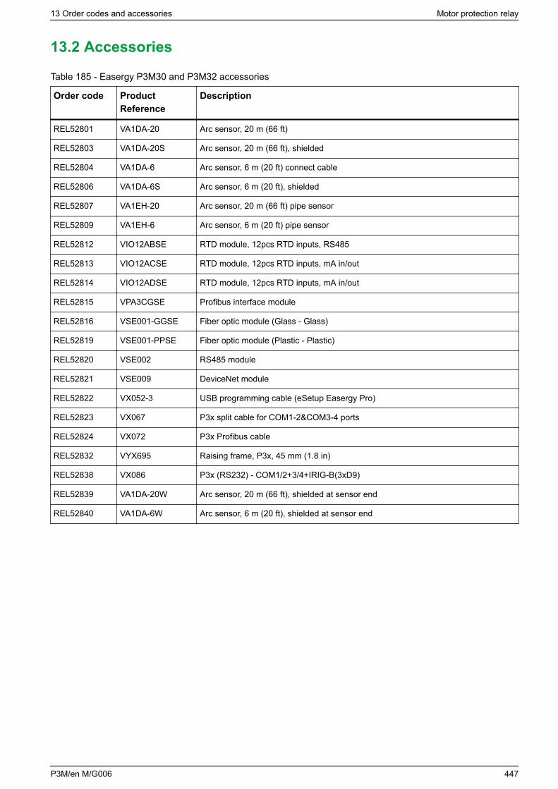
13.2 Accessories
Table 185 - Easergy P3M30 and P3M32 accessories
Order code ProductReference
Description
REL52801 VA1DA-20 Arc sensor, 20 m (66 ft)
REL52803 VA1DA-20S Arc sensor, 20 m (66 ft), shielded
REL52804 VA1DA-6 Arc sensor, 6 m (20 ft) connect cable
REL52806 VA1DA-6S Arc sensor, 6 m (20 ft), shielded
REL52807 VA1EH-20 Arc sensor, 20 m (66 ft) pipe sensor
REL52809 VA1EH-6 Arc sensor, 6 m (20 ft) pipe sensor
REL52812 VIO12ABSE RTD module, 12pcs RTD inputs, RS485
REL52813 VIO12ACSE RTD module, 12pcs RTD inputs, mA in/out
REL52814 VIO12ADSE RTD module, 12pcs RTD inputs, mA in/out
REL52815 VPA3CGSE Profibus interface module
REL52816 VSE001-GGSE Fiber optic module (Glass - Glass)
REL52819 VSE001-PPSE Fiber optic module (Plastic - Plastic)
REL52820 VSE002 RS485 module
REL52821 VSE009 DeviceNet module
REL52822 VX052-3 USB programming cable (eSetup Easergy Pro)
REL52823 VX067 P3x split cable for COM1-2&COM3-4 ports
REL52824 VX072 P3x Profibus cable
REL52832 VYX695 Raising frame, P3x, 45 mm (1.8 in)
REL52838 VX086 P3x (RS232) - COM1/2+3/4+IRIG-B(3xD9)
REL52839 VA1DA-20W Arc sensor, 20 m (66 ft), shielded at sensor end
REL52840 VA1DA-6W Arc sensor, 6 m (20 ft), shielded at sensor end
13 Order codes and accessories Motor protection relay
P3M/en M/G006 447
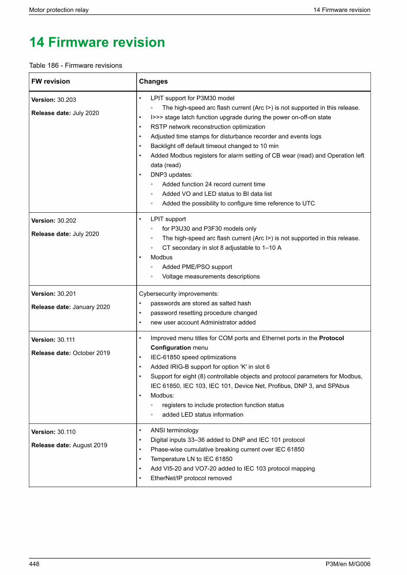
14 Firmware revisionTable 186 - Firmware revisions
FW revision Changes
Version: 30.203
Release date: July 2020
• LPIT support for P3M30 model The high-speed arc flash current (Arc I>) is not supported in this release.
• I>>> stage latch function upgrade during the power on-off-on state• RSTP network reconstruction optimization• Adjusted time stamps for disturbance recorder and events logs• Backlight off default timeout changed to 10 min• Added Modbus registers for alarm setting of CB wear (read) and Operation left
data (read)• DNP3 updates:
Added function 24 record current time Added VO and LED status to BI data list Added the possibility to configure time reference to UTC
Version: 30.202
Release date: July 2020
• LPIT support for P3U30 and P3F30 models only The high-speed arc flash current (Arc I>) is not supported in this release. CT secondary in slot 8 adjustable to 1–10 A
• Modbus Added PME/PSO support Voltage measurements descriptions
Version: 30.201
Release date: January 2020
Cybersecurity improvements:• passwords are stored as salted hash• password resetting procedure changed• new user account Administrator added
Version: 30.111
Release date: October 2019
• Improved menu titles for COM ports and Ethernet ports in the ProtocolConfiguration menu
• IEC-61850 speed optimizations• Added IRIG-B support for option 'K' in slot 6• Support for eight (8) controllable objects and protocol parameters for Modbus,
IEC 61850, IEC 103, IEC 101, Device Net, Profibus, DNP 3, and SPAbus• Modbus:
registers to include protection function status added LED status information
Version: 30.110
Release date: August 2019
• ANSI terminology• Digital inputs 33–36 added to DNP and IEC 101 protocol• Phase-wise cumulative breaking current over IEC 61850• Temperature LN to IEC 61850• Add VI5-20 and VO7-20 added to IEC 103 protocol mapping• EtherNet/IP protocol removed
Motor protection relay 14 Firmware revision
448 P3M/en M/G006
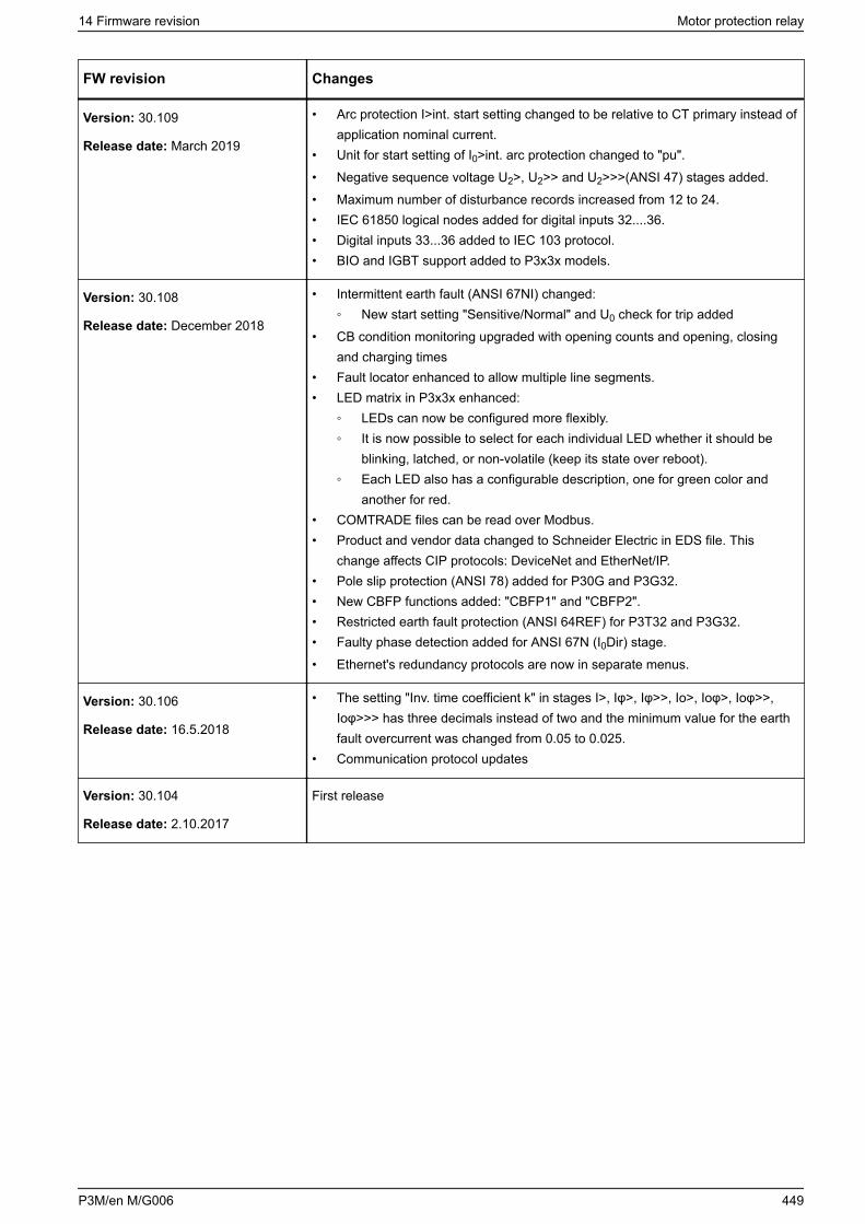
FW revision Changes
Version: 30.109
Release date: March 2019
• Arc protection I>int. start setting changed to be relative to CT primary instead ofapplication nominal current.
• Unit for start setting of I0>int. arc protection changed to "pu".• Negative sequence voltage U2>, U2>> and U2>>>(ANSI 47) stages added.• Maximum number of disturbance records increased from 12 to 24.• IEC 61850 logical nodes added for digital inputs 32....36.• Digital inputs 33...36 added to IEC 103 protocol.• BIO and IGBT support added to P3x3x models.
Version: 30.108
Release date: December 2018
• Intermittent earth fault (ANSI 67NI) changed: New start setting "Sensitive/Normal" and U0 check for trip added
• CB condition monitoring upgraded with opening counts and opening, closingand charging times
• Fault locator enhanced to allow multiple line segments.• LED matrix in P3x3x enhanced:
LEDs can now be configured more flexibly. It is now possible to select for each individual LED whether it should be
blinking, latched, or non-volatile (keep its state over reboot). Each LED also has a configurable description, one for green color and
another for red.• COMTRADE files can be read over Modbus.• Product and vendor data changed to Schneider Electric in EDS file. This
change affects CIP protocols: DeviceNet and EtherNet/IP.• Pole slip protection (ANSI 78) added for P30G and P3G32.• New CBFP functions added: "CBFP1" and "CBFP2".• Restricted earth fault protection (ANSI 64REF) for P3T32 and P3G32.• Faulty phase detection added for ANSI 67N (I0Dir) stage.• Ethernet's redundancy protocols are now in separate menus.
Version: 30.106
Release date: 16.5.2018
• The setting "Inv. time coefficient k" in stages I>, Iφ>, Iφ>>, Io>, Ioφ>, Ioφ>>,Ioφ>>> has three decimals instead of two and the minimum value for the earthfault overcurrent was changed from 0.05 to 0.025.
• Communication protocol updates
Version: 30.104
Release date: 2.10.2017
First release
14 Firmware revision Motor protection relay
P3M/en M/G006 449

Schneider Electric35 rue Joseph Monier92500 Rueil Malmaison - FrancePhone: +33 (0) 1 41 29 70 00www.schneider-electric.com
As standards, specifications, and designs change from time to time,please ask for confirmation of the information given in this publication.
© 2020 Schneider Electric All Rights Reserved.
P3M/en M/G006 — 07/2020