
Earth Attracts Us - Thames & Kosmos
48
WORKSHOP 1: POTATO TRAP Who Falls Up? How many times in your life have you taken a tumble? A dozen times? A hundred? On any one of those occasions, did you ever fall upwards? Or did you ever float around in the air like an astronaut? No, down you went, each time. The time in your life when you fell most often was probably when you were just learning to walk. No doubt, you were impatient to get your head in the air and stand on your own two feet. You wanted to move along much faster than you could when crawling along on all fours. You trained for weeks, trying your hardest to learn how to keep your balance. It was a mighty struggle against a formidable foe, a foe that tries its hardest to pull everyone and everything down to the ground. Its name: gravity. Gravity We usually don’t think much about gravity, but we always feel it. When we lift a pitcher of water, we feel it. When we pick up a pencil, we feel it, but less than with the pitcher of water. Earth’s gravity exerts its force equally on all physical bodies. So gravity must have something to do with weight — as we will learn in more detail with our first experiment, the potato trap. Earth Aracts Us KEYWORD: GRAVITY Gravity is the araction of the mass of Earth, the moon, or a planet, toward bodies at or near its surface. On Earth, the gravity at the surface is a downwards force that causes an acceleration equal to about 9.8 meters per second per second (m/s/s or m/s 2 ). You will also need: 70 cm (or about 30 in) piece of thread, 1 wooden match Be sure that the table is level and not tilted. Construct your assembly as shown in the picture. Aach the four long rods securely to one another. Then using anchor pins aach the two long frames to the boom rod, so the tower will not wobble. Next stand the tower on end and place it into the base plate. Finally using one anchor pin, aach the short rod to the top of the tower. Now we will determine the exact point where the potato, if dropped from above, will hit the base plate. First, rub the head off of a wooden matchstick and insert it into the slit of a shaft plug — that will be your stick on which your potato will be impaled. First, though, it will serve as a plumb bob. (A plumb bob always points downward, precisely toward the center of Earth.) Guide the thread through the last hole of the short rod on the top of the tower. Tie the end of the thread to the free end of the match in your “shaft plug-stick.” Lower the thread until the shaft plug-stick almost touches the base plate. Hold the thread in place by inserting a second shaft plug into the hole in the short rod. The shaft plug- stick on the other end of the thread should dangle just above the base plate. Wait until it stops swaying, then untie the shaft plug-stick from the string and insert it into the hole in the base plate closest to the spot above which it came to rest. This is where the potato will land. DID YOU KNOW? Gravity builds muscles In order to be able to walk upright, we grow sturdy bones and strong muscles. Our largest muscles are the ones that we use for walking — in our legs and rear end. If Earth’s gravity were much greater, we would walk around like hulking muscle-bound brutes. If it were much weaker, we would have stick-thin legs and skinny lile booms. Plants and animals would all look different too. NEED HELP? For larger images, go to www.thamesandkos- mos.com/support/pw 7 Earth Attracts Us
-
Upload
khangminh22 -
Category
Documents
-
view
1 -
download
0
Transcript of Earth Attracts Us - Thames & Kosmos
WORKSHOP 1: POTATO TRAP
Who Falls Up?How many times in your life have you taken a tumble? A dozen times? A hundred? On any one of those occasions, did you ever fall upwards? Or did you ever float around in the air like an astronaut? No, down you went, each time. The time in your life when you fell most often was probably when you were just learning to walk. No doubt, you were impatient to get your head in the air and stand on your own two feet. You wanted to move along much faster than you could when crawling along on all fours. You trained for weeks, trying your hardest to learn how to keep your balance. It was a mighty struggle against a formidable foe, a foe that tries its hardest to pull everyone and everything down to the ground. Its name: gravity.
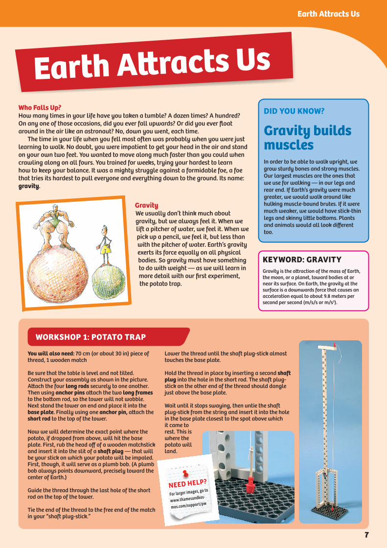
GravityWe usually don’t think much about gravity, but we always feel it. When we lift a pitcher of water, we feel it. When we pick up a pencil, we feel it, but less than with the pitcher of water. Earth’s gravity exerts its force equally on all physical bodies. So gravity must have something to do with weight — as we will learn in more detail with our first experiment, the potato trap.
Earth Attracts Us
KEYWORD: GRAVITYGravity is the attraction of the mass of Earth, the moon, or a planet, toward bodies at or near its surface. On Earth, the gravity at the surface is a downwards force that causes an acceleration equal to about 9.8 meters per second per second (m/s/s or m/s2).
You will also need: 70 cm (or about 30 in) piece of thread, 1 wooden match
Be sure that the table is level and not tilted. Construct your assembly as shown in the picture. Attach the four long rods securely to one another. Then using anchor pins attach the two long frames to the bottom rod, so the tower will not wobble. Next stand the tower on end and place it into the base plate. Finally using one anchor pin, attach the short rod to the top of the tower.
Now we will determine the exact point where the potato, if dropped from above, will hit the base plate. First, rub the head off of a wooden matchstick and insert it into the slit of a shaft plug — that will be your stick on which your potato will be impaled. First, though, it will serve as a plumb bob. (A plumb bob always points downward, precisely toward the center of Earth.)
Guide the thread through the last hole of the short rod on the top of the tower.
Tie the end of the thread to the free end of the match in your “shaft plug-stick.”
Lower the thread until the shaft plug-stick almost touches the base plate.
Hold the thread in place by inserting a second shaft plug into the hole in the short rod. The shaft plug-stick on the other end of the thread should dangle just above the base plate.
Wait until it stops swaying, then untie the shaft plug-stick from the string and insert it into the hole in the base plate closest to the spot above which it came to rest. This is where the potato will land.
DID YOU KNOW?
Gravity builds musclesIn order to be able to walk upright, we grow sturdy bones and strong muscles. Our largest muscles are the ones that we use for walking — in our legs and rear end. If Earth’s gravity were much greater, we would walk around like hulking muscle-bound brutes. If it were much weaker, we would have stick-thin legs and skinny little bottoms. Plants and animals would all look different too.
NEED HELP?
For larger images, go to
www.thamesandkos-
mos.com/support/pw
7
Earth Attracts Us
In reality, what we have determined with our locator is the center of gravity on the object’s surface — also known as center of area. In order to determine how deep the actual center of gravity lies within the three-dimensional object, we would need a more precise apparatus. In the case of the plate or the rods, this three-dimensional center would be about halfway through the object at the spot beneath its center of area.
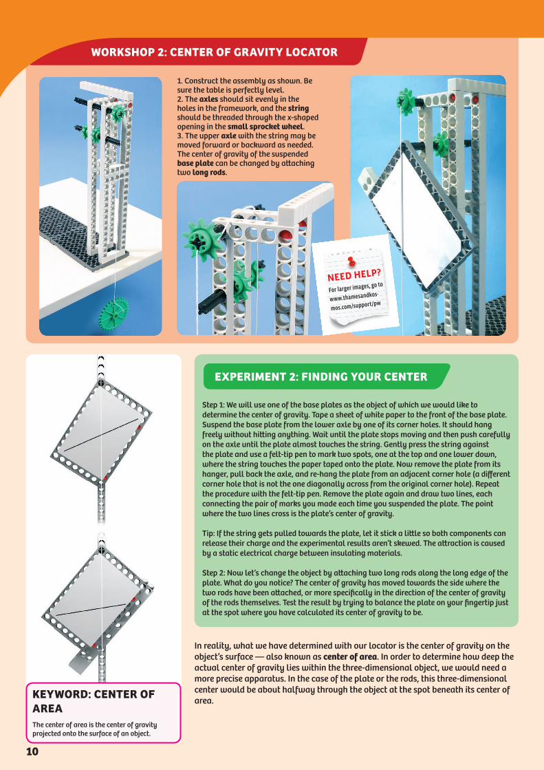
1. Construct the assembly as shown. Be sure the table is perfectly level.2. The axles should sit evenly in the holes in the framework, and the string should be threaded through the x-shaped opening in the small sprocket wheel. 3. The upper axle with the string may be moved forward or backward as needed. The center of gravity of the suspended base plate can be changed by attaching two long rods.
WORKSHOP 2: CENTER OF GRAVITY LOCATOR
NEED HELP?
For larger images, go to
www.thamesandkos-
mos.com/support/pw
Step 1: We will use one of the base plates as the object of which we would like to determine the center of gravity. Tape a sheet of white paper to the front of the base plate. Suspend the base plate from the lower axle by one of its corner holes. It should hang freely without hitting anything. Wait until the plate stops moving and then push carefully on the axle until the plate almost touches the string. Gently press the string against the plate and use a felt-tip pen to mark two spots, one at the top and one lower down, where the string touches the paper taped onto the plate. Now remove the plate from its hanger, pull back the axle, and re-hang the plate from an adjacent corner hole (a different corner hole that is not the one diagonally across from the original corner hole). Repeat the procedure with the felt-tip pen. Remove the plate again and draw two lines, each connecting the pair of marks you made each time you suspended the plate. The point where the two lines cross is the plate’s center of gravity.
Tip: If the string gets pulled towards the plate, let it stick a little so both components can release their charge and the experimental results aren’t skewed. The attraction is caused by a static electrical charge between insulating materials.
Step 2: Now let’s change the object by attaching two long rods along the long edge of the plate. What do you notice? The center of gravity has moved towards the side where the two rods have been attached, or more specifically in the direction of the center of gravity of the rods themselves. Test the result by trying to balance the plate on your fingertip just at the spot where you have calculated its center of gravity to be.
EXPERIMENT 2: FINDING YOUR CENTER
KEYWORD: CENTER OF AREAThe center of area is the center of gravity projected onto the surface of an object.
10

WORKSHOP 3: SAIL CAR
Speed Is No MysteryRemember how the potatoes fell very quickly from their starting point onto the spit in the potato experiment? How quickly did they fall? What do we mean by words like slowly and quickly, anyway? A snail creeps along at a snail’s pace, while a racecar whizzes by at Indy 500 speed. What does speed mean? It is an indication of the number of meters an object covers in a second. We could also say it specifies distance traveled over a period of time. So it’s just a matter of dividing the distance traveled by time.
What about Velocity?Velocity is similar to speed, but it also takes into account the direction of movement, not just the rate of movement.
Speed = meters (m) per seconds (s) = m/s Speed = kilometers (km) per hours (h) = km/h Speed = miles (mi) per hour (h) = mi/h
You will find the template for the sail on pages 2 and 3.
1. Assemble the chassis, securing the connection between the two base frames with tape.
Trace the template for the sail (see pages 2-3) onto a sheet of plastic (such as from a thick trash bag) and cut it out. Fold back the plastic at the edges of the sail, and secure the hems with tape.
2. Tape pre-cut sections of wooden skewers to the sail to provide it with a supporting framework.
3. Sew the sail with needle and thread to the mast, as shown. Don’t forget to tape the base frame pieces!
NEED HELP?
For larger images, go to
www.thamesandkos-
mos.com/support/pw
KEYWORD: SPEEDSpeed is the rate of motion of a body; distance traveled divided by travel time; the magnitude, but not the direction, of a velocity.
KEYWORD: VELOCITYVelocity is the speed and direction of a body.
12

WORKSHOP 4: ALL-TERRAIN VEHICLE WITH TREADS
Assemble the motor box and chassis as shown in the illustration. Be sure to orientate the long rods so that when the vehicle is viewed from the top or bottom two holes can be seen overhanging from each side of the motor box. Also the tread chains of the vehicle should be just long enough to fit without being too loose or too tight. It is okay if they are a little bit loose. The on/off switch lets you run the vehicle forward or in reverse.
On/Off Switch
NEED HELP?
For larger images, go to
www.thamesandkos-
mos.com/support/pw
DID YOU KNOW?
The historicsail vehicleThe ancient Egyptians used vehicles that sailed on land. Three thousand seven hundred years ago, the Qigong people drove sail-powered transport wagons 20,000 kilometers across the Chinese steppe. Around 1600, the Dutch inventor Simon Stevin’s sailing chariot “Wonder of the Hague” reached a speed of 33.5 km/h. The first steam locomotives were already running when, in 1853, the Windwagon Transport Company of Kansas City hoisted sails onto train cars. Up until the sixties, a sail car called “Aunt Anne” provided public transportation in Germany. Today, sail vehicles are mostly used for sport and entertainment.
2
1
13
Earth Attracts Us
Take one of the large sprocket wheels and drop it onto the ground. The drop may last about 0.5 seconds. Not much of an experiment, was it? Read on...
Now we will find out how fast our all-terrain vehicle goes. Find a room with a long stretch of open floor. Place a pencil on the floor at one end as your starting line. Have a second pencil ready for the finish line. Get a watch with a second hand, switch the motor to the forward mode, wait until the second hand is just before 12, and then set down the vehicle so its “headlights” are even with the starting line. Follow it as it drives along, keeping one eye on the watch. As soon as it has driven for 10 seconds, lay down your second pencil to mark the spot it has reached. Then measure the distance with a tape measure or ruler, and write it down.
If your vehicle goes, say, a distance of 6 meters (m) in 10 seconds (s), then in 1 second it goes exactly 6 meters divided by 10 seconds = 0.6 m/s (or 60 cm/s). Now for the speed in terms of hours: One hour equals 3,600 s. So in one hour the vehicle goes 3,600 x 0.6 m = 2.16 km. Its speed is therefore 2.16 km/h. That may not seem very fast, since a person can walk about 5 km in an hour. But your model, which is just 18 cm long, moves three times its own length each second! If a real vehicle 4 meters in length were to do that, it would have to go 13 m/s, or (multiplying x 3,600) 36 km/h. That’s about 22 miles per hour. For a treaded vehicle, that’s quite a brisk pace!
EXPERIMENT 3: ALL-TERRAIN VEHICLE TIME TEST
WORKSHOP 5: FALL SPEED INDICATOR
DID YOU KNOW?
What goes the fastest?Pedestrian: 5 km/hBicyclist: 20 km/hSkydiver w/ Parachute: 20 km/hBlue whale: 27 km/hCommon Swift (a Swallow-like bird): 160 km/hAmtrak Acela train: 250 km/hFormula One racecar, top speed: 362 km/hHigh-speed French TGV train: 300 km/hPassenger jet: 900 km/hSound: 1,195 km/hJet car on land, top speed: 1,227 km/hSaturn V space rocket on the way to the moon: 40,000 km/hEarth on its orbit around the Sun: 107,208 km/h
Half a second passes too quickly for us to be able to observe the drop very precisely. We need more time. For that purpose, we will construct a fall speed indicator that can slow down the sprocket’s descent. The indicator has a string that runs over two rollers. We will suspend weights from the two ends of the string. Of course, under normal circumstances nothing falls to the ground over rollers. But apart from friction on the rollers (you will read more about friction starting on page 28), the weight of the object is not altered, just turned around. Something that normally falls will be pulled upward in the next two experiments.
How Fast Does the Sprocket Wheel Fall?When something falls, it falls towards Earth’s center. But how fast does an object fall? Always at the same speed, right? That’s what we will investigate right now.
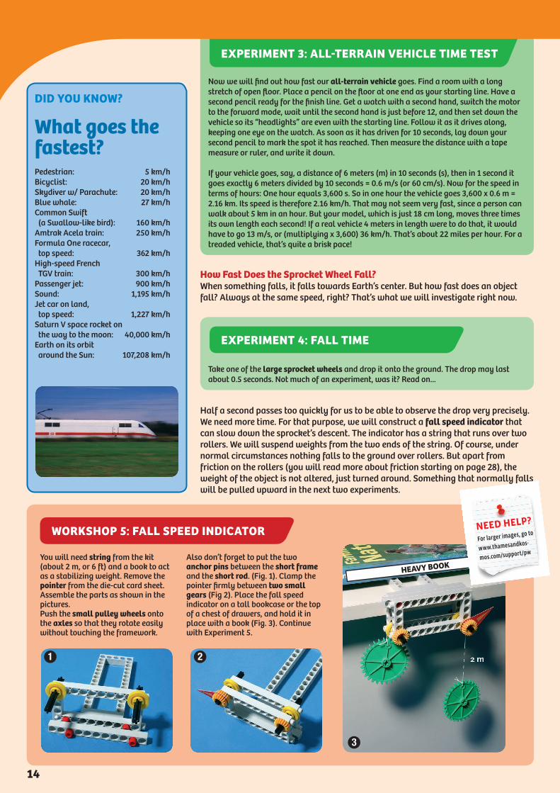
You will need string from the kit (about 2 m, or 6 ft) and a book to act as a stabilizing weight. Remove the pointer from the die-cut card sheet. Assemble the parts as shown in the pictures.Push the small pulley wheels onto the axles so that they rotate easily without touching the framework.
Also don’t forget to put the two anchor pins between the short frame and the short rod. (Fig. 1). Clamp the pointer firmly between two small gears (Fig 2). Place the fall speed indicator on a tall bookcase or the top of a chest of drawers, and hold it in place with a book (Fig. 3). Continue with Experiment 5.
HEAVY BOOK
1 2
3
NEED HELP?
For larger images, go to
www.thamesandkos-
mos.com/support/pw
EXPERIMENT 4: FALL TIME
14

WORKSHOP 6: FORCE SCALE, 0 TO 7.5 NEWTONS
in other words, just one tenth of the time. Any body attracted by gravity falls with accelerating speed. On the moon, acceleration amounts to just 1.62 m/s2. Earth’s gravitational acceleration or increase in speed, by contrast, amounts to 9.81 m/s every second that it falls. Expressed differently: the distance a body falls per second increases by 9.81 m every second. That means that after one second the speed a body falls is 9.81 m/s, and after two seconds its speed is an extra 9.81 m/s, or 19.62 m/s. After three seconds, you add another 9.81 m/s to get 29.43 m/s. Earth’s gravitational acceleration is the same for all bodies, regardless of how heavy they are. This acceleration formula applied to your potatoes from Experiment 1. However, the acceleration formula does not take into consideration air resistance, so it only really applies in airless space. Air does, in fact, slow down an object’s fall.
How Do You Measure Force?We now know what mass is and how to measure it. We learned a little about weight and the way it is elicited by the gravitational force of Earth. And in our fall speed experiment we learned what acceleration is. So we have learned about all the pieces that make up the definition of the unit of force. That unit is called the newton, abbreviated “N.” One newton is the force required to accelerate a mass of 1 kilogram (1 kg) to a speed of 1 meter per second (1 m/s) in a second. Expressed differently: 1 N is the force that gives the mass of 1 kg the acceleration of 1 m/s2. We can measure this force with our Force Scale. First, we will assemble one for larger forces.
1 N = 1 kg x 1 m / 1 s / 1 s = 1 kg • m / s2
Assemble the device as shown. Be sure that the measuring rod moves freely centered between the guide rods. Do not tilt the measuring rod when you take your readings.
Record your readings with a pencil or fine felt-tip pen mark on the indicated spot.
You will find the newton scale on the die-cut sheet.
You can use the large sprocket wheels to clamp the force scale to the edge of a table.
NEED HELP?
For larger images, go to
www.thamesandkos-
mos.com/support/pw
KEYWORD: FORCEForce is the cause of a change in a body’s state of movement.
16

WORKSHOP 7: SHIP’S LANTERN
Adding Up ForcesAs you know, gravity is directed toward the center of Earth. When you push open a door, your force is directed forward against the door. A force has a magnitude (size), but also always has a direction in which it acts. But if two forces of different magnitude act on the same body from different directions, what happens? The result is called the resulting force (or resultant force). It amounts to something like a compromise. Forces of different magnitudes can be added geometrically if they are represented as arrows. The length of the arrow indicates the magnitude of the force, and the arrow’s direction indicates the force’s line of action. From two separate forces, a third force arises, which is the resulting force. If they act on the same location, one can add them by a parallelogram method. For each line of force, one draws a parallel line through the tip of the arrow of the other force. Where the parallel lines cross is the point where the resulting force’s arrow ends.
Inert Mass and GimbalIf left to themselves, all objects would, in fact, prefer to remain in place wherever they already are. And when they did move, they would prefer to just keep going at the same pace and in the same direction. Pretty stubborn, don’t you think? These facts, which have to do with a tendency of matter called inertia, were described by Isaac Newton (1643-1727) in his First Law of Motion. Newton was an English natural scientist who studied forces and movement in great depth. The unit of force is named after him. In physics, a body in a state of rest is understood in terms of a state of movement. If a body’s state of movement is to change, a force must be applied to it. Thus, force is the cause of any change in a state of movement. In brief: Without force, nothing changes. You can sense that yourself when you pull yourself out of a deep sleep early in the morning and have to get up, even though you still feel sluggish and totally without the energy to do so. The next experiment will demonstrate the inertia of a body. In the experiment, a tea light candle is suspended in such a way that it moves freely on two axes. This so-called gimbal is a mounting system that is used for compasses and lanterns on boats, so that they don’t sway and tip over during a sea voyage.
Forces can be added with the parallelogram method.
The English physicist, mathematician, and astronomer Sir Isaac Newton (1643-1727).
You will also need: 1 tea light votive candleCaution! Under no circumstances should you light the tea light — the plastic could melt!
Assemble as shown. Be sure that all the
axles can rotate easily (Fig. 1). Secure the tea light with a rubber band (Fig. 2). Pay attention to the position of the rows of holes on the long rods: Make sure they match up! Mount the lamp holder structure in such a way that the structure is positioned in the center and can rotate
freely. Secure it with axle locks. When you move the base plate, as if it were a ship riding the waves, you can easily see how stable the tea light is.
3
2
1
This is the inner lamp holder structure.
NEED HELP?
For larger images, go to
www.thamesandkos-
mos.com/support/pw
17
Earth Attracts Us
The tea light, pulled by the force of gravity, moves into an upright position at the spot where it can be closest to the center of Earth. The lower the center of gravity of the light and its holder and the heavier the light, the more stable its equilibrium is. The tea light just stays and “hangs out” in this position. It can’t be moved very easily from its resting spot. It is even pretty much held in place if you jerk its support surface out from under it.
Propulsion-free through Space and TimeOn Earth, there are all kinds of obstacles and forms of resistance to the straight and steady forward movement of an object. The most important of these obstacles are friction (see p. 28) and gravity. Force must be continuously applied if the object’s speed and direction are to be maintained. A space ship, on the other hand, projected into weightless space and brought to a certain velocity by a single initial application of force, maintains its velocity and its initially determined direction. If force is continuously applied to the vehicle, for example by a rocket engine, it moves faster and faster. If the force is increased, then its acceleration increases proportionately.
Weight Is Indicated in Newtons TooBecause weight is determined by the force of gravity, it is also a force and is indicated in newtons. What was a newton again? Gravity accelerates any given body by 9.81 m/s every second. Now, if the force of 1 newton accelerates a mass of 1 kilogram at 1 meter per second, while Earth’s gravity accelerates a body by 9.81 meters a second, then the weight of one kilogram must add up to 9.81 times that — in other words, 9.81 newtons. We can therefore also use our force scale as a weight scale. If we want to measure the weight of an object in kilograms, we just have to divide the weight indicated in newtons (N) by about 10 (or more precisely by 9.81).
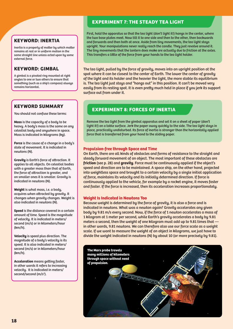
The Mars probe travels many millions of kilometers through space without need of propulsion.
KEYWORD SUMMARYYou should not confuse these terms:
Mass is the capacity of a body to be heavy. A body’s mass is the same on any celestial body and anywhere in space. Mass is indicated in kilograms (kg).
Force is the cause of a change in a body’s state of movement. It is indicated in newtons (N).
Gravity is Earth’s force of attraction. It applies to all objects. On celestial bodies with a greater mass than that of Earth, the force of attraction is greater, and on smaller ones it is smaller. Gravity is indicated in newtons (N).
Weight is what mass, i.e. a body, acquires when attracted by gravity. It changes when gravity changes. Weight is also indicated in newtons (N).
Speed is the distance covered in a certain amount of time. Speed is the magnitude of velocity. It is indicated in meters/second (m/s) or in kilometers/hour (km/h).
Velocity is speed plus direction. The magnitude of a body’s velocity is its speed. It is also indicated in meters/second (m/s) or in kilometers/hour (km/h).
Acceleration means getting faster, in other words it refers to increasing velocity. It is indicated in meters/second/second (m/s2).
KEYWORD: INERTIAInertia is a property of matter by which matter remains at rest or in uniform motion in the same straight line unless acted upon by some external force.
KEYWORD: GIMBALA gimbal is a pivoted ring mounted at right angles to one or two others to ensure that something (such as a ship’s compass) always remains horizontal.
First, hold the apparatus so that the tea light (don’t light it!) hangs in the center, where the two base plates meet. Now tilt it to one side and then to the other, then backwards and forwards and then both at once. Aside from tiny movements, the tea light stays upright. Your manipulations never really reach the candle. They just revolve around it. The tiny movements that the lantern does make are actually due to friction at the axles. This transfers a little of the force from your hands to the tea light holder.
EXPERIMENT 7: THE STEADY TEA LIGHT
Remove the tea light from the gimbal apparatus and set it on a sheet of paper (don’t light it!) on a table surface. Jerk the paper away quickly to the side. The tea light stays in place, practically undisturbed. Its force of inertia is stronger than the horizontally applied force that is transferred from your hand to the sliding paper.
EXPERIMENT 8: FORCES OF INERTIA
18
PhysicsWorkshopInside2014.indd 18 11/11/16 2:15 PM
WORKSHOP 8: SHOT PUT DEVICE
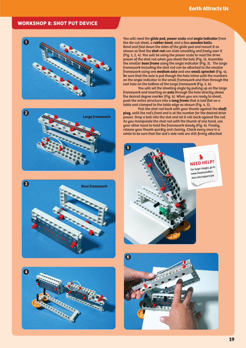
You will need the glide pad, power scale and angle indicator from the die-cut sheet, a rubber band, and a few wooden balls.Bend and fold down the sides of the glide pad and mount it as shown so that the shot rod can slide smoothly and freely over it (Fig. 1, 2, 4). You will be using the power scale to read the drive power of the shot rod when you shoot the ball (Fig. 5). Assemble the smaller base frame using the angle indicator (Fig. 3). The large framework including the shot rod can be attached to the smaller framework using one medium axle and one small sprocket (Fig. 4). Be sure that the axle is put though the hole inline with the numbers on the angle indicator in the small framework and then through the last hole on the bottom of the large framework (Fig. 5, 6). You will set the shooting angle by pulling up on the large framework and inserting an axle through the hole directly above the desired degree marker (Fig. 6). When you are ready to shoot, push the entire structure into a long frame that is laid flat on a table and clamped to the table edge as shown (Fig. 4, 5). Pull the shot rod back with your thumb against the shaft plug, until the rod’s front end is at the number for the desired drive power. Drop a ball into the slot and let it roll back against the rod. As you manipulate the shot rod with the thumb of one hand, use your other hand to hold the framework steady (Fig. 6). Finally, release your thumb quickly and cleanly. Check every once in a while to be sure that the slot’s side rods are still firmly attached.
1
2
3
4
5
6
NEED HELP?
For larger images, go to
www.thamesandkos-
mos.com/support/pw
Large framework
Base framework
19
Earth Attracts Us
PhysicsWorkshopInside2014.indd 19 11/11/16 2:15 PM

WORKSHOP 9: NUMBERED TARGET BOARD
Who Can Shoot Farthest?We will let you in on a little secret known by the world champion shot putters and javelin throwers: whatever you throw into the air in a high arch will inevitably fall back down again. Even the best training will not change that fact. As you know, gravity is the culprit here. And you also know that the harder you hurl a ball or stone the farther it will fly. The force with which the object leaves your hand plays an important role. If there were no gravity or air friction, your ball would fly off into space never to be seen again. From playing ball games, you have also learned how to throw the ball in the right direction and with the right force in order for it to reach its target — your teammate or the goal, for example. Somehow, you just have an automatic feel for the ball’s flight path. But how exactly? To figure it out, we will use a shot put device to shoot some balls at a numbered target board. The assembly instructions for the shot put device are on the previous page. The instructions for the target board are below. Once your shot put device is assembled, you can practice a few shots at flat and steep angles, and with weak and strong force. If someone else is doing the shooting, you might be able to follow the flight path of the ball. After that, it’s time to take some measurements with the target board.
This crossbow designed by the Renaissance genius Leonardo da Vinci (1452-1519) worked on the same principle as our shot put machine. Deciding factors when making a shot are angle and tension.
You will need the two number tables from the die-cut sheets. First assemble the stand from a base plate and two long rods. Attach the number tables to the two other base plates, as shown in the picture (secure them with shaft plugs and base connectors).
NEED HELP?
For larger images, go to
www.thamesandkos-
mos.com/support/pw
20

WORKSHOP 10: FORCE SCALE AND TYPE ONE LEVER
Force on the Lever: TorqueEach of the two sides of the lever equation represents what is called torque. Torque is the product (that is, the result of a multiplication equation) of a force and the (vertical) distance of its line of action from the fulcrum. The product is expressed in newtons times meters or newton meters (Nm). We will now measure how a lever works. First, build the force scale and a two-armed lever according to the workshop.
Calculation for “Measuring forces on a
lever” experiment assuming a battery
weight of 50 g.
We will use the following conversions:
centimeters to meters: 1 cm = 0.01 m
grams to kilograms: 1 g = 0.001 kg
kilogram-force to newtons: 1 kg = 9.81 N
(Here we will round up: 1 kg = 10 N)
1st Experiment:
effort side resistance side
0.08 m x 0.5 N = 0.08 m x 0.5 N
or 0.040 Nm = 0.040 Nm
2nd Experiment:
effort side resistance side
0.08 m x 0.25 N = 0.04 m x 0.5 N
or 0.020 Nm = 0.020 Nm
The torque (Nm) is the same, then, on
either side of the fulcrum.
You will also need the printed Newton Scale from the die-cut sheets. Assemble the force scale (0 N to 2 N) as shown in Fig. 1. A shaft plug should be inserted into the printed scale card so that the card is resting against the rear frame. The short axle at the tip of the short rod can be held in place using one axle lock. Now assemble the lever shown in the right of Fig. 2. The short rods creating the lever arm
should be held to each other using two anchor pins, one on either side of the long axle. This creates the point in this device called the fulcrum (Fig. 2) Guide the string down from the force scale over the first pulley wheel then under the next and last. The string should finally be threaded through the next-to-last hole of the effort arm. Secure the string using a joint plug (on the right in Fig. 2). To create the resistive
load insert a joint plug into the eighth hole from the fulcrum on the left arm of the lever and use the smaller rubber band to hang the motor box battery from the arm. Because the lever pivots in the middle, the resistance arm (left in Fig. 2) moves downward with its load, while the effort arm (right in Fig. 2) simultaneously moves up and pushes out the pointer of the force scale.
fulcrum
effort arm
resistance arm
1 2
NEED HELP?
For larger images, go to
www.thamesandkos-
mos.com/support/pw
Insert a joint plug into the next-to-last hole (the eighth hole from the fulcrum) on the left arm of the lever and use the smaller rubber band to hang the motor box battery from the arm to serve as the resistance load. On the opposite side, thread the end of the string through the next-to-last (eighth) hole and then insert a joint plug here as well. Then pull the string through the hole until the lever is horizontal. The pulling force (weight) of the force scale acts on the string and counterbalances the resistance load. When the pointer of the force scale has been pushed out, balance has been achieved. The force scale can be a little sluggish, however; give the pointer a little nudge upwards and tap with your finger a few times on the base plate. Now look through the third hole of the pointer and read the value on the scale. What does it say? Depending on the kind of battery you have, it should read about 0.5 or 0.75 N. You can also use your force scale to read the corresponding weight in grams: 50 or 75 g. The exertion points of the effort force and the resistance force are equally far from the fulcrum, namely eight holes or 8 cm. So the effort force has to equal the resistance force, since the effort arm length and resistance arm length are equal. The number you’re reading off the force scale in grams is the weight of the battery. Second experiment: Hang the battery from the fourth hole, cutting the distance from resistance force to fulcrum in half. Because that doubles the effort arm distance relative to the resistance arm, we must have saved energy. And what does the force scale show? Right! It now shows half the previous amount, about 25 or 37 N.
EXPERIMENT 11: MEASURING FORCES ON A LEVER
23
Simple Machines

WORKSHOP 12: LEVER POSTAL SCALE
WORKSHOP 11: FORCE SCALE AND TYPE TWO LEVER
If you want to prove that with a one-sided lever the two torques are equal in the state of equilibrium, and that it is therefore also possible with that kind of lever to save force, you will have to alter the experimental setup a little. Levers are all around us every day. Whether it’s a door handle at home, a hand brake in the car, a wrench in the workshop, or a crowbar at a construction site, levers make work easier by reducing the effort we need to perform it. Our fingers, arms, hands, and legs obey the law of levers no less than does the seesaw on the playground. Levers are also found in places where a balance needs to be obtained, for example in postal scales. You can assemble a postal scale of your own with the workshop below. It will measure weights of up to 50 g.
A bottle opener is a type two lever.
Use the assembly from the last workshop (type one lever) and convert it into a one-armed lever. The effort string will now only use the one large pulley wheel on the end before being threaded through the exertion point of the effort arm (left). A shorter resistance arm is utilized in this design. The battery is again hung from the arm as the resistance load (right).
You will need the postal scale dial from the die-cut sheet. When attaching both short rods to the long rod make sure to use joint plugs so that each short rod swings smoothly (left). The two small frames will serve as counterweights. When
choosing the final position of the base plate on the top of the long rod try a few different locations. Focus on the center of the plate until you find the location that balances the best. Place the object that you want to weigh in the center of the scale, right in the spot where it is
supported by the long rod. Don’t forget the maximum weight of 50 g! Before reading the weight, tap on the base plate a little and wait until the scale stops moving. Then, read off the weight at the top edge of the pointer rod.
NEED HELP?
For larger images, go to
www.thamesandkos-
mos.com/support/pw
NEED HELP?
For larger images, go to
www.thamesandkos-
mos.com/support/pw
24
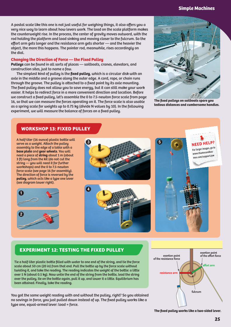
Tie a half-liter plastic bottle filled with water to one end of the string, and tie the force scale about 50 cm (20 in) from that end. Pull the bottle up by the force scale without twisting it, and take the reading. The reading indicates the weight of the bottle: a little over 5 N (about 0.5 kg). Now untie the end of the string from the bottle, lead the string over the pulley, tie on the bottle again, pull it up, and lower it a little. Equilibrium has been attained. Finally, take the reading.
EXPERIMENT 12: TESTING THE FIXED PULLEY
WORKSHOP 13: FIXED PULLEY
A postal scale like this one is not just useful for weighing things, it also offers you a very nice way to learn about how levers work. The load on the scale platform makes the counterweight rise. In the process, the center of gravity moves outward, with the rod holding the platform and load sinking and moving closer to the fulcrum. So the effort arm gets longer and the resistance arm gets shorter — and the heavier the object, the more this happens. The pointer rod, meanwhile, rises accordingly on the dial.
Changing the Direction of Force — the Fixed PulleyPulleys can be found in all sorts of places — sailboats, cranes, elevators, and construction sites, just to name a few. The simplest kind of pulley is the fixed pulley, which is a circular disk with an axle in the middle and a groove along the outer edge. A cord, rope, or chain runs through the groove. The pulley is attached to a fixed point by its axle mounting. The fixed pulley does not allow you to save energy, but it can still make your work easier. It helps to redirect force in a more convenient direction and location. Before we construct a fixed pulley, let’s assemble the 0 to 7.5-newton force scale from page 16, so that we can measure the forces operating on it. The force scale is also usable as a spring scale for weights up to 0.75 kg (divide N values by 10). In the following experiment, we will measure the balance of forces on a fixed pulley.
You got the same weight reading with and without the pulley, right? So you obtained no savings in force, you just pulled down instead of up. The fixed pulley works like a type one, equal-armed lever: load = force.
The fixed pulleys on sailboats spare you tedious distances and cumbersome handles.
The fixed pulley works like a two-sided lever.
A half-liter (16 ounce) plastic bottle will serve as a weight. Attach the pulley assembly to the edge of a table with a base plate and gear wheels. You will need a piece of string about 1 m (about 3 ft) long from the kit (do not cut the string — you will need it for further workshops) and the 0 to 7.5-newton force scale (see page 16 for assembly). The direction of force is reversed by the pulley, which acts like a type one lever (see diagram lower right).
1
2
4
3 5NEED HELP?
For larger images, go to
www.thamesandkos-
mos.com/support/pw
25
Simple Machines

Changing the Magnitude of the Force — the Movable PulleyThings are different with a movable pulley. It can change the required force, reducing it to half the load. But how can a movable pulley cut the required force in half? The movable pulley hangs by two string sections, each of which takes on half of the load. This type of pulley works like a type two lever, as you can see from the picture here. The next experiment will show you that the savings in force must be “paid for” by doubling the length of the string.
Fixed Pulley and Movable Pulley Combined — the Combination PulleyIf you want to not only cut the required force in half but also change its direction, then what you need is a simple combination pulley. It consists of a fixed and a movable pulley.
But you can achieve an even greater savings in force. The more pulleys the combination pulley has — more accurately, the more strings there are running to and fro — the more force you save. The load is simply divided by the number of strings. As with all machines, when you pull on the string of the combination pulley it swallows up some of the force. The reason for that is provided by another basic principle of mechanics:
Above all, there are losses caused by the friction of the axles and the strings. That is why your force scale shows a slightly higher value when you pull steadily on the string than when in the resting position.
There are no machines without losses.
This is how we measure force with the movable pulley.
The movable pulley works like a one-sided lever.
Combination pulley: a combination of a fixed and a movable pulley.
You will need the fixed pulley again (see page 25 for assembly), as well as the 0 to 7.5-N force scale (right), and a second pulley with an attachment for the load. Take note of the way you should thread the string through the components (see diagram, lower left).
NEED HELP?
For larger images, go to
www.thamesandkos-
mos.com/support/pw
Hook the end of the string over the force scale as shown below, suspend the pulley with the bottle from the string, and read how much force you saved.
EXPERIMENT 13: THE STRING EATER
WORKSHOP 14: SIMPLE COMBINATION PULLEY
26

WORKSHOP 15: TEST VEHICLE ON AN INCLINED PLANE
Forces on a Sloping Path — the Inclined PlaneA wheelchair cannot climb stairs. That is why there is often an extra path designed for wheel chair users, alongside the section with stairs used by other pedestrians. If you were pushing your heavily-loaded bicycle along, would you prefer to push it up the wheelchair ramp or carry it up the steps? Without a doubt, the ramp would be better. You know that the ramp requires less effort. But why is that? The ramp is an inclined plane, a surface that lies at a slant relative to horizontal. In order to observe experimentally how forces are distributed on it, we will first assemble a force scale for 0 to 2 N. In addition, we will build a test vehicle and an inclined plane, which we will attach to the force scale as shown in the picture below, so they can be rotated relative to each other.
Of course, the basic principle we learned before applies here as well; the savings in terms of force must be compensated for by adding distance. A road sign announces an incline in the road of 15%. That means that a car has to drive about 10 m in order to move just 1.5 m higher (1.5 divided by 10 = 0.15 or 15%). The driver has to take a longer stretch of road into account in order to get his car over the mountain. If the side of the mountain is too steep for a car to be able to drive up it on a straight road, then switchbacks have to be built — that is, the road has to wind back and forth.
Assemble your test vehicle as shown in the illustration. Tie a short pull-cord loop to the frame before mounting the front wheels (left). Then slip the loop over the joint pin tied to the end of the string (top right). That is how the vehicle is connected to the force scale (0
to 2 N) (see page 23 for assembly) over the pulley wheels, shown in the picture on the bottom right.
NEED HELP?
For larger images, go to
www.thamesandkos-
mos.com/support/pw
DID YOU KNOW?
Why is it called a pulley?You might think a pulley gets its name from the fact that you can use it to pull things up. In fact, the name comes from polos, Greek for “hinge.”
Step 1: Place the force scale at the edge of a table and let the vehicle dangle down by the string. As you take the reading, nudge the pointer bar upward and tip the force scale so that the string unwinds over the pulley wheels. The pointer indicates the weight of the vehicle. Step 2: Next, place the force scale on a stack of two or three thick books and connect it to the inclined plane with the joint pins. Take another reading. Now the force is considerably less. Once again, the question is raised: why is the force reduced on the inclined plane? The answer: because the force of the weight is distributed into two individual forces.
EXPERIMENT 14: ON A SLOPE OVER A PRECIPICE
27
Simple Machines
WORKSHOP 16: WHEELED SLED, RUNWAY, AND SLIDE
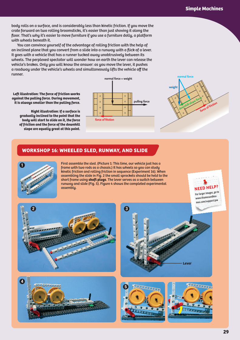
body rolls on a surface, and is considerably less than kinetic friction. If you move the crate forward on two rolling broomsticks, it’s easier than just shoving it along the floor. That’s why it’s easier to move furniture if you use a furniture dolly, a platform with wheels beneath it. You can convince yourself of the advantage of rolling friction with the help of an inclined plane that you convert from a slide into a runway with a flick of a lever. It goes with a vehicle that has a runner tucked away unobtrusively between its wheels. The perplexed spectator will wonder how on earth the lever can release the vehicle’s brakes. Only you will know the answer: as you move the lever, it pushes a roadway under the vehicle’s wheels and simultaneously lifts the vehicle off the runner.
Left illustration: The force of friction works against the pulling force. During movement,
it is always smaller than the pulling force.
Right illustration: If a surface is gradually inclined to the point that the
body will start to slide on it, the force of friction and the force of the downhill
slope are equally great at this point.
First assemble the sled. (Picture 1: This time, our vehicle just has a frame with two rods as a chassis.) It has wheels so you can study kinetic friction and rolling friction in sequence (Experiment 16). When assembling the slide in Fig. 2 the small sprockets should be held to the short frame using shaft plugs. The lever serves as a switch between runway and slide (Fig. 5). Figure 4 shows the completed experimental assembly.
1
2 3
45
Lever
NEED HELP?
For larger images, go to
www.thamesandkos-
mos.com/support/pw
29
Simple Machines

WORKSHOP 17: WEDGE AND STUCK RACK
A few days before launch, two pairs of sleds are pushed under the ship. Each pair has an upper and a lower part. Between the two parts is a glide layer made of soft soap or Teflon-coated steel. Next, long and slender beechwood wedges, spaced closely apart, are inserted over the upper sled part from the side. In time to bursts of a whistle, hundreds or more dockworkers beat on the wedges with sledgehammers. With each blow, the ship rises by a fraction of a millimeter – thanks to the action of the wedge, which we will now investigate in an experiment.
The power of wedges: stubby wedges (above) produce small side forces, pointy wedges produce large ones (below).
The rack lifts up a lot more easily now, doesn’t it? Let’s take a closer look at the wedge and its show of force: It consists of two inclined planes joined at the base. The force that is exerted at its rear divides into two side forces, perpendicular (at right angles) to the sides of the wedge. The narrower the wedge, as you can see in the diagram, the greater the side forces. Of course, the narrower wedge must also travel a greater distance between the pieces that the wedge is pressing against. But the gain in power is usually worth the price of the longer distance. Wedges are usually made from wood or iron, and they are used to drive objects apart or to split an object (wood, stone). But they can also be used to attach components to one another, for example in pieces of furniture.
First assemble the wedge and the rack anchored in the base plate. The end of the wedge without the small green sprockets should be held together using joint plugs (left). Then you can proceed
with Experiment 17. You will definitely be surprised how easy it is to loosen the rack from the base plate with a wedge.
Wedge
Rack
NEED HELP?
For larger images, go to
www.thamesandkos-
mos.com/support/pw
Start by pulling the rack up out of the base plate, without using the wedge. Then stick it back into the plate, but only after you have placed the wedge beneath it. Now push against the rear of the wedge.
EXPERIMENT 17: WEDGE WORK
32

WORKSHOP 18: TRANSMISSION OF FORCE
Forces can be transferred from one wheel onto another, and thereby increased or reduced. When used in that way, the wheels are connected to each other at their edges — usually by way of a chain, a transmission belt, or gear teeth. On the edges of the wheels, equal-sized forces are at work. But the effort arms of the large and small wheels are of different lengths, giving rise to different torques. In the adjacent examples, the force transferred (by chain, belt, or gear) from the periphery of the smaller wheel to the larger one creates a greater torque at the larger wheel. Let’s test it.
1
2
3
4
Transmission of force with wheels.1st Picture: Transmission of force over sprockets and chain.2nd Picture: Transmission of force over belt wheels (belt pulleys) and transmission belt.3rd Picture: Transmission of force over toothed wheels.4th Picture: The force operates on levers of different lengths.
For this workshop you will also need a few paperclips and a length of string. Do not use the string provided in the kit since this workshop requires you to cut the string. We suggest using dental floss or sewing thread as a supplement. Each axle has two sprocket wheels on the inside for stability (Fig. 1); when pushed together, they act as a spool for the string. When assembling, note that the two long axles should be inserted 4 holes apart (Fig. 2). This allows the teeth of the two gear wheels to bite into each other and transfer forces like a lever (Fig. 2). Slide the assembly to the edge of the table (Fig. 3) and lay a heavy book on top of the three base plates, so it doesn’t tip over.
1
2
3
NEED HELP?
For larger images, go to
www.thamesandkos-
mos.com/support/pw
Getting in Gear
37
Getting in Gear
WORKSHOP 19: TWO-SPEED CRANE WITH GEARSHIFT
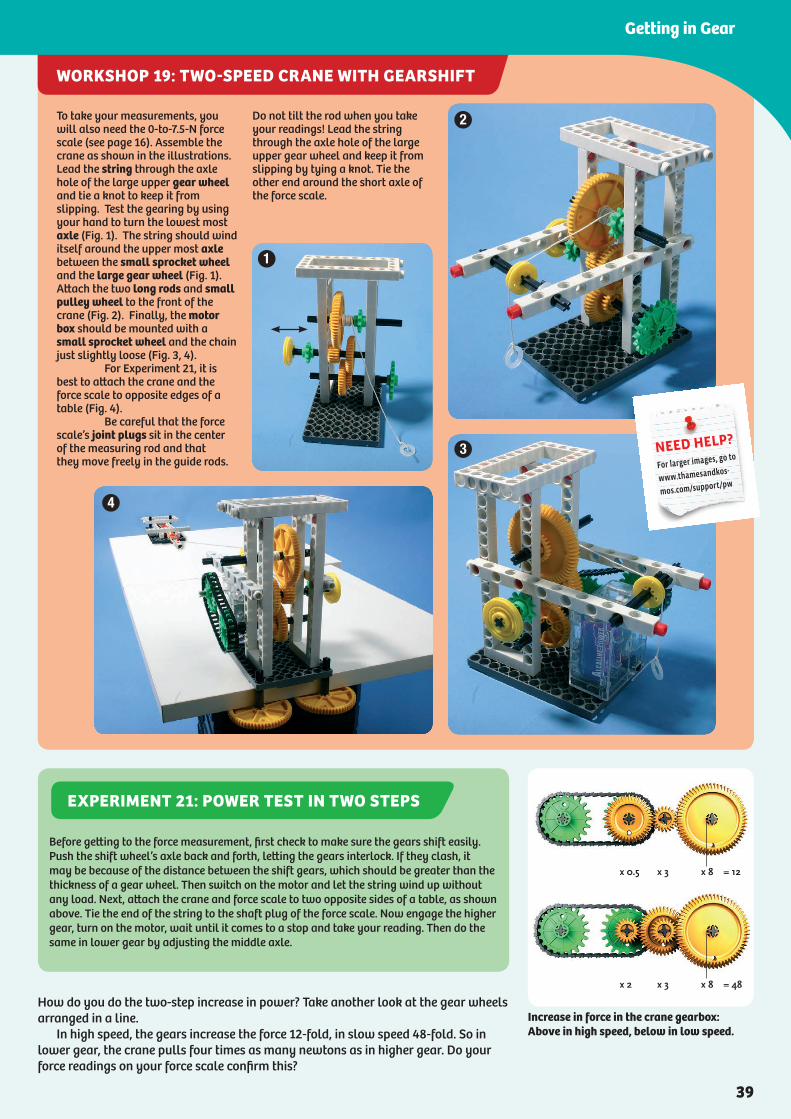
How do you do the two-step increase in power? Take another look at the gear wheels arranged in a line. In high speed, the gears increase the force 12-fold, in slow speed 48-fold. So in lower gear, the crane pulls four times as many newtons as in higher gear. Do your force readings on your force scale confirm this?
Increase in force in the crane gearbox:Above in high speed, below in low speed.
To take your measurements, you will also need the 0-to-7.5-N force scale (see page 16). Assemble the crane as shown in the illustrations. Lead the string through the axle hole of the large upper gear wheel and tie a knot to keep it from slipping. Test the gearing by using your hand to turn the lowest most axle (Fig. 1). The string should wind itself around the upper most axle between the small sprocket wheel and the large gear wheel (Fig. 1). Attach the two long rods and small pulley wheel to the front of the crane (Fig. 2). Finally, the motor box should be mounted with a small sprocket wheel and the chain just slightly loose (Fig. 3, 4). For Experiment 21, it is best to attach the crane and the force scale to opposite edges of a table (Fig. 4). Be careful that the force scale’s joint plugs sit in the center of the measuring rod and that they move freely in the guide rods.
Do not tilt the rod when you take your readings! Lead the string through the axle hole of the large upper gear wheel and keep it from slipping by tying a knot. Tie the other end around the short axle of the force scale.
2
3
1
4
NEED HELP?
For larger images, go to
www.thamesandkos-
mos.com/support/pw
Before getting to the force measurement, first check to make sure the gears shift easily. Push the shift wheel’s axle back and forth, letting the gears interlock. If they clash, it may be because of the distance between the shift gears, which should be greater than the thickness of a gear wheel. Then switch on the motor and let the string wind up without any load. Next, attach the crane and force scale to two opposite sides of a table, as shown above. Tie the end of the string to the shaft plug of the force scale. Now engage the higher gear, turn on the motor, wait until it comes to a stop and take your reading. Then do the same in lower gear by adjusting the middle axle.
EXPERIMENT 21: POWER TEST IN TWO STEPS
39
Getting in Gear
DID YOU KNOW?
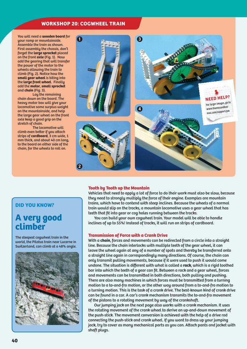
A very good climberThe steepest cogwheel train in the world, the Pilatus train near Lucerne in Switzerland, can climb at a 48% angle.
WORKSHOP 20: COGWHEEL TRAIN
Tooth by Tooth up the MountainVehicles that need to apply a lot of force to do their work must also be slow, because they need to strongly multiply the force of their engine. Examples are mountain trains, which have to contend with steep inclines. Because the wheels of a normal train would slip on the tracks, a mountain locomotive uses a gear wheel that has teeth that fit into gear or cog holes running between the tracks. You can build your own cogwheel train. Your model will be able to handle inclines of up to 55%! Instead of tracks, it will run on strips of cardboard.
Transmission of Force with a Crank DriveWith a chain, forces and movements can be redirected from a circle into a straight line. Because the chain interlocks with multiple teeth of the gear wheel, it can leave the wheel again at any of a number of spots and thereby be transferred onto a straight line again in correspondingly many directions. Of course, the chain can only transmit pulling movements, because if it were used to push it would come undone. The situation is different with what is called a rack, which is a rigid toothed bar into which the teeth of a gear can fit. Between a rack and a gear wheel, forces and movements can be transmitted in both directions, both pulling and pushing. There are also many machines in which forces must be transmitted from a turning motion to a to-and-fro motion, or the other way around from a to-and-fro motion to a turning motion. This is the task of a crank drive. The best-known kind of crank drive can be found in a car. A car’s crank mechanism transmits the to-and-fro movement of the pistons to a rotating movement by way of the crankshaft. Our jumping jack on the next page also works with a crank mechanism. It uses the rotating movement of the crank wheel to derive an up-and-down movement of the push-stick. The movement conversion is achieved with the help of a drive rod connecting the push-stick and crank wheel. If you want to dress up your jumping jack, try to cover as many mechanical parts as you can. Attach pants and jacket with shaft plugs.
You will need a wooden board for your ramp or mountainside.Assemble the train as shown. First assembly the chassis, don’t forget the large sprocket placed on the front axle (Fig. 1). Now add the gearing that will transfer the power of the motor to the wheels allowing the train to climb (Fig. 2). Notice how the small gear wheel is biting into the large front wheel. Finally add the motor, small sprocket and chain (Fig. 3). Lay the remaining chain down on the board. The heavy motor box will give your locomotive some surplus weight on the mountainside, and help the large gear wheel on the front axle keep a good grip on the stretch of chain. The locomotive will climb even better if you attach strips of cardboard, 3 cm wide, 1 mm thick, and about 40 cm long, to the board on either side of the chain, for the wheels to roll on.
1
2
3
4
NEED HELP?
For larger images, go to
www.thamesandkos-
mos.com/support/pw
40

WORKSHOP 22: HAND-CRANK THEATER
WORKSHOP 21: JUMPING JACK WITH CRANK DRIVE
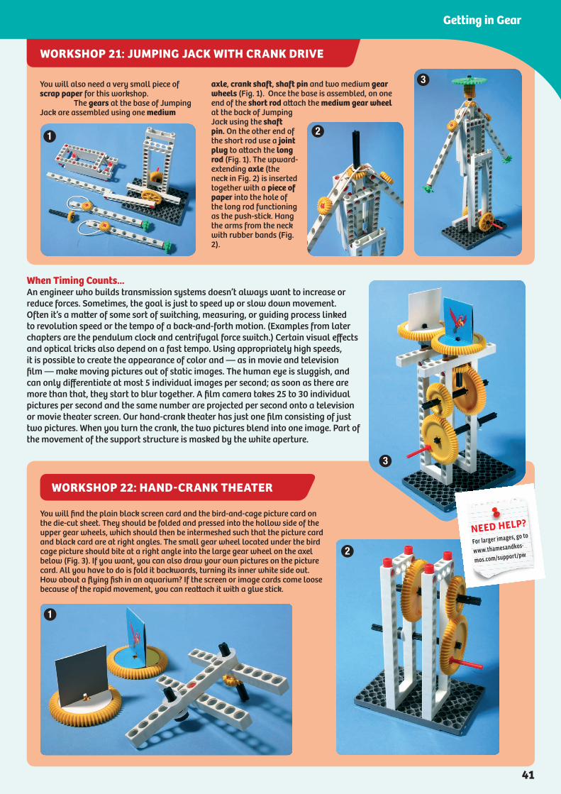
When Timing Counts...An engineer who builds transmission systems doesn’t always want to increase or reduce forces. Sometimes, the goal is just to speed up or slow down movement. Often it’s a matter of some sort of switching, measuring, or guiding process linked to revolution speed or the tempo of a back-and-forth motion. (Examples from later chapters are the pendulum clock and centrifugal force switch.) Certain visual effects and optical tricks also depend on a fast tempo. Using appropriately high speeds, it is possible to create the appearance of color and — as in movie and television film — make moving pictures out of static images. The human eye is sluggish, and can only differentiate at most 5 individual images per second; as soon as there are more than that, they start to blur together. A film camera takes 25 to 30 individual pictures per second and the same number are projected per second onto a television or movie theater screen. Our hand-crank theater has just one film consisting of just two pictures. When you turn the crank, the two pictures blend into one image. Part of the movement of the support structure is masked by the white aperture.
You will also need a very small piece of scrap paper for this workshop. The gears at the base of Jumping Jack are assembled using one medium
axle, crank shaft, shaft pin and two medium gear wheels (Fig. 1). Once the base is assembled, on one end of the short rod attach the medium gear wheel at the back of Jumping Jack using the shaft pin. On the other end of the short rod use a joint plug to attach the long rod (Fig. 1). The upward-extending axle (the neck in Fig. 2) is inserted together with a piece of paper into the hole of the long rod functioning as the push-stick. Hang the arms from the neck with rubber bands (Fig. 2).
1 2
3
You will find the plain black screen card and the bird-and-cage picture card on the die-cut sheet. They should be folded and pressed into the hollow side of the upper gear wheels, which should then be intermeshed such that the picture card and black card are at right angles. The small gear wheel located under the bird cage picture should bite at a right angle into the large gear wheel on the axel below (Fig. 3). If you want, you can also draw your own pictures on the picture card. All you have to do is fold it backwards, turning its inner white side out. How about a flying fish in an aquarium? If the screen or image cards come loose because of the rapid movement, you can reattach it with a glue stick.
2
1
3
NEED HELP?
For larger images, go to
www.thamesandkos-
mos.com/support/pw
41
Getting in Gear
WORKSHOP 22: HAND-CRANK THEATER
WORKSHOP 21: JUMPING JACK WITH CRANK DRIVE
When Timing Counts...An engineer who builds transmission systems doesn’t always want to increase or reduce forces. Sometimes, the goal is just to speed up or slow down movement. Often it’s a matter of some sort of switching, measuring, or guiding process linked to revolution speed or the tempo of a back-and-forth motion. (Examples from later chapters are the pendulum clock and centrifugal force switch.) Certain visual effects and optical tricks also depend on a fast tempo. Using appropriately high speeds, it is possible to create the appearance of color and — as in movie and television film — make moving pictures out of static images. The human eye is sluggish, and can only differentiate at most 5 individual images per second; as soon as there are more than that, they start to blur together. A film camera takes 25 to 30 individual pictures per second and the same number are projected per second onto a television or movie theater screen. Our hand-crank theater has just one film consisting of just two pictures. When you turn the crank, the two pictures blend into one image. Part of the movement of the support structure is masked by the white aperture.
You will also need a very small piece of scrap paper for this workshop. The gears at the base of Jumping Jack are assembled using one medium
axle, crank shaft, shaft pin and two medium gear wheels (Fig. 1). Once the base is assembled, on one end of the short rod attach the medium gear wheel at the back of Jumping Jack using the shaft pin. On the other end of the short rod use a joint plug to attach the long rod (Fig. 1). The upward-extending axle (the neck in Fig. 2) is inserted together with a piece of paper into the hole of the long rod functioning as the push-stick. Hang the arms from the neck with rubber bands (Fig. 2).
1 2
3
You will find the plain black screen card and the bird-and-cage picture card on the die-cut sheet. They should be folded and pressed into the hollow side of the upper gear wheels, which should then be intermeshed such that the picture card and black card are at right angles. The small gear wheel located under the bird cage picture should bite at a right angle into the large gear wheel on the axel below (Fig. 3). If you want, you can also draw your own pictures on the picture card. All you have to do is fold it backwards, turning its inner white side out. How about a flying fish in an aquarium? If the screen or image cards come loose because of the rapid movement, you can reattach it with a glue stick.
2
1
3
NEED HELP?
For larger images, go to
www.thamesandkos-
mos.com/support/pw
41
Getting in Gear
WORKSHOP 23: MARS ROBOT
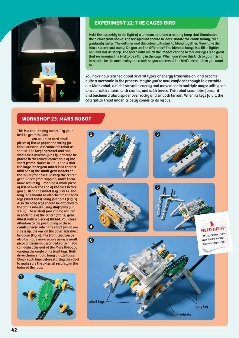
You have now learned about several types of energy transmission, and become quite a mechanic in the process. Maybe you’re now confident enough to assemble our Mars robot, which transmits energy and movement in multiple ways: with gear wheels, with chains, with cranks, and with levers. This robot scrambles forward and backward like a spider over rocky and smooth terrain. When its legs fail it, the caterpillar tread under its belly comes to its rescue.
This is a challenging model! Try your best to get it to work. You will also need small pieces of tissue paper and string for this workshop. Assemble the robot as shown. The large sprocket and two small axle assembly in Fig. 2 should be placed in the lowest corner hole of the short frame. Notice in Fig. 3 and 4 that the large inner gear wheel is in contact with one of the small gear wheels on the lower front axle. To keep the center gear wheels from slipping, make them more secure by wrapping a small piece of tissue over the end of the axle before you push on the wheel (Fig. 3 & 4). The long legs should be attached to the back legs (short rods) using joint pins (Fig. 5). Also the long legs should be attached to the crank wheels using shaft pins (Fig. 5 & 6). These shaft pins can be secured in each hole of the center (crank) gear wheel with a piece of thread. Pay close attention to the positioning of these crank wheels: when the shaft pin on one side is up, the one on the other side must be down (Fig. 6). The front legs can be also be made more secure using a small piece of tissue as described earlier. You can adjust the gait of the Mars Robot by varying the angle of its front legs. Both drive chains should hang a little loose. Check each time before starting the robot to make sure the axles sit securely in the holes of the rods.
long legshort legs
crank wheels
1
2 3
5
4
6
NEED HELP?
For larger images, go to
www.thamesandkos-
mos.com/support/pw
Hold the assembly in the light of a window, or under a reading lamp that illuminates the picture from above. The background should be dark. Rotate the crank slowly, then gradually faster. The outlines and the colors will start to blend together. Now, take the black screen card away. Do you see the difference? The blended image is a little lighter now but not as sharp. The speed with which the images change before our eyes is so great that we imagine the bird to be sitting in the cage. When you show this trick to your friend, be sure to be the one turning the crank, so you can reveal the bird’s secret when you want to.
EXPERIMENT 22: THE CAGED BIRD
42
WORKSHOP 24: WATER-POWERED SAWMILL
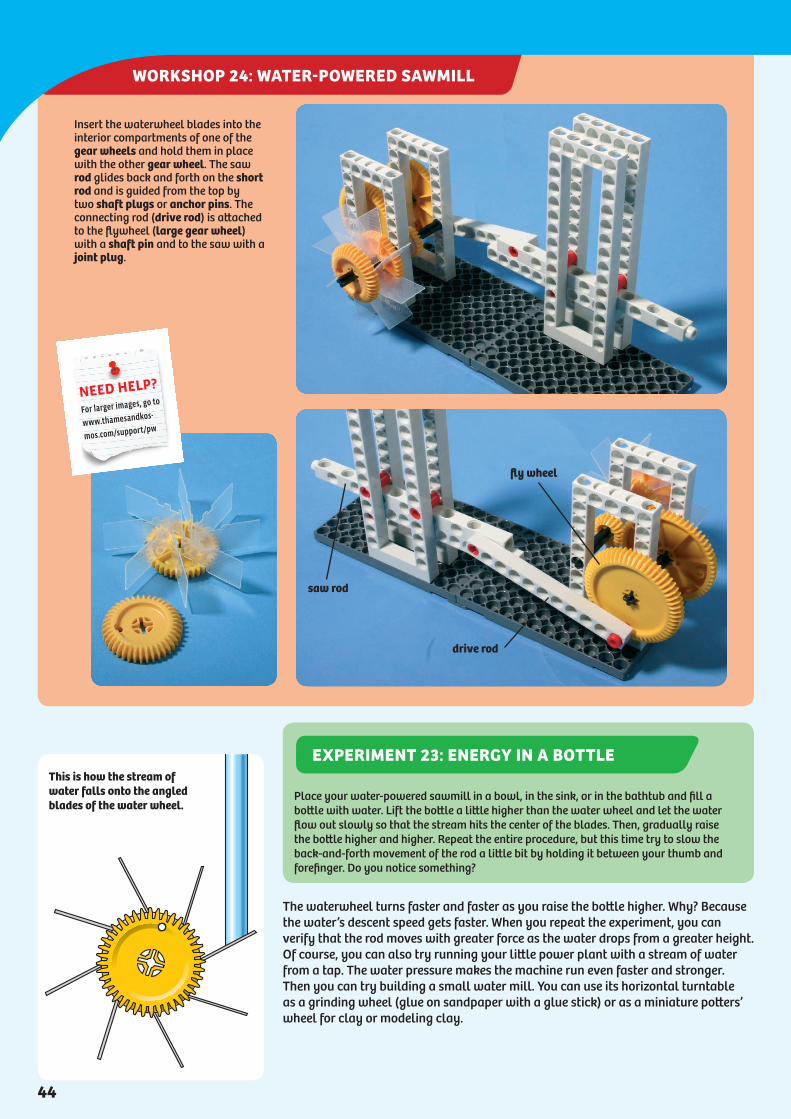
The waterwheel turns faster and faster as you raise the bottle higher. Why? Because the water’s descent speed gets faster. When you repeat the experiment, you can verify that the rod moves with greater force as the water drops from a greater height. Of course, you can also try running your little power plant with a stream of water from a tap. The water pressure makes the machine run even faster and stronger. Then you can try building a small water mill. You can use its horizontal turntable as a grinding wheel (glue on sandpaper with a glue stick) or as a miniature potters’ wheel for clay or modeling clay.
This is how the stream of water falls onto the angled blades of the water wheel.
Insert the waterwheel blades into the interior compartments of one of the gear wheels and hold them in place with the other gear wheel. The saw rod glides back and forth on the short rod and is guided from the top by two shaft plugs or anchor pins. The connecting rod (drive rod) is attached to the flywheel (large gear wheel) with a shaft pin and to the saw with a joint plug.
saw rod
drive rod
fly wheel
NEED HELP?
For larger images, go to
www.thamesandkos-
mos.com/support/pw
Place your water-powered sawmill in a bowl, in the sink, or in the bathtub and fill a bottle with water. Lift the bottle a little higher than the water wheel and let the water flow out slowly so that the stream hits the center of the blades. Then, gradually raise the bottle higher and higher. Repeat the entire procedure, but this time try to slow the back-and-forth movement of the rod a little bit by holding it between your thumb and forefinger. Do you notice something?
EXPERIMENT 23: ENERGY IN A BOTTLE
44

WORKSHOP 25: WATER-POWERED POTTER’S WHEEL
Water shoots down from a high reservoir through these conduits onto the blades of a turbine.
This water wheel, a Pelton turbine, transforms the kinetic energy of water into mechanical energy. The energy turns a generator, which turns the mechanical energy into electrical energy (electricity).
Energy is ChangeableAll right, where are we in our work and energy experiments? You lifted the full bottle up a certain vertical distance, which was your work. Up there, the water in your hand was stored work. In other words, it was energy that was created by the higher location of the water. Physicists refer to this as potential energy (Latin: potentia = power, possibility). As the stream fell toward the wheel, the water went into motion. In the process, its energy changed its state: potential energy was changed into kinetic energy (Greek: kinesis = movement). The kinetic energy of the falling stream of water performed work on the water wheel. After your preliminary work, this was the water’s work. Of course, not all the potential energy can be transformed into work at the drive rod. There are losses at the water wheel, and in the wheel housing and the saw track there are losses due to friction. Kinetic and potential energy are forms of mechanical energy.
Assemble the Potter’s Wheel as shown. The upright axle supporting the two large gear wheels and one small sprocket is composed of one long axle and one short axle. The upper most large gear wheel uses an extra support
disk, as does the small gear wheel on the other side of the short axle (between water wheel and potter’s wheel). You can use this water-driven potter’s wheel to make tiny cups or vases out of blobs of clay or modeling
clay. This project illustrates the principle of force transmission. For continuous operation, of course, you could substitute the electric motor for the water wheel, so as to not waste water.
NEED HELP?
For larger images, go to
www.thamesandkos-
mos.com/support/pw
DID YOU KNOW?
China’s mega power plantThe largest hydroelectric power plant in the world is on China’s Yangtze River. Starting in the year 2009, its production is supposed to be 18,200 megawatts (MW), or 18 billion watts (W). That is enough energy to provide electricity to 100 million people. In 2004, the first stage of the power plant was completed, producing 550 MW of energy which was fed into the power grid. To build the plant, the Yangtze River was dammed and a vast lake was created, flooding many valleys, villages, and towns. All of their residents were relocated beforehand; now, they live in new settlements above the lake’s water line.
45
Forces at Work
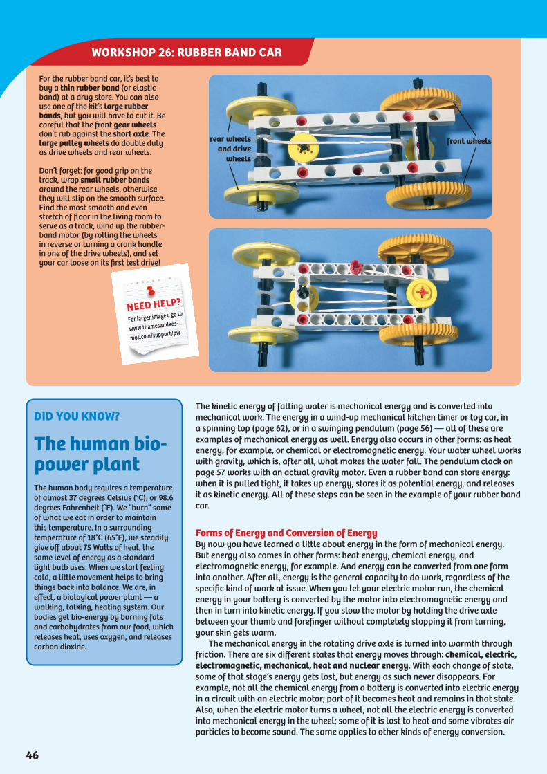
WORKSHOP 26: RUBBER BAND CAR
The kinetic energy of falling water is mechanical energy and is converted into mechanical work. The energy in a wind-up mechanical kitchen timer or toy car, in a spinning top (page 62), or in a swinging pendulum (page 56) — all of these are examples of mechanical energy as well. Energy also occurs in other forms: as heat energy, for example, or chemical or electromagnetic energy. Your water wheel works with gravity, which is, after all, what makes the water fall. The pendulum clock on page 57 works with an actual gravity motor. Even a rubber band can store energy: when it is pulled tight, it takes up energy, stores it as potential energy, and releases it as kinetic energy. All of these steps can be seen in the example of your rubber band car.
Forms of Energy and Conversion of EnergyBy now you have learned a little about energy in the form of mechanical energy. But energy also comes in other forms: heat energy, chemical energy, and electromagnetic energy, for example. And energy can be converted from one form into another. After all, energy is the general capacity to do work, regardless of the specific kind of work at issue. When you let your electric motor run, the chemical energy in your battery is converted by the motor into electromagnetic energy and then in turn into kinetic energy. If you slow the motor by holding the drive axle between your thumb and forefinger without completely stopping it from turning, your skin gets warm. The mechanical energy in the rotating drive axle is turned into warmth through friction. There are six different states that energy moves through: chemical, electric, electromagnetic, mechanical, heat and nuclear energy. With each change of state, some of that stage’s energy gets lost, but energy as such never disappears. For example, not all the chemical energy from a battery is converted into electric energy in a circuit with an electric motor; part of it becomes heat and remains in that state. Also, when the electric motor turns a wheel, not all the electric energy is converted into mechanical energy in the wheel; some of it is lost to heat and some vibrates air particles to become sound. The same applies to other kinds of energy conversion.
For the rubber band car, it’s best to buy a thin rubber band (or elastic band) at a drug store. You can also use one of the kit’s large rubber bands, but you will have to cut it. Be careful that the front gear wheels don’t rub against the short axle. The large pulley wheels do double duty as drive wheels and rear wheels.
Don’t forget: for good grip on the track, wrap small rubber bands around the rear wheels, otherwise they will slip on the smooth surface. Find the most smooth and even stretch of floor in the living room to serve as a track, wind up the rubber-band motor (by rolling the wheels in reverse or turning a crank handle in one of the drive wheels), and set your car loose on its first test drive!
rear wheelsand drive
wheels
front wheels
NEED HELP?
For larger images, go to
www.thamesandkos-
mos.com/support/pw
DID YOU KNOW?
The human bio-power plantThe human body requires a temperature of almost 37 degrees Celsius (°C), or 98.6 degrees Fahrenheit (°F). We “burn” some of what we eat in order to maintain this temperature. In a surrounding temperature of 18°C (65°F), we steadily give off about 75 Watts of heat, the same level of energy as a standard light bulb uses. When we start feeling cold, a little movement helps to bring things back into balance. We are, in effect, a biological power plant — a walking, talking, heating system. Our bodies get bio-energy by burning fats and carbohydrates from our food, which releases heat, uses oxygen, and releases carbon dioxide.
46

WORKSHOP 27: WIND-POWER PLANT
You will find the propeller blades and tail for your wind power plant on the die-cut sheet. Fig. 2 lays out the device’s gearing. Since it takes a keen eye to notice the orientation of the axle assemblies we will help you out just a bit:Axle A: long axle ring end to short axle non-ring end.Axle B: one long axle with ring end pointing to the right of the picture.Axle C: medium axle non-ring end to medium axle ring end.
Bend the propeller blades to create a rounded front edge and a pointed rear edge. Seal the rear edge with tape. Now use shaft plugs to attach the blades at the holes to the blade mounts (Fig. 5). Do not push the shaft plugs in completely, only far enough to make them secure. The blade is cut in such a way that it will end up being a little distorted when it is attached to the mount, so it has a narrower angle near the rotor axle than it has towards its tip (Fig. 5).
Attach the two blade mounts with anchor pins to the middle section of the rotor, but just to be sure they stay secure, wrap them with adhesive tape as well (Fig. 6). The tail piece at the rear should also the secured to the frame with tape in the same manner (Fig. 7). To prevent jiggling, the pieces of the frame should also be secured to one another at the important joints with tape.
For the mast, use a 1.5 meter-long (5 ft) bamboo pole or metal pipe of that length (from a garden center or building supply store). Whatever you use, the mast axle should fit into it exactly, so take it with you when you go to the store. The axle rod has to sit fairly tightly in the cylinder, but at the same time be able to rotate in it without sticking. If the bamboo pole has a joint in the way, you will have to cut it accordingly (see figures on page 50).
1
2
7
5
3 4
6
rotor
A
B
C
NEED HELP?
For larger images, go to
www.thamesandkos-
mos.com/support/pw
47
Forces at Work

WORKSHOP 28: PINBALL
If you collide an inelastic body against a similar immovable body, then it will bounce back. That’s how it is with this ball game. But if the body collides with a moveable body, then they will both move on with a common velocity. If several
This is how we determine the trajectory of the shot to the goal.
You will require the checked playing field from the die-cut sheet and a bit of tissue. The moveable rod is used to alter the course of the ball. Use base connectors to secure the base plates to each other from the bottom (Note: You may also substitute joint plugs if you run out of your supply of base connectors). Then lay the sheet with the checked playing field (from the die-cut sheet) on the top side, and attach the edge strips, the moveable rods and the launching section. Press the launching section’s anchor pin into the base plate with a bit of tissue. The small rubber band will provide the needed tension for shooting. When you pull it back in preparation for taking a shot, do not pull it too far, or it might get stuck. Secure it with a medium axle. Now, place a ball in the shooting groove. As soon as you pull the axle out of the bolt-hole, the bolt will be released and the ball will shoot out of the groove. Before you shoot, press the moveable rod against the playing surface! Otherwise, the playing field may slip.
edge strips
launching section
moveable rod
3
1
2
NEED HELP?
For larger images, go to
www.thamesandkos-
mos.com/support/pw
For this experiment, you will need your protractor. Lay a piece of paper down over the playing field. First, try an experiment without the moveable rod. The ball bounces back to the place where it came from. Now place the rear moveable rod on its joint pin and select an angle setting of your choosing. Next, take a pencil and draw a line along the rod through the shooting line, so you have a record of its position on the paper. Take a shot (don’t forget to press the rod against the surface) and take note of the spot where the ball hits the edge of the field after hitting the moveable rod first. Draw a line from there to the place where the line you drew along the rod crosses the shooting line. In that way, you have determined the trajectory of the ball. Measure the angle between that trajectory and the moveable rod.
Now try a different angle setting for the moveable rod and determine the trajectory again. What do all the trajectories have in common? The angle at which the ball hits the moveable rod is (almost) the same as that at which it bounces off the rod. So you can actually determine the trajectory in advance that will result in the ball going into the goal. Measure the angle of the moveable rods to the field edge and memorize the position of the rod with the help of the squares. Then, you’ll have a good chance of winning in this game. The procedure with two rods is similar, only a little more time-consuming. Note: The more firmly you press the rod down when you shoot, the better the ricochet and the more precise the result.
EXPERIMENT 26: THE TRAJECTORY OF THE PINBALL
52

WORKSHOP 29: BOWLING ALLEY
equally heavy bodies are lined up close together, and another body collides with the row straight on, then the momentum is passed on from the first one to the last. With this kind of continuous momentum, the final one will leave the row, while the other stay behind quite neatly. Give it a try with your bowling alley.
Impacts show their effects everywhere, such as in boxing, when a plane lands, when a dot-matrix printer inks the paper, and when a hammer hits a nail. Hammers offer us excellent examples of impact. A hammer’s basic principle can be found inside many machines: in jackhammers and percussion drills as well as in hammer mills at quarries or steel mills. A hammer mill is a grinder or crusher in which materials are broken up by hammers. You can build your own simple hammer mill model too.
Continuous momentum: six balls receive the blow, but just one must go.
First, assemble this ball collision test track as shown in the two pictures below. Then place seven wooden balls in the middle of the shooting groove. Be sure that they are touching each other!
Use the eighth ball as your shooting ball (Experiment 27).
shot bolt
Push the shot bolt to the rear of your bowling alley device. Place seven balls in the center of the groove and the eighth directly in front of the shot bolt. Be sure that the seven balls are touching each other, or the impact will not be transferred properly. Hold the apparatus to the table surface with one hand and use your other hand’s index finger to flick the shot bolt from the rear, so the ball hits the row of seven. One ball at the end of the row will roll away. The kinetic energy of the shot ball, its momentum, moved through the row of balls to the final ball. There, the momentum is transformed into work. Try it with two and then three balls instead of just one shot ball. They will also have to be lined up tightly together at the start. With each shot, the number of balls that roll away from the end will equal the number of balls that you shot with the shot bolt.
EXPERIMENT 27: MOMENTUM PROPAGATES ITSELF
GAME
PinballYou can play games with your pinball machine. You can make up your own rules, or follow these rules: the object is to shoot the ball into the goal via the moveable rod(s). Each player gets three shots. The players can decide together whether to use one or two moveable rods. Other rules can be used, too. If you have studied the path of the ball carefully in advance, you can greatly increase your chances of winning.
53
Forces at Work
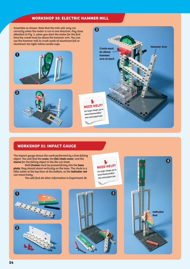
WORKSHOP 31: IMPACT GAUGE
WORKSHOP 30: ELECTRIC HAMMER MILL
Assemble as shown. Note that the mill will only run correctly when the motor is run in one direction. Pay close attention to Fig. 3, when you start the motor for the first time the crank must be above the hammer arm. You can use the hammer mill to crush wads of aluminum foil or aluminum tea light votive candle cups.
Hammer ArmCrank must be above hammer arm at start
3
1
2
The impact gauge shows the work performed by a free-falling object. You will find the scale, the fall chute cover, and the sleeve for the falling object in the die-cut sheet. Both frames must be pressed firmly into the base plate; they should stand vertically on the base. The chute is a little wider at the top than at the bottom, so the indicator rod can move freely. You will find all other information in Experiment 28.
1
2
3
4
Indicator Rod
NEED HELP?
For larger images, go to
www.thamesandkos-
mos.com/support/pw
NEED HELP?
For larger images, go to
www.thamesandkos-
mos.com/support/pw
54

WORKSHOP 32: OSCILLATION ABSORBER
Oscillating Energy A pendulum is an oscillating body, too. It changes its energy state in a steady beat between potential and kinetic energy. The time it takes to make one back-and-forth motion is called its periodic time, or simply its period. The useful thing about the swings of a pendulum is that the periodic time is not dependent on the mass of the body. A pendulum of a certain length always needs the same amount of time for a period, even when the amplitude becomes smaller or the mass changes. That is why pendulums lend themselves very well to measurements of time — in other words, to clocks. The periodic time of a pendulum depends on its length and on acceleration due to gravity. Long pendulums swing slowly, short pendulums swing quickly. If a pendulum is exactly 99.4 cm from the suspension point to the center of mass of the pendulum weight, it needs very close to one second to travel the distance from 0 to 1, in other words for a half swing. It’s easy to make a pendulum like that from the illustration at the lower left.
If a pendulum is to be used to determine the timing of a clock, it needs a source of power, because various forces of friction would otherwise bring it to a stop. The drive mechanism of the clock likewise needs the pendulum, so that it releases its energy in a specific timing rhythm.
01
Energy change in rhythm. At turning points 0 and 1, the pendulum possesses potential energy, while it has kinetic energy on the curved path between those points.
This pendulum needs one second to move through half a swing.
(See Experiment 29.) You will need two extra batteries. These act as weights, while the water-filled cup with the spool made of pulley wheels and gear wheels acts as the oscillation absorber. For the spring suspension, attach a small rubber band to a large one. If they have already
gotten a little stretched out, mount the large axle from which they will hang one hole higher. It is very important that the vertical axle with the battery holder hang from the top horizontal axle in such a way that vertical axle can swing equally far up and down.
1
2
3
4
Spool
NEED HELP?
For larger images, go to
www.thamesandkos-
mos.com/support/pw
Attach the battery with tape to the string as shown in the picture, then lead the other end of the string through the hole of the rod, pull the string through to leave a length of 99.4 cm exactly, and secure it with an anchor pin or joint plug. Take the measurement from the head (positive pole) of the battery to where the string goes through the hole of the rod. To start, make the battery swing about 30° to each side. Observe it for a minute to see if the swing of the pendulum is synchronized with the second hand of your watch. If not, you’ll have to alter the length of the string. The weight may have stretched it a little.
EXPERIMENT 30: THE SECOND PENDULUM
56

WORKSHOP 33: PENDULUM CLOCK
A centuries-old technology for pendulum clocks is the crown wheel (or escape wheel) and anchor. The anchor sits with the pendulum on an axle, and the drive rotation comes from the crown wheel. Without the anchor, the wheel would rotate quickly, and the driving energy of the wind-upspring would be rapidly used up. But the anchor seesaws back and forth against the teeth of the wheel, so it only lets ones tooth slip by with each swing of the pendulum. That is where the familiar ticking sound comes from. Here are instructions for a clock mechanism that just runs for one minute and indicates the time by making second marks on a sheet of paper. Study it well and take your time when assembling it.
This is how the completed pendulum clock should look. To hang the drive weight, use a paper clip. You may have to give the pendulum another push.
This model is very challenging. Do your best to figure it out!
The medium sprocket wheel, shaft plugs and short axle which connect the pendulum to the clock body, should be pressed onto the top most axle assembly so that the pendulum hangs perpendicular from the axle (bottom of Fig. 5, right side of Fig. 7). Also, when positioning your pendulum it is very important that you now take the time to position the crown wheel just under the center of the anchor’s crank rods (Fig. 7). The pendulum should swing equally far to the right and left. Its movement can be very finely adjusted at the hinge of the pendulum bar: The center of the pendulum’s gravity can be shifted by changing the angle of the bend. This fine adjustment is responsible for the pendulum’s clean, seamless “click-clack.” Experiment a little to find the best angle! Another fine adjustment that can be make to ensure proper functionality is the position of the anchor’s crank wheels in relation to the crown wheel.
2
3
4
1
5
6
7
8
shortaxle
hinge
crown wheel
anchor rods
NEED HELP?
For larger images, go to
www.thamesandkos-
mos.com/support/pw
If you have assembled your clock, you will be able to study the way it works. The pendulum’s period lasts about one second. To adjust the clock, or to get it to run with the right timing, compare its beat for about a minute with the second hand of your watch. If the length of the period is too long or short, shorten or lengthen the distance between the pendulum’s center of gravity and the axle. To do that, move the pendulum weight (the large sprocket wheel) by one hole.
EXPERIMENT 31: SETTING THE TIME
57
Forces at Work
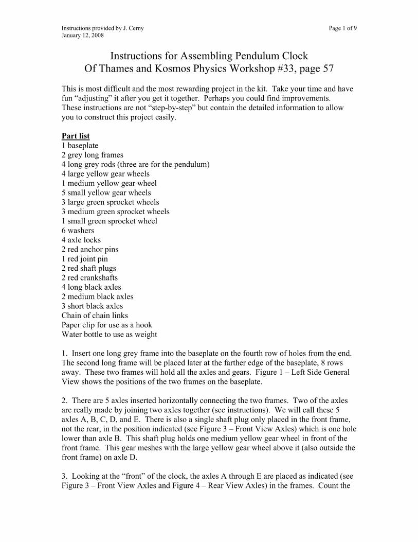
Instructions provided by J. Cerny Page 1 of 9 January 12, 2008
Instructions for Assembling Pendulum Clock Of Thames and Kosmos Physics Workshop #33, page 57
This is most difficult and the most rewarding project in the kit. Take your time and have fun “adjusting” it after you get it together. Perhaps you could find improvements. These instructions are not “step-by-step” but contain the detailed information to allow you to construct this project easily. Part list 1 baseplate 2 grey long frames 4 long grey rods (three are for the pendulum) 4 large yellow gear wheels 1 medium yellow gear wheel 5 small yellow gear wheels 3 large green sprocket wheels 3 medium green sprocket wheels 1 small green sprocket wheel 6 washers 4 axle locks 2 red anchor pins 1 red joint pin 2 red shaft plugs 2 red crankshafts 4 long black axles 2 medium black axles 3 short black axles Chain of chain links Paper clip for use as a hook Water bottle to use as weight 1. Insert one long grey frame into the baseplate on the fourth row of holes from the end. The second long frame will be placed later at the farther edge of the baseplate, 8 rows away. These two frames will hold all the axles and gears. Figure 1 – Left Side General View shows the positions of the two frames on the baseplate. 2. There are 5 axles inserted horizontally connecting the two frames. Two of the axles are really made by joining two axles together (see instructions). We will call these 5 axles A, B, C, D, and E. There is also a single shaft plug only placed in the front frame, not the rear, in the position indicated (see Figure 3 – Front View Axles) which is one hole lower than axle B. This shaft plug holds one medium yellow gear wheel in front of the front frame. This gear meshes with the large yellow gear wheel above it (also outside the front frame) on axle D. 3. Looking at the “front” of the clock, the axles A through E are placed as indicated (see Figure 3 – Front View Axles and Figure 4 – Rear View Axles) in the frames. Count the
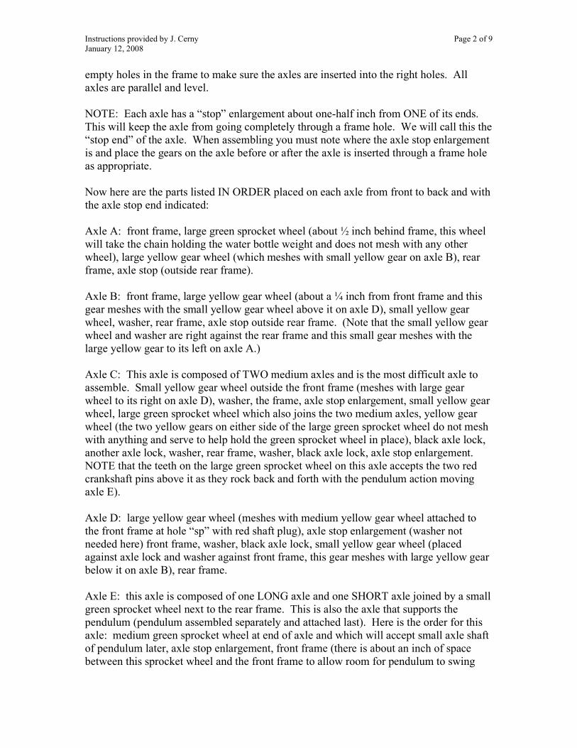
Instructions provided by J. Cerny Page 2 of 9 January 12, 2008
empty holes in the frame to make sure the axles are inserted into the right holes. All axles are parallel and level. NOTE: Each axle has a “stop” enlargement about one-half inch from ONE of its ends. This will keep the axle from going completely through a frame hole. We will call this the “stop end” of the axle. When assembling you must note where the axle stop enlargement is and place the gears on the axle before or after the axle is inserted through a frame hole as appropriate. Now here are the parts listed IN ORDER placed on each axle from front to back and with the axle stop end indicated: Axle A: front frame, large green sprocket wheel (about ½ inch behind frame, this wheel will take the chain holding the water bottle weight and does not mesh with any other wheel), large yellow gear wheel (which meshes with small yellow gear on axle B), rear frame, axle stop (outside rear frame). Axle B: front frame, large yellow gear wheel (about a ¼ inch from front frame and this gear meshes with the small yellow gear wheel above it on axle D), small yellow gear wheel, washer, rear frame, axle stop outside rear frame. (Note that the small yellow gear wheel and washer are right against the rear frame and this small gear meshes with the large yellow gear to its left on axle A.) Axle C: This axle is composed of TWO medium axles and is the most difficult axle to assemble. Small yellow gear wheel outside the front frame (meshes with large gear wheel to its right on axle D), washer, the frame, axle stop enlargement, small yellow gear wheel, large green sprocket wheel which also joins the two medium axles, yellow gear wheel (the two yellow gears on either side of the large green sprocket wheel do not mesh with anything and serve to help hold the green sprocket wheel in place), black axle lock, another axle lock, washer, rear frame, washer, black axle lock, axle stop enlargement. NOTE that the teeth on the large green sprocket wheel on this axle accepts the two red crankshaft pins above it as they rock back and forth with the pendulum action moving axle E). Axle D: large yellow gear wheel (meshes with medium yellow gear wheel attached to the front frame at hole “sp” with red shaft plug), axle stop enlargement (washer not needed here) front frame, washer, black axle lock, small yellow gear wheel (placed against axle lock and washer against front frame, this gear meshes with large yellow gear below it on axle B), rear frame. Axle E: this axle is composed of one LONG axle and one SHORT axle joined by a small green sprocket wheel next to the rear frame. This is also the axle that supports the pendulum (pendulum assembled separately and attached last). Here is the order for this axle: medium green sprocket wheel at end of axle and which will accept small axle shaft of pendulum later, axle stop enlargement, front frame (there is about an inch of space between this sprocket wheel and the front frame to allow room for pendulum to swing

Instructions provided by J. Cerny Page 3 of 9 January 12, 2008
below), second medium green sprocket wheel (about ¼ inch behind front frame and contains a red crankshaft pin), third medium green sprocket wheel (with another crankshaft pin), small green sprocket wheel which connects the two axles, start of small axle, washer, rear frame, axle stop enlargement. NOTE: this axle is the escape movement that allows the large green sprocket wheel on axle E to move only one tooth at each swing of the pendulum. The trick here is to assemble the two medium green sprocket wheels (each containing a red crankshaft pin in its outer hole) so that each pin touches the other sprocket wheel opposite. The pins only firmly touch the other sprocket wheel on the side and should be spaced so as to allow only one sprocket tooth to pass beneath with each swing of the pendulum (about a 90-degree separation angle with the axle). This is the “heart” of the clock and may need some adjusting. Use one long rod with anchor pins to join the tops of the two long frames together. Assemble pendulum and attach to axle E (hanging over table edge) so that it can swing freely. Attach chain with water bottle weight to large green sprocket wheel on axle A. You may have to move the pendulum by hand to get it to swing high enough to get the clock to work. Experiment with different weights and pendulum lengths. This is REALLY COOL!

Instructions provided by J. Cerny Page 4 of 9 January 12, 2008
PICTURES REFERRED TO IN THE INSTRUCTIONS
Figure 1 - Left Side general view
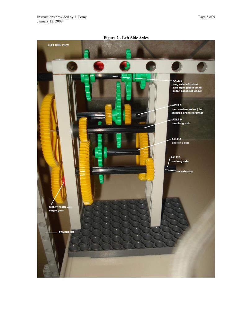
Instructions provided by J. Cerny Page 5 of 9 January 12, 2008
Figure 2 - Left Side Axles
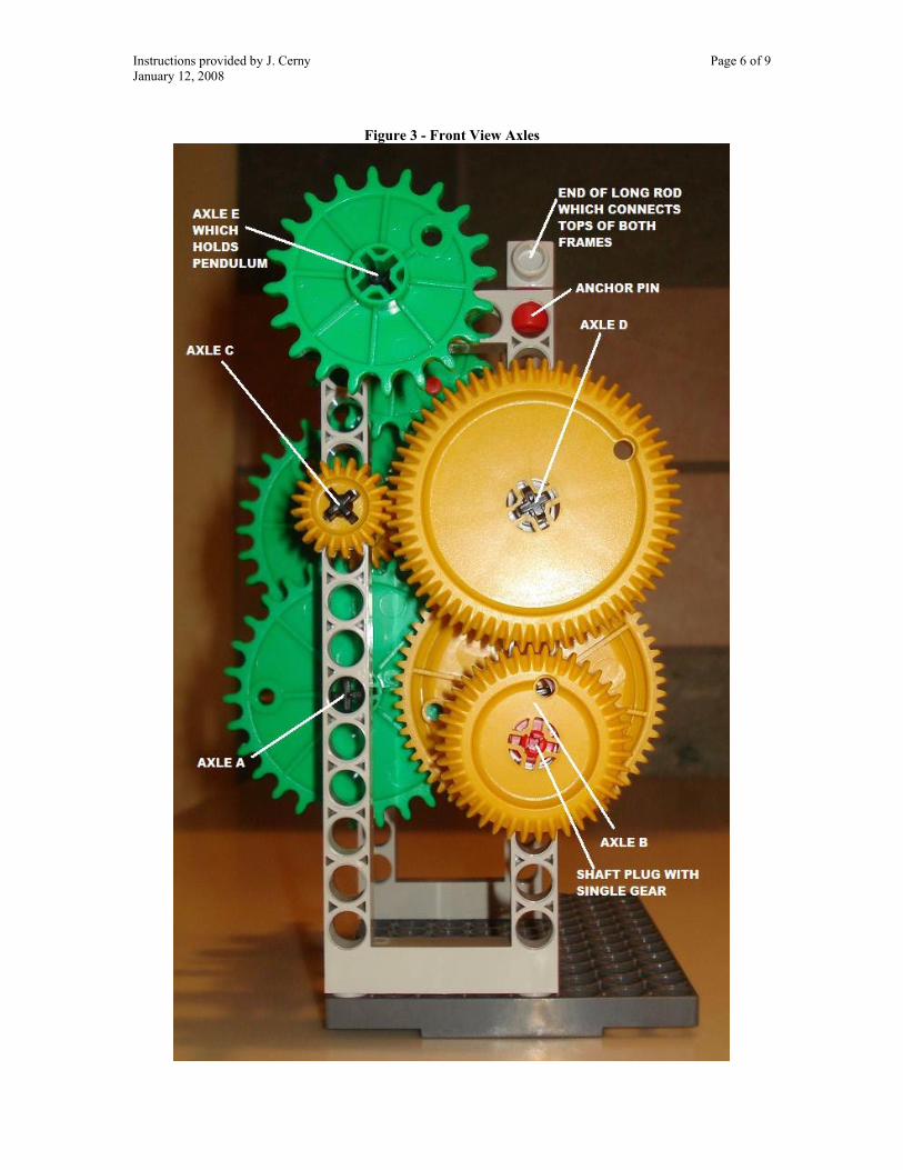
Instructions provided by J. Cerny Page 6 of 9 January 12, 2008
Figure 3 - Front View Axles

Instructions provided by J. Cerny Page 7 of 9 January 12, 2008
Figure 4 - Rear View Axles

Instructions provided by J. Cerny Page 8 of 9 January 12, 2008
Figure 5 - Right Side Axles
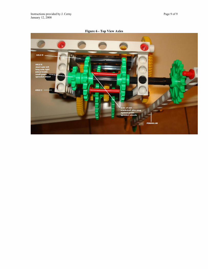
Instructions provided by J. Cerny Page 9 of 9 January 12, 2008
Figure 6 - Top View Axles
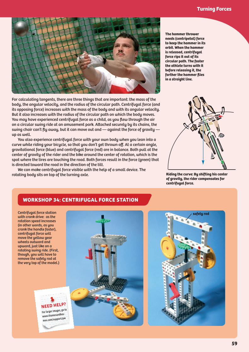
WORKSHOP 34: CENTRIFUGAL FORCE STATION
For calculating tangents, there are three things that are important: the mass of the body, the angular velocity, and the radius of the circular path. Centrifugal force (and its opposing force) increases with the mass of the body and with its angular velocity. But it also increases with the radius of the circular path on which the body moves. You may have experienced centrifugal force as a child, as you flew through the air on a circular swing ride at an amusement park. Attached securely by its chains, the swing chair can’t fly away, but it can move out and — against the force of gravity — up as well. You also experience centrifugal force with your own body when you lean into a curve while riding your bicycle, so that you don’t get thrown off. At a certain angle, gravitational force (blue) and centrifugal force (red) are in balance. Both pull at the center of gravity of the rider and the bike around the center of rotation, which is the spot where the tires are touching the road. Both forces result in the force (green) that is directed toward the road in the direction of the tilt. We can make centrifugal force visible with the help of a small device. The rotating body sits on top of the turning axle.
The hammer thrower needs (centripetal) force to keep the hammer in its orbit. When the hammer is released, centrifugal force rips it out of its circular path. The faster the athlete turns with it before releasing it, the farther the hammer flies in a straight line.
Riding the curve: By shifting his center of gravity, the rider compensates for centrifugal force.
Centrifugal force station with crank drive: as the rotation speed increases (in other words, as you crank the handle faster), centrifugal force will move the yellow gear wheels outward and upward, just like on a rotating swing ride. (First, though, you will have to remove the safety rod at the very top of the model.)
safety rod
NEED HELP?
For larger images, go to
www.thamesandkos-
mos.com/support/pw
59
Turning Forces
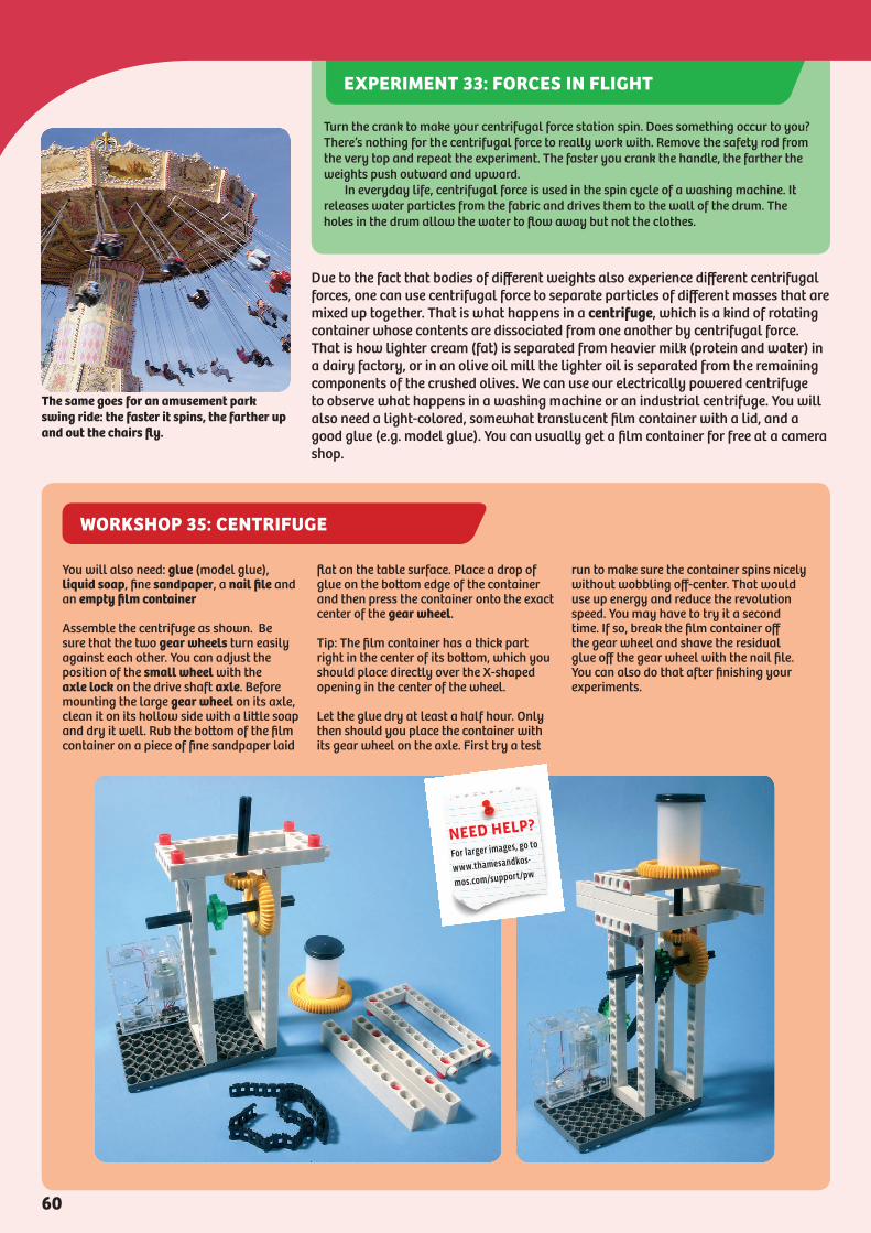
WORKSHOP 35: CENTRIFUGE
Due to the fact that bodies of different weights also experience different centrifugal forces, one can use centrifugal force to separate particles of different masses that are mixed up together. That is what happens in a centrifuge, which is a kind of rotating container whose contents are dissociated from one another by centrifugal force. That is how lighter cream (fat) is separated from heavier milk (protein and water) in a dairy factory, or in an olive oil mill the lighter oil is separated from the remaining components of the crushed olives. We can use our electrically powered centrifuge to observe what happens in a washing machine or an industrial centrifuge. You will also need a light-colored, somewhat translucent film container with a lid, and a good glue (e.g. model glue). You can usually get a film container for free at a camera shop.
The same goes for an amusement park swing ride: the faster it spins, the farther up and out the chairs fly.
You will also need: glue (model glue), liquid soap, fine sandpaper, a nail file and an empty film container
Assemble the centrifuge as shown. Be sure that the two gear wheels turn easily against each other. You can adjust the position of the small wheel with the axle lock on the drive shaft axle. Before mounting the large gear wheel on its axle, clean it on its hollow side with a little soap and dry it well. Rub the bottom of the film container on a piece of fine sandpaper laid
flat on the table surface. Place a drop of glue on the bottom edge of the container and then press the container onto the exact center of the gear wheel.
Tip: The film container has a thick part right in the center of its bottom, which you should place directly over the X-shaped opening in the center of the wheel.
Let the glue dry at least a half hour. Only then should you place the container with its gear wheel on the axle. First try a test
run to make sure the container spins nicely without wobbling off-center. That would use up energy and reduce the revolution speed. You may have to try it a second time. If so, break the film container off the gear wheel and shave the residual glue off the gear wheel with the nail file. You can also do that after finishing your experiments.
NEED HELP?
For larger images, go to
www.thamesandkos-
mos.com/support/pw
Turn the crank to make your centrifugal force station spin. Does something occur to you? There’s nothing for the centrifugal force to really work with. Remove the safety rod from the very top and repeat the experiment. The faster you crank the handle, the farther the weights push outward and upward. In everyday life, centrifugal force is used in the spin cycle of a washing machine. It releases water particles from the fabric and drives them to the wall of the drum. The holes in the drum allow the water to flow away but not the clothes.
EXPERIMENT 33: FORCES IN FLIGHT
60

WORKSHOP 36: AUTOMATIC CENTRIFUGAL SWITCH
What Makes the Top Slow Down — the Moment of InertiaWe have learned about velocity and the two important forces of rotation. If the physical factors of rotation are similar to those of linear movement, then what about mass? In other words, how does rotation affect the tendency of a body to be inert and heavy? Gravity naturally works on the mass of a rotating body too, and that makes it inert and pulls it towards Earth’s center. Now we have to add to that another inertia of its mass, one that comes from its rotation. A rotating body wants to maintain its movement as well, and conversely it acts inert if you want to prod it out of a state of rest into rotation. You are familiar with this kind of inertia from a top: once twirled and loaded with energy, it will continue to spin for a while without any extra help. To investigate the perseverance of a spinning body once again, we will construct a metal-tipped top. You can either spin this top between your thumb and forefinger, or start it in the classic manner with a pull-cord and rod.
The top on a plate
(For Experiment 36) Assemble the centrifugal switch as shown. The four base connectors serve as the centrifugal weights. Tape them or glue them with a thin layer of model glue into the large holes of the belt (from the die-cut card). Lay the small holes in the ends of the belt over one another and secure them with an axle lock (Fig. 3). Bend the belt just a little along the pre-marked folding lines — its middle sections with the axle holes should still bend away from each other after the belt is mounted — their outward-bulging tension saves us from having to use a spring. When your machine has done its work, remove the attachment plates from the belt and rub off any bits of dried glue with the nail file. If you want to assemble the device again later on, use the belt as a stencil and cut a new belt from some thin cardboard. If you initially taped the base connectors into the belt carefully remove the tape so that the belt can be reused.
1
6
4
2 3
5
switching axle
belt
exit shaft
centrifugal weights
NEED HELP?
For larger images, go to
www.thamesandkos-
mos.com/support/pw
62
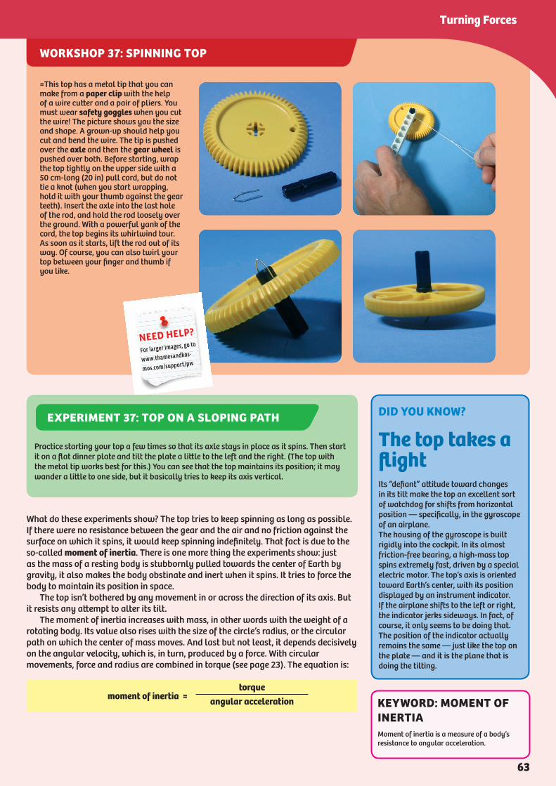
WORKSHOP 37: SPINNING TOP
What do these experiments show? The top tries to keep spinning as long as possible. If there were no resistance between the gear and the air and no friction against the surface on which it spins, it would keep spinning indefinitely. That fact is due to the so-called moment of inertia. There is one more thing the experiments show: just as the mass of a resting body is stubbornly pulled towards the center of Earth by gravity, it also makes the body obstinate and inert when it spins. It tries to force the body to maintain its position in space. The top isn’t bothered by any movement in or across the direction of its axis. But it resists any attempt to alter its tilt. The moment of inertia increases with mass, in other words with the weight of a rotating body. Its value also rises with the size of the circle’s radius, or the circular path on which the center of mass moves. And last but not least, it depends decisively on the angular velocity, which is, in turn, produced by a force. With circular movements, force and radius are combined in torque (see page 23). The equation is:
moment of inertia =torque
angular acceleration
=This top has a metal tip that you can make from a paper clip with the help of a wire cutter and a pair of pliers. You must wear safety goggles when you cut the wire! The picture shows you the size and shape. A grown-up should help you cut and bend the wire. The tip is pushed over the axle and then the gear wheel is pushed over both. Before starting, wrap the top tightly on the upper side with a 50 cm-long (20 in) pull cord, but do not tie a knot (when you start wrapping, hold it with your thumb against the gear teeth). Insert the axle into the last hole of the rod, and hold the rod loosely over the ground. With a powerful yank of the cord, the top begins its whirlwind tour. As soon as it starts, lift the rod out of its way. Of course, you can also twirl your top between your finger and thumb if you like.
NEED HELP?
For larger images, go to
www.thamesandkos-
mos.com/support/pw
DID YOU KNOW?
The top takes a flightIts “defiant” attitude toward changes in its tilt make the top an excellent sort of watchdog for shifts from horizontal position — specifically, in the gyroscope of an airplane. The housing of the gyroscope is built rigidly into the cockpit. In its almost friction-free bearing, a high-mass top spins extremely fast, driven by a special electric motor. The top’s axis is oriented toward Earth’s center, with its position displayed by an instrument indicator. If the airplane shifts to the left or right, the indicator jerks sideways. In fact, of course, it only seems to be doing that. The position of the indicator actually remains the same — just like the top on the plate — and it is the plane that is doing the tilting.
Practice starting your top a few times so that its axle stays in place as it spins. Then start it on a flat dinner plate and tilt the plate a little to the left and the right. (The top with the metal tip works best for this.) You can see that the top maintains its position; it may wander a little to one side, but it basically tries to keep its axis vertical.
EXPERIMENT 37: TOP ON A SLOPING PATH
KEYWORD: MOMENT OF INERTIAMoment of inertia is a measure of a body’s resistance to angular acceleration.
63
Turning Forces

DID YOU KNOW?
Riding a bike — pure trickeryHow is it actually possible to keep your balance on a bike? Trying to just stand still on two wheels results in falling. The art of bike riding consists in a balance of centrifugal forces that arise from small curves while riding. Without a steering wheel, then, bike riding would be impossible. With it, we accommodate the curves, without really being conscious of what we’re doing. Against the centrifugal force that arises when riding through a curve, our body instinctively angles itself a little too steeply. The body reacts to the sharp angle by shifting its weight to the other side, which leads to another curve in the opposite direction and another corresponding centrifugal force, to which our body reacts...and so on. As we start riding, the curves and our compensating movements are relatively great, but they become smaller as we get going, until we seem to be riding in a perfectly straight line. The faster the speed, the less we need the steering wheel to balance. Then we’re dealing increasingly with a different effect of rotation: the moment of inertia. This rises with the rotation speed of the wheels, and stabilizes the ride. Because of their mass, the wheels fall increasingly into a sort of “top defiance.” In other words, they are harder and harder to shift from the direction of their axis.
Work and Energy in RotationYou will recall that with bodies moving in a straight line, we defined work in terms of the product of force and distance: work = force x distance. With rotating bodies, too, the quantity of work is measured in terms of the change in location undergone by a force. Instead of meters, we indicate the change in location with and angle, and force — as just mentioned — with torque. In rotation, then, work is the product of torque and the angle by which the body turns. And where do things stand with rotational energy, or the capacity of rotating bodies to perform work? Its laws must be similar to those of bodies moving in a straight line as well. Start your high-performance top with the cord again. The harder you pull the cord to get it going, the faster the top spins, right? In other words: the greater the moment of inertia and the angular velocity, the greater the amount of stored rotational energy. The work that you applied at the start is now stored in the body as energy. We’ll prove it with a quickly assembled yo-yo.
What’s Going on with the Yo-Yo?Gravity pulls the body of the yo-yo, it unrolls from the cord, rotates (faster and faster, because of gravitational acceleration), and thereby takes up rotational energy. After the cord unrolls, the yo-yo body keeps rotating and climbs back up the cord with the help of the stored rotational energy. But because energy is lost through friction (above all by the rolling and unrolling of the cord), we keep having to add some back in. In industry, rotational energy is used in flywheel energy storage systems. Those usually have a wheel with a heavy metal rim, which is kept constantly rotating by a motor. When the motor is briefly required to provide more energy than it can, the flywheel springs into action and gets it through the critical few seconds of overload. Just like a bicyclist who gives some of his own energy to nudge an exhausted companion over a hill. Or the way your work in this booklet has hopefully made the task of constructing, experimenting, and understanding a little bit easier.
The EndWe hope you had a great time building the models, conducting the experiments, and learning the lessons in this kit!
Assemble the Yo-yo as shown. Pull the end of the 50 cm (20 in) cord through one of the four small holes in the center of the spool and tie it with a knot. Use a
joint pin to make a handle at the end of the cord. This is how it works: wind up the cord, hold the end tight, and let the yo-yo descend. Just before it gets to the end, pull up a little. If it comes up again, move your hand toward it with the cord held loosely. Then, by pulling up, pump more energy into it, pull up again just before it reaches the end, etc. The stored rotational energy keeps the yo-yo going.
NEED HELP?
For larger images, go to
www.thamesandkos-
mos.com/support/pw
WORKSHOP 38: WEDGE AND STUCK RACK
64