Ultrafast, Cross-Correlated Harmonic Imaging Through Scattering Media
Upload
independentCategory
view
4download
0
Dynamics of the plumes produced by ultrafast laser ablation of metalsT. Donnelly,1 J. G. Lunney,1 S. Amoruso,2,a� R. Bruzzese,2 X. Wang,2 and X. Ni31School of Physics, Trinity College Dublin, Dublin 2, Ireland2Dipartimento di Scienze Fisiche and CNR-SPIN, Università degli Studi di Napoli Federico II, ComplessoUniversitario di Monte S. Angelo, Via Cintia, I-80126 Napoli, Italy3Department of Electronic Engineering, Tianjin University of Technology and Education, Tianjin 300222,People’s Republic of China
�Received 4 March 2010; accepted 3 July 2010; published online 30 August 2010�
We have analyzed ultrafast laser ablation of a metallic target �Nickel� in high vacuum addressingboth expansion dynamics of the various plume components �ionic and nanoparticle� and basicproperties of the ultrafast laser ablation process. While the ion temporal profile and ion angulardistribution were analyzed by means of Langmuir ion probe technique, the angular distribution ofthe nanoparticulate component was characterized by measuring the thickness map of deposition ona transparent substrate. The amount of ablated material per pulse was found by applying scanningwhite light interferometry to craters produced on a stationary target. We have also compared theangular distribution of both the ionic and nanoparticle components with the Anisimov model. Whilethe agreement for the ion angular distribution is very good at any laser fluence �from ablationthreshold up to �1 J /cm2�, some discrepancies of nanoparticle plume angular distribution atfluencies above �0.4 J /cm2 are interpreted in terms of the influence of the pressure exerted by thenascent atomic plasma plume on the initial hydrodynamic evolution of the nanoparticle component.Finally, analyses of the fluence threshold and maximum ablation depth were also carried out, andcompared to predictions of theoretical models. Our results indicate that the absorbed energy isspread over a length comparable with the electron diffusion depth Lc ��30 nm� of Ni on thetimescale of electron-phonon equilibration and that a logarithmic dependence is well-suited for thedescription of the variation in the ablation depth on laser fluence in the investigated range.© 2010 American Institute of Physics. �doi:10.1063/1.3475149�
I. INTRODUCTION
Ultrashort laser ablation �ULA� of metals using femto-second �fs� pulses at intensities �1012–1013 W /cm2 is cur-rently receiving much attention both in terms of understand-ing the ablation physics and informing the development ofnew material processing techniques. ULA differs in severalways from nanosecond �ns� laser ablation. Since the laserpulse duration is much shorter than the electron-phonon re-laxation time, �ep �typically �10 ps for elemental metals�,there is little hydrodynamic movement of the heated materialduring the laser pulse. During the laser pulse the electronswithin the optical penetration depth are driven to high tem-perature while the lattice remains relatively cold. On timescale of �ep the electron temperature drops through energyrelaxation to the lattice. Energy continues to be transporteddeeper in the target by electron heat conduction and ablationof part of the heated region ensues.
Much of the research on ULA has concentrated on thelaser absorption, electron-phonon relaxation, electron heatconduction and phase decomposition leading to ablation. Thetwo-temperature model �TTM� provides a good descriptionof the thermal history of the electron and lattice subsystems.1
Hydrodynamic model �HM� and molecular dynamic �MD�simulations have been both used to describe the thermody-namic evolution leading to ablation.2–9 These simulations
show that the overall ULA process is governed by a set ofrather complex mechanisms occurring on very fast timescales and varying on small spatial scales. The initial laserheating is nearly isochoric and the relaxation of the hot near-solid-density material proceeds in a different manner at dif-ferent depths in the target. Near the surface the material iscompletely atomised; deeper layers decompose into a mix-ture of vapor and liquid clusters through mechanical frag-mentation and phase explosion. This leads to the appearanceof two distinct ablation plumes in the far-field: a fast-movingatomic plume which can be partially ionised and a slower-moving nanoparticle �NP� plume, as observed in severalexperiments.10–12 Typically, NPs constitute the major part ofthe ablated material, and the atomic plume accounts for only10%–20% of the total ablated mass.3,5,12,13 Recently, ultrafasttime-resolved x-ray absorption spectroscopy �with 30 ps timeresolution� during ULA of a metallic target �Al�, in vacuum,showed that a structured nascent plume, with the fasteratomic species followed by a hot-liquid-phase of slower NPs,already exists at the very early stages ��30 ns� of the abla-tion process.14 This study also indicated that material ejec-tion from the target surface starts within the first 30 ps andlasts for few tens of ns.
The properties of the ablated material and its expansiondynamics are of interest in numerous research fields, such aspulsed laser deposition �PLD�, laser induced breakdownspectroscopy, ion beam generation, NP synthesis and depo-sition. Analysis of the expansion dynamics can also improvea�Electronic mail: [email protected].
JOURNAL OF APPLIED PHYSICS 108, 043309 �2010�
0021-8979/2010/108�4�/043309/13/$30.00 © 2010 American Institute of Physics108, 043309-1
Downloaded 08 Oct 2010 to 134.226.1.234. Redistribution subject to AIP license or copyright; see http://jap.aip.org/about/rights_and_permissions

the physical understanding of the overall ablation process. Itis, therefore, interesting to relate parameters of the ejectedplumes in the far-field, for times of few microseconds ormore and distances from millimeters to centimeters from thetarget surface, to those near the target at the early stages ofablation. The large differences in the spatial and temporalscales involved make the use of HM codes and MD simula-tions unfeasible, thus, suggesting the need to consider mod-els which are suitable for the different stages and try tomatch them at an intermediate phase. Besides, in the veryearly stage a one-dimensional description is typically em-ployed, while it should be considered that some time afterablation the ejection of material ceases and the expansion ofthe clouds of ablated particles becomes fully three-dimensional �3D�. At this late stage more conventional hy-drodynamic descriptions can be used to describe the expan-sion of the ejected species. One of these is the adiabaticisentropic expansion model of Anisimov et al.,15,16 which hasbeen extensively applied to PLD with ns pulse duration todescribe both the laser ablation plume propagation and theangular profile of the deposition rate.17–19 These studies in-dicate that the Anisimov model provides a rather good de-scription of how the ablated material expands from a small,hot, dense vapor cloud at the end of the ns laser pulse to thetime when the ablated material has traveled several centime-ters, or more, from the target. More recently, the Anisimovmodel was also shown to describe fairly well the angulardistribution of the ionised plume produced by ULA of me-tallic thin films or bulk targets.19,20 In contrast, the applica-tion of the Anisimov model to describe the expansion of theNP plume in ULA has not yet been explored.
In this paper we describe the results of some experi-ments to examine various aspects of the ablation plume ex-pansion in ULA of metals. We have mainly sought to explorethe extent to which the Anisimov model can describe theexpansion of both the atomic and NP plumes produced in theULA process. This will help to highlight any differences be-tween the ablation components and provide insights into thegeometrical characteristics of these plumes at the beginningof their 3D expansion, which are of paramount interest inview of the matching of the late expansion stage with thepredictions of complex models of the early ablation phase.Finally, we compare the measured ablation rate with earliermodels of laser ablation based on the TTM,21,22 trying toaddress some aspects which have not yet been considered sofar.
The paper is divided in several sections. The followingsection describes the experimental methods, while Sec. IIIreports the theoretical background of the Anisimov model,and some predictions of the plume expansion characteristicsin our experimental conditions. Sec. IV is devoted to theexperimental characterization of the ion and NP plumes ex-pansions, and to their discussion within the framework of theAnisimov model. Sec. V presents an analysis of the ablationrate as a function of the laser fluence and a comparison withpredictions of simple models generally employed to describethe ablation threshold and dependence of the ablation rate on
material physical parameters. Finally, Sec. VI summarizesthe present investigations and outlines the main conclusionswhich can be drawn.
II. EXPERIMENTAL METHODS
The experimental setup used in this study is schemati-cally depicted in Fig. 1. The diagnostic setup is placed in ahigh vacuum chamber and comprises an ion probe, whichcan be moved on a circle in the zy plane, and a circularly-curved transparent plastic substrate collecting the ablatedmaterial. Both the ion probe and the substrate are centered atthe ablation spot. In Fig. 1 the shape of a semiellipsoidalplume expanding toward the substrate is also drawn sche-matically. The inset shows a magnification of the semiellip-soidal initial plume with the indication of the initial dimen-sions X0, Y0, and Z0 along the three axes, which will be usedin the Anisimov model of Sec. III.
The laser source delivers �250 fs, 1 mJ laser pulses at527 nm, at a repetition rate of 33 Hz. The laser beam inten-sity profile was approximately Gaussian. The p-polarized la-ser beam was focused at 45° incident angle to an ellipticalspot on a Ni target in high vacuum at 10−7 mbar. The laserbeam intensity profile on the target was found by measuringthe major and minor diameters of elliptical burn spots as afunction of laser pulse energy, E, and evaluating the slope ona semilogarithmic plot.23 Two laser shots were fired at eachlocation and the damaged area was measured by an opticalmicroscope. The estimated spot size was �0=1.3�10−3 cm2. The peak fluence at the center of the beam isgiven by Fp=2 E /�0, which, for a maximum energy on tar-get E�500 �J, gives Fp�0.8 J /cm2. The average fluencewithin a spot of area �0 is F=E /�0=0.5 Fp.
The plasma part of the ablation plume was measuredusing a planar Langmuir probe,24 oriented to face the targetspot and located at a distance of 64 mm from the target �seeFig. 1�. The probe collecting area was a 2.5�5 mm2 copper
z
x
y
θ
Ion probeTransparent
substrate
Target
Laser beamPlume
φ
y
Y0
Z0
x
z
FIG. 1. �Color online� Schematic of the experimental setup. The ion probemoves on a circle in the zy plane centered at the ablation spot. The ablatedmaterial is collected on a circularly-curved transparent plastic substrate alsocentered at the ablation spot. Sections of the deposits in the zy and zx planesare used to obtain angular deposition profiles as a function of the angle � ona hemispherical surface and of the angle � on a planar surface. The shape ofthe ablation plume is shown. The inset shows the semiellipsoidal initialplume with the indication of the initial dimensions X0, Y0, and Z0 along thethree axes.
043309-2 Donnelly et al. J. Appl. Phys. 108, 043309 �2010�
Downloaded 08 Oct 2010 to 134.226.1.234. Redistribution subject to AIP license or copyright; see http://jap.aip.org/about/rights_and_permissions
plate insulated at the rear side. The probe was negatively-biased to reject electrons, thus, the current density recordedby the probe is directly related to the positive ion flux due tothe plasma flow at the probe position. The angular distribu-tion of the ion flux in the atomic plume was measured bymoving the probe on a circle in the zy plane �see Fig. 1�. Asecond fixed probe �2�2 mm2� at the same distance andclose to the target normal was used to ensure the ablationconditions remained constant. 64 ion signals were averagedfor each condition.
To examine the angular distribution of ablated material,which is predominately NPs,3,5,12,13 we measured the spatialdistribution of deposition on the circularly-curved transpar-ent plastic substrate which was positioned at 77 mm from theablation spot and centered on it. The film thickness wasfound by measuring the optical transmission, around 515 nm,of the Ni film using a calibrated flatbed scanner. UV-visiblespectrophotometry and spectroscopic ellipsometry of the Nifilms showed that the optical constants are close to the bulkvalues, therefore, the film thickness was derived from themeasured transmission using the optical constants of bulk Ni.This deposition technique allows the angular distribution ofablated material to be obtained in the zy plane, as a functionof the angle � on a hemispherical surface, and in the zxplane, as a function of the angle � on a planar surface �seeFig. 1�. These can be directly compared to the Anisimovmodel predictions.15–17 During ion probe and depositionmeasurements the Ni target was rotated in its own plane toavoid drilling a hole.
Finally, craters were produced delivering a given numberof laser pulses at the same position on a stationary target.The amount of ablated material per pulse as a function of thelaser fluence was obtained by measuring the craters with aZygo scanning white light interferometer.
III. THEORETICAL BACKGROUND
The Anisimov model provides a gas dynamical descrip-tion of the adiabatic phase of expansion of a laser ablationplume in vacuum. In ns laser ablation this adiabatic regimecommences at the end of the laser pulse, at which time theablated material exists as a thin layer of hot vapor on thesurface of the target �see inset of Fig. 1�. It is based on a 3D,adiabatic and isentropic self-similar solution of the gas dy-namics equations. While the model was developed for theexpansion of a neutral gas cloud, it has been successfullyused to describe the expansion of both the plasma part andthe overall plume �ions and neutrals� for laser produced plas-mas �LPP� generated by ns laser ablation in vacuum.17,18 Theexpansion is considered to be isentropic when the thermaldiffusion is too slow to keep pace with the rate of expansion.Singh and Narayan25 considered the case where the plumecan be considered to be isothermal. By comparing the expan-sion velocity and the rate of heat diffusion in a LPP, Lunneyet al.26 estimated that when the electron temperature is lessthan �12 eV the expansion is isentropic.
The thickness of the layer of ablated material at the onsetof the adiabatic expansion is a critical parameter in the Anisi-mov expansion model, since it determines the extent to
which the final plume is forward-peaked. For ns pulses, va-por evolved from the target during the laser pulse is furtherheated by absorption of the laser. Thus, apart from someenergy transport from the vapor to the target, the end of thelaser pulse seems the appropriate choice for the onset of theadiabatic expansion. The initial dimensions of the gas cloudcan then be estimated as follows. The initial thickness d isapproximated as d�cs�p where cs is the sound velocity and�p is the laser pulse duration. The dimensions in the plane ofthe target are determined by the size of the ablation spot,which is related to the laser beam spot. Good agreement withthe experimental data seems to support theseassumptions.17,18
For ULA it is not clear how to choose the initial thick-ness of the ablated material at the beginning of the adiabaticexpansion. It was suggested earlier that the initial longitudi-nal dimension of an ULA plume could be taken as compa-rable to the thickness of removed material.2 This would re-sult in an extremely narrow angular width of the plume in theinertial expansion stage, which was not observedexperimentally.19,20 Indeed, it has been observed that twodistinct plumes are produced in the ULA process, a faster-moving atomic plume and a slower NP one.10–12 The validityof the Anisimov model should be tested for both compo-nents, which is the main aim of the present work.
Looking first at the formation of the atomic plume, wecan note that at the end of the fs laser pulse the material nearthe target surface has a high electron temperature, but thedensity is still close to the solid value. A rarefaction wavewill move into the hot material at about the sound velocityand vapor will move away from the target with a maximumvelocity of 2cs / �−1�, where the adiabatic index has avalue of about 1.25 in a low temperature plasma.27 The for-mation of the vapor layer will cease when the rarefactionwave reaches a depth beyond which the material is not trans-formed into vapor. At the fluence level of concern to thepresent experiment, this depth corresponds to 10%–20% ofthe total ablation depth,3,5,12,13 and amounts to 10–20 nm atthe highest values of fluence used here. Considering the partof laser pulse energy absorbed in such superficial layer, atFp�0.6 J /cm2 an absorbed energy per atom of�10–15 eV can be estimated, which gives cs��2–3��103 m /s. Thus a formation time for the atomic vapor layerof �3–7 ps is obtained. This, in turn, leads to a lower limitof �50–200 nm for the initial thickness of the atomic vaporwhen the adiabatic expansion begins. This estimate is con-sistent with recent work on double pulse ULA of Ni whichshowed that when the second pulse is delayed beyond�10 ps it is primarily absorbed in the vapor produced by thefirst pulse and does not contribute to further ablation.20
Regarding the definition of the parameters which deter-mine the expansion of the NP plume, the situation is evenless clear than for the atomic plume. However, time-resolvedimages of NP plume expansion show that they are quite el-lipsoidal in shape,11 as is the case in the Anisimov model.The starting thickness of the adiabatic expansion of the NPlayer might not be smaller than the ablation depth, but theappropriate value of for a NP plume is not clear at thisstage.
043309-3 Donnelly et al. J. Appl. Phys. 108, 043309 �2010�
Downloaded 08 Oct 2010 to 134.226.1.234. Redistribution subject to AIP license or copyright; see http://jap.aip.org/about/rights_and_permissions

The Anisimov model has been described in detailelsewhere,15–18 thus, only a brief description will be givenhere and related to our experimental conditions. The initialplume is considered to be semiellipsoidal in shape with prin-cipal radii X0, Y0, and Z0, where X0 and Y0 are the major andminor radii of the ablation spot and Z0 is the thickness of theablated material, as shown in the inset of Fig. 1. The x axis ischosen to lie along the major radius of the beam spot. As theexpansion proceeds the radii of the ellipsoidal plume front inthe x, y and z directions are X�t�, Y�t�, and Z�t�. The plumepropagation is described by the following set of equations:
d2
d�2 = �d2�
d�2 = �d2�
d�2 = � 0�0�0
��−1
, �1�
where
=X�t�X0
; � =Y�t�X0
; � =Z�t�X0
; � =t
t0�2�
are dimensionless space and time variables. The time param-eter t0 is given by
t0 =
X0. �3�
The parameter is defined as
= �5 − 3�Ep
Mp= �5 − 3�
�p
mp, �4�
where Ep and Mp are the thermal energy and mass of theinitial plume and �p and mp are the average energy per par-ticle and mass of the plume particles. It is worth nothing thatwhile t0 and, therefore, define the time scale of the plumeexpansion, the plume shape in the inertial expansion stage�t� t0� does not depend on these parameters. Numerical so-lution of this equation set yields the temporal variation in theprincipal radii of the plume front and, therefore, the plumeshape.
The plume expansion behavior can be illustrated bychoosing starting parameters of the same order as for theplasma plume in our ULA experiment, namely Y0 /X0=0.5.In our experiment X0 and Y0 are approximately 200 �m and100 �m, respectively �see Sec. III�. The initial plume thick-ness, Z0, is set to 100 nm, �p=15 eV, mp=58.70 u is theatomic mass of nickel �Ni�, and 1.25 is used for . Figure2�a� shows the evolution of the dimensionless radii. As ex-pected the expansion velocity is greatest in the z directionwhich is the direction of highest pressure gradient in theinitial plume. It can also be seen that the plume expansionbecomes inertial �constant velocity� for values of � beyond 5,which means a time delay after the laser pulse of about 100ns for the values considered above. The plume velocity ineach dimension can be found by differentiation. Figure 2�b�shows the aspects ratios � /, � /�, and � /��Z /X ,Z /Y ,Y /X� as a function of �. The so-called “flip-over” effect can be seen, where the aspect ratio Y /X is ini-tially less than 1 but changes to a value greater than 1 at latetime in the inertial phase. As before, this behavior is a reflec-tion of the ratio of pressure gradients in the x and y direc-tions in the initial plume. The final values of Z /X, Z /Y, and
Y /X are labeled kzx, kzy, and kyx and correspond to the plumelength-to-width ratios in the zy and zx planes and the widthratio in the yx plane. The values of kzx and kzy determine theangular spread of the particle flux on a detector at large dis-tance and larger values correspond to more forward-peakedexpansion. Figure 3 shows values of the plume aspect ratioskzx and kzy calculated as a function of normalized plumethickness Z0 /X0, for Y0 /X0=0.5 and for different values;the upper scale shows the corresponding values of Z0 forX0=200 �m. It can be seen that if the initial thickness isincreased with respect to the in plane dimension, the plumeaspect ratio is reduced. The plume shape is seen to dependstrongly on , becoming more forward-peaked for larger ata fixed value of Z0 /X0.
The equation describing the particle flux on to a detector
10-1
100
101
102
103
0
2
4
6
(b)
Y/X
,Z
/X,
Z/Y
Y/X
Z/X
Z/Y
dimensionless time τ
(a)10
-1
100
101
102
103
104
X/X0
Y/X0
Z/X0
X/X
0,
Y/X
0,
Z/X
0
FIG. 2. �Color online� �a� Dimensionless coordinates of the plume positionas a function of dimensionless time �. �b� The temporal evolution of theplume aspect ratios.
5x10⁻⁶
5x10⁻⁵
5x10⁻⁴
5x10⁻³
1
10
10010
010
110
210
3
γ = 1.15
γ = 1.25
γ = 1.4
γ =1.67
Z0
(nm)
kzx,
kzy
Z0/X0
FIG. 3. �Color online� Calculation of the plume aspect ratios kzx �opensymbol� and kzy �full symbol� as a function of the normalized initial plumethickness Z0 /X0, for several values of the adiabatic index : circles—=1.67; diamond—=1.4; triangles—=1.25; and squares—=1.15. Theaspect ratios were calculated for X0=200 �m and Y0 /X0=0.5. The upperscale reports values of Z0.
043309-4 Donnelly et al. J. Appl. Phys. 108, 043309 �2010�
Downloaded 08 Oct 2010 to 134.226.1.234. Redistribution subject to AIP license or copyright; see http://jap.aip.org/about/rights_and_permissions

positioned at �y ,z� in the zy plane and oriented to face theablation spot is �a similar equation holds for the zx plane�
j�y,z,t� = �N/I1��XYZ�−1�1 − � y
Y2
− � z
Z2 1/−1
�vy2
+ vz2�1/2, �5�
where N is the total number of particles in the plume, I1 is aconstant which depends on the value of , and vy and vz arethe components of the local plume velocity.15 Equation �5�describes the signal recorded on the ion probe operating intime-of-flight �TOF� mode. It also describes how the TOFsignal depends on the angle � measured away from the targetnormal, where y /z=tan �. This equation can be integrated toyield the angular distribution and its associated full-width-half-maximum �FWHM� of the deposition on hemisphericalor plane surfaces. For particles collected on a hemisphericalsurface, as for the ion probe or the deposit in the zy plane�see Fig. 1�, the angular distribution is
F��� = F�0��1 + tan2 ��3/2�1 + kzy2 tan2 ��−3/2, �6�
while for particle collection on a planar surface, as in thecase of the deposit profile in the zx plane �see Fig. 1�, it is
F��� = F�0��1 + kzx2 tan2 ��−3/2. �7�
The width at FWHM of the angular distribution fordeposition on hemispherical and planar substrates can befound from Eqs. �6� and �7�, respectively, and are as follows�see Fig. 1�:18
�� = 2 arctan 22/3 − 1
kzy2 − 22/3 ; �� = 2 arctan22/3 − 1
kzx2
�8�
IV. EXPANSION OF PLASMA AND NP PLUMES ANDCOMPARISON TO ANISIMOV MODEL
In this section the main experimental features of the ionand NP plumes expansions will be discussed and comparedto the predictions of the Anisimov model. Before discussingthe experimental data on the ion TOF profiles and the angu-lar distribution of ions and NPs, we consider useful to exam-ine how the collected material is partitioned between ionisedand nonionised material and compare it with the total num-ber of atoms removed from the target per laser shot. This lastquantity was determined by integrating crater depth maps tofind the volume removed, and then dividing by the numberof laser shots. As an example, Fig. 4 shows a white lightinterferometry map of the ablation crater produced by irradi-ating a stationary target with 260 �J pulses for 7 s at 33 Hz�231 shots�. The peak fluence in the center of the ablationspot was Fp�0.4 J cm−2. The maximum ablation depth perpulse is �75 nm. Figure 5�a� shows the variation in the totalamount of ablated material as a function of the peak fluenceFp. This is indicated in terms of the total number of Ni atomsremoved from the target per laser shot, Nr, as derived fromthe crater depth map measurements. In Fig. 5�a� we alsoreport the total number of atoms deposited per laser shot, Nd,as calculated from the spatial distribution of the deposits on
the hemispherical substrate. We observe a rather good agree-ment between Nr and Nd which indicates that all the ablatedmaterial is finally deposited.
Figure 5�b� reports an approximate estimate of the totalcollected ion yield Ni as a function of Fp, as obtained fromthe ion probe measurements. Since the ion flux angular dis-tribution in the zx plane was not measured directly, thisquantity has been derived by considering an ion plume cy-lindrically symmetric around the target normal. The ion yieldcorresponds to a rather low fraction ��1%� of the total ab-lated material, irrespective of fluence. This is consistent withthe earlier conclusion that the ablated material is predomi-nately decomposed as NPs, while the atomic products �neu-tral atoms and ions� constitute a minor fraction��10%–20%� of the total ablated material.3,5,12,13 We can,therefore, assume in the following that the angular distribu-tion of the deposits can be considered as representative of theNP plume. Moreover, the ion plasma plume characteristicswill be illustrative of the properties of the atomic ablationcomponent.
To compare the experimental results with the predictions
FIG. 4. �Color online� Surface profile of a crater formed from ablation atFp�0.4 J cm−2. The number of shots used in this case was 231.
0
10
20
30
0.0 0.5 1.00
10
20
Nr
Nd
Nr
,N
d(1
01
3a
tom
s) (a)
(b)
Ni(1
01
1io
ns)
Peak fluence Fp (J/cm2)
FIG. 5. �Color online� �a� Total number of atoms removed Nr �circle� anddeposited Nd �square�, per laser shot, as a function of peak fluence Fp. �b�Total number of ablated ions in the plume that was inferred from the ionprobe measurements.
043309-5 Donnelly et al. J. Appl. Phys. 108, 043309 �2010�
Downloaded 08 Oct 2010 to 134.226.1.234. Redistribution subject to AIP license or copyright; see http://jap.aip.org/about/rights_and_permissions

of the Anisimov model, we need as input parameter for themodel the transverse dimensions of the initial plume X0 andY0 when the 3D expansion starts. In our analysis we considerfor these quantities values comparable to the size of the ab-lated region as determined from white light interferometrymap of the ablation craters, as, for example, the one shownin Fig. 4. From the analysis of crater maps obtained at dif-ferent laser fluencies, we derived values of X0�200 �m andY0�100 �m, with a 15% accuracy. While an aspect ratio of0.5 similar to that of the laser spot size �0 is retained, weobserve that the area of the ablated region is almost half thedamaged area, indicating that in our experimental conditionsthe threshold for an effective ablation is reached only on halfof the irradiated region. In the following, these values of X0
and Y0, which were also used earlier in Sec. III, will be usedto compare the experimental results to the Anisimov modelpredictions.
A. Ion plasma plume
The ion plasma part of the ablation plume was measuredby recording the ion signal using the negatively-biased Lang-muir probe. Figure 6�a� shows ion TOF signals recorded as afunction of angle � away from the target normal �see Fig. 1�,for a peak fluence Fp�0.6 J /cm2. As expected for anAnisimov-type expansion, the amplitude of the ion signaland the expansion velocity progressively fall as the detectionangle � is increased. Figure 6�b� shows ion TOF signals,measured normal to the target surface ��=0�, for variousvalues of the peak fluence Fp. As Fp increases, the ion signalincreases accordingly, and, in general, the TOF of the peaksignal is gradually reduced indicating a more energetic ex-pansion.
There seem to be two components in the ion signal: asmall amplitude fast signal followed by a much larger slowsignal. The slower, second component is due to Ni ionsformed when target regions near the surface are ablated as
plasma. The presence of a faster peak in ion probe signalshas been previously observed in various studies of ULA ofmetallic targets, and assigned to low-Z contamination of thetarget surface.19,28,29 Optical emission spectroscopy analysisof ULA of a Cu target has shown the presence of hydrogenemission line due to impurities, which can be reduced byappropriate target conditioning in multishot ablationexperiments.30 To see if this is the origin of the fast signal inour experiment the following tests were carried out. With thelaser running at 33 Hz and the target rotating at about 3 Hzthe signals are as in Fig. 6. However, when the target rotationis turned off the fast signal disappears. It seems that ablationon the same spot at 33 Hz is sufficient to keep the surfacecontamination below our detection limit. Again with the tar-get stationary, if the laser is blocked for several minutes andthen unblocked, the first shot produces a large amplitude fastpeak. The amplitude falls below detection over the next fewshots. This behavior suggests that the contamination mayderive from the vacuum chamber rather than the target itself.It can also be noted in Fig. 6 that the fast signal falls lessrapidly with angle than the main peak, indicating that it has awider angular distribution.
To simplify the analysis of the TOF signals the contami-nation peak was removed by fitting the overall signal withtwo pulse functions, as shown in Fig. 7�a�, and then subtract-ing the fast signal. The ion energy distribution can be calcu-lated from the ion TOF signal, and hence, the average ionenergy.31 The angular variation in average ion energy isshown in Fig. 7�b� for laser peak fluence Fp�0.6 J /cm2.The average ion energy normal to the target is greatest indi-cating a forward-peaked expansion in agreement with the
0
1
2
3
0 5 10 150
1
2
(b)
Sig
na
l(m
A/c
m2)
0 deg
5 deg
10 deg
15 deg
20 deg
Probe Angle θ(a)
TOF (μs)
0.2
0.3
0.4
0.5
Fp (J/cm2)
FIG. 6. �Color online� �a� Ion TOF signals for various probe angles � atFp�0.6 J cm−2. �b� Ion TOF signals for various values of the laser peakfluence Fp, measured normal to the target surface ��=0�.
0 5 10 150
1
2
3
4Ion TOF
Contamination (1)
Main plasma (2)
(1) + (2)
Sig
na
l(m
A/c
m2)
TOF (μs)
(a)
-30 -20 -10 0 10 20 300
50
100
Ave
rag
ee
ne
rgy
(eV
)
Angle θ (deg)
(b)
FIG. 7. �Color online� �a� Ion TOF signal normal to target at a peak fluenceFp�0.6 J cm−2. The signal is resolved into two separate components: thefast contamination peak and the main Ni plasma. �b� Average ion energy asa function of the probe angle � calculated by considering the main Ni com-ponent of the ion TOF signals. The line is a guide for the eye.
043309-6 Donnelly et al. J. Appl. Phys. 108, 043309 �2010�
Downloaded 08 Oct 2010 to 134.226.1.234. Redistribution subject to AIP license or copyright; see http://jap.aip.org/about/rights_and_permissions

Anisimov interpretation. The average ion energy along thenormal to the target surface for different fluencies was alsocalculated: at low fluence Fp�0.1 J /cm2 it was �35 eV,and increased to around 100 eV at a maximum fluence Fp
�0.8 J /cm2.The TOF signals were integrated to find the net ion
charge collected by the probe. The angular variation in thisquantity is reported in Fig. 8 for both the main Ni plasma andcontamination components. As noted above, the distributionof the faster lower-Z contamination signal is wider. A similareffect has been observed in ns laser ablation of LiNbO3
where the Li had a wider distribution than Nb.32 Fitting theangular distributions to Eq. �6�, values of kzy �4.4 for theaspect ratio of the main Ni ion feature and kzy �2.3 for thecontamination component were found. In fact the angulardistribution for the integrated overall signal is very close tothat of the main peak on its own, since the contaminationcontribution is �15% with respect to the main ion plasmacomponent. Figure 9 shows how kzy and the correspondingangular width �� at FWHM �Eq. �8�� of the integrated ionsignal vary with laser fluence. The aspect ratio near thresholdis kzy �3.6 but increases to kzy �4.7 at Fp�0.8 J /cm2.Similar values of the aspect ratio ��4.4� were observed ear-lier for the ion plasma produced by irradiating bulk Ni with�200 fs, 775 nm Ti:sapphire laser pulses at a peak fluenceof �4 J /cm2.33 Instead, larger values of the aspect ratio�from �6 to 10� were reported when irradiating Ni thin films
with thicknesses from 2 to 50 nm with the same laser pulsesat a peak fluence of 1.9 J /cm2, and an adiabatic index �1.27 was estimated for the Ni ion plume.19 Moreover, aprogressive reduction in the aspect ratio was observed as thefilm thickness increases, thus suggesting that our experimen-tal aspect ratio should correspond to a value Z0 of the initialplume larger than 50 nm, which is consistent with the earlierestimate of a 50–200 nm lower limit for Z0 based on thepropagation of a rarefaction wave through the layer which isvaporized.
By comparing the measured aspect ratios of Fig. 9 withthe predictions of the Anisimov model we can get more in-sights on the thickness Z0 of the atomic plasma layer whenthe adiabatic expansion commences in our experimental con-ditions. The dependence of kzy on the layer thickness Z0 fordifferent values of the adiabatic constant for a gas cloudwith a lateral dimension ratio of Y0 /X0=0.5 predicted byAnisimov model is shown in Fig. 3 �full symbols�. The re-gion corresponding to our measurements lies approximatelybetween kzy =3.5–4.5. The k-values depend strongly on ,the value of which can be rather uncertain. However, forreasonable values of Z0, the measured aspect ratios point to avalue of of the order of 1.2–1.3. By taking �1.25 sug-gests that Z0�80–400 nm, which are comparable to the ear-lier estimate based on the propagation of a rarefaction wavethrough the layer which is vaporized. These values arebroadly consistent with MD simulations of ULA ablation ofNi at 0.6 J /cm2 by Amoruso et al.,5 and suggest an order ofmagnitude of 100 nm for the typical longitudinal dimensionof the atomic plume at the beginning of the 3D expansiondescribed by the Anisimov model.
It is also of interest to consider in detail the shape of theion TOF signal. The Ni ion signal in the forward direction at0.6 J cm−2 is shown in Fig. 10. The ion energy at the TOFcorresponding to the maximum ion flux is �68 eV. Thisvalue would correspond to energy per particle �p�15 eV inan Anisimov-type expansion with �1.25. Using these val-ues and Z0�100 nm derived from Fig. 3 for kzy �4.45 atFp=0.6 J /cm2, Eq. �2� yields an ion TOF signal that issomewhat narrower than we observe. This may suggest thatthe initial plume is rather inhomogeneous with respect toenergy per particle. Perhaps it is not surprising that the initialplasma plume is to some extent inhomogeneous for fs pulses
-20 -10 0 10 200
5
10
0.0
0.5
1.0
kzy=2.3
Main plasma
Yie
ld(1
01
0io
ns/c
m2
)
Angle θ (deg)
kzy=4.4
Contamination
Yie
ld10
10
(ions/c
m2)
FIG. 8. �Color online� �a� Angular variation in the ion yield for the main Niplasma component �circles, left axis� and for the contamination component�triangles, right axis� of the ion TOF signals. The curves are fits to theAnisimov model �Eq. �6��. The corresponding values of the aspect ratio kzy
are shown close to each fitting curve.
0.0 0.2 0.4 0.6 0.83.5
4.0
4.5
5.0
18
20
22
24
26
Asp
ectra
tio
kzy
Peak fluence Fp
(J/cm2)
Wid
thΔθ
(deg
)
FIG. 9. �Color online� Plasma plume aspect ratio, kzy, and correspondingangular width �FWHM� �� as a function of peak laser fluence Fp.
0 5 10 150.0
0.5
1.0
Experimental
Anisimov
Norm
alis
ed
ion
sig
nal
TOF (μs)
FIG. 10. �Color online� Ion TOF signal �circle� for Fp=0.6 J /cm2 comparedto the Anisimov model prediction for =1.25, �p=15 eV, and Z0
=100 nm �line�.
043309-7 Donnelly et al. J. Appl. Phys. 108, 043309 �2010�
Downloaded 08 Oct 2010 to 134.226.1.234. Redistribution subject to AIP license or copyright; see http://jap.aip.org/about/rights_and_permissions

when we consider that the ion plume properties may reflectthe variation in the energy coupled to different parts of theablation spot and that as the rarefaction wave moves into theheated target, regions lying deeper will unload with lowerenergy density than regions closer to the surface. These ef-fects are less important in the case of longer ns pulses wherea better agreement between experiment and Anisimov pre-dictions was observed.17 In this last case, in fact, the inter-action of the trailing edge of the laser pulse with the nascentvapor tends to produce a more homogeneous plasma plumeas a consequence of plasma absorption.
B. NP plume
The angular distribution of the overall ablation plumewas recorded by making deposits on curved transparent sub-strates located at 7.7 cm from the target and measuring thespatial distribution of thickness by optical transmission. Thenumber of laser shots was varied according to the fluenceused. Since the NP plume constitutes the major part of theablated material at the moderate laser fluencies used in thepresent investigation, the deposition profile is close to that ofthe NPs and can be considered as representative of the NPplume angular distribution. The physical description of theexpansion of the NP material produced in ULA to dimen-sions much larger than the ablation depth or spot size has notbeen investigated in detail. In the following, we aim to ex-plore if an Anismov-type description is appropriate also forthis important component of the ULA process and whatvalue of the adiabatic index or initial layer thickness of theexpanding NP plume should be used.
As an example, Figs. 11�a� and 11�b� show two-dimensional �2D� maps of the film thickness per pulse, t, at�a� low �Fp=0.15 J /cm2� and �b� high fluence �Fp
=0.7 J /cm2�. For the deposition at Fp=0.15 J /cm2 118 800shots were used, while at Fp=0.7 J /cm2 15 840 shots werefired at the Ni target. We observe a broadening of the depositthickness as the fluence increases. Figure 12�a� shows theangular variation in the film thickness in the zy plane, atFp=0.15 J /cm2. A fit using the Anisimov distribution �Eq.�6�� is also reported in Fig. 12�a�, and describes very well theexperimental data, with a kzy value of 9.5. This can be com-pared to the value of �3.7 observed for the ion plasmaplume at the same fluence, which indicates a more forward-peaked expansion of the NP component with respect to theion plume. A rather good agreement between the Anisimovmodel and the experimental angular distribution is main-tained up to fluencies of �0.3–0.4 J /cm2. A similar behav-ior was observed also for the angular profiles in the zx plane.
The angular distribution at larger fluencies is distinctlydifferent and is not very well-described by the Anisimov dis-tribution. As an example, Fig. 12�b� reports the angularvariation in the film thickness at Fp=0.7 J /cm2. We can ob-serve quite similar angular widths at FWHM for model andexperimental data, but the measured distribution is somewhatbroader than expected at small angles, while becoming nar-rower on the wings at larger angles.
The deposits on the hemispherical substrate �see Fig. 1�allow us to measure the angular profiles in both the zx and zy
planes. In Fig. 13 we report the FWHM of the angular dis-tributions measured in the zy ���� and zx ���� planes as afunction of laser peak fluence Fp. We observe slightly widerdistributions in the zy plane reflecting the fact that the minorradius of the elliptical ablation spot lies along the y axis. Thisobservation indicates that the flip-over effect predicted by theAnisimov model occurs also for the expansion of a NP
-20 -10 0 10 20
-20
-10
0
10
20 t (nm)
Angle θ (degree)
Ang
leφ
(de
gre
e)
0
4.3
8.5
13
17
(a)
-20 -10 0 10 20
-20
-10
0
10
20
(b) Angle θ (degree)
Ang
leφ
(de
gre
e)
0
1.8
3.5
5.3
7.0t (nm)
FIG. 11. �Color online� 2D maps of the films thickness per pulse t at �a� low�Fp=0.15 J /cm2, 118 800 shots� and �b� high-fluence �Fp=0.7 J /cm2
15 840 shots�.
0
5
10
15
Film
thic
kn
ess
(nm
)
kzy
= 9.5
Fp=0.15 J/cm
2(a)
-30 -20 -10 0 10 20 300
5
10
(b)
kzy
= 5.6
Fp=0.7 J/cm
2
Angle θ (deg)
FIG. 12. �Color online� Angular distribution of deposited material for a peakfluence �a� Fp=0.15 J /cm2 and �b� Fp=0.7 J /cm2. The solid lines are bestfits to the respective data sets using Eq. �6�; the corresponding kzy value isindicated in the figure.
043309-8 Donnelly et al. J. Appl. Phys. 108, 043309 �2010�
Downloaded 08 Oct 2010 to 134.226.1.234. Redistribution subject to AIP license or copyright; see http://jap.aip.org/about/rights_and_permissions

plume. This flip-over effect consists in the fact that when theplume is produced in vacuum by an elliptical beam spot, inthe inertial stage of expansion its major axis lies at 90° tothat of the initial spot.16 This is explained on the basis ofinitial pressure gradients.
The width of the angular distribution as a function of thepeak fluence Fp in Fig. 13 shows an increase in the region0.1 to 0.4 J /cm2 and remains rather constant above0.4 J /cm2. In comparison to the behavior of the ion plasmaangular width reported in Fig. 9, we observe a rather differ-ent influence of the laser fluence on the NPs. The NP plumeinitially tends to broaden as Fp increases, then levelling off atlaser fluencies above Fp�0.4 J /cm2. Instead, the width ofthe ion plume angular distribution reduces monotonicallywith Fp. This suggests that the observed changes in the NPplume distribution at larger fluencies is not a feature of thewhole ablated material, rather it is mostly related to a mecha-nism which seems to influence only the NP dynamics. Acomplete understanding of such a mechanism is not yet clearat this stage and deserves further experimental investigationand theoretical analysis of the first stages of NP materialexpansion by hydrodynamic or MD modeling. However,even at this stage, it is possible to provide some commentson possible explanations, as described below.
Changes in the deposit profile with increasing laser pulseenergy could be due to self-sputtering produced by energeticspecies impinging the substrate. In fact, we observe an in-crease in the ion average kinetic energy with Fp, and the ionenergies measured by the ion probe are sufficient to causeself-sputtering of the growing film. This effect will be mostpronounced in the center of the profile where the ion energiesare highest; which would act to flatten the profile, as is in-deed observed in Fig. 12�b�. However, we also observe areduced deposition rate at larger angles with respect to Anisi-mov prediction. Since both energy and amount of impingingions is progressively reduced at larger angle �, as shown inFigs. 7�b� and 8, the self-sputtering efficiency should be lessat these angles, contrary to the experimental observation.Moreover, it seems that the ion fraction is too small to causea significant effect on the final deposition profile, thus, wecan rule out this mechanism.
The previous comment, therefore, suggests that thecause of the changes should be related to a variation in theNP expansion dynamics before deposition. In this respect, inrecent experimental investigation and hydrodynamic model-
ing of ULA with two temporally delayed laser pulses, it wasobserved that absorption of the second pulse in the nascentatomic plume induced by the first pulse produces a plasmawhich generates a pressure pulse that acts to impede the out-flow of underlying target material, which subsequently de-composes for the most part in form of NPs, finally reducingthe ablation depth.20,34 Therefore, we might consider if thepressure exerted by the nascent atomic plasma plume cansomehow affect the expansion dynamics of the deeper layerof irradiated material which finally produces the NP plume inthe initial stages of the ablation process.
The average pressure, �p�, of the ULA atomic plasma atthe early stage of its formation and expansion can be esti-mated as15,28
�p� � � − 1��pnp, �9�
where np, �p, and are the number density, the averageenergy per particle, and the adiabatic index of the atomicplasma. The adiabatic index of the partly ionized atomicplasmas was shown to vary in the range 1.2–1.3. The atomicplume accounts for only 10%–20% of the total ablatedmass,3,5,12,13 which corresponds to a surface layer decompos-ing into atomic form with a typical thickness dat of severalnanometers, for maximum ablation depth of the craters ofseveral tens of nanometers observed in our experiment. Thisleads to an average number density of the atomic plasma np
at the electron-phonon relaxation time �ep
np � ns�dat/u�ep� , �10�
where ns and u are solid atomic number density of nickel�9.1�1022 cm−3� and atomic expansion velocity, respec-tively. The electron-phonon relaxation time of Ni is �ep
�6–7 ps.9,35 By energy balance considerations, the averageenergy per particle �p can be estimated as
�p ��1 − R��F
ns, �11�
where R is the target reflectivity �0.51 at 45° incidence forp-polarized light� and � is the linear absorption coefficient ofnickel �7.4�105 cm−1�. In our experimental conditions, �p
is expected to vary from few electronvolts to �10 eV as afunction of the laser fluence, with corresponding velocity u= �2�p /m�1/2 ranging from 2�105 to 6�105 cm /s. Thesevalues are consistent with the observed average ion velocityand with earlier theoretical model predictions and experi-mental results.5,6 Considering an initial thickness of the sur-face layer decomposing into the atomic plume dat rangingfrom �2 to 5 nm and an adiabatic index of the atomic plume�1.25, we obtain average pressure �p� of the atomic com-ponent of the order of 0.5–1.5 GPa at F�0.1 J /cm2, risingup with the fluence to �2–6 GPa at F�0.8 J /cm2. Thesevalues should be compared with the pressure in the underly-ing material decomposing into NPs at this time. NPs areproduced by mechanical fragmentation and phase explosionoccurring around the critical point, the critical pressure of Ni��1.1 GPa� can be considered as indicative of the pressureof this relaxing material. Therefore, we can expect that theatomic plasma pressure might have a progressively largerinfluence on the hydrodynamic evolution of the NP material
0.0 0.2 0.4 0.6 0.85
10
15
20
25Δθ (zy plane)
Δφ (zx plane)
An
gula
rw
idth
(de
g)
Fp (J/cm2)
FIG. 13. �Color online� Angular widths �� �zy plane� and �� �zx plane� ofthe deposits as a function of the peak fluence Fp.
043309-9 Donnelly et al. J. Appl. Phys. 108, 043309 �2010�
Downloaded 08 Oct 2010 to 134.226.1.234. Redistribution subject to AIP license or copyright; see http://jap.aip.org/about/rights_and_permissions

as the fluence increases, which could explain the changes inthe NP plume expansion dynamics we observe at Fp largerthan about 0.3 J /cm2, though detailed hydrodynamic mod-eling will be necessary to fully confirm this interpretation.Very recently Zhigilei et al.36 have confirmed by MD simu-lation that low velocity NPs emitted during the ablation pro-cess can be pushed back and redeposited on the target due tothe plasma pressure. This correlates well with our interpreta-tion of the change in the NP plume expansion with increas-ing fluence.
Finally, as we observe angular distributions in fairlygood agreement with the Anisimov model at low fluence, wecan deduce some information on adiabatic index and initiallayer thickness of the expanding NP plume for this case. AtFp�0.1–0.3 J /cm2, the measured maximum ablation depthvaries in the range 20–60 nm. MD simulations of ULA indi-cate that when the material at the limit of ablation undergoesphase decomposition, the overall density of the NP materialis a few times lower than solid density, thus an initial thick-ness of the NP layer in an Anisimov-type expansion roughlyequal to a few times the ablation depth can be inferred, i.e.,in the range 50–200 nm. This corresponds to a Z0 /X0 lying inthe interval �2.5–10��10−4. For Fp�0.1–0.3 J /cm2, weobserve that kzy reduces from �10 to 7 as a function of thefluence, which suggests a value of the adiabatic index �1.4 for the NP plume produced in the ULA process atmoderate fluence. However, we are not aware of any otherexperimental or theoretical estimate for the appropriate-value to describe the gas dynamics of NP material and thisvalue should be considered as indicative.
V. ABLATION THRESHOLD AND ABLATION RATE
An important ULA issue is to understand how ablationthreshold and ablation rate versus fluence are related to thematerial and laser pulse parameters. For metals, the TTM iswidely employed to describe temporal and spatial evolutionof electron and lattice temperatures.1 Simpler theoretical ap-proaches to laser ablation couple TTM to assumptions aboutthe kinetics of matter emission,21,22,37 while MD and HMmethods combined with TTM are employed for more quan-titative descriptions of the process.3–9 These studies are oftencomplicated by the fact that the physical parameters involved�electron-phonon coupling coefficient and electron thermalconductivity, e.g.� in the highly nonequilibrium regime in-duced by ultrashort laser irradiation are in general not verywell known and still under investigation,38 and approxima-tion should be normally used. Also, the analysis of materialrelaxation and removal after irradiation have shown the si-multaneous presence of different mechanisms including va-porization, fragmentation, and phase explosion,3–9 which fi-nally give rise to a complex plume, as discussed in previoussections. All these issues continue to stimulate analysis ofultrafast laser ablation even in the relatively simple case ofmetallic targets. In the following we discuss our results onthe ablation threshold of Ni and on the variation in the maxi-mum ablation depth as a function of the laser fluence.
A. Ablation threshold
The ablation threshold of Ni has been estimated throughthe measurements of the beam spot size � at various laserpulse energies.23 For a Gaussian beam, the area over whichthe pulse energy exceeds the threshold energy, is given by
� =�0
2ln� E
Eth , �12�
where �0 is the area of the Gaussian beam at the 1 /e2 pointon the energy distribution, E is the laser pulse energy, and Eth
is the threshold energy to damage/ablate the target. This de-pendence has been also seen in recent MD simulations of thecrater formation during ablation induced by a laser pulsewith a Gaussian spatial distribution of energy.39 Two lasershots were fired at each location. Figure 14�a� shows thevariation in � as a function of ln�E� �with E measured inmicrojoule�, from which a threshold energy Eth�80 �J anda beam spot �0=1.3�10−3 cm2 are obtained. The corre-sponding average threshold fluence is Fth=Eth /�0
�60 mJ /cm2.Figure 14�b� reports the variation in the ablation depth
dMD as a function of the logarithmic of the absorbed laserpulse fluence Fabs predicted by MD simulations of Ni irradi-ated by 527 nm, �300 fs laser pulses obtained earlier byAmoruso et al.5 By extrapolation to dMD=0, an absorbedthreshold fluence of Fabs,th=28 mJ /cm2 is obtained, which,
4 5 6 70
5
10
15
3 4 5 60
10
20
30
40
50
σ(1
0-4
cm
2)
ln (E)
(a)
(b)
Abla
tion
dep
thd
MD
(nm
)
ln (Fabs
)
FIG. 14. �Color online� �a� Variation in the beam spot size � on the loga-rithmic of the pulse energy ln�E�, �with the energy E measured in micro-joule�. The slope of the linear fit is used to find the energy threshold Eth andthe focused Gaussian beam size �0. �b� Variation in the ablation depth dMD
as a function of the logarithmic of the absorbed laser pulse fluence ln�Fabs��with Fabs in �J /cm2� predicted by MD simulations of Ni irradiated by 527nm, �300 fs laser pulses in Ref. 5.
043309-10 Donnelly et al. J. Appl. Phys. 108, 043309 �2010�
Downloaded 08 Oct 2010 to 134.226.1.234. Redistribution subject to AIP license or copyright; see http://jap.aip.org/about/rights_and_permissions

for 45° incidence p-polarized light �R=0.51�, corresponds toFth,MD=Fabs / �1−R��57 mJ /cm2, in fairly good agreementwith that obtained by the slope method applied to the spotsize in Fig. 14�a�. This is also consistent with earlier esti-mates based on the plume emission analysis and crater depthmeasurements for normal incidence.5 It is also interesting tonote that MD simulations of Fig. 14�b� give a fluence loga-rithmic dependence of the ablation depth dMD
=d0 ln�Fabs /Fabs,th�, with a constant d0= �25�2�. Studyingmelting threshold of Ni films, Wellershoff et al.36 measured adiffusive penetration length of excited electrons for Ni dur-ing the time of electron-phonon equilibration Lc=31 nm.The fact that this value is similar to d0 seems to suggest thatfor Ni, in our experimental conditions, the electron diffusionis always dominant even for fluence values around the abla-tion threshold.
For the sake of completeness, we would like to observethat with the assumption that vaporization is the materialremoval mechanism, the ablation threshold Fth was estimatedearlier as
Fth =��vapl0
�1 − R�, �13�
where � is the material solid density, �vap is the specific �perunit mass� heat of evaporation, and l0 is a characteristiclength over which energy is spread in the material.21 Tworegimes were considered: �i� a low-fluence regime for thecase when the number density of electrons is so low thatenergy transfer occurs only within the area characterized bythe optical skin depth �=1 /� �� is the optical absorptioncoefficient of the material� and �ii� a high-fluence regimeoccurring when electron thermal diffusion dominates. In theformer case l0=�, while in the latter case l0= le,th, the elec-tron thermal diffusion length. The optical absorption depth ofNi at 527 nm is �=13.5 nm and Eq. �13� predicts an averageablation threshold fluence for the low-fluence regime of�150 mJ /cm2, which is larger than our experimental esti-mate of �60 mJ /cm2. Moreover, the use of l0�d0 or Lc inEq. �13� would lead to an even larger estimate of the fluencethreshold, contrary to what is experimentally observed. Thisindicates that assumption of complete vaporization of a layerof thickness l0 overestimates the fluence threshold. Since infs laser ablation part of the material is released in aggregatedform, a lower threshold fluence should be expected, as in-deed is observed experimentally.
B. Maximum ablation depth versus fluence
Logarithmic dependence of the ablation depth d on thelaser fluence have been predicted earlier by using the TTMapproach21
d = l0 ln� F
Fth . �14�
This logarithmic dependence is also predicted, in the fluencerange of concern to the present experiment, by the results ofMD simulations for Ni ablation of Ref. 5, and reported inFig. 14�b�. More recently an approximately logarithmic de-pendence of the ablation depth on the laser fluence has been
also reported in studies of craters formed during ULA in thethermal regime based on MD simulations.39
Figure 15 reports the maximum ablation depth, dmax, ob-tained by Zygo analysis of the ablation craters as a functionof the peak fluence Fp. In the following, we consider thatdmax represents the ablation depth corresponding to the maxi-mum value of the fluence within the laser beam spot, there-fore the following relationship is expected:
dmax = l0 ln� Fp
Fth . �15�
For comparison, in Fig. 15 we report the calculated ablationdepth according to Eq. �14� in the low-fluence regime �curve1�, with Fth estimated from Eq. �13�.21 The assumption ofenergy absorption only within the optical skin depth leads toestimates of the maximum ablation depth which falls wellbelow the experimental values, again confirming that in ourcase we are in a diffusive regime. If we consider the diffu-sive regime with l0=Lc and the experimental fluence thresh-old obtained above with the slope method Fth=60 mJ /cm2
�curve 2�, we get estimates which are much closer to theexperimental values, even if dmax remains still slightly under-estimated.
An alternative model based on the electron conduction inthe high-fluence regime was considered by Vestentoft andBalling22 observing that the ablation time depends on thefluence and obtaining a different, linear relationship betweenmaximum ablation depth and fluence which in our case reads
dmax = 2
�e
�1 − R�Fp
��vap, �16�
where e is the Neper number. This is also shown for com-pleteness in Fig. 15 �curve 3�, and its estimates also fall wellbelow the experimental measurements.
Our previous analysis points to the fact that the variationin the maximum ablation depth seems to be better describedby a logarithmic dependence on the laser pulse fluence,which can be understood if one considers that the tempera-
0.0 0.2 0.4 0.6 0.8 1.00
50
100
(3)
(4)
(2)
dm
ax
(nm
)
Peak Fluence Fp
(J/cm2)
(1)
FIG. 15. �Color online� Maximum ablation depth, dmax, as a function of thepeak fluence Fp �circles�. Curves: �1� maximum ablation depth calculatedaccording to Eq. �14� in the low-fluence regine �l0=�, Fth given by Eq.�13��; �2� maximum ablation depth calculated according to Eq. �15� in thediffusive regime, with l0=Lc and Fth=60 mJ /cm2; �3� linear dependencepredicted by Vestentoft and Balling model �Eq. �16��; and �4� fit of theexperimental data to Eq. �15� with l0 and Fth as free parameters �l0
= �30�3� nm, Fth�40 mJ /cm2�.
043309-11 Donnelly et al. J. Appl. Phys. 108, 043309 �2010�
Downloaded 08 Oct 2010 to 134.226.1.234. Redistribution subject to AIP license or copyright; see http://jap.aip.org/about/rights_and_permissions
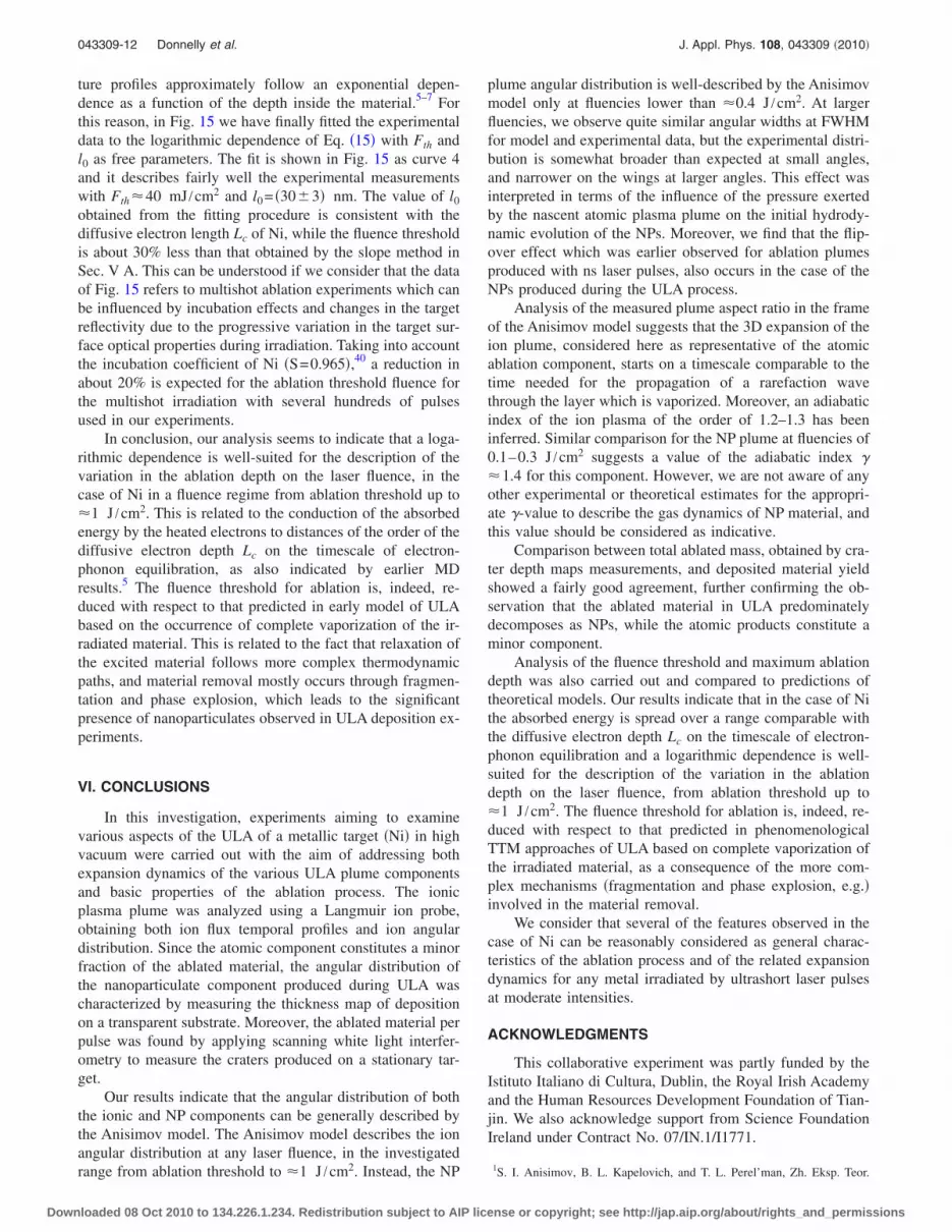
ture profiles approximately follow an exponential depen-dence as a function of the depth inside the material.5–7 Forthis reason, in Fig. 15 we have finally fitted the experimentaldata to the logarithmic dependence of Eq. �15� with Fth andl0 as free parameters. The fit is shown in Fig. 15 as curve 4and it describes fairly well the experimental measurementswith Fth�40 mJ /cm2 and l0= �30�3� nm. The value of l0
obtained from the fitting procedure is consistent with thediffusive electron length Lc of Ni, while the fluence thresholdis about 30% less than that obtained by the slope method inSec. V A. This can be understood if we consider that the dataof Fig. 15 refers to multishot ablation experiments which canbe influenced by incubation effects and changes in the targetreflectivity due to the progressive variation in the target sur-face optical properties during irradiation. Taking into accountthe incubation coefficient of Ni �S=0.965�,40 a reduction inabout 20% is expected for the ablation threshold fluence forthe multishot irradiation with several hundreds of pulsesused in our experiments.
In conclusion, our analysis seems to indicate that a loga-rithmic dependence is well-suited for the description of thevariation in the ablation depth on the laser fluence, in thecase of Ni in a fluence regime from ablation threshold up to�1 J /cm2. This is related to the conduction of the absorbedenergy by the heated electrons to distances of the order of thediffusive electron depth Lc on the timescale of electron-phonon equilibration, as also indicated by earlier MDresults.5 The fluence threshold for ablation is, indeed, re-duced with respect to that predicted in early model of ULAbased on the occurrence of complete vaporization of the ir-radiated material. This is related to the fact that relaxation ofthe excited material follows more complex thermodynamicpaths, and material removal mostly occurs through fragmen-tation and phase explosion, which leads to the significantpresence of nanoparticulates observed in ULA deposition ex-periments.
VI. CONCLUSIONS
In this investigation, experiments aiming to examinevarious aspects of the ULA of a metallic target �Ni� in highvacuum were carried out with the aim of addressing bothexpansion dynamics of the various ULA plume componentsand basic properties of the ablation process. The ionicplasma plume was analyzed using a Langmuir ion probe,obtaining both ion flux temporal profiles and ion angulardistribution. Since the atomic component constitutes a minorfraction of the ablated material, the angular distribution ofthe nanoparticulate component produced during ULA wascharacterized by measuring the thickness map of depositionon a transparent substrate. Moreover, the ablated material perpulse was found by applying scanning white light interfer-ometry to measure the craters produced on a stationary tar-get.
Our results indicate that the angular distribution of boththe ionic and NP components can be generally described bythe Anisimov model. The Anisimov model describes the ionangular distribution at any laser fluence, in the investigatedrange from ablation threshold to �1 J /cm2. Instead, the NP
plume angular distribution is well-described by the Anisimovmodel only at fluencies lower than �0.4 J /cm2. At largerfluencies, we observe quite similar angular widths at FWHMfor model and experimental data, but the experimental distri-bution is somewhat broader than expected at small angles,and narrower on the wings at larger angles. This effect wasinterpreted in terms of the influence of the pressure exertedby the nascent atomic plasma plume on the initial hydrody-namic evolution of the NPs. Moreover, we find that the flip-over effect which was earlier observed for ablation plumesproduced with ns laser pulses, also occurs in the case of theNPs produced during the ULA process.
Analysis of the measured plume aspect ratio in the frameof the Anisimov model suggests that the 3D expansion of theion plume, considered here as representative of the atomicablation component, starts on a timescale comparable to thetime needed for the propagation of a rarefaction wavethrough the layer which is vaporized. Moreover, an adiabaticindex of the ion plasma of the order of 1.2–1.3 has beeninferred. Similar comparison for the NP plume at fluencies of0.1–0.3 J /cm2 suggests a value of the adiabatic index �1.4 for this component. However, we are not aware of anyother experimental or theoretical estimates for the appropri-ate -value to describe the gas dynamics of NP material, andthis value should be considered as indicative.
Comparison between total ablated mass, obtained by cra-ter depth maps measurements, and deposited material yieldshowed a fairly good agreement, further confirming the ob-servation that the ablated material in ULA predominatelydecomposes as NPs, while the atomic products constitute aminor component.
Analysis of the fluence threshold and maximum ablationdepth was also carried out and compared to predictions oftheoretical models. Our results indicate that in the case of Nithe absorbed energy is spread over a range comparable withthe diffusive electron depth Lc on the timescale of electron-phonon equilibration and a logarithmic dependence is well-suited for the description of the variation in the ablationdepth on the laser fluence, from ablation threshold up to�1 J /cm2. The fluence threshold for ablation is, indeed, re-duced with respect to that predicted in phenomenologicalTTM approaches of ULA based on complete vaporization ofthe irradiated material, as a consequence of the more com-plex mechanisms �fragmentation and phase explosion, e.g.�involved in the material removal.
We consider that several of the features observed in thecase of Ni can be reasonably considered as general charac-teristics of the ablation process and of the related expansiondynamics for any metal irradiated by ultrashort laser pulsesat moderate intensities.
ACKNOWLEDGMENTS
This collaborative experiment was partly funded by theIstituto Italiano di Cultura, Dublin, the Royal Irish Academyand the Human Resources Development Foundation of Tian-jin. We also acknowledge support from Science FoundationIreland under Contract No. 07/IN.1/I1771.
1S. I. Anisimov, B. L. Kapelovich, and T. L. Perel’man, Zh. Eksp. Teor.
043309-12 Donnelly et al. J. Appl. Phys. 108, 043309 �2010�
Downloaded 08 Oct 2010 to 134.226.1.234. Redistribution subject to AIP license or copyright; see http://jap.aip.org/about/rights_and_permissions

Fiz. 66, 776 �1974�.2A. M. Komashko, M. D. Feit, and A. M. Rubenchik, Proc. SPIE 3935, 97�2000�.
3M. E. Povarnitsyn, T. E. Itina, M. Sentis, K. V. Khishchenko, and P. R.Levashov, Phys. Rev. B 75, 235414 �2007�.
4J. P. Colombier, P. Combis, R. Stoian, and E. Audouard, Phys. Rev. B 75,104105 �2007�.
5S. Amoruso, R. Bruzzese, X. Wang, N. N. Nedialkov, and P. A. Atanasov,J. Phys. D: Appl. Phys. 40, 331 �2007�.
6C. Cheng and X. Xu, Phys. Rev. B 72, 165415 �2005�.7D. Perez and L. J. Lewis, Phys. Rev. B 67, 184102 �2003�.8P. Lorazo, L. J. Lewis, and M. Meunier, Phys. Rev. Lett. 91, 225502�2003�.
9D. S. Ivanov and L. V. Zhigilei, Phys. Rev. B 68, 064114 �2003�.10S. Amoruso, R. Bruzzese, N. Spinelli, R. Velotta, M. Vitiello, X. Wang, G.
Ausanio, V. Iannotti, and L. Lanotte, Appl. Phys. Lett. 84, 4502 �2004�.11S. Amoruso, R. Bruzzese, C. Pagano, and X. Wang, Appl. Phys. A: Mater.
Sci. Process. 89, 1017 �2007�.12S. Amoruso, R. Bruzzese, X. Wang, and J. Xia, Appl. Phys. Lett. 92,
041503 �2008�.13S. Noël and J. Hermann, Appl. Phys. Lett. 94, 053120 �2009�.14K. Oguri, Y. Okano, T. Nishikawa, and H. Nakano, Phys. Rev. B 79,
144106 �2009�.15S. I. Anisimov, D. Bauerle, and B. S. Luk’yanchuk, Phys. Rev. B 48,
12076 �1993�.16S. I. Anisimov, B. S. Luk’yanchuk, and A. Luches, Appl. Surf. Sci. 96-98,
24 �1996�.17T. N. Hansen, J. Schou, and J. G. Lunney, Appl. Phys. A: Mater. Sci.
Process. 69, S601 �1999�.18B. Toftmann, J. Schou, and J. G. Lunney, Phys. Rev. B 67, 104101 �2003�.19G. O. Williams, S. Favre, and G. M. O’Connor, Appl. Phys. Lett. 94,
101503 �2009�.20T. Donnelly, J. G. Lunney, S. Amoruso, R. Brusezze, X. Wang, and X. Ni,
J. Appl. Phys. 106, 013304 �2009�.
21S. Nolte, C. Momma, H. Jacobs, A. Tunnermann, B. N. Chichkov, B.Wellegehausen, and H. Welling, J. Opt. Soc. Am. B 14, 2716 �1997�.
22K. Vestentoft and P. Balling, Appl. Phys. A: Mater. Sci. Process. 84, 207�2006�.
23J. M. Liu, Opt. Lett. 7, 196 �1982�.24B. Doggett and J. G. Lunney, J. Appl. Phys. 105, 033306 �2009�.25R. K. Singh and J. Narayan, Phys. Rev. B 41, 8843 �1990�.26J. G. Lunney, B. Doggett, and Y. Kaufman, J. Phys.: Conf. Ser. 59, 470
�2007�.27Y. B. Zel’dovich and Y. P. Raizer, Physics of Shock Waves and High
Temperature Hydrodynamic Phenomena �Dover, New York, 2002�.28G. O. Williams, G. M. O’Connor, P. T. Mannion, and T. J. Glynn, Appl.
Surf. Sci. 254, 5921 �2008�.29B. Toftmann, B. Doggett, J. Schou, and J. G. Lunney, �unpublished�.30X. Wang, S. Amoruso, and J. Xia, Appl. Surf. Sci. 255, 5211 �2009�.31T. Donnelly, B. Doggett, and J. G. Lunney, Appl. Surf. Sci. 252, 4445
�2006�.32S. Canulescu, E. L. Papadopoulou, D. Anglos, T. Lippert, C. W.
Schneider, and A. Wokaun, J. Appl. Phys. 105, 063107 �2009�.33P. T. Mannion, S. Favre, C. Mullan, D. S. Ivanov, G. M. O’Connor, T. J.
Glynn, B. Doggett, and J. G. Lunney, J. Phys.: Conf. Ser. 59, 753 �2007�.34M. E. Povarnitsyn, T. E. Itina, K. V. Khishchenko, and P. R. Levashov,
Phys. Rev. Lett. 103, 195002 �2009�.35S.-S. Wellershoff, J. Hohlfeld, J. Güdde, and E. Matthias, Appl. Phys. A:
Mater. Sci. Process. 69, S99 �1999�.36L. V. Zhigilei, Z. Lin, and D. S. Ivanov, J. Phys. Chem. C 113, 11892
�2009�.37K. Furusawa, K. Takahashi, H. Kumagai, K. Midorikawa, and M. Obara,
Appl. Phys. A: Mater. Sci. Process. 69, S359 �1999�.38Z. Lin, L. Zhigilei, and V. Celli, Phys. Rev. B 77, 075133 �2008�.39D. Bouilly, D. Perez, and L. J. Lewis, Phys. Rev. B 76, 184119 �2007�.40J. Güdde, J. Hohlfeld, J. G. Müller, and E. Matthias, Appl. Surf. Sci.
127-129, 40 �1998�.
043309-13 Donnelly et al. J. Appl. Phys. 108, 043309 �2010�
Downloaded 08 Oct 2010 to 134.226.1.234. Redistribution subject to AIP license or copyright; see http://jap.aip.org/about/rights_and_permissions
Copyright © 2022 FDOKUMEN