Delta Sensorless Vector Control Compact ... - Delta Electronics
Upload
khangminh22Category
view
3download
0
www.deltaww.com
Industrial Automation HeadquartersDelta Electronics, Inc. Taoyuan Technology CenterNo.18, Xinglong Rd., Taoyuan District, Taoyuan City 33068, TaiwanTEL: 886-3-362-6301 / FAX: 886-3-371-6301
AsiaDelta Electronics (Shanghai) Co., Ltd.No.182 Minyu Rd., Pudong Shanghai, P.R.C.Post code : 201209 TEL: 86-21-6872-3988 / FAX: 86-21-6872-3996Customer Service: 400-820-9595
Delta Electronics (Japan), Inc.Tokyo Office Industrial Automation Sales Department 2-1-14 Shibadaimon, Minato-kuTokyo, Japan 105-0012TEL: 81-3-5733-1155 / FAX: 81-3-5733-1255
Delta Electronics (Korea), Inc.Seoul Office1511, 219, Gasan Digital 1-Ro., Geumcheon-gu, Seoul, 08501 South KoreaTEL: 82-2-515-5305 / FAX: 82-2-515-5302
Delta Energy Systems (Singapore) Pte Ltd.4 Kaki Bukit Avenue 1, #05-04, Singapore 417939TEL: 65-6747-5155 / FAX: 65-6744-9228
Delta Electronics (India) Pvt. Ltd.Plot No.43, Sector 35, HSIIDC Gurgaon, PIN 122001, Haryana, IndiaTEL: 91-124-4874900 / FAX : 91-124-4874945
Delta Electronics (Thailand) PCL. 909 Soi 9, Moo 4, Bangpoo Industrial Estate (E.P.Z), Pattana 1 Rd., T.Phraksa, A.Muang, Samutprakarn 10280, ThailandTEL: 66-2709-2800 / FAX : 662-709-2827
Delta Energy Systems (Australia) Pty Ltd.Unit 20-21/45 Normanby Rd., Notting Hill Vic 3168, AustraliaTEL: 61-3-9543-3720
AmericasDelta Electronics (Americas) Ltd.Raleigh OfficeP.O. Box 12173, 5101 Davis Drive, Research Triangle Park, NC 27709, U.S.A.TEL: 1-919-767-3813 / FAX: 1-919-767-3969
Delta Greentech (Brasil) S/ASão Paulo OfficeRua Itapeva, 26 – 3˚ Andar - Bela VistaCEP: 01332-000 – São Paulo – SP - BrasilTEL: 55-11-3530-8642 / 55-11-3530-8640
Delta Electronics International Mexico S.A. de C.V.Mexico OfficeVía Dr. Gustavo Baz No. 2160, Colonia La Loma, 54060 Tlalnepantla Estado de MexicoTEL: 52-55-2628-3015 #3050/3052
*We reserve the right to change the information in this manual without prior notice.
EMEAHeadquarters: Delta Electronics (Netherlands) B.V. Sales: [email protected] Marketing: [email protected] Technical Support: [email protected] Customer Support: [email protected] Service: [email protected]: +31(0)40 800 3800
BENELUX: Delta Electronics (Netherlands) B.V.De Witbogt 20, 5652 AG Eindhoven, The Netherlands Mail: [email protected]: +31(0)40 800 3800
DACH: Delta Electronics (Netherlands) B.V.Coesterweg 45, D-59494 Soest, GermanyMail: [email protected]: +49(0)2921 987 0
France: Delta Electronics (France) S.A.ZI du bois Challand 2, 15 rue des Pyrénées, Lisses, 91090 Evry Cedex, France Mail: [email protected]: +33(0)1 69 77 82 60
Iberia: Delta Electronics Solutions (Spain) S.L.UCtra. De Villaverde a Vallecas, 265 1º Dcha Ed. Hormigueras – P.I. de Vallecas 28031 Madrid TEL: +34(0)91 223 74 20
Carrer Llacuna 166, 08018 Barcelona, SpainMail: [email protected]
Italy: Delta Electronics (Italy) S.r.l.Ufficio di Milano Via Senigallia 18/2 20161 Milano (MI) Piazza Grazioli 18 00186 Roma Italy Mail: [email protected]: +39 02 64672538
Russia: Delta Energy System LLC Vereyskaya Plaza II, office 112 Vereyskaya str. 17 121357 Moscow Russia Mail: [email protected]: +7 495 644 3240
Turkey: Delta Greentech Elektronik San. Ltd. Sti. (Turkey) Şerifali Mah. Hendem Cad. Kule Sok. No:16-A 34775 Ümraniye – İstanbulMail: [email protected]: + 90 216 499 9910
GCC: Delta Energy Systems AG (Dubai BR)P.O. Box 185668, Gate 7, 3rd Floor, Hamarain Centre Dubai, United Arab Emirates Mail: [email protected]: +971(0)4 2690148
Egypt + North Africa: Delta Electronics511 Cairo Business Plaza, North 90 street, New Cairo, Cairo, Egypt Mail: [email protected]
DVP-ES3 Series Operation Manual
DV
P-E
S3 S
eries Op
eration M
anu
al
DVP-0289420-01 2019/09/05

DVP-ES3 Series Operation Manual
Revision History Vers ion Revis ion Date
1 s t The f i rs t ve rs ion was pub l i shed . 2019/09 /05

i
DVP-ES3 Series Operation Manual
Table of Contents
Chapter 1 Product Introduction
1.1 Overview ........................................................................................... 1-2 1.1.1 Related Manuals ............................................................................ 1-2
1.1.2 Models Descriptions........................................................................ 1-2
1.2 Overview ........................................................................................... 1-7
1.3 Characteristics ................................................................................... 1-8
Chapter 2 Specifications and System Configuration
2.1 General Specifications ....................................................................... 2-2
2.2 CPU Module Specifications ................................................................. 2-3 2.2.1 Functional specifications ................................................................. 2-3 2.2.2 Electrical specifications ................................................................... 2-4 2.2.3 CPU Module Profiles........................................................................ 2-6 2.2.4 CPU Module Input/Output Terminals ................................................. 2-7
2.3 Digital Input/Output Module Specifications .................................... 2-10 2.3.1 General Specifications .................................................................. 2-10 2.3.2 Digital Input/Output Module Profiles ............................................... 2-12 2.3.3 Digital Input/Output Module Terminals ............................................ 2-13 2.3.4 Digital Input/Output Module Terminals ............................................ 2-13
2.4 Analog Input/Output Module Specifications .................................... 2-16 2.4.1 General Specifications .................................................................. 2-16 2.4.2 Analog Input/Output Module Profiles .............................................. 2-20 2.4.3 Analog Input/Output Terminals ...................................................... 2-21 2.4.4 Analog Input/Output Module Terminals ........................................... 2-21
2.5 Temperature Measurement Modules Specifications ......................... 2-22 2.5.1 General Specifications .................................................................. 2-22 2.5.2 Temperature Measurement Module Profiles ...................................... 2-24 2.5.3 Temperature Measurement Module Dimensions ................................ 2-25 2.5.4 Temperature Mesurement Module Terminals .................................... 2-26
2.6 Extension Cable Interface Module Specifications ............................. 2-27 2.6.1 General Specifications .................................................................. 2-27 2.6.2 Extension Cable Interface Module Profiles ....................................... 2-27

i i
2.6.3 Installation and Wiring .................................................................. 2-28
Chapter 3 Installing Software
3.1 Installing and Uninstalling ISPSoft ................................................... 3-2 3.1.1 Installing ISPSoft ........................................................................... 3-3 3.1.2 Uninstalling ISPSoft ....................................................................... 3-7
3.2 Installing and Uninstalling COMMGR ................................................. 3-9 3.2.1 Installing COMMGR ........................................................................ 3-9 3.2.2 Uninstalling COMMGR .................................................................... 3-12
Chapter 4 Installing Hardware
4.1 DVP-ES3 Hardware Framework ......................................................... 4-3 4.1.1 DVP-ES3 Hardware Component ....................................................... 4-3 4.1.2 Necessary Components .................................................................. 4-4 4.1.3 Optional Components ..................................................................... 4-4
4.2 Notes on Installation ......................................................................... 4-5
4.3 Installation ........................................................................................ 4-5 4.3.1 Linking the CPU module and a module .............................................. 4-6 4.3.2 Installation on the Set .................................................................... 4-7
4.4 Wiring ............................................................................................... 4-8
4.5 Connecting Power Cables ................................................................ 4-10 4.5.1 Precautions .................................................................................. 4-10 4.5.2 Ground ........................................................................................ 4-10 4.5.3 Wiring Power Supply ..................................................................... 4-11 4.5.4 Power Consumption ...................................................................... 4-12
4.6 Wiring CPU Modules ........................................................................ 4-14 4.6.1 Wiring Digital Input Terminals ........................................................ 4-14 4.6.2 Wiring Digital Output Terminals ...................................................... 4-17 4.6.3 Wiring RS-485 Terminals ............................................................... 4-21 4.6.4 Wiring CANopen Terminals ............................................................. 4-21
4.7 Wiring Digital Input / Output Modules ............................................ 4-22 4.7.1 Wiring DVP08XM211N ................................................................... 4-22 4.7.2 Wiring DVP08XN211R .................................................................... 4-22 4.7.3 Wiring DVP08XN211T .................................................................... 4-23 4.7.4 Wiring DVP08XP211R .................................................................... 4-23 4.7.5 Wiring DVP08XP211T .................................................................... 4-24 4.7.6 Wiring DVP16XM211N ................................................................... 4-25 4.7.7 Wiring DVP16XN211R .................................................................... 4-26 4.7.8 Wiring DVP16XN211T .................................................................... 4-27

i i i
4.7.9 Wiring DVP16XP211R ................................................................... 4-28 4.7.10 Wiring DVP16XP211T ................................................................... 4-29 4.7.11 Wiring DVP24XP200R ................................................................... 4-30 4.7.12 Wiring DVP24XP200T ................................................................... 4-31 4.7.13 Wiring DVP24XN200R ................................................................... 4-32 4.7.14 Wiring DVP24XN200T ................................................................... 4-32 4.7.15 Wiring DVP32XP200R ................................................................... 4-33 4.7.16 Wiring DVP32XP200T ................................................................... 4-34
4.8 Wiring Analog Input / Output Modules ............................................ 4-35 4.8.1 Wiring DVP04AD-E2 ..................................................................... 4-35 4.8.2 Wiring DVP02DA-E2/DVP04DA-E2 .................................................. 4-36 4.8.3 Wiring DVP06XA-E2...................................................................... 4-37
4.9 Wiring Temperature Measurement Modules .................................... 4-39 4.9.1 Wiring DVP04PT-E2/DVP06PT-E2 .................................................... 4-39 4.9.2 Wiring DVP04TC-E2 ...................................................................... 4-40
Chapter 5 Devices
5.1 Introduction to CPU Devices .................................................................. 5-2 5.1.1 Device Table .................................................................................. 5-2 5.1.2 Basic Structure of I/O Storage ......................................................... 5-3 5.1.3 Relation Between the PLC Action and the Device Type ........................ 5-3 5.1.4 Latched Areas in the Device Range ................................................... 5-4
5.2. CPU Device Functions ........................................................................... 5-5 5.2.1 Values and Constants ..................................................................... 5-5 5.2.2 Floating-point Numbers .................................................................. 5-7
5.2.2.1 Single-precision Floating-point Numbers .......................................... 5-7
5.2.2.2 Decimal Floating-point Numbers ..................................................... 5-8
5.2.3 Strings ......................................................................................... 5-9 5.2.4 Input Relays (X) .......................................................................... 5-10 5.2.5 Output Relays (Y) ........................................................................ 5-11 5.2.6 Auxiliary Relays (M) ..................................................................... 5-11 5.2.7 Special Auxiliary Relays (SM)......................................................... 5-11 5.2.8 Flags (S) ..................................................................................... 5-12 5.2.9 Timers (T) ................................................................................... 5-12 5.2.10 Counters ..................................................................................... 5-14 5.2.11 32-bit Counters (HC) .................................................................... 5-16 5.2.12 Data Registers (D) ....................................................................... 5-18 5.2.13 Special Data Registers (SR) ........................................................... 5-18 5.2.14 Index Register (E) ........................................................................ 5-18 5.2.15 File Registers (FR) ........................................................................ 5-18

i v
5.3. Module Device Functions .................................................................... 5-19 5.3.1 DVP04AD-E2 Control Registers ....................................................... 5-19 5.3.2 DVP02DA-E2 / DVP4DA-E2 Control Registers .................................... 5-24 5.3.3 DVP06XA-E2 Control Registers ....................................................... 5-28 5.3.4 DVP04PT-E2 /DVP06PT-E2 Control Registers .................................... 5-35 5.3.5 DVP04TC-E2 Control Registers ........................................................ 5-40
Chapter 6 Writing a Program
6.1 Quick Start ........................................................................................ 6-2 6.1.1 Example ....................................................................................... 6-2 6.1.2 Hardware ...................................................................................... 6-2 6.1.3 Program ....................................................................................... 6-3
6.2 Procedure for Creating a Project in ISPSoft....................................... 6-3
6.3 Creating a Project.............................................................................. 6-4
6.4 Hardware Configuration .................................................................... 6-5 6.4.1 Configuring a Module ..................................................................... 6-5 6.4.2 Setting the Parameters ................................................................... 6-6
6.5 Creating a Program ........................................................................... 6-7 6.5.1 Adding a Ladder Diagram ............................................................... 6-7 6.5.2 Basic Editing Creating a Contact and a Coil .................................... 6-9 6.5.3 Basic Editing Inserting a Network and Typing an Instruction ............ 6-12 6.5.4 Basic Editing Selection of a Network and Operation ........................ 6-14 6.5.5 Basic Editing Connecting a Contact in Parallel ................................ 6-17 6.5.6 Basic Editing Editing a Comment .................................................. 6-18 6.5.7 Basic Editing Inserting an Applied Instruction ................................ 6-19 6.5.8 Basic Editing Creating a Comparison Contact and Typing a Constant 6-21 6.5.9 Writing a Program ......................................................................... 6-22 6.5.10 Checking and Compiling a Program ................................................. 6-23
6.6 Testing and Debugging a Program .................................................. 6-24 6.6.1 Creating a Connection ................................................................... 6-24 6.6.2 Downloading a Program and Parameters .......................................... 6-27 6.6.3 Connection Test ............................................................................ 6-28
6.7 Setting a Real-time Clock ................................................................ 6-36
Chapter 7 Memory Card
7.1 Overview of Memory Cards ................................................................ 7-2
7.1.1 Appearances of Memory Cards ........................................................ 7-2 7.1.2 Memory Card Specifications ............................................................ 7-2

v
7.2 Before using a Memory Card .............................................................. 7-3
7.2.1 Formatting a Memory Card .............................................................. 7-3
7.3 Installing and Removing a Memory Card ........................................... 7-3
7.3.1 Memory Card Slot in a CPU Module .................................................. 7-3 7.3.2 Installing a Memory Card ................................................................ 7-4 7.3.3 Removing a Memory Card ............................................................... 7-4
7.4 Memory Card Contents ...................................................................... 7-5
7.4.1 Initializing a Memory Card .............................................................. 7-5 7.4.2 Folder Structure in a Memory Card ................................................... 7-5
7.5 Introduction to the CARD Utility ........................................................ 7-6
7.6 Backing Up a Project ......................................................................... 7-8
7.7 Restoring a Project .......................................................................... 7-13
7.8 Restoration Starts Once CPU is supplied with Power ....................... 7-17
7.9 CPU Error Log .................................................................................. 7-18
Chapter 8 Hardware Configuration and Data Exchange Setups
8.1 Hardware Configuration Tool for DVP-ES3 Series Modules ................ 8-2
8.1.1 Introduction of the HWCONFIG Environment .......................................... 8-2 8.1.2 Configuring a Module ........................................................................... 8-3 8.1.3 Editing a Comment.............................................................................. 8-3
8.2 Setting the Parameters in a DVP-ES3 Series CPU Module .................. 8-4
8.2.1 Opening the PLC Parameter Setting Window ........................................... 8-4 8.2.2 Setting the Basic CPU Parameters ......................................................... 8-5
8.3 Data Exchange ................................................................................. 8-24
8.3.1 Device Settings Dialog Box Descriptions ............................................... 8-24
Chapter 9 EtherNet Specification and Operation
9.1 Introduction ...................................................................................... 9-4
9.1.1 EtherNet/IP ................................................................................... 9-4 9.1.2 Definitions of Common Network Terms ............................................. 9-4 9.1.3 Ethernet Features .......................................................................... 9-5
9.1.3.1 Delta EIP Architecture ................................................................... 9-5
9.1.3.2 EIP Features ................................................................................. 9-6
9.2 Installation ........................................................................................ 9-6

vi
9.2.1 EtherNet/IP Device ........................................................................ 9-6 9.2.2 Network Cable Installation .............................................................. 9-6
9.2.2.1. Single Port Device........................................................................ 9-7
9.2.2.2. Dual Port Device .......................................................................... 9-7
9.2.2.3 EIP Builder Software ..................................................................... 9-9
9.3 Specifications .................................................................................. 9-10
9.3.1 Ethernet Specification ................................................................... 9-10 9.3.2 EtherNet/IP Specification ............................................................... 9-11 9.3.3 EtherNet Communication Port ........................................................ 9-12
9.3.3.1 Communication Port Pin Assignment .............................................. 9-12
9.3.3.2 Communication LED Indicator ....................................................... 9-12
9.4 EIP Builder ...................................................................................... 9-13
9.4.1 Run the EIP Builder ....................................................................... 9-13 9.4.1.1 Run the EIP Builder via an EIP Scanner .......................................... 9-13
9.4.2 Set up the IP Address.................................................................... 9-15 9.4.2.1 IP Address Types ......................................................................... 9-15
9.4.2.2 Set the IP Address (Static IP) ........................................................ 9-15
9.4.2.3 Set the IP Address (BOOTP/DHCP) ................................................. 9-17
9.4.2.4 Re-enable BOOTP/DHCP ............................................................... 9-20
9.5 Troubleshooting .............................................................................. 9-22
9.5.1 Error Code Classification ..................................................................... 9-22 9.5.2 Error Codes & How to fix them ............................................................ 9-22
9.5.2.1 Configuration Errors ..................................................................... 9-22
9.5.2.2 Application Error .......................................................................... 9-25
9.6 Studio 5000 Software Operation ..................................................... 9-26
9.6.1 Architecture ...................................................................................... 9-26 9.6.2 Create a New Project .......................................................................... 9-26 9.6.3 Create a Scanner ............................................................................... 9-28
9.6.3.1 Create a New Ethernet/IP Module .................................................. 9-28
9.6.4 Connect to a Delta Adapter ................................................................. 9-30 9.6.4.1 Import an EDS file ....................................................................... 9-30
9.6.4.2 Create an Adapter ....................................................................... 9-32
9.6.4.3 Editing Corresponding Addresses for DVP-ES3 ................................. 9-35
9.6.4.4 Download ................................................................................... 9-36
9.6.4.5 Data Mapping .............................................................................. 9-37
9.7 CIP Object ....................................................................................... 9-38
9.7.1 Object List ........................................................................................ 9-38

vi i
9.7.2 Data Type ........................................................................................ 9-39 9.7.3 Identity Object (Class ID: 01 Hex) ...................................................... 9-42 9.7.4 Message Router Object (Class ID: 02 Hex) ........................................... 9-44 9.7.5 Assembly Object (Class ID: 04 Hex) .................................................... 9-45 9.7.6 Connection Manager Object (Class ID: 06 Hex)..................................... 9-47 9.7.7 Port Object (Class ID: F4 Hex) ............................................................ 9-49 9.7.8 TCP/IP Interface Object (Class ID: F5 Hex) .......................................... 9-51 9.7.9 Ethernet Link Object (Class ID: F6 Hex) ............................................... 9-54 9.7.10 X Register (Class ID: 350 Hex) ......................................................... 9-57 9.7.11 Y Register (Class ID: 351 Hex).......................................................... 9-57 9.7.12 D Register (Class ID: 352 Hex) ......................................................... 9-58 9.7.13 M Register (Class ID: 353 Hex) ......................................................... 9-59 9.7.14 S Register (Class ID: 354 Hex) ......................................................... 9-60 9.7.15 T Register (Class ID: 355 Hex).......................................................... 9-61 9.7.16 C Register (Class ID: 356 Hex) ......................................................... 9-62 9.7.17 HC Register (Class ID: 357 Hex) ....................................................... 9-63 9.7.18 SM Register (Class ID: 358 Hex) ....................................................... 9-64 9.7.19 SR Register (Class ID: 359 Hex) ....................................................... 9-64
9.8 Delta EIP Product List ...................................................................... 9-65
9.8.1 Delta EIP Products ............................................................................ 9-65 9.8.2 Delta EIP Products, DLR (Device Level Ring) supported .......................... 9-66 9.8.3 Delta EIP Products, Scanner supported ................................................ 9-66
9.9 Operation and Monitor on the Web .................................................. 9-67
9.9.1 Getting Started ................................................................................. 9-67 9.9.1.1 Exploring the webpage ................................................................ 9-67
9.9.1.2 Using the Webpage ..................................................................... 9-68
9.9.1.3 Login ......................................................................................... 9-69
9.9.1.4 Menu ......................................................................................... 9-69
9.9.2 Device Information ............................................................................ 9-71 9.9.3 Network configuration ....................................................................... 9-71
9.9.3.1 Account management .................................................................. 9-71
9.9.4 Data Monitoring ................................................................................ 9-74 9.9.4.1 Data Monitoring Setup Page ......................................................... 9-74
9.9.4.2 Data Monitor Table Pages ............................................................. 9-78
9.9.5 Diagnostic ........................................................................................ 9-79 9.9.5.1 Hardware Status Page ................................................................. 9-79
9.9.6 Configurations .................................................................................. 9-80 9.9.6.1 Save Configuration Page .............................................................. 9-80

vi i i
Chapter 10 CANopen Funciton and Operation
10.1 Introduction to CANopen ................................................................. 10-2
10.1.1 CANopen Function Descriptions ...................................................... 10-2 10.1.2 The Input/Output Mapping Areas .................................................... 10-3
10.2 Installation and Network Topology ................................................. 10-4
10.2.1 The Dimensions of DVP-ES3 Series PLC ........................................... 10-4 10.2.2 CANopen Communication Port ........................................................ 10-5 10.2.3 Configure the DVP-ES3 Series PLC with HWCONFIG .......................... 10-5 10.2.4 The CAN Interface and Network Topology ........................................ 10-6
10.3 The CANopen Protocol ................................................................... 10-11
10.3.1 Introduction to the CANopen Protocol ............................................ 10-11 10.3.2 The CANopen Communication Object ............................................ 10-12 10.3.3 The Predefined Connection Set ..................................................... 10-17
10.4 Sending SDO, NMT and Reading Emergency Message through the Ladder Diagram ........................................................................................ 10-19
10.4.1 Data Structure of SDO Request Message ....................................... 10-19 10.4.2 Data Structure of NMT Message .................................................... 10-21 10.4.3 Data Structure of EMERGENCY Request Message ............................ 10-23 10.4.4 Example of Sending SDO through the Ladder Diagram .................... 10-25
10.5 Troubleshooting ............................................................................ 10-27
10.5.1 CANopen Network Node State Display ........................................... 10-27
10.6 Application Example ...................................................................... 10-30
10.7 Object Dictionary........................................................................... 10-38
Chapter 11 CPU Module Operating Principles
11.1 CPU Module Operations ................................................................... 11-2
11.1.1 Procedure .................................................................................... 11-2 11.1.2 I/O Refreshing and Communication Service ...................................... 11-3
11.2 CPU Module Operating Modes .......................................................... 11-4
11.2.1 Operating Modes .......................................................................... 11-4 11.2.2 Status and Operation under Different Operating Modes ..................... 11-4
Chapter 12 Troubleshooting
12.1 Troubleshooting .............................................................................. 12-1
12.1.1 Basic troubleshooting steps ............................................................ 12-1

i x
12.1.2 Clear the Error States ................................................................... 12-2 12.1.3 Troubleshooting SOP .................................................................... 12-3 12.1.4 System Log ................................................................................. 12-4
12.2 Troubleshooting for CPU Modules .................................................... 12-5
12.2.1 ERROR LED Indicators Are ON ....................................................... 12-5 12.2.2 ERROR LED Indicators Blinking Every 0.5 Seconds ........................... 12-5 12.2.3 ERROR LED Indicators Blinking Rapidly Every 0.2 Seconds ................ 12-6 12.2.4 ERROR LED Indicators Slow Blinking Every 3 Seconds and Lighting up for 1 Second
................................................................................................. 12-6 12.2.5 The LED RUN and ERROR Indicators are Blinking Simultaneously Every 0.5 Seconds 12-6 12.2.6 The RUN and LED Indicators are Blinking One After Another Every 0.5 Seconds.
................................................................................................. 12-6 12.2.7 Other Errors (Without LED Indicators) ............................................ 12-6
12.3 Troubleshooting for Analog Modules (AD/DA/XA) and Temperature Modules (PT/TC) ......................................................................................... 12-13
12.4 LED Indicators and Error Codes for CPU Modules .......................... 12-14
Chapter 13 Data Tracer and Data Logger
13.1 Data Tracer ...................................................................................... 13-2 13.1.1 About Data Tracer ........................................................................ 13-2
13.1.2 Example ..................................................................................... 13-4
13.2 Data Logger ..................................................................................... 13-5 13.2.1 About Data Logger ....................................................................... 13-5
13.2.2 Related SM Flags and SR Registors ................................................ 13-7
Appendix A Installing a USB Driver
A.1 Disable Driver Signature Enforcement ................................................... A-2
A.2 Installing the USB Driver for DVP-ES3 Series CPU Module ..................... A-6
Appendix B Device Addresses
B.1 Standard Modbus Device Addresses ...................................................... B-2
B.2 Function Codes and Number of Devices Supported for Modbus ProtocolsB-3
Appendix C EMC Standards
C.1 EMC Standards for an AS Series System ................................................ C-2 C.1.1 DVP-ES3 Series System EMC Standards................................................. C-2

x
C1.2 Installation Instructions to meet EMC Standards ...................................... C-4
C1.3 Cables ................................................................................................ C-5
Appendix D Maintenance and Inspection
D.1 Cautions ................................................................................................ D-2
D.2 Daily Maintenance ................................................................................. D-3 D.2.1 Required Inspection Tools.................................................................... D-3
D.2.2 Daily Inspection ................................................................................. D-3
D.3 Periodic Maintenance ............................................................................ D-4 D.3.1 Required Inspection Tools.................................................................... D-4
D.3.2 Periodic Inspection ............................................................................. D-5

1-1
Chapter 1 Product Introduction Table of Contents 1.1 Overview ........................................................................................... 1-2
1.1.1 Related Manuals ............................................................................ 1-2 1.1.2 Models Descriptions........................................................................ 1-2
1.2 Overview ........................................................................................... 1-7
1.3 Characteristics ................................................................................... 1-8
1

DVP-ES3 Ser ies Opera t ion Manual
1-2
_1 1.1 Overview
This manual introduces the DVP-ES3 Series PLC functions, devices, module tables, troubleshooting, and so
forth.
1.1.1 Related Manuals
The related manuals for DVP-ES3 Series programmable logic controllers are listed below. DVP-ES3 Series Programming Manual
This introduces programming for the DVP-ES3 Series programmable logic controllers, basic instructions, and applied instructions. For DVP-ES2 Series PLC, refer to DVP-ES2-/EX2-SS2/SA2/SX2/SE & TP Operation Manual – Programming.
ISPSoft User Manual This introduces the use of the ISPSoft software, programming language (Ladder, SFC, FBD, and ST), POUs, and tasks. DVP-ES3 Series PLC can only use ISPSoft for programming, NOT WPLSoft.
DVP-ES3 Series Operation Manual This introduces electrical specifications, dimensions, CPU functions, devices, module tables,
troubleshooting, and so forth.
1.1.2 Models Descriptions
Classification Model Name Description
DVP-ES3
Series CPU
module
DVP32ES311T
24 VDC powered CPU module
NPN output, 1x Ethernet port, 2x RS-485 ports, 1x USB
port, 1x Micro SD interface, supporting 32 I/Os
(16DI+16DO) and up to 256 I/Os. Program capacity: 64K
steps, removable terminal blocks
DVP32ES300T
100-220 VAC powered CPU module
NPN output, 1x Ethernet port, 2x RS-485 ports, 1x USB
port, 1x Micro SD interface, supporting 32 I/Os
(16DI+16DO) and up to 256 I/Os. Program capacity: 64K
steps, removable terminal blocks
DVP32ES300R
100-220 VAC powered CPU module
Relay output, 1x Ethernet port, 2x RS-485 ports, 1x USB
port, 1x Micro SD interface, supporting 32 I/Os
(16DI+16DO) and up to 256 I/Os. Program capacity: 64K
steps, removable terminal blocks
DVP48ES300T 100-220 VAC powered CPU module
NPN output, 1x Ethernet port, 2x RS-485 ports, 1x USB

Chapter 1 Product In t roduct ion
1-3
1_ Classification Model Name Description
port, 1x Micro SD interface, supporting 48 I/Os
(24DI+24DO) and up to 256 I/Os. Program capacity: 64K
steps, removable terminal blocks
DVP48ES300R
100-220 VAC powered CPU module
Relay output, 1x Ethernet port, 2x RS-485 ports, 1x USB
port, 1x Micro SD interface, supporting 48 I/Os
(24DI+24DO) and up to 256 I/Os. Program capacity: 64K
steps, removable terminal blocks
DVP64ES300T
100-220 VAC powered CPU module
NPN output, 1x Ethernet port, 2x RS-485 ports, 1x USB
port, 1x Micro SD interface, supporting 64 I/Os
(32DI+32DO) and up to 256 I/Os. Program capacity: 64K
steps, removable terminal blocks
DVP64ES300R
100-220 VAC powered CPU module
Relay output, 1x Ethernet port, 2x RS-485 ports, 1x USB
port, 1x Micro SD interface, supporting 64 I/Os
(32DI+32DO) and up to 256 I/Os. Program capacity: 64K
steps, removable terminal blocks
DVP80ES300T
100-220 VAC powered CPU module
NPN output, 1x Ethernet port, 2x RS-485 ports, 1x USB
port, 1x Micro SD interface, supporting 80 I/Os
(40DI+40DO) and up to 256 I/Os. Program capacity: 64K
steps, removable terminal blocks
DVP80ES300R
100-220 VAC powered CPU module
Relay output, 1x Ethernet port, 2x RS-485 ports, 1x USB
port, 1x Micro SD interface, supporting 80 I/Os
(40DI+40DO) and up to 256 I/Os. Program capacity: 64K
steps, removable terminal blocks
Digital
input/output
module
DVP08XM211N
8 inputs
24VDC
5mA
DVP08XP211R
4 inputs
24VDC
5mA

DVP-ES3 Ser ies Opera t ion Manual
1-4
_1 Classification Model Name Description
4 Relay outputs
250VAC
Below 30VDC
2A/output, 5A/COM
DVP08XP211T
4 inputs
24VDC
5mA
4 NPN (sinking) outputs
5 – 30VDC
0.5A/output, 4A/COM
DVP08XN211R
8 Relay outputs
250VAC
Below 30VDC
2A/output, 5A/COM
DVP08XN211T
8 NPN (sinking) outputs
5 – 30VDC
0.5A/output, 4A/COM
DVP16XM211N
16 inputs
24VDC
5mA
DVP16XP211R
8 inputs
24VDC
5mA
8 Relay outputs
250VAC
Below 30VDC
2A/output, 5A/COM
DVP16XP211T
8 inputs
24VDC
5mA
8 NPN (sinking) outputs
5 – 30VDC

Chapter 1 Product In t roduct ion
1-5
1_ Classification Model Name Description
0.5A/output, 4A/COM
DVP16XN211R
16 Relay outputs
250VAC
Below 30VDC
2A/output, 5A/COM
DVP16XN211T
16 NPN (sinking) outputs
5 – 30VDC
0.5A/output, 4A/COM
DVP24XP200R
16 inputs
24VDC
5mA
8 Relay outputs
250VAC
Below 30VDC
2A/output, 5A/COM
DVP24XP200T
16 inputs
24VDC
5mA
8 NPN (sinking) outputs
5 – 30VDC
0.5A/output, 4A/COM
DVP24XN200R
24 Relay outputs
250VAC
Below 30VDC
2A/output, 5A/COM
DVP24XN200T
24 NPN (sinking) outputs
5 – 30VDC
0.5A/output, 4A/COM
DVP32XP200R
16 inputs
24VDC
5mA
8 Relay outputs

DVP-ES3 Ser ies Opera t ion Manual
1-6
_1 Classification Model Name Description
250VAC
Below 30VDC
2A/output, 5A/COM
DVP32XP200T
16 inputs
24VDC
5mA
16 NPN (sinking) outputs
5 – 30VDC
0.5A/output, 4A/COM
Analog
input/output
module
DVP04AD-E2
4-channel analog input
Hardware resolution 14 bits: -5V ~ +5V, -10V ~ +10V,
-20mA ~ +20mA
Hardware resolution 13 bits: 0/4 ~ 20mA
Conversion time: 400 μs/channel
DVP02DA-E2
2-channel analog input
Hardware resolution 14 bits: -10V ~ +10V, -20mA ~ +20mA
Conversion time: 400 μs/channel
DVP04DA-E2
4-channel analog input module
Hardware resolution 14 bits: -10V ~ +10V, -20mA ~ +20mA
Conversion time: 400 μs/channel
DVP06XA-E2
4-channel analog input
Hardware resolution 14 bits: -5V ~ +5V, -10V ~ +10V,
-20mA ~ +20mA
Hardware resolution 13 bits: 0/4 ~ 20mA
Conversion time: 400 μs/channel
2-channel analog output
Hardware resolution 14 bits: -10V ~ +10V, -20mA ~ +20mA
Conversion time: 400 μs/channel
Temperature
measurement
module
DVP04PT-E2
4-channel, 2-wire/3-wire RTD
Sensor type: Pt100 / Pt1000 / Ni100 / Ni1000 / 0-300Ω /
0-3000Ω
Resolution: 0.1°C/0.1°F (16 bits)
Conversion time: 200 ms/channel

Chapter 1 Product In t roduct ion
1-7
1_ Classification Model Name Description
PID controller
DVP06PT-E2
6-channel, 2-wire/3-wire RTD
Sensor type: Pt100 / Pt1000 / Ni100 / Ni1000 / Cu50 /
Cu100 / 0-300Ω / 0-3000Ω / JPt100 / LG-Ni1000
Resolution: 0.1°C/0.1°F (16 bits)
Conversion time: 200 ms/channel
PID controller
DVP04TC-E2
4-channel thermocouple
Sensor type: J, K, R, S, T, E, N and -80 to +80 mV
Resolution: 0.1°C/0.1°F (16 bits)
Conversion time: 200 ms/channel
PID controller
External
terminal
module
DVPAEXT01-E2 For DVP-ES2/ES3 Series PLC
1.2 Overview
An DVP-ES3 Series CPU module is an advanced controller with built-in 4 high speed counters for inputs, up to
4-axis (pulse), and can optionally work with a total of 8-axis (CANopen) position outputs. It provides a strong
network function for users, and users can create connection among devices on the network through software.
An DVP-ES3 Series CPU module also provides structured programming. Users can assign programs to
different tasks, and write a program which is frequently executed in a function block. Besides, users can choose
different programming languages ladder diagrams (LD), structured texts (ST), sequential function charts (SFC),
and continuous function chart (CFC) dealt with by IEC 61131-3 according to their needs when writing programs.
They can create the DVP-ES3 Series hardware configuration by means of hardware configuration software.
They can also restore or back up a system rapidly through the built-in SD interface in an DVP-ES3 Series
series CPU module. This manual introduces the basic operation of an DVP-ES3 Series system, and help users
familiarize themselves with the DVP-ES3 Series system.

DVP-ES3 Ser ies Opera t ion Manual
1-8
_1 1.3 Characteristics
Characteristics of the DVP-ES3 Series CPU module:
(1) High efficiency
The DVP-ES3 Series CPU module uses a 32-bit high-speed processor. The module executes basic
instructions at 25 ns each and moving instructions at 150 ns each. The module executes instructions
at a speed of 40k steps/ms (40% of the instructions are basic instructions, and 60% of the instructions
are applied instructions).
The CPU of the DVP-ES3 Series uses the Soc architecture, built with 4 high speed counters. The
maximum frequency is 200 kHz for each counter; four-axis (8 points) high speed position output at
200 kHz.
(2) Supporting more inputs and outputs
The DVP-ES3 Series CPU module supports up to 256 digital I/Os (inputs + outputs) or 8 analog I/O
modules.
(3) Larger program capacity and memory
The AS300 Series advanced CPU modules have 64k steps of program capacity. 60000 general registers (30000 for specific use and 30000 for programming editing), and 64k words of memory (that can be used for storing parameters).
(4) Supporting IEC 61131-3
The DVP-ES3 Series CPU module supports IEC 61131-3.
Supported programming languages are ladder diagrams (LD), sequential function chart (SFC), structured text (ST), and continuous function chart (CFC, available for ISPSoft V3.01 or later)
You can select a programming language according to your preference. Programming languages support one another so that programs written by different users are compatible.

Chapter 1 Product In t roduct ion
1-9
1_ (5) Strong function block
Both standard IEC61131-3 function blocks and convenient functions blocks provided by Delta
Electronics, Inc. are supported. You can use function blocks for frequently used programs for greater
structure and convenience.
The symbol for a function block in a ladder diagram is similar to an integrated circuit (IC) in a circuit
diagram. Because the ladder diagram is based on the traditional circuit diagram, the operation of a
function block is similar to the function of an integrated circuit. You only need to send the signal to the
corresponding input of the function block. You do not need to consider the processing procedure
inside the function block.
A function block is a program element equipped with the operation function. It is similar to a subroutine,
and is a type of POU (Program Organization Unit). It cannot operate by itself, and must be called
through the main program POU. The function defined by the function block is executed after being
called with the related parameters. The final result can be sent to the device or variable in the superior
POU after the function block completes.
You can set passwords in ISPSoft to provide function block security. The program inside a function
block cannot be read, and business patents cannot be compromised.
(6) Task

DVP-ES3 Ser ies Opera t ion Manual
1-10
_1 You can assign 283 tasks at most to a program. Among these tasks, 32 are cyclic, 32 are I/O
interrupts, 4 are timer interrupts, two are communication interrupts, one is an external 24 V
low-voltage interrupt, and 212 are user-defined tasks.
You can enable and disable a task when running a program by using the TKON and TKOFF
instructions.
(7) Increasing hardware configuration efficiency through a USB cable and ISPSoft
The DVP-ES3 Series CPU module provides a standard USB 2.0 interface. USB 2.0 increases the data
transfer rate and decreases the time it takes to download the program, monitor the program, and
configure the hardware. You do not need to buy a special communication cable for the CPU module.
You can use a general USB cable to connect to the DVP-ES3 Series CPU module.
(8) Serial control interface with multiple functions
DVP-ES3 Series CPU modules provide two RS-485 serial control interfaces, COM1 and COM2, which
can be set as a either master or slave.
Built-in CAN communication port is for Delta Special Driver and CANopen DS301 communication
mode.
(9) High-speed Ethernet communication interface
DVP-ES3 Series CPU modules are equipped with a 10/100 M Ethernet communication interface and
support email, web, Modbust TCP, Ethernet/IP Adapter and socket services.
(10) Memory card
The memory card has the following functions.
System backup: user program, CPU parameters, module table, and the device setting values
System recovery: user program, CPU parameters, module table, and device setting values
Parameter storage: device value
Log storage: system error log and system status log
(11) Supporting on-line debugging mode
You can use the on-line debugging mode in the DVP-ES3 Series CPU module after a single
instruction step completes, or after a breakpoint is specified, to find bugs in the program.
The CPU module must be running to enter the debugging mode. After enabling the on-line monitoring
function, click . The debugging screen varies from programming language to programming

Chapter 1 Product In t roduct ion
1-11
1_ language, but the same operation applies to these programming languages. For the DVP-ES3 Series
PLC, structured text (ST) does not support debugging mode, and sequential function charts (SFC)
supports debugging mode during the action and the transition.
Step 1: Set the PLC to RUN
Step 2: Entering the on-line mode
Step 2: Enter online mode

DVP-ES3 Ser ies Opera t ion Manual
1-12
_1 Step 3: Enter debugging mode
(12) On-line editing mode
You can use the on-line editing mode when the system is running to update the program without
affecting the system operation.
When the system is in the on-line monitoring mode, enter the on-line editing mode by clicking .

Chapter 1 Product In t roduct ion
1-13
1_
After the program is modified and compiled, you can update the program in the CPU module by
clicking to download it to the CPU.

DVP-ES3 Ser ies Opera t ion Manual
1-14
_1 MEMO

2-1
Chapter 2 Specifications and System Configuration
Table of Contents 2.1 General Specifications ....................................................................... 2-2
2.2 CPU Module Specifications ................................................................. 2-3
2.2.1 Functional specifications ................................................................. 2-3
2.2.2 Electrical specifications ................................................................... 2-4
2.2.3 CPU Module Profiles ........................................................................ 2-6
2.2.4 CPU Module Input/Output Terminals ................................................. 2-7
2.3 Digital Input/Output Module Specifications ..................................... 2-10
2.3.1 General Specifications .................................................................. 2-10
2.3.2 Digital Input/Output Module Profiles ............................................... 2-12
2.3.3 Digital Input/Output Module Terminals ............................................ 2-13
2.3.4 Digital Input/Output Module Terminals ............................................ 2-13
2.4 Analog Input/Output Module Specifications .................................... 2-16
2.4.1 General Specifications .................................................................. 2-16
2.4.2 Analog Input/Output Module Profiles .............................................. 2-20
2.4.3 Analog Input/Output Terminals ...................................................... 2-21
2.4.4 Analog Input/Output Module Terminals ........................................... 2-21
2.5 Temperature Measurement Modules Specifications ......................... 2-22
2.5.1 General Specifications .................................................................. 2-22
2.5.2 Temperature Measurement Module Profiles ...................................... 2-24
2.5.3 Temperature Measurement Module Dimensions ................................ 2-25
2.5.4 Temperature Mesurement Module Terminals .................................... 2-26
2.6 Extension Cable Interface Module Specifications ............................. 2-27
2.6.1 General Specifications .................................................................. 2-27
2.6.2 Extension Cable Interface Module Profiles ....................................... 2-27
2.6.3 Installation and Wiring .................................................................. 2-28
2 2

Chapter 2 Spec i f ica t ions and System Conf igurat ion
2-2
2_
2.1 General Specifications Item Specifications
Operating temperature -0 to 55°C Storage temperature -40 to 70°C
Operating humidity 5–95% No condensation
Storage humidity 5–95% No condensation
Work environment No corrosive gas exists. Installation location In a control box Pollution degree 2 Ingress protection (IP ratings) IP20
EMC (electromagnetic compatibility) Refer to Appendis C for more information.
Vibration resistance
Tested with: 5 Hz ≦ f ≦ 8.4 Hz, constant amplitude 3.5 mm;
8.4 Hz ≦ f ≦ 150 Hz, constant acceleration 1g
Duration of oscillation: 10 sweep cycles per axis on each direction of the three mutually perpendicular axes International Standard IEC 61131-2 & IEC 60068-2-6 (TEST Fc)
Shock resistance
Tested with: Half-sine wave: Strength of shock 15 g peak value, 11 ms duration; Shock direction: The shocks in each in direction per axis, on three mutually perpendicular axes (total of 18 shocks) International Standard IEC 61131-2 & IEC 60068-2-27 (TEST Ea)
Safety Conforms to IEC 61131-2, UL 61010-2-201 Ambient air temperature-barometric pressure-altitude
Operating: 1080 ~ 795hPa (-1000 ~ 2000 m) Storage:1080 ~ 660hPa (-1000 ~ 3500 m)

DVP-ES3 Ser ies Opera t ion Manual
2-3
_2
2.2 CPU Module Specifications 2.2.1 Functional specifications
Item DVP32ES311T, DVPxxES300T, DVPxxES300R Remark Execution The program is executed cyclically.
Input/Output control Regenerated inputs/outputs Direct inputs/outputs
The inputs and outputs can be controlled through the direct inputs (DX) and direct outputs (DY).
Programming language IEC 61131-3 Ladder diagrams, continuous function charts, structured text, and sequential function charts
Instruction execution speed 40K steps/ms Number of instructions Over 600 instructions
Constant scan cycle (ms) 1-32000 (The scan cycle can be increased by one millisecond.)
Setting the parameter
Program capacity (step) 64K steps (128K bytes)
Installation DIN rails or screws Installation of a module No backplane installation; only module after module Maximum number of modules which can be installed
Up to 8 modules for AIO modules and cannot exceed 256 IO points
Number of tasks 283 tasks (32 cyclic tasks; 16 I/O interrupts; four timed interrupts, etc.)
Refer to ISPSoft Manual for more information.
Number of inputs/outputs 256
Number of inputs/outputs accessible to an actual input/output module
Input relays [X] 256 (X0 ~ X377) Octal format Output relays [Y] 256 (Y0 ~ Y377) Octal format Internal relays [M] 8192 (M0–M8191) Timers [T] 512 (T0–T511) Counters [C] 512 (C0–C511) 32-bit counter [HC] 256 (HC0–HC255) Data register [D] 30000 (D0–D29999) Data register [W] 30000 (W0–W29999) Stepping relay [S] 2048 (S0–S2047) Index register [E] 10 (E0–E9) Special auxiliary relay [SM] 4096 (SM0–SM4095) Special data register [SR] 2048 (SR0–SR2047) Serial communication port 2x RS-485 Ethernet port 10/100 M Refer to the section

Chapter 2 Spec i f ica t ions and System Conf igurat ion
2-4
2_
Item DVP32ES311T, DVPxxES300T, DVPxxES300R Remark Supporting Modbus TCP and Ethernet/IP Adapter protocols
9.3 for more details on Ethernet specificaitons
USB port Mini B type USB Storage interface SD Card (Micro SD); maximum storage: 32G
Real-time clock Years, months, days, hours, minutes, seconds and weeks
Active about one week, storing in an electric double layer capacitor
CANopen DS301 (Master) Maximum node: 64; maximum bytes: 2000 Built-in CAN communication port CANopen DS301 (Slave) Maximum PDO: 8; maximum bytes: 8
2.2.2 Electrical specifications
Model Item
DVP32ES311T
Supply voltage 24 VDC (20.4 VDC–28.8 VDC) (-15% to +20%) Weight (g) 390 g
Electrical specifications for the inputs on digital input/output module. The signals passing through
the inputs are 24 VDC signals.
Model Item
DVP32ES311T DVP32ES300T DVP32ES300R
DVP48ES300T DVP48ES300R
DVP64ES300T DVP64ES300R
DVP80ES300T DVP80ES300R
Number of inputs
16 (X0 ~ X17) 24 (X0 ~ X27) 32 (X0 ~ X37) 40 (X0 ~ X47)
Connector type Removable terminal blocks Input type Digital input Input form Direct current (sinking or sourcing) Input voltage/ current
X0 ~ X7: 24VDC, 5.8mA X10 ~ X47: 24VDC, 4mA
Action level
OFF→ON >15 VDC
ON→OFF <5 VDC
Response time
OFF→ON X0 ~ X7: 1.5μs
X10 ~ X17: 15μs X20~X47: 10ms
ON→OFF X0 ~X7: 1.5μs
X10 ~ X17: 15μs X20~X47: 10ms
Maximum input frequency
X0 ~ X7: 200kHz X10 ~ X17: 20kHz X20~X47: 50Hz
Input impedance X0 ~ X7: 3.9kΩ X10 ~ X47: 5.6kΩ

DVP-ES3 Ser ies Opera t ion Manual
2-5
_2
Model Item
DVP32ES311T DVP32ES300T DVP32ES300R
DVP48ES300T DVP48ES300R
DVP64ES300T DVP64ES300R
DVP80ES300T DVP80ES300R
Input signal Voltage input Sinking: The inputs are NPN transistors whose collectors are open collectors. Sourcing: The inputs are PNP transistors whose collectors are open collectors.
Electrical isolation Optocoupler
Input display When the optocoupler is driven, the input LED indicator is ON.
Electrical specifications for the outputs on DVP-ES3 Series.
Model Item
DVP-ES3 Series
32ES300R
48ES300R
64ES300R
80ES300R
32ES311T
32ES300T
48ES300T
64ES300T
80ES300T
Number of outputs 16 24 32 40 16 16 24 32 40 Connector type Removable terminal blocks
Output form Relay Transistor-T (sinking)
Voltage 10~250 VAC, 5~30VDC 5 ~ 30VDC
Leakage current 0uA <10uA
Maximum load
Resistance 2A/output, 5A/COM 0.5A/output, 2A/COM*2 Inductance Life cycle curve*3 12W (24VDC) Bulb 20WDC/100WAC 2W (24VDC)
Switching frequency*1 ≦1Hz Y0~Y7: 200kHz
Y10~Y47 ≦1kHz
Maximum Response time
OFF→ON
Approximately 10ms
Y0~Y7: 1.5μs
Y10~Y47: 100μs
ON→OFF Y0~Y7: 1.5μs
Y10~Y47: 100μs
*1: The scan cycle affects the frequency.
*2: UP, ZP should include external aid power 24VDC (-15% ~ +20%) and the rated comsumption is around 1mA/point.
*3: The life cycle curve is shown below.
Contact Current(A)
20
0.50.1 0.2
3050
0.3 0.7 1 2
200300500
100
100020003000
Ope
ratio
n(X
10)3
120VAC Resistive30VDC Inductive(t=7ms)
240VAC Inductive(cos 0.4)ψ=120VAC Inductive(cos =0.4)ψ
30VDC Inductive (t=40ms)

Chapter 2 Spec i f ica t ions and System Conf igurat ion
2-6
2_
2.2.3 CPU Module Profiles
DVP32ES300R / DVP32ES300T / DVP32ES311T / DVP48ES300R / DVP48ES300T / DVP64ES300R / DVP64ES300T / DVP80ES300R / DVP80ES300T
L1L
90 98 106
110
61 .578
4.5x2
7
8
1
45
3
6
2
DVP32 ES316DI / 1 6DO
8
6
9
10
14
12
1311
Unit: mm
Diameter chart
DVP 32ES311T 32ES300R/T 48ES300R/T 64ES300R/T 80ES300R/T
L 165 mm 165 mm 216 mm 267 mm 310 mm
L1 157 mm 157 mm 208 mm 259 mm 302 mm
LED indocaor descriptions Number Name Description
1 Output type R: Relay output T: Transistor output
2 Input/Output LED If there is an input signal, the input LED indicator is ON. If there is an output signal, the output LED indicator is ON.
3
Power LED Indicates the power status of the CPU module
Run LED
Operating status of the module ON: the program is running. OFF: the program is stopped. Blinking: the program detects an error
Error LED
Error status of the module Blinking slowly (1 second ON, 3 seconds OFF): warning Blinking (0.5 seconds ON, 0.5 seconds OFF): error occurs Blinking rapidly (0.2 seconds ON, 0.2 seconds OFF) ON: scanning timeout OFF: the module is normal.
USB LED Indicates the communication status OFF: no communication Blinking: communication
COM1 LED COM2 LED
LINK/ACT LED ON: communication port is connected Blinking: packet sending/receiving OFF: communication port is not connected

DVP-ES3 Ser ies Opera t ion Manual
2-7
_2
Number Name Description 4 SD card slot Provides an interface for SD card storing 5 RJ45 communication port Provides an interface for RJ45 communication 6 Removable terminal blocks Connects the module and the wiring module 7 Mounting hole Secures the module on the set 8 Terminal number Terminal number
9 RUN/STOP RUN: executes the program STOP: stops the program
10 USB port Mini USB communication port 11 Model name Shows the model name of the CPU module.
12 External module connection port Connects the modules
13 DIN rail slot (35 mm) For the DIN rail 14 I/O module securing clip Secures the modules
2.2.4 CPU Module Input/Output Terminals
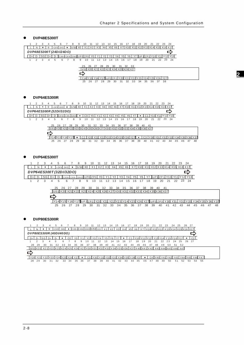
DVP32ES300R
X2X1X0S/S24 G+2 4V X5X4X3
Y4 C1Y3Y2Y 1Y 0C 0D - Y 7Y6Y5D+D-D +
DVP32ES300R (16DI/16DO) X15X1 4X 12X11X10X7X 6
Y1 0
X16
Y11 Y13Y12 Y14
X13
SG
1 2 3 4 5 6 7 8 9 10 11 12 13 14 1615 17 18 19 20 21 22 23
1 2 3 4 5 6 7 8 9 10 11 12 1 3 14 1615 17 18 19 20 21 22 2 3 24 2 5
L N X 1724
CA N+CAN- GND Y 15 Y1 7Y1626 27 28
DVP32ES300T
X2X1X0S/S24 G+2 4V X5X4X3
Y4Y3Y2Y 1Y 0D - Y 7Y6Y5D+D-D +
DVP32ES300T (16DI/16DO) X15X1 4X 12X11X10X7X 6
Y1 0
X16
Y11 Y13Y12 Y14
X13
SG
1 2 3 4 5 6 7 8 9 10 11 12 13 14 1615 17 18 19 20 21 22 23
1 2 3 4 5 6 7 8 9 10 11 12 1 3 14 1615 17 18 19 20 21 22 2 3 24 2 5
L N X 1724
CAN+CAN- GND Y 15 Y1 7Y1626 27 28
U P0 ZP 0 U P1 ZP1
DVP32ES311T
X2X1X0S/S0 V24 V X5X4X3
Y4Y3Y2Y 1Y 0D - Y 7Y6Y5D+D-D +
DVP32ES311T (16DI/16DO) X15X1 4X 12X11X10X7X 6
Y1 0
X16
Y11 Y13Y12 Y14
X13
SG
1 2 3 4 5 6 7 8 9 10 11 12 13 14 1615 17 18 19 20 21 22 23
1 2 3 4 5 6 7 8 9 10 11 12 1 3 14 1615 17 18 19 20 21 22 2 3 24 2 5
X 1724
CA N+CAN- GND Y 15 Y1 7Y1626 27 28
U P0 ZP0 U P1 ZP1
DVP48ES300R
Y3Y2Y1Y0C0D- Y5Y4D+D-D+DVP48ES300R (24DI/24DO)
X4X2X1X0S/S0 X7X6X5 X17X16X14X13X12X11X10
Y7Y6 C1 Y12Y11Y10
X27X26X24X23X22X21
Y15Y14 Y16 Y20C2Y17 Y22Y21 Y23 Y25Y24
X3 X15
X25
SG Y13
X20
1 2 3 4 5 6 7 8 9 10 11 12 13 14 1615 17 18 19 20 21 22
1 2 3 4 5 6 7 8 9 10 11 12 13 14 1615 17 18 19 20 21 22
25 26 27 28 29 30 31 32 33
25 26 27 28 29 30 31 32 33 34 35 36 37
23 24
S/S1
24 G+24 VL N
23 24CA N+ CA N- GND
Y2638Y27
Chapter 2 Spec i f ica t ions and System Conf igurat ion
2-8
2_
DVP48ES300T
Y3Y2Y1Y0D- Y5Y4D+D-D+DVP48ES300T (24DI/24DO)
X4X2X1X0S/S0 X7X6X5 X17X16X14X13X12X11X10
Y7Y6 Y12Y11Y10
X27X26X24X23X22X21
Y15Y14 Y16 Y20Y17 Y22Y21 Y23 Y25Y24
X3 X15
X25
SG Y13
X20
1 2 3 4 5 6 7 8 9 10 11 12 13 14 1615 17 18 19 20 21 22
1 2 3 4 5 6 7 8 9 10 11 12 13 14 1615 17 18 19 20 21 22
25 26 27 28 29 30 31 32 33
25 26 27 28 29 30 31 32 33 34 35 36 37
23 24
S/S1
24 G+24 VL N
23 24CAN+ CA N- GND
Y2638Y27
U P 0 ZP0 UP 1 ZP1
U P2 ZP 2
DVP64ES300R
Y3Y2Y1Y0C0D- Y5Y4D+D-D+DVP64ES300R (32DI/32DO)
X4X2X1X0S/S0 X7X6X5 X17X16X14X13X12X11X10
Y7Y6 C1 Y12Y11Y10
X34X33X31X30
Y20C2 Y22Y21 Y23 Y25Y24
X3 X15
X32
SG Y13
1 2 3 4 5 6 7 8 9 10 11 12 13 14 1615 17 18 19 20 21 22
1 2 3 4 5 6 7 8 9 10 11 12 13 14 1615 17 18 19 20 21 22
25 26 27 28 29 30 31 32 33
44 45 46 47 4830 31 32 33 34 35 36 37
23 2424 G+24 VL N
23 24CA N+ CAN- GND
Y2638
Y2739 40 41 42 43
Y15Y14 Y16 Y1725 26 27 28 29
35 36 37 3834X27X26X24X23X22X21 X25X20S/S1 X37X36X35
39 40 41
Y30C3 Y32Y31 Y33 Y35Y34 Y36 Y37
DVP64ES300T
Y3Y2Y1Y0D- Y5Y4D+D-D+DVP64ES300T (32DI/32DO)
X4X2X1X0S/S0 X7X6X5 X17X16X14X13X12X11X10
Y7Y6 Y12Y11Y10
X34X33X31X30
Y20 Y22Y21 Y23 Y25Y24
X3 X15
X32
SG Y13
1 2 3 4 5 6 7 8 9 10 11 12 13 14 1615 17 18 19 20 21 22
1 2 3 4 5 6 7 8 9 10 11 12 13 14 1615 17 18 19 20 21 22
25 26 27 28 29 30 31 32 33
44 45 46 47 4830 31 32 33 34 35 36 37
23 2424 G+24 VL N
23 24CA N+ CA N- GN D
Y2638
Y2739 40 41 42 43
Y15Y14 Y16 Y1725 26 27 28 29
35 36 37 3834X27X26X24X23X22X21 X25X20S/S1 X37X36X35
39 40 41
Y30 Y32Y31 Y33 Y35Y34 Y36 Y37
U P0 ZP0
U P3 ZP3
U P1 ZP 1
U P 2 ZP2
DVP80ES300R
Y2Y 1Y0C0D- Y5Y4Y3D+D -D+
DVP80ES300R (40DI/40 DO) X 4X2X 1X 0S/S0 X 7X6X5 X14X 13X12X11X10
Y7Y6 Y11Y10C 1 Y13 Y 15Y14
X30
Y1 6 Y17
X3 5X 34 X36
Y25Y24
X4 1X 40 X 42
Y27Y2 6
X3 X15
X31 X32 X33 X37 X43
S G Y12
1 2 3 4 5 6 7 8 9 10 11 12 13 14 1615 17 18 19 20 2 1 22 23 24 25
31 3 2 3 3 34 35 37 38 39 40 41 4 21 2 3 4 5 6 7 8 9 1 0 11 12 13 14 1615 17 18 1 9 20 21 22 2 3 24 25
28 2 9 30 3 1 32 33 34 35 37 38 39 40 41 42
43 44 45 4 636X4 5X44 X46 X47
Y2 1Y20 Y 22 Y23
28 29 30X27X26X2 4X 23 X25
36Y 31Y30 Y3 3Y32C3 Y35Y34 Y37Y 36 Y41Y40 Y43Y42C4 Y45Y44
43 44 45 4 6 4 7 48 49 50 5 1 52 53 54 55
26 27
26 2724G+2 4VL N CAN+CAN- GND X17X16
47 48 4 9 5 0 51 5 2X22X2 1X2 0S/S1
C2
Y4 7Y46

DVP-ES3 Ser ies Opera t ion Manual
2-9
_2
DVP80ES300T
ZP 0U P0 ZP1UP 1 ZP2U P2
ZP3U P 3 ZP4U P4
Y2Y 1Y0D- Y5Y4Y3D+D -D+
DVP80ES300T (40DI/40DO) X 4X2X 1X 0S/S0 X 7X6X5 X14X 13X12X11X10
Y7Y6 Y11Y10 Y13 Y 15Y14
X30
Y1 6 Y17
X3 5X 34 X36
Y25Y24
X4 1X 40 X 42
Y2 7Y2 6
X3 X15
X31 X32 X33 X37 X43
S G Y12
1 2 3 4 5 6 7 8 9 10 11 12 13 14 1615 17 18 19 20 2 1 22 23 24 25
31 3 2 3 3 34 35 37 38 39 40 41 4 21 2 3 4 5 6 7 8 9 1 0 11 12 13 14 1615 17 18 1 9 20 21 22 2 3 24 25
28 2 9 30 3 1 32 33 34 35 37 38 39 40 41 42
43 44 45 4 636X4 5X44 X46 X47
Y2 1Y20 Y 22 Y23
28 29 30X27X26X2 4X 23 X25
36Y 31Y30 Y3 3Y32 Y35Y34 Y37Y 36 Y41Y40 Y43Y42 Y45Y44
43 44 45 4 6 4 7 48 49 50 5 1 52 53 54 55
26 27
26 2724G+2 4VL N CAN+CAN- GND X17X16
47 48 4 9 5 0 51 5 2X22X2 1X2 0S/S1
Y4 7Y46

Chapter 2 Spec i f ica t ions and System Conf igurat ion
2-10
2_
2.3 Digital Input/Output Module Specifications 2.3.1 General Specifications
Model (DVP) Item
08XM 211N
08XN 211R
08XN 211T
08XP 211R
08XP 211T
16XM 211N
16XP 211T
16XN 211T
16XP 211R
16XN 211R
Power supply Provided by CPU module 24VDC Weight 105 g 135 g 109 g 120 g 107 g 148 g 149 g 143 g 179 g 209 g
Model (DVP) Item
24XN 200R
24XN 200T
24XP 200R
24XP 200T
32XP 200R
32XP 200T
Power supply 100VAC ~ 240VAC Weight 390 310 300 260 340 280 Electrical specifications for the inputs on digital input/output modules
(The signals passing through the inputs are 24 VDC signals.)
Model (DVP) Item
08XM 211N
08XP 211R
08XP 211T
16XM 211N
16XP 211R
16XP 211T
24XP 200R
24XP 200T
32XP 200R
32XP 200T
Number of inputs 8 4 4 16 8 8 16 16 16 16 Connector type Removable terminal block Input type Digital input Input form Direct current (sinking or sourcing) Input voltage 24VDC, 5mA
Action level
OFF→ON >15VDC
ON→OFF <5VDC
Response time
OFF→ON 10ms±10%
ON→OFF 15ms±10%
Input impedance 4.7kΩ
Input signal Voltage input Sinking: The inputs are NPN transistors whose collectors are open collectors. Sourcing: The inputs are PNP transistors whose collectors are open collectors.
Electrical isolation Optocoupler Input display When the optocoupler is driven, the input LED indicator is ON.
Electrical specifications for the outputs on a digital input/output module
Model (DVP) Item
08XP211R
08XN211R
16XP211R
16XN211R
24XP200R
24XN200R
32XP200R
08XP211T
08XN211T
16XP211T
16XN211T
24XP200T
24XN200T
32XP200T
Number of outputs 4 8 8 16 8 24 16 4 8 8 16 8 24 16 Connector type Removable terminal block Output type Relay-R Transistor-T (sinking) Voltage below 250 VAC, 30VDC 5 ~ 30VDC Leakage current 0uA <10uA
Max. load
Resis- tance 2A/output, 5A/COM*3 0.5A/output, 4A/COM*2
Induc- tance Life cycle curve*4 12W (24VDC)
Bulb 20WDC/100WAC 2W(24VDC)

DVP-ES3 Ser ies Opera t ion Manual
2-11
_2
Model (DVP) Item
08XP211R
08XN211R
16XP211R
16XN211R
24XP200R
24XN200R
32XP200R
08XP211T
08XN211T
16XP211T
16XN211T
24XP200T
24XN200T
32XP200T
Switching frequency*1 ≦1Hz ≦1kHz
Response time
OFF→ON
Approximately 10ms
50μs
ON→ OFF
200μs
*1: The scan cycle affects the frequency.
*2: UP, ZP should include external aid power 24VDC (-15% ~ +20%) and the rated comsumption is around 1mA/point.
*3: DVP16XN211R and DVP16XP211R should include external aid power 24VDC (-15% ~ +20%) and the
rated comsumption is around 5mA/point.
*4. The life cycle curve is shown below.
Contact Current(A)
20
0.50.1 0.2
3050
0.3 0.7 1 2
200300500
100
100020003000
Ope
ratio
n(X
10)3
120VAC Resistive30VDC Inductive(t=7ms)
240VAC Inductive(cos 0.4)ψ=120VAC Inductive(cos =0.4)ψ
30VDC Inductive (t=40ms)

Chapter 2 Spec i f ica t ions and System Conf igurat ion
2-12
2_
2.3.2 Digital Input/Output Module Profiles
1 6XP28DI / 8 DO
R
145
3
67
8
2 9
10
11
12 Unit: mm
Number Name Description
1 Removable terminal block The inputs are connected to sensors. The outputs are connected to loads to be driven.
2 External module connection port Connects the modules
3 Terminal number Terminal number 4 Mounting hole Secures the module on the set 5 Model name Model name of the module 6 Power LED Indicates the power status of the CPU module
7 Input/output LED indicator If there is an input signal, the input LED indicator is ON. If there is an output signal, the output LED indicator is ON.
8 External module connection port Connects the modules
9 DIN rail slot (35 mm) For the DIN rail 10 I/O module securing clip Secures the modules
11 Output type R: Relay output T: Transistor output
12 Input/Output LED If there is an input signal, the input LED indicator is ON. If there is an output signal, the output LED indicator is ON.

DVP-ES3 Ser ies Opera t ion Manual
2-13
_2
2.3.3 Digital Input/Output Module Terminals
7861.5
L1L
110
90 98 106
105.
829890 11
0
L1L
Unit: mm
Diameter chart
DVP 08XM2 11N
08XP2 11R/T
08XN2 11R/T
16XM2 11N
16XP2 11R/T
16XN2 11R/T
24XP2 00R/T
24XN2 00R/T
32XP2 00R/T
Refer to
L 45 70 145
L1 37 62 137
2.3.4 Digital Input/Output Module Terminals
DVP08XM211N
NCX3X2X1
NCX7X6X5
X0
X4NCDVP08XM2 (8DI)S/S
1 2 3 4 5 6
1 2 3 4 5 6
DVP08XN211R/T
NCY3Y2Y1
NCY7Y6Y5
Y0
Y4C1DVP08XN2-R (8DO)
C01 2 3 4 5 6
1 2 3 4 5 6
Y3Y2Y1Y0
Y7Y6Y5Y4
NC
ZPUPDVP08XN2-T (8DO)
NC1 2 3 4 5 6
1 2 3 4 5 6

Chapter 2 Spec i f ica t ions and System Conf igurat ion
2-14
2_
DVP08XP211R/T
NCX3X2X1
NCY3Y2Y1
X0
Y0C0DVP08XP2-R (4DI/4DO)S/S
1 2 3 4 5 6
1 2 3 4 5 6
NCX3X2X1
Y3Y2Y1Y0
X0
ZPUPDVP08XP2-T (4DI/4DO)S/S
1 2 3 4 5 6
1 2 3 4 5 6
DVP16XM211N
X4X3X2X1
X14X13X12X11
X0
X10S/S
DVP16XM2 (16DI)S/S NCX7X6X5
NCNCNCX17X16X151 2 3 4 5 6 7 8 9 10 11 12
1 2 3 4 5 6 7 8 9 10
DVP16XN211R/T
C1Y3Y2Y1
Y11Y10C2
Y0
0V24V
DVP16XN2-R (16DO)C0 Y7Y6Y5Y4
Y17Y16Y15Y14Y13Y121 2 3 4 5 6 7 8 9 10 11 12
1 2 3 4 5 6 7 8 9 10
Y3Y2Y1Y0
Y13Y12Y11
ZP0
ZP1UP1DVP16XN2-T (16DO)UP0 Y7Y6Y5Y4
NCY17Y16Y15Y14Y10
1 2 3 4 5 6 7 8 9 10
1 2 3 4 5 6 7 8 9 10 11 12
DVP16XP211R/T
X4X3X2X1
Y1Y0C0
X0
0V24V
DVP16XP2-R (8DI/8DO)S/S NCX7X6X5
Y7Y6Y5Y4Y3Y2
1 2 3 4 5 6 7 8 9 10
1 2 3 4 5 6 7 8 9 10 11 12
X4X3X2X1
Y3Y2Y1
X0
ZPUP
DVP16XP2-T (8DI/8DO)S/S NCX7X6X5
NCY0 Y7Y6Y5Y4
1 2 3 4 5 6 7 8 9 10
1 2 3 4 5 6 7 8 9 10 11 12

DVP-ES3 Ser ies Opera t ion Manual
2-15
_2
DVP24XP200R/T
X4X3X2X1
Y1Y0C0
X0
24G+24V
DVP24XP2-R (16DI/8DO)S/S X7X6X5
Y7Y6Y5Y4Y3Y2
X14X13X12X11X10 X17X16X15NCNL
NC
1 2 3 4 5 6 7 8 9 10 11 12
1 2 3 4 5 6 7 8 9 10 11 12
13 14 15 16 17 18 19 20 21
X4X3X2X1
Y1Y0ZP
X0
24G+24V
DVP24XP2-T (16DI/8DO)S/S
UP
X7X6X5
Y7Y6Y5Y4Y3Y2
X14X13X12X11X10 X17X16X15NCNL1 2 3 4 5 6 7 8 9 10 11 12 13 14 15 16 17 18 19 20 21
1 2 3 4 5 6 7 8 9 10 11 12
DVP24XN200R/T
Y4C1Y3Y2Y0
24G+24V
DVP24XN2-R (24DO)C0
NC
Y7Y6Y5 Y23Y22Y21Y20C4 NCNCNCNL Y1
Y14C3Y13Y12Y10C2 Y17Y16Y15 Y27Y26Y25Y24C5 NCNCNC Y11
1 2 3 4 5 6 7 8 9 10 11 12 13 14 15 16 17 18 19 20 211 2 3 4 5 6 7 8 9 10 20 21
11 12 13 14 15 16 17 18 19 20 211 2 3 4 5 6 7 8 9 10 20 21
Y4Y3Y2Y1ZP0
24G+24V
DVP24XN2-T (24DO)UP0
NC
Y7Y6Y5 Y22Y21Y20ZP2UP2 NCY23NCNL Y0
Y14Y13Y12Y11ZP1UP1 Y17Y16Y15 Y26Y25Y24ZP3UP3 NCY27NC Y10
1 2 3 4 5 6 7 8 9 10 11 12 13 14 15 16 17 18 19 20 211 2 3 4 5 6 7 8 9 10 20 21
1 2 3 4 5 6 7 8 9 10 11 12 13 14 15 16 17 18 19 20 211 2 3 4 5 6 7 8 9 10 20 21
DVP32XP200R/T
X5X4X3X2X0
24G+24V
DVP32XP2-R (16DI/16DO)S/S X10X7X6 X15X14X13X12X11 X17X16NCNL X1
Y6Y5Y4Y3Y1Y0 Y10C1Y7 Y15Y14Y13Y12Y11 Y17Y16C0 Y2NC
1 2 3 4 5 6 7 8 9 10 11 12 13 14 15 16 17 18 19 20 211 2 3 4 5 6 7 8 9 10 20 21
1 2 3 4 5 6 7 8 9 10 11 12 13 14 15 16 17 18 19 20 211 2 3 4 5 6 7 8 9 10 20 21
X5X4X3X2X0
24G+24V
DVP32XP2-T (16DI/16DO)S/S
UP
X10X7X6 X15X14X13X12X11 X17X16NCNL X1
Y6Y5Y4Y3Y1Y0 Y10ZP1Y7 Y15Y14Y13Y12Y11 Y17Y16ZP0 Y2
1 2 3 4 5 6 7 8 9 10 11 12 13 14 15 16 17 18 19 20 211 2 3 4 5 6 7 8 9 10 20 21
1 2 3 4 5 6 7 8 9 10 11 12 13 14 15 16 17 18 19 20 211 2 3 4 5 6 7 8 9 10 20 21

Chapter 2 Spec i f ica t ions and System Conf igurat ion
2-16
2_
2.4 Analog Input/Output Module Specifications 2.4.1 General Specifications
DVP04AD-E2
Electrical specifications
Module name DVP04AD-E2 Number of inputs Four Analog-to-digital conversion Voltage input/Current input
Supply voltage 24 VDC (20.4 VDC–28.8 VDC) (-15% to +20%) Connector type Removable terminal block (distance to the terminal is 5 mm) Conversion time 400 μs /channel Weight 204 g
Things to note when connecting the module to a CPU PLC module: 1. Up to 8 modules can be connected to a CPU PLC module.
2. The connected module is numbered automatically from 0 (nearest to the CPU PLC module) to 7 (furthest away from the CPU PLC module).
3. The connected modules do NOT take up any digital I/O points.
Functional specifications
Analog/digital module Voltage input Current input
Analog input channel 4 channels
Rated input range ±10V ±5V ±20 mA 0 ~ 20 mA 4 ~ 20 mA
Digital conversion range ±32,000 ±32,000 ±32,000 0 ~ 32,000 0 ~ 32,000
Hardware input limit*1 ±10.12V ±5.06V ±20.24 mA -0.24~20.24 mA 3.81~20.19 mA
Digital conversion limit*2 ±32,384 ±32,384 ±32,384 -384 ~+32,384 -384 ~+32,384
Hardware resolution 14-bit 14-bit 14-bit 13-bit 13-bit
Input impedance ≧1M Ω 250 Ω
Absolute input range*3 ±15 V ±32 mA
Digital data format 16-bit two’s complement number
Average function Yes, CR#8 ~ CR#11, setting range: K1 ~ K100
Self-diagnosis function Detecting if exceeding upper and lower limts or channel disconnection
Overall Accuracy 25° C/77° F: The allowed error range is ±0.5% of full scale. 0° C to 55° C/-32° F to 131° F: The allowed error range is ±1% of full scale.
Isolation
An analog circuit is isolated from a digital circuit by a digital integrated circuit/an optocoupler, but the analog channels are not isolated from one another. Isolation between a digital circuit and a ground: 500 VDC Isolation between an analog circuit and a ground: 500 VDC Isolation between an analog circuit and a digital circuit: 500 VDC Isolation between the 24 VDC and a ground: 500 VDC

DVP-ES3 Ser ies Opera t ion Manual
2-17
_2
*1: If the input signal exceeds the hardware input limit, the module only shows the maximum value. If the input signal is below the lower limit, it only shows the minimum value.
*2: If the input signal exceeds the hardware input limit, it also exceeds the digital conversion limit and a conversion limit error appears. For example in the voltage input mode (-10 V to +10 V), when the input signal is 10.15 V, exceeding the hardware upper limit, it also exceeds the conversion upper limit. The module uses the upper limit value (32387) as the input signal and a conversion limit error appears.
*3: If an input signal exceeds the absolute range, it might damage the channel.
DVP02DA-E2/DVP04DA-E2 Electrical specifications
Module name DVP02DA-E2 DVP04DA-E2 Number of outputs Two Four Analog-to-digital conversion Voltage output/Current output
Supply voltage 24 VDC (20.4 VDC–28.8 VDC) (-15% to +20%) Connector type Removable terminal block (distance to the terminal is 5 mm) Conversion time 400 μs /channel Short cicuit protection*1 Yes
Weight 194 g 207 g *1: The module is with short circuit protection, but if the duration of a short circuit is too long, it can cause circuit damage. Current output can be open circuit.
Things to note when connecting the module to a CPU PLC module: 1. Up to 8 modules can be connected to a CPU PLC module.
2. The connected module is numbered automatically from 0 (nearest to the CPU PLC module) to 7 (furthest away from the CPU PLC module).
3. The connected modules do NOT take up any digital I/O points.
Functional specifications
Digital/analog module Voltage output Current output
Rated output range -10 V ~ 10V 0 ~ 20 mA 4 mA ~ 20 mA
Digital conversion range -32,000 ~ +32,000 0 ~ +32,000 0 ~ +32,000
Digital conversion limit -32,768 ~ +32,767 0 ~ +32,767 -6,400 ~ +32,767
Hardware resolution 14-bit 14-bit 14-bit
Maximum output current 5 mA -
Load impedance 1K Ω ~ 2M Ω 0 ~ 500 Ω
Output impedance 0.5 Ω or lower
Overall Accuracy 25° C/77° F: The allowed error range is ±0.5% of full scale. 0° C to 55° C/-32° F to 131° F: The allowed error range is ±1% of full scale.
Digital data format 16-bit two’s complement number
Chapter 2 Spec i f ica t ions and System Conf igurat ion
2-18
2_
Digital/analog module Voltage output Current output
Isolation
An analog circuit is isolated from a digital circuit by a digital integrated circuit/an optocoupler, but the analog channels are not isolated from one another. Isolation between a digital circuit and a ground: 500 VDC Isolation between an analog circuit and a ground: 500 VDC Isolation between an analog circuit and a digital circuit: 500 VDC Isolation between the 24 VDC and a ground: 500 VDC
DVP06XA-E2 Electrical specifications
Module name DVP06XA-E2 Number of inputs/outputs Inputs: four; Outputs: two Analog-to-digital conversion Voltage input/Current input; Voltage output/Current output;
Supply voltage 24 VDC (20.4 VDC–28.8 VDC) (-15% to +20%) Connector type Removable terminal block (distance to the terminal is 5 mm) Conversion time 400 μs /channel Weight 213 g
Things to note when connecting the module to a CPU PLC module: 1. Up to 8 modules can be connected to a CPU PLC module.
2. The connected module is numbered automatically from 0 (nearest to the CPU PLC module) to 7 (furthest away from the CPU PLC module).
3. The connected modules do NOT take up any digital I/O points.
A/D Functional specifications
Voltage input Current input
Analog input channel 4 channels
Rated input range ±10V ±5V ±20 mA 0 ~ 20 mA 4 ~ 20 mA
Digital conversion range ±32,000 ±32,000 ±32,000 0 ~ 32,000 0 ~ 32,000
Hardware input limit*1 ±10.12V ±5.06V ±20.24 mA -0.24~20.24 mA 3.81 ~ 20.19 mA
Digital conversion limit*2 ±32,384 ±32,384 ±32,384 -384 ~+32,384 -384 ~ +32,384
Hardware resolution 14-bit 14-bit 14-bit 13-bit 13-bit
Input impedance ≧1M Ω 250 Ω
Absolute input range*3 ±15 V ±32 mA
Digital data format 16-bit two’s complement number
Average function Yes, CR#8 ~ CR#11, setting range: K1 ~ K100
Self-diagnosis function Detecting if exceeding upper and lower limts or channel disconnection
Overall Accuracy 25° C/77° F: The allowed error range is ±0.5% of full scale. 0° C to 55° C/-32° F to 131° F: The allowed error range is ±1% of full scale.

DVP-ES3 Ser ies Opera t ion Manual
2-19
_2
Voltage input Current input
Isolation
An analog circuit is isolated from a digital circuit by a digital integrated circuit/an optocoupler, but the analog channels are not isolated from one another. Isolation between a digital circuit and a ground: 500 VDC Isolation between an analog circuit and a ground: 500 VDC Isolation between an analog circuit and a digital circuit: 500 VDC Isolation between the 24 VDC and a ground: 500 VDC
*1: If the input signal exceeds the hardware input limit, the module only shows the maximum value. If the input signal is below the lower limit, it only shows the minimum value.
*2: If the input signal exceeds the hardware input limit, it also exceeds the digital conversion limit and a conversion limit error appears. For example in the voltage input mode (-10 V to +10 V), when the input signal is 10.15 V, exceeding the hardware upper limit, it also exceeds the conversion upper limit. The module uses the upper limit value (32387) as the input signal and a conversion limit error appears.
*3: If an input signal exceeds the absolute range, it might damage the channel.
D/A Functional specifications
Voltage output Current output
Analog output channel 2 channels
Rated output range -10V ~ 10V 0 ~ 20 mA 4 mA ~ 20 mA
Digital conversion range -32,000 ~ +32,000 0 ~ +32,000 0 ~ +32,000
Digital conversion limit -32,768 ~ +32,767 0 ~ +32,767 -6,400 ~ +32,767
Hardware resolution 14-bit 14-bit 14-bit
Maximum output current 5 mA -
Load impedance 1K Ω ~ 2M Ω 0 ~ 500 Ω
Output impedance 0.5 Ω or lower
Short cicuit protection*1 Yes
Overall Accuracy 25° C/77° F: The allowed error range is ±0.5% of full scale. 0° C to 55° C/-32° F to 131° F: The allowed error range is ±1% of full scale.
Digital data format 16-bit two’s complement number
Isolation
An analog circuit is isolated from a digital circuit by a digital integrated circuit/an optocoupler, but the analog channels are not isolated from one another. Isolation between a digital circuit and a ground: 500 VDC Isolation between an analog circuit and a ground: 500 VDC Isolation between an analog circuit and a digital circuit: 500 VDC Isolation between the 24 VDC and a ground: 500 VDC
*1: The module is with short circuit protection, but if the duration of a short circuit is too long, it can cause circuit damage. Current output can be open circuit.

Chapter 2 Spec i f ica t ions and System Conf igurat ion
2-20
2_
2.4.2 Analog Input/Output Module Profiles 1
4
5
3
6
7
8
2
9
0 4AD -E24AI
Unit: mm
Number Name Description
1 Removable terminal block The inputs are connected to sensors. The outputs are connected to loads to be driven.
2 External module connection port Connects the modules
3 Terminal number Terminal number 4 Model name Model name of the module
5
POWER LED indicator Indicates the status of the power supply ON: the power is on OFF: no power
ERROR LED indicator
Error status of the module ON: a serious error occurs in the module. OFF: the module is normal. Blinking: a minor error occurs in the module.
Analog to digital conversion indicator
Indicates the analog to digital conversion status Blinking: conversion is taking place OFF: stop conversion
6 External module connection port Connects the modules
7 DIN rail slot (35 mm) For the DIN rail 8 I/O module securing clip Secures the modules 9 Mounting hole Secures the module on the set

DVP-ES3 Ser ies Opera t ion Manual
2-21
_2
2.4.3 Analog Input/Output Terminals
706 2
10698
78
90
6 1.5
110
Unit: mm
2.4.4 Analog Input/Output Module Terminals
DVP04AD-E2
I4+V4+FE0V24V
DVP04AD-E2 (4AI)FEVI4-
I2+V2+FEVI1-I1+V1+ FEVI3-I3+V3+FEVI2-1 2 3 4 5 6 7 8 9 10 11 12
1 2 3 4 5 6 7 8
DVP02DA-E2
FEFEFE0V24V
DVP02DA-E2 (2AO)AGIO2VO2AGIO1VO1
1 2 3 4 5 6 7 8 9 10 11 12
DVP04DA-E2 1 2 3 4 5 6 7 8 9 10 11 12
IO4VO4FE0V24V
DVP04DA-E2 (4AO)FEAG
IO2VO2FEAGIO1VO1 FEAGIO3VO3FEAG
1 2 3 4 5 6 7 8
DVP06XA-E2
FEFEFE0V24V
DVP06XA-E2 (4AI/2AO)IO1VO1
VI2-I2+V2+VI1-I1+V1+ VI4-I4+V4+VI3-I3+V3+
AGIO2VO2AG
1 2 3 4 5 6 7 8 9 10 11 12
1 2 3 4 5 6 7 8 9 10 11 12

Chapter 2 Spec i f ica t ions and System Conf igurat ion
2-22
2_
2.5 Temperature Measurement Modules Specifications 2.5.1 General Specifications
DVP04PT-E2/DVP06PT-E2
Electrical specifications
Model Name DVP04PT-E2 DVP06PT-E2 Number of inputs Four Six Supply voltage 24 VDC (20.4 VDC–28.8 VDC) (-15% to +20%) Connector type Removable terminal block (distance to the terminal is 5 mm) Conversion time 200 ms /channel Weight 207 g 176 g
Things to note when connecting the module to a CPU PLC module: 1. Up to 8 modules can be connected to a CPU PLC module.
2. The connected module is numbered automatically from 0 (nearest to the CPU PLC module) to 7 (furthest away from the CPU PLC module).
3. The connected modules do NOT take up any digital I/O points.
Functional specifications
Centigrade (°C) Fahrenheit (°F) Input impedance
Digital data format 16-bit two’s complement number
Overall accuracy 25°C/77°F: The error is ±0.3% of the input within the range. 0 to +55°C / 32 to 131°F: The error is ±0.6% of the input within the range.
Applicable sensor
04PT: 3-Wire Pt100 (DIN 43760-1980 JIS C1604-1989, 100Ω 3850 PPM/°C); Pt1000 (DIN EN60751, 1 kΩ 3850 PPM/°C), Ni100/Ni1000 (DIN 43760); input impedence: 0 ~ 300Ω / 0 ~ 3000Ω
06PT: 3-Wire Pt100 (DIN 43760-1980 JIS C1604-1989, 100Ω 3850 PPM/°C); Pt1000 (DIN EN60751, 1 kΩ 3850 PPM/°C), Ni100/Ni1000 (DIN 43760), Cu50, Cu100, JPt100 (JIS C1604-1989), LG-Ni1000; input impedence: 0 ~ 300Ω / 0 ~ 3000Ω
Rated input range
Pt100: -180°C to +800°C Ni100: -80°C to +170°C Pt1000: -180°C to +800°C Ni1000: -80°C to +170°C JPt100: -180°C to +500°C LG-Ni1000: -50°C to +180°C Cu50: -50°C to +150°C Cu100: -50°C to +150°C
Pt100: -292°F to +1,472°F Ni100: -112°F to +338°F Pt1000: -292°F to +1,472°F Ni1000: -112°F to +338°F JPt100: -292°F to +932°F LG-Ni1000: -58°F to +356°F Cu50: -58°F to +302°F Cu100: -58°F to +302°F
0–300 Ω 0–3000 Ω
Analog-to-digital conversion
Pt100: K-1,800 ~ K8,000 Ni100: K-800 ~ K1,700 Pt1000: K-1,800 ~ K8,000 Ni1000: K-800 ~ K1,700 JPt100: K-1,800 ~ K5,000 Cu50: K-500 ~ K1,500 Cu100: K-500 ~ K1,500 LG-Ni1000: K-500 ~ K1,800
Pt100: K-2,920 ~ K14,720 Ni100: K-1,120 ~ K3,380 Pt1000: K-2,920 ~ K14,720 Ni1000: K-1,120 ~ K3,380 JPt100: K-2,920 ~ K9,320 Cu50: K-580 ~ K3,020 Cu100: K-580 ~ K3,020 LG-Ni1000: K-580 ~ K3,560
K0 ~ K3,000 K0 ~ K30,000
Hardware resolution 16-bit (0.1°C) 16-bit (0.1°F) 16-bit (0.1 Ω)

DVP-ES3 Ser ies Opera t ion Manual
2-23
_2
Average function Setting range: K1 ~ K100
Self-diagnosis function Detecting if exceeding upper and lower limts or channel disconnection
Isolation
An analog circuit is isolated from a digital circuit by a digital integrated circuit/an optocoupler, and the analog channels are isolated from one another by optocouplers. Isolation between a digital circuit and a ground: 500 VDC Isolation between an analog circuit and a ground: 500 VDC Isolation between an analog circuit and a digital circuit: 500 VDC Isolation between the 24 VDC and a ground: 500 VDC
DVP04TC-E2
Electrical specifications
Number of inputs Four Supply voltage 24 VDC (20.4 VDC–28.8 VDC) (-15% to +20%) Connector type Removable terminal block (distance to the terminal is 5 mm) Conversion time 200 ms /channel Weight 205 g
Things to note when connecting the module to a CPU PLC module: 1. Up to 8 modules can be connected to a CPU PLC module.
2. The connected module is numbered automatically from 0 (nearest to the CPU PLC module) to 7 (furthest away from the CPU PLC module).
3. The connected modules do NOT take up any digital I/O points.
Functional specifications
Centigrade (°C) Fahrenheit (°F) Input impedance
Analog input channel Four
Digital data format 16-bit two’s complement number
Overall accuracy 25°C/77°F: The error is ±0.3% of the input within the range. 0 to +55°C / 32 to 131°F: The error is ±0.6% of the input within the range.
Applicable sensor J-type, K-type, R-type, S-type, T-type, E-type, N-type thermocouple; input impedance: ±80mV
Rated input range
J-type:-100°C ~1,150°C
K-type:-100°C ~ 1,350°C
R-type:0°C ~ 1,750°C
S-type:0°C ~ 1,750°C
T-type:-150°C ~ 390°C
E-type:-150°C ~ 980°C
N-type:-150°C ~ 1,280°C
J-type:-148°F ~ 2,102°F
K-type:-148°F ~ 2,462°F
R-type:32°F ~ 3,182°F
S-type:32°F ~ 3,182°F
T-type:-238°F ~734°F
E-type:-238°F ~ 1,796°F
N-type:-238°F ~2,336°F
±80mV
Analog-to-digital conversion
J-type:K-1,000 ~ K11,500
K- type:K-1,000 ~ K13,500
R-type:K0 ~ K17,500
J-type:K-1,480 ~ K21,020
K-type:K-1,480 ~ K24,620
R-type:K320 ~ K31,820
±8,000

Chapter 2 Spec i f ica t ions and System Conf igurat ion
2-24
2_
S-type:K0 ~ K17,500
T-type:K-1,500 ~ K3,900
E-type:K-1,500 ~ K9,800
N-type:K-1,500 ~ K12,800
S-type:K320 ~ K31,820
T-type:K-2,380 ~ K7,340
E-type:K-2,380 ~ K17,960
N-type:K-2,380 ~ K23,360
Hardware resolution 16-bit (0.1°C) 16-bit (0.1°F) 16-bit
(0.01 mV)
Average function Yes, CR#8 ~ CR#11, setting range: K1 ~ K100
Self-diagnosis function Detecting if exceeding upper and lower limts or channel disconnection
Isolation
An analog circuit is isolated from a digital circuit by a digital integrated circuit/an optocoupler, and the analog channels are isolated from one another by optocouplers. Isolation between a digital circuit and a ground: 500 VDC Isolation between an analog circuit and a ground: 500 VDC Isolation between an analog circuit and a digital circuit: 500 VDC Isolation between the 24 VDC and a ground: 500 VDC Isolation between analog channels: 120 VAC
2.5.2 Temperature Measurement Module Profiles 1
4
5
3
6
7
8
2
9
0 4PT- E24AI -PT
Unit: mm
Number Name Description
1 Removable terminal block The inputs are connected to sensors. The outputs are connected to loads to be driven.
2 External module connection port Connects the modules
3 Terminal number Terminal number 4 Model name Model name of the module
5 POWER LED indicator Indicates the status of the power supply ON: the power is on OFF: no power

DVP-ES3 Ser ies Opera t ion Manual
2-25
_2
Number Name Description
ERROR LED indicator
Error status of the module ON: a serious error occurs in the module. OFF: the module is normal. Blinking: a minor error occurs in the module.
Analog to digital conversion indicator
Indicates the analog to digital conversion status Blinking: conversion is taking place OFF: stop conversion
6 External module connection port Connects the modules
7 DIN rail slot (35 mm) For the DIN rail 8 I/O module securing clip Secures the modules 9 Mounting hole Secures the module on the set
2.5.3 Temperature Measurement Module Dimensions
706 2
10698
78
90
6 1.5
110
Unit: mm

Chapter 2 Spec i f ica t ions and System Conf igurat ion
2-26
2_
2.5.4 Temperature Mesurement Module Terminals
DVP04PT-E2
I4+O4+FE0V24V
DVP04PT-E2 (4A I)FEI4-
I2+O2+F EI1-I 1+O1+ FEI3-I3+O 3+FEI2-1 2 3 4 5 6 7 8 9 10 11 12
1 2 3 4 5 6 7 8
DVP06PT-E2
I5+O5+FE0V24V
DVP06PT-E2 (6A I)I5-
I2+O2+I1-I 1+O1+
FE
I3-I3+O3+
F E
I2-1 2 3 4 5 6 7 8 9 10 11 12
1 2 3 4 5 6 7 8 9 10 11 12I6+O6+ I6-
I 4-I4+O4+
DVP04TC-E2
FEFEFE0V24VDVP04TC-E2 (4AI)
FEFE
FEI2-I2+FEI1-I1+ FEI4-I4+FEI3-I3+1 2 3 4 5 6 7 8 9 10 11 12
1 2 3 4 5 6 7 8

DVP-ES3 Ser ies Opera t ion Manual
2-27
_2
2.6 Extension Cable Interface Module Specifications 2.6.1 General Specifications
DVPAEXT01-E2 (DVPAEXT1R-E2 + DVPAEXT1L-E2) is an extension cable interface module. The extension distance is 0.7 meters. DVPAEXT01-E2 is only applicable to the connection between DVP-ES2/EX2 series CPU and the DI/DO or AI/AO extension modules, and the installation does not count as any digital extension point or analog module.
Model Item
DVPAEXT01-E2
DVPAEXT1R-E2 DVPAEXT1L-E2
Weight 50 g 55 g
2.6.2 Extension Cable Interface Module Profiles
DVPAEXT1R-E2 (right side, previous one) DVPAEXT1L-E2 (left side, latter one)
78
90
23
1
1
3
2
4
90 96
78
274
3
2
1
1
Number Name Description 1 I/O module securing clip Secures the modules 2 External module connection port Connects the modules 3 DIN rail slot (35 mm) For the DIN rail 4 Extension cable port Connects the extension cable

Chapter 2 Spec i f ica t ions and System Conf igurat ion
2-28
2_
2.6.3 Installation and Wiring Use DVPAEXT01-E2 (DVPAEXT1R-E2 + DVPAEXT1L-E2) to extend the connections Since the installation space is limited, you can use DVPAEXT01-E2 (DVPAEXT1R-E2 + DVPAEXT1L-E2) to extend the communication signal and the connection between DVP-ES2/EX2 series CPU and the DI/DO or AI/AO extension modules.
DVP
AEX
T1L-
E2
DV
PA
EX
T1R-E
2
Pin Definition Use the enclosed cable to connect DVPAEXT1R-E2 and DVPAEXT1L-E2.
1 2 3 4 5
6 7 8 9
1 2 3 4 5
6 7 8 9

3-1
Chapter 3 Installing Software Table of Contents 3.1 Installing and Uninstalling ISPSoft .................................................... 3-2
3.1.1 Installing ISPSoft ........................................................................... 3-3
3.1.2 Uninstalling ISPSoft ........................................................................ 3-7
3.2 Installing and Uninstalling COMMGR ................................................. 3-9
3.2.1 Installing COMMGR ........................................................................ 3-9
3.2.2 Uninstalling COMMGR ................................................................... 3-12
3

DVP-ES3 Ser ies Opera t ion Manual
3-2
_3
Before developing an DVP-ES3 Series system, install ISPSoft and COMMGR. ISPSoft is a software platform for
integrating the hardware, network configuration, and program development for a system. COMMGR functions as
middleware between a computer and devices. It functions as a communication management interface between
ISPSoft and DVP-ES3 Series hardware.
3.1 Installing and Uninstalling ISPSoft
System requirements
Item System requirement
Operating system Windows XP / 7 / 8 / 10
CPU Pentium 1.5 G or above
Memory 256 MB or above (512 MB or above is recommended.)
Hard disk drive Capacity : 1000 MB or above
CD-ROM drive This is optional for installing ISPSoft.
Monitor Resolution: 800×600 or above
(suggested setting: 1024x768/96 dpi)
Keyboard/Mouse A general keyboard/mouse or devices compatible with Windows
Printer A printer with a driver for Windows. This is needed to print projects.
RS-232 port For connecting to a PLC One of them is used, but a PLC that is
connected must have a corresponding port. (*1) USB port For connecting to a PLC
Ethernet port For connecting to a PLC
Communication
software COMMGR, a communication manager, must be installed. (*2)
Supported Models AH500 series PLCs/DVP series PLCs (exclusive of DVP-PM series PLCs)/ AS series, AC
motor drives: VFD with PLC built-in series, and Text panel HMI with PLC built-in series.
*1. ISPSoft supports several ways to connect a computer to a PLC. Make sure the port and the mode supported by the
PLC are correct before you connect a computer to the PLC.
*2. Refer to section 3.2 for more information about COMMGR.
*3. The functions and specifications mentioned above are only applicable to ISPSoft version 3.00 or above. The older
versions are not equipped with complete functions.

Chapter 3 Ins ta l l ing Software
3-3
3_
3.1.1 Installing ISPSoft
When the previous version of ISPSoft is detected in a computer, that version is advised to be uninstalled first before
the latest ISPSoft can be installed.
(1) Start a computer and enter the operating system. You have to log in to the system as a system administrator
before installing ISPSoft.
(2) Put an ISPSoft CD in the CD-ROM drive, or download the installation program from the official Delta website
http://www.deltaww.com/ to download ISPSoft. (The installation programs need to be decompressed if
downloaded from the internet.)
(3) Click Start, and Run… to open the Run window. Specify the path denoting the executable file which is used to install COMMGR in the Open box, and then click OK. Alternatively, you can double-click the ISPSoft setup icon to execute the installation program.
(4) When a previous version of the ISPSoft is found, click OK and then Yes to uninstall that version shown in the pop-up windows (see below).
(5) Click Install once Shield Wizard window appears.

DVP-ES3 Ser ies Opera t ion Manual
3-4
_3
(6) Type related information in the User Name box and the Organization box, and then click Next.
(7) Choose I accept the terms in the license agreement. Click Next to proceed to the next step.
(8) Then, click Next for the next step.

Chapter 3 Ins ta l l ing Software
3-5
3_
(9) Check the installation information, and then click Install.

DVP-ES3 Ser ies Opera t ion Manual
3-6
_3
(10) After installation is complete, click Finish to continue the next step.
(11) When installation is complete, shortcuts to the software is created on the desktop and Start menu. Click Close to exit the setup.

Chapter 3 Ins ta l l ing Software
3-7
3_
3.1.2 Uninstalling ISPSoft
(1) Generally, you can click ISPSoft Uninstall or choose Programs under Control Panel to remove the ISPSoft;
when ISPSoft Uninstall is not found, there are two methods to uninstall the software:
Method 1: Choose ISPSoft x.xx from the Windows list, click More then select Open file location.
Method 2: Place %ProgramData%\Microsoft\Windows\Start Menu\Programs\Delta Industrial
Automation\PLC\ in the address box and press Enter. Then, double click ISPSoft x.xx file.
(2) Remove the software by double-clicking the ISPSoft UnInstall.

DVP-ES3 Ser ies Opera t ion Manual
3-8
_3
(3) To uninstall ISPSoft, click Yes shown in the pop-up window. The window will automatically close once the software is removed.

Chapter 3 Ins ta l l ing Software
3-9
3_
3.2 Installing and Uninstalling COMMGR
3.2.1 Installing COMMGR
COMMGR is a software independent of ISPSoft. It must be installed separately. When the previous version of
COMMGR is detected in a computer, that version is advised to be uninstalled first before the latest COMMGR can be
installed.
(1) Start a computer and enter the operating system. You have to log in to the system as a system administrator
before installing COMMGR.
(2) Put a COMMGR CD in the CD-ROM drive, or download the installation program from the official Delta website
http://www.deltaww.com/. (The installation programs need to be decompressed if downloaded from the internet.)
(3) Click Start, and then click Run… to open the Run window. Specify the path denoting the executable file which is
used to install COMMGR in the Open box, and then click OK. Alternatively, you can double-click the Delta
COMMGR setup icon to execute the installation program.

DVP-ES3 Ser ies Opera t ion Manual
3-10
_3
(4) When the previous version of COMMGR is installed, click OK to remove that version shown in the pop-up
window (see below) and when uninstall is complete, click OK again.
(5) Click Next after the Setup window appears.

Chapter 3 Ins ta l l ing Software
3-11
3_
(6) Use default setup in the destination folder. Click Install to start the installation.
(7) When the installation is complete, the shortcut for COMMGR is created on the Start menu, click Finish to close
the setup.

DVP-ES3 Ser ies Opera t ion Manual
3-12
_3
3.2.2 Uninstalling COMMGR
(1) Enter the settings of Apps & features in Windows, select COMMGR x.xx and click Uninstall.
(2) Click Yes and then OK to complete COMMGR uninstallation.

4-1
Chapter 4 Installing Hardware
Table of Contents
4.1 DVP-ES3 Hardware Framework ......................................................... 4-3
4.1.1 DVP-ES3 Hardware Component ....................................................... 4-3
4.1.2 Necessary Components ................................................................... 4-4
4.1.3 Optional Components ..................................................................... 4-4
4.2 Notes on Installation ......................................................................... 4-5
4.3 Installation ........................................................................................ 4-5
4.3.1 Linking the CPU module and a module .............................................. 4-6
4.3.2 Installation on the Set .................................................................... 4-7
4.4 Wiring ................................................................................................ 4-8
4.5 Connecting Power Cables ................................................................ 4-10
4.5.1 Precautions ................................................................................. 4-10
4.5.2 Ground ....................................................................................... 4-10
4.5.3 Wiring Power Supply .................................................................... 4-11
4.5.4 Power Consumption ..................................................................... 4-12
4.6 Wiring CPU Modules ........................................................................ 4-14
4.6.1 Wiring Digital Input Terminals ....................................................... 4-14
4.6.2 Wiring Digital Output Terminals ..................................................... 4-17
4.6.3 Wiring RS-485 Terminals .............................................................. 4-21
4.6.4 Wiring CANopen Terminals ............................................................ 4-21
4.7 Wiring Digital Input / Output Modules ............................................ 4-22
4.7.1 Wiring DVP08XM211N .................................................................. 4-22
4.7.2 Wiring DVP08XN211R ................................................................... 4-22
4.7.3 Wiring DVP08XN211T ................................................................... 4-23
4.7.4 Wiring DVP08XP211R ................................................................... 4-23
4.7.5 Wiring DVP08XP211T ................................................................... 4-24
4.7.6 Wiring DVP16XM211N .................................................................. 4-25
4.7.7 Wiring DVP16XN211R ................................................................... 4-26
4 4

4-2
4.7.8 Wiring DVP16XN211T .................................................................... 4-27
4.7.9 Wiring DVP16XP211R .................................................................... 4-28
4.7.10 Wiring DVP16XP211T .................................................................... 4-29
4.7.11 Wiring DVP24XP200R .................................................................... 4-30
4.7.12 Wiring DVP24XP200T .................................................................... 4-31
4.7.13 Wiring DVP24XN200R .................................................................... 4-32
4.7.14 Wiring DVP24XN200T .................................................................... 4-32
4.7.15 Wiring DVP32XP200R .................................................................... 4-33
4.7.16 Wiring DVP32XP200T .................................................................... 4-34
4.8 Wiring Analog Input / Output Modules............................................ 4-35
4.8.1 Wiring DVP04AD-E2 ...................................................................... 4-35
4.8.2 Wiring DVP02DA-E2/DVP04DA-E2 ................................................... 4-36
4.8.3 Wiring DVP06XA-E2 ...................................................................... 4-37
4.9 Wiring Temperature Measurement Modules .................................... 4-39
4.9.1 Wiring DVP04PT-E2/DVP06PT-E2 .................................................... 4-39
4.9.2 Wiring DVP04TC-E2 ...................................................................... 4-40

Chapter 4 Ins ta l l ing Hardware
4-3
4_
4.1 DVP-ES3 Hardware Framework
4.1.1 DVP-ES3 Hardware Component
The DVP-ES3 series programmable logic controller is a small programmable logic control (PLC). The execution
speed and memory capacity are increased. Use of function blocks is also supported. In order to meet your
more advanced application requirements, the DVP-ES3 series programmable logic controllers provide more
flexible system extension frameworks. Under such system frameworks, you do not need to use several CPU
modules to control the system because there are too many I/O points or the equipment is too far away. This
retains system completeness, and you can be more efficient in developing projects.
The minimum framework requirement for the DVP-ES3 series system is only one CPU module.
DVP-ES3 CPU module (the example below uses AC power supply model)
X 0 X10E thernet X1 X2 X 3 X11 X 12 X13 X14 X 15 X16 X17S/S X4 X5 X 6L N X7
Y 0 Y10 Y 11 Y 12 Y13 Y14 Y15 Y16 Y17DDSG Y 1 Y2 Y 3 Y4 Y5 Y 6 Y7DD ++ C0
The following lists the limits for setting up a common framework of the DVP-ES3 PLC system. Exceeding the
first two limits causes the PLC to send an error message.
Limit 1: The maximum number of digital I/O points is 256. The built-in digital I/O points of the CPU module are
included. If DI points are 200, you can have less than 56 DO points.
Limit 2: You can connect up to 8 modules (AD, DA, XA, PT, TC or PU) to the PLC.
Limit 3: The maximum power consumption of CPU module and extension module should be within the range of
what a CPU module or a power module can supply. Refer to section 4.5.4 for the maximum power
consumption of modules.

DVP-ES3 Ser ies Opera t ion Manual
4-4
_4
4.1.2 Necessary Components
A completeDVP-ES3 Series system consists of the following two necessary components.
CPU module
A CPU module is the nucleus of a complete DVP Series system. It is responsible for controlling and
managing the whole system. Delta Electronics, Inc. provides businesses with several types of CPU
modules. You can select a CPU module according to your needs.
X 0 X10E thernet X1 X2 X 3 X11 X 12 X13 X14 X 15 X16 X17S/S X4 X5 X 6L N X7
Y 0 Y10 Y 11 Y 12 Y13 Y14 Y15 Y16 Y17DDSG Y 1 Y2 Y 3 Y4 Y5 Y 6 Y7DD ++ C0
Communication cable
Several communication interfaces are included in a CPU module, and many types of network modules are
available. You can select a suitable communication cable according to the actual situation.
The following table lists information about communication interfaces and main applications.
Interface Connector Application
Communication port Five-pin removable
terminal block
Computer/HMI communication/Industrial control network
(2x RS-485)
Ethernet RJ45 Computer/HMI communication/Remote control/Data
exchange/Industrial control network
USB Mini USB Computer communication
4.1.3 Optional Components
Extension modules
Apart from the standard communication ports on a CPU module, the CPU module is equipped with I/O
functions. Refer to section 1.1.2 for a selection of extension modules. You can select a suitable extension
module according to your needs.
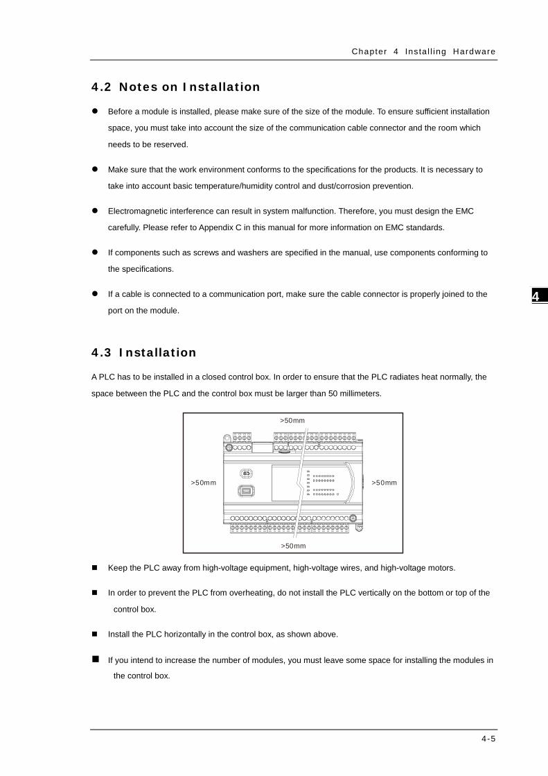
Chapter 4 Ins ta l l ing Hardware
4-5
4_
4.2 Notes on Installation
Before a module is installed, please make sure of the size of the module. To ensure sufficient installation
space, you must take into account the size of the communication cable connector and the room which
needs to be reserved.
Make sure that the work environment conforms to the specifications for the products. It is necessary to
take into account basic temperature/humidity control and dust/corrosion prevention.
Electromagnetic interference can result in system malfunction. Therefore, you must design the EMC
carefully. Please refer to Appendix C in this manual for more information on EMC standards.
If components such as screws and washers are specified in the manual, use components conforming to
the specifications.
If a cable is connected to a communication port, make sure the cable connector is properly joined to the
port on the module.
4.3 Installation
A PLC has to be installed in a closed control box. In order to ensure that the PLC radiates heat normally, the
space between the PLC and the control box must be larger than 50 millimeters.
>50mm>50mm
>50mm
>50mm
Keep the PLC away from high-voltage equipment, high-voltage wires, and high-voltage motors.
In order to prevent the PLC from overheating, do not install the PLC vertically on the bottom or top of the
control box.
Install the PLC horizontally in the control box, as shown above.
If you intend to increase the number of modules, you must leave some space for installing the modules in
the control box.

DVP-ES3 Ser ies Opera t ion Manual
4-6
_4
4.3.1 Linking the CPU module and a module
Step 1: Use a flat head screwdriver to open the side cover on the CPU module for linking a module.
Step 2: Use a flat head screwdriver to release the I/O module securing clip.
Step 3: Connect the CPU module and the module with the I/O connecting ports.

Chapter 4 Ins ta l l ing Hardware
4-7
4_
Step 4: Push the two I/O module securing clips towards the directions as the arrows below shown to hook the
modules together.
4.3.2 Installation on the Set
Method 1 – Direct installation: Use M4 screws on the mounting hole to fasten the module.
Method 2 – Installation with a DIN rail
Install the module on a DIN rail.
1. Link the module onto the DIN rail as the number 1 arrow indicated.
2. Push the module into the DIN rail as the number 2 arrow indicated, until you hear a click.
3. Make sure they are hooked together and the installation is done.
Remove the module from a DIN rail
1. Use a flat head screwdriver to unlink the module from the DIN rail.
2. Pull the module away from the DIN rail.

DVP-ES3 Ser ies Opera t ion Manual
4-8
_4
24-22AWG< 1mm 8-10mm
4.4 Wiring
Warnings
Before installing or wiring a module, you must verify that the external power supply is turned
off. If the power supply is not turned off, you may get an electric shock, or the product may be
damaged.
After you complete installing or wiring the module, make sure that a terminal block cover is
installed on the module before turning on the power supply or operating the module. If the
terminal block cover is not installed properly, you may get an electric shock, or the module
may not operate normally.
Be sure to connect the terminals FG and LG / with protective grounding conductors.
Otherwise, you may get an electric shock, or the module may not operate normally.
To ensure that a PLC is wired correctly, you must check the rated voltage of the product and
the arrangement of the terminals. If the PLC is connected to a power supply that does not
conform to the rated voltage, or the product is not wired correctly, a fire may occur, or the
product may be damaged.
The external connections should be crimped, press-welded by specific tools, or soldered
correctly. Improper connections may result in a short circuit, fire, or malfunction.
Tighten the terminal screws to the specified torque. If the terminal screws are loose, a short
circuit, fire, or faulty operation may occur. Tightening the terminal screws too far may cause
damage to the terminal screws or the module, resulting in a short circuit or malfunction.
Make sure there are no foreign substances such as iron filings or wiring debris inside the
module. Foreign substances may result in a fire, damage, or malfunction.
Things to note while wiring an I/O module
(1) Terminal definitions
Two-/three-wire (passive sensor): the sensor and the system share the same power circuit.
Four-wire (active sensor): the sensor uses an independent power supply and should not share the
same power circuit with the system.
(2) Terminals with insulation sleeves cannot be used as a terminal block. It is recommended that the
terminals be covered with insulation tubes.
(3) Use single-wire cables or two-wire cables with a diameter of 24 AWG to 22 AWG (2mm) and with less
than 1mm pin-type terminals. Only use copper conducting wires with a temperature rating of 60/75°C.

Chapter 4 Ins ta l l ing Hardware
4-9
4_
(4) Keep the input cables, output cables, and power cable separate from one another.
(5) If the main circuit and the power cable cannot be separated from each other, use a shielded cable,
and ground it at the side of the I/O module. In some cases, the shielded cable can be grounded at the
opposite side.
(6) If you wire a module through conduit, you must ground the conduit correctly.
(7) Keep 24 VDC input cables separate from 110 VAC input cables and 220 VDC input cables.
(8) If the wiring length is more than 200 meters (686.67 inches), leakage current can result from parasitic
capacitance, and the system will not function properly.
Things to note while grounding
1. Use correct and independent method to grounding.
2. Use single-wire cables or two-wire cables in a diameter of 22 AWG to 18 AWG and with less than 2 mm
pin-typed terminals.
3. Make the grounding point close to the PLC and make sure ground the surge protector and the PLC
system.
Notes:
(1) Use 110 V/220 V power cable and the 24 VDC power cable with a diameter of 22-18AWG and with less
than 2 mm pin-type terminals. Be sure to twist the power cables at the terminal screws. To prevent a short
circuit from loose screws, you must use solderless terminals with insulation sleeves.
22-18AWG< 2mm 11-12mm
(2) If cables are connected to the terminals LG and FG, you must ground the cables. Do not connect LG and
FG to any devices. If LG and FG are not grounded, the PLC will be susceptible to noise. Since LG carries
electric potential, you will get an electric shock if you touch the metal parts.
Shielded cable
AC power supply
Load through which the alternating current passes

DVP-ES3 Ser ies Opera t ion Manual
4-10
_4
4.5 Connecting Power Cables
4.5.1 Precautions
Connecting AC power cables
(1) The cables carrying the 110 VAC, 220 VAC, and 24 VDC should be single or two-wire cables.
(2) Do not bundle 110 VAC cable, 220 VAC cable, 24 VDC cable, the (high-voltage high-current) main
circuit, and the I/O signal cable together. The distance between adjacent cables should be more than
100 millimeters (3.94 inches).
(3) To prevent electrical surge from lightning, install a surge protector as shown below.
AC power supply100-240V
DVP-ES3 CPU Module
Surge absorber
Points for attention:
1. Ground the surge protector and the PLC system.
2. Select the surge protector with a working voltage that is not less than the maximum allowable input
voltage.
4.5.2 Ground
The diameter of the ground should not be less than the diameters of the cables connected to the terminals L and N.
If using multiple pieces of equipment, use a single-point ground.
DVP-ES3 CPU Module
Another piece of equipment
The single-point ground is better.
If you cannot use a single-point ground, use a common-point ground.
DVP-ES3CPU Module
The common-point ground is permitted.
Another piece of equipment
Do not connect equipment ground wires
together as shown on the right. DVP-ES3
CPU Module
The equipment can not be grounded in this way.
Another piece of equipment

Chapter 4 Ins ta l l ing Hardware
4-11
4_
4.5.3 Wiring Power Supply
Connecting an AC power cable
LN DVP-ES3 06XA
24V0V
100~220V
AC/DCConverter
Control box
The power input of DVP-ES3 is the AC input.
The alternating-current input voltage is between 100 VAC–240 VAC. Connect the power supply to the
terminals L and N. If you connect the 110 VAC or the 220 VAC power supply to the input terminals +24V
and 24G, you will damage the PLC.
If a power outage lasts for less than 10 milliseconds, the PLC keeps running without being affected. If the
power outage lasts longer, or if the voltage of the power supply decreases, the PLC stops running, and
there is no output. When the power supply returns to normal, the PLC resumes operating. Note that there
are latched auxiliary relays and registers in the PLC when you write the program.
Use single-wire cables or two-wire cables in a diameter of 22 AWG to 18 AWG and with less than 2 mm
pin-typed terminals. Only use copper conducting wires with a temperature rating of 60/75°C.
22-18AWG< 2mm 11-12mm

DVP-ES3 Ser ies Opera t ion Manual
4-12
_4
Connecting an DC power cable
DVP-ES3 06XA
24V 0V
24V0V
Control box
Note: Use appropriate power supply according to your device choice.
4.5.4 Power Consumption
Classification Model name
Internal power
consumption
(mA)
Internal power
consumption (W)
External power
consumption (W)
CPU module DVP32ES311T 137 3.3 N/A
Digital I/O
module
DVP08XM211N 10 0.24 N/A
DVP08XP211R 30 0.72 N/A
DVP08XP211T 12 0.29 0.12
DVP08XN211R 55 1.32 N/A
DVP08XN211T 12 0.29 0.24
DVP16XM211N 14 0.34 N/A
DVP16XP211R 14 0.34 1
DVP16XP211T 14 0.34 0.36
DVP16XN211R 14 0.34 1.9
DVP16XN211T 16 0.38 0.72
DVP24XP200R 12 0.29 N/A
DVP24XP200T 14 0.34 0.36
DVP24XN200R 14 0.34 N/A
DVP24XN200T 18 0.43 0.72

Chapter 4 Ins ta l l ing Hardware
4-13
4_
Classification Model name
Internal power
consumption
(mA)
Internal power
consumption (W)
External power
consumption (W)
DVP32XP200R 14 0.34 N/A
DVP32XP200T 16 0.38 0.72
Analog I/O
module
DVP04AD-E2 15 0.36 1
DVP02DA-E2 15 0.36 1.5
DVP04DA-E2 15 0.36 3
DVP06XA-E2 16.7 0.4 2.5
Temperature
measurement
module
DVP04PT-E2 15 0.36 1.5
DVP06PT-E2 16.7 0.4 1.5
DVP04TC-E2 15 0.36 1.2

DVP-ES3 Ser ies Opera t ion Manual
4-14
_4
4.6 Wiring CPU Modules
4.6.1 Wiring Digital Input Terminals
4.6.1.1 Direct Current Power Supply (24 VDC)
When the digital input signal is DC input, there are two DC input types, Sinking and Sourcing. See the definition
below.
Sinking Sourcing Sink = The current flows into the common terminal S/S.
S/S
X0
Source = The current flows from the common terminal S/S.
S/S
X0
4.6.1.2 Relay Types
Sinking
S/S
X0
I/O
Internal ci rcuit
24VDC+
Internal circuit
Sourcing
S/S
X0
I/O
Internal c ircuit
24VD C+
Internal circuit

Chapter 4 Ins ta l l ing Hardware
4-15
4_
4.6.1.3 Open-collector Input Types
Sinking (NPN input type)
S/ S
X0I/O
Inter nal c ircuit
24VDC+
+ Vcc
0V
NPN
Internal circuit
Souring (PNP input type)
S/S
X0I/O
Internal Circuit
+Vcc
0V
24VD C+
PNP
Internal circuit
4.6.1.4 Two-wire Proximity Switch
Use the two-wire proximity switch whose leakage current IL is less than 1.5 mA when the switch is OFF. If the
leakage current is larger than 1.5 mA, connect the divider resistance Rb using the formula below.
5.16−
≤IL
Rb (k Ω)
Sinking
S/S
X0I/O
Internal C ircuitRb
I L
24VDC+
Two-wir e Proxim ity Sw itch

DVP-ES3 Ser ies Opera t ion Manual
4-16
_4
Souring
S/S
X0I/O
Internal CircuitRb
IL
24 VDC+
Two-wir e Proxim ity Sw itch
4.6.1.5 Three-wire Proximity Switch
Sinking
S/S
X0
I/O
Internal Circuit
24VDC
+
Three-wire Proxim
ity Sw
itch
Souring
S/S
X0I/O
Internal Circuit
24VDC+
Three-wire P
roximity S
witch

Chapter 4 Ins ta l l ing Hardware
4-17
4_
4.6.1.6 Optoelectronic Switch
Sinking
Above 15 V DC
Optoelectronic switch
Internal circuit
S/S
X0.0
I/O
24VDC
Souring
Above 15 V DC
Optoelectronic switch
Internal circuit
S/S
X0.0
I/O
24VDC
4.6.2 Wiring Digital Output Terminals
4.6.2.1 Output Circuits
There are two types of output units. They are relay outputs and transistor outputs.
1. Relay output
250VAC2A
I/O Rel ayY0.0
C0
I/O Rel ay
Y0.0
C030VDC2A

DVP-ES3 Ser ies Opera t ion Manual
4-18
_4
2. Transistor output
5~3 0VDC 0.5A
C0
Y0.0+
I /O( )S ink
Y0.0
C0
+ 5~3 0VDC0.5A
I /O (Sou rce )
4.6.2.2 Relay Output Circuit
Relay terminals have no polarity. They can be used with alternating current that passes through a load, or with
direct current that passes through a load. The maximum current that can pass through every relay terminal is 2
A, and refer to each product specification for the maximum current that can pass through every common
terminal. The lifetime of a relay terminal varies with the working voltage, the load type (the power factor cosψ),
and the current passing through the terminal. The relation is shown in the life cycle curve below.
Contact Current(A)
20
0.50.1 0.2
3050
0.3 0.7 1 2
200300500
100
100020003000
Ope
ratio
n(X
10)3
120VAC Resistive30VDC Inductive(t=7ms)
240VAC Inductive(cos 0.4)ψ=120VAC Inductive(cos =0.4)ψ
30VDC Inductive (t=40ms)
Relay output circuit

Chapter 4 Ins ta l l ing Hardware
4-19
4_
① Direct-current power supply
② Emergency stop using an external switch.
③ Fuse: to protect the output circuit, a fuse having a breaking capacity between 5 A to 10 A is connected to the common terminal.
④ Alternating-current power supply
⑤
A relay or a solenoid valve is used as a DC load. A diode is connected in parallel to absorb the surge voltage that occurs when the load is OFF.
V D C pow er supply
⑥
An electromagnetic contactor is used as an AC load. A resistor and a capacitor are connected in parallel to absorb the surge voltage that occurs when the load is OFF.
Electromagnetic contac tor
Y0.7
⑦
A bulb (incandescent lamp) is used as a DC load. A thermistor is connected in series to absorb the surge current that occurs when the load is ON.
V DC power supply
A bulb (neon lamp) is used as an AC load. A thermistor is connected in series to absorb the surge current that occurs when the load is ON.
8 Mutually exclusive output: For example, Y0.3 controls the clockwise rotation of the motor, and Y0.4 controls the counterclockwise rotation of the motor. This interlock circuit and the program in the PLC ensure that there are protective measures if an abnormal condition occurs.

DVP-ES3 Ser ies Opera t ion Manual
4-20
_4
4.6.2.3 Transistor Output Circuit (NPN)
VDC+
D
ZP
Y
UPLow power
D: 1N4001 Diode or its equivalent
ZD D
VDC+
ZP
Y
UPHigh power and ON/OFF frequen tly
ZD: 9V Zener, 5WD: 1N4001 Diode or its equivalent
① Direct-current power supply
② Emergency stop
③ Fuse
④
The output terminals of a transistor module are open-collector output terminals. If Y0.0/Y0.1 is a pulse train output terminal of a transistor module, the output current passing through its output pull-up resistor must be greater than 0.1 A to ensure that the transistor module operates normally. 1. A diode is connected in parallel to absorb the surge voltage: used in low-power situations (refer to
Figure 1). 2. A diode and Zener are connected in parallel to absorb the surge voltage: used in high-power and
power-on/off frequently situations (refer to Figure 2).
⑤ Mutually exclusive output: For example, Y2 controls the clockwise rotation of the motor, and Y3 controls the counterclockwise rotation of the motor. This interlock circuit and the program in the PLC ensure that there are protective measures if an abnormal condition occurs.

Chapter 4 Ins ta l l ing Hardware
4-21
4_
4.6.3 Wiring RS-485 Terminals
D+ D- D+ D- D+ D-
3
4
1 2 2
3
4
① Master ② Slave ③ Terminal resistor ④ Shielded cable
Note:
1. It is suggested to use 120Ω terminal resistors on the master and the last slave.
2. Use two-wire shielded cables in a diameter of 20 AWG to ensure a quality communication.
4.6.4 Wiring CANopen Terminals
GNDCAN+ CAN-
3
4
1 2
3
GNDCAN+CA N- 2GND CAN+CA N-
① Master ② Slave ③ Terminal resistor ④ Shielded cable
Note:
1. It is recommended to use Daisy Chain for connection and be sure to use 120Ω terminal resistor in
the beginning and the end of the terminal arrangement.
2. GND is the grounding signal for CANopen network.

DVP-ES3 Ser ies Opera t ion Manual
4-22
_4
4.7 Wiring Digital Input / Output Modules
This section illustrates how to wire digital input/output modules. The wiring diagrams below also illustrate how
the power supplies are connected to S/S, and COM. If you need more information about wiring of digital
input/output terminals, refer to Section 4.6.1 and 4.6.2 in this manual.
4.7.1 Wiring DVP08XM211N
Input form Direct current (sinking or sourcing)
Voltage specifications 24 VDC, 5 mA
Sinking Sourcing
INS/S X0 X1 X2 X3 NC
NC NCX4 X5 X6 X7
DVP08XM211N ( 8DI )
INS/S X0 X1 X2 X3 NC
NC NCX4 X5 X6 X7
DVP08XM211N ( 8DI)
4.7.2 Wiring DVP08XN211R
Output form Relay
Voltage specifications 250 VAC, below 30 VDC, 2A/output, 5A/COM
OUTC0 Y0 Y1 Y2 Y3 NC
C1 NCY4 Y5 Y6 Y7
DVP08XN211R ( 8DO)OUTC0 Y0 Y1 Y2 Y3 NC
C1 NCY4 Y5 Y6 Y7
DVP08XN211R ( 8DO)

Chapter 4 Ins ta l l ing Hardware
4-23
4_
4.7.3 Wiring DVP08XN211T
Output form Transistor-T (sinking)
Voltage specifications 5 to 30 VDC, 0.5A/output, 4A/COM
OUTNC NC Y1 Y2 Y3
UP Y4 Y5 Y6 Y7
DVP08XN211T ( 8DO)
Y0
ZP
Note: You need to add external power supply 24 VDC (-15% ~ +20%) for UP and ZP; power consumption is up
to 10 mA. 4.7.4 Wiring DVP08XP211R
Input form Direct current (sinking or sourcing)
Voltage specifications 24 VDC, 5 mA
Output type Relay
Voltage specifications 250 VAC, below 30 VDC, 2A/output, 5A/COM
Sinking input and relay output Sourcing input and relay output
NC
C0 NC
DVP08XP211R ( 4DI/4DO)
OUT
Y0 Y1 Y2 Y3
NC
NC
INS/S X0 X1 X2 X3
NC
C0 NC
DVP08XP211R ( 4DI/4DO)
OUT
Y0 Y1 Y2 Y3
NC
NC
INS/S X0 X1 X2 X3

DVP-ES3 Ser ies Opera t ion Manual
4-24
_4
4.7.5 Wiring DVP08XP211T
Input form Direct current (sinking or sourcing)
Voltage specifications 24 VDC, 5 mA
Output type Transistor-T (sinking)
Voltage specifications 5 to 30 VDC, 0.5A/output, 4A/COM
Sinking input and output Sourcing input and sinking output
NC
DVP08XP211T ( 4DI/4DO)
OUT
NC
INS/S X0 X1 X2 X3
UP Y0 Y1 Y2 Y3ZP
NC
DVP08XP211T ( 4DI/4DO)
OUT
NC
INS/S X0 X1 X2 X3
UP Y0 Y1 Y2 Y3ZP
Note: You need to add external power supply 24 VDC (-15% ~ +20%) for UP and ZP; power consumption is up
to 5 mA.

Chapter 4 Ins ta l l ing Hardware
4-25
4_
4.7.6 Wiring DVP16XM211N
Input form Direct current (sinking or sourcing)
Voltage specifications 24 VDC, 5 mA
Sinking input
INS/S X0 X1 X2 X3 X4
DVP16XM211N ( 16DI)
NCX5 X6 X7
NCS/S X10 X11 X12 X13 X14 NCX15 X16 X17 NC
Sourcing input
INS/S X0 X1 X2 X3 X4
DVP16XM211N ( 16DI)
NCX5 X6 X7
NCS/S X10 X11 X12 X13 X14 NCX15 X16 X17 NC

DVP-ES3 Ser ies Opera t ion Manual
4-26
_4
4.7.7 Wiring DVP16XN211R
Output type Relay
Voltage specifications 250 VAC, below 30 VDC, 2A/output, 5A/COM
OUTC0 Y0 Y1 Y2 Y3 Y4 Y5 Y6 Y7
C2 Y10 Y11 Y12 Y13 Y14 Y15 Y16 Y17
DVP16XN211R ( 16DO)
C1
24V 0V
Note: Connect the terminal to ground.

Chapter 4 Ins ta l l ing Hardware
4-27
4_
4.7.8 Wiring DVP16XN211T
Output type Transistor-T (sinking)
Voltage specifications 5 to 30 VDC, 0.5A/output, 4A/COM
OUTY0 Y1 Y2 Y3 Y4 Y5 Y6 Y7
Y10 Y11 Y12 Y13 Y14 Y15 Y16 Y17
DVP16XN211T ( 16DO)
NC
UP0 ZP0
UP1 ZP1
Note:
1. You need to add external power supply 24 VDC (-15% ~ +20%) for UP0, ZP0 and UP1, ZP1; power
consumption is up to 30 mA.
2. Connect the terminal to ground.

DVP-ES3 Ser ies Opera t ion Manual
4-28
_4
4.7.9 Wiring DVP16XP211R
Input form Direct current (sinking or sourcing)
Voltage specifications 24 VDC, 5 mA
Output type Relay
Voltage specifications 250 VAC, below 30 VDC, 2A/output, 5A/COM
Sinking input and relay output
OUT
C0 Y0 Y1 Y2 Y3 Y4 Y5 Y6 Y7
DVP16XP211R ( 8DI/8DO)
24V 0V
S/S X0 X1 X2 X3 X4 NCX5 X6 X7
IN
Sourcing input and relay output
OUT
C0 Y0 Y1 Y2 Y3 Y4 Y5 Y6 Y7
DVP16XP211R ( 8DI/8DO)
24V 0V
S/S X0 X1 X2 X3 X4 NCX5 X6 X7
IN
Note: Connect the terminal to ground.

Chapter 4 Ins ta l l ing Hardware
4-29
4_
4.7.10 Wiring DVP16XP211T
Input form Direct current (sinking or sourcing)
Voltage specifications 24 VDC, 5 mA
Output type Transistor-T (sinking)
Voltage specifications 5 to 30 VDC, 0.5A/output, 4A/COM
Sinking input and output
OUT
Y0 Y1 Y2 Y3 Y4 Y5 Y6 Y7
DVP16XP211T ( 8DI /8DO)
UP ZP
S/S X0 X1 X2 X3 X4 NCX5 X6 X7
IN
NC
Sourcing input and sinking output
OUT
Y0 Y1 Y2 Y3 Y4 Y5 Y6 Y7
DVP16XP211T ( 8DI /8DO)
UP ZP
S/S X0 X1 X2 X3 X4 NCX5 X6 X7
IN
NC
Note:
1. You need to add external power supply 24 VDC (-15% ~ +20%) for UP and ZP; power consumption is up to
15 mA.
2. Connect the terminal to ground.

DVP-ES3 Ser ies Opera t ion Manual
4-30
_4
4.7.11 Wiring DVP24XP200R
Input form Direct current (sinking or sourcing)
Voltage specifications 24 VDC, 5 mA
Output type Relay
Voltage specifications 250 VAC, below 30 VDC, 2A/output, 5A/COM
Sinking input and relay output
OUT
C0 Y0 Y1 Y2 Y3 Y4 Y5 Y6 Y7
DVP24XP200R ( 16DI/8DO)
+24V 24G
S/S X0 X1 X2 X3 X4
X5 X6 X7
IN
NCL N
NC
X10 X11 X12 X13 X14 X15 X16 X17
Sourcing input and relay output
OUT
C0 Y0 Y1 Y2 Y3 Y4 Y5 Y6 Y7
DVP24XP200R ( 16DI/8DO)
+24V 24G
S/S X0 X1 X2 X3 X4
X5 X6 X7
IN
NCL N
NC
X10 X11 X12 X13 X14 X15 X16 X17
Note:
1. The module is built-in with a +24 V power supply for I/Os to use.
2. Connect the terminal to ground.

Chapter 4 Ins ta l l ing Hardware
4-31
4_
4.7.12 Wiring DVP24XP200T
Input form Direct current (sinking or sourcing)
Voltage specifications 24 VDC, 5 mA
Output type Transistor-T (sinking)
Voltage specifications 5 to 30 VDC, 0.5A/output, 4A/COM
Sinking input and output
OUT
ZP Y0 Y1 Y2 Y3 Y4 Y5 Y6 Y7
DVP24XP200T ( 16DI/8DO)
+24V 24G
S/S X0 X1 X2 X3 X4
X5 X6 X7
IN
NCL N
UP
X10 X11 X12 X13 X14 X15 X16 X17
Sourcing input and sinking output
OUT
ZP Y0 Y1 Y2 Y3 Y4 Y5 Y6 Y7
DVP24XP200T ( 16DI/8DO)
+24V 24G
S/S X0 X1 X2 X3 X4
X5 X6 X7
IN
NCL N
UP
X10 X11 X12 X13 X14 X15 X16 X17
Note:
1. You need to add external power supply 24 VDC (-15% ~ +20%) for UP and ZP; power consumption is up to
15 mA.
2. Connect the terminal to ground.

DVP-ES3 Ser ies Opera t ion Manual
4-32
_4
4.7.13 Wiring DVP24XN200R
Output type Relay
Voltage specifications 250 VAC, below 30 VDC, 2A/output, 5A/COM
C0 Y0 Y1 Y2 Y3 Y4 Y5 Y6 Y7
C2 Y10 Y11 Y12 Y13
DVP24XN200R ( 24DO)
C1 Y20 Y21 Y22 Y23C4NCL N
+24V 24G NC C3 Y14 Y15 Y16 Y17 C5 Y24 Y25 Y26 Y27NC NC NC
NC NC
OUT
Note:
1. The module is built-in with a +24 V power supply for I/Os to use.
2. Connect the terminal to ground. 4.7.14 Wiring DVP24XN200T
Output type Transistor-T (sinking)
Voltage specifications 5 to 30 VDC, 0.5A/output, 4A/COM
Y0 Y1 Y2 Y3 Y4 Y5 Y6 Y7
Y10 Y11 Y12 Y13
DVP24XN200T ( 24DO)
Y20 Y21 Y22 Y23NCL N
+24V 24G NC Y14 Y15 Y16 Y17 Y24 Y25 Y26 Y27NC NC
NC
OUTUP0 ZP0 UP2 ZP2
UP1 ZP1 UP3 ZP3
Note:
1. You need to add external power supply 24 VDC (-15% ~ +20%) for UP0, UP1, UP2, UP3 and ZP0, ZP1, ZP2,
ZP3; power consumption is up to 30 mA.
2. Connect the terminal to ground.

Chapter 4 Ins ta l l ing Hardware
4-33
4_
4.7.15 Wiring DVP32XP200R
Input form Direct current (sinking or sourcing)
Voltage specifications 24 VDC, 5 mA
Output type Relay
Voltage specifications 250 VAC, below 30 VDC, 2A/output, 5A/COM
Sinking input and relay output
OUT
C0 Y0 Y1 Y2 Y3 Y4 Y5 Y6 Y7
DVP32XP200R ( 16DI/16DO)
+24V 24G
S/S X0 X1 X2 X3 X4
X5 X6 X7
IN
NCL N
NC
X10 X11 X12 X13 X14 X15 X16 X17
C1 Y10 Y11 Y12 Y13 Y14 Y15 Y16 Y17
Sourcing input and relay output
OUT
C0 Y0 Y1 Y2 Y3 Y4 Y5 Y6 Y7
DVP32XP200R ( 16DI/16DO)
+24V 24G
S/S X0 X1 X2 X3 X4
X5 X6 X7
IN
NCL N
NC
X10 X11 X12 X13 X14 X15 X16 X17
C1 Y10 Y11 Y12 Y13 Y14 Y15 Y16 Y17
Note:
1. The module is built-in with a +24 V power supply for I/Os to use.
2. Connect the terminal to ground.

DVP-ES3 Ser ies Opera t ion Manual
4-34
_4
4.7.16 Wiring DVP32XP200T
Input form Direct current (sinking or sourcing)
Voltage specifications 24 VDC, 5 mA
Output type Transistor-T (sinking)
Voltage specifications 5 to 30 VDC, 0.5A/output, 4A/COM
Sinking input and output
OUT
Y0 Y1 Y2 Y3 Y4 Y5 Y6 Y7
DVP32XP200T ( 16DI/16DO)
+24V 24G
S/S X0 X1 X2 X3 X4
X5 X6 X7
IN
NCL N X10 X11 X12 X13 X14 X15 X16 X17
ZP1 Y10 Y11 Y12 Y13 Y14 Y15 Y16 Y17UP ZP0
Sourcing input and sinking output
OUT
Y0 Y1 Y2 Y3 Y4 Y5 Y6 Y7
DVP32XP200T ( 16DI/16DO)
+24V 24G
S/S X0 X1 X2 X3 X4
X5 X6 X7
IN
NCL N X10 X11 X12 X13 X14 X15 X16 X17
ZP1 Y10 Y11 Y12 Y13 Y14 Y15 Y16 Y17UP ZP0
Note:
1. You need to add external power supply 24 VDC (-15% ~ +20%) for UP, ZP0 and ZP1; power consumption is
up to 30 mA.
2. Connect the terminal to ground.

Chapter 4 Ins ta l l ing Hardware
4-35
4_
4.8 Wiring Analog Input / Output Modules
Definitions of the terminals
Two/three-wire (passive sensor): the sensor and the system share the same power circuit.
Four-wire (active sensor): the sensor uses an independent power supply and should not share the same
power circuit with the system.
Note: use cables with the same length (less than 200 m) and use terminal resistors of less than 100
ohm.
4.8.1 Wiring DVP04AD-E2
Shielded cable *1-10 V~+10 VV I+
I1 +
VI 1-
CHX
V 3+
I3 +
V I3 -
*3
* 2
CH1
1 M
CH3
AG
1M
1M
A G
1 M
2 5 0
25 0
0 V
24 V24 VDC
DC/DC
Con ve rt e r
+15 V
-15 VA G
FE*4
*5
+
-
-20 mA ~+2 0 mAV 2+
I2 +
V I2 -
* 2 CH2
1M
A G
1 M
25 0
*4
FE
+
-
+
-
+24 V
0 V
V4 +
I 4+
V I4 -
CH4
1M
A G
1 M
25 0
+2 4V
0V
4 mA ~+2 0m A
CH1
1M
A G
1M
25 0
-2 0m A~+20 m A
+24 V +
-
V 1+
I1 +
V I1 -
*2
-1 0 V~+10 V
+2 4V +
-
* 4
FE
*4 FE
*4 FE
0 V
+2 4V
0 V
0V
*6
CHX*6
CHX* 6
CHX*6
CHX* 6
Shielded c able *1
Shielded c able *1
Shielded c able *1
Shielded c able *1
4-wir e: vol tage input
4-wir e: c urr ent input
2-wire: cu rrent input
3-wire: vo ltage inpu t
2-wire: cu rrent input
3-wire: cur rent inpu t
*1. Use shielded cables to isolate the analog input signal cable from other power cables.
*2. If the module is connected to a current signal, the terminals Vn and In+ (n=1–4) must be short-circuited.

DVP-ES3 Ser ies Opera t ion Manual
4-36
_4
*3. If noise in the input voltage results in noise interference in the wiring, connect the module to a capacitor with
a capacitance between 0.1–0.47 μF with a working voltage of 25 V.
*4. Connect FE of the shielded cable to ground.
*5. Connect the terminal to ground.
*6. Every channel can work with the wiring shown above.
4.8.2 Wiring DVP02DA-E2/DVP04DA-E2
Conver ter
VO4IO4 AG
CHX0mA~20mA CH4
AG
VO1IO1
AG
CHX-10V~+10V
*2CH1
AG
24VDCDC/DC
+15V
-15VAG
FE
FE
FE*3
0V 24V
*4
*4
AC motor drive, recorder, proportioning valve
AC motor drive,recorder,proportioning valve
Shielded cable*1
Shielded cable*1
Vol tage output
Current output
*1. Use shielded cables to isolate the analog input signal cable from other power cables.
*2. If noise in the input voltage results in noise interference in the wiring, connect the module to a capacitor with
a capacitance between 0.1–0.47 μF with a working voltage of 25 V.
*3. Connect the terminal to ground.
*4. Every channel can work with the wiring shown above.

Chapter 4 Ins ta l l ing Hardware
4-37
4_
4.8.3 Wiring DVP06XA-E2
Shielded c able *14-wire: vol tage input
4-wire: c urr en t input
3-wire: vo ltage inpu t
3-wire: cur rent inpu t
Con ve rte r
CH1
1 M
CH2
AG
1M
1M
AG
1M
2 50
250
VO2IO2
AG
0mA~20 mA CH6
AG
VO1IO1
AG
-10V ~+10V
*5CH5
AG
2 4VDCDC/DC
+15V
-15 VA G
*7
*6
*6
FE
FE
CH3
1M
AG
1M
250
-1 0V~+10 VV1 +
I1+
VI1 -
CHX-I
V 3+
I 3+
VI 3-
*3
*2
+-
-2 0mA~+2 0mAV 2+I 2+
VI 2-
*2+
-
+
-
+24V
0V
+2 4V
0 V
4m A~+20m A
*6 FE
+2 4V
0 V
V4+
I 4+VI4-
CH4
1 M
A G
1M
25 0
CH1
1 M
A G
1M
25 0
-20 mA~+20 mA
+24V +
-
V 1+
I1 +
VI1-
*2
-1 0V~+10 V
+24V +
-
*6 FE
*6 FE
0V
0V
FE*6
FE*6
0V
24V
*8
CHX-I*8
CHX-I*8
CHX-I*8
CHX-I*8
CHX-O*8
CHX -O*8
Shielded c able *1
Shielded c able *1
Shielded c able *1
Shielded c able *1
Volt age output
Cur rent ou tpu t
Sh ielded cable *4
Sh ielded cable *4
AC motor dr ive, recorder, proport ioning valve
AC motor dr ive, recorder, proport ioning valve
2-wire: cu rrent inpu t
DVP-ES3 Ser ies Opera t ion Manual
4-38
_4
*1. Use shielded cables to isolate the analog input/output signal cable from other power cables.
*2. If the module is connected to a current signal, the terminals Vn and In+ (n=1–4) must be short-circuited.
*3. If noise in the input voltage results in noise interference with the wiring, connect the module to a capacitor
with a capacitance between 0.1–0.47 μF with a working voltage of 25 V.
*4. Use shielded cables to isolate the analog output signal cable from other power cables.
*5. If noise in the output voltage results in noise interference in the wiring, connect the module to a capacitor
with a capacitance between 0.1 μF–0.47 μF with a working voltage of 25 V.
*6. Connect FE of the shielded cable to ground.
*7. Connect the terminal to ground.
*8. CHX-I: Every channel can work with the input wiring shown above. CHX-O: Every channel can work with the
output wiring shown above.

Chapter 4 Ins ta l l ing Hardware
4-39
4_
4.9 Wiring Temperature Measurement Modules
4.9.1 Wiring DVP04PT-E2/DVP06PT-E2
Ni100/Pt100/JPt100Cu50/Cu100Ni1000/Pt1000/ LG-Ni1000 *3
AG
ADC
AG
INA
Shielded cable*1
CHXO1+I1+
I1-
0~300Ni100/Ni1000/Pt100/Pt1000Cu50/Cu100/JPt100/LG-Ni1000
Ω , 0~3000Ω
0~300Ni100/Ni1000/Pt100/Pt1000Cu50/Cu100/JPt100/LG-Ni1000
Ω, 0~3000Ω
FE
O4+I4+
I4-FE
24VDC
DC/DCconverter
+15V
-15VAG
0V
24V
2 Wire-
*5
*6
CHX*6
Shielded cable*13 Wire-
*1. Use shielded twisted pair cables for temperature sensors, including Ni100/Ni1000, Pt100/Pt1000,
Cu50/Cu100, JPt100, LG-Ni1000 for analog input module wiring and keep them away from power cables
and other cables that generate noise. Use 3-wire temperature sensors. But if you use two-wire
temperature sensors, In-+and In- must be short-circuited (where n is between 1–6).
*2. When the impedance to be measured is 0~300Ω or 0~3000Ω, it is recommended to use a 2-wire or 3-wire
temperature sensor instead of a 4-wire one.
*3. Choose a suitable temperature sensor.
DVP06PT-E2:
When using temperature sensors such as Ni100, Pt100, JPt100, Cu50, Cu100 and 0~300 Ω impedance
sensor, the internal excitation current is 1.0389 mA.
When using temperature sensors such as Ni1000, Pt1000, LG-Ni1000 and 0~3000 Ω impedance sensor,
the internal excitation current is 208.3μA。
DVP04PT-E2:
When using temperature sensors such as Ni100, Pt100 and 0~300 Ω impedance sensor, the internal
excitation current is 1.53mA.
When using temperature sensors such as Ni1000, Pt1000 and 0~3000 Ω impedance sensor, the internal
excitation current is 200μA.

DVP-ES3 Ser ies Opera t ion Manual
4-40
_4
*4. Connect FE of the shielded cable to ground when the noise it too loud.
*5. Connect the terminal to ground.
*6. CHX: Every channel can work with the input wiring shown above.
Note 1: use cables with the same length (less than 200 m) and use terminal resistors of less than 200 ohm.
4.9.2 Wiring DVP04TC-E2
+-
I4+
I4-
Col d conjunction compensation
MUX
+-
J,K,R,S,T,E,N
-80mV~80mV
I1+
I1-FE
FEShielded cabl e*1
24VDC
DC/DCConver ter
5V
AG0V
24V
*2
CHX*3
CHX*3
S hielded cable*1
*1. The cable connected to the input terminal should be the cable or the shielded twisted pair cable connected
to a type J, K, R, S, T, E, N thermocouple. It should be kept separate from other power cables and cables
that generate noise.
*2. Connect the terminal to ground.
*3. CHX: Every channel can work with the input wiring shown above.
Note 1: only use copper conducting wires with a temperature rating of 60/75°C and the length must be less
than 50 m.
Note2: TC modules must run for 30 minutes before they start to take any temperature measurement.

5-1
5 Chapter 5 CPU and Module Devices
Table of Contents
5.1 Introduction to CPU Devices .............................................................................. 5-2 5.1.1 Device Table ............................................................................................. 5-2 5.1.2 Basic Structure of I/O Storage ..................................................................... 5-3 5.1.3 Relation Between the PLC Action and the Device Type .................................... 5-3 5.1.4 Latched Areas in the Device Range .............................................................. 5-4
5.2. CPU Device Functions ....................................................................................... 5-5 5.2.1 Values and Constants ................................................................................. 5-5 5.2.2 Floating-point Numbers .............................................................................. 5-7
5.2.2.1 Single-precision Floating-point Numbers ...................................................... 5-7 5.2.2.2 Decimal Floating-point Numbers ................................................................. 5-8
5.2.3 Strings ..................................................................................................... 5-9 5.2.4 Input Relays (X) ...................................................................................... 5-10 5.2.5 Output Relays (Y) .................................................................................... 5-11 5.2.6 Auxiliary Relays (M) ................................................................................. 5-11 5.2.7 Special Auxiliary Relays (SM) .................................................................... 5-11 5.2.8 Flags (S) ................................................................................................. 5-12 5.2.9 Timers (T) .............................................................................................. 5-12 5.2.10 Counters ................................................................................................. 5-14 5.2.11 32-bit Counters (HC) ................................................................................ 5-16 5.2.12 Data Registers (D) ................................................................................... 5-18 5.2.13 Special Data Registers (SR)....................................................................... 5-18 5.2.14 Index Register (E) .................................................................................... 5-18 5.2.15 File Registers (FR).................................................................................... 5-18
5.3. Module Device Functions ................................................................................ 5-19 5.3.1 DVP04AD-E2 Control Registers .................................................................. 5-19 5.3.2 DVP02DA-E2 / DVP4DA-E2 Control Registers ............................................... 5-24 5.3.3 DVP06XA-E2 Control Registers .................................................................. 5-28 5.3.4 DVP04PT-E2 /DVP06PT-E2 Control Registers ............................................... 5-35 5.3.5 DVP04TC-E2 Control Registers .................................................................. 5-40

DVP-ES3 Ser ies Opera t ion Manual
5-2
_5
5.1 Introduction to CPU Devices This section describes the values and strings processed by the PLC. It also describes the functions of devices, including input, output and auxiliary relays, as well as timers, counters, and data registers. The PLC simulates external devices in the PLC’s internal memory, so the word “device” is a generic name that refers to all the internal memory locations in the PLC. A device can be a bit device or a word device. Bit devices simulate coils, contacts and flags, while word devices simulate registers.
5.1.1 Device Table Type Device name Number of devices Range
Bit device
Input relay X 256 X0–X377 Output relay Y 256 Y0–Y377
Data register D 48,0000 D0.0–D29999.15
W 48,0000 W0.0–W29999.15 *4
Auxiliary relay M 8192 M0–M8191 Special auxiliary relay SM 2048 SM0–SM4095 Flag S 2048 S0–S2047 Timer T 512 T0–T511 Counter C 512 C0–C511 32-bit counter HC 256 HC0–HC255
Word device
Input relay X 64 X0–X63 Output relay Y 64 Y0–Y63
Data register D 30000 D0–D29999
W 30000 W0–W29999 *4
Special auxiliary relay SR 2048 SR0–SR2047
File register FR 65536 FR0–FR65535
Timer T 512 T0–T511 Counter C 512 C0–C511
32-bit counter HC 256(512 words) HC0–HC255
Index register E 10 E0–E9
5 E10–E14 *4
Constant*1 Decimal system K 16 bits: -32768 to 32767 32 bits: -2147483648 to 2147483647
Constant*2 Hexadecimal system 16#
16 bits: 16#0–16#FFFF 32 bits: 16#0–16#FFFFFFFF
Single-precision floating-point number F 32 bits: ±1.17549435-38 to ±3.40282347+ 38
String*3 String “$” 1–31 characters
*1: Constants are indicated by K in the device lists in Chapter 5 and Chapter 6 in the DVP-ES3 Series Programming Manual. For example, when “K50” appears in the DVP-ES3 Series Programming Manual, enter only the number 50 in ISPSoft.
*2: Floating-point numbers are indicated by F/DF in the device lists in Chapter 5 and Chapter 6 in the DVP-ES3 Series Programming Manual, but they are represented by decimal points in ISPSoft. For example, for the floating-point

Chapter 5 CPU and Module Devices
5-3
5_
number F500, enter 500.0 in ISPSoft.
*3: Strings are indicated by $ in Chapter 5 and Chapter 6 in the DVP-ES3 Series Programming Manual, but they are represented by quotes (“ ”) in ISPSoft. For example, for the string of 1234, enter “1234” in ISPSoft.
*4: Used for editing in ISPSoft only.
5.1.2 Basic Structure of I/O Storage
Device Function Access by bits
Access by words
Modify by ISPSoft Force the bit ON/OFF
X Input relay OK OK OK OK Y Output relay OK OK OK OK M Auxiliary relay OK - OK -
SM Special auxiliary relay OK - OK -
S Flag OK - OK - T Timer OK OK OK - C Counter OK OK OK -
HC 32-bit counter OK OK OK - D Data register OK OK OK OK
SR Special data register - OK OK - FR File register - OK*1 - - E Index register - OK OK -
*1: Use an instruction for writing to an FR.
5.1.3 Relation Between the PLC Action and the Device Type
Device type PLC action
Non-latched area Latched area Device Y Other devices File register Other devices
Power: OFF→ON Cleared Cleared Retained Retained Restore to defaults Cleared Cleared Cleared Cleared
STOP ↓
RUN*1
The non-latched area is cleared. Cleared Cleared Retained Retained
The state of the non-latched area is retained.
Retained Retained Retained Retained
RUN ↓
STOP*1
The state of device Y is cleared. Cleared Retained Retained Retained
The state of device Y is retained. Retained Retained Retained Retained
SM204 is ON. (All non-latched areas are
cleared.) Cleared Cleared Retained Retained
SM205 is ON. (All latched areas are
cleared.) Retained Retained Retained Cleared
*1: For more on setting the states, see HWCONFIG in ISPSoft. The default for PLC STOP->RUN is “clear not-latched area”. The default for PLC RUN->STOP is “clear the state of device Y”.
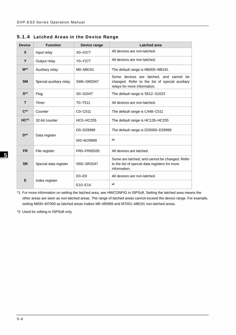
DVP-ES3 Ser ies Opera t ion Manual
5-4
_5
5.1.4 Latched Areas in the Device Range
Device Function Device range Latched area
X Input relay X0–X377 All devices are non-latched.
Y Output relay Y0–Y377 All devices are non-latched.
M*1 Auxiliary relay M0–M8191 The default range is M6000–M8191.
SM Special auxiliary relay SM0–SM2047 Some devices are latched, and cannot be changed. Refer to the list of special auxiliary relays for more information.
S*1 Flag S0–S2047 The default range is S512–S1023
T Timer T0–T511 All devices are non-latched.
C*1 Counter C0–C511 The default range is C448–C511
HC*1 32-bit counter HC0–HC255 The default range is HC128–HC255
D*1 Data register D0–D29999 The default range is D20000–D29999
W0–W29999 *2
FR File register FR0–FR65535 All devices are latched.
SR Special data register SR0–SR2047 Some are latched, and cannot be changed. Refer to the list of special data registers for more information.
E Index register E0–E9 All devices are non-latched.
E10–E14 *2
*1: For more information on setting the latched area, see HWCONFIG in ISPSoft. Setting the latched area means the other areas are seen as non-latched areas. The range of latched areas cannot exceed the device range. For example, setting M600–M7000 as latched areas makes M0–M5999 and M7001–M8191 non-latched areas.
*2: Used for editing in ISPSoft only.

Chapter 5 CPU and Module Devices
5-5
5_
5.2. CPU Device Functions The following flow chart shows the procedure for processing a program in the PLC.
Input terminal X
Device memory
Processin g th e prog ram
Device m
emory
Regenerating the output s ignaland sending it to the output terminal
Regenerating the input signal
Device memory
Regenerating the input signal 1. Before the program is executed, the state of the
external input signal is read into the memory location for the input signal.
2. When program is executed, the state in the memory location for the input signal does not change even if the input signal changes from ON to OFF or from OFF to ON. The input signal is not refreshed until the next scan begins.
Processing the program After the input signal is refreshed, the instructions in the program are executed in order from the start address of the program. The results are stored in the device memory.
Regenerating the state of the output After the instruction END is executed, the state in the device memory is sent to the specified output terminal.
5.2.1 Values and Constants Name Description
Bit A bit is the basic unit in the binary system. Its state is either 1 or 0.
Nibble A nibble is composed of four consecutive bits (for example b3–b0). Nibbles
can represent 0–9 in the decimal system, or 0–F in the hexadecimal system.
Byte A byte is composed of two consecutive nibbles ( 8 bits, b7–b0). Bytes can
represent 00–FF in the hexadecimal system.
Word A word is composed of two consecutive bytes (16 bits, b15–b0). Words can
represent 0000–FFFF in the hexadecimal system.
Double word A double word is composed of two consecutive words (i.e. 32 bits, b31–b0). Double words represent 00000000–FFFFFFFF in the hexadecimal system.
The relation among bits, nibbles, bytes, words, and double words in the binary system is shown in the picture below.
b31b30 b29 b28 b27b26 b25 b24b23 b22 b21 b20b19 b18 b17 b16 b15b14 b13 b12b11 b10 b9 b8 b7 b6 b5 b4 b3 b2 b1 b0
NB0NB1NB2NB3NB4NB5NB6NB7
BY3 BY2 BY1 BY0
W1
DW
W0
Double word
Word
Byte
N ibble
Bit

DVP-ES3 Ser ies Opera t ion Manual
5-6
_5
The PLC uses four types of values to execute the operation according to different control purposes.
1. Binary number (BIN)
The PLC uses the binary system to operate on the values.
2. Octal number (OCT) DVP-PLC uses the octal number on the external inut and output device number. For example:
External input device number: X0~X7, X10~X17, to X377.
External output device number: Y0~Y7, Y10~Y17, to Y377.
3. Decimal number (DEC)
The PLC uses decimal numbers for:
The setting value of a timer (T) or the setting value of a counter (C/HC); for example, TMR C0 50 (constant K).
The device number S, M, T, C, D, E; for example, M10 and T30 (device number)
The constant K, used as the operand in an applied instruction. For example, MOV 123 D0 (constant K).
4. Binary-coded decimal (BCD)
A decimal value that is represented by a nibble or four bits so that sixteen consecutive bits represent a four-digit decimal value.
5. Hexadecimal number (HEX)
The PLC uses hexadecimal numbers for:
The constant 16#, used as the operand in an applied instruction; for example, MOV 16#1A2B D0
(hexadecimal constant).
The following table shows the corresponding values.
Binary Number (BIN)
Octal Number (OCT)
Decimal Number (DEC)
Binary Code Decimal (BCD)
Hexadecimal Number (HEX)
PLC internal execution
X and Y device number
Constant K, Device number
BCD related instruction
Constant 16#, Device number
0000 0 0000 0 0001 1 0001 1 0010 2 0010 2 0011 3 0011 3 0100 4 0100 4 0101 5 0101 5 0110 6 0110 6 0111 7 0111 7 1000 8 1000 8 1001 9 1001 9 1010 10 - A 1011 11 - B 1100 12 - C 1101 13 - D 1110 14 - E

Chapter 5 CPU and Module Devices
5-7
5_
Binary Number (BIN)
Octal Number (OCT)
Decimal Number (DEC)
Binary Code Decimal (BCD)
Hexadecimal Number (HEX)
1111 15 - F 10000 16 0001 0000 10
10001 17 0001 0001 11
5.2.2 Floating-point Numbers Floating-point numbers are represented by decimal points in ISPSoft. For example, the floating-point number 500 is represented as 500.0.
5.2.2.1 Single-precision Floating-point Numbers
Floating-point numbers are represented by a 32-bit register. The representation adopts the IEEE754 standard, and the format shown in the following picture.
S Exponent Mantissa
8-b it 23-bi t
b31 b0
Sign b it0 : Positive1: Negative
Equation: ( ) 127;.121 =××− − BMBES
The single-precision floating-point numbers range between ±2-126 to ±2+128, and correspond to the range between
±1.1755×10-38 to ±3.4028×10+38.
The DVP-ES3 Series PLC uses two consecutive registers for a 32-bit floating-point number. Take (D1, D0) for example.
S E7 E6 E5 E1 E0 A22 A21 A20 A6 A5 A4 A3 A2 A1 A0
b0b1b2b3b4b5b6b20b21b22b23b24b28b29b30b31
2 2 2 2 2 2 2 2 2 2 2 2 22 2
D1(b15~b0) D0(b15~b0)
Exp on en t ( 8 b its) Ma nt issa (2 3b its)
Ma nt issa sign b it (0 : Po sit ive; 1: Ne ga tive)W hen b 0~b3 1 a re zeros, the con te nt is zero .
The pos it ion w here the d eci mal point is hid den

DVP-ES3 Ser ies Opera t ion Manual
5-8
_5
Example 1:
23 is represented by a single-precision floating-point number. Step 1: Convert 23 into the binary number, 23.0=10111.
Step 2: Normalize the binary number, 10111=1.0111 ×24 (0111 is the mantissa, and 4 is the exponent.).
Step 3: Get the value of the exponent.
∵ E-B=4→E-127=4 ∴ E=131=100000112
Step 4: Combine the sign bit, the exponent, and the mantissa to form the floating-point number.
0 10000011 011100000000000000000002=41B8000016
Example 2:
-23 is represented by a single-precision floating-point number.
Converting -23.0 into the floating-point number uses the same steps as converting 23.0 into the floating-point number, except that the sign bit is 1.
1 10000011 011100000000000000000002=C1B8000016
5.2.2.2 Decimal Floating-point Numbers
Single-precision floating-point numbers and double-precision floating-point numbers can be converted into decimal floating-point numbers so people can read them. However, internally the PLC uses single-precision floating-point numbers and double-precision floating-point numbers.
A 32-bit decimal floating-point number is represented by two consecutive registers. The constant is stored in the first register whose number is smaller while the exponent is stored in the register whose number is bigger. Take (D1, D0) for example.
10Decimal f loating-point number=[Constant ]*D0[Exponent ]D1
Base number D0=±1,000 to ±9,999
Exponent D1=-41 to +35
The base number 100 does not exist in D0 because 100 is represented by 1,000×10-1. 32-bit decimal floating-point numbers range between ±1175×10-41 to ±402×10+35.

Chapter 5 CPU and Module Devices
5-9
5_
5.2.3 Strings The PLC can process strings composed of ASCII codes (*1). A complete string begins with a start character, and ends with an ending character (NULL code). Strings can have maximum length of 31 characters, and ISPSoft automatically adds the ending character (16#00).
1. No string (NULL code) is moved.
D0=0 (NULL)
2. The string has an even number of characters.
D0 16#62 (b) 16#61 (a)
D1 16#64 (d) 16#63 (b)
D2 0 (NULL)
3. The string has an odd number of characters.
D0 16#62 (b) 16#61 (a)
D1 16#64 (d) 16#63 (b)
D2 0 (NULL) 16#65 (e)
*1: ASCII code chart
Hex 0 1 2 3 4 5 6 7 8 9 A B C D E F
ASCII
Hex 10 11 12 13 14 15 16 17 18 19 1A 1B 1C 1D 1E 1F
ASCII
Hex 20 21 22 23 24 25 26 27 28 29 2A 2B 2C 2D 2E 2F
ASCII SP ! " # $ % & ' ( ) * + , - . /

DVP-ES3 Ser ies Opera t ion Manual
5-10
_5
Hex 30 31 32 33 34 35 36 37 38 39 3A 3B 3C 3D 3E 3F
ASCII 0 1 2 3 4 5 6 7 8 9 : ; < = > ?
Hex 40 41 42 43 44 45 46 47 48 49 4A 4B 4C 4D 4E 4F
ASCII @ A B C D E F G H I J K L M N O
Hex 50 51 52 53 54 55 56 57 58 59 5A 5B 5C 5D 5E 5F
ASCII P Q R S T U V W X Y Z
Hex 60 61 62 63 64 65 66 67 68 69 6A 6B 6C 6D 6E 6F
ASCII ` a b c d e f g h i j k l M n o
Hex 70 71 72 73 74 75 76 77 78 79 7A 7B 7C 7D 7E 7F
ASCII p q r s t u v w x y z | –
Note: represents an invisible character. Do not use it in strings.
5.2.4 Input Relays (X)
Input function
The input is connected to the input device (external devices such as button switches, rotary switches, and number switches), and the PLC reads the input signal. You can use input contact A or contact B several times in the program, and the ON/OFF state of the input varies with the ON/OFF state of the input device.
Input number (the octal number)
For the PLC, the input numbers start from X0. The number of inputs varies with the number of inputs on the digital input/output modules. The inputs are numbered according to the order in which the digital input/output modules are connected to the CPU module. The maximum number of inputs for the PLC is 256, and the input number range is between X0 to X377.
Input type
Inputs are classified into two types.
1. Regenerated inputs: The PLC reads the state of a regenerated input before the program is executed; for example, LD X0.
2. Direct input: The state of a direct input is read by the PLC during the execution of the instructions; for example, LD DX0.

Chapter 5 CPU and Module Devices
5-11
5_
5.2.5 Output Relays (Y) Output function
The output sends the ON/OFF signal to drive the load connected to the output, such as an external signal lamp, a digital display, or an electromagnetic valve. There are four types of outputs. They are relays, transistors (NPN and PNP), and TRIACs (thyristors). You can use the output contact A or contact B several times in the program. Use output Y only once in the program; otherwise, according the PLC’s program-scanning function, the state of the output depends on the circuit connected to the last output Y in the program.
Output number (the octal number)
For the PLC, the output numbers start from Y0. The number of outputs varies with the number of outputs on the digital input/output modules. The outputs are numbered according to the order in which the digital input/output modules are connected to the PLC. The maximum number of outputs on the PLC is 256, and the range is between Y0 and Y377.
An output that is not used as an output device can be used as a general device.
Output types
Outputs are classified into two types.
1. Regenerated output: The state of a regenerated output is not written until the program executes the END instruction, according to the states of the outputs; for example, OUT Y0.
2. Direct output: The state of a direct output is written by the PLC during the execution of the instructions, according to the states of the outputs; for example, OUT DY0.
5.2.6 Auxiliary Relays (M) The auxiliary relay has contact A and contact B. It can be used several times in the program. You can combine the control loops by using the auxiliary relay, but you cannot drive the external load using the auxiliary relay. You can use the auxiliary relays in either of the following two ways.
1. For general use: In general use, if an electric power failure occurs when the PLC is running, the auxiliary relay resets to the OFF state. When the power is restored, the auxiliary relay remains in the OFF state.
2. For latched use: In latched use, ff an electric power failure occurs when the PLC is running, the state of the auxiliary relay is retained. When the power is restored, the relay state remains the same as before the power failure.
5.2.7 Special Auxiliary Relays (SM)
Every special auxiliary relay has its specific function. Do not use the special auxiliary relays which are not defined. Refer to section 2.2.7 in DVP-ES3 Series Programming Manual for more reference.

DVP-ES3 Ser ies Opera t ion Manual
5-12
_5
5.2.8 Flags (S)
You can easily use the flags in industrial automation to set a procedure. It is the most basic device in ladder diagram programming.
There are 2048 flags, (S0–S2047). Every flag is like an output relay in that it has an output coil, contact A, and contact B.
You can use a flag several times in a program. There are two kinds of flags.
A. General-purpose flags
When the power is OFF during execution, all the device states are cleared to OFF. When the power is turned back ON, the device states are kept as OFF.
B. Latch-purpose flags
When the power is OFF during execution, all the device states are remembered. When the power is turned back ON, the devices states are restored as they are before the power interruption.
5.2.9 Timers (T)
This topic describes the timers available in ISPSoft. Refer to the ISPSoft User Manual for more information on timers.
100 millisecond timer: The timer specified by the TMR instruction takes 100 milliseconds as the timing unit.
10 millisecond timer: The timer specified by the TMR instruction takes 10 milliseconds as the timing unit.
1 millisecond timer: The timer specified by the TMRH instruction takes 1 millisecond as the timing unit.
The accumulative timers are ST0–ST511. If you want to use the device-monitoring function, these timers can monitor T0–T511.
If you use the same timer repeatedly in a program, including in different TMR, TMRM and TMRH instructions, the timer setting value is the one that the timer matches first.
If you use the same timer repeatedly in a program, the timer is OFF when one of the conditional contacts is OFF.
If you use the same timer in a program as the timer for a subroutine’s exclusive use and an accumulative timer in the program, it is OFF when one of the conditional contacts is OFF.
When the timer switches from ON to OFF and the conditional contact is ON, the timer is reset and counts again.
When the TMR instruction is executed, the specified timer coil is ON and the timer begins to count. When the value of the timer matches the timer setting value (value of the timer ≧ setting value), the state of the contact is ON.
A. General-purpose timers
When the TMR instruction is executed, the general-purpose timer begins to count. When the value of the timer matches the timer setting value, the output coil is ON.
• When M0=ON and the timer takes 100 ms as the timing unit, the output coil T0 is ON when the value of the timer = timer setting value100.
• When M0=OFF or the power is off, the value of the timer is 0 and the output coil T0 is OFF.

Chapter 5 CPU and Module Devices
5-13
5_
X0. 0
T0( PV)
Y0. 0
SV: K100
10se c
M 0
M1
B. Accumulative timers
When the TMR instruction is executed, the accumulative timer begins to count. When the value of the timer matches the timer setting value, the output coil is ON. As long as you add the letter S in front of the letter T, the timer becomes an accumulative timer. When the conditional contact is OFF, the value of the accumulative timer is not reset. When the conditional contact is ON, the accumulative timer counts from the current value.
• When M0=ON and the timer T250 takes 100 ms as the timing unit, the output coil T250 is ON when the value of the timer = timer setting value 100.
• When M0=OFF or the power is off, the accumulative timer ST250 stops counting, and the value of the timer stays the same. When M0=ON, the value of the timer is the accumulating value. When the accumulated value = timer setting value 100, the output coil T250 is ON.

DVP-ES3 Ser ies Opera t ion Manual
5-14
_5
X0.0
T2
Y0. 0
SV: K100
T1+T2=10 sec
T250( PV)
T1
M 1
M 0
C. Timers used in function blocks
T412–T511 are the timers that you can use in the function block or in interrupts.
When the TMR or END instruction is executed, the timer in the functional block begins to count. When the value of the timer matches the timer setting value, the output coil is ON.
If you use a general-purpose timer in a function block or an interrupt, and the function or interrupt is not executed, the timer cannot count correctly.
5.2.10 Counters
Characteristics of the 16-bit counter
Item 16-bit counter Type General type Number C0–C511 Direction Counting up Setting value 0–32,767
Specifying the counter setting value The setting value can be either the constant or the value in the data register.
Change of the current value The counter stops counting when the value of the counter matches the counter setting value.
Output contact The contact is ON when the value of the counter matches the counter setting value.
Reset When the instruction RST is executed, the current value is cleared to zero, and the contact is reset of OFF.
Action of the contact After the scan is complete, the contact acts.
Function of the counter
Each time the input switches from OFF to ON, the value of the counter is the same as the output coil. You can use either the decimal constant or the value in the data register as the counter setting value.
16-bit counter:
1. Setting range: 0–32,767. The setting values 0 and 1 mean the same thing in that the output contact is ON when the counter counts for the first time.
2. For the general-purpose counter, the current value of the counter is cleared when power is lost. If the counter is latching, the current value of the counter and the state of the contact before power was lost power are retained. The latched counter counts from the current value when the power supply is restored.
3. If you use the MOV instruction or ISPSoft to transmit a value larger than the counter setting value to the current value

Chapter 5 CPU and Module Devices
5-15
5_
register C0, the contact of the counter C0 is ON and the current value becomes the same as the counter setting value the next time X0.1 switches from OFF to ON.
4. You can use either the constant or the value in the data register as the counter setting value.
5. The counter setting value can be positive or negative. If the counter counts up from 32,767, the next value is 0.
1. When M0=ON, the RST instruction is executed, the current value of C0 is reset to zero, and the output contact of the counter C0 is FF. And M0=OFF, the execution of RST instruction is done.
2. When M1 changes from OFF to ON, the value of the counter increments by one.
3. When the value of the counter C0 reaches the counter setting value of 5, the contact of the counter C0 is ON (the current value of C0 = the counter setting value = 5). After that the trigger from M1 is not accepted by C0 and the current value of C0 stays at the value 5.
X0.0
X0.1
Y0.0,C0
C0 (PV )
01
23
45(SV )
0
M1
M0
M 3

DVP-ES3 Ser ies Opera t ion Manual
5-16
_5
5.2.11 32-bit Counters (HC)
Characteristics of the 32-bit counter
Item 32-bit counter Type Up/down counter Up counter High-speed counter
Number HC0–HC63 HC64–HC199 HC200–HC255 Direction Counts up/down Counts up Counts up/down
Setting value -2,147,483,648 to +2,147,483,647 Specification of the
counter setting value The counter setting value can be either the constant or the value occupying two data registers (32-bit).
Change of the current value
The counter keeps counting even after the value of the counter matches the counter setting value.
Output contact
The contact is ON when the value of the addition counter matches the counter setting value. The contact is reset to OFF when the value of the subtraction counter matches the counter setting value.
Reset When the RST instruction is executed, the current value is cleared to zero, and the contact is reset to OFF.
Action of the contact After the DCNT instruction scan is complete, the contact acts.
32-bit general-purpose addition/subtraction counter
1. The difference between the 32-bit general-purpose addition counters and the 32-bit general-purpose subtraction counters depends on the states of the special auxiliary relays SM621–SM684. For example, the counter HC0 is an addition counter when SM621 is OFF, whereas HC0 is a subtraction counter when SM621 is ON.
2. You can use either the constant or the value in the data registers as the counter setting value, and this setting value can be positive or negative. If you use the value in the data registers as the counter setting value, this setting value occupies two consecutive registers.
3. For the general-purpose counter, the current value of the counter is cleared when power is lost. If the counter is latching, the current value of the counter and the state of the contact before loss of power is retained. The latched counter counts from the current value when power is restored.
4. If the counter counts up from 2,147,483,647, the next incremental value is -2,147,483,648. If the counter counts down from -2,147,483,648, the next incremental value is 2,147,483,647.

Chapter 5 CPU and Module Devices
5-17
5_
32-bit high speed addition/subtraction counter
Refer to the instruction description of API1004 DCNT in DVP-ES3 Series Programming Manual for more details.
Example:
1. M10 drives SM621 to determine the counting direction (up/down) for HC0.
2. When M11 changes from OFF to ON, the RST instruction is executed and the PV in HC0 is cleared to 0 and its contact is OFF.
3. When M12 changes from OFF to ON, PV for HC0 will count up (plus 1) or count down (minus 1).
4. When PV in HC0 changes from -6 to -5, the contact HC0 changes from OFF to ON. When PV in HC0 changes from -5 to -6, the contact HC0 changes from ON to OFF.
X10.0
X11.0
X12.0
Whe n the outp ut con tact wa s ON
Y0.0,HC0 Contacts
HC0 ( )PV
Accumu lativelyincrea sing Progressive ly
d ecreasing
01
23
45
43
21
0-1
-2-3
-4-5
-6-7
-8
0
-7-6
-5-4
-3
Accumulat ivelyincreasingM10
M11
M12
M0

DVP-ES3 Ser ies Opera t ion Manual
5-18
_5
5.2.12 Data Registers (D)
The data register stores 16-bit data. The highest bit represents either a positive sign or a negative sign, and the values that the data registers can store range between -32,768 to +32,767.
Two 16-bit registers can be combined into a 32-bit register; for example, (D+1, D) in which the lower number register represents the low 16 bits. The highest bit represents either a positive sign or a negative sign, and the values that the data registers can store range between -2,147,483,648 to +2,147,483,647.
Four 16-bit registers can be combined into a 64-bit register; for example, (D+3, D+2, D+1, D) in which the lower number register represents the lower 16 bits. The highest bit represents either a positive sign or a negative sign, and the values that the data registers can store range between -9,223,372,036,854,776 to +9,223,372,036,854,775,807.
You can also use the data registers to refresh the values in the control registers in the modules other than digital I/O modules. Refer to the ISPSoft User Manual for more information on refreshing the values in the control registers.
There are two types of registers.
General-purpose registers: When the PLC changes to RUN, or is disconnected, the value in the register is cleared to zero. If you want to retain the data when the PLC changes to RUN, Refer to the ISPSoft User Manual for more information. Note that the value is still cleared to zero when the PLC is disconnected.
Latched register: If the PLC is disconnected, the data in the latched register is not cleared. In other words, the value before the disconnection is retained. If you want to clear the data in the latched area, you can use the RST or ZRST instructions.
5.2.13 Special Data Registers (SR)
Every special data register has its own definition and specific function. System status and the error messages are stored in the special data registers. Refer to section 2.2.14 in DVP-ES3 Series Programming Manual for more reference.
5.2.14 Index Register (E)
The Index register is a 16-bit data register. It is similar to the General register in that data can be read from it and written to it; however, it is mainly used as the index register. The range of index registers is E0–E9. Refer to section 4.4 in DVP-ES3
Series Programming Manual for more reference.
5.2.15 File Registers (FR)
The DVP-ES3 Series PLC provides you with File registers for storing larger numbers of parameters.
You can edit, upload, and download the parameters in the File registers through ISPSoft.
You can read the values in File registers while operating the PLC. Refer to the MEMW instruction (API 2303) in DVP-ES3 Series Programming Manual for more information about how to write to the File registers.

Chapter 5 CPU and Module Devices
5-19
5_
5.3. Module Device Functions 5.3.1 DVP04AD-E2 Control Registers
CR# Attrib. Register name Explanation
0 O R Model name Set up by the system: DVP04AD-E2 model code = H’0080
1 O R Firmware version Display the current firmware version in hex. format 2 O R/W CH1 input mode setting Input mode: Default = H’0000.
Mode 0 (H’0000): Voltage input (±10V) Mode 1 (H’0001): Voltage input (±5V) Mode 2 (H’0002): Voltage input (0 ~ +10V) Mode 3 (H’0003): Voltage input (0 ~ +5V) Mode 4 (H’0004): Current input (±20mA) Mode 5 (H’0005): Current input (0 ~ +20mA) Mode 6 (H’0006): Current input (+4~ +20mA) Mode -1 (H’FFFF): Channel 1 unavailable
3 O R/W CH2 input mode setting 4 O R/W CH3 input mode setting
5 O R/W CH4 input mode setting
8 O R/W CH1 sampling range Set sampling range in CH1 ~ CH4: Range = K1 ~ K100 Default = K10
9 O R/W CH2 sampling range 10 O R/W CH3 sampling range 11 O R/W CH4 sampling range 12 X R CH1 average input value
Average value of input signals at CH1 ~ CH4 13 X R CH2 average input value 14 X R CH3 average input value 15 X R CH4 average input value 20 X R CH1 present input value
Present value of input signals at CH1 ~ CH4 21 X R CH2 present input value 22 X R CH3 present input value 23 X R CH4 present input value 28 O R/W Adjusted Offset value of CH1
Set the adjusted Offset value of CH1 ~ CH4. Default = K0 29 O R/W Adjusted Offset value of CH2 30 O R/W Adjusted Offset value of CH3
#31 O R/W Adjusted Offset value of CH4 34 O R/W Adjusted Gain value of CH1
Set the adjusted Gain value in CH1 ~ CH4. Default = K16,000 35 O R/W Adjusted Gain value of CH2 36 O R/W Adjusted Gain value of CH3 37 O R/W Adjusted Gain value of CH4
Adjusted Offset Value, Adjusted Gain Value: Note1: When using Mode 6 for input, the channel do NOT provide setups for adjusted Offset or Gain value. Note2: When input mode changes, the adjusted Offset or Gain value automatically returns to defaults.
40 O R/W Function: Set value changing prohibited Prohibit set value changing in CH1 ~ CH4. Default= H’0000.
41 X R/W Function: Save all the set values Save all the set values, Default =H’0000
43 X R Error status Register for storing all error status. Refer to table of error status for more information.
100 O R/W Function: Enable/Disable limit detection
Upper and lower bound detection, b0~b3 corresponds to Ch1~Ch4 (0: Enable/1: Disable). Default= H’0000.
101 X R/W Upper and lower bound status Display the upper and lower bound status (0: Not exceed /1: Exceeds upper or lower bound value), b0~b3 corresponds to Ch1~Ch4 for lower bound detection result; b8~b11 corresponds

DVP-ES3 Ser ies Opera t ion Manual
5-20
_5
CR# Attrib. Register name Explanation to CH1~CH4 for upper bound detection result.
102 O R/W Set value of CH1 upper bound
Set value of CH1~CH4 upper bound. Default = K32000. 103 O R/W Set value of CH2 upper bound 104 O R/W Set value of CH3 upper bound 105 O R/W Set value of CH4 upper bound 108 O R/W Set value of CH1 lower bound
Set value of CH1~CH4 lower bound. Default = K-32000. 109 O R/W Set value of CH2 lower bound 110 O R/W Set value of CH3 lower bound 111 O R/W Set value of CH4 lower bound
Symbols: O: When CR#41 is set to H’5678, the set value of CR will be saved. X: Set value will not be saved. R: You can use FROM instruction to read data. W: You can use TO instruction to write data. ※ CR#0 for module reset You can use CR#0 to reset all the settings by simply writing H’4352 in CR#0 and wait for one second before turning the power OFF and then ON again, all the modules connected will be initialized. It is suggested to connect to only one module for module reset. And this is only available for firmware V1.10 or later. ※ CR#43: Error status value. See the table below:
Description bit0 K1 (H’1) Power supply error bit6 K64 (H’40) CH4 Conversion error bit1 K2 (H’2) Hardware error bit9 K512 (H’0200) Mode setting error bit2 K4 (H’4) Upper/lower bound error bit10 K1024 (H’0400) Sampling range error
bit3 K8 (H’8) CH1 Conversion error bit11 K2048 (H’0800) Upper / lower bound setting error
bit4 K16 (H’10) CH2 Conversion error bit12 K4096 (H’1000) Set value changing prohibited
bit5 K32 (H’20) CH3 Conversion error bit13 K8192 (H’2000) Communication breakdown on next module
Note: Each error status is determined by the corresponding bit (b0 ~ b13) and there may be more than 2 errors occurring at the same time. 0 = normal; 1 = error
Adjust A/D Conversion Curve You can adjust the conversion curves according to the actual needs by changing the Offset value (CR#28 ~ CR#31) and Gain value (CR#34 ~ CR#37).
Offset: The corresponding voltage/current input value when the digital output value = 0.
Gain: The corresponding voltage/current input value when the digital output value = 16,000.
Equation for voltage input Mode0 / Mode2:
( )OffsetGainOffsetVVXY −
−××= 32000
1016000
)()(
Y=Digital output, X=Voltage input
Resolution: 0.3125mV = 20V/64,000 = 10V/32,000

Chapter 5 CPU and Module Devices
5-21
5_
Equation for voltage input Mode1 / Mode3:
( )OffsetGainOffsetVVXY −
−××= 32000
516000
)()(
Y=Digital output, X=Voltage input
Resolution: 0.15625mV = 10V/64,000 = 5V/32,000
Equation for current input Mode4 / Mode5:
( )OffsetGainOffsetmAmAXY −
−××= 32000
2016000
)()(
Y=Digital output, X=Current input
Resolution: 0.625μA = 40mA/64,000 = 20mA/32,000
Equation for current input Mode6:
( )64001920064003200020
16000 −
−××=
)()(
mAmAXY
Y=Digital output, X=Current input
Resolution: 0.5μA = 16mA/32,000
Mode 0 of CR#2 ~ CR#5 -10V ~ +10V, Default: Gain = 16,000(= ), Offset = 0
Mode 1 of CR#2 ~ CR#5 -5V ~ +5V, Default: Gain = 16,000(= ), Offset = 0
Range of digital conversion -32,000 ~ +32,000 Max./Min. range of digital conversion -32,384 ~ +32,384
Mode 0:
Mode 1:
Digital input
10V
5V
-5V
+32000
-10V
-32000
+160000
Gain
Offset
Voltageoutput
-32768
+32767
Voltage input
+32000
+16000
-16000
5V
-32000
-5V 2.5V0
GainOffset
Digitaloutput
+32384
-32384

DVP-ES3 Ser ies Opera t ion Manual
5-22
_5
Mode 2 of CR#2 ~ CR#5 0V ~ +10V, Default: Gain = 16,000(= ),Offset = 0
Mode 3 of CR#2 ~ CR#5 0V ~ +5V, Default: Gain = 16,000(= ),Offset = 0
Range of digital conversion 0 ~ +32,000
Max./Min. range of digital conversion
-384 ~ +32,384
Mode 2: Mode 3:
Voltage input
+32000
+16000
10V5V
0Gain
Offset
Digitaloutput
+32384
-384
Voltage input
+32000
+16000
5V2.5V
0Gain
Offset
Digitaloutput
+32384
-384
Mode 4 of CR#2 ~ CR#5 -20mA ~ +20mA, Default: Gain = 16,000(= ), Offset = 0
Range of digital conversion -32,000 ~ +32,000 Max./Min. range of digital conversion -32,384 ~ +32,384
Mode 4:
Current input
+32000
+16000
-16000
20mA
-32000
-20mA 10mA0
GainOffset
Digitaloutput
+32384
-32384
Mode 5 of CR#2 ~ CR#5 0mA ~ +20mA, Default: Gain = 16,000(= ), Offset = 0
Mode 6 of CR#2 ~ CR#5 +4mA ~ +20mA, Default: Gain = 19,200 (= ),
Offset = 6,400(= )
Range of digital conversion 0 ~ +32,000 Max./Min. range of digital conversion -384 ~ +32,384

Chapter 5 CPU and Module Devices
5-23
5_
Mode 5: Mode 6:
Current input
+32000
+16000
20mA10mA
0Gain
Offset
Digitaloutput
+32384
-384
Current input
+32000
+16000
20mA12mA0
Gain
Offset
Digitaloutput
+32384
-384 4mA

DVP-ES3 Ser ies Opera t ion Manual
5-24
_5
5.3.2 DVP02DA-E2 / DVP4DA-E2 Control Registers CR# Attrib. Register name Explanation
0 O R Model name Set up by the system, model code: DVP02DA-E2 = H’0041; DVP04DA-E2 = H’0081
1 O R Firmware version Display the current firmware version in hex. 2 O R/W CH1 output mode setting Output mode: Default = H’0000.
Mode 0 (H’0000): Voltage output (±10V) Mode 1 (H’0001): Current output (0~+20mA) Mode 2 (H’0002): Current output (+4~+20mA) Mode -1 (H’FFFF): All channels are unavailable
3 O R/W CH2 output mode setting 4 O R/W CH3 output mode setting
5 O R/W CH4 output mode setting
16 X R/W CH1 output signal value Voltage output range: K-32,000~K32,000. Current output range: K0~K32,000. Default: K0. CR#18~CR#19 of DVP02DA-E2 are reserved.
17 X R/W CH2 output signal value 18 X R/W CH3 output signal value 19 X R/W CH4 output signal value 28 O R/W Adjusted Offset value of CH1
Set the adjusted Offset value of CH1 ~ CH4. Default = K0 29 O R/W Adjusted Offset value of CH2 30 O R/W Adjusted Offset value of CH3 31 O R/W Adjusted Offset value of CH4 34 O R/W Adjusted Gain value of CH1
Set the adjusted Gain value of CH1 ~ CH4. Default = K16,000. 35 O R/W Adjusted Gain value of CH2 36 O R/W Adjusted Gain value of CH3 37 O R/W Adjusted Gain value of CH4
Adjusted Offset Value, Adjusted Gain Value: Note1: When using Mode 2, the channel do NOT provide setups for adjusted Offset or Gain value. Note2: When output mode changes, the adjusted Offset or Gain value automatically returns to defaults.
40 O R/W Function: Set value changing prohibited Prohibit set value changing in CH1 ~ CH4. Default= H’0000.
41 X R/W Function: Save all the set values Save all the set values. Default =H’0000.
43 X R Error status Register for storing all error status. Refer to table of error status for more information.
100 O R/W Function: Enable/Disable limit detection
Upper and lower bound detection, b0~b3 corresponds to CH1~CH4 (0: Disable/ 1: Enable). Default= H’0000.
101 X R/W Upper and lower bound status
Display the upper and lower bound status. (0: Not exceed /1: Exceeds upper or lower bound value), b0~b3 corresponds to Ch1~Ch4 for lower bound detection result; b8~b11 corresponds to CH1~CH4 for upper bound detection result..
102 O R/W Set value of CH1 upper bound
Set value of CH1~CH4 upper bound. Default = K32000. 103 O R/W Set value of CH2 upper bound 104 O R/W Set value of CH3 upper bound 105 O R/W Set value of CH4 upper bound 108 O R/W Set value of CH1 lower bound
Set value of CH1~CH4 lower bound. Default = K-32000. 109 O R/W Set value of CH2 lower bound 110 O R/W Set value of CH3 lower bound 111 O R/W Set value of CH4 lower bound 114 O R/W Output update time of CH1
Set value of CH1~CH4 lower bound. Setting range: K0~K100. Default =H’0000. 115 O R/W Output update time of CH2
116 O R/W Output update time of CH3

Chapter 5 CPU and Module Devices
5-25
5_
CR# Attrib. Register name Explanation 117 O R/W Output update time of CH4
118 O R/W LV output mode setting Set the output mode of CH1~CH4 when the power is at LV (low voltage) condition. Default= H’0000.
Symbols: O: When CR#41 is set to H’5678, the set value of CR will be saved. X: Set value will not be saved. R: You can use FROM instruction to read data. W: You can use TO instruction to write data. ※ CR#0 for module reset You can use CR#0 to reset all the settings by simply writing H’4352 in CR#0 and wait for one second before turning the power OFF and then ON again, all the modules connected will be initialized. It is suggested to connect to only one module for module reset. And this is only available for firmware V1.12 or later. ※ CR#43: Error status value. See the table below:
Description
bit0 K1 (H’1) Power supply error bit11 K2048 (H’0800) Upper / lower bound setting error
bit1 K2 (H’2) Hardware error bit12 K4096 (H’1000) Set value changing prohibited
bit2 K4 (H’4) Upper/lower bound error bit13 K8192 (H’2000) Communication breakdown on next module
bit9 K512 (H’0200) Mode setting error Note: Each error status is determined by the corresponding bit (b0 ~ b13) and there may be more than 2 errors
occurring at the same time. 0 = normal; 1 = error Adjust D/A Conversion Curve You can adjust the conversion curves according to the actual needs by changing the Offset value (CR#28 ~ CR#31) and Gain value (CR#34 ~ CR#37).
Offset: The corresponding voltage/current input value when the digital output value = 0.
Gain: The corresponding voltage/current input value when the digital output value = 16,000.
Equation for voltage output Mode0:
( ) ( )
×
+
−×=
32000)(10
16000VOffsetOffsetGainXVY
Y=Voltage output, X=Digital input
Resolution: 0.3125mV = 20V/64,000

DVP-ES3 Ser ies Opera t ion Manual
5-26
_5
Equation for current output Mode1:
( ) ( )
×
+
−×=
32000)(20
16000mAOffsetOffsetGainXmAY
Y=Current output, X=Digital input
Resolution: 0.625μA = 20mA/32,000
Equation for current input Mode2:
( ) ( )
×
+
−×=
32000)(206400
16000640019200 mAXmAY
Y=Current output, X=Digital input
Resolution: 0.5μA = 16mA/32,000
Mode 0 of CR#2 ~ CR#5 -10V ~ +10V, Default: Gain = 16,000(= ), Offset = 0
Range of digital conversion -32,000 ~ +32,000
Max./Min. range of digital conversion
-32,768 ~ +32,767
Mode 0:
Digital input
10V
5V
-5V
+32000
-10V
-32000
+160000
Gain
Offset
Voltageoutput
-32768
+32767
Mode 1 of CR#2 ~ CR#5 0mA ~ +20mA, Default: Gain = 16,000(= ), Offset = 0
Range of digital conversion 0 ~ +32,000
Max./Min. range of digital conversion
0 ~ +32,767

Chapter 5 CPU and Module Devices
5-27
5_
Mode 1:
Digital input
+32000+16000
20mA
10mA
0
Offset
Currentoutput
+32767
Gain
Mode 2 of CR#2 ~ CR#5 +4mA ~ +20mA, Default: Gain = 19,200(= ),Offset = 6,400(= )
Range of digital conversion 0 ~ +32,000
Max./Min. range of digital conversion
0 ~ +32,767
Mode 2:
Digital input
+32000+16000
20mA
12mA
0Offset
Currentoutput
+32767
Gain
4mA
-6400

DVP-ES3 Ser ies Opera t ion Manual
5-28
_5
5.3.3 DVP06XA-E2 Control Registers CR# Attrib. Register name Explanation
0 O R Model name Set up by the system: DVP06XA-E2 model code = H’00C4
1 O R Firmware version Display the current firmware version in hex. 2 O R/W CH1 Input mode setting Input mode: Default = H’0000. Take CH1 for example:
Mode 0 (H’0000):Voltage input (±10V) Mode 1 (H’0001):Voltage input (±5V) Mode 2 (H’0002):Voltage input (0 ~+10V) Mode 3 (H’0003):Voltage input (0 ~+5V) Mode 4 (H’0004):Current input (±20mA) Mode 5 (H’0005):Current input (0 ~+20mA) Mode 6 (H’0006):Current input (4 ~+20mA) Mode -1 (H’FFFF):Channel 1 unavailable
3 O R/W CH2 Input mode setting 4 O R/W CH3 Input mode setting
5 O R/W CH4 Input mode setting
6 O R/W CH5 output mode setting Output mode: Default = H’0000. Take CH5 for example: Mode 0 (H’0000):Voltage output (±10V) Mode 1 (H’0001):Current output (0~+20mA) Mode 2 (H’0002):Current output (4~+20mA) Mode -1 (H’FFFF):Channel 5 unavailable
7 O R/W CH6 output mode setting
8 O R/W CH1 average times Average times setting of CH1 ~ CH4: Range = K1 ~ K100 Default = K10
9 O R/W CH2 average times 10 O R/W CH3 average times 11 O R/W CH4 average times 12 X R CH1 average input value
Average value of input signals at CH1 ~ CH4 13 X R CH2 average input value 14 X R CH3 average input value 15 X R CH4 average input value 16 X R/W CH5 output signal value Voltage output range: K-32,000~K32,000. Current output range:
K0~K32,000. Default: K0. 17 X R/W CH6 output signal value
20 X R CH1 present input value
Present value of input signals at CH1 ~ CH4 21 X R CH2 present input value 22 X R CH3 present input value 23 X R CH4 present input value 28 O R/W Adjusted Offset value of CH1
Set the adjusted Offset value of CH1 ~ CH6 Default = K0. Definition of Offset in DVP06XA -E2: The corresponding voltage (current) input value when the digital output value = 0
29 O R/W Adjusted Offset value of CH2 30 O R/W Adjusted Offset value of CH3 31 O R/W Adjusted Offset value of CH4 32 O R/W Adjusted Offset value of CH5 33 O R/W Adjusted Offset value of CH6 34 O R/W Adjusted Gain value of CH1
Set the adjusted Gain value in CH1 ~ CH6 Default = K16,000. Definition of Gain in DVP06XA-E2: The corresponding voltage (current) input value when the digital output value = 16,000.
35 O R/W Adjusted Gain value of CH2 36 O R/W Adjusted Gain value of CH3 37 O R/W Adjusted Gain value of CH4 38 O R/W Adjusted Gain value of CH5
39 O R/W Adjusted Gain value of CH6

Chapter 5 CPU and Module Devices
5-29
5_
CR# Attrib. Register name Explanation Adjusted Offset Value, Adjusted Gain Value: Note 1: When using Mode 6 for input or Mode 2 for output, the channel do NOT provide setups for adjusted Offset and Gain value. Note 2: When mode changes, the adjusted Offset and Gain value returns to defaults.
40 O R/W Set value changing prohibited Prohibit set value changing in CH1 ~ CH4 Default= H’0000. 41 X R/W Save all the set values Save all the set values, Default =H’0000
43 X R Error status Register for storing all error status. Refer to table of error status for more information.
100 O R/W Enable/Disable limit detection Upper and lower bound detection, b0~b5 corresponds to CH1~CH6 (0: Disable/ 1: Enable). Default= H’0000.
101 X R/W Upper and lower bound status
Display the upper and lower bound status. (0: Not exceed /1: Exceeds upper or lower bound value), b0~b5 corresponds to Ch1~Ch6 for lower bound detection result; b8~b13 corresponds to CH1~CH6 for upper bound detection result.
102 O R/W Set value of CH1 upper bound
Set value of CH1~CH6 upper bound. Default = K32000.
103 O R/W Set value of CH2 upper bound 104 O R/W Set value of CH3 upper bound 105 O R/W Set value of CH4 upper bound 106 O R/W Set value of CH5 upper bound 107 O R/W Set value of CH6 upper bound 108 O R/W Set value of CH1 lower bound
Set value of CH1~CH6 lower bound. Default = K-32000.
109 O R/W Set value of CH2 lower bound 110 O R/W Set value of CH3 lower bound 111 O R/W Set value of CH4 lower bound 112 O R/W Set value of CH5 lower bound 113 O R/W Set value of CH6 lower bound 114 O R/W Output update time of CH5
Set output update time of CH5 ~ CH6 115 O R/W Output update time of CH6
118 O R/W LV output mode setting of Ch5 ~ Ch6
Set the output mode of CH5~CH6 when the power is at LV (low voltage) condition. Default=0
Symbols: O: When CR#41 is set to H’5678, the set value of CR will be saved. X: Set value will not be saved. R: You can use FROM instruction to read data. W: You can use TO instruction to write data. ※ CR#0 for module reset You can use CR#0 to reset all the settings by simply writing H’4352 in CR#0 and wait for one second before turning the power OFF and then ON again, all the modules connected will be initialized. It is suggested to connect to only one module for module reset. And this is only available for firmware V1.14 or later. ※ CR#43: Error status value. See the table below:
Description bit0 K1 (H’1) Power supply error bit6 K64 (H’40) CH4 Conversion error bit1 K2 (H’2) Hardware error bit9 K512 (H’0200) Mode setting error bit2 K4 (H’4) Upper/lower bound error bit10 K1024 (H’0400) Sampling range error
bit3 K8 (H’8) CH1 Conversion error bit11 K2048 (H’0800) Upper / lower bound setting error
bit4 K16 (H’10) CH2 Conversion error bit12 K4096 (H’1000) Set value changing prohibited

DVP-ES3 Ser ies Opera t ion Manual
5-30
_5
Description
bit5 K32 (H’20) CH3 Conversion error bit13 K8192 (H’2000) Communication breakdown on next module
Note: Each error status is determined by the corresponding bit (b0 ~ b13) and there may be more than 2 errors occurring at the same time. 0 = normal; 1 = error
Adjust A/D Conversion Curve You can adjust the conversion curves according to the actual needs by changing the Offset value (CR#28 ~ CR#31) and Gain value (CR#34 ~ CR#37).
Offset: The corresponding voltage/current input value when the digital output value = 0.
Gain: The corresponding voltage/current input value when the digital output value = 16,000.
Equation for voltage input Mode0 / Mode2:
( )OffsetGainOffsetVVXY −
−××= 32000
1016000
)()(
Y=Digital output, X=Voltage input
Resolution: 0.3125mV = 20V/64,000 = 10V/32,000
Equation for voltage input Mode1 / Mode3:
( )OffsetGainOffsetVVXY −
−××= 32000
516000
)()(
Y=Digital output, X=Voltage input
Resolution: 0.15625mV = 10V/64,000 = 5V/32,000
Equation for current input Mode4 / Mode5:
( )OffsetGainOffsetmAmAXY −
−××= 32000
2016000
)()(
Y=Digital output, X=Current input
Resolution: 0.625μA = 40mA/64,000 = 20mA/32,000
Equation for current input Mode6:
( )64001920064003200020
16000 −
−××=
)()(
mAmAXY
Y=Digital output, X=Current input
Resolution: 0.5μA = 16mA/32,000

Chapter 5 CPU and Module Devices
5-31
5_
Mode 0 of CR#2 ~ CR#5 -10V ~ +10V, Default: Gain = 16,000(= ), Offset = 0
Mode 1 of CR#2 ~ CR#5 -5V ~ +5V, Default: Gain = 16,000(= ), Offset = 0
Range of digital conversion -32,000 ~ +32,000 Max./Min. range of digital conversion -32,384 ~ +32,384
Mode 0:
Mode 1:
Digital input
10V
5V
-5V
+32000
-10V
-32000
+160000
Gain
Offset
Voltageoutput
-32768
+32
Voltage input
+32000
+16000
-16000
5V
-32000
-5V 2.5V0
GainOffset
Digitaloutput
+32384
-32384
Mode 2 of CR#2 ~ CR#5 0V ~ +10V, Default: Gain = 16,000(= ),Offset = 0
Mode 3 of CR#2 ~ CR#5 0V ~ +5V, Default: Gain = 16,000(= ),Offset = 0
Range of digital conversion 0 ~ +32,000
Max./Min. range of digital conversion
-384 ~ +32,384
Mode 2: Mode 3:
Voltage input
+32000
+16000
10V5V
0Gain
Offset
Digitaloutput
+32384
-384
Voltage input
+32000
+16000
5V2.5V
0Gain
Offset
Digitaloutput
+32384
-384
Mode 4 of CR#2 ~ CR#5 -20mA ~ +20mA, Default: Gain = 16,000(= ), Offset = 0
Range of digital conversion -32,000 ~ +32,000 Max./Min. range of digital conversion -32,384 ~ +32,384

DVP-ES3 Ser ies Opera t ion Manual
5-32
_5
Mode 4:
Current input
+32000
+16000
-16000
20mA
-32000
-20mA 10mA0
GainOffset
Digitaloutput
+32384
-32384
Mode 5 of CR#2 ~ CR#5 0mA ~ +20mA, Default: Gain = 16,000(= ), Offset = 0
Mode 6 of CR#2 ~ CR#5 +4mA ~ +20mA, Default: Gain = 19,200 (= ),
Offset = 6,400(= )
Range of digital conversion 0 ~ +32,000 Max./Min. range of digital conversion -384 ~ +32,384
Mode 5:
Mode 6:
Current input
+32000
+16000
20mA10mA
0Gain
Offset
Digitaloutput
+32384
-384
Current input
+32000
+16000
20mA12mA0
Gain
Offset
Digitaloutput
+32384
-384 4mA

Chapter 5 CPU and Module Devices
5-33
5_
Adjust D/A Conversion Curve You can adjust the conversion curves according to the actual needs by changing the Offset value (CR#32 ~ CR#33) and Gain value (CR#38 ~ CR#39).
Offset: The corresponding voltage/current input value when the digital output value = 0.
Gain: The corresponding voltage/current input value when the digital output value = 16,000.
Equation for voltage output Mode0:
( ) ( )
×
+
−×=
32000)(10
16000VOffsetOffsetGainXVY
Y=Voltage output, X=Digital input
Resolution: 0.3125mV = 20V/64,000
Equation for current output Mode1:
( ) ( )
×
+
−×=
32000)(20
16000mAOffsetOffsetGainXmAY
Y=Current output, X=Digital input
Resolution: 0.625μA = 20mA/32,000
Equation for current input Mode2:
( ) ( )
×
+
−×=
32000)(206400
16000640019200 mAXmAY
Y=Current output, X=Digital input
Resolution: 0.5μA = 16mA/32,000
Mode 0 of CR#2 ~ CR#5 -10V ~ +10V, Default: Gain = 16,000(= ), Offset = 0
Range of digital conversion -32,000 ~ +32,000
Max./Min. range of digital conversion
-32,768 ~ +32,767

DVP-ES3 Ser ies Opera t ion Manual
5-34
_5
Mode 0:
Digital input
10V
5V
-5V
+32000
-10V
-32000
+160000
Gain
Offset
Voltageoutput
-32768
+32767
Mode 1 of CR#2 ~ CR#5 0mA ~ +20mA, Default: Gain = 16,000(= ), Offset = 0
Range of digital conversion 0 ~ +32,000
Max./Min. range of digital conversion
0 ~ +32,767
Mode 1:
Digital input
+32000+16000
20mA
10mA
0
Offset
Currentoutput
+32767
Gain
Mode 2 of CR#2 ~ CR#5 +4mA ~ +20mA, Default: Gain = 19,200(= ),Offset = 6,400(= )
Range of digital conversion 0 ~ +32,000
Max./Min. range of digital conversion
0 ~ +32,767
Mode 2:
Digital input
+32000+16000
20mA
12mA
0Offset
Currentoutput
+32767
Gain
4mA
-6400
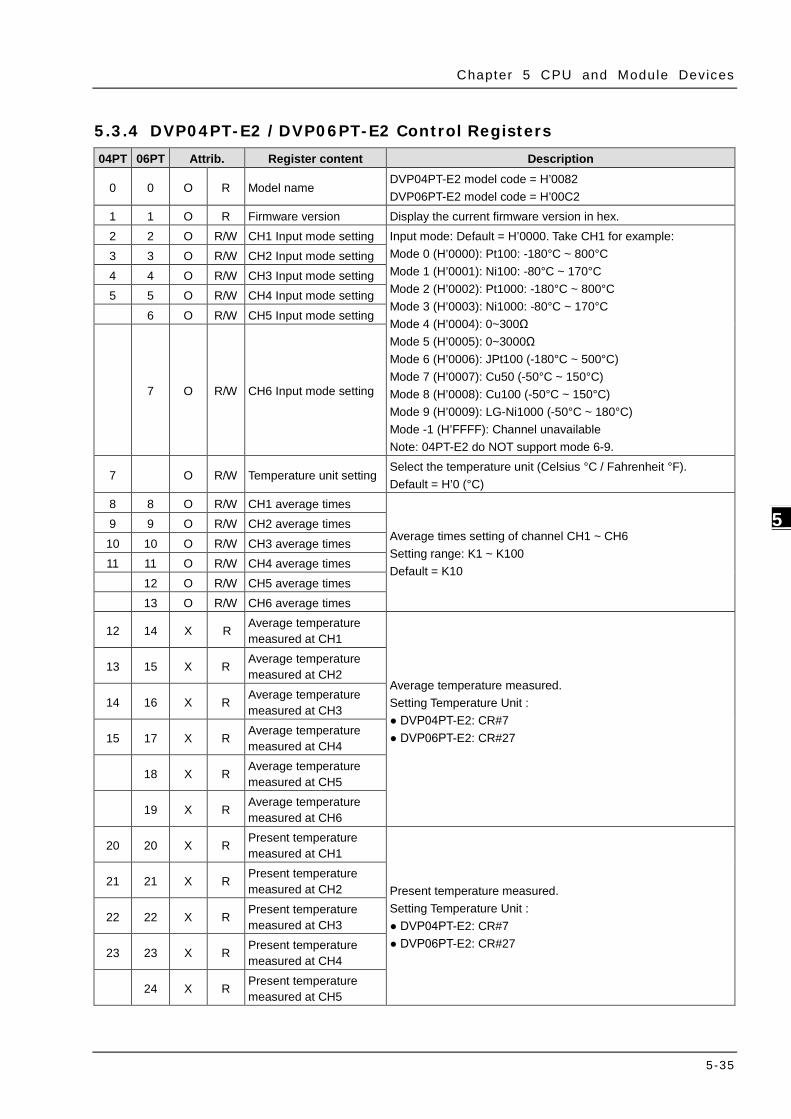
Chapter 5 CPU and Module Devices
5-35
5_
5.3.4 DVP04PT-E2 /DVP06PT-E2 Control Registers 04PT 06PT Attrib. Register content Description
0 0 O R Model name DVP04PT-E2 model code = H’0082 DVP06PT-E2 model code = H’00C2
1 1 O R Firmware version Display the current firmware version in hex. 2 2 O R/W CH1 Input mode setting Input mode: Default = H’0000. Take CH1 for example:
Mode 0 (H’0000): Pt100: -180°C ~ 800°C Mode 1 (H’0001): Ni100: -80°C ~ 170°C Mode 2 (H’0002): Pt1000: -180°C ~ 800°C Mode 3 (H’0003): Ni1000: -80°C ~ 170°C Mode 4 (H’0004): 0~300Ω Mode 5 (H’0005): 0~3000Ω Mode 6 (H’0006): JPt100 (-180°C ~ 500°C) Mode 7 (H’0007): Cu50 (-50°C ~ 150°C) Mode 8 (H’0008): Cu100 (-50°C ~ 150°C) Mode 9 (H’0009): LG-Ni1000 (-50°C ~ 180°C) Mode -1 (H’FFFF): Channel unavailable Note: 04PT-E2 do NOT support mode 6-9.
3 3 O R/W CH2 Input mode setting 4 4 O R/W CH3 Input mode setting 5 5 O R/W CH4 Input mode setting 6 O R/W CH5 Input mode setting
7 O R/W CH6 Input mode setting
7
O R/W Temperature unit setting Select the temperature unit (Celsius °C / Fahrenheit °F). Default = H’0 (°C)
8 8 O R/W CH1 average times
Average times setting of channel CH1 ~ CH6 Setting range: K1 ~ K100 Default = K10
9 9 O R/W CH2 average times 10 10 O R/W CH3 average times 11 11 O R/W CH4 average times 12 O R/W CH5 average times 13 O R/W CH6 average times
12 14 X R Average temperature measured at CH1
Average temperature measured. Setting Temperature Unit : DVP04PT-E2: CR#7 DVP06PT-E2: CR#27
13 15 X R Average temperature measured at CH2
14 16 X R Average temperature measured at CH3
15 17 X R Average temperature measured at CH4
18 X R Average temperature measured at CH5
19 X R Average temperature measured at CH6
20 20 X R Present temperature measured at CH1
Present temperature measured. Setting Temperature Unit : DVP04PT-E2: CR#7 DVP06PT-E2: CR#27
21 21 X R Present temperature measured at CH2
22 22 X R Present temperature measured at CH3
23 23 X R Present temperature measured at CH4
24 X R Present temperature measured at CH5

DVP-ES3 Ser ies Opera t ion Manual
5-36
_5
04PT 06PT Attrib. Register content Description
25 X R Present temperature measured at CH6
26 O R/W
Mode 4 (H’0004): 0~300Ω. Temperature display decimal digit changes
In mode 4 (0~300Ω), temperature display decimal changes (0: 1 digit after the decimal place/ 1: 2 digits after the decimal place). Default= H0
27 O R/W Temperature unit setting Select the temperature unit (Celsius °C / Fahrenheit °F). Default = H’0(°C)
28 28 O R/W Adjusted offset value of CH1
Adjusted offset value, range K-1000 ~ K1000. Default = K0 Measured Value = Original Value – Adjusted offset value Unit Setup: DVP04PT-E2: CR#7 DVP06PT-E2: CR#27
29 29 O R/W Adjusted offset value of CH2
30 30 O R/W Adjusted offset value of CH3
31 31 O R/W Adjusted offset value of CH4
32 O R/W Adjusted offset value of CH5
33 O R/W Adjusted offset value of CH6
40 40 O R/W Function: Set value changing prohibited
Prohibit set value changing, b0~b5 corresponds to CH1 ~ CH6. Default =H’0000
41 41 X R/W Function: Save all the set values Save all the set values. Default =H’0000
43 43 X R Error status Register for storing all error status. See the table of error status for more information.
100 100 O R/W Function: Enable/Disable limit detection
Upper and lower bound detection, b0~b5 corresponds to CH1 ~ CH6 (0: Disable/ 1: Enable). Default= H’0000.
101 101 X R/W Upper and lower bound status
Display the upper and lower bound status (0: Not Exceeding; 1: Exceeding upper and lower bound value), b0~b5 corresponds to CH1 ~ CH6 lower bound, b8~b13 corresponds to CH1 ~ CH6 upper bound. Default =H’0000
102 102 O R/W Set value of CH1 upper bound
Set upper bound value. Default = K32000.
103 103 O R/W Set value of CH2 upper bound
104 104 O R/W Set value of CH3 upper bound
105 105 O R/W Set value of CH4 upper bound
106 O R/W Set value of CH5 upper bound
107 O R/W Set value of CH6 upper bound
108 108 O R/W Set value of CH1 lower bound
Set lower bound value. Default = K-32000. 109 109 O R/W Set value of CH2 lower bound
110 110 O R/W Set value of CH3 lower

Chapter 5 CPU and Module Devices
5-37
5_
04PT 06PT Attrib. Register content Description bound
111 111 O R/W Set value of CH4 lower bound
112 O R/W Set value of CH5 lower bound
113 O R/W Set value of CH6 lower bound
Symbols: O: When CR#41 is set to H’5678, the set value of CR will be saved. X: Set value will not be saved. R: You can use FROM instruction to read data. W: You can use TO instruction to write data. ※ CR#0 for module reset You can use CR#0 to reset all the settings by simply writing H’4352 in CR#0 and wait for one second before turning the power OFF and then ON again, all the modules connected will be initialized. It is suggested to connect to only one module for module reset. ※ CR#43: Error status value. See the table below:
Description bit0 K1 (H’1) Power supply error bit6 K64 (H’40) CH4 Conversion error bit1 K2 (H’2) Hardware error bit9 K512 (H’0200) Mode setting error bit2 K4 (H’4) Upper/lower bound error bit10 K1024 (H’0400) Sampling range error
bit3 K8 (H’8) CH1 Conversion error bit11 K2048 (H’0800) Upper / lower bound setting error
bit4 K16 (H’10) CH2 Conversion error bit12 K4096 (H’1000) Set value changing prohibited
bit5 K32 (H’20) CH3 Conversion error bit13 K8192 (H’2000) Communication breakdown on next module
Note: Each error status is determined by the corresponding bit (b0 ~ b13) and there may be more than 2 errors occurring at the same time. 0 = normal; 1 = error
PID Control Registers
CR Attrib. Register content Description
CH1 CH2 CH3 CH4
120 140 160 180 O R/W Set temperature value Please set the temperature value according to proper range of each sensor type. Default = K0
121 141 161 181 O R/W Sampling time (s) Range: K1 ~ K30 (s). Default = K2 122 142 162 182 O R/W KP Proportional control constant. Default = K121 123 143 163 183 O R/W KI Integral constant. Default = K2,098 124 144 164 184 O R/W KD Derivative constant. Default = K-29 125 145 165 185 O R/W Upper limit of I value Upper limit of I value. Default = K0 126 146 166 186 O R/W Lower limit of I value Lower limit of I value. Default = K0 127 147 167 187 X R I value Current accumulated offset value 128 148 168 188 O R/W Heating/cooling 0: Heater, 1: Cooler. Default = K0 129 149 169 189 O R/W Upper limit of output Upper limit of output. Default = K32,000 130 150 170 190 O R/W Lower limit of output Lower limit of output. Default = K0 131 151 171 191 X R Output percentage Output percentage (Unit: 0.1%) 132 152 172 192 X R Output width (ms) Width of control output. Unit: ms 133 153 173 193 X R Output cycle (ms) Cycle of control output. Unit: ms

DVP-ES3 Ser ies Opera t ion Manual
5-38
_5
CR Attrib. Register content Description 134 154 174 194 X R Output volume Output volume 135 155 175 195 X R/W PID_RUN/STOP 0: STOP, 1: RUN. Default = K0 136 156 176 196 X R/W Auto-tuning 0: Disabled, 1: Auto-tuning. Default = K0 Symbols: O: Set value will be saved. X: Set value will not be saved. R: You can use FROM instruction to read data. W: You can use TO instruction to write data. Adjust PT Conversion Curve You can adjust the conversion curves according to the actual needs by changing the Offset value.
Offset in DVP04/06PT-E2: Deviation digital value from the target value.
(Measured Value= Original Value – Adjust Value Offset)
Mode0 ~ Mode3, Mode6 ~ Mode9 : output unit 0.1°
−
°°
= OffsetXY)(.)(
10
Y= Digital output,
X= Measured temperature input
Mode4 ~ Mode5: output unit 0.1Ω
−= OffsetXY
)Ohm(.)Ohm(
10
Y= Digital output,
X= Measured temperature input
Mode 0: Mode 1:
+8,000
+4,000
-1,800
+800
-180
+4000
C
C
Digital output
Measuredtemperature input
+1,700
-800
+170
-80
0
C
C
Digital output
Measuredtemperature input

Chapter 5 CPU and Module Devices
5-39
5_
Mode 2: Mode 3:
+14,720
+7,360
-2,920
+1,472
-292
+7360
F
F
Digital output
Measuredtemperature input
+3,380
-1,120
+338
-112
0
F
F
Digital output
Measuredtemperature input
Mode 4: Mode 5:
+3,000
3000 Ω
Digital output
Measured inputimpedance
+30,000
3,0000
M easured Inpu tImpedance
Dig ita l Outpu t
Ω

DVP-ES3 Ser ies Opera t ion Manual
5-40
_5
5.3.5 DVP04TC-E2 Control Registers CR# Attrib. Register content Description
0 O R Model name Set up by the system: DVP04TC-E2 model code = H’0083
1 O R Firmware version Display the current firmware version in hex. 2 O R/W CH1 Input mode setting Input mode: Default = H’0000. Take CH1 for example:
Mode 0 (H’0000): J-type (-100°C ~1,150°C) Mode 1 (H’0001): K-type (-100°C ~ 1,350°C) Mode 2 (H’0002): R-type (0°C ~ 1,750°C) Mode 3 (H’0003): S-type (0°C ~ 1,750°C) Mode 4 (H’0004): T-type (-150°C ~ 390°C) Mode 5 (H’0005): E-type (-150°C ~ 980°C) Mode 6 (H’0006): N-type (-150°C ~ 1,280°C) Mode 7 (H’0007): -80mV~+80mV Mode -1(H’FFFF): Close
3 O R/W CH2 Input mode setting 4 O R/W CH3 Input mode setting
5 O R/W CH4 Input mode setting
7 O R/W Temperature unit setting Select the temperature unit (Celsius °C / Fahrenheit °F). Default = H0(°C)
8 O R/W CH1 sampling range Set sampling range at CH1 ~ CH4 Range = K1 ~ K100 Default = K10
9 O R/W CH2 sampling range 10 O R/W CH3 sampling range 11 O R/W CH4 sampling range
12 X R Average temperature measured at CH1 Average temperature measured at CH1 ~ Ch2
Temperature unit: set in CR#7 13 X R Average temperature measured at
CH2
14 X R Average temperature measured at CH3 Average temperature measured at CH3 ~ Ch4
Temperature unit: set in CR#7 15 X R Average temperature measured at
CH4
20 X R Present temperature measured at CH1
Present temperature measured at CH1 ~ CH4 Temperature unit: set in CR#7
21 X R Present temperature measured at CH2
22 X R Present temperature measured at CH3
23 X R Present temperature measured at CH4
28 O R/W Adjusted Offset value of CH1 Set the adjusted Offset value of Ch1 ~ Ch4. Default = K0 Range: K-400 ~ K400 Temperature unit: set in CR#7 Definition of Offset at Ch1 ~ Ch4 in DVP04TC-E2: Deviation digital value from the target value.
29 O R/W Adjusted Offset value of CH2 30 O R/W Adjusted Offset value of CH3
31 O R/W Adjusted Offset value of CH4
40 O R/W Function: Set value changing prohibited Prohibit set value changing in CH1 ~ CH4
41 X R/W Function: Save all the set values Save all the set values, Default =H’0000
43 X R Error status Register for storing all error status. See the table of error status for more information.
100 O R/W Function: Enable / Disable limit detection
Upper and lower bound detection, b0~b3 corresponds to CH1 ~ CH4 (0: Disable/ 1: Enable). Default= H’0000.

Chapter 5 CPU and Module Devices
5-41
5_
CR# Attrib. Register content Description
101 X R/W Upper and lower bound status
Display the upper and lower bound status (0: Not Exceeding; 1: Exceeding upper and lower bound value), b0~b3 corresponds to CH1 ~ CH4 lower bound, b8~b13 corresponds to CH1 ~ CH4 upper bound.
102 O R/W Set value of CH1 upper bound
Set value of CH1~CH4 upper bound. Default = K32000. 103 O R/W Set value of CH2 upper bound 104 O R/W Set value of CH3 upper bound 105 O R/W Set value of CH4 upper bound 108 O R/W Set value of CH1 lower bound
Set value of CH1~CH4 lower bound. Default = K-32000. 109 O R/W Set value of CH2 lower bound 110 O R/W Set value of CH3 lower bound 111 O R/W Set value of CH4 lower bound Symbols: O: When CR#41 is set to H’5678, the set value of CR will be saved. X: Set value will not be saved. R: You can use FROM instruction to read data. W: You can use TO instruction to write data. ※ CR#43: Error status value. See the table below:
Description bit0 K1 (H’1) Power supply error bit6 K64 (H’40) CH4 Conversion error bit1 K2 (H’2) Hardware error bit9 K512 (H’0200) Mode setting error bit2 K4 (H’4) Upper/lower bound error bit10 K1024 (H’0400) Sampling range error
bit3 K8 (H’8) CH1 Conversion error bit11 K2048 (H’0800) Upper / lower bound setting error
bit4 K16 (H’10) CH2 Conversion error bit12 K4096 (H’1000) Set value changing prohibited
bit5 K32 (H’20) CH3 Conversion error bit13 K8192 (H’2000) Communication breakdown on next module
Note: Each error status is determined by the corresponding bit (b0 ~ b13) and there may be more than 2 errors occurring at the same time. 0 = normal; 1 = error
PID Control Registers
CR Attrib. Register content Description
CH1 CH2 CH3 CH4
120 140 160 180 O R/W Set temperature value Please set the temperature value according to proper range of each sensor type. Default = K0
121 141 161 181 O R/W Sampling time (s) Range: K1 ~ K30 (s). Default = K2 122 142 162 182 O R/W KP Proportional control constant. Default = K121 123 143 163 183 O R/W KI Integral constant. Default = K2,098 124 144 164 184 O R/W KD Derivative constant. Default = K-29 125 145 165 185 O R/W Upper limit of I value Upper limit of I value. Default = K0 126 146 166 186 O R/W Lower limit of I value Lower limit of I value. Default = K0 127 147 167 187 X R I value Current accumulated offset value 128 148 168 188 O R/W Heating/cooling 0: Heater, 1: Cooler. Default = K0 129 149 169 189 O R/W Upper limit of output Upper limit of output. Default = K32,000 130 150 170 190 O R/W Lower limit of output Lower limit of output. Default = K0 131 151 171 191 X R Output percentage Output percentage (Unit: 0.1%)

DVP-ES3 Ser ies Opera t ion Manual
5-42
_5
CR Attrib. Register content Description 132 152 172 192 X R Output width (ms) Width of control output. Unit: ms 133 153 173 193 X R Output cycle (ms) Cycle of control output. Unit: ms 134 154 174 194 X R Output volume Output volume 135 155 175 195 X R/W PID_RUN/STOP 0: STOP, 1: RUN. Default = K0 136 156 176 196 X R/W Auto-tuning 0: Disabled, 1: Auto-tuning. Default = K0 Symbols: O: Set value will be saved. X: Set value will not be saved. R: You can use FROM instruction to read data. W: You can use TO instruction to write data. Adjust PT Conversion Curve You can adjust the conversion curves according to the actual needs by changing the Offset value (CR#28 ~ CR#31).
Offset: The corresponding voltage/current input value when the digital output value = 0.
Mode0 ~ Mode6: output unit 0.1°
−
°°
= OffsetXY)(.)(
10
Y= Digital output,
X= Measured temperature input
Mode7: 0.01 mV = 80 mV/8000
−= Offset
VVXY
)m(.)m(
010
Y= Digital output,
X= Current input
Mode 0 of CR#2~ CR#5 -100°C ~ 1150°C (-1000~11500) -148°F ~ 2102°F (-1480~21020)
Mode 1 of CR#2~ CR#5 -100°C ~ 1350°C (-1000~13500) -148°F ~ 2462°F (-1480~24620)
Mode 2, 3 of CR#2~ CR#5 0°C ~ 1750°C (0~17500) 32°F ~ 3182°F (320~31820)
Mode 4 of CR#2~ CR#5 -150°C ~ 390°C (-1500~3900) -238°F ~ 734°F (-2380~7340)
Mode 5 of CR#2~ CR#5 -150°C ~ 980°C (-1500~9800) -238°F ~ 1796°F (-2380~17960)
Mode 6 of CR#2~ CR#5 -150°C ~ 1280°C (-1500~12800) -238°F ~ 2336°F (-2380~23360)
Offset (CR#34 ~ CR#37) Deviation digital value corresponds to 0°C/ °F

Chapter 5 CPU and Module Devices
5-43
5_
Mode 0: J-type thermocouple Mode 1: K-type thermocouple
+11,500(+21,020)
-1,000(-1,480)
+1,150
-100
0
C
C(+2,102 F)
(-148 F)
Digital output
Measuredtemperature input
+13,500(+24,620)
-1,000(-1,480)
+1,350
-100
0
C
C(+2,462 F)
(-148 F)
Digital output
Measuredtemperatureinput
Mode 2: R-type thermocouple Mode 3: S-type thermocouple
Mode 4: T-type thermocouple
+17,500(+31,820)
0(-320) +1,750
0 C
C(+3,182 F)
(-32 F)
Digital output
Measuredtemperature input
+3,900(+7,340)
-1,500(-2,380)
+390
-150
0
C
C(+734 F)
(-238 F)
Digital output
Measuredtemperatureinput
Mode 5: E-type thermocouple Mode 6: N-type thermocouple
+9,800(+17,960)
-1,500(-2,380)
+980
-150
0
C
C(+1,796 F)
(-238 F)
Digital output
Measuredtemperature input
+12,800(+23,360)
-1,500(-2,380)
+1,280
-150
0
C
C(+2,336 F)
(-238 F)
Digital output
Measured inputimpedance

DVP-ES3 Ser ies Opera t ion Manual
5-44
_5
Mode 7 of CR#2~ CR#5 -80mV ~ +80mV (-8000~8000)
Mode 7:
Voltage input
+8,000
+80mV
-8,000
-80mV 0
Digitaloutput

6-1
Chapter 6 Writing a Program Table of Contents
6.1 Quick Start ........................................................................................ 6-2 6.1.1 Example ....................................................................................... 6-2 6.1.2 Hardware ...................................................................................... 6-2 6.1.3 Program ....................................................................................... 6-3
6.2 Procedure for Creating a Project in ISPSoft ....................................... 6-3
6.3 Creating a Project .............................................................................. 6-4
6.4 Hardware Configuration .................................................................... 6-5 6.4.1 Configuring a Module ...................................................................... 6-5 6.4.2 Setting the Parameters ................................................................... 6-6
6.5 Creating a Program ........................................................................... 6-7 6.5.1 Adding a Ladder Diagram ................................................................ 6-7 6.5.2 Basic Editing Creating a Contact and a Coil .................................... 6-9 6.5.3 Basic Editing Inserting a Network and Typing an Instruction ........... 6-12 6.5.4 Basic Editing Selection of a Network and Operation ....................... 6-14 6.5.5 Basic Editing Connecting a Contact in Parallel ............................... 6-17 6.5.6 Basic Editing Editing a Comment ................................................. 6-18 6.5.7 Basic Editing Inserting an Applied Instruction ............................... 6-19 6.5.8 Basic Editing Creating a Comparison Contact and Typing a Constant 6-21 6.5.9 Writing a Program ........................................................................ 6-22 6.5.10 Checking and Compiling a Program ................................................ 6-23
6.6 Testing and Debugging a Program ................................................... 6-24 6.6.1 Creating a Connection .................................................................. 6-24 6.6.2 Downloading a Program and Parameters ......................................... 6-27 6.6.3 Connection Test ........................................................................... 6-28
6.7 Setting a Real-time Clock ................................................................ 6-36
6 6

DVP-ES3 Ser ies Opera t ion Manual
6-2
_6
6.1 Quick Start
This chapter provides a simple example showing you how to create a traditional ladder diagram in ISPSoft.
Because you may not be familiar with IEC 61131-3 and may not understand the functions provided by ISPSoft,
the chapter does not introduce programming concepts related to IEC 61131-3. For example, the chapter does
not include POUs, function blocks, variables, and so on.
6.1.1 Example
When the equipment in this example operates, the parts on the conveyor move from left to right. If a sensor
senses that a part is under an injector, the PLC sends a trigger signal to the injector, and the injector injects the
glue. The injection length is set externally and is not controlled by the PLC program . However, the PLC
program must be able to turn the trigger signal OFF so that the trigger signal can be sent next time. There are
two injectors above the conveyor, and the two injectors inject glue in the same way.
There is a sensor at the left side of the conveyor. When a part passes the sensor, the sensor value increases
by one increment. When the sensor value is 100, the internal completion flag is set to ON. The flag state can be
used by other procedures later. However, this example does not introduce the use of flag states.
6.1.2 Hardware
In this example, the DVP-ES3 series CPU module used is the DVP32ES311T.
Type ID Description
Digital input X0 START button
Digital input X1 STOP button
Digital input X2 In position sensor 1
Digital input X3 In position sensor 2
Digital input X4 Counting sensor
Digital output Y0 Conveyer
Digital output Y1 Trigger signal for injector 1
Digital output Y2 Trigger signal for injector 2

Chapter 6 W ri t ing a Program
6-3
6_
6.1.3 Program
(1) When the START button (X0) switches from OFF to ON, the internal operation flag is set to ON, and the
conveyor (Y0) starts. When the STOP button (X1) switches from OFF to ON, an error occurs (the error flag
is ON), the operation flag is reset to OFF, and the conveyor stops.
(2) When the in position sensor 1 (X2) is ON, the trigger signal for injector 1 (Y1) is set to ON. When the in
position sensor 1 is OFF, the trigger signal for injector 1 is reset to OFF.
(3) When the in position sensor 2 (X3) is ON, the trigger signal for injector 2 (Y2) is set to ON. When the in
position sensor 2 is OFF, the trigger signal for injector 2 is reset to OFF.
(4) When the counting sensor (X4) switches from OFF to ON, the sensor value increases by one increment. If
the sensor value is larger than or equal to 100, the internal completion flag is set to ON.
6.2 Procedure for Creating a Project in ISPSoft
This section shows you the procedure for creating a project in ISPSoft. You can adjust the procedure according
to your needs.
Hardware configuration
You set the parameters such as a range of latched devices and a port number in a PLC. You configure the
modules with a DVP-ES3 Series CPU module, and set the parameters in these modules.
Network configuration
If a system uses a network architecture, or devices need to exchange data, use the network configuration
tool NWCONFIG in ISPSoft to configure a network and exchange data with COM as well as Ethernet.
Programming
After you write a program in ISPSoft, compile the program. If the compiling is unsuccessful, messages in
the Compile Message page show where the errors occur.
Testing and debugging
Download the compiled program, the hardware configuration, and the network configuration to a PLC. You
can then test and debug the program online with the functions provided by ISPSoft.
Because the example introduced in this chapter does not discuss a network configuration, you only perform the
following procedure.

DVP-ES3 Ser ies Opera t ion Manual
6-4
_6
6.3 Creating a Project
After you start ISPSoft, on the File menu, point to New, and then click New to create a new project. You can
also create a new project by clicking on the toolbar after you start ISPSoft.
In the Create a New Project dialog box, type a project name in the Project Name box and a path in the
Drive/Path box, select a PLC in the PLC Type drop-down list box, and then click OK. The PLC in this example
is the DVP32ES3.
After you create the project, a project management area appears at the left side of the main screen. The
relation between the items listed in the project management area is represented by a hierarchical tree structure.
If the project management area does not appear, on the View menu, click Workspace , or click on the
toolbar.

Chapter 6 W ri t ing a Program
6-5
6_
6.4 Hardware Configuration
After you double-click HWCONFIG in the project management area, the HWCONFIG window appears.
6.4.1 Configuring a Module
In the HWCONFIG window, the default setting is with a CPU module. Refer to Chapter 8 for more information.

DVP-ES3 Ser ies Opera t ion Manual
6-6
_6
6.4.2 Setting the Parameters
After you double-click the CPU module or the extension module, the Device Setting dialog box appears with the module information.
Click the setting tabs for specific parts of the setup at the top of the window and then select the setting items on the left for configuration.
When the hardware configuration is complete, download the configuration and the settings to the CPU module.
Save the configuration and settings, and you can download them with the program later in the project.
On the File menu, click Save or on the toolbar to save the configuration and settings, and then close the
HWCONFIG window.
or
*. Refer to Chapter 8 for more information about HWCONFIG.

Chapter 6 W ri t ing a Program
6-7
6_
6.5 Creating a Program
The following sections show you how to create a traditional ladder diagram in ISPSoft. The sections include
creating a POU, editing a traditional diagram, and compiling a program.
6.5.1 Adding a Ladder Diagram
(1) Right-click Programs in the project management area, point to POU (program organization unit), and then click New….
(2) In the Create Program dialog box, type a program name in the POU Name box, select Ladder Diagram
(LD) in the Language section, and keep the other default values. Click OK after the setting is complete. A
new program organization unit (POU) appears under Programs in the project management area.

DVP-ES3 Ser ies Opera t ion Manual
6-8
_6
(3) After you add the POU, a program editing window appears in the main working area.
After the program editing window opens, the corresponding toolbar appears in the window. The list below
describes the functions.
Icon Keyboard shortcut Function
Shift+Ctrl+C Display/hides the comments on the networks
None Displaying/hides the commands on the devices
Shift+Ctrl+A Activates/deactivates the selected network
Shift+Ctrl+B Adds a bookmark to the selected network selected or
deletes a bookmark from the selected network
Shift+Ctrl+P Goes to the previous bookmarked position
Shift+Ctrl+N Goes to the next bookmarked position
Local symbol table
Program edit ing area

Chapter 6 W ri t ing a Program
6-9
6_
Icon Keyboard shortcut Function
Ctrl+I Puts a network above the selected network
Shift+Ctrl+I Put a network under the selected network
ESC Selects an item
Typing an instruction Inserts a contact
Typing an instruction Inserts a coil
Typing an instruction Inserts a comparison contact
Typing an instruction Selects a type of comparison contact
Typing an instruction Inserts a block logic instruction
(NP/PN/INV/FB_NP/FB_PN)
Typing an instruction Selects a type of block logic instruction
(NP/PN/INV/FB_NP/FB_PN)
Shift+Ctrl+U Inserts an instruction or a function block
*. Refer to Section 6.5.3 for more information about typing an instruction.
6.5.2 Basic Editing Creating a Contact and a Coil
(1) Click on the toolbar, and then move the mouse cursor to the red frame in Network 1. The mouse
cursor changes to a contact when the mouse cursor is moved to the left, right, or bottom of the red frame.
Decide where to insert a contact. If you edit a ladder diagram, the mouse cursor must be near a position
you want to edit. The system automatically arranges an inserted object; you cannot move the object.
In this example, you do not need to decide where to insert the contact. Place the mouse cursor near the
red frame and click the left mouse button.

DVP-ES3 Ser ies Opera t ion Manual
6-10
_6
(2) Click on the toolbar, or press Esc on the keyboard. After you double-click the contact, a list appears.
The items on the list are Normally Open, Normally Close, Rising-edge Trigger, and Falling-edge
Trigger. In this example, click Rising-edge Trigger.
(3) Click the line at the right side of the contact, click on the toolbar, and then move the mouse cursor to
the red frame. The mouse cursor changes to a coil when the mouse cursor is above or under the red frame.
Decide where to insert the coil.
In this example, you do not need to decide where to insert the coil. Place the mouse cursor near the red
frame and click the left mouse button.

Chapter 6 W ri t ing a Program
6-11
6_
(4) Click on the toolbar, or press Esc on the keyboard. After you double-click the coil, a list appears. The
items on the list are Out, Set, and Reset. In this example, click Set.
(5) Click ??? above the contact, type a device address in the box, and then press Enter on the keyboard to
jump to the next box in the network. After you type a device address in the box, press Esc on the keyboard
to complete the editing. In this example, type X0 in the box for the contact, and type M0 in the box for the
coil.

DVP-ES3 Ser ies Opera t ion Manual
6-12
_6
Additional remark
After you click a network and press Enter on the keyboard, you can edit a box. Press Enter on the keyboard to
edit the next box in the network. Press Tab on the keyboard to select the next network. Use the keyboard to edit
boxes. After you finish the editing, press Enter on the keyboard to jump to the next box. Press Esc on the
keyboard to exit editing.
If you have declared symbols, click in a box, or press Page Down on the keyboard when you edit the box.
The symbols on the drop-down list are the symbols that you can assign to the object. Select a symbol with the
mouse or the up/down key on the keyboard. Refer to Chapter 6 in the ISPSoft User Manual for more
information about symbols.
6.5.3 Basic Editing Inserting a Network and Typing an Instruction
Click on the toolbar to select a network. Click on the toolbar to place another network above the
selected network. In this example, Network 2 is under Network 1.

Chapter 6 W ri t ing a Program
6-13
6_
Create a contact and a coil by clicking and on the toolbar or by typing instructions.
(1) Click the line in Network 2.
(2) Type the IL instruction “LD M0”. This instruction is not case-sensitive. As soon as you type the IL instruction,
a box which you can edit appears. After you finish typing the IL instruction, press Enter on the keyboard or
click OK at the right side of the box.
(3) Type the IL instruction “OUT Y0”, and write the program shown below.

DVP-ES3 Ser ies Opera t ion Manual
6-14
_6
Additional remark
You create a contact and a coil by typing simple instructions. Refer to the description below. The instructions
typed are not case-sensitive.
To Insert a normally-open contact (contact A), type “A <device address>”
To insert a normally-closed contact (contact B), type “B <device address>”
To insert an output coil (OUT), type “O <device address>”
6.5.4 Basic Editing Selecting a Network and Operation
Before you select an object in a network, press Esc on the keyboard, or click on the toolbar. After the
cursor appears as a small arrow, click the object in the network. The basic selection shows below.

Chapter 6 W ri t ing a Program
6-15
6_
Select the network
Select the input contact
Select the network
Select the output coil
Select the block
To select a group of devices, click a device and drag it to draw a frame around the group of devices. You can
also select the group of devices by clicking the first device, pressing Ctrl+B on the keyboard, clicking the last
device, and then pressing Ctrl+B on the keyboard. You must draw a frame around devices that are in the same
network, and the devices must be adjacent to one another. Input and output devices cannot be in the same
frame.
To select several networks, press and hold the Ctrl key on the keyboard and click the networks. You can also
select a range of networks by pressing and holding Shift on the keyboard, clicking the first network within the
range, and then clicking the last network within the range.
Right-click an object after selecting it to show the context menu.
Item Function
Undo Undo the last action.
You can undo up to 20 previous actions.
Redo You can redo an action that has been undone.
Cut Cut a device, block, or network.
Copy Copy a device, block, or network.

DVP-ES3 Ser ies Opera t ion Manual
6-16
_6
Item Function
Paste Paste an object that has been copied or cut into the present position.
Paste right Paste an object at the right side of the selected position.
The object is connected in series to the selected position.
Paste under Paste an object under the selected position.
The object is connected in parallel to the selected position.
Delete Delete a device, block, or network.
Activate/Inactivate
Network
Activate or deactivate the selected network.
The deactivated network is ignored when you compile the program.
Proceed with the steps in the example below.
(1) Select Network 1, then right-click Network 1, and then click Copy.
(2) Select Network 2, right-click Network 2, and then click Paste. A copy of Network 1 is put above Network 2,
and Network 2 becomes Network 3.

Chapter 6 W ri t ing a Program
6-17
6_
6.5.5 Basic Editing Connecting a Contact in Parallel
(1) Click on the toolbar, and then move the mouse cursor to the input contact in Network 2. The mouse
cursor changes to a contact. Move the mouse cursor to the input contact in Network 2. After the mouse
cursor changes to , click the left mouse button. This connects a contact in parallel with the input
contact in Network 2.
(2) Write the program in Network 2 shown below.

DVP-ES3 Ser ies Opera t ion Manual
6-18
_6
Additional remark
After you select a group of contacts, connect a contact to the group of contacts as described above.
6.5.6 Basic Editing Editing a Comment
(1) Press on the toolbar. Click the position above a device name, type a comment in the box, and then
press Enter on the keyboard.
(2) Press on the toolbar. Click the position under a network number, and then type a comment in the box.
To start a new line of text, press Shift+Enter on the keyboard. Press Enter on the keyboard after the you
complete the editing.
(3) Write the program shown below.

Chapter 6 W ri t ing a Program
6-19
6_
6.5.7 Basic Editing Inserting an Applied Instruction
Add Network 6 under Network 5, and then write the program shown below. Insert an applied instruction in one
of the three ways described below.
Method 1
Click the position where you want to insert an instruction, type the instruction (INC in this example), and
then press Enter on the keyboard.
Method 2
Click APIs in the project management area and find the instruction type.

DVP-ES3 Ser ies Opera t ion Manual
6-20
_6
Click the instruction (INC in this example) that you want to insert, and then drag it to the desired position.
Method 3
Click the position where you want to insert an instruction, click on the toolbar, select the instruction
(INC in this example) to insert in the API/FB dialog box, and then click Insert.
After you insert the instruction, assign a device address to the operand, and write the program shown
below.

Chapter 6 W ri t ing a Program
6-21
6_
6.5.8 Basic Editing Creating a Comparison Contact and Typing a Constant
You can insert a comparison contact with the following steps. Add Network 7 under Network 6, and write
the program shown below.
(1) Click on the toolbar, and then select a operator (>= in this example).
(2) Click on the toolbar, and then move the mouse cursor to the position where you want to insert the
comparison contact. The mouse cursor changes to a comparison contact when you move the mouse to the
left, right, or bottom of the red frame. Decide where to insert the comparison contact, and then click the left
mouse button to insert the comparison contact.

DVP-ES3 Ser ies Opera t ion Manual
6-22
_6
Write the program shown below. In ISPSoft, K precedes a decimal value and H precedes a hexadecimal value.
To type a decimal value in ISPSoft, type it directly. To type a hexadecimal value in ISPSoft, type “16#” and the
hexadecimal value; e.g. 16#7FFF. In ISPSoft, 8# precedes an octal value, and 2# precedes a binary value.
6.5.9 Writing a Program
The previous sections introduced creating a traditional ladder diagram in ISPSoft. Write the program shown
below. Because the program is not yet compiled for the PLC, the mother line at the left side of the ladder
diagram is colored red while you write the program. The following sections show how to compile and download
the compiled program for testing.
*1. The program above saves in the folder …\ISPSoft x.xx\Project\Example\Gluing_System_C.
*2. Refer to Chapter 8 in the ISPSoft User Manual for more information about creating a ladder diagram.

Chapter 6 W ri t ing a Program
6-23
6_
6.5.10 Checking and Compiling a Program
After you write a program, check the syntax of the programming language or compile the program. The syntax
and structure in the present window are checked after you run the Check function. The system checks the
entire project after you run the Compile function. If the system does not find any errors in the project, it
automatically generates execution code. After you successfully compile the program, the mother line at the left
side of the ladder diagram becomes black.
Check
From the Compile menu, click Check, or on the toolbar.
Compile
From the Compile menu, click Compile, or on the toolbar.
After you complete the check, the Compile Message page shows the check result. If there are any errors in
the project, the Compile Message window shows the related message. After you click the message, the
system automatically shows you where the error occurs. You can run the Check function or the Compile
function after you correct the error.

DVP-ES3 Ser ies Opera t ion Manual
6-24
_6
6.6 Testing and Debugging a Program
6.6.1 Creating a Connection
Before you download a program and parameters to a PLC or monitor them online, connect ISPSoft to the PLC.
In this example, connect ISPSoft to the CPU module DVP32ES311T with a USB cable. Refer to Section 2.4 in
the ISPSoft User Manual for more information about connecting ISPSoft to a PLC in other ways. Refer to the
AS Operation Manual for more information about wiring.
You can skip this section if you have connected ISPSoft to a PLC successfully as described in Section 2.4 in the ISPSoft User Manual.
(1) Make sure that the wiring is correct, and then power on the CPU module.
(2) Connect the CPU module to the computer with a USB cable. If the USB driver for the DVP-ES3 series
CPU module is installed on the computer, Delta PLC appears in the Device Manager window, and a port
number is assigned to Delta PLC. Refer to Appendix A for more information about installing a USB driver.
(3) Make sure that COMMGR is started and the icon representing COMMGR is displayed on the system tray.
If the icon representing COMMGR is not displayed on the system tray, start COMMGR by clicking the
shortcut on the Start menu (Start > Programs > Delta Industrial Automation > Communication >
COMMGR).
(4) Double-click the icon representing COMMGR on the system tray to open the COMMGR window. Click Add
in the COMMGR window to create a driver.
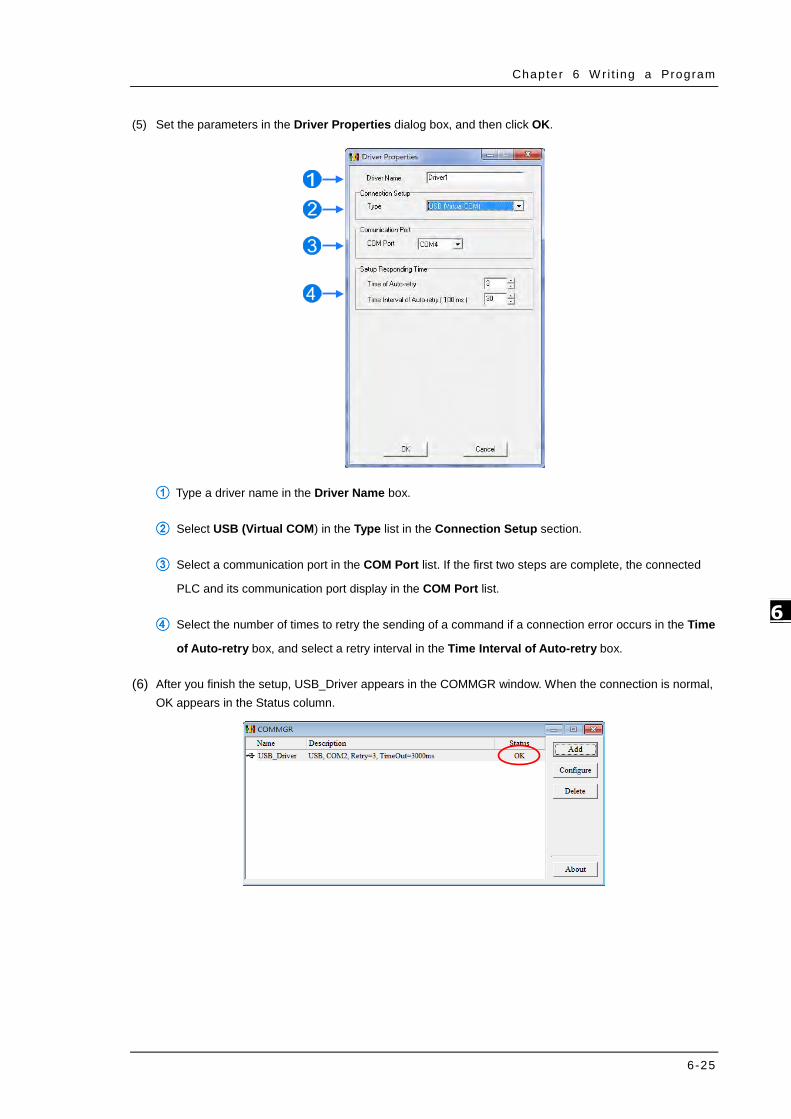
Chapter 6 W ri t ing a Program
6-25
6_
(5) Set the parameters in the Driver Properties dialog box, and then click OK.
Type a driver name in the Driver Name box.
Select USB (Virtual COM) in the Type list in the Connection Setup section.
Select a communication port in the COM Port list. If the first two steps are complete, the connected
PLC and its communication port display in the COM Port list.
Select the number of times to retry the sending of a command if a connection error occurs in the Time
of Auto-retry box, and select a retry interval in the Time Interval of Auto-retry box.
(6) After you finish the setup, USB_Driver appears in the COMMGR window. When the connection is normal, OK appears in the Status column.

DVP-ES3 Ser ies Opera t ion Manual
6-26
_6
(7) Click the driver you created in the COMMGR window, and then click Start. Start ISPSoft, and then on the
Tools menu, click Communication Settings…. In the Communication Setting dialog box, select the
driver you created in the Driver list, select 0 in the Station Address list, and then click OK. The driver
information displays in the ISPSoft status bar.
(8) On the PLC menu, click System Information. ISPSoft retrieves related information from the PLC. If the
computer communicates with the CPU module normally, the related information retrieved from the PLC
displays in the System Information dialog box.

Chapter 6 W ri t ing a Program
6-27
6_
6.6.2 Downloading a Program and Parameters
If ISPSoft is correctly connected to a PLC, you can download the parameters and program in the project to the
PLC. First, start ISPSoft and open the project you created in the previous sections. In this example, you
download two types of parameters to the CPU module: hardware configuration and the program itself.
Downloading the hardware configuration
(1) Double-click HWCONFIG in the project management area to open the HWCONFIG window.
(2) The hardware configuration displays in the window. Before you download the hardware configuration
to the CPU module, make sure the actual hardware configuration is the same as the hardware
configuration in the window.
(3) On the Options menu, click Download, or on the toolbar. The Transfer Items dialog box
appears. Click OK to download the hardware configuration to the CPU module.

DVP-ES3 Ser ies Opera t ion Manual
6-28
_6
(4) After you successfully download the hardware configuration to the CPU module, the BUS FAULT LED
indicator on the CPU module is OFF. Close the HWCONFIG window. If the BUS FAULT LED indicator
on the CPU module is still ON or blinking, the CPU module is in an abnormal state. Make sure the
actual hardware configuration is the same as the hardware configuration in the HWCONFIG window,
and refer to the operation manual for more information about eliminating the error. Refer to Chapter 8
for more information about HWCONFIG.
Downloading the program
After the program compiles, on the PLC menu point to Transfer, and then click Download. You can also
click on the toolbar after the program compiles. In the Transfer Setup dialog box select the
Program checkbox and the Comments checkbox so that you can upload the program in the CPU module
later, and then click OK.
6.6.3 Connection Test
After you download a program to a PLC, you can monitor the execution status of the PLC through ISPSoft.
ISPSoft provides two monitoring modes; device monitoring mode and program monitoring mode.
Monitoring mode Description
Device monitoring mode
You can monitor the status of the devices in the PLC through the monitoring
table. In this mode, ISPSoft updates only the status of the devices. The
current program in ISPSoft does not have to be the same as the program in
the PLC.
Program monitoring mode
In this mode, the operating status of the program is displayed in the program
editing window. The present program in ISPSoft must be the same as the
program in the PLC.
*. You can enable the device monitoring function without program monitoring; however, if you enable the program
monitoring function, the device monitoring function is also enabled.

Chapter 6 W ri t ing a Program
6-29
6_
On the PLC menu, click Online Mode, or on the toolbar, to enable the online monitoring function. The
system also enables device monitoring mode and program monitoring mode.
In the online monitoring mode, you can view the present scan time, the communication status, and the status of
the PLC in the status bar in ISPSoft.
The present status of the devices display in the original program editing window after you enable the program
monitoring function.
You can change the operating state of a PLC with the RUN/STOP switch on the PLC. You can also change the
operating status of a PLC with the functions provided by ISPSoft. On the PLC menu, click Run or on the
toolbar to start the PLC. On the PLC menu, click Stop or on the toolbar to stop the PLC.

DVP-ES3 Ser ies Opera t ion Manual
6-30
_6
In the online monitoring mode, you can select a device, then right-click the device, and the click a command on
the context menu. During a test, you can change the status of a device or the value in a device by clicking an
item on the context menu.
Before you change the status of a device, make sure the operation does not cause damage to
equipment or personnel.
The table below describes the items in the context menu. The Force command only applies to input and output
contacts.
Item Description
Set On Set the contact selected to ON
Set Off Set the contact selected to OFF
Rising-edge Trigger No matter what the state of the selected contact is, the system sets the contact to
OFF, and then sets it to ON.
Falling-edge Trigger No matter what the state of the selected contact is, the system sets the contact to
ON, and then sets it to OFF.
Force Force an input contact or output contact ON or OFF
Force Device List Force several input contacts or output contacts in the tables ON or OFF
To change the value in a device, right-click the device, click Change Present Value, and set a present value in
the Enter Present Value dialog box.

Chapter 6 W ri t ing a Program
6-31
6_
The list below describes the Enter Present Value dialog box.
Message
Type a value in the Present Value box.
Type the name of a device or a symbol whose present value you want to change
Type a 16-bit or 32-bit value.
Value change history (Format: Device name Value)
In binary mode, use the mouse to set the bit states.
Click OK to apply the setting values. Click Cancel to close the window without applying the values.
Display or hide binary mode.

DVP-ES3 Ser ies Opera t ion Manual
6-32
_6
In this example, X0–X17 and Y0–Y17 are input and output devices assigned to the digital I/O module
DVP32ES311T. After you download the hardware parameters to the CPU module, the states of X0–X17 are the
same as the states of the inputs on the actual module. Even if you set X0–X17 to ON or OFF in the program
editing window, the actual input signals update the states of X0–X17.
However, you can force an input contact ON or OFF during a test. Click an input or output contact to set,
right-click the contact, point to Force, and click On (X/Y), Off (X/Y), Release (X/Y), or Release All. If you force
an input or output contact ON or OFF, a lock symbol appears at the left side of the contact.
Force Description
On (X/Y) Force the selected input or output contact ON
Off (X/Y) Force the selected input or output contact OFF
Release (X/Y) Release the contact from the locked state
Release All Release all the contacts from the locked states
If you force an output contact in the program ON or OFF, the program execution result does not affect the
output state of this contact.
*. If you disable the online monitoring function, the contacts are not automatically released from the locked states. You must check whether the contacts need to be released from the locked states after you complete the test.
You can create a monitoring table online or offline.

Chapter 6 W ri t ing a Program
6-33
6_
Method 1
On the PLC menu, click New Devices Table, or on the toolbar.
Method 2
Right-click Device Monitoring Table in the project management area, and click New.
Type a table name in the Add Monitor Table dialog box, and then click OK. An item appears under Device
Monitor Table in the project management area. Double-click the item to open the monitoring table. You can
create several monitoring tables in the project, and the monitoring tables are saved with the project.

DVP-ES3 Ser ies Opera t ion Manual
6-34
_6
After you double-click the item, a item monitoring window appears. You can add items to be monitored to the
window. To add an item to the window, double-click the blank space in the monitoring table, type a device name,
type a start address, and the number of devices to be monitored in the Device Monitor Input dialog box. You
can add up to 100 items to a monitoring table.
Press Insert on the keyboard to switch between inserting and replacing an item in the monitoring table. The
selected mode displays in the status bar in ISPSoft.
If you select insert mode, the new item is added above the selected item in the monitoring table. If you select
replacement mode, the new item overwrites the selected item in the monitoring table.
To hide certain columns in the monitoring table, right-click the monitoring table, point to Set the Fields, and clear certain items. After you clear an item, the corresponding column disappears.

Chapter 6 W ri t ing a Program
6-35
6_
The following describes the columns in the monitoring table.
Column Description
Source Source of a symbol
Identifier Identifier of a symbol
Device name Name of a monitored device
Status State of a monitored bit device or a contact (ON or OFF).
Data type Data type of a monitored symbol.
Value (16 bits) In online mode, displays a 16-bit value.
Value (32 bits) In online mode, displays a 32-bit value.
Float In online mode, displays a 32-bit floating-point number.
Radix Select a format to represent a value.
Comment Display the comments on a device or on a symbol.
After you create the monitoring table, you can monitor the items in the monitoring table in online mode.
Right-click an item in the monitoring table in online mode to display a context menu which is the same as the
context menu in the program editing window. You can change the item state or the item value by clicking an
item in this context menu.
You can text and debug the program you created in this chapter through the monitoring table you created in this
section. Refer to Chapter 17 in the ISPSoft User Manual for more information about testing and debugging a
program.

DVP-ES3 Ser ies Opera t ion Manual
6-36
_6
6.7 Setting a Real-time Clock
After you connect an DVP-ES3 Series CPU module to a computer, you can set the real-time clock in the CPU
module through ISPSoft.
(1) On the Tools menu, click Set RTC.
(2) Select Computer, and then click Synchronize to complete setting the real time clock.
(3) RTC setting is complete.

Chapter 7 Memory Card Table of Contents 7.1 Overview of Memory Cards ................................................................ 7-2
7.1.1 Appearances of Memory Cards ......................................................... 7-2
7.1.2 Memory Card Specifications ............................................................ 7-2
7.2 Before using a Memory Card .............................................................. 7-3
7.2.1 Formatting a Memory Card .............................................................. 7-3
7.3 Installing and Removing a Memory Card ........................................... 7-3
7.3.1 Memory Card Slot in a CPU Module .................................................. 7-3
7.3.2 Installing a Memory Card ................................................................ 7-4
7.3.3 Removing a Memory Card ............................................................... 7-4
7.4 Memory Card Contents ...................................................................... 7-5
7.4.1 Initializing a Memory Card .............................................................. 7-5
7.4.2 Folder Structure in a Memory Card ................................................... 7-5
7.5 Introduction to the CARD Utility ........................................................ 7-6
7.6 Backing Up a Project ......................................................................... 7-8
7.7 Restoring a Project .......................................................................... 7-13
7.8 Restoration Starts Once CPU is supplied with Power ....................... 7-17
7.9 CPU Error Log .................................................................................. 7-18
7 7

DVP-ES3 Ser ies Opera t ion Manual
7-2
_7
7.1 Overview of Memory Cards
The DVP-ES3 Series CPU modules support standard MicroSD cards that meet the specifications in this
chapter. This chapter describes the specifications and usage for the MicroSD cards supported by the DVP-ES3
Series CPU modules.
7.1.1 Appearances of Memory Cards
SD cards are classified into three types according to size: SD cards, MiniSD cards, and MicroSD cards.
DVP-ES3 Series CPU modules support MicroSD cards.
7.1.2 Memory Card Specifications
SD cards are also classified into three types according to capacity: SD cards, SDHC cards, and SDXC cards.
The DVP-ES3 Series currently only supports a maximum of 32GB in FAT32 format. SD card families are shown
in the table below. The Micro SDHC in the SDHC column indicates the specifications supported by the
DVP-ES3 Series. Be sure to purchase products that meet these specifications.
SD card families
Type SD SDHC SDXC
Capacity 32 MB~2 GB 4 GB~32 GB 32 GB~2 TB
File
system FAT16/FAT32 FAT32 exFAT (FAT64)
Size SD SDHC Mini SDHC Micro SDHC SDXC Micro SDXC
Speed
class
rating
N/A
CLASS 2 (Min. 2 MB/Sec.)
CLASS 4 (Min. 4 MB/Sec.)
CLASS 6 (Min. 6 MB/Sec.)
CLASS 10 (Min. 10 MB/Sec.)
CLASS 2 (Min. 2 MB/Sec.)
CLASS 4 (Min. 4 MB/Sec.)
CLASS 6 (Min. 6 MB/Sec.)
CLASS 10 (Min. 10 MB/Sec.)

Chapter 7 Memory Card
7-3
7_
7.2 Before using a Memory Card
7.2.1 Formatting a Memory Card
You may need to format a new SDHC memory card with the FAT32 file system before you use it for the first
time. You cannot use an unformatted SDHC memory card in a DVP-ES3 Series CPU module.
The following example introduces the most common way to format an SDHC card: formatting an SDHC card
through a card reader. Also carefully read the documents provided by the SDHC card manufacturer.
(1) Insert the SDHC card into a card reader. The operating system detects a new storage device.
(2) Right-click the new storage device, and then click Format.
(3) You must format the memory card with the FAT32 file system. Do not change any other default settings.
Click Quick Format, and then click Start.
(4) After you click OK in the warning window, the SDHC card formats.
7.3 Installing and Removing a Memory Card
7.3.1 Memory Card Slot in a CPU Module
The memory card slot is on the front side of the DVP-ES3 Series PLC.
Memory Card Slot
When you format a memory card, you also delete all the data in the memory card. Verify whether you need to back up the data in a memory card before you format the memory card.

DVP-ES3 Ser ies Opera t ion Manual
7-4
_7
7.3.2 Installing a Memory Card
Insert a memory card into the CPU module memory card slot and push it in until it clicks. Be sure the memory
card is fixed firmly in the slot; if the memory card is loose, it is not installed correctly. The memory card can only
be inserted in one direction. Do not force the memory card or you may damage the CPU module. The correct
way to insert the memory card is shown below.
7.3.3 Removing a Memory Card
You can remove a memory card by pushing it in. The card then springs from the slot.

Chapter 7 Memory Card
7-5
7_
7.4 Memory Card Contents
7.4.1 Initializing a Memory Card
When you insert an SDHC card into a CPU module that is powered on, and use ISPSoft -> CARD Utility to back
up a project, the system initializes the SDHC card, and creates a default folder named according to the model
of the CPU module. (If the folder is already existed, the system does not create a second folder for the same
model.)
When the system initializes an SDHC card, it automatically adds any missing folders to the directory structure.
However, if the initialization of a SDHC card fails, you cannot initialize the SDHC card again until you reformat it.
When you initialize a memory card, the SYSTEM indicator in the software blinks.
7.4.2 Folder Structure in a Memory Card
The image below shows the default folder group created by a DVP-ES3 Series System. The folder name is
ES3. Several subfolders are contained inside the ES3 folder. Related files created by you and the DVP-ES3
Series system are stored in the subfolders.
PLC CARD SDCard ES3 Firmware
Log
SysDup
DevMem
Setup
UserProg
DVP-ES3 Ser ies Opera t ion Manual
7-6
_7
Folder Description
Firmware Stores firmware files (.ext)
Log Stores Log files (.log)
SysDup Stores backup files (.dup)
UserProg Stores device memory files (.txt, .dmd, .csv)
DevMem, Setup Reserved for the system use
7.5 Introduction to the CARD Utility
The DVP-ES3 Series CPU modules include SDHC slots, and you can back up and restore module data with a
memory card. ISPSoft includes the CARD Utility for the DVP-ES3 Series CPU modules. With this utility, you
can back up and restore data in a DVP-ES3 Series CPU module or backup and restore an ISPSoft project. The
backup can include the program code, parameter settings, hardware configuration, and network configuration,
as well as the values in the devices in a DVP-ES3 Series CPU module. Refer to Section 7.7.1 in the Operation
Manual for more information about the specifications and usage of SDHC cards with DVP-ES3 Series CPU
modules.
The list below describes the functions supported by the CARD Utility, including a flowchart.
If you export data from a DVP-ES3 Series CPU module as a backup file (*.dup), you can save the exported
data in the memory card in the module or in a folder on the computer. You can also decide whether to back
up the values in the devices in the DVP-ES3 Series CPU module.
If you export an ISPSoft project for a DVP-ES3 Series CPU module as a backup file (*.dup), you can only
save the exported ISPSoft project in a folder in the computer. You can see data such as register editing
(*.dvl), device status editing (*.dvb), file register editing (*.wft) for the DVP-ES3 Series as values in the
device and back them up. You can put a memory card with the backup file into the DVP-ES3 Series CPU
module. You can copy a backup file (*.dup) saved on the computer into the DVP-ES3 Series CPU module
connected to the computer, or restore the backup file to an ISPSoft project. If you choose to restore the
backup file to an ISPSoft project, the system automatically skips the values in the devices and the hardware
configuration in the backup file.
If you restore the backup file (*.dup) from the PC to an ISPSoft project for a DVP-ES3 Series CPU module,
you can also restore data such as register editing (*.dvl), device status editing (*.dvb), and file register
editing (*.wft) for the DVP-ES3 Series.

Chapter 7 Memory Card
7-7
7_
Double-click CARD Utility in the project management area to open the CARD Utility wizard. After selecting
the controller type, click “Next” to proceed.

DVP-ES3 Ser ies Opera t ion Manual
7-8
_7
7.6 Backing Up a Project
If the backup source or backup destination is a DVP-ES3 Series CPU module or memory card, make sure that
ISPSoft is connected to the DVP-ES3 Series CPU module. During backup, the CPU LED and Error LED blinks
alternatively and SM452 flag is ON. After the backup is done, the CPU LED and Error LED stops blinking and
SM452 flag is OFF. Refer to Section 2.4 in the ISPSoft User Manual for more information.
(1) Select the Backup (To DUP File) option button in the CARD Utility wizard and then click Next.
(2) Select a backup source, and then click Next.
a. If you select the CPU (Need Connection), the backup file is stored in the memory card.

Chapter 7 Memory Card
7-9
7_
b. If you select the ISP Project (Compiled and saved), the backup file is stored in your computer. Click
and select an isp file in the Open dialog box. If the program in the isp file selected is not compiled, a
message appears when you back up the isp file. Open the isp file with ISPSoft, compile the program in the
isp file, and then save the isp file. After the program in the isp file is compiled, you can back up the isp file.
(3) After you select CPU (Need Connection) / ISP Project (Compiled and saved), click Next,
a. If you select the CPU (Need Connection), a prompted window appears. And you need to decide
whether to back up the values in devices on the DVP-ES3 Series CPU module that is connected to ISPSoft.

DVP-ES3 Ser ies Opera t ion Manual
7-10
_7
b. If you select the ISP Project (Compiled and saved), the backup file is stored in your computer. Click
and select an isp file in the Open dialog box and then decide the file path where you’d like to store
the backup file in your computer and then define its file name.
(4) Select a backup destination. If the backup source is an ISPSoft project, the backup destination must be a
computer.
a. If you select Memory Card (PLC Side), the filename of the backup file is AUTOEXEC.dup, and the
backup file paths are shown below.
Root directory of the memory card\SDCard\PLC CARD\ES3\SysDup\AUTOEXEC.dup

Chapter 7 Memory Card
7-11
7_
b. If you select PC (DUP File), click , select a folder in the Save in list in the Save As dialog box, and
type a filename in the File name box. When you select the backup source for the ISPSoft Project, set
the PLC password. You can set the password to be the same as the Project password, set a new PLC
password, or not set a PLC password. If you do not set a password for the Project, the PLC password
is also not set. When you select Setting new PLC password, the wizard looks like the following
image. And you can set new PLC password and number of the attempt times.
(5) After that you can see the summary. Make sure that the summary in the CARD Utility wizard is
consistent with the data backup you want to perform, and then click Execute.

DVP-ES3 Ser ies Opera t ion Manual
7-12
_7
(6) The DVP-ES3 Series CPU module still performs the data backup even if you click Cancel. You can turn
off the DVP-ES3 Series CPU module to stop the data backup; however, the backup file produced is not a
complete backup file, and you must delete the backup file from the memory card.
If you select Memory Card (PLC Side), the filename of the backup file is AUTOEXEC.dup, and the
backup file path is Root directory of the memory card\ES3\SysDup\AUTOEXEC.dup. If there is an old
backup file in the memory card, the Warning message appears. Click Replace, Archive, or Cancel in the
Warning message.
If the backed up data is protected by passwords, these passwords are also backed up.
Data backup Description
CPU module Memory card The backed up data includes the PLC ID and the PLC password set
in the CPU module.
ISPSoft project Computer The backed up data includes the program ID and the project
password set in the ISPSoft project.
(7) After you perform the data backup, click Home or Close in the CARD Utility wizard.

Chapter 7 Memory Card
7-13
7_
7.7 Restoring a Project
If the restoration source or restoration destination is a DVP-ES3 Series CPU module or memory card, make
sure that ISPSoft is connected to the DVP-ES3 Series CPU module. During restoration, the CPU LED and
Error LED blinks alternatively and SM452 flag is ON. After restoration is done, the CPU LED and Error LED
stops blinking and SM452 flag is OFF. Refer to Section 2.4 in the ISPSoft User Manual for more information.
(1) Select Restore (From DUP File) in the CARD Utility wizard and then click Next.
(2) Select a restoration source, click and then select a backup file to be restored.
a. If you select Memory Card (PLC side) (Need Connection), the backup files in the memory card
display in a window after you click . Double-click a backup file in the window to choose it.

DVP-ES3 Ser ies Opera t ion Manual
7-14
_7
b. If you select PC (Need Connection), the backup files in the PC display in a window after you click .
Double-click a backup file in the window to choose it.

Chapter 7 Memory Card
7-15
7_
(3) Select a restoration destination, and then click Next.
a. To put the selected backup file into the DVP-ES3 Series CPU module, select CPU (Need
Connection). If the restoration source is the CPU (Need Connection), the restoration destination
must be the DVP-ES3 Series CPU module.
b. If you select ISP Project, click , and then specify a filename and a path. If the path specified point
to a file that already exists, the file is overwritten when you restore the data.

DVP-ES3 Ser ies Opera t ion Manual
7-16
_7
(4) Make sure that the summary in the CARD Utility wizard is consistent with the data restoration you want
to perform and then click Execute.
If you click Cancel in the process of restoring data to the DVP-ES3 Series CPU module, the data is not
completely restored. The DVP-ES3 Series CPU module still performs the data restoration even if you click
Cancel in the process of restoring a backup file in the memory card. You can turn off the DVP-ES3 Series
CPU module to stop the data restoration from being performed. To prevent the DVP-ES3 Series CPU
module from operating incorrectly, restore the DVP-ES3 Series CPU module to the factory setting, or
perform the data restoration again.
The restoration source or restoration destination may contain a password and an ID. The following table
describes the password and the ID process.
Data restoration Description
Memory card
PU module
a. The ID in the backup file must be the same as the ID in the CPU module;
otherwise the data is not restored.
b. If there is a PLC password in the CPU module, the password in the backup file
must be the same as the PLC password in the CPU module. Otherwise the
data is not restored.
c. If there is no PLC password in the CPU module, and there is a password in the
backup file, the system restores the data, and the password in the backup file
becomes the PLC password in the CPU.
Computer
ISPSoft project
The ID and the password in the backup file become the program ID and the
project password in the ISPSoft project.
(5) After you perform the data restoration, click Home or Close in the CARD Utility wizard.

Chapter 7 Memory Card
7-17
7_
7.8 Restoration Starts Once CPU is supplied with Power
When the backup file in the memory card is consistent with the specific path and file name, the CPU can
perform restoration once it is supplied with power. During restoration, the CPU LED and Error LED blinks
alternatively and SM452 flag is ON. After restoration is done, the CPU LED and Error LED stops blinking and
SM452 flag is OFF.
Operation Steps:
(1) Set up the backup file path and file name for the memory card backup file. The filename of the backup file
is BACKUP.dup and the backup file paths are shown below.
Memory card root directory\SDCard\PLC CARD\ES3\SysDup\ES3_BACKUP.dup
Insert the memory card into the card slot when the CPU power is off.
(2) When the CPU power is on, it automatically checks if the memory card data is consistent with the PLC data.
If not, the restoration begins. The data check is specifically on the data in CPU programs and HWCONFIG
parameters.
(3) During the restoration, the CPU LED and Error LED blinks alternatively. Once the restoration is done, the
blinking stops.
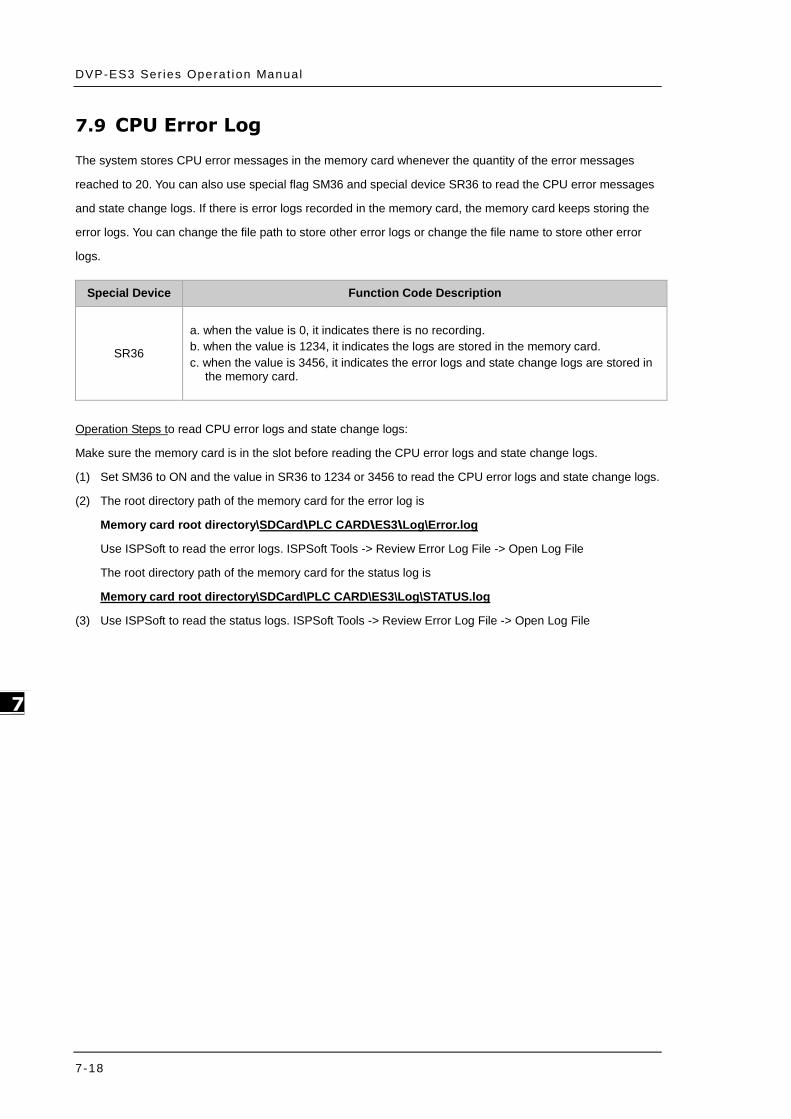
DVP-ES3 Ser ies Opera t ion Manual
7-18
_7
7.9 CPU Error Log The system stores CPU error messages in the memory card whenever the quantity of the error messages
reached to 20. You can also use special flag SM36 and special device SR36 to read the CPU error messages
and state change logs. If there is error logs recorded in the memory card, the memory card keeps storing the
error logs. You can change the file path to store other error logs or change the file name to store other error
logs.
Special Device Function Code Description
SR36
a. when the value is 0, it indicates there is no recording. b. when the value is 1234, it indicates the logs are stored in the memory card. c. when the value is 3456, it indicates the error logs and state change logs are stored in
the memory card.
Operation Steps to read CPU error logs and state change logs:
Make sure the memory card is in the slot before reading the CPU error logs and state change logs.
(1) Set SM36 to ON and the value in SR36 to 1234 or 3456 to read the CPU error logs and state change logs.
(2) The root directory path of the memory card for the error log is
Memory card root directory\SDCard\PLC CARD\ES3\Log\Error.log
Use ISPSoft to read the error logs. ISPSoft Tools -> Review Error Log File -> Open Log File
The root directory path of the memory card for the status log is
Memory card root directory\SDCard\PLC CARD\ES3\Log\STATUS.log
(3) Use ISPSoft to read the status logs. ISPSoft Tools -> Review Error Log File -> Open Log File

Chapter 8 Hardware Configuration and Data Exchange Setups
Table of Contents 8.1 Hardware Configuration Tool for DVP-ES3 Series Modules ................ 8-2
8.1.1 Introduction of the HWCONFIG Environment .......................................... 8-2
8.1.2 Configuring a Module ........................................................................... 8-3
8.1.3 Editing a Comment ............................................................................. 8-3
8.2 Setting the Parameters in a DVP-ES3 Series CPU Module .................. 8-4
8.2.1 Opening the PLC Parameter Setting Window ........................................... 8-4
8.2.2 Setting the Basic CPU Parameters ......................................................... 8-5
8.3 Data Exchange ................................................................................. 8-24
8.3.1 Device Settings Dialog Box Descriptions............................................... 8-24
8 8

DVP-ES3 Ser ies Opera t ion Manual
8-2
_8
8.1 Hardware Configuration Tool for DVP-ES3 Series Modules - HWCONFIG
HWCONFIG is a built-in hardware configuration tool in ISPSoft. You can set up CPU and module parameters,
download/upload parameters, detect a hardware configuration online, and make a diagnosis through HWCONFIG.
You must download all parameters set in HWCONFIG to the CPU module for them to take effect.
8.1.1 Introduction of the HWCONFIG Environment
In ISPSoft, double-click HWCONFIG in the project management area to start HWCONFIG.
Delta Electronics provides you with specific configuration tools for some CPU modules. You can add extension
modules to the right side of the DVP-ES3 Series CPU module. The system configuration area displays the present
system configuration. When you modify the configuration in the system configuration area, the information in the
information list updates.
Parameter: settings for CPU
AIO Wizard: settings for the right-side extension modules
CANopen Builder: for CANopen communication
EIP Builder: for EIP communication
You can use tools such as CANopen Builder and EIP Builder to set advanced network assignments for the modules.
Refer to the manuals for the communication software tools for more information on setting up communications.

Chapter 8 Hardware Conf igurat ion
8-3
8_
8.1.2 Configuring a Module
For DVP-ES3 Series, you need AIO Wizard to configure its right-side modules. Click AIO Wizard Setting to open the
wizard. You can Upload Module or Enter Edit Mode by clicking the relevant radio buttons.
8.1.3 Editing a Comment
You can add a comment directly in the Comment box.

DVP-ES3 Ser ies Opera t ion Manual
8-4
_8
8.2 Setting the Parameters in a DVP-ES3 Series CPU Module
8.2.1 Opening the PLC Parameter Setting Window
After you double-click HWCONFIG in the project management area, the ES3 Series setting page appears. Click
Settings button to set up the CPU parameters.
* You must download the set parameters to the CPU module before they take effect.
Here shows present
system configurations
and the product
specifications.

Chapter 8 Hardware Conf igurat ion
8-5
8_
The parameters are classified into several types. Click the tabs at the top of the Device Setting dialog box and then
click the setting options in the tree on the left. The setting parameters for the selected setting option appear on the
right in the Device Setting dialog box. Click the option on the left, and then set Value, Unit, Default, Minimum and
Maximum for each parameter.
8.2.2 Setting the Basic CPU Parameters
8.2.2.1 Options - System Information Page
In the Device Setting dialog box, click the Options tab, and unfold the System settings to set up the settings of
System Information, System Parameter, Device Range Setting, Input Point Filter Time, Position Control Para,
and Daylight Saving Timing.

DVP-ES3 Ser ies Opera t ion Manual
8-6
_8
System Information
On the System Information page, you can edit two parameters: Name and Comment. You can enter up to 15
characters in the Name section and up to 30 characters in the Comment section. You can use spaces and special
characters in these two sections, but note that a Chinese character occupies two characters.
After you create an ISPSoft project, the default project name is the name of the CPU module, and it is attached to the
model in the project management area. You can change the default name of the CPU module in the Value box of the
PLC Label.
You can identify a device by means of device name. When several devices are connected on a network, you can
check whether a device connected to the computer is the device you expect by the device name. If you want to
download or upload the program, but the name of the CPU module is different from the name attached to the model in
the project management area, the system reminds you to check the name of the CPU module and the name attached
to the model in the project management area.

Chapter 8 Hardware Conf igurat ion
8-7
8_
System Parameter
On the System Parameter page, you can set parameters by entering appropriate values or by selecting from a list.
Clear Non-latched area when Run Stop
This determines whether the states and values of the non-latched devices are cleared when the PLC changes
from Run to Stop.
Disable: all the states and values in the non-latched devices stay the same.
Enable: all the states and values in the non-latched devices are cleared and restored to defaults.
Y keeps outputting when RUNStop
This determines the states of the Y devices when the CPU module begins to run or stop.
Off: all Y devices are set to OFF.
Retain: the states of the Y devices stay the same.
Setting delay time to detect I/O Module
This sets the time to detect an I/O module after powering on the CPU module.
Assign X Input Point Control Run/Stop
This assigns an input point to have the CPU module run or stop.
Disable: run or stop the CPU module with the dip switch of the CPU module.
Enable: run or stop the CPU module with the assigned input point, and the dip switch of the CPU module still
controls the run stop state of the CPU module.

DVP-ES3 Ser ies Opera t ion Manual
8-8
_8
Select X Input Point
If you select Enable in the previous option, you can select one input point to control the Run or Stop state of the
CPU module from the dropdown list.
Constant Scan Cycle Time
This sets the minimum scan cycle time.
Disable: disables this function.
Enable: when the actual scan cycle time is less than the setting time, the CPU module waits until the setting
time is met, and then starts the next scan. When the actual scan time is longer than the setting time,
the CPU module starts the next scan after the actual scan time completes.
Input Constant Time
If you selected Enable in the previous option, you set the scan cycle time here. If the actual scan time is larger
than the setting time, a watchdog timeout occurs when the CPU module operates.
Setting Watchdog Time
This parameter sets a timeout during which the program is scanned. The CPU module sends an error if the
program execution exceeds the watchdog time.
Save Error History Info
This specifies where to store the error log.
PLC: store error logs in the PLC. The PLC can store up to twenty error logs. If there are more than twenty error
logs, the oldest error log is overwritten by the latest error log.
PLC & SD Card: when there are more than twenty error logs, the oldest error log is backed up to the memory
card before the oldest error log is overwritten in the PLC.
COM Communication Error Record
This parameter sets whether to enable the error record when there is an error at the COM port.
Disable: disables this function.
Enable: enables this function and starts recording COM errors in the error log.
Select Action When 24 Vdc Input Unstable
What to do when the 24 Vdc power is unstable
Continue Running when power stable: waits till the power is stable and then PLC begins to run.
Into Error Status: Stops and go to the error mode

Chapter 8 Hardware Conf igurat ion
8-9
8_
I601 Timer interrupt Setting Time Base
Sets the interval for triggering the 1601 timer interrupt. This function is used together with Timer Interrupt 0.
I602 Timer interrupt Setting Time Base
Sets the interval for triggering the 1602 timer interrupt. This function is used together with Timer Interrupt 1.
I603 Timer interrupt Setting Time Base
Sets the interval for triggering the 1603 timer interrupt. This function is used together with Timer Interrupt 2.
I604 Timer interrupt Setting Time Base
Sets the interval for triggering the 1604 timer interrupt. This function is used together with Timer Interrupt 3.
Device Range Setting
The parameters on Device Range Setting table are shown in the following window.
Click to open the parameter dialog box to set the start and end address. In the dialog box, click Default to restore
the setting to the default values; click Clear to clear the set values; click OK to save the values and close the dialog
box; click Cancel to discard the setting and close the dialog box.

DVP-ES3 Ser ies Opera t ion Manual
8-10
_8
Input Point Filter Time
On the Input Point Filter Time page, you can set the input point filter time for each input. If the duration of the received
signal time is less than the filter time setting value, it is processed as noise and filtered out. Select an appropriate filter
time according to your needs.
X Input Point Filter for CPU module
Default Setting: uses the default values in the input point filter.
Manual Setting: uses the values you enter for the filter time for each X input point.
X0–X17 Input Point Filter Time
If you select Manual Setting for the previous parameter, you can set the filter time individually for X0–X17.

Chapter 8 Hardware Conf igurat ion
8-11
8_
Position Control Parameter The parameters on Position Control Parameter table set to specify input points as the positive and negative limits of axis 1~ axis 4 channels. 12 limit points can be set at most. Axis No. 1~4 can also be set as Z phase triggers, home function finish points and clear output selects or positive/negative limited position.
Axis1 (Y0/Y1) Positive/negative Limited Select~ Axis4 (Y6/Y7) Positive/negative Limited
Select: select the rising or falling edge trigger and X input point on the drop-down list.
Axis1 (Y0/Y1) Z Phase Trigger ~ Axis4 (Y6/Y7) Z Phase Trigger:
Select the rising or falling edge trigger and X input point on the drop-down list.
Axis1 (Y0/Y1) Home Function Finish and Clear Output Select ~ Axis4 (Y6/Y7) Home Function Finish
and Clear Output Select: select the rising or falling edge trigger and X input point on the drop-down list.
Axis1 (Y0/Y1) Positive/negative Limited Position ~ Axis4 (Y6/Y7) Positive/negative Limited Position: set
up the number of pulses as the positive or negative limited position in axis 1~4; setting range is
-2147483647~2147483647.

DVP-ES3 Ser ies Opera t ion Manual
8-12
_8
Daylight Saving Timing
Enable or disable this function on the Daylight Saving Timing page. Set daylight saving time and the set the time zones
for daylight saving and the system acts accordingly.
Disable/Enable D.S.T Function
Sets whether or not to use daylight saving time.
Start Date – Month
Sets the month to start daylight saving
Start Date – Day
Sets the day to start daylight saving
End Date – Month
Sets the month to end daylight saving
Start Date – Day
Sets the day to end daylight saving
Saving time
Sets daylight saving time in minutes
Example explanation: example from the above image and all the options are enabled.
Date shown in SR Time shown in SR PLC time
(Real Time Clock) Remarks
3/31 23:59:58 23:59:58 Normal
3/31 23:59:59 23:59:59
4/01 01:00:00 00:00:00
Shown after 60 minutes 4/01 01:00:01 00:00:01
: (to) : (to) : (to)

Chapter 8 Hardware Conf igurat ion
8-13
8_
9/30 23:59:59 22:59:59
10/01 00:00:00 (9/30) 23:00:00
: (to) : (to) : (to) 10/01 00:59:59 (9/30) 23:59:59
10/01 00:00:00 00:00:00 Normal
10/01 00:00:01 00:00:01
8.2.2.2 Options - COM1 & COM2 Port Setting
The DVP-ES3 Series CPU module has two communication ports. There are two areas to set the parameters, one for
each communication port.
Set a station address. You can identify a device on a network by the station address. The station address cannot be
the same as the station address for another device on the same network. If the communication port functions as a
slave, and there are other slaves, the station address of the communication port cannot be 0. Station address 0
broadcasts to all slaves in a communication protocol. If a master specifies in a data packet that data must be sent to
station address 0, the data is sent to all slaves. No matter what the station address of these slaves are, these slaves
receive the data packet addressed to station address 0.
Set when the communication port runs. Select Stop --> Run, and communication works when the CPU module
switches from Stop to Run. If you instead select Power-on, the communication starts working when you Power-on the
module.
Select a communication speed in the Baud Rate list, or select Custom and enter a new rate.
Set the communication parameters for the port.
Set the Delay Time to Reply when the DVP-ES3 CPU module receives communication and how long it waits
before responding to the remote modules.

DVP-ES3 Ser ies Opera t ion Manual
8-14
_8
Received Data Timeout applies when the DVP-ES3 Series CPU module acts as a server to send out
communications. The timeout is how long the module waits before the received data times out.
8.2.2.3 Options - Ethernet Port Basic Setting
Click Ethernet Port Basic Setting to see the setup page. Set the communication parameters for the Ethernet port in
the CPU module on this page.
Select Static in the Mode list to specify an IP address. Select Dynamic or BOOTP in the Mode list to assign an IP
address from a DHCP/BOOTP server.
8.2.2.4 Options - Ethernet Port Advanced Setting
Click Ethernet Port Basic Setting to see the setup page. There are setups for IP Filter, NTP, Email, Socket, and
RTU mapping.
IP Filter
Devices whose IP addresses are listed in the table are allowed to communicate with the CPU module; the CPU
module discards data packets sent from devices whose IP addresses are not in the table. Devices on a network are
filtered. This setting ensures that objects communicating with the CPU module are known devices. You can set up to 8
address ranges for allowed devices.

Chapter 8 Hardware Conf igurat ion
8-15
8_
NTP
Click NTP to synchronize the real-time clock in the CPU module to an NTP server. Please refer to related documents
or manuals for more information about NTP.
Select the NTP Client Function Enable check box, and then set the related parameters.
Set the IP address of an NTP server. The CPU module corrects its internal time by connecting periodically to the
server.
Set a time interval for correcting the time in the CPU module. If the interval is thirty minutes, the CPU module
connects to the NTP server every thirty minutes.
Select a time zone in the Time Zone list.

DVP-ES3 Ser ies Opera t ion Manual
8-16
_8
Click Email to set the email-related functions. The system sends email to the set email address after you enable the
email function. You can set up to four sets of conditions for sending email to up to four groups of email addresses.
Select Email Function Enable to enable the function.
Set an IP address of the SMTP server. Set the COM port of SMTP server at the COM port and set the sender’s
local email address. Type the Mail Subject to appear at the start of the subject of every email.
Select Account identification checkbox to enable the function to authenticate the connection with a user name
and a password when logging into an SMTP server.
Type the target email addresses.
Click 1st Trigger Setting and type a trigger name in Trigger Name box and a minimum interval in Trigger Min Cycle.
Then select a trigger condition in the Trigger Mode list. When the sending condition is met, the system sends an email
every designated period of time. The system does not send the same email again.

Chapter 8 Hardware Conf igurat ion
8-17
8_
You can set email trigger modes as follows.
CPU Error
Trigger sending an email if an error occurs in the CPU module. Refer to the Operation manuals for more information
about errors occurring in CPU modules. After you select CPU Error, select Fatal Error Only or All Errors in the list at
the right side of the option.
a) Fatal Error Only: Send an email if a fatal error occurs in the CPU module.
b) All Errors: Send an email if an error occurs in the CPU module.
CPU (RUN<=>STOP)
Trigger sending an email when the CPU module begins to run, or when the CPU module stops running.
Bit Status Change
Trigger sending an email if the state of a bit device specified meets a set condition. For example, if X0 switches from
OFF to ON, it triggers sending an email. To set a condition, click the button in the following dialog box.

DVP-ES3 Ser ies Opera t ion Manual
8-18
_8
Device Name: Select a device type.
Device Number & Bit: Type a device address; if the device type selected is X/Y, you must specify a bit
number as well.
State: Select Rising or Falling.
Register Value Change
Trigger sending an email if the value in a device specified meets a set condition. For example, if the value in D0 is
larger than 10. To set a condition, click the button in the following dialog box.
Device Name: Users can select a device type in the Device Name drop-down list.
Device Number: Users can type a device address in the Device Number field.
State & Value: Users can set s condition of triggering the sending of an email here.
Periodic Timer
The system periodically sends an email. How often the system sends an email depends on the Trigger Min Cycle
interval in the Trigger Setting section.
When you set any trigger mode, the user message and error log related parameters appear.

Chapter 8 Hardware Conf igurat ion
8-19
8_
Select the Trigger User Message Enable check box and then click the to the right side of Trigger User
Message. Type some content for the email text in the dialog box.
If you select the Error Log Enable check box, the system automatically adds the error log to the email content.
Trigger Attachment Mode determines whether to add an attachment to the email. Check the maximum size allowed
for the email file before adding an attachment. Refer to the relevant email operation manuals for more information.
If you select None, no attachment is inserted.
File
Allows you to select an error log or the system backup file from the memory card as the email attachment.
PLC Device
The system automatically retrieves the device states or values listed in the table as the email attachment. After you
select this option, click in the following dialog box to open the Attachment dialog box. You can set a maximum of
two groups of devices. For example, if the condition is met, the values in D0–D9 are sent as an attachment.
Select the receiver’s target email address for the triggered email in the Trigger Receiving table. Set the specific email
address in the Email section.

DVP-ES3 Ser ies Opera t ion Manual
8-20
_8
Sockets
You can set the parameters for sockets through which data is transmitted. You must use this function with specific
applied instructions. Refer to the DVP-ES3 Series Programming Manual for more information, as sockets are not
described here. Refer to the related documents or manuals for more information about sockets. In the Socket table,
set COM port parameters for data transmission through Ethernet; however, you should use this function only with
specific API instructions. For relevant details, refer to DVP-ES3 Series Programming Manual.
The system for the DVP-ES3 Series module supports data transmission between the CPU module and other CPU
modules or devices through a socket as well as through TCP and UDP protocols. You can set up four connections in
each of the four groups. Select the Socket Function Enable checkbox and then select settings in the TCP and UDP
setting pages.

Chapter 8 Hardware Conf igurat ion
8-21
8_
The parameters in the TCP Socket Setting are the same as the parameters in the UDP Socket Setting except that
there is no Keep Alive Timer parameter in the UDP Socket Setting.
Remote IP: Sets a remote IP address.
Remote Port: Sets a communication port used by the remote device for this TCP connection. The port number
must be between 0–65535.
Local Port: Sets a communication port used by the local CPU module for this connection. The port number must be
between 0–65535.
Send Address: Sets an initial device in the CPU module where sent data is stored.
Send Length: Sets the length of data sent by the local CPU module. The length must be between 0–200 bytes.
Receive Address: Sets an initial device in the CPU module where received data is stored.
Receive Length: Sets the length of data received by the local CPU module. The length must be between 0–200
bytes.
Keep Alive Timer: Sets a maximum time to keep the connection alive. If no data is transmitted, and the keep alive
period has elapsed, the CPU module automatically terminates the connection.
The port number used by the local CPU module and the port number used by the remote device cannot be the same,
and the devices where you store the sent data cannot overlap the devices where you store the received data. If the IP
address of the remote device is 192.168.1.100, the port number used by the remote device is 65500, the port number
used by the local CPU module is 65501, and the remote device and the local CPU module can transmit data through
this TCP connection.
If the local CPU module sends 10-word data to the remote device, the data is stored in D0–D9 before the data is sent.
If the local CPU module receives 20-word data from the remote device, the data is stored in D100–D119.
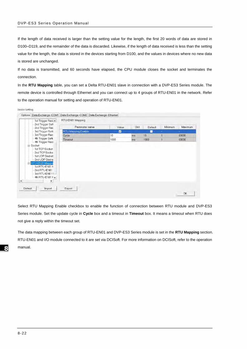
DVP-ES3 Ser ies Opera t ion Manual
8-22
_8
If the length of data received is larger than the setting value for the length, the first 20 words of data are stored in
D100–D119, and the remainder of the data is discarded. Likewise, if the length of data received is less than the setting
value for the length, the data is stored in the devices starting from D100, and the values in devices where no new data
is stored are unchanged.
If no data is transmitted, and 60 seconds have elapsed, the CPU module closes the socket and terminates the
connection.
In the RTU Mapping table, you can set a Delta RTU-EN01 slave in connection with a DVP-ES3 Series module. The
remote device is controlled through Ethernet and you can connect up to 4 groups of RTU-EN01 in the network. Refer
to the operation manual for setting and operation of RTU-EN01.
Select RTU Mapping Enable checkbox to enable the function of connection between RTU module and DVP-ES3
Series module. Set the update cycle in Cycle box and a timeout in Timeout box. It means a timeout when RTU does
not give a reply within the timeout set.
The data mapping between each group of RTU-EN01 and DVP-ES3 Series module is set in the RTU Mapping section.
RTU-EN01 and I/O module connected to it are set via DCISoft. For more information on DCISoft, refer to the operation
manual.

Chapter 8 Hardware Conf igurat ion
8-23
8_
Select RTU1 Enable to enable this RTU function. You can set each RTU individually.
Set a station address and an IP address.
Set the RX mapping address and RX mapping length to make the digital input points for the DI module
connected to RTU and mapped to X/M devices, as well as the length for the DVP-ES3 Series module. Set the
RY mapping address and length to set the digital output points for the DO module mapped to Y/M devices, as
well as the length for the DVP-ES3 Series module.
Set the RCR Read mapping address and RCR Read mapping length to make the analog input points for the AI
module connected to RTU and mapped to D/SR devices, as well as the length for the DVP-ES3 Series module.
Use the RCR Write mapping address and length to set the analog output points for the AO module mapped to
D/SR devices, as well as the length for the DVP-ES3 Series module.

DVP-ES3 Ser ies Opera t ion Manual
8-24
_8
8.3 Data Exchange
8.3.1 Device Settings Dialog Box Descriptions
In the Device Settings dialog box, after you click the Data Exchange-COM1, Data Exchange-COM2 or Data
Exchange-Ethernet tab, you can set the parameters for the data exchange table for the communication port built into
the DVP-ES3 Series module.
The DVP-ES3 Series module can be a master and exchange data with remote slave devices through COM1 and
COM2 using the Modbus protocol, or through an Ethernet port using the Modbus TCP protocol.
When you set the start Mode to Program Control, the program in the PLC determines whether to perform the set
data exchange. PLC Run means that the set data exchange is performed automatically when PLC is in the RUN
state. Always Enable means that the data exchange is performed constantly when the PLC is powered on.
Add a new row in the data exchange table in area by clicking Add. Move the selected data exchange row up or
down by clicking Move Up and Move Down. Delete the selected data exchange row by clicking Delete. Copy the
selected data exchange row by clicking Copy. You can then paste it back into the table as the last row.
The following table explains the columns in the data exchange table.
Name Description
Item The number of the block for data exchange
Enable Selects whether to enable the data exchange table when the data exchange is
performed.
Station Address/
IP Address
The slave station address for the data exchange table. You can set one address for
multiple data exchange tables. It is a station address under the COM1 and COM2 tabs,

Chapter 8 Hardware Conf igurat ion
8-25
8_
and IP under the Ethernet tab.
Local Address The device address range used by the master in the data exchange table
<< / >> 「<<」: Input: the data block where the master reads from a slave
「>>」: Output: the data block where the master writes to a slave
Remote Address
This is the device address range used by a slave in the data exchange table.
The device range is in hexadecimal if the slave in the data exchange table is a
user-defined Modbus Device.
Quantity This is the size of the data exchange table, which is consistent with the result calculated
from the device range.
8.3.1.1 Data Exchange - COM1 and Data Exchange - COM2
On the Data Exchange-COM1 or Data Exchange-COM2 tab, double-click row in the data exchange table to set to
open the Item dialog box as shown below. Select the Enable check box to enable the data exchange table in the
mode mentioned above. Remote Address is the address of the target slave for data exchange. The Shortest Update
Cycle is the period for data exchange of the data exchange table. The connection times out if the target device does
not make any response within the time specified by Connection Timeout.
Select Support Read/write synchronization (Function code 0x17) to have the master complete reading and writing
in a single command to improve the efficiency of data exchange. This uses the specific Modbus function code. Make
sure that all devices in data exchange support the Modbus function code for read and write synchronization. Otherwise,
the attempt to read and write fails due to the failure to identify function codes after receiving the command from the
master device.
Remote Device Type is the model of a target slave including the Delta PLC and standard Modbus devices.

DVP-ES3 Ser ies Opera t ion Manual
8-26
_8
Read
The DVP-ES3 Series module reads data from a remote device.
Local Start Address: The device type and start address of the devices where the DVP-ES3 Series module stores
data.
Remote Start Address: The device type and start address of the remote device to be read.
Quantity: This is the input data length.
Write
The DVP-ES3 Series module writes data to a remote device.
Local Start Address: The device type and start address of the source data for the DVP-ES3 Series module.
Remote Start Address: The device type and start address of the remote device where data is to be written.
Quantity: The output data length.
8.3.1.2 Data Exchange - Ethernet
On the Data Exchange - Ethernet tab, double click a row in the data exchange table to set to open the Item dialog
box as shown below. The settings are almost the same as those for Data Exchange - COM1 and Data Exchange -
COM2, except that the target slave model option in Remote Device Type contains Delta PLC and standard Modbus
TCP equipment, as well as the IP address for remote slaves. For other settings, refer to the descriptions of Data
Exchange - COM1 and Data Exchange - COM2.

Chapter 8 Hardware Conf igurat ion
8-27
8_
Select the Apply to all check box on the right side of The Shortest Update Cycle and Connection Timeout and then
click OK. Selecting the check box writes the settings for The Shortest Update Cycle and Connection Timeout to
other data tables on the tab Data Exchange - Ethernet. You can also set the data exchange tables separately without
selecting the Apply to all check box.

DVP-ES3 Ser ies Opera t ion Manual
8-28
_8
MEMO

9-1
Chapter 9. EtherNet/IP Specification and Operation
Table of Contents
9.1 Introduction .................................................................................................. 9-4
9.1.1 EtherNet/IP ............................................................................................... 9-4
9.1.2 Definitions of Common Network Terms ......................................................... 9-4
9.1.3 Ethernet Features ...................................................................................... 9-5
9.1.3.1 Delta EIP Architecture ............................................................................... 9-5
9.1.3.2 EIP Features ............................................................................................ 9-6
9.2 Installation .................................................................................................... 9-6
9.2.1 EtherNet/IP Device .................................................................................... 9-6
9.2.2 Network Cable Installation .......................................................................... 9-6
9.2.2.1. Single Port Device .................................................................................... 9-7
9.2.2.2. Dual Port Device ...................................................................................... 9-7
9.2.2.3 EIP Builder Software ................................................................................. 9-9
9.3 Specifications .............................................................................................. 9-10
9.3.1 Ethernet Specification ............................................................................... 9-10
9.3.2 EtherNet/IP Specification .......................................................................... 9-11
9.3.3 EtherNet Communication Port .................................................................... 9-12
9.3.3.1 Communication Port Pin Assignment ..........................................................9-12
9.3.3.2 Communication LED Indicator ...................................................................9-12
9.4 EIP Builder .................................................................................................. 9-13
9.4.1 Run the EIP Builder .................................................................................. 9-13
9.4.1.1 Run the EIP Builder via an EIP Scanner ......................................................9-13
9.4.2 Set up the IP Address ............................................................................... 9-15
9.4.2.1 IP Address Types .....................................................................................9-15
9.4.2.2 Set the IP Address (Static IP) ....................................................................9-15
9.4.2.3 Set the IP Address (BOOTP/DHCP) .............................................................9-17
9

9-2
_9
9.4.2.4 Re-enable BOOTP/DHCP ........................................................................... 9-20
9.5 Troubleshooting .......................................................................................... 9-22
9.5.1 Error Code Classification .................................................................................9-22
9.5.2 Error Codes & How to fix them ........................................................................9-22
9.5.2.1 Configuration Errors ................................................................................. 9-22
9.5.2.2 Application Error ...................................................................................... 9-25
9.6 Studio 5000 Software Operation ................................................................. 9-26
9.6.1 Architecture ..................................................................................................9-26
9.6.2 Create a New Project ......................................................................................9-26
9.6.3 Create a Scanner ...........................................................................................9-28
9.6.3.1 Create a New Ethernet/IP Module .............................................................. 9-28
9.6.4 Connect to a Delta Adapter .............................................................................9-30
9.6.4.1 Import an EDS file ................................................................................... 9-30
9.6.4.2 Create an Adapter ................................................................................... 9-32
9.6.4.3 Editing Corresponding Addresses for DVP-ES3 ............................................. 9-35
9.6.4.4 Download ............................................................................................... 9-36
9.6.4.5 Data Mapping .......................................................................................... 9-37
9.7 CIP Object ................................................................................................... 9-38
9.7.1 Object List ....................................................................................................9-38
9.7.2 Data Type .....................................................................................................9-39
9.7.3 Identity Object (Class ID: 01 Hex) ...................................................................9-42
9.7.4 Message Router Object (Class ID: 02 Hex) ........................................................9-44
9.7.5 Assembly Object (Class ID: 04 Hex) .................................................................9-45
9.7.6 Connection Manager Object (Class ID: 06 Hex) .................................................9-47
9.7.7 Port Object (Class ID: F4 Hex) ........................................................................9-49
9.7.8 TCP/IP Interface Object (Class ID: F5 Hex) .......................................................9-51
9.7.9 Ethernet Link Object (Class ID: F6 Hex) ...........................................................9-54
9.7.10 X Register (Class ID: 350 Hex) ......................................................................9-57
9.7.11 Y Register (Class ID: 351 Hex) ......................................................................9-57
9.7.12 D Register (Class ID: 352 Hex) ......................................................................9-58
9.7.13 M Register (Class ID: 353 Hex) ......................................................................9-59
9.7.14 S Register (Class ID: 354 Hex) ......................................................................9-60
9.7.15 T Register (Class ID: 355 Hex) ......................................................................9-61
9.7.16 C Register (Class ID: 356 Hex) ......................................................................9-62
9-3
9.7.17 HC Register (Class ID: 357 Hex) ................................................................... 9-63
9.7.18 SM Register (Class ID: 358 Hex) ................................................................... 9-64
9.7.19 SR Register (Class ID: 359 Hex) ................................................................... 9-64
9.8 Delta EIP Product List.................................................................................. 9-65
9.8.1 Delta EIP Products ........................................................................................ 9-65
9.8.2 Delta EIP Products, DLR (Device Level Ring) supported ...................................... 9-66
9.8.3 Delta EIP Products, Scanner supported ............................................................ 9-66
9.9 Operation and Monitor on the Web .............................................................. 9-67
9.9.1 Getting Started ............................................................................................. 9-67
9.9.1.1 Exploring the webpage .............................................................................9-67
9.9.1.2 Using the Webpage ..................................................................................9-68
9.9.1.3 Login ......................................................................................................9-69
9.9.1.4 Menu......................................................................................................9-69
9.9.2 Device Information ....................................................................................... 9-71
9.9.3 Network configuration ................................................................................... 9-71
9.9.3.1 Account management ...............................................................................9-71
9.9.4 Data Monitoring ............................................................................................ 9-74
9.9.4.1 Data Monitoring Setup Page ......................................................................9-74
9.9.4.2 Data Monitor Table Pages ..........................................................................9-78
9.9.5 Diagnostic .................................................................................................... 9-79
9.9.5.1 Hardware Status Page ..............................................................................9-79
9.9.6 Configurations .............................................................................................. 9-80
9.9.6.1 Save Configuration Page ...........................................................................9-80

DVP-ES3 Ser ies Opera t ion Manual
9-4
_9
9.1 Introduction 9.1.1 EtherNet/IP
EtherNet/IP (“IP” stands for “Industrial Protocol”) is an industrial Ethernet network managed by ODVA, Inc. (formerly Open DeviceNet Vendors Association, Inc.), a global trade and standards development organization.
EtherNet/IP works on a TCP/UDP/IP based Ethernet network and uses the most widely deployed collections of Ethernet standards to provide a broad range of applications in different industries that require high-speed and stability including Factory Automation (FA), Building Automation (BA), Process Automation (PA) and many more.
Delta covers a full range of controller and drive products supported by EtherNet/IP, including Programmable Logic Controllers (PLC), inverters, Human Machine Interfaces (HMI) and so on. Refer to Section 9.9 for a full product list that support EtherNet/IP. In addition, you can also use EDS files to connect to other brands of EtherNet/IP devices. You can run Delta EtherNet/IP software (EIP Builder) through the ISPSoft software V3.0 or later. Download the ISPSoft software at:
http://www.deltaww.com/services/DownloadCenter2.aspx?secID=8&pid=2&tid=0&CID=06&itemID=060301&typeID=1&downloadID=,&title=--%20Select%20Product%20Series%20--&dataType=8;&check=1&hl=en-US
9.1.2 Definitions of Common Network Terms
Term Definition
ODVA Open DeviceNet Vendor Association for EtherNet/IP
EIP EtherNet/IP, an industrial Ethernet network, provides interoperability for system providers.
IP stands for Industrial Protocol. The term “EIP” (EtherNet/IP) is used in this manual.
I/O Connection Use the I/O connection to connect to EtherNet/IP and to exchange data cyclically.
Explicit Message Connect to EtherNet/IP and to exchange data non-cyclically. Data is exchanged piece by
piece through instructions.
RPI Requested Packet Interval, through the I/O connection to connect to EtherNet/IP to
exchange data at regular time intervals.
ACD Address Conflict Detection to detect IP address duplications.
Produced/Consumed
TAG (P/C TAG)
You use TAGs for assigning and referencing memory locations for Rockwell PLCs,
the same as registers for Delta PLCs.
Produced tag: A tag that a controller makes available for other controllers. Multiple
controllers can simultaneously consume (receive) the data. A produced tag sends
its data to consumed tags (consumers) without using logic.
Consumed tag: A tag that receives the data of a produced tag. The data type of the
consumed tag and the produced tag must match (including any array dimensions).
The data is transferred over Ethernet/IP. For example, PLC-A needs data from
PLC-B, so PLC-B sends the data to PLC-A. Therefore, PLC-B is the producer and
PLC-A is the consumer.

Chapter 9 Ethernet Spec i f icat ion and Operat ion
9-5
9_
EDS
Electronic Data Sheets: EDS files are simple text files used by EtherNet/IP network
configuration tools to help you identify EtherNet/IP products and easily commission them
on a network.
Data Mapping Exchanging data between devices
EIP Scanner The master station is called an EIP Scanner in EtherNet/IP.
EIP Adapter The slave station is called an EIP Adapter in EtherNet/IP.
DLR
Device Level Ring (DLR) provides fault-tolerant network design for daisy-chain and linear
topology. The DLR protocol provides high network availability in a ring topology. It was
intended primarily for implementation in EtherNet/IP end-devices that have two Ethernet
ports and embedded switch technology, providing fast network fault detection and
reconfiguration to support the most demanding control applications.
Modbus TCP This is a Modbus variant used for communications over TCP/IP networks.
9.1.3 Ethernet Features
9.1.3.1 Delta EIP Architecture
This typical Delta EIP architecture includes an EIP Scanner and Adapters; data mapping is achieved between devices
through an I/O connection and explicit messaging. The DVP-ES3 Series supports single port Ethernet; thus you can install
and configure devices with embedded switch technology over EtherNet/IP.

DVP-ES3 Ser ies Opera t ion Manual
9-6
_9
9.1.3.2 EIP Features
Flexibility
- Flexible topology: EIP devices may include single port Ethernet as well as dual port Ethernet, and provideapplicable networks such as linear topology, ring topology and ring topology for faster expansion and easiermanagement.
- EtherNet/IP works on a TCP/UDP/IP based Ethernet network, uses most widely deployed collections of Ethernet standards, and supports Wi-fi connection. Even personnel with no IT background can build the network easily.
- Applicable networks include linear topology, ring topology, star topology, Ethernet, EtherNet/IP, one or moreLANs, etc. You can set configuration through USB or an interface.
Simplicity
- With a connector: Delta provides a full range of products, including human machine interfaces (HMI),programmable logic controllers (PLC), and inverter drives for application in an industrial operation. You can builda network simply through an RJ-45 connector, saving costs on cables and other connecting tools.
- Single network: in place of the 3-tier industrial architecture, single network architecture provides 100MB/bitshigh-speed cyclical and non-cyclical data mapping functions, ensuring complete network diagnosis andeffectively shortening debugging time.
- Graphical user interface software: the EIP Builder uses a graphical user interface designed for intuitive operation.
Integration
- Data mapping: the EIP Builder provides a consistent setting interface, allowing you to reduce the time to learnand set up configurations.
- Listed device parameters: the EIP Builder presents the device parameters in a list. Instead of looking them upin the user manual, you can quickly check on the parameters in the list.
- EDS file: you can connect to Delta and other brands of EtherNet/IP products with EDS files.
9.2 Installation 9.2.1 EtherNet/IP Device
A Delta EtherNet/IP (EIP) device allows you to build a linear topology, ring topology, and star topology networks. A Delta
EIP device includes the EIP Builder software, EIP Scanner, EIP Adapter, EIP Tap, and an Ethernet switch. EIP Scanners
and EIP Adapters can be further divided into single port and dual port devices. The DVP-ES3 Series are single port
devices. Refer to Section 9.2.2.1 for the single port setup and refer to Section 9.2.2.3 for the software installation.
9.2.2 Network Cable Installation
Each EtherNet/IP device is connected to an Ethernet switch with a CAT 5e cable. Please use Delta standard cables and
the DVS series industrial switches. Refer to the Delta PLC/HMI Cable Selection Guide for more information.

Chapter 9 Ethernet Spec i f icat ion and Operat ion
9-7
9_
9.2.2.1. Single Port Device
You can use a single port device to build up either a linear or a star network topology. An Ethernet switch and an Ethernet
tab are required to create a star topology or a ring topology.
Linear Topology
Linear Topology 1
Linear Topology 2
Star Topology
9.2.2.2. Dual Port Device
You can use a dual port device to build a linear, a star or a ring network topology. A DLR function is required to create a
ring topology. Refer to Section 9.8.2 for DLR supported series.
Linear Topology

DVP-ES3 Ser ies Opera t ion Manual
9-8
_9
Star Topology
Ring Topology
A DLR function is required to create a ring topology. Refer to Section 9.8.2 for DVP-ES3 that support DLR.
When a switch is needed for the particular topology, the switch should support the DLR function. If not, the connection
might fail.

Chapter 9 Ethernet Spec i f icat ion and Operat ion
9-9
9_
9.2.2.3 EIP Builder Software
Linear and star topology
Install the EIP Builder software on your PC to monitor and configure the EIP devices. You can also connect an EIP
device to your PCs directly, or use a switch to connect to the PCs.
Ring topology Install the EIP Builder on your PC to monitor and configure the EIP devices. Be sure to save a network connection for
your PC to connect to the EIP device.
Alternatively, you can use an EIP tap to connect your PC so that the ring topology stays intact.

DVP-ES3 Ser ies Opera t ion Manual
9-10
_9
9.3 Specifications
9.3.1 Ethernet Specification
Model DVP-ES3 Series
Communication Protocols EtherNet/IP Scanner / Adapter, MODBUS TCP
Protocols BOOTP, DHCP, SMTP, NTP, Socket, HTTP
Communication Speed 10/100 Mbps Auto-Detection
Communication Interface RJ-45 with Auto MDI/MDIX
Numbers of the Ethernet Port 1
Item / per transmission Specification
DVP-ES3 Series
MODBUS TCP
Maximum connection
quantity for Client and
Server*1
16
Max. data length 100 words
Socket
(communication
port) *2
TCP connection quantity
4 UDP connection quantity
SMTP (for
emailing) Emailing quantity 4
*1: The maximum connection is 16; a sum of client connection and server connection. For example, when client
connection quantity is 10, only 6 connections are left for server. If you need more connections, use DVP-ES3 Series
instead for more allowable connection quantity.
*2: Numbering is used for connections via the communication port. You can use connection 1 in TCP mode or UDP
mode and up to 4 connections can be made per transmission.

Chapter 9 Ethernet Spec i f icat ion and Operat ion
9-11
9_
9.3.2 EtherNet/IP Specification
Item DVP-ES3 Series
General Device type Scanner / Adapter
Topology type Linear, Star topology
CIP Network I/O
Connection
CIP connection number 16 8
TCP connection number 8
(for all connection types)
Requested Packet Interval (RPI) 5 ms – 1000 ms
Max. Transmission Speed 3000 pps
Max. Data Length/per
transmission 500 bytes
CIP Network Explicit
Message
Class 3
(Connected Type) 8 8
UCMM
(Non-Connected Type, only uses
TCP connections)
Total 8
(for all connection types)
CIP Objects
Identity, Message Router, Assembly, Connection
Manager, Port, TCP/IP interface, Ethernet link,
Vendor specific
CIP Network TAG
Max. Consumed TAG Number 16
Max. Produced TAG Number 16
Max. Data Length 500 bytes (IO Connection)
400 bytes (Explicit Message)
Requested Packet Interval (RPI) 5 ms – 1000 ms
Maximum number of connections when using DVP-ES3 Series to connect to other devices through Ethernet/IP:
DVP-ES3 Series can act as a Scanner and an Adapter simultaneously. It can connected up to 16 devices. Each
device can establish up to 8 connections for data mapping. Data mapping types can be I/O connection and
Consumed TAG. You can use explicit message for data mapping at the same time, up to 8 explicit message
connections can be created.

DVP-ES3 Ser ies Opera t ion Manual
9-12
_9
9.3.3 EtherNet Communication Port
9.3.3.1 Communication Port Pin Assignment
Delta EtherNet/IP devices use CAT5e industrial Ethernet cables and can be connected via RJ-45 communication port.
Pin Signal Description Pin Signal Description
1 Tx+ Transmit plus 5 -- N/C
2 Tx- Transmit negative 6 Rx- Receive negative
3 Rx+ Receive plus 7 -- N/C
4 -- N/C 8 -- N/C
9.3.3.2 Communication LED Indicator
LED Indicator LED Status Description
LINK / ACT Green
ON Connected to Ethernet
No transmission over Ethernet
Blinking Connected to Ethernet
Packets transmitting/receiving over Ethernet
OFF Not connected to Ethernet

Chapter 9 Ethernet Spec i f icat ion and Operat ion
9-13
9_
9.4 EIP Builder
The Delta EtherNet/IP software, EIP Builder, is embedded in ISPSoft. You run it from the ISPSoft software (version 3.0
or later). Download the ISPSoft software at:
http://www.deltaww.com/services/DownloadCenter2.aspx?secID=8&pid=2&tid=0&CID=06&itemID=060301&typeID=1&d
ownloadID=,&title=--%20Select%20Product%20Series%20--&dataType=8;&check=1&hl=en-US
9.4.1 Run the EIP Builder
You can call EIP Builder from Delta EIP Scanner’s HWCONFIG in ISPSoft. You can also call it independently to set up
parameters for the Adapter. The Delta EIP Scanner is equipped with the EtherNet/IP communication PLC and the
EtherNet/IP module. Refer to Section 9.8.3 for a list of Delta EIP Scanner products supported by EIP Builder.
9.4.1.1 Run the EIP Builder via an EIP Scanner
Steps to run EIP Builder
Run EIP Builder from an EIP Scanner product.
Open
ISPSoft V3 0.
CreateISPSoft Project
Open
HWCONFIG
DownloadHWCONFIG
OpenEIP Builder
Start
1. Open ISPSoft V3.0: click the Start menu and go to Programs > Delta Industrial Automation > PLC > ISPSoft
2. Create a new project: on the File menu, click New to display the Create a New Project dialog box.

DVP-ES3 Ser ies Opera t ion Manual
9-14
_9
3. Select a PLC: in the Create a New Project dialog box, select a PLC product that is supported by EIP builder.
4. Open HWCONFIG: double-click HWCONFIG in the Project window.
5. Save and download the settings from HWCONFIG:on the File menu click Save to save the settings and then
click the download button on the toolbar to download the file to PLC. You must save the configuration in
HWCONFIG before opening the other communication tools. While working in the communication tools, you
cannot work in HWCONFIG.
6. Open EIP Builder: right-click the CPU module in the system configuration area point to Communication
Software and then click EIP Builder.

Chapter 9 Ethernet Spec i f icat ion and Operat ion
9-15
9_
9.4.2 Set up the IP Address
This section provides an overview of how to set up IP address for DVP-ES3 Series modules. Set up the IP address
before configuring the EIP related parameters or data mapping settings.
9.4.2.1 IP Address Types
The DVP-ES3 supports 3 types of IP addressing, BOOTP, DHCP and static IP address.
Type of IP Address Definition
BOOTP
Uses the TCP/IP Bootstrap Protocol (BOOTP) to set up the IP address, netmask and
gateway. A BOOTP server may require some configuration. The BOOTP protocol is
designed for a network in which each host has a permanent network connection.
DHCP Uses the Dynamic Host Configuration Protocol (DHCP) to automatically obtain IP address,
netmask, gateway, main computer name and the WINS server.
Static IP You manually set the IP address, netmask and gateway.
9.4.2.2 Set the IP Address (Static IP)
Steps to set the IP address
When using an EIP product with a static IP address, set up the IP address in HWCONFIG in ISPSoft. The following
example uses the DVP-ES3 Series.
CreateProjectISPSoft
OpenHWCONFIG
Set up IP Address
DownloadHWCONFIG
Refer to Section 9.4.1.1 for how to set up an EIP module in HWCONFIG.
1. Configure the network parameters
Double-click HWCONFIG to open the DVP-ES3 Setting Page.
Click Settings to open the Device Setting Page and click Option tab and select the option Ethernet Port
Basic Settings to set the IP Address.

DVP-ES3 Ser ies Opera t ion Manual
9-16
_9
2. Save and download the settings from HWCONFIG: on the File menu click Save to save the settings and then
on the Options menu, click Download or click the Download button on the toolbar.

Chapter 9 Ethernet Spec i f icat ion and Operat ion
9-17
9_
9.4.2.3 Set the IP Address (BOOTP/DHCP)
Steps to set the IP address
When using an EIP product with a BOOTP/DHCP IP address, users can set up the IP address through the IP
Manager in the EIP Builder.
CreateAddressMAC Set up IP
Same I assign P mode after each power-on
Reset I assign P mode after each power-on
Y DisableBOOTP
N
OpenEIP Bui lder
Open IP M anager
Descriptions for the IP Manager:
123
4
7
6
89
10
5
Item Definition
Stop the Server Stops the BOOTP/DHCP server; the IP manager does not request an IP
addresses from the BOOTP/DHCP server.
Network Settings Opens a dialog box to set up the subnet mask, gateway, primary DNS,
secondary DNS, and domain name.
Clear List Clears the contents of the list.
New Adds a new IP/MAC address.
Delete Deletes the selected item from the list.

DVP-ES3 Ser ies Opera t ion Manual
9-18
_9
Import Imports the IP/MAC address list; the file format is .CSV.
Export Exports the IP/MAC address list; the file format is .CSV.
Enable BOOTP Enables the BOOTP to assign an IP address for the selected item.
Enable DHCP Enables the DHCP to assign an IP address to the selected item.
Disable BOOTP/DHCP Disables the BOOTP/DHCP on the device; the device does not request an IP
addresses from the server.
Steps to set the IP address:
1. MAC address: find the MAC address on the EIP device. The MAC address uniquely identifies the device.
2. Open the IP Manager
In EIP Builder on the Tool menu, click IP Manager.
The IP Manager can be the BOOTP/DHCP Server, receiving IP address requests from devices. The IP
Manager window is shown below.

Chapter 9 Ethernet Spec i f icat ion and Operat ion
9-19
9_
3. Set up the IP address
Double-click the listed MAC address for your device to open the Input Data dialog box.
Enter the IP address and click OK.
4. Disable DHCP/BOOTP
Click the device in the Mapping Table that you want to disable, then click Disable DHCP/BOOTP. The selected
device does not send DHCP/BOOTP requests. To change the IP address receiving mode, refer to Section 9.4.2.4
for more information.

DVP-ES3 Ser ies Opera t ion Manual
9-20
_9
Notes
Enable BOOTP: when the IP address receiving mode is BOOTP (BOOTP is enabled), the IP address is
assigned, and the device sends out BOOTP requests for IP addresses during each power-on.
Enable DHCP: when the IP address receiving mode is DHCP (DHCP is enabled), the IP address is assigned,
and the device sends out DHCP requests for IP addresses during each power-on.
Disable DHCP/BOOTP: when BOOTP is disabled, the device does not send out any DHCP/BOOTP requests
for IP addresses during each power-on.
9.4.2.4 Re-enable BOOTP/DHCP
To enable the DHCP or BOOTP function again, use the device software to make the change. Using the DVP-ES3 Series
as an example: from the Start menu, start ISPSoft, then HWCONFIG, and then IP Manager. In IP Manager sets the IP
address to the receiving mode.
Open HWCONFIG
Set upparameters
Set up IPreceiving mode
OpenEIP Builder
DownloadHWCONFIG
OpenIP Manager
Steps to set device parameters
1. Refer to Section 9.4.1.1 for how to start HWCONFIG.
2. Set the parameters: enable the IP address receiving mode to BOOTP/DHCP.
Double-click HWCONFIG to open the DVP-ES3 Setting Page.

Chapter 9 Ethernet Spec i f icat ion and Operat ion
9-21
9_
Click Settings to open the Device Setting Page and click Option tab and select the option Ethernet Port
Basic Settings to set the Mode to BOOTP or DHCP.
3. Download the settings from HWCONFIG
Refer to Section 9.4.1.1 for more information.
4. Open EIP Builder.
Refer to Section 9.4.1.1 for more information.
5. Open the IP Manager
Refer to Section 9.4.2.3 for more information.
6. Open the IP setup page
Refer to Section 9.4.2.3 for more information.

DVP-ES3 Ser ies Opera t ion Manual
9-22
_9
9.5 Troubleshooting
This section provides an overview of error codes and troubleshooting for the DVP-ES3 Series.
9.5.1 Error Code Classification
There are two types of error code categories for DVP-ES3 Series: Configuration Errors, and Application Errors. These
error codes are defined by the ODVA for EtherNet/IP errors. Refer to the following table for DVP-ES3 Series error codes.
Error Code Classification
Description 1st Phase 2nd Phase
Category Item
Configuration error EDS files mismatched Mismatched EDS files lead to I/O connection
failure. *
Data exchange setup error Data exchange setup error lead to I/O connection failure. *
Application error Ethernet/IP error EtherNet/IP communication failure *
* Only the last 2 bytes of the error code are shown; for example, only 011C appears for the error code H’1101011C.
9.5.2 Error Codes & How to fix them
9.5.2.1 Configuration Errors
(EIP Builder only shows Low word error codes)
Category Error Code Description How to fix them
EDS Files
Mismatched
H’1101011C
The Transport Class field
values of the Transport Class
and Trigger in the EDS file
are mismatched.
1. Check if the product information and the EDS file
match.
2. Reload the EDS file.
3. Ask the vendor of the device for the EDS file.
H’11010114
The Vender ID or the Product
Code in the EDS file is
mismatched.
1. Check if the product information and the EDS
file match.
2. Reload the EDS file.
3. Ask the vendor of the device for the EDS file.
H’11010115
The device type parameters
in the EDS file are
mismatched.
1. Check if the product information and the EDS file
match.
2. Reload the EDS file.
3. Ask the vendor of the device for the EDS file.
H’11010116 The revision parameters in
the EDS file are mismatched.
1. Check if the product information and the EDS file
match.

Chapter 9 Ethernet Spec i f icat ion and Operat ion
9-23
9_
Category Error Code Description How to fix them
2. Reload the EDS file.
3. Ask the vendor of the device for the EDS file.
H’1101011E The direction parameters in
the EDS file are mismatched.
1. Check if the product information and the EDS file
match.
2. Reload the EDS file.
3. Ask the vendor of the device for the EDS file.
H’1101011F
The fixed / variable output
flag in the EDS file is
mismatched.
1. Check if the product information and the EDS file
match.
2. Reload the EDS file.
3. Ask the vendor of the device for the EDS file.
H’11010120
The fixed / variable input flag
in the EDS file is
mismatched.
1. Check if the product information and the EDS file
match.
2. Reload the EDS file.
3. Ask the vendor of the device for the EDS file.
H’11010121 The output priority in the
EDS file is mismatched.
1. Check if the product information and the EDS file
match.
2. Reload the EDS file.
3. Ask the vendor of the device for the EDS file.
H’11010122 The input priority in the EDS
file is mismatched.
1. Check if the product information and the EDS file
match.
2. Reload the EDS file.
3. Ask the vendor of the device for the EDS file.
H’11010123
The output connection type
parameters in the EDS file
are mismatched.
1. Check if the product information and the EDS file
match.
2. Reload the EDS file.
3. Ask the vendor of the device for the EDS file.
H’11010124
The input connection type
parameters in the EDS file
are mismatched.
1. Check if the product information and the EDS file
match.
2. Reload the EDS file.
3. Ask the vendor of the device for the EDS file.
H’11010125 The redundant ownership
output parameters in the
1. Check if the product information and the EDS file
match.

DVP-ES3 Ser ies Opera t ion Manual
9-24
_9
Category Error Code Description How to fix them
EDS file are mismatched. 2. Reload the EDS file.
3. Ask the vendor of the device for the EDS file.
H’11010126
The configuration size
parameters in the EDS file
are mismatched.
1. Check if the product information and the EDS file
match.
2. Reload the EDS file.
3. Ask the vendor of the device for the EDS file.
H’11010129
The configuration path
parameters in the EDS file
are mismatched.
1. Check if the product information and the EDS file
match.
2. Reload the EDS file.
3. Ask the vendor of the device for the EDS file.
H’11010132 The EDS file does not
support Null forward open.
1. Check if the product information and the EDS file
match.
2. Reload the EDS file.
3. Ask the vendor of the device for the EDS file.
Data
Exchange
Setup Error
H’12010100 I/O connections duplicated
1. Check if the system has created the I/O
connections.
2. Change the connection type to Listen Only.
H’12010106 Ownership conflict
1. Check the scanner owner.
2. Reconfigure the invalid scanner.
3. Change the connection to multicast.
H’12010110 Target for connection not
configured
1. Check the I/O connection status.
2. Activate the I/O connections again.
H’12010111 Adapter RPI not supported Check the RPI for the adapter.
H’12010113 Out of connections
1. Check if the number of connections exceeds the
limit.
2. Reduce the number of the product connections.
H'12010119 Non-Listen only not opened
1. Check if the system has created the I/O
connections.
2. Check the scanner I/O connection status.
H’12010127 Invalid originator to target
Size
Check the module number and the product setup file
to see if they match.
H’12010128 Invalid target to originator Check the output size in the connection parameters.

Chapter 9 Ethernet Spec i f icat ion and Operat ion
9-25
9_
Category Error Code Description How to fix them
Size
H’1201012D Consumed TAG does not
exist.
Check if the parameters in the Consumed tag are set
correctly.
H’1201012E Produced TAG does not
exist.
Check if the parameters in the Produced tag are set
correctly.
H’12010204 Unconnected request timeout
No response from the adapter; check if the power
and the network connection for the adapter are
working properly.
H’12010302 Network bandwidth NOT
available for data
1. Check the I/O connection limit between the
scanner and the adapter.
2. Increase the RPI value or reduce the number of
connections.
H’12010315 Invalid segment in
connection path
Check the module number and the product setup file
to see if they match.
9.5.2.2 Application Error
Category Error Code Description How to fix them
EtherNet/
IP Error H’00010203 I/O connection timeout
1. Check the network connection status.
2. Check if the module is working properly.
3. Increase the RPI value.

DVP-ES3 Ser ies Opera t ion Manual
9-26
_9
9.6 Studio 5000 Software Operation
This section provides an overview using Ethernet/IP to connect to a Delta Ethernet/IP Adapter with third party software.
For this example we use the Rockwell Automation software Studio 5000.
9.6.1 Architecture
The Rockwell Automation (RA) EIP Scanner uses Ethernet to connect to a Delta Adapter. The PC connects to the RA
Scanner through Ethernet or USB.
※ Rockwell Software Studio 5000, ControlLogix, RSLogix are registered trademarks of Rockwell Automation, Inc.
Operation Steps:
Download Data ExchangeData ExchangeSet up
Data ExchangeTable
Network View
9.6.2 Create a New Project
Open Studio 5000 and under Create, click New Project.
New

Chapter 9 Ethernet Spec i f icat ion and Operat ion
9-27
9_
Select a PLC and select the chassis. This example uses a 1756-L71.
Click Finish to create the new project.
Select PLC
Select a backplane

DVP-ES3 Ser ies Opera t ion Manual
9-28
_9
After creating the project, Studio 5000 displays the Controller Organizer and workspace.
9.6.3 Create a Scanner
Next, add the 1756-EN2TR Ethernet/IP module, and then connect to the Ethernet/IP devices through the Ethernet/IP
module.
9.6.3.1 Create a New Ethernet/IP Module
Right-click 1756 Backplane 1756-A7 and then click New Module.

Chapter 9 Ethernet Spec i f icat ion and Operat ion
9-29
9_
Type 1756-EN2TR in the filter field, click the 1756-EN2TR module, and then click Create.
Type the Name, IP address and other required information, and then click OK to add the EtherNet/IP module.

DVP-ES3 Ser ies Opera t ion Manual
9-30
_9
The new 1756-EN2TR module appears in the Controller Organizer tree.
9.6.4 Connect to a Delta Adapter
This section provides an overview of connecting to a Delta Ethernet/IP Adapter with the Rockwell Automation software
Studio 5000.
9.6.4.1 Import an EDS file
In Studio 5000, on the Tools menu, click EDS Hardware Installation Tool.

Chapter 9 Ethernet Spec i f icat ion and Operat ion
9-31
9_
Select Register an EDS file(s) and click Next.
Select Register a single file and click Browse to find the EDS file to import.

DVP-ES3 Ser ies Opera t ion Manual
9-32
_9
Follow the instructions in the wizard and then click Finish to complete importing the EDS file.
9.6.4.2 Create an Adapter
In Studio 5000, in the Controller Organizer under 1756-EN2TR, right-click Ethernet and then click New Module.

Chapter 9 Ethernet Spec i f icat ion and Operat ion
9-33
9_
Type the module number of the imported Delta EDS file in the filter field, click the Delta module, and then click
Create.
Verify that the product name and IP address are the same as the information shown in the Module Definition
section.

DVP-ES3 Ser ies Opera t ion Manual
9-34
_9
Click Change if you need to make a change to the module definition.
Modify the module definition
1) Name: Click the arrow button to select a valid connection.
2) Size: Rockwell PLC supports maximum 500 bytes data size. (Data for input contains 2 bytes of Serial Number
and for output contains 4 bytes 32-bit Run-idle header and 2 bytes of Serial Number.) If using DVP-ES3 Series,
you can set the maximum data length 498 SINT for input and 494 SINT for output.
※ In general, there is no need to change the parameters from the imported EDS files which can usually be used
without modification.

Chapter 9 Ethernet Spec i f icat ion and Operat ion
9-35
9_
In the New Module dialog box, click the Connection tab to modify the Requested Packet Interval and Input Type
settings. The RPI uses the I/O connection to a Scanner to exchange data at regular intervals, and the units are
micro-seconds. For Input Type select either Unicast or Multicast. The Input Type selections may vary for different
products.
Click OK to create the adapter. The new Delta Adapter appears in the Controller Organizer tree.
9.6.4.3 Editing Corresponding Addresses for DVP-ES3
Refer to section 9.7.5 Assembly Object for defaults of mapping address. Refer to section 9.6.4.5 on how to open
Program TAG and modify the contents of TAG:C to edit the mapping addresses. Refer to section 9.7.5 Assembly Object
for details on TAG:C.

DVP-ES3 Ser ies Opera t ion Manual
9-36
_9
9.6.4.4 Download
The next step is to download the project to the PLC and go online.
In Studio 5000, on the Communications menu, click Who Active. To establish a connection, select the Scanner
connected to the PC, and then on the Communications menu click Download.
After the connection is successfully established, the I/O status shows green by I/O OK.

Chapter 9 Ethernet Spec i f icat ion and Operat ion
9-37
9_
9.6.4.5 Data Mapping
In the Controller Organizer, you can map data, including Configuration, Input and Output parameters. When you create a
device I/O Configuration, the tags are added automatically.
Click Program TAGs to display the Tags window.
Tags are listed in the Name column. Tag names begin with a product name and end with C or I1 or O1, separated
from the name by a colon (:), for example CMCEIP01:C, CMCEIP01:I1, and CMCEIP01:O1.
Tag name:C indicates the tag contains information from the Adapter EDS file, including Input and Output
parameters. You can edit these parameters in Studio 5000.
Tag name:I1 indicates that the mapping starts from TAG:I1[0], and is mapped to the first parameters of the
Adapter output. The length is the output length provided by the Adapter.
Tag name: O1, indicates that the mapping starts from TAG:O1[0], and is mapped to the first parameters of the
Adapter Input. The length is the input length provided by the Adapter.
Tag:I1[0]
Tag:I1
Tag:I1[1]
Tag:I1[31]
Parameter_0
Parameter_1
Parameter_31
AdapterOutput
Tag:O1[0]
Tag:O1
Tag:O1[1]
Tag:O1[31]
Parameter_0
Parameter_1
Parameter_31
AdapterInput
Delta AdapterVFD-C2000
RA EIP Scanner1756-L71+1756-EN2TR EtherNet/IP
... ...
... ...

DVP-ES3 Ser ies Opera t ion Manual
9-38
_9
9.7 CIP Object
9.7.1 Object List
CIP requires objects (groups of related data and behaviors associated with this data) to describe a device, how it
functions, communicates, and to define its unique identity. Objects can be further defined by Class (a set of objects
representing the same type of system), Instance (a copy of an object), and Attribute (data values). An object’s instance
and class have attributes, providing services and implementing behaviors. Instance 0 contains the basic information for
every object, that is: version and length. Instance 1–N contains parameters for creating connections. You can get product
parameters from the supported service code through objects.
The supported EtherNet/IP objects are listed in the following table. Refer to Section 9.7.2 for the data type definitions.
Refer to Section 9.7.3~9.7.19 for object contents. You can use explicit messages to read and write Objects. When DVP-
ES3 Series PLC acts as a Scanner, you can use EIPRW instruction to read and write Objects. Refer to DVP-ES3 Series
Programming Manual for more details on EIPRW instruction (API2208).
Object Name Function Class ID
Identity Object Provides identification of general information about the device. 1 (H’01)
Message Router Object
Provides a messaging connection point through which a client
can address a service to any object class or instance residing in
the physical device.
2 (H’02)
Assembly Object
Binds attributes of multiple objects, which allows data to or from
each object to be sent or received over a single connection and
can be used to bind input data or output data.
4 (H’04)
Connection Manager
Object
Provides connection and connectionless communications,
including establishing connections across multiple subnets. 6 (H’06)
Port Object Describes the communication interfaces that are present on the 244 (H’F4)

Chapter 9 Ethernet Spec i f icat ion and Operat ion
9-39
9_
Object Name Function Class ID
device and visible to CIP, including USB, Ethernet/IP and more.
TCP/IP Interface Object
Provides the mechanism to configure a device’s TCP/IP
network interface; examples of configurable items include the
device’s IP Address, Network Mask, and Gateway Address.
245 (H’F5)
Ethernet Link Object Maintains link-specific counters and status information for an
IEEE 802.3 communications interface. 246 (H’F6)
X Register Bit/Word Register 848(H’350)
Y Register Bit/Word Register 849(H’351)
D Register Bit/Word Register 850(H’352)
M Register Bit Register 851(H’353)
S Register Bit Register 852(H’354)
T Register Bit/Word Register 853(H’355)
C Register Bit/Word Register 854(H’356)
HC Register Bit/Word Register 855(H’357)
SM Register Bit Register 856(H’358)
SR Register Word Register 857(H’359)
9.7.2 Data Type
This section provides an overview of the data types supported by objects.
Data Type Description
BOOL False(H’00) or True(H’01)
SIGNED
INTEGER
SINT(1 byte), INT(2 bytes), DINT(4 bytes), LINT(8 bytes)
Number 1st 2nd 3rd 4th 5th 6th 7th 8th
SINT 0LSB
INT 0LSB 1LSB
DINT 0LSB 1LSB 2LSB 3LSB
LINT 0LSB 1LSB 2LSB 3LSB 4LSB 5LSB 6LSB 7LSB
Example: DINT value = H’12345678
Number 1st 2nd 3rd 4th
DINT 78 56 34 12

DVP-ES3 Ser ies Opera t ion Manual
9-40
_9
Data Type Description
UNSIGNED
INTEGER
USINT(1 byte), UINT(2 bytes), UDINT(4 bytes), ULINT(8 bytes)
Ex: UDINT value = H’AABBCCDD
Number 1st 2nd 3rd 4th
UDINT DD CC BB AA
STRING
ASCII CODES, 1 or 2 bytes/words
STRING: 2 bytes character count + 1 byte character
Contents (Char count) Contents (String contents)
STRING 04 00 4D 69 6C 6C
STRING2: 2 bytes character count + 2 byte character
Contents (Char count) Contents (String contents)
STRING2 04 00 4D 00 69 00 6C 00 6C 00
SHORT_STRING: 1 bytes character count + 1 byte character
Contents (Char count) Contents (String contents)
STRING 04 4D 69 6C 6C
Fixed LENGTH
BIT STRING
BYTE (1 byte), WORD (2 bytes), DWORD (4 bytes), LWORD (8 bytes)
1st 2nd 3rd 4th 5th 6th 7th 8th
Byte 7…0
WORD 7…0 15…8
DWORD 7…0 15…8 23…16 31…24
LWORD 7…0 15…8 23…16 31…24 39…32 47…40 55…48 63…56
STRINGI
A single string consists of multiple language representation
Name Data Type Meaning
Number USINT The number of internationalized character
strings
Strings Array of:
Struct of:
Array of individual internationalized character
strings
LanguageChar1 USINT The first ASCII character of the ISO 639-2/T
language

Chapter 9 Ethernet Spec i f icat ion and Operat ion
9-41
9_
Data Type Description
LanguageChar2 USINT The second ASCII character of the ISO 639-2/T
language
LanguageChar3 USINT The third ASCII character of the ISO 639-2/T
language
CharStringStruct USINT
The structure of the character string, limited to
the Elementary Data type value 0xD0
(STRING), 0xD5 (STRING2), 0xD9 (STRINGN)
and 0xDA (SHORT_STRING)
CharSet UINT
The character set which the character string is
based on which comes from IANA MIB Printer
Code (RFC 1759).
International String Defined in
CharStringStruct
An array of 8-bit octet elements which is the
actual international character string
ISO 639-2/T language:
Language First Character Second Character Third Character
English e n G
French f r e
Spanish s p a
Italian i t a
STRUCT
STRUCT of: Composed of any data types.
Ex.: STRUCT of BOOL, UINT, DINT = TRUE, H’1234, H’56789ABC
1st 2nd 3rd 4th 5th 6th 7th
Byte 01 34 12 BC 9A 78 56
ARRAY
Array of: Composed of one data type.
Ex.: ARRAY of UINTs = 1,2,3
Number 1st 2nd 3rd 4th 5th 6th
Array 01 00 02 00 03 00
EPATH
A path that consists of multiple segments and references the class, instance and attribute of
another object.
Example:Identity Object, Instance attribute 5 = “ 20 01 24 01 30 05 “

DVP-ES3 Ser ies Opera t ion Manual
9-42
_9
9.7.3 Identity Object (Class ID: 01 Hex)
This object stores identity information that consists of the Vendor ID, Device Type, Product Code and Major Revision for
your device.
Service Code
Service
code Service Name
Attribute Description
Class Attribute Instance Attribute
H’01 Get_Attributes_All X V Read all attributes
H’05 Reset X V Resets the drive to the start-up state.
H’0E Get_Attribute_Single V V Read one attribute
Class
Class ID: H’01
Instance
H’00: Class Attribute
H’01: Instance Attribute
When Instance = 0, the Class Attributes are listed below.
Class
Attribute Name
Access
Rule Data Type Values Description
H’01 Revision Get UINT H’1 Revision of this object
H’02 Max Instance Get UINT H’1 Maximum instance number of this
object
H’03 Number of Instance Get UINT H’1
Number of object instances
currently created at this class level
of the device
When Instance = 0, the Instance Attributes are listed below.
Instance
Attribute Name
Access
Rule Data Type Values Description
H’01 Vendor ID Get UINT H’31F Delta Electronics, Inc.
H’02 Device Type Get UINT H’0C Communication Adapter

Chapter 9 Ethernet Spec i f icat ion and Operat ion
9-43
9_
Instance
Attribute Name
Access
Rule Data Type Values Description
H’03 Product Code Get UINT H’4000 Product Code
H’04
Revision
Get
STRUCT -- Revision of this device: Major / Minor
Major Revision USINT H’01 Major Revision Range: H’01–H’7F
Minor Revision USINT H’01 Minor Revision Range: H’01–H’FF
H’05 Status Get WORD H’00 Status, refer to the following *1 table
H’06 Serial Number Get UDINT H’abcd The last 4 characters of the MAC
address, ab:cd
H’07 Product Name Get STRING Device
name
The maximum length of a product
name is 32 characters.
*1 Status Description (H’05)
Bit (s) Name Description
0 Owned
Does the device has an owner connection?.
0: No
1: Yes
1 Reserved 0,Always OFF
2 Configured
Is the device configured?
0: No
1: Yes
3 Reserved 0,Always OFF
4-7 Extended Device Status
0: Self-testing
1: Firmware update
2: At least one faulted I/O connection
3: No I/O connections established
4: Non-volatile configuration error
5: Major fault
6: At least one I/O connection in run mode
7: At least one I/O connection established, all in idle
mode.
8-15: Reserved

DVP-ES3 Ser ies Opera t ion Manual
9-44
_9
Bit (s) Name Description
8 Minor Recoverable Fault 0: No minor recoverable fault detected
1: Minor recoverable fault detected
9 Minor Unrecoverable Fault 0: No minor unrecoverable fault detected
1: Minor unrecoverable fault detected
10 Major Recoverable Fault 0: No major recoverable fault detected
1: Major recoverable fault detected
11 Major Unrecoverable Fault 0: No major unrecoverable fault detected
1: Major unrecoverable fault detected
9.7.4 Message Router Object (Class ID: 02 Hex)
This object provides a messaging connection point through which a client may address a service to any object class or
instance residing in the physical device.
Service Code
Service
Code Service Name
Support Description
Class Attribute Instance Attribute
H’0E Get_Attribute_Single V V Read a single attribute
Class
Class ID: H’02
Instance
H’00: Class Attribute
H’01: Instance Attribute
When Instance = 0, the Class Attributes are listed below.
Class
Attribute Name
Access
Rule Data Type Values Description
H’01 Revision Get UINT H’01 Revision of this object
When Instance = 0, the Instance Attributes are listed below.
Instance
Attribute Name
Access
Rule Data Type Values Description
H’02 Number Available Get UINT H’0 The maximum number of
connections

Chapter 9 Ethernet Spec i f icat ion and Operat ion
9-45
9_
Instance
Attribute Name
Access
Rule Data Type Values Description
H’03 Number Active Get UINT H’0 The number of connected
connections
9.7.5 Assembly Object (Class ID: 04 Hex)
This object binds attributes of multiple objects, which allows data to or from each object to be sent or received over a
single connection and can be used to bind input data or output data.
Service Code
Service
Code Service Name
Support Description
Class Attribute Instance Attribute
H’0E Get_Attribute_Single V V Read a single attribute
H’10 Set_Attribute_Single X V Edit a single attribute
Class
Class ID:H’04
Instance
H’00:Class Attribute
H’64:I/O Connection Output 1
H’65:I/O Connection Input 1
H’66:I/O Connection Output 2
H’67:I/O Connection Input 2
H’72:I/O Connection Output 8
H’73:I/O Connection Input 8
H’74-H’7A Reserved
H’80:Configuration 1
H’81:Configuration 2
H’87:Configuration 8
H’C:Listen-Only Connection Number

DVP-ES3 Ser ies Opera t ion Manual
9-46
_9
When Instance = 0, the Class Attributes are listed below.
Class
Attribute Name
Access
Rule Data Type Values Description
H’01 Revision Get UINT H’2 Revision of this object
H’02 Max Instance Get UINT H’C7 The maximum number of
instances
When Instance = 64–87, the Instance Attributes are listed below. (Length of input and output is editable. The
maximum length is 250 words; supports only even bytes)
I/O Message Connection
Connection No. Function Instance Attribute Length
Connection 1
Input (TO) 0x65 D1000~D1099
Output (OT) 0x64 D0~D99
Configuration 0x80 Refer to the table below
Connection 2
Input (TO) 0x67 D1100~D1199
Output (OT) 0x66 D100~D199
Configuration 0x81 Refer to the table below
Connection 3
Input (TO) 0x69 D1200~D1299
Output (OT) 0x68 D200~D299
Configuration 0x82 Refer to the table below
Connection 4
Input (TO) 0x6B D1300~D1399
Output (OT) 0x6A D300~D399
Configuration 0x83 Refer to the table below
Connection 5
Input (TO) 0x6D D1400~D1499
Output (OT) 0x6C D400~D499
Configuration 0x84 Refer to the table below
Connection 6
Input (TO) 0x6F D1500~D1599
Output (OT) 0x6E D500~D599
Configuration 0x85 Refer to the table below
Connection 7 Input (TO) 0x71 D1600~D1699
Output (OT) 0x70 D600~D699

Chapter 9 Ethernet Spec i f icat ion and Operat ion
9-47
9_
Configuration 0x86 Refer to the table below
Connection 8
Input (TO) 0x73 D1700~D1799
Output (OT) 0x72 D700~D799
Configuration 0x87 Refer to the table below
Configure the contents of input and output to edit the mapping address.
Configuration
Address Data Type Contents
Defaults
(Connection 1)
Word[0] UINT Input corresponding element
0: D, 1:X, 2: Y 0
Word[1] UINT Reserved 200
Word[2-3] DWORD Input corresponding element number 1000
Word[4] UINT Output corresponding element
0: D, 2: Y 0
Word[5] UINT Reserved 200
Word[6-7] DWORD Output corresponding element number 0
9.7.6 Connection Manager Object (Class ID: 06 Hex)
Use this object for connection and connectionless communications, including establishing connections across multiple
subnets.
Service Code
Service
Code Service Name
Support Description
Class Attribute Instance Attribute
H’0E Get_Attribute_Single V X Read a single attribute
H’4E Forward_Close X V Close a connection
H’54 Forward_Open X V Open a connection; the maximum
data size is 511 bytes.
Class
Class ID:H’06

DVP-ES3 Ser ies Opera t ion Manual
9-48
_9
Instance
H’00:Class Attribute
H’01:Instance Attribute
When Instance = 0, the Class Attributes are listed below.
Class
Attribute Name
Access
Rule Data Type Values Description
H’01 Revision Get UINT 1 Revision of this object
H’02 Max Instance Get UINT 1 Maximum instance number of this
object
When Instance = 1, the Instance Attributes are listed below.
Attribute Name Access
Rule Data Type Values Description
H’01 Open Requests Get UINT H’0 Number of Forward Open service
requests received.
H’02 Open Format Rejects Get UINT H’0
Number of Forward Open service
requests that were rejected due to
bad format.
H’03 Open Resources
Rejects Get UINT H’0
Number of Forward Open service
requests that were rejected due to
lack of resources.
H’04 Open Other Rejects Get STRUCT H’0
Number of Forward Open service
requests that were rejected for
reasons other than bad format or
lack of resources.
H’05 Close Requests Get WORD H’0 Number of Forward Close service
requests received.
H’06 Close Format Rejects Get UDINT H’0
Number of Forward Close service
requests that were rejected due to
bad format.

Chapter 9 Ethernet Spec i f icat ion and Operat ion
9-49
9_
Attribute Name Access
Rule Data Type Values Description
H’07 Close Other Rejects Get STRING H’0
Number of Forward Close service
requests that were rejected for
reasons other than bad format.
H’08 Connection Timeouts Get UINT H’0
Total number of connection
timeouts that have occurred in
connections controlled by this
Connection Manager.
9.7.7 Port Object (Class ID: F4 Hex)
This section describes the communication interfaces that are present on the device and visible to CIP, including USB,
EtherNet/IP and more.
Service Code
Service
Code Service Name
Support Description
Class Attribute Instance Attribute
H’01 Get_Attributes_All X V Returns a predefined listing of this
objects’ attributes
H’0E Set_Attribute_Single V V Returns the contents of the
specified attribute.
Class
Class ID:H’F4
Instance
H’00:Class Attribute
H’01:Instance Attribute
H’N: Instance #N Attribute, the number of the Ethernet port
When Instance = 0, the Class Attributes are listed below.

DVP-ES3 Ser ies Opera t ion Manual
9-50
_9
Class
Attribute Name
Access
Rule Data Type Values Description
H’01 Revision Get UINT 1 Revision of this object
H’02 Max Instance Get UINT 1 Maximum instance number of this
object
H’03 Number of Instance Get UINT 1
Number of object instances
currently created at this class level
of the device
H’08 Entry Port Get UINT 1 Communication port for EtherNet/IP
H’09
Port Instance Info
Get
ARRAY of
STRUCT of --
Port Instance information: Port Type
+ Port Number
Port Type UINT H’04 EtherNet/IP, refer to the following *1
Port Number UINT H’01 Identifies each communication port
When Instance = 1, the Instance Attributes are listed below.
Instance
Attribute Name
Access
Rule Data Type Values Description
H’01 Port Type Get UINT H’04 EtherNet/IP, refer to the following *1
H’02 Port Number Get UINT H’01 Identifies each communication port
H’03
Link Object
Get
STRUCT of -- Identifies Object attached to this
port. Path length + Link Path
Path Length UINT -- Path length
Link Path EPATH -- Path segment
H’04 Port Name Get SHORT_
STRING EIP1 Name of the communication port
H’07 Port Number and
Node Address Get EPATH 01 01
Communication port number and
node number of this device on port.

Chapter 9 Ethernet Spec i f icat ion and Operat ion
9-51
9_
*1 Communication Port Type
Communication Port Type Description
1 Self-defined
2 ControlNet
3 ControlNet Redundant
4 EtherNet/IP
5 DeviceNet
201 Modbus/TCP
203 SERCOS III
9.7.8 TCP/IP Interface Object (Class ID: F5 Hex)
This object provides the mechanism to configure a device’s TCP/IP network interface. Examples of configurable items
include the device’s IP Address, Network Mask, and Gateway Address.
Service Code
Service
Code Service Name
Support Description
Class Attribute Instance Attribute
H’01 Get_Attributes_All X V Read all attributes
H’0E Get_Attribute_Single V V Read one attribute
H’10 Set_Attribute_Single X V Write one attribute
Class
Class ID = H’F5
Instance
H’00:Class Attribute
H’01:Instance Attribute
H’N: Instance #N Attribute, number of IP addresses that the device supported
When Instance = 0, the Class Attributes are listed below.

DVP-ES3 Ser ies Opera t ion Manual
9-52
_9
Class
Attribute Name
Access
Rule Data Type Values Description
H’01 Revision Get UINT H’2 Revision of this object
H’02 Max Instance Get UINT H’2 Maximum instance number of this
object
H’03 Number of Instance Get UINT H’2
Number of object instances
currently created at this class level
of the device
When Instance = 1, the Instance Attributes are listed below.
Instance
Attribute Name
Access
Rule Data Type Values Description
H’01 Status Get DWORD H’2 IP status, refer to the following *1
H’02 Configuration
Capability Get DWORD H’15
Configuration capability, refer to
the following *2
H’03 Configuration
Control Get/Set DWORD H’0
Configuration Control, refer to the
following *3
H’04
Physical Link
Object:
Get
STRUCT of -- Path to physical link object
Path Size UINT H’0 Size of Path
Path EPATH -- Logical segments identifying the
physical link object
H’05
Interface
Configuration:
Get/Set
STRUCT of -- TCP/IP network interface
configuration.
IP Address UDINT H’C0A80005 The device’s IP address;
192.168.1.5
Network Mask UDINT H’FFFFFF00 The device’s network mask:
255.255.255.0
Gateway Address UDINT H’C0A80001 Default gateway address:
192.168.0.1
Name Server UDINT 0 Primary name server
Name Server 2 UDINT 0 Secondary name server
Domain Name STRING 00 00 Default domain name

Chapter 9 Ethernet Spec i f icat ion and Operat ion
9-53
9_
Instance
Attribute Name
Access
Rule Data Type Values Description
H’06 Host Name Get/Set STRING Device name Device name
H’13 Encapsulation
Inactivity Timeout Get/Set UINT 120
EIP device active connection time;
unit:0-3600 seconds
*1 Interface Status
Status Description
0 The Interface Configuration attribute has not been configured.
1 The Interface Configuration attribute contains valid configuration obtained from BOOTP, DHCP or non-
volatile memory.
2 The Interface Configuration attribute contains valid configuration obtained from hardware.
*2 Interface Capability Flags
Bit Description
0 BOOTP Client
1 DNS Client
2 DHCP Client
3 DHCP-DNS Update
4 Configuration Settable
5 Hardware Configurable
6 Interface Configuration Change Requires Reset
*3 Interface Configuration Control
Status Description
0 The device uses the interface configuration values previously stored (for example, in non-volatile
memory or through hardware switches).
1 The device obtains its interface configuration values through BOOTP.
2 The device obtains its interface configuration values through DHCP on start-up.

DVP-ES3 Ser ies Opera t ion Manual
9-54
_9
9.7.9 Ethernet Link Object (Class ID: F6 Hex)
This object maintains link-specific counters and status information for an IEEE 802.3 communications interface.
Service Code
Service
Code Service Name
Support Description
Class Attribute Instance Attribute
H’01 Get_Attributes_All X V Read all attributes
H’0E Get_Attributes_Single V V Read one attribute
Class
Class ID: H’F6
Instance
H’00: Class Attribute
H’01: Instance Attribute
H’N: Instance #N Attribute, the number of the Ethernet port
When Instance = 0, the Class Attributes are listed below.
Class
Attribute Name
Access
Rule Data Type Values Description
H’01 Revision Get UINT H’03 Revision of this object
H’02 Max Instance Get UINT H’021 Maximum instance number of this
object
H’03 Number of Instance Get UINT H’01
Number of object instances currently
created at this class level of the
device

Chapter 9 Ethernet Spec i f icat ion and Operat ion
9-55
9_
When Instance = 1, the Instance Attributes are listed below.
Instance
Attribute Name
Access
Rule Data Type Values Description
H’01 Interface Speed Get DWORD H’64
Interface speed currently in use
10(H’0A), 100(H’64), 1000(H’3E8)
Mbps
H’02 Interface Flags Get DWORD H’F Ethernet port status, refer to the
following *1
H’03 Physical Address Get ARRAY of
6 USINTs
By
Product MAC address
H’0A
Interface Label
Get
SHORT_S
TRING NA
Define the name of the Ethernet port
For example: for port 1, the definition
of the name in string is 01 31.
Length USINT NA The maximum length of the name is
16 words.
Interface name SHORT_S
TRING NA
Use ASCII characters to name the
Ethernet port name.
H’0B
Interface Capability
Get
STRUCT
of: --
Ethernet interface capability bits table
*2
Capability Bits DWORD H’0000000
7
Ethernet interface capability bits
definition
Speed/Duplex Options STRUCT
of: --
Ethernet interface capability speed &
duplex option definition
Speed/Duplex Array
Count USINT H’04
Ethernet interface capability speed &
duplex array count
Speed/Duplex Array
ARRAY of
STRUCT
of:
-- Ethernet interface capability speed &
duplex array contents
Interface Speed UINT NA Ethernet interface speed; ex:
H’0A: 10 bps and H’64: 100 bps
Interface Duplex Mode USINT NA
Ethernet interface duplex mode; H’00:
duplex mode and H’01: full duplex
mode

DVP-ES3 Ser ies Opera t ion Manual
9-56
_9
*1 Interface Flag Table
※2 Interface Capability Bits
Bit (s) Name Description
0 Link Status 0 indicates an inactive link
1 indicates an active link
1 Half/Full Duplex 0 indicates half duplex
1 indicates full duplex
2-4 Negotiation Status
0:Auto-negotiation in progress
1:Auto-negotiation and speed detection failed
2:Auto negotiation failed but detected speed
3:Successfully negotiated speed and duplex
4:Auto-negotiation not attempted. Forced speed and duplex.
5 Manual Setting Requires Reset Set to zero
6 Local Hardware Fault 0: the interface detects no local hardware fault
1: a local hardware fault is detected
7-31 Reserved 0
Bits Item Description
0 Manual Setting Requires
Reset
Indicates if the device requires a reset when instance attribute #6
(Interface Control attribute) changes.
0 indicates the device does not require a reset
1 indicates the device requires a rest
1 Auto-negotiate 0 indicates the interface does not support auto-negotiation
1 indicates the interface supports auto-negotiation
2 Auto-MDIX 0 indicates the interface does not support auto MDIX operation
1 indicates the interface supports auto MDIX operation
3 Manual Speed/Duplex
0 indicates the interface does not support speed/duplex setting.
(Instance attribute #6, Interface Control attribute)
1 indicates the interface supports speed/duplex setting
4-31 Reserved Should be 0

Chapter 9 Ethernet Spec i f icat ion and Operat ion
9-57
9_
9.7.10 X Register (Class ID: 350 Hex)
Service Code
Service Code Service Name
Support
Description Class Attribute
Instance
Attribute
H’0E Get_Attribute_Single X V Read one attribute
H’32 Read_Parameter X V Read Parameter
Class
Class ID:H’350
Instance
H’01:Instance Attribute, Bit Register
When Instance = 1, the Instance Attributes are listed below.
Instance
Attribute Name
Access
Rule Data Type Values Description
H’00 X0 Get BOOL H’00 X0 bit register
H’01 X1 Get BOOL H’00 X1 bit register
H’02~H’FE X2~X376 Get BOOL H’00 X2 –X376 bit register
H’FF X377 Get BOOL H’00 X3377 bit register
9.7.11 Y Register (Class ID: 351 Hex)
Service Code
Service Code Service Name
Support
Description Class Attribute
Instance
Attribute
H’0E Get_Attribute_Single X V Read one attribute
H’10 Set_Attribute_Single X V Write one attribute
H’32 Read_Parameter X V Read Parameter

DVP-ES3 Ser ies Opera t ion Manual
9-58
_9
H’33 Write_Parameter X V Write Parameter
Class
Class ID:H’351
Instance
H’01:Instance Attribute, Bit Register
When Instance = 1, the Instance Attributes are listed below.
Instance
Attribute Name
Access
Rule
Data
Type Values Description
H’00 Y0 Set BOOL H’00 Y0 bit register
H’01 Y1 Set BOOL H’00 Y1 bit register
H’02~H’0FE Y2~Y376 Set BOOL H’00 Y2-Y376 bit register
H’FF Y377 Set BOOL H’00 Y377 bit register
9.7.12 D Register (Class ID: 352 Hex)
Service Code
Service Code Service Name
Support
Description Class Attribute
Instance
Attribute
H’0E Get_Attribute_Single X V Read one attribute
H’10 Set_Attribute_Single X V Write one attribute
H’32 Read_Parameter X V Read Parameter
H’33 Write_Parameter X V Write Parameter
Class
Class ID:H’352
Instance
H’01:Instance Attribute, Bit Register
H’02:Instance Attribute, Word Register

Chapter 9 Ethernet Spec i f icat ion and Operat ion
9-59
9_
When Instance = 1, the Instance Attributes are listed below.
Instance
Attribute Name
Access
Rule
Data
Type Values Description
H’00 D0.0 Set BOOL H’00 D0.0 bit register
H’01 D0.1 Set BOOL H’00 D0.1 bit register
H’02-H’752FE D0.2-D29999.14 Set BOOL H’00 D0.2-D29999.14 bit register
H’752FF D29999.15 Set BOOL H’00 D29999.15 bit register
When Instance = 2, the Instance Attributes are listed below.
Instance
Attribute Name
Access
Rule
Data
Type Values Description
H’00 D0 Set INT H’00 D0 word register
H’01 D1 Set INT H’00 D1 word register
H’02-H’752E D2-D29998 Set INT H’00 D2-D29998 word register
H’752F D29999 Set INT H’00 D29999 word register
9.7.13 M Register (Class ID: 353 Hex)
Service Code
Service Code Service Name
Support
Description Class Attribute
Instance
Attribute
H’0E Get_Attribute_Single X V Read one attribute
H’10 Set_Attribute_Single X V Write one attribute
H’32 Read_Parameter X V Read Parameter
H’33 Write_Parameter X V Write Parameter
Class
Class ID:H’353
Instance
H’01:Instance Attribute, Bit Register

DVP-ES3 Ser ies Opera t ion Manual
9-60
_9
When Instance = 1, the Instance Attributes are listed below.
Instance
Attribute Name
Access
Rule
Data
Type Values Description
H’00 M0 Set BOOL H’00 M0 bit register
H’01 M1 Set BOOL H’00 M1 bit register
H’02-H’1FFE M2-M8190 Set BOOL H’00 M2-M8190 bit register
H’1FFF M8191 Set BOOL H’00 M8191 bit register
9.7.14 S Register (Class ID: 354 Hex)
Service Code
Service Code Service Name
Support
Description Class Attribute
Instance
Attribute
H’0E Get_Attribute_Single X V Read one attribute
H’10 Set_Attribute_Single X V Write one attribute
H’32 Read_Parameter X V Read Parameter
H’33 Write_Parameter X V Write Parameter
Class
Class ID:H’354
Instance
H’01:Instance Attribute, Bit Register
When Instance = 1, the Instance Attributes are listed below.
Instance
Attribute Name
Access
Rule
Data
Type Values Description
H’00 S0 Set BOOL H’00 S0 bit register
H’01 S1 Set BOOL H’00 S1 bit register
H’02-H’7FE S2-S2046 Set BOOL H’00 S2-S2046 bit register
H’7FF S2047 Set BOOL H’00 S2047 bit register

Chapter 9 Ethernet Spec i f icat ion and Operat ion
9-61
9_
9.7.15 T Register (Class ID: 355 Hex)
Service Code
Service Code Service Name
Support
Description Class Attribute
Instance
Attribute
H’0E Get_Attribute_Single X V Read one attribute
H’10 Set_Attribute_Single X V Write one attribute
H’32 Read_Parameter X V Read Parameter
H’33 Write_Parameter X V Write Parameter
Class
Class ID:H’355
Instance
H’01:Instance Attribute, Bit Register
H’02:Instance Attribute, Word Register
When Instance = 1, the Instance Attributes are listed below.
Instance
Attribute Name
Access
Rule
Data
Type Values Description
H’00 T0 Set BOOL H’00 T0 bit register
H’01 T1 Set BOOL H’00 T1 bit register
H’02-H’1FE T2-T510 Set BOOL H’00 T2-T510 bit register
H’1FF T511 Set BOOL H’00 T511 bit register
When Instance = 2, the Instance Attributes are listed below.
Instance
Attribute Name
Access
Rule
Data
Type Values Description
H’00 T0 Set INT H’00 T0 word register
H’01 T1 Set INT H’00 T1 word register
H’02-H’1FE T2-T510 Set INT H’00 T2-T510 word register
H’1FF T511 Set INT H’00 T511 word register

DVP-ES3 Ser ies Opera t ion Manual
9-62
_9
9.7.16 C Register (Class ID: 356 Hex)
Service Code
Service Code Service Name
Support
Description Class Attribute
Instance
Attribute
H’0E Get_Attribute_Single X V Read one attribute
H’10 Set_Attribute_Single X V Write one attribute
H’32 Read_Parameter X V Read Parameter
H’33 Write_Parameter X V Write Parameter
Class
Class ID:H’356
Instance
H’01:Instance Attribute, Bit Register
H’02:Instance Attribute, Word Register
When Instance = 1, the Instance Attributes are listed below.
Instance
Attribute Name
Access
Rule
Data
Type Values Description
H’00 C0 Set BOOL H’00 C0 bit register
H’01 C1 Set BOOL H’00 C1 bit register
H’02-H’1FE C2-C510 Set BOOL H’00 C2-C510 bit register
H’1FF C511 Set BOOL H’00 C511 bit register
When Instance = 2, the Instance Attributes are listed below.
Instance
Attribute Name
Access
Rule
Data
Type Values Description
H’00 C0 Set INT H’00 C0 word register
H’01 C1 Set INT H’00 C1 word register
H’02-H’1FE C2-C510 Set INT H’00 C2-C510 word register
H’1FF C511 Set INT H’00 C511 word register

Chapter 9 Ethernet Spec i f icat ion and Operat ion
9-63
9_
9.7.17 HC Register (Class ID: 357 Hex)
Service Code
Service Code Service Name
Support
Description Class Attribute
Instance
Attribute
H’0E Get_Attribute_Single X V Read one attribute
H’10 Set_Attribute_Single X V Write one attribute
H’32 Read_Parameter X V Read Parameter
H’33 Write_Parameter X V Write Parameter
Class
Class ID:H’357
Instance
H’01:Instance Attribute, Bit Register
H’02:Instance Attribute, Word Register
When Instance = 1, the Instance Attributes are listed below.
Instance
Attribute Name
Access
Rule
Data
Type Values Description
H’00 HC0 Set BOOL H’00 HC0 bit register
H’01 HC1 Set BOOL H’00 HC1 bit register
H’02-H’FE HC2-HC254 Set BOOL H’00 HC2-HC254 bit register
H’FF HC255 Set BOOL H’00 HC255 bit register
When Instance = 2, the Instance Attributes are listed below.
Instance
Attribute Name
Access
Rule
Data
Type Values Description
H’00 HC0 Set DINT H’00 HC0 word register
H’01 HC1 Set DINT H’00 HC1 word register
H’02-H’FE HC2-HC254 Set DINT H’00 HC2-HC254 word register
H’FF HC255 Set DINT H’00 HC255 word register

DVP-ES3 Ser ies Opera t ion Manual
9-64
_9
9.7.18 SM Register (Class ID: 358 Hex)
Service Code
Service Code Service Name
Support
Description Class Attribute
Instance
Attribute
H’0E Get_Attribute_Single X V Read one attribute
H’10 Set_Attribute_Single X V Write one attribute
H’32 Read_Parameter X V Read Parameter
H’33 Write_Parameter X V Write Parameter
Class
Class ID:H’358
Instance
H’01:Instance Attribute, Bit Register
When Instance = 1, the Instance Attributes are listed below.
Instance
Attribute Name
Access
Rule
Data
Type Values Description
H’00 SM0 Set BOOL H’00 SM0 bit register
H’01 SM1 Set BOOL H’00 SM1 bit register
H’02~H’FFE SM2~SM4095 Set BOOL H’00 SM2-SM4095 bit register
H’FFF SM4096 Set BOOL H’00 SM4096 bit register
9.7.19 SR Register (Class ID: 359 Hex)
Service Code
Service Code Service Name
Support
Description Class Attribute
Instance
Attribute
H’0E Get_Attribute_Single X V Read one attribute
H’10 Set_Attribute_Single X V Write one attribute

Chapter 9 Ethernet Spec i f icat ion and Operat ion
9-65
9_
H’32 Read_Parameter X V Read Parameter
H’33 Write_Parameter X V Write Parameter
Class
Class ID:H’359
Instance
H’01:Instance Attribute, Bit Register
When Instance = 1, the Instance Attributes are listed below.
Instance
Attribute Name
Access
Rule
Data
Type Values Description
H’00 SR0 Set INT H’00 SR0 word register
H’01 SR1 Set INT H’00 SR1 word register
H’02-H’7FE SR2-SR2046 Set INT H’00 SR2-SR2046 word register
H’7FF SR2047 Set INT H’00 SR2047 word register
9.8 Delta EIP Product List
9.8.1 Delta EIP Products
Positioning Product Firmware Version
Mid-range
PLC
AHCPU511-EN, AHCPU521-EN, AHCPU531-EN V2.00
AH10EN-5A V2.00
AHRTU-ETHN-5A V1.00
AH10EMC-5A V1.00
DVP-ES3 Series V1.00
AS200 Series V1.00
Small PLC DVP-ES2-E Series V1.00
Inverter VFD-MS300 Series (CMM-EIP01 Communication Card) V3.60
VFD-C2000 Series (CMC-EIP01 Communication Card) V1.06

DVP-ES3 Ser ies Opera t ion Manual
9-66
_9
9.8.2 Delta EIP Products, DLR (Device Level Ring) supported
Positioning Product Firmware Version
Mid-range
PLC
AH10EN-5A V2.00
AHRTU-ETHN-5A V1.00
9.8.3 Delta EIP Products, Scanner supported
Positioning Product Firmware Version
Mid-range
PLC
AHCPU511-EN, AHCPU521-EN, AHCPU531-EN V2.00
AH10EN-5A V2.00
Small PLC AS Series V1.00
DVP-ES3 Series V1.00

Chapter 9 Ethernet Spec i f icat ion and Operat ion
9-67
9_
9.9 Operation and Monitor on the Web
9.9.1 Getting Started
You can enter DVP-ES3 Series PLC IP address in the search bar of your browser to connect to your device. After that you
can set up and monitor DVP-ES3 Series PLC.
9.9.1.1 Exploring the webpage
After connected to the module, you can see the DVP-ES3 webpage with 5 sections as the image shown below.
Descriptions:
Section Contents
Banner Delta logo and the name of the connected device
Login Username and password
Menu Sitemap is shown in tree diagram. (The menu shows data based on the permission of the current user.)
Context Main contents; click an item on the menu section, its content appears here.
Bottom Copyright information and Delta webpage information

DVP-ES3 Ser ies Opera t ion Manual
9-68
_9
9.9.1.2 Using the Webpage
List of browsers that support DVP-ES3 webpage:
Provider Browser Supported versions
Microsoft Internet Explorer V10.0 and later
Microsoft Edge V20 and later
Google Chrome V14 and later
Mozilla Firefox V17 and later
Apple Safari V5.1 and later
Operation Steps:
a. Open your browser, enter DVP-ES3 IP address in the search bar to connect to DVP-ES3 PLC.
b. After the webpage appears, enter “Admin” in the User section and click Login without entering any password. Set up the password after login to ensure security.

Chapter 9 Ethernet Spec i f icat ion and Operat ion
9-69
9_
9.9.1.3 Login
You need to login to your account to set up.
Operation Steps:
a. Provide the login information to login.
b. After login successfully, the user field shows your account name (read only). After setting up, you can click Logout here to leave this webpage.
Item Description
User Your account name
Password Your password
“Login” / “Logout” Login: to enter the webpage Logout: to leave the webpage
9.9.1.4 Menu
The menu shows data based on the permission of the current user.
Nodes Permission
Administrator Write/Read Read
Device information V V V
Account management V
Data monitor setup V
Data monitor table 1 - 4 V V Read-only
Hardware status V Read-only Read-only
Save configuration V

DVP-ES3 Ser ies Opera t ion Manual
9-70
_9
Log in as an Administrator, the following nodes appear.
Log in with Write/Read permission, the following nodes appear.
Log in with Read only permission, the following nodes appear.

Chapter 9 Ethernet Spec i f icat ion and Operat ion
9-71
9_
9.9.2 Device Information
Here provides DVP-ES3 Series PLC product information.
You do not need to log in to see the device information. This page is read only, not for editing.
Item Description
Device name Product name
Device description Device description that user defined in ISPsoft
Firmware version Firmware version
IP address Product IP address
MAC address Product MAC address
Serial number Product serial number
9.9.3 Network configuration
You can set network related configurations here.
9.9.3.1 Account management
You can set 3 kinds of access types for up to 8 user accounts.

DVP-ES3 Ser ies Opera t ion Manual
9-72
_9
Item Description
User ID
To name your user ID, you can use up to 16 characters from the following characters,
A through Z (case-insensitive ), 0 through 9, _ (underscore) , (comma) and . (dot) .
The first default user ID is “Admin” (read only).
Password
To name your password, you can use up to 16 characters from the following
characters, A through Z (case-insensitive ), 0 through 9, _ (underscore) , (comma)
and . (dot) .
No password for the default user ID “Admin” (read only), you can set up the
password later.
Access type
Administrator: You can set up all parameters and have permission to edit the
password and permission.
Write/Read: You can open the data monitor pages and the diagnostic page. You can
also edit the parameters.
Read: You can open the data monitor pages and the diagnostic page. But you cannot
edit parameters.
Default user is “Administrator”.
“Delete” Use “Delete” to clear the user ID and password.
“Apply” Use “Apply” to save the settings.
Operation Steps:
a. After log in, double-click Account management to open the setting page.

Chapter 9 Ethernet Spec i f icat ion and Operat ion
9-73
9_
b. Set up the User ID, the password and the access type. After editing, click “Apply” to save the setting or click
“Delete” to clear the account.
c. Double-click Save configuration to open the setting page.
d. Click “Save” to save and download the settings to the device.

DVP-ES3 Ser ies Opera t ion Manual
9-74
_9
e. After download is complete, it will be prompted with a Download successful message.
9.9.4 Data Monitoring
You can set monitoring related configurations here.
9.9.4.1 Data Monitoring Setup Page
You can set up 4 pages of monitoring data and up to 30 items can be monitored on each page.

Chapter 9 Ethernet Spec i f icat ion and Operat ion
9-75
9_
Item Description
Table name To name your table, you can use up to 16 characters from the following
characters, A through Z (case-insensitive ), 0 through 9, _ (underscore) ,
(comma) and . (dot) .
Device quantity Device quantity to be monitored; default: read only
Default update cycle Set up the updated cycle time; default: 5 seconds; unit: second
“Edit” Click “Edit” to edit the table and the table name column turns green. The
table contents appear below.
“Delete” Click “Delete” to delete the table and its contents.
Device Devices to be monitored; you can enter the following devices to monitor
xX, yY, mM, sSmM, sSrR, dD, sS, tT, cC, hHcC and eE.
Radix
Positional numeral system to be shown on the monitoring page; available
formats are Signed decimal, Unsigned decimal, Hexadecimal, Octal,
Binary, 32bit Signed decimal, 32bit Unsigned decimal, 32bit Hexadecimal,
32bit Octal, 32bit Binary, 32bit Float and 64bit Double
Read only Set up the monitored devices to read only or not.
Description Add a description here for the table.
“Apply” Click “Apply” to save the settings.
Operation Steps:
a. After log in, double-click Data monitor setup to open the setting page.

DVP-ES3 Ser ies Opera t ion Manual
9-76
_9
b. Use “Edit” to edit the table name, device quantity, and update cycle time.
c. The corresponding table contents appear below.
d. Edit the devices to be monitored, radix to be shown, read only or not and the description. After editing, click “Apply” to save the setting.

Chapter 9 Ethernet Spec i f icat ion and Operat ion
9-77
9_
e. Double-click Save configuration to open the setting page.
f. Click “Save” to save and download the settings to the device.
g. Once the download is complete, you can see the newly added table to be monitored under the Data Monitor node.
h. Note: The data monitor table must be downloaded to the device otherwise even if the data monitor table is created, it cannot be monitored.

DVP-ES3 Ser ies Opera t ion Manual
9-78
_9
9.9.4.2 Data Monitor Table Pages
The setting results are shown as below.
Item Description
Table name Name of the table; read only
Monitor status Status of the monitoring; read only Yellow light: reading, Green light: reading complete, Red light: reading error
Update cycle Update cycle time; default is what you set up in data monitor setup page; unit: second
“-“ Minus; click once to decrease 1; the minimum value is 1
“+“ Plus; click once to increase 1; the maximum value is 60
Floating format setting Floating point setting; round down; default: round the number down to three decimal places
Device Devices to be monitored; read only
Radix
Positional numeral system to be shown on the monitoring page; available formats are Signed decimal, Unsigned decimal, Hexadecimal, Octal, Binary, 32bit Signed decimal, 32bit Unsigned decimal, 32bit Hexadecimal, 32bit Octal, 32bit Binary, 32bit Float and 64bit Double
Description Add a description here for the table; read only
Status Status of bit; read only Green LED: ON; No LED: OFF
Value
Values in devices to be monitored; read only Signed decimal: K+ Number Unsigned decimal: K+ Number Hexadecimal: H + hex Number Octal: O + octal Number Binary: B + binary Number 32bit Signed decimal: K+ Number

Chapter 9 Ethernet Spec i f icat ion and Operat ion
9-79
9_
Item Description
32bit Unsigned decimal: K+ Number 32bit Hexadecimal: H + hex Number 32bit Octal: O + octal Number 32bit Binary: B + binary Number 32bit Float: float Number 64bit Double: float Number
“On” / ”Off”
“ON”: the status of Bit is ON. “OFF”: the status of Bit is OFF. If the authority level for the logged in user is READ, this column is read only.
Set Value
Change the value for the device to be monitored Type the value in and click “SET” and the changed value appears in the VALUE column as the image shown above. If the authority level for the logged in user is READ, this column is read only.
“Set” Click “Set” to confirm the changed value. If the authority level for the logged in user is READ, this column is read only.
9.9.5 Diagnostic
You can set diagnostic related configurations here.
9.9.5.1 Hardware Status Page
This page displays information on hardware status and CPU module. You can set CPU to run or stop. Here also shows
the CPU running status and error codes.
For DVP-ES3 Series, the hardware status page looks like below.
Item Description
Refresh cycle Refresh cycle time; default: 10; unit: second
“-“ Minus; click once to decrease 1; the minimum value is 1
“+“ Plus; click once to increase 1; the maximum value is 60
CPU module name Name of the CPU module; read only

DVP-ES3 Ser ies Opera t ion Manual
9-80
_9
Item Description
CPU Run LED
LED of CPU running status; read only
Green light: RUN
LED Not Lit: STOP
CPU Error LED LED of CPU Error; read only
CPU Error code Error codes of CPU module; read only
“Run” / “Stop”
Click “RUN” to set the running status to RUN
Click “Stop” to set the running status to STOP
If the authority level for the logged in user is WRITE/READ or
READ, this column is read only.
9.9.6 Configurations
9.9.6.1 Save Configuration Page
You can save the configurations and download the parameters to your device here.
Item Description
“Save” Download the saved parameters to the device.
PLC Status LED of PLC running status; read only
Green light: RUN
LED Not Lit: STOP
“Run” / “Stop” Click “RUN” to set the running status to RUN
Click “Stop” to set the running status to STOP
Note: The data monitor table must be downloaded to the device. If not, once you log out, close the page or restart the
PLC, all the temporary saved parameters will be cleared.

10-1
Chapter 10 CANopen Function and Operation Table of Contents 10.1 Introduction to CANopen ...................................................................... 10-2
10.1.1 CANopen Function Descriptions .......................................................... 10-2
10.1.2 The Input/Output Mapping Areas ........................................................ 10-3
10.2 Installation and Network Topology ...................................................... 10-4
10.2.1 The Dimensions of DVP-ES3 Series PLC ............................................... 10-4
10.2.2 CANopen Communication Port ............................................................ 10-5
10.2.3 Configure the DVP-ES3 Series PLC with HWCONFIG .............................. 10-5
10.2.4 The CAN Interface and Network Topology ............................................ 10-6
10.3 The CANopen Protocol ........................................................................ 10-11
10.3.1 Introduction to the CANopen Protocol ................................................. 10-11
10.3.2 The CANopen Communication Object ................................................. 10-12
10.3.3 The Predefined Connection Set .......................................................... 10-17
10.4 Sending SDO, NMT and Reading Emergency Message through the Ladder Diagram ............................................................................................. 10-19
10.4.1 Data Structure of SDO Request Message ............................................ 10-19
10.4.2 Data Structure of NMT Message ......................................................... 10-21
10.4.3 Data Structure of EMERGENCY Request Message ................................. 10-23
10.4.4 Example of Sending SDO through the Ladder Diagram ......................... 10-25
10.5 Troubleshooting ................................................................................. 10-27
10.5.1 CANopen Network Node State Display ................................................ 10-27
10.6 Application Example ........................................................................... 10-30
10.7 Object Dictionary ............................................................................... 10-38
8 10

DVP-ES3 Ser ies Opera t ion Manual
10-2
_10
10.1 Introduction to CANopen 1. Because of its simple wiring, immediate and stable communication, strong debugging ability, and low
cost, the CANopen network is widely used in fields such as industrial automation, the automotive industry, the medical equipment industry, and the building trades.
2. The DVP-ES3 Series PLC is equipped with CANopen communication port. The CAN port conforms to the basic communication protocol CANopen DS301. It supports master and slave modes.
3. This chapter explains the functions of CANopen. In master mode, CANopen can support up to 64 slaves.
4. CANopen Builder is the CANopen network configuration software for the DVP-ES3 Series. You set the CANopen station address and the communication rate with this software. ISPSoft is the programming software for the DVP-ES3 Series.
5. This chapter mainly focuses on the CANopen functions. Refer to Section 10.3 for more information.
10.1.1 CANopen Function Descriptions
The CAN port has the following functions when acting as a master.
1. It supports the standard CANopen protocol DS301 V4.02.
2. It supports the NMT (network management object) service.
It supports NMT state control.
Use NMT state control to control the state of a slave in the CANopen network.
It supports NMT error control.
Use NMT error control detect the disconnection of a slave. The NMT error control is classified into two types; Heartbeat and Node Guarding. The DVP-ES3 Series PLC does not support Node Guarding.
3. It supports the PDO (process data object) service.
Use PDO messaging to transmit immediate input and output data.
It supports up to 256 RxPDO and 1894 bytes.
It supports up to 256 TxPDO and 1894 bytes.
It supports synchronous and asynchronous modes for the PDO transmission type.
4. It supports the SDO (Service Data Object) service.
Use SDO to read, write, or configure the slave parameters.
It supports standard SDO transmission mode.
It supports automatic SDO functions. You can write up to 20 pieces of data to a slave.
It supports using the SDO service in a PLC ladder diagram to read the data from a slave or write the data to a slave.
5. It supports the reading emergencies from a slave service.
Use this service to read an error or an alarm from a slave.
You can store up to 5 emergencies in a slave.

Chapter 10 CANopen Funct ion and Operat ion
10-3
10
You can read emergencies from a slave through a PLC ladder diagram.
6. It supports the SYNC object (synchronous object) service.
7. Several devices can operate synchronously through the synchronous object service.
8. The supported CANopen communication rates are: 20K, 50K, 125K, 250K, 500K, and 1Mbps.
The supported mapping data types are:
Storage Data type 8-bit SINT USINT BYTE
16-bit INT UINT WORD
32-bit DINT UDINT REAL DWORD
64-bit LINT ULINT LREAL LWORD
The CAN port has the following functions when acting as a slave.
It supports the standard CANopen protocol DS301 V4.02.
It supports the NMT (network management object) service.
It supports the NMT state control.
The state of the DVP-ES3 Series in the CANopen network is controlled by a master.
It supports the NMT error control.
The DVP-ES3 Series supports Heartbeat but not Node Guarding.
It supports the PDO (process data object) service.
The PDO message transmits the immediate input data and output data.
It supports up to 8 TxPDO and 8 RxPDO.
The PDO transmission type: synchronous mode and asynchronous mode
It supports the emergency service.
If an error or an alarm occurs in the DVP-ES3 series, the master is notified through the emergency service.
10.1.2 The Input/Output Mapping Areas
The following table lists the CANopen DS301 specifications for the AS DVP-ES3 Series PLC.
Type Item Description
Master Maximum slave nodes Up to 64 nodes Maximum transfer size of a PDO (Read + Write) Up to 2000 Bytes (including some system configurations)
Slave Maximum transfer size of a PDO (Read + Write)
Up to 8 PDOs; each PDO with up to 8 bytes can be transferred at a time

DVP-ES3 Ser ies Opera t ion Manual
10-4
_10
The output mapping areas are D25000-D25999, and the input mapping areas are D24000-D24999, as the following table shows.
Device in the PLC Mapping area Mapping length
D25000–D25031 SDO request information, NMT service information, and Emergency request information 64 bytes
D24000–D24031 SDO reply information, and Emergency reply information 64 bytes D25032–D25978 RxPDO mapping area 1894 bytes D24032–D24978 TxPDO mapping area 1894 bytes
If a DVP-ES3 Series functions as a slave, the output mapping areas are D25032–25063, and the input mapping areas are D24032–24063 as the following table shows.
Device in the PLC Mapping area Mapping length D24032~24063 RxPDO mapping area 64 bytes D25032~25063 TxPDO mapping area 64 bytes
10.2 Installation and Network Topology This section introduces the physical dimensions of DVP-ES3 Series PLC, the HWCONFIG settings, the CAN interface, the CANopen network framework, and the maximum communication distance.
10.2.1 The Dimensions of DVP-ES3 Series PLC
L1L
90 98 106
110
61.578
4.5x2
Unit: mm

Chapter 10 CANopen Funct ion and Operat ion
10-5
10
10.2.2 CANopen Communication Port
10.2.3 Configure the DVP-ES3 Series PLC with HWCONFIG
1. In ISPSoft, double-click HWCONFIG in the project management area to start HWCONFIG.
2. Click Settings to open the Device Setting page.

DVP-ES3 Ser ies Opera t ion Manual
10-6
_10
3. Select the working mode, node ID and the bit rate for DVP-ES3.
* Working mode: CANopen DS301
* Node ID: 1
* Bit rate: 125k bps (the default, or you can select your own bit rate)
4. When finished, click the Download button on the toolbar to download the settings to the PLC.
10.2.4 The CAN Interface and Network Topology 10.2.4.1 Definitions of the CAN Signal and Data Types The CAN signal is a differential signal. The voltage of the signal is the voltage difference between CAN+ and CAN-. The CAN+ and CAN- voltages take SG as a reference point. The CAN network can be in one of two states. One state is a dominant level, and is indicated by the logical “0”. The other state is a recessive level, and is indicated by the logical “1”. The CAN signal level shows below.
Dominant Recessive

Chapter 10 CANopen Funct ion and Operat ion
10-7
10
The following picture shows the data frame format. The CAN nodes transmit the CAN messages to the network from left to right.
10.2.4.2 The CAN Network Endpoint and the Topology Structure In order to make the CAN communication more stable, the two endpoints of the CAN network are connected to 120 ohm terminal resistors. The topology structure of the CAN network appears below.
10.2.4.3 The Topology Structure of the CANopen Network
1) Use standard Delta cables when wiring the CANopen network. These cables are the thick cable
UC-DN01Z-01A, the thin cable UC-DN01Z-02A, and the thin cable UC-DN01Z-02A. Separate the communication cables from any power cables to avoid interference.
2) Connect the CAN+ (white) and CAN- (blue), which are at the endpoints of the network, to 120 ohm resistors. Purchase the standard Delta terminal resistor (TAP-TR01) for use with the other devices and the RJ45 connecter.

DVP-ES3 Ser ies Opera t ion Manual
10-8
_10
3) Note the limitation on the length of the CANopen network. The transmission distance of the CANopen network depends on the transmission rate of the CANopen network. The following table shows the relation between the transmission rate and the maximum communication distance.
Transmission rate (bit/seconds) 20K 50K 125K 250K 500K 1M
Maximum communication distance (meters)
2500 1000 500 250 100 25
4) The list below shows the Delta network products for the CANopen network.
Product Model Function
AS332T-A AS332P-A
AS324MT-A AS320T-B AS320P-B AS300N-A
The AS300 series PLC can function as the CANopen master or slave when you install an AS-FCOPM function card. The AS-FCOPM is equipped with a 120 ohm resistor controlled by a switch.
AS228T-A AS228P-A AS228R-A
AS218TX-A AS218PX-A AS218RX-A
AS200 Series PLC is built with CAN communication port. The CAN port conforms to the basic communication protocol CANopen DS301. It supports master and slave modes. The CAN communication terminal is equipped with a 120 Ω resistor. You can use a short circuit to use this resistor.
DVP32ES300R DVP32ES300T DVP32ES311T DVP48ES300R DVP48ES300T DVP64ES300R DVP64ES300T DVP80ES300R DVP80ES300T
The DVP-ES3 Series PLC has a built-in CAN interface. It can function as the CANopen master or slave.
DVP32ES200RC DVP32ES200TC
The DVP-ES2-C series PLC has a built-in CAN interface. It can function as the CANopen master or slave.
DVPCOPM-SL
DVPCOPM-SL is a module connected to the left side of an S series PLC. It can function as the CANopen master or slave. The PLCs that you can connect to the DVPCOPM-SL are the DVP-28SV, DVP-28SV2, DVP-SX2, DVP-SA2, and DVP-EH2-L.

Chapter 10 CANopen Funct ion and Operat ion
10-9
10
Product Model Function
IFD9503
The IFD9503 gateway converts CANopen to Modbus, and connects a device (with an RS-232 or RS-485 interface) that conforms to the standard Modbus protocol to a CANopen network. You can connect up to 15 devices.
DVPCP02-H2
The CANopen slave module is connected to the right side of an EH2 series PLC. It can connect the EH2 series PLC to a CANopen network.
IFD6503
This analyzes CANopen network data, and has ports both ends for a CAN interface and a USB interface. Use it to monitor CAN network data, or allow CAN nodes to transmit the data. The product is used with the Netview Builder software.
ASD-A2-xxxx-M servo driver
This servo driver has a built-in CANopen interface. It controls positioning, speed, and torque.
VFD-C2000/CP2000/C200 series AC motor drives
This AC motor drive has a built-in CANopen function, and controls positioning, speed, and torque. For the C2000/CP2000 series AC motor drives, you must purchase a CMC-COP01 to provide the CAN interface. Only the C200 series AC motor drive has the built-in CANopen interface.
VFD-EC series AC motor drive
The EC series AC motor drive has a built-in CANopen interface. It controls speed and torque.

DVP-ES3 Ser ies Opera t ion Manual
10-10
_10
Product Model Function
TAP-CN01 This CANopen network topology distribution box has a 120 ohm resistor enabled with a switch.
TAP-CN02 This CANopen network topology distribution box has a 120 ohm resistor enabled with a switch.
TAP-CN03 This CANopen network topology distribution box has a 120 ohm resistor enabled with switch.
UC-CMC003-01A UC-CMC005-01A UC-CMC010-01A UC-CMC015-01A UC-CMC020-01A UC-CMC030-01A UC-CMC050-01A UC-CMC100-01A UC-CMC200-01A
These CANopen sub cables have RJ45 connectors at both ends. UC-CMC003-01A: 0.3 meters UC-CMC005-01A: 0.5 meters UC-CMC010-01A: 1 meter UC-CMC015-01A: 1.5 meters UC-CMC020-01A: 2 meters UC-CMC030-01A: 3 meters UC-CMC050-01A: 5 meters UC-CMC100-01A: 10 meters UC-CMC200-01A: 20 meters
UC-DN01Z-01A UC-DN01Z-02A
CANopen network cable UC-DN01Z-01A: CANopen main cable UC-DN01Z-02A: CANopen sub cable
TAP-TR01 This 120 ohm resistor has an RJ45 connector.

Chapter 10 CANopen Funct ion and Operat ion
10-11
10
10.3 The CANopen Protocol
10.3.1 Introduction to the CANopen Protocol
The CAN (controller area network) fieldbus only defines the physical layer and the data link layer of a network. See the ISO11898 standard for information. The CAN fieldbus does not define the application layer. In practice, the hardware contains the physical layer and the data link layer. The CAN fieldbus itself is not complete, and needs a superior protocol to define the use of 11/29-bit identifier and 8-byte data.
The CANopen protocol is the superior protocol based on the CAN fieldbus. It is one of the protocols defined and maintained by CiA (CAN-in-Automation) and was developed on the basis of the CAL (CAN application layer) protocol, using a subset of the CAL communication and service protocols.
The CANopen protocol contains the application layer and the communication profile (CiA DS301). It also contains a framework for programmable devices (CiA 302), recommendations for cables and connectors (CiA 303-1), and SI units and prefix representations (CiA 303-2).
In the OSI model, the relation between the CAN standard and the CANopen protocol is described in the following diagram.
1. The object dictionary
CANopen uses an object-based method to define a standard device. Every device is represented by a set of objects and can be visited by the network. The diagram below illustrates the CANopen device model. The object dictionary is the interface between the communication program and the superior application program.
The core concept of CANopen is the device object dictionary (OD). It is an orderly set of objects. Every object has a 16-bit index for addressing and also defines an 8-bit subindex. Every node in the CANopen network has an object dictionary that includes the parameters that describe the device and the network behavior. The object dictionary of a node is also described in the electronic data sheet (EDS) for the device.
Device profile CiA Device profile CiA Device profile CiA
OSI seventh layer
Application layer Communication profile CiA DS-301
CAN controller CAN 2.0A
ISO 11898 + - + -
CAN network
OSI second layer
Data link layer
OSI first layer Physical layer

DVP-ES3 Ser ies Opera t ion Manual
10-12
_10
10.3.2 The CANopen Communication Object
The CANopen communication protocol contains the following communication objects.
1. PDO (process data object)
The PDO provides the direct channel for the device application object, and transmits the real-time data. It has high priority. Every byte in the PDO CAN message data list transmits data, and the message usage rate is high.
There are two kinds of uses for PDOs; data transmission and data reception. They are distinguished by Transmit-PDOs (TxPDOs) and Receive-PDOs (RxPDOs). Devices supporting TxPDOs are called PDO producers, and devices that receive PDOs are called PDO consumers.
The PDO is described by the “producer/consumer mode”. The data transmits from one producer to one or many consumers. The data that can be transmitted is limited to between 1-byte and 8-byte data. After the producer transmits the data, the consumer does not need to reply to the data. Every node in the network detects the transmitted data and decides whether to process the received data .
Every PDO is described by two objects in the object dictionary: the PDO communication parameters and the PDO mapping parameters
PDO communication parameters: the COB-ID used by PDO, the transmission type, the prohibition time, and the counter cycle
PDO mapping parameters: the object list in an object dictionary. These objects are mapped into the PDO, including the data length (in bits). To explain the contents of the PDO, the producer and the consumer both have to understand the mapping.
The PDO transmission modes: synchronous and asynchronous
Synchronous mode: synchronous periodic and synchronous non-periodic
Asynchronous: The producer transmits the PDO when the data changes, or after a trigger.

Chapter 10 CANopen Funct ion and Operat ion
10-13
10
The following table lists supported transmission modes.
Type PDO transmission Periodic Non-periodic Synchronous Asynchronous RTR
0 X X 1 – 240 X X
254 X 255 X
Mode 0: The PDO information is transmitted only when the PDO data changes and the synchronous signal is received.
Modes 1–240: One piece of PDO information is transmitted every 1–240 synchronous signals.
Mode 254: The trigger is defined the manufacturer. The definition in the PLC is the same as mode 255.
Mode 255: The PDO is transmitted when the data changes, or it is transmitted after a trigger.
All the data in the PDO has to be mapped from the object dictionary. The following diagram shows an example of PDO mapping.
The following table shows the data format for RxPDO and TxPDO.
COB-ID Byte 0 Byte 1 Byte 2 Byte 3 Byte 4 Byte 5 Byte 6 Byte 7
Object identifier Data
2. SDO (service data object)
The SDO builds the client/server relation between two CANopen devices. The client device can read the data from the object dictionary on the server device and write the data into the object dictionary on the server device. The SDO visit mode is “client/server” mode. The mode which is visited is the SDO server. Every CANopen device has at least one service data object that provides the visit channel for the object dictionary of the device. SDO can read all the objects in the object dictionary, and write all objects into the object dictionary.
PDO_1
Application object C zzh zzzzh
Application object B yyh yyyyh
Application object A xxh xxxxh
Object dictionary
xxxxh
zzzzh
yyyyh
8 xxh 3
16 zzh 2
8 yyh 1
3 0
PDO_1 mapping
Application object A Application object C Application object B

DVP-ES3 Ser ies Opera t ion Manual
10-14
_10
The SDO message contains the index and subindex information used to position the objects in the object dictionary, and the composite data structure can easily be passed by the SDO visit. After the SDO client sends the reading/writing request, the SDO server replies. The client and the server can stop SDO transmission. The requested message and the reply message are separated by different COB-IDs.
The SDO can transmit the data in any length. If the data length is more than 4 bytes, the data must be transmitted by segment. The last segment of the data contains an end flag.
The following table shows the structures of the SDO requested message and reply message.
The format of the requested message:
COB-ID Byte 0 Byte 1 Byte 2 Byte 3 Byte 4 Byte 5 Byte 6 Byte 7 600 (Hex) +Node-ID
Requested code
Object index Object subindex
Requested data LSB MSB bit7-0 bit15-8 bit23-16 bit31-24
The definition of the requested code in the requested message:
Request code (Hex) Description 23 Writing 4-byte data 2B Writing 2-byte data 2F Writing 1-byte data 40 Reading data 80 Stopping the current SDO function
The format of the reply message:
COB-ID Byte 0 Byte 1 Byte 2 Byte 3 Byte 4 Byte 5 Byte 6 Byte 7 580(Hex) +Node-ID
Reply code
Object index Object subindex
Reply data LSB MSB bit7-0 bit15-8 bit23-16 bit31-24
The definition of the reply code in the reply message:
Reply code (Hex) Description 43 Reading 4-byte data 4B Reading 2-byte data 4F Reading 1-byte data 60 Writing 1/2/4-byte data 80 Stopping the current SDO function
3. NMT (network management object)
The CANopen network management conforms to the master/slave mode. Only one NMT master exists in the CANopen network, and all other nodes are considered to be slaves. NMT includes three services: module control, error control, and boot-up services.
Module control services
The master node in the CANopen network controls the slave by sending commands. The slave receives and executes the command, and does not need to reply. All CANopen nodes have internal NMT states. The slave node has four states: initialization, pre-operational, operational, and stop states. The following diagram illustrates the device states.

Chapter 10 CANopen Funct ion and Operat ion
10-15
10
(1) After power is supplied, the device automatically enters the initialization state.
(2) After the initialization is complete, the device automatically enters the pre-operational state.
(3), (6) The remote node starts.
(4), (7) The device enters the pre-operational state.
(5), (8) The remote node stops.
(9), (10), (11) The application layer resets.
(12), (13), (14) The communication resets.
(15) After the initializing is complete, the device automatically enters the reset application state.
(16) After the reset application state is complete, the device automatically enters the reset communication state.
The following table shows the relation between the communication object and the state. You can only execute the communication object service in the correct state. For example, you can only execute SDO in the operational state and pre-operational states.
Initialization Pre-operational Operational Stopped PDO X SDO X X SYNC X X Time Stamp X X EMCY X X Boot-up X NMT X X X
Initializing
Reset application
Reset communication
Pre-operational
Operational
Stopped
(1)
(15)
(16)
(2)
(3) (4) (7)
(5)
(6) (8) (9)
(10)
(11)
(12)
(13)
(14)
Initialization

DVP-ES3 Ser ies Opera t ion Manual
10-16
_10
The control message format for the node state:
COB-ID Byte 0 Byte 1
0 Command specifier (CS) Slave address (0: Broadcast)
The command specifiers:
Command specifier (Hex) Function
01 Start the remote node 02 Stop the remote node 80 Enter the pre-operational state 81 Reset the application layer 82 Reset the communication
Error control services
The error control service detects the disconnection of a network node. The error control services are classified into two types: Heartbeat and Node Guarding. The DVP-ES3 Series PLC only supports Heartbeat. For example, the master can detect the disconnection of the slave only after the slave enables the Heartbeat service.
The following illustrates the Heartbeat principle. The Heartbeat producer transmits the Heartbeat message according to the set Heartbeat producing time. One or many Heartbeat consumers detect the message transmitted by the Heartbeat producer. If the consumer does not receive the message transmitted by the producer within the timeout period, there is a problem in the CANopen communication or the producer is disconnected.
Request
Receiving
Receiving
Request
Heartbeat consumer Heartbeat producer
Heartbeat producing time Heartbeat
timeout period
Heartbeat event
Heartbeat timeout period
Receiving

Chapter 10 CANopen Funct ion and Operat ion
10-17
10
Boot-up services
After the slave completes the initialization and enters the pre-operational state, it transmits the Boot-up message.
1. Other predefined CANopen communication objects (SYNC and EMCY)
SYNC Object (Synchronous object)
The synchronous object is the message that the master node periodically broadcasts on the CANopen network. This object recognizes the network clock signal. Every device decides whether to use the event use synchronous communication with other network devices depending on its configuration. For example, when controlling a driving device, the devices do not act immediately after they receive the command sent by the master. They do act when they receive the synchronous message. This makes multiple devices act synchronously.
The format of the SYNC message:
COB-ID 80 (Hex)
Emergency object
The emergency object is used by a CANopen device to indicate an internal error. When an emergency error occurs in the device, the device sends the emergency message (including the emergency error code), and the device enters an error state. After the error is eliminated, the device sends another emergency message with emergency error code 0, and the device enters the normal state.
The format of the emergency message:
COB-ID Byte 0 Byte 1 Byte 2 Byte 3 Byte 4 Byte 5 Byte 6 Byte 7
80 (Hex) +Node-ID
Emergency error code Error
register Factory-defined error code LSB MSB
Note: The value in the error register is mapped to index 1001 (Hex) in the object dictionary. If the value is 0, no error occurred. If the value is 1, a normal error occurred. If the value is H’80, an internal error occurred in the device.
10.3.3 The Predefined Connection Set
In order to decrease the configuration workload of the network, CANopen defines a default identifier. In the predefined connection set, the structure of the 11-bit identifier is as follows.
Function code Node ID

DVP-ES3 Ser ies Opera t ion Manual
10-18
_10
The following tables list the objects that are supported and the COB-IDs that are assigned to the objects.
1. The broadcast object in the predefined connection setting
Object Function code COB-ID Index of the communication parameter
NMT 0000 0 - SYNC 0001 128 (80h) 1005h, 1006h, 1007h
Time stamp 0010 256 (100h) 1012h, 1013h
2. The corresponding object in the predefined connection set
Object Function code COB-ID Index of the communication parameter
Emergency 0001 129 (81h)–255 (FFh) 1014h, 1015h PDO1 (TX) 0011 385 (181h)–511 (1FFh) 1800h PDO1 (RX) 0100 513 (201h)–639 (27Fh) 1400h PDO2 (TX) 0101 641 (281h)–767 (2FFh) 1801h PDO2 (RX) 0110 769 (301h)–895 (37Fh) 1401h PDO3 (TX) 0111 879 (381h)–1023 (3FFh) 1802h PDO3 (RX) 1000 1025 (401h)–1151 (47Fh) 1402h PDO4 (TX) 1001 1153 (481h)–1279 (4FFh) 1803h PDO4 (RX) 1010 1281 (501h)–1407 (57Fh) 1403h SDO (TX) 1011 1409 (581h)–1535 (5FFh) 1200h SDO (RX) 1100 1537 (601h)–1663 (67Fh) 1200h
NMT Error Control 1110 1793 (701h)–1919 (77Fh) 1016h, 1017h

Chapter 10 CANopen Funct ion and Operat ion
10-19
10
10.4 Sending SDO, NMT and Reading Emergency Message through the Ladder Diagram You can edit the request message mapping area to affect the transmission of SDO, NMT and Emergency messages. The following table shows the corresponding relations between the request message mapping area, response message mapping area, and PLC device.
PLC device Mapping area Mapping length
D25000-D25031 SDO request message, NMT service message and Emergency request message 64 bytes
D24000-D24031 SDO response message and Emergency response message 64 bytes
The CANopen master can only send one SDO, NMT, or Emergency request message to the same device at a time. Clear the request message mapping area to zero when sending SDO, NMT, or Emergency request message through the WPL program.
10.4.1 Data Structure of SDO Request Message Sending SDO through the ladder diagram reads or writes the slave parameter.
1. The data format of the SDO request message:
PLC device Request message
High byte Low byte D25000
Message Header
ReqID Command (Fixed to 01)
D25001 Reserved Size
D25002 Type Node ID
D25003
Message Data
High byte of main index Low byte of main index
D25004 Reserved Sub-index
D25005 Datum 1 Datum 0
D25006 Datum 3 Datum 2
D25007 - D25031 Reserved
ReqID: the request ID. Whenever an SDO request message is sent out, the message is given a ReqID for CANopen master to identify. When reading/writing another SDO message, the original ID number must be changed. In other words, reading/writing SDO is triggered by changing of the value of “ReqID”. The ReqID range is between 00–FF (Hex).
Size: the length of the message data. The counting starts from D6253 with a byte as the unit. When reading, it is fixed to four and when writing, it is four plus the byte number of data types of index and subindex and the maximum value is eight. But when writing, if the data type of the index and subindex is word, the data length is six. The data length is file if the data type is byte.
Node ID: the node address for the target equipment on a CANopen network.
Type: 01 indicates the read access; 02 indicates the write access.
The following table shows the data format of the SDO response message.
PLC device Response message
High byte Low byte D24000
Message Header
ResID Status code D24001 Reserved Size
D24002 Type Node ID
D24003 Message Data High byte of main index Low byte of main index

DVP-ES3 Ser ies Opera t ion Manual
10-20
_10
PLC device Response message
High byte Low byte
D24004 Reserved Sub-index
D24005 Datum 1 Datum 0
D24006 Datum 3 Datum 2
D24007~D24031 Reserved
Status code:
The following table lists the status code values in the response message.
Status code Explanation 0 No data transmission request 1 SDO message transmission succeeds. 2 SDO message is being transmitted. 3 Error: SDO transmission time-out 4 Error: Illegal command code 5 Error: the length of the transmitted data is illegal. 6 Error: the length of the response data is illegal. 7 Error: Equipment to be sent messages is busy. 8 Error: Illegal type 9 Error: Incorrect node address
0A Error message (See the error code for SDO response message) 0B-FF Reserved
ResID: the same as the request ID in the request message.
Size: the length of the message data, maximum of 20 bytes. The unit is bytes. When writing, the maximum is four; the data length is decided by the data type of index and subindex when reading.
Node ID: the node address of the target equipment on CANopen network.
Type: in the SDO response message, 43 (Hex) refers to reading four bytes of data; 4B (Hex) refers to reading two bytes of data; 4F (Hex) refers to reading one byte of data; 60 (Hex) refers to writing 1/2/4 byte(s) of data; 80 (Hex) refers to stopping SDO command.
Example 1: write 010203E8 (Hex) to (Index_subindex) 212D_0 in slave of No. 3 through SDO; the data type of (Index_subindex) 212D_0 is double words (32 bits).
Request data:
PLC device Request message
High byte(Hex) Low byte(Hex) D25000
Message Header
ReqID=01 Command =01 D25001 Reserved =0 Size =8 D25002 Type =02 Node ID =03 D25003
Message data
Main index high byte =21 Main index low byte =2D D25004 Reserved =0 Subindex =0 D25005 Datum 1=03 Datum 0=E8 D25006 Datum 3=01 Datum 2=02
Chapter 10 CANopen Funct ion and Operat ion
10-21
10
Response data:
PLC device Response message
High byte(Hex) Low byte(Hex) D24000
Message Header
ResID =01 Command =01 D24001 Reserved =0 Size =4 D24002 Type =60 Node ID =03 D24003
Message data
Main index high byte =21 Main index low byte =2D D24004 Reserved =0 Subindex =0 D24005 Datum 1=00 Datum 0=00 D24006 Datum 3=00 Datum 2=00
Example 2: read the value of (Index_subindex) 212D_0 in slave of No. 3 through SDO; the data type of (Index_subindex) 212D_0 is double words (32 bits).
Request data:
PLC device Request message
High byte(Hex) Low byte(Hex) D25000
Message Header
ReqID =01 Command =01 D25001 Reserved =0 Size =4 D25002 Type =01 Node ID =03 D25003
Message data
Main index high byte =21 Main index low byte =2D D25004 Reserved =0 Subindex =0 D25005 Datum 1=0 Datum 0=0 D25006 Datum 3=0 Datum 2=0
10.4.2 Data Structure of NMT Message
Use the NMT service to manage the CANopen network such as start, operation, reset of nodes, etc.
The following table shows the data format of the NMT request message.
PLC device Request message
High byte Low byte
D25000 Message Header
ReqID Command (Fixed to 01)
D25001 Reserved Size (Fixed to 04)
D25002 Type (Fixed to 03) Node ID
D25003 Message data
Reserved NMT service code
D25004 Reserved Node ID
Command: Fixed to 01.
ReqID: the request ID. Whenever an NMT request message is sent, the message is given a ReqID for the CANopen master to identify. Before another NMT request message is sent out, the original ID number must be changed. In other words, change the value of ReqID. The ReqID range is between

DVP-ES3 Ser ies Opera t ion Manual
10-22
_10
00–FF (Hex) to trigger sending the NMA request message.
Node ID: the node address for the target equipment on the CANopen network (0: Broadcast).
NMT service code:
NMT service code (Hex) Function 01 Start remote node 02 Stop remote node 80 Enter the pre-operational state 81 Reset application 82 Reset communication
The following table shows the data format of the NMT Response message.
PLC device Response message
High byte Low byte D24000
Message header
ResID Status code D24001 Reserved Reserved D24002 Reserved Node ID
When status code is 1, the NMT operation has succeeded. When status code is not equal to1, the NMT operation has failed and you should verify that the data in NMT request message is correct.
Node ID: the node address for the target equipment on the CANopen network.
Example 1: Stop slave of No. 3 through NMT
Request data:
PLC device Request message
High byte (Hex) Low byte (Hex) D25000
Message header
ReqID =01 Command =01 D25001 Reserved =0 Size =04 D25002 Type =03 Node ID =03 D25003 Message
data Reserved NMT service code =02
D25004 Reserved Node ID =03
Response data:
PLC device Response message
High byte (Hex) Low byte (Hex) D24000
Message header
ResID=01 Status code =01 D24001 Reserved =0 Reserved =0 D24002 Reserved =0 Node ID =03

Chapter 10 CANopen Funct ion and Operat ion
10-23
10
10.4.3 Data Structure of EMERGENCY Request Message
The Emergency request message communicates the slave error and alarm information.
The following table shows the data format of the Emergency request message.
PLC device Request message
High byte Low byte D25000
Message header
ReqID Command (Fixed to 1) D25001 Reserved Size (Fixed to 0) D25002 Type (Fixed to 04) Node ID
D25003~D25031 Message data Reserved
Command: Fixed to 01.
ReqID: the request ID. Whenever an Emergency message is sent, the message is given a ReqID for the CANopen master to identify. Before another Emergency request message is sent out, the original ID number must be changed. In other words, change the value of ReqID. The ReqID range is between 00–FF (Hex) to trigger the sending the Emergency request message.
Node ID: the node address of the target equipment on CANopen network.
The following table shows data format of the Emergency response message.
PLC device Response message
High byte (Hex) Low byte (Hex) D24000
Message header
ResID Status code D24001 Reserved Size Fixed to 2A D24002 Type (Fixed to 04) Node ID D24003
Message data
Total number of data Number of data stored D24004 Datum 1 Datum 0 D24005 Datum 3 Datum 2 D24006 Datum 5 Datum 4 D24007 Datum 7 Datum 6
D24008-D24011 Emergency2 D24012-D24015 Emergency3 D24016-D24019 Emergency4 D24020-D24023 Emergency5 D24024-D24031 Reserved
Command: Fixed to 01(Hex).
When status code is 1, reading the Emergency message has succeeded. When status code is not equal to1, reading the Emergency message has failed and you should verify that the data in the Emergency message is correct.
Node ID: the node address for the target equipment on the CANopen network.
Total number of data: total number of Emergency messages CANopen master receives from the slave.
Number of data stored: the latest number of Emergency messages CANopen master receives from the slave (5 messages at most).

DVP-ES3 Ser ies Opera t ion Manual
10-24
_10
An Emergency 1 consists of the data in D6004-D6007 and every Emergency message consists of 8 bytes of data.
The following table shows the data format of Emergency messages on the CAN bus. Datum 0–datum 7 in Emergency response message correspond to byte 0–byte 7 respectively.
COB-ID Byte 0 Byte 1 Byte 2 Byte 3 Byte 4 Byte 5 Byte 6 Byte 7 80 (Hex) +Node-ID
Emergency error code
Error storage register Vendor custom error code
Example 1: read the Emergency message from the slave No.2, and the Emergency messages the slave sends out successively.
COB-ID Byte 0 Byte 1 Byte 2 Byte 3 Byte 4 Byte 5 Byte 6 Byte 7 82 (Hex) 43 54 20 14 0 0 0 0
COB-ID Byte 0 Byte 1 Byte 2 Byte 3 Byte 4 Byte 5 Byte 6 Byte 7 82 (Hex) 42 54 20 15 0 0 0 0
Request data:
PLC device Request message
High byte Low byte D25000
Message header
ReqID=01 Command =01 D25001 Reserved Size =0 D25002 Type =04 Node ID =03
Emergency response data
PLC device Response message
High byte Low byte D24000
Message header
ResID=01 Status code =01 D24001 Reserved =0 Size =2A (Hex) D24002 Type =04 Node ID =03 D24003
Message data
Total number of data =1 Number of data stored =1 D24004 Datum 1=54 Datum 0=42 D24005 Datum 3=20 Datum 2=14 D24006 Datum 5=0 Datum 4=0 D24007 Datum 7=0 Datum 6=0

Chapter 10 CANopen Funct ion and Operat ion
10-25
10
10.4.4 Example of Sending SDO through the Ladder Diagram
1. Control Requirement:
Read the value of P0-09 from the servo through SDO.
2. Hardware Connection:
3. The Corresponding Relation between Slave Parameter and Index/Subindex
The index_subindex corresponding to P0-09 in servo is 2009_0. In the CANopen Builder network configuration software, right click the servo icon, and then click Parameter Edit. In the Parameter Edit dialog box, you can see the index_subindex corresponding to the servo parameter.
For more details on how to operate the network configuration interface, refer to Section 11.1.1 in the CANopen Builder software help file

DVP-ES3 Ser ies Opera t ion Manual
10-26
_10
4. The Structure of the Request Message Devices:
PLC device Content
(Hex) Explanation
High byte (Hex) Low byte (Hex)
SDO request
message mapping
area
D25000 0101 ReqID = 01 Command = 01 D25001 0004 Reserved Size = 04 D25002 0102 Type = 01 Node ID = 03 D25003 2009 Index high byte = 20 Index low byte = 09 D25004 0000 Reserved Subindex = 00
5. Editing the Ladder Diagram in ISPSoft
When M2=ON, after reading succeeds, the program stores the data from the target device in D24000–D24005. The value of D24005: 100 (Hex) is the value read from P0-09.
6. The Structure of the Response Message Devices:
PLC device Content
(Hex) Explanation
High byte (Hex) Low byte (Hex)
SDO response message mapping
area
D24000 0101 ResID = 01 Status code = 01 D24001 0006 Reserved Size = 08 D24002 4303 Type = 43 Node ID = 03 D24003 2009 Main index high byte = 20 Index low byte = 09 D24004 0004 Reserved Subindex = 00 D24005 0100 Datum 1= 01 Datum 0= 00

Chapter 10 CANopen Funct ion and Operat ion
10-27
10
10.5 Troubleshooting
10.5.1 CANopen Network Node State Display
1. In the DVP-ES3 Series PLC, while you enable the CANopen function, it uses SR825–893 as the special registers as shown in the following table.
Special register Function SR825 Displays the state of CANopen DS301 Master
SR830–SR893 Displays the state of 64 nodes in the network SR826 Flag for the state of the slave 1–16 SR827 Flag for the state of the slave 17–32 SR828 Flag for the state of the slave 33–48 SR289 Flag for the state of the slave 49–64 SR821 Version of CANopen DS301 SR822 Displays the CANopen baud rate (unit: 1kpps)
2. As a master, the DVP-ES3 Series PLC supports a maximum of 64 slaves ranging from node 1 to node 64. You can use SR826–829 to monitor the state of the nodes in the network. The 16 bits in SR826 correspond to 16 slaves and their corresponding relations are shown in the following table.
Bit b7 b6 b5 b4 b3 b2 b1 b0 Node Node 8 Node 7 Node 6 Node 5 Node 4 Node 3 Node 2 Node 1 Bit b15 b14 b13 b12 b11 b10 b9 b8
Node Node16 Node15 Node14 Node13 Node12 Node11 Node10 Node 9
When the node in the master node list is normal, the corresponding bit is OFF; when the node in the master node list is abnormal (for example, initializing fails or the slave is offline for some reason), the corresponding bit is ON.
3. The error code of every node is displayed through the corresponding special register (SR830–893) and the relations between special register and corresponding node (1–16) is shown in the following table. (You can also judge for other correspondings that are not listed here.)
Special register
SR830 SR831 SR832 SR833 SR834 SR835 SR836 SR837
Node Node 1 Node 2 Node 3 Node 4 Node 5 Node 6 Node 7 Node 8
Special register
SR838 SR839 SR840 SR841 SR842 SR843 SR844 SR845
Node Node 9 Node10 Node11 Node12 Node13 Node14 Node15 Node16
4. Node codes displayed in SR830–893 when the ASSeries PLC is the master:
Code Indication How to correct
0 The node is error free or the node is not configured. N/A

DVP-ES3 Ser ies Opera t ion Manual
10-28
_10
Code Indication How to correct
E0 ASSeries PLC master module receives the emergency message sent from slave.
Read the relevant message with the PLC program
E1 PDO data length returned from the slave is not consistent with the length set in the node list.
Set the PDO data length of the slave and re-download.
E2 PDO of slave is not received. Check and ensure the setting is correct. E3 Downloading auto SDO fails. Check and ensure auto SDO is correct.
E4 Configuration of PDO parameter fails. Ensure that the PDO parameter setting is legal.
E5 Error in key parameter setting. Ensure that the connected slave device is consistent with the configured slave in the software.
E6 The slave does not exist in the network Ensure that the power supply of slave is normal
and slave is correctly connected to the network. E7 Slave error control is timed-out.
E8 The node IDs of master and slave repeat.
Set the node ID of the master and slave again and ensure their node IDs are unique.
5. Codes displayed in SR825 when the DVP-ES3 Series PLC is the master:
Code Indication How to correct
0
In CANopen DS301 mode: the PLC works as master and is working normally. Not in CANopen DS301 mode: the master mode function is not activated.
N/A
F1 No slave in the list Add slave into the node list and then re-download the configuration data.
F2 The data are being downloaded to the PLC Wait to finish downloading the configuration data.
F3 The configuration receiving error in the PLC Download parameter configuration again.
F4 Bus-OFF is detected. Check that the CANopen bus cables are properly connected and ensure that all the node devices run at the same baud rate before you reboot.
F5 The PLC setting error such as incorrect node address
The node address in the DVP-ES3 Series PLC should be between: 1–127.
F8 Internal error; the error is detected in the internal memory
If the same error occurs after cycling the power, replace it with a new DVP-ES3 Series PLC.
FB The sending buffer in the PLC is full. Check that the CANopen bus cable is properly connected and then reboot.
FC The receiving buffer in the PLC is full.
Check that the CANopen bus cable is properly connected and then reboot.

Chapter 10 CANopen Funct ion and Operat ion
10-29
10
6. Codes displayed in SR825 when the DVP-ES3 Series PLC is the slave:
Code Indication How to correct
0 Working normally
N/A Note: When the heartbeat alam function is not activated, if the connection is normal before a disconnection occurs, the code for the slave will still be working normally after the connection is back on.
A0 The PLC is being initialized. --
A1 The PLC is pre-operational. Check if the CANopen bus cable is properly connected. If the master communication is not activated, no handling is needed.
A3 The data are being downloaded to the PLC. Wait to finish downloading the configured data.
B0 Heartbeat message time-out Check if the CANopen bus cable is properly connected.
B1 PDO data length returned from the slave is not consistent with the length set in the node list.
Reset the PDO data length in the slave and download the new setting to the DVP-ES3 Series PLC.
F4 BUS-OFF state is detected. Check if the CANopen bus cables are properly connected and ensure that all the node devices run at the same baud rate before you reboot.
FB The sending buffer in the PLC is full. Check if the CANopen bus cable is properly connected and then reboot.
FC The receiving buffer in the PLC is full.
Check if the CANopen bus cable is properly connected and then reboot.

DVP-ES3 Ser ies Opera t ion Manual
10-30
_10
10.6 Application Example The DVP-ES3 Series PLC can control Delta A2 servo rotation, and monitor the actual rotation speed of the motor in real time. It does this by mapping the relevant servo drive parameters to the corresponding PDO, and reads or writes the relevant servo drive parameters through the CAN bus.
1. Connectting the Hardware
Note:
Use a standard communication cable such as UC-DN01Z-01A / UC-DN01Z-02A / UC-CMC010-01A and connect the terminal resistors (Delta standard terminal resistor TAP-TR01) to both ends of the network when you construct the network.
M of ASD-A2-xxxx-M refers to the model code and currently only the M-model servo supports CANopen communication.
2. Setting Servo Parameters:
Set servo parameters as shown in the following table.
Parameter Setting Explanation 3-00 03 Node ID of the A2 servo is 2 3-01 400 CAN communication rate is 1Mbps. 1-01 04 Speed mode 0-17 07 Drive displays the motor rotation speed (r/min) 2-10 101 Set DI1 as the signal for Servo On 2-12 114 Set DI3 as the signal _SPD0 for speed selection 2-13 115 Set DI4 as the signal _SPD1 for speed selection

Chapter 10 CANopen Funct ion and Operat ion
10-31
10
3. Setting the CANopen Baud Rate and Node ID of DVP-ES3 Series PLC
The DVP-ES3 Series PLC uses the default setting values: Node ID: 1 and baud rate: 1Mbps.
You set the CANopen Node ID and baud rate for the DVP-ES3 Series PLC in the CANopen Builder software, as shown in the following steps.
A. In ISPSoft, double-click HWCONFIG in the project management area to start HWCONFIG.
B. Click CANopen Builder.
C. IF DVP-ES3 is in master mode, you can skip this step. If not, you can go to Properites and set it in
Master mode. After that download the parameter to DVP-ES3. Set DVP-ES3 Power off for 2 seconds and supply power again and then proceed to the next step.

DVP-ES3 Ser ies Opera t ion Manual
10-32
_10
D. Click the Online button on the Toolbar to enter on-line mode.
E. Click the Scan Network button on the Toolbar to scan the network.

Chapter 10 CANopen Funct ion and Operat ion
10-33
10
F. On the Network menu, click Master parameter to display the Master Configuration dialog box.
Item Explanation Default
Node ID Node ID of DVP-ES3 Series PLC on the CANopen network 1
Baud rate CANopen communication rate 1M bit/second Work mode CANopen master/slave mode Master Cycle period Cycle time for sending one SYNC message 50ms
Master heartbeat time Interval time for sending the master heartbeat message 200ms
Configure the CANopen communication stations and rates in HWCONFIG.
G. After you complete the previous steps, click the Download button on the Toolbar to download the parameters to the PLC.
Note: you must reboot the DVP-ES3 Series PLC to enable the downloaded parameters.

DVP-ES3 Ser ies Opera t ion Manual
10-34
_10
4. Scanning the Network:
On the Network menu, click Online or click the button to scan for the master and slaves on the CANopen network. The master and slave found by the scan appear in CANopen Builder. For more information, refer to Section 11.1.1 in the CANopen Builder software help file.
5. Configurating Nodes:
Double click the slave icon in CANopen Builder to display the Node configuration dialog box.
Error Control Protocol
Sets the error control protocol for the master to monitor if the slave is offline.
Auto SDO Configuration
Perform one write action to the slave parameter with SDO. The write action is finished when the slave enters the operational state from the pre-operational state. You can configure up to 20 SDOs by clicking Auto SDO configuration.
PDO Mapping and Properties
Sets the mapping parameter and transmission type for the PDO.
For more details on the function of these buttons, refer to Section 11.1.1 in the CANopen Builder software help file.

Chapter 10 CANopen Funct ion and Operat ion
10-35
10
PDO Mapping:
RxPDO1: mapping parameter P1-09; transmission type 255.
RxPDO2: mapping parameter P3-06, P4-07; transmission type 255.
TxPDO1: mapping parameter P0-09; transmission type 1.
PDO transmission type :
PDOs can be classified into RxPDO or TxPDO. RxPDO data are sent from master to slave and TxPDO data are sent from slave to master.
The PDO transmission types can be synchronous or asynchronous. In synchronous transmission, the master sends out the SYNC message in a fixed cycle. You set the length of the cycle in the Master Properties dialog box (default is 50ms). In asynchronous transmission, the message is sent out when the PDO mapping parameter changes. The following table describes the PDO Transmission types.
Transmission Type Description Remark
0
RxPDO
When any change in the mapped data happens, RxPDO data is sent out immediately. The data the slave receives is valid only when receiving the next SYNCH message. RxPDO data is not sent out if there is no change in the data. SYNCH
non-cycle
TxPDO
When any change in the mapped data happens and the slave receives the SYNC message, the data are sent out immediately. The TxPDO data are valid immediately after master receives them. TxPDO data is not sent out if there is no change in the data.
N (N:1–240)
RxPDO
After N messages are sent out, and regardless of whether the mapped data changes, the data that the slave receives is valid only when receiving the next SYNCH message.
SYNCH cycle
TxPDO
After N messages are sent out and regardless of whether the mapped data is changed, the data that the master receives is valid at once.
254 RxPDO
The mapped data is sent out immediately when it changes and is valid when the slaves receives it. RxPDO data is not sent out if there is no change in the data.
ASYNCH

DVP-ES3 Ser ies Opera t ion Manual
10-36
_10
Transmission Type Description Remark
TxPDO
The slave sends out the data once every one Event timer time. After that, the TxPDO data is not allowed to be sent out within an inhibit timer time. When the Event timer and Inhibit timer are both equal to 0, the slave sends TxPDO data to the master immediately when the data changes, and the data that master receives is immediately valid.
255 Same as Type254
Note:
Synchronous transmission type can fulfill multi-axis motion at the same time.
If you monitor a real-time changing parameter such as the actual rotation speed of the motor, set the TxPDO to the synchronous transmission type; otherwise the frequent change in the slave data can block the CANopen network.
After you finish setting the above parameters, double click the master device to display the Node List Setting dialog box. Select ASDA-A2 Drive, and click > to move the A2 drive to the right-side list, and then download the configured data.
The mapping relation between master and slave:
DVP-ES3 Series PLC master register
Data transmission on CANopen bus A2 device
D25032 Low word of P1-09 of servo
D25033 High word of P1-09 of servo
D25034 P3-06 of servo
D25037 P4-07 of servo
D24032 Low word of P0-09 of
servo
D24033 High word of P0-09 of servo

Chapter 10 CANopen Funct ion and Operat ion
10-37
10
6. Program control: D25032 is given the value 256 in ISPSoft; that is, the speed command is set as 256r/min in the following diagram.
7. Program explanation
When the DVP-ES3 Series PLC runs for the first time, set the parameter P3-06 for servo drive to F.
When M0 switches from OFF to ON, the instruction writes 256 to D25032 and then writes the value to the servo parameter P1-09 through RxPDO1.
When M1 switches from OFF to ON, change P4-07 to 5. DI1 and DI3 are ON. DI1 means the SERVO is ON and DI3 calls the speed specified by parameter P1-09 for servo rotation.
When M1 switches from ON to OFF, the speed command becomes 0 and the motor stops running.

DVP-ES3 Ser ies Opera t ion Manual
10-38
_10
10.7 Object Dictionary The following table lists the communication objects in the object dictionary.
Index Subindex Object name Data type Attr. Default value
H’1000 H’00 Device type Unsigned 32 bits R 0x00000000 H’1001 H’00 Error register Unsigned 8 bits R 0 H’1005 H’00 COB-ID SYNC Unsigned 32 bits RW 0x00000080
H’1008 H’00 Manufacturer device name Vis-String R DVP-ES3 Series PLC
H’1014 H’00 COB-ID EMCY Unsigned 32 bits R 0x80 + Node-ID
H’1016 -- Consumer heartbeat time
H’00 Number of valid subindex Unsigned 8 bits R 1 H’01 Consumer heartbeat time Unsigned 32 bits RW 0
H’1017 H’00 Producer heartbeat time Unsigned 16 bits RW 0
H’1018
-- Identity Object H’00 Number of valid subindex Unsigned 8 bits R 3 H’01 Vendor-ID Unsigned 32 bits R 0x000001DD H’02 Product code Unsigned 32 bits R 0x00000055 H’03 Revision number Unsigned 32 bits R 0x00010002
H’1400
-- RxPDO1 communication parameter
H’00 Number of valid subindex Unsigned 8 bits R 3
H’01 COB-ID of RxPDO1 Unsigned 32 bits RW 0x00000200+Node-ID
H’02 Transmission mode Unsigned 8 bits RW 0xFF H’03 Inhibit time Unsigned 16 bits RW 0
H’1401
-- RxPDO2 communication parameter
H’00 Number of valid subindex Unsigned 8 bits R 3 H’01 COB-ID of RxPDO2 Unsigned 32 bits RW 0x80000000 H’02 Transmission mode Unsigned 8 bits RW 0xFF H’03 Inhibit time Unsigned 16 bits RW 0
H’1402
-- RxPDO3 communication parameter
H’00 Number of valid subindex Unsigned 8 bits R 3 H’01 COB-ID of RxPDO3 Unsigned 32 bits RW 0x80000000 H’02 Transmission mode Unsigned 8 bits RW 0xFF
H’1402 H’03 Inhibit time Unsigned 16 bits RW 0
H’1403
-- RxPDO4 communication parameter
H’00 Number of valid subindex Unsigned 8 bits R 3 H’01 COB-ID of RxPDO4 Unsigned 32 bits RW 0x80000000 H’02 Transmission mode Unsigned 8 bits RW 0xFF H’03 Inhibit time Unsigned 16 bits RW 0
H’1404 -- RxPDO5 communication

Chapter 10 CANopen Funct ion and Operat ion
10-39
10
Index Subindex Object name Data type Attr. Default value
parameter H’00 Number of valid subindex Unsigned 8 bits R 3 H’01 COB-ID of RxPDO5 Unsigned 32 bits RW 0x80000000 H’02 Transmission mode Unsigned 8 bits RW 0xFF H’03 Inhibit time Unsigned 16 bits RW 0
H’1405
-- RxPDO6 communication parameter
H’00 Number of valid subindex Unsigned 8 bits R 3 H’01 COB-ID of RxPDO6 Unsigned 32 bits RW 0x80000000 H’02 Transmission mode Unsigned 8 bits RW 0xFF H’03 Inhibit time Unsigned 16 bits RW 0
H’1406
-- RxPDO7 communication parameter
H’00 Number of valid subindex Unsigned 8 bits R 3 H’01 COB-ID of RxPDO7 Unsigned 32 bits RW 0x80000000 H’02 Transmission mode Unsigned 8 bits RW 0xFF H’03 Inhibit time Unsigned 16 bits RW 0
H’1407
-- RxPDO8 communication parameter
H’00 Number of valid subindex Unsigned 8 bits R 3 H’01 COB-ID of RxPDO8 Unsigned 32 bits RW 0x80000000 H’02 Transmission mode Unsigned 8 bits RW 0xFF H’03 Inhibit time Unsigned 16 bits RW 0
H’1600 -- RxPDO1 mapping parameter
H’1600
H’00 Number of valid subindex Unsigned 8 bits RW 4 H’01 The first mapped object Unsigned 32 bits RW 0x20000110 H’01 The second mapped object Unsigned 32 bits RW 0x20000210 H’02 The third mapped object Unsigned 32 bits RW 0x20000310 H’03 The fourth mapped object Unsigned 32 bits RW 0x20000410
H’1601
-- RxPDO2 mapping parameter H’00 Number of valid subindex Unsigned 8 bits RW 0 H’01 The first mapped object Unsigned 32 bits RW 0 H’01 The second mapped object Unsigned 32 bits RW 0 H’02 The third mapped object Unsigned 32 bits RW 0 H’03 The fourth mapped object Unsigned 32 bits RW 0
H’1602
-- RxPDO3 mapping parameter H’00 Number of valid subindex Unsigned 8 bits RW 0 H’01 The first mapped object Unsigned 32 bits RW 0 H’01 The second mapped object Unsigned 32 bits RW 0 H’02 The third mapped object Unsigned 32 bits RW 0 H’03 The fourth mapped object Unsigned 32 bits RW 0
H’1603 -- RxPDO4 mapping parameter
H’00 Number of valid subindex Unsigned 8 bits RW 0 H’01 The first mapped object Unsigned 32 bits RW 0
DVP-ES3 Ser ies Opera t ion Manual
10-40
_10
Index Subindex Object name Data type Attr. Default value
H’01 The second mapped object Unsigned 32 bits RW 0 H’02 The third mapped object Unsigned 32 bits RW 0 H’03 The fourth mapped object Unsigned 32 bits RW 0
H’1604 -- RxPDO5 mapping parameter
H’00 Number of valid subindex Unsigned 8 bits RW 0
H’1604
H’01 The first mapped object Unsigned 32 bits RW 0 H’01 The second mapped object Unsigned 32 bits RW 0 H’02 The third mapped object Unsigned 32 bits RW 0 H’03 The fourth mapped object Unsigned 32 bits RW 0
H’1605
-- RxPDO6 mapping parameter H’00 Number of valid subindex Unsigned 8 bits RW 0 H’01 The first mapped object Unsigned 32 bits RW 0 H’01 The second mapped object Unsigned 32 bits RW 0 H’02 The third mapped object Unsigned 32 bits RW 0 H’03 The fourth mapped object Unsigned 32 bits RW 0
H’1606
-- RxPDO7 mapping parameter H’00 Number of valid subindex Unsigned 8 bits RW 0 H’01 The first mapped object Unsigned 32 bits RW 0 H’01 The second mapped object Unsigned 32 bits RW 0 H’02 The third mapped object Unsigned 32 bits RW 0 H’03 The fourth mapped object Unsigned 32 bits RW 0
H’1607
-- RxPDO8 mapping parameter H’00 Number of valid subindex Unsigned 8 bits RW 0 H’01 The first mapped object Unsigned 32 bits RW 0 H’01 The second mapped object Unsigned 32 bits RW 0 H’02 The third mapped object Unsigned 32 bits RW 0 H’03 The fourth mapped object Unsigned 32 bits RW 0
H’1800
-- TxPDO1 communication parameter
H’00 Number of valid subindex Unsigned 8 bits R 5
H’01 COB-ID of TxPDO1 Unsigned 32 bits RW 0x00000180+Node-ID
H’02 Transmission mode Unsigned 8 bits RW 0xFF H’03 Inhibit time Unsigned 16 bits RW 50
H’1800 H’05 Timer Unsigned 16 bits RW 100
H’1801
-- TxPDO2 communication parameter
H’00 Number of valid subindex Unsigned 8 bits R 5 H’01 COB-ID of TxPDO2 Unsigned 32 bits RW 0x80000000 H’02 Transmission mode Unsigned 8 bits RW 0xFF H’03 Inhibit time Unsigned 16 bits RW 50 H’05 Timer Unsigned 16 bits RW 100
H’1802 -- TxPDO3 communication parameter

Chapter 10 CANopen Funct ion and Operat ion
10-41
10
Index Subindex Object name Data type Attr. Default value
H’00 Number of valid subindex Unsigned 8 bits R 5 H’01 COB-ID of TxPDO3 Unsigned 32 bits RW 0x80000000 H’02 Transmission mode Unsigned 8 bits RW 0xFF H’03 Inhibit time Unsigned 16 bits RW 50 H’05 Timer Unsigned 16 bits RW 100
H’1803
-- TxPDO4 communication parameter
H’00 Number of valid subindex Unsigned 8 bits R 5 H’01 COB-ID of TxPDO4 Unsigned 32 bits RW 0x80000000 H’02 Transmission mode Unsigned 8 bits RW 0xFF H’03 Inhibit time Unsigned 16 bits RW 50 H’05 Timer Unsigned 16 bits RW 100
H’1804
-- TxPDO5 communication parameter
H’00 Number of valid subindex Unsigned 8 bits R 5 H’01 COB-ID of TxPDO5 Unsigned 32 bits RW 0x80000000 H’02 Transmission mode Unsigned 8 bits RW 0xFF H’03 Inhibit time Unsigned 16 bits RW 50 H’05 Timer Unsigned 16 bits RW 100
H’1805
-- TxPDO6 communication parameter
H’00 Number of valid subindex Unsigned 8 bits R 5 H’01 COB-ID of TxPDO6 Unsigned 32 bits RW 0x80000000 H’02 Transmission mode Unsigned 8 bits RW 0xFF
H’1805 H’03 Inhibit time Unsigned 16 bits RW 50 H’05 Timer Unsigned 16 bits RW 100
H’1806
-- TxPDO7 communication parameter
H’00 Number of valid subindex Unsigned 8 bits R 5 H’01 COB-ID of TxPDO7 Unsigned 32 bits RW 0x80000000 H’02 Transmission mode Unsigned 8 bits RW 0xFF H’03 Inhibit time Unsigned 16 bits RW 50 H’05 Timer Unsigned 16 bits RW 100
H’1807
-- TxPDO8 communication parameter
H’00 Number of valid subindex Unsigned 8 bits R 5 H’01 COB-ID of TxPDO8 Unsigned 32 bits RW 0x80000000 H’02 Transmission mode Unsigned 8 bits RW 0xFF H’03 Inhibit time Unsigned 16 bits RW 50 H’05 Timer Unsigned 16 bits RW 100
H’1A00
-- TxPDO1 mapping parameter H’00 Number of valid subindex Unsigned 8 bits RW 4 H’01 The first mapped object Unsigned 32 bits RW 0x20010110 H’02 The second mapped object Unsigned 32 bits RW 0x20010210 H’03 The third mapped object Unsigned 32 bits RW 0x20010310

DVP-ES3 Ser ies Opera t ion Manual
10-42
_10
Index Subindex Object name Data type Attr. Default value
H’04 The fourth mapped object Unsigned 32 bits RW 0x20010410
H’1A01
-- TxPDO2 mapping parameter H’00 Number of valid subindex Unsigned 8 bits RW 0 H’01 The first mapped object Unsigned 32 bits RW 0 H’02 The second mapped object Unsigned 32 bits RW 0 H’03 The third mapped object Unsigned 32 bits RW 0 H’04 The fourth mapped object Unsigned 32 bits RW 0
H’1A02
-- TxPDO3 mapping parameter H’00 Number of valid subindex Unsigned 8 bits RW 0 H’01 The first mapped object Unsigned 32 bits RW 0 H’02 The second mapped object Unsigned 32 bits RW 0
H’1A02 H’03 The third mapped object Unsigned 32 bits RW 0 H’04 The fourth mapped object Unsigned 32 bits RW 0
H’1A03
-- TxPDO4 mapping parameter H’00 Number of valid subindex Unsigned 8 bits RW 0 H’01 The first mapped object Unsigned 32 bits RW 0 H’02 The second mapped object Unsigned 32 bits RW 0 H’03 The third mapped object Unsigned 32 bits RW 0
H’1A04
-- TxPDO5 mapping parameter H’00 Number of valid subindex Unsigned 8 bits RW 0 H’01 The first mapped object Unsigned 32 bits RW 0 H’02 The second mapped object Unsigned 32 bits RW 0 H’03 The third mapped object Unsigned 32 bits RW 0 H’04 The fourth mapped object Unsigned 32 bits RW 0
H’1A05
-- TxPDO6 mapping parameter H’00 Number of valid subindex Unsigned 8 bits RW 0 H’01 The first mapped object Unsigned 32 bits RW 0 H’02 The second mapped object Unsigned 32 bits RW 0 H’03 The third mapped object Unsigned 32 bits RW 0 H’04 The fourth mapped object Unsigned 32 bits RW 0
H’1A06
-- TxPDO7 mapping parameter H’00 Number of valid subindex Unsigned 8 bits RW 0 H’01 The first mapped object Unsigned 32 bits RW 0 H’02 The second mapped object Unsigned 32 bits RW 0 H’03 The third mapped object Unsigned 32 bits RW 0 H’04 The fourth mapped object Unsigned 32 bits RW 0
H’1A07 -- TxPDO8 mapping parameter
H’1A07
H’00 Number of valid subindex Unsigned 8 bits RW 0 H’01 The first mapped object Unsigned 32 bits RW 0 H’02 The second mapped object Unsigned 32 bits RW 0 H’03 The third mapped object Unsigned 32 bits RW 0 H’04 The fourth mapped object Unsigned 32 bits RW 0

11-1
Chapter 11 CPU Module Operating Principles
Table of Contents
11.1 CPU Module Operations ................................................................... 11-2
11.1.1 Procedure ................................................................................... 11-2
11.1.2 I/O Refreshing and Communication Service ..................................... 11-3
11.2 CPU Module Operating Modes .......................................................... 11-4
11.2.1 Operating Modes .......................................................................... 11-4
11.2.2 Status and Operation under Different Operating Modes ..................... 11-4
11

DVP-ES3 Ser ies Opera t ion Manual
11-2
_11
11.1 CPU Module Operations
11.1.1 Procedure
The following diagram describes the operation of the CPU module.
The CPU module is supplied with power.
The system enables the initialization. The non-latched memory is initialized. The downloaded program is checked. The parameters in the CPU module are checked. The parameters in the module table are checked. The module table in the CPU module is compared
with the actual I/O configuration. The I/O setting is downloaded to the I/O module. If the memory card is installed, whether to execute
the system copy procedure or not is checked.
Diagnosis processing: The memory card and other setting are checked. The I/O bus is checked. The system parameter is checked.
The data sent to the I/O module is refreshed. The data sent to the digital I/O module is refreshed. The data sent to the analog I/O module is refreshed. The data sent to other modules are refreshed.
Program execution: The user program is executed. The interrupt subroutine is executed.
The data sent from the I/O module is refreshed. The data sent from the digital I/O module is
refreshed. The data sent from the analog I/O module is
refreshed. The data sent from other modules are refreshed.
Communication service: The communication through the CPU module The communication through other I/O modules The internal communication between the CPU
module and the I/O module

Chapter 11 CPU Module Opera t ing Pr inc ip le
11-3
11
11.1.2 I/O Refreshing and Communication Service
Refreshing I/O
The CPU module reads external I/O data periodically or outputs data to an external I/O. Refreshing the
I/O includes the following.
Refreshing data in a digital I/O module
Refreshing data in an analog I/O module
Refreshing data in a network module
All I/O refreshing executes in the same loop. The data in an input device refreshes before a program
executes, and the data in an output device refreshes after the program executes.
Unit Maximum data exchange Data exchange area
Digital I/O module Depends on the number of input/output
channels in the unit. Input relay/Output relay
Analog I/O module Depends on the number of input/output
channels in the unit. Data register
Network module Depends on the unit. Data register
Communication service
Communication service is the unscheduled communication service for a network module. It includes the
communication requests sent from external equipment to a CPU module, and the communication requests
sent from the CPU module to the external equipment.

DVP-ES3 Ser ies Opera t ion Manual
11-4
_11
11.2 CPU Module Operating Modes
11.2.1 Operating Modes
There are two operating modes. They can be used to control a user program and all tasks.
STOP mode: A program is not executed under this mode. Users can download a module table, initialize CPU
configuration and other setting, download a program, check a program, and force a bit ON/OFF.
RUN mode: A program is executed under this mode. Users can not download a module table, and initialize
CPU configuration and other setting.
11.2.2 Status and Operation under Different Operating Modes
The following table lists the status and operation states for RUN and STOP modes.
Basic operation
CPU
mode Program
I/O
refreshing External output
Program memory
Non-latched
area
Latched
area
STOP
The execution
of the program
stops.
I/O refreshing
executes.
OFF. If you set the I/O
module so that the final
state of the external output
on the I/O module is
retained, the final state of
the external output on the
I/O module is retained.
The data in the program
memories is retained.
RUN The program
executes.
I/O refreshing
executes.
The program controls the
external output.
The program controls the
program memories.
Relationship between the operating modes and tasks
Mode Loop task Interrupt task
STOP Execution of a loop tasks stops. Execution of an interrupt task
stops.
RUN
The tasks that have not been executed are in the
HALT state.
If a task is active, or the instruction TKON is
executed, the task executes.
If a task is not active, or the instruction TKOFF
executes, the task does not execute.
If the condition of the interrupt is
met, the interrupt task executes.

Chapter 11 CPU Module Opera t ing Pr inc ip le
11-5
11
Relationship between changing modes and the program memory
Change of the mode Non-latched area Latched area
STOP→RUN Data is cleared or retained depending
on your setting. The data is retained.
RUN→STOP The data is retained. The data is retained.

12-1
Chapter 12 Troubleshooting Table of Contents 12.1 Troubleshooting ....................................................................................... 12-2
12.1.1 Basic troubleshooting steps ................................................................... 12-2
12.1.2 Clear the Error States ........................................................................... 12-2
12.1.3 Troubleshooting SOP ............................................................................. 12-3
12.1.4 System Log ......................................................................................... 12-4
12.2 Troubleshooting for CPU Modules............................................................. 12-5
12.2.1 ERROR LED Indicators Are ON ................................................................ 12-5
12.2.2 ERROR LED Indicators Blinking Every 0.5 Seconds .................................... 12-5
12.2.3 ERROR LED Indicators Blinking Rapidly Every 0.2 Seconds ........................ 12-6
12.2.4 ERROR LED Indicators Slow Blinking Every 3 Seconds and Lighting up for 1 Second .......................................................................................................... 12-6
12.2.5 The LED RUN and ERROR Indicators are Blinking Simultaneously Every 0.5 Seconds .............................................................................................. 12-6
12.2.6 The RUN and LED Indicators are Blinking One After Another Every 0.5 Seconds. . .......................................................................................................... 12-6
12.2.7 Other Errors (Without LED Indicators) ..................................................... 12-6
12.3 Troubleshooting for Analog Modules (AD/DA/XA) and Temperature Modules (PT/TC) .................................................................................................. 12-13
12.4 LED Indicators and Error Codes for CPU Modules ................................... 12-14
12 12

DVP-ES3 Ser ies Opera t ion Manual
12-2
_12
12.1 Troubleshooting 12.1.1 Basic troubleshooting steps This chapter includes the possible errors the can occur during operation, their causes, and corrective actions.
(1) Check the following:
The PLC should be operated in a safe environment (consider environmental, electronic, and vibration safeties).
Connect power supply correctly to the PLC.
Secure the module, terminal, and cable installations.
All LED indicators show correctly.
Set all switches correctly.
(2) Check the following operational functions:
Switch the RUN/STOP state
Check the settings for the DVP-ES3 Series to RUN/STOP
Check and eliminate errors from external devices
Use the System Log function in ISPSoft to check system operation and logs
(3) Identify possible causes:
DVP-ES3 Series or external device
CPU or extension modules
Parameters or program settings
12.1.2 Clear the Error States
Use the following methods to clear the error states. If the error source is not corrected, the system continues to show errors.
(1) Switch the CPU model state to STOP and then to RUN.
(2) Turn off the CPU and turn it on again.
(3) Use ISPSoft to clear the error logs.
(4) Reset the CPU to the default settings and download the program again.

Chapter 12 Troubleshoot ing
12-3
12_
12.1.3 Troubleshooting SOP An erroroccurred
Basictroub leshoot in g
steps done
CPU module er ror or modules er ror
ERROR LED ON
ERROR L ED b linking normal ly
(every 0 .5 sec.)
ERR OR LED bl ink ingslowly (every 1 sec. ,
stop for 3 sec.)
Other LED blinking
Refer to sect ion 12 1 1 for. .Basic troubleshooti ng steps
Yes
No
1. Refer to sec ti on 1 2.1.4 for the sys tem log2. Refer to sec ti on 1 2.4 for error codes and L ED indicators for CPU modules3. Refer to sec ti on 1 2.3 for troubleshoot ing for I /O modules
Yes
No
No
Yes
No
Yes
Yes
No
Yes
Yes
No
CPU moduleerror
Mo duleerror
ERROR LED b l inking fast
(every 0 .2 sec.)
After going t hrough troubleshooting s teps,the issues a re s til l not
reso lved.
No
The system runs normally.
1. Refer to sect ion 1 4 for the sys tem log 1 2. .2. Refer to sec ti on 1 2.4 for error codes and L ED indicators for CPU modules3. Refer to sec ti on 1 2.2 for troubleshoot ing for C PU modul es
1. Refer to sect ion 1 4 for the sys tem log 1 2. .2. Refer to sec ti on 1 2.4 for error codes and L ED indicators for CPU modules3. Refer to sec ti on 1 2.2 for troubleshoot ing for C PU modul es
1. Refer to sect ion 12 1 4 for the sys tem log. .2. Refer to sec ti on 1 2.4 for error codes and L ED indicators for CPU modules3. Refer to sec ti on 1 2.2 for troubleshoot ing for C PU modul es
1. Refer to sect ion 1 4 for the sys tem log 1 2. .2. Refer to sec ti on 1 2.4 for error codes and L ED indicators for CPU modules3. Refer to sec ti on 1 2.2 for troubleshoot ing for C PU modul es
1. Refer to sect ion 1 4 for the sys tem log 1 2. .2. Refer to sec ti on 1 2.4 for error codes and L ED indicators for CPU modules3. Refer to sec ti on 1 2.2 for troubleshoot ing for C PU modul es
If the p roblem per sis ts , please contact support .

DVP-ES3 Ser ies Opera t ion Manual
12-4
_12
12.1.4 System Log If ISPSoft is connected to a DVP-ES3 Series, you can view actions and errors in the DVP-ES3 Series by clicking System Log on the PLC menu. The CPU can store up to 20 error log sets. After the 20 sets are stored, the 1st log is replaced with the 21st if there are new logs coming in, and the old logs are replaced with the new ones sequentially. When the memory card is installed in the CPU module, 20 sets of the old logs are backed up in the memory card and up to 1000 logs can be recorded. If the stored logs exceed 1000, the oldest 20 logs are replaced with the newest 20 logs in the memory card.
(1) On the PLC menu, click System Log.
(2) The System Log window appears. Click Clear Log to clear the error log in the window and the error log in the CPU
module, and reset the CPU module.
Group No.: The number 1 indicates that the error occurred in the CPU module or the right-side module 1.
Module No.: The number 0 indicates that the error occurred in the CPU module or the remote module. T
PLC/Module name: Model names of the CPU, remote, and extension modules.
Error Code: Error codes in the error log.
Date & Time: The date and time the error occurred. The most recently occurring error is listed on the top.
The last column shows the descriptions for the error.

Chapter 12 Troubleshoot ing
12-5
12_
12.2 Troubleshooting for CPU Modules Check the LED indicators and the error codes from the CPU module and refer to the following table for troubleshooting. V in the Log column indicates the error is recorded in the log. X in the Log column indicates the error is not recorded in the log. H in the Log column indicates whether or not you can set recording the error in the log in HWCONFIG.
12.2.1 ERROR LED Indicators Are ON Error Code (16#)
Description Solution Flag Log
000A Scan timeout 1. Check the setting of the watchdog timer in HWCONFIG. 2. Check whether the program causes a long scan time
SM8 V
12.2.2 ERROR LED Indicators Blinking Every 0.5 Seconds
Error Code (16#)
Description Solution Flag Log
000C The program in the PLC is damaged. Download the program again. SM9 V
0010 CPU memory is denied. Contact the factory. SM9 V
002E CPU external memory access is denied. Contact the factory. SM9 V
002F PLC programs are not consistent with the system logs. Download the program again. SM34 V
0102 The interrupt number exceeds the range.
Check the program, compile the program again, and download the program again. SM5 X
0202 The MC instruction exceeds the range.
Check the program, compile the program again, and download the program again. SM5 X
0302 The MCR instruction exceeds the range.
Check the program, compile the program again, and download the program again. SM5 X
0D03 The operands used in DHSCS are not used properly.
Check the program, compile the program again, and download the program again. SM5 X
0E05 The operands HCXXX used in DCNT are not used properly.
Check the program, compile the program again, and download the program again. SM5 X
200A Invalid instruction Check the program, compile the program again, and download the program again. SM5 V
6010 The number of MODBUS TCP connections exceeds the range. Check the number of superior devices (maximum is 32). SM
1092 V
6011 The number of EtherNet/IP connections exceeds the range. Check the number of connections (maximum is 16). SM
1093 V
C000 -
CFFF The program syntax is incorrect. Save the PLC program and hand the file to the company
or the technicians.

DVP-ES3 Ser ies Opera t ion Manual
12-6
_12
12.2.3 ERROR LED Indicators Blinking Rapidly Every 0.2 Seconds This happens when the power supply 24 VDC of the CPU module is disconnected, or the power supply is not sufficient, not stable or abnormal.
Error Code (16#)
Description Solution Flag Log
002A The external voltage is abnormal. Check whether the external 24 V power supply to the module is normal. SM7 V
12.2.4 ERROR LED Indicators Slow Blinking Every 3 Seconds and Lighting up for 1 Second
Error Code (16#)
Description Solution Flag Log
1900 -
191C
Heartbeat errors occurred in the slave for the Delta ASD-A2 control.
1. Check the CANopen connection cable. 2. Check if the specific slave is working properly. Note: The last 2 digits of the error code represent the ID number of the slave (convert hexadecimal to decimal).
- V
12.2.5 The LED RUN and ERROR Indicators are Blinking Simultaneously Every 0.5 Seconds
This happens when the firmware of the CPU module is being upgraded. If this happens once the power is supplied to the CPU module, it means errors occurred during the previous firmware upgrade. Users need to upgrade the firmware again or contact your point of purchase.
12.2.6 The RUN and LED Indicators are Blinking One After Another Every 0.5 Seconds.
This happens when the CPU module memory card is backing up, restoring, or saving.
12.2.7 Other Errors (Without LED Indicators) Error Code (16#)
Description Solution Flag Log
0011 The PLC ID is incorrect. Check the PLC ID. SM34 V 0012 The PLC password is incorrect. Check the PLC password. SM34 V
002D The PLC maximum password attempts exceeded.
Reset the CPU module or restore the CPU module to its factory settings. SM34 V
0050 The memories in the latched special auxiliary relays are abnormal.
1. Reset the CPU module or restore the CPU module to its factory settings, and then download the program and the parameters again.
2. If the error still occurs, contact the factory.
SM6 V
0051 The latched special data registers are abnormal.
1. Reset the CPU module or restore the CPU module to its factory settings, and then download the program and the parameters again.
SM6 V

Chapter 12 Troubleshoot ing
12-7
12_
2. If the error still occurs, contact the factory.
0052 The memories in the latched auxiliary relays are abnormal.
1. Reset the CPU module or restore the CPU module to its factory settings, and then download the program and the parameters again.
2. If the error still occurs, contact the factory.
SM6 V
0054 The latched counters are abnormal.
1. Reset the CPU module or restore the CPU module to its factory settings, and then download the program and the parameters again.
2. If the error still occurs, please contact the factory.
SM6 V
0055 The latched 32-bit counters are abnormal.
1. Reset the CPU module or restore the CPU module to its factory settings, and then download the program and the parameters again.
2. If the error still occurs, contact the factory.
SM6 V
0056 The latched special auxiliary relay is abnormal.
1. Reset the CPU module or restore the CPU module to its factory settings, and then download the program and the parameters again.
2. If the error still occurs, contact the factory.
SM6 V
0059 The latched data registers are abnormal.
1. Reset the CPU module or restore the CPU module to its factory settings, and then download the program and the parameters again.
2. If the error still occurs, contact the factory.
SM6 V
005D The CPU module does not detect a memory card.
Check that the memory card is inserted correctly into the CPU module. SM453 V
005E The memory card is initialized incorrectly. Check whether the memory card is broken. SM453 V
0063 An error occurs when data is written to the memory card.
Check whether the file path is correct or whether the memory card is malfunctioning. SM453 V
0064 A file in the memory card cannot be read.
Check whether the file path is correct, or whether the file is damaged. SM453 V
1950
The initialization of the Delta ASD-A2 control has not yet been completed, the CANopen instructions cannot be executed.
1. Check the CANopen connection cable. 2. Check if the specific slave is working properly. 3. If nothing is wrong, initialize the Delta ASD-A2
again.
- V
2001 Not in the right mode for the ASDA-A2 while using the CANopen communication instruction.
Check if the CANopen operation mode is correct. SM0 V
2003 The device used in the program exceeds the device range.
Check the program, compile the program again, and download the program again. SM0 V
200B The operand n or the other constant operands K/H exceed the range.
Check the program, compile the program again, and download the program again. SM0 V
200C The operands overlap. Check the program, compile the program again, and download the program again. SM0 V
200D The binary to binary-coded decimal conversion is incorrect.
Check the program, compile the program again, and download the program again. SM0 V
200E The string does not end with 00. Check the program, compile the program again, and download the program again. SM0 V
2012 Incorrect division operation Check the program, compile the program again, and download the program again. SM0 V
2013 The value exceeds the range of values that can be represented by the
Check the program, compile the program again, and download the program again. SM0 V

DVP-ES3 Ser ies Opera t ion Manual
12-8
_12
floating-point numbers.
2014 The task designated by the TKON or YKOFF instruction is incorrect or exceeds the range.
Check the program, compile the program again, and download the program again.
SM0 V
2017 The instruction BREAK is written outside of the FOR-NEXT loop.
Check the program, compile the program again, and download the program again. SM0 V
2027 No such position planning table number or the format is incorrect.
1. Check the program, compile the program again, and download the program again.
2. Check the settings of the position planning table. SM0 V
2028 High speed output instruction is being executed. Only one instruction can be executed at a time.
Refer to SR28 for the record of the axis number and rearrange the output control procedures. - V
6004 The IP address filter is set incorrectly. Set the Ethernet parameter for the CPU module in HWCONFIG again. SM1108 X
600D RJ45 port is not connected. Check the connection. SM1100 X
6012 There are devices using the same IP address.
1. Check if there are devices using the same IP address.
2. Check if there is more than 1 DHCP or BOOTP server on the network.
SM1101 V
6100 The email connection is busy. Retry the email connection later. This error does not cause the PLC to stop running. Solve the problem by means of the related flag in the program.
SM1113 X
6103 The trigger attachment mode in the email is set incorrectly.
Set up the trigger attachment mode in HWCONFIG > CPU Module > Device Setting > Options > Ethernet Port Advanced > Email > Trigger Setting > Trigger Attachment Mode.
SM1113 X
6104 The attachment in the email does not exist.
Check whether the attachment exists in the memory card. SM1113 X
6105 The attachment in the email is oversized.
Check the size of the attachment. If the size is over 2 MB, the file cannot be sent as an attachment. SM1113 X
6106 There is an SMTP server response timeout.
Check for the correct address and set up the SMTP server in HWCONFIG > CPU Module > Device Setting > Options > Ethernet Port Advanced > Email again.
SM1113 X
6107 There is an SMTP server response timeout.
1. Check whether the status of the SMTP server is normal.
2. Retry sending of the email later. This error does not cause the PLC to stop running. Solve the problem by means of the related flag in the program.
SM1113 X
6108 SMTP verification failed Check for the correct ID/Password and set up in HWCONFIG > CPU Module > Device Setting > Options > Ethernet Port Advanced > Email again.
SM1113 X
6200 The remote communication IP address set in the TCP socket function is illegal.
1. Check the program and the related special data registers.
2. Set the Ethernet parameter for the CPU module in HWCONFIG CPU Module > Device Setting > Options > Ethernet Port Advanced > TCP Socket.
- X
6201 The local communication port set in the TCP socket function is illegal.
1. Check the program and the related special data registers.
2. Set the Ethernet parameter for the CPU module - X

Chapter 12 Troubleshoot ing
12-9
12_
in HWCONFIG CPU Module > Device Setting > Options > Ethernet Port Advanced > TCP Socket.
6202 The remote communication port set in the TCP socket function is illegal.
1. Check the program and the related special data registers.
2. Set the Ethernet parameter for the CPU module in HWCONFIG CPU Module > Device Setting > Options > Ethernet Port Advanced > TCP Socket.
- X
6203 The device from which the data is sent in the TCP socket function is illegal.
1. Check the program and the related special data registers.
2. Set the Ethernet parameter for the CPU module in HWCONFIG CPU Module > Device Setting > Options > Ethernet Port Advanced > TCP Socket.
- X
6206 The device which receives the data in the TCP socket function is illegal.
1. Check the program and the related special data registers.
2. Set the Ethernet parameter for the CPU module in HWCONFIG CPU Module > Device Setting > Options > Ethernet Port Advanced > TCP Socket.
- X
6208 The data received through the TCP socket exceeds the device range.
1. Check the program and the related special data registers.
2. Set the Ethernet parameter for the CPU module in HWCONFIG CPU Module > Device Setting > Options > Ethernet Port Advanced > TCP Socket.
- X
6209 The remote communication IP address set in the UDP socket function is illegal.
1. Check the program and the related special data registers.
2. Set the Ethernet parameter for the CPU module in HWCONFIG CPU Module > Device Setting > Options > Ethernet Port Advanced > UDP Socket.
- X
620A The local communication port set in the UDP socket function is illegal.
1. Check the program and the related special data registers.
2. Set the Ethernet parameter for the CPU module in HWCONFIG CPU Module > Device Setting > Options > Ethernet Port Advanced > UDP Socket.
- X
620C The device from which the data is sent in the UDP socket function is illegal.
1. Check the program and the related special data registers.
2. Set the Ethernet parameter for the CPU module in HWCONFIG CPU Module > Device Setting > Options > Ethernet Port Advanced > UDP Socket.
- X
620F The device which receives the data in the UDP socket function is illegal.
1. Check the program and the related special data registers.
2. Set the Ethernet parameter for the CPU module in HWCONFIG CPU Module > Device Setting > Options > Ethernet Port Advanced > UDP Socket.
- X

DVP-ES3 Ser ies Opera t ion Manual
12-10
_12
6210 The data received through the UDP socket exceeds the device range.
1. Check the program and the related special data registers.
2. Set the Ethernet parameter for the CPU module in HWCONFIG CPU Module > Device Setting > Options > Ethernet Port Advanced > UDP Socket.
- X
6212 There is no response from the remote device after the timeout period. Make sure that the remote device is connected. - X
6213 The data received exceeds the limit.
1. Check the program and the related special data registers.
2. Set the Ethernet parameter for the CPU module in HWCONFIG CPU Module > Device Setting > Options > Ethernet Port Advanced > UDP Socket.
- X
6214 The remote device refuses the connection. Make sure the remote device operates normally. - X
6215 The socket is not opened. Check whether operational sequence in the program is correct. - X
6217 The socket is opened. Check whether operational sequence in the program is correct. - X
6218 The data has been sent through the socket.
Check whether operational sequence in the program is correct. - X
6219 The data has been received through the socket.
Check whether operational sequence in the program is correct. - X
621A The socket is closed. Check whether operational sequence in the program is correct. - X
7011 The device communication function code in COM1 is incorrect.
1. Check the communication setting in the master and the slave.
2. Check the communication cable. - H
7012 The device communication address used in COM1 is incorrect.
1. Check the communication setting in the master and the slave.
2. Check the communication cable. - H
7013 The device used in COM1 exceeds the device range.
1. Check the communication setting in the master and the slave.
2. Check the communication cable. - H
7014 The device length of the communication data in COM1 exceeds the limit.
1. Check the communication setting in the master and the slave.
2. Check the communication cable. - H
7017 The device checksum for the communication serial port of COM1 is incorrect.
1. Check the communication setting in the master and the slave.
2. Check the communication cable. - H
7021 The device communication function code in COM2 is incorrect.
1. Check the communication setting in the master and the slave.
2. Check the communication cable. - H
7022 The device communication address used in COM2 is incorrect.
1. Check the communication setting in the master and the slave.
2. Check the communication cable. - H
7023 The device used in COM2 exceeds the device range.
1. Check the communication setting in the master and the slave.
2. Check the communication cable. - H

Chapter 12 Troubleshoot ing
12-11
12_
7024 The device length of the communication data in COM2 exceeds the limit.
1. Check the communication setting in the master and the slave.
2. Check the communication cable. - H
7027 The device checksum for the communication serial port of COM2 is incorrect.
1. Check the communication setting in the master and the slave.
2. Check the communication cable. - H
7031 The device communication function code in the Ethernet is incorrect.
1. Check the communication setting in the master and the slave.
2. Check the communication cable. - H
7032 The device communication address used in the Ethernet is incorrect.
1. Check the communication setting in the master and the slave.
2. Check the communication cable. - H
7033 The device used in the Ethernet exceeds the device range.
1. Check the communication setting in the master and the slave.
2. Check the communication cable. - H
7034 The device length of the communication data in the Ethernet exceeds the limit.
1. Check the communication setting in the master and the slave.
2. Check the communication cable. - H
7037 The device checksum for the communication serial port of the Ethernet is incorrect.
1. Check the communication setting in the master and the slave.
2. Check the communication cable. - H
7041 The device communication function code in the USB is incorrect.
1. Check the communication setting in the master and the slave.
2. Check the communication cable. - H
7042 The device communication address used in the USB is incorrect.
1. Check the communication setting in the master and the slave.
2. Check the communication cable. - H
7043 The device used in the USB exceeds the device range.
1. Check the communication setting in the master and the slave.
2. Check the communication cable. - H
7044 The device length of the communication data in the USB exceeds the limit.
1. Check the communication setting in the master and the slave.
2. Check the communication cable. - H
7047 The device checksum for the communication serial port of the USB is incorrect.
1. Check the communication setting in the master and the slave.
2. Check the communication cable. - H
7203 Invalid communication function code
1. Refer to the function codes defined by the communication protocols.
2. Check if the product firmware and the software used are the most updated versions.
3. Make a note of the operation procedures and screenshots of the error windows and hand this note to the company or the technicians from the agents.
- H
8105 The contents of the program downloaded are incorrect. The program syntax is incorrect.
1. Download the program and parameters again. 2. Check the communication cable. 3. Save all the projects and compress the projects into one compressed file and then hand this file to the company or the technicians from the agents.
- H

DVP-ES3 Ser ies Opera t ion Manual
12-12
_12
8106
The contents of the program downloaded are incorrect. The length of the execution code exceeds the limit.
1. Download the program and parameters again. 2. Save all the projects and compress the projects into one compressed file and then hand this file to the company or the technicians from the agents.
- H
8107
The contents of the program downloaded are incorrect. The length of the source code exceeds the limit.
1. Download the program and parameters again. 2. Save all the projects and compress the projects into one compressed file and then hand this file to the company or the technicians from the agents.
- H
8000 -
8FFF
Errors occur between software and PLC.
1. Check if the product firmware and the software used are the most updated versions.
2. Make a note of the operation procedures and screenshots of the error windows and hand this note to the company or the technicians from the agents.

Chapter 12 Troubleshoot ing
12-13
12_
12.3 Troubleshooting for Analog Modules (AD/DA/XA) and Temperature Modules (PT/TC)
Digital I/O, analog I/O, and temperature measurement modules can be installed in a DVP-ES3 Series system.
Error status is shown in error codes in CR#43. 0 indicates normal and 1 indicates error. Refer to the following table for more details.
Error Code
RUN LED ERROR LED Description Solution
bit0 OFF ON The external voltage is abnormal. Check the power supply. bit1
RUN: Blinking STOP: OFF Blinking
Hardware failure Contact the factory. bit2 Conversion value exceeds the set
upper/lower value Check the upper and lower value
bit3 The signal received by channel 1 exceeds the range of analog inputs (temperature).
Check the signal received by channel 1
bit4 The signal received by channel 2 exceeds the range of analog inputs (temperature).
Check the signal received by channel 2
bit5 The signal received by channel 3 exceeds the range of analog inputs (temperature).
Check the signal received by channel 3
bit6 The signal received by channel 4 exceeds the range of analog inputs (temperature).
Check the signal received by channel 4
bit7 The signal received by channel 5 exceeds the range of analog inputs (temperature).
Check the signal received by channel 5
bit8 The signal received by channel 6 exceeds the range of analog inputs (temperature).
Check the signal received by channel 6
bit9 Mode setting error Check the mode setting
bit10 Average time setting error Check the average time setting
bit11 Upper/lower value setting error Check the upper/lower value setting
bit12 Set value cannot be changed. Check the value in CR#40 (set value changing prohibited)
bit13 The later module is disconnected. Check the wiring.

DVP-ES3 Ser ies Opera t ion Manual
12-14
_12
12.4 LED Indicators and Error Codes for CPU Modules The error codes and LED indicators are presented in the following tables.
Descriptions used in the table
a. Error code: If an error occurs in the system, an error code is generated.
b. Description: The description of the error
c. CPU status: If the error occurs, the CPU stops running, keeps running, or shows the status you defined for the error.
Stop: The CPU stops running when the error occurs.
Continue: The CPU keeps running when the error occurs.
d. LED indicator status: If the error occurs, the LED indicator is ON, OFF, or blinks.
ERROR: System error
LED Indicator Description Table
There are five types of error indicator states for of the CPU module errors, including LED indicator ON, OFF, blinking fast, blinking normally, and blinking slowly. When the LED indicator is ON, blinking fast/normally, clear the problems first in order to run the CPU module. When the LED indicator is blinking slowly, indicating a warning type of error codes, it does not require immediate action. Clear the problems when the module is powered off.
Module Type LED Indicator Descriptions
CPU
Error Type ON: A serious error occurs in the module. Blinking fast (every 0.2 seconds): unstable power supply or hardware Failure. Blinking normally (every 0.5 second): system program errors or system cannot run.
Warning Type
Blinking slowly (every one second and off for three seconds): a warning is triggered, but the system can still run. OFF: a warning is triggered, but the system can still run. You can modify the rules of how a warning is triggered, or use the SM/SR to show the warnings.
Error Code Description Table
Error code Description CPU
status
ERROR LED indicator status
ON Blinking fast
Blinking normally
Blinking slowly
OFF
000A Scan timeout Stop V
000C The program in the PLC is damaged. Stop V 0010 The access to the memory in the CPU is denied. Stop V 0011 The PLC ID is incorrect. Continue V 0012 The PLC password is incorrect. Continue V 0026 RTC cannot keep track of the current time Continue V
002A 24VDC power supply is not sufficient and then is recovered from low-voltage for less than 10 ms. Continue V

Chapter 12 Troubleshoot ing
12-15
12_
Error code Description CPU
status
ERROR LED indicator status
ON Blinking fast
Blinking normally
Blinking slowly
OFF
002D The PLC maximum password attempts exceeded. Continue V
002E The access to the external memory of the CPU is denied. Stop V
002F PLC programs are not consistent with the system logs. Stop V
0050 The memories in the latched special auxiliary relays are abnormal. Continue V
0051 The latched special data registers are abnormal. Continue V
0052 The memories in the latched auxiliary relays are abnormal. Continue V
0054 The latched counters are abnormal. Continue V 0055 The latched 32-bit counters are abnormal. Continue V 0056 The latched special auxiliary relay is abnormal. Continue V 0059 The latched data registers are abnormal. Continue V 005D The CPU module does not detect a memory card. Continue V 005E The memory card is initialized incorrectly. Continue V
0063 An error occurs when data is written to the memory card. Continue V
0064 A file in the memory card cannot be read. Continue V
0102 The interrupt number exceeds the range. Stop V 0202 The MC instruction exceeds the range. Stop V 0302 The MCR instruction exceeds the range. Stop V
0D03 The operands used in DHSCS are not used properly. Stop V
0E05 The operands HCXXX used in DCNT are not used properly. Stop V
1800 -
180F Errors occurred in the extension modules Continue V
1900 -
191C
Heartbeat errors occurred in the slave of the Delta ASD-A2 control. Continue V
1950 The initialization of the Delta ASD-A2 control has not yet been completed, the CANopen instructions cannot be executed.
Continue V
2001 Not in the right mode for the ASDA-A2 while using the CANopen communication instruction. Continue V
2003 The device used in the program exceeds the device range. Continue V
200A Invalid instruction Stop V
200B The operand n or the other constant operands K/H exceed the range. Continue V
200C The operands overlap. Continue V

DVP-ES3 Ser ies Opera t ion Manual
12-16
_12
Error code Description CPU
status
ERROR LED indicator status
ON Blinking fast
Blinking normally
Blinking slowly
OFF
200D The binary to binary-coded decimal conversion is incorrect. Continue V
200E The string does not end with 00. Continue V 2012 Incorrect division operation Continue V
2013 The value exceeds the range of values which can be represented by the floating-point numbers. Continue V
2014 The task designated by the TKON or YKOFF instruction is incorrect, or exceeds the range. Continue V
2017 The instruction BREAK is written outside of the FOR-NEXT loop. Continue V
2027 No such position planning table number or the format is incorrect. Continue V
2028 The high speed output instruction is being executed. Only one instruction can be executed at a time.
Continue V
6004 The IP address filter is set incorrectly. Continue V 600D RJ45 port is not connected. Continue V
6010 The number of the MODBUS TCP connections exceeds the range. Continue V
6011 The number of the EtherNet/IP connections exceeds the range. Continue V
6012 There are devices using the same IP address. Continue V 6100 The email connection is busy. Continue V
6103 The trigger attachment mode in the email is set incorrectly. Continue V
6104 The attachment in the email does not exist. Continue V 6105 The attachment in the email is too big. Continue V 6106 There is an SMTP server response timeout. Continue V 6107 There is an SMTP server response timeout. Continue V 6108 SMTP verification failed Continue V
6200 The remote communication IP address set in the TCP socket function is illegal. Continue V
6201 The local communication port set in the TCP socket function is illegal. Continue V
6202 The remote communication port set in the TCP socket function is illegal. Continue V
6203 The device from which the data is sent in the TCP socket function is illegal. Continue V
6206 The device that receives the data in the TCP socket function is illegal. Continue V
6208 The data that is received through the TCP socket exceeds the device range. Continue V
6209 The remote communication IP address set in the UDP socket function is illegal. Continue V

Chapter 12 Troubleshoot ing
12-17
12_
Error code Description CPU
status
ERROR LED indicator status
ON Blinking fast
Blinking normally
Blinking slowly
OFF
620A The local communication port set in the UDP socket function is illegal. Continue V
620C The device from which the data is sent in the UDP socket function is illegal. Continue V
620F The device that receives the data in the UDP socket function is illegal. Continue V
6210 The data that is received through the UDP socket exceeds the device range. Continue V
6212 There is no response from the remote device after the timeout period. Continue V
6213 The data received exceeds the limit. Continue V 6214 The remote device refuses the connection. Continue V 6215 The socket is not opened. Continue V 6217 The socket is opened. Continue V 6218 The data has been sent through the socket. Continue V 6219 The data has been received through the socket. Continue V 621A The socket is closed. Continue V
7011 The device communication function code in COM1 is incorrect. Continue V
7012 The device communication address used in COM1 is incorrect. Continue V
7013 The device used in COM1 exceeds the device range. Continue V
7014 The device length of the communication data in COM1 exceeds the limit. Continue V
7017 The device checksum for the communication serial port of COM1 is incorrect. Continue V
7021 The device communication function code in COM2 is incorrect. Continue V
7022 The device communication address used in COM2 is incorrect. Continue V
7023 The device used in COM2 exceeds the device range. Continue V
7024 The device length of the communication data in COM2 exceeds the limit. Continue V
7027 The device checksum for the communication serial port of COM2 is incorrect. Continue V
7031 The device communication function code in Ethernet is incorrect. Continue V
7032 The device communication address used in Ethernet is incorrect. Continue V
7033 The device used in Ethernet exceeds the device range. Continue V
7034 The device length of the communication data in Ethernet exceeds the limit. Continue V

DVP-ES3 Ser ies Opera t ion Manual
12-18
_12
Error code Description CPU
status
ERROR LED indicator status
ON Blinking fast
Blinking normally
Blinking slowly
OFF
7037 The device checksum for the communication serial port of Ethernet is incorrect. Continue V
7041 The device communication function code in USB is incorrect. Continue V
7042 The device communication address used in USB is incorrect. Continue V
7043 The device used in USB exceeds the device range. Continue V
7044 The device length of the communication data in USB exceeds the limit. Continue V
7047 The device checksum for the communication serial port of USB is incorrect. Continue V
7203 Invalid communication function code Continue V
8105 The contents of the downloaded program are incorrect. The program syntax is incorrect.
Continue V
8106 The contents of the downloaded program are incorrect. The length of the execution code exceeds the limit.
Continue V
8107 The contents of the downloaded program are incorrect. The length of the source code exceeds the limit.
Continue V
8000 -
8FFF Errors occur between software and PLC. Continue V

13-1
Chapter 13 Data Tracer and Data Logger
Table of Contents 13.1 Data Tracer ...................................................................................... 13-2
13.1.1 About Data Tracer ......................................................................... 13-2
13.1.2 Example ...................................................................................... 13-4
13.2 Data Logger ..................................................................................... 13-5
13.2.1 About Data Logger ........................................................................ 13-5
13.2.2 Related SM Flags and SR Registors ................................................. 13-7
10 13

DVP-ES3 Ser ies Opera t ion Manual
13-2
_13
13.1 Data Tracer 13.1.1 About Data Tracer Data Tracer is used for the real-time collection of variable symbols, values, states in devices, after some trigger condition is met so as to draw curve charts for analysis of value trends. Refer to Section 22.2 in ISPSoft User Manual for more details.
Operation 1
Compile the current project before using the function. Click Wizard> Data Tracer to open the Data Tracer window as shown below.
Click the button of Symbol Name to open the Add Sample Source window.
Click the button of Symbol Name in the Add Sample Source window and select the variable symbol name to be added in the Choose Symbol window or directly type a device name in the Device Name box.

Chapter 13 Data Logger and Data Tracer
13-3
13
Set up the sample period and trigger setting.
After setting up the parameters, click on the icon toolbar to have the system in the online mode. Then click to download the settings to the PLC.
After the sample parameter settings in the data tracer are completed and downloaded, any of the following three modes on the icon toolbar can be used for watching curves in the online mode.
Click on the icon toolbar to export the data to your computer for future use.

DVP-ES3 Ser ies Opera t ion Manual
13-4
_13
13.1.2 Example If X0 is a signal to open/close externally. Use Data Trace to measure the width of time when X0 is ON.
Steps:
Open Data Tracer and enter X0 for monitoring.
Set the Customized Time to 100 ms to take samping, set the trigger device to X0, set the trigger position to 10, and then set the compare condition to ON as the image shown below.
Set the mode to One-shot trigger and wait for the trigger (ON). Once it is triggered, it displays the recorded curve data.
The value in I∆X1 is 2500 ms, the time measured between two vertical lines, X1 and X2. for X0.

Chapter 13 Data Logger and Data Tracer
13-5
13
13.2 Data Logger 13.2.1 About Data Logger
Data logger is used for the long-term recording of variable symbols, values, states in devices, and drawing curve charts. The data is stored in the PLC and the memory card of the PLC for analysis of value trends. Refer to Section 22.3 in ISPSoft User Manual for more details.
Operation A Compile the current project before using the function. Click Wizard> Data Logger to open the Data Logger window
as shown below.
Click the button of Symbol Name to open the Add Sample Source window.
Click the button of Symbol Name in the Add Sample Source window and select the variable symbol name to be added in the Choose Symbol window or directly type a device name in the Device Name box.

DVP-ES3 Ser ies Opera t ion Manual
13-6
_13
After setting up the parameters, click on the icon toolbar to have the system in the online mode. Then click
to download the settings to the PLC. And then click to record data. Note: From here you can also follow Operation B to complete the recording and saving.
When the recording is done, click the uploade button to update the data for later viewing.
Click on the icon toolbar to export the data to your computer for future use.
Click on the icon toolbar or use SM and SR to save the data to the SD Card installed on the PLC.
Operation B You can also use SM flags or SR registors to complete the data recording, data saving or set to store data on a SD card permanently. See the example below for reference. Example:
Check if the flag SM457 is ON. If the flag SM457 is ON, it indicates the valid recorded parameters are downloaded in
data logger. And that means the operation A is done correctly.
Use inputs to enable/disable or set the flag SM454 to ON for the PLC to start recording. If you need to store data on a SD card, set SR902=16#5AA5.
When SM455 is ON or when the quantity of data has met the value set in SR900 (32-bit value), the system start saving data on a SD card. NOTE: While sending data to the SD card for storage, the PLC needs a period of undisturbing time, approximately tens of milliseconds. During this period, the PLC is not allowed to execute interrupts. Make sure the PLC is NOT executing any interrupts, especially the external input ones before starting to send data to the SD card for storage.

Chapter 13 Data Logger and Data Tracer
13-7
13
When SM455 is switching from OFF to ON, set SM456 ON. And the PLC starts to store the recorded data on the SD card. The default path and the file name are as shown below:
Default saving path: \SDCard\PLC CARD\ES3\Log
Default file name DATA_LOGGER_yyyymmdd_hhmmss.log EX: DATA_LOGGER_20181108_161901.log
13.2.2 Related SM Flags and SR Registors
SM / SR Attr. Description
SM450 R Check here to see if a SD Card is installed in the PLC. ON: SD card inside OFF: No SD card
SM452 R Check here to see if data is being stored on the SD card. ON: In the operation of storing OFF: Not in the operation of storing
SM453 R Check here to see if there is any SD card operational error. ON: Abnormal OFF: Normal
SR453 R Check here to see the last operational error code of the SD card. Note: Only available when SM453=ON
SM454 R/W Set this flag to ON/OFF to start or stop recording. The system will not set this flag to OFF automatically even if the space for recording is full. You need to set the flag to OFF manually.
SM455 R Check here to see if the recorded number has reached the set limit. ON: The quantity of recordings has reached the set number or the SD card is in cycle recording.
SM456 R/W Used with SR902 to activate the settings in SR902 for the SD card. Note: Set the flag from OFF to ON and the PLC starts to store the recorded data on the SD card when SR902=16#5AA5.
SM457 R Check here to see if there is any valid, downloaded, recorded parameters in the data logger. ON: The valid recorded parameters are downloaded in data logger.
SR900 R Check here to see the quantity of the recorded data (32-bit value). Note: It increments the number of the recorded data by 1 for each record.
SR902 R/W
Control codes for recorded data. 16#5AA5: Store data to a default root and specified file name on the SD card. 0: The storing is done. Others: Invalid numbers Note: Used with SM456 to activate this setting.
Note: “R” in the column of attribute (Attr.) indicates the item is read only and the status can be read here.
“W” in the column of attribute (Attr.) indicates you can set, delete or write a value for this item.

DVP-ES3 Ser ies Opera t ion Manual
13-8
_13
MEMO

A-1
Appendix A Installing a USB Driver
Table of Contents A.1 Disable Driver Signature Enforcement .......................................................... A-2
A.2 Installing the USB Driver for DVP-ES3 Series CPU Module ............................ A-6
12 A

DVP-ES3 Ser ies Opera t ion Manual
A-2
_ A
A.1 Disable Driver Signature Enforcement
Driver signature enforcement provides a way to improve the security of the operating system by validating the
integrity of a driver or system file each time it is loaded into memory. Because the Delta PLC USB driver does
not include the driver signature, this section shows you how to disable driver signature enforcement in
Windows to successfully install the Delta PLC USB driver. Once you disable the driver signature enforcement
setting, it returns to its original state after you restart Windows.
A.1.1 Disable Driver Signature Enforcement in Windows 8
Follow these steps to disable driver signature enforcement in Windows 8.
1. Press the Windows button 【WIN】+【I】 on your keyboard to display the Settings window. Click
Change PC settings.
2. The PC settings window appears. Click General and then click Restart now under Advanced startup.

Appendix A Ins ta l l ing a USB Dr iver
A-3
A_
3. After the computer restarts, under Choose an option, click Troubleshoot. Under Troubleshoot, click
Advanced options.
4. On the Advanced options page, click Startup Settings, and then on the Startup Settings page, click
Restart to restart the computer.
5. Press the 7 or F7 key on your keyboard to choose Disable driver signature enforcement. Press Enter
and the system directs you back to the Windows 8 operating system. Install the Delta PLC USB driver now
by connecting the DVP-ES3 Series CPU module to your computer’s USB port. Refer to Section A2 for the
steps to install the USB driver.

DVP-ES3 Ser ies Opera t ion Manual
A-4
_ A
A.1.2 Disable Driver Signature Enforcement in Windows 10
Follow these steps to disable driver signature enforcement in Windows 10.
1. Click the Windows Start button and then click Settings.
2. In the Settings window, click Update & Security.
Setting Update & Security
3. In the Settings window, click Recovery, and then click Restart now.
Recovery Restart now

Appendix A Ins ta l l ing a USB Dr iver
A-5
A_
4. After the computer restarts, under Choose an Option, click Troubleshoot, and then click Advanced
options.
5. On the Advanced options page, click Startup Settings. On the Startup Settings page click Restart to
restart the computer.
6. On your keyboard, press 7 or F7 to choose Disable driver signature enforcement, and the system
directs you to the Windows 10 operating system page. Install the Delta PLC USB driver.

DVP-ES3 Ser ies Opera t ion Manual
A-6
_ A
A.2 Installing the USB Driver for DVP-ES3 Series CPU Module
This section describes the steps to install the USB driver for a DVP-ES3 Series CPU module on Windows 10.
To install the USB driver for a DVP-ES2 Series CPU module on another operating system, refer to the
instructions in the operating system for information about installing new hardware.
Before you install the USB driver, you must install ISPSoft version 3.00 or above on your computer.
Supply power to the DVP-ES3 Series CPU module. Connect the DVP-ES3 Series CPU module to a USB port
on the computer with a USB cable.
(1) Windows detects the module. From the Windows Control Panel, open the Device Manager. The name of
the USB device appears in the Device Manager window. Double-click DVP-ES3.

Appendix A Ins ta l l ing a USB Dr iver
A-7
A_
(2) In the DVP-ES3 Properties dialog box, click Update Driver…..
(3) Click Browse my computer for driver software.

DVP-ES3 Ser ies Opera t ion Manual
A-8
_ A
(4) After you install ISPSoft version 3.00 or later, the driver for the DVP-ES3 Series CPU module is under the
folder where you installed ISPSoft ...\ISPSoft\drivers\Delta_PLC_USB_Driver\. Enter the path to the
driver, or click Browse to browse to the correct folder.
Specify the correct path. If you installed the driver for the DVP-ES3 series CPU module to another location,
specify the corresponding path. Click Next to continue the installation.

Appendix A Ins ta l l ing a USB Dr iver
A-9
A_
(5) Click OK. The system installs the driver. If the Windows Security window appears during the installation,
click Install this driver software anyway.
(6) When the installation completes, click Close.

DVP-ES3 Ser ies Opera t ion Manual
A-10
_ A
(7) Open the Device Manager window again. If the name of the Delta USB device appears under Ports (COM
& LPT), the installation of the driver is successful. The operating system assigns a communication port
number to the USB device.
Additional remarks
If you connect the PLC to a different USB port on the computer, the system may ask you to install the driver
again. Install the driver again. After you install the driver, the communication port number that the operating
system assigns to the USB device may have changed.
B-1
Appendix B Device Addresses
Table of Contents B.1 Standard Modbus Device Addresses ...................................................... B-2
B.2 Function Codes and Number of Devices Supported for Modbus Protocols ......................................................................................................... B-3
B

DVP-ES3 Ser ies Opera t ion Manual
B-2
_ B
B.1 Standard Modbus Device Addresses
Device Type Format Device range Modbus address
(Decimal number)
DVP-ES3 Series
(Hexadecimal number)
X Bit OOO X0~X377 124577~124832 6000~60FF
Y Bit OOO Y0~Y377 040961~041216 A000~A0FF
M Bit DDDD M0~M8191 000001~008192 0000~1FFF
SM Bit DDDD SM0~SM4095 016385~020480 4000~4FFF
SR Word DDDD SR0~SR2047 449153~451200 C000~C7FF
D Word DDDDD D0~D29999 400001~430000 0000~752F
S Bit DDDD S0~S2047 020481~022528 5000~57FF
T Bit DDD T0~T511 057345~057856 E000~E1FF
Word DDD T0~T511 457345~457856 E000~E1FF
C Bit DDD C0~C511 061441~061952 F000~F1FF
Word DDD C0~C511 461441~461952 F000~F1FF
HC Bit DDD HC0~HC255 064513~064768 FC00~FCFF
DWord DDD HC0~HC255 464513~464768 FC00~FCFF
E Word D E0~E9 465025~465034 FE00~FE09

Appendix B Device Address
B-3
B_
B.2 Function Codes and Number of Devices Supported for Modbus Protocols
Function
code Name Description Number of devices supported
01 Read Coil Status X, Y, M, SM, S, T, C, HC 1~1600 bits
02 Read Discrete Input Status X, Y, M, SM, S, T, C, HC 1~1600 bits
03 Read Holding Registers X, Y, SR, D, T, C, HC, E 1~100 words, (1~50 for HC)
04 Read Input Registers X 1~100 words
05 Force Single Coil Y, M, SM, S, T, C, HC 1 bit
06 Preset Single Register Y, SR, D, T, C, HC, E 1 word
0F Force Multiple Coils Y, M, SM, S, T, C, HC 1~1600 bits
10 Preset Multiple Register Y, SR, D, T, C, HC, E 1~100 words, (1~50 for HC)
17 Read/Write Multiple Register Y, SR, D, T, C, HC, E 1~100 words, (1~50 for HC)

DVP-ES3 Ser ies Opera t ion Manual
B-4
_ B
MEMO

1
Appendix C EMC Standards
Table of Contents C.1 EMC Standards for an AS Series System ........................................................ C-2
C.1.1 DVP-ES3 Series System EMC Standards......................................................... C-2
C1.2 Installation Instructions to meet EMC Standards .............................................. C-4
C1.3 Cables ........................................................................................................ C-5
C

DVP-ES3 Ser ies Hardware Manual
C-2
_C
C.1 EMC Standards for an AS Series System
C.1.1 DVP-ES3 Series System EMC Standards
The EMC standards that are applicable to a DVP-ES3 series system are listed in the following tables.
EMI
Port Frequency range Level (Normative) Reference standard
Enclosure port
(radiated)
(measured at a
distance of 10 meters)
30-230 MHz 40 dB (μV/m) quasi-peak
IEC 61000-6-4 230-1000 MHz 47 dB (μV/m) quasi-peak
AC power port
(conducted)
0.15-0.5 MHz 79 dB (μV) quasi-peak
IEC 61000-6-4 66 dB (μV) average
0.5-30 MHz 73 dB (μV) quasi-peak
60 dB (μV) average
EMS
Environmental
phenomenon
Reference
standard Test Test level
Electrostatic
discharge IEC 61000-4-2
Contact ± 4 kV
Air ± 8 kV
Radio frequency
electromagnetic field
Amplitude modulated
IEC 61000-4-3 80% AM,
1 kHz sinusoidal
2.0-2.7 GHz 1 V/m
1.4-2.0 GHz 3 V/m
2.0-2.7 GHz 3 V/m
2.7-6.0 GHz 3 V/m
Power frequency
magnetic field IEC 61000-4-8
60 Hz 30 A/m
50 Hz 30 A/m

Appendix C EMC Standards
3
C_
Conducted immunity test
Environmental phenomenon Fast transient
burst High energy surge
Radio frequency
interference
Reference standard IEC 61000-4-4 IEC 61000-4-5 IEC 61000-4-6
Interface/Port Specific
interface/port Test level Test level Test level
Data
communication
Shielded cable 1 kV 1 kV line-to-earth 10 V
Unshielded cable 1 kV 1 kV line-to-earth 10 V
Digital and analog
I/O
AC I/O
(unshielded) 2 kV
2 kV line-to-earth
1 kV line-to-line 10 V
Analog or DC
I/O(unshielded) 1 kV 1 kV line-to-earth 10 V
All shielded lines
(to the earth) 1 kV 1 kV line-to-earth 10 V
Equipment power AC power 2 kV
2 kV line-to-earth 1 kV line-to-line 10 V
DC power 2 kV 0.5 kV line-to-earth
0.5 kV line-to-line 10 V
I/O power and
auxiliary power
output
AC I/O and AC
auxiliary power 2 kV
2 kV line-to-earth
1 kV line-to-line 10 V
DC I/O and DC
auxiliary power 2 kV
0.5 kV line-to-earth
0.5 kV line-to-line 10 V

DVP-ES3 Ser ies Hardware Manual
C-4
_C
C1.2 Installation Instructions to meet EMC Standards
You must install an AS Series PLC in a control box. The control box protects the PLC and isolates
electromagnetic interference generated by the PLC.
(1) Control box
Use a conductive control box. Remove the paint on the plate bolts to ensure good contact between the
inner plate and the control box.
Connect the control box with a thick wire to ensure that the control box is well-grounded, even if there
is high-frequency noise.
The diameter of holes in the control box must be less than 10 millimeters (3.94 inches). Radio
frequency noise may be emitted if the hole diameter is larger than 10 millimeters.
Minimize the distance between the door of the control box and the PLC to prevent radio waves from
leaking. You can also prevent radio waves from leaking by putting an EMI gasket on the painted
surface.
(2) Connecting a power cable and a ground
Connect the PLC system power cable and the ground as described below.
Provide a ground point near the power supply module. Use thick, short wires to connect the terminals
LG and FG with the ground. The length of the wire should be less than 30 centimeters (11.18 inches).
Noise generated by the PLC system is passed to the ground through LG and FG; therefore, the
impedance should be as low as possible. Although the wires are used to reduce noise, they
themselves carry a lot of noise. Using short wires can prevent the wires from acting as antennas.
Twist the ground and the power cable together; the noise flowing through the power cable is then
passed to the ground. The ground and the power cable do not need to be twisted if you install a filter
on the power cable.

Appendix C EMC Standards
5
C_
C1.3 Cables
Grounding a shielded cable
Cables drawn from the control box carry high-frequency noise. When they are outside of the control box, they
are like antennas emitting noise. The cables connected to digital input/output modules, analog input/output
modules, temperature measurement modules, network modules, and motion control modules should all be
shielded cables to prevent the emission of noise. Using shielded cables also increases the resistance to
external noise. You improve the resistance to noise if the signal cables that are connected to the digital
input/output modules, analog input/output modules, temperature measurement modules, network modules,
and motion control modules are all shielded cables that are grounded properly. If you do not use shielded
cables or ground the shielded cables correctly, noise resistance will not improve. Make sure the shield of any
connected cable contacts the control box. You must scrape any paint off of the control box at the contact point.
All fastening must be metal, and the shield must contact the surface of the control box. Use washers to correct
any unevenness or use an abrasive to level the surface.
Ground the shield of a shielded cable as close to a module as possible. Ensure that there is no electromagnetic
induction between grounded cables.

DVP-ES3 Ser ies Hardware Manual
C-6
_C
MEMO

D-1
Appendix D Maintenance and Inspection Table of Contents D.1 Cautions ....................................................................................................... D-2
D.2 Daily Maintenance ........................................................................................ D-3
D.2.1 Required Inspection Tools ............................................................................ D-3
D.2.2 Daily Inspection ......................................................................................... D-3
D.3 Periodic Maintenance ................................................................................... D-5
D.3.1 Required Inspection Tools ............................................................................ D-5
D.3.2 Periodic Inspection ..................................................................................... D-5
D

DVP-ES3 Ser ies Hardware Manual
D-2
_D
D.1 Cautions
Observe the following precautions before performing maintenance and inspection. Incorrect or careless operation
will lead to injury or equipment damage.
To prevent a breakdown of a DVP-ES3 Series system or a fire, ensure that the ambient environment
does not contain corrosive substances such as chloride gas, sulfide gas or flammable substances such
as oil mist, cutting powder, or dirt.
To prevent the connectors from oxidizing and to prevent electric shock, do not touch the connectors.
To prevent electric shock, turn off the power before pulling the connectors or loosening the screws.
To prevent cable damage, and to prevent the connectors from being loosened, do not put weight on the
cables or pull on them.
Ensure that the input voltage is within the rated range.
To prevent product breakdown, fire, or injury, do not disassemble or alter the modules.
To prevent a controlled element from malfunctioning, ensure that the program and parameters are written
into a new CPU module before restarting the DVP-ES3 Series system.
To prevent incorrect output or equipment damage, refer to the related manuals for more information
about operating the modules.
To prevent damage to the modules, touch grounded metal or wear an antistatic wrist strap to release
static electricity from your body before working on a module.
To prevent noise from causing system breakdown, keep a proper distance from the system when using a
cell phone or communication device.
Do not install a DVP-ES3 Series system in direct sun or in a humid environment.
To prevent the temperature of an element from being too high, maintain a proper distance between the
DVP-ES3 Series system and heat sources such as coils, heating devices, and resistors.
To protect a DVP-ES3 Series system, install an emergency stop switch and an overcurrent protection
device.
Inserting and pulling a module several times can loosen the contact between the module and the
backplane.
To prevent an unexpected shock from resulting in damage to the DVP-ES3 Series system and a
controlled element, ensure that the modules are correctly and firmly installed.

Appendix D Maintenance and Inspect ion
D-3
D_
D.2 Daily Maintenance
To keep a DVP-ES3 Series system operating normally, ensure that the ambient environment and the DVP-ES3 Series
system conform to the cautions listed in section 8.1. You can then perform the daily inspection described below. If you
find any problems, follow the solution and perform any necessary maintenance.
D.2.1 Required Inspection Tools
A screwdriver
Industrial alcohol
A clean cotton cloth
D.2.2 Daily Inspection
No. Item Inspection Criterion Remedy
1 Appearance Check visually. Dirt must not be present. Remove the dirt.
2 Installing of a backplane
Check whether the set
screws are loose. The backplane must be
installed firmly.
Tighten the screws.
Check whether the
backplane is installed on
the DIN rail properly.
Install the backplane on
the DIN rail properly.
3 Installing of a module
Check whether the
module is loose that the
projection is inserted into
the hole on the
backplane, and that the
screw is tightened.
The projection under the
module must be inserted
into the hole in the
backplane, and the
screw must be tightened.
Install the module firmly.
4 Connection
Check whether the
removable terminal block
is loose.
The removable terminal
block must not be loose.
Install the terminal block
firmly.
Check whether the
connector is loose.
The connector must not
be loose.
Tighten the screws on
the connector.
5
Power
supply
module
POWER
LED
indicator
Check whether the
POWER LED indicator is
ON.
The POWER LED
indicator must be ON.
Please refer to Chapter 9
for more information
about troubleshooting.

DVP-ES3 Ser ies Hardware Manual
D-4
_D
No. Item Inspection Criterion Remedy
CPU
module
RUN LED
indicator
When the CPU module is
running, check whether
the RUN LED is ON.
The RUN LED indicator
must be ON.
ERROR LED
indicator
Check whether the
ERROR LED indicator is
OFF.
The ERROR LED
indicator must be OFF.
BUS FAULT
LED
indicator
Check whether the BUS
FAULT LED indicator is
OFF.
The BUS FAULT LED
indicator must be OFF.
SYSTEM
LED
indicator
Check whether the
SYSTEM LED indicator
is OFF.
The SYSTEM LED
indicator must be OFF.
LED indicators on an
extension module*
Check whether the LED
indicators on the
extension module are
ON.
If the LED indicators are
ON, the module is
operating normally.
* Please refer to the Module Manual for more information related to the LED indicators on the extension modules.

Appendix D Maintenance and Inspect ion
D-5
D_
D.3 Periodic Maintenance
In addition to daily inspection, you should perform periodic maintenance depending on the actual operating
environment. After making sure that the ambient environment and the DVP-ES3 Series system conform to the
cautions listed in Section 8.1, perform the periodic inspection described below. If you find any problems, follow the
solution and perform any necessary maintenance.
D.3.1 Required Inspection Tools
A screwdriver
Industrial alcohol
A clean cotton cloth
A multimeter
A thermometer
A hygrometer
D.3.2 Periodic Inspection
No. Item Inspection Criterion Remedy
1
Ambi
ent e
nviro
nmen
t Ambient
temperature/hu
midity
The ambient temperature
and the ambient humidity
are measured by a
thermometer and a
hygrometer.
The ambient temperature
and the ambient humidity
must conform to the
specifications for the
modules or the
backplane. If the
specifications are
different, the strictest
specifications have
priority.
To ensure that the system
operates in a stable
environment, determine
why the environment
varies, and resolve the
issue.
Atmosphere Measure corrosive gas. Corrosive gas must not
be present.
2 Supply voltage Measure the AC power
supply.
The power supply should
meet the specifications
for the power supply
Check the power supply.

DVP-ES3 Ser ies Hardware Manual
D-6
_D
No. Item Inspection Criterion Remedy
module.
3
Inst
alla
tion Looseness
Check whether the
module is loose.
The module must be
installed firmly.
Please refer to Chapter 2
for more information on
installing the module.
Adhesion of
dirt Check the appearance. Dirt must not be present. Remove the dirt.
4
Con
nect
ion
Looseness of
terminal
screws
Tighten the screws with a
screwdriver.
The screws must not be
loose. Tighten the screws.
Looseness of
connectors Pull the connectors.
The connectors must not
be loose.
Tighten the screws on the
connectors.
5 PLC system
diagnosis Check the error logs. No new error occurs.
Please refer to Section
9.1.3 for more
information.
6 Maximum scan time
Check the states of
SR413 and SR414
through the device
monitoring table in
ISPSoft.
The maximum scan cycle
must be within the range
specified in the system
specifications.
Determine why the scan
time exceeds
specifications.
Copyright © 2022 FDOKUMEN