Dublin City University Development of a Manufacturing Feature ...
267
Dublin City University Development of a Manufacturing Feature-based Design System By A. S. M. MOJAHIDUL HOQUE B. Sc. Eng. Supervisor DR. TAMAS SZECSI This thesis is submitted in according with the requirements of Dublin City University for the degree of Doctor of Philosophy School of Mechanical and Manufacturing Engineering Dublin City University Ph. D. 2010
-
Upload
khangminh22 -
Category
Documents
-
view
2 -
download
0
Transcript of Dublin City University Development of a Manufacturing Feature ...

Dublin City University
Development of a Manufacturing Feature-based Design System
By
A. S. M. MOJAHIDUL HOQUE
B. Sc. Eng.
Supervisor
DR. TAMAS SZECSI
This thesis is submitted in according with the requirements of
Dublin City University for the degree of
Doctor of Philosophy
School of Mechanical and Manufacturing Engineering Dublin City University
Ph. D. 2010

II
_____________________________________________
DECLARATION
_____________________________________________
I herby declare that this material, which I now submit for assessment on the programme
of study leading to the award of Doctor of Philosophy(PhD) is entirely my own work and has not been taken from the work of others save and to the extent that such work has been cited and acknowledged with the text of my work.
Signed: ________________________ A. S. M. Mojahidul Hoque ID No: ________________________ Date: ________________________

III
ACKNOWLEDGEMENTS
I would like to thank each one of the people who directly or indirectly contributed to this
research.
Above all, I would like to thank my supervisor, Dr. Tamas Szecsi, for always being available
to give advice and encouragement, and for assisting with many hours of alignment and even
more hours of observing. His advices were much appreciated. Many thanks are also due for
his reading of this thesis.
Special thanks to Professor M.S.J. Hashmi, who has provided me with patient directions
throughout this work and his guidelines especially in the field of feature based design and its
applications, which were absolutely critical in this work.
To Dr. Tarik A Chowdhury, who did not waste a second to support me with my lack of
understanding on algorithm and C/C++ programming concepts. Also thank you for all those
corrections and directions. Above all thank you for being a good friend.
To my brother Shahriar Hasan for all those valuable debates on design and manufacturing
processes. I always remain a fan of your works. Thanks!

IV
This work is dedicated to my beloved father and mother

V
DEVELOPMENT OF A MANUFACTURING FEATURE-BASED DESIGN SYSTEM
By A. S. M. Mojahidul Hoque
ABSTRACT
Traditional CAD systems are based on the serial approach of the product development cycle: the design process is not integrated with other activities and thus it can not provide information for subsequent phases of product development. In order to eliminate this problem, many modern CAD systems allow the composition of designs from building blocks of higher level of abstraction called features. Although features used in current systems tend to be named after manufacturing processes, they do not, in reality, provide valuable manufacturing data. Apart from the obvious disadvantage that process engineers need to re-evaluate the design and capture the intent of the designer, this approach also prohibits early detection of possible manufacturing problems. This research attempts to bring the design and manufacturing phases together by implementing manufacturing features. A design is composed entirely in a bottom-up manner using manufacturable entities in the same way as they would be produced during the manufacturing phase. Each feature consists of parameterised geometry, manufacturing information (including machine tool, cutting tools, cutting conditions, fixtures, and relative cost information), design limitations, functionality rules, and design-for-manufacture rules. The designer selects features from a hierarchical feature library. Upon insertion of a feature, the system ensures that no functionality or manufacturing rules are violated. If a feature is modified, the system validates the feature by making sure that it remains consistent with its original functionality and design-for-manufacture rules are re-applied. The system also allows analysis of designs, from a manufacturing point of view, that were not composed using features. In order to reduce the complexity of the system, design functionality and design-for manufacture rules are organised into a hierarchical system and are pointed to the appropriate entries of the feature hierarchy. The system makes it possible to avoid costly designs by eliminating possible manufacturing problems early in the product development cycle. It also makes computer-aided process planning feasible. The system is developed as an extension of a commercially available CAD/CAM system (Pro/Engineer), and at its current stage only deals with machining features. However, using the same principles, it can be expanded to cover other kinds of manufacturing processes.

VI
TABLE OF CONTENTS DECLARATION………………………………………………………………………... II
ACKNOWLEDGEMENTS…………………………………………………………...... III
ABSTRACT…………………………………………………………………………....... V
TABLE OF CONTENTS……………………………………………………………….. VI
LIST OF FIGURES…………………………………………………………………….. X
LIST OF TABLES…………………………………………………………………....... XVI
GLOSSARY OF ACRONYMS………………………………………………………… XVII
CHAPTER ONE : INTRODUCTION
1.1 INTRODUCTION………………………………………………………………… 1 1.2 RESEARCH AIM AND OBJECTIVES……………………………………………………... 3 1.3 OUTLINE OF THESIS……………………………………………………………………….
5
CHAPTER TWO : LITERATURE SURVEY
2.1 INTRODUCTION……………………………………………………………………………
2.2 THEORY……………………………………………………………………………………..
Manufacturing systems and their design principle……………………
Origin of CAD/CAM…………………………………………………
Motivation for features………………………………………………..
Feature modelling…………………………………………………….
Manufacturing features………………………………………………..
Different benefits using manufacturing features……………………... 2.3 HISTORICAL DEVELOPMENT OF FEATURE BASED SYSTEM……………………… 2.4 EXAMPLES OF SOME EXPERT SYSTEMS IN DFM ……………………………………
2.5 MOTIVATION FOR DEVELOPMENT OF MANUFACTURING FEATURE BASED
DESIGN SYSTEMS………………………………………………………………………..
2.6 CONCLUSIONS……………………………………………………………………………
8
8
8
12
13
17
18
20
34
51
55

VII
CHAPTER THREE : HIERARCHICAL DESIGN-FOR-MANUFACTURE
(DFM) AND DESIGN FUNCTIONALITY (DF) RULES
3.1 INTRODUCTION……………………………………………………………………………
3.2 HIERARCHICAL DESIGN-FOR-MANUFACTURE (DFM) RULES…………………….
Hole features………………………………………………………..
Slot features………………………………………………………...
Pocket features……………………………………………………...
Boss features………………………………………………………..
Step features………………………………………………………...
Keyway features…………………………………………………….
Edge round and Edge chamfer features……………………………. 3.3 DESIGN FUNCTIONALITY OF FEATURES ……………………………………………
Design functionality rules for hole features………………………..
Design functionality rules for slot features………………………...
Design functionality for pocket features……………………………
Design functionality for keyway features…………………………..
Design functionality for step features………………………………
Design functionality for boss features……………………………..
Hierarchical Design Functionality (DF) rules……………………... 3.4 CONCLUSIONS……………………………………………………………………………
60
60
62
69
73
76
80
84
86
87
88
97
99
100
101
101
101
105
CHAPTER FOUR : STANDARD CUTTING TOOLS, CUTTING
CONDITION, CUTTING FLUID AND RECOMANDED
TOLERACE AND SURFACE FINISHING VALUES
4.1 INTRODUCTION……………………………………………………………………………
4.2 SELECTION OF STANDARD CUTTING TOOLS………………………..........................
4.3 CUTTING CONDITIONS…………………………………………………...........................
4.4 CUTTING FLUIDS…………………………………………………………………………..
4.5 EXPECTED TOLERANCE AND SURFACE FINISHING VALUE………………………
4.6 CONCLUSIONS…………………………………………………………………………….
106
106
110
112
114

VIII
116
CHAPTER FIVE: SOFTWARE CONFIGURATION
5.1 INTRODUCTION…………………………………………………………………………….
5.2 STRUCTURE OF A PRO/TOOLKIT APPLICATION……………………………………..
Essential Pro/TOOLKIT include files………………………………
The Core of a Pro/TOOLKIT Application………………………….
5.3 CONCLUSIONS…………………………………………………………………………….
117
119
119
120
122
CHAPTER SIX: DESIGN AND DEVELOPMENT OF THE
MANUFACTURING FEATURE LIBRARY SOFTWARE
6.1 INTRODUCTION…………………………………………………………………………..
6.2 GRAPHICAL USER INTERFACE…………………………………………………………
6.3 DESIGN AND DEVELOPMENT OF THE MANUFACTURING FEATURE LIBRARY.
6.4 SETUP OF CUTTING CONDITIONS, CUTTING FLUIDS, TOLERANCES AND
SURFACE FINISHING VALUES…………………………………………………………..
6.5 EXTRACTING MANUFACTURING FEATURES FROM A DESIGN-ORIENTED
FEATURE MODEL AND DFM /DF CHECK………………………………………………
6.6 CONCLUSIONS ……………………………………………………………………………
123
124
138
155
157
158
CHAPTER SEVEN: MANUFACTURING FEATURE LIBRARY
SOFTWARE TESTING
7.1 INTRODUCTION……………………………………………………………………………
7.2 CASE STUDY ONE: ROTATIONAL PART……………………………………………….
7.3 CASE STUDY TWO: NON-ROTATIONAL PART………………………………………..
7.4 CASE STUDY THREE: VALIDATION DESIGNS……………………………………….
7.5 CONCLUSIONS…………………………………………………………………………….
159
159
176
206
208
CHAPTER EIGHT: CONCLUSIONS AND FUTURE WORK
8.1 THESIS SUMMARY………………………………………………………...........................
8.2 CONCLUSIONS……………………………………………………………………………. 209
209

IX
8.3 FUTURE WORKS…………………………………………………………......................... 211
PUBLICATIONS ARISING FROM THIS WORK…………………………………………………………
212
REFERENCES………………………………………………………………………………………………
213
APPENDICES
APPENDIX A
Installing Pro/TOOLKIT……………………………………………
Testing the Pro/TOOLKIT installation……………………………..
APPENDIX B
System setup and creation of a visual studio.net project……………
APPENDIX C
Text message file for the Manufacturing feature library……………
APPENDIX D
Resource file………………………………………………………...
APPENDIX E
Warning Message and Info-window (examples)…………………..
i ii iv xii xiii xv

X
LIST OF FIGURES Figure 1.1 : Rejected manufacturing hole features……………………………………
Figure 1.2 : Hierarchical manufacturing feature system……………………………..
Figure 1.3 : Designing with manufacturing features………………………………….
Figure 2.1 : Window of economic opportunity for concurrent engineering…………..
Figure 2.2 : Economic goals for various manufacturing paradigms…………………..
Figure 2.3 : Key hardware and software features of manufacturing systems [17]……
Figure 2.4 : Mismatch of abstraction level [6]..............................................................
Figure 2.5 : Rigid definition………………………………………………………….
Figure 2.6 : Sample part of GT coding [24]………………………………………….
Figure 2.7 : Feature taxonomy code for GT [6]………………………………………
Figure 2.8 : A process plan……………………………………………………………
Figure 2.9 : Architecture of the CAPP system……………………………………….
Figure 2.10 : A four-dimensional framework for process planning systems………….
Figure 2.11 : DFM structure [38]………………………………………………………
Figure 2.12 : Syntactic recognition of a 2D hole shape [6]…………………………….
Figure 2.13 : Syntactic elements for recognizing holes………………………………...
Figure 2.14 : (a) Form feature model (b) Convex hull decomposition…………………
Figure 2.15 : Feature recognition by cell decomposition………………………………
Figure 2.16 : Graph Pattern Matching………………………………………………….
Figure 2.17 : Cost analysis system in DFM concurrent costing software [95]………...
Figure 2.18 : Assembly cost analysis system in DFM software [95]…………………..
Figure 2.19 : SmartLibrary GUI in Pro/ENGINEER for selecting standard nut and
bolt [96]………………………………………………………………….
Figure 2.20 : Overall DFM system architecture [100]…………………………………
Figure 2.21 : Knowledge acquisition system architecture [100]……………………….
Figure 2.22 : User interface to knowledge acquisition system [100]…………………
Figure 2.23 : Proposed DFM approach by A.K. Venkatachalam et all. [101]…………
Figure 2.24 : Schematic diagram of the expert system (by A.K. Venkatachalam et
all.) [101]………………………………………………………………
Figure 2.25 : A part and its manufacturing features……………………………………
Figure 2.26 : Linkage of manufacturing features and process model…………………..
3
4
5
8
10
10
14
15
22
23
26
26
27
31
36
37
38
39
40
48
49
50
52
52
53
54
55
56
57

XI
Figure 3.1 : Classification of most common manufacturing processes……………….
Figure 3.2 : Schematic illustrations of a steel mounting bracket that can be
manufactured by two different processes [102]…………………………
Figure 3.3 : Hierarchical classification of different types of hole features according
to the manufacturing process……………………………………………
Figure 3.4 : Hierarchical geometrical classification of hole features…………………
Figure 3.5 : Combined hierarchical manufacturing process and geometric
classification of hole feature……………………………………………..
Figure 3.6 : Pointing DFM rules (guidelines) to hole-making processes……………..
Figure 3.7 : DFM rules (guidelines) inheritance for the blind hole feature…………
Figure 3.8 : Hierarchical DFM rules (guidelines) for the blind hole feature………….
Figure 3.9 : Hierarchical classification of slot feature according to the manufacturing
process…………………………………………………………………
Figure 3.10 : Hierarchical classification of slot features according to their geometry…
Figure 3.11 : Combined hierarchical process and geometric classification of slot
features………………………………………………………………
Figure 3.12 : Pointing DFM rules to slot manufacturing processes……………………
Figure 3.13 : DFM rules inheritance for rectangular slot features……………………..
Figure 3.14 : Hierarchical DFM rules for rectangular slot features……………………
Figure 3.15 : Hierarchical classification of pocket features according to the
manufacturing process…………………………………………………..
Figure 3.16 : Hierarchical classification of pocket features according to
their geometry……………………………………………………………
Figure 3.17 : Combined hierarchical process and geometric classification of pocket
features…………………………………………………………………
Figure 3.18 : Pointing DFM rules to manufacturing processes of pocket features…….
Figure 3.19 : DFM rules inheritance for square-shaped pocket features……………….
Figure 3.20 : Hierarchical DFM rules for rectangular pocket features…………………
Figure 3.21 : Hierarchical classification of boss features according to the
manufacturing process…………………………………………………
Figure 3.22 : Hierarchical classification of boss features according to their geometry
Figure 3.23 : Combined hierarchical process and geometric classification of boss
features…………………………………………………………………
Figure 3.24 : Pointing DFM rules to boss manufacturing processes …………………..
60
61
63
63
65
66
66
68
69
69
70
71
71
72
73
74
74
75
75
76
77
77
78
79

XII
Figure 3.25 : DFM rules inheritance for free-form boss features………………………
Figure 3.26 : Hierarchical DFM rules for free-form boss features……………………..
Figure 3.27 : Hierarchical classification of step feature according to the
manufacturing processes………………………………………………...
Figure 3.28 : Hierarchical classification of step features according
to their geometry…………………………………………………………
Figure 3.29 : Combined hierarchical process and geometric classification of step
features…………………………………………………………………..
Figure 3.30 : Pointing DFM rules to step manufacturing processes…………………...
Figure 3.31 : DFM rules inheritance for rectangular step features……………………..
Figure 3.32 : Hierarchical DFM rules for rectangular step features……………………
Figure 3.33 : Hierarchical classification of keyway features according to their
manufacturing processes………………………………………………...
Figure 3.34 : Classification of keyway features according to their geometry………….
Figure 3.35 : Combined hierarchical process and geometric classification of keyway
features…………………………………………………………………..
Figure 3.36 : Pointing DFM rules to keyway manufacturing processes……………….
Figure 3.37 : DFM rules inheritance for keyway features……………………………...
Figure 3.38 : Hierarchical DFM rules for external keyway features…………………...
Figure 3.39 : Hierarchical classification of edge round (a) and chamfer (b) features
according to their manufacturing processes……………………………..
Figure 3.40 : Parameterised centre hole feature………………………………………..
Figure 3.41 : Improper feature parameter………………………………………………
Figure 3.42 : Rejected centre-hole features due to functionality and manufacturing
problems…………………………………………………………………
Figure 3.43 : Parameterised feature blind hole…………………………………………
Figure 3.44 : Linking of a blind hole feature to datum surfaces………………………..
Figure 3.45 : Rejected blind hole feature due to functionality and manufacturing
problems…………………………………………………………………
Figure 3.46 : Rejected blind hole feature due to functionality problems........................
Figure 3.47 : Rejected through hole feature due to functionality problems……………
Figure 3.48 : Rejected through hole feature due to functionality and manufacturing
problems…………………………………………………………………
Figure 3.49 : Parameterised feature counterbore with blind hole………………………
79
80
81
81
81
82
82
83
84
84
84
85
85
86
87
90
90
91
91
92
92
92
93
93
94

XIII
Figure 3.50 : Rejected counterbore feature due to improper parameters………………
Figure 3.51 : Parameterised feature countersink with through hole……………………
Figure 3.52 : Rejected countersink feature due to improper placement………………..
Figure 3.53 : Parameterised T-slot feature……………………………………………..
Figure 3.54 : Rejected T-slot feature due to functionality………………………………
Figure 3.55 : Parameterised feature dovetail slot………………………………………
Figure 3.56 : Rejected dovetail slot features due to functionality and manufacturing….
Figure 3.57 : Rejected rectangular pocket feature due to functionality………………...
Figure 3.58 : Rejected keyway features………………………………………………...
Figure 3.59 : Rejected step feature due to functionality problems……………………..
Figure 3.60 : Rejected boss feature due to functionality problems…………………….
Figure 3.61 : Pointing DF rules to the hierarchical geometric classification system of
hole features……………………………………………………………...
Figure 3.62 : DF rules inheritance for centre-hole features…………………………….
Figure 3.63 : Hierarchical DF rules for centre-hole features…………………………...
Figure 4.1 : Centre-hole cutting tool parameters in a hierarchical manufacturing
feature structure………………………………………………………….
Figure 4.2 : Rectangular slot cutting conditions (milling) in a hierarchical
manufacturing feature structure………………………………………….
Figure 4.3 : Recommended cutting fluids (drilling) in a hierarchical manufacturing
feature structure of blind holes…………………………………………..
Figure 4.4 : Relationship between tolerance, surface roughness and relative cost
[114]……………………………………………………………………
Figure 4.5 : Recommended tolerance and surface finish values (milling) in a
hierarchical manufacturing feature structure of rectangular slots……….
Figure 5.1 : The power vs. complexity of the customisation API options for
Pro/ENGINEER [116]…………………………………………………..
Figure 6.1 : Menu bar menu and push button for the manufacturing feature
library………………………………………
Figure 6.2 : Menu and push button GUI for the hierarchical structure of the centre-
drill feature………………………………………………………………
Figure 6.3 : Architecture of the UI components for
the manufacturing feature library………………………………………..
Figure 6.4 : T-slot parameter selection GUI for Pro/ENGINEER…………………….
95
96
97
97
98
98
99
99
100
101
101
102
102
104
110
112
114
115
116
118
125
128
131
132

XIV
Figure 6.5 : Hierarchical DFM rules for the T-slot feature…………………………...
Figure 6.6 : Main UI for a Pro/ENGINEER message window……………………….
Figure 6.7 : Location of the message file……………………………………………..
Figure 6.8 : A warning massage………………………………………………………
Figure 6.9 : Hierarchical structure of the manufacturing feature library……………..
Figure 6.10 : Flow chart for an empty Pro/ENGINEER model………………………..
Figure 6.11 : Common elements for hole types [115]………………………………….
Figure 6.12 : Element tree for centre-hole from common element tree [115]………….
Figure 6.13 : Different parameter values for the centre-hole common element tree…..
Figure 6.14 : Diameter measurement technique for centre-hole placement surface…..
Figure 6.15 : Flow chart for creating centre-hole feature (an example)………………..
Figure 6.16 : Element tree used in the manufacturing feature library for square holes
[115]……………………………………………………………………..
Figure 6.17 : Element value and value type for a square hole feature………………….
Figure 6.18 : Flow chart for creating square-hole features (example)…………………
Figure 6.19 : Template used for square-hole features…………………………………
Figure 6.20 : Template for T-slot feature………………………………………………
Figure 6.21 : Development architecture for the external keyway feature……………...
Figure 6.22 : Template for external keyway features…………………………………..
Figure 6.23 : Development architecture for rolled bar features………………………..
Figure 6.24 : Element Id for a rolled bar feature [115]………………………………...
Figure 6.25 : System architecture for standard cutting tools cutting condition, cutting
fluid, tolerances and surface finishing values set up…………………….
Figure 6.26 : Architecture of extracting and checking manufacturing features……….
Figure 7.1 : Manufacturable test part (rotational)……………………………………..
Figure 7.2 : 2D drawing of the rotational part………………………………………...
Figure 7.3 : Empty model (Testrotational) developed by the manufacturing feature
library……………………………………………………………………
Figure 7.4 : Design process of rolled bar by the manufacturing feature library………
Figure 7.5 : Design process of a facing feature by
the manufacturing feature library………………………………………..
Figure 7.6 : Design process of a centre-hole feature by the manufacturing feature
library……………………………………………………………………
Figure 7.7 : Straight turning features………………………………………………….
133
134
136
137
138
139
141
142
142
145
146
147
148
149
150
152
153
154
155
155
156
158
159
160
162
164
166
169
172

XV
Figure 7.8 : Chamfer feature…………………………………………………………..
Figure 7.9 : Straight turning and chamfering features for the symmetrical side……...
Figure 7.10 : Keyway feature…………………………………………………………..
Figure 7.11 : Warning massage………………………………………………………...
Figure 7.12 : Information window of rotational
part for manufacturing engineers………………………………………...
Figure 7.13 : Non-rotational part with manufacturing features………………………...
Figure 7.14 : Order of creating the manufacturing features……………………………
Figure 7.15 : Step of creating manufacturing features by using the manufacturing
feature library…………………………………………………………..
Figure 7.16 : Info window for non-rotational part…………………………………….
Figure 7.17 : Highlighting hole features due to violation of manufacturing rules…….
Figure 7.18 : Data file from applying DFM and DF rules to the design……………….
Figure A1 : Pro/TOOLKIT installation directory tree [115]…………………………
Figure A2 : Pro/DEVELOP installation directory tree [115]………………………...
Figure A3 : Install test results dialog box ……………………………………………
Figure A4 : Command prompt to run the project ……………………………………
Figure B1 : Three system environment variables and one user variable……………..
Figure B2 : (a) Synchronous DLL mode and (b) synchronous Multi-Process mode
[117]…………………………………………………………………
Figure B3 : Figure B3: Visual c++ windows 32 console project and setup project
name and application…………………………………………………….
Figure B4 : Additional include directory for Pro/TOOLKIT include files…………..
Figure B5 : Setup Pre-processor definitions for Pro/TOOLKIT……………………..
Figure B6 : Setup additional library directory for Pro/TOOLKIT…………………...
Figure B7 : Setup additional library dependencies for project……………………….
Figure B8 : Configuration multi-process synchronous mode (DLL) setup…………..
Figure B9 : Setup configuration type for multi-process synchronous mode…………
Figure C1 : A text message file used for menu and button (an example)……………
Figure D1 : An example of a resource file……………………………………………
Figure E1 : Some example of warning massages due to violated DFM or DF rules...
Figure E2 : Info-window for Dovetail slot cutting conditions……………………….
Figure E3 : Info-window for T-slot cutting fluids…...................................................
172
173
174
175
176
177
177
205
206
207
207
i
i
iii
iii
v
vi
vi
vii
viii
viii
ix
x
xi
xii
xiv
xvii
xviii
xviii

XVI
LIST OF TABLES
Table 2.1 : Summaries of definitions [17]…………………………………………….
Table 2.2 : Architectural dimensions of process planning [6]………………………...
Table 3.1 : Standard parameters of centre-holes……………………………………...
Table 3.2 : Standard drill and counterbore sizes for socket head cap screws…………
Table 3.3 : Standard drill and countersink sizes for slotted flat countersunk head cap
screws……………………………………………………………………..
Table 3.4 : British standard metric keyways for parallel keys………………………..
Table 4.1 : Metric standard centre-drill cutter parameters linked with parameterised
centre-hole (metric)……………………………………………………….
Table 4.2 : Standard metric T-slot cutter parameters linked with parameterised T-
slots and metric standard T-slot nuts……………………………………..
Table 4.3 : Metric Standard end milling cutter parameters linked with parameterised
keyways…………………………………………………………………..
Table 4.4 : Standard cutting speeds for twist drills [113]……………………………..
Table 4.5 : Recommended feed rates for HSS drills………………………………….
Table 4.6 : Recommended cutting fluids for milling [106]…………………………
12
28
89
95
96
100
107
108
109
111
111
113

XVII
GLOSSARY OF ACRONYMS
Acronyms Definition AFM Abrasive Flow Machining CAD Computer-aided design CAM Computer-aided manufacturing CMM Coordinate Measuring Machine CNC Computer Numerical Control CAPP Computer Aided Process Planning CM Chemical Machining CGS Constructive Solid Geometry DFM Design-for-manufacture DFA Design-for-assembly DF Design Functionality
EDM Electrical Discharge Machining EBM Electron Beam Machining ECM Electrochemical Machining FMS Flexible Manufacturing System GUI Graphical User Interface HSS High Speed Steel NC Numerical Control
RMS Reconfigurable Manufacturing System TQM Total Quality Management USM Ultrasonic Machining UDM User-defined-feature
UI User Interface MFL Manufacturing Feature Library

CHAPTER ONE
INTRODUCTION

Chapter One
_______________________________________________________________________________________ Development of a manufacturing feature-based design system
1
1.1 INTRODUCTION
Manufacturing has always been the key to success for economical growth of a country.
According to the requirement of the market, a responsive manufacturing system plays a vital
role in continuous improvements of existing products or successful introduction of new
products [1].
Depending upon the market demands various types of items are manufactured by
manufacturing firms which may be custom made or mass produced. Several types of
manufacturing systems are used for their production which are designed and tailored to
specific requirements. To cover new market demands, several manufacturing techniques were
also followed.
During the product design stage designers and product engineers analyse various aspects of
the design, investigate the availability of the resources and capabilities of the production
system, and create new ideas [2]. Nowadays, for rapid design and revisions of products, CAD
systems are widely used at this stage. Design-for-manufacture (DFM) and Design-for-
assembly (DFA) are used at this stage to pay attention to the significance of the links between
the design of a product and it’s manufacturing [3]. When a product design is ready it goes for
production where various type of machines and other equipment (e.g., material handling) and
resources are used. Nowadays, computer techniques are used broadly in production firms to
identify optimal machining configurations by taking into account the cost, quality, and
reliability of the entire system, control the activities of planning and distributing the sequence
of operations among the machines, and to specify machining parameters such as feed, speed,
etc [4 , 5].
Up to now for product design, ordinary geometric modelling methods such as: documenting
the complete design, geometric arrangement design, visualization, and, as a front end, various
engineering analysis tools like the Finite Element Method (FEM) have been used in
conventional CAD/CAM systems [6]. But these methods do not include other tasks of the
product development cycle such as: process planning, group technology classification,
Coordinate Measuring Machine (CMM) programming, path planning, and assembly planning.
According to the survey report of Ford Motors Company, design only accounts for 5% of the
total product development expenses but approximately 70% of the manufacturing cost is

Chapter One
_______________________________________________________________________________________ Development of a manufacturing feature-based design system
2
dictated by decisions made at the design stage [7]. Therefore, there is a significant need for an
increased effort in design by considering the product requirements of manufacturing and
assembly processes.
Features are more than helpful in many design tasks like part geometry creation, tolerance
specification and assembly design. Alongside with the enhancement of the design
environment of a CAD system, features make it possible to analyse the design concurrently
using numerical or knowledge–based systems.
Commercial implementation of feature-based modelling became available in the late 1980s.
Those are MicroStation Modeller, Mechanical Desktop, Solid Work, CATIA,
Pro/ENGINEER from Parametric Technology Corporation, I-DEAS and CIMPLEX from
Cimplex Inc. (formerly owned by ATP). All systems offer a set of common feature-based
tools for geometric modelling. To define the internal initial shapes (part modelling process),
Basic Features are used. Additional Features are used for detailed design of the initial shapes.
So the features provided by these tools can be divided into two groups: Basic Features (for
example Chamfer) and Additional Features (for example circular beam) [8].
The key benefit of designing with features is the less time-consuming aspect of it considering
the re-design issue. In this case, once a parent-feature is repositioned it will automatically re-
position all its child-features, as features are relatively positioned one adjacent to another.
Reuse of design is not usually the case in classical CAD systems, where everything had to be
reconsidered almost from the beginning [9]. In Pro/ENGINEER, for example, a component is
designed by starting with a simple extrusion or revolution operation ( such as a cylinder or a
protrusion base) and then modified by attaching features such as holes, ribs, slots etc. to the
components' base [10]. Due to the fact that the designer specifies the position, size and
orientation of features and the limitations of these parameters, the design does not contain all
actual manufacturing information such as DFM rules. Figure 1.1 shows a part designed by
using commercial CAD/CAM software. The part contains a drilled hole feature which
violates several DFM rules (guidelines): “The drill entry surface should be perpendicular to
the drill axis”, “Avoid open hole” etc.

Chapter One
_______________________________________________________________________________________ Development of a manufacturing feature-based design system
3
Figure 1.1: Rejected manufacturing hole features
So when the design (for example Figure 1.1) is ready and is passed over to the next expert, the
designer’s intent is lost since the model only contains geometric data. Although this approach
can be used easily with simpler designs, more complex ones make the process error prone.
This is especially true when the process is automated, like in a Computer Aided Process
Planning (CAPP) system. Later design changes are time consuming and costly.
According to K.L.Edwards, “DFM is a systematic procedure to maximise the use of
manufacturing processes in the design of parts and DFA is a systematic procedure to
maximise the use of parts in the design of products” [11]. A product is usually created by
design engineers. If the design engineers are not familiar with the manufacturing and
assembly processes of the product, or the design is done by another company, or there is
insufficient communication with other engineers and manufacturing functions, then the
designed product will lead to severe problems during manufacturing and assembly operations.
These problems include failure to meet dimension and tolerance requirements, or difficulties
in producing the product (due to the violation of the DFM and DFA rules) in a cost effective
way.
1.2 RESEARCH AIM AND OBJECTIVES
The aim of the project is to develop a manufacturing feature library to overcome the current
problems (lack of manufacturing information like DFM rules, DF rules, machine tool, cutting
tool, cutting conditions etc). The hierarchical manufacturing feature system is to be developed
inside the manufacturing feature library which is to contain the following information: the

Chapter One
_______________________________________________________________________________________ Development of a manufacturing feature-based design system
4
parameterised geometry of the feature, the description of the manufacturing process to
produce the feature (including machine tool, cutting tool, cutting conditions and production
volume), design limitations, DF rules, and links to DFM rules. A feature also includes the
description of the surfaces which link the feature to other features according to the
manufacturing rules. Since a manufacturing feature contains information about cutting tools,
too, limitations to feature dimensioning may apply due to the fact that the feature will have to
be produced using standard tools.
The designer will select manufacturing features from a hierarchical system (Figure 1.2). Since
inserting a manufacturing feature into the design involves manufacturing process planning,
the designer is guided in his/her selection.
Figure1.2: Hierarchical manufacturing feature system
By using manufacturing features, the designer can compose a 3D model from a set of
manufacturable features (Figure1.3).

Chapter One
_______________________________________________________________________________________ Development of a manufacturing feature-based design system
5
Figure 1.3: Designing with manufacturing features
The library enables designers to appreciate manufacturing process capabilities and limitations
during the design phase. The system will be linked to a commercial CAD/CAM package
Pro/ENGINEER by Pro/TOOLKIT that supports parametric feature-based design. The main
objectives of this project are:
♦ To developed all DFM and DF rules (guidelines) into a hierarchical rule
system according to the processes and features and apply the rules during the
design stage.
♦ To develop a database system of standard cutting tools, recommended cutting
conditions and cutting fluids, recommended dimensional tolerance and
expected surface finishing values according to the processes and
manufacturing features
1.3 OUTLINE OF THESIS
This chapter briefly described the shortfalls of the existing approaches in addressing design
for manufacture activities. It then proposed that the design system will assist the designer to
design the product with considerations of manufacturing activities. The remainder of this
chapter outlines the main topics discussed and development in the proceeding chapters.
• Chapter 2 “Literature Survey”: This chapter provides a comprehensive
literature survey on the concept of feature-based-design. It also describes the

Chapter One
_______________________________________________________________________________________ Development of a manufacturing feature-based design system
6
primitives of geometric modelling and the benefits from feature based design.
Then it also describes the current research status of feature-based design, and
finally what are the main benefits using manufacturing features at the design
stage. It also provides a comprehensive literature survey on the concept of DFM
rules, where they should be used, and the historical development of DFM.
• Chapter 3 “Hierarchical DFM and DF rules”: This chapter describes briefly
the DFM rules (guidelines) and how to arrange them in a hierarchical structure
according to the manufacturing processes. The chapter also provides the DF rules
according to the feature and process classification system.
• Chapter 4 “Standard cutting tools, Cutting conditions, Cutting fluids and
recommended tolerance and surface finishing values”: This chapter briefly
discusses the selection of standard cutting tools, cutting conditions, cutting fluids
and recommended dimensional tolerance and surface finishing values. The
designer will be guided in selecting those values during the design stage.
• Chapter 5 “Software Configuration”: In this chapter it is discussed how to
configure the software in the Microsoft Visual Studio.NET 2003 project for
Pro/TOOLKIT in the Windows XP operating system, and some general
information is given how Pro/TOOLKIT works.
• Chapter 6 “Design and development of the Manufacturing Feature Library
software”: This chapter describes the development system (algorithm) for
different types of manufacturing features, the User Interface (UI), warning
massages, and the algorithm for standard cutting tools, cutting conditions, cutting
fluids and recommended tolerance and surface finishing value selection.
• Chapter 7 “Manufacturing Feature Library Software Testing”: In this
chapter the Manufacturing Feature Library Software is tested by using two case
studies. Case study one is for a rotational part and case study two is for a non-
rotational part. Those two parts are designed by using the manufacturing feature
library. Part three is developed using the normal Pro/ENGINEER environment
(without manufacturing features) and is used to validate the part for the
manufacturing rules.

Chapter One
_______________________________________________________________________________________ Development of a manufacturing feature-based design system
7
• Chapter 8 “Conclusions and Future Works”: This chapter provides the
conclusions of the achievements of this work and it also identifies how this
research can be extended.

CHAPTER TWO
LITERATURE SURVEY

Chapter Two
_______________________________________________________________________________________ Development of a manufacturing feature-based design system
8
2.1 INTRODUCTION As outlined in chapter one, the aim of this project is to developed a manufacturing feature
library for CAD/CAM, where designer can design a part by using manufacturing features
instead of from geometric entities. Hierarchical Design-for-manufacture (DFM) and Design
Functionality (DF) rules for features are to be used to issue warning massages when the
designer violates the rules during the design process. This chapter provides an overview of
manufacturing systems and their design principles, the origin of CAD/CAM, motivation for
features, feature modelling, and manufacturing features. This chapter also provides the
historical development of feature based systems and some examples of expert systems in
DFM. In addition, based on the state-of-the-art of modern CAD/CAM systems and
background research, the motivation of conducting this research is explained.
2.2 THEORY
Manufacturing systems and their design principle
Concurrent engineering is basically the integration of product design with other activities of
the product development (like manufacturing) where the ultimate goal is to reduce product
development time, to reduce cost, and to provide better quality product for customers.
According to J. S. Noble [12], the best time to impact the economics of the product design is
in the conceptual design phase (Figure 2.1).
ConceptualDesign
20
40
60
80
100
0
DetailedDesign
Manufacturing Service, Maintenance,Disposal
Tota
l cos
t, %
Defined cost
Cost incurred
Ease of changeof design
Figure 2.1: Window of economic opportunity for concurrent engineering

Chapter Two
_______________________________________________________________________________________ Development of a manufacturing feature-based design system
9
Nowadays’ development of sophisticated technologies, more market demand, social and
economical changes in our societies and the changing international business have major
impacts on manufacturing. For this reason, several shifts in the focus of manufacturing
processes exist which can be observed and divided into three major epochs: pre-computer
numerical control, computer numerical control (CNC), and knowledge epochs [13, 14].
The major attention in the pre-computer numerical control (before the 1970s) was on the
expansion of the production rate; little demand existed for product variations and the market
was characterised by local competition. The objective was to produce one specific part type at
high volumes and with the required quality in a cost-effective way. The attention in the
computer numerical control (CNC) epoch (the 1970s and 1980s) was to supplement that cost-
effective production with a focus on improved production quality. After the invention of CNC
machines, manufacturing technology was rapidly changed and manufacturer got more precise
control and means for better quality. Japanese production techniques like just-in-time (JIT)
(elimination/ minimization of inventory); Kaizen (continuous improvement); lean
manufacturing (effective elimination of waste, reduced product cost, and improved quality
control); and total quality management (TQM) (increased and faster communications with
customers to meet their necessity) attracted considerable attention [15]. Moreover, CNC
machines provided necessary tools for easier integration/automation. Thus, it contributed to
manufacturing of a product family on the same system. At the same time, invention of
flexible manufacturing systems (FMSs) to develop changes in work orders, production
schedules, part programs, and tooling for the production of a family of parts happened. The
main objective of a FMS (Figure 2.2) is to make possible the cost-effective manufacturing
(for different types of parts) that can change over time [16]. This has to be maintained with
shortened change-over time, on the same system at the required volume and quality. It has a
fixed hardware and fixed (but programmable) software (Figure 2.3).

Chapter Two
_______________________________________________________________________________________ Development of a manufacturing feature-based design system
10
Figure 2.2: Economic goals for various manufacturing paradigms
Figure 2.3: Key hardware and software features of manufacturing systems [17]
The Knowledge epoch which was started in the early 1990s, mainly focused on the
responsiveness of a manufacturing system. The Knowledge epoch can also be described by
escalated global competition as tremendous progress in computer and information technology
and technological innovation [13, 14, 18]. Over the last few years there was rapid progress in
the following fields:
Advances in communication systems (hardware and software).
Development of software/application programs for various specific
purposes.
Penetration of computer technology.

Chapter Two
_______________________________________________________________________________________ Development of a manufacturing feature-based design system
11
Management information systems etc.
Due to that reason, global competition and information technology are the driving forces
behind recent changes in manufacturing technology. These conditions require a responsive
manufacturing system that can be rapidly designed. To cover new market demands, several
manufacturing techniques were also followed. DFM mainly focuses on the following matters:
1. Accuracy of machines/processes, tolerances of machined parts
2. Cost of a product
3. Correction of product manufacturing problems at the design stage
“To respond to rapid changes due to competition, agile manufacturing was introduced as a
new approach”. Individual companies joined each other to form an enterprise of
manufacturers and their suppliers with the help of advanced networks of computer and
communication systems. Production system technology or operations is not handled by agile
manufacturing. To respond to the new market-oriented manufacturing environment,
reconfigurable manufacturing systems were recently introduced, to adapt to market demands,
RMS has a modular structure which allows ease of reconfiguration (Table 2.1). Open
architecture control system has the ability to remove new software/ integrate/ hardware
modules without pretending the rest of the system (Figure 2.3). Another altering technology is
modular machines. For properly configuring a system, system design tools are also needed.
An RMS has the ability:
1. To be adjusted rapidly to exact capacity requirements as product
changes and the market grows
2. To integrate new technology
3. To be converted quickly to the production of new models
The functionality and capacity is provided by RMS and also configuration can be changed as
needed or can be dedicated or flexible.

Chapter Two
_______________________________________________________________________________________ Development of a manufacturing feature-based design system
12
Table 2.1: Summaries of definitions [17]
Origin of CAD/CAM
Computer-aided design and manufacturing (CAD/CAM) technology is concerned with the use
of digital computers to perform certain functions in design and production. CAD/CAM has a
quite distinct origin of history from each other. Emerging computer graphics technologies
influenced early CAD systems. Later, CAD systems lead to emphasis on 2D drafting and
surface design issues. The origin of CAD is rooted in programming numerically controlled
machine tools and the subsequent introduction of the APT language. Data transfer among
CAD and CAM were taken place by paper drawings which were interpreted by human users.
This situation still exists in many industrial companies.
Later, it was realised that a closer integration of CAD and CAM could bring about many
advantages. In this regard, human reinterpretation of design information for manufacturing
could reduce errors and save time. Feedback from manufacturing to design would lead to
products that are easier to manufacture and thus costly rework can be avoided. Overall lead
time can be shortened from design to manufacture to allow more design and manufacturing
alternatives to be investigated within a given time. Thus, a superior product can be
manufactured. Unfortunately, on the basis of the low-level CAD models expressed in terms of

Chapter Two
_______________________________________________________________________________________ Development of a manufacturing feature-based design system
13
geometric elements, it is difficult to create sufficiently general and/or powerful manufacturing
applications.
Motivation for features
Earlier, technical drawing was the basis of geometry and was needed for product
documentation and communication with engineers. Due to the rapid spread of computer
technology in the industrial sector, technical drawings have been expanded by electronic
documentation and communication on the basis of geometric modelling techniques. As the
only way of keeping record and statement, technical drawings are not acceptable in the light
of the agile production requirements. Because a technical drawing is subject to human
interpretation, therefore it is not void of errors and misinterpretations. It is very difficult to
document all characteristics of a product that are required during the various stages of its
design and manufacture. Generally the specification of a complex product contains hundreds,
even thousands of individual drawings, the consistency of which is difficult to maintain. It is
not possible to reuse the drawings effectively as a resource for the design and manufacture of
similar new products.
On the other hand, geometric models are not attractive when considered in the large context
of the overall design and manufacturing. Particularly, they do not consider the varying
functions that geometry has during the design stage because functional design is only
concerned with the key parts of the geometry. Geometry is required for establishing the
interfaces of the product with its environment like other products or the human user.
Similarly, conceptual design mostly deals with those important geometric characteristics of
the product. Those are required for delivering its vital function, and embodiment design with
geometry is correlated with the interfaces between the major subsystems of the product. The
geometric information is constantly changed, detailed, and augmented during all these stages
of design. Important modules and components in general, are detailed more in time than the
others which will lead to a case where the various design stages are actually interleaved. The
interleaving includes all life cycle issues of the product if concurrent engineer principles are
followed. In the event of these features and issues, geometric models have lacks that seriously
reduce their usefulness to the point that they are really attractive only for recording the detail
of the product design. Geometric model data is low and microscopic. For example, boundary
representation models can be described in terms of edges, faces, curves etc., CGS in terms of
Chapter Two
_______________________________________________________________________________________ Development of a manufacturing feature-based design system
14
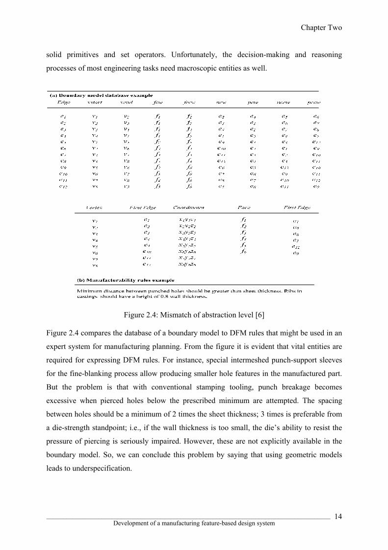
solid primitives and set operators. Unfortunately, the decision-making and reasoning
processes of most engineering tasks need macroscopic entities as well.
Figure 2.4: Mismatch of abstraction level [6]
Figure 2.4 compares the database of a boundary model to DFM rules that might be used in an
expert system for manufacturing planning. From the figure it is evident that vital entities are
required for expressing DFM rules. For instance, special intermeshed punch-support sleeves
for the fine-blanking process allow producing smaller hole features in the manufactured part.
But the problem is that with conventional stamping tooling, punch breakage becomes
excessive when pierced holes below the prescribed minimum are attempted. The spacing
between holes should be a minimum of 2 times the sheet thickness; 3 times is preferable from
a die-strength standpoint; i.e., if the wall thickness is too small, the die’s ability to resist the
pressure of piercing is seriously impaired. However, these are not explicitly available in the
boundary model. So, we can conclude this problem by saying that using geometric models
leads to underspecification.

Chapter Two
_______________________________________________________________________________________ Development of a manufacturing feature-based design system
15
A similar problem that occurs in macroscopic data is that geometric models cannot create the
difference between the geometry which is there to assure interface constrains, or to satisfy
functional needs, or for other reasons, such as strength, conductivity, stiffness, and
manufacturability. To capture this type of information, a design rationale representation is
required, which is absent in geometric modelling and fails to capture the design intent of the
designer. That’s why a geometric modeller fails to provide much support for editing
geometry. Typically, it means modifying, step-by-step, all affected parts of the model.
Consider the part shown in Figure 2.5 where for some reason it is needed to reduce the hole
diameter A to A1. Then the designer must re-create all attached geometric elements. In- order
to improve the problem solving, the designer is required to capture and maintain relationships
between the high-level constituents of the part, such as the hole and the elements attached to
it. A model could be specified based on geometric constrains of various high level entities
instead of microscopic entities with dimensional rigidity. This permits the system to create all
the detailed elements on the basis of a single high level instruction, such as “change hole
diameter”.
Figure 2.5: Rigid definition
A partial solution to these problems is Parametric and variational geometric modelling
techniques where in order to record the above design, the designer must map the high-level
specification of the desired behaviour of the model in low level constrains. This is not a
convenient way to describe the model and leads to poor understanding and maintains
difficulties.
Generally, geometry is recorded by geometric models at a single level of abstraction in terms
of precisely dimensioned geometric entities. On the other hand, when a part is designed by
using ordinary geometric modelling methods, the exact geometry of the part must be known
before the design and defined using exact co-ordinates, orientations, geometric locations and
Chapter Two
_______________________________________________________________________________________ Development of a manufacturing feature-based design system
16
so on. That's why geometric models are not suitable for design and can only be used after the
design is completed-for documentation.
If a design is created by using geometric modelling methods, even if for only some geometric
aspects of a product, a complete and proper geometric model that represent them must be
created. The result to be anticipated is overspecification: the designer is constrained to spell
out a “complete” representation of the product even if there is yet no need to do so. In the
later phases, this introduces problems as a result of interpreting the design and can lead to
working under constraints that were not anticipated. Some of these problems can be avoided
through a multilevel structure. They can only be noted as missing or provisional, when details
are handled as low-level characteristics of high-level entities.
Model creation in terms of low-level entities is inefficient, does not support the attractiveness
of the reusing of existing tested and trusted engineering solutions in the design phase. Where
an existing basic design is modified, most of the engineering undertakings can be
characterised as variants of the previous tasks. Indeed, reuse of existing structures is a key
prerequisite for a cost-effective result and diminished design lead time. If the adaptation of an
existing model were to be done by manipulating large quantities of low-level entities, many
designers decide on creating a new model from scratch.
All geometric modelling problems described in the previous section explain the same thing:
some macroscopic entities should be available in explicit form in the model. So,
researchers/developers develop new methods in the design sector which is called feature-
based design. In feature based design systems, the high-level modelling entities can provide
the essential element required by applications to store and retrieve information which can also
be used to relate geometric and other constraints with the model in terms of high-level
characteristics of the part modelled, and to organise constraint propagation after a design
change. The preliminary design can be combined quickly from the high-level entities and
their relations. More generally, the high-level entities can provide a platform for joining the
design rationale with the model, hence supporting reuse of information.

Chapter Two
_______________________________________________________________________________________ Development of a manufacturing feature-based design system
17
Feature modelling
A feature is what characterised the engineering meaning or significance of the geometry of a
part or assembly. They are very important and distinct entities in one or more engineering
viewpoints. On this basis, we can characterize a “feature” as follows [19]:
• “A feature is a physical constituent of a part.”
• “A feature is mappable to a generic shape.”
• “A feature has engineering significance.”
• “A feature has predictable properties.”
A feature model is a data structure. It represents a part mainly in terms of its constituent
features. Each feature in the feature model is a recognisable entity that has some explicit
representation. The form of a feature may be expressed in terms of dimension parameters and
list of geometric and topological entities and relations, or interims of architectural steps
needed to produce the geometry corresponding to the feature. The importance of engineering
may involve formalising the function the feature serves, or how it can be produced, or what
action must be taken when performing engineering analysis or evaluation, or how the feature
“behaves” in various situations.
A major function of features is to create associativity between entities in a product definition.
This association of entities makes it possible to summarise or enclose design or
manufacturing constraints and to do geometric reasoning required in various applications.
Thus the shape, behaviour, and engineering importance of a feature need to be encoded in its
demonstration.
The following complete list of feature properties is a union of information supported by
various modellers which signify the range of information that are possibly included in a
feature model [6]:
1. Dimension parameters (independent parameters)
2. Generic shape (topology and/or geometry)
3. Constrained parameters and constraint relations
4. Location parameters
5. Default values for parameters
6. Location/attachment method
7. Orientation method
8. Orientation parameters

Chapter Two
_______________________________________________________________________________________ Development of a manufacturing feature-based design system
18
9. Constraints relating to dimensions, location, and orientation,
possibly of several neighbouring features
10. Tolerances
11. Recognition algorithm
12. Constriction procedure for geometric models
13. Parameters computed on the basis of other features
14. Inheritance rules or procedures
15. Validation rules or procedures
16. Non-geometric attributes (part number, function, etc.)
A model may contain many instances of essentially the same kind of feature. For example, a
part may have many holes. As a result, feature properties can be divided into two sets: generic
and specific. All holes, for example, have certain generic properties regardless of their size
and specific location and they are only required to be formalised and archived once for each
family of similar features, such as holes. Specific hole instances can then simply refer to the
generic properties such as a characteristics topology expressed in terms of entry, exit, and
hole faces and their connectivity. It has a generic geometry: the entry, exit, and hole face is
cylindrical and generally specify in terms of high-level generic dimensions such as diameter
and depth.
Manufacturing features
Features can be described from different viewpoints like design, analysis, assembly, function,
etc. But from a manufacturing point of view, features must be explained in a form that
supports the planning and execution of various types of manufacturing processes like turning,
casting, milling, forging, etc on the modelled product.
One can say [6] that “a manufacturing feature is a collection of associated geometric
elements which as a whole corresponds to an exact manufacturing method or processes or
can be used to reason on the suitable manufacturing method or processes for producing the
geometry”. Manufacturing features like holes, slots, round edges, chamfered edges, pockets,
keyways etc are widely used in different types of manufacturing operations like forging,
casting, machining etc. In this section generation of manufacturing feature and different
benefits of using manufacturing features are explained.

Chapter Two
_______________________________________________________________________________________ Development of a manufacturing feature-based design system
19
Generation of manufacturing features
Manufacturing features like holes, ribs, slots, pockets etc. are more useful in terms of product
representations for manufacturing process planning and related tasks such as NC code
generation and fixturing analysis. Unfortunately, before these advantages can be achieved,
production representations in terms of manufacturing features must be generated fist.
Different ways of generating product models consisting of manufacturing features can be
identified. They are described briefly in the following subsections.
Interactive feature identification
By using this system, manufacturing features are identified interactively by picking geometric
elements of a geometric model when it is displayed on the computer screen during the design
stage. Due to the present relatively immature state of the other approaches, this system is still
used by many manufacturing applications.
Design by manufacturing features
The design by manufacturing feature approach is perhaps the most common choice in the
existing prototype systems. The First-Cut [20] system was implemented for concurrent part
and process planning. The system assumes that the designer creates the part model directly in
terms of its manufacturing features. In that system there is no need of conversion, mapping, or
extraction of manufacturing features.
The problem of this system is that it forces the designer to think in terms of manufacturing
operations during the design stage, which often is not natural for him or her. One of the most
important disadvantages of manufacturing features is that it is the idealisation for certain
manufacturing processes and requires vast knowledge of the underlying manufacturing
processes which is not good for designers. It forces the designer to assume the role of a
process planner.
Another design with manufacturing features approach was developed in 1989 which is called
the HutCAPP system [21], a facility for changing the feature specification of the part by
means of feature relaxation is provided. Essentially the system treated functionally similar
features as interchangeable. The system also used the possibility of modifying the given
features to optimise the manufacture of the part and eliminated to some extent the problem of
inexpert part formulation in terms of manufacturing features. The main problem of the system
was that it had no capability of judging whether a change in a feature or change in a feature
shape was functionally acceptable, a human user was needed to accept the proposed changes.

Chapter Two
_______________________________________________________________________________________ Development of a manufacturing feature-based design system
20
One of the problems from the viewpoint of the designer to design a product with
manufacturing approach is that only negative features are available. Due to this problem, the
design of a product with manufacturing approach is also called destructive solid geometry [6]
which is one way to represent a system of parts in terms of a CGS tree with only subtraction
operators. For creating pins, stiffeners and ribs most of designers prefer protrusion features
which are also available in this approach but unfortunately positive protrusion features have
no direct counterparts in machining operations. So they must be mapped to equivalent
material removal features [6].
Design to manufacturing feature mapping
A product model can be built by using design features in the CAD system where designers
should be given the freedom to design in terms of features most convenient for their use.
These design features could be mapped, recognised to manufacturing features interactively or
automatically.
Manufacturing feature recognition
A diametrically opposite approach to design with manufacturing features is to rely completely
on feature recognition where a little information from the design stage can be transferred to
manufacturing planning. The main disadvantage of this approach is that during transferring
information from the design stage to manufacturing planning dimensioning and tolerances are
totally lost. The benefit, however, is that a complete separation of concern between design
and manufacturing is achieved [6].
Different benefits using manufacturing features
In Group technology coding
In Group Technology (GT) systems, parts are classified into part families where each
family carries common characteristics of the parts and are identified by a multiple digit
alphanumeric code that signifies those characteristics of the family that influence the
application for which the GT scheme was developed. A GT code is also called an abstraction
of part specification where the detailed part data is replaced by a code. So we can say that the
code represents only a few high-level aspects of the part.

Chapter Two
_______________________________________________________________________________________ Development of a manufacturing feature-based design system
21
The application of GT for manufacturing-related activates are variant process planning,
design retrieval, and scheduling for cellular manufacturing etc. GT can have considerable
effects on cost savings (by eliminating design and process plan duplication, automating part
data retrieval, reducing the cost of introducing new parts and reducing the number of
changeovers in tooling and fixturing by scheduling similar parts together etc) [22] . These
characteristics have made GT code generation an important and popular manufacturing-
related application of features.
The motivation for development of GT schemes was for specific applications such as for
design retrieval or manufacturing planning. It is the applications that dictate the level of
information that must be encapsulated in the GT code and also differ in the range of parts that
are coded. It is necessary for an organisation to pick or develop a GT scheme, customise it,
and then classify all existing parts on the basis of the selected scheme before GT
implementation. If any new part is introduced it must be classified as well. GT coding is
basically a case analysis of possible part shapes where by using the GT scheme rules, part
classification is done (comparing part characteristics).
An example of part coding by using the Opitz coding system [23] is shown in Figure 2.6
where the roughest level of the analysis determines the first digit of the code on the basis of
the general shapes of the part like rotational, prismatic, or sheet-like. Digits indicate the
following characteristics of the part like its overall size, ratio of its main dimensions, and the
presence or lack of certain important characteristics. In the case of Figure 2.6 the code digits
are formed as follows:
Digit Meaning Code
1 Rotational part. L/D ratio>0.5
1
2 Step to one end 1
3 Internal bore without shape element
1
No external plane surface
4 0
Gear teeth5 6

Chapter Two
_______________________________________________________________________________________ Development of a manufacturing feature-based design system
22
Figure 2.6: Sample part of GT coding [24]
Consider that the code of the sample part is “11106”. This code can be used to access
manufacturing information of the part such as a rough process plan; observe, for instance, that
all parts sharing this code are likely to have the same fixturing characteristics.
A decision tree is used to represent GT schemes. So we can say that GT code is partly or fully
hierarchical. Computer programmes have been developed (e.g., DCLASS [25] ) to transverse
the decision three, prompt users to answer questions interactively, and to keep track of user
responses. Users required a paper engineering drawing of the part to use this programme.
This method has two disadvantages:
♦ In this system a part can be classified in different ways. That why the same
part is classified differently by different people. For Example, the question “is
the part rotational?” is rather subjective and can be interpreted in many
different ways.
♦ The process is not automated and it requires human intervention.
Features support automatic GT code. The above problem can be solved on the basis of
feature-based modelling. So we can say that GT coding is a historically important application
of feature technology. Probably the Kyprianou GT code [26] is the earliest method that uses
features where the recognition of features is based on classification of edges and faces and on
building a face-set data structure. A shape grammar was also devised for finding features by
pattern matching. He created a Meta-language for describing GT classification schemes. In
his system an interface program was automatically generated to interrogate the face set data
structure to determine the part code. The method was applied to an industrial classification
scheme for rotational parts only [27].

Chapter Two
_______________________________________________________________________________________ Development of a manufacturing feature-based design system
23
On the basis of a feature recogniser programme, Henderson [28] developed a GT coding
system. His system produced a list of primitive features from boundary representation models.
He used codes in the PROLOG language to classify rotational parts according to DCLASS
schemes. His coding programme first determines the axis sets where they are classified as
“main,” “external” and “internal.” Coding was done in two phases.
On the basis of a feature mapping approach, Shah and Bhatnagar [29] developed a GT code.
In their system by using a generic feature mapping shell a feature model was first converted to
an intermediate form. That intermediate form is used for actual GT classification. In the
intermediate form, features are mapped to a six-digit taxonomy code. This six-digit taxonomy
code conveys the essential characteristics of the feature from GT coding viewpoint (Figure
2.7).
Figure 2.7: Feature taxonomy code for GT [6]
For example, the figure shows that a form feature Straight-Cylinder has a taxonomy code that
conveys the essential characteristics of the feature from GT coding viewpoint. For instance, a
form feature Straight-Cylinder contains a taxonomy code of 111 101. The code represents that
it is a rotational, primary, and external feature. The generic class to which the Straight-
Cylinder belongs is 10, and it is the first member of this class.
To determine the overall shape (rotational and non-rotational) of the part, one needs to follow
answering the following questions:
1. “.Are the primary features (i.e. those that influence the external shape envelope
of a part) axisymmetric individually?”
2. “If the part has non-axisymmetric features, how does the size of the biggest cross-
sectional axisymmetric feature compare with the non-symmetric features
present?”
3. “What are the relative orientations of the centroidal axes of the major primary
features with respect to each other (collinear, parallel, or intersecting)?”

Chapter Two
_______________________________________________________________________________________ Development of a manufacturing feature-based design system
24
This simple information is available in a feature-based modelling system. Based on a feature
recognition algorithm, a powerful GT code [30] method was developed. It is specialised for
group technology classification. Similarly to the taxonomy coding idea above, the algorithm
concentrates on locating such properties of features that are deemed essential for GT coding.
Srikantappa and Crawford [31] developed another GT code system which was on the basis of
an intermediate-level part representation using the geometric relationships.
In process planning
In Process planning of machining operations, manufacturing features at present have found
their most widespread use. Process planning tasks must be completed before a designed
product can be manufactured. The benefits of manufacturing features in process planning are
that they enable:
• Selection of manufacturing technologies such as machining, casting, injection
moulding, welding, etc at design stage for producing a part.
• Determination of the sequence in which these technologies are to be used. • Selection of actual processes such as milling, drilling, facing, etc for creating the
individual features of the product.
• Determination of the various types of resources required for the realisation of
the processes (human labour, machines, tools, fixtures and jigs, cutting fluid
etc).
• Selection of the process parameters (for example for machining: feed and speed
rates).
• Detailed task planning of the processes.
Process planning is also historically important for the development of feature-based systems.
It has influenced the overall progress of features and their related concepts. So, process
planning is an attractive benchmark for applications of features. Process planning is complex
and several algorithms for process planning are discussed in many more general CAD/CAM
books.
In 1993 Remold et al [32] explain process planning in the wider context of production
engineering and conclude that it is “the sequence of technical planning and decision making
steps related to a product’s manufacturing”. Process planning includes the following task:
• The determination of the manufacturing technologies to be used.

Chapter Two
_______________________________________________________________________________________ Development of a manufacturing feature-based design system
25
• Breakdown of the product into a sequence of individual
manufacturing and assembly tasks.
• Design and selection of tools and fixtures for each manufacturing
step.
• Derivation of control programmes for driving various types of
manufacturing machinery, such as CNC machines, robots and
automatic transportation and storage equipment.
Due to the fact that all these planning tasks consume more human efforts and time than the
actual design process itself, it is required to fully realise the benefits of computer-aided design
and manufacturing. The objective of CAPP is to automate various aspects of process
planning. CAPP systems are becoming increasingly important for industrial companies. The
ultimate goal of CAPP is to reduce the cost of process planning to an acceptable level for
medium or short-batch production while still achieving adequate plan quality in terms of
throughput, lead time, product quality and cost-effective utilisation of various manufacturing
resources.
It is necessary to include inspection planning and assembly planning for a complete process
planning system for discrete manufacturing. The result of process planning for discrete
manufacturing may be a rough process plan. It only lists the major manufacturing steps
required. Rough plans are useful to determine the overall technological requirements of a
product. It could be used to access the productivity of the rough cost of a product. Skilled
operators have lot of experience and they are capable to execute such plans on the basis of
technical drawings. Alternatively, more detailed plans may be preferred, such as the plan
shown in Figure 2.8.

Chapter Two
_______________________________________________________________________________________ Development of a manufacturing feature-based design system
26
Figure 2.8: A process plan
Detailed plans are also required to control automatic production systems like FMC and FMS.
In a highly automated manufacturing environment, process plans generated by CAPP systems
should form input to various shop-floor systems controlling the actual physical manufacture.
Those are:
production scheduling
material management
FMS control etc.
So a process planning system should be capable of generating the attribute information as
required by all these applications. According to Paul and Parker [33, 34], “process plan
representation is an important item for future standardisation under the STEP umbrella.”
The CAPP system developed for CAM-I, Inc. [35] is a typical example of early variant
systems. The architecture of the system is shown in Figure 2.9.
Figure 2.9: Architecture of the CAPP system

Chapter Two
_______________________________________________________________________________________ Development of a manufacturing feature-based design system
27
Its operation takes the following outline which is shared by most variant planning systems:
The parts that can be handled are limited to the original part families known to the
system, reducing the overall flexibility of the system.
Experienced human planners are needed to edit the plans manually, increasing the
lead time from production order to finished product.
Detailed plans required for controlling highly automated production equipment
cannot be easily generated because the “opcodes” correspond to relatively rough
level operations.
Existing plans cannot easily be updated as the manufacturing resources change.
Nowadays, different types of computer tools and techniques are developed in order to
overcome those problems. Armed with these weapons, developers and researchers of process
planning systems can also explore a range of novel approaches to process planning. Many of
these novel viewpoints to CAPP can be inspected by means of a conceptual framework
consisting of a four-axis “Coordinate system” shown in Figure 2.10.
Figure 2.10: A four-dimensional framework for process planning systems
Each of the four coordinate axes has a strong influence on the architecture of a process
planning system. The meaning of the various axes is as follows:

Chapter Two
_______________________________________________________________________________________ Development of a manufacturing feature-based design system
28
Planning may be performed on a high level, where the focus is on overall election
of production technology (macro level), or on low levels increasingly concentred
on particular processes (micro level) [36].
The planning time scale can range from the short-term planning of a certain
production run to long-term development of the whole production facility.
The plan may be generated by varying existing plans (variant planning) or from
scratch on the basis of available generic process knowledge (generative planning).
The generated plan can be treated as fixed or variable by the shop-floor
scheduling system.
The effects of the various axes on process planning methodology and the significance of
particular points along the axes are summarised in Table 2.2.
Table 2.2: Architectural dimensions of process planning [6]
The various approaches are not mutually exclusive, either. Process planning is performed
early in the life cycle of a product. It should concern itself with the overall production process

Chapter Two
_______________________________________________________________________________________ Development of a manufacturing feature-based design system
29
alternatives. And therefore it is preferably carried out at a relatively high level by a generative
approach. Later, when the product has entered the production stage, processes should not be
altered unnecessarily. A variant approach may be attractive to deal with predefined, limited
variations in the product.
Available geometric information in Process planning, like in most other computer-aided
engineering applications, is insufficient. Process planning requires additional data on the
shapes, such as knowledge of the characteristic shapes producible by the various processes,
and their dimensions, locations, tolerances, and surface finish and also requires more
specialised factors such as tool accessibility, fixturing possibilities, and inspectability.
Manufacturing features and their related process models are an attractive approach to realise
such product definitions. Indeed, features have several advantages in process planning
systems:
♦ A feature is a convenient input data representation for the planning system.
♦ Process knowledge needed for planning can be associated with feature classes.
♦ Geometric reasoning for various tasks of process plans is facilitated by
features.
♦ Downstream operations such as NC code generation can be supported.
In assembly planning
Generally different parts are assembled together to produce a product and a key stage in their
manufacture is the physical assembly of the parts. Assembly planning can be roughly divided
into the following three phases:
1. The 1st phase is the selection of the assembly method where the designer
recognises and optimises the most suitable assembly method for the product.
2. In the 2nd phase, a sequence of assembly operations is defined which can be
implemented with the chosen overall assembly method.
3. Assembly operations planning emphasis is on the details of the individual
assembly steps (for example, access directions, mating movements and
application of fasteners etc).
Nowadays, the assembly process problems like poor efficiency, poor quality, or high cost etc.
are handled at the conceptual design stage. This has very good impact in the DFA approach
because the most economical production process is already selected during the design stage,
and the design is adapted to the characteristic of the chosen method.

Chapter Two
_______________________________________________________________________________________ Development of a manufacturing feature-based design system
30
A well-known approach to DFA has been developed and commercialised as a computerised
analysis procedure by Boothroyd [37]. This is very helpful for assembly plans because it leads
to diminished assembly costs and also reduced materials costs in handling, storing, and so on.
To determine whether a part should be included in a design, the method examines it against
the following three criteria:
♦ The part moves with respect to other already assembled parts (in contact with
this part) during the operation of the product.
♦ The part material must be different than the material of the other assembled
parts in contact with the current part.
♦ The part must be separate from all other parts, otherwise assembly and
disassembly of some other parts will be impossible.
If all of the above criteria do not apply, the part is considered to be non-essential, and a
candidate for merging with other parts. Its existence must be specifically justified by the
designers at product design stage.
Features can be used for data retrieval and geometric reasoning tasks. Those tasks are
required for the design-for-assembly approach. Some of the DFA guidelines for automatic
assembly include the following items:
1. Simplify the product by replacing a sub-assembly of the product by a more
complex single component.
2. Replace some of the assembly operations by fewer alternative procedures such as
adhesion or welding.
3. Reduce the number of different components without affecting the functionality of
the design.
4. Introduce guides and tapers to improve the easy of assembly.
Most of these analysis rules could be explained in terms of the assembly features of the
product in the design stage. Inspection planning is also related to process planning where
once characteristics to be inspected have been selected, the inspection processes themselves
must be organised in efficient sequences. This involves, say, the determination of accessible
details, and actual path planning of the motion of the measuring device to the region of space
being measured. The last problem is analogous to path planning in robotics. Quite obviously,
features can play a big role in all these tasks.

Chapter Two
_______________________________________________________________________________________ Development of a manufacturing feature-based design system
31
For DFM analysis
In assortment of the manufacturing environment, the general idea of DFM has been conceived
significantly because of its wide range of published references and case studies. DFM is
incorporated with the design process which connects the breach between manufacturing and
design, hence finally affecting productivity, cost and performance of a product. DFM is very
useful to establish a model that systematically addresses manufacturing, assembly, testing,
and performance concerns concurrent with the development of the design (Figure 2.11).
Figure 2.11: DFM structure [38]
Nowaday’s reduction of cost and complexity of a manufacturing product is necessary for
competitiveness and agility of a company. These essential characteristics are determined at
product design stage by the product designer. So early analysis and detection of possible
manufacturing problems is needed in order to avoid costly processes for manufacturing goods
and tooling changes and delayed product introduction to market. One of the methods to solve
this problem is to employ integrated product design teams that include manufacturing experts

Chapter Two
_______________________________________________________________________________________ Development of a manufacturing feature-based design system
32
as well. The aim of the integrated product design team is to generate error-free and
production-friendly designs at the first iteration. This method carries a relatively high cost and
not attractive for small batch. So it is clear that DFM discipline should be supported by an
organised company. A team approach is essential for best manufacturing which admits
suppliers and customers. For productivity, design projects should be prepared as well. This
can be carried out by organising integrated and multi-disciplinary teams that helps to include
lot knowledge from key stakeholders. A team of seven to ten members can analyse and
disseminate effectively the relevant information and render problem solving resources while
still allowing for unplanned changes [39]. The most essential part is to discover and carry off
risk. Product goals can be achieved by identifying the risk and it can be measured by the
probability and consequences of a failure.
At the primary phases of the design cycle, there is some risk of DFM because of having
negative impact. Depending on the methods and materials used at each process step, the effect
of design decisions changes. The cost and difficulty of making the product relates to design
for manufacture or 'manufacturability'. It is very important for the designers to know some
methods so that they can be sure whether the new or redesigned product will meet its
manufacturability and other objectives. The properties of the product and its
manufacturability are affected by all design variations.
DFM checking at design stage is required so that the designer or design team can ensure that
the designed product meets all product-life cycle requirements and also to compare the
designed object with other alternatives where it is possible to select the most effective design.
At the primary level (concept stage), the design team should accomplish the evaluation.
Whenever the proposed approach proves effectiveness and verified, then the time-consuming,
expensive development and detailed work takes place. Some numerical rating, index, or cost
should be utilised so that comparison can be made between alternative designs.
The above considerations form the motivation for various DFM rules which can be evaluated
at early stages of the product development cycle. The major problems in DFM analysis of a
product is that the designer is not familiar with manufacturing information for judging his or
her design. This leads one to consider a feature-based approach, where the designed object is
represented by means of its edge base that represents DFM analysis procedures. According to
the product life cycle management point of view it is the best way to describe the product by
using manufacturing features. Most of the DFM rules depend on manufacturing technology

Chapter Two
_______________________________________________________________________________________ Development of a manufacturing feature-based design system
33
used to produce the object. For example, DFM rules for a forging process are completely
different from those of a machining process.
DFM feedback can be performed simply on the basis of the knowledge of the manufacturing
technologies. More detailed feedback needs knowledge of machines tools, fixtures, cutting
conditions and cutting tools etc. Rough quantitative cost models are required for a rough
process plan where the best sequence of processes are optimised and applied. For example, a
hole feature can be produced by different manufacturing processes but the question is which
process is more reliable, less costly and more accurate. Knowledge of detailed manufacturing
analysis and the individual machining processes is required for every part/product. The
desired level of feedback must of course be balanced to the level of commitment that the
designer has to the detail of the product. It is not suitable to create detailed analysis
information on the basis of rough ideas. So, it is possible to control the level of detail of the
DFM analysis. To gain further insight into the issues of feature-based DFM analysis, we need
to consider the following questions:
♦ What types of manufacturing processes will be used to manufacture a designed
object?
♦ Are all required resources like materials, machines, cutting tools, etc available?
♦ Is it practically possible to implement all required manufacturing processes?
♦ Are the feature parameters in conformance with good practice?
For example, if we are going to manufacture a slot feature the following questions need to be
considered during design:
• Which manufacturing processes are feasible for slots?
• Are any cutters available in the market place for slots?
• Is a slot manufacturing process economical?
• Does the slot violate design functionality and DFM rules?
The DFM rules of a slot are determined against a known selection of tools. These rules are
applicable only for slot machining required for the part. It is most difficult for a designer to
select and optimise the manufacturing processes for parts because one of the factors to
optimise a process is that it depends on the physical presence of tools in the factory for the
process.
We may observe that to describe the rules, a fairly detailed interface to feature information is
needed for a product; scheduling step is needed before the manufacturing operations

Chapter Two
_______________________________________________________________________________________ Development of a manufacturing feature-based design system
34
performed. In scheduling the various processes are allocated to certain machines in a certain
sequence to manufacture a product. Scheduling is closely linked with process planning.
Sometimes it is very difficult to separate the two tasks in process planning. Consider one part
where several routing in the factory are possible. In this case the process planner should
postpone the choice of the routing to the scheduler. The routing can make the optimal choice
on the basis of machine capability information. In the case of most complex situation a new
rush production order may change the schedules of less critical orders. It requires
rescheduling and it can recover from production hardware problems. Features can contribute
to solve these and similar problems. It can give the process planner or scheduler extra degrees
of freedom compared to the more conventional process plans or routing charts. A
manufacturing feature may be associated with several alternative process sequences for the
process planner/scheduler. Where for any reason one of them becomes unavailable (for
example due to a dynamic bottleneck or hardware failure) the planner/scheduler may choose
another feasible process [6].
According to the discussion above it is clear that manufacturing features should be useful for
addressing a number of deeper issues in production engineering. Manufacturing facility is a
most important consideration during designing and maintaining the manufacturing processes.
Manufacturing product quality, cost, manufacturing capability depends on manufacturing
facility for a product firm. Their operational characteristics (range of part and features sizes
that can be manufactured and achievable tolerances, set-ups, cycle and change times, etc.)
also affect the product.
2.3 HISTORICAL DEVELOPMENT OF FEATURE BASED SYSTEM
The need to reduce product development time and cost initiated the development of feature-
based design methods in design and manufacturing. In the mid 1970s, research on techniques
for rendering data on manufacturing features for NC programming was first introduced. From
1975 to 1980 several research works were done at the Cambridge University CAD Centre for
automatic feature recognition. In 1976, Grayer presented some methods for automatic NC
programming for milling [40]. Although his sectioning technique was useful for 2.5D milling,
it did not contain recognised features. The idea of feature recognition was first introduced by
Kyprianou in 1980 [26] which was topological entity classification. The idea was based on
geometry. A method based on volumes to be taken out by machining without discerning the

Chapter Two
_______________________________________________________________________________________ Development of a manufacturing feature-based design system
35
features was developed by Woo in 1980 [41] by using the convex hull decomposition
algorithm. Other substantial contribution in feature recognition was brought in by
Henderson’s rule-based recognition [42], and CAM-I’s volume decomposition algorithm [43],
and Chio and Barash’s syntactic recognition [44]. Then the feature recognition method was
divided into two groups: one is the boundary-based method and another is the volume-based
method. In 1985, Ansaldi, DeFloriani, and Falcidieno [45] proposed attributed face adjacency
graphs that were further developed by Joshi and Change [46]. At the same time Sakurai and
Gossard [47], Dong and Wozny [48] investigated the problems related to “entity growing” in
feature extraction. In 1987, Lee [49] investigated recognition from CGS models. Around
1984, John Deere Company produced an elaborate report on feature taxonomies and feature
parameters useful in manufacturing which was sponsored by the project of CAM-I. Pratt and
Wilson [50] suggested for the first time the concept of design by features in another CAM-I
project. Most of the university labs came into sight with prototype feature-based modelling
systems in the mid-1980s.
Those are:
♦ Miner and Gossard’s system at MIT [ 51]
♦ Dixon et al.’s system at University of Massachusetts [52]
♦ Cutkosky’s FIRST-CUT at Stanford University [53]
♦ Turner and Anderson’s QTC at Purdue [54]
♦ Mäntylä et al.’s HUTCAPP at Helsinki University of Technology [21]
After the 1980s various approaches and algorithms were proposed by many researchers. For
example:
1. Syntactic pattern recognition by P. C. Sreevalsan and J. J Shah [55].
2. Volume decomposition by Lin & Lin, Nagaraj & Gurumoorthy [56, 57].
3. Expert system and logic by Madurai & Lin, Munns, Lin &Wang [58, 59].
4. The CGS-based approach by Natekar et al. [60].
5. The graph-based approach [46].
6. The neural-network based approach by Chang &Chang, Devireddy & Ghose [61,
62].
Syntactic pattern recognition is a classical method for recognizing shapes from raster images
which is widely used for feature recognition on the basis of graphical and boundary models.
Figure 2.12 presents a simple instance of the technique where in the top part a collection of
eight primitives corresponding with line segments of changing orientations is introduced.

Chapter Two
_______________________________________________________________________________________ Development of a manufacturing feature-based design system
36
Flat-bottomed hole shape was recognised by a particular matching rule which is shown in the
bottom part of the figure.
Figure 2.12: Syntactic recognition of a 2D hole shape [6]
Jakubowski [63] and Staley et al. [64] use string of straight lines and curve segments to
recognise a 2D profile of holes based on “classical” pattern recognition techniques. The
syntactic pattern recognition idea was intelligent and could be applied in three dimensions
only on the basis of higher-dimensional primitives. In 1998 Choi [44] explains several
syntactic elements. Those elements were very useful for recognising holes. Figure 2.13 shows
syntactic elements for recognising holes. In the figure an element HSS (hole-starting surface)
is described as a planar surface with an internal circular list of edges, various subtypes of
element HES (Hole-element-surface) correspond with a cylindrical surface bound by two
circular edge lists, a conical surface bound by circles, or a circular planar area with a
concentric circular hole. Elements (Hole-bottom surface) are a planar circular, a cone, or
another planar surface similar to HSS. With these syntactic elements, the general concept of a
hole is easily described:

Chapter Two
_______________________________________________________________________________________ Development of a manufacturing feature-based design system
37
Figure 2.13: Syntactic elements for recognising holes
<hole> ::= HSS{HES}* HBS
<HES> ::= HES-1| HES-2| HES-3
<HBS> ::= HBS-1| HBS-2| HBS-3
Here {X}* stands for repetition of X1….n times, and “|” for “or”. Alternatively, the same
elements could be used to model more refined kinds of holes:
<straight hole> ::= HSS HES-1 HBS-1
<countersink> ::=HSS HES-2 HES-1 HBS-2
<step hole> ::= HSS HES-1{HES-3 HES-1}* HBS-2
For slots, pockets, steps etc. similar rules can be established. The major problem of this
system is that there is no DFM and DF rules checking and the suggested optimal
manufacturing processes are not explained.
Henderson [42] used a syntax-based approach in his system, rather than using the boundary
representation as it stands for the structure which is converted into PROLOG predicates. To
compare the parts with feature patterns, features can then be located by running through the
structure using predicate calculus.
The most critical issue is how to recognise intersecting features. In this algorithm an input
object is decomposed into a set of intermediate volumes and then it influences the volumes to
produce a feature. In the example in Figure 2.14, a solid rectangular work piece is considered
to be machined. The interpretation and mapping of the design features into a machining
feature is done using volume decomposition methods by identifying the removal volumes
from the initial work piece and attribute them to manufacturing features.

Chapter Two
_______________________________________________________________________________________ Development of a manufacturing feature-based design system
38
Figure 2.14: (a) Form feature model (b) Convex hull decomposition
The system lacks the ability of checking DFM and DF rules. Also, the system can only
recognise machining features.
In 1983 a research group from Allied Signal Aerospace [65] in Kansas City explored the cell
decomposition approach. In 1994 Sakuri and Chin [66] described the cell decomposition
method which aimed at generating all possible machinable features accompanying a given
part or stock. In Figure 2.15 it is assumed that the top left part is manufactured off a
rectangular block of material. The first step is a cross–shape delta volume with the extended
surfaces contained in it. In this case the volume is split with the “side” surface of the cells. In
the cell based decomposition approach, the differences of the proposed algorithms mostly lie
in the methods for combining cells into features. In the figure at the bottom of the part are
shown the various features that have been generated by combining the cells: these include an
open pocket, two long slots, and four smaller slots.

Chapter Two
_______________________________________________________________________________________ Development of a manufacturing feature-based design system
39
Figure 2.15: Feature recognition by cell decomposition
In this system, only manufacturing feature identification is incorporated. There is no DFM
and DF rule checking implemented.
In Rule-Based Algorithms, “features are formalised by templates, and are defined for both
general features (like holes) and specific features (e.g., flat bottomed, constant diameter hole)
that consist of pattern rule.” The hole begins with an entrance face. All subsequent faces of
the hole share a common axis. All faces of the hole are sequentially adjacent. The hole
terminates with a valid hole bottom [67]. General features (depression, protrusion, passage),
and classification of general features into specific feature (T-slot, round hole, rectangular
pocket, etc.) is recognised in this procedure, by creating and subtracting the volume
corresponding to each feature from the cavity and by repeating the procedure until there are
no residual entities.
The graph pattern matching approach was first formalised by Joshi and Chang [46]. A graph
pattern can easily be viewed as the boundary representation of a part, where faces are
considered as nodes of the graph and face-face relationships form the arcs of the graph. To
understand the graph notation, let us study the example of a slot given in Figure 2.16 (a).
Additional information may be incorporated into the graph, e.g. edge-convexity, face-
orientation, etc. The neighbourhoods relationships of the faces can be modelled by means of a
faces adjacency graph (FAG) in Figure 2.16 (a). Nodes of the graph represent the faces, and
arcs between the nodes correspond to the neighbourhood relationships between the faces. In
Figure 2.16 (a), (f7, f8, f9) will be matched with the slot template in Figure 2.16 (b).

Chapter Two
_______________________________________________________________________________________ Development of a manufacturing feature-based design system
40
Figure 2.16: Graph Pattern Matching
S. Prabhakar and M. R. Henderson [68] first introduced a new method which is known as
neural network based approach where they built the adjacency matrix for representing the
object. Then they inputted it to the network. For each one of the feature classes there is a
neural network. The neural network will decide whether or not an instance of the respective
feature exists in the object. The network used is claimed to be with five layers and is used
very quickly in terms of computational time. Hwang [69] used a perceptron neural network to
recognise the features. The face score is used to present the concavity or convexity of faces.
Őztürk [70] used genetic algorithms to reduce both the number of input parameters and
hidden layers of a multi layer perceptron to enhance the training performance of their neural
networks. In this way, the training and processing time of the neural network was reduced.
The method based on neural networks shows a promising ability to solve the feature
recognition, benefiting from the high degree of the robustness and strong learning ability of
the neural networks.
Most of the suggested methods for feature recognition were used for the internal
representation of features in the CAD system. On the other hand, there is little research which
uses the standard format of product data. A short review on standard format of product data is
presented bellow:
In 1986 John Dixon [71] from the University of Massachusetts worked on several feature-
based design systems with his students in the area of applying artificial intelligence (AI) to
mechanical engineering design. His two students Luby [72] and Vaghul [73] note in paper

Chapter Two
_______________________________________________________________________________________ Development of a manufacturing feature-based design system
41
that many successful electrical engineering (EE) design systems applying AI techniques exist,
but that very few AI systems have been successfully applied in the mechanical domain.
According to Dixon the fundamental differences between electrical design and mechanical
design is that mechanical design requires to contain the information of materials,
manufacturing and geometry. That's why it is very difficult to apply AI in mechanical design.
He also felt that features were a good approach for representing design knowledge in AI
systems and worked on different types of expert systems in the area of extrusions, injection
mouldings and casting in order to reduce capabilities and limitation of design systems. His
developed system is used for limited number of features.
In 1986 Keith Hummel [74] worked with process planning features and developed an expert
system called XCUT. In the XCUT system he used a feature-based model of the part to
develop the process plan for manufacturing and identified features manually from the CAD.
The advantage of that system is that when a feature is added in the part then process plan is
generated automatically by using a production rules system. For representing features, he used
symbolic and object oriented data structures because those data structures have capabilities to
represent objects and flexibility to be updated as new techniques and processes emerge. He
used the concept of inheritance where new types of objects can be created by combining other
subtype objects. His hierarchical structure is called “feature taxonomy”. In his hierarchical
structure most general structure is in the top and specific structures are in the bottom places.
This way, specific structures are inherited by the properties of the most general structures. In
this system, hierarchical manufacturing processes are not used and the system is unable to
create manufacturing rules.
In 1987 Tom Kramer [75] from Catholic University developed a design protocol called
VWS2. VWS2 is used in the automated Manufacturing Research Facility (AMRF) of the
National Bureau of standards. VWS2 is a feature -based design tool that can be used to design
parts for several part families from a set of features.VWS2 allows both graphical and textual
input of feature information and then produces several outputs like NC code which can be
downloaded to a machine tool to manufacture the part. The part design can be displayed on a
monitor, and simulation of the NC code is run to show the order and path that the cutter will
take to produce each feature, process plan etc. A process plan can be executed in the vertical
workstation to represent the features. Kramer used Franz Lisp language and a property list as
a data structure. A property list is a collection of a number of attribute-value pairs and each
attribute-value pair of a feature must be completely defined. The attribute-value pairs are

Chapter Two
_______________________________________________________________________________________ Development of a manufacturing feature-based design system
42
checked by using a number of verification rules. Kramer developed a set of manufacturing
features like grooves, holes, pockets, text and side contours for vertical milling machine. He
also developed sub features like chamfers, countersinks and threads which can be attached to
any of the primary features. The system does not include DFM and DF rules checking.
In 1986 Steven Luby [72] worked in conjunction with Dixon in the area of a “feature-based
design aid” to provide on-line suggestions during the design process. Luby’s system is used
only for casting processes which are concerned primarily with manufacturability
considerations like metal flow and feeding, and with minimising the stress generated during
cooling. Different types of casting features like slabs, corners, L-breakers, bosses, holes, and
ribs are used in the system and it also provides suggestions during design to make the casting
design easier to manufacture. In his system each feature is added to the part and evaluation of
the part is made to ensure geometric consistency. He used the Lisp language for
implementation. He has done this by implementing an “object hierarchy” ranging from most
general to most specific. The problem of this type of approach is that they only explain
casting processes. Other processes like metal machining are not considered in this approach.
In 1985 Vaghul [73] developed a system for Injection Moulding Part Design called IMPARD.
IMPARD is a design aid system where part manufacturability analysis is performed during
the design process.
In IMPARD, features are added, and designs are returned to the user. IMPARD is similar to
Casper. The only difference is manufacturing process consideration. In IMPARD a true solid
modeller is used to represent the moulding. IMPARD has the capacity to generate the actual
geometric model. The major question of the IMPARD system is how it will make decisions
for complex parts. Vaghul also agreed that as the number of features becomes larger, design
and evaluating in the IMPARD system will be harder.
In 1984 Mark Henderson [42] worked with features and tried to implement a production rules
approach for features in Arizona State University. In his developed system a production rule
system is used and examined to determine features. Rules are used as a condition for features
in a part. If all conditions are met, then an appropriate action is taken. Another interesting
approach used by Henderson for feature extraction is called “cavity volumes”. When a feature
is found, it is subtracted from the cavity volumes using solid modelling techniques, which
results in new, smaller cavity volumes. This process is repeated until all cavity volumes are
completely eliminated. The features which have been found are formed into a feature tree, and

Chapter Two
_______________________________________________________________________________________ Development of a manufacturing feature-based design system
43
the part is redefined in terms of features. Henderson limited his search for features to swept
features, which he defines as "2 1/2 D volumes created by sweeping a tool profile through
space."
He limited his search because these are the most common types for example holes, slots, and
pockets found in machining. Rules are useful for identifying the "general" features, (e.g.,
holes, slots, or pockets), but other techniques may be more suitable for identifying the
"specific" features, (e.g. straight slots versus curved slots). In his system he considered a
logic language called Prolog, which would be suitable for a production rule system but is not
implemented.
The Extrusion Advisor system was developed by Hirschetickbb [76] in 1996 at Massachusetts
Institute of Technology. The system was designed for aluminium extrusions only. The system
examines a geometric model of a part to be manufactured.
In the system “characteristic patterns” are used to find an instance of a feature. The geometric
definition of the part is searched for one or more characteristic patterns. Several of these
patterns (for example parallel lines, triangles, etc) are combined to form a characteristic
pattern set or feature. He used a production rule system to examine the part geometry for
characteristic patterns to recognise walls, hollows, edges and a number of more specific kinds
of the last three. The output of the Extrusion Advisor is a list of features which will present
manufacturing difficulties and explain why they would cause a problem and what will be the
possible solution. He also concludes that feature-based design and feature extraction are both
necessary to explain process capabilities. He notes that “Feature descriptor modelling will
provide an excellent interface for solid modelling. The resulting feature information will
eliminate the need for some feature extraction. But for many powerful applications, it will be
necessary to use a feature extraction technique. This is because features will be needed which
are of a higher level than those used to create the part."
On the basis of graph theory Zhao et al [77] built up a methodology and algorithm for
recognising machined features. They used a wire-frame model. In the wire-frame model they
used 2D techniques for generating closed boundaries of the machined part. Their method was
useful only for symmetrical work-pieces like conical parts where all vertices have degree of
three. Much more computation is required to eliminate vertices with degree grater than three.
It is also difficult to determine each edge of the facets. The limitations of their system were

Chapter Two
_______________________________________________________________________________________ Development of a manufacturing feature-based design system
44
that they did not use 3D solid modelling and there were no standard formats for representing
the designed part.
In 1993, Kang and Nnaji [78] developed a feature representation and classification model for
an automatic process planning system based on B-rep where the part feature attributes are
defined by the geometry of the work-piece and the function that they serve. In their system,
they described and classified only mechanical assemblies and sheet metal fabrication.
The Super relation graph (SRG) method was proposed by Kao and Kumara [79] in 1993 for
recognising slots, holes and pockets. The system was very complex and the method used
pattern recognition, artificial neural networks and computational geometry techniques for
extracting shape features but not in standard formats.
In 1998 Sheu [80] developed a computer integrated manufacturing system for rotational parts
where parametric design and feature-based solid model were used to specify manufacturing
information. In the system the boundary of a solid model could be directly transferred into
line and arc profiles with the DXF format. In the system the part model was created by using
the cylinder, cone, convex arc, concave arc as primitives and the wire-frame part model can
be transfer into CSG. The main disadvantage of this approach is that only a limited number of
features could be recognised by this system.
In 1999 Rozenfeld and Kerry [81] developed a system for automated process planning for
parametric parts. In this system, at the same time they meet the planning requirement of any
other parts and produce a real industrial environment. In their CAPP system a part was
represented by a parametric module. For example, a hole is presented with its diameter,
length, tolerance and roughness. The major problem of that system is that there is no clear
concept of feature types that will be developed for a CAPP system.
In 1999 Aslan et al. [82] developed a feature extraction module. Their module is used only for
rotational parts that are to be machined on turning centres. In this module they used DFX file
format to extract 2D features. This feature extraction is basically a part of an expert system
which is called ASALUS. ASALUS was designed to manage the life cycle of rotational parts
from designs. One of the disadvantages of this system is that prismatic and intersecting
features were not involved in this module.

Chapter Two
_______________________________________________________________________________________ Development of a manufacturing feature-based design system
45
In 2001 Venkataraman et al. [83] developed a feature recognition system for User Defined
Features (UDF) by using a graph-based approach. An attributed facing adjacency graph
(consisting of topological and geometric attributes) was used to represent UDFs and involved
a feature recognition stage to find similar sub-graphs in the part graphs. In order to recognise
a wide range of features like pockets, free-form slots etc (which contain variable number of
side faces) this technique is used. But a major problem with this approach is the lack of ability
to recognise the intersecting feature because when an intersecting feature occur, the full
patterns of the feature do not appear in the graph representation and pattern matching fails.
The system does not use standard format data to develop the feature recognition methodology.
In 2003 Choi and Ko [84] present a C-Space based CAPP algorithm. The algorithm was for
free-form die-cavity machining and based on a trimmed surface CAD model. The paper
explained that Prismatic and volume type machining features like Wall Floor, Fillet, Step,
Slot, Cavity and Shoulder volume which are extracted using a rule-based approach. The
limitation of this type of implementation was that only a few machining features were
considered.
In 2004 Sundararajan and Wright [85] explained an algorithm. Their algorithm was used for
extracting free-form machining features from a B-rep Surface model for a 3-axis CNC
machine. In the system, Recursive Descent Algorithm is employed to extract free-form
pockets. For CAPP and CNC code generation essentially volumetric machining regions are
used. The main problem of this algorithm is that it is not possible to distinguish between
genuine free-from features and common non-2.5D features. The best examples are rounds and
fillets.
Zhang et all [86] presented a method that was based on a rules-based technique where they
tried to recognise free-form machining features (for example Cone, Cavity, Hole, Island and
Open cavity) from a machined part CAD model in IGES file format. The restriction of this
algorithm is that it requires optimising the orientation of the part before beginning the
geometric feature recognition.
In 2005 Sridharan and Shah [87] described a rule-based algorithm . Their algorithm was
used for recognising both simple and complex features. The system was restricted to features
that required free-form faces that may require 4- or 5-axis machining. Features were classified
into three major classes like cut-on, cut-around and cut-through. All classes were also

Chapter Two
_______________________________________________________________________________________ Development of a manufacturing feature-based design system
46
classified into 12 sub-classes based on the NC milling and tool path generation
considerations. The algorithm was limited in terms of the rules implemented since viz. free-
form boundaries are not captured as it is assumed that the regions are separated by sharp
curvature edges. It is also assumed that the regions are separated by sharp curvature edges.
The disadvantage of this algorithm was that only common shared faces are identified by the
recognition system.
Lefebvre and Louwers’ [88] approach was based on a segmentation method. In order to
recognise machining features they segmented machining regions of the STL model of a free-
form machined part. The algorithm is based on sharp-edge detection and work-piece set-up
for recognition in an STL model. The algorithm is very application-specific.
Jushi and Dutta [89] used a rules-based method to recognise and simplify features from free-
form surface models of automobile sheet metal panels. They used B-Rep format. Very limited
features like holes, fillets, and bosses were used to recognise and achieved improvement in
quality of automatically generated finite element meshes. This is not a complete system and
DFM and DF rules checking is not developed either.
Song et al. [90] proposed a system called Design by Reuse. The system is used for conceptual
design of products having free-form surfaces. In the system feature recognition is done by
using template matching techniques to get parameterised free-form features that can be reused
for future design. Different types of features like bumps, ridges and holes are recognised from
a 3D point set input by using this method. The system has the limitation in parameterising
complex free-form features. Another problem is that user intervention is required during
template machining which may be subjective. Only free-form design features are used in this
system which lack manufacturing information.
In 2003 Dumont and Wallace [91] developed an algorithm. In their system free-form features
are copied-and-pasted from one free-form surface to another by using placement field and
planar parameterisation operators. The inputs to the system are common triangular mesh
formats (.obj, .noff, etc) and free-form features are manually selected by using a digitised pen.
It is good for industrial designers because it provides an intuitive mechanism for transferring
brand-identity elements from one object to another. Only free-form features are used.

Chapter Two
_______________________________________________________________________________________ Development of a manufacturing feature-based design system
47
Edge-based identification of depression and protrusion (DP) features of free-form solids
represented as B-Rep model is developed by Lim et al. [92] in 2005. They used Edge vexity
and GI continuity to identify the feature boundaries. The main focus of the work was to
partition the complex parts into sets of smaller components using the identified features
because smaller component can be easily produced and assembled to form the desired shape.
The main problem of that algorithm was to identify DP-features because DP-features are not
bounded by edges in the geometrical model. The system does not contain manufacturing
features.
Chappuis et al. [93] presented method that was based on identifying geometrical primitives
viz. planes, spheres, cylinders, toruses and cones. They identified all geometrical primitives
from a finite element mesh or set of points of mechanical parts for the purpose of improving
the quality of surface re-mashing in CAE applications. The method proposes a diffuse
interpolation technique to build the local surface patch around a vertex. The disadvantage of
the method is that it does not consider free-form surface parts and assumes that the set of
points is dense and free of noise. The system was developed by using geometric primitives
and lacks manufacturing information.
The method proposed by Xu et.al. [94] was based on the 3D mesh representation of the face
(point of cloud data) for automatic face recognition only.
Nowadays various software companies are trying to develop DFM/DFA based CAD software.
One of the most successful companies is Boothroyd Dewhurst, Inc. [95], which received the
National Medal of Technology award from President George Bush for their concept,
development and commercialisation of DFM/DFA, which has dramatically reduced costs,
improved product quality, and enhanced the competitiveness of major U.S. manufacturers.
The company developed two softwares. One is DFM Concurrent costing and another is
Design for Assembly software. The DFM software can be liked with the DFA software. The
Concurrent Costing software is used to determine concurrent cost estimation and on the other
hand DFA is used to determine assembly cost. Benefits of using the DFM Concurrent Costing
software are:
♦ A Highly Accurate Cost-Estimator
♦ An Aid to Concurrent Engineering
♦ A Useful Design Tool
♦ An Effective Vendor-Negotiating Aid

Chapter Two
_______________________________________________________________________________________ Development of a manufacturing feature-based design system
48
♦ A Competitive Benchmarking Tool etc.
Benefits of using Design for Assembly software are:
Estimate difficulty of assembly
Support decision making
Benchmark existing products
Add focus to design reviews
Sharpen design skills
Integrate design and manufacturing etc
The system claimed that it is possible to reduce up to 50% of the overall cost of the product
by using the DFMA software.
Figures 2.17 and 2.18 show how DFM and DFA worked in their system. For estimating part
cost the designer selects the process and the material. The main problem of this system is that
material and cutting tool prices change and so the system needs to be updated frequently.
Another problem is that if it contains multiple processes for the same product it can not
estimate the cost. There is not any suggestion for designers to use recommended tolerance and
surface finishing values.
Figure 2.17: Cost analysis system in DFM concurrent costing software [95]

Chapter Two
_______________________________________________________________________________________ Development of a manufacturing feature-based design system
49
Figure 2.18: Assembly cost analysis system in DFM software [95]
Another company named SIGMAZIM [96] developed the SmartLibrary software for
Pro/ENGINEER that automates all aspects of library component usage, creation and
modification. The features of this software are:
Automatic creation of all necessary holes, threads and clearance cuts upon
library component placement
Automated component selection/placement
“Quick-preview” GUI dynamically updates to represent scaled x-sectional
views of the library component in the assembly before placement
Standard screws, bolts, nuts, washers, dowel pins, etc. are provided
Fast and easy custom component creation
Functionality to automatically create, export and easily customise BOM in
assembly mode
Fully compatible with SmartHolechart
Extremely short learning curve

Chapter Two
_______________________________________________________________________________________ Development of a manufacturing feature-based design system
50
Key benefits of using this software:
• Speed - faster initial design and faster changes – up to 10 times faster than using
standard component libraries because clearance cuts, holes and threads are
automatically created
• LibraryWizard allows even novices to develop/deploy new library components
quickly and easily
• Eliminates errors such as misaligned holes and mismatched screw/thread combinations
• Eliminates repetitive tasks such as creating holes, threads and counterbores for screws
• Promotes standardisation of not only components and assemblies, but also clearance
cuts, holes and thread information
• Faster regeneration times because Pro/E features are part level features
• Eliminates misaligned or undersized holes - ensures that proper holes, threads and
clearance cuts have been created for the particular component being placed
• Faster drawing creation – because hole dimensions can be shown automatically –
location is the only thing controlled at assembly level (top down)
• Tutorials and examples are provided with the software
Figure 2.19 shows a snapshot of the GUI for selection of a standard nut.
Figure 2.19: SmartLibrary GUI in Pro/ENGINEER for selecting standard nut and bolt [96]

Chapter Two
_______________________________________________________________________________________ Development of a manufacturing feature-based design system
51
The major problem of this software is that only design features are used and there are no
manufacturing features. By using this system the designer will not get manufacturing
information from the system.
Another Europe-based company is called Tebis [97] that develops CAD/CAM systems for
tool, die and mould manufacturing. The software does not contain manufacturing information
like DFM, DFA, and Design functionality.
2.4 EXAMPLES OF SOME EXPERT SYSTEMS IN DFM
Last few years, various types of DFM based expert system were developed where the main
aim was to optimise the product and process concepts during the design phase of a product in
order to insure that each is easily manufacturable. The optimisation would then be followed
by product simplification and conformation of product features to process compatibilities
[98]. The BRITE DEFMAT (EC funded) project [99] started at 1991 whose main aim was to
develop a generic DFM system architecture. In this project Digital Equipment Corporation,
Galway, Ireland addressed the surface mount technology PCB assembly process where they
aimed at the analysis of designs for Galway-specific design/manufacturing conflicts. Their
developed 1st prototype (Figure 2.20) was used to demonstrate the use of a commercial 3-D
design system with the DFM system. The Pro/ENGINEER CAD system is also interfaced
using the STEP/Express standard. In their proposed DFM system five major components like
knowledge system, product model, process model, interface engine, and user interface are
used. In their system architecture (Figure 2.21) the principle of feature based design and DFM
are contained where the manufacturing engineer is to input new rules described in terms of
features used by the designer.

Chapter Two
_______________________________________________________________________________________ Development of a manufacturing feature-based design system
52
Figure 2.20: Overall DFM system architecture [100]
Figure 2.21: Knowledge acquisition system architecture [100]

Chapter Two
_______________________________________________________________________________________ Development of a manufacturing feature-based design system
53
The Knowledge acquisition system is menu-driven where from a list features and parameters
can be select and automatically placed in the rules. An important feature of this system was
that it reflected the current manufacturing capabilities and allowed manufacturing engineers
to create new rules. So, the critical values in the rules must be linked to the process model
(Figure 2.22).
Figure 2.22: User interface to knowledge acquisition system [100]
In the system when the rule has been fully defined, it is stored in the relational database using
the same structure. The user interface also allows the user to search through the rule base
using the SQL language functionality. The system is still in its research phase. In the system
hierarchical DFM and DF rules are not implemented. Also, it is quite slow in comparison with
other systems.
Another expert system was developed by A.K. Venkatachalam et all. [101] where decisions
made during the design phase are evaluated with respect to cost, quality, and
manufacturability objectives. The overview of their DFM approach is shown in (Figure 2.23).

Chapter Two
_______________________________________________________________________________________ Development of a manufacturing feature-based design system
54
Figure 2.23: Proposed DFM approach by A.K. Venkatachalam et all. [101]
Basically their expert system contains two modules, one is for process selection and cost
estimation and another is for evaluation of design features for manufacturability in a CAD
system (Figure 2.24).

Chapter Two
_______________________________________________________________________________________ Development of a manufacturing feature-based design system
55
Products processes
CLASSES
Userinterface
Input
Process selection parameters
Componentsprimary processes
secondary processes
OBJECTS
Process selection and cost
estimation heuristics
RULES
Inferenceengine
Input
Cost estimation parameters
Process selection and cost estimation
Rules
Commands/recommendations
Figure 2.24: Schematic diagram of the expert system (by A.K. Venkatachalam et all.) [101]
The major problem of this system is that it is only valid for die casting. Other types of
manufacturing processes are not considered in this system.
2.5 MOTIVATION FOR DEVELOPMENT OF MANUFACTURING FEATURE
BASED DESIGN SYSTEMS
On the basic premises of theory and historical development of features we can say that
manufacturing feature-based techniques can support a much more effective design
environment, and that manufacturing features in a part give us the capability of deduction
what types of machining operation must be performed and determining the information
required for the execution of these operations like cutting tools , DFM rules, DF rules,
recommended tolerance and surface finishing values, relative cost estimation etc.
Nevertheless, manufacturing feature based models have not been developed for all types of
design or manufacturing tasks. Further research and development is necessary, and is being
carried out, to cover those applications.
On the other hand, several papers about DFM have been published for the last few years. But
how to apply DFM rules and DF rules in a systematic way at the design stage is not
mentioned in any paper or book. However, a large number of DFM rules (guidelines) have
been developed. The major problems with these rules are that there is no standard format for

Chapter Two
_______________________________________________________________________________________ Development of a manufacturing feature-based design system
56
organising them. A standard design-for-manufacture rule structure is required for applying
the rules in a systematic way.
Figure 2.25 shows a mechanical part with manufacturing features. In the figure, the part is
organised in a tree-type structure where the root stands for rough stock, and the others are
machinable features. It also represents some geometric relationships between the features (for
example, the pattern of holes is considered to be located on the bottom surface of the relief,
feature R1 is represented by arranging the node PTRN1 to be a child of R1 in the tree etc).
These types of information are more helpful for designers to determining the sequence of
corresponding machining operations.
Figure 2.25: A part and its manufacturing features
The link between manufacturing features and manufacturing information can be explained in
terms of manufacturing process models. For example for machining, process models can be
organised into a taxonomy containing elementary processes like milling, drilling, facing and
turning etc and also can be expressed in terms of the manufacturing resources like machine,
cutting tools, fixtures, auxiliary materials, cutting condition etc. Process parameters related to
the use of the resources, and attribute information guide the choice of a particular process.
The resources, for example, in machining, like feed and speed and attribute information like
time and cost could be analysed at the design stage in terms of manufacturability and also
procedural knowledge like DFM ad DF can be included on the basis of feature attribute
information.

Chapter Two
_______________________________________________________________________________________ Development of a manufacturing feature-based design system
57
To implement the linkage, manufacturing feature types can be referred to as a collection of
possible process models which can be used to generate instances of the feature type. Thus, for
example, a slot feature can be linked with alternative process models related to machining and
casting processes (Figure 2.26). The concept of a slot making method is used to denote a
sequence of process capabilities of producing a feature. Consider that method one
(Machining) requires different types of machines and tools. Tool and machine settings for
those processes will take more time and manufacturing cost will be higher compared to
method two ( casting ) if a large number of parts needed to be produced.
Figure 2.26: Linkage of manufacturing features and process model
On the basis of the above explanation, it can be concluded that manufacturing feature
identification and formalisation depends on identification and formalisation of the
manufacturing processes. “Hence, the task of “featurising” a product from the viewpoint of
manufacturing must start by cataloguing the manufacturing steps and processes of interest.”
This suggests a feature identification process with the following outline:
Selection opportunity of the manufacturing processes to be covered. If required the
scope can be restricted only for pure machining, or also can be included inspection
and assembly. The scope may be expanded widely from materials flow to supply
chain management.
Formalise the process steps as recurring process elements.
Identify process parameters and relationships between processes.
Identify the individual process steps within the chosen scope. Existing process plans,
process sheets, and so on, as well as part drawings, NC programs, and

Chapter Two
_______________________________________________________________________________________ Development of a manufacturing feature-based design system
58
manufacturing orders are useful sources of information. Company standards for
production should also be analysed.
Identify recurring process sequences related to the production of a certain type of
geometry; formalise the relation between the geometry created by the process
sequence and process parameters of the individual step of the sequence.
Call the resulting geometric shapes “manufacturing features”; draw a geometric
sketch for each manufacturing feature identified, and label all its parameters using
terminology from the manufacturing viewpoint.
So it is clear that the process outlined earlier is far from simple. Generally, the production
system of the target company requires very high level of standardisation and documentation.
Several people-months or even years are required to create a library of manufacturing features
suited for a chosen application. But some common manufacturing processes are used by all
companies. For example, the manufacturing processes that can be executed by a CNC milling
centre is roughly similar from one company to the next but detailed manufacturing
information of the products, materials, tools, and auxiliary materials vary from one company
to other.
2.6 CONCLUSIONS
From the literature review it is clear that significant efforts have been focused on the
development of fully automatic manufacturing feature based systems in the last two decades.
However, relatively few systems have been developed to address the issue of manufacturing
feature libraries, how the design intent from a CAD part model is created in a heterogeneous
product design environment, and in standard data exchange formats. It is therefore necessary
to conduct further research to develop an application oriented approach for the library of
manufacturing features for an integrated product design and manufacturing system.
Most modern CAD/CAM systems include feature-based design at least at a basic level.
Although most features are usually named after manufacturing processes and tools, the
features themselves do not actually contain much useful manufacturing information. In most
cases, the features only provide geometric data. Geometry, however, may not be the main
concern of process engineers.

Chapter Two
_______________________________________________________________________________________ Development of a manufacturing feature-based design system
59
There have been significant attempts to expand design features with manufacturing data.
However, the developed systems are still in their research phase and are still not implemented
in commercial CAD/CAM system. Also, most of them lack the ability to evaluate a design
decision from manufacturing viewpoint in real time.
As a result of background research and the state-of-the-art of existing solutions, the aim of
this research is to develop a manufacturing feature-based design system with the following
characteristics:
The system should expand the capabilities of an existing, commercially available
CAD/CAM system.
It should allow fast and easy composition of parts from manufacturable entities in a
bottom-up manner, similarly to how actual production would be performed.
It should be easily expandable to include features of various manufacturing processes.
It should enable feature functionality consistency check in real time.
It should allow real-time analysis of manufacturing problems at the design phase.
It should contain a graphical user interface for intuitive operation by the designer and
seamless integration with the base CAD/CAM system.

CHAPTER THREE
HIERARCHICAL DESIGN-FOR-MANUFACTURE (DFM) AND DESIGN FUNCTIONALITY (DF) RULES

Chapter Three
_______________________________________________________________________________________ Development of a manufacturing feature-based design system
60
3.1 INTRODUCTION
One way to organise features in a systematic manner and to apply functionality and
manufacturing rules to them is to include them in a hierarchical system. In a hierarchical
system, more general and more specific rules can be applied. Rules at lower levels of the
hierarchy (children) inherit the characteristics of their parent rules. The key advantages of
hierarchically structured rule systems are:
• It makes the development of the rules system easier and gives a much
clearer structure.
• It allows to avoid repetition (when applying the rules), thus reducing the
number of rules.
• All rules can be organised in a standard format.
• All manufacturing processes and design features can be arranged in a
hierarchical tree-like structure.
• The extension of the hierarchical systems is relatively simple, provided the
existing classifications are not altered, but only expanded. In this case, the
extension means that new rules and process are added to the hierarchical
trees without changing the remaining structure.
This chapter describes hierarchical DFM rules and hierarchical design functionality rules of
some common manufacturing features.
3.2 HIERARCHICAL DESIGN-FOR-MANUFACTURE (DFM) RULES
When manufacturing parts, usually more than one process is used for producing the part. The
classification of manufacturing processes is shown in Figure 3.1
Figure 3.1: Classification of most common manufacturing processes

Chapter Three
_______________________________________________________________________________________ Development of a manufacturing feature-based design system
61
Selection of a particular manufacturing process for producing product is the major concern of
manufacturing engineers and technicians. This selection depends not only on the shape to be
produced but also on a large number of other factors. Apart from shape, the type of material
and its properties, production volume, tolerances and surface finishes are the most important
characteristics in selecting manufacturing processes. For example, brittle and hard materials
are very difficult to shape, whereas they can be cast or machined by several methods. In many
cases, however, the manufacturing processes themselves alter the properties of the materials.
For example, any metal forming process performed at room temperature makes the material
stronger and harder and less ductile due to strain-hardening.
It is a great challenge for manufacturing engineers to find new solutions to manufacture
products in a cost-effective way. For example, sheet metal parts are traditionally produced
punches, and dies. They are still widely used. However, recent developments in laser-cutting
technologies have made them an alternative to traditional processes. By using advanced
computer control systems, one can automatically control the path of the laser, thus producing
a wide variety of shapes accurately, repeatedly, and economically [102].
Figure 3.2 shows two parts, one made by casting, one made by machining. Note that there are
some differences in the designs, although the parts are similar. Each of these contain common
hole features. But the hole-making process is not the same for both parts: they are produced
by casting and machining respectively. Both hole-making processes have their own DFM
rules (guidelines), process capabilities and limitations, as well as production rates and cost.
Figure 3.2: Schematic illustrations of a steel mounting bracket that can be manufactured by
two different processes [102]

Chapter Three
_______________________________________________________________________________________ Development of a manufacturing feature-based design system
62
Common manufacturing features like edge-round, edge-chamfer, holes, slots, keyway, gears,
ribs and pockets can be produced by machining processes. Cut-outs, bends, and welds can be
found in sheet metal products. Various types of manufacturing operations are used for
producing these features. For example, a hole feature can be produced by forming, machining,
as well as casting. Finishing operations are used for tolerance and surface finish
improvements of the holes. In many cases the same feature can be produce by two or more
methods. The main question is which method is more reliable and less costly. Since process
capabilities and limitations are different for all processes, the DFM guidelines are also
different for each of them.
DFM rules (guidelines) are considered as primary resource for providing guidance to improve
a product’s manufacturability. Several books and papers have been published and a lot of
research work has been done to improve product quality and to reduce product manufacturing
cost by using DFM and DFA rules (guidelines). But a fully systematic and organised system
that also allows easy extension has not yet been produced. Also, although a large selection of
guidelines is already available for designers, it is very difficult to remember all those DFM
principles and guidelines. Yet another problem with DFM guidelines is that their application
area and range is different. For example, a rule like “Avoid sharp corners; use generous fillet
radii” is valid for all manufacturing process. These types of general guidelines should be
arranged in the upper part of the hierarchical rules system. Another DFM rule for a machining
operation is “Avoid the use of hardened, difficult-to-machine materials (unless their special
properties are justified)” is only valid for machining operation. As such, it should appear at a
lower level in the hierarchical system. The following sub-section describes hierarchical DFM
rules (guidelines) of some common manufacturing features.
Hole features
In terms of classification, a hole is one of the most complex features. It can be classified
according to their geometric shape as well as manufacturing processes. The following
subsection describes the ‘Hole’ feature classification according to its geometric shape as well
as manufacturing processes. It also shows how to combine them, and at which level DFM
rules (guidelines) appear in the hierarchical system.

Chapter Three
_______________________________________________________________________________________ Development of a manufacturing feature-based design system
63
Classification of hole features (Hierarchical process and geometry)
There are different types of manufacturing process used to manufacture hole features: forging,
powder metal processing, plastic processes, EDM, machining etc. For rough machined hole
feature various types of machining operations such as turning, milling, drilling etc are used.
The boring process is used for enlarging or finishing holes or other circular contours.
Reaming is used to improve the accuracy of a round hole and to reduce the roughness of the
hole’s surface. Countersinking, counterboring, and spotfacing are three machining operations
used to enlarge the opening of a hole [103]. The primary machining operations (turning,
milling, drilling etc) combined with secondary machining operations (boring, countersinking,
counterboring and spotfacing) are used for manufacturing rough holes. After that semi-
finishing or finishing operations (grinding, lapping, burnishing etc) are used to improve
accuracy and roughness. Some rough holes are produced by casting. Then machining
operations (turning, milling, drilling etc) are used to make the proper shape of the hole and
after that semi-finishing (if required) and finishing operations are applied. So, all
manufacturing processes for hole features can be arranged in a hierarchical, tree like structure.
Hierarchical classification of different types of hole features according to the manufacturing
processes is shown in Figure 3.3.
Figure 3.3: Hierarchical classification of different types of hole features according to the
manufacturing process

Chapter Three
_______________________________________________________________________________________ Development of a manufacturing feature-based design system
64
Hole features can be classified according to their shape as well. In fact, most classification
and coding systems developed so far are based on geometry alone. Holes can be rectangular,
triangular, round etc. Rectangular, triangular, hexagonal, etc type holes are called non-round
features. Figure 3.4 shows the hierarchical geometrical classification of hole features. It is
possible to combine the geometrical and process-based classifications of hole features into
one common hierarchical structure. This is shown in Figure 3.5.
Figure 3.4: Hierarchical geometrical classification of hole features

Chapter Three
_______________________________________________________________________________________ Development of a manufacturing feature-based design system
65
Figure 3.5: Combined hierarchical manufacturing process and geometric classification of hole feature
Hierarchical DFM rules (guidelines) for hole features
The hierarchical rule system for hole features is based on a hierarchical process classification
system. One example of DFM rules (guidelines) is “Avoid the design of non-round holes”
covers all possible holes regardless of the manufacturing process. Figure 3.6 shows DFM
rules (guidelines) for hole features pointed at the corresponding manufacturing processes.
Some guidelines for hole features (for example the collection of CNC machining guidelines)
can not be pointed at the process structure without too much repetition. Instead, they are
pointed at the highest possible level of the process hierarchy (in this case Processes) and are
used conditionally (if the machining operation is performed on a CNC machine tool). The
hierarchical organisation of the DFM rules (guidelines) system for hole features enables the
reduction of links by applying inheritance principles. Rules at the higher level of the hierarchy
of the hole feature are inherited by the subclasses. Figure 3.7 shows an example of this
inheritance in the combined hierarchical classification system where the blind hole feature
inherits all DFM rules (guidelines) from its parent classes in the hierarchy. The specific rule

Chapter Three
_______________________________________________________________________________________ Development of a manufacturing feature-based design system
66
“A blind hole should not be with flat bottom”, applicable for the blind hole (geometric)
feature for twist drill operation only, is expanded by the more generic DFM rules (guidelines)
applicable at higher levels of the hierarchy. Figure 3.8 shows the hierarchical DFM rules for a
blind hole.
Figure 3.6: Pointing DFM rules (guidelines) to hole-making processes
Figure 3.7: DFM rules (guidelines) inheritance for the blind hole feature

Chapter Three
_______________________________________________________________________________________ Development of a manufacturing feature-based design system
67

Chapter Three
_______________________________________________________________________________________ Development of a manufacturing feature-based design system
68
Continue
Twist drilled Hole
Rule: “Avoid non-round hole, if possible”.
Rule: “Space holes in machined, cast, moulded, or stamped parts so that they can be made in one operation without tooling weakness. Most processes have limitations on the closeness with which holes can be made simultaneously because of the lack of strength of thin dies sections, material-flow problems in moulds or the difficulty in putting multiple machining spindles close together”.
No
Rule: “Entry or exit surface should be perpendicular to the drill axis.”
----------------------------------------------------------------
Yes
No Yes
Blind Hole
Rule: “Space holes in machined, cast, moulded, or stamped parts so that they can be made in one operation without tooling weakness. Most processes have limitations on the closeness with which holes can be made simultaneously because of the lack of strength of thin dies sections, material-flow problems in moulds or the difficulty in putting multiple machining spindles close together”.
Rule: “Avoid non-round hole, if possible”. No Yes
Rule: “Entry or exit surface should be perpendicular to the drill axis.”
No Yes
Rule: “Blind holes should not have flat bottoms, otherwise the standard drills can not be used”. No Yes
------------------------------------------------------
Rule: “Design for low-labour-cost operation if possible”
Close spacing Ample
Spacing
No Yes
Close spacing Ample
Spacing
No Yes
Rule: “Design for low-labour-cost operation if possible”
Figure 3.8: Hierarchical DFM rules (guidelines) for the blind hole feature

Chapter Three
_______________________________________________________________________________________ Development of a manufacturing feature-based design system
69
Slot features
The following subsection describes the ‘Slot feature classification according to its geometric
shape as well as manufacturing processes. It also shows how to combine them, and at which
level DFM rules (guidelines) appear in the hierarchical system.
Classification of slot features (Hierarchical process and geometry)
Forging, powder metal processes, plastic processes, machining, casting etc are used to
manufacture slot features. The hierarchical classification of different types of slot features
according to the manufacturing process is shown in Figure 3.9. According to the shape, slot
features can be classified as T-shaped, rectangular, V-shaped, Dovetail, round and free form
etc. The hierarchical classification of slot features according to the geometry is shown in
Figure 3.10.
Figure 3.9: Hierarchical classification of slot feature according to the manufacturing process
Figure 3.10: Hierarchical classification of slot features according to their geometry

Chapter Three
_______________________________________________________________________________________ Development of a manufacturing feature-based design system
70
Figure 3.11 shows the combined hierarchical geometric and process classification of slot
features.
Figure 3.11: Combined hierarchical process and geometric classification of slot features
Hierarchical DFM rules (guidelines) for slot features
One example of DFM rules (guidelines) is “Product design should permit the use of the radii
provided by the cutting tool.” covers all possible machined slots regardless of the
manufacturing process. Figure 3.12 show DFM rules (guidelines) for slot feature pointed at
the corresponding processes. Figure 3.13 shown an example of this inheritance in the
combined hierarchical classification system, where the rectangular slot feature inherits all
DFM rules (guidelines) from its parent classes in the hierarchy. Figure 3.14 shows the
hierarchical DFM rules for the rectangular slot feature.

Chapter Three
_______________________________________________________________________________________ Development of a manufacturing feature-based design system
71
Figure 3.12: Pointing DFM rules to slot manufacturing processes
Figure 3.13: DFM rules inheritance for rectangular slot features

Chapter Three
_______________________________________________________________________________________ Development of a manufacturing feature-based design system
72
D
Hmax = D
Figure 3.14: Hierarchical DFM rules for rectangular slot features

Chapter Three
_______________________________________________________________________________________ Development of a manufacturing feature-based design system
73
Pocket features
Pockets have flat sides and a flat bottom but may have a radius between the sides and the
bottom. The following subsection describes the pocket feature classification according to the
geometric shape as well as manufacturing processes.
Classification of pocket features (Hierarchical process and geometry)
The manufacturing processes to produce pockets are similar to those for producing slots. The
hierarchical classification of different types of pocket features according to the manufacturing
processes to produce them is shown in Figure 3.15.
Forged
Machined
Cast
Powder metal
Laser-beam maching
Plastic processing
Jet Cutter
--------
EBM
Milled
Sand mould casting
Investment casting
Plaster mould casting
Die casting
Ceramic casting
Rough
Finish
Grinding
Burnishing
HoningProcesses
Figure 3.15: Hierarchical classification of pocket features according to the manufacturing
process
According to their shape, pocket features can be classified as rectangular, square-shaped, free
form etc. The rectangular/square pocket is defined by specifying the lower left corner, the
length, the width, the depth, the corner radius, and the bottom radius. The free form (profile)
pocket is defined by a profile curve describing the outline of the top of the pocket. The top
edges of the pockets are provided with automatic extensions in the Z direction. The
hierarchical classification of pocket features according to their geometry is shown in Figure
3.16

Chapter Three
_______________________________________________________________________________________ Development of a manufacturing feature-based design system
74
Figure 3.16: Hierarchical classification of pocket features according to their geometry
Figure 3.17 shows the combined hierarchical process and geometric classification of pocket
features.
Forged
Machined
Cast
Powder metal
Laser-beam maching
Plastic processing
Jet Cutter
--------
EBM
Milled
Sand mould casting
---------
Rough
Finish
Grinding
Burnishing
HoningRectangular
Square
Free form
Processes
---
---
---
---
---
Figure 3.17: Combined hierarchical process and geometric classification of pocket features
Hierarchical DFM rules (guidelines) for pocket features
One example of DFM rules (guidelines) is “Avoid deep pockets with small fillet radii between
the surfaces” covers all possible milled pockets. Figure 3.18 shows DFM rules (guidelines)
for pocket features, pointed at the corresponding manufacturing processes. Figure 3.19 shows
an example of the inheritance of guidelines in the combined hierarchical classification system,
where a rectangular pocket feature inherits all DFM rules (guidelines) from its parent classes
in the hierarchy. Figure 3.20 shows the hierarchical DFM rules (guidelines) for the
rectangular pocket feature.

Chapter Three
_______________________________________________________________________________________ Development of a manufacturing feature-based design system
75
Figure 3.18: Pointing DFM rules to manufacturing processes of pocket features
Figure 3.19: DFM rules inheritance for square-shaped pocket features

Chapter Three
_______________________________________________________________________________________ Development of a manufacturing feature-based design system
76
ProcessesRule: “Whenever possible, design to use general-purpose tooling rather than special tooling( dies, cutter, etc).”
------------------------------------------------------------------------------------
Machined PocketRule: “Whenever possible, design to use general-purpose tooling rather than special tooling( dies, cutter, etc).”
Rule: “Design parts to be rigid enough to withstand clamping forces without distortion”
MilledRule: “Whenever possible, design to use general-purpose tooling rather than special tooling( dies, cutter, etc).”
Rule: “Provide clearances for the milling cutter”
Blind Rectangular pocketRule: “Whenever possible, design to use general-purpose tooling rather than special tooling( dies, cutter, etc).”
Rule: “Provide clearances for the milling cutter”
Rule: “Design parts to be rigid enough to withstand clamping forces without distortion”
--------------------------------------------------------------------------------------------
Rule: “Design parts to be rigid enough to withstand clamping forces without distortion”
Rule: “Avoid deep pockets with small fillet radius between the surfaces”
--------------------------------------------------------------------------------------------
--------------------------------------------------------------------------------------------
Figure 3.20: Hierarchical DFM rules for rectangular pocket features
Boss features
This parametric type constructs a boss or a protrusion that is often used to strengthen a casting
or forging around a hole. The hierarchical classification system for boss features is given
below.

Chapter Three
_______________________________________________________________________________________ Development of a manufacturing feature-based design system
77
Classification of boss features (Hierarchical process and geometry)
Boss features are mainly produced by forging, casting and milling with a subsequent finishing
operation. Figure 3.21 shown the hierarchical classification of different types of boss
features according to the manufacturing processes to produce them.
Boss
Forging
Machining
Casting
Powder metal
---------
Sawing
Turning
Chucking
Milling
Planing
Broaching
Shaping
Sand mould casting
Investment casting
Plaster mould casting
Die casting
Ceramic casting
Rough
FinishGrinding
Burnishing
HoningProcesses
Figure 3.21: Hierarchical classification of boss features according to the manufacturing
process
According to their geometric shape, boss features can be classified as rectangular, circular,
dovetail, free form etc. The hierarchical classification of boss features according to their
geometry is shown in Figure 3.22
Figure 3.22: Hierarchical classification of boss features according to their geometry
Figure 3.23 shows the combined hierarchical process and geometric classification of boss
features.

Chapter Three
_______________________________________________________________________________________ Development of a manufacturing feature-based design system
78
Figure 3.23: Combined hierarchical process and geometric classification of boss features
Hierarchical DFM rules (guidelines) for boss features
One example of DFM rules (guidelines) is “Do not design a boss too high and narrow
because during forging metal flow is relatively difficult to manage.” covers all possible
forged bosses. As this is a general guideline, it appears at the upper level of the hierarchical
system. Figure 3.24 shows how DFM rules (guidelines) for boss features are pointed at the
corresponding manufacturing processes. Figure 3.25 shows an example of the inheritance in
the combined hierarchical classification system, where a free-form boss feature inherits all

Chapter Three
_______________________________________________________________________________________ Development of a manufacturing feature-based design system
79
DFM rules (guidelines) from its parent classes in the hierarchy. Figure 3.26 shows the
hierarchical DFM rules for free-form boss features.
Figure 3.24: Pointing DFM rules to boss manufacturing processes
Figure 3.25: DFM rules inheritance for free-form boss features

Chapter Three
_______________________________________________________________________________________ Development of a manufacturing feature-based design system
80
Figure 3.26: Hierarchical DFM rules for free-form boss features
Step features
Steps features are similar to one-sided slots, so the manufacturing processes to produce them
are similar. Figures 3.27-3.32 represent the hierarchical combined classification of step
features.

Chapter Three
_______________________________________________________________________________________ Development of a manufacturing feature-based design system
81
Forged
Machined
USM
Powder metal
Plastic processing
Metal stamping
Metal extrusion
Swaging
Shaping
Planing
--------
Sawing
Rough
Finish
--------
Burnishing
Honing
-------
Step
Processes
------
Figure 3.27: Hierarchical classification of step feature according to the manufacturing
processes
Figure 3.28: Hierarchical classification of step features according to their geometry
Step
Forged
Machined
Powder metal
Metal stamping
Shaping
Milling
--------
Rough
Finish
--------
Burnishing
Honing-------
Rectangular
Wedge
Round
-------
Open
Blind
Open
Blind
Open
Blind
-------
-------
-------
--
--------------
Processes
------
Figure 3.29: Combined hierarchical process and geometric classification of step features

Chapter Three
_______________________________________________________________________________________ Development of a manufacturing feature-based design system
82
Figure 3.30: Pointing DFM rules to step manufacturing processes
Figure 3.31: DFM rules inheritance for rectangular step features

Chapter Three
_______________________________________________________________________________________ Development of a manufacturing feature-based design system
83
Figure 3.32: Hierarchical DFM rules for rectangular step features

Chapter Three
_______________________________________________________________________________________ Development of a manufacturing feature-based design system
84
Keyway features A keyway is a longitudinal slot milled along the side of a cylindrical shaft, or a notch cut into
the inside hole of a pulley or gear, all of which indentations are intended to accept a small
rectangular or semi-circular bit of metal (known as a Woodruff key). This helps in locking
pulleys, gears, and other parts to shafts in one way. Figures 3.33-3.38 show the
implementation of the hierarchical system for keyways features.
Figure 3.33: Hierarchical classification of keyway features according to their manufacturing
processes
Figure 3.34: Classification of keyway features according to their geometry
Keyway
Forged
Machined
------
Milling
Broaching
Shaping
Rough
-------
Finish
Grinding
Burnishing
Honing
-----
----
-------------
----
Processes
External
Internal
Round ends
-----------
Square ends
Woodruff
Figure 3.35: Combined hierarchical process and geometric classification of keyway features

Chapter Three
_______________________________________________________________________________________ Development of a manufacturing feature-based design system
85
Figure 3.36: Pointing DFM rules to keyway manufacturing processes
Keyway
Forged
Powder metal
Machined
----
Milling
Broaching
Shaping
Rough
Finish
-------
Grinding
Honing
Processes
1. First in importance, simplify the design. Reduce the number of parts required. This can be done most often by combining parts, designing one part so that it performs several functions.2. --------------------
1. First in importance, simplify the design. Reduce the number of parts required. This can be done most often by combining parts, designing one part so that it performs several functions.2. Use standard Dimension for keyway 3. -------------------------
1. First in importance, simplify the design. Reduce the number of parts required. This can be done most often by combining parts, designing one part so that it performs several functions.2. Use standard Dimension for keyway 3. Design parts to be rigid enough to withstand clamping and machining forces without distortion4. -----------------------
1. First in importance, simplify the design. Reduce the number of parts required. This can be done most often by combining parts, designing one part so that it performs several functions.2. Use standard Dimension for keyway 3. Design parts to be rigid enough to withstand clamping and machining forces without distortion4. Keyway should be designed so that a standard cutter can produce both sides and ends in one operation5. ----------------------------------
External
Internal
Round ends
Square ends
Woodruff
------
Figure 3.37: DFM rules inheritance for keyway features

Chapter Three
_______________________________________________________________________________________ Development of a manufacturing feature-based design system
86
ProcessesRule: “First in importance, simplify the design. Reduce the number of parts required. This can be done most often by combining parts, designing one part so that it performs several functions.”
--------------------------------------------------------------------------------
Keyway making processRule: “First in importance, simplify the design. Reduce the number of parts required. This can be done most often by combining parts, designing one part so that it performs several functions.”
Rule: “Use standard Dimension for keyway ”
--------------------------------------------------------------------------------------------
MachinedRule: “First in importance, simplify the design. Reduce the number of parts required. This can be done most often by combining parts, designing one part so that it performs several functions.”
Rule: “Use standard Dimension for keyway ”
Rule: “Design parts to be rigid enough to withstand clamping and machining forces without distortion”
Milled external keywayRule: “First in importance, simplify the design. Reduce the number of parts required. This can be done most often by combining parts, designing one part so that it performs several functions.”
Rule: “Use standard Dimension for keyway ”
Rule: “ Keyway should be designed so that a standard cutter can produce both sides and ends in one operation”
Rule: “Design parts to be rigid enough to withstand clamping and machining forces without distortion”
--------------------------------------------------------------------------------------------
--------------------------------------------------------------------------------------------
Figure 3.38: Hierarchical DFM rules for external keyway features
Edge round and Edge chamfer features A chamfer is a bevelled edge connecting two surfaces. If the surfaces are at right angles, the
chamfer will typically be symmetrical at 45 degrees. A fillet is the rounding off of an interior
corner. A rounding of an exterior corner is called a "round" or a “radius”. “Chamfer” is a term
commonly used in industrial applications. Special tools such as chamfer mills and chamfer
planes are available. A fillet is a concave easing of an interior corner of a part design. A

Chapter Three
_______________________________________________________________________________________ Development of a manufacturing feature-based design system
87
rounding of an exterior corner is called a "round". The hierarchical structures for these
features are shown in Figure 3.39.
Figure 3.39: Hierarchical classification of edge round (a) and chamfer (b) features according
to their manufacturing processes
Hierarchical DFM rules (guidelines) for edge round and edge chamfer features
The hierarchical rule system for edge round and edge chamfer features is based upon a
hierarchical process classification system. All manufacturing processes for edge round and
edge chamfer feature are arranged in a hierarchical, tree like structure. One example of DFM
rules (guidelines), “Avoid sharp corners”, covers all possible edge round and edge chamfer
regardless of their manufacturing processes. But there is another DFM rule “Use chamfers
rather than fillets (rounding). Fillets require special tools” which is a limitation for edge
round.
3.3 DESIGN FUNCTIONALITY OF FEATURES
Design functionality is one of the key factors to design a product through a feature-based
system. A designed product may be rejected by a feature-based design system not only
because they violate DFM rules but also due to functionality problems of features.
Functionality is the major concern of a designer and as such it is much easier to implement in
feature-based design systems. As opposed to DFM guidelines, design functionality guidelines
appear not only in feature-based design systems. However, in order to organise functionality
rules into a hierarchical system, design features can be implemented. In general, feature-based
design functionality deals with concepts of higher level of abstraction and the main aim of
using them is to ensure that a design can perform according to the concept of the feature.
Design functionality of a feature means that the concept and functionality of the feature

Chapter Three
_______________________________________________________________________________________ Development of a manufacturing feature-based design system
88
remains consistent with its underlying geometry. For example, the concept of a through hole,
expressed as a feature, will ensure that the hole remains open at both ends even if the
geometry of the linked surfaces is modified, otherwise the concept would be violated. This,
however, is limited to the feature itself and does not deal with the overall functionality of the
part in the assembly.
Feature-based design functionality includes:
1. Parameterised geometry.
2. Datum surfaces that are to be linked to existing surface in the design.
3. Functionality rules.
Even though design functionality is not directly associated to manufacturing processes, in a
manufacturing feature-based design system it is not possible to separate the two. CAD
systems currently available on the market when dealing with features do use features that are
called after manufacturing processes. However, they only make connection to the geometry
(shape, form, proportions) of the cutting tool that produces the feature and not to the actual
process parameters. In those systems, for example, a feature centre hole does not reflect the
actual manufacturing process that produces the hole, nor does it make any attempt to deal
with process capabilities and limitations during the design phase. It merely reflects the shape
of the feature based on the geometry of the eventual cutting tool that can produce it.
Design functionality rules for hole features
Hole features can be manufactured by a large number of manufacturing processes. This means
that a manufacturing feature-based design system should include a large selection of features.
This is only applicable if the feature library is organised in a hierarchical manner. Although
the features in the library are process-based, their functionality rules do not depend on the
underlying manufacturing process. Rather, they reflect the concept of the feature and whether
the concept remains intact during normal operation of the part. In the section below, design
functionality rules of several features are given.
Centre-hole feature
Centre holes are mainly used to support a rotational workpiece with a tailstock centre on a
lathe. Since the weight of the workpiece depends on its size, and heavier workpieces need to
have a larger contact area between the centre and the hole, it is very important to co-ordinate
the size of the centre-hole feature with the overall dimensions of the workpiece. When

Chapter Three
_______________________________________________________________________________________ Development of a manufacturing feature-based design system
89
selecting the feature form the feature library, the CAD system needs to associate the feature
with the other features already in the design and it has to ensure that the size of the centre-
hole is according to the diameter of the workpiece. Table 3.1 shows the standard parameters
of centre-holes [104]. Note that the correspondence between the size of the centre-hole feature
and the outside diameter of the cylindrical feature is only important from a functionality point
of view. In terms of manufacturing, drilling a smaller hole than required is even preferable
due to reduced cutting forces.
Table 3.1: Standard parameters of centre-holes
Workpiece Dia., (mm) A (mm) D (mm) C (mm)
D
AC
6----10---------
12
3.15
------2.50
58
----481225---63
5------
12-----
17------
63---100-----
60º
--------
10---25
The designer needs to select standard parameters from Table 3.1 for the centre-hole feature.
All features rely on parameterised geometry, and the parameters of the features need to match
the corresponding standard values in the table in order to avoid functionality problems. Figure
3.40 shows the parameterised centre-hole. In Figure 3.41, an example of violating
functionality rules is shown. If the depth parameter of the feature does not match the length of
a standard centre-hole drill, the contact surface between the centre and the hole becomes
cylindrical (instead of conical), thus reducing the contact area to a minimum. This may cause
increased surface stress in the place of the contact, which is a functionality problem of the
feature.
At the same time, attempting to drill a centre-hole deeper than the cutting edge of the drill
would result in the cylindrical surface of the drill (where there is no flute in the body)
blocking the outlet of the hole during drilling, thus preventing chips to escape the hole and

Chapter Three
_______________________________________________________________________________________ Development of a manufacturing feature-based design system
90
cutting fluid to enter the cutting zone. This, on the other hand, is not a functionality but a
manufacturing problem. The example shows that functionality and manufacturing problems
may or may not occur at the same time, and may occur for different reasons. This is why
design functionality and DFM rules need to be checked separately, but are applied to the same
feature.
Figure 3.40: Parameterised centre hole feature
Figure 3.41: Improper feature parameter
The parts in Figure 3.42 are rejected due to both functionality and manufacturing problems.
The part on the left is rejected because the axis of the centre-hole does not coincide with the
axis of the rotational body, which is the functionality violation of the concept of a centre-hole.
From a manufacturing point of view, it is impossible to produce the hole because its axis does
not coincide with the rotation axis of the main body. The feature on the right results is too thin
wall L5, thus causing both functionality and manufacturing problem of the centre-hole.

Chapter Three
_______________________________________________________________________________________ Development of a manufacturing feature-based design system
91
Figure 3.42: Rejected centre-hole features due to functionality and manufacturing problems Blind hole feature
Machining of rough blind holes is usually done by drilling, milling or turning to a specified
depth. Reaming operation is used to enlarge the hole’s diameter for finishing its surface.
Figure 3.43 shows a parameterised rough blind hole feature. Upon insertion into the design,
the datum surfaces of the feature are related to surfaces of already inserted objects, and values
are assigned to the parameterised dimensions.
Figure 3.43: Parameterised feature blind hole The feature is needed to positioned in the design by relating its datum surfaces to existing
surfaces of other features in the design according to Figure 3.44. Otherwise features may be
rejected by both functionality and manufacturing reasons. The blind hole feature in Figure
3.45 violates the functionality of the feature and causes manufacturing problems due to the
entry surface not being perpendicular to the drilling axis.
The detection of all feature functionality violations are detected through geometric analysis
and reasoning.

Chapter Three
_______________________________________________________________________________________ Development of a manufacturing feature-based design system
92
Figure 3.44: Linking of a blind hole feature to datum surfaces
Figure 3.45: Rejected blind hole feature due to functionality and manufacturing problems
Besides some functionality problems, the major problem with this design is that due to the
non-perpendicular entry surface the horizontal chisel edge of the drill causes the drill to be
pushed away from the entry surface. Even if the drill does manage to enter the surface, the
entry point may be shifted, thus causing a very complex stress formation in the drill, which
may lead to its breakage.
Another example of design functionality problem of a blind hole is shown in Figure 3.46
where the distance between hole’s conical surface and the exit surface (t6) is very small,
which causes functionality problems of the hole during the assembly operation.
Figure 3.46: Rejected blind hole feature due to functionality problems Through hole
The functionality of a through hole depends on its parameterised geometry. The parameters of
the through hole depend on the standard cutting tool dimensions. Figure 3.47 shows a through

Chapter Three
_______________________________________________________________________________________ Development of a manufacturing feature-based design system
93
hole that will be rejected due to the concept of the through hole feature violated and which
will cause functionality problems the during assembly operation.
Figure 3.47: Rejected through hole feature due to functionality problems
Another functionality and manufacturing problem of through or blind hole features is thin
wall between two or more holes. Figure 3.48 shows a part that will be rejected by the CAD
system due functionality problems of the part. apart from the main manufacturing problem,
that during machining the wall may deform or break, thus making the whole non-cylindrical
and may cause damage to the tool, the thin wall also represents a functionality problem as the
wall may be too weak during normal operation.
Figure 3.48: Rejected through hole feature due to functionality and manufacturing problems

Chapter Three
_______________________________________________________________________________________ Development of a manufacturing feature-based design system
94
Counterbore
A counterbore is a cylindrical flat-bottomed hole which enlarges another hole. It is usually
used when a bolt or cap head screw is required to sit flush with or below the level of a
workpiece's surface. A very shallow counterbore, such as one machined on a cast part to
provide a flat surface for a fastener head, may also be called a spot face. Figure 3.49 shows
the parameterised feature rough blind hole & counterbore.
Figure 3.49: Parameterised feature counterbore with blind hole
Since the parameters of a counterbore feature are connected to the dimensions of the part
(screw, bolt) that is inserted into the hole, the functionality rule requires that this relationship
remains consistent. Thus the designer needs to select the feature parameters from Table 3.2 in
order to optimise the parameters for example for a socket head screw [105]. If this
consistency is violated, the design should be rejected. Figure 3.50 shows a rejected
counterbore feature due to improper parameters.

Chapter Three
_______________________________________________________________________________________ Development of a manufacturing feature-based design system
95
Table 3.2: Standard drill and counterbore sizes for socket head cap screws
A
B
C
60º
Screw size
Hex Key
Screw Head
Dia., D(mm)
Height, H(mm)
Counter bore
Dia., C(mm)
Depth, E(mm)
Countersink Dia.
(mm)
Clearance Drills, A
Norm. fit
(mm)
Close fit
(mm)--- --- --- --- --- --- --- --- ---
M12 10 18.0 12.0 19.5 12.0 14.20 13.0 12.5
M14 12.0 21.0 14.0 22.5 14.0 16.20 15.0 14.5
M16 14.0 24.0 16.0 25.5 16.0 18.2 17.0 16.5
--- --- --- --- --- --- --- --- ---
EH
D
.
Figure 3.50: Rejected counterbore feature due to improper parameters
Countersink
Countersink is a conical hole cut into a manufactured object. A common usage is to allow the
head of a countersunk bolt or screw, when placed in the hole, to sit flush with or below the
surface of the surrounding material. A countersink may also be used to remove the burr left
by a drilling or tapping operation, thereby improving the finish of the product and removing
any hazardous sharp edges. Figure 3.51 shows a parameterised countersink feature with a
through hole.

Chapter Three
_______________________________________________________________________________________ Development of a manufacturing feature-based design system
96
A
60º
Figure 3.51: Parameterised feature countersink with through hole
If a countersink is used for cap screws during assembly operation then the designer needs to
select parameters from Table 3.3 [105]. Otherwise the part will be rejected by the CAD
system due to functionality problems of the design. Figure 3.52 shows a rejected countersink
feature because the datum axes of the countersink and through hole do not coincide and this
causes functionality problems in the assembly.
Table 3.3: Standard drill and countersink sizes for slotted flat countersunk head cap screws
Ax
Nominal size or basic Screw Diameter
Nominal size , A
Normal FitCountersink Diameter,x
------------- ---------- -----------
M16 17.00 18.2
M20 21.00 22.4
M24 25.00 26.4
M30 31.5 33.4
------------- ---------- -----------

Chapter Three
_______________________________________________________________________________________ Development of a manufacturing feature-based design system
97
Datum axis
Figure 3.52: Rejected countersink feature due to improper placement
Design functionality rules for slot features
Various types of slot features like dovetail-slot, T-slot, V-slot etc have various design
functionality. Most of design functionality rules, however, are common for all types of slot
features. The following section describes the design functionality rules.
T-slot feature
A T-shaped slot is called a T-slot. Figure 3.53 shows a parameterised T-slot design feature.
Upon insertion into the design, the datum surfaces of the T-slot are related to surfaces of
already inserted objects, and values are assigned to the parameterised dimensions. If the
parameterised dimensions do not correspond to standard cutting tools then the designed
product will increase manufacturing costs during part manufacture. It will also effect the
assembly operation due to the need of non-standard bolts.
Figure 3.53: Parameterised T-slot feature
The associated functionality rules ensure that the design feature is consistent with its
functionality. If functionality rules are violated, the design is rejected. Figure 3.54 shows two

Chapter Three
_______________________________________________________________________________________ Development of a manufacturing feature-based design system
98
T-slot features that do not comply with the underlying functionality rules. The T-slot in
Figure 3.54a is rejected because it violates a functionality rule (the width of the T-slot is
larger than the width of the main body, thus a minimum wall thickness is not ensured). For
this design, for obvious reasons, DFM rules are also violated since a slot with negative wall
thickness would disintegrate the machined part. This means that this design is rejected also by
the applied DFM rules. Figure 3.54b is less straightforward: the upper section of the T-slot is
too thin and it would not withstand the forces exerted by the head of the bolt when holding a
devise. So the part design is rejected because it violates a DF rule.
Figure 3.54: Rejected T-slot feature due to functionality
Dovetailed slot A dovetailed slot can be produced with a milling operation where a ‘dovetail’ cutter is
used. Figure 3.55 shows a parameterised Dovetail slot design feature. Upon insertion into the
design, the datum surfaces of the Dovetail slot are related to surfaces of already inserted
objects, and values are assigned to the parameterised dimensions such as W, θ and D.
Figure 3.55: Parameterised feature dovetail slot
The dovetail slot feature in Figure 3.56a violates a functionality rule (one side minimum wall
thickness is not ensured) of the feature and also causes problems during manufacturing

Chapter Three
_______________________________________________________________________________________ Development of a manufacturing feature-based design system
99
operations. Figure 3.56b is less straightforward: the upper section of the dovetail slot is too
thin, so it will not withstand the cutting forces. Even during assembly with another part it is
possible to break the upper side. Figure 3.56c also violates functionality rules (the width of
the dovetail slot is lager than the width of the main body, thus minimum wall thickness is not
ensured). So the design will be rejected.
a b
c
Figure 3.56: Rejected dovetail slot features due to functionality and manufacturing The same problem can happen for v-shaped, rectangular, and round slots as well. Design functionality for pocket features
A pocket is a complex manufacturing feature. There is not any standard parameterised
dimension for pocket features. Design functionality of a pocket depends on the purpose of its
use. One of the design functionality limitations of pocket features is minimum wall thickness.
Figure 3.57 shows a rectangular pocket which will be rejected due to violation of the
minimum wall thickness of bottom surface.
Figure 3.57: Rejected rectangular pocket feature due to functionality

Chapter Three
_______________________________________________________________________________________ Development of a manufacturing feature-based design system
100
Design functionality for keyway features There are two types of keyways: external and internal. They are basically a type of a slot
feature. Key size depends on the size of the shaft and hub. Table 3.4 shows the British
standard Metric Keyways for Parallel keys [106]. Design functionality rules for keyways
depend on the standard geometric values.
Table 3.4: British standard metric keyways for parallel keys
There are lot of reasons a keyway feature may be rejected. Figure 3.58 shows a rejected
keyway feature during assembly operation due to violation of functionality rules.
Figure 3.58: Rejected keyway features

Chapter Three
_______________________________________________________________________________________ Development of a manufacturing feature-based design system
101
Design functionality for step features Generally, a Step feature is used for facing operations which involve a single step in height.
Rectangular and round wedge steps are commonly used in design. Consider the length L1
and L2 in Figure 3.59. In order to avoid functionality problems, a step feature design needs to
maintain a standard ratio between L1 and L2. Otherwise the feature is rejected during the
assembly operation due to functionality problems of the step feature.
Figure 3.59: Rejected step feature due to functionality problems
Design functionality for boss features The boss parametric type constructs a boss or a protrusion that is often used to strengthen a
casting or forging around a hole. The boss feature wall thickness should follow a standard
format. The thin wall between the boss and hole may cause functionality problems of the boss
feature. Figure 3.60 shown a boss feature that will be rejected due to functionality problems.
Figure 3.60: Rejected boss feature due to functionality problems Hierarchical Design Functionality (DF) rules The hierarchical rule system for features is based upon a hierarchical geometric classification
system. One example of a DF rule, “Avoid thin walls”, covers most features. Consider a

Chapter Three
_______________________________________________________________________________________ Development of a manufacturing feature-based design system
102
centre-hole feature, where DF rules are pointed at the corresponding hierarchical geometric
classification system (Figure 3.61). Figure 3.62 shown an example of this inheritance in the
hierarchical geometric classification system, where centre-hole features inherit all DF rules
from their parent classes in the hierarchy. Figure 3.63 shows the hierarchical DF rules for
centre-hole features.
Figure 3.61: Pointing DF rules to the hierarchical geometric classification system of hole features
Figure 3.62: DF rules inheritance for centre-hole features

Chapter Three
_______________________________________________________________________________________ Development of a manufacturing feature-based design system
103
Feature
Rule: “Avoid thin wall”
Example:
---------------------------------------------------------------------------
Round hole
Rule: “If hole is designed for bolt, screw, centre-hole thread, taper, etc then use standard parameterised dimension.”
Example: standard parameters for centre-hole
-----------------------------------------------------------------------
Thin wall
Rule: “Avoid thin wall”
Example: Thin wall
Continue
Workpiece Dia., (mm) A (mm) D (mm) C (mm)
D
AC
6----10---------
12
3.15
------2.50
58
----481225---63
5------
12-----
17------
63---100-----
60º
--------
10---25

Chapter Three
_______________________________________________________________________________________ Development of a manufacturing feature-based design system
104
Figure 3.63: Hierarchical DF rules for centre-hole features

Chapter Three
_______________________________________________________________________________________ Development of a manufacturing feature-based design system
105
3.4 CONCLUSIONS This chapter demonstrates the principles of defining manufacturing features and the
development of a hierarchical feature library. The proposed hierarchical DFM rules
(guidelines) and DF rules systems can be linked with commercial CAD/CAM packages to
provide guidelines for designers to design the parts with functionality and manufacturing in
mind. The rules system can be used in a manufacturing feature library (MFL). During
inserting manufacturing features from the MFL, the hierarchical rules system ensures that the
DFM and DF rules are applied in real time, during the actual design process. The designers
are warned if they attempt to include features that violate manufacturing and/or feature
functionality rules. The system also provides alternative solutions. Due to the fact that a
hierarchical DFM and DF rules system is based on processes and a feature classification
system, it can reduce the number of rules.
Using manufacturing features, it is possible to design a part entirely in a bottom-up manner by
composing it from manufacturable entities (volumes). These entities reflect the actual
manufacturing processes that are to be used to produce the part.
Since the developed features are linked to underlying manufacturing processes, it is possible
to restrict the selection of only those features that are feasible for the specified material and
production volume.

CHAPTER FOUR
STANDARD CUTTING TOOLS, CUTTING CONDITION, CUTTING FLUID AND
RECOMMENDED TOLERACE AND SURFACE FINISHING VALUES

Chapter Four
_______________________________________________________________________________________ Development of a manufacturing feature-based design system
106
4.1 INTRODUCTION
Selection of cutting tools, cutting conditions, cutting fluids, recommended tolerances and
surface finishing values etc are a sub-function of process planning. It is a complex task, which
requires considerable experience and knowledge. The objectives of any tool selection exercise
are to select the best tool holder(s) and insert(s) from available cutting tool stock, and to
determine the optimum cutting condition, cutting fluid, recommended tolerances and surface
finishing values [107].
This means that selecting standard cutting tools makes the definition of cutting conditions,
appropriate cutting fluids, recommended tolerances and surface finishing values easier.
Designing through machining features using standard cutting tool parameters help the
designer to avoid the violation of parameterisation problems of features and to avoid feature
functionality and manufacturing problems. This chapter describes different standard cutting
tools parameters, cutting conditions, cutting fluids, recommended tolerances and surface
finishing values for manufacturing features.
4.2 SELECTION OF STANDARD CUTTING TOOLS
Selection of standard cutting tools parameters is an important consideration during feature-
based design in order to reduce the product cost. Standard cutting tools are available
commercially. The machining features like hole, slot, keyway, pocket etc depend on standard
cutting tool parameters. Consider the centre-hole feature in Table 4.1 where standard
parameterised dimensions for centre-holes are taken from Trainees’ Handbook of Lessons
[104] and standard (metric) cutting tools parameter are taken from the Tap & die catalogue
[108]. The parameterised dimensions of centre-holes require standard cutting tool parameters
in order to optimise the feature.

Chapter Four
_______________________________________________________________________________________ Development of a manufacturing feature-based design system
107
Table 4.1: Metric standard centre-drill cutter parameters linked with parameterised centre-
hole (metric)
Cutting T-slots is a milling operation where the size of the T-slot depends on the size of the T-
slot bolts, which are used in assembly operations. Generally, two milling cutters are used for
milling T-slots. Those are:
• A T-slot milling cutter and a side milling cutter
• A T-slot milling cutter and an end milling cutter
To start a T-slot milling operation first required is to cut a slot in the work-piece equal in
width to the throat width of the T-slot and with a depth slightly less than the headspace depth
plus the throat depth. For this operation, a side milling cutter (preferably with staggered teeth)
or an end-milling cutter is used. Then the T-slot milling cutter is used to cut the head space to
the prescribed dimensions. The position of the T-slot is laid out on the work-piece and the
throat depth is determined by considering the thickness of the work-piece and the maximum
and minimum dimensions allowable.
A side milling cutter or an end milling cutter should be of the proper size to mill a slot equal
in width to the throat width prescribed for the T-slot size. T-slot milling cutters are identified
by the T-Slot bolt diameter and remanufactured with the proper diameter and width to cut the
head space to the dimensions.
Consider the T-slot feature with a parameterised slot width of 22mm from table 4. 2. Standard
parameterised dimensions for the T- slot nut are taken from George H. Seltzer & Co.[109]

Chapter Four
_______________________________________________________________________________________ Development of a manufacturing feature-based design system
108
and standard cutting tools parameter (metric) are taken from Made-in-China.com [110]. It is
required to select corresponding cutting tools, which have a maximum cutter diameter of
18mm in order to reduce the cutting cost. Then it will not cause any problem in assembly
operations since the designer has already parameterised the design with a metric size T-Slot
bolt or nut (Table 4.2).
Table 4.2: Standard metric T-slot cutter parameters linked with parameterised T-slots and
metric standard T-slot nuts
3
“Keyways are grooves of different shapes cut along the axis of the cylindrical surface of
shafts, into which keys are fitted to provide a positive method of locating and driving
members on the shafts” [111]. A keyway is also machined in the mounted member to receive
the key and depends upon the types of key used for the keyway. Generally, Woodruff key, the
square-ends machine key, and the round-end machine key are most commonly used.
Round-ends machined keys are square or rectangular in section with round end and several
times as long as they are wide. For the purpose of interchangeability and standardisation,
these keys are usually proportioned with relation to the shaft diameter in the following
method:

Chapter Four
_______________________________________________________________________________________ Development of a manufacturing feature-based design system
109
• Depth of the keyway for rectangular section keys (flat keys) is 1/2 the thickness
of the key.
• Key width equals approximately one-quarter of the shaft diameter.
• Key thickness for rectangular section keys (flat keys) equals approximately 1/6 of
the shaft diameter.
• Minimum length of the key equals 1 1/2 times the shaft diameter.
• Depth of the keyway for square section keys is 1/2 the width of the key.
Round-end keyways must be milled with end milling cutters so that the rounded end or ends
of the key may fit the ends of the keyway and the cutter should be equal in diameter to the
width of the key.
Consider a keyway width of 2mm from Table 4.3. Standard parameterised dimensions for
keyways (external) are taken from the Machinery’s Handbook [106], and standard end-
milling cutting tool parameters (metric) are taken from DeArmond Tool [112]. If the keyway
is round–end for a shaft then the designer needs to select an end milling cutter diameter of
2mm. As Table 4.3 shows, standard parameters of keyways are linked with standard cutting
tool parameters.
Table 4.3: Metric Standard end milling cutter parameters linked with parameterised keyways
Cutting tools parameters can be included in a hierarchical manufacturing feature structure.
Consider a centre-hole feature drill diameter of 1mm in Table 4.1. From the hierarchical
manufacturing feature structure, the designer can check which cutting tools can be used for

Chapter Four
_______________________________________________________________________________________ Development of a manufacturing feature-based design system
110
his parameterised centre-hole feature. Figure 4.1 shows centre-hole cutting tool parameters in
a hierarchical manufacturing feature structure.
Forged
Punched
Machined Rough
-----
Drilled
-------
----
-------Round Centre-hole
-------
Hole Process
Slot
------
Circular +Taper
DFM Rules
DF Rules
Cutting tools
-------------
--------
a 60º d
Point diametera (mm)
Body diameterd (mm)
---------12
------3.15
583.15
------ -----
HSS Centre-drill cutter
Figure 4.1: Centre-hole cutting tool parameters in a hierarchical manufacturing feature
structure
4.3 CUTTING CONDITIONS
The three main factors, the cutting speed, the feed rate, and the depth of cut are called cutting
conditions. These cutting conditions must also be considered in relation to the tool life. Tool
life is reduced when either the feed or cutting speed is increased. Cutting speed (which is also
known as surface speed) is the speed at the outside edge of the tool when it is cutting. The
cutting speed depends on the properties of the work material and tool material. The harder
the work material, the slower the cutting speed. On the other hand, the harder the cutting tool
material, the faster the cutting speed. Table 4.4 shows recommended cutting speeds for twist
drilling operations. The recommended cutting speed for countersink and counter-bore is one-
third of the speed for drilling, and half for reaming.

Chapter Four
_______________________________________________________________________________________ Development of a manufacturing feature-based design system
111
Table 4.4: Standard cutting speeds for twist drills [113]
Materials Hardness (Bhn)
Cutting speed(fpm)
Plain Carbon SteelsAISI–1019, 1020, 1030, 1040, 1050, 1060, 1070,
1080, 1090
120-150150-170170-190190-220
80–12070–9060–8050–70
Bronze (High Strength) 30–100
Brass & Bronze (Ordinary) 150–300------------------ ----------- ----------
The cutting feed in drilling is the distance that the tool travels into the work-piece per one
revolution of the drill. Recommended feed rates for HSS drills are shown in Table 4.5
Table 4.5: Recommended feed rates for HSS drills
Available manufacturing facilities are an important consideration during the design stage.
Consider the dovetail slot feature. Its machining requires an end milling operation with a
dovetail slot cutter. So cutting the condition for end milling can be applied. The cutting
condition can be organised according to the hierarchical manufacturing feature structure.
Dovetail slot cutting tools are generally made of HHS. Figure 4.2 shows recommended
cutting conditions in a hierarchical manufacturing feature structure for dovetail slot cutters.
Cutting speed data taken from Machine shop1 [113] and cutting feed, depth of cut data are
taken from the Machinery’s hand book [106].

Chapter Four
_______________________________________________________________________________________ Development of a manufacturing feature-based design system
112
Slot making process
Machined
Milled
------
Rough
Process
Hole making process
-----------
---------------
Dovetail
-------------
Through
Blind
DFM Rules
DF Rules
Cutting tools
-------------
Cutting condition
Materials Hardness(HB)
Depth of cut = 6.35mm Depth of cut = 1.27mm
Cutting speed in meter per minute
(mpm)
Plain Carbon Steel, AISI 1010 to AISI 1030; 1513 to1522
Cutter diameter (mm) Cutter diameter (mm)
Cutting feed in mm per tooth
100-150
19.05 25.4 or more
150-200
19.05 25.4 or more
0.08
0.05
0.08
0.05
0.10
Plain Carbon Steel, AISI 1040 to 1095; 1524 to 1566
120-180
180-220
220-300
0.10
------------
0.08 33.533.5 to 42.7
0.08 0.08 30.4824.39 to 36.58
0.08 0.08 0.08 59.4424.39 to 36.58
0.080.05 0.05 0.08 25.9121.34 to 33.5
0.05 0.05 0.05 0.08 18.299.14 to 24.39
------------ ------- ------------ --------- ------------ ------------
Figure 4.2: Rectangular slot cutting conditions (milling) in a hierarchical manufacturing
feature structure
4.4 CUTTING FLUIDS
The selection of cutting fluids depends on many complex interactions including the
machinability of the metal, the severity of the operation, cutting tool material, metallurgical,
chemical, and human computation, fluid properties, reliability and stability. Cutting fluids
vary for different work piece materials as well as for different processes used for the same
feature. Table 4.6 shows recommended cutting fluids for milling operations according to the
machined materials. The designer can select appropriate cutting fluids for their design and
make suggestions for manufacturing engineers.

Chapter Four
_______________________________________________________________________________________ Development of a manufacturing feature-based design system
113
Table 4.6: Recommended cutting fluids for milling [106]
Manufacturing features are arranged in a hierarchical classification system. Recommended
Cutting fluids can be applied in hierarchical classification systems because the hierarchical
classification system is based on the process classification system. Consider a circular blind
hole feature for a twist drilling operation. The recommended cutting fluid depends on the
machine tools (drilling machine). Figure 4.3 shows recommended cutting fluids for blind hole
features.

Chapter Four
_______________________________________________________________________________________ Development of a manufacturing feature-based design system
114
Figure 4.3: Recommended cutting fluids (drilling) in a hierarchical manufacturing feature
structure of blind holes
4.5 EXPECTED TOLERANCE AND SURFACE FINISHING VALUE
Tolerance design plays an important role as a link between the product functional
requirements and the manufacturing cost. Unnecessarily tight tolerances lead to higher
manufacturing cost because of the following:
Extra (finishing)operations are need
Higher tooling costs (to insure greater precision)
More frequent and more careful maintenance required
Longer operating cycles

Chapter Four
_______________________________________________________________________________________ Development of a manufacturing feature-based design system
115
Higher materials costs
Higher scrap and rework costs
More skilled and highly trained workers are required
Extra investments for precision equipment
However, loose tolerances may lead to large variability in assembly output characteristics.
Designers need to use appropriate dimensional tolerances during the design phase.
Surface roughness values are also an important consideration during component design. Low
values of surface roughness improve fatigue life, reduce the coefficient of friction and wear
rates, improve corrosion resistance. At the same time, tight surface roughness values increase
manufacturing cost. In Figure 4.4 (A), 0% relative cost increase is at roughness 10μm. In
Figure 4.4 (B), 0% relative cost increase is at tolerance 1.5 mm.
0 0.3 0.6 0.9 1.2 1.5 0
100
200
300
400
Tolerance, mm
Rel
ativ
e co
st in
crea
se, %
Surface roughness Ra, μm
Rel
ativ
e co
st in
crea
se, %
0 2 4 6 8 10 0
500
1000
Figure 4.4: Relationship between tolerance, surface roughness and relative cost [114]
Designers need to use appropriate dimensional tolerances and surface finish values during the
design phase. Tolerance and surface finish can be arranged according to the hierarchical
process structure and according to the features. For example for milling operations for
rectangular slot features, the designer can use the recommended dimensional tolerance and
surface finishing vales from the hierarchical manufacturing feature structure (Figure 4.5).

Chapter Four
_______________________________________________________________________________________ Development of a manufacturing feature-based design system
116
Figure 4.5: Recommended tolerance and surface finish values (milling) in a hierarchical
manufacturing feature structure of rectangular slots
4.6 CONCLUSIONS
This chapter discussed the development of a system of standard cutting tools, recommended
cutting conditions and cutting fluids, recommended dimensional tolerances and expected
surface finishing values according to the hierarchical process structure and manufacturing
features. All this manufacturing information becomes part of the manufacturing feature
library. So, when a feature is inserted into a design, manufacturing data are automatically
included into the model and thus provide valuable information for process engineers. It also
facilitates computer-aided process planning.
Using the standard cutting tools that are linked to the features ensures elimination of many
manufacturing problems at later stages.

CHAPTER FIVE
SOFTWARE CONFIGURATION

Chapter Five
_______________________________________________________________________________________ Development of a manufacturing feature-based design system
117
5.1 INTRODUCTION
This chapter describes all necessary steps to set up a programming environment for
developing external applications for Pro/ENGINEER. Pro/ENGINEER provides three
Application Programming Interfaces (API) to develop internal components of
Pro/ENGINEER and for customisation. Those are:
♦ J-Link
♦ Pro/Web.Link
♦ Pro/TOOLKIT
J-Link is a Java language API. It allows the developed Java programmes to access the internal
components of a Pro/ENGINEER session, to customise models. Benefits of using J-link API
are:
• No separate or additional licensing
• Hardware platform is independent
• Free Java IDE
• Object oriented programming
• Object reuse
• Creation of graphical user interface (GUI) is easy
• Seamlessly embedded custom processes
• Fully supported
• A comprehensive set of built-in libraries and capabilities such as XML, GUI,
Listeners, network programming, and JDBC exist
J-Link is part of the Pro/ENGINEER Foundation Class (PFC) package.
Pro/Web.Link is a free-of-charge Java Scripting language API for Pro/ENGINEER and
allows the development of Web Applets to access the internal components of a
Pro/ENGINEER session, to customise models through the Pro/ENGINEER internal web
browser. It can call other J-Link programs as well. The main benefits of using WebLink API
are:
• No Separate or additional licensing
• Hardware platform is independent
• Object oriented programming
• Object reuse

Chapter Five
_______________________________________________________________________________________ Development of a manufacturing feature-based design system
118
• Easy creation of Web pages
• Seamlessly embedded custom processes
• Fully Supported
Pro/TOOLKIT is the customisation toolkit for Pro/ENGINEER. It provides customers and
third-parties with the ability to expand Pro/ENGINEER capabilities by writing C
programming language code and then seamlessly integrate the resulting application into
Pro/ENGINEER. It has a large library of C functions to provide the external applications safe
and controlled access to the Pro/ENGINEER database and applications. This means that
Pro/TOOLKIT is the primary Parametric Technology Corporation (PTC) application
programmer's interface (API) for Pro/ENGINEER [115]. The benefits of using Pro/TOOLKIT
API are:
• Hardware Platform is Independent
• Object reuse
• Provides more functions than other API applications
• Fully Supported
• Can access 3D annotations and feature element trees
• No manufacturing limitations
Figure 5.1 shows the power vs. complexity of the customisation API options for
Pro/ENGINEER.
Figure 5.1: The power vs. complexity of the customisation API options for Pro/ENGINEER
[116]

Chapter Five
_______________________________________________________________________________________ Development of a manufacturing feature-based design system
119
Due to the fact that the Pro/TOOLKIT can access 3D annotations and feature element trees
and that there are no manufacturing limitations and has more functions included than other
API options, we used the Pro/TOOLKIT library functions in Visual C/C++ programming
language for Microsoft windows XP operating system for the development of the
Manufacturing feature library. Before starting using the Pro/TOOLKIT functions, one would
need to perform some system configuration and project setup. This chapter describes shortly
how to install Pro/TOOLKIT, test the installation, compile and link and register, how to set up
a Microsoft visual studio.NET 2003 project for Pro/TOOLKIT and test a simple programme.
5.2 STRUCTURE OF A PRO/TOOLKIT APPLICATION
Before explaining the structure of a Pro/TOOLKIT application, it is essential to install
Pro/TOOLKIT and to setup the system and create a visual studio.net project. Both are
explained in Appendix A and Appendix B, respectively.
The contents of this section refer to the use of synchronous mode.
Essential Pro/TOOLKIT include files
The only header file that must be included in every source file of a Pro/TOOLKIT application
is ProToolkit.h. This file must always be present, and must be the first include file because it
defines the value of wchar_t, the type for characters in a wide string, referenced from many
other include files. ProToolkit.h also includes this standard include files:
• stdio.h
• string.h
• stddef.h
• stdlib.h
Therefore, they do not need to be included explicitly in the application. When use functions
for a particular Pro/TOOLKIT object, one should always include the header file that contains
the function prototypes for those functions. Otherwise, the benefit of function argument type-
checking during compilation is lost. The header file ProObjects.h, which contains the
declarations of the object handles, is included indirectly in each of the header files that
contain function prototypes, and so does not need to be included explicitly.
For example, when using the function ProSurfaceAreaEval(), we need to include the file
ProSurface.h, which contains the prototype of that function, but we do not need to include

Chapter Five
_______________________________________________________________________________________ Development of a manufacturing feature-based design system
120
ProObjects.h in order to see the definition of ProSurface, because ProObjects.h is included in
ProSurface.h.
The Core of a Pro/TOOLKIT Application
Functions introduced:
• user_initialize()
• ProEngineerDisplaydatecodeGet()
• user_terminate()
A Pro/TOOLKIT application must always contain the functions user_initialize() and
user_terminate(). These functions have the prefix “user_” because they are written by the
Pro/TOOLKIT application developer, but they are called from within Pro/ENGINEER at the
start and end of the session.
user_initialize() must contain at least one Pro/TOOKIT API call. Failure to do so causes the
Pro/TOOLKIT application to fail and return PRO_TK_GENERAL_ERROR. The function
user_initialize() initialises a synchronous-mode Pro/TOOLKIT application. This function
must be present in any synchronous mode application in order for it to be loaded into
Pro/ENGINEER. This function is used to set up user interface additions, or to run the
commands required for a non-interactive application. All input and output arguments to this
function are optional and do not need to be in the function signature.
Applications must contain at least one Pro/TOOLKIT function call in order to be registered
with Pro/ENGINEER through this function. The function user_initialize() is called after
Pro/ENGINEER.
After these steps, the application has been initialised and the Graphics Window has been
created. user_initialize() should contain any initialisations that a Pro/TOOLKIT application
needs, including any modification of Pro/ENGINEER menus (such as adding new buttons).
The user_initialize() function is called with a number of optional arguments that can be
added to user function definitions. These arguments provide information about command-line
arguments entered when Pro/ENGINEER was invoked, and the revision and build number of
the Pro/ENGINEER session.
The initialisation function must return 0 to indicate that the Pro/TOOLKIT application was
initialised successfully. Any other returned value is interpreted as a failure, and the system

Chapter Five
_______________________________________________________________________________________ Development of a manufacturing feature-based design system
121
will notify the Pro/ENGINEER user that the Pro/TOOLKIT application failed. One can use
the optional output argument to user_initialize() to specify the wording of this error message.
The function ProEngineerDisplaydatecodeGet() returns the user-visible date-code string
from Pro/ENGINEER. An application that presents a Date-code string to users in messages
and information should use the new format for the Pro/ENGINEER displayed Date-code.
The function user terminate () is called at the end of the Pro/ENGINEER session, after the
user selects Yes on the Exit confirmation dialog box. Its return type is void. The following
example is the empty core of a Pro/TOOLKIT application. This code should always be the
starting point of each new application.
#include “ProToolkit.h”
int user_initialize()
{
return (0);
}
void user_terminate()
{
}
If the options to start and stop a multiprocessor-mode Pro/TOOLKIT application within a
Pro/ENGINEER session are used, user_initialize() and user_terminate() are called upon
starting and stopping the Pro/TOOLKIT process. However, any menu modifications defined
in user_initialize () will be made, even if this involves repainting menus that are already
displayed. All of these modifications will be reset when the Pro/TOOLKIT application is
stopped.
User initialize () Arguments
User initialize () is called with a number of input and output arguments. As always in C, if a
function doesn’t need to use an argument, the function does not need to declare it, provided
that it declares all the arguments up to the last one used.
The input arguments are:
int arg_num: Number of command-line arguments.
char *argc[]: Command-line arguments passed by Pro/ENGINEER.
char* version: Release name of the Pro/ENGINEER being used.

Chapter Five
_______________________________________________________________________________________ Development of a manufacturing feature-based design system
122
char* build: The build number of the Pro/ENGINEER being used.
The output argument is:
wchar_t err_buff[80]
An error message is passed to Pro/ENGINEER if the Pro/TOOLKIT fails to initialise.
Pro/ENGINEER displays this text when it reports the Pro/TOOLKIT failure (if
user_initialize() returns non-zero).
The first command-line argument passed to Pro/TOOLKIT is the same one seen by
Pro/ENGINEER; that is, it is the name of the Pro/ENGINEER executable. The remaining
command-line arguments passed to user_initialize() are a subset of those given on the
command line that invoked Pro/ENGINEER. The rule is that Pro/ENGINEER passes on to
user_initialize() any command-line argument that starts with a “+”, or with a “-” followed by
an upper-case character. For example, these command-line arguments will be passed to
Pro/TOOLKIT:
+batch=mybatchfile.txt
-Level=expert
Command-line arguments such as -g:no_graphics are interpreted by Pro/ENGINEER but are
not passed on to Pro/TOOLKIT. int arg_num, the number of command-line arguments, and
‘char *argc[]’, the command-line arguments, are passed by Pro/ENGINEER. ‘char* version’,
is the release name of the Pro/ENGINEER being used. ‘char* build’ is the build number of
the Pro/ENGINEER being used. ‘wchar_t err_buff [80]’ is an error message passed to
Pro/ENGINEER if the Pro/TOOLKIT fails to initialise. Pro/ENGINEER displays this text
when it reports the Pro/TOOLKIT failure (if user_initialize() returns non-zero).
5.3 CONCLUSIONS
The procedures described above can be used to developed coding and modify
Pro/ENGINEER capability by using Pro/TOOLKIT. The system is configured this way for
the development of the manufacturing feature library.

CHAPTER SIX
DESIGN AND DEVELOPMENT OF THE MANUFACTURING FEATURE LIBRARY SOFTWARE

Chapter Six
_______________________________________________________________________________________ Development of a manufacturing feature-based design system
123
6.1 INTRODUCTION
The Manufacturing feature library, developed in this thesis, is an external application of
Pro/ENGINEER which is developed by using Pro/TOOLKIT functions to reduce
manufacturing cost (by selecting standard parameters of features and standard cutting tools).
The aim of this chapter is to introduce the manufacturing feature library software which
allows designers to design a part by considering manufacturing processes that will be used to
produce the part. The developed new software addresses designing of parts by considering
DFM to support planning and decision making.
Since working with Pro/TOOLKIT is not as straightforward as it should be, the procedures of
using it is explained in more detail.
The layout of this chapter takes the following structure: Section 6 .2: It presents an overview of the Graphical User Interface (GUI), which consists of
the hierarchical structure of the processes (mainly menus and buttons) and user dialog boxes
(containing Hierarchical DFM rules, Hierarchical DF rules etc). Warning massages are
explained separately. It also explains the way how a user interacts with the Manufacturing
feature library.
Section 6 .3: This section explains the steps that have been taken to design and develop
different types of manufacturing features and methods of checking DFM and DF rules, and
the selecting methods of the parameterised geometry of the features.
Section 6 .4: This section explains the selection methods of cutting conditions, recommended
tolerances and surface finishing values etc for the system.
Section 6 .5: This section explains the extracting methods of manufacturing features from a
design-oriented feature model and the procedures to check DFM /DF guidelines.
Section 6 .6: This section explains the relative manufacturing cost and process optimisation procedures.

Chapter Six
_______________________________________________________________________________________ Development of a manufacturing feature-based design system
124
6.2 GRAPHICAL USER INTERFACE
The Manufacturing feature library has a menu-driven capability where the user is first guided
by a set of introductory screens explaining its capabilities. The menu-driven system allows the
designer to select appropriate processes from the hierarchical process structure. Then the
designer is prompted for the values of the properties of the components object like dialog
components, different value sets, read help information like Hierarchical DFM rules,
Hierarchical DF rules, cutting condition etc. The warning messages from the system are
displayed on separate screens with details of violation of DFM and DF rules. The interaction
between the system and the user is entirely through menu-driven options and the user is
prompted for data inputs whenever numerical values are required. The following section
describes the developed User Interface (UI) for the Manufacturing feature library in the Pro/
ENGINEER environment.
Menus and buttons Using Pro/TOOLKIT, it is possible to modify and supplement the Pro/ENGINEER menu
structure. This functionality incorporates Pro/ENGINEER’S ability to provide language
translation for menu buttons and help strings. When designing a Pro/TOOLKIT application, it
is required to carefully consider the context of the buttons and menus that are added to the
Pro/ENGINEER UI. Buttons specific to a particular mode should be located on the menu
related to that mode. Buttons that initiate some action on a part, for example, should be
located on the PART menu. For another example, user programmes that use the 3-D model
and have their own interface are best located on the application menu. There are fundamental
differences in the files and functions used to manipulate menu bars and mode-specific menus.
The menu bar of the Pro/ENGINEER interface contains menus composed of both buttons and
submenus. Using Pro/TOOLKIT, it is possible to create similar menu structures in the
Pro/ENGINEER menu bar. These are the menu bar object definitions:
• Menu bar—the top level horizontal bar in the Pro/ENGINEER
UI, containing the main menus like File, Edit, and Applications.
• Menu bar menu—a menu, such as the File menu, or a sub-menu,
such as the Export menu under the File menu.

Chapter Six
_______________________________________________________________________________________ Development of a manufacturing feature-based design system
125
• Push button—a named item in a menu bar menu that is used to
launch a set of instructions. An example is the Exit button in the
File menu.
In the manufacturing feature library menu bar, menu bar menus and push buttons are used to
make up the hierarchical structure (Figure 6.1).
Figure 6.1: Menu bar menu and push button for the manufacturing feature library
To add a sub-menu to a Pro/ENGINEER menu bar menu, it is required to call the function
ProMenubarmenuMenuAdd(). This function requires the following input arguments:
• Parent menu
• Placement of added menu items
• Message file that contains the text of the menu items
• Keyword used to find the text in the message file
The ProMenubarmenuMenuAdd(function), however, does not require arguments that specify
access or priority and it is required to add actions using the function ProCmdActionAdd(). To
add a menu to the menu bar, it is required to call the function ProMenubarMenuAdd(), which
is similar to ProMenubarmenuMenuAdd(). Both functions require the following input
arguments:
• The neighbour of the added menu
• A Boolean flag that specifies the placement of the new menu
relative to the neighbour
• The message file
• Keywords for the text of the menu

Chapter Six
_______________________________________________________________________________________ Development of a manufacturing feature-based design system
126
In the call to ProMenubarMenuAdd(), if the Boolean flag is set to PRO_B_TRUE, the added
menu will be displayed to the right of the neighbour. It is not possible to set the neighbour
argument for this function to NULL. To add a button to the menu bar, the Pro/TOOLKIT
application must do the following:
• Define the action command to be initiated by the button. The
action is defined in a function known as the “call-back function.”
• Add the button to the menu bar. This operation binds the added
action to the button.
The function ProCmdActionAdd() adds an action to Pro/ENGINEER. The syntax of this
function is as follows:
ProError ProCmdActionAdd ( char *action_name,
uiCmdCmdActFn action_cb, uiCmdPriority priority,
uiCmdAccessFn access_func, ProBoolean allow_in_non_active_window, ProBoolean allow_in_accessory_window,
uiCmdCmdId *action_id ); This function takes the following arguments:
• action_name —the name of the command as it will be used in
Pro/ENGINEER. This name must be unique, and it must occur
only once in the applications or in Pro/ENGINEER.
• action_cb—the action function (callback function) that will be
called when the command is activated by pressing the button, cast
to a uiCmdCmdActFn:
typedef int (*uiCmdCmdActFn) ( uiCmdCmdId command, uiCmdValue *p_value,
void *p_push_command_data);
• Command—identifier of the action or option.
• p_value—for options passed to values to get functions. Ignored for
actions.
• p_push_command_data—not implemented in this release.

Chapter Six
_______________________________________________________________________________________ Development of a manufacturing feature-based design system
127
• Priority—the command priority. The priority of the action refers to
the level of precedence the added action takes over other
Pro/ENGINEER actions.
Adding a button to the Pro/ENGINEER menu bar requires that the necessary information is
specified in a text message file and in the input arguments to
ProMenubarmenuPushbuttonAdd().The syntax of the function is as follows:
ProError ProMenubarmenuPushbuttonAdd (
ProMenuItemName parent_menu,
ProMenuItemName push_button_name,
ProMenuItemLabel push_button_label,
ProMenuLineHelp one_line_help,
ProMenuItemName neighbor,
ProBoolean add_after_neighbor,
uiCmdCmdId action_id,
ProFileName filename);
The arguments are as follows: • parent_menu—the name of the parent menu under which the new
push button is to appear.
• push_button_name—the name (in character string format) of the
added button. Button names are important when specifying the
neighbours of items added to a menu.
• push_button_label—the label for the new push button. The label
is a keyword that is used to look up the text in the message file. It
identifies the text seen when the button is displayed.
• one_line_help—the one-line Help for the button. The label is a
keyword that is used to look up the text in the message file. It
identifies the help line seen when the mouse moves over the
button. The appearance and the one-line Help of the added menu
bar button are both specified in a text message file. This message
file follows the format of other Pro/ENGINEER text message files
in that it contains groups of four lines of information. (See
Appendix C).

Chapter Six
_______________________________________________________________________________________ Development of a manufacturing feature-based design system
128
Figure 6.2 shows the menu and push buttons for the hierarchical structure of the centre-drill feature.
Figure 6.2: Menu and push button GUI for the hierarchical structure of the centre-drill feature
User interface components The UI dialogs allow Pro/TOOLKIT users to create dialogs with the same look and feel as
those in Pro/ENGINEER. The functions do not allow Pro/TOOLKIT users to modify
Pro/ENGINEER dialogs. The UI dialogs provide UI components and attributes to help users
limit the cost of implementing, testing, and documenting applications that use these dialogs.
The UI components support most of the common Pro/ENGINEER UI choices, and the
attributes supported allow users to control the dialog look and feel within Pro/ENGINEER
style guidelines. The components and attributes supported by Pro/TOOLKIT are described
fully in the sections that follow. The dialog component library is integral to Pro/ENGINEER;
thus, the components can only be used while a Pro/ENGINEER session is active. The library
can not be used to create user interfaces for applications that do not run with, or connect to,
Pro/ENGINEER. The dialog components that Pro/TOOLKIT can access are shortly
described:

Chapter Six
_______________________________________________________________________________________ Development of a manufacturing feature-based design system
129
• Tab—part of a dialog that can contain several groups of
components, formatted such that only one group is visible at a
time. A Tab component must always contain a set of Layout
components; each layout contains the components that must
display at one time.
• Layout—an area of a dialog which can contain any number of
other dialog components. A Layout can be used to better control
the relative position of components in a dialog, by allowing the
grids in different parts of the dialog to adopt unaligned rows or
columns. A layout can also be used inside a Tab component.
• Check Button—a button which toggles between a TRUE and
FALSE state each time the user selects it.
• Input Panel—a box containing a single line of text. The Input
Panel may be set to expect text in different formats, for example a
real number or an integer. The Input Panel may also be set to be
read-only, when it is used by the application to show information
to the user.
• Label—a text string used to label the other components.
• List—a box containing a list of text strings which can be selected
by the user. Users can set the List to allow selection of only one
item at a time, or more than one.
• Option Menu—a single-line box which allows selection of a
single text string from a list of options. The selection is done using
a pull-down menu which appears when a button next to the text
box is selected.
• Progress Bar—a component which shows the progress of a time-
consuming action.
• Push Button—a button which performs some action when it is
selected. It does not contain any remembered state. Push Buttons
appear on almost every dialog as OK and Cancel buttons.
• Radio Group—a set of buttons which individually act like check
buttons, but which are connected to each other such that only one

Chapter Six
_______________________________________________________________________________________ Development of a manufacturing feature-based design system
130
can be set to TRUE at any time. Selecting one button sets that
button and unsets all others in the group.
• Separator—a separator is for cosmetic purposes only, and helps
to visually divide components into logical groups.
• Slider—a device which allows the user to set a value in a
predefined range by moving a handle with the mouse. Use sliders
in situations where an exact value may not be needed. A slider
should usually be tied programmatically with a read-only input
panel to show the current value.
• Spin-Box—a box containing a single numerical value that can be
directly edited. The spin box also has up- and down-arrow buttons
for increasing or decreasing the value in steps. A single click
increments or decrements by a single step. Holding a button down
makes the value change in repeated steps, first small steps and then
large steps. The step sizes can be set for each spin box.
• Table—a set of tabulated rows and columns containing text and
other components.
• Text Area—a box containing unformatted text containing any
number of lines. It may be set to be read-only and used by the
application to output information to the user.
• Thumbwheel—a thumbwheel is similar to a slider but provides
finer control over a wider range of values. Unlike the slider, it does
not provide a visual indication of the current value.
The overall structure of a dialog is described in a text file called a resource file. When the
Pro/TOOLKIT application wants to show a dialog to the Pro/ENGINEER user, it simply asks
Pro/ENGINEER to load the dialog from the file. The first task for the Pro/TOOLKIT user
who wants to display his dialog is to write the resource file (See Appendix D). The resource
file describes:
• Overall attributes of the dialog.
• A list of components it contains.
• Attributes of the components themselves and the relative positions
of the components.
• Rules for how they behave when the user resizes the dialog.

Chapter Six
_______________________________________________________________________________________ Development of a manufacturing feature-based design system
131
Many of the dialog and component attributes can also be read and modified programmatically
with Pro/TOOLKIT functions. The benefit of using resource files is that the designer can at
any time modify or update the UI components without recompiling the program. Figure 6.3
shows the development architecture of the UI components for Manufacturing feature library.
Figure 6.3: Architecture of the UI components for the manufacturing feature library

Chapter Six
_______________________________________________________________________________________ Development of a manufacturing feature-based design system
132
Consider the T-slot feature in Figure 6.4 where the UI component was developed for
Pro/ENGINEER by using a resource file.
Figure 6.4: T-slot parameter selection GUI for Pro/ENGINEER
An information window is also developed by using a resource file were the designer can read
DFM rules, DF rules and Cutting conditions from a hierarchical rules structure in order to get
manufacturing knowledge. The Hierarchical DFM rules for the T-slot feature (in an info-
window) is shown in Figure 6.5.

Chapter Six
_______________________________________________________________________________________ Development of a manufacturing feature-based design system
133
Figure 6.5: Hierarchical DFM rules for the T-slot feature

Chapter Six
_______________________________________________________________________________________ Development of a manufacturing feature-based design system
134
Message
Messages cannot be simply entered into the message window from an application using a
string of characters. Pro/TOOLKIT uses message files that contain the messages that the
programmer wishes to display. The Pro/ENGINEER message window is not actually a
separate window from the main UI figure 6.6. It might be better to call it a status bar rather
than a message window. Its default positioning is at the bottom of the main UI screen but can
be configured otherwise.
Figure 6.6: Main UI for a Pro/ENGINEER message window
Messages displayed in Pro/ENGINEER include a symbol which identifies the message type.
Each message type is identified by a classification which begins with the characters %C. A
message classification requires that the message key (line 1 in the message file) be preceded
by the classification code. Note that the message key string used in the code should not
contain the classification. Pro/TOOLKIT applications can now display any or all of these
message symbols
• Prompt—the Pro/ENGINEER message displayed is preceded by a
green arrow. The user must respond to this message type (to either
input information, accept the default value offered, or cancel the
application). Without such action, no progress can be made. The

Chapter Six
_______________________________________________________________________________________ Development of a manufacturing feature-based design system
135
response may be either textual or in the form of a selection. The
classification code for prompt messages is %CP.
• Info—the Pro/ENGINEER message displayed is preceded by a
blue dot. This message type contains information such as user
requests or feedback from either Pro/ENGINEER or the
Pro/TOOKIT application. The classification code for prompt
messages is %CI.
• Warning—the Pro/ENGINEER message displayed is preceded by
a triangle containing an exclamation point. Warnings alert the user
to situations which may lead to potentially erroneous situations at
a later stage, for example, possible process restrictions imposed or
a suspected data problem. However, warnings do not prevent or
interrupt task completion, nor should they be used to indicate a
failed operation. Warnings only caution the user that the operation
has been completed, but may not have been performed in a
completely desirable way. The classification code for prompt
messages is %CW.
• Error—the Pro/ENGINEER message is preceded by a broken
square. This message type informs the user when a required task
was not successfully completed. It may or may not require
intervention or correction before work can continue, depending on
the application. Whenever possible, provide a path to redress this
situation. The classification code for prompt messages is %CE.
• Critical—the Pro/ENGINEER message displayed is preceded by a
red X. This message type informs the user of extremely serious
situations, especially those which could cause the loss of user data.
Options for redressing the situation (if available) should be
provided with the message. The classification code for prompt
messages is %CC.
Required massages will be displayed from the Pro/ENGINEER internal database system
during modelling. By using a Pro/TOOLKIT function, external messages can also be display
in the main UI. Message files must reside in either the Pro/ENGINEER current working
directory or the text directory of the corresponding application as specified by the text_ dir

Chapter Six
_______________________________________________________________________________________ Development of a manufacturing feature-based design system
136
statement in the protk.dat file. Pro/ENGINEER loads message files once during start-up.
Therefore if changes to message files occur throughout the development, Pro/ENGINEER
must be restarted in order to reload the altered message file. Figure 6.7 is an example
directory structure of an application showing the location of the message file.
Figure 6.7: Location of the message file
Each message in the message file consists of a block of four lines each with a specific
purpose. Line one contains a unique message identifier, line two contains the actual message
string, line three contains the alternate language message string, line four contains an
intentional blank line. In the manufacturing feature library, Prompt and info messages are
used in the Pro/ENGINEER main UI screen. The following codes are used for info messages
.
.
. static ProFileName message_file; ProStringToWstring ( message_file, "Application.txt" ); status = ProMessageDisplay (message_file, "Welcome to manufacturing feature library ");
. . .
This research uses popup message boxes for warning the designer when DFM or DF rules are
violated. It is more visible for the designer and he can not go further in the design without
accepting or rejecting the message. DFM or DF rules are warning massages for the designer
and he can accept or reject these messages. For example, the designer may already know that
his feature is not standard and violates DFM or DF rules but due to the special purpose of the
feature it may be required to design and manufacture. So, a popup massage contains two
buttons and one message information. Action will be taken when the designer presses the
button.
The function ProUIMessageDialogDisplay() displays the UI message dialog(See Appendix
E). The input arguments to the function are:
• The type of message to be displayed
• The text to display as the title of the dialog

Chapter Six
_______________________________________________________________________________________ Development of a manufacturing feature-based design system
137
• The message text to be displayed in the dialog
• ProArray of possible button identifiers for the dialog
• The identifier of the default button for the dialog
The function outputs the button that the user selected. The programme was developed to
display a UI massage shown bellow: . . .
ProUIMessageButton *pro_aUIMsgBtn; ProUIMessageButton pro_UIMsgBtnChoice; ProArrayAlloc (2, sizeof (ProUIMessageButton),1, (ProArray*)& pro_aUIMsgBtn); pro_aUIMsgBtn [0] = PRO_UI_MESSAGE_OK; pro_aUIMsgBtn [1] = PRO_UI_MESSAGE_CANCEL; ProUIMessageDialogDisplay(PROUIMESSAGE_WARNING, L"Hole", L"Welcome to hole feature.” ,PRO_UI_MESSAGE_OK,&pro_UIMsgBtnChoice); ProArrayFree((ProArray*)&pro_aUIMsgBtn); if (pro_UIMsgBtnChoice == PRO_UI_MESSAGE_OK) { . . . } else if (pro_UIMsgBtnChoice == PRO_UI_MESSAGE_CANCEL) { . . . } return PRO_TK_NO_ERROR; . . .
The designer can make his decision by pressing either the OK or CANCEL button. Figure 6.8 shows a warning massage.
Figure 6.8: A warning massage

Chapter Six
_______________________________________________________________________________________ Development of a manufacturing feature-based design system
138
6.3 DESIGN AND DEVELOPMENT OF THE MANUFACTURING FEATURE LIBRARY
The manufacturing feature library is divided into two groups: one is an empty
Pro/ENGINEER model and another is a manufacturing feature. The hierarchical structure of
the manufacturing feature library is shown in (Figure 6.9).
Manufacturing feature library
Empty Pro/ENGINEER model
Manufacturing feature
Hole feature Slot feature Pocket feature Step feature ---------
---------- ---------- --------- -------- -------- ----------- -------- --------
Figure 6.9: Hierarchical structure of the manufacturing feature library
Before starting to design a part (by using the manufacturing feature library), the designer is
required to open one empty Pro/ENGINEER model and setup the production volume and
materials because without these parameters of the Pro/ENGINEER model the designer is
unable to use any manufacturing feature from the library. This is because any manufacturing
feature is only feasible for certain materials and production volume. The production volume
and materials will automatically be saved in a data file which will be used during design by
using manufacturing features in order to calculate the optimum processes for the feature.
Consider one part that will be manufactured by casting. The economical casting process
depends on the production volume. If the production volume is small then it better to use sand
mould casting rather than die casting. But for larger production volume die casting will be the
appropriate solution. The flow chart for an empty Pro/ENGINEER model is shown in Figure
6.10.

Chapter Six
_______________________________________________________________________________________ Development of a manufacturing feature-based design system
139
Start
Pro/ENGINEER
Select Manufacturing feature library
Select Empty Pro/ENGINEER model
Massage:Use mmns_part_solid
template
Set Production Volume
Set work-piece materials
Store model name, production volume,
work-piece materials
End
Create new model
Yes
No
Figure 6.10: Flow chart for an empty Pro/ENGINEER model
Previous chapters explained different types of manufacturing features (like holes, slots,
pockets, steps etc), the hierarchical process structure, hierarchical DFM rules, DF rules,
cutting conditions for various manufacturing processes. In this section, the development
method and algorithm for machining features are explained.
Machining hole feature
Three types of hole features like straight, standard, and sketched are supported by
Pro/TOOLKIT. The standard hole type is sub-divided into two categories:
Standard Clearance Hole
Standard Threaded Hole

Chapter Six
_______________________________________________________________________________________ Development of a manufacturing feature-based design system
140
The Pro/TOOLKIT header file “ProHole.h” contains the element tree for hole features.
ProHole.h describes:
The basic elements representing the feature type and feature form
Common elements defining hole types
Common elements defining hole placement
All hole types and placement types require entry of specific elements during element tree
creations. Element may vary in the element tree for different types of hole features. A
common element tree for hole features is shown in figure6.11. Elements must be entered in
the order specified. It is also required to specify the element data type. Pro/TOOLKIT
supports the following types of hole placement:
• Linear Hole on a Plane
• Radial Hole on Plane with Radial Dimensioning
• Radial Hole on Plane with Diameter Dimensioning
• Radial Hole on Plane with Linear Dimensioning
• Radial Hole on Cone or Cylinder
• Coaxial Hole with Axis as Primary Reference
• Coaxial Hole with Primary Reference not an Axis
• On-point Hole
In the manufacturing feature library, the library contains round type hole features: centre-hole,
through hole, blind hole, hole with countersink, taper hole, hole with counter-bore etc, and
non-round holes like rectangular, oval, square etc. In the case of non-round hole features, the
element tree is not used.

Chapter Six
_______________________________________________________________________________________ Development of a manufacturing feature-based design system
141
PRO_E_FEATURE_TREE
PRO_E_FEATURE_TYPE
PRO_E_FEATURE_FROM
PRO_E_HLE_COM
PRO_E_HLE_TYPE_NEW
PRO_E_HLE_STAN_TYPE
PRO_E_HLE_THRDSERIS
PRO_E_HLE_FITTYPE
PRO_E_HLE_SCREWSIZE
PRO_E_HLE_ADD_THREAD
PRO_E_HLE_ADD_CBORE
PRO_E_ADD_CSINK
PRO_E_DIAMETER
PRO_E_HOLE_STD_DEPTH
PRO_E_HOLE_DEPTH_TO
PRO_E_HLE_HOLEDIAM
PRO_E_HLE_DRILLANGLE
PRO_E_HLE_CSINKANGLE
PRO_E_HLE_CBOREDEPTH
PRO_E_HLE_CBOREDIAM
PRO_E_HLE_CSINKDIAM
PRO_E_HLE_THRDDEPTH
PRO_E_HLE_DRILLDEPTH
PRO_E_HLE_THRD_DEPTH
PRO_E_HLE_DEPTH
PRO_E_SKETCHER
PRO_E_HLE_CRDIR_FLIP
PRO_E_HLE_ADD_EXIT_CSINK
PRO_E_HLE_EXIT_CSINKDIAM
PRO_E_HLE_ADD_EXIT_CSINKANGLE
PRO_E_HOLE_DEPTH_TO_TYPE
PRO_E_HOLE_DEPTH_TO_VALUE
PRO_E_HOLE_DEPTH_TO_REF
PRO_E_HOLE_DEPTH_FROM
PRO_E_HOLE_DEPTH_FROM_TYPE
PRO_E_HOLE_DEPTH_FROM_VALUE
PRO_E_HOLE_DEPTH_FROM_REF
PRO_E_HLE_PLACEMENT
PRO_E_HLE_PRIM_REF
PRO_E_HLE_PL_TYPE
PRO_E_HLE_DIM_REF1
PRO_E_HLE_PLC_ALIGN_OPT1
PRO_E_HLE_DIM_DIST1
PRO_E_HLE_DIM_REF2
PRO_E_HLE_PLC_ALIGN_OPT2
PRO_E_HLE_DIM_DIST2
PRO_E_HLE_AXIS
PRO_E_HLE_REF_PLANE
PRO_E_HLE_REF_ANG
PRO_E_HLE_DIM_DIA
PRO_E_HLE_DIM_RAD
PRO_E_HLE_DIM_LIN
PRO_E_HLE_NORM_PLA
PRO_E_HLE_NORM_OFFST
PRO_E_HLE_PLCMNT_PLANE
PRO_E_HLE_REF_PLANE_1
PRO_E_HLE_REF_ANG_1
Figure 6.11: Common elements for hole types [115] The machined centre-hole feature is a kind of drilling operation. According to Pro/TOOLKIT,
it is a kind of standard straight-hole feature. The element tree for the centre- hole is developed
by only calling a few elements. The centre-hole is blind hole with countersinks. The used
elements for centre-holes from the common element tree structure are shown in Figure 6.12.
Generally, combined drill and countersinks (centre drill bits, bell type) are designed with a
118° point angle and a 60° countersink included angle with spiral flutes. So in the centre-hole
element tree data structure, it is possible to set the point angle to 118º statically and other
dimension from the parameterised geometry of the centre-hole feature (Figure 6.13).

Chapter Six
_______________________________________________________________________________________ Development of a manufacturing feature-based design system
142
Figure 6.12: Element tree for centre-hole from common element tree [115]
Figure 6.13: Different parameter values for the centre-hole common element tree
Consider that the diameter of the centre-hole feature (PRO_E_HLE_HOLEDIAM ) was
allocated by using the Pro/TOOLKIT function “ProElementAlloc” and the value was set
from the user interface. The programme was implemented as below:
.

Chapter Six
_______________________________________________________________________________________ Development of a manufacturing feature-based design system
143
.
. status = ProUIOptionmenuValueGet (GD_UI_MAIN, "OptionMenu1",&label); ProWstringToString(str, label); cshinkdia=atof(str); if (cshinkdia == 2.50) { drilldiameter = 1.00; drilldepth= 4.00; countersinkangle = 60 } . . . printf(" PRO_E_HLE_HOLEDIAM \n"); printf(" ****************** \n"); status = ProElementAlloc ( PRO_E_HLE_HOLEDIAM, &elem_hle_holediam ); value_data.type = PRO_VALUE_TYPE_DOUBLE; value_data.v.d = drilldiameter; status = UserElemtreeElementAdd ( elem_hle_com, elem_hle_holediam, value_data ); . . .
For the placement of the centre-hole feature, Coaxial hole with axis as primary reference is
used where the designer is required to select an axis and a surface (Co-axis with axis). The
system checks the surface type and counts the surface edges using geometric analysis. The
programme was implemented bellow:
.
.
.
status = ProSelect ( "surface", 1, NULL, NULL, NULL, NULL, &p_selection1, &n_selection1); if ( n_selection1 <= 0 ) return (0);

Chapter Six
_______________________________________________________________________________________ Development of a manufacturing feature-based design system
144
value_data.type = PRO_VALUE_TYPE_SELECTION; value_data.v.r = p_selection1[0] ; status = UserElemtreeElementAdd ( elem_hle_placement, elem_hle_plcmnt_plane, value_data ); status = ProSelectionModelitemGet (p_selection1[0], &model_item); status = ProGeomitemToSurface (&model_item, &surface); status = ProSurfaceAreaEval ( surface, &area ); status = ProSurfaceTypeGet (surface, &surface_type);
if (surface_type = = PRO_SRF_PLANE) {
status = ProSurfaceContourVisit (surface, (ProSurfaceContourVisitAction)Ex8ContourVisitAct, NULL, (ProAppData)surface); . . .
else { ProArrayAlloc(2, sizeof(ProUIMessageButton), 1,(ProArray*)&pro_aUIMsgBtn1); //Set button definitions pro_aUIMsgBtn1[0] = PRO_UI_MESSAGE_OK; pro_aUIMsgBtn1[1] = PRO_UI_MESSAGE_CANCEL; //Display the message dialog ProUIMessageDialogDisplay(PROUIMESSAGE_WARNING, L"Centre Hole (DFM)", L"Entry surface should be perpendicular to the drill axis.", pro_aUIMsgBtn1, PRO_UI_MESSAGE_OK, &pro_UIMsgBtnChoice1); //Free the array of buttons ProArrayFree((ProArray*)&pro_aUIMsgBtn1); }
. . . In Pro/ENGINEER, solid cylindrical part coaxial surfaces contain only two edges. If the
surface contains more or less than two edges that means it is not a coaxial surface of solid
cylinder or the surface contains another machining feature like boss, hole, etc or it is not a

Chapter Six
_______________________________________________________________________________________ Development of a manufacturing feature-based design system
145
circular-type flat surface. Another method also used is to check the surface type (when the
surface is flat but oval) and to measure the work-piece diameter by measuring the distance
between the centre-point of the surface and the edges. Two edges of the surfaces can be
divided into 360 different points and the distance between the centre point of the surface and
those points can be measured (Figure 6.14).
Figure 6.14: Diameter measurement technique for centre-hole placement surface
If the distance from the centre point to all points in the edges is constant then the system will
assume that it is a coaxial surface of a solid cylinder and the diameter of the work-piece will
be twice the measured distance. The system will also measure the work-piece diameter by
measuring the surface area (using the Pro/TOOLKIT function “ProSurfaceAreaEval” ) . If
both are same than it will create hole feature. After that, the system measures the minimum
distance between the centre-hole surface and the cylindrical surface of the work-piece. Then
it compares it with the difference between the work-piece radius and the centre-hole radius
and creates one text file for the feature (if it does not exist) and writes the parametric
dimension, feature name, and id.
Hierarchical DFM and DF rules are checked at different stages of the development. The flow
chart in Figure 6.15 (an example) describes the stages how some Hierarchical DFM and DF
rules are checked for a centre-hole.

Chapter Six
_______________________________________________________________________________________ Development of a manufacturing feature-based design system
146
Figure 6.15: Flow chart for creating a centre-hole feature (an example)

Chapter Six
_______________________________________________________________________________________ Development of a manufacturing feature-based design system
147
A similar flowchart is used for editing/modifying a feature that was created earlier. During
the development stage the research already set the work-piece material and used
parameterised dimensions (based on cutting tool parameters). Cutting tool parameters are
arranged based on the cutting tool material. If the same parameter is found for two or more
cutting tools in the database, the system will select the cutting tools according to the work-
piece materials.
Generally, a milling operation is used to machine square hole features. In Pro/ENGINEER it
is one kind of extruded cut through all features. The used element for the square hole is shown
in Figure 6.16.
Figure 6.16: Element tree used in the manufacturing feature library for square holes [115]
To regenerate the extruded feature in Pro/ENGINEER, it is required to set the permissible
values of the parameters. Those values will communicate with the internal system of
Pro/ENGINEER which only can grant permission for Pro/ENGINEER developers. In this
research case, different values were set and taken from their API toolkit help file. Figure 6.17
shows those values. One important DFM rule for milling a square-hole feature is “Concave
surfaces without fillets between them can not be milled. Due to the tool radius, unmachined
areas remain” so the designer is required to the set radius of the arc which will be used as the
maximum cutting tool radius.

Chapter Six
_______________________________________________________________________________________ Development of a manufacturing feature-based design system
148
Figure 6.17: Element value and value type for a square hole feature
For the placement of a square hole feature it is required to select the surface for the sketch
placement, then the surface for the sketch orientation, the first projection reference (one edge
of the sketch plane), the second projection reference as an edge (vertex angle with the first
edge). Then the offset distance from the first projection reference is entered, then the offset
distance from the second projection reference and then the feature is created. In order to avoid
thin wall problems, the system checks the minimum distance between the square-hole feature
surface and other features contained in the model. It also measures the distance between the
square-hole feature surfaces and the model outer surfaces. It also counts the total number of
surfaces and checks the surface type. If the total number of surfaces is eight and four of them
are cylindrical and four are straight then it will start to count the total number of edges in each
surface. If the total number of edges is more than 4 for each surface then it will show a
warning massage that the square-hole feature is overlapping with another feature. Before the
placement of the square-hole feature the designer is required to set the length and radius
(corner) from the GUI. Figure 6.18 shows an example of different implementations and
designs for square-hole features.

Chapter Six
_______________________________________________________________________________________ Development of a manufacturing feature-based design system
149
Figure 6.18: Flow chart for creating square-hole features (example)

Chapter Six
_______________________________________________________________________________________ Development of a manufacturing feature-based design system
150
In Pro/ENGINEER in order to create a square-hole feature it is required to create a sketch
template in the sketch surface. Figure 6.19 shows the template for a square hole.
Figure 6.19: Template used for square-hole features
The values are entered by the user from the GUI. The following programme was
implemented:
.
.
. status = ProUIInputpanelDoubleSet (UI_MAIN, UI_SQUARE_H_LENGTH, h_ptr->square_hole_length);
status = ProUIInputpanelDoubleGet (UI_MAIN, UI_SQUARE_H_LENGTH, &h_ptr->square_hole_length);
.
.
. c_line.type = PRO_2D_CENTER_LINE; c_line.end1[0] = 0.0; c_line.end1[1] = 0.0; c_line.end2[0] = 0.0; c_line.end2[1] = 1.0; ProUtil2DPointTrans(matrix_data.sec_trf, c_line.end1, c_line.end1); ProUtil2DPointTrans(matrix_data.sec_trf, c_line.end2, c_line.end2); status = ProSectionEntityAdd(section, (Pro2dEntdef*)&c_line, &ctr_line_id);

Chapter Six
_______________________________________________________________________________________ Development of a manufacturing feature-based design system
151
ERROR_CHECK("UserSectionEntityAdd - 1", "UserSectionBuild", status); if (status != PRO_TK_NO_ERROR) return status;
. . .
line.type = PRO_2D_LINE; line.end1[0] = od1; line.end1[1] = od2+R; line.end2[0] = od1; line.end2[1] = od2+L-R; ProUtil2DPointTrans(matrix_data.sec_trf, line.end1, line.end1); ProUtil2DPointTrans(matrix_data.sec_trf, line.end2, line.end2); status = ProSectionEntityAdd(section, (Pro2dEntdef*)&line, <_line_id); ERROR_CHECK("UserSectionEntityAdd - 1", "UserSectionBuild", status); if (status != PRO_TK_NO_ERROR) return status;
.
.
. Generally, an end milling process from the Hierarchical MFL is used to machine freeform-
hole features. For machining a freeform-hole feature the designer sketches the feature in the
sketch plane by using Pro/ENGINEER’S standard parameters and after that the programme
automatically measures the arc radius and finds standard cutting tools from the cutting tool
table. If there is no arc found in the feature then it shows a warning massage “Concave
surfaces without fillets between them can not be milled. Due to the tool radius unmachined
areas remain”. For creating rectangular or oval-hole features the system uses other templates
which have concept as the one for the square-hole feature.
Machined slot feature
Different types of machined slot features like T-slot, V-slot, Dovetail slot etc are
manufactured by using milling. In Pro/ENGINEER these are all extruded cut features. So the
element tree and element data are the same as for square-hole features. The only difference is
that for blind slots it is required to add one extra element and some element values are to be
changed. The element is PRO_E_EXT_DEPTH_FROM_VALUE that is in the
PRO_E_EXT_DEPTH_FROM_TYPE structure and the
PRO_E_EXT_DEPTH_FROM_TYPE value is to be changed from
PRO_EXT_DEPTH_FROM_ALL to PRO_EXT_DEPTH_FROM_BLIND and ‘blind’ value
is required to be set. The element‘s PRO_E_EXT_DEPTH_TO_TYPE value also required to
change from PRO_EXT_DEPTH_ALL to PRO_EXT_DEPTH_SYMMETRIC. For all slot

Chapter Six
_______________________________________________________________________________________ Development of a manufacturing feature-based design system
152
features it is required to make a template and all values will are entered from the GUI. Figure
6.20 shows the template for a T-slot feature.
Figure 6.20: Template for T-slot feature
For a T-slot all values are applied from parameterised dimension. This is similar to how it was
done with square hole features. For the placement of a T-slot feature the designer selects the
placement surface, 1st reference edges, 2nd reference edges, orientation direction etc. From
the GUI the designer selects the parameterised dimensions (for example, width of the T- slot
feature). Other parameterised dimensions are selected automatically from the parameterised
T-slot data file. Similarly to square-hole features, the programme counts the total number of
surfaces, measures the minimum distance from the T-slot surface to the nearest another
surface or another feature, the total number of edges etc. It also measures the actual surface
area and calculates the geometric surface area and compares the two.
Machined keyway feature
Round-end machines keyways are the most commonly. They are cut along the axis of the
cylindrical surface of shafts. In Pro/ENGINEER the keyway is an extruded cut feature similar
to t-slot and rectangular slot features. But for the placement and references of keyway features
it is required to create datum surfaces. Figure 6.21 shows an example of the development
architecture (external keyway).

Chapter Six
_______________________________________________________________________________________ Development of a manufacturing feature-based design system
153
Figure 6.21: Development architecture for the external keyway feature

Chapter Six
_______________________________________________________________________________________ Development of a manufacturing feature-based design system
154
In order to apply different values for the parameters of external keyway features from the
GUI, a static template is used (Figure 6.22).
OD1
OD2
B
L
R
X
Y
(OD2+R, OD1)
(OD2+R, OD1+B)(OD2+L-R, OD1+B)
(OD2+L-R, OD1)
Figure 6.22: Template for external keyway features
The Internal keyway feature is similar but the placement method is different and the extruded
cut feature is through the whole length of the workpiece.
Rolled bar A rolled bar feature is used to manufacture round shape type parts. Proper selection of rolled
bars reduces the product cost. Consider one shaft (mild steel) whose maximum rotational
diameter is 67 mm. In order to reduce the turning cost the manufacturing engineer is required
to select a rolled bar with diameter 70 mm. The diameter of metric size rolled bars depends on
its material type. There are two types of rolled bars on the market. One is hot rolled another is
cold rolled bar. The Figure 6.23 shows an example of the development of rolled bar features.
In Pro/ENGINEER a rolled bar is a kind of revolved sketched feature. The element Id used
for a rolled bar feature is shows in figure 6.24. A sketched template was created and values
for the temple were assigned from the GUI.

Chapter Six
_______________________________________________________________________________________ Development of a manufacturing feature-based design system
155
Figure 6.23: Development architecture for rolled bar features
Figure 6.24: Element Id for a rolled bar feature [115]
Other types of machined features like pockets, steps, and bosses are basically similar to the
extruded cut feature. So their development methods are also similar to that of the rectangular
hole feature. Different types of templates are used to develop those features.
6.4 SETUP OF CUTTING CONDITIONS, CUTTING FLUIDS, TOLERANCES
AND SURFACE FINISHING VALUES In the manufacturing feature library recommended cutting conditions, cutting fluids,
tolerances and surface finishing values are arranged in a way that the designer can
automatically select them in order to make suggestions to manufacturing engineers. Figure

Chapter Six
_______________________________________________________________________________________ Development of a manufacturing feature-based design system
156
6.25 shows the system architecture to develop cutting condition, cutting fluid, tolerances and
surface finishing set up. For example, to calculate the appropriate rpm rate for centre-holes,
the appropriate cutting speed required. Centre drills will break if they are run too slowly.
Figure 6.25: System architecture for standard cutting tools, cutting condition, cutting fluid, recommended tolerances and surface finishing values set up

Chapter Six
_______________________________________________________________________________________ Development of a manufacturing feature-based design system
157
6.5 EXTRACTING MANUFACTURING FEATURES FROM A DESIGN-ORIENTED FEATURE MODEL AND DFM /DF CHECK.
The developed system can also be utilised for models (designs) that were not built using
manufacturing features. The only requirement is that the model has to contain design features
(otherwise a highly sophisticated feature recognition and extraction system is needed).
Although the model does not contain any manufacturing data, it can still be analysed using the
developed system. Since designs like this can not apply DFM rules automatically, the
volumes composing the features need to be either recognised automatically or selected by the
designer. The developed system then is capable of validating the feature using the same
techniques that were utilised during manufacturing feature creation.
Consider, for example, a part containing a designed hole feature using Pro/Engineer’s
standard design features. If the designer selects the hole feature in the model, the matching
manufacturing feature from the hierarchical DFM process classification system can be used to
check the DFM/DF rules by clicking the check button. The system automatically highlights
the design feature and shows a warning massage if a DFM or DF rule is violated. Figure 6.26
shows the system architecture for validating design feature oriented models using the
manufacturing feature library.

Chapter Six
_______________________________________________________________________________________ Development of a manufacturing feature-based design system
158
Figure 6.26: Architecture of validating non-manufacture fetures 6.6 CONCLUSIONS This chapter discussed the design and development of the manufacturing feature library
software. The system is developed as an extension of a commercially available CAD/CAM
system, Pro/ENGINEER, thus allowing utilising all of its standard features.
The current system is restricted to machining features; however, using the same techniques
and algorithms, features of other manufacturing processes can be added to the system. The
hierarchical structure of the feature library ensures that such an extension can be made with
relatively little effort.
The developed feature templates enable easy feature parameter modification and consistency
check. The developed graphical user interface makes it easy and intuitive to implement the
manufacturing feature library for both simple and complex designs.

CHAPTER SEVEN
MANUFACTURING FEATURE LIBRARY SOFTWARE TESTING

Chapter Seven
_______________________________________________________________________________________ Development of a manufacturing feature-based design system
159
7.1 INTRODUCTION
Having described the design and development steps of the manufacturing feature library in
chapter six, the objective of this chapter is to test the manufacturing feature library software
by conducting case studies of different part designs. Three simple case studies from different
domain are described in this chapter in order to understand it in more depth.
7.2 CASE STUDY ONE: ROTATIONAL PART
The rotational part chosen for this demonstration is shown in Figure 7.1. This part was
developed by using the manufacturing feature library.
Figure 7.1: Manufacturable test part (rotational)
There are six manufacturing features involved with this design. Those are: Rolled bar, facing,
straight turning, centre-hole, keyway and edge chamfer. The 2D drawing of the design is
shown in Figure 7.2.

Chapter Seven
_______________________________________________________________________________________ Development of a manufacturing feature-based design system
160
AA'
60
Figure 7.2: 2D drawing of the rotational part
In order to design a part by using manufacturing feature library the designer is required to
open an Empty model before adding any feature. This Empty model will contain the
information of materials selection, production volume, part name etc. For the case study of
the rotational part an empty part named “Testrotational .part” was created. Figure 7.3 shows
step by step the creation of the empty model.

Chapter Seven
_______________________________________________________________________________________ Development of a manufacturing feature-based design system
161

Chapter Seven
_______________________________________________________________________________________ Development of a manufacturing feature-based design system
162
Figure 7.3: Empty model (Testrotational) developed by the manufacturing feature library
In order to design the rotational part by using the manufacturing feature library the designer
firstly needs to select a standard round rolled bar from the library and to specify its
dimensions. In this case the round rolled bar diameter is 105 mm and its length is 505 mm.

Chapter Seven
_______________________________________________________________________________________ Development of a manufacturing feature-based design system
163
Standard rolled bar data was taken from Parker Steel Company [117]. If the length-to-
diameter ratio is more than 3:1 the system will show a DFM warning massage “Rolled bar
should be rigid enough to withstand operational forces”. Figure 7.4 shows the procedure to
create the rolled bar feature by using the manufacturing feature library.

Chapter Seven
_______________________________________________________________________________________ Development of a manufacturing feature-based design system
164
Figure 7.4: Design process of rolled bar by the manufacturing feature library
After creating the rolled bar feature, the designer adds a facing feature because the rolled bar
piece was cut from a large size rolled bar by using a band saw which results in a rough
surface finish. Facing is the operation of removing metal from the end of a work-piece to
produce a flat surface. The facing feature is a kind of machining feature and general DFM or
DF rules for facing will alert the designer to consider those rules during design. In this case
study the designer will apply a 2.5 mm depth for the facing feature from the GUI and will
create the facing manufacturing feature by pressing the create button. Figure 7.5 shows the
implementation steps of the facing feature.

Chapter Seven
_______________________________________________________________________________________ Development of a manufacturing feature-based design system
165

Chapter Seven
_______________________________________________________________________________________ Development of a manufacturing feature-based design system
166
Figure7.5: Design process of a facing feature by the manufacturing feature library
Now the designer creates a centre-hole feature. He/she selects the centre-hole feature from the
hierarchical structure. Figure 7.6 shows the step-by-step creation of the centre-hole feature for
this test part.

Chapter Seven
_______________________________________________________________________________________ Development of a manufacturing feature-based design system
167

Chapter Seven
_______________________________________________________________________________________ Development of a manufacturing feature-based design system
168

Chapter Seven
_______________________________________________________________________________________ Development of a manufacturing feature-based design system
169
Figure 7.6: Design process of a centre-hole feature by the manufacturing feature library
Now the designer repeats the facing and centre-drill operation on the other side as well in
order to hold the work-piece from both sides.
Straight Turning is a kind of machining operation where metal is removed from the outer
diameter of a rotating cylindrical work-piece in order to get the diameter of the work-piece
with the specified dimension. Often the work-piece is turned so that adjacent sections have
different diameters. Since the rolled bar has a diameter of 105 mm it is required to straight
turn it to a 100 mm diameter along the whole length. This requires a straight turning feature
for all over the surface of the work-piece.
Most of the general rules for machining are valid for turning operations. One most important
DFM rules for turning is “Radii, unless critical for the part’s functions, should be large and
conform to standard tool nose-radius specifications.” In order to avoid the inconsistency of
the design with this DFM rule, a straight turning feature is arranged as a combined extruded
cut and a fillet feature in manufacturing feature library. In the test part three straight turning
features are applied at each side. Figure 7.7 shows step-by-step how the different straight
turning features are added to the part.

Chapter Seven
_______________________________________________________________________________________ Development of a manufacturing feature-based design system
170

Chapter Seven
_______________________________________________________________________________________ Development of a manufacturing feature-based design system
171

Chapter Seven
_______________________________________________________________________________________ Development of a manufacturing feature-based design system
172
Figure 7.7: Straight turning features
A chamfer feature is a beveled edge connecting two surfaces. If the surfaces are at right
angles, the chamfer will typically be symmetrical at 45 degrees. Chamfer features are used to
conform to an important General Rule “Avoid Sharp Corners” and also for easy assembly
operations. Due to the absence of DFM rules in Pro/E, the designer selects a chamfer feature
from the manufacturing feature library , after which an info window massage will show (in
the main window) that “please select edge for chamfer and specify the DxD value”
(Figure7.8.).
Figure 7.8. Chamfer feature

Chapter Seven
_______________________________________________________________________________________ Development of a manufacturing feature-based design system
173
Now the designer repeats the straight turning and chamfering operations for the symmetrical
side of the part (Figure 7.9).
Figure 7.9: Straight turning and chamfering features for the symmetrical side The size of an External keyway feature depends on the diameter of the surface where it is
placed. So when the feature is inserted the system measures the placement surface diameter
and compares it with the parameterised diameter. Figure 7.10 shows the implementation
method for a keyway feature.

Chapter Seven
_______________________________________________________________________________________ Development of a manufacturing feature-based design system
174
Figure 7.10: Keyway feature

Chapter Seven
_______________________________________________________________________________________ Development of a manufacturing feature-based design system
175
If at this time the designer attempts to save the file the system would alert him by a warning
message (Figure 7.11) due to the lack of chamfers.
Figure 7.11: Warning massage Apply standard cutting tools, cutting conditions, cutting fluid, recommended tolerance and
surface finishing values for this part
The previous chapter explained how the algorithm was developed for setting cutting tools,
cutting conditions, cutting fluids, recommended tolerance and surface finishing values.
Standard manufacturing information is required before production because process
parameters have a direct influence on machining processes and it is important to control these
variables for optimising productivity. Figure 7.12 shows how standard cutting tools, cutting
conditions, cutting fluid, recommended tolerance and surface finishing values were applied
for the Testrotational part during design and how it created information windows for the
manufacturing engineer.

Chapter Seven
_______________________________________________________________________________________ Development of a manufacturing feature-based design system
176
Figure 7.12: Information window of rotational part for manufacturing engineers 7.3 CASE STUDY TWO: NON-ROTATIONAL PART
The non-rotational part chosen for this demonstration is shown in Figure 7.13. This part was
also developed by using the developed manufacturing feature library. There are twelve
manufacturing features involved in this design. In this case study, it is shown step-by-step
how features are added to the part.

Chapter Seven
_______________________________________________________________________________________ Development of a manufacturing feature-based design system
177
Blind Dovetail slot Through
Rectangular slotThrough
Counterbored hole
Blind Rectangular slot
Through Round slot Through T-slot
Rectangular pocket
Free-form pocket
Round Blind-hole
Square Through-hole
Open Rectangular step
Blind Rectangular step
Figure 7.13: Non-rotational part with manufacturing features For the case study of the non-rotational part an empty part named “Testnonrotational .part”
was created. The production volume is specified as 2500 and the workpiece material is
aluminium. In order to develop this part the designer needs to design a solid box first.
Suppose the solid box will be manufactured by casting for this case study. Designer selects
the box feature from the manufacturing feature library and applies the parameters for the solid
box. Since most of the features are on the same face it will be economical to use a vertical
milling centre for medium production volume. The feature structure is shown in Figure 7.14
which was created step by step (Figure7.15) by using the manufacturing feature library.
Figure 7.14: Order of creating the manufacturing features

Chapter Seven
_______________________________________________________________________________________ Development of a manufacturing feature-based design system
178
Solid Box

Chapter Seven
_______________________________________________________________________________________ Development of a manufacturing feature-based design system
179
Rectangular Step (Open)

Chapter Seven
_______________________________________________________________________________________ Development of a manufacturing feature-based design system
180
Rectangular Step (Open)

Chapter Seven
_______________________________________________________________________________________ Development of a manufacturing feature-based design system
181

Chapter Seven
_______________________________________________________________________________________ Development of a manufacturing feature-based design system
182
Rectangular Step (Blind)

Chapter Seven
_______________________________________________________________________________________ Development of a manufacturing feature-based design system
183

Chapter Seven
_______________________________________________________________________________________ Development of a manufacturing feature-based design system
184
Rectangular Slot (Through)

Chapter Seven
_______________________________________________________________________________________ Development of a manufacturing feature-based design system
185
Rectangular Slot (Blind)

Chapter Seven
_______________________________________________________________________________________ Development of a manufacturing feature-based design system
186

Chapter Seven
_______________________________________________________________________________________ Development of a manufacturing feature-based design system
187
Dovetail Slot (Blind)

Chapter Seven
_______________________________________________________________________________________ Development of a manufacturing feature-based design system
188

Chapter Seven
_______________________________________________________________________________________ Development of a manufacturing feature-based design system
189
Round Slot (Through)

Chapter Seven
_______________________________________________________________________________________ Development of a manufacturing feature-based design system
190
Rectangular Slot (Through)

Chapter Seven
_______________________________________________________________________________________ Development of a manufacturing feature-based design system
191

Chapter Seven
_______________________________________________________________________________________ Development of a manufacturing feature-based design system
192
T- Slot (Through)

Chapter Seven
_______________________________________________________________________________________ Development of a manufacturing feature-based design system
193
Pocket (Freeform)

Chapter Seven
_______________________________________________________________________________________ Development of a manufacturing feature-based design system
194

Chapter Seven
_______________________________________________________________________________________ Development of a manufacturing feature-based design system
195
Pocket (Rectangular)

Chapter Seven
_______________________________________________________________________________________ Development of a manufacturing feature-based design system
196

Chapter Seven
_______________________________________________________________________________________ Development of a manufacturing feature-based design system
197
Blind Hole

Chapter Seven
_______________________________________________________________________________________ Development of a manufacturing feature-based design system
198

Chapter Seven
_______________________________________________________________________________________ Development of a manufacturing feature-based design system
199
Hole (Through)

Chapter Seven
_______________________________________________________________________________________ Development of a manufacturing feature-based design system
200
Counterbore

Chapter Seven
_______________________________________________________________________________________ Development of a manufacturing feature-based design system
201

Chapter Seven
_______________________________________________________________________________________ Development of a manufacturing feature-based design system
202
Through Hole

Chapter Seven
_______________________________________________________________________________________ Development of a manufacturing feature-based design system
203
Square Hole

Chapter Seven
_______________________________________________________________________________________ Development of a manufacturing feature-based design system
204

Chapter Seven
_______________________________________________________________________________________ Development of a manufacturing feature-based design system
205
Chamfering
Figure 7.15: Step of creating manufacturing features by using the manufacturing feature library

Chapter Seven
_______________________________________________________________________________________ Development of a manufacturing feature-based design system
206
Cutting tools, cutting conditions, cutting fluid, recommended tolerance and surface finishing
values for this part are selected and an info window is created (Figure 7.16) for the
manufacturing engineer.
Figure 7.16: Info window for non-rotational part
7.4 CASE STUDY THREE : VALIDATION DESIGNS
This case study demonstrates how the developed system can be applied to designs that were
not created form features. The part shown in Figure 7.17 was designed using the normal
Pro/ENGINERING environment (without implementing the manufacturing feature library).
Then the manufacturability of the part is evaluated by applying the DFM and DF rules of the

Chapter Seven
_______________________________________________________________________________________ Development of a manufacturing feature-based design system
207
feature library system. The system then creates a data file Figure7.18) and highlights the
features in the model that violate DFM or DF rules (Figure 7.17).
Figure 7.17: Highlighting hole features due to violation of manufacturing rules
Figure 7.18: Data file from applying DFM and DF rules to the design

Chapter Seven
_______________________________________________________________________________________ Development of a manufacturing feature-based design system
208
7.5 CONCLUSIONS This chapter demonstrated the usability of the developed system through three case studies.
Two examples showed the step-by-step process of creating parts from manufacturing features.
The third example showed how the system can be applied also for designs that are not created
out of manufacturing features.
It needs to be noted that optimised process selection depends not only on the cutting cost per
unit but also on production volume. Consider case study one where for larger production
volume the selected processes would not be optimal. For economical production the part
would be forged first and then profile turning would be used. The feature-based system
enables to take into consideration the production volume. Features that are not feasible for a
certain production volume are not shown in the menu (thus the designer can not select
improper processes), or at least the designer is warned that a particular feature is not
appropriate for the production volume.
It also needs to be noted that in order to compose parts from manufacturing features designers
need to have a deeper knowledge in process engineering. Since a design now includes
manufacturing data, improperly selected features may unduly restrict the choices of process
engineers.

CHAPTER EIGHT
CONCLUSIONS AND FUTURE WORK

Chapter Eight
_______________________________________________________________________________________ Development of a manufacturing feature-based design system
209
8.1 THESIS SUMMARY
The aim of this project was to develop a system that enables designing parts by composing
them from manufacturing features. The focus of the project can be summarised as follows:
♦ An extensive literature survey was carried out to show the capabilities and limitations of
commercially available CAD/CAM systems and to explore the state-of-the-art and current
trends in integrating design with other activities of the product life cycle.
♦ A hierarchical manufacturing feature library was developed for machining features. Each
feature is composed of parameterised geometry, tolerance and surface specifications,
design functionality rules, design for manufacture rules, and manufacturing information to
produce the feature. The manufacturing information includes cutting tools, machine tools,
cutting conditions and relative cost information.
♦ The developed manufacturing feature library was implemented in a software component
using the Pro/TOOLKIT Application Programming Interface. Detailed instructions are
given how to set up the environment and how the functions are to be implemented. The
feature library enables the composition of a part from features that are easily
manufacturable.
♦ In order to make the application of the feature library easier, a Graphical User Interface
was developed. It links the developed system with Pro/ENGINEER itself and thus it
appears to be transparent to the user.
♦ The developed system was extensively tested and three case studies were used to
demonstrate its capabilities.
8.2 CONCLUSIONS
The main conclusions that can be drawn from the developed thesis are as follows:
♦ In order to avoid costly changes in the design due to manufacturing problems, process
limitations and capabilities should be considered from the very early stages of conceptual
design. This can be achieved by integrating design with other activities of the product life
cycle.
♦ Due to the complexity of detailed design and processing, it is still impossible to
completely replace the human decision factor with an automatic manufacturing analysis

Chapter Eight
_______________________________________________________________________________________ Development of a manufacturing feature-based design system
210
system. Since it is unlikely that a designer can be equally knowledgeable in all
engineering areas, it is important to provide product designers with information about
later stages of the product development cycle like manufacturing, assembly, etc.
♦ Having a segmented database representing product information may lead to
inconsistencies. It is preferable to have an integrated data structure that includes product
information for its complete life cycle.
♦ The thesis presented a new approach of composing a part entirely from entities of higher
level of abstraction than geometric primitives and their combination. A part is built up in
the same sequence as it will be manufactured. This ensures that when the design
documentation is ready it is optimised not only from a functionality but also from a
manufacturing point of view.
♦ The main objective of the research project was achieved by developing a manufacturing
feature library and a graphical user interface to use it. Both were implemented as a
software module. The developed system and software have the following main
characteristics:
Easy to use by designers even if they are not experts in the manufacturing domain.
Provides a hierarchical structure of all features, thus simplifying feature insertion.
Design-for-Manufacture and Design Functionality rules are pointed at the
hierarchical feature structure which enables minimum number of rules to be applied.
Provides a natural integration between design and manufacturing activities.
Provides valuable manufacturing information to the designer starting from the
earliest stages of conceptual design.
Since a manufacturing feature includes both geometric and process data, the integrity
of the data is maintained which ensures that there is consistency between design and
manufacture.
Expands the capabilities of an existing commercially available CAD/CAM system
Pro/Engineer. Since the manufacturing feature library and the graphical user
interface are developed using Pro/ENGINEER’S own toolkit, the integration
between the two systems is seamless for the user.
Ensures that upon insertion of a feature it remains consistent with its functionality
rules even if the design is modified.
Ensures that costly manufacturing solutions will be avoided.

Chapter Eight
_______________________________________________________________________________________ Development of a manufacturing feature-based design system
211
Warns the designer if a solution violates design functionality or manufacturing rules.
Advices designers how to select cutting tools, machine tools, and cutting conditions.
Provides relative cost information.
Ensures that the selected manufacturing processes are consistent with the production
volume and material of the part.
Enables easy ‘what-if’ variations of the design.
Enables easy expansion of the system.
Facilitates computer-aided process planning and group technology.
Enables validating designs that were not composed of features.
♦ The test cases showed the functionality of the developed system. They proved that parts
can be composed with little effort using manufacturable entities.
8.3 FUTURE WORK
In order to improve the developed system and make it commercially available, the following
recommendations for future work can be made:
♦ This thesis only deals with machining features. It could be expanded with manufacturing
features of other processes like casting, forging, sheet-metal production etc. The
hierarchical structure of the feature library makes this process easier.
♦ For parts that were not created using the feature library, validating functionality and
manufacturing rules is currently only available for extracted hole features. Extraction of
other features is necessary.
♦ A detailed relative manufacturing cost database should be developed for each
manufacturing feature.
♦ The manufacturing data for each feature can be expanded with more information on
fixtures, standard cutting tools and cutting conditions.
♦ In a full-scale feature-based CAD/CAM system, rules/guidelines of other stages (like
assembly, inspection, maintenance, safety …) of the product life cycle can be added.

Publications Arising from This work
_______________________________________________________________________________________ Development of a manufacturing feature-based design system
212
PUBLICATIONS ARISING FROM THIS WORK
Journals
[1] A.S.M.Hoque and T. Szecsi “Designing Using Manufacturing Feature Library.” Journal of materials processing technology. Elsevier 201 (2008) 204–208.
[2] A.S.M.Hoque and T. Szecsi “Application of Design-for-manufacture and Design
functionality rules in CAD/CAM” International journal of computer aided Engineering and Technology, Inderscience publishers, in press.
Peer-reviewed Conferences
[1] A.S.M.Hoque and T. Szecsi, “Application of design-for-manufacture (DFM) rules in CAD/CAM.” Proceedings of the 3rd Virtual Conference, I*PROMS, Whittles Publishing, UK, July 2 ~13, 2007. (Best student paper for I*PROMS 2007).
[2] A.S.M.Hoque and T. Szecsi “Hierarchical Design-for-Manufacture (DFM) Rules
forfeature-Based Design.” Proceedings of the 24th International Manufacturing Conference (IMC-24), Waterford Institute of Technology, Waterford, Ireland, August 29~31, 2007.
[3] A.S.M.Hoque and T. Szecsi “Application of Design functionality rules in
CAD/CAM, Proceedings of the 4th Virtual Conference, I*PROMS, Whittles Publishing, UK, July 01~14, 2008.
[4] A.S.M.Hoque, M.M. Parvez and T. Szecsi “An intelligent Manufacturing feature
based design system for CAD/CAM.” Proceedings of the 25th International Manufacturing Conference (IMC-25), Dublin Institute of Technology, Dublin, Ireland. September 03~05, 2008.
Non Peer-reviewed Conferences
[1] A.S.M.Hoque and T. Szecsi “State-Art Report on Machining Features.” Proceedings of the Scientific Conference-2007, University of Rousse, Bulgaria, November 08~10, 2007.
Poster
[1] A.S.M.Hoque , T.Szecsi , “ Implement manufacturing feature library” DCU charismas symposium-06, School of Mechanical and Manufacturing Engineering, DCU, Dublin-9, Ireland , 2006.

References
_______________________________________________________________________________________ Development of a manufacturing feature-based design system
213
References
[1] Cohen, S.S. and Zysman, J. (1988), Manufacturing Matters: The Myth of the
Post-Industrial Economy, Basic Books, New York. [2] Groover, M. and Zimmers, E.W., (1984), CAD/CAM, Computer-Aided Design
and Manufacturing, Prentice-Hall Inc., Englewood Cliffs, New Jersey. [3] Beckert, B., (1990), “Integrated manufacturing: New wizards of management”,
Industry Week, Vol. 239 (6), pp. 60–84. [4] Vajpayee, K., (1995), Principles of Computer-Integrated Manufacturing,
Prentice Hall Inc, Englewood Cliffs, New Jersey. [5] Bedworth, D.D., Handerson, M.R. and Wolfe, P.M., (1991), Computer
Integrated Design and Manufacturing, McGraw-Hill, New York. [6] Shah, J.J. and Mantyla, M., (1995), Parametric and Feature-Based CAD/CAM:
Concepts, Techniques and Applications, John Wiley &Sons, Inc., New York. [7] Plastics World, 1988. [8] Junior, A. C. S. and Dias, A., (2001), “A CAD-RDBMS integration approach for
storage and recovery of reusable information in mechanical design”, in M. El-
Baradie and T. Szecsi, eds., Proceedings of the 11thInternational Conference on
Flexible Automation and Intelligent Manufacturing (FAIM ‘01), Dublin, Ireland,
pp.520-529. [9] Dumitrescu, R. and Szecsi, T., (2001), “Implementing design for manufacture
rules”, in M. El-Baradie and T. Szecsi, eds., Proceedings of the 11th International
Conference on Flexible Automation and Intelligent Manufacturing (FAIM ‘01),
Dublin, Ireland, pp 379-388. [10] Boothroyd, G, and Dewhurst, P., (1983), “Design for assembly – a designer
handbook”, Technique Report, Department of Mechanical Engineering,
University of Massachusetts, USA. [11] Edward, K.L., (2002), “Towards more strategic product design for manufacture
and assembly: priorities for concurrent engineering”, Materials & Design,
Vol.23 (7), pp. 651-656.

References
_______________________________________________________________________________________ Development of a manufacturing feature-based design system
214
[12] Noble, J. S., (1993), “Economic design in concurrent engineering” IN: Parsaei ,
H. R. and Sullivan, W.G. (eds.) Concurrent Engineering: Contemporary issues
and modern design tools. UK. Chapman & Hall.
[13] Mehrabi, M.G. and A.G. Ulsoy, (1997), “State-of-the-Art in Reconfigurable
Manufacturing Systems”, ERC/RMS Report #2, Vol. I, Engineering Research
Center for Reconfigurable Machining Systems (ERC/RMS), The University of
Michigan, Ann Arbor.
[14] Mehrabi, M.G., Ulsoy, A.G. and Koren, Y., (2000), “Reconfigurable
manufacturing systems: Key to future manufacturing”, J. of Intelligent
Manufacturing, Vol.11 (4), pp. 403-419.
[15] Farooquie, A. J. and Mohapatra, A.B., (2007), “Japanese Techniques and
Indian Manufacturing: Some Inferences”, IEEE International Conference on
Industrial Engineering and Engineering Management, Singapore, pp. 412-417.
[16] Mehrabi, M.G., Ulsoy, A.G. and Koren, Y., (2000), “Reconfigurable
manufacturing systems and their enabling technologies”, Int. J. of Manufacturing
Technology and Management, Vol.1 (1), pp. 114-131.
[17] Hurmuzlu, Y. and Nwokah, O., (2002), The Mechanical Systems Design
Handbook: Modeling, Measurement and Control, CRC Press LLC .
[18] Jaikumar, R., (1993), “200 years to CIM”, IEEE Spectrum, Vol.30 (9), pp26–27.
[19] Shah, J.J., and Rogers, M.T., (1988), “Expert form feature modelling shell”,
Computer-Aided-Design 20 (9), pp 515-524.
[20] Cutkosky, M., and Tenenbaum, J. M., (1990), “A methodology and
computational framework for concurrent product and process design”,
Mechanism and Machine Theory, Vol 25(3), pp 365-381.
[21] Mantyla, M., Opas, J., and Puhakka, J., (1989), “Generative process planning of
prismatic parts by feature relaxation”, Proc. 15th ASME Design Automation
Conference, ASME, New York, pp. 49-60.
[22] Hyde, W., (1981), “Improving Productivity by Classification, Coding, and
Database Standardization”, Dekker.
[23] Opitz, H., (1970), “A Classification System to Describe Workpieces”, Pergamon
Press, Oxford.
[24] Chang, T-C., (1990), Expert Process Planning for Manufacturing, Addison-
Wesley, Reading, MA.

References
_______________________________________________________________________________________ Development of a manufacturing feature-based design system
215
[25] Allen, D.K., (1979), Generative process planning using the DCLASS
Information System, Monograph no. 14, CAM Software Research Laboratory,
Brigham Young University, Provo.
[26] Kyprianou, L., (1980), “Shape classification in computer aided design” Ph.D.
dissertation, University of Cambridge, UK.
[27] Jared, G.E.M., (1984), “Shape features in geometric modelling”, IN: M.S.
Pickett and J.W. Boyse, (eds.), Solid Modelling by Computera: From Theory to
Applications, Plenum Press, pp. 121-137.
[28] Henderson, M. R., (1986), “Automated group technology part coding from a 3-
dimensinal CAD database”, ASME Winter Annual Meeting, Anaheim, ASME
Press, New York.
[29] Shah, J.J., and Bhatnagar, A., (1989), “Group technology classification from
feature based geometric models”, Manufacturing Rev Vol.2(3)
[30] Ames, A.L., (1991), “Production ready feature recognition based automatic
group technology part coding”, Proc. First Symposium on Solid Modelling
Foundations and CAD/CAM applications. ACM press, USA.
[31] Srikantappa, A.B., and Crawford, R.H., (1994), “Automatic part coding based on
inter-feature relationships”, IN: J.J. Shah, M. Mantyla, and D. Nau, (eds.),
Advances in Feature Based Manufacturing, Elsevier Science. Pp.215-237.
[32] Rembold , U., Nnaji, B.O., and Storr, A., (1993), Computer Integrated
Manufacturing and Engineering, Addison-Wesley.
[33] Paul, G., ed., (1994), “Industrial automation systems and integration-Product
data representation and exchange-Part 49: Integrated generic resources: Process
structure and properties”, Project draft, ISO/WD 10303-48.
[34] Parker, L., O., ed., (1994), “Industrial automation systems and integration-
Product data representation and exchange-Part 213: Application protocols:
Numerical control (NC) process plans for machined parts”, Project draft, ISO
TC184/SC4/WG3_N303.
[35] Link, C.H., (1976), “CAPP, CAM-I automated process planning system”, Proc.
of 1976 NC Conf., CAM-I, Inc., Arlington, TX.
[36] EIMaraghy, H.A., (1993), “Evaluation and future perspectives of CAPP”, Ann.
of CIRP 42(2).

References
_______________________________________________________________________________________ Development of a manufacturing feature-based design system
216
[37] Boothroyed, G., (1994), “Product design for manufacturing and assembly”,
Computer-Aided Design, Vol.26 (7) pp505-520
[38] ACI Technologies Inc. USA, [online],
http://www.empf.org/empfasis/archive/104dfm.htm (Accessed 9th March, 2008).
[39] Bralla J. (1999), Design for Manufacturability Handbook, McGraw-Hill, USA.
[40] Grayer, A.R., (1976), “A computer link between design and manufacture” Ph.D.
dissertation, University of Cambridge, UK.
[41] Woo, T., (1982), “Feature extraction by volume decomposition” Proc. of Conf.
on CAD/CAM Technology in Mechanical Engineering, MIT, Cambridge, MA,
pp.76-94.
[42] Henderson, M. R., (1984), “Extraction of feature information from three
dimensional CAD data”, Ph.D. dissertation, Purdue University, Indiana.
[43] General Dynamics Corporation, (1985), “Volume decomposition algorithm –
Final report” Technical Report R-82-ANC-01, CAM-I, Inc., Arlington, TX.
[44] Choi, B. K., Barash, M. M and Anderson, D.C, (1984) “Automatic recognition
of machined surfaces from a 3D solid model”, J. of Computer-Aided Design,
Vol.16 (2) , pp. 81-86.
[45] Ansaldi, S., De Floriani, L. and Falcidieno, B., (1985), “Geometric modelling of
solid objects by using a face adjacency graph representation”, Proc. of
Siggraph’85, Comp. Gr. 19, pp.131-139.
[46] Joshi, S., Chang, T. C., (1988), “Graph-based heuristics for recognition of
machined features from a 3-D solid model” J. of Computer-Aided Design, Vol.
20 (2), pp. 58-66.
[47] Sakurai, H., Gossard, D. C., (1988), “Shape feature recognition from 3D solid
models”, ASME Computers in Engineering Conference., ASME Press, San
Francisco, pp. 515-519.
[48] Dong, X., Wozny, M., (1988), “a frame-based feature extraction system”, Proc.
of Int. Conf. on Computer Integrated Manufacturing, Rensselaer Polytechnic
Institute, New York, pp. 296-305.
[49] Lee, Y. C., Fu, K. S., (1987), “Machine understanding of CGS: Extraction and
unification of manufacturing features”, IEEE Comp. Gr. & Appl. Vol.7 (1), pp.
20-32.

References
_______________________________________________________________________________________ Development of a manufacturing feature-based design system
217
[50] Pratt, M.J., Wilson, P. R., (1987), “Conceptual design of a feature-oriented solid
modeler”, Draft Document 3B, General Electric Corporation R&D.
[51] Miner, H. R., (1985), “A method for the representation and manipulation of
geometric features in solid model”, M.S. dissertation, Mechanical Engineering
Department, MIT, Cambridge, M.A.
[52] Cunninggham, J., Dixon, J. R., (1988), “Designing with features: The origin of
features”, ASME Computers in Engineering Conference, ASME Press, San
Francisco, pp.237-243.
[53] Cutkosky, M., Tenenbaum, J.M., Muller, D., (1988), “Features in process based
design”, ASME Computers in Engineering Conference, ASME Press, San
Francisco, pp.557-567.
[54] Turner, G., Anderson, D. C, (1988), “An object oriented approach to interactive,
feature based design for quick turnaround manufacturing”, ASME Computers in
Engineering Conference, ASME Press, San Francisco.
[55] Sreevalsan, P. C., Shah, J. J., (1992), “Unification of form feature definition
methods”, Proceeding of the IFIP WG 5.2 Working Conf. of Intelligent
Computer Aided Design, pp. 83-106.
[56] Lin, A. C., Lin, S-Y, (1988), “Volume decomposition approach to process
planning for prismatic parts with depression and protrusion design features”, Int.
J. of Computer Integrated Manufacturing, Vol.11 (6), pp. 548-563.
[57] Nagaraj, H. S., Gurumoorthy, B., (2002), “Machinable Volume extraction for
automatic process planning”, II E Transactions, Vol.34 (4), pp.393-410.
[58] Madurai, S. S., Lin, L., (1992), “Rule-based automatic part feature extraction and
recognition from CAD data”, J. of Computers and Industrial Engineering, Vol.
22(1), pp. 49-62.
[59] Munns, A., Li, Y., Wang, Y.C., (1995), “A rule-based feature extraction from
CSG representations and an application in construction”, Proc. of SPIE–The
International Society of optical Engineering, Vol.2620 (11) pp.269-276.
[60] Natekar, D., Zhang, X., Subbarayan, G., (2004), “Constructive solid analysis: a
hierarchal, geometry-based meshless analysis procedure for integrated design
and analysis”, Computer Aided Design, Vol.36 (5), pp. 473-486.

References
_______________________________________________________________________________________ Development of a manufacturing feature-based design system
218
[61] Chang, P., Chang, C., (2000), “An integral artificial intelligent Computer aided
process planning system”, Int. J. of Computer Integrated Manufacturing, Vol.13
(6), pp.483-497.
[62] Devireddy, C. R., Ghosh, K., (1999), “Feature-based modelling and neural
networks-based CAPP for integrated manufacturing”, Int. J. of Computer
Integrate manufacturing, Vol. 12(1), pp. 61-74.
[63] Jakubowski, R., (1982), “Syntactic characterization of machining parts shapes”,
Cybernetics and System: An Int. J. Vol.3(1), pp.1-24
[64] Staley, S. M., Henderson , M.R., and Anderson, D.C., (1983), “Using syntactic
pattern recognition to extract feature information from a solid geometric data
base”, Comp. in Mech. Eng. Vol.2(2), pp61-66
[65] Chistensen N.C., Emory J.D., Smith M.L, (1983), “Phoenix method for
automatic conversion between geometric models”, Allied Signal Incorporated,
Kansas City, US patent 728364
[66] Sakurai, H. and Chin, C.-W., (1994), “Definition and recognition of volume
features for process planning.” In Advances in Feature Based Manufacturing,
Manufacturing Research and Technology, ed. J. J. Shah, M. Mantyla and D. S.
Nau. Elsevier Science, pp. 65-80.
[67] Henderson , M.R., and Anderson, D.C., (1984), “Computer recognition and
extraction of form features A CAD/CAM link”, Computer in Industry, Vol.5, pp
329-339.
[68] Prabhakar, S., and Henderson, M. R., (1992), “Automatic form feature
recognition using neural network based techniques on boundary representations
of solid models” Computer-Aided Design. Vol. 24 (7):381-.393
[69] Hwan, J.L., and Henderson, M. R., (1992), “Applying the perceptron to three-
dimensional feature recognition”, Design and Manufacturing, Vol.2 (4) , pp 178-
198
[70] Öztürk, N., Öztürk, F., (2004), “Hybrid neural network and genetic algorithm
based machining feature recognition”, Journal of Intelligent Manufacturing,
Vol.15 (3), pp 287- 298
[71] Brown, P.F., Ray, S.R., (1987), "Research Issues in Process Planning at the
National Bureau of Standards", Proceedings of the 19th CIRP International
Seminar on Manufacturing Systems, Pennsylvania State University, pp. 111-119.

References
_______________________________________________________________________________________ Development of a manufacturing feature-based design system
219
[72] Luby, S. C., Dixon, J. R., Simmons, M. K., (1986), “Creating and Using a
Features Data Base”, Computers in Mechanical Engineering, Vol. 5, no. 3, pp.
25-33.
[73] Vaghul, M., Dixon, J. R., Sinsmeister, G. E., (1985) “Expert Systems in a CAD
Environment: Injection Molding Part Design as an Example’’, Proceedings of
the 1985 ASME Computers in Engineering Conference, Boston, MA.
[74] Hummel, K. and Brooks, S., (1986), “Symbolic Representation of Manufacturing
Features for an Automated Process Planning System”, Proceedings of Winter
Annual Meeting of the ASME, Anaheim, CA, pp. 233-243.
[75] Kramer, T., Jau-Shi J., (1988), “The Design Protocol, Part Design Editor, and
Geometry Library of the Vertical Workstation of the Automated Manufacturing
Research Facility at the National Bureau of Standards’’, NBSIR 88-3717, 1988.
[76] Hirschtick, J. K., Gossard, D. C., “Geometric Reasoning for Design Advisory
Systems’’, Proceedings of the 1986 Computers in Engineering Conference,
Chicago, IL., July, 1986, pp. 263-270.
[77] Zhao, Z., Ghosh, S. K., & Link, D. (1990) “Recognition of machined surfaces
for manufacturing based on wireframe models” Journal of Materials Processing
Technology,Vol. 24(1), 137–145.
[78] Kang, T. S., & Nnaji, B. O. (1993), “Feature representation and classification for
automatic process planning systems” Journal of Manufacturing System,
Vol.12(2), 133–145.
[79] Kao, C-Y., Kumara, S. R. T., & Kasturi, R. (1995), “Extraction of 3D object
features from cad boundary representation using super relation graph method”,
IEEE Transaction on Pattern Analysis and Machine Intelligence, Vol.17(12),
1228–1233.
[80] Sheu, J. J. (1998), “A computer integrated manufacturing system for rotational
parts”, International Journal of Computer Integrated Manufacturing, 11(6),
538–547.
[81] Rozenfeld, H., & Kerry, H. T. (1999), “Automated process planning for
parametric parts”, International Journal of Production Research, 37(17), 3981–
3993.

References
_______________________________________________________________________________________ Development of a manufacturing feature-based design system
220
[82] Aslan, E., Seker, U., & Alpdemir, N. (1999), “Data extraction from CAD model
for rotational parts to be machined at turning centres”. Turkish Journal of
Engineering and Environmental Science, 23(5), 339–347.
[83] Venkataraman, S., Sohoni, M., & Kulkarni, V, (2001), “A graph-based
framework for feature recognition”, Proceedings of the Symposium on Solid
Modeling and Applications, Ann Arbor, MI, pp. 194–205.
[84] Choi, BK, and Ko ,K. (2003) , “C-space based CAPP algorithm for freeform die-
cavity machining”, Computer-Aided Design, Vol. 35(2), pp 179–89.
[85] Sundararajan V, Wright PK., (2004), “Volumetric feature recognition for
machining components with freeform surfaces,” Computer-Aided Design, Vol.
36(1), pp11–25.
[86] Zhang ,X., Wang, J., Yamazaki, K., and Mori, M., (2004), “A surface based
approach to recognition of geometric features for quality freeform surface
machining” Computer-Aided Design, Vol. 36(8):735–44.
[87] Sridharan, N., and Shah, J.J., (2005), “Recognition of multi-axis milling features:
Part II—Algorithms & implementation”, Journal of Computing and Information
Science in Engineering, Vol. (5), pp25–34.
[88] Lefebvre, P.P., Lauwers, B., (2004), “STL model segmentation for multi-axis
machining operations planning”, Computer-Aided Design & Applications, Vol.1
(1–4) pp 277–84.
[89] Joshi, N, and Dutta, D., (2003), “Feature simplification techniques for freeform
surface models”, Journal of Computing and Information Science in Engineering
Vol. 3 pp177–86.
[90] Song, Y., Vergeest, J.S.M., and Bronsvoort, W.F., (2005), “Fitting and
manipulating free-form shapes using templates”, Journal of Computing and
Information Science in Engineering, Vol. 5 pp86–94.
[91] Dumont, C, Wallace, D.R., (2003), “Free-form surface copy-and-paste: A
mechanism for transferring brand-identity elements from one object to another”.
In: Proceedings of DETC’03.
[92] Lim. T, Medellin, H, Torres-Sanchez, C., Corney, J.R., Ritchie, J.M., and
Davies, J.B.C, (2005), “Edge-based identification of DP-features on free-form
solids” IEEE Transactions on Pattern Analysis and Machine Intelligence ,Vol.
27(6) pp 851–60

References
_______________________________________________________________________________________ Development of a manufacturing feature-based design system
221
[93] Chappuis, C, Rassineux, A, Breitkopf, P, and Villon, P, (2004), “Improving
surface meshing from discrete data by feature recognition” Engineering with
Computers , Vol. 20(3), pp 202–9
[94] Xu, C., Wang, Y., Tan, T., and Quan, L., (2004) , “Face recognition based on
3D mesh model”, Accepted by SPIE defense & security symposium , [online],
Intelligent Recognition and Digital Security Group, China, Available from:
http://www.nlpr.ia.ac.cn/english/irds/publications.htm (Accessed 13 Jan 2008).
[95] Boothroyd Dewhurst, Inc. , USA, [online],
http://www.dfma.com/software/index.html (Accessed 9th March, 2009).
[96] SIGMAXIM, Inc., USA, [online],
http://www.sigmaxim.com/html/contact_us.html (Accessed 9th March, 2007)
[97] Tebis Software , Germany, [online] , http://www.tebis.com/cms/index.php?L=1
(Accessed 9th September, 2009)
[98] Stoll , H.W. (1988), “Manufacturing Engineering”, pp 66-73.
[99] Yap, B.J. (1991), Development of Computer Aided Tools To Support Strategic
Planning, CIMRU, UCG, and Galway, Ireland.
[100] Molloy, E. and Browne, J., (1993), A knowledge-based approach to design for
manufacture using features, IN: Parsaei , H. R. and Sullivan, W.G. (eds.)
Concurrent Engineering: Contemporary issues and modern design tools. UK.
Chapman & Hall.
[101] Venkatachalam, A.R., Mellichamp, J. M. , and Miller D.M. , (1993) ,
Automating design for manufacturability through expert systems approaches, IN:
Parsaei , H. R. and Sullivan, W.G. (eds.) Concurrent Engineering:
Contemporary issues and modern design tools. UK. Chapman & Hall.
[102] Kalpakjian, S., (1995), Manufacturing Engineering and Technology, ( 3rd
Edition), Addison-Wesley Publishing Company, U.S.A
[103] Mehrabi , M.G, Ulsoy, A.G. and Koren, Y. , (2002), “ Manufacturing Systems
and Their Design Principles” in Y. Hurmuzlu and O. Nwokah, eds., The
mechanical system Design Handbook :Modelling , measurement and control, (3rd
Edition), CRC Press, pp. 1-10.
[104] Krechlok, D., Centring, Drilling and Counterboring/Countersinking – Course:
Techniques for Machining of Material. Trainees’ Handbook of Lessons, (1st
Edition), Institut für Berufliche Entwicklung, Berlin, Germany.

References
_______________________________________________________________________________________ Development of a manufacturing feature-based design system
222
[105] Computer Support Group, California, [online],
http://www.csgnetwork.com/screwsochdcaptable.html (Accessed 9th January
2008).
[106] Oberg, E., Jones, F.D., Horton ,H.L. and Ryffel, H.H. , (2004), Machinery’s
Handbook, (27th Edition), Industrial Press Inc , New York. [107] Arezoo, B., Ridgway, K. and Al-Ahmari, A.M.A., (2000), “Selection of
cutting tools and conditions of machining operations using an expert system”,
Computers in Industry, Vol. 42(1), pp.43–58.
[108] The Tap & Die Co., UK, [online],
http://www.tapdie.com/html/taps_dies_dienuts_products.html (Accessed 9th
November 2008).
[109] George H. Seltzer & Co., PA, USA, [online],
http://zipbolts.thomasnet.com/viewitems/all-categories/din-508-t-slot-nuts-
metric-?&plpver=10&forward=1 (Accessed 9th January, 2009).
[110] Made-in-china.com, China, [online], http://www.made-in -china.com/image/
2f0j00UBhElLGCVIkfM/Carbide-T-Slot-Cutters.jpg (Accessed 9th November
2008).
[111] American Machine Tools Corp., IL, USA, [online],
http://www.americanmachinetools.com/how_to_use_a_milling_machine.html
(Accessed 19th January, 2009).
[112] DeArmond Tool , TX, USA, [online],
http://www.positiveflow.com/cuttersm.html (Accessed 29th January, 2009).
[113] Fox Valley Technical College, WI, USA, [online]
http://its.foxvalleytech.com/MachShop1/drillpress/cutspeeds.html (Accessed 29th
January, 2009).
[114] Szecsi, T. (2007), “Design for manufacture and assembly”. Module Note.
MM451. School of Mechanical and Manufacturing Engineering, Dublin City
University (DCU), Ireland.
[115] Pro/TOOLKIT User Guide for Wildfire 2.0, 2004. Parametric Technology
Corporation, USA
[116] FALCO Solutions, Inc. , U.S.A, [online],
http://www.felcosolutions.com/apiInfo.html (Accessed 9th March 2006)

References
_______________________________________________________________________________________ Development of a manufacturing feature-based design system
223
[117] Parker Steel Company, USA [online]
http://www.metricmetal.com/products/round.htm (Accessed 29th
January, 2009).
[118] FroTime, Inc. U.S.A, [online], http://www.frotime.com/Portals/0/PDF/TK1.pdf
(Accessed 9th March 2006)

APPENDICES

Appendices
_____________________________________________________________________________________ Development of a manufacturing feature-based design system
i
APPENDIX A
Installing Pro/TOOLKIT
When Pro/ENGINEER is installed using Pro/setup, one of the optional components is “API Toolkits”. This includes Pro/TOOLKIT, Pro/WebLink, and J-Link. If Pro/TOOLKIT is selected, it is installed automatically under the load point of Pro/ENGINEER. Two directories are added under the chosen Pro/ENGINEER load point:
• Pro/TOOLKIT —Contains all the headers, libraries, example applications, and documentation specific to Pro/TOOLKIT since Revision 18.
• Pro/DEVELOP—contains the equivalent files for Pro/DEVELOP: the Pro/ENGINEER API until Revision 17. This directory allows support of Pro/TOOLKIT applications which continue to use Pro/DEVELOP functions.
Figure A1 shows the tree of directories found under the Pro/TOOLKIT load point after installation.
Figure A1: Pro/TOOLKIT installation directory tree [115]
Figure A2 shows the tree of directories found under the Pro/DEVELOP load point after installation.
Figure A2: Pro/DEVELOP installation directory tree [115]

Appendices
_____________________________________________________________________________________ Development of a manufacturing feature-based design system
ii
One can add a Pro/TOOLKIT installation to an existing Pro/ENGINEER installation using the ‘Update’ option in Pro/SETUP. Testing the Pro/TOOLKIT installation After the system administrator has installed Pro/TOOLKIT, it needs to be compiled, linked, and a simple Pro/TOOLKIT application should be run as soon as possible on each machine intended to be used for development. This provides an independent test of the following items:
• The installation of Pro/TOOLKIT is present, complete, and visible from the machine.
• The version of Pro/ENGINEER to be used during development has the Pro/TOOLKIT license option added to it.
• The machine that will be used for development has access to all the necessary C programme development tools, in versions supported by Pro/TOOLKIT (especially, of course, the C compiler and linker).
To help make this test, the Pro/TOOLKIT load point includes the source of a simple application designed specifically for this purpose. The steps required to build and run the test application are described in the following sections. In this explanation, <TK_LOADPOINT> refers to the directory that forms the load point of Pro/TOOLKIT, and <MACHINE> refers to the name of the type of platform that the installation is using (for example, sgi_elf2 or i486_nt).
Compile and link the Pro/TOOLKIT installation with the test application using the following make file:
<TK_LOADPOINT>/<MACHINE>/obj/make_install On Windows systems, the make file is in an equivalent location, and is intended for nmake instead of make. The make file is designed to be run in that location and creates a Pro/TOOLKIT application file in the directory from which it is run. Users without root privileges need to copy the make file to their own directory so the output file can be created. In the latter case one also needs to edit the make file to correct the macro that refers to the Pro/TOOLKIT load point. In the visual studio.net system, the make file will be created automatically and Pro/ENGINEER is linked with a project through the system variables. In the same directory, create a text file called protk.dat. This file is the “registry file” that tells Pro/ENGINEER about the Pro/TOOLKIT application. Refer to Sample Registry Files for the syntax requirements for this file. The protk.dat file should contain the following lines:
name install_test exec_file pt_install_test
text_dir <TK_LOADPOINT>/protk_appls/pt_install_test revision Wildfire
end Next one needs to run Pro/ENGINEER from the directory that contains the protk.dat file. Pro/ENGINEER starts the Pro/TOOLKIT application in multiprocessor mode. The Pro/ENGINEER file menu has a new button, added by the Pro/TOOLKIT application, called “-Install Test.” When this button is selected, the Pro/TOOLKIT application displays a custom dialog (Figure A3) indicating whether the installation test has succeeded.

Appendices
_____________________________________________________________________________________ Development of a manufacturing feature-based design system
iii
Figure A3: Install test results dialog box
If the installation failed Pro/TOOLKIT needs to be installed again by follow the instructions. Before the install test is complete it is not possible to start writing code. For the Microsoft visual studio.NET 2003 environment (Multi-process synchronous mode (EXE)), one needs to write a simple program and debug it. After debugging is complete it is necessary to create one register file which contains the exe file directory and text file directory. From the windows command prompt the following commands are to be entered: (Figure A4).
Figure A4: Command prompt to run the project To build for DLL mode, the same makefile is to be used, but instead of the line “make -f make_install”, make -f make_install dll is to be entered. This will create a file called pt_install_test.dll, which is the library to be dynamically linked. Next, two changes need to be made to the protk.dat file: add a line with ‘Startup dll’ after the first line, and change the exec_file statement to reference the new Pro/TOOLKIT file. If this works then it is possible to do programming in DLL mode for Visual Stodio.net 2003.

Appendices
_____________________________________________________________________________________ Development of a manufacturing feature-based design system
iv
APPENDIX B
System setup and creation of a visual studio.net project System setup contains only environmental variables. Environment variables contain information like drive, path, or file name etc. They are basically strings and are stored in a small area of memory available to all programs running within the Windows Operating System environment. They are used to control the behaviour of various programmes. There are two types of environment variables: user environment variables and system environment variables. Any user can add, modify, or remove only a user environment variable but in order to modify or remove a system environment variable administrator privileges are required. Environment variables are used to control what version and build of Pro/ENGINEER are used to create programmes. Essentially the environment variables will store the path to the version and build of Pro/ENGINEER used to create user Pro/TOOLKIT programmes.
Creating environment variables Environment variables are required to control the version and build of Pro/ENGINEER to be use when programming with Pro/TOOLKIT. Three System Environment Variables were created: (Pro/ENGINEER, Pro/TOOLKIT and Pro/DEVELOP) and one user Environment Variable (PRO_COMM_MSG_EXE) (Figure B1)
Windows System variables: #NEW Variable Name: DEVPRO
Variable Value: D:\PTC\m160 , #OK
Windows System variables: #NEW Variable Name: DEVPROTK
Variable Value: %DEVPRO%\protoolkit, #OK
Windows System variables: #NEW Variable Name: DEVPRODEV
Variable Value: %DEVPRO%\ prodevelop, #OK
Windows User variables: #NEW Variable Name: PRO_COMM_MSG_EXE
Variable Value: D:\PTC\m160\i486_nt\obj\pro_comm_msg.exe

Appendices
_____________________________________________________________________________________ Development of a manufacturing feature-based design system
v
Figure B1: Three system environment variables and one user variable These environment variables will allow us to test new versions of Pro/ENGINEER without modifying our Visual Studio projects. There are only two type’s modes allowed by Pro/TOOLKIT. Those are:
♦ Synchronous Mode ♦ Asynchronous Mode
Asynchronous mode is a multi-process mode. In Asynchronous mode, a Pro/TOOLKIT application and Pro/ENGINEER can perform concurrent operations and use remote procedure calls (rpc), as the means of communication between the application and Pro/ENGINEER. In synchronous mode, a registry file is used to start the Pro/TOOLKIT application in Pro/ENGINEER. The registry file contains some strings and variables, which work the same way as configuration files used in many computer programmes. It allows the developer to change mode, some variables without changing and recompiling the whole program. But in asynchronous mode, the programme contains its own main function which is used to start the programme to connect the application in the Pro/ENGINEER process. The current project implements Synchronous Mode. Synchronous Mode There are two types of synchronous modes used in the Pro/TOOLKIT application. Those are:
♦ Synchronous DLL mode ♦ Synchronous Multi-Process mode.
A synchronous DLL mode is a dynamically linked library for a Pro/TOOLKIT application. It is loaded by using the Pro/ENGINEER executable (xtop.exe) on start-up or through the Auxiliary Applications dialog (Figure B2 a). The Synchronous Multi-Process mode is a debug version of the Synchronous mode application. It is an executable that Pro/ENGINEER loads

Appendices
_____________________________________________________________________________________ Development of a manufacturing feature-based design system
vi
on start-up or is started from the Auxiliary Applications dialog (Figure B2 b). A massage dispatcher called pro_comm_msg.exe is used to communicate messages between a Pro/TOOLKIT application and Pro/ENGINEER. Due to the fact that a message dispatcher is used to communicate messages between the application and Pro/ENGINEER, the Pro/TOOLKIT function called in Pro/ENGINEER is extremely slow compared to the same function calls running in Synchronous DLL mode but it is very useful for debugging the application programme and can be attached with any standard windows supported compiler. This research used visual studio.net to compile the programme and to add the mode with visual Studio.NET’s debugger. So in the current project Multi-process synchronous mode was used.
Figure B2: (a) Synchronous DLL mode and (b) synchronous Multi-Process mode [118] Create a new project for Multi-process synchronous mode (EXE) To create a new Visual Studio project for Pro/TOOLKIT application, one first needs to open the New Project dialog box in Visual Studio.net (Figure B3). Then the Win32 Console Project and setup name and the location for project have to be selected.
Figure B3: Visual c++ windows 32 console project and setup project name and application After creating a new project, the “Debug” and “Release” configurations need to be set up properly. The “Debug” configuration corresponds to the “Multi-Process” application is the

Appendices
_____________________________________________________________________________________ Development of a manufacturing feature-based design system
vii
debug version of the “Synchronous” mode application. In this step the C/C++ settings need to be modified in order to set the Pro/TOOLKIT include directories and pre-processor definitions. This is because include directories allow Visual Studio to find the header files that need to be included in the code and the pre-processor definitions will conditionally define certain constructs within the Pro/TOOLKIT header files. Now we need to add the following entry to the additional include directories:
• Visual Studio: #C/C++, #General • Additional Include Directories: $(DEVPROTK)\includes
Figure B4 shows how to add the additional include directory.
Figure B4: Additional include directory for Pro/TOOLKIT include files After finishing with the additional include directory, the following pre-processor definitions for the project need to be added.
Visual Studio: #Preprocessor Pre-processor Definitions:
PRO_MACHINE=29; PRO_OS=4;
hypot=_hypot; MSB_LEFT; far=pt c_far; huge=p_huge; near=p_near;
_X86_=1; USE_ANSI_IOSTREAMS;
PRO_USE_VAR_ARGS Figure B5 shows how to add pre-processor definitions for the project.

Appendices
_____________________________________________________________________________________ Development of a manufacturing feature-based design system
viii
Figure B5: Setup Pre-processor definitions for Pro/TOOLKIT After that we need to add the following entry to the library directories:
• Visual Studio: #Linker, #General • Additional Library Directories: $(DEVPROTK)\i486_nt\obj
Figure B6 shows how to add library directories for the project.
Figure B6: Setup additional library directory for Pro/TOOLKIT Then the library dependencies are to be designated. The following libraries were added to the project:

Appendices
_____________________________________________________________________________________ Development of a manufacturing feature-based design system
ix
Visual Studio: #Input Additional Dependencies:
protoolkit.lib libc.lib
kernel32.lib user32.lib
wsock32.lib advapi32.lib
mpr.lib winspool.lib netapi32.lib
Figure B7 shows how to add library dependencies for the project.
Figure B7: Setup additional library dependencies for project Synchronous Project Settings (DLL) This section shows how to set up the configuration settings for the “Release” configuration. The “Release” configuration corresponds to the “Synchronous” mode application. The “Synchronous” mode application is the release version of the “Multi-Process” mode application. We need to distribute the “Synchronous” mode application to customised Pro/ENGINEER users. Only a DLL file is capable to communicate directly with Pro/ENGINEER. In this case the user does not need to open the registry file every time, just the very first time they need to install the customised Pro/ENGINEER in their computer. The project’s individual features used Multi-process synchronous mode (EXE). The Multi-process synchronous mode (DLL) is done at the end of the project during intermigration of all features in the Manufacturing feature library.

Appendices
_____________________________________________________________________________________ Development of a manufacturing feature-based design system
x
The Multi-process synchronous mode (DLL) is similar to the Multi-process synchronous mode (EXE). The steps for the “Multi-Process” mode application are to be followed before taking the following steps. During the step of Multi-process synchronous mode (DLL) we need to change the configuration from “Debug” to “Release” using the Configuration dropdown (Figure B8).
Figure B8: Configuration multi-process synchronous mode (DLL) setup There is a library dependency that needs to be substituted. The protoolkit.lib needs to be replaced with protk_dll.lib. This library file is specifically used in the creation of a dynamically linked library and it is not an executable. A clear explanation of the different libraries can be found in the API Wizard documentation of Pro/TOOLKIT. The library dependency can be modified by:
• Visual Studio: #Linker, #Input • Additional Dependencies: protoolkit.lib -> protk_dll.lib
Next we need to change this configuration from an executable to a dynamically linked library (Figure B9):
• Visual Studio: #Configuration Properties, #General • Configuration Type: #Dynamic Library

Appendices
_____________________________________________________________________________________ Development of a manufacturing feature-based design system
xi
Figure B9: Setup configuration type for multi-process synchronous mode

Appendices
_____________________________________________________________________________________ Development of a manufacturing feature-based design system
xii
APPENDIX C Text message file for the Manufacturing feature library A text message file enables the user to provide his/her own translation of the text message. The message file consists of groups of four lines- one group for each message to be displayed. The content of the four lines per group should follow the following format.
• The first line is a keyword that identifies the message when ProMessageDisplay() is called.
• The second line is the format string that will be submitted for the first string when call ProMessageDisplay(). By modifying this line in the message file, anyone can modify the text of the message without modifying the C code.
• The translation of the message into another language (can be blank). Use ‘#’ for easier reading instead of blank line.
• An intentionally blank line reserved for future extensions. Use ‘#’ instead of blank line for easier reading.
Figure C1 shows a text message file used for menu and button.
Figure C1: A text message file used for menu and button (an example)

Appendices
_____________________________________________________________________________________ Development of a manufacturing feature-based design system
xiii
APPENDIX D
Resource file The overall structure of a dialog is described in a text file called a resource file. When the Pro/TOOLKIT application wants to show a dialog to the Pro/ENGINEER user, it simply asks Pro/ENGINEER to load the dialog from the file. The first task for the Pro/TOOLKIT user who wants to display his own dialog is to write the resource file. The resource file describes:
• Overall attributes of the dialog. • A list of components it contains. • Attributes of the components themselves and the relative positions of the
components. • Rules for how they behave when the user resizes the dialog.
Many of the dialog and component attributes can also be read and modified programmatically with Pro/TOOLKIT functions. The resource files used by Pro/ENGINEER dialogs can be found in the directory: {Pro/E loadpoint}/text/resource Figure D1 shows an example of a resource file. !--------------------------------------------------------------------- ! File: Centerdrill.res ! Description: Resource file for PrO/TOOLKIT CENTER DRILL ! ! PTC File ! Date Version Author Vers Comment !--------- ------- -------- ----- ------------------------------------ !26-March-08 Wlidfire2 MOJAHID $$1 Created ! !---------------------------------------------------------------------- (Dialog T-slot (Components (SubLayout ActionButtonLayout) (Separator Separator3) (SubLayout StdBtnLayout) ) (Resources (Tab3.Decorated True) (Separator3.TopOffset 4) (Separator3.BottomOffset 4) (Separator3.LeftOffset 4) (Separator3.RightOffset 4) (.Label "Stright Turning") (.Layout (Grid (Rows 1 1 1 ) (Cols 1) ActionButtonLayout Separator3 StdBtnLayout ) ) ) ) (Layout ActionButtonLayout (Components (PushButton DFMRules) (PushButton Cuttingcondition) (PushButton DFRules) (PushButton Cuttingfluid) (PushButton Toleranceandsurfacefinish) ) (Resources (DFMRules.Label "Hierarchical DFM Guideline") (DFMRules.AttachLeft True)

Appendices
_____________________________________________________________________________________ Development of a manufacturing feature-based design system
xiv
(DFMRules.TopOffset 4) (DFMRules.BottomOffset 4) (DFMRules.LeftOffset 4) (DFMRules.RightOffset 4) (Cuttingcondition.Label "Cutting Condition") (Cuttingcondition.AttachRight True) (Cuttingcondition.TopOffset 4) (Cuttingcondition.BottomOffset 4) (Cuttingcondition.LeftOffset 4) (Cuttingcondition.RightOffset 4) (DFRules.Label "Hierarchical DF Guidline") (DFRules.AttachLeft True) (DFRules.TopOffset 4) (DFRules.BottomOffset 4) (DFRules.LeftOffset 4) (DFRules.RightOffset 4) (Cuttingfluid.Label "Recommended Cutting Fluid") (Cuttingfluid.AttachLeft True) (Cuttingfluid.TopOffset 4) (Cuttingfluid.BottomOffset 4) (Cuttingfluid.LeftOffset 4) (Cuttingfluid.RightOffset 4) (Toleranceandsurfacefinish.Label "Recommended Tolerance and surface finish") (Toleranceandsurfacefinish.Alignment 2) (Toleranceandsurfacefinish.AttachRight True) (Toleranceandsurfacefinish.TopOffset 4) (Toleranceandsurfacefinish.BottomOffset 4) (Toleranceandsurfacefinish.LeftOffset 4) (Toleranceandsurfacefinish.RightOffset 4) (.AttachLeft True) (.AttachRight True) (.AttachBottom True) (.Layout (Grid (Rows 1 1 1) (Cols 1 1) DFMRules Cuttingcondition DFRules Cuttingfluid Toleranceandsurfacefinish ) ) ) ) (Layout StdBtnLayout (Components (PushButton CloseBtn) (PushButton OkBtn) ) (Resources (CloseBtn.Label "Close") (CloseBtn.AttachLeft True) (CloseBtn.Alignment 2) (CloseBtn.TopOffset 4) (CloseBtn.BottomOffset 4) (CloseBtn.LeftOffset 4) (CloseBtn.RightOffset 4) (OkBtn.Label "Create>>") (OkBtn.AttachRight True) (OkBtn.TopOffset 4) (OkBtn.BottomOffset 4) (OkBtn.LeftOffset 4) (OkBtn.RightOffset 4) (.AttachLeft True) (.AttachRight True) (.AttachBottom True) (.Layout (Grid (Rows 1) (Cols 1 1) CloseBtn OkBtn ) ) ) )
Figure D1: An example of a resource file

Appendices
_____________________________________________________________________________________ Development of a manufacturing feature-based design system
xv
APPENDIX E
Warning Message and Info-window (examples)

Appendices
_____________________________________________________________________________________ Development of a manufacturing feature-based design system
xvi

Appendices
_____________________________________________________________________________________ Development of a manufacturing feature-based design system
xvii
Figure E1: Some example of warning massages due to violated DFM or DF rules

Appendices
_____________________________________________________________________________________ Development of a manufacturing feature-based design system
xviii
Figure E2: Info-window for Dovetail slot cutting conditions
Figure E3: Info-window for T-slot cutting fluids